US11649046B2 - Ganged servo flight control system for an unmanned aerial vehicle - Google Patents
Ganged servo flight control system for an unmanned aerial vehicleDownload PDFInfo
- Publication number
- US11649046B2 US11649046B2US16/810,463US202016810463AUS11649046B2US 11649046 B2US11649046 B2US 11649046B2US 202016810463 AUS202016810463 AUS 202016810463AUS 11649046 B2US11649046 B2US 11649046B2
- Authority
- US
- United States
- Prior art keywords
- servo
- assembly
- connection portion
- actuators
- actuator
- Prior art date
- Legal status (The legal status is an assumption and is not a legal conclusion. Google has not performed a legal analysis and makes no representation as to the accuracy of the status listed.)
- Active
Links
Images


Classifications
- B—PERFORMING OPERATIONS; TRANSPORTING
- B64—AIRCRAFT; AVIATION; COSMONAUTICS
- B64C—AEROPLANES; HELICOPTERS
- B64C27/00—Rotorcraft; Rotors peculiar thereto
- B64C27/54—Mechanisms for controlling blade adjustment or movement relative to rotor head, e.g. lag-lead movement
- B64C27/58—Transmitting means, e.g. interrelated with initiating means or means acting on blades
- B64C27/59—Transmitting means, e.g. interrelated with initiating means or means acting on blades mechanical
- B64C27/605—Transmitting means, e.g. interrelated with initiating means or means acting on blades mechanical including swash plate, spider or cam mechanisms
- B—PERFORMING OPERATIONS; TRANSPORTING
- B64—AIRCRAFT; AVIATION; COSMONAUTICS
- B64C—AEROPLANES; HELICOPTERS
- B64C13/00—Control systems or transmitting systems for actuating flying-control surfaces, lift-increasing flaps, air brakes, or spoilers
- B64C13/24—Transmitting means
- B64C13/38—Transmitting means with power amplification
- B64C13/50—Transmitting means with power amplification using electrical energy
- B—PERFORMING OPERATIONS; TRANSPORTING
- B64—AIRCRAFT; AVIATION; COSMONAUTICS
- B64C—AEROPLANES; HELICOPTERS
- B64C27/00—Rotorcraft; Rotors peculiar thereto
- B64C27/54—Mechanisms for controlling blade adjustment or movement relative to rotor head, e.g. lag-lead movement
- B64C27/58—Transmitting means, e.g. interrelated with initiating means or means acting on blades
- B64C27/59—Transmitting means, e.g. interrelated with initiating means or means acting on blades mechanical
- B64C27/625—Transmitting means, e.g. interrelated with initiating means or means acting on blades mechanical including rotating masses or servo rotors
- B—PERFORMING OPERATIONS; TRANSPORTING
- B64—AIRCRAFT; AVIATION; COSMONAUTICS
- B64C—AEROPLANES; HELICOPTERS
- B64C39/00—Aircraft not otherwise provided for
- B64C39/02—Aircraft not otherwise provided for characterised by special use
- B64C39/024—Aircraft not otherwise provided for characterised by special use of the remote controlled vehicle type, i.e. RPV
- B—PERFORMING OPERATIONS; TRANSPORTING
- B64—AIRCRAFT; AVIATION; COSMONAUTICS
- B64U—UNMANNED AERIAL VEHICLES [UAV]; EQUIPMENT THEREFOR
- B64U10/00—Type of UAV
- B64U10/10—Rotorcrafts
- B64U10/17—Helicopters
- B—PERFORMING OPERATIONS; TRANSPORTING
- B64—AIRCRAFT; AVIATION; COSMONAUTICS
- B64U—UNMANNED AERIAL VEHICLES [UAV]; EQUIPMENT THEREFOR
- B64U40/00—On-board mechanical arrangements for adjusting control surfaces or rotors; On-board mechanical arrangements for in-flight adjustment of the base configuration
- B64U40/10—On-board mechanical arrangements for adjusting control surfaces or rotors; On-board mechanical arrangements for in-flight adjustment of the base configuration for adjusting control surfaces or rotors
- B64C2201/024—
- B—PERFORMING OPERATIONS; TRANSPORTING
- B64—AIRCRAFT; AVIATION; COSMONAUTICS
- B64U—UNMANNED AERIAL VEHICLES [UAV]; EQUIPMENT THEREFOR
- B64U10/00—Type of UAV
- B64U10/10—Rotorcrafts
- B—PERFORMING OPERATIONS; TRANSPORTING
- B64—AIRCRAFT; AVIATION; COSMONAUTICS
- B64U—UNMANNED AERIAL VEHICLES [UAV]; EQUIPMENT THEREFOR
- B64U20/00—Constructional aspects of UAVs
- B64U20/70—Constructional aspects of the UAV body
- B—PERFORMING OPERATIONS; TRANSPORTING
- B64—AIRCRAFT; AVIATION; COSMONAUTICS
- B64U—UNMANNED AERIAL VEHICLES [UAV]; EQUIPMENT THEREFOR
- B64U2101/00—UAVs specially adapted for particular uses or applications
- B64U2101/30—UAVs specially adapted for particular uses or applications for imaging, photography or videography
- B—PERFORMING OPERATIONS; TRANSPORTING
- B64—AIRCRAFT; AVIATION; COSMONAUTICS
- B64U—UNMANNED AERIAL VEHICLES [UAV]; EQUIPMENT THEREFOR
- B64U2201/00—UAVs characterised by their flight controls
- B64U2201/10—UAVs characterised by their flight controls autonomous, i.e. by navigating independently from ground or air stations, e.g. by using inertial navigation systems [INS]
- B64U2201/104—UAVs characterised by their flight controls autonomous, i.e. by navigating independently from ground or air stations, e.g. by using inertial navigation systems [INS] using satellite radio beacon positioning systems, e.g. GPS
- B—PERFORMING OPERATIONS; TRANSPORTING
- B64—AIRCRAFT; AVIATION; COSMONAUTICS
- B64U—UNMANNED AERIAL VEHICLES [UAV]; EQUIPMENT THEREFOR
- B64U2201/00—UAVs characterised by their flight controls
- B64U2201/20—Remote controls
- B—PERFORMING OPERATIONS; TRANSPORTING
- B64—AIRCRAFT; AVIATION; COSMONAUTICS
- B64U—UNMANNED AERIAL VEHICLES [UAV]; EQUIPMENT THEREFOR
- B64U50/00—Propulsion; Power supply
- B64U50/30—Supply or distribution of electrical power
- B64U50/31—Supply or distribution of electrical power generated by photovoltaics
Definitions
- This inventionrelates generally to flight control systems, and more specifically to ganged servo flight control systems for an unmanned aerial vehicle.
- Fly-by-wire flight control systemssuch as those found in an unmanned aerial vehicle (UAV) (e.g., a helicopter), use servo-actuators to control flight components (e.g., a swashplate).
- servo-actuatorsare connected to the swashplate to control the collective and cyclic pitch of the helicopter.
- the flight control systemsmust provide sufficient speed, torque output, and positioning resolution to obtain precise control of the UAV.
- the flight control systemsmust be simple, lightweight, and inexpensive.
- larger UAVsincorporate larger servo-actuators as torque demands increase. Larger servo-actuators, however, do not increase proportionally in cost with respect to scale in the current market and may have less desirable speed characteristics associated with their increased torque qualities.
- larger servo-actuatorsare typically manufactured in low quantity and with long lead times, both of which hinder the availability of larger UAVs in the marketplace.
- the present disclosuregenerally provides ganged servo-actuator flight controls that offer improvements or an alternative to existing arrangements.
- the present disclosuregenerally provides a flight control system for a helicopter.
- the flight control systemmay include a swashplate having first, second, and third connection portions; a first control assembly connected to the first connection portion of the swashplate; a second control assembly connected to the second connection portion of the swashplate; and a third control assembly connected to the third connection portion of the swashplate.
- the first control assemblymay include two or more servo-actuators connected to operate in cooperation with each other.
- Embodiments of the present disclosuremay include an unmanned aerial vehicle.
- the unmanned aerial vehiclemay include a drive system having a swashplate and a rotor assembly, and a control system operable to control the drive system.
- the control systemmay include a first servo assembly operable to control the drive system in a first manner, a second servo assembly operable to control the drive system in a second manner, and a third servo assembly operable to control the drive system in a third manner.
- Each of the first, second, and third servo assembliesmay include a respective plurality of servo-actuators in ganged relationship to operate as a single servo-actuator.
- Embodiments of the present disclosuremay include a method of calibrating a ganged servo flight control system for a helicopter including two or more servo-actuators, each of the servo-actuators having a servo arm.
- the methodmay include calibrating a first of the servo-actuators to respond correctly with respect to one or more input signals, providing the first of the servo-actuators with a known input signal, providing a second of the servo-actuators with the known input signal, and adjusting a neutral servo position of the second of the servo-actuators such that the servo arms of the servo-actuators are parallel.
- FIG. 1is a top, front isometric view of a helicopter UAV incorporating a ganged servo flight control system in accordance with an embodiment of the present disclosure.
- FIG. 2is a fragmentary top, front isometric view of a flight control assembly in accordance with an embodiment of the present disclosure.
- FIG. 3is a fragmentary bottom, rear isometric view of the flight control assembly of FIG. 2 in accordance with an embodiment of the present disclosure.
- FIG. 4is a fragmentary bottom plan view of the flight control assembly of FIG. 2 in accordance with an embodiment of the present disclosure.
- FIG. 5is a fragmentary rear elevation view of the flight control assembly of FIG. 2 in accordance with an embodiment of the present disclosure.
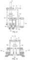
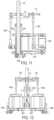
- FIG. 6is an isometric view of a ganged servo control system in accordance with an embodiment of the present disclosure.
- FIG. 7is a top plan view of the ganged servo control system of FIG. 6 in accordance with an embodiment of the present disclosure.
- FIG. 8is a bottom plan view of the ganged servo control system of FIG. 6 in accordance with an embodiment of the present disclosure.
- FIG. 9is a right side elevation view of the ganged servo control system of FIG. 6 in accordance with an embodiment of the present disclosure.
- FIG. 10is a front elevation view of the ganged servo control system of FIG. 6 in accordance with an embodiment of the present disclosure.
- FIG. 11is a cross-sectional view of the ganged servo control system of FIG. 6 taken along line 11 - 11 of FIG. 6 in accordance with an embodiment of the present disclosure.
- FIG. 12is a rear elevation view of the ganged servo control system of FIG. 6 in accordance with an embodiment of the present disclosure.
- FIG. 13is a fragmentary isometric view of a main rotor assembly in accordance with an embodiment of the present disclosure.
- FIG. 14is wiring diagram for a ganged servo flight control system in accordance with an embodiment of the present disclosure.
- FIG. 15is a flowchart of a process of calibrating a ganged servo flight control system in accordance with an embodiment of the present disclosure.
- the present disclosuregenerally provides a ganged servo flight control system for a UAV.
- the flight control systemcan be used in a variety of applications, for example, controlling a main rotor of a helicopter UAV, or the like.
- the flight control systemintegrates ganged servo-actuators to control the flight of the UAV in at least one direction.
- the ganged servo-actuatorsfunction to increase torque output of the servo assembly by operating as a single servo-actuator. Through use of ganged servo-actuators, significant servo speed improvements can be achieved over larger single servo-actuators with similar torque characteristics.
- the ganged servo-actuatorsintroduce redundancy of servo-actuators at the swashplate, which is a common failure mode for small, fly-by-wire helicopter UAV applications.
- the ganged servo-actuatorsoperate from a single drive signal.
- the ganged servo-actuatorsprovide the high speed, high torque, and high precision required for accurate control of the UAV.
- a helicopter UAV 100generally includes a frame structure 102 to which a main rotor assembly 104 having a plurality of main rotor blades 106 (e.g., three main rotor blades) is rotatably attached at a first rotational axis R 1 .
- a tail boom 108is connected to the frame structure 102 to locate a tail rotor assembly 110 having a plurality of tail rotor blades 112 (e.g., two tail rotor blades) a distance away from the first rotational axis R 1 of the main rotor assembly 104 .
- the tail boom 108includes a proximal end and a distal end.
- the proximal end of the tail boom 108is connected to a rear portion of the frame structure 102 and the tail rotor assembly 110 is rotatably attached to the distal end of the tail boom 108 at a second rotational axis R 2 , which may be orthogonally positioned relative to the first rotational axis R 1 .
- the main rotor assembly 104is horizontally-mounted to the UAV 100 to provide vertical lift upon rotation of the main rotor assembly 104 about the first rotational axis R 1 .
- the tail rotor assembly 110is vertically-mounted to the distal end of the tail boom 108 to provide horizontal thrust upon rotation of the tail rotor assembly 110 about the second rotational axis R 2 .
- the horizontal thrust provided by the tail rotor assembly 110controls the rotational position (i.e., yaw) of the UAV 100 by, for example, counteracting the torque created by rotation of the main rotor assembly 104 .
- the tail boom 108may include a vertical stabilizer 114 to prevent the tail rotor assembly 110 from touching a support surface (e.g., the ground) during landing or ground operation of the UAV 100 .
- the vertical stabilizer 114may support the UAV 100 against the support surface during non-flight operation and/or storage. Additionally or alternatively, the vertical stabilizer 114 may help or otherwise allow the UAV 100 to “weathervane” into the direction of motion during flight.
- the UAV 100may include additional components to improve the functionality and capabilities of the UAV 100 .
- the UAV 100may include a canopy 116 attached to the frame structure 102 to improve both the aesthetic and aerodynamic characteristics of the UAV 100 .
- the canopy 116hides or otherwise conceals the internal components of the UAV 100 .
- the UAV 100may include landing gear to support the UAV 100 during non-flight operation or storage.
- the landing gearwhich may include planar or tubular landing skids 118 , is attached to the frame structure 102 (e.g., to opposing sides of the frame structure 102 ).
- the landing skids 118may be the only portion of the UAV 100 touching the support surface, or alternatively support the UAV 100 in a tripod-like manner with the vertical stabilizer 114 .
- the UAV 100may also include accessory equipment 120 attached to the UAV 100 (e.g., to a front portion of the frame structure 102 and below the canopy 116 ) to provide numerous aviation uses, including, for example, aerial surveillance, inspection, surveying, 3D mapping, photography, and/or filmmaking.
- the UAV 100may be equipped with a flashlight, a Nadir mounted DSLR high resolution camera, and/or a fully stabilized camera gimbal having electro-optical and/or infrared sensors.
- a flashlighta Nadir mounted DSLR high resolution camera
- a fully stabilized camera gimbalhaving electro-optical and/or infrared sensors.
- substantially any type of accessorymay be attached to the frame structure 102 .
- the UAV 100may be equipped with positioning and communication equipment.
- the UAV 100may be controlled by a hand-held remote control unit or ground station.
- the UAV 100may include an automatic flight control system capable of precise navigation, guidance, and control of the UAV.
- the automatic flight control systemmay include an embedded computer system, a global positioning satellite (GPS) receiver, an inertial measurement unit, a barometer, a magnetometer, and/or absolute and differential pressure sensors.
- the UAV 100may transfer data to, or receive data from, a user, a ground station, and/or other UAVs through Wi-Fi, cellular data, mobile satellite communications, radio frequency, infrared or ultrasonic remote control devices, or any other wireless data communication mediums.
- a plurality of frame membersmay connect together to form the frame structure 102 of the UAV 100 .
- the frame structure 102may include a first frame member 122 connected to a second frame member 124 by a plurality of connection members 126 .
- the first and second frame members 122 , 124are substantially identical to and horizontally spaced from each other and define a longitudinal length of the frame structure 102 .
- Each of the plurality of connection members 126includes a base portion 128 having tabs 130 perpendicularly extending from opposing ends of the base portion 128 .
- Each tab 130is attached to an interior surface of one of the first and second frame members 122 , 124 (e.g., adjacent bottom portions of the first and second frame members 122 , 124 ).
- the connection members 126define a transverse width of the frame structure 102 .
- the frame structure 102defines an internal cavity 132 operable to receive portions of a flight control assembly 134 , as explained below.
- the flight control assembly 134 of the UAV 100includes a drive system 136 and a control system 138 operable to control the drive system 136 during flight operation.
- the drive system 136includes a powertrain 140 , the main rotor assembly 104 , and a swashplate 142 .
- the powertrain 140includes a motor 144 (e.g., an electric motor) and a gearing assembly 146 to respectively generate power and deliver it to the main rotor assembly 104 and/or the tail rotor assembly 110 .
- the gearing assembly 146which converts and/or translates the rotation of the motor 144 into the rotation required to drive the main rotor assembly 104 and/or the tail rotor assembly 110 , may include a set of meshingly engaged mechanical gearboxes and/or an electromagnetic transmission. Through the set of mechanical gearboxes and/or the electromagnetic transmission, the gearing assembly 146 directs the power generated by the motor 144 to both the main rotor assembly 104 and the tail rotor assembly 110 . In some embodiments, however, the tail rotor assembly 110 may be driven by a secondary powertrain located substantially within the tail boom 108 . As illustrated in FIGS.
- the motor 144is attached to a motor mount 148 positioned at least partially within the internal cavity 132 of the frame structure 102 and connected to the interior surfaces of both the first and second frame members 122 , 124 .
- vibration from the motor 144may be vibrationally isolated from the frame structure 102 by one or more vibration dampers operably associated with the motor mount 148 .
- the UAV 100includes a power source (e.g., a battery pack) to power the motor 144 during flight operation.
- the power sourcemay be rechargeable through connection with DC and/or AC voltage sources. Additionally or alternatively, the power source may recharge through one or more solar panels connected to the UAV 100 .
- portions of the drive system 136is received within the internal cavity 132 of the frame structure 102 to conserve space and protect the individual components of the drive system 136 .
- the gearing assembly 146 and the power sourceare positioned within the internal cavity 132 .
- the figuresillustrate the motor 144 external to the internal cavity 132 , it is contemplated that the motor 144 may also be received within the internal cavity 132 of the frame structure 102 .
- the main rotor assembly 104includes a mast 150 , a hub 152 circumferentially attached to the mast 150 , and the plurality of main rotor blades 106 (e.g., three main rotor blades) attached to the hub 152 .
- the mast 150which may be a cylindrical shaft that rotates about the first rotational axis R 1 , extends upwards from, and is rotationally driven by, the gearing assembly 146 .
- the mast 150may be free to rotate through a bearing 154 held in place by a rigid support 156 connected to and between the interior surfaces of the first and second frame members 122 , 124 . As shown in FIG.
- the hub 152includes a first connection portion 158 and a second connection portion 160 .
- the first connection portion 158may be removably or fixedly attached to the top of the mast 150 by, for example, mechanical fasteners or other suitable fastening mechanisms.
- the main rotor blades 106may be rotationally connected to the second connection portion 160 of the hub 152 .
- FIG. 1In the exemplary embodiment shown in FIG. 1
- the main rotor blades 106connect to the second connection portion 160 perpendicularly to the first rotational axis R 1 such that the main rotor blades 106 reside and move within a common plane, although it is contemplated that the main rotor blades 106 may extend at an acute or an obtuse angle to the first rotational axis R 1 .
- Each of the main rotor blades 106have an airfoil-type cross-section to create lift as the main rotor blades 106 rotate about the first rotational axis R 1 .
- each main rotor blademay be varied to control the amount of vertical lift and/or horizontal thrust applied to the UAV 100 by the main rotor assembly 104 , as explained below.
- the swashplate 142is connected to the drive system 136 to control the blade pitch of each of the main rotor blades 106 .
- the swashplate 142which surrounds and at least partially rotates about the mast 150 of the main rotor assembly 104 , operates to vary the blade pitch of the main rotor blades 106 cyclically throughout rotation of the main rotor assembly 104 about the first rotational axis R 1 .
- the swashplate 142operates to vary the blade pitch of all the main rotor blades 106 collectively at the same time.
- the swashplate 142includes a non-rotating plate 162 and a rotary disc 164 that resides and moves within a plane parallel to the non-rotating plate 162 .
- the non-rotating plate 162is connected to and manipulated by the control system 138 .
- the non-rotating plate 162may include first, second, and third connection portions 166 , 168 , 170 through which the control system 138 may manipulate the swashplate 142 , as explained below.
- first, second, and third connection portions 166 , 168 , 170may be offset from one another by 120 degrees.
- the non-rotating plate 162is rotationally constrained by an anti-rotation bracket 172 attached to the rigid support 156 (e.g., a rear side of the rigid support 156 ).
- the third connection portion 170includes an anti-rotation boss 174 that is horizontally constrained within a vertical slot 176 defined in the anti-rotation plate.
- the rotary disc 164rotates with the mast 150 relative to the non-rotating plate 162 and is connected to each of the main rotor blades 106 through pitch links 178 .
- the non-rotating plate 162 and the rotary disc 164may each include a bearing 180 that allows the respective non-rotating plate 162 and the rotary disc 164 to tilt relative to the mast 150 and/or the hub 152 .
- the swashplate 142may tilt and vertically shift along the mast 150 to control the blade pitch of the main rotor blades 106 through the pitch links 178 .
- the control system 138includes a plurality of control assemblies 182 operable to control the drive system 136 .
- each of the plurality of control assemblieswhich may be referred to individually as respective servo assemblies, includes a respective plurality of servo-actuators 184 , 188 connected to operate in cooperation with each other.
- the servo-actuators of each control assemblyare connected in ganged relationship to effectively operate as a single servo-actuator.
- the ganged servo relationshipoperates to increase the torque output of the control assembly without resorting to disproportionally larger and more expensive single servo-actuators.
- the solution costmay be intrinsically linearly proportional to the size (torque) required for a particular application.
- the ganged servo relationshipmay also provide significant servo speed improvements over a single larger servo-actuator with similar torque characteristics. More importantly, the ganged servo relationship of each control assembly provides a redundancy of servo-actuators at each connection portion of the swashplate 142 , which is a common failure mode for small, fly-by-wire, helicopter applications. Should one of the servo-actuators of the ganged servo assembly fail, a second servo-actuator may provide the required control of the swashplate 142
- control system 138may include a first control assembly 182 A operable to control the drive system 136 in a first manner, a second control assembly 1828 operable to control the drive system 136 in a second manner, and a third control assembly 182 C operable to control the drive system 136 in a third manner.
- the first control assembly 182 A(or first servo assembly) is connected to the first connection portion 166 of the swashplate 142
- the second control assembly 1828(or second servo assembly) is connected to the second connection portion 168 of the swashplate 142
- the third control assembly 182 C(or third servo assembly) is connected to the third connection portion 170 of the swashplate 142 .
- the first, second, and third control assemblies 182 A, 1828 , 182 Cmay be positioned relative to each other by attachment to an upper frame 183 A and a lower frame 1838 .
- Each of the upper and lower frames 183 A, 1838may be positioned at least partially within the internal cavity 132 of the frame structure 102 and attached to the first and second frame members 122 , 124 (e.g. to the interior surfaces of the first and second frame members 122 , 124 ) to secure the control system to the UAV 100 .
- the upper and lower frames 183 A, 1838may rotationally receive the mast 150 (see FIG. 6 ).
- the first control assembly 182 Aincludes a first servo-actuator 184 A having a first servo arm 186 A, and a second servo-actuator 188 A having a second servo arm 190 A.
- Each of the first and second servo arms 186 A, 190 Aare rotatably connected to the first and second servo-actuators 184 A, 188 A, respectively.
- the first and second servo-actuators 184 A, 188 A of the first control assembly 182 Aare horizontally stacked or arranged side-by-side such that the first servo arm 186 A and the second servo arm 190 A reside and move within a first common plane.
- a linkage member 192 Aconnects the second servo arm 190 A to the first servo arm 186 A.
- the linkage member 192 Amay be a rigid member pivotably attached to each of and between the first servo arm 186 A and the second servo arm 190 A.
- the linkage member 192 Amay be an elongate member having opposing first and second ends 194 , 196 . As shown in FIG.
- the first end 194may be pivotably connected to the first servo arm 186 A (e.g., an end of the first servo arm 186 A), and the second end 196 may be pivotably connected to the second servo arm 190 A (e.g., an end of the second servo arm 190 A).
- the linkage member 192 Amay be a shaft about which each of the first servo arm 186 A and the second servo arm 190 A rotates.
- the first control assembly 182 Amay also include a linkage assembly 198 A connected to the second servo arm 190 A and to the first connection portion 166 of the swashplate 142 ; however, in some embodiments, the second servo arm 190 A may be connected directly to the first connection portion 166 .
- the first servo arm 186 A and the second servo arm 190 Arotate in unison to move (e.g., raise or lower) the first connection portion 166 , as explained below.
- the second control assembly 1828may be configured similar to the first control assembly 182 A.
- the second control assembly 1828may include a first servo-actuator 1848 and a second servo-actuator 1888 horizontally stacked or arranged side-by-side such that associated first and second servo arms 1868 , 1908 reside and move within a second common plane.
- the second control assembly 1828may include a linkage member 1928 configured similar to the linkage member 192 A of the first control assembly 182 A.
- the second control assembly 1828may include a linkage assembly 198 B connected to the second servo arm 190 B and to the second connection portion 168 of the swashplate 142 .
- first and second servo arms 1868 , 1908 of the second control assembly 1828rotate in unison to move (e.g., raise or lower) the second connection portion 168 of the swashplate 142 , as explained below.
- the third control assembly 182 Cincludes a first servo-actuator 184 C having a first servo arm 186 C, and a second servo-actuator 188 C arranged opposite the first servo-actuator 184 C and having a second servo arm 190 C.
- the first servo arm 186 C and the second servo arm 190 Care mirror images of each other.
- the first and second servo-actuators of the third control assembly 182 Care arranged opposite each other in facing relationship such that the first servo arm 186 C and the second servo arm 190 C reside and move within parallel planes.
- the first and second servo-actuators of the third control assembly 182 Cmay be positioned in facing relationship with each other across a vertical midline 181 of the UAV 100 .
- the third control assembly 182 Cmay include a linkage assembly connected to the first and second servo arms 186 C, 190 C and to the third connection portion 170 of the swashplate 142 .
- the linkage assembly of the third control assembly 182 Cmay be positioned at least partially between the first and second servo arms 186 C, 190 C.
- the first and second servo arms 186 C, 190 C of the third control assembly 182 Crotate in unison to move (e.g., raise or lower) the third connection portion 170 of the swashplate 142 , as explained below.
- first, second, and third control assemblies 182 A, 1828 , 182 Cmanipulate the swashplate 142 to control the cyclic and collective pitch of the main rotor blades 106 .
- each of the first, second, and third control assemblies 182 A, 182 B, 182 Cvertically shift (e.g., raise or lower) the swashplate 142 relative to the hub 152 of the main rotor assembly 104 .
- the servo-actuators 184 , 188 of the first, second, and third control assemblies 182 A, 1828 , 182 Crotate the respective servo arms 186 , 190 to raise or lower the respective linkage assemblies 198 equally to collectively raise or lower the swashplate 142 along the mast 150 .
- each of the pitch links 178may cause an associated main rotor blade 106 to equally rotate in a first rotational direction at the second connection portion 160 of the hub 152 .
- each of the pitch links 178may cause an associated main rotor blade 106 to equally rotate in a second rotational direction opposite the first rotational direction. In this manner, the blade pitch is increased or decreased by the same amount and at the same time on all main rotor blades 106 , thereby increasing or decreasing the total lift derived from the main rotor assembly 104 .
- At least one of the first, second, and third control assemblies 182 A, 182 B, 182 Ctilts the swashplate 142 relative to the hub 152 . Tilting of the swashplate 142 relative to the hub 152 changes the blade pitch of the main rotor blades 106 cyclically depending on the position of the main rotor blades 106 as they rotate about the first rotational axis R 1 such that each of the main rotor blades 106 has the same blade pitch at the same point in a revolutionary cycle.
- the lift generated by each of the main rotor blades 106changes as the blade rotates through a revolutionary cycle, thereby causing the UAV 100 to pitch or roll depending on the relative positions of the first, second, and third connection portions 166 , 168 , 170 of the swashplate 142 .
- raising or lowering the third connection portion 170 relative to at least one of the first and second connection portions 166 , 168causes the UAV 100 to pitch forward or aft, respectively.
- raising or lowering one of the first and second connection portions 166 , 168 relative to the other of the first and second connection portions 166 , 168causes the UAV 100 to roll left or right.
- the ganged servo-actuators 184 , 188 of each control assembly 182may operate from a single drive signal.
- a servo output signal generator 200whether incorporated into the UAV 100 or part of a ground control system, provides a plurality of outputs (e.g., three outputs) for the first, second, and third control assemblies 182 A, 182 B, 182 C.
- FIG. 14a servo output signal generator 200 , whether incorporated into the UAV 100 or part of a ground control system, provides a plurality of outputs (e.g., three outputs) for the first, second, and third control assemblies 182 A, 182 B, 182 C.
- the servo output signal generator 200includes cyclic/collective pitch mixing (CCPM) software 202 to mix the individual control inputs for roll, pitch, and collective to control the swashplate 142 .
- CCPMcyclic/collective pitch mixing
- the first and second servo-actuators of the first control assembly 182 Aare connected to a first signal output 204
- the first and second servo-actuators of the second control assembly 182 Bare connected to a second signal output 206
- the first and second servo-actuators of the third control assembly 182 Care connected to a third signal output 208 .
- each of the servo-actuators 184 , 188 of each control assembly 182operate as a single servo-actuator.
- the servo-actuators 184 , 188 of each control assembly 182are rigidly connected by the linkage member 192 , it is desirable to calibrate the ganged servo control system 138 such that the servo-actuators 184 , 188 of each control assembly 182 operate in unison.
- One method to calibrate the control system 138is shown in FIG. 15 .
- the first servo-actuator 184is calibrated to respond correctly with respect to one or more input signals.
- the first servo-actuator 184is provided with a known input signal.
- the second servo-actuator 188is provided with the known input signal.
- step 320includes providing the known input signal to N number of servo-actuators.
- step 330a neutral servo position of the second servo-actuator 188 is adjusted such that the servo arms 186 , 190 of the first and second servo-actuators 184 , 188 are parallel.
- step 330may include adjusting a neutral position of N number of servo-actuators.
- the methodmay include steps 340 , 350 , and 360 .
- a rigid servo linkagee.g., the linkage member 190
- the rigid servo linkageshould be connected without binding of the first and second servo-actuators 184 , 188 .
- a current draw of each servo-actuator 184 , 188is monitored.
- step 350may include verifying that the current draw of each servo-actuator 184 , 188 is not greater than a nominal servo draw of each of the servo-actuators 184 , 188 at rest.
- the first and second servo-actuators 184 , 188are configured to move freely upon power or signal loss. Should one of the ganged servo-actuators 184 , 188 fail during operation, the remaining servo-actuator(s) 184 , 188 may continue to provide the desired control of the swashplate 142 and/or the UAV 100 , as noted above.
- the above stepsare not exhaustive, and the ganged servo control system 138 may be calibrated using additional steps. Moreover, any number of the above steps, whether in or out of the sequence outlined above, may be used to calibrate the ganged servo control system 138 .
Landscapes
- Engineering & Computer Science (AREA)
- Aviation & Aerospace Engineering (AREA)
- Mechanical Engineering (AREA)
- Remote Sensing (AREA)
- Automation & Control Theory (AREA)
- Toys (AREA)
Abstract
Description
Claims (18)
Priority Applications (3)
| Application Number | Priority Date | Filing Date | Title |
|---|---|---|---|
| US16/810,463US11649046B2 (en) | 2015-08-25 | 2020-03-05 | Ganged servo flight control system for an unmanned aerial vehicle |
| US18/136,727US12054249B2 (en) | 2015-08-25 | 2023-04-19 | Ganged servo flight control system for an unmanned aerial vehicle |
| US18/778,531US20240367786A1 (en) | 2015-08-25 | 2024-07-19 | Ganged servo flight control system for an unmanned aerial vehicle |
Applications Claiming Priority (2)
| Application Number | Priority Date | Filing Date | Title |
|---|---|---|---|
| US14/835,243US10618645B2 (en) | 2015-08-25 | 2015-08-25 | Ganged servo flight control system for an unmanned aerial vehicle |
| US16/810,463US11649046B2 (en) | 2015-08-25 | 2020-03-05 | Ganged servo flight control system for an unmanned aerial vehicle |
Related Parent Applications (1)
| Application Number | Title | Priority Date | Filing Date |
|---|---|---|---|
| US14/835,243ContinuationUS10618645B2 (en) | 2015-08-25 | 2015-08-25 | Ganged servo flight control system for an unmanned aerial vehicle |
Related Child Applications (1)
| Application Number | Title | Priority Date | Filing Date |
|---|---|---|---|
| US18/136,727ContinuationUS12054249B2 (en) | 2015-08-25 | 2023-04-19 | Ganged servo flight control system for an unmanned aerial vehicle |
Publications (2)
| Publication Number | Publication Date |
|---|---|
| US20200255134A1 US20200255134A1 (en) | 2020-08-13 |
| US11649046B2true US11649046B2 (en) | 2023-05-16 |
Family
ID=58097473
Family Applications (4)
| Application Number | Title | Priority Date | Filing Date |
|---|---|---|---|
| US14/835,243Active2039-03-30US10618645B2 (en) | 2015-08-25 | 2015-08-25 | Ganged servo flight control system for an unmanned aerial vehicle |
| US16/810,463ActiveUS11649046B2 (en) | 2015-08-25 | 2020-03-05 | Ganged servo flight control system for an unmanned aerial vehicle |
| US18/136,727ActiveUS12054249B2 (en) | 2015-08-25 | 2023-04-19 | Ganged servo flight control system for an unmanned aerial vehicle |
| US18/778,531PendingUS20240367786A1 (en) | 2015-08-25 | 2024-07-19 | Ganged servo flight control system for an unmanned aerial vehicle |
Family Applications Before (1)
| Application Number | Title | Priority Date | Filing Date |
|---|---|---|---|
| US14/835,243Active2039-03-30US10618645B2 (en) | 2015-08-25 | 2015-08-25 | Ganged servo flight control system for an unmanned aerial vehicle |
Family Applications After (2)
| Application Number | Title | Priority Date | Filing Date |
|---|---|---|---|
| US18/136,727ActiveUS12054249B2 (en) | 2015-08-25 | 2023-04-19 | Ganged servo flight control system for an unmanned aerial vehicle |
| US18/778,531PendingUS20240367786A1 (en) | 2015-08-25 | 2024-07-19 | Ganged servo flight control system for an unmanned aerial vehicle |
Country Status (6)
| Country | Link |
|---|---|
| US (4) | US10618645B2 (en) |
| EP (2) | EP3341289B1 (en) |
| CN (2) | CN108349588B (en) |
| AU (2) | AU2016311443B2 (en) |
| ES (1) | ES2909574T3 (en) |
| WO (1) | WO2017035391A1 (en) |
Cited By (1)
| Publication number | Priority date | Publication date | Assignee | Title |
|---|---|---|---|---|
| US12054249B2 (en) | 2015-08-25 | 2024-08-06 | Aerovironment, Inc. | Ganged servo flight control system for an unmanned aerial vehicle |
Families Citing this family (8)
| Publication number | Priority date | Publication date | Assignee | Title |
|---|---|---|---|---|
| US20180186472A1 (en)* | 2016-12-30 | 2018-07-05 | Airmada Technology Inc. | Method and apparatus for an unmanned aerial vehicle with a 360-degree camera system |
| US10994840B1 (en) | 2017-08-16 | 2021-05-04 | United States Of America As Represented By The Secretary Of The Air Force | Thrust vectoring control of a cyclorotor |
| US10661898B2 (en) | 2018-06-21 | 2020-05-26 | Cimcon Lighting, Inc. | Unmanned aerial vehicle for infrastructure maintenance |
| US11443640B2 (en)* | 2018-10-19 | 2022-09-13 | Anduril Industries, Inc. | Ruggedized autonomous helicopter platform |
| US11745886B2 (en)* | 2021-06-29 | 2023-09-05 | Beta Air, Llc | Electric aircraft for generating a yaw force |
| CN113911337A (en)* | 2021-10-29 | 2022-01-11 | 李宪军 | A kind of automatic tilter control system and control method thereof |
| CN115138081A (en)* | 2022-08-01 | 2022-10-04 | 董群法 | Children toy |
| EP4619311A1 (en)* | 2022-11-14 | 2025-09-24 | Toofon, Inc. | Collective-pitch adjustment mechanism for variable-pitch propeller or rotor utilized in a flight vehicle or drone and method for shaping noise profile |
Citations (43)
| Publication number | Priority date | Publication date | Assignee | Title |
|---|---|---|---|---|
| US4741672A (en) | 1985-07-08 | 1988-05-03 | Gerald Breuner | Collective pitch change system for teter-bar type gyroplane rotary wing aircraft |
| US5012423A (en)* | 1989-04-17 | 1991-04-30 | Mcdonnell Douglas Corporation | Back-up fly by wire control system |
| US5224664A (en)* | 1991-07-22 | 1993-07-06 | United Technologies Corporation | Adaptive control system input limiting |
| US5678786A (en)* | 1995-12-06 | 1997-10-21 | Mcdonnell Douglas Helicopter Co. | Reconfigurable helicopter flight control system |
| US5709357A (en)* | 1994-06-30 | 1998-01-20 | Von Wilmowsky; Kaspar Freiherr | Tiltrotor helicopter |
| DE10001378A1 (en)* | 1999-02-05 | 2000-08-10 | Futaba Denshi Kogyo Kk | Radio-controlled helicopter has wobble plate contg. 3 control points, associated with servo devices, at corners of equilateral triangular base, movable point at centre of triangle height |
| US6145428A (en)* | 1998-03-31 | 2000-11-14 | Sikorsky Aircraft Corporation | Integrated fire and flight control system for controlling the angle of attack of a rotary wing aircraft |
| US20040160133A1 (en) | 2003-02-17 | 2004-08-19 | Eiji Jinno | Servo device for radio control |
| US20060011777A1 (en)* | 2004-04-14 | 2006-01-19 | Arlton Paul E | Rotary wing vehicle |
| TWM287704U (en) | 2005-11-01 | 2006-02-21 | Gazaur Technology Corp | Improved structure of main-shaft sliding sleeve for remote-controlled helicopter |
| US20060266880A1 (en) | 2005-05-26 | 2006-11-30 | Chien-Chao Chen | Servo fixing base structure for remote control helicopers |
| US20070102588A1 (en) | 2005-10-25 | 2007-05-10 | John Durant | Servo Mounting System for Direct Drive of an Aircraft Control Surface |
| US20080065278A1 (en) | 2004-10-14 | 2008-03-13 | Shultz Peter M | Mechanical Flight Control Auxiliary Power Assist System |
| US20090242691A1 (en) | 2008-03-27 | 2009-10-01 | Wittmer Kenneth S | Swashplate trajectory control |
| US20100084517A1 (en) | 2008-10-08 | 2010-04-08 | Honeywell International Inc. | Electromechanical actuation system and method |
| CN201490896U (en) | 2009-08-21 | 2010-05-26 | 北京中科可来博电子技术有限公司 | Static zero-power safe and energy-saving conversion device |
| US20100210169A1 (en)* | 2009-02-04 | 2010-08-19 | Ulrich Röhr | Model Helicopter Control and Receiving Means |
| US20110057071A1 (en)* | 2009-09-10 | 2011-03-10 | Vineet Sahasrabudhe | Life improving flight control system |
| CN102131702A (en) | 2008-07-18 | 2011-07-20 | 空中巴士运作公司 | Device for shrouding an aircraft nacelle |
| US20110315806A1 (en)* | 2010-05-17 | 2011-12-29 | Piasecki John W | Modular and morphable air vehicle |
| DE102010025718A1 (en) | 2010-06-30 | 2012-01-05 | Deutsches Zentrum für Luft- und Raumfahrt e.V. | Helicopter rotor controlling device has rotor head, which is arranged at rotor shaft driven by drive unit in torque proof manner |
| US20120072056A1 (en)* | 2008-03-31 | 2012-03-22 | Muhammad Emadul Hasan | Flight control system for rotary wing aircraft |
| US20120205494A1 (en)* | 2009-10-19 | 2012-08-16 | Bae Systems Plc | Tactile cueing apparatus |
| US20120231695A1 (en)* | 2011-03-11 | 2012-09-13 | Ta-Sen Tu | Transmission mechanism for remote-controlled toy helicopter |
| US20120282103A1 (en) | 2009-12-24 | 2012-11-08 | Prox Dynamics As | Rotor assembly |
| CN103085970A (en) | 2011-11-01 | 2013-05-08 | 贝尔直升机泰克斯特龙公司 | Active Prop Rotor Stability System |
| US20130119187A1 (en) | 2011-11-10 | 2013-05-16 | Eurocopter | Device for varying blade pitch of a lift rotor |
| US20130195662A1 (en) | 2012-01-26 | 2013-08-01 | Ta Sen Tu | Transmission structure of main propeller clamping seat and swashplate of remote-controlled helicopter |
| EP2626302A1 (en) | 2012-02-09 | 2013-08-14 | Bell Helicopter Textron Inc. | System and method of actuating a swashplate for main rotor control |
| US20140110532A1 (en) | 2012-10-19 | 2014-04-24 | Bell Helicopter Textron Inc. | Direct-Drive Control of Aircraft Stability Augmentation |
| US20140271204A1 (en) | 2013-03-15 | 2014-09-18 | Bell Helicopter Textron Inc. | Tiltrotor Control System With Two Rise/Fall Actuators |
| US20140377068A1 (en)* | 2011-09-19 | 2014-12-25 | Zf Friedrichshafen Ag | Rotor blade control device |
| US20150041278A1 (en) | 2013-08-12 | 2015-02-12 | Airbus Defence and Space GmbH | Pneumatically Actuated Decoupling Device |
| US20150050148A1 (en) | 2012-03-14 | 2015-02-19 | Zf Friedrichshafen Ag | Rotor blade control device |
| US20150081102A1 (en) | 2012-02-09 | 2015-03-19 | Moog Inc. | Actuator system and method |
| CN204223182U (en) | 2014-11-12 | 2015-03-25 | 锦州联升汽车零部件有限公司 | Civilian depopulated helicopter rotor controls tilting frame actuating device |
| US9022314B1 (en) | 2010-09-09 | 2015-05-05 | Groen Brothers Aviation, Inc. | Torsionally stiff rotorcraft control apparatus and method |
| CN104590559A (en) | 2015-01-30 | 2015-05-06 | 北京万户空天科技有限公司 | Cyclic pitch hybrid-control system for large unmanned helicopter or manned helicopter |
| EP1846291B1 (en) | 2005-02-11 | 2015-05-27 | Bell Helicopter Textron Inc. | Dual motor dual concentric valve |
| CN204369862U (en) | 2014-11-14 | 2015-06-03 | 江苏省家禽科学研究所 | Cock sexual prematurity genes involved---GDF9 gene 5 ' control region SNP somatotype and promoter activity quick detection kit |
| US20150217865A1 (en) | 2014-01-31 | 2015-08-06 | UNIVERSITé DE SHERBROOKE | Magnetorheological Rotorcraft Actuation System |
| US20150232177A1 (en) | 2014-02-19 | 2015-08-20 | Sikorsky Aircraft Corporation | Fly by wire servos with internal loop closure |
| WO2017035391A1 (en) | 2015-08-25 | 2017-03-02 | Pulse Aerospace LLC | Ganged servo flight control system for an unmanned aerial vehicle |
Family Cites Families (7)
| Publication number | Priority date | Publication date | Assignee | Title |
|---|---|---|---|---|
| US4362085A (en)* | 1979-06-11 | 1982-12-07 | The United States Of America As Represented By The Secretary Of The Army | Flight control system |
| US4930988A (en)* | 1989-01-02 | 1990-06-05 | Honeywell Inc | Individual blade control system for helicopters |
| US20030030582A1 (en)* | 2001-08-10 | 2003-02-13 | Vickers Roger S. | Environment measurement methods, systems, media, signals and data structures |
| CN102490896A (en)* | 2011-12-27 | 2012-06-13 | 天津曙光敬业科技有限公司 | Variable-torque four-rotor aircraft with large load capacity |
| US9365288B2 (en)* | 2012-11-15 | 2016-06-14 | Textron Innovations Inc. | Blade-pitch control system with indexing swashplate |
| FR3014838B1 (en)* | 2013-12-17 | 2015-12-25 | Eurocopter France | GIRAVION EQUIPPED WITH A REVERSE ROTOR ANTI COUPLE PARTICIPATING SELECTIVELY TO THE SUSTENTATION AND PROPULSION IN TRANSLATION OF THE GIRAVION |
| CN104369862B (en)* | 2014-10-27 | 2016-03-30 | 湖南星索尔航空科技有限公司 | A kind of pilotless helicopter |
- 2015
- 2015-08-25USUS14/835,243patent/US10618645B2/enactiveActive
- 2016
- 2016-08-25ESES16840151Tpatent/ES2909574T3/enactiveActive
- 2016-08-25WOPCT/US2016/048765patent/WO2017035391A1/ennot_activeCeased
- 2016-08-25CNCN201680062321.1Apatent/CN108349588B/enactiveActive
- 2016-08-25EPEP16840151.1Apatent/EP3341289B1/enactiveActive
- 2016-08-25CNCN202111370008.3Apatent/CN114056560A/enactivePending
- 2016-08-25EPEP22152835.9Apatent/EP4026771B1/enactiveActive
- 2016-08-25AUAU2016311443Apatent/AU2016311443B2/enactiveActive
- 2020
- 2020-02-05AUAU2020200827Apatent/AU2020200827B2/enactiveActive
- 2020-03-05USUS16/810,463patent/US11649046B2/enactiveActive
- 2023
- 2023-04-19USUS18/136,727patent/US12054249B2/enactiveActive
- 2024
- 2024-07-19USUS18/778,531patent/US20240367786A1/enactivePending
Patent Citations (50)
| Publication number | Priority date | Publication date | Assignee | Title |
|---|---|---|---|---|
| US4741672A (en) | 1985-07-08 | 1988-05-03 | Gerald Breuner | Collective pitch change system for teter-bar type gyroplane rotary wing aircraft |
| US5012423A (en)* | 1989-04-17 | 1991-04-30 | Mcdonnell Douglas Corporation | Back-up fly by wire control system |
| US5224664A (en)* | 1991-07-22 | 1993-07-06 | United Technologies Corporation | Adaptive control system input limiting |
| US5709357A (en)* | 1994-06-30 | 1998-01-20 | Von Wilmowsky; Kaspar Freiherr | Tiltrotor helicopter |
| US5678786A (en)* | 1995-12-06 | 1997-10-21 | Mcdonnell Douglas Helicopter Co. | Reconfigurable helicopter flight control system |
| US6145428A (en)* | 1998-03-31 | 2000-11-14 | Sikorsky Aircraft Corporation | Integrated fire and flight control system for controlling the angle of attack of a rotary wing aircraft |
| DE10001378A1 (en)* | 1999-02-05 | 2000-08-10 | Futaba Denshi Kogyo Kk | Radio-controlled helicopter has wobble plate contg. 3 control points, associated with servo devices, at corners of equilateral triangular base, movable point at centre of triangle height |
| US20040160133A1 (en) | 2003-02-17 | 2004-08-19 | Eiji Jinno | Servo device for radio control |
| US20060011777A1 (en)* | 2004-04-14 | 2006-01-19 | Arlton Paul E | Rotary wing vehicle |
| CN101421157A (en) | 2004-04-14 | 2009-04-29 | 保罗·E·阿尔托恩 | Rotor craft |
| US20080065278A1 (en) | 2004-10-14 | 2008-03-13 | Shultz Peter M | Mechanical Flight Control Auxiliary Power Assist System |
| EP1846291B1 (en) | 2005-02-11 | 2015-05-27 | Bell Helicopter Textron Inc. | Dual motor dual concentric valve |
| US20060266880A1 (en) | 2005-05-26 | 2006-11-30 | Chien-Chao Chen | Servo fixing base structure for remote control helicopers |
| US20070102588A1 (en) | 2005-10-25 | 2007-05-10 | John Durant | Servo Mounting System for Direct Drive of an Aircraft Control Surface |
| TWM287704U (en) | 2005-11-01 | 2006-02-21 | Gazaur Technology Corp | Improved structure of main-shaft sliding sleeve for remote-controlled helicopter |
| US20090242691A1 (en) | 2008-03-27 | 2009-10-01 | Wittmer Kenneth S | Swashplate trajectory control |
| US20120072056A1 (en)* | 2008-03-31 | 2012-03-22 | Muhammad Emadul Hasan | Flight control system for rotary wing aircraft |
| CN102131702A (en) | 2008-07-18 | 2011-07-20 | 空中巴士运作公司 | Device for shrouding an aircraft nacelle |
| US20100084517A1 (en) | 2008-10-08 | 2010-04-08 | Honeywell International Inc. | Electromechanical actuation system and method |
| US8070091B2 (en)* | 2008-10-08 | 2011-12-06 | Honeywell International Inc. | Electromechanical actuation system and method |
| US20100210169A1 (en)* | 2009-02-04 | 2010-08-19 | Ulrich Röhr | Model Helicopter Control and Receiving Means |
| CN201490896U (en) | 2009-08-21 | 2010-05-26 | 北京中科可来博电子技术有限公司 | Static zero-power safe and energy-saving conversion device |
| US20110057071A1 (en)* | 2009-09-10 | 2011-03-10 | Vineet Sahasrabudhe | Life improving flight control system |
| US20120205494A1 (en)* | 2009-10-19 | 2012-08-16 | Bae Systems Plc | Tactile cueing apparatus |
| US20120282103A1 (en) | 2009-12-24 | 2012-11-08 | Prox Dynamics As | Rotor assembly |
| US20110315806A1 (en)* | 2010-05-17 | 2011-12-29 | Piasecki John W | Modular and morphable air vehicle |
| DE102010025718A1 (en) | 2010-06-30 | 2012-01-05 | Deutsches Zentrum für Luft- und Raumfahrt e.V. | Helicopter rotor controlling device has rotor head, which is arranged at rotor shaft driven by drive unit in torque proof manner |
| US9022314B1 (en) | 2010-09-09 | 2015-05-05 | Groen Brothers Aviation, Inc. | Torsionally stiff rotorcraft control apparatus and method |
| US20120231695A1 (en)* | 2011-03-11 | 2012-09-13 | Ta-Sen Tu | Transmission mechanism for remote-controlled toy helicopter |
| US20140377068A1 (en)* | 2011-09-19 | 2014-12-25 | Zf Friedrichshafen Ag | Rotor blade control device |
| CN103085970A (en) | 2011-11-01 | 2013-05-08 | 贝尔直升机泰克斯特龙公司 | Active Prop Rotor Stability System |
| US20130119187A1 (en) | 2011-11-10 | 2013-05-16 | Eurocopter | Device for varying blade pitch of a lift rotor |
| US20130195662A1 (en) | 2012-01-26 | 2013-08-01 | Ta Sen Tu | Transmission structure of main propeller clamping seat and swashplate of remote-controlled helicopter |
| EP2626302A1 (en) | 2012-02-09 | 2013-08-14 | Bell Helicopter Textron Inc. | System and method of actuating a swashplate for main rotor control |
| US20130209252A1 (en) | 2012-02-09 | 2013-08-15 | Bell Helicopter Textron Inc. | System and Method of Actuating a Swashplate for Main Rotor Control |
| US20150081102A1 (en) | 2012-02-09 | 2015-03-19 | Moog Inc. | Actuator system and method |
| US20150050148A1 (en) | 2012-03-14 | 2015-02-19 | Zf Friedrichshafen Ag | Rotor blade control device |
| US9669923B2 (en)* | 2012-03-14 | 2017-06-06 | Zf Friedrichshafen Ag | Rotor blade control device |
| US20140110532A1 (en) | 2012-10-19 | 2014-04-24 | Bell Helicopter Textron Inc. | Direct-Drive Control of Aircraft Stability Augmentation |
| US20140271204A1 (en) | 2013-03-15 | 2014-09-18 | Bell Helicopter Textron Inc. | Tiltrotor Control System With Two Rise/Fall Actuators |
| US20150041278A1 (en) | 2013-08-12 | 2015-02-12 | Airbus Defence and Space GmbH | Pneumatically Actuated Decoupling Device |
| US20150217865A1 (en) | 2014-01-31 | 2015-08-06 | UNIVERSITé DE SHERBROOKE | Magnetorheological Rotorcraft Actuation System |
| US20150232177A1 (en) | 2014-02-19 | 2015-08-20 | Sikorsky Aircraft Corporation | Fly by wire servos with internal loop closure |
| US9193455B2 (en)* | 2014-02-19 | 2015-11-24 | Sikorsky Aircraft Corporation | Fly by wire servos with internal loop closure |
| CN204223182U (en) | 2014-11-12 | 2015-03-25 | 锦州联升汽车零部件有限公司 | Civilian depopulated helicopter rotor controls tilting frame actuating device |
| CN204369862U (en) | 2014-11-14 | 2015-06-03 | 江苏省家禽科学研究所 | Cock sexual prematurity genes involved---GDF9 gene 5 ' control region SNP somatotype and promoter activity quick detection kit |
| CN104590559A (en) | 2015-01-30 | 2015-05-06 | 北京万户空天科技有限公司 | Cyclic pitch hybrid-control system for large unmanned helicopter or manned helicopter |
| WO2017035391A1 (en) | 2015-08-25 | 2017-03-02 | Pulse Aerospace LLC | Ganged servo flight control system for an unmanned aerial vehicle |
| AU2016311443B2 (en) | 2015-08-25 | 2019-11-07 | AeroVironment, lnc. | Ganged servo flight control system for an unmanned aerial vehicle |
| US10618645B2 (en)* | 2015-08-25 | 2020-04-14 | Aerovironment, Inc. | Ganged servo flight control system for an unmanned aerial vehicle |
Non-Patent Citations (5)
| Title |
|---|
| "Search Report issued by Chinese Patent Office dated Jan. 28, 2021, for Chinese Application No. 201680062321.1, 3 pages". |
| English Machine Translation of CN2014223182U (Year: 2015).* |
| EPO, "Extended European Search Report", Application No. 16840151.1, dated Feb. 26, 2019, 8 pages. |
| IP Australia, "Examination Report", Application No. 2016311443, dated Nov. 8, 2018, 6 Pages. |
| PCT, "International Search Report and Written Opinion", Application No. PCT/US2016/048765, dated Dec. 28, 2016, 10 pages. |
Cited By (1)
| Publication number | Priority date | Publication date | Assignee | Title |
|---|---|---|---|---|
| US12054249B2 (en) | 2015-08-25 | 2024-08-06 | Aerovironment, Inc. | Ganged servo flight control system for an unmanned aerial vehicle |
Also Published As
| Publication number | Publication date |
|---|---|
| EP4026771C0 (en) | 2024-04-10 |
| CN108349588B (en) | 2021-12-03 |
| EP4026771A1 (en) | 2022-07-13 |
| US20200255134A1 (en) | 2020-08-13 |
| CN114056560A (en) | 2022-02-18 |
| US20170057628A1 (en) | 2017-03-02 |
| AU2020200827B2 (en) | 2021-09-23 |
| EP4026771B1 (en) | 2024-04-10 |
| CN108349588A (en) | 2018-07-31 |
| WO2017035391A1 (en) | 2017-03-02 |
| US20230249813A1 (en) | 2023-08-10 |
| US12054249B2 (en) | 2024-08-06 |
| EP3341289B1 (en) | 2022-01-26 |
| EP3341289A4 (en) | 2019-03-27 |
| AU2016311443A1 (en) | 2018-03-15 |
| AU2016311443B2 (en) | 2019-11-07 |
| US10618645B2 (en) | 2020-04-14 |
| EP3341289A1 (en) | 2018-07-04 |
| AU2020200827A1 (en) | 2020-02-20 |
| ES2909574T3 (en) | 2022-05-09 |
| US20240367786A1 (en) | 2024-11-07 |
Similar Documents
| Publication | Publication Date | Title |
|---|---|---|
| US12054249B2 (en) | Ganged servo flight control system for an unmanned aerial vehicle | |
| AU2020200833A1 (en) | Dispersement system for an unmanned aerial vehicle | |
| US10407162B2 (en) | Multicopters with variable flight characteristics | |
| US9938011B2 (en) | Unmanned aircraft system (UAS) with active energy harvesting and power management | |
| JP6086519B1 (en) | Delivery rotorcraft | |
| JP6606648B1 (en) | Unmanned aerial vehicle | |
| KR100812756B1 (en) | Quadcopter with easy yawing control | |
| US20160152321A1 (en) | Volitant vehicle rotating about an axis and method for controlling the same | |
| JP6261830B2 (en) | Airborne position control device | |
| JP2021502920A (en) | For example, a system that forms a two-degree-of-freedom actuator that changes the pitch angle of the propeller blades during rotation. | |
| JP6592679B1 (en) | Unmanned aerial vehicle | |
| US20230093447A1 (en) | Rotary-wing unmanned aerial vehicle | |
| WO2023182127A1 (en) | Flying apparatus | |
| BARAL | Under Supervision of |
Legal Events
| Date | Code | Title | Description |
|---|---|---|---|
| AS | Assignment | Owner name:AEROVIRONMENT, INC., CALIFORNIA Free format text:ASSIGNMENT OF ASSIGNORS INTEREST;ASSIGNOR:PULSE AEROSPACE, LLC;REEL/FRAME:052031/0472 Effective date:20190731 Owner name:PULSE AEROSPACE LLC, KANSAS Free format text:ASSIGNMENT OF ASSIGNORS INTEREST;ASSIGNORS:HOLLY, LANCE;DONOVAN, WILLIAM;REEL/FRAME:052031/0189 Effective date:20160829 | |
| FEPP | Fee payment procedure | Free format text:ENTITY STATUS SET TO UNDISCOUNTED (ORIGINAL EVENT CODE: BIG.); ENTITY STATUS OF PATENT OWNER: LARGE ENTITY | |
| STPP | Information on status: patent application and granting procedure in general | Free format text:DOCKETED NEW CASE - READY FOR EXAMINATION | |
| STPP | Information on status: patent application and granting procedure in general | Free format text:NON FINAL ACTION MAILED | |
| AS | Assignment | Owner name:BANK OF AMERICA, N.A., AS ADMINISTRATIVE AGENT, TEXAS Free format text:NOTICE OF GRANT OF SECURITY INTEREST IN PATENTS;ASSIGNOR:AEROVIRONMENT, INC.;REEL/FRAME:055343/0926 Effective date:20210219 | |
| STPP | Information on status: patent application and granting procedure in general | Free format text:RESPONSE TO NON-FINAL OFFICE ACTION ENTERED AND FORWARDED TO EXAMINER | |
| STPP | Information on status: patent application and granting procedure in general | Free format text:FINAL REJECTION MAILED | |
| STPP | Information on status: patent application and granting procedure in general | Free format text:DOCKETED NEW CASE - READY FOR EXAMINATION | |
| STPP | Information on status: patent application and granting procedure in general | Free format text:NON FINAL ACTION MAILED | |
| STPP | Information on status: patent application and granting procedure in general | Free format text:RESPONSE TO NON-FINAL OFFICE ACTION ENTERED AND FORWARDED TO EXAMINER | |
| STPP | Information on status: patent application and granting procedure in general | Free format text:NOTICE OF ALLOWANCE MAILED -- APPLICATION RECEIVED IN OFFICE OF PUBLICATIONS | |
| STCF | Information on status: patent grant | Free format text:PATENTED CASE |