US11648922B2 - Manually-operated, height-adjustable wheeled vehicle, and a brake assembly and wheel fork assembly thereof - Google Patents
Manually-operated, height-adjustable wheeled vehicle, and a brake assembly and wheel fork assembly thereofDownload PDFInfo
- Publication number
- US11648922B2 US11648922B2US16/738,423US202016738423AUS11648922B2US 11648922 B2US11648922 B2US 11648922B2US 202016738423 AUS202016738423 AUS 202016738423AUS 11648922 B2US11648922 B2US 11648922B2
- Authority
- US
- United States
- Prior art keywords
- brake
- assembly
- cable
- brake cable
- height
- Prior art date
- Legal status (The legal status is an assumption and is not a legal conclusion. Google has not performed a legal analysis and makes no representation as to the accuracy of the status listed.)
- Active, expires
Links
Images


Classifications
- B—PERFORMING OPERATIONS; TRANSPORTING
- B60—VEHICLES IN GENERAL
- B60T—VEHICLE BRAKE CONTROL SYSTEMS OR PARTS THEREOF; BRAKE CONTROL SYSTEMS OR PARTS THEREOF, IN GENERAL; ARRANGEMENT OF BRAKING ELEMENTS ON VEHICLES IN GENERAL; PORTABLE DEVICES FOR PREVENTING UNWANTED MOVEMENT OF VEHICLES; VEHICLE MODIFICATIONS TO FACILITATE COOLING OF BRAKES
- B60T11/00—Transmitting braking action from initiating means to ultimate brake actuator without power assistance or drive or where such assistance or drive is irrelevant
- B60T11/04—Transmitting braking action from initiating means to ultimate brake actuator without power assistance or drive or where such assistance or drive is irrelevant transmitting mechanically
- B60T11/046—Using cables
- A—HUMAN NECESSITIES
- A61—MEDICAL OR VETERINARY SCIENCE; HYGIENE
- A61G—TRANSPORT, PERSONAL CONVEYANCES, OR ACCOMMODATION SPECIALLY ADAPTED FOR PATIENTS OR DISABLED PERSONS; OPERATING TABLES OR CHAIRS; CHAIRS FOR DENTISTRY; FUNERAL DEVICES
- A61G1/00—Stretchers
- A61G1/02—Stretchers with wheels
- A61G1/0287—Stretchers with wheels having brakes, e.g. slowing down and/or holding
- A—HUMAN NECESSITIES
- A61—MEDICAL OR VETERINARY SCIENCE; HYGIENE
- A61G—TRANSPORT, PERSONAL CONVEYANCES, OR ACCOMMODATION SPECIALLY ADAPTED FOR PATIENTS OR DISABLED PERSONS; OPERATING TABLES OR CHAIRS; CHAIRS FOR DENTISTRY; FUNERAL DEVICES
- A61G5/00—Chairs or personal conveyances specially adapted for patients or disabled persons, e.g. wheelchairs
- A61G5/10—Parts, details or accessories
- A61G5/1005—Wheelchairs having brakes
- A61G5/1013—Wheelchairs having brakes engaging the wheel
- A61G5/1018—Wheelchairs having brakes engaging the wheel on the running surface
- A—HUMAN NECESSITIES
- A61—MEDICAL OR VETERINARY SCIENCE; HYGIENE
- A61H—PHYSICAL THERAPY APPARATUS, e.g. DEVICES FOR LOCATING OR STIMULATING REFLEX POINTS IN THE BODY; ARTIFICIAL RESPIRATION; MASSAGE; BATHING DEVICES FOR SPECIAL THERAPEUTIC OR HYGIENIC PURPOSES OR SPECIFIC PARTS OF THE BODY
- A61H3/00—Appliances for aiding patients or disabled persons to walk about
- A61H3/04—Wheeled walking aids for patients or disabled persons
- B—PERFORMING OPERATIONS; TRANSPORTING
- B60—VEHICLES IN GENERAL
- B60T—VEHICLE BRAKE CONTROL SYSTEMS OR PARTS THEREOF; BRAKE CONTROL SYSTEMS OR PARTS THEREOF, IN GENERAL; ARRANGEMENT OF BRAKING ELEMENTS ON VEHICLES IN GENERAL; PORTABLE DEVICES FOR PREVENTING UNWANTED MOVEMENT OF VEHICLES; VEHICLE MODIFICATIONS TO FACILITATE COOLING OF BRAKES
- B60T1/00—Arrangements of braking elements, i.e. of those parts where braking effect occurs specially for vehicles
- B60T1/02—Arrangements of braking elements, i.e. of those parts where braking effect occurs specially for vehicles acting by retarding wheels
- B60T1/04—Arrangements of braking elements, i.e. of those parts where braking effect occurs specially for vehicles acting by retarding wheels acting directly on tread
- B—PERFORMING OPERATIONS; TRANSPORTING
- B60—VEHICLES IN GENERAL
- B60T—VEHICLE BRAKE CONTROL SYSTEMS OR PARTS THEREOF; BRAKE CONTROL SYSTEMS OR PARTS THEREOF, IN GENERAL; ARRANGEMENT OF BRAKING ELEMENTS ON VEHICLES IN GENERAL; PORTABLE DEVICES FOR PREVENTING UNWANTED MOVEMENT OF VEHICLES; VEHICLE MODIFICATIONS TO FACILITATE COOLING OF BRAKES
- B60T1/00—Arrangements of braking elements, i.e. of those parts where braking effect occurs specially for vehicles
- B60T1/02—Arrangements of braking elements, i.e. of those parts where braking effect occurs specially for vehicles acting by retarding wheels
- B60T1/06—Arrangements of braking elements, i.e. of those parts where braking effect occurs specially for vehicles acting by retarding wheels acting otherwise than on tread, e.g. employing rim, drum, disc, or transmission or on double wheels
- F—MECHANICAL ENGINEERING; LIGHTING; HEATING; WEAPONS; BLASTING
- F16—ENGINEERING ELEMENTS AND UNITS; GENERAL MEASURES FOR PRODUCING AND MAINTAINING EFFECTIVE FUNCTIONING OF MACHINES OR INSTALLATIONS; THERMAL INSULATION IN GENERAL
- F16C—SHAFTS; FLEXIBLE SHAFTS; ELEMENTS OR CRANKSHAFT MECHANISMS; ROTARY BODIES OTHER THAN GEARING ELEMENTS; BEARINGS
- F16C1/00—Flexible shafts; Mechanical means for transmitting movement in a flexible sheathing
- F16C1/10—Means for transmitting linear movement in a flexible sheathing, e.g. "Bowden-mechanisms"
- F16C1/22—Adjusting; Compensating length
- A—HUMAN NECESSITIES
- A61—MEDICAL OR VETERINARY SCIENCE; HYGIENE
- A61H—PHYSICAL THERAPY APPARATUS, e.g. DEVICES FOR LOCATING OR STIMULATING REFLEX POINTS IN THE BODY; ARTIFICIAL RESPIRATION; MASSAGE; BATHING DEVICES FOR SPECIAL THERAPEUTIC OR HYGIENIC PURPOSES OR SPECIFIC PARTS OF THE BODY
- A61H3/00—Appliances for aiding patients or disabled persons to walk about
- A61H3/04—Wheeled walking aids for patients or disabled persons
- A61H2003/046—Wheeled walking aids for patients or disabled persons with braking means
- A—HUMAN NECESSITIES
- A61—MEDICAL OR VETERINARY SCIENCE; HYGIENE
- A61H—PHYSICAL THERAPY APPARATUS, e.g. DEVICES FOR LOCATING OR STIMULATING REFLEX POINTS IN THE BODY; ARTIFICIAL RESPIRATION; MASSAGE; BATHING DEVICES FOR SPECIAL THERAPEUTIC OR HYGIENIC PURPOSES OR SPECIFIC PARTS OF THE BODY
- A61H2201/00—Characteristics of apparatus not provided for in the preceding codes
- A61H2201/01—Constructive details
- A61H2201/0161—Size reducing arrangements when not in use, for stowing or transport
- A—HUMAN NECESSITIES
- A61—MEDICAL OR VETERINARY SCIENCE; HYGIENE
- A61H—PHYSICAL THERAPY APPARATUS, e.g. DEVICES FOR LOCATING OR STIMULATING REFLEX POINTS IN THE BODY; ARTIFICIAL RESPIRATION; MASSAGE; BATHING DEVICES FOR SPECIAL THERAPEUTIC OR HYGIENIC PURPOSES OR SPECIFIC PARTS OF THE BODY
- A61H2201/00—Characteristics of apparatus not provided for in the preceding codes
- A61H2201/01—Constructive details
- A61H2201/0192—Specific means for adjusting dimensions
- A—HUMAN NECESSITIES
- A61—MEDICAL OR VETERINARY SCIENCE; HYGIENE
- A61H—PHYSICAL THERAPY APPARATUS, e.g. DEVICES FOR LOCATING OR STIMULATING REFLEX POINTS IN THE BODY; ARTIFICIAL RESPIRATION; MASSAGE; BATHING DEVICES FOR SPECIAL THERAPEUTIC OR HYGIENIC PURPOSES OR SPECIFIC PARTS OF THE BODY
- A61H2201/00—Characteristics of apparatus not provided for in the preceding codes
- A61H2201/16—Physical interface with patient
- A61H2201/1602—Physical interface with patient kind of interface, e.g. head rest, knee support or lumbar support
- A61H2201/1628—Pelvis
- A61H2201/1633—Seat
- A—HUMAN NECESSITIES
- A61—MEDICAL OR VETERINARY SCIENCE; HYGIENE
- A61H—PHYSICAL THERAPY APPARATUS, e.g. DEVICES FOR LOCATING OR STIMULATING REFLEX POINTS IN THE BODY; ARTIFICIAL RESPIRATION; MASSAGE; BATHING DEVICES FOR SPECIAL THERAPEUTIC OR HYGIENIC PURPOSES OR SPECIFIC PARTS OF THE BODY
- A61H2201/00—Characteristics of apparatus not provided for in the preceding codes
- A61H2201/16—Physical interface with patient
- A61H2201/1602—Physical interface with patient kind of interface, e.g. head rest, knee support or lumbar support
- A61H2201/164—Feet or leg, e.g. pedal
- A—HUMAN NECESSITIES
- A61—MEDICAL OR VETERINARY SCIENCE; HYGIENE
- A61H—PHYSICAL THERAPY APPARATUS, e.g. DEVICES FOR LOCATING OR STIMULATING REFLEX POINTS IN THE BODY; ARTIFICIAL RESPIRATION; MASSAGE; BATHING DEVICES FOR SPECIAL THERAPEUTIC OR HYGIENIC PURPOSES OR SPECIFIC PARTS OF THE BODY
- A61H2201/00—Characteristics of apparatus not provided for in the preceding codes
- A61H2201/50—Control means thereof
- A61H2201/5053—Control means thereof mechanically controlled
- F—MECHANICAL ENGINEERING; LIGHTING; HEATING; WEAPONS; BLASTING
- F16—ENGINEERING ELEMENTS AND UNITS; GENERAL MEASURES FOR PRODUCING AND MAINTAINING EFFECTIVE FUNCTIONING OF MACHINES OR INSTALLATIONS; THERMAL INSULATION IN GENERAL
- F16D—COUPLINGS FOR TRANSMITTING ROTATION; CLUTCHES; BRAKES
- F16D2125/00—Components of actuators
- F16D2125/18—Mechanical mechanisms
- F16D2125/58—Mechanical mechanisms transmitting linear movement
- F16D2125/60—Cables or chains, e.g. Bowden cables
- F16D2125/62—Fixing arrangements therefor, e.g. cable end attachments
Definitions
- the present inventionrelates to a manually-operated, height-adjustable wheeled vehicle.
- the inventionrelates to a manually-operated, height-adjustable wheeled vehicle, such as a walker, a rollator, a transport chair, a wheelchair, a wheeled commode, an evacuation chair, or height-adjustable stretcher, and a brake assembly and wheel fork assembly thereof.
- U.S. Pat. No. 10,053,062 to Luidiscloses a brake assembly for a height-adjustable walker apparatus.
- the brake assemblyincludes a brake actuator, a wheel-engaging brake member and a brake cable assembly.
- the brake cable assemblyincludes a flexible, inner cable, and a flexible, outer casing through which the inner cable extends and is moveable relative thereto.
- the inner cablehas a first end coupled to the brake actuator and a second end coupled to the wheel-engaging brake member.
- the brake assemblyincludes a brake cable housing shaped to enclose a slack portion of the brake cable assembly.
- U.S. Pat. No. 4,962,781 to Kanbardiscloses a collapsible rolling cane adapted to assist an elderly or handicapped person in walking.
- the caneincludes a front leg having a handle attached to its upper end at a height convenient to the user, with a single front wheel being mounted on the lower end.
- a shorter tubular rear legis pivotally connected at its upper end to the leaf of a first hinge joined to the front leg at a position below the upper end thereof.
- the lower end of the rear legis joined to the midpoint of a transverse axle on either end of which a rear wheel is mounted.
- a foldable armone end of which is pivotally connected to the leaf of a second hinge joined to the front leg at a position above its lower end, the other end of the arm being pivotally connected through a longitudinal slot in the rear leg to a slide therein, whereby when the cane is collapsed to put it in an inactive state, the slide rides up the rear leg to fold the arm and position the front and rear legs in parallel relation, and when the cane is put in an active state, the slide rides down the rear leg to extend the arm and cause the front and rear legs to assume an acute angle and the front and rear wheels then engage the ground at the points of a triangle to render the rolling cane stable.
- the present inventionprovides, and it is an object to provide, an improved manually-operated, height-adjustable wheeled vehicle, and brake assembly and wheel fork assembly thereof.
- the brake assemblyincludes a brake cable assembly.
- the brake assemblyincludes a brake cable housing shaped to enclose an excess portion of the brake cable assembly.
- the brake assemblyincludes a cable adjuster coupled to the brake cable assembly. The cable adjuster is enclosed by the brake cable housing.
- the vehicleincludes a height-adjustable assembly.
- the brake assemblyincludes a brake cable housing coupled to and extending laterally outwards from the height-adjustable assembly.
- the brake cable housingencloses a chamber and has an opening in communication with the chamber.
- the brake assemblyincludes a brake cable assembly.
- the brake cable assemblyincludes a first portion extending along the height-adjustable assembly.
- the brake cable assemblyincludes a second portion enclosed within the brake cable housing. The second portion of the brake cable assembly extends into the chamber via said opening and is movable anywhere within said chamber.
- the vehicleincludes a height-adjustable assembly.
- the brake assemblyincludes a brake cable assembly extending along the height-adjustable assembly.
- the brake assemblyincludes a brake cable housing shaped to enclose an excess portion of the brake cable assembly within a chamber thereof.
- the brake cable housinghas an access port extending through an inner side planar portion thereof. The access port being in communication with the chamber.
- the vehicleincludes a frame member.
- the wheel fork assemblyincludes a mount shaped to couple with a lower end of the frame member of the vehicle.
- the mounthas a longitudinal axis.
- the wheel fork assemblyincludes a wheel fork having a longitudinal axis offset from the longitudinal axis of the mount.
- the wheel forkis integrally coupled to and formed with the mount.
- the vehicleincludes a frame member.
- the wheel fork assemblyincludes a mount.
- An upper portion of the mountis shaped to couple with a lower end of the frame member of the vehicle.
- a lower portion of the mountcurves laterally outwards.
- the wheel fork assemblyincludes a wheel fork coupled to the lower portion of the mount.
- the wheel fork assemblyincludes a pair of elongate supports.
- the supportshave lower portions between which a wheel is mountable.
- the supportshave upper portions.
- An apertureextends through the upper portion of one said support.
- the wheel fork assemblyincludes an upper cover which couples together the upper portions of the supports.
- the wheel fork assemblyincludes a side cover that extends across the aperture and which is selectively removable.
- the vehicleincludes a wheel-engaging brake member and a brake adjustment mechanism.
- the wheel fork assemblyincludes a pair of elongate supports between which a wheel is received and to which the wheel rotatably couples.
- the wheel fork assemblyincludes a housing which couples together the supports and extends about the wheel-engaging brake member and the brake adjustment mechanism.
- the housingincludes a side cover. Removal of the side cover thereof provides access to the brake adjustment mechanism. The side cover aligns with one of the elongate supports.
- the vehicleincludes a wheel-engaging brake member and a brake adjustment mechanism.
- the wheel fork assemblyincludes a pair of elongate supports between which a wheel is received and to which the wheel rotatably couples.
- the wheel fork assemblyincludes a housing which couples together the supports.
- the housingextends about the wheel-engaging brake member and the brake adjustment mechanism.
- the housingincludes a cover. Removal of the cover provides access to the brake adjustment mechanism. The cover aligns with an inner side of the wheel fork assembly.
- a walkercomprising one of the preceding brake assemblies and/or wheel fork assemblies.
- a rollatorcomprising one of the preceding brake assemblies and/or wheel fork assemblies.
- a transport chaircomprising one of the preceding brake assemblies and/or wheel fork assemblies.
- a combination transport chair and walkercomprising one of the preceding brake assemblies and/or wheel fork assemblies.
- a wheelchaircomprising one of the preceding brake assemblies and/or wheel fork assemblies.
- a wheeled commodecomprising one of the preceding brake assemblies and/or wheel fork assemblies.
- an evacuation chaircomprising one of the preceding brake assemblies and/or wheel fork assemblies.
- a height-adjustable stretchercomprising one of the preceding brake assemblies and/or wheel fork assemblies.
- the vehicleincludes a height-adjustable assembly having a longitudinal axis.
- the vehicleincludes a side frame member coupled to the height-adjustable assembly.
- the side frame memberextends outwards from the height-adjustable assembly relative to the longitudinal axis of the height-adjustable assembly.
- the vehicleincludes a brake cable having an elongate portion and an excess portion; and a brake cable housing axially offset from the height-adjustable assembly, the brake cable housing enclosing the excess portion of the brake cable at least in part, and the brake cable housing coupling to the side frame member.
- FIG. 1is a rear, right side, top perspective of a manually-operated, height-adjustable wheeled vehicle according to a first aspect, the vehicle comprising a walker apparatus that includes a folding mechanism, a seat assembly, a height-adjustable assembly shown in an extended position and a brake assembly, the brake assembly including a pair of brake cable housings coupled to the height-adjustable assembly;
- FIG. 2is a rear, right side, top perspective of the walker apparatus of FIG. 1 , with one of the brake cable housings being shown partially unassembled to reveal interior components thereof, and the brake assembly including a pair of brake cable assemblies one of which is shown partially in ghost;
- FIG. 3is a rear, right side, top perspective of the walker apparatus of FIG. 2 , with the height-adjustable assembly being shown in a retracted position;
- FIG. 4is an enlarged, inner side perspective view of the partially unassembled brake cable housing of FIG. 3 revealing a slack portion of the brake cable assembly enclosed therewithin, the brake assembly including a cable adjuster shown in a retracted position, with the rest of the walker apparatus being shown in fragment and with transparent shading to reveal the interior components thereof;
- FIG. 5is an inner side elevation view of the brake cable housing of FIG. 4 , with the cable adjuster shown in its retracted position, and the rest of the walker apparatus being shown in fragment and with transparent shading to reveal the interior components thereof;
- FIG. 6is an inner side elevation view of the brake cable housing of FIG. 5 , with the cable adjuster shown in an extended position, and the rest of the walker apparatus being shown in fragment and with transparent shading to reveal the interior components thereof;
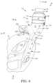
- FIG. 7is a rear elevation view of a rear, right side wheel fork assembly of the walker apparatus of FIG. 1 , with a wheel of the walker apparatus and one of the height-adjustable assembly of the walker apparatus being shown in fragment;
- FIG. 8is a rear, inner side perspective view of the rear wheel fork assembly of FIG. 7 , the rear wheel fork assembly including a side cover, and with the wheel and height-adjustable assembly of FIG. 7 being shown in fragment;
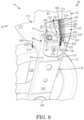
- FIG. 9is an inner side elevation view of the rear wheel fork assembly of FIG. 8 , with the side cover thereof being removed to reveal a brake adjustment mechanism of the brake assembly of the walker apparatus, and with the wheel and rear wheel fork assembly of FIG. 8 being shown in fragment;
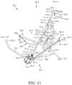
- FIG. 10is a rear elevation view of a rear, left side wheel fork assembly of the walker apparatus of FIG. 1 , with a brake and brake adjustment mechanism thereof being removed and not shown;
- FIG. 11is a front elevation view of the rear, left side wheel fork assembly of FIG. 10 , with the brake and brake adjustment mechanism thereof being removed and not shown;
- FIG. 12is a front, inner side, bottom perspective view of the rear, left side wheel fork assembly of FIG. 10 , with a side cover thereof, the brake and the brake adjustment mechanism thereof being removed and not shown;
- FIG. 13is an inner side elevation view of the rear, left side wheel fork assembly of FIG. 10 , with the side cover, the brake and the brake adjustment mechanism thereof being removed and not shown;
- FIG. 14is a right side, rear perspective view of a manually-operated, height-adjustable wheeled vehicle according to a second aspect, the vehicle comprising a combination transport chair and walker apparatus;
- FIG. 15is a right side elevation view of a manually-operated, height-adjustable wheeled vehicle according to a third aspect, the vehicle comprising a wheelchair;
- FIG. 16is a right side elevation view of a manually-operated, height-adjustable wheeled vehicle according to a fourth aspect, the vehicle comprising a wheeled commode;
- FIG. 17is a right side elevation view of a manually-operated, height-adjustable wheeled vehicle according to a fifth aspect, the vehicle comprising an evacuation chair;
- FIG. 18is a right side elevation view of a manually-operated, height-adjustable wheeled vehicle according to a sixth aspect, the vehicle comprising a height-adjustable stretcher.
- FIG. 19is an inner side elevation view of a manually-operated, height-adjustable wheeled vehicle according to a seventh aspect, the vehicle comprising a walker apparatus similar to FIG. 1 with each brake cable housing thereof having an access port for selectively accessing a cable adjuster of the brake cable assembly thereof, and with the height-adjustable assembly, side framing and folding mechanism of the walker apparatus being shown in fragment;
- FIG. 20is an inner side elevation view of the walker apparatus of FIG. 19 , with a removable cover of the brake cable housing thereof shown extending across and covering the access port of FIG. 19 , and with the height-adjustable assembly, side framing and folding mechanism of the walker apparatus being shown in fragment;
- FIG. 21is an inner side elevation view of the walker apparatus of FIG. 19 , with the inner half of the brake cable housing thereof shown removed;
- FIG. 22is a left side elevation view of a manually-operated, height-adjustable wheeled vehicle according to an eighth aspect, the vehicle comprising a walker apparatus similar to FIG. 1 , with the apparatus including connectors which couple the brake cable housings thereof to the height-adjustable assemblies thereof, and with the walker apparatus being shown partially in fragment;
- FIG. 23is a sectional view taken along lines 23 - 23 of the walker apparatus of FIG. 22 , showing the connectors thereof, the height-adjustable assembly thereof, and the brake cable assembly thereof, with the rest of the apparatus not being shown;
- FIG. 24is a left side elevation view of a manually-operated, height-adjustable wheeled vehicle according to a ninth aspect, the vehicle comprising a walker apparatus similar to FIG. 22 , with the apparatus including connectors which couple the brake cable housings thereof to upper side frame members thereof, and with the walker apparatus being shown partially in fragment; and
- FIG. 25is a left side elevation view of a manually-operated, height-adjustable wheeled vehicle according to a tenth aspect, the vehicle comprising a walker apparatus similar to FIG. 22 , with the apparatus including connectors which couple the brake cable housings thereof to lower side frame members thereof, and with the walker apparatus being shown partially in fragment.
- the vehiclemay also be referred to as a transport apparatus or a travel-assistance apparatus and in this example comprises a height-adjustable walker apparatus 20 .
- the walker apparatusmay be referred to as a walker or rollator.
- the walker apparatus 20has a rear 22 and a front 24 .
- the walker apparatushas a pair of spaced-apart sides 26 and 28 , a top 30 and a bottom 32 which is spaced-apart from the top.
- the rear 22 and front 24 of the walker apparatus 20extend between the sides 26 and 28 thereof and the top 30 and bottom 32 thereof.
- the top and bottom of the walker apparatusalso extend between the sides 26 and 28 thereof.
- the walker apparatus 20includes a pair of spaced-apart, upright, height/length-adjustable assemblies 34 and 36 aligning with respective ones of the sides 26 and 28 thereof.
- Each of the assemblieshas a lower end and an upper end, as seen by lower end 38 and upper end 40 for assembly 34 .
- Each of the assembliesis telescopic and height-adjustable, with a lower outer elongate member or tube, and an upper inner elongate member or tube shaped to fit within the lower tube. This is seen by outer tube 42 and inner tube 44 for assembly 34 .
- the assemblies 34 and 36have longitudinal axes 43 and 47 . Portions 57 of outer tubes 42 and telescoping portions 45 of inner tubes 44 extend along respective said axes.
- Each of the inner tubes 44has a plurality of longitudinally spaced-apart apertures 46 which provide a length LH of adjustment range.
- the walker apparatus 20includes a pair of coupling mechanisms for selectively coupling the pairs of telescoping tubes 42 and 44 together, in this example in the form of thumb screws 48 .
- the thumb screwsare threadably coupled to the outer tubes 42 in this example. Selective rotation of the thumb screws causes the thumb screws to be selectively inserted through one of said apertures 46 of the inner tube 44 to fixedly adjust the height of the telescoping tubes. This enables the height of the walker apparatus to be adjusted to provide an optimized handlebar height for the user.
- the height of the walker apparatusis thus adjustable from a retracted position of the tubes 42 and 44 seen in FIG. 3 to an extended position of the tubes seen in FIG. 1 as well as positions therebetween.
- each of the outer tubes 42 of the height-adjustable assemblies 34has an aperture 51 extending therein.
- Each apertureextends about a lateral axis 49 that is perpendicular to the longitudinal axis 43 of its corresponding assembly 34 .
- Each aperture 51is slot shaped and obround in this example; however this is not strictly required.
- Each aperturefaces the front 24 of the walker apparatus 20 in this example and extends through a front portion 180 of the tube 42 .
- Each aperture 51is interposed between the lower end 38 and upper end 40 of its height-adjustable assembly 34 seen in FIG. 1 .
- Each apertureis adjacent to and spaced-apart upwards from the corresponding end 38 of its height-adjustable assembly seen in FIG. 1 .
- the walker apparatus 20includes a pair of spaced-apart laterally-extending assemblies 50 and 52 .
- the laterally-extending assembliesalign with respective ones of the sides 26 and 28 of the walker apparatus and extend from near the bottom 32 towards the top 30 thereof.
- Each of the laterally-extending assembliesincludes a pair of spaced-apart, elongate upper and lower side members, or side frame members, with the upper members being in the form of tubes 54 in this example and the lower members being the form of tubes 56 in this example.
- Each tubehas a proximal end 58 coupled to corresponding outer tube 42 and a distal end 60 spaced-apart from its proximal end.
- Tubes 56thus couple to and extend radially outwards from tubes 42 and height-adjustable assemblies 34 and 36 .
- Each tube 56extends laterally-outwards and perpendicular from its corresponding outer tube 42 towards the front 24 of the walker apparatus 20 , in this example.
- each tubehas a longitudinally-extending top 61 which faces corresponding tube 54 of its laterally-extending assembly 50 .
- the tops of the tubesare curved at least in part in lateral cross-section and outwardly convex in lateral cross-section in this example.
- each tube 54includes a substantially-straight portion 62 in this example which is coupled to and extends laterally-outwards from corresponding outer tube 42 towards the front 24 of the walker apparatus 20 .
- Aperture 51 of tube 42is interposed and extends between tube 56 and substantially-straight portion 62 of tube 54 and is positioned adjacent to tube 56 in this example.
- Each straight portion 62 of the tubes 54has a longitudinally-extending bottom 63 which face the top 61 of its corresponding tube 56 .
- the bottoms of the straight portions of the tubes 54are curved at least in part in lateral cross-section and outwardly convex in lateral cross-section in this example.
- each tubeincludes a curved portion 64 in this example which couples to and is interposed between the straight portion thereof and distal end 60 of its corresponding tube 56 .
- the walker apparatusincludes folding mechanism 66 in this example coupled to and extending between the laterally-extending assemblies 50 and 52 .
- the folding mechanismis configured to enable the walker apparatus 20 to selectively fold laterally.
- the walker apparatusincludes a seat assembly 68 which extends between and pivotally couples to the straight portions 62 of tubes 54 of the laterally-extending assemblies 50 and 52 in this example.
- the walker apparatus 20includes a foldable basket 71 adjacent to the front 24 thereof and which couples to and extends between laterally-extending assemblies 50 and 52 thereof via connectors 73 .
- the various parts and functionings of the folding mechanism 66 , seat assembly 68 and foldable basketare described in more detail in U.S. Pat. No. 8,083,239 and United States Patent Application Publication No. 2019/0009758 A1, the disclosures of which are incorporated herein by reference.
- the walker apparatus 20includes a first or front pair of ground-engageable wheels 70 operatively coupled to and pivotable relative to the distal ends 72 of the curved portions 64 of tubes 54 by way of front wheel forks 74 .
- the walker apparatusincludes a second or rear pair of ground-engageable wheels 75 and 75 ′ operatively coupled to and rotatable relative to the lower ends 38 and 38 ′ of the height-adjustable assemblies via wheel fork assemblies 76 and 76 ′.
- the wheel fork assembliesare rear wheel fork assemblies.
- Like partshave like numbers and functionings with the addition of extension’.
- the wheel fork assemblies 76 and 76 ′have outer sides 77 and 77 ′ which align with sides 26 and 28 of the walker apparatus 20 .
- the wheel fork assemblieshave inner sides 78 and 78 ′ which are inwardly facing and which face each other.
- each wheel fork assembly 76includes a mount 79 having an upper portion 81 which is tubular in this example.
- the upper portion of the mountis shaped to receive the lower end 38 of its corresponding tube 42 and couple thereto via fasteners, in this example screws 83 .
- the upper portion 81 of the mount 79has a longitudinal axis 85 which is coaxial with the longitudinal axis 47 of the corresponding height-adjustable assembly 36 of the walker apparatus 20 .
- each mount 79includes a lower portion 87 that couples to and is integrally formed with the upper portion 81 thereof.
- the lower portion of the mountextends laterally outwards relative to the axis 85 of the upper portion of the mount and axis 47 of the corresponding height-adjustable assembly 36 , from the upper portion of the mount towards the bottom 32 and corresponding side 28 of the walker apparatus 20 .
- the lower portion 87 of the mount 79has an inner surface 89 which extends along the inner side 78 of the wheel fork assembly 76 in this example.
- the inner surface of the lower portion of the mounthas an upper region 91 which is outwardly convex.
- the inner surface 89 of the lower portion 87 of the mount 79has a lower region 93 adjacent to wheel 75 and which is outwardly concave in this example.
- the inner sides 78 of the wheel fork assembliesare thus outwardly concave in part and outwardly convex in part in this example.
- the outer sides of the lower portion of the mountare outwardly convex in this example, as seen by outer side 95 ′ in FIG. 11 .
- each wheel fork assembly 76includes a wheel fork 135 .
- the wheel forkcouples to the lower portion 87 of the mount 79 and in this example is integrally coupled to and formed with the mount.
- each wheel fork 135 mounthas a longitudinal axis 137 that is laterally offset from the longitudinal axis 85 of its corresponding mount 79 .
- the wheel forkincludes a pair of elongate inner and outer supports 139 and 141 with lower portions 149 between which wheel 75 is received and to which the wheel rotatably couples.
- Each of the elongate supportsis planar in shape in this example and may be referred to a planar portion of the wheel fork.
- the wheel fork 135is shaped to receive the wheel 75 therebetween such the wheel is forward facing and laterally outwardly spaced from tube 42 .
- inner support 141 ′aligns with the longitudinal axis 85 ′ of mount 79 ′ and longitudinal axis 85 ′ of assembly 34 seen in FIG. 1 in this example. Referring to FIG.
- each of the inner elongate supports 141has an upper portion 151 with an aperture 155 extending therethrough.
- each of the supportsincludes a plurality of strengthening ribs 207 ′ coupled thereto. The ribs of the two supports 139 ′ and 141 ′ face each other and are positioned between the supports.
- each wheel fork 135includes an upper cover 171 which couples together the upper portions 151 of the supports 139 and 141 .
- the upper coveris arc-shaped in this example.
- the upper cover 171 and upper portions 151 of the supports 139 and 141form a wheel fork housing 173 .
- the wheel fork housingincludes a side cover 175 that extends over aperture 155 .
- the wheel fork housing 173 ′includes a pair of outwardly extending flanges 199 ′ and 201 ′ between which the aperture 155 ′ extends and between which the side cover extends.
- the side cover 175is outwardly-curved and in this example is outwardly-convex.
- the side coveraligns with the upper portion 151 of the inner support 141 of its corresponding wheel fork 135 and extends along the inner side 78 of the wheel fork assembly 76 in this example.
- the wheel fork assemblyincludes a fastener, in this example screw 179 via which the side cover 175 couples to the inner support. The side cover is thus selectively removable.
- the walker apparatus 20includes a pair of brake assemblies 203 and 203 ′ for its rear wheels 75 and 75 ′.
- Each brake assemblyincludes a wheel-engaging brake member 205 .
- each brake memberhas a first end 209 and a second end 211 spaced-apart from the first end.
- each brake member 205pivotally connects to its respective wheel fork 135 via bearing 197 which is interposed between the first and second ends of the brake member.
- the bearingrotatably mounts to and pivots about shaft 213 coupled to the wheel fork.
- Each brake member 205includes a brake pad 215 in this example coupled to and extending downwards from the first end 209 thereof. Each brake pad faces its corresponding wheel 75 .
- Each brake member 205includes in this example a resilient member in the form of a coil spring 217 .
- the coil springhas an upper end 219 which abuts upper wall 221 of the wheel fork 135 in this example.
- the coil spring 217has a lower end 237 which abuts end 211 of the brake member 205 .
- the coil springis configured to spring-bias the brake pad 215 away and, in this example, upwards from wheel 75 .
- each brake assembly 203includes a brake adjustment mechanism 223 .
- the brake adjustment mechanism in this exampleincludes a sleeve 225 coupled to the end 211 of the brake member 205 .
- the lower end 237 of the coil spring 217abuts the sleeve.
- the brake adjustment mechanism 223includes a set screw 227 threadably coupled to the sleeve 225 .
- Housing 173is shaped to extend about the brake member 205 and brake adjustment mechanism 223 .
- Aperture 155is in fluid communication with the brake adjustment mechanism. Selective removable of the side cover 175 , seen in FIG. 8 , provides access to the brake adjustment mechanism 223 seen in FIG. 9 .
- each brake assembly 203further includes a brake cable assembly 98 , in this example in the form of Bowden-type brake cable assembly.
- the brake cable assemblyincludes a flexible, inner cable 100 made of metal in this example.
- the cablehas an upper or first end 101 .
- each cable 100has a lower or second end 103 .
- the second end of the cable 100is operatively coupled to the second end 211 of brake member 205 , in this example via portion 105 of the cable extending through sleeve 225 , with set screw 227 thereafter being tightened to engage with said portion 105 .
- the set screwenables the tension of cable 100 to be adjusted by lowering or elevating end 103 of the cable and thereafter securing the cable in place via the set screw.
- each brake cable assembly 98has a first, and in this example, generally straight and elongate portion 111 which extends along the height-adjustable assembly 34 .
- the elongate portion of the brake cable assemblyis primarily enclosed within its corresponding height-adjustable assembly 34 .
- the elongate portion 111 of the brake cable assembly 98may extend along the outside of the height-adjustable assembly in other embodiments.
- the elongate portion of the brake cable assemblyextends generally parallel with longitudinal axis 43 where the elongate portion enters within outer tube 42 and the telescoping portion 45 of the inner tube 44 .
- each cablehas a second or excess portion, in this example a slack portion 109 that is loop-shaped.
- the slack portionis thus a coiled section of the brake cable assembly comprising, and in this example consisting of, a single loop.
- the slack portion 109 of the brake cable assemblyextends through the aperture 51 of tube 42 .
- the slack portion of the brake cable assembly 98extends laterally outwards relative to longitudinal axis 43 from assembly 34 and generally in the direction lateral axis 49 .
- Each brake cable assembly 98includes a flexible outer casing or cable sleeve 108 through which cable 100 , seen in FIG. 9 , extends and is moveable relative thereto.
- the cable sleevemay be referred to as a cable sleeve and is made of plastic in this example.
- the cable sleeve 108has a first end 110 seen in FIG. 2 and a second end 112 seen in FIG. 9 . Second end 112 of the cable sleeve couples to wheel fork 135 via a mount 79 through which cable 100 extends. Upward movement of cable 100 , as shown by arrow of numeral 122 , causes end 211 of brake member 205 to more upwards relative to FIG. 9 .
- each brake member 205operatively connects to the lower end 38 of its height-adjustable assembly 34 seen in FIG. 2 .
- the brake member as herein describedis one example of a braking system for apparatus 20 , and the brake assembly 203 may use other braking systems for the brake cable assembly 98 in other embodiments.
- the walker apparatus 20includes a pair of handle bar assemblies 124 and 125 coupled to the upper ends 40 of respective ones of the height-adjustable assemblies 34 and 36 .
- the walker apparatusincludes an arcuate-shaped backrest 127 positioned along the front 24 thereof.
- the backrestis in the shape of a flexible strap in this example and extends between the handle bar assemblies 124 and 125 .
- the backrest 127couples to the handle bar assemblies via spaced-apart ends 131 and 133 of the backrest.
- each of the handle bar assembliesincludes a brake actuator, in this example in the form of a gripping handle 130 pivotally mounted to a respective handle bar housing 134 .
- First end 101 of cable 100operatively couples to the gripping handle.
- Upward movement of the gripping handles 130causes the cable of the brake cable assembly 98 to be actuated, pulled and moved relative to casing 108 of the brake cable assembly for selectively actuating brake member 205 seen in FIG. 9 .
- Gripping handles and brake actuators for brake assembliesare known per se and more details in this regard are disclosed, for example, in U.S. Pat. No. 8,083,239, the disclosure of which is incorporated herein by reference.
- the walker apparatus 20includes a pair of hollow, brake cable housings corresponding to respective ones of the height-adjustable assemblies, as seen by brake cable housing 168 for height-adjustable assembly 34 .
- each brake cable housingis shaped to enclose the slack portion 109 of its corresponding brake cable assembly 98 .
- Each brake cable housing 168is generally rectangular in the shape in this example in side, top, bottom, rear and front profile.
- each brake cable housinghas an elongate top 170 shaped to align with and receive the bottom 63 of the substantially-straight portion 62 of tube 54 in this example.
- Each brake cable housing 168has an elongate bottom 174 opposite its top 170 .
- the bottom of the brake cable housingis shaped to align with, extend along in part and receive the top 61 of tube 56 in this example.
- Each brake cable housing 168further includes an elongate rear 178 which extends between the top 170 and bottom 174 thereof.
- the rear of the brake cable housingextends along and is shaped to abut and receive a front portion 180 of tube 42 of its corresponding height-adjustable assembly 34 extending between tubes 54 and 56 in this example.
- brake cable housing 168thus couples to and has a longitudinal axis 169 axially offset from the tubes 42 and 44 of assembly 34 .
- the brake cable housingthus couples to and extends laterally outwards from the assembly 34 in this example.
- each brake cable housing 168includes a hollow protrusion 182 which extends outwards from rear 178 thereof.
- the protrusionis shaped to fit within tube 42 via aperture 51 .
- Portions 53 of tube 42 extending around aperture 51are configured to snugly abut with the protrusion in this example.
- Each brake cable housing 168has a front 184 spaced-apart from the rear 178 thereof.
- the front of the brake cable housingextends between the top 170 and bottom 174 thereof.
- the front 184 of the brake cable housing 168is substantially vertically-extending and straight in this example.
- the brake cable housingsinclude a pair of spaced-apart side planar portions, in this example inner side planar portions, in this case inner sides 186 and 186 ′, and exterior side planar portions, in this case outer sides 188 and 188 ′.
- the outer sidesextend along sides 26 and 28 of the walker apparatus 20 .
- the outer sides 188 and 188 ′face opposite from the inner sides 186 and 186 ′.
- the inner and outer sides of the brake cable housings 168are substantially planar and rectangular in this example. Each side extends between the top 170 , bottom 174 , rear 178 and front 184 of the brake cable housing seen in FIG. 4 . Still referring to FIG.
- the brake cable housing 168includes a peripheral portion 176 which extends along the top 170 , front 184 , bottom 174 and rear 178 thereof.
- the peripheral portionextends about the inner side 186 and outer side 188 thereof seen in FIG. 2 .
- each brake cable housing 168includes a first part 190 which extends between top 170 , bottom 174 , rear 178 and front 184 thereof and which extends from its inner side towards its outer side.
- each brake cable housing 168includes a second part 192 that is complementary to, selectively connectable to and selectively removable from part 190 .
- Parts 190 and 192are respective halves of the brake cable housing in this example though this is not strictly required.
- Part 192extends between the top, bottom, rear and front of the brake cable housing, and extends from the outer side towards the inner side of the brake cable housing.
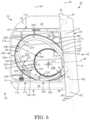
- each brake cable housing 168has an interior or interior space 200 that is generally crescent-shaped in this example.
- Each brake cable housinghas an outer portion 202 which extends along the top 170 , bottom 174 , rear 178 , and front 184 thereof.
- the outer portion 202 of the brake cable housinghas an inner wall or peripheral edge 204 which encloses the interior space 200 thereof along with the sides of the brake cable housing.
- the inner peripheral edge of the outer portionis inwardly concave and is generally arc-shaped, in this case tear-drop shaped in this example.
- the peripheral edge 204 seen in FIG. 4extends between the sides 186 and 188 of the brake cable housing seen in FIG. 1 .
- the outer portion 202 of the brake cable housinghas a central axis 206 in this example.
- Each brake cable housing 168includes an inner portion 208 positioned within the interior space 200 thereof.
- the inner portion of the brake cable housingincludes an inner wall or outer peripheral edge 210 which is outwardly convex and arc-shaped in this example.
- the outer peripheral edgeextends between the sides 186 and 188 of the brake cable housing 168 seen in FIG. 1 .
- the inner portion 208 of the brake cable housing 168has a central axis 212 which is axially offset from the central axis 206 of the outer portion 202 of the brake cable housing.
- the brake cable housing 168receives and in this example encloses the slack portion 109 of brake cable assembly 98 within interior space 200 thereof.
- the brake cable housingincludes an upper passageway 214 within the interior space thereof.
- the upper passagewayextends from the rear 178 of the brake cable housing adjacent to aperture 51 towards the top 170 and front 184 of the brake cable housing.
- the upper passageway 214is arc-shaped and downwardly concave in shape in this example.
- the upper passagewayis shaped to receive excess portions 216 of the brake cable assembly 98 extending from the wheel-engaging brake member 205 and thus lower end 103 of cable 100 seen in FIG. 9 .
- the brake cable housing 168includes a lower passageway 218 within the interior space 200 thereof.
- the lower passagewayextends through protrusion 182 of the brake cable housing 168 in this example towards the bottom 174 and front 184 of the brake cable housing.
- the lower passageway 218is arc-shaped and upwardly concave in shape in this example.
- the lower passagewayis shaped to receive excess portions 220 of brake cable assembly 98 extending from the gripping handle 130 as seen in FIG. 2 and thus extending from end 101 of cable 100 .
- each brake cable housing 168includes a chamber 222 within the interior space 200 thereof.
- the brake cable housingencloses the chamber within the interior space.
- Chamber 222is defined by and spans between peripheral edges 204 and 210 and sides 186 and 188 of the brake cable housing seen in FIG. 2 in this embodiment.
- the chamberis interposed between and in communication with the passageways 214 and 218 .
- the upper and lower passagewaysmay be referred to as openings in communication with the chamber.
- the cross-sectional widths of the upper passageway 214 and the lower passageway 218taper so as to increase as the passageways extend from the height-adjustable assembly 34 towards the chamber 222 .
- width W 1 of passageway 218 adjacent to tube 42being smaller than width W 2 of the passageway 218 adjacent chamber 222 .
- the chamberis shaped to receive further excess portions 224 of brake cable assembly 98 coupled to and integrally formed with excess portions 216 and 220 thereof.
- the chamber 222is concave in this example in a direction facing the upper passageway 214 and the lower passageway 218 .
- the chamberis larger in volume and cross-section width W 3 compared to the upper passageway 214 and compared to the lower passageway 218 .
- the chamber 222is c-shaped in this embodiment.
- Slack portion 109 of brake cable assembly 98abuts at least in part the inner peripheral edge 204 of the outer portion 202 of its corresponding brake cable housing 168 when the walker apparatus 20 is its retracted position in this example; however this is not strictly required.
- the slack portion of the brake cable assemblyforms an enlarged loop in the retracted position of the walker apparatus.
- the slack portion 109 of the brake cable assembly 98extends at least in part between the outer peripheral edge 210 of the inner portion 208 of brake cable housing 168 and inner peripheral edge 204 of outer portion 202 of the brake cable housing when the walker apparatus 20 is in an intermediate position between the retracted position seen in FIG. 3 and the extended position seen in FIG. 2 .
- slack portion 109 of brake cable assembly 98 in this exampleabuts the outer peripheral edge 210 of the inner portion 208 of its corresponding brake cable housing 168 when the walker apparatus 20 is its extended position; however this is not strictly required.
- the slack portion of the brake cable assemblyforms a loop of a smaller size in the extended position of the walker apparatus seen in FIG. 2 compared to the size of the loop seen in FIG. 4 when the walker apparatus is in its retracted position.
- the slack portion 109 of brake cable assembly 98thus forms a reduced loop shape spanning a planar area that is less than that of the enlarged loop shape.
- the brake cable housing 168is thus shaped to enclose the slack portion 109 of the brake cable assembly within the chamber 222 thereof.
- the height-adjustable assemblies 34 and 36 and brake cable housings 168may collectively be referred to as a macro adjustment mechanism for altering the length/portion of the brake cable assembly 98 extending within the height-adjustable assemblies.
- the walker apparatus 20includes a cable adjuster 229 positioned within chamber 222 and enclosed by the brake cable housing 168 .
- the cable adjustermay be referred to as a tension-adjustment knob.
- the brake cable housingis shaped to protect the cable adjuster.
- the cable adjuster 229comprises a first subassembly 231 including a first sleeve 233 .
- the first sleeveis shaped to receive and couple to a distal or upper end 235 of a first or lower segment 181 of the cable sleeve 108 of the brake cable assembly 98 .
- the first subassembly 231includes a male member, in this example a threaded tube 239 with exterior threading thereon. The threaded tube couples to and extends outwards from the sleeve 233 .
- the cable adjuster 229comprises a second subassembly 241 including a second sleeve 243 .
- the second sleeveis shaped to receive and couple to a proximal or lower end 245 of a second or upper segment 177 of the cable sleeve 108 of the brake cable assembly 98 .
- the cable adjuster 229is inline with the cable sleeve of the brake cable assembly 98 , and in this example inline with the slack portion 109 of the brake cable assembly.
- the cable adjustercouples together upper segment 177 and lower segment 181 of the cable sleeve 108 of the brake cable assembly 98 .
- Cable 100extends through the cable adjuster 229 .
- One of the sleeves 233 and 243 of the cable adjuster 229is rotatable relative to its corresponding segment of brake cable assembly 98 , in this example sleeve 243 .
- the second subassembly 241includes a female member, in this example a nut 249 coupled to, integrally formed with and extending outwards from the second sleeve 243 .
- a female memberin this example a nut 249 coupled to, integrally formed with and extending outwards from the second sleeve 243 .
- thisis not strictly required: instead of being referred to as a nut, the second subassembly 241 may be said to comprise sleeve 243 having internal threading extending inwards from one end 251 thereof.
- the nut 249threadably couples to and receives the threaded tube 239 .
- the cable adjuster 229has a retracted position seen in FIGS. 4 and 5 in which the threaded tube 239 is fully inserted into and threadably coupled with the nut 249 . Rotation of the nut relative to the threaded tube enables the cable adjuster to move from its retracted position seen in FIG. 5 to an extended position seen in FIG. 6 . Only the distal end 281 of the threaded tube 239 threadably couples with and is inserted into the nut 249 when the cable adjuster is in its extended position in this example.
- Positioning of the upper segment 177 of the cable sleeve 108 of the brake cable assembly 98 relative to the lower segment 181 of the cable sleeve of the brake cable assemblymay thus be adjusted to by a desired extension or length L C .
- the cable sleeve of the brake cable assemblymay therefore be selectively effectively lengthened by up to length L C via the cable adjuster 229 .
- Threaded adjustment of the nut along and relative to the threaded tubealters the effective length of the cable sleeve 108 of the brake cable assembly 98 .
- Actuation of the cable adjusterthus alters the effective length of the cable sleeve of the brake cable assembly and the cable adjuster may be said to comprise a micro adjustment mechanism for the brake cable assembly 98 .
- the position of the end point of the cable relative to the brake pad 215changes by actuating the cable adjuster 229 as spring 217 is continuously applying a pressure to the cable. Tension adjustment may thus occur via the inline nut.
- the slack portion 109 of the brake cable assembly 98is configured to abut in part the peripheral edge 204 of the outer portion 202 of the brake cable housing 168 when the height-adjustable assembly 34 is in a retracted position and the cable adjuster 229 is in an extended position in this example.
- the slack portion of the brake cable assemblyis configured to abut in part the peripheral edge 210 of the inner portion of the brake cable housing when the height-adjustable assembly is in an extended position and the cable adjuster is in a retracted position.
- FIG. 14shows a manually-operated, height-adjustable wheeled vehicle, in this example a combination transport chair and walker apparatus 20 . 1 according to a second embodiment.
- Like partshave like numbers and functionings as the embodiment shown in FIGS. 1 to 13 with the addition of “0.1”.
- Apparatus 20 . 1is substantially the same as apparatus 20 seen in FIGS. 1 to 13 with the following exceptions.
- the apparatus 20 . 1includes a pair of foot rest assemblies 226 and 228 .
- the foot rest assembliesinclude foot rests 230 and 232 that are positioned along the front 24 . 1 and bottom 32 . 1 of the apparatus, with foot rest 230 being adjacent to side 26 . 1 and foot rest 232 being adjacent to side 28 . 1 .
- the foot restsare planar and rectangular in shape in this example and are shaped to receive respective feet of a person who is sitting on seat assembly 68 . 1 while sitting facing the front of the apparatus 20 . 1 .
- Each of the foot rest assemblies 226 and 228includes length-adjustable framing, in this example in the form of telescoping tubes 234 and 236 .
- Outer tube 234selectively couples to its respective laterally-extending assembly 50 . 1 via a coupling mechanism, in this example clamps 238 and 240 that extend about curved portion 64 . 1 of tube 54 . 1 .
- Inner tube 236couples to foot rest 230 and is received in part within the outer tube.
- Each of the foot rest assemblies 226 and 228includes an adjustable mechanism, in this example a thumb screw 242 .
- the apparatus 20 . 1has a transportation chair mode shown with the backrest 127 . 1 in solid lines and in a transport-chair-mode position.
- the backrest in this positionextends from its ends 131 . 1 and 133 . 1 towards the rear 22 . 1 of the apparatus.
- the backrest 127 . 1includes a pair of adjustment mechanisms 244 and 246 adjacent to the ends 131 . 1 and 133 . 1 thereof.
- the adjustment mechanisms when loosenedenable the backrest to move from the transport-chair-mode position to a walker-mode position seen by the positioning of the backrest in ghost lines.
- the backrest 127 . 1 in this positionextends from its ends 131 . 1 and 133 . 1 towards the front 24 . 1 of the apparatus 20 . 1 .
- Apparatus 20 . 1thus can be a transportation chair at times and a walker apparatus at times.
- the apparatuscan be configured as a transport chair or walker apparatus.
- Apparatus 20 . 1is in part a transport chair may thus also be referred to as transport chair.
- Lower side frame member, in this example tube 56 . 1is J-shaped and has wheels 70 . 1 and 75 . 1 operatively connected thereto at distal ends 58 . 1 and 60 . 1 thereof.
- Upright assemblies 34 . 1 and 36 . 1are positioned between the front 24 . 1 and the rear 22 . 1 of the apparatus 20 . 1 in this example.
- Tube 42 . 1couples and extends upwards from tube 56 . 1 .
- Tubes 42 . 1 , 44 . 1 and 56 . 1are similar in diameter in this example, with tubes 54 . 1 being smaller in diameter compared thereto.
- Bottom 174 . 1 of brake cable housing 168 . 1couples to and abuts top 61 . 1 of frame member 56 . 1 in this example.
- Elongate rear 178 . 1 of the brake cable housingcouples to and abuts the outer tube 42 . 1 adjacent to frame member 56 . 1 in this case.
- Substantially straight portion 62 . 1 of tube 54 . 1is spaced-apart above of the brake cable housing 168 . 1 in this example and curved portion 64 . 1 of the tube is positioned forward of the brake cable housing.
- FIG. 15shows a manually-operated, height-adjustable wheeled vehicle, in this example a wheelchair 20 . 2 according to a third embodiment.
- Like partshave like numbers and functionings as the embodiment shown in FIGS. 1 to 13 with the addition of “0.2”.
- Apparatus 20 . 2is substantially the same as apparatus 20 seen in FIGS. 1 to 13 with the following exceptions.
- the wheelchairhas a pair of spaced-apart front wheels 75 . 2 to which brake assemblies 203 . 2 are coupled and a pair of spaced-apart, enlarged, hand-propelled rear wheel 70 . 2 .
- the wheelchair 20 . 2includes a pair of spaced-apart height-adjustable assemblies 34 . 2 to which corresponding gripping handles 130 . 2 pivotally couple at upper ends 40 . 2 of the height-adjustable assemblies.
- the wheelchairincludes various u-shaped frames 248 and 250 per laterally-extending assembly 50 . 2 in this example.
- Armrests 252couple to and extend along the tops 261 of respective ones of frames 250 .
- the frames 248 and 250couple to and extend upwards from tube 54 . 2 in this example.
- the wheelchair 20 . 2includes brake assemblies 203 . 2 for its front wheels 75 . 2 , with a brake cable housing 168 . 2 per side thereof.
- Each brake cable housingis position within the square-shaped opening 254 formed by corresponding frame 250 and tube 54 . 2 in this example.
- Bottom 174 . 2 of the brake cable housing 168 . 2couples to tube 54 . 2 and rear 178 . 2 of the brake cable housing couples to upright portion 256 of frame 250 in this example.
- the wheelchairincludes an upright backrest 131 . 2 which couples to the upright portion of frame 250 in this example. Tubes 42 . 2 of the height-adjustable assemblies 34 . 2 also couple to frame 250 in this example.
- the wheelchair 20 . 2includes a vertically-extending hollow frame member, in this example tube 253 per side thereof, with the tube extending between tubes 54 . 2 and 56 . 2 in this example.
- Brake cable assembly 98 . 2is positioned within the framing of the wheelchair 20 . 2 , in this example within tubes 44 . 2 , 42 . 2 , 54 . 2 , and 253 , with slack portion 109 . 2 of the brake cable assembly being enclosed within the brake cable housing 168 . 2 in a like manner as described previously.
- the brake cable housingis shaped to accommodate varying amounts of excess portions of the brake cable assembly as the vertical positioning of the gripping handles 130 . 2 is adjusted by the user as needed.
- FIG. 16shows a manually-operated, height-adjustable wheeled vehicle, in this example a wheeled commode, shown by number 20 . 3 , according to a fourth embodiment.
- a wheeled commodeshown by number 20 . 3 .
- Apparatus 20 . 3is substantially the same as apparatus 20 seen in FIGS. 1 to 13 with the following exceptions.
- the commodehas a pair of spaced-apart front wheels 70 . 3 and a pair of spaced-apart rear wheel 75 . 3 .
- the commode 20 . 3includes a pair of spaced-apart height-adjustable assemblies 34 . 3 to which gripping handles 130 . 3 pivotally couple at upper ends 40 . 3 of the height-adjustable assemblies.
- the commodeincludes a chamber pot 258 which couples to and extends downwards from seat 68 . 3 thereof.
- the commodeincludes an upright backrest 131 . 3 which couples to and extends upwards from the seat.
- the commode 20 . 3includes a u-shaped frame 260 per laterally-extending assembly 50 . 3 in this example.
- Armrests 262couple to and extend along the tops 263 of respective ones of the frames.
- Each frame 260couples to and extends upwards from a respective tube 56 . 3 .
- Tube 54 . 3is positioned between tube 56 . 3 and top 263 of the frame in this example and couples to and extends between the frame.
- the commode 20 . 3includes brake assemblies 203 . 3 to selectively brake wheels 70 . 3 in this example.
- Each brake assemblyincludes a brake cable housing 168 . 3 positioned within the opening 264 formed by frame 260 and tubes 54 . 3 and 56 . 3 in this example.
- Bottom 174 . 3 of the brake cable housingcouples to the top 61 . 3 of tube 56 . 3 in this example.
- Rear 178 . 3 of the brake cable housing 168 . 3couples to upright portion 266 of frame 260 in this example.
- Tubes 42 . 3 of the height-adjustable assemblies 34 . 3couple to the upright portions 266 of frames 260 in this example.
- Brake cable assembly 98 . 3is positioned within the framing of the commode 20 . 3 , with tubes 42 . 3 , 44 . 3 and 56 . 3 extending therearound. Slack portion 109 . 3 of the brake cable assembly is enclosed within the brake cable housing 168 . 3 in a like manner as described previously.
- the brake cable housingis shaped to accommodate varying amounts of excess portions of the brake cable assembly as the vertical positioning of the gripping handles 130 . 3 is adjusted by the user as needed. Actuation of gripping handle 130 . 3 causes the brake cable assembly 98 . 3 to 3 to selectively engage and the brake wheels 75 . 3 . This functions to inhibit movement of the commode in a like manner as previous described above.
- FIG. 17shows a manually-operated, height-adjustable wheeled vehicle, in this example an evacuation chair 20 . 4 according to a fifth embodiment.
- Like partshave like numbers and functionings as the embodiment shown in FIGS. 1 to 13 with the addition of “0.4”.
- Apparatus 20 . 4is substantially the same as apparatus 20 seen in FIGS. 1 to 13 with the following exceptions.
- the evacuation chairincludes a pair of spaced-apart front wheels 75 . 4 and a pair of spaced-apart rear wheel 70 . 4 .
- the evacuation chair 20 . 4includes a pair of height/length-adjustable assemblies at adjacent sides thereof and to which respective laterally-extending assemblies pivotally connect. This is shown by height-adjustable assembly 34 . 4 pivotally connecting with laterally-extending assembly 50 . 4 between the lower end 38 . 4 and upper end 40 . 4 thereof.
- Front wheels 75 . 4are rotatably mounted to the height-adjustable assemblies upright 34 . 4 adjacent to the lower ends thereof.
- a foot-supportin this example in the form of u-shaped frame 270 , seen in side profile, pivotally couples to front wheels 75 . 4 and is extendable outwards from lower ends 38 . 4 of the height-adjustable assemblies upright 34 . 4 .
- the evacuation chair 20 . 4includes a pair of wheel folding assemblies 274 per side thereof.
- Each folding assemblyincludes a pair of base frame members 276 and 278 that pivotally couple together via axle 279 .
- Front wheels 75 . 4rotatably couple to respective base frame members 276 .
- Rear wheels 70 . 4rotatably mount to base frame members 278 .
- Each folding assemblyincludes in this example a hydraulic actuator 280 that pivotally connects to and couples together base frame member 278 and front wheel 75 . 4 .
- Rear end 282 of laterally-extending assembly 50 . 4pivotally couples to axle 279 in this example.
- the folding mechanisms, foot support, height-adjustable assemblies and laterally-extending assemblies of the evacuation chair 20.
- Evacuation chairs per seincluding their various parts and functionings, are well known to those skilled in the art and details regarding folding mechanisms in this regard will thus not be described in further detail.
- the evacuation chair 20 . 4includes a flexible member 284 with a bottom portion in the form of a seat 68 . 4 and an upright portion in the form of backrest 131 . 4 .
- the flexible memberextends between the sides 28 . 4 of the evacuation chair with a lower end 286 extending about and coupled to distal ends 288 of the laterally-extending assemblies 50 . 4 in this example.
- An upper end 290 of the flexible member 284couples to the height-adjustable assemblies 34 . 4 at a location adjacent to thumb screw 48 . 4 in this example.
- the evacuation chair 20 . 4includes brake assemblies 203 . 4 with brake members 205 . 4 mounted to the height-adjustable assemblies 34 . 4 adjacent to the front wheels 70 . 4 of the evacuation chair.
- the brake assembliesinclude a brake cable housing 168 . 4 per side thereof.
- the front 184 . 4 of each brake cable housingcouples to and extends along a respective tube 42 . 4 of its corresponding height-adjustable assembly 34 . 4 in this example.
- Brake cable assembly 98 . 4is positioned within the framing of the evacuation chair 20 . 4 , in this example within tubes 44 . 4 and 42 . 4 , with slack portion 109 . 4 of the brake cable assembly being enclosed within the brake cable housing 168 . 4 in a like manner as described previously.
- the brake cable housingis shaped to accommodate varying amounts of excess portions of the brake cable assembly as the positioning of the gripping handles 130 . 4 is adjusted by the user as needed. Actuation of the gripping handle causes the brake cable assembly 98 . 4 to move brake member 205 . 4 so as to selectively engage and brake front wheel 75 . 4 . This functions to inhibit movement of the evacuation chair 20 . 4 in a like manner as previous described above.
- FIG. 18shows a manually-operated, height-adjustable wheeled vehicle, in this example a height-adjustable stretcher 20 . 5 according to a sixth embodiment.
- Like partshave like numbers and functionings as the embodiment shown in FIGS. 1 to 13 with the addition of “0.5”.
- Apparatus 20 . 5is substantially the same as apparatus 20 seen in FIGS. 1 to 13 with the following exceptions.
- the stretcherincludes a horizontally-extending upper platform 294 upon a body mattress 296 and head cushion 298 couple and extend in this example.
- the stretcher 20 . 5includes a base, in this example a base frame assembly 300 to which front wheels 70 . 5 rotatably mount at a forward end 302 thereof and to which rear wheels 75 . 5 mount at a rearward end 304 thereof.
- the stretcherincludes a height-adjustment mechanism 34 . 5 which in this example comprises a pair of crossed-linking telescoping assemblies 306 and 308 that are hollow in this example. The telescoping assemblies pivotally couple to and extend between platform 294 and base frame assembly 300 .
- the stretcher 20 . 5includes a pair of gripping handles 130 . 5 that pivotally couple to the bottom 310 of platform 294 in this example adjacent to the rearward end 312 of the platform.
- the stretcherincludes brake assemblies 203 . 5 to selectively brake wheels 75 . 5 in this example.
- Each brake assemblyincludes a brake cable housing 168 . 5 .
- the top 170 . 5 of each brake cable housingcouples to and extends along the bottom 310 of the platform 294 adjacent to the rearward end 312 of the platform.
- Brake cable assembly 98 . 5is positioned within the framing of the stretcher 20 . 5 , in this example extending within platform 294 , rearward tubing 314 telescoping assembly 306 and rearward tubing 316 of telescoping assembly 308 ; however this is not strictly required and the brake cable assembly may extend along the outside thereof in other embodiments.
- Slack portion 109 . 5 of the brake cable assemblyis enclosed within the brake cable housing 168 . 5 in a like manner as described previously.
- the brake cable housingis shaped to accommodate varying amounts of excess portions of the brake cable assembly as the height of the stretcher is adjusted as needed. Actuation of gripping handle 130 . 5 causes the brake cable assembly 98 . 5 to move brake member 205 . 5 to selectively engage and brake rear wheels 70 . 5 . This functions to inhibit movement of the stretcher in a like manner as previous described above.
- FIGS. 19 to 21show a manually-operated, height-adjustable wheeled vehicle, in this example a walker apparatus 20 . 6 according to a seventh embodiment.
- Like partshave like numbers and functionings as the embodiment shown in FIGS. 1 to 13 with the addition of “0.6”.
- Apparatus 20 . 6is substantially the same as apparatus 20 seen in FIGS. 1 to 13 with the following exceptions.
- the brake cable housing 168 . 6has an access port 255 extending through the inner side planar portion, in this example inner side 186 . 6 thereof.
- the access portis in communication with the chamber 222 . 6 and interior space 200 . 6 of the brake cable housing.
- the brake cable housing 168 . 6includes a removable cover 257 which extends across the access port 255 .
- the removable coverincludes a planar portion 259 that is rectangular in this example.
- the removable cover 257includes a pair of spaced-apart tabs 265 and 267 which are integrally formed with the planar portion thereof in this example. The tabs couple to and extend outwards from the planar portion 259 .
- the removable cover 257threadably couples to the inner side 186 . 6 of the brake cable housing 168 . 6 via fasteners, in this example screws 269 which extend through the tabs.
- the interior space 200 . 6 of the brake cable housing seen in FIG. 19is thus accessible by selectively removing the cover seen in FIG. 20 .
- the peripheral portion 176 . 6 of the brake cable housing 168 . 6is outwardly spaced from and extends about the removable cover 257 .
- the removable coveris smaller in span compared to the inner side 186 . 6 of the brake cable housing 168 . 6 in this example.
- the brake cable housing 168 . 6has a single opening or passageway 214 . 6 in this embodiment in communication with aperture 51 . 6 .
- the excess or slack portion 109 . 6 of the brake cable assembly 98 . 6extends into the chamber 222 . 6 via the passageway of the brake cable housing.
- the chamberis defined by and spans between inner wall or peripheral edge 204 . 6 , which is arc-shaped, and the inner side 186 . 6 and outer side 188 . 6 of the brake cable housing 168 . 6 seen in FIG. 20 .
- There is no inner portion or inner peripheral edge to the brake cable housingsuch as the inner portion 208 and peripheral edge 210 of brake cable housing 168 shown in FIG. 4 .
- the slack portion 109 . 6 of the brake cable assembly 98 . 6is thus movable anywhere within the chamber 222 . 6 .
- FIGS. 22 and 23show a manually-operated, height-adjustable wheeled vehicle, in this example a walker apparatus 20 . 7 according to an eighth embodiment.
- Like partshave like numbers and functionings as the embodiment shown in FIGS. 1 to 13 with the addition of “0.7”.
- Apparatus 20 . 7is substantially the same as apparatus 20 seen in FIGS. 1 to 13 with the following exceptions.
- the brake cable housing 168 . 7is spaced-apart from the one or more side frame members, in this example tubes 54 . 7 and 56 . 7 in this embodiment.
- the brake cable housingabuts front portion 180 . 7 of the height-adjustable assembly 34 . 7 , in this example tube 42 . 7 .
- the walker apparatus 20 . 7includes at least one, and in this example a pair of connectors, in this example coupling members 270 and 271 .
- Each coupling memberis planar and rectangular in this example as seen by coupling member 271 in FIG. 22 .
- the coupling membersextend outwards from the rear 178 . 7 of the brake cable housing 168 . 7 in this example.
- the coupling members 270 and 271include arc-shaped portions 273 and 277 which couple to, receive in part and abut opposite side portions 275 and 283 of the height-adjustable assembly 34 . 7 , in this example tube 42 . 7 .
- the coupling memberscouple to the side portions of the height-adjustable assembly via fasteners, in this example screws 285 and 287 .
- FIG. 24shows a manually-operated, height-adjustable wheeled vehicle, in this example a walker apparatus 20 . 8 according to a ninth embodiment.
- Like partshave like numbers and functionings as the embodiment shown in FIGS. 22 to 23 with decimal extension “0.8” replacing decimal extension “0.7”.
- Apparatus 20 . 8is substantially the same as apparatus 20 . 7 seen in FIGS. 22 to 23 with the following exceptions.
- Each brake cable housing 168 . 8is spaced-apart from its height-adjustable assembly 34 . 8 and couples to its lateral-extending assembly 52 . 8 .
- the top 170 . 8 of the brake cable housing 168 . 8abuts the bottom 63 . 8 of the substantially-straight portion 62 . 8 of the upper side frame member, in this case tube 54 . 8 .
- the brake cable housingcouples to the tube via connector members 271 . 8 .
- the coupling membersextend outwards from the top 170 . 8 of the brake cable housing 168 . 8 in this example.
- Bottom 174 . 8 of the brake cable housingis spaced-apart above the lower side frame member, in this case tube 52 . 8 .
- FIG. 25shows a manually-operated, height-adjustable wheeled vehicle, in this example a walker apparatus 20 . 9 according to a tenth embodiment.
- Like partshave like numbers and functionings as the embodiment shown in FIG. 24 with decimal extension “0.9” replacing decimal extension “0.8”.
- Apparatus 20 . 9is substantially the same as apparatus 20 . 8 seen in FIG. 24 with the following exceptions.
- Each brake cable housing 168 . 9is spaced-apart from its height-adjustable assembly 34 . 9 and couples to its lateral-extending assembly 52 . 9 , with bottom 174 . 9 of the brake cable housing abutting the top 61 . 9 of the lower side frame member, in this case tube 52 . 9 .
- the brake cable housingcouples to the tube via connector members 271 . 9 .
- the coupling membersextend downwards from the bottom 174 . 9 of the brake cable housing 168 . 9 in this example.
- Top 170 . 9 of the brake cable housingis spaced-apart below the upper side frame member, in this case tube 54 . 9 .
- the cable adjusteris enclosed by the brake cable housing of the apparatus, thereby inhibiting inadvertent dislodgement thereof and functioning to protect the adjuster from wear and damage.
- the tension adjusting featureallows the brake cable tension to be selectively adjusted without needing to completely disassemble the braking system.
- the new fork structureallows a wider gait and greater tipping angle, thereby inhibiting tipping of the apparatus on its side when in use.
Landscapes
- Engineering & Computer Science (AREA)
- Health & Medical Sciences (AREA)
- Veterinary Medicine (AREA)
- Life Sciences & Earth Sciences (AREA)
- Animal Behavior & Ethology (AREA)
- General Health & Medical Sciences (AREA)
- Public Health (AREA)
- Mechanical Engineering (AREA)
- Transportation (AREA)
- Rehabilitation Therapy (AREA)
- Physical Education & Sports Medicine (AREA)
- General Engineering & Computer Science (AREA)
- Pain & Pain Management (AREA)
- Epidemiology (AREA)
- Oral & Maxillofacial Surgery (AREA)
- Rehabilitation Tools (AREA)
Abstract
Description
- (1) A brake assembly for a manually-operated, height-adjustable wheeled vehicle, the brake assembly comprising: a brake cable assembly; a brake cable housing shaped to enclose an excess portion of the brake cable assembly; and a cable adjuster coupled to the brake cable assembly, the cable adjuster being enclosed by the brake cable housing.
- (2) The brake assembly of
clause 1, wherein the brake cable housing is shaped to protect the cable adjuster. - (3) The brake assembly of any one of
clauses 1 to 2, the vehicle including a height-adjustable assembly, and wherein the brake cable assembly extends along the height-adjustable assembly. - (4) The brake assembly of any one of
clauses 1 to 2, the vehicle including a height-adjustable assembly, and wherein the brake cable housing couples to the height-adjustable assembly. - (5) The brake assembly of any one of
clauses 1 to 2, the vehicle including a height-adjustable assembly having a longitudinal axis, wherein the brake cable housing couples to the height-adjustable assembly, and wherein the brake cable housing extends laterally outwards relative to said longitudinal axis. - (6) The brake assembly of any one of clauses 3 to 5 wherein a first portion of the brake cable assembly extends along the height-adjustable assembly and a second portion of the brake cable assembly is enclosed within the brake cable housing.
- (7) The brake assembly of clause 6 wherein the second portion of the brake cable assembly is loop-shaped.
- (8) The brake assembly of any one of clauses 3 to 7, the vehicle including one or more side frame members which couple to and extend laterally outwards from the height-adjustable assembly, and wherein the brake cable housing is spaced-apart from the one or more side frame members.
- (9) The brake assembly of any one of clauses 3 to 8 wherein the brake cable housing abuts a front portion of the height-adjustable assembly and is coupled to at least one side portion of the height-adjustable assembly.
- (10) The brake assembly of any one of clauses 3 to 8 further including a planar member which couples the brake cable housing to a side portion of the height-adjustable assembly.
- (11) The brake assembly of
clause 10 wherein the planar member couples to and extends in part along an outer side of the brake cable housing. - (12) The brake assembly of any one of clauses 3 to 8 further including at least one connector extending outwards from the brake cable housing and which includes an arc-shaped portion which couples to and abuts a side portion of the height-adjustable assembly.
- (13) The brake assembly of any one of clauses 3 to 12, wherein the brake cable housing includes an outer portion having an inner peripheral edge, and wherein the excess portion of the brake cable assembly is configured to abut in part the inner peripheral edge of the outer portion of the brake cable housing when the height-adjustable assembly is in a retracted position and the cable adjuster is in an extended position.
- (14) The brake assembly of any one of clauses 3 to 13 wherein the brake cable housing includes an inner portion having an outer peripheral edge, and wherein the excess portion of the brake cable assembly is configured to abut in part the outer peripheral edge of the inner portion of the brake cable housing when the height-adjustable assembly is in an extended position and the cable adjuster is in a retracted position.
- (15) The brake assembly of any one of
clauses 1 to 12, wherein the cable adjuster has a retracted position and an extended position. - (16) The brake assembly of any one of
clauses 1 to 15 wherein the brake cable assembly includes a cable and a cable sleeve extending about said cable, and wherein actuation the cable adjuster alters the effective length of the cable sleeve of the brake cable assembly. - (17) The brake assembly of any one of
clauses 1 to 16 wherein the cable adjuster is inline with the brake cable assembly. - (18) The brake assembly of any one of clauses 6 to 7 wherein the cable adjuster is inline with the second portion of the brake cable assembly.
- (19) The brake assembly of any one of
clauses 1 to 15 wherein the cable adjuster includes a female member and a male member threadably coupled to and selectively adjustable relative to the female member. - (20) The brake assembly of clause 19 wherein the brake cable assembly includes a cable and a cable sleeve, wherein the female member and the male member are coupled to respective segments of the cable sleeve of the brake cable assembly and wherein one of the female member and the male member is rotatably coupled to its corresponding segment of the cable sleeve of the brake cable assembly.
- (21) The brake assembly of any one of clauses 19 to 20 wherein the male member comprises a threaded tube and the female member comprises a threaded sleeve.
- (22) The brake assembly of any one of
clauses 1 to 15 wherein the brake cable assembly includes a cable and a cable sleeve extending about the cable, wherein the cable adjuster includes a first subassembly comprising a first sleeve shaped to receive and couple to an end of a first segment of the cable sleeve of said brake cable assembly, the first subassembly further comprising a threaded tube coupled to and extending outwards from the first sleeve, and wherein the cable adjuster includes a second subassembly comprising a second sleeve shaped to receive and couple to an end of a second segment of the cable sleeve of said brake cable assembly, the second subassembly further comprising a nut coupled to and extending outwards from said second sleeve, the nut threadably coupling to said threaded tube, with threaded adjustment of the nut relative to the threaded tube altering the effective length of the cable sleeve of the brake cable assembly. - (23) The brake assembly of
clause 22 wherein the nut is integrally connected to and formed with the second sleeve. - (24) The brake assembly of any one of
clauses 1 to 23 wherein the brake cable housing has an interior and includes a removable cover via which said interior is accessible. - (25) The brake assembly of any one of
clauses 1 to 24, further including a wheel-engaging brake member, wherein actuation of the cable adjuster alters positioning of the wheel-engaging brake member relative to a wheel. - (26) The brake assembly of any one of
clauses 1 to 24, further including a wheel-engaging brake member, wherein actuation of the cable adjuster alters positioning of an end point of the brake cable assembly relative to the wheel-engaging brake member. - (27) The brake assembly of any one of
clauses 1 to 26, further including a resilient member which continuously applies a pressure to the brake cable assembly. - (28) A brake assembly for a manually-operated, height-adjustable wheeled vehicle, the vehicle including a height-adjustable assembly, and the brake assembly comprising: a brake cable housing coupled to and extending laterally outwards from the height-adjustable assembly, the brake cable housing enclosing a chamber and having an opening in communication with said chamber; and a brake cable assembly including a first portion extending along the height-adjustable assembly and a second portion enclosed within the brake cable housing, the second portion of the brake cable assembly extending into the chamber via said opening and being movable anywhere within said chamber.
- (29) A brake assembly for a manually-operated, height-adjustable wheeled vehicle, the vehicle including a height-adjustable assembly, and the brake assembly comprising: a brake cable assembly extending along the height-adjustable assembly; and a brake cable housing shaped to enclose an excess portion of the brake cable assembly within a chamber thereof, the brake cable housing having an access port extending through an inner side planar portion thereof, the access port being in communication with said chamber.
- (30) The brake assembly of clause 29, further including a removable cover which extends across said access port.
- (31) The brake assembly of any one of clauses 29 to 30, wherein the removable cover is smaller than the inner side planar portion of the brake cable housing.
- (32) The brake assembly of clause 31 wherein the brake cable housing includes a peripheral portion which extends about the inner side planar portion thereof and a top, a bottom, a front and a rear thereof, the peripheral portion of the brake cable housing being outwardly spaced from and extending about the removable cover.
- (33) The brake assembly of any one of clauses 29 to 32, wherein the brake cable housing includes an outer side planar portion, wherein the brake cable housing includes an arc-shaped wall extending between said side planar portions, and wherein the chamber is defined by and spans between said side planar portions and said arc-shape wall.
- (34) A walker comprising the brake assembly of any one of
clauses 1 to 33. - (35) A rollator comprising the brake assembly of any one of
clauses 1 to 33. - (36) A transport chair comprising the brake assembly of any one of
clauses 1 to 33. - (37) A combination transport chair and walker apparatus comprising the brake assembly of any one of
clauses 1 to 33. - (38) A wheelchair comprising the brake assembly of any one of
clauses 1 to 33. - (39) A wheeled commode comprising the brake assembly of any one of
clauses 1 to 33. - (40) An evacuation chair comprising the brake assembly of any one of
clauses 1 to 33. - (41) A height-adjustable stretcher comprising the brake assembly of any one of
clauses 1 to 33. - (42) A wheel fork assembly for a manually-operated, height-adjustable wheeled vehicle, the vehicle including a frame member, and the wheel fork assembly comprising: a mount shaped to couple with a lower end of the frame member, the mount having a longitudinal axis; and a wheel fork having a longitudinal axis offset from the longitudinal axis of the mount and being integrally coupled to and formed with said mount.
- (43) The wheel fork assembly of
clause 42 wherein an inner planar portion of the wheel fork aligns with the longitudinal axis of the mount. - (44) The wheel fork assembly of any one of
clauses 42 to 43, wherein the mount is tubular at least in part. - (45) A wheel fork assembly for a manually-operated, height-adjustable wheeled vehicle, the vehicle including a frame member, and the wheel fork assembly comprising: a mount including an upper portion shaped to couple with a lower end of the frame member and a lower portion that curves laterally outwards; and a wheel fork coupled to the lower portion of the mount.
- (46) The wheel fork assembly of any one of
clauses 42 to 45, wherein the wheel fork assembly has outer and inner sides, and wherein each said side of the wheel fork assembly is outwardly concave in part and outwardly convex in part. - (47) The wheel fork assembly of
clause 45 wherein the mount has an outer side and an inner side, with the lower portion of the mount being outwardly concave at said outer side of the mount and being outwardly convex at said inner side of the mount. - (48) The wheel fork assembly of any one of
clauses 45 to 47, wherein the upper portion of the mount is tubular. - (49) The wheel fork assembly of any one of
clauses 45 to 47, wherein the wheel fork is shaped to receive a wheel therebetween such that the wheel is forward facing and laterally outwardly spaced from the frame member of the vehicle. - (50) A wheel fork assembly for a manually-operated, height-adjustable wheeled vehicle, the wheel fork assembly comprising: a pair of elongate supports having lower portions between which a wheel is mountable and having upper portions, an aperture extending through the upper portion of one said elongate support; an upper cover which couples together the upper portions of the elongate supports; and a side cover that extends across said aperture and which is selectively removable.
- (51) The wheel fork assembly of
clause 50, the vehicle including a wheel-engaging brake member and a brake adjustment mechanism, wherein the upper cover and the upper portions of the elongate supports extend about the wheel-engaging brake member and the brake adjustment mechanism, wherein the aperture is in communication with the brake adjustment mechanism, and wherein selective removable of the side cover provides access to the brake adjustment mechanism. - (52) The wheel fork assembly of any one of
clauses 50 to 51 wherein the upper portion of the one said elongate support includes a pair of flanges between which said aperture extends. - (53) The wheel fork assembly of any one of
clauses 50 to 52, further including a fastener, the side cover coupling to the one said elongate support via said fastener. - (54) A wheel fork assembly for a manually-operated, height-adjustable wheeled vehicle, the vehicle including a wheel-engaging brake member and a brake adjustment mechanism, and the wheel fork assembly comprising: a pair of elongate supports between which a wheel is received and to which the wheel rotatably couples; and a housing which couples together the elongate supports and extends about the wheel-engaging brake member and the brake adjustment mechanism, the housing including a side cover with removal thereof providing access to the brake adjustment mechanism, the side cover aligning with one of said elongate supports.
- (55) The wheel fork assembly of any one of
clauses 50 to 54, wherein the wheel fork assembly has an inner side and the side cover extends along said inner side. - (56) The wheel fork assembly of any one of
clauses 50 to 54, wherein the side cover is outwardly-curved at least in part. - (57) The wheel fork assembly of any one of
clauses 50 to 56, wherein the side cover is outwardly-convex at least in part. - (58) A wheel fork assembly for a manually-operated, height-adjustable wheeled vehicle, the vehicle including a wheel-engaging brake member and a brake adjustment mechanism, and the wheel fork assembly comprising: a pair of elongate supports between which a wheel is received and to which the wheel rotatably couples; and a housing which couples together the elongate supports and extends about the wheel-engaging brake member and the brake adjustment mechanism, the housing including a cover with removal thereof providing access to the brake adjustment mechanism, the cover aligning with an inner side of the wheel fork assembly.
- (59) A walker comprising the wheel fork assembly of any one of
clauses 42 to 58. - (60) A rollator comprising the wheel fork assembly of any one of
clauses 42 to 58. - (61) A transport chair comprising the wheel fork assembly of any one of
clauses 42 to 58. - (62) A combination transport chair and walker apparatus comprising the wheel fork assembly of any one of
clauses 42 to 58. - (63) A wheelchair comprising the wheel fork assembly of any one of
clauses 42 to 58. - (64) A wheeled commode comprising the wheel fork assembly of any one of
clauses 42 to 58. - (65) An evacuation chair comprising the wheel fork assembly of any one of
clauses 42 to 58. - (66) A height-adjustable stretcher comprising the wheel fork assembly of any one of
clauses 42 to 58. - (67) A manually-operated, height-adjustable wheeled vehicle comprising: a height-adjustable assembly having a longitudinal axis; a side frame member coupled to the height-adjustable assembly, the side frame member extending outwards from the height-adjustable assembly relative to the longitudinal axis of the height-adjustable assembly; a brake cable having an elongate portion and a slack portion; and a brake cable housing axially offset from the height-adjustable assembly, the slack portion of the brake cable being enclosed within a hollow interior of the brake cable housing, and the brake cable housing coupling to said side frame member.
- (68) The vehicle of clause 67 wherein the brake cable housing is spaced-apart from said height-adjustable assembly.
- (69) The vehicle of any one of clauses 67 to 68 further including a connector extending outwards from the brake cable housing, the connector including an arc-shaped portion which couples to and abuts a side portion of the height-adjustable assembly.
Claims (18)
Priority Applications (1)
| Application Number | Priority Date | Filing Date | Title |
|---|---|---|---|
| US16/738,423US11648922B2 (en) | 2015-09-02 | 2020-01-09 | Manually-operated, height-adjustable wheeled vehicle, and a brake assembly and wheel fork assembly thereof |
Applications Claiming Priority (5)
| Application Number | Priority Date | Filing Date | Title |
|---|---|---|---|
| US201562213566P | 2015-09-02 | 2015-09-02 | |
| US14/966,572US10053062B2 (en) | 2015-09-02 | 2015-12-11 | Brake assembly for a height-adjustable walker apparatus |
| US16/107,895US10730489B2 (en) | 2015-09-02 | 2018-08-21 | Brake assembly for height-adjustable patient transport apparatus |
| US201962908091P | 2019-09-30 | 2019-09-30 | |
| US16/738,423US11648922B2 (en) | 2015-09-02 | 2020-01-09 | Manually-operated, height-adjustable wheeled vehicle, and a brake assembly and wheel fork assembly thereof |
Related Parent Applications (1)
| Application Number | Title | Priority Date | Filing Date |
|---|---|---|---|
| US16/107,895Continuation-In-PartUS10730489B2 (en) | 2015-09-02 | 2018-08-21 | Brake assembly for height-adjustable patient transport apparatus |
Publications (2)
| Publication Number | Publication Date |
|---|---|
| US20200146926A1 US20200146926A1 (en) | 2020-05-14 |
| US11648922B2true US11648922B2 (en) | 2023-05-16 |
Family
ID=70550203
Family Applications (1)
| Application Number | Title | Priority Date | Filing Date |
|---|---|---|---|
| US16/738,423Active2036-03-02US11648922B2 (en) | 2015-09-02 | 2020-01-09 | Manually-operated, height-adjustable wheeled vehicle, and a brake assembly and wheel fork assembly thereof |
Country Status (1)
| Country | Link |
|---|---|
| US (1) | US11648922B2 (en) |
Families Citing this family (4)
| Publication number | Priority date | Publication date | Assignee | Title |
|---|---|---|---|---|
| US20200268578A1 (en)* | 2015-12-31 | 2020-08-27 | Lamisha Fleming | Hydro-chair |
| WO2022182654A1 (en)* | 2021-02-26 | 2022-09-01 | Telo LLC | Multi-use mobility aid device |
| CN215558134U (en)* | 2021-06-18 | 2022-01-18 | 厦门基信医疗技术有限公司 | Folding capable ware brake line take-up that helps |
| TWI777910B (en)* | 2022-04-28 | 2022-09-11 | 長庚大學 | A wheelchair with the function of a walker |
Citations (327)
| Publication number | Priority date | Publication date | Assignee | Title |
|---|---|---|---|---|
| US188835A (en) | 1877-03-27 | Improvement in perambulators | ||
| US291351A (en) | 1884-01-01 | jackson | ||
| US522117A (en) | 1894-06-26 | Phrey | ||
| US534443A (en) | 1895-02-19 | Combined blacking-case and chair | ||
| US879803A (en) | 1907-10-09 | 1908-02-18 | Charles Joseph Vlasak | Combined chair and cabinet. |
| GB191223483A (en) | 1912-11-15 | 1913-05-01 | Thomas Morgan | A Friction Brake for Perambulators & the like. |
| US1767925A (en) | 1928-06-16 | 1930-06-24 | Hargreaves Thomas | Combined seat and carrier |
| GB365901A (en) | 1929-10-04 | 1932-01-28 | Edwin Oetiker | Improvements in brakes for motor vehicles |
| US2169860A (en) | 1937-02-12 | 1939-08-15 | Gen Electric | Guard means for electric switches |
| US2483307A (en) | 1946-06-20 | 1949-09-27 | Wheary Inc | Suitcase handle having transparent plastic grip and u-shaped metal core |
| US2631655A (en) | 1947-01-28 | 1953-03-17 | Jannello Cesar Victorino | Chair |
| US2656881A (en) | 1950-07-24 | 1953-10-27 | Bertis F Hamilton | Metal furniture |
| US2681809A (en) | 1950-12-30 | 1954-06-22 | Raymond L Hamill | Combined seat and tote box for fishermen's use |
| US2710084A (en) | 1954-02-23 | 1955-06-07 | Irving L Braverman | Traveling bags |
| US2732047A (en) | 1956-01-24 | Finkelstein | ||
| US2864466A (en) | 1955-09-08 | 1958-12-16 | Webb H C & Co Ltd | Brakes for cycles |
| US2866495A (en) | 1956-06-05 | 1958-12-30 | Invalid Walker & Wheel Chair C | Invalid folding walker and chair |
| US2937248A (en) | 1959-02-27 | 1960-05-17 | Ite Circuit Breaker Ltd | Circuit breaker handle lock |
| AT214095B (en) | 1960-03-11 | 1961-03-10 | Sykora & M Prokop H | Bed bench or double bed bench |
| US2987149A (en) | 1959-01-26 | 1961-06-06 | Philadelphia Handle Company In | Luggage handle |
| US3018506A (en) | 1958-05-09 | 1962-01-30 | Haydock Raymond | Caster insert socket |
| US3061049A (en) | 1960-07-18 | 1962-10-30 | William S West | Braking system |
| US3109899A (en) | 1960-10-18 | 1963-11-05 | Cutler Hammer Inc | Handle lock |
| US3142351A (en) | 1962-01-19 | 1964-07-28 | Canadian Res | Stair climbing wheelchair |
| GB984025A (en) | 1963-01-03 | 1965-02-24 | Tan Sad Ltd | Improvements relating to brakes for invalid chairs, perambulators and the like |
| US3194577A (en) | 1962-03-22 | 1965-07-13 | Berlin Daniel | Combination baby walker and jumper |
| AT242315B (en) | 1962-11-30 | 1965-09-10 | Rogelio Raichs Mill | Multi-part handle or handle for vessels of all kinds |
| US3268965A (en) | 1964-05-11 | 1966-08-30 | Lisle Corp | Cable clamp |
| US3288250A (en) | 1965-07-08 | 1966-11-29 | Oja | Braking means for mobile devices |
| US3376400A (en) | 1965-03-10 | 1968-04-02 | Square D Co | Handle locking attachment for electrical control devices |
| US3387681A (en)* | 1966-02-14 | 1968-06-11 | Rodney R. Rabjohn | Power operated wheel chair |
| US3409105A (en) | 1967-06-21 | 1968-11-05 | Stewart Warner Corp | Caster assembly |
| US3690652A (en) | 1971-06-07 | 1972-09-12 | Parker Machine Co Inc | Foldable invalid walker convertible from fixed to swingable walker |
| US3692155A (en) | 1970-10-22 | 1972-09-19 | Lark Luggage Corp | Handle assembly |
| GB1396227A (en) | 1972-04-24 | 1975-06-04 | Happe & Co | Castors |
| US3890668A (en) | 1971-01-20 | 1975-06-24 | Tente Rollen Gmbh & Co | Lockable castor, in particular swivel castor |
| US3903944A (en) | 1973-07-18 | 1975-09-09 | Cannondale Corp | Fabric utility bag |
| US3927727A (en) | 1974-04-17 | 1975-12-23 | Corbin Gentry Inc | Vehicular seat and fairing assembly |
| US3969964A (en) | 1975-09-02 | 1976-07-20 | Douglas Franklin George | Hand tool for holding an elongated member while simultaneously moving a second member axially along the elongated member |
| US4029279A (en) | 1975-07-25 | 1977-06-14 | Koma Nakatani | Device for holding each of the legs of a tripod |
| US4029311A (en) | 1975-05-01 | 1977-06-14 | Hal Chanslor | Invalid walker with brakes |
| US4056115A (en) | 1976-05-06 | 1977-11-01 | Thomas Morton I | Adapter for manipulating a spring loaded pushbutton |
| US4087141A (en) | 1976-09-03 | 1978-05-02 | General Electric Company | Door pull handle assembly |
| US4116464A (en) | 1976-08-30 | 1978-09-26 | Haley Frederick J | Automatic brake for wheeled carriages |
| US4149721A (en) | 1977-05-09 | 1979-04-17 | Strickland Gordon E | Replaceable grip piece for racket |
| US4184618A (en) | 1977-05-26 | 1980-01-22 | Jones Marjorie F | Article carrying attachment for walkers |
| US4185936A (en) | 1977-08-05 | 1980-01-29 | Kenlock Corporation | Locking device in a telescopic tripod leg assembly |
| US4261561A (en) | 1978-12-06 | 1981-04-14 | Ilon B E | Walking support |
| US4286401A (en) | 1979-04-23 | 1981-09-01 | Pachmayr Gun Works, Inc. | Cushioned gun grip |
| US4325561A (en) | 1980-03-17 | 1982-04-20 | Lynn Gary S | Nesting patient transport tables |
| US4371183A (en) | 1980-12-22 | 1983-02-01 | Dion Jean Paul | Folding wheel-chair |
| US4384713A (en) | 1980-05-28 | 1983-05-24 | White Cap Enterprises Corporation | Safety rolling invalid walker |
| US4404822A (en) | 1981-05-18 | 1983-09-20 | Green Leonard O | Pre-coiled cable-lock device |
| US4414702A (en) | 1981-05-16 | 1983-11-15 | Firm Tente-Rollen Gesellschaft Mit Beschrankter Haftung Compagnie | Castor locking device for arresting the rotation and the swivelling of the castor |
| US4415198A (en) | 1980-11-18 | 1983-11-15 | Brearley Gordon D | Seat for invalid walker |
| US4449750A (en) | 1982-09-09 | 1984-05-22 | Pultman Martin D | Accessories for wheelchairs and the like |
| US4460188A (en) | 1982-04-15 | 1984-07-17 | Maloof John J | Cart with seat and storage compartment |
| US4462138A (en) | 1981-05-04 | 1984-07-31 | Pemco-Kalamazoo, Inc. | Wheel bracket assembly having a resilient element with progressively increasing resistance |
| US4477098A (en) | 1980-11-13 | 1984-10-16 | Quadra Wheelchairs, Inc. | Wheelchair construction |
| US4493488A (en) | 1982-02-16 | 1985-01-15 | Panaia David J | Pressure control wheel chair seat |
| US4494271A (en) | 1981-11-30 | 1985-01-22 | Perlin Materials Handling Development Co. | Caster having a three piece encapsulating bearing assembly |
| US4509662A (en) | 1983-01-13 | 1985-04-09 | Weiss Sherman L | Caulking gun |
| US4570370A (en) | 1984-03-12 | 1986-02-18 | Smith Alan K | Wide angled gun magazine entrance guide opening |
| US4572409A (en) | 1983-05-02 | 1986-02-25 | Gary Finnegan | Drip free caulking gun |
| US4596484A (en) | 1984-10-05 | 1986-06-24 | Velbon International Corporation | Lock for telescoping tubular support |
| GB2180508A (en) | 1985-09-18 | 1987-04-01 | Mullin And Company Limited | A portable container trolley |
| US4659099A (en) | 1986-03-24 | 1987-04-21 | Charlotte Malone | Food and item tray for a walker and a wheelchair |
| US4669146A (en) | 1984-12-30 | 1987-06-02 | Nissan Motor Company, Limited | Caster |
| US4676416A (en) | 1986-06-06 | 1987-06-30 | Harmon Carol A | Walker and carrier therefor |
| US4694706A (en) | 1986-02-14 | 1987-09-22 | Acco Babcock Inc. | Control cable conduit length adjustment device |
| US4722114A (en) | 1985-09-06 | 1988-02-02 | Tente-Rollen Gmbh & Co. | Caster device |
| US4740010A (en) | 1987-01-09 | 1988-04-26 | Accurate Metal Products, Inc. | Foldable cart |
| US4761092A (en) | 1984-10-05 | 1988-08-02 | Koma Nakatani | Lock for telescoping tubular leg |
| US4765644A (en) | 1987-01-20 | 1988-08-23 | Bell Laurence G | Foldable cart |
| US4800991A (en) | 1985-08-19 | 1989-01-31 | Miller Nicholas A | Brake maintenance monitor |
| US4800911A (en) | 1987-04-06 | 1989-01-31 | Endres Kathleen O | Walker carrier |
| US4830035A (en) | 1987-05-13 | 1989-05-16 | Liu Antony Ching Fong | Seesawly-controlled foldable walker |
| US4853500A (en) | 1987-12-11 | 1989-08-01 | Wyle Laboratories | Jamfree cable storage |
| US4856123A (en) | 1987-09-24 | 1989-08-15 | Henderson Medical Appliance Company Ltd. | Toilet apparatus for use by bed ridden patients |
| US4883317A (en) | 1988-10-17 | 1989-11-28 | Davenport Lizzie B | Multi-purpose chair |
| US4890355A (en) | 1988-10-26 | 1990-01-02 | Schulten Elizabeth W | Releasably mountable hand grip for handles |
| US4907839A (en) | 1988-10-11 | 1990-03-13 | Guardian Products, Inc. | Walker with folding seat |
| US4907794A (en) | 1987-12-24 | 1990-03-13 | Guardian Products, Inc. | Foldable rolling walker |
| US4913452A (en) | 1989-06-05 | 1990-04-03 | Zun Hong Fu | Caster-supporting device for a baby stroller |
| US4930697A (en) | 1988-09-13 | 1990-06-05 | Combi Co., Ltd. | Shopping basket for use with stroller |
| US4962781A (en) | 1989-12-26 | 1990-10-16 | Kanbar Maurice S | Collapsible rolling cane |
| US4962941A (en)* | 1989-03-22 | 1990-10-16 | Rembos Steven N | Wheelchair apparatus |
| US4974760A (en) | 1989-12-21 | 1990-12-04 | Miller Patricia H | Article carrier for a walker |
| US5012963A (en) | 1989-09-29 | 1991-05-07 | Patricia Rosenbaum | Walker support tote bag |
| US5020560A (en) | 1990-08-17 | 1991-06-04 | Rob Turbeville | Walker having wheels and brakes |
| US5046748A (en) | 1990-04-06 | 1991-09-10 | Oat Judge Patricia C | Walker with automatic braking mechanism |
| US5052075A (en) | 1990-01-11 | 1991-10-01 | Babcock Industries Inc. | Apparatus and method for securing a caster to an object having a hole |
| US5103530A (en) | 1990-09-28 | 1992-04-14 | Century Products Company | Hub and wheel assembly with shock absorber |
| WO1992006661A1 (en) | 1990-10-23 | 1992-04-30 | Etac Ab | Handbrake for wheeled vehicles |
| US5109569A (en) | 1991-07-26 | 1992-05-05 | Eastman Kodak Company | Non-oscillating caster |
| US5125685A (en) | 1989-09-11 | 1992-06-30 | Alps Electric Co., Ltd. | Cable reel for expandable and contractible steering device of vehicle |
| US5158313A (en) | 1991-08-12 | 1992-10-27 | Becker Sharon L | Wheeled walker |
| US5167048A (en) | 1991-05-10 | 1992-12-01 | Medical Composite Technology | Caster wheel retention device |
| US5188139A (en) | 1991-11-08 | 1993-02-23 | Garelick Mfg. Co. | Foldable support device |
| JPH05303018A (en) | 1991-09-09 | 1993-11-16 | Sumitomo Electric Ind Ltd | Surplus length processing mechanism for optical fiber in optical cable terminal |
| US5268986A (en) | 1991-09-09 | 1993-12-07 | Sumitomo Electric Industries, Ltd. | Redundant length treatment mechanism for optical fiber at terminal of optical cable |
| US5269157A (en) | 1992-10-13 | 1993-12-14 | Michael Ciminelli | Insulated beach box with utility attachments |
| US5279180A (en) | 1992-03-24 | 1994-01-18 | Ergotek I Smaland Ab | Actuating device |
| US5294027A (en) | 1993-02-25 | 1994-03-15 | Bel-Art Products, Inc. | Portable combination table top/basket apparatus |
| US5293965A (en) | 1991-08-28 | 1994-03-15 | Shimano Inc. | Bicycle brake |
| US5348336A (en) | 1993-02-09 | 1994-09-20 | Fernie Geoffrey R | Walking aid |
| US5353824A (en) | 1993-12-14 | 1994-10-11 | Woods Carlton M | Bifold seat for folding walker |
| US5356237A (en) | 1992-12-17 | 1994-10-18 | Sung Jung T | Expandable handles of walk-aiding wheeled frame |
| US5380034A (en) | 1992-09-11 | 1995-01-10 | Love Lift, L.P. | Wheelchair with convertible seat-stretcher |
| DE4328875C1 (en) | 1993-08-27 | 1995-02-16 | Gregor Horacek | Collapsible walking aid |
| CA2137650A1 (en) | 1993-12-17 | 1995-06-18 | Hart Walker Canada Inc. | Lower limb walking aid |
| US5429377A (en) | 1993-04-15 | 1995-07-04 | Duer; Sandra D. | Sanitary protective covers for shopping cart use |
| US5433235A (en) | 1993-11-12 | 1995-07-18 | Guardian Products, Inc. | Foldable and lockable walker |
| US5465745A (en) | 1993-02-17 | 1995-11-14 | Trek Medical Corporation | Crutch |
| US5465986A (en) | 1993-05-24 | 1995-11-14 | Macrae; Elwyn F. | Wheel restraining device for a shopping cart or a portable vehicle |
| US5475896A (en) | 1994-08-09 | 1995-12-19 | Hua Peng Limited Co. | Furniture handle |
| US5482189A (en) | 1994-06-30 | 1996-01-09 | Z-Pro International, Inc. | Caulk gun |
| US5499697A (en) | 1994-09-15 | 1996-03-19 | Trimble; Willard R. | Shopping cart automatic dual brake |
| US5513789A (en) | 1992-05-21 | 1996-05-07 | Woods; Robert D. | Fabric accessories for crutches and walkers, providing carrying expandable volumes for personal use items and shopping items, and presenting reflective fabric portions thereof for observation by others |
| US5527096A (en) | 1993-04-05 | 1996-06-18 | Safe Strap Company, Inc. | Infant highchair |
| US5531238A (en) | 1995-01-31 | 1996-07-02 | Azzarelli; Paul T. | Attachment apparatus for a walker caddy container |
| US5551413A (en) | 1994-09-13 | 1996-09-03 | Hoyt Usa | Archery bow handle riser with replaceable grip heel |
| DE19615567A1 (en)* | 1995-04-19 | 1996-11-28 | Nippon Cable System Inc | Seat lifting device |
| US5593461A (en) | 1993-01-22 | 1997-01-14 | Metro Industries, Inc. | Method of manufacturing a caster with a fouling-resistant bearing cup feature |
| US5594974A (en) | 1993-02-03 | 1997-01-21 | James P. Wattron | Releasable caster |
| US5605345A (en) | 1993-10-21 | 1997-02-25 | Brookefield Hunter Incorporated | Wheeled apparatus for use as walker and wheelchair |
| US5622404A (en) | 1993-10-26 | 1997-04-22 | Premier Marine, Inc. | Combination seat and storage system |
| US5621997A (en) | 1996-01-29 | 1997-04-22 | Pearce Grip, Inc. | Handgun grip enhancer |
| JPH09123915A (en) | 1995-11-02 | 1997-05-13 | Junzaburo Kawasaki | Shopping cart |
| US5632362A (en) | 1995-08-15 | 1997-05-27 | Rockshox, Inc. | Bicycle disc brake |
| US5639052A (en) | 1995-08-14 | 1997-06-17 | Chrysler Corporation | Flexible cupholder |
| US5640741A (en) | 1994-10-13 | 1997-06-24 | Ryobi Limited | Structure for handle of power tool |
| US5662342A (en) | 1994-07-21 | 1997-09-02 | Clares Merchandise Handling Equipment Ltd. | Wheeled trolley |
| US5687984A (en) | 1995-08-02 | 1997-11-18 | Samuel; Violet S. | Collapsing cart |
| US5692762A (en) | 1995-06-26 | 1997-12-02 | Invacare Corporation | Walker with glide assembly |
| DE19636587C1 (en)* | 1996-09-09 | 1998-01-22 | Doescher Handels Kg Geraetebau | Operating device, especially for brake |
| US5722717A (en) | 1996-03-08 | 1998-03-03 | Rettenberger; Randy C. | Portable seat with storage compartment |
| US5772234A (en) | 1997-09-23 | 1998-06-30 | Luo; Chung-I | Configuring frame of walker |
| US5774936A (en) | 1994-04-13 | 1998-07-07 | Tente-Rollen Gmbh & Co. | Roller, in particular a castor |
| US5775352A (en) | 1995-10-23 | 1998-07-07 | Invacare Corporation | Cam lock assembly for adjustable cane |
| US5813582A (en) | 1997-01-14 | 1998-09-29 | Wright; Joi Henderson | Adjustable shopping basket for wheelchairs |
| US5816650A (en) | 1997-02-21 | 1998-10-06 | Lear Corporation | Underseat storage bin for motor vehicles |
| CA2285305A1 (en) | 1997-04-01 | 1998-10-08 | Sven Malmstrom | Braking device |
| JPH10291401A (en) | 1997-04-18 | 1998-11-04 | Takagi Sansho:Kk | Fork for caster |
| WO1998051557A1 (en) | 1997-05-09 | 1998-11-19 | John William Bagnall | A braking system for wheelchairs, wheeled walking frames and the like |
| US5865065A (en) | 1997-10-01 | 1999-02-02 | Valentine International Limited | Hand brake for a wheeled walker |
| US5896779A (en) | 1997-08-01 | 1999-04-27 | Sunrise Medical Hhg Inc. | Dual mode brake actuator for walker |
| US5901891A (en) | 1993-09-23 | 1999-05-11 | Douglass; Karl J. | Attachable container particularly suited for ambulatory aids |
| US5915712A (en) | 1995-05-23 | 1999-06-29 | Stephenson; John Thomas | Removable handles for mounting on the handles of a wheelchair |
| US5927441A (en) | 1997-09-23 | 1999-07-27 | Luo; Chung-I | Braking device for trolley |
| DE29818710U1 (en) | 1998-10-21 | 1999-09-02 | Thüringer Institut für Akademische Weiterbildung e.V., 99084 Erfurt | Support and baby carrier |
| US5953962A (en) | 1995-11-13 | 1999-09-21 | 1029894 Ontario Inc. | Cable controller |
| US5954161A (en) | 1997-08-20 | 1999-09-21 | Apex Care Industry Inc. | Braking structure for rehabilitation trolley |
| US6032765A (en) | 1999-08-09 | 2000-03-07 | Larmine Manufacturing Corp. | Brake control device for a wheeled walker |
| US6047439A (en) | 1998-10-16 | 2000-04-11 | Emerson Power Transmission Corp. | Caster wheel with releasable bearing assembly |
| CA2352801A1 (en) | 1998-12-08 | 2000-06-15 | Liko Research And Development Ab | A hand operated brake |
| US6079894A (en) | 1996-06-13 | 2000-06-27 | Invacare Corporation | Integral snap button and anti-rattle member |
| US6079290A (en) | 1999-02-02 | 2000-06-27 | Li; Charles | Rollator braking device |
| US6082468A (en) | 1998-04-20 | 2000-07-04 | Snap-On Tools Company | Interchangeable grips for power hand tools |
| US6099002A (en) | 1998-11-05 | 2000-08-08 | Uchie Co., Ltd. | Foldable walking-assistant device |
| US6098487A (en) | 1999-06-25 | 2000-08-08 | Frank Fang | Hand brake for a wheeled walker |
| US6112446A (en) | 1997-03-20 | 2000-09-05 | Sig Arms International Ag | Replaceable weapon grip |
| US6135475A (en) | 1998-10-16 | 2000-10-24 | Brown; Richard | Portable wheelchair |
| US6142526A (en) | 1999-02-16 | 2000-11-07 | Katz; David L. | Speed control pole for in-line skating |
| US6161896A (en) | 1999-10-13 | 2000-12-19 | Daimlerchrysler Corporation | Automotive vehicle rear seat storage system |
| US6164154A (en) | 1999-06-17 | 2000-12-26 | Teleflex Incorporated | Adjustable pedal with cable assembly |
| US6189914B1 (en) | 1993-10-01 | 2001-02-20 | Worth Pfaff Innovations, Inc. | Folding stroller |
| US6192772B1 (en) | 1999-09-03 | 2001-02-27 | Shih-Yi Huang | Controller for the brake of a rolling walkkit |
| US6196562B1 (en) | 1999-08-25 | 2001-03-06 | Yu-Lin Zhuang | Push device of a stroller |
| US6202502B1 (en) | 1999-04-27 | 2001-03-20 | Genemax Medical Products Industry Corp. | Brake mechanism for auxiliary walker |
| US6216825B1 (en) | 1999-08-16 | 2001-04-17 | Chih-Cheng Hung | Brake mechanism |
| EP1092411A2 (en) | 1999-10-12 | 2001-04-18 | Takano Co., Ltd. | Rolling walker |
| US6247882B1 (en) | 2000-03-28 | 2001-06-19 | May Huang | Cargo bracing device |
| US6296263B1 (en) | 2000-08-22 | 2001-10-02 | Theodore L. Schultz | Wheeled triple leg walker folding tray |
| US6296261B1 (en) | 1999-07-12 | 2001-10-02 | Degoma Rolando I | Brake assisted steering system for a wheeled bed |
| US6311708B1 (en) | 1999-05-27 | 2001-11-06 | Kaye Products, Inc. | Foldable walker |
| US6318392B1 (en) | 2000-01-06 | 2001-11-20 | Scott Chen | Supportive walker with safety features |
| US6328139B1 (en)* | 2000-01-24 | 2001-12-11 | Dia—Compe, Taiwan, Co. LTD | Connection device of bicycle brake cable |
| US6338493B1 (en) | 2000-04-19 | 2002-01-15 | Eli Wohlgemuth | Walker chair |
| US6338355B1 (en) | 2000-06-22 | 2002-01-15 | Merits Health Products Co., Ltd. | Safety brake type rollator |
| US6340168B1 (en) | 2000-08-25 | 2002-01-22 | Doris W. Alexander | Convertible chair and walker assembly |
| US6347777B1 (en) | 2000-02-01 | 2002-02-19 | Hoist Fitness Systems | Seat adjustment apparatus |
| US6354619B1 (en) | 2000-06-14 | 2002-03-12 | Jeong Ki Kim | Portable and collapsible carts |
| WO2002022070A2 (en) | 2000-09-12 | 2002-03-21 | Random Products Trust | Wheeled walker |
| US6364070B1 (en) | 2001-07-17 | 2002-04-02 | Far Great Plastics Industrial Co., Ltd. | Scooter hand & foot braking mechanism |
| US6371142B1 (en) | 1999-07-19 | 2002-04-16 | Tubular Fabricators Industry | Seated walker |
| US6378663B1 (en) | 2000-11-01 | 2002-04-30 | Apex Medical Corp. | Brake mechanism for a walker |
| US6378883B1 (en) | 2000-01-11 | 2002-04-30 | Aaron J. Epstein | Motorized walker/wheelchair and method |
| US20020050697A1 (en) | 2000-09-12 | 2002-05-02 | Bjarki Hallgrimsson | Combination walker and transport chair |
| US6386575B1 (en) | 2000-08-10 | 2002-05-14 | Convaid Products, Inc. | Mobile seat arrangement |
| US6401321B2 (en) | 1996-05-02 | 2002-06-11 | Burgoo Holdings Limited | Application of grips to handles |
| CA2329485A1 (en) | 2000-12-21 | 2002-06-21 | Random Products Trust | Walker with moveable carry basket |
| US6409196B1 (en) | 1999-11-22 | 2002-06-25 | Mcfarland Ryan J. | Wheelchair front fork |
| US20020093178A1 (en) | 2001-01-12 | 2002-07-18 | Turner Dennis M. | Juvenile stroller with collapsible basket |
| US6442797B1 (en) | 2000-11-07 | 2002-09-03 | Link Treasure Limited | Flexible transmission device |
| US20020140196A1 (en) | 2001-03-29 | 2002-10-03 | Crouch John D. | Medical walker |
| US6467785B2 (en) | 1998-07-20 | 2002-10-22 | Tony Toppses | Wheelchair with adjustable seat |
| US6491318B1 (en) | 2000-08-29 | 2002-12-10 | Tamara Lyn Galt | Folding cart |
| US6502280B2 (en) | 2000-12-13 | 2003-01-07 | Satco, Inc. | Lightweight high capacity industrial caster |
| US20030010368A1 (en) | 2000-10-10 | 2003-01-16 | Mackinnon John Dan | Pull handle for invalid walkers |
| US6527136B1 (en) | 2000-11-22 | 2003-03-04 | Pro-Mart Industries, Inc. | Collapsible hamper & handle |
| CN2551232Y (en) | 2002-05-21 | 2003-05-21 | 东莞上安鸿运动器材厂 | A car for the elderly that helps the elderly to walk and provides them with a rest |
| US6584641B1 (en) | 1999-08-21 | 2003-07-01 | Tente-Rollen Gmbh & Co. | Brake and steering lock for castor |
| US6604789B1 (en) | 1994-10-27 | 2003-08-12 | David Downing | Cushioning and protection apparatus for a chair armrest |
| US6622587B1 (en) | 2002-02-07 | 2003-09-23 | David Wu | Wheeled walker brake lever mounting arrangement |
| US6647825B1 (en) | 2003-01-17 | 2003-11-18 | Ching-Hsu Lin | Hand brake device |
| US6655702B2 (en) | 2002-01-15 | 2003-12-02 | Patent Holding Company | Combination vehicle passenger seat/child stroller |
| US20030226584A1 (en) | 2002-06-05 | 2003-12-11 | Michael Serhan | Walker with release mechanism |
| US6688633B2 (en) | 2000-01-06 | 2004-02-10 | Van't Schip Joannes Stefanus | Rolling aid for use by elderly and disabled people |
| US20040094999A1 (en) | 2002-11-19 | 2004-05-20 | Dmitriy Volotsenko | Convertible device for sitting |
| US20040111830A1 (en) | 2002-12-11 | 2004-06-17 | Cooper Rory A. | Oblique angled suspension caster fork for wheelchairs |
| US6754936B2 (en) | 2000-06-07 | 2004-06-29 | Irega, S.A. | Exchangeable handle for the handles of monkey wrenches |
| US6755285B1 (en) | 2002-08-16 | 2004-06-29 | David Wu | Wheeled walker brake lever mounting structure |
| US6769701B1 (en) | 1999-12-03 | 2004-08-03 | The Fairhaven Group, Inc. | Shock-absorbing wheel assemblies for luggage bag |
| NL1022512C1 (en) | 2003-01-28 | 2004-08-03 | Robertus Johannes Barnhoorn | Inwardly foldable rollator is for persons with walking problems, helping them to stand and walk, being equipped with two L-shaped side arms, each with horizontal leg |
| CA2513558A1 (en) | 2003-02-24 | 2004-09-02 | Dolomite Ab | A walker device |
| US6810560B1 (en) | 2003-11-06 | 2004-11-02 | Hai-Ming Tsai | Castor |
| DE202004010326U1 (en) | 2004-07-01 | 2004-11-11 | Wang, Chu-Yu | Position adjusting system for telescopic tubes comprises tubular sleeve which fits over them and carries spring-loaded lever with latch which cooperates with slots in inner tube through aperture in outer tube |
| US6817066B1 (en) | 2003-03-20 | 2004-11-16 | Kenneth Williams | Handle grip apparatus |
| US6837503B2 (en) | 2002-12-03 | 2005-01-04 | Nova Ortho-Med, Inc. | Folding walker with removable back rest |
| US20050001398A1 (en) | 2003-07-02 | 2005-01-06 | Michael Serhan | Wheeled walker |
| USD501432S1 (en) | 2003-01-20 | 2005-02-01 | R82 A/S | Walker for disabled children |
| US20050057021A1 (en) | 2003-09-16 | 2005-03-17 | Etsuo Miyoshi | Wheelchair useable as walking stick |
| US20050067804A1 (en) | 2003-09-30 | 2005-03-31 | Ulf Tolfsen | Walker with adjustable handlebar |
| US6877519B2 (en) | 2002-05-29 | 2005-04-12 | Daniel J. Fink | Collapsible side wheeled walker |
| US6886575B2 (en) | 2003-03-25 | 2005-05-03 | Medical Depot, Inc. | Lock release mechanism for foldable walkers |
| US6886216B2 (en) | 2003-09-30 | 2005-05-03 | Component Hardware Group, Inc. | Caster leg assembly with adjustment locking means |
| US6889998B2 (en) | 2000-06-05 | 2005-05-10 | Creative Action Llc | Foldable utility cart with lift mechanism |
| US20050121481A1 (en) | 2003-09-22 | 2005-06-09 | Chiu Johnny J. | Walker basket |
| US20050156395A1 (en) | 2004-01-20 | 2005-07-21 | Bohn David L. | Rolling walker with arm rest platforms |
| US20050156404A1 (en) | 2003-02-07 | 2005-07-21 | Givi Lauren | Combined wheelchair, walker, and sitting chair |
| CA2492392A1 (en) | 2004-03-26 | 2005-09-26 | Ross Lyell Cowie | Mobility aiding device |
| US20050250605A1 (en) | 2004-05-07 | 2005-11-10 | Tubular Fabricators Industry, Inc. | Replaceable grip handle |
| US20060059656A1 (en) | 2002-10-23 | 2006-03-23 | David Hackett | Castor |
| US20060156511A1 (en) | 2005-01-19 | 2006-07-20 | Li Yuan J | Caster |
| US7090239B2 (en) | 2002-09-24 | 2006-08-15 | Combi Corporation | Stroller |
| WO2006112779A1 (en) | 2005-04-20 | 2006-10-26 | Volaris Sweden Ab | Brake device for walker and walker comprising the brake device |
| US7211744B2 (en) | 2004-07-09 | 2007-05-01 | Hubbell Incorporated | Snap-in cable connector |
| US7219906B2 (en) | 2000-09-12 | 2007-05-22 | Random Products In Trust | Height-adjustable cordless brake |
| US7231689B2 (en) | 2002-06-05 | 2007-06-19 | Sunrise Medical Hhg Inc. | Adjustable wheel assembly |
| US20070170699A1 (en) | 2006-01-26 | 2007-07-26 | Genteel Homecare Products Co., Ltd. | Magic rollator |
| US20070199586A1 (en) | 2006-02-24 | 2007-08-30 | Juei-Chuan Cheng | Lock assembly of foldable walker |
| US20070227570A1 (en) | 2006-03-30 | 2007-10-04 | Cosco Management, Inc. | Adult Walker Lock-Release Apparatus |
| US7278436B2 (en) | 2004-04-26 | 2007-10-09 | Cosco Management, Inc. | Adjustable walker |
| US20070235067A1 (en) | 2006-03-30 | 2007-10-11 | Cosco Management, Inc. | Rolling walker |
| US7281611B2 (en)* | 2005-02-18 | 2007-10-16 | Szu-Fang Tsai | Bicycle handbrake conduit structure |
| US7290742B2 (en) | 2004-03-19 | 2007-11-06 | Wang Dennis H | Adjustable support tool for vertical and horizontal mounting |
| US20070267054A1 (en) | 2006-05-17 | 2007-11-22 | Amg Medical Inc. | Rolling walker and handle grips thereof |
| US20070267453A1 (en) | 2004-07-20 | 2007-11-22 | Carroll Donald K | Walker including supports for carrying oxygen bottles |
| US20070278271A1 (en) | 2005-12-21 | 2007-12-06 | Joe Koren | Walker support tote bag |
| US20070278768A1 (en) | 2006-06-01 | 2007-12-06 | Lynam Timothy B | System combining a foldable wheeled cart and removable cloth bag |
| US7306246B2 (en) | 2006-01-19 | 2007-12-11 | Gale Bradley D | Highly collapsible ambulatory assistive walker apparatus |
| US20070283990A1 (en) | 2006-06-12 | 2007-12-13 | Fernandez Felix L | Convertible wheelchair and walker |
| WO2008019454A1 (en) | 2006-08-18 | 2008-02-21 | Querine Pty Ltd | A wheeled walker |
| US20080042476A1 (en) | 2004-05-17 | 2008-02-21 | Orbit Baby, Inc. | Modular child restraint system |
| US20080079230A1 (en) | 2006-09-25 | 2008-04-03 | Gary Graham | Bipedal motion assisting method and apparatus |
| US7353566B2 (en) | 2002-06-05 | 2008-04-08 | Sunrise Medical Hhg Inc. | Adjustable wheel assembly |
| US20080111349A1 (en) | 2006-01-31 | 2008-05-15 | Willis Phillip M | Mobile support assembly |
| US7377285B2 (en) | 2003-08-25 | 2008-05-27 | Karasin Craig E | Walker |
| US20080121258A1 (en) | 2006-11-28 | 2008-05-29 | Mei Ru Lin | Walker with folding seat |
| US20080129016A1 (en) | 2006-01-31 | 2008-06-05 | Phillip Minyard Willis | Mobile support assembly |
| US7384058B2 (en) | 2005-01-05 | 2008-06-10 | Ki Mobility Llc | Foldable wheelchair with extensible link assembly and method |
| US7383611B2 (en) | 2002-08-28 | 2008-06-10 | Castor Technology Ltd. | Castors |
| US20080174084A1 (en) | 2007-01-19 | 2008-07-24 | Larry Ellis Gee | Crutch stroller |
| US7422550B1 (en) | 2004-09-20 | 2008-09-09 | Michelle Pinero | Gait trainer |
| US7445216B1 (en) | 2005-05-24 | 2008-11-04 | Eht Worldwide Co., Ltd. | Multifunctional handcart |
| US20080302201A1 (en) | 2007-06-11 | 2008-12-11 | Tomandl Mark G | Compensator for cables |
| US20090033052A1 (en) | 2007-08-01 | 2009-02-05 | Bradshaw Scott N | Reversible walker assembly |
| US7500689B2 (en) | 2005-11-09 | 2009-03-10 | Peter Pasternak | Wheelchair attachments |
| US20090165208A1 (en) | 2007-12-31 | 2009-07-02 | Monster Medic, Inc. | Ambulance cot system |
| EP2090276A1 (en) | 2008-02-14 | 2009-08-19 | AMG Medical Inc. | Height adjustable rolling walker for transportation seating |
| US7587852B1 (en) | 2007-05-25 | 2009-09-15 | Ccf Raceframes Llc | Handgun grip with a removable and replaceable grip portion |
| US20100083994A1 (en) | 2008-10-08 | 2010-04-08 | Julian Liu | Foldable walker apparatus |
| US7775547B2 (en) | 2005-01-21 | 2010-08-17 | Graco Children's Products Inc. | Collapsible stroller |
| US7837205B2 (en) | 2007-03-05 | 2010-11-23 | Cari-All Products Inc. | Shopping cart and collapsible compartment thereof |
| US20100301574A1 (en) | 2009-05-29 | 2010-12-02 | Medline Industries Inc. | Apparatus for a convertible wheeled patient aid |
| US20110030749A1 (en) | 2008-04-10 | 2011-02-10 | Stander Inc. | Collapsible walking device |
| US7926834B2 (en) | 2003-10-07 | 2011-04-19 | AMG Medical, USA | Mobile support assembly |
| US20110146027A1 (en) | 2009-12-22 | 2011-06-23 | Po-Chuan Tsai | Castor Assembly Having Adjustable Height |
| US7980415B2 (en) | 2000-10-30 | 2011-07-19 | Crawley Timothy M | Apparatus for replacing gripping member on wire bucket handle |
| US20110173861A1 (en) | 2005-04-07 | 2011-07-21 | Marc Roth | Firearm grips and firearm grip construction sets |
| US7984724B1 (en) | 2009-05-04 | 2011-07-26 | Eric Eberle | Rolling walking support with a utility bag having interchangeable front panels providing alert indicia |
| US20110187067A1 (en) | 2010-02-01 | 2011-08-04 | Staggs Gary M | Shower chair/walker combination |
| US8002363B2 (en) | 2009-08-26 | 2011-08-23 | Pao-Hsien Cheng | Quick release structure for front wheel of baby stroller |
| US8020679B2 (en) | 2009-03-16 | 2011-09-20 | Chen-Chuan Wu | Rotatable foot-wheel used for luggage trunk |
| US20110241303A1 (en) | 2009-05-07 | 2011-10-06 | Campbell Ronald B | Walkers with improved handles |
| US8087127B2 (en) | 2005-12-29 | 2012-01-03 | Bruandet Sa | Castor for a piece of furniture or the like |
| DE102010031954A1 (en) | 2010-07-22 | 2012-01-26 | Bischoff & Bischoff Medizin- Und Rehabilitationstechnik Gmbh | Walking frame for use as continuous supporter by walking impaired person, during walking, has seat surface formed by foldable seat board, and foldable cross beam arranged under seat board, which lies on cross beam in folded apart condition |
| US20120043739A1 (en) | 2008-10-08 | 2012-02-23 | Julian Liu | Foldable walker apparatus |
| DE202011003227U1 (en) | 2011-02-22 | 2012-02-27 | Boris Schulmann | Compact lightweight folding walker as walker device |
| CN202163565U (en) | 2011-07-21 | 2012-03-14 | 易扬波 | Rollator brake locking device |
| US20120084940A1 (en) | 2010-10-07 | 2012-04-12 | Po-Chuan Tsai | Castor Having a Greater Structural Strength to Bear a Heavier Load |
| US8157273B2 (en) | 2008-08-17 | 2012-04-17 | Amir Bar-Lev | Adjustable stroller |
| US8167351B2 (en) | 2010-01-06 | 2012-05-01 | Plowman Donald J | Seat/flatbed/drop-in-container assembly for cart |
| US20120104710A1 (en) | 2010-10-29 | 2012-05-03 | Julian Liu | Foldable walker apparatus |
| US20120133106A1 (en) | 2010-10-29 | 2012-05-31 | Julian Liu | Foldable walker apparatus |
| US20120205882A1 (en) | 2010-02-01 | 2012-08-16 | Staggs Gary M | Shower chair/walker combination |
| US8251391B2 (en) | 2005-12-05 | 2012-08-28 | Invacare Corporation | Removable wheel support device for a wheelchair |
| CN202490148U (en) | 2012-03-07 | 2012-10-17 | 佛山市东方医疗设备厂有限公司 | Wheeled walker with variable wheelchair |
| EP2522404A1 (en) | 2011-05-11 | 2012-11-14 | Yuan Min An Enterprise Co., Ltd. | Racket with replaceable grip sleeve |
| US8313066B2 (en) | 2008-06-25 | 2012-11-20 | Medline Industries, Inc. | Intravenous fluid container stand and methods for making same |
| US20120299272A1 (en) | 2008-10-08 | 2012-11-29 | Julian Liu | Foldable walker apparatus |
| US20130062864A1 (en) | 2011-09-09 | 2013-03-14 | Wendy HUANG | Foldable rollator |
| US8424215B2 (en) | 2007-02-01 | 2013-04-23 | Eveready Battery Company, Inc. | Razor handle |
| US8434171B2 (en) | 2009-04-09 | 2013-05-07 | Free 2 Go Producs | Commode seat for a rollator |
| US20130168947A1 (en) | 2010-09-15 | 2013-07-04 | David Leslie Offord | Vehicle frame assembly |
| US20130187356A1 (en) | 2010-09-23 | 2013-07-25 | Hazeleger Investments B.V. | Assist Device with Standing Aid for Adding to a Wheelchair, a Wheelchair Integrated with such an Assist Device and Method for Manufacture Thereof |
| US20130264787A1 (en) | 2012-04-10 | 2013-10-10 | Chin-Ming Cheng | Stroller |
| US20130320640A1 (en) | 2008-10-08 | 2013-12-05 | Evolution Technologies Inc. | Foldable walker apparatus |
| USD697163S1 (en) | 2010-09-08 | 2014-01-07 | Michael B. Bietsch | Handgun grip insert |
| CN203544058U (en) | 2013-10-09 | 2014-04-16 | 巫锦沧 | Fixtures for adjusting the telescoping frame |
| US20140125037A1 (en) | 2012-11-06 | 2014-05-08 | Medline Industries, Inc. | Rollator |
| US8801073B1 (en) | 2013-03-06 | 2014-08-12 | Ford Global Technologies, Llc | Luggage retention system |
| US8857093B2 (en) | 2010-01-11 | 2014-10-14 | Hogue, Inc. | Firearm grip sleeve with retention feature |
| US20140305249A1 (en) | 2013-04-15 | 2014-10-16 | Julian Liu | Foldable walker apparatus |
| DE102013217906B3 (en) | 2013-09-09 | 2014-12-24 | Schaeffler Technologies Gmbh & Co. Kg | Braking device for walking aids |
| EP2821046A2 (en)* | 2013-07-03 | 2015-01-07 | Etac As | Support wheel assembly for wheel-chairs |
| US20150048582A1 (en) | 2010-10-29 | 2015-02-19 | Evolution Technologies Inc. | Foldable walker apparatus |
| US9022397B1 (en) | 2013-10-09 | 2015-05-05 | Raymon Earl Prettyman | Adapter system for walker |
| US20150320633A1 (en)* | 2014-05-08 | 2015-11-12 | James Sumner Jacobs | Ambulatory walker with seat |
| US9221433B2 (en) | 2010-10-18 | 2015-12-29 | Thomas F. Dunlap | Safety braking system for a hand-pushed rollator |
| US9315173B1 (en)* | 2012-11-30 | 2016-04-19 | Hopkins Manufacturing Corporation | Towed vehicle brake controls |
| EP3012472A1 (en) | 2014-10-22 | 2016-04-27 | Fico Cables Lda | Conduit length adjustment device and relating methods |
| US9339432B2 (en) | 2014-02-28 | 2016-05-17 | Evolution Technologies Inc. | Walker apparatus and backrest therefor |
| US9500831B2 (en)* | 2012-04-30 | 2016-11-22 | Commscope Technologies Llc | Cable payout cassette with single layer cable storage area |
| US20170057473A1 (en) | 2015-09-02 | 2017-03-02 | Evolution Technologies Inc. | Brake assembly for a height-adjustable walker apparatus |
| US20190009758A1 (en) | 2015-09-02 | 2019-01-10 | Evolution Technologies Inc. | Brake assembly for height-adjustable patient transport apparatus |
- 2020
- 2020-01-09USUS16/738,423patent/US11648922B2/enactiveActive
Patent Citations (360)
| Publication number | Priority date | Publication date | Assignee | Title |
|---|---|---|---|---|
| US2732047A (en) | 1956-01-24 | Finkelstein | ||
| US291351A (en) | 1884-01-01 | jackson | ||
| US522117A (en) | 1894-06-26 | Phrey | ||
| US534443A (en) | 1895-02-19 | Combined blacking-case and chair | ||
| US188835A (en) | 1877-03-27 | Improvement in perambulators | ||
| US879803A (en) | 1907-10-09 | 1908-02-18 | Charles Joseph Vlasak | Combined chair and cabinet. |
| GB191223483A (en) | 1912-11-15 | 1913-05-01 | Thomas Morgan | A Friction Brake for Perambulators & the like. |
| US1767925A (en) | 1928-06-16 | 1930-06-24 | Hargreaves Thomas | Combined seat and carrier |
| GB365901A (en) | 1929-10-04 | 1932-01-28 | Edwin Oetiker | Improvements in brakes for motor vehicles |
| US2169860A (en) | 1937-02-12 | 1939-08-15 | Gen Electric | Guard means for electric switches |
| US2483307A (en) | 1946-06-20 | 1949-09-27 | Wheary Inc | Suitcase handle having transparent plastic grip and u-shaped metal core |
| US2631655A (en) | 1947-01-28 | 1953-03-17 | Jannello Cesar Victorino | Chair |
| US2656881A (en) | 1950-07-24 | 1953-10-27 | Bertis F Hamilton | Metal furniture |
| US2681809A (en) | 1950-12-30 | 1954-06-22 | Raymond L Hamill | Combined seat and tote box for fishermen's use |
| US2710084A (en) | 1954-02-23 | 1955-06-07 | Irving L Braverman | Traveling bags |
| US2864466A (en) | 1955-09-08 | 1958-12-16 | Webb H C & Co Ltd | Brakes for cycles |
| US2866495A (en) | 1956-06-05 | 1958-12-30 | Invalid Walker & Wheel Chair C | Invalid folding walker and chair |
| US3018506A (en) | 1958-05-09 | 1962-01-30 | Haydock Raymond | Caster insert socket |
| US2987149A (en) | 1959-01-26 | 1961-06-06 | Philadelphia Handle Company In | Luggage handle |
| US2937248A (en) | 1959-02-27 | 1960-05-17 | Ite Circuit Breaker Ltd | Circuit breaker handle lock |
| AT214095B (en) | 1960-03-11 | 1961-03-10 | Sykora & M Prokop H | Bed bench or double bed bench |
| US3061049A (en) | 1960-07-18 | 1962-10-30 | William S West | Braking system |
| US3109899A (en) | 1960-10-18 | 1963-11-05 | Cutler Hammer Inc | Handle lock |
| US3142351A (en) | 1962-01-19 | 1964-07-28 | Canadian Res | Stair climbing wheelchair |
| US3194577A (en) | 1962-03-22 | 1965-07-13 | Berlin Daniel | Combination baby walker and jumper |
| AT242315B (en) | 1962-11-30 | 1965-09-10 | Rogelio Raichs Mill | Multi-part handle or handle for vessels of all kinds |
| GB984025A (en) | 1963-01-03 | 1965-02-24 | Tan Sad Ltd | Improvements relating to brakes for invalid chairs, perambulators and the like |
| US3268965A (en) | 1964-05-11 | 1966-08-30 | Lisle Corp | Cable clamp |
| US3376400A (en) | 1965-03-10 | 1968-04-02 | Square D Co | Handle locking attachment for electrical control devices |
| US3288250A (en) | 1965-07-08 | 1966-11-29 | Oja | Braking means for mobile devices |
| US3387681A (en)* | 1966-02-14 | 1968-06-11 | Rodney R. Rabjohn | Power operated wheel chair |
| US3409105A (en) | 1967-06-21 | 1968-11-05 | Stewart Warner Corp | Caster assembly |
| US3692155A (en) | 1970-10-22 | 1972-09-19 | Lark Luggage Corp | Handle assembly |
| US3890668A (en) | 1971-01-20 | 1975-06-24 | Tente Rollen Gmbh & Co | Lockable castor, in particular swivel castor |
| US3690652A (en) | 1971-06-07 | 1972-09-12 | Parker Machine Co Inc | Foldable invalid walker convertible from fixed to swingable walker |
| GB1396227A (en) | 1972-04-24 | 1975-06-04 | Happe & Co | Castors |
| US3903944A (en) | 1973-07-18 | 1975-09-09 | Cannondale Corp | Fabric utility bag |
| US3927727A (en) | 1974-04-17 | 1975-12-23 | Corbin Gentry Inc | Vehicular seat and fairing assembly |
| US4029311A (en) | 1975-05-01 | 1977-06-14 | Hal Chanslor | Invalid walker with brakes |
| US4029279A (en) | 1975-07-25 | 1977-06-14 | Koma Nakatani | Device for holding each of the legs of a tripod |
| US3969964A (en) | 1975-09-02 | 1976-07-20 | Douglas Franklin George | Hand tool for holding an elongated member while simultaneously moving a second member axially along the elongated member |
| US4056115A (en) | 1976-05-06 | 1977-11-01 | Thomas Morton I | Adapter for manipulating a spring loaded pushbutton |
| US4116464A (en) | 1976-08-30 | 1978-09-26 | Haley Frederick J | Automatic brake for wheeled carriages |
| US4087141A (en) | 1976-09-03 | 1978-05-02 | General Electric Company | Door pull handle assembly |
| US4149721A (en) | 1977-05-09 | 1979-04-17 | Strickland Gordon E | Replaceable grip piece for racket |
| US4184618A (en) | 1977-05-26 | 1980-01-22 | Jones Marjorie F | Article carrying attachment for walkers |
| US4185936A (en) | 1977-08-05 | 1980-01-29 | Kenlock Corporation | Locking device in a telescopic tripod leg assembly |
| US4261561A (en) | 1978-12-06 | 1981-04-14 | Ilon B E | Walking support |
| US4286401A (en) | 1979-04-23 | 1981-09-01 | Pachmayr Gun Works, Inc. | Cushioned gun grip |
| US4325561A (en) | 1980-03-17 | 1982-04-20 | Lynn Gary S | Nesting patient transport tables |
| US4384713A (en) | 1980-05-28 | 1983-05-24 | White Cap Enterprises Corporation | Safety rolling invalid walker |
| US4477098A (en) | 1980-11-13 | 1984-10-16 | Quadra Wheelchairs, Inc. | Wheelchair construction |
| US4415198A (en) | 1980-11-18 | 1983-11-15 | Brearley Gordon D | Seat for invalid walker |
| US4371183A (en) | 1980-12-22 | 1983-02-01 | Dion Jean Paul | Folding wheel-chair |
| US4462138A (en) | 1981-05-04 | 1984-07-31 | Pemco-Kalamazoo, Inc. | Wheel bracket assembly having a resilient element with progressively increasing resistance |
| US4414702A (en) | 1981-05-16 | 1983-11-15 | Firm Tente-Rollen Gesellschaft Mit Beschrankter Haftung Compagnie | Castor locking device for arresting the rotation and the swivelling of the castor |
| US4404822A (en) | 1981-05-18 | 1983-09-20 | Green Leonard O | Pre-coiled cable-lock device |
| US4494271A (en) | 1981-11-30 | 1985-01-22 | Perlin Materials Handling Development Co. | Caster having a three piece encapsulating bearing assembly |
| US4493488A (en) | 1982-02-16 | 1985-01-15 | Panaia David J | Pressure control wheel chair seat |
| US4460188A (en) | 1982-04-15 | 1984-07-17 | Maloof John J | Cart with seat and storage compartment |
| US4449750A (en) | 1982-09-09 | 1984-05-22 | Pultman Martin D | Accessories for wheelchairs and the like |
| US4509662A (en) | 1983-01-13 | 1985-04-09 | Weiss Sherman L | Caulking gun |
| US4572409A (en) | 1983-05-02 | 1986-02-25 | Gary Finnegan | Drip free caulking gun |
| US4570370A (en) | 1984-03-12 | 1986-02-18 | Smith Alan K | Wide angled gun magazine entrance guide opening |
| US4596484A (en) | 1984-10-05 | 1986-06-24 | Velbon International Corporation | Lock for telescoping tubular support |
| US4761092A (en) | 1984-10-05 | 1988-08-02 | Koma Nakatani | Lock for telescoping tubular leg |
| US4669146A (en) | 1984-12-30 | 1987-06-02 | Nissan Motor Company, Limited | Caster |
| US4800991A (en) | 1985-08-19 | 1989-01-31 | Miller Nicholas A | Brake maintenance monitor |
| US4722114A (en) | 1985-09-06 | 1988-02-02 | Tente-Rollen Gmbh & Co. | Caster device |
| GB2180508A (en) | 1985-09-18 | 1987-04-01 | Mullin And Company Limited | A portable container trolley |
| US4694706A (en) | 1986-02-14 | 1987-09-22 | Acco Babcock Inc. | Control cable conduit length adjustment device |
| US4659099A (en) | 1986-03-24 | 1987-04-21 | Charlotte Malone | Food and item tray for a walker and a wheelchair |
| US4676416A (en) | 1986-06-06 | 1987-06-30 | Harmon Carol A | Walker and carrier therefor |
| US4740010A (en) | 1987-01-09 | 1988-04-26 | Accurate Metal Products, Inc. | Foldable cart |
| US4765644A (en) | 1987-01-20 | 1988-08-23 | Bell Laurence G | Foldable cart |
| US4800911A (en) | 1987-04-06 | 1989-01-31 | Endres Kathleen O | Walker carrier |
| US4830035A (en) | 1987-05-13 | 1989-05-16 | Liu Antony Ching Fong | Seesawly-controlled foldable walker |
| US4856123A (en) | 1987-09-24 | 1989-08-15 | Henderson Medical Appliance Company Ltd. | Toilet apparatus for use by bed ridden patients |
| US4853500A (en) | 1987-12-11 | 1989-08-01 | Wyle Laboratories | Jamfree cable storage |
| US4907794A (en) | 1987-12-24 | 1990-03-13 | Guardian Products, Inc. | Foldable rolling walker |
| US4930697A (en) | 1988-09-13 | 1990-06-05 | Combi Co., Ltd. | Shopping basket for use with stroller |
| US4907839A (en) | 1988-10-11 | 1990-03-13 | Guardian Products, Inc. | Walker with folding seat |
| US4883317A (en) | 1988-10-17 | 1989-11-28 | Davenport Lizzie B | Multi-purpose chair |
| US4890355A (en) | 1988-10-26 | 1990-01-02 | Schulten Elizabeth W | Releasably mountable hand grip for handles |
| US4962941A (en)* | 1989-03-22 | 1990-10-16 | Rembos Steven N | Wheelchair apparatus |
| US4913452A (en) | 1989-06-05 | 1990-04-03 | Zun Hong Fu | Caster-supporting device for a baby stroller |
| US5125685A (en) | 1989-09-11 | 1992-06-30 | Alps Electric Co., Ltd. | Cable reel for expandable and contractible steering device of vehicle |
| US5012963A (en) | 1989-09-29 | 1991-05-07 | Patricia Rosenbaum | Walker support tote bag |
| US4974760A (en) | 1989-12-21 | 1990-12-04 | Miller Patricia H | Article carrier for a walker |
| US4962781A (en) | 1989-12-26 | 1990-10-16 | Kanbar Maurice S | Collapsible rolling cane |
| US5052075A (en) | 1990-01-11 | 1991-10-01 | Babcock Industries Inc. | Apparatus and method for securing a caster to an object having a hole |
| US5046748A (en) | 1990-04-06 | 1991-09-10 | Oat Judge Patricia C | Walker with automatic braking mechanism |
| US5020560A (en) | 1990-08-17 | 1991-06-04 | Rob Turbeville | Walker having wheels and brakes |
| US5103530A (en) | 1990-09-28 | 1992-04-14 | Century Products Company | Hub and wheel assembly with shock absorber |
| WO1992006661A1 (en) | 1990-10-23 | 1992-04-30 | Etac Ab | Handbrake for wheeled vehicles |
| US5167048A (en) | 1991-05-10 | 1992-12-01 | Medical Composite Technology | Caster wheel retention device |
| US5109569A (en) | 1991-07-26 | 1992-05-05 | Eastman Kodak Company | Non-oscillating caster |
| US5158313A (en) | 1991-08-12 | 1992-10-27 | Becker Sharon L | Wheeled walker |
| US5293965A (en) | 1991-08-28 | 1994-03-15 | Shimano Inc. | Bicycle brake |
| US5268986A (en) | 1991-09-09 | 1993-12-07 | Sumitomo Electric Industries, Ltd. | Redundant length treatment mechanism for optical fiber at terminal of optical cable |
| JPH05303018A (en) | 1991-09-09 | 1993-11-16 | Sumitomo Electric Ind Ltd | Surplus length processing mechanism for optical fiber in optical cable terminal |
| US5188139A (en) | 1991-11-08 | 1993-02-23 | Garelick Mfg. Co. | Foldable support device |
| US5279180A (en) | 1992-03-24 | 1994-01-18 | Ergotek I Smaland Ab | Actuating device |
| US5513789A (en) | 1992-05-21 | 1996-05-07 | Woods; Robert D. | Fabric accessories for crutches and walkers, providing carrying expandable volumes for personal use items and shopping items, and presenting reflective fabric portions thereof for observation by others |
| US5380034A (en) | 1992-09-11 | 1995-01-10 | Love Lift, L.P. | Wheelchair with convertible seat-stretcher |
| US5269157A (en) | 1992-10-13 | 1993-12-14 | Michael Ciminelli | Insulated beach box with utility attachments |
| US5356237A (en) | 1992-12-17 | 1994-10-18 | Sung Jung T | Expandable handles of walk-aiding wheeled frame |
| US5593461A (en) | 1993-01-22 | 1997-01-14 | Metro Industries, Inc. | Method of manufacturing a caster with a fouling-resistant bearing cup feature |
| US5594974A (en) | 1993-02-03 | 1997-01-21 | James P. Wattron | Releasable caster |
| US5348336A (en) | 1993-02-09 | 1994-09-20 | Fernie Geoffrey R | Walking aid |
| US5465745A (en) | 1993-02-17 | 1995-11-14 | Trek Medical Corporation | Crutch |
| US5294027A (en) | 1993-02-25 | 1994-03-15 | Bel-Art Products, Inc. | Portable combination table top/basket apparatus |
| US5527096A (en) | 1993-04-05 | 1996-06-18 | Safe Strap Company, Inc. | Infant highchair |
| US5429377A (en) | 1993-04-15 | 1995-07-04 | Duer; Sandra D. | Sanitary protective covers for shopping cart use |
| US5465986A (en) | 1993-05-24 | 1995-11-14 | Macrae; Elwyn F. | Wheel restraining device for a shopping cart or a portable vehicle |
| DE4328875C1 (en) | 1993-08-27 | 1995-02-16 | Gregor Horacek | Collapsible walking aid |
| US5901891A (en) | 1993-09-23 | 1999-05-11 | Douglass; Karl J. | Attachable container particularly suited for ambulatory aids |
| US6189914B1 (en) | 1993-10-01 | 2001-02-20 | Worth Pfaff Innovations, Inc. | Folding stroller |
| US5605345A (en) | 1993-10-21 | 1997-02-25 | Brookefield Hunter Incorporated | Wheeled apparatus for use as walker and wheelchair |
| US5622404A (en) | 1993-10-26 | 1997-04-22 | Premier Marine, Inc. | Combination seat and storage system |
| US5433235A (en) | 1993-11-12 | 1995-07-18 | Guardian Products, Inc. | Foldable and lockable walker |
| US5353824A (en) | 1993-12-14 | 1994-10-11 | Woods Carlton M | Bifold seat for folding walker |
| CA2137650A1 (en) | 1993-12-17 | 1995-06-18 | Hart Walker Canada Inc. | Lower limb walking aid |
| US5774936A (en) | 1994-04-13 | 1998-07-07 | Tente-Rollen Gmbh & Co. | Roller, in particular a castor |
| US5482189A (en) | 1994-06-30 | 1996-01-09 | Z-Pro International, Inc. | Caulk gun |
| US5662342A (en) | 1994-07-21 | 1997-09-02 | Clares Merchandise Handling Equipment Ltd. | Wheeled trolley |
| US5475896A (en) | 1994-08-09 | 1995-12-19 | Hua Peng Limited Co. | Furniture handle |
| US5551413A (en) | 1994-09-13 | 1996-09-03 | Hoyt Usa | Archery bow handle riser with replaceable grip heel |
| US5499697A (en) | 1994-09-15 | 1996-03-19 | Trimble; Willard R. | Shopping cart automatic dual brake |
| US5640741A (en) | 1994-10-13 | 1997-06-24 | Ryobi Limited | Structure for handle of power tool |
| US6604789B1 (en) | 1994-10-27 | 2003-08-12 | David Downing | Cushioning and protection apparatus for a chair armrest |
| US5531238A (en) | 1995-01-31 | 1996-07-02 | Azzarelli; Paul T. | Attachment apparatus for a walker caddy container |
| DE19615567A1 (en)* | 1995-04-19 | 1996-11-28 | Nippon Cable System Inc | Seat lifting device |
| US5915712A (en) | 1995-05-23 | 1999-06-29 | Stephenson; John Thomas | Removable handles for mounting on the handles of a wheelchair |
| US5692762A (en) | 1995-06-26 | 1997-12-02 | Invacare Corporation | Walker with glide assembly |
| US5687984A (en) | 1995-08-02 | 1997-11-18 | Samuel; Violet S. | Collapsing cart |
| US5639052A (en) | 1995-08-14 | 1997-06-17 | Chrysler Corporation | Flexible cupholder |
| US5632362A (en) | 1995-08-15 | 1997-05-27 | Rockshox, Inc. | Bicycle disc brake |
| US5775352A (en) | 1995-10-23 | 1998-07-07 | Invacare Corporation | Cam lock assembly for adjustable cane |
| JPH09123915A (en) | 1995-11-02 | 1997-05-13 | Junzaburo Kawasaki | Shopping cart |
| US5953962A (en) | 1995-11-13 | 1999-09-21 | 1029894 Ontario Inc. | Cable controller |
| US5621997A (en) | 1996-01-29 | 1997-04-22 | Pearce Grip, Inc. | Handgun grip enhancer |
| US5722717A (en) | 1996-03-08 | 1998-03-03 | Rettenberger; Randy C. | Portable seat with storage compartment |
| US6401321B2 (en) | 1996-05-02 | 2002-06-11 | Burgoo Holdings Limited | Application of grips to handles |
| US6079894A (en) | 1996-06-13 | 2000-06-27 | Invacare Corporation | Integral snap button and anti-rattle member |
| DE19636587C1 (en)* | 1996-09-09 | 1998-01-22 | Doescher Handels Kg Geraetebau | Operating device, especially for brake |
| US5813582A (en) | 1997-01-14 | 1998-09-29 | Wright; Joi Henderson | Adjustable shopping basket for wheelchairs |
| US5816650A (en) | 1997-02-21 | 1998-10-06 | Lear Corporation | Underseat storage bin for motor vehicles |
| US6112446A (en) | 1997-03-20 | 2000-09-05 | Sig Arms International Ag | Replaceable weapon grip |
| CA2285305A1 (en) | 1997-04-01 | 1998-10-08 | Sven Malmstrom | Braking device |
| US6283484B1 (en) | 1997-04-01 | 2001-09-04 | Malmstroem Sven | Braking device |
| JPH10291401A (en) | 1997-04-18 | 1998-11-04 | Takagi Sansho:Kk | Fork for caster |
| WO1998051557A1 (en) | 1997-05-09 | 1998-11-19 | John William Bagnall | A braking system for wheelchairs, wheeled walking frames and the like |
| US5896779A (en) | 1997-08-01 | 1999-04-27 | Sunrise Medical Hhg Inc. | Dual mode brake actuator for walker |
| US5954161A (en) | 1997-08-20 | 1999-09-21 | Apex Care Industry Inc. | Braking structure for rehabilitation trolley |
| US5772234A (en) | 1997-09-23 | 1998-06-30 | Luo; Chung-I | Configuring frame of walker |
| US5927441A (en) | 1997-09-23 | 1999-07-27 | Luo; Chung-I | Braking device for trolley |
| US5865065A (en) | 1997-10-01 | 1999-02-02 | Valentine International Limited | Hand brake for a wheeled walker |
| US6082468A (en) | 1998-04-20 | 2000-07-04 | Snap-On Tools Company | Interchangeable grips for power hand tools |
| US6467785B2 (en) | 1998-07-20 | 2002-10-22 | Tony Toppses | Wheelchair with adjustable seat |
| US6135475A (en) | 1998-10-16 | 2000-10-24 | Brown; Richard | Portable wheelchair |
| US6047439A (en) | 1998-10-16 | 2000-04-11 | Emerson Power Transmission Corp. | Caster wheel with releasable bearing assembly |
| DE29818710U1 (en) | 1998-10-21 | 1999-09-02 | Thüringer Institut für Akademische Weiterbildung e.V., 99084 Erfurt | Support and baby carrier |
| US6099002A (en) | 1998-11-05 | 2000-08-08 | Uchie Co., Ltd. | Foldable walking-assistant device |
| CA2352801A1 (en) | 1998-12-08 | 2000-06-15 | Liko Research And Development Ab | A hand operated brake |
| US6079290A (en) | 1999-02-02 | 2000-06-27 | Li; Charles | Rollator braking device |
| US6142526A (en) | 1999-02-16 | 2000-11-07 | Katz; David L. | Speed control pole for in-line skating |
| US6202502B1 (en) | 1999-04-27 | 2001-03-20 | Genemax Medical Products Industry Corp. | Brake mechanism for auxiliary walker |
| US6311708B1 (en) | 1999-05-27 | 2001-11-06 | Kaye Products, Inc. | Foldable walker |
| US6164154A (en) | 1999-06-17 | 2000-12-26 | Teleflex Incorporated | Adjustable pedal with cable assembly |
| US6098487A (en) | 1999-06-25 | 2000-08-08 | Frank Fang | Hand brake for a wheeled walker |
| US6296261B1 (en) | 1999-07-12 | 2001-10-02 | Degoma Rolando I | Brake assisted steering system for a wheeled bed |
| US6371142B1 (en) | 1999-07-19 | 2002-04-16 | Tubular Fabricators Industry | Seated walker |
| US6032765A (en) | 1999-08-09 | 2000-03-07 | Larmine Manufacturing Corp. | Brake control device for a wheeled walker |
| US6216825B1 (en) | 1999-08-16 | 2001-04-17 | Chih-Cheng Hung | Brake mechanism |
| US6584641B1 (en) | 1999-08-21 | 2003-07-01 | Tente-Rollen Gmbh & Co. | Brake and steering lock for castor |
| US6196562B1 (en) | 1999-08-25 | 2001-03-06 | Yu-Lin Zhuang | Push device of a stroller |
| US6192772B1 (en) | 1999-09-03 | 2001-02-27 | Shih-Yi Huang | Controller for the brake of a rolling walkkit |
| EP1092411A2 (en) | 1999-10-12 | 2001-04-18 | Takano Co., Ltd. | Rolling walker |
| US6494469B1 (en) | 1999-10-12 | 2002-12-17 | Takano Co., Ltd. | Rolling walker |
| US6161896A (en) | 1999-10-13 | 2000-12-19 | Daimlerchrysler Corporation | Automotive vehicle rear seat storage system |
| US6409196B1 (en) | 1999-11-22 | 2002-06-25 | Mcfarland Ryan J. | Wheelchair front fork |
| US6769701B1 (en) | 1999-12-03 | 2004-08-03 | The Fairhaven Group, Inc. | Shock-absorbing wheel assemblies for luggage bag |
| US6688633B2 (en) | 2000-01-06 | 2004-02-10 | Van't Schip Joannes Stefanus | Rolling aid for use by elderly and disabled people |
| US6318392B1 (en) | 2000-01-06 | 2001-11-20 | Scott Chen | Supportive walker with safety features |
| US6378883B1 (en) | 2000-01-11 | 2002-04-30 | Aaron J. Epstein | Motorized walker/wheelchair and method |
| US6328139B1 (en)* | 2000-01-24 | 2001-12-11 | Dia—Compe, Taiwan, Co. LTD | Connection device of bicycle brake cable |
| US6347777B1 (en) | 2000-02-01 | 2002-02-19 | Hoist Fitness Systems | Seat adjustment apparatus |
| US6247882B1 (en) | 2000-03-28 | 2001-06-19 | May Huang | Cargo bracing device |
| US6338493B1 (en) | 2000-04-19 | 2002-01-15 | Eli Wohlgemuth | Walker chair |
| US6889998B2 (en) | 2000-06-05 | 2005-05-10 | Creative Action Llc | Foldable utility cart with lift mechanism |
| US6754936B2 (en) | 2000-06-07 | 2004-06-29 | Irega, S.A. | Exchangeable handle for the handles of monkey wrenches |
| US6354619B1 (en) | 2000-06-14 | 2002-03-12 | Jeong Ki Kim | Portable and collapsible carts |
| US6338355B1 (en) | 2000-06-22 | 2002-01-15 | Merits Health Products Co., Ltd. | Safety brake type rollator |
| US6386575B1 (en) | 2000-08-10 | 2002-05-14 | Convaid Products, Inc. | Mobile seat arrangement |
| US6296263B1 (en) | 2000-08-22 | 2001-10-02 | Theodore L. Schultz | Wheeled triple leg walker folding tray |
| US6340168B1 (en) | 2000-08-25 | 2002-01-22 | Doris W. Alexander | Convertible chair and walker assembly |
| US6491318B1 (en) | 2000-08-29 | 2002-12-10 | Tamara Lyn Galt | Folding cart |
| WO2002022070A2 (en) | 2000-09-12 | 2002-03-21 | Random Products Trust | Wheeled walker |
| US7219906B2 (en) | 2000-09-12 | 2007-05-22 | Random Products In Trust | Height-adjustable cordless brake |
| US6659478B2 (en) | 2000-09-12 | 2003-12-09 | Random Products Trust | Combination walker and transport chair |
| US20020050697A1 (en) | 2000-09-12 | 2002-05-02 | Bjarki Hallgrimsson | Combination walker and transport chair |
| US20030010368A1 (en) | 2000-10-10 | 2003-01-16 | Mackinnon John Dan | Pull handle for invalid walkers |
| US7980415B2 (en) | 2000-10-30 | 2011-07-19 | Crawley Timothy M | Apparatus for replacing gripping member on wire bucket handle |
| US6378663B1 (en) | 2000-11-01 | 2002-04-30 | Apex Medical Corp. | Brake mechanism for a walker |
| US6442797B1 (en) | 2000-11-07 | 2002-09-03 | Link Treasure Limited | Flexible transmission device |
| US6527136B1 (en) | 2000-11-22 | 2003-03-04 | Pro-Mart Industries, Inc. | Collapsible hamper & handle |
| US6502280B2 (en) | 2000-12-13 | 2003-01-07 | Satco, Inc. | Lightweight high capacity industrial caster |
| CA2329485A1 (en) | 2000-12-21 | 2002-06-21 | Random Products Trust | Walker with moveable carry basket |
| US6651994B2 (en) | 2000-12-21 | 2003-11-25 | Randon Products Trust | Walker with movable carry basket |
| US20020079663A1 (en) | 2000-12-21 | 2002-06-27 | Bjarki Hallgrimsson | Walker with movable carry basket |
| US20020093178A1 (en) | 2001-01-12 | 2002-07-18 | Turner Dennis M. | Juvenile stroller with collapsible basket |
| US20020140196A1 (en) | 2001-03-29 | 2002-10-03 | Crouch John D. | Medical walker |
| US6364070B1 (en) | 2001-07-17 | 2002-04-02 | Far Great Plastics Industrial Co., Ltd. | Scooter hand & foot braking mechanism |
| US6655702B2 (en) | 2002-01-15 | 2003-12-02 | Patent Holding Company | Combination vehicle passenger seat/child stroller |
| US6622587B1 (en) | 2002-02-07 | 2003-09-23 | David Wu | Wheeled walker brake lever mounting arrangement |
| CN2551232Y (en) | 2002-05-21 | 2003-05-21 | 东莞上安鸿运动器材厂 | A car for the elderly that helps the elderly to walk and provides them with a rest |
| US6877519B2 (en) | 2002-05-29 | 2005-04-12 | Daniel J. Fink | Collapsible side wheeled walker |
| US7231689B2 (en) | 2002-06-05 | 2007-06-19 | Sunrise Medical Hhg Inc. | Adjustable wheel assembly |
| US20030226584A1 (en) | 2002-06-05 | 2003-12-11 | Michael Serhan | Walker with release mechanism |
| US7353566B2 (en) | 2002-06-05 | 2008-04-08 | Sunrise Medical Hhg Inc. | Adjustable wheel assembly |
| US6755285B1 (en) | 2002-08-16 | 2004-06-29 | David Wu | Wheeled walker brake lever mounting structure |
| US7383611B2 (en) | 2002-08-28 | 2008-06-10 | Castor Technology Ltd. | Castors |
| US7090239B2 (en) | 2002-09-24 | 2006-08-15 | Combi Corporation | Stroller |
| US20060059656A1 (en) | 2002-10-23 | 2006-03-23 | David Hackett | Castor |
| US20040094999A1 (en) | 2002-11-19 | 2004-05-20 | Dmitriy Volotsenko | Convertible device for sitting |
| US6837503B2 (en) | 2002-12-03 | 2005-01-04 | Nova Ortho-Med, Inc. | Folding walker with removable back rest |
| US20040111830A1 (en) | 2002-12-11 | 2004-06-17 | Cooper Rory A. | Oblique angled suspension caster fork for wheelchairs |
| US6647825B1 (en) | 2003-01-17 | 2003-11-18 | Ching-Hsu Lin | Hand brake device |
| USD501432S1 (en) | 2003-01-20 | 2005-02-01 | R82 A/S | Walker for disabled children |
| NL1022512C1 (en) | 2003-01-28 | 2004-08-03 | Robertus Johannes Barnhoorn | Inwardly foldable rollator is for persons with walking problems, helping them to stand and walk, being equipped with two L-shaped side arms, each with horizontal leg |
| US20050156404A1 (en) | 2003-02-07 | 2005-07-21 | Givi Lauren | Combined wheelchair, walker, and sitting chair |
| US7410179B2 (en) | 2003-02-24 | 2008-08-12 | Dolomite Ab | Walker device |
| WO2004073578A1 (en) | 2003-02-24 | 2004-09-02 | Dolomite Ab | A walker device |
| CA2513558A1 (en) | 2003-02-24 | 2004-09-02 | Dolomite Ab | A walker device |
| US6817066B1 (en) | 2003-03-20 | 2004-11-16 | Kenneth Williams | Handle grip apparatus |
| US6886575B2 (en) | 2003-03-25 | 2005-05-03 | Medical Depot, Inc. | Lock release mechanism for foldable walkers |
| US20050001398A1 (en) | 2003-07-02 | 2005-01-06 | Michael Serhan | Wheeled walker |
| US7052030B2 (en) | 2003-07-02 | 2006-05-30 | Medical Depot | Wheeled walker |
| US7377285B2 (en) | 2003-08-25 | 2008-05-27 | Karasin Craig E | Walker |
| US20050057021A1 (en) | 2003-09-16 | 2005-03-17 | Etsuo Miyoshi | Wheelchair useable as walking stick |
| US20050121481A1 (en) | 2003-09-22 | 2005-06-09 | Chiu Johnny J. | Walker basket |
| US6886216B2 (en) | 2003-09-30 | 2005-05-03 | Component Hardware Group, Inc. | Caster leg assembly with adjustment locking means |
| US7182179B2 (en) | 2003-09-30 | 2007-02-27 | Access As | Walker with adjustable handlebar |
| US20050067804A1 (en) | 2003-09-30 | 2005-03-31 | Ulf Tolfsen | Walker with adjustable handlebar |
| US7926834B2 (en) | 2003-10-07 | 2011-04-19 | AMG Medical, USA | Mobile support assembly |
| US6810560B1 (en) | 2003-11-06 | 2004-11-02 | Hai-Ming Tsai | Castor |
| US20050156395A1 (en) | 2004-01-20 | 2005-07-21 | Bohn David L. | Rolling walker with arm rest platforms |
| US7290742B2 (en) | 2004-03-19 | 2007-11-06 | Wang Dennis H | Adjustable support tool for vertical and horizontal mounting |
| US20050211285A1 (en) | 2004-03-26 | 2005-09-29 | Cowie Ross L | Mobility aiding device |
| US7108004B2 (en) | 2004-03-26 | 2006-09-19 | Random Products In Trust | Mobility aiding device |
| CA2492392A1 (en) | 2004-03-26 | 2005-09-26 | Ross Lyell Cowie | Mobility aiding device |
| US7278436B2 (en) | 2004-04-26 | 2007-10-09 | Cosco Management, Inc. | Adjustable walker |
| US20050250605A1 (en) | 2004-05-07 | 2005-11-10 | Tubular Fabricators Industry, Inc. | Replaceable grip handle |
| US20080042476A1 (en) | 2004-05-17 | 2008-02-21 | Orbit Baby, Inc. | Modular child restraint system |
| DE202004010326U1 (en) | 2004-07-01 | 2004-11-11 | Wang, Chu-Yu | Position adjusting system for telescopic tubes comprises tubular sleeve which fits over them and carries spring-loaded lever with latch which cooperates with slots in inner tube through aperture in outer tube |
| US7211744B2 (en) | 2004-07-09 | 2007-05-01 | Hubbell Incorporated | Snap-in cable connector |
| US20070267453A1 (en) | 2004-07-20 | 2007-11-22 | Carroll Donald K | Walker including supports for carrying oxygen bottles |
| US7422550B1 (en) | 2004-09-20 | 2008-09-09 | Michelle Pinero | Gait trainer |
| US7384058B2 (en) | 2005-01-05 | 2008-06-10 | Ki Mobility Llc | Foldable wheelchair with extensible link assembly and method |
| US20060156511A1 (en) | 2005-01-19 | 2006-07-20 | Li Yuan J | Caster |
| US7775547B2 (en) | 2005-01-21 | 2010-08-17 | Graco Children's Products Inc. | Collapsible stroller |
| US7281611B2 (en)* | 2005-02-18 | 2007-10-16 | Szu-Fang Tsai | Bicycle handbrake conduit structure |
| US20110173861A1 (en) | 2005-04-07 | 2011-07-21 | Marc Roth | Firearm grips and firearm grip construction sets |
| WO2006112779A1 (en) | 2005-04-20 | 2006-10-26 | Volaris Sweden Ab | Brake device for walker and walker comprising the brake device |
| US7445216B1 (en) | 2005-05-24 | 2008-11-04 | Eht Worldwide Co., Ltd. | Multifunctional handcart |
| US7500689B2 (en) | 2005-11-09 | 2009-03-10 | Peter Pasternak | Wheelchair attachments |
| US8251391B2 (en) | 2005-12-05 | 2012-08-28 | Invacare Corporation | Removable wheel support device for a wheelchair |
| US20070278271A1 (en) | 2005-12-21 | 2007-12-06 | Joe Koren | Walker support tote bag |
| US8087127B2 (en) | 2005-12-29 | 2012-01-03 | Bruandet Sa | Castor for a piece of furniture or the like |
| US7306246B2 (en) | 2006-01-19 | 2007-12-11 | Gale Bradley D | Highly collapsible ambulatory assistive walker apparatus |
| US20070170699A1 (en) | 2006-01-26 | 2007-07-26 | Genteel Homecare Products Co., Ltd. | Magic rollator |
| US7559560B2 (en) | 2006-01-26 | 2009-07-14 | Genteel Homecare Products Co., Ltd. | Magic rollator |
| US20080129016A1 (en) | 2006-01-31 | 2008-06-05 | Phillip Minyard Willis | Mobile support assembly |
| US20080111349A1 (en) | 2006-01-31 | 2008-05-15 | Willis Phillip M | Mobile support assembly |
| US20070199586A1 (en) | 2006-02-24 | 2007-08-30 | Juei-Chuan Cheng | Lock assembly of foldable walker |
| US20070227570A1 (en) | 2006-03-30 | 2007-10-04 | Cosco Management, Inc. | Adult Walker Lock-Release Apparatus |
| US20070235067A1 (en) | 2006-03-30 | 2007-10-11 | Cosco Management, Inc. | Rolling walker |
| US20070267054A1 (en) | 2006-05-17 | 2007-11-22 | Amg Medical Inc. | Rolling walker and handle grips thereof |
| US7828305B2 (en) | 2006-05-17 | 2010-11-09 | Amg Medical Inc. | Rolling walker and handle grips thereof |
| US20070278768A1 (en) | 2006-06-01 | 2007-12-06 | Lynam Timothy B | System combining a foldable wheeled cart and removable cloth bag |
| US20070283990A1 (en) | 2006-06-12 | 2007-12-13 | Fernandez Felix L | Convertible wheelchair and walker |
| US20090206578A1 (en) | 2006-08-18 | 2009-08-20 | Nir Pizmony | Wheeled Walker |
| WO2008019454A1 (en) | 2006-08-18 | 2008-02-21 | Querine Pty Ltd | A wheeled walker |
| US7494138B2 (en) | 2006-09-25 | 2009-02-24 | Gary Graham | Bipedal motion assisting method and apparatus |
| US20080079230A1 (en) | 2006-09-25 | 2008-04-03 | Gary Graham | Bipedal motion assisting method and apparatus |
| US20080121258A1 (en) | 2006-11-28 | 2008-05-29 | Mei Ru Lin | Walker with folding seat |
| US20080174084A1 (en) | 2007-01-19 | 2008-07-24 | Larry Ellis Gee | Crutch stroller |
| US8424215B2 (en) | 2007-02-01 | 2013-04-23 | Eveready Battery Company, Inc. | Razor handle |
| US7837205B2 (en) | 2007-03-05 | 2010-11-23 | Cari-All Products Inc. | Shopping cart and collapsible compartment thereof |
| US7587852B1 (en) | 2007-05-25 | 2009-09-15 | Ccf Raceframes Llc | Handgun grip with a removable and replaceable grip portion |
| US7841257B2 (en) | 2007-06-11 | 2010-11-30 | Grand Rapids Controls Company, Llc | Compensator for cables |
| US20080302201A1 (en) | 2007-06-11 | 2008-12-11 | Tomandl Mark G | Compensator for cables |
| US20090033052A1 (en) | 2007-08-01 | 2009-02-05 | Bradshaw Scott N | Reversible walker assembly |
| US8511694B2 (en) | 2007-08-01 | 2013-08-20 | Scott N. Bradshaw | Reversible walker assembly |
| US20090165208A1 (en) | 2007-12-31 | 2009-07-02 | Monster Medic, Inc. | Ambulance cot system |
| EP2090276A1 (en) | 2008-02-14 | 2009-08-19 | AMG Medical Inc. | Height adjustable rolling walker for transportation seating |
| US20110030749A1 (en) | 2008-04-10 | 2011-02-10 | Stander Inc. | Collapsible walking device |
| US8313066B2 (en) | 2008-06-25 | 2012-11-20 | Medline Industries, Inc. | Intravenous fluid container stand and methods for making same |
| US8157273B2 (en) | 2008-08-17 | 2012-04-17 | Amir Bar-Lev | Adjustable stroller |
| US8251380B2 (en) | 2008-10-08 | 2012-08-28 | Evolution Technologies Inc. | Foldable walker apparatus |
| US20140175841A1 (en) | 2008-10-08 | 2014-06-26 | Evolution Technologies Inc. | Foldable walker apparatus |
| US8083239B2 (en) | 2008-10-08 | 2011-12-27 | Evolution Technologies Inc. | Foldable walker apparatus |
| US20140284891A1 (en) | 2008-10-08 | 2014-09-25 | Evolution Technologies Inc. | Foldable walker apparatus |
| US8602424B2 (en) | 2008-10-08 | 2013-12-10 | Evolution Technologies, Inc. | Foldable walker apparatus |
| US20120043739A1 (en) | 2008-10-08 | 2012-02-23 | Julian Liu | Foldable walker apparatus |
| US8517399B2 (en) | 2008-10-08 | 2013-08-27 | Evolution Technologies Inc. | Foldable walker apparatus |
| US9022413B2 (en) | 2008-10-08 | 2015-05-05 | Evolution Technologies Inc. | Foldable walker apparatus |
| US20100083994A1 (en) | 2008-10-08 | 2010-04-08 | Julian Liu | Foldable walker apparatus |
| US20120299272A1 (en) | 2008-10-08 | 2012-11-29 | Julian Liu | Foldable walker apparatus |
| US8448960B2 (en) | 2008-10-08 | 2013-05-28 | Julian Liu | Foldable walker apparatus |
| US20120280463A1 (en) | 2008-10-08 | 2012-11-08 | Julian Liu | Foldable walker apparatus |
| US8936256B2 (en) | 2008-10-08 | 2015-01-20 | Evolution Technologies Inc. | Foldable walker apparatus |
| US20140333040A1 (en) | 2008-10-08 | 2014-11-13 | Evolution Technologies, Inc. | Foldable walker apparatus |
| US20130320640A1 (en) | 2008-10-08 | 2013-12-05 | Evolution Technologies Inc. | Foldable walker apparatus |
| US8020679B2 (en) | 2009-03-16 | 2011-09-20 | Chen-Chuan Wu | Rotatable foot-wheel used for luggage trunk |
| US8434171B2 (en) | 2009-04-09 | 2013-05-07 | Free 2 Go Producs | Commode seat for a rollator |
| US7984724B1 (en) | 2009-05-04 | 2011-07-26 | Eric Eberle | Rolling walking support with a utility bag having interchangeable front panels providing alert indicia |
| US20110241303A1 (en) | 2009-05-07 | 2011-10-06 | Campbell Ronald B | Walkers with improved handles |
| US20100301574A1 (en) | 2009-05-29 | 2010-12-02 | Medline Industries Inc. | Apparatus for a convertible wheeled patient aid |
| US8002363B2 (en) | 2009-08-26 | 2011-08-23 | Pao-Hsien Cheng | Quick release structure for front wheel of baby stroller |
| US20110146027A1 (en) | 2009-12-22 | 2011-06-23 | Po-Chuan Tsai | Castor Assembly Having Adjustable Height |
| US8167351B2 (en) | 2010-01-06 | 2012-05-01 | Plowman Donald J | Seat/flatbed/drop-in-container assembly for cart |
| US8857093B2 (en) | 2010-01-11 | 2014-10-14 | Hogue, Inc. | Firearm grip sleeve with retention feature |
| US20120205882A1 (en) | 2010-02-01 | 2012-08-16 | Staggs Gary M | Shower chair/walker combination |
| US20110187067A1 (en) | 2010-02-01 | 2011-08-04 | Staggs Gary M | Shower chair/walker combination |
| DE102010031954A1 (en) | 2010-07-22 | 2012-01-26 | Bischoff & Bischoff Medizin- Und Rehabilitationstechnik Gmbh | Walking frame for use as continuous supporter by walking impaired person, during walking, has seat surface formed by foldable seat board, and foldable cross beam arranged under seat board, which lies on cross beam in folded apart condition |
| USD697163S1 (en) | 2010-09-08 | 2014-01-07 | Michael B. Bietsch | Handgun grip insert |
| US20130168947A1 (en) | 2010-09-15 | 2013-07-04 | David Leslie Offord | Vehicle frame assembly |
| US20130187356A1 (en) | 2010-09-23 | 2013-07-25 | Hazeleger Investments B.V. | Assist Device with Standing Aid for Adding to a Wheelchair, a Wheelchair Integrated with such an Assist Device and Method for Manufacture Thereof |
| US20120084940A1 (en) | 2010-10-07 | 2012-04-12 | Po-Chuan Tsai | Castor Having a Greater Structural Strength to Bear a Heavier Load |
| US9221433B2 (en) | 2010-10-18 | 2015-12-29 | Thomas F. Dunlap | Safety braking system for a hand-pushed rollator |
| US20120104710A1 (en) | 2010-10-29 | 2012-05-03 | Julian Liu | Foldable walker apparatus |
| US8573613B2 (en) | 2010-10-29 | 2013-11-05 | Evolution Technologies Inc. | Foldable walker apparatus |
| US20150048582A1 (en) | 2010-10-29 | 2015-02-19 | Evolution Technologies Inc. | Foldable walker apparatus |
| US20120133106A1 (en) | 2010-10-29 | 2012-05-31 | Julian Liu | Foldable walker apparatus |
| US8864151B1 (en) | 2010-10-29 | 2014-10-21 | Evolution Technologies Inc. | Foldable walker apparatus |
| US8505936B2 (en) | 2010-10-29 | 2013-08-13 | Evolution Technologies Inc. | Foldable walker apparatus |
| DE202011003227U1 (en) | 2011-02-22 | 2012-02-27 | Boris Schulmann | Compact lightweight folding walker as walker device |
| EP2522404A1 (en) | 2011-05-11 | 2012-11-14 | Yuan Min An Enterprise Co., Ltd. | Racket with replaceable grip sleeve |
| CN202163565U (en) | 2011-07-21 | 2012-03-14 | 易扬波 | Rollator brake locking device |
| US20130062864A1 (en) | 2011-09-09 | 2013-03-14 | Wendy HUANG | Foldable rollator |
| CN202490148U (en) | 2012-03-07 | 2012-10-17 | 佛山市东方医疗设备厂有限公司 | Wheeled walker with variable wheelchair |
| US20130264787A1 (en) | 2012-04-10 | 2013-10-10 | Chin-Ming Cheng | Stroller |
| US20140312586A1 (en) | 2012-04-10 | 2014-10-23 | Chin-Ming Cheng | Stroller |
| US9500831B2 (en)* | 2012-04-30 | 2016-11-22 | Commscope Technologies Llc | Cable payout cassette with single layer cable storage area |
| US20140125037A1 (en) | 2012-11-06 | 2014-05-08 | Medline Industries, Inc. | Rollator |
| US9315173B1 (en)* | 2012-11-30 | 2016-04-19 | Hopkins Manufacturing Corporation | Towed vehicle brake controls |
| US8801073B1 (en) | 2013-03-06 | 2014-08-12 | Ford Global Technologies, Llc | Luggage retention system |
| US20140305249A1 (en) | 2013-04-15 | 2014-10-16 | Julian Liu | Foldable walker apparatus |
| EP2821046A2 (en)* | 2013-07-03 | 2015-01-07 | Etac As | Support wheel assembly for wheel-chairs |
| DE102013217906B3 (en) | 2013-09-09 | 2014-12-24 | Schaeffler Technologies Gmbh & Co. Kg | Braking device for walking aids |
| US9022397B1 (en) | 2013-10-09 | 2015-05-05 | Raymon Earl Prettyman | Adapter system for walker |
| CN203544058U (en) | 2013-10-09 | 2014-04-16 | 巫锦沧 | Fixtures for adjusting the telescoping frame |
| US9339432B2 (en) | 2014-02-28 | 2016-05-17 | Evolution Technologies Inc. | Walker apparatus and backrest therefor |
| US20150320633A1 (en)* | 2014-05-08 | 2015-11-12 | James Sumner Jacobs | Ambulatory walker with seat |
| EP3012472A1 (en) | 2014-10-22 | 2016-04-27 | Fico Cables Lda | Conduit length adjustment device and relating methods |
| US20170057473A1 (en) | 2015-09-02 | 2017-03-02 | Evolution Technologies Inc. | Brake assembly for a height-adjustable walker apparatus |
| US10053062B2 (en) | 2015-09-02 | 2018-08-21 | Evolution Technologies Inc. | Brake assembly for a height-adjustable walker apparatus |
| US20190009758A1 (en) | 2015-09-02 | 2019-01-10 | Evolution Technologies Inc. | Brake assembly for height-adjustable patient transport apparatus |
Non-Patent Citations (20)
| Title |
|---|
| "Pruefprotokoll/test protocol Rollatoren 07/05", signed on Oct. 30, 2007 (exhibit TT-25), Hannover, Germany. |
| A web printout screen shot of http://doclibrary.invacare.fr/Office/Europe/Marketing/MktDocCor.nsf/MListeDocument?openform&bu=3000&subgroup=3300&family=3410&product=65_JAZ showing the words "TUV Certificate 2007—Jazz" (exhibit T-23). |
| A web printout screen shot of http://doclibrary.invacare.fr/Office/Europe/Marketing/MktDocIE.nsf/MListeProduct?openform&bu=3000&subgroup=3300&family=3410 (exhibit TT-5). |
| A web printout screen shot of http://web.archive.org/web/20080214151414/http://www.dolomite.biz/ (exhibit TT-32) dated Feb. 14, 2008. |
| A web printout screen shot of http://web.archive.org/web/20080512005035/http://www.handicat.com/at-num-18827.html (exhibits TT-16, 17) dated May 12, 2008. |
| A web printout screen shot of http://web.archive.org/web/20080512005035/http://www.handicat.com/at-num-18827.html (translated) (exhibit TT-18) dated May 12, 2008. |
| A web printout screen shot of http://web.archive.org/web/20080608193327/http://www.dolomite.biz/dolomite/products.php (exhibit TT-33) dated Feb. 14, 2008. |
| A web printout screen shot of http://web.archive.org/web/20080919040758/http://www.dolomite.biz/dolomite/dolomite-jazz.php (exhibit TT-34) dated Feb. 14, 2008. |
| A web screen shot printout from doclibrary.invacare.fr . . . (?) dated Aug. 6, 2013, in which adjacent to the heading "Dolomite Jazz", a "Jazz Sales Brochure" is listed as having a "start date of validity" of May 1, 2008, and in which a "Jazz spare parts list" is listed as having a "start date of validity" of May 1, 2008. |
| A web screen shot printout of: web.archive.org/web/20080508194602/http://www.dolomite.biz/, dated May 8, 2008. |
| Caster, http://en.wikipedia.org/wiki/Caster, dated Oct. 20, 2010. |
| International Search Report and Written Opinion for PCT/CA2015/050058, dated May 1, 2015. |
| International Search Report and Written Opinion for PCT/CA2016/050371, dated Jun. 9, 2016. |
| International Search Report and Written Opinion for PCT/CA2016/050978, dated Oct. 17, 2016. |
| International Search Report and Written Opinion for PCT/CA2016/051017, dated Oct. 26, 2016. |
| Merriam-Webster Dictionary, Arch—Definition and More from the Free Merriam-Webster Dictionary, dated Mar. 26, 2013. |
| Showing the words "Jazz Sales Brochure" besides a listing "May 1, 2008", which allegedly eventually links to "Dolomite Jazz Operating Instructions" shown in exhibit TT-7(http://doclibrary.invacare.fr/Office/Europe/Marketing/MktDocIE.nsf/VALLMDocument/BCCFF695FBFFA571C12575BA0056AB70/$File/OPERATING%20INSTRUCTIONS%20JAZZ.pdf). |
| Thelma Thibodeau, "Affidavit of Thelma Thibodeau", signed on Nov. 20, 2012, 113 pages, Montreal, Canada, listing the following. |
| Two web screen shot printouts from doclibrary.invacare.fr . . . (?) dated Aug. 6, 2013, in which adjacent to a "Dolomite Jazz" heading, "2007" is set out by a "TUV certificate". |
| Two web screen shot printouts from handicat.com/classif4-num-03-09-06.html, dated Aug. 6, 2013, in which adjacent to a "Dolomite Jazz" heading, the words "Crée le . . . May 7, 2008—Modifiée: Jul. 24, 2013", which may mean "Created on May 7, 2008—Modified: May 24, 2013". |
Also Published As
| Publication number | Publication date |
|---|---|
| US20200146926A1 (en) | 2020-05-14 |
Similar Documents
| Publication | Publication Date | Title |
|---|---|---|
| US11648922B2 (en) | Manually-operated, height-adjustable wheeled vehicle, and a brake assembly and wheel fork assembly thereof | |
| EP2090276B1 (en) | Height adjustable rolling walker for transportation seating | |
| US11179289B2 (en) | Collapsible walking device | |
| US11220246B2 (en) | Brake assembly for height-adjustable patient transport apparatus | |
| EP3344210B1 (en) | Brake assembly for a height-adjustable walker apparatus | |
| US12090115B2 (en) | Cable tension adjuster for height-adjustable wheeled vehicle | |
| US7988163B2 (en) | Balance compensation apparatus | |
| US7540527B2 (en) | Mobile support assembly | |
| US7451992B2 (en) | Mobile support assembly | |
| US8439376B2 (en) | Mobile support assembly | |
| US20080252043A1 (en) | Mobile support assembly | |
| US20040245737A1 (en) | Height-adjustable cordless brake | |
| JP2007503264A (en) | Walker | |
| CA2845521A1 (en) | A mobile support assembly | |
| WO2008103143A1 (en) | Mobile support assembly | |
| EP2777669A1 (en) | A mobile support assembly | |
| CA2940154C (en) | Brake assembly for a height-adjustable walker apparatus | |
| CA2498165C (en) | Height-adjustable cordless brake | |
| KR102112697B1 (en) | Walking help devices for the walking disabled |
Legal Events
| Date | Code | Title | Description |
|---|---|---|---|
| FEPP | Fee payment procedure | Free format text:ENTITY STATUS SET TO UNDISCOUNTED (ORIGINAL EVENT CODE: BIG.); ENTITY STATUS OF PATENT OWNER: SMALL ENTITY | |
| FEPP | Fee payment procedure | Free format text:ENTITY STATUS SET TO SMALL (ORIGINAL EVENT CODE: SMAL); ENTITY STATUS OF PATENT OWNER: SMALL ENTITY | |
| AS | Assignment | Owner name:EVOLUTION TECHNOLOGIES INC., CANADA Free format text:ASSIGNMENT OF ASSIGNORS INTEREST;ASSIGNOR:LIU, JULIAN;REEL/FRAME:052353/0783 Effective date:20200327 | |
| STPP | Information on status: patent application and granting procedure in general | Free format text:DOCKETED NEW CASE - READY FOR EXAMINATION | |
| STPP | Information on status: patent application and granting procedure in general | Free format text:NON FINAL ACTION MAILED | |
| STPP | Information on status: patent application and granting procedure in general | Free format text:RESPONSE TO NON-FINAL OFFICE ACTION ENTERED AND FORWARDED TO EXAMINER | |
| STPP | Information on status: patent application and granting procedure in general | Free format text:FINAL REJECTION MAILED | |
| STPP | Information on status: patent application and granting procedure in general | Free format text:RESPONSE AFTER FINAL ACTION FORWARDED TO EXAMINER | |
| STPP | Information on status: patent application and granting procedure in general | Free format text:NON FINAL ACTION MAILED | |
| STPP | Information on status: patent application and granting procedure in general | Free format text:FINAL REJECTION MAILED | |
| STPP | Information on status: patent application and granting procedure in general | Free format text:RESPONSE AFTER FINAL ACTION FORWARDED TO EXAMINER | |
| STCF | Information on status: patent grant | Free format text:PATENTED CASE |