US11648692B2 - Personal care product docking system - Google Patents
Personal care product docking systemDownload PDFInfo
- Publication number
- US11648692B2 US11648692B2US15/866,623US201815866623AUS11648692B2US 11648692 B2US11648692 B2US 11648692B2US 201815866623 AUS201815866623 AUS 201815866623AUS 11648692 B2US11648692 B2US 11648692B2
- Authority
- US
- United States
- Prior art keywords
- handle
- personal care
- care product
- stand
- product system
- Prior art date
- Legal status (The legal status is an assumption and is not a legal conclusion. Google has not performed a legal analysis and makes no representation as to the accuracy of the status listed.)
- Active
Links
Images


Classifications
- B—PERFORMING OPERATIONS; TRANSPORTING
- B26—HAND CUTTING TOOLS; CUTTING; SEVERING
- B26B—HAND-HELD CUTTING TOOLS NOT OTHERWISE PROVIDED FOR
- B26B19/00—Clippers or shavers operating with a plurality of cutting edges, e.g. hair clippers, dry shavers
- B26B19/38—Details of, or accessories for, hair clippers, or dry shavers, e.g. housings, casings, grips, guards
- B26B19/3853—Housing or handle
- A—HUMAN NECESSITIES
- A45—HAND OR TRAVELLING ARTICLES
- A45D—HAIRDRESSING OR SHAVING EQUIPMENT; EQUIPMENT FOR COSMETICS OR COSMETIC TREATMENTS, e.g. FOR MANICURING OR PEDICURING
- A45D27/00—Shaving accessories
- A45D27/22—Containers or carriers for storing shaving appliances
- A45D27/29—Stands for shavers or razors
- B—PERFORMING OPERATIONS; TRANSPORTING
- B26—HAND CUTTING TOOLS; CUTTING; SEVERING
- B26B—HAND-HELD CUTTING TOOLS NOT OTHERWISE PROVIDED FOR
- B26B19/00—Clippers or shavers operating with a plurality of cutting edges, e.g. hair clippers, dry shavers
- B26B19/38—Details of, or accessories for, hair clippers, or dry shavers, e.g. housings, casings, grips, guards
- B26B19/3873—Electric features; Charging; Computing devices
- H—ELECTRICITY
- H01—ELECTRIC ELEMENTS
- H01F—MAGNETS; INDUCTANCES; TRANSFORMERS; SELECTION OF MATERIALS FOR THEIR MAGNETIC PROPERTIES
- H01F7/00—Magnets
- H01F7/02—Permanent magnets [PM]
- H01F7/0231—Magnetic circuits with PM for power or force generation
- H01F7/0242—Magnetic drives, magnetic coupling devices
Definitions
- the present disclosureprovides for a docking system for a personal care product.
- Personal care productsinclude dry shaving razors and wet shaving razors, among other types of grooming and hygiene-related implements.
- An example of a dry shaving razoris an electric razor, which can be used without water, soap, or shaving cream.
- Wet shaving razorsare typically used with water and soap or shaving cream.
- a wet shaving razorcan include a replaceable cartridge in which one or more blades are mounted in a housing. After the blades in a cartridge have become dull from use, the cartridge is discarded, and a new cartridge is replaced on the handle.
- Personal care productsare often stored on a sink, in a medicine cabinet, or on a shelf between uses. Many personal care products are considered commodity consumer articles, having relatively low price points. Due in part to the low-price point of various personal care products, consumers may have reduced expectations in regard to aesthetics, style, functionality, and ease of use. Rechargeable personal care products can have a much higher price point, but are often more expensive to manufacture because of the added cost for the rechargeable power source and the associated electronics. Accordingly, rechargeable personal care products must not only perform very well, but must also be aesthetically pleasing to justify the higher purchase price.
- a personal care productthat addresses one or more of these issues. Indeed, it would be advantageous to provide for a personal care product providing for storing a personal care product in an aesthetically pleasing manner, thereby allowing a user to leave the personal care product in view between uses while the personal care product is charging. It would also be advantageous to provide a personal care product that is perceived as a premium product in view of its usability, functionality, looks, among other characteristics, especially when the personal care product is connected to a power source while charging.
- a personal care product systemcomprising a personal care product stand having a resting plane and a handle having an elongated gripping portion.
- the handleis suspended at an angle relative to the personal care product stand and has a handle resting plane that intersects the resting plane of the personal care product stand at an included angle of less than 90 degrees.
- the handlehas an unsupported length that is not engaged with the personal care product stand and that is 90% to 100% of an overall length of the handle.
- a personal care product standcomprises a base having a resting plane, a center axis, and a top surface defining a handle receiving portion that is configured to hold a handle.
- the basedefines a cavity and at least one permanent docking magnet is positioned within the cavity at least 10 mm from a center axis of the base.
- a personal care productcomprises a handle having an elongated gripping portion.
- the handlehas a handle resting plane and an end portion.
- a first docking magnetis positioned within the end portion.
- the first docking magnethas an axis of polarity that intersects the handle resting plane at an included angle of 15 degrees to 35 degrees.
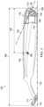
- FIG. 1is a side view of an exemplary personal care product system in accordance with one nonlimiting embodiment of the present disclosure
- FIG. 2is an isometric view of a handle
- FIG. 3is a side view of the handle shown in FIG. 2 with a cutaway view of a first end portion;
- FIG. 4is a partial cutaway view of a first end portion of a handle that is docked with a personal care product stand, with various components removed for clarity of illustration;
- FIG. 5is a partial cutaway view of a handle showing docking magnets positioned within a first end portion
- FIG. 6is an isometric view of docking magnets of a handle with various components removed for clarity of illustration;
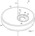
- FIG. 7is an isometric view of one non-limiting example personal care product stand
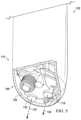
- FIG. 8is a partial cutaway view of the personal care product stand shown in FIG. 7 ;
- FIG. 9is a cross-sectional view of the personal care product stand shown in FIG. 7 with a handle of a personal care product docked thereto;
- FIG. 10is a bottom isometric view of a portion of a handle receiving portion that extends into a cavity of a personal care product stand in accordance with one non-limiting embodiment.
- the present disclosureprovides for personal care product systems having a handle and a personal care product stand for docking the handle when not in use.
- Various nonlimiting embodiments of the present disclosurewill now be described to provide an overall understanding of the principles of the function, design, and operation of the personal care product systems.
- One or more examples of these nonlimiting embodimentsare illustrated in the accompanying drawings.
- Those of ordinary skill in the artwill understand that the methods described herein and illustrated in the accompanying drawings are nonlimiting example embodiments and that the scope of the various nonlimiting embodiments of the present disclosure are defined solely by the claims.
- the features illustrated or described in connection with one nonlimiting embodimentmay be combined with the features of other nonlimiting embodiments. Such modifications and variations are intended to be included within the scope of the present disclosure.
- the personal care product system 100comprises a handle 102 that is docked with a personal care product stand 150 . While the handle 102 is shown as a rechargeable wet razor having powered components, such depiction is for illustrative purposes only.
- Other examples of personal consumer products that can be docked to the personal care product stand 150may include, without limitation, dry razors, epilators or other hair cutting and/or epilating household devices, trimmers, personal groomers, toothbrushes, hair removal devices, and so forth.
- a shaving razor cartridge 122 having bladesis depicted as being coupled to a distal end of a second end portion 111 of the handle 102
- the handle 102may additionally or alternatively include other types of grooming devices, such as perforated shaving foils, rotary cutters, oscillating cutters, trimmers, and so forth.
- the handle 102 with the depicted shaving razor cartridge 122 coupled to the second end portion 111is for illustrative purposes only and is not intended to limit the disclosure to any particular configuration of the handle 102 , the personal care product system 100 , or the shaving razor cartridge 122 .
- the handle 102may include one or more powered elements, such as fluid pumps, motors, sensors, vibrating or oscillating components, heating elements, and so forth.
- the term handle 102is to refer to the personal grooming device that can be stored in the personal care product stand 150 , including any attachable components, such as the shaving razor cartridge 122 . Any lengths, measurements or calculations of center of gravity, center of mass, etc. are to be determined with the shaving razor cartridge, or other associated grooming implement, attached to the handle 102 .
- the handle 102is shown to have a generally cylindrical elongated gripping portion 104 , this disclosure is not so limited. Instead, the elongated gripping portion 104 can be any suitable shape, size, or configuration and is the portion of the handle 102 that is handled by the user during use of the personal care product.
- the shaving razor cartridge 122(or other type of attachment or fixed implement) may be fixedly or pivotably mounted to the handle 102 , depending on the overall desired cost and performance.
- the shaving razor cartridge 122may be permanently attached or removably mounted to the handle 102 .
- the shaving razor cartridge 122may include one or more blades 123 ( FIG. 2 ), or other cutting instruments.
- the handle 102may hold a power source 119 ( FIG. 3 ) that supplies power to one or more of the onboard powered elements, such as a heating element, a motor, a vibrating element, or other type of element driven by electricity.
- the power sourcemay be a rechargeable battery that may be recharged while the handle 102 is docked in the personal care product stand 150 while not in use.
- the handle 102is shown in a docked position in FIG. 1 . While in the docked position, at least a portion of a first end portion 110 of the handle 102 can be received into a personal care product stand 150 , as described in more detail below.
- the personal care product stand 150can include a base 194 and a power plug 192 that can be plugged into a power source, such as a wall outlet.
- the personal care product stand 150can further include a base charging system 148 ( FIG. 4 ) that delivers power to a handle charging system 146 ( FIG. 3 ) of the handle 102 when the personal care product stand 150 is connected to a power source and the handle 102 is docked to the personal care product stand 150 . While the power plug 192 is shown in FIG.
- the personal care product stand 150comprises a rechargeable power source that is configured to store power and then charge the handle 102 when it is docked with the stand.
- the personal care product stand 150can be any suitable shape that can rest on a flat surface.
- a stand resting plane 154 shown in FIG. 1depicts the flat surface that the personal care product stand 150 can rest on, such as a shelf, tabletop, sink, etc.
- the personal care product stand 150can also include feet or other nubs which contact the stand resting plane 154 defined by the flat surface.
- the personal care product stand 150also defines a handle mounting surface 176 . When the handle 102 is in the docked position, at least a portion of the handle mounting surface 176 may contact a personal care product stand contact area 138 of the handle 102 , as described in more detail below.
- the base 194 of the personal care product stand 150also defines a geometrical center 180 , sometimes referred to as a centroid, as well as a center of mass 178 .
- the base 194may be configured such that the center of mass 178 may be spaced apart from the geometrical center 180 and positioned toward the handle mounting surface 176 such that the center of mass 178 is horizontally offset from the geometrical center 180 . Positioning the center of mass 178 toward the handle mounting surface 176 can increase the stability of the personal care product stand 150 when the handle 102 is being docked or undocked by a user.
- the center of mass 178is horizontally offset from the geometrical center 180 towards the handle mounting surface 176 by at least about 4 mm. In some configurations, as shown in FIG. 1 the center of mass 178 is vertically positioned between the handle mounting surface 176 and the stand resting plane 154 .
- FIG. 2depicts an isometric view of the handle 102 and FIG. 3 is a side view of the handle 102 with a cutaway view of the first end portion 110 .
- the handle 102has an overall length 108 ( FIG. 3 ), as measured from the most proximal point of the first end portion 110 (shown as point 113 ) to the most distal point (shown as point 115 ) on the shaving razor cartridge 122 (or other grooming implement operationally coupled to the handle 102 ).
- the overall length 108 of the handle 102is between about 130 mm and about 170 mm.
- the overall length 108 of the handle 102is between about 150 mm and about 160 mm.
- the handle 102also defines a center of mass 106 .
- the center of mass 106 of the handle 102is spaced apart from the most proximal point of the first end portion 110 by about 30 mm to about 80 mm, shown as spacing 120 in FIG. 3 .
- the handle 102rests on a flat surface (e.g., sink, shelf, etc.) with the blades 123 ( FIG. 2 ) of the shaving razor cartridge 122 facing the flat surface, the flat surface defines a handle resting plane 112 .
- FIG. 1The relative position of the handle resting plane 112 to the stand resting plane 154 of the personal care product stand 150 when the handle 102 is docked is shown in FIG. 1 .
- the personal care product stand 150has a center axis 170 that is perpendicular to the stand resting plane 154 and extending through the geometrical center 180 .
- the handle 102is tilted relative to the center axis 170 .
- the handle 102is suspended at an angle relative to the personal care product stand 150 .
- the second end portion 111extends outward beyond the perimeter of the base 194 .
- the handle resting plane 112intersects the stand resting plane 154 of the personal care product stand 150 at an included angle (shown as angle 182 in FIG. 1 ) of less than 90 degrees. In some configurations, the included angle 182 is between about 60 degrees and 80 degrees. While the handle 102 is tilted, however, a majority of the overall length 108 of handle 102 is unsupported, thereby creating an appearance that the handle 102 is levitated or floating to defy gravity. Only the personal care product stand contact area 138 at the first end portion 110 of the handle 102 contacts the personal care product stand 150 , with a remaining surface 128 of the handle 102 suspended without touching the base 194 or other type of physical support.
- an unsupported length 114is the portion of the handle 102 extending upward from the personal care product stand 150 , the entirety of which is free-standing and not engaged with or otherwise contacting a structural element.
- the unsupported length 114can be about 90% to 100%, but more preferably 92% to 96% of the overall length 108 ( FIG. 3 ) of the handle 102 .
- the personal care product stand contact area 138 of the handle 102may be entirely positioned within a lower 10% of an overall length 108 of the handle 102 .
- the personal care product stand contact area 138 of the handle 102may be entirely positioned within a lower 10% of an overall length 108 of the handle 102 , or more preferably with a lower 6% of the overall length 108 of the handle 102 . In some configurations, the personal care product stand contact area 138 of the handle 102 may be entirely positioned within a lower 2% of an overall length 108 of the handle 102 . In one embodiment, the overall length 108 of the handle 102 is about 158 mm, and the unsupported length 114 is about 150 mm.
- the tilted relationship between the handle 102 and the personal care product stand 150provides for an aesthetically pleasing docking arrangement, as the handle 102 seemingly defies gravity with a minimal amount of structural support from the stand.
- the docking relationshipcan also aid a user in placing handle 102 in the personal care product stand 150 , while also providing for easy removal. As such, the docking process is eased as the user need only set the handle 102 on the personal care product stand 150 to dock. Similarly, to use the handle 102 , the user need only lift the handle 102 away from the personal care product stand 150 to undock.
- FIG. 4is a partial cutaway view of the first end portion 110 of the handle 102 docked with the personal care product stand 150 , as shown in FIG. 1 , with various components removed for clarity of illustration.
- Each of the handle 102 and the personal care product stand 150include docking magnets (the handle 102 is shown to include docking magnets 118 , 132 and the personal care product stand 150 is shown to include docking magnets 158 , 160 ) that facilitate the docking of the handle 102 to the personal care product stand 150 .
- the relative position and location of the docking magnets 118 , 132 of the handle 102 and the docking magnets 158 , 160 of the personal care product stand 150facilitate the visually appealing tilting of the handle 102 relative to the personal care product stand 150 , while the handle 102 is substantially unsupported. While the number and shape of docking magnets can vary, in the illustrated configuration, the handle 102 has a first docking magnet 118 that is positioned beside a second docking magnet 132 , both of which are substantially cylindrical. Similarly, the personal care product stand 150 has a first docking magnet 158 that is positioned beside a second docking magnet 160 , both of which are substantially cylindrical and mounted within a cavity 152 defined by the personal care product stand 150 .
- the handle 102may also have a handle charging system 146 that is configured to receive power from a base charging system 148 when the handle 102 is docked to the personal care product stand 150 .
- the handle charging system 146can use the power received from the base charging system 148 to recharge the power source 119 of the handle 102 .
- each of the handle charging system 146 and the base charging system 148comprises at least one coil that facilitates induction charging.
- the handle charging system 146is positioned in close proximity to the first docking magnet 118 and the second docking magnet 132 .
- the base charging system 148is positioned in close proximity to the first docking magnet 158 and the second docking magnet 160 .
- the personal care product stand contact area 138is placed in contact with the handle mounting surface 176 , such that the docking magnets 118 , 132 of the handle 102 are positioned proximate to the docking magnets 158 , 160 of the personal care product stand 150 .
- the magnetic attraction between the docking magnetsmaintains the titled position of the handle 102 relative to the personal care product stand 150 to overcome the gravitational force acting upon on the handle 102 .
- the handle 102can remain in this position until the user lifts the handle 102 off the personal care product stand 150 .
- the personal care product stand 150also has a ballast mass 162 ( FIG. 9 ) which generates additional gravitational force.
- the ballast mass 162is over half the total stand mass, although this disclosure is not so limited.
- the shape and placement of the ballast mass 162can be configured to appropriately position the center of mass 178 within the personal care product stand 150 .
- the gravitational force of the total stand masscan be greater than a magnetic attraction between the docking magnets 118 , 132 of the handle 102 and the docking magnets 158 , 160 of the personal care product stand 150 .
- the stand mass of the personal care product stand 150will keep the personal care product stand 150 from lifting with the handle 102 .
- the relative location of the center of mass 178 of the personal care product stand 150can further provide stability during operational use.
- the personal care product stand 150will continue to remain stable on the stand resting plane 154 as the handle is undocked.
- increasing the stand masscan allow for the use of a higher docking force between the handle 102 and the personal care product stand 150 .
- the stand mass of the personal care product standis between about 150 grams and 300 grams. In some embodiments, the stand mass of the personal care product stand is about 250 grams, thereby allowing for a docking force between the handle 102 and the personal care product stand 150 of up to about 2 Newtons.
- FIG. 5is an isometric partial cutaway view of the handle 102 to show the docking magnets 118 , 132 positioned within the first end portion 110 .
- docking magnets 118 , 132are contacting an inner surface 126 of the personal care product contact area 138 ( FIG. 2 ).
- FIG. 6is an isometric view of the docking magnets 118 , 132 of the handle 102 with various components removed for clarity of illustration.
- the polarity of the first docking magnet 118may be opposite to the polarity of the second docking magnet 132 .
- a yoke 124may connect the first docking magnet 118 to the second docking magnet 132 .
- the yoke 124may be a flux guiding member and may comprise a ferromagnetic material. When functioning as a flux guiding member, the yoke 124 can direct the magnetic fields of the docking magnets 118 , 132 so that the impact of these fields on the non-contacting charging capabilities of the handle charging system 146 is reduced.
- a similar yokecan be used with the docking magnets 158 , 160 of the personal care product stand 150 to guide the magnetic fields of those magnets.
- the first docking magnet 118defines an axis of polarity 130 that runs through the two poles of the magnet.
- the second docking magnet 132defines an axis of polarity 134 that runs through the two poles of that magnet.
- the polarity of the first docking magnet 118can be opposite of the polarity of the second docking magnet 132 .
- the axis of polarity 130 of the first docking magnet 118is shown in FIG. 3 .
- the axis of polarity 130may intersect the handle resting plane 112 at an included angle (shown as included angle 136 ) which may be between about 15 degrees and about 35 degrees to facilitate the angular position of the handle 102 to the personal care product stand 150 .
- FIG. 7depicts an isometric view of the personal care product stand 150 and FIG. 8 depicts a partial cutaway view of FIG. 7 to show the internal cavity 152 , with various components removed for clarity of illustration.
- FIG. 9is a cross-sectional view of the personal care product stand shown in FIG. 7 with the handle 102 of a personal care product docked thereto.
- the personal care product stand 150has a top surface 174 that has a handle receiving portion 190 ( FIG. 7 ).
- the top surface 174can be planar, rounded, sloped, angled, multi-faceted, or have any other suitable configuration.
- the handle receiving portion 190may also define a recess 188 having the handle mounting surface 176 that includes a bottom surface 156 .
- the handle receiving portion 190may be generally flat or have another suitable arrangement.
- the bottom surface 156can be non-parallel to the stand resting plane 154 ( FIG. 1 ) of the personal care product stand 150 .
- the recess 188is sized and configured to receive the first end portion 110 of the handle 102 when the handle 102 is in the docked position.
- the depth of the recess 188as measured vertically between the uppermost point and lowermost point (shown as depth 144 in FIG. 1 ) may be in the range of about 2 mm to about 10 mm. In some configurations, the depth of the recess 188 is about 5.5 mm.
- the personal care product contact area 138( FIG.
- the docking magnets 158 , 160can be received into the recess 188 such that the docking magnets 118 , 132 of the handle 102 magnetically engage with the docking magnets 158 , 160 of the personal care product stand 150 that are positioned beneath the bottom surface 156 .
- the docking magnets 158 , 160are in contact with the underside of the bottom surface 156 , to minimize the distance between the related docking magnets of the handle 102 to increase the magnetic attraction force.
- the docking magnets 158 , 160as shown in FIG. 8 , can each have a respective axis of polarity 140 , 142 extending through the poles of the magnet.
- the polarity of the docking magnet 158can be opposite of the polarity of the docking magnet 160 and be configured to magnetically engage with the complementary docking magnets 132 and 118 of the handle 102 .
- the axes of polarity 140 , 142can be generally parallel and co-planar to the axes of polarity 130 , 134 of the handle 102 when the handle 102 is docked to the personal care product stand 150 .
- the axes of polarity 140 , 142can be generally non-parallel and/or non-planar to the axes of polarity 130 , 134 of the handle 102 when the handle 102 is docked to the personal care product stand 150 .
- the docking magnets 158 , 160may be positioned within the personal care product stand 150 offset from its center. As shown in FIG. 8 , the docking magnets 158 , 160 can be positioned within the cavity 152 at least 8 mm from the center axis 170 , as laterally measured parallel to the stand resting plane 154 . In some configurations, the docking magnets 158 , 160 can be positioned within the cavity 152 more than about 10 mm from the center axis 170 . In some configurations, the docking magnets 158 , 160 can be positioned within the cavity 152 more than about 13 mm from the center axis 170 .
- the handle receiving portion 190may comprise an alignment member 184 .
- the alignment member 184may assist a user with docking the handle 102 in the recess 188 , such as to function as a centering feature, to ease the docking process, and to provide consumer feedback that correct alignment between the handle 102 and the personal care product stand 150 is achieved.
- Proper alignmentcan assist with ensuring sufficient magnetic coupling between the docking magnets 118 , 132 of the handle 102 and the docking magnets 158 , 160 of the personal care product stand 150 .
- Proper alignmentcan assist with sufficient inductive coupling between the base charging system 148 and the handle charging system 146 .
- the alignment member 184provides no mechanical support of the handle 102 , but instead merely ensures proper placement of the handle 102 relative to the personal care product stand 150 during docking.
- the alignment member 184is shown as a ridge that is positioned along a portion of perimeter of the bottom surface 156 .
- the first end portion 110 of the handle 102may have a corresponding alignment member 116 that engages with the alignment member 184 of the personal care product stand 150 when the handle 102 is docked.
- the alignment member 116is a groove that is sized to receive the ridge positioned in the recess 188 of the personal care product stand 150 .
- the engagement of the alignment member 116 of the handle 102 and the alignment member 184 of the personal care product stand 150ensures the user is docking the handle 102 at the proper orientation and with the proper angular alignment.
- the alignment members 116 , 184are illustrated as an arcuate ridge and groove, this disclosure is not so limited. Instead, the alignment members may be any suitable configurations, such as another type of protrusion and corresponding recess, and the like.
- personal care product stand 150includes a ballast mass 162 which can be sized to provide sufficient mass to position the center of mass 178 ( FIG. 1 ) in a desired position to maintain stability during docking and undocking.
- the ballast mass 162is positioned such that the center of mass 178 ( FIG. 1 ) is drawn toward the handle receiving portion 190 ( FIG. 7 ) in order to increase stability.
- the ballast mass 162can also be sized so that the gravitational force acting upon the base 194 of the personal care product stand 150 is greater than the magnetic attraction between the docking magnets 118 , 134 of the handle 102 and the docking magnets 158 , 160 of the personal care product stand 150 .
- FIG. 10is a bottom isometric view of the portion of the handle receiving portion 190 that extends into the cavity 152 of the personal care product stand 150 in accordance with one non-limiting embodiment.
- the handle receiving portion 190can include a gasket 186 to assist with sealing the cavity 152 ( FIG. 8 ).
- the handle receiving portion 190defines a first pocket 196 and a second pocket 198 .
- the first docking magnet 158may be received into the first pocket 196 and the second docking magnet 160 may be received into the second pocket 198 such that they each contact the underside surface of the bottom surface 156 ( FIG. 7 ).
- the docking magnets 158 , 160are inserted into their respective pockets 196 , 198 and fixed by hot stamping, or other assembly techniques. Furthermore, in some configurations the end of the docking magnet facing the bottom surface 156 may be slanted.
- a personal care product stand( 150 ) having a resting plane ( 154 );
- a handle ( 102 )having an elongated gripping portion ( 104 ), the handle ( 102 ) suspended at an angle relative to the base and having a handle resting plane ( 112 ) that intersects the resting plane ( 154 ) of the personal care product stand at an included angle ( 182 ) of less than 90 degrees, wherein the handle has an unsupported length ( 114 ) that is not engaged with the personal care product stand and that is about 90% to 100% of an overall length ( 108 ) of the handle.
- a base194 having a resting plane ( 154 ), a center axis ( 170 ) and a top surface ( 174 ) defining a handle receiving portion ( 190 ) configured to hold a handle ( 102 ), the base defining a cavity ( 152 );
- At least one permanent docking magnet ( 158 )positioned within the cavity at least 10 mm from a center axis ( 170 ) of the base ( 194 ).
Landscapes
- Engineering & Computer Science (AREA)
- Life Sciences & Earth Sciences (AREA)
- Forests & Forestry (AREA)
- Mechanical Engineering (AREA)
- Physics & Mathematics (AREA)
- Electromagnetism (AREA)
- Power Engineering (AREA)
- Purses, Travelling Bags, Baskets, Or Suitcases (AREA)
- Dry Shavers And Clippers (AREA)
- Magnetic Treatment Devices (AREA)
Abstract
Description
- A. A personal care product system (100), comprising:
- B. The personal care product system of paragraph A wherein the handle (102) has a center of mass (106) spaced apart from a lowermost point of a personal care product stand contact area (138) of the handle by about 30 mm to about 80 mm.
- C. The personal care product system according to any one of the paragraphs A and B wherein the handle (102) is not mechanically secured to the personal care product stand (150).
- D. The personal care product system according to any one of the paragraphs A-C wherein the handle resting plane (112) intersects the resting plane (154) of the personal care product (150) stand at an included angle (182) of about 60 to about 85 degrees.
- E. The personal care product system according to any one of the paragraphs B-D, wherein the personal care product stand contact area (138) is at a first end portion (110) of the handle (102).
- F. The personal care product system according to any one of the paragraphs B-E wherein the personal care product stand (150) has a geometrical center (180) that is spaced apart from a handle mounting surface (176) of the personal care product stand (150) that engages the personal care product stand contact area (138) on the handle (102).
- G. The personal care product system according to any one of the paragraphs A-F wherein the handle (102) comprises at least a first docking magnet (118) having an axis of polarity (130) that intersects the resting plane (112) at an included angle (136) of about 15 degrees to about 35 degrees.
- H. The personal care product system according to paragraph G wherein the handle (102) comprises a second docking magnet (132) having an opposite polarity as a polarity of the first docking magnet (118).
- I. The personal care product system according to paragraph H further comprising a yoke (124) connecting the first docking magnet (118) and second docking magnet (132).
- J. The personal care product system according to any one of the paragraphs A-I wherein the personal care product stand (150) has a stand mass (162) to form a gravitational force that is greater than a magnetic attraction force between the personal care product stand (150) and the handle (102).
- K. The personal care product system according to any one of the paragraphs A-J wherein the personal care product stand (150) has a center of mass (178) that is spaced apart from a geometrical center (180) of the personal care product stand (150) and toward a handle mounting surface (176) on the personal care product stand (150).
- L. The personal care product system according to any one of the paragraphs F-K wherein the handle mounting surface (176) on the personal care product stand (150) has an alignment member (184) that engages a corresponding alignment member (116) on the handle (102).
- M. The personal care product system according to paragraph L wherein at least one of the alignment members (184,116) comprises an arc shaped groove or a protrusion.
- N. The personal care product system according to any one of the paragraphs F-M wherein the handle mounting surface (176) on the personal care product stand (150) has a recess (188) configured to receive the personal care product stand contact area (138) of the handle (102).
- O. The personal care product system according to paragraph N wherein the handle mounting surface (176) on the personal care product stand (150) has an alignment member (184) that engages a corresponding alignment member (116) on the personal care product stand contact area (138) on the handle (102) and the alignment member (184) of the handle mounting surface (176) on the personal care product stand (150) is positioned along a perimeter of a bottom surface (156) of the recess (188).
- P. A personal care product stand (150) comprising:
- Q. The personal care product stand of paragraph P wherein the handle receiving portion (190) defines a recess (188) configured to receive a handle.
- R. The personal care product stand according to any one of the paragraphs P-Q wherein the handle receiving portion (190) comprises an alignment member (184) configured to engage a corresponding alignment member (116) on a handle (102).
- S. The personal care product stand according to paragraph R wherein the alignment member (184) is positioned on a surface (176) of the handle receiving portion (190).
- T. The personal care product stand according to paragraph S wherein the alignment member (184) of the handle receiving portion (190) is positioned along a perimeter of a bottom surface (156).
- U. The personal care product stand according to paragraph S wherein the alignment member (184) of the handle receiving portion (190) is arcuate.
- V. The personal care product stand according to paragraph S wherein the alignment member (184) of the handle receiving portion (190) is a protrusion.
- W. The personal care product stand according to paragraph S wherein the alignment member (184) of the handle receiving portion (190) is a recess.
- X. The personal care product stand according to any one of the paragraphs P-W wherein the at least one permanent docking magnet (158) positioned within the cavity (152) comprises a pair of permanent docking magnets (158,160) positioned within the cavity (152).
- Y. The personal care product stand according to paragraph X wherein the pair of permanent docking magnets (158,160) positioned within the cavity (152) have opposing polarities.
- Z. The personal care product stand according to any one of the paragraphs P-Y further comprising a ballast mass (162) positioned within the base (194).
- AA. The personal care product stand according to any one of the paragraphs P-Z wherein the at least one permanent docking magnet (158) is maintained in a position against an inner surface (172) of the stand directly below the handle receiving portion (190).
- BB. The personal care product stand according to any one of the paragraphs P-AA wherein the at least one permanent docking magnet (158) has a slanted end face directly contacting an inner surface (172) directly below the handle receiving portion (190).
- CC. The personal care product stand according to any one of the paragraphs P-BB wherein the handle receiving portion (190) is not parallel to the resting plane (154) of the base (194).
- DD. A personal care product, comprising:
- EE. The personal care product according to paragraph DD wherein the handle (102) comprises a second docking magnet (132) positioned within the end portion (110).
- FF. The personal care product according to paragraph EE wherein the first docking magnet (118) has an opposite polarity as a polarity of the second docking magnet (132).
- GG. The personal care product according to any one of the paragraphs EE-FF further comprising a yoke (124) connecting the first docking magnet (118) and the second docking magnet (132).
- HH. The personal care product according to any one of the paragraphs DD-GG wherein the first docking magnet (118) is cylindrical.
- II. The personal care product according to any one of the paragraphs DD-HH wherein the end portion (110) comprises a personal care product stand contact area (138).
- JJ. The personal care product according to paragraph II wherein the personal care product stand contact area (138) is entirely positioned within a lower 6% of an overall length (108) of the handle (102).
- KK. The personal care product according to paragraph JJ wherein the personal care product stand contact area (138) is entirely positioned within a lower 2% of an overall length (108) of the handle (102).
- LL. The personal care product according to paragraph II wherein the personal care product stand contact area (138) has an inner surface (126) and the first docking magnet (118) is in contact with the inner surface (126).
- MM. The personal care product according to any one of the paragraphs II-LL wherein the handle (102) has a center of mass (106) spaced apart from a lowermost point of a personal care product stand contact area (138) of the handle by about 30 mm to about 80 mm.
- NN. The personal care product according to any one of the paragraphs DD-MM wherein the end portion (110) of the handle (102) further comprises an alignment member (116).
- OO. The personal care product according to paragraph NN wherein the alignment member (116) comprises a groove.
- PP. The personal care product according to paragraph NN wherein the alignment member (116) comprises a protrusion.
- QQ. The personal care product according to any one of the paragraphs NN-PP wherein the alignment member (116) is positioned within the personal care product stand contact area (138).
- RR. The personal care product according to any one of the paragraphs00-QQ wherein the alignment member (116) is configured to engage a corresponding alignment member (184) on a personal care product stand (150).
Claims (17)
Priority Applications (1)
| Application Number | Priority Date | Filing Date | Title |
|---|---|---|---|
| US17/523,256US11648693B2 (en) | 2017-01-20 | 2021-11-10 | Personal care product docking system |
Applications Claiming Priority (3)
| Application Number | Priority Date | Filing Date | Title |
|---|---|---|---|
| EP17152539 | 2017-01-20 | ||
| EP17152539.7 | 2017-01-20 | ||
| EP17152539.7AEP3351138B1 (en) | 2017-01-20 | 2017-01-20 | Personal care product docking system |
Related Child Applications (1)
| Application Number | Title | Priority Date | Filing Date |
|---|---|---|---|
| US17/523,256ContinuationUS11648693B2 (en) | 2017-01-20 | 2021-11-10 | Personal care product docking system |
Publications (2)
| Publication Number | Publication Date |
|---|---|
| US20180207820A1 US20180207820A1 (en) | 2018-07-26 |
| US11648692B2true US11648692B2 (en) | 2023-05-16 |
Family
ID=57906450
Family Applications (2)
| Application Number | Title | Priority Date | Filing Date |
|---|---|---|---|
| US15/866,623ActiveUS11648692B2 (en) | 2017-01-20 | 2018-01-10 | Personal care product docking system |
| US17/523,256ActiveUS11648693B2 (en) | 2017-01-20 | 2021-11-10 | Personal care product docking system |
Family Applications After (1)
| Application Number | Title | Priority Date | Filing Date |
|---|---|---|---|
| US17/523,256ActiveUS11648693B2 (en) | 2017-01-20 | 2021-11-10 | Personal care product docking system |
Country Status (6)
| Country | Link |
|---|---|
| US (2) | US11648692B2 (en) |
| EP (1) | EP3351138B1 (en) |
| JP (1) | JP7111713B2 (en) |
| KR (1) | KR20190091317A (en) |
| CN (1) | CN110191660B (en) |
| WO (1) | WO2018136282A1 (en) |
Cited By (8)
| Publication number | Priority date | Publication date | Assignee | Title |
|---|---|---|---|---|
| US20230115141A1 (en)* | 2021-10-08 | 2023-04-13 | Nucurrent, Inc. | Heat Diffuser In Wrist Worn Wireless Power And Data System |
| US12166358B2 (en) | 2021-10-15 | 2024-12-10 | Nucurrent, Inc. | Wireless power and data transfer system with out of band communications hand off |
| US12184355B2 (en) | 2021-01-28 | 2024-12-31 | Nucurrent, Inc. | Wireless power transfer with in-band virtualized wired communications |
| US12191930B2 (en) | 2021-01-28 | 2025-01-07 | Nucurrent, Inc. | Wireless power transfer system with data versus power priority optimization |
| US12199695B2 (en) | 2021-01-28 | 2025-01-14 | Nucurrent, Inc. | Wireless power transfer system with mode switching using selective quality factor alteration |
| US12231187B2 (en) | 2021-10-15 | 2025-02-18 | Nucurrent, Inc. | High speed data communications system for industrial use in packaged goods with out of band communications hand off |
| US12320838B2 (en) | 2021-10-15 | 2025-06-03 | Nucurrent, Inc. | Testing device for electronic devices with in-band virtualized wired communications |
| US12355527B2 (en) | 2021-01-28 | 2025-07-08 | Nucurrent, Inc. | High speed data communications system for industrial use in packaged goods |
Families Citing this family (9)
| Publication number | Priority date | Publication date | Assignee | Title |
|---|---|---|---|---|
| US20200178669A1 (en)* | 2018-08-16 | 2020-06-11 | The Gillette Company Llc | Personal care system |
| USD831375S1 (en)* | 2017-01-20 | 2018-10-23 | The Gillette Company Llc | Shaving razor stand |
| EP3351137B1 (en)* | 2017-01-20 | 2020-01-08 | The Gillette Company LLC | Personal care product handle |
| EP3351138B1 (en) | 2017-01-20 | 2020-09-09 | The Gillette Company LLC | Personal care product docking system |
| USD916495S1 (en) | 2018-08-17 | 2021-04-20 | The Gillette Company Llc | Stand for a shaving razor |
| USD878084S1 (en) | 2018-10-05 | 2020-03-17 | The Gillette Company Llc | Grooming station |
| ZA202104136B (en)* | 2020-06-19 | 2022-09-28 | Norman Frederick Parkin | Mobile device charger |
| US20220088810A1 (en)* | 2020-09-21 | 2022-03-24 | Beauty Perspectives, LLC | Razor handle |
| WO2024054883A1 (en)* | 2022-09-09 | 2024-03-14 | The Gillette Company Llc | Cover and stand for personal care product |
Citations (105)
| Publication number | Priority date | Publication date | Assignee | Title |
|---|---|---|---|---|
| US2386500A (en)* | 1943-12-29 | 1945-10-09 | Parker Pen Co | Magnetic desk set |
| US2693788A (en)* | 1952-10-04 | 1954-11-09 | Frawley Corp | Magnetic desk pen set |
| US3283185A (en) | 1960-01-11 | 1966-11-01 | Sperry Rand Corp | Battery operated electric shaver |
| US4042700A (en) | 1975-09-12 | 1977-08-16 | Boehringer Ingelheim Gmbh | Quaternary N-β-substituted N-alkyl-nortropine benzilates |
| US4643604A (en)* | 1984-09-04 | 1987-02-17 | Bertin Enrico | Magnetic pen holder |
| US4865285A (en)* | 1988-01-13 | 1989-09-12 | Winninghorse, Srl | Magnetic penholder and magnetic pen set |
| EP0410849A1 (en) | 1989-07-27 | 1991-01-30 | Institut Français du Pétrole | Polysulfide compositions from unsaturated fatty elements and/or (poly)unsaturated esters from acids and from olefins, optionally their preparation and their utilisation as lubricant additives |
| US5138245A (en) | 1988-05-11 | 1992-08-11 | Wella Aktiengesellschaft | Holder for a rechargeable tool |
| USD339655S (en) | 1990-10-05 | 1993-09-21 | Remington Products, Inc. | Hair trimmer and support base assembly |
| WO1994027479A1 (en) | 1993-06-01 | 1994-12-08 | Smith Colin J | Device for securing utensils and containers to smooth surfaces |
| US5680028A (en) | 1994-06-30 | 1997-10-21 | Mceachern; Alexander | Charger for hand-held rechargeable electric apparatus with reduced magnetic field |
| US5894670A (en) | 1996-12-13 | 1999-04-20 | U.S. Philips Corporation | Electric shaving system |
| US5923544A (en) | 1996-07-26 | 1999-07-13 | Tdk Corporation | Noncontact power transmitting apparatus |
| US5966822A (en) | 1993-02-10 | 1999-10-19 | Warner-Lambert Company | Holder for a wet shaver |
| US5966821A (en) | 1998-01-12 | 1999-10-19 | Armbruster; Joseph M. | Storage canister for electric razor and shaving items |
| JP3055446B2 (en) | 1995-12-06 | 2000-06-26 | 三菱自動車工業株式会社 | Screw part fastening structure |
| JP3059096B2 (en) | 1996-01-10 | 2000-07-04 | 日本碍子株式会社 | Insulation tube thickness withstand voltage test method and external electrode used for it |
| JP3079978B2 (en) | 1995-11-21 | 2000-08-21 | 住友電装株式会社 | Terminal crimping machine |
| US6112414A (en)* | 1997-09-10 | 2000-09-05 | Andis Company | Rechargeable hair clipper assembly |
| JP2001053853A (en) | 1999-08-06 | 2001-02-23 | Toshiba Corp | Electronics |
| USD456096S1 (en) | 2001-04-13 | 2002-04-23 | Conair Corporation | Hair clipper |
| US20020116775A1 (en) | 2001-02-06 | 2002-08-29 | Wong Man Kwan | Automatic power-driven toothbrushes |
| US20020133308A1 (en) | 1999-06-09 | 2002-09-19 | William G. Lundell | System for communicating operational data between an electric toothbrush and a separate control unit |
| JP2003070170A (en) | 2001-08-28 | 2003-03-07 | Matsushita Electric Works Ltd | Non-contact feeding device |
| US20040172831A1 (en) | 2003-03-04 | 2004-09-09 | Paas Edward L. | Vibratory shaver |
| JP2004260917A (en) | 2003-02-26 | 2004-09-16 | Sony Corp | Non-contact power transmission apparatus |
| US20050007065A1 (en)* | 2003-07-07 | 2005-01-13 | Jon Freas | Interlocking charging stands |
| US20060089178A1 (en) | 2004-10-14 | 2006-04-27 | Matsushita Electric Industrial Co., Ltd. | Cordless telephone set |
| USD521927S1 (en) | 2005-03-04 | 2006-05-30 | General Instrument Corporation | Base for cordless telephone charger |
| USD529533S1 (en) | 2006-01-03 | 2006-10-03 | Creative Technology Ltd | Camera stand |
| USD544264S1 (en) | 2004-11-30 | 2007-06-12 | Gallagher Richard N | Stand for razor and shaving brush |
| USD557321S1 (en) | 2006-08-21 | 2007-12-11 | Microsoft Corporation | Portion of an electronic camera |
| USD557320S1 (en) | 2006-08-21 | 2007-12-11 | Microsoft Corporation | Portion of an electronic camera |
| US20080052912A1 (en) | 2006-09-01 | 2008-03-06 | Eveready Battery Company. Inc. | Integrated shave counter and base |
| USD564272S1 (en) | 2007-03-19 | 2008-03-18 | Trung Quach | Toothbrush and razor holder |
| USD572063S1 (en) | 2007-05-03 | 2008-07-01 | The Gillette Company | Razor stand |
| US20080237412A1 (en)* | 2007-03-26 | 2008-10-02 | The Bank Of Tokyo-Mitsubishi Ufj, Ltd. | Display device stand |
| USD577998S1 (en) | 2006-02-10 | 2008-10-07 | Airlessystems | Pushbutton dispenser cap |
| US20080306417A1 (en) | 2006-02-01 | 2008-12-11 | Imboden Ethan F | Rechargeable personal massager |
| USD586955S1 (en) | 2006-06-26 | 2009-02-17 | Wella Aktiengesellschaft | Combined hair cutting device and base |
| US20090050598A1 (en) | 2007-08-20 | 2009-02-26 | Chow-Chi Huang | Supportable pressurizable container and base cup therefor |
| US20090056141A1 (en) | 2007-08-28 | 2009-03-05 | Eveready Battery Company, Inc. | Shaving implement and method for using same |
| JP2009159660A (en) | 2007-12-25 | 2009-07-16 | Casio Comput Co Ltd | Non-contact power transmission device |
| CN201380471Y (en) | 2009-04-02 | 2010-01-13 | 陈奇伟 | Handle capable of holding |
| US7684965B2 (en) | 2006-06-09 | 2010-03-23 | Fujitsu Microelectronics Limited | Method and apparatus for processing data, and computer product |
| US7733058B2 (en) | 2006-07-14 | 2010-06-08 | Matsushikta Electric Works, Ltd. | Engaging structure of electric shaver and electric charger thereof |
| WO2010134051A1 (en) | 2009-05-20 | 2010-11-25 | Braun Gmbh | Personal body cleaning device |
| WO2010134050A1 (en) | 2009-05-20 | 2010-11-25 | Braun Gmbh | Personal body cleaning device |
| USD634955S1 (en) | 2010-11-17 | 2011-03-29 | The Gillette Company | Razor stand |
| CN201813180U (en) | 2010-08-31 | 2011-04-27 | 深圳市启欣科技有限公司 | Wireless charging magnetic positioning system |
| US20110247156A1 (en)* | 2008-11-20 | 2011-10-13 | Braun Gmbh | Oral Care System |
| CN202167887U (en) | 2011-07-14 | 2012-03-14 | 四川东林科技有限公司 | Radio-frequency charging device |
| USD657740S1 (en) | 2009-07-12 | 2012-04-17 | Koninklijke Philips Electronics N.V. | Stand for three head dry shaver |
| US20120112553A1 (en) | 2010-11-04 | 2012-05-10 | Access Business Group International Llc | Wireless power system and method with improved alignment |
| US8237401B2 (en) | 2008-12-29 | 2012-08-07 | Hong Fu Jin Precision Industry (Shenzhen) Co., Ltd. | Recharging system and electronic device |
| US20120217930A1 (en) | 2011-02-28 | 2012-08-30 | Panasonic Corporation | Holder for compact electric device |
| US20120306440A1 (en) | 2011-06-01 | 2012-12-06 | Ming-Hsiang Yeh | Handheld electronic device with positioning function |
| USD675048S1 (en) | 2012-08-13 | 2013-01-29 | Rolling Razor, Inc. | Razor stand |
| USD677090S1 (en) | 2012-09-05 | 2013-03-05 | The Gillette Company | Stand for a razor |
| USD677503S1 (en) | 2012-09-05 | 2013-03-12 | The Gillette Company | Stand for a razor |
| US20130200246A1 (en) | 2012-02-02 | 2013-08-08 | Jaypro Sports, Inc. | Pole Support Structure |
| US20130323941A1 (en)* | 2012-06-04 | 2013-12-05 | Adonit Co., Ltd. | Magnetic Connector |
| USD695545S1 (en) | 2013-01-25 | 2013-12-17 | The Gillette Company | Stand for a razor |
| USD695544S1 (en) | 2013-01-25 | 2013-12-17 | The Gillette Company | Stand for a razor |
| USD699473S1 (en) | 2013-10-02 | 2014-02-18 | The Gillette Company | Stand for a razor |
| US8727141B2 (en)* | 2007-02-07 | 2014-05-20 | Colgate-Palmolive Company | Magnetic toothbrush and holder |
| US20140375248A1 (en)* | 2013-06-24 | 2014-12-25 | Sony Corporation | Charging stand |
| US20150032178A1 (en) | 2011-03-10 | 2015-01-29 | ElectroCore, LLC | Non-invasive vagal nerve stimulation to treat disorders |
| US9011031B2 (en) | 2011-05-17 | 2015-04-21 | Anisa International, Inc. | Multi-applicator tool |
| US9143041B2 (en) | 2010-02-05 | 2015-09-22 | Hitachi Metals, Ltd. | Magnetic circuit, power-supplying device and power-receiving device for non-contact charging apparatus, and non-contact charging apparatus |
| US20150270046A1 (en)* | 2014-03-24 | 2015-09-24 | Apple Inc. | Magnetic connection and alignment of connectible devices |
| US20150280483A1 (en)* | 2014-03-26 | 2015-10-01 | Apple Inc. | Temperature management for inductive charging systems |
| US20150320178A1 (en) | 2014-05-12 | 2015-11-12 | Breath Scenter, LLC | Assembly and method of use for a convenient personal care product storage and dispensary |
| USD745916S1 (en) | 2014-03-19 | 2015-12-22 | Samsung Electronics Co., Ltd. | Lens for camera |
| CN105305525A (en) | 2014-06-20 | 2016-02-03 | 全汉企业股份有限公司 | Wireless charging device |
| CN205081509U (en) | 2015-10-21 | 2016-03-09 | 深圳罗马仕科技有限公司 | On -vehicle wireless battery charging outfit |
| US20160094076A1 (en) | 2014-09-29 | 2016-03-31 | Apple Inc. | Inductive charging between electronic devices |
| US20160094078A1 (en) | 2014-09-29 | 2016-03-31 | Apple Inc. | Inductive coupling assembly for an electronic device |
| US20160125988A1 (en) | 2014-11-05 | 2016-05-05 | Bing-Zhang LEE | Magnetic attraction-fixing assembly, two-piece apparatus, and rotating support structure for a portable device having the magnetic attraction-fixing assembly |
| JP2016093084A (en) | 2014-10-31 | 2016-05-23 | 株式会社京光製作所 | Wireless power supply system |
| WO2016113502A1 (en) | 2015-01-15 | 2016-07-21 | Seb S.A. | Electric appliance for the body with accessory storage |
| US9419468B1 (en) | 2013-12-20 | 2016-08-16 | Amazon Technologies, Inc. | Inductive charging system |
| US20160296078A1 (en) | 2013-11-21 | 2016-10-13 | Colgate-Palmolive Company | Oral Care Implement Support and Oral Care System Comprising the Same |
| US20160374395A1 (en)* | 2015-06-25 | 2016-12-29 | Geoffrey Brandon Jordan | Charger assembly and charging system for an electronic vaping device |
| USD776180S1 (en) | 2015-04-13 | 2017-01-10 | Fibar Group S.A. | Video gateway device |
| US9579809B2 (en) | 2013-12-20 | 2017-02-28 | The Gillette Company Llc | Removable razor cartridge having magnetic elements |
| US20170094399A1 (en) | 2015-09-30 | 2017-03-30 | Apple Inc. | Wireless pairing of earbuds and case |
| USD783838S1 (en) | 2014-05-20 | 2017-04-11 | Scanadu Incorporated | Portable wireless vital signs scanner |
| USD784259S1 (en) | 2015-12-17 | 2017-04-18 | Mingchang Huang | Multi-functional charger |
| USD790372S1 (en) | 2016-02-16 | 2017-06-27 | PB, Inc. | Tracking device |
| JP1589419S (en) | 2017-06-02 | 2017-10-30 | ||
| US20180021117A1 (en) | 2015-04-06 | 2018-01-25 | Panasonic Intellectual Property Management Co., Ltd. | Electric apparatus unit |
| US20180041058A1 (en) | 2016-08-05 | 2018-02-08 | Goby | Inductive charger with mechanical, modular, hygienic stand for hand-held appliances |
| USD820000S1 (en) | 2017-02-17 | 2018-06-12 | The Gillette Company Llc | Razor stand |
| US20180207821A1 (en) | 2017-01-20 | 2018-07-26 | The Gillette Company Llc | Personal care product charging system with flux guiding members |
| US20180212466A1 (en) | 2017-01-20 | 2018-07-26 | The Gillette Company Llc | Personal care product docking system with flux guiding members |
| US20180212465A1 (en) | 2017-01-20 | 2018-07-26 | The Gillette Company Llc | Personal care product system with flux guiding members |
| US10104950B1 (en) | 2014-08-01 | 2018-10-23 | Shavelogic, Inc. | Shaving razor stand |
| USD831375S1 (en) | 2017-01-20 | 2018-10-23 | The Gillette Company Llc | Shaving razor stand |
| USD831996S1 (en) | 2016-11-15 | 2018-10-30 | The Gillette Company Llc | Razor stand |
| EP2770603B1 (en) | 2011-10-21 | 2018-11-21 | Panasonic Corporation | Structure for holding electric shaver on charger |
| USD839627S1 (en) | 2016-11-15 | 2019-02-05 | The Gillette Company Llc | Razor stand |
| USD879499S1 (en) | 2015-12-03 | 2020-03-31 | Koninklijke Philips N.V. | Stand for shaver |
| USD918137S1 (en) | 2019-05-31 | 2021-05-04 | T-Mobile Usa, Inc. | Tracking device charging dock |
| US20220063118A1 (en) | 2017-01-20 | 2022-03-03 | The Gillette Company Llc | Personal care product docking system |
Family Cites Families (4)
| Publication number | Priority date | Publication date | Assignee | Title |
|---|---|---|---|---|
| JPS6098408U (en) | 1983-12-10 | 1985-07-04 | 日本発条株式会社 | resin toecap |
| JPH0511830U (en)* | 1991-07-26 | 1993-02-19 | 東京電気株式会社 | electric toothbrush |
| EP3351133B1 (en) | 2017-01-20 | 2020-09-09 | The Gillette Company LLC | Personal care product stand |
| EP3351137B1 (en) | 2017-01-20 | 2020-01-08 | The Gillette Company LLC | Personal care product handle |
- 2017
- 2017-01-20EPEP17152539.7Apatent/EP3351138B1/enactiveActive
- 2018
- 2018-01-10USUS15/866,623patent/US11648692B2/enactiveActive
- 2018-01-11KRKR1020197018984Apatent/KR20190091317A/ennot_activeCeased
- 2018-01-11CNCN201880007619.1Apatent/CN110191660B/enactiveActive
- 2018-01-11WOPCT/US2018/013234patent/WO2018136282A1/ennot_activeCeased
- 2018-01-11JPJP2019531061Apatent/JP7111713B2/enactiveActive
- 2021
- 2021-11-10USUS17/523,256patent/US11648693B2/enactiveActive
Patent Citations (111)
| Publication number | Priority date | Publication date | Assignee | Title |
|---|---|---|---|---|
| US2386500A (en)* | 1943-12-29 | 1945-10-09 | Parker Pen Co | Magnetic desk set |
| US2693788A (en)* | 1952-10-04 | 1954-11-09 | Frawley Corp | Magnetic desk pen set |
| US3283185A (en) | 1960-01-11 | 1966-11-01 | Sperry Rand Corp | Battery operated electric shaver |
| US4042700A (en) | 1975-09-12 | 1977-08-16 | Boehringer Ingelheim Gmbh | Quaternary N-β-substituted N-alkyl-nortropine benzilates |
| JPS625983A (en) | 1975-09-12 | 1987-01-12 | ツエ− ハ− ベ−リンガ− ゾ−ン | Novel tertiary n-substituted nortropine compound |
| US4643604A (en)* | 1984-09-04 | 1987-02-17 | Bertin Enrico | Magnetic pen holder |
| US4865285A (en)* | 1988-01-13 | 1989-09-12 | Winninghorse, Srl | Magnetic penholder and magnetic pen set |
| US5138245A (en) | 1988-05-11 | 1992-08-11 | Wella Aktiengesellschaft | Holder for a rechargeable tool |
| EP0410849A1 (en) | 1989-07-27 | 1991-01-30 | Institut Français du Pétrole | Polysulfide compositions from unsaturated fatty elements and/or (poly)unsaturated esters from acids and from olefins, optionally their preparation and their utilisation as lubricant additives |
| USD339655S (en) | 1990-10-05 | 1993-09-21 | Remington Products, Inc. | Hair trimmer and support base assembly |
| US5966822A (en) | 1993-02-10 | 1999-10-19 | Warner-Lambert Company | Holder for a wet shaver |
| WO1994027479A1 (en) | 1993-06-01 | 1994-12-08 | Smith Colin J | Device for securing utensils and containers to smooth surfaces |
| US5680028A (en) | 1994-06-30 | 1997-10-21 | Mceachern; Alexander | Charger for hand-held rechargeable electric apparatus with reduced magnetic field |
| JP3079978B2 (en) | 1995-11-21 | 2000-08-21 | 住友電装株式会社 | Terminal crimping machine |
| JP3055446B2 (en) | 1995-12-06 | 2000-06-26 | 三菱自動車工業株式会社 | Screw part fastening structure |
| JP3059096B2 (en) | 1996-01-10 | 2000-07-04 | 日本碍子株式会社 | Insulation tube thickness withstand voltage test method and external electrode used for it |
| US5923544A (en) | 1996-07-26 | 1999-07-13 | Tdk Corporation | Noncontact power transmitting apparatus |
| US5894670A (en) | 1996-12-13 | 1999-04-20 | U.S. Philips Corporation | Electric shaving system |
| US6112414A (en)* | 1997-09-10 | 2000-09-05 | Andis Company | Rechargeable hair clipper assembly |
| US5966821A (en) | 1998-01-12 | 1999-10-19 | Armbruster; Joseph M. | Storage canister for electric razor and shaving items |
| US20020133308A1 (en) | 1999-06-09 | 2002-09-19 | William G. Lundell | System for communicating operational data between an electric toothbrush and a separate control unit |
| JP2001053853A (en) | 1999-08-06 | 2001-02-23 | Toshiba Corp | Electronics |
| US20020116775A1 (en) | 2001-02-06 | 2002-08-29 | Wong Man Kwan | Automatic power-driven toothbrushes |
| USD456096S1 (en) | 2001-04-13 | 2002-04-23 | Conair Corporation | Hair clipper |
| JP2003070170A (en) | 2001-08-28 | 2003-03-07 | Matsushita Electric Works Ltd | Non-contact feeding device |
| JP2004260917A (en) | 2003-02-26 | 2004-09-16 | Sony Corp | Non-contact power transmission apparatus |
| US20040172831A1 (en) | 2003-03-04 | 2004-09-09 | Paas Edward L. | Vibratory shaver |
| US20050007065A1 (en)* | 2003-07-07 | 2005-01-13 | Jon Freas | Interlocking charging stands |
| US20060089178A1 (en) | 2004-10-14 | 2006-04-27 | Matsushita Electric Industrial Co., Ltd. | Cordless telephone set |
| USD544264S1 (en) | 2004-11-30 | 2007-06-12 | Gallagher Richard N | Stand for razor and shaving brush |
| USD521927S1 (en) | 2005-03-04 | 2006-05-30 | General Instrument Corporation | Base for cordless telephone charger |
| USD529533S1 (en) | 2006-01-03 | 2006-10-03 | Creative Technology Ltd | Camera stand |
| US20150359704A1 (en) | 2006-02-01 | 2015-12-17 | LELO Inc. | Rechargeable Personal Massager |
| US9132058B2 (en) | 2006-02-01 | 2015-09-15 | LELO Inc. | Rechargeable personal massager |
| US20080306417A1 (en) | 2006-02-01 | 2008-12-11 | Imboden Ethan F | Rechargeable personal massager |
| USD577998S1 (en) | 2006-02-10 | 2008-10-07 | Airlessystems | Pushbutton dispenser cap |
| US7684965B2 (en) | 2006-06-09 | 2010-03-23 | Fujitsu Microelectronics Limited | Method and apparatus for processing data, and computer product |
| USD586955S1 (en) | 2006-06-26 | 2009-02-17 | Wella Aktiengesellschaft | Combined hair cutting device and base |
| US7733058B2 (en) | 2006-07-14 | 2010-06-08 | Matsushikta Electric Works, Ltd. | Engaging structure of electric shaver and electric charger thereof |
| USD557320S1 (en) | 2006-08-21 | 2007-12-11 | Microsoft Corporation | Portion of an electronic camera |
| USD557321S1 (en) | 2006-08-21 | 2007-12-11 | Microsoft Corporation | Portion of an electronic camera |
| US20080052912A1 (en) | 2006-09-01 | 2008-03-06 | Eveready Battery Company. Inc. | Integrated shave counter and base |
| US8727141B2 (en)* | 2007-02-07 | 2014-05-20 | Colgate-Palmolive Company | Magnetic toothbrush and holder |
| USD564272S1 (en) | 2007-03-19 | 2008-03-18 | Trung Quach | Toothbrush and razor holder |
| US20080237412A1 (en)* | 2007-03-26 | 2008-10-02 | The Bank Of Tokyo-Mitsubishi Ufj, Ltd. | Display device stand |
| USD572063S1 (en) | 2007-05-03 | 2008-07-01 | The Gillette Company | Razor stand |
| USD576436S1 (en) | 2007-05-03 | 2008-09-09 | The Gillette Company | Razor stand |
| US20090050598A1 (en) | 2007-08-20 | 2009-02-26 | Chow-Chi Huang | Supportable pressurizable container and base cup therefor |
| US20090056141A1 (en) | 2007-08-28 | 2009-03-05 | Eveready Battery Company, Inc. | Shaving implement and method for using same |
| JP5303929B2 (en) | 2007-12-25 | 2013-10-02 | カシオ計算機株式会社 | Non-contact power transmission device |
| JP2009159660A (en) | 2007-12-25 | 2009-07-16 | Casio Comput Co Ltd | Non-contact power transmission device |
| US20110247156A1 (en)* | 2008-11-20 | 2011-10-13 | Braun Gmbh | Oral Care System |
| US8237401B2 (en) | 2008-12-29 | 2012-08-07 | Hong Fu Jin Precision Industry (Shenzhen) Co., Ltd. | Recharging system and electronic device |
| CN201380471Y (en) | 2009-04-02 | 2010-01-13 | 陈奇伟 | Handle capable of holding |
| WO2010134050A1 (en) | 2009-05-20 | 2010-11-25 | Braun Gmbh | Personal body cleaning device |
| WO2010134051A1 (en) | 2009-05-20 | 2010-11-25 | Braun Gmbh | Personal body cleaning device |
| USD657740S1 (en) | 2009-07-12 | 2012-04-17 | Koninklijke Philips Electronics N.V. | Stand for three head dry shaver |
| US9143041B2 (en) | 2010-02-05 | 2015-09-22 | Hitachi Metals, Ltd. | Magnetic circuit, power-supplying device and power-receiving device for non-contact charging apparatus, and non-contact charging apparatus |
| CN201813180U (en) | 2010-08-31 | 2011-04-27 | 深圳市启欣科技有限公司 | Wireless charging magnetic positioning system |
| US20120112553A1 (en) | 2010-11-04 | 2012-05-10 | Access Business Group International Llc | Wireless power system and method with improved alignment |
| USD634955S1 (en) | 2010-11-17 | 2011-03-29 | The Gillette Company | Razor stand |
| US20120217930A1 (en) | 2011-02-28 | 2012-08-30 | Panasonic Corporation | Holder for compact electric device |
| US20150032178A1 (en) | 2011-03-10 | 2015-01-29 | ElectroCore, LLC | Non-invasive vagal nerve stimulation to treat disorders |
| US9011031B2 (en) | 2011-05-17 | 2015-04-21 | Anisa International, Inc. | Multi-applicator tool |
| US20120306440A1 (en) | 2011-06-01 | 2012-12-06 | Ming-Hsiang Yeh | Handheld electronic device with positioning function |
| CN202167887U (en) | 2011-07-14 | 2012-03-14 | 四川东林科技有限公司 | Radio-frequency charging device |
| EP2770603B1 (en) | 2011-10-21 | 2018-11-21 | Panasonic Corporation | Structure for holding electric shaver on charger |
| US20130200246A1 (en) | 2012-02-02 | 2013-08-08 | Jaypro Sports, Inc. | Pole Support Structure |
| US20130323941A1 (en)* | 2012-06-04 | 2013-12-05 | Adonit Co., Ltd. | Magnetic Connector |
| USD675048S1 (en) | 2012-08-13 | 2013-01-29 | Rolling Razor, Inc. | Razor stand |
| USD677503S1 (en) | 2012-09-05 | 2013-03-12 | The Gillette Company | Stand for a razor |
| USD677090S1 (en) | 2012-09-05 | 2013-03-05 | The Gillette Company | Stand for a razor |
| USD695545S1 (en) | 2013-01-25 | 2013-12-17 | The Gillette Company | Stand for a razor |
| USD695544S1 (en) | 2013-01-25 | 2013-12-17 | The Gillette Company | Stand for a razor |
| US20140375248A1 (en)* | 2013-06-24 | 2014-12-25 | Sony Corporation | Charging stand |
| USD699473S1 (en) | 2013-10-02 | 2014-02-18 | The Gillette Company | Stand for a razor |
| US20160296078A1 (en) | 2013-11-21 | 2016-10-13 | Colgate-Palmolive Company | Oral Care Implement Support and Oral Care System Comprising the Same |
| US9579809B2 (en) | 2013-12-20 | 2017-02-28 | The Gillette Company Llc | Removable razor cartridge having magnetic elements |
| US9419468B1 (en) | 2013-12-20 | 2016-08-16 | Amazon Technologies, Inc. | Inductive charging system |
| USD745916S1 (en) | 2014-03-19 | 2015-12-22 | Samsung Electronics Co., Ltd. | Lens for camera |
| US20150270046A1 (en)* | 2014-03-24 | 2015-09-24 | Apple Inc. | Magnetic connection and alignment of connectible devices |
| US20150280483A1 (en)* | 2014-03-26 | 2015-10-01 | Apple Inc. | Temperature management for inductive charging systems |
| US20150320178A1 (en) | 2014-05-12 | 2015-11-12 | Breath Scenter, LLC | Assembly and method of use for a convenient personal care product storage and dispensary |
| USD783838S1 (en) | 2014-05-20 | 2017-04-11 | Scanadu Incorporated | Portable wireless vital signs scanner |
| CN105305525A (en) | 2014-06-20 | 2016-02-03 | 全汉企业股份有限公司 | Wireless charging device |
| US10104950B1 (en) | 2014-08-01 | 2018-10-23 | Shavelogic, Inc. | Shaving razor stand |
| US20160094076A1 (en) | 2014-09-29 | 2016-03-31 | Apple Inc. | Inductive charging between electronic devices |
| US20160094078A1 (en) | 2014-09-29 | 2016-03-31 | Apple Inc. | Inductive coupling assembly for an electronic device |
| JP2016093084A (en) | 2014-10-31 | 2016-05-23 | 株式会社京光製作所 | Wireless power supply system |
| US20160125988A1 (en) | 2014-11-05 | 2016-05-05 | Bing-Zhang LEE | Magnetic attraction-fixing assembly, two-piece apparatus, and rotating support structure for a portable device having the magnetic attraction-fixing assembly |
| WO2016113502A1 (en) | 2015-01-15 | 2016-07-21 | Seb S.A. | Electric appliance for the body with accessory storage |
| US20180021117A1 (en) | 2015-04-06 | 2018-01-25 | Panasonic Intellectual Property Management Co., Ltd. | Electric apparatus unit |
| USD776180S1 (en) | 2015-04-13 | 2017-01-10 | Fibar Group S.A. | Video gateway device |
| US20160374395A1 (en)* | 2015-06-25 | 2016-12-29 | Geoffrey Brandon Jordan | Charger assembly and charging system for an electronic vaping device |
| US20170094399A1 (en) | 2015-09-30 | 2017-03-30 | Apple Inc. | Wireless pairing of earbuds and case |
| CN205081509U (en) | 2015-10-21 | 2016-03-09 | 深圳罗马仕科技有限公司 | On -vehicle wireless battery charging outfit |
| USD879499S1 (en) | 2015-12-03 | 2020-03-31 | Koninklijke Philips N.V. | Stand for shaver |
| USD784259S1 (en) | 2015-12-17 | 2017-04-18 | Mingchang Huang | Multi-functional charger |
| USD790372S1 (en) | 2016-02-16 | 2017-06-27 | PB, Inc. | Tracking device |
| US20180041058A1 (en) | 2016-08-05 | 2018-02-08 | Goby | Inductive charger with mechanical, modular, hygienic stand for hand-held appliances |
| USD839627S1 (en) | 2016-11-15 | 2019-02-05 | The Gillette Company Llc | Razor stand |
| USD831996S1 (en) | 2016-11-15 | 2018-10-30 | The Gillette Company Llc | Razor stand |
| US20180212466A1 (en) | 2017-01-20 | 2018-07-26 | The Gillette Company Llc | Personal care product docking system with flux guiding members |
| USD831375S1 (en) | 2017-01-20 | 2018-10-23 | The Gillette Company Llc | Shaving razor stand |
| US20180212465A1 (en) | 2017-01-20 | 2018-07-26 | The Gillette Company Llc | Personal care product system with flux guiding members |
| US20180207821A1 (en) | 2017-01-20 | 2018-07-26 | The Gillette Company Llc | Personal care product charging system with flux guiding members |
| US20220063118A1 (en) | 2017-01-20 | 2022-03-03 | The Gillette Company Llc | Personal care product docking system |
| USD820000S1 (en) | 2017-02-17 | 2018-06-12 | The Gillette Company Llc | Razor stand |
| USD862923S1 (en) | 2017-02-17 | 2019-10-15 | The Gillette Company Llc | Razor stand |
| JP1589419S (en) | 2017-06-02 | 2017-10-30 | ||
| USD918137S1 (en) | 2019-05-31 | 2021-05-04 | T-Mobile Usa, Inc. | Tracking device charging dock |
Non-Patent Citations (13)
| Title |
|---|
| All Office Actions, U.S. Appl. No. 15/866,666, filed Jan. 10, 2018. |
| All Office Actions, U.S. Appl. No. 29/591,458, filed Jan. 20, 2017. |
| All Office Actions, U.S. Appl. No. 29/663,011, filed Sep. 11, 2018. |
| All Office Actions, U.S. Appl. No. 29/770,315, filed Feb. 11, 2021. |
| All Office Actions; U.S. Appl. No. 15/866,564, filed Jan. 10, 2018. |
| All Office Actions; U.S. Appl. No. 15/866,611, filed Jan. 10, 2018. |
| All Office Actions; U.S. Appl. No. 15/866,646, filed Jan. 10, 2018. |
| All Office Actions; U.S. Appl. No. 15/866,677, filed Jan. 10, 2018. |
| All Office Actions; U.S. Appl. No. 17/523,256, filed Nov. 10, 2021. |
| EPO Search Report with Written Opinion in corresponding EPO application 17152539.7 dated Apr. 13, 2017. |
| PCT International Search Report with Written Opinion in corresponding international application PCT/US2018/013234 dated Apr. 12, 2018. |
| U.S. Appl. No. 15/866,564, filed Jan. 10, 2018, Robert Schaefer et al. |
| U.S. Appl. No. 15/866,646, filed Jan. 10, 2018, Robert Schaefer et al. |
Cited By (10)
| Publication number | Priority date | Publication date | Assignee | Title |
|---|---|---|---|---|
| US12184355B2 (en) | 2021-01-28 | 2024-12-31 | Nucurrent, Inc. | Wireless power transfer with in-band virtualized wired communications |
| US12191930B2 (en) | 2021-01-28 | 2025-01-07 | Nucurrent, Inc. | Wireless power transfer system with data versus power priority optimization |
| US12199695B2 (en) | 2021-01-28 | 2025-01-14 | Nucurrent, Inc. | Wireless power transfer system with mode switching using selective quality factor alteration |
| US12355527B2 (en) | 2021-01-28 | 2025-07-08 | Nucurrent, Inc. | High speed data communications system for industrial use in packaged goods |
| US12438573B1 (en) | 2021-01-28 | 2025-10-07 | Nucurrent, Inc. | Wireless power transfer system with data versus power priority optimization |
| US20230115141A1 (en)* | 2021-10-08 | 2023-04-13 | Nucurrent, Inc. | Heat Diffuser In Wrist Worn Wireless Power And Data System |
| US12170549B2 (en)* | 2021-10-08 | 2024-12-17 | Nucurrent, Inc. | Heat diffuser in wrist worn wireless power and data system |
| US12166358B2 (en) | 2021-10-15 | 2024-12-10 | Nucurrent, Inc. | Wireless power and data transfer system with out of band communications hand off |
| US12231187B2 (en) | 2021-10-15 | 2025-02-18 | Nucurrent, Inc. | High speed data communications system for industrial use in packaged goods with out of band communications hand off |
| US12320838B2 (en) | 2021-10-15 | 2025-06-03 | Nucurrent, Inc. | Testing device for electronic devices with in-band virtualized wired communications |
Also Published As
| Publication number | Publication date |
|---|---|
| CN110191660A (en) | 2019-08-30 |
| JP2020500646A (en) | 2020-01-16 |
| EP3351138A1 (en) | 2018-07-25 |
| US20220063118A1 (en) | 2022-03-03 |
| WO2018136282A1 (en) | 2018-07-26 |
| US20180207820A1 (en) | 2018-07-26 |
| US11648693B2 (en) | 2023-05-16 |
| CN110191660B (en) | 2022-06-28 |
| JP7111713B2 (en) | 2022-08-02 |
| KR20190091317A (en) | 2019-08-05 |
| EP3351138B1 (en) | 2020-09-09 |
Similar Documents
| Publication | Publication Date | Title |
|---|---|---|
| US11648693B2 (en) | Personal care product docking system | |
| US10688674B2 (en) | Personal care product handle | |
| US20180206611A1 (en) | Personal care product stand | |
| EP3643462B1 (en) | Personal care system | |
| US11025093B2 (en) | Personal care product system with flux guiding members | |
| AU2004202859B2 (en) | Interlocking charging stands | |
| US20180207821A1 (en) | Personal care product charging system with flux guiding members | |
| EP3661003B1 (en) | Charging stand with swivel jack | |
| EP3351135A1 (en) | Personal care product docking system with flux guiding members | |
| US9956678B1 (en) | Rechargeable drill having rotatable prongs |
Legal Events
| Date | Code | Title | Description |
|---|---|---|---|
| AS | Assignment | Owner name:THE GILLETTE COMPANY LLC, MASSACHUSETTS Free format text:ASSIGNMENT OF ASSIGNORS INTEREST;ASSIGNORS:SCHAEFER, ROBERT;ZEGULA, CHRISTOPH;PASCHOLD, MATTHIAS;AND OTHERS;SIGNING DATES FROM 20170405 TO 20170406;REEL/FRAME:044581/0726 | |
| FEPP | Fee payment procedure | Free format text:ENTITY STATUS SET TO UNDISCOUNTED (ORIGINAL EVENT CODE: BIG.); ENTITY STATUS OF PATENT OWNER: LARGE ENTITY | |
| STPP | Information on status: patent application and granting procedure in general | Free format text:NON FINAL ACTION MAILED | |
| STPP | Information on status: patent application and granting procedure in general | Free format text:RESPONSE TO NON-FINAL OFFICE ACTION ENTERED AND FORWARDED TO EXAMINER | |
| STPP | Information on status: patent application and granting procedure in general | Free format text:FINAL REJECTION MAILED | |
| STPP | Information on status: patent application and granting procedure in general | Free format text:DOCKETED NEW CASE - READY FOR EXAMINATION | |
| STPP | Information on status: patent application and granting procedure in general | Free format text:NON FINAL ACTION MAILED | |
| STPP | Information on status: patent application and granting procedure in general | Free format text:RESPONSE TO NON-FINAL OFFICE ACTION ENTERED AND FORWARDED TO EXAMINER | |
| STCV | Information on status: appeal procedure | Free format text:NOTICE OF APPEAL FILED | |
| STCV | Information on status: appeal procedure | Free format text:APPEAL BRIEF (OR SUPPLEMENTAL BRIEF) ENTERED AND FORWARDED TO EXAMINER | |
| STPP | Information on status: patent application and granting procedure in general | Free format text:NON FINAL ACTION MAILED | |
| STPP | Information on status: patent application and granting procedure in general | Free format text:RESPONSE TO NON-FINAL OFFICE ACTION ENTERED AND FORWARDED TO EXAMINER | |
| STPP | Information on status: patent application and granting procedure in general | Free format text:FINAL REJECTION MAILED | |
| STCV | Information on status: appeal procedure | Free format text:NOTICE OF APPEAL FILED | |
| STCV | Information on status: appeal procedure | Free format text:APPEAL BRIEF (OR SUPPLEMENTAL BRIEF) ENTERED AND FORWARDED TO EXAMINER | |
| STCV | Information on status: appeal procedure | Free format text:EXAMINER'S ANSWER TO APPEAL BRIEF MAILED | |
| STCV | Information on status: appeal procedure | Free format text:ON APPEAL -- AWAITING DECISION BY THE BOARD OF APPEALS | |
| STCV | Information on status: appeal procedure | Free format text:BOARD OF APPEALS DECISION RENDERED | |
| STCF | Information on status: patent grant | Free format text:PATENTED CASE |