US11648131B2 - Expandable implant - Google Patents
Expandable implantDownload PDFInfo
- Publication number
- US11648131B2 US11648131B2US17/132,422US202017132422AUS11648131B2US 11648131 B2US11648131 B2US 11648131B2US 202017132422 AUS202017132422 AUS 202017132422AUS 11648131 B2US11648131 B2US 11648131B2
- Authority
- US
- United States
- Prior art keywords
- implant
- actuator
- bottom plates
- expansion
- expansion members
- Prior art date
- Legal status (The legal status is an assumption and is not a legal conclusion. Google has not performed a legal analysis and makes no representation as to the accuracy of the status listed.)
- Active, expires
Links
Images


Classifications
- A—HUMAN NECESSITIES
- A61—MEDICAL OR VETERINARY SCIENCE; HYGIENE
- A61F—FILTERS IMPLANTABLE INTO BLOOD VESSELS; PROSTHESES; DEVICES PROVIDING PATENCY TO, OR PREVENTING COLLAPSING OF, TUBULAR STRUCTURES OF THE BODY, e.g. STENTS; ORTHOPAEDIC, NURSING OR CONTRACEPTIVE DEVICES; FOMENTATION; TREATMENT OR PROTECTION OF EYES OR EARS; BANDAGES, DRESSINGS OR ABSORBENT PADS; FIRST-AID KITS
- A61F2/00—Filters implantable into blood vessels; Prostheses, i.e. artificial substitutes or replacements for parts of the body; Appliances for connecting them with the body; Devices providing patency to, or preventing collapsing of, tubular structures of the body, e.g. stents
- A61F2/02—Prostheses implantable into the body
- A61F2/30—Joints
- A61F2/44—Joints for the spine, e.g. vertebrae, spinal discs
- A61F2/4455—Joints for the spine, e.g. vertebrae, spinal discs for the fusion of spinal bodies, e.g. intervertebral fusion of adjacent spinal bodies, e.g. fusion cages
- A61F2/447—Joints for the spine, e.g. vertebrae, spinal discs for the fusion of spinal bodies, e.g. intervertebral fusion of adjacent spinal bodies, e.g. fusion cages substantially parallelepipedal, e.g. having a rectangular or trapezoidal cross-section
- A—HUMAN NECESSITIES
- A61—MEDICAL OR VETERINARY SCIENCE; HYGIENE
- A61F—FILTERS IMPLANTABLE INTO BLOOD VESSELS; PROSTHESES; DEVICES PROVIDING PATENCY TO, OR PREVENTING COLLAPSING OF, TUBULAR STRUCTURES OF THE BODY, e.g. STENTS; ORTHOPAEDIC, NURSING OR CONTRACEPTIVE DEVICES; FOMENTATION; TREATMENT OR PROTECTION OF EYES OR EARS; BANDAGES, DRESSINGS OR ABSORBENT PADS; FIRST-AID KITS
- A61F2/00—Filters implantable into blood vessels; Prostheses, i.e. artificial substitutes or replacements for parts of the body; Appliances for connecting them with the body; Devices providing patency to, or preventing collapsing of, tubular structures of the body, e.g. stents
- A61F2/02—Prostheses implantable into the body
- A61F2/30—Joints
- A61F2/44—Joints for the spine, e.g. vertebrae, spinal discs
- A61F2/442—Intervertebral or spinal discs, e.g. resilient
- A—HUMAN NECESSITIES
- A61—MEDICAL OR VETERINARY SCIENCE; HYGIENE
- A61F—FILTERS IMPLANTABLE INTO BLOOD VESSELS; PROSTHESES; DEVICES PROVIDING PATENCY TO, OR PREVENTING COLLAPSING OF, TUBULAR STRUCTURES OF THE BODY, e.g. STENTS; ORTHOPAEDIC, NURSING OR CONTRACEPTIVE DEVICES; FOMENTATION; TREATMENT OR PROTECTION OF EYES OR EARS; BANDAGES, DRESSINGS OR ABSORBENT PADS; FIRST-AID KITS
- A61F2/00—Filters implantable into blood vessels; Prostheses, i.e. artificial substitutes or replacements for parts of the body; Appliances for connecting them with the body; Devices providing patency to, or preventing collapsing of, tubular structures of the body, e.g. stents
- A61F2/02—Prostheses implantable into the body
- A61F2/30—Joints
- A61F2/46—Special tools for implanting artificial joints
- A61F2/4603—Special tools for implanting artificial joints for insertion or extraction of endoprosthetic joints or of accessories thereof
- A61F2/4611—Special tools for implanting artificial joints for insertion or extraction of endoprosthetic joints or of accessories thereof of spinal prostheses
- A—HUMAN NECESSITIES
- A61—MEDICAL OR VETERINARY SCIENCE; HYGIENE
- A61F—FILTERS IMPLANTABLE INTO BLOOD VESSELS; PROSTHESES; DEVICES PROVIDING PATENCY TO, OR PREVENTING COLLAPSING OF, TUBULAR STRUCTURES OF THE BODY, e.g. STENTS; ORTHOPAEDIC, NURSING OR CONTRACEPTIVE DEVICES; FOMENTATION; TREATMENT OR PROTECTION OF EYES OR EARS; BANDAGES, DRESSINGS OR ABSORBENT PADS; FIRST-AID KITS
- A61F2/00—Filters implantable into blood vessels; Prostheses, i.e. artificial substitutes or replacements for parts of the body; Appliances for connecting them with the body; Devices providing patency to, or preventing collapsing of, tubular structures of the body, e.g. stents
- A61F2/02—Prostheses implantable into the body
- A61F2/30—Joints
- A61F2/46—Special tools for implanting artificial joints
- A61F2/4603—Special tools for implanting artificial joints for insertion or extraction of endoprosthetic joints or of accessories thereof
- A—HUMAN NECESSITIES
- A61—MEDICAL OR VETERINARY SCIENCE; HYGIENE
- A61F—FILTERS IMPLANTABLE INTO BLOOD VESSELS; PROSTHESES; DEVICES PROVIDING PATENCY TO, OR PREVENTING COLLAPSING OF, TUBULAR STRUCTURES OF THE BODY, e.g. STENTS; ORTHOPAEDIC, NURSING OR CONTRACEPTIVE DEVICES; FOMENTATION; TREATMENT OR PROTECTION OF EYES OR EARS; BANDAGES, DRESSINGS OR ABSORBENT PADS; FIRST-AID KITS
- A61F2/00—Filters implantable into blood vessels; Prostheses, i.e. artificial substitutes or replacements for parts of the body; Appliances for connecting them with the body; Devices providing patency to, or preventing collapsing of, tubular structures of the body, e.g. stents
- A61F2/02—Prostheses implantable into the body
- A61F2/30—Joints
- A61F2002/30001—Additional features of subject-matter classified in A61F2/28, A61F2/30 and subgroups thereof
- A61F2002/30108—Shapes
- A61F2002/30199—Three-dimensional shapes
- A61F2002/3028—Three-dimensional shapes polyhedral different from parallelepipedal and pyramidal
- A61F2002/30281—Three-dimensional shapes polyhedral different from parallelepipedal and pyramidal wedge-shaped
- A—HUMAN NECESSITIES
- A61—MEDICAL OR VETERINARY SCIENCE; HYGIENE
- A61F—FILTERS IMPLANTABLE INTO BLOOD VESSELS; PROSTHESES; DEVICES PROVIDING PATENCY TO, OR PREVENTING COLLAPSING OF, TUBULAR STRUCTURES OF THE BODY, e.g. STENTS; ORTHOPAEDIC, NURSING OR CONTRACEPTIVE DEVICES; FOMENTATION; TREATMENT OR PROTECTION OF EYES OR EARS; BANDAGES, DRESSINGS OR ABSORBENT PADS; FIRST-AID KITS
- A61F2/00—Filters implantable into blood vessels; Prostheses, i.e. artificial substitutes or replacements for parts of the body; Appliances for connecting them with the body; Devices providing patency to, or preventing collapsing of, tubular structures of the body, e.g. stents
- A61F2/02—Prostheses implantable into the body
- A61F2/30—Joints
- A61F2002/30001—Additional features of subject-matter classified in A61F2/28, A61F2/30 and subgroups thereof
- A61F2002/30316—The prosthesis having different structural features at different locations within the same prosthesis; Connections between prosthetic parts; Special structural features of bone or joint prostheses not otherwise provided for
- A61F2002/30329—Connections or couplings between prosthetic parts, e.g. between modular parts; Connecting elements
- A61F2002/30383—Connections or couplings between prosthetic parts, e.g. between modular parts; Connecting elements made by laterally inserting a protrusion, e.g. a rib into a complementarily-shaped groove
- A61F2002/3039—Connections or couplings between prosthetic parts, e.g. between modular parts; Connecting elements made by laterally inserting a protrusion, e.g. a rib into a complementarily-shaped groove with possibility of relative movement of the rib within the groove
- A61F2002/30397—Limited lateral translation of the rib within a larger groove
- A—HUMAN NECESSITIES
- A61—MEDICAL OR VETERINARY SCIENCE; HYGIENE
- A61F—FILTERS IMPLANTABLE INTO BLOOD VESSELS; PROSTHESES; DEVICES PROVIDING PATENCY TO, OR PREVENTING COLLAPSING OF, TUBULAR STRUCTURES OF THE BODY, e.g. STENTS; ORTHOPAEDIC, NURSING OR CONTRACEPTIVE DEVICES; FOMENTATION; TREATMENT OR PROTECTION OF EYES OR EARS; BANDAGES, DRESSINGS OR ABSORBENT PADS; FIRST-AID KITS
- A61F2/00—Filters implantable into blood vessels; Prostheses, i.e. artificial substitutes or replacements for parts of the body; Appliances for connecting them with the body; Devices providing patency to, or preventing collapsing of, tubular structures of the body, e.g. stents
- A61F2/02—Prostheses implantable into the body
- A61F2/30—Joints
- A61F2002/30001—Additional features of subject-matter classified in A61F2/28, A61F2/30 and subgroups thereof
- A61F2002/30316—The prosthesis having different structural features at different locations within the same prosthesis; Connections between prosthetic parts; Special structural features of bone or joint prostheses not otherwise provided for
- A61F2002/30329—Connections or couplings between prosthetic parts, e.g. between modular parts; Connecting elements
- A61F2002/30383—Connections or couplings between prosthetic parts, e.g. between modular parts; Connecting elements made by laterally inserting a protrusion, e.g. a rib into a complementarily-shaped groove
- A61F2002/3039—Connections or couplings between prosthetic parts, e.g. between modular parts; Connecting elements made by laterally inserting a protrusion, e.g. a rib into a complementarily-shaped groove with possibility of relative movement of the rib within the groove
- A61F2002/30398—Sliding
- A61F2002/304—Sliding with additional means for limiting said sliding
- A—HUMAN NECESSITIES
- A61—MEDICAL OR VETERINARY SCIENCE; HYGIENE
- A61F—FILTERS IMPLANTABLE INTO BLOOD VESSELS; PROSTHESES; DEVICES PROVIDING PATENCY TO, OR PREVENTING COLLAPSING OF, TUBULAR STRUCTURES OF THE BODY, e.g. STENTS; ORTHOPAEDIC, NURSING OR CONTRACEPTIVE DEVICES; FOMENTATION; TREATMENT OR PROTECTION OF EYES OR EARS; BANDAGES, DRESSINGS OR ABSORBENT PADS; FIRST-AID KITS
- A61F2/00—Filters implantable into blood vessels; Prostheses, i.e. artificial substitutes or replacements for parts of the body; Appliances for connecting them with the body; Devices providing patency to, or preventing collapsing of, tubular structures of the body, e.g. stents
- A61F2/02—Prostheses implantable into the body
- A61F2/30—Joints
- A61F2002/30001—Additional features of subject-matter classified in A61F2/28, A61F2/30 and subgroups thereof
- A61F2002/30316—The prosthesis having different structural features at different locations within the same prosthesis; Connections between prosthetic parts; Special structural features of bone or joint prostheses not otherwise provided for
- A61F2002/30329—Connections or couplings between prosthetic parts, e.g. between modular parts; Connecting elements
- A61F2002/30405—Connections or couplings between prosthetic parts, e.g. between modular parts; Connecting elements made by screwing complementary threads machined on the parts themselves
- A—HUMAN NECESSITIES
- A61—MEDICAL OR VETERINARY SCIENCE; HYGIENE
- A61F—FILTERS IMPLANTABLE INTO BLOOD VESSELS; PROSTHESES; DEVICES PROVIDING PATENCY TO, OR PREVENTING COLLAPSING OF, TUBULAR STRUCTURES OF THE BODY, e.g. STENTS; ORTHOPAEDIC, NURSING OR CONTRACEPTIVE DEVICES; FOMENTATION; TREATMENT OR PROTECTION OF EYES OR EARS; BANDAGES, DRESSINGS OR ABSORBENT PADS; FIRST-AID KITS
- A61F2/00—Filters implantable into blood vessels; Prostheses, i.e. artificial substitutes or replacements for parts of the body; Appliances for connecting them with the body; Devices providing patency to, or preventing collapsing of, tubular structures of the body, e.g. stents
- A61F2/02—Prostheses implantable into the body
- A61F2/30—Joints
- A61F2002/30001—Additional features of subject-matter classified in A61F2/28, A61F2/30 and subgroups thereof
- A61F2002/30316—The prosthesis having different structural features at different locations within the same prosthesis; Connections between prosthetic parts; Special structural features of bone or joint prostheses not otherwise provided for
- A61F2002/30329—Connections or couplings between prosthetic parts, e.g. between modular parts; Connecting elements
- A61F2002/30433—Connections or couplings between prosthetic parts, e.g. between modular parts; Connecting elements using additional screws, bolts, dowels, rivets or washers e.g. connecting screws
- A—HUMAN NECESSITIES
- A61—MEDICAL OR VETERINARY SCIENCE; HYGIENE
- A61F—FILTERS IMPLANTABLE INTO BLOOD VESSELS; PROSTHESES; DEVICES PROVIDING PATENCY TO, OR PREVENTING COLLAPSING OF, TUBULAR STRUCTURES OF THE BODY, e.g. STENTS; ORTHOPAEDIC, NURSING OR CONTRACEPTIVE DEVICES; FOMENTATION; TREATMENT OR PROTECTION OF EYES OR EARS; BANDAGES, DRESSINGS OR ABSORBENT PADS; FIRST-AID KITS
- A61F2/00—Filters implantable into blood vessels; Prostheses, i.e. artificial substitutes or replacements for parts of the body; Appliances for connecting them with the body; Devices providing patency to, or preventing collapsing of, tubular structures of the body, e.g. stents
- A61F2/02—Prostheses implantable into the body
- A61F2/30—Joints
- A61F2002/30001—Additional features of subject-matter classified in A61F2/28, A61F2/30 and subgroups thereof
- A61F2002/30316—The prosthesis having different structural features at different locations within the same prosthesis; Connections between prosthetic parts; Special structural features of bone or joint prostheses not otherwise provided for
- A61F2002/30329—Connections or couplings between prosthetic parts, e.g. between modular parts; Connecting elements
- A61F2002/30476—Connections or couplings between prosthetic parts, e.g. between modular parts; Connecting elements locked by an additional locking mechanism
- A61F2002/30507—Connections or couplings between prosthetic parts, e.g. between modular parts; Connecting elements locked by an additional locking mechanism using a threaded locking member, e.g. a locking screw or a set screw
- A—HUMAN NECESSITIES
- A61—MEDICAL OR VETERINARY SCIENCE; HYGIENE
- A61F—FILTERS IMPLANTABLE INTO BLOOD VESSELS; PROSTHESES; DEVICES PROVIDING PATENCY TO, OR PREVENTING COLLAPSING OF, TUBULAR STRUCTURES OF THE BODY, e.g. STENTS; ORTHOPAEDIC, NURSING OR CONTRACEPTIVE DEVICES; FOMENTATION; TREATMENT OR PROTECTION OF EYES OR EARS; BANDAGES, DRESSINGS OR ABSORBENT PADS; FIRST-AID KITS
- A61F2/00—Filters implantable into blood vessels; Prostheses, i.e. artificial substitutes or replacements for parts of the body; Appliances for connecting them with the body; Devices providing patency to, or preventing collapsing of, tubular structures of the body, e.g. stents
- A61F2/02—Prostheses implantable into the body
- A61F2/30—Joints
- A61F2002/30001—Additional features of subject-matter classified in A61F2/28, A61F2/30 and subgroups thereof
- A61F2002/30316—The prosthesis having different structural features at different locations within the same prosthesis; Connections between prosthetic parts; Special structural features of bone or joint prostheses not otherwise provided for
- A61F2002/30329—Connections or couplings between prosthetic parts, e.g. between modular parts; Connecting elements
- A61F2002/30518—Connections or couplings between prosthetic parts, e.g. between modular parts; Connecting elements with possibility of relative movement between the prosthetic parts
- A61F2002/30523—Connections or couplings between prosthetic parts, e.g. between modular parts; Connecting elements with possibility of relative movement between the prosthetic parts by means of meshing gear teeth
- A—HUMAN NECESSITIES
- A61—MEDICAL OR VETERINARY SCIENCE; HYGIENE
- A61F—FILTERS IMPLANTABLE INTO BLOOD VESSELS; PROSTHESES; DEVICES PROVIDING PATENCY TO, OR PREVENTING COLLAPSING OF, TUBULAR STRUCTURES OF THE BODY, e.g. STENTS; ORTHOPAEDIC, NURSING OR CONTRACEPTIVE DEVICES; FOMENTATION; TREATMENT OR PROTECTION OF EYES OR EARS; BANDAGES, DRESSINGS OR ABSORBENT PADS; FIRST-AID KITS
- A61F2/00—Filters implantable into blood vessels; Prostheses, i.e. artificial substitutes or replacements for parts of the body; Appliances for connecting them with the body; Devices providing patency to, or preventing collapsing of, tubular structures of the body, e.g. stents
- A61F2/02—Prostheses implantable into the body
- A61F2/30—Joints
- A61F2002/30001—Additional features of subject-matter classified in A61F2/28, A61F2/30 and subgroups thereof
- A61F2002/30316—The prosthesis having different structural features at different locations within the same prosthesis; Connections between prosthetic parts; Special structural features of bone or joint prostheses not otherwise provided for
- A61F2002/30535—Special structural features of bone or joint prostheses not otherwise provided for
- A61F2002/30537—Special structural features of bone or joint prostheses not otherwise provided for adjustable
- A61F2002/3055—Special structural features of bone or joint prostheses not otherwise provided for adjustable for adjusting length
- A—HUMAN NECESSITIES
- A61—MEDICAL OR VETERINARY SCIENCE; HYGIENE
- A61F—FILTERS IMPLANTABLE INTO BLOOD VESSELS; PROSTHESES; DEVICES PROVIDING PATENCY TO, OR PREVENTING COLLAPSING OF, TUBULAR STRUCTURES OF THE BODY, e.g. STENTS; ORTHOPAEDIC, NURSING OR CONTRACEPTIVE DEVICES; FOMENTATION; TREATMENT OR PROTECTION OF EYES OR EARS; BANDAGES, DRESSINGS OR ABSORBENT PADS; FIRST-AID KITS
- A61F2/00—Filters implantable into blood vessels; Prostheses, i.e. artificial substitutes or replacements for parts of the body; Appliances for connecting them with the body; Devices providing patency to, or preventing collapsing of, tubular structures of the body, e.g. stents
- A61F2/02—Prostheses implantable into the body
- A61F2/30—Joints
- A61F2002/30001—Additional features of subject-matter classified in A61F2/28, A61F2/30 and subgroups thereof
- A61F2002/30316—The prosthesis having different structural features at different locations within the same prosthesis; Connections between prosthetic parts; Special structural features of bone or joint prostheses not otherwise provided for
- A61F2002/30535—Special structural features of bone or joint prostheses not otherwise provided for
- A61F2002/30537—Special structural features of bone or joint prostheses not otherwise provided for adjustable
- A61F2002/30556—Special structural features of bone or joint prostheses not otherwise provided for adjustable for adjusting thickness
- A—HUMAN NECESSITIES
- A61—MEDICAL OR VETERINARY SCIENCE; HYGIENE
- A61F—FILTERS IMPLANTABLE INTO BLOOD VESSELS; PROSTHESES; DEVICES PROVIDING PATENCY TO, OR PREVENTING COLLAPSING OF, TUBULAR STRUCTURES OF THE BODY, e.g. STENTS; ORTHOPAEDIC, NURSING OR CONTRACEPTIVE DEVICES; FOMENTATION; TREATMENT OR PROTECTION OF EYES OR EARS; BANDAGES, DRESSINGS OR ABSORBENT PADS; FIRST-AID KITS
- A61F2/00—Filters implantable into blood vessels; Prostheses, i.e. artificial substitutes or replacements for parts of the body; Appliances for connecting them with the body; Devices providing patency to, or preventing collapsing of, tubular structures of the body, e.g. stents
- A61F2/02—Prostheses implantable into the body
- A61F2/30—Joints
- A61F2002/30001—Additional features of subject-matter classified in A61F2/28, A61F2/30 and subgroups thereof
- A61F2002/30316—The prosthesis having different structural features at different locations within the same prosthesis; Connections between prosthetic parts; Special structural features of bone or joint prostheses not otherwise provided for
- A61F2002/30535—Special structural features of bone or joint prostheses not otherwise provided for
- A61F2002/30579—Special structural features of bone or joint prostheses not otherwise provided for with mechanically expandable devices, e.g. fixation devices
- A—HUMAN NECESSITIES
- A61—MEDICAL OR VETERINARY SCIENCE; HYGIENE
- A61F—FILTERS IMPLANTABLE INTO BLOOD VESSELS; PROSTHESES; DEVICES PROVIDING PATENCY TO, OR PREVENTING COLLAPSING OF, TUBULAR STRUCTURES OF THE BODY, e.g. STENTS; ORTHOPAEDIC, NURSING OR CONTRACEPTIVE DEVICES; FOMENTATION; TREATMENT OR PROTECTION OF EYES OR EARS; BANDAGES, DRESSINGS OR ABSORBENT PADS; FIRST-AID KITS
- A61F2/00—Filters implantable into blood vessels; Prostheses, i.e. artificial substitutes or replacements for parts of the body; Appliances for connecting them with the body; Devices providing patency to, or preventing collapsing of, tubular structures of the body, e.g. stents
- A61F2/02—Prostheses implantable into the body
- A61F2/30—Joints
- A61F2002/30001—Additional features of subject-matter classified in A61F2/28, A61F2/30 and subgroups thereof
- A61F2002/30316—The prosthesis having different structural features at different locations within the same prosthesis; Connections between prosthetic parts; Special structural features of bone or joint prostheses not otherwise provided for
- A61F2002/30535—Special structural features of bone or joint prostheses not otherwise provided for
- A61F2002/30594—Special structural features of bone or joint prostheses not otherwise provided for slotted, e.g. radial or meridian slot ending in a polar aperture, non-polar slots, horizontal or arcuate slots
- A—HUMAN NECESSITIES
- A61—MEDICAL OR VETERINARY SCIENCE; HYGIENE
- A61F—FILTERS IMPLANTABLE INTO BLOOD VESSELS; PROSTHESES; DEVICES PROVIDING PATENCY TO, OR PREVENTING COLLAPSING OF, TUBULAR STRUCTURES OF THE BODY, e.g. STENTS; ORTHOPAEDIC, NURSING OR CONTRACEPTIVE DEVICES; FOMENTATION; TREATMENT OR PROTECTION OF EYES OR EARS; BANDAGES, DRESSINGS OR ABSORBENT PADS; FIRST-AID KITS
- A61F2/00—Filters implantable into blood vessels; Prostheses, i.e. artificial substitutes or replacements for parts of the body; Appliances for connecting them with the body; Devices providing patency to, or preventing collapsing of, tubular structures of the body, e.g. stents
- A61F2/02—Prostheses implantable into the body
- A61F2/30—Joints
- A61F2002/30001—Additional features of subject-matter classified in A61F2/28, A61F2/30 and subgroups thereof
- A61F2002/30316—The prosthesis having different structural features at different locations within the same prosthesis; Connections between prosthetic parts; Special structural features of bone or joint prostheses not otherwise provided for
- A61F2002/30535—Special structural features of bone or joint prostheses not otherwise provided for
- A61F2002/30601—Special structural features of bone or joint prostheses not otherwise provided for telescopic
- A—HUMAN NECESSITIES
- A61—MEDICAL OR VETERINARY SCIENCE; HYGIENE
- A61F—FILTERS IMPLANTABLE INTO BLOOD VESSELS; PROSTHESES; DEVICES PROVIDING PATENCY TO, OR PREVENTING COLLAPSING OF, TUBULAR STRUCTURES OF THE BODY, e.g. STENTS; ORTHOPAEDIC, NURSING OR CONTRACEPTIVE DEVICES; FOMENTATION; TREATMENT OR PROTECTION OF EYES OR EARS; BANDAGES, DRESSINGS OR ABSORBENT PADS; FIRST-AID KITS
- A61F2/00—Filters implantable into blood vessels; Prostheses, i.e. artificial substitutes or replacements for parts of the body; Appliances for connecting them with the body; Devices providing patency to, or preventing collapsing of, tubular structures of the body, e.g. stents
- A61F2/02—Prostheses implantable into the body
- A61F2/30—Joints
- A61F2002/30001—Additional features of subject-matter classified in A61F2/28, A61F2/30 and subgroups thereof
- A61F2002/30316—The prosthesis having different structural features at different locations within the same prosthesis; Connections between prosthetic parts; Special structural features of bone or joint prostheses not otherwise provided for
- A61F2002/30535—Special structural features of bone or joint prostheses not otherwise provided for
- A61F2002/30604—Special structural features of bone or joint prostheses not otherwise provided for modular
- A61F2002/30607—Kits of prosthetic parts to be assembled in various combinations for forming different prostheses
- A—HUMAN NECESSITIES
- A61—MEDICAL OR VETERINARY SCIENCE; HYGIENE
- A61F—FILTERS IMPLANTABLE INTO BLOOD VESSELS; PROSTHESES; DEVICES PROVIDING PATENCY TO, OR PREVENTING COLLAPSING OF, TUBULAR STRUCTURES OF THE BODY, e.g. STENTS; ORTHOPAEDIC, NURSING OR CONTRACEPTIVE DEVICES; FOMENTATION; TREATMENT OR PROTECTION OF EYES OR EARS; BANDAGES, DRESSINGS OR ABSORBENT PADS; FIRST-AID KITS
- A61F2/00—Filters implantable into blood vessels; Prostheses, i.e. artificial substitutes or replacements for parts of the body; Appliances for connecting them with the body; Devices providing patency to, or preventing collapsing of, tubular structures of the body, e.g. stents
- A61F2/02—Prostheses implantable into the body
- A61F2/30—Joints
- A61F2002/30001—Additional features of subject-matter classified in A61F2/28, A61F2/30 and subgroups thereof
- A61F2002/30621—Features concerning the anatomical functioning or articulation of the prosthetic joint
- A61F2002/30622—Implant for fusing a joint or bone material
- A—HUMAN NECESSITIES
- A61—MEDICAL OR VETERINARY SCIENCE; HYGIENE
- A61F—FILTERS IMPLANTABLE INTO BLOOD VESSELS; PROSTHESES; DEVICES PROVIDING PATENCY TO, OR PREVENTING COLLAPSING OF, TUBULAR STRUCTURES OF THE BODY, e.g. STENTS; ORTHOPAEDIC, NURSING OR CONTRACEPTIVE DEVICES; FOMENTATION; TREATMENT OR PROTECTION OF EYES OR EARS; BANDAGES, DRESSINGS OR ABSORBENT PADS; FIRST-AID KITS
- A61F2/00—Filters implantable into blood vessels; Prostheses, i.e. artificial substitutes or replacements for parts of the body; Appliances for connecting them with the body; Devices providing patency to, or preventing collapsing of, tubular structures of the body, e.g. stents
- A61F2/02—Prostheses implantable into the body
- A61F2/30—Joints
- A61F2/30767—Special external or bone-contacting surface, e.g. coating for improving bone ingrowth
- A61F2/30771—Special external or bone-contacting surface, e.g. coating for improving bone ingrowth applied in original prostheses, e.g. holes or grooves
- A61F2002/30772—Apertures or holes, e.g. of circular cross section
- A61F2002/30777—Oblong apertures
- A—HUMAN NECESSITIES
- A61—MEDICAL OR VETERINARY SCIENCE; HYGIENE
- A61F—FILTERS IMPLANTABLE INTO BLOOD VESSELS; PROSTHESES; DEVICES PROVIDING PATENCY TO, OR PREVENTING COLLAPSING OF, TUBULAR STRUCTURES OF THE BODY, e.g. STENTS; ORTHOPAEDIC, NURSING OR CONTRACEPTIVE DEVICES; FOMENTATION; TREATMENT OR PROTECTION OF EYES OR EARS; BANDAGES, DRESSINGS OR ABSORBENT PADS; FIRST-AID KITS
- A61F2/00—Filters implantable into blood vessels; Prostheses, i.e. artificial substitutes or replacements for parts of the body; Appliances for connecting them with the body; Devices providing patency to, or preventing collapsing of, tubular structures of the body, e.g. stents
- A61F2/02—Prostheses implantable into the body
- A61F2/30—Joints
- A61F2/30767—Special external or bone-contacting surface, e.g. coating for improving bone ingrowth
- A61F2/30771—Special external or bone-contacting surface, e.g. coating for improving bone ingrowth applied in original prostheses, e.g. holes or grooves
- A61F2002/30772—Apertures or holes, e.g. of circular cross section
- A61F2002/30784—Plurality of holes
- A61F2002/30785—Plurality of holes parallel
- A—HUMAN NECESSITIES
- A61—MEDICAL OR VETERINARY SCIENCE; HYGIENE
- A61F—FILTERS IMPLANTABLE INTO BLOOD VESSELS; PROSTHESES; DEVICES PROVIDING PATENCY TO, OR PREVENTING COLLAPSING OF, TUBULAR STRUCTURES OF THE BODY, e.g. STENTS; ORTHOPAEDIC, NURSING OR CONTRACEPTIVE DEVICES; FOMENTATION; TREATMENT OR PROTECTION OF EYES OR EARS; BANDAGES, DRESSINGS OR ABSORBENT PADS; FIRST-AID KITS
- A61F2/00—Filters implantable into blood vessels; Prostheses, i.e. artificial substitutes or replacements for parts of the body; Appliances for connecting them with the body; Devices providing patency to, or preventing collapsing of, tubular structures of the body, e.g. stents
- A61F2/02—Prostheses implantable into the body
- A61F2/30—Joints
- A61F2/30767—Special external or bone-contacting surface, e.g. coating for improving bone ingrowth
- A61F2/30771—Special external or bone-contacting surface, e.g. coating for improving bone ingrowth applied in original prostheses, e.g. holes or grooves
- A61F2002/3082—Grooves
- A61F2002/30827—Plurality of grooves
- A—HUMAN NECESSITIES
- A61—MEDICAL OR VETERINARY SCIENCE; HYGIENE
- A61F—FILTERS IMPLANTABLE INTO BLOOD VESSELS; PROSTHESES; DEVICES PROVIDING PATENCY TO, OR PREVENTING COLLAPSING OF, TUBULAR STRUCTURES OF THE BODY, e.g. STENTS; ORTHOPAEDIC, NURSING OR CONTRACEPTIVE DEVICES; FOMENTATION; TREATMENT OR PROTECTION OF EYES OR EARS; BANDAGES, DRESSINGS OR ABSORBENT PADS; FIRST-AID KITS
- A61F2/00—Filters implantable into blood vessels; Prostheses, i.e. artificial substitutes or replacements for parts of the body; Appliances for connecting them with the body; Devices providing patency to, or preventing collapsing of, tubular structures of the body, e.g. stents
- A61F2/02—Prostheses implantable into the body
- A61F2/30—Joints
- A61F2/30767—Special external or bone-contacting surface, e.g. coating for improving bone ingrowth
- A61F2/30771—Special external or bone-contacting surface, e.g. coating for improving bone ingrowth applied in original prostheses, e.g. holes or grooves
- A61F2002/30841—Sharp anchoring protrusions for impaction into the bone, e.g. sharp pins, spikes
- A61F2002/30843—Pyramidally-shaped
- A—HUMAN NECESSITIES
- A61—MEDICAL OR VETERINARY SCIENCE; HYGIENE
- A61F—FILTERS IMPLANTABLE INTO BLOOD VESSELS; PROSTHESES; DEVICES PROVIDING PATENCY TO, OR PREVENTING COLLAPSING OF, TUBULAR STRUCTURES OF THE BODY, e.g. STENTS; ORTHOPAEDIC, NURSING OR CONTRACEPTIVE DEVICES; FOMENTATION; TREATMENT OR PROTECTION OF EYES OR EARS; BANDAGES, DRESSINGS OR ABSORBENT PADS; FIRST-AID KITS
- A61F2/00—Filters implantable into blood vessels; Prostheses, i.e. artificial substitutes or replacements for parts of the body; Appliances for connecting them with the body; Devices providing patency to, or preventing collapsing of, tubular structures of the body, e.g. stents
- A61F2/02—Prostheses implantable into the body
- A61F2/30—Joints
- A61F2/30767—Special external or bone-contacting surface, e.g. coating for improving bone ingrowth
- A61F2/30771—Special external or bone-contacting surface, e.g. coating for improving bone ingrowth applied in original prostheses, e.g. holes or grooves
- A61F2002/30878—Special external or bone-contacting surface, e.g. coating for improving bone ingrowth applied in original prostheses, e.g. holes or grooves with non-sharp protrusions, for instance contacting the bone for anchoring, e.g. keels, pegs, pins, posts, shanks, stems, struts
- A61F2002/30891—Plurality of protrusions
- A61F2002/30892—Plurality of protrusions parallel
- A—HUMAN NECESSITIES
- A61—MEDICAL OR VETERINARY SCIENCE; HYGIENE
- A61F—FILTERS IMPLANTABLE INTO BLOOD VESSELS; PROSTHESES; DEVICES PROVIDING PATENCY TO, OR PREVENTING COLLAPSING OF, TUBULAR STRUCTURES OF THE BODY, e.g. STENTS; ORTHOPAEDIC, NURSING OR CONTRACEPTIVE DEVICES; FOMENTATION; TREATMENT OR PROTECTION OF EYES OR EARS; BANDAGES, DRESSINGS OR ABSORBENT PADS; FIRST-AID KITS
- A61F2/00—Filters implantable into blood vessels; Prostheses, i.e. artificial substitutes or replacements for parts of the body; Appliances for connecting them with the body; Devices providing patency to, or preventing collapsing of, tubular structures of the body, e.g. stents
- A61F2/02—Prostheses implantable into the body
- A61F2/30—Joints
- A61F2/30767—Special external or bone-contacting surface, e.g. coating for improving bone ingrowth
- A61F2/30771—Special external or bone-contacting surface, e.g. coating for improving bone ingrowth applied in original prostheses, e.g. holes or grooves
- A61F2002/30904—Special external or bone-contacting surface, e.g. coating for improving bone ingrowth applied in original prostheses, e.g. holes or grooves serrated profile, i.e. saw-toothed
- A—HUMAN NECESSITIES
- A61—MEDICAL OR VETERINARY SCIENCE; HYGIENE
- A61F—FILTERS IMPLANTABLE INTO BLOOD VESSELS; PROSTHESES; DEVICES PROVIDING PATENCY TO, OR PREVENTING COLLAPSING OF, TUBULAR STRUCTURES OF THE BODY, e.g. STENTS; ORTHOPAEDIC, NURSING OR CONTRACEPTIVE DEVICES; FOMENTATION; TREATMENT OR PROTECTION OF EYES OR EARS; BANDAGES, DRESSINGS OR ABSORBENT PADS; FIRST-AID KITS
- A61F2/00—Filters implantable into blood vessels; Prostheses, i.e. artificial substitutes or replacements for parts of the body; Appliances for connecting them with the body; Devices providing patency to, or preventing collapsing of, tubular structures of the body, e.g. stents
- A61F2/02—Prostheses implantable into the body
- A61F2/30—Joints
- A61F2/46—Special tools for implanting artificial joints
- A61F2/4603—Special tools for implanting artificial joints for insertion or extraction of endoprosthetic joints or of accessories thereof
- A61F2002/4625—Special tools for implanting artificial joints for insertion or extraction of endoprosthetic joints or of accessories thereof with relative movement between parts of the instrument during use
- A61F2002/4627—Special tools for implanting artificial joints for insertion or extraction of endoprosthetic joints or of accessories thereof with relative movement between parts of the instrument during use with linear motion along or rotating motion about the instrument axis or the implantation direction, e.g. telescopic, along a guiding rod, screwing inside the instrument
- A—HUMAN NECESSITIES
- A61—MEDICAL OR VETERINARY SCIENCE; HYGIENE
- A61F—FILTERS IMPLANTABLE INTO BLOOD VESSELS; PROSTHESES; DEVICES PROVIDING PATENCY TO, OR PREVENTING COLLAPSING OF, TUBULAR STRUCTURES OF THE BODY, e.g. STENTS; ORTHOPAEDIC, NURSING OR CONTRACEPTIVE DEVICES; FOMENTATION; TREATMENT OR PROTECTION OF EYES OR EARS; BANDAGES, DRESSINGS OR ABSORBENT PADS; FIRST-AID KITS
- A61F2/00—Filters implantable into blood vessels; Prostheses, i.e. artificial substitutes or replacements for parts of the body; Appliances for connecting them with the body; Devices providing patency to, or preventing collapsing of, tubular structures of the body, e.g. stents
- A61F2/02—Prostheses implantable into the body
- A61F2/30—Joints
- A61F2/46—Special tools for implanting artificial joints
- A61F2/4603—Special tools for implanting artificial joints for insertion or extraction of endoprosthetic joints or of accessories thereof
- A61F2002/4625—Special tools for implanting artificial joints for insertion or extraction of endoprosthetic joints or of accessories thereof with relative movement between parts of the instrument during use
- A61F2002/4628—Special tools for implanting artificial joints for insertion or extraction of endoprosthetic joints or of accessories thereof with relative movement between parts of the instrument during use with linear motion along or rotating motion about an axis transverse to the instrument axis or to the implantation direction, e.g. clamping
Definitions
- the present inventionrelates to expandable implants and tools for the insertion of such implants. More particularly, the invention pertains to an expandable spinal implant having opposed plates, which are expandable via wedge members and ramped surfaces included on the plates. An insertion instrument used for implantation of the implant, and methods of utilizing the same, are also disclosed.
- Common degenerative spinal diseasessuch as chronic degeneration of an intervertebral disc of the spine, may result in substantial pain and discomfort for a patient.
- diseases of this typeneed to be treated through surgical intervention, which may include replacing the affected disc(s) and potentially fusing the associated vertebrae through the use of an implant or other like device.
- adjacent vertebral bodiesmay be fused via an implant, through screw arrangements, and/or by using bone graft material to secure the vertebrae in a fixed state.
- Exemplary indications for such devicesinclude, but are not limited to, spinal stenosis, degenerative disc disease with a loss of disc height, disc herniation, spondylolisthesis, retrolisthesis, and disogenic back pain.
- the implant or deviceIn replacing a diseased intervertebral disc(s) and effecting fusion, it may also be necessary to ensure that proper spacing is maintained between the vertebral bodies. Stated differently, once the implant or other like device is situated between adjacent vertebrae, the implant or device should adequately recreate the spacing previously maintained via the excised intervertebral disc (e.g., in its natural condition).
- Various expandable implantshave been designed for this purpose. As such, it is possible for a surgeon to adjust the height of particular intervertebral implants to intra-operatively tailor the implant height to match the natural spacing between vertebrae, or any desired implant height. This may reduce the number of different implants needed to accommodate the varying anatomical confines of different patients.
- expandable implantsmay be subject to torsional forces and/or compressive forces upon distraction or implantation.
- the expansion mechanism of the implantmay serve to keep the plates in alignment with one another to counteract these forces.
- rods or support barshave been used to inhibit the effect of torsional forces acting on the plates.
- a first aspect of the inventionprovides an expandable intervertebral implant having top and bottom plates with inner and outer surfaces, the inner surfaces facing each other and each having a ramp surface and a recess disposed adjacent the ramp surface.
- An actuatoris also situated between the inner surfaces of the top and bottom plates, and first and second expansion members are coupled to the actuator and located between the inner surfaces of the top and bottom plates.
- the first and second expansion memberseach have at least one vertical projection extending outwardly therefrom. Rotation of the actuator in opposing directions may cause the first and second expansion members to move toward and away from one another along a longitudinal axis of the actuator, resulting in movement of the top and bottom plates toward and away from one another along a vertical axis perpendicular to the longitudinal axis.
- the at least one vertical projection of the first and second expansion membersmay also be received and guided at least partially within one of the recesses adjacent the ramp surfaces of the top or bottom plates while such plates move along the vertical axis.
- the first and second expansion membersmay also each include at least one lateral projection received within a corresponding lateral slot situated adjacent the ramp surface of each of the top and bottom plates.
- the actuatormay also include first and second threaded portions, the first and second threaded portions having oppositely facing threads configured to engage threads of the first and second expansion members, such that when the actuator is rotated, the first and second expansion members move along the longitudinal axis of the actuator in opposite directions.
- an expandable intervertebral implantin which the implant comprises top and bottom plates having inner and outer surfaces, the inner surfaces facing each other and each having a ramp surface.
- An actuatormay also be situated between the inner surfaces of the top and bottom plates, and first and second expansion members may be coupled to the actuator and located between the inner surfaces of the top and bottom plates, the first and second expansion members each having a horizontal portion with at least one projection extending outward therefrom.
- Rotation of the actuator in opposing directionsmay cause the horizontal portion of the first and second expansion members to translate along the ramp surfaces toward and away from one another along a longitudinal axis of the actuator, resulting in movement of the top and bottom plates toward and away from one another along a vertical axis perpendicular to the longitudinal axis, the projections of the horizontal portions being received within at least one lateral slot situated adjacent each ramp surface as the top and bottom plates move along the vertical axis.
- the inner surfaces of the top and bottom plateseach include a recess adjacent the respective ramp surface
- the first and second expansion memberseach include a vertical portion adapted to translate within the recesses during movement of the top and bottom plates along the vertical axis.
- Other embodimentsinclude the horizontal portion of the first and second expansion members having at least a first and second projection extending therefrom, the first projection being received within a lateral slot situated adjacent the ramp surface of the top plate, and the second projection being received within a lateral slot situated adjacent the ramp surface of the bottom plate.
- the lateral slotsmay also each include a terminal portion, and the first and second projections may be adapted to interact with the terminal portion to prevent movement of the first and second expansion members away from one another.
- FIGS. 1 A-Bare perspective views of an expandable implant according to one embodiment of the present invention, with FIG. 1 A showing the implant in collapsed form, and FIG. 1 B showing the implant expanded.
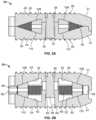
- FIGS. 2 A-Bare cross-sectional views of the implant of FIGS. 1 A- 1 B .
- FIGS. 3 A-Bare exposed views of the top and bottom plates, respectively, of the implant of FIGS. 1 A- 1 B , with the distraction mechanism shown alongside the relevant plate.
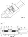
- FIGS. 4 A-Bare perspective views of an instrument used for implantation, removal, and distraction of an expandable implant.
- FIGS. 5 A-Bare perspective views of the instrument of FIGS. 4 A-B , in which the instrument is being attached to the implant.
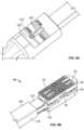
- FIGS. 6 A-Bare perspective views of the instrument of FIGS. 4 A-B , with the instrument configured for implantation of the implant.
- FIGS. 7 A-Bdepict the instrument of FIGS. 4 A-B , in which the instrument is configured for distraction of the implant.
- FIGS. 8 A-Bare perspective views of the instrument of FIGS. 4 A-B , with the instrument configured to be removed from the implant.
- FIG. 9is an exploded view of another embodiment of an expandable implant according to the present invention.
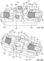
- FIGS. 10 A-Bare perspective views of the implant of FIG. 9 in collapsed and expanded orientations, respectively.
- FIGS. 11 A-Bare cross-sectional views of the implant of FIGS. 10 A-B .
- FIGS. 12 A-Bare exposed views of the bottom and top plates, respectively, of the implant of FIG. 9 .
- FIG. 13 Ais a perspective view of an alternate expandable implant according to one embodiment of the present invention, while FIG. 13 B is an exploded view of the distraction mechanism used with that implant.
- FIG. 14is a cross-sectional view of the implant of FIG. 13 A .
- FIG. 15is an exposed view of one of the plates of the implant of FIG. 13 A , the other plate being a mirror image thereof.
- an expandable implant 10which in some cases may be used as an intervertebral implant, the expandable implant 10 having, generally: (1) top and bottom plates 20 , 50 situated in opposition to one another; (2) a rod or axle 80 arranged between the top and bottom plates 20 , 50 ; and (3) expansion members 100 , 102 for contacting angled surfaces 22 , 52 on top and bottom plates 20 , 50 , respectively, and for expanding the implant 10 (e.g., in situ).
- implant 10may be inserted between adjacent vertebral bodies and expanded through use of an instrument, such as instrument 120 shown in FIGS. 4 A-B , for example.
- This systemprovides a surgeon, nurse, or other skilled practitioner (hereinafter “the user”) with an improved expandable implant 10 for use in interventional procedures designed to combat various degenerative disorders, for example.
- top and bottom plates 20 , 50may include outer bone-contacting surfaces 24 , 54 and inner surfaces 26 , 56 opposed to the outer surfaces 24 , 54 .
- outer bone-contacting surfaces 24 , 54may include teeth, notches, serrations, keels, or other bone-penetrating features 28 , 58 for engaging bone during use.
- An end of top and bottom plates 20 , 50may also be tapered 31 , 61 for facilitating implantation of implant 10 , in one embodiment.
- Top plate 20may also include, as shown in FIG. 1 A , multiple elongate apertures 30 for facilitating bone in-growth or for receiving other biocompatible materials, for example.
- top plate 20may include four elongate apertures 30
- bottom plate 50may only include two, as reflected in FIGS. 3 A-B , respectively.
- a separate set of apertures 34 , 64may also be formed in plates 20 , 50 for receiving a post(s) 36 and nut(s) 38 construct, as shown in FIGS. 2 A-B .
- apertures 34 in top plate 20may be generally thin in comparison to the elongate nature of apertures 64 in bottom plate 50 , thereby guiding and facilitating movement of posts 36 in apertures 64 .
- Each of plates 20 , 50may also include a projection 40 , 70 , which in one embodiment may be dovetail-shaped.
- Inner surfaces 26 , 56 of top and bottom plates 20 , 50may each include angled surfaces 22 , 52 on either side of a center of the plate 20 , 50 .
- bottom plate 50may include a raised center 72 having apertures 64 , and on either side of center 72 may be an angled surface(s) 52 .
- Such surfaces 52may also be angled in a direction extending from respective ends of plate 50 to raised center 72 .
- top plate 20may include a recessed center 42 having apertures 34 , and on either side of recessed center 42 may be an angled surface(s) 22 .
- Such surfaces 22may be angled in a direction extending from respective ends of plate 20 to recessed center 42 .
- angled surfaces 22 , 52 of plates 20 , 50may converge towards one another, in one embodiment, as shown in FIGS. 3 A-B .
- Angled surfaces 22 , 52 of plates 20 , 50may also be bounded by adjacent side walls 44 , 74 for guiding expansion members 100 , 102 , as described in detail below. Further: (1) raised center portion 72 may include a cutout 78 for accommodating an hourglass-shaped structure 82 ; (2) one end of each plate 20 , 50 may include a semi-cylindrical cutout 29 , 59 for accommodating part of axle 80 ; and (3) dovetail-shaped projections 40 , 70 may each include a semi-cylindrical opening 25 , 55 for receiving another portion of axle 80 . Inner surfaces 26 , 56 of plates 20 , 50 may also include a channel 27 , 57 for housing axle 80 .
- axle 80may be situated between plates 20 , 50 , and may include an hourglass-shaped member 82 .
- First and second threaded sections 84 , 86may also be arranged on opposite sides of hourglass-shaped member 82 , such sections 84 , 86 having opposed right and left-handed threading.
- threaded section 84may be situated on one side of hourglass-shaped member 82 and include left-hand threads
- threaded section 86may be positioned on an opposing side of hourglass-shaped member 82 and include right-hand threads.
- Expansion members 100 , 102may also be situated on axle 80 , such members 100 , 102 each including an internally-threaded bore (not shown) for receiving one of threaded sections 84 , 86 .
- expansion members 100 , 102may include top and bottom surfaces 108 , 110 angled in opposition to angled surfaces 22 , 52 and in opposition to one another. Stated differently, top surfaces 108 of expansion members 100 , 102 may be angled to seat flush with angled surfaces 22 of top plate 20 , while bottom surfaces 110 of expansion members 100 , 102 may be angled to seat flush with angled surfaces 52 of bottom plate 50 , as shown in detail in FIGS. 2 A-B . As such, top and bottom surfaces 108 , 110 of expansion members 100 , 102 may form a wedge.
- Engagement and/or stop nuts 90 , 94may either be separate components threaded onto axle 80 , or, in some embodiments, may be unitarily formed with axle 80 .
- Engagement nut 90includes ridges or serrations 96 on an exterior surface thereof for attaching with a portion of instrument 120 , and stop nut 94 comprises a smooth and enlarged exterior surface for interacting with a portion of expansion members 100 , 102 .
- ridges 96 on engagement nut 90may form a Torx structure.
- top and bottom plates 20 , 50may first be situated in opposition to one another with inner surfaces 26 , 56 facing towards each other.
- Axle 80previously assembled to include expansion members 100 , 102 , and engagement 90 and stop 94 nuts, may also be situated between plates 20 , 50 and within channels 27 , 57 .
- top surfaces 108 of expansion members 100 , 102may engage with angled surfaces 22 of top plate 20
- bottom surfaces 110 of expansion members 100 , 102may engage with angled surfaces 52 of bottom plate 50 , as shown in FIGS. 2 A-B .
- engagement nut 90may be surrounded by semi-cylindrical openings 25 , 55 of dovetail-shaped projections 40 , 70 , and stop nut 94 by semi-cylindrical openings 29 , 59 .
- An end of posts 36which in some cases includes an enlarged head 32 , may also be accommodated within apertures 64 in bottom plate 50 , and a stop surface 65 within each aperture 64 may prevent passage of head 32 completely through the aperture 64 ( FIG. 2 B ).
- An opposing end of posts 36which in some instances includes threading, may also be situated within apertures 34 in top plate 20 and be engaged with nuts 38 housed in apertures 34 .
- plates 20 , 50may be connected together via posts 36 , which may allow expansion of implant 10 through movement of heads 32 within apertures 64 in bottom plate 50 , as shown in detail in the progression between FIGS. 2 A-B .
- raised center section 72 of bottom plate 50may be accommodated within recessed center section 42 of top plate 20 , and a perimeter of inner surfaces 26 , 56 may be in contact with one another.
- hourglass-shaped member 82 of axle 80may be situated within the cutout 78 in bottom plate 50 .
- protrusions 77 extending into cutout 78may engage a portion of hourglass-shaped member 82 to stabilize axle 80 along a longitudinal axis of plates 20 , 50 ( FIG. 3 B ).
- rotation of axle 80 in one directionmay cause corresponding outward movement of expansion members 100 , 102 (e.g., towards the ends of axle 80 ), and rotation in another opposite direction may cause inward movement of expansion members 100 , 102 (e.g., towards hourglass-shaped member 82 ).
- Such movement of expansion members 100 , 102may also interact with angled surface 22 , 52 on plates 20 , 50 to cause corresponding expansion or collapse of implant 10 (e.g., within an intervertebral disc space), as shown in FIGS. 2 A-B .
- expansion members 100 , 102may cause such members 100 , 102 to ride up angled surfaces 22 , 52 on plates 20 , 50 and thereby cause expansion of implant 10 .
- top and bottom surfaces 108 , 110 of expansion members 100 , 102being angled in the manner discussed above, the movement of plates 20 , 50 may be generally uniform. In other words, were respective planes drawn along outer bone-contacting surfaces 24 , 54 of plates 20 , 50 , upon expansion of implant 10 , such planes would remain in generally the same orientation with respect to one another (i.e., due to top and bottom surfaces 108 , 110 of expansion members 100 , 102 being set flush against angled surfaces 22 , 52 ).
- the aforementioned planesmay be arranged at lordotic angles to one another. This may appropriately accommodate lordosis of adjacent vertebral bodies, if present. Such lordotic angles may also be maintained upon expansion of implant 10 .
- axle 80may rotate within channels 27 , 57 , and particularly: (1) hourglass-shaped member 82 may rotate within cutout 78 ; (2) engagement nut 90 within semi-circular openings 25 , 55 ; and (3) stop nut 94 within semi-circular openings 29 , 59 .
- expansion members 100 , 102may move towards or away from one another (i.e., in opposing directions). Such movement of expansion members 100 , 102 may also be limited by engagement 90 and stop 94 nuts, and hourglass-shaped member 82 .
- expansion members 100 , 102may be stabilized via side walls 44 , 74 of inner surfaces 26 , 76 , and posts 36 may limit and/or prevent over-expansion of implant 10 .
- the head 32 of posts 36may slide within elongate apertures 64 in plate 50 until such a point as head 32 contacts stop surface 65 , as shown in FIG. 2 B .
- posts 36may act to prevent over distraction of implant 10 .
- posts 36may also operate to stabilize implant 10 upon expansion, since sections of posts 36 are engaged with both top and bottom plates 20 , 50 during expansion. In other words, posts 36 may serve to provide torsional and/or compressive stability to plates 20 , 50 in one embodiment.
- implant 10may be inserted into the intervertebral disc space of a patient, with outer bone-contacting surfaces 24 , 54 engaging adjacent vertebrae, and such implant 10 may be expanded in the manner described above. Further details pertaining to this method of expansion, and the insertion of the implant 10 within an intervertebral space, are set forth in subsequent sections.
- Instrument 120engageable with the aforementioned implant 10 , and usable to place implant 10 at the treatment site (e.g., within the intervertebral disc space).
- Instrument 120may generally include: (1) a shaft 122 with a sleeve 128 overlying the shaft 122 ; (2) distal 124 and proximal 126 ends; (3) a socket 130 for engaging with engagement nut 90 ; and (4) a rotatable handle 132 connected to socket 130 , such that rotation of handle 132 may cause rotation of socket 130 and expansion of implant 10 (e.g., when instrument 120 is engaged with engagement nut 90 ).
- Distal end 124 of instrument 120may also include fingers 134 , 136 that are engageable with dovetail-shaped projections 40 , 70 , and may be actuated via a knob 138 situated adjacent proximal end 126 of instrument 120 .
- instrument 120may provide a useful tool for a user in the insertion and/or expansion of implant 10 , as detailed more fully below.
- handle 132 of instrument 120may be connected to a rod (not shown) extending generally within and along shaft 122 of instrument 120 .
- the rodmay extend to distal end 124 of instrument 120 and may terminate in socket 130 , which in one embodiment may be configured to engage with engagement nut 90 .
- socket 130may be a Torx-type socket for engaging with an engagement nut 90 having Torx structure.
- a separate handle 142may also be provided adjacent proximal end 126 , such handle 142 extending generally outward from instrument 120 .
- Instrument 120may also include a grip 144 . Handle 142 and grip 144 may allow the user to effectively grasp instrument 120 during insertion of implant 10 into the intervertebral disc space.
- FIG. 4 Afurther depicts a knob 138 adjacent proximal end 126 that is rotatable about a longitudinal axis of shaft 122 .
- An interior of knob 138may include internal threading for cooperating with an actuator (not shown) connected to sleeve 128 .
- the threading within knob 138may be configured such that, upon rotation of knob 138 in one direction, the actuator and sleeve 128 may move longitudinally towards distal end 124 ; and, upon rotation of knob 138 in an opposing direction, the actuator and sleeve 128 may move longitudinally towards proximal end 126 .
- a viewing window 148may also be provided with instrument 120 , as shown in close-up in FIG. 4 B , for indicating to a user of instrument 120 the particular mode in which instrument 120 is situated (e.g., “implant” mode, “distract” mode, or “remove” mode).
- An indicator 150may be housed within viewing window 148 , and a series of markings 152 may also be situated adjacent the window 148 . Further, in one embodiment, wording or other information may be provided proximate viewing window 148 and markings 152 to inform a user of the mode in which instrument 120 is placed.
- distal end 124 of shaft 122 of instrument 120may be provided with resilient fingers 134 , 136 running along opposing sides of shaft 122 , and positioned within channels (not shown) in shaft 122 .
- Each finger 134 , 136may include an end having generally angled surfaces 154 for engaging with projections 40 , 70 on implant 10 .
- fingers 134 , 136may be shaped to conform to the dovetail shape of projections 40 , 70 .
- distal end 124 of instrument 120may be positioned adjacent dovetail-shaped projections 40 , 70 of implant 10 so that socket 130 of instrument 120 may be attached to engagement nut 90 .
- resilient fingers 134 , 136may be inserted over projections 40 , 70 with sleeve 128 in its retracted position.
- Such position of sleeve 128may, in one embodiment, correspond to the “remove” mode shown in FIG. 8 A .
- fingers 134 , 136may translate outwards to accommodate the shape of projections 40 , 70 .
- angled surfaces 154may seat within or accommodate the shape of projections 40 , 70 .
- fingers 134 , 136may be biased to remain within the channels in shaft 122 , after insertion of fingers 134 , 136 over projections 40 , 70 , fingers 134 , 136 may return to their normal un-translated state and conform to the shape of projections 40 , 70 . Such is shown in detail in FIG. 5 B .
- sleeve 128 of instrument 120may then be translated longitudinally via knob 138 until such a point as sleeve 128 contacts implant 10 , as shown in FIGS. 6 A-B .
- This position of sleeve 128may correspond to the “implant” mode of instrument 120 , which may be indicated by the movement of indicator 150 within viewing window 148 .
- movement of sleeve 128may cause movement of indicator 150 within window 148 , such that indicator 150 becomes aligned with a marking 152 corresponding to the “implant” mode of instrument 120 , as shown in FIG. 6 A .
- Implant 10may then be inserted into the intervertebral disc space via instrument 120 , such that outer bone-contacting surfaces 24 , 54 engage upper and lower vertebral bodies.
- the approach for implantation of implant 10in some cases, may be a posterior or posterior-lateral approach, although other approaches are contemplated.
- the vertebral bodiesmay also be prepared (e.g., through the use of cutting instruments) according to traditional spinal procedures prior to implantation of implant 10 .
- tapered ends 31 , 61 of plates 20 , 50may provide easier insertion of implant 10 into the intervertebral space via insertion instrument 120 .
- the lordotic angle between plates 20 , 50may, in one embodiment, accommodate lordosis of the adjacent vertebrae, if present.
- instrument 120may be placed in “distract” mode. Referring to FIGS. 7 A-B , this involves rotating knob 138 in one direction to move the actuator and sleeve 128 toward proximal end 126 of instrument 120 . As sleeve 128 moves toward proximal end 126 , indicator 150 may also move within viewing window 148 so as to line up with the particular marking 152 corresponding to “distract” mode. Thus, a user may be informed when instrument 120 is placed in “distract” mode via rotation of knob 138 .
- sleeve 128may be retracted towards proximal end 126 , such that fingers 134 , 136 may still retain projections 40 , 70 and implant 10 , but that pressure therebetween is somewhat relieved so as to allow distraction of implant 10 .
- the usermay simply rotate handle 132 ( FIG. 4 A ) causing socket 130 to rotate within engagement nut 90 .
- This rotation of engagement nut 90may cause expansion members 100 , 102 to interact with ramped surfaces 22 , 52 of plates 20 , 50 and force plates 20 , 50 apart. Distraction of plates 20 , 50 in this manner may also cause distraction of adjacent vertebral bodies. It is thusly possible for implant 10 to accommodate varying degrees of intervertebral spacing, as required during different surgeries or with different patients. Implant 10 , in its expanded state as discussed above, is shown in detail in FIG. 7 B .
- instrument 120may be placed in “remove” mode, which again may be indicated by movement of indicator 150 within viewing window 148 .
- knob 138may be rotated in one direction causing movement of sleeve 128 towards proximal end 126 of instrument 120 and corresponding movement of indicator 150 .
- fingers 134 , 136may be fully released and allowed to resiliently deform outwards as instrument 120 is removed from about projections 40 , 70 .
- Instrument 120may then be removed from the surgical site and implant 10 left to affect fusion of the adjacent vertebral bodies.
- bone-chips, synthetic graft material, or other biocompatible materialmay be inserted within the intervertebral disc space prior to or during the implantation of implant 10 , and such material may adhere to the apertures in plates 20 , 50 (e.g., apertures 30 ) provided for in-growth.
- FIG. 9An alternate embodiment implant 210 is shown in FIG. 9 . Due to the similarity between the structures of implants 10 , 210 , like numerals will refer to like elements and, predominantly, only the structural differences between implants 10 , 210 will be highlighted. Thus, apart from the below-mentioned distinguishing features, it is contemplated that implants 10 , 210 may have the same structure and may operate in the same manner (e.g., as set forth above) to accomplish the same purpose.
- implant 210may include top and bottom plates 220 , 250 , such plates including, inter alia: (1) outer bone-contacting surfaces 224 , 254 and opposed inner surfaces 226 , 256 ; (2) projections 240 , 270 , which in one embodiment may be dovetail-shaped; (3) apertures 234 , 264 for receiving posts 236 and nuts 238 ; (4) recessed and raised center portions 242 , 272 ; and (5) angled surfaces 222 , 252 for engaging with expansion members 300 , 302 .
- Other similar features to implant 10are also present in implant 210 ; and, although not discussed in detail herein, such features are indicated by like reference numerals in the figures.
- implant 210may include an axle 280 disposed between top and bottom plates 220 , 250 , with axle 280 including a center member 282 that is slightly different in shape than hourglass-shaped member 80 of implant 10 . Even so, center member 282 of axle 280 may include opposed discs 400 for engaging with cutouts 402 formed in bottom plate 250 , and a center portion having a reduced diameter for seating within cutout 278 , as shown in detail in FIG. 12 A . With center member 282 situated in bottom plate 250 as described, axle 280 may be longitudinally stabilized with respect to plate 250 (e.g., through the interaction of opposed discs 400 and cutouts 402 ), as is the case with axle 80 of implant 10 .
- Implant 210may also include expansion members 300 , 302 having top and bottom surfaces 308 , 310 that are angled in the manner described with reference to expansion members 100 , 102 , as shown in FIGS. 11 A-B , but expansion members 300 , 302 may also have vertically-extensive projections 312 , 314 extending outward therefrom. Expansion members 300 , 302 may also include a set (or one or more) of pins 316 extending from the sides of members 300 , 302 .
- Vertically-extensive projections 312 , 314 of expansion members 300 , 302may be received in elongate apertures 230 formed in top and bottom plates 220 , 250 , such apertures 230 being configured to allow translation of vertically-extensive projections 312 , 314 during expansion of implant 210 .
- Pins 316 of expansion members 300 , 302may ride along slots 318 formed within side walls 244 , 274 situated adjacent angled surfaces 222 , 252 for guiding expansion members 300 , 302 during expansion of implant 210 , as shown in detail in FIGS. 9 and 12 A -B.
- implant 210may be implanted and/or expanded in much the same manner as implant 10 .
- insertion instrument 120may be modified only slightly to properly operate with and engage implant 210 , and to distract such implant 210 after implantation.
- engagement nut 290 of implant 210may include Torx structure, it is shown in the figures as a hexagonal nut 290 ( FIGS. 9 , 11 A -B).
- socket 130 of instrument 120may be modified to accommodate this structure, and to engage with engagement nut 290 in the manner described in relation to implant 10 .
- such modified socket 130may be inserted over engagement nut 290 , and rotated via handle 132 so as to expand implant 210 .
- instrument 120may be placed into the various modes (e.g., “implant” mode, “distract” mode, and/or “remove” mode) upon engaging, distracting, and/or separating from implant 210 , as discussed previously.
- implante.g., “implant” mode, “distract” mode, and/or “remove” mode
- instrument 120may be placed into the various modes (e.g., “implant” mode, “distract” mode, and/or “remove” mode) upon engaging, distracting, and/or separating from implant 210 , as discussed previously.
- implant 210may operate differently to provide a more stabilized and improved distraction procedure.
- expansion members 300 , 302may engage with angled surfaces 222 , 252 ; but, during separation of expansion members 300 , 302 via the reverse threading of threaded sections 284 , 286 , pins 316 extending from expansion members 300 , 302 may ride along slots 318 formed in respective side walls 244 , 274 of top and bottom plates 220 , 250 .
- the engagement between pins 316 and slots 318may act to stabilize the movement of expansion members 300 , 302 , and may also serve to limit the expansion of implant 210 .
- slots 318may terminate at one section of side walls 244 , 274 , and pins 316 may abut this section upon full expansion of implant 210 to prohibit further movement of expansion members 300 , 302 (e.g., away from one another).
- pins 316may be situated on diagonally opposite sides of each respective expansion member 300 , 302 , although it is contemplated that additional pins 316 may be used (e.g., on all four (4) corners of expansion members 300 , 302 ).
- the engagement between pins 516 and slots 518may also, at least partially, serve to keep plates 220 , 250 in registration with one another during distraction.
- An additional stabilization and/or expansion-limiting featuremay be included with implant 210 in the form of elongate apertures 230 .
- vertically-extensive projections 312 , 314 of expansion members 300 , 302may interact with elongate apertures 230 in top and bottom plates 220 , 250 to stabilize such members 300 , 302 and plates 220 , 250 .
- FIGS. 10 A- 11 BAs shown in the progression between FIGS.
- vertically-extensive projections 312 , 314may be arranged within elongate apertures 230 of plates 220 , 250 ; and, upon expansion of implant 210 , vertically-extensive projections 312 , 314 may translate within apertures 230 , such that plates 220 , 250 and expansion members 300 , 302 are stabilized during distraction. Upon reaching an end of apertures 230 , expansion members 300 , 302 may also be limited from further outward movement. Apertures 230 may also, like apertures 30 of implant 10 , operate to receive bone graft or other osteoinductive material to facilitate fusion of adjacent vertebral bodies upon implantation of implant 210 . Although not discussed in detail herein, the remainder of steps pertaining to the implantation and/or expansion of implant 210 , and its interaction with instrument 120 , is again substantially identical to that discussed above with respect to implant 10 .
- FIGS. 13 A- 15Another embodiment of an expandable implant, implant 410 , is shown in FIGS. 13 A- 15 .
- like numeralswill refer to like elements, with the structural differences between implants 10 , 210 , 410 being discussed.
- implants 10 , 210 , 410may have the same structure and operate in the same manner to accomplish the same purpose.
- FIG. 15only depicts top plate 420
- bottom plate 450is a mirror image thereof, and thus, FIG. 15 is an accurate representation of both plates 420 , 450 (e.g., with like reference numerals referring to like elements).
- implant 410may include top and bottom plates 420 , 450 with angled inner surfaces 422 , 452 for engaging with expansion members 500 , 502 , much like implants 10 , 210 . Further, expansion members 500 , 502 of implant 410 may also include vertically-extensive projections 512 , 514 for engaging with elongate apertures 430 in plates 420 , 450 , such that upon expansion of implant 410 , vertically-extensive projections 512 , 514 may translate within apertures 430 .
- implant 410Other similar features to implants 10 , 210 are also included with implant 410 , such as: (1) outer bone-contacting surfaces 424 , 454 with teeth or serrations 428 , 458 ; (2) tapered ends 431 , 461 of plates 420 , 450 ; (3) dovetail-shaped projections 440 , 470 ; (4) slots 518 in side walls 444 , 474 of plates 420 , 450 ; and (5) expansion members 500 , 502 including pins 516 for engaging with slots 518 . Yet, other features, such as the distraction mechanism of implant 410 , may operate differently than found with implants 10 , 210 .
- the distraction mechanism of implant 410may include a rod or axle 480 , a capture mechanism 530 , and a containment ring 532 .
- Axle 480like axles 80 , 280 , may be threaded in one embodiment, and may include separate sections 484 , 486 with left-handed and right-handed threads.
- An engagement nut 490 structuremay also be disposed on one end of axle 480 , and a center of axle may include a radially-extending flange 534 and a press-fit region 536 .
- Capture mechanism 530may include a set of apertures 538 , 540 for receiving a portion of axle 480 , and a slot 542 for receiving containment ring 532 .
- Slot 542may be dimensioned to allow free movement of containment ring 532 and axle 480 once situated therein.
- aperture 538 of capture mechanism 530may have a diameter that is larger than aperture 540 so as to allow flange 534 to be received in aperture 538 .
- each aperture 538 , 540may be smaller in diameter than an outer diameter of containment ring 532 .
- containment ring 532includes an inner diameter such that, upon insertion of press-fit region 536 into containment ring 532 , a dimensional interference is established therebetween.
- implant 410may also include plates 420 , 450 with apertures 550 for receiving a portion of capture mechanism 530 , as shown in FIG. 14 .
- Inner surfaces 426 , 456 of plates 420 , 450may also include structure (e.g. a housing 560 ) for stabilizing capture mechanism 530 (and thus axle 480 ) in a longitudinal direction, as shown in FIG. 15 .
- plates 420 , 450also include openings 520 through which pins 516 may be inserted.
- expansion members 500 , 502may include openings 522 for receiving pins 516 .
- the distraction mechanism of implant 410may be situated between plates 420 , 450 such that axle 480 is inserted into capture mechanism 530 and through containment ring 532 , as shown in FIG. 14 .
- containment ring 532may be disposed within slot 542 in capture mechanism 530 , and axle 480 may be inserted through apertures 538 , 540 .
- axle 480may be inserted through containment ring 532 until such a point as press-fit region 536 is situated within containment ring 532 and flange 534 is housed within aperture 538 and abuts containment ring 532 .
- press-fit region 536may interact with containment ring 532 to establish a dimensional interference between such structures, such that axle 480 may be securely retained within capture mechanism 530 .
- the interaction between flange 534 and containment ring 532may prevent movement of axle 480 in one direction
- the cooperation between press-fit region 536 , containment ring 532 , and slot 542may prevent movement of axle 480 in another opposing direction.
- capture mechanism 530With axle situated in capture mechanism 530 in the manner described above, capture mechanism 530 may then be inserted into apertures 550 in plates 420 , 450 .
- Capture mechanism 530 , axle 480 , and expansion members 500 , 502may be situated between plates 420 , 450 , with the inner surfaces 426 , 456 of plates 420 , 450 facing one another, as discussed above, and pins 516 may be inserted through openings 520 in plates 420 , 450 and into openings 522 in expansion members 500 , 502 .
- pins 516may be press-fit into openings 522 in expansion members 500 , 502 , such that pins 516 are firmly retained in expansion members 500 , 502 .
- Pins 516are also designed to ride within slots 518 to limit movement of expansion members 500 , 502 , and such pins 516 may also serve to keep plates 420 , 450 firmly connected together.
- each expansion member 500 , 502engages with a slot 518 in top plate 420
- at least one pin 516 with a slot 518 in bottom plate 450such plates 420 , 450 may be securely retained together via the interaction between pins 516 and slots 518 .
- a terminal portion of slots 518may also serve to prevent over-expansion of implant 410 , as discussed above with respect to implant 210 .
- Implant 410may also interact with instrument 120 in the same manner as implants 10 , 210 (e.g., for purposes of implantation and/or distraction). For instance, rotation of handle 132 with respect to engagement nut 490 in one direction may cause expansion members 500 , 502 to move outwardly, and pins 516 to engage with slots 518 . Such movement of expansion members 500 , 502 may also cause outward movement or distraction of plates 420 , 450 , as with implants 10 , 210 ; and additional rotation of handle 132 may cause pins 516 of expansion members 500 , 502 to engage with a terminal portion of slots 518 to prevent further outward movement of expansion members 500 , 502 .
- vertically-extensive projections 512 , 514may translate within apertures 430 in plates 420 , 450 , and apertures 550 in plates 420 , 450 may interact with capture mechanism 530 .
- apertures 550 in plates 420 , 450may slide along portions of capture mechanism 530
- vertically-extensive projections 512 , 514may translate within apertures 430
- pins 516may ride within slots 518 .
- expansion members 500 , 502may therefore serve to stabilize implant 410 during distraction.
- the interaction between vertically-extensive projections 512 , 514 and apertures 430 , and apertures 550 and capture mechanism 530may provide torsional and/or compressive stability to implant 410 during distraction, and pins 516 may act as distraction-limiting features.
- implant 410may provide an expandable implant with improved features for maintaining stability and/or controlling distraction during replacement of an intervertebral disc.
- angled surfaces 22 , 52 , 222 , 252 , 422 , 452are shown in the figures as being predominantly flat, it is also contemplated that surfaces 22 , 52 , 222 , 252 , 422 , 452 may be curved in one embodiment so as to facilitate expansion of implants 10 , 210 , 410 .
- Top and bottom surfaces 108 , 110 , 308 , 310 , 508 , 510 of expansion members 100 , 102 , 300 , 302 , 500 , 502may likewise be shaped to accommodate the curvature of angled surfaces 22 , 52 , 222 , 252 , 422 , 452 , as previously discussed with respect to implants 10 , 210 , 410 .
Landscapes
- Health & Medical Sciences (AREA)
- Engineering & Computer Science (AREA)
- Biomedical Technology (AREA)
- Orthopedic Medicine & Surgery (AREA)
- Neurology (AREA)
- Transplantation (AREA)
- Heart & Thoracic Surgery (AREA)
- Oral & Maxillofacial Surgery (AREA)
- Cardiology (AREA)
- Vascular Medicine (AREA)
- Life Sciences & Earth Sciences (AREA)
- Animal Behavior & Ethology (AREA)
- General Health & Medical Sciences (AREA)
- Public Health (AREA)
- Veterinary Medicine (AREA)
- Physical Education & Sports Medicine (AREA)
- Prostheses (AREA)
Abstract
Description
Claims (20)
Priority Applications (1)
| Application Number | Priority Date | Filing Date | Title |
|---|---|---|---|
| US17/132,422US11648131B2 (en) | 2011-08-16 | 2020-12-23 | Expandable implant |
Applications Claiming Priority (5)
| Application Number | Priority Date | Filing Date | Title |
|---|---|---|---|
| US201161523981P | 2011-08-16 | 2011-08-16 | |
| US13/587,205US9320610B2 (en) | 2011-08-16 | 2012-08-16 | Expandable implant |
| US15/091,058US9962270B2 (en) | 2011-08-16 | 2016-04-05 | Expandable implant |
| US15/959,716US10898344B2 (en) | 2011-08-16 | 2018-04-23 | Expandable implant |
| US17/132,422US11648131B2 (en) | 2011-08-16 | 2020-12-23 | Expandable implant |
Related Parent Applications (1)
| Application Number | Title | Priority Date | Filing Date |
|---|---|---|---|
| US15/959,716ContinuationUS10898344B2 (en) | 2011-08-16 | 2018-04-23 | Expandable implant |
Publications (2)
| Publication Number | Publication Date |
|---|---|
| US20210106434A1 US20210106434A1 (en) | 2021-04-15 |
| US11648131B2true US11648131B2 (en) | 2023-05-16 |
Family
ID=47715475
Family Applications (4)
| Application Number | Title | Priority Date | Filing Date |
|---|---|---|---|
| US13/587,205ActiveUS9320610B2 (en) | 2011-08-16 | 2012-08-16 | Expandable implant |
| US15/091,058ActiveUS9962270B2 (en) | 2011-08-16 | 2016-04-05 | Expandable implant |
| US15/959,716Active2033-04-29US10898344B2 (en) | 2011-08-16 | 2018-04-23 | Expandable implant |
| US17/132,422Active2033-05-11US11648131B2 (en) | 2011-08-16 | 2020-12-23 | Expandable implant |
Family Applications Before (3)
| Application Number | Title | Priority Date | Filing Date |
|---|---|---|---|
| US13/587,205ActiveUS9320610B2 (en) | 2011-08-16 | 2012-08-16 | Expandable implant |
| US15/091,058ActiveUS9962270B2 (en) | 2011-08-16 | 2016-04-05 | Expandable implant |
| US15/959,716Active2033-04-29US10898344B2 (en) | 2011-08-16 | 2018-04-23 | Expandable implant |
Country Status (6)
| Country | Link |
|---|---|
| US (4) | US9320610B2 (en) |
| EP (2) | EP2729092B1 (en) |
| JP (1) | JP6047571B2 (en) |
| AU (1) | AU2012296522B2 (en) |
| CA (1) | CA2843745C (en) |
| WO (1) | WO2013025876A1 (en) |
Families Citing this family (249)
| Publication number | Priority date | Publication date | Assignee | Title |
|---|---|---|---|---|
| US6793678B2 (en) | 2002-06-27 | 2004-09-21 | Depuy Acromed, Inc. | Prosthetic intervertebral motion disc having dampening |
| AU2004212942A1 (en) | 2003-02-14 | 2004-09-02 | Depuy Spine, Inc. | In-situ formed intervertebral fusion device |
| US20040267367A1 (en) | 2003-06-30 | 2004-12-30 | Depuy Acromed, Inc | Intervertebral implant with conformable endplate |
| US8636802B2 (en) | 2004-03-06 | 2014-01-28 | DePuy Synthes Products, LLC | Dynamized interspinal implant |
| US8597360B2 (en) | 2004-11-03 | 2013-12-03 | Neuropro Technologies, Inc. | Bone fusion device |
| WO2006058221A2 (en) | 2004-11-24 | 2006-06-01 | Abdou Samy M | Devices and methods for inter-vertebral orthopedic device placement |
| US9801733B2 (en)* | 2005-03-31 | 2017-10-31 | Life Spine, Inc. | Expandable spinal interbody and intravertebral body devices |
| US9848993B2 (en) | 2005-04-12 | 2017-12-26 | Nathan C. Moskowitz | Zero-profile expandable intervertebral spacer devices for distraction and spinal fusion and a universal tool for their placement and expansion |
| US7942903B2 (en) | 2005-04-12 | 2011-05-17 | Moskowitz Ahmnon D | Bi-directional fixating transvertebral body screws and posterior cervical and lumbar interarticulating joint calibrated stapling devices for spinal fusion |
| US11903849B2 (en) | 2005-04-12 | 2024-02-20 | Moskowitz Family Llc | Intervertebral implant and tool assembly |
| WO2008070863A2 (en) | 2006-12-07 | 2008-06-12 | Interventional Spine, Inc. | Intervertebral implant |
| US8900307B2 (en) | 2007-06-26 | 2014-12-02 | DePuy Synthes Products, LLC | Highly lordosed fusion cage |
| EP2237748B1 (en) | 2008-01-17 | 2012-09-05 | Synthes GmbH | An expandable intervertebral implant |
| US8936641B2 (en) | 2008-04-05 | 2015-01-20 | DePuy Synthes Products, LLC | Expandable intervertebral implant |
| US9220547B2 (en) | 2009-03-27 | 2015-12-29 | Spinal Elements, Inc. | Flanged interbody fusion device |
| US9526620B2 (en) | 2009-03-30 | 2016-12-27 | DePuy Synthes Products, Inc. | Zero profile spinal fusion cage |
| WO2010135440A1 (en)* | 2009-05-22 | 2010-11-25 | Medtronic, Inc. | A cover having self-anchoring protrusions for use with an implantable medical device |
| KR101687435B1 (en) | 2009-07-06 | 2016-12-19 | 신세스 게엠바하 | Expandable fixation assemblies |
| US10973656B2 (en) | 2009-09-18 | 2021-04-13 | Spinal Surgical Strategies, Inc. | Bone graft delivery system and method for using same |
| US8906028B2 (en) | 2009-09-18 | 2014-12-09 | Spinal Surgical Strategies, Llc | Bone graft delivery device and method of using the same |
| US10245159B1 (en) | 2009-09-18 | 2019-04-02 | Spinal Surgical Strategies, Llc | Bone graft delivery system and method for using same |
| US11344430B2 (en) | 2009-10-15 | 2022-05-31 | Globus Medical, Inc. | Expandable fusion device and method of installation thereof |
| US11103366B2 (en) | 2009-10-15 | 2021-08-31 | Globus Medical, Inc. | Expandable fusion device and method of installation thereof |
| US8685098B2 (en) | 2010-06-25 | 2014-04-01 | Globus Medical, Inc. | Expandable fusion device and method of installation thereof |
| US10098758B2 (en) | 2009-10-15 | 2018-10-16 | Globus Medical, Inc. | Expandable fusion device and method of installation thereof |
| US20140163682A1 (en)* | 2012-12-11 | 2014-06-12 | Expandable Vertebral Implant | Expandable Vertebral Implant |
| US8764806B2 (en) | 2009-12-07 | 2014-07-01 | Samy Abdou | Devices and methods for minimally invasive spinal stabilization and instrumentation |
| US9393129B2 (en) | 2009-12-10 | 2016-07-19 | DePuy Synthes Products, Inc. | Bellows-like expandable interbody fusion cage |
| US8870880B2 (en) | 2010-04-12 | 2014-10-28 | Globus Medical, Inc. | Angling inserter tool for expandable vertebral implant |
| US8979860B2 (en) | 2010-06-24 | 2015-03-17 | DePuy Synthes Products. LLC | Enhanced cage insertion device |
| US9907560B2 (en) | 2010-06-24 | 2018-03-06 | DePuy Synthes Products, Inc. | Flexible vertebral body shavers |
| US9597200B2 (en) | 2010-06-25 | 2017-03-21 | Globus Medical, Inc | Expandable fusion device and method of installation thereof |
| US8623091B2 (en) | 2010-06-29 | 2014-01-07 | DePuy Synthes Products, LLC | Distractible intervertebral implant |
| US10945858B2 (en) | 2010-09-03 | 2021-03-16 | Globus Medical, Inc. | Expandable interspinous process fixation device |
| US9351848B2 (en) | 2010-09-03 | 2016-05-31 | Globus Medical, Inc. | Expandable fusion device and method of installation thereof |
| US12370057B2 (en) | 2010-09-03 | 2025-07-29 | Globus Medical, Inc. | Expandable fusion device and method of installation thereof |
| US12059358B2 (en) | 2010-09-03 | 2024-08-13 | Globus Medical Inc. | Expandable fusion device and method of installation thereof |
| US9566168B2 (en) | 2010-09-03 | 2017-02-14 | Globus Medical, Inc. | Expandable fusion device and method of installation thereof |
| US8632595B2 (en) | 2010-09-03 | 2014-01-21 | Globus Medical, Inc. | Expandable fusion device and method of installation thereof |
| US10842644B2 (en) | 2010-09-03 | 2020-11-24 | Globus Medical, Inc. | Expandable fusion device and method of installation thereof |
| US10835387B2 (en) | 2010-09-03 | 2020-11-17 | Globus Medical Inc. | Expandable fusion device and method of installation thereof |
| US20120078372A1 (en) | 2010-09-23 | 2012-03-29 | Thomas Gamache | Novel implant inserter having a laterally-extending dovetail engagement feature |
| US9402732B2 (en) | 2010-10-11 | 2016-08-02 | DePuy Synthes Products, Inc. | Expandable interspinous process spacer implant |
| US9308099B2 (en) | 2011-02-14 | 2016-04-12 | Imds Llc | Expandable intervertebral implants and instruments |
| US9358123B2 (en)* | 2011-08-09 | 2016-06-07 | Neuropro Spinal Jaxx, Inc. | Bone fusion device, apparatus and method |
| WO2013023096A1 (en) | 2011-08-09 | 2013-02-14 | Neuropro Technologies, Inc. | Bone fusion device, system and method |
| US10420654B2 (en) | 2011-08-09 | 2019-09-24 | Neuropro Technologies, Inc. | Bone fusion device, system and method |
| EP2729092B1 (en) | 2011-08-16 | 2016-09-21 | Stryker European Holdings I, LLC | Expandable implant |
| US9248028B2 (en) | 2011-09-16 | 2016-02-02 | DePuy Synthes Products, Inc. | Removable, bone-securing cover plate for intervertebral fusion cage |
| US8845728B1 (en) | 2011-09-23 | 2014-09-30 | Samy Abdou | Spinal fixation devices and methods of use |
| US8864833B2 (en) | 2011-09-30 | 2014-10-21 | Globus Medical, Inc. | Expandable fusion device and method of installation thereof |
| US10799367B2 (en) | 2011-10-05 | 2020-10-13 | H. Lee Moffitt Cancer Center And Research Institute, Inc. | Bone fusion system |
| WO2013052807A2 (en) | 2011-10-05 | 2013-04-11 | H. Lee Moffitt Cancer Center And Research Institute, Inc. | Bone fusion system |
| US9233007B2 (en)* | 2012-02-13 | 2016-01-12 | Blue Tip Biologics, Llc | Expandable self-anchoring interbody cage for orthopedic applications |
| US20130226240A1 (en) | 2012-02-22 | 2013-08-29 | Samy Abdou | Spinous process fixation devices and methods of use |
| US9532883B2 (en) | 2012-04-13 | 2017-01-03 | Neuropro Technologies, Inc. | Bone fusion device |
| US10159583B2 (en) | 2012-04-13 | 2018-12-25 | Neuropro Technologies, Inc. | Bone fusion device |
| US9044342B2 (en) | 2012-05-30 | 2015-06-02 | Globus Medical, Inc. | Expandable interbody spacer |
| EP2877127B1 (en) | 2012-07-26 | 2019-08-21 | Synthes GmbH | Expandable implant |
| US9198767B2 (en) | 2012-08-28 | 2015-12-01 | Samy Abdou | Devices and methods for spinal stabilization and instrumentation |
| US9320617B2 (en) | 2012-10-22 | 2016-04-26 | Cogent Spine, LLC | Devices and methods for spinal stabilization and instrumentation |
| US8715351B1 (en)* | 2012-11-29 | 2014-05-06 | Spine Wave, Inc. | Expandable interbody fusion device with graft chambers |
| US10350081B2 (en) | 2012-12-11 | 2019-07-16 | Globus Medical, Inc. | Expandable vertebral implant |
| US8663332B1 (en) | 2012-12-13 | 2014-03-04 | Ouroboros Medical, Inc. | Bone graft distribution system |
| EP2742914A1 (en)* | 2012-12-14 | 2014-06-18 | FACET-LINK Inc. | Infinitely height-adjustable vertebral fusion implant |
| USD700332S1 (en)* | 2012-12-18 | 2014-02-25 | Tyber Medical Llc | Intervertebral implant |
| US9486251B2 (en)* | 2012-12-31 | 2016-11-08 | Globus Medical, Inc. | Spinous process fixation system and methods thereof |
| US9011493B2 (en) | 2012-12-31 | 2015-04-21 | Globus Medical, Inc. | Spinous process fixation system and methods thereof |
| US9782265B2 (en) | 2013-02-15 | 2017-10-10 | Globus Medical, Inc | Articulating and expandable vertebral implant |
| US9492288B2 (en) | 2013-02-20 | 2016-11-15 | Flexuspine, Inc. | Expandable fusion device for positioning between adjacent vertebral bodies |
| US10117754B2 (en) | 2013-02-25 | 2018-11-06 | Globus Medical, Inc. | Expandable intervertebral implant |
| US9717601B2 (en)* | 2013-02-28 | 2017-08-01 | DePuy Synthes Products, Inc. | Expandable intervertebral implant, system, kit and method |
| US9204972B2 (en) | 2013-03-01 | 2015-12-08 | Globus Medical, Inc. | Articulating expandable intervertebral implant |
| US9770343B2 (en)* | 2013-03-01 | 2017-09-26 | Globus Medical Inc. | Articulating expandable intervertebral implant |
| US9554918B2 (en)* | 2013-03-01 | 2017-01-31 | Globus Medical, Inc. | Articulating expandable intervertebral implant |
| US10004607B2 (en) | 2013-03-01 | 2018-06-26 | Globus Medical, Inc. | Articulating expandable intervertebral implant |
| US9522070B2 (en) | 2013-03-07 | 2016-12-20 | Interventional Spine, Inc. | Intervertebral implant |
| JP6412551B2 (en)* | 2013-03-11 | 2018-10-24 | グローバス メディカル インコーポレイティッド | Expandable fusion device and installation method thereof |
| US9456908B2 (en) | 2013-03-12 | 2016-10-04 | Coorstek Medical Llc | Fusion cage |
| US10383741B2 (en) | 2013-03-13 | 2019-08-20 | Life Spine, Inc. | Expandable spinal interbody assembly |
| US12193948B2 (en) | 2013-03-13 | 2025-01-14 | Life Spine, Inc. | Expandable implant assembly |
| US10154911B2 (en)* | 2013-03-13 | 2018-12-18 | Life Spine, Inc. | Expandable implant assembly |
| US11304818B2 (en) | 2013-03-13 | 2022-04-19 | Life Spine, Inc. | Expandable spinal interbody assembly |
| US10426632B2 (en) | 2013-03-13 | 2019-10-01 | Life Spine, Inc. | Expandable spinal interbody assembly |
| US9186258B2 (en) | 2013-03-15 | 2015-11-17 | Globus Medical, Inc. | Expandable intervertebral implant |
| CA2906531C (en)* | 2013-03-15 | 2020-10-06 | Neuropro Technologies, Inc. | Bodiless bone fusion device, apparatus and method |
| US9456906B2 (en)* | 2013-03-15 | 2016-10-04 | Globus Medical, Inc. | Expandable intervertebral implant |
| US9149367B2 (en) | 2013-03-15 | 2015-10-06 | Globus Medical Inc | Expandable intervertebral implant |
| US9572677B2 (en) | 2013-03-15 | 2017-02-21 | Globus Medical, Inc. | Expandable intervertebral implant |
| US9987143B2 (en) | 2013-03-15 | 2018-06-05 | Spectrum Spine Ip Holdings, Llc | Expandable inter-body fusion devices and methods |
| US9474622B2 (en)* | 2013-03-15 | 2016-10-25 | Globus Medical, Inc | Expandable intervertebral implant |
| US9233009B2 (en) | 2013-03-15 | 2016-01-12 | Globus Medical, Inc. | Expandable intervertebral implant |
| US9421110B2 (en)* | 2013-05-10 | 2016-08-23 | Sidewinder Medical Products Llc | Expandable spinal fusion cage |
| AU2014268740B2 (en) | 2013-05-20 | 2018-04-26 | K2M, Inc. | Adjustable implant and insertion tool |
| US9788971B1 (en) | 2013-05-22 | 2017-10-17 | Nuvasive, Inc. | Expandable fusion implant and related methods |
| US9801734B1 (en) | 2013-08-09 | 2017-10-31 | Nuvasive, Inc. | Lordotic expandable interbody implant |
| US9566167B2 (en) | 2013-08-22 | 2017-02-14 | K2M, Inc. | Expandable spinal implant |
| JP6664324B2 (en) | 2013-08-29 | 2020-03-13 | スパインイーエックス・インコーポレーテッド | Expandable and adjustable lordosis interbody fusion system |
| US11452614B2 (en) | 2013-08-29 | 2022-09-27 | Adcura, Inc. | Expandable and adjustable lordosis interbody fusion system |
| US9186259B2 (en) | 2013-09-09 | 2015-11-17 | Ouroboros Medical, Inc. | Expandable trials |
| US9364344B2 (en) | 2013-10-03 | 2016-06-14 | Amendia, Inc. | Expandable spinal implant |
| US9259249B2 (en)* | 2013-11-26 | 2016-02-16 | Globus Medical, Inc. | Spinous process fixation system and methods thereof |
| US9668876B2 (en) | 2013-12-05 | 2017-06-06 | Spinal Elements, Inc. | Expandable interbody device |
| WO2015095353A1 (en) | 2013-12-17 | 2015-06-25 | H. Lee Moffit Cancer Center And Research Institute, Inc. | Transdiscal screw |
| US9642720B2 (en) | 2013-12-19 | 2017-05-09 | Amendia, Inc. | Expandable spinal implant |
| US9662224B2 (en) | 2014-02-07 | 2017-05-30 | Globus Medical, Inc. | Variable lordosis spacer and related methods of use |
| US9839528B2 (en) | 2014-02-07 | 2017-12-12 | Globus Medical, Inc. | Variable lordosis spacer and related methods of use |
| US9788856B2 (en) | 2014-03-11 | 2017-10-17 | Stryker European Holdings I, Llc | Endoscopic surgical systems and methods |
| WO2015145343A1 (en) | 2014-03-26 | 2015-10-01 | Medacta International Sa | Device for implanting a surgical screw |
| US10322009B2 (en)* | 2014-08-01 | 2019-06-18 | H. Lee Moffitt Cancer Center And Research Institute, Inc. | Expandable intervertebral cage |
| US10034769B2 (en)* | 2014-08-26 | 2018-07-31 | Atlas Spine, Inc. | Spinal implant device |
| US9585762B2 (en) | 2014-10-09 | 2017-03-07 | K2M, Inc. | Expandable spinal interbody spacer and method of use |
| WO2016069796A1 (en) | 2014-10-28 | 2016-05-06 | Spectrum Spine Ip Holdings, Llc | Expandable, adjustable inter-body fusion devices and methods |
| US10575964B2 (en) | 2014-10-28 | 2020-03-03 | Spectrum Spine Ip Holdings, Llc | Expandable, adjustable inter-body fusion devices and methods |
| US10363142B2 (en) | 2014-12-11 | 2019-07-30 | K2M, Inc. | Expandable spinal implants |
| US9901459B2 (en) | 2014-12-16 | 2018-02-27 | Globus Medical, Inc. | Expandable fusion devices and methods of installation thereof |
| US9060876B1 (en) | 2015-01-20 | 2015-06-23 | Ouroboros Medical, Inc. | Stabilized intervertebral scaffolding systems |
| US11426290B2 (en) | 2015-03-06 | 2022-08-30 | DePuy Synthes Products, Inc. | Expandable intervertebral implant, system, kit and method |
| CH711040A1 (en)* | 2015-05-05 | 2016-11-15 | Rs-Technik Cad-Cam Gmbh | Intervertebral implant. |
| US9814602B2 (en)* | 2015-05-14 | 2017-11-14 | Globus Medical, Inc. | Expandable intervertebral implants and methods of installation thereof |
| US10433975B2 (en) | 2015-05-21 | 2019-10-08 | Globus Medical, Inc. | Device and method for deployment of an anchoring device for intervertebral spinal fusion |
| US10765532B2 (en) | 2015-05-21 | 2020-09-08 | Globus Medical, Inc. | Device and method for deployment of an anchoring device for intervertebral spinal fusion |
| US10631997B2 (en) | 2015-05-21 | 2020-04-28 | Globus Medical, Inc. | Device and method for deployment of an anchoring device for intervertebral spinal fusion |
| US9913727B2 (en) | 2015-07-02 | 2018-03-13 | Medos International Sarl | Expandable implant |
| US11045326B2 (en) | 2015-07-17 | 2021-06-29 | Global Medical Inc | Intervertebral spacer and plate |
| US10016282B2 (en) | 2015-07-17 | 2018-07-10 | Globus Medical, Inc. | Intervertebral spacer and plate |
| JP6949006B2 (en) | 2015-08-25 | 2021-10-13 | アイエムディーエス リミテッド ライアビリティ カンパニー | Expandable facet implant |
| US10034768B2 (en) | 2015-09-02 | 2018-07-31 | Globus Medical, Inc. | Implantable systems, devices and related methods |
| US10137009B2 (en)* | 2015-09-02 | 2018-11-27 | Globus Medical, Inc. | Expandable intervertebral fusion devices and methods of installation thereof |
| US10857003B1 (en) | 2015-10-14 | 2020-12-08 | Samy Abdou | Devices and methods for vertebral stabilization |
| CN105310805B (en)* | 2015-12-07 | 2017-05-03 | 北京市富乐科技开发有限公司 | Anti-retreat distraction anterior cervical spine fusion cage |
| US10524928B2 (en) | 2015-12-15 | 2020-01-07 | Globus Medical, Inc | Stabilized intervertebral spacer |
| US10369004B2 (en) | 2015-12-16 | 2019-08-06 | Globus Medical, Inc. | Expandable intervertebralspacer |
| US9974575B2 (en) | 2016-02-02 | 2018-05-22 | Globus Medical, Inc. | Expandable spinal fixation system |
| WO2017147340A1 (en)* | 2016-02-23 | 2017-08-31 | Life Spine, Inc. (A Delaware Corporation) | Expandable lateral spine cage with reverse dovetail configuration |
| US10004608B2 (en) | 2016-02-26 | 2018-06-26 | K2M, Inc. | Insertion instrument for expandable spinal implants |
| RU2715750C1 (en)* | 2016-03-30 | 2020-03-03 | Апификс Лтд. | Adjustable cage for vertebral column |
| US11510788B2 (en) | 2016-06-28 | 2022-11-29 | Eit Emerging Implant Technologies Gmbh | Expandable, angularly adjustable intervertebral cages |
| EP3474784A2 (en) | 2016-06-28 | 2019-05-01 | Eit Emerging Implant Technologies GmbH | Expandable and angularly adjustable intervertebral cages with articulating joint |
| US10052215B2 (en)* | 2016-06-29 | 2018-08-21 | Globus Medical, Inc. | Expandable fusion device and method of installation thereof |
| US9974662B2 (en)* | 2016-06-29 | 2018-05-22 | Globus Medical, Inc. | Expandable fusion device and method of installation thereof |
| WO2018040240A1 (en)* | 2016-08-30 | 2018-03-08 | 北京市富乐科技开发有限公司 | Zero-incisura spinal fusion cage system |
| US11596526B2 (en) | 2016-09-14 | 2023-03-07 | Globus Medical Inc. | Systems and methods for expandable corpectomy spacer implantation |
| US12161563B2 (en) | 2016-09-14 | 2024-12-10 | Globus Medical, Inc. | Systems and methods for expandable corpectomy spacer implantation |
| US9883953B1 (en) | 2016-09-21 | 2018-02-06 | Integrity Implants Inc. | Stabilized laterovertically-expanding fusion cage systems with tensioner |
| WO2018081322A1 (en) | 2016-10-25 | 2018-05-03 | Imds Llc | Methods and instrumentation for intervertebral cage expansion |
| US10973648B1 (en) | 2016-10-25 | 2021-04-13 | Samy Abdou | Devices and methods for vertebral bone realignment |
| US10537436B2 (en) | 2016-11-01 | 2020-01-21 | DePuy Synthes Products, Inc. | Curved expandable cage |
| US10888433B2 (en) | 2016-12-14 | 2021-01-12 | DePuy Synthes Products, Inc. | Intervertebral implant inserter and related methods |
| WO2018112324A2 (en) | 2016-12-16 | 2018-06-21 | Advance Research System, Llc | Interbody implant with concave profiled nose |
| EP3345575B1 (en)* | 2017-01-06 | 2023-08-16 | Ke Ling Biotech Limited | Expandable spinal interbody cage |
| JP7085554B2 (en) | 2017-01-10 | 2022-06-16 | インテグリティ インプランツ インコーポレイテッド | Deployable intervertebral fusion device |
| US10729560B2 (en) | 2017-01-18 | 2020-08-04 | Neuropro Technologies, Inc. | Bone fusion system, device and method including an insertion instrument |
| US10213321B2 (en) | 2017-01-18 | 2019-02-26 | Neuropro Technologies, Inc. | Bone fusion system, device and method including delivery apparatus |
| US10111760B2 (en) | 2017-01-18 | 2018-10-30 | Neuropro Technologies, Inc. | Bone fusion system, device and method including a measuring mechanism |
| US10973657B2 (en) | 2017-01-18 | 2021-04-13 | Neuropro Technologies, Inc. | Bone fusion surgical system and method |
| USD879295S1 (en) | 2017-02-13 | 2020-03-24 | Advance Research System, Llc | Spinal fusion cage |
| US10398563B2 (en) | 2017-05-08 | 2019-09-03 | Medos International Sarl | Expandable cage |
| US11344424B2 (en)* | 2017-06-14 | 2022-05-31 | Medos International Sarl | Expandable intervertebral implant and related methods |
| USD847339S1 (en)* | 2017-06-26 | 2019-04-30 | Advanced Research System, LLC | Spinal fusion cage |
| US10940016B2 (en) | 2017-07-05 | 2021-03-09 | Medos International Sarl | Expandable intervertebral fusion cage |
| US11896494B2 (en) | 2017-07-10 | 2024-02-13 | Life Spine, Inc. | Expandable implant assembly |
| US11033403B2 (en) | 2017-07-10 | 2021-06-15 | Life Spine, Inc. | Expandable implant assembly |
| US10441430B2 (en) | 2017-07-24 | 2019-10-15 | K2M, Inc. | Expandable spinal implants |
| CN111031969A (en) | 2017-07-24 | 2020-04-17 | 整体植入有限公司 | Surgical implants and related methods |
| US10022239B1 (en)* | 2017-08-16 | 2018-07-17 | Hammill Medical LLC | Spinal implant with opposing taper coaxial drive system |
| US10709578B2 (en) | 2017-08-25 | 2020-07-14 | Integrity Implants Inc. | Surgical biologics delivery system and related methods |
| USD847340S1 (en)* | 2017-10-25 | 2019-04-30 | Ikon Spine LLC | Transforaminal lumbar interbody fusion device |
| US10219841B1 (en)* | 2017-10-25 | 2019-03-05 | Foundation Fusion Solutions, LLC | Bone structure coupling systems and methods of use |
| USD847342S1 (en)* | 2017-10-31 | 2019-04-30 | Warsaw Orthopedic, Inc. | Spinal implant |
| USD847996S1 (en)* | 2017-10-31 | 2019-05-07 | Warsaw Orthopedic, Inc. | Spinal implant |
| USD847341S1 (en)* | 2017-10-31 | 2019-04-30 | Warsaw Orthopedic, Inc. | Spinal implant |
| USD847995S1 (en)* | 2017-10-31 | 2019-05-07 | Warsaw Orthopedic, Inc. | Spinal implant |
| US10722379B2 (en)* | 2017-11-09 | 2020-07-28 | Globus Medical, Inc. | Expandable intervertebral implant |
| US10709569B2 (en)* | 2017-11-09 | 2020-07-14 | Globus Medical, Inc. | Expandable intervertebral implant |
| US11273047B2 (en)* | 2017-12-18 | 2022-03-15 | Nuvasive, Inc. | Expandable implant device |
| US10945859B2 (en) | 2018-01-29 | 2021-03-16 | Amplify Surgical, Inc. | Expanding fusion cages |
| US10278830B1 (en) | 2018-02-07 | 2019-05-07 | Zavation, Llc | Expandable orthopedic implant |
| EP3755273B1 (en)* | 2018-02-22 | 2025-04-30 | Warsaw Orthopedic, Inc. | Expandable spinal implant system |
| US11806250B2 (en) | 2018-02-22 | 2023-11-07 | Warsaw Orthopedic, Inc. | Expandable spinal implant system and method of using same |
| JP7572857B2 (en) | 2018-03-01 | 2024-10-24 | インテグリティ インプランツ インコーポレイテッド | Expandable Fusion Device with Independent Deployment System |
| WO2019210235A1 (en)* | 2018-04-27 | 2019-10-31 | Kleiner Device Labs, Llc. | Tools for spinal surgery |
| AU2019342137A1 (en) | 2018-09-20 | 2021-03-25 | Spinal Elements, Inc. | Spinal implant device |
| JP2022502164A (en)* | 2018-09-26 | 2022-01-11 | スパインイーエックス・インコーポレーテッド | Stretchable and adjustable spinal lordosis interbody fusion system |
| US11446156B2 (en) | 2018-10-25 | 2022-09-20 | Medos International Sarl | Expandable intervertebral implant, inserter instrument, and related methods |
| US11382764B2 (en) | 2019-06-10 | 2022-07-12 | Life Spine, Inc. | Expandable implant assembly with compression features |
| US12042395B2 (en) | 2019-06-11 | 2024-07-23 | Life Spine, Inc. | Expandable implant assembly |
| US11179242B2 (en) | 2019-07-18 | 2021-11-23 | Globus Medical, Inc. | Expanding intervertebral implants |
| US11259933B2 (en) | 2019-09-06 | 2022-03-01 | Globus Medical Inc. | Expandable motion preservation spacer |
| US11737888B1 (en) | 2019-09-19 | 2023-08-29 | Advance Research System, Llc | Spinal fusion implant system and method |
| US11547575B2 (en) | 2019-09-27 | 2023-01-10 | Degen Medical, Inc. | Expandable intervertebral spacers |
| TWI736010B (en) | 2019-11-08 | 2021-08-11 | 財團法人工業技術研究院 | Spinal intervertebral body fusion device |
| US11337824B2 (en) | 2019-12-20 | 2022-05-24 | Globus Medical, Inc. | Stabilizing vertebrae with articulating implants |
| DE102020000319A1 (en) | 2020-01-21 | 2021-07-22 | Joimax Gmbh | Intervertebral implant |
| US11154405B2 (en) | 2020-01-23 | 2021-10-26 | Globus Medical, Inc. | Articulating expandable interbody fusions devices |
| WO2021158571A1 (en)* | 2020-02-03 | 2021-08-12 | Abdou Sam | Devices and methods for vertebral bone realignment |
| US11191650B2 (en) | 2020-02-03 | 2021-12-07 | Globus Medical Inc. | Expandable fusions devices, instruments, and methods thereof |
| US11690732B2 (en) | 2020-03-05 | 2023-07-04 | Alphatec Spine, Inc. | Expandable lordotic interbodies and related methods |
| US11426286B2 (en) | 2020-03-06 | 2022-08-30 | Eit Emerging Implant Technologies Gmbh | Expandable intervertebral implant |
| US11065127B1 (en)* | 2020-04-01 | 2021-07-20 | Hammill Medical LLC | Dual-lead thread drive screw for a lateral expanding coaxial spinal implant |
| US11857432B2 (en) | 2020-04-13 | 2024-01-02 | Life Spine, Inc. | Expandable implant assembly |
| US11602439B2 (en) | 2020-04-16 | 2023-03-14 | Life Spine, Inc. | Expandable implant assembly |
| US12336917B2 (en) | 2020-05-15 | 2025-06-24 | Life Spine, Inc. | Steerable implant assembly |
| US11298240B2 (en) | 2020-06-16 | 2022-04-12 | Globus Medical, Inc. | Expanding intervertebral implants |
| US11602440B2 (en) | 2020-06-25 | 2023-03-14 | Life Spine, Inc. | Expandable implant assembly |
| US11357640B2 (en) | 2020-07-08 | 2022-06-14 | Globus Medical Inc. | Expandable interbody fusions devices |
| US20220117749A1 (en) | 2020-07-09 | 2022-04-21 | Globus Medical, Inc. | Intradiscal fixation systems |
| US11491020B2 (en) | 2020-07-09 | 2022-11-08 | Globus Medical, Inc. | Articulating and expandable interbody fusions devices |
| EP4171448A4 (en) | 2020-07-20 | 2025-02-12 | Integrity Implants Inc. | EXPANDABLE FUSION DEVICE WITH INDEPENDENT EXPANSION SYSTEMS |
| US11554020B2 (en) | 2020-09-08 | 2023-01-17 | Life Spine, Inc. | Expandable implant with pivoting control assembly |
| US11291554B1 (en) | 2021-05-03 | 2022-04-05 | Medtronic, Inc. | Unibody dual expanding interbody implant |
| US11638653B2 (en) | 2020-11-05 | 2023-05-02 | Warsaw Orthopedic, Inc. | Surgery instruments with a movable handle |
| US12121453B2 (en) | 2020-11-05 | 2024-10-22 | Warsaw Orthopedic, Inc. | Dual wedge expandable implant with eyelets, system, and method of use |
| US11285014B1 (en) | 2020-11-05 | 2022-03-29 | Warsaw Orthopedic, Inc. | Expandable inter-body device, system, and method |
| US11517363B2 (en) | 2020-11-05 | 2022-12-06 | Warsaw Orthopedic, Inc. | Screw driver and complimentary screws |
| US12239544B2 (en) | 2020-11-05 | 2025-03-04 | Warsaw Orthopedic, Inc. | Rhomboid shaped implants |
| US11376134B1 (en) | 2020-11-05 | 2022-07-05 | Warsaw Orthopedic, Inc. | Dual expanding spinal implant, system, and method of use |
| US11833059B2 (en) | 2020-11-05 | 2023-12-05 | Warsaw Orthopedic, Inc. | Expandable inter-body device, expandable plate system, and associated methods |
| US12318308B2 (en) | 2020-11-05 | 2025-06-03 | Warsaw Orthopedic, Inc. | Dual expandable inter-body device |
| US12171439B2 (en) | 2020-11-05 | 2024-12-24 | Warsaw Orthopedic, Inc. | Protected drill |
| US11395743B1 (en) | 2021-05-04 | 2022-07-26 | Warsaw Orthopedic, Inc. | Externally driven expandable interbody and related methods |
| US11963881B2 (en) | 2020-11-05 | 2024-04-23 | Warsaw Orthopedic, Inc. | Expandable inter-body device, system, and method |
| US11517443B2 (en) | 2020-11-05 | 2022-12-06 | Warsaw Orthopedic, Inc. | Dual wedge expandable implant, system and method of use |
| US11911284B2 (en) | 2020-11-19 | 2024-02-27 | Spinal Elements, Inc. | Curved expandable interbody devices and deployment tools |
| WO2022133456A1 (en) | 2020-12-17 | 2022-06-23 | Spinal Elements, Inc. | Spinal implant device |
| JP7270659B2 (en)* | 2021-01-04 | 2023-05-10 | アピフィックス・リミテッド | adjustable spine cage |
| US11850160B2 (en) | 2021-03-26 | 2023-12-26 | Medos International Sarl | Expandable lordotic intervertebral fusion cage |
| EP4312890A1 (en) | 2021-04-02 | 2024-02-07 | Nuvasive, Inc. | Expansion driver |
| JP2024514536A (en) | 2021-04-04 | 2024-04-02 | ニューヴェイジヴ,インコーポレイテッド | expandable implant |
| US11752009B2 (en) | 2021-04-06 | 2023-09-12 | Medos International Sarl | Expandable intervertebral fusion cage |
| US11173044B1 (en) | 2021-04-20 | 2021-11-16 | Zavation Medical Products, Llc | Expanding orthopedic implant |
| WO2022271280A1 (en) | 2021-06-24 | 2022-12-29 | Warsaw Orthopedic, Inc. | Expandable interbody implant and corresponding surgical tool |
| US11612499B2 (en) | 2021-06-24 | 2023-03-28 | Warsaw Orthopedic, Inc. | Expandable interbody implant |
| US12295865B2 (en) | 2021-06-24 | 2025-05-13 | Warsaw Orthopedic, Inc. | Expandable interbody implant and corresponding inserter |
| US12268614B2 (en) | 2021-06-24 | 2025-04-08 | Warsaw Orthopedic, Inc. | Interbody implant with adjusting shims |
| US11730608B2 (en) | 2021-07-13 | 2023-08-22 | Warsaw Orthopedic, Inc. | Monoblock expandable interbody implant |
| WO2023285675A1 (en) | 2021-07-16 | 2023-01-19 | Blue Ocean Spine Gmbh | Adjustable intervertebral cage, associated instrument and manufacturing process therefor |
| US11389303B1 (en) | 2021-10-07 | 2022-07-19 | Zavation Medical Products, Llc | Externally threaded expandable orthopedic implant |
| US20230277330A1 (en)* | 2021-11-12 | 2023-09-07 | Corelink, Llc | Expandable Interbody Spacer for Spinal Fusion |
| US12324748B2 (en) | 2021-12-02 | 2025-06-10 | Globus Medical, Inc. | Expandable fusion device with integrated deployable retention spikes |
| US11712346B2 (en) | 2021-12-02 | 2023-08-01 | Globus Medical, Inc. | Expandable fusion device with integrated deployable retention spikes |
| US11850163B2 (en) | 2022-02-01 | 2023-12-26 | Warsaw Orthopedic, Inc. | Interbody implant with adjusting shims |
| US12090064B2 (en) | 2022-03-01 | 2024-09-17 | Medos International Sarl | Stabilization members for expandable intervertebral implants, and related systems and methods |
| US20230363923A1 (en)* | 2022-05-11 | 2023-11-16 | Teslake, Inc. | Reversibly, proximally, and distally expandable spinal cage |
| US12011364B2 (en) | 2022-06-15 | 2024-06-18 | Globus Medical, Inc | Expandable footprint implant |
| US11883080B1 (en) | 2022-07-13 | 2024-01-30 | Globus Medical, Inc | Reverse dynamization implants |
| US12396867B2 (en) | 2023-03-21 | 2025-08-26 | Globus Medical, Inc. | Expandable footprint implant |
| US12427038B2 (en) | 2023-06-27 | 2025-09-30 | Globus Medical Inc. | Expandable intervertebral interbody implants |
| US12396866B2 (en) | 2023-09-27 | 2025-08-26 | Globus Medical, Inc. | Expandable anterior lumbar implants |
Citations (246)
| Publication number | Priority date | Publication date | Assignee | Title |
|---|---|---|---|---|
| US2799196A (en) | 1952-11-12 | 1957-07-16 | Alvarez Octavio Jose | Electrical musical instrument |
| US3426364A (en) | 1966-08-25 | 1969-02-11 | Colorado State Univ Research F | Prosthetic appliance for replacing one or more natural vertebrae |
| US3486505A (en) | 1967-05-22 | 1969-12-30 | Gordon M Morrison | Orthopedic surgical instrument |
| JPS528029B2 (en) | 1974-10-22 | 1977-03-05 | ||
| US4309777A (en) | 1980-11-13 | 1982-01-12 | Patil Arun A | Artificial intervertebral disc |
| GB2083754A (en) | 1980-09-15 | 1982-03-31 | Rezaian Seyed Mahmoud | Spinal fixator |
| US4522200A (en) | 1983-06-10 | 1985-06-11 | Ace Orthopedic Company | Adjustable intramedullar rod |
| US4545374A (en) | 1982-09-03 | 1985-10-08 | Jacobson Robert E | Method and instruments for performing a percutaneous lumbar diskectomy |
| US4553273A (en) | 1983-11-23 | 1985-11-19 | Henry Ford Hospital | Vertebral body prosthesis and spine stabilizing method |
| US4599086A (en) | 1985-06-07 | 1986-07-08 | Doty James R | Spine stabilization device and method |
| US4636217A (en) | 1985-04-23 | 1987-01-13 | Regents Of The University Of Minnesota | Anterior spinal implant |
| US4657550A (en) | 1984-12-21 | 1987-04-14 | Daher Youssef H | Buttressing device usable in a vertebral prosthesis |
| JPS62164458A (en) | 1986-01-14 | 1987-07-21 | ユセフ・ハツサン・ダヘル | Support apparatus used in vertebra prosthetic material |
| EP0260044A1 (en) | 1986-08-29 | 1988-03-16 | John Anthony Norman Shepperd | Spinal implant |
| US4733665A (en) | 1985-11-07 | 1988-03-29 | Expandable Grafts Partnership | Expandable intraluminal graft, and method and apparatus for implanting an expandable intraluminal graft |
| EP0269175A2 (en) | 1986-11-21 | 1988-06-01 | Nobelpharma AB | A bone ingrowth chamber |
| JPS63158045A (en) | 1986-11-21 | 1988-07-01 | ノベルフアルマ・アーベー | Bone interior growing chamber |
| DE3729600A1 (en) | 1987-09-04 | 1989-03-16 | Aesculap Werke Ag | Implant for insertion between the vertebral bodies of the spine |
| US4878915A (en) | 1987-01-22 | 1989-11-07 | Brantigan John W | Surgical prosthetic implant facilitating vertebral interbody fusion |
| GB2219060A (en) | 1988-05-27 | 1989-11-29 | Benjamin Leonard Lee | A connector |
| WO1990000037A1 (en) | 1988-06-28 | 1990-01-11 | Michelson Gary K | Artificial spinal fusion implants |
| US4932375A (en) | 1987-07-27 | 1990-06-12 | Reeves Brothers, Inc. | Mechanical pulley for automotive cruise control system |
| US4932969A (en) | 1987-01-08 | 1990-06-12 | Sulzer Brothers Limited | Joint endoprosthesis |
| US4936851A (en) | 1988-08-26 | 1990-06-26 | Colin Electronics Co., Ltd. | Analytic bone implant |
| US4946378A (en) | 1987-11-24 | 1990-08-07 | Asahi Kogaku Kogyo Kabushiki Kaisha | Artificial intervertebral disc |
| US5059193A (en) | 1989-11-20 | 1991-10-22 | Spine-Tech, Inc. | Expandable spinal implant and surgical method |
| US5171278A (en) | 1991-02-22 | 1992-12-15 | Madhavan Pisharodi | Middle expandable intervertebral disk implants |
| US5192327A (en) | 1991-03-22 | 1993-03-09 | Brantigan John W | Surgical prosthetic implant for vertebrae |
| US5236460A (en) | 1990-02-12 | 1993-08-17 | Midas Rex Pneumatic Tools, Inc. | Vertebral body prosthesis |
| EP0566807A1 (en) | 1991-01-03 | 1993-10-27 | Jean-Claude Sgro | Self expanding vascular endoprosthesis and its implantation device |
| US5344252A (en) | 1992-02-12 | 1994-09-06 | Hiroshi Kakimoto | Key for coupling driving and driven members together |
| WO1994028824A2 (en) | 1988-06-13 | 1994-12-22 | Karlin Technology, Inc. | Apparatus and method of inserting spinal implants |
| US5390683A (en) | 1991-02-22 | 1995-02-21 | Pisharodi; Madhavan | Spinal implantation methods utilizing a middle expandable implant |
| US5425772A (en) | 1993-09-20 | 1995-06-20 | Brantigan; John W. | Prosthetic implant for intervertebral spinal fusion |
| EP0664994A1 (en) | 1994-01-26 | 1995-08-02 | BIOMAT(S.a.r.l.) | Interbody vertebral cage |
| EP0669114A1 (en) | 1994-02-25 | 1995-08-30 | Robert E. Fischell | Stent having a multiplicity of closed circular structures |
| WO1995025485A1 (en) | 1994-03-23 | 1995-09-28 | Schnorrenberg Chirurgiemechanik Gmbh | Positioning and support device for the spinal column |
| WO1995032673A1 (en) | 1994-05-27 | 1995-12-07 | Michelson Gary K | Apparatus and method, delivery of electrical current |
| WO1996014809A1 (en) | 1994-11-16 | 1996-05-23 | Atlas Implants | Implant for the fusion of two adjacent bony bodies, particularly two consecutive vertebrae |
| WO1996027321A2 (en) | 1995-02-27 | 1996-09-12 | Michelson Gary K | Improved methods and instrumentation for the surgical correction of human thoracic and lumbar spinal disease from the lateral aspect of the spine |
| WO1996027345A2 (en) | 1988-06-13 | 1996-09-12 | Michelson Gary K | Appartus and method of inserting spinal implants |
| US5562736A (en) | 1994-10-17 | 1996-10-08 | Raymedica, Inc. | Method for surgical implantation of a prosthetic spinal disc nucleus |
| US5571190A (en) | 1993-08-20 | 1996-11-05 | Heinrich Ulrich | Implant for the replacement of vertebrae and/or stabilization and fixing of the spinal column |
| US5571192A (en) | 1994-07-02 | 1996-11-05 | Heinrich Ulrich | Prosthetic vertebral implant |
| WO1996040020A1 (en) | 1995-06-07 | 1996-12-19 | Michelson Gary K | Threaded frusto-conical interbody spinal fusion implants |
| WO1996040016A2 (en) | 1994-03-18 | 1996-12-19 | Madhavan Pisharodi | Intervertebral disk stabilizer and instrument for reduction of spondylolisthesis |
| WO1996039988A2 (en) | 1995-06-07 | 1996-12-19 | Michelson Gary K | Translateral spinal implant |
| WO1996040015A1 (en) | 1995-06-07 | 1996-12-19 | Michelson Gary K | Lordotic interbody spinal fusion implants |
| WO1996040019A1 (en) | 1995-06-07 | 1996-12-19 | Michelson Gary K | Frusto-conical interbody spinal fusion implants |
| US5593409A (en) | 1988-06-13 | 1997-01-14 | Sofamor Danek Group, Inc. | Interbody spinal fusion implants |
| US5653763A (en) | 1996-03-29 | 1997-08-05 | Fastenetix, L.L.C. | Intervertebral space shape conforming cage device |
| US5658335A (en) | 1995-03-09 | 1997-08-19 | Cohort Medical Products Group, Inc. | Spinal fixator |
| US5665122A (en) | 1995-01-31 | 1997-09-09 | Kambin; Parviz | Expandable intervertebral cage and surgical method |
| US5693100A (en) | 1991-02-22 | 1997-12-02 | Pisharodi; Madhavan | Middle expandable intervertebral disk implant |
| US5702453A (en) | 1994-12-09 | 1997-12-30 | Sofamor Danek Group | Adjustable vertebral body replacement |
| US5776197A (en) | 1994-12-09 | 1998-07-07 | Sdgi Holdings, Inc. | Adjustable vertebral body replacement |
| US5782832A (en) | 1996-10-01 | 1998-07-21 | Surgical Dynamics, Inc. | Spinal fusion implant and method of insertion thereof |
| US5865848A (en) | 1997-09-12 | 1999-02-02 | Artifex, Ltd. | Dynamic intervertebral spacer and method of use |
| US5888228A (en) | 1995-10-20 | 1999-03-30 | Synthes (U.S.A.) | Intervertebral implant with cage and rotating element |
| US5893889A (en) | 1997-06-20 | 1999-04-13 | Harrington; Michael | Artificial disc |
| US5893890A (en) | 1994-03-18 | 1999-04-13 | Perumala Corporation | Rotating, locking intervertebral disk stabilizer and applicator |
| US5972015A (en) | 1997-08-15 | 1999-10-26 | Kyphon Inc. | Expandable, asymetric structures for deployment in interior body regions |
| US5980522A (en) | 1994-07-22 | 1999-11-09 | Koros; Tibor | Expandable spinal implants |
| US6015436A (en) | 1996-06-07 | 2000-01-18 | Heinrich Ulrich | Implant for filling a space between vertebrae |
| US6039761A (en) | 1997-02-12 | 2000-03-21 | Li Medical Technologies, Inc. | Intervertebral spacer and tool and method for emplacement thereof |
| US6045579A (en) | 1997-05-01 | 2000-04-04 | Spinal Concepts, Inc. | Adjustable height fusion device |
| US6083228A (en) | 1998-06-09 | 2000-07-04 | Michelson; Gary K. | Device and method for preparing a space between adjacent vertebrae to receive an insert |
| US6083225A (en) | 1996-03-14 | 2000-07-04 | Surgical Dynamics, Inc. | Method and instrumentation for implant insertion |
| US6090143A (en) | 1998-09-21 | 2000-07-18 | Meriwether; Michael W. | Box cage for intervertebral body fusion |
| US6093207A (en) | 1994-03-18 | 2000-07-25 | Pisharodi; Madhavan | Middle expanded, removable intervertebral disk stabilizer disk |
| US6102950A (en) | 1999-01-19 | 2000-08-15 | Vaccaro; Alex | Intervertebral body fusion device |
| US6102949A (en) | 1997-12-03 | 2000-08-15 | Biedermann Motech Gmbh | Intervertebrae implant |
| US6113638A (en) | 1999-02-26 | 2000-09-05 | Williams; Lytton A. | Method and apparatus for intervertebral implant anchorage |
| US6117174A (en) | 1998-09-16 | 2000-09-12 | Nolan; Wesley A. | Spinal implant device |
| US6127597A (en) | 1997-03-07 | 2000-10-03 | Discotech N.V. | Systems for percutaneous bone and spinal stabilization, fixation and repair |
| US6156037A (en) | 1998-10-28 | 2000-12-05 | Sdgi Holdings, Inc. | Anterior lateral spine cage-plate fixation device and technique |
| US6159244A (en) | 1999-07-30 | 2000-12-12 | Suddaby; Loubert | Expandable variable angle intervertebral fusion implant |
| US6174334B1 (en) | 1998-12-16 | 2001-01-16 | Loubert Suddaby | Expandable intervertebral fusion implant and applicator |
| US6176882B1 (en) | 1998-02-20 | 2001-01-23 | Biedermann Motech Gmbh | Intervertebral implant |
| US6190414B1 (en) | 1996-10-31 | 2001-02-20 | Surgical Dynamics Inc. | Apparatus for fusion of adjacent bone structures |
| US6193756B1 (en) | 1997-09-30 | 2001-02-27 | Sulzer Orthopaedie Ag | Tubular support body for bridging two vertebrae |
| US6193757B1 (en) | 1998-10-29 | 2001-02-27 | Sdgi Holdings, Inc. | Expandable intervertebral spacers |
| US6206923B1 (en) | 1999-01-08 | 2001-03-27 | Sdgi Holdings, Inc. | Flexible implant using partially demineralized bone |
| US6210412B1 (en) | 1988-06-13 | 2001-04-03 | Gary Karlin Michelson | Method for inserting frusto-conical interbody spinal fusion implants |
| US6224604B1 (en) | 1999-07-30 | 2001-05-01 | Loubert Suddaby | Expandable orthopedic drill for vertebral interbody fusion techniques |
| US6245107B1 (en) | 1999-05-28 | 2001-06-12 | Bret A. Ferree | Methods and apparatus for treating disc herniation |
| US6287308B1 (en) | 1997-07-14 | 2001-09-11 | Sdgi Holdings, Inc. | Methods and apparatus for fusionless treatment of spinal deformities |
| US20010032020A1 (en) | 1999-07-02 | 2001-10-18 | Petrus Besselink | Reinforced expandable cage |
| US6328738B1 (en) | 1999-11-24 | 2001-12-11 | Loubert Suddaby | Anterior cervical fusion compression plate and screw guide |
| US6332895B1 (en) | 2000-03-08 | 2001-12-25 | Loubert Suddaby | Expandable intervertebral fusion implant having improved stability |
| US6344057B1 (en) | 1994-11-22 | 2002-02-05 | Sdgi Holdings, Inc. | Adjustable vertebral body replacement |
| WO2002009626A1 (en) | 1999-07-26 | 2002-02-07 | Advanced Prosthetic Technologies, Inc. | Improved spinal surgical prosthesis |
| US6368351B1 (en) | 2001-03-27 | 2002-04-09 | Bradley J. Glenn | Intervertebral space implant for use in spinal fusion procedures |
| US20020045945A1 (en) | 1998-08-28 | 2002-04-18 | Mingyan Liu | Expandable interbody fusion cage |
| US20020052656A1 (en) | 2000-02-04 | 2002-05-02 | Michelson Gary Karlin | Expandable push-in interbody spinal fusion implant |
| US6395032B1 (en) | 1998-12-11 | 2002-05-28 | Dimso (Distribution Medicale Du Sud-Ouest) | Intervertebral disc prosthesis with liquid chamber |
| US6395034B1 (en) | 1999-11-24 | 2002-05-28 | Loubert Suddaby | Intervertebral disc prosthesis |
| US20020068977A1 (en) | 2000-12-05 | 2002-06-06 | Jackson Roger P. | Anterior variable expandable fusion cage |
| US20020068974A1 (en) | 2000-07-21 | 2002-06-06 | Kuslich Stephen D. | Expandable porous mesh bag device and methods of use for reduction, filling, fixation and supporting of bone |
| US6402750B1 (en) | 2000-04-04 | 2002-06-11 | Spinlabs, Llc | Devices and methods for the treatment of spinal disorders |
| US6409766B1 (en) | 1998-07-30 | 2002-06-25 | Expanding Concepts, Llc | Collapsible and expandable interbody fusion device |
| US20020082696A1 (en) | 2000-12-27 | 2002-06-27 | Jurgen Harms | Lengthwise adjustable space-maintainer for inserting between two vertebral bodies |
| US6432140B1 (en) | 1999-12-10 | 2002-08-13 | Chih-I Lin | Intervertebral retrieval device |
| US6436103B1 (en) | 2000-12-21 | 2002-08-20 | Loubert Suddaby | Drill guide and plate attachment mechanism for orthopedic plating |
| US6443990B1 (en) | 1997-08-06 | 2002-09-03 | Synthes (U.S.A.) | Adjustable intervertebral implant |
| US6443989B1 (en) | 2000-12-04 | 2002-09-03 | Roger P. Jackson | Posterior expandable fusion cage |
| US6451052B1 (en) | 1994-05-19 | 2002-09-17 | Scimed Life Systems, Inc. | Tissue supporting devices |
| US6454807B1 (en) | 2000-11-30 | 2002-09-24 | Roger P. Jackson | Articulated expandable spinal fusion cage system |
| US6454806B1 (en) | 1999-07-26 | 2002-09-24 | Advanced Prosthetic Technologies, Inc. | Spinal surgical prosthesis |
| US20020138146A1 (en) | 2000-04-18 | 2002-09-26 | Jackson Roger P. | Anterior expandable spinal fusion cage system |
| US6491724B1 (en) | 1999-08-13 | 2002-12-10 | Bret Ferree | Spinal fusion cage with lordosis correction |
| US20030004575A1 (en) | 1999-06-23 | 2003-01-02 | Sulzer Spine-Tech Inc. | Expandable fusion device and method |
| WO2003003951A1 (en) | 2001-07-02 | 2003-01-16 | Surgicraft Limited | Collapsible and expandable instrument for insertion in a dorsal vertebra |
| US6527803B1 (en) | 1998-06-23 | 2003-03-04 | Dimso (Distribution Medicale Du Sud-Ouest) | Intersomatic spine implant having anchoring elements |
| EP1293180A1 (en) | 2001-08-28 | 2003-03-19 | Schröder, Johannes | Spinal implant with adjustable height |
| USD472633S1 (en) | 2000-10-27 | 2003-04-01 | Lifenet | Bone implant |
| USD472632S1 (en) | 2002-05-09 | 2003-04-01 | Lifenet | Bone implant |
| US6562074B2 (en) | 2001-10-17 | 2003-05-13 | Medicinelodge, Inc. | Adjustable bone fusion implant and method |
| US6582451B1 (en) | 1999-03-16 | 2003-06-24 | The University Of Sydney | Device for use in surgery |
| US6582467B1 (en) | 2000-10-31 | 2003-06-24 | Vertelink Corporation | Expandable fusion cage |
| US6582431B1 (en) | 1997-02-06 | 2003-06-24 | Howmedica Osteonics Corp. | Expandable non-threaded spinal fusion device |
| US6592625B2 (en) | 1999-10-20 | 2003-07-15 | Anulex Technologies, Inc. | Spinal disc annulus reconstruction method and spinal disc annulus stent |
| US6595998B2 (en) | 2001-03-08 | 2003-07-22 | Spinewave, Inc. | Tissue distraction device |
| US6610089B1 (en) | 1997-08-26 | 2003-08-26 | Sdgi Holdings, Inc. | Spinal implant and cutting tool preparation accessory for mounting the implant |
| US20030171813A1 (en) | 2002-03-05 | 2003-09-11 | P. Douglas Kiester | Method and apparatus for providing an expandable spinal fusion cage |
| US6626905B1 (en) | 2000-08-02 | 2003-09-30 | Sulzer Spine-Tech Inc. | Posterior oblique lumbar arthrodesis |
| US20030195630A1 (en) | 2002-04-10 | 2003-10-16 | Ferree Bret A. | Disc augmentation using materials that expand in situ |
| US6641614B1 (en) | 1997-05-01 | 2003-11-04 | Spinal Concepts, Inc. | Multi-variable-height fusion device |
| US20030208272A1 (en) | 1998-01-30 | 2003-11-06 | Yves Crozet | Implant for replacing a vertebra |
| US20030208275A1 (en) | 2000-02-04 | 2003-11-06 | Michelson Gary K. | Expandable push-in interbody spinal fusion implant |
| WO2003092507A2 (en) | 2002-05-06 | 2003-11-13 | Sdgi Holdings, Inc. | Instrumentation and methods for preparation of an intervertebral space |
| US20030220650A1 (en) | 2002-03-18 | 2003-11-27 | Major Eric D. | Minimally invasive bone manipulation device and method of use |
| US6666891B2 (en) | 2000-11-13 | 2003-12-23 | Frank H. Boehm, Jr. | Device and method for lumbar interbody fusion |
| US20030236520A1 (en) | 2002-06-25 | 2003-12-25 | Roy Lim | Minimally invasive expanding spacer and method |
| US20040010315A1 (en) | 2002-03-29 | 2004-01-15 | Song John K. | Self-expanding intervertebral device |
| US20040010312A1 (en) | 2002-07-09 | 2004-01-15 | Albert Enayati | Intervertebral prosthesis |
| US6679915B1 (en) | 1998-04-23 | 2004-01-20 | Sdgi Holdings, Inc. | Articulating spinal implant |
| US6685742B1 (en) | 2002-11-12 | 2004-02-03 | Roger P. Jackson | Articulated anterior expandable spinal fusion cage system |
| US20040024460A1 (en) | 2002-05-10 | 2004-02-05 | Ferree Bret A. | Prosthetic components with partially contained compressible resilient members |
| US20040024463A1 (en) | 2001-08-27 | 2004-02-05 | Thomas James C. | Expandable implant for partial disc replacement and reinforcement of a disc partially removed in a discectomy and for reduction and maintenance of alignment of cancellous bone fractures and methods and apparatuses for same |
| US20040030387A1 (en) | 2002-03-11 | 2004-02-12 | Landry Michael E. | Instrumentation and procedure for implanting spinal implant devices |
| US20040044411A1 (en) | 2002-08-30 | 2004-03-04 | Loubert Suddaby | Lordotic fusion implant |
| US6723126B1 (en) | 2002-11-01 | 2004-04-20 | Sdgi Holdings, Inc. | Laterally expandable cage |
| US20040078080A1 (en) | 2002-08-19 | 2004-04-22 | Jeffrey Thramann | Shaped memory artificial disc and methods of engrafting the same |
| US20040087947A1 (en) | 2002-08-28 | 2004-05-06 | Roy Lim | Minimally invasive expanding spacer and method |
| US20040087948A1 (en) | 2002-08-29 | 2004-05-06 | Loubert Suddaby | Spinal facet fixation device |
| US20040102774A1 (en) | 2002-11-21 | 2004-05-27 | Trieu Hai H. | Systems and techniques for intravertebral spinal stabilization with expandable devices |
| WO2004047691A1 (en) | 2002-11-21 | 2004-06-10 | Sdgi Holdings, Inc. | Systems and techniques for interbody spinal stablization with expandable devices |
| US6758849B1 (en) | 1995-02-17 | 2004-07-06 | Sdgi Holdings, Inc. | Interbody spinal fusion implants |
| WO2004080356A2 (en) | 2003-03-07 | 2004-09-23 | Smart Disc, Inc. | Spinal implant with securement spikes |
| US20040199252A1 (en) | 2003-04-03 | 2004-10-07 | William Sears | Apparatus and method for supporting vertebral bodies |
| US20040215342A1 (en) | 2003-04-23 | 2004-10-28 | Loubert Suddaby | Inflatable intervertebral disc replacement prosthesis |
| US6814754B2 (en) | 2000-10-30 | 2004-11-09 | Secant Medical, Llc | Woven tubular graft with regions of varying flexibility |
| US6814756B1 (en) | 2000-02-04 | 2004-11-09 | Gary K. Michelson | Expandable threaded arcuate interbody spinal fusion implant with lordotic configuration during insertion |
| US20040225360A1 (en) | 2000-12-14 | 2004-11-11 | Malone David G. | Devices and methods for facilitating controlled bone growth or repair |
| US20040243240A1 (en) | 2001-05-04 | 2004-12-02 | Jacques Beaurain | Intervertebral disc prosthesis and fitting tools |
| US20040254644A1 (en) | 2002-10-21 | 2004-12-16 | Taylor Brett Allison | Intervertebral disk prosthesis |
| US6837850B2 (en) | 2002-05-14 | 2005-01-04 | Loubert Suddaby | Percutaneous tissue dissection |
| US20050004673A1 (en) | 2003-05-27 | 2005-01-06 | Patrick Kluger | Implant and instrument for placement and distraction of the implant |
| US6840944B2 (en) | 2002-05-21 | 2005-01-11 | Loubert Suddaby | Vertebral body end plate cutter |
| US6843804B2 (en) | 2000-09-15 | 2005-01-18 | Donald W. Bryan | Spinal vertebral implant and methods of insertion |
| US20050015149A1 (en) | 2001-02-04 | 2005-01-20 | Michelson Gary K. | Instrumentation with inwardly moveable extensions for inserting an expandable interbody spinal fusion implant |
| US20050015150A1 (en) | 2003-07-17 | 2005-01-20 | Lee Casey K. | Intervertebral disk and nucleus prosthesis |
| US20050027358A1 (en) | 2003-07-29 | 2005-02-03 | Loubert Suddaby | Inflatable nuclear prosthesis |
| US20050060036A1 (en) | 2003-05-21 | 2005-03-17 | Robert Schultz | Spinal column implant |
| US20050071007A1 (en) | 2003-09-30 | 2005-03-31 | Malek Michel H. | Intervertebral disc prosthesis |
| US20050070911A1 (en) | 2003-09-29 | 2005-03-31 | Scimed Life Systems, Inc. | Apparatus and methods for reducing compression bone fractures using high strength ribbed members |
| US6875173B2 (en) | 2003-01-17 | 2005-04-05 | Loubert Suddaby | Laminectomy suction and retraction device |
| US6902568B2 (en) | 2002-03-19 | 2005-06-07 | Hassan Serhan | Vertebral endplate milling device |
| US6955691B2 (en) | 2003-11-21 | 2005-10-18 | Kyungwon Medical Co., Ltd. | Expandable interfusion cage |
| US20050273171A1 (en) | 2003-08-05 | 2005-12-08 | Gordon Charles R | Method of inserting an expandable intervertebral implant without overdistraction |
| US20060022180A1 (en) | 2004-07-21 | 2006-02-02 | Selness Jerry N | Universal adjustable spacer assembly |
| US20060064169A1 (en) | 2002-09-10 | 2006-03-23 | Ferree Bret A | Shock-absorbing joint and spine replacements |
| US7018415B1 (en) | 2002-09-23 | 2006-03-28 | Sdgi Holdings, Inc. | Expandable spinal fusion device and methods of promoting spinal fusion |
| WO2006034436A2 (en) | 2004-09-21 | 2006-03-30 | Stout Medical Group, L.P. | Expandable support device and method of use |
| WO2006037013A1 (en) | 2004-09-24 | 2006-04-06 | Secant Medical, Llc | Expandable support devices and methods of use |
| WO2006042334A2 (en) | 2004-10-12 | 2006-04-20 | Stout Medical Group, L.P. | Expandable support device and method of use |
| WO2006050500A2 (en) | 2004-11-03 | 2006-05-11 | Mcluen Design, Inc. | Bone fusion device |
| US20060116767A1 (en) | 2002-11-14 | 2006-06-01 | Sepitec Foundation | Implant Used in Procedures for Stiffening the Vertebral Column |
| US20060122701A1 (en) | 2004-11-23 | 2006-06-08 | Kiester P D | Posterior lumbar interbody fusion expandable cage with lordosis and method of deploying the same |
| US20060129244A1 (en) | 2004-10-25 | 2006-06-15 | Alphaspine, Inc. | Expandable intervertebral spacer method and apparatus |
| WO2006068682A1 (en) | 2004-09-24 | 2006-06-29 | Stout Medical Group, L.P. | Expandable support device and method of use |
| US7070598B2 (en) | 2002-06-25 | 2006-07-04 | Sdgi Holdings, Inc. | Minimally invasive expanding spacer and method |
| US7083650B2 (en) | 2004-05-13 | 2006-08-01 | Moskowitz Nathan C | Artificial expansile total lumbar and thoracic discs for posterior placement without supplemental instrumentation and its adaptation for anterior placement of artificial cervical, thoracic and lumbar discs |
| US7094257B2 (en) | 2003-02-14 | 2006-08-22 | Zimmer Spine, Inc. | Expandable intervertebral implant cage |
| US7097648B1 (en) | 1999-01-27 | 2006-08-29 | Disc-O-Tech Medical Technologies Ltd. | Expandable element delivery system |
| US20060206207A1 (en) | 2005-01-20 | 2006-09-14 | Dryer Randall F | Expandable spinal fusion cage and associated instrumentation |
| US20060224241A1 (en) | 2005-03-31 | 2006-10-05 | Life Spine, Llc | Expandable spinal interbody and intravertebral body devices |
| US20060241643A1 (en) | 2002-06-25 | 2006-10-26 | Roy Lim | Minimally invasive expanding spacer and method |
| US7128760B2 (en) | 2001-03-27 | 2006-10-31 | Warsaw Orthopedic, Inc. | Radially expanding interbody spinal fusion implants, instrumentation, and methods of insertion |
| WO2006116760A2 (en) | 2005-04-27 | 2006-11-02 | Stout Medical Group, L.P. | Expandable support device and method of use |
| WO2006116761A2 (en) | 2005-04-27 | 2006-11-02 | Stout Medical Group, L.P. | Expandable support device and methods of use |
| US20060247770A1 (en) | 2005-04-29 | 2006-11-02 | Sdgi Holdings, Inc. | Expandable intervertebral implant and associated instrumentation |
| DE102005022920A1 (en) | 2005-05-19 | 2006-11-23 | Aesculap Ag & Co. Kg | Implant, in particular to be inserted between two vertebrae, comprises clamping element for axially movable piston |
| WO2007009107A2 (en) | 2005-07-14 | 2007-01-18 | Stout Medical Group, P.L. | Expandable support device and method of use |
| WO2007041665A2 (en) | 2005-10-04 | 2007-04-12 | Stout Medical Group, L.P. | Expandable support device and method of use |
| US7204853B2 (en) | 2003-08-05 | 2007-04-17 | Flexuspine, Inc. | Artificial functional spinal unit assemblies |
| US7217291B2 (en) | 2003-12-08 | 2007-05-15 | St. Francis Medical Technologies, Inc. | System and method for replacing degenerated spinal disks |
| US7220280B2 (en) | 2002-10-16 | 2007-05-22 | Advanced Medical Technologies Ag | Spreader implant for placement between vertebrae |
| USD553742S1 (en) | 2006-03-24 | 2007-10-23 | Paceco Corp. | Anterior lumbar interbody fusion implant |
| US7306626B2 (en) | 1997-02-12 | 2007-12-11 | Arthrex, Inc. | Method of loading tendons into the knee |
| US7311733B2 (en) | 2002-05-21 | 2007-12-25 | Peter Metz-Stavenhagen | Vertebral body placeholder |
| US7316714B2 (en) | 2003-08-05 | 2008-01-08 | Flexuspine, Inc. | Artificial functional spinal unit assemblies |
| US7326251B2 (en) | 2003-04-01 | 2008-02-05 | Sdgi Holdings, Inc. | Interbody fusion device |
| US7331996B2 (en) | 2002-08-20 | 2008-02-19 | Showa Ika Kohgyo Co., Ltd. | Intervertebral spacer |
| US20080058931A1 (en) | 2006-07-21 | 2008-03-06 | John White | Expandable vertebral implant and methods of use |
| US20080071279A1 (en) | 2006-06-07 | 2008-03-20 | Stryker Spine | Collet-activated distraction wedge inserter |
| US20080082173A1 (en) | 2006-09-13 | 2008-04-03 | Delurio Robert J | Allograft intervertebral implant and method of manufacturing the same |
| US20080140207A1 (en)* | 2006-12-07 | 2008-06-12 | Interventional Spine, Inc. | Intervertebral implant |
| US7569074B2 (en) | 2003-12-11 | 2009-08-04 | Warsaw Orthopedic, Inc. | Expandable intervertebral implant |
| US20090222100A1 (en) | 2008-02-28 | 2009-09-03 | Stryker Spine | Tool for implanting expandable intervertebral implant |
| US7618456B2 (en) | 2002-02-19 | 2009-11-17 | Synthes Usa, Llc | Intervertebral implant |
| US7618458B2 (en) | 2003-12-09 | 2009-11-17 | Biedermann Motech Gmbh | Height-adjustable intervertebrae implant |
| US20100017965A1 (en) | 2007-03-21 | 2010-01-28 | Hans-Peter Barthelt | Hospital bed having a locally reinforced frame |
| US7674297B2 (en) | 2002-06-14 | 2010-03-09 | U.S. Spinal Technologies, Llc | Anatomic vertebral cage |
| US7678148B2 (en) | 2004-07-23 | 2010-03-16 | Warsaw Orthopedic, Inc. | Expandable spinal implant having interlocking geometry for structural support |
| US7708779B2 (en) | 2006-05-01 | 2010-05-04 | Warsaw Orthopedic, Inc. | Expandable intervertebral spacers and methods of use |
| US7731752B2 (en) | 2006-07-21 | 2010-06-08 | Warsaw Orthopedic, Inc. | Implant with nested members and methods of use |
| US20100145455A1 (en) | 2008-12-10 | 2010-06-10 | Innvotec Surgical, Inc. | Lockable spinal implant |
| US20100211176A1 (en) | 2008-11-12 | 2010-08-19 | Stout Medical Group, L.P. | Fixation device and method |
| US7780732B2 (en) | 2005-03-16 | 2010-08-24 | Dennis Lee Abernathie | Spinal fusion cage and method of use |
| US7794501B2 (en) | 2006-04-27 | 2010-09-14 | Wasaw Orthopedic, Inc. | Expandable intervertebral spacers and methods of use |
| US7824445B2 (en) | 1999-07-26 | 2010-11-02 | Ladislau Biro | Corpectomy vertebral body replacement implant system |
| US20100280616A1 (en) | 2009-04-29 | 2010-11-04 | William Frasier | Minimally invasive corpectomy cage and instrument |
| US20100286779A1 (en) | 2009-05-06 | 2010-11-11 | Thibodeau Lee L | Expandable spinal implant apparatus and method of use |
| US20100292796A1 (en) | 2009-05-14 | 2010-11-18 | Stout Medical Group, L.P. | Expandable support device and method of use |
| US7850733B2 (en) | 2004-02-10 | 2010-12-14 | Atlas Spine, Inc. | PLIF opposing wedge ramp |
| WO2010148112A1 (en) | 2009-06-16 | 2010-12-23 | Stout Medical Group, L.P. | Expandable support device and method of use |
| US7909869B2 (en) | 2003-08-05 | 2011-03-22 | Flexuspine, Inc. | Artificial spinal unit assemblies |
| US7909830B2 (en) | 2005-08-25 | 2011-03-22 | Synthes Usa, Llc | Methods of spinal fixation and instrumentation |
| WO2011047230A1 (en) | 2009-10-15 | 2011-04-21 | Globus Medical, Inc. | Expandable fusion device and method of installation thereof |
| US20110130838A1 (en) | 2008-05-26 | 2011-06-02 | Interventional Spine, Inc. | Intervertebral implant and installation tool |
| US20110160861A1 (en) | 2009-07-22 | 2011-06-30 | Jimenez Omar F | Methods and apparatuses for vertebral body distraction and fusion employing a coaxial screw gear sleeve mechanism |
| US20110172774A1 (en) | 2010-01-11 | 2011-07-14 | Armando Varela | Expandable intervertebral implant and associated surgical method |
| US7985256B2 (en) | 2005-09-26 | 2011-07-26 | Coalign Innovations, Inc. | Selectively expanding spine cage, hydraulically controllable in three dimensions for enhanced spinal fusion |
| US8070813B2 (en) | 2005-09-26 | 2011-12-06 | Coalign Innovations, Inc. | Selectively expanding spine cage, hydraulically controllable in three dimensions for vertebral body replacement |
| US8096994B2 (en) | 2005-02-17 | 2012-01-17 | Kyphon Sarl | Percutaneous spinal implants and methods |
| US8105358B2 (en) | 2008-02-04 | 2012-01-31 | Kyphon Sarl | Medical implants and methods |
| US8187331B2 (en) | 2006-04-27 | 2012-05-29 | Warsaw Orthopedic, Inc. | Expandable vertebral implant and methods of use |
| USD664252S1 (en) | 2011-01-27 | 2012-07-24 | Advanced Medical Technologies Ag | Wave oblique |
| US8273124B2 (en) | 2007-05-17 | 2012-09-25 | Depuy Spine, Inc. | Self-distracting cage |
| US8273126B2 (en) | 2008-01-29 | 2012-09-25 | Aesculap Ag | Vertebral body replacement implant and instrument for handling the vertebral body replacement implant |
| US8328818B1 (en) | 2007-08-31 | 2012-12-11 | Globus Medical, Inc. | Devices and methods for treating bone |
| US8337558B2 (en) | 2008-01-29 | 2012-12-25 | Aesculap Ag | Vertebral body replacement implant |
| US8366777B2 (en) | 2006-11-23 | 2013-02-05 | Biedermann Technologies Gmbh & Co. Kg | Expandable intervertebral implant |
| US9962270B2 (en) | 2011-08-16 | 2018-05-08 | Stryker European Holdings I, Llc | Expandable implant |
Family Cites Families (3)
| Publication number | Priority date | Publication date | Assignee | Title |
|---|---|---|---|---|
| JPS528029A (en) | 1975-07-08 | 1977-01-21 | Nihon Cement | Production method of cement product by screening slurry |
| JP3350080B2 (en) | 1992-01-31 | 2002-11-25 | 京セラ株式会社 | Artificial vertebral body spacer |
| US20060276899A1 (en)* | 2005-06-03 | 2006-12-07 | Zipnick Richard I | Minimally invasive apparatus to manipulate and revitalize spinal column disc |
- 2012
- 2012-08-16EPEP12823945.6Apatent/EP2729092B1/ennot_activeNot-in-force
- 2012-08-16WOPCT/US2012/051083patent/WO2013025876A1/enactiveApplication Filing
- 2012-08-16USUS13/587,205patent/US9320610B2/enactiveActive
- 2012-08-16JPJP2014526201Apatent/JP6047571B2/ennot_activeExpired - Fee Related
- 2012-08-16AUAU2012296522Apatent/AU2012296522B2/ennot_activeCeased
- 2012-08-16CACA2843745Apatent/CA2843745C/ennot_activeExpired - Fee Related
- 2012-08-16EPEP16189450.6Apatent/EP3123982B1/enactiveActive
- 2016
- 2016-04-05USUS15/091,058patent/US9962270B2/enactiveActive
- 2018
- 2018-04-23USUS15/959,716patent/US10898344B2/enactiveActive
- 2020
- 2020-12-23USUS17/132,422patent/US11648131B2/enactiveActive
Patent Citations (348)
| Publication number | Priority date | Publication date | Assignee | Title |
|---|---|---|---|---|
| US2799196A (en) | 1952-11-12 | 1957-07-16 | Alvarez Octavio Jose | Electrical musical instrument |
| US3426364A (en) | 1966-08-25 | 1969-02-11 | Colorado State Univ Research F | Prosthetic appliance for replacing one or more natural vertebrae |
| US3486505A (en) | 1967-05-22 | 1969-12-30 | Gordon M Morrison | Orthopedic surgical instrument |
| JPS528029B2 (en) | 1974-10-22 | 1977-03-05 | ||
| GB2083754A (en) | 1980-09-15 | 1982-03-31 | Rezaian Seyed Mahmoud | Spinal fixator |
| US4401112A (en) | 1980-09-15 | 1983-08-30 | Rezaian Seyed M | Spinal fixator |
| US4309777A (en) | 1980-11-13 | 1982-01-12 | Patil Arun A | Artificial intervertebral disc |
| US4545374A (en) | 1982-09-03 | 1985-10-08 | Jacobson Robert E | Method and instruments for performing a percutaneous lumbar diskectomy |
| US4522200A (en) | 1983-06-10 | 1985-06-11 | Ace Orthopedic Company | Adjustable intramedullar rod |
| US4553273A (en) | 1983-11-23 | 1985-11-19 | Henry Ford Hospital | Vertebral body prosthesis and spine stabilizing method |
| US4657550A (en) | 1984-12-21 | 1987-04-14 | Daher Youssef H | Buttressing device usable in a vertebral prosthesis |
| US4636217A (en) | 1985-04-23 | 1987-01-13 | Regents Of The University Of Minnesota | Anterior spinal implant |
| US4599086A (en) | 1985-06-07 | 1986-07-08 | Doty James R | Spine stabilization device and method |
| US4733665A (en) | 1985-11-07 | 1988-03-29 | Expandable Grafts Partnership | Expandable intraluminal graft, and method and apparatus for implanting an expandable intraluminal graft |
| US4733665B1 (en) | 1985-11-07 | 1994-01-11 | Expandable Grafts Partnership | Expandable intraluminal graft,and method and apparatus for implanting an expandable intraluminal graft |
| US4733665C2 (en) | 1985-11-07 | 2002-01-29 | Expandable Grafts Partnership | Expandable intraluminal graft and method and apparatus for implanting an expandable intraluminal graft |
| JPS62164458A (en) | 1986-01-14 | 1987-07-21 | ユセフ・ハツサン・ダヘル | Support apparatus used in vertebra prosthetic material |
| US4863476A (en) | 1986-08-29 | 1989-09-05 | Shepperd John A N | Spinal implant |
| EP0260044A1 (en) | 1986-08-29 | 1988-03-16 | John Anthony Norman Shepperd | Spinal implant |
| EP0269175A2 (en) | 1986-11-21 | 1988-06-01 | Nobelpharma AB | A bone ingrowth chamber |
| JPS63158045A (en) | 1986-11-21 | 1988-07-01 | ノベルフアルマ・アーベー | Bone interior growing chamber |
| US4932969A (en) | 1987-01-08 | 1990-06-12 | Sulzer Brothers Limited | Joint endoprosthesis |
| US4878915A (en) | 1987-01-22 | 1989-11-07 | Brantigan John W | Surgical prosthetic implant facilitating vertebral interbody fusion |
| US4932375A (en) | 1987-07-27 | 1990-06-12 | Reeves Brothers, Inc. | Mechanical pulley for automotive cruise control system |
| DE3729600A1 (en) | 1987-09-04 | 1989-03-16 | Aesculap Werke Ag | Implant for insertion between the vertebral bodies of the spine |
| US4946378A (en) | 1987-11-24 | 1990-08-07 | Asahi Kogaku Kogyo Kabushiki Kaisha | Artificial intervertebral disc |
| GB2219060A (en) | 1988-05-27 | 1989-11-29 | Benjamin Leonard Lee | A connector |
| US6923810B1 (en) | 1988-06-13 | 2005-08-02 | Gary Karlin Michelson | Frusto-conical interbody spinal fusion implants |
| US6210412B1 (en) | 1988-06-13 | 2001-04-03 | Gary Karlin Michelson | Method for inserting frusto-conical interbody spinal fusion implants |
| US5593409A (en) | 1988-06-13 | 1997-01-14 | Sofamor Danek Group, Inc. | Interbody spinal fusion implants |
| US5772661A (en) | 1988-06-13 | 1998-06-30 | Michelson; Gary Karlin | Methods and instrumentation for the surgical correction of human thoracic and lumbar spinal disease from the antero-lateral aspect of the spine |
| US6080155A (en) | 1988-06-13 | 2000-06-27 | Michelson; Gary Karlin | Method of inserting and preloading spinal implants |
| WO1996027345A2 (en) | 1988-06-13 | 1996-09-12 | Michelson Gary K | Appartus and method of inserting spinal implants |
| WO1994028824A2 (en) | 1988-06-13 | 1994-12-22 | Karlin Technology, Inc. | Apparatus and method of inserting spinal implants |
| US5484437A (en) | 1988-06-13 | 1996-01-16 | Michelson; Gary K. | Apparatus and method of inserting spinal implants |
| CA1333209C (en) | 1988-06-28 | 1994-11-29 | Gary Karlin Michelson | Artificial spinal fusion implants |
| US20030149482A1 (en) | 1988-06-28 | 2003-08-07 | Sofamor Danek Group, Inc. | Artificial spinal fusion implants |
| US20030065396A1 (en) | 1988-06-28 | 2003-04-03 | Sofamor Danek Group, Inc. | Artificial spinal fusion implant |
| WO1990000037A1 (en) | 1988-06-28 | 1990-01-11 | Michelson Gary K | Artificial spinal fusion implants |
| US6478823B1 (en) | 1988-06-28 | 2002-11-12 | Sofamor Danek Holdings, Inc. | Artificial spinal fusion implants |
| US5609635A (en) | 1988-06-28 | 1997-03-11 | Michelson; Gary K. | Lordotic interbody spinal fusion implants |
| US7066961B2 (en) | 1988-06-28 | 2006-06-27 | Gary Karlin Michelson | Spinal implant |
| US6733535B2 (en) | 1988-06-28 | 2004-05-11 | Sdgi Holdings, Inc. | Spinal fusion implant having a trailing end adapted to engage an insertion device |
| US5776199A (en) | 1988-06-28 | 1998-07-07 | Sofamor Danek Properties | Artificial spinal fusion implants |
| US20060241764A1 (en) | 1988-06-28 | 2006-10-26 | Michelson Gary K | Spinal implant |
| US5522899A (en) | 1988-06-28 | 1996-06-04 | Sofamor Danek Properties, Inc. | Artificial spinal fusion implants |
| US6447547B1 (en) | 1988-06-28 | 2002-09-10 | Sofamor Danek Group, Inc. | Artificial spinal fusion implants |
| US20030135279A1 (en) | 1988-06-28 | 2003-07-17 | Sofamor Danek Group, Inc. | Artificial spinal fusion implants |
| EP0637439A1 (en) | 1988-06-28 | 1995-02-08 | Karlin Technology, Inc. | Artificial spinal fusion implants |
| EP0734702A1 (en) | 1988-06-28 | 1996-10-02 | Karlin Technology, Inc. | Artificial spinal fusion implants |
| US4936851A (en) | 1988-08-26 | 1990-06-26 | Colin Electronics Co., Ltd. | Analytic bone implant |
| US5059193A (en) | 1989-11-20 | 1991-10-22 | Spine-Tech, Inc. | Expandable spinal implant and surgical method |
| US5236460A (en) | 1990-02-12 | 1993-08-17 | Midas Rex Pneumatic Tools, Inc. | Vertebral body prosthesis |
| EP0566807A1 (en) | 1991-01-03 | 1993-10-27 | Jean-Claude Sgro | Self expanding vascular endoprosthesis and its implantation device |
| US5693100A (en) | 1991-02-22 | 1997-12-02 | Pisharodi; Madhavan | Middle expandable intervertebral disk implant |
| US5390683A (en) | 1991-02-22 | 1995-02-21 | Pisharodi; Madhavan | Spinal implantation methods utilizing a middle expandable implant |
| US5171278A (en) | 1991-02-22 | 1992-12-15 | Madhavan Pisharodi | Middle expandable intervertebral disk implants |
| US5192327A (en) | 1991-03-22 | 1993-03-09 | Brantigan John W | Surgical prosthetic implant for vertebrae |
| US5344252A (en) | 1992-02-12 | 1994-09-06 | Hiroshi Kakimoto | Key for coupling driving and driven members together |
| US5571190A (en) | 1993-08-20 | 1996-11-05 | Heinrich Ulrich | Implant for the replacement of vertebrae and/or stabilization and fixing of the spinal column |
| US5425772A (en) | 1993-09-20 | 1995-06-20 | Brantigan; John W. | Prosthetic implant for intervertebral spinal fusion |
| US5554191A (en) | 1994-01-26 | 1996-09-10 | Biomat | Intersomatic vertebral cage |
| EP0664994A1 (en) | 1994-01-26 | 1995-08-02 | BIOMAT(S.a.r.l.) | Interbody vertebral cage |
| EP0669114A1 (en) | 1994-02-25 | 1995-08-30 | Robert E. Fischell | Stent having a multiplicity of closed circular structures |
| WO1996040016A2 (en) | 1994-03-18 | 1996-12-19 | Madhavan Pisharodi | Intervertebral disk stabilizer and instrument for reduction of spondylolisthesis |
| US5893890A (en) | 1994-03-18 | 1999-04-13 | Perumala Corporation | Rotating, locking intervertebral disk stabilizer and applicator |
| US5653762A (en) | 1994-03-18 | 1997-08-05 | Pisharodi; Madhavan | Method of stabilizing adjacent vertebrae with rotating, lockable, middle-expanded intervertebral disk stabilizer |
| US6093207A (en) | 1994-03-18 | 2000-07-25 | Pisharodi; Madhavan | Middle expanded, removable intervertebral disk stabilizer disk |
| WO1995025485A1 (en) | 1994-03-23 | 1995-09-28 | Schnorrenberg Chirurgiemechanik Gmbh | Positioning and support device for the spinal column |
| US6582461B1 (en) | 1994-05-19 | 2003-06-24 | Scimed Life Systems, Inc. | Tissue supporting devices |
| US6451052B1 (en) | 1994-05-19 | 2002-09-17 | Scimed Life Systems, Inc. | Tissue supporting devices |
| US20030208263A1 (en) | 1994-05-19 | 2003-11-06 | Burmeister Paul H. | Tissue supporting devices |
| WO1995032673A1 (en) | 1994-05-27 | 1995-12-07 | Michelson Gary K | Apparatus and method, delivery of electrical current |
| US5571192A (en) | 1994-07-02 | 1996-11-05 | Heinrich Ulrich | Prosthetic vertebral implant |
| US6217579B1 (en) | 1994-07-22 | 2001-04-17 | Tibor Koros | Expandable spinal implants |
| US5980522A (en) | 1994-07-22 | 1999-11-09 | Koros; Tibor | Expandable spinal implants |
| US5562736A (en) | 1994-10-17 | 1996-10-08 | Raymedica, Inc. | Method for surgical implantation of a prosthetic spinal disc nucleus |
| WO1996014809A1 (en) | 1994-11-16 | 1996-05-23 | Atlas Implants | Implant for the fusion of two adjacent bony bodies, particularly two consecutive vertebrae |
| US6344057B1 (en) | 1994-11-22 | 2002-02-05 | Sdgi Holdings, Inc. | Adjustable vertebral body replacement |
| US5702453A (en) | 1994-12-09 | 1997-12-30 | Sofamor Danek Group | Adjustable vertebral body replacement |
| US5776197A (en) | 1994-12-09 | 1998-07-07 | Sdgi Holdings, Inc. | Adjustable vertebral body replacement |
| US5665122A (en) | 1995-01-31 | 1997-09-09 | Kambin; Parviz | Expandable intervertebral cage and surgical method |
| US6758849B1 (en) | 1995-02-17 | 2004-07-06 | Sdgi Holdings, Inc. | Interbody spinal fusion implants |
| WO1996027321A2 (en) | 1995-02-27 | 1996-09-12 | Michelson Gary K | Improved methods and instrumentation for the surgical correction of human thoracic and lumbar spinal disease from the lateral aspect of the spine |
| US5658335A (en) | 1995-03-09 | 1997-08-19 | Cohort Medical Products Group, Inc. | Spinal fixator |
| WO1996040015A1 (en) | 1995-06-07 | 1996-12-19 | Michelson Gary K | Lordotic interbody spinal fusion implants |
| US6447544B1 (en) | 1995-06-07 | 2002-09-10 | Gary Karlin Michelson | Lordotic interbody spinal fusion implants |
| US7503933B2 (en) | 1995-06-07 | 2009-03-17 | Warsaw Orthopedic, Inc. | Lordotic interbody spinal fusion implants |
| US20030040798A1 (en) | 1995-06-07 | 2003-02-27 | Michelson Gary Karlin | Lordotic interbody spinal fusion implants |
| US7789914B2 (en) | 1995-06-07 | 2010-09-07 | Warsaw Orthopedic, Inc. | Implant having arcuate upper and lower bearing surfaces along a longitudinal axis |
| US20050038512A1 (en) | 1995-06-07 | 2005-02-17 | Michelson Gary Karlin | Implant having arcuate upper and lower bearing surfaces along a longitudinal axis |
| WO1996040020A1 (en) | 1995-06-07 | 1996-12-19 | Michelson Gary K | Threaded frusto-conical interbody spinal fusion implants |
| WO1996040019A1 (en) | 1995-06-07 | 1996-12-19 | Michelson Gary K | Frusto-conical interbody spinal fusion implants |
| US8021430B2 (en) | 1995-06-07 | 2011-09-20 | Warsaw Orthopedic, Inc. | Anatomic spinal implant having anatomic bearing surfaces |
| US20120071982A1 (en) | 1995-06-07 | 2012-03-22 | Michelson Gary K | Anatomic spinal implant having anatomic bearing surfaces |
| WO1996039988A2 (en) | 1995-06-07 | 1996-12-19 | Michelson Gary K | Translateral spinal implant |
| US6302914B1 (en) | 1995-06-07 | 2001-10-16 | Gary Karlin Michelson | Lordotic interbody spinal fusion implants |
| US5888228A (en) | 1995-10-20 | 1999-03-30 | Synthes (U.S.A.) | Intervertebral implant with cage and rotating element |
| US6083225A (en) | 1996-03-14 | 2000-07-04 | Surgical Dynamics, Inc. | Method and instrumentation for implant insertion |
| US5653763A (en) | 1996-03-29 | 1997-08-05 | Fastenetix, L.L.C. | Intervertebral space shape conforming cage device |
| US6015436A (en) | 1996-06-07 | 2000-01-18 | Heinrich Ulrich | Implant for filling a space between vertebrae |
| US5782832A (en) | 1996-10-01 | 1998-07-21 | Surgical Dynamics, Inc. | Spinal fusion implant and method of insertion thereof |
| US6190414B1 (en) | 1996-10-31 | 2001-02-20 | Surgical Dynamics Inc. | Apparatus for fusion of adjacent bone structures |
| US6582431B1 (en) | 1997-02-06 | 2003-06-24 | Howmedica Osteonics Corp. | Expandable non-threaded spinal fusion device |
| US6039761A (en) | 1997-02-12 | 2000-03-21 | Li Medical Technologies, Inc. | Intervertebral spacer and tool and method for emplacement thereof |
| US7306626B2 (en) | 1997-02-12 | 2007-12-11 | Arthrex, Inc. | Method of loading tendons into the knee |
| US6127597A (en) | 1997-03-07 | 2000-10-03 | Discotech N.V. | Systems for percutaneous bone and spinal stabilization, fixation and repair |
| US6080193A (en) | 1997-05-01 | 2000-06-27 | Spinal Concepts, Inc. | Adjustable height fusion device |
| US6576016B1 (en) | 1997-05-01 | 2003-06-10 | Spinal Concepts, Inc. | Adjustable height fusion device |
| US6641614B1 (en) | 1997-05-01 | 2003-11-04 | Spinal Concepts, Inc. | Multi-variable-height fusion device |
| US6045579A (en) | 1997-05-01 | 2000-04-04 | Spinal Concepts, Inc. | Adjustable height fusion device |
| US6706070B1 (en)* | 1997-05-01 | 2004-03-16 | Spinal Concepts, Inc. | Multi-variable-height fusion device |
| US5893889A (en) | 1997-06-20 | 1999-04-13 | Harrington; Michael | Artificial disc |
| US6287308B1 (en) | 1997-07-14 | 2001-09-11 | Sdgi Holdings, Inc. | Methods and apparatus for fusionless treatment of spinal deformities |
| US6443990B1 (en) | 1997-08-06 | 2002-09-03 | Synthes (U.S.A.) | Adjustable intervertebral implant |
| US5972015A (en) | 1997-08-15 | 1999-10-26 | Kyphon Inc. | Expandable, asymetric structures for deployment in interior body regions |
| US6280456B1 (en) | 1997-08-15 | 2001-08-28 | Kyphon Inc | Methods for treating bone |
| US6610089B1 (en) | 1997-08-26 | 2003-08-26 | Sdgi Holdings, Inc. | Spinal implant and cutting tool preparation accessory for mounting the implant |
| WO1999013806A1 (en) | 1997-09-12 | 1999-03-25 | Bhc Engineering, L.P. | Dynamic intervertebral spacer |
| US5865848A (en) | 1997-09-12 | 1999-02-02 | Artifex, Ltd. | Dynamic intervertebral spacer and method of use |
| US6193756B1 (en) | 1997-09-30 | 2001-02-27 | Sulzer Orthopaedie Ag | Tubular support body for bridging two vertebrae |
| US6102949A (en) | 1997-12-03 | 2000-08-15 | Biedermann Motech Gmbh | Intervertebrae implant |
| US20030208272A1 (en) | 1998-01-30 | 2003-11-06 | Yves Crozet | Implant for replacing a vertebra |
| US6176882B1 (en) | 1998-02-20 | 2001-01-23 | Biedermann Motech Gmbh | Intervertebral implant |
| US6679915B1 (en) | 1998-04-23 | 2004-01-20 | Sdgi Holdings, Inc. | Articulating spinal implant |
| US6083228A (en) | 1998-06-09 | 2000-07-04 | Michelson; Gary K. | Device and method for preparing a space between adjacent vertebrae to receive an insert |
| US6527803B1 (en) | 1998-06-23 | 2003-03-04 | Dimso (Distribution Medicale Du Sud-Ouest) | Intersomatic spine implant having anchoring elements |
| US6409766B1 (en) | 1998-07-30 | 2002-06-25 | Expanding Concepts, Llc | Collapsible and expandable interbody fusion device |
| US6436140B1 (en) | 1998-08-28 | 2002-08-20 | Sofamor S.N.C. | Expandable interbody fusion cage and method for insertion |
| US20020045945A1 (en) | 1998-08-28 | 2002-04-18 | Mingyan Liu | Expandable interbody fusion cage |
| US6117174A (en) | 1998-09-16 | 2000-09-12 | Nolan; Wesley A. | Spinal implant device |
| US6159245A (en) | 1998-09-21 | 2000-12-12 | Meriwether; Michael W. | Box cage for intervertebral body fusion |
| US6090143A (en) | 1998-09-21 | 2000-07-18 | Meriwether; Michael W. | Box cage for intervertebral body fusion |
| US6156037A (en) | 1998-10-28 | 2000-12-05 | Sdgi Holdings, Inc. | Anterior lateral spine cage-plate fixation device and technique |
| US6193757B1 (en) | 1998-10-29 | 2001-02-27 | Sdgi Holdings, Inc. | Expandable intervertebral spacers |
| US6833006B2 (en) | 1998-10-29 | 2004-12-21 | Sdgi Holdings, Inc. | Expandable intervertebral spacers |
| US20050113920A1 (en) | 1998-10-29 | 2005-05-26 | Kevin Foley | Expandable intervertebral spacers |
| US6395031B1 (en) | 1998-10-29 | 2002-05-28 | Sdgi Holdings, Inc. | Expandable intervertebral spacers |
| US7655042B2 (en) | 1998-10-29 | 2010-02-02 | Warsaw Orthopedic, Inc. | Expandable intervertebral spacers |
| US6395032B1 (en) | 1998-12-11 | 2002-05-28 | Dimso (Distribution Medicale Du Sud-Ouest) | Intervertebral disc prosthesis with liquid chamber |
| US6174334B1 (en) | 1998-12-16 | 2001-01-16 | Loubert Suddaby | Expandable intervertebral fusion implant and applicator |
| US6183517B1 (en) | 1998-12-16 | 2001-02-06 | Loubert Suddaby | Expandable intervertebral fusion implant and applicator |
| US6206923B1 (en) | 1999-01-08 | 2001-03-27 | Sdgi Holdings, Inc. | Flexible implant using partially demineralized bone |
| US6102950A (en) | 1999-01-19 | 2000-08-15 | Vaccaro; Alex | Intervertebral body fusion device |
| US7097648B1 (en) | 1999-01-27 | 2006-08-29 | Disc-O-Tech Medical Technologies Ltd. | Expandable element delivery system |
| US6113638A (en) | 1999-02-26 | 2000-09-05 | Williams; Lytton A. | Method and apparatus for intervertebral implant anchorage |
| US6582451B1 (en) | 1999-03-16 | 2003-06-24 | The University Of Sydney | Device for use in surgery |
| US6245107B1 (en) | 1999-05-28 | 2001-06-12 | Bret A. Ferree | Methods and apparatus for treating disc herniation |
| US20030004575A1 (en) | 1999-06-23 | 2003-01-02 | Sulzer Spine-Tech Inc. | Expandable fusion device and method |
| US20010032020A1 (en) | 1999-07-02 | 2001-10-18 | Petrus Besselink | Reinforced expandable cage |
| US7824445B2 (en) | 1999-07-26 | 2010-11-02 | Ladislau Biro | Corpectomy vertebral body replacement implant system |
| US7282063B2 (en) | 1999-07-26 | 2007-10-16 | Advanced Prosthetic Technologies, Inc. | Artificial disc spinal surgical prosthesis |
| US20020128716A1 (en) | 1999-07-26 | 2002-09-12 | Howard Cohen | Spinal surgical prosthesis |
| US6719796B2 (en) | 1999-07-26 | 2004-04-13 | Advanced Prosthetic Technologies, Inc. | Spinal surgical prosthesis |
| WO2002009626A1 (en) | 1999-07-26 | 2002-02-07 | Advanced Prosthetic Technologies, Inc. | Improved spinal surgical prosthesis |
| US6454806B1 (en) | 1999-07-26 | 2002-09-24 | Advanced Prosthetic Technologies, Inc. | Spinal surgical prosthesis |
| US20040153156A1 (en) | 1999-07-26 | 2004-08-05 | Howard Cohen | Artificial disc spinal surgical prosthesis |
| US6224604B1 (en) | 1999-07-30 | 2001-05-01 | Loubert Suddaby | Expandable orthopedic drill for vertebral interbody fusion techniques |
| US6159244A (en) | 1999-07-30 | 2000-12-12 | Suddaby; Loubert | Expandable variable angle intervertebral fusion implant |
| US6491724B1 (en) | 1999-08-13 | 2002-12-10 | Bret Ferree | Spinal fusion cage with lordosis correction |
| US6743255B2 (en) | 1999-08-13 | 2004-06-01 | Bret Ferree | Spinal fusion cage with lordosis correction |
| US6592625B2 (en) | 1999-10-20 | 2003-07-15 | Anulex Technologies, Inc. | Spinal disc annulus reconstruction method and spinal disc annulus stent |
| US6395034B1 (en) | 1999-11-24 | 2002-05-28 | Loubert Suddaby | Intervertebral disc prosthesis |
| US6328738B1 (en) | 1999-11-24 | 2001-12-11 | Loubert Suddaby | Anterior cervical fusion compression plate and screw guide |
| US6432140B1 (en) | 1999-12-10 | 2002-08-13 | Chih-I Lin | Intervertebral retrieval device |
| US20020052656A1 (en) | 2000-02-04 | 2002-05-02 | Michelson Gary Karlin | Expandable push-in interbody spinal fusion implant |
| US20030208275A1 (en) | 2000-02-04 | 2003-11-06 | Michelson Gary K. | Expandable push-in interbody spinal fusion implant |
| US6962606B2 (en) | 2000-02-04 | 2005-11-08 | Gary Karlin Michelson | Expandable push-in interbody spinal fusion implant |
| US20030208270A9 (en) | 2000-02-04 | 2003-11-06 | Michelson Gary Karlin | Expandable push-in interbody spinal fusion implant |
| US6814756B1 (en) | 2000-02-04 | 2004-11-09 | Gary K. Michelson | Expandable threaded arcuate interbody spinal fusion implant with lordotic configuration during insertion |
| US6332895B1 (en) | 2000-03-08 | 2001-12-25 | Loubert Suddaby | Expandable intervertebral fusion implant having improved stability |
| US6402750B1 (en) | 2000-04-04 | 2002-06-11 | Spinlabs, Llc | Devices and methods for the treatment of spinal disorders |
| US6821298B1 (en) | 2000-04-18 | 2004-11-23 | Roger P. Jackson | Anterior expandable spinal fusion cage system |
| US20020138146A1 (en) | 2000-04-18 | 2002-09-26 | Jackson Roger P. | Anterior expandable spinal fusion cage system |
| US6835206B2 (en) | 2000-04-18 | 2004-12-28 | Roger P. Jackson | Anterior expandable spinal fusion cage system |
| US20020068974A1 (en) | 2000-07-21 | 2002-06-06 | Kuslich Stephen D. | Expandable porous mesh bag device and methods of use for reduction, filling, fixation and supporting of bone |
| US6626905B1 (en) | 2000-08-02 | 2003-09-30 | Sulzer Spine-Tech Inc. | Posterior oblique lumbar arthrodesis |
| US6843804B2 (en) | 2000-09-15 | 2005-01-18 | Donald W. Bryan | Spinal vertebral implant and methods of insertion |
| USD472633S1 (en) | 2000-10-27 | 2003-04-01 | Lifenet | Bone implant |
| US6814754B2 (en) | 2000-10-30 | 2004-11-09 | Secant Medical, Llc | Woven tubular graft with regions of varying flexibility |
| US6582467B1 (en) | 2000-10-31 | 2003-06-24 | Vertelink Corporation | Expandable fusion cage |
| US6666891B2 (en) | 2000-11-13 | 2003-12-23 | Frank H. Boehm, Jr. | Device and method for lumbar interbody fusion |
| US6454807B1 (en) | 2000-11-30 | 2002-09-24 | Roger P. Jackson | Articulated expandable spinal fusion cage system |
| US6443989B1 (en) | 2000-12-04 | 2002-09-03 | Roger P. Jackson | Posterior expandable fusion cage |
| US6773460B2 (en) | 2000-12-05 | 2004-08-10 | Roger P. Jackson | Anterior variable expandable fusion cage |
| US20020068977A1 (en) | 2000-12-05 | 2002-06-06 | Jackson Roger P. | Anterior variable expandable fusion cage |
| US20040225360A1 (en) | 2000-12-14 | 2004-11-11 | Malone David G. | Devices and methods for facilitating controlled bone growth or repair |
| US6436103B1 (en) | 2000-12-21 | 2002-08-20 | Loubert Suddaby | Drill guide and plate attachment mechanism for orthopedic plating |
| US20020082696A1 (en) | 2000-12-27 | 2002-06-27 | Jurgen Harms | Lengthwise adjustable space-maintainer for inserting between two vertebral bodies |
| US20050015149A1 (en) | 2001-02-04 | 2005-01-20 | Michelson Gary K. | Instrumentation with inwardly moveable extensions for inserting an expandable interbody spinal fusion implant |
| US6595998B2 (en) | 2001-03-08 | 2003-07-22 | Spinewave, Inc. | Tissue distraction device |
| US7621951B2 (en) | 2001-03-27 | 2009-11-24 | Spider-Tek, Llc | Intervertebral space implant for use in spinal fusion procedures |
| US6368351B1 (en) | 2001-03-27 | 2002-04-09 | Bradley J. Glenn | Intervertebral space implant for use in spinal fusion procedures |
| US7128760B2 (en) | 2001-03-27 | 2006-10-31 | Warsaw Orthopedic, Inc. | Radially expanding interbody spinal fusion implants, instrumentation, and methods of insertion |
| US20040243240A1 (en) | 2001-05-04 | 2004-12-02 | Jacques Beaurain | Intervertebral disc prosthesis and fitting tools |
| US7326250B2 (en) | 2001-05-04 | 2008-02-05 | Ldr Medical | Intervertebral disc prosthesis and fitting tools |
| WO2003003951A1 (en) | 2001-07-02 | 2003-01-16 | Surgicraft Limited | Collapsible and expandable instrument for insertion in a dorsal vertebra |
| US20040024463A1 (en) | 2001-08-27 | 2004-02-05 | Thomas James C. | Expandable implant for partial disc replacement and reinforcement of a disc partially removed in a discectomy and for reduction and maintenance of alignment of cancellous bone fractures and methods and apparatuses for same |
| EP1293180A1 (en) | 2001-08-28 | 2003-03-19 | Schröder, Johannes | Spinal implant with adjustable height |
| US6863673B2 (en) | 2001-10-17 | 2005-03-08 | Movdice Holding, Inc. | Methods for adjustable bone fusion implants |
| US6648917B2 (en) | 2001-10-17 | 2003-11-18 | Medicinelodge, Inc. | Adjustable bone fusion implant and method |
| US6562074B2 (en) | 2001-10-17 | 2003-05-13 | Medicinelodge, Inc. | Adjustable bone fusion implant and method |
| US6852129B2 (en) | 2001-10-17 | 2005-02-08 | Movdice Holding, Inc. | Adjustable bone fusion implant and method |
| US7618456B2 (en) | 2002-02-19 | 2009-11-17 | Synthes Usa, Llc | Intervertebral implant |
| US20030171813A1 (en) | 2002-03-05 | 2003-09-11 | P. Douglas Kiester | Method and apparatus for providing an expandable spinal fusion cage |
| US6893464B2 (en) | 2002-03-05 | 2005-05-17 | The Regents Of The University Of California | Method and apparatus for providing an expandable spinal fusion cage |
| US20040030387A1 (en) | 2002-03-11 | 2004-02-12 | Landry Michael E. | Instrumentation and procedure for implanting spinal implant devices |
| US8303662B2 (en) | 2002-03-11 | 2012-11-06 | Zimmer Spine, Inc. | Instrumentation and procedure for implanting spinal implant devices |
| US20030220650A1 (en) | 2002-03-18 | 2003-11-27 | Major Eric D. | Minimally invasive bone manipulation device and method of use |
| US6902568B2 (en) | 2002-03-19 | 2005-06-07 | Hassan Serhan | Vertebral endplate milling device |
| US20040010315A1 (en) | 2002-03-29 | 2004-01-15 | Song John K. | Self-expanding intervertebral device |
| US20030195630A1 (en) | 2002-04-10 | 2003-10-16 | Ferree Bret A. | Disc augmentation using materials that expand in situ |
| WO2003092507A2 (en) | 2002-05-06 | 2003-11-13 | Sdgi Holdings, Inc. | Instrumentation and methods for preparation of an intervertebral space |
| USD472632S1 (en) | 2002-05-09 | 2003-04-01 | Lifenet | Bone implant |
| US20040024460A1 (en) | 2002-05-10 | 2004-02-05 | Ferree Bret A. | Prosthetic components with partially contained compressible resilient members |
| US6837850B2 (en) | 2002-05-14 | 2005-01-04 | Loubert Suddaby | Percutaneous tissue dissection |
| US6840944B2 (en) | 2002-05-21 | 2005-01-11 | Loubert Suddaby | Vertebral body end plate cutter |
| US7311733B2 (en) | 2002-05-21 | 2007-12-25 | Peter Metz-Stavenhagen | Vertebral body placeholder |
| US7674297B2 (en) | 2002-06-14 | 2010-03-09 | U.S. Spinal Technologies, Llc | Anatomic vertebral cage |
| US20060241643A1 (en) | 2002-06-25 | 2006-10-26 | Roy Lim | Minimally invasive expanding spacer and method |
| US20120290094A1 (en) | 2002-06-25 | 2012-11-15 | Warsaw Orthopedic, Inc. | Minimally invasive expanding spacer and method |
| US20030236520A1 (en) | 2002-06-25 | 2003-12-25 | Roy Lim | Minimally invasive expanding spacer and method |
| US7070598B2 (en) | 2002-06-25 | 2006-07-04 | Sdgi Holdings, Inc. | Minimally invasive expanding spacer and method |
| US7087055B2 (en) | 2002-06-25 | 2006-08-08 | Sdgi Holdings, Inc. | Minimally invasive expanding spacer and method |
| US20040010312A1 (en) | 2002-07-09 | 2004-01-15 | Albert Enayati | Intervertebral prosthesis |
| US20040078080A1 (en) | 2002-08-19 | 2004-04-22 | Jeffrey Thramann | Shaped memory artificial disc and methods of engrafting the same |
| US7331996B2 (en) | 2002-08-20 | 2008-02-19 | Showa Ika Kohgyo Co., Ltd. | Intervertebral spacer |
| US20040087947A1 (en) | 2002-08-28 | 2004-05-06 | Roy Lim | Minimally invasive expanding spacer and method |
| US20040087948A1 (en) | 2002-08-29 | 2004-05-06 | Loubert Suddaby | Spinal facet fixation device |
| US20040044411A1 (en) | 2002-08-30 | 2004-03-04 | Loubert Suddaby | Lordotic fusion implant |
| US20060064169A1 (en) | 2002-09-10 | 2006-03-23 | Ferree Bret A | Shock-absorbing joint and spine replacements |
| US7018415B1 (en) | 2002-09-23 | 2006-03-28 | Sdgi Holdings, Inc. | Expandable spinal fusion device and methods of promoting spinal fusion |
| US20060149385A1 (en) | 2002-09-23 | 2006-07-06 | Mckay William F | Expandable spinal fusion device and methods of promoting spinal fusion |
| US7220280B2 (en) | 2002-10-16 | 2007-05-22 | Advanced Medical Technologies Ag | Spreader implant for placement between vertebrae |
| US7214243B2 (en) | 2002-10-21 | 2007-05-08 | 3Hbfm, Llc | Intervertebral disk prosthesis |
| US20040254644A1 (en) | 2002-10-21 | 2004-12-16 | Taylor Brett Allison | Intervertebral disk prosthesis |
| US6953477B2 (en) | 2002-11-01 | 2005-10-11 | Sdgi Holdings, Inc. | Laterally expandable cage |
| US6723126B1 (en) | 2002-11-01 | 2004-04-20 | Sdgi Holdings, Inc. | Laterally expandable cage |
| US20040254643A1 (en) | 2002-11-12 | 2004-12-16 | Jackson Roger P. | Articulated anterior expandable spinal fusion cage system |
| US6685742B1 (en) | 2002-11-12 | 2004-02-03 | Roger P. Jackson | Articulated anterior expandable spinal fusion cage system |
| US20060116767A1 (en) | 2002-11-14 | 2006-06-01 | Sepitec Foundation | Implant Used in Procedures for Stiffening the Vertebral Column |
| WO2004047691A1 (en) | 2002-11-21 | 2004-06-10 | Sdgi Holdings, Inc. | Systems and techniques for interbody spinal stablization with expandable devices |
| US20040102774A1 (en) | 2002-11-21 | 2004-05-27 | Trieu Hai H. | Systems and techniques for intravertebral spinal stabilization with expandable devices |
| US6875173B2 (en) | 2003-01-17 | 2005-04-05 | Loubert Suddaby | Laminectomy suction and retraction device |
| US7094257B2 (en) | 2003-02-14 | 2006-08-22 | Zimmer Spine, Inc. | Expandable intervertebral implant cage |
| US20050049590A1 (en) | 2003-03-07 | 2005-03-03 | Neville Alleyne | Spinal implant with securement spikes |
| WO2004080356A2 (en) | 2003-03-07 | 2004-09-23 | Smart Disc, Inc. | Spinal implant with securement spikes |
| US7326251B2 (en) | 2003-04-01 | 2008-02-05 | Sdgi Holdings, Inc. | Interbody fusion device |
| US20040199252A1 (en) | 2003-04-03 | 2004-10-07 | William Sears | Apparatus and method for supporting vertebral bodies |
| US20040215342A1 (en) | 2003-04-23 | 2004-10-28 | Loubert Suddaby | Inflatable intervertebral disc replacement prosthesis |
| US20050060036A1 (en) | 2003-05-21 | 2005-03-17 | Robert Schultz | Spinal column implant |
| US20050004673A1 (en) | 2003-05-27 | 2005-01-06 | Patrick Kluger | Implant and instrument for placement and distraction of the implant |
| US20050015150A1 (en) | 2003-07-17 | 2005-01-20 | Lee Casey K. | Intervertebral disk and nucleus prosthesis |
| US20050027358A1 (en) | 2003-07-29 | 2005-02-03 | Loubert Suddaby | Inflatable nuclear prosthesis |
| US8118871B2 (en) | 2003-08-05 | 2012-02-21 | Flexuspine, Inc. | Expandable articulating intervertebral implant |
| US7909869B2 (en) | 2003-08-05 | 2011-03-22 | Flexuspine, Inc. | Artificial spinal unit assemblies |
| US20120310349A1 (en) | 2003-08-05 | 2012-12-06 | Flexuspine, Inc. | Expandable articulating intervertebral implant with limited articulation |
| US7708778B2 (en) | 2003-08-05 | 2010-05-04 | Flexuspine, Inc. | Expandable articulating intervertebral implant with cam |
| US7204853B2 (en) | 2003-08-05 | 2007-04-17 | Flexuspine, Inc. | Artificial functional spinal unit assemblies |
| US7753958B2 (en) | 2003-08-05 | 2010-07-13 | Gordon Charles R | Expandable intervertebral implant |
| US20050278026A1 (en) | 2003-08-05 | 2005-12-15 | Gordon Charles R | Expandable intervertebral implant with wedged expansion member |
| US8257440B2 (en) | 2003-08-05 | 2012-09-04 | Gordon Charles R | Method of insertion of an expandable intervertebral implant |
| US8172903B2 (en) | 2003-08-05 | 2012-05-08 | Gordon Charles R | Expandable intervertebral implant with spacer |
| US8147550B2 (en) | 2003-08-05 | 2012-04-03 | Flexuspine, Inc. | Expandable articulating intervertebral implant with limited articulation |
| US8123810B2 (en) | 2003-08-05 | 2012-02-28 | Gordon Charles R | Expandable intervertebral implant with wedged expansion member |
| US8118870B2 (en) | 2003-08-05 | 2012-02-21 | Flexuspine, Inc. | Expandable articulating intervertebral implant with spacer |
| US7316714B2 (en) | 2003-08-05 | 2008-01-08 | Flexuspine, Inc. | Artificial functional spinal unit assemblies |
| US20050273171A1 (en) | 2003-08-05 | 2005-12-08 | Gordon Charles R | Method of inserting an expandable intervertebral implant without overdistraction |
| US20100331985A1 (en) | 2003-08-05 | 2010-12-30 | Flexuspine, Inc. | Expandable intervertebral implant system and method |
| US20050070911A1 (en) | 2003-09-29 | 2005-03-31 | Scimed Life Systems, Inc. | Apparatus and methods for reducing compression bone fractures using high strength ribbed members |
| US20050071007A1 (en) | 2003-09-30 | 2005-03-31 | Malek Michel H. | Intervertebral disc prosthesis |
| US6955691B2 (en) | 2003-11-21 | 2005-10-18 | Kyungwon Medical Co., Ltd. | Expandable interfusion cage |
| US7217291B2 (en) | 2003-12-08 | 2007-05-15 | St. Francis Medical Technologies, Inc. | System and method for replacing degenerated spinal disks |
| US7837734B2 (en) | 2003-12-08 | 2010-11-23 | Warsaw Orthopedic, Inc. | System and method for replacing degenerated spinal disks |
| US7618458B2 (en) | 2003-12-09 | 2009-11-17 | Biedermann Motech Gmbh | Height-adjustable intervertebrae implant |
| US20100049325A1 (en) | 2003-12-09 | 2010-02-25 | Biedermann Motech Gmbh | Height-adjustable intervertebrae implant |
| US7569074B2 (en) | 2003-12-11 | 2009-08-04 | Warsaw Orthopedic, Inc. | Expandable intervertebral implant |
| US7850733B2 (en) | 2004-02-10 | 2010-12-14 | Atlas Spine, Inc. | PLIF opposing wedge ramp |
| US7083650B2 (en) | 2004-05-13 | 2006-08-01 | Moskowitz Nathan C | Artificial expansile total lumbar and thoracic discs for posterior placement without supplemental instrumentation and its adaptation for anterior placement of artificial cervical, thoracic and lumbar discs |
| US20060022180A1 (en) | 2004-07-21 | 2006-02-02 | Selness Jerry N | Universal adjustable spacer assembly |
| US7678148B2 (en) | 2004-07-23 | 2010-03-16 | Warsaw Orthopedic, Inc. | Expandable spinal implant having interlocking geometry for structural support |
| WO2006034436A2 (en) | 2004-09-21 | 2006-03-30 | Stout Medical Group, L.P. | Expandable support device and method of use |
| WO2006068682A1 (en) | 2004-09-24 | 2006-06-29 | Stout Medical Group, L.P. | Expandable support device and method of use |
| WO2006037013A1 (en) | 2004-09-24 | 2006-04-06 | Secant Medical, Llc | Expandable support devices and methods of use |
| WO2006042334A2 (en) | 2004-10-12 | 2006-04-20 | Stout Medical Group, L.P. | Expandable support device and method of use |
| US20060129244A1 (en) | 2004-10-25 | 2006-06-15 | Alphaspine, Inc. | Expandable intervertebral spacer method and apparatus |
| WO2006050500A2 (en) | 2004-11-03 | 2006-05-11 | Mcluen Design, Inc. | Bone fusion device |
| US7727280B2 (en) | 2004-11-03 | 2010-06-01 | Mcluen Design, Inc. | Bone fusion device |
| US20060253201A1 (en) | 2004-11-03 | 2006-11-09 | Mcluen Design, Inc. | Bone fusion device |
| US20060122701A1 (en) | 2004-11-23 | 2006-06-08 | Kiester P D | Posterior lumbar interbody fusion expandable cage with lordosis and method of deploying the same |
| US20060206207A1 (en) | 2005-01-20 | 2006-09-14 | Dryer Randall F | Expandable spinal fusion cage and associated instrumentation |
| US20100286780A1 (en) | 2005-01-20 | 2010-11-11 | Dryer Randall F | Expandable spinal fusion cage and associated instrumentation |
| US8096994B2 (en) | 2005-02-17 | 2012-01-17 | Kyphon Sarl | Percutaneous spinal implants and methods |
| US7780732B2 (en) | 2005-03-16 | 2010-08-24 | Dennis Lee Abernathie | Spinal fusion cage and method of use |
| US7731751B2 (en) | 2005-03-31 | 2010-06-08 | Life Spine, Inc. | Expandable spinal devices and method of insertion |
| US20060224241A1 (en) | 2005-03-31 | 2006-10-05 | Life Spine, Llc | Expandable spinal interbody and intravertebral body devices |
| WO2006116761A2 (en) | 2005-04-27 | 2006-11-02 | Stout Medical Group, L.P. | Expandable support device and methods of use |
| WO2006116760A2 (en) | 2005-04-27 | 2006-11-02 | Stout Medical Group, L.P. | Expandable support device and method of use |
| US20060247770A1 (en) | 2005-04-29 | 2006-11-02 | Sdgi Holdings, Inc. | Expandable intervertebral implant and associated instrumentation |
| DE102005022920A1 (en) | 2005-05-19 | 2006-11-23 | Aesculap Ag & Co. Kg | Implant, in particular to be inserted between two vertebrae, comprises clamping element for axially movable piston |
| WO2007009107A2 (en) | 2005-07-14 | 2007-01-18 | Stout Medical Group, P.L. | Expandable support device and method of use |
| US7909830B2 (en) | 2005-08-25 | 2011-03-22 | Synthes Usa, Llc | Methods of spinal fixation and instrumentation |
| US8394143B2 (en) | 2005-09-26 | 2013-03-12 | Coalign Innovations, Inc. | Selectively expanding spine cage, hydraulically controllable in three dimensions for enhanced spinal fusion |
| US8454695B2 (en) | 2005-09-26 | 2013-06-04 | Coalign Innovations, Inc. | Selectively expanding spine cage, hydraulically controllable in three dimensions for enhanced spinal fusion |
| US7985256B2 (en) | 2005-09-26 | 2011-07-26 | Coalign Innovations, Inc. | Selectively expanding spine cage, hydraulically controllable in three dimensions for enhanced spinal fusion |
| US8480741B2 (en) | 2005-09-26 | 2013-07-09 | Coalign Innovations, Inc. | Selectively expanding spine cage, hydraulically controllable in three dimensions for vertebral body replacement |
| US8070813B2 (en) | 2005-09-26 | 2011-12-06 | Coalign Innovations, Inc. | Selectively expanding spine cage, hydraulically controllable in three dimensions for vertebral body replacement |
| WO2007041665A2 (en) | 2005-10-04 | 2007-04-12 | Stout Medical Group, L.P. | Expandable support device and method of use |
| USD553742S1 (en) | 2006-03-24 | 2007-10-23 | Paceco Corp. | Anterior lumbar interbody fusion implant |
| US8187331B2 (en) | 2006-04-27 | 2012-05-29 | Warsaw Orthopedic, Inc. | Expandable vertebral implant and methods of use |
| US7794501B2 (en) | 2006-04-27 | 2010-09-14 | Wasaw Orthopedic, Inc. | Expandable intervertebral spacers and methods of use |
| US7708779B2 (en) | 2006-05-01 | 2010-05-04 | Warsaw Orthopedic, Inc. | Expandable intervertebral spacers and methods of use |
| US20080071279A1 (en) | 2006-06-07 | 2008-03-20 | Stryker Spine | Collet-activated distraction wedge inserter |
| US20080058931A1 (en) | 2006-07-21 | 2008-03-06 | John White | Expandable vertebral implant and methods of use |
| US7731752B2 (en) | 2006-07-21 | 2010-06-08 | Warsaw Orthopedic, Inc. | Implant with nested members and methods of use |
| US20080082173A1 (en) | 2006-09-13 | 2008-04-03 | Delurio Robert J | Allograft intervertebral implant and method of manufacturing the same |
| US8366777B2 (en) | 2006-11-23 | 2013-02-05 | Biedermann Technologies Gmbh & Co. Kg | Expandable intervertebral implant |
| US20120191194A1 (en) | 2006-12-07 | 2012-07-26 | Interventional Spine, Inc. | Intervertebral implant |
| US8568481B2 (en) | 2006-12-07 | 2013-10-29 | Interventional Spine, Inc. | Intervertebral implant |
| WO2008070863A2 (en) | 2006-12-07 | 2008-06-12 | Interventional Spine, Inc. | Intervertebral implant |
| US20080140207A1 (en)* | 2006-12-07 | 2008-06-12 | Interventional Spine, Inc. | Intervertebral implant |
| US8105382B2 (en) | 2006-12-07 | 2012-01-31 | Interventional Spine, Inc. | Intervertebral implant |
| US20100017965A1 (en) | 2007-03-21 | 2010-01-28 | Hans-Peter Barthelt | Hospital bed having a locally reinforced frame |
| US8273124B2 (en) | 2007-05-17 | 2012-09-25 | Depuy Spine, Inc. | Self-distracting cage |
| US20120316652A1 (en) | 2007-05-17 | 2012-12-13 | Depuy Spine, Inc. | Self-Distracting Cage |
| US8328818B1 (en) | 2007-08-31 | 2012-12-11 | Globus Medical, Inc. | Devices and methods for treating bone |
| US8337558B2 (en) | 2008-01-29 | 2012-12-25 | Aesculap Ag | Vertebral body replacement implant |
| US8273126B2 (en) | 2008-01-29 | 2012-09-25 | Aesculap Ag | Vertebral body replacement implant and instrument for handling the vertebral body replacement implant |
| US8105358B2 (en) | 2008-02-04 | 2012-01-31 | Kyphon Sarl | Medical implants and methods |
| US8435296B2 (en) | 2008-02-22 | 2013-05-07 | Coalign Innovations, Inc. | Hydraulically actuated expanding spine cage with extendable locking anchor |
| US20090222100A1 (en) | 2008-02-28 | 2009-09-03 | Stryker Spine | Tool for implanting expandable intervertebral implant |
| US8267939B2 (en) | 2008-02-28 | 2012-09-18 | Stryker Spine | Tool for implanting expandable intervertebral implant |
| US20110130838A1 (en) | 2008-05-26 | 2011-06-02 | Interventional Spine, Inc. | Intervertebral implant and installation tool |
| US20100211176A1 (en) | 2008-11-12 | 2010-08-19 | Stout Medical Group, L.P. | Fixation device and method |
| US20100145455A1 (en) | 2008-12-10 | 2010-06-10 | Innvotec Surgical, Inc. | Lockable spinal implant |
| US20100280616A1 (en) | 2009-04-29 | 2010-11-04 | William Frasier | Minimally invasive corpectomy cage and instrument |
| US20100286779A1 (en) | 2009-05-06 | 2010-11-11 | Thibodeau Lee L | Expandable spinal implant apparatus and method of use |
| US20100292796A1 (en) | 2009-05-14 | 2010-11-18 | Stout Medical Group, L.P. | Expandable support device and method of use |
| WO2010148112A1 (en) | 2009-06-16 | 2010-12-23 | Stout Medical Group, L.P. | Expandable support device and method of use |
| US8303663B2 (en) | 2009-07-22 | 2012-11-06 | Spinex Tec, Llc | Methods and apparatuses for vertebral body distraction and fusion employing a coaxial screw gear sleeve mechanism |
| US20110160861A1 (en) | 2009-07-22 | 2011-06-30 | Jimenez Omar F | Methods and apparatuses for vertebral body distraction and fusion employing a coaxial screw gear sleeve mechanism |
| WO2011047230A1 (en) | 2009-10-15 | 2011-04-21 | Globus Medical, Inc. | Expandable fusion device and method of installation thereof |
| US8062375B2 (en) | 2009-10-15 | 2011-11-22 | Globus Medical, Inc. | Expandable fusion device and method of installation thereof |
| US20120035729A1 (en) | 2009-10-15 | 2012-02-09 | Chad Glerum | Expandable Fusion Device and Method of Installation Thereof |
| US20110172774A1 (en) | 2010-01-11 | 2011-07-14 | Armando Varela | Expandable intervertebral implant and associated surgical method |
| USD664252S1 (en) | 2011-01-27 | 2012-07-24 | Advanced Medical Technologies Ag | Wave oblique |
| US9962270B2 (en) | 2011-08-16 | 2018-05-08 | Stryker European Holdings I, Llc | Expandable implant |
| US10898344B2 (en)* | 2011-08-16 | 2021-01-26 | Stryker European Operations Holdings Llc | Expandable implant |
Non-Patent Citations (5)
| Title |
|---|
| Extended European Search Report for Application No. EP16189450 dated Nov. 16, 2016. |
| International Search Report and Written Opinion for Application No. PCT/US2012/051083 dated Dec. 20, 2012. |
| Milton, AIPLA quarterly Journal, vol. 34, No. 3, p. 333-358, Summer 2006. |
| Supplementary European Search Report for Application No. EP 12823945 dated Sep. 26, 2014. |
| Wave Plif Cage, "Product Information: The Expandable Lumbar Cage", Advanced Medical Technologies AG (date unkown.). |
Also Published As
| Publication number | Publication date |
|---|---|
| CA2843745C (en) | 2016-10-04 |
| AU2012296522B2 (en) | 2016-12-22 |
| US20210106434A1 (en) | 2021-04-15 |
| JP2014531921A (en) | 2014-12-04 |
| US20180303625A1 (en) | 2018-10-25 |
| US10898344B2 (en) | 2021-01-26 |
| US9962270B2 (en) | 2018-05-08 |
| EP3123982B1 (en) | 2018-05-23 |
| AU2012296522A1 (en) | 2014-02-27 |
| EP2729092B1 (en) | 2016-09-21 |
| EP2729092A1 (en) | 2014-05-14 |
| US9320610B2 (en) | 2016-04-26 |
| US20130211526A1 (en) | 2013-08-15 |
| CA2843745A1 (en) | 2013-02-21 |
| US20160213482A1 (en) | 2016-07-28 |
| EP3123982A1 (en) | 2017-02-01 |
| WO2013025876A1 (en) | 2013-02-21 |
| JP6047571B2 (en) | 2016-12-21 |
| EP2729092A4 (en) | 2014-11-05 |
Similar Documents
| Publication | Publication Date | Title |
|---|---|---|
| US11648131B2 (en) | Expandable implant | |
| US11850159B2 (en) | Surgical implant with guiding rail | |
| US11331200B2 (en) | Expandable spinal implants | |
| US12029662B2 (en) | Expandable spinal implants | |
| EP3222251B1 (en) | Expandable spinal implant | |
| US12318123B2 (en) | Cervical plate and inserter | |
| US8603175B2 (en) | Method of inserting surgical implant with guiding rail | |
| US9675466B2 (en) | Expandable spinal implant | |
| US20120083852A1 (en) | Instrument for inserting surgical implant with guiding rail | |
| EP3240506B1 (en) | Expandable intervertebral cage | |
| US20220346973A1 (en) | Devices For Inserting And Expanding Spinal Implants | |
| US20250099262A1 (en) | Expandable anterior lumbar implants |
Legal Events
| Date | Code | Title | Description |
|---|---|---|---|
| FEPP | Fee payment procedure | Free format text:ENTITY STATUS SET TO UNDISCOUNTED (ORIGINAL EVENT CODE: BIG.); ENTITY STATUS OF PATENT OWNER: LARGE ENTITY | |
| STPP | Information on status: patent application and granting procedure in general | Free format text:APPLICATION DISPATCHED FROM PREEXAM, NOT YET DOCKETED | |
| AS | Assignment | Owner name:STRYKER SPINE, FRANCE Free format text:ASSIGNMENT OF ASSIGNORS INTEREST;ASSIGNORS:ALHEIDT, THOMAS A.;MILZ, BRYAN D.;BOLJONIS, DAN;AND OTHERS;SIGNING DATES FROM 20120925 TO 20120928;REEL/FRAME:054873/0352 | |
| AS | Assignment | Owner name:STRYKER EUROPEAN HOLDINGS I, LLC, MICHIGAN Free format text:NUNC PRO TUNC ASSIGNMENT;ASSIGNOR:STRYKER EUROPEAN HOLDINGS VI, LLC;REEL/FRAME:056629/0173 Effective date:20151008 | |
| AS | Assignment | Owner name:STRYKER EUROPEAN HOLDINGS III, LLC, DELAWARE Free format text:NUNC PRO TUNC ASSIGNMENT;ASSIGNOR:STRYKER EUROPEAN HOLDINGS I, LLC;REEL/FRAME:055000/0290 Effective date:20200519 | |
| AS | Assignment | Owner name:STRYKER EUROPEAN OPERATIONS HOLDINGS LLC, MICHIGAN Free format text:CHANGE OF NAME;ASSIGNOR:STRYKER EUROPEAN HOLDINGS III, LLC;REEL/FRAME:055009/0849 Effective date:20190226 | |
| AS | Assignment | Owner name:STRYKER EUROPEAN HOLDINGS VI, LLC, MICHIGAN Free format text:ASSIGNMENT OF ASSIGNORS INTEREST;ASSIGNOR:STRYKER SPINE;REEL/FRAME:055659/0928 Effective date:20151008 | |
| STPP | Information on status: patent application and granting procedure in general | Free format text:DOCKETED NEW CASE - READY FOR EXAMINATION | |
| STPP | Information on status: patent application and granting procedure in general | Free format text:NON FINAL ACTION MAILED | |
| STCF | Information on status: patent grant | Free format text:PATENTED CASE | |
| AS | Assignment | Owner name:STRYKER EUROPEAN OPERATIONS HOLDINGS LLC, MICHIGAN Free format text:CHANGE OF ADDRESS;ASSIGNOR:STRYKER EUROPEAN OPERATIONS HOLDINGS LLC;REEL/FRAME:069730/0754 Effective date:20241217 | |
| AS | Assignment | Owner name:VB SPINE US OPCO LLC, DELAWARE Free format text:ASSIGNMENT OF ASSIGNORS INTEREST;ASSIGNOR:STRYKER EUROPEAN OPERATIONS HOLDINGS LLC;REEL/FRAME:071267/0099 Effective date:20250401 | |
| AS | Assignment | Owner name:ANKURA TRUST COMPANY, LLC, AS COLLATERAL AGENT, CONNECTICUT Free format text:PATENT SECURITY AGREEMENT;ASSIGNORS:K2M, INC.;VB SPINE US OPCO LLC;VB SPINE LLC;REEL/FRAME:071682/0116 Effective date:20250616 | |
| AS | Assignment | Owner name:TEXAS CAPITAL BANK, AS COLLATERAL AGENT, TEXAS Free format text:SECURITY INTEREST;ASSIGNORS:K2M, INC.;VB SPINE US OPCO LLC;REEL/FRAME:072340/0397 Effective date:20250401 |