US11648128B2 - Facet screw and delivery device - Google Patents
Facet screw and delivery deviceDownload PDFInfo
- Publication number
- US11648128B2 US11648128B2US16/959,522US201916959522AUS11648128B2US 11648128 B2US11648128 B2US 11648128B2US 201916959522 AUS201916959522 AUS 201916959522AUS 11648128 B2US11648128 B2US 11648128B2
- Authority
- US
- United States
- Prior art keywords
- facet
- screw
- washer
- implant
- guide
- Prior art date
- Legal status (The legal status is an assumption and is not a legal conclusion. Google has not performed a legal analysis and makes no representation as to the accuracy of the status listed.)
- Active, expires
Links
Images


Classifications
- A—HUMAN NECESSITIES
- A61—MEDICAL OR VETERINARY SCIENCE; HYGIENE
- A61F—FILTERS IMPLANTABLE INTO BLOOD VESSELS; PROSTHESES; DEVICES PROVIDING PATENCY TO, OR PREVENTING COLLAPSING OF, TUBULAR STRUCTURES OF THE BODY, e.g. STENTS; ORTHOPAEDIC, NURSING OR CONTRACEPTIVE DEVICES; FOMENTATION; TREATMENT OR PROTECTION OF EYES OR EARS; BANDAGES, DRESSINGS OR ABSORBENT PADS; FIRST-AID KITS
- A61F2/00—Filters implantable into blood vessels; Prostheses, i.e. artificial substitutes or replacements for parts of the body; Appliances for connecting them with the body; Devices providing patency to, or preventing collapsing of, tubular structures of the body, e.g. stents
- A61F2/02—Prostheses implantable into the body
- A61F2/30—Joints
- A61F2/44—Joints for the spine, e.g. vertebrae, spinal discs
- A61F2/4405—Joints for the spine, e.g. vertebrae, spinal discs for apophyseal or facet joints, i.e. between adjacent spinous or transverse processes
- A—HUMAN NECESSITIES
- A61—MEDICAL OR VETERINARY SCIENCE; HYGIENE
- A61B—DIAGNOSIS; SURGERY; IDENTIFICATION
- A61B17/00—Surgical instruments, devices or methods
- A61B17/16—Instruments for performing osteoclasis; Drills or chisels for bones; Trepans
- A61B17/17—Guides or aligning means for drills, mills, pins or wires
- A61B17/1739—Guides or aligning means for drills, mills, pins or wires specially adapted for particular parts of the body
- A61B17/1757—Guides or aligning means for drills, mills, pins or wires specially adapted for particular parts of the body for the spine
- A—HUMAN NECESSITIES
- A61—MEDICAL OR VETERINARY SCIENCE; HYGIENE
- A61B—DIAGNOSIS; SURGERY; IDENTIFICATION
- A61B17/00—Surgical instruments, devices or methods
- A61B17/16—Instruments for performing osteoclasis; Drills or chisels for bones; Trepans
- A61B17/1662—Instruments for performing osteoclasis; Drills or chisels for bones; Trepans for particular parts of the body
- A61B17/1671—Instruments for performing osteoclasis; Drills or chisels for bones; Trepans for particular parts of the body for the spine
- A—HUMAN NECESSITIES
- A61—MEDICAL OR VETERINARY SCIENCE; HYGIENE
- A61B—DIAGNOSIS; SURGERY; IDENTIFICATION
- A61B17/00—Surgical instruments, devices or methods
- A61B17/56—Surgical instruments or methods for treatment of bones or joints; Devices specially adapted therefor
- A61B17/58—Surgical instruments or methods for treatment of bones or joints; Devices specially adapted therefor for osteosynthesis, e.g. bone plates, screws or setting implements
- A61B17/68—Internal fixation devices, including fasteners and spinal fixators, even if a part thereof projects from the skin
- A61B17/70—Spinal positioners or stabilisers, e.g. stabilisers comprising fluid filler in an implant
- A61B17/7062—Devices acting on, attached to, or simulating the effect of, vertebral processes, vertebral facets or ribs ; Tools for such devices
- A61B17/7064—Devices acting on, attached to, or simulating the effect of, vertebral facets; Tools therefor
- A—HUMAN NECESSITIES
- A61—MEDICAL OR VETERINARY SCIENCE; HYGIENE
- A61B—DIAGNOSIS; SURGERY; IDENTIFICATION
- A61B17/00—Surgical instruments, devices or methods
- A61B17/56—Surgical instruments or methods for treatment of bones or joints; Devices specially adapted therefor
- A61B17/58—Surgical instruments or methods for treatment of bones or joints; Devices specially adapted therefor for osteosynthesis, e.g. bone plates, screws or setting implements
- A61B17/68—Internal fixation devices, including fasteners and spinal fixators, even if a part thereof projects from the skin
- A61B17/84—Fasteners therefor or fasteners being internal fixation devices
- A61B17/86—Pins or screws or threaded wires; nuts therefor
- A61B17/8605—Heads, i.e. proximal ends projecting from bone
- A—HUMAN NECESSITIES
- A61—MEDICAL OR VETERINARY SCIENCE; HYGIENE
- A61B—DIAGNOSIS; SURGERY; IDENTIFICATION
- A61B17/00—Surgical instruments, devices or methods
- A61B17/56—Surgical instruments or methods for treatment of bones or joints; Devices specially adapted therefor
- A61B17/58—Surgical instruments or methods for treatment of bones or joints; Devices specially adapted therefor for osteosynthesis, e.g. bone plates, screws or setting implements
- A61B17/68—Internal fixation devices, including fasteners and spinal fixators, even if a part thereof projects from the skin
- A61B17/84—Fasteners therefor or fasteners being internal fixation devices
- A61B17/86—Pins or screws or threaded wires; nuts therefor
- A61B17/8685—Pins or screws or threaded wires; nuts therefor comprising multiple separate parts
- A—HUMAN NECESSITIES
- A61—MEDICAL OR VETERINARY SCIENCE; HYGIENE
- A61B—DIAGNOSIS; SURGERY; IDENTIFICATION
- A61B17/00—Surgical instruments, devices or methods
- A61B17/56—Surgical instruments or methods for treatment of bones or joints; Devices specially adapted therefor
- A61B17/58—Surgical instruments or methods for treatment of bones or joints; Devices specially adapted therefor for osteosynthesis, e.g. bone plates, screws or setting implements
- A61B17/88—Osteosynthesis instruments; Methods or means for implanting or extracting internal or external fixation devices
- A61B17/8875—Screwdrivers, spanners or wrenches
- A61B17/8886—Screwdrivers, spanners or wrenches holding the screw head
- A61B17/8891—Screwdrivers, spanners or wrenches holding the screw head at its periphery
- A—HUMAN NECESSITIES
- A61—MEDICAL OR VETERINARY SCIENCE; HYGIENE
- A61F—FILTERS IMPLANTABLE INTO BLOOD VESSELS; PROSTHESES; DEVICES PROVIDING PATENCY TO, OR PREVENTING COLLAPSING OF, TUBULAR STRUCTURES OF THE BODY, e.g. STENTS; ORTHOPAEDIC, NURSING OR CONTRACEPTIVE DEVICES; FOMENTATION; TREATMENT OR PROTECTION OF EYES OR EARS; BANDAGES, DRESSINGS OR ABSORBENT PADS; FIRST-AID KITS
- A61F2/00—Filters implantable into blood vessels; Prostheses, i.e. artificial substitutes or replacements for parts of the body; Appliances for connecting them with the body; Devices providing patency to, or preventing collapsing of, tubular structures of the body, e.g. stents
- A61F2/02—Prostheses implantable into the body
- A61F2/30—Joints
- A61F2/30721—Accessories
- A61F2/30749—Fixation appliances for connecting prostheses to the body
- A—HUMAN NECESSITIES
- A61—MEDICAL OR VETERINARY SCIENCE; HYGIENE
- A61F—FILTERS IMPLANTABLE INTO BLOOD VESSELS; PROSTHESES; DEVICES PROVIDING PATENCY TO, OR PREVENTING COLLAPSING OF, TUBULAR STRUCTURES OF THE BODY, e.g. STENTS; ORTHOPAEDIC, NURSING OR CONTRACEPTIVE DEVICES; FOMENTATION; TREATMENT OR PROTECTION OF EYES OR EARS; BANDAGES, DRESSINGS OR ABSORBENT PADS; FIRST-AID KITS
- A61F2/00—Filters implantable into blood vessels; Prostheses, i.e. artificial substitutes or replacements for parts of the body; Appliances for connecting them with the body; Devices providing patency to, or preventing collapsing of, tubular structures of the body, e.g. stents
- A61F2/02—Prostheses implantable into the body
- A61F2/30—Joints
- A61F2/44—Joints for the spine, e.g. vertebrae, spinal discs
- A61F2/4455—Joints for the spine, e.g. vertebrae, spinal discs for the fusion of spinal bodies, e.g. intervertebral fusion of adjacent spinal bodies, e.g. fusion cages
- A61F2/446—Joints for the spine, e.g. vertebrae, spinal discs for the fusion of spinal bodies, e.g. intervertebral fusion of adjacent spinal bodies, e.g. fusion cages having a circular or elliptical cross-section substantially parallel to the axis of the spine, e.g. cylinders or frustocones
- A—HUMAN NECESSITIES
- A61—MEDICAL OR VETERINARY SCIENCE; HYGIENE
- A61F—FILTERS IMPLANTABLE INTO BLOOD VESSELS; PROSTHESES; DEVICES PROVIDING PATENCY TO, OR PREVENTING COLLAPSING OF, TUBULAR STRUCTURES OF THE BODY, e.g. STENTS; ORTHOPAEDIC, NURSING OR CONTRACEPTIVE DEVICES; FOMENTATION; TREATMENT OR PROTECTION OF EYES OR EARS; BANDAGES, DRESSINGS OR ABSORBENT PADS; FIRST-AID KITS
- A61F2/00—Filters implantable into blood vessels; Prostheses, i.e. artificial substitutes or replacements for parts of the body; Appliances for connecting them with the body; Devices providing patency to, or preventing collapsing of, tubular structures of the body, e.g. stents
- A61F2/02—Prostheses implantable into the body
- A61F2/30—Joints
- A61F2/46—Special tools for implanting artificial joints
- A61F2/4603—Special tools for implanting artificial joints for insertion or extraction of endoprosthetic joints or of accessories thereof
- A61F2/4611—Special tools for implanting artificial joints for insertion or extraction of endoprosthetic joints or of accessories thereof of spinal prostheses
- A—HUMAN NECESSITIES
- A61—MEDICAL OR VETERINARY SCIENCE; HYGIENE
- A61B—DIAGNOSIS; SURGERY; IDENTIFICATION
- A61B17/00—Surgical instruments, devices or methods
- A61B17/56—Surgical instruments or methods for treatment of bones or joints; Devices specially adapted therefor
- A61B17/58—Surgical instruments or methods for treatment of bones or joints; Devices specially adapted therefor for osteosynthesis, e.g. bone plates, screws or setting implements
- A61B17/68—Internal fixation devices, including fasteners and spinal fixators, even if a part thereof projects from the skin
- A61B17/70—Spinal positioners or stabilisers, e.g. stabilisers comprising fluid filler in an implant
- A61B17/7001—Screws or hooks combined with longitudinal elements which do not contact vertebrae
- A61B17/7035—Screws or hooks, wherein a rod-clamping part and a bone-anchoring part can pivot relative to each other
- A—HUMAN NECESSITIES
- A61—MEDICAL OR VETERINARY SCIENCE; HYGIENE
- A61B—DIAGNOSIS; SURGERY; IDENTIFICATION
- A61B17/00—Surgical instruments, devices or methods
- A61B17/56—Surgical instruments or methods for treatment of bones or joints; Devices specially adapted therefor
- A61B17/58—Surgical instruments or methods for treatment of bones or joints; Devices specially adapted therefor for osteosynthesis, e.g. bone plates, screws or setting implements
- A61B17/68—Internal fixation devices, including fasteners and spinal fixators, even if a part thereof projects from the skin
- A61B17/84—Fasteners therefor or fasteners being internal fixation devices
- A61B17/86—Pins or screws or threaded wires; nuts therefor
- A61B17/8625—Shanks, i.e. parts contacting bone tissue
- A61B17/863—Shanks, i.e. parts contacting bone tissue with thread interrupted or changing its form along shank, other than constant taper
- A—HUMAN NECESSITIES
- A61—MEDICAL OR VETERINARY SCIENCE; HYGIENE
- A61B—DIAGNOSIS; SURGERY; IDENTIFICATION
- A61B17/00—Surgical instruments, devices or methods
- A61B17/56—Surgical instruments or methods for treatment of bones or joints; Devices specially adapted therefor
- A61B17/58—Surgical instruments or methods for treatment of bones or joints; Devices specially adapted therefor for osteosynthesis, e.g. bone plates, screws or setting implements
- A61B17/88—Osteosynthesis instruments; Methods or means for implanting or extracting internal or external fixation devices
- A61B17/8875—Screwdrivers, spanners or wrenches
- A61B17/8886—Screwdrivers, spanners or wrenches holding the screw head
- A—HUMAN NECESSITIES
- A61—MEDICAL OR VETERINARY SCIENCE; HYGIENE
- A61B—DIAGNOSIS; SURGERY; IDENTIFICATION
- A61B17/00—Surgical instruments, devices or methods
- A61B17/02—Surgical instruments, devices or methods for holding wounds open, e.g. retractors; Tractors
- A61B17/025—Joint distractors
- A61B2017/0256—Joint distractors for the spine
- A—HUMAN NECESSITIES
- A61—MEDICAL OR VETERINARY SCIENCE; HYGIENE
- A61B—DIAGNOSIS; SURGERY; IDENTIFICATION
- A61B17/00—Surgical instruments, devices or methods
- A61B17/56—Surgical instruments or methods for treatment of bones or joints; Devices specially adapted therefor
- A61B17/58—Surgical instruments or methods for treatment of bones or joints; Devices specially adapted therefor for osteosynthesis, e.g. bone plates, screws or setting implements
- A61B17/68—Internal fixation devices, including fasteners and spinal fixators, even if a part thereof projects from the skin
- A61B17/84—Fasteners therefor or fasteners being internal fixation devices
- A61B17/86—Pins or screws or threaded wires; nuts therefor
- A61B2017/8655—Pins or screws or threaded wires; nuts therefor with special features for locking in the bone
- A—HUMAN NECESSITIES
- A61—MEDICAL OR VETERINARY SCIENCE; HYGIENE
- A61B—DIAGNOSIS; SURGERY; IDENTIFICATION
- A61B90/00—Instruments, implements or accessories specially adapted for surgery or diagnosis and not covered by any of the groups A61B1/00 - A61B50/00, e.g. for luxation treatment or for protecting wound edges
- A61B90/03—Automatic limiting or abutting means, e.g. for safety
- A61B2090/037—Automatic limiting or abutting means, e.g. for safety with a frangible part, e.g. by reduced diameter
- A—HUMAN NECESSITIES
- A61—MEDICAL OR VETERINARY SCIENCE; HYGIENE
- A61F—FILTERS IMPLANTABLE INTO BLOOD VESSELS; PROSTHESES; DEVICES PROVIDING PATENCY TO, OR PREVENTING COLLAPSING OF, TUBULAR STRUCTURES OF THE BODY, e.g. STENTS; ORTHOPAEDIC, NURSING OR CONTRACEPTIVE DEVICES; FOMENTATION; TREATMENT OR PROTECTION OF EYES OR EARS; BANDAGES, DRESSINGS OR ABSORBENT PADS; FIRST-AID KITS
- A61F2/00—Filters implantable into blood vessels; Prostheses, i.e. artificial substitutes or replacements for parts of the body; Appliances for connecting them with the body; Devices providing patency to, or preventing collapsing of, tubular structures of the body, e.g. stents
- A61F2/02—Prostheses implantable into the body
- A61F2/30—Joints
- A61F2002/30001—Additional features of subject-matter classified in A61F2/28, A61F2/30 and subgroups thereof
- A61F2002/30316—The prosthesis having different structural features at different locations within the same prosthesis; Connections between prosthetic parts; Special structural features of bone or joint prostheses not otherwise provided for
- A61F2002/30329—Connections or couplings between prosthetic parts, e.g. between modular parts; Connecting elements
- A61F2002/30433—Connections or couplings between prosthetic parts, e.g. between modular parts; Connecting elements using additional screws, bolts, dowels, rivets or washers e.g. connecting screws
- A—HUMAN NECESSITIES
- A61—MEDICAL OR VETERINARY SCIENCE; HYGIENE
- A61F—FILTERS IMPLANTABLE INTO BLOOD VESSELS; PROSTHESES; DEVICES PROVIDING PATENCY TO, OR PREVENTING COLLAPSING OF, TUBULAR STRUCTURES OF THE BODY, e.g. STENTS; ORTHOPAEDIC, NURSING OR CONTRACEPTIVE DEVICES; FOMENTATION; TREATMENT OR PROTECTION OF EYES OR EARS; BANDAGES, DRESSINGS OR ABSORBENT PADS; FIRST-AID KITS
- A61F2/00—Filters implantable into blood vessels; Prostheses, i.e. artificial substitutes or replacements for parts of the body; Appliances for connecting them with the body; Devices providing patency to, or preventing collapsing of, tubular structures of the body, e.g. stents
- A61F2/02—Prostheses implantable into the body
- A61F2/30—Joints
- A61F2002/30001—Additional features of subject-matter classified in A61F2/28, A61F2/30 and subgroups thereof
- A61F2002/30316—The prosthesis having different structural features at different locations within the same prosthesis; Connections between prosthetic parts; Special structural features of bone or joint prostheses not otherwise provided for
- A61F2002/30535—Special structural features of bone or joint prostheses not otherwise provided for
- A61F2002/30604—Special structural features of bone or joint prostheses not otherwise provided for modular
- A61F2002/30616—Sets comprising a plurality of prosthetic parts of different sizes or orientations
- A—HUMAN NECESSITIES
- A61—MEDICAL OR VETERINARY SCIENCE; HYGIENE
- A61F—FILTERS IMPLANTABLE INTO BLOOD VESSELS; PROSTHESES; DEVICES PROVIDING PATENCY TO, OR PREVENTING COLLAPSING OF, TUBULAR STRUCTURES OF THE BODY, e.g. STENTS; ORTHOPAEDIC, NURSING OR CONTRACEPTIVE DEVICES; FOMENTATION; TREATMENT OR PROTECTION OF EYES OR EARS; BANDAGES, DRESSINGS OR ABSORBENT PADS; FIRST-AID KITS
- A61F2/00—Filters implantable into blood vessels; Prostheses, i.e. artificial substitutes or replacements for parts of the body; Appliances for connecting them with the body; Devices providing patency to, or preventing collapsing of, tubular structures of the body, e.g. stents
- A61F2/02—Prostheses implantable into the body
- A61F2/30—Joints
- A61F2/30767—Special external or bone-contacting surface, e.g. coating for improving bone ingrowth
- A61F2/30771—Special external or bone-contacting surface, e.g. coating for improving bone ingrowth applied in original prostheses, e.g. holes or grooves
- A61F2002/3085—Special external or bone-contacting surface, e.g. coating for improving bone ingrowth applied in original prostheses, e.g. holes or grooves with a threaded, e.g. self-tapping, bone-engaging surface, e.g. external surface
- A—HUMAN NECESSITIES
- A61—MEDICAL OR VETERINARY SCIENCE; HYGIENE
- A61F—FILTERS IMPLANTABLE INTO BLOOD VESSELS; PROSTHESES; DEVICES PROVIDING PATENCY TO, OR PREVENTING COLLAPSING OF, TUBULAR STRUCTURES OF THE BODY, e.g. STENTS; ORTHOPAEDIC, NURSING OR CONTRACEPTIVE DEVICES; FOMENTATION; TREATMENT OR PROTECTION OF EYES OR EARS; BANDAGES, DRESSINGS OR ABSORBENT PADS; FIRST-AID KITS
- A61F2/00—Filters implantable into blood vessels; Prostheses, i.e. artificial substitutes or replacements for parts of the body; Appliances for connecting them with the body; Devices providing patency to, or preventing collapsing of, tubular structures of the body, e.g. stents
- A61F2/02—Prostheses implantable into the body
- A61F2/30—Joints
- A61F2/46—Special tools for implanting artificial joints
- A61F2/4603—Special tools for implanting artificial joints for insertion or extraction of endoprosthetic joints or of accessories thereof
- A61F2002/4625—Special tools for implanting artificial joints for insertion or extraction of endoprosthetic joints or of accessories thereof with relative movement between parts of the instrument during use
- A61F2002/4627—Special tools for implanting artificial joints for insertion or extraction of endoprosthetic joints or of accessories thereof with relative movement between parts of the instrument during use with linear motion along or rotating motion about the instrument axis or the implantation direction, e.g. telescopic, along a guiding rod, screwing inside the instrument
- A—HUMAN NECESSITIES
- A61—MEDICAL OR VETERINARY SCIENCE; HYGIENE
- A61F—FILTERS IMPLANTABLE INTO BLOOD VESSELS; PROSTHESES; DEVICES PROVIDING PATENCY TO, OR PREVENTING COLLAPSING OF, TUBULAR STRUCTURES OF THE BODY, e.g. STENTS; ORTHOPAEDIC, NURSING OR CONTRACEPTIVE DEVICES; FOMENTATION; TREATMENT OR PROTECTION OF EYES OR EARS; BANDAGES, DRESSINGS OR ABSORBENT PADS; FIRST-AID KITS
- A61F2/00—Filters implantable into blood vessels; Prostheses, i.e. artificial substitutes or replacements for parts of the body; Appliances for connecting them with the body; Devices providing patency to, or preventing collapsing of, tubular structures of the body, e.g. stents
- A61F2/02—Prostheses implantable into the body
- A61F2/30—Joints
- A61F2/46—Special tools for implanting artificial joints
- A61F2/4657—Measuring instruments used for implanting artificial joints
- A61F2002/4658—Measuring instruments used for implanting artificial joints for measuring dimensions, e.g. length
- A—HUMAN NECESSITIES
- A61—MEDICAL OR VETERINARY SCIENCE; HYGIENE
- A61F—FILTERS IMPLANTABLE INTO BLOOD VESSELS; PROSTHESES; DEVICES PROVIDING PATENCY TO, OR PREVENTING COLLAPSING OF, TUBULAR STRUCTURES OF THE BODY, e.g. STENTS; ORTHOPAEDIC, NURSING OR CONTRACEPTIVE DEVICES; FOMENTATION; TREATMENT OR PROTECTION OF EYES OR EARS; BANDAGES, DRESSINGS OR ABSORBENT PADS; FIRST-AID KITS
- A61F2/00—Filters implantable into blood vessels; Prostheses, i.e. artificial substitutes or replacements for parts of the body; Appliances for connecting them with the body; Devices providing patency to, or preventing collapsing of, tubular structures of the body, e.g. stents
- A61F2/02—Prostheses implantable into the body
- A61F2/30—Joints
- A61F2/46—Special tools for implanting artificial joints
- A61F2002/4681—Special tools for implanting artificial joints by applying mechanical shocks, e.g. by hammering
Definitions
- This applicationis directed to medical devices and methods. More specifically, the application is directed to devices and methods related to use of a facet screw in various spine surgery procedures.
- spinal fusion proceduresin which two adjacent vertebrae are fused together using plates, screws and other implants, are the most commonly performed surgical procedures in the United States.
- Spinal fusionis often performed in conjunction with an attempt to increase space between the two adjacent vertebrae being operated on (spinal distraction) and to thus prevent impingement of the spinal cord or nerve roots branching from the spinal cord and passing through openings in the vertebral column (radiculopathy).
- spinal distractionan attempt to increase space between the two adjacent vertebrae being operated on
- radiculopathyspinal cord or nerve roots branching from the spinal cord and passing through openings in the vertebral column
- spinal fusion surgeryis often very invasive is that, due to the position of the spinal cord in back of (posterior to) the central vertebral bodies of spine, many of the procedures require entering the patient through the front of the body (an “anterior approach”) and dissecting through various tissues to gain access to the spine. Fusion procedures are often performed on the cervical spine (neck region), which requires dissecting through the neck, or the lumbar spine (lower back region), which requires dissecting through the abdomen. In either case, cutting through the anterior tissues of the patient to reach the spine is not without risk. Fusion procedures may also involve relatively large plates and screws, which require a relatively large surgical access field and thus more dissection of tissue than would be ideal. Not only are these invasive spinal fusion techniques potentially risky, but they are also expensive and typically require lengthy recovery and rehabilitation times.
- Such devices and methodsmay be minimally invasive or less invasive than many of the currently available techniques.
- Embodiments described hereinaddress the challenges described above by providing a system for implanting facet screw assembly through a vertebra of a vertebral column of a patient.
- Embodiments described hereinaddress the challenges described above by providing a system for implanting a locking screw through a vertebra of a vertebral column of a patient, the locking screw extending near or through a facet screw in the vertebral column.
- the locking screwis advanced through an opening in a facet screw that has been placed in a facet joint between two vertebrae, so that the locking screw attaches to one of the two vertebrae and thus helps secure the facet screw in place within the facet joint.
- a system for implanting a locking screwincludes a facet screw, a locking screw, a locking screw delivery mechanism detachably connected to the locking screw, and a guide tube configured to receive, at a proximal end of the guide tube, the locking screw and locking screw delivery mechanism and, at a distal end, the facet screw.
- the guide tubeincludes one or more bends, and as the locking screw is advanced through the guide tube along a first trajectory, the bend in the guide tube (or multiple bends) causes the locking screw to exit a distal end of the guide tube along a second trajectory.
- the angle of the second trajectoryis generally such that the locking screw enters the facet screw and the vertebra at a desired angle for its intended purpose.
- a systemfor implanting a locking screw into a vertebra of a vertebral column of a patient to help secure a facet screw within a joint between the vertebra and an adjacent vertebra.
- the systemmay include a facet screw, a locking screw, a locking screw delivery mechanism detachably connected to the locking screw, and a guide tube.
- the guide tubemay include a proximal end, a distal end, a lumen configured to receive the locking screw and the locking screw delivery mechanism, and at least one bend disposed nearer the distal end than the proximal end.
- the bend (or bends) in the guide tubeare designed to change a trajectory of the locking screw and the locking screw delivery mechanism advancing through the lumen from a first trajectory along a longitudinal axis of the guide tube to a second trajectory that is angled relative to the longitudinal axis.
- the second trajectoryis designed to direct the locking screw out of the distal end of the guide tube and into the vertebra at a desired angle offset from the longitudinal axis of the facet screw to help secure the facet screw.
- the joint in which the system is usedis a facet joint
- the implantis a facet screw
- the locking screw, the locking screw delivery mechanism and the guide tubemay be designed to advance the locking screw through an opening in the facet screw and into the vertebra.
- the bend in the guide tubechanges the trajectory from the first trajectory to the second trajectory without assistance from a user of the system.
- the locking screw delivery mechanismmay be detachable from the locking screw by breaking the locking screw delivery mechanism off of the locking screw at a breakable junction. For example, the locking screw delivery mechanism may break off of the locking screw when a predetermined amount of force is applied to the locking screw delivery mechanism and a break in the junction occurs.
- the locking screw delivery mechanismincludes a flexible region configured to flex when the delivery mechanism is advanced through the bend in the guide tube. In such embodiments, when the locking screw is engaged with the vertebra and the flexible region is flexed, a load may be concentrated at a breakable junction between the locking screw and the locking screw delivery mechanism. In some embodiments, the locking screw delivery mechanism detaches from the locking screw upon the breakable junction experiencing a predetermined load. Furthermore, in some embodiments, the locking screw and the locking screw delivery mechanism are a one-piece device with a breakable section between the locking screw and the locking screw delivery mechanism. In such embodiments, the locking screw detaches from the locking screw delivery mechanism when the locking screw breaks off of the locking screw delivery mechanism at the breakable section.
- a device for securing an implant within a joint formed by two adjacent vertebraemay include an elongate locking screw delivery mechanism extending along a longitudinal axis from a proximal end to a distal end and a locking screw detachably connected to the distal end of the locking screw delivery mechanism.
- the devicemay also include a breakable junction between the locking screw delivery mechanism and the locking screw, and the locking screw delivery mechanism is detachable from the locking screw by breaking the locking screw delivery mechanism off of the locking screw at the breakable junction.
- the locking screw delivery mechanismbreaks off of the locking screw when a predetermined amount of force is applied to the locking screw delivery mechanism and a break in the junction occurs.
- the locking screw delivery mechanismincludes a flexible region.
- the locking screwmay include a shaft extending from a screw head, the screw head being monolithically formed with the distal end of the delivery mechanism.
- the shaftextends from the screw head along the longitudinal axis.
- the locking screw and the locking screw delivery mechanismare a one-piece device with a breakable section between the locking screw and the locking screw delivery mechanism.
- a system for delivering a facet screw to a vertebraincludes a facet screw and a guide tube having a proximal end, a distal end configured to receive the facet screw, and a lumen comprising a bend disposed nearer the distal end than the proximal end.
- the bend in the guide tubeis configured to change a trajectory of a screw device advancing through the lumen from a first trajectory along a longitudinal axis of the guide tube to a second trajectory that is angled relative to the longitudinal axis.
- the second trajectoryis configured to direct the screw device out of the distal end of the guide tube and into the facet screw and the vertebra at an angle offset from a longitudinal axis of the facet screw.
- the facet screwincludes a proximal end and a distal end and a guide tube engagement feature positioned proximate the proximal end of the facet screw.
- the guide tube engagement featureincludes one or more notches.
- the distal end of the guide tubeincludes one or more protrusions.
- the one or more notchesare complementary to and receive the one or more protrusions such that the guide tube engagement feature and the distal end of the guide tube are releasably coupled together.
- a system for delivering a facet screw assembly to a joint between a vertebra and an adjacent vertebraincludes a facet screw assembly and a delivery device.
- the delivery devicemay include an actuator shaft having a distal threaded end configured to receive at least a portion of the facet screw assembly, a central sleeve defining a first longitudinally extending lumen, the central sleeve configured to receive the actuator shaft, and an outer sleeve having one or more notches at a distal end and further defining a second longitudinally extending lumen, the outer sleeve configured to receive the central sleeve.
- the facet screw assemblyincludes a facet screw having an elongated shaft with a proximal end and a distal end, a washer including: a base having an opening for engagement with the proximal end of the elongated shaft of the facet screw, and one or more protrusions extending longitudinally from the base, the protrusions having teeth extending therefrom.
- the facet screw assemblymay also include a locking ring configured to secure the washer to the proximal end of the facet screw.
- the jointis a facet joint.
- the proximal end of the elongated shaft of the facet screwcomprises internal threads configured for engagement with the actuator shaft of the delivery device.
- the distal end of the elongated shaft of the facet screwmay include external threads configured for engagement with the facet joint.
- a channelis defined at least partially in the external threads of the facet screw and the channel may hinder rotation of the screw in the facet joint.
- the central sleevehas a hex shape to rotationally drive the facet screw.
- the proximal portion of the one or more protrusions of the washerare complementary to and received by the one or more notches at the distal end of the outer sleeve.
- an intra-facet screw assemblyincludes a facet screw having an elongated shaft with a proximal end and a distal end.
- the assemblyfurther includes a washer including a base having an opening for engagement with the proximal end of the elongated shaft of the facet screw and one or more protrusions extending longitudinally from the base, the protrusions having teeth extending therefrom.
- the assemblyfurther includes a locking ring configured to secure the washer to the proximal end of the facet screw.
- a method of treating radiculopathyis disclosed.
- the methodmay include delivering the intra-facet screw assembly to a narrowed facet joint between a vertebra and an adjacent vertebra, and inserting the intra-facet screw assembly into the narrowed facet joint to expand the facet joint and increase foraminal height to decompress a nerve root, in addition to stabilizing and fixating the joint.
- a trans-facet screw assemblyin some aspects, includes a facet screw having an elongated shaft with a proximal end and a distal end.
- the assemblyfurther includes a washer including a base having an opening for engagement with the proximal end of the elongated shaft of the facet screw and one or more protrusions extending longitudinally from the base, the protrusions having teeth extending therefrom.
- the assemblyfurther includes a locking ring configured to secure the washer to the proximal end of the facet screw.
- a method of treating spinal instabilityis disclosed. The method may include delivering the trans-facet screw assembly through a facet joint between a vertebra and an adjacent vertebra, to stabilize an fixate the facet joint.
- a system for delivering a facet screw assembly to a joint between a vertebra and an adjacent vertebraincludes a facet screw assembly comprising a facet screw having a proximal portion and a distal portion and a delivery device including a proximal and distal end and defining a longitudinally extending lumen therethrough.
- the distal end of the delivery devicemay include a facet screw engagement feature.
- the facet screw engagement featureis keyed to a corresponding delivery device engagement feature located at or near the proximal portion of the facet screw.
- a method for implanting a locking screw and a facet screw in a vertebramay involve inserting the locking screw and a locking screw delivery mechanism through a proximal end of a guide tube along a first trajectory, where a proximal end of the locking screw is attached to a distal end of the locking screw delivery mechanism, and a distal end of the guide tube, including a facet screw, is positioned adjacent the vertebra.
- the methodmay further involve advancing the locking screw and the locking screw delivery mechanism through a bend in the guide tube to cause the locking screw to exit the distal end of the guide tube along a second trajectory, through the facet screw and contact the vertebra.
- the methodmay also involve rotating the delivery mechanism to cause the locking screw to screw into the vertebra and detaching the locking screw delivery mechanism from the locking screw.
- the locking screw delivery mechanismis advanced through the guide tube in a straight direction along the first trajectory, and the bend in the guide tube automatically adjusts a path of travel of the locking screw delivery mechanism from the first trajectory to the second trajectory.
- detaching the locking screw delivery mechanism from the locking screwcomprises breaking the locking screw delivery mechanism off of the locking screw at a breakable junction. For example, breaking the locking screw delivery mechanism off of the locking screw may involve screwing the locking screw into the vertebra until a break in the junction occurs. More generally, breaking the locking screw delivery mechanism off of the locking screw may involve applying force to the locking screw delivery mechanism until a break in the junction occurs.
- the locking screw and the locking screw delivery mechanismare a one-piece device with a breakable section between the locking screw and the locking screw delivery mechanism.
- detaching the locking screw delivery mechanism from the locking screwmay involve breaking the locking screw delivery mechanism off of the locking screw at the breakable section.
- the methodmay further involve advancing the guide tube into the patient to position the distal end of the guide tube adjacent the vertebra.
- this advancing of the guide tubeinvolves advancing it through a larger guide tube previously placed in the patient proximate the vertebra.
- the step of advancing the locking screwmay involve advancing the locking screw through an opening in a facet screw located in a facet joint formed by the vertebra and an adjacent vertebra.
- the methodmay further involve, prior to the inserting step: advancing a larger guide tube into the patient from a posterior approach, to position a distal end of the larger guide tube in the facet joint; implanting the facet screw in the facet joint through the larger guide tube; and positioning the guide tube in a desired position for advancing the locking screw through the facet screw.
- a loadis concentrated at a breakable junction.
- the locking screw delivery mechanismdetaches from the locking screw upon the breakable junction experiencing a predetermined load.
- a method for implanting a locking screw through a facet screw to attach to a vertebramay involve: advancing a guide tube into the patient to position a distal end of the guide tube adjacent the facet joint; inserting a distal end of a locking screw delivery mechanism through the guide tube along a first trajectory; advancing the locking screw delivery mechanism through a bend in the guide tube to cause a distal locking screw portion of the locking screw delivery mechanism to exit the distal end of the guide tube along a second trajectory and advance through an opening in the facet screw at an angle; rotating the locking screw delivery mechanism to cause the distal locking screw portion to screw into the vertebra to secure the facet screw to the vertebra; and breaking a proximal elongate shaft portion of the locking screw delivery mechanism off of the distal locking screw portion at a breakable junction between the two portions.
- Advancing the locking screw delivery mechanismmay involve advancing the locking screw delivery mechanism in a straight direction along the first trajectory, where the bend in the guide tube automatically adjusts a path of travel of the locking screw delivery mechanism from the first trajectory to the second trajectory.
- breaking the proximal elongate shaft portion off of the distal locking screw portioninvolves screwing the distal locking screw portion into the vertebra until a break in the breakable junction occurs.
- breaking the proximal elongate shaft portion off of the distal locking screw portioncomprises applying force to the proximal elongate shaft portion until a break in the breakable junction occurs.
- the proximal elongate shaft portion and the distal locking screw portionare a one-piece device with the breakable junction between them.
- a methodfor implanting a locking screw in a vertebra at or immediately adjacent a facet screw disposed in a spinal joint formed by the vertebra and an adjacent vertebra.
- the methodmay first involve inserting a locking screw delivery mechanism through a proximal end of a guide tube along a first trajectory, where a distal end of the locking screw delivery mechanism is attached to a proximal end of the locking screw, and where a distal end of the guide tube is positioned proximate the facet screw.
- the methodmay next involve advancing the facet screw delivery mechanism through one or more bends in the guide tube to cause the facet screw to exit the distal end of the guide tube along a second trajectory and contact the vertebra.
- the methodmay further involve rotating the delivery mechanism to cause the locking screw to screw into the vertebra to help secure the facet screw within the spinal joint and separating the locking screw delivery mechanism from the locking screw.
- the locking screwmay be advanced through an opening in the facet screw to contact the vertebra.
- the spinal jointis a facet joint.
- a facet screw assembly delivery systemcomprises a facet screw assembly and an articulating delivery device.
- the delivery deviceincludes a facet screw delivery lumen, a spacer delivery lumen and an actuator rod having a knob and a spacer engagement member configured for receipt in the spacer delivery lumen.
- a system for delivering a facet screw assembly to a joint between a vertebra and an adjacent vertebracomprises a facet screw assembly and a delivery device.
- the delivery deviceincludes a first lumen configured for delivery of a facet screw, a second lumen configured for delivery of a rotatable spacer, the lumens coupled together in a coplanar orientation, and an actuator rod having a knob and a spacer engagement member configured for receipt in the spacer delivery lumen.
- the facet screw assemblycomprises a facet screw having an elongated shaft with a proximal end and a distal end, and a rotatable spacer.
- the rotatable spacerincludes a base having a rotatable member including a rod opening, the rod opening configured to receive the actuator rod and one or more protrusions extending longitudinally from the base, the protrusions having teeth extending therefrom.
- the actuator rodengages the rod opening to rotate the rotatable member.
- Either or both systemsmay further comprise a connecting member coupling the lumens together.
- the spacer delivery lumenhas a length and the facet screw delivery lumen extends less than a full length of the spacer delivery lumen.
- the second lumenhas a length and the first lumen extends less than a full length of the second lumen.
- the jointis a facet joint.
- an intra-facet screw assemblyincludes a facet screw having an elongated shaft with a proximal portion and a distal portion and a spacer.
- the spacerincludes a base having a rotatable member including a rod opening, the rod opening configured to receive an actuator rod, and one or more protrusions extending longitudinally from the base, the protrusions having teeth extending therefrom.
- a method of treating radiculopathycomprises delivering the intra-facet screw assembly as disclosed herein to a narrowed facet joint between a vertebra and an adjacent vertebra and inserting the intra-facet screw assembly into the narrowed facet joint to expand the facet joint and increase foraminal height to decompress a nerve root.
- an intra-facet screw assemblycomprising a facet screw having an elongated shaft with a proximal portion having a head and a distal portion including threads and a spacer.
- the spacercomprises a first portion having an intrafacet engagement portion and a second portion having a lateral mass engagement portion, each portion further including a facet screw opening configured to receive at least a portion of the facet screw.
- the first portioncomprises one or more surfaces having teeth extending therefrom.
- the second portioncomprises one or more surfaces configured for engagement with at least a portion of a lateral mass of a vertebra.
- a facet screw assembly delivery systemcomprises a facet screw assembly and a delivery device.
- the delivery devicecomprises a facet screw delivery lumen coupled to and positioned in parallel to a spacer delivery lumen and an actuator rod having a knob and a spacer engagement member configured for receipt in the spacer delivery lumen.
- the facet screw assemblycomprises a facet screw having an elongated shaft with a proximal portion having a head and a distal portion including threads and a spacer comprising a first portion having an intrafacet engagement portion and a second portion at an angle relative to the first portion, the second portion having a lateral mass engagement portion, each portion further including a facet screw opening configured to receive at least a portion of the facet screw.
- the angle between the first portion and the second portionis an acute angle or less than 90 degrees, preferably approximately 45-60 degrees.
- a method of treating radiculopathycomprises delivering the intra-facet screw assembly as disclosed herein or the facet screw assembly delivery system as disclosed herein to a narrowed facet joint between a vertebra and an adjacent vertebra and inserting the assembly or delivery device into the narrowed facet joint to expand the facet joint and increase foraminal height to decompress a nerve root.
- a facet screw assembly delivery systemmay include a facet screw assembly, a facet access guide, a washer sizer tool configured to removably engage with the facet access guide, a lateral mass decorticator guide configured to slidably and removably engage with the washer size tool, a washer implant delivery tool configured to removably engage with the facet access guide and detachably couple to the facet screw assembly, and an impact handle configured to detachably couple to the facet access guide, the washer sizer tool, and the washer implant delivery tool.
- the facet screw assemblyincludes facet screw having an elongated shaft with a proximal end and a distal end, a washer implant including a lateral mass engagement portion, an intrafacet engagement portion, a facet screw opening extending through the lateral mass engagement portion and the intrafacet engagement portion, the facet screw opening configured to accept the distal end of the facet screw, a keyway configured to align with a keyed feature on the washer implant delivery tool to maintain a position of the washer implant during delivery, and a coupling member configured to detachably couple the washer implant to the washer implant delivery tool.
- the facet access guideincludes a proximal end including an instrument guide handle portal that is parallel to an impact handle socket, a ramped distal end including an intra-facet distractor and depth stop adjacent the intra-facet distractor, and an instrument guide portal formed an open channel and extending between the proximal end and the distal end.
- the washer sizer toolincludes an access guide interface configured to engage with a facet access guide, a joint spacer positioned at a distal end of the washer size tool, the joint spacer angled with respect to a central portion of the washer sizer tool, a pin positioned adjacent the joint spacer and configured to engage with the facet access guide, an alignment feature extending from a posterior side of the washer sizer tool and configured to slidably engage with the lateral mass decorticator guide, and a washer size marker configured to provide a user with information regarding a recommended size of the facet screw assembly.
- the washer implant delivery toolincludes a shaft, a rotatable washer release knob adjacent a proximal end of the shaft, an actuation rod coupled to the rotatable washer release knob and extending through at least a portion of the shaft, the actuation rod including a distal end configured to engage the facet screw assembly, a facet screw guide positioned at an angle with respect to the shaft and including a facet screw portal extending through the facet screw guide, and a key feature configured to align with a keyway feature on facet screw assembly to maintain a position of the face screw assembly during delivery.
- a system for delivering a facet screw assembly to a joint between a vertebra and an adjacent vertebraincludes a facet screw assembly, a delivery device including a facet access guide, a washer implant delivery tool configured to removably engage with the facet access guide and detachably couple to the facet screw assembly, an impact handle configured to detachably connect to the facet access guide and the washer implant delivery tool.
- a method of delivering a facet screw assembly to a facet joint using a facet screw assembly delivery systemincludes placing a facet access guide into the facet joint, detachably coupling a washer sizer tool with the facet access guide, disconnecting an impact handle from the facet access guide and detachably coupling the impact handle to the washer sizer tool, impacting the impact handle to position the washer sizer tool in an appropriate location with respect to the facet joint, coupling a lateral mass decorticator guide with the washer sizer tool, contacting a lateral mass of the facet joint with the lateral mass decorticator tool, advancing a decorticator through a tool guide of the lateral mass decorticator guide and decorticating the lateral mass, determining a recommended facet screw assembly size for the facet joint, selecting a facet screw assembly size and coupling a component of the facet screw assembly to a washer implant delivery tool, decoupling the lateral mass decorticator guide and washer sizer tool from the facet access guide, coup
- a facet screw assemblyincludes a facet screw having an elongated shaft with a proximal end and a distal end, a washer implant including a lateral mass engagement portion, an intrafacet engagement portion, a facet screw opening extending through the lateral mass engagement portion and the intrafacet engagement portion, the facet screw opening configured to accept the distal end of the facet screw, a keyway configured to align with a keyed feature on a washer implant delivery tool to maintain a position of the washer implant during delivery, and a coupling member configured to detachably couple the washer implant to the washer implant delivery tool.
- a facet access guideincludes a proximal end including an instrument guide handle portal that is parallel to an impact handle socket, a ramped distal end including an intra-facet distractor and depth stop adjacent the intra-facet distractor, and an instrument guide portal formed an open channel and extending between the proximal end and the distal end.
- a washer sizer toolincludes an access guide interface configured to engage with a facet access guide, a joint spacer positioned at a distal end of the washer size tool, the joint spacer angled with respect to a central portion of the washer sizer tool, a pin positioned adjacent the joint spacer and configured to engage with the facet access guide, an alignment feature extending from a posterior side of the washer sizer tool and configured to slidably engage with the lateral mass decorticator guide, and a washer size marker configured to provide a user with information regarding a recommended size of a facet screw assembly.
- a washer implant delivery toolincludes a shaft, a rotatable washer release knob adjacent a proximal end of the shaft, an actuation rod coupled to the rotatable washer release knob and extending through at least a portion of the shaft, the actuation rod including a distal end configured to engage a facet screw assembly, a facet screw guide positioned at an angle with respect to the shaft and including a facet screw portal extending through the facet screw guide, and a key feature configured to align with a keyway feature on the facet screw assembly to maintain a position of the facet screw assembly during delivery.
- a system for delivering a facet screw assembly to a joint between a vertebra and an adjacent vertebra while reducing tissue incision sizeincludes a facet screw assembly, an angled delivery device including an angled facet access guide, a washer implant delivery tool configured to removably engage with the facet access guide and detachably couple to the facet screw assembly, and an impact handle configured to detachably connect to the facet access guide and the washer implant delivery tool.
- a system for delivering a facet screw assembly to a joint between a vertebra and an adjacent vertebraincludes a facet screw assembly, a non-linear delivery device including a non-linear facet access guide, a washer implant delivery tool configured to removably engage with the facet access guide and detachably couple to the facet screw assembly, and an impact handle configured to detachably connect to the facet access guide and the washer implant delivery tool.
- a facet screw assemblyincludes a trans-facet screw having an elongated shaft with a proximal portion and a distal portion; an intra-facet screw having an elongated shaft with a proximal portion and a distal portion; a washer including an intra-facet threaded aperture extending through a length of or along a longitudinal axis of the washer; and a trans-facet aperture extending through a width of or along a transverse axis of the washer.
- the trans-facet screwis positioned within the trans-facet aperture and the intra-facet screw is positioned within the intra-facet aperture, and the washer is configured to be positioned in a facet joint.
- the washerincludes a reduced thickness, with the height of the washer at a first end being larger than a height of a second end of the washer along the length of the intra-facet threaded aperture.
- the second end of the washeris configured to expand in a width-direction as the intra-facet screw is inserted.
- the assemblyfurther includes a pivoting plate rotatably coupled to the first end of the washer, wherein the pivoting plate is configured to pivot about the first end of the washer.
- a facet implant assemblyincludes a facet screw with a first end and a tapered, threaded end opposite the first end; a cylindrical expandable spacer coupled to the first end of the facet screw, wherein the expandable spacer is configured to rotate in unison with the facet screw when coupled to the face screw, and a compression nut; wherein in a deployed position, the spacer is configured to expand to distract the facet joint and maintain the distracted aspect; and wherein the compression nut is threadably coupled to the first end of the facet screw to fixate the facet screw across the facet joint.
- a facet implant assemblyincludes a first facet implant comprising a screw and a polyaxial head with a rod receiving feature; a second facet implant comprising a screw and a polyaxial head with a rod receiving feature; and a rod; wherein in a deployed position, the first facet implant is configured to be deployed across a first facet joint and the second facet implant is configured to be deployed across a second facet joint, and a portion of the rod is positioned within each of the rod receiving features of the first facet implant and the second facet implant to couple the first facet implant with the second facet implant.
- first facet implantis deployed across the first facet joint in a trans-facet manner and the second facet implant is deployed across the second facet join in a trans-facet manner.
- first facet implantis deployed across the first facet joint in an intra-facet manner and the second facet implant is deployed across the second facet join in an intra-facet manner.
- a facet implant assemblyincludes a first facet implant comprising a polyaxial head with a rod receiving feature; a second facet implant comprising a polyaxial head with a rod receiving feature; a first cage implant; and a rod; wherein in a deployed position, the first facet implant and optionally, the first cage implant, are configured to be deployed in an intra-facet manner adjacent one another between a first vertebra and a second vertebra; the second facet implant and optionally, a second cage implant, are configured to be deployed in an intra-facet manner adjacent one another between a second vertebra and a third vertebra; and wherein a portion of the rod is positioned within each of the rod receiving features of the first facet implant and the second facet implant to couple the first facet implant with the second facet implant.
- a system for delivering a facet screw assembly to a joint between a vertebra and an adjacent vertebraincludes a facet screw assembly; and a delivery device including a screw driver configured to drive a facet screw into the joint; a screw driver locking collar positioned about a portion of the screw driver shaft and configured to engage the screw driver to engage with the facet screw assembly; and a screw expander driver positioned within a lumen of the screw driver configured to expand the facet screw assembly into a deployed configuration once the facet screw assembly is driven into the facet joint.
- the facet screw assemblyincludes a screw and a screw expander, and wherein the screw expander is configured to splay an end of the screw when the facet screw assembly is in a deployed configuration.
- the screw expanderis a retracting ball expander.
- the ball expanderis positioned adjacent a first end of the screw expander so that threaded portions of the screw expander extend from both sides of the ball expander, and the first end of the screw expander is configured to remain within the facet joint space when the facet screw assembly is in a deployed configuration.
- a system for delivering a facet screw assembly to a joint between a vertebra and an adjacent vertebraincludes a facet screw including a screw body including self-tapping threads; and a head including a first keyway and a second keyway, wherein an outer circumference of the head includes teeth; wherein the teeth have alternating teeth angles and are positioned on two sides of the head; a delivery device comprising a driver including a shaft with a keyed first end and a handle opposite the first end; and a holder including a tapered end with at least one arm extending from the taper end, wherein the keyed first end of the driver is configured to engage with the first keyway of the facet screw, and the arm of the holder is configured to engage with the second keyway of the facet screw.
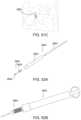
- FIG. 1 Ais a perspective view of a system including a locking screw device and an implant delivery device, depicted for intra-facet placement, according to certain embodiments;
- FIG. 1 Bis a cross-section view of a distal end of the devices of FIG. 1 A , shown without the vertebra for clarity;
- FIG. 1 Cis a perspective view of the system including a locking screw device and an implant delivery device of FIG. 1 A , depicted for trans-facet placement, according to certain embodiments;
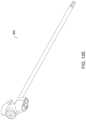
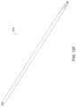
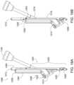
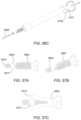
- FIG. 2 Ais a detailed side view of the locking screw device of FIG. 1 A ;
- FIG. 2 Bis a detailed side view of a distal end of the locking screw device of FIG. 2 A ;
- FIG. 3is an exploded view of an implant and a locking screw according to some embodiments of FIG. 1 A ;
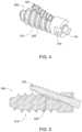
- FIG. 4is a perspective view and FIG. 5 is a cross-section view which depicts the implant and locking screw of FIG. 3 shown in a coupled state;
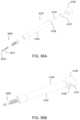
- FIGS. 6 A- 6 Cdepict perspective, partial and cross section views of the implant delivery device of FIG. 1 A ;
- FIGS. 7 A- 7 Cdepict perspective and exploded views of an implant that may be used with embodiments according to the present disclosure
- FIGS. 8 A- 8 Bdepict perspective and rear views of an implant that may be used with embodiments according to the present disclosure
- FIGS. 9 A- 9 Bare partial perspective and cross-section views of a delivery device for use with the implants of FIGS. 7 A- 8 B , and others, according to certain embodiments;
- FIGS. 10 A- 10 Bare partial perspective and cross-section views of the delivery device of FIGS. 9 A- 9 B , shown with an implant, according to certain embodiments;
- FIGS. 11 A- 11 Bare perspective, partial views of the implant and delivery device of FIGS. 9 - 10 when inserted in a facet joint for intra-facet placement, according to certain embodiments.
- FIGS. 11 C- 11 Dare perspective, partial views of the implant and delivery device of FIGS. 9 - 10 when inserted in a facet joint for trans-facet placement, according to certain embodiments.
- FIGS. 12 A- 12 Gdepict various tools of a distraction system that may be used according to certain embodiments.
- FIGS. 13 A- 13 Cdepict various views of a delivery system and facet assembly, according to certain embodiments.
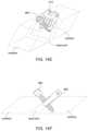
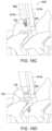
- FIGS. 14 A- 14 Fdepict the system and assembly of FIGS. 13 A- 13 C in use.
- FIGS. 15 A- 15 Fdepict various views of a facet assembly, according to certain embodiments.
- FIGS. 16 A- 16 Hdepict a delivery system and use of the assembly of FIGS. 15 A- 15 F in use.
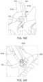
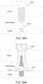
- FIG. 17 Ais a perspective view of a facet access guide and an impact handle.
- FIG. 17 Bis a cross-sectional view of the facet access guide and impact handle of FIG. 17 A .
- FIG. 18 Ais a perspective view of a washer sizer tool and a lateral mass decorticator guide in a first position.
- FIG. 18 Bis a perspective view of the washer sizer tool with the lateral mass decorticator guide of FIG. 18 A in an alternate position.
- FIG. 19is a perspective view of one example of a washer implant that may be used in accordance with the present disclosure.
- FIG. 20 Ais a perspective view of a washer implant delivery tool assembled with an impact handle and washer.
- FIG. 20 Bis a cross-sectional view of a portion of the washer implant delivery tool and washer implant of FIG. 20 A .
- FIG. 21is a perspective view of a facet screw.
- FIG. 22 Ais a perspective view of a facet screw assembly.
- FIG. 22 Bis a cross-sectional view of the facet screw assembly of FIG. 22 A .
- FIG. 22 Cis a cross-sectional view of the washer or spacer positioned with respect to a facet joint.
- FIG. 23is a perspective view of the facet access guide positioned adjacent a facet joint.
- FIG. 24 Ais a perspective view of the facet access guide positioned adjacent the facet joint and further assembled with the lateral mass decorticator guide and washer sizer tool.
- FIG. 24 Bis a side view of the assembly of FIG. 24 A .
- FIG. 24 Cis an enlarged cross-sectional view of the assembly of FIG. 24 B .
- FIG. 24 Dis a side view of the assembly of FIG. 24 B with the lateral mass decorticator guide positioned in an alternate position adjacent the lateral mass.
- FIG. 24 Eis a side view of the assembly of FIG. 24 D with a decorticator instrument.
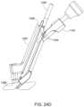
- FIG. 25 Ais a perspective view of the facet access guide assembled with a washer implant delivery tool and washer positioned in a first position.
- FIG. 25 Bis a side view of the tool assembly of FIG. 25 A .
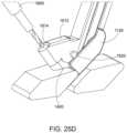
- FIG. 25 Cis an enlarged cross-sectional view of the tool assembly of FIG. 25 B with the washer implant delivery tool and washer positioned in the facet joint.
- FIG. 25 Dis a perspective view of the tool assembly of FIG. 25 C with a drill positioned adjacent a facet screw portal of the washer implant delivery tool.
- FIG. 26 Ais a perspective view of the washer implant delivery tool and washer positioned within the facet joint with a facet screw adjacent the lateral mass.
- FIG. 26 Bis a cross-sectional view of the washer implant delivery tool and washer positioned in the placed position with a facet screw positioned to extend through the facet joint.
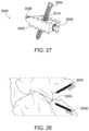
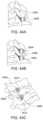
- FIGS. 27 - 29 Bdepict views of an implant that may be used with embodiments according to the present disclosure.
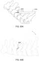
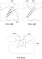
- FIGS. 30 - 32 Bdepict views of an implant that may be used with embodiments according to the present disclosure.
- FIGS. 33 - 35 Bdepict views of an implant that may be used with embodiments according to the present disclosure.
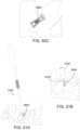
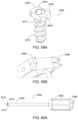
- FIGS. 36 - 37 Ddepict views of an implant that may be used with embodiments according to the present disclosure.
- FIGS. 38 A- 38 Edepict views of an implant and delivery device that may be used with embodiments according to the present disclosure.
- FIGS. 39 A- 41 Ddepict views of an implant and delivery device that may be used with embodiments according to the present disclosure.
- FIGS. 42 A- 42 Bdepict views of an implant that may be used with embodiments according to the present disclosure
- FIGS. 43 A- 43 Bdepict views of the implant of FIGS. 42 A- 42 B in use in a trans-facet deployment.
- FIGS. 44 A- 44 Edepict views of the implant of FIGS. 42 A- 42 B in use in an intra-facet deployment.
- FIGS. 45 A- 49 Cdepict views of an implant and delivery device that may be used with embodiments according to the present disclosure.
- FIGS. 50 A- 50 Cdepict views of the implant and delivery tool of FIGS. 45 A- 49 F in use in an intra-facet deployment.
- FIGS. 51 A- 51 Cdepict views of the implant and delivery tool of FIGS. 45 A- 49 C in use in a trans-facet deployment.
- FIGS. 52 A- 53 Edepict views of an implant and delivery device that may be used with embodiments according to the present disclosure.
- FIGS. 54 A- 54 Cdepict views of the implant and delivery tool of FIGS. 51 A- 52 E in use in an intra-facet deployment.
- FIGS. 55 A- 55 Bdepict views of the implant and delivery tool of FIGS. 51 A- 52 E in use in a trans-facet deployment.
- FIGS. 56 A- 57 Cdepict views of an implant and delivery device that may be used with embodiments according to the present disclosure.
- FIGS. 58 A- 58 Bdepicts views of the implant and delivery device of FIGS. 56 A- 57 C in use in a trans-facet deployment.
- FIGS. 59 A- 60 Ddepict views of an implant and delivery device that may be used with embodiments according to the present disclosure.
- FIGS. 61 A- 62 Gdepict views of the implant and delivery tool of FIGS. 59 A- 60 D in use in an intra-facet deployment.
- Spinal stenosisreflects a narrowing of one or more areas of the spine, often in the upper or lower back. This narrowing can put pressure on the spinal cord or on the nerves that branch out from the compressed areas (radiculopathy).
- Individual vertebrae of the spineare positioned relative to each other, and their separation is maintained by discs separating main vertebral bodies and by capsules positioned within facet joints. The discs and capsules are separated from the bone of their respective joints by cartilage.
- Spinal stenosisis often indicative of degeneration of a disc, a capsule, or the cartilage in a joint, which leads to a compression of the joints and the narrowing mentioned.
- a device, system and methodfor posterior fixation of two adjacent vertebrae of a spine, in an effort to ameliorate spinal instability, spinal stenosis and radiculopathy.
- Some embodimentsinvolve delivery of the fixation device from a posterior approach.
- Facet screwsare commonly used in spine surgery as a means for posterior fixation.
- the screwconsists of either a cannulated or solid screw and with or without a head washer.
- a facet screwis placed across the facet joint to provide posterior fixation.
- the concern with placing a screw across the facet jointis that it may potentially compress the joint and narrow the foraminal space where the nerve root resides causing foraminal stenosis.
- a fixation devicesuch as a facet screw or facet screw assembly
- a fixation devicesuch as a facet screw or facet screw assembly
- the shape, size, surface features and overall configuration of the facet screwmay cause it to remain securely within the facet joint without further attachment devices required.
- Such an additional devicemay include a screw, anchor, washer or similar securement device, and it may help to maintain the facet screw in a desired position within the joint and to prevent it from “backing out” of the joint—i.e., slipping posteriorly out of the joint.
- a locking screwmay be delivered through an opening in a facet screw or adjacent the facet screw, so that the locking screw is attached to one of the vertebrae that form the facet joint, to help secure the facet screw within the joint.
- a system for delivering a facet screw assembly to a joint between a vertebra and an adjacent vertebramay include the facet screw assembly.
- the facet screw assemblyincludes a facet screw having a proximal portion and a distal portion.
- the systemalso includes a delivery device, which may include a proximal end and a distal end and the delivery device defines a longitudinally extending lumen therethrough.
- the distal end of the delivery devicemay include a facet screw engagement feature.
- the facet screw engagement featuremay be keyed to a corresponding delivery device engagement feature located at or near the proximal portion of the facet screw.
- the systemmay include a locking screw and a locking screw delivery mechanism for anchoring an implant, such as a facet screw, into a facet joint, and for distracting and maintaining the distracted position of the joint.
- the locking screwis detachably connected to a locking screw delivery mechanism.
- the systemmay also include a guide tube for delivering the implant and to guide the locking screw to the implant. The locking screw is caused to detach from the delivery mechanism upon the locking screw becoming sufficiently secured to the implant and facet joint. This approach may ensure that the implant is securely affixed to the facet joint, for maintaining the distraction of the joint, thereby relieving symptoms associated with spinal stenosis.
- the systemincludes a locking screw detachably connected to a delivery mechanism at a breakable junction, and a guide tube configured to receive the locking screw and delivery mechanism.
- the guide tubemay include a bend, and as the locking screw and delivery mechanism is advanced through the guide tube along a first trajectory, the bend causes the locking screw to exit a distal end of the guide tube along a second trajectory.
- the delivery mechanismmay include a flexible region, which flexes as it advances through the bend in the guide tube.
- the guide tubemay include multiple bends.
- the bend (or bends) in the guide tubeare configured to direct the locking screw out of the distal end of the guide tube at a desired angle, such as an angle that will direct the locking screw through an opening in an implant and into one of two adjacent vertebrae.
- a desired anglesuch as an angle that will direct the locking screw through an opening in an implant and into one of two adjacent vertebrae.
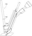
- FIG. 1 Ashows a perspective view of a fixation system 100 including a locking screw device 101 including a locking screw 102 and a locking screw delivery mechanism 104 , the fixation system also including a guide tube assembly 106 , according to certain embodiments.
- FIG. 1 Bis an exploded view of a distal portion of the system 100 .
- the locking screw 102is detachably connected to the delivery mechanism 104 .
- the locking screw 102 and delivery mechanism 104are separate components that couple together for delivery of the locking screw 102 and then separate when the locking screw 102 is secured to a vertebra, similar to the way a conventional screw and screwdriver work.
- the locking screw 102 and delivery mechanism 104are separate components, which are attached to one another at a breakable junction during manufacturing, and the breakable junction is configured to break upon experiencing a predetermined load.
- the locking screw 102 and delivery mechanism 104are manufactured as a one-piece, monolithically formed unit, having a breakable junction, which breaks upon experiencing a predetermined load. Therefore, although the following description focuses on the embodiment in which the locking screw 102 and the delivery mechanism 104 are a one-piece unit, other embodiments are possible and are encompassed within the scope of the disclosure.
- FIG. 1 Adepicts a portion of the fixation system for an intra-facet placement.
- FIG. 1 Cdepicts a portion of the fixation system for a trans-facet placement.
- the locking screw device 101may extend longitudinally from a proximal end 106 to a distal end 108 along Axis-I.
- the locking screw device 101may include a holding portion or a handle 112 .
- the locking screw delivery mechanism 104may include an elongate shaft 110 , extending from a proximal end, where it attaches to or includes the handle 112 , to a distal end where it is joined to the locking screw 102 .
- the elongate shaft 110 of the delivery mechanism 104may include a region 128 that tapers (at 130 ) to a flexible region 126 , which may facilitate the locking screw 102 in detaching from the delivery mechanism 104 , the details of which will be described in further detail below.
- FIG. 2 Bshows a detailed side view of a distal portion of the locking screw device 101 of FIG. 1 , according to certain embodiments.
- the locking screw 102may comprise a tip 120 , a helical ridge 114 , and a groove 118 .
- the locking screw 102may screw into a facet joint implant (such as a facet screw) and a vertebra, to secure the implant in the joint and thus prevent the implant from backing out of the joint.
- the delivery mechanism 104may be used to insert and secure the locking screw 102 to the vertebral bone.
- the locking screw device 101may be configured such that, upon securing the locking screw 102 into the implant and the vertebra, the locking screw 102 may detach from the delivery mechanism 104 . As such, the locking screw 102 may be inserted and secured into the vertebra and the facet joint implant.
- the locking screw 102may be detachably connected to the delivery mechanism 104 at a breakable junction 122 .
- the breakable junctionmay include a distal portion 124 a and a proximal portion 124 b that taper to form an arcuate shaped groove 132 .
- the groove 132may break upon experiencing a predetermined amount of force, the details of which will be described in detail below.
- the locking screw 102may detach from the delivery mechanism 104 , so that a screw head 116 is exposed.
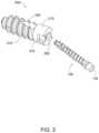
- FIGS. 3 , 4 and 5show an exploded, perspective and cross-section view of the locking screw 102 inserted into a facet joint implant, such as facet screw 200 .
- the depicted facet joint implant 200is a facet screw, and in alternative embodiments the locking screw device 101 may be used to secure any suitable implant within a vertebral joint.
- the facet screw 200may include a cylindrical body with external threads, a channel and, optionally, a washer 215 .
- the cylindrical body 210may include an opening 205 leading to the channel 220 .
- the channel 220may be located within a top wall so that the screw 102 may screw into the upper vertebra of a patient's facet joint to secure the implant 200 thereto.
- the channel 220may include complementary threads configured to engage with the helical ridge 114 of the locking screw 102 .
- a usermay rotate the locking screw device 101 to cause the helical ridge 114 to mate with the complementary threads within the channel 220 so that the screw 102 progresses through the cavity 220 .
- FIGS. 5 A- 5 Dshow the screw 102 progressing through the opening 210 and out through the channel.
- the screw 102may detach from the delivery mechanism 104 .
- FIGS. 4 - 5show the locking screw 102 secured to the implant or facet screw 200 after the locking screw 102 has detached from the delivery mechanism 104 .
- the implant 200such as facet screw 200
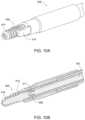
- an implant (or facet screw) delivery device 300through which the locking screw and locking screw delivery mechanism is deployed.
- the implant (or facet screw) delivery device 300may be used with the locking screw device 101 and is configured to cause the locking screw 102 to detach from the delivery mechanism 104 upon the locking screw 102 becoming sufficiently secured to the implant or facet screw 200 and vertebra.
- the implant delivery device 300may include a shaft 302 with a lumen 304 extending therethrough.
- the delivery device 300may include a handle 306 for engaging with other components of a deployment system.
- the delivery device 300may include an inner guide tube 350 extending within the lumen 304 .
- the inner guide tube 350is configured to receive the locking screw device 101 and guide the locking screw 102 to the implant, such as facet screw 200 .
- the distal end 305 of the implant delivery device 300is engaged with the implant or facet screw 200 .
- the facet screwincludes recesses 310 defined in the washer. The recesses are complementary to protrusions 320 at the distal portion of the implant delivery device 300 .
- the inner guide tube 350may include a proximal portion that extends longitudinally along Axis-A and a distal portion that extends along Axis-B, wherein the proximal portion and distal portion are joined at a bend 303 .
- Axis-Bmay extend upward from Axis-A at an angle.
- the channel 220 of the facet joint implant 200may extend at an angle.
- the angle of the bendmay be configured to cause the locking screw 102 to detach from the delivery mechanism 104 upon securing the implant 200 to a vertebra of a patient's facet joint.
- the bend 303 in the inner guide tube 350may be configured to cause the flexible region of the delivery mechanism 104 to flex.
- the locking screw 102may become stabilized so that the flexing or bending force is concentrated at the breakable junction 122 .
- the implant delivery device 300may facilitate a user in securing the locking screw 102 into an implant 200 and vertebra a sufficient amount.
- the implant 200may be a facet screw.
- the facet screw assembly 400may have some similar features to facet screw 200 .
- the assembly 400may include a facet screw 405 that includes a cylindrical body 410 having an elongated shaft and external threads.
- the assembly 400also includes washer 415 , a lock ring 417 , and optionally, a channel 420 for a screw.
- the washer 415includes a base having an opening for engagement with the proximal end of the elongated shaft of the facet screw.
- the washeralso includes one or more protrusions extending longitudinally from the base. In some embodiments, the protrusions have teeth extending therefrom.
- the locking ringis generally ring shaped. In one embodiment, the locking ring secures the washer to the proximal end of the facet screw.
- the cylindrical body 210 or 410may include channel features 420 along its axis.
- the channels 420may be located diametrically opposed to each other so that it modifies the cross-sectional shape of the cylindrical body 210 or 410 , as shown in FIG. 8 B , such that the implant, once placed within the vertebrae, resists rotation or other unwanted migration.
- the facet screw assembly 400may be part of a system.
- the systemmay further include a delivery device 500 , as shown in FIGS. 9 A- 9 B .
- the delivery device 500includes an actuator shaft 501 having a distal end 505 with threads 502 configured to receive at least a portion of the facet screw assembly.
- the device 500may also include a central sleeve 510 defining a first longitudinally extending lumen.
- the central sleeveis configured to receive the actuator shaft.
- the device 500also includes an outer sleeve 515 having one or more notches 520 at a distal end.
- the outer sleevedefines a second longitudinally extending lumen and is configured to receive the central sleeve.
- the one or more notches of the outer sleeveengage at least a second portion of the facet screw assembly to aid in delivery of the facet screw assembly.
- the elongated shaft of the facet screwincludes internal threads 411 .
- the internal threads 411engage with the threads 502 of the distal end 505 of the actuator shaft 501 of the delivery device, as shown in FIGS. 10 A- 10 B .
- the washer 415engages with the notches 520 .
- the actuator shaftengages the facet screw assembly to advance the facet screw assembly to the facet joint.
- the systemis inserted into the narrowed facet joint ( FIG. 11 A ) to expand the facet joint ( FIG. 11 B ).
- the threads of the facet screw and the teeth of the washerengage with the vertebrae of the facet joint to secure in the joint and prevent backout.
- the facet screw assemblymay be inserted in a trans-facet direction (see FIGS. 11 C- 11 D ) to fixate the facet joint without joint distraction.
- the facet screw assembly and the delivery system associated with itare useful for a transfacet approach.
- the facet screw assemblyalso comprises a facet screw and a washer (also referred to in these embodiments as a spacer), but the delivery system is different from other embodiments.
- FIGS. 13 A- 13 Bwhich illustrate portions of a delivery system and facet screw assembly, the delivery system 600 includes a delivery device 618 having one or more guide lumens 620 .
- the delivery devicemay be an articulating delivery device.
- the guide lumens 620may be generally parallel or coplanar. As indicated in FIG.
- delivery device 618comprises a first lumen 620 a configured to receive a facet screw and a second lumen 620 b configured to receive a rod associated with a washer or spacer.
- the first lumenis coupled to the second lumen by a connecting member 625 and extends less than the full length of the second lumen. In some embodiments, the length of the first lumen may be the same or similar to the length of the second lumen.
- the second lumen 620 bextends longitudinally between a proximal portion 630 and distal portion 635 .
- the distal portion 635includes a spacer receiving member 640 having a base 645 and two arms or prongs 650 extending therefrom and configured to receive at least a portion of the spacer.
- the delivery system 600further comprises a rod 645 having a proximal portion with a knob 650 and a distal portion 655 for engagement with the spacer.
- the distal portion 655may include threads.
- the delivery system 600is used with a component of the facet screw assembly
- the washer or spacer 605includes a base 607 having a rotatable member 610 , such as a pin.
- the rotatable member 610includes a rod opening 612 configured to receive the rod 640 .
- the spacer 605also includes one or more arms or protrusions 615 extending longitudinally from the base. In some embodiments, the protrusions have teeth 615 a extending therefrom. In use, and as shown in later figures, the spacer 605 , and more specifically the arms 615 , help to anchor the facet screw of the facet screw assembly in the facet joint.
- FIG. 13 Cillustrates how the delivery system 600 transitions from delivering the spacer 605 to delivering the facet screw (not shown here, but see FIG. 14 C , et seq.).
- the second (or rod receiving lumen) 620 b of the delivery device 618 and the spacer 605are initially substantially planar for insertion into a facet joint.
- the knob 650is rotated thereby rotating the rod and engaging the rotation member 610 of the spacer 605 and unlocking or loosening the spacer.
- the delivery system 600may rotate approximately 90 degrees at which point the knob and rod are rotated again to engage the rotation member and tighten and lock the system 600 into position for receiving a facet screw.
- the rotated deviceacts as a trajectory guide for the facet screw and allows the screw to be placed across the facet joint in a transfacet approach.
- FIGS. 14 A- 14 Fillustrate a method of using the delivery system 600 with both components of the facet screw assembly—the washer or spacer 605 and the facet screw 660 .
- the methodbegins by inserting the spacer 605 into the facet joint with the delivery system 600 via a posterior approach.
- the delivery system 600is then rotated 90 degrees as described with reference to FIG. 13 C to put the spacer into the proper position to receive the facet screw.
- the facet screw 660coupled to driver 665 , is then inserted into the screw receiving lumen of the delivery device 618 ( FIG. 14 C ) and across the facet joint ( FIG. 14 D ).
- a pilot holemay be pre-drilled before the facet screw is inserted in the device 618 .
- the driver 665is detached from the facet screw and withdrawn.
- knob 650is rotated to disengage device 618 from spacer 605 ( FIGS. 14 E- 14 F ). With the spacer deployed in the intra-facet joint and the facet screw deployed across the facet joint, the joint space is distracted while maintaining fixation with the spacer and the screw.
- the facet assembly 720also comprises a facet screw and a washer (also referred to in these embodiments as a spacer), but the delivery system is different from other embodiments.
- the washer or spacer 700comprises a first portion 705 having an intrafacet engagement portion 707 and a second portion 710 having a lateral mass engagement portion 712 .
- Each of the first portion 705 and the second portion 710includes a facet screw opening 715 configured to receive a facet screw 725 .
- FIGS. 15 A- 15 Fthe facet assembly 720 also comprises a facet screw and a washer (also referred to in these embodiments as a spacer), but the delivery system is different from other embodiments.
- the washer or spacer 700comprises a first portion 705 having an intrafacet engagement portion 707 and a second portion 710 having a lateral mass engagement portion 712 .
- Each of the first portion 705 and the second portion 710includes a facet screw opening 715 configured to receive a facet screw 725 .
- the facet assemblyalso includes the facet screw 725 , the screw comprising a head 730 and an elongated shaft 735 extending from the head.
- the shaftmay include threads for additional fixation when placed across the facet joint.
- the shaftpasses through both facet screw openings 715 in each of the first and second portions of the spacer.
- the head of the screwmay be larger than the facet screw opening 715 in the first portion and may only engage a top surface of the first portion.
- the head of the screwmay have a smaller diameter than facet screw opening 715 such that when the screw is fully inserted, the screw head is flush or substantially flush with the top surface of the first portion.
- the screwmay be an anti-backout screw.
- the anti-backout screwmay include an interference thread on the head of the screw that engages with a female thread on the opening 715 . When the interference thread is engaged with the female thread, the screw is locked in position thereby hindering or preventing backout or unscrewing.
- a delivery system 800includes a delivery device 805 having one or more guide lumens 810 , each guide lumen having a central longitudinal axis therethrough.
- the guide lumens 810may be generally parallel or coplanar.
- the guide lumens 810may have parallel central longitudinal axes.
- delivery device 805comprises a first lumen 810 a configured to receive a facet screw and a second lumen 810 b configured to receive a rod associated with a washer or spacer.
- the first lumenis coupled to the second lumen by a connecting member 815 and extends less than the full length of the second lumen.
- the length of the first lumenmay be the same or similar to the length of the second lumen.
- the second lumen 810 bextends longitudinally between a proximal portion 820 and distal portion 825 .
- the distal portion 825includes a spacer receiving member 830 configured to receive at least a portion of the spacer.
- the delivery system 800further comprises a rod 840 having a proximal portion with a knob 845 and a distal portion 850 for engagement with the spacer.
- the distal portion 850may include threads (not shown).
- FIGS. 16 A- 16 Hillustrate a method of using the delivery system 800 with the facet screw assembly 720 .
- the methodbegins by inserting the spacer 700 into the facet joint with the delivery system 800 via a posterior approach.
- the systemdoes not articulate but rather is placed in a trajectory that is close to vertical relative to a horizontal spine (i.e. the patient is laying down).
- the facet screw 725coupled to driver 860 , is then inserted into the screw receiving lumen of the delivery device 805 ( FIG. 16 C ), through the screw receiving openings in the spacer and across the facet joint ( FIG. 16 D ).
- a pilot holemay be pre-drilled before the facet screw is inserted in the device 805 .
- the driver 860is detached from the facet screw and withdrawn. Then, knob 845 is rotated to disengage device 805 from spacer 700 ( FIGS. 16 E- 16 F ). With a portion of the spacer deployed in the intra-facet joint and the other portion acting as a washer for the screw, the joint space is distracted while maintaining fixation with the spacer and the screw.
- FIGS. 12 A- 12 Gthe systems and devices disclosed herein may be used with a distraction system 900 configured to minimally invasively or percutaneously deliver implementations of the implant into a spinal facet joint space via, for example, a posterior approach. While the following discussion is made in terms of implant 200 , it can be appreciated that certain aspects of distraction system 900 may also be used with the facet screw assemblies 400 , 605 , 660 , 720 and others and related delivery devices or systems 500 , 600 , 800 , and others.
- the system 900includes a delivery tool 902 and a guide tool 904 , both of which extend from a respective leading distal end 906 , 907 to a respective trailing proximal end 908 , 909 .
- the delivery tool 902can be received in the lumen of the guide tool 904 to bring about the delivery of the implant 200 into the target spinal facet joint.
- the system 900may further include a decorticator 936 , an injector or push rod or actuator 948 , a chisel 960 , a place holding chisel 974 , and a mallet 980 .
- the delivery system components depicted in FIGS. 12 A- 12 Gcan be used to implant an implant 200 in a spinal facet joint that is the target of treatment.
- a percutaneous or minimally invasive incisionis made in the posterior region of the neck to lead to the target facet joint.
- the access chisel 974is routed through an incision, optionally under fluoroscopic guidance, until the tapered distal tip resides in the target facet joint and the chisel shaft extends out of the patient via the incision.
- the outer decorticatorWith the access chisel so positioned, the outer decorticator can be grasped and distally routed over the access chisel such that the chisel shaft is received in the lumen that extends longitudinally through the outer decorticator. With the distal decorticating end of the outer decorticator abutting against one or more lateral masses adjacent the target facet joint, the outer decorticator can be rotated about the chisel shaft to decorticate the bone surfaces of the lateral masses adjacent the target facet joint. Once decortication of the lateral masses has been sufficiently achieved, the decorticator can be removed from about the chisel shaft and from the patient.
- the guide toolWith the place holding or access chisel so positioned, the guide tool is grasped and distally routed over the chisel 974 such that the chisel shaft is received in the guide tool lumen that extends longitudinally through the guide tool shaft.
- the tapered forked distal end of the guide tool 904is distally advanced through the incision and along the chisel shaft until the tapered forks of the guide tool 904 are positioned inside the target facet joint, the chisel tapered distal tip being located between the pair of forks of the guide tool distal end, the guide tool shaft extending out of the patient via the incision.
- the place holding or access chisel 974can be withdrawn out of the guide tool lumen and out of the patient, leaving the guide tool tapered forked distal end residing in the target facet joint and the guide tool shaft extending out of the patient.
- the decorticating chisel 960can then be distally routed through the lumen of the guide tool 904 to place the tapered decorticating distal end of the chisel 960 between the guide tool forks located in the target facet joint space.
- the decorticating chisel 960can then be displaced distal-proximal to cause the tapered decorticating distal end of the chisel 960 to remove the cartilage of the target facet joint space located between the guide tool forks and further decorticate any associated bone surfaces of the target facet joint space.
- the chisel 960can be removed from the lumen of the guide tool 904 and the patient.
- the implant 200may be coupled to, and supported off of, the distal end 906 of an implant delivery tool. Once the implant 200 is decoupled from the delivery tool and delivered or deposited into the facet joint space, the delivery tool can be withdrawn from the guide tool 904 , which is left in place with its forked distal end occupying the facet joint space and the implant 200 being located between the forks of the guide tool 904 .
- a usermay insert the implant delivery device 300 through the lumen of the guide tool 904 to deliver the locking screw 102 and thus anchor the implant 200 to the vertebra.
- a usermay insert the implant delivery device 300 through the lumen of the guide tool 904 such that the distal end of the inner guide tube 350 is proximate the facet implant, such as the facet screw 200 .
- the usermay insert the locking screw device 101 through a proximal end of the inner guide tube 350 and advance the locking screw device 101 through the proximal portion of the inner guide tube 350 along a first trajectory.
- the usermay continue to advance the locking screw device 101 through the inner guide tube, and the bend within the guide tube may cause the flexible region 126 of the delivery mechanism 104 to flex.
- the locking screw 102may exit the distal end of the inner guide tube 350 along a second trajectory so that the locking screw 102 is directed to the channel 220 .
- the usermay rotate the locking screw device 101 to cause the locking screw 102 to advance through implant 200 and into the vertebra.
- the locking screw 102may advance through the implant 200 and into the vertebra along a third trajectory.
- the flexible region 126further flexes and a load is concentrated at the breakable junction 122 .
- the breakable junction 122may experience a predetermined load to cause the bone screw 102 to detach from the delivery mechanism 104 . The process can then be repeated for another facet joint if needed.
- a system for delivering a facet screw assembly to a joint between a vertebra and an adjacent vertebramay include the facet screw assembly.
- the facet screw assemblyincludes a facet screw that interfaces with a washer that is deployed in the facet joint to distract or maintain the facet joint space thereby reducing or preventing radiculopathy.
- the washermay also be used as an additional anchoring point for the screw to reduce the likelihood of screw backout.
- the interface between the washer and the screwprovides a fixed length for the screw to protrude beyond the facet joint and into bone which makes the placement of the screw predictable and minimizes bone breach and potential nerve or tissue damage to the patient.
- the instruments that interface with the screw and washerprovide a way to place the facet screw assembly while minimizing the required tissue incision size typically seen in facet screw placement.
- the instrumentsalso provide a way to decorticate the lateral mass to prepare for fusion.
- the instrumentsguide the facet screw at a fixed angle across the facet joint, eliminating the variability by doing it with other methods.
- the embodiments of the current disclosuremay be an improvement over traditional facet screws placed across the facet joint with a transfacet approach.
- the traditional transfacet approachcompresses the facet joint, narrows the lateral foramen, and potentially induces spinal stenosis.
- the traditional approachdoes not decompress the nerve root.
- Another traditional methodis the use of bone dowels, where the bone dowels are placed within the facet joint to expand and fuse the joint.
- this approachmay require further instrumentation to fixate the joint and/or spine construct, to allow for fusion.
- FIG. 17 Ais a perspective view of components of a facet screw assembly delivery system including a facet access guide 1100 and a detachably connected impact handle or handle 1102 . While the handle 1102 is referred to as an impact handle, it can be appreciated that it is a handle with a portion having a wider surface area for grasping or hitting or driving an instrument in accordance with the present disclosure.
- FIG. 17 Bis a cross-sectional view of the facet access guide and handle of FIG. 17 A .
- the facet access guide 1100may be used in the delivery system and multiple tools may be configured to engage, such as slidably or rotatably engage with, various features of the facet access guide 1100 to deliver the facet screw assembly.
- the facet access guide 1100includes a posterior side 1198 , an anterior side 1197 , and a distal end formed as ramp 1120 including an intra-facet distractor 1108 and a stop or depth stop 1106 .
- the facet access guide 1100also includes a proximal end formed by an instrument guide handle portal 1110 and impact handle socket 1122 .
- An instrument guide portal 1104is positioned between the ramp 1120 and the combination of the instrument guide handle portal 1110 and impact handle socket 1122 .
- the instrument guide portal 1104includes an upper portion 1116 and a lower portion 1118 .
- the upper portion 1116is positioned adjacent the instrument guide handle portal 1110 .
- the lower portion 1118is adjacent the ramp 1120 .
- the instrument guide handle portal 1110may be a lumen formed as a circle, square, triangular, oblong, tube or other shaped portal extending through the proximal end of the facet access guide 1100 .
- the instrument guide handle portal 1110includes an axis 1124 that is generally parallel to an axis 1114 that extends through the impact handle socket 1122 .
- the impact handle socket 1122may be formed as a cavity within the proximal end of the facet access guide 1100 .
- the upper portion 1116 of the instrument guide portal 1104may be generally coaxial with the axis 1124 of the instrument guide handle portal 1110 .
- the upper portion 1116may form an open lumen or channel, such as a generally half-cylindrical channel with an open side or a u-shaped channel, with an opening directed towards a posterior side 1198 of the facet access guide 1100 .
- the upper portion 1116is angled with respect to the lower portion 1118 .
- the lower portion 1118may also form a channel, such as generally half-cylindrical channel with an open side or a u-shaped channel, with an opening directed towards the posterior side 1198 of the facet access guide 1100 .
- the lower portion 1118 of the instrument guide portal 1104may be angled with respect to the distal end of the facet access guide 1100 .
- a plane extending through the ramp 1120may be parallel to the axis 1114 and axis 1124 of the proximal end.
- the angle of the lower portion 1118 of the instrument guide portal 1104may help to minimize the tissue incision size due to the off-axis, multi-angle geometry of the facet access guide 1100 .
- the intra-facet distractor 1108may be used to distract a target facet joint to prepare the joint for insertion, coupling, or receipt of a facet screw assembly.
- the ramp 1120 and intra-facet distractor 1108may form a fork like shape that may aid in preparation of the facet joint by partially or fully distracting the facet joint or at least anchoring the tool in the joint.
- a stop or depth stop 1106may also be positioned at the end of the ramp 1120 . In use, the depth stop 1106 may positively locate the intra-facet distractor 108 and prevent the intra-facet distractor 1108 from extending too far or being inserted to an undesired depth into the facet joint.
- the angled or non-linear shape of the facet access guide 100may reduce tissue incision size and/or instrument footprint for distracting a facet joint and inserting a facet screw assembly.
- the delivery system of FIGS. 17 A- 17 Bmay also include a detachable impact handle 1102 .
- the impact handle 1102may be detachably coupled to the facet access guide 1100 at the impact handle socket 1122 .
- the detachable couplingmay be in the form of a threaded rod and socket assembly, such that the impact handle socket 1122 includes threads on an internal surface that may mate with external threads formed on an end of the impact handle 1102 .
- FIG. 18 Ais a perspective view of a facet screw assembly delivery system that includes a washer sizer tool and a lateral mass decorticator guide in a first position.
- FIG. 18 Bis a perspective view of the washer sizer tool and the lateral mass decorticator guide of FIG. 18 A in an alternate position.
- the delivery systemmay also include a washer sizer tool 1200 and a lateral mass decorticator guide 1300 .
- the washer sizer tool 1200may include an anterior side 1297 , a posterior side 1298 , and an access guide interface 1202 , which extends from a central portion of the washer sizer tool 1200 on the anterior side 1297 down to a distal end.
- the access guide interface 1202may be shaped to engage, fit adjacent to or detachably couple with the instrument guide portal 1104 of the facet access guide 1100 .
- the access guide interface 1202may be cylindrical or u-shaped to fit at least partially within and slide with respect to the posterior side 1198 of the instrument guide portal 1104 of the facet access guide 1100 .
- the access guide interface 1202may include an upper portion 1216 and a lower portion 1218 .
- the lower portion 1218may be generally coaxial with a washer sizer shaft 1212 , which is positioned adjacent the upper portion 1216 .
- the upper portion 1216may be angled with respect to the lower portion 1218 and the washer sizer shaft 1212 .
- the angle and shape of the upper portion 1216is configured to align with the upper portion 1116 of the facet access guide 1100 .
- the upper portion 1216may also include a threaded socket configured so that the washer sizer tool 1200 may be detachably coupled with the impact handle 1102 (as shown assembled in FIG. 18 B ). Positioned above the upper portion 1216 may be a shoulder. The shoulder may be used to help align the washer sizer tool 1200 with the facet access guide 1100 .
- the joint spacer 1206is shaped to be positioned and slide along the ramp 1120 and between the forks that form the intra-facet distractor 1108 on the posterior side 1198 of the facet access guide 1100 .
- the joint spacermay include teeth extending from its sides to help position the joint spacer 1206 within the facet joint and to also help decorticate the facet joint in preparation for the installation of the facet screw assembly.
- a dovetail feature 1222may be formed on the posterior side 1298 of the washer sizer tool 1200 .
- the dovetail feature 1222may extend along at least half a length of the washer sizer tool 1200 , and is configured to align with a corresponding dovetail feature on the lateral mass decorticator guide 1300 . This may allow the lateral mass decorticator guide 1300 to be fixedly axially located with respect to the washer sizer tool 1200 , but allows the lateral mass decorticator guide 1300 to be translated or slid up and down along the washer sizer tool 1200 .
- the washer sizer tool 1200may also include a washer size indication or indicator, such as a washer size marker line 1204 positioned on or at least partially about the circumference of the washer sizer shaft 1212 .
- the washer size marker line 1204may be used in conjunction with the lateral mass decorticator guide 1300 to help a user determine the washer or spacer that is needed in the facet screw assembly.
- the posterior side of the washer sizer tool 1200may also include a pin 1220 , or posts that extends away from, in a lateral medial direction, the general body of the washer sizer tool 1200 adjacent the joint spacer 1206 .
- the post or pin 1220may align with the ramp 1120 of the facet access guide 1100 to help guide the washer sizer tool 1200 during the facet screw assembly installation procedure.
- the pinmay slide or ride against the edge of the ramp to help ensure alignment of the washer sizer tool 1200 with respect to the facet access guide 1100 .
- the lateral mass decorticator guide 1300is also shown in FIGS. 18 A- 18 B .
- the lateral mass decorticator guide 1300may include a decorticator guide shaft 1304 extending from a proximal end 1308 towards a distal end of the lateral mass decorticator guide 1300 .
- the distal end of the lateral mass decorticator guide 1300may include a tool guide 1310 with a decorticator portal 1302 extending through it.
- the decorticator guide shaft 1304is angled with respect to the axis of the decorticator portal 1302 .
- a distal end of the tool guide 1310is the lateral mass contacting surface 1306 .
- the lateral mass contacting surface 1306is used to contact the lateral mass of the vertebrae forming the target facet joint.
- the lateral mass decorticator guide 1300includes a dovetail feature 1322 that extends from the anterior side 1397 of the lateral mass decorticator guide 1300 and is configured to slidably align or mate with the dovetail feature 1222 that extends from the posterior side of the washer sizer tool 1200 .
- the lateral mass decorticator guide 1300may be translated or slide up and down the dovetail feature 1222 to help position the lateral mass decorticator guide 1300 in the desired location, and to indicate, using the washer size marker line 1204 , which size facet screw assembly should be used.
- This distance or space 1312helps determine the size of the facet screw assembly components, such as the length and size of the facet screw and the size of the washer implant 1400 .
- FIG. 19is a perspective view of a washer implant 1400 that may be used in a facet screw assembly delivery system.
- Other washer implantsthat may be used with the systems described herein include those described in U.S. Application No. 62/667,951 and U.S. Application No. 62/613,547, which are hereby incorporated by reference.
- the washer implant 1400includes a first portion 1402 having a lateral mass engagement portion 1416 and a second portion 1404 having an intrafacet engagement portion 1418 .
- Each of the first portion 1402 and second portion 1404includes a facet screw opening 1412 configured to receive a facet screw.
- the facet screw opening 1412 in the first portion 1402may include a threaded portion 1406 , so that the head of a facet screw may fit at least partially within or flush within the first portion 1402 .
- the threaded portion 1406may have a machine type thread pitch, and is configured to engage with the threaded head of the facet screw.
- the threaded portion 1406may not extend the full length of the facet screw opening 1412 in the first portion 1402 , so that there is a shoulder 1420 near the bottom of the facet screw opening 1412 of the first portion 1402 . This shoulder 1420 may help to prevent a facet screw from being rotated through the entire facet screw opening 1412 of the first portion 1402 and becoming decoupled or disengaged from the washer implant 1400 .
- the intrafacet engagement portion 1418 of the second portion 1404may also include teeth 1414 extending from either side.
- the teethmay be used to engage the intrafacet surfaces of a first or primary and adjacent vertebra.
- the washer implant 1400may also include a coupling member or feature to couple the washer to an implant delivery tool.
- the coupling memberis a threaded aperture 1408 that extends through a portion of the washer implant 1400 , such as extending through the intrafacet engagement portion 1418 .
- a keyway 1410positioned between the threaded aperture 408 and the facet screw opening 1412 of the first portion 1402 is a keyway 1410 .
- the keyway 1410is a groove 1410 .
- the groove 1410may be shaped to align or fit with a feature, such as a tongue or key feature, of the washer implant delivery tool (see FIG. 20 B ) to help prevent the washer implant 1400 from undesirably rotating or moving with respect to the washer implant delivery tool 1600 during the delivery of the facet screw assembly.
- FIG. 20 Ais a perspective view of a facet screw assembly delivery system including a washer implant delivery tool assembled with an impact handle and a detachably connected washer implant.
- FIG. 20 Bis a cross-sectional view of a portion of the washer implant delivery tool and washer implant of FIG. 20 A .
- the washer implant delivery tool 1600includes a distal end with a facet screw guide 1612 and a proximal end with a washer release knob 1604 .
- a shaft 1608may extend between the facet screw guide 1612 and washer release knob 1604 .
- Above the shaft and proximate to the washer release knob 1604may be a shoulder 1622 .
- the shoulder 1622may be cylindrically shaped and have a diameter that is larger than a diameter of the shaft 1608 . In use, the shoulder 1622 may be used to align the washer implant delivery tool 1600 with the facet access guide 1100 .
- the shaft 1608may include an upper portion 1616 and a lower portion 1618 . Similar to the upper portion 1116 and lower portion 1118 of the facet access guide 1100 , the upper portion 1616 and lower portion 1618 may be angled with respect to each other. The upper portion 1616 may be shaped to fit adjacent to or align with the posterior side of the upper portion 1116 of the facet access guide 1100 . The lower portion 1618 may be shaped to fit adjacent to or align with the posterior side of the lower portion 1118 of the facet access guide 1100 .
- an actuation rod 1602may be coupled to the washer release knob 1604 on a proximal end of the actuation rod 1602 .
- the actuation rod 1602may be configured to be coupled to the threaded aperture 1408 of the washer implant 1400 on a distal end of the actuation rod 1602 .
- the distal end of the actuation rod 1602may not be threaded, but may be keyed in an acceptable manner to engage a complementary-shaped keyway on the washer implant 1400 at a location similar to threaded aperture 1408 .
- the distal end of the washer implant delivery tool 1600also includes a key feature 1610 .
- the key featureis a raised feature or a tongue 1610 .
- the tongue 1610is configured to align with the keyway or groove 1410 of the washer implant 1400 to properly position the washer implant 1400 with the washer implant delivery tool 1600 .
- the distal end of the washer implant delivery tool 1600also includes a facet screw guide 1612 , including a facet screw portal 1614 extending through the facet screw guide 1612 .
- the facet screw guide 1612may be positioned at an angle with respect to the shaft 1608 and actuation rod 1602 .
- the facet screw portal 1614When assembled with the washer implant 1400 , the facet screw portal 1614 may be generally coaxial with the facet screw opening 1412 of the first portion 1402 and second portion 1404 of the washer implant 1400 .
- a post or pin 1620may extend away from the facet screw guide 1612 , in a lateral medial direction.
- the pin 1620 of washer implant delivery tool 1600may be similar to the pin 1220 of washer sizer tool 1200 .
- the pin 1620may be used to align or locate the washer implant delivery tool 1600 with respect to the facet access guide 1100 when assembled or coupled together to deliver the facet screw assembly.
- FIG. 21is a perspective view of an embodiment of a facet screw that may be used in various embodiments of a facet screw assembly delivery system.
- the facet screw 1500may include a head 1510 having external threads and a cylindrical body extending away from the head 1510 with an elongated shaft 1512 and additional external threads.
- the facet screw 1500is not a set screw, and a diameter of the head 1510 may be larger in size than a diameter of the elongated shaft 1512 .
- the external threads on the head 1510may differ from those on the elongated shaft 1512 .
- the head 1510may include a washer interface 1502 and the elongated shaft 1512 may include a facet joint interface 1504 .
- the washer interface 1502includes machine threads on an outside or outer circumference of the head 1510 and the facet joint interface 1504 includes screw threads that extend to the end 1508 .
- the elongated shaft 1512may taper from a larger diameter adjacent the head 1510 to a small diameter at the end 1508 .
- the threads of the elongated shaft 1512may be formed so that the elongated shaft 1512 is self-tapping to engage the lateral mass of the vertebrae.
- the head 1510may also include a tool connector feature 1506 , for example a keyway or being keyed to accept a hex, star, cross, or other type of tool key to rotate or manipulate the position of the facet screw 1500 .
- a tool connector feature 1506for example a keyway or being keyed to accept a hex, star, cross, or other type of tool key to rotate or manipulate the position of the facet screw 1500 .
- FIG. 22 Ais a perspective view of a facet screw assembly that may be used with a facet screw assembly delivery system, with a facet screw assembled with a washer implant 1400 .
- FIG. 22 Bis a cross-sectional view of the facet screw and washer of FIG. 22 A .
- FIG. 22 Cis a cross-sectional view of the washer positioned over the lateral mass of a first vertebrae and into the facet joint.
- the facet screwextends through the lateral mass, through the facet joint, and into the adjacent vertebrae.
- the facet screw shaftpasses through both facet screw openings 1412 in each of the first and second portions of the spacer.
- the threaded head 1510 of the facet screw 1500engages with the threaded portion 1406 of the facet screw opening 1412 in the first portion 1402 of the spacer 1400 .
- the threaded facet joint interface 1504 of the facet screw 1500engages and extends through the lateral mass of a first vertebrae, extends through the facet screw opening 1412 of the second portion 1404 of the washer implant 1400 , and then extends through the intrafacet surface and, into an adjacent vertebrae.
- the engagement of the threaded head 1510 with the threaded portion 1406 of the washer implant 1400in combination with the engagement of the threaded elongated shaft 1512 , work to create a compressive effect across the facet joint to fix the first and adjacent vertebrae. This compressive effect may also help to prevent the facet screw from backing out or separating from the spacer 1400 .
- the overall length of the facet screw 1500 in combination with the size of washer implant 1400controls the depth at which the end 1508 of the facet screw 1500 extends into the adjacent vertebrae.
- the protrusion length across the facet jointis known and can be used as a safety feature to minimize bone breach.
- FIGS. 23 - 26 Bshows the process and progression of delivering a facet screw assembly using the described facet screw assembly delivery system components.
- FIG. 23is a perspective view of the facet access guide 1100 positioned adjacent a facet joint.
- the facet access guide 1100may be positioned so that the intra-facet distractor 1108 begins to extend into the facet joint 1101 .
- the impact handle 1102is impacted or tamped.
- the force on the impact handle 1102is transmitted to the intra-facet distractor 1108 , which helps to drive the facet access guide 1100 correctly into the facet joint at a proper angle and maximizes the transfer of force from the impact handle 1102 to the facet access guide 1100 .
- the angle of the lower portion 1118 of the instrument guide portal 1104helps minimize the tissue incision size due to the off-axis, multi-angle geometry of the facet access guide 1100 .
- the depth stop 1106may engage with the lateral mass of the vertebra to help prevent the intra-facet distractor 1108 from extending too far into or from being over inserted into the facet joint 1101 .
- a userwill separate or remove the impact handle 1102 from the facet access guide 1100 .
- the usermay then removably and/or slidably engage or assemble the washer sizer tool 1200 with the facet access guide 1100 , so that the access guide interface 1202 of the washer sizer tool 1200 aligns with the instrument guide portal 1104 of the facet access guide 1100 .
- a usermay then remove or decouple the impact handle 1102 from impact handle connection 1107 of the facet access guide 1100 (see FIG. 24 A ).
- the usermay then removably or detachably couple the impact handle 1102 to the upper portion 216 (see FIG. 18 A ) of the washer sizer tool 1200 , with the distal end of the impact handle 1102 extending through the instrument guide handle portal 1110 .
- FIG. 24 Ais a perspective view of the facet access guide positioned adjacent the facet joint and further assembled with the lateral mass decorticator guide and washer sizer tool.
- FIG. 24 Bis a side view of the assembly of FIG. 24 A , with the impact handle 1102 detachably coupled to the upper portion 1216 of the washer sizer tool 1200 .
- FIG. 24 Cis an enlarged cross-sectional view of the assembly of FIG. 24 B .
- the joint spacer 1206may not be in the desired or proper positon within the facet joint.
- a userwould tamp or impact the impact handle 1102 coupled to the washer sizer tool 1200 .
- the impact force on the impact handle 1102would move or force the washer sizer tool 200 downwards with respect to the facet access guide 1100 .
- the connection of the impact handle 1102 to the upper portion 1216would provide alignment support for the washer sizer tool 200 with respect to the facet access guide 1100 , and the pin 1220 would engage the ramp 1120 to provide further alignment and support.
- washer sizer tool 1200is guided by the impact handle 1102 shaft and the instrument guide handle portal 1110 , as well as the ramp 1120 and the pin 1220 . With this, the distal end of the joint spacer 1206 may be properly placed in the facet joint.
- a usermay determine the appropriate size facet screw assembly components, such as the washer implant 1400 and facet screw 1500 , to use for the procedure.
- FIG. 24 Dis a side view of the assembly of FIG. 24 B with the lateral mass decorticator guide positioned in an alternate position adjacent the lateral mass.
- the usermay inspect the washer size marker line 1204 of the washer sizer tool 1200 with respect to the proximal end 1308 of the lateral mass decorticator guide 1300 .
- the alignment of the proximal end 308 with the washer size marker line 1204helps measure the thickness of the lateral mass and can provide a determination or instruction to a user about what size facet screw assembly components, such as a washer implant 1400 and facet screw 1500 , to use.
- the lateral massmay be an uneven or contoured bone surface (i.e. bumpy, wavy, or generally not flat), and a user may want to flatten or even out the surface to help to size the washer implant 1400 appropriately.
- the lateral massmay be generally flat, but the user may wish to decorticate the surface to help stimulate and improve bone growth around the area of the facet screw assembly.
- FIG. 24 Eis a side view of the assembly of FIG. 24 D with a decorticator instrument. When the lateral mass contacting surface 1306 of the lateral mass decorticator guide 1300 is positioned adjacent the lateral mass, such as in FIG.
- a usermay then insert or place a distal end of a decorticator instrument 1700 down through the decorticator portal 1302 of the lateral mass decorticator guide 1300 .
- the decorticator instrument 1700may include a shoulder or raised lip 1702 that helps to control the depth that the distal end of the decorticator instrument 1700 may be moved to.
- the shoulder or raised lip 1702may act as a hard stop to prevent the over-decortication of the lateral mass.
- the decortication of the lateral massmay help flatten or otherwise refine the bony surface to the shape of the washer implant 1400 .
- FIG. 25 Ais a perspective view of the facet access guide assembled with a washer implant delivery tool and washer implant positioned in a first position.
- FIG. 25 Bis a side view of the tool assembly of FIG. 25 A .
- a userwill then attach the appropriately sized washer implant 1400 to the actuation rod 1602 of the washer implant delivery tool 1600 .
- the userwill then slidably engage or assemble the washer implant delivery tool 1600 with the facet access guide 1100 .
- the userwill align the upper portion 616 of the washer implant delivery tool 1600 with the upper portion 116 of the facet access guide 1100 , align the lower portion 1618 of the washer implant delivery tool 1600 with the lower portion 1118 of the facet access guide 1100 , and then insert the impact handle 1102 through the instrument guide handle portal 1110 and reattach it to the washer implant delivery tool 1600 at the upper portion 1616 of the washer implant delivery tool 1600 .
- the userwill then impact the handle to advance the washer implant 1400 over the lateral mass of the first or primary vertebrae and into the facet joint.
- the instrument trajectoryis guided by the shaft of the impact handle 1102 through the instrument guide handle portal 1110 and by the ramp 1120 and the pin 1620 of the washer implant delivery tool 1600 .
- FIG. 25 Cis an enlarged cross-sectional view of the tool assembly of FIG. 25 B with the washer implant delivery tool and washer implant 1400 positioned in a placed position, with the lateral mass engagement portion 1416 of the washer implant 1400 adjacent the lateral mass and the intrafacet engagement portion 1418 positioned within the facet joint.
- FIG. 25 Dis a perspective view of the tool assembly of FIG. 25 C with a drill positioned adjacent the facet screw portal of the washer implant delivery tool.
- FIG. 26 Ais a perspective view of the washer implant delivery tool and washer implant.
- FIG. 26 Bis a cross-sectional view of the washer implant delivery tool and washer implant with a facet screw positioned to extend through the facet joint.
- the usermay then insert the appropriately sized facet screw 1500 through the facet screw portal 1614 and advance the screw 1500 there through.
- the facet screw portal 1614guides the facet screw 1500 to the proper fixed angle trajectory across the washer implant 1400 and the facet joint.
- the tightening of the head 1510 of the facet screw 1500 with the threaded portion 1406 of first portion 1402 of the washer implant 1400 in combination with the threaded elongated shaft 1512 engaging with the first or primary vertebrahelps to compress the facet joint.
- a userwill remove the drill bit from the facet screw portal 1614 .
- the userwill then rotatably engage the washer release knob 1604 , thereby rotating the actuation rod 1602 .
- the distal end of the actuation rod 1602will disengage or unscrew from the threaded aperture 1408 of the washer implant 1400 .
- a usermay remove both the washer implant delivery tool 1600 and the facet access guide 1100 from the surgical space, and the washer implant 1400 will remain in place. The process can then be repeated for another facet joint if needed.
- a method of delivering a facet screw assembly to a facet joint using a facet screw assembly delivery systemmay include placing a facet access guide, such as or similar to facet access guide 1100 , into the facet joint.
- the methodmay include detachably or removably coupling a washer sizer tool, such as or similar to washer sizer tool 1200 , with the facet access guide.
- the washer sizer toolmay be slidably coupled with the facet access guide.
- An impact handlemay then be disconnected from the facet access guide and detachably coupled to the washer sizer tool. The impact handle may then be impact to position the washer sizer tool in an appropriate location with respect to the facet joint.
- the methodmay also include coupling a lateral mass decorticator guide, such as or similar to lateral mass decorticator guide 1300 , with the washer sizer tool.
- the lateral mass decorticator guidemay be slid down a shaft of the washer sizer tool to be positioned adjacent or contact a lateral mass of the facet joint.
- the methodmay include advancing a decorticator through a tool guide of the lateral mass decorticator guide and decorticating the lateral mass.
- the methodmay include measuring, by the alignment of the lateral mass decorticator guide and the washer sizer tool, a recommended facet screw assembly size for the facet joint.
- the facet screw assemblymay include components that are the same or similar to the facet screw 1500 and washer 1400 .
- the methodmay include decoupling the lateral mass decorticator guide and washer sizer tool from the facet access guide.
- the methodmay then include selecting a washer size and coupling the washer to a washer implant delivery tool.
- the washer implant delivery toolmay then be slidably coupled to the facet access guide, and the impact handle may be coupled to the washer implant delivery tool.
- the washer implant delivery toolmay then be impacted to position the washer into the facet joint.
- the methodmay then include drilling a pilot hole across the facet joint for the facet screw.
- the methodmay then include advancing a facet screw through the pilot hole and placing the facet screw across the facet joint.
- the methodmay include tightening the screw onto the washer and compressing the facet joint.
- the methodmay then include decoupling the washer implant delivery tool from the facet screw assembly.
- the methodmay then include removing the washer implant delivery tool and facet access guide from the facet joint.
- FIGS. 27 - 29 Bdepict views of an implant that may be used with embodiments according to the present disclosure.
- FIG. 27is an isometric view of the implant
- FIG. 28is a view of the implant within the facet joint space between adjacent vertebra.
- the implant 2000may include a washer 2002 , a trans-facet screw 2004 , and an intra-facet screw 2006 .
- the washer 2002may include two threaded apertures and the washer may have a generally constant thickness from a first end to a second end.
- An intra-facet threaded aperture 2008extending through a length of or along a longitudinal axis of the washer 2002 includes internal threads that correspond to the external threads of the intra-facet screw 2006 .
- a trans-facet aperture 2010 extending through a width of or along a transverse axis of the washer 2002has internal threads that correspond to the external threads of the trans-facet screw 2004 .
- the washer 2002is inserted into a facet joint space and allows for modular compatibility for placement of the intra-facet screw 2006 and/or the placement of the trans-facet screw 2004 .
- the positioning of the threaded apertures 2008 , 2010allow for either a combination of the two screws (intra-facet screw 2006 and trans-facet screw 2004 in FIG. 29 A ), or a single screw placement (either an intra-facet screw 2006 or a trans-facet screw 2004 in FIG. 29 B .)
- FIGS. 30 - 32 Bdepict views of an implant that may be used with embodiments according to the present disclosure.
- the implant 2100 of FIGS. 30 - 32 Bmay be similar to the implant 2000 of FIGS. 27 - 29 B , with intra-facet threaded aperture 2108 and a trans-facet threaded aperture 2110 .
- a washer 2102may have a reduced thickness, with the height of the washer at a first end being larger or greater than the height of a second end of the washer along the length of the intra-facet threaded aperture 2108 .
- the reduced thickness of the washer 2102may allow for more intra-facet and trans-facet screw engagement.
- the washermay include one or more teeth on the top and bottom surfaces to provided retention of the intra-facet surfaces of the facet joint.
- the diameter of the trans-facet threaded aperture 2108 and corresponding trans-facet screw 2104( FIGS. 31 A- 31 C ) is larger or greater than the intra-facet threaded aperture 2110 and corresponding intra-facet screw 2106 ( FIGS. 32 A- 32 B ) to allow thread engagement for both screws.
- FIGS. 33 - 35 Bdepict views of an implant that may be used with embodiments according to the present disclosure.
- the implant 2200 of FIGS. 33 - 35 Bmay be similar to the implant 2000 , 2100 of FIGS. 27 - 32 B , with intra-facet threaded aperture 2208 and a trans-facet threaded aperture 2210 .
- a second end of the washer 2202may expand in a width-direction as the intra-facet screw 2206 is inserted.
- the expanding washer 2202may allow the diameter of the trans-facet screw 2204 ( FIGS. 34 A- 34 B ) to be reduced in relation to the diameter of the intra-facet screw 2206 ( FIGS. 35 A- 35 B ).
- the washermay include one or more teeth on the top and bottom surfaces (such as the teeth shown on the washer of FIG. 36 ) to provide retention of the washer at the intra-facet surfaces within the facet joint.
- FIGS. 36 - 37 Ddepict views of an implant that may be used with embodiments according to the present disclosure.
- the implant 2300 of FIGS. 36 - 37 Dmay be similar to the implant 2000 of FIGS. 27 - 29 B , with intra-facet threaded aperture 2308 and a trans-facet threaded aperture 2310 .
- the implant 2300may also include a pivoting plate 2312 which may be rotatably coupled to the first end of the washer 2302 .
- the pivoting platemay include a trans-facet aperture that allows the trans-facet screw 2304 to be inserted through a portion of the pivoting plate 2312 .
- the trans-facet aperture in the pivoting plate 2312may be threaded or a thru-hole.
- the pivoting plate 2312may pivot about the first end of the washer 2302 .
- the plate 2312may provide trans-facet screw alignment assistance of the trans-facet screw 2304 to the washer 2302 .
- the washer 2302may be inserted in the facet joint space.
- the plate 2312may then be pivoted in the direction of arrow 2315 so that it contacts the lateral mass of the adjacent vertebra, as shown in FIG. 37 B .
- FIG. 37 Athe washer 2302 may be inserted in the facet joint space.
- the plate 2312may then be pivoted in the direction of arrow 2315 so that it contacts the lateral mass of the adjacent vertebra, as shown in FIG. 37 B .
- FIG. 37 Athe washer 2302 may be inserted in the facet joint space.
- the plate 2312may then be pivoted in the direction of arrow 2315 so that it contacts the lateral mass of the adjacent vertebra, as shown in FIG. 37 B .
- the trans-facet screw 2304may then be inserted through the trans-facet aperture of the pivoting plate, through the lateral mass of the adjacent vertebra, through the intrafacet surface of the adjacent vertebra, through the washer 2302 , through the intrafacet surface of the vertebra, and into the lateral mass of the vertebra. As shown in FIG. 37 D , the intra-facet screw 2306 may then be inserted through the washer 2302 .
- the trans-facet screw 2304includes a head that may be positioned against the pivoting plate 2312 when the trans-facet screw 2304 is deployed across the facet joint to further compress the pivoting plate 2312 against the lateral mass of the adjacent vertebra.
- FIGS. 38 A- 38 Edepict views of an implant and delivery device that may be used with embodiments according to the present disclosure.
- the implantmay include the washer 2302 , the intra-facet screw 2306 , and the trans-facet screw 2304 .
- the delivery device 2320may include a washer guide tube 2350 and an intra-facet inserter 2352 , an additional screw guide tube 2356 and trans-facet screw inserter 2354 , and an alignment tool 2358 .
- an incisionmay be made and the washer 2302 will be inserted through the incision and into the facet joint via the guide tube 2350 .
- the intra-facet screw 2306may be inserted through the washer guide tube 2350 and driven into the washer 2302 via rotation of the intra-facet inserter 2352 .
- the trans-facet screw 2304may be inserted through a separate incision and through the lateral mass of an adjacent vertebra and driven into the washer 2302 .
- the trans-facet screw 2304may be driven through the washer 2302 and into the lateral mass via rotation of the trans-facet screw inserter 2354 in the screw guide tube 2356 .
- an alignment tool 2358can be attached or coupled to the screw guide tube 2356 and the washer guide tube 2350 to help vertically align the trans-facet screw 2304 , the intra-facet screw 2306 , and the washer 2302 .
- FIGS. 39 A- 41 Ddepict views of an implant and delivery device that may be used with embodiments according to the present disclosure.
- the implant 2400is shown in an exploded view ( FIG. 39 A ), a view depicting a first configuration ( FIG. 39 B ), and a view depicting a deployed configuration or position ( FIG. 39 C ).
- FIGS. 40 A- 40 Dshow views of the implant 2400 in an assembled view ( FIG. 40 A ), a view in a semi-deployed position or configuration ( FIG. 40 B ), a view in a fully deployed position or configuration ( FIG. 40 C ), and a cross-sectional view of the assembled view ( FIG. 40 D ), respectively.
- the implant 2400includes a facet screw 2402 , an expandable spacer 2404 , and a compression nut 2406 .
- the facet screwmay include a first end 2410 that is keyed to align with a keyway or socket feature on a driver 2412 , and a tapered threaded end 2408 opposite the first end 2410 .
- Located along the shaft of the screw 2402 , between the first end 2410 and the tapered threaded end 2408may be a threaded portion 2414 .
- the expandable spacer 2404When assembled, the expandable spacer 2404 may be coupled to the facet screw 2402 as to help prevent rotational movement of the spacer relative to the screw 2402 .
- the spacer 2404may be welded or keyed to the screw 2402 .
- the expandable spacer 2404may be generally cylinder shaped or cylindrical, with an inner diameter that is larger or greater than the shaft diameter of the facet screw 2402 . This may allow the spacer 2404 to slide along the shaft of the facet screw 2402 and abut the threaded end 2408 , such as in the configuration shown in FIGS. 39 B and 40 A .
- the spacer 2404may be compressed and expanded outward from a central axis or central longitudinal axis of the spacer.
- the internal threads of the compression nut 2406may be coupled to the threaded portion 2414 of the screw 2402 to fix the screw 2402 across the facet joint.
- the threaded screw holder 2412is inserted through a lumen or portal in a guide tube 2418 .
- the expandable sleeve 2404is positioned about the shaft of the screw 2402 .
- the facet screw 2402may then be detachably coupled at end 2410 to the threaded screw holder 2412 .
- the end 2410includes an internal threaded end configured to engage the threads of the threaded screw holder.
- the screw 2402may then be inserted in a trans-facet direction into the facet joint, as shown in FIG. 41 A .
- the outer sleeve 2418is then deployed to compress the spacer 2404 .
- the spacer 2404expands partially ( FIG.
- FIG. 41 Band then fully ( FIG. 41 C ) to help distract the joint and maintain the distracted position.
- the threaded screw holder 2412is then disengaged from the screw 2402 , and the outer sleeve 2418 and threaded screw holder 2412 are removed.
- the compression nut 2406is then threadably coupled to the screw 2402 to fixate the screw 2402 across the facet joint.
- FIGS. 42 A- 42 Bdepict views of an implant that may be used with embodiments according to the present disclosure.
- FIGS. 42 A and 42 Bare an isometric and side view of an implant 2500 .
- the implant 2500includes a screw 2505 and a head 2504 .
- the head 2504may be formed as a polyaxial head structure, such as a captured ball joint, and may be designed to accept a posterior fixation rod (see 2508 in FIG. 43 A ), such as in a notch 2506 .
- FIGS. 43 A- 43 Bdepict views of the implant of FIGS. 42 A- 42 B in use in a trans-facet deployment.
- FIG. 43 Ais a side view of two deployed implants
- FIG. 43 Bis a perspective view of FIG. 43 A .
- a pilot holeis drilled with a trajectory that spans the two vertebral bodies across the facet joint.
- the polyaxial head 2504can be rotated such that the rod receiving feature 2506 is in line with the spinal axis.
- a second implant 2500may now be deployed across the adjacent facet joint.
- each implant 2500may then be connected at their respective notches 2506 with an appropriately sized rod component 2508 .
- the rod 2508is then held in place via a set screw 2510 ( FIG. 43 B ), which also locks the polyaxial head 2504 in the desired position.
- multiple implants 2500may be placed in adjacent vertebra, and then connected or coupled with a rod of appropriate length.
- FIGS. 44 A- 44 Edepict views of the implant of FIGS. 42 A- 42 B in use in an intra-facet deployment.
- FIG. 44 Ais a side view of a single deployed implant.
- FIG. 42 Bis a side view of two deployed implants.
- FIG. 44 Cis a perspective view of FIG. 44 B .
- the implant 2500is deployed with a trajectory that is parallel to the facet joint opening, with the shaft of the screw 2502 driven in between the two bone surfaces of the facet joint.
- the polyaxial head 2504can be rotated such that the rod receiving feature 2506 is in line with the spinal axis, as shown in FIG. 44 A .
- a second implant 2500may now be deployed with a trajectory that is parallel to the adjacent facet joint opening.
- the heads 2504 of each implant 2500may then be connected at their respective notches 2506 with an appropriately sized rod component 2508 .
- the rod 2508is then held in place via a set screw 2510 , which also locks the polyaxial head 2504 in the desired position.
- multiple implants 2500may be placed in adjacent vertebra, and then connected or coupled with a rod of appropriate length.
- FIGS. 44 D and 44 Edepict views of the implant of FIGS. 42 A- 42 C in use in an intra-facet deployment.
- FIG. 44 Dis a perspective view of implants 2500 connected by rods 2508
- FIG. 44 Eis a perspective view of FIG. 44 D as deployed in a spine.
- the assembly of FIGS. 44 D- 44 Emay also include a cage implant 2501 . When deployed, each cage implant 2501 may be deployed in an intra-facet manner, in between the two bone surfaces of the facet joint, adjacent to implants 2500 .
- a similar assemblymay be used for a next series of adjacent vertebra and facet joint. In some examples, a similar assembly may be used on the left and right sides of each vertebra.
- FIGS. 45 A- 49 Cdepict views of an implant and delivery device that may be used with embodiments according to the present disclosure.
- FIGS. 45 A- 45 Fincludes views of an implant 2600 and delivery device 2700 .
- the implant 2600includes a screw 2602 and a screw expander 2604 .
- the delivery device 2700may include a screw driver 2702 , a screw driver locking collar 2704 , and a screw expander driver 2706 .
- FIG. 45 Ais an exploded view of the implant 2600 and delivery device 2700 .
- FIG. 45 Bis a perspective view of the implant 2600 and delivery device 2700
- FIG. 45 Cis a cross-sectional view of FIG. 45 B .
- FIG. 45 Dis an enlarged view of a portion of FIG. 45 B , with FIG. 45 E a cross-sectional view of FIG. 45 D .
- FIG. 45 Fis a semi-expanded view of the implant 2600 and delivery device 2700 of FIG. 45 B with the screw driver locking collar 2704 minimized.
- the screw expander 2604is positioned within the screw 2602 .
- the screw expander driver 2706fits within a lumen of the screw driver 2702 .
- a portion of the screw driver 2702fits within a lumen of the screw driver locking collar 2704 .
- the screw expander driver 2706includes a first end 2612 , a shaft 2626 , and a second end 2616 .
- the second end 2728 of screw expander driver 2706engages the first end 2612 of the screw expander 2604 .
- An end 2718 of the screw driver 2702engages with the screw 2602 .
- FIGS. 45 E- 46 EDetails of the screw 2602 and screw expander 2604 are shown in FIGS. 45 E- 46 E .
- FIGS. 46 A- 46 Bare side and cross-sectional views of the implant 2600 .
- FIG. 46 Cis a side view of the implant 2600 in a splayed configuration.
- screw expander 2604includes external threads 2620 that extend from the first end 2610 and about a portion of the shaft 2626 .
- the second end 2616 of screw expander 2604is tapered, and the portion of the shaft 2626 adjacent the second end 2616 is smooth, with an external diameter that is smaller than the outer-diameter of the external threads 2620 .
- the screw 2602includes a first end 2610 and a second end 2614 .
- the first end 2610includes a key feature 2618 ( FIGS. 45 E and 46 D ), such as a hex feature.
- the screw 2602is hollow and/or has a lumen 2628 extending through its center.
- the lumen 2628has a taper 2630 that expands as it extends from adjacent the second end 2614 towards first end 2610 .
- the lumen 2628also includes internal threads 2622 extending from the first end 2610 towards the taper 2630 .
- the internal threads 2622are shaped to receive and engage the external threads 2620 of screw expander 2604 .
- the screw 2602includes external threads 2624 which extend from adjacent the first end 2610 and towards the second end 2614 . Adjacent the second end 2614 of the screw 2602 , the outer diameter and external threads 2624 taper. A slot 2608 extends from the second end 2614 towards the first end 2610 , extending through the taper 2630 and a portion of the internal threads 2622 and external threads 2624 .
- FIGS. 46 D- 47 BDetails of the engagement between the implant 2600 and the screw driver 2702 are shown in FIGS. 46 D- 47 B .
- FIGS. 46 D and 46 Eare front and rear perspective views of the implant 2600 and a second end 2718 of the screw driver 2702 .
- FIGS. 47 A and 47 Bare exploded and assembled cross-sections views of the implant 2600 and the second end 2718 of the screw driver 2702 , with the end of the screw driver 2702 shown in dash in FIG. 47 B .
- the first end 2610 of the screw 2602includes the key 2618 , such as an external hex feature or shape.
- the second end 2718 of the screw driver 2702includes a keyway 2716 , such as an internal hex feature.
- the keyway 2716may be used to engage with the key 2618 .
- the key 2618 and keyway 2716may help orient the screw 2602 to the screw driver 2702 and to transfer any rotational force and/or movement from the screw driver 2702 to the screw 2602 .
- the second end 2718 of the screw driver 2702has enough clearance to accept a first end of the screw assembly 2600 , such as the first end 2610 of the screw 2602 .
- the screw driver 2702includes a taper 2730 adjacent the second end 2718 .
- a slot 2720extends from the second end 2718 and through a majority of the taper 2730 .
- FIGS. 48 A- 49 Cdepict how the implant 2600 and delivery tool 2700 are engaged in use.
- FIG. 48 Ais a side view of the implant 2600 and the driver assembly 2700 without the screw expander driver 2706 shown.
- FIG. 48 Bis an enlarged, cross-sectional view of the components of FIG. 48 A .
- FIG. 48 Cis an enlarged view of the implant 2600 and end of the drive assembly 2700 in a first configuration.
- FIG. 48 Dis an enlarged view of the implant 2600 and end of the drive assembly 2700 in a secured configuration.
- FIG. 49 Ais a perspective view of the implant 2600 and second end of the driver assembly 2700 positioned within a guide tube 2720 .
- FIGS. 49 B and 49 Care views of the driver assembly 2700 with the expander driver 2706 shown when the implant is in the secured position ( FIG. 49 B ) and when the implant is in the deployed position ( FIG. 49 C ).
- the screw driver locking collar 2704includes internal threads 2712 adjacent a first end 2726 .
- the screw driver 2702includes external threads 2714 extending about a portion of the shaft of the screw driver 2702 .
- the screw 2602is secured to the screw driver 2702 by rotating the locking collar 2704 clockwise, in direction of arrow 2710 ( FIG. 48 A ).
- the second end 2724 of the collar 2704advances toward the second end 2718 of the screw driver 2702 in the direction of arrow 2708 with the aid of the external threads 2714 and internal threads 2712 on both the driver and collar.
- the screw driver locking collar 2704forces the second end 2718 of the screw driver 2702 to compress (in direction of arrows 2732 ) as the locking collar 2704 contacts the tapered neck 2730 of the screw driver 2702 .
- the slot 2720 on the screw driver 2702allows the second end 2718 of the screw driver 2702 to compress about the first end 2610 of the screw 2602 and firmly secure the implant 2600 with the delivery tool delivery tool 2700 .
- the implant 2600is fully locked or secured with the delivery tool 2700 when the screw driver locking collar 2704 butts up against or abuts the second end 2718 of the screw driver screw driver 2702 .
- an incisionis made in the posterior spine, such as the cervical, thoracic, and/or lumbar spine and manual dissection performed down to the surgical area, such as a cervical, thoracic, and/or lumbar facet joints.
- the facet jointis accessed with an access chisel and a guide tube is placed.
- the surgical siteis prepared using an awl and chisel rasp.
- the assembled implant 2600 and delivery tool 2700are placed down the guide tube to implant the implant 2600 .
- the screw driver 2702is rotated clockwise with a pushing force to implant the implant 2600 .
- the screw expander driver 2706is placed into the cannula of the screw driver 2702 .
- the screw expander driver 2706mates with the first end 2612 of the screw expander 2604 .
- a clockwise rotationis applied to the screw expander driver 2706 to advance the screw expander 2604 forward with respect to the screw 2602 .
- the threads 2620 on the screw expander 2604engage with the internal threads 2622 on the screw 2602 and allow the screw expander 2604 to advance forward with respect to screw 2602 .
- the second end 2616 of the screw expander 2604forces the screw 2602 to splay open (see FIG. 46 C ).
- the screw expander 2604is fully deployed when the screw expander driver 2706 knob bottoms out on the first end 2722 of the screw driver screw driver 2702 , as shown in FIG. 49 C .
- the screw expander driver 2706is removed by pulling the screw driver 2702 straight out from the delivery tool 2700 .
- the implant 2600is released from the screw driver 2702 by rotating the screw driver locking collar 2704 counter clockwise.
- FIGS. 50 A- 50 Cdepict views of the implant and delivery tool of FIGS. 45 A- 49 C in use in an intra-facet deployment.
- the split screw design of implant 2600may provide a lordotic angle to the implant 2600 when placed into the facet joint.
- the amount of lordosiscan be adjusted by how far the screw expander 2604 is advanced forward within the screw 2602 . The more the screw expander 2604 is positioned forward, the more lordosis or splay the screw 2602 will have. In some examples, this application is suited for lordotic correction.
- FIGS. 51 A- 51 Cdepict views of the implant and delivery tool of FIGS. 45 A- 49 C in use in a trans-facet deployment.
- the implant 2600is preloaded onto the screw driver 2702 as described with reference to FIGS. 45 A- 48 D .
- the implant 2600is then implanted into the facet joint by rotating the screw driver 2702 clockwise and applying force on the screw driver 2702 as the screw 2702 is driven in.
- the screwis expanded in a similar manner as described in FIGS. 45 A- 49 C .
- FIG. 51 Cshows the screw 2602 fully implanted and deployed or expanded. The expansion of the screw 2602 creates more interference between screw 2602 and facet body which provide additional “locking” in the bone in a trans-facet scenario.
- FIGS. 52 A- 53 Edepict views of an implant 2800 and delivery device 2900 that may be used with embodiments according to the present disclosure.
- the implant 2800includes a screw 2802 and a retracting ball expander 2804 .
- FIGS. 53 A-Bare side and perspective views of the implant 2800 .
- FIG. 53 Cis a cross-sectional view of the implant 2800 of FIG. 53 A .
- FIGS. 53 D and 53 Eare cross-sectional and side views of the implant 2800 in an expanded or splayed configuration.
- FIG. 52 Ais an exploded view of the implant 2800 of FIGS. 53 A- 53 E and delivery device 2900 .
- the delivery device 2900includes a screw driver 2902 and a retracting ball expander driver 2904 .
- the implant 2800 and delivery device 2900may include similar features to the implant 2600 and delivery device 2700 .
- the screw 2802may include a hex or keying feature at its first end 2810 and a slot 2808 to allow the second end 2814 of the screw 2802 to be expanded or splayed in a deployed position.
- the retracting ball expander driver 2804may include a hex or keying feature on its first end 2812 .
- the retracting ball expander driver 2804may include a ball or enlarged portion on its second end 2816 .
- the screw driver 2902may use a friction fit to hold or position the screw 2802 with respect to the delivery device 2900 .
- FIGS. 54 A- 54 Cdepict views of the implant and delivery tool of FIGS. 52 A- 53 E in use in an intra-facet deployment.
- the implant 2800is loaded onto the screw driver 2902 . Once the surgical site is prepped, the implant 2800 is installed in its correct position.
- the implant 2800is implanted into the facet as shown using the screw driver 2902 with a clockwise rotation and pushing force.
- the retracting ball expander driver 2904is placed down the screw driver 2902 cannula, as shown in FIG. 54 B .
- the retracting ball expander driver 2904mates with the retracting ball expander 2804 .
- the ball expander driveris engaged, such as by rotating counter clockwise, to retract the ball end 2816 into the screw 2802 .
- the expander 2804forces the second end 2814 of the screw to 2802 splay open, as shown in FIGS. 53 D-E .
- the screw 2802 in the splayed position or configuration of FIGS. 53 D-Eis shown without threads.
- the splayed screw 2802provides lordotic correction. The further the retracting ball expander 2804 is retracted with respect to the screw 2802 , the more lordosis or splay the screw 2802 has.
- FIGS. 55 A- 55 Bdepict views of the implant and delivery tool of FIGS. 52 A- 53 E in use in a trans-facet deployment.
- the implant 2800is loaded onto the screw driver 2902 as described with respect to FIGS. 52 A- 54 C and implanted into the facet as shown in FIG. 55 A .
- Expansion of the screw 2802is similar to the procedure described in FIGS. 52 A- 54 C .
- the screw 2802is presumed to not breach the next facet.
- the tip 2814 of the screw 2802remains within the facet joint space.
- the screw 2802splays open and the splay prevents screw back out and provides additional “locking” into the bone.
- FIGS. 56 A- 57 Cdepict views of an implant 3000 and delivery device 3100 that may be used with embodiments according to the present disclosure.
- FIGS. 56 A and 56 Bare exploded and perspective views of the implant 3000 and delivery device 3100
- FIG. 56 Cis a perspective view of FIG. 56 B with a locking collar 3105 minimized.
- FIGS. 57 A- 57 Bare side and perspective views of the implant 3000 in an unexpanded configuration.
- FIG. 57 Cis a side view of the implant 3000 is an expanded or deployed configuration.
- the implant 3000may be similar to the implant 2800 , with, for example, a difference being that a ball expander portion 3017 is not positioned at an end 3016 of the expander 3004 , but adjacent the end 3016 of the expander 3004 so that threaded portions of the expander 3004 extend from both side of the ball expander portion 3017 .
- the delivery device 3100may be similar to the delivery device 2900 , with, in some examples, a difference being that the delivery device 3100 may also include a locking collar 3105 ( FIGS. 56 A-B ) that engages with a locking feature or tabs 3107 of the expander driver 3104 , which also engage with a locking feature or tabs 3109 of the screw driver 3102 . In use, the locking collar 3105 keeps the screw driver 3102 and screw expander driver 3104 from rotating in opposite direction as the implant 3000 is driven.
- the same implantation technique for intra-facet and trans-facetmay be used with the implant 3000 and delivery device 3100 . Similar to the implant 2800 and delivery device 2900 , the implant 3000 is loaded onto the screw driver 3102 . In the assembly of implant 3000 and delivery device 3100 , a friction fit may be used as a holding mechanism for the screw 3002 . In some embodiments, the same screw holding mechanism described with respect to implant 2600 and delivery device 2700 could be applied.
- the locking collar 3105is removed from the screw driver 3102 , as shown in FIG. 56 C .
- the screw expander driver 3104is rotated counter clockwise to retract the ball 3017 in the direction of arrow 3009 in FIG. 56 .
- the retraction of the ball 3017splays open the screw 3002 and may provide lordosis when implanted in an intra-facet scenario and provides additional locking in a trans-facet application.
- FIGS. 58 A- 58 Bdepicts views of the implant 3000 and delivery device 3100 of FIGS. 55 A- 56 C in use in a trans-facet deployment.
- the screw 3002is to be driven into both facets, as shown in FIGS. 58 A- 58 B .
- the ball 3017remains in the facet joint space.
- the screw 3002 being driven into both facet bodiesprovides additional anchoring of the screw construct.
- the splayed end 3107 of the screw 3002provides further locking of the screw construct, as shown in FIG. 58 B .
- FIGS. 59 A- 60 Ddepict views of an implant 3200 and delivery device 3300 that may be used with embodiments according to the present disclosure.
- FIG. 59 Ais a perspective view of the implant 3200
- FIG. 59 Bis an enlarged view of the head portion of the implant 3200 of FIG. 59 A .
- the implant 3200is a screw, with a rectangular head 3202 including a keyway feature 3204 , such as a hex head socket.
- An outer circumference of the head 3202may include teeth 3206 that may be used to anchor, grip, or engage bone.
- the teeth 3206may be generally positioned on two sides of the rectangular head, with alternating teeth angles.
- a holding indentation 3208 or keyway featuremay also be positioned on two side of the head 3202 .
- the implant 3200may also include a screw body with self-tapping threads 3210 .
- FIGS. 60 A- 60 Dare views of the delivery device 3300 that may be used to deliver implant 3200 to a surgical site.
- FIG. 60 Ais a side view of the fully assembled delivery device 3300 .
- FIG. 60 Bis a side view of the hex driver assembly 3302 .
- FIG. 60 Cis a side view of the end portion of a screw holder 3304 .
- FIG. 60 Dis a perspective view of the end of the screw holder 3304 of FIG. 60 C .
- the delivery device 3300may include two subassemblies—a driver 3302 (see FIG. 60 B ) and holder 3304 (see FIG. 60 C- 60 D ). As shown in FIG.
- the driver 3302may include a shaft 3320 , with handle 3308 on one end, and the other end formed into a key 3310 , such as a hex head shape.
- the holder 3304may include a hollow shaft body 3314 with a tapered end 3316 and arms 3312 extending from the tapered end 3316 .
- the shaft body 3314may have an inner diameter that is larger than an outer diameter of the driver shaft 3320 , so that the driver shaft 3320 may be inserted through or positioned within the lumen of the holder body 3314 .
- an inner surface of the end of each arm 3312may include a raised feature, such as a detent 3318 .
- the detents 3318are hemispherical shaped.
- Each arm 3312may be secured to the body 3314 , such as by welding or screw attachment. In use, the detents 3318 interface with the indentations 3208 of the implant 3200 .
- FIGS. 61 A- 62 Gdepict views of the implant 3200 and delivery tool 3300 of FIGS. 59 A- 60 D in use in an intra-facet deployment.
- an incisionis made in the posterior spine, such as the cervical, thoracic, and/or lumbar spine and access tube 3330 is inserted to anchor into spinal joint, such as a cervical, thoracic, and/or lumbar facet joint as shown in FIGS. 61 A- 61 B .
- spinal jointsuch as a cervical, thoracic, and/or lumbar facet joint as shown in FIGS. 61 A- 61 B .
- the delivery device 3300 with the attached implant 3200is inserted through the access tube 3330 until implant 3200 contacts the spinal joint.
- 61 E- 61 Fshow the implant advancement and release from the delivery instrument 3300 without the guide tube 3330 shown.
- a userwill then apply pressure and rotate the driver handle 3308 clockwise to advance implant 3200 into the spinal joint until driver handle 3308 abuts the access tube 3330 .
- the tabs or arms 3312which help to hold or couple the implant via the engagement of the detents 3318 with the holding indentations 3208 , will flex open naturally, disengaging the detents 3318 from the indentations 3208 , to allow the implant 3200 to be released from the arms 3312 and the holder 3304 , as shown in FIG. 61 F .
- FIGS. 62 A-Care top views showing the sequence of inserting the implant 3200 by the clockwise rotation of the implant.
- FIGS. 62 D-Fare side views of the sequence of FIGS. 62 A- 62 C .
- the neck radius 3212opens the facet joint to allow at least a portion of the head 3202 to enter.
- the angle of teeth 3206allow clockwise rotation of the implant 3200 but helps prevent backout and advancement of the implant 3200 when anchored in bone.
Landscapes
- Health & Medical Sciences (AREA)
- Orthopedic Medicine & Surgery (AREA)
- Engineering & Computer Science (AREA)
- Biomedical Technology (AREA)
- Life Sciences & Earth Sciences (AREA)
- Animal Behavior & Ethology (AREA)
- Veterinary Medicine (AREA)
- Public Health (AREA)
- General Health & Medical Sciences (AREA)
- Heart & Thoracic Surgery (AREA)
- Surgery (AREA)
- Neurology (AREA)
- Oral & Maxillofacial Surgery (AREA)
- Transplantation (AREA)
- Cardiology (AREA)
- Vascular Medicine (AREA)
- Molecular Biology (AREA)
- Medical Informatics (AREA)
- Nuclear Medicine, Radiotherapy & Molecular Imaging (AREA)
- Dentistry (AREA)
- Physical Education & Sports Medicine (AREA)
- Surgical Instruments (AREA)
Abstract
Description
Claims (13)
Priority Applications (1)
| Application Number | Priority Date | Filing Date | Title |
|---|---|---|---|
| US16/959,522US11648128B2 (en) | 2018-01-04 | 2019-01-04 | Facet screw and delivery device |
Applications Claiming Priority (5)
| Application Number | Priority Date | Filing Date | Title |
|---|---|---|---|
| US201862613547P | 2018-01-04 | 2018-01-04 | |
| US201862667951P | 2018-05-07 | 2018-05-07 | |
| US201862734568P | 2018-09-21 | 2018-09-21 | |
| US16/959,522US11648128B2 (en) | 2018-01-04 | 2019-01-04 | Facet screw and delivery device |
| PCT/US2019/012367WO2019136263A1 (en) | 2018-01-04 | 2019-01-04 | Facet screw and delivery device |
Related Parent Applications (1)
| Application Number | Title | Priority Date | Filing Date |
|---|---|---|---|
| PCT/US2019/012367A-371-Of-InternationalWO2019136263A1 (en) | 2018-01-04 | 2019-01-04 | Facet screw and delivery device |
Related Child Applications (1)
| Application Number | Title | Priority Date | Filing Date |
|---|---|---|---|
| US18/095,138ContinuationUS11813172B2 (en) | 2018-01-04 | 2023-01-10 | Facet screw and delivery device |
Publications (2)
| Publication Number | Publication Date |
|---|---|
| US20210059833A1 US20210059833A1 (en) | 2021-03-04 |
| US11648128B2true US11648128B2 (en) | 2023-05-16 |
Family
ID=67143978
Family Applications (4)
| Application Number | Title | Priority Date | Filing Date |
|---|---|---|---|
| US16/959,522Active2039-06-22US11648128B2 (en) | 2018-01-04 | 2019-01-04 | Facet screw and delivery device |
| US18/095,138ActiveUS11813172B2 (en) | 2018-01-04 | 2023-01-10 | Facet screw and delivery device |
| US18/375,792PendingUS20240024121A1 (en) | 2018-01-04 | 2023-10-02 | Facet screw and delivery device |
| US19/025,161PendingUS20250169961A1 (en) | 2018-01-04 | 2025-01-16 | Facet screw and delivery device |
Family Applications After (3)
| Application Number | Title | Priority Date | Filing Date |
|---|---|---|---|
| US18/095,138ActiveUS11813172B2 (en) | 2018-01-04 | 2023-01-10 | Facet screw and delivery device |
| US18/375,792PendingUS20240024121A1 (en) | 2018-01-04 | 2023-10-02 | Facet screw and delivery device |
| US19/025,161PendingUS20250169961A1 (en) | 2018-01-04 | 2025-01-16 | Facet screw and delivery device |
Country Status (2)
| Country | Link |
|---|---|
| US (4) | US11648128B2 (en) |
| WO (1) | WO2019136263A1 (en) |
Cited By (9)
| Publication number | Priority date | Publication date | Assignee | Title |
|---|---|---|---|---|
| US11813172B2 (en) | 2018-01-04 | 2023-11-14 | Providence Medical Technology, Inc. | Facet screw and delivery device |
| US11871968B2 (en) | 2017-05-19 | 2024-01-16 | Providence Medical Technology, Inc. | Spinal fixation access and delivery system |
| US11890038B2 (en) | 2008-06-06 | 2024-02-06 | Providence Medical Technology, Inc. | Vertebral joint implants and delivery tools |
| US12004781B2 (en) | 2014-05-27 | 2024-06-11 | Providence Medical Technology, Inc. | Lateral mass fixation implant |
| US12102348B2 (en) | 2016-09-07 | 2024-10-01 | Vertos Medical, Inc. | Percutaneous lateral recess resection methods and instruments |
| US12144513B2 (en) | 2018-09-21 | 2024-11-19 | Providence Medical Technology, Inc. | Vertebral joint access and decortication devices and methods of using |
| US12324572B2 (en) | 2022-06-16 | 2025-06-10 | Vertos Medical, Inc. | Integrated instrument assembly |
| US12409044B2 (en) | 2008-06-06 | 2025-09-09 | Providence Medical Technology, Inc. | Cervical distraction/implant delivery device |
| USD1098431S1 (en) | 2023-02-27 | 2025-10-14 | Providence Medical Technology, Inc. | Spinal cage |
Families Citing this family (8)
| Publication number | Priority date | Publication date | Assignee | Title |
|---|---|---|---|---|
| US20080161929A1 (en) | 2006-12-29 | 2008-07-03 | Mccormack Bruce | Cervical distraction device |
| WO2009089367A2 (en) | 2008-01-09 | 2009-07-16 | Providence Medical Technology, Inc. | Methods and apparatus for accessing and treating the facet joint |
| US8267966B2 (en) | 2008-06-06 | 2012-09-18 | Providence Medical Technology, Inc. | Facet joint implants and delivery tools |
| USD945621S1 (en) | 2020-02-27 | 2022-03-08 | Providence Medical Technology, Inc. | Spinal cage |
| KR102117224B1 (en)* | 2020-03-06 | 2020-06-01 | (주)엘앤케이바이오메드 | Expandable Spinal Fusion Cage |
| EP4601558A1 (en)* | 2022-10-11 | 2025-08-20 | Providence Medical Technology, Inc. | Lateral mass drill guide system |
| FR3147087A1 (en)* | 2023-03-29 | 2024-10-04 | Sc Medica | Device for assisting in fixing a surgical implant after its placement. |
| FR3151969B1 (en)* | 2023-08-10 | 2025-07-25 | Sc Medica | System for performing spinal arthrodesis via the posterior approach at the level of a facet joint |
Citations (440)
| Publication number | Priority date | Publication date | Assignee | Title |
|---|---|---|---|---|
| US1934962A (en) | 1932-03-23 | 1933-11-14 | White S Dental Mfg Co | Surgical chisel holding and driving implement |
| US2708376A (en) | 1949-11-07 | 1955-05-17 | Firth Brown Toois Ltd | Cutting and abrading tools |
| US2984241A (en) | 1958-11-06 | 1961-05-16 | Esar R Wren | Powered osteotome |
| US3486505A (en) | 1967-05-22 | 1969-12-30 | Gordon M Morrison | Orthopedic surgical instrument |
| US4479491A (en) | 1982-07-26 | 1984-10-30 | Martin Felix M | Intervertebral stabilization implant |
| US4530355A (en) | 1982-01-18 | 1985-07-23 | Richards Manufacturing Co., Inc. | Compression screw assembly |
| US4604995A (en) | 1984-03-30 | 1986-08-12 | Stephens David C | Spinal stabilizer |
| US4772287A (en) | 1987-08-20 | 1988-09-20 | Cedar Surgical, Inc. | Prosthetic disc and method of implanting |
| US4877020A (en) | 1984-11-30 | 1989-10-31 | Vich Jose M O | Apparatus for bone graft |
| US4878915A (en) | 1987-01-22 | 1989-11-07 | Brantigan John W | Surgical prosthetic implant facilitating vertebral interbody fusion |
| US5015247A (en) | 1988-06-13 | 1991-05-14 | Michelson Gary K | Threaded spinal implant |
| US5026373A (en) | 1988-10-17 | 1991-06-25 | Surgical Dynamics, Inc. | Surgical method and apparatus for fusing adjacent bone structures |
| US5100405A (en) | 1990-09-07 | 1992-03-31 | Mclaren Alexander C | Locking cap for medical implants |
| US5135528A (en) | 1991-06-04 | 1992-08-04 | Frederick Winston | Hockey stick chisel |
| US5192327A (en) | 1991-03-22 | 1993-03-09 | Brantigan John W | Surgical prosthetic implant for vertebrae |
| DE9304368U1 (en) | 1993-03-18 | 1993-05-13 | AAP GmbH & Co. Betriebs KG, 1000 Berlin | Spinal implant |
| US5236460A (en) | 1990-02-12 | 1993-08-17 | Midas Rex Pneumatic Tools, Inc. | Vertebral body prosthesis |
| US5443514A (en) | 1993-10-01 | 1995-08-22 | Acromed Corporation | Method for using spinal implants |
| US5484437A (en) | 1988-06-13 | 1996-01-16 | Michelson; Gary K. | Apparatus and method of inserting spinal implants |
| FR2722980A1 (en) | 1994-07-26 | 1996-02-02 | Samani Jacques | Spinal implant for securing adjacent pair of vertebrae |
| US5489307A (en) | 1993-02-10 | 1996-02-06 | Spine-Tech, Inc. | Spinal stabilization surgical method |
| US5527312A (en) | 1994-08-19 | 1996-06-18 | Salut, Ltd. | Facet screw anchor |
| US5549679A (en) | 1994-05-20 | 1996-08-27 | Kuslich; Stephen D. | Expandable fabric implant for stabilizing the spinal motion segment |
| US5554191A (en) | 1994-01-26 | 1996-09-10 | Biomat | Intersomatic vertebral cage |
| US5571191A (en) | 1995-03-16 | 1996-11-05 | Fitz; William R. | Artificial facet joint |
| US5571109A (en) | 1993-08-26 | 1996-11-05 | Man Ceramics Gmbh | System for the immobilization of vertebrae |
| US5584832A (en) | 1993-03-15 | 1996-12-17 | Synthes (U.S.A.) | Hook with screw for treatment of vertebral column deformities |
| WO1996041582A1 (en) | 1995-06-13 | 1996-12-27 | Societe De Fabrication De Materiel Orthopedique En Abrege - Sofamor | Implant for surgically treating a vertebral isthmic fracture |
| US5593409A (en) | 1988-06-13 | 1997-01-14 | Sofamor Danek Group, Inc. | Interbody spinal fusion implants |
| US5632747A (en) | 1995-03-15 | 1997-05-27 | Osteotech, Inc. | Bone dowel cutter |
| US5649945A (en) | 1994-10-17 | 1997-07-22 | Raymedica, Inc. | Spinal anulus cutter |
| US5653763A (en) | 1996-03-29 | 1997-08-05 | Fastenetix, L.L.C. | Intervertebral space shape conforming cage device |
| US5665122A (en) | 1995-01-31 | 1997-09-09 | Kambin; Parviz | Expandable intervertebral cage and surgical method |
| US5674295A (en) | 1994-10-17 | 1997-10-07 | Raymedica, Inc. | Prosthetic spinal disc nucleus |
| US5772661A (en) | 1988-06-13 | 1998-06-30 | Michelson; Gary Karlin | Methods and instrumentation for the surgical correction of human thoracic and lumbar spinal disease from the antero-lateral aspect of the spine |
| US5792044A (en) | 1996-03-22 | 1998-08-11 | Danek Medical, Inc. | Devices and methods for percutaneous surgery |
| US5797909A (en) | 1988-06-13 | 1998-08-25 | Michelson; Gary Karlin | Apparatus for inserting spinal implants |
| US5836948A (en) | 1997-01-02 | 1998-11-17 | Saint Francis Medical Technologies, Llc | Spine distraction implant and method |
| US5879353A (en) | 1995-01-17 | 1999-03-09 | Gore Enterprise Holdings, Inc. | Guided bone rasp |
| US5885299A (en) | 1994-09-15 | 1999-03-23 | Surgical Dynamics, Inc. | Apparatus and method for implant insertion |
| US5891147A (en) | 1996-06-25 | 1999-04-06 | Sdgi Holdings, Inc. | Minimally invasive spinal surgical methods & instruments |
| US5895426A (en) | 1996-09-06 | 1999-04-20 | Osteotech, Inc. | Fusion implant device and method of use |
| JPH11508781A (en) | 1995-06-07 | 1999-08-03 | エスディージーアイ・ホールディングス・インコーポレーテッド | Anterior spinal instrument placement and method for endograft and revision |
| US5953820A (en) | 1996-11-12 | 1999-09-21 | Maxtech, Inc. | Chisels and scrapers with replaceable blades |
| US5961522A (en) | 1997-11-10 | 1999-10-05 | Mehdizadeh; Hamid M. | Laminectomy chisel and guide apparatus |
| WO1999049818A1 (en) | 1998-03-30 | 1999-10-07 | Marchosky J Alexander | Prosthetic system |
| US5976146A (en) | 1997-07-11 | 1999-11-02 | Olympus Optical Co., Ltd. | Surgical operation system and method of securing working space for surgical operation in body |
| US6008433A (en) | 1998-04-23 | 1999-12-28 | Stone; Kevin R. | Osteotomy wedge device, kit and methods for realignment of a varus angulated knee |
| US6033405A (en) | 1994-09-15 | 2000-03-07 | Surgical Dynamics, Inc. | Apparatus and method for implant insertion |
| US6063088A (en) | 1997-03-24 | 2000-05-16 | United States Surgical Corporation | Method and instrumentation for implant insertion |
| WO2000035388A1 (en) | 1998-12-14 | 2000-06-22 | Phoenix Biomedical Corp. | System for stabilizing the vertebral column including deployment instruments and variable expansion inserts therefor |
| US6090143A (en) | 1998-09-21 | 2000-07-18 | Meriwether; Michael W. | Box cage for intervertebral body fusion |
| US6099531A (en) | 1998-08-20 | 2000-08-08 | Bonutti; Peter M. | Changing relationship between bones |
| US6102950A (en) | 1999-01-19 | 2000-08-15 | Vaccaro; Alex | Intervertebral body fusion device |
| US6113602A (en) | 1999-03-26 | 2000-09-05 | Sulzer Spine-Tech Inc. | Posterior spinal instrument guide and method |
| WO2000053126A1 (en) | 1999-03-10 | 2000-09-14 | Aesculap Ag & Co. Kg | Implant for fixing an articulated joint |
| US6149650A (en) | 1988-06-13 | 2000-11-21 | Michelson; Gary Karlin | Threaded spinal implant |
| WO2001001895A1 (en) | 1999-07-02 | 2001-01-11 | Petrus Besselink | Reinforced expandable cage |
| US6174311B1 (en) | 1998-10-28 | 2001-01-16 | Sdgi Holdings, Inc. | Interbody fusion grafts and instrumentation |
| US6176882B1 (en) | 1998-02-20 | 2001-01-23 | Biedermann Motech Gmbh | Intervertebral implant |
| US6179873B1 (en) | 1995-08-11 | 2001-01-30 | Bernhard Zientek | Intervertebral implant, process for widening and instruments for implanting an intervertebral implant |
| US6190414B1 (en) | 1996-10-31 | 2001-02-20 | Surgical Dynamics Inc. | Apparatus for fusion of adjacent bone structures |
| US6193757B1 (en) | 1998-10-29 | 2001-02-27 | Sdgi Holdings, Inc. | Expandable intervertebral spacers |
| US6200322B1 (en) | 1999-08-13 | 2001-03-13 | Sdgi Holdings, Inc. | Minimal exposure posterior spinal interbody instrumentation and technique |
| US6210412B1 (en) | 1988-06-13 | 2001-04-03 | Gary Karlin Michelson | Method for inserting frusto-conical interbody spinal fusion implants |
| US6224607B1 (en) | 1999-01-25 | 2001-05-01 | Gary K. Michelson | Instrumentation and method for creating an intervertebral space for receiving an implant |
| US6224630B1 (en) | 1998-05-29 | 2001-05-01 | Advanced Bio Surfaces, Inc. | Implantable tissue repair device |
| US6245108B1 (en) | 1999-02-25 | 2001-06-12 | Spineco | Spinal fusion implant |
| US6248110B1 (en) | 1994-01-26 | 2001-06-19 | Kyphon, Inc. | Systems and methods for treating fractured or diseased bone using expandable bodies |
| US20010004710A1 (en) | 1994-05-06 | 2001-06-21 | Jeffrey C. Felt | Mold apparatus and kit for in situ tissue repair |
| USD444878S1 (en) | 1999-08-05 | 2001-07-10 | Gore Enterprise Holdings, Inc. | Implantable surgical membrane |
| USD445188S1 (en) | 1999-08-05 | 2001-07-17 | Gore Enterprise Holdings, Inc. | Implantable surgical membrane |
| US6267763B1 (en) | 1999-03-31 | 2001-07-31 | Surgical Dynamics, Inc. | Method and apparatus for spinal implant insertion |
| US6283966B1 (en) | 1999-07-07 | 2001-09-04 | Sulzer Spine-Tech Inc. | Spinal surgery tools and positioning method |
| US20010047208A1 (en) | 1999-12-08 | 2001-11-29 | Michelson Gary K. | Spinal implant surface configuration |
| US6325827B1 (en) | 1999-02-01 | 2001-12-04 | Blacksheep Technologies, Inc. | Intervertebral implant |
| US20010053914A1 (en) | 2000-01-06 | 2001-12-20 | Landry Michael E. | Instrument and method for implanting an interbody fusion device |
| US20020026195A1 (en) | 2000-04-07 | 2002-02-28 | Kyphon Inc. | Insertion devices and method of use |
| US6371984B1 (en) | 1999-09-13 | 2002-04-16 | Keraplast Technologies, Ltd. | Implantable prosthetic or tissue expanding device |
| US6371988B1 (en) | 1996-10-23 | 2002-04-16 | Sdgi Holdings, Inc. | Bone grafts |
| WO2002034120A2 (en) | 2000-10-27 | 2002-05-02 | Blackstone Medical, Inc. | Facet fixation devices |
| WO2002038062A2 (en) | 2000-11-13 | 2002-05-16 | Boehm Frank H Jr | Device and method for lumbar interbody fusion |
| US20020068941A1 (en) | 2000-07-06 | 2002-06-06 | Hanson David A. | Bone preparation instruments and methods |
| US6402784B1 (en) | 1997-07-10 | 2002-06-11 | Aberdeen Orthopaedic Developments Limited | Intervertebral disc nucleus prosthesis |
| US20020077641A1 (en) | 1988-06-13 | 2002-06-20 | Michelson Gary Karlin | Apparatus and method of inserting spinal implants |
| US6423083B2 (en) | 1994-01-26 | 2002-07-23 | Kyphon Inc. | Inflatable device for use in surgical protocol relating to fixation of bone |
| US6425919B1 (en) | 1999-08-18 | 2002-07-30 | Intrinsic Orthopedics, Inc. | Devices and methods of vertebral disc augmentation |
| US20020107519A1 (en) | 2001-02-05 | 2002-08-08 | Dixon Robert A. | Dual spreader flange-tube vertebral stabilizer |
| US6436098B1 (en) | 1993-06-10 | 2002-08-20 | Sofamor Danek Holdings, Inc. | Method for inserting spinal implants and for securing a guard to the spine |
| US6451023B1 (en) | 2001-01-25 | 2002-09-17 | Linvatec Corporation | Guide bushing for coring reamer, storage package for reamer assembly, and method of use |
| US6454807B1 (en) | 2000-11-30 | 2002-09-24 | Roger P. Jackson | Articulated expandable spinal fusion cage system |
| US20020143343A1 (en) | 2001-03-27 | 2002-10-03 | Surgical Dynamics, Inc. | Method and apparatus for spinal implant insertion |
| WO2002076335A2 (en) | 2001-03-27 | 2002-10-03 | Michelson Gary K | Radially expanding interbody spinal fusion implants and instrumentation for insertion thereof |
| US20020147496A1 (en) | 2001-04-06 | 2002-10-10 | Integrated Vascular Systems, Inc. | Apparatus for treating spinal discs |
| US20020165612A1 (en) | 2001-05-03 | 2002-11-07 | David Gerber | Intervertebral implant for transforaminal posterior lumbar interbody fusion procedure |
| US20020169471A1 (en) | 2001-04-16 | 2002-11-14 | Kyphon Inc. | Insertion devices and method of use |
| US20020177866A1 (en) | 2001-04-19 | 2002-11-28 | Stuart Weikel | Inflatable device and method for reducing fractures in bone and in treating the spine |
| US6500206B1 (en) | 2000-09-15 | 2002-12-31 | Donald W. Bryan | Instruments for inserting spinal vertebral implant |
| US20030023312A1 (en) | 2000-08-15 | 2003-01-30 | Thalgott John S. | Disc prosthesis |
| US6514256B2 (en) | 1997-01-02 | 2003-02-04 | St. Francis Medical Technologies, Inc. | Spine distraction implant and method |
| US20030028251A1 (en) | 2001-07-30 | 2003-02-06 | Mathews Hallett H. | Methods and devices for interbody spinal stabilization |
| US20030032962A1 (en) | 2000-02-22 | 2003-02-13 | Mcgahan Thomas V. | Instruments and techniques for disc space preparation |
| US20030033017A1 (en) | 2001-06-29 | 2003-02-13 | The Regents Of The University Of California | Biodegradable/bioactive nucleus pulposus implant and method for treating degenerated intervertebral discs |
| US6530955B2 (en) | 1999-06-08 | 2003-03-11 | Osteotech, Inc. | Ramp-shaped intervertebral implant |
| US6537279B1 (en) | 1998-06-09 | 2003-03-25 | Gary K. Michelson | Device and method for preparing a space between adjacent vertebrae to receive an insert |
| US20030083668A1 (en) | 2001-10-30 | 2003-05-01 | Christopher Rogers | Slaphammer tool |
| US6558390B2 (en) | 2000-02-16 | 2003-05-06 | Axiamed, Inc. | Methods and apparatus for performing therapeutic procedures in the spine |
| US6565605B2 (en) | 2000-12-13 | 2003-05-20 | Medicinelodge, Inc. | Multiple facet joint replacement |
| US6569186B1 (en) | 2000-10-05 | 2003-05-27 | Biomet, Inc. | Soft tissue screw and fixation device |
| US20030105526A1 (en) | 2001-11-30 | 2003-06-05 | Amei Technologies Inc. | High tibial osteotomy (HTO) wedge |
| US6575899B1 (en) | 1999-10-20 | 2003-06-10 | Sdgi Holdings, Inc. | Methods and instruments for endoscopic interbody surgical techniques |
| US6575919B1 (en) | 1999-10-19 | 2003-06-10 | Kyphon Inc. | Hand-held instruments that access interior body regions |
| US6575979B1 (en) | 2000-02-16 | 2003-06-10 | Axiamed, Inc. | Method and apparatus for providing posterior or anterior trans-sacral access to spinal vertebrae |
| US20030109928A1 (en) | 2000-07-12 | 2003-06-12 | Denis Pasquet | Intersomatic implant |
| US6579319B2 (en) | 2000-11-29 | 2003-06-17 | Medicinelodge, Inc. | Facet joint replacement |
| US6582467B1 (en) | 2000-10-31 | 2003-06-24 | Vertelink Corporation | Expandable fusion cage |
| US20030144737A1 (en) | 2002-01-29 | 2003-07-31 | Sherman Michael C. | System and method for spine spacing |
| US20030149438A1 (en) | 2001-04-30 | 2003-08-07 | Howmedica Osteonics Corp. | Insertion instrument |
| US6607530B1 (en) | 1999-05-10 | 2003-08-19 | Highgate Orthopedics, Inc. | Systems and methods for spinal fixation |
| US20030158553A1 (en) | 1988-06-13 | 2003-08-21 | Michelson Gary Karlin | Instrumentation for the surgical correction of spinal disease |
| US6610091B1 (en) | 1999-10-22 | 2003-08-26 | Archus Orthopedics Inc. | Facet arthroplasty devices and methods |
| US6626905B1 (en) | 2000-08-02 | 2003-09-30 | Sulzer Spine-Tech Inc. | Posterior oblique lumbar arthrodesis |
| US6648893B2 (en) | 2000-10-27 | 2003-11-18 | Blackstone Medical, Inc. | Facet fixation devices |
| US6652584B2 (en) | 2000-02-04 | 2003-11-25 | Gary K. Michelson | Expandable threaded arcuate interbody spinal fusion implant with lordotic configuration during insertion |
| US20030225416A1 (en) | 2002-05-21 | 2003-12-04 | Bonvallet Todd C. | Instruments and techniques for separating bony structures |
| US6666866B2 (en) | 2000-11-07 | 2003-12-23 | Osteotech, Inc. | Spinal intervertebral implant insertion tool |
| US20040010259A1 (en) | 2002-03-12 | 2004-01-15 | Waldemar Link Gmbh & Co. | Cervical prosthesis and instrumentation therefor |
| US6679886B2 (en) | 2000-09-01 | 2004-01-20 | Synthes (Usa) | Tools and methods for creating cavities in bone |
| US6682535B2 (en) | 1999-06-16 | 2004-01-27 | Thomas Hoogland | Apparatus for decompressing herniated intervertebral discs |
| US6685742B1 (en) | 2002-11-12 | 2004-02-03 | Roger P. Jackson | Articulated anterior expandable spinal fusion cage system |
| US6709458B2 (en) | 2000-02-04 | 2004-03-23 | Gary Karlin Michelson | Expandable push-in arcuate interbody spinal fusion implant with tapered configuration during insertion |
| US20040059337A1 (en) | 2000-07-06 | 2004-03-25 | Sulzer Spine-Tech Inc. | Bone preparation instruments and methods |
| US6712853B2 (en) | 2000-12-15 | 2004-03-30 | Spineology, Inc. | Annulus-reinforcing band |
| US6719773B1 (en) | 1998-06-01 | 2004-04-13 | Kyphon Inc. | Expandable structures for deployment in interior body regions |
| US6723095B2 (en) | 2001-12-28 | 2004-04-20 | Hemodynamics, Inc. | Method of spinal fixation using adhesive media |
| US20040087948A1 (en) | 2002-08-29 | 2004-05-06 | Loubert Suddaby | Spinal facet fixation device |
| US6740093B2 (en) | 2000-02-28 | 2004-05-25 | Stephen Hochschuler | Method and apparatus for treating a vertebral body |
| US6751875B2 (en) | 2001-09-13 | 2004-06-22 | William Randolph Jones | High-speed, hand-held reciprocating method for cutting, carving, sawing, chiseling, filing, sanding, and engraving |
| US20040133280A1 (en) | 2002-11-21 | 2004-07-08 | Trieu Hai H. | Systems and techniques for interbody spinal stabilization with expandable devices |
| JP2004523288A (en) | 2001-02-06 | 2004-08-05 | エスディージーアイ・ホールディングス・インコーポレーテッド | Spinal implant having an attached band member |
| US20040162562A1 (en) | 2003-02-13 | 2004-08-19 | Osteotech, Inc. | Instrumentation system for treating end plates of adjacent vertebrae |
| US6805715B2 (en) | 2001-10-09 | 2004-10-19 | Pmt Corporation | Method and device for treating intervertebral disc herniations |
| US6808537B2 (en) | 2000-07-07 | 2004-10-26 | Gary Karlin Michelson | Expandable implant with interlocking walls |
| US6814738B2 (en) | 2001-01-23 | 2004-11-09 | Depuy Acromed, Inc. | Medical impacting device and system |
| US6823871B2 (en) | 2000-06-01 | 2004-11-30 | Arthrex, Inc. | Allograft bone or synthetic wedges for osteotomy |
| US6840941B2 (en) | 2001-10-31 | 2005-01-11 | Depuy Acromed, Inc. | Vertebral endplate chisel |
| US20050010294A1 (en) | 2001-02-04 | 2005-01-13 | Michelson Gary K. | Instrumentation for inserting and deploying an expandable interbody spinal fusion implant |
| US20050015097A1 (en) | 2003-04-10 | 2005-01-20 | Mujwid James R. | Variable-axis surgical driver |
| US20050021042A1 (en) | 2003-07-21 | 2005-01-27 | Theirry Marnay | Instruments and method for inserting an intervertebral implant |
| US20050027358A1 (en) | 2003-07-29 | 2005-02-03 | Loubert Suddaby | Inflatable nuclear prosthesis |
| US6851430B2 (en) | 2000-05-01 | 2005-02-08 | Paul M. Tsou | Method and apparatus for endoscopic spinal surgery |
| US20050033432A1 (en) | 2003-08-05 | 2005-02-10 | Charles Gordon | Artificial spinal unit assemblies |
| US20050038511A1 (en) | 2003-08-15 | 2005-02-17 | Martz Erik O. | Transforaminal lumbar interbody fusion (TLIF) implant, surgical procedure and instruments for insertion of spinal implant in a spinal disc space |
| US20050049705A1 (en) | 2003-08-29 | 2005-03-03 | Hale Horace Winston | Facet implant |
| US20050049623A1 (en) | 2003-09-02 | 2005-03-03 | Moore Jeffrey D. | Devices and techniques for a minimally invasive disc space preparation and implant insertion |
| US20050055096A1 (en) | 2002-12-31 | 2005-03-10 | Depuy Spine, Inc. | Functional spinal unit prosthetic |
| US20050065609A1 (en) | 2001-11-19 | 2005-03-24 | Douglas Wardlaw | Intervertebral disc prosthesis |
| WO2005032358A2 (en) | 2003-10-02 | 2005-04-14 | Endius, Inc. | Methods, systems and apparatuses for performing minimally invasive spinal procedures |
| US20050080422A1 (en) | 2003-10-14 | 2005-04-14 | Centerpulse Spine-Tech, Inc. | Instruments for use with implants, and methods |
| US20050090901A1 (en) | 2001-12-05 | 2005-04-28 | Armin Studer | Intervertebral disk prosthesis or nucleus replacement prosthesis |
| US20050090829A1 (en) | 2003-10-23 | 2005-04-28 | Osteotech, Inc. | Spinal bone chisels |
| US20050113842A1 (en) | 2002-05-06 | 2005-05-26 | Rudolf Bertagnoli | Instrumentation and methods for preparation of an intervertebral space |
| US20050119680A1 (en) | 2001-12-07 | 2005-06-02 | Diamatrix Limited, Inc. | Surgical device with a moveable instrument protector |
| US20050124993A1 (en) | 2002-12-02 | 2005-06-09 | Chappuis James L. | Facet fusion system |
| US20050149192A1 (en) | 2003-11-20 | 2005-07-07 | St. Francis Medical Technologies, Inc. | Intervertebral body fusion cage with keels and implantation method |
| US20050159746A1 (en) | 2004-01-21 | 2005-07-21 | Dieter Grob | Cervical facet resurfacing implant |
| US20050159650A1 (en) | 2003-12-18 | 2005-07-21 | Depuy Spine, Inc. | Surgical methods and surgical kits |
| US6921403B2 (en) | 2000-02-16 | 2005-07-26 | Trans1 Inc. | Method and apparatus for spinal distraction and fusion |
| US6923813B2 (en) | 2003-09-03 | 2005-08-02 | Kyphon Inc. | Devices for creating voids in interior body regions and related methods |
| US20050177240A1 (en) | 2004-02-06 | 2005-08-11 | Jason Blain | Vertebral facet joint prosthesis and method of fixation |
| US20050182417A1 (en) | 2004-02-12 | 2005-08-18 | Pagano Paul J. | Surgical instrumentation and method for treatment of a spinal structure |
| US20050209698A1 (en) | 2003-08-05 | 2005-09-22 | Gordon Charles R | Expandable intervertebral implant |
| US20050216018A1 (en) | 2004-03-29 | 2005-09-29 | Sennett Andrew R | Orthopedic surgery access devices |
| US20050234455A1 (en) | 2004-04-19 | 2005-10-20 | Lawrence Binder | Bone fixation plate |
| US20050240188A1 (en) | 2001-12-27 | 2005-10-27 | Osteotech, Inc. | Bone fasteners and method for stabilizing vertebral bone facets using the bone fasteners |
| US6962606B2 (en) | 2000-02-04 | 2005-11-08 | Gary Karlin Michelson | Expandable push-in interbody spinal fusion implant |
| US20050251257A1 (en) | 2004-05-04 | 2005-11-10 | Mitchell Margaret E | Spinal implants with body and insert |
| US20050251146A1 (en) | 2002-07-19 | 2005-11-10 | Martz Erik O | Chisels and procedure for insertion of spinal implant in a spinal disc space |
| US6964686B2 (en) | 1999-05-17 | 2005-11-15 | Vanderbilt University | Intervertebral disc replacement prosthesis |
| US6966930B2 (en) | 2003-10-20 | 2005-11-22 | Impliant Ltd. | Facet prosthesis |
| US6972035B2 (en) | 2000-04-19 | 2005-12-06 | Michelson Gary K | Expandable threaded arcuate interbody spinal fusion implant with cylindrical configuration during insertion |
| US6974478B2 (en) | 1999-10-22 | 2005-12-13 | Archus Orthopedics, Inc. | Prostheses, systems and methods for replacement of natural facet joints with artificial facet joint surfaces |
| US20060004367A1 (en) | 2004-06-17 | 2006-01-05 | Alamin Todd F | Facet joint fusion devices and methods |
| US6986772B2 (en) | 2001-03-01 | 2006-01-17 | Michelson Gary K | Dynamic lordotic guard with movable extensions for creating an implantation space posteriorly in the lumbar spine |
| US20060015184A1 (en) | 2004-01-30 | 2006-01-19 | John Winterbottom | Stacking implants for spinal fusion |
| US20060036243A1 (en) | 2004-08-13 | 2006-02-16 | Ricardo Sasso | Replacement facet joint and method |
| US20060036323A1 (en) | 2004-08-03 | 2006-02-16 | Carl Alan L | Facet device and method |
| US20060041311A1 (en) | 2004-08-18 | 2006-02-23 | Mcleer Thomas J | Devices and methods for treating facet joints |
| US20060058790A1 (en) | 2004-08-03 | 2006-03-16 | Carl Allen L | Spinous process reinforcement device and method |
| US20060079905A1 (en) | 2003-06-17 | 2006-04-13 | Disc-O-Tech Medical Technologies Ltd. | Methods, materials and apparatus for treating bone and other tissue |
| US20060085074A1 (en) | 2004-10-18 | 2006-04-20 | Kamshad Raiszadeh | Medical device systems for the spine |
| US20060085068A1 (en) | 2004-10-18 | 2006-04-20 | Barry Richard J | Spine microsurgery techniques, training aids and implants |
| US7033394B2 (en) | 1999-05-05 | 2006-04-25 | Sdgi Holdings, Inc. | Interbody spinal fusion implants with end cap for locking vertebral body penetrating members |
| US20060095028A1 (en) | 2004-10-15 | 2006-05-04 | Baxano, Inc. | Devices and methods for tissue access |
| US20060111780A1 (en) | 2004-11-22 | 2006-05-25 | Orthopedic Development Corporation | Minimally invasive facet joint hemi-arthroplasty |
| US20060111779A1 (en) | 2004-11-22 | 2006-05-25 | Orthopedic Development Corporation, A Florida Corporation | Minimally invasive facet joint fusion |
| WO2006058221A2 (en) | 2004-11-24 | 2006-06-01 | Abdou Samy M | Devices and methods for inter-vertebral orthopedic device placement |
| US7066961B2 (en) | 1988-06-28 | 2006-06-27 | Gary Karlin Michelson | Spinal implant |
| USD524443S1 (en) | 2005-11-04 | 2006-07-04 | Quantum Orthopedics, Inc. | Interbody fusion device |
| US20060149289A1 (en) | 2004-12-13 | 2006-07-06 | St. Francis Medical Technologies, Inc. | Inter-cervical facet implant and method |
| US7083623B2 (en) | 1996-07-31 | 2006-08-01 | Sdgi Holdings, Inc. | Milling instrumentation and method for preparing a space between adjacent vertebral bodies |
| US7090698B2 (en) | 2001-03-02 | 2006-08-15 | Facet Solutions | Method and apparatus for spine joint replacement |
| US20060190081A1 (en) | 2005-02-09 | 2006-08-24 | Gary Kraus | Facet stabilization schemes |
| US20060189991A1 (en) | 2005-01-11 | 2006-08-24 | Bickley Barry T | Graft anchor |
| US7096972B2 (en) | 2002-09-17 | 2006-08-29 | Orozco Jr Efrem | Hammer drill attachment |
| US7101398B2 (en) | 2002-12-31 | 2006-09-05 | Depuy Acromed, Inc. | Prosthetic facet joint ligament |
| US20060200137A1 (en) | 2001-02-16 | 2006-09-07 | St. Francis Medical Technologies, Inc. | Method and device for treating ailments of the spine |
| US20060206118A1 (en) | 2005-03-11 | 2006-09-14 | Kim Daniel H | Percutaneous endoscopic access tools for the spinal epidural space and related methods of treatment |
| US20060217812A1 (en) | 1999-08-18 | 2006-09-28 | Lambrecht Greg H | Method of anchoring an implant in an intervertebral disc |
| US20060229627A1 (en) | 2004-10-29 | 2006-10-12 | Hunt Margaret M | Variable angle spinal surgery instrument |
| US20060235391A1 (en) | 2005-03-08 | 2006-10-19 | Sutterlin Chester Iii | Facet joint stabilization |
| US20060241758A1 (en) | 2005-04-20 | 2006-10-26 | Sdgi Holdings, Inc. | Facet spacers |
| US20060241597A1 (en) | 2004-12-13 | 2006-10-26 | St. Francis Medical Technologies, Inc. | Inter-cervical facet joint implant with locking screw system |
| US20060247633A1 (en) | 2004-12-13 | 2006-11-02 | St. Francis Medical Technologies, Inc. | Inter-cervical facet implant with surface enhancements |
| US20060271195A1 (en) | 2005-05-24 | 2006-11-30 | Jeffery Thramann | Facet replacement |
| US20060276801A1 (en) | 2005-04-04 | 2006-12-07 | Yerby Scott A | Inter-cervical facet implant distraction tool |
| US20060276897A1 (en) | 2004-12-13 | 2006-12-07 | St. Francis Medical Technologies, Inc. | Implant for stabilizing a bone graft during spinal fusion |
| WO2006130791A2 (en) | 2005-06-02 | 2006-12-07 | Zimmer Spine, Inc. | Minimally invasive facet joint repair |
| US20060293663A1 (en) | 2005-04-21 | 2006-12-28 | Spine Wave, Inc. | Dynamic stabilization system for the spine |
| US20070016195A1 (en) | 2005-05-10 | 2007-01-18 | Winslow Charles J | Inter-cervical facet implant with implantation tool |
| US20070016196A1 (en) | 2005-05-10 | 2007-01-18 | Winslow Charles J | Inter-cervical facet implant with implantation tool |
| US7166110B2 (en) | 2004-01-09 | 2007-01-23 | Yundt Kent D | Method, system and apparatus for interbody fusion |
| US7175023B2 (en) | 2000-12-04 | 2007-02-13 | Irwin Industrial Tool Company | Chisel scabbard with removable insert |
| US7179263B2 (en) | 2000-03-15 | 2007-02-20 | Sdgi Holdings, Inc. | Methods and instruments for laparoscopic spinal surgery |
| US20070043362A1 (en) | 2005-02-17 | 2007-02-22 | Malandain Hugues F | Percutaneous spinal implants and methods |
| US20070050031A1 (en) | 2005-08-23 | 2007-03-01 | Hamid Khosrowshahi | Spinal implant and implant inserter |
| US20070055245A1 (en) | 2004-08-13 | 2007-03-08 | Sasso Ricardo C | Replacement facet joint and method |
| US20070055263A1 (en) | 2005-07-29 | 2007-03-08 | X-Sten Corp. | Tools for Percutaneous Spinal Ligament Decompression and Device for Supporting Same |
| US20070073402A1 (en) | 2005-08-26 | 2007-03-29 | Edward Vresilovic | Hydrogel balloon prosthesis for nucleus pulposus |
| US20070083265A1 (en) | 2000-12-14 | 2007-04-12 | Malone David G | Devices and methods for facilitating controlled bone growth or repair |
| US7220280B2 (en) | 2002-10-16 | 2007-05-22 | Advanced Medical Technologies Ag | Spreader implant for placement between vertebrae |
| US20070123888A1 (en) | 2004-10-15 | 2007-05-31 | Baxano, Inc. | Flexible tissue rasp |
| US20070123863A1 (en) | 2004-12-13 | 2007-05-31 | St. Francis Medical Technologies, Inc. | Inter-cervical facet implant with multiple direction articulation joint and method for implanting |
| US20070135921A1 (en) | 2005-12-09 | 2007-06-14 | Park Kee B | Surgical implant |
| US20070135814A1 (en) | 2005-12-12 | 2007-06-14 | Sdgi Holdings, Inc. | Facet spacer |
| US20070149983A1 (en) | 2005-12-13 | 2007-06-28 | Deru Gmbh | Facet joint prosthesis |
| US20070150061A1 (en) | 2005-12-27 | 2007-06-28 | Sdgi Holdings, Inc. | Intervertebral disc augmentation and rehydration with superabsorbent polymers |
| US20070161991A1 (en) | 2004-10-20 | 2007-07-12 | Moti Altarac | Systems and methods for posterior dynamic stabilization of the spine |
| US20070162138A1 (en) | 2005-12-12 | 2007-07-12 | Sdgi Holdings, Inc. | Vertebral implant and insertion tool |
| US20070179617A1 (en) | 2006-01-25 | 2007-08-02 | Spinemedica Corporation | Prosthetic wide range motion facets and methods of fabricating same |
| US20070191861A1 (en) | 2006-01-30 | 2007-08-16 | Sdgi Holdings, Inc. | Instruments and methods for implanting nucleus replacement material in an intervertebral disc nucleus space |
| US7261739B2 (en) | 2001-10-18 | 2007-08-28 | Spinecore, Inc. | Intervertebral spacer device having arch shaped spring element |
| US7273498B2 (en) | 1997-06-03 | 2007-09-25 | Warsaw Orthopedic, Inc. | Open intervertebral spacer |
| US20070225812A1 (en) | 2003-10-30 | 2007-09-27 | Gill Steven S | Intervertebral Prosthesis |
| US20070225721A1 (en) | 2000-03-07 | 2007-09-27 | Zimmer Technology, Inc. | Method and apparatus for reducing femoral fractures |
| WO2007120903A2 (en) | 2006-04-14 | 2007-10-25 | Blackstone Medical, Inc. | Percutaneous facet fusion system and method |
| US20070250167A1 (en) | 2003-04-21 | 2007-10-25 | Rsb Spine Llc | Spine implants |
| US7291149B1 (en) | 1995-06-07 | 2007-11-06 | Warsaw Orthopedic, Inc. | Method for inserting interbody spinal fusion implants |
| US7300440B2 (en) | 1995-03-27 | 2007-11-27 | Warsaw Orthopedic, Inc. | Methods and instruments for interbody fusion |
| US20070276491A1 (en) | 2006-05-24 | 2007-11-29 | Disc Dynamics, Inc. | Mold assembly for intervertebral prosthesis |
| US20070282441A1 (en) | 2006-05-19 | 2007-12-06 | Katie Stream | Spinal Stabilization Device and Methods |
| US20070288014A1 (en) | 2006-06-06 | 2007-12-13 | Shadduck John H | Spine treatment devices and methods |
| US20070293949A1 (en) | 2004-10-08 | 2007-12-20 | Salerni Anthony A | Interior connecting interbody cage insertional tools, methods and devices |
| US20070299451A1 (en) | 2006-06-08 | 2007-12-27 | Howmedica Osteonics Corp. | Offset tool guide for femoral head preparation |
| US20080015581A1 (en) | 2006-04-28 | 2008-01-17 | Concept Matrix, Llc | Cervical fixation device |
| US20080021457A1 (en) | 2006-07-05 | 2008-01-24 | Warsaw Orthopedic Inc. | Zygapophysial joint repair system |
| US20080021464A1 (en) | 2006-07-19 | 2008-01-24 | Joshua Morin | System and method for a spinal implant locking assembly |
| US7326211B2 (en) | 2001-08-23 | 2008-02-05 | Interventional Spine, Inc. | Deployment tool for distal bone anchors with secondary compression |
| US20080058954A1 (en) | 2006-08-22 | 2008-03-06 | Hai Trieu | Methods of treating spinal injuries using injectable flowable compositions comprising organic materials |
| US20080065219A1 (en) | 2006-09-08 | 2008-03-13 | Justin Dye | Offset radius lordosis |
| US20080077245A1 (en) | 2006-04-20 | 2008-03-27 | Lee Casey K | Intervertebral disc and facet joint prosthesis |
| US20080097436A1 (en) | 2006-04-21 | 2008-04-24 | Culbert Brad S | Method and apparatus for spinal fixation |
| US20080140207A1 (en) | 2006-12-07 | 2008-06-12 | Interventional Spine, Inc. | Intervertebral implant |
| US20080154377A1 (en) | 2006-12-22 | 2008-06-26 | Voellmicke John C | Composite vertebral spacers and instrument |
| US20080161929A1 (en) | 2006-12-29 | 2008-07-03 | Mccormack Bruce | Cervical distraction device |
| JP2008522787A (en) | 2004-12-13 | 2008-07-03 | セント フランシス メディカル テクノロジーズ インコーポレイテッド | Intervertebral implant |
| US20080161810A1 (en) | 2006-10-18 | 2008-07-03 | Warsaw Orthopedic, Inc. | Guide and Cutter for Contouring Facet Joints and Methods of Use |
| US20080167657A1 (en) | 2006-12-31 | 2008-07-10 | Stout Medical Group, L.P. | Expandable support device and method of use |
| US20080177311A1 (en) | 2006-10-30 | 2008-07-24 | St. Francis Medical Technologies, Inc. | Facet joint implant sizing tool |
| US20080183209A1 (en) | 2005-09-23 | 2008-07-31 | Spinal Kinetics, Inc. | Spinal Stabilization Device |
| US20080195206A1 (en) | 2007-02-14 | 2008-08-14 | Spinal Kinetics, Inc. | Prosthetic intervertebral discs assemblies having compressible core elements with enhanced torque transmission |
| US20080216846A1 (en) | 2005-08-10 | 2008-09-11 | Bruce Levin | Spinal intervention techniques and instruments for post-laminectomy syndrome and other spinal disorders |
| US20080234677A1 (en) | 2007-03-21 | 2008-09-25 | The University Of North Carolina At Chapel Hill Anglefix Tech, Llc | Anti-unscrewing and multi-angular fastening apparatuses and methods for surgical bone screw/plate systems |
| US20080234758A1 (en) | 2007-02-26 | 2008-09-25 | Depuy Spine, Inc. | Intra-facet fixation device and method of use |
| US7431722B1 (en) | 1995-02-27 | 2008-10-07 | Warsaw Orthopedic, Inc. | Apparatus including a guard member having a passage with a non-circular cross section for providing protected access to the spine |
| US20080255618A1 (en) | 2007-04-13 | 2008-10-16 | Depuy Spine, Inc. | Articulating facet fusion screw |
| US20080255667A1 (en) | 2007-04-13 | 2008-10-16 | Horton Kenneth L | Allograft spinal facet fusion system |
| US20080255622A1 (en) | 2007-04-13 | 2008-10-16 | Depuy Spine, Inc. | Facet fixation and fusion screw and washer assembly and method of use |
| US20080255666A1 (en) | 2007-04-13 | 2008-10-16 | Depuy Spine, Inc. | Facet fixation and fusion wedge and method of use |
| US20080275455A1 (en) | 2006-08-16 | 2008-11-06 | Amicus, Llc | Apparatus and Methods for Inserting an Implant |
| US20080300685A1 (en) | 2007-06-20 | 2008-12-04 | Warsaw Orthopedic, Inc. | Posterior Total Joint Replacement |
| US20080306537A1 (en) | 2007-06-08 | 2008-12-11 | Interventional Spine, Inc. | Method and apparatus for spinal stabilization |
| US7465304B1 (en) | 2003-04-14 | 2008-12-16 | Spine Design, Inc. | Anterior cervical facet discectomy surgery kit and method for its use |
| WO2008153732A1 (en) | 2007-05-22 | 2008-12-18 | Vg Innovations, Llc | Method and apparatus for spinal facet fusion |
| US20080312744A1 (en) | 2004-07-27 | 2008-12-18 | Edward Vresilovic | Supplementation or replacement of a nucleus pulposus of an intervertebral disc |
| US7476251B2 (en) | 2002-10-29 | 2009-01-13 | Kyphon Sarl | Interspinous process apparatus and method with a selectably expandable spacer |
| US7491240B1 (en) | 2005-10-10 | 2009-02-17 | Donna Jean Carver | Artificial spinal disc replacement system and method |
| US7500992B2 (en) | 2004-10-05 | 2009-03-10 | Kung-Chia Li | Distractable body augmenter capable of being planted through a pedicle for vertebral body reconstruction |
| US20090131986A1 (en) | 2007-11-19 | 2009-05-21 | David Lee | Method and apparatus for spinal facet joint fusion using irregularly shaped cortical bone implants |
| US20090138053A1 (en) | 2007-09-25 | 2009-05-28 | Zyga Technology, Inc. | Method and apparatus for facet joint stabilization |
| US20090177237A1 (en) | 2008-01-04 | 2009-07-09 | Spartek Medical, Inc. | Cervical spine implant system and method |
| US20090177215A1 (en) | 2003-01-16 | 2009-07-09 | Stack Richard S | Satiation pouches and methods of use |
| US20090177205A1 (en) | 2008-01-09 | 2009-07-09 | Providence Medical Technology, Inc. | Methods and apparatus for accessing and treating the facet joint |
| US20090182429A1 (en) | 2008-01-16 | 2009-07-16 | Warsaw Orthopedic, Inc. | Total joint Replacement |
| US7569057B2 (en) | 2003-09-11 | 2009-08-04 | Warsaw Orthopedic, Inc. | Impulsive percussion instruments for endplate preparation |
| US7580743B2 (en) | 2002-02-11 | 2009-08-25 | Spineguard | Device for monitoring penetration into anatomical members |
| US20090234397A1 (en) | 2004-11-22 | 2009-09-17 | Petersen David A | Methods and Surgical Kits for Minimally-Invasive Facet Joint Fusion |
| US20090248076A1 (en) | 2008-03-26 | 2009-10-01 | Reynolds Martin A | Interspinous Process Spacer Having Tight Access Offset Hooks |
| US20090263461A1 (en) | 2008-04-18 | 2009-10-22 | Warsaw Orthopedic, Inc. | Alpha adrenergic receptor agonists for treatment of degenerative disc disease |
| US7608077B2 (en) | 2000-02-16 | 2009-10-27 | Trans1 Inc. | Method and apparatus for spinal distraction and fusion |
| US20090270929A1 (en) | 2008-04-24 | 2009-10-29 | Loubert Suddaby | Facet joint fixation device |
| US20090275994A1 (en) | 2008-04-30 | 2009-11-05 | Phan Christopher U | Apparatus and methods for inserting facet screws |
| US7615079B2 (en) | 2006-04-20 | 2009-11-10 | Meditech Advisors, Llc | Monorail system |
| US7618451B2 (en) | 2001-05-25 | 2009-11-17 | Conformis, Inc. | Patient selectable joint arthroplasty devices and surgical tools facilitating increased accuracy, speed and simplicity in performing total and partial joint arthroplasty |
| US20090297603A1 (en) | 2008-05-29 | 2009-12-03 | Abhijeet Joshi | Interspinous dynamic stabilization system with anisotropic hydrogels |
| WO2009148619A2 (en) | 2008-06-06 | 2009-12-10 | Providence Medical Technology, Inc. | Facet joint implants and delivery tools |
| US20090306671A1 (en) | 2008-06-06 | 2009-12-10 | Providence Medical Technology, Inc. | Facet joint implants and delivery tools |
| US7632291B2 (en) | 2003-06-13 | 2009-12-15 | Trivascular2, Inc. | Inflatable implant |
| US20090312763A1 (en) | 2008-06-06 | 2009-12-17 | Mccormack Bruce M | Facet joint implants and delivery tools |
| US7648509B2 (en) | 2003-03-10 | 2010-01-19 | Ilion Medical Llc | Sacroiliac joint immobilization |
| US7648523B2 (en) | 2004-12-08 | 2010-01-19 | Interventional Spine, Inc. | Method and apparatus for spinal stabilization |
| US7655043B2 (en) | 2005-04-29 | 2010-02-02 | Warsaw Orthopedic, Inc. | Expandable spinal implant and associated instrumentation |
| US20100036418A1 (en) | 2008-08-05 | 2010-02-11 | The Cleveland Clinic Foundation | Facet augmentation |
| US7662173B2 (en) | 2000-02-16 | 2010-02-16 | Transl, Inc. | Spinal mobility preservation apparatus |
| USD611147S1 (en) | 2007-02-27 | 2010-03-02 | Zimmer Spine, Inc. | Spinal implant |
| US20100069912A1 (en) | 2008-06-06 | 2010-03-18 | Mccormack Bruce M | Cervical distraction/implant delivery device |
| US7682378B2 (en) | 2004-11-10 | 2010-03-23 | Dfine, Inc. | Bone treatment systems and methods for introducing an abrading structure to abrade bone |
| US7686807B2 (en) | 2001-03-22 | 2010-03-30 | Interventional Spine, Inc. | Tool for bone fixation device |
| US20100082065A1 (en) | 2008-10-01 | 2010-04-01 | Butler Michael S | Spinal Facet Fastener |
| US20100086185A1 (en) | 2004-03-11 | 2010-04-08 | Weiss Kenneth L | Image creation, analysis, presentation and localization technology |
| US20100093829A1 (en) | 2006-07-07 | 2010-04-15 | Gorman James R | Methods for preventing, postponing or improving the outcome of spinal device and fusion procedures |
| US7699878B2 (en) | 2002-11-13 | 2010-04-20 | Synthes Usa, Llc | Method for locking an artificial facet between two vertebral bodies |
| US20100111829A1 (en) | 2008-10-31 | 2010-05-06 | Warsaw Orthopedic, Inc. | Flowable composition that hardens on delivery to a target tissue site beneath the skin |
| US20100114318A1 (en) | 2005-09-01 | 2010-05-06 | Spinal Kinetics, Inc. | Prosthetic Intervertebral Discs |
| USD615653S1 (en) | 2009-06-05 | 2010-05-11 | Horton Kenneth L | Spinal implant |
| US20100145391A1 (en) | 2008-12-05 | 2010-06-10 | Kleiner Jeffrey | Apparatus and method of spinal implant and fusion |
| US20100145459A1 (en) | 2008-11-07 | 2010-06-10 | Mcdonough William P | Zero-profile interbody spacer and coupled plate assembly |
| USD619719S1 (en) | 2009-06-26 | 2010-07-13 | Pannu Yashdip S | Spinal insert |
| USD620113S1 (en) | 2008-12-02 | 2010-07-20 | Eminent Spine Llc | Interbody fusion device implant |
| US7763050B2 (en) | 2004-12-13 | 2010-07-27 | Warsaw Orthopedic, Inc. | Inter-cervical facet implant with locking screw and method |
| US7763024B2 (en) | 2004-09-23 | 2010-07-27 | Spine Solutions, Inc. | Adjustable cutting of cutout in vertebral bone |
| US20100211104A1 (en) | 2009-02-13 | 2010-08-19 | Missoum Moumene | Dual Spring Posterior Dynamic Stabilization Device With Elongation Limiting Elastomers |
| US7789898B2 (en) | 2005-04-15 | 2010-09-07 | Warsaw Orthopedic, Inc. | Transverse process/laminar spacer |
| USD623749S1 (en) | 2009-10-23 | 2010-09-14 | Horton Kenneth L | Cervical spinal implant |
| USD623748S1 (en) | 2009-09-24 | 2010-09-14 | Horton Kenneth L | Cervical spinal implant with lock |
| WO2010107692A1 (en) | 2009-03-16 | 2010-09-23 | Synthes Usa, Llc | System and method for stabilizing vertebrae in spine surgery through a lateral access channel |
| US20100286783A1 (en) | 2008-01-17 | 2010-11-11 | Synthes Usa, Llc | Expandable intervertebral implant and associated method of manufacturing the same |
| USD627468S1 (en) | 2008-07-26 | 2010-11-16 | Ulrich Gmbh & Co. Kg | Spinal implant |
| US7850733B2 (en) | 2004-02-10 | 2010-12-14 | Atlas Spine, Inc. | PLIF opposing wedge ramp |
| US20110004247A1 (en) | 2008-03-06 | 2011-01-06 | Beat Lechmann | Facet interference screw |
| US7867277B1 (en) | 2005-07-15 | 2011-01-11 | Nuvasive Inc. | Spinal fusion implant and related methods |
| US20110022089A1 (en) | 2009-07-24 | 2011-01-27 | Zyga Technology, Inc | Systems and methods for facet joint treatment |
| US7879098B1 (en) | 2005-10-19 | 2011-02-01 | Simmons Jr James W | Expandable lordosis stabilizing cage |
| US7896803B2 (en) | 2005-02-14 | 2011-03-01 | Karl Storz Imaging, Inc. | Variable direction of view instrument with on-board actuators |
| US20110054613A1 (en) | 2009-08-26 | 2011-03-03 | Murren, Llc | Spinal implant and method |
| US20110077686A1 (en) | 2009-09-29 | 2011-03-31 | Kyphon Sarl | Interspinous process implant having a compliant spacer |
| US7918891B1 (en) | 2004-03-29 | 2011-04-05 | Nuvasive Inc. | Systems and methods for spinal fusion |
| US20110082548A1 (en) | 2009-10-07 | 2011-04-07 | Zyga Technology, Inc. | Low friction resurfacing implant |
| WO2011050140A1 (en) | 2009-10-22 | 2011-04-28 | Blue Fury Consulting, L.L.C. | Posterior cervical fusion system and techniques |
| US7938857B2 (en) | 2001-11-09 | 2011-05-10 | Zimmer Spine, Inc. | Spinal implant |
| US7942903B2 (en) | 2005-04-12 | 2011-05-17 | Moskowitz Ahmnon D | Bi-directional fixating transvertebral body screws and posterior cervical and lumbar interarticulating joint calibrated stapling devices for spinal fusion |
| US20110144755A1 (en) | 2004-02-10 | 2011-06-16 | Baynham Bret O | PLIF opposing wedge ramp |
| US20110184470A1 (en) | 2008-08-07 | 2011-07-28 | K2M, Inc. | Bone screw assembly |
| US7988714B2 (en) | 2004-10-08 | 2011-08-02 | Aesculap Ag | Bone screw |
| US20110190821A1 (en) | 2010-02-04 | 2011-08-04 | Spinefrontier, Inc | Spinal screw assembly |
| US20110245930A1 (en) | 2008-10-29 | 2011-10-06 | Smith & Nephew, Inc. | Porous surface layers with increased surface roughness and implants incorporating the same |
| US8052728B2 (en) | 2007-07-31 | 2011-11-08 | Zimmer Spine, Inc. | Method for stabilizing a facet joint |
| USD650481S1 (en) | 2011-06-02 | 2011-12-13 | Jamie Gottlieb | Intervertebral body fusion implant device |
| US20110307061A1 (en) | 2010-06-15 | 2011-12-15 | Zyga Technology, Inc. | Systems and methods for facet joint treatment |
| US20120010669A1 (en) | 2010-07-12 | 2012-01-12 | Depuy Spine, Inc. | Pedicular facet fusion screw with plate |
| US20120010659A1 (en) | 2010-07-09 | 2012-01-12 | Nicholas Angert | Facet fusion implant |
| JP2012501234A (en) | 2008-09-02 | 2012-01-19 | ジンテス ゲゼルシャフト ミット ベシュレンクテル ハフツング | Intervertebral implant having blades for connection to adjacent vertebral bodies |
| US20120029545A1 (en) | 2009-09-24 | 2012-02-02 | Medicinelodge, Inc Dba Imds Co-Innovation | Reciprocating surgical instrument |
| USD653757S1 (en) | 2010-03-09 | 2012-02-07 | Binder Biomedical, Inc. | Intervertebral spinal stabilization device |
| US8114158B2 (en) | 2004-08-03 | 2012-02-14 | Kspine, Inc. | Facet device and method |
| US20120065613A1 (en) | 2010-08-27 | 2012-03-15 | Pepper John R | Methods and Systems for Interbody Implant and Bone Graft Delivery |
| US8177872B2 (en) | 2008-02-14 | 2012-05-15 | Donaldson Company, Inc. | Raincap precleaner, motor vehicle having a raincap precleaner, and method for precleaning air |
| US20120130496A1 (en) | 2008-09-02 | 2012-05-24 | Duffield William E | Intervertebral Fusion Implant |
| US20120143334A1 (en) | 1999-02-23 | 2012-06-07 | Warsaw Orthopedic, Inc. | Shaped load-bearing osteoimplant and methods of making the same |
| US8206418B2 (en) | 2007-01-10 | 2012-06-26 | Gmedelaware 2 Llc | System and method for facet joint replacement with detachable coupler |
| US20120179259A1 (en) | 2010-12-21 | 2012-07-12 | Mcdonough William P | Intervertebral implants, systems, and methods of use |
| US20120245689A1 (en) | 2011-03-25 | 2012-09-27 | Gimbel Jonathan A | Interbody device insertion systems and methods |
| US20120265250A1 (en) | 2011-03-18 | 2012-10-18 | Raed M. Ali, M.D., Inc. | Transpedicular access to intervertebral spaces and related spinal fusion systems and methods |
| US20120277801A1 (en) | 2011-04-29 | 2012-11-01 | Warsaw Orthopedic, Inc. | Methods and Instruments for Use in Vertebral Treatment |
| US20120283776A1 (en) | 2011-05-04 | 2012-11-08 | Kyphon Sarl | Methods and instruments for use in vertebral treatment |
| US20120323242A1 (en) | 2011-06-16 | 2012-12-20 | Industrial Technology Research Institute | Surgical awl and method of using the same |
| USD674900S1 (en) | 2012-03-01 | 2013-01-22 | David Janice | Intervertebral body fusion implant device |
| US20130023889A1 (en) | 2007-07-19 | 2013-01-24 | Spinal Elements, Inc. | Attachable instrument guide with detachable handle |
| US8382767B2 (en) | 2008-10-31 | 2013-02-26 | K2M, Inc. | Implant insertion tool |
| US8394107B2 (en) | 2003-04-09 | 2013-03-12 | Depuy Spine, Inc. | Guide for spinal tools, implants, and devices |
| US8394129B2 (en) | 2011-03-10 | 2013-03-12 | Interventional Spine, Inc. | Method and apparatus for minimally invasive insertion of intervertebral implants |
| USD677791S1 (en) | 2012-02-03 | 2013-03-12 | Zimmer Spine, Inc. | Intervertebral implant |
| WO2013043584A2 (en) | 2010-01-13 | 2013-03-28 | Jcbd, Llc | Systems for and methods of fusing a sacroiliac joint |
| USD681205S1 (en) | 2012-04-23 | 2013-04-30 | Nanovis, LLC | Intervertebral body spacer implant |
| US20130110243A1 (en) | 2011-11-01 | 2013-05-02 | Titan Spine Llc | Microstructured implant surfaces |
| US8439922B1 (en) | 2008-02-06 | 2013-05-14 | NiVasive, Inc. | Systems and methods for holding and implanting bone anchors |
| US20130226239A1 (en) | 2012-02-23 | 2013-08-29 | Moti Altarac | Facet screw and method for spinal stabilization |
| US8529609B2 (en) | 2009-12-01 | 2013-09-10 | Osteomed Llc | Polyaxial facet fixation screw system |
| US20130238095A1 (en) | 2012-03-06 | 2013-09-12 | Nicholas Pavento | Nubbed Plate |
| US20130253649A1 (en) | 2012-02-17 | 2013-09-26 | Timothy T. DAVIS | Implantable facet fusion devices |
| US20130274763A1 (en) | 2012-04-13 | 2013-10-17 | Warsaw Orthopedic, Inc. | Methods and devices for facet joint preparation and implant delivery |
| US20140012318A1 (en) | 2011-09-06 | 2014-01-09 | Atul Goel | Devices and method for treatment of spondylotic disease |
| US20140025113A1 (en) | 2008-06-06 | 2014-01-23 | Providence Medical Technology, Inc. | Composite spinal facet implant with textured surfaces |
| US20140100657A1 (en) | 2008-06-06 | 2014-04-10 | Providence Medical Technology, Inc. | Spinal facet cage implant |
| US20140114415A1 (en) | 2012-10-19 | 2014-04-24 | Jeffrey Tyber | Orthopedic Systems for Spine and Tracking Control |
| US20140135930A1 (en) | 2012-11-09 | 2014-05-15 | Bacem Georges | Interbody Device With Opening to Allow Packing Graft and Other Biologies |
| US20140172103A1 (en) | 2012-12-17 | 2014-06-19 | Michael J. O'Neil | Polyaxial Intervertebral Cage |
| US8764755B2 (en) | 2001-03-01 | 2014-07-01 | Warsaw Orthopedic, Inc. | Method for using a guard for creating a socket posteriorly in the lumbar spine |
| JP2014516268A (en) | 2011-03-22 | 2014-07-10 | デピュイ・スパイン・インコーポレイテッド | Novel implant inserter with laterally extending dovetail engagement mechanism |
| US20140228959A1 (en) | 2013-02-14 | 2014-08-14 | Globus Medical, Inc | Devices and Methods for Correcting Vertebral Misalignment |
| US8845727B2 (en) | 2011-05-04 | 2014-09-30 | Omni Acquisitions, Inc. | Intervertebral body fusion implant device |
| WO2014188280A2 (en) | 2013-01-16 | 2014-11-27 | Retrospine Pty Ltd | Spinal plate selection and positioning system |
| US20150025635A1 (en) | 2013-07-17 | 2015-01-22 | Aesculap Implant Systems, Llc | Spinal interbody device, system and method |
| USD723691S1 (en) | 2012-10-23 | 2015-03-03 | Providence Medical Technology, Inc. | Cervical cage |
| USD723690S1 (en) | 2012-10-23 | 2015-03-03 | Providence Medical Technology, Inc. | Spinal implant |
| US20150100129A1 (en) | 2013-10-07 | 2015-04-09 | Warsaw Orthopedic, Inc. | Spinal implant system and method |
| USD732667S1 (en) | 2012-10-23 | 2015-06-23 | Providence Medical Technology, Inc. | Cage spinal implant |
| US20150230834A1 (en) | 2009-10-22 | 2015-08-20 | Nuvasive, Inc. | System and Method for Posterior Cervical Fusion |
| US20150297357A1 (en) | 2012-12-07 | 2015-10-22 | Providence Medical Technology, Inc. | Apparatus and method for bone screw deployment |
| US9186193B2 (en) | 2009-09-18 | 2015-11-17 | Spinal Surgical Strategies, Llc | Fusion cage with combined biological delivery system |
| US20150328010A1 (en) | 2014-05-15 | 2015-11-19 | Globus Medical, Inc. | Standalone interbody implants |
| US20150328005A1 (en) | 2014-05-15 | 2015-11-19 | Globus Medical, Inc | Standalone Interbody Implants |
| US20150342649A1 (en) | 2014-05-28 | 2015-12-03 | Bruce M. McCormack | Lateral mass fixation system |
| US20150342648A1 (en) | 2014-05-27 | 2015-12-03 | Bruce M. McCormack | Lateral mass fixation implant |
| USD745156S1 (en) | 2012-10-23 | 2015-12-08 | Providence Medical Technology, Inc. | Spinal implant |
| US9220608B2 (en) | 2012-04-24 | 2015-12-29 | Warsaw Orthopedic, Inc. | Facet joint implant device |
| USD750249S1 (en) | 2014-10-20 | 2016-02-23 | Spinal Surgical Strategies, Llc | Expandable fusion cage |
| US9271765B2 (en) | 2011-02-24 | 2016-03-01 | Spinal Elements, Inc. | Vertebral facet joint fusion implant and method for fusion |
| WO2016049784A1 (en) | 2014-09-29 | 2016-04-07 | Startech Engineering Ag | Expandable spinal implant |
| US20160250035A1 (en) | 2003-05-27 | 2016-09-01 | Simplify Medical Ptd, Ltd. | Prosthetic disc for intervertebral insertion |
| US20160331553A1 (en)* | 2015-05-11 | 2016-11-17 | Providence Medical Technology, Inc. | Bone screw and implant delivery device |
| US9504583B2 (en) | 2004-06-10 | 2016-11-29 | Spinal Elements, Inc. | Implant and method for facet immobilization |
| US20170135733A1 (en) | 2013-03-15 | 2017-05-18 | Jcbd, Llc | Systems and methods for fusing a sacroiliac joint and anchoring an orthopedic appliance |
| US9717403B2 (en) | 2008-12-05 | 2017-08-01 | Jeffrey B. Kleiner | Method and apparatus for performing retro peritoneal dissection |
| US20170281360A1 (en) | 2011-11-09 | 2017-10-05 | Globus Medical, Inc. | Intervertebral spinal implant |
| US20170360571A1 (en) | 2012-03-30 | 2017-12-21 | Ali H. MESIWALA | Spinal Fusion Implant and Related Methods |
| US9937053B2 (en) | 2014-11-04 | 2018-04-10 | Warsaw Orthopedic, Inc. | Expandable interbody implant |
| US20180303631A1 (en) | 2015-10-13 | 2018-10-25 | Providence Medical Technology, Inc. | Spinal joint implant delivery device and system |
| USD841165S1 (en) | 2015-10-13 | 2019-02-19 | Providence Medical Technology, Inc. | Cervical cage |
| USD841167S1 (en) | 2017-08-16 | 2019-02-19 | American Medical Ortho Systems LLC | Lumbar interbody implant |
| US20190083271A1 (en)* | 2017-09-15 | 2019-03-21 | Jcbd, Llc | Systems for and methods of preparing and fusing a sacroiliac joint |
| US10327913B2 (en) | 2011-10-28 | 2019-06-25 | Warsaw Orthopedic, Inc. | Pivotable interbody implant system |
| US20190239932A1 (en) | 2016-06-28 | 2019-08-08 | Providence Medical Technology, Inc. | Spinal implant and methods of using the same |
| US20190307572A1 (en) | 2008-06-06 | 2019-10-10 | Providence Medical Technology, Inc. | Cervical distraction/implant delivery device |
| US20200155205A1 (en) | 2017-05-19 | 2020-05-21 | Providence Medical Technology, Inc. | Spinal fixation access and delivery system |
| USD887552S1 (en) | 2016-07-01 | 2020-06-16 | Providence Medical Technology, Inc. | Cervical cage |
| US20200289285A1 (en) | 2017-11-16 | 2020-09-17 | Providence Medical Technology, Inc. | Arthroplasty implant for a facet joint |
| US20200405502A1 (en)* | 2019-06-27 | 2020-12-31 | Pioneer Surgical Technology, Inc. | Intervertebral implant inserter tool |
| USD911525S1 (en) | 2019-06-21 | 2021-02-23 | Providence Medical Technology, Inc. | Spinal cage |
| US20210386434A1 (en) | 2018-09-21 | 2021-12-16 | Providence Medical Technology, Inc. | Vertebral joint access and decortication devices and methods of using |
Family Cites Families (26)
| Publication number | Priority date | Publication date | Assignee | Title |
|---|---|---|---|---|
| DE69526094T2 (en) | 1994-09-15 | 2002-11-21 | Surgical Dynamics, Inc. | CONICAL FUSION CAGE |
| US6478805B1 (en) | 1999-04-16 | 2002-11-12 | Nuvasive, Inc. | System for removing cut tissue from the inner bore of a surgical instrument |
| WO2001041681A1 (en) | 1999-12-10 | 2001-06-14 | Nuvasive, Inc. | Facet screw and bone allograft intervertebral support and fusion system |
| DE59901090D1 (en) | 1999-12-23 | 2002-05-02 | Storz Karl Gmbh & Co Kg | Decentralized drive screw |
| US6468310B1 (en) | 2001-07-16 | 2002-10-22 | Third Millennium Engineering, Llc | Intervertebral spacer device having a wave washer force restoring element |
| EP1542626B1 (en) | 2002-08-15 | 2012-09-26 | Synthes GmbH | Controlled artificial intervertebral disc implant |
| US7354442B2 (en) | 2003-05-05 | 2008-04-08 | Warsaw Orthopedic, Inc. | Bone anchor and methods of using the same |
| US7749251B2 (en) | 2003-06-13 | 2010-07-06 | Aeolin, Llc | Method and apparatus for stabilization of facet joint |
| US7153325B2 (en) | 2003-08-01 | 2006-12-26 | Ultra-Kinetics, Inc. | Prosthetic intervertebral disc and methods for using the same |
| US7708766B2 (en) | 2003-08-11 | 2010-05-04 | Depuy Spine, Inc. | Distraction screw |
| US7351261B2 (en) | 2004-06-30 | 2008-04-01 | Depuy Spine, Inc. | Multi-joint implant |
| US8366747B2 (en) | 2004-10-20 | 2013-02-05 | Zimmer Spine, Inc. | Apparatus for connecting a longitudinal member to a bone portion |
| US7828828B2 (en) | 2005-04-14 | 2010-11-09 | Warsaw Orthopedic, Inc | Intervertebral joint |
| US8092475B2 (en) | 2005-04-15 | 2012-01-10 | Integra Lifesciences (Ireland) Ltd. | Ultrasonic horn for removal of hard tissue |
| US7909872B2 (en) | 2005-06-03 | 2011-03-22 | Zipnick Richard I | Minimally invasive apparatus to manipulate and revitalize spinal column disc |
| US8333804B1 (en) | 2008-03-27 | 2012-12-18 | Spinelogik, Inc. | Intervertebral fusion device and method of use |
| US10045860B2 (en)* | 2008-12-19 | 2018-08-14 | Amicus Design Group, Llc | Interbody vertebral prosthetic device with self-deploying screws |
| US9039766B1 (en) | 2011-06-30 | 2015-05-26 | Mx Orthopedics, Corp. | Wave spring for a spinal implant |
| US20140066758A1 (en)* | 2012-08-28 | 2014-03-06 | Warsaw Orthopedic, Inc. | Spinal implant system and methods of use |
| GB2509739A (en) | 2013-01-11 | 2014-07-16 | Nobel Biocare Services Ag | Dental drill bit with spherical head and helical fluting |
| US9451986B2 (en)* | 2013-01-24 | 2016-09-27 | Michael R. Stoffman | Percutaneous sacroiliac joint implant and method for surgically inserting and securing the implant into the sacroiliac joint |
| CN104009062B (en)* | 2014-04-23 | 2015-04-29 | 京东方科技集团股份有限公司 | Color film substrate, manufacturing method, organic electroluminescence display panel and display device |
| EP3313320B1 (en) | 2015-06-23 | 2020-08-26 | The Research Foundation of the State University of New York | Multi-diameter drill bit |
| EP3612138A1 (en) | 2017-04-19 | 2020-02-26 | Life Spine, Inc. (a Delaware Corporation) | Stand-alone alif spine implants |
| US11648128B2 (en) | 2018-01-04 | 2023-05-16 | Providence Medical Technology, Inc. | Facet screw and delivery device |
| EP3986336A4 (en) | 2019-06-21 | 2023-07-19 | Providence Medical Technology, Inc. | SPINAL FACET JOINT IMPLANT AND RELATED INSTRUMENTS |
- 2019
- 2019-01-04USUS16/959,522patent/US11648128B2/enactiveActive
- 2019-01-04WOPCT/US2019/012367patent/WO2019136263A1/ennot_activeCeased
- 2023
- 2023-01-10USUS18/095,138patent/US11813172B2/enactiveActive
- 2023-10-02USUS18/375,792patent/US20240024121A1/enactivePending
- 2025
- 2025-01-16USUS19/025,161patent/US20250169961A1/enactivePending
Patent Citations (674)
| Publication number | Priority date | Publication date | Assignee | Title |
|---|---|---|---|---|
| US1934962A (en) | 1932-03-23 | 1933-11-14 | White S Dental Mfg Co | Surgical chisel holding and driving implement |
| US2708376A (en) | 1949-11-07 | 1955-05-17 | Firth Brown Toois Ltd | Cutting and abrading tools |
| US2984241A (en) | 1958-11-06 | 1961-05-16 | Esar R Wren | Powered osteotome |
| US3486505A (en) | 1967-05-22 | 1969-12-30 | Gordon M Morrison | Orthopedic surgical instrument |
| US4530355A (en) | 1982-01-18 | 1985-07-23 | Richards Manufacturing Co., Inc. | Compression screw assembly |
| US4479491A (en) | 1982-07-26 | 1984-10-30 | Martin Felix M | Intervertebral stabilization implant |
| US4604995A (en) | 1984-03-30 | 1986-08-12 | Stephens David C | Spinal stabilizer |
| US4877020A (en) | 1984-11-30 | 1989-10-31 | Vich Jose M O | Apparatus for bone graft |
| US4878915A (en) | 1987-01-22 | 1989-11-07 | Brantigan John W | Surgical prosthetic implant facilitating vertebral interbody fusion |
| US4772287A (en) | 1987-08-20 | 1988-09-20 | Cedar Surgical, Inc. | Prosthetic disc and method of implanting |
| US6210412B1 (en) | 1988-06-13 | 2001-04-03 | Gary Karlin Michelson | Method for inserting frusto-conical interbody spinal fusion implants |
| US7491205B1 (en) | 1988-06-13 | 2009-02-17 | Warsaw Orthopedic, Inc. | Instrumentation for the surgical correction of human thoracic and lumbar spinal disease from the lateral aspect of the spine |
| US20060184172A1 (en) | 1988-06-13 | 2006-08-17 | Karlin Technology Inc. | Fusion device formed of a porous biocompatible material |
| US6264656B1 (en) | 1988-06-13 | 2001-07-24 | Gary Karlin Michelson | Threaded spinal implant |
| US8066705B2 (en) | 1988-06-13 | 2011-11-29 | Warsaw Orthopedic, Inc. | Instrumentation for the endoscopic correction of spinal disease |
| US7452359B1 (en) | 1988-06-13 | 2008-11-18 | Warsaw Orthopedic, Inc. | Apparatus for inserting spinal implants |
| US6270498B1 (en) | 1988-06-13 | 2001-08-07 | Gary Karlin Michelson | Apparatus for inserting spinal implants |
| US6582432B1 (en) | 1988-06-13 | 2003-06-24 | Karlin Technology Inc. | Cap for use with artificial spinal fusion implant |
| US5484437A (en) | 1988-06-13 | 1996-01-16 | Michelson; Gary K. | Apparatus and method of inserting spinal implants |
| US20060200138A1 (en) | 1988-06-13 | 2006-09-07 | Sdgi Holdings, Inc. | Surgical instrument for distracting a spinal disc space |
| US20030139816A1 (en) | 1988-06-13 | 2003-07-24 | Karlin Technology, Inc. | Threaded spinal implant for insertion between vertebral bodies |
| US5505732A (en) | 1988-06-13 | 1996-04-09 | Michelson; Gary K. | Apparatus and method of inserting spinal implants |
| US20030158553A1 (en) | 1988-06-13 | 2003-08-21 | Michelson Gary Karlin | Instrumentation for the surgical correction of spinal disease |
| US7722619B2 (en) | 1988-06-13 | 2010-05-25 | Warsaw Orthopedic, Inc. | Method of maintaining distraction of a spinal disc space |
| US7914530B2 (en) | 1988-06-13 | 2011-03-29 | Warsaw Orthopedic, Inc. | Tissue dilator and method for performing a spinal procedure |
| US20020077641A1 (en) | 1988-06-13 | 2002-06-20 | Michelson Gary Karlin | Apparatus and method of inserting spinal implants |
| US6096038A (en) | 1988-06-13 | 2000-08-01 | Michelson; Gary Karlin | Apparatus for inserting spinal implants |
| US7569054B2 (en) | 1988-06-13 | 2009-08-04 | Warsaw Orthopedic, Inc. | Tubular member having a passage and opposed bone contacting extensions |
| US5015247A (en) | 1988-06-13 | 1991-05-14 | Michelson Gary K | Threaded spinal implant |
| US5593409A (en) | 1988-06-13 | 1997-01-14 | Sofamor Danek Group, Inc. | Interbody spinal fusion implants |
| US7288093B2 (en) | 1988-06-13 | 2007-10-30 | Warsaw Orthopedic, Inc. | Spinal fusion implant having a curved end |
| US6080155A (en) | 1988-06-13 | 2000-06-27 | Michelson; Gary Karlin | Method of inserting and preloading spinal implants |
| US20060200139A1 (en) | 1988-06-13 | 2006-09-07 | Sdgi Holdings, Inc. | Tissue dilator and method for performing a spinal procedure |
| US7115128B2 (en) | 1988-06-13 | 2006-10-03 | Sdgi Holdings, Inc. | Method for forming through a guard an implantation space in the human spine |
| US6149650A (en) | 1988-06-13 | 2000-11-21 | Michelson; Gary Karlin | Threaded spinal implant |
| US20050065518A1 (en) | 1988-06-13 | 2005-03-24 | Karlin Technology, Inc. | Spinal fusion system including spinal fusion device and additional orthopedic hardware |
| US5741253A (en) | 1988-06-13 | 1998-04-21 | Michelson; Gary Karlin | Method for inserting spinal implants |
| US5772661A (en) | 1988-06-13 | 1998-06-30 | Michelson; Gary Karlin | Methods and instrumentation for the surgical correction of human thoracic and lumbar spinal disease from the antero-lateral aspect of the spine |
| US20050065519A1 (en) | 1988-06-13 | 2005-03-24 | Karlin Technology, Inc. | Threaded spinal device for insertion between vertebral bodies |
| US5797909A (en) | 1988-06-13 | 1998-08-25 | Michelson; Gary Karlin | Apparatus for inserting spinal implants |
| US7686805B2 (en) | 1988-06-13 | 2010-03-30 | Warsaw Orthopedic, Inc. | Methods for distraction of a disc space |
| US6770074B2 (en) | 1988-06-13 | 2004-08-03 | Gary Karlin Michelson | Apparatus for use in inserting spinal implants |
| US20040133277A1 (en) | 1988-06-13 | 2004-07-08 | Michelson Gary Karlin | Spinal implant for insertion between vertebral bodies |
| US7066961B2 (en) | 1988-06-28 | 2006-06-27 | Gary Karlin Michelson | Spinal implant |
| US5026373A (en) | 1988-10-17 | 1991-06-25 | Surgical Dynamics, Inc. | Surgical method and apparatus for fusing adjacent bone structures |
| US5236460A (en) | 1990-02-12 | 1993-08-17 | Midas Rex Pneumatic Tools, Inc. | Vertebral body prosthesis |
| US5100405A (en) | 1990-09-07 | 1992-03-31 | Mclaren Alexander C | Locking cap for medical implants |
| US5192327A (en) | 1991-03-22 | 1993-03-09 | Brantigan John W | Surgical prosthetic implant for vertebrae |
| US5135528A (en) | 1991-06-04 | 1992-08-04 | Frederick Winston | Hockey stick chisel |
| US5899908A (en) | 1993-02-10 | 1999-05-04 | Sulzer Spine-Tech Inc. | Spinal drill tube guide |
| US5489307A (en) | 1993-02-10 | 1996-02-06 | Spine-Tech, Inc. | Spinal stabilization surgical method |
| US5720748A (en) | 1993-02-10 | 1998-02-24 | Spine-Tech, Inc. | Spinal stabilization surgical apparatus |
| US5584832A (en) | 1993-03-15 | 1996-12-17 | Synthes (U.S.A.) | Hook with screw for treatment of vertebral column deformities |
| DE9304368U1 (en) | 1993-03-18 | 1993-05-13 | AAP GmbH & Co. Betriebs KG, 1000 Berlin | Spinal implant |
| US20080287955A1 (en) | 1993-06-10 | 2008-11-20 | Karlin Technology, Inc. | Distractor for use in spinal surgery and method of use thereof |
| US20060058793A1 (en) | 1993-06-10 | 2006-03-16 | Karlin Technology, Inc. | Distractor for use in spinal surgery |
| US6875213B2 (en) | 1993-06-10 | 2005-04-05 | Sdgi Holdings, Inc. | Method of inserting spinal implants with the use of imaging |
| US6436098B1 (en) | 1993-06-10 | 2002-08-20 | Sofamor Danek Holdings, Inc. | Method for inserting spinal implants and for securing a guard to the spine |
| US20040073217A1 (en) | 1993-06-10 | 2004-04-15 | Karlin Technology, Inc. | Osteogenic packing device and method |
| US7326214B2 (en) | 1993-06-10 | 2008-02-05 | Warsaw Orthopedic, Inc. | Bone cutting device having a cutting edge with a non-extending center |
| US7399303B2 (en) | 1993-06-10 | 2008-07-15 | Warsaw Orthopedic, Inc. | Bone cutting device and method for use thereof |
| US20060036247A1 (en) | 1993-06-10 | 2006-02-16 | Karlin Technology, Inc. | Distractor for use in spinal surgery |
| US20060142762A1 (en) | 1993-06-10 | 2006-06-29 | Michelson Gary K | Apparatus and method for sequential distraction |
| US7264622B2 (en) | 1993-06-10 | 2007-09-04 | Warsaw Orthopedic, Inc. | System for radial bone displacement |
| US7887565B2 (en) | 1993-06-10 | 2011-02-15 | Warsaw Orthopedic, Inc. | Apparatus and method for sequential distraction |
| US20080255564A1 (en) | 1993-06-10 | 2008-10-16 | Karlin Technology, Inc. | Bone cutting device |
| US5571109A (en) | 1993-08-26 | 1996-11-05 | Man Ceramics Gmbh | System for the immobilization of vertebrae |
| US5443514A (en) | 1993-10-01 | 1995-08-22 | Acromed Corporation | Method for using spinal implants |
| US6663647B2 (en) | 1994-01-26 | 2003-12-16 | Kyphon Inc. | Inflatable device for use in surgical protocol relating to fixation of bone |
| US6899719B2 (en) | 1994-01-26 | 2005-05-31 | Kyphon Inc. | Systems and methods for treating fractured or diseased bone using expandable bodies |
| US5554191A (en) | 1994-01-26 | 1996-09-10 | Biomat | Intersomatic vertebral cage |
| US6248110B1 (en) | 1994-01-26 | 2001-06-19 | Kyphon, Inc. | Systems and methods for treating fractured or diseased bone using expandable bodies |
| US6423083B2 (en) | 1994-01-26 | 2002-07-23 | Kyphon Inc. | Inflatable device for use in surgical protocol relating to fixation of bone |
| US20010004710A1 (en) | 1994-05-06 | 2001-06-21 | Jeffrey C. Felt | Mold apparatus and kit for in situ tissue repair |
| US6443988B2 (en) | 1994-05-06 | 2002-09-03 | Disc Dynamics, Inc. | Mold apparatus and kit for in situ tissue repair |
| US5549679A (en) | 1994-05-20 | 1996-08-27 | Kuslich; Stephen D. | Expandable fabric implant for stabilizing the spinal motion segment |
| FR2722980A1 (en) | 1994-07-26 | 1996-02-02 | Samani Jacques | Spinal implant for securing adjacent pair of vertebrae |
| US5527312A (en) | 1994-08-19 | 1996-06-18 | Salut, Ltd. | Facet screw anchor |
| US6033405A (en) | 1994-09-15 | 2000-03-07 | Surgical Dynamics, Inc. | Apparatus and method for implant insertion |
| US5885299A (en) | 1994-09-15 | 1999-03-23 | Surgical Dynamics, Inc. | Apparatus and method for implant insertion |
| US5649945A (en) | 1994-10-17 | 1997-07-22 | Raymedica, Inc. | Spinal anulus cutter |
| US5674295A (en) | 1994-10-17 | 1997-10-07 | Raymedica, Inc. | Prosthetic spinal disc nucleus |
| US5879353A (en) | 1995-01-17 | 1999-03-09 | Gore Enterprise Holdings, Inc. | Guided bone rasp |
| US5665122A (en) | 1995-01-31 | 1997-09-09 | Kambin; Parviz | Expandable intervertebral cage and surgical method |
| US6224595B1 (en) | 1995-02-17 | 2001-05-01 | Sofamor Danek Holdings, Inc. | Method for inserting a spinal implant |
| US7207991B2 (en) | 1995-02-27 | 2007-04-24 | Warsaw Orthopedic, Inc. | Method for the endoscopic correction of spinal disease |
| US7431722B1 (en) | 1995-02-27 | 2008-10-07 | Warsaw Orthopedic, Inc. | Apparatus including a guard member having a passage with a non-circular cross section for providing protected access to the spine |
| US5632747A (en) | 1995-03-15 | 1997-05-27 | Osteotech, Inc. | Bone dowel cutter |
| US5928238A (en) | 1995-03-15 | 1999-07-27 | Osteotech, Inc. | Bone dowel cutter |
| US5571191A (en) | 1995-03-16 | 1996-11-05 | Fitz; William R. | Artificial facet joint |
| USRE36758E (en) | 1995-03-16 | 2000-06-27 | Fitz; William R. | Artificial facet joint |
| US7300440B2 (en) | 1995-03-27 | 2007-11-27 | Warsaw Orthopedic, Inc. | Methods and instruments for interbody fusion |
| USRE37005E (en) | 1995-06-07 | 2000-12-26 | Sdgi Holdings, Inc. | Anterior spinal instrumentation and method for implantation and revision |
| USRE37161E1 (en) | 1995-06-07 | 2001-05-01 | Gary Karlin Michelson | Anterior spinal instrumentation and method for implantation and revision |
| US7291149B1 (en) | 1995-06-07 | 2007-11-06 | Warsaw Orthopedic, Inc. | Method for inserting interbody spinal fusion implants |
| JPH11508781A (en) | 1995-06-07 | 1999-08-03 | エスディージーアイ・ホールディングス・インコーポレーテッド | Anterior spinal instrument placement and method for endograft and revision |
| US6190388B1 (en) | 1995-06-07 | 2001-02-20 | Gary K. Michelson | Anterior spinal instrumentation and method for implantation and revision |
| WO1996041582A1 (en) | 1995-06-13 | 1996-12-27 | Societe De Fabrication De Materiel Orthopedique En Abrege - Sofamor | Implant for surgically treating a vertebral isthmic fracture |
| US6179873B1 (en) | 1995-08-11 | 2001-01-30 | Bernhard Zientek | Intervertebral implant, process for widening and instruments for implanting an intervertebral implant |
| US5792044A (en) | 1996-03-22 | 1998-08-11 | Danek Medical, Inc. | Devices and methods for percutaneous surgery |
| US5653763A (en) | 1996-03-29 | 1997-08-05 | Fastenetix, L.L.C. | Intervertebral space shape conforming cage device |
| US5891147A (en) | 1996-06-25 | 1999-04-06 | Sdgi Holdings, Inc. | Minimally invasive spinal surgical methods & instruments |
| US7083623B2 (en) | 1996-07-31 | 2006-08-01 | Sdgi Holdings, Inc. | Milling instrumentation and method for preparing a space between adjacent vertebral bodies |
| US5895426A (en) | 1996-09-06 | 1999-04-20 | Osteotech, Inc. | Fusion implant device and method of use |
| US6045580A (en) | 1996-09-06 | 2000-04-04 | Osteotech, Inc. | Fusion implant device and method of use |
| US6315795B1 (en) | 1996-09-06 | 2001-11-13 | Osteotech, Inc. | Fusion implant device and method of use |
| US6371988B1 (en) | 1996-10-23 | 2002-04-16 | Sdgi Holdings, Inc. | Bone grafts |
| US6190414B1 (en) | 1996-10-31 | 2001-02-20 | Surgical Dynamics Inc. | Apparatus for fusion of adjacent bone structures |
| US5953820A (en) | 1996-11-12 | 1999-09-21 | Maxtech, Inc. | Chisels and scrapers with replaceable blades |
| US6478796B2 (en) | 1997-01-02 | 2002-11-12 | St. Francis Medical Technologies, Inc. | Spin distraction implant and method |
| US5836948A (en) | 1997-01-02 | 1998-11-17 | Saint Francis Medical Technologies, Llc | Spine distraction implant and method |
| US6514256B2 (en) | 1997-01-02 | 2003-02-04 | St. Francis Medical Technologies, Inc. | Spine distraction implant and method |
| US6063088A (en) | 1997-03-24 | 2000-05-16 | United States Surgical Corporation | Method and instrumentation for implant insertion |
| US7273498B2 (en) | 1997-06-03 | 2007-09-25 | Warsaw Orthopedic, Inc. | Open intervertebral spacer |
| US6402784B1 (en) | 1997-07-10 | 2002-06-11 | Aberdeen Orthopaedic Developments Limited | Intervertebral disc nucleus prosthesis |
| US5976146A (en) | 1997-07-11 | 1999-11-02 | Olympus Optical Co., Ltd. | Surgical operation system and method of securing working space for surgical operation in body |
| US5961522A (en) | 1997-11-10 | 1999-10-05 | Mehdizadeh; Hamid M. | Laminectomy chisel and guide apparatus |
| US6176882B1 (en) | 1998-02-20 | 2001-01-23 | Biedermann Motech Gmbh | Intervertebral implant |
| WO1999049818A1 (en) | 1998-03-30 | 1999-10-07 | Marchosky J Alexander | Prosthetic system |
| US6008433A (en) | 1998-04-23 | 1999-12-28 | Stone; Kevin R. | Osteotomy wedge device, kit and methods for realignment of a varus angulated knee |
| US6224630B1 (en) | 1998-05-29 | 2001-05-01 | Advanced Bio Surfaces, Inc. | Implantable tissue repair device |
| US6719773B1 (en) | 1998-06-01 | 2004-04-13 | Kyphon Inc. | Expandable structures for deployment in interior body regions |
| US6537279B1 (en) | 1998-06-09 | 2003-03-25 | Gary K. Michelson | Device and method for preparing a space between adjacent vertebrae to receive an insert |
| US20130144389A1 (en) | 1998-08-20 | 2013-06-06 | Bonutti Skeletal Innovations, LLC | Joint spacer |
| US7892261B2 (en) | 1998-08-20 | 2011-02-22 | P Tech, Llc | Spinal implant and methods for changing spatial relationships between vertebrae |
| US7001385B2 (en) | 1998-08-20 | 2006-02-21 | Bonutti Ip, Llc | Joint spacer with compartment for orthobiologic material |
| US6099531A (en) | 1998-08-20 | 2000-08-08 | Bonutti; Peter M. | Changing relationship between bones |
| US6423063B1 (en) | 1998-08-20 | 2002-07-23 | Peter M. Bonutti | Changing relationship between bones |
| US6090143A (en) | 1998-09-21 | 2000-07-18 | Meriwether; Michael W. | Box cage for intervertebral body fusion |
| US6159245A (en) | 1998-09-21 | 2000-12-12 | Meriwether; Michael W. | Box cage for intervertebral body fusion |
| US7479160B2 (en) | 1998-10-28 | 2009-01-20 | Warsaw Orthopedic, Inc. | Interbody fusion grafts and instrumentation |
| US6174311B1 (en) | 1998-10-28 | 2001-01-16 | Sdgi Holdings, Inc. | Interbody fusion grafts and instrumentation |
| US6193757B1 (en) | 1998-10-29 | 2001-02-27 | Sdgi Holdings, Inc. | Expandable intervertebral spacers |
| WO2000035388A1 (en) | 1998-12-14 | 2000-06-22 | Phoenix Biomedical Corp. | System for stabilizing the vertebral column including deployment instruments and variable expansion inserts therefor |
| US6436142B1 (en) | 1998-12-14 | 2002-08-20 | Phoenix Biomedical Corp. | System for stabilizing the vertebral column including deployment instruments and variable expansion inserts therefor |
| US6102950A (en) | 1999-01-19 | 2000-08-15 | Vaccaro; Alex | Intervertebral body fusion device |
| US6565574B2 (en) | 1999-01-25 | 2003-05-20 | Gary K. Michelson | Distractor for use in spinal surgery |
| US6224607B1 (en) | 1999-01-25 | 2001-05-01 | Gary K. Michelson | Instrumentation and method for creating an intervertebral space for receiving an implant |
| US6325827B1 (en) | 1999-02-01 | 2001-12-04 | Blacksheep Technologies, Inc. | Intervertebral implant |
| US20120143334A1 (en) | 1999-02-23 | 2012-06-07 | Warsaw Orthopedic, Inc. | Shaped load-bearing osteoimplant and methods of making the same |
| US6245108B1 (en) | 1999-02-25 | 2001-06-12 | Spineco | Spinal fusion implant |
| WO2000053126A1 (en) | 1999-03-10 | 2000-09-14 | Aesculap Ag & Co. Kg | Implant for fixing an articulated joint |
| US6113602A (en) | 1999-03-26 | 2000-09-05 | Sulzer Spine-Tech Inc. | Posterior spinal instrument guide and method |
| US6267763B1 (en) | 1999-03-31 | 2001-07-31 | Surgical Dynamics, Inc. | Method and apparatus for spinal implant insertion |
| US7033394B2 (en) | 1999-05-05 | 2006-04-25 | Sdgi Holdings, Inc. | Interbody spinal fusion implants with end cap for locking vertebral body penetrating members |
| US6607530B1 (en) | 1999-05-10 | 2003-08-19 | Highgate Orthopedics, Inc. | Systems and methods for spinal fixation |
| US6964686B2 (en) | 1999-05-17 | 2005-11-15 | Vanderbilt University | Intervertebral disc replacement prosthesis |
| US6530955B2 (en) | 1999-06-08 | 2003-03-11 | Osteotech, Inc. | Ramp-shaped intervertebral implant |
| US6682535B2 (en) | 1999-06-16 | 2004-01-27 | Thomas Hoogland | Apparatus for decompressing herniated intervertebral discs |
| WO2001001895A1 (en) | 1999-07-02 | 2001-01-11 | Petrus Besselink | Reinforced expandable cage |
| US6283966B1 (en) | 1999-07-07 | 2001-09-04 | Sulzer Spine-Tech Inc. | Spinal surgery tools and positioning method |
| USD444878S1 (en) | 1999-08-05 | 2001-07-10 | Gore Enterprise Holdings, Inc. | Implantable surgical membrane |
| USD445188S1 (en) | 1999-08-05 | 2001-07-17 | Gore Enterprise Holdings, Inc. | Implantable surgical membrane |
| US6200322B1 (en) | 1999-08-13 | 2001-03-13 | Sdgi Holdings, Inc. | Minimal exposure posterior spinal interbody instrumentation and technique |
| US20060217812A1 (en) | 1999-08-18 | 2006-09-28 | Lambrecht Greg H | Method of anchoring an implant in an intervertebral disc |
| US7524333B2 (en) | 1999-08-18 | 2009-04-28 | Intrinsic Therapeutics, Inc. | Method of anchoring an implant in an intervertebral disc |
| US6425919B1 (en) | 1999-08-18 | 2002-07-30 | Intrinsic Orthopedics, Inc. | Devices and methods of vertebral disc augmentation |
| US6371984B1 (en) | 1999-09-13 | 2002-04-16 | Keraplast Technologies, Ltd. | Implantable prosthetic or tissue expanding device |
| US6575919B1 (en) | 1999-10-19 | 2003-06-10 | Kyphon Inc. | Hand-held instruments that access interior body regions |
| US6575899B1 (en) | 1999-10-20 | 2003-06-10 | Sdgi Holdings, Inc. | Methods and instruments for endoscopic interbody surgical techniques |
| US6974478B2 (en) | 1999-10-22 | 2005-12-13 | Archus Orthopedics, Inc. | Prostheses, systems and methods for replacement of natural facet joints with artificial facet joint surfaces |
| US6610091B1 (en) | 1999-10-22 | 2003-08-26 | Archus Orthopedics Inc. | Facet arthroplasty devices and methods |
| US20010047208A1 (en) | 1999-12-08 | 2001-11-29 | Michelson Gary K. | Spinal implant surface configuration |
| US6524312B2 (en) | 2000-01-06 | 2003-02-25 | Spinal Concepts, Inc. | Instrument and method for implanting an interbody fusion device |
| US20010053914A1 (en) | 2000-01-06 | 2001-12-20 | Landry Michael E. | Instrument and method for implanting an interbody fusion device |
| US20050065608A1 (en) | 2000-02-04 | 2005-03-24 | Michelson Gary K. | Expandable threaded arcuate interbody spinal fusion implant with lordotic configuration during insertion |
| US8097034B2 (en) | 2000-02-04 | 2012-01-17 | Warsaw Orthopedic, Inc. | Expandable arcuate interbody spinal fusion implant with two expanders |
| US7892286B2 (en) | 2000-02-04 | 2011-02-22 | Warsaw Orthopedic, Inc. | Expandable push-in orthopedic implant |
| US6793679B2 (en) | 2000-02-04 | 2004-09-21 | Gary Karlin Michelson | Expandable push-in arcuate interbody spinal fusion implant with tapered configuration during insertion |
| US7008453B1 (en) | 2000-02-04 | 2006-03-07 | Sdgi Holdings, Inc. | Expandable push-in arcuate interbody spinal fusion implant with cylindrical configuration during insertion |
| US6652584B2 (en) | 2000-02-04 | 2003-11-25 | Gary K. Michelson | Expandable threaded arcuate interbody spinal fusion implant with lordotic configuration during insertion |
| US20060069442A1 (en) | 2000-02-04 | 2006-03-30 | Michelson Gary K | Expandable push-in orthopedic implant |
| US6709458B2 (en) | 2000-02-04 | 2004-03-23 | Gary Karlin Michelson | Expandable push-in arcuate interbody spinal fusion implant with tapered configuration during insertion |
| US20070032871A1 (en) | 2000-02-04 | 2007-02-08 | Michelson Gary K | Expandable push-in arcuate orthopedic implant |
| US7118598B2 (en) | 2000-02-04 | 2006-10-10 | Sdgi Holdings, Inc. | Expandable push-in arcuate interbody spinal fusion implant with cylindrical configuration during insertion |
| US6962606B2 (en) | 2000-02-04 | 2005-11-08 | Gary Karlin Michelson | Expandable push-in interbody spinal fusion implant |
| US6575979B1 (en) | 2000-02-16 | 2003-06-10 | Axiamed, Inc. | Method and apparatus for providing posterior or anterior trans-sacral access to spinal vertebrae |
| US6921403B2 (en) | 2000-02-16 | 2005-07-26 | Trans1 Inc. | Method and apparatus for spinal distraction and fusion |
| US7608077B2 (en) | 2000-02-16 | 2009-10-27 | Trans1 Inc. | Method and apparatus for spinal distraction and fusion |
| US7662173B2 (en) | 2000-02-16 | 2010-02-16 | Transl, Inc. | Spinal mobility preservation apparatus |
| US6558390B2 (en) | 2000-02-16 | 2003-05-06 | Axiamed, Inc. | Methods and apparatus for performing therapeutic procedures in the spine |
| US20030032962A1 (en) | 2000-02-22 | 2003-02-13 | Mcgahan Thomas V. | Instruments and techniques for disc space preparation |
| US20060195109A1 (en) | 2000-02-22 | 2006-08-31 | Mcgahan Thomas V | Instruments and techniques for disc space preparation |
| US20060241626A1 (en) | 2000-02-22 | 2006-10-26 | Mcgahan Thomas V | Instruments and techniques for disc space preparation |
| US7033362B2 (en) | 2000-02-22 | 2006-04-25 | Sdgi Holdings, Inc. | Instruments and techniques for disc space preparation |
| US20040215344A1 (en) | 2000-02-28 | 2004-10-28 | Stephen Hochschuler | Method and apparatus for treating a vertebral body |
| US6740093B2 (en) | 2000-02-28 | 2004-05-25 | Stephen Hochschuler | Method and apparatus for treating a vertebral body |
| US20070225721A1 (en) | 2000-03-07 | 2007-09-27 | Zimmer Technology, Inc. | Method and apparatus for reducing femoral fractures |
| US7179263B2 (en) | 2000-03-15 | 2007-02-20 | Sdgi Holdings, Inc. | Methods and instruments for laparoscopic spinal surgery |
| US20020026195A1 (en) | 2000-04-07 | 2002-02-28 | Kyphon Inc. | Insertion devices and method of use |
| US20060079962A1 (en) | 2000-04-19 | 2006-04-13 | Michelson Gary K | Expandable implant with expander |
| US8007534B2 (en) | 2000-04-19 | 2011-08-30 | Warsaw Orthopedic, Inc. | Expandable implant with expander |
| US6972035B2 (en) | 2000-04-19 | 2005-12-06 | Michelson Gary K | Expandable threaded arcuate interbody spinal fusion implant with cylindrical configuration during insertion |
| US6851430B2 (en) | 2000-05-01 | 2005-02-08 | Paul M. Tsou | Method and apparatus for endoscopic spinal surgery |
| US6823871B2 (en) | 2000-06-01 | 2004-11-30 | Arthrex, Inc. | Allograft bone or synthetic wedges for osteotomy |
| US6641582B1 (en) | 2000-07-06 | 2003-11-04 | Sulzer Spine-Tech Inc. | Bone preparation instruments and methods |
| US6635060B2 (en) | 2000-07-06 | 2003-10-21 | Sulzer Spine-Tech Inc. | Bone preparation instruments and methods |
| US20020068941A1 (en) | 2000-07-06 | 2002-06-06 | Hanson David A. | Bone preparation instruments and methods |
| US20040059337A1 (en) | 2000-07-06 | 2004-03-25 | Sulzer Spine-Tech Inc. | Bone preparation instruments and methods |
| US6808537B2 (en) | 2000-07-07 | 2004-10-26 | Gary Karlin Michelson | Expandable implant with interlocking walls |
| US7608107B2 (en) | 2000-07-07 | 2009-10-27 | Warsaw Orthopedic, Inc. | Expandable implant with interlocking walls and method for use thereof |
| US20030109928A1 (en) | 2000-07-12 | 2003-06-12 | Denis Pasquet | Intersomatic implant |
| US7033392B2 (en) | 2000-08-02 | 2006-04-25 | Zimmer Spine, Inc. | Posterior oblique lumbar arthrodesis |
| US6626905B1 (en) | 2000-08-02 | 2003-09-30 | Sulzer Spine-Tech Inc. | Posterior oblique lumbar arthrodesis |
| US20030023312A1 (en) | 2000-08-15 | 2003-01-30 | Thalgott John S. | Disc prosthesis |
| US6679886B2 (en) | 2000-09-01 | 2004-01-20 | Synthes (Usa) | Tools and methods for creating cavities in bone |
| US7476226B2 (en) | 2000-09-01 | 2009-01-13 | Synthes (U.S.A.) | Tools and methods for creating cavities in bone |
| US20040087956A1 (en) | 2000-09-01 | 2004-05-06 | Synthes (U.S.A) | Tools and methods for creating cavities in bone |
| US6500206B1 (en) | 2000-09-15 | 2002-12-31 | Donald W. Bryan | Instruments for inserting spinal vertebral implant |
| US6569186B1 (en) | 2000-10-05 | 2003-05-27 | Biomet, Inc. | Soft tissue screw and fixation device |
| US6648893B2 (en) | 2000-10-27 | 2003-11-18 | Blackstone Medical, Inc. | Facet fixation devices |
| WO2002034120A2 (en) | 2000-10-27 | 2002-05-02 | Blackstone Medical, Inc. | Facet fixation devices |
| US6582467B1 (en) | 2000-10-31 | 2003-06-24 | Vertelink Corporation | Expandable fusion cage |
| US6666866B2 (en) | 2000-11-07 | 2003-12-23 | Osteotech, Inc. | Spinal intervertebral implant insertion tool |
| WO2002038062A2 (en) | 2000-11-13 | 2002-05-16 | Boehm Frank H Jr | Device and method for lumbar interbody fusion |
| US6579319B2 (en) | 2000-11-29 | 2003-06-17 | Medicinelodge, Inc. | Facet joint replacement |
| US6454807B1 (en) | 2000-11-30 | 2002-09-24 | Roger P. Jackson | Articulated expandable spinal fusion cage system |
| US7175023B2 (en) | 2000-12-04 | 2007-02-13 | Irwin Industrial Tool Company | Chisel scabbard with removable insert |
| US6565605B2 (en) | 2000-12-13 | 2003-05-20 | Medicinelodge, Inc. | Multiple facet joint replacement |
| US8142503B2 (en) | 2000-12-14 | 2012-03-27 | Depuy Spine, Inc. | Devices and methods for facilitating controlled bone growth or repair |
| US20070083265A1 (en) | 2000-12-14 | 2007-04-12 | Malone David G | Devices and methods for facilitating controlled bone growth or repair |
| US20130317548A1 (en) | 2000-12-14 | 2013-11-28 | Depuy Synthes Products Llc | Devices and methods for facilitating controlled bone growth or repair |
| US8523908B2 (en) | 2000-12-14 | 2013-09-03 | Depuy Synthes Products Llc | Devices and methods for facilitating controlled bone growth or repair |
| US6712853B2 (en) | 2000-12-15 | 2004-03-30 | Spineology, Inc. | Annulus-reinforcing band |
| US6814738B2 (en) | 2001-01-23 | 2004-11-09 | Depuy Acromed, Inc. | Medical impacting device and system |
| US6451023B1 (en) | 2001-01-25 | 2002-09-17 | Linvatec Corporation | Guide bushing for coring reamer, storage package for reamer assembly, and method of use |
| US20050015149A1 (en) | 2001-02-04 | 2005-01-20 | Michelson Gary K. | Instrumentation with inwardly moveable extensions for inserting an expandable interbody spinal fusion implant |
| US7922729B2 (en) | 2001-02-04 | 2011-04-12 | Warsaw Orthopedic, Inc. | Instrumentation for inserting and deploying an expandable interbody spinal fusion implant |
| US20050010294A1 (en) | 2001-02-04 | 2005-01-13 | Michelson Gary K. | Instrumentation for inserting and deploying an expandable interbody spinal fusion implant |
| US7655027B2 (en) | 2001-02-04 | 2010-02-02 | Warsaw Orthopedic, Inc. | Method for inserting and deploying an expandable interbody spinal fusion implant |
| US20020107519A1 (en) | 2001-02-05 | 2002-08-08 | Dixon Robert A. | Dual spreader flange-tube vertebral stabilizer |
| JP2004523288A (en) | 2001-02-06 | 2004-08-05 | エスディージーアイ・ホールディングス・インコーポレーテッド | Spinal implant having an attached band member |
| US7371238B2 (en) | 2001-02-16 | 2008-05-13 | Queen's University At Kingston | Method and device for treating scoliosis |
| US20060200137A1 (en) | 2001-02-16 | 2006-09-07 | St. Francis Medical Technologies, Inc. | Method and device for treating ailments of the spine |
| US6986772B2 (en) | 2001-03-01 | 2006-01-17 | Michelson Gary K | Dynamic lordotic guard with movable extensions for creating an implantation space posteriorly in the lumbar spine |
| US9211198B2 (en) | 2001-03-01 | 2015-12-15 | Warsaw Orthopedic, Inc. | Method for using a guard for creating a socket posteriorly in the lumbar spine |
| US8764755B2 (en) | 2001-03-01 | 2014-07-01 | Warsaw Orthopedic, Inc. | Method for using a guard for creating a socket posteriorly in the lumbar spine |
| US7090698B2 (en) | 2001-03-02 | 2006-08-15 | Facet Solutions | Method and apparatus for spine joint replacement |
| US7686807B2 (en) | 2001-03-22 | 2010-03-30 | Interventional Spine, Inc. | Tool for bone fixation device |
| WO2002076335A2 (en) | 2001-03-27 | 2002-10-03 | Michelson Gary K | Radially expanding interbody spinal fusion implants and instrumentation for insertion thereof |
| US20060058878A1 (en) | 2001-03-27 | 2006-03-16 | Michelson Gary K | Radially expanding implants |
| US20020143343A1 (en) | 2001-03-27 | 2002-10-03 | Surgical Dynamics, Inc. | Method and apparatus for spinal implant insertion |
| US7128760B2 (en) | 2001-03-27 | 2006-10-31 | Warsaw Orthopedic, Inc. | Radially expanding interbody spinal fusion implants, instrumentation, and methods of insertion |
| US7445636B2 (en) | 2001-03-27 | 2008-11-04 | Warsaw Orthopedic, Inc. | Instrumentation for use with radially expanding interbody spinal fusion implant |
| US7410501B2 (en) | 2001-03-27 | 2008-08-12 | Warsaw Orthopedic, Inc. | Radially expanding interbody spinal fusion implants, instrumentation, and method of insertion |
| US20020147496A1 (en) | 2001-04-06 | 2002-10-10 | Integrated Vascular Systems, Inc. | Apparatus for treating spinal discs |
| US20020169471A1 (en) | 2001-04-16 | 2002-11-14 | Kyphon Inc. | Insertion devices and method of use |
| US20020177866A1 (en) | 2001-04-19 | 2002-11-28 | Stuart Weikel | Inflatable device and method for reducing fractures in bone and in treating the spine |
| US6632235B2 (en) | 2001-04-19 | 2003-10-14 | Synthes (U.S.A.) | Inflatable device and method for reducing fractures in bone and in treating the spine |
| US20030149438A1 (en) | 2001-04-30 | 2003-08-07 | Howmedica Osteonics Corp. | Insertion instrument |
| US20020165612A1 (en) | 2001-05-03 | 2002-11-07 | David Gerber | Intervertebral implant for transforaminal posterior lumbar interbody fusion procedure |
| US6719794B2 (en) | 2001-05-03 | 2004-04-13 | Synthes (U.S.A.) | Intervertebral implant for transforaminal posterior lumbar interbody fusion procedure |
| US7618451B2 (en) | 2001-05-25 | 2009-11-17 | Conformis, Inc. | Patient selectable joint arthroplasty devices and surgical tools facilitating increased accuracy, speed and simplicity in performing total and partial joint arthroplasty |
| US7156877B2 (en) | 2001-06-29 | 2007-01-02 | The Regents Of The University Of California | Biodegradable/bioactive nucleus pulposus implant and method for treating degenerated intervertebral discs |
| US20030033017A1 (en) | 2001-06-29 | 2003-02-13 | The Regents Of The University Of California | Biodegradable/bioactive nucleus pulposus implant and method for treating degenerated intervertebral discs |
| US20060149279A1 (en) | 2001-07-30 | 2006-07-06 | Mathews Hallett H | Methods and devices for interbody spinal stabilization |
| US20030028251A1 (en) | 2001-07-30 | 2003-02-06 | Mathews Hallett H. | Methods and devices for interbody spinal stabilization |
| US20040106999A1 (en) | 2001-07-30 | 2004-06-03 | Mathews Hallett H. | Methods and devices for interbody spinal stabilization |
| US7326211B2 (en) | 2001-08-23 | 2008-02-05 | Interventional Spine, Inc. | Deployment tool for distal bone anchors with secondary compression |
| US20080108996A1 (en) | 2001-08-23 | 2008-05-08 | Interventional Spine, Inc. | Deployment tool for distal bone anchors with secondary compression |
| US6751875B2 (en) | 2001-09-13 | 2004-06-22 | William Randolph Jones | High-speed, hand-held reciprocating method for cutting, carving, sawing, chiseling, filing, sanding, and engraving |
| US6805715B2 (en) | 2001-10-09 | 2004-10-19 | Pmt Corporation | Method and device for treating intervertebral disc herniations |
| US7261739B2 (en) | 2001-10-18 | 2007-08-28 | Spinecore, Inc. | Intervertebral spacer device having arch shaped spring element |
| US20030083668A1 (en) | 2001-10-30 | 2003-05-01 | Christopher Rogers | Slaphammer tool |
| US6840941B2 (en) | 2001-10-31 | 2005-01-11 | Depuy Acromed, Inc. | Vertebral endplate chisel |
| US7938857B2 (en) | 2001-11-09 | 2011-05-10 | Zimmer Spine, Inc. | Spinal implant |
| US20050065609A1 (en) | 2001-11-19 | 2005-03-24 | Douglas Wardlaw | Intervertebral disc prosthesis |
| US20030105526A1 (en) | 2001-11-30 | 2003-06-05 | Amei Technologies Inc. | High tibial osteotomy (HTO) wedge |
| US20050090901A1 (en) | 2001-12-05 | 2005-04-28 | Armin Studer | Intervertebral disk prosthesis or nucleus replacement prosthesis |
| US20050119680A1 (en) | 2001-12-07 | 2005-06-02 | Diamatrix Limited, Inc. | Surgical device with a moveable instrument protector |
| US20050240188A1 (en) | 2001-12-27 | 2005-10-27 | Osteotech, Inc. | Bone fasteners and method for stabilizing vertebral bone facets using the bone fasteners |
| US6979333B2 (en) | 2001-12-28 | 2005-12-27 | Hemodynamics, Inc. | Method of spinal fixation using adhesive media |
| US6723095B2 (en) | 2001-12-28 | 2004-04-20 | Hemodynamics, Inc. | Method of spinal fixation using adhesive media |
| US20060095036A1 (en) | 2001-12-28 | 2006-05-04 | Hammerslag Julius G | Method of spinal fixation using adhesive media |
| US20030144737A1 (en) | 2002-01-29 | 2003-07-31 | Sherman Michael C. | System and method for spine spacing |
| US6733534B2 (en) | 2002-01-29 | 2004-05-11 | Sdgi Holdings, Inc. | System and method for spine spacing |
| US7580743B2 (en) | 2002-02-11 | 2009-08-25 | Spineguard | Device for monitoring penetration into anatomical members |
| US20040010259A1 (en) | 2002-03-12 | 2004-01-15 | Waldemar Link Gmbh & Co. | Cervical prosthesis and instrumentation therefor |
| US20050113842A1 (en) | 2002-05-06 | 2005-05-26 | Rudolf Bertagnoli | Instrumentation and methods for preparation of an intervertebral space |
| US20030225416A1 (en) | 2002-05-21 | 2003-12-04 | Bonvallet Todd C. | Instruments and techniques for separating bony structures |
| US20050251146A1 (en) | 2002-07-19 | 2005-11-10 | Martz Erik O | Chisels and procedure for insertion of spinal implant in a spinal disc space |
| US20050267480A1 (en) | 2002-08-29 | 2005-12-01 | Loubert Suddaby | Spinal facet fixation device |
| US20040087948A1 (en) | 2002-08-29 | 2004-05-06 | Loubert Suddaby | Spinal facet fixation device |
| US7096972B2 (en) | 2002-09-17 | 2006-08-29 | Orozco Jr Efrem | Hammer drill attachment |
| US7220280B2 (en) | 2002-10-16 | 2007-05-22 | Advanced Medical Technologies Ag | Spreader implant for placement between vertebrae |
| US7476251B2 (en) | 2002-10-29 | 2009-01-13 | Kyphon Sarl | Interspinous process apparatus and method with a selectably expandable spacer |
| US6685742B1 (en) | 2002-11-12 | 2004-02-03 | Roger P. Jackson | Articulated anterior expandable spinal fusion cage system |
| US8668722B2 (en) | 2002-11-13 | 2014-03-11 | DePuy Synthes Products, LLC | Method for locking an artificial facet between two vertebral bodies |
| US7699878B2 (en) | 2002-11-13 | 2010-04-20 | Synthes Usa, Llc | Method for locking an artificial facet between two vertebral bodies |
| US20040133280A1 (en) | 2002-11-21 | 2004-07-08 | Trieu Hai H. | Systems and techniques for interbody spinal stabilization with expandable devices |
| US20050124993A1 (en) | 2002-12-02 | 2005-06-09 | Chappuis James L. | Facet fusion system |
| US7101398B2 (en) | 2002-12-31 | 2006-09-05 | Depuy Acromed, Inc. | Prosthetic facet joint ligament |
| US20060259142A1 (en) | 2002-12-31 | 2006-11-16 | Andrew Dooris | Prosthetic Facet Joint Ligament |
| US20050055096A1 (en) | 2002-12-31 | 2005-03-10 | Depuy Spine, Inc. | Functional spinal unit prosthetic |
| US20090177215A1 (en) | 2003-01-16 | 2009-07-09 | Stack Richard S | Satiation pouches and methods of use |
| US20040162562A1 (en) | 2003-02-13 | 2004-08-19 | Osteotech, Inc. | Instrumentation system for treating end plates of adjacent vertebrae |
| US7648509B2 (en) | 2003-03-10 | 2010-01-19 | Ilion Medical Llc | Sacroiliac joint immobilization |
| US8394107B2 (en) | 2003-04-09 | 2013-03-12 | Depuy Spine, Inc. | Guide for spinal tools, implants, and devices |
| US20050015097A1 (en) | 2003-04-10 | 2005-01-20 | Mujwid James R. | Variable-axis surgical driver |
| US7255703B2 (en) | 2003-04-10 | 2007-08-14 | Zimmer Spine, Inc. | Variable-axis surgical driver |
| US7465304B1 (en) | 2003-04-14 | 2008-12-16 | Spine Design, Inc. | Anterior cervical facet discectomy surgery kit and method for its use |
| US20070250167A1 (en) | 2003-04-21 | 2007-10-25 | Rsb Spine Llc | Spine implants |
| US20160250035A1 (en) | 2003-05-27 | 2016-09-01 | Simplify Medical Ptd, Ltd. | Prosthetic disc for intervertebral insertion |
| US7632291B2 (en) | 2003-06-13 | 2009-12-15 | Trivascular2, Inc. | Inflatable implant |
| US20060079905A1 (en) | 2003-06-17 | 2006-04-13 | Disc-O-Tech Medical Technologies Ltd. | Methods, materials and apparatus for treating bone and other tissue |
| US20050021042A1 (en) | 2003-07-21 | 2005-01-27 | Theirry Marnay | Instruments and method for inserting an intervertebral implant |
| US6958077B2 (en) | 2003-07-29 | 2005-10-25 | Loubert Suddaby | Inflatable nuclear prosthesis |
| US20050027358A1 (en) | 2003-07-29 | 2005-02-03 | Loubert Suddaby | Inflatable nuclear prosthesis |
| US20050033432A1 (en) | 2003-08-05 | 2005-02-10 | Charles Gordon | Artificial spinal unit assemblies |
| US20050209698A1 (en) | 2003-08-05 | 2005-09-22 | Gordon Charles R | Expandable intervertebral implant |
| US20050038511A1 (en) | 2003-08-15 | 2005-02-17 | Martz Erik O. | Transforaminal lumbar interbody fusion (TLIF) implant, surgical procedure and instruments for insertion of spinal implant in a spinal disc space |
| US7988712B2 (en) | 2003-08-29 | 2011-08-02 | Gerraspine A.G. | Method for resurfacing a lumbar articular facet |
| US20050049705A1 (en) | 2003-08-29 | 2005-03-03 | Hale Horace Winston | Facet implant |
| US20070149976A1 (en) | 2003-08-29 | 2007-06-28 | Gerraspine A.G. | Method for resurfacing a lumbar articular facet |
| US20050049623A1 (en) | 2003-09-02 | 2005-03-03 | Moore Jeffrey D. | Devices and techniques for a minimally invasive disc space preparation and implant insertion |
| US6923813B2 (en) | 2003-09-03 | 2005-08-02 | Kyphon Inc. | Devices for creating voids in interior body regions and related methods |
| US7569057B2 (en) | 2003-09-11 | 2009-08-04 | Warsaw Orthopedic, Inc. | Impulsive percussion instruments for endplate preparation |
| WO2005032358A2 (en) | 2003-10-02 | 2005-04-14 | Endius, Inc. | Methods, systems and apparatuses for performing minimally invasive spinal procedures |
| US20050080422A1 (en) | 2003-10-14 | 2005-04-14 | Centerpulse Spine-Tech, Inc. | Instruments for use with implants, and methods |
| US6966930B2 (en) | 2003-10-20 | 2005-11-22 | Impliant Ltd. | Facet prosthesis |
| US20050090829A1 (en) | 2003-10-23 | 2005-04-28 | Osteotech, Inc. | Spinal bone chisels |
| US20070225812A1 (en) | 2003-10-30 | 2007-09-27 | Gill Steven S | Intervertebral Prosthesis |
| US20050149192A1 (en) | 2003-11-20 | 2005-07-07 | St. Francis Medical Technologies, Inc. | Intervertebral body fusion cage with keels and implantation method |
| US20050159650A1 (en) | 2003-12-18 | 2005-07-21 | Depuy Spine, Inc. | Surgical methods and surgical kits |
| US7166110B2 (en) | 2004-01-09 | 2007-01-23 | Yundt Kent D | Method, system and apparatus for interbody fusion |
| US20050159746A1 (en) | 2004-01-21 | 2005-07-21 | Dieter Grob | Cervical facet resurfacing implant |
| US7922766B2 (en) | 2004-01-21 | 2011-04-12 | Gerraspine A.G. | Method for resurfacing a cervical articular facet |
| US20070179619A1 (en) | 2004-01-21 | 2007-08-02 | Gerraspine A.G. | Method for resurfacing a cervical articular facet |
| US20060015184A1 (en) | 2004-01-30 | 2006-01-19 | John Winterbottom | Stacking implants for spinal fusion |
| US7846183B2 (en) | 2004-02-06 | 2010-12-07 | Spinal Elements, Inc. | Vertebral facet joint prosthesis and method of fixation |
| US20050177240A1 (en) | 2004-02-06 | 2005-08-11 | Jason Blain | Vertebral facet joint prosthesis and method of fixation |
| US7850733B2 (en) | 2004-02-10 | 2010-12-14 | Atlas Spine, Inc. | PLIF opposing wedge ramp |
| US20110144755A1 (en) | 2004-02-10 | 2011-06-16 | Baynham Bret O | PLIF opposing wedge ramp |
| US20050182417A1 (en) | 2004-02-12 | 2005-08-18 | Pagano Paul J. | Surgical instrumentation and method for treatment of a spinal structure |
| US7641664B2 (en) | 2004-02-12 | 2010-01-05 | Warsaw Orthopedic, Inc. | Surgical instrumentation and method for treatment of a spinal structure |
| US20100086185A1 (en) | 2004-03-11 | 2010-04-08 | Weiss Kenneth L | Image creation, analysis, presentation and localization technology |
| US7918891B1 (en) | 2004-03-29 | 2011-04-05 | Nuvasive Inc. | Systems and methods for spinal fusion |
| US20050216018A1 (en) | 2004-03-29 | 2005-09-29 | Sennett Andrew R | Orthopedic surgery access devices |
| US20050234455A1 (en) | 2004-04-19 | 2005-10-20 | Lawrence Binder | Bone fixation plate |
| US20050251257A1 (en) | 2004-05-04 | 2005-11-10 | Mitchell Margaret E | Spinal implants with body and insert |
| US9504583B2 (en) | 2004-06-10 | 2016-11-29 | Spinal Elements, Inc. | Implant and method for facet immobilization |
| US20060004367A1 (en) | 2004-06-17 | 2006-01-05 | Alamin Todd F | Facet joint fusion devices and methods |
| US7935136B2 (en) | 2004-06-17 | 2011-05-03 | Alamin Todd F | Facet joint fusion devices and methods |
| US8147553B2 (en) | 2004-07-27 | 2012-04-03 | Synthes Usa, Llc | Supplementation or replacement of a nucleus pulposus of an intervertebral disc |
| US20080312744A1 (en) | 2004-07-27 | 2008-12-18 | Edward Vresilovic | Supplementation or replacement of a nucleus pulposus of an intervertebral disc |
| US20060036323A1 (en) | 2004-08-03 | 2006-02-16 | Carl Alan L | Facet device and method |
| US8114158B2 (en) | 2004-08-03 | 2012-02-14 | Kspine, Inc. | Facet device and method |
| US20060058790A1 (en) | 2004-08-03 | 2006-03-16 | Carl Allen L | Spinous process reinforcement device and method |
| US20060036243A1 (en) | 2004-08-13 | 2006-02-16 | Ricardo Sasso | Replacement facet joint and method |
| JP2008509735A (en) | 2004-08-13 | 2008-04-03 | リカルド・サッソ | Small joint surface joint for replacement and method therefor |
| US20070055245A1 (en) | 2004-08-13 | 2007-03-08 | Sasso Ricardo C | Replacement facet joint and method |
| US7846184B2 (en) | 2004-08-13 | 2010-12-07 | Sasso Ricardo C | Replacement facet joint and method |
| US20080249571A1 (en) | 2004-08-13 | 2008-10-09 | Sasso Ricardo C | Replacement facet joint and method |
| US20060041311A1 (en) | 2004-08-18 | 2006-02-23 | Mcleer Thomas J | Devices and methods for treating facet joints |
| US7763024B2 (en) | 2004-09-23 | 2010-07-27 | Spine Solutions, Inc. | Adjustable cutting of cutout in vertebral bone |
| US7500992B2 (en) | 2004-10-05 | 2009-03-10 | Kung-Chia Li | Distractable body augmenter capable of being planted through a pedicle for vertebral body reconstruction |
| US7988714B2 (en) | 2004-10-08 | 2011-08-02 | Aesculap Ag | Bone screw |
| US20070293949A1 (en) | 2004-10-08 | 2007-12-20 | Salerni Anthony A | Interior connecting interbody cage insertional tools, methods and devices |
| US20060095028A1 (en) | 2004-10-15 | 2006-05-04 | Baxano, Inc. | Devices and methods for tissue access |
| US20070123888A1 (en) | 2004-10-15 | 2007-05-31 | Baxano, Inc. | Flexible tissue rasp |
| US7452369B2 (en) | 2004-10-18 | 2008-11-18 | Barry Richard J | Spine microsurgery techniques, training aids and implants |
| US20060085068A1 (en) | 2004-10-18 | 2006-04-20 | Barry Richard J | Spine microsurgery techniques, training aids and implants |
| US20060085074A1 (en) | 2004-10-18 | 2006-04-20 | Kamshad Raiszadeh | Medical device systems for the spine |
| US20070161991A1 (en) | 2004-10-20 | 2007-07-12 | Moti Altarac | Systems and methods for posterior dynamic stabilization of the spine |
| US20060229627A1 (en) | 2004-10-29 | 2006-10-12 | Hunt Margaret M | Variable angle spinal surgery instrument |
| US7682378B2 (en) | 2004-11-10 | 2010-03-23 | Dfine, Inc. | Bone treatment systems and methods for introducing an abrading structure to abrade bone |
| US7517358B2 (en) | 2004-11-22 | 2009-04-14 | Orthopedic Development Corporation | Implant device used in minimally invasive facet joint hemi-arthroplasty |
| US20060111781A1 (en) | 2004-11-22 | 2006-05-25 | Orthopedic Development Corporation | Implant device used in minimally invasive facet joint hemi-arthroplasty |
| US20060111779A1 (en) | 2004-11-22 | 2006-05-25 | Orthopedic Development Corporation, A Florida Corporation | Minimally invasive facet joint fusion |
| US20060111780A1 (en) | 2004-11-22 | 2006-05-25 | Orthopedic Development Corporation | Minimally invasive facet joint hemi-arthroplasty |
| US7708761B2 (en) | 2004-11-22 | 2010-05-04 | Minsurg International, Inc. | Spinal plug for a minimally invasive facet joint fusion system |
| US7837713B2 (en) | 2004-11-22 | 2010-11-23 | Minsurg International, Inc. | Methods and surgical kits for minimally-invasive facet joint fusion |
| US20090234397A1 (en) | 2004-11-22 | 2009-09-17 | Petersen David A | Methods and Surgical Kits for Minimally-Invasive Facet Joint Fusion |
| WO2006058221A2 (en) | 2004-11-24 | 2006-06-01 | Abdou Samy M | Devices and methods for inter-vertebral orthopedic device placement |
| US7648523B2 (en) | 2004-12-08 | 2010-01-19 | Interventional Spine, Inc. | Method and apparatus for spinal stabilization |
| US7601170B2 (en) | 2004-12-13 | 2009-10-13 | Kyphon Sarl | Inter-cervical facet implant and method |
| US8172877B2 (en) | 2004-12-13 | 2012-05-08 | Kyphon Sarl | Inter-cervical facet implant with surface enhancements |
| US7763050B2 (en) | 2004-12-13 | 2010-07-27 | Warsaw Orthopedic, Inc. | Inter-cervical facet implant with locking screw and method |
| US20070123863A1 (en) | 2004-12-13 | 2007-05-31 | St. Francis Medical Technologies, Inc. | Inter-cervical facet implant with multiple direction articulation joint and method for implanting |
| US7776090B2 (en) | 2004-12-13 | 2010-08-17 | Warsaw Orthopedic, Inc. | Inter-cervical facet implant and method |
| US20060247650A1 (en) | 2004-12-13 | 2006-11-02 | St. Francis Medical Technologies, Inc. | Inter-cervical facet joint fusion implant |
| US20060276897A1 (en) | 2004-12-13 | 2006-12-07 | St. Francis Medical Technologies, Inc. | Implant for stabilizing a bone graft during spinal fusion |
| US8100944B2 (en) | 2004-12-13 | 2012-01-24 | Kyphon Sarl | Inter-cervical facet implant and method for preserving the tissues surrounding the facet joint |
| US20060149289A1 (en) | 2004-12-13 | 2006-07-06 | St. Francis Medical Technologies, Inc. | Inter-cervical facet implant and method |
| US20060247633A1 (en) | 2004-12-13 | 2006-11-02 | St. Francis Medical Technologies, Inc. | Inter-cervical facet implant with surface enhancements |
| US8118838B2 (en) | 2004-12-13 | 2012-02-21 | Kyphon Sarl | Inter-cervical facet implant with multiple direction articulation joint and method for implanting |
| US20060247632A1 (en) | 2004-12-13 | 2006-11-02 | St. Francis Medical Technologies, Inc. | Inter-cervical facet implant with surface enhancements |
| US7591851B2 (en) | 2004-12-13 | 2009-09-22 | Kyphon Sarl | Inter-cervical facet implant and method |
| US8128660B2 (en) | 2004-12-13 | 2012-03-06 | Kyphon Sarl | Inter-cervical facet joint implant with locking screw system |
| US20060241597A1 (en) | 2004-12-13 | 2006-10-26 | St. Francis Medical Technologies, Inc. | Inter-cervical facet joint implant with locking screw system |
| JP2008522787A (en) | 2004-12-13 | 2008-07-03 | セント フランシス メディカル テクノロジーズ インコーポレイテッド | Intervertebral implant |
| US20060189991A1 (en) | 2005-01-11 | 2006-08-24 | Bickley Barry T | Graft anchor |
| US20060190081A1 (en) | 2005-02-09 | 2006-08-24 | Gary Kraus | Facet stabilization schemes |
| US7896803B2 (en) | 2005-02-14 | 2011-03-01 | Karl Storz Imaging, Inc. | Variable direction of view instrument with on-board actuators |
| US7998174B2 (en) | 2005-02-17 | 2011-08-16 | Kyphon Sarl | Percutaneous spinal implants and methods |
| US20070043362A1 (en) | 2005-02-17 | 2007-02-22 | Malandain Hugues F | Percutaneous spinal implants and methods |
| US20060235391A1 (en) | 2005-03-08 | 2006-10-19 | Sutterlin Chester Iii | Facet joint stabilization |
| US20060206118A1 (en) | 2005-03-11 | 2006-09-14 | Kim Daniel H | Percutaneous endoscopic access tools for the spinal epidural space and related methods of treatment |
| US20060276801A1 (en) | 2005-04-04 | 2006-12-07 | Yerby Scott A | Inter-cervical facet implant distraction tool |
| US20110295327A1 (en) | 2005-04-12 | 2011-12-01 | Moskowitz Ahmnon D | Bi-directional fixating transvertebral body screws and posterior cervical and lumbar interarticulating joint calibrated stapling devices for spinal fusion |
| US7942903B2 (en) | 2005-04-12 | 2011-05-17 | Moskowitz Ahmnon D | Bi-directional fixating transvertebral body screws and posterior cervical and lumbar interarticulating joint calibrated stapling devices for spinal fusion |
| US7789898B2 (en) | 2005-04-15 | 2010-09-07 | Warsaw Orthopedic, Inc. | Transverse process/laminar spacer |
| US20060241758A1 (en) | 2005-04-20 | 2006-10-26 | Sdgi Holdings, Inc. | Facet spacers |
| US20060293663A1 (en) | 2005-04-21 | 2006-12-28 | Spine Wave, Inc. | Dynamic stabilization system for the spine |
| US7655043B2 (en) | 2005-04-29 | 2010-02-02 | Warsaw Orthopedic, Inc. | Expandable spinal implant and associated instrumentation |
| US20070016218A1 (en) | 2005-05-10 | 2007-01-18 | Winslow Charles J | Inter-cervical facet implant with implantation tool |
| US8029540B2 (en) | 2005-05-10 | 2011-10-04 | Kyphon Sarl | Inter-cervical facet implant with implantation tool |
| US20070016196A1 (en) | 2005-05-10 | 2007-01-18 | Winslow Charles J | Inter-cervical facet implant with implantation tool |
| US20070244483A9 (en) | 2005-05-10 | 2007-10-18 | Winslow Charles J | Inter-cervical facet implant with implantation tool |
| US20070016195A1 (en) | 2005-05-10 | 2007-01-18 | Winslow Charles J | Inter-cervical facet implant with implantation tool |
| US7862589B2 (en) | 2005-05-24 | 2011-01-04 | Lanx, Inc. | Facet replacement |
| US20060271195A1 (en) | 2005-05-24 | 2006-11-30 | Jeffery Thramann | Facet replacement |
| US20060276790A1 (en) | 2005-06-02 | 2006-12-07 | Zimmer Spine, Inc. | Minimally invasive facet joint repair |
| WO2006130791A2 (en) | 2005-06-02 | 2006-12-07 | Zimmer Spine, Inc. | Minimally invasive facet joint repair |
| US7867277B1 (en) | 2005-07-15 | 2011-01-11 | Nuvasive Inc. | Spinal fusion implant and related methods |
| US20070055263A1 (en) | 2005-07-29 | 2007-03-08 | X-Sten Corp. | Tools for Percutaneous Spinal Ligament Decompression and Device for Supporting Same |
| US20080216846A1 (en) | 2005-08-10 | 2008-09-11 | Bruce Levin | Spinal intervention techniques and instruments for post-laminectomy syndrome and other spinal disorders |
| US20070050031A1 (en) | 2005-08-23 | 2007-03-01 | Hamid Khosrowshahi | Spinal implant and implant inserter |
| US20070073402A1 (en) | 2005-08-26 | 2007-03-29 | Edward Vresilovic | Hydrogel balloon prosthesis for nucleus pulposus |
| US20100114318A1 (en) | 2005-09-01 | 2010-05-06 | Spinal Kinetics, Inc. | Prosthetic Intervertebral Discs |
| US20080183209A1 (en) | 2005-09-23 | 2008-07-31 | Spinal Kinetics, Inc. | Spinal Stabilization Device |
| US7491240B1 (en) | 2005-10-10 | 2009-02-17 | Donna Jean Carver | Artificial spinal disc replacement system and method |
| US7879098B1 (en) | 2005-10-19 | 2011-02-01 | Simmons Jr James W | Expandable lordosis stabilizing cage |
| USD541940S1 (en) | 2005-11-04 | 2007-05-01 | Spinal Elements, Inc. | Interbody fusion device |
| USD524443S1 (en) | 2005-11-04 | 2006-07-04 | Quantum Orthopedics, Inc. | Interbody fusion device |
| US20070135921A1 (en) | 2005-12-09 | 2007-06-14 | Park Kee B | Surgical implant |
| US20070162138A1 (en) | 2005-12-12 | 2007-07-12 | Sdgi Holdings, Inc. | Vertebral implant and insertion tool |
| US20070135814A1 (en) | 2005-12-12 | 2007-06-14 | Sdgi Holdings, Inc. | Facet spacer |
| US20070149983A1 (en) | 2005-12-13 | 2007-06-28 | Deru Gmbh | Facet joint prosthesis |
| US7896903B2 (en) | 2005-12-13 | 2011-03-01 | Deru Gmbh | Facet joint prosthesis |
| US20070150061A1 (en) | 2005-12-27 | 2007-06-28 | Sdgi Holdings, Inc. | Intervertebral disc augmentation and rehydration with superabsorbent polymers |
| US20070179617A1 (en) | 2006-01-25 | 2007-08-02 | Spinemedica Corporation | Prosthetic wide range motion facets and methods of fabricating same |
| US20070191861A1 (en) | 2006-01-30 | 2007-08-16 | Sdgi Holdings, Inc. | Instruments and methods for implanting nucleus replacement material in an intervertebral disc nucleus space |
| WO2007120903A2 (en) | 2006-04-14 | 2007-10-25 | Blackstone Medical, Inc. | Percutaneous facet fusion system and method |
| US20080077245A1 (en) | 2006-04-20 | 2008-03-27 | Lee Casey K | Intervertebral disc and facet joint prosthesis |
| US7615079B2 (en) | 2006-04-20 | 2009-11-10 | Meditech Advisors, Llc | Monorail system |
| US20080097436A1 (en) | 2006-04-21 | 2008-04-24 | Culbert Brad S | Method and apparatus for spinal fixation |
| US20080015581A1 (en) | 2006-04-28 | 2008-01-17 | Concept Matrix, Llc | Cervical fixation device |
| US20070282441A1 (en) | 2006-05-19 | 2007-12-06 | Katie Stream | Spinal Stabilization Device and Methods |
| US20070276491A1 (en) | 2006-05-24 | 2007-11-29 | Disc Dynamics, Inc. | Mold assembly for intervertebral prosthesis |
| US20070288014A1 (en) | 2006-06-06 | 2007-12-13 | Shadduck John H | Spine treatment devices and methods |
| US20070299451A1 (en) | 2006-06-08 | 2007-12-27 | Howmedica Osteonics Corp. | Offset tool guide for femoral head preparation |
| US20080021457A1 (en) | 2006-07-05 | 2008-01-24 | Warsaw Orthopedic Inc. | Zygapophysial joint repair system |
| US20100093829A1 (en) | 2006-07-07 | 2010-04-15 | Gorman James R | Methods for preventing, postponing or improving the outcome of spinal device and fusion procedures |
| US20080021464A1 (en) | 2006-07-19 | 2008-01-24 | Joshua Morin | System and method for a spinal implant locking assembly |
| US20080275455A1 (en) | 2006-08-16 | 2008-11-06 | Amicus, Llc | Apparatus and Methods for Inserting an Implant |
| US8062303B2 (en) | 2006-08-16 | 2011-11-22 | K2M, Inc. | Apparatus and methods for inserting an implant |
| US20080058954A1 (en) | 2006-08-22 | 2008-03-06 | Hai Trieu | Methods of treating spinal injuries using injectable flowable compositions comprising organic materials |
| US20080065219A1 (en) | 2006-09-08 | 2008-03-13 | Justin Dye | Offset radius lordosis |
| US20080161810A1 (en) | 2006-10-18 | 2008-07-03 | Warsaw Orthopedic, Inc. | Guide and Cutter for Contouring Facet Joints and Methods of Use |
| US20080177311A1 (en) | 2006-10-30 | 2008-07-24 | St. Francis Medical Technologies, Inc. | Facet joint implant sizing tool |
| US20080140207A1 (en) | 2006-12-07 | 2008-06-12 | Interventional Spine, Inc. | Intervertebral implant |
| US10206787B2 (en) | 2006-12-22 | 2019-02-19 | Medos International Sarl | Composite vertebral spacers and instrument |
| US20080154377A1 (en) | 2006-12-22 | 2008-06-26 | Voellmicke John C | Composite vertebral spacers and instrument |
| US20080161929A1 (en) | 2006-12-29 | 2008-07-03 | Mccormack Bruce | Cervical distraction device |
| US9622873B2 (en) | 2006-12-29 | 2017-04-18 | Providence Medical Technology, Inc. | Cervical distraction method |
| US20140379087A1 (en) | 2006-12-29 | 2014-12-25 | Providence Medical Technology, Inc. | Cervical distraction method |
| US10219910B2 (en) | 2006-12-29 | 2019-03-05 | Providence Medical Technology, Inc. | Cervical distraction method |
| US8348979B2 (en) | 2006-12-29 | 2013-01-08 | Providence Medical Technology, Inc. | Cervical distraction method |
| US20190307571A1 (en) | 2006-12-29 | 2019-10-10 | Providence Medical Technology, Inc. | Cervical distraction method |
| US8834530B2 (en) | 2006-12-29 | 2014-09-16 | Providence Medical Technology, Inc. | Cervical distraction method |
| US11285010B2 (en) | 2006-12-29 | 2022-03-29 | Providence Medical Technology, Inc. | Cervical distraction method |
| US7824431B2 (en) | 2006-12-29 | 2010-11-02 | Providence Medical Technology, Inc. | Cervical distraction method |
| US20080208341A1 (en) | 2006-12-29 | 2008-08-28 | Providence Medical Technology, Inc. | Cervical distraction method |
| US20170216044A1 (en) | 2006-12-29 | 2017-08-03 | Providence Medical Technology, Inc. | Cervical distraction method |
| US20130123922A1 (en) | 2006-12-29 | 2013-05-16 | Providence Medical Technology, Inc. | Cervical distraction method |
| WO2008083349A2 (en) | 2006-12-29 | 2008-07-10 | Providence Medical Technology Inc. | Cervical distraction device |
| US20080167657A1 (en) | 2006-12-31 | 2008-07-10 | Stout Medical Group, L.P. | Expandable support device and method of use |
| US8206418B2 (en) | 2007-01-10 | 2012-06-26 | Gmedelaware 2 Llc | System and method for facet joint replacement with detachable coupler |
| US20080195206A1 (en) | 2007-02-14 | 2008-08-14 | Spinal Kinetics, Inc. | Prosthetic intervertebral discs assemblies having compressible core elements with enhanced torque transmission |
| US20080234758A1 (en) | 2007-02-26 | 2008-09-25 | Depuy Spine, Inc. | Intra-facet fixation device and method of use |
| US8133261B2 (en) | 2007-02-26 | 2012-03-13 | Depuy Spine, Inc. | Intra-facet fixation device and method of use |
| USD611147S1 (en) | 2007-02-27 | 2010-03-02 | Zimmer Spine, Inc. | Spinal implant |
| US20080234677A1 (en) | 2007-03-21 | 2008-09-25 | The University Of North Carolina At Chapel Hill Anglefix Tech, Llc | Anti-unscrewing and multi-angular fastening apparatuses and methods for surgical bone screw/plate systems |
| US7901439B2 (en) | 2007-04-13 | 2011-03-08 | Horton Kenneth L | Allograft spinal facet fusion system |
| US8043334B2 (en) | 2007-04-13 | 2011-10-25 | Depuy Spine, Inc. | Articulating facet fusion screw |
| US20080255618A1 (en) | 2007-04-13 | 2008-10-16 | Depuy Spine, Inc. | Articulating facet fusion screw |
| US20080255667A1 (en) | 2007-04-13 | 2008-10-16 | Horton Kenneth L | Allograft spinal facet fusion system |
| US20080255622A1 (en) | 2007-04-13 | 2008-10-16 | Depuy Spine, Inc. | Facet fixation and fusion screw and washer assembly and method of use |
| US20080255666A1 (en) | 2007-04-13 | 2008-10-16 | Depuy Spine, Inc. | Facet fixation and fusion wedge and method of use |
| US8197513B2 (en) | 2007-04-13 | 2012-06-12 | Depuy Spine, Inc. | Facet fixation and fusion wedge and method of use |
| WO2008127978A2 (en) | 2007-04-13 | 2008-10-23 | Depuy Spine, Inc. | Facet fixation and fusion screw and washer assembly and method of use |
| US8162981B2 (en) | 2007-05-22 | 2012-04-24 | Vg Innovations, Llc | Method and apparatus for spinal facet fusion |
| WO2008153732A1 (en) | 2007-05-22 | 2008-12-18 | Vg Innovations, Llc | Method and apparatus for spinal facet fusion |
| US20080306537A1 (en) | 2007-06-08 | 2008-12-11 | Interventional Spine, Inc. | Method and apparatus for spinal stabilization |
| US20080300685A1 (en) | 2007-06-20 | 2008-12-04 | Warsaw Orthopedic, Inc. | Posterior Total Joint Replacement |
| US20130023889A1 (en) | 2007-07-19 | 2013-01-24 | Spinal Elements, Inc. | Attachable instrument guide with detachable handle |
| US8052728B2 (en) | 2007-07-31 | 2011-11-08 | Zimmer Spine, Inc. | Method for stabilizing a facet joint |
| US20090138053A1 (en) | 2007-09-25 | 2009-05-28 | Zyga Technology, Inc. | Method and apparatus for facet joint stabilization |
| US20090131986A1 (en) | 2007-11-19 | 2009-05-21 | David Lee | Method and apparatus for spinal facet joint fusion using irregularly shaped cortical bone implants |
| US20090177237A1 (en) | 2008-01-04 | 2009-07-09 | Spartek Medical, Inc. | Cervical spine implant system and method |
| US20210022881A1 (en) | 2008-01-09 | 2021-01-28 | Providence Medical Technology, Inc. | Methods and apparatus for accessing and treating the facet joint |
| US20150201977A1 (en) | 2008-01-09 | 2015-07-23 | Providence Medical Technology, Inc. | Methods and apparatus for accessing and treating the facet joint |
| US9005288B2 (en) | 2008-01-09 | 2015-04-14 | Providence Medical Techonlogy, Inc. | Methods and apparatus for accessing and treating the facet joint |
| US20170189199A1 (en) | 2008-01-09 | 2017-07-06 | Providence Medical Technology, Inc. | Methods and apparatus for accessing and treating the facet joint |
| US20090177205A1 (en) | 2008-01-09 | 2009-07-09 | Providence Medical Technology, Inc. | Methods and apparatus for accessing and treating the facet joint |
| WO2009089367A2 (en) | 2008-01-09 | 2009-07-16 | Providence Medical Technology, Inc. | Methods and apparatus for accessing and treating the facet joint |
| US20090182429A1 (en) | 2008-01-16 | 2009-07-16 | Warsaw Orthopedic, Inc. | Total joint Replacement |
| US20100286783A1 (en) | 2008-01-17 | 2010-11-11 | Synthes Usa, Llc | Expandable intervertebral implant and associated method of manufacturing the same |
| US8439922B1 (en) | 2008-02-06 | 2013-05-14 | NiVasive, Inc. | Systems and methods for holding and implanting bone anchors |
| US8177872B2 (en) | 2008-02-14 | 2012-05-15 | Donaldson Company, Inc. | Raincap precleaner, motor vehicle having a raincap precleaner, and method for precleaning air |
| US20110004247A1 (en) | 2008-03-06 | 2011-01-06 | Beat Lechmann | Facet interference screw |
| US20090248076A1 (en) | 2008-03-26 | 2009-10-01 | Reynolds Martin A | Interspinous Process Spacer Having Tight Access Offset Hooks |
| US20090263461A1 (en) | 2008-04-18 | 2009-10-22 | Warsaw Orthopedic, Inc. | Alpha adrenergic receptor agonists for treatment of degenerative disc disease |
| US20090270929A1 (en) | 2008-04-24 | 2009-10-29 | Loubert Suddaby | Facet joint fixation device |
| US20090275994A1 (en) | 2008-04-30 | 2009-11-05 | Phan Christopher U | Apparatus and methods for inserting facet screws |
| US20090297603A1 (en) | 2008-05-29 | 2009-12-03 | Abhijeet Joshi | Interspinous dynamic stabilization system with anisotropic hydrogels |
| US10238501B2 (en) | 2008-06-06 | 2019-03-26 | Providence Medical Technology, Inc. | Cervical distraction/implant delivery device |
| US10149673B2 (en) | 2008-06-06 | 2018-12-11 | Providence Medical Technology, Inc. | Facet joint implants and delivery tools |
| US20160008040A1 (en) | 2008-06-06 | 2016-01-14 | Providence Medical Technology, Inc. | Facet joint implants and delivery tools |
| US9333086B2 (en) | 2008-06-06 | 2016-05-10 | Providence Medical Technology, Inc. | Spinal facet cage implant |
| US10588672B2 (en) | 2008-06-06 | 2020-03-17 | Providence Medical Technology, Inc. | Vertebral joint implants and delivery tools |
| US9381049B2 (en) | 2008-06-06 | 2016-07-05 | Providence Medical Technology, Inc. | Composite spinal facet implant with textured surfaces |
| US20220211513A1 (en) | 2008-06-06 | 2022-07-07 | Providence Medical Technology, Inc. | Cervical distraction/implant delivery device |
| US20220031297A1 (en) | 2008-06-06 | 2022-02-03 | Providence Medical Technology, Inc. | Facet joint implants and delivery tools |
| US20160242754A1 (en) | 2008-06-06 | 2016-08-25 | Providence Medical Technology, Inc. | Cervical distraction/implant delivery device |
| US11272964B2 (en) | 2008-06-06 | 2022-03-15 | Providence Medical Technology, Inc. | Vertebral joint implants and delivery tools |
| US9011492B2 (en) | 2008-06-06 | 2015-04-21 | Providence Medical Technology, Inc. | Facet joint implants and delivery tools |
| WO2009148619A2 (en) | 2008-06-06 | 2009-12-10 | Providence Medical Technology, Inc. | Facet joint implants and delivery tools |
| US20160317316A1 (en) | 2008-06-06 | 2016-11-03 | Providence Medical Technology, Inc. | Spinal facet cage implant |
| US20090306671A1 (en) | 2008-06-06 | 2009-12-10 | Providence Medical Technology, Inc. | Facet joint implants and delivery tools |
| US10568666B2 (en) | 2008-06-06 | 2020-02-25 | Providence Medical Technology, Inc. | Vertebral joint implants and delivery tools |
| US9622791B2 (en) | 2008-06-06 | 2017-04-18 | Providence Medical Technology, Inc. | Vertebral joint implants and delivery tools |
| US8267966B2 (en) | 2008-06-06 | 2012-09-18 | Providence Medical Technology, Inc. | Facet joint implants and delivery tools |
| US20190350626A1 (en) | 2008-06-06 | 2019-11-21 | Providence Medical Technology, Inc. | Facet joint implants and delivery tools |
| US10456175B2 (en) | 2008-06-06 | 2019-10-29 | Providence Medical Technology, Inc. | Vertebral joint implants and delivery tools |
| US20190307572A1 (en) | 2008-06-06 | 2019-10-10 | Providence Medical Technology, Inc. | Cervical distraction/implant delivery device |
| US20090312763A1 (en) | 2008-06-06 | 2009-12-17 | Mccormack Bruce M | Facet joint implants and delivery tools |
| US20190240041A1 (en) | 2008-06-06 | 2019-08-08 | Providence Medical Technology, Inc. | Spinal facet cage implant |
| US20130006364A1 (en) | 2008-06-06 | 2013-01-03 | Providence Medical Technology, Inc. | Facet joint implants and delivery tools |
| US20140296916A1 (en) | 2008-06-06 | 2014-10-02 | Providence Medical Technology, Inc. | Vertebral joint implants and delivery tools |
| US20130012994A1 (en) | 2008-06-06 | 2013-01-10 | Providence Medical Technology, Inc. | Vertebral joint implants and delivery tools |
| US20130013070A1 (en) | 2008-06-06 | 2013-01-10 | Providence Medical Technology, Inc. | Vertebral joint implants and delivery tools |
| US20130018474A1 (en) | 2008-06-06 | 2013-01-17 | Providence Medical Technology, Inc. | Vertebral joint implants and delivery tools |
| US20190209151A1 (en) | 2008-06-06 | 2019-07-11 | Providence Medical Technology, Inc. | Facet joint implants and delivery tools |
| US20100069912A1 (en) | 2008-06-06 | 2010-03-18 | Mccormack Bruce M | Cervical distraction/implant delivery device |
| US20130023996A1 (en) | 2008-06-06 | 2013-01-24 | Providence Medical Technology, Inc. | Vertebral joint implants and delivery tools |
| US20130023995A1 (en) | 2008-06-06 | 2013-01-24 | Providence Medical Technology, Inc. | Vertebral joint implants and delivery tools |
| US8361152B2 (en) | 2008-06-06 | 2013-01-29 | Providence Medical Technology, Inc. | Facet joint implants and delivery tools |
| US20130030440A1 (en) | 2008-06-06 | 2013-01-31 | Providence Medical Technology, Inc. | Vertebral joint implants and delivery tools |
| US20130030532A1 (en) | 2008-06-06 | 2013-01-31 | Providence Medical Technology, Inc. | Vertebral joint implants and delivery tools |
| US8828062B2 (en) | 2008-06-06 | 2014-09-09 | Providence Medical Technology, Inc. | Vertebral joint implants and delivery tools |
| US9622874B2 (en) | 2008-06-06 | 2017-04-18 | Providence Medical Technology, Inc. | Cervical distraction/implant delivery device |
| US9629665B2 (en) | 2008-06-06 | 2017-04-25 | Providence Medical Technology, Inc. | Vertebral joint implants and delivery tools |
| US8753345B2 (en) | 2008-06-06 | 2014-06-17 | Providence Medical Technology, Inc. | Vertebral joint implants and delivery tools |
| US10226285B2 (en) | 2008-06-06 | 2019-03-12 | Providence Medical Technology, Inc. | Vertebral joint implants and delivery tools |
| US20220151663A1 (en) | 2008-06-06 | 2022-05-19 | Providence Medical Technology, Inc. | Vertebral joint implants and delivery tools |
| US8425558B2 (en) | 2008-06-06 | 2013-04-23 | Providence Medical Technology, Inc. | Vertebral joint implants and delivery tools |
| US8753347B2 (en) | 2008-06-06 | 2014-06-17 | Providence Medical Technology, Inc. | Vertebral joint implants and delivery tools |
| US10172721B2 (en) | 2008-06-06 | 2019-01-08 | Providence Technology, Inc. | Spinal facet cage implant |
| US20130110168A1 (en) | 2008-06-06 | 2013-05-02 | Providence Medical Technology, Inc. | Facet joint implants and delivery tools |
| US20100191241A1 (en) | 2008-06-06 | 2010-07-29 | Mccormack Bruce M | Vertebral joint implants and delivery tools |
| US20140100657A1 (en) | 2008-06-06 | 2014-04-10 | Providence Medical Technology, Inc. | Spinal facet cage implant |
| US20140025113A1 (en) | 2008-06-06 | 2014-01-23 | Providence Medical Technology, Inc. | Composite spinal facet implant with textured surfaces |
| US8512347B2 (en) | 2008-06-06 | 2013-08-20 | Providence Medical Technology, Inc. | Cervical distraction/implant delivery device |
| US20200085475A1 (en) | 2008-06-06 | 2020-03-19 | Providence Medical Technology, Inc. | Vertebral joint implants and delivery tools |
| WO2010030994A2 (en) | 2008-06-06 | 2010-03-18 | Providence Medical Technology, Inc. | Cervical distraction/implant delivery device |
| US20170348027A1 (en) | 2008-06-06 | 2017-12-07 | Providence Medical Technology, Inc. | Vertebral joint implants and delivery tools |
| US10039649B2 (en) | 2008-06-06 | 2018-08-07 | Providence Medical Technology, Inc. | Composite spinal facet implant with textured surfaces |
| US20180161077A1 (en) | 2008-06-06 | 2018-06-14 | Providence Medical Technology, Inc. | Vertebral joint implants and delivery tools |
| US20170354444A1 (en) | 2008-06-06 | 2017-12-14 | Providence Medical Technology, Inc. | Vertebral joint implants and delivery tools |
| US20130310839A1 (en) | 2008-06-06 | 2013-11-21 | Providence Medical Technology, Inc. | Cervical distraction/implant delivery device |
| US20130310878A1 (en) | 2008-06-06 | 2013-11-21 | Providence Medical Technology, Inc. | Cervical distraction/implant delivery device |
| US20130310943A1 (en) | 2008-06-06 | 2013-11-21 | Providence Medical Technology, Inc. | Cervical distraction/implant delivery device |
| US8623054B2 (en) | 2008-06-06 | 2014-01-07 | Providence Medical Technology, Inc. | Vertebral joint implants and delivery tools |
| USD627468S1 (en) | 2008-07-26 | 2010-11-16 | Ulrich Gmbh & Co. Kg | Spinal implant |
| US20100036418A1 (en) | 2008-08-05 | 2010-02-11 | The Cleveland Clinic Foundation | Facet augmentation |
| US20110184470A1 (en) | 2008-08-07 | 2011-07-28 | K2M, Inc. | Bone screw assembly |
| US9358127B2 (en) | 2008-09-02 | 2016-06-07 | Globus Medical, Inc. | Intervertebral fusion implant |
| JP2012501234A (en) | 2008-09-02 | 2012-01-19 | ジンテス ゲゼルシャフト ミット ベシュレンクテル ハフツング | Intervertebral implant having blades for connection to adjacent vertebral bodies |
| US20120130496A1 (en) | 2008-09-02 | 2012-05-24 | Duffield William E | Intervertebral Fusion Implant |
| US20100082065A1 (en) | 2008-10-01 | 2010-04-01 | Butler Michael S | Spinal Facet Fastener |
| US20110245930A1 (en) | 2008-10-29 | 2011-10-06 | Smith & Nephew, Inc. | Porous surface layers with increased surface roughness and implants incorporating the same |
| US20100111829A1 (en) | 2008-10-31 | 2010-05-06 | Warsaw Orthopedic, Inc. | Flowable composition that hardens on delivery to a target tissue site beneath the skin |
| US8382767B2 (en) | 2008-10-31 | 2013-02-26 | K2M, Inc. | Implant insertion tool |
| US20100145459A1 (en) | 2008-11-07 | 2010-06-10 | Mcdonough William P | Zero-profile interbody spacer and coupled plate assembly |
| USD620113S1 (en) | 2008-12-02 | 2010-07-20 | Eminent Spine Llc | Interbody fusion device implant |
| US20100145391A1 (en) | 2008-12-05 | 2010-06-10 | Kleiner Jeffrey | Apparatus and method of spinal implant and fusion |
| US9717403B2 (en) | 2008-12-05 | 2017-08-01 | Jeffrey B. Kleiner | Method and apparatus for performing retro peritoneal dissection |
| US8366748B2 (en) | 2008-12-05 | 2013-02-05 | Kleiner Jeffrey | Apparatus and method of spinal implant and fusion |
| US20130338720A1 (en) | 2008-12-05 | 2013-12-19 | Jeffrey KLEINER | Apparatus and method of spinal implant and fusion |
| US9427264B2 (en) | 2008-12-05 | 2016-08-30 | Jeffrey KLEINER | Apparatus and method of spinal implant and fusion |
| US8870882B2 (en) | 2008-12-05 | 2014-10-28 | Jeffrey KLEINER | Apparatus and method of spinal implant and fusion |
| US20170027713A1 (en) | 2008-12-05 | 2017-02-02 | Jeffrey B. Kleiner | Apparatus and Method of Spinal Implant and Fusion |
| WO2010074714A2 (en) | 2008-12-23 | 2010-07-01 | Providence Medical Technology, Inc. | Vertebral joint implants and delivery tools |
| US20100211104A1 (en) | 2009-02-13 | 2010-08-19 | Missoum Moumene | Dual Spring Posterior Dynamic Stabilization Device With Elongation Limiting Elastomers |
| WO2010107692A1 (en) | 2009-03-16 | 2010-09-23 | Synthes Usa, Llc | System and method for stabilizing vertebrae in spine surgery through a lateral access channel |
| USD615653S1 (en) | 2009-06-05 | 2010-05-11 | Horton Kenneth L | Spinal implant |
| USD631967S1 (en) | 2009-06-05 | 2011-02-01 | Horton Kenneth L | Spinal implant |
| USD619719S1 (en) | 2009-06-26 | 2010-07-13 | Pannu Yashdip S | Spinal insert |
| US20110022089A1 (en) | 2009-07-24 | 2011-01-27 | Zyga Technology, Inc | Systems and methods for facet joint treatment |
| US20110054613A1 (en) | 2009-08-26 | 2011-03-03 | Murren, Llc | Spinal implant and method |
| US9186193B2 (en) | 2009-09-18 | 2015-11-17 | Spinal Surgical Strategies, Llc | Fusion cage with combined biological delivery system |
| USD623748S1 (en) | 2009-09-24 | 2010-09-14 | Horton Kenneth L | Cervical spinal implant with lock |
| US20120029545A1 (en) | 2009-09-24 | 2012-02-02 | Medicinelodge, Inc Dba Imds Co-Innovation | Reciprocating surgical instrument |
| US20110077686A1 (en) | 2009-09-29 | 2011-03-31 | Kyphon Sarl | Interspinous process implant having a compliant spacer |
| US20110082548A1 (en) | 2009-10-07 | 2011-04-07 | Zyga Technology, Inc. | Low friction resurfacing implant |
| WO2011050140A1 (en) | 2009-10-22 | 2011-04-28 | Blue Fury Consulting, L.L.C. | Posterior cervical fusion system and techniques |
| US20150230834A1 (en) | 2009-10-22 | 2015-08-20 | Nuvasive, Inc. | System and Method for Posterior Cervical Fusion |
| US20120215259A1 (en) | 2009-10-22 | 2012-08-23 | Blue Fury Consulting, Llc | Posterior cervical fusion system and techniques |
| USD623749S1 (en) | 2009-10-23 | 2010-09-14 | Horton Kenneth L | Cervical spinal implant |
| US8529609B2 (en) | 2009-12-01 | 2013-09-10 | Osteomed Llc | Polyaxial facet fixation screw system |
| WO2013043584A2 (en) | 2010-01-13 | 2013-03-28 | Jcbd, Llc | Systems for and methods of fusing a sacroiliac joint |
| US20110190821A1 (en) | 2010-02-04 | 2011-08-04 | Spinefrontier, Inc | Spinal screw assembly |
| USD653757S1 (en) | 2010-03-09 | 2012-02-07 | Binder Biomedical, Inc. | Intervertebral spinal stabilization device |
| US20110307061A1 (en) | 2010-06-15 | 2011-12-15 | Zyga Technology, Inc. | Systems and methods for facet joint treatment |
| US20120010659A1 (en) | 2010-07-09 | 2012-01-12 | Nicholas Angert | Facet fusion implant |
| US20120010669A1 (en) | 2010-07-12 | 2012-01-12 | Depuy Spine, Inc. | Pedicular facet fusion screw with plate |
| US20120010662A1 (en) | 2010-07-12 | 2012-01-12 | Depuy Spine, Inc. | Pedicular facet fusion screw with plate |
| US20120065613A1 (en) | 2010-08-27 | 2012-03-15 | Pepper John R | Methods and Systems for Interbody Implant and Bone Graft Delivery |
| US20120179259A1 (en) | 2010-12-21 | 2012-07-12 | Mcdonough William P | Intervertebral implants, systems, and methods of use |
| US9271765B2 (en) | 2011-02-24 | 2016-03-01 | Spinal Elements, Inc. | Vertebral facet joint fusion implant and method for fusion |
| US8394129B2 (en) | 2011-03-10 | 2013-03-12 | Interventional Spine, Inc. | Method and apparatus for minimally invasive insertion of intervertebral implants |
| US20120265250A1 (en) | 2011-03-18 | 2012-10-18 | Raed M. Ali, M.D., Inc. | Transpedicular access to intervertebral spaces and related spinal fusion systems and methods |
| JP2014516268A (en) | 2011-03-22 | 2014-07-10 | デピュイ・スパイン・インコーポレイテッド | Novel implant inserter with laterally extending dovetail engagement mechanism |
| US20120245689A1 (en) | 2011-03-25 | 2012-09-27 | Gimbel Jonathan A | Interbody device insertion systems and methods |
| US8998905B2 (en) | 2011-04-29 | 2015-04-07 | Warsaw Orthopedic, Inc. | Methods and instruments for use in vertebral treatment |
| US20120277801A1 (en) | 2011-04-29 | 2012-11-01 | Warsaw Orthopedic, Inc. | Methods and Instruments for Use in Vertebral Treatment |
| US20120283776A1 (en) | 2011-05-04 | 2012-11-08 | Kyphon Sarl | Methods and instruments for use in vertebral treatment |
| US8845727B2 (en) | 2011-05-04 | 2014-09-30 | Omni Acquisitions, Inc. | Intervertebral body fusion implant device |
| USD650481S1 (en) | 2011-06-02 | 2011-12-13 | Jamie Gottlieb | Intervertebral body fusion implant device |
| US20120323242A1 (en) | 2011-06-16 | 2012-12-20 | Industrial Technology Research Institute | Surgical awl and method of using the same |
| US20140012318A1 (en) | 2011-09-06 | 2014-01-09 | Atul Goel | Devices and method for treatment of spondylotic disease |
| US10327913B2 (en) | 2011-10-28 | 2019-06-25 | Warsaw Orthopedic, Inc. | Pivotable interbody implant system |
| US20130110243A1 (en) | 2011-11-01 | 2013-05-02 | Titan Spine Llc | Microstructured implant surfaces |
| US20170281360A1 (en) | 2011-11-09 | 2017-10-05 | Globus Medical, Inc. | Intervertebral spinal implant |
| USD677791S1 (en) | 2012-02-03 | 2013-03-12 | Zimmer Spine, Inc. | Intervertebral implant |
| US20130253649A1 (en) | 2012-02-17 | 2013-09-26 | Timothy T. DAVIS | Implantable facet fusion devices |
| US20130226239A1 (en) | 2012-02-23 | 2013-08-29 | Moti Altarac | Facet screw and method for spinal stabilization |
| USD674900S1 (en) | 2012-03-01 | 2013-01-22 | David Janice | Intervertebral body fusion implant device |
| US20130238095A1 (en) | 2012-03-06 | 2013-09-12 | Nicholas Pavento | Nubbed Plate |
| US20170360571A1 (en) | 2012-03-30 | 2017-12-21 | Ali H. MESIWALA | Spinal Fusion Implant and Related Methods |
| US20130274763A1 (en) | 2012-04-13 | 2013-10-17 | Warsaw Orthopedic, Inc. | Methods and devices for facet joint preparation and implant delivery |
| USD681205S1 (en) | 2012-04-23 | 2013-04-30 | Nanovis, LLC | Intervertebral body spacer implant |
| US9220608B2 (en) | 2012-04-24 | 2015-12-29 | Warsaw Orthopedic, Inc. | Facet joint implant device |
| US20140114415A1 (en) | 2012-10-19 | 2014-04-24 | Jeffrey Tyber | Orthopedic Systems for Spine and Tracking Control |
| USD723691S1 (en) | 2012-10-23 | 2015-03-03 | Providence Medical Technology, Inc. | Cervical cage |
| USD723690S1 (en) | 2012-10-23 | 2015-03-03 | Providence Medical Technology, Inc. | Spinal implant |
| USD732667S1 (en) | 2012-10-23 | 2015-06-23 | Providence Medical Technology, Inc. | Cage spinal implant |
| USD745156S1 (en) | 2012-10-23 | 2015-12-08 | Providence Medical Technology, Inc. | Spinal implant |
| USRE48501E1 (en) | 2012-10-23 | 2021-04-06 | Providence Medical Technology, Inc. | Cage spinal implant |
| US20140135930A1 (en) | 2012-11-09 | 2014-05-15 | Bacem Georges | Interbody Device With Opening to Allow Packing Graft and Other Biologies |
| US20150297357A1 (en) | 2012-12-07 | 2015-10-22 | Providence Medical Technology, Inc. | Apparatus and method for bone screw deployment |
| US20140172103A1 (en) | 2012-12-17 | 2014-06-19 | Michael J. O'Neil | Polyaxial Intervertebral Cage |
| WO2014188280A2 (en) | 2013-01-16 | 2014-11-27 | Retrospine Pty Ltd | Spinal plate selection and positioning system |
| US20140228959A1 (en) | 2013-02-14 | 2014-08-14 | Globus Medical, Inc | Devices and Methods for Correcting Vertebral Misalignment |
| US20170135733A1 (en) | 2013-03-15 | 2017-05-18 | Jcbd, Llc | Systems and methods for fusing a sacroiliac joint and anchoring an orthopedic appliance |
| US20150025635A1 (en) | 2013-07-17 | 2015-01-22 | Aesculap Implant Systems, Llc | Spinal interbody device, system and method |
| US20150100129A1 (en) | 2013-10-07 | 2015-04-09 | Warsaw Orthopedic, Inc. | Spinal implant system and method |
| US20150328010A1 (en) | 2014-05-15 | 2015-11-19 | Globus Medical, Inc. | Standalone interbody implants |
| US20150328005A1 (en) | 2014-05-15 | 2015-11-19 | Globus Medical, Inc | Standalone Interbody Implants |
| US20150342648A1 (en) | 2014-05-27 | 2015-12-03 | Bruce M. McCormack | Lateral mass fixation implant |
| US20200375633A1 (en) | 2014-05-27 | 2020-12-03 | Providence Medical Technology, Inc. | Lateral mass fixation implant |
| US20150342649A1 (en) | 2014-05-28 | 2015-12-03 | Bruce M. McCormack | Lateral mass fixation system |
| US20190247099A1 (en) | 2014-05-28 | 2019-08-15 | Providence Medical Technology, Inc. | Lateral mass fixation system |
| US10201375B2 (en) | 2014-05-28 | 2019-02-12 | Providence Medical Technology, Inc. | Lateral mass fixation system |
| US20210378720A1 (en) | 2014-05-28 | 2021-12-09 | Providence Medical Technology, Inc. | Lateral mass fixation system |
| WO2016049784A1 (en) | 2014-09-29 | 2016-04-07 | Startech Engineering Ag | Expandable spinal implant |
| USD750249S1 (en) | 2014-10-20 | 2016-02-23 | Spinal Surgical Strategies, Llc | Expandable fusion cage |
| US9937053B2 (en) | 2014-11-04 | 2018-04-10 | Warsaw Orthopedic, Inc. | Expandable interbody implant |
| US20160331553A1 (en)* | 2015-05-11 | 2016-11-17 | Providence Medical Technology, Inc. | Bone screw and implant delivery device |
| US10682243B2 (en) | 2015-10-13 | 2020-06-16 | Providence Medical Technology, Inc. | Spinal joint implant delivery device and system |
| USD841165S1 (en) | 2015-10-13 | 2019-02-19 | Providence Medical Technology, Inc. | Cervical cage |
| USD884895S1 (en) | 2015-10-13 | 2020-05-19 | Providence Medical Technology, Inc. | Cervical cage |
| US20180303631A1 (en) | 2015-10-13 | 2018-10-25 | Providence Medical Technology, Inc. | Spinal joint implant delivery device and system |
| US20190239932A1 (en) | 2016-06-28 | 2019-08-08 | Providence Medical Technology, Inc. | Spinal implant and methods of using the same |
| USD887552S1 (en) | 2016-07-01 | 2020-06-16 | Providence Medical Technology, Inc. | Cervical cage |
| US20200155205A1 (en) | 2017-05-19 | 2020-05-21 | Providence Medical Technology, Inc. | Spinal fixation access and delivery system |
| USD841167S1 (en) | 2017-08-16 | 2019-02-19 | American Medical Ortho Systems LLC | Lumbar interbody implant |
| US20190083271A1 (en)* | 2017-09-15 | 2019-03-21 | Jcbd, Llc | Systems for and methods of preparing and fusing a sacroiliac joint |
| US20200289285A1 (en) | 2017-11-16 | 2020-09-17 | Providence Medical Technology, Inc. | Arthroplasty implant for a facet joint |
| US20210386434A1 (en) | 2018-09-21 | 2021-12-16 | Providence Medical Technology, Inc. | Vertebral joint access and decortication devices and methods of using |
| USD911525S1 (en) | 2019-06-21 | 2021-02-23 | Providence Medical Technology, Inc. | Spinal cage |
| US20200405502A1 (en)* | 2019-06-27 | 2020-12-31 | Pioneer Surgical Technology, Inc. | Intervertebral implant inserter tool |
Non-Patent Citations (10)
| Title |
|---|
| Atul Goel, Facetal distraction as treatment for single- and multilevel cervical spondylotic radiculopathy and myelopathy: a preliminary report, J Neurosurg Spine, Jun. 2011, pp. 689-696. |
| Press Release, Interventional Spine, Inc., FDA Grants Conditional Approval to Interventional Spine's PercuDyn System IDE Application, Jul. 1, 2008, 1 Page. |
| Press Release, Interventional Spine, Inc., Interventional Spine, Inc. Introduces the PERPOS Fusion Facet Prep Kit, Oct. 14, 2008, 1 Page. |
| Press Release, minSURG Corp., Orthopedic Development Corporation's TruFUSE Procedure Tops 1,750 Patients in First Year, Sep. 24, 2007, 1 Page. |
| Providence Medical Technology, "Cavux Cervical Cages", first available Oct. 5, 2016. (hllps://web.archive.org/web/20161005063842/https:/providencemt.com/cavux-cervical-cages/). |
| Providence Medical Technology, "Posterior Cervical Stabilization System (PCSS)", first available Jun. 21, 2020. (hllps://web.archive.org/web/20200621181620/hllps:/providencemt.com/pcss/). |
| Research Gate, "DTRAX Posterior Cervical Cage", first available Jul. 2016. (hllps://www.researchgate.net/figure/ DTRAX-Posterior-Cervical-Cage-Note-The-cervical-cages-are-manufactured-from-implant_fig3_305314436). |
| Spinal News International, "FDA clears Renovis Surgical 3D-printed titanium standalone cervical cage", first available Apr. 11, 2016. https://spinalnewsinternational.com/fda-clears-renovis-surgical-3d-printed-titanium-standalone-cervical-cage/. |
| Stein, et al., "Percutaneous Facet Joint Fusion: Preliminary Experience," Journal of Vascular and Interventional Radiology, Jan.-Feb. 1993, pp. 69-74, vol. 4, No. 1. |
| US 7,063,700 B2, 06/2006, Michelson (withdrawn) |
Cited By (11)
| Publication number | Priority date | Publication date | Assignee | Title |
|---|---|---|---|---|
| US11890038B2 (en) | 2008-06-06 | 2024-02-06 | Providence Medical Technology, Inc. | Vertebral joint implants and delivery tools |
| US12409044B2 (en) | 2008-06-06 | 2025-09-09 | Providence Medical Technology, Inc. | Cervical distraction/implant delivery device |
| US12004781B2 (en) | 2014-05-27 | 2024-06-11 | Providence Medical Technology, Inc. | Lateral mass fixation implant |
| US12102348B2 (en) | 2016-09-07 | 2024-10-01 | Vertos Medical, Inc. | Percutaneous lateral recess resection methods and instruments |
| US11871968B2 (en) | 2017-05-19 | 2024-01-16 | Providence Medical Technology, Inc. | Spinal fixation access and delivery system |
| US11813172B2 (en) | 2018-01-04 | 2023-11-14 | Providence Medical Technology, Inc. | Facet screw and delivery device |
| US12144513B2 (en) | 2018-09-21 | 2024-11-19 | Providence Medical Technology, Inc. | Vertebral joint access and decortication devices and methods of using |
| US12324572B2 (en) | 2022-06-16 | 2025-06-10 | Vertos Medical, Inc. | Integrated instrument assembly |
| US12342999B2 (en) | 2022-06-16 | 2025-07-01 | Vertos Medical, Inc. | Integrated instrument assembly |
| USD1098431S1 (en) | 2023-02-27 | 2025-10-14 | Providence Medical Technology, Inc. | Spinal cage |
| USD1098433S1 (en) | 2023-12-28 | 2025-10-14 | Providence Medical Technology, Inc. | Spinal cage |
Also Published As
| Publication number | Publication date |
|---|---|
| US20210059833A1 (en) | 2021-03-04 |
| US20240024121A1 (en) | 2024-01-25 |
| US20250169961A1 (en) | 2025-05-29 |
| WO2019136263A1 (en) | 2019-07-11 |
| US11813172B2 (en) | 2023-11-14 |
| US20230181327A1 (en) | 2023-06-15 |
Similar Documents
| Publication | Publication Date | Title |
|---|---|---|
| US11813172B2 (en) | Facet screw and delivery device | |
| US20250160907A1 (en) | Spinal fixation access and delivery system | |
| US20240277391A1 (en) | Bone fusion system | |
| US20230233235A1 (en) | Tissue Retraction And Vertebral Displacement Devices, Systems, And Methods For Posterior Spinal Fusion | |
| US10080670B2 (en) | Apparatus and method for stabilizing adjacent bone portions | |
| EP2675400B1 (en) | Percutaneous arthrodesis system | |
| US9486324B2 (en) | Apparatus and method for stabilizing adjacent bone portions | |
| US20090228052A1 (en) | Break-off screw extensions | |
| US20160345952A1 (en) | Minimally invasive devices, systems and methods for treating the spine | |
| CA2525491A1 (en) | System and method for minimally invasive posterior fixation | |
| EP1351610A2 (en) | Methods and instrumentation for vertebral interbody fusion | |
| US20220323117A1 (en) | Spinal facet implant and delivery tools | |
| US20130150864A1 (en) | Surgical instrument and method | |
| CN115052540A (en) | System and method for pedicle screw stabilization of vertebrae | |
| US20160038309A1 (en) | Spinal fusion apparatus and related methods | |
| US20240180710A1 (en) | Sacroiliac joint fixation | |
| JP2025107577A (en) | Pedicle Screw Stabilization Systems and Instruments | |
| EP1432356A1 (en) | Methods and instrumentation for vertebral interbody fusion | |
| AU2002330130A1 (en) | Methods and instrumentation for vertebral interbody fusion |
Legal Events
| Date | Code | Title | Description |
|---|---|---|---|
| FEPP | Fee payment procedure | Free format text:ENTITY STATUS SET TO UNDISCOUNTED (ORIGINAL EVENT CODE: BIG.); ENTITY STATUS OF PATENT OWNER: SMALL ENTITY | |
| STPP | Information on status: patent application and granting procedure in general | Free format text:APPLICATION UNDERGOING PREEXAM PROCESSING | |
| FEPP | Fee payment procedure | Free format text:ENTITY STATUS SET TO SMALL (ORIGINAL EVENT CODE: SMAL); ENTITY STATUS OF PATENT OWNER: SMALL ENTITY | |
| STPP | Information on status: patent application and granting procedure in general | Free format text:APPLICATION DISPATCHED FROM PREEXAM, NOT YET DOCKETED | |
| AS | Assignment | Owner name:PROVIDENCE MEDICAL TECHNOLOGY, INC., CALIFORNIA Free format text:ASSIGNMENT OF ASSIGNORS INTEREST;ASSIGNORS:TANAKA, SHIGERU;PHAN, CHRISTOPHER U;LAMBERT, CHRISTOPHER;AND OTHERS;REEL/FRAME:056882/0547 Effective date:20190104 | |
| AS | Assignment | Owner name:INNOVATUS LIFE SCIENCES LENDING FUND I, LP, NEW YORK Free format text:INTELLECTUAL PROPERTY SECURITY AGREEMENT;ASSIGNOR:PROVIDENCE MEDICAL TECHNOLOGY, INC.;REEL/FRAME:057650/0016 Effective date:20210730 | |
| STPP | Information on status: patent application and granting procedure in general | Free format text:DOCKETED NEW CASE - READY FOR EXAMINATION | |
| STPP | Information on status: patent application and granting procedure in general | Free format text:NON FINAL ACTION MAILED | |
| STPP | Information on status: patent application and granting procedure in general | Free format text:NOTICE OF ALLOWANCE MAILED -- APPLICATION RECEIVED IN OFFICE OF PUBLICATIONS | |
| STPP | Information on status: patent application and granting procedure in general | Free format text:NOTICE OF ALLOWANCE MAILED -- APPLICATION RECEIVED IN OFFICE OF PUBLICATIONS | |
| AS | Assignment | Owner name:PROVIDENCE MEDICAL TECHNOLOGY, INC., CALIFORNIA Free format text:ASSIGNMENT OF ASSIGNORS INTEREST;ASSIGNORS:TANAKA, SHIGERU;PHAN, CHRISTOPHER U.;LAMBERT, CHRISTOPHER;AND OTHERS;REEL/FRAME:060980/0885 Effective date:20190104 | |
| STPP | Information on status: patent application and granting procedure in general | Free format text:DOCKETED NEW CASE - READY FOR EXAMINATION | |
| STPP | Information on status: patent application and granting procedure in general | Free format text:NOTICE OF ALLOWANCE MAILED -- APPLICATION RECEIVED IN OFFICE OF PUBLICATIONS | |
| STPP | Information on status: patent application and granting procedure in general | Free format text:PUBLICATIONS -- ISSUE FEE PAYMENT VERIFIED | |
| STCF | Information on status: patent grant | Free format text:PATENTED CASE |