US11648019B2 - Joint spacer systems and methods - Google Patents
Joint spacer systems and methodsDownload PDFInfo
- Publication number
- US11648019B2 US11648019B2US16/750,829US202016750829AUS11648019B2US 11648019 B2US11648019 B2US 11648019B2US 202016750829 AUS202016750829 AUS 202016750829AUS 11648019 B2US11648019 B2US 11648019B2
- Authority
- US
- United States
- Prior art keywords
- spacer
- guide
- bone
- metatarsal
- cuneiform
- Prior art date
- Legal status (The legal status is an assumption and is not a legal conclusion. Google has not performed a legal analysis and makes no representation as to the accuracy of the status listed.)
- Active, expires
Links
Images


Classifications
- A—HUMAN NECESSITIES
- A61—MEDICAL OR VETERINARY SCIENCE; HYGIENE
- A61B—DIAGNOSIS; SURGERY; IDENTIFICATION
- A61B17/00—Surgical instruments, devices or methods
- A61B17/16—Instruments for performing osteoclasis; Drills or chisels for bones; Trepans
- A61B17/17—Guides or aligning means for drills, mills, pins or wires
- A61B17/1739—Guides or aligning means for drills, mills, pins or wires specially adapted for particular parts of the body
- A61B17/1775—Guides or aligning means for drills, mills, pins or wires specially adapted for particular parts of the body for the foot or ankle
- A—HUMAN NECESSITIES
- A61—MEDICAL OR VETERINARY SCIENCE; HYGIENE
- A61B—DIAGNOSIS; SURGERY; IDENTIFICATION
- A61B17/00—Surgical instruments, devices or methods
- A61B17/14—Surgical saws
- A61B17/15—Guides therefor
- A—HUMAN NECESSITIES
- A61—MEDICAL OR VETERINARY SCIENCE; HYGIENE
- A61B—DIAGNOSIS; SURGERY; IDENTIFICATION
- A61B17/00—Surgical instruments, devices or methods
- A61B17/14—Surgical saws
- A61B17/15—Guides therefor
- A61B17/151—Guides therefor for corrective osteotomy
- A—HUMAN NECESSITIES
- A61—MEDICAL OR VETERINARY SCIENCE; HYGIENE
- A61B—DIAGNOSIS; SURGERY; IDENTIFICATION
- A61B17/00—Surgical instruments, devices or methods
- A61B17/14—Surgical saws
- A61B17/15—Guides therefor
- A61B17/151—Guides therefor for corrective osteotomy
- A61B17/152—Guides therefor for corrective osteotomy for removing a wedge-shaped piece of bone
- A—HUMAN NECESSITIES
- A61—MEDICAL OR VETERINARY SCIENCE; HYGIENE
- A61B—DIAGNOSIS; SURGERY; IDENTIFICATION
- A61B17/00—Surgical instruments, devices or methods
- A61B17/16—Instruments for performing osteoclasis; Drills or chisels for bones; Trepans
- A61B17/1662—Instruments for performing osteoclasis; Drills or chisels for bones; Trepans for particular parts of the body
- A61B17/1682—Instruments for performing osteoclasis; Drills or chisels for bones; Trepans for particular parts of the body for the foot or ankle
- A—HUMAN NECESSITIES
- A61—MEDICAL OR VETERINARY SCIENCE; HYGIENE
- A61B—DIAGNOSIS; SURGERY; IDENTIFICATION
- A61B17/00—Surgical instruments, devices or methods
- A61B17/16—Instruments for performing osteoclasis; Drills or chisels for bones; Trepans
- A61B17/17—Guides or aligning means for drills, mills, pins or wires
- A61B17/1739—Guides or aligning means for drills, mills, pins or wires specially adapted for particular parts of the body
- A—HUMAN NECESSITIES
- A61—MEDICAL OR VETERINARY SCIENCE; HYGIENE
- A61B—DIAGNOSIS; SURGERY; IDENTIFICATION
- A61B17/00—Surgical instruments, devices or methods
- A61B17/56—Surgical instruments or methods for treatment of bones or joints; Devices specially adapted therefor
- A61B17/562—Implants for placement in joint gaps without restricting joint motion, e.g. to reduce arthritic pain
- A—HUMAN NECESSITIES
- A61—MEDICAL OR VETERINARY SCIENCE; HYGIENE
- A61B—DIAGNOSIS; SURGERY; IDENTIFICATION
- A61B17/00—Surgical instruments, devices or methods
- A61B17/56—Surgical instruments or methods for treatment of bones or joints; Devices specially adapted therefor
- A61B17/58—Surgical instruments or methods for treatment of bones or joints; Devices specially adapted therefor for osteosynthesis, e.g. bone plates, screws or setting implements
- A61B17/68—Internal fixation devices, including fasteners and spinal fixators, even if a part thereof projects from the skin
- A61B17/80—Cortical plates, i.e. bone plates; Instruments for holding or positioning cortical plates, or for compressing bones attached to cortical plates
- A61B17/8061—Cortical plates, i.e. bone plates; Instruments for holding or positioning cortical plates, or for compressing bones attached to cortical plates specially adapted for particular bones
- A—HUMAN NECESSITIES
- A61—MEDICAL OR VETERINARY SCIENCE; HYGIENE
- A61B—DIAGNOSIS; SURGERY; IDENTIFICATION
- A61B17/00—Surgical instruments, devices or methods
- A61B17/56—Surgical instruments or methods for treatment of bones or joints; Devices specially adapted therefor
- A61B17/58—Surgical instruments or methods for treatment of bones or joints; Devices specially adapted therefor for osteosynthesis, e.g. bone plates, screws or setting implements
- A61B17/88—Osteosynthesis instruments; Methods or means for implanting or extracting internal or external fixation devices
- A61B17/8866—Osteosynthesis instruments; Methods or means for implanting or extracting internal or external fixation devices for gripping or pushing bones, e.g. approximators
- A—HUMAN NECESSITIES
- A61—MEDICAL OR VETERINARY SCIENCE; HYGIENE
- A61B—DIAGNOSIS; SURGERY; IDENTIFICATION
- A61B17/00—Surgical instruments, devices or methods
- A61B17/02—Surgical instruments, devices or methods for holding wounds open, e.g. retractors; Tractors
- A61B17/025—Joint distractors
- A—HUMAN NECESSITIES
- A61—MEDICAL OR VETERINARY SCIENCE; HYGIENE
- A61B—DIAGNOSIS; SURGERY; IDENTIFICATION
- A61B17/00—Surgical instruments, devices or methods
- A61B17/16—Instruments for performing osteoclasis; Drills or chisels for bones; Trepans
- A61B17/17—Guides or aligning means for drills, mills, pins or wires
- A61B17/1728—Guides or aligning means for drills, mills, pins or wires for holes for bone plates or plate screws
- A—HUMAN NECESSITIES
- A61—MEDICAL OR VETERINARY SCIENCE; HYGIENE
- A61B—DIAGNOSIS; SURGERY; IDENTIFICATION
- A61B17/00—Surgical instruments, devices or methods
- A61B17/56—Surgical instruments or methods for treatment of bones or joints; Devices specially adapted therefor
- A61B2017/564—Methods for bone or joint treatment
- A61B2017/565—Methods for bone or joint treatment for surgical correction of axial deviation, e.g. hallux valgus or genu valgus
Definitions
- This disclosurerelates generally to devices and methods for preparing and realigning bones.
- Bonessuch as the bones of a foot, may be anatomically misaligned. In certain circumstances, surgical intervention is required to correctly align the bones to reduce patient discomfort and improve patient quality of life.
- this disclosureis directed to devices and techniques for preparing and realigning one or more bones from an anatomically misaligned position to an anatomically aligned position.
- the devices and techniquesare utilized to correct a bunion deformity where a first metatarsal is anatomically misaligned relative to a medial cuneiform and/or second metatarsal.
- a systemmay be utilized that includes a bone preparing guide and a spacer.
- the bone preparing guidecan provide one or more cutting surfaces and/or cutting slots along or through which a cutting instrument can be translated to prepare opposed ends of the first metatarsal and/or medial cuneiform for relative realignment.
- the spacercan serve as an alignment and/or reference tool for the bone preparing guide.
- a clinicianinserts the spacer into the joint space between the first metatarsal and medial cuneiform.
- the spacercan have a variety of different configurations, such as a centered insertion portion, an offset insertion portion, a constant thickness, a tapered thickness, or the like.
- the clinicianmay insert the bone preparing guide across the joint space, e.g., by installing the bone preparing guide over a portion of the spacer projecting out of the joint space.
- the cliniciancan then use the bone preparing guide to cut the end of the first metatarsal and/or the end of the medial cuneiform to facilitate realignment of the bones relative to each other.
- the clinicianutilizes a tissue removing instrument location check to check the position and/or orientation of one or more cutting surfaces or slots relative to the bone(s) to be cut before making such cuts. In either case, the clinician may adjust the position of the first metatarsal either before or after making the cuts to achieve realignment of the metatarsal.
- a method for preparing one or more bonesincludes inserting a spacer into a space defined between a first bone and a second bone. The method further involves aligning a bone preparation guide with a portion of the first bone or the second bone while the spacer is inserted into the space, using the spacer as a reference. In addition, the method includes contacting the portion of the first bone or the second bone with a tissue removing instrument using the bone preparation guide to guide the tissue removing instrument.
- a bone preparation guidein another example, includes a body and a spacer.
- the bodyhas a first guide surface to define a first preparing plane and a second guide surface to define a second preparing plane.
- the first and second guide surfacesare spaced from each other by a distance.
- the examplespecifies that a first end extends from the body in a first direction and a second end extends from the body in a second direction, the second direction being different than the first direction, with each of the first end and the second end including a fixation aperture configured to receive a fixation device.
- the examplealso specifies that the spacer extends from the body in a third direction, the third direction being different than the first and second directions.
- the spaceris configured to be placed into a joint space between opposing bones.
- a spacerconfigured to be inserted into a joint space between first and second opposing bones.
- the spacerincludes a first portion configured to extend into the joint space and a second portion, opposite the first portion, configured to extend above the joint space.
- the spaceralso includes an intermediate portion disposed between the first portion and the second portion. The example specifies that the spacer is configured to serve as a reference to position a tissue removing instrument with respect to the first and/or second bone.
- FIG. 1is a perspective view of a bone preparing guide and spacer in accordance with an embodiment of the invention.
- FIG. 2 Ais a perspective view of a spacer in accordance with an embodiment of the invention.
- FIG. 2 Bis a perspective view of the spacer of FIG. 2 A on a foot in accordance with an embodiment of the invention.
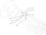
- FIGS. 3 A and 3 Bare perspective and side views, respectively, of the bone preparing guide and spacer on a foot in accordance with an embodiment of the invention.
- FIG. 4 Ais a perspective view of a spacer in accordance with another embodiment of the invention.
- FIG. 4 Bis a perspective view of the spacer of FIG. 4 A on a foot in accordance with an embodiment of the invention.
- FIGS. 4 C- 4 Fillustrate an example configuration of a spacer where the thickness of the spacer varies across the width of the spacer.
- FIGS. 4 G- 4 Jillustrate another example configuration of a spacer where the thickness of the spacer varies across the width of the spacer.
- FIG. 4 Killustrates an example configuration of a spacer that includes at least two pins separated from each other with a gap.
- FIG. 4 Lillustrates an example configuration of the spacer in FIG. 4 K where the ends of the pins are tapered to a point to facilitate insertion.
- FIG. 4 Millustrates an example configuration of the spacer in FIG. 4 K where the pins have an alternative cross-sectional shape.
- FIG. 5is a top plan view of an embodiment of a bone preparing guide and the spacer of FIG. 4 A on a foot in accordance with an embodiment of the invention.
- FIGS. 6 A and 6 Bare perspective views of a bone preparing guide and a tissue removing instrument location check member in accordance with an embodiment of the invention.
- FIGS. 6 C and 6 Dare perspective views of the bone preparing guide and tissue removing instrument location check member on a foot in accordance with an embodiment of the invention.
- FIGS. 7 and 8are perspective views of a tissue removing instrument used in conjunction with the bone preparing guide in accordance with an embodiment of the invention.
- FIG. 9is a side perspective view of a foot depicting bone plates across a joint between first and second bones in accordance with an embodiment of the invention.
- this disclosureis directed to surgical instruments and techniques that can be used in a bone correction procedure.
- Embodiments of the disclosureinclude a spacer, bone preparing guide, and/or tissue removing instrument location check member along with methods of positioning such spacers and guides in a medical procedure.
- Such instrumentscan be used alone or in combination to improve the efficacy of a bone correction procedure as compared to when the procedure is used without the instruments.
- embodiments of the spacer, bone preparing guide, and/or tissue removing instrument location check membercan be used before and/or during a surgical procedure, such as a bone alignment, osteotomy, fusion procedure, and/or other procedures where one or more bones are to be prepared (e.g., cartilage or bone removal and/or cut).
- a surgical proceduresuch as a bone alignment, osteotomy, fusion procedure, and/or other procedures where one or more bones are to be prepared (e.g., cartilage or bone removal and/or cut).
- a surgical proceduresuch as a bone alignment, osteotomy, fusion procedure, and/or other procedures where one or more bones are to be prepared (e.g., cartilage or bone removal and/or cut).
- a surgical proceduresuch as a bone alignment, osteotomy, fusion procedure, and/or other procedures where one or more bones are to be prepared (e.g., cartilage or bone removal and/or cut).
- Such a procedurecan be performed, for example, on bones (e.g.,
- a procedure utilizing one or more embodiments of the disclosurecan be performed to correct an alignment between a metatarsal (e.g., a first metatarsal) and a second metatarsal and/or a cuneiform (e.g., a medial, or first, cuneiform), such as in a bunion correction surgery.
- a metatarsale.g., a first metatarsal
- a cuneiforme.g., a medial, or first, cuneiform
- An example of such a procedureis a Lapidus procedure (also known as a first tarsal-metatarsal fusion).
- the procedurecan be performed by modifying an alignment of a metatarsal (e.g., a first metatarsal).
- An example of such a procedureis a basilar metatarsal osteotomy procedure.
- the described surgical instrumentscan be used in combination during a tarsometatarsal (“TMT”) fusion procedure to achieve a multi-planar realignment (e.g., bi-planar, tri-planar) of a first metatarsal with respect to a medial cuneiform.
- the spacercan be used to properly position a bone preparation guide, or cut guide, with respect to the TMT joint and, more particularly, guide surfaces or slots of the cut guide with respect to bone ends to be cut.
- one or more guide surfaces or slots of the cut guideare angled.
- the cut guidemay be configured to position a guide slot through which a cutting instrument is translated parallel to the end face of a first metatarsal while another guide slot is skewed with respect to the end face of a medial cuneiform.
- the guide slot positioned over the end of the medial cuneiformmay angle proximally from the medial to the lateral sides of the medial cuneiform, resulting in a wedge-shaped section of bone being removed from the medial cuneiform.
- the disclosed instrumentscan help appropriately prepare the ends of the first metatarsal and medial cuneiform for repositioning in multiple planes (e.g., a frontal plane, a transverse plane, and/or a sagittal plane), allowing the first metatarsal to be corrected from an anatomically misaligned position to an anatomically aligned position.
- multiple planese.g., a frontal plane, a transverse plane, and/or a sagittal plane
- FIG. 1shows a perspective view of an exemplary bone preparing guide and spacer 10 .
- the bone preparing guide and spacer 10can include a bone preparing guide 12 and a spacer 14 .
- the bone preparing guide and spacer 10can be provided to facilitate the positioning and/or preparation of a bone or bones.
- the bone preparing guide 12includes a body 16 defining a first guide surface 18 to define a first preparing plane and a second guide surface 20 to define a second preparing plane.
- a tissue removing instrumente.g., a saw, rotary bur, osteotome, etc., not shown
- remove tissuee.g., remove cartilage or bone and/or make cuts to bone).
- the first and second guide surfaces 18 , 20can be spaced from each other by a distance (e.g., between about 2 millimeters and about 10 millimeters, such as between about 4 and about 7 millimeters). In the embodiment shown, the first and second guide surfaces are parallel, such that cuts to adjacent bones using the guide surfaces will be generally parallel.
- a first facing surface 22is positioned adjacent the first guide surface 18 and/or a second facing surface 24 is positioned adjacent the second guide surface 20 .
- the distance between the first guide surface and the first facing surfacedefines a first guide slot 26
- the distance between the second guide surface and the second facing surfacedefines a second guide slot 28 .
- Each slot 26 , 28can be sized to receive a tissue removing instrument to prepare the bone ends therethrough.
- the first and second slots 26 , 28may be parallel or skewed (e.g., non-parallel) to each other.
- the facing surfaceseach contain a gap along their respective lengths, such that each of the surfaces is not a single, continuous surface. In other embodiments, the facing surfaces can each be a single, continuous surface lacking any such gap.
- an opening 30can be defined by the body 16 between the first and second facing surfaces 22 , 24 .
- the opening 30can thus be an area between the slots 26 , 28 useful, for instance, for allowing a practitioner to have a visual path to an osteotomy site (e.g., cartilage, bones, and/or joint space) during bone preparation and/or to receive instruments, as discussed further below.
- an osteotomy sitee.g., cartilage, bones, and/or joint space
- the opening 30extends across the body 16 a distance from a surface 32 opposite of the first facing surface 22 to a surface 34 opposite of the second facing surface 24 .
- the embodiment shownalso includes a first end 40 extending from the body 16 in a first direction and a second end 42 extending from the body 16 in a second direction.
- the second directioncan be different than the first direction (e.g., an opposite direction).
- the first and second ends 40 , 42can each extend out perpendicularly from the body 16 as shown or, in other embodiments, the first and second ends 40 , 42 can extend out from the body at differing angles.
- each of the first end 40 and the second end 42can include at least one fixation aperture 44 configured to receive a fixation device (e.g., a pin, not shown) to secure the guide 12 to one or more bones.
- a fixation devicee.g., a pin, not shown
- Such apertures 44may extend through each respective end at a vertical or skewed angle relative to a top surface of the guide 12 .
- the bone preparing guide 12can also include a first adjustable stabilization member 46 engaged with the first end 40 .
- the bone preparing guide 12also includes a second adjustable stabilization member 48 engaged with the second end 42 .
- Each of the members 46 , 48can be threaded and engage a threaded aperture defined by the ends 40 , 42 .
- the elevation of each end 40 , 42can be adjusted with respect to one or more bones by adjusting the member 46 , 48 at the end for which an elevation adjustment is desired.
- the members 46 , 48may be cannulated such that they can receive respective fixation devices.
- the guidecan include fewer adjustable stabilization members (e.g., none, one) or more adjustable stabilization members (e.g., three, four, or more) and the disclosure is not limited in this respect.
- the bone preparing guide as shown in FIG. 1includes the spacer 14 .
- the spacercan extend from the body in a third direction, the third direction being different than the first and second directions (e.g., perpendicular to the first and second directions), and it can be configured to be placed into a joint space between opposing bones.
- the spaceris integral with the guide and the guide and spacer are a single component, for example, a unibody construction.
- the spaceris physically separate from and insertable into the guide.
- the spacer and bone cutting guidemay be provided as part of a sterile kit (e.g., packed in single common container), alone or in combination with other components to facilitate the procedure being performed.
- the spacer 14can be selectively engaged with the bone preparing guide 12 , such that the spacer and guide can be attached and detached.
- the spacer 14can be received by the body 16 of the guide 12 , such as by inserting the spacer into opening 30 .
- the spacer 14may extend from the body in between the first guide surface 18 and the second guide surface 20 , or in between the first and second slots 26 , 28 , when provided.
- no connection between the guide 12 and spacer 14need be present, as the opening 30 itself may be sufficient for engaging the guide and spacer.
- the spacer 14can engage the guide 12 such that the guide 12 and/or spacer 14 can move relative to one another while engaged (e.g., in a vertical direction).
- the guide 12can move relative to the spacer 14 while the guide 12 and spacer 14 are engaged, such that the guide can be inserted over the spacer or removed from the spacer while the spacer is engaged within a joint space.
- a distal portion of the spacercan be inserted into a joint space (e.g., tarsal-metatarsal joint space) and the guide 12 positioned over the top of the spacer with a proximal portion of the spacer projecting out from the top of the guide.
- the guide 12 and spacer 14can be removably attachable, such as by magnets, a snap-fit, male-female interfacing parts, or other temporary connections.
- FIGS. 2 A and 2 Bshow an embodiment of a spacer 14 .
- the spacer 14is configured to be used to guide bone preparation instruments during a surgical procedure.
- the spacer 14is configured to be inserted into a bone preparation guide.
- FIG. 2 Aillustrates a perspective view of the spacer 14
- FIG. 2 Billustrates the spacer 14 on a foot.
- the spacer 14whether a stand-alone component, a separate component selectively engageable with a guide, or integrated with a guide, can be configured to be inserted into a space between two bones 50 and 52 (e.g., adjacent bones separated by a joint or different portions of a single bone).
- the space between two bones into which the spacer 14 is configured to be insertedcan be a TMT joint space, such as the first metatarsal-cuneiform joint as shown in FIG. 2 B where bone 50 is a first metatarsal and bone 52 is a medial cuneiform.
- the spacer 14can be inserted into a space between two bones in a variety of differing directions, depending on the application. In one example, the spacer 14 is inserted from the generally dorsal side of a foot. In another example, the spacer 14 is inserted from a generally dorsal-medial side of a foot or a medial surface of a foot.
- the spacer 14can include a first portion 60 that is configured to extend, at least partially, into a space between two bones (e.g., a joint space between bones 50 and 52 as shown in FIG. 2 B ).
- the first portion 60is a generally planar member having opposite planar surfaces.
- the generally planar memberhas one or more slots and/or apertures.
- the first portionhas at least two extending members configured to extend into the joint space.
- the extending memberscan include any cross-sectional shape, such as cylindrical, triangular, or frustoconical shape.
- the first portion 60can include a keel 62 , where the keel 62 is configured to facilitate insertion of an end of the first portion 60 into the space between two bones.
- the tip of the keel 62is linear (e.g., extending in a plane parallel to the width of the keel). In other embodiments, the tip of the keel 62 may be rounded and/or tapered to provide for easier insertion of the keel 62 into the space between two bones.
- the keel 62can have a width that is less than or equal to a width of the space between two bones (e.g., a width of a joint).
- the keel 62can have a thickness (e.g., extending in a direction perpendicular to the width of the keel and along the length of the space between two bones) that is equal to or less than the length of the space between two bones.
- a thicknesse.g., extending in a direction perpendicular to the width of the keel and along the length of the space between two bones.
- the thickness of the keel 62may be sized to alter, such as expand, the space between two bones when inserted.
- the keel 62can have a uniform thickness along its length as seen in FIG. 2 A or can have a thickness that varies, such as a thickness that tapers in a direction proceeding toward the tip of the keel 62 (e.g., a
- a length of the keel 62 , and first portion 60can be configured to allow the keel 62 to extend vertically to a bottom base of the space between two bones (e.g., where the spacer 14 is used in an application on the foot as seen in FIG. 2 B , the keel 62 can extend from a generally dorsal side of the foot to a generally plantar side).
- the length of the keel 62can be configured such that the keel 62 extends only partially into the space between two bones, such as through a point in the space between two bones where there is present opposing interfacing surfaces (e.g., planar interfacing surfaces of two bones) and stops extending into the space between two bones where a bump or eccentric interfacing surface is present.
- the keel 62 as shown in the illustrated exampleis generally linear along its length. However, in other examples the keel 62 may include one or more contours along its length, where the one or more contours are configured to conform to an anatomic geometry of one or more bone ends interfacing at the space into which the keel 62 is inserted.
- the keel 62 , and the first portion 60can be made of various materials appropriate for one or more desired applications of the spacer.
- the keelcan made of a rigid material, such as metal or plastic, which does not deform or otherwise change geometry when inserted into the space between two bones. By preventing the keel from deforming when inserted into the space between two bones, the spacer can be maintained in general alignment with the interfacing bone surfaces at the space.
- the keelcan be made of a flexible material in order to generally maintain alignment of the spacer with the interfacing bones surfaces at the space while providing the keel with some give in its geometry to conform to one or more non-parallel portions of interfacing bones at the space.
- the keelincludes a combination of a rigid material and a flexible material.
- a perimeter of the keelmay include the flexible material to facilitate insertion into the joint space and a central portion can include a rigid material to prevent deformation.
- the spacer 14can further include a second portion 64 at or near an end of the spacer 14 opposite the keel 62 .
- the second portion 64can be designed to be gripped, such as by a hand of a surgeon during a procedure.
- the second portion 64can have, in some instances, one or more recesses 66 (two recesses 66 are shown in FIG. 2 A , with each recess 66 disposed opposite the other) to enhance a grip on the second portion 64 .
- the second portion 64can also include a roughened texture to also enhance a grip on the second portion 64 .
- the one or more recesses 66 and/or roughened texturecan be particularly beneficial where the second portion 64 is to be gripped by a wet and/or gloved hand of a surgeon.
- the spacer 14can have an intermediate portion 68 disposed between the first and second portions 60 , 64 .
- the first, second, and intermediate portionscan be provided as an integral member or can be provided as separately joined components.
- each portioncan comprise a material different from the other portions, and the material can have different characteristics, such as rigidity and flexibility, than the materials of the other portions.
- all the portions of spacer 14may be fabricated from the same material, such as a unitary body formed of metal or plastic.
- the intermediate portion 68can be engageable with the body of the guide (e.g., at the opening defined by the body of the guide).
- the intermediate portion 68can have a first region 70 and a second region 72 .
- the first region 70can have an extended thickness relative to the thickness of the first portion 60 (and thus the keel 62 ) and can transition from interfacing with the guide to the second portion 64 along its length.
- the second region 72can have an extended width relative to the width of the first portion 60 (and thus keel 62 ).
- the extended thickness of the first region and/or the extended width of the second region 72can allow the spacer 14 to be more stably received by the body of the guide in examples where the spacer 14 and guide are separate components.
- the intermediate portion 68can be used to provide a first guide surface and an opposite second guide surface.
- the first portion 60 (and thus the keel 62 ) of the spacercan be inserted into a joint space, and a surface of the intermediate portion 68 can be used to provide a guide surface.
- the surface of the first region 70 on a first side of the spacer 14can be configured as a first guide surface
- the surface of the first region 70 on an opposite side of the spacer 14can be configured as a second guide surface.
- At least the first region 70 of the intermediate portion 68has a thickness greater than the thickness of the first portion 60 .
- the difference in thickness of the first region 70 and the first portion 60 on each side of the spacer 14can define a length and thickness of tissue to be removed by a tissue removing instrument guided by the surface of the intermediate portion.
- the first portion 60may be inserted into a joint space and a tissue removal instrument placed against the intermediate portion 68 to guide a preparation of a first bone on a first side of the spacer 14 .
- a tissue removal instrumentcan be placed against the intermediate portion 68 to guide a second preparation to a second bone on a second, opposite side of the spacer 14 .
- the tissue removing instrumentcan be guided by the spacer 14 for about one-half of a thickness of the tissue to be removed. Then the spacer can be removed from the joint space and the tissue removing instrument could be reinserted to finish the tissue removal.
- FIGS. 3 A and 3 Bshow perspective and side views, respectively, of the bone preparation guide and spacer 10 on a foot.
- the bone preparing guide and spacer 10can be positioned onto the foot in different ways.
- the spacer 14can first be inserted into the space between two bones (as shown in FIG. 2 B ).
- the guide 12can then be placed onto the foot so as to engage the already inserted spacer 14 (e.g., by sliding the guide 12 vertically downward toward the foot on the spacer 14 , such as via the opening defined by the body of the guide 12 ).
- the guide 12can first be positioned in proximity to the space between two bones and the spacer 14 then inserted through the guide 12 and into the joint space underlying the guide.
- the guide 12can preliminarily position the spacer 14 (e.g. via the opening defined by the body of the guide 12 ) into the space between two bones.
- the cliniciancan manipulate the location of guide 12 and/or spacer 14 to orient the components at a desired location relative to the two bones (e.g., by orienting the cutting slots of the guide 12 relative to the ends of bones 50 and 52 , respectively).
- the bone preparing guide and spacer 10can be positioned on the foot with guide 12 being positioned in the joint between the two bones as a single structure, e.g., thereby simultaneously positioning the guide 12 and spacer 14 on the foot.
- the spacer 14can serve to provide initial stability to the guide 12 (e.g., prior to the guide 12 receiving fixation devices).
- the spacer 14can engage with the guide 12 and, once seated in the space between the bones, act to support the guide 12 .
- the guide 12 and spacer 14are separate components insertable into each other, the depth that the spacer 14 is inserted within the space between bones can be adjusted without needing to remove the guide 12 .
- the distance between where the guide 12 is positioned vertically in relation to the space between bonescan be adjusted while leaving the spacer 14 in place.
- spacer 14can serve as an alignment and/or reference tool for the guide 12 with respect to the one or more bone surfaces to be prepared (e.g., cut, morselized).
- bone surfaces to be preparedcan include all or a portion of an interfacing surface of bone 50 or 52 as shown.
- the spacer 14When the spacer 14 is inserted into the space (e.g., a joint) between the bones 50 , 52 , the spacer 14 can act to align the guide 12 at an appropriate position (e.g., longitudinal along the bones 50 , 52 ) and orientation (e.g., angle relative to the bones 50 , 52 in multiple planes selected from more than one of a frontal plane, a transverse plane, and a sagittal plane) for the intended procedure relative to the surfaces of the bones 50 , 52 to be prepared.
- an appropriate positione.g., longitudinal along the bones 50 , 52
- orientatione.g., angle relative to the bones 50 , 52 in multiple planes selected from more than one of a frontal plane, a transverse plane, and a sagittal plane
- the spacer 14when the spacer 14 is inserted into the space between bones 50 , 52 , the spacer can help align and orient, in one or more planes, the first guide surface 18 and the second guide surface 20 (and/or slots 26 , 28 , when provided) of the guide 12 relative to respective surfaces of the bones 50 , 52 to be prepared.
- the spacer 14can engage the guide 12 (e.g., physically restrict the free range of movement of guide 12 ), longitudinally aligning the guide 12 with the surface of each of bones 50 and 52 to be prepared.
- spacer 14can longitudinally align the first guide surface 18 with the end surface of the bone 52 and the second guide surface 20 with the end surface of the bone 50 .
- the spacer 14when inserted into the space between bones, can extend out from the space and provide an indication as to the location of the interfacing, end surfaces of each of bones 50 and 52 . In this way, orienting the guide 12 relative to the spacer 14 serves as an angular reference relative to the end surfaces of each of bones 50 and 52 . Thus, the spacer 14 can facilitate accurate preparation of a desired surface of one or more bones 50 , 52 .
- the spacer 14can be configured to orient a first guide surface 18 parallel to the preparation surface of bone 52 and/or a second guide surface 20 parallel to the preparation surface of bone 50 .
- orienting the first guide surface 18 and the second guide surface 20 , or slots 26 , 28when provided, parallel to the bone end surfaces to be cut using the spacer 14 as a reference can facilitate removal of a slice of relatively constant thickness.
- the end of bone 50 facing bone 52 and/or the end of bone 52 facing bone 50may be morselized in addition to or in lieu of being cut to prepare the end of the bone.
- a plantar-based wedgemay be cut from a medial cuneiform (e.g., bone 52 ), e.g., to correct a misaligned first metatarsal (e.g., bone 50 ).
- first guide surface 18 and the second guide surface 20 , or slots 26 and 28when provided, can be oriented at a skewed angle relative to respective bones 52 and/or 50 using the spacer 14 as a reference for the skewed angle at which the one or more bones 50 , 52 are to be cut.
- first guide surface 18 and/or second guide surface 20may skew proximally back along the length of the medial cuneiform as the guide surface extends from the medial side of the medial cuneiform to the lateral side of the medial cuneiform.
- the bone portion cut using a guide surface so configuredcan remove more bone from the lateral side of the medial cuneiform than the medial side of the medial cuneiform, resulting in a wedge-shaped portion of bone being removed from the medial cuneiform.
- the spacer 14can also serve as a reference for indicating a thickness of tissue (e.g., such as bone) to be removed from a surface of a bone 50 and/or 52 .
- tissuee.g., such as bone
- a distance between a first longitudinal surface of spacer 14 and the first guide surface 18may define a thickness of tissue to be cut from the surface of the bone 52 .
- a distance between a second longitudinal surface (e.g., opposite the first longitudinal surface) of the spacer 14 and the second guide surface 20may define a thickness of tissue to be cut from the surface of the bone 50 .
- a cliniciancan utilize the spacer 14 as a reference prior to preparing one or more bones in order to visualize whether the proposed bone preparation matches the desired bone preparation, such as whether the thickness of the cut to be made is in accordance with a desired thickness of tissue to be removed, and make any adjustments prior to implementation of the bone preparation action.
- a guidecan be designated with an identification number representing a cut thickness facilitated by that particular guide, which is defined by the distance between an adjacent surface of the spacer 14 and the respective guide surface of the guide.
- the distance between a first guide surface 18 and the spacer 14can be different from the distance between a second guide surface 20 and the spacer 14 , such that different thickness cuts can be made on different, interfacing bones.
- the distance between one or more guide surfaces on the guide and the spacer 14can be adjustable, allowing a user to vary the thickness of matter removed by a cut.
- cut guide 12includes a guide surface (e.g., first guide surface 18 and/or second guide surface 20 ) that skews proximally from the medial to the lateral side of the foot to which the cut guide is applied
- the angle of skewmay be fixed or may be variable.
- cut guide 12may have an adjustable guide surface (e.g., first guide surface 18 and/or second guide surface 20 ) where the angle of skew can be adjusted.
- a cliniciancan set the angle of the guide surface(s) relative to the bone, e.g., to remove more on the lateral side than the medial side, more on the medial side than the lateral side, or the same amount on both the lateral and medial sides, depending on the angle set.
- the adjustable anglecan be temporarily fixed, or locked, to prevent inadvertent movement after setting the desired angle.
- the guide surfacee.g., first guide surface 18 and/or second guide surface 20
- the guide surfacemay be adjustable to provide an angle (e.g., between the guide surface and first and/or second facing surfaces 22 , 24 ) ranging from 0 degrees to 25 degrees, such as 0 degrees to 10 degrees.
- the guide surfacemay be adjustable from 25 degrees to a non-zero degree angle less than 25 degrees.
- spacer 14is illustrated to be engageable with the guide 12
- the spacer 14can also be configured to engage with other guides.
- spacer 14may be used as part of a kit that includes a plurality of guides with different sized cut widths.
- a cliniciancan select one of the plurality of different sized guides and use the selected guide in combination with the spacer to perform a procedure.
- a clinicianmay select one guide 12 to engage with spacer 14 and provide a designated first cut thickness. If the clinician, using the spacer 14 as a reference, determines that the cut thickness that would result using the first guide is not desirable for the particular operation, the spacer 14 can be removed from the first guide and engaged with a second guide having a designated second cut thickness different from the first cut thickness of the first guide.
- spacer 14 illustrated and described above with respect to FIGS. 1 - 3can provide an effective tool for performing various medical procedures, such as helping to position a bone preparation guide during a tarsal-metatarsal fusion procedure
- the configuration of spacer 14may vary, e.g., depending on the characteristics of use and targeted clinical outcome.
- the width of the spacer 14can be sized such that the spacer extends into a lateral region of adjacent bone ends, when the spacer is positioned between the bones.
- the width of the portion of spacer 14 configured to be positioned between adjacent portions of bonee.g., first portion 60
- the width of the portion of spacer 14 configured to be positioned between adjacent portions of bonecan be wide enough (in the medial to lateral direction) that the spacer extends at least into the lateral half of the end faces of the adjacent bones between which the spacer is positioned.
- first portion 60 of the spacermay be project laterally a distance sufficient to position the first portion of the spacer between the lateral half of the end faces of first metatarsal 50 and medial cuneiform 52 .
- the first portion 60may contact the ends of first metatarsal 50 and medial cuneiform 52 on the lateral side of the bone ends (e.g., lateral-most half, lateral-most third, lateral-most edges).
- the first portion 60 of spacer 14extends laterally a distance sufficient to contact a medial side of an adjacent bone (e.g., second metatarsal), when positioned between first metatarsal 50 and medial cuneiform 52 .
- an adjacent bonee.g., second metatarsal
- first portion 60 of the spacermay also project medially to contact the ends of first metatarsal 50 and medial cuneiform 52 on the medial side of the bone ends (e.g., medial-most half, medial-most third, medial-most edges).
- first portion 60may be laterally offset in the medial-lateral dimension.
- second portion 64may be symmetric with respect to the first portion and have the same width as the first portion or may be asymmetric with respect to the first portion and/or have a different width than the first portion.
- Configuring spacer 14 to have a portion positionable within a lateral portion of a joint spacecan be useful to help prevent misalignment of guide 12 .
- a gap between bone 50 and bone 52may open on the medial side of the joint space between the ends of the bones. This gap may occur, e.g., as an intermetatarsal angle between a first metatarsal and second metatarsal is closed by pivoting and/or rotating the first metatarsal toward the second metatarsal.
- a spacer positioned inside of the joint spacecan shift (e.g., laterally or medially) and/or rotate (e.g., such that the portion of the spacer above the joint space does not project dorsally but instead projects in a lateral-dorsal or medial-dorsal direction).
- the cutting surface(s) of the guidemay be misaligned with respect to when the ends of bones 50 and 52 are desirably cut.
- the spacer 14By configuring the spacer 14 so that at least a portion of the spacer positioned between the ends of bones 50 and 52 (e.g., within the tarsal-metatarsal joint space) is on the lateral side of the joint space, the spacer may remain properly positioned through realignment of bone 50 .
- the intermetatarsal angle between a first metatarsal and second metatarsalis closed by pivoting and/or rotating the first metatarsal toward the second metatarsal
- the lateral side of the ends of bones 50 and 52may move toward each other while the medial side of the ends of the bones may move away from each other.
- the spacer 14may be retained in a stable position in the joint space between the bones such that, when guide 12 is subsequently positioned over spacer 14 , the guide is appropriately positioned to cut the ends of bones 50 and 52 (e.g., by translating a cutting instrument along and/or through guide surfaces of the guide to resects the bone ends).
- Spacer 14can have a variety of different configurations that allow at least a portion of the spacer to be positioned on lateral sides of the end faces of the bones between which the spacer is inserted.
- the portion of spacer 14 that is configured to project plantarly of bone preparation guide 12e.g., the portion positioned in the joint space between opposed ends of bones 50 and 52 while guide 12 is positioned on top of the bones
- first portion 60 of spacer 14may be offset relative to an axis extending through a geometric center of the ends of the bones and the joint therebetween.
- the spacer 14may be inserted into one side of the joint space between the bones 50 and 52 while leaving another side of the joint space devoid of any spacer substrate.
- spacer 14may be configured so that first portion 60 is offset relative to an axis extending through a geometric center of second portion 64 .
- first portion 60may project downwardly from one side of the second portion.
- the cross-sectional planee.g., medial-lateral plane at a single elevation
- first portion 60 of the spacermay be laterally offset relative to second portion 64 . That is, first portion 60 may be positioned preferentially toward the lateral side of the joint as opposed to the medial side of the joint.
- the laterally-offset first portion 60 of spacer 14may contact the ends of bones 50 and 52 on the lateral side of the bone ends (e.g., lateral-most half, lateral-most third, lateral-most edges) but not on the medial side of the bone ends (e.g., medial-most half, medial-most third, medial-most edges).
- the second portion 64 of the spacermay be substantially centered between the lateral and medial edges of bones 50 and 52 . Accordingly, the portion of spacer 14 that is visible by the clinician and/or used to orient guide 12 (e.g., by positioning the guide over the spacer) can be substantially centered in the medial-lateral direction over the ends of the bones 50 and 52 . However, the portion of spacer 14 that actually projects below the dorsal face of bones 50 and 52 in the plantar direction can be offset to the lateral side in the medial-lateral direction.
- FIGS. 4 A and 4 Billustrate an example configuration of a spacer 400 that has a laterally offset structure positionable within a joint space.
- FIG. 4 Aillustrates a perspective view of the spacer 400
- FIG. 4 Billustrates a perspective view of the spacer 400 on a foot.
- the spacer 400whether a stand-alone component, a separate component selectively engageable with a guide, or integrated with a guide, can be configured to be inserted into a space between two bones 50 and 52 (e.g., adjacent bones separated by a joint or different portions of a single bone).
- the space between two bones into which the spacer 400 is configured to be insertedcan be a tarsometatarsal (“TMT”) joint space, such as the first metatarsal-cuneiform joint as shown in FIG. 4 B .
- TMTtarsometatarsal
- the spacer 400includes the first portion 60 that is configured to extend, at least partially, into a space between two bones (e.g., a joint space between bones 50 and 52 as shown in FIG. 4 B ).
- the first portion 60defines a central longitudinal axis 402 .
- the first portion 60further includes a first sidewall 404 and a second sidewall 406 defining a width of the first portion 60 therebetween.
- the first portion 60can include a keel 62 , where the keel 62 is configured to facilitate insertion of an end of the first portion 60 into the space between two bones.
- a thickness of the keel 62can taper moving in a direction toward the tip of the first portion 60 (e.g., toward the tip of the keel 62 ).
- the keel 62can extend vertically to a bottom base of the space between two bones, and in other cases the keel 62 may only partially extend into the space between two bones.
- the thickness of first portion 60is constant across the length of the first portion or varies, in some examples, the thickness ranges from 0.2 mm to 3 mm, such as from 0.38 mm to 1.8 mm.
- the spacer 400 illustrated in FIGS. 4 A and 4 Bfurther includes a second portion 64 at or adjacent an end of the spacer 400 opposite the keel 62 .
- the second portion 64has a central longitudinal axis 408 .
- the second portion 64can be designed to be gripped, such as by a hand of a surgeon during a procedure.
- the second portion 64can have, in some instances, one or more recesses 66 and/or a roughened texture to enhance a grip on the second portion 64 .
- the spacer 400can also have, in some embodiments, an intermediate portion 68 disposed between the first and second portions 62 , 64 .
- the intermediate portion 68can be engageable with the body of the guide (e.g., at the opening defined by the body of the guide).
- the intermediate portion 68has a first region 70 and a second region 72 .
- the first region 70can have an extended thickness relative to the thickness of the first portion 60 (and thus the keel 62 ) and can transition from interfacing with the guide to the second portion 64 along its length.
- the second region 72can have an extended width relative to the width of the first portion 60 (and thus keel 62 ).
- the intermediate portion 68including the first and second regions 70 , 72 , has a central longitudinal axis that coincides (e.g., is coaxial) with the central longitudinal axis 408 of the second portion 64 .
- an offset configuration of the spacer 400includes the first portion 60 being offset from the second portion 64 and/or the intermediate portion 68 .
- the first portion 60is offset from both the second portion 64 and the intermediate portion 68 .
- the central longitudinal axis 402 of the first portion 60is spaced from the central longitudinal axis 408 of the second portion 64 and intermediate portion 68 .
- the distance separating a geometric enter of the central longitudinal axis 402 of the first portion 60 from the geometric center of the central longitudinal axis 408 of the second portionranges from 1 mm to 20 mm, such as from 3 mm to 17 mm.
- the width of first portion 60may also vary, in some instances, the width ranges from 2 m to 25 mm, such as 5 mm and 20 mm. Accordingly, in some configurations, a distance from a geometric center of central longitudinal axis 408 to first sidewall 404 bounding the lateral-most extend of spacer 14 may range from 5 mm to 15.
- the spacer 400can be inserted into the space between two bones 50 and 52 , such as shown in FIG. 4 B .
- the offset configuration of the spacer 400can result in the first portion 60 contacting the bones 50 and 52 (e.g., the end faces of the bones) and optionally an adjacent third bone 53 (e.g., a medial side of the bone), while the second portion 64 and central longitudinal axis 408 thereof is generally positioned at a center of the joint.
- the spacer 400is inserted into the first TMT joint and the first portion 60 contacts the first metatarsal 50 , first cuneiform 52 , and second metatarsal 53 .
- a first face surface of the first portion 60can contact the first metatarsal 50
- a second face surface of the first portion 60 opposite the first face surfacecan contact the first cuneiform 52
- the first sidewall 404 of the first portion 60can contact the medial side of the second metatarsal 53 .
- the central longitudinal axis 408 of the second portion 64may be generally centered between a medial side and a lateral side of the TMT joint
- the central longitudinal axis 402 of the first portion 60may be generally closer to the lateral side than the medial side of the TMT joint (e.g., at a lateral third of the TMT joint). Accordingly, in some instances, the first portion 60 may be inserted and secured within only a lateral region of the TMT joint.
- the offset configuration of the spacer 400can be useful in providing a stable spacer within the joint space, for instance, during a procedure where a bone alignment is to be altered.
- the bone 50may need to be realigned (e.g., using positioner device 410 ) in a manner that reduces an angle between the bone 50 and the bone 53 .
- a gap at the medial side of the joint between the bone 50 and bone 52may increase. This may cause a spacer positioned within the joint to become unstable (e.g., because the spacer is no longer tightly engaged between the bones 50 and 52 due to the increased gap at the medial side of the joint).
- spacer 400 having the offset configuration within the joint during bone realignmentcan help stably maintain the spacer 400 within the joint.
- the spacer 400can have the first portion 60 positioned in the joint closer to the lateral side than the medial side (e.g., at the lateral region of the joint such that the first sidewall 404 contacts the medial side of the second metatarsal 53 ) the spacer can be generally maintained at a constant position within the joint during this realignment. This can result because the spacing between the bones 50 and 52 at the lateral side of the joint during realignment may stay substantially constant or be reduced relative to the spacing before the realignment.
- the first portion 60 positioned at the lateral regioncan be stably held within the joint even after this realignment is completed.
- the second portion 64 , and central longitudinal axis 408 thereofmay also be generally maintained at its original position, such as at the center of the joint.
- This spacer 400 configurationwhich may provide increased stability, can in turn be useful when the spacer 400 is utilized to facilitate preparation (e.g., cutting) of one or more bone surfaces, as will be described below with reference to FIG. 5 .
- the spacercan have a variety of different cross-sectional configurations.
- spacer 14 in FIGS. 1 - 3 and spacer 400 in FIGS. 4 A and 4 Bare illustrated as having a constant thickness across the width of the spacer, the thickness of the spacer can vary over the width.
- FIGS. 4 C- 4 Fillustrate an example configuration of spacer 14 where the thickness of the spacer varies across the width of the spacer.
- FIG. 4 Cis a top view of the example spacer;
- FIG. 4 Dis a front view of the spacer; and
- FIGS. 4 E and 4 Fare opposite side views of the spacer.
- the Z-axis on the figuresrepresents the vertical orientation of the spacer (e.g., dorsal to plantar direction) in typical use.
- spacer 14defines a length L (e.g., parallel to the longest axis of the spacer), a width W perpendicular to the length, and a thickness T perpendicular to both the length and width.
- the width W of the first portion 60is the distance from the first sidewall 15 to the second sidewall 17 of the first portion.
- the thickness T of the spacertapers across the width of the spacer from the first sidewall 15 to the second sidewall 17 .
- FIGS. 4 G- 4 Jsimilarly illustrates an example configuration of spacer 400 where the thickness of the spacer varies across the width of the spacer.
- FIG. 4 Gis a top view of the example spacer;
- FIG. 4 His a front view of the spacer; and
- FIGS. 4 E and 4 Fare opposite side views of the spacer.
- the Z-axis on the figuresrepresents the vertical orientation of the spacer (e.g., dorsal to plantar direction) in typical use.
- spacer 14defines a length L (e.g., parallel to the longest axis of the spacer), a width W perpendicular to the length, and a thickness T perpendicular to both the length and width.
- the width W of the first portion 60is the distance from the first sidewall 404 to the second sidewall 406 of the first portion.
- the thickness T of the spacertapers across the width of the spacer from the first sidewall 404 to the second sidewall 406 .
- spacer 14When configured with a differential thickness across its width, spacer 14 ( FIGS. 4 C- 4 F )/spacer 400 ( FIGS. 4 G- 4 J ) is thicker on one side than the other side.
- the spacercan have a continuous angle of taper across its width W or discontinuous taper, such one or more steps that define discrete thickness transition points.
- the spacerhas a thickness at least 0.1 mm less at its thinner sidewall compared to its thicker sidewall, such as at least 0.2 mm less, at least 0.5 mm less, or at least 1 mm less.
- the spacermay have a thickness from 0.1 mm to 2 mm less at its thinner sidewall compared to its thicker sidewall.
- second portion 64 and intermediate portion 68 of spacer 14 / 400are illustrated as not being tapered, one or both of second portion 64 and intermediate portion 68 can be tapered in other embodiments.
- a spacer with tapered thicknessmay be positioned in a TMT joint with the thicker side of the spacer located medially and the thinner side of the spacer located laterally across the joint.
- a larger gapmay open on the medial side between the end face of the first metatarsal and the end face of the medial cuneiform than on the lateral side. Accordingly, positioning the thicker portion of the spacer medially and the thinner portion of the spacer laterally across the TMT joint can help fill a gap between the bones, e.g., helping the spacer to fit snuggly within the TMT joint space and prevent inadvertent movement of the spacer.
- Spacer 14 / 400can have any suitable cross-section shape.
- spacer 14 / 400is illustrated as defining a substantially rectangular shape, in other examples the spacer can define other shapes.
- Spacer 14 / 400can define any polygonal (e.g., square, hexagonal) or arcuate (e.g., circular, elliptical) shape, or even combinations of polygonal and arcuate shapes.
- first portion 60 of spacer 14 / 400need not be a continuous structure across its width W but can be formed of discontinuous segments or portions of material which, in combination, achieve spacer functions.
- FIG. 4 Killustrates an example configuration of spacer 400 where first portion 60 is formed by at least two pins 403 A and 403 B separated from each other with a gap therebetween.
- the pins 403 A and 403 Bextend parallel to the length of the spacer (e.g., from intermediate portion 68 and/or second portion 64 ).
- spacer 400may include more pins (e.g., three, four, or more) pins arrayed across at least a portion of the width of the spacer with a gap between each adjacent pin.
- Each pincan have the same cross-sectional dimension (e.g., diameter) or at least one pin can have a cross-sectional dimension greater than at least one other pin.
- a medial-most pin(e.g., centered pin) may have a larger cross-sectional diameter than a lateral-most pin.
- pins 403 A and 403 Bare illustrated as arranged to provide a laterally offset first portion 60 , the pins may be arranged to provide a first portion that is centered with the second portion 64 or otherwise suitably arranged.
- FIG. 4 Lillustrates an example configuration of the spacer in FIG. 4 K where the ends 405 A and 405 B of pins 403 A and 403 B, respectively, are tapered to a point to facilitate insertion.
- pins 403 A and 403 B of spacer 400can define any polygonal (e.g., square, hexagonal) or arcuate (e.g., circular, elliptical) shape, or even combinations of polygonal and arcuate shapes.
- the pinscan be cylindrical, trapezoidal, triangular, square, rectangular, oval, hexagonal, or have yet other cross-sectional shape.
- FIG. 4 Millustrates an example configuration of the spacer in FIG. 4 K where pins 403 A and 403 B have a rectangular cross-sectional shape (e.g., across the width of the pins).
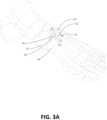
- FIG. 5illustrates a top plan view of an embodiment of a bone preparing guide 450 and the spacer 400 on a foot.
- Like numerals used herein in connection with the bone preparing guide 450refer to like elements of the bone preparing guide 12 .
- the bone preparing guide 450can be placed after one or more bones have been realigned by engaging the bone preparing guide 450 with the spacer 400 similar to that described previously.
- the bone preparing guide 450can be engaged at the intermediate portion of the spacer 400 by moving the opening 30 of the guide 450 over the second portion of the spacer 400 .
- using the spacer 400can substantially maintain the intermediate and second portions, and thus central longitudinal axis thereof, at the desired position, such as at the center of the joint.
- placing the guide 450 using the intermediate and/or second portions of the spacer 400can result in alignment of the guide 450 at the desired position with respect to the joint, and thus bones 50 and 52 .
- bone preparationcan proceed efficiently using the guide 450 .
- bone preparing guide 450can have a variety of different configurations, as described above with respect to bone preparing guide 12 , in the configuration illustrated in FIG. 5 , bone preparing guide 450 includes a cutting slot 26 that is skewed form (e.g., oriented at an angle) relative to cutting slot 28 and/or the joint between bones 50 and 52 .
- the slot 26can be angled to an extent suitable for providing anatomically appropriate bone preparation (e.g., one or more bone cuts) depending on the procedure, and thus anatomical region, for which the guide 450 is used.
- Example angles of skew discussed above with respect to cut guide 12can also be used for bone preparing guide 450 .
- the slot 26can be angled relative to a TMT joint space and/or end of first metatarsal for cutting a portion of a cuneiform (e.g., medial cuneiform 52 ).
- the slot 26can be angled proximally (e.g., away from the distal end of the medial cuneiform) as the slot extends from the medial side to the lateral side of the medial cuneiform.
- a cut made along slot 26can result in a wedge being cut off the medial cuneiform that progressively increases in width (e.g., thickness) moving the medial side to the lateral side of the medial cuneiform.
- guide 450is configured to be flipped in the frontal plane 180 degrees for interchangeable use on either the right or left foot of a patient. For example, if a TMT fusion procedure is being performed on the left foot of the patient, guide 450 may be rotated in a first orientation so slot 26 is angled proximal from the medial to lateral direction of the left foot. By contrast, if the TMT fusion procedure is being performed on the right foot of the patient, guide 450 may be rotated 180 degrees to a second orientation so slot 26 is angled proximal from the medial to lateral direction of the right foot.
- the top and bottom surfaces of guide 450may be devoid of projections or other structural features that prevent the guide from being flipped and placed over a joint to be cut in order to configure the guide with skewed cutting slot for deployment on either foot.
- guide 450 with skewed slot 26is provided as part of a kit that includes a plurality of different guides.
- the guidescan vary by having different sizes and/or angles at which slot 26 is skewed relative to each other.
- a cliniciancan select one of the plurality of different guides, e.g., that best matches the size and/or angle of the cut desired to be made.
- each of the plurality of guidescan have anchoring apertures (e.g., first and second adjustable stabilization members 46 , 48 ) that are at the same location relative to each other (e.g., same separation distance and angle).
- a clinicianmay remove one guide from anchoring pins set into first metatarsal 50 and medial cuneiform 52 (e.g., by pulling the guide up off the pins) and insert a different guide, for example having a slot 26 skewed at a different angle than the removed guide, over the same pins (e.g., by pushing the second guide down over the pins).
- a clinicianmay take an X-ray of a TMT joint being operated upon before selecting the guide.
- the clinicianmay take the X-ray from the dorsal to plantar direction to select and size the cut angle to be made on the medial cuneiform.
- the clinicianmay then select a particular one of the plurality of available guides whose angle best matches the size and/or angle of the cut to be made for subsequently deployment over the TMT joint, and particularly over the end of the medial cuneiform to be cut, during the procedure.
- the slot 26is illustrated adjacent a cuneiform and thus can be configured at an angle proceeding proximally from the medial side to the lateral side of the guide 450 , e.g., corresponding generally to bone preparation appropriate for a cuneiform (e.g., cutting a wedge-shaped portion of the cuneiform). That is, a cut made using slot 26 can produce a progressively thicker bone cut progressing from the medial to lateral side of the cuneiform bone.
- an end of the slot 26 at the lateral side of the guide 450can be angled between two and ten degrees relative to an end of the slot 26 at the medial side of the guide 450 .
- an end of the slot 26 at the lateral side of the guide 450can be angled between two and five degrees relative to an end of the slot 26 at the medial side of the guide 450 .
- FIGS. 6 A- 6 Dshow an embodiment of a tissue removal location check member 80 .
- FIGS. 6 A and 6 Bshow perspective views of the bone preparing guide 12 and tissue removing instrument location check member 80 in isolation
- FIGS. 6 C and 6 Dshow perspective views of the bone preparing guide 12 and tissue removing instrument location check member 80 on a foot.
- the tissue removing instrument location check member 80can serve to allow a surgeon to visualize the position and/or orientation of a cut to be made using the guide 12 .
- the spacer and tissue removing instrument location check member 80can be engaged with the guide 12 at the same time.
- the tissue removing instrument location check member 80can include a first portion 82 and a second portion 84 . In some embodiments, such as that shown, the member 80 may further include an opening 86 defined between the first portion 82 and the second portion 84 .
- the member 80can be engageable with the guide 12 , such as at a slot 26 or 28 or opening 30 , via the first portion 82 of the member 80 . As shown, the first portion 82 is engaged with the guide 12 at the slot 28 and in some cases can extend down through the slot 28 . In other examples, the first portion 82 can engage the guide 12 at the slot 26 or at the opening 30 . Depending on the configuration of the tissue removing instrument location check member 80 , the first portion 82 may in some instances engage the guide 12 at more than one of the slot 26 , slot 28 , and opening 30 .
- the second portion 84is connected to or integral with the first portion 82 and extends and is spaced from the first portion 82 .
- the second portion 84can be configured to extend out from the guide 12 while the first portion 82 is engaged with the guide 12 .
- the first portion 82can be within the slot 28 of the guide 12 while the second portion 84 is spaced from the first portion 82 in a direction (e.g., radial) outside of the slot 28 .
- the second portion 84can have a width less than a width of the first portion 82 , and additionally may include curvature along its length.
- the second portion 84includes curvature along its length in a direction toward the guide 12 when the first portion 82 is engaged with the guide 12 .
- the opening 86may be configured to receive a portion of a bone such that the second portion 84 can extend outwardly around such bone portion received in the opening 86 .
- the first portion 82 and the second portion 84can be designed to be complimentary portions.
- the position of the second portion 84can in some predetermined manner correspond to the position of the first portion 82 .
- a tip of the second portion 84can extend a same depth as a bottom edge of the first portion 82 (e.g., the tip of the second portion 84 and a bottom edge of the first portion 82 extend along a same plane).
- visually inspecting a depth of the second portion 84(e.g., extended outside of the guide 12 ) can provide an indication as to a depth of the first portion 82 .
- the second portion 84can allow a surgeon to ascertain how deep the first portion 82 is within the tissue by simply looking at the second portion 84 that is outside the tissue.
- the depth of the second portion 84can directly correspond to the depth of the first portion 82 , and in other cases the correspondence between the first and second portions can be a predetermined ratio.
- the tissue removing instrument location check member 80can engage with the guide 12 in a manner that allows the member 80 to rotate relative to the guide 12 while engaged with the guide 12 . This can be seen by comparing the position of the member 80 in FIG. 6 A relative to the position of the member 80 in FIG. 6 B .
- the member 80can be configured such that rotational movement applied to the member 80 may cause the second portion 84 to rotate about the guide 12 from the position shown in FIG. 6 A to the position shown in FIG. 6 B , which in some cases can result in the second portion 84 being positioned downward from the guide 12 while the first portion 82 is engaged in one of the slots 26 , 28 or opening 30 .
- the opening 86can, in some applications, facilitate rotation of the second portion 84 about a portion of a bone by receiving a portion of such bone within the opening 86 and allowing the second portion 84 to extend outwardly around such bone. As such, the opening 86 can facilitate rotation of the member 80 while the member 80 is engaged with the guide 12 by preventing interference between the member 80 and a portion of a bone adjacent the second portion 84 .
- the member 80can be engaged with the guide 12 when the guide 12 is placed onto a foot (as shown in FIGS. 6 C and 6 D ).
- the first and second portions 82 , 84can be designed as complimentary portions.
- the first portion 82when the member 80 is engaged with the guide 12 on a foot, the first portion 82 can extend and contact a bone end at a same depth and location at which a cutting instrument would contact this bone end when using the guide 12 (e.g., via a slot defined in the guide).
- the second portion 84 of the member 80can act as an external extension from the guide 12 that projects down the side of a bone (e.g., 50 or 52 ) at the same trajectory and/or depth that a cutting instrument would be positioned when inserted through a slot of the guide 12 .
- a bonee.g., 50 or 52
- the first and second portions 82 , 84can be complimentary.
- the second portion 84can act to provide an indication as to trajectory and/or depth at which a cutting instrument would contact a bone end.
- the member 80may allow a surgeon to check the position and/or orientation of one or more preparation slots of the guide 12 relative to one or more bone 50 , 52 ends before performing the bone preparation action on the one or more bones 50 , 52 . Therefore, the member 80 can facilitate visualization of a cut depth and/or trajectory that would result from the current position and orientation of the guide 12 and allow a surgeon to adjust the position and/or orientation of the guide 12 as may be necessary for the desired application.
- imaging techniquese.g., X-ray
- the member 80can be engaged with the guide 12 such that the first portion 82 extends into tissue and contacts a bone end at a same depth and location at which a cutting instrument would contact this bone end when using the guide 12 in conjunction with the cutting instrument.
- the footcan then be imaged using an appropriate imaging technique while the first portion of the member 80 is within the tissue.
- Resulting images from the imaging techniquecan show the first portion of the member 80 relative to the bone end desired to be prepared in the specific application, and provide an indication as to a proposed cut depth and/or trajectory. In turn, this can allow a surgeon to adjust a position and/or orientation of the guide 12 as needed before performing the desired preparation action on this bone end.
- the member 80can be any component that projects from the guide (e.g., guide slot of a guide) in a manner that allows visualization of bone preparation position, trajectory, and/or thickness.
- the spacer 14 and member 80can both be used in a procedure to visualize proposed bone preparation and facilitate any adjustments to such bone preparation.
- the member 80can be a separate component.
- the member 80can engage with the guide 12 , and in some examples can additionally or alternatively engage with the spacer 14 .
- the member 80can be integral with the spacer 14 and/or guide 12 .
- the instrument location check member 80is capable of showing where the tissue removing instrument will intersect both the first and second bones.
- Such an embodimentincludes an instrument location check member with a first check member and a second check member (either or both of which can include some or all of the features described above with respect to a single member 80 ) connected together, such as with a bridge member.
- the first check membercan be received within the guide slot 26 and the second check member can be received with the guide slot 28 at the same time.
- FIGS. 7 and 8show perspective views of a tissue removing instrument 90 used in conjunction with the bone preparing guide 12 .
- the spacer 14can be engaged with the guide 12 while the instrument 90 is used to prepare one or more bones.
- the spacer 14can be removed from the guide 12 prior to use of the instrument 90 .
- the guide 12can be fixed in a position, such as by use of fixation devices through the guide 12 , along the foot resulting from use of the spacer 14 as a reference.
- FIG. 9shows a side perspective view of a foot 200 depicting bone plates 310 , 320 across a joint between a first metatarsal 210 and a medial cuneiform 220 .
- the ends of prepared bonescan be placed in apposition, optionally compressed together, and fixed with a bone fixation device.
- FIG. 9depicts a threaded olive pin 300 inserted through the first metatarsal 210 and into the medial cuneiform 220 to provide compression between the first metatarsal and the medial cuneiform.
- the position of the bonescan then be fixed with one or more bone fixation devices.
- FIG. 9shows a side perspective view of a foot 200 depicting bone plates 310 , 320 across a joint between a first metatarsal 210 and a medial cuneiform 220 .
- first bone plate 310e.g., a straight or curved bone plate positioned on a dorsal-medial side
- second bone plate 320e.g., a helical bone plate positioned from a medial side of the cuneiform to a plantar side of the metatarsal (other embodiments, not shown, may include a second straight bone plate)
- the olive pinmay be removed.
- Embodiments of the present inventionalso include methods, such as methods for fixing an orientation of a bone or bones.
- one method of positioning a boneincludes the steps of moving a bone from an anatomically misaligned position to an anatomically aligned position with respect to another bone and, after moving the bone into the aligned position, preparing an end of the moved bone and a facing end of another bone.
- a methodincludes the step of preparing a joint for a corrective procedure. For example, after creating surgical access to the joint and before moving the bones into an aligned position, soft tissue can be released to allow a bone, such as a metatarsal, to rotate freely.
- a bonesuch as a metatarsal
- obstructing bonemay be excised (e.g., a flare of the metatarsal base, or osteophyte) to further promote free rotation.
- the location of the intersection of the tissue removing instrument and the bone to be preparedis confirmed before bone preparation.
- a tissue removing instrument location check membercan be engaged with the preparation guide to visually confirm where a tissue removal instrument will contact the bone.
- a tissue spaceris engaged with the preparation guide to provide a reference for a position and/or orientation of a cut made through one or more defined by the guide. In either embodiment, such visual confirmation can include the use of an imaging device, such as an X-ray.
- additional fixation devicese.g., pins
- the aperturese.g., angled apertures
- the spacercan be reattached prior to further bone preparation steps.
- the end of a first metatarsal facing the medial cuneiformcan be prepared with a tissue removing instrument aligned with the first guide surface, such as by inserting the tissue removing instrument through a slot defined by the first guide surface and a first facing surface.
- the end of the medial cuneiform facing the first metatarsalcan be prepared with the tissue removing instrument aligned with a second guide surface, such as by inserting the tissue removing instrument through a slot defined by the second guide surface and a second facing surface.
- the cuneiform cut and the metatarsal cutcan be parallel, conforming cuts.
- embodiments of methods in accordance with the inventioncan also include steps performed after preparing the ends of the bones.
- the ends of the bonesmay be placed in apposition and optionally compressed together and the position of the bones can be fixed with one or more bone fixation devices (e.g., compressing bone screw, bone plate, bone staple, external fixator, intramedullary implant or nail) prior to a closing of the surgical access to the joint.
- bone fixation devicese.g., compressing bone screw, bone plate, bone staple, external fixator, intramedullary implant or nail
- one methodcan include inserting a spacer into a joint (e.g., TMT joint space) and then engaging the guide with the inserted spacer (in embodiments where the guide and the spacer are provided as separate components).
- the spacercan be inserted into the joint while the guide is placed onto the foot (in embodiments where the guide and the spacer are provided as separate components).
- the guide and the spacercan be positioned together. Then, the spacer can be used as a reference for positioning and/or orienting the guide at an appropriate location relative to one or more bones for an intended application.
- a tissue removing instrument location check membercan additionally or alternatively be used to provide an indication as to a depth and/or trajectory of a cut to be made through a slot defined by the guide on the foot.
- the location of the guide relative to the one or more bones to be preparedmay be adjusted according to references obtained from the spacer and/or tissue removing instrument location check member.
- the guidecan be fixed to the foot, such as through fixation devices (e.g., pins) inserted through apertures defined in the guide. After fixing the guide to the foot, the spacer and/or tissue removing instrument location check member may be removed.
- the spacer and/or tissue removing instrument location check membercan remain engaged with the guide after the guide is fixed to the foot so long as no interference with the tissue removing instrument will result.
- a tissue removing instrumentcan then be inserted through the guide (e.g., through a slot defined in the guide) to prepare one or more bones at the location of the fixed guide. Any cut portions of bone resulting from use of the tissue removing instrument can be removed from the joint.
- the prepared bonescan have their respective ends apposed together and fixation (e.g., one or more bone plates) can be applied for fusion of the prepared bone ends.
- Embodiments of the inventionalso include a disposable, sterile kit that includes an embodiment of a bone positioning guide, bone preparation guide, spacer, and/or tissue removing instrument location check member described herein.
- Other components that may be included within the sterile kitinclude bone fixation devices, such as bone plates and/or pins, and tissue removing instruments.
Landscapes
- Health & Medical Sciences (AREA)
- Surgery (AREA)
- Life Sciences & Earth Sciences (AREA)
- Orthopedic Medicine & Surgery (AREA)
- Medical Informatics (AREA)
- General Health & Medical Sciences (AREA)
- Veterinary Medicine (AREA)
- Engineering & Computer Science (AREA)
- Biomedical Technology (AREA)
- Heart & Thoracic Surgery (AREA)
- Public Health (AREA)
- Molecular Biology (AREA)
- Animal Behavior & Ethology (AREA)
- Nuclear Medicine, Radiotherapy & Molecular Imaging (AREA)
- Dentistry (AREA)
- Oral & Maxillofacial Surgery (AREA)
- Neurology (AREA)
- Pain & Pain Management (AREA)
- Rheumatology (AREA)
- Surgical Instruments (AREA)
- Prostheses (AREA)
- Joining Of Building Structures In Genera (AREA)
- Mutual Connection Of Rods And Tubes (AREA)
Abstract
Description
Claims (20)
Priority Applications (3)
| Application Number | Priority Date | Filing Date | Title |
|---|---|---|---|
| US16/750,829US11648019B2 (en) | 2015-09-18 | 2020-01-23 | Joint spacer systems and methods |
| US18/057,762US11771443B2 (en) | 2015-09-18 | 2022-11-21 | Joint spacer systems and methods |
| US18/479,708US12349927B2 (en) | 2015-09-18 | 2023-10-02 | Joint spacer systems and methods |
Applications Claiming Priority (4)
| Application Number | Priority Date | Filing Date | Title |
|---|---|---|---|
| US201562220530P | 2015-09-18 | 2015-09-18 | |
| US201662366219P | 2016-07-25 | 2016-07-25 | |
| US15/267,531US10575862B2 (en) | 2015-09-18 | 2016-09-16 | Joint spacer systems and methods |
| US16/750,829US11648019B2 (en) | 2015-09-18 | 2020-01-23 | Joint spacer systems and methods |
Related Parent Applications (1)
| Application Number | Title | Priority Date | Filing Date |
|---|---|---|---|
| US15/267,531ContinuationUS10575862B2 (en) | 2015-09-18 | 2016-09-16 | Joint spacer systems and methods |
Related Child Applications (1)
| Application Number | Title | Priority Date | Filing Date |
|---|---|---|---|
| US18/057,762ContinuationUS11771443B2 (en) | 2015-09-18 | 2022-11-21 | Joint spacer systems and methods |
Publications (2)
| Publication Number | Publication Date |
|---|---|
| US20200155176A1 US20200155176A1 (en) | 2020-05-21 |
| US11648019B2true US11648019B2 (en) | 2023-05-16 |
Family
ID=58276318
Family Applications (4)
| Application Number | Title | Priority Date | Filing Date |
|---|---|---|---|
| US15/267,531Active2037-07-04US10575862B2 (en) | 2015-09-18 | 2016-09-16 | Joint spacer systems and methods |
| US16/750,829Active2038-04-20US11648019B2 (en) | 2015-09-18 | 2020-01-23 | Joint spacer systems and methods |
| US18/057,762ActiveUS11771443B2 (en) | 2015-09-18 | 2022-11-21 | Joint spacer systems and methods |
| US18/479,708ActiveUS12349927B2 (en) | 2015-09-18 | 2023-10-02 | Joint spacer systems and methods |
Family Applications Before (1)
| Application Number | Title | Priority Date | Filing Date |
|---|---|---|---|
| US15/267,531Active2037-07-04US10575862B2 (en) | 2015-09-18 | 2016-09-16 | Joint spacer systems and methods |
Family Applications After (2)
| Application Number | Title | Priority Date | Filing Date |
|---|---|---|---|
| US18/057,762ActiveUS11771443B2 (en) | 2015-09-18 | 2022-11-21 | Joint spacer systems and methods |
| US18/479,708ActiveUS12349927B2 (en) | 2015-09-18 | 2023-10-02 | Joint spacer systems and methods |
Country Status (6)
| Country | Link |
|---|---|
| US (4) | US10575862B2 (en) |
| EP (1) | EP3349674A4 (en) |
| JP (4) | JP6940488B2 (en) |
| AU (3) | AU2016323600B2 (en) |
| CA (1) | CA2998481C (en) |
| WO (1) | WO2017049056A1 (en) |
Families Citing this family (67)
| Publication number | Priority date | Publication date | Assignee | Title |
|---|---|---|---|---|
| KR20140119797A (en) | 2012-03-01 | 2014-10-10 | 솔라나 서지컬, 엘엘씨 | Surgical staple for insertion into bones |
| US20160015426A1 (en) | 2014-07-15 | 2016-01-21 | Treace Medical Concepts, Inc. | Bone positioning and cutting system and method |
| WO2016134154A1 (en) | 2015-02-18 | 2016-08-25 | Treace Medical Concepts, Inc. | Pivotable bone cutting guide useful for bone realignment and compression techniques |
| US10376268B2 (en) | 2015-02-19 | 2019-08-13 | First Ray, LLC | Indexed tri-planar osteotomy guide and method |
| US10653467B2 (en) | 2015-05-06 | 2020-05-19 | Treace Medical Concepts, Inc. | Intra-osseous plate system and method |
| US9622805B2 (en) | 2015-08-14 | 2017-04-18 | Treace Medical Concepts, Inc. | Bone positioning and preparing guide systems and methods |
| EP4483824A3 (en) | 2015-07-14 | 2025-03-05 | Treace Medical Concepts, Inc. | Bone positioning guide |
| US10849663B2 (en)* | 2015-07-14 | 2020-12-01 | Treace Medical Concepts, Inc. | Bone cutting guide systems and methods |
| WO2017031020A1 (en) | 2015-08-14 | 2017-02-23 | Treace Medical Concepts, Inc. | Tarsal-metatarsal joint procedure utilizing fulcrum |
| EP4494582A3 (en) | 2015-08-14 | 2025-04-16 | Treace Medical Concepts, Inc. | Tarsal-metatarsal joint procedure utilizing fulcrum |
| CA2998481C (en)* | 2015-09-18 | 2024-05-14 | Treace Medical Concepts, Inc. | Joint spacer systems and methods |
| US10512470B1 (en)* | 2016-08-26 | 2019-12-24 | Treace Medical Concepts, Inc. | Osteotomy procedure for correcting bone misalignment |
| US10524808B1 (en) | 2016-11-11 | 2020-01-07 | Treace Medical Concepts, Inc. | Devices and techniques for performing an osteotomy procedure on a first metatarsal to correct a bone misalignment |
| US10939939B1 (en) | 2017-02-26 | 2021-03-09 | Treace Medical Concepts, Inc. | Fulcrum for tarsal-metatarsal joint procedure |
| US10881436B2 (en) | 2017-10-27 | 2021-01-05 | Wright Medical Technology, Inc. | Implant with intramedullary portion and offset extramedullary portion |
| EP3720366B1 (en)* | 2017-12-06 | 2024-07-17 | Paragon 28, Inc. | Alignment guides, cut guides, systems and methods of use and assembly |
| WO2020014320A1 (en)* | 2018-07-10 | 2020-01-16 | Paragon 28, Inc. | Guides, instruments, systems and methods of use |
| US11690660B2 (en)* | 2018-07-10 | 2023-07-04 | Paragon 28, Inc. | Guides, instruments, systems and methods of use |
| US11596443B2 (en) | 2018-07-11 | 2023-03-07 | Treace Medical Concepts, Inc. | Compressor-distractor for angularly realigning bone portions |
| US10646263B2 (en)* | 2018-07-11 | 2020-05-12 | Crossroads Extremity Systems, Llc | Bunion correction system and method |
| US11583323B2 (en) | 2018-07-12 | 2023-02-21 | Treace Medical Concepts, Inc. | Multi-diameter bone pin for installing and aligning bone fixation plate while minimizing bone damage |
| US11607250B2 (en)* | 2019-02-13 | 2023-03-21 | Treace Medical Concepts, Inc. | Tarsal-metatarsal joint procedure utilizing compressor-distractor and instrument providing sliding surface |
| USD904609S1 (en)* | 2019-04-09 | 2020-12-08 | Paragon 28, Inc. | Cutting guide |
| USD915588S1 (en)* | 2019-04-09 | 2021-04-06 | Paragon 28, Inc. | Cutting guide |
| EP3968872A4 (en) | 2019-05-13 | 2023-04-19 | Wright Medical Technology, Inc. | Surgical tools and methods of use |
| GB201907781D0 (en)* | 2019-05-31 | 2019-07-17 | Innovation Advances Ltd | Osteotomy method and device |
| WO2021021640A1 (en) | 2019-07-26 | 2021-02-04 | Crossroads Extremity Systems, Llc | Bone repositioning guide system and procedure |
| CA3146564A1 (en)* | 2019-08-07 | 2021-02-11 | Jason May | Bi-planar instrument for bone cutting and joint realignment procedure |
| US11889998B1 (en) | 2019-09-12 | 2024-02-06 | Treace Medical Concepts, Inc. | Surgical pin positioning lock |
| EP4027911A4 (en)* | 2019-09-12 | 2023-12-06 | Cartiva, Inc. | Bone cutting guides |
| US11890039B1 (en) | 2019-09-13 | 2024-02-06 | Treace Medical Concepts, Inc. | Multi-diameter K-wire for orthopedic applications |
| EP4027922A4 (en) | 2019-09-13 | 2023-10-04 | MIOS Marketing LLC, DBA RedPoint Medical 3D | Patient-specific surgical methods and instrumentation |
| US11986251B2 (en) | 2019-09-13 | 2024-05-21 | Treace Medical Concepts, Inc. | Patient-specific osteotomy instrumentation |
| GB2589960B (en) | 2019-09-16 | 2023-09-20 | Nextremity Solutions Inc | Bone cut guide apparatus |
| US12295589B2 (en) | 2019-12-12 | 2025-05-13 | Relja Innovations, Llc | Method, surgical apparatus, and surgical implant for minimally invasive surgical procedures |
| WO2021155269A1 (en) | 2020-01-31 | 2021-08-05 | Treace Medical Concepts, Inc. | Metatarsophalangeal joint preparation and metatarsal realignment for fusion |
| US12295590B2 (en)* | 2020-02-10 | 2025-05-13 | Wright Medical Technology, Inc. | MIS osteotomy guide |
| JP7639014B2 (en) | 2020-02-19 | 2025-03-04 | クロスローズ エクストリミティ システムズ リミテッド ライアビリティ カンパニー | Systems and methods for lapidus bunion repair |
| GB2596629A (en)* | 2020-03-19 | 2022-01-05 | Nextremity Solutions Inc | Bone cut guide apparatus and method |
| GB2595578B (en) | 2020-04-24 | 2024-10-16 | Nextremity Solutions Inc | Bone align and joint preparation device and method |
| AU2021275140A1 (en) | 2020-05-19 | 2023-02-02 | Treace Medical Concepts, Inc. | Devices and techniques for treating metatarsus adductus |
| WO2021247498A1 (en) | 2020-06-01 | 2021-12-09 | Pmo Llc | Bone deformity treatment system, device, and related methods |
| US11672549B2 (en) | 2020-11-18 | 2023-06-13 | Fusion Orthopedics USA, LLC | Surgical jig |
| US12064127B2 (en) | 2020-11-18 | 2024-08-20 | Fusion Orthopedics USA, LLC | Surgical cutting block including multiple cut guides |
| US11439415B2 (en) | 2020-11-18 | 2022-09-13 | Fusion Orthopedics USA, LLC | Osteotomy cutting systems and surgical techniques |
| US12161371B2 (en) | 2021-01-18 | 2024-12-10 | Treace Medical Concepts, Inc. | Contoured bone plate with locking screw for bone compression, particularly across a tarsometatarsal joint |
| US12310603B2 (en) | 2021-02-18 | 2025-05-27 | Treace Medical Concepts, Inc. | System and technique for metatarsal realignment with reduced incision length |
| AU2022276540A1 (en)* | 2021-05-20 | 2023-11-30 | Treace Medical Concepts, Inc. | Cut guide with integrated joint realignment features |
| US12256969B2 (en) | 2021-06-17 | 2025-03-25 | Wright Medical Technology, Inc. | Minimally invasive surgery osteotomy fragment shifter, stabilizer, and targeter |
| US20230027816A1 (en)* | 2021-07-22 | 2023-01-26 | Inverted Ortho, LLC | Oblique diaphyseal osteotomy system for metatarsal shortening |
| US11883075B2 (en) | 2021-11-08 | 2024-01-30 | Relja Innovations, Llc | Device and surgical technique for foot surgery |
| USD1051382S1 (en) | 2022-02-23 | 2024-11-12 | Treace Medical Concepts, Inc. | Lesser metatarsal cut guide |
| USD1011524S1 (en) | 2022-02-23 | 2024-01-16 | Treace Medical Concepts, Inc. | Compressor-distractor for the foot |
| US11826062B2 (en)* | 2022-02-23 | 2023-11-28 | Medartis Ag | Bone align and joint preparation device and method |
| USD1057155S1 (en) | 2022-02-23 | 2025-01-07 | Treace Medical Concepts, Inc. | Lesser metatarsal cut guide with parallel cut faces |
| USD1075012S1 (en) | 2022-02-23 | 2025-05-13 | Treace Medical Concepts, Inc. | Metatarsal lateral release instrument |
| USD1079011S1 (en) | 2022-02-23 | 2025-06-10 | Treace Medical Concepts, Inc. | Metatarsal cut guide with parallel cut faces |
| US11844506B2 (en) | 2022-03-22 | 2023-12-19 | Medartis Ag | Devices and methods for cutting, aligning, and joining bones |
| US11547425B1 (en) | 2022-05-19 | 2023-01-10 | Gramercy Extremity Orthopedics Llc | Tarsometatarsal joint arthrodesis tools and related method for bunion correction |
| US12245777B2 (en) | 2022-08-18 | 2025-03-11 | Arthrex, Inc. | Guide systems and methods for lapidus fusion |
| JP2025531217A (en)* | 2022-09-14 | 2025-09-19 | トリース メディカル コンセプツ,インコーポレイティド | Minimally Invasive Metatarsal Realignment |
| US12232790B2 (en) | 2022-12-30 | 2025-02-25 | IvyTech Design LLC | Adjustable angle orthopedic distractor, compressor, and distractor-compressor |
| USD1068077S1 (en) | 2023-02-08 | 2025-03-25 | Treace Medical Concepts, Inc. | Orthopedic rasp for preparing an intercuneiform joint |
| US20240260976A1 (en)* | 2023-02-08 | 2024-08-08 | Treace Medical Concepts, Inc. | Orthopedic rasp and surgical technique for preparing an intercuneiform joint for fusion |
| USD1068078S1 (en) | 2023-02-08 | 2025-03-25 | Treace Medical Concepts, Inc. | Handle for an orthopedic instrument |
| US12303140B2 (en) | 2023-04-20 | 2025-05-20 | Fusion Orthopedics USA, LLC | Surgical systems and methods including cutting and aligning guides for performing an osteotomy |
| US11963686B1 (en) | 2023-04-20 | 2024-04-23 | Fusion Orthopedics USA, LLC | Surgical systems and methods including cutting and aligning guides for performing an osteotomy |
Citations (437)
| Publication number | Priority date | Publication date | Assignee | Title |
|---|---|---|---|---|
| US3664022A (en) | 1971-01-28 | 1972-05-23 | Irwin A Small | Drill guide for mandibular staple and staple construction |
| US4069824A (en) | 1976-07-12 | 1978-01-24 | Weinstock Robert E | Method of and apparatus for forming a crescentic joint in a bone |
| FR2362616A1 (en) | 1976-08-26 | 1978-03-24 | Duyck Jean | Metatarsal osteotomy anchor plate - has curved support with hooks, and holes for anchoring screws |
| US4159716A (en) | 1977-10-17 | 1979-07-03 | Borchers Clinton H | Method of compressing and realigning bone structures to correct splay foot |
| US4187840A (en) | 1978-08-14 | 1980-02-12 | Watanabe Robert S | Bone plate clamp |
| US4335715A (en) | 1980-06-20 | 1982-06-22 | Kirkley William H | Osteotomy guide |
| US4338927A (en) | 1981-03-16 | 1982-07-13 | Volkov Mstislav V | Device for restoring the function of the lower extremities |
| US4349018A (en) | 1980-12-29 | 1982-09-14 | Chambers Gary R | Osteotomy apparatus |
| US4409973A (en) | 1981-01-29 | 1983-10-18 | Neufeld John A | Method and apparatus for corrective osteotomy |
| US4440168A (en) | 1981-08-31 | 1984-04-03 | Warren Mark G | Surgical device |
| US4501268A (en) | 1981-08-20 | 1985-02-26 | Comparetto John E | Bone wedge guidance system |
| US4502474A (en) | 1981-08-20 | 1985-03-05 | Comparetto John E | Bone wedge guidance system |
| US4509511A (en) | 1983-06-30 | 1985-04-09 | Neufeld John A | Method and apparatus for corrective osteotomy |
| GB2154143A (en) | 1984-02-13 | 1985-09-04 | Orthofix Srl | Bone fixation device |
| GB2154144A (en) | 1984-02-13 | 1985-09-04 | Orthofix Srl | Bone fixation device |
| US4565191A (en) | 1984-01-12 | 1986-01-21 | Slocum D Barclay | Apparatus and method for performing cuneiform osteotomy |
| US4570624A (en) | 1983-08-10 | 1986-02-18 | Henry Ford Hospital | Universal guide for inserting parallel pins |
| US4627425A (en) | 1983-09-28 | 1986-12-09 | Reese H William | Osteotomy appliances and method |
| US4628919A (en) | 1983-09-09 | 1986-12-16 | Clyburn Terry | Dynamic external fixator and method of use |
| US4632102A (en) | 1981-08-20 | 1986-12-30 | Comparetto John E | Bone wedge osteotomy method |
| US4664102A (en) | 1985-04-10 | 1987-05-12 | Comparetto John E | Electronic guidance for bone wedge excision |
| SU1333328A2 (en) | 1986-03-05 | 1987-08-30 | .В,М.Надгериев, Р,В,Никогос н, А.Я,Ахмед-заде, Б,Н.Балашев и С.П,Гордеев | Arrangement for reposition and fixing of fractures of metallurgical and metacarpal bones of foot and hand |
| US4708133A (en) | 1985-04-10 | 1987-11-24 | Comparetto John E | Arcuate bone cutter and wedge guide system |
| JPS635739A (en) | 1986-06-26 | 1988-01-11 | 京セラ株式会社 | Instruments for knee replacement surgery |
| US4736737A (en) | 1986-03-31 | 1988-04-12 | William Fargie | Tibial cutting jig |
| US4750481A (en) | 1984-04-16 | 1988-06-14 | Reese H William | Osteotomy appliances and method |
| US4754746A (en) | 1986-09-25 | 1988-07-05 | Cox Kenneth L | Self-retaining metatarsal spreader |
| US4757810A (en) | 1986-07-23 | 1988-07-19 | Reese Hewitt W | Osteotomy apparatus and method |
| US4895141A (en) | 1984-04-26 | 1990-01-23 | Harrington Arthritis Research Center | Unilateral external fixation device |
| US4952214A (en) | 1981-08-20 | 1990-08-28 | Ohio Medical Instrument Co., Inc. | Arcuate osteotomy blade, blade guide, and cutting method |
| US4959066A (en) | 1989-02-24 | 1990-09-25 | Zimmer, Inc. | Femoral osteotomy guide assembly |
| US4978347A (en) | 1988-07-26 | 1990-12-18 | Ilizarov Gavrill A | Distraction apparatus for osteosynthesis of short tubular bones |
| US4988349A (en) | 1987-01-21 | 1991-01-29 | Orthofix S.R.L. | Device for osteosynthesis |
| US4995875A (en) | 1988-05-27 | 1991-02-26 | Cecil Coes | Femoral elevating tool |
| US5021056A (en) | 1989-09-14 | 1991-06-04 | Intermedics Orthopedics, Inc. | Upper tibial osteotomy system |
| US5035698A (en) | 1985-04-10 | 1991-07-30 | Ohio Medical Instrument Co., Inc. | Arcuate osteotomy blade |
| US5042983A (en) | 1989-10-30 | 1991-08-27 | Rayhack John M | Precision bone cutting guide |
| US5049149A (en) | 1988-12-14 | 1991-09-17 | Joachim Schmidt | Sawing gauge system |
| US5053039A (en) | 1989-09-14 | 1991-10-01 | Intermedics Orthopedics | Upper tibial osteotomy system |
| US5078719A (en) | 1990-01-08 | 1992-01-07 | Schreiber Saul N | Osteotomy device and method therefor |
| US5112334A (en) | 1990-10-25 | 1992-05-12 | Alchermes Stephen L | Surgical instrument for facilitating accurate osteotomy cuts in bone and method for utilizing same |
| US5147364A (en) | 1981-08-20 | 1992-09-15 | Ohio Medical Instrument Company | Osteotomy saw/file, cutting guide and method |
| US5176685A (en) | 1989-10-30 | 1993-01-05 | Rayhack John M | Precision bone cutting guide |
| JPH0531116A (en) | 1991-01-15 | 1993-02-09 | Howmedica Inc | Surgical drill guide and method of using the same |
| US5207676A (en) | 1989-02-27 | 1993-05-04 | Jaquet Orthopedie S.A. | External fixator with controllable damping |
| US5246444A (en) | 1990-01-08 | 1993-09-21 | Schreiber Saul N | Osteotomy device and method |
| US5254119A (en) | 1991-08-23 | 1993-10-19 | Schreiber Saul N | Osteotomy device and method therefor |
| US5312412A (en) | 1993-02-03 | 1994-05-17 | Whipple Terry L | Fixation alignment guide for surgical use |
| US5358504A (en) | 1993-05-05 | 1994-10-25 | Smith & Nephew Richards, Inc. | Fixation brace with focal hinge |
| US5364402A (en) | 1993-07-29 | 1994-11-15 | Intermedics Orthopedics, Inc. | Tibial spacer saw guide |
| US5374271A (en) | 1993-02-24 | 1994-12-20 | Hwang; Chi-Yuan | Double nail guiding system for targeting of distal screw holes of interlocking nails |
| US5413579A (en) | 1992-05-03 | 1995-05-09 | Technology Finance Corporation (Proprietary) Limited | Surgical saw guide and drill guide |
| US5417694A (en) | 1993-11-08 | 1995-05-23 | Smith & Nephew Richards Inc. | Distal femoral cutting guide apparatus with anterior or posterior referencing for use in knee joint replacement surgery |
| US5449360A (en) | 1991-08-23 | 1995-09-12 | Schreiber; Saul N. | Osteotomy device and method |
| US5490854A (en) | 1992-02-20 | 1996-02-13 | Synvasive Technology, Inc. | Surgical cutting block and method of use |
| US5529075A (en) | 1994-09-12 | 1996-06-25 | Clark; David | Fixation device and method for repair of pronounced hallux valgus |
| US5540695A (en) | 1994-02-18 | 1996-07-30 | Howmedica Inc. | Osteotomy cutting guide |
| US5578038A (en) | 1992-06-18 | 1996-11-26 | Slocum; D. Barclay | Jig for use in osteotomies |
| US5586564A (en) | 1994-02-04 | 1996-12-24 | Instratek, Inc. | Instrumentation and surgical procedure for decompression for Morton's neuroma |
| US5601565A (en) | 1995-06-02 | 1997-02-11 | Huebner; Randall J. | Osteotomy method and apparatus |
| US5613969A (en) | 1995-02-07 | 1997-03-25 | Jenkins, Jr.; Joseph R. | Tibial osteotomy system |
| US5620448A (en) | 1995-03-24 | 1997-04-15 | Arthrex, Inc. | Bone plate system for opening wedge proximal tibial osteotomy |
| US5620442A (en) | 1995-05-12 | 1997-04-15 | Bailey; Kirk J. | Method and apparatus for external fixation of small bones |
| US5643270A (en) | 1995-08-03 | 1997-07-01 | Combs; C. Robert | Multi-plane curvilinear saw, guide and method |
| US5667510A (en) | 1995-08-03 | 1997-09-16 | Combs; C. Robert | Joint fixation system and method |
| RU2098036C1 (en) | 1994-12-28 | 1997-12-10 | Научно-исследовательский центр Татарстана "Восстановительная травматология и ортопедия" | Method for elongating foot's metatarsal bones and toes phalanges |
| USH1706H (en) | 1996-07-08 | 1998-01-06 | The United States Of America As Represented By The Secretary Of The Air Force | Osteotomy guide |
| US5722978A (en) | 1996-03-13 | 1998-03-03 | Jenkins, Jr.; Joseph Robert | Osteotomy system |
| US5779709A (en) | 1997-02-12 | 1998-07-14 | Wright Medical Technology, Inc. | Ulnar cut guide alignment system |
| US5788695A (en) | 1993-12-15 | 1998-08-04 | Richardson; James Bruce | Patient-operated orthopedic devices |
| US5803924A (en) | 1993-08-05 | 1998-09-08 | Hi-Shear Fastners Europe Limited | External fixator |
| US5810822A (en) | 1994-04-27 | 1998-09-22 | Mortier; Jean-Pierre | Apparatus for correcting long bone deformation |
| US5843085A (en) | 1997-10-14 | 1998-12-01 | Graser; Robert E. | Device for repair of hallux valgus |
| US5893553A (en) | 1997-10-17 | 1999-04-13 | Pinkous; Stephen L. | Portable C-clamp with non-rotatable clamping pad means |
| US5911724A (en) | 1995-05-26 | 1999-06-15 | Mathys Medizinaltechnik Ag | Instrument for adjustment osteotomy of a lower extremity |
| US5935128A (en) | 1997-04-18 | 1999-08-10 | Bristol-Myers Squibb Co. | Orthopaedic template system including a joint locator |
| US5941877A (en) | 1998-01-14 | 1999-08-24 | The Board Of Regents Of The University Of Texas System | Hand external fixation and joint mobilization and distraction device |
| US5951556A (en) | 1996-05-15 | 1999-09-14 | Orthofix S.R.L. | Compact external fixation device |
| FR2764183B1 (en) | 1997-06-09 | 1999-11-05 | Jacques Afriat | MATERIAL ALLOWING THE CORRECTION OF "HALLUX VALGUS" |
| US5980526A (en) | 1997-02-12 | 1999-11-09 | Orthopaedic Innovations, Inc. | Wedge osteotomy device including a guide for controlling osteotomy depth |
| US5984931A (en) | 1997-03-18 | 1999-11-16 | Greenfield; Bruce G. | Diagnostic measurement transfer apparatus |
| US6007535A (en) | 1996-01-03 | 1999-12-28 | John M. Rayhack | Multi-plane bone distraction system |
| US6027504A (en) | 1996-12-06 | 2000-02-22 | Mcguire; David A. | Device and method for producing osteotomies |
| US6030391A (en) | 1998-10-26 | 2000-02-29 | Micropure Medical, Inc. | Alignment gauge for metatarsophalangeal fusion surgery |
| EP0685206B1 (en) | 1994-05-26 | 2000-09-06 | Waldemar Link (GmbH & Co.) | Finger bone fixator |
| US6162223A (en) | 1999-04-09 | 2000-12-19 | Smith & Nephew, Inc. | Dynamic wrist fixation apparatus for early joint motion in distal radius fractures |
| US6171309B1 (en) | 1995-02-15 | 2001-01-09 | Acumed, Inc. | External fixator for repairing fractures of distal radius and wrist |
| US6203545B1 (en) | 1996-03-26 | 2001-03-20 | Waldemar Link (Gmbh & Co.) | Implant for fixing bone fragments after an osteotomy |
| US6248109B1 (en) | 1998-07-30 | 2001-06-19 | Waldemar Link (Gmbh & Co.) | Implant for interconnecting two bone fragments |
| WO2001066022A1 (en) | 2000-03-10 | 2001-09-13 | Smith & Nephew, Inc | Apparatus for use in arthroplasty of the knees |
| US6391031B1 (en) | 2001-05-17 | 2002-05-21 | Eugene P. Toomey | Device for the repair of a hallux valgus deformity |
| US20020099381A1 (en) | 2001-01-23 | 2002-07-25 | Maroney Brian J. | Method and apparatus for resecting a greater tubercle from a humerus of a patient during performance of a shoulder replacement procedure |
| US20020107519A1 (en) | 2001-02-05 | 2002-08-08 | Dixon Robert A. | Dual spreader flange-tube vertebral stabilizer |
| US20020165552A1 (en) | 2001-03-29 | 2002-11-07 | Duffner David W. | Adjustable tibial osteotomy jig and method |
| US6478799B1 (en) | 2000-06-29 | 2002-11-12 | Richard V. Williamson | Instruments and methods for use in performing knee surgery |
| US20020198531A1 (en) | 2001-06-25 | 2002-12-26 | Thierry Millard | Apparatus for positioning the angle of a bone cutting guide |
| RU2195892C2 (en) | 2000-07-19 | 2003-01-10 | Самарский государственный медицинский университет | Method for surgical treatment of cross-sectional foot spreading and varus defect of the great toe |
| GB2334214B (en) | 1998-02-12 | 2003-01-22 | John Knowles Stanley | Cutting guide |
| US6511481B2 (en) | 2001-03-30 | 2003-01-28 | Triage Medical, Inc. | Method and apparatus for fixation of proximal femoral fractures |
| WO2003075775A1 (en) | 2002-03-12 | 2003-09-18 | Kupa Präzisionsmaschinen Gesellschaft M.B.H. | Implant for the dynamic fixation of a corrective osteotomy |
| US6676662B1 (en) | 1999-10-20 | 2004-01-13 | Sulzer Spine-Tech Inc. | Bone instruments and methods |
| US20040010259A1 (en) | 2002-03-12 | 2004-01-15 | Waldemar Link Gmbh & Co. | Cervical prosthesis and instrumentation therefor |
| US20040039394A1 (en) | 2002-08-26 | 2004-02-26 | Conti Stephen F. | Ankle fusion guide and method |
| US6719773B1 (en) | 1998-06-01 | 2004-04-13 | Kyphon Inc. | Expandable structures for deployment in interior body regions |
| US20040097946A1 (en) | 2002-07-25 | 2004-05-20 | Richard Wolf Gmbh | Device for cutting bones to size |
| US6743233B1 (en) | 2000-08-02 | 2004-06-01 | Orthopaedic Biosystems, Ltd., Inc. | Medical screw and method of installation |
| JP2004174265A (en) | 2002-11-27 | 2004-06-24 | Zimmer Technology Inc | Method and apparatus for achieving correct limb alignment in unicondylar knee arthroplasty |
| US6755838B2 (en) | 2001-04-04 | 2004-06-29 | Newdeal S.A. | Arthrodesis guide for angularly positioning joint bones |
| US20040138669A1 (en) | 2002-02-15 | 2004-07-15 | Horn Paul C. | Long oblique ulna shortening osteotomy jig |
| WO2004089227A2 (en) | 2003-04-11 | 2004-10-21 | Harald Kuhn | Osteotome and surgical instrument used in osteotomy |
| US20050004676A1 (en) | 2002-06-27 | 2005-01-06 | Schon Lew C. | Semi-constrained ankle joint prosthesis and its method of implantation |
| US6859661B2 (en) | 2001-01-25 | 2005-02-22 | Finsbury (Development) Limited | Surgical system for use in the course of a knee replacement operation |
| US20050059978A1 (en) | 2001-11-02 | 2005-03-17 | Eugene Sherry | Apparatus and methods for bone surgery |
| US20050070909A1 (en) | 2002-02-13 | 2005-03-31 | Berthold Egger | Saw jig for medical purposes |
| US20050075641A1 (en) | 2003-10-03 | 2005-04-07 | Linvatec Corporation | Osteotomy system |
| US20050101961A1 (en) | 2003-11-12 | 2005-05-12 | Huebner Randall J. | Bone screws |
| US20050149042A1 (en) | 2003-01-15 | 2005-07-07 | Robert Metzger | Instrumentation for knee resection |
| CA2491824A1 (en) | 2004-03-08 | 2005-09-08 | James E. Grimm | Navigated orthopaedic guide and method |
| US20050228389A1 (en) | 2002-05-23 | 2005-10-13 | Claes-Olof Stiernborg | Mitre instrument, as an example for hallux surgery |
| US20050251147A1 (en) | 2004-05-07 | 2005-11-10 | Novak Vincent P | Open wedge osteotomy system and surgical method |
| US20050267482A1 (en) | 2004-04-22 | 2005-12-01 | Hyde Edward R Jr | Bone treatment method with implants and instrumentation |
| US20050273112A1 (en) | 2004-05-26 | 2005-12-08 | Mcnamara Michael G | Three-dimensional osteotomy device and method for treating bone deformities |
| US7033361B2 (en) | 2004-02-19 | 2006-04-25 | Howmedica Osteonics Corp. | Tibial cutting guide having variable adjustment |
| JP2006158972A (en) | 2004-12-07 | 2006-06-22 | Depuy Products Inc | Bone shaping instrument and method for using the same |
| US7097647B2 (en) | 2003-01-25 | 2006-08-29 | Christopher Paige Segler | Tarsal joint space distractor |
| US20060206044A1 (en) | 2002-08-10 | 2006-09-14 | Simon Willliam H | Method and apparatus for repairing the mid-food region via an intramedullary nail |
| US7112204B2 (en) | 2003-02-06 | 2006-09-26 | Medicinelodge, Inc. | Tibial tubercle osteotomy for total knee arthroplasty and instruments and implants therefor |
| US20060217733A1 (en) | 2005-02-15 | 2006-09-28 | Norman Plassky | User guidance in adjusting bone incision blocks |
| CH695846A5 (en) | 2002-02-05 | 2006-09-29 | Marc Lottenbach | Surgical instrument set for scarf osteotomy of metatarsal of bone, has osteotomy pad including two guiding channels, in which one channel forming acute angle is attached at one of two drilling wires, which are anchored at bones |
| US20060229621A1 (en) | 2004-12-14 | 2006-10-12 | Cadmus Calvin M | Apparatus and methods for tibial plateau leveling osteotomy |
| US20060241607A1 (en) | 2005-03-31 | 2006-10-26 | Mark Myerson | Metatarsal fixation plate |
| US20060241608A1 (en) | 2005-03-31 | 2006-10-26 | Mark Myerson | Plate for fusion of the metatarso-phalangeal joint |
| US20060264961A1 (en) | 2003-10-25 | 2006-11-23 | Murray-Brown James H | Surgical jig |
| US7153310B2 (en) | 2001-07-16 | 2006-12-26 | Spinecore, Inc. | Vertebral bone distraction instruments |
| US20070010818A1 (en) | 2005-07-06 | 2007-01-11 | Stone Howard A | Surgical system for joints |
| DE202006010241U1 (en) | 2006-07-01 | 2007-02-22 | Rhee, Ryszard van, Dr.med. | Surgical instrument, especially for an osteotomy, acts as a gage for the saw to guide the blade at a precise and controlled angle |
| US7182766B1 (en) | 2003-08-08 | 2007-02-27 | Stuart Mogul | Adjustable osteotomy guide |
| EP1508316B1 (en) | 2003-08-06 | 2007-05-16 | Depuy (Ireland) Limited | Total metatarsalphalangeal prothesis and ancillary for setting same. |
| US20070123857A1 (en) | 2005-10-27 | 2007-05-31 | Deffenbaugh Daren L | Orthopaedic joint, device and associated method |
| US7241298B2 (en) | 2003-01-31 | 2007-07-10 | Howmedica Osteonics Corp. | Universal alignment guide |
| CN2930668Y (en) | 2006-06-15 | 2007-08-08 | 林艳 | Drop foot reposition fixer |
| US20070233138A1 (en) | 2006-01-27 | 2007-10-04 | Zimmer Technology, Inc. | Apparatuses and methods for arthroplastic surgery |
| US7282054B2 (en) | 2003-12-26 | 2007-10-16 | Zimmer Technology, Inc. | Adjustable cut block |
| US20070265634A1 (en) | 2006-03-31 | 2007-11-15 | Ermi Corporation | Osteotomy guide |
| US20070276383A1 (en) | 2006-05-11 | 2007-11-29 | Rayhack L.L.C. | Osteotomy system |
| US20080009863A1 (en) | 2006-06-23 | 2008-01-10 | Zimmer Spine, Inc. | Pedicle screw distractor and associated method of use |
| US20080015603A1 (en) | 2006-06-30 | 2008-01-17 | Howmedica Osteonics Corp. | High tibial osteotomy system |
| US20080039850A1 (en) | 2004-03-10 | 2008-02-14 | Liam Rowley | Apparatus For Guiding A Surgical Instrument |
| RU2320287C1 (en) | 2006-11-02 | 2008-03-27 | Федеральное государственное учреждение "Нижегородский научно-исследовательский институт травматологии и ортопедии Федерального агентства по здравоохранению и социальному развитию" | Method for surgical therapy of transverse platypodia |
| RU2321366C2 (en) | 2006-01-26 | 2008-04-10 | Государственное образовательное учреждение Высшего профессионального образования "Самарский государственный медицинский университет Росздрава" | Surgical correction method for treating flat valgus foot deformity in children and adolescents |
| RU2321369C1 (en) | 2006-11-02 | 2008-04-10 | Научно-исследовательский центр Татарстана "Восстановительная травматология и ортопедия" | Surgical method for treating calcaneus bone fracture with wire-and-rod apparatus |
| US20080091197A1 (en) | 2001-09-26 | 2008-04-17 | Newdeal S.A. | Plate for fixing the bones of a joint, in particular a metatarso-phalangeal joint |
| WO2008051064A1 (en) | 2006-10-26 | 2008-05-02 | Anguiano Quijada Juan Jose | Device for securing and elongating human fingers |
| US7377924B2 (en) | 2004-09-09 | 2008-05-27 | Howmedica Osteonics Corp. | Navigated drill guided resection block |
| US20080140081A1 (en) | 2006-12-04 | 2008-06-12 | Zimmer, Inc. | Cut guides |
| US20080147073A1 (en) | 2005-01-31 | 2008-06-19 | Ammann Kelly G | Method and apparatus for performing an open wedge, high tibial osteotomy |
| US20080172054A1 (en) | 2007-01-16 | 2008-07-17 | Zimmer Technology, Inc. | Orthopedic device for securing to tissue |
| CN101237835A (en) | 2005-04-01 | 2008-08-06 | I平衡医疗公司 | Method and apparatus for performing an open wedge, high tibial osteotomy |
| US20080195215A1 (en) | 2007-02-09 | 2008-08-14 | Morton Troy N | Artificial toe joint |
| JP4134243B2 (en) | 2001-07-26 | 2008-08-20 | グンゼ株式会社 | Tools for processing osteosynthesis plates |
| US20080208252A1 (en) | 2007-01-17 | 2008-08-28 | Arthrex, Inc. | Bunion repair using suture-button construct |
| JP2008537498A (en) | 2005-03-17 | 2008-09-18 | スパイナル・エレメンツ・インコーポレーテッド | Interbody fusion device with flange |
| JP4162380B2 (en) | 1998-02-24 | 2008-10-08 | ジンテーズ ゲゼルシャフト ミト ベシュレンクテル ハフツング | Bone fixation device introducer |
| US20080262500A1 (en) | 2007-04-19 | 2008-10-23 | Howmedica Osteonics Corp. | Cutting guide with internal distraction |
| US20080269908A1 (en) | 2007-04-27 | 2008-10-30 | Piper Medical, Inc. | Carpometacarpal (cmc) joint arthoplasty implants and related jigs, medical kits and methods |
| US20080288004A1 (en) | 2007-05-16 | 2008-11-20 | Genesis Biosystems Corporation | Tissue suspension device |
| US7465303B2 (en) | 2004-04-22 | 2008-12-16 | Wright Medical Technology, Inc. | External fixation assembly |
| US20090036931A1 (en) | 2007-08-04 | 2009-02-05 | Normed Medizin-Technik Vertriebs-Gmbh | Foot surgery bone plate, and system comprising bone plate and insertion aid |
| US20090036893A1 (en) | 2007-08-02 | 2009-02-05 | Proactive Orthopedic, Llc | Fixation and alignment device and method used in orthopaedic surgery |
| RU2346663C2 (en) | 2006-09-06 | 2009-02-20 | Государственное учреждение "Волгоградский научный центр Российской академии медицинских наук и Администрации Волгоградской области" | Method of operative treatment of forefoot deformation |
| US20090054899A1 (en) | 2005-01-31 | 2009-02-26 | Ammann Kelly G | Method and apparatus for performing an open wedge, high tibial osteotomy |
| WO2009029798A1 (en) | 2007-08-31 | 2009-03-05 | Acumed Llc | Rod-based system for bone fixation |
| WO2009032101A2 (en) | 2007-08-29 | 2009-03-12 | Simon William H | Tibia-talus-calcaneus (t-t-c) locking plate |
| DE102007053058B3 (en) | 2007-11-05 | 2009-04-09 | Normed Medizin-Technik Vertriebs-Gmbh | Surgical saw jig, has lower contact surface extending transverse to side surfaces for contacting bones, and wedge edge running at angle to longitudinal extension of contact surface, where angle deviates from specific degrees |
| US20090093849A1 (en) | 2007-10-03 | 2009-04-09 | Greg Grabowski | Metatarsal fixation system |
| US20090105767A1 (en) | 2007-10-18 | 2009-04-23 | Inbone Technologies, Inc. | Total joint subsidence protector |
| US20090118733A1 (en) | 2007-10-31 | 2009-05-07 | Wright Medical Technology, Inc. | Orthopedic device |
| US7540874B2 (en) | 2004-05-27 | 2009-06-02 | Trimed Inc. | Method and device for use in osteotomy |
| KR100904142B1 (en) | 2004-07-15 | 2009-06-24 | 라이트 메디컬 테크놀로지 아이엔씨. | Intramedullary fixation assembly and devices and methods for installing the same |
| EP1897509B1 (en) | 2006-09-11 | 2009-07-08 | Surge Foot | Arthrodesis plate for a metatarsal-phalanges joint |
| US20090198279A1 (en) | 2008-02-02 | 2009-08-06 | Texas Scottish Rite Hospital For Children | Spinal Rod Link Reducer |
| US20090198244A1 (en) | 2005-11-18 | 2009-08-06 | Leibel David A | Instrument for Implanting a Wrist Prosthesis |
| US20090222047A1 (en) | 2008-03-03 | 2009-09-03 | Michael Graham | Implant for correcting skeletal mechanics |
| US20090254092A1 (en) | 2008-04-03 | 2009-10-08 | Albiol Llorach Agusti | Cutting apparatus for performing osteotomy |
| US20090254126A1 (en) | 2008-04-04 | 2009-10-08 | Skeletal Dynamics Llc | Compression/distraction osteotomy system, plate, method, drill guide and saw guide |
| US20090287309A1 (en) | 2007-01-30 | 2009-11-19 | Tornier Sas | Intra-articular joint replacement |
| EP2124772A1 (en) | 2007-02-02 | 2009-12-02 | Ascension Orthopedics, Inc. | Wrist preparation system and method |
| US7641660B2 (en) | 2004-03-08 | 2010-01-05 | Biomet Manufacturing Corporation | Method, apparatus, and system for image guided bone cutting |
| USD610257S1 (en) | 2008-12-17 | 2010-02-16 | Horton Kenneth L | Surgical drill guide |
| US20100069910A1 (en) | 2006-12-15 | 2010-03-18 | Synthes Usa, Llc | Osteotomy Guide and Method of Cutting the Medial Distal Tibia Employing the Same |
| US7686811B2 (en) | 2006-04-17 | 2010-03-30 | Zimmer Technology, Inc. | Surgical component fixation and method |
| US7691108B2 (en) | 2003-03-11 | 2010-04-06 | Perception Raisonnement Action En Medecine | Instrument for locating the position of a cutting plane |
| US20100121334A1 (en) | 2007-07-09 | 2010-05-13 | Pierre Couture | Universal positioning device for orthopedic surgery and method of use thereof |
| US20100152782A1 (en) | 2006-02-27 | 2010-06-17 | Biomet Manufactring Corp. | Patient Specific High Tibia Osteotomy |
| US20100168799A1 (en) | 2008-12-29 | 2010-07-01 | Schumer Evan D | Ulnar osteotomy plate including increased compression |
| US20100185245A1 (en) | 2009-01-14 | 2010-07-22 | Paul David C | Devices and Methods for Treating Vertebral Fractures |
| CN201558162U (en) | 2009-06-19 | 2010-08-25 | 杜晓健 | Minisize bone plate for fracture dislocation of fourth and fifth tarsometatarsal joints |
| CN201572172U (en) | 2009-06-19 | 2010-09-08 | 杜晓健 | Minitype bone fracture plate for fracture and dislocation of second and third tarsometatarsal joints |
| CN201586060U (en) | 2009-06-19 | 2010-09-22 | 杜晓健 | Minitype bone fixation plate for fracture dislocation at first tarsometatarsal articulation |
| US20100249779A1 (en) | 2009-02-24 | 2010-09-30 | The Hospital For Special Surgery | External fixation devices and methods of use |
| US20100256687A1 (en) | 2009-04-01 | 2010-10-07 | Merete Medical Gmbh | Fixation Device and Method of Use for a Ludloff Osteotomy Procedure |
| US20100318088A1 (en) | 2007-07-20 | 2010-12-16 | Talus Medical, Inc. | Methods and devices for deploying biological implants |
| US20100324556A1 (en) | 2008-06-24 | 2010-12-23 | Jeff Tyber | Fixation system, an intramedullary fixation assembly and method of use |
| USD629900S1 (en) | 2009-04-20 | 2010-12-28 | Synvasive Technology, Inc. | Surgical cutting guide device |
| US20110009865A1 (en) | 2009-07-13 | 2011-01-13 | Orfaly Robert M | Bone fixation using an intramedullary pin |
| RU2412662C1 (en) | 2009-08-31 | 2011-02-27 | Сергей Яковлевич Зырянов | Method of surgical management of patients with subtotal metatarsal bone defect and platypodia |
| WO2011037885A1 (en) | 2009-09-25 | 2011-03-31 | Tarsus Medical, Inc. | Devices for treating a structural bone and joint deformity |
| US20110093084A1 (en) | 2007-02-09 | 2011-04-21 | Morton Troy N | Artificial joint preserving tendon and/or sesamoid bone structure |
| JP2011092405A (en) | 2009-10-29 | 2011-05-12 | Lexi:Kk | Program for preoperative plan of artificial knee joint replacement operation |
| US20110118739A1 (en) | 2008-06-24 | 2011-05-19 | Jeff Tyber | Intramedullary fixation assembly and method of use |
| US7967823B2 (en) | 2005-01-31 | 2011-06-28 | Arthrex, Inc. | Method and apparatus for performing an open wedge, high tibial osteotomy |
| US7972338B2 (en) | 2007-05-23 | 2011-07-05 | O'brien Todd | Self-supporting osteotomy guide and retraction device and method of use |
| US20110178524A1 (en) | 2010-01-18 | 2011-07-21 | Lawrence Bruce R | Metatarsal bone implant cutting guide |
| CN201912210U (en) | 2010-11-02 | 2011-08-03 | 西安交通大学 | Bone plate for treating fracture and deformity of metatarsal bone |
| JP2011523889A (en) | 2008-06-10 | 2011-08-25 | ソノマ・オーソペディック・プロダクツ・インコーポレーテッド | Device, tool and method for fixing fractures |
| USD646389S1 (en) | 2010-06-01 | 2011-10-04 | Zimmer, Inc. | Patella osteotomy guide |
| US20110245835A1 (en) | 2007-06-25 | 2011-10-06 | Depuy Orthopadie Gmbh | Surgical Instrument |
| JP4796943B2 (en) | 2006-11-20 | 2011-10-19 | 日本メディカルマテリアル株式会社 | Osteotomy guide instrument for proximal tibia |
| US8057478B2 (en) | 2005-04-18 | 2011-11-15 | Arthrex, Inc. | Unicondylar knee instrument system |
| US8062301B2 (en) | 2005-01-31 | 2011-11-22 | Arthrex, Inc. | Method and apparatus for performing a high tibial, dome osteotomy |
| US20110288550A1 (en) | 2010-05-24 | 2011-11-24 | Skeletal Dynamics Llc | Devices, implements and methods for the treatment of a multi-axis joint |
| US20110301648A1 (en) | 2010-06-03 | 2011-12-08 | Trevor Lofthouse | Methods and Devices for Treating Hallux Valgus |
| US8080010B2 (en) | 2004-03-25 | 2011-12-20 | Greatbatch Medical S.A. | Device and template for canine humeral slide osteotomy |
| US8080045B2 (en) | 2008-04-08 | 2011-12-20 | Wotton Iii Harold M | Bone clamp |
| USD651315S1 (en) | 2010-05-28 | 2011-12-27 | Zimmer, Inc. | Femoral provisional prosthesis with cut guide |
| USD651316S1 (en) | 2010-06-04 | 2011-12-27 | Zimmer, Inc. | Femoral cut guide |
| US20120016426A1 (en) | 2009-03-17 | 2012-01-19 | Bonfix Ltd. | Hallux abducto valgus assemblies |
| FR2953120B1 (en) | 2009-11-27 | 2012-01-20 | Patrick Hechard | SYSTEM FOR ASSISTING FEMORAL AND TIBIAL CUTS |
| US8123753B2 (en) | 2008-04-28 | 2012-02-28 | Depuy (Ireland) Ltd. | Cutting guide assembly |
| WO2012029008A1 (en) | 2010-08-29 | 2012-03-08 | Bonfix Ltd. | Orthopedic implant for treatment of bone deformities |
| US20120065689A1 (en) | 2010-09-10 | 2012-03-15 | Priya Prasad | Joint Fusion Construct And Method |
| US8137406B2 (en) | 2006-09-27 | 2012-03-20 | Arthrex, Inc. | Method and apparatus for performing an open wedge, high tibial osteotomy |
| US20120078258A1 (en) | 2010-03-31 | 2012-03-29 | Darrick Lo | Shoulder arthroplasty instrumentation |
| US8147530B2 (en) | 2006-03-07 | 2012-04-03 | Orthohelix Surgical Designs, Inc. | Variable axis locking mechanism for use in orthopedic implants |
| US8167918B2 (en) | 2008-02-19 | 2012-05-01 | Orthohelix Surgical Designs, Inc. | Orthopedic plate for use in the MTP joint |
| US8172848B2 (en) | 2007-04-27 | 2012-05-08 | Spinemedica, Llc | Surgical instruments for spinal disc implants and related methods |
| US20120123484A1 (en) | 2010-03-04 | 2012-05-17 | Eva Lietz | Ulna Osteotomy System |
| US20120123420A1 (en) | 2009-06-24 | 2012-05-17 | John Robert Honiball | Positioning guide and bone cutting guide system |
| US20120130382A1 (en) | 2010-09-07 | 2012-05-24 | The Cleveland Clinic Foundation | Positioning apparatus and method for a prosthetic implant |
| US20120130376A1 (en) | 2008-06-25 | 2012-05-24 | Small Bone Innovations, Inc. | Surgical instrumentation and methods of use for implanting a prosthesis |
| US20120130383A1 (en) | 2010-11-18 | 2012-05-24 | Budoff Jeffrey E | Method of performing osteotomy |
| US8192441B2 (en) | 2008-10-03 | 2012-06-05 | Howmedica Osteonics Corp. | High tibial osteotomy instrumentation |
| US8197487B2 (en) | 2008-04-28 | 2012-06-12 | Depuy (Ireland) Ltd. | Reaming guide alignment instrument |
| US20120184961A1 (en) | 2011-01-19 | 2012-07-19 | Synvasive Inc. | Knee arthroplasty apparatus and method |
| US20120191199A1 (en) | 2010-12-17 | 2012-07-26 | Michael Raemisch | Method and apparatus for distal radioulnar joint (druj) arthroplasty |
| US8231663B2 (en) | 2005-01-28 | 2012-07-31 | Orthohelix Surgical Designs, Inc. | Orthopedic plate |
| US8231623B1 (en) | 2009-11-23 | 2012-07-31 | Christopher Jordan | Bone reduction and plate clamp assembly |
| US8236000B2 (en) | 2005-01-31 | 2012-08-07 | Arthrex, Inc. | Method and apparatus for performing an open wedge, high tibial osteotomy |
| EP2124832B1 (en) | 2006-12-23 | 2012-08-08 | Corin Limited | Improvements in and relating to an ankle prosthesis |
| US8246561B1 (en) | 2007-08-07 | 2012-08-21 | John M. Agee | Systems, devices and methods for treating acute dorsal fracture dislocations of the PIP joint |
| USD666721S1 (en) | 2011-06-30 | 2012-09-04 | Depuy Products, Inc. | Patella resection guide |
| US20120239045A1 (en) | 2011-03-17 | 2012-09-20 | Zimmer, Inc. | Patient-specific instruments for total ankle arthroplasty |
| US8277459B2 (en) | 2009-09-25 | 2012-10-02 | Tarsus Medical Inc. | Methods and devices for treating a structural bone and joint deformity |
| US20120253350A1 (en) | 2011-03-31 | 2012-10-04 | Depuy Products, Inc. | Bone graft shaper |
| US8282644B2 (en) | 2007-01-17 | 2012-10-09 | Edwards Scott G | System and method for bone shortening |
| US20120265301A1 (en) | 2011-04-16 | 2012-10-18 | Matt Demers | Intraosseous fixation assembly for an osteotomy and method of use |
| US20120277745A1 (en) | 2009-04-21 | 2012-11-01 | Emmanuel Lizee | Systems and methods for positioning a foot in ankle arthrodesis |
| US8303596B2 (en) | 2008-07-07 | 2012-11-06 | Brainlab Ag | Method and device for positioning or attaching a medical operating instrument, especially an incision block or a cutting block |
| US8313492B2 (en) | 2008-05-30 | 2012-11-20 | Wright Medical Technology, Inc. | Drill guide assembly |
| US20120303033A1 (en) | 2011-02-01 | 2012-11-29 | Nextremity Solutions, Llc | Bone defect repair device and method |
| US8323289B2 (en) | 2008-02-21 | 2012-12-04 | Covidien Lp | Tibial guide for ACL repair having left/right docking configuration |
| US8337503B2 (en) | 2009-04-13 | 2012-12-25 | George John Lian | Custom radiographically designed cutting guides and instruments for use in total ankle replacement surgery |
| US20120330135A1 (en) | 2010-03-03 | 2012-12-27 | Manuel Millahn | Method for enabling medical navigation with minimised invasiveness |
| US8343159B2 (en) | 2007-09-30 | 2013-01-01 | Depuy Products, Inc. | Orthopaedic bone saw and method of use thereof |
| CN102860860A (en) | 2012-10-17 | 2013-01-09 | 夏和桃 | Longitudinal minimal-invasion bone cutter for tubular bones |
| US20130012949A1 (en) | 2011-07-08 | 2013-01-10 | Mtp Solutions, Llc | Osteotomy guide and method |
| US20130035694A1 (en) | 2011-08-01 | 2013-02-07 | Zimmer, Inc. | Combination ligament tensioner and alignment device |
| US8377105B2 (en) | 2008-10-23 | 2013-02-19 | Stryker Leibinger Gmbh & Co., Kg | Bone plate for use in a surgical procedure |
| CN202801773U (en) | 2012-06-07 | 2013-03-20 | 汤福刚 | One-way double-track combined type external skeletal fixing device |
| USD679395S1 (en) | 2011-06-30 | 2013-04-02 | Depuy (Ireland) | Combination patella clamp and drill guide |
| US8409209B2 (en) | 2006-11-22 | 2013-04-02 | Arthrex, Inc. | Method and apparatus for performing an open wedge, high tibial osteotomy |
| US20130085502A1 (en) | 2011-09-30 | 2013-04-04 | Arthrocare Corporation | Method and apparatus for installation of intramedullary medical device |
| US20130096563A1 (en) | 2011-10-13 | 2013-04-18 | Arthrex, Inc. | Total joint instrumentation and method for use |
| US8435246B2 (en) | 2009-11-02 | 2013-05-07 | Synvasive Technology, Inc. | Knee arthroplasty apparatus and method |
| CA2854997A1 (en) | 2011-11-11 | 2013-05-16 | Depuy (Ireland) | A bone sizing guide |
| US20130131821A1 (en) | 2004-03-03 | 2013-05-23 | Victor V. Cachia | Catheter deliverable foot implant and method of delivering the same |
| US20130150903A1 (en) | 2011-12-12 | 2013-06-13 | Extremity Medical, Llc | Devices and methods for bone fixation using axial implants |
| US20130150900A1 (en) | 2011-12-09 | 2013-06-13 | Dr. Steven L. Haddad | Orthopedic plate, orthopedic device, method of coupling bone segments, and method of assembling an orthopedic plate |
| US20130158556A1 (en) | 2011-12-19 | 2013-06-20 | Zimmer, Inc. | Surgical cutting guide |
| US20130165938A1 (en) | 2011-12-16 | 2013-06-27 | Imds Corporation | Prosthetic femoral stem for use in high impact hip replacement |
| US20130165936A1 (en) | 2011-11-23 | 2013-06-27 | Symmetry Medical, Inc | System and method for a modular resection guide |
| US8475462B2 (en) | 2008-11-27 | 2013-07-02 | Gareth Thomas | Adjustable excision device for bones |
| US20130172942A1 (en) | 2011-12-28 | 2013-07-04 | Orthohelix Surgical Designs, Inc. | Orthopedic compression plate and method of surgery |
| US20130184714A1 (en) | 2010-09-13 | 2013-07-18 | Ryutaku | Bone Resection Jig Used in Artificial Knee Joint Replacement Surgery |
| US20130190766A1 (en) | 2010-06-03 | 2013-07-25 | Biomet Uk Healthcare Limited | Guiding tool |
| US20130190765A1 (en) | 2010-04-28 | 2013-07-25 | Biomet Uk Healthcare Limited | Alignment tool |
| US8496662B2 (en) | 2005-01-31 | 2013-07-30 | Arthrex, Inc. | Method and apparatus for forming a wedge-like opening in a bone for an open wedge osteotomy |
| US20130204259A1 (en) | 2012-02-06 | 2013-08-08 | Arthrex, Inc. | Surgical instrumentation set and surgical technique |
| US20130226248A1 (en) | 2012-03-23 | 2013-08-29 | Osteomed Llc | Locking Plate with Screw Fixation from Opposite Cortex |
| US20130226252A1 (en) | 2010-09-30 | 2013-08-29 | Woodwelding Ag | Method and implant for stabilizing two bone portions separated by a cut or fracture |
| US8523870B2 (en) | 2009-08-20 | 2013-09-03 | Wright Medical Technology, Inc. | Adjustable femoral resection guide |
| EP2632349A1 (en) | 2010-10-29 | 2013-09-04 | The Cleveland Clinic Foundation | System for assisting with attachment of a stock implant to a patient tissue |
| US20130231668A1 (en) | 2011-08-30 | 2013-09-05 | Russell G. Olsen | Bone treatment system |
| US8529571B2 (en) | 2009-01-23 | 2013-09-10 | DePuy Synthes Products, LLC | Jig and saw guides for use in osteotomies |
| US20130237987A1 (en) | 2012-03-08 | 2013-09-12 | The Cleveland Clinic Foundation | Arthrodesis apparatus and method |
| US20130237989A1 (en) | 2000-01-14 | 2013-09-12 | Bonutti Skeletal Innovations Llc | Tibial guide for knee surgery |
| WO2013134387A1 (en) | 2012-03-08 | 2013-09-12 | Biomet Manufacturing Corp. | Lockable intramedullary fixation device |
| US8540777B2 (en) | 2005-01-31 | 2013-09-24 | Arthrex, Inc. | Method and apparatus for performing an open wedge, high tibial osteotomy |
| US20130267956A1 (en) | 2012-03-26 | 2013-10-10 | Imds Corporation | Blade anchor for foot and ankle |
| WO2013169475A1 (en) | 2012-05-08 | 2013-11-14 | Neal David J | Porous spacers, instruments, and methods for foot and ankle fusion |
| US20130310836A1 (en) | 2012-05-18 | 2013-11-21 | Zimmer, Inc. | Pivoting cut guides |
| USD694884S1 (en) | 2012-02-06 | 2013-12-03 | Zimmer, Inc. | Cut guide |
| US20130325076A1 (en) | 2011-01-26 | 2013-12-05 | Del Palma Orthopedics, LLC | Lower extremity fusion devices and methods |
| US20130325019A1 (en) | 2012-05-30 | 2013-12-05 | Kyle B. Thomas | Method of surgically preparing a patient's tibia |
| USD695402S1 (en) | 2012-07-26 | 2013-12-10 | Paragon 28, Inc. | Lapidus cut guide |
| US20130338785A1 (en) | 2008-10-22 | 2013-12-19 | Wright Medical Technology, Inc. | Instruments for preparing bone implants |
| CN103462675A (en) | 2012-06-07 | 2013-12-25 | 汤福刚 | Single-side double-rail combined skeletal external fixation device |
| US20140005672A1 (en) | 2012-06-30 | 2014-01-02 | Jon M. Edwards | Cutting block including modular mounting systems |
| CN103505276A (en) | 2013-09-16 | 2014-01-15 | 王伟 | Calcaneus pre-operation returning frame |
| US20140025127A1 (en) | 2009-12-11 | 2014-01-23 | Small Bone Innovations, Inc. | Ankle Fusion Device, Instrumentation and Methods |
| WO2014022055A1 (en) | 2012-08-01 | 2014-02-06 | Moximed, Inc. | Surgical methods and instruments for implanting a joint unloading system |
| US20140039561A1 (en) | 2012-08-03 | 2014-02-06 | Nextremity Solutions, Llc | Bone fixation device and method |
| US20140039501A1 (en) | 2012-08-06 | 2014-02-06 | The Cleveland Clinic Foundation | Method and apparatus for providing a soft-tissue transplant to a receiving bone |
| WO2014020561A1 (en) | 2012-08-01 | 2014-02-06 | Custom Med Orthopaedics Proprietary Limited | A surgical tool guide |
| US20140046387A1 (en) | 2011-03-02 | 2014-02-13 | Hipp Medical Ag | Clamping element for setting a bone fracture and fixation device comprising same |
| US8652142B2 (en) | 2006-04-28 | 2014-02-18 | Acumed Llc | Osteotomy systems |
| US8657820B2 (en) | 2009-10-12 | 2014-02-25 | Tornier, Inc. | Bone plate and keel systems |
| CN203458450U (en) | 2013-09-16 | 2014-03-05 | 王伟 | Preoperative restoration frame for heel bone |
| WO2014035991A1 (en) | 2012-08-27 | 2014-03-06 | Conformis, Inc. | Methods, devices and techniques for improved placement and fixation of shoulder implant components |
| US20140074099A1 (en) | 2011-05-16 | 2014-03-13 | University Of Zurich | Surgical guides and methods for manufacturing thereof |
| USD701303S1 (en) | 2011-11-09 | 2014-03-18 | Weston Area Health NHS Trust Weston General Hospital | Clip for securing a medical guide wire |
| US8672945B2 (en) | 2004-12-08 | 2014-03-18 | Perception Raisonnement Action En Medecine | Device for positioning a bone cutting guide |
| US20140094924A1 (en) | 2007-12-18 | 2014-04-03 | The Royal Institution For The Advancement Of Learning / Mcgill University | Orthopaedic implants |
| US20140094861A1 (en) | 2012-10-01 | 2014-04-03 | Smith & Nephew, Inc. | Surgical locator |
| JP5466647B2 (en) | 2007-10-10 | 2014-04-09 | バイオメット マニュファクチャリング,エルエルシー | Artificial knee joint system and implant method |
| US8702715B2 (en) | 2005-01-31 | 2014-04-22 | Arthrex, Inc. | Method and apparatus for performing an open wedge, high tibial osteotomy |
| CN103735306A (en) | 2014-01-04 | 2014-04-23 | 邓宇 | Frame-type pressurizing multipurpose guider |
| US8715363B2 (en) | 2006-01-24 | 2014-05-06 | Tornier Sas | Surgical instrumentation kit for inserting an ankle prosthesis |
| CN203576647U (en) | 2013-11-27 | 2014-05-07 | 黄若昆 | Bone cutting guide template for treating strephexopodia |
| JP2014511207A (en) | 2011-01-28 | 2014-05-15 | シンセス・ゲーエムベーハー | Reamer guide system |
| US20140135775A1 (en) | 2010-02-26 | 2014-05-15 | Biomet Sports Medicine, Llc | Patient-Specific Osteotomy Devices And Methods |
| US8728084B2 (en) | 2011-06-27 | 2014-05-20 | Biomet Sports Medicine, Llc | Apparatus for repairing bone defects |
| USD705929S1 (en) | 2011-06-29 | 2014-05-27 | George A. Frey | Surgical guide |
| US20140163563A1 (en) | 2012-12-12 | 2014-06-12 | Wright Medical Technology, Inc. | Instrument for intra-operative implant templating using fluoroscopy |
| WO2014085882A1 (en) | 2012-12-07 | 2014-06-12 | Angeli José Alberto | Device with protection and guide for cutting bone tissue |
| EP2742878A1 (en) | 2012-12-12 | 2014-06-18 | Wright Medical Technology, Inc. | Alignment guide with embedded features for intra-operative fluoro-checks |
| US20140171953A1 (en) | 2012-10-26 | 2014-06-19 | Aston Medical | Jig for placing a shoulder prosthesis joint implant on a humeral head |
| US8758354B2 (en) | 2010-10-22 | 2014-06-24 | Zimmer, Inc. | Flexible attachment for an extramedullary surgical instrument |
| US20140180342A1 (en) | 2012-08-30 | 2014-06-26 | Wright Medical Technology, Inc. | Implant for osteotomy, tool for inserting the implant, and method of inserting the implant using the tool |
| US8764760B2 (en) | 2011-07-01 | 2014-07-01 | Biomet Manufacturing, Llc | Patient-specific bone-cutting guidance instruments and methods |
| US20140188139A1 (en) | 2011-07-08 | 2014-07-03 | Smith & Nephew, Inc. | Osteotomy guide and method |
| US8771279B2 (en) | 2005-01-31 | 2014-07-08 | Arthrex, Inc. | Method and apparatus for performing an osteotomy in bone |
| EP2750617A1 (en) | 2011-08-31 | 2014-07-09 | Merete Medical GmbH | Anatomically customized plantar bone plate and bone plate system |
| US20140194884A1 (en) | 2006-03-09 | 2014-07-10 | Microport Orthopedics Holdings Inc. | Instruments for total knee arthroplasty |
| AU2009227957B2 (en) | 2008-03-25 | 2014-07-10 | Orthosoft Ulc | Method and system for planning/guiding alterations to a bone |
| US20140194999A1 (en) | 2010-05-24 | 2014-07-10 | Skeletal Dynamics Llc | Devices, implements and methods for the treatment of a multi-axis joint |
| US8777948B2 (en) | 2008-11-27 | 2014-07-15 | I.T.S. Gmbh | Device for shortening an elongated bone |
| US8784457B2 (en) | 2010-10-14 | 2014-07-22 | Michael E Graham | Implant for correcting skeletal mechanics |
| US8784427B2 (en) | 2011-07-08 | 2014-07-22 | Smith & Nephew, Inc. | Orthopedic guide and method |
| US20140207144A1 (en) | 2013-01-24 | 2014-07-24 | Michael S. Lee | Adjustable allograft templates and methods of use |
| US8801727B2 (en) | 2011-07-08 | 2014-08-12 | Smith & Nephew, Inc. | Orthopedic suture passer and method |
| US8808303B2 (en) | 2009-02-24 | 2014-08-19 | Microport Orthopedics Holdings Inc. | Orthopedic surgical guide |
| JP2014521384A (en) | 2011-05-19 | 2014-08-28 | ザ クリーブランド クリニック ファウンデイション | Apparatus and method for providing a reference index to a patient's tissue |
| US8828012B2 (en) | 2009-03-02 | 2014-09-09 | Zimmer, Inc. | Anterior cortex referencing extramedullary femoral cut guide |
| US20140257308A1 (en) | 2013-03-07 | 2014-09-11 | Zimmer, Inc. | Intramedullary resection guide and methods |
| US20140257509A1 (en) | 2011-04-08 | 2014-09-11 | Paragon 28, Inc. | Bone implants and cutting apparatuses and methods |
| US20140276853A1 (en) | 2013-03-12 | 2014-09-18 | Jack F. Long | Instruments for use in the implantation of an ankle prosthesis and method of using the same |
| US20140277176A1 (en) | 2013-03-15 | 2014-09-18 | Merete Medical Gmbh | Fixation device and method of use for a lapidus-type plantar hallux valgus procedure |
| US20140276815A1 (en) | 2013-03-15 | 2014-09-18 | Nicholas Riccione | External Bone Fixation System |
| US20140277214A1 (en) | 2013-03-13 | 2014-09-18 | Arthrex, Inc. | Osteotomy opening jack |
| US20140288562A1 (en) | 2013-03-21 | 2014-09-25 | Robert Von Zabern | System and method for performing measurable and controled osteotomy |
| WO2014152535A1 (en) | 2013-03-14 | 2014-09-25 | Wright Medical Technology, Inc. | Ankle replacement system and method |
| WO2014152219A2 (en) | 2013-03-15 | 2014-09-25 | Paragon 28, Inc. | Intramedullary nail fixation guides, devices, and methods of use |
| WO2014147099A1 (en) | 2013-03-18 | 2014-09-25 | Claes Antoon | Surgical device for proper orientation during osteotomy |
| US20140296995A1 (en) | 2005-03-14 | 2014-10-02 | Inbone Technologies, Inc. | Ankle replacement system |
| US20140303621A1 (en) | 2013-01-23 | 2014-10-09 | Fixx Orthopedics, LLC | Orthopedic external fixation device |
| WO2014177783A1 (en) | 2013-04-29 | 2014-11-06 | Biotech Ortho | Osteotomy device, in particular for performing extreme scarf osteotomy in the treatment of severe hallux valgus |
| US8882816B2 (en) | 2007-08-02 | 2014-11-11 | Proactive Orthopedics, Llc | Fixation and alignment device and method used in orthopaedic surgery |
| US8882778B2 (en) | 2007-11-10 | 2014-11-11 | Waldemar Link Gmbh & Co. Kg | Instruments for carrying out an operating procedure on a joint |
| US20140336658A1 (en) | 2012-12-27 | 2014-11-13 | Wright Medical Technology, Inc. | Ankle replacement system and method |
| JP5628875B2 (en) | 2006-02-08 | 2014-11-19 | ジンテス ゲゼルシャフト ミット ベシュレンクテル ハフツング | Bone plate |
| US20140343555A1 (en) | 2013-05-15 | 2014-11-20 | Martin Russi | Minimally invasive osteotomy device with protection and cutting guide |
| US20140350561A1 (en) | 2011-04-08 | 2014-11-27 | Paragon 28, Inc. | Bone implants and cutting apparatuses and methods |
| MD756Z (en) | 2013-10-11 | 2014-11-30 | Серджиу ЧОБАНУ | Method for concomitant surgical correction of metatarsus varus and hallux-valgus |
| US8900247B2 (en) | 2012-05-11 | 2014-12-02 | National Central University | Measuring and guiding device for reconstruction surgery |
| US8906026B2 (en) | 2005-01-31 | 2014-12-09 | Arthrex, Inc. | Method and apparatus for performing an open wedge, high tibial osteotomy |
| WO2014200017A1 (en) | 2013-06-11 | 2014-12-18 | Tanji Atsushi | Bone cutting assistance system, information processing device, image processing method, and image processing program |
| USD720456S1 (en) | 2012-07-26 | 2014-12-30 | Paragon 28, Inc. | Lapidus bone wedge |
| US20150032168A1 (en) | 2012-02-16 | 2015-01-29 | Paragon 28, Inc. | Charco-resis implant, alignment instrument, system and method of use |
| US8945132B2 (en) | 2007-02-13 | 2015-02-03 | Brainlab Ag | Device, system and method for positioning or preparing the positioning of a medical operating instrument |
| US20150045839A1 (en) | 2013-08-12 | 2015-02-12 | Paragon 28, Inc. | Devices and method of achieving bone fusion |
| US20150045801A1 (en) | 2010-05-21 | 2015-02-12 | Howmedica Osteonics Corp. | Natural alignment knee instruments |
| US20150051650A1 (en) | 2012-04-18 | 2015-02-19 | Materialise N.V. | Orthopedic bone fixation systems and methods |
| US20150066094A1 (en) | 2008-10-02 | 2015-03-05 | Memometal Technologies | Orthopedic implant in the form of a plate to be fixed between two bone parts |
| US8998904B2 (en) | 2012-07-17 | 2015-04-07 | Fastforward Surgical Inc. | Winged tether plate and method of use for reducing angular bone deformity |
| US8998903B2 (en) | 2010-03-10 | 2015-04-07 | Orthohelix Surgical Designs, Inc. | Wedge opening osteotomy plate |
| CN104490460A (en) | 2015-01-13 | 2015-04-08 | 上海斯地德商务咨询中心 | First tread wedge joint plate |
| CN104510523A (en) | 2015-01-12 | 2015-04-15 | 上海斯地德商务咨询中心 | Cross-navicular cuneiform second tarsometatarsal joint back side plate |
| CN104523327A (en) | 2015-01-12 | 2015-04-22 | 常州华森医疗器械有限公司 | Talonavicular fusion plate |
| US20150112446A1 (en) | 2012-04-30 | 2015-04-23 | Eyal Aharon Melamed | Device and method for hallux valgus repair by intermedullary spring clip |
| CN104546102A (en) | 2015-01-12 | 2015-04-29 | 常州华森医疗器械有限公司 | Lisfrance joint injury fusion plate |
| US20150119944A1 (en) | 2012-04-12 | 2015-04-30 | Josef J. Geldwert | Surgical implant for correction of hallux valgus or tailor's bunion |
| US20150142064A1 (en) | 2013-11-18 | 2015-05-21 | Biomet C.V. | Plate Benders and System |
| CN204379413U (en) | 2015-01-13 | 2015-06-10 | 上海斯地德商务咨询中心 | First sole of the foot wedge joint dorsal plate |
| CN204410951U (en) | 2014-12-12 | 2015-06-24 | 上海斯地德商务咨询中心 | A kind of first metatarsal osteotomy of distal plate |
| WO2015094409A1 (en) | 2013-12-20 | 2015-06-25 | Paragon 28, Inc. | Alignment guide apparatus, methods and systems |
| CN204428145U (en) | 2015-01-13 | 2015-07-01 | 上海斯地德商务咨询中心 | First sole of the foot wedge intraarticular side plate |
| CN204428143U (en) | 2014-12-12 | 2015-07-01 | 上海斯地德商务咨询中心 | Hollow shape osteotomy plate |
| CN204428144U (en) | 2015-01-12 | 2015-07-01 | 上海斯地德商务咨询中心 | Across boat wedge second sole of the foot wedge joint dorsal plate |
| US20150182273A1 (en) | 2012-12-27 | 2015-07-02 | Wright Medical Technology, Inc. | Ankle replacement system and method |
| CN204446081U (en) | 2015-01-12 | 2015-07-08 | 常州华森医疗器械有限公司 | Treatment of Tarsometatarsal Joint Injury merges plate |
| WO2015105880A1 (en) | 2014-01-07 | 2015-07-16 | Nextremity Solutions, Inc. | Resection guides, implants and methods |
| US9089376B2 (en) | 2008-05-05 | 2015-07-28 | Trimed, Incorporated | Combination holder/impactor and bone plate for fracture fixation |
| US9101421B2 (en) | 2011-12-12 | 2015-08-11 | Solana Surgical, Llc | Metatarsal fixation device, system and method |
| US20150223851A1 (en) | 2014-02-12 | 2015-08-13 | Centric Medical, LLC | Foot Bone Plate Providing Fixation and Compression |
| US9107715B2 (en) | 2008-11-19 | 2015-08-18 | Amei Technologies, Inc. | Fixation plate for use in the lapidus approach |
| WO2015127515A2 (en) | 2014-02-26 | 2015-09-03 | Biomet Manufacturing, Llc | Accessory for osteotomy |
| US20150245858A1 (en) | 2012-09-12 | 2015-09-03 | Nextremity Solutions, Inc. | Bone shortening device and method |
| USD740424S1 (en) | 2012-07-26 | 2015-10-06 | Paragon 28, Inc. | Metatarsal phalangeal length restoration disc |
| EP2624764B1 (en) | 2010-10-06 | 2015-12-30 | CeramTec GmbH | Ceramic cutting template |
| US20160015426A1 (en) | 2014-07-15 | 2016-01-21 | Treace Medical Concepts, Inc. | Bone positioning and cutting system and method |
| US20160022315A1 (en) | 2013-01-21 | 2016-01-28 | Tecres S.P.A. | External fixing device, for treating bone fractures |
| US20160135858A1 (en) | 2014-11-19 | 2016-05-19 | Paragon 28, Inc. | Step off bone plates, systems, and methods of use |
| US20160151165A1 (en) | 2014-12-01 | 2016-06-02 | First Ray, LLC | Correction of first ray deformity |
| US20160175089A1 (en) | 2014-12-22 | 2016-06-23 | First Ray, LLC | Correction of first ray deformity via peroneus longus tendon modification |
| FR3030221A1 (en) | 2014-12-19 | 2016-06-24 | Novastep | INSTRUMENT AND METHOD FOR GUIDING A GUIDE PIN |
| US20160192950A1 (en) | 2015-01-07 | 2016-07-07 | Treace Medical Concepts, Inc. | Bone cutting guide systems and methods |
| US20160199076A1 (en) | 2015-01-14 | 2016-07-14 | First Ray, LLC | Opening and closing wedge osteotomy guide and method |
| US20160213384A1 (en) | 2015-01-28 | 2016-07-28 | First Ray, LLC | Freeform tri-planar osteotomy guide and method |
| US20160235414A1 (en) | 2015-02-18 | 2016-08-18 | Treace Medical Concepts, Inc. | Pivotable bone cutting guide useful for bone realignment and compression techniques |
| US20160242791A1 (en) | 2015-02-19 | 2016-08-25 | First Ray, LLC | Indexed tri-planar osteotomy guide and method |
| WO2016134160A1 (en) | 2015-02-18 | 2016-08-25 | Treace Medical Concepts, Inc. | Bone plating kit for foot and ankle applications |
| USD765844S1 (en) | 2014-10-23 | 2016-09-06 | Paragon 28, Inc. | Bone plate |
| US20160256204A1 (en) | 2014-09-11 | 2016-09-08 | Wright Medical Technology, Inc. | Medial-plantar plate for medial column arthrodesis |
| USD766439S1 (en) | 2015-03-13 | 2016-09-13 | Paragon 28, Inc. | Bone plate |
| USD766438S1 (en) | 2015-03-13 | 2016-09-13 | Paragon 28, Inc. | Single ray bone plate |
| USD766434S1 (en) | 2014-10-23 | 2016-09-13 | Paragon 28, Inc. | Bone plate |
| USD766437S1 (en) | 2015-03-13 | 2016-09-13 | Paragon 28, Inc. | Bone plate |
| US20160354127A1 (en) | 2015-06-08 | 2016-12-08 | Andrew Lundquist | Combined Intramedullary - Extramedullary Bone Stabilization and Alignment System |
| US20170042599A1 (en) | 2015-08-14 | 2017-02-16 | Treace Medical Concepts, Inc. | Tarsal-metatarsal joint procedure utilizing fulcrum |
| US20170042598A1 (en) | 2015-08-14 | 2017-02-16 | Treace Medical Concepts, Inc. | Bone positioning and preparing guide systems and methods |
| US20170143511A1 (en) | 2004-03-03 | 2017-05-25 | Victor V. Cachia | Catheter deliverable foot implant and method of delivering the same |
| US20170164989A1 (en) | 2014-08-28 | 2017-06-15 | Nextremity Solutions, Inc. | Proximal bunion resection guides and plates and methods of use |
| US9785747B2 (en) | 2012-12-17 | 2017-10-10 | Materialise Nv | Method for designing a surgical guide |
| US20180344334A1 (en) | 2016-03-29 | 2018-12-06 | Corentec Co., Ltd. | Coupler assembly for tibial cutting guide |
| US10327829B2 (en) | 2012-12-28 | 2019-06-25 | Paragon 28, Inc. | Alignment guide apparatus, methods and systems |
| US10779867B2 (en) | 2017-04-06 | 2020-09-22 | Extremity Medical Llc | Orthopedic plate with modular peg and compression screw |
Family Cites Families (7)
| Publication number | Priority date | Publication date | Assignee | Title |
|---|---|---|---|---|
| US4364381A (en) | 1980-01-31 | 1982-12-21 | Sher Jay H | Surgical clamp and drill-guiding instrument |
| US6035437A (en)* | 1997-12-17 | 2000-03-07 | Ncr Corporation | Communication device and method for electronic price label systems |
| US6478499B1 (en)* | 2000-08-03 | 2002-11-12 | Panduit Corp. | Adjustable corner fitting |
| US6692501B2 (en)* | 2000-12-14 | 2004-02-17 | Gary K. Michelson | Spinal interspace shaper |
| US6734827B2 (en)* | 2002-06-27 | 2004-05-11 | Harris Corporation | High efficiency printed circuit LPDA |
| US8167888B2 (en)* | 2004-08-06 | 2012-05-01 | Zimmer Technology, Inc. | Tibial spacer blocks and femoral cutting guide |
| CA2998481C (en) | 2015-09-18 | 2024-05-14 | Treace Medical Concepts, Inc. | Joint spacer systems and methods |
- 2016
- 2016-09-16CACA2998481Apatent/CA2998481C/enactiveActive
- 2016-09-16USUS15/267,531patent/US10575862B2/enactiveActive
- 2016-09-16WOPCT/US2016/052087patent/WO2017049056A1/ennot_activeCeased
- 2016-09-16JPJP2018514331Apatent/JP6940488B2/enactiveActive
- 2016-09-16AUAU2016323600Apatent/AU2016323600B2/enactiveActive
- 2016-09-16EPEP16847367.6Apatent/EP3349674A4/enactivePending
- 2020
- 2020-01-23USUS16/750,829patent/US11648019B2/enactiveActive
- 2021
- 2021-09-02JPJP2021143050Apatent/JP7356479B2/enactiveActive
- 2021-09-24AUAU2021236565Apatent/AU2021236565B2/enactiveActive
- 2022
- 2022-11-21USUS18/057,762patent/US11771443B2/enactiveActive
- 2023
- 2023-09-22JPJP2023158451Apatent/JP7691465B2/enactiveActive
- 2023-10-02USUS18/479,708patent/US12349927B2/enactiveActive
- 2024
- 2024-02-16AUAU2024201006Apatent/AU2024201006A1/enactivePending
- 2025
- 2025-05-30JPJP2025090840Apatent/JP2025113501A/enactivePending
Patent Citations (486)
| Publication number | Priority date | Publication date | Assignee | Title |
|---|---|---|---|---|
| US3664022A (en) | 1971-01-28 | 1972-05-23 | Irwin A Small | Drill guide for mandibular staple and staple construction |
| US4069824A (en) | 1976-07-12 | 1978-01-24 | Weinstock Robert E | Method of and apparatus for forming a crescentic joint in a bone |
| FR2362616A1 (en) | 1976-08-26 | 1978-03-24 | Duyck Jean | Metatarsal osteotomy anchor plate - has curved support with hooks, and holes for anchoring screws |
| US4159716A (en) | 1977-10-17 | 1979-07-03 | Borchers Clinton H | Method of compressing and realigning bone structures to correct splay foot |
| US4187840A (en) | 1978-08-14 | 1980-02-12 | Watanabe Robert S | Bone plate clamp |
| US4335715A (en) | 1980-06-20 | 1982-06-22 | Kirkley William H | Osteotomy guide |
| US4349018A (en) | 1980-12-29 | 1982-09-14 | Chambers Gary R | Osteotomy apparatus |
| US4409973A (en) | 1981-01-29 | 1983-10-18 | Neufeld John A | Method and apparatus for corrective osteotomy |
| US4338927A (en) | 1981-03-16 | 1982-07-13 | Volkov Mstislav V | Device for restoring the function of the lower extremities |
| US4501268A (en) | 1981-08-20 | 1985-02-26 | Comparetto John E | Bone wedge guidance system |
| US4502474A (en) | 1981-08-20 | 1985-03-05 | Comparetto John E | Bone wedge guidance system |
| US4952214A (en) | 1981-08-20 | 1990-08-28 | Ohio Medical Instrument Co., Inc. | Arcuate osteotomy blade, blade guide, and cutting method |
| US5147364A (en) | 1981-08-20 | 1992-09-15 | Ohio Medical Instrument Company | Osteotomy saw/file, cutting guide and method |
| US4632102A (en) | 1981-08-20 | 1986-12-30 | Comparetto John E | Bone wedge osteotomy method |
| US4440168A (en) | 1981-08-31 | 1984-04-03 | Warren Mark G | Surgical device |
| US4509511A (en) | 1983-06-30 | 1985-04-09 | Neufeld John A | Method and apparatus for corrective osteotomy |
| US4570624A (en) | 1983-08-10 | 1986-02-18 | Henry Ford Hospital | Universal guide for inserting parallel pins |
| US4628919A (en) | 1983-09-09 | 1986-12-16 | Clyburn Terry | Dynamic external fixator and method of use |
| US4627425A (en) | 1983-09-28 | 1986-12-09 | Reese H William | Osteotomy appliances and method |
| US4565191A (en) | 1984-01-12 | 1986-01-21 | Slocum D Barclay | Apparatus and method for performing cuneiform osteotomy |
| GB2154144A (en) | 1984-02-13 | 1985-09-04 | Orthofix Srl | Bone fixation device |
| GB2154143A (en) | 1984-02-13 | 1985-09-04 | Orthofix Srl | Bone fixation device |
| US4750481A (en) | 1984-04-16 | 1988-06-14 | Reese H William | Osteotomy appliances and method |
| US4895141A (en) | 1984-04-26 | 1990-01-23 | Harrington Arthritis Research Center | Unilateral external fixation device |
| US4708133A (en) | 1985-04-10 | 1987-11-24 | Comparetto John E | Arcuate bone cutter and wedge guide system |
| US4664102A (en) | 1985-04-10 | 1987-05-12 | Comparetto John E | Electronic guidance for bone wedge excision |
| US5035698A (en) | 1985-04-10 | 1991-07-30 | Ohio Medical Instrument Co., Inc. | Arcuate osteotomy blade |
| SU1333328A2 (en) | 1986-03-05 | 1987-08-30 | .В,М.Надгериев, Р,В,Никогос н, А.Я,Ахмед-заде, Б,Н.Балашев и С.П,Гордеев | Arrangement for reposition and fixing of fractures of metallurgical and metacarpal bones of foot and hand |
| US4736737A (en) | 1986-03-31 | 1988-04-12 | William Fargie | Tibial cutting jig |
| JPS635739A (en) | 1986-06-26 | 1988-01-11 | 京セラ株式会社 | Instruments for knee replacement surgery |
| US4757810A (en) | 1986-07-23 | 1988-07-19 | Reese Hewitt W | Osteotomy apparatus and method |
| US4754746A (en) | 1986-09-25 | 1988-07-05 | Cox Kenneth L | Self-retaining metatarsal spreader |
| US4988349A (en) | 1987-01-21 | 1991-01-29 | Orthofix S.R.L. | Device for osteosynthesis |
| US4995875A (en) | 1988-05-27 | 1991-02-26 | Cecil Coes | Femoral elevating tool |
| US4978347A (en) | 1988-07-26 | 1990-12-18 | Ilizarov Gavrill A | Distraction apparatus for osteosynthesis of short tubular bones |
| US5049149A (en) | 1988-12-14 | 1991-09-17 | Joachim Schmidt | Sawing gauge system |
| US4959066A (en) | 1989-02-24 | 1990-09-25 | Zimmer, Inc. | Femoral osteotomy guide assembly |
| US5207676A (en) | 1989-02-27 | 1993-05-04 | Jaquet Orthopedie S.A. | External fixator with controllable damping |
| US5021056A (en) | 1989-09-14 | 1991-06-04 | Intermedics Orthopedics, Inc. | Upper tibial osteotomy system |
| US5053039A (en) | 1989-09-14 | 1991-10-01 | Intermedics Orthopedics | Upper tibial osteotomy system |
| US5176685A (en) | 1989-10-30 | 1993-01-05 | Rayhack John M | Precision bone cutting guide |
| US5042983A (en) | 1989-10-30 | 1991-08-27 | Rayhack John M | Precision bone cutting guide |
| US5078719A (en) | 1990-01-08 | 1992-01-07 | Schreiber Saul N | Osteotomy device and method therefor |
| US5246444A (en) | 1990-01-08 | 1993-09-21 | Schreiber Saul N | Osteotomy device and method |
| US5112334A (en) | 1990-10-25 | 1992-05-12 | Alchermes Stephen L | Surgical instrument for facilitating accurate osteotomy cuts in bone and method for utilizing same |
| JPH0531116A (en) | 1991-01-15 | 1993-02-09 | Howmedica Inc | Surgical drill guide and method of using the same |
| US5254119A (en) | 1991-08-23 | 1993-10-19 | Schreiber Saul N | Osteotomy device and method therefor |
| US5449360A (en) | 1991-08-23 | 1995-09-12 | Schreiber; Saul N. | Osteotomy device and method |
| US5490854A (en) | 1992-02-20 | 1996-02-13 | Synvasive Technology, Inc. | Surgical cutting block and method of use |
| US5470335A (en) | 1992-05-03 | 1995-11-28 | Technology Finance Corporation (Proprietary) Limited | Method for carrying out an osteotomy procedure |
| US5413579A (en) | 1992-05-03 | 1995-05-09 | Technology Finance Corporation (Proprietary) Limited | Surgical saw guide and drill guide |
| US5578038A (en) | 1992-06-18 | 1996-11-26 | Slocum; D. Barclay | Jig for use in osteotomies |
| US5312412A (en) | 1993-02-03 | 1994-05-17 | Whipple Terry L | Fixation alignment guide for surgical use |
| US5374271A (en) | 1993-02-24 | 1994-12-20 | Hwang; Chi-Yuan | Double nail guiding system for targeting of distal screw holes of interlocking nails |
| US5358504A (en) | 1993-05-05 | 1994-10-25 | Smith & Nephew Richards, Inc. | Fixation brace with focal hinge |
| US5364402A (en) | 1993-07-29 | 1994-11-15 | Intermedics Orthopedics, Inc. | Tibial spacer saw guide |
| US5803924A (en) | 1993-08-05 | 1998-09-08 | Hi-Shear Fastners Europe Limited | External fixator |
| US5417694A (en) | 1993-11-08 | 1995-05-23 | Smith & Nephew Richards Inc. | Distal femoral cutting guide apparatus with anterior or posterior referencing for use in knee joint replacement surgery |
| US5788695A (en) | 1993-12-15 | 1998-08-04 | Richardson; James Bruce | Patient-operated orthopedic devices |
| US5586564A (en) | 1994-02-04 | 1996-12-24 | Instratek, Inc. | Instrumentation and surgical procedure for decompression for Morton's neuroma |
| US5540695A (en) | 1994-02-18 | 1996-07-30 | Howmedica Inc. | Osteotomy cutting guide |
| US5810822A (en) | 1994-04-27 | 1998-09-22 | Mortier; Jean-Pierre | Apparatus for correcting long bone deformation |
| EP0685206B1 (en) | 1994-05-26 | 2000-09-06 | Waldemar Link (GmbH & Co.) | Finger bone fixator |
| US5529075A (en) | 1994-09-12 | 1996-06-25 | Clark; David | Fixation device and method for repair of pronounced hallux valgus |
| RU2098036C1 (en) | 1994-12-28 | 1997-12-10 | Научно-исследовательский центр Татарстана "Восстановительная травматология и ортопедия" | Method for elongating foot's metatarsal bones and toes phalanges |
| US5613969A (en) | 1995-02-07 | 1997-03-25 | Jenkins, Jr.; Joseph R. | Tibial osteotomy system |
| US6171309B1 (en) | 1995-02-15 | 2001-01-09 | Acumed, Inc. | External fixator for repairing fractures of distal radius and wrist |
| US5620448A (en) | 1995-03-24 | 1997-04-15 | Arthrex, Inc. | Bone plate system for opening wedge proximal tibial osteotomy |
| US5749875A (en) | 1995-03-24 | 1998-05-12 | Arthrex, Inc. | Bone plate system for proximal tibial osteotomy |
| US5620442A (en) | 1995-05-12 | 1997-04-15 | Bailey; Kirk J. | Method and apparatus for external fixation of small bones |
| US5911724A (en) | 1995-05-26 | 1999-06-15 | Mathys Medizinaltechnik Ag | Instrument for adjustment osteotomy of a lower extremity |
| US5601565A (en) | 1995-06-02 | 1997-02-11 | Huebner; Randall J. | Osteotomy method and apparatus |
| US5667510A (en) | 1995-08-03 | 1997-09-16 | Combs; C. Robert | Joint fixation system and method |
| US5643270A (en) | 1995-08-03 | 1997-07-01 | Combs; C. Robert | Multi-plane curvilinear saw, guide and method |
| US6007535A (en) | 1996-01-03 | 1999-12-28 | John M. Rayhack | Multi-plane bone distraction system |
| US5722978A (en) | 1996-03-13 | 1998-03-03 | Jenkins, Jr.; Joseph Robert | Osteotomy system |
| US6203545B1 (en) | 1996-03-26 | 2001-03-20 | Waldemar Link (Gmbh & Co.) | Implant for fixing bone fragments after an osteotomy |
| US5951556A (en) | 1996-05-15 | 1999-09-14 | Orthofix S.R.L. | Compact external fixation device |
| USH1706H (en) | 1996-07-08 | 1998-01-06 | The United States Of America As Represented By The Secretary Of The Air Force | Osteotomy guide |
| US7018383B2 (en) | 1996-12-06 | 2006-03-28 | David A. McGuire | Systems and methods for producing osteotomies |
| US20060129163A1 (en) | 1996-12-06 | 2006-06-15 | Mcguire David A | Systems and methods for producing osteotomies |
| US6547793B1 (en) | 1996-12-06 | 2003-04-15 | David A. McGuire | Systems and methods for producing osteotomies |
| US6027504A (en) | 1996-12-06 | 2000-02-22 | Mcguire; David A. | Device and method for producing osteotomies |
| US5980526A (en) | 1997-02-12 | 1999-11-09 | Orthopaedic Innovations, Inc. | Wedge osteotomy device including a guide for controlling osteotomy depth |
| US5779709A (en) | 1997-02-12 | 1998-07-14 | Wright Medical Technology, Inc. | Ulnar cut guide alignment system |
| US5984931A (en) | 1997-03-18 | 1999-11-16 | Greenfield; Bruce G. | Diagnostic measurement transfer apparatus |
| US5935128A (en) | 1997-04-18 | 1999-08-10 | Bristol-Myers Squibb Co. | Orthopaedic template system including a joint locator |
| FR2764183B1 (en) | 1997-06-09 | 1999-11-05 | Jacques Afriat | MATERIAL ALLOWING THE CORRECTION OF "HALLUX VALGUS" |
| US5843085A (en) | 1997-10-14 | 1998-12-01 | Graser; Robert E. | Device for repair of hallux valgus |
| US5893553A (en) | 1997-10-17 | 1999-04-13 | Pinkous; Stephen L. | Portable C-clamp with non-rotatable clamping pad means |
| US5941877A (en) | 1998-01-14 | 1999-08-24 | The Board Of Regents Of The University Of Texas System | Hand external fixation and joint mobilization and distraction device |
| GB2334214B (en) | 1998-02-12 | 2003-01-22 | John Knowles Stanley | Cutting guide |
| JP4162380B2 (en) | 1998-02-24 | 2008-10-08 | ジンテーズ ゲゼルシャフト ミト ベシュレンクテル ハフツング | Bone fixation device introducer |
| US6719773B1 (en) | 1998-06-01 | 2004-04-13 | Kyphon Inc. | Expandable structures for deployment in interior body regions |
| US6248109B1 (en) | 1998-07-30 | 2001-06-19 | Waldemar Link (Gmbh & Co.) | Implant for interconnecting two bone fragments |
| US6030391A (en) | 1998-10-26 | 2000-02-29 | Micropure Medical, Inc. | Alignment gauge for metatarsophalangeal fusion surgery |
| US6162223A (en) | 1999-04-09 | 2000-12-19 | Smith & Nephew, Inc. | Dynamic wrist fixation apparatus for early joint motion in distal radius fractures |
| US6676662B1 (en) | 1999-10-20 | 2004-01-13 | Sulzer Spine-Tech Inc. | Bone instruments and methods |
| US20130237989A1 (en) | 2000-01-14 | 2013-09-12 | Bonutti Skeletal Innovations Llc | Tibial guide for knee surgery |
| WO2001066022A1 (en) | 2000-03-10 | 2001-09-13 | Smith & Nephew, Inc | Apparatus for use in arthroplasty of the knees |
| US6478799B1 (en) | 2000-06-29 | 2002-11-12 | Richard V. Williamson | Instruments and methods for use in performing knee surgery |
| RU2195892C2 (en) | 2000-07-19 | 2003-01-10 | Самарский государственный медицинский университет | Method for surgical treatment of cross-sectional foot spreading and varus defect of the great toe |
| US6743233B1 (en) | 2000-08-02 | 2004-06-01 | Orthopaedic Biosystems, Ltd., Inc. | Medical screw and method of installation |
| US20020099381A1 (en) | 2001-01-23 | 2002-07-25 | Maroney Brian J. | Method and apparatus for resecting a greater tubercle from a humerus of a patient during performance of a shoulder replacement procedure |
| US6859661B2 (en) | 2001-01-25 | 2005-02-22 | Finsbury (Development) Limited | Surgical system for use in the course of a knee replacement operation |
| US20020107519A1 (en) | 2001-02-05 | 2002-08-08 | Dixon Robert A. | Dual spreader flange-tube vertebral stabilizer |
| US20020165552A1 (en) | 2001-03-29 | 2002-11-07 | Duffner David W. | Adjustable tibial osteotomy jig and method |
| US6796986B2 (en) | 2001-03-29 | 2004-09-28 | David W. Duffner | Adjustable tibial osteotomy jig and method |
| US6511481B2 (en) | 2001-03-30 | 2003-01-28 | Triage Medical, Inc. | Method and apparatus for fixation of proximal femoral fractures |
| US6755838B2 (en) | 2001-04-04 | 2004-06-29 | Newdeal S.A. | Arthrodesis guide for angularly positioning joint bones |
| US6391031B1 (en) | 2001-05-17 | 2002-05-21 | Eugene P. Toomey | Device for the repair of a hallux valgus deformity |
| US20020198531A1 (en) | 2001-06-25 | 2002-12-26 | Thierry Millard | Apparatus for positioning the angle of a bone cutting guide |
| US7153310B2 (en) | 2001-07-16 | 2006-12-26 | Spinecore, Inc. | Vertebral bone distraction instruments |
| JP4134243B2 (en) | 2001-07-26 | 2008-08-20 | グンゼ株式会社 | Tools for processing osteosynthesis plates |
| US20080091197A1 (en) | 2001-09-26 | 2008-04-17 | Newdeal S.A. | Plate for fixing the bones of a joint, in particular a metatarso-phalangeal joint |
| US20050059978A1 (en) | 2001-11-02 | 2005-03-17 | Eugene Sherry | Apparatus and methods for bone surgery |
| CH695846A5 (en) | 2002-02-05 | 2006-09-29 | Marc Lottenbach | Surgical instrument set for scarf osteotomy of metatarsal of bone, has osteotomy pad including two guiding channels, in which one channel forming acute angle is attached at one of two drilling wires, which are anchored at bones |
| US20050070909A1 (en) | 2002-02-13 | 2005-03-31 | Berthold Egger | Saw jig for medical purposes |
| US7763026B2 (en) | 2002-02-13 | 2010-07-27 | Karl Storz Gmbh & Co. Kg | Saw jig for medical purposes |
| US20040138669A1 (en) | 2002-02-15 | 2004-07-15 | Horn Paul C. | Long oblique ulna shortening osteotomy jig |
| US20040010259A1 (en) | 2002-03-12 | 2004-01-15 | Waldemar Link Gmbh & Co. | Cervical prosthesis and instrumentation therefor |
| WO2003075775A1 (en) | 2002-03-12 | 2003-09-18 | Kupa Präzisionsmaschinen Gesellschaft M.B.H. | Implant for the dynamic fixation of a corrective osteotomy |
| US20050228389A1 (en) | 2002-05-23 | 2005-10-13 | Claes-Olof Stiernborg | Mitre instrument, as an example for hallux surgery |
| US7572258B2 (en) | 2002-05-23 | 2009-08-11 | Claes-Olof Stiernborg | Mitre instrument, as an example for hallux surgery |
| US20050004676A1 (en) | 2002-06-27 | 2005-01-06 | Schon Lew C. | Semi-constrained ankle joint prosthesis and its method of implantation |
| US20040097946A1 (en) | 2002-07-25 | 2004-05-20 | Richard Wolf Gmbh | Device for cutting bones to size |
| US20060206044A1 (en) | 2002-08-10 | 2006-09-14 | Simon Willliam H | Method and apparatus for repairing the mid-food region via an intramedullary nail |
| US20040039394A1 (en) | 2002-08-26 | 2004-02-26 | Conti Stephen F. | Ankle fusion guide and method |
| JP2004174265A (en) | 2002-11-27 | 2004-06-24 | Zimmer Technology Inc | Method and apparatus for achieving correct limb alignment in unicondylar knee arthroplasty |
| US20050149042A1 (en) | 2003-01-15 | 2005-07-07 | Robert Metzger | Instrumentation for knee resection |
| US7097647B2 (en) | 2003-01-25 | 2006-08-29 | Christopher Paige Segler | Tarsal joint space distractor |
| US7241298B2 (en) | 2003-01-31 | 2007-07-10 | Howmedica Osteonics Corp. | Universal alignment guide |
| US7112204B2 (en) | 2003-02-06 | 2006-09-26 | Medicinelodge, Inc. | Tibial tubercle osteotomy for total knee arthroplasty and instruments and implants therefor |
| US8262664B2 (en) | 2003-02-06 | 2012-09-11 | Zimmer, Inc. | Methods for performing a tibial tubercle osteotomy |
| US7691108B2 (en) | 2003-03-11 | 2010-04-06 | Perception Raisonnement Action En Medecine | Instrument for locating the position of a cutting plane |
| WO2004089227A2 (en) | 2003-04-11 | 2004-10-21 | Harald Kuhn | Osteotome and surgical instrument used in osteotomy |
| EP1508316B1 (en) | 2003-08-06 | 2007-05-16 | Depuy (Ireland) Limited | Total metatarsalphalangeal prothesis and ancillary for setting same. |
| US7182766B1 (en) | 2003-08-08 | 2007-02-27 | Stuart Mogul | Adjustable osteotomy guide |
| US20050075641A1 (en) | 2003-10-03 | 2005-04-07 | Linvatec Corporation | Osteotomy system |
| US20060264961A1 (en) | 2003-10-25 | 2006-11-23 | Murray-Brown James H | Surgical jig |
| US20050101961A1 (en) | 2003-11-12 | 2005-05-12 | Huebner Randall J. | Bone screws |
| US7282054B2 (en) | 2003-12-26 | 2007-10-16 | Zimmer Technology, Inc. | Adjustable cut block |
| US7033361B2 (en) | 2004-02-19 | 2006-04-25 | Howmedica Osteonics Corp. | Tibial cutting guide having variable adjustment |
| US20170143511A1 (en) | 2004-03-03 | 2017-05-25 | Victor V. Cachia | Catheter deliverable foot implant and method of delivering the same |
| US20130131821A1 (en) | 2004-03-03 | 2013-05-23 | Victor V. Cachia | Catheter deliverable foot implant and method of delivering the same |
| CA2491824A1 (en) | 2004-03-08 | 2005-09-08 | James E. Grimm | Navigated orthopaedic guide and method |
| US7641660B2 (en) | 2004-03-08 | 2010-01-05 | Biomet Manufacturing Corporation | Method, apparatus, and system for image guided bone cutting |
| US20080039850A1 (en) | 2004-03-10 | 2008-02-14 | Liam Rowley | Apparatus For Guiding A Surgical Instrument |
| US8080010B2 (en) | 2004-03-25 | 2011-12-20 | Greatbatch Medical S.A. | Device and template for canine humeral slide osteotomy |
| US7465303B2 (en) | 2004-04-22 | 2008-12-16 | Wright Medical Technology, Inc. | External fixation assembly |
| US20050267482A1 (en) | 2004-04-22 | 2005-12-01 | Hyde Edward R Jr | Bone treatment method with implants and instrumentation |
| US20050251147A1 (en) | 2004-05-07 | 2005-11-10 | Novak Vincent P | Open wedge osteotomy system and surgical method |
| US8083746B2 (en) | 2004-05-07 | 2011-12-27 | Arthrex, Inc. | Open wedge osteotomy system and surgical method |
| US20050273112A1 (en) | 2004-05-26 | 2005-12-08 | Mcnamara Michael G | Three-dimensional osteotomy device and method for treating bone deformities |
| US7540874B2 (en) | 2004-05-27 | 2009-06-02 | Trimed Inc. | Method and device for use in osteotomy |
| KR100904142B1 (en) | 2004-07-15 | 2009-06-24 | 라이트 메디컬 테크놀로지 아이엔씨. | Intramedullary fixation assembly and devices and methods for installing the same |
| US7377924B2 (en) | 2004-09-09 | 2008-05-27 | Howmedica Osteonics Corp. | Navigated drill guided resection block |
| JP2006158972A (en) | 2004-12-07 | 2006-06-22 | Depuy Products Inc | Bone shaping instrument and method for using the same |
| US8672945B2 (en) | 2004-12-08 | 2014-03-18 | Perception Raisonnement Action En Medecine | Device for positioning a bone cutting guide |
| US20060229621A1 (en) | 2004-12-14 | 2006-10-12 | Cadmus Calvin M | Apparatus and methods for tibial plateau leveling osteotomy |
| US8231663B2 (en) | 2005-01-28 | 2012-07-31 | Orthohelix Surgical Designs, Inc. | Orthopedic plate |
| US8771279B2 (en) | 2005-01-31 | 2014-07-08 | Arthrex, Inc. | Method and apparatus for performing an osteotomy in bone |
| US9113920B2 (en) | 2005-01-31 | 2015-08-25 | Arthrex, Inc. | Method and apparatus for performing an open wedge osteotomy |
| US8496662B2 (en) | 2005-01-31 | 2013-07-30 | Arthrex, Inc. | Method and apparatus for forming a wedge-like opening in a bone for an open wedge osteotomy |
| US8888785B2 (en) | 2005-01-31 | 2014-11-18 | Arthrex, Inc. | Method and apparatus for performing an open wedge, high tibial osteotomy |
| US20080147073A1 (en) | 2005-01-31 | 2008-06-19 | Ammann Kelly G | Method and apparatus for performing an open wedge, high tibial osteotomy |
| US8062301B2 (en) | 2005-01-31 | 2011-11-22 | Arthrex, Inc. | Method and apparatus for performing a high tibial, dome osteotomy |
| US8540777B2 (en) | 2005-01-31 | 2013-09-24 | Arthrex, Inc. | Method and apparatus for performing an open wedge, high tibial osteotomy |
| US20090054899A1 (en) | 2005-01-31 | 2009-02-26 | Ammann Kelly G | Method and apparatus for performing an open wedge, high tibial osteotomy |
| US7967823B2 (en) | 2005-01-31 | 2011-06-28 | Arthrex, Inc. | Method and apparatus for performing an open wedge, high tibial osteotomy |
| US8236000B2 (en) | 2005-01-31 | 2012-08-07 | Arthrex, Inc. | Method and apparatus for performing an open wedge, high tibial osteotomy |
| US20150057667A1 (en) | 2005-01-31 | 2015-02-26 | Arthrex, Inc. | Apparatus for performing an open wedge, high tibial osteotomy |
| US8906026B2 (en) | 2005-01-31 | 2014-12-09 | Arthrex, Inc. | Method and apparatus for performing an open wedge, high tibial osteotomy |
| US8702715B2 (en) | 2005-01-31 | 2014-04-22 | Arthrex, Inc. | Method and apparatus for performing an open wedge, high tibial osteotomy |
| US20060217733A1 (en) | 2005-02-15 | 2006-09-28 | Norman Plassky | User guidance in adjusting bone incision blocks |
| US20140296995A1 (en) | 2005-03-14 | 2014-10-02 | Inbone Technologies, Inc. | Ankle replacement system |
| JP2008537498A (en) | 2005-03-17 | 2008-09-18 | スパイナル・エレメンツ・インコーポレーテッド | Interbody fusion device with flange |
| US20060241607A1 (en) | 2005-03-31 | 2006-10-26 | Mark Myerson | Metatarsal fixation plate |
| US20060241608A1 (en) | 2005-03-31 | 2006-10-26 | Mark Myerson | Plate for fusion of the metatarso-phalangeal joint |
| CN101237835B (en) | 2005-04-01 | 2012-11-07 | 阿特雷克斯公司 | Apparatus for performing an open wedge, high tibial osteotomy |
| CN101237835A (en) | 2005-04-01 | 2008-08-06 | I平衡医疗公司 | Method and apparatus for performing an open wedge, high tibial osteotomy |
| US8057478B2 (en) | 2005-04-18 | 2011-11-15 | Arthrex, Inc. | Unicondylar knee instrument system |
| US20070010818A1 (en) | 2005-07-06 | 2007-01-11 | Stone Howard A | Surgical system for joints |
| US20070123857A1 (en) | 2005-10-27 | 2007-05-31 | Deffenbaugh Daren L | Orthopaedic joint, device and associated method |
| US20090198244A1 (en) | 2005-11-18 | 2009-08-06 | Leibel David A | Instrument for Implanting a Wrist Prosthesis |
| US8715363B2 (en) | 2006-01-24 | 2014-05-06 | Tornier Sas | Surgical instrumentation kit for inserting an ankle prosthesis |
| RU2321366C2 (en) | 2006-01-26 | 2008-04-10 | Государственное образовательное учреждение Высшего профессионального образования "Самарский государственный медицинский университет Росздрава" | Surgical correction method for treating flat valgus foot deformity in children and adolescents |
| US20070233138A1 (en) | 2006-01-27 | 2007-10-04 | Zimmer Technology, Inc. | Apparatuses and methods for arthroplastic surgery |
| JP5628875B2 (en) | 2006-02-08 | 2014-11-19 | ジンテス ゲゼルシャフト ミット ベシュレンクテル ハフツング | Bone plate |
| US20100152782A1 (en) | 2006-02-27 | 2010-06-17 | Biomet Manufactring Corp. | Patient Specific High Tibia Osteotomy |
| US8147530B2 (en) | 2006-03-07 | 2012-04-03 | Orthohelix Surgical Designs, Inc. | Variable axis locking mechanism for use in orthopedic implants |
| US20140194884A1 (en) | 2006-03-09 | 2014-07-10 | Microport Orthopedics Holdings Inc. | Instruments for total knee arthroplasty |
| US20070265634A1 (en) | 2006-03-31 | 2007-11-15 | Ermi Corporation | Osteotomy guide |
| US7686811B2 (en) | 2006-04-17 | 2010-03-30 | Zimmer Technology, Inc. | Surgical component fixation and method |
| US8652142B2 (en) | 2006-04-28 | 2014-02-18 | Acumed Llc | Osteotomy systems |
| US20070276383A1 (en) | 2006-05-11 | 2007-11-29 | Rayhack L.L.C. | Osteotomy system |
| CN2930668Y (en) | 2006-06-15 | 2007-08-08 | 林艳 | Drop foot reposition fixer |
| US20080009863A1 (en) | 2006-06-23 | 2008-01-10 | Zimmer Spine, Inc. | Pedicle screw distractor and associated method of use |
| US8545508B2 (en) | 2006-06-30 | 2013-10-01 | Howmedica Osteonics Corp. | High tibial osteotomy guide |
| US20140074101A1 (en) | 2006-06-30 | 2014-03-13 | Howmedica Osteonics Corp. | High tibial osteotomy guide |
| US20080015603A1 (en) | 2006-06-30 | 2008-01-17 | Howmedica Osteonics Corp. | High tibial osteotomy system |
| DE202006010241U1 (en) | 2006-07-01 | 2007-02-22 | Rhee, Ryszard van, Dr.med. | Surgical instrument, especially for an osteotomy, acts as a gage for the saw to guide the blade at a precise and controlled angle |
| RU2346663C2 (en) | 2006-09-06 | 2009-02-20 | Государственное учреждение "Волгоградский научный центр Российской академии медицинских наук и Администрации Волгоградской области" | Method of operative treatment of forefoot deformation |
| EP1897509B1 (en) | 2006-09-11 | 2009-07-08 | Surge Foot | Arthrodesis plate for a metatarsal-phalanges joint |
| US8137406B2 (en) | 2006-09-27 | 2012-03-20 | Arthrex, Inc. | Method and apparatus for performing an open wedge, high tibial osteotomy |
| WO2008051064A1 (en) | 2006-10-26 | 2008-05-02 | Anguiano Quijada Juan Jose | Device for securing and elongating human fingers |
| RU2320287C1 (en) | 2006-11-02 | 2008-03-27 | Федеральное государственное учреждение "Нижегородский научно-исследовательский институт травматологии и ортопедии Федерального агентства по здравоохранению и социальному развитию" | Method for surgical therapy of transverse platypodia |
| RU2321369C1 (en) | 2006-11-02 | 2008-04-10 | Научно-исследовательский центр Татарстана "Восстановительная травматология и ортопедия" | Surgical method for treating calcaneus bone fracture with wire-and-rod apparatus |
| JP4796943B2 (en) | 2006-11-20 | 2011-10-19 | 日本メディカルマテリアル株式会社 | Osteotomy guide instrument for proximal tibia |
| US8409209B2 (en) | 2006-11-22 | 2013-04-02 | Arthrex, Inc. | Method and apparatus for performing an open wedge, high tibial osteotomy |
| US20080140081A1 (en) | 2006-12-04 | 2008-06-12 | Zimmer, Inc. | Cut guides |
| US20100069910A1 (en) | 2006-12-15 | 2010-03-18 | Synthes Usa, Llc | Osteotomy Guide and Method of Cutting the Medial Distal Tibia Employing the Same |
| EP2124832B1 (en) | 2006-12-23 | 2012-08-08 | Corin Limited | Improvements in and relating to an ankle prosthesis |
| US20080172054A1 (en) | 2007-01-16 | 2008-07-17 | Zimmer Technology, Inc. | Orthopedic device for securing to tissue |
| US8282644B2 (en) | 2007-01-17 | 2012-10-09 | Edwards Scott G | System and method for bone shortening |
| US20080208252A1 (en) | 2007-01-17 | 2008-08-28 | Arthrex, Inc. | Bunion repair using suture-button construct |
| US20090287309A1 (en) | 2007-01-30 | 2009-11-19 | Tornier Sas | Intra-articular joint replacement |
| US20100130981A1 (en) | 2007-02-02 | 2010-05-27 | Ascension Orthopedics, Inc. | Wrist preparation system and method |
| EP2124772A1 (en) | 2007-02-02 | 2009-12-02 | Ascension Orthopedics, Inc. | Wrist preparation system and method |
| US8292966B2 (en) | 2007-02-09 | 2012-10-23 | Morton Ballard Arthrotechnology, LLC. | Artificial toe joint |
| US20110093084A1 (en) | 2007-02-09 | 2011-04-21 | Morton Troy N | Artificial joint preserving tendon and/or sesamoid bone structure |
| US20080195215A1 (en) | 2007-02-09 | 2008-08-14 | Morton Troy N | Artificial toe joint |
| US8945132B2 (en) | 2007-02-13 | 2015-02-03 | Brainlab Ag | Device, system and method for positioning or preparing the positioning of a medical operating instrument |
| US20080262500A1 (en) | 2007-04-19 | 2008-10-23 | Howmedica Osteonics Corp. | Cutting guide with internal distraction |
| US20080269908A1 (en) | 2007-04-27 | 2008-10-30 | Piper Medical, Inc. | Carpometacarpal (cmc) joint arthoplasty implants and related jigs, medical kits and methods |
| US8172848B2 (en) | 2007-04-27 | 2012-05-08 | Spinemedica, Llc | Surgical instruments for spinal disc implants and related methods |
| US20120185056A1 (en) | 2007-04-27 | 2012-07-19 | Warburton Mark J | Carpometacarpal (cmc) joint arthroplasty implants and related jigs and methods |
| US20080288004A1 (en) | 2007-05-16 | 2008-11-20 | Genesis Biosystems Corporation | Tissue suspension device |
| US7972338B2 (en) | 2007-05-23 | 2011-07-05 | O'brien Todd | Self-supporting osteotomy guide and retraction device and method of use |
| US20110245835A1 (en) | 2007-06-25 | 2011-10-06 | Depuy Orthopadie Gmbh | Surgical Instrument |
| US20100121334A1 (en) | 2007-07-09 | 2010-05-13 | Pierre Couture | Universal positioning device for orthopedic surgery and method of use thereof |
| US20100318088A1 (en) | 2007-07-20 | 2010-12-16 | Talus Medical, Inc. | Methods and devices for deploying biological implants |
| US8696716B2 (en) | 2007-08-02 | 2014-04-15 | Proactive Orthopedics, Llc | Fixation and alignment device and method used in orthopaedic surgery |
| US8882816B2 (en) | 2007-08-02 | 2014-11-11 | Proactive Orthopedics, Llc | Fixation and alignment device and method used in orthopaedic surgery |
| US20090036893A1 (en) | 2007-08-02 | 2009-02-05 | Proactive Orthopedic, Llc | Fixation and alignment device and method used in orthopaedic surgery |
| US20090036931A1 (en) | 2007-08-04 | 2009-02-05 | Normed Medizin-Technik Vertriebs-Gmbh | Foot surgery bone plate, and system comprising bone plate and insertion aid |
| US8246561B1 (en) | 2007-08-07 | 2012-08-21 | John M. Agee | Systems, devices and methods for treating acute dorsal fracture dislocations of the PIP joint |
| WO2009032101A2 (en) | 2007-08-29 | 2009-03-12 | Simon William H | Tibia-talus-calcaneus (t-t-c) locking plate |
| WO2009029798A1 (en) | 2007-08-31 | 2009-03-05 | Acumed Llc | Rod-based system for bone fixation |
| US8343159B2 (en) | 2007-09-30 | 2013-01-01 | Depuy Products, Inc. | Orthopaedic bone saw and method of use thereof |
| US10028750B2 (en) | 2007-09-30 | 2018-07-24 | DePuy Synthes Products, Inc. | Apparatus and method for fabricating a customized patient-specific orthopaedic instrument |
| US20090093849A1 (en) | 2007-10-03 | 2009-04-09 | Greg Grabowski | Metatarsal fixation system |
| JP5466647B2 (en) | 2007-10-10 | 2014-04-09 | バイオメット マニュファクチャリング,エルエルシー | Artificial knee joint system and implant method |
| US20090105767A1 (en) | 2007-10-18 | 2009-04-23 | Inbone Technologies, Inc. | Total joint subsidence protector |
| US20090118733A1 (en) | 2007-10-31 | 2009-05-07 | Wright Medical Technology, Inc. | Orthopedic device |
| DE102007053058B3 (en) | 2007-11-05 | 2009-04-09 | Normed Medizin-Technik Vertriebs-Gmbh | Surgical saw jig, has lower contact surface extending transverse to side surfaces for contacting bones, and wedge edge running at angle to longitudinal extension of contact surface, where angle deviates from specific degrees |
| US8882778B2 (en) | 2007-11-10 | 2014-11-11 | Waldemar Link Gmbh & Co. Kg | Instruments for carrying out an operating procedure on a joint |
| US20140094924A1 (en) | 2007-12-18 | 2014-04-03 | The Royal Institution For The Advancement Of Learning / Mcgill University | Orthopaedic implants |
| US20090198279A1 (en) | 2008-02-02 | 2009-08-06 | Texas Scottish Rite Hospital For Children | Spinal Rod Link Reducer |
| US8167918B2 (en) | 2008-02-19 | 2012-05-01 | Orthohelix Surgical Designs, Inc. | Orthopedic plate for use in the MTP joint |
| US8323289B2 (en) | 2008-02-21 | 2012-12-04 | Covidien Lp | Tibial guide for ACL repair having left/right docking configuration |
| US20090222047A1 (en) | 2008-03-03 | 2009-09-03 | Michael Graham | Implant for correcting skeletal mechanics |
| AU2009227957B2 (en) | 2008-03-25 | 2014-07-10 | Orthosoft Ulc | Method and system for planning/guiding alterations to a bone |
| US20090254092A1 (en) | 2008-04-03 | 2009-10-08 | Albiol Llorach Agusti | Cutting apparatus for performing osteotomy |
| US20090254126A1 (en) | 2008-04-04 | 2009-10-08 | Skeletal Dynamics Llc | Compression/distraction osteotomy system, plate, method, drill guide and saw guide |
| US8080045B2 (en) | 2008-04-08 | 2011-12-20 | Wotton Iii Harold M | Bone clamp |
| US8123753B2 (en) | 2008-04-28 | 2012-02-28 | Depuy (Ireland) Ltd. | Cutting guide assembly |
| US8197487B2 (en) | 2008-04-28 | 2012-06-12 | Depuy (Ireland) Ltd. | Reaming guide alignment instrument |
| US9089376B2 (en) | 2008-05-05 | 2015-07-28 | Trimed, Incorporated | Combination holder/impactor and bone plate for fracture fixation |
| US20140249537A1 (en) | 2008-05-30 | 2014-09-04 | Wright Medical Technology, Inc. | Procedure for repairing foot injury |
| US8764763B2 (en) | 2008-05-30 | 2014-07-01 | Wright Medical Technology, Inc. | Procedure for repairing foot injury |
| US8313492B2 (en) | 2008-05-30 | 2012-11-20 | Wright Medical Technology, Inc. | Drill guide assembly |
| JP2011523889A (en) | 2008-06-10 | 2011-08-25 | ソノマ・オーソペディック・プロダクツ・インコーポレーテッド | Device, tool and method for fixing fractures |
| US20110118739A1 (en) | 2008-06-24 | 2011-05-19 | Jeff Tyber | Intramedullary fixation assembly and method of use |
| US20100324556A1 (en) | 2008-06-24 | 2010-12-23 | Jeff Tyber | Fixation system, an intramedullary fixation assembly and method of use |
| US20120130376A1 (en) | 2008-06-25 | 2012-05-24 | Small Bone Innovations, Inc. | Surgical instrumentation and methods of use for implanting a prosthesis |
| US8303596B2 (en) | 2008-07-07 | 2012-11-06 | Brainlab Ag | Method and device for positioning or attaching a medical operating instrument, especially an incision block or a cutting block |
| US20150066094A1 (en) | 2008-10-02 | 2015-03-05 | Memometal Technologies | Orthopedic implant in the form of a plate to be fixed between two bone parts |
| US8192441B2 (en) | 2008-10-03 | 2012-06-05 | Howmedica Osteonics Corp. | High tibial osteotomy instrumentation |
| US20130338785A1 (en) | 2008-10-22 | 2013-12-19 | Wright Medical Technology, Inc. | Instruments for preparing bone implants |
| US8377105B2 (en) | 2008-10-23 | 2013-02-19 | Stryker Leibinger Gmbh & Co., Kg | Bone plate for use in a surgical procedure |
| US9107715B2 (en) | 2008-11-19 | 2015-08-18 | Amei Technologies, Inc. | Fixation plate for use in the lapidus approach |
| US8777948B2 (en) | 2008-11-27 | 2014-07-15 | I.T.S. Gmbh | Device for shortening an elongated bone |
| US8475462B2 (en) | 2008-11-27 | 2013-07-02 | Gareth Thomas | Adjustable excision device for bones |
| USD610257S1 (en) | 2008-12-17 | 2010-02-16 | Horton Kenneth L | Surgical drill guide |
| US20100168799A1 (en) | 2008-12-29 | 2010-07-01 | Schumer Evan D | Ulnar osteotomy plate including increased compression |
| US20100185245A1 (en) | 2009-01-14 | 2010-07-22 | Paul David C | Devices and Methods for Treating Vertebral Fractures |
| US20130331845A1 (en) | 2009-01-23 | 2013-12-12 | DePuy Synthes Products, LLC | Jig and Saw Guides for Use in Osteotomies |
| US8529571B2 (en) | 2009-01-23 | 2013-09-10 | DePuy Synthes Products, LLC | Jig and saw guides for use in osteotomies |
| US20100249779A1 (en) | 2009-02-24 | 2010-09-30 | The Hospital For Special Surgery | External fixation devices and methods of use |
| US8808303B2 (en) | 2009-02-24 | 2014-08-19 | Microport Orthopedics Holdings Inc. | Orthopedic surgical guide |
| US8828012B2 (en) | 2009-03-02 | 2014-09-09 | Zimmer, Inc. | Anterior cortex referencing extramedullary femoral cut guide |
| US20120016426A1 (en) | 2009-03-17 | 2012-01-19 | Bonfix Ltd. | Hallux abducto valgus assemblies |
| US20100256687A1 (en) | 2009-04-01 | 2010-10-07 | Merete Medical Gmbh | Fixation Device and Method of Use for a Ludloff Osteotomy Procedure |
| US8337503B2 (en) | 2009-04-13 | 2012-12-25 | George John Lian | Custom radiographically designed cutting guides and instruments for use in total ankle replacement surgery |
| US20130085499A1 (en) | 2009-04-13 | 2013-04-04 | George John Lian | Custom Radiographically Designed Cutting Guides and Instruments for Use in Total Ankle Replacement Surgery |
| USD629900S1 (en) | 2009-04-20 | 2010-12-28 | Synvasive Technology, Inc. | Surgical cutting guide device |
| US20120277745A1 (en) | 2009-04-21 | 2012-11-01 | Emmanuel Lizee | Systems and methods for positioning a foot in ankle arthrodesis |
| CN201572172U (en) | 2009-06-19 | 2010-09-08 | 杜晓健 | Minitype bone fracture plate for fracture and dislocation of second and third tarsometatarsal joints |
| CN201558162U (en) | 2009-06-19 | 2010-08-25 | 杜晓健 | Minisize bone plate for fracture dislocation of fourth and fifth tarsometatarsal joints |
| CN201586060U (en) | 2009-06-19 | 2010-09-22 | 杜晓健 | Minitype bone fixation plate for fracture dislocation at first tarsometatarsal articulation |
| US20120123420A1 (en) | 2009-06-24 | 2012-05-17 | John Robert Honiball | Positioning guide and bone cutting guide system |
| US20110009865A1 (en) | 2009-07-13 | 2011-01-13 | Orfaly Robert M | Bone fixation using an intramedullary pin |
| US8523870B2 (en) | 2009-08-20 | 2013-09-03 | Wright Medical Technology, Inc. | Adjustable femoral resection guide |
| RU2412662C1 (en) | 2009-08-31 | 2011-02-27 | Сергей Яковлевич Зырянов | Method of surgical management of patients with subtotal metatarsal bone defect and platypodia |
| US8795286B2 (en) | 2009-09-25 | 2014-08-05 | Tarsus Medical Inc. | Methods and devices for treating a structural bone and joint deformity |
| WO2011037885A1 (en) | 2009-09-25 | 2011-03-31 | Tarsus Medical, Inc. | Devices for treating a structural bone and joint deformity |
| US8277459B2 (en) | 2009-09-25 | 2012-10-02 | Tarsus Medical Inc. | Methods and devices for treating a structural bone and joint deformity |
| US8657820B2 (en) | 2009-10-12 | 2014-02-25 | Tornier, Inc. | Bone plate and keel systems |
| JP2011092405A (en) | 2009-10-29 | 2011-05-12 | Lexi:Kk | Program for preoperative plan of artificial knee joint replacement operation |
| US8435246B2 (en) | 2009-11-02 | 2013-05-07 | Synvasive Technology, Inc. | Knee arthroplasty apparatus and method |
| US8231623B1 (en) | 2009-11-23 | 2012-07-31 | Christopher Jordan | Bone reduction and plate clamp assembly |
| FR2953120B1 (en) | 2009-11-27 | 2012-01-20 | Patrick Hechard | SYSTEM FOR ASSISTING FEMORAL AND TIBIAL CUTS |
| US20140025127A1 (en) | 2009-12-11 | 2014-01-23 | Small Bone Innovations, Inc. | Ankle Fusion Device, Instrumentation and Methods |
| US8282645B2 (en) | 2010-01-18 | 2012-10-09 | Solana Surgical, Llc | Metatarsal bone implant cutting guide |
| US20110178524A1 (en) | 2010-01-18 | 2011-07-21 | Lawrence Bruce R | Metatarsal bone implant cutting guide |
| US20140135775A1 (en) | 2010-02-26 | 2014-05-15 | Biomet Sports Medicine, Llc | Patient-Specific Osteotomy Devices And Methods |
| US20120330135A1 (en) | 2010-03-03 | 2012-12-27 | Manuel Millahn | Method for enabling medical navigation with minimised invasiveness |
| US20120123484A1 (en) | 2010-03-04 | 2012-05-17 | Eva Lietz | Ulna Osteotomy System |
| US9023052B2 (en) | 2010-03-04 | 2015-05-05 | DePuy Synthes Products, Inc. | Ulna osteotomy system |
| US8998903B2 (en) | 2010-03-10 | 2015-04-07 | Orthohelix Surgical Designs, Inc. | Wedge opening osteotomy plate |
| US20120078258A1 (en) | 2010-03-31 | 2012-03-29 | Darrick Lo | Shoulder arthroplasty instrumentation |
| US20130190765A1 (en) | 2010-04-28 | 2013-07-25 | Biomet Uk Healthcare Limited | Alignment tool |
| US20150045801A1 (en) | 2010-05-21 | 2015-02-12 | Howmedica Osteonics Corp. | Natural alignment knee instruments |
| US20140194999A1 (en) | 2010-05-24 | 2014-07-10 | Skeletal Dynamics Llc | Devices, implements and methods for the treatment of a multi-axis joint |
| US20110288550A1 (en) | 2010-05-24 | 2011-11-24 | Skeletal Dynamics Llc | Devices, implements and methods for the treatment of a multi-axis joint |
| USD651315S1 (en) | 2010-05-28 | 2011-12-27 | Zimmer, Inc. | Femoral provisional prosthesis with cut guide |
| USD646389S1 (en) | 2010-06-01 | 2011-10-04 | Zimmer, Inc. | Patella osteotomy guide |
| US20130190766A1 (en) | 2010-06-03 | 2013-07-25 | Biomet Uk Healthcare Limited | Guiding tool |
| US20110301648A1 (en) | 2010-06-03 | 2011-12-08 | Trevor Lofthouse | Methods and Devices for Treating Hallux Valgus |
| USD651316S1 (en) | 2010-06-04 | 2011-12-27 | Zimmer, Inc. | Femoral cut guide |
| WO2012029008A1 (en) | 2010-08-29 | 2012-03-08 | Bonfix Ltd. | Orthopedic implant for treatment of bone deformities |
| US20120130382A1 (en) | 2010-09-07 | 2012-05-24 | The Cleveland Clinic Foundation | Positioning apparatus and method for a prosthetic implant |
| US20120065689A1 (en) | 2010-09-10 | 2012-03-15 | Priya Prasad | Joint Fusion Construct And Method |
| US20130184714A1 (en) | 2010-09-13 | 2013-07-18 | Ryutaku | Bone Resection Jig Used in Artificial Knee Joint Replacement Surgery |
| US20130226252A1 (en) | 2010-09-30 | 2013-08-29 | Woodwelding Ag | Method and implant for stabilizing two bone portions separated by a cut or fracture |
| EP2624764B1 (en) | 2010-10-06 | 2015-12-30 | CeramTec GmbH | Ceramic cutting template |
| US8784457B2 (en) | 2010-10-14 | 2014-07-22 | Michael E Graham | Implant for correcting skeletal mechanics |
| US8758354B2 (en) | 2010-10-22 | 2014-06-24 | Zimmer, Inc. | Flexible attachment for an extramedullary surgical instrument |
| EP2632349A1 (en) | 2010-10-29 | 2013-09-04 | The Cleveland Clinic Foundation | System for assisting with attachment of a stock implant to a patient tissue |
| CN201912210U (en) | 2010-11-02 | 2011-08-03 | 西安交通大学 | Bone plate for treating fracture and deformity of metatarsal bone |
| US20120130383A1 (en) | 2010-11-18 | 2012-05-24 | Budoff Jeffrey E | Method of performing osteotomy |
| US20120191199A1 (en) | 2010-12-17 | 2012-07-26 | Michael Raemisch | Method and apparatus for distal radioulnar joint (druj) arthroplasty |
| EP2665428A1 (en) | 2011-01-19 | 2013-11-27 | Synvasive Technology, Inc. | Knee arthroplasty apparatus and method |
| US20120184961A1 (en) | 2011-01-19 | 2012-07-19 | Synvasive Inc. | Knee arthroplasty apparatus and method |
| US20130325076A1 (en) | 2011-01-26 | 2013-12-05 | Del Palma Orthopedics, LLC | Lower extremity fusion devices and methods |
| JP2014511207A (en) | 2011-01-28 | 2014-05-15 | シンセス・ゲーエムベーハー | Reamer guide system |
| US8858602B2 (en) | 2011-02-01 | 2014-10-14 | Nextremity Solutions, Inc. | Bone defect repair device and method |
| US20120303033A1 (en) | 2011-02-01 | 2012-11-29 | Nextremity Solutions, Llc | Bone defect repair device and method |
| US20140046387A1 (en) | 2011-03-02 | 2014-02-13 | Hipp Medical Ag | Clamping element for setting a bone fracture and fixation device comprising same |
| US20120239045A1 (en) | 2011-03-17 | 2012-09-20 | Zimmer, Inc. | Patient-specific instruments for total ankle arthroplasty |
| US20120253350A1 (en) | 2011-03-31 | 2012-10-04 | Depuy Products, Inc. | Bone graft shaper |
| US20180132868A1 (en) | 2011-04-08 | 2018-05-17 | Paragon 28, Inc. | Bone implants and cutting apparatuses and methods |
| US10159499B2 (en) | 2011-04-08 | 2018-12-25 | Paragon 26, Inc. | Bone implants and cutting apparatuses and methods |
| US20140257509A1 (en) | 2011-04-08 | 2014-09-11 | Paragon 28, Inc. | Bone implants and cutting apparatuses and methods |
| US9452057B2 (en) | 2011-04-08 | 2016-09-27 | Paragon 28, Inc. | Bone implants and cutting apparatuses and methods |
| US20140350561A1 (en) | 2011-04-08 | 2014-11-27 | Paragon 28, Inc. | Bone implants and cutting apparatuses and methods |
| US10064631B2 (en) | 2011-04-08 | 2018-09-04 | Paragon 28, Inc. | Bone implants and cutting apparatuses and methods |
| US20120265301A1 (en) | 2011-04-16 | 2012-10-18 | Matt Demers | Intraosseous fixation assembly for an osteotomy and method of use |
| US20140074099A1 (en) | 2011-05-16 | 2014-03-13 | University Of Zurich | Surgical guides and methods for manufacturing thereof |
| JP2014521384A (en) | 2011-05-19 | 2014-08-28 | ザ クリーブランド クリニック ファウンデイション | Apparatus and method for providing a reference index to a patient's tissue |
| US8728084B2 (en) | 2011-06-27 | 2014-05-20 | Biomet Sports Medicine, Llc | Apparatus for repairing bone defects |
| USD705929S1 (en) | 2011-06-29 | 2014-05-27 | George A. Frey | Surgical guide |
| USD679395S1 (en) | 2011-06-30 | 2013-04-02 | Depuy (Ireland) | Combination patella clamp and drill guide |
| USD666721S1 (en) | 2011-06-30 | 2012-09-04 | Depuy Products, Inc. | Patella resection guide |
| US8764760B2 (en) | 2011-07-01 | 2014-07-01 | Biomet Manufacturing, Llc | Patient-specific bone-cutting guidance instruments and methods |
| US8801727B2 (en) | 2011-07-08 | 2014-08-12 | Smith & Nephew, Inc. | Orthopedic suture passer and method |
| US20130012949A1 (en) | 2011-07-08 | 2013-01-10 | Mtp Solutions, Llc | Osteotomy guide and method |
| US20140188139A1 (en) | 2011-07-08 | 2014-07-03 | Smith & Nephew, Inc. | Osteotomy guide and method |
| US8784427B2 (en) | 2011-07-08 | 2014-07-22 | Smith & Nephew, Inc. | Orthopedic guide and method |
| US20130035694A1 (en) | 2011-08-01 | 2013-02-07 | Zimmer, Inc. | Combination ligament tensioner and alignment device |
| US20130231668A1 (en) | 2011-08-30 | 2013-09-05 | Russell G. Olsen | Bone treatment system |
| US9044250B2 (en) | 2011-08-30 | 2015-06-02 | Russell G. Olsen | Bone treatment system |
| EP2750617A1 (en) | 2011-08-31 | 2014-07-09 | Merete Medical GmbH | Anatomically customized plantar bone plate and bone plate system |
| US20130085502A1 (en) | 2011-09-30 | 2013-04-04 | Arthrocare Corporation | Method and apparatus for installation of intramedullary medical device |
| US20130096563A1 (en) | 2011-10-13 | 2013-04-18 | Arthrex, Inc. | Total joint instrumentation and method for use |
| USD701303S1 (en) | 2011-11-09 | 2014-03-18 | Weston Area Health NHS Trust Weston General Hospital | Clip for securing a medical guide wire |
| CA2854997A1 (en) | 2011-11-11 | 2013-05-16 | Depuy (Ireland) | A bone sizing guide |
| US20130165936A1 (en) | 2011-11-23 | 2013-06-27 | Symmetry Medical, Inc | System and method for a modular resection guide |
| US9522023B2 (en) | 2011-12-09 | 2016-12-20 | Zimmer Gmbh | Orthopedic plate, orthopedic device, method of coupling bone segments, and method of assembling an orthopedic plate |
| US20130150900A1 (en) | 2011-12-09 | 2013-06-13 | Dr. Steven L. Haddad | Orthopedic plate, orthopedic device, method of coupling bone segments, and method of assembling an orthopedic plate |
| US9101421B2 (en) | 2011-12-12 | 2015-08-11 | Solana Surgical, Llc | Metatarsal fixation device, system and method |
| WO2013090392A1 (en) | 2011-12-12 | 2013-06-20 | Extremity Medical, Llc | Devices and methods for bone fixation using axial implants |
| US20150150608A1 (en) | 2011-12-12 | 2015-06-04 | Extremity Medical, Llc | Devices and methods for bone fixation using axial implants |
| US20130150903A1 (en) | 2011-12-12 | 2013-06-13 | Extremity Medical, Llc | Devices and methods for bone fixation using axial implants |
| US20130165938A1 (en) | 2011-12-16 | 2013-06-27 | Imds Corporation | Prosthetic femoral stem for use in high impact hip replacement |
| US20130158556A1 (en) | 2011-12-19 | 2013-06-20 | Zimmer, Inc. | Surgical cutting guide |
| US9060822B2 (en) | 2011-12-28 | 2015-06-23 | Orthohelix Surgical Designs, Inc. | Orthopedic compression plate and method of surgery |
| US20130172942A1 (en) | 2011-12-28 | 2013-07-04 | Orthohelix Surgical Designs, Inc. | Orthopedic compression plate and method of surgery |
| US20130204259A1 (en) | 2012-02-06 | 2013-08-08 | Arthrex, Inc. | Surgical instrumentation set and surgical technique |
| USD694884S1 (en) | 2012-02-06 | 2013-12-03 | Zimmer, Inc. | Cut guide |
| US20150032168A1 (en) | 2012-02-16 | 2015-01-29 | Paragon 28, Inc. | Charco-resis implant, alignment instrument, system and method of use |
| WO2013134387A1 (en) | 2012-03-08 | 2013-09-12 | Biomet Manufacturing Corp. | Lockable intramedullary fixation device |
| US20130237987A1 (en) | 2012-03-08 | 2013-09-12 | The Cleveland Clinic Foundation | Arthrodesis apparatus and method |
| US20130226248A1 (en) | 2012-03-23 | 2013-08-29 | Osteomed Llc | Locking Plate with Screw Fixation from Opposite Cortex |
| US20130267956A1 (en) | 2012-03-26 | 2013-10-10 | Imds Corporation | Blade anchor for foot and ankle |
| US20150119944A1 (en) | 2012-04-12 | 2015-04-30 | Josef J. Geldwert | Surgical implant for correction of hallux valgus or tailor's bunion |
| US20150051650A1 (en) | 2012-04-18 | 2015-02-19 | Materialise N.V. | Orthopedic bone fixation systems and methods |
| US20150112446A1 (en) | 2012-04-30 | 2015-04-23 | Eyal Aharon Melamed | Device and method for hallux valgus repair by intermedullary spring clip |
| EP2849684A1 (en) | 2012-05-08 | 2015-03-25 | Zimmer, Inc. | Porous spacers, instruments, and methods for foot and ankle fusion |
| WO2013169475A1 (en) | 2012-05-08 | 2013-11-14 | Neal David J | Porous spacers, instruments, and methods for foot and ankle fusion |
| US8900247B2 (en) | 2012-05-11 | 2014-12-02 | National Central University | Measuring and guiding device for reconstruction surgery |
| US20130310836A1 (en) | 2012-05-18 | 2013-11-21 | Zimmer, Inc. | Pivoting cut guides |
| US20130325019A1 (en) | 2012-05-30 | 2013-12-05 | Kyle B. Thomas | Method of surgically preparing a patient's tibia |
| CN202801773U (en) | 2012-06-07 | 2013-03-20 | 汤福刚 | One-way double-track combined type external skeletal fixing device |
| CN103462675A (en) | 2012-06-07 | 2013-12-25 | 汤福刚 | Single-side double-rail combined skeletal external fixation device |
| US20140005672A1 (en) | 2012-06-30 | 2014-01-02 | Jon M. Edwards | Cutting block including modular mounting systems |
| US8998904B2 (en) | 2012-07-17 | 2015-04-07 | Fastforward Surgical Inc. | Winged tether plate and method of use for reducing angular bone deformity |
| USD740424S1 (en) | 2012-07-26 | 2015-10-06 | Paragon 28, Inc. | Metatarsal phalangeal length restoration disc |
| USD720456S1 (en) | 2012-07-26 | 2014-12-30 | Paragon 28, Inc. | Lapidus bone wedge |
| USD695402S1 (en) | 2012-07-26 | 2013-12-10 | Paragon 28, Inc. | Lapidus cut guide |
| WO2014022055A1 (en) | 2012-08-01 | 2014-02-06 | Moximed, Inc. | Surgical methods and instruments for implanting a joint unloading system |
| WO2014020561A1 (en) | 2012-08-01 | 2014-02-06 | Custom Med Orthopaedics Proprietary Limited | A surgical tool guide |
| US20140039561A1 (en) | 2012-08-03 | 2014-02-06 | Nextremity Solutions, Llc | Bone fixation device and method |
| US20140039501A1 (en) | 2012-08-06 | 2014-02-06 | The Cleveland Clinic Foundation | Method and apparatus for providing a soft-tissue transplant to a receiving bone |
| WO2014035991A1 (en) | 2012-08-27 | 2014-03-06 | Conformis, Inc. | Methods, devices and techniques for improved placement and fixation of shoulder implant components |
| US20140180342A1 (en) | 2012-08-30 | 2014-06-26 | Wright Medical Technology, Inc. | Implant for osteotomy, tool for inserting the implant, and method of inserting the implant using the tool |
| US20150245858A1 (en) | 2012-09-12 | 2015-09-03 | Nextremity Solutions, Inc. | Bone shortening device and method |
| US20140094861A1 (en) | 2012-10-01 | 2014-04-03 | Smith & Nephew, Inc. | Surgical locator |
| CN102860860B (en) | 2012-10-17 | 2014-05-21 | 夏和桃 | Longitudinal minimal-invasion bone cutter for tubular bones |
| CN102860860A (en) | 2012-10-17 | 2013-01-09 | 夏和桃 | Longitudinal minimal-invasion bone cutter for tubular bones |
| US20140171953A1 (en) | 2012-10-26 | 2014-06-19 | Aston Medical | Jig for placing a shoulder prosthesis joint implant on a humeral head |
| WO2014085882A1 (en) | 2012-12-07 | 2014-06-12 | Angeli José Alberto | Device with protection and guide for cutting bone tissue |
| EP2742878A1 (en) | 2012-12-12 | 2014-06-18 | Wright Medical Technology, Inc. | Alignment guide with embedded features for intra-operative fluoro-checks |
| US20140163563A1 (en) | 2012-12-12 | 2014-06-12 | Wright Medical Technology, Inc. | Instrument for intra-operative implant templating using fluoroscopy |
| US9785747B2 (en) | 2012-12-17 | 2017-10-10 | Materialise Nv | Method for designing a surgical guide |
| US20140336658A1 (en) | 2012-12-27 | 2014-11-13 | Wright Medical Technology, Inc. | Ankle replacement system and method |
| US20150182273A1 (en) | 2012-12-27 | 2015-07-02 | Wright Medical Technology, Inc. | Ankle replacement system and method |
| US10327829B2 (en) | 2012-12-28 | 2019-06-25 | Paragon 28, Inc. | Alignment guide apparatus, methods and systems |
| US9750538B2 (en) | 2013-01-21 | 2017-09-05 | Tecres S.P.A. | External fixing device, for treating bone fractures |
| US20160022315A1 (en) | 2013-01-21 | 2016-01-28 | Tecres S.P.A. | External fixing device, for treating bone fractures |
| US20140303621A1 (en) | 2013-01-23 | 2014-10-09 | Fixx Orthopedics, LLC | Orthopedic external fixation device |
| US20140207144A1 (en) | 2013-01-24 | 2014-07-24 | Michael S. Lee | Adjustable allograft templates and methods of use |
| US20140257308A1 (en) | 2013-03-07 | 2014-09-11 | Zimmer, Inc. | Intramedullary resection guide and methods |
| US20140276853A1 (en) | 2013-03-12 | 2014-09-18 | Jack F. Long | Instruments for use in the implantation of an ankle prosthesis and method of using the same |
| US20140277214A1 (en) | 2013-03-13 | 2014-09-18 | Arthrex, Inc. | Osteotomy opening jack |
| WO2014152535A1 (en) | 2013-03-14 | 2014-09-25 | Wright Medical Technology, Inc. | Ankle replacement system and method |
| US20140276815A1 (en) | 2013-03-15 | 2014-09-18 | Nicholas Riccione | External Bone Fixation System |
| US20140277176A1 (en) | 2013-03-15 | 2014-09-18 | Merete Medical Gmbh | Fixation device and method of use for a lapidus-type plantar hallux valgus procedure |
| WO2014152219A2 (en) | 2013-03-15 | 2014-09-25 | Paragon 28, Inc. | Intramedullary nail fixation guides, devices, and methods of use |
| WO2014147099A1 (en) | 2013-03-18 | 2014-09-25 | Claes Antoon | Surgical device for proper orientation during osteotomy |
| US20140288562A1 (en) | 2013-03-21 | 2014-09-25 | Robert Von Zabern | System and method for performing measurable and controled osteotomy |
| WO2014177783A1 (en) | 2013-04-29 | 2014-11-06 | Biotech Ortho | Osteotomy device, in particular for performing extreme scarf osteotomy in the treatment of severe hallux valgus |
| US20140343555A1 (en) | 2013-05-15 | 2014-11-20 | Martin Russi | Minimally invasive osteotomy device with protection and cutting guide |
| WO2014200017A1 (en) | 2013-06-11 | 2014-12-18 | Tanji Atsushi | Bone cutting assistance system, information processing device, image processing method, and image processing program |
| US20150045839A1 (en) | 2013-08-12 | 2015-02-12 | Paragon 28, Inc. | Devices and method of achieving bone fusion |
| CN103505276A (en) | 2013-09-16 | 2014-01-15 | 王伟 | Calcaneus pre-operation returning frame |
| CN203458450U (en) | 2013-09-16 | 2014-03-05 | 王伟 | Preoperative restoration frame for heel bone |
| MD756Z (en) | 2013-10-11 | 2014-11-30 | Серджиу ЧОБАНУ | Method for concomitant surgical correction of metatarsus varus and hallux-valgus |
| US20150142064A1 (en) | 2013-11-18 | 2015-05-21 | Biomet C.V. | Plate Benders and System |
| CN203576647U (en) | 2013-11-27 | 2014-05-07 | 黄若昆 | Bone cutting guide template for treating strephexopodia |
| WO2015094409A1 (en) | 2013-12-20 | 2015-06-25 | Paragon 28, Inc. | Alignment guide apparatus, methods and systems |
| CN103735306A (en) | 2014-01-04 | 2014-04-23 | 邓宇 | Frame-type pressurizing multipurpose guider |
| WO2015105880A1 (en) | 2014-01-07 | 2015-07-16 | Nextremity Solutions, Inc. | Resection guides, implants and methods |
| US20160324532A1 (en) | 2014-01-07 | 2016-11-10 | Nextremity Solutions, Inc. | Resection guides, implants and methods |
| US20150223851A1 (en) | 2014-02-12 | 2015-08-13 | Centric Medical, LLC | Foot Bone Plate Providing Fixation and Compression |
| WO2015127515A2 (en) | 2014-02-26 | 2015-09-03 | Biomet Manufacturing, Llc | Accessory for osteotomy |
| US20160015426A1 (en) | 2014-07-15 | 2016-01-21 | Treace Medical Concepts, Inc. | Bone positioning and cutting system and method |
| US20170164989A1 (en) | 2014-08-28 | 2017-06-15 | Nextremity Solutions, Inc. | Proximal bunion resection guides and plates and methods of use |
| US20160256204A1 (en) | 2014-09-11 | 2016-09-08 | Wright Medical Technology, Inc. | Medial-plantar plate for medial column arthrodesis |
| USD765844S1 (en) | 2014-10-23 | 2016-09-06 | Paragon 28, Inc. | Bone plate |
| USD766434S1 (en) | 2014-10-23 | 2016-09-13 | Paragon 28, Inc. | Bone plate |
| US20160135858A1 (en) | 2014-11-19 | 2016-05-19 | Paragon 28, Inc. | Step off bone plates, systems, and methods of use |
| EP3023068A2 (en) | 2014-11-19 | 2016-05-25 | Paragon 28, Inc. | Bone plates, plate alignment systems, and methods of use |
| US9980760B2 (en) | 2014-11-19 | 2018-05-29 | Paragon 28, Inc. | Step off bone plates, systems, and methods of use |
| US20160151165A1 (en) | 2014-12-01 | 2016-06-02 | First Ray, LLC | Correction of first ray deformity |
| CN204410951U (en) | 2014-12-12 | 2015-06-24 | 上海斯地德商务咨询中心 | A kind of first metatarsal osteotomy of distal plate |
| CN204428143U (en) | 2014-12-12 | 2015-07-01 | 上海斯地德商务咨询中心 | Hollow shape osteotomy plate |
| FR3030221A1 (en) | 2014-12-19 | 2016-06-24 | Novastep | INSTRUMENT AND METHOD FOR GUIDING A GUIDE PIN |
| US20160175089A1 (en) | 2014-12-22 | 2016-06-23 | First Ray, LLC | Correction of first ray deformity via peroneus longus tendon modification |
| US20160192950A1 (en) | 2015-01-07 | 2016-07-07 | Treace Medical Concepts, Inc. | Bone cutting guide systems and methods |
| CN104546102A (en) | 2015-01-12 | 2015-04-29 | 常州华森医疗器械有限公司 | Lisfrance joint injury fusion plate |
| CN204446081U (en) | 2015-01-12 | 2015-07-08 | 常州华森医疗器械有限公司 | Treatment of Tarsometatarsal Joint Injury merges plate |
| CN204428144U (en) | 2015-01-12 | 2015-07-01 | 上海斯地德商务咨询中心 | Across boat wedge second sole of the foot wedge joint dorsal plate |
| CN104523327A (en) | 2015-01-12 | 2015-04-22 | 常州华森医疗器械有限公司 | Talonavicular fusion plate |
| CN104510523A (en) | 2015-01-12 | 2015-04-15 | 上海斯地德商务咨询中心 | Cross-navicular cuneiform second tarsometatarsal joint back side plate |
| CN104490460A (en) | 2015-01-13 | 2015-04-08 | 上海斯地德商务咨询中心 | First tread wedge joint plate |
| CN204379413U (en) | 2015-01-13 | 2015-06-10 | 上海斯地德商务咨询中心 | First sole of the foot wedge joint dorsal plate |
| CN204428145U (en) | 2015-01-13 | 2015-07-01 | 上海斯地德商务咨询中心 | First sole of the foot wedge intraarticular side plate |
| US20160199076A1 (en) | 2015-01-14 | 2016-07-14 | First Ray, LLC | Opening and closing wedge osteotomy guide and method |
| US10470779B2 (en) | 2015-01-28 | 2019-11-12 | First Ray, LLC | Freeform tri-planar osteotomy guide and method |
| US10292713B2 (en) | 2015-01-28 | 2019-05-21 | First Ray, LLC | Freeform tri-planar osteotomy guide and method |
| US20160213384A1 (en) | 2015-01-28 | 2016-07-28 | First Ray, LLC | Freeform tri-planar osteotomy guide and method |
| US20160235414A1 (en) | 2015-02-18 | 2016-08-18 | Treace Medical Concepts, Inc. | Pivotable bone cutting guide useful for bone realignment and compression techniques |
| WO2016134160A1 (en) | 2015-02-18 | 2016-08-25 | Treace Medical Concepts, Inc. | Bone plating kit for foot and ankle applications |
| US20160242791A1 (en) | 2015-02-19 | 2016-08-25 | First Ray, LLC | Indexed tri-planar osteotomy guide and method |
| US10376268B2 (en) | 2015-02-19 | 2019-08-13 | First Ray, LLC | Indexed tri-planar osteotomy guide and method |
| US11304705B2 (en) | 2015-02-19 | 2022-04-19 | Crossroads Extremity Systems, Llc | Indexed tri-planar osteotomy guide and method |
| USD766439S1 (en) | 2015-03-13 | 2016-09-13 | Paragon 28, Inc. | Bone plate |
| USD766438S1 (en) | 2015-03-13 | 2016-09-13 | Paragon 28, Inc. | Single ray bone plate |
| USD766437S1 (en) | 2015-03-13 | 2016-09-13 | Paragon 28, Inc. | Bone plate |
| US20160354127A1 (en) | 2015-06-08 | 2016-12-08 | Andrew Lundquist | Combined Intramedullary - Extramedullary Bone Stabilization and Alignment System |
| US20170042598A1 (en) | 2015-08-14 | 2017-02-16 | Treace Medical Concepts, Inc. | Bone positioning and preparing guide systems and methods |
| US20170042599A1 (en) | 2015-08-14 | 2017-02-16 | Treace Medical Concepts, Inc. | Tarsal-metatarsal joint procedure utilizing fulcrum |
| US20180344334A1 (en) | 2016-03-29 | 2018-12-06 | Corentec Co., Ltd. | Coupler assembly for tibial cutting guide |
| US10779867B2 (en) | 2017-04-06 | 2020-09-22 | Extremity Medical Llc | Orthopedic plate with modular peg and compression screw |
Non-Patent Citations (179)
| Title |
|---|
| "Accu-Cut Osteotomy Guide System," BioPro, Brochure, Oct. 2018, 2 pages. |
| "Acumed Osteotomiesystem Operationstechnik," Acumed, 2014, 19 pages (including 3 pages English translation). |
| "Foot and Ankle Instrument Set," Smith & Nephew, 2013, 2 pages. |
| "Futura Forefoot Implant Arthroplasty Products," Tornier, Inc., 2008, 14 pages. |
| "Hat-Trick Lesser Toe Repair System, Foot and Ankle Technique Guide, Metatarsal Shortening Osteotomy Surgical Technique," Smith & Nephew, 2014, 16 pages. |
| "Hat-Trick Lesser Toe Repair System," Smith & Nephew, Brochure, Aug. 2014, 12 pages. |
| "Hoffmann II Compact External Fixation System," Stryker, Brochure, Literature No. 5075-1-500, 2006, 12 pages. |
| "Hoffmann II Micro Lengthener," Stryker, Operative Technique, Literature No. 5075-2-002, 2008, 12 pages. |
| "Hoffmann Small System External Fixator Orthopedic Instruments," Stryker, retrieved Dec. 19, 2014, from the Internet: <http://www.alibaba.com/product-detail/Stryker-Hoffmann-Small-System-External-Fixator_1438850129.html>, 3 pages. |
| "Lag Screw Target Bow," Stryker Leibinger GmbH & Co. KG, Germany 2004, 8 pages. |
| "Lapidus Pearls: Gaining Joint Exposure to Decrease Non-Union," Youtube, Retrieved online from <https://www.youtube.com/watch?v=-jqJyE7pj-Y>, dated Nov. 2, 2009, 3 pages. |
| "Patient to Patient Precision, Accu-Cut, Osteotomy Guide System," BioPro, Foot & Ankle International Journal, vol. 23, No. 8, Aug. 2002, 2 pages. |
| "Prophecy Inbone Preoperative Navigation Guides," Wright Medical Technology, Inc., Nov. 2013, 6 pages. |
| "Rayhack Ulnar Shortening Generation II Low-Profile Locking System Surgical Technique," Wright Medical Technology, Inc., Dec. 2013, 20 pages. |
| "Reconstructive Surgery of the Foot & Ankle," The Podiatry Institute, Update 2015, Conference Program, May 2015, 28 pages. |
| "Smith & Nephew scores a HAT-TRICK with its entry into the high-growth hammer toe repair market," Smith & Nephew, Jul. 31, 2014, 2 pages. |
| "Speed Continuous Active Compression Implant," BioMedical Enterprises, Inc., A120-029 Rev. 3, 2013, 4 pages. |
| "Visionaire: Patient Matched Cutting Blocks Surgical Procedure," Smith & Nephew, Inc., 2009, 2 pages. |
| Albano et al., "Biomechanical Study of Transcortical or Transtrabecular Bone Fixation of Patellar Tendon Graft wih Bioabsorbable Pins in ACL Reconstruction in Sheep," Revista Brasileira de Ortopedia (Rev Bras Ortop.) vol. 47, No. 1, 2012, pp. 43-49. |
| Alvine et al., "Peg and Dowel Fusion of the Proximal Interphalangeal Joint," Foot & Ankle, vol. 1, No. 2, 1980, pp. 90-94. |
| Anderson et al., "Uncemented STAR Total Ankle Prostheses," The Journal of Bone and Joint Surgery, vol. 86(1, Suppl 2), Sep. 2004, pp. 103-111, (Abstract Only). |
| Arthrex, "Comprehensive Foot System," Retrieved online from <https://www.arthrex.com/resources/animation/8U3iaPvY6kO8bwFAwZF50Q/comprehensive-foot-system?referringTeam=foot_and_ankle>, dated Aug. 27, 2013, 3 pages. |
| Baravarian, "Why the Lapidus Procedure is Ideal for Bunions," Podiatry Today, Retrieved online from <https://www.nmpgloballearhmpgloballe.com/site/podipodi/article/5542>, dated May 2006, 8 pages. |
| Bauer et al., "Offset-V Osteotomy of the First Metatarsal Shaft in Hallux Abducto Valgus," McGlamry's Comprehensive Textbook of Foot and Ankle Surgery, Fourth Edition, vol. 1, Chapter 29, 2013, 26 pages. |
| Bednarz et al., "Modified Lapidus Procedure for the Treatment of Hypermobile Hallux Valgus," Foot & Ankle International, vol. 21, No. 10, Oct. 2000, pp. 816-821. |
| Blomer, "Knieendoprothetik—Herstellerische Probleme und technologische Entwicklungen," Orthopade, vol. 29, 2000, pp. 688-696, including English Abstract on p. 689. |
| Bouaicha et al., "Fixation of Maximal Shift Scarf Osteotomy with Inside-Out Plating: Technique Tip," Foot & Ankle International, vol. 32, No. 5, May 2011, pp. 567-569. |
| Carr et al., "Correctional Osteotomy for Metatarsus Primus Varus and Hallux Valgus," The Journal of Bone and Joint Surgery, vol. 50-A, No. 7, Oct. 1968, pp. 1353-1367. |
| Catanese et al., "Measuring Sesamoid Position in Hallux Valgus: When Is the Sesamoid Axial View Necessary," Foot and Ankle Specialist, 2014, 3 pages. |
| Claim Chart for Fishco, "A Straightforward Guide to the Lapidus Bunionectomy," HMP Global (Sep. 6, 2013), Exhibit B2 of Defendant Fusion Orthopedics LLC's Invalidity Contentions, No. CV-22-00490-PHX-SRB, US District Court for the District of Arizona, Aug. 27, 2022, 67 pages. |
| Claim Chart for Fishco, "Making the Lapidus Easy," The Podiatry Institute (Apr. 2014), Exhibit B1 of Defendant Fusion Orthopedics LLC's Invalidity Contentions, No. CV-22-00490-PHX-SRB, US District Court for the District of Arizona, Aug. 27, 2022, 97 pages. |
| Claim Chart for Groves Public Use (Mar. 26, 2014), Exhibit B4 of Defendant Fusion Orthopedics LLC's Invalidity Contentions, No. CV-22-00490-PHX-SRB, US District Court for the District of Arizona, Aug. 27, 2022, 161 pages. |
| Claim Chart for Groves, "Functional Position Joint Sectioning: Pre-Load Method for Lapidus Arthrodesis," Update 2015: Proceedings of the Annual Meeting of the Podiatry Institute, Chpt. 6, pp. 23-29 (Apr. 2015), Exhibit B3 of Defendant Fusion Orthopedics LLC's Invalidity Contentions, No. CV-22-00490-PHX-SRB, US District Court for the District of Arizona, Aug. 27, 2022, 151 pages. |
| Claim Chart for Mote, "First Metatarsal-Cuneiform Arthrodesis for the Treatment of First Ray Pathology: A Technical Guide," The Journal Foot & Ankle Surgery (Sep. 1, 2009), Exhibit B5 of Defendant Fusion Orthopedics LLC's Invalidity Contentions, No. CV-22-00490-PHX-SRB, US District Court for the District of Arizona, Aug. 27, 2022, 21 pages. |
| Claim Chart for U.S. Pat. No. 10,376,268 to Fallin et al., entitled "Indexed Tri-Planar Osteotomy Guide and Method," Issued Aug. 13, 2019, Exhibit B6 of Defendant Fusion Orthopedics LLC's Invalidity Contentions, No. CV-22-00490-PHX-SRB, US District Court for the District of Arizona, Aug. 27, 2022, 155 pages. |
| Claim Chart for U.S. Pat. No. 8,282,645 to Lawrence et al., entitled "Metatarsal Bone Implant Cutting Guide," issued Jan. 18, 2010, Exhibit B7 of Defendant Fusion Orthopedics LLC's Invalidity Contentions, No. CV-22-00490-PHX-SRB, US District Court for the District of Arizona, Aug. 27, 2022, 76 pages. |
| Claim Chart for U.S. Pat. No. 9,452,057 to Dacosta et al., entitled "Bone Implants and Cutting Apparatuses and Methods," issued Apr. 8, 2011, Exhibit B8 of Defendant Fusion Orthopedics LLC's Invalidity Contentions, No. CV-22-00490-PHX-SRB, US District Court for the District of Arizona, Aug. 27, 2022, 110 pages. |
| Coetzee et al., "Revision Hallux Valgus Correction," Operative Techniques in Foot and Ankle Surgery, Section I, Chapter 15, 2011, pp. 84-96. |
| Coetzee et al., "The Lapidus Procedure: A Prospective Cohort Outcome Study," Foot & Ankle International, vol. 25, No. 8, Aug. 2004, pp. 526-531. |
| Collan et al., "The biomechanics of the first metatarsal bone in hallux valgus: A preliminary study utilizing a weight bearing extremity CT," Foot and Ankle Surgery, vol. 19, 2013, pp. 155-161. |
| Cottom, "Fixation of the Lapidus Arthrodesis with a Plantar Interfragmentary Screw and Medial Low Profile Locking Plate," The Journal of Foot & Ankle Surgery, vol. 51, 2012, pp. 517-522. |
| Coughlin, "Fixation of the Lapidus Arthrodesis with a Plantar Interfragmentary Screw and Medial Low Profile Locking Plate,"Orthopaedics and Traumatology, vol. 7, 1999, pp. 133-143. |
| D'Amico et al., "Motion of the First Ray: Clarification Through Investigation," Journal of the American Podiatry Association, vol. 69, No. 1, Jan. 1979, pp. 17-23. |
| Dayton et al., "A new triplanar paradigm for bunion management," Lower Extremity Review, Apr. 2015, 9 pages. |
| Dayton et al., "A User-Friendly Method of Pin Site Management for External Fixators," Foot and Ankle Specialist, Sep. 16, 2011, 4 pages. |
| Dayton et al., "American College of Foot and Ankle Surgeons' Clinical Consensus Statement: Perioperative Prophylactic Antibiotic Use in Clean Elective Foot Surgery," The Journal of Foot and Ankle Surgery, Article in Press, 2015, 7 pages. |
| Dayton et al., "Biwinged Excision for Round Pedal Lesions," The Journal of Foot and Ankle Surgery, vol. 35, No. 3, 1996, pp. 244-249. |
| Dayton et al., "Clarification of the Anatomic Definition of the Bunion Deformity," The Journal of Foot and Ankle Surgery, vol. 53, 2014, pp. 160-163. |
| Dayton et al., "Comparison of Complications for Internal and External Fixation for Charcot Reconstruction: A Systematic Review," The Journal of Foot and Ankle Surgery, Article in Press, 2015, 4 pages. |
| Dayton et al., "Comparison of the Mechanical Characteristics of a Universal Small Biplane Plating Technique Without Compression Screw and Single Anatomic Plate With Compression Screw," The Journal of Foot & Ankle Surgery, vol. 55, No. 3, May/Jun. 2016, published online: Feb. 9, 2016, pp. 567-571. |
| Dayton et al., "Complications of Metatarsal Suture Techniques for Bunion Correction: A Systematic Review of the Literature," The Journal of Foot and Ankle Surgery, Article in Press, 2015, 3 pages. |
| Dayton et al., "Does Postoperative Showering or Bathing of a Surgical Site Increase the Incidence of Infection? A Systematic Review of the Literature," The Journal of Foot and Ankle Surgery, vol. 52, 2013, pp. 612-614. |
| Dayton et al., "Dorsal Suspension Stitch: An Alternative Stabilization After Flexor Tenotomy for Flexible Hammer Digit Syndrome," The Journal of Foot and Ankle Surgery, vol. 48, No. 5, Sep./Oct. 2009, pp. 602-605. |
| Dayton et al., "Early Weightbearing After First Metatarsophalangeal Joint Arthrodesis: A Retrospective Observational Case Analysis," The Journal of Foot and Ankle Surgery, vol. 43, No. 3, May/Jun. 2004, pp. 156-159. |
| Dayton et al., "Effectiveness of a Locking Plate in Preserving Midcalcaneal Length and Positional Outcome after Evans Calcaneal Osteotomy: A Retrospective Pilot Study," The Journal of Foot and Ankle Surgery, vol. 52, 2013, pp. 710-713. |
| Dayton et al., "Hallux Varus as Complication of Foot Compartment Syndrome," The Journal of Foot and Ankle Surgery, vol. 50, 2011, pp. 504-506. |
| Dayton et al., "Is Our Current Paradigm for Evaluation and Management of the Bunion Deformity Flawed? A Discussion of Procedure Philosophy Relative to Anatomy," The Journal of Foot and Ankle Surgery, vol. 54, 2015, pp. 102-111. |
| Dayton et al., "Measurement of Mid-Calcaneal Length on Plain Radiographs: Reliability of a New Method," Foot and Ankle Specialist, vol. 4, No. 5, Oct. 2011, pp. 280-283. |
| Dayton et al., "Medial Incision Approach to the First Metatarsophalangeal Joint," The Journal of Foot and Ankle Surgery, vol. 40, No. 6, Nov./Dec. 2001, pp. 414-417. |
| Dayton et al., "Observed Changes in First Metatarsal and Medial Cuneiform Positions after First Metatarsophalangeal Joint Arthrodesis," The Journal of Foot and Ankle Surgery, vol. 53, 2014, pp. 32-35. |
| Dayton et al., "Observed Changes in Radiographic Measurements of the First Ray after Frontal and Transverse Plane Rotation of the Hallux: Does the Hallux Drive the Metatarsal in a Bunion Deformity?," The Journal of Foot and Ankle Surgery, Article in Press, 2014, 4 pages. |
| Dayton et al., "Observed Changes in Radiographic Measurements of the First Ray after Frontal and Transverse Plane Rotation of the Hallux: Does the Hallux Drive the Metatarsal in a Bunion Deformity?," The Journal of Foot and Ankle Surgery, vol. 53, 2014, pp. 584-587. |
| Dayton et al., "Observed Changes in Radiographic Measurements of the First Ray after Frontal Plane Rotation of the First Metatarsal in a Cadaveric Foot Model," The Journal of Foot & Ankle Surgery, vol. 53, 2014, pp. 274-278. |
| Dayton et al., "Observed Changes in Radiographic Measurements of the First Ray after Frontal Plane Rotation of the First Metatarsal in a Cadaveric Foot Model," The Journal of Foot and Ankle Surgery, Article in Press, 2014, 5 pages. |
| Dayton et al., "Principles of Management of Growth Plate Fractures in the Foot and Ankle," Clinics in Podiatric Medicine and Surgery, Pediatric Foot Deformities, Oct. 2013, 17 pages. |
| Dayton et al., "Quantitative Analysis of the Degree of Frontal Rotation Required to Anatomically Align the First Metatarsal Phalangeal Joint During Modified Tarsal-Metatarsal Arthrodesis Without Capsular Balancing," The Journal of Foot and Ankle Surgery, 2015, pp. 1-6. |
| Dayton et al., "Reduction of the Intermetatarsal Angle after First Metatarsal Phalangeal Joint Arthrodesis: A Systematic Review," The Journal of Foot and Ankle Surgery, Article in Press, 2014, 4 pages. |
| Dayton et al., "Reduction of the Intermetatarsal Angle after First Metatarsophalangeal Joint Arthrodesis in Patients with Moderate and Severe Metatarsus Primus Adductus," The Journal of Foot and Ankle Surgery, vol. 41, No. 5, Sep./Oct. 2002, pp. 316-319. |
| Dayton et al., "Relationship of Frontal Plane Rotation of First Metatarsal to Proximal Articular Set Angle and Hallux Alignment in Patients Undergoing Tarsometatarsal Arthrodesis for Hallux Abducto Valgus: A Case Series and Critical Review of the Literature," The Journal of Foot & Ankle Surgery, 2013, Article in Press, Mar. 1, 2013, 7 pages. |
| Dayton et al., "Relationship Of Frontal Plane Rotation Of First Metatarsal To Proximal Articular Set Angle And Hallux Alignment In Patients Undergoing Tarsometatarsal Arthrodesis For Hallux Abducto Valgus: A Case Series And Critical Review Of The Literature," The Journal of Foot and Ankle Surgery, vol. 52, No. 3, May/Jun. 2013, pp. 348-354. |
| Dayton et al., "Technique for Minimally Invasive Reduction of Calcaneal Fractures Using Small Bilateral External Fixation," The Journal of Foot and Ankle Surgery, Article in Press, 2014, 7 pages. |
| Dayton et al., "The Extended Knee Hemilithotomy Position for Gastrocnemius Recession," The Journal of Foot and Ankle Surgery, vol. 49, 2010, pp. 214-216. |
| Dayton et al., "Use of the Z Osteotomy for Tailor Bunionectomy," The Journal of Foot and Ankle Surgery, vol. 42, No. 3, May/Jun. 2003, pp. 167-169. |
| De Geer et al., "A New Measure of Tibial Sesamoid Position in Hallux Valgus in Relation to the Coronal Rotation of the First Metatarsal in CT Scans," Foot and Ankle International, Mar. 26, 2015, 9 pages. |
| DeCarbo et al., "Locking Plates: Do They Prevent Complications?," Podiatry Today, Apr. 2014, 7 pages. |
| DeCarbo et al., "Resurfacing Interpositional Arthroplasty for Degenerative Joint Diseas of the First Metatarsalphalangeal Joint," Podiatry Management, Jan. 2013, pp. 137-142. |
| DeCarbo et al., "The Weil Osteotomy: A Refresher," Techniques in Foot and Ankle Surgery, vol. 13, No. 4, Dec. 2014, pp. 191-198. |
| Defendant Fusion Orthopedics LLC's Invalidity Contentions, No. CV-22-00490-PHX-SRB, US District Court for the District of Arizona, Aug. 27, 2022, 41 pages. |
| Didomenico et al., "Correction of Frontal Plane Rotation of Sesamoid Apparatus during the Lapidus Procedure: A Novel Approach," The Journal of Foot and Ankle Surgery, vol. 53, 2014, pp. 248-251. |
| DiDomenico et al., "Lapidus Bunionectomy: First Metatarsal-Cuneiform Arthrodesis," McGlamry's Comprehensive Textbook of Foot and Ankle Surgery, Fourth Edition, vol. 1, Chapter 31, 2013, 24 pages. |
| Dobbe et al. "Patient-Tailored Plate For Bone Fixation And Accurate 3D Positioning In Corrective Osteotomy," Medical and Biological Engineering and Computing, vol. 51, No. 1-2, Feb. 2013, pp. 19-27, (Abstract Only). |
| Doty et al., "Hallux valgus and hypermobility of the first ray: facts and fiction," International Orthopaedics, vol. 37, 2013, pp. 1655-1660. |
| Easley et al., "Current Concepts Review: Hallux Valgus Part I: Pathomechanics, Clinical Assessment, and Nonoperative Management," Foot and Ankle International, vol. 28, No. 5, May 2007, pp. 654-659. |
| Easley et al., "Current Concepts Review: Hallux Valgus Part II: Operative Treatment," Foot and Ankle International, vol. 28, No. 6, Jun. 2007, pp. 748-758. |
| Easley et al., "What is the Best Treatment for Hallux Valgus?," Evidence-Based Orthopaedics—The Best Answers to Clinical Questions, Chapter 73, 2009, pp. 479-491. |
| EBI Extra Small Rail Fixator, Biomet Trauma, retrieved Dec. 19, 2014, from the Internet: <http://footandanklefixation.com/product/biomet-trauma-ebi-extra-small-rail-fixator>, 7 pages. |
| European Patent Application No. 16847367.6, Extended European Search Report dated Apr. 18, 2019, 9 pages. |
| Eustace et al., "Hallux valgus, first metatarsal pronation and collapse of the medial longitudinal arch—a radiological correlation," Skeletal Radiology, vol. 23, 1994, pp. 191-194. |
| Fallin et al., US Provisional Application Entitled Indexed Tri-Planar Osteotomy Guide and Method, U.S. Appl. No. 62/118,378, filed Feb. 19, 2015, 62 pages. |
| Feilmeier et al., "Incidence of Surgical Site Infection in the Foot and Ankle with Early Exposure and Showering of Surgical Sites: A Prospective Observation," The Journal of Foot and Ankle Surgery, vol. 53, 2014, pp. 173-175. |
| Feilmeier et al., "Reduction of Intermetatarsal Angle after First Metatarsophalangeal Joint Arthrodesis in Patients with Hallux Valgus," The Journal of Foot and Ankle Surgery, vol. 53, 2014, pp. 29-31. |
| Fishco, "A Straightforward Guide To The Lapidus Bunionectomy," Podiatry Today, Retrieved online from <https://www.hmpgloballearningnetwork.com/site/podiatry/blogged/straightforward-guide-lapidus-bunionectomy>, dated Sep. 6, 2013, 5 pages. |
| Fishco, "Making the Lapidus Easy," The Podiatry Institute, Update 2014, Chapter 14, 2014, pp. 91-93. |
| Fleming et al., "Results of Modified Lapidus Arthrodesis Procedure Using Medial Eminence as an Interpositional Autograft," The Journal of Foot & Ankle Surgery, vol. 50, 2011, pp. 272-275. |
| Fuhrmann, "Arthrodesis of the First Tarsometatarsal Joint for Correction of the Advanced Splayfoot Accompanied by a Hallux Valgus," Operative Orthopadie und Traumatologie, No. 2, 2005, pp. 195-210. |
| Galli et al., "Enhanced Lapidus Arthrodesis: Crossed Screw Technique With Middle Cuneiform Fixation Further Reduces Sagittal Mobility," The Journal of Foot & Ankle Surgery, vol. 54, vol. 3, May/Jun. 2015, published online Nov. 21, 2014, pp. 437-440. |
| Garthwait, "Accu-Cut System Facilitates Enhanced Precision," Podiatry Today, vol. 18, No. 6, Jun. 2005, 6 pages. |
| Gerard et al., "The Modified Lapidus Procedure," Orthopedics, vol. 31, No. 3, Mar. 2008, 7 pages. |
| Giannoudis et al., "Hallux Valgus Correction," Practical Procedures in Elective Orthopaedic Surgery, Pelvis and Lower Extremity, Chapter 38, 2012, 22 pages. |
| Gonzalez Del Pino et al., "Variable Angle Locking Intercarpal Fusion System for Four-Corner Arthrodesis: Indications and Surgical Technique," Journal of Wrist Surgery, vol. 1, No. 1, Aug. 2012, pp. 73-78. |
| Gotte, "Entwicklung eines Assistenzrobotersystems für die Knieendoprothetik," Forschungsberichte, Technische Universitat Munchen, 165, 2002, 11 pages, including partial English Translation. |
| Gregg et al., "Plantar plate repair and Weil osteotomy for metatarsophalangeal joint instability," Foot and Ankle Surgery, vol. 13, 2007, pp. 116-121. |
| Greiner, "The Jargon of Pedal Movements," Foot & Ankle International, vol. 28, No. 1, Jan. 2007, pp. 109-125. |
| Grondal et al., "A Guide Plate for Accurate Positioning of First Metatarsophalangeal Joint during Fusion," Operative Orthopädie Und Traumatologie, vol. 16, No. 2, 2004, pp. 167-178 (Abstract Only). |
| Groves, "Functional Position Joint Sectioning: Pre-Load Method for Lapidus Arthrodesis," The Podiatry Institute, Update 2015, Chapter 6, 2015, pp. 23-29. |
| Groves, "Operative Report," St. Tammany Parish Hospital, Date of Procedure, Mar. 26, 2014, 2 pages. |
| Hardy et al., "Observations on Hallux Valgus," The Journal of Bone and Joint Surgery, vol. 33B, No. 3, Aug. 1951, pp. 376-391. |
| Hetherington et al., "Evaluation of surgical experience and the use of an osteotomy guide on the apical angle of an Austin osteotomy," The Foot, vol. 18, 2008, pp. 159-164. |
| Hirao et al., "Computer assisted planning and custom-made surgical guide for malunited pronation deformity after first metatarsophalangeal joint arthrodesis in rheumatoid arthritis: A case report," Computer Aided Surgery, vol. 19, Nos. 1-3, 2014, pp. 13-19. |
| Holmes, Jr., "Correction of the Intermetatarsal Angle Component of Hallux Valgus Using Fiberwire-Attached Endo-buttons," Revista Internacional de Ciencias Podologicas, vol. 6, No. 2, 2012, pp. 73-79. |
| Integra, "Integra Large Qwix Positioning and Fixation Screw, Surgical Technique," 2012, 16 pages. |
| International Patent Application No. PCT/US2016/052087, International Search Report and Written Opinion dated Dec. 20, 2016, 7 pages. |
| Kilmartin et al., "Combined rotation scarf and Akin osteotomies for hallux valgus: a patient focused 9 year follow up of 50 patients," Journal of Foot and Ankle Research, vol. 3, No. 2, 2010, 12 pages. |
| Kim et al., "A New Measure of Tibial Sesamoid Position in Hallux Valgus in Relation to the Coronal Rotation of the First Metatarsal in CT Scans," Foot and Ankle International, vol. 36, No. 8, 2015, pp. 944-952. |
| Kim et lal., "A Multicenter Retrospective Review of Outcomes for Arthrodesis, Hemi-Metallic Joint Implant, and Resectional Arthroplasty in the Surgical Treatment of End-Stage Hallux Rigidus," The Journal of Foot and Ankle Surgery, vol. 51, 2012, pp. 50-56. |
| Lapidus, "The Author's Bunion Operation From 1931 to 1959," Clinical Orthopaedics, vol. 16,1960, pp. 119-135. |
| Le et al., "Tarsometatarsal Arthrodesis," Operative Techniques in Foot and Ankle Surgery, Section II, Chapter 40, 2011, pp. 281-285. |
| Lee et al., "Technique Tip: Lateral Soft-Tissue Release for Correction of Hallux Valgus Through a Medial Incision Using A Dorsal Flap Over the First Metatarsal," Foot & Ankle International, vol. 28, No. 8, Aug. 2007, pp. 949-951. |
| Lieske et al., "Implantation einer Sprunggelenktotalendo-prothese vom Typ Salto 2," Operative Orthopädie und Traumatologie, vol. 26, No. 4, 2014, pp. 401-413, including English Abstract on p. 403. |
| MAC (Multi Axial Correction) Fixation System, Biomet Trauma, retrieved Dec. 19, 2014, from the Internet: <http://footandanklefixation.com/product/biomet-trauma-mac-multi-axial-correction-fixation-system>, 7 pages. |
| Magin, "Computernavigierter Gelenkersatz am Knie mit dem Orthopilot," Operative Orthopädie und Traumatologie, vol. 22, No. 1, 2010, pp. 63-80, including English Abstract on p. 64. |
| Magin, "Die belastungsstabile Lapidus-Arthrodese bei Hallux-valgus-Deformität mittels IVP-Plattenfixateur (V-TEK-System)," Operative Orthopadie und Traumatologie, vol. 26, No. 2, 2014, pp. 184-195, including English Abstract on p. 186. |
| Michelangelo Bunion System, Surgical Technique, InsliaLek Incorporated, publication date unknown, 4 pages. |
| Mini Joint Distractor, Arthrex, retrieved Dec. 19, 2014, from the Internet: <http://www.arthrex.com/foot-ankle/mini-joint-distractor/products>, 2 pages. |
| MiniRail System, Small Bone Innovations, Surgical Technique, 2010, 24 pages. |
| Miyake et al., "Three-Dimensional Corrective Osteotomy for Malunited Diaphyseal Forearm Fractures Using Custom-Made Surgical Guides Based on Computer Simulation," JBJS Essential Surgical Techniques, vol. 2, No. 4, 2012, 11 pages. |
| Mizuno et al., "Detorsion Osteotomy of the First Metatarsal Bone in Hallux Valgus," Japanese Orthopaedic Association, Tokyo, 1956; 30:813-819. |
| Modular Rail System: External Fixator, Smith & Nephew, Surgical Technique, 2013, 44 pages. |
| Monnich et al., "A Hand Guided Robotic Planning System for Laser Osteotomy in Surgery," World Congress on Medical Physics and Biomedical Engineering vol. 25/6: Surgery, Nimimal Invasive Interventions, Endoscopy and Image Guided Therapy, Sep. 7-12, 2009, pp. 59-62, (Abstract Only). |
| Moore et al., "Effect Of Ankle Flexion Angle On Axial Alignment Of Total Ankle Replacement," Foot and Ankle International, vol. 31, No. 12, Dec. 2010, pp. 1093-1098, (Abstract Only). |
| Mortier et al., "Axial Rotation of the First Metatarsal Head in a Normal Population and Hallux Valgus Patients," Orthopaedics and Traumatology: Surgery and Research, vol. 98, 2012, pp. 677-683. |
| Mote et al., "First Metatarsal-Cuneiform Arthrodesis for the Treatment of First Ray Pathology: A Technical Guide," JFAS Techniques Guide, vol. 48, No. 5, Sep./Oct. 2009, pp. 593-601. |
| Myerson, "Cuneiform-Metatarsal Arthrodesis," The Foot and Ankle, Chapter 9, 1997, pp. 107-117. |
| Nagy et al., "The AO Ulnar Shortening Osteotomy System Indications and Surgical Technique," Journal of Wrist Surgery, vol. 3, No. 2, 2014, pp. 91-97. |
| NexFix from Nexa Orthopedics, MetaFix I from Merete Medical, Inc. and The BioPro Lower Extremities from BioPro, found in Foot & Ankle International Journal, vol. 28, No. 1, Jan. 2007, 4 pages. |
| Obviousness Chart, Exhibit C of Defendant Fusion Orthopedics LLC's Invalidity Contentions, No. CV-22-00490-PHX-SRB, US District Court for the District of Arizona, Aug. 27, 2022, 153 pages. |
| Odenbring et al., "A guide instrument for high tibial osteotomy," Acta Orthopaedica Scandinavica, vol. 60, No. 4, 1989, pp. 449-451. |
| Okuda et al., "Postoperative Incomplete Reduction of the Sesamoids as a Risk Factor for Recurrence of Hallux Valgus," The Journal of Bone and Joint Surgery, vol. 91-A, No. 1, Jul. 2009, pp. 1637-1645. |
| Okuda et al., "Proximal Metatarsal Osteotomy for Hallux Valgus: Comparison of Outcome for Moderate and Severe Deformities," Foot and Ankle International, vol. 29, No. 7, Jul. 2008, pp. 664-670. |
| Okuda et al., "The Shape of the Lateral Edge of the First Metatarsal Head as a Risk Factor for Recurrence of Hallux Valgus," The Journal of Bone and Joint Surgery, vol. 89, 2007, pp. 2163-2172. |
| Osher et al., "Accurate Determination of Relative Metatarsal Protrusion with a Small Intermetatarsal Angle: A Novel Simplified Method," The Journal of Foot & Ankle Surgery, vol. 53, No. 5, Sep./Oct. 2014, published online Jun. 3, 2014, pp. 548-556. |
| Otsuki et al., "Developing a novel custom cutting guide for curved per-acetabular osteotomy," International Orthopaedics (SICOT), vol. 37, 2013, pp. 1033-1038. |
| Patel et al., "Modified Lapidus Arthrodesis: Rate of Nonunion in 227 Cases," The Journal of Foot & Ankle Surgery, vol. 43, No. 1, Jan./Feb. 2004, pp. 37-42. |
| Peters et al., "Flexor Hallucis Longus Tendon Laceration as a Complication of Total Ankle Arthroplasty," Foot & Ankle International, vol. 34, No. 1, 2013, pp. 148-149. |
| Prior Art Publications, Exhibit A of Defendant Fusion Orthopedics LLC's Invalidity Contentions, No. CV-22-00490-PHX-SRB, US District Court for the District of Arizona, Aug. 27, 2022, 3 pages. |
| Rodriguez et al., "Ilizarov method of fixation for the management of pilon and distal tibial fractures in the compromised diabetic patient: A technique guide," The Foot and Ankle Journal Online, vol. 7, No. 2, 2014, 9 pages. |
| Rx-Fix Mini Rail External Fixator, Wright Medical Technology, Brochure, Aug. 15, 2014, 2 pages. |
| Saltzman et al., "Prospective Controlled Trial of STAR Total Ankle Replacement Versus Ankle Fusion: Initial Results," Foot & Ankle International, vol. 30, No. 7, Jul. 2009, pp. 579-596. |
| Sammarco, "Surgical Strategies: Mau Osteotomy for Correction of Moderate and Severe Hallux Valgus Deformity," Foot & Ankle International, vol. 28, No. 7, Jul. 2007, pp. 857-864. |
| Sandhu et al., "Digital Arthrodesis With a One-Piece Memory Nitinol Intramedullary Fixation Device: A Retrospective Review," Foot and Ankle Specialist, vol. 6, No. 5, Oct. 2013, pp. 364-366. |
| Scanlan et al. "Technique Tip: Subtalar Joint Fusion Using a Parallel Guide and Double Screw Fixation," The Journal of Foot and Ankle Surgery, vol. 49, Issue 3, May-Jun. 2010, pp. 305-309, (Abstract Only). |
| Schon et al., "Cuneiform-Metatarsal Arthrodesis for Hallux Valgus," The Foot and Ankle, Second Edition, Chapter 8, 2002, pp. 99-117. |
| Scranton Jr. et al, "Anatomic Variations in the First Ray: Part I. Anatomic Aspects Related to Bunion Surgery," Clinical Orthopaedics and Related Research, vol. 151, Sep. 1980, pp. 244-255. |
| Shurnas et al., "Proximal Metatarsal Opening Wedge Osteotomy," Operative Techniques in Foot and Ankle Surgery, Section I, Chapter 13, 2011, pp. 73-78. |
| Siddiqui et al. "Fixation Of Metatarsal Fracture With Bone Plate In A Dromedary Heifer," Open Veterinary Journal, vol. 3, No. 1, 2013, pp. 17-20. |
| Sidekick Stealth Rearfoot Fixator, Wright Medical Technology, Surgical Technique, Dec. 2, 2013, 20 pages. |
| Simpson et al., "Computer-Assisted Distraction Ostegogenesis By Ilizarov's Method," International Journal of Medical Robots and Computer Assisted Surgery, vol. 4, No. 4, Dec. 2008, pp. 310-320, (Abstract Only). |
| Small Bone External Fixation System, Acumed, Surgical Technique, Effective date Sep. 2014, 8 pages. |
| Smith et al., "Opening Wedge Osteotomies for Correction of Hallux Valgus: A Review of Wedge Plate Fixation," Foot and Ankle Specialist, vol. 2, No. 6, Dec. 2009, pp. 277-282. |
| Sokoloff, "Lapidus Procedure," Textbook of Bunion Surgery, Chapter 15, 1981, pp. 277-287. |
| Stableloc External Fixation System, Acumed, Product Overview, Effective date Sep. 2015, 4 pages. |
| Stahl et al., "Derotation Of Post-Traumatic Femoral Deformities By Closed Intramedullary Sawing," Injury, vol. 37, No. 2, Feb. 2006, pp. 145-151, (Abstract Only). |
| Stamatis et al., "Mini Locking Plate as "Medial Buttress" for Oblique Osteotomy for Hallux Valgus," Foot & Ankle International, vol. 31, No. 10, Oct. 2010, pp. 920-922. |
| Stewart, "Use for BME Speed Nitinol Staple Fixation for the Lapidus Procedure," date unknown, 1 page. |
| Talbot et al., "Assessing Sesamoid Subluxation: How Good is the AP Radiograph?," Foot and Ankle International, vol. 19, No. 8, Aug. 1998, pp. 547-554. |
| TempFix Spanning the Ankle Joint Half Pin and Transfixing Pin Techniques, Biomet Orthopedics, Surgical Technique, 2012, 16 pages. |
| Toth et al., "The Effect of First Ray Shortening in the Development of Metatarsalgia in the Second Through Fourth Rays After Metatarsal Osteotomy," Foot & Ankle International, vol. 28, No. 1, Jan. 2007, pp. 61-63. |
| Tricot et al., "3D-corrective osteotomy using surgical guides for posttraumatic distal humeral deformity," Acta Orthopaedica Belgica, vol. 78, No. 4, 2012, pp. 538-542. |
| Vitek et al., "Die Behandlung des Hallux rigidus mit Cheilektomie und Akin-Moberg-Osteotomie unter Verwendung einer neuen Schnittlehre und eines neuen Schraubensystems," Orthopadische Praxis, vol. 44, Nov. 2008, pp. 563-566, including English Abstract on p. 564. |
| Vitek, "Neue Techniken in der Fußchirurgie Das V-tek-System," ABW Wissenschaftsverlag GmbH, 2009, 11 pages, including English Abstract. |
| Weber et al., "A Simple System For Navigation Of Bone Alignment Osteotomies Of The Tibia," International Congress Series, vol. 1268, Jan. 2004, pp. 608-613, (Abstract Only). |
| Weber et al., "Use of the First Ray Splay Test to Assess Transverse Plane Instability Before First Metatarsocuneiform Fusion," The Journal of Foot and Ankle Surgery, vol. 45, No. 4, Jul./Aug. 2006, pp. 278-282. |
| Weil et al., "Anatomic Plantar Plate Repair Using the Weil Metatarsal Osteotomy Approach," Foot & Ankle Specialist, vol. 4, No. 3, 2011, pp. 145-150. |
| Wendl et al., "Navigation in der Knieendoprothetik," OP-Journal, vol. 17, 2002, pp. 22-27, including English Abstract. |
| Whipple et al., "Zimmer Herbert Whipple Bone Screw System: Surgical Techniques for Fixation of Scaphoid and Other Small Bone Fractures," Zimmer, 2003, 59 pages. |
| Wienke et al., "Bone Stimulation For Nonunions: What the Evidence Reveals," Podiatry Today, vol. 24, No. 9, Sep. 2011, pp. 52-57. |
| Wukich et al., "Hypermobility of the First Tarsometatarsal Joint," Foot and Ankle Clinics, vol. 10, No. 1, Mar. 2005, pp. 157-166. |
| Yakacki et al. "Compression Forces of Internal and External Ankle Fixation Devices with Simulated Bone Resorption," Foot and Ankle International, vol. 31, No. 1, Jan. 2010, pp. 76-85, (Abstract Only). |
| Yasuda et al., "Proximal Supination Osteotomy of the First Metatarsal for Hallux Valgus," Foot and Ankle International, vol. 36, No. 6, Jun. 2015, pp. 696-704. |
Also Published As
| Publication number | Publication date |
|---|---|
| US10575862B2 (en) | 2020-03-03 |
| AU2016323600A1 (en) | 2018-04-12 |
| AU2021236565B2 (en) | 2023-11-16 |
| JP2023165824A (en) | 2023-11-17 |
| EP3349674A1 (en) | 2018-07-25 |
| US11771443B2 (en) | 2023-10-03 |
| US20200155176A1 (en) | 2020-05-21 |
| US20170079669A1 (en) | 2017-03-23 |
| EP3349674A4 (en) | 2019-05-22 |
| CA2998481A1 (en) | 2017-03-23 |
| WO2017049056A1 (en) | 2017-03-23 |
| JP2021183268A (en) | 2021-12-02 |
| JP7356479B2 (en) | 2023-10-04 |
| JP6940488B2 (en) | 2021-09-29 |
| US12349927B2 (en) | 2025-07-08 |
| AU2024201006A1 (en) | 2024-03-07 |
| AU2021236565A1 (en) | 2021-10-28 |
| JP7691465B2 (en) | 2025-06-11 |
| JP2025113501A (en) | 2025-08-01 |
| CA2998481C (en) | 2024-05-14 |
| AU2016323600B2 (en) | 2021-06-24 |
| US20230090511A1 (en) | 2023-03-23 |
| JP2018528008A (en) | 2018-09-27 |
| US20240023979A1 (en) | 2024-01-25 |
Similar Documents
| Publication | Publication Date | Title |
|---|---|---|
| US12349927B2 (en) | Joint spacer systems and methods | |
| US12274481B2 (en) | Bone positioning and preparing guide systems and methods | |
| US11950819B2 (en) | Bone positioning guide |
Legal Events
| Date | Code | Title | Description |
|---|---|---|---|
| FEPP | Fee payment procedure | Free format text:ENTITY STATUS SET TO UNDISCOUNTED (ORIGINAL EVENT CODE: BIG.); ENTITY STATUS OF PATENT OWNER: SMALL ENTITY | |
| FEPP | Fee payment procedure | Free format text:ENTITY STATUS SET TO SMALL (ORIGINAL EVENT CODE: SMAL); ENTITY STATUS OF PATENT OWNER: SMALL ENTITY | |
| STPP | Information on status: patent application and granting procedure in general | Free format text:DOCKETED NEW CASE - READY FOR EXAMINATION | |
| AS | Assignment | Owner name:CRG SERVICING LLC, AS ADMINISTRATIVE AGENT, TEXAS Free format text:SECURITY INTEREST;ASSIGNOR:TREACE MEDICAL CONCEPTS, INC.;REEL/FRAME:053399/0190 Effective date:20200731 | |
| AS | Assignment | Owner name:TREACE MEDICAL CONCEPTS, INC., FLORIDA Free format text:RELEASE BY SECURED PARTY;ASSIGNOR:CRG SERVICING LLC;REEL/FRAME:059713/0718 Effective date:20220429 | |
| STPP | Information on status: patent application and granting procedure in general | Free format text:NON FINAL ACTION MAILED | |
| AS | Assignment | Owner name:MIDCAP FINANCIAL TRUST, MARYLAND Free format text:SECURITY INTEREST (TERM);ASSIGNOR:TREACE MEDICAL CONCEPTS, INC.;REEL/FRAME:061792/0839 Effective date:20220429 Owner name:MIDCAP FUNDING IV TRUST, MARYLAND Free format text:SECURITY INTEREST (REVOLVING);ASSIGNOR:TREACE MEDICAL CONCEPTS, INC.;REEL/FRAME:061792/0913 Effective date:20220429 | |
| STPP | Information on status: patent application and granting procedure in general | Free format text:RESPONSE TO NON-FINAL OFFICE ACTION ENTERED AND FORWARDED TO EXAMINER | |
| STCF | Information on status: patent grant | Free format text:PATENTED CASE | |
| FEPP | Fee payment procedure | Free format text:ENTITY STATUS SET TO UNDISCOUNTED (ORIGINAL EVENT CODE: BIG.); ENTITY STATUS OF PATENT OWNER: LARGE ENTITY | |
| FEPP | Fee payment procedure | Free format text:ENTITY STATUS SET TO SMALL (ORIGINAL EVENT CODE: SMAL); ENTITY STATUS OF PATENT OWNER: SMALL ENTITY |