US11647935B2 - Masked ring electrodes - Google Patents
Masked ring electrodesDownload PDFInfo
- Publication number
- US11647935B2 US11647935B2US16/042,336US201816042336AUS11647935B2US 11647935 B2US11647935 B2US 11647935B2US 201816042336 AUS201816042336 AUS 201816042336AUS 11647935 B2US11647935 B2US 11647935B2
- Authority
- US
- United States
- Prior art keywords
- partially
- masked
- electrode
- conductive material
- electrodes
- Prior art date
- Legal status (The legal status is an assumption and is not a legal conclusion. Google has not performed a legal analysis and makes no representation as to the accuracy of the status listed.)
- Active, expires
Links
Images


Classifications
- A—HUMAN NECESSITIES
- A61—MEDICAL OR VETERINARY SCIENCE; HYGIENE
- A61B—DIAGNOSIS; SURGERY; IDENTIFICATION
- A61B5/00—Measuring for diagnostic purposes; Identification of persons
- A61B5/24—Detecting, measuring or recording bioelectric or biomagnetic signals of the body or parts thereof
- A61B5/25—Bioelectric electrodes therefor
- A61B5/279—Bioelectric electrodes therefor specially adapted for particular uses
- A61B5/28—Bioelectric electrodes therefor specially adapted for particular uses for electrocardiography [ECG]
- A61B5/283—Invasive
- A—HUMAN NECESSITIES
- A61—MEDICAL OR VETERINARY SCIENCE; HYGIENE
- A61B—DIAGNOSIS; SURGERY; IDENTIFICATION
- A61B18/00—Surgical instruments, devices or methods for transferring non-mechanical forms of energy to or from the body
- A61B18/04—Surgical instruments, devices or methods for transferring non-mechanical forms of energy to or from the body by heating
- A61B18/12—Surgical instruments, devices or methods for transferring non-mechanical forms of energy to or from the body by heating by passing a current through the tissue to be heated, e.g. high-frequency current
- A61B18/14—Probes or electrodes therefor
- A61B18/1492—Probes or electrodes therefor having a flexible, catheter-like structure, e.g. for heart ablation
- A—HUMAN NECESSITIES
- A61—MEDICAL OR VETERINARY SCIENCE; HYGIENE
- A61B—DIAGNOSIS; SURGERY; IDENTIFICATION
- A61B5/00—Measuring for diagnostic purposes; Identification of persons
- A61B5/24—Detecting, measuring or recording bioelectric or biomagnetic signals of the body or parts thereof
- A61B5/25—Bioelectric electrodes therefor
- A61B5/279—Bioelectric electrodes therefor specially adapted for particular uses
- A61B5/28—Bioelectric electrodes therefor specially adapted for particular uses for electrocardiography [ECG]
- A61B5/283—Invasive
- A61B5/287—Holders for multiple electrodes, e.g. electrode catheters for electrophysiological study [EPS]
- A—HUMAN NECESSITIES
- A61—MEDICAL OR VETERINARY SCIENCE; HYGIENE
- A61B—DIAGNOSIS; SURGERY; IDENTIFICATION
- A61B5/00—Measuring for diagnostic purposes; Identification of persons
- A61B5/68—Arrangements of detecting, measuring or recording means, e.g. sensors, in relation to patient
- A61B5/6846—Arrangements of detecting, measuring or recording means, e.g. sensors, in relation to patient specially adapted to be brought in contact with an internal body part, i.e. invasive
- A61B5/6847—Arrangements of detecting, measuring or recording means, e.g. sensors, in relation to patient specially adapted to be brought in contact with an internal body part, i.e. invasive mounted on an invasive device
- A61B5/6852—Catheters
- A61B5/6858—Catheters with a distal basket, e.g. expandable basket
- A—HUMAN NECESSITIES
- A61—MEDICAL OR VETERINARY SCIENCE; HYGIENE
- A61N—ELECTROTHERAPY; MAGNETOTHERAPY; RADIATION THERAPY; ULTRASOUND THERAPY
- A61N1/00—Electrotherapy; Circuits therefor
- A61N1/02—Details
- A61N1/04—Electrodes
- A61N1/05—Electrodes for implantation or insertion into the body, e.g. heart electrode
- A61N1/056—Transvascular endocardial electrode systems
- A—HUMAN NECESSITIES
- A61—MEDICAL OR VETERINARY SCIENCE; HYGIENE
- A61B—DIAGNOSIS; SURGERY; IDENTIFICATION
- A61B18/00—Surgical instruments, devices or methods for transferring non-mechanical forms of energy to or from the body
- A61B2018/00053—Mechanical features of the instrument of device
- A61B2018/00059—Material properties
- A61B2018/00071—Electrical conductivity
- A61B2018/00083—Electrical conductivity low, i.e. electrically insulating
- A—HUMAN NECESSITIES
- A61—MEDICAL OR VETERINARY SCIENCE; HYGIENE
- A61B—DIAGNOSIS; SURGERY; IDENTIFICATION
- A61B18/00—Surgical instruments, devices or methods for transferring non-mechanical forms of energy to or from the body
- A61B2018/00053—Mechanical features of the instrument of device
- A61B2018/00107—Coatings on the energy applicator
- A—HUMAN NECESSITIES
- A61—MEDICAL OR VETERINARY SCIENCE; HYGIENE
- A61B—DIAGNOSIS; SURGERY; IDENTIFICATION
- A61B18/00—Surgical instruments, devices or methods for transferring non-mechanical forms of energy to or from the body
- A61B2018/00053—Mechanical features of the instrument of device
- A61B2018/00214—Expandable means emitting energy, e.g. by elements carried thereon
- A61B2018/00267—Expandable means emitting energy, e.g. by elements carried thereon having a basket shaped structure
- A—HUMAN NECESSITIES
- A61—MEDICAL OR VETERINARY SCIENCE; HYGIENE
- A61B—DIAGNOSIS; SURGERY; IDENTIFICATION
- A61B18/00—Surgical instruments, devices or methods for transferring non-mechanical forms of energy to or from the body
- A61B2018/00315—Surgical instruments, devices or methods for transferring non-mechanical forms of energy to or from the body for treatment of particular body parts
- A61B2018/00345—Vascular system
- A61B2018/00351—Heart
- A61B2018/00357—Endocardium
- A—HUMAN NECESSITIES
- A61—MEDICAL OR VETERINARY SCIENCE; HYGIENE
- A61B—DIAGNOSIS; SURGERY; IDENTIFICATION
- A61B18/00—Surgical instruments, devices or methods for transferring non-mechanical forms of energy to or from the body
- A61B2018/00315—Surgical instruments, devices or methods for transferring non-mechanical forms of energy to or from the body for treatment of particular body parts
- A61B2018/00345—Vascular system
- A61B2018/00351—Heart
- A61B2018/00363—Epicardium
- A—HUMAN NECESSITIES
- A61—MEDICAL OR VETERINARY SCIENCE; HYGIENE
- A61B—DIAGNOSIS; SURGERY; IDENTIFICATION
- A61B18/00—Surgical instruments, devices or methods for transferring non-mechanical forms of energy to or from the body
- A61B2018/00636—Sensing and controlling the application of energy
- A61B2018/00773—Sensed parameters
- A61B2018/00839—Bioelectrical parameters, e.g. ECG, EEG
- A—HUMAN NECESSITIES
- A61—MEDICAL OR VETERINARY SCIENCE; HYGIENE
- A61B—DIAGNOSIS; SURGERY; IDENTIFICATION
- A61B18/00—Surgical instruments, devices or methods for transferring non-mechanical forms of energy to or from the body
- A61B18/04—Surgical instruments, devices or methods for transferring non-mechanical forms of energy to or from the body by heating
- A61B18/12—Surgical instruments, devices or methods for transferring non-mechanical forms of energy to or from the body by heating by passing a current through the tissue to be heated, e.g. high-frequency current
- A61B18/14—Probes or electrodes therefor
- A61B2018/1497—Electrodes covering only part of the probe circumference
- A—HUMAN NECESSITIES
- A61—MEDICAL OR VETERINARY SCIENCE; HYGIENE
- A61B—DIAGNOSIS; SURGERY; IDENTIFICATION
- A61B5/00—Measuring for diagnostic purposes; Identification of persons
- A61B5/48—Other medical applications
- A61B5/4848—Monitoring or testing the effects of treatment, e.g. of medication
Definitions
- the present disclosurerelates to electrophysiology catheters.
- the instant disclosurerelates to an electrophysiology catheter having one or more partially insulated or masked electrodes that reduce or eliminate far field effects on electrical signals indicative of tissue in a region of interest.
- Electrophysiology (EP) mapping cathetersare used to generate electrophysiology maps of tissue in a region of interest.
- the EP mapping datamay be used, for example, in the diagnosis and treatment of tissues within a body.
- EP maps of heart tissuecan be used to guide ablation catheters which are used to convey an electrical stimulus to a region of interest within the heart and create tissue necrosis.
- Ablation cathetersmay be used to necrose heart tissue to correct conditions such as atrial and ventricular arrhythmias (including, but not limited to, ectopic atrial tachycardia, atrial fibrillation, atrial flutter and ventricular tachycardias).
- EP mapscan also be used to evaluate the effectiveness of ablation therapy, or to locate ectopic sources or a critical isthmus.
- An EP mapping cathetermay include one or more electrodes at a distal end that samples electrical activity in tissue. Many EP mapping catheters have a relatively large number of electrodes to enable sampling over a relatively wide area of interest and reduce procedure time.
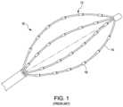
- one type of EP mapping catheter 10 in use todayincludes a collapsible and expandable basket electrode assembly 12 disposed at the distal end of the catheter 10 .
- the basket electrode assembly 12assumes a compressed state as the catheter is maneuvered through an introducer sheath to a region of interest in the body and an expanded state once the catheter reaches the region of interest and emerges from the sheath.
- the basket electrode assembly 12includes a plurality of splines 14 on which un-insulated or un-masked electrodes 16 are disposed. The splines 14 are coupled together at proximal and distal ends and bow outward (i.e. a bowed shape) when the basket assembly 12 is in an expanded state.
- the present disclosurerelates to an electrophysiology catheter.
- the instant disclosurerelates to an electrophysiology catheter having a plurality of partially-masked electrodes which, when placed in contact with the surface of a tissue of interest, the conductive material of the partially-masked electrode is not in contact with the blood pool.
- a partially-masked electrodein accordance with at least one embodiment of the present disclosure, includes a conductive material and an insulated coating having an outer surface.
- the insulated coatingdefines a contoured opening that exposes or reveals an area of the conductive material, wherein the contoured opening has an upper perimeter at the outer surface of the insulated coating.
- the upper perimeter of the openingdefines an imaginary boundary area above the exposed area of the conductive material beyond which no part of the exposed conductive material extends.
- a catheter in accordance with at least another embodiment of the present disclosureincludes an elongate, deformable shaft comprising a proximal end and a distal end.
- the catheterfurther includes a distal tip assembly coupled to said distal end of said shaft, said distal tip assembly comprising a plurality of partially-masked electrodes disposed thereon.
- At least one of the plurality of partially-masked electrodescomprises a conductive material and an insulated coating having an outer surface.
- the insulated coatingdefines a contoured opening that exposes an area of the conductive material, wherein the contoured opening has an upper perimeter at the outer surface of the insulated coating.
- the upper perimeter of the openingdefines an imaginary boundary area above the exposed area of the conductive material beyond which no part of the exposed conductive material extends.
- a catheter in accordance with at least another embodiment of the present disclosureincludes an elongate, deformable shaft having a proximal end and a distal end.
- the catheterfurther includes a distal tip assembly coupled to said distal end of said shaft, said distal tip assembly comprising a plurality of partially-masked electrodes disposed thereon.
- At least one of the plurality of partially-masked electrodescomprises a conductive material and an insulated coating having an outer surface, wherein the insulated coating defines a contoured opening that exposes or reveals an area of the conductive material.
- the contoured openinghas an upper perimeter at the outer surface of the insulated coating.
- the insulated coatingWhen the upper perimeter of the insulated coating is placed in contact with a tissue of interest, wherein the tissue of interest is proximate a blood pool, the insulated coating creates a seal between the blood pool and the contoured opening so that no blood in the blood pool can contact the conductive material.
- a catheter in accordance with at least another embodiment of the present disclosureincludes an elongate, deformable shaft having a proximal end and a distal end.
- the catheterfurther includes a basket electrode assembly coupled to the distal end of the shaft.
- the basket electrode assemblycomprises a proximal end and a distal end, and is configured to assume a compressed state and an expanded state.
- the basket catheter assemblyincludes a first spline comprising a plurality of partially-masked electrodes disposed thereon. At least one of the plurality of partially-masked electrodes comprises a conductive material and an insulated coating having an outer surface, wherein the insulated coating defines a contoured opening that exposes or reveals an area of the conductive material.
- the contoured openinghas an upper perimeter at the outer surface of the insulated coating. The upper perimeter of the opening defines an imaginary boundary area above the exposed area of the conductive material beyond which no part of the exposed conductive material extends.
- a catheter in accordance with at least another embodiment of the present disclosureincludes an elongate, deformable shaft comprising a proximal end and a distal end and a flexible tip portion located adjacent to the distal end of the shaft.
- the flexible tip portioncomprises a flexible framework and a plurality of partially-masked electrodes disposed on the flexible framework and forms a flexible array of partially-masked electrodes adapted to conform to tissue.
- At least one of the plurality of partially-masked electrodescomprises a conductive material and an insulated coating having an outer surface, wherein the insulated coating defines a contoured opening that exposes or reveals an area of the conductive material.
- the contoured openinghas an upper perimeter at the outer surface of the insulated coating. The upper perimeter of the opening defines an imaginary boundary area above the exposed area of the conductive material beyond which no part of the exposed conductive material extends.
- a partially-masked electrode in accordance with at least another embodiment of the present disclosureincludes a conductive material and an insulated coating having an outer surface.
- the insulated coatingdefines a contoured opening that exposes or reveals an area of the conductive material, wherein the contoured opening has an upper perimeter at the outer surface of the insulated coating.
- a catheter in accordance with at least another embodiment of the present disclosureincludes an elongate, deformable shaft having a proximal end and a distal end.
- the catheterfurther includes a basket electrode assembly coupled to the distal end of the shaft.
- the basket electrode assemblycomprises a proximal end and a distal end and is configured to assume a compressed state and an expanded state and includes a first spline comprising a plurality of partially-masked electrodes disposed thereon.
- At least one of the plurality of partially-masked electrodescomprises a conductive material and an insulated coating having an outer surface, wherein the insulated coating defines a contoured opening that exposes or reveals an area of the conductive material.
- the contoured openinghas an upper perimeter at the outer surface of the insulated coating.
- the insulated coatingcreates a seal between the blood pool and the contoured opening so that no blood in the blood pool can contact the conductive material.
- a catheter in accordance with at least another embodiment of the present disclosureincludes an elongate, deformable shaft comprising a proximal end and a distal end and a flexible tip portion located adjacent to the distal end of the shaft.
- the flexible tip portioncomprises a flexible framework and a plurality of partially-masked electrodes disposed on the flexible framework and forming a flexible array of partially-masked electrodes adapted to conform to tissue.
- At least one of the plurality of partially-masked electrodescomprises a conductive material and an insulated coating having an outer surface, wherein the insulated coating defines a contoured opening that exposes or reveals an area of the conductive material.
- the contoured openinghas an upper perimeter at the outer surface of the insulated coating.
- the insulated coatingWhen the upper perimeter of the insulated coating is placed in contact with a tissue of interest, wherein the tissue of interest is proximate a blood pool, the insulated coating creates a seal between the blood pool and the contoured opening so that no blood in the blood pool can contact the conductive material.
- a partially-masked electrodein accordance with at least another embodiment of the present disclosure, includes an insulated coating that is selected and configured to allow the reception of a localization signal by a conductive material of the partially-masked electrode.
- the insulated coatingis selected and configured to prevent the reception of at least a significant amount of a far field signal by the conductive material.
- a catheter in accordance with at least another embodiment of the present disclosureincludes an insulated coating on at least one partially-masked electrode that is selected and configured to allow the reception of a localization signal by a conductive material of the partially-masked electrode.
- the insulated coating on the at least one partially-masked electrodesconfigured to prevent the reception of at least a portion of a far field signal by the conductive material.
- a catheter in accordance with various embodiments of the present disclosurewherein the insulated coating of at least one of the partially-masked electrodes configured to receive a localization signal through the conductive material; and wherein the insulated coating of at least one of the partially-masked electrodes is configured to prevent the reception of at least a portion of a far field signal via the conductive material.
- a method of using a catheter in accordance with various embodiments of the present disclosurecomprising tracking the location of at least one of the partially-masked electrodes within a body of a patient, wherein the insulated coating of at least one of the partially-masked electrodes is configured to receive a localization signal by the conductive material; and wherein the insulated coating of at least one of the partially-masked electrodes is configured to prevent the reception of at least a portion of a far field signal by the conductive material; and placing the upper perimeter of the insulated coating of at least one of the partially-masked electrodes in contact with a tissue of interest in the body of the patient, the tissue of interest being proximate a blood pool, such that the insulated coating creates a seal between the blood pool and the contoured opening to inhibit the receipt of the far field signal in the blood pool.
- a method of using a catheter in accordance with various embodiments of the present disclosurecomprising: tracking the location of one of a plurality of partially-masked electrodes within a body of a patient; wherein the insulated coating of the partially-masked electrode is configured to receive a localization signal by the conductive material; and wherein the insulated coating of the partially-masked electrode is configured to prevent the reception of at least a portion of a far field signal by the conductive material; placing the upper perimeter of the insulated coating of the partially-masked electrode in contact with a tissue of interest at a first location in the body of the patient, the tissue of interest being proximate a blood pool, such that the insulated coating creates a seal between the blood pool and the contoured opening to inhibit the receipt of the far field signal in the blood pool; and receiving, via the partially-masked electrode, a first local electrical signal from the first location on the tissue of interest at the contoured opening, the first local electrical signal having a first magnitude, wherein as a result of the seal between
- FIG. 1is an isometric view of a prior art electrophysiology mapping catheter.
- FIG. 2is a diagrammatic view of an electrophysiology catheter according to an embodiment of the disclosure.
- FIG. 3is an enlarged isometric view of a distal tip assembly of the electrophysiology catheter of FIG. 2 comprising a basket electrode assembly.
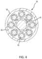
- FIG. 4is a cross-sectional view of a spline comprising part of the basket electrode assembly of FIG. 3 , taken along line 4 - 4 in FIG. 3 .
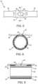
- FIG. 5is an enlarged side view of the region in the dashed circle labeled “ FIG. 5 ” in FIG. 3 , depicting a partially masked electrode on a section of a spline of the basket electrode assembly depicted in FIG. 3 .
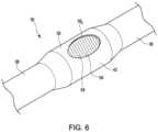
- FIG. 6is an enlarged isometric view of the region in dashed circle 5 in FIG. 3 .
- FIG. 7is an enlarged, cross-sectional view of the partially-masked electrode depicted in FIGS. 5 and 6 , taken along line 7 - 7 of FIG. 5 .
- FIG. 8is a cross-sectional side view of a partially-masked electrode positioned against a tissue of interest.
- FIG. 9is a cross-sectional view taken along line 9 - 9 of FIG. 5 , with the partially-masked electrode positioned against a tissue of interest.
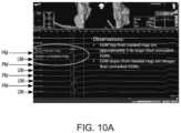
- FIG. 10 Ais a graphical user interface display showing measured electrocardiogram voltages of a prior art un-masked electrode and a partially-masked electrode, according to various embodiment of the disclosure.
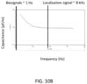
- FIG. 10 Bis a graph showing the measured capacitance frequency response of an acrylated urethane masking material, according to an embodiment of the disclosure.
- FIG. 10 Cis a graph showing the measured impedance of an acrylated urethane masking material, according to an embodiment of the disclosure.
- FIG. 11is a top plan view of a distal tip assembly comprising a planar array of partially-masked electrodes, according to another embodiment of the disclosure.
- FIG. 12is a top plan view of a distal tip assembly comprising a planar array of partially-masked electrodes, according to another embodiment of the disclosure.
- FIG. 13is an isometric view of a distal tip assembly comprising a basket electrode assembly having partially-masked flex circuit electrodes, according to another embodiment of the disclosure.
- FIG. 14is an enlarged view of the region in the dashed circle labeled “ FIG. 14 ” in FIG. 13 , depicting a partially-masked electrode on a section of a spline of the basket electrode assembly depicted in FIG. 13 .
- FIG. 15is an enlarged, cross-sectional view of the partially-masked flex circuit electrode depicted in FIGS. 13 and 14 taken along line 15 - 15 of FIG. 14 .
- FIG. 16is a cross-sectional view of a partially-masked flex circuit electrode of FIGS. 13 - 15 positioned against a tissue of interest.
- FIG. 17is a plan view of a partially-masked flex circuit electrode according to another embodiment of the disclosure.
- FIG. 18is a cross-sectional view of a partially-masked flex circuit electrode of FIG. 17 taken along line 18 - 18 of FIG. 17 .
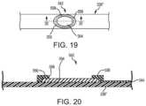
- FIG. 19depicts a plan view of a partially-masked flex circuit electrode according to another embodiment of the disclosure.
- FIG. 20is a cross-sectional view of the partially-masked flex circuit electrode of FIG. 19 taken along line 20 - 20 .
- FIG. 21depicts a plan view of a partially-masked flex circuit electrode according to another embodiment of the disclosure.
- FIG. 22depicts a cross-sectional view of the partially-masked flex circuit electrode of FIG. 21 taken along line 22 - 22 .
- FIG. 23is a flowchart illustrating a method of using catheters having partially-masked electrodes according to various embodiments of the disclosure.
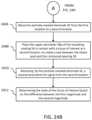
- FIGS. 24 A- 24 Bare flowcharts illustrating another method of using catheters having partially-masked electrodes according to various embodiments of the disclosure.
- Typical catheter-based electrodeshave predominantly been cylindrically-shaped (e.g., rings, tips, or spots). These electrodes have been used to take electrical signal measurements in a tissue of interest, for example the heart. As these electrodes are in the blood pool (or conductive pool), the electrodes will pick up various electrical signals in the heart, including signals proximal to the electrodes as well as signals distal the electrodes, the latter generally called far field effects. When an electrode is in contact with healthy tissue, a more distinct and/or stronger electrical signal is measured by the electrode. The electrical signal from the tissue is often referred to as a local source. However, in use, only a portion of a typical electrode, such as electrode 16 shown in FIG. 1 , is in direct contact with the tissue of interest. Most of the electrode 16 is exposed to the blood pool and therefore the resulting output signal of the electrode 16 is a combination of local and far field effects. That is, the far field effects create noise in the received signal which makes it difficult to identify, locate, and/or diagnose unhealthy tissue.
- the method to locate, identify, and/or diagnose unhealthy regions of tissueincludes sensing one or more electrophysiological characteristics from the tissue.
- the local electrical signals from unhealthy tissueare often much weaker than the local electrical signals from healthy tissue.
- the magnitude of the local electrical signals from unhealthy tissueis about equal to or less than the far field magnitude. Therefore, it becomes difficult to distinguish between the far field and local effects. That is, the signal-to-noise ratio when sensing on or near unhealthy tissue may approach 1.
- the poor signal fidelity and/or low magnitude at the unhealthy tissue of interestmakes it difficult to determine, for example, what is a boundary edge or conduction path/gap between unhealthy tissue and healthy tissue.
- aspects of the present disclosureare directed to the use of printed or flex circuit electrodes to increase resolution.
- printed or flex circuit electrodesSome benefits of printed or flex circuit electrodes are that they can be manufactured via batch fabrication, which reduces costs, and allow for the design of small and/or close electrodes and associated electrical connections into a smaller space.
- the printed and/or flex circuit electrodestend to be one-sided electrodes. That is, they are only conductive on one side, and thereby minimize exposure of the electrode to the blood pool enhancing signal fidelity.
- the focus of the industry so farso far has been on size and/or spacing optimization and not on tissue contact and/or far field isolation.
- printed or flex circuit electrodestend to be planar and relatively smooth. Both of these qualities result in poor contact with tissue by the printed or flex circuit electrodes which may allow some blood pool contact and far field influence into a sensed electrophysiology signal.
- cathetersincluding electrodes which are partially-masked with an insulating material facilitate improved EP diagnostics.
- the insulating material of the partially-masked electrodescreates a seal between the blood pool and the conductive material of the partially-masked electrode which reduces or eliminates the reception of the far field effects by the partially-masked electrode, making it easier to locate and diagnose unhealthy tissue.
- FIG. 2illustrates one embodiment of an electrophysiology catheter 18 having a plurality of partially-masked electrodes in accordance with the present disclosure.
- Catheter 18is provided for use in generating an electrophysiological map of tissue and, in particular, cardiac tissue. It should be understood, however, that catheter 18 may be used in conjunction with various tissue types.
- Catheter 18may include a cable connector or interface 20 , a handle 22 , a shaft 24 having a proximal end 26 and a distal end 28 , and a distal tip assembly such as the basket electrode assembly 30 depicted in FIG. 2 .
- Catheter 18may also include other conventional components not illustrated herein such as deflection mechanisms, additional electrodes and corresponding conductors or leads.
- Connector 20provides mechanical and electrical connection(s) for cables extending from an electronic control unit (ECU) (not shown) or similar device that is configured to receive signals generated by basket electrode assembly 30 .
- Connector 20may be conventional in the art and be disposed at the proximal end 26 of catheter 18 .
- Handle 22provides a location for the physician to hold catheter 18 and may further provides a means for steering or guiding shaft 24 within the body.
- handle 22may include means to change the length of a guide wire extending through catheter 18 to distal end 28 of shaft 24 to steer distal end 28 and, thus, shaft 24 .
- Handle 22may also be conventional in the art and it will be understood that the construction of handle 22 may vary.
- Shaft 24is an elongate, deformable member configured for movement within the body.
- Shaft 24supports electrode assembly 30 , associated conductors, and, in some embodiments, additional electronics used for signal processing or conditioning.
- Shaft 24may also be configured to permit transport, delivery, and/or removal of fluids (including irrigation fluids and bodily fluids), medicines, and/or surgical tools or instruments.
- Shaft 24may be made from conventional materials such as polyurethane and defines one or more lumens configured to house and/or transport electrical conductors, fluids, medicines, guide wires or surgical tools or instruments.
- Shaft 24may be introduced into a blood vessel or other structure within the body through an introducer sheath. Shaft 24 may then be steered or guided through the body to a desired location such as tissue in a region of interest using guide wires or pull wires or other means known in the art including remote control guidance systems.
- basket electrode assembly 30provides a means for conducting an electrophysiological study of tissue.
- Assembly 30may be coupled to a distal end of shaft 24 and includes a proximal end 32 and a distal end 34 .
- Assembly 30may include a plurality of splines 36 on which electrodes are disposed and that form an electrode “basket” that is configured to assume a compressed state and an expanded state.
- Assembly 30may assume the expanded state in the absence of an extraneous force acting on the assembly 30 (i.e., assembly 30 may be biased to the expanded state by, for example, nickel titanium memory alloy components) or may be urged to the expanded state through mechanical means (e.g., wires that are pulled or pushed) or by an internal balloon that can be expanded within the basket electrode assembly 30 .
- Assembly 30may assume the compressed state, for example, as catheter 18 is maneuvered through an introducer sheath within the body to the region of interest and assume the expanded state upon emerging from a distal end of the sheath.
- Splines 36are configured to support electrodes in a predetermined configuration to allow contact and/or non-contact mapping of electrical activity in tissue. Referring to FIG.
- each spline 36may include a tubular body 38 , means, such as wire 40 , for supporting (and biasing) body 38 to assume a predetermined shape, one or more partially-masked electrodes 42 (as shown in FIG. 3 ), and associated conductors 44 .
- a splinee.g., spline 36
- spline(s)may be constructed in a variety of ways.
- one or more splinesmay include a flexible circuit as described and illustrated in U.S.
- Body 38provides structural support for partially-masked electrodes 42 and insulates conductors 44 from bodily fluids and other elements.
- body 38is tubular and may be annular in shape. It should be understood, however, that the shape of body 38 may vary.
- Body 38may be made from conventional polymeric materials such as polyurethane, and nylon or thermoplastic elastomers such as the elastomer sold under the registered trademark “PEBAX” by Arkema, Inc. and reinforcements such as metallic braids.
- Body 38may define a central lumen 46 extending between proximal and distal ends 48 , 50 (as shown in FIG. 3 ) of body 38 and configured to allow passage of wire 40 and conductors 44 .
- body 38may alternatively define one or more channels each configured to receive one of wire 40 or a conductor 44 .
- wire 40is illustrated at the center of lumen 46 with conductors 44 disposed circumferentially around wire 40 . It should be understood, however, that the relative arrangement of wire 40 and conductors 44 within lumen 46 may vary.
- Wire 40is provided to support and bias body 38 to assume a predetermined shape.
- Wiremay be made from a shape memory alloy such as nitinol (nickel titanium).
- Wireextends through lumen 46 of body 38 from proximal end 48 of body 38 to distal end 50 and may extend through the bodies 38 of multiple splines 36 to couple one or more splines together.
- splines 36may be coupled at distal end 50 by a hinge connector 52 or in any of the ways described and illustrated in U.S. patent application Ser. No. 13/340,760 (published as United States Patent Application Publication No. US 2013/0172715), the entire disclosure of which is incorporated by reference as though fully set forth herein.
- the distal end 34 of the basket electrode assembly 30may be specialized to form a small, but blunt mechanical connection point so that the distal portion of the catheter 18 may safely be pressed against tissue.
- partially-masked electrodes 42may be configured to diagnose, sense, and measure electrical activity in tissue such as cardiac tissue. One or more partially-masked electrodes 42 may also be used to provide tissue ablation therapy. Each partially-masked electrode 42 is coupled to a corresponding conductor 44 or one or more electrodes being coupled to the same conductor with the signal being multi-plexed.
- conductors 44may be configured to transmit electrical signals from partially-masked electrodes 42 through shaft 24 of catheter 18 to an electronic control unit or similar device.
- Conductors 44may comprise wires or cables or other means for conducting signals and may be disposed with the lumen 46 of a body 38 of a given spline 36 .
- Each conductor 44may be coupled at a distal end to a corresponding partially-masked electrode 42 and extend through lumen 46 to the proximal end 32 of basket electrode assembly 30 .
- each of the partially-masked electrodes 42may be formed of a conductive band 54 attached circumferentially about body 38 .
- the conductive bands 54may be composed of platinum, gold, stainless steel, iridium, or alloys of these metals, or other biocompatible, electrically-conductive materials or compositions thereof.
- the conductive bands 54 of each partially-masked ring electrode 42may have an electrically-insulating, polymer surface coating 56 .
- the surface coating 56may be formed of a material with high dielectric properties that can be applied in a very thin layer.
- Exemplary surface coatingsmay include thin coatings of polyester, polyamides, polyimides, and blends of polyurethane and polyimides.
- surface coating 56may be Parylene (e.g., Parylene C, Parylene N).
- surface coating 56may be an acrylated urethane.
- the thickness of the surface coating 56may range from about 0.0001 mm to about 0.05 mm. In other embodiments, for example only and without limitation, the thickness of the surface coating 56 may range from about 0.0003 mm to about 0.0006 mm.
- the surface coating 56may be thicker around the opening 58 in order to create a taller “wall” to aid in creating a seal between the conductive band 54 and the blood pool, and thinner around the rest of the conductive band 54 to aid in reception of the localization signal by the partially-masked electrode 42 .
- An apertureis formed in the insulated surface coating 56 to create a contoured opening 58 that exposes or reveals a small area of the conductive band 54 .
- the contoured opening 58may be formed by laser, chemical, or other material removing or etching process to remove a portion of the insulated surface coating 56 to expose the conductive band 54 underneath.
- the edges or corners of the contoured opening 58may be curved, rounded, or otherwise contoured to minimize any edge effects that could arise due to the imposition of a sharp edge, corner, or point.
- the openings 58are oriented on the partially-masked electrodes 42 such that when the splines 36 of basket electrode assembly 30 are expanded, the openings 58 are facing the tissue of interest, such that they can contact the tissue of interest.
- the openings 58are oriented on the partially-masked electrodes 42 such that when the splines 36 of basket electrode assembly 30 are expanded, the openings 58 may be maneuvered or oriented such that they are facing the tissue of interest and can contact the tissue of interest.
- opening 58is shown as having an oval shape, it will be understood that opening 58 may have other shapes, with or without rounded edges or corners, without departing from the scope of the disclosure, including, for example only and without limitation, a circle, an ellipse, a diamond, a rectangle, a hexagon, a square, a pentagon, an irregular polygon, a triangle. Opening 58 may be of different sizes without departing from the scope of the disclosure. For example only and without limitation, where opening 58 is a circle, the diameter of the opening 58 may range from about 0.010 mm to about 0.050 mm. In one embodiment, for example only and without limitation, the diameter of the opening 58 may be about 0.014 mm.
- the diameter of the opening 58may be about 0.022 mm. In yet another embodiment, for example only and without limitation, the diameter of the opening 58 may be about 0.031 mm. Moreover, although a single opening 58 is shown per partially-masked electrode 42 , it will be understood that each partially-masked electrode 42 may include more than one opening 58 (e.g., 2, 3, 4, or more) without departing from the scope of the disclosure.
- the surface area of the conductive band 54 exposed at the opening 58is only about 10 percent (10%) of the total surface area of the conductive band 54 . Stated another way, about 90 percent (90%) of the conductive band 54 is insulated. Therefore, the electrically-conductive surface area of electrode 42 is only about 10 percent (10%) of the electrically-conductive surface area of a typical un-masked (un-insulated) ring electrode. In various embodiments, for example only and without limitation, the surface area of an un-insulated ring electrode may be about 2.5 mm 2 whereas the surface area of the opening 58 and thus the exposed area of conductive band 54 is about 0.25 mm 2 .
- the exposed area of conductive band 54may be from about 0.01 mm 2 to about 1.0 mm 2 . In other embodiments, for example only and without limitation, the exposed area of conductive band 54 may be from about 0.044 mm 2 to about 0.486 mm 2 .
- opening 58has an upper perimeter 58 p at the outer surface 56 s of the surface coating 56 .
- the upper perimeter 58 p of opening 58defines an imaginary boundary area 59 above the exposed area of the conductive band 54 beyond which no part of the exposed conductive band 54 extends.
- the imaginary boundary area 59is an imaginary surface having an outer edge(s) which is/are coincident and coextensive with the upper perimeter 58 p of opening 58 .
- the imaginary boundary area 59may be a plane or may have a contoured surface such as, for example only and without limitation, a saddle shape, a hyperbolic paraboloid, and a parabolic cylinder.
- the imaginary boundary area 59is represented in FIG. 6 by a series of lines covering opening 58 within upper perimeter 58 p .
- the imaginary boundary area 59is represented in FIG. 7 by a dashed line extending from one side of the opening 58 to the other side of the opening within upper perimeter 58 p . Therefore partially-masked electrode 42 includes a gap or void 59 v between imaginary boundary area 59 and conductive band 54 .
- partially-masked electrode 42is shown interfacing with the surface 60 of a tissue of interest.
- the surface coating 56is between the conductive band 54 and the surface 60 of the tissue of interest. Because no part of conductive band 54 extends beyond the imaginary boundary area 59 shown in FIGS. 6 and 7 , a void 62 is created between the conductive band 54 and the surface 60 of the tissue of interest at the location of the opening 58 in the surface coating 56 . It is desirable to have the void 62 be as small as possible to increase the signal received by the partially-masked electrode 42 . Thus, if the surface 60 of the tissue is touching the conductive band 54 the received signal may be increased.
- the thickness of the surface coating 56creates a cupped or cup-like profile at the opening 58 which isolates the conductive band 54 of the partially-masked electrode 42 from the conductive path through the blood pool. That is, when the upper perimeter 58 p of the raised surface coating 56 is placed in contact with the surface 60 of the tissue of interest, the surface coating 56 creates a seal between the blood pool and the opening 58 so that no blood in the blood pool can contact conductive band 54 .
- the conductive band 54is completely isolated or sealed from any far field effects present in the blood pool. This will be even more effective in smoother tissue than in rougher tissue.
- typical unmasked electrodesdue to the combination of the rough surface and far field interference, the signal received by a typical unmasked electrode may be inaccurate.
- a partially-masked electrode 42even if a complete seal may not be able to be achieved against rough ventricle surface, for example.
- partially-masked electrode 42has no other open conductive ends or portions as with typical ring electrodes. This results in a more focused electrode as compared to un-masked electrodes. Thus it is desirable to minimize the volume of the void 62 while maintaining the seal from the blood pool provided by surface coating 56 .
- the noise from the far field effectsis significantly reduced or eliminated. This increases the signal to noise ratio of the electrical signal measured by the partially-masked electrode 42 . Because the far field effects are no longer measured by the partially-masked electrode 42 , the signal quality and magnitude of the measured weak local electrical signals from unhealthy tissue is improved as compared to a typical un-insulated ring electrode 16 . This also allows for easier identification, locating, detecting and/or diagnosing unhealthy tissue. For example, as shown in FIG.
- Vppelectrogram peak-to-peak voltage
- PMelectrogram
- Vppelectrogram peak-to-peak voltage
- UMtypical un-insulated ring electrode 16
- the measured peak-to-peak voltage (Vpp) signal from partially-masked electrode 42was about 13.5 mV compared to 3.5 mV from a typical un-insulated ring electrode 16 .
- the slopes of the EGM signals from partially-masked electrode 42were steeper than those measured by a typical un-insulated ring electrode 16 .
- the surface coating 56 material and/or the surface coating 56 thicknessis selected and configured to inhibit or block the receipt of the far field electrical signals when the surface coating 56 creates a seal between the blood pool and the opening 58 , while still allowing the partially-masked ring electrode 42 to receive a localization signal. That is, the surface coating 56 is of a sufficient thickness and has material properties or characteristics such that the far field electrical signals cannot penetrate the surface coating 56 to the underlying conductive band 54 , but still allows the localization signal to penetrate the surface coating 56 to the underlying conductive band 54 .
- partially-masked electrode 42can function as both an electrode for mapping and/or diagnostic purposes and for localization purposes.
- the surface coating 56substantially or completely filters out the far field signals, with minimal or no filtering out of the localization signals.
- the partially-masked electrode 42may be tuned to filter out far field signals from about 1.0 Hz to about 600 Hz while being receptive to localization signals at or above approximately 8 kHz.
- the partially masked electrode 42can filter out frequencies around the normal heart rate frequency (i.e., 1.0 Hz to about 1.67 Hz.
- the insulating properties of the insulated surface coating 56therefore, may be frequency dependent.
- FIGS. 10 B and 10 Cillustrate frequency response and impedance of an acrylated urethane insulated surface coating having a thickness of 0.5 mm. It is believed that the measured properties of the acrylated urethane insulated surface coating will behave similarly when applied to conductive band 54 to create an embodiment of partially-masked electrode 42 . For example, as shown in FIG. 10 B , the capacitance is much higher at lower frequencies (e.g., from about 1.0 Hz to about 300 Hz), and decreases before substantially leveling off at higher frequencies (e.g., from about 400 Hz and above).
- lower frequenciese.g., from about 1.0 Hz to about 300 Hz
- substantially leveling off at higher frequenciese.g., from about 400 Hz and above.
- a partially-masked electrode 42that is partially-masked with an acrylated urethane insulated surface coating having a thickness of 0.5 mm, will effectively filter out lower frequency signals (including far field biosignals), but will not filter out higher frequency signals (including localization signals).
- the localization signalmay be a current pulse as described in U.S. Pat. No. 7,263,397, the entire disclosure of which is incorporated by reference as though fully set forth herein.
- the partially-masked electrode 42will work like a high-pass filter, and will have an equivalent circuit like a parallel RC (resistor-capacitor) circuit.
- the capacitance change shown in FIG. 10 Bresults in the impedance curves shown in FIG. 10 C .
- the increase in capacitance, at low frequencywill effectively act as a far-field biosignal filter by dielectric relaxational screening of the non-contact low frequency noise.
- a resultant real component impedance of a tested acrylated urethane insulated surface coating with a thickness of 0.5 mmis equal to (z*cos( ⁇ )).
- a partially-masked electrode 42 having a 0.5 mm thick acrylated urethane insulated surface coating 56will result in an impedance of about 90 k ohms between 100 Hz and 10 kHz.
- an insulated surface coating 56 of 5 ⁇ mwill have an impedance of about 900 ohms.
- This impedanceis within the range measured between partially-masked and unmasked electrodes. Therefore, the increased impedance of the partially-masked electrodes is still usable with impedance-based localization systems, such that the partially-masked electrodes 42 may be used for localization purposes as well as measuring biosignals from tissues of interest.
- Pre-clinical testinghas also shown that partially-masked electrodes, where the surface area of the opening 58 is only about 10 percent (10%) of the total surface area of the conductive band 54 , had a smaller impedance increase than printed or flex circuit electrodes. Thus the impedance localization performance impact is minimized as compared to printed or flex circuit electrodes.
- the impedance of the partially-masked electrodesonly increases from about 200-350 ohms to a range of about 430-610 ohms, as compared to unmasked electrodes.
- partially-masked electrodes 42are incorporated into a basket catheter having the structure shown in FIGS. 2 and 3 , it will be understood that partially-masked electrodes 42 may be used in any type of catheter structure without departing from the scope of the disclosure.
- partially-masked electrodes 42may be incorporated into any of the basket catheter structures as described and illustrated in U.S. patent application Ser. No. 15/333,798 (published as U.S. Patent Application Pub. No. 2017/0100075), U.S. patent application Ser. No. 15/155,277 (published as U.S. Patent Application Pub. No. 2016/0331254), U.S. Pat. Nos. 9,339,331, and 8,224,416, the entire disclosures of which are incorporated by reference as though fully set forth herein.
- partially-masked electrodes 42may be incorporated into another distal tip assembly comprising a planar array of partially-masked electrodes.
- the distal tip assemblymay be, for example, a high density electrode assembly as shown in FIGS. 11 and 12 .
- FIG. 11depicts a top view of a high density electrode assembly 101 according to various embodiments of the present disclosure.
- the high density electrode assembly 101may include a flexible tip portion 110 that forms a flexible array of partially-masked electrodes 42 having openings 58 in an insulated coating.
- This planar array (or ‘paddle’ configuration) of partially-masked electrodes 42comprises four side-by-side, longitudinally-extending arms 103 , 104 , 105 , 106 , which can form a flexible framework on which the partially-masked electrodes 42 are disposed.
- the four microelectrode-carrier armscomprise a first outboard arm 103 , a second outboard arm 106 , a first inboard arm 104 , and a second inboard arm 105 . These arms are laterally separated from each other.
- This distal member 109may be constructed from metal or some other radiopaque material to provide fluoro visualization and semi-independent planar movement between the outer and inner arms.
- high density electrode assembly 101does not include distal member 109 .
- high density electrode assembly 101may be used for electrophysiology (EP) mapping.
- high density electrode assembly 101may be used for tissue ablation.
- Each of the four armsmay carry a plurality of partially-masked electrodes 42 .
- each of the four armscan carry partially-masked electrodes 42 spaced along a length of each of the four arms.
- the high density electrode assembly 101 depicted in FIG. 11depicts four arms, the high density electrode assembly 101 could comprise more or fewer arms.
- one or more of the armsmay include electrode 116 , which may be an un-masked, partially-masked, or fully masked electrode. In some embodiments, for example only and without limitation, electrodes 116 may be fully masked and may be used for localization purposes.
- electrodes 116may be masked with an insulated coating that isolates the conductive material of electrode 116 from far field or tissue signals (e.g., cardiac signals), but does not isolate electrode 116 from localization signals.
- the high density electrode assembly 101 depicted in FIG. 11depicts 16 partially-masked electrodes (e.g., 4 partially-masked electrodes 42 on first outboard arm 103 and second outboard arm 106 and 4 partially-masked electrodes 42 on first inboard arm 104 and second inboard arm 105 )
- the catheterscan include more or fewer than 16 partially-masked electrodes.
- the first outboard arm 103 and second outboard arm 106can include more or fewer than 4 partially-masked electrodes and the first inboard arm 104 and second inboard arm 105 can include more or fewer than 4 partially-masked electrodes.
- electrodes on first outboard 103may be spaced closer together or further apart than electrodes on first inboard arm 104 .
- the electrodesare shown as substantially evenly distributed on arms 103 , 104 , 105 and 106 , it will be understood that the electrodes may be unevenly spaced intervals on each arm without departing from the scope of the disclosure.
- the electrodesmay be located on the arms such that the electrodes are closer together near the distal end of flexible tip portion 110 and further apart near the proximal end of flexible tip portion 110 .
- the electrodesmay be located on the arms such that the electrodes are farther apart near the distal end of flexible tip portion 110 and closer together near the proximal end of flexible tip portion 110 .
- the partially-masked electrodes 42can be used in diagnostic, therapeutic, and/or mapping procedures.
- the partially-masked electrodes 42can be used for electrophysiological studies, pacing, cardiac mapping, and ablation.
- the partially-masked electrodes 42can be used to perform unipolar or bipolar ablation. This unipolar or bipolar ablation can create specific lines or patterns of lesions.
- the partially-masked electrodes 42can receive electrical signals from the heart, which can be used for electrophysiological studies.
- the partially-masked electrodes 42can perform location or position sensing functions related to cardiac mapping.
- the high density electrode assembly 101can include a catheter shaft 107 .
- the catheter shaft 107can include a proximal end and a distal end.
- the proximal end of catheter shaft 107may be connected to or integrally formed with the distal end 28 of shaft 24 of catheter 18 , as shown in FIG. 2 , in place of electrode assembly 30 . That is, the distal tip assembly of the basket electrode assembly 30 may be swapped with, interchanged with, or substituted with the distal tip assembly of the high density electrode assembly 101 .
- the distal endcan include a connector 108 , which can couple the distal end of the catheter shaft 107 to a proximal end of the planar array.
- the catheter shaft 107can define a catheter shaft longitudinal axis aa, as depicted in FIG. 11 , along which the first outboard arm 103 , first inboard arm 104 , second inboard arm 105 , and second outboard arm 106 can generally extend parallel in relation therewith.
- the catheter shaft 107can be made of a flexible material, such that it can be threaded through a tortuous vasculature of a patient.
- the catheter shaft 107can include one or more ring electrodes 111 disposed along a length of the catheter shaft 107 .
- the ring electrodes 111can be used for diagnostic, therapeutic, and/or mapping procedures, in an example.
- ring electrodes 111may be partially-masked in the same manner as partially-masked electrodes 42 . In other embodiments, ring electrodes 111 may be un-masked. In yet other embodiments, the high density electrode assembly 101 may include a combination of partially-masked, unmasked, or fully masked ring electrodes.
- the flexible tip portion 110can be adapted to conform to tissue (e.g., cardiac tissue). For example, when the flexible tip portion 110 contacts tissue, the flexible tip portion can deflect, allowing the flexible framework to conform to the tissue.
- the arms (or the understructure of the arms) comprising the paddle structure (or multi-arm, electrode-carrying, flexible framework) at the distal end of the catheter depicted in FIG. 11is preferably constructed from a flexible or spring-like material such as Nitinol and/or a flexible substrate, as discussed herein.
- the construction (including, for example, the length and/or diameter of the arms) and material of the armscan be adjusted or tailored to create, for example, desired resiliency, flexibility, foldability, conformability, and stiffness characteristics.
- the foldability of materials such as Nitinol and/or flexible substrateprovide the additional advantage of facilitating insertion of the paddle structure into a delivery catheter or introducer, whether during delivery of the catheter into the body or removal of the catheter from the body at the end of a procedure.
- Some features of high density electrode assemblies 201 and 101are common to one another and, accordingly, descriptions of such features in one embodiment should be understood to apply to the other embodiment.
- particular characteristics and aspects of one embodimentmay be used in combination with, or instead of, particular characteristics and aspects of another embodiment.
- FIG. 12illustrates another embodiment of a high density electrode assembly 201 which includes a variety of partially-masked and un-masked electrodes. Other than the differences in the electrodes, high density electrode assembly 201 is substantially the same or identical to high density electrode assembly 101 .
- High density electrode mapping catheter 201includes a population of partially-masked electrodes having different sized openings.
- first outboard arm 103includes four partially-masked electrodes 42 a each having an opening 58 a
- first inboard arm 104includes four partially-masked electrodes 42 b each having an opening 58 b smaller than opening 58 a
- second inboard arm 105includes four partially-masked electrodes 42 c each having an opening 58 c smaller than openings 58 a and 58 b
- opening 58 amay have a diameter about 0.031 mm
- opening 58 bmay have a diameter about 0.022 mm
- opening 58 cmay have a diameter about 0.014 mm.
- openings 58 a , 58 b , and 58 care shown as having an oval shape, it will be understood that openings 58 a , 58 b , and 58 c may have other shapes, with or without rounded edges or corners, without departing from the scope of the disclosure, including, for example only and without limitation, a circle, an ellipse, a diamond, a rectangle, a hexagon, a square, a pentagon, an irregular polygon, a triangle. Openings 58 a , 58 b , and 58 c may be of different sizes without departing from the scope of the disclosure.
- second outboard arm 106 of high density electrode assembly 201includes four un-masked electrodes 16 .
- second outboard arm 106may include partially-masked electrodes having openings of a different shape and/or size from openings 58 a , 58 b , and 58 c.
- High density electrode assembly 201may be used as a test bed for testing one or more parameters, such as for example only and without limitation: opening 58 shapes, opening 58 sizes, coating 56 thickness, coating material, electrode spacing, distribution, and number of electrodes (masked, unmasked, and partially masked).
- partially-masked electrodes shown and described hereinare ring electrodes, it will be understood that printed or flex circuit electrodes may be partially-masked without departing from the scope of the disclosure.
- the embodiment of FIGS. 13 - 15incorporate partially-masked flex circuit electrodes 342 into a distal tip.
- Some features of partially-masked flex circuit electrodes 34 and partially-masked electrodes 42are common to one another and, accordingly, descriptions of such features in one embodiment should be understood to apply to other embodiments.
- particular characteristics and aspects of one embodimentmay be used in combination with, or instead of, various aspects of another embodiment.
- a distal tip assemblycomprising a basket electrode assembly 325 is shown having a plurality of partially-masked flex circuit electrodes 342 (as shown in FIG. 14 ) which are oriented to contact tissue of interest. Basket electrode assembly 325 is shown with the basket portion of the catheter in an expanded configuration.
- Basket electrode assembly 325is shown as it may include an outer tubing 330 housing, a deployment member 331 , and a terminal end 350 .
- the outer tubing 330 of basket electrode assembly 325may be connected to, or integrally formed with, the distal end 28 of shaft 24 of catheter 18 , as shown in FIG. 2 (in place of electrode assembly 30 ).
- Basket electrode assemblyis shown having splines 336 a - f ; however, the basket catheter 325 is not limited to any particular number of splines 336 , as will be readily understood by those having ordinary skill in the art after becoming familiar with the teachings herein. Additional features and structure of basket electrode assembly are shown and described in U.S. patent application Ser. No. 15/333,798 (published as U.S. Patent Application Pub. No. 2017/0100075) the entire disclosure of which is incorporated by reference as though fully set forth herein.
- Each spline 336is connected at the proximal end of the splines 336 to the outer tubing 330 , and each spline 336 is connected at the opposite or distal end of the splines 336 to the deployment member 331 .
- the deployment member 331is operable to be moved in a first direction (e.g., in the direction of arrow 338 a ) relative to the outer tubing 330 to expand the splines 336 to a deployed position, as shown in FIG. 13 .
- the deployment member 331is also operable to be moved in a second direction (e.g., in the direction of arrow 338 b ) relative to the outer tubing 330 to collapse the splines 336 to an undeployed position.
- the deployment member 331may include a pull wire.
- the deployment member 331may be a solid stainless steel or Nitinol wire.
- the deployment member 331may be a hollow tube (or configured to house tubing).
- the deployment member 331should be manufactured to be sufficiently stiff such that the deployment member 331 can be operated remotely (e.g., outside of the patient's body), and be moved in the directions illustrated by arrows 338 a and 338 b to expand and contract the splines 336 .
- the basket electrode assembly 325may be inserted into a catheter shaft (e.g., sheath (not shown) in its undeployed position for placement in the patient's body (e.g., within a heart chamber).
- the basket electrode assembly 325may then be expanded to its deployed position for a medical procedure within the patient's body.
- the basket electrode assembly 325may again be collapsed to its undeployed position so that the basket electrode assembly 325 may be withdrawn from the patient.
- the splines 336are formed from sheets.
- the sheetscan be formed of a suitable flexible material such as plastic (e.g., polyimide) or metal (e.g., platinum, gold, stainless steel, iridium, or alloys of these metals).
- a population of spaced apart partially-masked flex circuit electrodes 342 and corresponding electrode traces 344are provided on the splines 336 .
- the partially-masked flex circuit electrodes 342may be formed of a conductive material 354 which may be printed, adhered, bonded, etched or otherwise provided on the splines 336 , which may serve as a substrate for the partially-masked flex circuit electrodes 342 .
- the traces 344may then be connected to electrical wiring and extend through a catheter (e.g., catheter 18 shown in FIG. 2 ).
- the electrical wiringmay convey electrical signals between the partially-masked flex circuit electrodes 342 and one or more control system (not shown).
- the electrical signalsmay be used to control output of ablation electrodes, or for processing input from mapping electrodes for viewing or storage by the user (e.g., on an electrical monitoring device).
- the conductive material 354may be composed of platinum, gold, stainless steel, iridium, or alloys including one or more of these metals, or other biocompatible, electrically-conductive material.
- an electrically-insulating, polymer surface coating 356may be applied to each spline 336 and the conductive material 354 .
- the surface coating 356may be formed of a material with high dielectric properties that can be applied in a very thin layer. Exemplary surface coatings may include thin coatings of polyester, polyamides, polyimides, and blends of polyurethane and polyimides. In one embodiment, for example only and without limitation, surface coating 356 may be Parylene.
- the thickness of the surface coating 356may range from about 0.0001 mm to about 0.05 mm. In other embodiments, for example only and without limitation, the thickness of the surface coating 356 may range from about 0.0003 mm to about 0.0006 mm.
- An apertureis formed in the surface coating 356 to create a contoured opening 358 that exposes or reveals a small area of the conductive band 354 .
- the contoured opening 358may be formed by laser, chemical, or other material removing or etching process to remove a portion of the surface coating 356 to expose the conductive band 354 underneath.
- the edges or corners of the contoured opening 358may be curved, rounded, or otherwise contoured to minimize any edge effects that could arise due to the imposition of a sharp edge, corner, or point.
- the openings 358are oriented on the partially-masked electrodes 342 such that when the splines 336 of basket electrode assembly 325 are expanded, the openings 358 are facing the tissue of interest, such that they can contact the tissue of interest. In other embodiments, for example only and without limitation, the openings 358 are oriented on the partially-masked electrodes 342 such that when the splines 336 of basket electrode assembly 325 are expanded, the openings 358 may be maneuvered or oriented such that they are facing the tissue of interest and can contact the tissue of interest.
- opening 358is shown as having an oval shape, it will be understood that opening 358 may have other shapes, with or without rounded edges or corners, without departing from the scope of the disclosure, including, for example only and without limitation, a circle, an ellipse, a diamond, a rectangle, a hexagon, a square, a pentagon, an irregular polygon, a triangle. Opening 358 may be of different sizes without departing from the scope of the disclosure. For example only and without limitation, where opening 358 is a circle, the diameter of the opening 358 may range from about 0.010 mm to about 0.050 mm. In one embodiment, for example only and without limitation, the diameter of the opening 358 may be about 0.014 mm.
- the diameter of the opening 358may be about 0.022 mm. In yet another embodiment, for example only and without limitation, the diameter of the opening 358 may be about 0.031 mm. Moreover, although a single opening 358 is shown per partially-masked flex circuit electrode 342 , it will be understood that each partially-masked flex circuit electrode 342 may include more than one opening 358 (e.g., 2, 3, 4, or more) without departing from the scope of the disclosure.
- opening 358has an upper perimeter 358 p at the outer surface 356 s of the surface coating 356 .
- the upper perimeter 358 p of opening 358defines an imaginary boundary area 359 above the exposed area of the conductive material beyond which no part of the exposed conductive material 354 extends.
- the imaginary boundary area 359is a planar surface having an outer edge(s) which is/are coincident and coextensive with the upper perimeter 358 p of opening 358 . Therefore partially-masked flex circuit electrode 342 includes a gap or void 359 v between imaginary boundary area 359 and conductive band 354 .
- partially-masked flex circuit electrode 342is shown interfacing with the surface 60 of a tissue of interest.
- the surface coating 356is between the conductive material 354 and the surface 60 of the tissue of interest and because no part of conductive material 354 extends beyond the imaginary boundary area 359 shown in FIG. 15 , a void 62 is created between the conductive material 354 and the surface 60 of the tissue of interest at the location of the opening 358 in the surface coating 356 . It is desirable to have the void 62 be as small as possible to increase the signal received by the partially-masked flex circuit electrode 342 . Thus, if the surface 60 of the tissue is touching the conductive material 354 the received signal may be increased. In some embodiments, for example only and without limitation, an electrical signal may be emitted by the partially-masked flex circuit electrode 342 to attract the surface 60 of the tissue toward the conductive material 354 .
- the raised surface coating 356which is between the conductive material 354 and the surface 60 , creates a cupped or cup-like profile at the opening 358 which isolates the conductive material 354 of the partially-masked flex circuit electrode 342 from the conductive path through the blood pool. That is, when the upper perimeter 358 p of the raised surface coating 356 is in contact with the tissue of interest, the surface coating 356 creates a seal between the blood pool and the opening 358 so that no blood in the blood pool can contact conductive material 354 .
- the conductive band 354is completely isolated or sealed from any far field effects present in the blood pool. This will be even more effective in rougher tissue (e.g., ventricle) than in smother tissue (e.g., atria).
- smother tissuee.g., atria
- partially-masked flex circuit electrode 342has no other open conductive ends or portions as with typical ring electrodes. This results in a more focused electrode as compared to un-masked electrodes. Aspects of the present disclosure are desirable to minimize the volume of the void 62 while maintaining the seal from the blood pool provided by surface coating 356 .
- the noise from the far field effectsis significantly reduced or eliminated. This increases the signal to noise ratio of the electrical signal measured by the partially-masked flex circuit electrode 342 . Because the far field effects are no longer measured by the partially-masked electrode 342 , the signal quality and magnitude of the measured (weak) local electrical signals from unhealthy tissue is improved as compared to a typical un-insulated ring electrode 16 . This also allows for easier identification, locating, detecting and/or diagnosing unhealthy tissue.
- FIGS. 17 and 18Another embodiment of a partially-masked flex circuit electrode 442 of the disclosure is illustrated in FIGS. 17 and 18 and is described below. Some features of partially-masked flex circuit electrode 442 and 342 are common to one another and, accordingly, descriptions of such features in one embodiment should be understood to apply to other embodiments. Furthermore, particular characteristics and aspects of one embodiment may be used in combination with, or instead of, particular characteristics and aspects of another embodiment.
- a spline 336 ′is shown with a conductive material 354 which may be printed, adhered, bonded, etched, or otherwise provided on the spline 336 ′. Additionally, an electrically-insulating, polymer surface coating 456 may be applied to each spline 336 ′. However, unlike partially-masked flex circuit electrode 342 shown in FIGS. 14 - 16 , the surface coating 456 is not applied on top of conductive material 354 , or is fully removed from conductive material, such that opening 458 in the surface coating 456 has the same area as conductive material 354 . Thus, as shown in FIG. 18 , surface coating 456 abuts, but does not overlap, conductive material 354 .
- FIGS. 19 and 20Another embodiment of a partially-masked flex circuit electrode 542 of the disclosure is illustrated in FIGS. 19 and 20 and is described below.
- Some features of partially-masked flex circuit electrode 542 and 342are common to one another and, accordingly, descriptions of such features in one embodiment should be understood to apply to other embodiments.
- particular characteristics and aspects of one embodimentmay be used in combination with, or instead of, particular characteristics and aspects of another embodiment.
- a spline 336 ′′is shown with a conductive material 354 which may be printed, adhered, bonded, etched or otherwise provided on the spline 336 ′′.
- the conductive material 354has an outer perimeter or outer edge defined by dashed line 355 in FIG. 19 .
- the outer perimeter 355is an ellipsoid, but may define other shapes, including irregular shapes.
- an electrically-insulating, polymer surface coating 556may be applied to each spline 336 ′′ locally around conductive material 354 . That is, unlike partially-masked flex circuit electrodes 342 and 442 shown in FIGS.
- the surface coating 556is only applied proximate to the outer perimeter 355 of conductive material 354 .
- surface coating 556surrounds the outer edges or sides of conductive material 354 and projects above conductive material 354 but does not otherwise cover all of spline 336 ′′.
- Surface coating 556therefore only rings around conductive material 354 .
- An opening 558 smaller than the area of conductive material 354is provided in surface coating 556 .
- FIGS. 21 and 22Another embodiment of a partially-masked flex circuit electrode 642 of the disclosure is illustrated in FIGS. 21 and 22 and is described below.
- Some features of partially-masked flex circuit electrode 642 , 542 , 442 , and 342are common to one another and, accordingly, descriptions of such features in one embodiment should be understood to apply to other embodiments.
- particular characteristics and aspects of one embodimentmay be used in combination with, or instead of, particular characteristics and aspects of another embodiment.
- a spline 336 ′′′is shown with a conductive material 354 which may be printed, adhered, bonded, etched, or otherwise provided on the spline 336 ′′.
- an electrically-insulating, polymer surface coating 656may be applied to each spline 336 ′′′ locally around conductive material. That is, unlike partially-masked flex circuit electrodes 342 and 442 shown in FIGS. 14 - 16 and 17 - 18 , the surface coating 656 is only applied proximate conductive material 354 . Thus, surface coating 656 surrounds the sides of conductive material 354 and projects above conductive material 354 but does not otherwise cover all of spline 336 .
- Surface coating 656therefore only rings around conductive material 354 . Moreover, like opening 458 (see FIGS. 17 and 18 ) of partially-masked flex circuit electrode 442 , the surface coating 656 is not applied on top of conductive material 354 , or is fully removed from conductive material, such that opening 658 in the surface coating 656 has the same area as conductive material 354 . Thus, as shown in FIG. 22 , surface coating 656 abuts, but does not overlap, conductive material 354 .
- the partially-masked electrodes described hereinare shown as being used in basket electrode assemblies and high density electrode assemblies, it will be understood that the partially-masked electrodes can be used in any type and shape of distal tip assembly for a catheter, including for example only and without limitation, a catheter having a single distal tip assembly which may be steerable.
- the insulated surface coating material, the insulated surface coating thickness, and/or the insulated surface coating locationmay be selected and configured to allow repeated opening and closing of the splines of the basket electrode assemblies and repeated flexure of the arms of the high density electrode assemblies described herein without cracking, flaking, breaking and/or other failure of the insulated surface coating. This aids durability, longevity and/or reliability of the distal tip assembly having the partially-masked electrodes. Such aspects also reduce the potential for the insulated surface coating to be released from the distal tip assembly and remaining in a patient.
- the surface coating material, the surface coating thickness, and/or the insulated surface coating locationmay be selected and configured such that the insulated surface coating does not impede or inhibit the opening and closing of the splines of the basket electrode assemblies or the flexure of the arms of the high density electrode assembly described herein.
- the localized insulated surface coatingis only proximate the conductive material as shown in FIGS. 19 - 22 . Because the insulated surface coating is only proximate the conductive material, the impact of the insulated surface coating on the opening and closing of the splines is reduced or eliminated.
- the localized insulated surface coatingis less likely to flex during the opening and closing of the splines.
- the localized insulated surface coatingis thus potentially subject to lower stresses and strains as compared to an insulated surface coating along the entire spline (see e.g., FIGS. 14 - 18 ).
- the use of the insulated surface coatings to partially mask electrodesmay also provide manufacturing advantages. For example only and without limitation, because a surface coating is applied to an electrode and an opening is made to expose a portion of the conductive material of the electrode, the manufacturing tolerances of the conductive material may be reduced. That is, the size of the conductive material does not need to be held to such a tight tolerance because the effective size of the conductive area of the electrode will be determined by the size of the opening in the surface coating. This may allow the use of a common size of conductive material for different applications, wherein the size of the opening is varied for the particular application. This may also reduce manufacturing costs and time.
- the disclosed catheterswith their plurality of partially-masked electrodes, are useful to (1) define regional propagation maps of particularly sized areas (e.g., one centimeter square areas) within the atrial walls of the heart; (2) identify complex fractionated atrial electrograms for ablation; (3) identify localized, focal potentials between the microelectrodes for higher electrogram resolution; and/or (4) more precisely target areas for ablation.
- These mapping catheters and ablation cathetersare constructed to conform to, and remain in contact with, cardiac tissue despite potentially erratic cardiac motion. Such enhanced stability of the catheter on a heart wall during cardiac motion provides more accurate mapping and ablation due to sustained tissue electrode contact.
- the catheters described hereinmay be useful for epicardial and/or endocardial use.
- planar array embodiments depicted hereinmay be used in an epicardial procedure where the planar array of partially-masked electrodes is positioned between the myocardial surface and the pericardium.
- planar array embodimentsmay be used in an endocardial procedure to quickly sweep and/or analyze the inner surfaces of the myocardium and quickly create high-density maps of the heart tissue's electrical properties.
- the methodfurther includes, at step 2302 , placing the upper perimeter 58 p of the insulated coating 56 of at least one of the partially-masked electrodes 42 in contact with a tissue of interest in the body of the patient, the tissue of interest being proximate a blood pool, such that the insulated coating 56 creates a seal between the blood pool and the contoured opening 58 to inhibit the receipt of the far field signal in the blood pool.
- the methodincludes tracking the location of one of the partially-masked electrodes 42 within a body of a patient.
- the insulated coating 56 of the partially-masked electrode 42is selected and configured to allow the reception of a localization signal by the conductive material 54 , as described in greater detail elsewhere herein.
- the insulated coating 56 of the partially-masked electrode 42is selected and configured to prevent the reception of at least a significant amount of a far field signal by the conductive material 54 .
- the methodfurther includes placing the upper perimeter 58 p of the insulated coating 56 of the partially-masked electrode 42 in contact with a tissue of interest at a first location in the body of the patient, the tissue of interest being proximate a blood pool, such that the insulated coating 56 creates a seal between the blood pool and the contoured opening 58 to inhibit the receipt of the far field signal in the blood pool.
- the methodfurther includes receiving, by the partially-masked electrode 42 , a first local electrical signal from the first location on the tissue of interest at the contoured opening 58 .
- the first local electrical signalhaving a first magnitude, wherein as a result of the seal between the blood pool and the contoured opening the first local electrical signal comprises little or no far field signal.
- the methodmay continue, at step 2406 , with moving the partially-masked electrode 42 from the first location to a second location in the body of the patient.
- the methodmay further include placing the upper perimeter 58 p of the insulated coating 56 of the partially-masked electrode 42 in contact with the tissue of interest at the second location in the body of the patient.
- the tissue of interestbeing proximate a blood pool, such that the insulated coating 56 creates a seal between the blood pool and the contoured opening 58 , and thereby inhibits the receipt of the far field signal in the blood pool.
- the methodmay further include, receiving, by the partially-masked electrode 42 , a second local electrical signal from the second location on the tissue of interest at the contoured opening 58 .
- the second local electrical signalhaving a second magnitude, wherein as a result of the seal between the blood pool and the contoured opening the second local electrical signal comprises little or no far field signal.
- the second local electrical signalmay have a second magnitude different from the first magnitude of the first local electrical signal.
- the methodmay further include diagnosing the health of the tissue of interest based on the difference between the first magnitude and the second magnitude. That is, the state (e.g., voltage magnitude) of the tissue can be determined and an assessment of the health of the tissue may be able to be made based on the measured state.
- one or more partially-masked electrodesmay be oriented inward (away from the tissue) relative to the catheter. Accordingly, these inward oriented partially-masked electrodes are solely exposed to a blood pool and receives signals from the blood pool indicative of “far field” influences. Controller circuitry may utilize the signal from such inward oriented partially-masked electrodes to filter out such “far field” influences from the signals received from outward facing partially-masked electrodes in contact with the tissue.
- proximal and distalmay be used throughout the specification with reference to a clinician manipulating one end of an instrument used to treat a patient.
- proximalrefers to the portion of the instrument closest to the clinician and the term “distal” refers to the portion located furthest from the clinician.
- distalrefers to the portion located furthest from the clinician.
- spatial termssuch as “vertical,” “horizontal,” “up,” and “down” may be used herein with respect to the illustrated embodiments.
- surgical instrumentsmay be used in many orientations and positions, and these terms are not intended to be limiting and absolute.
Landscapes
- Health & Medical Sciences (AREA)
- Life Sciences & Earth Sciences (AREA)
- Engineering & Computer Science (AREA)
- Heart & Thoracic Surgery (AREA)
- Surgery (AREA)
- Animal Behavior & Ethology (AREA)
- Biomedical Technology (AREA)
- Veterinary Medicine (AREA)
- Public Health (AREA)
- General Health & Medical Sciences (AREA)
- Molecular Biology (AREA)
- Physics & Mathematics (AREA)
- Medical Informatics (AREA)
- Cardiology (AREA)
- Pathology (AREA)
- Biophysics (AREA)
- Nuclear Medicine, Radiotherapy & Molecular Imaging (AREA)
- Plasma & Fusion (AREA)
- Otolaryngology (AREA)
- Vascular Medicine (AREA)
- Radiology & Medical Imaging (AREA)
- Physiology (AREA)
- Measurement And Recording Of Electrical Phenomena And Electrical Characteristics Of The Living Body (AREA)
Abstract
Description
Claims (19)
Priority Applications (2)
| Application Number | Priority Date | Filing Date | Title |
|---|---|---|---|
| US16/042,336US11647935B2 (en) | 2017-07-24 | 2018-07-23 | Masked ring electrodes |
| US18/089,116US12138059B2 (en) | 2017-07-24 | 2022-12-27 | Masked ring electrodes |
Applications Claiming Priority (2)
| Application Number | Priority Date | Filing Date | Title |
|---|---|---|---|
| US201762536369P | 2017-07-24 | 2017-07-24 | |
| US16/042,336US11647935B2 (en) | 2017-07-24 | 2018-07-23 | Masked ring electrodes |
Related Child Applications (1)
| Application Number | Title | Priority Date | Filing Date |
|---|---|---|---|
| US18/089,116ContinuationUS12138059B2 (en) | 2017-07-24 | 2022-12-27 | Masked ring electrodes |
Publications (2)
| Publication Number | Publication Date |
|---|---|
| US20190021620A1 US20190021620A1 (en) | 2019-01-24 |
| US11647935B2true US11647935B2 (en) | 2023-05-16 |
Family
ID=65014240
Family Applications (2)
| Application Number | Title | Priority Date | Filing Date |
|---|---|---|---|
| US16/042,336Active2040-05-21US11647935B2 (en) | 2017-07-24 | 2018-07-23 | Masked ring electrodes |
| US18/089,116ActiveUS12138059B2 (en) | 2017-07-24 | 2022-12-27 | Masked ring electrodes |
Family Applications After (1)
| Application Number | Title | Priority Date | Filing Date |
|---|---|---|---|
| US18/089,116ActiveUS12138059B2 (en) | 2017-07-24 | 2022-12-27 | Masked ring electrodes |
Country Status (1)
| Country | Link |
|---|---|
| US (2) | US11647935B2 (en) |
Families Citing this family (22)
| Publication number | Priority date | Publication date | Assignee | Title |
|---|---|---|---|---|
| EP3542853B1 (en)* | 2018-03-23 | 2021-05-05 | Heraeus Deutschland GmbH & Co. KG | Manufacturing method for a microlead |
| EP3542854B1 (en) | 2018-03-23 | 2021-06-30 | Heraeus Deutschland GmbH & Co. KG | Manufacturing method for a multi electrode system |
| US20220054192A1 (en)* | 2019-12-20 | 2022-02-24 | Biosense Webster (Israel) Ltd. | Devices and methods for an expandable assembly catheter |
| US12029862B2 (en) | 2019-12-20 | 2024-07-09 | Biosense Webster (Israel) Ltd. | Expandable assembly catheter |
| US20220087742A1 (en)* | 2020-09-23 | 2022-03-24 | Oscor Inc. | Ablation catheters and systems |
| CN114642468A (en)* | 2020-12-21 | 2022-06-21 | 杭州诺芮医疗科技有限公司 | Left atrial appendage closure device and system |
| CN112754645A (en)* | 2021-01-11 | 2021-05-07 | 安杭医疗科技(杭州)有限公司 | Ablation catheter device with mapping function |
| CN217772490U (en)* | 2021-02-09 | 2022-11-11 | 杭州德诺电生理医疗科技有限公司 | Left atrial appendage occlusion ablation system |
| US20220313353A1 (en)* | 2021-04-06 | 2022-10-06 | Acclarent, Inc. | Ent instrument with rf electrodes on wire frame |
| WO2022214953A1 (en)* | 2021-04-06 | 2022-10-13 | Acclarent, Inc. | Ent instrument with rf electrodes on wire frame |
| CR20230475A (en) | 2021-04-07 | 2024-01-19 | Btl Medical Dev A S | Pulsed field ablation device and method |
| US20220370119A1 (en)* | 2021-05-18 | 2022-11-24 | Biosense Webster (Israel) Ltd. | Catheter with multiple physically symmetrical ablation electrodes that are asymmetric electrically |
| CN113995501A (en)* | 2021-05-25 | 2022-02-01 | 圣犹达医疗用品心脏病学部门有限公司 | System and method for electroporation device incorporating basket and balloon |
| US20230000548A1 (en)* | 2021-07-02 | 2023-01-05 | Boston Scientific Scimed, Inc. | Focal ablation devices with foldable elements, and systems and methods thereof |
| EP4366637B1 (en) | 2021-07-06 | 2025-06-25 | BTL Medical Development A.S. | Pulsed field ablation device |
| US20230015298A1 (en)* | 2021-07-13 | 2023-01-19 | Biosense Webster (Isreal) Ltd. | Ablation electrodes made from electrical traces of flexible printed circuit board |
| JP2023064100A (en)* | 2021-09-30 | 2023-05-10 | バイオセンス・ウエブスター・(イスラエル)・リミテッド | Device and method for expandable assembly catheter |
| CN114668482A (en)* | 2022-01-28 | 2022-06-28 | 心航路医学科技(广州)有限公司 | Double-layer basket conduit device |
| IL319700A (en) | 2022-10-05 | 2025-05-01 | Btl Medical Dev A S | Pulsed field ablation device and method |
| US20240216046A1 (en)* | 2022-12-29 | 2024-07-04 | Biosense Webster (Israel) Ltd. | Systems and methods for linear spines forming a spherical basket for improved tissue contact and current delivery |
| EP4406504A1 (en)* | 2023-01-25 | 2024-07-31 | Biosense Webster (Israel) Ltd. | Electrode designs for catheters |
| CN116035586B (en)* | 2023-03-31 | 2023-06-27 | 中国医学科学院阜外医院 | Mapping Catheter |
Citations (201)
| Publication number | Priority date | Publication date | Assignee | Title |
|---|---|---|---|---|
| US4522212A (en) | 1983-11-14 | 1985-06-11 | Mansfield Scientific, Inc. | Endocardial electrode |
| US4690155A (en)* | 1985-07-03 | 1987-09-01 | Cordis Corporation | Monophasic action potential recording lead |
| US4847980A (en)* | 1987-11-16 | 1989-07-18 | The Governors Of The University Of Alberta | Method of manufacturing transmural cardiac electrodes |
| US5029585A (en)* | 1989-07-14 | 1991-07-09 | Baxter International Inc. | Comformable intralumen electrodes |
| US5224939A (en) | 1992-05-22 | 1993-07-06 | Scimed Life Systems, Inc. | Self locking guide catheter |
| US5380301A (en) | 1992-07-10 | 1995-01-10 | Sherwood Medical Company | Catheter/hub strain relief and method of manufacture thereof |
| US5400783A (en) | 1993-10-12 | 1995-03-28 | Cardiac Pathways Corporation | Endocardial mapping apparatus with rotatable arm and method |
| US5456254A (en) | 1991-02-15 | 1995-10-10 | Cardiac Pathways Corp | Flexible strip assembly having insulating layer with conductive pads exposed through insulating layer and device utilizing the same |
| US5626136A (en) | 1993-04-28 | 1997-05-06 | Cordis Webster, Inc. | Electrophysiology catheter with pre-curved circular tip |
| US5643255A (en) | 1994-12-12 | 1997-07-01 | Hicor, Inc. | Steerable catheter with rotatable tip electrode and method of use |
| US5702438A (en) | 1995-06-08 | 1997-12-30 | Avitall; Boaz | Expandable recording and ablation catheter system |
| US5715832A (en) | 1995-02-28 | 1998-02-10 | Boston Scientific Corporation | Deflectable biopsy catheter |
| US5715817A (en) | 1993-06-29 | 1998-02-10 | C.R. Bard, Inc. | Bidirectional steering catheter |
| US5772590A (en)* | 1992-06-30 | 1998-06-30 | Cordis Webster, Inc. | Cardiovascular catheter with laterally stable basket-shaped electrode array with puller wire |
| WO1998043530A1 (en) | 1997-03-31 | 1998-10-08 | Biosense Inc. | Deflectable catheter |
| US5827278A (en) | 1997-05-20 | 1998-10-27 | Cordis Webster, Inc. | Deflectable tip electrode catheter with nylon stiffener and compression coil |
| US5876373A (en) | 1997-04-04 | 1999-03-02 | Eclipse Surgical Technologies, Inc. | Steerable catheter |
| US5964757A (en) | 1997-09-05 | 1999-10-12 | Cordis Webster, Inc. | Steerable direct myocardial revascularization catheter |
| US6029091A (en) | 1998-07-09 | 2000-02-22 | Irvine Biomedical, Inc. | Catheter system having lattice electrodes |
| US6071282A (en) | 1994-10-07 | 2000-06-06 | Ep Technologies, Inc. | Structures for deploying electrode elements |
| US6074379A (en) | 1998-03-06 | 2000-06-13 | Sherwood Services Ag | Catheter strain relief device |
| US6123699A (en) | 1997-09-05 | 2000-09-26 | Cordis Webster, Inc. | Omni-directional steerable catheter |
| US6171277B1 (en) | 1997-12-01 | 2001-01-09 | Cordis Webster, Inc. | Bi-directional control handle for steerable catheter |
| US6183463B1 (en) | 1997-12-01 | 2001-02-06 | Cordis Webster, Inc. | Bidirectional steerable cathether with bidirectional control handle |
| US6198974B1 (en) | 1998-08-14 | 2001-03-06 | Cordis Webster, Inc. | Bi-directional steerable catheter |
| US6210407B1 (en) | 1998-12-03 | 2001-04-03 | Cordis Webster, Inc. | Bi-directional electrode catheter |
| US6267746B1 (en) | 1999-03-22 | 2001-07-31 | Biosense Webster, Inc. | Multi-directional steerable catheters and control handles |
| US20010012918A1 (en)* | 1995-07-28 | 2001-08-09 | Swanson David K. | Systems and methods for conducting electrophysiological testing using high-voltage energy pulses to stun tissue |
| US6273404B1 (en) | 1995-06-05 | 2001-08-14 | Scimed Life Systems, Inc. | Method of making monolithic hub and strain relief |
| WO2001068178A1 (en) | 2000-03-10 | 2001-09-20 | Cardiofocus, Inc. | Steerable catheter |
| US6415187B1 (en) | 1998-02-10 | 2002-07-02 | Advanced Bionics Corporation | Implantable, expandable, multicontact electrodes and insertion needle for use therewith |
| US20020165484A1 (en) | 2001-05-04 | 2002-11-07 | Bowe Wade A. | Self-locking handle for steering a single or multiple-profile catheter |
| US6491681B1 (en) | 2000-04-06 | 2002-12-10 | Scimed Life Systems, Inc. | Handle for use with steerable device for introducing diagnostic and therapeutic elements into the body |
| US6522932B1 (en) | 1998-02-10 | 2003-02-18 | Advanced Bionics Corporation | Implantable, expandable, multicontact electrodes and tools for use therewith |
| US6554794B1 (en) | 1997-09-24 | 2003-04-29 | Richard L. Mueller | Non-deforming deflectable multi-lumen catheter |
| US20030212395A1 (en)* | 2000-05-12 | 2003-11-13 | Arthrocare Corporation | Systems and methods for electrosurgery |
| US6652515B1 (en) | 1997-07-08 | 2003-11-25 | Atrionix, Inc. | Tissue ablation device assembly and method for electrically isolating a pulmonary vein ostium from an atrial wall |
| EP0889744B1 (en) | 1996-02-16 | 2004-01-28 | Medtronic, Inc. | Reduced stiffness, bidirectionally deflecting catheter assembly |
| US6692492B2 (en)* | 2001-11-28 | 2004-02-17 | Cardiac Pacemaker, Inc. | Dielectric-coated ablation electrode having a non-coated window with thermal sensors |
| US20040162554A1 (en)* | 2002-12-20 | 2004-08-19 | Manoa Medical, Inc., A Delaware Corporation | Systems and methods for cutting tissue |
| US20040181139A1 (en)* | 2001-04-27 | 2004-09-16 | Falwell Gary S. | Method and apparatus for three dimensional mapping of electrical activity in blood vessels and ablation of electrical pathways identified by the three dimension map |
| US6837886B2 (en) | 2000-05-03 | 2005-01-04 | C.R. Bard, Inc. | Apparatus and methods for mapping and ablation in electrophysiology procedures |
| US20050159741A1 (en) | 2004-01-16 | 2005-07-21 | Saurav Paul | Conforming-electrode catheter and method for ablation |
| US6961602B2 (en) | 2001-12-31 | 2005-11-01 | Biosense Webster, Inc. | Catheter having multiple spines each having electrical mapping and location sensing capabilities |
| US7004937B2 (en) | 2002-07-31 | 2006-02-28 | Cryocor, Inc. | Wire reinforced articulation segment |
| US7027851B2 (en) | 2002-10-30 | 2006-04-11 | Biosense Webster, Inc. | Multi-tip steerable catheter |
| US7089045B2 (en) | 2002-08-30 | 2006-08-08 | Biosense Webster, Inc. | Catheter and method for mapping Purkinje fibers |
| US20070005053A1 (en) | 2005-06-30 | 2007-01-04 | Dando Jeremy D | Ablation catheter with contoured openings in insulated electrodes |
| US7214220B2 (en) | 2001-09-21 | 2007-05-08 | Boston Scientific Scimed, Inc. | Intravascular device with carrier tube engagement member |
| US7217256B2 (en) | 2003-11-17 | 2007-05-15 | Angiodynamics, Inc. | Locking catheter hub |
| US7257435B2 (en) | 2003-06-02 | 2007-08-14 | Biosense Webster, Inc. | Catheter and method for mapping a pulmonary vein |
| US20070299490A1 (en)* | 2006-06-23 | 2007-12-27 | Zhongping Yang | Radiofrequency (rf)-shunted sleeve head and use in electrical stimulation leads |
| WO2008091197A1 (en) | 2007-01-23 | 2008-07-31 | Neuronano Ab | Electrode array |
| US7429261B2 (en) | 2004-11-24 | 2008-09-30 | Ablation Frontiers, Inc. | Atrial ablation catheter and method of use |
| EP1254641B1 (en) | 2001-04-30 | 2008-11-19 | Biosense Webster, Inc. | Asymmetrical bidirectional steerable catheter |
| EP1690564B1 (en) | 2005-02-14 | 2009-04-01 | Biosense Webster, Inc. | Steerable catheter with in-plane deflection |
| US20090198300A1 (en) | 2008-02-01 | 2009-08-06 | Siemens Medical Solutions Usa, Inc. | System for Characterizing Patient Tissue Impedance for Monitoring and Treatment |
| US7608063B2 (en) | 2006-02-23 | 2009-10-27 | Medrad, Inc. | Dual lumen aspiration catheter system |
| US7625365B2 (en) | 2001-09-21 | 2009-12-01 | Boston Scientific Scimed, Inc. | Intravascular device and carrier tube with interference fit member |
| US7666204B2 (en) | 1999-04-09 | 2010-02-23 | Evalve, Inc. | Multi-catheter steerable guiding system and methods of use |
| CN101797181A (en) | 2008-12-30 | 2010-08-11 | 韦伯斯特生物官能公司 | Catheter with multiple electrode assemblies for use at or near tubular regions of the heart |
| EP1723981B1 (en) | 2005-05-19 | 2010-08-18 | Biosense Webster, Inc. | Steerable catheter with distal tip orientation sheaths |
| US20100219085A1 (en)* | 2009-02-27 | 2010-09-02 | Edwards Lifesciences Corporation | Analyte Sensor Offset Normalization |
| JP4545384B2 (en) | 2002-03-25 | 2010-09-15 | バイオセンス・ウエブスター・インコーポレーテツド | Bidirectional mapping catheter |
| CN101927053A (en) | 2009-06-22 | 2010-12-29 | 韦伯斯特生物官能公司 | Catheter with obliquely-oriented coils |
| US20110118726A1 (en) | 2009-11-13 | 2011-05-19 | St. Jude Medical, Inc. | Assembly of staggered ablation elements |
| US7985215B2 (en) | 2007-12-28 | 2011-07-26 | St. Jude Medical, Atrial Fibrillation Division, Inc. | Deflectable catheter with distal deflectable segment |
| US20110213231A1 (en) | 2007-05-09 | 2011-09-01 | Hall Sacha C | Bendable catheter arms having varied flexibility |
| EP2135634B1 (en) | 2008-06-16 | 2011-10-19 | Greatbatch Ltd. | Bi-Directional Asymmetric Steerable Sheath |
| US8103327B2 (en) | 2007-12-28 | 2012-01-24 | Rhythmia Medical, Inc. | Cardiac mapping catheter |
| JP4887810B2 (en) | 2006-01-31 | 2012-02-29 | 日本ゼオン株式会社 | Catheter insert and catheter insert set |
| US8137321B2 (en) | 2010-05-12 | 2012-03-20 | Medtronic Vascular, Inc. | Introducer sheath |
| JP2012055602A (en) | 2010-09-13 | 2012-03-22 | Terumo Corp | Catheter |
| US20120130220A1 (en)* | 2010-11-18 | 2012-05-24 | Barun Maskara | Guidewire and signal analyzer for pacing site optimization |
| JP4940332B2 (en) | 2010-06-15 | 2012-05-30 | 日本ライフライン株式会社 | catheter |
| US20120143298A1 (en) | 2010-12-02 | 2012-06-07 | Just Dale E | Catheter electrode assemblies and methods of construction therefor |
| EP2018203B1 (en) | 2006-05-17 | 2012-06-27 | St. Jude Medical, Atrial Fibrillation Division, Inc. | Auto lock for catheter handle |
| US8224416B2 (en) | 2007-05-09 | 2012-07-17 | St. Jude Medical, Atrial Fibrillation Division, Inc. | Basket catheter having multiple electrodes |
| US8221390B2 (en) | 2006-04-20 | 2012-07-17 | Cook Medical Technologies Llc | Medical device delivery system having a sheath with a flared strain relief member operatively coupled by a unidirectional handle |
| US8271099B1 (en) | 2009-03-23 | 2012-09-18 | Advanced Neuromodulation Systems, Inc. | Implantable paddle lead comprising compressive longitudinal members for supporting electrodes and method of fabrication |
| US8273016B2 (en) | 2006-03-10 | 2012-09-25 | Biosense Webster, Inc. | Esophagus isolation device |
| JP2012200509A (en) | 2011-03-28 | 2012-10-22 | Terumo Corp | Catheter hub and catheter |
| US20120271302A1 (en) | 2000-09-15 | 2012-10-25 | Boston Scientific Scimed, Inc. | Methods and systems for focused bipolar tissue ablation |
| US20120296232A1 (en) | 2011-05-18 | 2012-11-22 | St. Jude Medical, Inc. | Method and apparatus of assessing transvascular denervation |
| EP1814450B1 (en) | 2004-11-15 | 2013-01-09 | Biosense Webster, Inc. | Internal reference coronary sinus catheter |
| US8391947B2 (en) | 2010-12-30 | 2013-03-05 | Biosense Webster (Israel), Ltd. | Catheter with sheet array of electrodes |
| CN103157168A (en) | 2011-12-12 | 2013-06-19 | 泰尔茂株式会社 | Strain relief and catheter provided with strain relief |
| US20130172715A1 (en) | 2011-12-30 | 2013-07-04 | Dale E. Just | Electrode support structure assemblies |
| US8486063B2 (en) | 2004-10-14 | 2013-07-16 | Medtronic Ablation Frontiers Llc | Ablation catheter |
| US20130253504A1 (en) | 2012-03-21 | 2013-09-26 | Itzhak Fang | Flower catheter for mapping and ablating veinous and other tubular locations |
| US20130274582A1 (en) | 2010-12-30 | 2013-10-17 | Valtino X. Afonso | System and Method for Diagnosing Arrhythmias and Directing Catheter Therapies |
| US8565894B2 (en) | 2007-10-17 | 2013-10-22 | Neuronexus Technologies, Inc. | Three-dimensional system of electrode leads |
| EP2664295A1 (en) | 2012-05-14 | 2013-11-20 | Biosense Webster (Israel), Ltd. | Catheter with helical end section for vessel ablation |
| US8603069B2 (en) | 2004-06-14 | 2013-12-10 | Biosense Webster, Inc. | Steering mechanism for bi-directional catheter |
| US8608703B2 (en) | 2007-06-12 | 2013-12-17 | Medrad, Inc. | Infusion flow guidewire system |
| US8649880B1 (en) | 2011-10-07 | 2014-02-11 | Autry J. Parker, Jr. | Deployable stimulator array and method of use |
| US20140058197A1 (en)* | 2008-11-11 | 2014-02-27 | Amr Salahieh | Low Profile Electrode Assembly |
| US20140100639A1 (en) | 2012-10-10 | 2014-04-10 | Korea Institute Of Science And Technology | Nerve electrode provided with anti-inflammatory drug and method of manufacturing the same |
| US8700129B2 (en) | 2008-12-31 | 2014-04-15 | St. Jude Medical, Atrial Fibrillation Division, Inc. | Devices and methods for catheter localization |
| US8700120B2 (en) | 2006-09-05 | 2014-04-15 | Boston Scientific Scimed, Inc. | Multi-bend steerable mapping catheter |
| US8744599B2 (en) | 2007-03-09 | 2014-06-03 | St. Jude Medical, Atrial Fibrillation Division, Inc. | High density mapping catheter |
| EP2752153A1 (en) | 2013-01-08 | 2014-07-09 | Nhut Diep | Catheter with multiple spines of different lengths arranged in one or more distal assemblies |
| US8777929B2 (en) | 2005-06-28 | 2014-07-15 | St. Jude Medical, Atrial Fibrillation Division, Inc. | Auto lock for catheter handle |
| JP5550150B2 (en) | 2011-12-14 | 2014-07-16 | 日本ライフライン株式会社 | Tip deflectable catheter |
| US20140200639A1 (en) | 2013-01-16 | 2014-07-17 | Advanced Neuromodulation Systems, Inc. | Self-expanding neurostimulation leads having broad multi-electrode arrays |
| US8792962B2 (en) | 2010-12-30 | 2014-07-29 | Biosense Webster, Inc. | Catheter with single axial sensors |
| US8814825B2 (en) | 2012-05-07 | 2014-08-26 | St. Jude Medical, Atrial Fibrillation Division, Inc. | Deflectable catheter shaft section, catheter incorporating same, and method of manufacturing same |
| US8814824B2 (en) | 2006-10-10 | 2014-08-26 | St. Jude Medical, Atrial Fibrillation Division, Inc. | Steerable short sheath access device |
| US20140296902A1 (en) | 2011-08-25 | 2014-10-02 | Covidien Lp | Expandable support structure for delivery through a working channel |
| US20140316496A1 (en) | 2012-11-21 | 2014-10-23 | NeuroTronik IP Holding (Jersey) Limited | Intravascular Electrode Arrays for Neuromodulation |
| US8894610B2 (en) | 2012-11-28 | 2014-11-25 | Hansen Medical, Inc. | Catheter having unirail pullwire architecture |
| US20150080715A1 (en)* | 2008-12-30 | 2015-03-19 | St. Jude Medical, Atrial Fibrillation Division, Inc. | Intracardiac imaging system utilizing a multipurpose catheter |
| CN104434083A (en) | 2013-09-16 | 2015-03-25 | 韦伯斯特生物官能(以色列)有限公司 | Basket catheter with deflectable spine |
| US20150105645A1 (en) | 2013-10-14 | 2015-04-16 | Boston Scientific Scimed, Inc. | High resolution cardiac mapping electrode array catheter |
| US9017308B2 (en) | 2002-05-21 | 2015-04-28 | Boston Scientific Scimed, Inc. | Insert molded hub and strain relief |
| US20150119911A1 (en) | 2013-10-25 | 2015-04-30 | Gladys MCKENZIE | Tongue scraper |
| US9033917B2 (en) | 2012-08-15 | 2015-05-19 | Abbott Cardiovascular Systems Inc. | Needle catheter for delivery of agents directly into vessel wall |
| US20150141785A1 (en) | 2013-11-21 | 2015-05-21 | Biosense Webster (Israel) Ltd. | Flexible multiple-arm diagnostic catheter |
| US9044245B2 (en) | 2011-01-05 | 2015-06-02 | Medtronic Ablation Frontiers Llc | Multipolarity epicardial radiofrequency ablation |
| US9050010B2 (en) | 2012-12-31 | 2015-06-09 | Biosense Webster (Israel) Ltd. | Double loop lasso with single puller wire for bi-directional actuation |
| US20150159741A1 (en) | 2012-09-07 | 2015-06-11 | Dana Limited | Ball Type Continuously Variable Transmission/Infinitely Variable Transmission |
| WO2015095577A1 (en) | 2013-12-20 | 2015-06-25 | St. Jude Medical, Cardiology Division, Inc. | Coaxial electrode catheters for extracting electrophysiologic parameters |
| US9101733B2 (en) | 2009-09-29 | 2015-08-11 | Biosense Webster, Inc. | Catheter with biased planar deflection |
| WO2015130824A1 (en) | 2014-02-25 | 2015-09-03 | St. Jude Medical, Cardiology Division, Inc. | System and method for local electrophysiological characterization of cardiac substrate using multi-electrode catheters |
| CN104958824A (en) | 2015-07-30 | 2015-10-07 | 湖南埃普特医疗器械有限公司 | Guiding catheter |
| US20150351652A1 (en) | 2014-06-04 | 2015-12-10 | Boston Scientific Scimed, Inc. | Electrode assembly |
| US9216056B2 (en) | 2012-03-02 | 2015-12-22 | Biosense Webster (Israel) Ltd. | Catheter for treatment of atrial flutter having single action dual deflection mechanism |
| WO2016001015A1 (en) | 2014-07-03 | 2016-01-07 | Heraeus Deutschland GmbH & Co. KG | Multi-layered structure and method |
| EP2732843B1 (en) | 2012-11-14 | 2016-01-13 | Biosense Webster (Israel), Ltd. | Catheter with improved torque transmission |
| US9326815B2 (en) | 2009-02-20 | 2016-05-03 | Boston Scientific Scimed Inc. | Asymmetric dual directional steerable catheter sheath |
| US9339331B2 (en) | 2008-12-29 | 2016-05-17 | St. Jude Medical, Atrial Fibrillation Division, Inc. | Non-contact electrode basket catheters with irrigation |
| US9339631B2 (en) | 2009-09-25 | 2016-05-17 | Boston Scientific Scimed, Inc. | Locking mechanism for a medical device |
| US20160143588A1 (en) | 2014-11-20 | 2016-05-26 | Biosense Webster (Israel) Ltd. | Catheter with high density electrode spine array |
| JP5944331B2 (en) | 2006-05-17 | 2016-07-05 | セント・ジュード・メディカル・エイトリアル・フィブリレーション・ディヴィジョン・インコーポレーテッド | Self-locking catheter handle |
| US9433752B2 (en) | 2012-11-14 | 2016-09-06 | Biosense Webster (Israel) Ltd. | Catheter with flat beam deflection in tip |
| EP2241279B1 (en) | 2009-04-13 | 2016-09-14 | Biosense Webster, Inc. | Epicardial mapping and ablation catheter |
| EP1968679B1 (en) | 2005-12-29 | 2016-09-21 | Biosense Webster, Inc. | Deflectable catheter with a flexibly attached tip section |
| US20160278851A1 (en) | 2015-03-23 | 2016-09-29 | Medtronic Cryocath Lp | Steerable catheter having pull wires affixed within the distal portion of the catheter |
| US9468495B2 (en) | 2005-06-20 | 2016-10-18 | Medtronic Ablation Frontiers Llc | Ablation catheter |
| US9486280B2 (en) | 2013-03-13 | 2016-11-08 | Boston Scientific Scimed, Inc. | Steerable ablation device with linear ionically conductive balloon |
| US20160331933A1 (en) | 2015-05-14 | 2016-11-17 | Medtronic Cryocath Lp | Dual deflection pull wire ring |
| IL246415A0 (en) | 2015-06-29 | 2016-11-30 | Biosense Webster Israel Ltd | Catheter with stacked spine electrode assembly |
| CA2934214A1 (en) | 2015-06-29 | 2016-12-29 | Biosense Webster (Israel) Ltd. | Catheter having closed loop array with in-plane linear electrode portion |
| CA2934209A1 (en) | 2015-06-30 | 2016-12-30 | Biosense Webster (Israel) Ltd. | Catheter having closed electrode assembly with spines of uniform length |
| US9539413B2 (en) | 2010-05-11 | 2017-01-10 | Cathrx Ltd | Catheter handle |
| EP3115076A1 (en) | 2014-03-04 | 2017-01-11 | Terumo Kabushiki Kaisha | Catheter |
| EP3117863A1 (en) | 2014-03-14 | 2017-01-18 | Terumo Kabushiki Kaisha | Medical tube |
| JP2017051211A (en) | 2014-01-27 | 2017-03-16 | テルモ株式会社 | Catheter and catheter hub |
| US20170100075A1 (en) | 2013-03-08 | 2017-04-13 | St. Jude Medical, Atrial Fibrillation Division, Inc. | Basket for a multi-electrode array catheter |
| WO2017070559A1 (en) | 2015-10-21 | 2017-04-27 | St. Jude, Cardiology Division, Inc. | High density electrode mapping catheter |
| US20170112404A1 (en) | 2015-10-21 | 2017-04-27 | St. Jude Medical, Cardiology Division, Inc. | High density electrode mapping catheter |
| WO2017098198A1 (en) | 2015-12-07 | 2017-06-15 | Diasolve Ltd | Microcatheter apparatus |
| JP2017104552A (en) | 2015-12-10 | 2017-06-15 | バイオセンス・ウエブスター・(イスラエル)・リミテッドBiosense Webster (Israel), Ltd. | Stabilized spine electrophysiology catheter |
| US9694161B2 (en) | 2012-11-14 | 2017-07-04 | Biosense Webster (Israel), Ltd. | Catheter with flat beam providing nonsymmetrical curve bi-directional deflection |
| US9693733B2 (en) | 2014-10-28 | 2017-07-04 | Biosense Webster (Israel) Ltd. | Basket catheter with microelectrode array distal tip |
| US20170319269A1 (en) | 2016-05-03 | 2017-11-09 | St. Jude Medical, Cardiology Division, Inc. | Irrigated high density electrode catheter |
| US9844645B2 (en) | 2014-06-17 | 2017-12-19 | St. Jude Medical, Cardiology Division, Inc. | Triple coil catheter support |
| US20170367756A1 (en) | 2016-06-23 | 2017-12-28 | St. Jude Medical, Cardiology Division, Inc. | Catheter system and electrode assembly for intraprocedural evaluation of renal denervation |
| CN107529958A (en) | 2014-10-20 | 2018-01-02 | 研发国际公司 | steerable microendoscope |
| CN206880930U (en) | 2015-10-28 | 2018-01-16 | 贝克顿·迪金森公司 | Vascular access devices |
| US9872717B2 (en)* | 2008-05-27 | 2018-01-23 | Boston Scientific Scimed, Inc. | Balloon catheter with flexible electrode assemblies |
| US20180042667A1 (en) | 2015-01-28 | 2018-02-15 | St. Jude Medical, Cardiology Division, Inc. | Thermal mapping catheter |
| US20180050190A1 (en) | 2012-11-20 | 2018-02-22 | NeuroTronik IP Holding (Jersey) Limited | Positioning Methods for Intravascular Electrode Arrays for Neuromodulation |
| US9907480B2 (en) | 2016-02-08 | 2018-03-06 | Biosense Webster (Israel) Ltd. | Catheter spine assembly with closely-spaced bipole microelectrodes |
| WO2018053148A1 (en) | 2016-09-14 | 2018-03-22 | Boston Scientific Scimed, Inc | Catheter hubs |
| WO2018053164A1 (en) | 2016-09-14 | 2018-03-22 | Boston Scientific Scimed, Inc. | Catheter hubs |
| US20180085064A1 (en) | 2016-09-29 | 2018-03-29 | Biosense Webster (Israel) Ltd. | Basket catheter conforming to organ using strain-relief elements |
| US20180116539A1 (en) | 2016-10-28 | 2018-05-03 | St. Jude Medical, Cardiology Division, Inc. | Flexible high-density mapping catheter |
| US9986949B2 (en) | 2014-03-05 | 2018-06-05 | Biosense Webster (Israel) Ltd. | Multi-arm catheter with signal transmission over braid wires |
| JP6342524B2 (en) | 2014-06-17 | 2018-06-13 | セント・ジュード・メディカル,カーディオロジー・ディヴィジョン,インコーポレイテッド | Asymmetric catheter curve shape |
| US20180161093A1 (en) | 2016-12-08 | 2018-06-14 | Biosense Webster (Israel) Ltd. | Irrigated balloon catheter with support spines and variable shape |
| WO2018136741A1 (en) | 2017-01-19 | 2018-07-26 | St. Jude Medical, Cardiology Division, Inc. | Sheath visualization |
| US20180229030A1 (en) | 2017-02-13 | 2018-08-16 | Pacesetter, Inc. | Paddle lead with elastic deflection coupling between feed wire and paddle |
| US10052457B2 (en) | 2006-05-17 | 2018-08-21 | St. Jude Medical, Atrial Fibrillation Division, Inc. | Deflectable variable radius catheters |
| EP2907462B1 (en) | 2014-02-12 | 2018-09-26 | Biosense Webster (Israel) Ltd. | Catheter with transverse branches |
| US10099036B2 (en) | 2006-05-16 | 2018-10-16 | St. Jude Medical, Atrial Fibrillation Division, Inc. | Steerable catheter using flat pull wires and having torque transfer layer made of braided flat wires |
| EP3391928A1 (en) | 2013-12-10 | 2018-10-24 | St. Jude Medical Atrial Fibrillation Division Inc. | Catheter curve shape strut |
| US10118022B2 (en) | 2014-06-05 | 2018-11-06 | St. Jude Medical, Cardiology Division, Inc. | Deflectable catheter shaft section |
| EP1759668B1 (en) | 2005-09-02 | 2018-12-12 | Medtronic Vascular, Inc. | Stent delivery system with multiple evenly spaced pullwires |
| US20180369574A1 (en) | 2017-06-23 | 2018-12-27 | Pacesetter Inc. | Stimulation lead and method including a multi-dimensional electrode array |
| US20190009052A1 (en) | 2017-07-07 | 2019-01-10 | St. Jude Medical, Cardiology Division, Inc. | Layered high density electrode mapping catheter |
| CN109641121A (en) | 2016-09-01 | 2019-04-16 | 泰尔茂株式会社 | Intubator sheath |
| US10285610B2 (en) | 2016-03-23 | 2019-05-14 | Biosense Webster (Israel) Ltd. | Dispersed irrigation configuration for catheter tip design |
| US10376170B2 (en) | 2015-08-10 | 2019-08-13 | Boston Scientific Scimed, Inc. | Catheter with annular lumen to provide distal flushing |
| US10384036B2 (en) | 2013-05-03 | 2019-08-20 | St. Jude Medical International Holding S.À R.L. | Dual bend radii steering catheter |
| US10478325B2 (en) | 2015-04-09 | 2019-11-19 | Mubin I. Syed | Apparatus and method for proximal to distal stent deployment |
| CN110536646A (en) | 2017-04-11 | 2019-12-03 | 圣犹达医疗用品心脏病学部门有限公司 | Ultrasound transducer array conduit with integrated connector |
| CN110545874A (en) | 2017-04-18 | 2019-12-06 | 圣犹达医疗用品心脏病学部门有限公司 | Twistable steerable sheath |
| US10556091B2 (en) | 2014-05-07 | 2020-02-11 | St. Jude Medical, Cardiology Division, Inc. | Threaded, locking handle mechanism for attaching to shaft |
| US10578737B2 (en) | 2017-05-19 | 2020-03-03 | Biosense Webster (Israel) Ltd. | Using proximal location sensors to improve accuracy and location immunity to interference |
| US10653423B2 (en) | 2012-06-29 | 2020-05-19 | University Of Washington | Catheters for emergency endovascular surgery and associated devices, systems, and methods |
| US10702677B2 (en) | 2016-06-30 | 2020-07-07 | Terumo Kabushiki Kaisha | Introducer sheath and introducer |
| US10702177B2 (en) | 2016-08-24 | 2020-07-07 | Biosense Webster (Israel) Ltd. | Catheter with bipole electrode spacer and related methods |
| US10898685B2 (en) | 2008-12-31 | 2021-01-26 | St. Jude Medical, Atrial Fibrillation Division, Inc. | Shaft and handle for a catheter with independently-deflectable segments |
| US10966753B2 (en) | 2016-10-14 | 2021-04-06 | Pacesetter, Inc. | Catheter-based system for delivery and retrieval of a leadless pacemaker |
| US10987045B2 (en) | 2015-09-14 | 2021-04-27 | Biosense Webster (Israel) Ltd. | Basket catheter with individual spine control |
| US20210145342A1 (en) | 2011-08-26 | 2021-05-20 | Symap Medical (Suzhou), Limited | System and method for mapping the functional nerves innervating the wall of arteries, 3-d mapping and catheters for same |
| US11033715B2 (en) | 2015-05-18 | 2021-06-15 | Biosense Webster (Israel) Ltd. | Catheter with adjustable deflection |
| US20210204871A1 (en) | 2016-03-09 | 2021-07-08 | CARDIONOMIC, Inc. | Neurostimulation devices and methods |
| US11141568B2 (en) | 2015-10-19 | 2021-10-12 | Biocardia, Inc. | Multi-directional steerable catheter |
| JP6980386B2 (en) | 2014-04-15 | 2021-12-15 | キューマックス,エルエルシー | Spiral balloon catheter |
- 2018
- 2018-07-23USUS16/042,336patent/US11647935B2/enactiveActive
- 2022
- 2022-12-27USUS18/089,116patent/US12138059B2/enactiveActive
Patent Citations (396)
| Publication number | Priority date | Publication date | Assignee | Title |
|---|---|---|---|---|
| US4522212A (en) | 1983-11-14 | 1985-06-11 | Mansfield Scientific, Inc. | Endocardial electrode |
| US4690155A (en)* | 1985-07-03 | 1987-09-01 | Cordis Corporation | Monophasic action potential recording lead |
| US4847980A (en)* | 1987-11-16 | 1989-07-18 | The Governors Of The University Of Alberta | Method of manufacturing transmural cardiac electrodes |
| US5029585A (en)* | 1989-07-14 | 1991-07-09 | Baxter International Inc. | Comformable intralumen electrodes |
| US5456254A (en) | 1991-02-15 | 1995-10-10 | Cardiac Pathways Corp | Flexible strip assembly having insulating layer with conductive pads exposed through insulating layer and device utilizing the same |
| US5224939A (en) | 1992-05-22 | 1993-07-06 | Scimed Life Systems, Inc. | Self locking guide catheter |
| US5772590A (en)* | 1992-06-30 | 1998-06-30 | Cordis Webster, Inc. | Cardiovascular catheter with laterally stable basket-shaped electrode array with puller wire |
| US5380301A (en) | 1992-07-10 | 1995-01-10 | Sherwood Medical Company | Catheter/hub strain relief and method of manufacture thereof |
| US5626136A (en) | 1993-04-28 | 1997-05-06 | Cordis Webster, Inc. | Electrophysiology catheter with pre-curved circular tip |
| US5715817A (en) | 1993-06-29 | 1998-02-10 | C.R. Bard, Inc. | Bidirectional steering catheter |
| US5400783A (en) | 1993-10-12 | 1995-03-28 | Cardiac Pathways Corporation | Endocardial mapping apparatus with rotatable arm and method |
| US6071282A (en) | 1994-10-07 | 2000-06-06 | Ep Technologies, Inc. | Structures for deploying electrode elements |
| US5643255A (en) | 1994-12-12 | 1997-07-01 | Hicor, Inc. | Steerable catheter with rotatable tip electrode and method of use |
| US5715832A (en) | 1995-02-28 | 1998-02-10 | Boston Scientific Corporation | Deflectable biopsy catheter |
| US6273404B1 (en) | 1995-06-05 | 2001-08-14 | Scimed Life Systems, Inc. | Method of making monolithic hub and strain relief |
| US5702438A (en) | 1995-06-08 | 1997-12-30 | Avitall; Boaz | Expandable recording and ablation catheter system |
| US20010012918A1 (en)* | 1995-07-28 | 2001-08-09 | Swanson David K. | Systems and methods for conducting electrophysiological testing using high-voltage energy pulses to stun tissue |
| EP0889744B1 (en) | 1996-02-16 | 2004-01-28 | Medtronic, Inc. | Reduced stiffness, bidirectionally deflecting catheter assembly |
| WO1998043530A1 (en) | 1997-03-31 | 1998-10-08 | Biosense Inc. | Deflectable catheter |
| US5876373A (en) | 1997-04-04 | 1999-03-02 | Eclipse Surgical Technologies, Inc. | Steerable catheter |
| US5827278A (en) | 1997-05-20 | 1998-10-27 | Cordis Webster, Inc. | Deflectable tip electrode catheter with nylon stiffener and compression coil |
| US6652515B1 (en) | 1997-07-08 | 2003-11-25 | Atrionix, Inc. | Tissue ablation device assembly and method for electrically isolating a pulmonary vein ostium from an atrial wall |
| US6123699A (en) | 1997-09-05 | 2000-09-26 | Cordis Webster, Inc. | Omni-directional steerable catheter |
| US5964757A (en) | 1997-09-05 | 1999-10-12 | Cordis Webster, Inc. | Steerable direct myocardial revascularization catheter |
| US6554794B1 (en) | 1997-09-24 | 2003-04-29 | Richard L. Mueller | Non-deforming deflectable multi-lumen catheter |
| US6183463B1 (en) | 1997-12-01 | 2001-02-06 | Cordis Webster, Inc. | Bidirectional steerable cathether with bidirectional control handle |
| US6171277B1 (en) | 1997-12-01 | 2001-01-09 | Cordis Webster, Inc. | Bi-directional control handle for steerable catheter |
| US6658302B1 (en) | 1998-02-10 | 2003-12-02 | Advanced Bionics Corporation | Insertion needle for use with implantable, expandable, multicontact electrodes |
| US6522932B1 (en) | 1998-02-10 | 2003-02-18 | Advanced Bionics Corporation | Implantable, expandable, multicontact electrodes and tools for use therewith |
| US6415187B1 (en) | 1998-02-10 | 2002-07-02 | Advanced Bionics Corporation | Implantable, expandable, multicontact electrodes and insertion needle for use therewith |
| US6074379A (en) | 1998-03-06 | 2000-06-13 | Sherwood Services Ag | Catheter strain relief device |
| US6029091A (en) | 1998-07-09 | 2000-02-22 | Irvine Biomedical, Inc. | Catheter system having lattice electrodes |
| US6198974B1 (en) | 1998-08-14 | 2001-03-06 | Cordis Webster, Inc. | Bi-directional steerable catheter |
| US6210407B1 (en) | 1998-12-03 | 2001-04-03 | Cordis Webster, Inc. | Bi-directional electrode catheter |
| US6267746B1 (en) | 1999-03-22 | 2001-07-31 | Biosense Webster, Inc. | Multi-directional steerable catheters and control handles |
| US7666204B2 (en) | 1999-04-09 | 2010-02-23 | Evalve, Inc. | Multi-catheter steerable guiding system and methods of use |
| WO2001068178A1 (en) | 2000-03-10 | 2001-09-20 | Cardiofocus, Inc. | Steerable catheter |
| US6491681B1 (en) | 2000-04-06 | 2002-12-10 | Scimed Life Systems, Inc. | Handle for use with steerable device for introducing diagnostic and therapeutic elements into the body |
| US6837886B2 (en) | 2000-05-03 | 2005-01-04 | C.R. Bard, Inc. | Apparatus and methods for mapping and ablation in electrophysiology procedures |
| US7306594B2 (en) | 2000-05-03 | 2007-12-11 | C.R. Bard, Inc. | Apparatus and methods for mapping and ablation in electrophysiology procedures |
| US8157796B2 (en) | 2000-05-03 | 2012-04-17 | C.R. Bard, Inc. | Apparatus and methods for mapping and ablation in electrophysiology procedures |
| US20030212395A1 (en)* | 2000-05-12 | 2003-11-13 | Arthrocare Corporation | Systems and methods for electrosurgery |
| US20120271302A1 (en) | 2000-09-15 | 2012-10-25 | Boston Scientific Scimed, Inc. | Methods and systems for focused bipolar tissue ablation |
| US7255695B2 (en) | 2001-04-27 | 2007-08-14 | C.R. Bard, Inc. | Systems and methods for three-dimensional mapping of electrical activity |
| US20040181139A1 (en)* | 2001-04-27 | 2004-09-16 | Falwell Gary S. | Method and apparatus for three dimensional mapping of electrical activity in blood vessels and ablation of electrical pathways identified by the three dimension map |
| EP1254641B1 (en) | 2001-04-30 | 2008-11-19 | Biosense Webster, Inc. | Asymmetrical bidirectional steerable catheter |
| US20020165484A1 (en) | 2001-05-04 | 2002-11-07 | Bowe Wade A. | Self-locking handle for steering a single or multiple-profile catheter |
| US7214220B2 (en) | 2001-09-21 | 2007-05-08 | Boston Scientific Scimed, Inc. | Intravascular device with carrier tube engagement member |
| US7625365B2 (en) | 2001-09-21 | 2009-12-01 | Boston Scientific Scimed, Inc. | Intravascular device and carrier tube with interference fit member |
| US6692492B2 (en)* | 2001-11-28 | 2004-02-17 | Cardiac Pacemaker, Inc. | Dielectric-coated ablation electrode having a non-coated window with thermal sensors |
| US7561907B2 (en) | 2001-12-31 | 2009-07-14 | Biosense Webster, Inc. | Catheter having multiple spines each having electrical mapping and location sensing capabilities |
| US7099712B2 (en) | 2001-12-31 | 2006-08-29 | Biosense Webster, Inc. | Catheter having multiple spines each having electrical mapping and location sensing capabilities |
| US6961602B2 (en) | 2001-12-31 | 2005-11-01 | Biosense Webster, Inc. | Catheter having multiple spines each having electrical mapping and location sensing capabilities |
| JP4545384B2 (en) | 2002-03-25 | 2010-09-15 | バイオセンス・ウエブスター・インコーポレーテツド | Bidirectional mapping catheter |
| US9017308B2 (en) | 2002-05-21 | 2015-04-28 | Boston Scientific Scimed, Inc. | Insert molded hub and strain relief |
| US7004937B2 (en) | 2002-07-31 | 2006-02-28 | Cryocor, Inc. | Wire reinforced articulation segment |
| US7089045B2 (en) | 2002-08-30 | 2006-08-08 | Biosense Webster, Inc. | Catheter and method for mapping Purkinje fibers |
| US7228164B2 (en) | 2002-08-30 | 2007-06-05 | Biosense Webster Inc. | Catheter and method for mapping Purkinje fibers |
| US7412274B2 (en) | 2002-10-30 | 2008-08-12 | Biosense Webster, Inc. | Multi-tip steerable catheter |
| US7027851B2 (en) | 2002-10-30 | 2006-04-11 | Biosense Webster, Inc. | Multi-tip steerable catheter |
| US20040162554A1 (en)* | 2002-12-20 | 2004-08-19 | Manoa Medical, Inc., A Delaware Corporation | Systems and methods for cutting tissue |
| US7257435B2 (en) | 2003-06-02 | 2007-08-14 | Biosense Webster, Inc. | Catheter and method for mapping a pulmonary vein |
| US7217256B2 (en) | 2003-11-17 | 2007-05-15 | Angiodynamics, Inc. | Locking catheter hub |
| US20050159741A1 (en) | 2004-01-16 | 2005-07-21 | Saurav Paul | Conforming-electrode catheter and method for ablation |
| US8603069B2 (en) | 2004-06-14 | 2013-12-10 | Biosense Webster, Inc. | Steering mechanism for bi-directional catheter |
| US8486063B2 (en) | 2004-10-14 | 2013-07-16 | Medtronic Ablation Frontiers Llc | Ablation catheter |
| EP1814450B1 (en) | 2004-11-15 | 2013-01-09 | Biosense Webster, Inc. | Internal reference coronary sinus catheter |
| US7429261B2 (en) | 2004-11-24 | 2008-09-30 | Ablation Frontiers, Inc. | Atrial ablation catheter and method of use |
| JP5372314B2 (en) | 2005-02-14 | 2013-12-18 | バイオセンス・ウエブスター・インコーポレーテツド | An inflexible catheter that bends in-plane |
| US7959601B2 (en) | 2005-02-14 | 2011-06-14 | Biosense Webster, Inc. | Steerable catheter with in-plane deflection |
| EP1690564B1 (en) | 2005-02-14 | 2009-04-01 | Biosense Webster, Inc. | Steerable catheter with in-plane deflection |
| US8882705B2 (en) | 2005-02-14 | 2014-11-11 | Biosense Webster, Inc. | Steerable catheter with in-plane deflection |
| US8376990B2 (en) | 2005-05-19 | 2013-02-19 | Biosense Webster, Inc. | Steerable catheter with distal tip orientation sheaths |
| EP1723981B1 (en) | 2005-05-19 | 2010-08-18 | Biosense Webster, Inc. | Steerable catheter with distal tip orientation sheaths |
| JP5154031B2 (en) | 2005-05-19 | 2013-02-27 | バイオセンス・ウエブスター・インコーポレーテツド | Steerable catheter with distal tip directing sheath |
| US9433751B2 (en) | 2005-05-19 | 2016-09-06 | Biosense Webster (Israel) Ltd. | Steerable catheter with distal tip orientation sheaths |
| US9468495B2 (en) | 2005-06-20 | 2016-10-18 | Medtronic Ablation Frontiers Llc | Ablation catheter |
| US8777929B2 (en) | 2005-06-28 | 2014-07-15 | St. Jude Medical, Atrial Fibrillation Division, Inc. | Auto lock for catheter handle |
| US9694159B2 (en) | 2005-06-28 | 2017-07-04 | St. Jude Medical, Atrial Fibrillation Division, Inc. | Auto lock for catheter handle |
| US20070005053A1 (en) | 2005-06-30 | 2007-01-04 | Dando Jeremy D | Ablation catheter with contoured openings in insulated electrodes |
| EP1759668B1 (en) | 2005-09-02 | 2018-12-12 | Medtronic Vascular, Inc. | Stent delivery system with multiple evenly spaced pullwires |
| EP1968679B1 (en) | 2005-12-29 | 2016-09-21 | Biosense Webster, Inc. | Deflectable catheter with a flexibly attached tip section |
| JP4887810B2 (en) | 2006-01-31 | 2012-02-29 | 日本ゼオン株式会社 | Catheter insert and catheter insert set |
| US7608063B2 (en) | 2006-02-23 | 2009-10-27 | Medrad, Inc. | Dual lumen aspiration catheter system |
| US8273016B2 (en) | 2006-03-10 | 2012-09-25 | Biosense Webster, Inc. | Esophagus isolation device |
| US8221390B2 (en) | 2006-04-20 | 2012-07-17 | Cook Medical Technologies Llc | Medical device delivery system having a sheath with a flared strain relief member operatively coupled by a unidirectional handle |
| US10099036B2 (en) | 2006-05-16 | 2018-10-16 | St. Jude Medical, Atrial Fibrillation Division, Inc. | Steerable catheter using flat pull wires and having torque transfer layer made of braided flat wires |
| JP5944331B2 (en) | 2006-05-17 | 2016-07-05 | セント・ジュード・メディカル・エイトリアル・フィブリレーション・ディヴィジョン・インコーポレーテッド | Self-locking catheter handle |
| EP2018203B1 (en) | 2006-05-17 | 2012-06-27 | St. Jude Medical, Atrial Fibrillation Division, Inc. | Auto lock for catheter handle |
| US10052457B2 (en) | 2006-05-17 | 2018-08-21 | St. Jude Medical, Atrial Fibrillation Division, Inc. | Deflectable variable radius catheters |
| JP5193190B2 (en) | 2006-05-17 | 2013-05-08 | セント・ジュード・メディカル・エイトリアル・フィブリレーション・ディヴィジョン・インコーポレーテッド | Self-locking catheter handle |
| US20070299490A1 (en)* | 2006-06-23 | 2007-12-27 | Zhongping Yang | Radiofrequency (rf)-shunted sleeve head and use in electrical stimulation leads |
| US8700120B2 (en) | 2006-09-05 | 2014-04-15 | Boston Scientific Scimed, Inc. | Multi-bend steerable mapping catheter |
| US8814824B2 (en) | 2006-10-10 | 2014-08-26 | St. Jude Medical, Atrial Fibrillation Division, Inc. | Steerable short sheath access device |
| US20160213423A1 (en) | 2006-10-10 | 2016-07-28 | St. Jude Medical, Atrial Fibrillation Division, Inc. | Steerable sheath access device |
| US9247990B2 (en) | 2006-10-10 | 2016-02-02 | St. Jude Medical, Atrial Fibrillation Division, Inc. | Steerable sheath access device |
| WO2008091197A1 (en) | 2007-01-23 | 2008-07-31 | Neuronano Ab | Electrode array |
| US8744599B2 (en) | 2007-03-09 | 2014-06-03 | St. Jude Medical, Atrial Fibrillation Division, Inc. | High density mapping catheter |
| US20110213231A1 (en) | 2007-05-09 | 2011-09-01 | Hall Sacha C | Bendable catheter arms having varied flexibility |
| US8224416B2 (en) | 2007-05-09 | 2012-07-17 | St. Jude Medical, Atrial Fibrillation Division, Inc. | Basket catheter having multiple electrodes |
| US8996091B2 (en) | 2007-05-09 | 2015-03-31 | St. Jude Medical, Atrial Fibrillation Division, Inc. | Basket catheter having multiple electrodes |
| US8608703B2 (en) | 2007-06-12 | 2013-12-17 | Medrad, Inc. | Infusion flow guidewire system |
| EP2155301B1 (en) | 2007-06-12 | 2021-04-14 | Boston Scientific Limited | Infusion flow guidewire system |
| US8565894B2 (en) | 2007-10-17 | 2013-10-22 | Neuronexus Technologies, Inc. | Three-dimensional system of electrode leads |
| EP2234537B1 (en) | 2007-12-28 | 2019-01-23 | Boston Scientific Scimed, Inc. | Non contact mapping catheter |
| US11272886B2 (en) | 2007-12-28 | 2022-03-15 | Boston Scientific Scimed, Inc. | Cardiac mapping catheter |
| US8103327B2 (en) | 2007-12-28 | 2012-01-24 | Rhythmia Medical, Inc. | Cardiac mapping catheter |
| US8755861B2 (en) | 2007-12-28 | 2014-06-17 | Rhythmia Medical, Inc. | Cardiac mapping catheter |
| US8447377B2 (en) | 2007-12-28 | 2013-05-21 | Rhythmia Medical, Inc. | Cardiac mapping catheter |
| US10034637B2 (en) | 2007-12-28 | 2018-07-31 | Boston Scientific Scimed, Inc. | Cardiac mapping catheter |
| US7985215B2 (en) | 2007-12-28 | 2011-07-26 | St. Jude Medical, Atrial Fibrillation Division, Inc. | Deflectable catheter with distal deflectable segment |
| JP2014014713A (en) | 2007-12-28 | 2014-01-30 | Rhythmia Medical Inc | Non contact mapping catheter |
| US20090198300A1 (en) | 2008-02-01 | 2009-08-06 | Siemens Medical Solutions Usa, Inc. | System for Characterizing Patient Tissue Impedance for Monitoring and Treatment |
| US9872717B2 (en)* | 2008-05-27 | 2018-01-23 | Boston Scientific Scimed, Inc. | Balloon catheter with flexible electrode assemblies |
| EP2135634B1 (en) | 2008-06-16 | 2011-10-19 | Greatbatch Ltd. | Bi-Directional Asymmetric Steerable Sheath |
| US20140058197A1 (en)* | 2008-11-11 | 2014-02-27 | Amr Salahieh | Low Profile Electrode Assembly |
| US20160331254A1 (en) | 2008-12-29 | 2016-11-17 | St. Jude Medical, Atrial Fibrillation Division, Inc. | Non-contact electrode basket catheters with irrigation |
| US9339331B2 (en) | 2008-12-29 | 2016-05-17 | St. Jude Medical, Atrial Fibrillation Division, Inc. | Non-contact electrode basket catheters with irrigation |
| AU2015202258B2 (en) | 2008-12-30 | 2016-06-30 | Biosense Webster, Inc. | Catheter with multiple electrode assemblies for use at or near tubular regions of the heart |
| US20150080715A1 (en)* | 2008-12-30 | 2015-03-19 | St. Jude Medical, Atrial Fibrillation Division, Inc. | Intracardiac imaging system utilizing a multipurpose catheter |
| CN101797181A (en) | 2008-12-30 | 2010-08-11 | 韦伯斯特生物官能公司 | Catheter with multiple electrode assemblies for use at or near tubular regions of the heart |
| CN101797181B (en) | 2008-12-30 | 2015-12-16 | 韦伯斯特生物官能公司 | At heart tubular area place or the conduit having multiple electrode assemblie that uses near it |
| US8700129B2 (en) | 2008-12-31 | 2014-04-15 | St. Jude Medical, Atrial Fibrillation Division, Inc. | Devices and methods for catheter localization |
| US10898685B2 (en) | 2008-12-31 | 2021-01-26 | St. Jude Medical, Atrial Fibrillation Division, Inc. | Shaft and handle for a catheter with independently-deflectable segments |
| US9326815B2 (en) | 2009-02-20 | 2016-05-03 | Boston Scientific Scimed Inc. | Asymmetric dual directional steerable catheter sheath |
| US20100219085A1 (en)* | 2009-02-27 | 2010-09-02 | Edwards Lifesciences Corporation | Analyte Sensor Offset Normalization |
| US8271099B1 (en) | 2009-03-23 | 2012-09-18 | Advanced Neuromodulation Systems, Inc. | Implantable paddle lead comprising compressive longitudinal members for supporting electrodes and method of fabrication |
| EP2241279B1 (en) | 2009-04-13 | 2016-09-14 | Biosense Webster, Inc. | Epicardial mapping and ablation catheter |
| EP2269532B1 (en) | 2009-06-22 | 2013-03-13 | Biosense Webster, Inc. | Catheter with obliquely-oriented coils |
| JP5762697B2 (en) | 2009-06-22 | 2015-08-12 | バイオセンス・ウエブスター・インコーポレーテツド | Catheter with diagonally oriented coils |
| CN101927053A (en) | 2009-06-22 | 2010-12-29 | 韦伯斯特生物官能公司 | Catheter with obliquely-oriented coils |
| US8706193B2 (en) | 2009-06-22 | 2014-04-22 | Biosense Webster, Inc. | Catheter with obliquely-oriented coils |
| CN101927053B (en) | 2009-06-22 | 2015-01-07 | 韦伯斯特生物官能公司 | Catheter with obliquely-oriented coils |
| US9339631B2 (en) | 2009-09-25 | 2016-05-17 | Boston Scientific Scimed, Inc. | Locking mechanism for a medical device |
| US9101733B2 (en) | 2009-09-29 | 2015-08-11 | Biosense Webster, Inc. | Catheter with biased planar deflection |
| EP2915555A1 (en) | 2009-09-29 | 2015-09-09 | Biosense Webster, Inc. | Catheter with biased planar deflection |
| EP2550989B1 (en) | 2009-09-29 | 2019-06-12 | Biosense Webster, Inc. | Catheter with biased planar deflection |
| US20110118726A1 (en) | 2009-11-13 | 2011-05-19 | St. Jude Medical, Inc. | Assembly of staggered ablation elements |
| US9539413B2 (en) | 2010-05-11 | 2017-01-10 | Cathrx Ltd | Catheter handle |
| EP2569040B1 (en) | 2010-05-11 | 2019-02-06 | Cathrx Ltd | A catheter handle |
| US8137321B2 (en) | 2010-05-12 | 2012-03-20 | Medtronic Vascular, Inc. | Introducer sheath |
| JP4940332B2 (en) | 2010-06-15 | 2012-05-30 | 日本ライフライン株式会社 | catheter |
| JP2012055602A (en) | 2010-09-13 | 2012-03-22 | Terumo Corp | Catheter |
| US20120130220A1 (en)* | 2010-11-18 | 2012-05-24 | Barun Maskara | Guidewire and signal analyzer for pacing site optimization |
| US20120143298A1 (en) | 2010-12-02 | 2012-06-07 | Just Dale E | Catheter electrode assemblies and methods of construction therefor |
| US8560086B2 (en) | 2010-12-02 | 2013-10-15 | St. Jude Medical, Atrial Fibrillation Division, Inc. | Catheter electrode assemblies and methods of construction therefor |
| US8391947B2 (en) | 2010-12-30 | 2013-03-05 | Biosense Webster (Israel), Ltd. | Catheter with sheet array of electrodes |
| US20130274582A1 (en) | 2010-12-30 | 2013-10-17 | Valtino X. Afonso | System and Method for Diagnosing Arrhythmias and Directing Catheter Therapies |
| US8792962B2 (en) | 2010-12-30 | 2014-07-29 | Biosense Webster, Inc. | Catheter with single axial sensors |
| US9044245B2 (en) | 2011-01-05 | 2015-06-02 | Medtronic Ablation Frontiers Llc | Multipolarity epicardial radiofrequency ablation |
| JP2012200509A (en) | 2011-03-28 | 2012-10-22 | Terumo Corp | Catheter hub and catheter |
| US20120296232A1 (en) | 2011-05-18 | 2012-11-22 | St. Jude Medical, Inc. | Method and apparatus of assessing transvascular denervation |
| US10398500B2 (en) | 2011-08-25 | 2019-09-03 | Covidien Lp | Flexible circuit for delivery through a working channel |
| US20140296902A1 (en) | 2011-08-25 | 2014-10-02 | Covidien Lp | Expandable support structure for delivery through a working channel |
| US20140350564A1 (en) | 2011-08-25 | 2014-11-27 | Covidien Lp | Expandable support structure and operative element for delivery through a working channel |
| US20210145342A1 (en) | 2011-08-26 | 2021-05-20 | Symap Medical (Suzhou), Limited | System and method for mapping the functional nerves innervating the wall of arteries, 3-d mapping and catheters for same |
| US8649880B1 (en) | 2011-10-07 | 2014-02-11 | Autry J. Parker, Jr. | Deployable stimulator array and method of use |
| EP2604306B1 (en) | 2011-12-12 | 2014-01-29 | Terumo Kabushiki Kaisha | Strain relief and catheter provided with strain relief |
| CN103157168B (en) | 2011-12-12 | 2015-04-22 | 泰尔茂株式会社 | Strain relief and catheter provided with strain relief |
| US10065019B2 (en) | 2011-12-12 | 2018-09-04 | Terumo Kabushiki Kaisha | Strain relief and catheter with strain relief |
| CN103157168A (en) | 2011-12-12 | 2013-06-19 | 泰尔茂株式会社 | Strain relief and catheter provided with strain relief |
| JP5908270B2 (en) | 2011-12-12 | 2016-04-26 | テルモ株式会社 | catheter |
| JP5550150B2 (en) | 2011-12-14 | 2014-07-16 | 日本ライフライン株式会社 | Tip deflectable catheter |
| US20130172715A1 (en) | 2011-12-30 | 2013-07-04 | Dale E. Just | Electrode support structure assemblies |
| JP6246742B2 (en) | 2012-03-02 | 2017-12-13 | バイオセンス・ウエブスター・(イスラエル)・リミテッドBiosense Webster (Israel), Ltd. | Catheter for treatment of atrial flutter with single action double deflection mechanism |
| US9649158B2 (en) | 2012-03-02 | 2017-05-16 | Biosense Webster (Israel) Ltd. | Catheter for treatment of atrial flutter having single action dual deflection mechanism |
| EP3466363A1 (en) | 2012-03-02 | 2019-04-10 | Biosense Webster (Israel) Ltd. | Catheter for the treatment of atrial flutter having single action dual deflection mechanism |
| US9216056B2 (en) | 2012-03-02 | 2015-12-22 | Biosense Webster (Israel) Ltd. | Catheter for treatment of atrial flutter having single action dual deflection mechanism |
| US20130253504A1 (en) | 2012-03-21 | 2013-09-26 | Itzhak Fang | Flower catheter for mapping and ablating veinous and other tubular locations |
| EP3037122B1 (en) | 2012-05-07 | 2018-12-05 | St. Jude Medical Atrial Fibrillation Division Inc. | Deflectable catheter shaft section and catheter incorporating same |
| US8814825B2 (en) | 2012-05-07 | 2014-08-26 | St. Jude Medical, Atrial Fibrillation Division, Inc. | Deflectable catheter shaft section, catheter incorporating same, and method of manufacturing same |
| US10646692B2 (en) | 2012-05-07 | 2020-05-12 | St. Jude Medical, Atrial Fibrillation Division, Inc. | Deflectable catheter shaft section, catheter incorporating same, and method of manufacturing same |
| EP2809254B1 (en) | 2012-05-07 | 2021-06-16 | St. Jude Medical Atrial Fibrillation Division Inc. | Deflectable catheter shaft section |
| JP5856712B2 (en) | 2012-05-07 | 2016-02-10 | セント・ジュード・メディカル・エイトリアル・フィブリレーション・ディヴィジョン・インコーポレーテッド | Deformable catheter shaft section and catheter incorporating it |
| US9919132B2 (en) | 2012-05-07 | 2018-03-20 | St. Jude Medical, Atrial Fibrillation Division, Inc. | Deflectable catheter shaft section, catheter incorporating same, and method of manufacturing same |
| US10004877B2 (en) | 2012-05-07 | 2018-06-26 | St. Jude Medical, Atrial Fibrillation Division, Inc. | Deflectable catheter shaft section, catheter incorporating same, and method of manufacturing same |
| EP2664295A1 (en) | 2012-05-14 | 2013-11-20 | Biosense Webster (Israel), Ltd. | Catheter with helical end section for vessel ablation |
| US10653423B2 (en) | 2012-06-29 | 2020-05-19 | University Of Washington | Catheters for emergency endovascular surgery and associated devices, systems, and methods |
| US9033917B2 (en) | 2012-08-15 | 2015-05-19 | Abbott Cardiovascular Systems Inc. | Needle catheter for delivery of agents directly into vessel wall |
| US20150159741A1 (en) | 2012-09-07 | 2015-06-11 | Dana Limited | Ball Type Continuously Variable Transmission/Infinitely Variable Transmission |
| US20140100639A1 (en) | 2012-10-10 | 2014-04-10 | Korea Institute Of Science And Technology | Nerve electrode provided with anti-inflammatory drug and method of manufacturing the same |
| EP2732843B1 (en) | 2012-11-14 | 2016-01-13 | Biosense Webster (Israel), Ltd. | Catheter with improved torque transmission |
| US9694161B2 (en) | 2012-11-14 | 2017-07-04 | Biosense Webster (Israel), Ltd. | Catheter with flat beam providing nonsymmetrical curve bi-directional deflection |
| US9433752B2 (en) | 2012-11-14 | 2016-09-06 | Biosense Webster (Israel) Ltd. | Catheter with flat beam deflection in tip |
| US20180050190A1 (en) | 2012-11-20 | 2018-02-22 | NeuroTronik IP Holding (Jersey) Limited | Positioning Methods for Intravascular Electrode Arrays for Neuromodulation |
| US20140316496A1 (en) | 2012-11-21 | 2014-10-23 | NeuroTronik IP Holding (Jersey) Limited | Intravascular Electrode Arrays for Neuromodulation |
| US8894610B2 (en) | 2012-11-28 | 2014-11-25 | Hansen Medical, Inc. | Catheter having unirail pullwire architecture |
| US9050010B2 (en) | 2012-12-31 | 2015-06-09 | Biosense Webster (Israel) Ltd. | Double loop lasso with single puller wire for bi-directional actuation |
| EP2752153A1 (en) | 2013-01-08 | 2014-07-09 | Nhut Diep | Catheter with multiple spines of different lengths arranged in one or more distal assemblies |
| US20160213916A1 (en) | 2013-01-16 | 2016-07-28 | Advanced Neuromodulation Systems, Inc. | Self-expanding neurostimulation leads having broad multi-electrode arrays |
| EP3738509A1 (en) | 2013-01-16 | 2020-11-18 | St. Jude Medical, Cardiology Division, Inc. | Flexible high-density mapping catheter tips and flexible ablation catheter tips with onboard high-density mapping electrodes |
| JP6445509B2 (en) | 2013-01-16 | 2018-12-26 | セント・ジュード・メディカル,カーディオロジー・ディヴィジョン,インコーポレイテッド | Flexible ablation catheter tip with flexible high density mapping catheter tip and on-board high density mapping electrode |
| EP3738508A1 (en) | 2013-01-16 | 2020-11-18 | St. Jude Medical, Cardiology Division, Inc. | Flexible high-density mapping catheter tips and flexible ablation catheter tips with onboard high-density mapping electrodes |
| US10842990B2 (en) | 2013-01-16 | 2020-11-24 | St. Jude Medical, Cardiology Division, Inc. | Flexible high-density mapping catheter tips and flexible ablation catheter tips with onboard high-density mapping electrodes |
| US10857349B2 (en) | 2013-01-16 | 2020-12-08 | St. Jude Medical, Cardiology Division, Inc. | Flexible high-density mapping catheter tips and flexible ablation catheter tips with onboard high-density mapping electrodes |
| US20140200639A1 (en) | 2013-01-16 | 2014-07-17 | Advanced Neuromodulation Systems, Inc. | Self-expanding neurostimulation leads having broad multi-electrode arrays |
| EP2908723B1 (en) | 2013-01-16 | 2020-03-25 | St. Jude Medical, Cardiology Division, Inc. | Flexible high-density mapping catheter tips and flexible ablation catheter tips with onboard high-density mapping electrodes |
| US20200138378A1 (en) | 2013-01-16 | 2020-05-07 | St. Jude Medical, Cardiology Division, Inc. | Flexible high-density mapping catheter tips and flexible ablation catheter tips with onboard high-density mapping electrodes |
| CN104968261A (en) | 2013-01-16 | 2015-10-07 | 圣犹达医疗用品心脏病学部门有限公司 | Flexible High Density Mapping Catheter Tip and Flexible Ablation Catheter Tip with Onboard High Density Mapping Electrodes |
| JP6050522B2 (en) | 2013-01-16 | 2016-12-21 | セント・ジュード・メディカル,カーディオロジー・ディヴィジョン,インコーポレイテッド | Flexible ablation catheter tip with flexible high density mapping catheter tip and on-board high density mapping electrode |
| CN104968261B (en) | 2013-01-16 | 2019-05-31 | 圣犹达医疗用品心脏病学部门有限公司 | Flexible High Density Mapping Catheter Tip and Flexible Ablation Catheter Tip with Onboard High Density Mapping Electrodes |
| US20170100075A1 (en) | 2013-03-08 | 2017-04-13 | St. Jude Medical, Atrial Fibrillation Division, Inc. | Basket for a multi-electrode array catheter |
| US9486280B2 (en) | 2013-03-13 | 2016-11-08 | Boston Scientific Scimed, Inc. | Steerable ablation device with linear ionically conductive balloon |
| US10384036B2 (en) | 2013-05-03 | 2019-08-20 | St. Jude Medical International Holding S.À R.L. | Dual bend radii steering catheter |
| US10143394B2 (en) | 2013-09-16 | 2018-12-04 | Biosense Webster (Israel) Ltd. | Basket catheter with deflectable spine |
| JP6466114B2 (en) | 2013-09-16 | 2019-02-06 | バイオセンス・ウエブスター・(イスラエル)・リミテッドBiosense Webster (Israel), Ltd. | Basket catheter with deflectable spine |
| EP3398549A1 (en) | 2013-09-16 | 2018-11-07 | Biosense Webster (Israel) Ltd. | Basket catheter with deflectable spine |
| US11160482B2 (en) | 2013-09-16 | 2021-11-02 | Biosense Webster (Israel) Ltd. | Basket catheter with deflectable spine |
| US9486282B2 (en) | 2013-09-16 | 2016-11-08 | Biosense Webster (Israel) Ltd. | Basket catheter with deflectable spine |
| US10575745B2 (en) | 2013-09-16 | 2020-03-03 | Biosense Webster (Israel) Ltd. | Basket catheter with deflectable spine |
| US9788895B2 (en) | 2013-09-16 | 2017-10-17 | Biosense Webster (Israel) Ltd. | Basket catheter with deflectable spine |
| US20220054066A1 (en) | 2013-09-16 | 2022-02-24 | Biosense Webster (Israel) Ltd. | Basket catheter with deflectable spine |
| US9204929B2 (en) | 2013-09-16 | 2015-12-08 | Biosense Webster (Israel) Ltd. | Basket catheter with deflectable spine |
| CN104434083A (en) | 2013-09-16 | 2015-03-25 | 韦伯斯特生物官能(以色列)有限公司 | Basket catheter with deflectable spine |
| EP2848226B1 (en) | 2013-09-16 | 2018-07-18 | Biosense Webster (Israel) Ltd. | Basket catheter with deflectable spine |
| CN104434083B (en) | 2013-09-16 | 2019-04-16 | 韦伯斯特生物官能(以色列)有限公司 | Basket catheter with deflection ridge |
| US20150105645A1 (en) | 2013-10-14 | 2015-04-16 | Boston Scientific Scimed, Inc. | High resolution cardiac mapping electrode array catheter |
| CN105592778B (en) | 2013-10-14 | 2019-07-23 | 波士顿科学医学有限公司 | High-resolution cardiac mapping electrod-array conduit |
| WO2015057521A1 (en) | 2013-10-14 | 2015-04-23 | Boston Scientific Scimed, Inc. | High resolution cardiac mapping electrode array catheter |
| EP3057488B1 (en) | 2013-10-14 | 2018-05-16 | Boston Scientific Scimed, Inc. | High resolution cardiac mapping electrode array catheter |
| CN105592778A (en) | 2013-10-14 | 2016-05-18 | 波士顿科学医学有限公司 | High resolution cardiac mapping electrode array catheter |
| US9687166B2 (en) | 2013-10-14 | 2017-06-27 | Boston Scientific Scimed, Inc. | High resolution cardiac mapping electrode array catheter |
| US20150119911A1 (en) | 2013-10-25 | 2015-04-30 | Gladys MCKENZIE | Tongue scraper |
| US20150141785A1 (en) | 2013-11-21 | 2015-05-21 | Biosense Webster (Israel) Ltd. | Flexible multiple-arm diagnostic catheter |
| US20220023594A1 (en) | 2013-12-10 | 2022-01-27 | St. Jude Medical, Atrial Fibrillation Division, Inc. | Catheter curve shape strut |
| EP3391928A1 (en) | 2013-12-10 | 2018-10-24 | St. Jude Medical Atrial Fibrillation Division Inc. | Catheter curve shape strut |
| US20160317094A1 (en) | 2013-12-20 | 2016-11-03 | St. Jude Medical, Cardiology Division, Inc. | Coaxial electrode catheters for extracting electrophysiologic parameters |
| WO2015095577A1 (en) | 2013-12-20 | 2015-06-25 | St. Jude Medical, Cardiology Division, Inc. | Coaxial electrode catheters for extracting electrophysiologic parameters |
| JP2017051211A (en) | 2014-01-27 | 2017-03-16 | テルモ株式会社 | Catheter and catheter hub |
| EP2907462B1 (en) | 2014-02-12 | 2018-09-26 | Biosense Webster (Israel) Ltd. | Catheter with transverse branches |
| CN105960201B (en) | 2014-02-25 | 2020-03-17 | 圣犹达医疗用品心脏病学部门有限公司 | System and method for local electrophysiological characterization of cardiac substrates using multi-electrode catheters |
| WO2015130824A1 (en) | 2014-02-25 | 2015-09-03 | St. Jude Medical, Cardiology Division, Inc. | System and method for local electrophysiological characterization of cardiac substrate using multi-electrode catheters |
| US20170042449A1 (en) | 2014-02-25 | 2017-02-16 | St. Jude Medical, Cardiology Division, Inc. | System and method for local electrophysiological characterization of cardiac substrate using multi-electrode catheters |
| US20200253496A1 (en) | 2014-02-25 | 2020-08-13 | St. Jude Medical, Cardiology Division, Inc. | System and method for local electrophysiological characterization of cardiac substrate using multi-electrode catheter |
| CN105960201A (en) | 2014-02-25 | 2016-09-21 | 圣犹达医疗用品心脏病学部门有限公司 | System and method for local electrophysiological characterization of cardiac substrate using multi-electrode catheters |
| JP6515084B2 (en) | 2014-03-04 | 2019-05-15 | テルモ株式会社 | catheter |
| EP3115076A4 (en) | 2014-03-04 | 2017-10-25 | Terumo Kabushiki Kaisha | Catheter |
| EP3115076A1 (en) | 2014-03-04 | 2017-01-11 | Terumo Kabushiki Kaisha | Catheter |
| US9986949B2 (en) | 2014-03-05 | 2018-06-05 | Biosense Webster (Israel) Ltd. | Multi-arm catheter with signal transmission over braid wires |
| US10835712B2 (en) | 2014-03-14 | 2020-11-17 | Terumo Kabushiki Kaisha | Medical tube |
| EP3117863A4 (en) | 2014-03-14 | 2017-10-25 | Terumo Kabushiki Kaisha | Medical tube |
| EP3117863A1 (en) | 2014-03-14 | 2017-01-18 | Terumo Kabushiki Kaisha | Medical tube |
| JP6434495B2 (en) | 2014-03-14 | 2018-12-05 | テルモ株式会社 | Medical tube |
| JP6980386B2 (en) | 2014-04-15 | 2021-12-15 | キューマックス,エルエルシー | Spiral balloon catheter |
| US10556091B2 (en) | 2014-05-07 | 2020-02-11 | St. Jude Medical, Cardiology Division, Inc. | Threaded, locking handle mechanism for attaching to shaft |
| US9848795B2 (en) | 2014-06-04 | 2017-12-26 | Boston Scientific Scimed Inc. | Electrode assembly |
| US20150351652A1 (en) | 2014-06-04 | 2015-12-10 | Boston Scientific Scimed, Inc. | Electrode assembly |
| US10967150B2 (en) | 2014-06-05 | 2021-04-06 | St. Jude Medical, Cardiology Division, Inc. | Deflectable catheter shaft section |
| US10118022B2 (en) | 2014-06-05 | 2018-11-06 | St. Jude Medical, Cardiology Division, Inc. | Deflectable catheter shaft section |
| US20210268234A1 (en) | 2014-06-05 | 2021-09-02 | St. Jude Medical, Cardiology Division, Inc. | Deflectable catheter shaft section |
| EP3434218B1 (en) | 2014-06-17 | 2020-02-12 | St. Jude Medical, Cardiology Division, Inc. | Asymmetric catheter curve shapes |
| CN110559544B (en) | 2014-06-17 | 2021-09-10 | 圣犹达医疗用品心脏病学部门有限公司 | Asymmetrically curved catheter |
| US10869992B2 (en) | 2014-06-17 | 2020-12-22 | St. Jude Medical, Cardiology Division, Inc. | Triple coil catheter support |
| US10912925B2 (en) | 2014-06-17 | 2021-02-09 | St. Jude Medical, Cardiology Division, Inc. | Asymmetric catheter curve shapes |
| US20210187246A1 (en) | 2014-06-17 | 2021-06-24 | St. Jude Medical, Cardiology Division, Inc. | Asymmetric catheter curve shapes |
| JP6342524B2 (en) | 2014-06-17 | 2018-06-13 | セント・ジュード・メディカル,カーディオロジー・ディヴィジョン,インコーポレイテッド | Asymmetric catheter curve shape |
| JP6655655B2 (en) | 2014-06-17 | 2020-02-26 | セント・ジュード・メディカル,カーディオロジー・ディヴィジョン,インコーポレイテッド | Asymmetric catheter curved shape |
| US9844645B2 (en) | 2014-06-17 | 2017-12-19 | St. Jude Medical, Cardiology Division, Inc. | Triple coil catheter support |
| US10322261B2 (en) | 2014-06-17 | 2019-06-18 | St. Jude Medical, Cardiology Division, Inc. | Triple coil catheter support |
| CN110559544A (en) | 2014-06-17 | 2019-12-13 | 圣犹达医疗用品心脏病学部门有限公司 | Asymmetrically curved catheter |
| EP3122276B1 (en) | 2014-06-17 | 2018-11-07 | St. Jude Medical, Cardiology Division, Inc. | Asymmetric catheter curve shapes |
| WO2016001015A1 (en) | 2014-07-03 | 2016-01-07 | Heraeus Deutschland GmbH & Co. KG | Multi-layered structure and method |
| CN107529958B (en) | 2014-10-20 | 2021-07-27 | 研发国际公司 | Steerable miniature endoscope |
| CN107529958A (en) | 2014-10-20 | 2018-01-02 | 研发国际公司 | steerable microendoscope |
| US9693733B2 (en) | 2014-10-28 | 2017-07-04 | Biosense Webster (Israel) Ltd. | Basket catheter with microelectrode array distal tip |
| JP6843502B2 (en) | 2014-11-20 | 2021-03-17 | バイオセンス・ウエブスター・(イスラエル)・リミテッドBiosense Webster (Israel), Ltd. | Catheter with high density electrode spine array |
| EP3023052B1 (en) | 2014-11-20 | 2019-03-27 | Biosense Webster (Israel) Ltd. | Catheter with high density electrode spine array |
| US20180070845A1 (en) | 2014-11-20 | 2018-03-15 | Biosense Webster (Israel) Ltd. | Catheter with high density electrode spine array |
| CN105615994A (en) | 2014-11-20 | 2016-06-01 | 韦伯斯特生物官能(以色列)有限公司 | Catheter with high density electrode spine array |
| CN105615994B (en) | 2014-11-20 | 2021-10-29 | 韦伯斯特生物官能(以色列)有限公司 | Catheters with high-density electrode ridge arrays |
| US10595740B2 (en) | 2014-11-20 | 2020-03-24 | Biosense Webster (Israel) Ltd | Catheter with high density electrode spine array |
| JP6926306B2 (en) | 2014-11-20 | 2021-08-25 | バイオセンス・ウエブスター・(イスラエル)・リミテッドBiosense Webster (Israel), Ltd. | Catheter with high density electrode spine array |
| US20160143588A1 (en) | 2014-11-20 | 2016-05-26 | Biosense Webster (Israel) Ltd. | Catheter with high density electrode spine array |
| US11083400B2 (en) | 2014-11-20 | 2021-08-10 | Biosense Webster (Israel) Ltd. | Catheter with high density electrode spine array |
| US9820664B2 (en) | 2014-11-20 | 2017-11-21 | Biosense Webster (Israel) Ltd. | Catheter with high density electrode spine array |
| EP3527125A1 (en) | 2014-11-20 | 2019-08-21 | Biosense Webster (Israel) Ltd. | Catheter with high density electrode spine array |
| US20210361216A1 (en) | 2014-11-20 | 2021-11-25 | Biosense Webster (Israel) Ltd. | Catheter with high density electrode spine array |
| US20180042667A1 (en) | 2015-01-28 | 2018-02-15 | St. Jude Medical, Cardiology Division, Inc. | Thermal mapping catheter |
| US20160278851A1 (en) | 2015-03-23 | 2016-09-29 | Medtronic Cryocath Lp | Steerable catheter having pull wires affixed within the distal portion of the catheter |
| US10478325B2 (en) | 2015-04-09 | 2019-11-19 | Mubin I. Syed | Apparatus and method for proximal to distal stent deployment |
| US20160331933A1 (en) | 2015-05-14 | 2016-11-17 | Medtronic Cryocath Lp | Dual deflection pull wire ring |
| US11033715B2 (en) | 2015-05-18 | 2021-06-15 | Biosense Webster (Israel) Ltd. | Catheter with adjustable deflection |
| CN106264715A (en) | 2015-06-29 | 2017-01-04 | 韦伯斯特生物官能(以色列)有限公司 | There is the conduit of closed loop array with plane internal linear electrode part |
| US11039772B2 (en) | 2015-06-29 | 2021-06-22 | Biosense Webster (Israel) Ltd. | Catheter with stacked spine electrode assembly |
| IL246415A0 (en) | 2015-06-29 | 2016-11-30 | Biosense Webster Israel Ltd | Catheter with stacked spine electrode assembly |
| CN106264716B (en) | 2015-06-29 | 2020-11-10 | 韦伯斯特生物官能(以色列)有限公司 | Catheter with stacked spine electrode assembly |
| CA2934214A1 (en) | 2015-06-29 | 2016-12-29 | Biosense Webster (Israel) Ltd. | Catheter having closed loop array with in-plane linear electrode portion |
| CA2934211A1 (en) | 2015-06-29 | 2016-12-29 | Biosense Webster (Israel) Ltd. | Catheter with stacked spine electrode assembly |
| US20160374753A1 (en) | 2015-06-29 | 2016-12-29 | Biosense Webster (Israel) Ltd. | Catheter having closed loop array with in-plane linear electrode portion |
| JP6786275B2 (en) | 2015-06-29 | 2020-11-18 | バイオセンス・ウエブスター・(イスラエル)・リミテッドBiosense Webster (Israel), Ltd. | Catheter with laminated spine electrode assembly |
| US20200405166A1 (en) | 2015-06-29 | 2020-12-31 | Biosense Webster (Israel) Ltd. | Catheter having closed loop array with in-plane linear electrode portion |
| US20210298656A1 (en) | 2015-06-29 | 2021-09-30 | Biosense Webster (Israel) Ltd. | Catheter with stacked spine electrode assembly |
| CN106264715B (en) | 2015-06-29 | 2020-11-06 | 韦伯斯特生物官能(以色列)有限公司 | Catheter with closed loop array with in-plane linear electrode sections |
| EP3363397A1 (en) | 2015-06-29 | 2018-08-22 | Biosense Webster (Israel) Ltd. | Catheter having closed loop array with in-plane linear electrode portion |
| JP2022020838A (en) | 2015-06-29 | 2022-02-01 | バイオセンス・ウエブスター・(イスラエル)・リミテッド | Catheter having closed loop array with in-plane linear electrode portion |
| US9949656B2 (en) | 2015-06-29 | 2018-04-24 | Biosense Webster (Israel) Ltd. | Catheter with stacked spine electrode assembly |
| JP2021007772A (en) | 2015-06-29 | 2021-01-28 | バイオセンス・ウエブスター・(イスラエル)・リミテッドBiosense Webster (Israel), Ltd. | Catheter having closed loop array with in-plane linear electrode portion |
| US10966623B2 (en) | 2015-06-29 | 2021-04-06 | Biosense Webster (Israel) Ltd. | Catheter having closed loop array with in-plane linear electrode portion |
| CN106264716A (en) | 2015-06-29 | 2017-01-04 | 韦伯斯特生物官能(以色列)有限公司 | There is the conduit of stacking ridge electrode assemblie |
| EP3111871B1 (en) | 2015-06-29 | 2018-03-28 | Biosense Webster (Israel) Ltd. | Catheter with stacked spine electrode assembly |
| AU2016204353A1 (en) | 2015-06-29 | 2017-01-19 | Biosense Webster (Israel) Ltd | Catheter with stacked spine electrode assembly |
| EP3111872B1 (en) | 2015-06-29 | 2018-04-11 | Biosense Webster (Israel) Ltd. | Catheter having closed loop array with in-plane linear electrode portion |
| US10506938B2 (en) | 2015-06-29 | 2019-12-17 | Biosense Webster (Israel) Ltd. | Catheter with stacked spine electrode assembly |
| US10537259B2 (en) | 2015-06-29 | 2020-01-21 | Biosense Webster (Israel) Ltd. | Catheter having closed loop array with in-plane linear electrode portion |
| US10542899B2 (en) | 2015-06-29 | 2020-01-28 | Biosense Webster (Israel) Ltd. | Catheter having closed loop array with in-plane linear electrode portion |
| JP2017012750A (en) | 2015-06-29 | 2017-01-19 | バイオセンス・ウエブスター・(イスラエル)・リミテッドBiosense Webster (Israel), Ltd. | Catheter having a closed loop array with in-plane linear electrode portions |
| JP2017038919A (en) | 2015-06-29 | 2017-02-23 | バイオセンス・ウエブスター・(イスラエル)・リミテッドBiosense Webster (Israel), Ltd. | Catheter with laminated spine electrode assembly |
| AU2016204351A1 (en) | 2015-06-29 | 2017-01-19 | Biosense Webster (Israel) Ltd | Catheter having closed loop array with in-plane linear electrode portion |
| JP6776021B2 (en) | 2015-06-29 | 2020-10-28 | バイオセンス・ウエブスター・(イスラエル)・リミテッドBiosense Webster (Israel), Ltd. | Catheter with closed loop array with in-plane linear electrode portion |
| US11116436B2 (en) | 2015-06-30 | 2021-09-14 | Biosense Webster (Israel) Ltd. | Catheter having closed electrode assembly with spines of uniform length |
| JP6932484B2 (en) | 2015-06-30 | 2021-09-08 | バイオセンス・ウエブスター・(イスラエル)・リミテッドBiosense Webster (Israel), Ltd. | Catheter with closed electrode assembly with uniform length spine |
| CN106308790A (en) | 2015-06-30 | 2017-01-11 | 韦伯斯特生物官能(以色列)有限公司 | Catheter having closed electrode assembly with spines of uniform length |
| CN106308790B (en) | 2015-06-30 | 2021-06-08 | 韦伯斯特生物官能(以色列)有限公司 | Catheter with closed electrode assembly with ridges of consistent length |
| EP3114987A1 (en) | 2015-06-30 | 2017-01-11 | Biosense Webster (Israel) Ltd. | Catheter having closed electrode assembly with spines of uniform length |
| US20170000365A1 (en) | 2015-06-30 | 2017-01-05 | Biosense Webster (Israel) Ltd. | Catheter having closed electrode assembly with spines of uniform length |
| US10602948B2 (en) | 2015-06-30 | 2020-03-31 | Biosense Webster (Israel) Ltd | Catheter having closed electrode assembly with spines of uniform length |
| US20210401345A1 (en) | 2015-06-30 | 2021-12-30 | Biosense Webster (Israel) Ltd. | Catheter having closed electrode assembly with spines of uniform length |
| JP2017012755A (en) | 2015-06-30 | 2017-01-19 | バイオセンス・ウエブスター・(イスラエル)・リミテッドBiosense Webster (Israel), Ltd. | Catheter with a closed electrode assembly having a uniform length of spine |
| US10575742B2 (en) | 2015-06-30 | 2020-03-03 | Biosense Webster (Israel) Ltd. | Catheter having closed electrode assembly with spines of uniform length |
| AU2016204355A1 (en) | 2015-06-30 | 2017-01-19 | Biosense Webster (Israel) Ltd | Catheter having closed electrode assembly with spines of uniform length |
| CA2934209A1 (en) | 2015-06-30 | 2016-12-30 | Biosense Webster (Israel) Ltd. | Catheter having closed electrode assembly with spines of uniform length |
| EP3114987B1 (en) | 2015-06-30 | 2020-08-05 | Biosense Webster (Israel) Ltd. | Catheter having closed electrode assembly with spines of uniform length |
| EP3750475A1 (en) | 2015-06-30 | 2020-12-16 | Biosense Webster (Israel) Ltd. | Catheter having closed electrode assembly with spines of uniform length |
| CN104958824B (en) | 2015-07-30 | 2018-12-21 | 湖南埃普特医疗器械有限公司 | A kind of guiding catheter |
| CN104958824A (en) | 2015-07-30 | 2015-10-07 | 湖南埃普特医疗器械有限公司 | Guiding catheter |
| US10376170B2 (en) | 2015-08-10 | 2019-08-13 | Boston Scientific Scimed, Inc. | Catheter with annular lumen to provide distal flushing |
| US10987045B2 (en) | 2015-09-14 | 2021-04-27 | Biosense Webster (Israel) Ltd. | Basket catheter with individual spine control |
| US11141568B2 (en) | 2015-10-19 | 2021-10-12 | Biocardia, Inc. | Multi-directional steerable catheter |
| US20170112404A1 (en) | 2015-10-21 | 2017-04-27 | St. Jude Medical, Cardiology Division, Inc. | High density electrode mapping catheter |
| EP3340916B1 (en) | 2015-10-21 | 2020-12-02 | St. Jude Medical, Cardiology Division, Inc. | High density electrode mapping catheter |
| CN108289709A (en) | 2015-10-21 | 2018-07-17 | 圣犹达医疗用品心脏病学部门有限公司 | High-density electrode mapping catheter |
| US10362954B2 (en) | 2015-10-21 | 2019-07-30 | St. Jude Medical, Cardiology Division, Inc. | High density electrode mapping catheter |
| JP6445742B1 (en) | 2015-10-21 | 2018-12-26 | セント・ジュード・メディカル,カーディオロジー・ディヴィジョン,インコーポレイテッド | High density electrode mapping catheter |
| US10595738B2 (en) | 2015-10-21 | 2020-03-24 | St. Jude Medical, Cardiology Division, Inc. | High density electrode mapping catheter |
| WO2017070559A1 (en) | 2015-10-21 | 2017-04-27 | St. Jude, Cardiology Division, Inc. | High density electrode mapping catheter |
| CN108289709B (en) | 2015-10-21 | 2022-03-04 | 圣犹达医疗用品心脏病学部门有限公司 | High-density electrode mapping catheter |
| US20170112405A1 (en) | 2015-10-21 | 2017-04-27 | St. Jude Medical, Cardiology Division, Inc. | High density electrode mapping catheter |
| EP3791820B9 (en) | 2015-10-21 | 2022-04-27 | St. Jude Medical, Cardiology Division, Inc. | High density electrode mapping catheter |
| CN111657866A (en) | 2015-10-21 | 2020-09-15 | 圣犹达医疗用品心脏病学部门有限公司 | High-density electrode mapping catheter |
| US11039773B2 (en) | 2015-10-21 | 2021-06-22 | St. Jude Medical Cardiology Division, Inc. | High density electrode mapping catheter |
| CN206880930U (en) | 2015-10-28 | 2018-01-16 | 贝克顿·迪金森公司 | Vascular access devices |
| WO2017098198A1 (en) | 2015-12-07 | 2017-06-15 | Diasolve Ltd | Microcatheter apparatus |
| JP2017104552A (en) | 2015-12-10 | 2017-06-15 | バイオセンス・ウエブスター・(イスラエル)・リミテッドBiosense Webster (Israel), Ltd. | Stabilized spine electrophysiology catheter |
| CN106859765A (en) | 2015-12-10 | 2017-06-20 | 韦伯斯特生物官能(以色列)有限公司 | The ridge electrophysiologicalcatheter catheter of stabilization |
| US10362952B2 (en) | 2015-12-10 | 2019-07-30 | Biosense Webster (Israel) Ltd. | Stabilized spine electrophysiologic catheter |
| EP3178516B1 (en) | 2015-12-10 | 2020-09-23 | Biosense Webster (Israel) Ltd. | Stabilized spine electrophysiologic catheter |
| US9907480B2 (en) | 2016-02-08 | 2018-03-06 | Biosense Webster (Israel) Ltd. | Catheter spine assembly with closely-spaced bipole microelectrodes |
| US20210204871A1 (en) | 2016-03-09 | 2021-07-08 | CARDIONOMIC, Inc. | Neurostimulation devices and methods |
| US10285610B2 (en) | 2016-03-23 | 2019-05-14 | Biosense Webster (Israel) Ltd. | Dispersed irrigation configuration for catheter tip design |
| JP6528010B1 (en) | 2016-05-03 | 2019-06-12 | セント・ジュード・メディカル,カーディオロジー・ディヴィジョン,インコーポレイテッド | Irrigation type high density electrode catheter |
| CN113425304A (en) | 2016-05-03 | 2021-09-24 | 圣犹达医疗用品心脏病学部门有限公司 | Flushing high density electrode catheter |
| EP3432820B1 (en) | 2016-05-03 | 2021-04-28 | St. Jude Medical, Cardiology Division, Inc. | Irrigated high density electrode catheter |
| CN109310469A (en) | 2016-05-03 | 2019-02-05 | 圣犹达医疗用品心脏病学部门有限公司 | Flushing high-density leads |
| EP3858277A1 (en) | 2016-05-03 | 2021-08-04 | St. Jude Medical, Cardiology Division, Inc. | Irrigated high density electrode catheter |
| CN109310469B (en) | 2016-05-03 | 2021-07-23 | 圣犹达医疗用品心脏病学部门有限公司 | Flushing high-density leads |
| US20170319269A1 (en) | 2016-05-03 | 2017-11-09 | St. Jude Medical, Cardiology Division, Inc. | Irrigated high density electrode catheter |
| US20170367756A1 (en) | 2016-06-23 | 2017-12-28 | St. Jude Medical, Cardiology Division, Inc. | Catheter system and electrode assembly for intraprocedural evaluation of renal denervation |
| US10702677B2 (en) | 2016-06-30 | 2020-07-07 | Terumo Kabushiki Kaisha | Introducer sheath and introducer |
| JP6776025B2 (en) | 2016-06-30 | 2020-10-28 | テルモ株式会社 | Introducer sheath and introducer |
| US10702177B2 (en) | 2016-08-24 | 2020-07-07 | Biosense Webster (Israel) Ltd. | Catheter with bipole electrode spacer and related methods |
| CN109641121B (en) | 2016-09-01 | 2021-09-21 | 泰尔茂株式会社 | Sheath for cannula |
| EP3508245B1 (en) | 2016-09-01 | 2021-07-28 | Terumo Kabushiki Kaisha | Introducer sheath |
| US20190192826A1 (en) | 2016-09-01 | 2019-06-27 | Terumo Kabushiki Kaisha | Introducer sheath |
| CN109641121A (en) | 2016-09-01 | 2019-04-16 | 泰尔茂株式会社 | Intubator sheath |
| JP6920312B2 (en) | 2016-09-01 | 2021-08-18 | テルモ株式会社 | Introducer sheath |
| WO2018053148A1 (en) | 2016-09-14 | 2018-03-22 | Boston Scientific Scimed, Inc | Catheter hubs |
| CN109963610B (en) | 2016-09-14 | 2021-11-30 | 波士顿科学国际有限公司 | Catheter hub |
| CN109963610A (en) | 2016-09-14 | 2019-07-02 | 波士顿科学国际有限公司 | Catheter hub |
| EP3512590A1 (en) | 2016-09-14 | 2019-07-24 | Boston Scientific Scimed, Inc. | Catheter hubs |
| JP6821812B2 (en) | 2016-09-14 | 2021-01-27 | ボストン サイエンティフィック サイムド,インコーポレイテッドBoston Scientific Scimed,Inc. | Catheter hub |
| CN109952123A (en) | 2016-09-14 | 2019-06-28 | 波士顿科学国际有限公司 | catheter hub |
| CN109952123B (en) | 2016-09-14 | 2021-09-03 | 波士顿科学国际有限公司 | Catheter hub |
| EP3512589A1 (en) | 2016-09-14 | 2019-07-24 | Boston Scientific Scimed, Inc. | Catheter hubs |
| US10737060B2 (en) | 2016-09-14 | 2020-08-11 | Boston Scientific Scimed, Inc. | Catheter hubs |
| US10953196B2 (en) | 2016-09-14 | 2021-03-23 | Boston Scientific Scimed, Inc. | Catheter hubs |
| WO2018053164A1 (en) | 2016-09-14 | 2018-03-22 | Boston Scientific Scimed, Inc. | Catheter hubs |
| US20180085064A1 (en) | 2016-09-29 | 2018-03-29 | Biosense Webster (Israel) Ltd. | Basket catheter conforming to organ using strain-relief elements |
| US10966753B2 (en) | 2016-10-14 | 2021-04-06 | Pacesetter, Inc. | Catheter-based system for delivery and retrieval of a leadless pacemaker |
| US20220061727A1 (en) | 2016-10-28 | 2022-03-03 | St. Jude Medical, Cardiology Division, Inc. | Flexible high-density mapping catheter |
| US20180116539A1 (en) | 2016-10-28 | 2018-05-03 | St. Jude Medical, Cardiology Division, Inc. | Flexible high-density mapping catheter |
| US11172858B2 (en) | 2016-10-28 | 2021-11-16 | St. Jude Medical, Cardiology Division, Inc. | Flexible high-density mapping catheter |
| US20180161093A1 (en) | 2016-12-08 | 2018-06-14 | Biosense Webster (Israel) Ltd. | Irrigated balloon catheter with support spines and variable shape |
| EP3531903A1 (en) | 2017-01-19 | 2019-09-04 | St. Jude Medical, Cardiology Division, Inc. | Sheath visualization |
| WO2018136741A1 (en) | 2017-01-19 | 2018-07-26 | St. Jude Medical, Cardiology Division, Inc. | Sheath visualization |
| US20180229030A1 (en) | 2017-02-13 | 2018-08-16 | Pacesetter, Inc. | Paddle lead with elastic deflection coupling between feed wire and paddle |
| CN110536646A (en) | 2017-04-11 | 2019-12-03 | 圣犹达医疗用品心脏病学部门有限公司 | Ultrasound transducer array conduit with integrated connector |
| US11116476B2 (en) | 2017-04-11 | 2021-09-14 | St. Jude Medical, Cardiology Division, Inc. | Ultrasonic transducer array catheter with integrated coupler |
| EP3579758B1 (en) | 2017-04-11 | 2021-05-19 | St. Jude Medical, Cardiology Division, Inc. | Ultrasonic transducer array catheter with integrated coupler |
| JP6894004B2 (en) | 2017-04-11 | 2021-06-23 | セント・ジュード・メディカル,カーディオロジー・ディヴィジョン,インコーポレイテッド | Ultrasonic Transducer Array Catheter with Integrated Coupler |
| JP6936872B2 (en) | 2017-04-18 | 2021-09-22 | セント・ジュード・メディカル,カーディオロジー・ディヴィジョン,インコーポレイテッド | Steelable sheath that can apply torque |
| CN110545874B (en) | 2017-04-18 | 2021-09-17 | 圣犹达医疗用品心脏病学部门有限公司 | Twistable steerable sheath |
| CN110545874A (en) | 2017-04-18 | 2019-12-06 | 圣犹达医疗用品心脏病学部门有限公司 | Twistable steerable sheath |
| EP3579908B1 (en) | 2017-04-18 | 2020-12-09 | St. Jude Medical, Cardiology Division, Inc. | Torqueable steerable sheaths |
| US10578737B2 (en) | 2017-05-19 | 2020-03-03 | Biosense Webster (Israel) Ltd. | Using proximal location sensors to improve accuracy and location immunity to interference |
| US20180369574A1 (en) | 2017-06-23 | 2018-12-27 | Pacesetter Inc. | Stimulation lead and method including a multi-dimensional electrode array |
| US20190009052A1 (en) | 2017-07-07 | 2019-01-10 | St. Jude Medical, Cardiology Division, Inc. | Layered high density electrode mapping catheter |
Also Published As
| Publication number | Publication date |
|---|---|
| US20190021620A1 (en) | 2019-01-24 |
| US12138059B2 (en) | 2024-11-12 |
| US20230210432A1 (en) | 2023-07-06 |
Similar Documents
| Publication | Publication Date | Title |
|---|---|---|
| US12138059B2 (en) | Masked ring electrodes | |
| CN112135576B (en) | Radiofrequency ablation and direct current electroporation catheters | |
| JP7724039B2 (en) | Device for the diagnosis of arrhythmias | |
| JP6517277B2 (en) | Real-time feedback of electrode contacts during mapping | |
| EP2136702B1 (en) | High resolution electrophysiology catheter | |
| CN105852843B (en) | Basket catheter with far-field electrodes | |
| US20210153932A1 (en) | High density electrode mapping catheter | |
| JP2020065932A (en) | Electrodes on double-sided printed circuit board (PCB) for canceling far-field signals | |
| US20230112251A1 (en) | Measuring tissue proximity for multi-electrode catheter | |
| KR101464085B1 (en) | Multi electrode pulmonary vein circular catheter with angiography lumen | |
| KR101501837B1 (en) | Multi electrode pulmonary vein circular catheter |
Legal Events
| Date | Code | Title | Description |
|---|---|---|---|
| FEPP | Fee payment procedure | Free format text:ENTITY STATUS SET TO UNDISCOUNTED (ORIGINAL EVENT CODE: BIG.); ENTITY STATUS OF PATENT OWNER: LARGE ENTITY | |
| AS | Assignment | Owner name:ST. JUDE MEDICAL, CARDIOLOGY DIVISION, INC., MINNESOTA Free format text:ASSIGNMENT OF ASSIGNORS INTEREST;ASSIGNORS:OLSON, GREGORY K.;DAHLEN, TRAVIS;MONAHAN, BRIAN M.;AND OTHERS;SIGNING DATES FROM 20180409 TO 20180810;REEL/FRAME:046624/0981 Owner name:ST. JUDE MEDICAL, CARDIOLOGY DIVISION, INC., MINNE Free format text:ASSIGNMENT OF ASSIGNORS INTEREST;ASSIGNORS:OLSON, GREGORY K.;DAHLEN, TRAVIS;MONAHAN, BRIAN M.;AND OTHERS;SIGNING DATES FROM 20180409 TO 20180810;REEL/FRAME:046624/0981 | |
| STPP | Information on status: patent application and granting procedure in general | Free format text:DOCKETED NEW CASE - READY FOR EXAMINATION | |
| STPP | Information on status: patent application and granting procedure in general | Free format text:NON FINAL ACTION MAILED | |
| STPP | Information on status: patent application and granting procedure in general | Free format text:FINAL REJECTION MAILED | |
| FEPP | Fee payment procedure | Free format text:PETITION RELATED TO MAINTENANCE FEES GRANTED (ORIGINAL EVENT CODE: PTGR); ENTITY STATUS OF PATENT OWNER: LARGE ENTITY | |
| STPP | Information on status: patent application and granting procedure in general | Free format text:RESPONSE TO NON-FINAL OFFICE ACTION ENTERED AND FORWARDED TO EXAMINER | |
| STPP | Information on status: patent application and granting procedure in general | Free format text:NON FINAL ACTION MAILED | |
| STPP | Information on status: patent application and granting procedure in general | Free format text:RESPONSE TO NON-FINAL OFFICE ACTION ENTERED AND FORWARDED TO EXAMINER | |
| STPP | Information on status: patent application and granting procedure in general | Free format text:FINAL REJECTION MAILED | |
| STPP | Information on status: patent application and granting procedure in general | Free format text:DOCKETED NEW CASE - READY FOR EXAMINATION | |
| STPP | Information on status: patent application and granting procedure in general | Free format text:NON FINAL ACTION MAILED | |
| STPP | Information on status: patent application and granting procedure in general | Free format text:RESPONSE TO NON-FINAL OFFICE ACTION ENTERED AND FORWARDED TO EXAMINER | |
| STPP | Information on status: patent application and granting procedure in general | Free format text:NOTICE OF ALLOWANCE MAILED -- APPLICATION RECEIVED IN OFFICE OF PUBLICATIONS | |
| STPP | Information on status: patent application and granting procedure in general | Free format text:PUBLICATIONS -- ISSUE FEE PAYMENT VERIFIED | |
| STCF | Information on status: patent grant | Free format text:PATENTED CASE |