US11647693B2 - Stomping shoe assembly for an agricultural harvester header - Google Patents
Stomping shoe assembly for an agricultural harvester headerDownload PDFInfo
- Publication number
- US11647693B2 US11647693B2US16/684,025US201916684025AUS11647693B2US 11647693 B2US11647693 B2US 11647693B2US 201916684025 AUS201916684025 AUS 201916684025AUS 11647693 B2US11647693 B2US 11647693B2
- Authority
- US
- United States
- Prior art keywords
- stomping
- shoe
- stalk cutter
- shoe assembly
- distal end
- Prior art date
- Legal status (The legal status is an assumption and is not a legal conclusion. Google has not performed a legal analysis and makes no representation as to the accuracy of the status listed.)
- Active, expires
Links
Images


Classifications
- A—HUMAN NECESSITIES
- A01—AGRICULTURE; FORESTRY; ANIMAL HUSBANDRY; HUNTING; TRAPPING; FISHING
- A01D—HARVESTING; MOWING
- A01D47/00—Headers for topping of plants, e.g. stalks with ears
- A—HUMAN NECESSITIES
- A01—AGRICULTURE; FORESTRY; ANIMAL HUSBANDRY; HUNTING; TRAPPING; FISHING
- A01D—HARVESTING; MOWING
- A01D34/00—Mowers; Mowing apparatus of harvesters
- A01D34/835—Mowers; Mowing apparatus of harvesters specially adapted for particular purposes
- A01D34/8355—Mowers; Mowing apparatus of harvesters specially adapted for particular purposes for cutting up or crushing remaining standing stalks, e.g. stubble
- A—HUMAN NECESSITIES
- A01—AGRICULTURE; FORESTRY; ANIMAL HUSBANDRY; HUNTING; TRAPPING; FISHING
- A01D—HARVESTING; MOWING
- A01D45/00—Harvesting of standing crops
- A01D45/02—Harvesting of standing crops of maize, i.e. kernel harvesting
- A01D45/021—Cornheaders
- A—HUMAN NECESSITIES
- A01—AGRICULTURE; FORESTRY; ANIMAL HUSBANDRY; HUNTING; TRAPPING; FISHING
- A01D—HARVESTING; MOWING
- A01D45/00—Harvesting of standing crops
- A01D45/02—Harvesting of standing crops of maize, i.e. kernel harvesting
- A01D45/028—Harvesting devices mounted to a vehicle
Definitions
- the exemplary embodiments of present inventionrelate generally to a stomping shoe assembly for a header of a plant cutting machine (e.g., a combine harvester) and, more specifically, to a stomping shoe assembly having a stalk cutter mounted to and extending from a stomping shoe.
- a plant cutting machinee.g., a combine harvester
- An agricultural harvestere.g., a plant cutting machine, such as, but not limited to, a combine or a windrower, generally includes a header operable for severing and collecting plant or crop material as the harvester is driven over a crop field.
- the headerWhen used for processing stalk plants such as corn, the header has a stalk stripping mechanism, e.g., a plurality of row units, for stripping ears of corn from their stalks. After the ears of corn are stripped by the row units, they are collected inside the header and transported via a conveyor such as a draper belt or auger towards a feederhouse located centrally of the header through which ears of corn are passed to the harvester to undergo further processing.
- a stomping shoe assemblyfor an agricultural harvester header including a stomping shoe having a substantially planar proximal end for connecting to an agricultural harvester header, and a curved distal end for engaging crop.
- the assemblyfurther includes a stalk cutter having an elongated body mounted to the stomping shoe and extending from the stomping shoe from the curved distal end to the substantially planar proximal end.
- a header for an agricultural harvestercomprising a chassis configured to mount to a forward end of the agricultural harvester, a row unit mounted to the chassis for processing crop, and a stomping shoe assembly mounted to the chassis.
- the stomping shoe assemblycomprises a stomping shoe having a substantially planar proximal end connected to the chassis and a curved distal end for engaging crop.
- the assemblyfurther includes a stalk cutter having an elongated body mounted to the stomping shoe and extending from the stomping shoe from the curved distal end to the substantially planar proximal end.
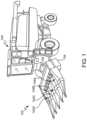
- FIG. 1is a perspective view of an agricultural harvester including a header in accordance with an exemplary embodiment of the subject disclosure
- FIG. 2is a perspective view of a first exemplary embodiment of a stomping shoe assembly and structure for mounting the stomping shoe assembly to a header suitable for use with the agricultural harvester header of FIG. 1 ;
- FIG. 3is a perspective view of the stomping shoe assembly of FIG. 2 showing a stalk cutter of the stomping shoe assembly in a first position relative to a stomping shoe of the stomping shoe assembly;
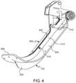
- FIG. 4is a perspective view of the stomping shoe assembly of FIG. 2 showing a stalk cutter of the stomping shoe assembly in a second position relative to a stomping shoe of the stomping shoe assembly;
- FIG. 5is a side view of the stomping shoe assembly of FIG. 4 ;
- FIG. 6is a side view of the stalk cutter of the stomping shoe assembly of FIG. 4 ;
- FIG. 7is a front view of the stomping shoe assembly shown in FIG. 5 ;
- FIG. 8is a top plan view of the stomping shoe assembly shown in FIG. 5 ;
- FIG. 9is a bottom plan view of the stomping shoe assembly shown in FIG. 5 ;
- FIG. 10is a perspective view of a second exemplary embodiment of a stomping shoe assembly in accordance with the subject disclosure.
- FIG. 11is a side view of the stomping shoe assembly of FIG. 10 ;
- FIG. 12is a front view of the stomping shoe assembly shown in FIG. 10 ;
- FIG. 13is a top plan view of the stomping shoe assembly shown in FIG. 10 .
- cornrefers to that part of a crop which is harvested and separated from discardable portions of the crop material.
- debrismaterial other than grain, and the like are used interchangeably.
- range formatis merely for convenience and brevity and should not be construed as an inflexible limitation on the scope of the subject disclosure. Accordingly, the description of a range should be considered to have specifically disclosed all the possible subranges as well as individual numerical values within that range. For example, description of a range such as from 1 to 6 should be considered to have specifically disclosed subranges such as from 1 to 3, from 1 to 4, from 1 to 5, from 2 to 4, from 2 to 6, from 3 to 6 etc., as well as individual numbers within that range, for example, 1, 2, 2.7, 3, 4, 5, 5.3, and 6. This applies regardless of the breadth of the range.
- FIG. 1illustrates an agricultural harvester 100 in accordance with an exemplary embodiment of the present disclosure.
- the agricultural harvesteris illustrated as a combine harvester.
- the harvester 100includes a header 102 attached to a forward end of the harvester 100 , which is configured to process crops, including (without limitation) corn.
- the headerincludes a plurality of row units 104 A, 1048 , 104 C and 104 D mounted to a chassis or frame 104 of the header.
- the row unitsare spaced apart substantially in accordance with the spacing of a row of corn stalks (not illustrated).
- the row unitsstrip ears of corn from the corn stalks in the known manner and induct the cut crops into a feederhouse 106 as the harvester moves forward over a crop field.
- Mounting assembly 200includes a plurality of stomping shoe assemblies 300 , 300 ′ and 300 ′′ coupled to an intermediate frame member 202 via respective mounting brackets 202 A, 202 B, and 202 C.
- the intermediate frame member 202is configured to couple to the frame 104 of the header via mounting points 204 A and 204 B such that each of stomping shoe assemblies 300 , 300 ′ and 300 ′′ is positioned inline and behind an associated row unit for flattening stalks of corn after the stalks are processed by the row units.
- stomping shoe assemblies 300 , 300 ′ and 300 ′′may be coupled directly to the frame of a corn header without need for intermediate frame member 202 .
- mounting assembly 200is intended to be used with a corn header having three row units.
- mounting assembly 200may be sized and configured to include any number of stomping shoe assemblies to match corn headers having a commensurate number of row units.
- mounting assembly 200may be sized and configured to include eight stomping shoe assemblies to accommodate corn headers with eight row units.
- multiple mounting assemblies 200may be mounted to a corn header in modular fashion to accommodate a certain number of row units.
- two modular mounting assemblies, each with three stomping shoe assembliesmay be mounted to a corn header having six row units.
- FIG. 3shows on an enlarged scale the construction of a first exemplary embodiment of a stomping shoe assembly 300 according to the present disclosure.
- Stomping shoe assembly 300comprises a stomping shoe 302 having a substantially planar proximal end 304 for connecting to the agricultural harvester header 102 .
- the stomping shoe 302also has a curved distal end 306 , for engaging crop, which is contiguous with the planar proximal end 304 .
- the stomping shoe assembly 300further comprises a stalk cutter 308 having an elongated body mounted to the stomping shoe 302 .
- the stalk cutterextends along the stomping shoe from the curved distal end 306 to the substantially planar proximal end 304 .
- the stalk cutter 308is provided at its distal end with a stop 301 and a notch 303 .
- the stop 301is adapted to contact the distalmost end of the curved distal end 306 of the stomping shoe 302 to prevent overtravel of the stalk cutter downwardly through a slot 310 ( FIG. 7 ) of the stomping shoe.
- the stomping shoe 302includes the slot 310 sized to allow passage of the stalk cutter 308 therethrough.
- the stomping shoefurther comprises a rib 312 extending along a longitudinal length of the stomping shoe, e.g., about its mid-line.
- the ribincludes a fastener 316 about its mid-portion.
- the fastenercan be, e.g., a through hole 314 in combination with a pin or shear bolt.
- the stalk cutter 308is a planar stalk cutter and is mounted with the slot 310 .
- the stalk cutterfurther comprises a curved distal end 320 having a sharpened bottom edge for engaging crop, and a dorsal fin-like extension 322 about its proximal end 323 ( FIGS. 4 and 5 ).
- FIG. 6is a side view of the stalk cutter 308 which shows a through hole 325 located at the proximal end 323 for receiving a pivot 318 , discussed below.
- Stalk cutterfurther includes a plurality of through holes 328 , the function of which is described below.
- the stalk cutter 308has a cross-sectional profile curve 324 that substantially matches a cross-sectional profile curve 326 of the stomping shoe 302 , such that when the stalk cutter is fully retracted the stock cutter does not project downwardly from a bottom surface of the stomping shoe.
- the stalk cutter 308is pivotable relative to the stomping shoe 302 .
- the stalk cutter 308is pivotably connected to the stomping shoe 302 via a pivot 318 which passes through the through hole 325 of the stalk cutter.
- the stalk cutter 308comprises a plurality of through holes 328 substantially about its mid-portion ( FIGS. 3 , 5 and 6 ) for receiving the pin.
- the stalk cutteris movable about a plurality of positions through the slot 310 and fixable in position by the fastener 316 .
- the through holes 328are individually alignable with the stomping shoe rib through hole 314 to receive the pin therethrough such that the stalk cutter is fixed in position with the slot 310 .
- the usercan set a depth of extension of the stalk cutter 308 at several positions relative to the stomping shoe 302 .
- the usercan set the extension depth of the stalk cutter to be comparatively large.
- the usercan set the extension depth of the stalk cutter to be comparatively smaller.
- the usercan set the stalk cutter such that it does not extend from the stomping shoe.
- fastener 316include a shear bolt that shears when the stalk cutter encounters a hard object. As such, the stalk cutter can be freed to pivot upwardly so as to minimize damage to the stalk cutter and stomping shoe assembly.
- Stomping shoe assembly 400constructed in accordance with another exemplary embodiment of the subject disclosure.
- Stomping shoe assembly 400is constructed similar to stomping shoe assembly 300 . Accordingly, only those aspects of the stomping shoe assembly 400 that depart materially in structure and/or function from their counterparts in stomping shoe assembly 300 , or are otherwise necessary for a proper understanding of the subject disclosure, will be discussed in detail.
- the stomping shoe assembly 400comprises a stalk cutter 408 having a dorsal fin-like extension 422 about its proximal end and a biasing member 436 biasing a stalk cutter 408 relative to the stomping shoe 402 .
- the biasing member 436biases the pivotably mounted stalk cutter towards the extended position.
- the biasing memberis formed as a torsion spring having an inner end 438 in contact with the dorsal fin-like extension 422 and opposed outer legs 440 in contact with an upper surface 442 of the stomping shoe 402 .
- biasing membersmay be used to bias the stalk cutter to extend from the stomping shoe including, without limitation, a compression spring, an elastomer, a leaf spring, and the like. Constructed as a spring, the biasing member 436 is also yieldable in the event the stalk cutter 408 encounters a hard object. In such an event, the stalk cutter is free to pivot upwardly against the bias of the biasing member so as to minimize potential damage to the stalk cutter.
- the stomping shoe assembly 300further comprises a mount 330 ( FIG. 3 ) for attaching to the agricultural harvester header 102 .
- the stomping shoe 302is pivotably connected to the mount at pivot 332 ( FIG. 5 ) so as to pivot about axis 334 ( FIG. 3 ).
- a similar mountmay be used to attach the stomping shoe assembly 400 to the agricultural harvester header 102 .
- stomping shoe assembly 300includes a cross bar 344 and the stomping shoe 302 is rotationally coupled to the cross bar 344 about a pivot axis 334 .
- a torsion spring 346is provided for biasing the stomping shoe 302 angularly about pivot axis 334 with respect to the cross bar 344 , thereby urging a lower surface 347 of stomping shoe 302 along direction 348 and into the ground when being used in conjunction with a combine harvester.
- the biasing force provided by the torsion springmay be provided by other means, such as, for example, a compression spring, an elastomer, a leaf spring and the like, positioned to provide an angular compression force between the cross bar 344 and the stomping shoe 302 .
- the mountmay also include a limit bar 350 and associated pins 352 , 354 limit the angular travel of the stomping shoe 302 with respect to the cross bar 344 , thereby preventing undesirable over-travel of stomping shoe along direction 348 and ensuring proper orientation of stomping shoe with respect to the ground when being used.
- Cross bar 344is configured to releasably attach to a mounting bracket 356 , for example, to facilitate expeditious replacement and/or maintenance of the stomping shoe.
- cross bar 344is provided with a locking pin 354 and an engaging bar 358 for engaging a receptacle 360 of mounting bracket 356 . To detach stomping shoe 302 for replacement or maintenance, the locking pin 354 is removed, thereby allowing engaging bar 358 to be displaced from engaging the receptacle 360 of the mounting bracket 356 .
- the slot of the stomping shoemay be of sufficient width to accommodate two or more pivotable stalk cutters, if such is desired or necessary.
- the foregoing exemplary embodiments of the stomping shoe assemblyadvantageously cut and break down stalks and/or weaken stalks without the need for any or minimal additional power, e.g., horsepower from the harvester.
- the foregoingprovides a low cost means to consumers for addressing leftover stalks concurrently during harvesting operations. Consequently, the rate of decomposition of the cut stalks and clearing of the field for subsequent planting is accelerated.
Landscapes
- Life Sciences & Earth Sciences (AREA)
- Environmental Sciences (AREA)
- Harvester Elements (AREA)
Abstract
Description
Claims (11)
Priority Applications (1)
| Application Number | Priority Date | Filing Date | Title |
|---|---|---|---|
| US16/684,025US11647693B2 (en) | 2019-11-14 | 2019-11-14 | Stomping shoe assembly for an agricultural harvester header |
Applications Claiming Priority (1)
| Application Number | Priority Date | Filing Date | Title |
|---|---|---|---|
| US16/684,025US11647693B2 (en) | 2019-11-14 | 2019-11-14 | Stomping shoe assembly for an agricultural harvester header |
Publications (2)
| Publication Number | Publication Date |
|---|---|
| US20210144921A1 US20210144921A1 (en) | 2021-05-20 |
| US11647693B2true US11647693B2 (en) | 2023-05-16 |
Family
ID=75908325
Family Applications (1)
| Application Number | Title | Priority Date | Filing Date |
|---|---|---|---|
| US16/684,025Active2040-05-25US11647693B2 (en) | 2019-11-14 | 2019-11-14 | Stomping shoe assembly for an agricultural harvester header |
Country Status (1)
| Country | Link |
|---|---|
| US (1) | US11647693B2 (en) |
Families Citing this family (2)
| Publication number | Priority date | Publication date | Assignee | Title |
|---|---|---|---|---|
| WO2020101841A1 (en)* | 2018-11-16 | 2020-05-22 | Cnh Industrial America Llc | Locking mechanism for an agricultural header |
| US12290025B2 (en) | 2021-06-29 | 2025-05-06 | Deere & Company | Stalk conditioner |
Citations (33)
| Publication number | Priority date | Publication date | Assignee | Title |
|---|---|---|---|---|
| US843479A (en)* | 1906-07-27 | 1907-02-05 | Jose Ma Callejas Y Becerra | Sugar-cane-straw-cutting machine. |
| US1068986A (en)* | 1913-02-12 | 1913-07-29 | James B Dawson | Beet topper or crowner. |
| US1261150A (en)* | 1918-02-16 | 1918-04-02 | Earl L Mountjoy | Stalk-cutting attachment for plows. |
| US1454580A (en)* | 1920-06-01 | 1923-05-08 | Foss Walter Levi | Grass-digging implement |
| US1458615A (en)* | 1921-03-03 | 1923-06-12 | Peter J Boyle | Beet harvester |
| US1747525A (en)* | 1927-05-23 | 1930-02-18 | Nagy Louis | Attachment to seeding machines |
| US1795182A (en)* | 1928-10-13 | 1931-03-03 | Trustees Of Purdue University | Cornstalk and clod cutter attachment for tractors |
| US2068467A (en)* | 1936-07-27 | 1937-01-19 | Paus Frank | Cultivator and shield |
| US2319520A (en)* | 1941-05-02 | 1943-05-18 | Ernest A Holznagel | Highway ice crusher and loosener |
| US2487609A (en)* | 1946-03-25 | 1949-11-08 | Linious W Sparks | Stubble controller |
| US3233683A (en) | 1964-02-14 | 1966-02-08 | Paul T Lofshult | Stalk and root cutter and mulcher |
| US3984966A (en) | 1974-06-27 | 1976-10-12 | International Harvester Company | Harvesting machine equipped with a stalk cutter |
| US4217835A (en)* | 1978-10-27 | 1980-08-19 | Deere & Company | Depth control and seed boot assembly for tillage apparatus |
| US4942833A (en)* | 1988-11-01 | 1990-07-24 | Wallace L. Hill | Turf treating process and apparatus |
| US5161356A (en) | 1990-09-07 | 1992-11-10 | Norbert Pick | Stalk chopper and crusher accessory |
| EP0898869A1 (en)* | 1997-09-01 | 1999-03-03 | CLAAS Selbstfahrende Erntemaschinen GmbH | Beet harvester |
| US5941316A (en) | 1996-06-14 | 1999-08-24 | Great Western Corporation Pty Ltd. | Stalk puller and chopper assembly |
| US6539697B2 (en) | 2001-02-22 | 2003-04-01 | Carl A. Burk | Apparatus and method for knocking down and crushing farm crop residue |
| DE102007049377A1 (en)* | 2007-10-15 | 2009-04-16 | Grimme Landmaschinenfabrik Gmbh & Co. Kg | Beet harvesting machine, in particular in the form of a self-propelled harvesting machine |
| US7658058B2 (en) | 2007-05-11 | 2010-02-09 | Pierson Douglas C | Methods and apparatus for guiding harvest residue |
| US7997218B2 (en)* | 2009-07-20 | 2011-08-16 | Landoll Corporation | Soil strip assembly for seed drill row unit |
| US20130061569A1 (en) | 2010-11-03 | 2013-03-14 | Dean J. McClenathen | Device for flattening corn stalk stubbles |
| US8567167B2 (en) | 2011-07-19 | 2013-10-29 | Kenneth E. Shoup | Quick connect/disconnect coupling for a stalk stomper |
| US8813865B2 (en)* | 2011-03-25 | 2014-08-26 | AgSynergy, LLC | Coulter unit for high speed tillage applications |
| US20150096773A1 (en) | 2013-10-03 | 2015-04-09 | Ricky Alan Miller | Stalk stomper |
| US9095093B2 (en) | 2012-01-11 | 2015-08-04 | Lankota Group, Inc. | Stem deflector mount |
| US20150250098A1 (en) | 2014-03-04 | 2015-09-10 | Deere & Company | Stalk Breaker for a Corn Head |
| US20160066504A1 (en) | 2014-09-05 | 2016-03-10 | Michael Holman | Crop Stubble Flattening and Slicing Apparatus |
| US9295196B2 (en) | 2010-11-22 | 2016-03-29 | Carl Geringhoff Gmbh & Co. Kg | Adjustable stalk support device for harvesting stalky stem material |
| WO2016109714A1 (en) | 2014-12-30 | 2016-07-07 | Agco Corporation | Easy mount stalk stomper |
| US9730374B2 (en) | 2014-01-17 | 2017-08-15 | May-Wes Mfg. | Dual-position quick-connect mount and adjustably tensioned stalk stomper |
| US9743587B2 (en) | 2014-12-30 | 2017-08-29 | Agco Corporation | Breakaway stalk stomper for corn header |
| US20180042180A1 (en) | 2016-08-12 | 2018-02-15 | Cnh Industrial America Llc | Stalk conditioner for a header of an agricultural combine |
- 2019
- 2019-11-14USUS16/684,025patent/US11647693B2/enactiveActive
Patent Citations (33)
| Publication number | Priority date | Publication date | Assignee | Title |
|---|---|---|---|---|
| US843479A (en)* | 1906-07-27 | 1907-02-05 | Jose Ma Callejas Y Becerra | Sugar-cane-straw-cutting machine. |
| US1068986A (en)* | 1913-02-12 | 1913-07-29 | James B Dawson | Beet topper or crowner. |
| US1261150A (en)* | 1918-02-16 | 1918-04-02 | Earl L Mountjoy | Stalk-cutting attachment for plows. |
| US1454580A (en)* | 1920-06-01 | 1923-05-08 | Foss Walter Levi | Grass-digging implement |
| US1458615A (en)* | 1921-03-03 | 1923-06-12 | Peter J Boyle | Beet harvester |
| US1747525A (en)* | 1927-05-23 | 1930-02-18 | Nagy Louis | Attachment to seeding machines |
| US1795182A (en)* | 1928-10-13 | 1931-03-03 | Trustees Of Purdue University | Cornstalk and clod cutter attachment for tractors |
| US2068467A (en)* | 1936-07-27 | 1937-01-19 | Paus Frank | Cultivator and shield |
| US2319520A (en)* | 1941-05-02 | 1943-05-18 | Ernest A Holznagel | Highway ice crusher and loosener |
| US2487609A (en)* | 1946-03-25 | 1949-11-08 | Linious W Sparks | Stubble controller |
| US3233683A (en) | 1964-02-14 | 1966-02-08 | Paul T Lofshult | Stalk and root cutter and mulcher |
| US3984966A (en) | 1974-06-27 | 1976-10-12 | International Harvester Company | Harvesting machine equipped with a stalk cutter |
| US4217835A (en)* | 1978-10-27 | 1980-08-19 | Deere & Company | Depth control and seed boot assembly for tillage apparatus |
| US4942833A (en)* | 1988-11-01 | 1990-07-24 | Wallace L. Hill | Turf treating process and apparatus |
| US5161356A (en) | 1990-09-07 | 1992-11-10 | Norbert Pick | Stalk chopper and crusher accessory |
| US5941316A (en) | 1996-06-14 | 1999-08-24 | Great Western Corporation Pty Ltd. | Stalk puller and chopper assembly |
| EP0898869A1 (en)* | 1997-09-01 | 1999-03-03 | CLAAS Selbstfahrende Erntemaschinen GmbH | Beet harvester |
| US6539697B2 (en) | 2001-02-22 | 2003-04-01 | Carl A. Burk | Apparatus and method for knocking down and crushing farm crop residue |
| US7658058B2 (en) | 2007-05-11 | 2010-02-09 | Pierson Douglas C | Methods and apparatus for guiding harvest residue |
| DE102007049377A1 (en)* | 2007-10-15 | 2009-04-16 | Grimme Landmaschinenfabrik Gmbh & Co. Kg | Beet harvesting machine, in particular in the form of a self-propelled harvesting machine |
| US7997218B2 (en)* | 2009-07-20 | 2011-08-16 | Landoll Corporation | Soil strip assembly for seed drill row unit |
| US20130061569A1 (en) | 2010-11-03 | 2013-03-14 | Dean J. McClenathen | Device for flattening corn stalk stubbles |
| US9295196B2 (en) | 2010-11-22 | 2016-03-29 | Carl Geringhoff Gmbh & Co. Kg | Adjustable stalk support device for harvesting stalky stem material |
| US8813865B2 (en)* | 2011-03-25 | 2014-08-26 | AgSynergy, LLC | Coulter unit for high speed tillage applications |
| US8567167B2 (en) | 2011-07-19 | 2013-10-29 | Kenneth E. Shoup | Quick connect/disconnect coupling for a stalk stomper |
| US9095093B2 (en) | 2012-01-11 | 2015-08-04 | Lankota Group, Inc. | Stem deflector mount |
| US20150096773A1 (en) | 2013-10-03 | 2015-04-09 | Ricky Alan Miller | Stalk stomper |
| US9730374B2 (en) | 2014-01-17 | 2017-08-15 | May-Wes Mfg. | Dual-position quick-connect mount and adjustably tensioned stalk stomper |
| US20150250098A1 (en) | 2014-03-04 | 2015-09-10 | Deere & Company | Stalk Breaker for a Corn Head |
| US20160066504A1 (en) | 2014-09-05 | 2016-03-10 | Michael Holman | Crop Stubble Flattening and Slicing Apparatus |
| WO2016109714A1 (en) | 2014-12-30 | 2016-07-07 | Agco Corporation | Easy mount stalk stomper |
| US9743587B2 (en) | 2014-12-30 | 2017-08-29 | Agco Corporation | Breakaway stalk stomper for corn header |
| US20180042180A1 (en) | 2016-08-12 | 2018-02-15 | Cnh Industrial America Llc | Stalk conditioner for a header of an agricultural combine |
Non-Patent Citations (1)
| Title |
|---|
| Yetter Co., "Yetter Farm Equipment—Yetter Stalk Devastator", Nov. 13, 2018, pp. 1-10, Yetter Manufacturing Company. |
Also Published As
| Publication number | Publication date |
|---|---|
| US20210144921A1 (en) | 2021-05-20 |
Similar Documents
| Publication | Publication Date | Title |
|---|---|---|
| US4891932A (en) | Grain-saver dam for combine cutter bar | |
| US8196381B2 (en) | Crop lifter pans | |
| US20150250098A1 (en) | Stalk Breaker for a Corn Head | |
| US11606906B2 (en) | Harvesting inter-seeded crops | |
| EP4044791B1 (en) | Multi-segment header for an agricultural harvester | |
| US11647693B2 (en) | Stomping shoe assembly for an agricultural harvester header | |
| AU2010302890B2 (en) | Seed pans | |
| US20240245002A1 (en) | Multi-segment header for an agricultural harvester | |
| US9894838B2 (en) | Basecutter blade for a cane harvester | |
| EP3434097B1 (en) | Crop divider for an agricultural harvester header having multiple harvesting reels | |
| US10159189B2 (en) | Stalk conditioner for a header of an agricultural combine | |
| US9027316B2 (en) | Cutting header with finger mounted raised divider pans | |
| US20230363314A1 (en) | Header for an agricultural harvester having integral seed saver | |
| US20090183483A1 (en) | Crop lifter pans | |
| US20230013518A1 (en) | Cutter bar skid shoe for an agricultural harvester header | |
| US11785892B2 (en) | Preventing damage from dislodged crop saving accessories | |
| SU1547769A1 (en) | Method of harvesting agricultural crops | |
| KR102018574B1 (en) | Crop pick-up apparatus for agricultural combine with round blade | |
| Park | Combine cutting and feeding mechanisms in the Southeast | |
| JP5206023B2 (en) | Combine harvester conveyor | |
| CA2640269C (en) | Crop lifter pans | |
| HU191882B (en) | Method and harvesting device for gathering maize or other grain crops as well as device formed as an adapter |
Legal Events
| Date | Code | Title | Description |
|---|---|---|---|
| AS | Assignment | Owner name:CNH INDUSTRIAL AMERICA LLC, PENNSYLVANIA Free format text:ASSIGNMENT OF ASSIGNORS INTEREST;ASSIGNOR:SHANE, NICHOLAS;REEL/FRAME:051012/0174 Effective date:20191029 | |
| FEPP | Fee payment procedure | Free format text:ENTITY STATUS SET TO UNDISCOUNTED (ORIGINAL EVENT CODE: BIG.); ENTITY STATUS OF PATENT OWNER: LARGE ENTITY | |
| STPP | Information on status: patent application and granting procedure in general | Free format text:NON FINAL ACTION MAILED | |
| STPP | Information on status: patent application and granting procedure in general | Free format text:RESPONSE TO NON-FINAL OFFICE ACTION ENTERED AND FORWARDED TO EXAMINER | |
| STPP | Information on status: patent application and granting procedure in general | Free format text:FINAL REJECTION MAILED | |
| STPP | Information on status: patent application and granting procedure in general | Free format text:RESPONSE AFTER FINAL ACTION FORWARDED TO EXAMINER | |
| STPP | Information on status: patent application and granting procedure in general | Free format text:ADVISORY ACTION MAILED | |
| STPP | Information on status: patent application and granting procedure in general | Free format text:DOCKETED NEW CASE - READY FOR EXAMINATION | |
| STPP | Information on status: patent application and granting procedure in general | Free format text:NON FINAL ACTION MAILED | |
| STPP | Information on status: patent application and granting procedure in general | Free format text:RESPONSE TO NON-FINAL OFFICE ACTION ENTERED AND FORWARDED TO EXAMINER | |
| STPP | Information on status: patent application and granting procedure in general | Free format text:FINAL REJECTION MAILED | |
| STPP | Information on status: patent application and granting procedure in general | Free format text:RESPONSE AFTER FINAL ACTION FORWARDED TO EXAMINER | |
| STPP | Information on status: patent application and granting procedure in general | Free format text:NOTICE OF ALLOWANCE MAILED -- APPLICATION RECEIVED IN OFFICE OF PUBLICATIONS | |
| STCF | Information on status: patent grant | Free format text:PATENTED CASE | |
| AS | Assignment | Owner name:BLUE LEAF I.P., INC., DELAWARE Free format text:ASSIGNMENT OF ASSIGNORS INTEREST;ASSIGNOR:CNH INDUSTRIAL AMERICA LLC;REEL/FRAME:066932/0175 Effective date:20231020 |