US11644115B2 - Fuel cap with duckbill valve - Google Patents
Fuel cap with duckbill valveDownload PDFInfo
- Publication number
- US11644115B2 US11644115B2US17/666,028US202217666028AUS11644115B2US 11644115 B2US11644115 B2US 11644115B2US 202217666028 AUS202217666028 AUS 202217666028AUS 11644115 B2US11644115 B2US 11644115B2
- Authority
- US
- United States
- Prior art keywords
- valve
- fuel cap
- fuel
- fuel tank
- valve member
- Prior art date
- Legal status (The legal status is an assumption and is not a legal conclusion. Google has not performed a legal analysis and makes no representation as to the accuracy of the status listed.)
- Active
Links
Images


Classifications
- F—MECHANICAL ENGINEERING; LIGHTING; HEATING; WEAPONS; BLASTING
- F16—ENGINEERING ELEMENTS AND UNITS; GENERAL MEASURES FOR PRODUCING AND MAINTAINING EFFECTIVE FUNCTIONING OF MACHINES OR INSTALLATIONS; THERMAL INSULATION IN GENERAL
- F16K—VALVES; TAPS; COCKS; ACTUATING-FLOATS; DEVICES FOR VENTING OR AERATING
- F16K15/00—Check valves
- F16K15/14—Check valves with flexible valve members
- F16K15/144—Check valves with flexible valve members the closure elements being fixed along all or a part of their periphery
- F16K15/147—Check valves with flexible valve members the closure elements being fixed along all or a part of their periphery the closure elements having specially formed slits or being of an elongated easily collapsible form
- B—PERFORMING OPERATIONS; TRANSPORTING
- B60—VEHICLES IN GENERAL
- B60K—ARRANGEMENT OR MOUNTING OF PROPULSION UNITS OR OF TRANSMISSIONS IN VEHICLES; ARRANGEMENT OR MOUNTING OF PLURAL DIVERSE PRIME-MOVERS IN VEHICLES; AUXILIARY DRIVES FOR VEHICLES; INSTRUMENTATION OR DASHBOARDS FOR VEHICLES; ARRANGEMENTS IN CONNECTION WITH COOLING, AIR INTAKE, GAS EXHAUST OR FUEL SUPPLY OF PROPULSION UNITS IN VEHICLES
- B60K15/00—Arrangement in connection with fuel supply of combustion engines or other fuel consuming energy converters, e.g. fuel cells; Mounting or construction of fuel tanks
- B60K15/03—Fuel tanks
- B60K15/035—Fuel tanks characterised by venting means
- B60K15/03519—Valve arrangements in the vent line
- B—PERFORMING OPERATIONS; TRANSPORTING
- B60—VEHICLES IN GENERAL
- B60K—ARRANGEMENT OR MOUNTING OF PROPULSION UNITS OR OF TRANSMISSIONS IN VEHICLES; ARRANGEMENT OR MOUNTING OF PLURAL DIVERSE PRIME-MOVERS IN VEHICLES; AUXILIARY DRIVES FOR VEHICLES; INSTRUMENTATION OR DASHBOARDS FOR VEHICLES; ARRANGEMENTS IN CONNECTION WITH COOLING, AIR INTAKE, GAS EXHAUST OR FUEL SUPPLY OF PROPULSION UNITS IN VEHICLES
- B60K15/00—Arrangement in connection with fuel supply of combustion engines or other fuel consuming energy converters, e.g. fuel cells; Mounting or construction of fuel tanks
- B60K15/03—Fuel tanks
- B60K15/04—Tank inlets
- B60K15/0406—Filler caps for fuel tanks
- B—PERFORMING OPERATIONS; TRANSPORTING
- B60—VEHICLES IN GENERAL
- B60K—ARRANGEMENT OR MOUNTING OF PROPULSION UNITS OR OF TRANSMISSIONS IN VEHICLES; ARRANGEMENT OR MOUNTING OF PLURAL DIVERSE PRIME-MOVERS IN VEHICLES; AUXILIARY DRIVES FOR VEHICLES; INSTRUMENTATION OR DASHBOARDS FOR VEHICLES; ARRANGEMENTS IN CONNECTION WITH COOLING, AIR INTAKE, GAS EXHAUST OR FUEL SUPPLY OF PROPULSION UNITS IN VEHICLES
- B60K15/00—Arrangement in connection with fuel supply of combustion engines or other fuel consuming energy converters, e.g. fuel cells; Mounting or construction of fuel tanks
- B60K15/03—Fuel tanks
- B60K15/04—Tank inlets
- B60K15/05—Inlet covers
- B—PERFORMING OPERATIONS; TRANSPORTING
- B60—VEHICLES IN GENERAL
- B60K—ARRANGEMENT OR MOUNTING OF PROPULSION UNITS OR OF TRANSMISSIONS IN VEHICLES; ARRANGEMENT OR MOUNTING OF PLURAL DIVERSE PRIME-MOVERS IN VEHICLES; AUXILIARY DRIVES FOR VEHICLES; INSTRUMENTATION OR DASHBOARDS FOR VEHICLES; ARRANGEMENTS IN CONNECTION WITH COOLING, AIR INTAKE, GAS EXHAUST OR FUEL SUPPLY OF PROPULSION UNITS IN VEHICLES
- B60K15/00—Arrangement in connection with fuel supply of combustion engines or other fuel consuming energy converters, e.g. fuel cells; Mounting or construction of fuel tanks
- B60K15/03—Fuel tanks
- B60K15/035—Fuel tanks characterised by venting means
- B60K15/03504—Fuel tanks characterised by venting means adapted to avoid loss of fuel or fuel vapour, e.g. with vapour recovery systems
- B60K2015/03514—Fuel tanks characterised by venting means adapted to avoid loss of fuel or fuel vapour, e.g. with vapour recovery systems with vapor recovery means
- B—PERFORMING OPERATIONS; TRANSPORTING
- B60—VEHICLES IN GENERAL
- B60K—ARRANGEMENT OR MOUNTING OF PROPULSION UNITS OR OF TRANSMISSIONS IN VEHICLES; ARRANGEMENT OR MOUNTING OF PLURAL DIVERSE PRIME-MOVERS IN VEHICLES; AUXILIARY DRIVES FOR VEHICLES; INSTRUMENTATION OR DASHBOARDS FOR VEHICLES; ARRANGEMENTS IN CONNECTION WITH COOLING, AIR INTAKE, GAS EXHAUST OR FUEL SUPPLY OF PROPULSION UNITS IN VEHICLES
- B60K15/00—Arrangement in connection with fuel supply of combustion engines or other fuel consuming energy converters, e.g. fuel cells; Mounting or construction of fuel tanks
- B60K15/03—Fuel tanks
- B60K15/035—Fuel tanks characterised by venting means
- B60K2015/03542—Mounting of the venting means
- B60K2015/03547—Mounting of the venting means the venting means are integrated in the fuel cap or inlet cover
- B—PERFORMING OPERATIONS; TRANSPORTING
- B60—VEHICLES IN GENERAL
- B60K—ARRANGEMENT OR MOUNTING OF PROPULSION UNITS OR OF TRANSMISSIONS IN VEHICLES; ARRANGEMENT OR MOUNTING OF PLURAL DIVERSE PRIME-MOVERS IN VEHICLES; AUXILIARY DRIVES FOR VEHICLES; INSTRUMENTATION OR DASHBOARDS FOR VEHICLES; ARRANGEMENTS IN CONNECTION WITH COOLING, AIR INTAKE, GAS EXHAUST OR FUEL SUPPLY OF PROPULSION UNITS IN VEHICLES
- B60K15/00—Arrangement in connection with fuel supply of combustion engines or other fuel consuming energy converters, e.g. fuel cells; Mounting or construction of fuel tanks
- B60K15/03—Fuel tanks
- B60K15/04—Tank inlets
- B60K15/0406—Filler caps for fuel tanks
- B60K2015/0432—Filler caps for fuel tanks having a specific connection between the cap and the vehicle or tank opening
- B60K2015/0438—Filler caps for fuel tanks having a specific connection between the cap and the vehicle or tank opening using screw or bayonet
Definitions
- This disclosurerelates in general to a fuel cap for an internal combustion engine, and more specifically, to apparatus and techniques for regulation of evaporative emissions using the fuel cap.
- a fuel tank for an internal combustion engineencloses and stores combustible fuel.
- the fuelmay include hydrocarbons.
- the fuelnaturally evaporates into the atmosphere. When hydrocarbons evaporate and escape to the atmosphere, the hydrocarbons may become pollutants. Evaporation rates may be increased by heat from warm weather. Evaporation levels may accumulate over time for engines that often spend long periods of time between starts and/or spend long periods in non-climate controlled environments such as garages. Evaporation is also caused from heat from the operation of the engine.
- a fuel capmay vent pressurized fuel vapor out of the fuel tank into one or more filters for removing hydrocarbons. High pressure in the fuel tank may affect the venting of the pressurized vapor. Challenges remain in venting of evaporative fuel vapors from the fuel tank.
- FIG. 1illustrates a fuel cap
- FIG. 2 Aillustrates an example exploded view of the fuel cap of FIG. 1 .
- FIG. 2 Billustrates another example exploded view of the fuel cap of FIG. 1 .
- FIG. 3illustrates a cross sectional view of the fuel cap of FIG. 1 .
- FIG. 4 Aillustrates a more detailed view of the fuel cap of FIG. 1 including a duckbill valve.
- FIG. 4 Billustrates the duckbill valve of FIG. 4 A .
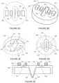
- FIGS. 5 A and 5 Billustrate views of the top of the duckbill valve.
- FIGS. 5 C and 5 Dillustrate views of the bottom of the duckbill valve.
- FIG. 5 Eillustrates a cross sectional side view of the duckbill valve.
- FIGS. 6 A and 6 Billustrate views of the top of the duckbill valve with outwardly arranged bosses.
- FIGS. 6 C and 6 Dillustrate views of the bottom of the duckbill valve with outwardly arranged bosses.
- FIG. 6 Eillustrates a cross sectional side view of the duckbill valve with outwardly arranged bosses.
- FIGS. 7 A and 7 Billustrate views of the top of the duckbill valve with inwardly arranged bosses.
- FIGS. 7 C and 7 Dillustrate views of the bottom of the duckbill valve with inwardly arranged bosses.
- FIG. 7 Eillustrates a cross sectional side view of the duckbill valve with inwardly arranged bosses.
- FIGS. 8 A and 8 Billustrate views of the top of the duckbill valve with both outwardly and inwardly arranged bosses.
- FIGS. 8 C and 8 Dillustrate views of the bottom of the duckbill valve with both outwardly and inwardly arranged bosses.
- FIG. 8 Eillustrates a cross sectional side view of the duckbill valve with both outwardly and inwardly arranged bosses.
- FIGS. 9 A and 9 Billustrate views of the top of the duckbill valve with a large spacer ring.
- FIGS. 9 C and 9 Dillustrate views of the bottom of the duckbill valve with the large spacer ring.
- FIG. 9 Eillustrates a cross sectional side view of the duckbill valve with the large spacer ring.
- FIGS. 10 A and 10 Billustrate views of the top of the duckbill valve with a small spacer ring.
- FIGS. 10 C and 10 Dillustrate views of the bottom of the duckbill valve with the small spacer ring.
- FIG. 10 Eillustrates a cross sectional side view of the duckbill valve with the small spacer ring.
- FIGS. 11 A and 11 Billustrate views of the top of the duckbill valve with the large and small spacer rings.
- FIGS. 11 C and 11 Dillustrate views of the bottom of the duckbill valve with the large and small spacer rings.
- FIG. 11 Eillustrates a cross sectional side view of the duckbill valve with the large and small spacer rings.
- FIG. 12illustrates a flowchart for manufacturing the fuel cap.
- FIG. 1illustrates a fuel cap 100 , which may include at least an outer shell or cover 105 , an internal sleeve 140 , and a tether 150 .
- the internal sleeve 140may couple internal components of the fuel cap 100 together.
- the internal sleeve 140may include a threading or another coupling mechanism to secure the fuel cap 100 to a fuel port of an engine.
- the tether 150includes an extended member, which may be formed of plastic and may be flexible or rigid, that connects the fuel cap 100 to an anchor.
- the anchoris sized larger than the largest dimension of the fuel port of the engine to prevent the fuel cap 100 from becoming detached from the engine at a distance greater than the length of the extended member.
- the enginemay be a small internal combustion engine applicable to chainsaws, lawn mowers, wood chippers, stump grinders, concrete trowels, mini excavators, concrete saws, portable saw mills, weed trimmers, all-terrain vehicles, wood splitters, pressure washers, garden tillers, tractors, plows, snow blowers, welding equipment, generators, and other devices. Often such small engine containing devices are used in close proximity to a user (e.g., a human). It is desirable to reduce or minimize the amount of hydrocarbon evaporative emissions from these types of devices.
- the fuel cap 100includes an evaporative emission reduction device for reducing the leakage or escape of emissions from the fuel tank of the engine.
- FIG. 2 Aillustrates an exploded view of the fuel cap 105 of FIG. 1 including the evaporative emission reduction device.
- the fuel cap 105 aincludes an upper filter retainer 110 a , a lower filter retainer 125 a , a duck bill valve 130 , a valve support 135 a , and a seal 145 a .
- the upper filter retainer 110 a and the lower filter retainer 125 asupport an upper filter 115 a and a lower filter 120 a .
- FIG. 2 Billustrates an example exploded view of the fuel cap of FIG. 1 using similar components that vary in structure from the example of FIG. 2 A including a fuel cap 105 b , an upper filter retainer 110 b , a lower filter retainer 125 b , a duck bill valve 130 , a valve support 135 b , an internal sleeve 140 b , and a seal 145 b .
- the upper filter retainer 110 b and the lower filter retainer 125 bsupport an upper filter 115 a , a middle filter 118 , and a lower filter 120 a.
- FIG. 3illustrates a cross sectional view of the fuel cap of FIG. 1 .
- a hydrocarbon filter 300that removes hydrocarbon material from the vapor released from the fuel tank.
- the hydrocarbon filtermay adsorb hydrocarbons from the vapor.
- the hydrocarbon filter 300may include adsorption capsules. Vapor entering the hydrocarbon filter may be hydrocarbon evaporative emission and the flow leaving the hydrocarbon filter may be considered scrubbed vapor or air. The scrubbed air may be safe for release into the atmosphere according to one or more guidelines or regulations.
- the upper filter 115 , the lower filter 120 , or bothmay be formed from a felt or another type of fabric. Example types of fabric include a compounding non-spinning fabric.
- the combination of the upper filter 115 the lower filter 120may be referred to as a dilayer compounding non-spinning fabric.
- three layerse.g., upper filter 115 a , middle filter 118 , and lower filter 120 a ) form a trilayer fabric.
- FIG. 4 Aillustrates a more detailed view of the fuel cap of FIG. 1 including a duckbill valve 130 .
- FIG. 4 Billustrates the duckbill valve 130 of FIG. 4 A .
- the duck bill valve 130may include multiple valves.
- the valvesmay include one or more one-way valve and/or one or more check valve. The valves allow air flow or pressure to flow in one direction through the duckbill valve 130 and not in another direction through the duckbill valve 130 .
- FIGS. 5 A and 5 Billustrate views of the top of a duckbill valve member 530 including a major valve 533 and multiple minor valves (e.g., minor valve 531 and 532 ).
- the major valve 533may allow air flow in a first direction (e.g., into the fuel tank from the atmosphere or elsewhere in the vicinity of the engine) and the minor valves 531 and 532 may allow air flow in a second direction (e.g., out of the fuel tank to the atmosphere or elsewhere in the vicinity of the engine).
- the valvesmay have any size, orientation, and direction.
- the terms minor and majordo not necessarily represent relative size or flow volumes for the valves.
- FIGS. 5 C and 5 Dillustrate views of the bottom of the duckbill valve member 530 and FIG. 5 E illustrates a cross sectional side view of the duckbill valve, illustrating that the major valve 533 extends in a duck bill shape or a triangular prism shape away from the base of the duckbill valve member 530 towards the interior of the fuel tank.
- the major valve 533includes a first angled portion 538 and a second angled portion 539 that terminate at opening 535 .
- the minor valves 531 and 532each include a domed shaped cavity for openings 536 and 537 , respectively, that is concave in a direction opposite that of the extension of the major valve 533 .
- the major valve 533 and the minor valves 531 and 532operate as one-way or check valves in opposite directions.
- a forceis applied to the domed shaped cavities for openings 536 and 537 .
- the forcecauses the openings 537 and 537 to allow air or vapor flow from the fuel tank and into the fuel cap including the emission filter.
- the forcemay cause the duckbill valve member 530 to deform or otherwise change shape. Some of the deformation allows the duckbill valve member 530 to operate properly. However, when the duckbill valve member 530 becomes too deformed it may contact an adjacent member (e.g., lower filter retainer 125 ). Contact with the adjacent member may disrupt the valve operation and restrict the flow of air out of the fuel tank.
- FIG. 4 Billustration a distance a between the adjacent member (e.g., lower filter retainer 125 ) and the duckbill valve member 530 .
- the adjacent membere.g., lower filter retainer 125
- the duckbill valve member 530does not operate properly.
- the following embodimentsinclude apparatus and techniques for preventing this disruption of the valve operation and/or maintaining at least the distance a between the adjacent member (e.g., lower filter retainer 125 ) and the duckbill valve member.
- FIGS. 6 A and 6 Billustrate views of the top of the duckbill valve member 630 with outwardly arranged bosses 690 and 691 .
- FIGS. 6 C and 6 Dillustrate views of the bottom of the duckbill valve 630 with outwardly arranged bosses 690 and 691 .
- FIG. 6 Eillustrates a cross sectional side view of the duckbill valve 630 with outwardly arranged bosses 690 and 691 .
- the bosses 690 and 691press against or near the adjacent member (e.g., lower filter retainer 125 ).
- the bosses 690 and 691prevent or reduce deformation to the duckbill valve member 630 . Therefore, the duckbill valve member 630 can operate under higher pressures in the fuel tank without reduction of the flow of air through the minor valves 531 and 532 .
- the bosses 690 and 691may be made of the same material as the duckbill valve member 630 (e.g., rubber, elastomer, silicone or hydrocarbon-resistant fluorosilicone rubber).
- the bosses 690 and 691may be positioned at a predetermined distance (e.g., 1 mm) from minor valves 531 and 532 in a direction of the circumference of the duckbill valve member 630 .
- the bosses 690 and 691may be formed integrally with the duckbill valve member 630 . In one example, the bosses 690 and 691 may be dimples pressed into the duckbill valve member 630 from the opposite side.
- bossesmay be spaced at different distances from the major valve 533 or minor valves 531 and 531 .
- the bossesmay be spaced from the circumference of the duckbill valve member 630 .
- the bossesmay be another shape such as circular, triangular, or oval.
- the sides of the spacer ringsmay be sloped.
- the bossesmay be arranged in a line in a direction perpendicular to a face of the bosses.
- the bossesmay be arranged at different angles with respect to the major valve 533 , minor valves 531 and 531 , or the circumference of the duckbill valve member 630 .
- bosses 690 and 691may be sized at 1 mm cubed, 1 mm by 2 mm by 1 mm, or another size.
- One of the bossesmay be one size and another of the bosses may be a different size. Any of these variations may be applied to bosses 690 and 691 as well as other embodiments herein.
- FIGS. 7 A and 7 Billustrate views of the top of the duckbill valve 730 with inwardly arranged bosses 790 and 791 .
- FIGS. 7 C and 7 Dillustrate views of the bottom of the duckbill valve 730 with inwardly arranged bosses 790 and 791 .
- FIG. 7 Eillustrates a cross sectional side view of the duckbill valve 730 with inwardly arranged bosses 790 and 791 .
- the bosses 790 and 791press against or near the adjacent member (e.g., lower filter retainer 125 ).
- the bosses 790 and 791prevent or reduce deformation to the duckbill valve member 730 . Therefore, the duckbill valve member 730 can operate under higher pressures in the fuel tank without reduction of the flow of air through the minor valves 531 and 532 .
- the bosses 790 and 791may be made of the same material as the duckbill valve member 730 (e.g., rubber, elastomer, silicone or hydrocarbon-resistant fluorosilicone rubber).
- the bosses 790 and 791may be positioned at a predetermined distance (e.g., 1 mm) from minor valves 531 and 532 in a direction toward the center of the duckbill valve member 630 .
- the bosses 790 and 791may be positioned at a predetermined distance (e.g., 0.1 mm) from major valve 533 in a direction toward the circumference of the duckbill valve member 630 .
- Variations in shapes, sizes, quantity, and arrangement of bosses 790 and 791may be made and examples of such variations are described in other embodiments herein.
- FIGS. 8 A and 8 Billustrate views of the top of the duckbill valve 830 with both outwardly arranged bosses 690 and 691 and inwardly arranged bosses 790 and 791 .
- FIGS. 8 C and 8 Dillustrate views of the bottom of the duckbill valve 830 with outwardly arranged bosses 690 and 691 and inwardly arranged bosses 790 and 791 .
- FIG. 8 Eillustrates a cross sectional side view of the duckbill valve 830 with both outwardly arranged bosses 690 and 691 and inwardly arranged bosses 790 and 791 .
- Variations in shapes, sizes, quantity, and arrangement of bosses 690 , 691 , 790 and 791may be made and examples of such variations are described in other embodiments herein.
- FIGS. 9 A and 9 Billustrate views of the top of the duckbill valve 930 with a large spacer ring 990 .
- FIGS. 9 C and 9 Dillustrate views of the bottom of the duckbill valve 930 with the large spacer ring 990 .
- FIG. 9 Eillustrates a cross sectional side view of the duckbill valve 930 with the large spacer ring 990 .
- the large spacer ring 990may have a diameter greater than a width of the major valve 533 and smaller than a dimeter of the duckbill valve 930 . Examples for the diameter of the large spacer ring 990 may include 10 mm and 15 mm.
- FIGS. 10 A and 10 Billustrate views of the top of the duckbill valve 1030 with a small spacer ring 1090 .
- FIGS. 10 C and 10 Dillustrate views of the bottom of the duckbill valve 1030 with the small spacer ring 1090 .
- FIG. 10 Eillustrates a cross sectional side view of the duckbill valve 1030 with the small spacer ring 1090 .
- the small spacer ring 1090may have a diameter smaller than a width of the major valve 533 .
- the small spacer ring 1090may have a diameter equal to or greater than a width of the minor valves 531 and 532 . Examples for the small spacer ring 1090 may include 5 mm and 8 mm.
- FIGS. 11 A and 11 Billustrate views of the top of the duckbill valve 1130 with the large spacer ring 990 and the small spacer ring 1090 .
- FIGS. 11 C and 11 Dillustrate views of the bottom of the duckbill valve 1130 with the large spacer ring 990 and the small spacer ring 1090 .
- FIG. 11 Eillustrates a cross sectional side view of the duckbill valve 1130 with the large spacer ring 990 and the small spacer ring 1090 .
- a ratio between the diameter of the large spacer ring 990 and the small spacer ring 1090may be in a range from 1.5 to 3.
- An example ratiois 2 such that the large spacer ring 990 is twice the width of the small spacer ring 1090 .
- Examples for the width and height (H) of the large spacer ring 990 and the small spacer ring 1090may include 1 mm, 1.2 mm, 1.5 mm, and 2 mm.
- the spacer ringsmay have the same or different width or heights.
- the spacer ringsmay not be complete rings. In some examples, one or more of the spacer rings may be semi-circles or quarter-circles.
- the spacer ringsmay be another proportion of a complete circle such as 70% or 90%.
- the spacer ringsmay be discontinuous and formed of spaced portions (e.g., dashed circle shape). Other quantities of spacer rings may be used.
- the spacer ringsmay be concentric or arranged at different sides of the duckbill valve member.
- the spacer rings, rather than circular,may be square, rectangular or another shape. The sides of the spacer rings may be sloped.
- FIG. 12illustrates an example flowchart for manufacturing a fuel cap including a duckbill filter or valve and an evaporative emission reduction device. Additional, different, or fewer acts may be included.
- an evaporative emission reduction deviceis provided to a fuel cap (e.g., fuel cap 100 ).
- the evaporative emission reduction devicemay include a hydrocarbon filter that adsorbs vapor or hydrocarbon material from the vapor released from the fuel tank.
- the evaporative emission reduction devicereduces the escape of vapors from a fuel tank.
- a deformation prevention memberis mounted on a valve member.
- the deformation prevention membermay include one component, two components, or more than two components.
- the deformation prevention membermay include at least one dimension (e.g., height) that meets or exceeds a deformation prevention threshold distance.
- the deformation prevention threshold distancemay be selected according to the dimensions or materials of the valve member. Stiffer (e.g., with coefficient of elasticity below a predetermined value) valve members may have lower deformation prevention thresholds and require larger height for the deformation prevention member. More flexible (e.g., with coefficient of elasticity above a predetermined value) valve members may have higher deformation prevention thresholds and require smaller height for the deformation prevention member.
- the deformation prevention memberprevents the valve from become deformed, which may affect the control of the escape of vapors from the fuel tank.
- the valve membermay be shaped in a disc that can twist or become contorted and prevent the valve opening from opening and closing in normal operation.
- the deformationmay be caused by pressure above a predetermined pressure threshold in the fuel tank.
- the pressure thresholdmay depend on the size of the fuel tank, the shape of the fuel tank, the type of fuel in the fuel tank, the diameter of the fuel tank opening for the fuel tank, and/or the width and materials for the valve member.
- the deformation prevention membermay be placed at a predetermined distance from the opening of the valve to protect the shape of the valve member and ensure that the valve opening open and closes in normal operation.
- the deformation prevention membermay be placed between the valve and an outer circumference of the valve member or between the valve in and a center of the valve member.
- the deformation prevention membermay include two components include a first ring outside of the valve in a direction of an outer circumference of the valve member and a second ring that overlaps the valve.
- valve memberis aligned to the evaporative emission reduction device with a valve retainer.
- the valve retainermay include multiple layers such as the upper filter retainer 110 a and the lower filter retainer 125 a.
- the retainer sleevemay include an outer shell or cover 105 , an internal sleeve 140 , or a combination of shell 105 and internal sleeve 140 .
- the fuel capmay be anchored to the fuel cap or the engine including the fuel tank with a tether (e.g., tether 150 ).
- the tethermay be shaped so that it cannot be removed from the fuel tank through the opening for the fuel tank.
- the tetheris a cable or other coupling device that is secured to the fuel tank or the engine by a bolt, welding, rivet, or another fastening technique.
- inventions of the disclosuremay be referred to herein, individually and/or collectively, by the term “invention” merely for convenience and without intending to voluntarily limit the scope of this application to any particular invention or inventive concept.
- inventionsmerely for convenience and without intending to voluntarily limit the scope of this application to any particular invention or inventive concept.
- specific embodimentshave been illustrated and described herein, it should be appreciated that any subsequent arrangement designed to achieve the same or similar purpose may be substituted for the specific embodiments shown.
- This disclosureis intended to cover any and all subsequent adaptations or variations of various embodiments. Combinations of the above embodiments, and other embodiments not specifically described herein, will be apparent to those of skill in the art upon reviewing the description.
Landscapes
- Engineering & Computer Science (AREA)
- Mechanical Engineering (AREA)
- General Engineering & Computer Science (AREA)
- Life Sciences & Earth Sciences (AREA)
- Sustainable Development (AREA)
- Sustainable Energy (AREA)
- Chemical & Material Sciences (AREA)
- Combustion & Propulsion (AREA)
- Transportation (AREA)
- Supplying Secondary Fuel Or The Like To Fuel, Air Or Fuel-Air Mixtures (AREA)
- Closures For Containers (AREA)
- Fuel Cell (AREA)
Abstract
Description
Claims (20)
Priority Applications (1)
| Application Number | Priority Date | Filing Date | Title |
|---|---|---|---|
| US17/666,028US11644115B2 (en) | 2017-11-30 | 2022-02-07 | Fuel cap with duckbill valve |
Applications Claiming Priority (4)
| Application Number | Priority Date | Filing Date | Title |
|---|---|---|---|
| US201762592962P | 2017-11-30 | 2017-11-30 | |
| US16/194,620US10663069B2 (en) | 2017-11-30 | 2018-11-19 | Fuel cap with duck bill valve |
| US16/851,262US11274757B2 (en) | 2017-11-30 | 2020-04-17 | Fuel cap with duckbill valve |
| US17/666,028US11644115B2 (en) | 2017-11-30 | 2022-02-07 | Fuel cap with duckbill valve |
Related Parent Applications (1)
| Application Number | Title | Priority Date | Filing Date |
|---|---|---|---|
| US16/851,262ContinuationUS11274757B2 (en) | 2017-11-30 | 2020-04-17 | Fuel cap with duckbill valve |
Publications (2)
| Publication Number | Publication Date |
|---|---|
| US20220154836A1 US20220154836A1 (en) | 2022-05-19 |
| US11644115B2true US11644115B2 (en) | 2023-05-09 |
Family
ID=66634986
Family Applications (3)
| Application Number | Title | Priority Date | Filing Date |
|---|---|---|---|
| US16/194,620ActiveUS10663069B2 (en) | 2017-11-30 | 2018-11-19 | Fuel cap with duck bill valve |
| US16/851,262ActiveUS11274757B2 (en) | 2017-11-30 | 2020-04-17 | Fuel cap with duckbill valve |
| US17/666,028ActiveUS11644115B2 (en) | 2017-11-30 | 2022-02-07 | Fuel cap with duckbill valve |
Family Applications Before (2)
| Application Number | Title | Priority Date | Filing Date |
|---|---|---|---|
| US16/194,620ActiveUS10663069B2 (en) | 2017-11-30 | 2018-11-19 | Fuel cap with duck bill valve |
| US16/851,262ActiveUS11274757B2 (en) | 2017-11-30 | 2020-04-17 | Fuel cap with duckbill valve |
Country Status (2)
| Country | Link |
|---|---|
| US (3) | US10663069B2 (en) |
| CN (2) | CN109899192B (en) |
Families Citing this family (2)
| Publication number | Priority date | Publication date | Assignee | Title |
|---|---|---|---|---|
| US10663069B2 (en) | 2017-11-30 | 2020-05-26 | Kohler Co. | Fuel cap with duck bill valve |
| BR112022001231A2 (en)* | 2019-07-24 | 2022-04-05 | Quest Medical Inc | Filtered vacuum discharge vent valve |
Citations (68)
| Publication number | Priority date | Publication date | Assignee | Title |
|---|---|---|---|---|
| US4028075A (en) | 1976-11-02 | 1977-06-07 | Emile Roberge | Fuel tank cap |
| US4341239A (en)* | 1980-07-14 | 1982-07-27 | Vernay Laboratories, Inc. | Combination check-overpressure relief valve |
| JPS5874662U (en) | 1981-11-16 | 1983-05-20 | 株式会社ニコフ | check valve assembly |
| US4846836A (en) | 1988-10-03 | 1989-07-11 | Reich Jonathan D | Artificial lower gastrointestinal valve |
| US4924923A (en) | 1989-05-17 | 1990-05-15 | Vernay Laboratories, Inc. | Fuel filler pipe seal |
| US5261459A (en) | 1992-12-07 | 1993-11-16 | Vernay Laboratories, Inc. | Miniature duckbill valve having a low cracking pressure and high flow rate |
| US5649639A (en) | 1994-02-22 | 1997-07-22 | Sotralentz S.A. | Vented container for flowable media |
| JP2000205073A (en) | 1999-01-19 | 2000-07-25 | Nissan Motor Co Ltd | Fuel tank swirl tank structure |
| US6095363A (en) | 1994-05-06 | 2000-08-01 | Stant Manufacturing Inc. | Quick-on fuel cap |
| US20030234254A1 (en) | 2002-06-24 | 2003-12-25 | Grybush Anthony F. | Vented fuel tank cap |
| US20040094554A1 (en) | 2002-06-24 | 2004-05-20 | Grybush Anthony F. | Vented fuel tank cap |
| US6866056B1 (en) | 2004-05-14 | 2005-03-15 | William A. Scott | Fuel tank venting system |
| US7159741B2 (en) | 2002-08-01 | 2007-01-09 | Briggs & Stratton Corporation | Cap for a fuel container |
| US20070125784A1 (en) | 2005-11-30 | 2007-06-07 | Bisceglia Donald T | Vent assembly for fuel tanks |
| CN2924212Y (en) | 2006-07-14 | 2007-07-18 | 季志刚 | Loose-joint non-return valve |
| US20070175514A1 (en) | 2006-01-20 | 2007-08-02 | Bemis Manufacturing Company | Vent including a separator membrane |
| US7261093B2 (en) | 2004-07-21 | 2007-08-28 | Stant Manufacturing Inc. | Evaporative emissions control fuel cap |
| US20070261679A1 (en) | 2006-05-11 | 2007-11-15 | Tschantz Michael F | Active purge method for small engine equipment |
| CN101078424A (en) | 2006-05-24 | 2007-11-28 | 康尼公司 | Nonreturn valve for a shock absorber |
| US7311088B1 (en) | 2006-05-22 | 2007-12-25 | Miniature Precision Components, Inc. | Passive evaporative emission control module |
| US7320314B2 (en) | 2005-05-24 | 2008-01-22 | Honda Motor Co., Ltd. | General-purpose engine fuel tank fuel vapor treatment system |
| CN101232927A (en) | 2005-05-13 | 2008-07-30 | 曼·胡默尔有限公司 | Filter device, especially for filtering liquids in internal combustion engines |
| US20080251053A1 (en) | 2007-04-16 | 2008-10-16 | Shears Peter D | Evaporative emissions control system |
| US20080251055A1 (en) | 2007-04-16 | 2008-10-16 | Briggs & Stratton Corporation | Evaporative emissions control system |
| US20080251138A1 (en) | 2007-04-10 | 2008-10-16 | Aaron Wang | Fuel Volatilizing Control System of Fuel Tank |
| US7493894B2 (en) | 2004-02-13 | 2009-02-24 | Kelch Corporation | Tank assembly and components |
| WO2009111967A1 (en) | 2008-03-10 | 2009-09-17 | Wang Kai | A motor exhaust gas purification method and a system thereof |
| KR20100002379A (en) | 2008-06-30 | 2010-01-07 | 쌍용자동차 주식회사 | Drain device of remaining oil in oilfilter for automobile |
| KR20100002387A (en) | 2008-06-30 | 2010-01-07 | 쌍용자동차 주식회사 | Drain device of remaining oil in oilfilter for automobile |
| CN201395047Y (en) | 2009-03-31 | 2010-02-03 | 钟亚峰 | Improved structure of motorcycle fuel tank cap |
| US7677277B2 (en) | 2005-12-29 | 2010-03-16 | Eaton Corporation | Fuel tank cap with integrated carbon canister |
| US7703629B2 (en) | 2005-11-16 | 2010-04-27 | Nelson Eric A | Bi-laterally cleansing fuel cap |
| US7789075B2 (en) | 2007-12-18 | 2010-09-07 | Aisan Kogyo Kabushiki Kaisha | Fuel vapor processing apparatus |
| US20110168715A1 (en) | 2010-01-13 | 2011-07-14 | Eaton Corporation | Fuel cap with emissions protection |
| US8038027B2 (en) | 2006-11-14 | 2011-10-18 | Toyo Roki Seizo Kabushiki Kaisha | Fuel cap and vaporized fuel adsorption canister used in the fuel cap |
| US8096438B2 (en) | 2008-06-03 | 2012-01-17 | Briggs & Stratton Corporation | Fuel tank cap for a fuel tank |
| CN202381203U (en) | 2012-01-31 | 2012-08-15 | 斯丹德汽车系统(苏州)有限公司 | Labyrinth-type carbon tank cover |
| US8551231B2 (en) | 2010-05-27 | 2013-10-08 | Fuji Jukogyo Kabushiki Kaisha | Vaporized fuel treatment apparatus |
| US8561826B2 (en) | 2011-06-02 | 2013-10-22 | Chongqing Zongshen General Power Machine Co., Ltd. | Universal gasoline engine fuel tank cover |
| US8567628B2 (en) | 2008-10-14 | 2013-10-29 | Stant Usa Corp. | Fuel cap with fuel-tank pressure/vacuum dissipation control system |
| US20130341331A1 (en) | 2012-06-22 | 2013-12-26 | Bemis Manufacturing Company | Cap with adsorption media |
| US8746485B1 (en) | 2012-11-29 | 2014-06-10 | Briggs & Stratton Corporation | Snap-on fuel cap cover |
| CN104190488A (en) | 2014-08-13 | 2014-12-10 | 广东体必康生物科技有限公司 | Anti-refluxing sealing test tube cap |
| US8915234B2 (en) | 2010-10-25 | 2014-12-23 | Briggs & Stratton Corporation | Fuel cap |
| US20150040765A1 (en) | 2012-03-06 | 2015-02-12 | Donaldson Company, Inc. | Filter for humidity control, typically for control of humidity in a bulk liquid tank |
| CN104385908A (en) | 2014-11-12 | 2015-03-04 | 重庆峰瑞塑料制品有限公司 | Universal loss prevention oil tank cover |
| CN104389705A (en) | 2014-11-12 | 2015-03-04 | 重庆峰瑞塑料制品有限公司 | Oil tank of universal machine |
| CN104481761A (en) | 2014-11-12 | 2015-04-01 | 重庆峰瑞塑料制品有限公司 | Exhaust system for common oil tank |
| CN204267183U (en) | 2014-10-22 | 2015-04-15 | 宁波利凯特环保科技有限公司 | The fuel tank cap of general purpose engine band fuel-oil vaporization controlling device |
| US9096124B2 (en) | 2008-04-02 | 2015-08-04 | Brunswick Corporation | Fuel cap apparatus for use with fuel venting systems |
| US9193260B2 (en) | 2010-10-21 | 2015-11-24 | Kohler Co. | Closure device for controlling evaporative emissions from a fuel tank |
| US20160091077A1 (en) | 2014-09-29 | 2016-03-31 | Honda Motor Co., Ltd. | Power unit |
| US9492779B2 (en) | 2014-09-01 | 2016-11-15 | CHONGQING FENGRUI PLASTIC Co., Ltd. | Fuel tank cap with separated charcoal canister |
| US9611819B2 (en) | 2014-09-01 | 2017-04-04 | CHONGQING FENGRUI PLASTIC Co., Ltd. | Air filter assembly with charcoal canister |
| CN106704059A (en) | 2016-12-12 | 2017-05-24 | 宁波利凯特环保科技有限公司 | Fuel tank cap with carbon tank function |
| US9669707B2 (en) | 2015-02-13 | 2017-06-06 | CHONGQING FENGRUI PLASTIC Co., Ltd. | Vertical shaft fuel tank cap with charcoal canister |
| US9732649B2 (en) | 2012-10-10 | 2017-08-15 | Ingevity South Carolina, Llc | Evaporative fuel vapor emission control systems |
| US9737843B2 (en) | 2015-11-11 | 2017-08-22 | Sentec E&E Co., Ltd. | Fuel tank cap capable of capturing harmful vapors |
| CN107143440A (en) | 2017-06-21 | 2017-09-08 | 重庆市百科鼎昱科技有限公司 | A kind of canister fuel tank cap |
| US9770977B2 (en) | 2014-09-01 | 2017-09-26 | CHONGQING FENGRUI PLASTIC Co., Ltd. | Fuel tank cap with charcoal canister |
| US20170304765A1 (en) | 2016-04-25 | 2017-10-26 | Sentec E&E Co., Ltd. | Fuel tank cap capable of capturing harmful vapors |
| US9809112B2 (en) | 2015-02-13 | 2017-11-07 | CHONGQING FENGRUI PLASTIC Co., Ltd. | Horizontal shaft fuel tank cap with charcoal canister |
| CN206816419U (en) | 2017-06-21 | 2017-12-29 | 重庆市百科鼎昱科技有限公司 | A kind of safe anti-overflow oil Oiltank structure |
| US20180118019A1 (en) | 2016-11-02 | 2018-05-03 | Chongqing Baike Dingyu Technology Co., Ltd. | Cap assembly for a carbon canister fuel tank |
| US9976661B2 (en) | 2016-05-03 | 2018-05-22 | Chongqing Baike Dingyu Technology Co., Ltd. | Breather valve |
| CN109253290A (en) | 2017-07-14 | 2019-01-22 | 福特环球技术公司 | The cap assembly of pressure retaining valve and integrated pressure retaining valve |
| CN209557139U (en) | 2017-11-30 | 2019-10-29 | 科勒公司 | Valve member and fuel cap |
| CN209908589U (en) | 2018-01-26 | 2020-01-07 | 科勒公司 | Residual oil drain system for replacing engine oil filter |
- 2018
- 2018-11-19USUS16/194,620patent/US10663069B2/enactiveActive
- 2018-11-28CNCN201811433047.1Apatent/CN109899192B/enactiveActive
- 2018-11-28CNCN201821980265.2Upatent/CN209557139U/enactiveActive
- 2020
- 2020-04-17USUS16/851,262patent/US11274757B2/enactiveActive
- 2022
- 2022-02-07USUS17/666,028patent/US11644115B2/enactiveActive
Patent Citations (77)
| Publication number | Priority date | Publication date | Assignee | Title |
|---|---|---|---|---|
| US4028075A (en) | 1976-11-02 | 1977-06-07 | Emile Roberge | Fuel tank cap |
| US4341239A (en)* | 1980-07-14 | 1982-07-27 | Vernay Laboratories, Inc. | Combination check-overpressure relief valve |
| JPS5874662U (en) | 1981-11-16 | 1983-05-20 | 株式会社ニコフ | check valve assembly |
| US4846836A (en) | 1988-10-03 | 1989-07-11 | Reich Jonathan D | Artificial lower gastrointestinal valve |
| US4924923A (en) | 1989-05-17 | 1990-05-15 | Vernay Laboratories, Inc. | Fuel filler pipe seal |
| US5261459A (en) | 1992-12-07 | 1993-11-16 | Vernay Laboratories, Inc. | Miniature duckbill valve having a low cracking pressure and high flow rate |
| US5649639A (en) | 1994-02-22 | 1997-07-22 | Sotralentz S.A. | Vented container for flowable media |
| US6095363A (en) | 1994-05-06 | 2000-08-01 | Stant Manufacturing Inc. | Quick-on fuel cap |
| JP2000205073A (en) | 1999-01-19 | 2000-07-25 | Nissan Motor Co Ltd | Fuel tank swirl tank structure |
| US20030234254A1 (en) | 2002-06-24 | 2003-12-25 | Grybush Anthony F. | Vented fuel tank cap |
| US20040094554A1 (en) | 2002-06-24 | 2004-05-20 | Grybush Anthony F. | Vented fuel tank cap |
| US7159741B2 (en) | 2002-08-01 | 2007-01-09 | Briggs & Stratton Corporation | Cap for a fuel container |
| US7493894B2 (en) | 2004-02-13 | 2009-02-24 | Kelch Corporation | Tank assembly and components |
| US6866056B1 (en) | 2004-05-14 | 2005-03-15 | William A. Scott | Fuel tank venting system |
| US7261093B2 (en) | 2004-07-21 | 2007-08-28 | Stant Manufacturing Inc. | Evaporative emissions control fuel cap |
| CN101232927A (en) | 2005-05-13 | 2008-07-30 | 曼·胡默尔有限公司 | Filter device, especially for filtering liquids in internal combustion engines |
| US7320314B2 (en) | 2005-05-24 | 2008-01-22 | Honda Motor Co., Ltd. | General-purpose engine fuel tank fuel vapor treatment system |
| US7703629B2 (en) | 2005-11-16 | 2010-04-27 | Nelson Eric A | Bi-laterally cleansing fuel cap |
| US20070125784A1 (en) | 2005-11-30 | 2007-06-07 | Bisceglia Donald T | Vent assembly for fuel tanks |
| US7677277B2 (en) | 2005-12-29 | 2010-03-16 | Eaton Corporation | Fuel tank cap with integrated carbon canister |
| US20070175514A1 (en) | 2006-01-20 | 2007-08-02 | Bemis Manufacturing Company | Vent including a separator membrane |
| US20070261679A1 (en) | 2006-05-11 | 2007-11-15 | Tschantz Michael F | Active purge method for small engine equipment |
| US7311088B1 (en) | 2006-05-22 | 2007-12-25 | Miniature Precision Components, Inc. | Passive evaporative emission control module |
| US7610905B2 (en) | 2006-05-22 | 2009-11-03 | Callahan Douglas J | Passive evaporative emission control module |
| CN101078424A (en) | 2006-05-24 | 2007-11-28 | 康尼公司 | Nonreturn valve for a shock absorber |
| US20080041682A1 (en) | 2006-05-24 | 2008-02-21 | Koni B.V. | Nonreturn valve for a shock absorber |
| CN2924212Y (en) | 2006-07-14 | 2007-07-18 | 季志刚 | Loose-joint non-return valve |
| US8038027B2 (en) | 2006-11-14 | 2011-10-18 | Toyo Roki Seizo Kabushiki Kaisha | Fuel cap and vaporized fuel adsorption canister used in the fuel cap |
| US20080251138A1 (en) | 2007-04-10 | 2008-10-16 | Aaron Wang | Fuel Volatilizing Control System of Fuel Tank |
| US20080251053A1 (en) | 2007-04-16 | 2008-10-16 | Shears Peter D | Evaporative emissions control system |
| US20080251055A1 (en) | 2007-04-16 | 2008-10-16 | Briggs & Stratton Corporation | Evaporative emissions control system |
| US7789075B2 (en) | 2007-12-18 | 2010-09-07 | Aisan Kogyo Kabushiki Kaisha | Fuel vapor processing apparatus |
| WO2009111967A1 (en) | 2008-03-10 | 2009-09-17 | Wang Kai | A motor exhaust gas purification method and a system thereof |
| US9096124B2 (en) | 2008-04-02 | 2015-08-04 | Brunswick Corporation | Fuel cap apparatus for use with fuel venting systems |
| US8408415B2 (en) | 2008-06-03 | 2013-04-02 | Briggs & Stratton Corporation | Fuel tank cap for a fuel tank |
| US8096438B2 (en) | 2008-06-03 | 2012-01-17 | Briggs & Stratton Corporation | Fuel tank cap for a fuel tank |
| KR20100002379A (en) | 2008-06-30 | 2010-01-07 | 쌍용자동차 주식회사 | Drain device of remaining oil in oilfilter for automobile |
| KR20100002387A (en) | 2008-06-30 | 2010-01-07 | 쌍용자동차 주식회사 | Drain device of remaining oil in oilfilter for automobile |
| US8567628B2 (en) | 2008-10-14 | 2013-10-29 | Stant Usa Corp. | Fuel cap with fuel-tank pressure/vacuum dissipation control system |
| CN201395047Y (en) | 2009-03-31 | 2010-02-03 | 钟亚峰 | Improved structure of motorcycle fuel tank cap |
| US20110168715A1 (en) | 2010-01-13 | 2011-07-14 | Eaton Corporation | Fuel cap with emissions protection |
| US8551231B2 (en) | 2010-05-27 | 2013-10-08 | Fuji Jukogyo Kabushiki Kaisha | Vaporized fuel treatment apparatus |
| US20160068060A1 (en) | 2010-10-21 | 2016-03-10 | Kohler Co. | Closure device for controlling evaporative emissions from a fuel tank |
| US9193260B2 (en) | 2010-10-21 | 2015-11-24 | Kohler Co. | Closure device for controlling evaporative emissions from a fuel tank |
| US10052946B2 (en) | 2010-10-21 | 2018-08-21 | Kohler Co. | Closure device for controlling evaporative emissions from a fuel tank |
| US8915234B2 (en) | 2010-10-25 | 2014-12-23 | Briggs & Stratton Corporation | Fuel cap |
| US8561826B2 (en) | 2011-06-02 | 2013-10-22 | Chongqing Zongshen General Power Machine Co., Ltd. | Universal gasoline engine fuel tank cover |
| CN202381203U (en) | 2012-01-31 | 2012-08-15 | 斯丹德汽车系统(苏州)有限公司 | Labyrinth-type carbon tank cover |
| US20150040765A1 (en) | 2012-03-06 | 2015-02-12 | Donaldson Company, Inc. | Filter for humidity control, typically for control of humidity in a bulk liquid tank |
| CN103640466A (en) | 2012-06-22 | 2014-03-19 | 碧美斯制造公司 | Cap with adsorption media |
| US20130341331A1 (en) | 2012-06-22 | 2013-12-26 | Bemis Manufacturing Company | Cap with adsorption media |
| US20160256814A1 (en) | 2012-06-22 | 2016-09-08 | Bemis Manufacturing Company | Cap with Adsorption Media |
| US9365109B2 (en) | 2012-06-22 | 2016-06-14 | Bemis Manufacturing Company | Cap with adsorption media |
| US9732649B2 (en) | 2012-10-10 | 2017-08-15 | Ingevity South Carolina, Llc | Evaporative fuel vapor emission control systems |
| US8746485B1 (en) | 2012-11-29 | 2014-06-10 | Briggs & Stratton Corporation | Snap-on fuel cap cover |
| CN104190488A (en) | 2014-08-13 | 2014-12-10 | 广东体必康生物科技有限公司 | Anti-refluxing sealing test tube cap |
| US9770977B2 (en) | 2014-09-01 | 2017-09-26 | CHONGQING FENGRUI PLASTIC Co., Ltd. | Fuel tank cap with charcoal canister |
| US9492779B2 (en) | 2014-09-01 | 2016-11-15 | CHONGQING FENGRUI PLASTIC Co., Ltd. | Fuel tank cap with separated charcoal canister |
| US9611819B2 (en) | 2014-09-01 | 2017-04-04 | CHONGQING FENGRUI PLASTIC Co., Ltd. | Air filter assembly with charcoal canister |
| US20160091077A1 (en) | 2014-09-29 | 2016-03-31 | Honda Motor Co., Ltd. | Power unit |
| CN204267183U (en) | 2014-10-22 | 2015-04-15 | 宁波利凯特环保科技有限公司 | The fuel tank cap of general purpose engine band fuel-oil vaporization controlling device |
| CN104389705A (en) | 2014-11-12 | 2015-03-04 | 重庆峰瑞塑料制品有限公司 | Oil tank of universal machine |
| CN104385908A (en) | 2014-11-12 | 2015-03-04 | 重庆峰瑞塑料制品有限公司 | Universal loss prevention oil tank cover |
| CN104481761A (en) | 2014-11-12 | 2015-04-01 | 重庆峰瑞塑料制品有限公司 | Exhaust system for common oil tank |
| US9669707B2 (en) | 2015-02-13 | 2017-06-06 | CHONGQING FENGRUI PLASTIC Co., Ltd. | Vertical shaft fuel tank cap with charcoal canister |
| US9809112B2 (en) | 2015-02-13 | 2017-11-07 | CHONGQING FENGRUI PLASTIC Co., Ltd. | Horizontal shaft fuel tank cap with charcoal canister |
| US9737843B2 (en) | 2015-11-11 | 2017-08-22 | Sentec E&E Co., Ltd. | Fuel tank cap capable of capturing harmful vapors |
| US20170304765A1 (en) | 2016-04-25 | 2017-10-26 | Sentec E&E Co., Ltd. | Fuel tank cap capable of capturing harmful vapors |
| US9976661B2 (en) | 2016-05-03 | 2018-05-22 | Chongqing Baike Dingyu Technology Co., Ltd. | Breather valve |
| US20180118019A1 (en) | 2016-11-02 | 2018-05-03 | Chongqing Baike Dingyu Technology Co., Ltd. | Cap assembly for a carbon canister fuel tank |
| CN106704059A (en) | 2016-12-12 | 2017-05-24 | 宁波利凯特环保科技有限公司 | Fuel tank cap with carbon tank function |
| CN206816419U (en) | 2017-06-21 | 2017-12-29 | 重庆市百科鼎昱科技有限公司 | A kind of safe anti-overflow oil Oiltank structure |
| CN107143440A (en) | 2017-06-21 | 2017-09-08 | 重庆市百科鼎昱科技有限公司 | A kind of canister fuel tank cap |
| CN109253290A (en) | 2017-07-14 | 2019-01-22 | 福特环球技术公司 | The cap assembly of pressure retaining valve and integrated pressure retaining valve |
| CN209557139U (en) | 2017-11-30 | 2019-10-29 | 科勒公司 | Valve member and fuel cap |
| US10663069B2 (en) | 2017-11-30 | 2020-05-26 | Kohler Co. | Fuel cap with duck bill valve |
| CN209908589U (en) | 2018-01-26 | 2020-01-07 | 科勒公司 | Residual oil drain system for replacing engine oil filter |
Non-Patent Citations (3)
| Title |
|---|
| Chinese Office Action for Chinese Application No. 201811433047.1 dated May 11, 2021. |
| Chinese Office Action for Chinese Application No. 201811433047.1 dated Sep. 24, 2020. |
| Chinese Office Action for Chinese Application No. 201910074444.2 dated Apr. 13, 2021, with English summary. |
Also Published As
| Publication number | Publication date |
|---|---|
| CN109899192B (en) | 2022-03-29 |
| CN109899192A (en) | 2019-06-18 |
| US20200240535A1 (en) | 2020-07-30 |
| US10663069B2 (en) | 2020-05-26 |
| CN209557139U (en) | 2019-10-29 |
| US20220154836A1 (en) | 2022-05-19 |
| US20190162322A1 (en) | 2019-05-30 |
| US11274757B2 (en) | 2022-03-15 |
Similar Documents
| Publication | Publication Date | Title |
|---|---|---|
| US11644115B2 (en) | Fuel cap with duckbill valve | |
| US8096438B2 (en) | Fuel tank cap for a fuel tank | |
| US4896789A (en) | Anti-leak fuel cap liner | |
| US4022343A (en) | Protective device for compressed gas cylinders | |
| CN105805373B (en) | A kind of breather valve, fuel tank cap and fuel tank | |
| US10076720B2 (en) | Cap with adsorption media | |
| US20030024510A1 (en) | Bi-directional flow seal for a fuel vapor pressure management apparatus | |
| US7415997B2 (en) | Seal assembly for fuel fill pipes | |
| US20080053413A1 (en) | Sealed fuel tank evaporative emissions control system for small internal combustion engines | |
| KR100636970B1 (en) | Oil filler pipe for fuel tank | |
| US20150096983A1 (en) | Fuel nozzle-receiving assembly | |
| CN103075266B (en) | The arrangement of valve bonnet at the cylinder head of internal combustion engine | |
| CA2909724A1 (en) | Relief valve | |
| US20170304765A1 (en) | Fuel tank cap capable of capturing harmful vapors | |
| US20120240906A1 (en) | Evaporated fuel treatment device for vehicle | |
| JP2015148173A (en) | Check valve device and evaporated fuel supply system with the same | |
| EP3969791B1 (en) | Fuel tank protector valve | |
| US11649749B2 (en) | Air inlet device for an oil system in an internal combustion engine | |
| US9206772B2 (en) | Articulating poppet to seal a natural vacuum leak detection device | |
| US10323758B2 (en) | Adjustable pressure actuated diaphragm valve assembly | |
| JP4320284B2 (en) | Engine breather equipment | |
| US7210466B1 (en) | Purge valve and vapor control system | |
| KR20040046710A (en) | Vent valve of fuel tank for vehicle | |
| US6705348B2 (en) | Check valve | |
| JPS63102962U (en) |
Legal Events
| Date | Code | Title | Description |
|---|---|---|---|
| FEPP | Fee payment procedure | Free format text:ENTITY STATUS SET TO UNDISCOUNTED (ORIGINAL EVENT CODE: BIG.); ENTITY STATUS OF PATENT OWNER: LARGE ENTITY | |
| STPP | Information on status: patent application and granting procedure in general | Free format text:DOCKETED NEW CASE - READY FOR EXAMINATION | |
| AS | Assignment | Owner name:KOHLER CO., WISCONSIN Free format text:ASSIGNMENT OF ASSIGNORS INTEREST;ASSIGNORS:STENZ, GARY;HUIBREGTSE, MARK;HARTWIG, BRIAN;REEL/FRAME:059110/0163 Effective date:20181119 | |
| STPP | Information on status: patent application and granting procedure in general | Free format text:NON FINAL ACTION MAILED | |
| STPP | Information on status: patent application and granting procedure in general | Free format text:RESPONSE TO NON-FINAL OFFICE ACTION ENTERED AND FORWARDED TO EXAMINER | |
| STCF | Information on status: patent grant | Free format text:PATENTED CASE | |
| AS | Assignment | Owner name:DISCOVERY ENERGY, LLC, WISCONSIN Free format text:ASSIGNMENT OF ASSIGNORS INTEREST;ASSIGNOR:KOHLER CO.;REEL/FRAME:067289/0516 Effective date:20240501 | |
| AS | Assignment | Owner name:BANK OF AMERICA, N.A, AS COLLATERAL AGENT, NORTH CAROLINA Free format text:PATENT SECURITY AGREEMENT (TERM);ASSIGNORS:CURTIS INSTRUMENTS, INC.;DISCOVERY ENERGY, LLC;HEILA TECHNOLOGIES, INC.;REEL/FRAME:067290/0853 Effective date:20240501 | |
| AS | Assignment | Owner name:BANK OF AMERICA, N.A., AS COLLATERAL AGENT, NORTH CAROLINA Free format text:PATENT SECURITY AGREEMENT (ABL);ASSIGNORS:CURTIS INSTRUMENTS, INC.;DISCOVERY ENERGY, LLC;HEILA TECHNOLOGIES, INC.;REEL/FRAME:067306/0903 Effective date:20240501 |