US11641790B2 - Method of planning a path for a vehicle having a work tool and a vehicle path planning system - Google Patents
Method of planning a path for a vehicle having a work tool and a vehicle path planning systemDownload PDFInfo
- Publication number
- US11641790B2 US11641790B2US15/975,391US201815975391AUS11641790B2US 11641790 B2US11641790 B2US 11641790B2US 201815975391 AUS201815975391 AUS 201815975391AUS 11641790 B2US11641790 B2US 11641790B2
- Authority
- US
- United States
- Prior art keywords
- path plan
- path
- vehicle
- work tool
- previous
- Prior art date
- Legal status (The legal status is an assumption and is not a legal conclusion. Google has not performed a legal analysis and makes no representation as to the accuracy of the status listed.)
- Active, expires
Links
- 238000000034methodMethods0.000titleclaimsabstractdescription39
- 241000196324EmbryophytaSpecies0.000claimsdescription21
- 230000007613environmental effectEffects0.000claimsdescription19
- 239000002689soilSubstances0.000claimsdescription18
- 238000011065in-situ storageMethods0.000claimsdescription9
- 238000013500data storageMethods0.000claimsdescription5
- 238000012876topographyMethods0.000claimsdescription5
- 235000015097nutrientsNutrition0.000description26
- 101001080825Homo sapiens PH and SEC7 domain-containing protein 1Proteins0.000description6
- 101001080808Homo sapiens PH and SEC7 domain-containing protein 2Proteins0.000description6
- 102100027472PH and SEC7 domain-containing protein 1Human genes0.000description6
- 102100027455PH and SEC7 domain-containing protein 2Human genes0.000description6
- 238000010899nucleationMethods0.000description6
- 239000003337fertilizerSubstances0.000description4
- 230000004807localizationEffects0.000description4
- 101100451536Arabidopsis thaliana HSD2 geneProteins0.000description3
- 101100451537Caenorhabditis elegans hsd-1 geneProteins0.000description3
- 238000004891communicationMethods0.000description3
- 230000004044responseEffects0.000description3
- IJGRMHOSHXDMSA-UHFFFAOYSA-NAtomic nitrogenChemical compoundN#NIJGRMHOSHXDMSA-UHFFFAOYSA-N0.000description2
- 230000008901benefitEffects0.000description2
- 238000010276constructionMethods0.000description2
- 238000003306harvestingMethods0.000description2
- 239000000463materialSubstances0.000description2
- 238000001556precipitationMethods0.000description2
- 230000008569processEffects0.000description2
- 239000000126substanceSubstances0.000description2
- 230000000007visual effectEffects0.000description2
- 239000002699waste materialSubstances0.000description2
- 101100352626Arabidopsis thaliana QUA2 geneProteins0.000description1
- 101100426871Ustilago maydis (strain 521 / FGSC 9021) TSD2 geneProteins0.000description1
- 240000008042Zea maysSpecies0.000description1
- 235000005824Zea mays ssp. parviglumisNutrition0.000description1
- 235000002017Zea mays subsp maysNutrition0.000description1
- 238000005056compactionMethods0.000description1
- 235000005822cornNutrition0.000description1
- 238000005520cutting processMethods0.000description1
- 230000035558fertilityEffects0.000description1
- 230000004720fertilizationEffects0.000description1
- 230000035784germinationEffects0.000description1
- 230000005484gravityEffects0.000description1
- 230000011890leaf developmentEffects0.000description1
- 238000007726management methodMethods0.000description1
- 230000007246mechanismEffects0.000description1
- 238000012986modificationMethods0.000description1
- 230000004048modificationEffects0.000description1
- 239000003607modifierSubstances0.000description1
- 238000012544monitoring processMethods0.000description1
- 229910052757nitrogenInorganic materials0.000description1
- 238000005507sprayingMethods0.000description1
- 239000013589supplementSubstances0.000description1
Images


Classifications
- A—HUMAN NECESSITIES
- A01—AGRICULTURE; FORESTRY; ANIMAL HUSBANDRY; HUNTING; TRAPPING; FISHING
- A01B—SOIL WORKING IN AGRICULTURE OR FORESTRY; PARTS, DETAILS, OR ACCESSORIES OF AGRICULTURAL MACHINES OR IMPLEMENTS, IN GENERAL
- A01B69/00—Steering of agricultural machines or implements; Guiding agricultural machines or implements on a desired track
- A01B69/003—Steering or guiding of machines or implements pushed or pulled by or mounted on agricultural vehicles such as tractors, e.g. by lateral shifting of the towing connection
- A01B69/004—Steering or guiding of machines or implements pushed or pulled by or mounted on agricultural vehicles such as tractors, e.g. by lateral shifting of the towing connection automatic
- A—HUMAN NECESSITIES
- A01—AGRICULTURE; FORESTRY; ANIMAL HUSBANDRY; HUNTING; TRAPPING; FISHING
- A01B—SOIL WORKING IN AGRICULTURE OR FORESTRY; PARTS, DETAILS, OR ACCESSORIES OF AGRICULTURAL MACHINES OR IMPLEMENTS, IN GENERAL
- A01B69/00—Steering of agricultural machines or implements; Guiding agricultural machines or implements on a desired track
- A01B69/007—Steering or guiding of agricultural vehicles, e.g. steering of the tractor to keep the plough in the furrow
- A01B69/008—Steering or guiding of agricultural vehicles, e.g. steering of the tractor to keep the plough in the furrow automatic
- A—HUMAN NECESSITIES
- A01—AGRICULTURE; FORESTRY; ANIMAL HUSBANDRY; HUNTING; TRAPPING; FISHING
- A01B—SOIL WORKING IN AGRICULTURE OR FORESTRY; PARTS, DETAILS, OR ACCESSORIES OF AGRICULTURAL MACHINES OR IMPLEMENTS, IN GENERAL
- A01B79/00—Methods for working soil
- A01B79/005—Precision agriculture
- B—PERFORMING OPERATIONS; TRANSPORTING
- B62—LAND VEHICLES FOR TRAVELLING OTHERWISE THAN ON RAILS
- B62D—MOTOR VEHICLES; TRAILERS
- B62D13/00—Steering specially adapted for trailers
Definitions
- GNSSGlobal Navigation Satellite System
- GNSSGlobal Navigation Satellite System
- work toolsuch as an implement to name a non-limiting example.
- guidance systemsare capable of monitoring the position of the vehicle and/or work tool relative to the intended position, any errors of travel through a work area, i.e., differences between the intended path and the path actually traveled by the vehicle and/or work tool, are not recorded. Subsequent passes through the work area follow the initial intended path and ignore the errors or inaccuracies from the actual path of a previous pass.
- Many agricultural and other work vehiclesare utilized to precisely place seed, nutrients, or other materials or precisely cut, harvest, and/or perform another task in a work area along a planned path. Such errors or inaccuracies of the actual path affect the desired precision involved with such tasks.
- a method for planning a path of a vehicle having a work toolincludes determining an actual path through a work area, modifying the actual path with a margin to determine a modified path plan through the work area, and passing the work tool through the work area with the vehicle along the modified path plan.
- a vehicle path planning systemincludes a work tool, a vehicle configured to pass the work tool through a work area along a modified path plan based on an actual path of a previous path plan work tool through the work area along a previous path plan, and a controller configured to determine the actual path of the previous path plan work tool, determine an unmodified path plan through the work area based on at least the actual path of the previous path plan work tool, and modify the unmodified path plan with a margin to determine the modified path plan through the work area.
- a vehicle path planning systemincludes a work tool, a vehicle configured to pass the work tool through a work area, a location-determining receiver configured to determine location data of at least one of the vehicle and the work tool, an actual path map comprising location data of at least one of a previous path plan vehicle and a previous path plan work tool generated from the previous path plan vehicle passing the previous path plan work tool through the work area, a modified path plan map comprising a modified path plan based at least partially on the actual path map and a margin, and a processor configured to determine the modified path plan based at least partially on the actual path map and the margin.
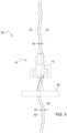
- FIG. 1illustrates a schematic of a vehicle path planning system in accordance with an embodiment of the present disclosure
- FIG. 2is a plan view of one or more paths of a vehicle path planning system in accordance with an embodiment of the present disclosure
- FIG. 3is a plan view of one or more paths of a vehicle path planning system in accordance with an embodiment of the present disclosure
- FIG. 4is a plan view of one or more paths of a vehicle path planning system in accordance with an embodiment of the present disclosure
- FIG. 5illustrates a method of planning a path of a vehicle having a work tool in accordance with an embodiment of the present disclosure
- FIG. 6illustrates a method of planning a path of a vehicle having a work tool in accordance with an embodiment of the present disclosure.
- FIGS. 1 through 6 of the drawingsAt least one example embodiment of the subject matter of this disclosure is understood by referring to FIGS. 1 through 6 of the drawings.
- FIGS. 1 - 3 of the present disclosureillustrates a system 10 for planning the path of a vehicle 12 .
- the system 10 of FIG. 1includes one or more location-determining receiver(s) 18 in communication with a controller 20 .
- the system 10further includes an actual path map 22 configured to determine, track, and/or store where the vehicle 12 and/or an implement or other work tool 26 has traveled in a work area 24 based on location data of the work tool 26 generated from the vehicle 12 passing the work tool 26 through the work area 24 .
- the vehicle 12 in the illustrated embodiments hereinincludes a tractor, while the work tool 26 in the illustrated embodiments is an agricultural implement being pulled by the tractor.
- the work tool 26such as an agricultural implement in the non-limiting example, is configured to rotate or pivot relative to the vehicle 12 , such as a tractor in the non-limiting example, at a hitch point.
- the implement or other work tool 26is rigidly attached to the tractor or other vehicle 12 , such as with a three-point hitch in a non-limiting example.
- the vehicle 12is a combine harvester, a self-propelled agricultural vehicle, construction or heavy equipment vehicle, or any other type of vehicle
- the work tool 26is a cutting, harvesting, spraying, applying, and/or any other type of implement or equipment, such as construction or work equipment, capable of performing a task in the work area 24 .
- the vehicle 12 and the work tool 26are combined as a single vehicle or piece of equipment.
- the actual path map 22may determine, track, and/or store one or multiple paths or passes taken by the vehicle 12 and/or the work tool 26 in the work area 24 .
- the actual path map 22 of the system 10records, determines, calculates, and/or stores the actual path of the work tool 26 .
- the system 10further includes a path plan map 28 configured to determine, establish, and/or store one or more path plans of the vehicle 12 and/or the work tool 26 .
- the system 10further includes a margin map 30 configured to determine, establish, and/or store a margin 32 or margins for application with one or more path plans of the vehicle 12 and/or the work tool 26 in the work area 24 .
- the path plan(s) described in one or more embodiments hereinrefers to one or more guidance lines in the work area 24 . Such guidance lines may be straight or curved in particular embodiments and may be connected or disconnected in particular embodiments.
- One or more of the path plan(s) described in the various embodiments hereinmay be created, modified, and/or stored on-board the vehicle 12 or other vehicle or work tool in the work area 24 or off-board, such as at a location where other relevant information is processed, stored, or otherwise accessed, such as in management map layers including soil fertility level, nutrient need, crop type, and/or other information layers, to name non-limiting examples.
- the system 10further includes a work tool guidance system 34 in the illustrated embodiment of the present disclosure.
- the work tool guidance system 34includes the receiver 18 and/or a separate receiver (not shown) to determine the location of the work tool 26 in the work area 24 .
- the work tool guidance system 34cooperates with a receiver, in an embodiment, and/or another component of the system 10 , in another embodiment, to guide the work tool 26 , such as an implement pulled by a tractor in one non-limiting example, along a planned or predetermined path.
- the system 10 of an embodiment not showndoes not include the work tool guidance system 34 .
- the system 10 and/or the work tool guidance system 34may communicate with a steering system and/or a propulsion system of the vehicle 12 in particular embodiments.
- the system 10further includes one or more sensor(s) 36 , including various types of in situ sensors as non-limiting examples, connected or in communication with the system 10 .
- the margin 32is based at least partially on one or more in situ environmental factors in one or more embodiments.
- the sensor(s) 36 of the illustrated embodimentsense such environmental factors or conditions related to one or more of a topology, plant type, plant condition, soil moisture, soil type, and/or soil traction.
- the sensor(s) 36include one or more topology sensors, plant visual sensors, e.g., cameras, soil moisture sensors, soil type sensors, and/or soil traction sensors to name non-limiting examples.
- the system 10further includes a data storage device 38 configured to store data.
- the data storage device 38is configured to store data relating to one or more a priori environmental factors including, without limitation, a soil type, topography, and plant type.
- a priori environmental factorsincluding, without limitation, a soil type, topography, and plant type.
- the various environmental or other factorsthat may be stored in the device 38 and affect the traveling along a path plan or tasks of the vehicle 12 , and the device 38 is configured to store such factors in one or more embodiments of the present disclosure.
- a processor 40 of the controller 20receives location information from the receiver(s), data from the sensor(s) 36 , and/or data from the data storage device 38 , as well as receiving data from and/or otherwise accessing or being in communication with the actual path map 22 , the path plan map 28 , and the margin map 30 .
- the controller 20may replace or supplement the processor 40 and vice versa.
- the processor 40 and/or the controller 20may differ by type, number, and/or location, such as single or multiple processor(s) or local or remotely located processors to name non-limiting examples, for different passes by the vehicle 12 and/or the work tool 26 through the work area 24 or for different maps, path plans, or other electronic processes of one or more embodiments described herein.
- the processor 40determines a modified path plan 42 based at least partially on the actual path map 22 and the margin 32 in one embodiment. In an embodiment, the processor 40 determines a modified path plan map based on the modified path plan 42 .
- the processor 40determines the modified path plan 42 based on any one or more of the data from the sensor(s) 36 , the data from the data storage device 38 , the actual path map 22 , the path plan map 28 , and the margin map 30 .
- the previous actual passis a seeding pass
- the current passis a nutrient-application pass.
- the current path planmight involve placement of nutrient a predetermined distance from the placed seeds (e.g., 4 inches laterally spaced and 4 inches below the seed) with an application and/or site-specific buffer or margin (e.g., 2 cm to compensate for GNSS localization error).
- the processor 40determines the modified path plan 42 based on the actual path map 22 , the path plan map 28 (with 4 inch by 4 inch spacing), and the margin map 30 (with error margin).
- FIG. 2illustrates an embodiment of the system 10 whereby the processor 40 , the controller 20 , and/or another controller of the vehicle 12 guides the vehicle 12 along a path plan 50 , represented by the solid line in FIG. 2 , of the path plan map 28 .
- the path plan of one or more embodimentsincludes a predetermined path and/or control algorithm that an operator utilizes to control the movement of vehicle 12 and/or the work tool 26 in the work area 24 .
- the vehicle 12 and/or the work tool 26may deviate from the desired path of the path plan 50 , thereby forming an actual path 52 , represented by the dashed line in FIG. 2 , of the vehicle 12 and/or the work tool 26 .
- Deviationmay be caused by conditions relating to the crop, the soil, or one or more other environmental factors, topography, error in GNSS localization or another location-determining limit or error, equipment or vehicle physical limitations and/or response time, and/or any other factor or condition related to the vehicle 12 , the work tool 26 , the work area 24 , and/or a path of the work area 24 .
- One or more components of the system 10records, determines, calculates, and/or stores the actual path 52 of the vehicle 12 and/or the work tool 26 to form the actual path map 22 .
- the actual path map 22 , the path plan map 28 , the modified path plan map, and/or the margin map 30 , as described herein,may include, in one or more embodiments, a visual representation of the map, a listing or collection of location and/or margin values, and/or any other data format usable by the processor 40 and/or the controller 20 .
- the processor 40 or other component of the system 10utilizes the actual path 52 and/or the actual path map 22 to create or otherwise determine a path for the vehicle 12 and/or the work tool 26 during one or more subsequent pass(es) through the work area 24 .
- the actual path 52 and the actual path map 22are not formed by and/or do not represent a pass actually taken by the vehicle 12 and/or the work tool 26 .
- the actual path 52is an identified, preferred, or otherwise predetermined path as part of an overall path plan or determined path in a row or other area of the work area 24 .
- the actual path 52is determined post-emergence via an image captured by an unmanned aerial vehicle (UAV) or another device capable of determining planting or crop location.
- UAVunmanned aerial vehicle
- the system 10 of an embodimentdetermines an unmodified, previously recorded actual path plan through the work area 24 based on at least the actual path 52 of the vehicle 12 and/or the work tool 26 .
- the system 10modifies the actual path plan with the margin 32 to determine the modified path plan 42 through the work area 24 .
- the margin 32is based, at least partially, on data received by one or more of the in situ sensor(s) 36 , one or more a priori environmental factors, a difference between the actual path 52 and the previous path plan 50 or another path plan or previous actual path, error in GNSS localization or another location-determining limit, error, or margin, equipment response time, and/or other sensed, calculated, known, and/or determined data or information related to the vehicle 12 , the work tool 26 , and/or a path of the work area 24 .
- the controller 20 , the processor 40 , and/or another component of the system 10controls the vehicle 12 and/or the work tool 26 along a modified path 54 associated with the modified path plan 42 .
- the margin 32 and/or the margin map 30is/are utilized in one or more embodiments to incorporate look-ahead capabilities to anticipate and prepare the vehicle 12 and/or the work tool 26 for changing conditions in the path of the work area 24 .
- the actual path 52 , the actual path map 22 , and/or other dataindicate(s) a condition in the work area 24 that may impact travel, such as a slope or other topographical element to name a non-limiting example, and the margin 32 and/or the margin map 30 results in steering and/or other control of the vehicle 12 to compensate for the condition before or as the vehicle 12 traverses the condition location.
- particular vehiclessuch as sprayers in a non-limiting example, have higher centers of gravity compared to tractors, for example, and operate at higher ground speeds.
- the look-ahead capabilities and/or information relating to the margin 32 and/or the margin map 30may be incorporated with location and vehicle roll, pitch, yaw, and other machine form data to predictively and precisely control the position and orientation of the vehicle 12 and/or work tool in the work area 24 .
- a towed implementmay be especially susceptible to slipping sideways on side slopes.
- the system 10may identify an area with sideslip and/or an empirically-generated likelihood and magnitude for a sideslip condition for a given area based on a tractor-implement configuration and a map of the work area 24 .
- Such a sideslip predictionmay form the basis for a margin 32 , e.g., at location X, slip is likely 3 cm downhill; therefore, the margin 32 is 3 cm uphill.
- the margin 32 and/or the margin map 30includes variable values such that the distance between the actual path 52 and the modified path 54 is variable in an embodiment, or at least different at two or more locations of the work area 24 , while the margin 32 and/or the margin map 30 includes a single, constant or fixed value or distance in another embodiment.
- the margin map 30may be combined with the path plan map 28 in a modified path plan map to determine, establish, and/or store one or more path plans of the vehicle 12 and/or the work tool 26 as modified by the margin(s) 32 .
- FIG. 4illustrates one embodiment of the system 10 whereby the processor 40 and/or another controller component of the system 10 controls application of nutrients adjacent to a first crop row R 1 having individual plants 11 - 14 and a second crop row R 2 having individual plants 21 - 24 .
- Historic side dress paths HSD 1 , HSD 2represent the paths of nutrient application disposed generally evenly between crop rows.
- the historic paths HSD 1 , HSD 2are configured to minimize damage to the crop by machinery.
- the spacing of the historic paths HSD 1 , HSD 2 from the crop rowsmay reduce growth from a delay of plant roots in finding nutrients and/or result in nutrient waste.
- Preferred side dress paths PSD 1 , PSD 2represent ideal paths of nutrient application as close to roots 62 as possible to minimize waste of nutrients and allow strong crop growth without being too close to the roots to cause damage to the roots or crop.
- One of ordinary skill in the artwill recognize the ability to determine the location of roots of some crops, such as corn, from the location of leaves. Further, root variation may relate to crop variety, such as roots growing deeper or broader relative to leaf development. Even further, some crops have root structures that grow as a function of precipitation since germination. In a non-limiting example, such crops may grow deeper in relatively dry conditions and grow broader in relatively wet conditions. Empirical data from root extent as a function of precipitation may be analyzed to generate a margin 32 or other factor.
- Such determinations described hereinmay result in a fixed, multiplied, and/or variable margin 32 from, for example, the tip of the leaves to the edge of the root ball.
- a margin 32maybe combined with any other margin 32 described herein.
- the preferred paths PSD 1 , PSD 2are recorded, actual paths taken by a nutrient-applying work tool or other vehicle or work tool in an embodiment, while the preferred paths PSD 1 , PSD 2 are planned, calculated, or otherwise determined paths not previously taken by a vehicle or work tool in another embodiment.
- a structure, size, and/or orientation of the crop and/or the roots of the cropwill affect the paths PSD 1 , PSD 2 in that particular embodiment.
- one or more actual paths or preferred paths PSD 1 , PSD 2are based at least partially on root depth, horizontal root span, and/or root density to name non-limiting examples.
- the system 10 of an embodimentmodifies the preferred paths PSD 1 , PSD 2 , which may or may not be based on an actual path traveled by the vehicle 12 and/or the work tool 26 , with the margin 32 to determine target side dress paths TSD 1 , TSD 2 .
- the margin 32is based, at least partially, on data received by one or more of the in situ sensor(s) 36 , one or more a priori environmental factors, crop root mass, a difference between the actual path 52 and the previous path plan 50 or another path plan or previous actual path, error in GNSS localization or another location-determining limit, error, or margin, equipment response time, and/or other sensed, calculated, known, and/or determined data or information related to the vehicle 12 , the work tool 26 , and/or a path of the work area 24 .
- the offset or margin 32is 2 centimeters. In an additional non-limiting example, the offset or margin is between 0.1 and 10 centimeters.
- the offset or margin 32is less than 0.1 centimeters in a further embodiment and greater than 10 centimeters in an even further embodiment. As applicable, the margin 32 may also compensate for root mass in an embodiment. In addition to the various factors discussed herein, the margin 32 may vary within a pass based on further factors including, without limitation, leaf orientation, root mass orientation, GNSS error in a previous pass, topography, and/or vehicle or equipment dynamics.
- Any embodiment of the system 10 described hereinmay utilize real time kinematic positioning (RTK) or precision point positioning (PPP) techniques and/or equipment in order to enhance accuracy of any pass or coverage by the vehicle 12 and/or work tool 26 .
- RTK and PPP systemsenhance the precision of position data and may utilize reference stations in or near the work area 24 in particular embodiments.
- the PPP or RTK systemmay replace or be combined with the margin 32 or other path-modifier described herein in particular embodiments.
- FIG. 5illustrates a method 100 for planning a path of the vehicle 12 having the work tool 26 .
- the system 10 and/or the method 100relates to planning, controlling, and/or determining a path of the vehicle 12 , the work tool 26 , or both.
- the method 100includes determining, at step 110 , or otherwise accessing, receiving, calculating, creating, and/or storing, the unmodified path plan based on the actual path previously taken by the work tool 26 through the work area 24 with the vehicle 12 .
- the method 100further includes modifying, at step 112 , the unmodified path plan with the margin 32 to determine the modified path plan through the work area 24 .
- the method 100further includes passing, at step 114 , the work tool 26 through the work area 24 with the vehicle 12 along the modified path plan.
- the actual pathmay be taken by a previous path plan work tool that is different than the work tool 26 and/or taken by a previous path plan vehicle that is different from the vehicle 12 .
- the vehicle 12 and/or the work tool 26 described as passing through the work area 24may be different at any one or more times, such as a tractor pulling a planter implement to establish an initial actual path compared to a harvester following a modified path plan later in the season to describe one non-limiting example.
- any one or more previous path plan work tools or other work tools described hereinmay be the same work tool, such as a towed agricultural implement or, more specifically, a nutrient application implement to name non-limiting examples.
- previous path plan vehicles or other vehicles described hereinmay be the same vehicle, such as a tractor in a non-limiting example.
- the system 10 and/or the method 100includes determining a second actual path from passing the vehicle 12 and/or another vehicle and the work tool 26 and/or another work tool through the work area 24 along any determined modified path plan.
- the system 10 and/or the method 100 of particular embodimentsfurther includes modifying the second actual path with the margin 32 and/or a second margin to determine a second modified path plan through the work area 24 .
- the second modified path plan, the margin 32 and/or the second marginmay be determined in accordance with any embodiment described herein.
- the system 10 and/or the method 100 of particular embodimentsfurther includes passing a second actual path work tool through the work area 24 with a second actual path vehicle along the second modified path plan.
- the second actual path work tool and/or vehiclemay be the same as or different from the work tool 26 and/or the vehicle 12 of any one or more previous passes.
- the method 200includes determining, at step 210 , or otherwise accessing, receiving, calculating, creating, and/or storing, the path plan of the vehicle 12 pulling an implement applying nutrients.
- the method 200further includes recording, tracking, storing, or otherwise determining, at step 212 , the actual path of the implement applying nutrients in the work area 24 .
- the method 200further includes creating or otherwise determining, at step 214 , a path plan for a seeder based at least partially on the actual path of the implement that applied nutrients in step 212 .
- the method 200further includes recording, tracking, storing, or otherwise determining, at step 216 , the actual path of the seeder.
- the method 200further includes passing, at step 218 , the vehicle 12 and/or an implement along the actual path of the seeder for one or more passes over a predetermined period of time.
- the actual path of the seedermay be utilized or followed for passes by the vehicle 12 , implement, or any other equipment in the work area 24 for the remainder of the season or a number of seasons.
- another actual passsuch as by an implement applying a nutrient or another material or another vehicle or work tool traversing the work area 24 , may be utilized or followed for one or more remaining passes in the work area 24 .
- the methods 100 , 200 and any other method or step described hereinmay utilize the margin 32 of any one or more embodiments to determine a path to be executed by a vehicle, implement, and/or work tool in the work area 24 .
- a planter being pulled by the vehicle 12plants seed along a path in the work area 24 .
- the pathmay or may not be controlled by a predetermined path plan of the vehicle 12 .
- the system 10records the actual placement of seed in the work area 24 .
- a side dress fertilizer applicatorthen travels through the work area 24 along the recorded path of the actual placement of seed/plants with or without application of a universal or a side dress fertilizer applicator-specific margin.
- a sprayerthen travels through the work area 24 along the same recorded seeding path, with or without application of a universal or sprayer-specific margin.
- a high-clearance, late season nitrogen applicatorthen comes through the work area 24 along the same recorded seeding path, with or without a universal or late season applicator-specific margin.
- the cropping seasonends, and a nutrient application then travels through the work area 24 along the same recorded seeding path, with or without a universal or nutrient applicator-specific margin, at the start of the next cropping season.
- any one or more other pass(es) by the vehicle 12 and/or other equipmentmay be utilized or followed for path planning purposes. Further, any pass may be recorded and stored with or without being utilized later.
- the vehicle 12such as a tractor in a non-limiting example
- the work tool 26such as a nutrient-applying implement in a non-limiting example
- a tractormay be controlled to pass through the work area 24 along an original guidance line or path plan used for the planting operation, such as to reduce or limit soil compaction, while the nutrient-applying implement is controlled to follow the actual path of the planter from the planting operation to achieve desired placement of nutrients based on plant location.
- the implement gauge or transport wheels or other componentmay be controlled to travel on the actual planting path traveled by the tractor or implement, and the nutrient applicator(s), knives, and or other mechanism may be controlled to move laterally and follow along an offset, modified, or otherwise different path plan, such as one having a predetermined offset from the plant stalk in a non-limiting example.
- capturing the actual path of the implement, work tool, or vehicle that is traveling through the work area 24 and, in the illustrated example, applying the seeds or nutrients, rather than simply following an intended path of the implement, work tool, and/or vehiclesolves the problem of precisely placing seed and nutrients after, for example, an initial pass.
- the recorded path of the vehicle, implement, or work toolcan be used to create the intended path for the next application pass in the work area.
- the process of capturing the actual path of the vehicle in the work areamay be repeated until a critical, master, or controlling path is complete, such as seeding plants.
- Precision guidance for seed and nutrient placement throughout and across growing seasonsis a key to application of early nutrients, eliminating unnecessary fertilization, and providing plants consistent access to nutrients across a field.
- the embodiments of the present disclosureimprove agricultural performance at least due to improved placement of seed relative to a recently placed fertilizer band, as well as placement of fertilizer relative to locations of plants, from improved implement guidance precision and consistency, as illustrated in one non-limiting example.
Landscapes
- Life Sciences & Earth Sciences (AREA)
- Engineering & Computer Science (AREA)
- Mechanical Engineering (AREA)
- Soil Sciences (AREA)
- Environmental Sciences (AREA)
- Management, Administration, Business Operations System, And Electronic Commerce (AREA)
- Control Of Position, Course, Altitude, Or Attitude Of Moving Bodies (AREA)
- Guiding Agricultural Machines (AREA)
Abstract
Description
Claims (19)
Priority Applications (2)
| Application Number | Priority Date | Filing Date | Title |
|---|---|---|---|
| US15/975,391US11641790B2 (en) | 2018-05-09 | 2018-05-09 | Method of planning a path for a vehicle having a work tool and a vehicle path planning system |
| EP19173369.0AEP3566556B1 (en) | 2018-05-09 | 2019-05-08 | Method of planning a path for a vehicle having a work tool and a vehicle path planning system |
Applications Claiming Priority (1)
| Application Number | Priority Date | Filing Date | Title |
|---|---|---|---|
| US15/975,391US11641790B2 (en) | 2018-05-09 | 2018-05-09 | Method of planning a path for a vehicle having a work tool and a vehicle path planning system |
Publications (2)
| Publication Number | Publication Date |
|---|---|
| US20190343035A1 US20190343035A1 (en) | 2019-11-14 |
| US11641790B2true US11641790B2 (en) | 2023-05-09 |
Family
ID=66476410
Family Applications (1)
| Application Number | Title | Priority Date | Filing Date |
|---|---|---|---|
| US15/975,391Active2038-11-20US11641790B2 (en) | 2018-05-09 | 2018-05-09 | Method of planning a path for a vehicle having a work tool and a vehicle path planning system |
Country Status (2)
| Country | Link |
|---|---|
| US (1) | US11641790B2 (en) |
| EP (1) | EP3566556B1 (en) |
Families Citing this family (66)
| Publication number | Priority date | Publication date | Assignee | Title |
|---|---|---|---|---|
| US11977378B2 (en)* | 2018-09-17 | 2024-05-07 | The Charles Machine Works, Inc. | Virtual path guidance system |
| US11672203B2 (en) | 2018-10-26 | 2023-06-13 | Deere & Company | Predictive map generation and control |
| US11079725B2 (en) | 2019-04-10 | 2021-08-03 | Deere & Company | Machine control using real-time model |
| US11467605B2 (en) | 2019-04-10 | 2022-10-11 | Deere & Company | Zonal machine control |
| US12069978B2 (en) | 2018-10-26 | 2024-08-27 | Deere & Company | Predictive environmental characteristic map generation and control system |
| US11641800B2 (en) | 2020-02-06 | 2023-05-09 | Deere & Company | Agricultural harvesting machine with pre-emergence weed detection and mitigation system |
| US11240961B2 (en) | 2018-10-26 | 2022-02-08 | Deere & Company | Controlling a harvesting machine based on a geo-spatial representation indicating where the harvesting machine is likely to reach capacity |
| US11957072B2 (en) | 2020-02-06 | 2024-04-16 | Deere & Company | Pre-emergence weed detection and mitigation system |
| US11178818B2 (en) | 2018-10-26 | 2021-11-23 | Deere & Company | Harvesting machine control system with fill level processing based on yield data |
| US11653588B2 (en) | 2018-10-26 | 2023-05-23 | Deere & Company | Yield map generation and control system |
| US11589509B2 (en) | 2018-10-26 | 2023-02-28 | Deere & Company | Predictive machine characteristic map generation and control system |
| US11234366B2 (en) | 2019-04-10 | 2022-02-01 | Deere & Company | Image selection for machine control |
| US11778945B2 (en) | 2019-04-10 | 2023-10-10 | Deere & Company | Machine control using real-time model |
| US11112262B2 (en) | 2019-09-20 | 2021-09-07 | Deere & Company | Method and system for planning a path of a vehicle |
| US12035648B2 (en) | 2020-02-06 | 2024-07-16 | Deere & Company | Predictive weed map generation and control system |
| US12329148B2 (en) | 2020-02-06 | 2025-06-17 | Deere & Company | Predictive weed map and material application machine control |
| US12225846B2 (en) | 2020-02-06 | 2025-02-18 | Deere & Company | Machine control using a predictive map |
| US11477940B2 (en) | 2020-03-26 | 2022-10-25 | Deere & Company | Mobile work machine control based on zone parameter modification |
| US11930731B2 (en) | 2020-04-09 | 2024-03-19 | Kinze Manufacturing, Inc. | Simultaneous mapped view of historical and realtime geospatial and non-geospatial data |
| US11778938B2 (en)* | 2020-04-20 | 2023-10-10 | Deere & Company | Agricultural machine section control |
| WO2021222720A1 (en) | 2020-05-01 | 2021-11-04 | Kinze Manufacturing, Inc. | Automatic field partners |
| SE2050727A1 (en)* | 2020-06-17 | 2021-12-18 | Husqvarna Ab | Methods of navigating a self-propelled robotic tool, and robotic tools, and computer pograms implementing such methods |
| US20220078963A1 (en)* | 2020-09-11 | 2022-03-17 | Kinze Manufacturing, Inc. | Systems, methods, and/or apparatus for the display of agricultural data on a user interface |
| US11983009B2 (en) | 2020-10-09 | 2024-05-14 | Deere & Company | Map generation and control system |
| US11927459B2 (en) | 2020-10-09 | 2024-03-12 | Deere & Company | Machine control using a predictive map |
| US11711995B2 (en) | 2020-10-09 | 2023-08-01 | Deere & Company | Machine control using a predictive map |
| US11946747B2 (en) | 2020-10-09 | 2024-04-02 | Deere & Company | Crop constituent map generation and control system |
| US11864483B2 (en) | 2020-10-09 | 2024-01-09 | Deere & Company | Predictive map generation and control system |
| US11849672B2 (en) | 2020-10-09 | 2023-12-26 | Deere & Company | Machine control using a predictive map |
| US12419220B2 (en) | 2020-10-09 | 2025-09-23 | Deere & Company | Predictive map generation and control system |
| US12069986B2 (en) | 2020-10-09 | 2024-08-27 | Deere & Company | Map generation and control system |
| US11474523B2 (en) | 2020-10-09 | 2022-10-18 | Deere & Company | Machine control using a predictive speed map |
| US12013245B2 (en) | 2020-10-09 | 2024-06-18 | Deere & Company | Predictive map generation and control system |
| US11592822B2 (en) | 2020-10-09 | 2023-02-28 | Deere & Company | Machine control using a predictive map |
| US11874669B2 (en) | 2020-10-09 | 2024-01-16 | Deere & Company | Map generation and control system |
| US11675354B2 (en) | 2020-10-09 | 2023-06-13 | Deere & Company | Machine control using a predictive map |
| US12422847B2 (en) | 2020-10-09 | 2025-09-23 | Deere & Company | Predictive agricultural model and map generation |
| US11844311B2 (en) | 2020-10-09 | 2023-12-19 | Deere & Company | Machine control using a predictive map |
| US11825768B2 (en) | 2020-10-09 | 2023-11-28 | Deere & Company | Machine control using a predictive map |
| US11871697B2 (en) | 2020-10-09 | 2024-01-16 | Deere & Company | Crop moisture map generation and control system |
| US11727680B2 (en) | 2020-10-09 | 2023-08-15 | Deere & Company | Predictive map generation based on seeding characteristics and control |
| US11889788B2 (en) | 2020-10-09 | 2024-02-06 | Deere & Company | Predictive biomass map generation and control |
| US11650587B2 (en) | 2020-10-09 | 2023-05-16 | Deere & Company | Predictive power map generation and control system |
| US12178158B2 (en) | 2020-10-09 | 2024-12-31 | Deere & Company | Predictive map generation and control system for an agricultural work machine |
| US12386354B2 (en) | 2020-10-09 | 2025-08-12 | Deere & Company | Predictive power map generation and control system |
| US11895948B2 (en) | 2020-10-09 | 2024-02-13 | Deere & Company | Predictive map generation and control based on soil properties |
| US11845449B2 (en) | 2020-10-09 | 2023-12-19 | Deere & Company | Map generation and control system |
| US11849671B2 (en) | 2020-10-09 | 2023-12-26 | Deere & Company | Crop state map generation and control system |
| US11635765B2 (en) | 2020-10-09 | 2023-04-25 | Deere & Company | Crop state map generation and control system |
| US11889787B2 (en) | 2020-10-09 | 2024-02-06 | Deere & Company | Predictive speed map generation and control system |
| US12250905B2 (en) | 2020-10-09 | 2025-03-18 | Deere & Company | Machine control using a predictive map |
| US11914379B2 (en) | 2020-12-23 | 2024-02-27 | Deere & Company | Methods and apparatus to generate a path plan |
| US12127500B2 (en) | 2021-01-27 | 2024-10-29 | Deere & Company | Machine control using a map with regime zones |
| US20230027071A1 (en)* | 2021-07-21 | 2023-01-26 | Blue White Robotics Ltd | Two level mission planning for autonomous platforms and payloads |
| US12229886B2 (en) | 2021-10-01 | 2025-02-18 | Deere & Company | Historical crop state model, predictive crop state map generation and control system |
| US12310286B2 (en) | 2021-12-14 | 2025-05-27 | Deere & Company | Crop constituent sensing |
| US12302791B2 (en) | 2021-12-20 | 2025-05-20 | Deere & Company | Crop constituents, predictive mapping, and agricultural harvester control |
| US12185651B2 (en) | 2021-12-23 | 2025-01-07 | Cnh Industrial America Llc | System and method for adjusting swath lines for a work vehicle |
| US12245549B2 (en) | 2022-01-11 | 2025-03-11 | Deere & Company | Predictive response map generation and control system |
| US12082531B2 (en) | 2022-01-26 | 2024-09-10 | Deere & Company | Systems and methods for predicting material dynamics |
| US12295288B2 (en) | 2022-04-05 | 2025-05-13 | Deere &Company | Predictive machine setting map generation and control system |
| US12058951B2 (en) | 2022-04-08 | 2024-08-13 | Deere & Company | Predictive nutrient map and control |
| US12284934B2 (en) | 2022-04-08 | 2025-04-29 | Deere & Company | Systems and methods for predictive tractive characteristics and control |
| US12358493B2 (en) | 2022-04-08 | 2025-07-15 | Deere & Company | Systems and methods for predictive power requirements and control |
| US12298767B2 (en) | 2022-04-08 | 2025-05-13 | Deere & Company | Predictive material consumption map and control |
| US12364194B2 (en)* | 2022-08-02 | 2025-07-22 | Deere & Company | System and method for controlling soil compaction |
Citations (27)
| Publication number | Priority date | Publication date | Assignee | Title |
|---|---|---|---|---|
| US4184551A (en) | 1977-11-16 | 1980-01-22 | Orthman Manufacturing, Inc. | Steering device for row crop cultivator |
| EP0821296A2 (en) | 1996-07-23 | 1998-01-28 | CLAAS KGaA | Route planning system for agricultural working vehicles |
| US20060178825A1 (en) | 2005-02-04 | 2006-08-10 | Novariant, Inc. | System and method for interactive selection of agricultural vehicle guide paths with varying curvature along their length |
| EP2236020A1 (en) | 2009-03-31 | 2010-10-06 | CLAAS Selbstfahrende Erntemaschinen GmbH | Navigation method and system for agricultural machine |
| US7894951B2 (en) | 2005-10-21 | 2011-02-22 | Deere & Company | Systems and methods for switching between autonomous and manual operation of a vehicle |
| US20120296529A1 (en)* | 2011-05-16 | 2012-11-22 | Trimble Navigation Ltd. | Agricultural Autopilot Path Adjustment |
| US20140236431A1 (en)* | 2013-02-20 | 2014-08-21 | Deere And Company | Soil compaction reduction system and method |
| DE102016111691A1 (en) | 2015-06-29 | 2016-12-29 | Mitsubishi Electric Corporation | Semi-autonomous vehicle and method of controlling a semi-autonomous vehicle |
| DE102016216740A1 (en) | 2015-09-30 | 2017-03-30 | Deere & Company | System and method for using geo-fenced guidlines |
| US20170112045A1 (en) | 2015-10-27 | 2017-04-27 | Cnh Industrial America Llc | Device and method for guiding agricultural vehicles |
| US20170192431A1 (en)* | 2016-01-06 | 2017-07-06 | Cnh Industrial America Llc | Multi-mode mission planning and optimization for autonomous agricultural vehicles |
| US20170354078A1 (en)* | 2016-06-10 | 2017-12-14 | Cnh Industrial America Llc | Planning and control of autonomous agricultural operations |
| US20170357262A1 (en)* | 2016-06-10 | 2017-12-14 | Cnh Industrial America Llc | Swath tracking system for an off-road vehicle |
| US20170354079A1 (en)* | 2016-06-10 | 2017-12-14 | Cnh Industrial America Llc | Planning and control of autonomous agricultural operations |
| EP3300562A1 (en) | 2016-09-28 | 2018-04-04 | Deere & Company | System and method for guided line acquisitions |
| US20180325019A1 (en)* | 2017-05-12 | 2018-11-15 | Deere & Company | Ground-engaging implement with lateral position adjustment |
| US20180325020A1 (en)* | 2017-05-12 | 2018-11-15 | Deere & Company | Ground-engaging implement with lateral position adjustment |
| US20180325021A1 (en)* | 2017-05-12 | 2018-11-15 | Deere & Company | Ground-engaging implement with lateral position adjustment |
| US20180325011A1 (en)* | 2017-05-12 | 2018-11-15 | Deere & Company | Ground-engaging implement with lateral position adjustment |
| US20180325010A1 (en)* | 2017-05-12 | 2018-11-15 | Deere & Company | Ground-engaging implement with lateral position adjustment |
| US20180359904A1 (en)* | 2017-06-19 | 2018-12-20 | Cnh Industrial America Llc | Path planning system for autonomous off-road vehicles |
| US20200033146A1 (en)* | 2018-07-26 | 2020-01-30 | Trimble Inc. | Vehicle manual guidance systems with steering wheel angle sensors and road wheel angle sensors |
| US20200097021A1 (en)* | 2018-09-19 | 2020-03-26 | Continental Automotive Systems, Inc. | Autonomous Farm Equipment Hitching To A Tractor |
| US10648820B2 (en) | 2018-01-03 | 2020-05-12 | Deere & Company | Methods and apparatus for assessing coordinate data |
| US20200281110A1 (en)* | 2019-03-08 | 2020-09-10 | The Climate Corporation | Real-time agricultural recommendations using weather sensing on equipment |
| US10830751B2 (en) | 2017-10-31 | 2020-11-10 | Deere & Company | Method for treating plants with respect to estimated root zones |
| US10912251B2 (en) | 2017-10-31 | 2021-02-09 | Deere & Company | Method for treating plants with respect to estimated root zones |
- 2018
- 2018-05-09USUS15/975,391patent/US11641790B2/enactiveActive
- 2019
- 2019-05-08EPEP19173369.0Apatent/EP3566556B1/enactiveActive
Patent Citations (29)
| Publication number | Priority date | Publication date | Assignee | Title |
|---|---|---|---|---|
| US4184551A (en) | 1977-11-16 | 1980-01-22 | Orthman Manufacturing, Inc. | Steering device for row crop cultivator |
| EP0821296A2 (en) | 1996-07-23 | 1998-01-28 | CLAAS KGaA | Route planning system for agricultural working vehicles |
| US20060178825A1 (en) | 2005-02-04 | 2006-08-10 | Novariant, Inc. | System and method for interactive selection of agricultural vehicle guide paths with varying curvature along their length |
| US7894951B2 (en) | 2005-10-21 | 2011-02-22 | Deere & Company | Systems and methods for switching between autonomous and manual operation of a vehicle |
| EP2236020A1 (en) | 2009-03-31 | 2010-10-06 | CLAAS Selbstfahrende Erntemaschinen GmbH | Navigation method and system for agricultural machine |
| US20120296529A1 (en)* | 2011-05-16 | 2012-11-22 | Trimble Navigation Ltd. | Agricultural Autopilot Path Adjustment |
| US20140236431A1 (en)* | 2013-02-20 | 2014-08-21 | Deere And Company | Soil compaction reduction system and method |
| DE102016111691A1 (en) | 2015-06-29 | 2016-12-29 | Mitsubishi Electric Corporation | Semi-autonomous vehicle and method of controlling a semi-autonomous vehicle |
| DE102016216740A1 (en) | 2015-09-30 | 2017-03-30 | Deere & Company | System and method for using geo-fenced guidlines |
| US20170112045A1 (en) | 2015-10-27 | 2017-04-27 | Cnh Industrial America Llc | Device and method for guiding agricultural vehicles |
| US20170192431A1 (en)* | 2016-01-06 | 2017-07-06 | Cnh Industrial America Llc | Multi-mode mission planning and optimization for autonomous agricultural vehicles |
| US20170354078A1 (en)* | 2016-06-10 | 2017-12-14 | Cnh Industrial America Llc | Planning and control of autonomous agricultural operations |
| US20170357262A1 (en)* | 2016-06-10 | 2017-12-14 | Cnh Industrial America Llc | Swath tracking system for an off-road vehicle |
| US20170354079A1 (en)* | 2016-06-10 | 2017-12-14 | Cnh Industrial America Llc | Planning and control of autonomous agricultural operations |
| EP3300562A1 (en) | 2016-09-28 | 2018-04-04 | Deere & Company | System and method for guided line acquisitions |
| US20180325020A1 (en)* | 2017-05-12 | 2018-11-15 | Deere & Company | Ground-engaging implement with lateral position adjustment |
| US20180325021A1 (en)* | 2017-05-12 | 2018-11-15 | Deere & Company | Ground-engaging implement with lateral position adjustment |
| US20180325011A1 (en)* | 2017-05-12 | 2018-11-15 | Deere & Company | Ground-engaging implement with lateral position adjustment |
| US20180325010A1 (en)* | 2017-05-12 | 2018-11-15 | Deere & Company | Ground-engaging implement with lateral position adjustment |
| US20180325019A1 (en)* | 2017-05-12 | 2018-11-15 | Deere & Company | Ground-engaging implement with lateral position adjustment |
| US20180359904A1 (en)* | 2017-06-19 | 2018-12-20 | Cnh Industrial America Llc | Path planning system for autonomous off-road vehicles |
| US10912251B2 (en) | 2017-10-31 | 2021-02-09 | Deere & Company | Method for treating plants with respect to estimated root zones |
| US10830751B2 (en) | 2017-10-31 | 2020-11-10 | Deere & Company | Method for treating plants with respect to estimated root zones |
| US20210293553A1 (en) | 2018-01-03 | 2021-09-23 | Deere & Company | Methods and apparatus for assessing coordinate data |
| US10648820B2 (en) | 2018-01-03 | 2020-05-12 | Deere & Company | Methods and apparatus for assessing coordinate data |
| US11047692B2 (en) | 2018-01-03 | 2021-06-29 | Deere & Company | Methods and apparatus for assessing coordinate data |
| US20200033146A1 (en)* | 2018-07-26 | 2020-01-30 | Trimble Inc. | Vehicle manual guidance systems with steering wheel angle sensors and road wheel angle sensors |
| US20200097021A1 (en)* | 2018-09-19 | 2020-03-26 | Continental Automotive Systems, Inc. | Autonomous Farm Equipment Hitching To A Tractor |
| US20200281110A1 (en)* | 2019-03-08 | 2020-09-10 | The Climate Corporation | Real-time agricultural recommendations using weather sensing on equipment |
Non-Patent Citations (9)
| Title |
|---|
| 2011 Olin College "teach and playback" path for JD Gator retrieved from https://www.youtube.com/watch?v=KmToNvrdgzc, published on Apr. 23, 2011. |
| 2011 Toro greens mower with Probotic B.V. "teach and playback" retrieved from http://www.probotiq.com/?tag=teach-playback. |
| Automated Harvesting retrieved from http://www.expo21xx.com/automation21xx/14891_st3_university/default.htm. |
| European Search Report issued in counterpart European Patent Application No. 19173369.0 dated Oct. 7, 2019 (7 pages). |
| John Deere Active Implements Guidance retrieved from https://www.deere.com/en_US/products/equipment/ag_management_solutions/guidance/active_implement_guidance/active_implement_guidance.page#viewTabs. |
| John Deere Guidance Systems retrieved from https://www.deere.com/common/docs/products/equipment/agricultural_management_solutions/guidance_systems/brochure/en_GB_yy1114823_e.pdf. |
| John Deere Implements Guidance retrieved from http://www.orthman.com/our-products.aspx?pagename=Product%20Details&itemid=2056&prodid=12238&pagetitle=Implement+Guidance. |
| Scott Shearer and Santosh Pitla, Precision Planting and Crop Thinning, Automation: The Future of Weed Control in Cropping Systems, retrieved from internet https://books.google.com/books?id=yQ7IBAAAQBAJ&printsec=frontcover&source=gbs_ge_summary_r&cad=0#v=onepage&q&f=false, 2 pages, Springer, Dordrecht, Heidelberg, London and New york. |
| Translation of EP2236020 (Year: 2010).* |
Also Published As
| Publication number | Publication date |
|---|---|
| EP3566556A1 (en) | 2019-11-13 |
| US20190343035A1 (en) | 2019-11-14 |
| EP3566556B1 (en) | 2023-06-14 |
Similar Documents
| Publication | Publication Date | Title |
|---|---|---|
| US11641790B2 (en) | Method of planning a path for a vehicle having a work tool and a vehicle path planning system | |
| US7591226B2 (en) | Automatic path generation for tramlines | |
| JP7076969B2 (en) | Fertilization equipment, fertilization methods and programs | |
| EP3725632B1 (en) | Travel path generation system and field work vehicle | |
| US11395452B2 (en) | Method of mitigating compaction and a compaction mitigation system | |
| EP3482619B1 (en) | Method for treating plants with respect to estimated root zones | |
| US8655559B2 (en) | Agricultural autopilot path adjustment | |
| Stoll et al. | Guidance of a forage harvester with GPS | |
| US8718874B2 (en) | Raster-based contour swathing for guidance and variable-rate chemical application | |
| US6199000B1 (en) | Methods and apparatus for precision agriculture operations utilizing real time kinematic global positioning system systems | |
| EP3618601B1 (en) | Guidance working depth compensation for implement | |
| Lipiński et al. | Precision of tractor operations with soil cultivation implements using manual and automatic steering modes | |
| US20090265098A1 (en) | Swath line creation including slope compensation for an automatic guidance system of a work vehicle | |
| DE112015003946T5 (en) | System and method for steering a device on sloping ground | |
| CN115104587B (en) | Method and unmanned aerial vehicle for applying crop protection products to a field | |
| US11470759B2 (en) | System for controlling a working implement connected to a vehicle | |
| WO2023106158A1 (en) | Route planning system for automatically operated farm machine | |
| Pota et al. | Agricultural robotics: A streamlined approach to realization of autonomous farming | |
| EP1475609A2 (en) | Reference system compensation system of a land vehicle | |
| US20230273614A1 (en) | Dynamic guidance system for accompanying vehicle and methods for same | |
| Fulton et al. | GPS, GIS, Guidance, and Variable‐rate Technologies for Conservation Management | |
| EP4489568A1 (en) | Computer-implemented method for providing variable application rate data | |
| Nagasaka et al. | Autonomous rice field operation project in NARO | |
| RU2756346C1 (en) | Automatic system for implementing the method for seeding and method for seeding | |
| JP7270309B2 (en) | Weeding system for fields, spraying system for spraying material for fields, planting system for fields and fertilizer spraying system for paddy fields |
Legal Events
| Date | Code | Title | Description |
|---|---|---|---|
| AS | Assignment | Owner name:DEERE & COMPANY, ILLINOIS Free format text:ASSIGNMENT OF ASSIGNORS INTEREST;ASSIGNORS:SMITH, BENJAMIN M.;MAYER, JACOB D.;PICKETT, TERENCE D.;AND OTHERS;SIGNING DATES FROM 20180430 TO 20180501;REEL/FRAME:045756/0920 | |
| FEPP | Fee payment procedure | Free format text:ENTITY STATUS SET TO UNDISCOUNTED (ORIGINAL EVENT CODE: BIG.); ENTITY STATUS OF PATENT OWNER: LARGE ENTITY | |
| STPP | Information on status: patent application and granting procedure in general | Free format text:DOCKETED NEW CASE - READY FOR EXAMINATION | |
| STPP | Information on status: patent application and granting procedure in general | Free format text:NON FINAL ACTION MAILED | |
| STPP | Information on status: patent application and granting procedure in general | Free format text:RESPONSE TO NON-FINAL OFFICE ACTION ENTERED AND FORWARDED TO EXAMINER | |
| STPP | Information on status: patent application and granting procedure in general | Free format text:FINAL REJECTION MAILED | |
| STPP | Information on status: patent application and granting procedure in general | Free format text:DOCKETED NEW CASE - READY FOR EXAMINATION | |
| STPP | Information on status: patent application and granting procedure in general | Free format text:NON FINAL ACTION MAILED | |
| STPP | Information on status: patent application and granting procedure in general | Free format text:RESPONSE TO NON-FINAL OFFICE ACTION ENTERED AND FORWARDED TO EXAMINER | |
| STPP | Information on status: patent application and granting procedure in general | Free format text:NOTICE OF ALLOWANCE MAILED -- APPLICATION RECEIVED IN OFFICE OF PUBLICATIONS | |
| STCF | Information on status: patent grant | Free format text:PATENTED CASE |