US11641321B2 - Packet processing for logical datapath sets - Google Patents
Packet processing for logical datapath setsDownload PDFInfo
- Publication number
- US11641321B2 US11641321B2US16/030,772US201816030772AUS11641321B2US 11641321 B2US11641321 B2US 11641321B2US 201816030772 AUS201816030772 AUS 201816030772AUS 11641321 B2US11641321 B2US 11641321B2
- Authority
- US
- United States
- Prior art keywords
- packet
- network
- managed
- switching element
- switching elements
- Prior art date
- Legal status (The legal status is an assumption and is not a legal conclusion. Google has not performed a legal analysis and makes no representation as to the accuracy of the status listed.)
- Active, expires
Links
Images


Classifications
- H—ELECTRICITY
- H04—ELECTRIC COMMUNICATION TECHNIQUE
- H04L—TRANSMISSION OF DIGITAL INFORMATION, e.g. TELEGRAPHIC COMMUNICATION
- H04L47/00—Traffic control in data switching networks
- H—ELECTRICITY
- H04—ELECTRIC COMMUNICATION TECHNIQUE
- H04L—TRANSMISSION OF DIGITAL INFORMATION, e.g. TELEGRAPHIC COMMUNICATION
- H04L41/00—Arrangements for maintenance, administration or management of data switching networks, e.g. of packet switching networks
- H04L41/08—Configuration management of networks or network elements
- H04L41/0896—Bandwidth or capacity management, i.e. automatically increasing or decreasing capacities
- H—ELECTRICITY
- H04—ELECTRIC COMMUNICATION TECHNIQUE
- H04L—TRANSMISSION OF DIGITAL INFORMATION, e.g. TELEGRAPHIC COMMUNICATION
- H04L45/00—Routing or path finding of packets in data switching networks
- H—ELECTRICITY
- H04—ELECTRIC COMMUNICATION TECHNIQUE
- H04L—TRANSMISSION OF DIGITAL INFORMATION, e.g. TELEGRAPHIC COMMUNICATION
- H04L45/00—Routing or path finding of packets in data switching networks
- H04L45/22—Alternate routing
- H—ELECTRICITY
- H04—ELECTRIC COMMUNICATION TECHNIQUE
- H04L—TRANSMISSION OF DIGITAL INFORMATION, e.g. TELEGRAPHIC COMMUNICATION
- H04L45/00—Routing or path finding of packets in data switching networks
- H04L45/74—Address processing for routing
- H—ELECTRICITY
- H04—ELECTRIC COMMUNICATION TECHNIQUE
- H04L—TRANSMISSION OF DIGITAL INFORMATION, e.g. TELEGRAPHIC COMMUNICATION
- H04L49/00—Packet switching elements
- H04L49/25—Routing or path finding in a switch fabric
- H—ELECTRICITY
- H04—ELECTRIC COMMUNICATION TECHNIQUE
- H04L—TRANSMISSION OF DIGITAL INFORMATION, e.g. TELEGRAPHIC COMMUNICATION
- H04L69/00—Network arrangements, protocols or services independent of the application payload and not provided for in the other groups of this subclass
- H04L69/30—Definitions, standards or architectural aspects of layered protocol stacks
- H04L69/32—Architecture of open systems interconnection [OSI] 7-layer type protocol stacks, e.g. the interfaces between the data link level and the physical level
- H04L69/322—Intralayer communication protocols among peer entities or protocol data unit [PDU] definitions
- H04L69/329—Intralayer communication protocols among peer entities or protocol data unit [PDU] definitions in the application layer [OSI layer 7]
- H—ELECTRICITY
- H04—ELECTRIC COMMUNICATION TECHNIQUE
- H04L—TRANSMISSION OF DIGITAL INFORMATION, e.g. TELEGRAPHIC COMMUNICATION
- H04L9/00—Cryptographic mechanisms or cryptographic arrangements for secret or secure communications; Network security protocols
- H04L9/40—Network security protocols
- H—ELECTRICITY
- H04—ELECTRIC COMMUNICATION TECHNIQUE
- H04L—TRANSMISSION OF DIGITAL INFORMATION, e.g. TELEGRAPHIC COMMUNICATION
- H04L41/00—Arrangements for maintenance, administration or management of data switching networks, e.g. of packet switching networks
- H04L41/08—Configuration management of networks or network elements
- H04L41/0896—Bandwidth or capacity management, i.e. automatically increasing or decreasing capacities
- H04L41/0897—Bandwidth or capacity management, i.e. automatically increasing or decreasing capacities by horizontal or vertical scaling of resources, or by migrating entities, e.g. virtual resources or entities
Definitions
- U.S. patent application Ser. No. 13/543,784claims benefit to U.S. Provisional Patent Application 61/482,205, filed on May 3, 2011, U.S.
- U.S. patent application Ser. Nos. 13/543,784now issued as U.S. Pat. No. 10,021,019; and 13/177,535, now issued as U.S.
- Networkshave traditionally been managed through low-level configuration of individual components. Network configurations often depend on the underlying network: for example, blocking a user's access with an access control list (“ACL”) entry requires knowing the user's current IP address. More complicated tasks require more extensive network knowledge: forcing guest users' port 80 traffic to traverse an HTTP proxy requires knowing the current network topology and the location of each guest. This process is of increased difficulty where the network switching elements are shared across multiple users.
- ACLaccess control list
- SDNSoftware-Defined Networking
- a network controllerrunning on one or more servers in a network, controls, maintains, and implements control logic that governs the forwarding behavior of shared network switching elements on a per user basis. Making network management decisions often requires knowledge of the network state.
- the network controllercreates and maintains a view of the network state and provides an application programming interface upon which management applications may access a view of the network state.
- Some embodiments of the inventionprovide a method of distributing packet processing across several managed non-edge switching elements.
- a managed edge switching element of several managed switching elements that implement a logical datapath setmay not be able to process a packet through the logical datapath set so as to determine where to forward the packet.
- the managed edge switching elementforwards the packet to one of several managed non-edge switching elements for further processing.
- the managed edge switching elementmay not be able to process the packet for different reasons.
- the packetmay be unknown to the managed edge switching element (e.g., the forwarding table of the managed switching element does not have an entry that matches the packet).
- the packetmay be a certain type of packet (e.g., a multicast packet and broadcast packet).
- some embodimentsdetermine a managed non-edge switching element based on a hash function.
- the methodapplies the hash function on the packet's header (e.g., source media access control (MAC) address, destination MAC address, etc.) to generate a hash value.
- the method of some embodimentsthen compares the hash value to a hash range list that includes different hash value ranges that correspond to different managed non-edge switching elements. Based on the comparison, the method determines a managed non-edge switching element to which the packet is forwarded for further processing.
- MACmedia access control
- FIG. 1conceptually illustrates a network architecture of some embodiments.
- FIG. 2conceptually illustrates a network control system of some embodiments that manages physical switching elements.
- FIG. 3conceptually illustrates a network control system of some embodiments for managing software switching elements.
- FIG. 4conceptually illustrates a network control system of some embodiments for managing physical and software switching elements.
- FIG. 5conceptually illustrates a network control system of some embodiments for managing edge switching elements and non-edge switching elements.
- FIG. 6conceptually illustrates an example of a tunnel provided by a tunneling protocol.
- FIG. 7illustrates the transmission of network data through a tunnel according to some embodiments of the invention.
- FIG. 8illustrates an example of multiple logical switching elements implemented across a set of switching elements.
- FIG. 9conceptually illustrates a block diagram of a switching element of some embodiments.
- FIG. 10conceptually illustrates an architectural diagram of a hardware switching element of some embodiments.
- FIG. 11conceptually illustrates an architectural diagram of a computing device that includes a software switching element of some embodiments.
- FIG. 12conceptually illustrates an architectural diagram of a software switching element of some embodiments.
- FIG. 13conceptually illustrates a network control system of some embodiments for managing a switching element.
- FIG. 14conceptually illustrates a processing pipeline of some embodiments for processing network data through a logical switching element.
- FIG. 15conceptually illustrates a process of some embodiments for processing network data.
- FIG. 16conceptually illustrates a network architecture of some embodiments that includes a pool node.
- FIG. 17conceptually illustrates an example multi-recipient packet flow through the network architecture illustrated in FIG. 16 according to some embodiments of the invention
- FIG. 18conceptually illustrates another example multi-recipient packet flow through the network architecture illustrated in FIG. 16 according to some embodiments of the invention
- FIG. 19conceptually illustrates an example of a pool node configured to assist in processing packets for managed switching elements.
- FIG. 20conceptually illustrates a process of some embodiments for processing packets.
- FIG. 21conceptually illustrates a network architecture of some embodiments that includes root nodes.
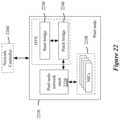
- FIG. 22conceptually illustrates an architectural diagram of a pool node of some embodiments.
- FIG. 23conceptually illustrates a network architecture of some embodiments that includes extenders.
- FIG. 24conceptually illustrates a network architecture that includes a managed network zone and an unmanaged network zone.
- FIG. 25conceptually illustrates a network architecture that includes a managed network zone and an unmanaged network zone, which are part of a data center.
- FIG. 26conceptually illustrates an example of mapping logical context tags between managed networks and unmanaged networks.
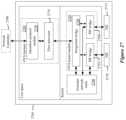
- FIG. 27conceptually illustrates an architectural diagram of an extender of some embodiments.
- FIG. 28conceptually illustrates a network architecture for distributing packet processing between pool nodes.
- FIG. 29conceptually illustrates an example tunnel configuration of some embodiments.
- FIG. 30conceptually illustrates a process of some embodiments for processing packets.
- FIG. 31conceptually illustrates a block diagram of a switching element of some embodiments that processes packets to determine a pool node to which to send the packet.
- FIG. 32conceptually illustrates a process of some embodiments for creating a managed network.
- FIG. 33conceptually illustrates the creation of additional switching elements to a managed network according to some embodiments of the invention.
- FIG. 34conceptually illustrates the addition of managed switching elements and the creation of additional switching elements to a managed network according to some embodiments of the invention.
- FIG. 35conceptually illustrates an example of updating hash functions when a pool node is added to a managed network.
- FIG. 36conceptually illustrates a process of some embodiments for updating a hash function.
- FIGS. 37 A-Fconceptually illustrate examples of pool node failure handling according to some embodiments of the invention.
- FIGS. 38 A-Bconceptually illustrate the creation of additional network controllers to manage a managed network according to some embodiments of the invention.
- FIG. 39conceptually illustrates a process of some embodiments for processing a packet through a logical switching element that is implemented across a set of managed switching elements in a managed network.
- FIG. 40conceptually illustrates a processing pipeline of some embodiments for processing a packet through a logical switching element.
- FIG. 41conceptually illustrates a processing pipeline of some embodiments for processing a packet through a logical switching element.
- FIG. 42conceptually illustrates distribution of logical processing across managed switching elements in a managed network according to some embodiments of the invention.
- FIG. 43conceptually illustrates distribution of logical processing across managed switching elements in a managed network according to some embodiments of the invention.
- FIG. 44illustrates several example flow entries that implement a portion of a processing pipeline of some embodiments.
- FIG. 45conceptually illustrates a network architecture of some embodiments.
- FIG. 46conceptually illustrates an electronic computer system with which some embodiments of the invention are implemented.
- FIGS. 47 A-Cconceptually illustrate an example of network controller failure handling according to some embodiments of the invention.
- FIGS. 48 A-Cconceptually illustrate another example of network controller failure handling according to some embodiments of the invention.
- switching elements and machinesmay be referred to as network elements.
- a network that is managed by one or more network controllersmay be referred to as a managed network in the present application.
- the managed networkincludes only managed switching elements (e.g., switching elements that are controlled by one or more network controllers) while, in other embodiments, the managed network includes managed switching elements as well as unmanaged switching elements (e.g., switching elements that are not controlled by a network controller).
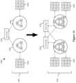
- FIG. 1conceptually illustrates a network architecture 100 of some embodiments.
- the network architecture 100includes network controllers 110 and 120 , managed switching elements 130 - 150 , and machines 155 - 185 .
- the managed switching elements 130 - 150route network data (e.g., packets) between network elements in the network that are coupled to the managed switching elements 130 - 150 .
- network datae.g., packets
- the managed switching element 130routes network data between the machines 155 - 165 and the managed switching element 140 .
- the managed switching element 140routes network data between the machine 170 and the managed switching elements 140 and 150
- the managed switching element 150routes network data between the machines 175 - 185 and the managed switching element 150 .
- the managed switching elements 130 - 150 of some embodimentscan be configured to route network data according to defined rules.
- the managed switching elements 130 - 150routes network data based on routing criteria defined in the rules. Examples of routing criteria include source media access control (MAC) address, destination MAC, packet type, source Internet Protocol (IP) address, destination IP address, source port, destination port, and/or virtual local area network (VLAN) identifier, among other routing criteria.
- routing criteriainclude source media access control (MAC) address, destination MAC, packet type, source Internet Protocol (IP) address, destination IP address, source port, destination port, and/or virtual local area network (VLAN) identifier, among other routing criteria.
- MACmedia access control
- IPInternet Protocol
- VLANvirtual local area network
- the managed switching elements 130 - 150can include standalone physical switching elements, software switching elements that operate within a computer, or any other type of switching element.
- each of the managed switching elements 130 - 150may be implemented as a hardware switching element, a software switching element, a virtual switching element, a network interface controller (NIC), or any other type of network element that can route network data.
- the software or virtual switching elementsmay operate on a dedicated computer, or on a computer that performs non-switching operations.
- the machines 155 - 185send and receive network data between each other over the network.
- the machines 155 - 185are referred to as network hosts that are each assigned a network layer host addresses (e.g., IP address).
- IP addresse.g., IP address
- Some embodimentsrefer to the machines 155 - 185 as end systems because the machines 155 - 185 are located at the edge of the network.
- each of the machines 155 - 185can be a desktop computer, a laptop computer, a smartphone, a virtual machine (VM) running on a computing device, a terminal, or any other type of network host.
- VMvirtual machine
- each of the network controllers 110 and 120controls one or more managed switching elements 130 - 150 that are located at the edge of a network (e.g., edge switching elements or edge devices).
- the managed switching elements 130 - 150are edge switching elements. That is, the managed switching elements 130 - 150 are switching elements that are located at or near the edge of the network.
- an edge switching elementis the last switching element before end machines (the machines 155 - 185 in this example) in a network.
- the network controller 110controls (i.e., manages) switching elements 130 and 140 and the network controller 120 controls switching element 150 .
- a switching element that is controlled by a network controller of some embodimentsmay be referred to as a managed switching element.
- Controlling only edge switchesallows the network architecture 100 to be deployed independent of concerns about the hardware vendor of the non-edge switches, because deploying at the edge allows the edge switches to treat the internal nodes of the network as simply a collection of elements that moves packets without considering the hardware makeup of these internal nodes. Also, controlling only edge switches makes distributing switching logic computationally easier. Controlling only edge switches also enables non-disruptive deployment of the system because edge-switching solutions can be added as top of rack switches without disrupting the configuration of the non-edge switches.
- the network controllers 110 and 120 of some embodimentsalso utilize and control non-edge switching elements (e.g., pool nodes, root nodes, and extenders, which are described in further detail below) that are inserted in the network to simplify and/or facilitate the operation of the managed edge switching elements.
- non-edge switching elementse.g., pool nodes, root nodes, and extenders, which are described in further detail below
- the network controller 110 and 120require the switching elements that the network controller 110 and 120 control to be interconnected in a hierarchical switching architecture that has several edge switching elements as the leaf nodes in the hierarchical switching architecture and one or more non-edge switching elements as the non-leaf nodes in this architecture.
- each edge switching elementconnects to one or more of the non-leaf switching elements, and uses such non-leaf switching elements to facilitate the communication of the edge switching element with other edge switching elements.
- Examples of such communications with an edge switching elementsinclude (1) routing of a packet with an unknown destination address (e.g., unknown MAC address) to the non-leaf switching element so that the non-leaf switching element can route the packet to the appropriate edge switching element, (2) routing a multicast or broadcast packet to the non-leaf switching element so that the non-leaf switching element can distribute the multicast or broadcast packet to the desired destinations.
- an unknown destination addresse.g., unknown MAC address
- Some embodimentsemploy one level of non-leaf (non-edge) switching elements that connect to edge switching elements and in some cases to other non-leaf switching elements.
- Other embodimentsemploy multiple levels of non-leaf switching elements, with each level of non-leaf switching elements after the first level serving as a mechanism to facilitate communication between lower level non-leaf switching elements and leaf switching elements.
- the non-leaf switching elementsare software switching elements that are implemented by storing the switching tables in the memory of a standalone computer instead of an off the shelf switch.
- the standalone computermay also be executing in some cases a hypervisor and one or more virtual machines on top of that hypervisor. Irrespective of the manner by which the leaf and non-leaf switching elements are implemented, the network controllers 110 and 120 of some embodiments store switching state information regarding the leaf and non-leaf switching elements.
- the switching elements 130 - 150 of some embodimentsroute network data between network elements in the network.
- the network controllers 110 and 120configure the managed switching elements 130 - 150 s ′ routing of network data between the network elements in the network. In this manner, the network controllers 110 and 120 can control the flow (i.e., specify the datapath) of network data between network elements.
- the network controller 110might instruct the managed switching elements 130 and 140 to route network data from the machine 155 to the machine 170 (and vice versa) and to not route (e.g., drop) network data from other machines to the machines 155 and 170 .
- the network controller 110controls the flow of network data through the managed switching elements 130 and 140 such that network data transmitted to and from the machine 155 is only routed to the machine 170 .
- the machines 155 and 170cannot send and receive network data to and from the machines 160 , 165 , and 175 - 185 .
- the network controllers 110 and 120store physical network information and logical network information.
- the physical network informationspecifies the physical components in the managed network and how the physical components are physically connected one another in the managed network.
- the physical network informationmay include the number of machines, managed switching elements, pool nodes, root nodes, and extenders (the latter three are described in further detail in the following sections), and how the components are physically connected to one another in the managed network.
- the logical network informationmay specify the logical connections between a set of physical components in the managed network (e.g., machines) and a mapping of the logical connections across the physical components of the managed network.
- Some embodiments of the network controllers 110 and 120implement a logical switching element across the managed switching elements 130 - 150 based on the physical network information and the logical switching element information described above.
- a logical switching elementcan be defined to function any number of different ways that a switching element might function.
- the network controllers 110 and 120implement the defined logical switching element through control of the managed switching elements 130 - 150 .
- the network controllers 110 and 120implement multiple logical switching elements across the managed switching elements 130 - 150 . This allows multiple different logical switching elements to be implemented across the managed switching elements 130 - 150 without regard to the network topology of the network.
- a logical datapath setdefines a logical switching element.
- a logical datapath setin some embodiments, is a set of network datapaths through the managed switching elements 130 - 150 that implement the logical switching element and the logical switch's defined functionalities.
- the network controllers 110 and 120translate (e.g., maps) the defined logical datapath set into network configuration information for implementing the logical switching element.
- the network controllers 110 and 120translate the defined logical datapath set into a corresponding set of data flows (i.e., datapaths) between network elements in the network, in some embodiments.
- the network controllers 110 and 120instruct the managed switching elements 130 - 150 to route network data according to the data flows and, thus, implement the functionalities of the defined logical switching element.
- the network controllers 110 and 120are implemented differently. For example, some embodiments implement the network controllers 110 and 120 in software as instances of a software application. In these cases, the network controllers 110 and 120 may be executed on different types of computing devices, such as a desktop computer, a laptop computer, a smartphone, etc. In addition, the software application may be executed on a virtual machine that runs on a computing device in some embodiments. In some embodiments, the network controllers 110 and 120 are implemented in hardware (e.g., circuits).
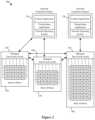
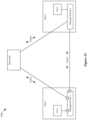
- FIG. 2illustrates an example of a network control system that includes physical switching elements.
- This figureconceptually illustrates a network control system 200 of some embodiments for managing physical switching elements.
- the network control system 200manages network data in a data center that includes top of the rack (TOR) switching elements 230 - 250 and racks of hosts 260 - 280 .
- Network controllers 210 and 220manage the network by controlling the TOR switching elements 230 - 250 .
- a TOR switching elementroutes network data between hosts in the TOR switch's rack and network elements coupled to the TOR switching element.
- the TOR switching element 230routes network data between the rack of hosts 260 and TOR switching elements 240 and 250
- the TOR switching element 240routes network data between the rack of hosts 270 and TOR switching elements 230 and 250
- the TOR switching element 250routes network data between the rack of hosts 280 and TOR switching elements 230 and 240 .
- each rack of hosts 260 - 280includes multiple hosts.
- the hosts of some embodiments in the racks of hosts 260 - 280are physical computing devices.
- each hostis a computing device that is assigned a network layer host address (e.g., IP address).
- the hosts of some embodimentssend and receive network data to and from each other over the network.
- the network controller of some embodimentscan be implemented in software as an instance of an application.
- the network controllers 210 and 220are instances of a software application.
- each of the network controllers 210 and 220includes several software layers: a control application layer, a virtualization application layer, and a networking operating system layer.
- control application layerreceives user input that specifies a network switching element.
- the control application layermay receive the user input in any number of different interfaces, such as a graphical user interface (GUI), a command line interfaces, a web-based interface, a touchscreen interface, etc.
- GUIgraphical user interface
- the user inputspecifies characteristics and behaviors of the network switching element, such as the number of switching element ports, access control lists (ACLs), network data forwarding, port security, or any other network switching element configuration options.
- ACLsaccess control lists
- the control application layer of some embodimentsdefines a logical datapath set based on user input that specifies a network switching element.
- a logical datapath setis a set of network datapaths through managed switching elements that are used to implement the user-specified network switching element.
- the logical datapath setis a logical representation of the network switching element and the network switch's specified characteristics and behaviors.
- Some embodiments of the virtualization application layertranslate the defined logical datapath set into network configuration information for implementing the logical network switching element across the managed switching elements in the network. For example, the virtualization application layer of some embodiments translates the defined logical datapath set into a corresponding set of data flows. In some of these cases, the virtualization application layer may take into account various factors (e.g., logical switching elements that are currently implemented across the managed switching elements, the current network topology of the network, etc.), in determining the corresponding set of data flows.
- factorse.g., logical switching elements that are currently implemented across the managed switching elements, the current network topology of the network, etc.
- the network operating system layer of some embodimentsconfigures the managed switching elements' routing of network data.
- the network operating systeminstructs the managed switching elements to route network data according to the set of data flows determined by the virtualization application layer.
- the network operating system layermaintains several views of the network based on the current network topology.
- One view that the network operating system layer maintainsis a logical view.
- the logical view of the networkincludes the different logical switching elements that are implemented across the managed switching elements, in some embodiments.
- Some embodiments of the network operating system layermaintain a managed view of the network. Such managed views include the different managed switching elements in the network (i.e., the switching elements in the network that the network controllers control).
- the network operating system layeralso maintains relationship data that relate the logical switching elements implemented across the managed switching elements to the managed switching elements.
- FIG. 2may show a set of managed switching elements managed by a network controller
- some embodimentsprovide several network controllers (also referred to as a cluster of network controllers or a control cluster) for managing the set of managed switching elements.
- different control clustersmay manage different sets of managed switching elements.
- Employing a cluster of network controllers in such embodiments to manage a set of managed switchesincreases the scalability of the managed network and increases the redundancy and reliability of the managed network.
- the network controllers in a control clustershare (e.g., through the network operating system layer of the network controllers) data related to the state of the managed network in order to synchronize the network controllers.
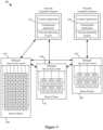
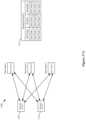
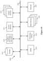
- FIG. 3conceptually illustrates a network control system 300 of some embodiments for managing software switching elements.
- the network control system 300includes network controllers 310 and 320 , TOR switching elements 330 - 350 , and racks of hosts 360 - 380 .
- the TOR switching elements 330 - 350are similar to the TOR switching elements 230 - 250 .
- the TOR switching elements 330 - 350route network data between network elements in the network that are coupled to the TOR switching elements 330 - 350 .
- the TOR switching element 330routes network data between the rack of hosts 360 and TOR switching elements 340 and 350
- the TOR switching element 340routes network data between the rack of hosts 370 and TOR switching elements 330 and 350
- the TOR switching element 350routes network data between the rack of hosts 380 and TOR switching elements 330 and 340 .
- the network controllers 310 and 320do not control these switching elements.
- the TOR switching elements 330 - 350rely on the switching elements' preconfigured functionalities to route network data.
- each host in the racks of hosts 360 - 380includes a software switching element (an open virtual switch (OVS) in this example) and several VMs.
- the VMsare virtual machines that are each assigned a set of network layer host addresses (e.g., a MAC address for network layer 2, an IP address for network layer 3, etc.) and can send and receive network data to and from other network elements over the network.
- OVSopen virtual switch
- the OVSs of some embodimentsroute network traffic between network elements coupled to the OVSs. For example, in this example, each OVS routes network data between VMs that are running on the host on which the OVS is running, OVSs running on other hosts in the rack of hosts, and the TOR switching element of the rack.
- the number of end machines or network hosts in the networkmay increase.
- the network topology of the networkis changed.
- the TOR switching elements 330 - 350are no longer edge switching elements.
- the edge switching elements in this exampleare the software switching elements running on the hosts since these software switching elements are the last switching elements before end machines (i.e., VMs in this example) in the network.
- the network controllers 310 and 320perform similar functions as the network controllers 210 and 220 , which described above by reference to FIG. 2 , and also are for managing edge switching elements. As such, the network controllers 310 and 320 manage the OVSs that are running on the hosts in the rack of hosts 360 - 380 .
- FIGS. 2 and 3illustrate a network control systems for managing physical switching elements and a network control system for managing software switching elements, respectively.
- the network control system of some embodimentscan manage both physical switching elements and software switching elements.
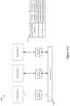
- FIG. 4illustrates an example of such a network control system.
- this figureconceptually illustrates a network control system 400 of some embodiments for managing TOR switching element 430 and OVSs running on hosts in the racks of hosts 470 and 480 .
- the network controllers 410 and 420perform similar functions as the network controllers 210 and 220 , which described above by reference to FIG. 2 , and also are for managing edge switching elements.
- the managed switching element 430 and the OVSs running on the hosts in the racks of hosts 470 and 480are edge switching elements because they are the last switching elements before end machines in the network.
- the network controller 410manages the TOR switching element 410 and the OVSs that are running on the hosts in the rack of hosts 460
- the network controller 420manage the OVSs that are running on the hosts in the rack of hosts 480 .
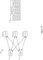
- FIG. 5illustrates a network control system that includes such network controllers.
- FIG. 5conceptually illustrates a network control system 500 of some embodiments for managing TOR switching elements 530 - 550 and OVS running on hosts in the racks of hosts 570 and 580 .
- the network controllers 510 and 520manage edge switching elements and non-edge switching elements. Specifically, the network controller 510 manages the TOR switching elements 530 and 520 , and the OVSs running on the hosts in the rack of hosts 570 .
- the network controller 520manages TOR switching element 580 and the OVSs running on the hosts in the rack of hosts 580 .
- the TOR switching element 530 and the OVSs running on the hosts in the racks of hosts 570 and 580are edge switching elements, and the TOR switching elements 540 and 550 are non-edge switching elements.
- the network controllers 510 and 520perform similar functions as the network controllers 210 and 220 , which are described above by reference to FIG. 2 .
- FIG. 6conceptually illustrates an example of a tunnel provided by a tunneling protocol.
- a network 600includes routers 610 and 620 , switching elements 630 and 640 , and machines 650 - 680 .
- the machines 650 - 680are similar to the machines 155 - 185 described above.
- the machines 650 - 680 of some embodimentsare network hosts that are each assigned a set of network layer host addresses (e.g., a MAC address for network layer 2, an IP address for network layer 3, etc.).
- the machines 650 - 680may also be referred to as end machines. Similar to the machines 155 - 185 described above, each of the machines 650 - 680 can be a desktop computer, a laptop computer, a smartphone, a virtual machine (VM) running on a computing device, a terminal, or any other type of network host.
- the machines 650 - 680may belong to different tenants (e.g., in a data center environment). As illustrated in FIG. 6 , each of the machines 650 - 680 belongs to either tenant A or tenant B.
- the switching elements 630 and 640are network switching elements that route (e.g., forwards) network data at the data link layer (also referred to as layer 2 or L2 layer) based on protocols such as the Ethernet protocol.
- the switching elements 630 and 640may also be referred to as network bridges in some embodiments. As shown, the switching element 630 routes network data at the data link layer between the machines 650 and 660 and the router 610 , and the switching element 640 routes network data at the data link layer between the machines 670 and 680 and the router 620 .
- the switching elements 630 and 640use a media access control (MAC) address of a network host's network interface card (NIC) to determine where to route network data (e.g., packets, frames, etc.).
- MACmedia access control
- NICnetwork interface card
- the switching elements 630 and 640are implemented differently in different embodiments. For instance, each of the switching elements 630 and 640 can be implemented as a hardware switching element, a software switching element, a virtual switching element, some types of network interface card (NIC), or any other type of network element that can route network data at the data link layer.
- the switching elements 630 and 640support any number of different types of tunneling protocols in different embodiments.
- tunneling protocolsinclude control and provisioning of wireless access points (CAPWAP), generic route encapsulation (GRE), GRE Internet Protocol Security (IPsec), among other types of tunneling protocols.
- CAPWAPwireless access points
- GREgeneric route encapsulation
- IPsecGRE Internet Protocol Security
- the routers 610 and 620are network routers that route network data at the network layer (also referred to as the layer 3 or L3 layer) based on protocols such as the Internet Protocol (IP). As illustrated in FIG. 6 , the router 610 routes network data at the network layer between the router 620 and the switching element 630 , and the router 620 routes network data at the network layer between the router 610 and the switching element 640 .
- IPInternet Protocol
- the routers 610 and 620 of some embodimentsuse an IP address assigned to a network host to determine where to route network data (e.g., packets). Moreover, the routers 610 and 620 of some embodiments may provide other functions as well, such as security functions, quality of service (QoS) functions, checksum functions, flow accounting functions, or any other type of router functions.
- QoSquality of service
- each of the routers 610 and 620can be implemented differently.
- each of the routers 610 and 620can be implemented as a hardware router, a software router, a virtual router, or any other type of network element that can route network data at the network layer.
- the switching elements 630 and 640 of some embodimentscan support tunneling protocols.
- a tunneling protocolallows network data to be sent along a path between two points in a network where the tunneling protocol used by the network elements along the path in the network is different than the payload protocol used by the destination network element
- a tunneling protocolis a network protocol (e.g., a delivery protocol) that encapsulates another protocol (e.g., a payload protocol).
- a tunneling protocolcan be used, for example, to transmit network data over an incompatible delivery-network.
- a tunneling protocolmay provide a tunnel over a layer 3 network through which layer 2 network data is transmitted.
- the machines 650 - 680are communicating over an L2 network.
- a tunneling protocolfacilitates the communication of layer 2 network data between network hosts separated by a layer 3 network.
- FIG. 6illustrates a tunnel 690 that has been established between the switching element 630 and the switching element 640 .
- the tunnel 690is established over a layer 3 network 695 (e.g., the Internet).
- the tunnel 690allows layer 2 network data to be transmitted between the machines 650 - 680 by encapsulating the layer 2 network data with a layer 3 header and transmitting the network data through the tunnel 690 that is established over the layer 3 network 695 .
- the network 695includes switching elements (not shown in FIG. 6 ) that facilitate the forwarding of packets through the tunnel.
- switching elementsinclude standard switches (which may be cheaper than proprietary switches), off the shelf switches, or any other type of switching element that forwards data through the network 695 .
- These switching elementsmay be referred to as unmanaged switching elements because they are not managed by a network controller that manages the switching elements 630 and 640 .
- Using the tunnel 690allows the switching elements 630 and 640 to route packets through the network 695 of switching elements independent of the type of switching elements in the network 695 .
- the switching elements 630 and 640treat the switching elements in the network 695 as simply a collection of elements that moves packets without considering the hardware makeup of these switching elements.
- the use of the tunnel 690 to route packets between the switching elements 630 and 640does not disrupt the network 695 .
- the switching elements in the network 695do not have to be managed in order to facilitate communication between the switching elements 630 and 640 .
- packets that are routed through the tunnel 690are encapsulated with a tunneling protocol.
- the switching elements included in the network 695are unaware of the encapsulated data (e.g., logical network data such as a MAC address or an IP address) that is routed through the tunnel 690 .
- the encapsulated datais hidden from the unmanaged switching elements in the network 695 that forward the encapsulated data through the network 695 .
- routing packets through the tunnel 690requires fewer entries in the forwarding tables of the unmanaged switching elements in the network 695 compared to routing the packets using non-tunneling methods (e.g., using a transmission control protocol (TCP), a user datagram protocol (UDP), or an Ethernet protocol).
- TCPtransmission control protocol
- UDPuser datagram protocol
- Ethernet protocolan Ethernet protocol
- an unmanaged switching elementlearns and stores forwarding entries for each of the different packets that are forwarded through the unmanaged switching elements. Accordingly, routing packets through the tunnel 690 reduces the size of the forwarding tables of the unmanaged switching elements in the network 695 .
- a single tunnel 690is established between the switching elements 630 and 640 .
- multiple tunnels using the same or different tunneling protocolsmay be established between the switching elements 630 and 640 .
- the tunnel 690 shown in FIG. 6is a bidirectional tunnel, as indicated by an arrow at each end of the tunnel 690 .
- some embodimentsmay provide unidirectional tunnels. In such cases, a tunnel is established for each direction of communication between two points in the network. Referring to FIG. 6 as an example, when one of the machines 650 and 660 wishes to communicate with one of the machines 670 and 680 , a tunnel is established that allows network data to be transmitted only from the switching element 630 to the switching element 640 . Conversely, when one of the machines 670 and 680 wishes to communicate with one of the machines 650 and 660 , a tunnel is established that allows network data to be transmitted from only the switching element 640 to the switching element 630 .
- FIG. 6illustrates routers and switching elements as separate components
- the functions described above for the router and switching elementsmay be performed by a single component in some embodiments. For instance, some embodiments combine the functions of the router 610 and the switching element 630 into one component and/or combine the functions of the router 620 and the switching element 640 into another component.
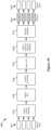
- FIG. 7illustrates the transmission of network data through a tunnel according to some embodiments of the invention.
- FIG. 7conceptually illustrates multiplexing network data that belongs to different tenants through a tunnel 770 .
- this figureillustrates a network 700 that includes switching elements 710 and 720 and machines 730 - 760 .
- the machines 730 - 760are similar to the machines 155 - 185 described above.
- the tunnel 770is established between the switching element 710 and the switching element 720 .
- the tunnel 770is a unidirectional tunnel, as indicated by an arrow, that allows network data to be transmitted from the switching element 710 to the switching element 720 .
- different tunneling protocolse.g., CAPWAP, GRE, etc.
- CAPWAPCAPWAP
- GREGRE
- an ID tagWhen transmitting network data through the tunnel 770 , some embodiments include an identifier (ID) tag with the network data when the network data is transmitted through the tunnel 770 .
- ID tagis a unique identifier for identifying a tenant to which the network data is associated. In this manner, switching elements can identify the tenant to which the network data belongs. This enables network data for different tenants to be transmitted through a single tunnel.
- an ID tagallows machines of different tenants to have overlapping network identifiers (e.g., logical MAC addresses or logical IP addresses). For example, in a layer 2 network where some machines of different tenants each has the same MAC address, an ID tag can be used to differentiate between the machines of the different tenants and the network data directed at the different tenants. Similarly, an ID tag may be used to differentiate between machines of different tenants where some of the machines of the different tenants each has the same IP address.
- an ID tag “ID 1 ”is associated with tenant A and an ID tag “ID 2 ” is associated with tenant B.
- the switching elements 710 and 720are configured with this ID tag information (e.g., stored in a lookup table).
- tenant A's machines and tenant B's machineshave overlapping network identifiers (e.g., they have the same MAC addresses or are use the same private IP address space).
- the packet Ais transmitted to the switching element 710 .
- the switching element 710determines that the packet A originated from a machine that belongs to tenant A (e.g., based on the packet A's source MAC address and/or the port through which the packet A is received). Then, the switching element 710 identifies the ID tag (e.g., by performing a lookup on a lookup table) that is associated with tenant A (ID 1 in this example) and includes the ID tag in the packet A before the packet is transmitted to the switching element 720 through the tunnel 770 .
- the ID tage.g., by performing a lookup on a lookup table
- tenant A's machine (machine 750 ) and tenant B's machine (machine 760 )have overlapping network identifiers (e.g., the machine 750 and 760 each has the same MAC address or use the same private IP address space), the switching element 720 would not be able to differentiate between tenant A's machines and tenant B's machines based only on the machines' network identifiers. However, the ID tag allows the switching element 720 to differentiate between tenant A's machines and tenant B's machines.
- the switching element 720examines the ID tag included in the packet A and determines the tenant to which the packet A belongs (e.g., by performing a lookup on a lookup table). After determining the tenant to which the packet A belongs, the switching element 720 removes the ID tag from the packet A and transmits to the packet A to the machine 750 , the intended recipient of the packet A in this example.
- the switching elements 710 and 720perform similar functions as those performed for the packet A described above. That is, the switching element 710 determines the tenant to which the packet B belongs, identifies the ID tag associated with the tenant, and includes the ID tag in the packet B. Then, the switching element 710 transmits the packet B to the switching element 720 through the tunnel 770 . When the switching element 720 receives the packet B from the switching element 710 through the tunnel 770 , the switching element 720 determines the tenant to which the packet B belongs by examining the ID tag included in the packet, removes the ID tag from the packet B, and transmits the packet B to the machine 760 . As explained, the ID tag allows network data for tenants A's machines and tenant B's machines, which have overlapping network identifiers, to be transmitted through a single tunnel 770 .
- the managed switching elements of some embodimentscan be configured to route network data based on different routing criteria. In this manner, the flow of network data through switching elements in a network can be controlled in order to implement multiple logical switching elements across the switching elements.
- FIG. 8illustrates an example of multiple logical switching elements implemented across a set of switching elements.
- FIG. 8conceptually illustrates logical switching elements 870 and 880 implemented across switching elements 810 - 830 .
- a network 800includes switching elements 810 - 830 and machines 840 - 865 .
- the machines 840 - 865are similar to the machines 155 - 185 described above.
- the machines 840 , 850 , and 860belong to tenant A and the machines 845 , 855 , and 865 belong to tenant B.
- the switching elements 810 - 830 of some embodimentsroute network data (e.g., packets, frames, etc.) between network elements in the network that are coupled to the switching elements 810 - 830 . As shown, the switching element 810 routes network data between the machines 840 and 845 and the switching element 820 . Similarly, the switching element 810 routes network data between the machine 850 and the switching elements 810 and 820 , and the switching element 830 routes network data between the machines 855 - 865 and the switching element 820 .
- network datae.g., packets, frames, etc.
- each of the switching elements 810 - 830routes network data based on the switch's forwarding tables.
- a forwarding tabledetermines where to route network data (e.g., a port on the switch) according to routing criteria. For instance, a forwarding table of a layer 2 switching element may determine where to route network data based on MAC addresses (e.g., source MAC address and/or destination MAC address). As another example, a forwarding table of a layer 3 switching element may determine where to route network data based on IP addresses (e.g., source IP address and/or destination IP address). Many other types of routing criteria are possible.
- the forwarding table in each of the switching elements 810 - 830includes several records.
- each of the recordsspecifies operations for routing network data based on routing criteria.
- the recordsmay be referred to as flow entries in some embodiments as the records control the “flow” of data through the switching elements 810 - 830 .
- FIG. 8also illustrates conceptual representations of each tenant's logical network.
- the logical network 880 of tenant Aincludes a logical switching element 885 to which tenant A's machines 840 , 850 , and 860 are coupled.
- Tenant B's logical network 890includes a logical switching element 895 to which tenant B's machines 845 , 855 , and 865 are coupled.
- tenant Ahas a switching element to which only tenant A's machines are coupled
- tenant Bhas a switching element to which only tenant B's machines are coupled.
- the tenanthas its own network that includes only the tenant's machines.
- the followingwill describe the conceptual flow entries for implementing the flow of network data originating from the machine 840 and destined for the machine 850 and originating from the machine 840 and destined for the machine 860 .
- the flow entries for routing network data originating from the machine 840 and destined for the machine 850will be described followed by the flow entries for routing network data originating from the machine 840 and destined for the machine 860 .
- the flow entry “A1 to A2” in the switching element 810 's forwarding tableinstructs the switching element 810 to route network data that originates from machine 810 and is destined for the machine 850 to the switching element 820 .
- the flow entry “A1 to A2” in the forwarding table of the switching element 820instructs the switching element 820 to route network data that originates from machine 810 and is destined for the machine 850 to the machine 850 . Therefore, when the machine 840 sends network data that is destined for the machine 850 , the switching elements 810 and 820 route the network data along datapath 870 based on the corresponding records in the switching elements' forwarding tables.
- the flow entry “A1 to A3” in the switching element 810 's forwarding tableinstructs the switching element 810 to route network data that originates from machine 810 and is destined for the machine 850 to the switching element 820 .
- the flow entry “A1 to A3” in the forwarding table of the switching element 820instructs the switching element 820 to route network data that originates from machine 810 and is destined for the machine 860 to the switching element 830 .
- the flow entry “A1 to A3” in the forwarding table of the switching element 830instructs the switching element 830 to route network data that originates from machine 810 and is destined for the machine 860 to the machine 860 .
- the switching elements 810 - 830route the network data along datapath 875 based on the corresponding records in the switching elements' forwarding tables.
- tunnels provided by tunneling protocols described abovemay be used to facilitate the implementation of the logical switching elements 885 and 895 across the switching elements 810 - 830 .
- the tunnelsmay be viewed as the “logical wires” that connect machines in the network in order to implement the logical switching elements 880 and 890 .
- unidirectional tunnelsare used. For instance, a unidirectional tunnel between the switching element 810 and the switching element 820 may be established and through which network data originating from the machine 840 and destined for the machine 850 is transmitted. Similarly, a unidirectional tunnel between the switching element 810 and the switching element 830 may be established and through which network data originating from the machine 840 and destined for the machine 860 is transmitted. In some embodiments, a unidirectional tunnel is established for each direction of network data flow between two machines in the network.
- bidirectional tunnelscan be used in some embodiments. For instance, in some of these embodiments, only one bidirectional tunnel is established between two switching elements. Referring to FIG. 8 as an example, a tunnel would be established between the switching elements 810 and 820 , a tunnel would be established between the switching elements 820 and 830 , and a tunnel would be established between the switching elements 810 and 830 .
- ID tagsare utilized to distinguish between the network data of different tenants (e.g., tenants A and B in FIG. 8 ), as described above by reference to FIG. 7 .
- Configuring the switching elements in the various ways described above to implement multiple logical switching elements across a set of switching elementsallows multiple tenants, from the perspective of each tenant, to each have a separate network and/or switching element while the tenants are in fact sharing some or all of the same set of switching elements and/or connections between the set of switching elements (e.g., tunnels, physical wires).
- FIG. 9conceptually illustrates a block diagram of a switching element 900 of some embodiments. Many of the switching elements illustrated in the figures throughout this application may be the same or similar to the switching element 900 as described below. As illustrated in this figure, the switching element 900 includes ingress ports 910 , egress ports 920 , dispatch port 930 , and a forwarding table 940 .
- the ingress ports 910conceptually represent a set of ports through which the switching element 900 receives network data.
- the ingress ports 910may include different amounts of ingress ports in different embodiments.
- the ingress ports 910can receive network data that is external to the switching element 900 , which is indicated as incoming packets in this example.
- the ingress ports 910can also receive network data (e.g., packets) within the switching element 900 from the dispatch port 930 .
- the ingress ports 910forwards the network data to the forwarding tables 940 .
- the forwarding tables 940conceptually represent a set of forwarding tables for routing and modifying network data received from the ingress ports 910 .
- the forwarding tables 940include a set of records (or rules) that instruct the switching element 900 to route and/or modify network data and send the network data to the egress ports 920 and/or the dispatch port 930 based on defined routing criteria.
- routing criteriainclude source media access control (MAC) address, destination MAC, packet type, source Internet Protocol (IP) address, destination IP address, source port, destination port, and/or virtual local area network (VLAN) identifier, among other routing criteria.
- the switching element 900routes network data to a particular egress port according to the routing criteria.
- the egress ports 920conceptually represent a set of ports through which the switching element 900 sends network data out of the switching element 900 .
- the egress ports 920may include different amounts of egress ports in different embodiments. In some embodiments, some or all of the egress ports 920 may overlap with some or all of the ingress ports 910 .
- the set of ports of the egress ports 920is the same set of ports as the set of ports of ingress ports 910 . As illustrated in FIG. 9 , the egress ports 920 receive network data after the switching element 900 processes the network data based on the forwarding tables 940 .
- the switching element 900sends the network data out of the egress ports 920 , which is indicated as outgoing packets in this example, based on the routing criteria in the forwarding tables 940 .
- the dispatch port 930allows packets to be reprocessed by the forwarding tables 940 .
- the forwarding tables 940are implemented as a single table (e.g., due to the switching element 900 s hardware and/or software limitations). However, some embodiments of the forwarding tables 940 may logically need more than one table. Therefore, in order to implement multiple forwarding tables in a single table, the dispatch port 930 may be used. For example, when the forwarding tables 940 processes a packet, the packet may be tagged (e.g., modifying a context tag of the packet or a header field of the packet) and sent to the dispatch port 930 for the forwarding tables 940 to process again. Based on the tag, the forwarding tables 940 processes the packet using a different set of records. So logically, a different forwarding table is processing the packet.
- the dispatch port 930receives after the switching element 900 processes the network data according to the forwarding tables 940 .
- the switching element 900might route the network data to the dispatch port 930 according to routing criteria defined the forwarding tables 940 .
- the dispatch port 930sends the network data to the ingress ports 910 to be further processed by the forwarding tables 940 .
- the switching element 900might modify the network data based on the forwarding tables 940 and send the modified network data to the dispatch port 930 for further processing by the forwarding tables 940 .
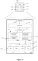
- FIG. 10conceptually illustrates an architectural diagram of a hardware switching element 1000 of some embodiments.
- the switching element 1000includes ingress ports 1010 , egress ports 1020 , dispatch port 1030 , forwarding tables 1040 , management processor 1050 , configuration database 1060 , control plane 1070 , communication interface 1080 , and packet processor 1090 .
- the ingress ports 1010are similar to the ingress ports 910 illustrated in FIG. 9 except the ingress ports 1010 send network data to the packet processor 1090 instead of forwarding tables.
- the egress ports 1020are similar to the ingress ports 1020 illustrated in FIG. 07 except the egress ports 1020 receive network data from the packet processor 1090 instead of forwarding tables.
- the dispatch port 1030is similar to the dispatch port 930 of FIG. 9 except the dispatch port 1030 receives network data from the packet processor 1090 instead of forwarding tables.
- the management processor 1050controls the operations and functions of the switching element 1000 . As shown in FIG. 10 , the management processor 1050 of some embodiments receives commands for controlling the switching element 1000 through a switching control protocol.
- a switching control protocolis the Openflow protocol.
- the Openflow protocolin some embodiments, is a communication protocol for controlling the forwarding plane (e.g., forwarding tables) of a switching element. For instance, the Openflow protocol provides commands for adding flow entries to, removing flow entries from, and modifying flow entries in the switching element 1000 .
- the management processor 1050also receives configuration information through a configuration protocol. When the management processor 1050 receives configuration information, the management processor 1050 sends the configuration information to the configuration database 1060 for the configuration database 1060 to store.
- configuration informationincludes information for configuring the switching element 1000 , such as information for configuring ingress ports, egress ports, QoS configurations for ports, etc.
- the management processor 1050When the management processor 1050 of some embodiments receives switching control commands and the configuration commands, the management processor 1050 translates such commands into equivalent commands for configuring the switching element 1000 to implement the functionalities of the commands. For instance, when the management processor 1050 receives a command to add a flow entry, the management processor 1050 translates the flow entry into equivalent commands that configure the switching element 1000 to perform functions equivalent to the flow entry. In some embodiments, the management processor 1050 might request configuration information from the configuration database 1060 in order to perform translation operations.
- management processor 1050Some embodiments of the management processor 1050 are implemented as electronic circuitry while other embodiments of the management processor 1050 are implemented as an embedded central processing unit (CPU) that executes switching element management software (e.g., OVS) that performs some or all of the functions described above.
- CPUcentral processing unit
- OVSswitching element management software
- the configuration database 1060 of some embodimentsstores configuration information that the configuration database 1060 receives from the management processor 1050 .
- the configuration database 1060retrieves the appropriate configuration information and sends the requested configuration information to the management processor 1050 .
- control plane 1070stores a set of flow tables that each includes a set of flow entries (also referred to collectively as configured flow entries).
- the control plane 1070receives flow entries from the management processor 1050 to add to the set of flow tables, and receives requests from the management processor 1050 to remove and modify flow entries in the set of flow tables.
- some embodiments of the control plane 1070might receive requests from the management processor 1050 for flow tables and/or flow entries. In such instances, the control plane 1070 retrieves the requested flow tables and/or flow entries and sends the flow tables and/or flow entries to the management processor 1050 .
- control plane 1070 of some embodimentsstores different flow tables and/or flow entries that serve different purposes.
- a switching elementmay be one of several switching elements in a network across which multiple logical switching elements are implemented.
- the control plane 1070stores flow tables and/or flow entries for operating in the physical domain (i.e., physical context) and stores flow tables and/or flow entries for operating in the logical domain (i.e., logical context).
- the control plane 1070 of these embodimentsstores flow tables and/or flow entries for processing network data (e.g., packets) through logical switching elements and flow tables and/or flow entries for processing network the data through physical switching elements in order to implement the logical switching elements.
- the control plane 1070allows the switching element 1000 to facilitate implementing logical switching elements across the switching element 1000 (and other switching elements in the managed network).
- the flow tables and/or flow entries for operating in the physical domain process packets based on a set of fields in the packets' headere.g., source MAC address, destination MAC address, source IP address, destination IP address, source port number, destination port number
- the flow tables and/or flow entries for operating in the logical domain process packets based on the packets' logical context IDe.g., as described above by reference to FIG. 8
- a logical context tage.g., as described below by reference to FIGS. 14 , 15 , 40 , 41 , and 44 .
- the communication interface 1080facilitate communication between management processor 1050 and packet processor 1090 . For instance, when the communication interface 1080 receives messages (e.g., commands) from the management processor 1050 , the communication interface 1080 forwards the messages to the packet processor 1090 and when the communication interface 1080 receives messages from the packet processor 1090 , the communication interface 1080 forwards the messages to the management processor 1050 . In some embodiments, the communication interface 1080 translates the messages such that the recipient of the message can understand the message before sending the message to the recipient.
- the communication interface 1080can be implemented as a peripheral component interconnect (PCI) or PCI express bus in some embodiments. However, the communication interface 1080 may be implemented as other types of busses in other embodiments.
- PCIperipheral component interconnect
- PCI express busin some embodiments.
- the communication interface 1080may be implemented as other types of busses in other embodiments.
- the forwarding tables 1040store active flow tables and/or flow entries that are used to determine operations for routing or modifying network data (e.g., packets).
- active tables and/or flow entriesare a subset of the flow tables and/or entries stored in the control plane 1070 that the forwarding tables 1040 is currently using or was recently using to process and route network data.
- each flow entryis includes a qualifier and an action.
- the qualifierdefines a set of fields to match against the network data. Examples of fields for matching network data include ingress port, source MAC address, destination MAC address, Ethernet type, VLAN ID, VLAN priority, multiprotocol label switching (MPLS) label, MPLS traffic class, source IP address, destination IP address, transport control protocol (TCP)/user datagram protocol (UDP)/stream control transmission protocol (SCTP) source port, and/or TCP/UDP/SCTP destination port. Other types of packet header fields are possible as well in other embodiments.
- the action of a flow entrydefines operations for processing the network data when the network data matches the qualifier of the flow entry. Examples of actions include modify the network data and route the network data to a particular port or ports. Other embodiments provide additional and/or other actions to apply to the network data.
- the packet processor 1090processes network data (e.g., packets) that the packet processor 1090 receives from the ingress ports 1010 . Specifically, the packet processor 1090 processes (e.g., route, modify, etc.) the network data based on flow entries in the forwarding tables 1040 . In order to process the network data, the packet processor 1090 accesses the flow entries in the forwarding tables 1040 . As mentioned above, the forwarding tables 1040 include a subset of flow tables and/or flow entries stored in the control plane 1070 .
- the packet processor 1090When the packet processor 1090 needs a flow table and/or flow entries that is not in the forwarding tables 1040 , the packet processor 1090 requests the desired flow table and/or flow entries, which are stored in the control plane 1070 , from the management processor 1050 through the communication interface 1080 .
- the packet processor 1090Based on the flow entries in the forwarding tables 1040 , the packet processor 1090 sends the network data to one or more ports of the egress ports 1020 or the dispatch port 1030 . In some embodiments, the network data may match multiple flow entries in the forwarding tables 1040 . In such cases, the packet processor 1090 might process the network data based on the first flow entry that has a qualifier that matches the network data.
- the packet processor 1090is an application-specific integrated circuit (ASIC) that performs some or all of the functions described above. In other embodiments, the packet processor 1090 is an embedded CPU that executes packet processing software that performs some or all of the functions described above.
- ASICapplication-specific integrated circuit
- the packet processor 1090is an embedded CPU that executes packet processing software that performs some or all of the functions described above.
- the switching element 1000may implement the packet processor 1090 and forwarding tables 1040 differently.
- the packet processor 1090 and forwarding tables 1040are implemented as a multi-stage processing pipeline.
- each flow entry in the forwarding tables 1040are implemented as one or more operations along one or more stages of the multi-stage packet processing pipeline.
- the management processor 1050 of some embodimentstranslates flow entries into equivalent commands that configure the switching element 1000 to perform functions equivalent to the flow entry. Accordingly, the management processor 1050 would configure the multi-stage packet processing pipeline to perform the functions equivalent to the flow entries in the forwarding tables.
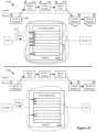
- FIG. 11conceptually illustrates an architectural diagram of a physical host 1100 that includes a software switching element 1110 (e.g., an OVS) of some embodiments.
- the top portion of FIG. 11illustrates the physical host 1100 , which includes the software switching element 1110 and four VMs 1120 - 1135 .
- the physical host 1100is the same or similar as the hosts that are running software switching elements in FIGS. 3 - 5 .
- Different embodiments of the physical host 1100can be a desktop computer, a server computer, a laptop, or any other type of computing device.
- the bottom portion of FIG. 11illustrates the physical host 1100 in more detail.
- the physical host 1100includes physical ports 1140 , a hypervisor 1145 , patch ports 1150 , the software switching element 1110 , patch ports 1155 , and the VMs 1120 - 1135 .
- the physical ports 1140 of the physical host 1100are a set of network interface controllers (NICs) that are for receiving network data and sending network data outside the physical host 1100 .
- the physical ports 1140are a set of wireless NICs.
- the physical ports 1140 of other embodimentsare a combination of NICs and wireless NICs.
- the hypervisor 1145(also referred to as a virtual machine monitor (VMM)) of some embodiments is a virtualization application that manages multiple operating systems (e.g., VMs) on the physical host 1100 . That is, the hypervisor 1145 provides a virtualization layer in which other operating systems can run with the appearance of full access to the underlying system hardware (not shown) of the physical host 1100 except such access is actually under the control of the hypervisor 1145 . In this example, the hypervisor 1145 manages the VMs 1120 - 1135 running on the physical host 1100 .
- VMMvirtual machine monitor
- the hypervisor 245manages system resources, such as memory, processors (or processing units), persistent storage, or any other type of system resource, for each of the operating systems that the hypervisor 1145 manages.
- system resourcessuch as memory, processors (or processing units), persistent storage, or any other type of system resource, for each of the operating systems that the hypervisor 1145 manages.
- the hypervisor 1145manages the physical ports 1140 , the network resources of the physical host 1100 .
- the hypervisor 1145manages and controls network data flowing through the physical ports 1140 and the patch ports 1150 by, for example, mapping each port of the patch ports 1150 to a corresponding port of the physical ports 1140 .
- the hypervisor 1145is a Xen hypervisor is used while, in other embodiments, the hypervisor 1145 is a VMware hypervisor. Other hypervisors can be used in other embodiments.
- the patch ports 1150are a set of virtual ports (e.g., virtual network interfaces (VIFs)). To the software switching element 1110 and the hypervisor 1145 , the patch ports 1150 appear and behave similar to physical ports on a hardware switching element. For instance, the software switching element 1110 and the hypervisor 1145 may send and receive network data through the patch ports 1150 .
- the patch ports 1150are provided by the hypervisor 1145 to the software switching element 1110 while, in other embodiments, the patch ports 1150 are provided by the software switching element 1110 to the hypervisor 1145 .
- the patch ports 1155are a set of virtual ports that are similar to the patch ports 250 . That is, to the software switching element 1110 and the VMs 1120 - 1135 , the patch ports 1155 appear and behave similar to physical ports on a hardware switching element. As such, the software switching element 1110 and the VMs 1120 - 1135 may send and receive network data through the patch ports 1155 . In some embodiments, the patch ports 1155 are provided by the software switching element 1110 to the VMs 1120 - 1135 while, in other embodiments, the patch ports 1155 are provided by the VMs 1120 - 1135 to the software switching element 1110 .
- the software switching element 1110includes a control plane 1160 , a configuration database 1165 , a forwarding plane 1170 , and forwarding tables 1175 .
- the control plane 1160 of some embodimentsis similar to the control plane 1070 of FIG. 10 in that the control plane 1160 also stores configured flow entries (i.e., a set of flow tables that each includes a set of flow entries).
- the configuration database 1165is similar to the configuration database 1060 of FIG. 10 . That is, the configuration database 1165 stores configuration information for configuring the software switching element 1110 . (e.g., information for configuring ingress ports, egress ports, QoS configurations for ports, etc.)
- the forwarding plane 1170 and the forwarding tables 1175performs functions similar to ones performed by packet processor 1090 and the forwarding tables 1040 described above by reference to FIG. 10 .
- the forwarding plane 1170 of some embodimentsprocesses network data (e.g., packets) that the forwarding plane 1170 receives from the patch ports 1150 and the patch ports 1155 .
- the forwarding plane 1170processes the network data by accessing the flow entries in the forwarding tables 1175 .
- the forwarding plane 1170 of some embodimentsrequests the desired flow table and/or flow entries from the control plane 1070 .
- the forwarding plane 1170Based on the flow entries in the forwarding tables 1175 , the forwarding plane 1170 sends the network data to one or more ports of the patch ports 1150 and/or one or more ports of the patch ports 1155 .
- the network datamay match multiple flow entries in the forwarding tables 1175 .
- the forwarding plane 1170might process the network data based on the first flow entry that has a qualifier that matches the network data.
- FIG. 12conceptually illustrates an architectural diagram of a software switching element of some embodiments that is implemented in a host 1200 .
- the software switching elementincludes three components—an OVS kernel module 1245 , which runs in the kernel of the VM 1285 , and an OVS daemon 1265 and an OVS database (DB) daemon 1267 , which run in the user space of the VM 1285 .
- FIG. 12illustrates the software switching elements as two components for the purpose of explanation, the OVS kernel module 1245 , the OVS daemon 1265 , and the OVS DB daemon 1267 collectively form the software switching element running on the VM 1285 .
- the OVS kernel module 1245 , the OVS daemon 1265 , and the OVS DB daemon 1267may be referred to as the software switching element and/or the OVS switching element in the description of FIG. 12 .
- the software switching elementcan be any of the software switching elements illustrated in FIGS. 3 - 5 and, in such cases, the host 1200 is the host in the rack of hosts in which the software switching element is running.
- the host 1200includes hardware 1205 , hypervisor 1220 , and VMs 1285 - 1295 .
- the hardware 1205may include typical computer hardware, such as processing units, volatile memory (e.g., random access memory (RAM)), non-volatile memory (e.g., hard disc drives, optical discs, etc.), network adapters, video adapters, or any other type of computer hardware.
- volatile memorye.g., random access memory (RAM)
- non-volatile memorye.g., hard disc drives, optical discs, etc.
- network adapterse.g., hard disc drives, optical discs, etc.
- video adapterse.g., video adapters, or any other type of computer hardware.
- the hardware 1205includes NICs 1210 and 1215 , which are typical network interface controllers for connecting a computing device to a network.
- the hypervisor 1220is a software abstraction layer that runs on top of the hardware 1205 and runs below any operation system.
- the hypervisor 1205handles various management tasks, such as memory management, processor scheduling, or any other operations for controlling the execution of the VMs 1285 - 1295 .
- the hypervisor 1220communicates with the VM 1285 to achieve various operations (e.g., setting priorities).
- the hypervisor 1220is a Xen hypervisor while, in other embodiments, the hypervisor 1220 may be any other type of hypervisor for providing hardware virtualization of the hardware 1205 on the host 1200 .
- the hypervisor 1220includes device drivers 1225 and 1230 for the NICs 1210 and 1215 , respectively.
- the device drivers 1225 and 1230allow an operating system to interact with the hardware of the host 1200 .
- the device driver 1225allows the VM 1285 to interact with the NIC 1210 .
- the device driver 1230allows the VM 1285 to interact with the NIC 1215 .
- the hypervisor 1220may include other device drivers (not shown) for allowing the VM 1285 to interact with other hardware (not shown) in the host 1200 .
- VMs 1285 - 1295are virtual machines running on the hypervisor 1220 . As such, the VMs 1285 - 1295 run any number of different operating systems. Examples of such operations systems include Solaris, FreeBSD, or any other type of Unix-based operating system. Other examples include Windows-based operating systems as well.
- the VM 1285is a unique virtual machine, which includes a modified Linux kernel, running on the hypervisor 1220 .
- the VM 1285may be referred to as domain 0 or dom0 in some embodiments.
- the VM 1285 of such embodimentsis responsible for managing and controlling other VMs running on the hypervisor 1220 (e.g., VMs 1290 and 1295 ).
- the VM 1285may have special rights to access the hardware 1205 of the host 1200 .
- other VMs running on the hypervisor 1220interact with the VM 1285 in order to access the hardware 1205 .
- the VM 1285may be responsible for starting and stopping VMs on the hypervisor 1220 .
- the VM 1285may perform other functions for managing and controlling the VMs running on the hypervisor 1220 .
- Some embodiments of the VM 1285may include several daemons (e.g., Linux daemons) for supporting the management and control of other VMs running on the hypervisor 1220 . Since the VM 1285 of some embodiments is manages and controls other VMs running on the hypervisor 1220 , the VM 1285 may be required to run on the hypervisor 1220 before any other VM is run on the hypervisor 1220 .
- daemonse.g., Linux daemons
- the VM 1285includes a kernel and a user space.
- the kernelis the most basic component of an operating system that runs on a separate memory space and is responsible for managing system resources (e.g., communication between hardware and software resources).
- the user spaceis a memory space where all user mode applications may run.
- the user space of the VM 1285includes the OVS daemon 1265 and the OVS DB daemon 1267 .
- Other applicationsmay be included in the user space of the VM 1285 as well.
- the OVS daemon 1265is an application that runs in the background of the user space of the VM 1285 .
- Some embodiments of the OVS daemon 1265communicate with a network controller 1280 in order to process and route packets that the VM 1285 receives.
- the OVS daemon 1265receives commands from the network controller 1280 regarding operations for processing and routing packets that the VM 1285 receives.
- the OVS daemon 1265communicates with the network controller 1280 through the Openflow protocol. In some embodiments, another type of communication protocol is used.
- some embodiments of the OVS daemon 1265receives configuration information from the OVS DB daemon 1267 to facilitate the processing and routing of packets.
- the OVS DB daemon 1267is also an application that runs in the background of the user space of the VM 1285 .
- the OVS DB daemon 1267 of some embodimentscommunicates with the network controller 1280 in order to configure the OVS switching element (e.g., the OVS daemon 1265 and/or the OVS kernel module 1245 ).
- the OVS DB daemon 1267receives configuration information from the network controller 1280 for configuring ingress ports, egress ports, QoS configurations for ports, etc., and stores the configuration information in a set of databases.
- the OVS DB daemon 1267communicates with the network controller 1280 through a database communication protocol (e.g., a JavaScript Object Notation (JSON) remote procedure call (RPC)-based protocol). In some embodiments, another type of communication protocol is utilized. In some cases, the OVS DB daemon 1267 may receive requests for configuration information from the OVS daemon 1265 . The OVS DB daemon 1267 , in these cases, retrieves the requested configuration information (e.g., from a set of databases) and sends the configuration information to the OVS daemon 1265 .
- a database communication protocole.g., a JavaScript Object Notation (JSON) remote procedure call (RPC)-based protocol.
- JSONJavaScript Object Notation
- RPCremote procedure call
- the network controller 1280is similar to the various network controllers described in this application, such as the ones described by reference to FIGS. 1 - 5 . That is, the network controller 1280 manages and controls the software switching element running on the VM 1285 of the host 1200 .
- FIG. 12also illustrates that the OVS daemon 1265 includes an Openflow protocol module 1270 and a flow processor 1275 .
- the Openflow protocol module 1270communicates with the network controller 1280 through the Openflow protocol.
- the Openflow protocol module 1270receives configuration information from the network controller 1280 for configuring the software switching element.
- Configuration informationmay include flows that specify rules (e.g. flow entries) for processing and routing packets.
- the Openflow protocol module 1270may translate the configuration information into information that the flow processor 1275 can understand.
- the Openflow protocol module 1270is a library that the OVS daemon 1265 accesses for some or all of the functions described above.
- the flow processor 1275manages the rules for processing and routing packets. For instance, the flow processor 1275 stores rules (e.g., in a storage medium, such as a disc drive) that the flow processor 1275 receives from the Openflow protocol module 1270 (which, in some cases, the Openflow protocol module 1270 receives from the network controller 1280 ). In some embodiments, the rules are stored as a set of flow tables that each includes a set of flow entries (also referred to collectively as configured flow entries). As noted above, flow entries specify operations for processing and/or routing network data (e.g., packets) based on routing criteria. In addition, when the flow processor 1275 receives commands from the Openflow protocol module 1270 to remove rules, the flow processor 1275 removes the rules.
- rulese.g., in a storage medium, such as a disc drive
- the rulesare stored as a set of flow tables that each includes a set of flow entries (also referred to collectively as configured flow entries).
- flow entriesspecify operations for processing and/or routing
- the flow processor 1275supports different types of rules.
- the flow processor 1275 of such embodimentssupports wildcard rules and exact match rules.
- an exact match ruleis defined to match against every possible field of a particular set of protocol stacks.
- a wildcard ruleis defined to match against a subset of the possible fields of the particular set of protocol stacks.
- different exact match rules and wildcard rulesmay be defined for different set of protocol stacks.
- the flow processor 1275handles packets for which integration bridge 1250 does not have a matching rule. For example, the flow processor 1275 receives packets from the integration bridge 1250 that does not match any of the rules stored in the integration bridge 1250 . In such cases, the flow processor 1275 matches the packets against the rules stored in the flow processor 1275 , which include wildcard rules as well as exact match rules. When a packet matches an exact match rule or a wildcard rule, the flow processor 1275 sends the exact match rule or the wildcard rule and the packet to the integration bridge 1250 for the integration bridge 1250 to process.
- the flow processor 1275when a packet matches a wildcard rule, the flow processor 1275 generates an exact match rule based on the wildcard rule to which the packet matches.
- a rulein some embodiments, specifies an action to perform based on a qualifier.
- the generated exact match ruleincludes the corresponding action specified in the wildcard rule from which the exact match rule is generated.
- the flow processor 1275when a packet matches a wildcard rule, the flow processor 1275 generates a wildcard rule that is more specific than the wildcard rule to which the packet matches.
- the generated (and more specific) wildcard ruleincludes the corresponding action specified in the wildcard rule from which the exact match rule is generated.
- the flow processor 1275may not have a rule to which the packet matches. In such cases, some embodiments of the flow process 1275 send the packet to the network controller 1280 (through the Openflow protocol module 1270 ). However, in other cases, the flow processor 1275 may have received from the network controller 1280 a catchall rule that drops the packet when a rule to which the packet matches does not exist in the flow processor 1275 .
- the flow processor 1275After the flow processor 1275 generates the exact match rule based on the wildcard rule to which the packet originally matched, the flow processor 1275 sends the generated exact match rule and the packet to the integration bridge 1250 for the integration bridge 1250 to process. This way, when the integration bridge 1250 receives a similar packet that matches generated the exact match rule, the packet will be matched against the generated exact match rule in the integration bridge 1250 so the flow processor 1275 does not have to process the packet.
- Some embodiments of the flow processor 1275support rule priorities for specifying the priority for a rule with respect to other rules. For example, when the flow processor 1275 matches a packet against the rules stored in the flow processor 1275 , the packet may match more than one rule. In these cases, rule priorities may be used to specify which rule among the rules to which the packet matches that is to be used to match the packet.
- the flow processor 1275 of some embodimentsis also responsible for managing rules in the integration bridge 1250 .
- the integration bridge 1250 of some embodimentsstores only active rules.
- the flow processor 1275monitors the rules stored in the integration bridge 1250 and removes the active rules that have not been access for a defined amount of time (e.g., 1 second, 3 seconds, 5, seconds, 10 seconds, etc.). In this manner, the flow processor 1275 manages the integration bridge 1250 so that the integration bridge 1250 stores rules that are being used or have recently been used.
- the OVS kernel module 1245may include multiple integration bridges.
- the OVS kernel module 1245includes an integration bridge for each logical switching element that is implemented across a managed network to which the software switching element belongs. That is, the OVS kernel module 1245 has a corresponding integration bridge for each logical switching element that is implemented across the managed network.
- the kernelincludes a hypervisor network stack 1240 and an OVS kernel module 1245 .
- the hypervisor network stack 1240is an Internet Protocol (IP) network stack that runs on the VM 1285 .
- IPInternet Protocol
- the hypervisor network stack 1240processes and routes IP packets that are received from the OVS kernel module 1245 and the PIF bridges 1255 and 1260 .
- the hypervisor network stack 1240determines to which of physical interface (PIF) bridges 1255 and 1260 the packet is to be sent.
- the hypervisor network stack 1240may make such determination by examining the destination IP address of the packet and a set of routing tables (not shown).
- the hypervisor network stack 1240is provided by the hypervisor 1220 .
- the OVS kernel module 1245processes and routes network data (e.g., packets) between VMs running on the host 1200 and network hosts external to the host 1200 (i.e., network data received through the NICs 1210 and 1215 ). For example, the OVS kernel module 1245 of some embodiments routes packets between VMs running on the host 1200 and network hosts external to the host 1200 (e.g., when packets are not routed through a tunnel) through a set of patch ports (not shown) that couple the OVS kernel module 1245 to the PIF bridges 1255 and 1260 .
- forwarding tablesare illustrated as part of a forwarding plane of a software switching element. However, the forwarding tables may be conceptual representations and may be implemented by the OVS kernel module 1245 , in some embodiments.
- the OVS kernel module 1245communicates with OVS daemon 1265 .
- the OVS kernel module 1245receives processing and routing information (e.g., flow entries) from the OVS daemon 1265 that specifies how the OVS kernel module 1245 is to process and route packets when the OVS kernel module 1245 receives packets.
- Some embodiments of the OVS kernel module 1245include a bridge interface (not shown) that allows the hypervisor network stack 1240 to send packets to and receiving packets from the OVS kernel module 1245 .
- the hypervisor 1240sends packets to and receives packets from the bridges included in OVS kernel module 1245 (e.g., integration bridge 1250 and/or PIF bridges 1255 and 1260 ).
- FIG. 12illustrates that the OVS kernel module 1245 includes an integration bridge 1250 and the PIF bridges 1255 and 1260 .
- the integration bridge 1250processes and routes packets received from the hypervisor network stack 1240 , the VMs 1290 and 1295 (e.g., through VIFs), and the PIF bridges 1255 and 1260 .
- a set of patch portsis directly connects two bridges.
- the integration bridge 1250 of some such embodimentsis directly coupled to each of the PIF bridges 1255 and 1260 through a set of patch ports.
- the integration bridge 1250receives packets from the hypervisor network stack 1240 through a default hypervisor bridge (not shown) that handles packet processing and routing.
- a function pointeralso referred to as a bridge hook
- a bridge hookthat instructs the hypervisor bridge to pass packets to the integration bridge 1250 is registered with the hypervisor bridge.
- the set of rules that the integration bridge 1250 storesare only exact match rules.
- the integration bridge 1250 of some such embodimentsstores only active exact match rules, which are a subset of the rules stored in the flow processor 1275 (and/or rules derived from rules stored in the flow processor 1275 ) that the integration bridge 1250 is currently using or was recently using to process and route packets.
- the integration bridge 1250 of some embodimentsstores a set of rules (e.g., flow entries) for performing mapping lookups and logical forwarding lookups, such as the ones described below in further detail by reference to FIGS. 14 , 40 , 41 , 42 , and 43 .
- Some embodiments of the integration bridge 1250may also perform standard layer 2 packet learning and routing.
- the OVS kernel module 1245includes a PIF bridge for each NIC in the hardware 1205 .
- the OVS kernel module 1245would include four PIF bridges for each of the four NICs in the hardware 1205 .
- a PIF bridge in the OVS kernel module 1245may interact with more than one NIC in the hardware 1205 .
- the PIF bridges 1255 and 1260route network data between the hypervisor network stack 1240 and network hosts external to the host 1200 (i.e., network data received through the NICs 1210 and 1215 ). As shown, the PIF bridge 1255 routes network data between the hypervisor network stack 1240 and the NIC 1210 and the PIF bridge 1260 routes network data between the hypervisor network stack 1240 and the NIC 1215 .
- the PIF bridges 1255 and 1260 of some embodimentsperform standard layer 2 packet learning and routing. In some embodiments, the PIF bridges 1255 and 1260 performs physical lookups/mapping, such as the ones described below in further detail by reference to FIGS. 14 , 40 , 42 , and 43 .
- the VM 1285provides and controls the PIF bridges 1255 and 1260 .
- the network controller 1280may, in some embodiments, control the PIF bridges 1255 and 1260 (via the OVS daemon 1265 ) in order to implement various functionalities (e.g., quality of service (QoS)) of the software switching element.
- QoSquality of service
- forwarding tablesare illustrated as part of a forwarding plane of a software switching element.
- these forwarding tablesmay be, in some embodiments, conceptual representations that can be implemented by the OVS kernel module 1245 .
- FIGS. 10 , 11 , and 13illustrate a control plane in a switching element.
- These control planesmay similarly be conceptual representations, which can be implemented by the OVS daemon 1265 , in some embodiments.
- FIG. 12The architectural diagram of the software switching element and the host illustrated in FIG. 12 is one exemplary configuration.
- One of ordinary skill in the artwill recognize that other configurations are possible.
- some embodimentsmay include several integration bridges in the OVS kernel module, additional NICs and corresponding PIF bridges, and additional VMs.
- the OVS kernel module 1245processes packets and routes packets.
- the OVS kernel module 1245can receive packets in different ways. For instance, the OVS kernel module 1245 can receive a packet from the VM 1290 or the VM 1295 through the VM's VIF. In particular, the OVS kernel module 1245 receives the packet from the VM 1290 or the VM 1295 at the integration bridge 1250 .
- the OVS kernel module 1245can receive a packet from a network host external to the host 1200 through one of the NICs 1210 and 1215 , the NIC's corresponding PIF bridge (i.e., PIF bridge 1225 or PIF bridge 1230 ), and the hypervisor network stack 1240 .
- the hypervisor network stack 1240then sends the packets to the integration bridge 1250 of the OVS kernel bridge 1245 .
- the packetis received from a network host external to the host 1200 through a tunnel.
- the tunnelterminates at the hypervisor network stack 1240 .
- the hypervisor network stack 1240when the hypervisor network stack 1240 receives the packet through the tunnel, the hypervisor network stack 1240 unwraps (i.e., decapsulates) the tunnel header and determines, based on the tunnel information (e.g., tunnel ID), which integration bridge of the OVS kernel module 1245 to which to send the unwrapped packet.
- the OVS kernel module 1245 of some embodimentsmay include an integration bridge for each logical switching element that is implemented across the managed network to which the OVS switching element belongs. Accordingly, the hypervisor network stack 1240 determines the logical switching element to which the tunnel belongs, identifies the integration bridge that corresponds to the determined logical switching element, and sends the packet to the identified integration bridge.
- the OVS kernel module 1245can receive a packet from a network host external to the host 1200 through one of the NICs 1210 and 1215 , the NIC's corresponding PIF bridge (i.e., PIF bridge 1225 or PIF bridge 1230 ), and a set of patch ports (not shown) that couple the PIF bridge to the OVS kernel module 1245 .
- the OVS kernel module 1245 of some embodimentsmay include an integration bridge for each logical switching element that is implemented across the managed network to which the OVS switching element belongs. Accordingly, the NIC's corresponding PIF bridge determines the logical switching element to which the tunnel belongs, identifies the integration bridge that corresponds to the determined logical switching element, and sends the packet to the identified integration bridge.
- the integration bridge 1250processes the packet and routes the packet.
- some embodiments of the integration bridge 1250stores only active exact match rules, which are a subset of the rules stored in the flow processor 1275 (and/or rules derived from rules stored in the flow processor 1275 ) that the integration bridge 1250 is currently using or was recently using to process and route packets.
- the integration bridge 1250performs a lookup based on a set of fields in the packet's header (e.g., by applying a hash function to the set of fields).
- the set of fieldsmay include a field for storing metadata that describes the packet.
- the integration bridge 1250performs the action (e.g., forward the packet, drop the packet, reprocess the packet, etc.) specified in the rule. However, if the lookup does not return a rule, the integration bridge 1250 sends the packet to the flow processor 1275 to process.
- the actione.g., forward the packet, drop the packet, reprocess the packet, etc.
- the flow processor 1275handles packets for which the integration bridge 1250 does not have a matching rule.
- the flow processor 1275matches the packet against the rules stored in the flow processor 1275 , which include wildcard rules as well as exact match rules.
- the flow processor 1275sends the exact match rule and the packet to the integration bridge 1250 for the integration bridge 1250 to process.
- the flow processor 1275generates an exact match rule based on the wildcard rule to which the packet matches, and sends the generated exact match rule and the packet to the integration bridge 1250 for the integration bridge 1250 to process.
- FIG. 12illustrates the VM 1285 as a virtual machine
- different embodimentsmay implement the VM 1285 differently.
- some embodimentsmay implement the VM 1285 as part of the hypervisor 1220 .
- the VM 1285performs the same or similar functions as those described above with respect to the VM 1285 .
- FIG. 13conceptually illustrates a network control system 1300 of some embodiments for managing a switching element 1320 .
- FIG. 13conceptually illustrates communication protocols that are employed in order for a network controller 1310 to communicate with and control the switching element 1320 .
- the network control system 1300may be used to manage and control the switching element 1320 in order to implement logical switching elements across the switching element and other switching elements, which belong to a network managed by the network controller 1300 .
- the network controller 1310is similar to the network controllers described above by reference to FIGS. 2 - 5 except the network controller 1310 communicates with the switching element 1320 through a database connection and an Openflow connection.
- a JavaScript Object Notation (JSON) remote procedure call (RPC)-based protocolis used to establish the database connection and to communicate (e.g., updating databases) through the database connection.
- JSONJavaScript Object Notation
- RPCremote procedure call
- any of the many known database connection and communication methodse.g., Java DataBase Connectivity (JDBC) or Open Database Connectivity (ODBC)
- JDBCJava DataBase Connectivity
- ODBCOpen Database Connectivity
- the Openflow connectionuses the Openflow protocol to establish a connection and facilitate communication.
- the switching element 1320is a software switching element (e.g., the OVS switching element illustrated in FIGS. 11 and 12 ) while, in other embodiments, the switching element 1320 is a hardware switching elements (e.g., the switching element illustrated in FIG. 10 ). Therefore, even for a hardware switching element, OVS is executed on the hardware switching element.
- the management processor 1050are implemented as an embedded central processing unit (CPU) that executes switching element management software.
- the switching element management softwareis OVS.
- the switching element 1320includes a user space daemon 1325 and a forwarding plane 1355 .
- the user space daemon 1325includes an OVS connection manager 1330 , a configuration database controller 1335 , a configuration database 1340 , a control plane controller 1345 , and a control plane 1350 .
- the OVS connection manager 1330manages the connection between the network controller 1310 and the configuration database controller 1335 , and the connection between the network controller 1310 and the control plane controller 1345 so that communications received over a particular connection is routed to the appropriate controller.
- the OVS connection manager 1330translates the commands and/or messages into a format that the recipient can understand. For example, when the network controller 1310 sends a command to the switching element 1320 through the database connection, the OVS connection manager 1330 may translate the command so that the configuration database controller 1335 can understand the command. Similarly, when the network controller 1310 sends a command to the switching element 1320 through the Openflow connection, the OVS connection manager 1330 may translate the command so that the control plane controller 1345 can understand the command.
- the configuration database controller 1340 of some embodimentsmanages the configuration database 1340 and receives commands from the OVS connection manager 1330 related to the configuration database 1340 .
- commandsinclude create a table, delete a table, create a record in a table, modify (i.e., update) a record in a table, delete a record in a table, among other types of database commands.
- the configuration database controller 1335receives a command from the OVS connection manager 1330 , the configuration database controller 1335 performs the corresponding action to the configuration database 1340 .
- the configuration database 1335is similar to the configuration database 1060 , which is described above by reference to FIG. 10 . That is, the configuration database 1335 stores configuration information for configuring the switching element 1320 . (e.g., information for configuring ingress ports, egress ports, QoS configurations for ports, etc.).
- configuration information for configuring the switching element 1320e.g., information for configuring ingress ports, egress ports, QoS configurations for ports, etc.
- control plane controller 1345manage the Openflow rules stored in the control plane 1350 and receives commands from the OVS connection manager 1330 related to the control plane 1350 .
- commandsinclude add a rule, modify (i.e., update) a rule, delete a rule, or other types of Openflow commands.
- the configuration database controller 1335receives a command from the OVS connection manager 1330 , the configuration database controller 1335 performs the command's corresponding action to the configuration database 1340 .
- the control plane 1350is similar to the control plane 1070 , which is described above by reference to FIG. 10 .
- the control plane 1350stores configured flow entries that are, in some embodiments, a set of flow tables that each includes a set of flow entries.
- the control plane 1350also stores flow tables and/or flow entries for operating in the physical domain (i.e., physical context) and stores flow tables and/or flow entries for operating in the logical domain (i.e., logical context) in order to implement logical switching elements.
- control plane 1350receives flow entries from the network controller 1310 (through the OVS connection manager 1330 and the control plane controller 1345 ) to add to the configured flow entries, and receives requests from the network controller 1310 (through the OVS connection manager 1330 and the control plane controller 1345 ) to remove and modify the configured flow entries.
- the control plane 1350may manage the flow entries stored in the forwarding plane 1355 in a similar manner that the flow processor 1275 manages rules in the integration bridge 1250 .
- control plane 1350monitors the flow entries stored in the forwarding plane 1355 and removes the flow entries that have not been access for a defined amount of time (e.g., 1 second, 3 seconds, 5, seconds, 10 seconds, etc.) so that the control plane 1355 stores flow entries that are being used or have recently been used.
- a defined amount of timee.g. 1 second, 3 seconds, 5, seconds, 10 seconds, etc.
- the forwarding plane 1355is similar to the forwarding plane described above by reference to FIG. 11 . That is, the forwarding plane 1355 processes and routes network data (e.g., packets). In some embodiments, the forwarding plane 1355 stores only active rules (e.g., flow entries) that specify operations for processing and routing packets. In some embodiments, the forwarding plane 1355 sends packets to the control plane 1350 that the forwarding plane 1355 cannot process (e.g., the forwarding plane 1355 does not have a flow entry that matches the packets).
- the switching element 1320 of some embodimentsis a software switching element. In these embodiments, the forwarding plane 1355 is implemented as a software forwarding plane, such as the software forwarding planes described above by reference to FIGS. 11 and 12 . Similarly, in some embodiments where the switching element 1320 is a hardware switching elements, the forwarding plane 1355 is implemented, for example, as the hardware forwarding plane described above by reference to FIG. 10 .
- FIG. 14conceptually illustrates a processing pipeline 1400 of some embodiments for processing network data through a logical switching element.
- the processing pipeline 1400includes four stages 1410 - 1440 for processing a packet through a logical switching element that is implemented across a set of managed switching elements in a managed network.
- each managed switching element in the managed network that receives the packetperforms the processing pipeline 1400 when the managed switching element receives the packet.
- a packetincludes a header and a payload.
- the headerincludes, in some embodiments, a set of fields that contains information used for routing the packet through a network.
- Switching elementsmay determine switching decisions based on the contained in the header and may, in some cases, modify some or all of the header fields. As explained above, some embodiments determine switching decisions based on flow entries in the switching elements' forwarding tables.
- the processing pipeline 1400may be implemented by flow entries in the managed switching elements in the network. For instance, some or all of the flow entries are defined such that the packet is processed against the flow entries based on the logical context tag in the packet's header. Therefore, in some of these embodiments, the managed switching elements are configured (e.g., by a network controller illustrated in FIGS. 1 - 5 ) with such flow entries.
- a logical context lookupis performed on a packet to determine the logical context of the packet.
- the first stage 1410is performed when the logical switching element receives the packet (e.g., the packet is initially received by a managed switching element in the network that implements the logical switching element).
- a logical contextrepresents the state of the packet with respect to the logical switching element.
- some embodiments of the logical contextmay specify the logical switching element to which the packet belongs, the logical port of the logical switching element through which the packet was received, the logical port of the logical switching element through which the packet is to be transmitted, the stage of the logical forwarding plane of the logical switching element the packet is at, etc.
- the logical context of some embodiments for packets sent from tenant A's machinesspecify that the packets are to be processed according to the logical switching element 880 , which is defined for tenant A (rather than the logical switching element 890 , which is defined for tenant B).
- Some embodimentsdetermine the logical context of a packet based on the source MAC address of the packet (i.e., the machine from which the packet was sent). Some embodiments perform the logical context lookup based on the source MAC address of the packet and the inport (i.e., ingress port) of the packet (i.e., the port of the managed switching element through which the packet was received). Other embodiments may use other fields in the packet's header (e.g., MPLS header, VLAN id, etc.) for determining the logical context of the packet.
- some embodimentsstore the information that represents the determined logical context in one or more fields of the packet's header. These fields may also be referred to as a logical context tag or a logical context ID. Furthermore, the logical context tag may coincide with one or more known header fields (e.g., the VLAN id field) in some embodiments. As such, these embodiments do not utilize the known header field or its accompanying features in the manner that the header field is defined to be used.
- logical forwarding lookupsare performed on the packets to determine where to route the packet based on the logical switching element (e.g., the logical port of the logical switching element of which to send the packet out) through which the packet is being processed.
- the logical forwarding lookupsinclude a logical ingress ACL lookup for determining access control when the logical switching element receives the packet, a logical L2 lookup for determining where to route the packet through a layer 2 network, and a logical egress ACL lookup for determining access control before the logical switching element routes the packet out of the logical switching element.
- some embodiments of the logical forwarding lookupsinclude a logical L3 lookup for determining where to route the packet through a layer three network. These logical lookups are performed based on the logical context tag of the packet in some of these embodiments.
- the result of the logical forwarding lookupsmay include dropping the packet, forwarding the packet to one or more logical egress ports of the logical switching element, or forwarding the packet to a dispatch port of the logical switching element.
- the logical forwarding lookupsdetermines that the packet is to be routed to the dispatch port of the logical switching element, some embodiments repeat the logical forwarding lookups until the packet is determined to be either dropped or forwarded to one or more logical egress ports.
- the mapping lookupis a logical to physical mapping lookup that determines the logical egress port of the logical switching element. That is, the mapping lookup determines one or more ports of one or more managed switching elements that correspond to the logical egress port of the logical switching element through which the packet is to be sent out.
- the third stage 1430 of some embodimentsdetermines the ports of the managed switching elements that correspond to the logical egress ports of the logical switching element through which the packet is to be broadcasted or multicasted out (i.e., the logical ports to which the intended recipients of the packet is coupled). If the packet is a unicast packet, the third stage 1430 determines a port of a managed switching element that corresponds to the logical egress port of the logical switching element through which the packet is to be sent out (i.e., the logical port to which the intended recipient of the packet is coupled). In some embodiments of the third stage 1430 , the mapping lookups are performed based on the logical context tag of the packet.
- a physical lookupis performed.
- the physical lookup of some embodimentsdetermines operations for routing the packet to the physical port(s) that corresponds to the logical egress port(s) that was determined in the third stage 1430 .
- the physical lookup of some embodimentsdetermines one or more ports of the managed switching element on which the processing pipeline 1400 is being performed through which to send the packet out in order for the packet to reach the physical port(s) determined in the third stage 1430 . This way, the managed switching elements can route the packet along the correct path in the network for the packet to reach the determined physical port(s) that corresponds to the logical egress port(s).
- Some embodimentsremove the logical context tag after the fourth stage 1440 is completed in order to return the packet to its original state before the packet was processed by the processing pipeline 1400 .
- the processing pipeline 1400is performed by each managed switching element in the managed network that is used to implement the logical switching element.
- some of the managed switching elementsperform only a portion of the processing pipeline 1400 .
- the managed switching element that initially receives the packetmay perform the first-fourth stages 1410 - 1440 and the remaining managed switching elements that subsequently receive the packet only perform the first, third, and fourth stages 1410 , 1430 , and 1440 .
- FIG. 15conceptually illustrates a process 1500 of some embodiments for implementing a processing pipeline, such as the processing pipeline 1400 , that is distributed across managed switching elements according to flow entries in the managed switching elements.
- the process 1500is performed by each managed switching element in a managed network in order to process a packet through a logical switching element that is implemented across the managed switching elements.
- the process 1500begins by determining (at 1505 ) whether the packet has a logical context tag. When the process 1500 determines that the packet does not have a logical context tag, the process 1500 determines (at 1510 ) whether the packet matches a flow entry that specifies a logical context. In some embodiments, the process 1500 determines the packet's logical context in a similar fashion as that described above by reference to the first stage 1410 of FIG. 14 . That is, the process 1500 determines the logical context of the packet based on a defined set of fields in the packet's header (e.g., the source MAC address, inport, etc.).
- a defined set of fields in the packet's headere.g., the source MAC address, inport, etc.
- the process 1500determines that the packet does not match a flow entry that specifies a logical context
- the process 1500drops (at 1535 ) the packet and the process 1500 then ends.
- the process 1500determines that the packet matches a flow entry that specifies a logical context
- the process 1500adds (at 1515 ) a logical context tag to the header of the packet.
- the process 1500proceeds to 1520 .
- the process 1500determines that the packet does have a logical context tag, the process 1500 proceeds to 1520 .
- the process 1500determines whether the packet matches a flow entry that specifies the packet's logical context tag to be modified.
- the flow entries that the process 1500 matches the packet againstare flow entries that implement the logical ingress ACL lookup described above by reference to the second stage 1420 of FIG. 14 .
- the process 1500modifies (at 1525 ) the packet according to the flow entry against which the packet matches. Then, the process 1500 proceeds to 1530 .
- the process 1500determines that the packet does not match a flow entry that specifies the packet's logical context tag to be modified, the process 1500 proceeds to 1530 .
- the process 1500determines (at 1530 ) whether the packet matches a flow entry that specifies the packet to be dropped.
- the flow entries that the process 1500 matches the packet againstare flow entries that implement the logical L2 lookup described above by reference to the second stage 1420 of FIG. 14 .
- the process 1500drops (at 1535 ) the packet and the process 1500 ends.
- the process 1500determines (at 1540 ) whether the packet matches a flow entry that specifies the destination of the packet is local. In some embodiments, the destination of the packet is local when the recipient of the packet is coupled to the managed switching element on which the process 1500 is being performed. When the process 1500 determines that the packet matches a flow entry that specifies the destination of the packet is local, the process 1500 removes (at 1545 ) the logical context tag from the packet's header. Next, the process 1500 forwards (at 1550 ) the packet to the local destination. In some embodiments, the process 1500 determines the local destination by matching the packet against flow entries that implement the logical L2 lookup described above by reference to the second stage 1420 of FIG. 14 . After forwarding the packet to the local destination, the process 1500 ends.
- the process 1500determines that the packet does not match a flow entry that specifies the destination of the packet is local, the process 1500 forwards (at 1555 ) the packet to the next managed switching element for further processing. Then, the process 1500 ends.
- FIG. 16conceptually illustrates a network architecture 1600 of some embodiments that includes a pool node 1605 .
- the network architecture 1600is similar to the network architecture 100 illustrated in FIG. 1 , but the network architecture 1600 also includes the pool node 1605 and the managed switching element 130 is no longer connected to the managed switching element 140 .
- the network controllers 110 and 120are not shown in FIG. 16 .
- the machines 155 , 160 , 170 , and 175are indicated as belonging to a tenant A
- the machines 165 , 180 , and 185are indicated as belonging to a tenant B.
- the pool node 1605is a switching element (e.g., a hardware switching element or an OVS) that is coupled to and positioned above the managed switching elements 130 - 150 in the hierarchy of the network architecture 1600 to assist in the implementation of logical switching elements across the managed switching elements 130 - 150 .
- a switching elemente.g., a hardware switching element or an OVS
- the pool node 1605 of some embodimentsis responsible for processing packets that the managed switching elements 130 - 150 cannot process.
- the managed switching elementsends the packet to the pool node 1605 to process.
- the pool nodes 1605processes packets with destination MAC addresses that are not known to one of the managed switching elements 130 - 150 (e.g., the managed switching element does not have a flow entry that matches the destination MAC address).
- one of the managed switching elements 130 - 150cannot process a packet due to the limited storage capacity of the managed switching element and does not include flow entries for processing the packet.
- Another example where the managed switching elements 130 - 150 cannot process a packetis because the packet is destined for a remote network that may not be managed by the network controllers 110 and 120 .
- the pool node 1605serves as a communication bridge between managed switching elements.
- the managed switching element 130cannot communicate with the managed switching elements 140 and 150 . Therefore, when the managed switching element 130 wants to send packets, for example, to the managed switching element 140 or the managed switching element 150 , the managed switching element 130 sends the packets to the pool node 1605 to forward to the managed switching element 140 or the managed switching element 150 . Similarly, when the managed switching element 140 or the managed switching element 150 wants to send packets to the managed switching element 130 , the managed switching element 140 or the managed switching element 150 sends the packets to the pool node 1605 to forward to the managed switching element 130 .
- Some embodiments of the pool node 1605process packets are that are intended for multiple recipients (e.g., broadcast packets and multicast packets) in the same logical network. For instance, when one of the managed switching elements 130 - 150 receives a broadcast or multicast packet from one of the machines, the managed switching element sends the broadcast or multicast packet to the pool node 1605 for processing. Referring to FIG. 16 as an example, when the managed switching element 130 receives a broadcast from the machine 155 , the managed switching element 130 sends the broadcast packet to the pool node 1605 . The pool node 1605 determines that the broadcast is destined for the machines on tenant A's logical network.
- the pool node 1605determines that the machines 155 , 160 , 170 , and 175 belong to tenant A and sends the packet to each of those machines.
- the pool node 1605processes multicast packets in a similar manner except, for the multicast packet, the pool node 1650 identifies the intended recipients of the multicast packet.
- FIG. 17conceptually illustrates an example multi-recipient packet flow through the network architecture 1600 illustrated in FIG. 16 according to some embodiments of the invention. Specifically, FIG. 17 conceptually illustrates a managed switching element performing the replication of packets for the multi-recipient packet.
- tenant B's machine 165sends a multi-recipient packet (e.g., a broadcast packet or a multicast packet) to the managed switching element 130 .
- the multi-recipient packetspecifies a destination MAC address that is defined (e.g., by a network controller managing) to indicate the packet is a multi-recipient packet.
- Some embodimentsmight indicate that the packet is a multi-recipient packet through data stored in a set of fields (e.g., a context tag) in the packet's header.
- the managed switching element 130identifies the packet as a multi-recipient packet based on the defined destination MAC address and/or the set of header fields. Since the pool node 1605 is responsible for processing multi-recipient packets, the managed switching element 130 forwards the packet to the pool node 1605 for processing.
- the pool node 1605determines that the packet is a multi-recipient packet by examining the destination MAC address of the packet and/or the set of header fields.
- the packetalso specifies the logical network to which the packet belongs (e.g., via a context tag).
- the packetspecifies that the packet belongs to the logical network that includes tenant B's machines (machines 165 , 180 , and 185 in this example).
- the pool node 1605determines the managed switching elements to which to route the multi-recipient packet. Since the managed switching element 140 is not coupled to any of tenant B's machines, the pool node 1605 only forwards the multi-recipient packet to the managed switching element 150 .
- the managed switching element 150determines that the packet is a multi-recipient packet by examining the destination MAC address of the packet. The managed switching element 150 then determines the logical network to which the packet belongs and identifies the machines coupled to the managed switching element 150 that belong to the logical network to which the packet belongs. For this example, the packet belongs to tenant B's logical network. Therefore, the managed switching element 150 identifies the machines 180 and 185 as the machines coupled to the managed switching element 150 that belong to tenant B's logical network. Then, the managed switching element 150 replicates the multi-recipient packet for each identified machine, modifies each replicated packet to specify the MAC address of the corresponding machine as the packet's destination MAC address, and sends the replicated packets to the machines.
- FIG. 17illustrates a packet flow of a multi-recipient packet through a network architecture of some embodiments where a managed switching element performs the replication of packets for the multi-recipient packet.
- the pool node of some embodimentsmay perform the replication of packets for a multi-recipient packet.
- FIG. 18conceptually illustrates such an example multi-recipient packet flow through the network architecture 1600 illustrated in FIG. 16 according to some embodiments of the invention.
- tenant A's machine 175sends a multi-recipient packet (e.g., a broadcast packet or a multicast packet) to the managed switching element 150 that specifies tenant A's machine 155 and 160 as recipients of the packet.
- the multi-recipient packetspecifies a destination MAC address that is defined (e.g., by a network controller managing) to indicate the packet is a multi-recipient packet and the recipients of the multi-recipient packet.
- Some embodimentsmight indicate that the packet is a multi-recipient packet through data stored in a set of fields (e.g., a context tag) in the packet's header.
- the managed switching element 130identifies the packet as a multi-recipient packet based on the defined destination MAC address and/or the set of header fields. As the pool node 1605 is responsible for processing multi-recipient packets, the managed switching element 150 forwards the packet to the pool node 1605 for processing.
- the pool node 1605determines that the packet is a multi-recipient packet by examining the destination MAC address of the packet and/or the set of header fields.
- the packetalso specifies the logical network to which the packet belongs (e.g., via a context tag).
- the packetspecifies that the packet belongs to the logical network that includes tenant A's machines (machines 155 , 160 , 170 , and 175 in this example).
- the pool node 1605After the pool node 1605 determines the logical network to which the packet belongs, the pool node 1605 identifies the set of managed switching elements (the managed switching element 130 in this example) to which the intended recipients of the multi-recipient packet (the machines 155 and 160 in this example) are coupled. The pool node 1605 then replicates the multi-recipient packet and sends a copy of the multi-recipient packet to each of the identified set of managed switching elements.
- FIGS. 17 and 18describes packets that are sent from a managed switching element to a pool node and from a pool node to a managed switching element.
- the packetsare sent through tunnels in a similar manner that is described above by reference to FIGS. 6 and 7 .
- FIG. 19conceptually illustrates an example of the pool node 1605 configured to assist in processing packets for the managed switching elements 130 and 150 .
- this figureillustrates the managed switching elements 130 and 150 configured (e.g., by a network controller illustrated in FIGS. 1 - 5 ) with flow entries for processing packets and the pool node 1605 configured (e.g., by a network controller illustrated in FIGS. 1 - 5 ) with flow entries for processing packets for the managed switching elements 130 and 150 .
- the managed switching element 130includes a forwarding table 1920 and the managed switching element 150 includes a forwarding table 1930 .
- the managed switching elements of some embodimentsmay have limited storage capacity and cannot store all the necessary flow entries to process the different packets in the network.
- the managed switching element 130can only store 27 flow entries (i.e., 9 flow entries for each of the machines 155 - 165 ) and the managed switching element 150 can only store 21 flow entries (i.e., 7 flow entries for each of the machines 175 - 185 ).
- the flow entries in each of the forwarding tables 1920 and 1930conceptually represent the packets that the managed switching elements 130 and 150 can process.
- the pool node 1605processes packets that the managed switching elements 130 and 150 cannot process (e.g., unknown destination MAC address, broadcast and multicast packets, etc.).
- the pool node 1605includes a forwarding table 1910 with m+n flow entries.
- the flow entries in the forwarding table 1910conceptually represent flow entries for processing packets that the managed switching elements 130 and 150 cannot process.
- a pool nodeincludes all the flow entries that are used to manage the network. For instance, referring to FIG. 19 as an example, the pool node 1605 of such embodiments would include the flow entries in the forwarding tables 1920 and 1930 in addition to the flow entries shown in the forwarding table 1910 . Moreover, a pool node of some embodiments includes information (e.g., MAC addresses) related to every machine in the managed network. In some such embodiments, the pool node would include flow entries for forwarding network data from every machine in the managed network to each other. In cases where a managed network includes multiple pool nodes, some embodiments configure each pool node similarly while other embodiments may configure one or more pool nodes differently.
- FIG. 19shows forwarding tables with the same number of flow entries for each machine stored in a forwarding table of the managed switching elements and pool node
- this figureillustrates an exemplary configuration of the managed switching elements and the pool node.
- the managed switching elements and the pool nodemay include multiple forwarding tables with a different number of flow entries for each of the different machines.
- FIG. 20conceptually illustrates a process 2000 of some embodiments for processing packets.
- the process 2000is performed by each managed switching element in a managed network.
- the managed switching elements of some embodimentsperform the process 2000 when performing the second stage 1420 of the processing pipeline 1400 , which is described above by reference to FIG. 14 .
- the process 2000starts by determining (at 2010 ) whether the packet has an unknown destination MAC address.
- the destination MAC address of the packetis unknown when the managed switching element that is performing the process 2000 does not have a flow entry that matches the packet's destination MAC address.
- the process 2000determines that the packet does not have an unknown destination MAC address, the process 2000 proceeds to 2020 . Otherwise, the process 2000 forwards (at 2060 ) the packet to a pool node and then the process 2000 ends.
- the process 2000determines (at 2020 ) whether the packet can be processed.
- the packetcan be processed when the managed switching element on which the process 2000 is being performed has a flow entry that matches the packet.
- the process 2000forwards (at 2060 ) the packet to a pool node and then the process 2000 ends.
- the process 2000processes (at 2030 ) the packet.
- the process 2000 of some embodimentsprocesses the packet by performing the action specified in the flow entry that matches the packet. After processing the packet, the process 2000 proceeds to 2040 .
- the process 2000determines whether the packet is a multicast or broadcast packet. Some embodiments define a multicast or broadcast packet as a packet with defined values in a set of header fields (e.g., destination MAC address, inport, etc.). When the process 2000 determines that the packet is not a multicast or broadcast packet, the process 2000 ends. Otherwise, the process 2000 determines (at 2050 ) whether the packet needs further processing. A packet may need further processing when the packet is a multicast or broadcast packet and one or more of the recipients of the multicast or broadcast packet are unknown (e.g., the recipients are not coupled to the managed switching element that is performing the process 2000 ).
- the process 2000determines that the packet needs further processing, the process 2000 forwards (at 2060 ) the packet to a pool node and then the process 2000 ends. When the process 2000 determines that the packet does not need further processing, the process 2000 ends.
- some or all of the operations in the process 2000is implemented by flow entries in the managed switching element on which the process 2000 is performed.
- the managed switching elementmay include a set of flow entries that define a broadcast or multicast packet in some such embodiments.
- the managed switching elementperforms a lookup on the set of flow entries to determine whether a packet is a broadcast or multicast packet (i.e., whether the packet matches against the set of flow entries).
- FIG. 21conceptually illustrates a network architecture 2100 of some embodiments that includes root nodes 2105 and 2110 .
- the network architecture 2100includes the root nodes 2105 and 2110 , pool nodes 2115 - 2130 , and managed switching elements 2135 - 2170 .
- FIG. 21also shows that each zone include a root node.
- each zone in the networkincludes only one root node while, in other embodiments, each zone in the network can include several root nodes.
- a root nodemay also be referred to as a root bridge.
- a root nodeis similar to a pool node in that the root node is a switching element (e.g., a hardware switching element or an OVS) that is for assisting in the implementation of logical switching elements across managed switching elements.
- the root nodeprovides different functions than a pool node and is positioned at a different level in the network hierarchy. The following will describe some functions that the root node of some embodiments provides.
- a zoneis a defined group of machines in a network.
- a zonemay be defined any number of different ways in different embodiments. For instance, a zone may be defined as a group of machines in an office, a group of machines in a section of a data center, a group of machines in a building.
- zone 1 of the network architectureincludes the pool nodes 2115 and 2120 and the managed switching elements 2135 - 2150 and the zone 2 of the network architecture includes the pool nodes 2125 and 2130 and the managed switching elements 2155 - 2170 .
- the network elements in zone 1 of the networkcannot communicate with the network elements in zone 2 of the network.
- a network element in one of the zoneswants to communicate with a network element in the other zone, such communications are forwarded to the corresponding root node in the zone.
- the managed switching element 2135wants to send a packet to the managed switching element 2170
- the managed switching element 2135sends the packets to the pool node 2115 , which sends the packet to the root node 2105 .
- the root node 2105 of zone 1then forwards the packet to the root node 2110 of zone 2 to forward to the managed switching element 2170 through the pool node 2130 .
- the root nodes 2105 and 2110perform logical context learning.
- Logical context learningin some embodiments, is a process of identifying the network element(s) to which packets are forwarded so that the packets can reach the packets' intended destination. Referring to FIG.
- the root node 2105receives from the pool node 2115 a packet from a new machine (e.g., the packet includes an unknown source MAC address or IP address) that has recently been connected to the managed switching element 2135 , the root node 2105 “learns” that the root node 2105 should forward packets destined for the new machine to the root node 2115 (as opposed to forwarding the packets to the pool node 2120 or the root node 2110 ).
- the root nodes 2105 and 2110 of some embodimentsis indirectly aware of the location of all the network elements in the network and can thus forward packets to the correct network element in order for packets to reach their intended destinations.
- the packetis sent to the corresponding root node in the pool node's zone for processing (e.g., to forward to the packet's intended destination).
- FIG. 21shows root nodes as separate components at the top of a network architecture hierarchy.
- a similar network architecturemay be implemented with pool nodes, which include some or all of the functions described above by reference to the root nodes in FIG. 21 , in place of root nodes at the top of the network architecture hierarchy.
- the some or all of the root node functionsare implemented by each of the pool nodes.
- FIG. 21illustrates one level of pool nodes in the hierarchy of a network architecture
- different embodiments of different network architecturesmay include different numbers of levels of pool nodes in the hierarchy of the network architecture as well as any number pool nodes at each level in the hierarchy of the network architecture.
- FIG. 22conceptually illustrates an architectural diagram of a pool node 2210 of some embodiments.
- FIG. 22conceptually illustrates an example of a root node 2230 (i.e., root bridge) that is included in the pool node 2210 .
- the pool node 2210is general computing device (e.g., an x86 computing device) that runs an operating system, such as a Unix-based operating system.
- the pool node 2210includes pool node network stack 2220 , the root bridge 2230 , patch bridge 2240 , and a set of NICs 2250 .
- each NIC in the set of NICs 2250is typical network interface controllers for connecting a computing device to one or more networks and sending and receiving network data (e.g., packets) over such networks.
- the set of NICs 2250sends and receives network data from the pool node network stack 2220 .
- the pool node network stack 2220is similar to the hypervisor network stack described above by reference to FIG. 12 .
- the pool node network stack 2220is an IP network stack that runs on the pool node 2210 .
- the pool node network stack 2220processes and routes IP packets that are received from the patch bridge 2240 and the set of NICs 2250 , by utilizing a set of routing tables (not shown) to route the packets.
- the patch bridge 2240stores a set of rules (e.g., flow entries) that specify operations for processing and routing packets.
- the patch bridge 2240communicates with a network controller 2260 in order to process and route packets that the patch bridge 2240 receives. For instance, the patch bridge 2240 receives commands from the network controller 2260 related to processing and routing of packets that the pool node 2210 receives.
- the patch bridge 2240communicates with the network controller 2260 through the Openflow protocol while, in other embodiments, another type of communication protocol may be used.
- the network controller 2260is similar to the various network controllers described in this application, such as the ones described by reference to FIGS. 1 - 5 .
- the network controller 2260manages and controls the switching element (OVS in this example) that is running on the pool node 2210 .
- OVSswitching element
- a pool node of some embodimentsis responsible for processing packets that managed switching elements in a managed network cannot process.
- the patch bridge 2240processes and routes such packets.
- the patch bridge 2240receives packets from managed switching elements through the set of NICs 2250 and the pool node network stack 2220 .
- the patch bridge 2240processes and routes the packet according to the set of rules stored in the patch bridge 2240 .
- the patch bridge 2240cannot process a packet (e.g., the patch bridge 2240 does not have a rule to which the packet matches). In these cases, the patch bridge 2240 sends the packet to the root bridge 2230 for processing.
- the root bridge 2230are responsible for a learning function.
- the root bridge 2230 of some embodimentsstores a set of tables of learned MAC addresses (unlike the pool nodes and managed switches of some embodiments, which are controlled by a network controller).
- the root bridge 2230learns MAC addresses in the typical manner that layer 2 switches learn MAC addresses. For instance, when the root bridge 2230 does not know a MAC address (i.e., a destination MAC address of a packet is not included in the set of tables of learned MAC addresses), the root bridge 2230 floods all of the ports of the root bridge 2230 and records the MAC address of the packet that responds to the flood in the set of tables.
- the root bridge 2230when the root bride 2230 receives a packet that includes a destination MAC address that the root bridge 2230 does not know (i.e., the destination MAC address of the packet is not included in the set of tables of learned MAC addresses), the root bridge 2230 records the source MAC address of the packet in the set of tables of learned MAC addresses. When the root bridge 2230 knows the MAC address of a packet (i.e., the MAC address is included in the set of tables of learned MAC addresses), the root bridge 2230 sends the packet to the patch bridge 2240 to forward to the appropriate NIC in the set of NICs 2250 in order for the packet to reach the packet's destination.
- the root bridge 2230 and the patch bridge 2240communicate through a set of patch ports, which are for connecting two bridges directly together.
- the root bridge 2230may be directly connected to one or more extenders. In some of these embodiments, a tunnel is established between the root bridge 2230 and each of the extenders in order for the root bridge 2230 and the extenders to communicate.
- FIG. 22illustrates a pool node that includes a root bridge
- some embodimentsmay not include a root bridge.
- the functions described aboveare implemented in the patch bridge of the pool node.
- FIG. 23conceptually illustrates a network architecture 2300 of some embodiments that includes extenders 2305 and 2310 .
- This figureshows the network architecture 2300 that includes two managed networks, a San Diego zone and a Chicago zone.
- the San Diego zone and the Chicago zoneare each controlled by a network controller (or control clusters).
- the San Diego zoneincludes the extender 2305 , a router 2376 , a root node 2320 , pool nodes 2335 and 2340 , and managed switching elements 2352 - 2362 , and the router 2376 , the root node 2320 , the pool nodes 2335 and 2340 , and managed switching elements 2352 - 2362 are physically located in a datacenter in San Diego.
- the Chicago zoneincludes the extender 2310 , a router 2378 , root nodes 2325 and 2330 , pool nodes 2345 and 2350 , and the managed switching elements 2364 - 2374 . Also, the extenders 2305 and 2310 , the router 2378 , the root nodes 2325 and 2330 , the pool nodes 2345 and 2350 , and the managed switching elements 2364 - 2374 are physically located in a datacenter in Chicago.
- an extenderis a switching element (e.g., a hardware switching element or an OVS) for communicatively bridging remote managed networks that are separated by one or more other networks.
- a switching elemente.g., a hardware switching element or an OVS
- the San Diego zone and the Chicago zoneare separated by external network 2315 .
- the extender 2305which is physically located in the Chicago datacenter, and the extender 2310 provide a communication bridge between the San Diego zone and the Chicago zone.
- the communication bridge between the two zonesis partially provided by a tunnel, which is established using any of the tunneling protocols described above by reference to FIGS. 6 and 7 , between the extender 2305 and the root node 2320 .
- the tunnel in FIG. 23is a secure tunnel that is secured using Internet Protocol Security (IPsec) since communications are sent between the two zones through the external network 2315 , which may be unsecure.
- IPsecInternet Protocol Security
- FIG. 23describes extenders that are used to bridge managed networks that are separately by an external network.
- the extenders of some embodimentscan be used to bridge a managed network with an unmanaged network.
- An unmanaged networkis a network that is not managed by a network controller, in some embodiments.
- FIG. 24conceptually illustrates an example of extenders used for such a purpose.
- FIG. 24conceptually illustrates a network architecture 2400 that includes a managed network zone and an unmanaged network zone.
- the managed network zoneincludes a root node 2415 , pool nodes 2420 and 2425 , and managed switching elements 2430 - 2455 .
- These network elementsmay be implemented by different embodiments of corresponding network elements that are described in this application.
- the root node 2415may be implemented by the root nodes described above by reference to FIG. 21
- the pool nodes 2420 and 2425may be implemented by the pool nodes described above by reference to FIG. 16
- the managed switching elements 2430 - 2455may be implemented by the switching element described above by reference to FIG. 12 .
- the unmanaged network zoneincludes an extender 2410 , switching elements 1-n, and multiple end hosts.
- the unmanaged network zonemay include any number of different networks and end hosts, as indicated by dashed lines in FIG. 24 .
- the extender 2410 in the unmanaged network zoneis configured before deploying the extender in the unmanaged network zone. For example, some embodiments require an IP address of a network controller (or a network controller of a control cluster) that is will be controlling the extender 2410 to be specified (e.g., through a command line interface provided by the extender 2410 ).
- the network elements in the unmanaged network zoneare not used to implement logical switching elements (i.e., not controlled by a network controller), the network elements in the unmanaged network zone will not recognize logical context tags defined for the managed network. Accordingly, some embodiments of the extenders 2405 and 2410 remove the logical context tag from packets before sending the packets to the network elements of the unmanaged network zone.
- the extender 2405removes the logical context tag from packets to be forwarded to the extender 2410 while, in other embodiments, the extender 2410 removes the logical context tag from packets that the extender 2410 receives from the extender 2405 and that are to be forwarded to network elements in the unmanaged network zone.
- the extenders 2405 and 2410add logical context tags to packets that are received from network elements in the unmanaged network zone and destined for the managed network zone.
- the extender 2410 of some embodimentsmay add a logical context tag to a packet that the extender 2410 receives from one of the network elements (e.g., switching elements 1-n).
- the logical context tagmay, in some embodiments, indicate that the packet belongs to a generic logical context representing packets that originate from an unmanaged network that are destined for the managed network zone.
- the extender 2410adds the logical context tag to the packet when the extender 2410 receives the packets from network elements in the unmanaged network zone while, in other embodiments, the extender 2405 adds the logical context tag to the packet when the extender 2405 receives the packets from the extender 2410 .
- FIG. 25conceptually illustrates a network architecture 2500 that includes a managed network zone and an unmanaged network zone, which are part of a data center.
- FIG. 25conceptually illustrates the use of an extender to facilitate the implementation of a logical switching element that logically connects a tenant's machines that are spread across a managed network zone and an unmanaged network zone.
- the managed network zoneincludes a root node 2505 , a pool node 2510 , managed switching elements 2515 and 2520 , and machines 2525 - 2550 .
- These network elementsmay be implemented by different embodiments of corresponding network elements that are described in this application.
- the root node 2505may be implemented by the root nodes described above by reference to FIG. 21
- the pool node 2510may be implemented by the pool nodes described above by reference to FIG. 16
- the managed switching elements 2515 and 2520may be implemented by the switching element described above by reference to FIG. 12
- the machinesmay be implemented by the machines describe above by reference to FIG. 1 .
- the unmanaged network zoneincludes an extender 2555 , switching elements 1-n, and multiple machines.
- the unmanaged network zonemay include any number of different networks and end hosts, as indicated by dashed lines.
- FIG. 25illustrates that the managed network zone and the unmanaged network are coupled to each other through network 2560 .
- the root node 2505 of the managed network zone and the extender 2555 of the unmanaged network zoneare coupled to each other through the network 2560 .
- the network 2560may be a layer 2 network (e.g., a local area network (LAN)) in some embodiments while the network 2560 may be a layer 3 network.
- LANlocal area network
- the extender 2555 in the unmanaged network zoneis configured before deploying the extender in the unmanaged network zone. For example, some embodiments require an IP address of a network controller (or a network controller of a control cluster) that is will be controlling the extender 2555 to be specified (e.g., through a command line interface provided by the extender 2555 ).
- the extender 2555removes the logical context tag from packets before sending the packets to the network elements of the unmanaged network zone through the network 2560 .
- the extender 2555 of some embodimentsadds logical context tags to packets that are received from network elements in the unmanaged network zone and destined for the managed network.
- the extender 2555 of some embodimentsmay add a logical context tag to a packet that the extender 2555 receives from one of the network elements (e.g., switching elements 1-n).
- the logical context tagmay, in some embodiments, indicate that the packet belongs to a generic logical context representing packets that originate from an unmanaged network.
- the extender 2555adds the logical context tag to the packet when the extender 2555 receives the packets from network elements in the unmanaged network zone that are destined for the managed network zone.
- FIG. 25shows a managed network zone coupled to an unmanaged network through a root node in the managed network zone and an extender in the unmanaged network zone
- some embodimentsmay utilize an extender in the managed network zone to couple the managed network zone to the unmanaged network, similar to the managed network zone illustrated in FIG. 24 .
- FIG. 25illustrates the use of an extender to facilitate the implementation of a logical switching element that logically connects one tenant's machines that are spread across a managed network zone and an unmanaged network zone.
- the extendermay utilized to facilitate the implementation of different logical switching elements that logically connects different tenant's machines that are spread across a managed network zone and an unmanaged network zone.
- FIG. 26conceptually illustrates an example of mapping logical context tags between managed networks and unmanaged networks. As mentioned above, some embodiments of extenders add logical context tags to packets and/or remove logical context tags from packets. FIG. 26 conceptually illustrates examples of such mappings. As shown, an extender 2630 provides a communication bridge between a managed network zone and an unmanaged network zone.
- the managed network zoneincludes a set of root nodes, a set of pool nodes, and a set of managed switching elements.
- the unmanaged network zoneincludes a set of unmanaged switching elements.
- the extender 2630receives packet from the managed network zone that includes a logical context tag.
- packet Aincludes a logical context tag, as indicated by an “ID” in the packet's header.
- the extender 2630removes the logical context tag from the packet A.
- the packet Ano longer has the “ID” logical context tag.
- the extender 2630 of some embodimentsmaps packets from the unmanaged network zone to the managed network zone.
- the extender 2630identifies a logical context for the packets and adds a logical context tag that represents the identified logical context.
- the packet Bwhen packet B is sent to the extender 2630 , the packet B does not have a logical context tag.
- the extender 2630receives the packet B, the extender 2630 identifies a logical context for the packet B (e.g., by matching the packet B against flow entries) and adds a logical context tag that represents the identified logical context of the packet B.
- the logical context tagmay, in some embodiments, indicate that the packet B belongs to a generic logical context representing packets that originate from an unmanaged network. Then, the extender 2630 sends the packet B to the managed network zone.
- FIG. 26illustrates mapping of logical context tags between managed networks and unmanaged networks by an extender
- some embodimentsimplement such functionality in a different network element. For instance, a root node to which the extender is connected may perform logical context tag mapping between managed networks and unmanaged networks, in some embodiments.
- FIG. 27conceptually illustrates an architectural diagram of an extender 2785 of some embodiments.
- the extender 2785is similar to the VM 1285 , which is described above by reference to FIG. 12 , except the extender 2785 is running on the extender 2785 's own computing device (e.g., a x86 computing device) instead of a VM that is running on a hypervisor along with other VMs in a single host.
- the extender 2785is similar to the VM 1285 , which is described above by reference to FIG. 12 , except the extender 2785 is running on the extender 2785 's own computing device (e.g., a x86 computing device) instead of a VM that is running on a hypervisor along with other VMs in a single host.
- a x86 computing devicee.g., a x86 computing device
- the extender 2785essentially functions similar to the VM 1285 , as explained above.
- NICs 2710 and 2715function similar to the NICs 1210 and 1215
- extender network stack 2740functions similar to the hypervisor network stack 1240
- PIF bridges 2755 and 2760function similar to the PIF bridges 1255 and 1260
- integration bridge 2750functions similar to the integration bridge 1250
- flow processor 2775functions similar to the flow processor 1275
- Openflow protocol module 2770functions similar to the Openflow protocol module 1270 .
- the extender 2785 of some embodimentsserves different purposes in a managed network, as noted above, and, thus, may be configured differently by a network controller of the managed network.
- FIG. 28conceptually illustrates a network architecture 2800 for distributing packet processing between pool nodes 2805 and 2810 .
- This figureshows the network architecture 2800 that includes the pool nodes 2805 and 2810 , software switching elements 2815 - 2825 , and VMs 2830 - 2860 .
- the software switching elements 2815 - 2825are managed switching elements and the VMs 2830 - 2860 run on the same host as the corresponding software switching element. That is, VMs 2830 - 2840 are running on the same host as the software switching element 2815 , the VM 2845 is running on the same host as the software switching element 2820 , and the VMs 2850 - 2860 are running on the same host as the software switching element 2825 .
- a software switching elementmay be an OVS that runs on a physical host in some embodiments.
- the software switching elements 2815 - 2825are OVSs that each runs a physical host.
- FIG. 28a block diagram of the software switching element 2825 and the physical host on which the software switching element 2825 runs is shown.
- the physical hostincludes physical ports 2865 , hypervisor 2870 , patch ports 2875 , OVS 2880 , patch ports 2895 , and the VMs 2850 - 2860 .
- the physical ports 2865 , hypervisor 2870 , patch ports 2875 , OVS 2880 , patch ports 2895 , and the VMs 2850 - 2860are similar to the corresponding components illustrated in FIG. 11 .
- each of the pool nodes 2805 and 2810needs to be able to process a given packet.
- the pool nodes 2805 and 2810each include the same set of flow entries, in some embodiments. This way, either the pool node 2805 or the pool node 2810 can process a given packet.
- each of the software switching elements 2815 - 2825needs to be able to access both of the pool nodes 2805 and 2810 in some embodiments.
- some embodimentscouple the software switching elements 2815 - 2825 to the pool nodes 2805 and 2810 using tunnels that are provided by tunneling protocols that are described above by reference to FIGS. 6 and 7 .
- each of the software switching elements 2815 - 2825is coupled to each of the pool nodes 2805 and 2810 through a tunnel.
- each of the software switching elements 2815 - 2825is also coupled to each of the other software switching elements 2815 - 2825 through a tunnel (e.g., a layer 3 tunnel), and, thus, can each communicate with one another.
- a tunnele.g., a layer 3 tunnel
- each of the software switching elements 2815 - 2825is aware of the interface (e.g., VIF) through which each VM is coupled, and, thus, has access to the MAC address associated with each of the interfaces through which the VMs are coupled.
- the tunnel configuration between the pool nodes 2805 and 2810 and the software switching elements 2815 - 2825 illustrated in FIG. 28is referred to as a full tunnel mesh in some embodiments.
- software switching elements 2815 - 2825send packets to the pool nodes 2805 and 2810 through designated ports.
- the designated portsare referred to as uplink ports in some embodiments.
- the patch ports 2875include uplink ports 2885 and 2890 .
- the uplink port 2885corresponds to the pool node 2805 and the uplink port 2890 corresponds to the pool node 2810 . Therefore, when the software switching element 2825 wants to send packet to the pool node 2805 , the software switching element 2825 sends the packet to the uplink port 2885 and when the software switching element 2825 wants to send packet to the pool node 2810 , the software switching element 2825 sends the packet to the uplink port 2890 .
- the hypervisor 2870 of some embodimentsmanages the uplink ports 2885 and 2890 such that the uplink ports 2885 and 2890 correspond to the correct physical ports 2865 for the packets to reach the pool nodes 2805 and 2810 .
- FIG. 28illustrates a full tunnel mesh configuration between software switching elements and pool nodes in a managed network.
- different embodimentsmay use different tunnel configurations between the software switching elements and the pool nodes.
- some embodimentsmight implement a partial tunnel mesh configuration.
- the pool nodesare divided into subsets of pool nodes and each subset of pool nodes handles a portion of the packet processing load.
- FIG. 29conceptually illustrates a tunnel configuration for reducing the number of tunnels between the pool nodes, root nodes, and/or managed switching elements in the managed network while providing all the managed switching elements access to the pool node and root nodes.
- a managed network 2900includes pool and root nodes 2910 - 2930 and cliques 2940 and 2950 .
- a pool and root nodeis a physical host (e.g., a server computer) on which an OVS runs as a pool node and an OVS runs as a root node.
- a cliqueincludes two or more managed switching elements that are coupled to each other in a full tunnel mesh configuration.
- the managed switching elements in the clique 2940are each coupled to each other through tunnels.
- the managed switching elements in the clique 2950also are each coupled to each other through tunnels.
- none of the managed switching elements in the clique 2940are coupled to any of the managed switching elements in the clique 2950 .
- a lower number of tunnelsare utilized than the number of tunnels that would be required if the managed switching elements in the cliques 2940 and 2950 were all configure in a full tunnel mesh configuration.
- each managed switching element in the cliques 2940 and 2950are coupled to each of the pool and root nodes 2910 - 2930 through a tunnel.
- FIG. 30conceptually illustrates a process 3000 of some embodiments for processing packets.
- the process 3000is performed by each managed switching element in a managed network that employs the pool node distribution technique described above by reference to FIG. 28 . That is, the pool nodes in the managed network each include the same set of flow entries and each of the managed switching elements can access each of the pool nodes.
- each of the managed switching elementsperform the process 3000 when performing the second stage 1420 of the processing pipeline 1400 , which is described above by reference to FIG. 14 .
- the process 3000is similar in many respects to the process 2000 described above by reference to FIG. 20 .
- the process 3000includes an addition operation for determining a hash value to determine a pool node to which to send the packet.
- the operations 3010 - 3050 of the process 3000are the same as the operations 2010 - 2050 of the process 2000 . That is, the process 3000 determines (at 3010 ) whether the packet has an unknown destination MAC address. If the packet has an unknown destination MAC address, the process 3000 continues to 3060 . Otherwise, the process 3000 determines (at 3020 ) whether the packet can be processed. If the packet cannot be processed, the process 3000 proceeds to 3060 . If the process 3000 determines that the packet can be processed, the process 3000 processes (at 3030 ) the packet and then the process 3000 determines (at 3040 ) whether the packet is a multicast or broadcast packet.
- the process 3000determines (at 3050 ) whether the packet needs further processing. If the packet does not need further processing, the process 3000 ends. Otherwise, the process 3000 proceeds to 3060 .
- the process 3000applies a hash function on a set of fields of the packet.
- Different embodiments of the process 3000apply a hash function on different sets of fields of the packet. For instance, some embodiments apply a hash function on the source MAC address of the packet while other embodiments apply a hash function on the source IP address of the packet.
- a hash functionis applied on the destination MAC address of the packet. Some embodiments may apply a hash function on both the source MAC address and the source IP address. Other ways of applying a hash function on the packet are possible in other embodiments.
- the process 3000forwards (at 3070 ) the packet to a pool node based on the hash of the packet.
- the hash function used to hash the packetmay be defined based on the number of pool nodes from which to choose in the managed network. For instance, referring to FIG. 29 as an example, some embodiments may define a hash function that hashes to three different values that each correspond to each of the pool and root nodes 2910 - 2930 . This way, a hash of a packet selects one of the pool nodes based on the value of the hash of the packet. After the process 3000 forwards the packet to the pool node, the process 3000 ends.
- FIG. 31conceptually illustrates a block diagram of a switching element 3100 of some embodiments that processes packets to determine a pool node to which to send the packet.
- the switching element 3100includes ingress ports 3110 , egress ports 3120 , a dispatch port 3130 , forwarding tables 3140 , a packet processor 3150 , a hash function module 3160 , a range list module 3170 , a virtualization application 3175 , and pool nodes 3180 - 3190 .
- the ingress ports 3110 , the egress ports 3120 , the dispatch port 3130 , and the forwarding tables 3140are similar to the ingress ports 910 , the egress ports 920 , the dispatch port 930 , and the forwarding tables 940 , which are described above by reference to FIG. 9 .
- the forwarding tables 3140include a set of flow entries for processing packets to determine a pool node to which to send the packet.
- the forwarding tables 3140includes a flow entry that specifies a hash function to be performed on packet when the packet is identified as a multicast packet, and flow entries that specify one of the pool node 3180 - 3190 to which to sent the packet based on a hash value.
- the packet processor 3150is similar to the packet processor 1090 , which is described above by reference to FIG. 10 . That is, the packet processor 3150 processes network data (e.g., packets) that the packet processor 3150 receives from the ingress ports 3110 based on flow entries in the forwarding tables 3140 .
- the packet processor 3150wants to apply a hash function to a packet
- the packet processor 3150sends a copy of the packet to the hash function module 3160 and, in return, receives a hash value.
- the packet processor 3150sends the hash value to the range list module 3170 , and, in return, receives a value that corresponds to a pool node in the managed network.
- the hash function module 3160performs a hash function on the packet and returns a hash value.
- different embodimentsdefine different types of hash functions that can be applied on different sets of fields of the packet (e.g., the source MAC address, the source IP address, etc.).
- the hash function module 3160 of some embodimentsreceives hash functions from the virtualization application 3175 .
- the range list module 3170 of some embodimentsrestricts the hash values of the hash functions to a defined range of values.
- the range of valuescorresponds to the number of pool nodes in the managed network from which a pool node can be selected.
- Some embodiments of the range list module 3170restrict the hash values of the hash function to the defined range of values by mapping hash values to a corresponding value in the defined range of values.
- the virtualization application 3175is similar to the virtualization applications described above by reference to FIGS. 2 - 5 .
- the virtualization application 3175 of some embodimentsdefines a range of values for the range list module 3170 .
- the virtualization application 3175 of some embodimentsdynamically redefines the range of values to reflect the number of pool nodes currently in managed network from which to select and provides the redefined range of values to the range list module 3170 .
- the virtualization application 3175sends defined hash functions to the hash function module 3160 , in some embodiments.
- a pool nodeis added or removed (e.g., the pool node fails) from the managed network
- some embodiments of the virtualization application 3175alternatively, or in conjunction with redefining a range of values for the range list module 3170 , redefine a hash function and provide the redefined hash function to the hash function module 3160 .
- the followingwill describe an example packet processing operation to determine a pool node to which to send a packet.
- the packetis forwarded to the packet processor 3150 to process.
- the packet processor 3150matches the packet against the flow entries in the forwarding tables 3140 to process the packet.
- the packetis a multicast packet and needs to be processed by a pool node in the managed network.
- the packet processor 3150determines that the packet matches the first flow entry illustrated in the forwarding tables 3140 .
- the first flow entryspecifies to apply a hash function on the packet in order to select a pool node from the pool nodes 3180 - 3190 to which to sent the packet for processing.
- the packet processor 3150sends a copy of the packet to the hash function module 3160 .
- the hash function module 3160applies the defined hash function on the copy of the packet and returns a hash value to the packet processor 3150 .
- the packet processor 3150sends the hash value to the range list module 3170 to receive a value that corresponds to one of the pool nodes 3180 - 3190 .
- the range list module 3170receives the hash value from the packet processor 3150
- the range list module 3170identifies a value in a defined set of values to which the hash value maps and returns the identified value to the packet processor 3150 .
- the identified valueis 2.
- the packet processor 3150stores the value that the packet processor 3150 receives from the range list module 3170 in the packet (e.g., in a logical context tag or another field in the packet header). The packet processor 3150 then sends the packet to the dispatch port 3130 for further processing. When the dispatch port 3130 receives the packet, the packet is sent back to a port of the ingress ports 3110 . The packet is then forwarded back to the packet processor 3150 for processing.
- some embodiments of the packet processor 3150store the value that the packet processor 3150 receives from the range list module 3170 as metadata that is associated with (instead of stored in the packet itself) and passed along with the packet.
- the packet processor 3150sends the packet and the associated metadata to the dispatch port 3130 for further processing.
- the dispatch port 3130receives the packet and the associated metadata
- the packet and the associated metadatais sent back to a port of the ingress ports 3110 .
- the packet and the associated metadatais then forwarded back to the packet processor 3150 for processing.
- the packet processor 3150again matches the packet against the flow entries in the forwarding tables 3140 to process the packet. This time, the packet processor 3150 determines that the packet matches the third flow entry illustrated in the forwarding tables 3140 .
- the third flow entryspecifies that the packet be sent to uplink port 2, which corresponds to the pool node 3185 in this example. Accordingly, the packet processor 3150 sends the packet to the port of the egress ports 3120 that corresponds to the uplink port 2.
- the packet processor 3150removes the value (“2” in this example) resulting from the hash operation from the packet's header before sending the packet to the egress ports 3120 .
- FIG. 32conceptually illustrates a process 3200 of some embodiments for creating a managed network.
- the process 3200is performed by a network controller, such as the ones described above by reference to FIGS. 2 - 5 , that is controlling a managed network.
- the network controllerperforms the process 3200 when the network controller first starts up, in some embodiments.
- the virtualization application layer of the network controllerperforms the process 3200 .
- the process 3200begins by determining (at 3210 ) whether the managed network needs switching elements.
- switching elementsinclude pool nodes, root nodes, and extenders.
- the process 3200 of some embodimentscan determine whether the managed network needs switching elements based on several factors. Examples of such factors include the number of machines, VMs, hosts, and any other type of network host in the managed network, the number of managed switching elements in the managed network, the attributes of the managed switching elements (e.g., hardware switching element or software switching element, amount of memory, amount of processing power, etc.) in the managed networks, the number of tenants in the managed network, etc.
- the process 3200determines that the managed network does not need switching elements, the process 3200 proceeds to 3230 .
- the process 3200determines that the managed network needs switching elements, the process 3200 creates (at 3220 ) a set of switching elements for the managed network. Some embodiments of the process 3200 determine the number of switching elements to create based on the same or similar factors listed above for the operation 3210 .
- the process 3200creates (at 3230 ) tunnels in the managed network.
- different embodimentscreate tunnels for different purposes and in different situations. For instance, some embodiments use tunnels to connect pool nodes and managed switching elements in a full tunnel mesh configuration in order to distribute packet processing between the pool nodes. Some embodiments use tunnels to form cliques of managed switching elements.
- the process 3200populates (at 3240 ) flow entries in the managed switching elements and switching elements in the managed network.
- Flow entriesspecify operations for processing packets as the packets flow through the various managed switching elements and switching elements in the managed network.
- the process 3200 of some embodimentsdetermines and defines flow entries for each managed switching element and switching element in the managed network.
- flow entriesare determined and defined based on the same factors used in the operation 3210 described above. Some embodiments also take into account the switching elements, if any, that were created at the operation 3220 and the tunnels that were created at the operation 3230 in determining and defining the flow entries.
- the process 3200populates the flow entries into the respective managed switching elements and switching elements (e.g., through a switching control protocol, such as the Openflow protocol). The process 3200 then ends.
- changes to the managed networkmay occur.
- the managed networkmay be reconfigured (e.g., by a network controller managing the managed network) in response to a change. For instance, additions of machines to the managed network might require additional switching elements (e.g., managed switching elements, pool nodes, root nodes, etc.). Conversely, when machines are removed from the managed network, switching elements might be removed from the managed network as well.
- switching elementsmight be removed from the managed network as well.
- FIG. 33conceptually illustrates the creation of additional switching elements in a managed network 3300 according to some embodiments of the invention.
- FIG. 33conceptually illustrates the creation of additional switching elements in the managed network 3300 at two stages 3310 and 3320 of the operation of the managed network 3300 in response to an increase in the number of machines in the managed network 3300 .
- the first stage 3310illustrates that the managed network 3300 includes a pool node 3330 , managed switching elements 3340 - 3360 , and machines belonging to a tenant A that are coupled to each of the managed switching elements 3340 - 3360 .
- the first stage 3310illustrates that tunnel is established between the each of the managed switching elements 3340 - 3360 and the pool node 3330 , and between the managed switching element 3350 and the managed switching element 3360 .
- the second stage 3320 of the managed network 3300additional machines have been added to the managed network 3300 .
- machines that belong to a tenant Bare now coupled to each of the managed switching elements 3340 - 3360 .
- the pool node 3330cannot handle processing load with the addition of tenant B's machines. Therefore, a set of network controllers (not shown) that are managing the managed network 3300 determined that the managed network 3300 requires another pool node 3380 to lessen the load on the pool node 3330 .
- the set of network controllersalso determined that the pool node 3380 will support the managed switching element 3350 .
- the tunnel between the managed switching element 3350 and the pool node 3330is torn down and a tunnel between the managed switching element 3350 and the pool node 3380 is established.
- the pool node 3330 and the managed switching element 3340will not be able to communicate with the pool node 3380 and the managed switching elements 3350 and 3360 .
- logical context learningneeds to be performed.
- the set of network controllersdetermined to create a root node 3370 to provide a communication bridge between the pool nodes 3330 and 3380 and to perform logical context learning. As shown, tunnels between the pool nodes 3330 and 3380 and the root node 3370 are established.
- FIG. 34conceptually illustrates the addition of managed switching elements and the creation of additional switching elements to a managed network 3400 according to some embodiments of the invention. Specifically, FIG. 34 conceptually illustrates the addition of managed switching elements to and the creation of additional switching elements in the managed network 3400 at two stages 3405 and 3410 of the operation of the managed network 3400 in response to an increase in the number of machines in the managed network 3400 .
- the managed network 3400includes a pool node 3420 , cliques 3430 and 3440 , and groups of machines 3450 and 3460 , which to a tenant A.
- Each of the cliques 3430 and 3440includes three managed switching elements that are coupled to each other with tunnels in a full tunnel mesh configuration.
- the managed switching elementseach include the same set of flow entries (not shown).
- the machines 3450are coupled to the clique 3430 and the machines 3460 are coupled to the clique 3440 .
- the pool node 3420processes packets that the managed switching elements in the cliques 3430 and 3440 cannot process.
- the cliques 3430 and 3440are each coupled to the pool node 3420 through tunnels. That is, a tunnel is established between each of the managed switching elements in the cliques 3430 and 3440 and the pool node 3420 .
- the second stage 3410illustrates that additional groups of machines 3480 and 3490 have been added to the managed network 3400 .
- the machines 3480are coupled to the managed switching elements in the clique 3430 and the machines 3490 are coupled to the managed switching elements in the clique 3440 .
- the addition of the machines 3480 and 3490increases the load on the three managed switching elements in the cliques 3430 and 3440 that are illustrated in the first stage 3405 .
- a set of network controllers(not shown) that are managing the managed network 3400 determined that the managed network 3400 requires additional managed switching elements.
- the cliques 3430 and 3440now each include six managed switching elements in order to handle the additional load of processing packets from the machines 3450 , 3460 , 3480 , and 3490 .
- the six managed switching elements in the cliques 3430 and 3440are coupled to each other in a full tunnel mesh configuration (not shown) in some embodiments.
- the addition of the machines 3480 and 3490 and the managed switching elements to the cliques 3430 and 3440also increases the load on the pool node 3420 .
- the pool nodes 3420may not have sufficient resources (e.g., memory or data storage) to handle all the packets that the managed switching elements in the cliques 3430 and 3440 cannot handle.
- the set of network controllershas also determined that the managed network 3400 needs another pool node 3470 .
- the pool node 3470has been created and added to the managed network 3400 .
- the packet processing distribution technique described above by reference to FIG. 28is utilized. Accordingly, as shown in FIG.
- the cliques 3430 and 3440are coupled to each of the pool nodes 3420 and 3470 (i.e., each of the managed switching elements cliques 3430 and 3440 are coupled to each of the pool nodes 3420 and 3470 ). That way, the packet processing load is distributed between the pool nodes 3420 and 3470 .
- FIGS. 33 and 34illustrate example scenarios in which pool nodes and/or root nodes are added to a managed network.
- the pool nodes and/or root nodesare added to the managed network through manual deployment.
- the pool nodes and/or root nodesmay require a user to power up and manually issue commands to specify the network controller or control cluster that is managing the managed network in order to add the pool nodes and/or root nodes to the managed network.
- the pool nodes and/or root nodesare automatically deployment and added (e.g., by the network controller or control cluster) to the managed network.
- FIG. 35conceptually illustrates an example of updating a hash function when a pool node is added to a managed network.
- FIG. 35conceptually illustrates a switching element 3540 at three different stages 3510 - 3530 of a hash function update operation.
- the switching element 3540is a software switching element (e.g., an OVS switch) while, in other embodiments, the switching element 3540 is a hardware switching element.
- the switching element 3540may be any other type of network element that can route network data.
- the first stage 3510illustrates that the managed network includes the switching element 3540 and pool nodes 3560 and 3570 .
- the switching element 3540includes a forwarding plane 3550 .
- the forwarding plane 3550 of some embodimentsis similar to the forwarding plane 1170 described above by reference to FIG. 11 . That is, in these embodiments, the forwarding plane 3550 processes network data that the switching element 3540 receives and determines where to route the network data. Since the packet processing is distributed between the pool nodes 3560 and 3570 , the pool nodes 3560 and 3570 include the same set of flow entries.
- the forwarding plane 3550includes a hash function X.
- the hash function Xrepresents is a hash function that the forwarding plane 3550 uses to select one of the pool nodes 3560 and 3570 when the forwarding plane 3550 wants to send a packet to a pool node for processing.
- packet processingis distributed based on logical datapaths. Therefore, different logical datapaths in a logical datapath set may be distributed to different pool nodes.
- the hash function Xmay be applied to data in the packet (e.g., a header field, such as a logical context tag) that represents the logical datapath to which the packet belongs, in some embodiments.
- the first stage 3510shows that the hash function X is defined to map packets that belong to the logical datapath of flow A to the pool node 3560 , map packets that belong to the logical datapath of flow B to the pool node 3560 , and map packets that belong to the logical datapath of flow C to the pool node 3570 .
- the pool node 3580includes the same set of flow entries as the pool nodes 3560 and 3580 .
- the hash function for selecting a pool nodeis still hash function X. As shown, packets that belong to the logical datapath of flow A are still mapped to the pool node 3560 , packets that belong to the logical datapath of flow B are still mapped to the pool node 3560 , and packets that belong to the logical datapath of flow C are still mapped to the pool node 3570 .
- the third stage 3530illustrates the switching element 3540 after the hash function X has been updated to a hash function Y in response to the addition of the pool node 3580 .
- the hash function Yis provided to the switching element 3540 by a network controller that manages the switching element 3540 .
- the hash function Yis defined to evenly distribute packets that belong to the logical datapaths A, B, and C.
- the hash function Ymaps packets that belong to the logical datapath of flow A to the pool node 3560 , maps packets that belong to the logical datapath of flow B to the pool node 3570 , and maps packets that belong to the logical datapath of flow C to the pool node 3580 .
- FIG. 35illustrates the update of a hash function for selecting a pool node from a group of pool nodes
- this methodmay be similarly used in other embodiment as well.
- the hash function in the hash function module 3160may also be updated (e.g., by the virtualization application 3175 ) in a similar manner as described above.
- FIG. 36conceptually illustrates a process 3600 of some embodiments for updating a hash function.
- the process 3600is performed by a network controller that manages managed switching elements in a managed network that employs a packet processing distribution technique, such as the one described above by reference to FIG. 28 .
- the process 3600begins by determining (at 3610 ) whether a change in the status of pool nodes in the managed network has occurred.
- a change in the status of the pool nodesincludes a pool node is added to the managed network, a pool node is removed from the managed network, or a pool node in the managed network is not functioning.
- a change in the status of pool nodes in the managed networkmay include additional and/or other types of events in other embodiments.
- the process 3600updates (at 3620 ) the status of uplink ports on the managed switching elements in the managed network. For instance, when a pool node is added to the managed network, the process 3600 of some embodiments updates the status of the uplink ports on the managed switching elements to include another uplink port for the newly added pool node. Conversely, when a pool node is removed from the managed network, some embodiments of the process 3600 updates the status of the uplink ports on the managed switching elements to remove an uplink port.
- the process 3600sends (at 3630 ) an updated hash flow entry to the managed switching elements.
- the hash flow entryspecifies the hash function for the managed switching elements to select a pool node in the managed network to which to send packets that the managed switching elements cannot process. The process 3600 then ends.
- the process 3600determines (at 3640 ) whether a hash error has occurred on one of the managed switching elements in the managed network. Examples of hash errors include hash value collisions, hash values that are outside a defined range, etc.
- the process 3600sends (at 3630 ) an updated hash flow entry to the managed switching elements.
- some embodimentssends a hash flow entry that specifies a hash function for the managed switching elements to select a pool node in the managed network to which to send packets that the managed switching elements cannot process.
- the process 3600sends a hash flow entry that corrects the hash error. Then, the process 3600 ends.
- the process 3600is constantly repeated while the network controller is managing the managed switching elements in the managed network in order to continue checking for changes in the status of pool nodes in the managed network and updating the hash flow entries in the managed switching elements accordingly. In other embodiments, the process 3600 is repeated at defined intervals (e.g., 1 minute, 5 minutes, 30 minutes, 1 hour, etc.).
- FIGS. 35 and 36relate to updating hash functions when a pool node is added or removed to a managed network.
- a pool nodeis removed from a managed network because the pool node has failed.
- FIG. 37conceptually illustrates an example of pool node failure handling according to some embodiments of the invention.
- a network architecture 3700includes managed switching elements 3705 and 3710 , and pool nodes A-C.
- each of the arrows in FIG. 37represents a tunnel.
- Some embodimentsutilize tunnel “bundling” as a pool node fault tolerance technique.
- each pool node in the networkis designated a failover pool node so that packets destined for the failed pool node may quickly continue to be processed by the network architecture.
- the failover pool nodeis referred to as a secondary pool node and the pool node for which the failover pool node is designated is referred to as a primary pool node.
- FIG. 37 Aconceptually illustrates such an example. Specifically, FIG. 37 A illustrates a hierarchy traversal table 3715 of the managed switching element 3705 . As shown, the primary pool node for the pool node 1 is the pool node A, the primary pool node for the pool node 2 is the pool node B, and the primary pool node for the pool node 3 is the pool node C. Additionally, the hierarchy traversal table 3715 specifies the secondary pool nodes for each of the primary pool nodes 1-3.
- the secondary pool node for the pool node 1is the pool node B
- the primary pool node for the pool node 2is the pool node C
- the primary pool node for the pool node 3is the pool node A.
- the managed switching elements 3705 and 3710monitor the pool nodes 1-3 in order to detect when one of the pool nodes 1-3 fails.
- FIG. 37 Bconceptually illustrates the network architecture 3700 after the managed switching element 3705 has detected that a pool node has failed.
- the managed switching element 3705has detected that the primary pool node for the pool node 2 (pool node B in this example) has failed.
- FIG. 37 Balso illustrates the hierarchy traversal table 3715 of the managed switching element 3705 after the managed switching element 3705 has modified the hierarchy traversal table 3715 in response to the detected failure of the pool node 2.
- the primary pool node for the pool node 2is now pool node C, which was previously the secondary pool node for the pool node 2.
- the managed switching element 3705determines that a packet is to be sent to the pool node 2 for processing, the managed switching element 3705 sends the packet to the pool node C.
- the managed switching element 3705since the pool node B was designated as the secondary pool node for the pool node 1, the managed switching element 3705 has modified the hierarchy traversal table 3715 to no longer specify a secondary pool node for the pool node 1. However, in some embodiments, the managed switching element 3705 automatically designates new secondary pool nodes when a pool node fails.
- the managed switching element 3705may designate the pool node C as the secondary pool node for the pool node 1 and designate the pool node A as the secondary pool node for the pool node 2.
- FIG. 37 Cconceptually illustrates the network architecture 3700 after a new pool node D has been inserted into the network architecture 3700 . More specifically, the pool node D is specified as the primary pool node for the pool node 2, as illustrated by the hierarchy traversal table 3715 . FIG. 37 C also illustrates that the managed switching element 3705 has specified secondary pool nodes for the pool node 1 and the pool node 2 upon detection of the addition of the pool node D. As shown in the hierarchy traversal table 3715 , the pool node D is designated as the secondary pool node for the pool node 1 and the pool node C is designated as the secondary pool node for the pool node 2.
- FIG. 37 Dconceptually illustrates an example of the network architecture 3700 that employs backup pool nodes. As shown, FIG. 37 D illustrates the hierarchy traversal table 3715 .
- the hierarchy traversal table 3715specifies the primary pool node for the pool node 1 as the pool node A, the primary pool node for the pool node 2 as the pool node B, and the primary pool node for the pool node 3 as the pool node C.
- the hierarchy traversal table 3715specifies the secondary pool node for pool node 1 as the pool node B, the primary pool node for pool node 2 as the pool node C, and the primary pool node for pool node 3 as the pool node A.
- FIG. 37 Econceptually illustrates the network architecture 3700 after the managed switching element 3705 has detected that a pool node has failed.
- the managed switching element 3705has detected that the primary pool node for the pool node 2 (pool node B in this example) has failed.
- FIG. 37 Efurther shows the hierarchy traversal table 3715 of the managed switching element 3705 after the managed switching element 3705 has modified the hierarchy traversal table 3715 in response to the detected failure of the pool node 2.
- the primary pool node for the pool node 2is now pool node N, which was previously the secondary pool node for the pool node 2.
- the managed switching element 3705determines that a packet is to be sent to the pool node 2 for processing, the managed switching element 3705 sends the packet to the pool node N.
- FIG. 37 Fconceptually illustrates the network architecture 3700 after a new pool node P has been inserted into the network architecture 3700 .
- a pool node Phas been inserted into the network architecture 3700 .
- the pool node Pis specified as the secondary pool node for the pool node 2, as illustrated by the hierarchy traversal table 3715 .
- the managed switching element 3705may specify the newly added pool node, the pool node P, as the primary pool node for the pool node 2 and designate the pool node N back to the pool node N's previously role as the secondary pool node for the pool node 2.
- the tunnels to the pool nodes and the pool nodesmay be viewed as a single entity (a “bundle” of tunnels) from the perspective of the network controllers in the network.
- the network controllersview the managed switching element as coupled to a single pool node through a single tunnel.
- the network controllersmay send flow entries that only specify that packets be sent to a pool node instead of having to determine the number of pool nodes in the network and to specify pool node to which the packet be sent.
- the managed switching elementsare responsible for selecting a pool node when a packet to be sent to a pool node for processing.
- the network controller or control cluster managing the managed networkdoes not need to specify new flow entries to the managed switching elements 3705 and 3710 each time a pool node fails.
- the response time to a pool node failureis faster by implementing this functionality in the managed switching elements 3705 and 3710 instead of the network controller or control cluster.
- FIG. 38conceptually illustrates the creation of additional network controllers to a control cluster for managing a managed network 3800 according to some embodiments of the invention.
- FIG. 38 Aconceptually illustrates an example of creating additional network controllers in the control cluster for the managed network 3800 at two stages 3810 and 3820 of the operation of the managed network 3800 in response to an increase in the number of machines in the managed network 3800 .
- the first stage 3810 of FIG. 38 Aillustrates the managed network 3800 .
- the managed network 3800is similar to the managed network 3300 illustrated in FIG. 33 except managed network 3800 also includes a network controller 3830 .
- the network controller 3830is similar to the network controllers described above by reference to FIGS. 2 - 5 .
- the network controller 3830manages the pool node 3330 and the managed switching elements 3340 - 3360 .
- the second stage 3820 of FIG. 38 Ais similar to the second stage 3320 that is described above by reference to FIG. 33 , but the second stage 3820 of the managed network 3800 shows additional machines added to the managed network 3800 that belong to a tenant C. As shown machines that belong to tenant C are now coupled to each of the managed switching elements 3350 and 3360 .
- the pool node 3330Similar to the second stage 3320 , the pool node 3330 , at the second stage 3820 , cannot handle processing load with the addition of tenant B's and tenant C's machines. Therefore, the network controller 3830 determined that the managed network 3800 requires another pool node 3380 to lessen the load on the pool node 3330 . As a result, the tunnel between the managed switching element 3350 and the pool node 3330 is torn down, a tunnel between the managed switching element 3350 and the pool node 3380 is established, and a root node 3380 is created to provide a communication bridge between the pool nodes 3330 and 3380 and to perform logical context learning.
- the second stage 3820illustrates that another network controller 3840 has been added to the control cluster.
- the computation demands of a network controller 3830increases as the number of tenants increases in the managed network 3800 since the network controller would have to implement a logical switching element for each additional tenant across the managed switching elements in the managed network.
- an increase in the number of machines and/or switching elements in the managed network 3800would increase the computational demands of the network controller 3830 .
- the network controllercannot handle the load of managing managed network 3800 due to the addition of tenant B's and tenant C's machines to the managed network 3800 .
- the network controller 3830would have to define logical datapath sets for each of the tenants B and C in order to implement corresponding logical switching elements for the tenants across the managed switching elements 3340 - 3360 in the managed network 3800 . Therefore, the network controller 3830 determined to add the network controller 3840 to assist in the management of the managed network 3800 .
- FIG. 38 Aillustrates a simple case of creating additional network controllers to a control cluster for managing a managed network.
- the addition of one network controller to the control cluster in this examplemay be problematic from a reliability point of view.
- some embodimentsemploy a majority/minority technique for maintaining reliability of a control cluster.
- the network controllerscommunicate with each other and the control cluster continues to operate as long as a majority (i.e., greater than half) of the network controllers in the control cluster can communicate with each other. Therefore, the control cluster can withstand a minority (i.e., less than half) of the network controllers in the control cluster failing before the control cluster fails.
- the addition of one network controller to the control clusteris thus problematic under the majority/minority technique. Specifically, while the addition of the one network controller to the control cluster increases the compute capacity of the control cluster, the reliability of the control cluster is reduced because the number of points of failure in the control cluster is increased to two (i.e., a failure of any one of the two network controllers causes the control cluster to fail) without an increase in the number of failures that the control cluster can withstand (one in this example).
- FIG. 38 Bconceptually illustrates such an example of creating additional network controllers in the control cluster for the managed network 3800 at two stages 3850 and 3860 of the operation of the managed network 3800 in response to an increase in the number of machines in the managed network 3800 .
- the first stage 3850 of FIG. 38 Bis similar to the first stage 3810 illustrated in FIG. 38 A .
- the network controller 3830manages the pool node 3330 and the managed switching elements 3340 - 3360 .
- the second stage 3860 of FIG. 38 Bis similar to the second stage 3820 of FIG. 38 A except the second stage 3860 of the managed network 3800 shows two network controllers 3840 and 3870 added to the control cluster due to the increased computation demands of the network controller 3830 .
- the addition of the two network controllers 3840 and 3870increases the compute capacity of the control cluster and increases the minority (from zero to one in this example) of the network controllers 3830 , 3840 , and 3870 in the control cluster failing before the control cluster fails.
- FIG. 38 Bshows one example of adding a number of network controllers to a control cluster in a manner that maximizes the reliability of the control cluster
- FIG. 38illustrates an example scenario in which a network controller is added to a managed network.
- the network controlleris added to the managed network through manual deployment.
- the network controllermay require a user to power up and manually issue commands to specify the network controller or control cluster that is managing the managed network in order to add the network controller to the managed network.
- the network controlleris automatically deployment and added (e.g., by the existing network controller) to the managed network.
- Some embodimentsmay provide a network controller fault tolerance method for handling the failure of a network controller.
- a logical switching elementis managed by only one network controller (but a network controller may manage more than one logical switching elements).
- some of these embodimentsspecify, for a particular network controller, another network controller as a failover network controller in the event the particular network controller fails.
- the failover network controlleris referred to as a secondary network controller and the network controller for which the failover network controller is specified is referred to as a primary network controller.
- FIG. 47conceptually illustrates an example of network controller failure handling according to some embodiments of the invention.
- a network architecture 4700includes logical switching elements 1 and 2, network controllers A-C, and managed network 4705 .
- FIG. 47illustrates a logical switching element master table 4710 .
- each of the network controllers A-Cstores the logical switching element master table 4710 and communicates with each other to synchronize the contents of the logical switching element master table 4710 .
- the logical switching element master table 4710specifies that the primary network controller for the logical switching element 1 is the network controller A, the primary network controller for the logical switching element 2 is the network controller B, and the primary network controller for the logical switching element 3 is the network controller C.
- the logical switching element master table 4710specifies that the secondary network controller for the logical switching element 1 is the network controller B, the secondary network controller for the logical switching element 2 is the network controller C, and the secondary network controller for the logical switching element 3 is the network controller A.
- the network controllers A-Ccommunicate with each other in order to detect when one of the network controllers A-C fails.
- FIG. 47 Bconceptually illustrates the network architecture 4700 after the network controllers B and C have detected that the network controller A has failed.
- FIG. 47 Balso illustrates the logical switching element master table 4710 after the network controllers B and C have modified the logical switching element master table 4710 in response to the detected failure of the network controller A.
- the primary network controller for the logical switching element 1is now the network controller B, which was previously the secondary network controller for the logical switching element 1.
- the network controller Bnow manages the logical switching element 1.
- the network controllers B and Chave modified the logical switching element master table 4710 to no longer specify a secondary network controller for the logical switching element 3.
- the network controllers B and Cmay automatically designate new secondary network controllers when a network controller fails. For instance, the network controllers B and C may specify the network controller C as the secondary network controller for the logical switching element 1 and specify the network controller B as the secondary network controller for the logical switching element 3.
- FIG. 47 Cconceptually illustrates the network architecture 4700 after a new network controller D has been added to the network architecture 4700 .
- the network controller Dis specified as the primary network controller for the logical switching element 1, as illustrated by the logical switching element master table 4710 .
- FIG. 47 Calso illustrates that the network controllers B and C have specified secondary network controllers for the logical switching element 1 and the logical switching element 3 upon detection of the addition of the network controller D.
- the network controller Bis designated as the secondary network controller for the logical switching element 1
- the network controller Dis designated as the secondary network controller for the logical switching element 3.
- FIGS. 47 A-Cillustrate failure handling of a network controller that manages a logical switching element
- some embodimentsalso provide failure handling of a network controller of a managed switching element.
- a managed switching element of some embodimentsis managed by only one network controller (but a network controller may manage more than one managed switching elements).
- some embodimentsspecify, for a particular network controller, another network controller as a secondary network controller in the event the particular network controller fails.
- FIG. 48conceptually illustrates another example of network controller failure handling according to some embodiments of the invention.
- a network architecture 4800includes logical switching element 4805 , network controllers A-C, and managed switching elements 1-3.
- FIG. 48illustrates a managed switching element master table 4810 .
- each of the network controllers A-Cstores the managed switching element master table 4810 and communicates with each other to synchronize the contents of the logical switching element master table 4810 .
- the managed switching element master table 4810specifies that the primary network controller for the managed switching element 1 is the network controller A, the primary network controller for the managed switching element 2 is the network controller B, and the primary network controller for the managed switching element 3 is the network controller C. Additionally, the managed switching element master table 4810 specifies that the secondary network controller for the managed switching element 1 is the network controller B, the secondary network controller for the managed switching element 2 is the network controller C, and the secondary network controller for the managed switching element 3 is the network controller A. In this example, the network controllers A-C communicate with each other in order to detect when one of the network controllers A-C fails.
- FIG. 48 Bconceptually illustrates the network architecture 4800 after the network controllers A and C have detected that the network controller B has failed. Also, FIG. 48 B illustrates the managed switching element master table 4810 after the network controllers A and C have modified the managed switching element master table 4810 in response to the detected failure of the network controller B. As shown, the primary network controller for the managed switching element 2 is now the network controller C, which was previously the secondary network controller for the managed switching element 2. Accordingly, the network controller C now manages the managed switching element 2.
- the network controller Bwas designated as the secondary network controller for the managed switching element 1
- the network controllers A and Chave modified the managed switching element master table 4810 to no longer specify a secondary network controller for the managed switching element 1.
- the network controllers A and C of some embodimentsmay automatically specify new secondary network controllers when a network controller fails.
- the network controllers A and Cmay specify the network controller C as the secondary network controller for the managed switching element 1 and specify the network controller A as the secondary network controller for the logical switching element 2.
- FIG. 48 Cconceptually illustrates the network architecture 4800 after a new network controller D has been added to the network architecture 4800 .
- the network controller Dis specified as the primary network controller for the managed switching element 2, as illustrated by the managed switching element master table 4810 .
- FIG. 48 Calso illustrates that the network controllers A and C have specified secondary network controllers for the managed switching element 1 and the managed switching element 2 upon detection of the addition of the network controller D.
- the network controller Dis designated as the secondary network controller for the managed switching element 1 and the network controller C is designated as the secondary network controller for the managed switching element 2.
- FIG. 39conceptually illustrates a process 3900 of some embodiments for processing a packet through a logical switching element that is implemented across a set of managed switching elements in a managed network.
- each managed switching element in the managed networkperforms the process 3900 when the managed switching element receives a packet.
- the process 3900starts by mapping (at 3910 ) the packet to a logical context.
- a logical context of some embodimentsrepresents the state of the packet with respect to a logical switching element.
- the process 3900maps the packet to the packet's logical context in order to identify the stage in the logical switching element the packet is at.
- the process 3900performs (at 3920 ) logical processing on the packet.
- the logical switching elementmay be implemented as a layer 2 switching element.
- the logical processingincludes performing logical layer 2 operations on the packet, such as performing a logical layer 2 lookup on the packet to determine the logical egress port of the logical switching element through which to send the packet.
- the process 3900performs only a portion of the logical processing on the packet. For example, the process 3900 may start performing the logical processing on the packet, but the process 3900 does not complete the logical processing. Rather than waste the logical processing that has already been performed on the packet, the process 3900 modifies the logical context of the packet to indicate the stage in the logical processing that the packet is at so that logical processing on the packet can resume where the logical processing left off the next time the logical processing is performed on the packet (e.g., by the managed switching element that receives the packet next).
- the process 3900performs only a portion of the logical processing on the packet is when a portion of the logical processing has already been performed on the packet (e.g., by a previous managed switching element).
- the logical context of the packetwhich was identified by the mapping of the packet to a logical context in the operation 3910 , indicates the stage in the logical processing that the packet is at. Accordingly, the process 3900 resumes performing the logical processing on the packet at this point in the logical processing.
- the process 3900maps (at 3930 ) the result of the logical processing of the packet a corresponding physical result. For example, when the result of the logical processing of the packet determines a logical port of the logical switching element through which to send the packet, the process 3900 maps the logical port(s) to a corresponding physical port(s) (e.g., a port of a managed switching element that is used to implement the logical switching element) through which to send the packet.
- the physical portmay be a physical port of a managed switching element that is different from the managed switching element that is performing the process 3900 .
- the process 3900performs (at 3940 ) physical processing on the packet to determine the physical port of the managed switching element that is performing the process 3900 through which to send the packet so the packet reaches the physical port(s) determined at the operation 3930 .
- FIG. 40conceptually illustrates a processing pipeline 4000 of some embodiments for processing a packet through a logical switching element.
- the processing pipeline 4000includes six stages 4020 - 4070 for processing a packet through a logical switching element that is implemented across a set of managed switching elements in a managed network.
- each managed switching element in the managed network that receives the packetperforms the processing pipeline 4000 when the managed switching element receives the packet.
- a packetincludes a header and a payload.
- the headerincludes, in some embodiments, a set of fields that contains information used for routing the packet through a network.
- Switching elementsmay determine switching decisions based on the contained in the header and may, in some cases, modify some or all of the header fields. As explained above, some embodiments determine switching decisions based on flow entries in the switching elements' forwarding tables.
- the processing pipeline 4000may be implemented by flow entries in the managed switching elements in the network. For instance, some or all of the flow entries are defined such that the packet is processed against the flow entries based on the logical context tag in the packet's header. Therefore, in some of these embodiments, the managed switching elements are configured (e.g., by a network controller illustrated in FIGS. 1 - 5 ) with such flow entries.
- FIG. 40illustrates a set of ingress ports 4010 , a set of queues 4080 , and a set of egress ports 4090 .
- the set of ingress ports 4010conceptually represent a set of ports (e.g., a tunnel port, NICs, VIFs, PIFs) of the managed switching element that is performing the processing pipeline 4000 .
- the ingress ports 4010are ports through which the managed switching element receives packets.
- the set of queues 4080conceptually represents a set of queues of the managed switching element that is performing the processing pipeline 4000 .
- the set of queues 4080are for implementing resource control mechanisms, such as quality of service (QoS).
- QoSquality of service
- the set of egress ports 4090conceptually represent a set of ports (e.g., a tunnel port, NICs, VIFs, PIFs) of the managed switching element that is performing the processing pipeline 4000 .
- the egress ports 4090are ports through which the managed switching element sends packets.
- at least one port in the set of ingress ports 4010is also a port in the set of egress ports 4090 .
- the set of ingress ports 4010 and the set of egress ports 4090are the same set of ports. That is, the managed switching element includes a set of ports that are used both to receive packets and to send packets.
- the first stage 4020is similar to the first stage 1410 of the processing pipeline 1400 , which is described above by reference to FIG. 14 .
- ingress context mappingis performed on a packet to determine the logical context of the packet.
- the first stage 4020is performed when the logical switching element receives the packet (e.g., the packet is initially received by a managed switching element in the network that implements the logical switching elements).
- a logical contextin some embodiments, represents the state of the packet with respect to the logical switching element.
- the logical contextmay, for example, specify the logical switching element to which the packet belongs, the logical port of the logical switching element through which the packet was received, the logical port of the logical switching element through which the packet is to be transmitted, the stage of the logical forwarding plane of the logical switching element the packet is at, etc.
- Some embodimentsdetermine the logical context of a packet based on the source MAC address of the packet (i.e., the machine from which the packet was sent). Some embodiments perform the logical context lookup based on the source MAC address of the packet and the inport (i.e., ingress port) of the packet (i.e., the port of the managed switching element through which the packet was received). Other embodiments may use other fields in the packet's header (e.g., MPLS header, VLAN id, etc.) for determining the logical context of the packet.
- some embodimentsstore the information that represents the logical context in one or more fields of the packet's header. These fields may also be referred to as a logical context tag or a logical context ID. Furthermore, the logical context tag may coincide with one or more known header fields (e.g., the VLAN id field) in some embodiments. As such, these embodiments do not utilize the known header field or its accompanying features in the manner that the header field is defined to be used. Alternatively, some embodiments store the information that represents the logical context as metadata that is associated with (instead of stored in the packet itself) and passed along with the packet.
- the second stage 4030is defined for the logical switching element. In some such embodiments, the second stage 4030 operates on the packet's logical context to determine ingress access control of the packet with respect to the logical switching element. For example, an ingress ACL is applied to the packet to control the packet's access to the logical switching element when the logical switching element receives the packet.
- the ingress ACLmay be defined to implement other ACL functionalities, such as counters, port security (e.g., allow packets received through a port that originated only from a particular machine(s)), and machine isolation (e.g., allow broadcast/multicast packets received from a particular machine to be sent to only machines that belong to the same tenant or logical switching element), among other ACL functionalities.
- the packetmay be further processed (e.g., by the third stage 4040 ) or the packet may be dropped, for example.
- logical processingis performed on the packet in the context of the logical switching element.
- the third stage 4040operates on the packet's logical context to process and route the packet with respect to the logical switching element.
- Different embodimentsdefine logical processing for the logical switching element differently. For instance, some embodiments define a logical layer 2 table for processing the packet at layer 2 of the logical network. Alternatively, or in conjunction with the logical layer 2 table, some embodiments define a logical layer 3 table for processing the packet at layer 3 of the logical network. Other embodiments may define other logical process for the packet at the stage 4040 .
- the fourth stage 4050 of some embodimentsis defined for the logical switching element.
- the fourth stage 4050 of some such embodimentsoperates on the packet's logical context to determine egress access control of the packet with respect to the logical switching element. For instance, an egress ACL may be applied to the packet to control the packet's access out of the logical switching element after logical processing has been performed on the packet. Based on the egress ACL defined for the logical switching element, the packet may be further processed (e.g., sent out of a logical port of the logical switching element or sent to a dispatch port for further processing) or the packet may be dropped, for example.
- egress context mappingis performed to identify a physical result that corresponds to the result of the logical processing of the packet.
- the logical processing of the packetmay specify that the packet is to be sent out of one or more logical ports (e.g., a logical egress port) of the logical switching element.
- the egress context mapping operationidentifies a physical port(s) of one or more of the managed switching elements that corresponds to the particular logical port of the logical switching element.
- the sixth stage 4070 of the processing pipeline 4000performs a physical mapping based on the egress context mapping performed at the fifth stage 4060 .
- the physical mappingdetermines operations for routing the packet to the physical port that was determined in the fifth stage 4060 .
- the physical mapping of some embodimentsdetermines one or more queues in the set of queues 4080 associated with one or more ports of the set of ports 4080 of the managed switching elements that is performing the processing pipeline 4000 through which to send the packet in order for the packet to reach the physical port(s) determined in the fifth stage 4060 .
- the managed switching elementscan route the packet along the correct path in the network for the packet to reach the determined physical port(s).
- some embodimentsremove the logical context tag after the sixth stage 4070 is completed in order to return the packet to its original state before the packet was processed by the processing pipeline 4000 .
- the processing pipeline 4000is performed by each managed switching element in the managed network that is used to implement the logical switching element.
- the processing pipeline 4000 of some embodimentsmay be distributed across the managed switching elements in the managed network.
- the second-fourth stages 4030 - 4050are distributed across the managed switching elements in the managed network.
- the managed switching element that initially receives the packetmay perform the first-sixth stages 4020 - 4070 and the remaining managed switching elements that subsequently receive the packet only perform the first, fifth, and sixth stages 4020 , 4060 , and 4070 .
- FIG. 41conceptually illustrates a processing pipeline 4100 of some embodiments for processing a packet through a logical switching element.
- the processing pipeline 4100includes four stages 4120 - 4150 for processing a packet, by operating on a 64-bit logical context tag of the packet, through a logical switching element that is implemented across a set of managed switching elements in a managed network.
- each managed switching element in the managed network that receives the packetperforms the processing pipeline 4100 when the managed switching element receives the packet.
- a packetin some embodiments, includes a header and a payload.
- the headerincludes a set of fields that contains information used for routing the packet through a network.
- Switching elementsmay determine switching decisions based on the fields contained in the header and may, in some cases, modify some or all of the header fields. As explained above, some embodiments determine switching decisions based on flow entries in the switching elements' forwarding tables.
- the 64-bit context tagis a field that is included in the header of a packet.
- the 64-bit context tagincludes a 32-bit virtual routing function (VRF) field, a 16-bit logical inport field, and a 16-bit logical outport field.
- the 32-bit VRF fieldrepresents the logical switching element to which the packet belongs and the stage of the logical forwarding plane of the logical switching element the packet is at
- the 16-bit logical inport fieldrepresents the logical port of the logical switching element through which the packet was received
- the 16-bit logical outport fieldrepresents the logical port of the logical switching element through which the packet is to be transmitted.
- the processing pipeline 4100may be implemented by flow entries in the managed switching elements in the network. For instance, some or all of the flow entries are defined such that the packet is processed against the flow entries based on the 64-bit logical context tag in the packet's header. Therefore, in some of these embodiments, the managed switching elements are configured (e.g., by a network controller illustrated in FIGS. 1 - 5 ) with such flow entries.
- FIG. 41illustrates a set of ingress ports 4110 , a set of queues 4180 , and a set of egress ports 4190 .
- the set of ingress ports 4110 , the set of queues 4180 , and the set of egress ports 4190are similar to the set of ingress ports 4010 , the set of queues 4080 , and the set of egress ports 4090 , respectively.
- the set of ingress ports 4110conceptually represent a set of ports (e.g., a tunnel port, NICs, VIFs, PIFs) of the managed switching element that is performing the processing pipeline 4100 .
- the ingress ports 4110are ports through which the managed switching element receives packets.
- the set of queues 4180conceptually represents a set of queues of the managed switching element that is performing the processing pipeline 4100 .
- the set of queues 4180are for implementing resource control mechanisms, such as quality of service (QoS).
- QoSquality of service
- the set of egress ports 4190conceptually represent a set of ports (e.g., a tunnel port, NICs, VIFs, PIFs) of the managed switching element that is performing the processing pipeline 4100 .
- the egress ports 4190are ports through which the managed switching element sends packets.
- at least one port in the set of ingress ports 4110is also a port in the set of egress ports 4190 .
- the set of ingress ports 4110 and the set of egress ports 4190are the same set of ports. That is, the managed switching element includes a set of ports that are used both to receive packets and to send packets.
- a physical to logical mappingis performed on a packet to determine the logical context of the packet.
- the physical to logical mapping of the first stage 4120determines the logical switching element to which the packet belongs, the stage of the logical forwarding plane of the logical switching element the packet is at, and the logical port of the logical switching element through which the packet was received.
- the first stage 4120is performed when the logical switching element receives the packet (e.g., the packet is initially received by a managed switching element in the network that implements the logical switching elements).
- Different embodimentsdetermine the logical context of a packet based on different fields of the packet's header. For instance, as shown in FIG. 41 , some embodiments determine the logical context of a packet based on the source MAC address of the packet (i.e., the machine from which the packet was sent), an inport (i.e., an ingress port in the set of ingress ports 4110 ) of the packet (i.e., the physical port of the managed switching element through which the packet was received), a VLAN id, the 64-bit context tag, or any combination of the four fields.
- the source MAC address of the packeti.e., the machine from which the packet was sent
- an inporti.e., an ingress port in the set of ingress ports 4110
- the packeti.e., the physical port of the managed switching element through which the packet was received
- VLAN idthe 64-bit context tag
- some embodimentsstore the information that represents the logical context in the packet's 64-bit logical context tag, as illustrated by arrows from the stage 4120 to the corresponding fields below.
- the logical switching element to which the packet belongs and the stage of the logical forwarding plane of the logical switching element the packet is atis stored in the 32-bit VRF field
- the logical port of the logical switching element through which the packet was receivedis stored in the 16-bit logical inport field.
- the second stage 4130is defined for the logical switching element.
- the second stage 4130operates on the packet's 64-bit logical context tag to determine access control of the packet with respect to the logical switching element.
- an ACLoperates on the 16-bit logical inport field and the 32-bit VRF field of the packet's 64-bit logical context tag, which results in allowing the packet to be further processed (e.g., by the third stage 4140 ), denying the packet (i.e., dropping the packet), or enqueuing the packet.
- enqueuing the packetinvolves sending the packet to a queue in the set of queues 4180 that is associated with a port in the set of egress ports 4190 for QoS purposes.
- the ACLmay be defined to implement other ACL functionalities (not shown), such as counters, port security (e.g., allow packets received through a port that originated only from a particular machine(s)), and machine isolation (e.g., allow broadcast/multicast packets received from a particular machine to be sent to only machines that belong to the same tenant or logical switching element), among ACL functionalities.
- the packetis processed against a logical L2 (layer 2) table to determine a logical outport, which corresponds to a logical port of the logical switching element through which the packet is to be sent.
- the L2 tableoperates on the 16-bit logical inport field and the 32-bit VRF field of the packet's 64-bit logical context tag in addition to the destination MAC address of the packet.
- some embodimentsstore the information that represents the determined logical outport in the 16-bit logical outport field of the packet's 64-bit logical context tag, as illustrated by an arrow from the stage 4140 to the outport field below.
- a logical to physical mappingis performed to identify one or more physical ports of one or more managed switching elements in the managed network that corresponds to the logical outport, which was determined in the third stage 4140 , of the logical switching element.
- the fourth stage 4150operates on the packet's 64-bit logical context tag to identify one or more physical ports in the set of egress ports 4190 through which to send the packet out in order for the packet to reach the determined logical outport.
- the fourth stage 4150operates on the 16-bit logical outport field and the 32-bit VRF field of the packet's 64-bit logical context tag, which results in setting the 64-bit logical context tag (e.g., saving the stage of the logical switching element that the packet is at, removing the 64-bit logical context tag), setting the one or more queues in the set of queues 4180 associated with the physical ports, and setting the one or more physical ports in the set of egress ports 4190 through which to send the packet out.
- setting the 64-bit logical context tage.g., saving the stage of the logical switching element that the packet is at, removing the 64-bit logical context tag
- setting the one or more queues in the set of queues 4180 associated with the physical portse.g., saving the stage of the logical switching element that the packet is at, removing the 64-bit logical context tag
- setting the one or more queues in the set of queues 4180 associated with the physical portse.g., saving the stage
- the processing pipeline 4100is performed by each managed switching element in the managed network that is used to implement the logical switching element.
- the processing pipeline 4100 of some embodimentsmay be distributed across the managed switching elements in the managed network.
- the second and third stages 4130 and 4140are distributed across the managed switching elements in the managed network.
- the managed switching element that initially receives the packetmay perform the first-fourth stages 4120 - 4150 and the remaining managed switching elements that subsequently receive the packet only perform the first and fourth stages 4120 and 4150 .
- reference to “physical” componentsrefers to the managed switching elements in the managed network.
- a managed switching elementmay be a hardware switching element, a software switching element, or a virtual switching element.
- logical componentse.g., a logical switching element, a logical port, etc.
- FIG. 42conceptually illustrates distribution of logical processing across managed switching elements in a managed network according to some embodiments of the invention.
- FIG. 42conceptually illustrates a processing pipeline 4200 distributed across two managed switching elements 4210 and 4220 .
- the processing pipeline 4200is similar to the processing pipeline 4000 described above by reference to FIG. 40 .
- Stage 4240corresponds to the stage 4020
- stage 4250corresponds to the stage 4030
- stage 4260corresponds to the stage 4040
- stage 4270corresponds to the stage 4050
- stage 4280corresponds to the stage 4060
- stage 4290corresponds to the stage 4070 .
- FIG. 42conceptually illustrates forwarding tables in the managed switching elements 4210 and 4220 that are each implemented as a single table and implementing multiple forwarding tables (e.g., using a dispatch port, which is not shown) with the single table.
- VM 1is coupled to the managed switching element 4210
- the managed switching element 4210is coupled to the managed switching element 4220
- the managed switching element 4220is coupled to VM 2.
- the VM 1sends a packet 4230 to VM 2 through a logical switching element that is implemented by the managed switching elements 4210 and 4220 .
- the managed switching element 4210includes a forwarding table that includes rules (e.g., flow entries) for processing and routing the packet 4230 .
- rulese.g., flow entries
- the managed switching element 4210receives the packet 4230 from the VM 1 through a VIF (not shown) of the managed switching element 4210
- the managed switching element 4210begins processing the packet 4230 based on the forwarding tables of the managed switching element 4210 .
- the managed switching element 4210identifies a record indicated by an encircled 1 (referred to as “record 1”) in the forwarding tables that implements the context mapping of the stage 4240 .
- the record 1identifies the packet 4230 's logical context based on the inport, which is the VIF through which the packet 4230 is received from the VM 1.
- the record 1specifies that the managed switching element 4210 store the logical context of the packet 4230 in a set of fields (e.g., a VLAN id field) of the packet 4230 's header.
- the record 1also specifies the packet 4230 be further processed by the forwarding tables (e.g., by sending the packet 4230 to a dispatch port).
- the managed switching element 4210Based on the logical context and/or other fields stored in the packet 4230 's header, the managed switching element 4210 identifies a record indicated by an encircled 2 (referred to as “record 2”) in the forwarding tables that implements the ingress ACL of the stage 4250 .
- the record 2allows the packet 4230 to be further processed and, thus, specifies the packet 4230 be further processed by the forwarding tables (e.g., by sending the packet 4230 to a dispatch port).
- the record 2specifies that the managed switching element 4210 store the logical context (i.e., the packet 4230 has been processed by the second stage 4250 of the processing pipeline 4200 ) of the packet 4230 in the set of fields of the packet 4230 's header.
- the managed switching element 4210identifies, based on the logical context and/or other fields stored in the packet 4230 's header, a record indicated by an encircled 3 (referred to as “record 3”) in the forwarding tables that implements the logical L2 forwarding of the stage 4260 .
- the record 3identifies the logical port of the logical switching element, which is implemented by the managed switching elements 4210 and 4220 , to which the packet 4230 is to be forwarded.
- the record 3also specifies that the packet 4230 be further processed by the forwarding tables (e.g., by sending the packet 4230 to a dispatch port).
- the record 3specifies that the managed switching element 4210 store the logical context (i.e., the packet 4230 has been processed by the third stage 4260 of the processing pipeline 4200 ) in the set of fields of the packet 4230 's header.
- the managed switching element 4210Based on the logical context and/or other fields stored in the packet 4230 's header, the managed switching element 4210 identifies a record indicated by an encircled 4 (referred to as “record 4”) in the forwarding tables that implements the egress ACL of the stage 4270 .
- the record 4allows the packet 4230 to be further processed and, thus, specifies the packet 4230 be further processed by the forwarding tables (e.g., by sending the packet 4230 to a dispatch port).
- the record 4specifies that the managed switching element 4210 store the logical context (i.e., the packet 4230 has been processed by the fourth stage 4270 of the processing pipeline 4200 ) of the packet 4230 in the set of fields of the packet 4230 's header.
- the managed switching element 4210identifies, based on the logical context and/or other fields stored in the packet 4230 's header, a record indicated by an encircled 5 (referred to as “record 5”) in the forwarding tables that implements the context mapping of the stage 4280 .
- the record 5identifies the VIF (not shown) of the managed switching element 4220 to which the VM 2 is coupled as the port that corresponds to the logical port of the logical switching element to which the packet 4230 is to be forwarded.
- the record 5additionally specifies that the packet 4230 be further processed by the forwarding tables (e.g., by sending the packet 4230 to a dispatch port).
- the managed switching element 4210Based on the logical context and/or other fields stored in the packet 4230 's header, the managed switching element 4210 then identifies a record indicated by an encircled 6 (referred to as “record 6”) in the forwarding tables that implements the physical mapping of the stage 4290 .
- the record 6specifies the port of the managed switching element 4210 through which the packet 4230 is to be sent in order for the packet 4230 to reach the VM 2. In this case, the managed switching element 4210 is to send the packet 4230 out of the port (not shown) of managed switching element 4210 that is coupled to the managed switching element 4220 .
- the managed switching element 4220includes a forwarding table that includes rules (e.g., flow entries) for processing and routing the packet 4230 .
- rulese.g., flow entries
- the managed switching element 4220receives the packet 4230 from the managed switching element 4210
- the managed switching element 4220begins processing the packet 4230 based on the forwarding tables of the managed switching element 4220 .
- the managed switching element 4220identifies a record indicated by an encircled 1 (referred to as “record 1”) in the forwarding tables that implements the context mapping of the stage 4240 .
- the record 1identifies the packet 4230 's logical context based on the logical context that is stored in the packet 4230 's header.
- the logical contextspecifies that the packet 4230 has been processed by the second-fourth stages 4250 - 4270 of the processing pipeline 4200 , which was performed by the managed switching element 4210 .
- the record 1specifies that the packet 4230 be further processed by the forwarding tables (e.g., by sending the packet 4230 to a dispatch port).
- the managed switching element 4220identifies, based on the logical context and/or other fields stored in the packet 4230 's header, a record indicated by an encircled 2 (referred to as “record 2”) in the forwarding tables that implements the context mapping of the stage 4280 .
- the record 2identifies the VIF (not shown) of the managed switching element 4220 to which the VM 2 is coupled as the port that corresponds to the logical port of the logical switching element (which was determined by the managed switching element 4210 ) to which the packet 4230 is to be forwarded.
- the record 2additionally specifies that the packet 4230 be further processed by the forwarding tables (e.g., by sending the packet 4230 to a dispatch port).
- the managed switching element 4220Based on the logical context and/or other fields stored in the packet 4230 's header, the managed switching element 4220 identifies a record indicated by an encircled 3 (referred to as “record 3”) in the forwarding tables that implements the physical mapping of the stage 4290 .
- the record 3specifies the port of the managed switching element 4220 through which the packet 4230 is to be sent in order for the packet 4230 to reach the VM 2.
- the managed switching element 4220is to send the packet 4230 out of the VIF (not shown) of managed switching element 4220 that is coupled to the VM 2.
- FIG. 42illustrates a managed switching element in a managed network that performs an entire logical processing of a processing pipeline of some embodiments. However, some embodiments may distribute the logical processing of a processing pipeline across several managed switching element in a managed network. The following figure conceptually illustrates an example of such an embodiment.
- FIG. 43conceptually illustrates the distribution of logical processing across managed switching elements in a managed network according to some embodiments of the invention. Specifically, FIG. 43 conceptually illustrates the processing pipeline 4200 distributed across the two managed switching elements 4210 and 4220 .
- FIG. 43is similar to FIG. 42 except FIG. 43 conceptually illustrates that the managed switching element 4210 performs only a portion of the logical processing of the processing pipeline 4200 and the managed switching element 4220 performs the remaining portion of the logical processing of the processing pipeline 4200 .
- the managed switching element 4210performs the context mapping of the stage 4240 , the ingress ACL of the stage 4250 , the logical L2 forwarding of the stage 4260 , the context mapping of the stage 4280 , and the physical mapping of the stage 4290 .
- the managed switching element 4210does not perform the egress ACL of the stage 4270 , which is one of the stages of the logical processing of the processing pipeline 4200 .
- the managed switching element 4220sends the packet 4230 to the managed switching element 4220 (at the stage 4290 )
- the logical context stored in the packet 4230 's headerspecifies that the packet 4230 has been processed by the third stage 4260 of the processing pipeline 4200 ).
- the managed switching element 4220when the managed switching element 4220 receives the packet 4230 from the managed switching element 4210 , the managed switching element 4220 begins processing the packet 4230 based on the forwarding tables of the managed switching element 4220 .
- the managed switching element 4220identifies a record indicated by an encircled 1 (referred to as “record 1”) in the forwarding tables that implements the context mapping of the stage 4240 .
- the record 1identifies the packet 4230 's logical context based on the logical context that is stored in the packet 4230 's header.
- the logical contextspecifies that the packet 4230 has been processed by the second and third stages 4250 and 4260 of the processing pipeline 4200 , which was performed by the managed switching element 4210 .
- the record 1specifies that the packet 4230 be further processed by the forwarding tables (e.g., by sending the packet 4230 to a dispatch port).
- the managed switching element 4220Based on the logical context and/or other fields stored in the packet 4230 's header, the managed switching element 4220 identifies a record indicated by an encircled 2 (referred to as “record 2”) in the forwarding tables that implements the egress ACL of the stage 4270 .
- the record 2allows the packet 4230 to be further processed and, thus, specifies the packet 4230 be further processed by the forwarding tables (e.g., by sending the packet 4230 to a dispatch port).
- the record 2specifies that the managed switching element 4220 store the logical context (i.e., the packet 4230 has been processed by the fourth stage 4270 of the processing pipeline 4200 ) of the packet 4230 in the set of fields of the packet 4230 's header.
- the managed switching element 4210performs the context mapping of the stage 4280 and the physical mapping of the stage 4290 is a similar manner was that described above by reference to FIG. 42 .
- FIGS. 42 and 43show examples of distributing logical processing across managed switching elements in a managed network
- some or all of the logical processingmay need to be processed again.
- a root nodedoes not preserve the logical context of a packet.
- the pool nodemay have to perform the logical processing of the processing pipeline due to the lack of a logical context in the packet.
- FIG. 44illustrates several example flow entries that implement a portion of a processing pipeline of some embodiments.
- a packet's logical contextis stored in a VLAN id field of the packet's header.
- these examplesuse port 4000 as the dispatch port to which packets are sent for further processing.
- FIG. 45conceptually illustrates a network architecture 4500 of some embodiments.
- FIG. 45conceptually illustrates a host 1 that includes a managed switching element 1 to which VM 1 is coupled through a port 1 and a host 2 that includes a managed switching element 2 to which VM 2 is couple through port (not shown) of the managed switching element 2.
- the host 1is coupled to the host 2 a tunnel.
- the tunnelterminates at port 3 of the managed switching element 1 of the host 1 and a port (not shown) of the managed switching element 2.
- a pool nodeis coupled to the host 1 through a tunnel that terminates at a port 2 of the managed switching element 1 and is coupled to the host 2 through a tunnel that terminates at a port (not shown) of the managed switching element 2.
- the flow entriesare stored in the managed switching element 1, and, thus, are for processing packets that are received by the managed switching element 1.
- flow entry 1is for performing physical to logical mapping (i.e., ingress context mapping).
- the flow entry 1specifies that when a packet is received on port 1, the packet's VLAN id is to be modified to 2057 and the packet is to be submitted to port 4000 , which is the dispatch port.
- the VLAN id of 2057represents the context of the packet and indicates that the packet has been received on port 1 of the managed switching element 1.
- Flow entry 2is for modifying the packet's context to indicate that the packet is at the start of logical processing (e.g., stages 4250 - 4270 of the processing pipeline 4200 ) of the processing pipeline.
- the flow entry 2specifies that when a packet is received on port 4000 and the packet's VLAN id is 2057, the packet's VLAN id is to be modified to 2054 and the packet is to be submitted to port 4000 , which is the dispatch port.
- the VLAN id of 2054represents the context of the packet and indicates that the packet is at the start of the logical processing of the processing pipeline.
- flow entry 3is for performing an ingress ACL lookup.
- the flow entry 3specifies that when a packet is received on port 4000 and the packet's VLAN id is 2054, the packet's VLAN id is to be modified to 2055 and the packet is to be submitted to port 4000 , which is the dispatch port.
- the VLAN id of 2055represents the context of the packet and indicates that the packet has been processed by the ingress ACL and allowed through the ingress ACL.
- Flow entries 4-6are for performing logical lookups.
- the flow entry 4specifies that when a packet is received on port 4000 , the packet's VLAN id is 2055, and the packet's destination MAC address is 00:23:20:01:01:01, the packet's VLAN id is to be modified to 2056 and the packet is to be submitted to port 4000 , which is the dispatch port.
- the VLAN id of 2056represents the context of the packet and indicates that the packet is to be sent to the VM 1.
- the flow entry 5specifies that when a packet is received on port 4000 , the packet's VLAN id is 2055, and the packet's destination MAC address is 00:23:20:03:01:01, the packet's VLAN id is to be modified to 2058 and the packet is to be submitted to port 4000 , which is the dispatch port.
- the VLAN id of 2058represents the context of the packet and indicates that the packet is to be sent to the VM 2.
- the flow entry 6specifies that when a packet is received on port 4000 , the packet's VLAN id is 2055, and the packet's destination MAC address is ff:ff:ff:ff:ff:ff, the packet's VLAN id is to be modified to 2050 and the packet is to be submitted to port 4000 , which is the dispatch port.
- the VLAN id of 2050represents the context of the packet and indicates that the packet is a broadcast packet.
- flow entry 7is for performing logical to physical mapping (i.e., egress context mapping).
- the flow entry 7specifies that when a packet is received on port 4000 , and the packet's VLAN id is 2056, the packet's VLAN id is to be stripped (i.e., removed) and the packet is to be submitted to port 1 which is the port to which VM 1 is coupled. Thus, the flow entry 7 is for sending the packet to VM 1.
- Flow entry 8is for performing logical to physical mapping (i.e., egress context mapping). As illustrated in FIG. 44 , the flow entry 8 specifies that when a packet is received on port 4000 and the packet's VLAN id is 2058, the packet's VLAN id is to be modified to 2058 and the packet is to be submitted to port 3, which is the port to the tunnel (i.e., a tunnel port) that couples the managed switching element 1 to the managed switching element 2. As such, the flow entry 8 is for sending the packet to the host 2.
- the tunneli.e., a tunnel port
- flow entry 9is for processing a broadcast packet. Specifically, the flow entry 9 specifies that when a packet is received on port 4000 and the packet's VLAN id is 2050, the packet's VLAN id is to be modified to 2056 and the packet is to be submitted to port 4000 , which is the dispatch port. In addition, the flow entry 9 specifies that when a packet is received on port 4000 and the packet's VLAN id is 2050, the packet's VLAN id is to be modified to 2056 and a copy of the packet is to be submitted to port 4000 . Therefore, the flow entry 9 is for sending a broadcast packet to the VM 1 and to other VMs in the same logical network as the VM 1, which include the VM 2 in this example.
- Flow entry 10is for sending a broadcast packet to the pool node.
- the flow entry 10specifies that when a packet is received on port 4000 and the packet's VLAN id is 2051, the packet's VLAN id is to be modified to 2050 and the packet is to be submitted to port 2, which is the port to the tunnel (i.e., a tunnel port) that couples the managed switching element 1 to the pool node.
- the VLAN id of 2050represents the context of the packet and indicates that the packet is a broadcast packet.
- flow entry 11is for performing logical to physical mapping (i.e., egress context mapping).
- the flow entry 11specifies that when a packet is received on port 3, which is the tunnel (i.e., a tunnel port) that couples the managed switching element 1 to the managed switching element 2, and the packet's VLAN id is 2056, the packet's VLAN id is to be modified to 2056 and the packet is to be submitted to port 4000 , which is the dispatch port. Therefore, the flow entry 11 is for sending the packet, which is received from the managed switching element 2, to the VM 1.
- the tunneli.e., a tunnel port
- flow entry 12is for performing logical to physical mapping (i.e., egress context mapping). As illustrated, the flow entry 12 specifies that when a packet is received on port 2, which is the tunnel (i.e., a tunnel port) that couples the managed switching element 1 to the pool node, and the packet's VLAN id is 2056, the packet's VLAN id is to be modified to 2056 and the packet is to be submitted to port 4000 , which is the dispatch port. As such, the flow entry 12 is for sending the packet, which is received from the pool node, to the VM 1.
- the tunneli.e., a tunnel port
- Flow entry 13is for performing a logical lookup. Specifically, the flow entry 13 is for sending all packets with unknown destination MAC addresses to a pool node via an uplink. As shown in FIG. 44 , the flow entry 13 specifies that when a packet is received on port 4000 and the packet's VLAN id is 2055, the packet's VLAN id is to be modified to 2049 and the packet is to be submitted to port 4000 , which is the dispatch port.
- the VLAN id of 2049represents the context of the packet and indicates that the packet is a packet with an unknown MAC address.
- the flow entry 13includes a priority value that is lower that the flow entries 4-6, which are also for performing logical lookups. Since the priority value of the flow entry 13 is lower than all the other flow entries, the flow entry 13 is evaluated after all the other flow entries have been evaluated against the packet. Thus, the flow entry 13 is for sending a packet with an unknown MAC address to the pool node.
- flow entry 14is for sending a packet with an unknown MAC address to the pool node.
- the flow entry 14specifies that when a packet is received on port 4000 and the packet's VLAN id is 2049, the packet's VLAN id is to be modified to 2049 and the packet is to be submitted to port 2, which is the port to the tunnel (i.e., a tunnel port) that couples the managed switching element 1 to the pool node.
- the VLAN id of 2049represents the context of the packet and indicates that the packet is a packet with unknown MAC address.
- FIG. 44illustrates that some embodiments may define a context tag for each point in a processing pipeline for processing a packet through a logical switching element that is implemented across a set of managed switching elements in a managed network.
- some such embodimentsmay not write the context of the packet to the packet after every point in the processing pipeline. For instance, if several stages of the processing pipeline are defined to be performed by a particular managed switching element (e.g., by the managed switching element that initially receives the packet), some embodiments may skip the writing of the context tag until the last stage of the several stages of the processing pipeline has been performed. In this fashion, the managed switching element may function faster by not having to repeatedly read a context tag and write a context tag at every point in the processing pipeline.
- Computer readable storage mediumalso referred to as computer readable medium.
- processing unit(s)e.g., one or more processors, cores of processors, or other processing units
- processing unit(s)e.g., one or more processors, cores of processors, or other processing units
- Examples of computer readable mediainclude, but are not limited to, CD-ROMs, flash drives, RAM chips, hard drives, EPROMs, etc.
- the computer readable mediadoes not include carrier waves and electronic signals passing wirelessly or over wired connections.
- the term “software”is meant to include firmware residing in read-only memory or applications stored in magnetic storage which can be read into memory for processing by a processor.
- multiple software inventionscan be implemented as sub-parts of a larger program while remaining distinct software inventions.
- multiple software inventionscan also be implemented as separate programs.
- any combination of separate programs that together implement a software invention described hereis within the scope of the invention.
- the software programswhen installed to operate on one or more electronic systems, define one or more specific machine implementations that execute and perform the operations of the software programs.
- FIG. 46conceptually illustrates a computer system 4600 with which some embodiments of the invention are implemented.
- the electronic system 4600may be a computer, phone, PDA, or any other sort of electronic device.
- Such an electronic systemincludes various types of computer readable media and interfaces for various other types of computer readable media.
- Electronic system 4600includes a bus 4605 , processing unit(s) 4610 , a graphics processing unit (GPU) 4620 , a system memory 4625 , a read-only memory 4630 , a permanent storage device 4635 , input devices 4640 , and output devices 4645 .
- GPUgraphics processing unit
- the bus 4605collectively represents all system, peripheral, and chipset buses that communicatively connect the numerous internal devices of the electronic system 4600 .
- the bus 4605communicatively connects the processing unit(s) 4610 with the read-only memory 4630 , the GPU 4620 , the system memory 4625 , and the permanent storage device 4635 .
- the processing unit(s) 4610retrieve instructions to execute and data to process in order to execute the processes of the invention.
- the processing unit(s)may be a single processor or a multi-core processor in different embodiments. Some instructions are passed to and executed by the GPU 4620 .
- the GPU 4620can offload various computations or complement the image processing provided by the processing unit(s) 4610 .
- the read-only-memory (ROM) 4630stores static data and instructions that are needed by the processing unit(s) 4610 and other modules of the electronic system.
- the permanent storage device 4635is a read-and-write memory device. This device is a non-volatile memory unit that stores instructions and data even when the electronic system 4600 is off. Some embodiments of the invention use a mass-storage device (such as a magnetic or optical disk and its corresponding disk drive) as the permanent storage device 4635 .
- the system memory 4625is a read-and-write memory device. However, unlike storage device 4635 , the system memory is a volatile read-and-write memory, such a random access memory.
- the system memorystores some of the instructions and data that the processor needs at runtime.
- the invention's processesare stored in the system memory 4625 , the permanent storage device 4635 , and/or the read-only memory 4630 .
- the various memory unitsinclude instructions for processing multimedia clips in accordance with some embodiments. From these various memory units, the processing unit(s) 4610 retrieve instructions to execute and data to process in order to execute the processes of some embodiments.
- the bus 4605also connects to the input and output devices 4640 and 4645 .
- the input devicesenable the user to communicate information and select commands to the electronic system.
- the input devices 4640include alphanumeric keyboards and pointing devices (also called “cursor control devices”).
- the output devices 4645display images generated by the electronic system.
- the output devicesinclude printers and display devices, such as cathode ray tubes (CRT) or liquid crystal displays (LCD). Some embodiments include devices such as a touchscreen that function as both input and output devices.
- bus 4605also couples electronic system 4600 to a network 4665 through a network adapter (not shown).
- the computercan be a part of a network of computers (such as a local area network (“LAN”), a wide area network (“WAN”), or an Intranet, or a network of networks, such as the Internet. Any or all components of electronic system 4600 may be used in conjunction with the invention.
- Some embodimentsinclude electronic components, such as microprocessors, storage and memory that store computer program instructions in a machine-readable or computer-readable medium (alternatively referred to as computer-readable storage media, machine-readable media, or machine-readable storage media).
- computer-readable mediainclude RAM, ROM, read-only compact discs (CD-ROM), recordable compact discs (CD-R), rewritable compact discs (CD-RW), read-only digital versatile discs (e.g., DVD-ROM, dual-layer DVD-ROM), a variety of recordable/rewritable DVDs (e.g., DVD-RAM, DVD-RW, DVD+RW, etc.), flash memory (e.g., SD cards, mini-SD cards, micro-SD cards, etc.), magnetic and/or solid state hard drives, read-only and recordable Blu-Ray® discs, ultra density optical discs, any other optical or magnetic media, and floppy disks.
- CD-ROMcompact discs
- CD-Rrecordable compact discs
- the computer-readable mediamay store a computer program that is executable by at least one processing unit and includes sets of instructions for performing various operations.
- Examples of computer programs or computer codeinclude machine code, such as is produced by a compiler, and files including higher-level code that are executed by a computer, an electronic component, or a microprocessor using an interpreter.
- ASICsapplication specific integrated circuits
- FPGAsfield programmable gate arrays
- integrated circuitsexecute instructions that are stored on the circuit itself.
- the terms “computer”, “server”, “processor”, and “memory”all refer to electronic or other technological devices. These terms exclude people or groups of people.
- display or displayingmeans displaying on an electronic device.
- computer readable mediumand “computer readable media” are entirely restricted to tangible, physical objects that store information in a form that is readable by a computer. These terms exclude any wireless signals, wired download signals, and any other ephemeral signals.
- FIGS. 15 , 20 , 30 , 32 , 36 , and 39conceptually illustrate processes.
- the specific operations of these processesmay not be performed in the exact order shown and described.
- the specific operationsmay not be performed in one continuous series of operations, and different specific operations may be performed in different embodiments.
- the processcould be implemented using several sub-processes, or as part of a larger macro process.
Landscapes
- Engineering & Computer Science (AREA)
- Computer Networks & Wireless Communication (AREA)
- Signal Processing (AREA)
- Computer Security & Cryptography (AREA)
- Data Exchanges In Wide-Area Networks (AREA)
Abstract
Description
Claims (18)
Priority Applications (2)
| Application Number | Priority Date | Filing Date | Title |
|---|---|---|---|
| US16/030,772US11641321B2 (en) | 2010-07-06 | 2018-07-09 | Packet processing for logical datapath sets |
| US18/141,981US20230353485A1 (en) | 2010-07-06 | 2023-05-01 | Packet processing for logical datapath sets |
Applications Claiming Priority (19)
| Application Number | Priority Date | Filing Date | Title |
|---|---|---|---|
| US36191310P | 2010-07-06 | 2010-07-06 | |
| US36191210P | 2010-07-06 | 2010-07-06 | |
| US201161429754P | 2011-01-04 | 2011-01-04 | |
| US201161429753P | 2011-01-04 | 2011-01-04 | |
| US201161466453P | 2011-03-22 | 2011-03-22 | |
| US201161482205P | 2011-05-03 | 2011-05-03 | |
| US201161482616P | 2011-05-04 | 2011-05-04 | |
| US201161482615P | 2011-05-04 | 2011-05-04 | |
| US201161501743P | 2011-06-27 | 2011-06-27 | |
| US201161501785P | 2011-06-28 | 2011-06-28 | |
| US201161505100P | 2011-07-06 | 2011-07-06 | |
| US201161505103P | 2011-07-06 | 2011-07-06 | |
| US201161505102P | 2011-07-06 | 2011-07-06 | |
| US13/177,536US8959215B2 (en) | 2010-07-06 | 2011-07-06 | Network virtualization |
| US13/177,538US8830823B2 (en) | 2010-07-06 | 2011-07-06 | Distributed control platform for large-scale production networks |
| US13/177,535US8750164B2 (en) | 2010-07-06 | 2011-07-06 | Hierarchical managed switch architecture |
| US13/290,054US9680750B2 (en) | 2010-07-06 | 2011-11-04 | Use of tunnels to hide network addresses |
| US13/543,784US10021019B2 (en) | 2010-07-06 | 2012-07-06 | Packet processing for logical datapath sets |
| US16/030,772US11641321B2 (en) | 2010-07-06 | 2018-07-09 | Packet processing for logical datapath sets |
Related Parent Applications (1)
| Application Number | Title | Priority Date | Filing Date |
|---|---|---|---|
| US13/543,784ContinuationUS10021019B2 (en) | 2010-07-06 | 2012-07-06 | Packet processing for logical datapath sets |
Related Child Applications (1)
| Application Number | Title | Priority Date | Filing Date |
|---|---|---|---|
| US18/141,981ContinuationUS20230353485A1 (en) | 2010-07-06 | 2023-05-01 | Packet processing for logical datapath sets |
Publications (2)
| Publication Number | Publication Date |
|---|---|
| US20190044845A1 US20190044845A1 (en) | 2019-02-07 |
| US11641321B2true US11641321B2 (en) | 2023-05-02 |
Family
ID=47753147
Family Applications (3)
| Application Number | Title | Priority Date | Filing Date |
|---|---|---|---|
| US13/290,054Active2034-04-18US9680750B2 (en) | 2010-07-06 | 2011-11-04 | Use of tunnels to hide network addresses |
| US13/543,784ActiveUS10021019B2 (en) | 2010-07-06 | 2012-07-06 | Packet processing for logical datapath sets |
| US16/030,772Active2031-09-20US11641321B2 (en) | 2010-07-06 | 2018-07-09 | Packet processing for logical datapath sets |
Family Applications Before (2)
| Application Number | Title | Priority Date | Filing Date |
|---|---|---|---|
| US13/290,054Active2034-04-18US9680750B2 (en) | 2010-07-06 | 2011-11-04 | Use of tunnels to hide network addresses |
| US13/543,784ActiveUS10021019B2 (en) | 2010-07-06 | 2012-07-06 | Packet processing for logical datapath sets |
Country Status (1)
| Country | Link |
|---|---|
| US (3) | US9680750B2 (en) |
Cited By (2)
| Publication number | Priority date | Publication date | Assignee | Title |
|---|---|---|---|---|
| US20240220264A1 (en)* | 2023-01-03 | 2024-07-04 | Hewlett Packard Enterprise Development Lp | Nic line-rate hardware packet processing |
| US12177078B2 (en) | 2010-07-06 | 2024-12-24 | Nicira, Inc. | Managed switch architectures: software managed switches, hardware managed switches, and heterogeneous managed switches |
Families Citing this family (126)
| Publication number | Priority date | Publication date | Assignee | Title |
|---|---|---|---|---|
| US7823185B1 (en) | 2005-06-08 | 2010-10-26 | Federal Home Loan Mortgage Corporation | System and method for edge management of grid environments |
| US7675854B2 (en) | 2006-02-21 | 2010-03-09 | A10 Networks, Inc. | System and method for an adaptive TCP SYN cookie with time validation |
| US8312507B2 (en) | 2006-10-17 | 2012-11-13 | A10 Networks, Inc. | System and method to apply network traffic policy to an application session |
| US9960967B2 (en) | 2009-10-21 | 2018-05-01 | A10 Networks, Inc. | Determining an application delivery server based on geo-location information |
| US9160609B2 (en)* | 2010-05-28 | 2015-10-13 | Futurewei Technologies, Inc. | Virtual Layer 2 and mechanism to make it scalable |
| PL2586137T3 (en) | 2010-06-23 | 2017-09-29 | Telefonaktiebolaget Lm Ericsson (Publ) | Reference signal interference management in heterogeneous network deployments |
| EP2589208A1 (en) | 2010-06-29 | 2013-05-08 | Huawei Technologies Co., Ltd. | Delegate gateways and proxy for target hosts in large layer 2 and address resolution with duplicated internet protocol addresses |
| CN104396192B (en) | 2010-06-29 | 2018-03-06 | 华为技术有限公司 | Asymmetric Network Address Encapsulation |
| US9680750B2 (en) | 2010-07-06 | 2017-06-13 | Nicira, Inc. | Use of tunnels to hide network addresses |
| US9525647B2 (en) | 2010-07-06 | 2016-12-20 | Nicira, Inc. | Network control apparatus and method for creating and modifying logical switching elements |
| US10103939B2 (en) | 2010-07-06 | 2018-10-16 | Nicira, Inc. | Network control apparatus and method for populating logical datapath sets |
| US8964528B2 (en) | 2010-07-06 | 2015-02-24 | Nicira, Inc. | Method and apparatus for robust packet distribution among hierarchical managed switching elements |
| US9215275B2 (en) | 2010-09-30 | 2015-12-15 | A10 Networks, Inc. | System and method to balance servers based on server load status |
| US8842673B2 (en)* | 2010-11-22 | 2014-09-23 | Nec Corporation | Communication system, communication device, controller, and method and program for controlling forwarding path of packet flow |
| US9609052B2 (en) | 2010-12-02 | 2017-03-28 | A10 Networks, Inc. | Distributing application traffic to servers based on dynamic service response time |
| ES2706416T3 (en)* | 2011-01-13 | 2019-03-28 | Nec Corp | Network system and routing method |
| US9043452B2 (en) | 2011-05-04 | 2015-05-26 | Nicira, Inc. | Network control apparatus and method for port isolation |
| US8897154B2 (en) | 2011-10-24 | 2014-11-25 | A10 Networks, Inc. | Combining stateless and stateful server load balancing |
| US9178833B2 (en)* | 2011-10-25 | 2015-11-03 | Nicira, Inc. | Chassis controller |
| US9094364B2 (en) | 2011-12-23 | 2015-07-28 | A10 Networks, Inc. | Methods to manage services over a service gateway |
| EP2806603A4 (en)* | 2012-01-16 | 2015-09-30 | Nec Corp | NETWORK SYSTEM AND METHOD FOR SYNCHRONIZING PATH INFORMATION |
| US10044582B2 (en) | 2012-01-28 | 2018-08-07 | A10 Networks, Inc. | Generating secure name records |
| EP2849397A4 (en)* | 2012-05-09 | 2015-12-23 | Nec Corp | COMMUNICATION SYSTEM, CONTROL DEVICE, COMMUNICATION METHOD, AND PROGRAM |
| US8782221B2 (en) | 2012-07-05 | 2014-07-15 | A10 Networks, Inc. | Method to allocate buffer for TCP proxy session based on dynamic network conditions |
| US9843484B2 (en) | 2012-09-25 | 2017-12-12 | A10 Networks, Inc. | Graceful scaling in software driven networks |
| US10021174B2 (en) | 2012-09-25 | 2018-07-10 | A10 Networks, Inc. | Distributing service sessions |
| KR101692751B1 (en) | 2012-09-25 | 2017-01-04 | 에이10 네트워크스, 인코포레이티드 | Load distribution in data networks |
| US10002141B2 (en) | 2012-09-25 | 2018-06-19 | A10 Networks, Inc. | Distributed database in software driven networks |
| US9729425B2 (en)* | 2012-11-29 | 2017-08-08 | Futurewei Technologies, Inc. | Transformation and unified control of hybrid networks composed of OpenFlow switches and other programmable switches |
| US9338225B2 (en) | 2012-12-06 | 2016-05-10 | A10 Networks, Inc. | Forwarding policies on a virtual service network |
| US9531846B2 (en) | 2013-01-23 | 2016-12-27 | A10 Networks, Inc. | Reducing buffer usage for TCP proxy session based on delayed acknowledgement |
| US9900252B2 (en) | 2013-03-08 | 2018-02-20 | A10 Networks, Inc. | Application delivery controller and global server load balancer |
| WO2014144837A1 (en) | 2013-03-15 | 2014-09-18 | A10 Networks, Inc. | Processing data packets using a policy based network path |
| US9509549B2 (en)* | 2013-03-15 | 2016-11-29 | Cisco Technology, Inc. | Extending routing rules from external services |
| US9621425B2 (en)* | 2013-03-27 | 2017-04-11 | Telefonaktiebolaget L M Ericsson | Method and system to allocate bandwidth for heterogeneous bandwidth request in cloud computing networks |
| US10038693B2 (en) | 2013-05-03 | 2018-07-31 | A10 Networks, Inc. | Facilitating secure network traffic by an application delivery controller |
| US9667447B2 (en)* | 2013-07-08 | 2017-05-30 | Nicira, Inc. | Managing context identifier assignment across multiple physical domains |
| US9432252B2 (en)* | 2013-07-08 | 2016-08-30 | Nicira, Inc. | Unified replication mechanism for fault-tolerance of state |
| US9887960B2 (en) | 2013-08-14 | 2018-02-06 | Nicira, Inc. | Providing services for logical networks |
| US9952885B2 (en) | 2013-08-14 | 2018-04-24 | Nicira, Inc. | Generation of configuration files for a DHCP module executing within a virtualized container |
| EP2843891B1 (en)* | 2013-08-26 | 2016-10-19 | VMWare, Inc. | Traffic and load aware dynamic queue management |
| US9571426B2 (en) | 2013-08-26 | 2017-02-14 | Vmware, Inc. | Traffic and load aware dynamic queue management |
| US10097503B2 (en) | 2013-09-27 | 2018-10-09 | Fastly, Inc. | Content node network address selection for content delivery |
| US9455901B2 (en)* | 2013-10-04 | 2016-09-27 | Nicira, Inc. | Managing software and hardware forwarding elements to define virtual networks |
| US10230770B2 (en) | 2013-12-02 | 2019-03-12 | A10 Networks, Inc. | Network proxy layer for policy-based application proxies |
| US10044609B2 (en)* | 2014-02-04 | 2018-08-07 | Fastly, Inc. | Communication path selection for content delivery |
| US9419855B2 (en) | 2014-03-14 | 2016-08-16 | Nicira, Inc. | Static routes for logical routers |
| US9590901B2 (en) | 2014-03-14 | 2017-03-07 | Nicira, Inc. | Route advertisement by managed gateways |
| WO2015142404A1 (en)* | 2014-03-21 | 2015-09-24 | Nicira, Inc. | Dynamic routing for logical routers |
| US9503321B2 (en) | 2014-03-21 | 2016-11-22 | Nicira, Inc. | Dynamic routing for logical routers |
| US9647883B2 (en) | 2014-03-21 | 2017-05-09 | Nicria, Inc. | Multiple levels of logical routers |
| US9942152B2 (en) | 2014-03-25 | 2018-04-10 | A10 Networks, Inc. | Forwarding data packets using a service-based forwarding policy |
| US9942162B2 (en) | 2014-03-31 | 2018-04-10 | A10 Networks, Inc. | Active application response delay time |
| US10404613B1 (en)* | 2014-03-31 | 2019-09-03 | Amazon Technologies, Inc. | Placement of control and data plane resources |
| US9906422B2 (en) | 2014-05-16 | 2018-02-27 | A10 Networks, Inc. | Distributed system to determine a server's health |
| US10129122B2 (en) | 2014-06-03 | 2018-11-13 | A10 Networks, Inc. | User defined objects for network devices |
| US9992229B2 (en) | 2014-06-03 | 2018-06-05 | A10 Networks, Inc. | Programming a data network device using user defined scripts with licenses |
| US9986061B2 (en) | 2014-06-03 | 2018-05-29 | A10 Networks, Inc. | Programming a data network device using user defined scripts |
| US10200292B2 (en)* | 2014-08-25 | 2019-02-05 | Intel Corporation | Technologies for aligning network flows to processing resources |
| CN106664248B (en)* | 2014-08-28 | 2020-04-14 | 华为技术有限公司 | Method and controller for routing packets in software-defined networking |
| WO2016048389A1 (en) | 2014-09-26 | 2016-03-31 | Hewlett Packard Enterprise Development Lp | Maximum transmission unit installation for network traffic along a datapath in a software defined network |
| CN105791109B (en)* | 2014-12-25 | 2020-03-10 | 中兴通讯股份有限公司 | Method, device and node for multicast forwarding of multi-protocol label switching intermediate node |
| US9787605B2 (en) | 2015-01-30 | 2017-10-10 | Nicira, Inc. | Logical router with multiple routing components |
| US10038628B2 (en)* | 2015-04-04 | 2018-07-31 | Nicira, Inc. | Route server mode for dynamic routing between logical and physical networks |
| US10708158B2 (en)* | 2015-04-10 | 2020-07-07 | Hewlett Packard Enterprise Development Lp | Network address of a computing device |
| US9942058B2 (en) | 2015-04-17 | 2018-04-10 | Nicira, Inc. | Managing tunnel endpoints for facilitating creation of logical networks |
| US9558029B2 (en) | 2015-05-17 | 2017-01-31 | Nicira, Inc. | Logical processing for containers |
| US10484304B2 (en) | 2015-05-29 | 2019-11-19 | Hewlett Packard Enterprise Development Lp | Determining actions to be immediately performed on a network packet with an application specific integrated circuit |
| US10554484B2 (en) | 2015-06-26 | 2020-02-04 | Nicira, Inc. | Control plane integration with hardware switches |
| US9825851B2 (en) | 2015-06-27 | 2017-11-21 | Nicira, Inc. | Distributing routing information in a multi-datacenter environment |
| US9967182B2 (en) | 2015-07-31 | 2018-05-08 | Nicira, Inc. | Enabling hardware switches to perform logical routing functionalities |
| US9847938B2 (en) | 2015-07-31 | 2017-12-19 | Nicira, Inc. | Configuring logical routers on hardware switches |
| US10129142B2 (en) | 2015-08-11 | 2018-11-13 | Nicira, Inc. | Route configuration for logical router |
| US10581976B2 (en) | 2015-08-12 | 2020-03-03 | A10 Networks, Inc. | Transmission control of protocol state exchange for dynamic stateful service insertion |
| US10243791B2 (en) | 2015-08-13 | 2019-03-26 | A10 Networks, Inc. | Automated adjustment of subscriber policies |
| US10313186B2 (en) | 2015-08-31 | 2019-06-04 | Nicira, Inc. | Scalable controller for hardware VTEPS |
| US10057157B2 (en) | 2015-08-31 | 2018-08-21 | Nicira, Inc. | Automatically advertising NAT routes between logical routers |
| US10230576B2 (en) | 2015-09-30 | 2019-03-12 | Nicira, Inc. | Managing administrative statuses of hardware VTEPs |
| US9979593B2 (en) | 2015-09-30 | 2018-05-22 | Nicira, Inc. | Logical L3 processing for L2 hardware switches |
| US9948577B2 (en) | 2015-09-30 | 2018-04-17 | Nicira, Inc. | IP aliases in logical networks with hardware switches |
| US10263828B2 (en) | 2015-09-30 | 2019-04-16 | Nicira, Inc. | Preventing concurrent distribution of network data to a hardware switch by multiple controllers |
| US10095535B2 (en) | 2015-10-31 | 2018-10-09 | Nicira, Inc. | Static route types for logical routers |
| US10871981B2 (en) | 2015-11-01 | 2020-12-22 | Nicira, Inc. | Performing logical network functionality within data compute nodes |
| US10250553B2 (en) | 2015-11-03 | 2019-04-02 | Nicira, Inc. | ARP offloading for managed hardware forwarding elements |
| US9992112B2 (en) | 2015-12-15 | 2018-06-05 | Nicira, Inc. | Transactional controls for supplying control plane data to managed hardware forwarding elements |
| US9998375B2 (en) | 2015-12-15 | 2018-06-12 | Nicira, Inc. | Transactional controls for supplying control plane data to managed hardware forwarding elements |
| US9917799B2 (en)* | 2015-12-15 | 2018-03-13 | Nicira, Inc. | Transactional controls for supplying control plane data to managed hardware forwarding elements |
| US9998371B2 (en) | 2015-12-16 | 2018-06-12 | Nicira, Inc. | Packet communication between container data compute nodes and a managed forwarding element |
| US10063469B2 (en) | 2015-12-16 | 2018-08-28 | Nicira, Inc. | Forwarding element implementation for containers |
| US10333849B2 (en) | 2016-04-28 | 2019-06-25 | Nicira, Inc. | Automatic configuration of logical routers on edge nodes |
| US10841273B2 (en) | 2016-04-29 | 2020-11-17 | Nicira, Inc. | Implementing logical DHCP servers in logical networks |
| US10484515B2 (en) | 2016-04-29 | 2019-11-19 | Nicira, Inc. | Implementing logical metadata proxy servers in logical networks |
| US10200343B2 (en) | 2016-06-29 | 2019-02-05 | Nicira, Inc. | Implementing logical network security on a hardware switch |
| US10153973B2 (en) | 2016-06-29 | 2018-12-11 | Nicira, Inc. | Installation of routing tables for logical router in route server mode |
| JP6744985B2 (en)* | 2016-08-27 | 2020-08-19 | ニシラ, インコーポレイテッド | Extend network control system to public cloud |
| US10367757B2 (en) | 2016-08-27 | 2019-07-30 | Nicira, Inc. | Extension of network control system into public cloud |
| US10454758B2 (en) | 2016-08-31 | 2019-10-22 | Nicira, Inc. | Edge node cluster network redundancy and fast convergence using an underlay anycast VTEP IP |
| US10341236B2 (en) | 2016-09-30 | 2019-07-02 | Nicira, Inc. | Anycast edge service gateways |
| CN108880969B (en)* | 2017-05-16 | 2021-02-02 | 上海层峰网络科技有限公司 | Method and device for establishing link in SDN network |
| US10567482B2 (en) | 2017-08-24 | 2020-02-18 | Nicira, Inc. | Accessing endpoints in logical networks and public cloud service providers native networks using a single network interface and a single routing table |
| WO2019046071A1 (en) | 2017-08-27 | 2019-03-07 | Nicira, Inc. | Performing in-line service in public cloud |
| CA3081591A1 (en)* | 2017-11-06 | 2019-05-09 | Pensando Systems Inc. | Network system including match processing unit for table-based actions |
| US10680966B2 (en)* | 2017-12-27 | 2020-06-09 | Juniper Networks, Inc. | Intelligent buffering for packet reordering by virtual nodes within a network device |
| CA3091265A1 (en) | 2018-02-22 | 2019-08-29 | Michael Brian Galles | Programmable computer io device interface |
| US11343229B2 (en) | 2018-06-28 | 2022-05-24 | Vmware, Inc. | Managed forwarding element detecting invalid packet addresses |
| WO2020036824A2 (en)* | 2018-08-13 | 2020-02-20 | Stratus Technologies Bermuda, Ltd. | High reliability fault tolerant computer architecture |
| US11374794B2 (en) | 2018-08-24 | 2022-06-28 | Vmware, Inc. | Transitive routing in public cloud |
| US11196591B2 (en) | 2018-08-24 | 2021-12-07 | Vmware, Inc. | Centralized overlay gateway in public cloud |
| US11165697B2 (en)* | 2018-11-16 | 2021-11-02 | Juniper Networks, Inc. | Network controller subclusters for distributed compute deployments |
| US10931560B2 (en) | 2018-11-23 | 2021-02-23 | Vmware, Inc. | Using route type to determine routing protocol behavior |
| US10797998B2 (en) | 2018-12-05 | 2020-10-06 | Vmware, Inc. | Route server for distributed routers using hierarchical routing protocol |
| US10938788B2 (en) | 2018-12-12 | 2021-03-02 | Vmware, Inc. | Static routes for policy-based VPN |
| WO2020240706A1 (en)* | 2019-05-28 | 2020-12-03 | 日本電信電話株式会社 | Network management device and method |
| CN111147483B (en)* | 2019-12-25 | 2021-11-12 | 武汉绿色网络信息服务有限责任公司 | Lossy compression storage method and device for original network data packet |
| CN113098770B (en)* | 2020-01-08 | 2024-04-16 | 华为技术有限公司 | Message sending method, routing table item generation method, device and storage medium |
| DE102020001035A1 (en)* | 2020-02-18 | 2021-08-19 | Drägerwerk AG & Co. KGaA | Switching device, network access point, system, method and computer program for a switching device |
| US11777793B2 (en) | 2020-04-06 | 2023-10-03 | Vmware, Inc. | Location criteria for security groups |
| US11258668B2 (en) | 2020-04-06 | 2022-02-22 | Vmware, Inc. | Network controller for multi-site logical network |
| US11374817B2 (en) | 2020-04-06 | 2022-06-28 | Vmware, Inc. | Determining span of logical network element |
| US11374850B2 (en) | 2020-04-06 | 2022-06-28 | Vmware, Inc. | Tunnel endpoint group records |
| US11088902B1 (en) | 2020-04-06 | 2021-08-10 | Vmware, Inc. | Synchronization of logical network state between global and local managers |
| US11848980B2 (en)* | 2020-07-09 | 2023-12-19 | Boray Data Technology Co. Ltd. | Distributed pipeline configuration in a distributed computing system |
| US11757940B2 (en) | 2020-09-28 | 2023-09-12 | Vmware, Inc. | Firewall rules for application connectivity |
| US12107722B2 (en) | 2022-07-20 | 2024-10-01 | VMware LLC | Sharing network manager between multiple tenants |
| US12184521B2 (en) | 2023-02-23 | 2024-12-31 | VMware LLC | Framework for providing health status data |
| WO2025085649A2 (en)* | 2023-10-20 | 2025-04-24 | Stratus Technologies Ireland Ltd. | Cost reduced high reliability fault tolerant computer architecture |
Citations (439)
| Publication number | Priority date | Publication date | Assignee | Title |
|---|---|---|---|---|
| US5224100A (en) | 1991-05-09 | 1993-06-29 | David Sarnoff Research Center, Inc. | Routing technique for a hierarchical interprocessor-communication network between massively-parallel processors |
| US5245609A (en) | 1991-01-30 | 1993-09-14 | International Business Machines Corporation | Communication network and a method of regulating the transmission of data packets in a communication network |
| US5265092A (en) | 1992-03-18 | 1993-11-23 | Digital Equipment Corporation | Synchronization mechanism for link state packet routing |
| WO1995006989A1 (en) | 1993-09-01 | 1995-03-09 | Cabletron Systems, Inc. | Apparatus and method for determining network topology |
| US5504921A (en) | 1990-09-17 | 1996-04-02 | Cabletron Systems, Inc. | Network management system using model-based intelligence |
| US5550816A (en) | 1994-12-29 | 1996-08-27 | Storage Technology Corporation | Method and apparatus for virtual switching |
| US5729685A (en) | 1993-06-29 | 1998-03-17 | Bay Networks, Inc. | Apparatus for determining the topology of an ATM network or the like Via communication of topology information between a central manager and switches in the network over a virtual service path |
| US5751967A (en) | 1994-07-25 | 1998-05-12 | Bay Networks Group, Inc. | Method and apparatus for automatically configuring a network device to support a virtual network |
| US5796936A (en) | 1993-03-01 | 1998-08-18 | Hitachi, Ltd. | Distributed control system in which individual controllers executed by sharing loads |
| US5831975A (en) | 1996-04-04 | 1998-11-03 | Lucent Technologies Inc. | System and method for hierarchical multicast routing in ATM networks |
| US5926463A (en) | 1997-10-06 | 1999-07-20 | 3Com Corporation | Method and apparatus for viewing and managing a configuration of a computer network |
| US6006275A (en) | 1992-05-12 | 1999-12-21 | Compaq Computer Corporation | Network connector operable in bridge mode and bypass mode |
| US6055243A (en) | 1995-06-14 | 2000-04-25 | Us West, Inc. | System and associated method for re-engineering a telecommunications support with object-oriented translators |
| US6104700A (en) | 1997-08-29 | 2000-08-15 | Extreme Networks | Policy based quality of service |
| US6104699A (en) | 1994-06-13 | 2000-08-15 | Telefonaktiebolget Lm Ericsson | Method and device for partitioning physical network resources |
| US6108304A (en) | 1996-03-08 | 2000-08-22 | Abe; Hajime | Packet switching network, packet switching equipment, and network management equipment |
| US6141738A (en) | 1998-07-08 | 2000-10-31 | Nortel Networks Corporation | Address translation method and system having a forwarding table data structure |
| US6181697B1 (en) | 1998-03-31 | 2001-01-30 | At&T Corp. | Method for a unicast endpoint client to access a multicast internet protocol (IP) session and to serve as a redistributor of such session |
| US6219699B1 (en) | 1996-01-02 | 2001-04-17 | Cisco Technologies, Inc. | Multiple VLAN Architecture system |
| US6272621B1 (en) | 1998-06-29 | 2001-08-07 | Cisco Technology, Inc. | Synchronization and control system for an arrayed processing engine |
| US20010043614A1 (en) | 1998-07-17 | 2001-11-22 | Krishna Viswanadham | Multi-layer switching apparatus and method |
| US6359909B1 (en) | 1996-05-09 | 2002-03-19 | Fujitsu Limited | Switch device for relayin G cells or packets on demand |
| US20020034189A1 (en) | 1997-08-29 | 2002-03-21 | Haddock Stephen R. | Data path architecture for a lan switch |
| US6366582B1 (en) | 1997-09-19 | 2002-04-02 | Hitachi, Ltd. | Connection switching apparatus, connection switching network control system and connection switching network control method |
| US6377998B2 (en) | 1997-08-22 | 2002-04-23 | Nortel Networks Limited | Method and apparatus for performing frame processing for a network |
| JP2002141905A (en) | 2000-10-31 | 2002-05-17 | Pfu Ltd | Node monitoring method, node monitoring system, and recording medium |
| US20020093952A1 (en) | 2000-06-30 | 2002-07-18 | Gonda Rumi Sheryar | Method for managing circuits in a multistage cross connect |
| US20020131414A1 (en) | 2001-03-15 | 2002-09-19 | Hadzic Iiija | Metropolitan area ethernet networks |
| US6456624B1 (en)* | 1997-10-29 | 2002-09-24 | Enterasys Networks, Inc. | Network address resolve blocker |
| US20020194369A1 (en) | 2001-03-20 | 2002-12-19 | Worldcom, Inc. | Policy-based synchronization of per-class resources between routers in a data network |
| US20030009552A1 (en) | 2001-06-29 | 2003-01-09 | International Business Machines Corporation | Method and system for network management with topology system providing historical topological views |
| US20030014391A1 (en) | 2000-03-07 | 2003-01-16 | Evans Paul A | Data distribution |
| US6510135B1 (en) | 1998-12-18 | 2003-01-21 | Nortel Networks Limited | Flow-level demultiplexing within routers |
| US6513108B1 (en) | 1998-06-29 | 2003-01-28 | Cisco Technology, Inc. | Programmable processing engine for efficiently processing transient data |
| US20030026258A1 (en) | 2001-06-14 | 2003-02-06 | Yukihiro Takatani | Communication system |
| US20030026241A1 (en) | 2001-04-27 | 2003-02-06 | Hideaki Ono | Packet transfer method for hierarchical packet network, hierarchical packet communication system, and gate node, edge node and mobile terminal for use with hierarchical packet communication system, as well as handover method and routing node for packet network |
| US20030041170A1 (en) | 2001-08-23 | 2003-02-27 | Hiroyuki Suzuki | System providing a virtual private network service |
| US6539432B1 (en) | 1998-05-19 | 2003-03-25 | Hitachi, Ltd. | Network manager, nodes and network management system |
| US20030058850A1 (en) | 2001-07-05 | 2003-03-27 | Anand Rangarajan | Routing packets across multiple forwarding elements |
| US20030069972A1 (en) | 2001-10-10 | 2003-04-10 | Yutaka Yoshimura | Computer resource allocating method |
| US6574230B1 (en) | 1998-12-18 | 2003-06-03 | Nortel Networks Limited | Scheduling technique for delayed queue service |
| US6597658B1 (en) | 1998-12-28 | 2003-07-22 | At&T Corp. | Hierarchical telecommunications network with fault recovery |
| US20030185217A1 (en) | 2002-03-28 | 2003-10-02 | Sudhakar Ganti | Label distribution protocol supporting multiple classes of service in a multi protocol label switching (MPLS) network, methods and MPLS network using thereof |
| US20030204768A1 (en) | 2002-04-24 | 2003-10-30 | Fee John A. | Network restoration using refreshed switch state tables |
| JP2003318949A (en) | 2002-04-19 | 2003-11-07 | Nippon Telegr & Teleph Corp <Ntt> | Vpn system and router |
| US6654353B1 (en) | 1998-06-12 | 2003-11-25 | Yazaki Corporation | Network and node device |
| US6658002B1 (en) | 1998-06-30 | 2003-12-02 | Cisco Technology, Inc. | Logical operation unit for packet processing |
| US6680934B1 (en) | 1999-12-02 | 2004-01-20 | Nortel Networks Limited | System, device and method for expediting control flow in a communication system |
| US6697338B1 (en) | 1999-10-28 | 2004-02-24 | Lucent Technologies Inc. | Determination of physical topology of a communication network |
| US20040037279A1 (en)* | 2002-08-23 | 2004-02-26 | David Zelig | Virtual private LAN service using a multicast protocol |
| US20040047286A1 (en) | 2002-09-05 | 2004-03-11 | Larsen Loren D. | Network switch assembly, network switching device, and method |
| US20040054680A1 (en) | 2002-06-13 | 2004-03-18 | Netscout Systems, Inc. | Real-time network performance monitoring system and related methods |
| US20040054793A1 (en) | 2002-09-16 | 2004-03-18 | Richard Coleman | System and method for high performance shared web hosting |
| US20040062209A1 (en)* | 1998-08-27 | 2004-04-01 | Goldman Tomasz J. | Spanning tree recovery in machine networks |
| US6717944B1 (en) | 1999-11-10 | 2004-04-06 | Nortel Networks Corporation | System, device, and method for allocating virtual circuits in a communication network |
| US20040073659A1 (en) | 2002-10-15 | 2004-04-15 | Carl Rajsic | Method and apparatus for managing nodes in a network |
| US6728777B1 (en)* | 1999-06-02 | 2004-04-27 | Nortel Networks Limited | Method for engineering paths for multicast traffic |
| US20040098505A1 (en) | 2002-11-20 | 2004-05-20 | Clemmensen Daniel G. | Forwarding system with multiple logical sub-system functionality |
| US20040097232A1 (en) | 2002-09-12 | 2004-05-20 | Haverinen Henry Petteri | Handover |
| US6768740B1 (en) | 2000-08-08 | 2004-07-27 | Sun Microsystems, Inc. | Coordinating loop-free forwarding table updates |
| US20040165600A1 (en) | 2003-02-21 | 2004-08-26 | Alcatel | Customer site bridged emulated LAN services via provider provisioned connections |
| US6785843B1 (en) | 2001-02-23 | 2004-08-31 | Mcrae Andrew | Data plane restart without state change in a control plane of an intermediate network node |
| US6792423B1 (en) | 2000-11-28 | 2004-09-14 | International Business Machines Corporation | Hybrid longest prefix match and fixed match searches |
| US20040186914A1 (en) | 2003-03-20 | 2004-09-23 | Toru Shimada | Data processing circuit |
| US6804263B1 (en) | 1999-10-21 | 2004-10-12 | Sony Corporation | Controlling the state of a node connected to a bus during the self identification phase of bus arbitration |
| US20040210889A1 (en) | 2003-04-17 | 2004-10-21 | International Business Machines Corporation | System management infrastructure for corrective actions to servers with shared resources |
| US20040267866A1 (en) | 2003-06-24 | 2004-12-30 | International Business Machines Corporation | Virtual machine connection to a tangible network |
| US20040267897A1 (en) | 2003-06-24 | 2004-12-30 | Sychron Inc. | Distributed System Providing Scalable Methodology for Real-Time Control of Server Pools and Data Centers |
| US20050018669A1 (en) | 2003-07-25 | 2005-01-27 | International Business Machines Corporation | Infiniband subnet management queue pair emulation for multiple logical ports on a single physical port |
| US20050021683A1 (en) | 2003-03-27 | 2005-01-27 | Chris Newton | Method and apparatus for correlating network activity through visualizing network data |
| US20050027881A1 (en) | 2003-07-30 | 2005-02-03 | Nortel Networks Limited | Method and apparatus for direct frame switching using frame contained destination information |
| US20050050377A1 (en) | 2003-08-25 | 2005-03-03 | Chan Chun Kin | Brink of failure and breach of security detection and recovery system |
| US20050053079A1 (en) | 2003-09-06 | 2005-03-10 | Havala Paul F. | Virtual private network (VPN) with channelized ethernet over sonet (EoS) interface and method |
| US20050083953A1 (en) | 2003-10-17 | 2005-04-21 | Ip Infusion Inc., A Delaware Corporation | System and method for providing redundant routing capabilities for a network node |
| US20050111445A1 (en) | 2003-11-21 | 2005-05-26 | Samsung Electronics Co., Ltd. | Router using switching-before-routing packet processing and method of operation |
| US20050120160A1 (en) | 2003-08-20 | 2005-06-02 | Jerry Plouffe | System and method for managing virtual servers |
| US20050132044A1 (en) | 2003-12-12 | 2005-06-16 | Alcatel | Distributed architecture for real-time flow measurement at the network domain level |
| US6912221B1 (en) | 1999-01-15 | 2005-06-28 | Cisco Technology, Inc. | Method of providing network services |
| US6917985B2 (en) | 2000-03-10 | 2005-07-12 | The Regents Of The University Of California | Core assisted mesh protocol for multicast routing in ad-hoc Networks |
| US20050169270A1 (en) | 2003-03-19 | 2005-08-04 | Ryoichi Mutou | Router, frame forwarding method, and lower layer frame virtual forwarding system |
| US6934252B2 (en) | 2002-09-16 | 2005-08-23 | North Carolina State University | Methods and systems for fast binary network address lookups using parent node information stored in routing table entries |
| US6941487B1 (en) | 2002-03-07 | 2005-09-06 | Riverstone Networks, Inc. | Method, system, and computer program product for providing failure protection in a network node |
| US20050201398A1 (en) | 2003-12-22 | 2005-09-15 | Naik Uday R. | Optimized back-to-back enqueue/dequeue via physical queue parallelism |
| US6947433B2 (en) | 2000-09-21 | 2005-09-20 | Avici Systems, Inc. | System and method for implementing source based and egress based virtual networks in an interconnection network |
| US6950428B1 (en) | 1998-12-30 | 2005-09-27 | Hewlett-Packard Development Company, L.P. | System and method for configuring adaptive sets of links between routers in a system area network (SAN) |
| US20050232230A1 (en) | 2004-04-16 | 2005-10-20 | Intec Netcore, Inc. | System and method for visualizing traffic and path in network |
| US6959002B2 (en) | 2001-05-01 | 2005-10-25 | Integrated Device Technology, Inc. | Traffic manager for network switch port |
| US20050238058A1 (en) | 2004-04-26 | 2005-10-27 | Peirce Kenneth L Jr | Synchronization of upstream and downstream data transfer in wireless mesh topologies |
| US6963585B1 (en) | 1999-10-21 | 2005-11-08 | International Business Machines Corporation | Method and system for establishing a virtual path capability in a frame relay network |
| WO2005112390A1 (en) | 2004-05-12 | 2005-11-24 | Alcatel | Automated containment of network intruder |
| US20060002370A1 (en) | 2004-07-02 | 2006-01-05 | Nortel Networks Limited | VLAN support of differentiated services |
| US20060026225A1 (en) | 2004-08-02 | 2006-02-02 | Alcatel | Shared resources in a multi manager environment |
| US20060029056A1 (en) | 2003-10-14 | 2006-02-09 | Raptor Networks Technology, Inc. | Virtual machine task management system |
| US20060028999A1 (en) | 2004-03-28 | 2006-02-09 | Robert Iakobashvili | Flows based visualization of packet networks with network performance analysis, troubleshooting, optimization and network history backlog |
| US20060031432A1 (en) | 2004-05-21 | 2006-02-09 | Bea Systens, Inc. | Service oriented architecture with message processing pipelines |
| US6999454B1 (en) | 2001-02-09 | 2006-02-14 | Nortel Networks Limited | Information routing system and apparatus |
| US20060037075A1 (en) | 2004-03-10 | 2006-02-16 | Frattura David E | Dynamic network detection system and method |
| US7013342B2 (en) | 2001-12-10 | 2006-03-14 | Packeteer, Inc. | Dynamic tunnel probing in a communications network |
| US20060056412A1 (en) | 2004-09-14 | 2006-03-16 | Gregory Page | Optimization of routing forwarding database in a network processor |
| EP1653688A1 (en) | 2004-11-01 | 2006-05-03 | Lucent Technologies Inc. | Softrouter protocol disaggregation |
| US20060092976A1 (en) | 2004-11-01 | 2006-05-04 | Lucent Technologies Inc. | Softrouter separate control network |
| US7042912B2 (en) | 2001-12-18 | 2006-05-09 | Nortel Networks Limited | Resynchronization of control and data path state for networks |
| US7061896B2 (en) | 2000-09-20 | 2006-06-13 | George Mason Intellectual Properties, Inc. | Wireless label switched packet transfer network |
| US20060174087A1 (en) | 2005-01-28 | 2006-08-03 | Hitachi, Ltd. | Computer system, computer, storage system, and control terminal |
| US7089240B2 (en) | 2000-04-06 | 2006-08-08 | International Business Machines Corporation | Longest prefix match lookup using hash function |
| US20060178898A1 (en) | 2005-02-07 | 2006-08-10 | Babak Habibi | Unified event monitoring system |
| US20060182037A1 (en) | 2003-12-15 | 2006-08-17 | Sbc Knowledge Ventures, L.P. | System and method to provision MPLS/VPN network |
| US20060184937A1 (en) | 2005-02-11 | 2006-08-17 | Timothy Abels | System and method for centralized software management in virtual machines |
| US20060184653A1 (en) | 2005-02-16 | 2006-08-17 | Red Hat, Inc. | System and method for creating and managing virtual services |
| US7096228B2 (en) | 2002-03-27 | 2006-08-22 | Microsoft Corporation | Method and system for managing data records on a computer network |
| US20060187950A1 (en) | 2005-02-18 | 2006-08-24 | Alcatel | Architecture and provisioning tools for managed multicast virtual private LAN trees |
| US20060193266A1 (en) | 2005-02-25 | 2006-08-31 | Ip Infusion, Inc. A Delaware Corporation | Hardware abstraction layer |
| US20060221961A1 (en) | 2005-04-01 | 2006-10-05 | International Business Machines Corporation | Network communications for operating system partitions |
| US7120728B2 (en) | 2002-07-31 | 2006-10-10 | Brocade Communications Systems, Inc. | Hardware-based translating virtualization switch |
| US7126923B1 (en) | 2002-05-28 | 2006-10-24 | Extreme Networks, Inc. | Method and system for inter-domain loop protection using a hierarchy of loop resolving protocols |
| US20060248179A1 (en) | 2005-04-29 | 2006-11-02 | Short Michael E | Method and system for event-driven network management |
| US20060245438A1 (en) | 2005-04-28 | 2006-11-02 | Cisco Technology, Inc. | Metro ethernet network with scaled broadcast and service instance domains |
| US20060251074A1 (en)* | 2005-05-06 | 2006-11-09 | Corrigent Systems Ltd. | Tunnel provisioning with link aggregation |
| US7149216B1 (en) | 2000-09-05 | 2006-12-12 | Cisco Technology, Inc. | M-trie based packet processing |
| US20060282895A1 (en) | 2005-06-10 | 2006-12-14 | Alex Rentzis | Infected electronic system tracking |
| US20060291388A1 (en)* | 2001-05-24 | 2006-12-28 | F5 Networks, Inc. | Method and system for scaling network traffic managers |
| US7158972B2 (en) | 2001-12-11 | 2007-01-02 | Sun Microsystems, Inc. | Methods and apparatus for managing multiple user systems |
| US20070028239A1 (en) | 2005-07-29 | 2007-02-01 | Bill Dyck | Dynamic performance management for virtual servers |
| US7177943B1 (en) | 2001-12-27 | 2007-02-13 | Cisco Technology, Inc. | System and method for processing packets in a multi-processor environment |
| US20070050763A1 (en) | 2005-08-23 | 2007-03-01 | Mellanox Technologies Ltd. | System and method for accelerating input/output access operation on a virtual machine |
| US7197561B1 (en) | 2001-03-28 | 2007-03-27 | Shoregroup, Inc. | Method and apparatus for maintaining the status of objects in computer networks using virtual state machines |
| US7197572B2 (en) | 2002-05-06 | 2007-03-27 | Qlogic, Corporation | System and method for implementing logical switches in a network system |
| US7200144B2 (en) | 2001-10-18 | 2007-04-03 | Qlogic, Corp. | Router and methods using network addresses for virtualization |
| US20070076709A1 (en)* | 2005-07-01 | 2007-04-05 | Geoffrey Mattson | Apparatus and method for facilitating a virtual private local area network service with realm specific addresses |
| US20070076719A1 (en) | 2005-10-05 | 2007-04-05 | Nortel Networks Limited | Provider backbone bridging - provider backbone transport internetworking |
| US20070086448A1 (en) | 2005-10-17 | 2007-04-19 | Sbc Knowledge Ventures Lp | Integrated pseudo-wire and virtual routing and forwarding on a single provider edge router |
| US7209439B2 (en) | 2001-03-20 | 2007-04-24 | Mci, Llc | Pool-based resource management in a data network |
| US20070098006A1 (en) | 2005-11-01 | 2007-05-03 | Nortel Networks Limited | Multilink trunking for encapsulated traffic |
| US20070110047A1 (en) | 2004-01-30 | 2007-05-17 | Sun-Kwon Kim | Method of collecting and searching for access route of information resource on internet and computer readable medium stored thereon program for implementing the same |
| US20070140235A1 (en) | 2005-12-21 | 2007-06-21 | Nortel Networks Limited | Network visible inter-logical router links |
| US20070156919A1 (en) | 2005-06-21 | 2007-07-05 | Sunil Potti | Enforcing network service level agreements in a network element |
| US20070174429A1 (en) | 2006-01-24 | 2007-07-26 | Citrix Systems, Inc. | Methods and servers for establishing a connection between a client system and a virtual machine hosting a requested computing environment |
| US7263290B2 (en) | 2002-06-06 | 2007-08-28 | Lucent Technologies Inc. | Network operating system with distributed data architecture |
| US20070220358A1 (en) | 2006-03-17 | 2007-09-20 | Eric Goodill | Customer traffic forwarding continues while control plane is reset |
| US20070234302A1 (en) | 2006-03-31 | 2007-10-04 | Prowess Consulting Llc | System and method for deploying a virtual machine |
| US20070240160A1 (en) | 2006-03-31 | 2007-10-11 | Amazon Technologies, Inc. | Managing execution of programs by multiple computing systems |
| US20070239987A1 (en) | 2006-03-31 | 2007-10-11 | Amazon Technologies, Inc. | Managing communications between computing nodes |
| US7283465B2 (en) | 2003-01-07 | 2007-10-16 | Corrigent Systems Ltd. | Hierarchical virtual private LAN service protection scheme |
| US7283473B2 (en) | 2003-04-10 | 2007-10-16 | International Business Machines Corporation | Apparatus, system and method for providing multiple logical channel adapters within a single physical channel adapter in a system area network |
| US20070245082A1 (en) | 2006-04-04 | 2007-10-18 | Margolus Norman H | Storage Assignment Technique for Scalable and Fault Tolerant Storage System |
| US7286490B2 (en) | 2000-12-30 | 2007-10-23 | Cisco Technology, Inc. | Method for routing information over a network employing centralized control |
| US20070250608A1 (en) | 2001-11-08 | 2007-10-25 | Watt Charles T | System and method for dynamic server allocation and provisioning |
| US7292542B2 (en) | 2003-03-05 | 2007-11-06 | At&T Bls Intellectual Property, Inc. | Method for traffic engineering of connectionless virtual private network services |
| US20070258447A1 (en) | 2006-05-04 | 2007-11-08 | Robert Raszuk | Inter-area summarization of edge-device addresses using RFC3107 |
| US20070260721A1 (en) | 2006-05-02 | 2007-11-08 | Patrick Glen Bose | Physical server discovery and correlation |
| US20070266433A1 (en) | 2006-03-03 | 2007-11-15 | Hezi Moore | System and Method for Securing Information in a Virtual Computing Environment |
| US20070271362A1 (en) | 2006-05-18 | 2007-11-22 | Yehuda Bamnolker | Implementation of reflexive access control lists on distributed platforms |
| US20070280243A1 (en) | 2004-09-17 | 2007-12-06 | Hewlett-Packard Development Company, L.P. | Network Virtualization |
| US20070286185A1 (en) | 2003-12-22 | 2007-12-13 | Anders Eriksson | Control of Mobile Packet Streams |
| US20070286137A1 (en) | 2006-06-09 | 2007-12-13 | Aruba Wireless Networks | Efficient multicast control processing for a wireless network |
| US20070297428A1 (en) | 2006-06-26 | 2007-12-27 | Patrick Glen Bose | Port pooling |
| US20080002579A1 (en) | 2004-12-21 | 2008-01-03 | Fredrik Lindholm | Arrangement and a Method Relating to Flow of Packets in Communication Systems |
| US20080002683A1 (en) | 2006-06-30 | 2008-01-03 | Sun Microsystems, Inc. | Virtual switch |
| US20080008202A1 (en) | 2002-10-31 | 2008-01-10 | Terrell William C | Router with routing processors and methods for virtualization |
| US20080031263A1 (en) | 2006-08-07 | 2008-02-07 | Cisco Technology, Inc. | Method and apparatus for load balancing over virtual network links |
| US20080034249A1 (en) | 2001-11-21 | 2008-02-07 | Husain Syed M A | Fail-Over In A Multi-Computer System |
| US20080040467A1 (en) | 2006-08-09 | 2008-02-14 | Cisco Technology, Inc. | Method and system for dynamic loading of management information bases on network devices |
| US7333487B2 (en) | 2001-07-16 | 2008-02-19 | International Business Machines Corporation | Methods and apparatus for updating subsource addressing multicast routing records in a communications network |
| US20080049646A1 (en) | 1998-12-21 | 2008-02-28 | Xiaolin Lu | Communication network apparatus and method |
| US20080049621A1 (en) | 2004-12-31 | 2008-02-28 | Mcguire Alan | Connection-Oriented Communications Scheme For Connection-Less Communications Traffic |
| US20080052206A1 (en) | 2006-08-22 | 2008-02-28 | Edwards Stephen K | System and method for billing users for communicating over a communications network |
| US20080049614A1 (en) | 2006-08-23 | 2008-02-28 | Peter John Briscoe | Capacity Management for Data Networks |
| US20080059556A1 (en) | 2006-08-31 | 2008-03-06 | Egenera, Inc. | Providing virtual machine technology as an embedded layer within a processing platform |
| US7342916B2 (en) | 2003-09-10 | 2008-03-11 | Intel Corporation | Method, apparatus and system for optimizing routing of mobile IP packets |
| US7343410B2 (en) | 2001-06-28 | 2008-03-11 | Finisar Corporation | Automated creation of application data paths in storage area networks |
| US20080071900A1 (en) | 2005-03-16 | 2008-03-20 | Wavestorm | Device and a method for communicating in a network |
| US7349382B2 (en) | 2002-08-10 | 2008-03-25 | Cisco Technology, Inc. | Reverse path forwarding protection of packets using automated population of access control lists based on a forwarding information base |
| US7359971B2 (en) | 1998-07-10 | 2008-04-15 | Van Drebbel Mariner Llc | Use of priority-based scheduling for the optimization of latency and jitter sensitive IP flows in a wireless point to multi-point transmission system |
| US7369852B2 (en) | 2005-04-27 | 2008-05-06 | Motorola, Inc. | Methods for informing subscribers in a channelized network of adjacent sites |
| US20080112400A1 (en) | 2006-11-15 | 2008-05-15 | Futurewei Technologies, Inc. | System for Providing Both Traditional and Traffic Engineering Enabled Services |
| US7382787B1 (en) | 2001-07-30 | 2008-06-03 | Cisco Technology, Inc. | Packet routing and switching device |
| US7391771B2 (en) | 2004-01-23 | 2008-06-24 | Metro Packet Systems Inc. | Method of sending information through a tree and ring topology of a network system |
| US20080163207A1 (en) | 2007-01-03 | 2008-07-03 | International Business Machines Corporation | Moveable access control list (acl) mechanisms for hypervisors and virtual machines and virtual port firewalls |
| US20080159301A1 (en) | 2006-12-29 | 2008-07-03 | De Heer Arjan Arie | Enabling virtual private local area network services |
| US20080186962A1 (en) | 2007-02-01 | 2008-08-07 | Cisco Technology, Inc. | Policy-Based Tunneling of Multicast Streams |
| US20080189769A1 (en) | 2007-02-01 | 2008-08-07 | Martin Casado | Secure network switching infrastructure |
| US20080196100A1 (en) | 2007-02-14 | 2008-08-14 | Sajeev Madhavan | Network monitoring |
| US7415463B2 (en) | 2003-05-13 | 2008-08-19 | Cisco Technology, Inc. | Programming tree data structures and handling collisions while performing lookup operations |
| US20080212496A1 (en) | 2005-11-11 | 2008-09-04 | Huawei Technologies Co., Ltd. | Communication network system and signal transmission method between leaf-nodes of multicast tree and node thereof |
| US20080225780A1 (en) | 2007-03-13 | 2008-09-18 | Nortel Networks Limited | Use of distributed hashtables for wireless access mobility management |
| US20080225853A1 (en) | 2007-02-14 | 2008-09-18 | Melman David | Logical bridging system and method |
| US7428220B1 (en) | 2005-02-10 | 2008-09-23 | Sun Microsystems, Inc. | Method and apparatus for data aggregation in a distributed system |
| US20080240121A1 (en) | 2005-08-05 | 2008-10-02 | Yi Xiong | Method for Fast Converging End-to End Services and Provider Edge Equipment Thereof |
| US20080240122A1 (en) | 2007-03-27 | 2008-10-02 | Richardson David R | Configuring intercommunications between computing nodes |
| US7436782B2 (en) | 2004-03-25 | 2008-10-14 | Alcatel Lucent | Full mesh LSP and full mesh T-LDP provisioning between provider edge routers in support of Layer-2 and Layer-3 virtual private network services |
| US20080253366A1 (en) | 2007-04-11 | 2008-10-16 | Palo Alto Networks, Inc. | L2/l3 multi-mode switch including policy processing |
| US7447203B2 (en) | 2003-07-29 | 2008-11-04 | At&T Intellectual Property I, L.P. | Broadband access for virtual private networks |
| US20080279196A1 (en) | 2004-04-06 | 2008-11-13 | Robert Friskney | Differential Forwarding in Address-Based Carrier Networks |
| US20080285463A1 (en) | 2007-05-14 | 2008-11-20 | Cisco Technology, Inc. | Tunneling reports for real-time internet protocol media streams |
| US20080285452A1 (en) | 2007-05-14 | 2008-11-20 | Cisco Technology, Inc. | Remote monitoring of real-time internet protocol media streams |
| US20080291910A1 (en) | 2007-05-24 | 2008-11-27 | World Wide Packets, Inc. | Transitioning a Virtual Interface from One Tunnel to Another Tunnel |
| US7460482B2 (en) | 2001-09-27 | 2008-12-02 | Alcatel-Lucent | Master-slave communications system and method for a network element |
| US7463579B2 (en) | 2003-07-11 | 2008-12-09 | Nortel Networks Limited | Routed split multilink trunking |
| US20080310437A1 (en)* | 2007-06-15 | 2008-12-18 | Tellabs Operations, Inc. | Method and apparatus for carrying unknown traffic over a resilient packet ring (RPR) without flooding |
| US7478173B1 (en) | 2003-12-18 | 2009-01-13 | Wmware, Inc. | Method and system for sharing a network connection in a virtual computer system |
| US7483411B2 (en) | 2001-06-04 | 2009-01-27 | Nec Corporation | Apparatus for public access mobility LAN and method of operation thereof |
| US7483370B1 (en) | 2003-12-22 | 2009-01-27 | Extreme Networks, Inc. | Methods and systems for hitless switch management module failover and upgrade |
| US20090043823A1 (en) | 2007-04-12 | 2009-02-12 | Liviu Iftode | System and method for controlling a file system |
| US20090041032A1 (en) | 2005-08-12 | 2009-02-12 | Huawei Technologies Co., Ltd. | Method and a node device for transferring a message based on traffic engineering tunnels |
| US7496597B2 (en) | 1998-12-24 | 2009-02-24 | Sony Corporation | Techniques for spatial representation of data and browsing based on similarity |
| US20090073989A1 (en)* | 2007-09-19 | 2009-03-19 | Dezhong Cai | Redundancy at a Virtual Provider Edge Node that faces a Tunneling Protocol Core Network for Virtual Private Local Area Network (LAN) Service (VPLS) |
| US20090083445A1 (en) | 2007-09-24 | 2009-03-26 | Ganga Ilango S | Method and system for virtual port communications |
| US7512744B2 (en) | 2001-12-28 | 2009-03-31 | Network Appliance, Inc. | Technique for enabling multiple virtual filers on a single filer to participate in multiple address spaces with overlapping network addresses |
| US20090089625A1 (en) | 2007-08-02 | 2009-04-02 | Lakshmanan Kannappan | Method and Apparatus for Multi-Domain Identity Interoperability and certification |
| WO2009042919A2 (en) | 2007-09-26 | 2009-04-02 | Nicira Networks | Network operating system for managing and securing networks |
| US20090092137A1 (en) | 2007-10-03 | 2009-04-09 | Virtela Communications, Inc. | Virtualized application acceleration infrastructure |
| US20090097495A1 (en) | 2007-10-11 | 2009-04-16 | Brocade Communications Systems, Inc. | Flexible virtual queues |
| US7522595B2 (en) | 2006-06-16 | 2009-04-21 | Cisco Technology, Inc. | Communicating packets between forwarding contexts using virtual interfaces |
| US7529199B1 (en) | 2005-05-31 | 2009-05-05 | Cisco Technology, Inc. | System and method for resolving conflicts in proxy routing information associated with multicast distribution trees |
| US20090122710A1 (en) | 2007-11-08 | 2009-05-14 | Chen Bar-Tor | Event correlation using network data flow simulation over unmanaged network segments |
| US20090141729A1 (en) | 2006-09-29 | 2009-06-04 | Huawei Technologies Co., Ltd. | Multiplex method of vlan switching tunnel and vlan switching system |
| US20090144220A1 (en) | 2007-11-30 | 2009-06-04 | Yahoo! Inc. | System for storing distributed hashtables |
| US20090150527A1 (en) | 2007-12-10 | 2009-06-11 | Sun Microsystems, Inc. | Method and system for reconfiguring a virtual network path |
| US20090161547A1 (en) | 2007-12-20 | 2009-06-25 | Packeteer, Inc. | Compression Mechanisms for Control Plane-Data Plane Processing Architectures |
| US7555002B2 (en) | 2003-11-06 | 2009-06-30 | International Business Machines Corporation | Infiniband general services queue pair virtualization for multiple logical ports on a single physical port |
| US20090168786A1 (en) | 2007-12-26 | 2009-07-02 | Verizon Data Services Inc. | Defining an end-to-end path for a network service |
| US20090177863A1 (en) | 2008-01-02 | 2009-07-09 | Oracle International Corporation | Hierarchical management of realtime edge processor |
| US20090213858A1 (en)* | 2008-02-27 | 2009-08-27 | Alcatel Lucent | Application-aware MPLS tunnel selection |
| US20090222924A1 (en) | 2006-03-02 | 2009-09-03 | International Business Machines Corporation | Operating a network monitoring entity |
| US7590669B2 (en) | 2004-04-06 | 2009-09-15 | Microsoft Corporation | Managing client configuration data |
| US20090232029A1 (en)* | 2008-03-17 | 2009-09-17 | Rateb Abu-Hamdeh | Method and apparatus for providing full logical connectivity in mpls networks |
| US20090249473A1 (en) | 2008-03-31 | 2009-10-01 | Cohn Daniel T | Authorizing communications between computing nodes |
| US7606260B2 (en) | 2003-03-31 | 2009-10-20 | Fujitsu Limited | Virtual path configuration apparatus, virtual path configuration method, and computer product |
| US7606229B1 (en) | 2002-11-08 | 2009-10-20 | Cisco Technology, Inc. | Generic bridge packet tunneling |
| US7606187B2 (en) | 2004-10-28 | 2009-10-20 | Meshnetworks, Inc. | System and method to support multicast routing in large scale wireless mesh networks |
| US20090276661A1 (en) | 2006-01-31 | 2009-11-05 | Akira Deguchi | Storage system creating a recovery request point enabling execution of a recovery |
| US20090279545A1 (en) | 2006-09-15 | 2009-11-12 | Koninklijke Philips Electronics N.V. | Automatic packet tagging |
| US20090279536A1 (en) | 2007-12-31 | 2009-11-12 | Nortel Networks Limited | IP forwarding across a link state protocol controlled ethernet network |
| US7619966B2 (en) | 2003-02-21 | 2009-11-17 | Alcatel Lucent | Hybrid virtual private LAN extensions |
| US20090292858A1 (en) | 2008-05-23 | 2009-11-26 | Vmware, Inc. | Distributed Virtual Switch for Virtualized Computer Systems |
| US20090296726A1 (en) | 2008-06-03 | 2009-12-03 | Brocade Communications Systems, Inc. | ACCESS CONTROL LIST MANAGEMENT IN AN FCoE ENVIRONMENT |
| US20090303880A1 (en) | 2008-06-09 | 2009-12-10 | Microsoft Corporation | Data center interconnect and traffic engineering |
| US7633961B2 (en) | 2004-04-07 | 2009-12-15 | Alcatel Lucent | Edge-router scaling for BGP peering with virtual private routed networks (VPRN) |
| US7643488B2 (en) | 2006-09-29 | 2010-01-05 | Nortel Networks Limited | Method and apparatus for supporting multiple customer provisioned IPSec VPNs |
| US7649851B2 (en) | 2005-11-11 | 2010-01-19 | Hitachi, Ltd. | Virtual network management method, virtual network management program, virtual network management system, and virtual network means |
| US7660253B2 (en) | 2005-02-14 | 2010-02-09 | Telefonaktiebolaget L M Ericsson (Publ) | Method and nodes for aggregating data traffic through unicast messages over an access domain using service bindings |
| US20100046531A1 (en) | 2007-02-02 | 2010-02-25 | Groupe Des Ecoles Des Telecommunications (Get) Institut National Des Telecommunications (Int) | Autonomic network node system |
| US20100061231A1 (en) | 2006-11-06 | 2010-03-11 | Janos Harmatos | Multi-domain network and method for multi-domain network |
| US20100082799A1 (en) | 2008-09-26 | 2010-04-01 | Dehaan Michael Paul | Methods and systems for managing network connections in a software provisioning environment |
| US7693073B2 (en) | 2006-10-13 | 2010-04-06 | At&T Intellectual Property I, L.P. | System and method for routing packet traffic |
| US20100107162A1 (en) | 2008-03-07 | 2010-04-29 | Aled Edwards | Routing across a virtual network |
| US7710872B2 (en) | 2005-12-14 | 2010-05-04 | Cisco Technology, Inc. | Technique for enabling traffic engineering on CE-CE paths across a provider network |
| US7710874B2 (en) | 2003-06-04 | 2010-05-04 | International Business Machines Corporation | System and method for automatic management of many computer data processing system pipes |
| US20100115101A1 (en) | 2008-03-07 | 2010-05-06 | Antonio Lain | Distributed network connection policy management |
| US7715309B2 (en) | 2006-05-24 | 2010-05-11 | At&T Intellectual Property I, L.P. | Method and apparatus for reliable communications in a packet network |
| US20100125667A1 (en) | 2008-11-19 | 2010-05-20 | Vmware, Inc. | Dynamic configuration of virtual machines |
| US20100131636A1 (en) | 2008-11-24 | 2010-05-27 | Vmware, Inc. | Application delivery control module for virtual network switch |
| US20100153701A1 (en) | 2008-12-17 | 2010-06-17 | Cisco Technology, Inc. | Layer two encryption for data center interconnectivity |
| US20100153554A1 (en) | 2008-12-15 | 2010-06-17 | Thomas Anschutz | Method and apparatus for providing network virtualization |
| US20100157888A1 (en) | 2008-12-18 | 2010-06-24 | Motorola, Inc. | System and method for improving efficiency and reliability of broadcast communications in a multi-hop wireless mesh network |
| US20100157889A1 (en) | 2008-12-18 | 2010-06-24 | Motorola, Inc. | System and method for improving efficiency of broadcast communications in a multi-hop wireless mesh network |
| US20100169302A1 (en) | 2008-12-31 | 2010-07-01 | Arthur Vargas Lopes | System, method, and computer-readable medium for grouping database level object access counts per processing module in a parallel processing system |
| US20100165874A1 (en) | 2008-12-30 | 2010-07-01 | International Business Machines Corporation | Differentiating Blade Destination and Traffic Types in a Multi-Root PCIe Environment |
| US20100169467A1 (en) | 2008-12-30 | 2010-07-01 | Amit Shukla | Method and apparatus for determining a network topology during network provisioning |
| US20100165923A1 (en) | 2008-12-30 | 2010-07-01 | Yu-Chee Tseng | Wireless network |
| US20100165877A1 (en) | 2008-12-30 | 2010-07-01 | Amit Shukla | Methods and apparatus for distributed dynamic network provisioning |
| US20100185672A1 (en) | 2009-01-21 | 2010-07-22 | Rising Iii Hawley K | Techniques for spatial representation of data and browsing based on similarity |
| US7764599B2 (en) | 2006-06-01 | 2010-07-27 | Alaxala Networks Corporation | Network routing device and network routing method |
| US20100191846A1 (en) | 2009-01-28 | 2010-07-29 | Gregory G. Raleigh | Verifiable service policy inplementation for intermediate networking devices |
| US20100192225A1 (en) | 2009-01-28 | 2010-07-29 | Juniper Networks, Inc. | Efficient application identification with network devices |
| US20100205479A1 (en) | 2006-10-30 | 2010-08-12 | Hiroaki Akutsu | Information system, data transfer method and data protection method |
| US7778259B1 (en) | 1999-05-14 | 2010-08-17 | Dunti Llc | Network packet transmission mechanism |
| US20100214949A1 (en) | 2009-02-23 | 2010-08-26 | Cisco Technology, Inc. | Distributed data center access switch |
| US7792029B2 (en) | 2003-02-28 | 2010-09-07 | Siemens Aktiengesellchaft | Network data transmission based on predefined receive times |
| US7792099B2 (en) | 2003-02-07 | 2010-09-07 | Nippon Telegraph And Telephone Corporation | Method of setting multicast transfer route and method of multicast label switching for realizing the same |
| US7792046B2 (en) | 2008-06-05 | 2010-09-07 | Vss Monitoring, Inc. | Ethernet switch-based network monitoring system and methods |
| US7792987B1 (en) | 2003-04-21 | 2010-09-07 | Juniper Networks, Inc. | Supporting virtual private networks using a first network topology for forwarding and a subset of the first network topology or a smaller topology for signaling |
| US7796503B2 (en) | 2002-09-03 | 2010-09-14 | Fujitsu Limited | Fault tolerant network routing |
| US7802251B2 (en) | 2005-11-09 | 2010-09-21 | Hitachi, Ltd. | System for resource allocation to an active virtual machine using switch and controller to associate resource groups |
| US7801137B2 (en) | 2008-03-11 | 2010-09-21 | Cisco Technology, Inc. | Receiver-based construction of point-to-multipoint trees using path computation elements in a computer network |
| US7805407B1 (en) | 2004-06-16 | 2010-09-28 | Oracle America, Inc. | System and method for dynamic configuration of replicated database servers |
| US20100250784A1 (en) | 2009-03-26 | 2010-09-30 | Terascale Supercomputing Inc. | Addressing Scheme and Message Routing for a Networked Device |
| US7808919B2 (en) | 2008-03-18 | 2010-10-05 | Cisco Technology, Inc. | Network monitoring using a proxy |
| US7808929B2 (en) | 2008-09-30 | 2010-10-05 | Oracle America, Inc. | Efficient ACL lookup algorithms |
| US7808983B2 (en) | 2004-07-08 | 2010-10-05 | Cisco Technology, Inc. | Network device architecture for centralized packet processing |
| US20100257263A1 (en) | 2009-04-01 | 2010-10-07 | Nicira Networks, Inc. | Method and apparatus for implementing and managing virtual switches |
| US7818452B2 (en) | 2000-09-13 | 2010-10-19 | Fortinet, Inc. | Distributed virtual system to support managed, network-based services |
| US7817637B2 (en) | 2007-12-14 | 2010-10-19 | Alaxala Networks Corporation | Network switching system |
| US7822032B1 (en) | 2004-03-30 | 2010-10-26 | Extreme Networks, Inc. | Data structures for supporting packet data modification operations |
| US20100275199A1 (en) | 2009-04-28 | 2010-10-28 | Cisco Technology, Inc. | Traffic forwarding for virtual machines |
| US7826482B1 (en) | 2006-11-17 | 2010-11-02 | Juniper Networks, Inc. | Service-specific forwarding in an LDP-RSVP hybrid network |
| US20100284402A1 (en) | 2003-06-27 | 2010-11-11 | Spyder Navigations L.L.C. | System and method for nodes communicating in a shared network segment |
| US20100290485A1 (en) | 2009-05-18 | 2010-11-18 | Luca Martini | Regulation of network traffic in virtual private networks |
| US7839847B2 (en) | 2006-05-08 | 2010-11-23 | Cisco Technology, Inc. | Methods and apparatus providing VPN traffic matrix construction |
| US20100306408A1 (en) | 2009-05-28 | 2010-12-02 | Microsoft Corporation | Agile data center network architecture |
| US7856549B2 (en) | 2007-01-24 | 2010-12-21 | Hewlett-Packard Development Company, L.P. | Regulating power consumption |
| US7855950B2 (en) | 2005-08-01 | 2010-12-21 | Cisco Technology, Inc. | Congruent forwarding paths for unicast and multicast traffic |
| US20100322255A1 (en) | 2009-06-22 | 2010-12-23 | Alcatel-Lucent Usa Inc. | Providing cloud-based services using dynamic network virtualization |
| US20110002346A1 (en) | 2009-07-01 | 2011-01-06 | Riverbed Technology, Inc. | Extended Network Protocols for Communicating Metadata with Virtual Machines |
| US20110004877A1 (en) | 2009-07-01 | 2011-01-06 | Riverbed Technology, Inc. | Maintaining Virtual Machines in a Network Device |
| US20110004876A1 (en) | 2009-07-01 | 2011-01-06 | Riverbed Technology, Inc. | Network Traffic Processing Pipeline for Virtual Machines in a Network Device |
| US20110004698A1 (en) | 2009-07-01 | 2011-01-06 | Riverbed Technology, Inc. | Defining Network Traffic Processing Flows Between Virtual Machines |
| US20110004913A1 (en) | 2007-07-31 | 2011-01-06 | Symbol Technologies, Inc. | Architecture for seamless enforcement of security policies when roaming across ip subnets in ieee 802.11 wireless networks |
| US20110013557A1 (en) | 2007-05-28 | 2011-01-20 | Lars Westberg | Mobility plane architecture for telecommunications system |
| US20110016215A1 (en) | 2002-03-01 | 2011-01-20 | Verizon Business Global Llc | Resource allocation in virtual routers |
| US7876754B2 (en) | 2001-07-16 | 2011-01-25 | International Business Machines Corporation | Methods and arrangements for monitoring subsource addressing multicast distribution trees |
| US20110022695A1 (en) | 2009-07-27 | 2011-01-27 | Vmware, Inc. | Management and Implementation of Enclosed Local Networks in a Virtual Lab |
| US20110026521A1 (en) | 2009-07-31 | 2011-02-03 | Gamage Nimal K K | Apparatus and methods for forwarding data packets captured from a network |
| US7885276B1 (en) | 2008-09-30 | 2011-02-08 | Emc Corporation | Isolating network traffic in multi-tenant virtualization environments |
| US20110032843A1 (en) | 2008-04-10 | 2011-02-10 | Oktavian Papp | Setting up a virtual private network using virtual lan identifiers |
| US20110032830A1 (en) | 2009-08-06 | 2011-02-10 | Jacobus Van Der Merwe | Live Router Migration |
| US7899027B2 (en) | 2005-03-23 | 2011-03-01 | Cisco Technology, Inc. | Automatic route configuration in hierarchical wireless mesh networks |
| US7907595B2 (en) | 2006-09-29 | 2011-03-15 | Avaya, Inc. | Method and apparatus for learning endpoint addresses of IPSec VPN tunnels |
| US7912955B1 (en) | 2007-04-24 | 2011-03-22 | Hewlett-Packard Development Company, L.P. | Model-based provisioning of resources |
| US7916739B2 (en) | 2003-06-24 | 2011-03-29 | Ntt Docomo, Inc. | Location privacy for internet protocol networks using cryptographically protected prefixes |
| US20110075674A1 (en) | 2009-09-30 | 2011-03-31 | Alcatel-Lucent Usa Inc. | Scalable architecture for enterprise extension in a cloud topology |
| US20110075664A1 (en) | 2009-09-30 | 2011-03-31 | Vmware, Inc. | Private Allocated Networks Over Shared Communications Infrastructure |
| US20110085559A1 (en) | 2009-10-08 | 2011-04-14 | Brocade Communications Systems, Inc. | Transit Switches in a Network of Logical Switches |
| US20110085557A1 (en) | 2009-10-08 | 2011-04-14 | Brocade Communications Systems, Inc. | Partitioning of Switches and Fabrics into Logical Switches and Fabrics |
| US7937438B1 (en) | 2009-12-07 | 2011-05-03 | Amazon Technologies, Inc. | Using virtual networking devices to manage external connections |
| US7936770B1 (en) | 2005-03-08 | 2011-05-03 | Enterasys Networks, Inc. | Method and apparatus of virtual class of service and logical queue representation through network traffic distribution over multiple port interfaces |
| US20110119748A1 (en) | 2004-10-29 | 2011-05-19 | Hewlett-Packard Development Company, L.P. | Virtual computing infrastructure |
| US7948986B1 (en) | 2009-02-02 | 2011-05-24 | Juniper Networks, Inc. | Applying services within MPLS networks |
| US7953865B1 (en) | 2009-12-28 | 2011-05-31 | Amazon Technologies, Inc. | Using virtual networking devices to manage routing communications between connected computer networks |
| US20110128959A1 (en) | 2009-12-01 | 2011-06-02 | Masanori Bando | Hash-based prefix-compressed trie for ip route lookup |
| US20110134931A1 (en) | 2009-12-08 | 2011-06-09 | Jacobus Van Der Merwe | Virtual router migration |
| US7961646B2 (en) | 2005-04-25 | 2011-06-14 | Thomson Licensing | Multicast mesh routing protocol |
| US20110142053A1 (en) | 2009-12-15 | 2011-06-16 | Jacobus Van Der Merwe | Methods and apparatus to communicatively couple virtual private networks to virtual machines within distributive computing networks |
| US7970917B2 (en) | 2003-01-21 | 2011-06-28 | Hitachi, Ltd. | Virtual file servers with storage device |
| US7978725B2 (en) | 2006-03-06 | 2011-07-12 | Cisco Technology, Inc. | Dynamic modification of contention-based transmission control parameters achieving load balancing scheme in wireless mesh networks |
| US20110185075A1 (en) | 2010-01-28 | 2011-07-28 | Texas Instruments Incorporated | System and method for preventing collisions in a hierarchical network |
| US7991859B1 (en) | 2009-12-28 | 2011-08-02 | Amazon Technologies, Inc. | Using virtual networking devices to connect managed computer networks |
| US7995569B2 (en) | 2005-04-01 | 2011-08-09 | Nortel Networks Limited | Virtual routers for GMPLS networks |
| US7995483B1 (en) | 2009-01-20 | 2011-08-09 | Juniper Networks, Inc. | Simultaneously testing connectivity to multiple remote maintenance endpoints of the same maintenance association |
| US20110194567A1 (en) | 2002-07-20 | 2011-08-11 | Naiming Shen | Method and apparatus for routing and forwarding between virtual routers within a single network element |
| US8000261B2 (en) | 2007-03-12 | 2011-08-16 | Espre Solutions, Inc. | System and method for multicast transmission |
| US20110206053A1 (en) | 2009-03-26 | 2011-08-25 | Terascale Supercomputing Inc. | Hierarchical Network Topology |
| US8023465B2 (en) | 2005-06-30 | 2011-09-20 | Ntt Docomo, Inc. | Apparatus and method for improved handover in mesh networks |
| US8027354B1 (en) | 2009-04-29 | 2011-09-27 | Cisco Technology, Inc. | Network consolidation for virtualized servers |
| US8031633B2 (en) | 2007-08-13 | 2011-10-04 | Honeywell International Inc. | Virtual network architecture for space data processing |
| US8032899B2 (en) | 2006-10-26 | 2011-10-04 | International Business Machines Corporation | Providing policy-based operating system services in a hypervisor on a computing system |
| US8031606B2 (en) | 2008-06-24 | 2011-10-04 | Intel Corporation | Packet switching |
| US8036229B2 (en) | 2007-10-08 | 2011-10-11 | Cisco Technology, Inc. | Switch with virtual network identifier re-write capability |
| US8045550B2 (en) | 2007-03-01 | 2011-10-25 | Hewlett-Packard Development Company, L.P. | Packet tunneling |
| US20110261812A1 (en) | 2010-04-23 | 2011-10-27 | Sriganesh Kini | Efficient encapsulation of packets transmitted on a packet-pseudowire over a packet switched network |
| US20110261828A1 (en) | 2010-04-27 | 2011-10-27 | Cisco Technology, Inc. | Virtual switching overlay for cloud computing |
| US20110261825A1 (en) | 2009-03-09 | 2011-10-27 | Nec Corporation | OpenFlow COMMUNICATION SYSTEM AND OpenFlow COMMUNICATION METHOD |
| US20110268118A1 (en) | 2010-04-30 | 2011-11-03 | Michael Schlansker | Method for routing data packets using vlans |
| US20110271007A1 (en) | 2010-04-28 | 2011-11-03 | Futurewei Technologies, Inc. | System and Method for a Context Layer Switch |
| US8054832B1 (en) | 2008-12-30 | 2011-11-08 | Juniper Networks, Inc. | Methods and apparatus for routing between virtual resources based on a routing location policy |
| US8060875B1 (en) | 2006-05-26 | 2011-11-15 | Vmware, Inc. | System and method for multiple virtual teams |
| US8059560B2 (en) | 2005-05-10 | 2011-11-15 | Brother Kogyo Kabushiki Kaisha | Tree-type network system, node device, broadcast system, broadcast method, and the like |
| US20110283017A1 (en) | 2010-05-14 | 2011-11-17 | Microsoft Corporation | Interconnecting Members of a Virtual Network |
| US20110299534A1 (en) | 2010-06-08 | 2011-12-08 | Brocade Communications Systems, Inc. | Virtual port grouping for virtual cluster switching |
| US20110299413A1 (en) | 2010-06-02 | 2011-12-08 | Brocade Communications Systems, Inc. | Port profile management for virtual cluster switching |
| US20110310899A1 (en) | 2010-06-22 | 2011-12-22 | Microsoft Corporation | Distributed Virtual Network Gateways |
| US20110318011A1 (en) | 2010-06-24 | 2011-12-29 | Brassil John T | Tenant isolation in a multi-tenant cloud system |
| US8089904B2 (en) | 2006-08-01 | 2012-01-03 | Opnet Technologies, Inc. | Link inference in large networks based on incomplete data |
| US8089964B2 (en) | 2005-04-05 | 2012-01-03 | Cisco Technology, Inc. | Transporting multicast over MPLS backbone using virtual interfaces to perform reverse-path forwarding checks |
| US8089871B2 (en) | 2005-03-25 | 2012-01-03 | At&T Intellectual Property Ii, L.P. | Method and apparatus for traffic control of dynamic denial of service attacks within a communications network |
| US20120014387A1 (en) | 2010-05-28 | 2012-01-19 | Futurewei Technologies, Inc. | Virtual Layer 2 and Mechanism to Make it Scalable |
| US20120016947A1 (en) | 2009-05-05 | 2012-01-19 | Ayodele Damola | P2p for mobile providers |
| US20120014386A1 (en) | 2010-06-29 | 2012-01-19 | Futurewei Technologies, Inc. | Delegate Gateways and Proxy for Target Hosts in Large Layer 2 and Address Resolution with Duplicated Internet Protocol Addresses |
| US8102781B2 (en) | 2008-07-31 | 2012-01-24 | Cisco Technology, Inc. | Dynamic distribution of virtual machines in a communication network |
| US20120033668A1 (en) | 2010-08-04 | 2012-02-09 | Alcatel-Lucent Usa, Inc. | IP Multicast Snooping and Routing with Multi-Chassis Link Aggregation |
| US8121041B2 (en) | 2007-07-30 | 2012-02-21 | Cisco Technology, Inc. | Redundancy for point-to-multipoint and multipoint-to-multipoint ethernet virtual connections |
| US20120044943A1 (en) | 2010-08-18 | 2012-02-23 | Michael Hinz | Method and system for layer-2 pseudo-wire rapid-deployment service over unknown internet protocol networks |
| US8130648B2 (en) | 2006-01-04 | 2012-03-06 | Broadcom Corporation | Hierarchical queue shaping |
| US8131773B2 (en) | 2000-10-20 | 2012-03-06 | Sharp Kabushiki Kaisha | Search information managing for moving image contents |
| US20120063360A1 (en) | 2009-05-25 | 2012-03-15 | Panasonic Corporation | Path setting device and path setting method |
| US8146148B2 (en) | 2003-11-19 | 2012-03-27 | Cisco Technology, Inc. | Tunneled security groups |
| US8149737B2 (en) | 2005-08-09 | 2012-04-03 | Motorola Solutions, Inc. | Method and system for data transmission in a wireless network |
| US8160069B2 (en) | 2009-01-30 | 2012-04-17 | Palo Alto Research Center Incorporated | System for forwarding a packet with a hierarchically structured variable-length identifier |
| US8161152B2 (en) | 2003-03-18 | 2012-04-17 | Renesys Corporation | Methods and systems for monitoring network routing |
| US8161270B1 (en) | 2004-03-30 | 2012-04-17 | Extreme Networks, Inc. | Packet data modification processor |
| US20120093429A1 (en) | 2009-06-16 | 2012-04-19 | Koninklijke Philips Electronics N.V. | Encoding a signal into a scalable bitstream and decoding such bitstream |
| US20120096211A1 (en) | 2009-10-30 | 2012-04-19 | Calxeda, Inc. | Performance and power optimized computer system architectures and methods leveraging power optimized tree fabric interconnect |
| US8166205B2 (en) | 2007-07-31 | 2012-04-24 | Cisco Technology, Inc. | Overlay transport virtualization |
| US8165031B2 (en) | 2007-10-12 | 2012-04-24 | Rockstar Bidco, LP | Multi-point and rooted multi-point protection switching |
| US20120099602A1 (en) | 2010-10-25 | 2012-04-26 | Brocade Communications Systems, Inc. | End-to-end virtualization |
| US8174992B2 (en) | 2007-02-08 | 2012-05-08 | Telefonaktiebolaget Lm Ericsson (Publ) | Fault localisation in multiple spanning tree based architectures |
| US20120120964A1 (en) | 2010-07-06 | 2012-05-17 | Teemu Koponen | Network control apparatus and method for populating logical datapath sets |
| US20120126488A1 (en) | 2009-07-01 | 2012-05-24 | Mahle Metal Leve S/A | Piston ring |
| US20120137075A1 (en) | 2009-06-09 | 2012-05-31 | Hyperion Core, Inc. | System and Method for a Cache in a Multi-Core Processor |
| US8199750B1 (en) | 2007-12-18 | 2012-06-12 | World Wide Packets, Inc. | Communicating with a control plane using a forwarding information format and control plane processing of packets devoid of a virtual switch identifier |
| US20120147898A1 (en) | 2010-07-06 | 2012-06-14 | Teemu Koponen | Network control apparatus and method for creating and modifying logical switching elements |
| US20120158993A1 (en) | 2010-12-16 | 2012-06-21 | Openet Telecom Ltd. | Methods, systems and devices for pipeline processing |
| WO2012093429A1 (en) | 2011-01-05 | 2012-07-12 | Nec Corporation | Communication control system, control server, forwarding node, communication control method, and communication control program |
| US8223668B2 (en) | 2006-12-14 | 2012-07-17 | Rockstar Bidco Lp | Method and apparatus for exchanging routing information and the establishment of connectivity across multiple network areas |
| US8224971B1 (en) | 2009-12-28 | 2012-07-17 | Amazon Technologies, Inc. | Using virtual networking devices and routing information to initiate external actions |
| US8224931B1 (en) | 2010-03-31 | 2012-07-17 | Amazon Technologies, Inc. | Managing use of intermediate destination computing nodes for provided computer networks |
| US8230050B1 (en) | 2008-12-10 | 2012-07-24 | Amazon Technologies, Inc. | Providing access to configurable private computer networks |
| US8233489B2 (en) | 2006-11-27 | 2012-07-31 | Telefonaktiebolaget Lm Ericsson (Publ) | System, method, and router for routing data packets in an overlay network |
| US20120207018A1 (en) | 2011-02-14 | 2012-08-16 | Mellanox Technologies Ltd. | Reducing power consumption in a fat-tree network |
| US8260914B1 (en) | 2010-06-22 | 2012-09-04 | Narus, Inc. | Detecting DNS fast-flux anomalies |
| US8265075B2 (en) | 2009-03-16 | 2012-09-11 | International Business Machines Corporation | Method and apparatus for managing, configuring, and controlling an I/O virtualization device through a network switch |
| US20120239790A1 (en) | 2008-12-10 | 2012-09-20 | Amazon Technologies, Inc. | Establishing secure remote access to private computer networks |
| US20120246637A1 (en) | 2011-03-22 | 2012-09-27 | Cisco Technology, Inc. | Distributed load balancer in a virtual machine environment |
| WO2012126488A1 (en) | 2011-03-24 | 2012-09-27 | Nec Europe Ltd. | Method for operating a flow-based switching system and switching system |
| US8279871B1 (en) | 2007-10-29 | 2012-10-02 | Marvell Israel (M.I.S.L.) Ltd. | Methods and apparatus for processing multi-headed packets |
| US20120257629A1 (en) | 2011-04-11 | 2012-10-11 | Cisco Technology, Inc., A Corporation Of California | Termination of a Pseudowires on Multiple Line Cards |
| US8300532B1 (en) | 2008-09-23 | 2012-10-30 | Juniper Networks, Inc. | Forwarding plane configuration for separation of services and forwarding in an integrated services router |
| US8310957B1 (en) | 2010-03-09 | 2012-11-13 | Juniper Networks, Inc. | Minimum-cost spanning trees of unicast tunnels for multicast distribution |
| US20120291029A1 (en) | 2011-05-13 | 2012-11-15 | International Business Machines Corporation | Operating virtual switches in a virtualized computing environment |
| US20120300615A1 (en) | 2011-05-23 | 2012-11-29 | Telefonaktiebolaget L M Ericsson (Publ) | Implementing EPC in a Cloud Computer with OpenFlow Data Plane |
| US8339959B1 (en) | 2008-05-20 | 2012-12-25 | Juniper Networks, Inc. | Streamlined packet forwarding using dynamic filters for routing and security in a shared forwarding plane |
| US8339994B2 (en) | 2009-08-27 | 2012-12-25 | Brocade Communications Systems, Inc. | Defining an optimal topology for a group of logical switches |
| US8340090B1 (en) | 2007-03-08 | 2012-12-25 | Cisco Technology, Inc. | Interconnecting forwarding contexts using u-turn ports |
| US8345650B2 (en) | 2009-04-17 | 2013-01-01 | Viasat, Inc. | Access node/gateway to access node/gateway layer-2 connectivity (end-to-end) |
| US8351418B2 (en) | 2009-02-19 | 2013-01-08 | Futurewei Technologies, Inc. | System and method for point to multipoint inter-domain multiprotocol label switching traffic engineering path calculation |
| US8391185B2 (en) | 2007-05-29 | 2013-03-05 | Cisco Technology, Inc. | Method to transport bidir PIM over a multiprotocol label switched network |
| US20130058354A1 (en) | 2010-07-06 | 2013-03-07 | Martin Casado | Managed switching elements used as extenders |
| US20130058350A1 (en) | 2011-05-04 | 2013-03-07 | Bryan J. Fulton | Network control apparatus and method for port isolation |
| US20130058335A1 (en) | 2010-07-06 | 2013-03-07 | Teemu Koponen | Packet processing for logical datapath sets |
| US20130058229A1 (en) | 2010-07-06 | 2013-03-07 | Martin Casado | Method and apparatus for robust packet distribution among hierarchical managed switching elements |
| US20130073743A1 (en) | 2011-09-19 | 2013-03-21 | Cisco Technology, Inc. | Services controlled session based flow interceptor |
| US8422359B2 (en) | 2010-03-31 | 2013-04-16 | Hitachi, Ltd. | Communication network control system and control method |
| US8441919B2 (en) | 2006-01-18 | 2013-05-14 | Cisco Technology, Inc. | Dynamic protection against failure of a head-end node of one or more TE-LSPs |
| US8456984B2 (en) | 2010-07-19 | 2013-06-04 | Ciena Corporation | Virtualized shared protection capacity |
| US8462774B2 (en) | 2010-08-04 | 2013-06-11 | Alcatel Lucent | Virtual IP interfaces on multi-chassis link aggregates |
| US8514890B2 (en) | 2009-11-03 | 2013-08-20 | International Business Machines Corporation | Method for switching traffic between virtual machines |
| US8537720B2 (en) | 2010-03-26 | 2013-09-17 | Cisco Technology, Inc. | Aggregating data traffic from access domains |
| US8538919B1 (en) | 2009-05-16 | 2013-09-17 | Eric H. Nielsen | System, method, and computer program for real time remote recovery of virtual computing machines |
| US8565124B2 (en) | 2005-03-04 | 2013-10-22 | Nec Corporation | Node, network, correspondence relationship generation method and frame transfer program |
| US8571031B2 (en) | 2009-10-07 | 2013-10-29 | Intel Corporation | Configurable frame processing pipeline in a packet switch |
| US8599822B2 (en) | 2005-03-23 | 2013-12-03 | Cisco Technology, Inc. | Slot-based transmission synchronization mechanism in wireless mesh networks |
| US8611351B2 (en) | 2007-04-19 | 2013-12-17 | Hewlett-Packard Development Company, L.P. | Marked packet forwarding |
| US8612627B1 (en) | 2010-03-03 | 2013-12-17 | Amazon Technologies, Inc. | Managing encoded multi-part communications for provided computer networks |
| US8611352B2 (en) | 2010-04-20 | 2013-12-17 | Marvell World Trade Ltd. | System and method for adapting a packet processing pipeline |
| US8625603B1 (en) | 2006-05-16 | 2014-01-07 | Cisco Technology, Inc. | Systems and methods for multicast switching in a private VLAN |
| US8627313B2 (en) | 2008-03-07 | 2014-01-07 | Hewlett-Packard Development Company, L.P. | Virtual machine liveness determination |
| US8625616B2 (en) | 2010-05-11 | 2014-01-07 | Brocade Communications Systems, Inc. | Converged network extension |
| US8625594B2 (en) | 2009-11-02 | 2014-01-07 | Marvell World Trade Ltd. | Switching apparatus and method based on virtual interfaces |
| US8635375B2 (en) | 2010-04-14 | 2014-01-21 | Brocade Communications Systems, Inc. | Remote F—ports |
| US8644188B1 (en) | 2009-06-25 | 2014-02-04 | Amazon Technologies, Inc. | Providing virtual networking functionality for managed computer networks |
| US8650618B2 (en) | 2009-07-22 | 2014-02-11 | Cisco Technology, Inc. | Integrating service insertion architecture and virtual private network |
| US8670450B2 (en) | 2011-05-13 | 2014-03-11 | International Business Machines Corporation | Efficient software-based private VLAN solution for distributed virtual switches |
| US8730979B2 (en) | 2010-02-08 | 2014-05-20 | Zte Corporation | Method and system for increasing forwarding efficiency of virtual private LAN service network |
| US8767731B2 (en) | 2010-05-19 | 2014-07-01 | Alcatel Lucent | Method and apparatus for MPLS label allocation for a BGP MAC-VPN |
| US8817596B2 (en) | 2009-01-09 | 2014-08-26 | Futurewei Technologies, Inc. | Protecting ingress and egress of a label switched path |
| US8854982B2 (en) | 2007-08-30 | 2014-10-07 | Rockstar Consortium Us Lp | Method and apparatus for managing the interconnection between network domains |
| US8897134B2 (en) | 2010-06-25 | 2014-11-25 | Telefonaktiebolaget L M Ericsson (Publ) | Notifying a controller of a change to a packet forwarding configuration of a network element over a communication channel |
| US9032095B1 (en) | 2004-01-06 | 2015-05-12 | Juniper Networks, Inc. | Routing device having multiple logical routers |
| US20220394014A1 (en)* | 2021-06-07 | 2022-12-08 | Vmware, Inc. | Multi-uplink path quality aware ipsec |
- 2011
- 2011-11-04USUS13/290,054patent/US9680750B2/enactiveActive
- 2012
- 2012-07-06USUS13/543,784patent/US10021019B2/enactiveActive
- 2018
- 2018-07-09USUS16/030,772patent/US11641321B2/enactiveActive
Patent Citations (567)
| Publication number | Priority date | Publication date | Assignee | Title |
|---|---|---|---|---|
| US5504921A (en) | 1990-09-17 | 1996-04-02 | Cabletron Systems, Inc. | Network management system using model-based intelligence |
| US5245609A (en) | 1991-01-30 | 1993-09-14 | International Business Machines Corporation | Communication network and a method of regulating the transmission of data packets in a communication network |
| US5224100A (en) | 1991-05-09 | 1993-06-29 | David Sarnoff Research Center, Inc. | Routing technique for a hierarchical interprocessor-communication network between massively-parallel processors |
| US5265092A (en) | 1992-03-18 | 1993-11-23 | Digital Equipment Corporation | Synchronization mechanism for link state packet routing |
| US6006275A (en) | 1992-05-12 | 1999-12-21 | Compaq Computer Corporation | Network connector operable in bridge mode and bypass mode |
| US5796936A (en) | 1993-03-01 | 1998-08-18 | Hitachi, Ltd. | Distributed control system in which individual controllers executed by sharing loads |
| US5729685A (en) | 1993-06-29 | 1998-03-17 | Bay Networks, Inc. | Apparatus for determining the topology of an ATM network or the like Via communication of topology information between a central manager and switches in the network over a virtual service path |
| WO1995006989A1 (en) | 1993-09-01 | 1995-03-09 | Cabletron Systems, Inc. | Apparatus and method for determining network topology |
| US6104699A (en) | 1994-06-13 | 2000-08-15 | Telefonaktiebolget Lm Ericsson | Method and device for partitioning physical network resources |
| US5751967A (en) | 1994-07-25 | 1998-05-12 | Bay Networks Group, Inc. | Method and apparatus for automatically configuring a network device to support a virtual network |
| US5550816A (en) | 1994-12-29 | 1996-08-27 | Storage Technology Corporation | Method and apparatus for virtual switching |
| US6055243A (en) | 1995-06-14 | 2000-04-25 | Us West, Inc. | System and associated method for re-engineering a telecommunications support with object-oriented translators |
| US6219699B1 (en) | 1996-01-02 | 2001-04-17 | Cisco Technologies, Inc. | Multiple VLAN Architecture system |
| US6512745B1 (en) | 1996-03-08 | 2003-01-28 | Hitachi, Ltd. | Packet switching network, packet switching equipment, and network management equipment |
| US6108304A (en) | 1996-03-08 | 2000-08-22 | Abe; Hajime | Packet switching network, packet switching equipment, and network management equipment |
| US7046630B2 (en) | 1996-03-08 | 2006-05-16 | Hitachi, Ltd. | Packet switching network, packet switching equipment and network management equipment |
| US5831975A (en) | 1996-04-04 | 1998-11-03 | Lucent Technologies Inc. | System and method for hierarchical multicast routing in ATM networks |
| US6359909B1 (en) | 1996-05-09 | 2002-03-19 | Fujitsu Limited | Switch device for relayin G cells or packets on demand |
| US6377998B2 (en) | 1997-08-22 | 2002-04-23 | Nortel Networks Limited | Method and apparatus for performing frame processing for a network |
| US6104700A (en) | 1997-08-29 | 2000-08-15 | Extreme Networks | Policy based quality of service |
| US20020034189A1 (en) | 1997-08-29 | 2002-03-21 | Haddock Stephen R. | Data path architecture for a lan switch |
| US6366582B1 (en) | 1997-09-19 | 2002-04-02 | Hitachi, Ltd. | Connection switching apparatus, connection switching network control system and connection switching network control method |
| US5926463A (en) | 1997-10-06 | 1999-07-20 | 3Com Corporation | Method and apparatus for viewing and managing a configuration of a computer network |
| US6456624B1 (en)* | 1997-10-29 | 2002-09-24 | Enterasys Networks, Inc. | Network address resolve blocker |
| US6181697B1 (en) | 1998-03-31 | 2001-01-30 | At&T Corp. | Method for a unicast endpoint client to access a multicast internet protocol (IP) session and to serve as a redistributor of such session |
| US6539432B1 (en) | 1998-05-19 | 2003-03-25 | Hitachi, Ltd. | Network manager, nodes and network management system |
| US6654353B1 (en) | 1998-06-12 | 2003-11-25 | Yazaki Corporation | Network and node device |
| US6513108B1 (en) | 1998-06-29 | 2003-01-28 | Cisco Technology, Inc. | Programmable processing engine for efficiently processing transient data |
| US6272621B1 (en) | 1998-06-29 | 2001-08-07 | Cisco Technology, Inc. | Synchronization and control system for an arrayed processing engine |
| US7895412B1 (en) | 1998-06-29 | 2011-02-22 | Cisco Tehnology, Inc. | Programmable arrayed processing engine architecture for a network switch |
| US6658002B1 (en) | 1998-06-30 | 2003-12-02 | Cisco Technology, Inc. | Logical operation unit for packet processing |
| US6243720B1 (en) | 1998-07-08 | 2001-06-05 | Nortel Networks Limited | Address translation method and system having a forwarding table data structure |
| US6141738A (en) | 1998-07-08 | 2000-10-31 | Nortel Networks Corporation | Address translation method and system having a forwarding table data structure |
| US7359971B2 (en) | 1998-07-10 | 2008-04-15 | Van Drebbel Mariner Llc | Use of priority-based scheduling for the optimization of latency and jitter sensitive IP flows in a wireless point to multi-point transmission system |
| US20010043614A1 (en) | 1998-07-17 | 2001-11-22 | Krishna Viswanadham | Multi-layer switching apparatus and method |
| US20040062209A1 (en)* | 1998-08-27 | 2004-04-01 | Goldman Tomasz J. | Spanning tree recovery in machine networks |
| US6510135B1 (en) | 1998-12-18 | 2003-01-21 | Nortel Networks Limited | Flow-level demultiplexing within routers |
| US6574230B1 (en) | 1998-12-18 | 2003-06-03 | Nortel Networks Limited | Scheduling technique for delayed queue service |
| US8149734B2 (en) | 1998-12-21 | 2012-04-03 | At&T Intellectual Property Ii, L.P. | Communication network apparatus and method |
| US20080049646A1 (en) | 1998-12-21 | 2008-02-28 | Xiaolin Lu | Communication network apparatus and method |
| US7496597B2 (en) | 1998-12-24 | 2009-02-24 | Sony Corporation | Techniques for spatial representation of data and browsing based on similarity |
| US6597658B1 (en) | 1998-12-28 | 2003-07-22 | At&T Corp. | Hierarchical telecommunications network with fault recovery |
| US6862263B1 (en) | 1998-12-28 | 2005-03-01 | At&T Corp. | Hierarchical telecommunications network with fault recovery |
| US6950428B1 (en) | 1998-12-30 | 2005-09-27 | Hewlett-Packard Development Company, L.P. | System and method for configuring adaptive sets of links between routers in a system area network (SAN) |
| US6912221B1 (en) | 1999-01-15 | 2005-06-28 | Cisco Technology, Inc. | Method of providing network services |
| US7778259B1 (en) | 1999-05-14 | 2010-08-17 | Dunti Llc | Network packet transmission mechanism |
| US6728777B1 (en)* | 1999-06-02 | 2004-04-27 | Nortel Networks Limited | Method for engineering paths for multicast traffic |
| US6963585B1 (en) | 1999-10-21 | 2005-11-08 | International Business Machines Corporation | Method and system for establishing a virtual path capability in a frame relay network |
| US6804263B1 (en) | 1999-10-21 | 2004-10-12 | Sony Corporation | Controlling the state of a node connected to a bus during the self identification phase of bus arbitration |
| US6697338B1 (en) | 1999-10-28 | 2004-02-24 | Lucent Technologies Inc. | Determination of physical topology of a communication network |
| US6717944B1 (en) | 1999-11-10 | 2004-04-06 | Nortel Networks Corporation | System, device, and method for allocating virtual circuits in a communication network |
| US6680934B1 (en) | 1999-12-02 | 2004-01-20 | Nortel Networks Limited | System, device and method for expediting control flow in a communication system |
| US20030014391A1 (en) | 2000-03-07 | 2003-01-16 | Evans Paul A | Data distribution |
| US6917985B2 (en) | 2000-03-10 | 2005-07-12 | The Regents Of The University Of California | Core assisted mesh protocol for multicast routing in ad-hoc Networks |
| US7702630B2 (en) | 2000-04-06 | 2010-04-20 | International Business Machines Corporation | Longest prefix match lookup using hash function |
| US7089240B2 (en) | 2000-04-06 | 2006-08-08 | International Business Machines Corporation | Longest prefix match lookup using hash function |
| US20020093952A1 (en) | 2000-06-30 | 2002-07-18 | Gonda Rumi Sheryar | Method for managing circuits in a multistage cross connect |
| US6768740B1 (en) | 2000-08-08 | 2004-07-27 | Sun Microsystems, Inc. | Coordinating loop-free forwarding table updates |
| US7149216B1 (en) | 2000-09-05 | 2006-12-12 | Cisco Technology, Inc. | M-trie based packet processing |
| US7818452B2 (en) | 2000-09-13 | 2010-10-19 | Fortinet, Inc. | Distributed virtual system to support managed, network-based services |
| US7061896B2 (en) | 2000-09-20 | 2006-06-13 | George Mason Intellectual Properties, Inc. | Wireless label switched packet transfer network |
| US7616599B2 (en) | 2000-09-20 | 2009-11-10 | George Mason Intellectual Properties, Inc. | Label switched packet transfer base station |
| US8213424B2 (en) | 2000-09-20 | 2012-07-03 | George Mason Intellectual Properties, Inc. | Label switched packet transfer device |
| US6947433B2 (en) | 2000-09-21 | 2005-09-20 | Avici Systems, Inc. | System and method for implementing source based and egress based virtual networks in an interconnection network |
| US8131773B2 (en) | 2000-10-20 | 2012-03-06 | Sharp Kabushiki Kaisha | Search information managing for moving image contents |
| JP2002141905A (en) | 2000-10-31 | 2002-05-17 | Pfu Ltd | Node monitoring method, node monitoring system, and recording medium |
| US6792423B1 (en) | 2000-11-28 | 2004-09-14 | International Business Machines Corporation | Hybrid longest prefix match and fixed match searches |
| US7286490B2 (en) | 2000-12-30 | 2007-10-23 | Cisco Technology, Inc. | Method for routing information over a network employing centralized control |
| US6999454B1 (en) | 2001-02-09 | 2006-02-14 | Nortel Networks Limited | Information routing system and apparatus |
| US6785843B1 (en) | 2001-02-23 | 2004-08-31 | Mcrae Andrew | Data plane restart without state change in a control plane of an intermediate network node |
| US20020131414A1 (en) | 2001-03-15 | 2002-09-19 | Hadzic Iiija | Metropolitan area ethernet networks |
| US20020194369A1 (en) | 2001-03-20 | 2002-12-19 | Worldcom, Inc. | Policy-based synchronization of per-class resources between routers in a data network |
| US7209439B2 (en) | 2001-03-20 | 2007-04-24 | Mci, Llc | Pool-based resource management in a data network |
| US7197561B1 (en) | 2001-03-28 | 2007-03-27 | Shoregroup, Inc. | Method and apparatus for maintaining the status of objects in computer networks using virtual state machines |
| US20030026241A1 (en) | 2001-04-27 | 2003-02-06 | Hideaki Ono | Packet transfer method for hierarchical packet network, hierarchical packet communication system, and gate node, edge node and mobile terminal for use with hierarchical packet communication system, as well as handover method and routing node for packet network |
| US6959002B2 (en) | 2001-05-01 | 2005-10-25 | Integrated Device Technology, Inc. | Traffic manager for network switch port |
| US20060291388A1 (en)* | 2001-05-24 | 2006-12-28 | F5 Networks, Inc. | Method and system for scaling network traffic managers |
| US7483411B2 (en) | 2001-06-04 | 2009-01-27 | Nec Corporation | Apparatus for public access mobility LAN and method of operation thereof |
| US20030026258A1 (en) | 2001-06-14 | 2003-02-06 | Yukihiro Takatani | Communication system |
| US7343410B2 (en) | 2001-06-28 | 2008-03-11 | Finisar Corporation | Automated creation of application data paths in storage area networks |
| US20030009552A1 (en) | 2001-06-29 | 2003-01-09 | International Business Machines Corporation | Method and system for network management with topology system providing historical topological views |
| US20030058850A1 (en) | 2001-07-05 | 2003-03-27 | Anand Rangarajan | Routing packets across multiple forwarding elements |
| US7333487B2 (en) | 2001-07-16 | 2008-02-19 | International Business Machines Corporation | Methods and apparatus for updating subsource addressing multicast routing records in a communications network |
| US7876754B2 (en) | 2001-07-16 | 2011-01-25 | International Business Machines Corporation | Methods and arrangements for monitoring subsource addressing multicast distribution trees |
| US7813340B2 (en) | 2001-07-16 | 2010-10-12 | International Business Machines Corporation | Methods and apparatus for updating subsource addressing multicast routing records in a communications network |
| US7382787B1 (en) | 2001-07-30 | 2008-06-03 | Cisco Technology, Inc. | Packet routing and switching device |
| JP2003069609A (en) | 2001-08-23 | 2003-03-07 | Fujitsu Ltd | A system that provides virtual private network services |
| US20030041170A1 (en) | 2001-08-23 | 2003-02-27 | Hiroyuki Suzuki | System providing a virtual private network service |
| US7460482B2 (en) | 2001-09-27 | 2008-12-02 | Alcatel-Lucent | Master-slave communications system and method for a network element |
| JP2003124976A (en) | 2001-10-10 | 2003-04-25 | Hitachi Ltd | Computer resource allocation method |
| US20030069972A1 (en) | 2001-10-10 | 2003-04-10 | Yutaka Yoshimura | Computer resource allocating method |
| US20070183421A1 (en) | 2001-10-18 | 2007-08-09 | Terrell William C | Router and methods using network addresses for virtualization |
| US7200144B2 (en) | 2001-10-18 | 2007-04-03 | Qlogic, Corp. | Router and methods using network addresses for virtualization |
| US20070250608A1 (en) | 2001-11-08 | 2007-10-25 | Watt Charles T | System and method for dynamic server allocation and provisioning |
| US20080034249A1 (en) | 2001-11-21 | 2008-02-07 | Husain Syed M A | Fail-Over In A Multi-Computer System |
| US7013342B2 (en) | 2001-12-10 | 2006-03-14 | Packeteer, Inc. | Dynamic tunnel probing in a communications network |
| US7158972B2 (en) | 2001-12-11 | 2007-01-02 | Sun Microsystems, Inc. | Methods and apparatus for managing multiple user systems |
| US7042912B2 (en) | 2001-12-18 | 2006-05-09 | Nortel Networks Limited | Resynchronization of control and data path state for networks |
| US7177943B1 (en) | 2001-12-27 | 2007-02-13 | Cisco Technology, Inc. | System and method for processing packets in a multi-processor environment |
| US7512744B2 (en) | 2001-12-28 | 2009-03-31 | Network Appliance, Inc. | Technique for enabling multiple virtual filers on a single filer to participate in multiple address spaces with overlapping network addresses |
| US20110016215A1 (en) | 2002-03-01 | 2011-01-20 | Verizon Business Global Llc | Resource allocation in virtual routers |
| US6941487B1 (en) | 2002-03-07 | 2005-09-06 | Riverstone Networks, Inc. | Method, system, and computer program product for providing failure protection in a network node |
| US7096228B2 (en) | 2002-03-27 | 2006-08-22 | Microsoft Corporation | Method and system for managing data records on a computer network |
| US20030185217A1 (en) | 2002-03-28 | 2003-10-02 | Sudhakar Ganti | Label distribution protocol supporting multiple classes of service in a multi protocol label switching (MPLS) network, methods and MPLS network using thereof |
| JP2003318949A (en) | 2002-04-19 | 2003-11-07 | Nippon Telegr & Teleph Corp <Ntt> | Vpn system and router |
| US20030204768A1 (en) | 2002-04-24 | 2003-10-30 | Fee John A. | Network restoration using refreshed switch state tables |
| US7197572B2 (en) | 2002-05-06 | 2007-03-27 | Qlogic, Corporation | System and method for implementing logical switches in a network system |
| US7126923B1 (en) | 2002-05-28 | 2006-10-24 | Extreme Networks, Inc. | Method and system for inter-domain loop protection using a hierarchy of loop resolving protocols |
| US7263290B2 (en) | 2002-06-06 | 2007-08-28 | Lucent Technologies Inc. | Network operating system with distributed data architecture |
| US20080212963A1 (en) | 2002-06-06 | 2008-09-04 | Alcatel-Lucent Technologies, Inc. | Network operating system with distributed data architecture |
| US20040054680A1 (en) | 2002-06-13 | 2004-03-18 | Netscout Systems, Inc. | Real-time network performance monitoring system and related methods |
| US20110194567A1 (en) | 2002-07-20 | 2011-08-11 | Naiming Shen | Method and apparatus for routing and forwarding between virtual routers within a single network element |
| US7120728B2 (en) | 2002-07-31 | 2006-10-10 | Brocade Communications Systems, Inc. | Hardware-based translating virtualization switch |
| US7349382B2 (en) | 2002-08-10 | 2008-03-25 | Cisco Technology, Inc. | Reverse path forwarding protection of packets using automated population of access control lists based on a forwarding information base |
| US20040037279A1 (en)* | 2002-08-23 | 2004-02-26 | David Zelig | Virtual private LAN service using a multicast protocol |
| US7339929B2 (en)* | 2002-08-23 | 2008-03-04 | Corrigent Systems Ltd. | Virtual private LAN service using a multicast protocol |
| US7796503B2 (en) | 2002-09-03 | 2010-09-14 | Fujitsu Limited | Fault tolerant network routing |
| US20040047286A1 (en) | 2002-09-05 | 2004-03-11 | Larsen Loren D. | Network switch assembly, network switching device, and method |
| US20040097232A1 (en) | 2002-09-12 | 2004-05-20 | Haverinen Henry Petteri | Handover |
| US20040054793A1 (en) | 2002-09-16 | 2004-03-18 | Richard Coleman | System and method for high performance shared web hosting |
| US6934252B2 (en) | 2002-09-16 | 2005-08-23 | North Carolina State University | Methods and systems for fast binary network address lookups using parent node information stored in routing table entries |
| US20040073659A1 (en) | 2002-10-15 | 2004-04-15 | Carl Rajsic | Method and apparatus for managing nodes in a network |
| US20080008202A1 (en) | 2002-10-31 | 2008-01-10 | Terrell William C | Router with routing processors and methods for virtualization |
| US7606229B1 (en) | 2002-11-08 | 2009-10-20 | Cisco Technology, Inc. | Generic bridge packet tunneling |
| US20090031041A1 (en) | 2002-11-20 | 2009-01-29 | 4198638 Canada Inc. | Forwarding system with multiple logical sub-system functionality |
| US20040098505A1 (en) | 2002-11-20 | 2004-05-20 | Clemmensen Daniel G. | Forwarding system with multiple logical sub-system functionality |
| US7283465B2 (en) | 2003-01-07 | 2007-10-16 | Corrigent Systems Ltd. | Hierarchical virtual private LAN service protection scheme |
| US7970917B2 (en) | 2003-01-21 | 2011-06-28 | Hitachi, Ltd. | Virtual file servers with storage device |
| US7792099B2 (en) | 2003-02-07 | 2010-09-07 | Nippon Telegraph And Telephone Corporation | Method of setting multicast transfer route and method of multicast label switching for realizing the same |
| US20040165600A1 (en) | 2003-02-21 | 2004-08-26 | Alcatel | Customer site bridged emulated LAN services via provider provisioned connections |
| US7619966B2 (en) | 2003-02-21 | 2009-11-17 | Alcatel Lucent | Hybrid virtual private LAN extensions |
| US7792029B2 (en) | 2003-02-28 | 2010-09-07 | Siemens Aktiengesellchaft | Network data transmission based on predefined receive times |
| US7292542B2 (en) | 2003-03-05 | 2007-11-06 | At&T Bls Intellectual Property, Inc. | Method for traffic engineering of connectionless virtual private network services |
| US7646734B2 (en) | 2003-03-05 | 2010-01-12 | At&T Intellectual Property, I, L.P. | Method for traffic engineering of connectionless virtual private network services |
| US7961652B2 (en) | 2003-03-05 | 2011-06-14 | At&T Intellectual Property I, L.P. | Method for traffic engineering of connectionless virtual private network services |
| US8161152B2 (en) | 2003-03-18 | 2012-04-17 | Renesys Corporation | Methods and systems for monitoring network routing |
| US20050169270A1 (en) | 2003-03-19 | 2005-08-04 | Ryoichi Mutou | Router, frame forwarding method, and lower layer frame virtual forwarding system |
| US20040186914A1 (en) | 2003-03-20 | 2004-09-23 | Toru Shimada | Data processing circuit |
| US20050021683A1 (en) | 2003-03-27 | 2005-01-27 | Chris Newton | Method and apparatus for correlating network activity through visualizing network data |
| US7606260B2 (en) | 2003-03-31 | 2009-10-20 | Fujitsu Limited | Virtual path configuration apparatus, virtual path configuration method, and computer product |
| US7283473B2 (en) | 2003-04-10 | 2007-10-16 | International Business Machines Corporation | Apparatus, system and method for providing multiple logical channel adapters within a single physical channel adapter in a system area network |
| US20040210889A1 (en) | 2003-04-17 | 2004-10-21 | International Business Machines Corporation | System management infrastructure for corrective actions to servers with shared resources |
| US7792987B1 (en) | 2003-04-21 | 2010-09-07 | Juniper Networks, Inc. | Supporting virtual private networks using a first network topology for forwarding and a subset of the first network topology or a smaller topology for signaling |
| US7415463B2 (en) | 2003-05-13 | 2008-08-19 | Cisco Technology, Inc. | Programming tree data structures and handling collisions while performing lookup operations |
| US7710874B2 (en) | 2003-06-04 | 2010-05-04 | International Business Machines Corporation | System and method for automatic management of many computer data processing system pipes |
| US7916739B2 (en) | 2003-06-24 | 2011-03-29 | Ntt Docomo, Inc. | Location privacy for internet protocol networks using cryptographically protected prefixes |
| US20040267897A1 (en) | 2003-06-24 | 2004-12-30 | Sychron Inc. | Distributed System Providing Scalable Methodology for Real-Time Control of Server Pools and Data Centers |
| US20040267866A1 (en) | 2003-06-24 | 2004-12-30 | International Business Machines Corporation | Virtual machine connection to a tangible network |
| US20100284402A1 (en) | 2003-06-27 | 2010-11-11 | Spyder Navigations L.L.C. | System and method for nodes communicating in a shared network segment |
| US7463579B2 (en) | 2003-07-11 | 2008-12-09 | Nortel Networks Limited | Routed split multilink trunking |
| US20050018669A1 (en) | 2003-07-25 | 2005-01-27 | International Business Machines Corporation | Infiniband subnet management queue pair emulation for multiple logical ports on a single physical port |
| US7447203B2 (en) | 2003-07-29 | 2008-11-04 | At&T Intellectual Property I, L.P. | Broadband access for virtual private networks |
| US8243732B2 (en) | 2003-07-29 | 2012-08-14 | At&T Intellectual Property I, L.P. | Broadband access for virtual private networks |
| US20050027881A1 (en) | 2003-07-30 | 2005-02-03 | Nortel Networks Limited | Method and apparatus for direct frame switching using frame contained destination information |
| US20050120160A1 (en) | 2003-08-20 | 2005-06-02 | Jerry Plouffe | System and method for managing virtual servers |
| US20050050377A1 (en) | 2003-08-25 | 2005-03-03 | Chan Chun Kin | Brink of failure and breach of security detection and recovery system |
| US20050053079A1 (en) | 2003-09-06 | 2005-03-10 | Havala Paul F. | Virtual private network (VPN) with channelized ethernet over sonet (EoS) interface and method |
| US7342916B2 (en) | 2003-09-10 | 2008-03-11 | Intel Corporation | Method, apparatus and system for optimizing routing of mobile IP packets |
| US7352745B2 (en) | 2003-10-14 | 2008-04-01 | Raptor Networks Technology, Inc. | Switching system with distributed switching fabric |
| US20060029056A1 (en) | 2003-10-14 | 2006-02-09 | Raptor Networks Technology, Inc. | Virtual machine task management system |
| US20050083953A1 (en) | 2003-10-17 | 2005-04-21 | Ip Infusion Inc., A Delaware Corporation | System and method for providing redundant routing capabilities for a network node |
| US7555002B2 (en) | 2003-11-06 | 2009-06-30 | International Business Machines Corporation | Infiniband general services queue pair virtualization for multiple logical ports on a single physical port |
| US8146148B2 (en) | 2003-11-19 | 2012-03-27 | Cisco Technology, Inc. | Tunneled security groups |
| US20120131643A1 (en) | 2003-11-19 | 2012-05-24 | Cisco Technology, Inc. | Tunneled Security Groups |
| US20050111445A1 (en) | 2003-11-21 | 2005-05-26 | Samsung Electronics Co., Ltd. | Router using switching-before-routing packet processing and method of operation |
| US20050132044A1 (en) | 2003-12-12 | 2005-06-16 | Alcatel | Distributed architecture for real-time flow measurement at the network domain level |
| US20060182037A1 (en) | 2003-12-15 | 2006-08-17 | Sbc Knowledge Ventures, L.P. | System and method to provision MPLS/VPN network |
| US7450598B2 (en) | 2003-12-15 | 2008-11-11 | At&T Intellectual Property I, L.P. | System and method to provision MPLS/VPN network |
| US7478173B1 (en) | 2003-12-18 | 2009-01-13 | Wmware, Inc. | Method and system for sharing a network connection in a virtual computer system |
| US20070286185A1 (en) | 2003-12-22 | 2007-12-13 | Anders Eriksson | Control of Mobile Packet Streams |
| US7483370B1 (en) | 2003-12-22 | 2009-01-27 | Extreme Networks, Inc. | Methods and systems for hitless switch management module failover and upgrade |
| US20050201398A1 (en) | 2003-12-22 | 2005-09-15 | Naik Uday R. | Optimized back-to-back enqueue/dequeue via physical queue parallelism |
| US9032095B1 (en) | 2004-01-06 | 2015-05-12 | Juniper Networks, Inc. | Routing device having multiple logical routers |
| US7391771B2 (en) | 2004-01-23 | 2008-06-24 | Metro Packet Systems Inc. | Method of sending information through a tree and ring topology of a network system |
| US20070110047A1 (en) | 2004-01-30 | 2007-05-17 | Sun-Kwon Kim | Method of collecting and searching for access route of information resource on internet and computer readable medium stored thereon program for implementing the same |
| US20060037075A1 (en) | 2004-03-10 | 2006-02-16 | Frattura David E | Dynamic network detection system and method |
| US7436782B2 (en) | 2004-03-25 | 2008-10-14 | Alcatel Lucent | Full mesh LSP and full mesh T-LDP provisioning between provider edge routers in support of Layer-2 and Layer-3 virtual private network services |
| US20060028999A1 (en) | 2004-03-28 | 2006-02-09 | Robert Iakobashvili | Flows based visualization of packet networks with network performance analysis, troubleshooting, optimization and network history backlog |
| US8161270B1 (en) | 2004-03-30 | 2012-04-17 | Extreme Networks, Inc. | Packet data modification processor |
| US7822032B1 (en) | 2004-03-30 | 2010-10-26 | Extreme Networks, Inc. | Data structures for supporting packet data modification operations |
| US20080279196A1 (en) | 2004-04-06 | 2008-11-13 | Robert Friskney | Differential Forwarding in Address-Based Carrier Networks |
| US7590669B2 (en) | 2004-04-06 | 2009-09-15 | Microsoft Corporation | Managing client configuration data |
| US7633961B2 (en) | 2004-04-07 | 2009-12-15 | Alcatel Lucent | Edge-router scaling for BGP peering with virtual private routed networks (VPRN) |
| US20050232230A1 (en) | 2004-04-16 | 2005-10-20 | Intec Netcore, Inc. | System and method for visualizing traffic and path in network |
| US20050238058A1 (en) | 2004-04-26 | 2005-10-27 | Peirce Kenneth L Jr | Synchronization of upstream and downstream data transfer in wireless mesh topologies |
| WO2005106659A1 (en) | 2004-04-26 | 2005-11-10 | Virtual Iron Software, Inc. | System and method for managing virtual servers |
| WO2005112390A1 (en) | 2004-05-12 | 2005-11-24 | Alcatel | Automated containment of network intruder |
| US20060031432A1 (en) | 2004-05-21 | 2006-02-09 | Bea Systens, Inc. | Service oriented architecture with message processing pipelines |
| US7805407B1 (en) | 2004-06-16 | 2010-09-28 | Oracle America, Inc. | System and method for dynamic configuration of replicated database servers |
| US20060002370A1 (en) | 2004-07-02 | 2006-01-05 | Nortel Networks Limited | VLAN support of differentiated services |
| US7808983B2 (en) | 2004-07-08 | 2010-10-05 | Cisco Technology, Inc. | Network device architecture for centralized packet processing |
| US20060026225A1 (en) | 2004-08-02 | 2006-02-02 | Alcatel | Shared resources in a multi manager environment |
| US20060056412A1 (en) | 2004-09-14 | 2006-03-16 | Gregory Page | Optimization of routing forwarding database in a network processor |
| US20070280243A1 (en) | 2004-09-17 | 2007-12-06 | Hewlett-Packard Development Company, L.P. | Network Virtualization |
| US7606187B2 (en) | 2004-10-28 | 2009-10-20 | Meshnetworks, Inc. | System and method to support multicast routing in large scale wireless mesh networks |
| US20110119748A1 (en) | 2004-10-29 | 2011-05-19 | Hewlett-Packard Development Company, L.P. | Virtual computing infrastructure |
| EP1653688A1 (en) | 2004-11-01 | 2006-05-03 | Lucent Technologies Inc. | Softrouter protocol disaggregation |
| US20060092976A1 (en) | 2004-11-01 | 2006-05-04 | Lucent Technologies Inc. | Softrouter separate control network |
| US20080002579A1 (en) | 2004-12-21 | 2008-01-03 | Fredrik Lindholm | Arrangement and a Method Relating to Flow of Packets in Communication Systems |
| US20080049621A1 (en) | 2004-12-31 | 2008-02-28 | Mcguire Alan | Connection-Oriented Communications Scheme For Connection-Less Communications Traffic |
| US7783856B2 (en) | 2005-01-28 | 2010-08-24 | Hitachi, Ltd. | Method and apparatus for management between virtualized machines and virtualized storage systems |
| US20060174087A1 (en) | 2005-01-28 | 2006-08-03 | Hitachi, Ltd. | Computer system, computer, storage system, and control terminal |
| US20060178898A1 (en) | 2005-02-07 | 2006-08-10 | Babak Habibi | Unified event monitoring system |
| US7428220B1 (en) | 2005-02-10 | 2008-09-23 | Sun Microsystems, Inc. | Method and apparatus for data aggregation in a distributed system |
| US20060184937A1 (en) | 2005-02-11 | 2006-08-17 | Timothy Abels | System and method for centralized software management in virtual machines |
| US7660253B2 (en) | 2005-02-14 | 2010-02-09 | Telefonaktiebolaget L M Ericsson (Publ) | Method and nodes for aggregating data traffic through unicast messages over an access domain using service bindings |
| US20060184653A1 (en) | 2005-02-16 | 2006-08-17 | Red Hat, Inc. | System and method for creating and managing virtual services |
| US20060187950A1 (en) | 2005-02-18 | 2006-08-24 | Alcatel | Architecture and provisioning tools for managed multicast virtual private LAN trees |
| US20060193266A1 (en) | 2005-02-25 | 2006-08-31 | Ip Infusion, Inc. A Delaware Corporation | Hardware abstraction layer |
| US8565124B2 (en) | 2005-03-04 | 2013-10-22 | Nec Corporation | Node, network, correspondence relationship generation method and frame transfer program |
| US7936770B1 (en) | 2005-03-08 | 2011-05-03 | Enterasys Networks, Inc. | Method and apparatus of virtual class of service and logical queue representation through network traffic distribution over multiple port interfaces |
| US20080071900A1 (en) | 2005-03-16 | 2008-03-20 | Wavestorm | Device and a method for communicating in a network |
| US8599822B2 (en) | 2005-03-23 | 2013-12-03 | Cisco Technology, Inc. | Slot-based transmission synchronization mechanism in wireless mesh networks |
| US7899027B2 (en) | 2005-03-23 | 2011-03-01 | Cisco Technology, Inc. | Automatic route configuration in hierarchical wireless mesh networks |
| US8089871B2 (en) | 2005-03-25 | 2012-01-03 | At&T Intellectual Property Ii, L.P. | Method and apparatus for traffic control of dynamic denial of service attacks within a communications network |
| US20060221961A1 (en) | 2005-04-01 | 2006-10-05 | International Business Machines Corporation | Network communications for operating system partitions |
| US7995569B2 (en) | 2005-04-01 | 2011-08-09 | Nortel Networks Limited | Virtual routers for GMPLS networks |
| US8089964B2 (en) | 2005-04-05 | 2012-01-03 | Cisco Technology, Inc. | Transporting multicast over MPLS backbone using virtual interfaces to perform reverse-path forwarding checks |
| US7961646B2 (en) | 2005-04-25 | 2011-06-14 | Thomson Licensing | Multicast mesh routing protocol |
| US7369852B2 (en) | 2005-04-27 | 2008-05-06 | Motorola, Inc. | Methods for informing subscribers in a channelized network of adjacent sites |
| US20060245438A1 (en) | 2005-04-28 | 2006-11-02 | Cisco Technology, Inc. | Metro ethernet network with scaled broadcast and service instance domains |
| US20060248179A1 (en) | 2005-04-29 | 2006-11-02 | Short Michael E | Method and system for event-driven network management |
| US7974202B2 (en)* | 2005-05-06 | 2011-07-05 | Corrigent Systems, Ltd. | Tunnel provisioning with link aggregation |
| US20060251074A1 (en)* | 2005-05-06 | 2006-11-09 | Corrigent Systems Ltd. | Tunnel provisioning with link aggregation |
| US8059560B2 (en) | 2005-05-10 | 2011-11-15 | Brother Kogyo Kabushiki Kaisha | Tree-type network system, node device, broadcast system, broadcast method, and the like |
| US7529199B1 (en) | 2005-05-31 | 2009-05-05 | Cisco Technology, Inc. | System and method for resolving conflicts in proxy routing information associated with multicast distribution trees |
| US20060282895A1 (en) | 2005-06-10 | 2006-12-14 | Alex Rentzis | Infected electronic system tracking |
| US20070156919A1 (en) | 2005-06-21 | 2007-07-05 | Sunil Potti | Enforcing network service level agreements in a network element |
| US8023465B2 (en) | 2005-06-30 | 2011-09-20 | Ntt Docomo, Inc. | Apparatus and method for improved handover in mesh networks |
| US20070076709A1 (en)* | 2005-07-01 | 2007-04-05 | Geoffrey Mattson | Apparatus and method for facilitating a virtual private local area network service with realm specific addresses |
| US7587492B2 (en) | 2005-07-29 | 2009-09-08 | Hewlett-Packard Development Company, L.P. | Dynamic performance management for virtual servers |
| US20070028239A1 (en) | 2005-07-29 | 2007-02-01 | Bill Dyck | Dynamic performance management for virtual servers |
| US7855950B2 (en) | 2005-08-01 | 2010-12-21 | Cisco Technology, Inc. | Congruent forwarding paths for unicast and multicast traffic |
| US20080240121A1 (en) | 2005-08-05 | 2008-10-02 | Yi Xiong | Method for Fast Converging End-to End Services and Provider Edge Equipment Thereof |
| US8149737B2 (en) | 2005-08-09 | 2012-04-03 | Motorola Solutions, Inc. | Method and system for data transmission in a wireless network |
| US20090041032A1 (en) | 2005-08-12 | 2009-02-12 | Huawei Technologies Co., Ltd. | Method and a node device for transferring a message based on traffic engineering tunnels |
| US20070050763A1 (en) | 2005-08-23 | 2007-03-01 | Mellanox Technologies Ltd. | System and method for accelerating input/output access operation on a virtual machine |
| US20070076719A1 (en) | 2005-10-05 | 2007-04-05 | Nortel Networks Limited | Provider backbone bridging - provider backbone transport internetworking |
| US20070086448A1 (en) | 2005-10-17 | 2007-04-19 | Sbc Knowledge Ventures Lp | Integrated pseudo-wire and virtual routing and forwarding on a single provider edge router |
| US20070098006A1 (en) | 2005-11-01 | 2007-05-03 | Nortel Networks Limited | Multilink trunking for encapsulated traffic |
| US7802251B2 (en) | 2005-11-09 | 2010-09-21 | Hitachi, Ltd. | System for resource allocation to an active virtual machine using switch and controller to associate resource groups |
| US20080212496A1 (en) | 2005-11-11 | 2008-09-04 | Huawei Technologies Co., Ltd. | Communication network system and signal transmission method between leaf-nodes of multicast tree and node thereof |
| US7649851B2 (en) | 2005-11-11 | 2010-01-19 | Hitachi, Ltd. | Virtual network management method, virtual network management program, virtual network management system, and virtual network means |
| US8155000B2 (en) | 2005-12-14 | 2012-04-10 | Cisco Technology, Inc. | Technique for enabling traffic engineering on CE-CE paths across a provider network |
| US7710872B2 (en) | 2005-12-14 | 2010-05-04 | Cisco Technology, Inc. | Technique for enabling traffic engineering on CE-CE paths across a provider network |
| US20070140235A1 (en) | 2005-12-21 | 2007-06-21 | Nortel Networks Limited | Network visible inter-logical router links |
| US8130648B2 (en) | 2006-01-04 | 2012-03-06 | Broadcom Corporation | Hierarchical queue shaping |
| US8441919B2 (en) | 2006-01-18 | 2013-05-14 | Cisco Technology, Inc. | Dynamic protection against failure of a head-end node of one or more TE-LSPs |
| US20070174429A1 (en) | 2006-01-24 | 2007-07-26 | Citrix Systems, Inc. | Methods and servers for establishing a connection between a client system and a virtual machine hosting a requested computing environment |
| US20090276661A1 (en) | 2006-01-31 | 2009-11-05 | Akira Deguchi | Storage system creating a recovery request point enabling execution of a recovery |
| US20090222924A1 (en) | 2006-03-02 | 2009-09-03 | International Business Machines Corporation | Operating a network monitoring entity |
| US20070266433A1 (en) | 2006-03-03 | 2007-11-15 | Hezi Moore | System and Method for Securing Information in a Virtual Computing Environment |
| US7978725B2 (en) | 2006-03-06 | 2011-07-12 | Cisco Technology, Inc. | Dynamic modification of contention-based transmission control parameters achieving load balancing scheme in wireless mesh networks |
| US20070220358A1 (en) | 2006-03-17 | 2007-09-20 | Eric Goodill | Customer traffic forwarding continues while control plane is reset |
| US20070239987A1 (en) | 2006-03-31 | 2007-10-11 | Amazon Technologies, Inc. | Managing communications between computing nodes |
| US20070240160A1 (en) | 2006-03-31 | 2007-10-11 | Amazon Technologies, Inc. | Managing execution of programs by multiple computing systems |
| US20070234302A1 (en) | 2006-03-31 | 2007-10-04 | Prowess Consulting Llc | System and method for deploying a virtual machine |
| US20070245082A1 (en) | 2006-04-04 | 2007-10-18 | Margolus Norman H | Storage Assignment Technique for Scalable and Fault Tolerant Storage System |
| US20070260721A1 (en) | 2006-05-02 | 2007-11-08 | Patrick Glen Bose | Physical server discovery and correlation |
| US20070258447A1 (en) | 2006-05-04 | 2007-11-08 | Robert Raszuk | Inter-area summarization of edge-device addresses using RFC3107 |
| US7839847B2 (en) | 2006-05-08 | 2010-11-23 | Cisco Technology, Inc. | Methods and apparatus providing VPN traffic matrix construction |
| US8625603B1 (en) | 2006-05-16 | 2014-01-07 | Cisco Technology, Inc. | Systems and methods for multicast switching in a private VLAN |
| US20070271362A1 (en) | 2006-05-18 | 2007-11-22 | Yehuda Bamnolker | Implementation of reflexive access control lists on distributed platforms |
| US7715309B2 (en) | 2006-05-24 | 2010-05-11 | At&T Intellectual Property I, L.P. | Method and apparatus for reliable communications in a packet network |
| US8064336B2 (en) | 2006-05-24 | 2011-11-22 | At&T Intellectual Property I, L.P. | Method and apparatus for reliable communications in a packet network |
| US8060875B1 (en) | 2006-05-26 | 2011-11-15 | Vmware, Inc. | System and method for multiple virtual teams |
| US7764599B2 (en) | 2006-06-01 | 2010-07-27 | Alaxala Networks Corporation | Network routing device and network routing method |
| US20070286137A1 (en) | 2006-06-09 | 2007-12-13 | Aruba Wireless Networks | Efficient multicast control processing for a wireless network |
| US7522595B2 (en) | 2006-06-16 | 2009-04-21 | Cisco Technology, Inc. | Communicating packets between forwarding contexts using virtual interfaces |
| US20070297428A1 (en) | 2006-06-26 | 2007-12-27 | Patrick Glen Bose | Port pooling |
| US20080002683A1 (en) | 2006-06-30 | 2008-01-03 | Sun Microsystems, Inc. | Virtual switch |
| US8089904B2 (en) | 2006-08-01 | 2012-01-03 | Opnet Technologies, Inc. | Link inference in large networks based on incomplete data |
| US20080031263A1 (en) | 2006-08-07 | 2008-02-07 | Cisco Technology, Inc. | Method and apparatus for load balancing over virtual network links |
| US20080040467A1 (en) | 2006-08-09 | 2008-02-14 | Cisco Technology, Inc. | Method and system for dynamic loading of management information bases on network devices |
| US20080052206A1 (en) | 2006-08-22 | 2008-02-28 | Edwards Stephen K | System and method for billing users for communicating over a communications network |
| US20080049614A1 (en) | 2006-08-23 | 2008-02-28 | Peter John Briscoe | Capacity Management for Data Networks |
| US20080059556A1 (en) | 2006-08-31 | 2008-03-06 | Egenera, Inc. | Providing virtual machine technology as an embedded layer within a processing platform |
| US20090279545A1 (en) | 2006-09-15 | 2009-11-12 | Koninklijke Philips Electronics N.V. | Automatic packet tagging |
| US7643488B2 (en) | 2006-09-29 | 2010-01-05 | Nortel Networks Limited | Method and apparatus for supporting multiple customer provisioned IPSec VPNs |
| US20090141729A1 (en) | 2006-09-29 | 2009-06-04 | Huawei Technologies Co., Ltd. | Multiplex method of vlan switching tunnel and vlan switching system |
| US7907595B2 (en) | 2006-09-29 | 2011-03-15 | Avaya, Inc. | Method and apparatus for learning endpoint addresses of IPSec VPN tunnels |
| US8023414B2 (en) | 2006-10-13 | 2011-09-20 | At&T Intellectual Property I, L.P. | System and method for routing packet traffic |
| US7693073B2 (en) | 2006-10-13 | 2010-04-06 | At&T Intellectual Property I, L.P. | System and method for routing packet traffic |
| US8032899B2 (en) | 2006-10-26 | 2011-10-04 | International Business Machines Corporation | Providing policy-based operating system services in a hypervisor on a computing system |
| US20100205479A1 (en) | 2006-10-30 | 2010-08-12 | Hiroaki Akutsu | Information system, data transfer method and data protection method |
| US20100061231A1 (en) | 2006-11-06 | 2010-03-11 | Janos Harmatos | Multi-domain network and method for multi-domain network |
| US20080112400A1 (en) | 2006-11-15 | 2008-05-15 | Futurewei Technologies, Inc. | System for Providing Both Traditional and Traffic Engineering Enabled Services |
| US7826482B1 (en) | 2006-11-17 | 2010-11-02 | Juniper Networks, Inc. | Service-specific forwarding in an LDP-RSVP hybrid network |
| US8233489B2 (en) | 2006-11-27 | 2012-07-31 | Telefonaktiebolaget Lm Ericsson (Publ) | System, method, and router for routing data packets in an overlay network |
| US8223668B2 (en) | 2006-12-14 | 2012-07-17 | Rockstar Bidco Lp | Method and apparatus for exchanging routing information and the establishment of connectivity across multiple network areas |
| US20080159301A1 (en) | 2006-12-29 | 2008-07-03 | De Heer Arjan Arie | Enabling virtual private local area network services |
| US20080163207A1 (en) | 2007-01-03 | 2008-07-03 | International Business Machines Corporation | Moveable access control list (acl) mechanisms for hypervisors and virtual machines and virtual port firewalls |
| US7856549B2 (en) | 2007-01-24 | 2010-12-21 | Hewlett-Packard Development Company, L.P. | Regulating power consumption |
| US20080189769A1 (en) | 2007-02-01 | 2008-08-07 | Martin Casado | Secure network switching infrastructure |
| US20080186962A1 (en) | 2007-02-01 | 2008-08-07 | Cisco Technology, Inc. | Policy-Based Tunneling of Multicast Streams |
| WO2008095010A1 (en) | 2007-02-01 | 2008-08-07 | The Board Of Trustees Of The Leland Stanford Jr. University | Secure network switching infrastructure |
| US20100046531A1 (en) | 2007-02-02 | 2010-02-25 | Groupe Des Ecoles Des Telecommunications (Get) Institut National Des Telecommunications (Int) | Autonomic network node system |
| US8174992B2 (en) | 2007-02-08 | 2012-05-08 | Telefonaktiebolaget Lm Ericsson (Publ) | Fault localisation in multiple spanning tree based architectures |
| US20080225853A1 (en) | 2007-02-14 | 2008-09-18 | Melman David | Logical bridging system and method |
| US7796594B2 (en) | 2007-02-14 | 2010-09-14 | Marvell Semiconductor, Inc. | Logical bridging system and method |
| US20080196100A1 (en) | 2007-02-14 | 2008-08-14 | Sajeev Madhavan | Network monitoring |
| US8089963B2 (en) | 2007-02-14 | 2012-01-03 | Marvell International Ltd. | Packet forwarding apparatus and method |
| US8045550B2 (en) | 2007-03-01 | 2011-10-25 | Hewlett-Packard Development Company, L.P. | Packet tunneling |
| US8340090B1 (en) | 2007-03-08 | 2012-12-25 | Cisco Technology, Inc. | Interconnecting forwarding contexts using u-turn ports |
| US8000261B2 (en) | 2007-03-12 | 2011-08-16 | Espre Solutions, Inc. | System and method for multicast transmission |
| US20080225780A1 (en) | 2007-03-13 | 2008-09-18 | Nortel Networks Limited | Use of distributed hashtables for wireless access mobility management |
| US8166201B2 (en) | 2007-03-27 | 2012-04-24 | Amazon Technologies, Inc. | Configuring intercommunications between computing nodes |
| US8055789B2 (en) | 2007-03-27 | 2011-11-08 | Amazon Technologies, Inc. | Configuring intercommunications between computing nodes |
| US20080240122A1 (en) | 2007-03-27 | 2008-10-02 | Richardson David R | Configuring intercommunications between computing nodes |
| US20080253366A1 (en) | 2007-04-11 | 2008-10-16 | Palo Alto Networks, Inc. | L2/l3 multi-mode switch including policy processing |
| US20090043823A1 (en) | 2007-04-12 | 2009-02-12 | Liviu Iftode | System and method for controlling a file system |
| US8611351B2 (en) | 2007-04-19 | 2013-12-17 | Hewlett-Packard Development Company, L.P. | Marked packet forwarding |
| US7912955B1 (en) | 2007-04-24 | 2011-03-22 | Hewlett-Packard Development Company, L.P. | Model-based provisioning of resources |
| US20080285452A1 (en) | 2007-05-14 | 2008-11-20 | Cisco Technology, Inc. | Remote monitoring of real-time internet protocol media streams |
| US20080285463A1 (en) | 2007-05-14 | 2008-11-20 | Cisco Technology, Inc. | Tunneling reports for real-time internet protocol media streams |
| US20080291910A1 (en) | 2007-05-24 | 2008-11-27 | World Wide Packets, Inc. | Transitioning a Virtual Interface from One Tunnel to Another Tunnel |
| US20110013557A1 (en) | 2007-05-28 | 2011-01-20 | Lars Westberg | Mobility plane architecture for telecommunications system |
| US8391185B2 (en) | 2007-05-29 | 2013-03-05 | Cisco Technology, Inc. | Method to transport bidir PIM over a multiprotocol label switched network |
| US20080310437A1 (en)* | 2007-06-15 | 2008-12-18 | Tellabs Operations, Inc. | Method and apparatus for carrying unknown traffic over a resilient packet ring (RPR) without flooding |
| US8121041B2 (en) | 2007-07-30 | 2012-02-21 | Cisco Technology, Inc. | Redundancy for point-to-multipoint and multipoint-to-multipoint ethernet virtual connections |
| US20110004913A1 (en) | 2007-07-31 | 2011-01-06 | Symbol Technologies, Inc. | Architecture for seamless enforcement of security policies when roaming across ip subnets in ieee 802.11 wireless networks |
| US8166205B2 (en) | 2007-07-31 | 2012-04-24 | Cisco Technology, Inc. | Overlay transport virtualization |
| US20090089625A1 (en) | 2007-08-02 | 2009-04-02 | Lakshmanan Kannappan | Method and Apparatus for Multi-Domain Identity Interoperability and certification |
| US8031633B2 (en) | 2007-08-13 | 2011-10-04 | Honeywell International Inc. | Virtual network architecture for space data processing |
| US8854982B2 (en) | 2007-08-30 | 2014-10-07 | Rockstar Consortium Us Lp | Method and apparatus for managing the interconnection between network domains |
| US20090073989A1 (en)* | 2007-09-19 | 2009-03-19 | Dezhong Cai | Redundancy at a Virtual Provider Edge Node that faces a Tunneling Protocol Core Network for Virtual Private Local Area Network (LAN) Service (VPLS) |
| US20090083445A1 (en) | 2007-09-24 | 2009-03-26 | Ganga Ilango S | Method and system for virtual port communications |
| US8798056B2 (en) | 2007-09-24 | 2014-08-05 | Intel Corporation | Method and system for virtual port communications |
| US20090138577A1 (en) | 2007-09-26 | 2009-05-28 | Nicira Networks | Network operating system for managing and securing networks |
| WO2009042919A2 (en) | 2007-09-26 | 2009-04-02 | Nicira Networks | Network operating system for managing and securing networks |
| US20090092137A1 (en) | 2007-10-03 | 2009-04-09 | Virtela Communications, Inc. | Virtualized application acceleration infrastructure |
| US8036229B2 (en) | 2007-10-08 | 2011-10-11 | Cisco Technology, Inc. | Switch with virtual network identifier re-write capability |
| US20090097495A1 (en) | 2007-10-11 | 2009-04-16 | Brocade Communications Systems, Inc. | Flexible virtual queues |
| US8165031B2 (en) | 2007-10-12 | 2012-04-24 | Rockstar Bidco, LP | Multi-point and rooted multi-point protection switching |
| US8279871B1 (en) | 2007-10-29 | 2012-10-02 | Marvell Israel (M.I.S.L.) Ltd. | Methods and apparatus for processing multi-headed packets |
| US20090122710A1 (en) | 2007-11-08 | 2009-05-14 | Chen Bar-Tor | Event correlation using network data flow simulation over unmanaged network segments |
| US20090144220A1 (en) | 2007-11-30 | 2009-06-04 | Yahoo! Inc. | System for storing distributed hashtables |
| US20090150527A1 (en) | 2007-12-10 | 2009-06-11 | Sun Microsystems, Inc. | Method and system for reconfiguring a virtual network path |
| US7817637B2 (en) | 2007-12-14 | 2010-10-19 | Alaxala Networks Corporation | Network switching system |
| US8199750B1 (en) | 2007-12-18 | 2012-06-12 | World Wide Packets, Inc. | Communicating with a control plane using a forwarding information format and control plane processing of packets devoid of a virtual switch identifier |
| US20090161547A1 (en) | 2007-12-20 | 2009-06-25 | Packeteer, Inc. | Compression Mechanisms for Control Plane-Data Plane Processing Architectures |
| US20090168786A1 (en) | 2007-12-26 | 2009-07-02 | Verizon Data Services Inc. | Defining an end-to-end path for a network service |
| US20090279536A1 (en) | 2007-12-31 | 2009-11-12 | Nortel Networks Limited | IP forwarding across a link state protocol controlled ethernet network |
| US20090177863A1 (en) | 2008-01-02 | 2009-07-09 | Oracle International Corporation | Hierarchical management of realtime edge processor |
| US20090213858A1 (en)* | 2008-02-27 | 2009-08-27 | Alcatel Lucent | Application-aware MPLS tunnel selection |
| US8627313B2 (en) | 2008-03-07 | 2014-01-07 | Hewlett-Packard Development Company, L.P. | Virtual machine liveness determination |
| US20100115101A1 (en) | 2008-03-07 | 2010-05-06 | Antonio Lain | Distributed network connection policy management |
| US20100107162A1 (en) | 2008-03-07 | 2010-04-29 | Aled Edwards | Routing across a virtual network |
| US8370834B2 (en) | 2008-03-07 | 2013-02-05 | Hewlett-Packard Development Company, L.P. | Routing across a virtual network |
| US7801137B2 (en) | 2008-03-11 | 2010-09-21 | Cisco Technology, Inc. | Receiver-based construction of point-to-multipoint trees using path computation elements in a computer network |
| US20090232029A1 (en)* | 2008-03-17 | 2009-09-17 | Rateb Abu-Hamdeh | Method and apparatus for providing full logical connectivity in mpls networks |
| US8155028B2 (en) | 2008-03-17 | 2012-04-10 | Alcatel Lucent | Method and apparatus for providing full logical connectivity in MPLS networks |
| US7808919B2 (en) | 2008-03-18 | 2010-10-05 | Cisco Technology, Inc. | Network monitoring using a proxy |
| US20090249473A1 (en) | 2008-03-31 | 2009-10-01 | Cohn Daniel T | Authorizing communications between computing nodes |
| US20110032843A1 (en) | 2008-04-10 | 2011-02-10 | Oktavian Papp | Setting up a virtual private network using virtual lan identifiers |
| US8339959B1 (en) | 2008-05-20 | 2012-12-25 | Juniper Networks, Inc. | Streamlined packet forwarding using dynamic filters for routing and security in a shared forwarding plane |
| US20090292858A1 (en) | 2008-05-23 | 2009-11-26 | Vmware, Inc. | Distributed Virtual Switch for Virtualized Computer Systems |
| US20090296726A1 (en) | 2008-06-03 | 2009-12-03 | Brocade Communications Systems, Inc. | ACCESS CONTROL LIST MANAGEMENT IN AN FCoE ENVIRONMENT |
| US7792046B2 (en) | 2008-06-05 | 2010-09-07 | Vss Monitoring, Inc. | Ethernet switch-based network monitoring system and methods |
| US20090303880A1 (en) | 2008-06-09 | 2009-12-10 | Microsoft Corporation | Data center interconnect and traffic engineering |
| US8031606B2 (en) | 2008-06-24 | 2011-10-04 | Intel Corporation | Packet switching |
| US8102781B2 (en) | 2008-07-31 | 2012-01-24 | Cisco Technology, Inc. | Dynamic distribution of virtual machines in a communication network |
| US8300532B1 (en) | 2008-09-23 | 2012-10-30 | Juniper Networks, Inc. | Forwarding plane configuration for separation of services and forwarding in an integrated services router |
| US20100082799A1 (en) | 2008-09-26 | 2010-04-01 | Dehaan Michael Paul | Methods and systems for managing network connections in a software provisioning environment |
| US7885276B1 (en) | 2008-09-30 | 2011-02-08 | Emc Corporation | Isolating network traffic in multi-tenant virtualization environments |
| US7808929B2 (en) | 2008-09-30 | 2010-10-05 | Oracle America, Inc. | Efficient ACL lookup algorithms |
| US20100125667A1 (en) | 2008-11-19 | 2010-05-20 | Vmware, Inc. | Dynamic configuration of virtual machines |
| US20100131636A1 (en) | 2008-11-24 | 2010-05-27 | Vmware, Inc. | Application delivery control module for virtual network switch |
| US8230050B1 (en) | 2008-12-10 | 2012-07-24 | Amazon Technologies, Inc. | Providing access to configurable private computer networks |
| US20120239790A1 (en) | 2008-12-10 | 2012-09-20 | Amazon Technologies, Inc. | Establishing secure remote access to private computer networks |
| US8578003B2 (en) | 2008-12-10 | 2013-11-05 | Amazon Technologies, Inc. | Providing access to configurable private computer networks |
| US20100153554A1 (en) | 2008-12-15 | 2010-06-17 | Thomas Anschutz | Method and apparatus for providing network virtualization |
| US20100153701A1 (en) | 2008-12-17 | 2010-06-17 | Cisco Technology, Inc. | Layer two encryption for data center interconnectivity |
| US20100157888A1 (en) | 2008-12-18 | 2010-06-24 | Motorola, Inc. | System and method for improving efficiency and reliability of broadcast communications in a multi-hop wireless mesh network |
| US20100157889A1 (en) | 2008-12-18 | 2010-06-24 | Motorola, Inc. | System and method for improving efficiency of broadcast communications in a multi-hop wireless mesh network |
| US8054832B1 (en) | 2008-12-30 | 2011-11-08 | Juniper Networks, Inc. | Methods and apparatus for routing between virtual resources based on a routing location policy |
| US20100165874A1 (en) | 2008-12-30 | 2010-07-01 | International Business Machines Corporation | Differentiating Blade Destination and Traffic Types in a Multi-Root PCIe Environment |
| US20100169467A1 (en) | 2008-12-30 | 2010-07-01 | Amit Shukla | Method and apparatus for determining a network topology during network provisioning |
| US20100165923A1 (en) | 2008-12-30 | 2010-07-01 | Yu-Chee Tseng | Wireless network |
| US20100165877A1 (en) | 2008-12-30 | 2010-07-01 | Amit Shukla | Methods and apparatus for distributed dynamic network provisioning |
| US20100169302A1 (en) | 2008-12-31 | 2010-07-01 | Arthur Vargas Lopes | System, method, and computer-readable medium for grouping database level object access counts per processing module in a parallel processing system |
| US8817596B2 (en) | 2009-01-09 | 2014-08-26 | Futurewei Technologies, Inc. | Protecting ingress and egress of a label switched path |
| US7995483B1 (en) | 2009-01-20 | 2011-08-09 | Juniper Networks, Inc. | Simultaneously testing connectivity to multiple remote maintenance endpoints of the same maintenance association |
| US20100185672A1 (en) | 2009-01-21 | 2010-07-22 | Rising Iii Hawley K | Techniques for spatial representation of data and browsing based on similarity |
| US20100191846A1 (en) | 2009-01-28 | 2010-07-29 | Gregory G. Raleigh | Verifiable service policy inplementation for intermediate networking devices |
| US20100191612A1 (en) | 2009-01-28 | 2010-07-29 | Gregory G. Raleigh | Verifiable device assisted service usage monitoring with reporting, synchronization, and notification |
| US20100192207A1 (en) | 2009-01-28 | 2010-07-29 | Gregory G. Raleigh | Virtual service provider systems |
| US20100192225A1 (en) | 2009-01-28 | 2010-07-29 | Juniper Networks, Inc. | Efficient application identification with network devices |
| US8160069B2 (en) | 2009-01-30 | 2012-04-17 | Palo Alto Research Center Incorporated | System for forwarding a packet with a hierarchically structured variable-length identifier |
| US7948986B1 (en) | 2009-02-02 | 2011-05-24 | Juniper Networks, Inc. | Applying services within MPLS networks |
| US8351418B2 (en) | 2009-02-19 | 2013-01-08 | Futurewei Technologies, Inc. | System and method for point to multipoint inter-domain multiprotocol label switching traffic engineering path calculation |
| US20100214949A1 (en) | 2009-02-23 | 2010-08-26 | Cisco Technology, Inc. | Distributed data center access switch |
| US20110261825A1 (en) | 2009-03-09 | 2011-10-27 | Nec Corporation | OpenFlow COMMUNICATION SYSTEM AND OpenFlow COMMUNICATION METHOD |
| US8265075B2 (en) | 2009-03-16 | 2012-09-11 | International Business Machines Corporation | Method and apparatus for managing, configuring, and controlling an I/O virtualization device through a network switch |
| US20110206053A1 (en) | 2009-03-26 | 2011-08-25 | Terascale Supercomputing Inc. | Hierarchical Network Topology |
| US20100250784A1 (en) | 2009-03-26 | 2010-09-30 | Terascale Supercomputing Inc. | Addressing Scheme and Message Routing for a Networked Device |
| US8966035B2 (en) | 2009-04-01 | 2015-02-24 | Nicira, Inc. | Method and apparatus for implementing and managing distributed virtual switches in several hosts and physical forwarding elements |
| WO2010115060A2 (en) | 2009-04-01 | 2010-10-07 | Nicira Networks | Method and apparatus for implementing and managing virtual switches |
| US20100257263A1 (en) | 2009-04-01 | 2010-10-07 | Nicira Networks, Inc. | Method and apparatus for implementing and managing virtual switches |
| US9590919B2 (en) | 2009-04-01 | 2017-03-07 | Nicira, Inc. | Method and apparatus for implementing and managing virtual switches |
| US20150180801A1 (en) | 2009-04-01 | 2015-06-25 | Nicira, Inc. | Method and Apparatus for Implementing and Managing Virtual Switches |
| US8345650B2 (en) | 2009-04-17 | 2013-01-01 | Viasat, Inc. | Access node/gateway to access node/gateway layer-2 connectivity (end-to-end) |
| US20100275199A1 (en) | 2009-04-28 | 2010-10-28 | Cisco Technology, Inc. | Traffic forwarding for virtual machines |
| US8027354B1 (en) | 2009-04-29 | 2011-09-27 | Cisco Technology, Inc. | Network consolidation for virtualized servers |
| US20120016947A1 (en) | 2009-05-05 | 2012-01-19 | Ayodele Damola | P2p for mobile providers |
| US8538919B1 (en) | 2009-05-16 | 2013-09-17 | Eric H. Nielsen | System, method, and computer program for real time remote recovery of virtual computing machines |
| US20100290485A1 (en) | 2009-05-18 | 2010-11-18 | Luca Martini | Regulation of network traffic in virtual private networks |
| US20120063360A1 (en) | 2009-05-25 | 2012-03-15 | Panasonic Corporation | Path setting device and path setting method |
| US20100306408A1 (en) | 2009-05-28 | 2010-12-02 | Microsoft Corporation | Agile data center network architecture |
| US20120137075A1 (en) | 2009-06-09 | 2012-05-31 | Hyperion Core, Inc. | System and Method for a Cache in a Multi-Core Processor |
| US20120093429A1 (en) | 2009-06-16 | 2012-04-19 | Koninklijke Philips Electronics N.V. | Encoding a signal into a scalable bitstream and decoding such bitstream |
| US20100322255A1 (en) | 2009-06-22 | 2010-12-23 | Alcatel-Lucent Usa Inc. | Providing cloud-based services using dynamic network virtualization |
| US8644188B1 (en) | 2009-06-25 | 2014-02-04 | Amazon Technologies, Inc. | Providing virtual networking functionality for managed computer networks |
| US20110004698A1 (en) | 2009-07-01 | 2011-01-06 | Riverbed Technology, Inc. | Defining Network Traffic Processing Flows Between Virtual Machines |
| US20110004876A1 (en) | 2009-07-01 | 2011-01-06 | Riverbed Technology, Inc. | Network Traffic Processing Pipeline for Virtual Machines in a Network Device |
| US20120126488A1 (en) | 2009-07-01 | 2012-05-24 | Mahle Metal Leve S/A | Piston ring |
| US20110002346A1 (en) | 2009-07-01 | 2011-01-06 | Riverbed Technology, Inc. | Extended Network Protocols for Communicating Metadata with Virtual Machines |
| US20110004877A1 (en) | 2009-07-01 | 2011-01-06 | Riverbed Technology, Inc. | Maintaining Virtual Machines in a Network Device |
| US8650618B2 (en) | 2009-07-22 | 2014-02-11 | Cisco Technology, Inc. | Integrating service insertion architecture and virtual private network |
| US20110022695A1 (en) | 2009-07-27 | 2011-01-27 | Vmware, Inc. | Management and Implementation of Enclosed Local Networks in a Virtual Lab |
| US20110026521A1 (en) | 2009-07-31 | 2011-02-03 | Gamage Nimal K K | Apparatus and methods for forwarding data packets captured from a network |
| US20110032830A1 (en) | 2009-08-06 | 2011-02-10 | Jacobus Van Der Merwe | Live Router Migration |
| US8339994B2 (en) | 2009-08-27 | 2012-12-25 | Brocade Communications Systems, Inc. | Defining an optimal topology for a group of logical switches |
| US20110075674A1 (en) | 2009-09-30 | 2011-03-31 | Alcatel-Lucent Usa Inc. | Scalable architecture for enterprise extension in a cloud topology |
| US20110075664A1 (en) | 2009-09-30 | 2011-03-31 | Vmware, Inc. | Private Allocated Networks Over Shared Communications Infrastructure |
| US8571031B2 (en) | 2009-10-07 | 2013-10-29 | Intel Corporation | Configurable frame processing pipeline in a packet switch |
| US20110085559A1 (en) | 2009-10-08 | 2011-04-14 | Brocade Communications Systems, Inc. | Transit Switches in a Network of Logical Switches |
| US20110085557A1 (en) | 2009-10-08 | 2011-04-14 | Brocade Communications Systems, Inc. | Partitioning of Switches and Fabrics into Logical Switches and Fabrics |
| US20120096211A1 (en) | 2009-10-30 | 2012-04-19 | Calxeda, Inc. | Performance and power optimized computer system architectures and methods leveraging power optimized tree fabric interconnect |
| US8625594B2 (en) | 2009-11-02 | 2014-01-07 | Marvell World Trade Ltd. | Switching apparatus and method based on virtual interfaces |
| US8537860B2 (en) | 2009-11-03 | 2013-09-17 | International Business Machines Corporation | Apparatus for switching traffic between virtual machines |
| US8514890B2 (en) | 2009-11-03 | 2013-08-20 | International Business Machines Corporation | Method for switching traffic between virtual machines |
| US20110128959A1 (en) | 2009-12-01 | 2011-06-02 | Masanori Bando | Hash-based prefix-compressed trie for ip route lookup |
| US7937438B1 (en) | 2009-12-07 | 2011-05-03 | Amazon Technologies, Inc. | Using virtual networking devices to manage external connections |
| US8046456B1 (en) | 2009-12-07 | 2011-10-25 | Amazon Technologies, Inc. | Using virtual networking devices to manage external connections |
| US20110134931A1 (en) | 2009-12-08 | 2011-06-09 | Jacobus Van Der Merwe | Virtual router migration |
| US8705513B2 (en) | 2009-12-15 | 2014-04-22 | At&T Intellectual Property I, L.P. | Methods and apparatus to communicatively couple virtual private networks to virtual machines within distributive computing networks |
| US20110142053A1 (en) | 2009-12-15 | 2011-06-16 | Jacobus Van Der Merwe | Methods and apparatus to communicatively couple virtual private networks to virtual machines within distributive computing networks |
| US8312129B1 (en) | 2009-12-28 | 2012-11-13 | Amazon Technologies, Inc. | Using virtual networking devices to connect managed computer networks |
| US7953865B1 (en) | 2009-12-28 | 2011-05-31 | Amazon Technologies, Inc. | Using virtual networking devices to manage routing communications between connected computer networks |
| US7991859B1 (en) | 2009-12-28 | 2011-08-02 | Amazon Technologies, Inc. | Using virtual networking devices to connect managed computer networks |
| US8224971B1 (en) | 2009-12-28 | 2012-07-17 | Amazon Technologies, Inc. | Using virtual networking devices and routing information to initiate external actions |
| US8131852B1 (en) | 2009-12-28 | 2012-03-06 | Amazon Technologies, Inc. | Using virtual networking devices to manage routing communications between connected computer networks |
| US20110185075A1 (en) | 2010-01-28 | 2011-07-28 | Texas Instruments Incorporated | System and method for preventing collisions in a hierarchical network |
| US8730979B2 (en) | 2010-02-08 | 2014-05-20 | Zte Corporation | Method and system for increasing forwarding efficiency of virtual private LAN service network |
| US8612627B1 (en) | 2010-03-03 | 2013-12-17 | Amazon Technologies, Inc. | Managing encoded multi-part communications for provided computer networks |
| US8310957B1 (en) | 2010-03-09 | 2012-11-13 | Juniper Networks, Inc. | Minimum-cost spanning trees of unicast tunnels for multicast distribution |
| US8537720B2 (en) | 2010-03-26 | 2013-09-17 | Cisco Technology, Inc. | Aggregating data traffic from access domains |
| US8224931B1 (en) | 2010-03-31 | 2012-07-17 | Amazon Technologies, Inc. | Managing use of intermediate destination computing nodes for provided computer networks |
| US8422359B2 (en) | 2010-03-31 | 2013-04-16 | Hitachi, Ltd. | Communication network control system and control method |
| US8635375B2 (en) | 2010-04-14 | 2014-01-21 | Brocade Communications Systems, Inc. | Remote F—ports |
| US8611352B2 (en) | 2010-04-20 | 2013-12-17 | Marvell World Trade Ltd. | System and method for adapting a packet processing pipeline |
| US20110261812A1 (en) | 2010-04-23 | 2011-10-27 | Sriganesh Kini | Efficient encapsulation of packets transmitted on a packet-pseudowire over a packet switched network |
| US20110261828A1 (en) | 2010-04-27 | 2011-10-27 | Cisco Technology, Inc. | Virtual switching overlay for cloud computing |
| US20110271007A1 (en) | 2010-04-28 | 2011-11-03 | Futurewei Technologies, Inc. | System and Method for a Context Layer Switch |
| US8504718B2 (en) | 2010-04-28 | 2013-08-06 | Futurewei Technologies, Inc. | System and method for a context layer switch |
| US20110268118A1 (en) | 2010-04-30 | 2011-11-03 | Michael Schlansker | Method for routing data packets using vlans |
| US8625616B2 (en) | 2010-05-11 | 2014-01-07 | Brocade Communications Systems, Inc. | Converged network extension |
| US20110283017A1 (en) | 2010-05-14 | 2011-11-17 | Microsoft Corporation | Interconnecting Members of a Virtual Network |
| US8767731B2 (en) | 2010-05-19 | 2014-07-01 | Alcatel Lucent | Method and apparatus for MPLS label allocation for a BGP MAC-VPN |
| US20120014387A1 (en) | 2010-05-28 | 2012-01-19 | Futurewei Technologies, Inc. | Virtual Layer 2 and Mechanism to Make it Scalable |
| US20110299413A1 (en) | 2010-06-02 | 2011-12-08 | Brocade Communications Systems, Inc. | Port profile management for virtual cluster switching |
| US20110299534A1 (en) | 2010-06-08 | 2011-12-08 | Brocade Communications Systems, Inc. | Virtual port grouping for virtual cluster switching |
| US8260914B1 (en) | 2010-06-22 | 2012-09-04 | Narus, Inc. | Detecting DNS fast-flux anomalies |
| US20110310899A1 (en) | 2010-06-22 | 2011-12-22 | Microsoft Corporation | Distributed Virtual Network Gateways |
| US20110318011A1 (en) | 2010-06-24 | 2011-12-29 | Brassil John T | Tenant isolation in a multi-tenant cloud system |
| US8897134B2 (en) | 2010-06-25 | 2014-11-25 | Telefonaktiebolaget L M Ericsson (Publ) | Notifying a controller of a change to a packet forwarding configuration of a network element over a communication channel |
| US20120014386A1 (en) | 2010-06-29 | 2012-01-19 | Futurewei Technologies, Inc. | Delegate Gateways and Proxy for Target Hosts in Large Layer 2 and Address Resolution with Duplicated Internet Protocol Addresses |
| US9007903B2 (en) | 2010-07-06 | 2015-04-14 | Nicira, Inc. | Managing a network by controlling edge and non-edge switching elements |
| US20160127274A1 (en) | 2010-07-06 | 2016-05-05 | Nicira, Inc. | Method and apparatus for replicating network information base in a distributed network control system with multiple controller instances |
| US20130058334A1 (en) | 2010-07-06 | 2013-03-07 | Teemu Koponen | Packet processing in a network with hierarchical managed switching elements |
| US20130058339A1 (en) | 2010-07-06 | 2013-03-07 | Martin Casado | Network control apparatus and method |
| US20130058215A1 (en) | 2010-07-06 | 2013-03-07 | Teemu Koponen | Network virtualization apparatus and method with a table mapping engine |
| US20130058343A1 (en) | 2010-07-06 | 2013-03-07 | Martin Casado | Use of rich context tags in logical data processing |
| US20130058225A1 (en) | 2010-07-06 | 2013-03-07 | Martin Casado | Distributed network control apparatus and method |
| US20130060817A1 (en) | 2010-07-06 | 2013-03-07 | Teemu Koponen | Method and apparatus for interacting with a network information base in a distributed network control system with multiple controller instances |
| US20130060922A1 (en) | 2010-07-06 | 2013-03-07 | Teemu Koponen | Use of network information base structure to establish communication between applications |
| US20130060736A1 (en) | 2010-07-06 | 2013-03-07 | Martin Casado | Method and apparatus for replicating network information base in a distributed network control system with multiple controller instances |
| US20130060819A1 (en) | 2010-07-06 | 2013-03-07 | W. Andrew Lambeth | Distributed network control system with one master controller per logical datapath set |
| US20130060818A1 (en) | 2010-07-06 | 2013-03-07 | W. Andrew Lambeth | Processing requests in a network control system with multiple controller instances |
| US20130058229A1 (en) | 2010-07-06 | 2013-03-07 | Martin Casado | Method and apparatus for robust packet distribution among hierarchical managed switching elements |
| US20130058358A1 (en) | 2010-07-06 | 2013-03-07 | Bryan J. Fulton | Network control apparatus and method with quality of service controls |
| US20130058348A1 (en) | 2010-07-06 | 2013-03-07 | Teemu Koponen | Distributed network control system with one master controller per managed switching element |
| US20130058226A1 (en) | 2010-07-06 | 2013-03-07 | Martin Casado | Network virtualization apparatus |
| US20130058344A1 (en) | 2010-07-06 | 2013-03-07 | Martin Casado | One-hop packet processing in a network with managed switching elements |
| US8761036B2 (en) | 2010-07-06 | 2014-06-24 | Nicira, Inc. | Network control apparatus and method with quality of service controls |
| US20130058250A1 (en) | 2010-07-06 | 2013-03-07 | Martin Casado | Hierarchical managed switch architecture |
| US20130058357A1 (en) | 2010-07-06 | 2013-03-07 | Teemu Koponen | Distributed network virtualization apparatus and method |
| US20190028351A1 (en) | 2010-07-06 | 2019-01-24 | Nicira, Inc. | Managed switch architectures: software managed switches, hardware managed switches, and heterogeneous managed switches |
| US10038597B2 (en) | 2010-07-06 | 2018-07-31 | Nicira, Inc. | Mesh architectures for managed switching elements |
| US20130058255A1 (en) | 2010-07-06 | 2013-03-07 | Martin Casado | Managed switch architectures: software managed switches, hardware managed switches, and heterogeneous managed switches |
| US20130058252A1 (en) | 2010-07-06 | 2013-03-07 | Martin Casado | Mesh architectures for managed switching elements |
| US20130058351A1 (en) | 2010-07-06 | 2013-03-07 | Martin Casado | Use of tunnels to hide network addresses |
| US20130058353A1 (en) | 2010-07-06 | 2013-03-07 | Teemu Koponen | Control system that manages edge only switching elements but not interior switches |
| US20130060940A1 (en) | 2010-07-06 | 2013-03-07 | Teemu Koponen | Network virtualization |
| US20130060737A1 (en) | 2010-07-06 | 2013-03-07 | Teemu Koponen | Secondary storage architecture for a network control system that utilizes a primary network information base |
| US20130060738A1 (en) | 2010-07-06 | 2013-03-07 | Teemu Koponen | Distributed network control system with a distributed hash table |
| US20130058335A1 (en) | 2010-07-06 | 2013-03-07 | Teemu Koponen | Packet processing for logical datapath sets |
| US20130058208A1 (en) | 2010-07-06 | 2013-03-07 | Benjamin L. Pfaff | Fault tolerant managed switching element architecture |
| US20130058356A1 (en) | 2010-07-06 | 2013-03-07 | Teemu Koponen | Method and apparatus for using a network information base to control a plurality of shared network infrastructure switching elements |
| US20130058228A1 (en) | 2010-07-06 | 2013-03-07 | Teemu Koponen | Network virtualization apparatus and method |
| US10021019B2 (en) | 2010-07-06 | 2018-07-10 | Nicira, Inc. | Packet processing for logical datapath sets |
| US20130058354A1 (en) | 2010-07-06 | 2013-03-07 | Martin Casado | Managed switching elements used as extenders |
| US9692655B2 (en) | 2010-07-06 | 2017-06-27 | Nicira, Inc. | Packet processing in a network with hierarchical managed switching elements |
| US9680750B2 (en) | 2010-07-06 | 2017-06-13 | Nicira, Inc. | Use of tunnels to hide network addresses |
| US20170085395A1 (en) | 2010-07-06 | 2017-03-23 | Nicira, Inc. | Network control apparatus and method for creating and modifying logical switching elements |
| US20130058341A1 (en) | 2010-07-06 | 2013-03-07 | Bryan J. Fulton | Network control apparatus and method with port security controls |
| US9525647B2 (en) | 2010-07-06 | 2016-12-20 | Nicira, Inc. | Network control apparatus and method for creating and modifying logical switching elements |
| US20130058331A1 (en) | 2010-07-06 | 2013-03-07 | Pankaj THAKKAR | Deployment of hierarchical managed switching elements |
| US20160359674A1 (en) | 2010-07-06 | 2016-12-08 | Nicira, Inc. | Network virtualization apparatus and method |
| US20160315882A1 (en) | 2010-07-06 | 2016-10-27 | Nicira, Inc. | Mesh architectures for managed switching elements |
| US8717895B2 (en) | 2010-07-06 | 2014-05-06 | Nicira, Inc. | Network virtualization apparatus and method with a table mapping engine |
| US8718070B2 (en) | 2010-07-06 | 2014-05-06 | Nicira, Inc. | Distributed network virtualization apparatus and method |
| US20160294627A1 (en) | 2010-07-06 | 2016-10-06 | Nicira, Inc. | Method and apparatus for interacting with a network information base in a distributed network control system with multiple controller instances |
| US8743889B2 (en) | 2010-07-06 | 2014-06-03 | Nicira, Inc. | Method and apparatus for using a network information base to control a plurality of shared network infrastructure switching elements |
| US8743888B2 (en) | 2010-07-06 | 2014-06-03 | Nicira, Inc. | Network control apparatus and method |
| US20130060929A1 (en) | 2010-07-06 | 2013-03-07 | Teemu Koponen | Distributed control platform for large-scale production networks |
| US8750119B2 (en) | 2010-07-06 | 2014-06-10 | Nicira, Inc. | Network control apparatus and method with table mapping engine |
| US9391928B2 (en) | 2010-07-06 | 2016-07-12 | Nicira, Inc. | Method and apparatus for interacting with a network information base in a distributed network control system with multiple controller instances |
| US9363210B2 (en) | 2010-07-06 | 2016-06-07 | Nicira, Inc. | Distributed network control system with one master controller per logical datapath set |
| US8775594B2 (en) | 2010-07-06 | 2014-07-08 | Nicira, Inc. | Distributed network control system with a distributed hash table |
| US20120147898A1 (en) | 2010-07-06 | 2012-06-14 | Teemu Koponen | Network control apparatus and method for creating and modifying logical switching elements |
| US8817621B2 (en) | 2010-07-06 | 2014-08-26 | Nicira, Inc. | Network virtualization apparatus |
| US8817620B2 (en) | 2010-07-06 | 2014-08-26 | Nicira, Inc. | Network virtualization apparatus and method |
| US20120120964A1 (en) | 2010-07-06 | 2012-05-17 | Teemu Koponen | Network control apparatus and method for populating logical datapath sets |
| US8750164B2 (en) | 2010-07-06 | 2014-06-10 | Nicira, Inc. | Hierarchical managed switch architecture |
| US8830823B2 (en) | 2010-07-06 | 2014-09-09 | Nicira, Inc. | Distributed control platform for large-scale production networks |
| US8837493B2 (en) | 2010-07-06 | 2014-09-16 | Nicira, Inc. | Distributed network control apparatus and method |
| US8842679B2 (en) | 2010-07-06 | 2014-09-23 | Nicira, Inc. | Control system that elects a master controller instance for switching elements |
| US9306875B2 (en) | 2010-07-06 | 2016-04-05 | Nicira, Inc. | Managed switch architectures for implementing logical datapath sets |
| US8880468B2 (en) | 2010-07-06 | 2014-11-04 | Nicira, Inc. | Secondary storage architecture for a network control system that utilizes a primary network information base |
| US20130058340A1 (en) | 2010-07-06 | 2013-03-07 | W. Andrew Lambeth | Network control apparatus and method with table mapping engine |
| US8913483B2 (en) | 2010-07-06 | 2014-12-16 | Nicira, Inc. | Fault tolerant managed switching element architecture |
| US8958292B2 (en) | 2010-07-06 | 2015-02-17 | Nicira, Inc. | Network control apparatus and method with port security controls |
| US8959215B2 (en) | 2010-07-06 | 2015-02-17 | Nicira, Inc. | Network virtualization |
| US8966040B2 (en) | 2010-07-06 | 2015-02-24 | Nicira, Inc. | Use of network information base structure to establish communication between applications |
| US8964528B2 (en) | 2010-07-06 | 2015-02-24 | Nicira, Inc. | Method and apparatus for robust packet distribution among hierarchical managed switching elements |
| US9300603B2 (en) | 2010-07-06 | 2016-03-29 | Nicira, Inc. | Use of rich context tags in logical data processing |
| US8964598B2 (en) | 2010-07-06 | 2015-02-24 | Nicira, Inc. | Mesh architectures for managed switching elements |
| US20130058251A1 (en) | 2010-07-06 | 2013-03-07 | Teemu Koponen | Managing a network by controlling edge switching elements; using standard interior switches |
| US9008087B2 (en) | 2010-07-06 | 2015-04-14 | Nicira, Inc. | Processing requests in a network control system with multiple controller instances |
| US9231891B2 (en) | 2010-07-06 | 2016-01-05 | Nicira, Inc. | Deployment of hierarchical managed switching elements |
| US9172663B2 (en) | 2010-07-06 | 2015-10-27 | Nicira, Inc. | Method and apparatus for replicating network information base in a distributed network control system with multiple controller instances |
| US9049153B2 (en) | 2010-07-06 | 2015-06-02 | Nicira, Inc. | Logical packet processing pipeline that retains state information to effectuate efficient processing of packets |
| US20130058342A1 (en) | 2010-07-06 | 2013-03-07 | Martin Casado | Logical packet processing pipeline that retains state information to effectuate efficient processing of packets |
| US9077664B2 (en) | 2010-07-06 | 2015-07-07 | Nicira, Inc. | One-hop packet processing in a network with managed switching elements |
| US9106587B2 (en) | 2010-07-06 | 2015-08-11 | Nicira, Inc. | Distributed network control system with one master controller per managed switching element |
| US9112811B2 (en) | 2010-07-06 | 2015-08-18 | Nicira, Inc. | Managed switching elements used as extenders |
| US8456984B2 (en) | 2010-07-19 | 2013-06-04 | Ciena Corporation | Virtualized shared protection capacity |
| US20120033668A1 (en) | 2010-08-04 | 2012-02-09 | Alcatel-Lucent Usa, Inc. | IP Multicast Snooping and Routing with Multi-Chassis Link Aggregation |
| US8462774B2 (en) | 2010-08-04 | 2013-06-11 | Alcatel Lucent | Virtual IP interfaces on multi-chassis link aggregates |
| US20120044943A1 (en) | 2010-08-18 | 2012-02-23 | Michael Hinz | Method and system for layer-2 pseudo-wire rapid-deployment service over unknown internet protocol networks |
| US20120099602A1 (en) | 2010-10-25 | 2012-04-26 | Brocade Communications Systems, Inc. | End-to-end virtualization |
| US20120158993A1 (en) | 2010-12-16 | 2012-06-21 | Openet Telecom Ltd. | Methods, systems and devices for pipeline processing |
| WO2012093429A1 (en) | 2011-01-05 | 2012-07-12 | Nec Corporation | Communication control system, control server, forwarding node, communication control method, and communication control program |
| US20120207018A1 (en) | 2011-02-14 | 2012-08-16 | Mellanox Technologies Ltd. | Reducing power consumption in a fat-tree network |
| US20120246637A1 (en) | 2011-03-22 | 2012-09-27 | Cisco Technology, Inc. | Distributed load balancer in a virtual machine environment |
| WO2012126488A1 (en) | 2011-03-24 | 2012-09-27 | Nec Europe Ltd. | Method for operating a flow-based switching system and switching system |
| US20120257629A1 (en) | 2011-04-11 | 2012-10-11 | Cisco Technology, Inc., A Corporation Of California | Termination of a Pseudowires on Multiple Line Cards |
| US9043452B2 (en) | 2011-05-04 | 2015-05-26 | Nicira, Inc. | Network control apparatus and method for port isolation |
| US20130058350A1 (en) | 2011-05-04 | 2013-03-07 | Bryan J. Fulton | Network control apparatus and method for port isolation |
| US8670450B2 (en) | 2011-05-13 | 2014-03-11 | International Business Machines Corporation | Efficient software-based private VLAN solution for distributed virtual switches |
| US20120291029A1 (en) | 2011-05-13 | 2012-11-15 | International Business Machines Corporation | Operating virtual switches in a virtualized computing environment |
| US8824485B2 (en) | 2011-05-13 | 2014-09-02 | International Business Machines Corporation | Efficient software-based private VLAN solution for distributed virtual switches |
| US20120300615A1 (en) | 2011-05-23 | 2012-11-29 | Telefonaktiebolaget L M Ericsson (Publ) | Implementing EPC in a Cloud Computer with OpenFlow Data Plane |
| US20130073743A1 (en) | 2011-09-19 | 2013-03-21 | Cisco Technology, Inc. | Services controlled session based flow interceptor |
| US20220394014A1 (en)* | 2021-06-07 | 2022-12-08 | Vmware, Inc. | Multi-uplink path quality aware ipsec |
Non-Patent Citations (49)
| Title |
|---|
| Al-Fares, Mohammad, et al., "A Scalable, Commodity Data Center Network Architecture," SIGCOMM '08, Aug. 17-22, 2008, 12 pages, Seattle, Washington, USA. |
| Anderson, Thomas, et al., "Overcoming the Internet Impasse through Virtualization," Apr. 2005, 8 pages, IEEE Computer Society. |
| Anhalt, Fabienne, et al., "Analysis and Evaluation of a XEN based Virtual Router," Sep. 2008, 63 pages, Unite de recherché INRA Phone-Alpes, Montbonnot Saint-Ismier, France. |
| Anwer, Muhammad Bilal, et al., "Building A Fast, Virtualized Data Plane with Programmable Hardware," Aug. 17, 2009, 8 pages, VISA'09, ACM, Barcelona, Spain. |
| Author Unknown, "Cisco VN-Link: Virtualization-Aware Networking," Mar. 2009, 10 pages, Cisco Systems, Inc. |
| Author Unknown, "OpenFlow Switch Specification, Version 0.9.0 (Wire Protocol 0x98)," Jul. 20, 2009, 36 pages, Open Networking Foundation. |
| Author Unknown, "OpenFlow Switch Specification, Version 1.1.0 Implemented (Wire Protocol 0x02)," Feb. 28, 2011, 56 pages, Open Networking Foundation. |
| Author Unknown, OpenFlow Switch Specification, Version 1.0.0 (Wire Protocol 0x01), Dec. 31, 2009, 42 pages. Open Networking Foundation. |
| Bavier, Andy, et. al., "In VINI Veritas: Realistic and Controlled Network Experimentation," SIGCOMM'06, Sep. 2006, 14 pages, Pisa, Italy. |
| Bhatia, Sapan, et al., "Trellis: A Platform for Building Flexible, Fast Virtual Networks on Commodity Hardware," ROADS'08, Dec. 9, 2008, 6 pages, Madrid, Spain, ACM. |
| Caesar, Matthew, et al., "Design and Implementation of a Routing Control Platform," NSDI '05: 2nd Symposium on Networked Systems Design & Implementation , Apr. 2005, 14 pages, Usenix Association. |
| Cai, Zheng, et al., "The Preliminary Design and Implementation of the Maestro Network Control Platform," Oct. 1, 2008, 17 pages, NSF. |
| Casado, Martin, et al. "Ethane: Taking Control of the Enterprise," SIGCOMM'07, Aug. 27-31, 2007, 12 pages, ACM, Kyoto, Japan. |
| Casado, Martin, et al., "Rethinking Packet Forwarding Hardware," Seventh ACM SIGCOMM' HotNets Workshop, Nov. 2008, 6 pages, ACM. |
| Casado, Martin, et al., "SANE: A Protection Architecture for Enterprise Networks," Proceedings of the 15th USENIX Security Symposium, Jul. 31-Aug. 4, 2006, 15 pages, USENIX, Vancouver, Canada. |
| Casado, Martin, et al., "Scaling Out: Network Virtualization Revisited," Month Unknown 2010, 8 pages. |
| Casado, Martin, et al., "Virtualizing the Network Forwarding Plane," Dec. 2010, 6 pages. |
| Das, Saurav, et al., "Simple Unified Control for Packet and Circuit Networks," Month Unknown 2009, 2 pages, IEEE. |
| Das, Saurav, et al., "Unifying Packet and Circuit Switched Networks with OpenFlow," Dec. 7, 2009, 10 pages, available at http://OpenFlowSwitch.org/downloads/technicalreports/openflow-tr-2009-4-unification.pdf. |
| Dobrescu, Mihai, et al., "RouteBricks: Exploiting Parallelism To Scale Software Routers," SOSP'09, Proceedings of the ACM SIGOPS 22nd Symposium on Operating Systems Principles, Oct. 2009, 17 pages, ACM, New York, NY. |
| Farinacci, D., et al., "Generic Routing Encapsulation (GRE)," Mar. 2000, pp. 1-9, The Internet Society (RFC 2784). |
| Fernandes, Natalia C., et al., "Virtual Networks: Isolation, Performance, and Trends," Annals of Telecommunications, Oct. 7, 2010, 17 pages, vol. 66, Institut Telecom and Springer-Verlag, Paris. |
| Godfrey, P. Brighten, et al., "Pathlet Routing," SIGCOMM, Aug. 2009, pp. 1-6, ACM. |
| Greenberg, Albert, et al., "VL2: A Scalable and Flexible Data Center Network," SIGCOMM '09, Aug. 17-21, 2009, 12 pages, ACM, Barcelona, Spain. |
| Greenhalgh, Adam, et al., "Flow Processing and The Rise of Commodity Network Hardware," ACM SIGCOMM Computer Communication Review, Apr. 2009, 6 pages, vol. 39, No. 2. |
| Gude, Natasha, et al., "NOX: Towards an Operating System for Networks," ACM SIGCOMM Computer Communication Review, Jul. 2008, 6 pages, vol. 38, No. 3, ACM. |
| Guo, Chanxiong, et al., "BCube: A High Performance, Server-centric Network Architecture for Modular Data Centers," SIGCOMM '09, Aug. 17-21, 2009, 12 pages, ACM, Barcelona, Spain. |
| Hamilton, James, et al., "Datacenter Networks Are In My Way," Principals of Amazon Series, Oct. 28, 2010, 14 pages. |
| Hinrichs, Timothy L., et al., "Practical Declarative Network Management," WREN'09, Aug. 21, 2009, 10 pages, Barcelona, Spain. |
| Keller, Eric, et al., "The ‘Platform as a Service’ Model for Networking," Month Unknown 2010, 6 pages. |
| Kim, Changhoon, et al., "Floodless in SEATTLE: A Scalable Ethernet Architecture for Large Enterprises," SIGCOMM'08, Aug. 17-22, 2008, 12 pages, ACM, Seattle, Washington, USA. |
| Koponen, Teemu, et al., "Onix: A Distributed Control Platform for Large-scale Production Networks," In Proc. OSDI, Oct. 2010, 14 pages. |
| Lakshminarayanan, Karthik, et al., "Routing as a Service," Report No. UCB/CSD-04-1327, Month Unknown 2004, 16 pages, Computer Science Division (EECS), University of California—Berkeley, Berkeley, California. |
| Loo, Boon Thau, et al., "Declarative Routing: Extensible Routing with Declarative Queries," In Proc. of SIGCOMM, Aug. 21-26, 2005, 12 pages, Philadelphia, PA, USA. |
| Loo, Boon Thau, et al., "Implementing Declarative Overiays," In Proc. of SOSP, Oct. 2005, 16 pages, Brighton, UK. |
| Luo, Jianying, et al., "Prototyping Fast, Simple, Secure Switches for Ethane," Month Unknown 2007, 6 pages. |
| McKeown, Nick, et al., "OpenFlow: Enabling Innovation in Campus Networks," ACS SIGCOMM Computer Communication Review, Apr. 2008, 6 pages, vol. 38, No. 2. |
| Mysore, Radhka Niranjan, et al., "PortLand: A Scalable Fault-Tolerant Layer 2 Data Center Network Fabric," Proc. Of SIGCOMM, Aug. 17-21, 2009, 12 pages. |
| PCT International Search Report and Written Opinion dated Sep. 17, 2010 for commonly owned International Patent Application PCT/US10/029717, 14 pages, International Searching Authority. |
| Pettit, Justin, et al., "Virtual Switching in an Era of Advanced Edges," In Proc. 2nd Workshop on Data Center—Converged and Virtual Ethernet Switching (DCCAVES), Sep. 2010, 7 pages, vol. 22. ITC. |
| Pfaff, Ben., et al., "Extending Networking into the Virtualization Layer," Proc. Of HotNets, Oct. 2009, 6 pages. |
| Sherwood, Rob, et al., "Can the Production Network Be the Testbed?," Month Unknown 2010, 14 pages. |
| Sherwood, Rob, et al., "Carving Research Slices Out of Your Production Networks with OpenFlow," ACM SIGCOMM Computer Communications Review, Jan. 2010, 2 pages, vol. 40, No. 1. |
| Sherwood, Rob, et al., "FlowVisor: A Network Virtualization Layer," Oct. 14, 2009, 15 pages, OPENFLOW-TR-2009-1. |
| Tavakoli, Arsalan, et al., "Applying NOX to the Datacenter," Proc. HotNets, Month Unknown 2009, 6 pages. |
| Turner, Jon, et al., "Supercharging PlanetLab—High Performance, Multi-Application Overlay Network Platform," SIGCOMM-07, Aug. 27-31, 2007, 12 pages, ACM, Koyoto, Japan. |
| Wang, Wei-Ming, et al., "Analysis and Implementation of an Open Programmable Router Based on Forwarding and Control Element Separation," Journal of Computer Science and Technology, Sep. 2008, 11 pages, vol. 23, No. 5. |
| Yang, L., et al., "Forwarding and Control Element Separation (ForCES) Framework," Apr. 2004, 41 pages, The Internet Society. |
| Yu, Minlan, et al., "Scalable Flow-Based Networking with DIFANE," In Proc. SIGCOMM, Aug. 2010, 16 pages. |
Cited By (3)
| Publication number | Priority date | Publication date | Assignee | Title |
|---|---|---|---|---|
| US12177078B2 (en) | 2010-07-06 | 2024-12-24 | Nicira, Inc. | Managed switch architectures: software managed switches, hardware managed switches, and heterogeneous managed switches |
| US20240220264A1 (en)* | 2023-01-03 | 2024-07-04 | Hewlett Packard Enterprise Development Lp | Nic line-rate hardware packet processing |
| US12067397B2 (en)* | 2023-01-03 | 2024-08-20 | Hewlett Packard Enterprise Development Lp | NIC line-rate hardware packet processing |
Also Published As
| Publication number | Publication date |
|---|---|
| US20130058351A1 (en) | 2013-03-07 |
| US20130058335A1 (en) | 2013-03-07 |
| US10021019B2 (en) | 2018-07-10 |
| US20190044845A1 (en) | 2019-02-07 |
| US9680750B2 (en) | 2017-06-13 |
Similar Documents
| Publication | Publication Date | Title |
|---|---|---|
| US12177078B2 (en) | Managed switch architectures: software managed switches, hardware managed switches, and heterogeneous managed switches | |
| US11641321B2 (en) | Packet processing for logical datapath sets | |
| US8964528B2 (en) | Method and apparatus for robust packet distribution among hierarchical managed switching elements | |
| US11522788B2 (en) | Database protocol for exchanging forwarding state with hardware switches | |
| US20230353485A1 (en) | Packet processing for logical datapath sets |
Legal Events
| Date | Code | Title | Description |
|---|---|---|---|
| FEPP | Fee payment procedure | Free format text:ENTITY STATUS SET TO UNDISCOUNTED (ORIGINAL EVENT CODE: BIG.); ENTITY STATUS OF PATENT OWNER: LARGE ENTITY | |
| STPP | Information on status: patent application and granting procedure in general | Free format text:DOCKETED NEW CASE - READY FOR EXAMINATION | |
| STPP | Information on status: patent application and granting procedure in general | Free format text:NON FINAL ACTION MAILED | |
| STPP | Information on status: patent application and granting procedure in general | Free format text:RESPONSE TO NON-FINAL OFFICE ACTION ENTERED AND FORWARDED TO EXAMINER | |
| STPP | Information on status: patent application and granting procedure in general | Free format text:FINAL REJECTION MAILED | |
| STCV | Information on status: appeal procedure | Free format text:NOTICE OF APPEAL FILED | |
| STCV | Information on status: appeal procedure | Free format text:EXAMINER'S ANSWER TO APPEAL BRIEF MAILED | |
| STCV | Information on status: appeal procedure | Free format text:APPEAL READY FOR REVIEW | |
| STCV | Information on status: appeal procedure | Free format text:ON APPEAL -- AWAITING DECISION BY THE BOARD OF APPEALS | |
| STCV | Information on status: appeal procedure | Free format text:BOARD OF APPEALS DECISION RENDERED | |
| STPP | Information on status: patent application and granting procedure in general | Free format text:DOCKETED NEW CASE - READY FOR EXAMINATION | |
| STPP | Information on status: patent application and granting procedure in general | Free format text:NOTICE OF ALLOWANCE MAILED -- APPLICATION RECEIVED IN OFFICE OF PUBLICATIONS | |
| AS | Assignment | Owner name:NICIRA, INC., CALIFORNIA Free format text:ASSIGNMENT OF ASSIGNORS INTEREST;ASSIGNORS:KOPONEN, TEEMU;AMIDON, KEITH E.;CASADO, MARTIN;SIGNING DATES FROM 20190203 TO 20190422;REEL/FRAME:062275/0707 | |
| STCF | Information on status: patent grant | Free format text:PATENTED CASE | |
| AS | Assignment | Owner name:VMWARE LLC, CALIFORNIA Free format text:MERGER;ASSIGNOR:NICIRA, INC.;REEL/FRAME:070187/0487 Effective date:20240820 |