US11641305B2 - Network diagnosis in software-defined networking (SDN) environments - Google Patents
Network diagnosis in software-defined networking (SDN) environmentsDownload PDFInfo
- Publication number
- US11641305B2 US11641305B2US16/714,805US201916714805AUS11641305B2US 11641305 B2US11641305 B2US 11641305B2US 201916714805 AUS201916714805 AUS 201916714805AUS 11641305 B2US11641305 B2US 11641305B2
- Authority
- US
- United States
- Prior art keywords
- network
- issue
- code information
- computer system
- detection
- Prior art date
- Legal status (The legal status is an assumption and is not a legal conclusion. Google has not performed a legal analysis and makes no representation as to the accuracy of the status listed.)
- Active
Links
Images


Classifications
- H—ELECTRICITY
- H04—ELECTRIC COMMUNICATION TECHNIQUE
- H04L—TRANSMISSION OF DIGITAL INFORMATION, e.g. TELEGRAPHIC COMMUNICATION
- H04L41/00—Arrangements for maintenance, administration or management of data switching networks, e.g. of packet switching networks
- H04L41/14—Network analysis or design
- H04L41/142—Network analysis or design using statistical or mathematical methods
- H—ELECTRICITY
- H04—ELECTRIC COMMUNICATION TECHNIQUE
- H04L—TRANSMISSION OF DIGITAL INFORMATION, e.g. TELEGRAPHIC COMMUNICATION
- H04L12/00—Data switching networks
- H04L12/28—Data switching networks characterised by path configuration, e.g. LAN [Local Area Networks] or WAN [Wide Area Networks]
- H04L12/46—Interconnection of networks
- H04L12/4641—Virtual LANs, VLANs, e.g. virtual private networks [VPN]
- H—ELECTRICITY
- H04—ELECTRIC COMMUNICATION TECHNIQUE
- H04L—TRANSMISSION OF DIGITAL INFORMATION, e.g. TELEGRAPHIC COMMUNICATION
- H04L41/00—Arrangements for maintenance, administration or management of data switching networks, e.g. of packet switching networks
- H04L41/06—Management of faults, events, alarms or notifications
- H04L41/0604—Management of faults, events, alarms or notifications using filtering, e.g. reduction of information by using priority, element types, position or time
- H04L41/0613—Management of faults, events, alarms or notifications using filtering, e.g. reduction of information by using priority, element types, position or time based on the type or category of the network elements
- H—ELECTRICITY
- H04—ELECTRIC COMMUNICATION TECHNIQUE
- H04L—TRANSMISSION OF DIGITAL INFORMATION, e.g. TELEGRAPHIC COMMUNICATION
- H04L41/00—Arrangements for maintenance, administration or management of data switching networks, e.g. of packet switching networks
- H04L41/06—Management of faults, events, alarms or notifications
- H04L41/0631—Management of faults, events, alarms or notifications using root cause analysis; using analysis of correlation between notifications, alarms or events based on decision criteria, e.g. hierarchy, tree or time analysis
- H04L41/065—Management of faults, events, alarms or notifications using root cause analysis; using analysis of correlation between notifications, alarms or events based on decision criteria, e.g. hierarchy, tree or time analysis involving logical or physical relationship, e.g. grouping and hierarchies
- H—ELECTRICITY
- H04—ELECTRIC COMMUNICATION TECHNIQUE
- H04L—TRANSMISSION OF DIGITAL INFORMATION, e.g. TELEGRAPHIC COMMUNICATION
- H04L41/00—Arrangements for maintenance, administration or management of data switching networks, e.g. of packet switching networks
- H04L41/06—Management of faults, events, alarms or notifications
- H04L41/0654—Management of faults, events, alarms or notifications using network fault recovery
- H—ELECTRICITY
- H04—ELECTRIC COMMUNICATION TECHNIQUE
- H04L—TRANSMISSION OF DIGITAL INFORMATION, e.g. TELEGRAPHIC COMMUNICATION
- H04L41/00—Arrangements for maintenance, administration or management of data switching networks, e.g. of packet switching networks
- H04L41/08—Configuration management of networks or network elements
- H04L41/0803—Configuration setting
- H04L41/0813—Configuration setting characterised by the conditions triggering a change of settings
- H04L41/0816—Configuration setting characterised by the conditions triggering a change of settings the condition being an adaptation, e.g. in response to network events
- H—ELECTRICITY
- H04—ELECTRIC COMMUNICATION TECHNIQUE
- H04L—TRANSMISSION OF DIGITAL INFORMATION, e.g. TELEGRAPHIC COMMUNICATION
- H04L41/00—Arrangements for maintenance, administration or management of data switching networks, e.g. of packet switching networks
- H04L41/08—Configuration management of networks or network elements
- H04L41/0895—Configuration of virtualised networks or elements, e.g. virtualised network function or OpenFlow elements
- H—ELECTRICITY
- H04—ELECTRIC COMMUNICATION TECHNIQUE
- H04L—TRANSMISSION OF DIGITAL INFORMATION, e.g. TELEGRAPHIC COMMUNICATION
- H04L41/00—Arrangements for maintenance, administration or management of data switching networks, e.g. of packet switching networks
- H04L41/40—Arrangements for maintenance, administration or management of data switching networks, e.g. of packet switching networks using virtualisation of network functions or resources, e.g. SDN or NFV entities
- H—ELECTRICITY
- H04—ELECTRIC COMMUNICATION TECHNIQUE
- H04L—TRANSMISSION OF DIGITAL INFORMATION, e.g. TELEGRAPHIC COMMUNICATION
- H04L45/00—Routing or path finding of packets in data switching networks
- H04L45/02—Topology update or discovery
- H—ELECTRICITY
- H04—ELECTRIC COMMUNICATION TECHNIQUE
- H04L—TRANSMISSION OF DIGITAL INFORMATION, e.g. TELEGRAPHIC COMMUNICATION
- H04L45/00—Routing or path finding of packets in data switching networks
- H04L45/28—Routing or path finding of packets in data switching networks using route fault recovery
- H—ELECTRICITY
- H04—ELECTRIC COMMUNICATION TECHNIQUE
- H04L—TRANSMISSION OF DIGITAL INFORMATION, e.g. TELEGRAPHIC COMMUNICATION
- H04L47/00—Traffic control in data switching networks
- H04L47/10—Flow control; Congestion control
- H04L47/11—Identifying congestion
- H—ELECTRICITY
- H04—ELECTRIC COMMUNICATION TECHNIQUE
- H04L—TRANSMISSION OF DIGITAL INFORMATION, e.g. TELEGRAPHIC COMMUNICATION
- H04L69/00—Network arrangements, protocols or services independent of the application payload and not provided for in the other groups of this subclass
- H04L69/22—Parsing or analysis of headers
- H—ELECTRICITY
- H04—ELECTRIC COMMUNICATION TECHNIQUE
- H04L—TRANSMISSION OF DIGITAL INFORMATION, e.g. TELEGRAPHIC COMMUNICATION
- H04L12/00—Data switching networks
- H04L12/28—Data switching networks characterised by path configuration, e.g. LAN [Local Area Networks] or WAN [Wide Area Networks]
- H04L12/46—Interconnection of networks
- H04L12/4633—Interconnection of networks using encapsulation techniques, e.g. tunneling
- H—ELECTRICITY
- H04—ELECTRIC COMMUNICATION TECHNIQUE
- H04L—TRANSMISSION OF DIGITAL INFORMATION, e.g. TELEGRAPHIC COMMUNICATION
- H04L43/00—Arrangements for monitoring or testing data switching networks
- H04L43/08—Monitoring or testing based on specific metrics, e.g. QoS, energy consumption or environmental parameters
- H—ELECTRICITY
- H04—ELECTRIC COMMUNICATION TECHNIQUE
- H04L—TRANSMISSION OF DIGITAL INFORMATION, e.g. TELEGRAPHIC COMMUNICATION
- H04L45/00—Routing or path finding of packets in data switching networks
- H04L45/64—Routing or path finding of packets in data switching networks using an overlay routing layer
Definitions
- Virtualizationallows the abstraction and pooling of hardware resources to support virtual machines in a Software-Defined Networking (SDN) environment, such as a Software-Defined Data Center (SDDC).
- SDNSoftware-Defined Networking
- SDDCSoftware-Defined Data Center
- virtualization computing instancessuch as virtual machines (VMs) running different operating systems may be supported by the same physical machine (e.g., referred to as a “host”).
- Each VMis generally provisioned with virtual resources to run an operating system and applications.
- the virtual resourcesmay include central processing unit (CPU) resources, memory resources, storage resources, network resources, etc.
- CPUcentral processing unit
- FIG. 1is a schematic diagram illustrating an example software-defined networking (SDN) environment in which network diagnosis may be performed;
- SDNsoftware-defined networking
- FIG. 2is a schematic diagram illustrating an example management plane view of the SDN environment in FIG. 1 ;
- FIG. 3is a flowchart of an example process for a first computer system to perform network diagnosis in an SDN environment
- FIG. 4is a flowchart of an example detailed process for computer systems to perform network diagnosis in an SDN environment
- FIG. 5is a schematic diagram illustrating an example network diagnosis in the SDN environment in FIG. 1 ;
- FIG. 6is a schematic diagram illustrating example cross-cloud network diagnosis in an SDN environment.
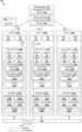
- FIG. 1is a schematic diagram illustrating example software-defined networking (SDN) environment 100 in which network diagnosis may be performed.
- SDN environment 100may include additional and/or alternative components than that shown in FIG. 1 .
- SDN environment 100includes multiple hosts, such as host-A 110 A, host-B 110 B and host-C 110 C that are inter-connected via physical network 104 .
- SDN environment 100may include any number of hosts (also known as a “host computers”, “host devices”, “physical servers”, “server systems”, “transport nodes,” etc.), where each host may be supporting tens or hundreds of VMs.
- Each host 110 A/ 110 B/ 110 Cmay include suitable hardware 112 A/ 112 B/ 112 C and virtualization software (e.g., hypervisor-A 114 A, hypervisor-B 114 B, hypervisor-C 114 C) to support various virtual machines (VMs) 131 - 136 .
- VMsvirtual machines
- host-A 110 Asupports VM1 131 and VM2 132
- host-B 110 Bsupports VM3 133 and VM4 134
- host-C 110 Csupports VM5 135 VM6 136 .
- Hypervisor 114 A/ 114 B/ 114 Cmaintains a mapping between underlying hardware 112 A/ 112 B/ 112 C and virtual resources allocated to respective VMs 131 - 136 .
- Hardware 112 A/ 112 B/ 112 Cincludes suitable physical components, such as central processing unit(s) (CPU(s)) or processor(s) 120 A/ 120 B/ 120 C; memory 122 A/ 122 B/ 122 C; physical network interface controllers (NICs) 124 A/ 124 B/ 124 C; and storage disk(s) 126 A/ 126 B/ 126 C, etc.
- CPUcentral processing unit
- processorprocessor
- NICsphysical network interface controllers
- storage disk(s) 126 A/ 126 B/ 126 Cetc.
- Virtual resourcesare allocated to respective VMs 131 - 136 to support a guest operating system (OS) and application(s).
- the virtual resourcesmay include virtual CPU, guest physical memory, virtual disk, virtual network interface controller (VNIC), etc.
- Hardware resourcesmay be emulated using virtual machine monitors (VMMs).
- VMMsvirtual machine monitors
- FIG. 1VNICs 141 - 146 are emulated by corresponding VMMs (not shown for simplicity).
- the VMMsmay be considered as part of respective VMs 131 - 136 , or alternatively, separated from VMs 131 - 136 .
- one VMmay be associated with multiple VNICs (each VNIC having its own network address).
- a virtualized computing instancemay represent an addressable data compute node (DCN) or isolated user space instance.
- DCNaddressable data compute node
- Any suitable technologymay be used to provide isolated user space instances, not just hardware virtualization.
- Other virtualized computing instancesmay include containers (e.g., running within a VM or on top of a host operating system without the need for a hypervisor or separate operating system or implemented as an operating system level virtualization), virtual private servers, client computers, etc. Such container technology is available from, among others, Docker, Inc.
- the VMsmay also be complete computational environments, containing virtual equivalents of the hardware and software components of a physical computing system.
- hypervisormay refer generally to a software layer or component that supports the execution of multiple virtualized computing instances, including system-level software in guest VMs that supports namespace containers such as Docker, etc.
- Hypervisors 114 A-Cmay each implement any suitable virtualization technology, such as VMware ESX® or ESXiTM (available from VMware, Inc.), Kernel-based Virtual Machine (KVM), etc.
- packetmay refer generally to a group of bits that can be transported together, and may be in another form, such as “frame,” “message,” “segment,” etc.
- trafficmay refer generally to multiple packets.
- layer-2may refer generally to a link layer or Media Access Control (MAC) layer; “layer-3” to a network or Internet Protocol (IP) layer; and “layer-4” to a transport layer (e.g., using Transmission Control Protocol (TCP), User Datagram Protocol (UDP), etc.), in the Open System Interconnection (OSI) model, although the concepts described herein may be used with other networking models.
- MACMedia Access Control
- IPInternet Protocol
- layer-4to a transport layer (e.g., using Transmission Control Protocol (TCP), User Datagram Protocol (UDP), etc.), in the Open System Interconnection (OSI) model, although the concepts described herein may be used with other networking models.
- OSIOpen System Interconnection
- Hypervisor 114 A/ 114 B/ 114 Cimplements virtual switch 115 A/ 115 B/ 115 C and logical distributed router (DR) instance 117 A/ 117 B/ 117 C to handle egress packets from, and ingress packets to, corresponding VMs 131 - 136 .
- logical switches and logical DRsmay be implemented in a distributed manner and can span multiple hosts to connect VMs 131 - 136 .
- logical switches that provide logical layer-2 connectivitymay be implemented collectively by virtual switches 115 A-C and represented internally using forwarding tables 116 A-C at respective virtual switches 115 A-C.
- Forwarding tables 116 A-Cmay each include entries that collectively implement the respective logical switches.
- logical DRs that provide logical layer-3 connectivitymay be implemented collectively by DR instances 117 A-C and represented internally using routing tables 118 A-C at respective DR instances 117 A-C.
- Routing tables 118 A-Cmay each include entries that collectively implement the respective logical DRs.
- Packetsmay be received from, or sent to, each VM via an associated logical switch port.
- logical switch ports 151 - 156(labelled “LSP1” to “LSP6”) are associated with respective VMs 131 - 136 .
- the term “logical port” or “logical switch port”may refer generally to a port on a logical switch to which a virtualized computing instance is connected.
- a “logical switch”may refer generally to a software-defined networking (SDN) construct that is collectively implemented by virtual switches 115 A-C in the example in FIG. 1
- a “virtual switch”may refer generally to a software switch or software implementation of a physical switch.
- mappingthere is usually a one-to-one mapping between a logical port on a logical switch and a virtual port on virtual switch 115 A/ 115 B/ 115 C.
- the mappingmay change in some scenarios, such as when the logical port is mapped to a different virtual port on a different virtual switch after migration of the corresponding VM (e.g., when the source host and destination host do not have a distributed virtual switch spanning them).
- SDN manager 170 and SDN controller 160are example network management entities in SDN environment 100 .
- each host 110 A/ 110 B/ 110 Cmay implement local control plane (LCP) agent (not shown) to interact with SDN controller 160 .
- LCPlocal control plane
- control-plane channel 101 / 102 / 103may be established between SDN controller 160 and host 110 A/ 110 B/ 110 C using TCP over Secure Sockets Layer (SSL), etc.
- Management entity 160 / 170may be implemented using physical machine(s), virtual machine(s), a combination thereof, etc.
- Each host 110 A/ 110 B/ 110 Calso maintains data-plane connectivity with other host(s) via physical network 104 .
- VTEPvirtual tunnel endpoint
- Encapsulated packetsmay be sent via a logical overlay tunnel established between a pair of VTEPs over physical network 104 .
- logical overlay networksmay be provisioned, changed, stored, deleted and restored programmatically without having to reconfigure the underlying physical hardware architecture.
- a logical overlay network(also known as “logical network”) may be formed using any suitable tunneling protocol, such as Generic Network Virtualization Encapsulation (GENEVE), Virtual eXtensible Local Area Network (VXLAN), Stateless Transport Tunneling (STT), etc.
- GENEVEGeneric Network Virtualization Encapsulation
- VXLANVirtual eXtensible Local Area Network
- STTStateless Transport Tunneling
- tunnel encapsulationmay be implemented according to a tunneling protocol to extend layer-2 segments across multiple hosts.
- the term “logical overlay tunnel”may refer generally to a tunnel established between a pair of VTEPs over physical network 104 , over which respective hosts are in layer-3 connectivity with one another.
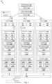
- FIG. 2is a schematic diagram illustrating example management plane view 200 of SDN environment 100 in FIG. 1 .
- IaaSinfrastructure-as-a-service
- multiple logical overlay networksmay be deployed to support multiple tenants in SDN environment 100 .
- each logical overlay networkmay be designed to be an abstract representation of a tenant's network in SDN environment 100 .
- a logical DRconnects logical switches 201 - 202 to facilitate communication among VMs 131 - 136 on different segments. See also logical switch ports “LSP7” 203 and “LSP8” 204 , and logical router ports “LRP1” 207 and “LRP2” 208 connecting DR 205 with logical switches 201 - 202 .
- Logical switch 201 / 202may be implemented collectively by multiple transport nodes, such as using virtual switches 115 A-C and represented internally using forwarding tables 116 A-C.
- DR 205may be implemented collectively by multiple transport nodes, such as using edge node 206 and hosts 110 A-C. For example, DR 205 may be implemented using DR instances 117 A-C and represented internally using routing tables 118 A-C at respective hosts 110 A-C.
- Edge node 206may implement one or more logical DRs and logical service routers (SRs), such as DR 205 and SR 209 in FIG. 2 .
- SR 209may represent a centralized routing component that provides centralized stateful services to VMs 131 - 136 , such as IP address assignment using dynamic host configuration protocol (DHCP), load balancing, network address translation (NAT), etc.
- EDGE1 206may be implemented using VM(s) and/or physical machines (also known as “bare metal machines”), and capable of performing functionalities of a switch, router (e.g., logical service router), bridge, gateway, edge appliance, or any combination thereof.
- EDGE1 206may be deployed at the edge of a geographical site to facilitate north-south traffic to an external network, such as another data center at a different geographical site.
- a multi-tier topologymay be used to isolate multiple tenants.
- a two-tier topologyincludes an upper tier associated with a provider logical router (PLR) and a lower tier associated with a tenant logical router (TLR).
- PLRprovider logical router
- TLRtenant logical router
- Each tiermay include both DRs and SRs, or DRs and SRs on the upper tier (known as “tier-0”) but only DRs at the lower tier (known “tier-1”).
- a logical routermay be categorized as one of the following types: TLR-DR, TLR-SR, PLR-DR and PLR-SR.
- DR 205 and SR 209may be connected via a transit logical switch (not shown in FIG. 2 for simplicity).
- network troubleshootingis to use network tools or utilities such as ping, traceroute, traceflow, etc.
- network toolsnecessitate the injection of diagnostic packets into physical network 104 , which generally lacks efficiency.
- network troubleshooting and debuggingmay become increasingly time- and resource-intensive. Any inefficiency relating to network diagnosis and troubleshooting may in turn increase system downtime due to undiagnosed network issues.
- network diagnosismay be performed in an improved manner using actual network traffic as a “source of truth” during runtime.
- a “packetsourcing” approachmay be implemented to encode and report information about network issues experienced by packets.
- network diagnostic code informationmay be added to packets to specify whether network issues are detected or not detected along their datapath. This way, network issues may be identified and reported with higher efficiency and accuracy for troubleshooting purposes. Examples of the present disclosure should be contrasted against the conventional approach of intentionally injecting diagnostic packets into the network.
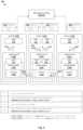
- FIG. 3is a flowchart of example process 300 for a computer system to perform network diagnosis in SDN environment 100 .
- Example process 300may include one or more operations, functions, or actions illustrated by one or more blocks, such as 310 to 350 . The various blocks may be combined into fewer blocks, divided into additional blocks, and/or eliminated depending on the desired implementation.
- example process 300may be implemented by any suitable “computer system,” such as physical host 110 A/ 110 B/ 110 C (e.g., using hypervisor 114 A/ 114 B/ 114 C) supporting logical forwarding element(s), etc.
- logical forwarding elementmay refer generally to a logical entity that is supported by a computer system and located on a datapath between a pair of virtualized computing instances, such as a logical switch port, logical switch, logical router port, logical DR, logical SR, edge node, VNIC, etc.
- a “next hop”in a logical overlay network
- the second computer systeme.g., host-B 110 B
- a logical forwarding elementsupported by the second computer system
- host-A 110 Amay determine whether each of multiple network issues is detected or not detected for the egress packet or a datapath between VM1 131 and VM3 133 .
- network issuemay refer generally to a detectable event, incident or phenomenon associated with packet(s) and/or a datapath being travelled by the packet(s).
- Example network issuesmay include network address conflict, reachability issue, congestion issue, latency issue, jitter issue, throughput issue, network parameter configuration issue (e.g., maximum transmission unit (MTU) issue), network security issue, any combination thereof, etc.
- MTUmaximum transmission unit
- LS1 201may be collectively implemented using virtual switches 115 A-C spanning respective hosts 110 A-C.
- DR 205may be collectively implemented using DR instances 115 A-C spanning respective hosts 110 A-C, and EDGE1 206 .
- host-A 110 Amay generate network diagnosis code information to indicate whether each of the multiple network issues is detected or not detected.
- the term “network diagnosis code information”may refer generally to any suitable information that is configurable to specifying result(s) of a network diagnosis, particularly to indicate the detection, or no detection, of a set of network issues.
- the network diagnosis code informationmay be in any suitable format or length, such as a set of numbers, bits, letters, symbols, etc. As will be explained using FIGS. 4 , 5 and 6 , the network diagnosis code information may be an N-bit bitmap, where N denotes the number of network issues, and the i th bit (code_i) indicates the detection or no detection of the i th network issue.
- host-A 110 Amay generate an encapsulated packet (see 181 in FIG. 1 ) by encapsulating the egress packet (see 180 in FIG. 1 ) with an outer header that specifies the network diagnosis code information.
- the encapsulated packetmay be generated according to a tunneling protocol (e.g., GENEVE) associated with a tunnel connecting VTEP-A 119 A on host-A 110 A and VTEP-B 119 B on host-B 110 B.
- GENEVEtunneling protocol
- host-B 110 Bin response to receiving an encapsulated packet that includes the network diagnosis code information (see 181 ), host-B 110 B may perform a remediation action, such as by generating and sending a report (see 182 ) to management entity 160 / 170 .
- reports regarding the network issuesmay be propagated to management entity 160 / 170 to assist with automatic and/or manual troubleshooting.
- management entity 160 / 170may analyze these reports periodically from packets entering and leaving a node to reduce the likelihood of false positives.
- code_iWhen a network issue (issue_i) is not detected anymore, the corresponding network diagnostic code information (code_i) may be reset to indicate no detection.
- the use of encapsulated packets as a source of truthmay also improve the speed and accuracy of identification (and isolation) of network issues in SDN environment 100 .
- FIG. 4is a flowchart of example detailed process 400 for network diagnosis in SDN environment 100 .
- Example process 400may include one or more operations, functions, or actions illustrated at 405 to 483 .
- the various operations, functions or actionsmay be combined into fewer blocks, divided into additional blocks, and/or eliminated depending on the desired implementation.
- FIG. 5is a schematic diagram illustrating example network diagnosis 500 in SDN environment 100 in FIG. 1 .
- hosts 110 A-Cmay communicate via tunnels established among VTEPs 119 A-C according to 405 - 410 in FIG. 4 .
- One example tunneling protocol in FIG. 5is GENEVE, which is used to establish tunnels that act as backplanes among virtual switches 115 A-C residing in respective hypervisors 114 A-C.
- GENEVEGENEVE
- a first tunnelmay be established between VTEP-A 119 A on host-A 110 A and VTEP-B 119 B on host-B 110 B to facilitate communication between VM1 131 and VM3 133 .
- a second tunnelmay be established between VTEP-A 119 A and VTEP-C 119 C on host-C 110 C to facilitate communication between VM2 132 and VM6 136 .
- the tunnelsmay be established using any suitable transport protocol, such as UDP, etc.
- encapsulated packets transported via the tunnelsmay be encoded with network diagnosis code information to facilitate network troubleshooting.
- host-A 110 Ae.g., virtual switch 115 A
- the set of N network issuesmay be configured by management entity 160 / 170 , such as based on input from a network administrator.
- issue_0may represent a network address conflict, such as an IPv4 or IPv6 address conflict, etc.
- issue_1may represent a network congestion or slowness issue.
- issue_2may represent a reachability issue, which may be detected when routing tables are incorrectly configured. In this case, the number of hops via which packets are forwarded may be tracked, and the exact logical forwarding element that detects the reachability issue may encode the reachability issue in the outer header.
- issue_3may represent a latency issue.
- Any additional and/or alternative network issuesmay be considered, such as jitter issue, throughput issue, network parameter configuration issue (e.g., MTU configuration), network security issue, any combination thereof.
- Any suitable approachmay be implemented to perform network diagnosis at block 420 , such as by monitoring a performance metric and comparing the performance metric against a predetermined threshold. The detection of issue_i occurs when the threshold is not satisfied, but otherwise there is no detection.
- Network congestionmay be detected using any suitable approach, such as by tracking a quality of service measure associated with the datapath for comparison with an acceptable threshold.
- Any suitable logical forwarding element(s) supported by host-A 110 Amay be used to detect network issue(s).
- packet “P1” 510 / 180travels from VM1 131 to VM3 133 along a datapath (see dashed line) that includes the following logical forwarding elements: LSP1 151 , LS1 201 , LSP7 203 , LRP1 207 , DR 205 , LRP2 208 , LSP8 204 , LS2 202 , and LSP4 154 .
- One examplemay involve configuring an instance of LS1 201 (see 210 ) implemented by virtual switch 115 A to perform network diagnosis at block 420 .
- Any alternative and/or additional logical forwarding element(s) along the datapathmay be configured to perform network diagnosis.
- different logical forwarding elementse.g., LS1 201 and DR 205
- host-A 110 Amay generate network diagnosis code information, which is a form of metadata specifying whether particular issue_i is detected or not detected.
- the network diagnosis code informationmay be in any suitable format and length.
- N bytesmay be used to encode N network issues, in which case eight bits are allocated for each code_i.
- host-A 110 Amay enhance code_i to include additional metadata relating to the detection of corresponding issue_i, such as metadata relating to different types of a particular network issue.
- additional metadatarelating to the detection of corresponding issue_i, such as metadata relating to different types of a particular network issue.
- host-A 110 Amay insert DIAG_CODE1 into any suitable field in the outer header, such as GENEVE option data field in a GENEVE header.
- Any suitable approach for outer header insertionmay be used, such as using a context engine and kernel module(s). Examples of the context engine and kernel module(s) are described in related U.S.
- datapathsmay be configured with a mechanism (e.g., application programming interface) that allows a kernel module supported by host-A 110 A to insert DIAG_CODE into the outer header.
- the kernel modulemay register for an input/output (I/O) callback to get notified about egress packets (e.g., “P1” 510 ) and perform GENEVE header insertion accordingly.
- I/Oinput/output
- host-A 110 Amay generate send the encapsulated packet towards destination VM3 133 over a tunnel connecting VTEP-A 119 A and VTEP-B 119 B.
- Example remediation actionsinclude generating and sending a report to the management plane (see 481 ), updating a routing configuration (e.g., select a less congested route on the return path; see 482 ), updating network parameter (e.g., adjusting an MTU size; see 483 ), requesting host-A 110 A to perform updates, any combination thereof, etc.
- a routing configuratione.g., select a less congested route on the return path; see 482
- updating network parametere.g., adjusting an MTU size; see 483
- a logical forwarding elementdetects a potential network issue (issue_i)
- the network diagnosis code information (code_i) for that particular issuemay be configured to indicate the detection accordingly.
- a next hop along the datapathmay perform a remediation action, such as by raising an alarm to notify the management plane about the potential network issue in the logical overlay network.
- Thisallows management entity 160 / 170 to act in a proactive manner to troubleshoot network issues in SDN environment 100 .
- the risk of false positivesmay also be reduced, if not eliminated.
- management entity 160 / 170may decide how to best use the reports from various hosts 110 A-B, such as by making use of the underlying context of each network issue or simply use the counts of the issues to reduce or eliminate false positives.
- FIG. 2A logical view of the datapath between VM6 136 and VM2 132 is shown in FIG. 2 .
- a congestion issue(issue_1) is detected by an instance of LS2 202 that is implemented by virtual switch 115 C on host-C 110 C (see 220 in FIG. 2 ).
- Any alternative and/or additional logical forwarding element(s)may be configured to perform network diagnosis, such as LSP6 156 , LSP2 152 , any combination thereof, etc.
- Host-C 110 Cmay then send the encapsulated packet (see 560 ) to host-A 110 A, and send a report (see 580 ) to management entity 160 / 170 . See corresponding 415 - 450 in FIG. 4 .
- a decapsulated packet(see 570 ) is sent to destination VM2 132 .
- remediation action(s)may be performed.
- host-A 110 Amay report (see 581 ) the congestion issue to management entity 160 / 170 to facilitate automatic troubleshooting to resolve the issue and/or manual process by a network administrator.
- host-A 110 Amay update a routing configuration by sending a request to source host-C 110 C to slow down its egress packet rate, select a different route, etc. See corresponding 455 - 480 in FIG. 4 .
- FIG. 6is a schematic diagram illustrating example cross-cloud network diagnosis 600 in an SDN environment.
- SDN environment 600spans across multiple geographical sites, such as a first geographical site where private cloud environment 601 (“first cloud environment”) is located, a second geographical site where public cloud environment 602 (“second cloud environment”) is located, etc.
- first cloud environmentmay refer generally to an on-premise data center or cloud platform supported by infrastructure that is under an organization's private ownership and control.
- public cloud environmentmay refer generally a cloud platform supported by infrastructure that is under the ownership and control of a public cloud provider.
- a public cloud provideris generally an entity that offers a cloud-based platform to multiple users or tenants. This way, a user may take advantage of the scalability and flexibility provided by public cloud environment 602 for data center capacity extension, disaster recovery, etc.
- public cloud environment 602may be implemented using any suitable cloud technology, such as Amazon Web Services® (AWS) and Amazon Virtual Private Clouds (VPCs); VMware CloudTM on AWS; Microsoft Azure®; Google Cloud PlatformTM, IBM CloudTM; a combination thereof, etc.
- Amazon VPC and Amazon AWSare registered trademarks of Amazon Technologies, Inc.
- public cloud environment 602will be exemplified using VMware CloudTM on AWS. It should be understood that any additional and/or additional cloud technology may be implemented.
- EDGE1 610is deployed at the edge of private cloud environment 601 to handle traffic to and from public cloud environment 602 .
- EDGE1 610is connected with public cloud environment 602 via EDGE2 640 (e.g., virtual gateway) that is connected with tier-1 management gateway 651 (labelled “T1-MGW”) and tier-1 compute gateway 653 (labelled “T1-CGW”) via tier-0 gateway 650 (labelled “T0-GW”).
- T0-GW 650 , MGW 651 and CGW 653may be logical constructs that are implemented by an edge appliance in public cloud environment 602 .
- T1-MGW 651may be deployed to handle management-related traffic to and/or from management component(s) 652 (labelled “MC”) for managing various entities within public cloud environment 602 .
- T1-CGW 653may be deployed to handle workload-related traffic to and/or from VMs, such as VM7 631 and VM8 632 .
- EDGE1 610 in private cloud environment 601may communicate with EDGE2 640 in public cloud environment 602 using any suitable tunnel(s) 603 , such as GRE, Internet Protocol Security (IPSec), layer-2 virtual private network (L2VPN), direct connection, etc. This way, VM1 131 in private cloud environment 601 may send packets to VM7 631 in public cloud environment 602 via tunnel 603 .
- IPSecInternet Protocol Security
- L2VPNlayer-2 virtual private network
- cross-cloud network diagnosismay be implemented using EDGE1 610 acting as a “first computer system” and EDGE2 640 as a “second computer system” in the example in FIG. 4 .
- EDGE1 610may generate and send encapsulated packet 670 to EDGE2 640 over tunnel 603 .
- the network diagnosis code informationmay be inserted into a GRE (or VPN) header.
- examples of the present disclosuremay be implemented to identify network health parameters and potential bottlenecks in in a proactive manner. This facilitates better routing decisions and reduces the likelihood of traffic loss and network outages.
- SDN environment 100may include other virtual workloads, such as containers, etc.
- containeralso known as “container instance”
- container technologiesmay be used to run various containers inside respective VMs.
- Containersare “OS-less”, meaning that they do not include any OS that could weigh 10 s of Gigabytes (GB). This makes containers more lightweight, portable, efficient and suitable for delivery into an isolated OS environment.
- Running containers inside a VM(known as “containers-on-virtual-machine” approach) not only leverages the benefits of container technologies but also that of virtualization technologies.
- the containersmay be executed as isolated processes inside respective VMs.
- the above examplescan be implemented by hardware (including hardware logic circuitry), software or firmware or a combination thereof.
- the above examplesmay be implemented by any suitable computing device, computer system, etc.
- the computer systemmay include processor(s), memory unit(s) and physical NIC(s) that may communicate with each other via a communication bus, etc.
- the computer systemmay include a non-transitory computer-readable medium having stored thereon instructions or program code that, when executed by the processor, cause the processor to perform process(es) described herein with reference to FIG. 1 to FIG. 6 .
- the instructions or program codewhen executed by the processor of the computer system, may cause the processor to perform network troubleshooting according to examples of the present disclosure.
- Special-purpose hardwired circuitrymay be in the form of, for example, one or more application-specific integrated circuits (ASICs), programmable logic devices (PLDs), field-programmable gate arrays (FPGAs), and others.
- ASICsapplication-specific integrated circuits
- PLDsprogrammable logic devices
- FPGAsfield-programmable gate arrays
- processoris to be interpreted broadly to include a processing unit, ASIC, logic unit, or programmable gate array etc.
- a computer-readable storage mediummay include recordable/non recordable media (e.g., read-only memory (ROM), random access memory (RAM), magnetic disk or optical storage media, flash memory devices, etc.).
Landscapes
- Engineering & Computer Science (AREA)
- Computer Networks & Wireless Communication (AREA)
- Signal Processing (AREA)
- Computer Security & Cryptography (AREA)
- Mathematical Analysis (AREA)
- General Physics & Mathematics (AREA)
- Algebra (AREA)
- Mathematical Optimization (AREA)
- Mathematical Physics (AREA)
- Probability & Statistics with Applications (AREA)
- Pure & Applied Mathematics (AREA)
- Physics & Mathematics (AREA)
- Data Exchanges In Wide-Area Networks (AREA)
Abstract
Description
Claims (21)
Priority Applications (1)
| Application Number | Priority Date | Filing Date | Title |
|---|---|---|---|
| US16/714,805US11641305B2 (en) | 2019-12-16 | 2019-12-16 | Network diagnosis in software-defined networking (SDN) environments |
Applications Claiming Priority (1)
| Application Number | Priority Date | Filing Date | Title |
|---|---|---|---|
| US16/714,805US11641305B2 (en) | 2019-12-16 | 2019-12-16 | Network diagnosis in software-defined networking (SDN) environments |
Publications (2)
| Publication Number | Publication Date |
|---|---|
| US20210184914A1 US20210184914A1 (en) | 2021-06-17 |
| US11641305B2true US11641305B2 (en) | 2023-05-02 |
Family
ID=76318426
Family Applications (1)
| Application Number | Title | Priority Date | Filing Date |
|---|---|---|---|
| US16/714,805ActiveUS11641305B2 (en) | 2019-12-16 | 2019-12-16 | Network diagnosis in software-defined networking (SDN) environments |
Country Status (1)
| Country | Link |
|---|---|
| US (1) | US11641305B2 (en) |
Cited By (1)
| Publication number | Priority date | Publication date | Assignee | Title |
|---|---|---|---|---|
| US11848833B1 (en)* | 2022-10-31 | 2023-12-19 | Vmware, Inc. | System and method for operational intelligence based on network traffic |
Families Citing this family (4)
| Publication number | Priority date | Publication date | Assignee | Title |
|---|---|---|---|---|
| US12238076B2 (en)* | 2018-10-02 | 2025-02-25 | Arista Networks, Inc. | In-line encryption of network data |
| WO2022168155A1 (en)* | 2021-02-02 | 2022-08-11 | 日本電信電話株式会社 | Traffic engineering device, traffic engineering method, and traffic engineering program |
| US12039471B2 (en) | 2021-11-29 | 2024-07-16 | T-Mobile Usa, Inc. | Tracking issues and resolution of same in a wireless communication network |
| US11962455B2 (en) | 2021-11-29 | 2024-04-16 | T-Mobile Usa, Inc. | Prioritizing multiple issues associated with a wireless telecommunication network |
Citations (125)
| Publication number | Priority date | Publication date | Assignee | Title |
|---|---|---|---|---|
| US5504921A (en) | 1990-09-17 | 1996-04-02 | Cabletron Systems, Inc. | Network management system using model-based intelligence |
| US5528516A (en)* | 1994-05-25 | 1996-06-18 | System Management Arts, Inc. | Apparatus and method for event correlation and problem reporting |
| US5550816A (en) | 1994-12-29 | 1996-08-27 | Storage Technology Corporation | Method and apparatus for virtual switching |
| US5729685A (en) | 1993-06-29 | 1998-03-17 | Bay Networks, Inc. | Apparatus for determining the topology of an ATM network or the like Via communication of topology information between a central manager and switches in the network over a virtual service path |
| US5751967A (en) | 1994-07-25 | 1998-05-12 | Bay Networks Group, Inc. | Method and apparatus for automatically configuring a network device to support a virtual network |
| US5796936A (en) | 1993-03-01 | 1998-08-18 | Hitachi, Ltd. | Distributed control system in which individual controllers executed by sharing loads |
| US5825779A (en) | 1996-10-07 | 1998-10-20 | Timeplex, Inc. | PBX networking with quality of service control |
| US6104699A (en) | 1994-06-13 | 2000-08-15 | Telefonaktiebolget Lm Ericsson | Method and device for partitioning physical network resources |
| US6219699B1 (en) | 1996-01-02 | 2001-04-17 | Cisco Technologies, Inc. | Multiple VLAN Architecture system |
| US20030006919A1 (en) | 2001-07-09 | 2003-01-09 | Roger Collins | System and method for compressing data on a bandwidth-limited network |
| US6512745B1 (en) | 1996-03-08 | 2003-01-28 | Hitachi, Ltd. | Packet switching network, packet switching equipment, and network management equipment |
| US6539432B1 (en) | 1998-05-19 | 2003-03-25 | Hitachi, Ltd. | Network manager, nodes and network management system |
| US20030093481A1 (en) | 2001-11-09 | 2003-05-15 | Julian Mitchell | Middlebox control |
| US6680934B1 (en) | 1999-12-02 | 2004-01-20 | Nortel Networks Limited | System, device and method for expediting control flow in a communication system |
| US20040047286A1 (en) | 2002-09-05 | 2004-03-11 | Larsen Loren D. | Network switch assembly, network switching device, and method |
| US20040073659A1 (en) | 2002-10-15 | 2004-04-15 | Carl Rajsic | Method and apparatus for managing nodes in a network |
| US20040098505A1 (en) | 2002-11-20 | 2004-05-20 | Clemmensen Daniel G. | Forwarding system with multiple logical sub-system functionality |
| US6785843B1 (en) | 2001-02-23 | 2004-08-31 | Mcrae Andrew | Data plane restart without state change in a control plane of an intermediate network node |
| US20040267897A1 (en) | 2003-06-24 | 2004-12-30 | Sychron Inc. | Distributed System Providing Scalable Methodology for Real-Time Control of Server Pools and Data Centers |
| US6842768B1 (en) | 2000-03-01 | 2005-01-11 | Siemens Communications, Inc. | Apparatus and method for selectable compression |
| US20050018669A1 (en) | 2003-07-25 | 2005-01-27 | International Business Machines Corporation | Infiniband subnet management queue pair emulation for multiple logical ports on a single physical port |
| US20050038834A1 (en) | 2003-08-14 | 2005-02-17 | Oracle International Corporation | Hierarchical management of the dynamic allocation of resources in a multi-node system |
| US20050083953A1 (en) | 2003-10-17 | 2005-04-21 | Ip Infusion Inc., A Delaware Corporation | System and method for providing redundant routing capabilities for a network node |
| US20050120160A1 (en) | 2003-08-20 | 2005-06-02 | Jerry Plouffe | System and method for managing virtual servers |
| US6941487B1 (en) | 2002-03-07 | 2005-09-06 | Riverstone Networks, Inc. | Method, system, and computer program product for providing failure protection in a network node |
| US6963585B1 (en) | 1999-10-21 | 2005-11-08 | International Business Machines Corporation | Method and system for establishing a virtual path capability in a frame relay network |
| US20060002370A1 (en) | 2004-07-02 | 2006-01-05 | Nortel Networks Limited | VLAN support of differentiated services |
| US20060026225A1 (en) | 2004-08-02 | 2006-02-02 | Alcatel | Shared resources in a multi manager environment |
| US20060092976A1 (en) | 2004-11-01 | 2006-05-04 | Lucent Technologies Inc. | Softrouter separate control network |
| US20060092940A1 (en) | 2004-11-01 | 2006-05-04 | Ansari Furquan A | Softrouter protocol disaggregation |
| US7079544B2 (en) | 2000-06-02 | 2006-07-18 | Hitachi, Ltd. | Apparatus and method for interworking between MPLS network and non-MPLS network |
| US20060174087A1 (en) | 2005-01-28 | 2006-08-03 | Hitachi, Ltd. | Computer system, computer, storage system, and control terminal |
| US20060184937A1 (en) | 2005-02-11 | 2006-08-17 | Timothy Abels | System and method for centralized software management in virtual machines |
| US7096228B2 (en) | 2002-03-27 | 2006-08-22 | Microsoft Corporation | Method and system for managing data records on a computer network |
| US20060193266A1 (en) | 2005-02-25 | 2006-08-31 | Ip Infusion, Inc. A Delaware Corporation | Hardware abstraction layer |
| US20070043860A1 (en) | 2005-08-15 | 2007-02-22 | Vipul Pabari | Virtual systems management |
| US7197572B2 (en) | 2002-05-06 | 2007-03-27 | Qlogic, Corporation | System and method for implementing logical switches in a network system |
| US7200144B2 (en) | 2001-10-18 | 2007-04-03 | Qlogic, Corp. | Router and methods using network addresses for virtualization |
| US7209439B2 (en) | 2001-03-20 | 2007-04-24 | Mci, Llc | Pool-based resource management in a data network |
| US20070156919A1 (en) | 2005-06-21 | 2007-07-05 | Sunil Potti | Enforcing network service level agreements in a network element |
| US20070220059A1 (en) | 2006-03-20 | 2007-09-20 | Manyi Lu | Data processing node |
| US20070220358A1 (en) | 2006-03-17 | 2007-09-20 | Eric Goodill | Customer traffic forwarding continues while control plane is reset |
| US7286490B2 (en) | 2000-12-30 | 2007-10-23 | Cisco Technology, Inc. | Method for routing information over a network employing centralized control |
| US20070260721A1 (en) | 2006-05-02 | 2007-11-08 | Patrick Glen Bose | Physical server discovery and correlation |
| US20070283348A1 (en) | 2006-05-15 | 2007-12-06 | White Anthony R P | Method and system for virtual machine migration |
| US20070297428A1 (en) | 2006-06-26 | 2007-12-27 | Patrick Glen Bose | Port pooling |
| US20080002579A1 (en) | 2004-12-21 | 2008-01-03 | Fredrik Lindholm | Arrangement and a Method Relating to Flow of Packets in Communication Systems |
| US20080040467A1 (en) | 2006-08-09 | 2008-02-14 | Cisco Technology, Inc. | Method and system for dynamic loading of management information bases on network devices |
| US20080049621A1 (en) | 2004-12-31 | 2008-02-28 | Mcguire Alan | Connection-Oriented Communications Scheme For Connection-Less Communications Traffic |
| US20080059556A1 (en) | 2006-08-31 | 2008-03-06 | Egenera, Inc. | Providing virtual machine technology as an embedded layer within a processing platform |
| US20080071900A1 (en) | 2005-03-16 | 2008-03-20 | Wavestorm | Device and a method for communicating in a network |
| US20080080559A1 (en) | 2006-10-02 | 2008-04-03 | Motorola, Inc. | Link Layer Assisted Robust Header Compression Context Update Management |
| US7359971B2 (en) | 1998-07-10 | 2008-04-15 | Van Drebbel Mariner Llc | Use of priority-based scheduling for the optimization of latency and jitter sensitive IP flows in a wireless point to multi-point transmission system |
| US20080159301A1 (en) | 2006-12-29 | 2008-07-03 | De Heer Arjan Arie | Enabling virtual private local area network services |
| US20080165704A1 (en) | 2007-01-09 | 2008-07-10 | Michael Frank Marchetti | Automatically maximizing network link utilization using virtual networks |
| US7450598B2 (en) | 2003-12-15 | 2008-11-11 | At&T Intellectual Property I, L.P. | System and method to provision MPLS/VPN network |
| US7483370B1 (en) | 2003-12-22 | 2009-01-27 | Extreme Networks, Inc. | Methods and systems for hitless switch management module failover and upgrade |
| US7606260B2 (en) | 2003-03-31 | 2009-10-20 | Fujitsu Limited | Virtual path configuration apparatus, virtual path configuration method, and computer product |
| US20090296726A1 (en) | 2008-06-03 | 2009-12-03 | Brocade Communications Systems, Inc. | ACCESS CONTROL LIST MANAGEMENT IN AN FCoE ENVIRONMENT |
| US7649851B2 (en) | 2005-11-11 | 2010-01-19 | Hitachi, Ltd. | Virtual network management method, virtual network management program, virtual network management system, and virtual network means |
| US20100039296A1 (en) | 2006-06-02 | 2010-02-18 | James Marggraff | System and method for recalling media |
| US7710874B2 (en) | 2003-06-04 | 2010-05-04 | International Business Machines Corporation | System and method for automatic management of many computer data processing system pipes |
| US20100125667A1 (en) | 2008-11-19 | 2010-05-20 | Vmware, Inc. | Dynamic configuration of virtual machines |
| US7730486B2 (en) | 2005-02-28 | 2010-06-01 | Hewlett-Packard Development Company, L.P. | System and method for migrating virtual machines on cluster systems |
| US20100169441A1 (en) | 2006-08-21 | 2010-07-01 | Philippe Jonathan Gabriel Lafleur | Text messaging system and method employing predictive text entry and text compression and apparatus for use therein |
| US20100177789A1 (en) | 2009-01-13 | 2010-07-15 | Fujitsu Limited | Device and Method for Reducing Overhead in a Wireless Network |
| US7792987B1 (en) | 2003-04-21 | 2010-09-07 | Juniper Networks, Inc. | Supporting virtual private networks using a first network topology for forwarding and a subset of the first network topology or a smaller topology for signaling |
| US7818452B2 (en) | 2000-09-13 | 2010-10-19 | Fortinet, Inc. | Distributed virtual system to support managed, network-based services |
| US7826482B1 (en) | 2006-11-17 | 2010-11-02 | Juniper Networks, Inc. | Service-specific forwarding in an LDP-RSVP hybrid network |
| US7885276B1 (en) | 2008-09-30 | 2011-02-08 | Emc Corporation | Isolating network traffic in multi-tenant virtualization environments |
| US7937438B1 (en) | 2009-12-07 | 2011-05-03 | Amazon Technologies, Inc. | Using virtual networking devices to manage external connections |
| US20110103259A1 (en) | 2009-11-04 | 2011-05-05 | Gunes Aybay | Methods and apparatus for configuring a virtual network switch |
| US7948986B1 (en) | 2009-02-02 | 2011-05-24 | Juniper Networks, Inc. | Applying services within MPLS networks |
| US8027354B1 (en) | 2009-04-29 | 2011-09-27 | Cisco Technology, Inc. | Network consolidation for virtualized servers |
| US8055789B2 (en) | 2007-03-27 | 2011-11-08 | Amazon Technologies, Inc. | Configuring intercommunications between computing nodes |
| US8054832B1 (en) | 2008-12-30 | 2011-11-08 | Juniper Networks, Inc. | Methods and apparatus for routing between virtual resources based on a routing location policy |
| US20110296052A1 (en) | 2010-05-28 | 2011-12-01 | Microsoft Corportation | Virtual Data Center Allocation with Bandwidth Guarantees |
| US20120051216A1 (en)* | 2010-09-01 | 2012-03-01 | Ying Zhang | Localized Congestion Exposure |
| US20120075991A1 (en) | 2009-12-15 | 2012-03-29 | Nec Corporation | Network system, control method thereof and controller |
| US20120120964A1 (en) | 2010-07-06 | 2012-05-17 | Teemu Koponen | Network control apparatus and method for populating logical datapath sets |
| US20120147894A1 (en) | 2010-12-08 | 2012-06-14 | Mulligan John T | Methods and apparatus to provision cloud computing network elements |
| US8223668B2 (en) | 2006-12-14 | 2012-07-17 | Rockstar Bidco Lp | Method and apparatus for exchanging routing information and the establishment of connectivity across multiple network areas |
| US8224931B1 (en) | 2010-03-31 | 2012-07-17 | Amazon Technologies, Inc. | Managing use of intermediate destination computing nodes for provided computer networks |
| US8224971B1 (en) | 2009-12-28 | 2012-07-17 | Amazon Technologies, Inc. | Using virtual networking devices and routing information to initiate external actions |
| US8312129B1 (en) | 2009-12-28 | 2012-11-13 | Amazon Technologies, Inc. | Using virtual networking devices to connect managed computer networks |
| US20130024579A1 (en) | 2011-07-19 | 2013-01-24 | Telefonaktiebolaget L M Ericsson (Publ) | Controller Placement for Split Architecture Networks |
| US20130044752A1 (en) | 2011-08-17 | 2013-02-21 | Teemu Koponen | Flow generation from second level controller to first level controller to managed switching element |
| US20130088997A1 (en)* | 2010-06-17 | 2013-04-11 | British Telecommunications Public Limited Company | Monitoring path characterisation information |
| US20130103817A1 (en) | 2011-10-25 | 2013-04-25 | Teemu Koponen | Chassis controller |
| US8456984B2 (en) | 2010-07-19 | 2013-06-04 | Ciena Corporation | Virtualized shared protection capacity |
| US8504718B2 (en) | 2010-04-28 | 2013-08-06 | Futurewei Technologies, Inc. | System and method for a context layer switch |
| WO2013184846A1 (en) | 2012-06-06 | 2013-12-12 | Juniper Networks, Inc. | Physical path determination for virtual network packet flows |
| US20130332619A1 (en) | 2012-06-06 | 2013-12-12 | Futurewei Technologies, Inc. | Method of Seamless Integration and Independent Evolution of Information-Centric Networking via Software Defined Networking |
| US8621058B2 (en) | 2010-10-28 | 2013-12-31 | Hewlett-Packard Development Company, L.P. | Providing cloud-based computing services |
| US8644188B1 (en) | 2009-06-25 | 2014-02-04 | Amazon Technologies, Inc. | Providing virtual networking functionality for managed computer networks |
| US20140050223A1 (en) | 2012-08-15 | 2014-02-20 | Futurewei Technologies, Inc. | Method and System for Creating Software Defined Ordered Service Patterns in a Communications Network |
| US8705513B2 (en) | 2009-12-15 | 2014-04-22 | At&T Intellectual Property I, L.P. | Methods and apparatus to communicatively couple virtual private networks to virtual machines within distributive computing networks |
| US20140181829A1 (en) | 2012-12-20 | 2014-06-26 | Telefonaktiebolaget L M Ericsson (Publ) | Pseudo-random hardware resource allocation |
| US20140229944A1 (en) | 2013-02-12 | 2014-08-14 | Futurewei Technologies, Inc. | Dynamic Virtual Machines Migration Over Information Centric Networks |
| US20140241247A1 (en) | 2011-08-29 | 2014-08-28 | Telefonaktiebolaget L M Ericsson (Publ) | Implementing a 3g packet core in a cloud computer with openflow data and control planes |
| US20140280836A1 (en) | 2013-03-15 | 2014-09-18 | Cisco Technology, Inc. | Workload based service chain insertion in a network environment |
| US20140351229A1 (en) | 2013-05-22 | 2014-11-27 | Amazon Technologies, Inc. | Efficient data compression and analysis as a service |
| US20140355516A1 (en) | 2013-05-31 | 2014-12-04 | Thales | Methods for transmitting and receiving data between a terminal and a gateway, in particular via a satellite link |
| US20150009995A1 (en) | 2013-07-08 | 2015-01-08 | Nicira, Inc. | Encapsulating Data Packets Using an Adaptive Tunnelling Protocol |
| US20150103645A1 (en) | 2013-10-10 | 2015-04-16 | Vmware, Inc. | Controller side method of generating and updating a controller assignment list |
| US9021098B1 (en) | 2012-06-27 | 2015-04-28 | Juniper Networks, Inc. | Allocation of interface identifiers within network device having multiple forwarding components |
| US20150195202A1 (en)* | 2012-07-31 | 2015-07-09 | Nec Corporation | Mobile terminal, control node, packet transfer node, and method for controlling congestion |
| US20160099853A1 (en) | 2014-10-01 | 2016-04-07 | Cisco Technology, Inc. | Active and passive dataplane performance monitoring of service function chaining |
| US20160105377A1 (en) | 2014-10-14 | 2016-04-14 | Fujitsu Limited | Information processing system, control device and control method |
| US20160330111A1 (en) | 2015-05-06 | 2016-11-10 | Telefonaktiebolaget L M Ericsson (Publ) | Packet marking for l4-7 advanced counting and monitoring |
| US20160330070A1 (en) | 2014-02-04 | 2016-11-10 | Fatpipe, Inc. | Flatnet failover control |
| US20170078207A1 (en) | 2015-09-10 | 2017-03-16 | Lenovo Enterprise Solutions (Singapore) Pte. Ltd. | Network prioritization based on node-level attributes |
| US20170235774A1 (en) | 2016-02-11 | 2017-08-17 | Pure Storage, Inc. | Compressing data in dependence upon characteristics of a storage system |
| US20180006935A1 (en) | 2016-06-30 | 2018-01-04 | Juniper Networks, Inc. | Auto discovery and auto scaling of services in software-defined network environment |
| US20180270288A1 (en)* | 2016-02-29 | 2018-09-20 | Tencent Technology (Shenzhen) Company Limited | Voice encoding and sending method and apparatus |
| US20190028300A1 (en)* | 2017-07-18 | 2019-01-24 | Nicira, Inc. | Maintaining data-plane connectivity between hosts |
| US20190045031A1 (en) | 2018-06-21 | 2019-02-07 | Wajdi Feghali | Low-latency link compression schemes |
| US10225270B2 (en) | 2016-08-02 | 2019-03-05 | Cisco Technology, Inc. | Steering of cloned traffic in a service function chain |
| US10326830B1 (en)* | 2016-09-02 | 2019-06-18 | Amazon Technologies, Inc. | Multipath tunneling to a service offered at several datacenters |
| US20190238263A1 (en)* | 2017-09-26 | 2019-08-01 | Purdue Research Foundation | Transcoding wireless communication system |
| US10374830B1 (en) | 2016-07-17 | 2019-08-06 | Fatpipe, Inc. | WAN-span LAN (WSL) networking technology |
| WO2020009784A1 (en) | 2018-07-05 | 2020-01-09 | Vmware, Inc. | Context aware middlebox services at datacenter edges |
| US20200014638A1 (en) | 2018-07-05 | 2020-01-09 | Vmware, Inc. | Context aware middlebox services at datacenter edge |
| US20200014663A1 (en) | 2018-07-05 | 2020-01-09 | Vmware, Inc. | Context aware middlebox services at datacenter edges |
| US20200177458A1 (en)* | 2018-12-03 | 2020-06-04 | At&T Intellectual Property I, L.P. | Cloud zone network analytics platform |
- 2019
- 2019-12-16USUS16/714,805patent/US11641305B2/enactiveActive
Patent Citations (132)
| Publication number | Priority date | Publication date | Assignee | Title |
|---|---|---|---|---|
| US5504921A (en) | 1990-09-17 | 1996-04-02 | Cabletron Systems, Inc. | Network management system using model-based intelligence |
| US5796936A (en) | 1993-03-01 | 1998-08-18 | Hitachi, Ltd. | Distributed control system in which individual controllers executed by sharing loads |
| US5729685A (en) | 1993-06-29 | 1998-03-17 | Bay Networks, Inc. | Apparatus for determining the topology of an ATM network or the like Via communication of topology information between a central manager and switches in the network over a virtual service path |
| US5528516A (en)* | 1994-05-25 | 1996-06-18 | System Management Arts, Inc. | Apparatus and method for event correlation and problem reporting |
| US6104699A (en) | 1994-06-13 | 2000-08-15 | Telefonaktiebolget Lm Ericsson | Method and device for partitioning physical network resources |
| US5751967A (en) | 1994-07-25 | 1998-05-12 | Bay Networks Group, Inc. | Method and apparatus for automatically configuring a network device to support a virtual network |
| US5550816A (en) | 1994-12-29 | 1996-08-27 | Storage Technology Corporation | Method and apparatus for virtual switching |
| US6219699B1 (en) | 1996-01-02 | 2001-04-17 | Cisco Technologies, Inc. | Multiple VLAN Architecture system |
| US6512745B1 (en) | 1996-03-08 | 2003-01-28 | Hitachi, Ltd. | Packet switching network, packet switching equipment, and network management equipment |
| US5825779A (en) | 1996-10-07 | 1998-10-20 | Timeplex, Inc. | PBX networking with quality of service control |
| US6539432B1 (en) | 1998-05-19 | 2003-03-25 | Hitachi, Ltd. | Network manager, nodes and network management system |
| US7359971B2 (en) | 1998-07-10 | 2008-04-15 | Van Drebbel Mariner Llc | Use of priority-based scheduling for the optimization of latency and jitter sensitive IP flows in a wireless point to multi-point transmission system |
| US6963585B1 (en) | 1999-10-21 | 2005-11-08 | International Business Machines Corporation | Method and system for establishing a virtual path capability in a frame relay network |
| US6680934B1 (en) | 1999-12-02 | 2004-01-20 | Nortel Networks Limited | System, device and method for expediting control flow in a communication system |
| US6842768B1 (en) | 2000-03-01 | 2005-01-11 | Siemens Communications, Inc. | Apparatus and method for selectable compression |
| US7079544B2 (en) | 2000-06-02 | 2006-07-18 | Hitachi, Ltd. | Apparatus and method for interworking between MPLS network and non-MPLS network |
| US7818452B2 (en) | 2000-09-13 | 2010-10-19 | Fortinet, Inc. | Distributed virtual system to support managed, network-based services |
| US7286490B2 (en) | 2000-12-30 | 2007-10-23 | Cisco Technology, Inc. | Method for routing information over a network employing centralized control |
| US6785843B1 (en) | 2001-02-23 | 2004-08-31 | Mcrae Andrew | Data plane restart without state change in a control plane of an intermediate network node |
| US7209439B2 (en) | 2001-03-20 | 2007-04-24 | Mci, Llc | Pool-based resource management in a data network |
| US20030006919A1 (en) | 2001-07-09 | 2003-01-09 | Roger Collins | System and method for compressing data on a bandwidth-limited network |
| US7200144B2 (en) | 2001-10-18 | 2007-04-03 | Qlogic, Corp. | Router and methods using network addresses for virtualization |
| US20030093481A1 (en) | 2001-11-09 | 2003-05-15 | Julian Mitchell | Middlebox control |
| US6941487B1 (en) | 2002-03-07 | 2005-09-06 | Riverstone Networks, Inc. | Method, system, and computer program product for providing failure protection in a network node |
| US7096228B2 (en) | 2002-03-27 | 2006-08-22 | Microsoft Corporation | Method and system for managing data records on a computer network |
| US7197572B2 (en) | 2002-05-06 | 2007-03-27 | Qlogic, Corporation | System and method for implementing logical switches in a network system |
| US20040047286A1 (en) | 2002-09-05 | 2004-03-11 | Larsen Loren D. | Network switch assembly, network switching device, and method |
| US20040073659A1 (en) | 2002-10-15 | 2004-04-15 | Carl Rajsic | Method and apparatus for managing nodes in a network |
| US20040098505A1 (en) | 2002-11-20 | 2004-05-20 | Clemmensen Daniel G. | Forwarding system with multiple logical sub-system functionality |
| US7606260B2 (en) | 2003-03-31 | 2009-10-20 | Fujitsu Limited | Virtual path configuration apparatus, virtual path configuration method, and computer product |
| US7792987B1 (en) | 2003-04-21 | 2010-09-07 | Juniper Networks, Inc. | Supporting virtual private networks using a first network topology for forwarding and a subset of the first network topology or a smaller topology for signaling |
| US7710874B2 (en) | 2003-06-04 | 2010-05-04 | International Business Machines Corporation | System and method for automatic management of many computer data processing system pipes |
| US20040267897A1 (en) | 2003-06-24 | 2004-12-30 | Sychron Inc. | Distributed System Providing Scalable Methodology for Real-Time Control of Server Pools and Data Centers |
| US20050018669A1 (en) | 2003-07-25 | 2005-01-27 | International Business Machines Corporation | Infiniband subnet management queue pair emulation for multiple logical ports on a single physical port |
| US20050038834A1 (en) | 2003-08-14 | 2005-02-17 | Oracle International Corporation | Hierarchical management of the dynamic allocation of resources in a multi-node system |
| US20050120160A1 (en) | 2003-08-20 | 2005-06-02 | Jerry Plouffe | System and method for managing virtual servers |
| US20050083953A1 (en) | 2003-10-17 | 2005-04-21 | Ip Infusion Inc., A Delaware Corporation | System and method for providing redundant routing capabilities for a network node |
| US7450598B2 (en) | 2003-12-15 | 2008-11-11 | At&T Intellectual Property I, L.P. | System and method to provision MPLS/VPN network |
| US7483370B1 (en) | 2003-12-22 | 2009-01-27 | Extreme Networks, Inc. | Methods and systems for hitless switch management module failover and upgrade |
| US20060002370A1 (en) | 2004-07-02 | 2006-01-05 | Nortel Networks Limited | VLAN support of differentiated services |
| US20060026225A1 (en) | 2004-08-02 | 2006-02-02 | Alcatel | Shared resources in a multi manager environment |
| US20060092940A1 (en) | 2004-11-01 | 2006-05-04 | Ansari Furquan A | Softrouter protocol disaggregation |
| US20060092976A1 (en) | 2004-11-01 | 2006-05-04 | Lucent Technologies Inc. | Softrouter separate control network |
| US20080002579A1 (en) | 2004-12-21 | 2008-01-03 | Fredrik Lindholm | Arrangement and a Method Relating to Flow of Packets in Communication Systems |
| US20080049621A1 (en) | 2004-12-31 | 2008-02-28 | Mcguire Alan | Connection-Oriented Communications Scheme For Connection-Less Communications Traffic |
| US20060174087A1 (en) | 2005-01-28 | 2006-08-03 | Hitachi, Ltd. | Computer system, computer, storage system, and control terminal |
| US20060184937A1 (en) | 2005-02-11 | 2006-08-17 | Timothy Abels | System and method for centralized software management in virtual machines |
| US20060193266A1 (en) | 2005-02-25 | 2006-08-31 | Ip Infusion, Inc. A Delaware Corporation | Hardware abstraction layer |
| US7730486B2 (en) | 2005-02-28 | 2010-06-01 | Hewlett-Packard Development Company, L.P. | System and method for migrating virtual machines on cluster systems |
| US20080071900A1 (en) | 2005-03-16 | 2008-03-20 | Wavestorm | Device and a method for communicating in a network |
| US20070156919A1 (en) | 2005-06-21 | 2007-07-05 | Sunil Potti | Enforcing network service level agreements in a network element |
| US20070043860A1 (en) | 2005-08-15 | 2007-02-22 | Vipul Pabari | Virtual systems management |
| US7649851B2 (en) | 2005-11-11 | 2010-01-19 | Hitachi, Ltd. | Virtual network management method, virtual network management program, virtual network management system, and virtual network means |
| US20070220358A1 (en) | 2006-03-17 | 2007-09-20 | Eric Goodill | Customer traffic forwarding continues while control plane is reset |
| US20070220059A1 (en) | 2006-03-20 | 2007-09-20 | Manyi Lu | Data processing node |
| US20070260721A1 (en) | 2006-05-02 | 2007-11-08 | Patrick Glen Bose | Physical server discovery and correlation |
| US20070283348A1 (en) | 2006-05-15 | 2007-12-06 | White Anthony R P | Method and system for virtual machine migration |
| US20100039296A1 (en) | 2006-06-02 | 2010-02-18 | James Marggraff | System and method for recalling media |
| US20070297428A1 (en) | 2006-06-26 | 2007-12-27 | Patrick Glen Bose | Port pooling |
| US20080040467A1 (en) | 2006-08-09 | 2008-02-14 | Cisco Technology, Inc. | Method and system for dynamic loading of management information bases on network devices |
| US20100169441A1 (en) | 2006-08-21 | 2010-07-01 | Philippe Jonathan Gabriel Lafleur | Text messaging system and method employing predictive text entry and text compression and apparatus for use therein |
| US20080059556A1 (en) | 2006-08-31 | 2008-03-06 | Egenera, Inc. | Providing virtual machine technology as an embedded layer within a processing platform |
| US20080080559A1 (en) | 2006-10-02 | 2008-04-03 | Motorola, Inc. | Link Layer Assisted Robust Header Compression Context Update Management |
| US7826482B1 (en) | 2006-11-17 | 2010-11-02 | Juniper Networks, Inc. | Service-specific forwarding in an LDP-RSVP hybrid network |
| US8223668B2 (en) | 2006-12-14 | 2012-07-17 | Rockstar Bidco Lp | Method and apparatus for exchanging routing information and the establishment of connectivity across multiple network areas |
| US20080159301A1 (en) | 2006-12-29 | 2008-07-03 | De Heer Arjan Arie | Enabling virtual private local area network services |
| US20080165704A1 (en) | 2007-01-09 | 2008-07-10 | Michael Frank Marchetti | Automatically maximizing network link utilization using virtual networks |
| US8055789B2 (en) | 2007-03-27 | 2011-11-08 | Amazon Technologies, Inc. | Configuring intercommunications between computing nodes |
| US8166201B2 (en) | 2007-03-27 | 2012-04-24 | Amazon Technologies, Inc. | Configuring intercommunications between computing nodes |
| US20090296726A1 (en) | 2008-06-03 | 2009-12-03 | Brocade Communications Systems, Inc. | ACCESS CONTROL LIST MANAGEMENT IN AN FCoE ENVIRONMENT |
| US7885276B1 (en) | 2008-09-30 | 2011-02-08 | Emc Corporation | Isolating network traffic in multi-tenant virtualization environments |
| US20100125667A1 (en) | 2008-11-19 | 2010-05-20 | Vmware, Inc. | Dynamic configuration of virtual machines |
| US8054832B1 (en) | 2008-12-30 | 2011-11-08 | Juniper Networks, Inc. | Methods and apparatus for routing between virtual resources based on a routing location policy |
| US20100177789A1 (en) | 2009-01-13 | 2010-07-15 | Fujitsu Limited | Device and Method for Reducing Overhead in a Wireless Network |
| US7948986B1 (en) | 2009-02-02 | 2011-05-24 | Juniper Networks, Inc. | Applying services within MPLS networks |
| US8027354B1 (en) | 2009-04-29 | 2011-09-27 | Cisco Technology, Inc. | Network consolidation for virtualized servers |
| US8644188B1 (en) | 2009-06-25 | 2014-02-04 | Amazon Technologies, Inc. | Providing virtual networking functionality for managed computer networks |
| US20110103259A1 (en) | 2009-11-04 | 2011-05-05 | Gunes Aybay | Methods and apparatus for configuring a virtual network switch |
| US7937438B1 (en) | 2009-12-07 | 2011-05-03 | Amazon Technologies, Inc. | Using virtual networking devices to manage external connections |
| US8046456B1 (en) | 2009-12-07 | 2011-10-25 | Amazon Technologies, Inc. | Using virtual networking devices to manage external connections |
| US8705513B2 (en) | 2009-12-15 | 2014-04-22 | At&T Intellectual Property I, L.P. | Methods and apparatus to communicatively couple virtual private networks to virtual machines within distributive computing networks |
| US20120075991A1 (en) | 2009-12-15 | 2012-03-29 | Nec Corporation | Network system, control method thereof and controller |
| US8312129B1 (en) | 2009-12-28 | 2012-11-13 | Amazon Technologies, Inc. | Using virtual networking devices to connect managed computer networks |
| US8224971B1 (en) | 2009-12-28 | 2012-07-17 | Amazon Technologies, Inc. | Using virtual networking devices and routing information to initiate external actions |
| US8224931B1 (en) | 2010-03-31 | 2012-07-17 | Amazon Technologies, Inc. | Managing use of intermediate destination computing nodes for provided computer networks |
| US8504718B2 (en) | 2010-04-28 | 2013-08-06 | Futurewei Technologies, Inc. | System and method for a context layer switch |
| US20110296052A1 (en) | 2010-05-28 | 2011-12-01 | Microsoft Corportation | Virtual Data Center Allocation with Bandwidth Guarantees |
| US20130088997A1 (en)* | 2010-06-17 | 2013-04-11 | British Telecommunications Public Limited Company | Monitoring path characterisation information |
| US20120120964A1 (en) | 2010-07-06 | 2012-05-17 | Teemu Koponen | Network control apparatus and method for populating logical datapath sets |
| US8456984B2 (en) | 2010-07-19 | 2013-06-04 | Ciena Corporation | Virtualized shared protection capacity |
| US20120051216A1 (en)* | 2010-09-01 | 2012-03-01 | Ying Zhang | Localized Congestion Exposure |
| US8621058B2 (en) | 2010-10-28 | 2013-12-31 | Hewlett-Packard Development Company, L.P. | Providing cloud-based computing services |
| US20120147894A1 (en) | 2010-12-08 | 2012-06-14 | Mulligan John T | Methods and apparatus to provision cloud computing network elements |
| US20130024579A1 (en) | 2011-07-19 | 2013-01-24 | Telefonaktiebolaget L M Ericsson (Publ) | Controller Placement for Split Architecture Networks |
| US20130044752A1 (en) | 2011-08-17 | 2013-02-21 | Teemu Koponen | Flow generation from second level controller to first level controller to managed switching element |
| US20140241247A1 (en) | 2011-08-29 | 2014-08-28 | Telefonaktiebolaget L M Ericsson (Publ) | Implementing a 3g packet core in a cloud computer with openflow data and control planes |
| US20130103817A1 (en) | 2011-10-25 | 2013-04-25 | Teemu Koponen | Chassis controller |
| US20130332602A1 (en) | 2012-06-06 | 2013-12-12 | Juniper Networks, Inc. | Physical path determination for virtual network packet flows |
| WO2013184846A1 (en) | 2012-06-06 | 2013-12-12 | Juniper Networks, Inc. | Physical path determination for virtual network packet flows |
| US20130332619A1 (en) | 2012-06-06 | 2013-12-12 | Futurewei Technologies, Inc. | Method of Seamless Integration and Independent Evolution of Information-Centric Networking via Software Defined Networking |
| US9021098B1 (en) | 2012-06-27 | 2015-04-28 | Juniper Networks, Inc. | Allocation of interface identifiers within network device having multiple forwarding components |
| US20150195202A1 (en)* | 2012-07-31 | 2015-07-09 | Nec Corporation | Mobile terminal, control node, packet transfer node, and method for controlling congestion |
| US20140050223A1 (en) | 2012-08-15 | 2014-02-20 | Futurewei Technologies, Inc. | Method and System for Creating Software Defined Ordered Service Patterns in a Communications Network |
| US20140181829A1 (en) | 2012-12-20 | 2014-06-26 | Telefonaktiebolaget L M Ericsson (Publ) | Pseudo-random hardware resource allocation |
| US20140229944A1 (en) | 2013-02-12 | 2014-08-14 | Futurewei Technologies, Inc. | Dynamic Virtual Machines Migration Over Information Centric Networks |
| US20140280836A1 (en) | 2013-03-15 | 2014-09-18 | Cisco Technology, Inc. | Workload based service chain insertion in a network environment |
| US20140351229A1 (en) | 2013-05-22 | 2014-11-27 | Amazon Technologies, Inc. | Efficient data compression and analysis as a service |
| US20140355516A1 (en) | 2013-05-31 | 2014-12-04 | Thales | Methods for transmitting and receiving data between a terminal and a gateway, in particular via a satellite link |
| US20150009995A1 (en) | 2013-07-08 | 2015-01-08 | Nicira, Inc. | Encapsulating Data Packets Using an Adaptive Tunnelling Protocol |
| US20150103645A1 (en) | 2013-10-10 | 2015-04-16 | Vmware, Inc. | Controller side method of generating and updating a controller assignment list |
| US20150103661A1 (en) | 2013-10-10 | 2015-04-16 | Vmware, Inc. | Host side method of using a controller assignment list |
| US10148484B2 (en) | 2013-10-10 | 2018-12-04 | Nicira, Inc. | Host side method of using a controller assignment list |
| US9596126B2 (en) | 2013-10-10 | 2017-03-14 | Nicira, Inc. | Controller side method of generating and updating a controller assignment list |
| US20190075012A1 (en) | 2013-10-10 | 2019-03-07 | Nicira, Inc. | Host side method of using a controller assignment list |
| US20160330070A1 (en) | 2014-02-04 | 2016-11-10 | Fatpipe, Inc. | Flatnet failover control |
| US20160099853A1 (en) | 2014-10-01 | 2016-04-07 | Cisco Technology, Inc. | Active and passive dataplane performance monitoring of service function chaining |
| US20160105377A1 (en) | 2014-10-14 | 2016-04-14 | Fujitsu Limited | Information processing system, control device and control method |
| US20160330111A1 (en) | 2015-05-06 | 2016-11-10 | Telefonaktiebolaget L M Ericsson (Publ) | Packet marking for l4-7 advanced counting and monitoring |
| US20170078207A1 (en) | 2015-09-10 | 2017-03-16 | Lenovo Enterprise Solutions (Singapore) Pte. Ltd. | Network prioritization based on node-level attributes |
| US20170235774A1 (en) | 2016-02-11 | 2017-08-17 | Pure Storage, Inc. | Compressing data in dependence upon characteristics of a storage system |
| US20180270288A1 (en)* | 2016-02-29 | 2018-09-20 | Tencent Technology (Shenzhen) Company Limited | Voice encoding and sending method and apparatus |
| US20180006935A1 (en) | 2016-06-30 | 2018-01-04 | Juniper Networks, Inc. | Auto discovery and auto scaling of services in software-defined network environment |
| US10374830B1 (en) | 2016-07-17 | 2019-08-06 | Fatpipe, Inc. | WAN-span LAN (WSL) networking technology |
| US10225270B2 (en) | 2016-08-02 | 2019-03-05 | Cisco Technology, Inc. | Steering of cloned traffic in a service function chain |
| US10326830B1 (en)* | 2016-09-02 | 2019-06-18 | Amazon Technologies, Inc. | Multipath tunneling to a service offered at several datacenters |
| US20190028300A1 (en)* | 2017-07-18 | 2019-01-24 | Nicira, Inc. | Maintaining data-plane connectivity between hosts |
| US20190238263A1 (en)* | 2017-09-26 | 2019-08-01 | Purdue Research Foundation | Transcoding wireless communication system |
| US20190045031A1 (en) | 2018-06-21 | 2019-02-07 | Wajdi Feghali | Low-latency link compression schemes |
| WO2020009784A1 (en) | 2018-07-05 | 2020-01-09 | Vmware, Inc. | Context aware middlebox services at datacenter edges |
| US20200014638A1 (en) | 2018-07-05 | 2020-01-09 | Vmware, Inc. | Context aware middlebox services at datacenter edge |
| US20200014663A1 (en) | 2018-07-05 | 2020-01-09 | Vmware, Inc. | Context aware middlebox services at datacenter edges |
| US20200177458A1 (en)* | 2018-12-03 | 2020-06-04 | At&T Intellectual Property I, L.P. | Cloud zone network analytics platform |
Non-Patent Citations (3)
| Title |
|---|
| Author Unknown, "Apache Cassandra™ 1.2 Documentation," Jan. 13, 2013, 201 pages, DataStax. |
| Author Unknown, "Virtual Machine Backup Guide," Nov. 2007, 78 pages, VMware, Inc., Palo Alto, California. |
| International Search Report and Written Opinion of the International Searching Authority, International application No. PCT/US2019/036645 dated Sep. 2, 2019. |
Cited By (1)
| Publication number | Priority date | Publication date | Assignee | Title |
|---|---|---|---|---|
| US11848833B1 (en)* | 2022-10-31 | 2023-12-19 | Vmware, Inc. | System and method for operational intelligence based on network traffic |
Also Published As
| Publication number | Publication date |
|---|---|
| US20210184914A1 (en) | 2021-06-17 |
Similar Documents
| Publication | Publication Date | Title |
|---|---|---|
| US11558255B2 (en) | Logical network health check in software-defined networking (SDN) environments | |
| US11641305B2 (en) | Network diagnosis in software-defined networking (SDN) environments | |
| US20210218652A1 (en) | Container-based connectivity check in software-defined networking (sdn) environments | |
| US11522763B2 (en) | Agent-based network scanning in software-defined networking (SDN) environments | |
| US10536362B2 (en) | Configuring traffic flow monitoring in virtualized computing environments | |
| US11652717B2 (en) | Simulation-based cross-cloud connectivity checks | |
| US11349736B1 (en) | Flow-based latency measurement for logical overlay network traffic | |
| US11470071B2 (en) | Authentication for logical overlay network traffic | |
| US11627080B2 (en) | Service insertion in public cloud environments | |
| US10560375B2 (en) | Packet flow information invalidation in software-defined networking (SDN) environments | |
| US11936554B2 (en) | Dynamic network interface card fabric | |
| US11323326B2 (en) | Pre-validation of network configuration | |
| US11546242B2 (en) | Logical overlay tunnel monitoring | |
| US11271776B2 (en) | Logical overlay network monitoring | |
| US11005745B2 (en) | Network configuration failure diagnosis in software-defined networking (SDN) environments | |
| US11695665B2 (en) | Cross-cloud connectivity checks | |
| US20250219869A1 (en) | Virtual tunnel endpoint (vtep) mapping for overlay networking | |
| US10911338B1 (en) | Packet event tracking | |
| EP4304152A2 (en) | Edge services using network interface cards having processing units | |
| US20210226869A1 (en) | Offline connectivity checks | |
| US20240406104A1 (en) | Adaptive traffic forwarding over multiple connectivity services | |
| US11606257B2 (en) | Topology-aware control information dissemination in software-defined networking environments | |
| US12425314B2 (en) | Packet flow monitoring with attribute-to-identifier mapping | |
| US20250097138A1 (en) | Connectivity service provisioning for a software-defined data center (sddc) group |
Legal Events
| Date | Code | Title | Description |
|---|---|---|---|
| AS | Assignment | Owner name:VMWARE, INC., CALIFORNIA Free format text:ASSIGNMENT OF ASSIGNORS INTEREST;ASSIGNORS:MYNENI, SIRISHA;KUMAR, KAUSUM;MANDLIWALA, NAFISA;AND OTHERS;SIGNING DATES FROM 20191118 TO 20191203;REEL/FRAME:051287/0299 | |
| FEPP | Fee payment procedure | Free format text:ENTITY STATUS SET TO UNDISCOUNTED (ORIGINAL EVENT CODE: BIG.); ENTITY STATUS OF PATENT OWNER: LARGE ENTITY | |
| STPP | Information on status: patent application and granting procedure in general | Free format text:RESPONSE AFTER FINAL ACTION FORWARDED TO EXAMINER | |
| STPP | Information on status: patent application and granting procedure in general | Free format text:NON FINAL ACTION MAILED | |
| STPP | Information on status: patent application and granting procedure in general | Free format text:RESPONSE TO NON-FINAL OFFICE ACTION ENTERED AND FORWARDED TO EXAMINER | |
| STPP | Information on status: patent application and granting procedure in general | Free format text:FINAL REJECTION MAILED | |
| STPP | Information on status: patent application and granting procedure in general | Free format text:DOCKETED NEW CASE - READY FOR EXAMINATION | |
| STPP | Information on status: patent application and granting procedure in general | Free format text:NON FINAL ACTION MAILED | |
| STPP | Information on status: patent application and granting procedure in general | Free format text:RESPONSE TO NON-FINAL OFFICE ACTION ENTERED AND FORWARDED TO EXAMINER | |
| STPP | Information on status: patent application and granting procedure in general | Free format text:NOTICE OF ALLOWANCE MAILED -- APPLICATION RECEIVED IN OFFICE OF PUBLICATIONS | |
| STCF | Information on status: patent grant | Free format text:PATENTED CASE | |
| AS | Assignment | Owner name:VMWARE LLC, CALIFORNIA Free format text:CHANGE OF NAME;ASSIGNOR:VMWARE, INC.;REEL/FRAME:067102/0395 Effective date:20231121 |