US11641177B2 - Coordinated control of renewable electric generation resource and charge storage device - Google Patents
Coordinated control of renewable electric generation resource and charge storage deviceDownload PDFInfo
- Publication number
- US11641177B2 US11641177B2US16/579,282US201916579282AUS11641177B2US 11641177 B2US11641177 B2US 11641177B2US 201916579282 AUS201916579282 AUS 201916579282AUS 11641177 B2US11641177 B2US 11641177B2
- Authority
- US
- United States
- Prior art keywords
- electrical energy
- time
- soc
- mode
- control signal
- Prior art date
- Legal status (The legal status is an assumption and is not a legal conclusion. Google has not performed a legal analysis and makes no representation as to the accuracy of the status listed.)
- Active
Links
Images


Classifications
- G—PHYSICS
- G06—COMPUTING OR CALCULATING; COUNTING
- G06Q—INFORMATION AND COMMUNICATION TECHNOLOGY [ICT] SPECIALLY ADAPTED FOR ADMINISTRATIVE, COMMERCIAL, FINANCIAL, MANAGERIAL OR SUPERVISORY PURPOSES; SYSTEMS OR METHODS SPECIALLY ADAPTED FOR ADMINISTRATIVE, COMMERCIAL, FINANCIAL, MANAGERIAL OR SUPERVISORY PURPOSES, NOT OTHERWISE PROVIDED FOR
- G06Q10/00—Administration; Management
- G06Q10/06—Resources, workflows, human or project management; Enterprise or organisation planning; Enterprise or organisation modelling
- G06Q10/063—Operations research, analysis or management
- G—PHYSICS
- G06—COMPUTING OR CALCULATING; COUNTING
- G06Q—INFORMATION AND COMMUNICATION TECHNOLOGY [ICT] SPECIALLY ADAPTED FOR ADMINISTRATIVE, COMMERCIAL, FINANCIAL, MANAGERIAL OR SUPERVISORY PURPOSES; SYSTEMS OR METHODS SPECIALLY ADAPTED FOR ADMINISTRATIVE, COMMERCIAL, FINANCIAL, MANAGERIAL OR SUPERVISORY PURPOSES, NOT OTHERWISE PROVIDED FOR
- G06Q50/00—Information and communication technology [ICT] specially adapted for implementation of business processes of specific business sectors, e.g. utilities or tourism
- G06Q50/06—Energy or water supply
- H—ELECTRICITY
- H01—ELECTRIC ELEMENTS
- H01M—PROCESSES OR MEANS, e.g. BATTERIES, FOR THE DIRECT CONVERSION OF CHEMICAL ENERGY INTO ELECTRICAL ENERGY
- H01M10/00—Secondary cells; Manufacture thereof
- H01M10/42—Methods or arrangements for servicing or maintenance of secondary cells or secondary half-cells
- H01M10/425—Structural combination with electronic components, e.g. electronic circuits integrated to the outside of the casing
- H—ELECTRICITY
- H02—GENERATION; CONVERSION OR DISTRIBUTION OF ELECTRIC POWER
- H02J—CIRCUIT ARRANGEMENTS OR SYSTEMS FOR SUPPLYING OR DISTRIBUTING ELECTRIC POWER; SYSTEMS FOR STORING ELECTRIC ENERGY
- H02J3/00—Circuit arrangements for AC mains or AC distribution networks
- H02J3/004—Generation forecast, e.g. methods or systems for forecasting future energy generation
- H—ELECTRICITY
- H02—GENERATION; CONVERSION OR DISTRIBUTION OF ELECTRIC POWER
- H02J—CIRCUIT ARRANGEMENTS OR SYSTEMS FOR SUPPLYING OR DISTRIBUTING ELECTRIC POWER; SYSTEMS FOR STORING ELECTRIC ENERGY
- H02J3/00—Circuit arrangements for AC mains or AC distribution networks
- H02J3/28—Arrangements for balancing of the load in a network by storage of energy
- H02J3/32—Arrangements for balancing of the load in a network by storage of energy using batteries with converting means
- H—ELECTRICITY
- H02—GENERATION; CONVERSION OR DISTRIBUTION OF ELECTRIC POWER
- H02J—CIRCUIT ARRANGEMENTS OR SYSTEMS FOR SUPPLYING OR DISTRIBUTING ELECTRIC POWER; SYSTEMS FOR STORING ELECTRIC ENERGY
- H02J3/00—Circuit arrangements for AC mains or AC distribution networks
- H02J3/38—Arrangements for parallely feeding a single network by two or more generators, converters or transformers
- H02J3/381—Dispersed generators
- H—ELECTRICITY
- H02—GENERATION; CONVERSION OR DISTRIBUTION OF ELECTRIC POWER
- H02J—CIRCUIT ARRANGEMENTS OR SYSTEMS FOR SUPPLYING OR DISTRIBUTING ELECTRIC POWER; SYSTEMS FOR STORING ELECTRIC ENERGY
- H02J7/00—Circuit arrangements for charging or depolarising batteries or for supplying loads from batteries
- H02J7/007—Regulation of charging or discharging current or voltage
- H02J7/0071—Regulation of charging or discharging current or voltage with a programmable schedule
- H—ELECTRICITY
- H02—GENERATION; CONVERSION OR DISTRIBUTION OF ELECTRIC POWER
- H02J—CIRCUIT ARRANGEMENTS OR SYSTEMS FOR SUPPLYING OR DISTRIBUTING ELECTRIC POWER; SYSTEMS FOR STORING ELECTRIC ENERGY
- H02J7/00—Circuit arrangements for charging or depolarising batteries or for supplying loads from batteries
- H02J7/34—Parallel operation in networks using both storage and other DC sources, e.g. providing buffering
- H02J7/35—Parallel operation in networks using both storage and other DC sources, e.g. providing buffering with light sensitive cells
- H—ELECTRICITY
- H02—GENERATION; CONVERSION OR DISTRIBUTION OF ELECTRIC POWER
- H02S—GENERATION OF ELECTRIC POWER BY CONVERSION OF INFRARED RADIATION, VISIBLE LIGHT OR ULTRAVIOLET LIGHT, e.g. USING PHOTOVOLTAIC [PV] MODULES
- H02S10/00—PV power plants; Combinations of PV energy systems with other systems for the generation of electric power
- H02S10/10—PV power plants; Combinations of PV energy systems with other systems for the generation of electric power including a supplementary source of electric power, e.g. hybrid diesel-PV energy systems
- H02S10/12—Hybrid wind-PV energy systems
- H—ELECTRICITY
- H02—GENERATION; CONVERSION OR DISTRIBUTION OF ELECTRIC POWER
- H02S—GENERATION OF ELECTRIC POWER BY CONVERSION OF INFRARED RADIATION, VISIBLE LIGHT OR ULTRAVIOLET LIGHT, e.g. USING PHOTOVOLTAIC [PV] MODULES
- H02S40/00—Components or accessories in combination with PV modules, not provided for in groups H02S10/00 - H02S30/00
- H02S40/30—Electrical components
- H02S40/38—Energy storage means, e.g. batteries, structurally associated with PV modules
- H—ELECTRICITY
- H02—GENERATION; CONVERSION OR DISTRIBUTION OF ELECTRIC POWER
- H02S—GENERATION OF ELECTRIC POWER BY CONVERSION OF INFRARED RADIATION, VISIBLE LIGHT OR ULTRAVIOLET LIGHT, e.g. USING PHOTOVOLTAIC [PV] MODULES
- H02S50/00—Monitoring or testing of PV systems, e.g. load balancing or fault identification
- H—ELECTRICITY
- H01—ELECTRIC ELEMENTS
- H01M—PROCESSES OR MEANS, e.g. BATTERIES, FOR THE DIRECT CONVERSION OF CHEMICAL ENERGY INTO ELECTRICAL ENERGY
- H01M10/00—Secondary cells; Manufacture thereof
- H01M10/42—Methods or arrangements for servicing or maintenance of secondary cells or secondary half-cells
- H01M10/425—Structural combination with electronic components, e.g. electronic circuits integrated to the outside of the casing
- H01M2010/4271—Battery management systems including electronic circuits, e.g. control of current or voltage to keep battery in healthy state, cell balancing
- H—ELECTRICITY
- H02—GENERATION; CONVERSION OR DISTRIBUTION OF ELECTRIC POWER
- H02J—CIRCUIT ARRANGEMENTS OR SYSTEMS FOR SUPPLYING OR DISTRIBUTING ELECTRIC POWER; SYSTEMS FOR STORING ELECTRIC ENERGY
- H02J2300/00—Systems for supplying or distributing electric power characterised by decentralized, dispersed, or local generation
- H02J2300/20—The dispersed energy generation being of renewable origin
- H02J2300/22—The renewable source being solar energy
- H02J2300/24—The renewable source being solar energy of photovoltaic origin
- H—ELECTRICITY
- H02—GENERATION; CONVERSION OR DISTRIBUTION OF ELECTRIC POWER
- H02J—CIRCUIT ARRANGEMENTS OR SYSTEMS FOR SUPPLYING OR DISTRIBUTING ELECTRIC POWER; SYSTEMS FOR STORING ELECTRIC ENERGY
- H02J2300/00—Systems for supplying or distributing electric power characterised by decentralized, dispersed, or local generation
- H02J2300/20—The dispersed energy generation being of renewable origin
- H02J2300/28—The renewable source being wind energy
- Y—GENERAL TAGGING OF NEW TECHNOLOGICAL DEVELOPMENTS; GENERAL TAGGING OF CROSS-SECTIONAL TECHNOLOGIES SPANNING OVER SEVERAL SECTIONS OF THE IPC; TECHNICAL SUBJECTS COVERED BY FORMER USPC CROSS-REFERENCE ART COLLECTIONS [XRACs] AND DIGESTS
- Y02—TECHNOLOGIES OR APPLICATIONS FOR MITIGATION OR ADAPTATION AGAINST CLIMATE CHANGE
- Y02E—REDUCTION OF GREENHOUSE GAS [GHG] EMISSIONS, RELATED TO ENERGY GENERATION, TRANSMISSION OR DISTRIBUTION
- Y02E10/00—Energy generation through renewable energy sources
- Y02E10/50—Photovoltaic [PV] energy
- Y02E10/56—Power conversion systems, e.g. maximum power point trackers
- Y—GENERAL TAGGING OF NEW TECHNOLOGICAL DEVELOPMENTS; GENERAL TAGGING OF CROSS-SECTIONAL TECHNOLOGIES SPANNING OVER SEVERAL SECTIONS OF THE IPC; TECHNICAL SUBJECTS COVERED BY FORMER USPC CROSS-REFERENCE ART COLLECTIONS [XRACs] AND DIGESTS
- Y02—TECHNOLOGIES OR APPLICATIONS FOR MITIGATION OR ADAPTATION AGAINST CLIMATE CHANGE
- Y02E—REDUCTION OF GREENHOUSE GAS [GHG] EMISSIONS, RELATED TO ENERGY GENERATION, TRANSMISSION OR DISTRIBUTION
- Y02E60/00—Enabling technologies; Technologies with a potential or indirect contribution to GHG emissions mitigation
- Y02E60/10—Energy storage using batteries
- Y—GENERAL TAGGING OF NEW TECHNOLOGICAL DEVELOPMENTS; GENERAL TAGGING OF CROSS-SECTIONAL TECHNOLOGIES SPANNING OVER SEVERAL SECTIONS OF THE IPC; TECHNICAL SUBJECTS COVERED BY FORMER USPC CROSS-REFERENCE ART COLLECTIONS [XRACs] AND DIGESTS
- Y02—TECHNOLOGIES OR APPLICATIONS FOR MITIGATION OR ADAPTATION AGAINST CLIMATE CHANGE
- Y02E—REDUCTION OF GREENHOUSE GAS [GHG] EMISSIONS, RELATED TO ENERGY GENERATION, TRANSMISSION OR DISTRIBUTION
- Y02E70/00—Other energy conversion or management systems reducing GHG emissions
- Y02E70/30—Systems combining energy storage with energy generation of non-fossil origin
- Y—GENERAL TAGGING OF NEW TECHNOLOGICAL DEVELOPMENTS; GENERAL TAGGING OF CROSS-SECTIONAL TECHNOLOGIES SPANNING OVER SEVERAL SECTIONS OF THE IPC; TECHNICAL SUBJECTS COVERED BY FORMER USPC CROSS-REFERENCE ART COLLECTIONS [XRACs] AND DIGESTS
- Y04—INFORMATION OR COMMUNICATION TECHNOLOGIES HAVING AN IMPACT ON OTHER TECHNOLOGY AREAS
- Y04S—SYSTEMS INTEGRATING TECHNOLOGIES RELATED TO POWER NETWORK OPERATION, COMMUNICATION OR INFORMATION TECHNOLOGIES FOR IMPROVING THE ELECTRICAL POWER GENERATION, TRANSMISSION, DISTRIBUTION, MANAGEMENT OR USAGE, i.e. SMART GRIDS
- Y04S10/00—Systems supporting electrical power generation, transmission or distribution
- Y04S10/50—Systems or methods supporting the power network operation or management, involving a certain degree of interaction with the load-side end user applications
Definitions
- Subject matter hereinrelates to methods for controlling renewable electrical energy generation resources and associated electrical energy charge storage devices in a coordinated fashion, such as for supplying an aggregated power output to an electrical grid.
- renewable electric generation resourcessuch as solar photovoltaic (PV) and wind power generators
- PVsolar photovoltaic
- wind power generatorsA substantial increase of renewable electric generation resources, such as solar photovoltaic (PV) and wind power generators, has taken place in recent years.
- the unsteady nature of solar and wind generation due to natural and meteorological conditionscan result in network frequency and voltage deviations.
- renewable electric generation resourcesstart to provide a greater percentage of electrical supply and displace traditional base-load electrical generation units such as coal-fired and nuclear-powered units, technical challenges are introduced, such as grid interconnection, power quality, reliability, stability, protection, and generation dispatch and control.
- the intermittent nature of solar and wind generation and rapid fluctuation in their outputmake energy storage devices (such as a battery energy storage system or BESS) attractive to enhance compatibility with electrical grids.
- BESSbattery energy storage system
- Co-locating renewable electric generation and electrical energy storage devicesmay provide cost savings by reducing costs related to site preparation, land acquisition, permitting, interconnection, installation labor, hardware, and overhead. Additionally, tax savings may result, typically if the electrical energy storage devices are subject to being charged exclusively from on-site renewable electric generation resources.
- Lithium-based batteriescan degrade at an accelerated rate when at or near a full charge capacity.
- Grid operators seeking to dispatch an integrated renewable electric generation and charge storage facilitymay require attainment of specific battery state of charge (SOC) conditions at particular times in a given day (with SOC being generally defined as the percentage of the full capacity of a battery that is still available for further discharge).
- SOCbattery state of charge
- the present disclosurerelates in various aspects to a method for coordinated control of a renewable electrical energy generation resource and an electrical energy storage device, with the method utilizing a time-dependent forecast of electrical energy production by the renewable electrical energy generation resource and state of charge (SOC) schedule for the electrical energy storage, wherein both of the electrical energy production forecast and the SOC schedule may be subject to change.
- SOCstate of charge
- the disclosurerelates to a method for controlling (i) a renewable electrical energy generation resource and (ii) an electrical energy storage device chargeable with electric power produced by the renewable electrical energy generation resource.
- the methodcomprises utilizing (A) a time-dependent forecast of electrical energy production by the renewable electrical energy generation resource and (B) a state of charge (SOC) schedule for the electrical energy storage device including at least one SOC target value, to generate a time-varying charge/discharge control signal for the electrical energy storage device, wherein the time-varying charge/discharge control signal is configured to ensure that the SOC schedule is satisfied by charging at the average rate necessary to meet the SOC target value, while periodically updating the generation of the time-varying charge/discharge control signal based upon at least one of an updated time-dependent forecast of electrical energy production or an updated SOC schedule.
- SOCstate of charge
- the electrical energy storage deviceis charged exclusively from the renewable electrical energy generation resource.
- the methodfurther comprises altering the time-varying charge/discharge control signal responsive to a difference between forecasted production and the actual production of at least one electric generation facility to ensure that the SOC schedule is satisfied.
- the time-varying charge/discharge control signalis permitted to change only once within a configurable refresh period, to keep aggregated power output of a RES-ESS facility during the refresh period, thereby enabling participation in energy markets and/or energy balance markets.
- the methodfurther comprises periodically updating the generation of the time-varying control signal upon expiration of a refresh period, wherein the periodic updating comprises computing and using a new basepoint value for aggregated energy supplied from the renewable electrical energy generation resource and the electrical energy storage device to an electrical grid upon expiration of the refresh period.
- the refresh periodis configurable, and the time-varying charge/discharge control signal is permitted to change no more than once per refresh period.
- the time-varying charge/discharge control signalis further configured to increase the value of the time-varying charge/discharge control signal during periods of increased relative production of the renewable electrical energy generation resource to smooth an aggregated power output supplied to the electrical grid by the renewable electrical energy generation resource and the electrical energy storage device, while ensuring that the SOC schedule is satisfied.
- the time-varying charge/discharge control signalis susceptible to being varied by adoption of one or more control modes of a plurality of control modes, and wherein the method further comprises: for each control mode of the plurality of control modes, generating a plurality of control signal candidate values including an upper bound value, a lower bound value, and an ideal value; and identifying an intersection of control signal candidate values among multiple control modes, or selecting an ideal value for a control mode of highest priority, to generate the time-varying charge/discharge control signal.
- the plurality of control modescomprises two or more of the following modes: Charge-Discharge mode, Coordinate Charge Discharge mode, Active Power Limit mode, Active Power Response mode, Active Power Smoothing mode, and Pricing Signal mode.
- the plurality of control modesfurther comprises at least one of the following modes: Volt-Watt mode, Frequency-Watt Curve mode, and Automatic Generation Control mode.
- the renewable electrical energy generation resourcecomprises a photovoltaic array
- the electrical energy storage devicecomprises a battery array
- the time-dependent forecast of electrical energy productioncomprises a solar production forecast
- the renewable electrical energy generation resourcecomprises at least one wind turbine
- the electrical energy storage devicecomprises a battery array
- the time-dependent forecast of electrical energy productioncomprises a wind production forecast
- the time-dependent forecast of electrical energy productioncomprises an ensemble based on of two or more of the following: on-site sky imaging, satellite imaging, and meteorological modeling.
- the time-dependent forecast of electrical energy productioncomprises a refresh rate that determines how often a new basepoint value for aggregated photovoltaic plus storage energy supplied to an electric grid (PV+S output basepoint value) is computed.
- PV+S output basepoint valuea pre-existing PV+S Output value is used until a new PV+S output basepoint value is computed.
- the disclosurerelates to a non-transitory computer readable medium containing program instructions for controlling, by at least one processor, (i) a renewable electrical energy generation resource and (ii) an electrical energy storage device chargeable with electric power produced by the renewable electrical energy generation resource, the method comprising utilizing, by the at least one processor, (A) a time-dependent forecast of electrical energy production by the renewable electrical energy generation resource and (B) a state of charge (SOC) schedule for the electrical energy storage device including at least one SOC target value, to generate a time-varying charge/discharge control signal for the electrical energy storage device, wherein the time-varying charge/discharge control signal is configured to ensure that the SOC schedule is satisfied by charging at the average rate necessary to meet the SOC target schedule, while periodically updating the generation of the time-varying charge/discharge control signal based upon at least one of an updated time-dependent forecast of electrical energy production or an updated SOC schedule.
- the program instructions contained in the computer readable mediummay be configured to perform additional method steps as
- any of the foregoing aspects, and/or various separate aspects and features as described herein,may be combined for additional advantage. Any of the various features and elements as disclosed herein may be combined with one or more other disclosed features and elements unless indicated to the contrary herein.
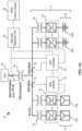
- FIG. 1 Ais a schematic diagram showing interconnections between various components of an AC coupled metering and control system for controlling a renewable energy source and energy storage system (e.g., a photovoltaic (PV) array and a battery array chargeable with electric power produced by the PV array) according to one embodiment.
- a renewable energy source and energy storage systeme.g., a photovoltaic (PV) array and a battery array chargeable with electric power produced by the PV array
- FIG. 1 Bis a schematic diagram showing certain components of the AC coupled metering and control system of FIG. 1 A .
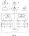
- FIG. 2is a block diagram for a processor-based energy dispatch control system for dispatching a renewable electrical energy generation resource and an electrical energy storage device chargeable with electric power produced by the renewable electrical energy generation resource according to one embodiment.
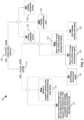
- FIG. 3is a logic diagram for charging an electrical energy storage device to reach a state of charge (SOC) target value using a system that includes a PV array and a battery array chargeable with electric power produced by the PV array according to one embodiment.
- SOCstate of charge
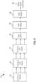
- FIG. 4is a logic diagram for discharging an electrical energy storage device using a system that includes a PV array and a battery array chargeable with electric power produced by the PV array according to one embodiment.
- FIG. 5is a modeled output plot for a system including a renewable electrical energy generation resource (RES) and an electrical energy storage device (ESS) chargeable with electric power produced by the renewable electrical energy generation resource, when controlled by a method as disclosed herein, for a period between 06:00 and 21:00 of a single day.
- RESrenewable electrical energy generation resource
- ESSelectrical energy storage device
- FIG. 6is a first diagram illustrating a serial (or stacking) arrangement of different control modes, with each control mode including multiple control signal candidate values, and with the serially connected control modes configured to produce a basepoint signal useable as a single active power command.
- FIGS. 7 A- 7 Eembody tables identifying control signal candidate values for multiple serially connected control modes and a net output value according to different examples.
- FIG. 8is an exemplary output plot for system including a renewable electrical energy generation resource (RES) and an electrical energy storage device (ESS) chargeable with electric power produced by the renewable electrical energy generation resource, when controlled by a method utilizing different combinations of connected control modes at different times according to one embodiment.
- RESrenewable electrical energy generation resource
- ESSelectrical energy storage device
- FIG. 9is a second diagram illustrating a serial (or stacking) arrangement of different control modes including multiple control signal candidate values, including serially connected basepoint and non-basepoint control modes configured to produce a single active power command.
- FIG. 10is schematic diagram of a generalized representation of a computer system that can be included as one or more components of a system for controlling a renewable electrical energy generation resource and an electrical energy storage device chargeable with electric power produced by the renewable electrical energy generation resource, according to one embodiment.
- FIG. 11 Ais a modeled output plot for a system including a renewable electrical energy generation resource (RES) and an electrical energy storage device (ESS) chargeable with electric power produced by the RES, when controlled by a method as disclosed herein but without a configurable refresh period, for a period including 06:00 to 21:00 of a single day.
- RESrenewable electrical energy generation resource
- ESSelectrical energy storage device
- FIG. 11 Bis a modeled output plot for the same RES-ESS system and period depicted in FIG. 11 A , when controlled by a method disclosed herein with utilization of a 30 minute refresh period, in which basepoint value is recalculated once every 30 minutes.
- FIGS. 12 A and 12 Bprovided modeled output plots for a system including a renewable electrical energy generation resource (RES) and an electrical energy storage device (ESS) chargeable with electric power produced by the RES, each utilizing a refresh period, but with FIG. 12 B using a static window that takes into account the solar production forecast from the beginning of the control period until the end in order to meet a SOC target schedule.
- RESrenewable electrical energy generation resource
- ESSelectrical energy storage device
- the Modular Energy Storage Association(MESA) recently released a specification titled “DNP3 Application Note AN2018-001-DNP3 Profile for Communications with Distributed Energy Resources,” wherein “DNP” refers to Distributed Network Protocol.
- This MESA specificationdefines control modes for standalone energy storage systems.
- One of these control modesis called “Coordinated Charge/Discharge (CCD).”
- CCD modean Energy Storage System (ESS) is given a schedule by which to reach a certain state of charge (SOC) by charging or discharging. For example, an ESS may be instructed to reach 100% SOC by 5 PM, and then reach 10% SOC by 10 PM. This schedule may be repeated every day.
- An ESSmay be co-located and controlled in tandem with a photovoltaic (PV) electricity generator or any other renewable energy source.
- PVphotovoltaic
- Embodiments described in the present application documentprovide a highly desirable implementation of CCD mode for an integrated renewable energy source (“RES”) (e.g., PV, wind, etc.) and energy storage system (“ESS’) facility or plant, wherein the combination may be referred to here as RES-ESS or a RES-ESS facility (of which a photovoltaic plus storage or “PV+S” facility is a subset).
- RES-ESSintegrated renewable energy source
- ESSenergy storage system
- a RES-ESS facilitywill reach the desired SOC when charging.
- a RES-ESS facilitywill reach the desired SOC by prioritizing charging at times when RES generation is high. For example, an ESS may be charged more when more RES generation is available, and an ESS may be charged less (or not at all) when RES generation is limited.
- a RES-ESS facilitywill charge the ESS only from the RES, so that a maximum investment tax credit (ITC) can be utilized to reduce the effective cost of the facility.
- the ESSmay additionally be charged from an electric grid connected to the RES-ESS facility.
- a periodic maximum SOC value specified in a SOC schedule(e.g., the maximum SOC for a particular day, wherein such value may be less than 100%) is attained as late as possible to enable maximal recovery of excess energy that would otherwise be clipped by a DC/AC inverter.
- a periodic maximum SOC value specified in a SOC schedulemay be attained as late as possible by charging the ESS at the lowest average charging rate that will satisfy the SOC schedule; in certain embodiments, this may involve maintaining the minimum possible average SOC that still enables satisfaction of the SOC schedule. By charging an ESS as late as possible, headroom remains in the ESS to implement ancillary services that further increase the revenue generated by the RES-ESS plant.
- One benefit of maintaining average SOC of an ESS as low as possibleis that it may prolong the life of batteries associated with the ESS, since it is widely recognized that various types of lithium polymer batteries exhibit increased degradation with maintenance of a high average SOC.
- Utilization of methods disclosed hereinmay also beneficially smooth the output of a RES-ESS plant, thereby providing a very desirable attribute for utilities and grid operators.
- a na ⁇ ve implementation of CCD modei.e., without benefit of reading the present disclosure
- maintaining a high SOC for a long period of timewould be expected to increase degradation of an ESS over its lifetime.
- CCD modemay interpolate the charging such that the RES-ESS facility charges the ESS linearly between the current time and the SOC target time.
- This proposed strategysuffers from the drawback that a desired SOC may be not satisfied if the RES-ESS facility is unable to produce energy according to the day's renewable energy production forecast.
- a time-dependent forecast of electrical energy productionmay be based on on-site sky imaging (e.g., using a camera), satellite imaging, or meteorological modeling. In certain embodiments, a time-dependent forecast of electrical energy production may be based on an ensemble of two or more (or all three) of on-site sky imaging (e.g., using a camera), satellite imaging, and meteorological modeling.
- FIG. 1 Ais a schematic diagram showing interconnections between various components of an AC coupled metering and control system 10 for controlling a renewable electrical energy generation device 14 including multiple generation units 14 A- 14 N (such as a photovoltaic (PV) array including photovoltaic units) and an energy storage device 24 including multiple energy storage units 24 A- 24 N (such as a battery array including battery units) chargeable with electric power produced by the renewable electrical energy generation device 14 in a RES-ESS facility 11 according to one embodiment.
- a renewable electrical energy generation device 14including multiple generation units 14 A- 14 N (such as a photovoltaic (PV) array including photovoltaic units) and an energy storage device 24 including multiple energy storage units 24 A- 24 N (such as a battery array including battery units) chargeable with electric power produced by the renewable electrical energy generation device 14 in a RES-ESS facility 11 according to one embodiment.
- PVphotovoltaic
- the RES-ESS facility 11may combine a renewable electrical energy generation device 14 (e.g., such as an array of PV panels, wind turbines, or the like), and an energy storage device 24 (e.g., an array of lithium-based batteries) that may be coupled to a single substation 30 and/or located in a single property, area, or structure.
- a renewable electrical energy generation device 14e.g., such as an array of PV panels, wind turbines, or the like
- an energy storage device 24e.g., an array of lithium-based batteries
- FIG. 1 Aillustrates an AC-coupled RES-ESS facility 11 that uses inverters 16 , 26 to convert DC power produced by a renewable electrical energy generation device 14 (e.g., a PV array in certain embodiments) or power released by the energy storage device 24 to AC power for coupling to an AC electrical grid 34 ), but in certain embodiments, the RES-ESS facility 11 may embody a DC coupled RES-ESS facility.
- an energy storage device 24may include at least one of (or a combination of) batteries 24 A, 24 B using various constructions and chemistries, capacitors, or mechanical energy storage devices such as flywheels or pumped-hydro installations.
- an energy storage device 24may include at least one hydrolysis unit (e.g., configured to electrolyze water to release hydrogen) and a hydrogen storage unit (e.g., adsorbent media for releasably binding hydrogen, storage vessels, and/or reversible chemical reactant vessels or beds).
- a hydrogen storage unite.g., adsorbent media for releasably binding hydrogen, storage vessels, and/or reversible chemical reactant vessels or beds.
- an energy storage device 24may consist of electrical charge storage devices such as batteries, optionally augmented with capacitors.
- a RES-ESS dispatcher unit 36has the ability to control the charge or discharge of the energy storage device 24 (e.g., batteries) by communicating with an ESS controller 22 , which may be located in the RES-ESS facility 11 .
- a RES SCADA (supervisory control and data acquisition) controller 12is operatively coupled with RES inverters 16 associated with the renewable electrical energy generation device 14 (optionally embodied in a PV array), and the ESS controller 22 is operatively coupled with ESS inverters 26 associated with the energy storage device 24 , with both the RES SCADA controller 12 and the ESS controller 22 being in communication with the RES-ESS dispatcher unit 36 .
- a utility control center 38may communicate with the RES-ESS dispatcher unit 36 using DNP3 and set different configuration options. Additionally, the RES-ESS dispatcher unit 36 receives (or generates) an accurate renewable generation forecast (e.g., solar generation forecast) that it uses to implement the CCD and other control modes. As shown in FIG. 1 A , certain embodiments may utilize readily available electric power meters, such as a RES+ESS electrical power meter 32 to measure RES-ESS (e.g., PV+S) facility output, a RES electrical power meter 19 to measure RES output, and an ESS electrical power meter 29 to measure ESS output.
- RES+ESS electrical power meter 32to measure RES-ESS (e.g., PV+S) facility output
- RES electrical power meter 19to measure RES output
- an ESS electrical power meter 29to measure ESS output.
- Signals from the RES electrical power meter 19are provided to the RES SCADA controller 12 , and signals from the ESS electrical power meter 29 are provided to the ESS controller 22 .
- the electric power generated by the RES-ESS facility 11may be provided to an electric power system (e.g., an AC electrical grid 34 ) via a generator step-up (GSU) substation 30 that implements protection and appropriate voltage conversion.
- GSUgenerator step-up
- RES transformers 18 and ESS transformers 28may be arranged between the inverters 16 , 26 , respectively, and the GSU substation 30 to provide voltage conversion utility (e.g., to supply AC power signals to the GSU substation 30 at 34.5 kV in certain implementations).
- FIG. 1 Bis a schematic diagram showing certain components of the AC coupled metering and control system of FIG. 1 A , including interconnection of control- and sensor-related components.
- the RES-ESS dispatcher unit 36is arranged between a utility control center 38 and a RES-ESS facility 11 .
- a RES SCADA controller 12is operatively coupled with RES inverters 16 A- 16 N (wherein N represents any suitable number) that are configured to provide AC conversion of DC power produced by renewable electrical energy generation units 14 A- 14 N (e.g., arrangeable as parts of a renewable electrical energy generation device 14 ).
- an ESS controller 22is operatively coupled with ESS inverters 26 A- 26 N that are configured to provide AC conversion of DC power supplied by energy storage units 24 A- 24 N (e.g., arrangeable as parts of an energy storage device 24 ).
- the RES-ESS facility 11further includes at least one sensor 40 , which may comprise one or more sky imaging sensors useful to determine sky conditions (such as presence of clouds) proximate to the RES-ESS facility 11 , with output signals from the at least one sensor 40 being supplied to the RES-ESS dispatcher unit 36 .
- the RES-ESS dispatcher unit 36may also receive: (i) signals from one or more sensors 42 (e.g., satellite imaging sensors or the like) not necessarily associated with the RES-ESS facility 11 ; (ii) meteorological data provided by a meteorological modeling unit 44 ; (iii) signals from a forecasting unit 46 that may forecast generation by the renewable electrical energy generation device 14 and/or one or more other renewable electrical energy generation devices or units. In certain embodiments, time-dependent forecasting of electrical energy production may be performed by the forecasting unit 46 or may be performed by the RES-ESS dispatcher unit 36 .
- sensors 42e.g., satellite imaging sensors or the like
- meteorological dataprovided by a meteorological modeling unit 44
- signals from a forecasting unit 46that may forecast generation by the renewable electrical energy generation device 14 and/or one or more other renewable electrical energy generation devices or units.
- time-dependent forecasting of electrical energy productionmay be performed by the forecasting unit 46 or may be performed by the RES-ESS dispatcher unit 36 .
- a time-dependent forecast of electrical energy productionmay utilize one, two, or all three of the following: on-site sky imaging provided by the sensor(s) 40 , satellite imaging provided by the sensor(s) 42 , and meteorological data provided by the meteorological modeling unit 44 .
- sensors of other typesmay be used.
- FIG. 2is a block diagram showing for a processor-based energy dispatch control system 50 for dispatching a RES-ESS facility (e.g., including renewable electrical energy generation resource and an electrical energy storage device chargeable with electric power produced by the renewable electrical energy generation resource) according to one embodiment.
- the control system 50includes as functional blocks a utility interface 52 , manual inputs 54 , a settings combiner 56 , and an energy dispatcher 58 .
- the utility interface 52communicates with an electric power system utility, and with the energy dispatcher 58 to receive configuration commands (e.g., CCD mode configuration commands) and send plant status and state information 62 .
- configuration commandse.g., CCD mode configuration commands
- An example of a CCD mode configuration set by a utilitymay be a schedule that contains a first SOC target at a pre-determined time, and a second SOC target at a second pre-determined time. For example, the utility may want the ESS to reach an SOC of 90% by 5:00 PM and an SOC of 10% by 10:00 PM.
- the utility interface 52receives DNP3 (Distributed Network Protocol) information via a DNP3 link 60 , and is responsible for converting the published DNP3 configuration points to internal data structures.
- the utility interface 52is also responsible for communicating any data structure changes back to the utility via the DNP3 link 60 .
- Manual inputs 54include configuration parameters that are not addressable by MESA-ESS SCADA points.
- the settings combiner 56validates any configuration inputs and passes them to the energy dispatcher 58 in one implementation.
- the settings combiner 56receives MESA-ESS schedules/modes/curves provided by a utility or grid operator, receives schedules produced by an optimizer, and receives any potential manual inputs 54 , and then produces combined schedules/modes/curves.
- the energy dispatcher 58is an engine that executes control modes (including but not limited to coordinated charge/discharge or CCD) for the RES-ESS facility (or plant) and decides on the charge or discharge level of the ESS utilizing a renewable energy production forecast 64 .
- the energy dispatcher 58is responsible for controlling output of a RES-ESS fin short time scales by observing the current state of the RES-ESS plant, utilizing time-dependent forecasts of electrical energy production by the RES, and utilizing any combined MESA-ESS schedules/modes/curves produced by the settings combiner 56 .
- a renewable energy forecastmay contain a time series of points for the power expected to be generated by the renewable energy source (e.g., PV array, wind turbine, etc.). Such a forecast may have a format of (timestamp, power value) and contain a set of time values of specified intervals (e.g., 15 minutes in 1 minute intervals, 36 hours in 1 hour intervals, etc.). These potential formats and timeframes are provided to illustrate the nature of an exemplary forecast, and are not intended to limit the disclosure.
- the energy dispatcher 58is also responsible for passing alerts and RES-ESS plant state and/or status information back to the utility interface 52 .
- methods disclosed herein for controlling a RES-ESS plant utilizing a coordinated charge/discharge (CCD) modemay work simultaneously with other (e.g., PV+S) control algorithms according to an amalgamation process.
- Such an amalgamation processesuses ideal, minimum (lower bound), and maximum (upper bound) values produced by each control algorithm (wherein each algorithm corresponds to a different control mode), and based on the configured priority of a control algorithm, amalgamation produces a final ESS charge or discharge target.
- a time-varying charge/discharge control signalis susceptible to being varied by adoption of one or more control modes of multiple control modes, wherein for each control mode of a plurality of control modes, signal candidate values including an upper bound value, a lower bound value, and an ideal value are generated. Additionally, an intersection of control signal candidate values among multiple control modes is identified, or an ideal value for a control mode of highest priority is selected, to generate the time-varying charge/discharge control signal.
- control modesthat may be utilized in methods disclosed herein include the following active power modes specified in the MESA-ESS specification: Charge-Discharge (CD) mode, Coordinated Charge Discharge (CCD) mode, Active Power Limit (APL) mode, Active Power Response (APR) mode, Active Power Smoothing (APS) mode, Pricing Signal (PS) mode, Volt-Watt (VW) mode, Frequency-Watt Curve (FWC) mode, and Automatic Generation Control (AGC) mode.
- active power modesspecified in the MESA-ESS specification: Charge-Discharge (CD) mode, Coordinated Charge Discharge (CCD) mode, Active Power Limit (APL) mode, Active Power Response (APR) mode, Active Power Smoothing (APS) mode, Pricing Signal (PS) mode, Volt-Watt (VW) mode, Frequency-Watt Curve (FWC) mode, and Automatic Generation Control (AGC) mode.
- FIGS. 3 and 4embody logic diagrams for charging and discharging, respectively, of an electrical energy storage device using a system that includes a PV array and a battery array chargeable with electric power produced by the PV array.
- PVis referenced herein, it is to be appreciated that the disclosed concepts extend to any one or more types of renewable electrical energy generating units (wind, solar, tidal, etc.)
- FIGS. 3 and 4refer to numerous variables. Before describing FIGS. 3 and 4 in detail, variables described in such figures are described in the following Table 1.
- FIG. 3is a diagram providing charging logic 100 for charging an electrical energy storage device to reach a state of charge (SOC) target value using a system that includes a PV array and a battery array chargeable with electric power produced by the PV array, according to one embodiment.
- CCD moderuns from a configured start time to a configured end time and works to get the ESS to a desired SOC target by a certain time.
- CCD modemay be executed in a loop inside the energy dispatcher and at each refresh period calculates and returns to the controller the following three values: BESS_ideal, BESS_max, and BESS_min, as will be described hereinafter, following discussion of refresh period.
- a refresh periodis considered before execution of CCD mode, in order to limit the ability of RES-ESS facility output to fluctuate except during specified time intervals. From a dispatching perspective, limiting the RES-ESS output fluctuations to specified time intervals is attractive to permit an electrical system (e.g., grid) operator to coordinate different generation resources to meet a specified system load, since various generation purchase and supply transactions are commonly scheduled as firm power outputs for specific (predetermined) blocks of time. Participation by bidding in energy markets or energy balance markets requires firm commitments to supply power for specified periods of time. To address this issue, a refresh period may be used with systems and method disclosed herein, with the refresh period being selected to be a time period convenient for a system operator (e.g., 15 minutes, 30 minutes, or another selectable time interval).
- a refresh periodcorresponds to a time between two consecutive executions of a RES-ESS control algorithm (e.g., for establishment of new basepoint values).
- BESS_min, BESS_ideal, and BESS_max valuesare recalculated once upon the expiration of a refresh period, but after such values are recalculated, they remain constant until expiration of the next refresh period. This is shown in FIG. 3 .
- Decision block 102considers whether the current time matches the refresh frequency.
- Step block 110considers whether a forecast is available. If a forecast is available (i.e., the inquiry at decision block 110 is true), then the BESS prioritizes charging at times when the PV generation is higher, and BESS_min, BESS_ideal, and BESS_max are computed at blocks 112 , 114 , and 116 , respectively.
- BESS_idealis set to the minimum of proportional_charge_power and BESS nameplate discharge power capacity. In implementations wherein grid charging is not permitted, the highest charging level that can be obtained is equal to the power generated from PV.
- the BESSperforms “greedy charging” by charging the entire chargeable_pv at every timestep.
- the BESS_ideal set-pointis the minimum of SOE to manage in Wh or BESS nameplate discharge power capacity, as indicated at block 122 .
- the BESS_max power set-point for CCDis the same as the BESS_ideal power set-point if the amount of energy available is less than the amount of energy required to reach the SOC target.
- the BESS_max power set-pointis the nameplate discharge power capacity of the BESS, as indicated at block 116 . If a forecast is not available (i.e., the inquiry at decision block 110 is false), then the BESS_max power set-point is the BESS nameplate discharge power capacity, as indicated at block 124 .
- the BESS_min power set-point for chargingis the minimum of (i) (ECP interconnection limit (in Watts) times Time Remaining (in Hours)) minus PV energy production in time interval (in Watt hours) plus SOE to manage (in Watt hours), (ii) Bess nameplate discharge power, or (iii) Bess_ideal setpoint of this mode, as indicated at block 112 . If a forecast is not available (i.e., the inquiry at decision block 110 is false), then the BESS_min power set-point is the minimum of SOE to manage in Wh or BESS nameplate discharge power capacity, as indicated at block 120 .
- FIG. 4is a diagram providing discharging logic 130 for discharging an electrical energy storage device using a system that includes a PV array and a battery array chargeable with electric power produced by the PV array according to one embodiment.
- a refresh periodis considered before execution of CCD mode, in order to limit the ability of RES-ESS facility output to fluctuate except during specified time intervals.
- decision block 132considers whether the current time matches the refresh frequency.
- CCD moderuns from a configured start time to a configured end time and works to get the ESS to a desired SOC target by a certain time.
- CCD modemay be executed in a loop inside the energy dispatcher and at each refresh period calculates and returns to the controller the following three values: Bess_Ideal, Bess_Max, and Bess_Min, as will be described below.
- BESS_ideal CalculationDecision block 140 considers whether a forecast is available. If a forecast is available (i.e., the inquiry at decision block 140 is true), then the BESS prioritizes discharging at times when the PV generation is lower, and BESS_min, BESS_ideal, and BESS_max are computed at blocks 142 , 144 , and 146 , respectively.
- Bess_idealis set to the minimum of chargeable PV and proportional_charge_power. If the discharging period is not during the day, then the BESS_ideal power setpoint would be the avg_discharge_power. If a forecast is not available (i.e., the inquiry at decision block 140 is false), the Ideal BESS discharge power setpoint would be chargeable_pv, as indicated at block 154 .
- the BESS_min power setpointwould be the minimum of (i) SOE_to_Manage (in Watt-hours) or chargeable_PV, as indicated at blocks 142 and 152 .
- BESS_maxCalculation. If a forecast is available (i.e., the inquiry at decision block 140 is true), then logic proceeds to decision block 146 , which presents an inquiry whether available_energy is less than or equal to SOE_to_manage. If the inquiry at decision block 146 is true, then the BESS_max power setpoint would be the minimum of chargeable PV and proportional_charge_power, as indicated at block 148 . If the inquiry at decision block 146 is false, then the BESS_max power setpoint would be the BESS discharging power nameplate capacity, as indicated at block 150 . Turning back to decision block 140 , if the inquiry at decision block 140 is false, then the BESS_max power setpoint would be chargeable_pv, as indicated at block 156 .
- FIG. 5is an exemplary output plot for system including a renewable electrical energy generation resource (RES) and an electrical energy storage device (e.g., a battery energy storage system or BESS) chargeable with electric power produced by the renewable electrical energy generation resource, when controlled by a method as disclosed herein, for a period between 06:00 and 21:00 of a single day.
- the output plotincludes PV generation in megawatts (PV MW), state of charge of the battery energy storage system (BESS SOC), and aggregated photovoltaic plus storage energy supplied to an electric grid (PV+S Output).
- PV MWmegawatts
- BESS SOCstate of charge of the battery energy storage system
- PV+S Outputaggregated photovoltaic plus storage energy supplied to an electric grid
- a SOC schedulerequires attainment of 80% SOC for the BESS by 12:00, and 0% SOC by 20:00 (8:00 PM).
- a charging algorithmis employed from about 07:00 to 12:00, and a discharging algorithm is employed from 12:00 to 20:00. While the charging algorithm is employed, PV MW is not necessarily the PV+S Output, since a portion of the PV generation is allocated to charge the BESS. The SOC of the BESS rises from 07:00 to 12:00, but not at a linear rate. As shown by the dashed vertical lines with arrow ends, while the charging algorithm is in use, a greater amount of BESS charging results when more PV generation is available, and a lesser amount of BESS charging results when less PV generation is available. Conversely, while the discharging algorithm is in use, a lesser amount of energy is discharged from the BESS when more PV generation is available, and a greater amount of energy is discharged from the BESS when less PV generation is available.
- the MESA-ESS specificationdescribes the following active power modes: [1] Charge-Discharge (CD) mode, [2] Coordinated Charge-Discharge (CCD) mode, [3] Active Power Limit (APL) mode, [4] Active Power Response (APR) mode, [5] Active Power Smoothing (APS) mode, [6] Pricing Signal (PS) mode, [7] Volt-Watt (VW) mode, [8] Frequency-Watt Curve (FWC) mode, and [9] Automatic Generation Control (AGC) mode.
- Modes [1] to [6]result in a battery active power output that may be called a “basepoint,” such that modes [1] to [6] may be termed basepoint modes.
- Modes [7] to [9]are “additive” modes that add positive or negative power to the basepoint, and may be termed non-basepoint modes.
- a unique characteristic of the non-basepoint modesis that APS mode will not consider the resultant added power from them when calculating the next basepoint.
- the MESA-ESS specificationdelineates how different active power control modes should function and identifies the possibility of combining them, but such document does not attempt to define how the functionality of different control modes can be combined or stacked.
- Each active modecan usually be satisfied with a range of power responses at any given time. For example, if a 4 hour battery (e.g., that is chargeable from 0% to 100% in 4 hours) has an 8 hour window in which the battery is to be charged, the battery could charge all in the beginning, all at the end, or evenly throughout the 8 hour window. This flexibility can be leveraged to implement multiple modes at the same time, such as a charge window and smoothing solar power generation. Amalgamation processes described herein enable different MESA-ESS active power control modes to be combined to produce an output that accommodates the respective control modes if they are compatible, while also allowing each control mode to be prioritized relative to the other control mode.
- an algorithm dedicated to each active power control modemay output an ideal value, a minimum (lower bound—corresponding to the most negative or least positive) value, and a maximum (upper bound—corresponding to the most positive or least negative) value that can be accommodated by a BESS while the still being able to satisfy defined requirements (e.g., according to a SOC schedule).
- such valuesembody power setpoints that may be defined with respect to a BESS meter, whereby a negative value represents charging and a positive value represents discharging.
- the ideal BESS power setpoint for each moderepresents the preferred active power requirement for it to operate most efficiently in order to perform its function.
- the three setpoints (ideal, minimum, and maximum)could mean different things for different active power control modes.
- the Min and Max BESS power setpointswould represent the minimum and maximum BESS power, respectively, that the mode can accommodate at that instant while satisfaction of a SOC target is still attained.
- the ideal power setpointcould be defined as the required BESS active power to reach the SOC target in an optimal fashion.
- the BESS_max power setpointwould be the maximum power the control mode can accommodate (i.e., a power threshold), while the minimum BESS power setpoint for this case could be the minimum operating limit of the RES-ESS plant since the control mode does not have a set lower limit threshold.
- Mode-stackingmay be performed by connecting different control modes in series. This may be implemented by passing the Min, Max, and Ideal setpoints of one control mode to the next control mode in order of priority of the respective control mode.
- the control mode next in seriesmay use the setpoint values of the previous control mode in its computation, and then output its own setpoint values.
- FIG. 6is a first diagram illustrating a serial (or stacking) arrangement of different control modes 162 , 164 , 166 useable by a control system 160 , with each control mode including multiple control signal candidate values, and with the serially connected control modes producing a single active power command.
- the highest priority, staging mode 162consists of the operating limits of the BESS and is always the highest priority (e.g., Priority 0). All control modes should operate within the limit (Min and Max) defined by the staging mode 162 .
- Stacking control modessequentially tests whether a lower priority mode's requirement is within the limits of a higher priority mode. If the lower priority mode is out of bounds, then the setpoints of the higher priority mode get preference by overriding setpoints of the lower priority mode.
- next highest priority modesare CCD mode 164 and APS mode 166 , respectively.
- a basepoint signal 168is generated by identifying an intersection of control signal candidate values among the multiple control modes 162 , 164 , 166 , or selecting an ideal value for a control mode 162 , 164 , 166 of highest priority, and in the present embodiment the basepoint signal 168 serves as a time-varying charge/discharge control signal (e.g., an active power command signal) 169 useable for controlling one or more components of a RES-ESS facility.
- a time-varying charge/discharge control signale.g., an active power command signal
- the staging modeis by default the highest priority mode and contains the present operating limits of the ESS (e.g., BESS).
- the Min and Max of this modeare calculated using the current operational state and conditions of the ESS.
- limits addressed by staging modeinclude fundamental system limits (e.g., energy source or self-imposed limits), nameplate and device limits (e.g., nameplate maximum voltage rating and nameplate active generation power rating at unity power factor)), and present operating limits (e.g., maximum voltage and maximum active generation power).
- FIGS. 7 A- 7 Eembody tables identifying control signal candidate values for multiple serially connected control modes and a net output value according to five different examples.
- all control modesare within the bounds set by the higher priority mode, and a value of ⁇ 20 MW is selected as the basepoint net output.
- FIG. 7 Ball control modes are outside the bounds set by the higher priority mode, and a value of 0 MW is selected as the basepoint net output.
- FIG. 7 Call control modes partially overlap, and a value of 10 MW is selected as the basepoint net output.
- the higher priority CCD modecan partially accommodate the lower priority APS mode, and a value of 10 MW is selected as the basepoint net output.
- the higher priority CCD mode and lower priority APS mode setpointsconflict with one another, such that the value within CCD mode range and closest to the APS mode range (namely, 0 MW) is selected as the basepoint net output.
- control modesmay be operated at different times.
- FIG. 8is an exemplary output plot for system including a renewable electrical energy generation resource (e.g., a PV source) and an electrical energy storage device (e.g., a BESS) chargeable with electric power produced by the renewable electrical energy generation resource, when controlled by a method utilizing different combinations of connected control modes at different times according to one embodiment.
- the output plotincludes PV generation in megawatts (PV MW)), state of charge of the battery energy storage system (BESS SOC), and aggregated photovoltaic plus storage energy supplied to an electric grid (PV+S Output).
- Active Power Smoothing (APS) mode plus Coordinated Charge-Discharge (CCD) modeare enabled at sunrise (about 07:00) to reach 50% SOC by 12:00. Only APS mode is enabled from 12:00 until 14:30.
- APSis a basepoint control mode that smooths PV+S plant output based on a specified Electrical Connection Point (ECP) reference meter signal.
- ECPElectrical Connection Point
- APSmay involve measuring current PV+S output at the point of interconnect with a grid, calculating a moving average of the ECP reference meter based on an APS filter time, calculating additional watts required based on (i) a deadband (extending ahead and behind of the moving average of reference power), (ii) a smoothing gradient, and (iii) the moving average of the ECP reference meter.
- FIG. 9is a second diagram illustrating a serial (or stacking) arrangement of different control modes 172 , 174 , 176 , 180 , 182 useable by a control system 170 .
- the control system 170utilizes serially connected basepoint control modes 172 , 174 , 176 and non-basepoint control modes 180 , 182 that produce a single active power command.
- Each control mode 172 , 174 , 176 , 180 , 182includes multiple control signal candidate values.
- the highest priority, staging mode 172consists of the operating limits of the BESS, and is followed (in decreasing priority) by CCD mode 172 and APS mode 174 , respectively, to yield a basepoint value 178 .
- the basepoint value 178is generated by identifying an intersection of control signal candidate values among the preceding control modes 172 , 174 , 176 , or selecting an ideal value for the preceding control mode of highest priority.
- This basepoint value 178is modified (e.g., increased or decreased) by serial application of the Automatic Generation Control (AGC) mode 180 and Frequency-Watt Curve (FWC) mode 182 , respectively.
- a time-varying charge/discharge control signal (e.g., an active power command signal) 183results from modification of the basepoint value 178 with non-basepoint values generated by the AGC and FWC modes 180 , 182 .
- FIG. 9therefore illustrates how AGC and FWC modes 180 , 182 may add power to the basepoint.
- a typical implementation of additive modesmay assume that some power from the BESS is reserved from the calculation of the basepoint value 178 .
- a 20 MW BESSmay have 2 MW reserved for AGC and FWC modes. Therefore the staging mode (priority 0) would only see ⁇ 18 to 18 MW available.
- a basepoint value of ⁇ 18 MWmay be calculated, AGC mode may yield 2 MW, and FWC mode may yield ⁇ 1 MW.
- An active power command of ⁇ 17 MWmay result (calculated as ( ⁇ 18)+(2)+( ⁇ 1)).
- AGC modeis an additive power control mode that outputs a single PV+S power setpoint based on an active power target set by the master, wherein the AGC output is added on top of the basepoint value, subject to operating limit constraints of a RES-ESS (e.g., PV+S) facility.
- RES-ESSe.g., PV+S
- FWC modeis an additive power control mode used to alter a system's power output in response to measured deviation from a specified nominal frequency.
- FWCmay involve measuring grid frequency using the reference EPC meter. If the grid frequency is within a specified deadband or if the current BESS SOC is outside allowed usable SOC limits, then no action is performed. However, if the grid frequency is outside a specified deadband, then additional power to be provided is calculated using a measured droop.
- ramp rate constraintsmay be applied to a control signal for a RES-ESS facility, wherein forecasted RES produced may be examined at every timestep, and power may be curtailed preemptively in order to mitigate RES production ramp down events (e.g., sudden dips in PV production).
- Ramp rate in this contextmay be defined as the change in power output of a RES facility or RES-ESS facility (e.g., PV+S facility) in a given time interval (e.g., change per minute or change per hour). Leveraging of short-term RES production forecasts may be used.
- the two main ramping events subject to controlare (1) ramp down events, and (2) ramp up events.
- Ramp-down events in the context of a facility including PV productionmay be mitigated by obtaining a forecast for future PV from the current time to ‘f’ minutes in the future, wherein T is a function of a ramp rate down limit.
- a gradient or slope between the current plant production and the forecasted PV power valuesmay be calculated and compared with a defined ramp rate down limit. If the gradients of future power values are not within the ramp rate down limit, then PV power may be curtailed by an amount equal to the minimum gradient in the current forecast time series. If the gradients of future power values are within the ramp rate down limit, then no corrective action is necessary.
- Controlling ramp rate up eventsis simpler.
- current RESe.g., PV
- curtailmentis applied to make sure that the RES plant output does not violate the ramp limit.
- This functionmay be performed by inverters at the RES-ESS plant. This may be applied in two instances. Firstly, if there is a sudden increase in RES production, this logic will control plant production so that total output increases in steps of power that are less than equal to the ramp rate up limit.
- the RES-ESS plant outputis increased by no greater than the ramp rate up limit in order to bring the curtailment back to zero.
- ramp rate up curtailment powerhas been calculated, gradients to forecasted RES production values are recalculated for the ramp-up curtailment. If the result of the current ramp rate up event causes uncontrollable violations in the future, then an optimal curtailment solution is obtained so that all future violations are controlled.
- FIG. 10is schematic diagram of a generalized representation of a computer system 200 that can be included as one or more components of a system for controlling a renewable electrical energy generation resource and an electrical energy storage device chargeable with electric power produced by the renewable electrical energy generation resource, according to one embodiment.
- the computer system 200may be adapted to execute instructions from a computer-readable medium to perform these and/or any of the functions or processing described herein.
- the computer system 200may include a set of instructions that may be executed to program and configure programmable digital signal processing circuits for supporting scaling of supported communications services.
- the computer system 200may be connected (e.g., networked) to other machines in a local area network (LAN), an intranet, an extranet, or the Internet. While only a single device is illustrated, the term “device” shall also be taken to include any collection of devices that individually or jointly execute a set (or multiple sets) of instructions to perform any one or more of the methodologies discussed herein.
- the computer system 200may be a circuit or circuits included in an electronic board or card, such as a printed circuit board (PCB), a server, a personal computer, a desktop computer, a laptop computer, a personal digital assistant (PDA), a computing pad, a mobile device, or any other device, and may represent, for example, a server or a user's computer.
- PCBprinted circuit board
- PDApersonal digital assistant
- the computer system 200 in this embodimentincludes a processing device or processor 202 , a main memory 204 (e.g., read-only memory (ROM), flash memory, dynamic random access memory (DRAM), such as synchronous DRAM (SDRAM), etc.), and a static memory 206 (e.g., flash memory, static random access memory (SRAM), etc.), which may communicate with each other via a data bus 208 .
- a main memory 204e.g., read-only memory (ROM), flash memory, dynamic random access memory (DRAM), such as synchronous DRAM (SDRAM), etc.
- static memory 206e.g., flash memory, static random access memory (SRAM), etc.
- SRAMstatic random access memory
- the processing device 202represents one or more general-purpose processing devices, such as a microprocessor, central processing unit (CPU), or the like.
- the processing device 202may be a complex instruction set computing (CISC) microprocessor, a reduced instruction set computing (RISC) microprocessor, a very long instruction word (VLIW) microprocessor, a processor implementing other instruction sets, or other processors implementing a combination of instruction sets.
- the processing device 202is configured to execute processing logic in instructions for performing the operations and steps discussed herein.
- the computer system 200may further include a network interface device 210 .
- the computer system 200may additionally include at least one input 212 , configured to receive input and selections to be communicated to the computer system 200 when executing instructions.
- the computer system 200also may include an output 214 , including but not limited to a display, a video display unit (e.g., a liquid crystal display (LCD) or a cathode ray tube (CRT)), an alphanumeric input device (e.g., a keyboard), and/or a cursor control device (e.g., a mouse).
- a displaye.g., a liquid crystal display (LCD) or a cathode ray tube (CRT)
- an alphanumeric input devicee.g., a keyboard
- a cursor control devicee.g., a mouse
- the computer system 200may or may not include a data storage device that includes instructions 216 stored in a computer readable medium 218 .
- the instructions 216may also reside, completely or at least partially, within the main memory 204 and/or within the processing device 202 during execution thereof by the computer system 200 , the main memory 204 and the processing device 202 also constituting computer readable medium.
- the instructions 216may further be transmitted or received over a network 220 via the network interface device 210 .
- While the computer readable medium 218is shown in an embodiment to be a single medium, the term “computer-readable medium” should be taken to include a single medium or multiple media (e.g., a centralized or distributed database, and/or associated caches and servers) that store the one or more sets of instructions.
- the term “computer readable medium”shall also be taken to include any medium that is capable of storing, encoding, or carrying a set of instructions for execution by the processing device and that cause the processing device to perform any one or more of the methodologies of the embodiments disclosed herein.
- the term “computer readable medium”shall accordingly be taken to include, but not be limited to, solid-state memories, an optical medium, and/or a magnetic medium.
- systems and apparatuses disclosed hereinmay utilize a non-transitory computer readable medium containing program instructions for controlling, by at least one processor, (i) a renewable electrical energy generation resource and (ii) an electrical energy storage device chargeable with electric power produced by the renewable electrical energy generation resource, the method comprising utilizing, by the at least one processor, (A) a time-dependent forecast of electrical energy production by the renewable electrical energy generation resource and (B) a state of charge (SOC) schedule for the electrical energy storage device including at least one SOC target value, to generate a time-varying charge/discharge control signal for the electrical energy storage device, wherein the time-varying charge/discharge control signal is configured to ensure that the SOC schedule is satisfied by charging at the average rate necessary to meet the SOC target schedule, while periodically updating the generation of the time-varying charge/discharge control signal based upon at least one of an updated time-dependent forecast of electrical energy production or an updated SOC schedule.
- the program instructions contained in the computer readable mediummay be configured
- FIGS. 11 A and 11 Bare provided to permit visual comparison of the effects of not utilizing versus utilizing a refresh period to limit recalculation of basepoint values for controlling aggregate output of a RES-ESS facility.
- FIG. 11 Ais a modeled output plot for a system including a renewable electrical energy generation resource (RES) in the form of PV and an electrical energy storage device (ESS) chargeable with electric power produced by the renewable electrical energy generation resource, when controlled by a method as disclosed herein but without a configurable refresh period, for a period including 06:00 to 21:00 of a single day.
- Significant temporal fluctuation in aggregated photovoltaic plus storage (PV+S) outputis shown between 09:00 and 18:00, with very few time periods having a non zero slope that would correspond to constant power output.
- FIG. 11 Bis a modeled output plot for the same RES-ESS system and period depicted in FIG. 11 A , when controlled by a method disclosed herein with utilization of a 30 minute refresh period, in which basepoint value is recalculated once every 30 minutes.
- the aggregated PV+S outputremains substantially constant for each 30 minute time period, since the basepoint control value remains constant during each 30 minute refresh period.
- the application of a refresh period for coordinate control of a RES-ESS facilityenables the plant to supply fixed blocks of power for specified time periods, thereby permitting the plant operator to participate by bidding to supply fixed blocks of power for specified periods of time in energy markets and/or energy balance markets.
- FIGS. 12 A and 12 Bprovided modeled output plots for a system including a renewable electrical energy generation resource (RES) (e.g., PV) and an electrical energy storage device (ESS) chargeable with electric power produced by the RES.
- the output plots of FIGS. 12 A and 12 Bexhibit utilization of a refresh period, but only the output plot of FIG. 12 B avoids an undesirable valley in aggregated plant (PV+S) output after daily PV production has ended, followed by an increase in PV+S output during discharge of the ESS.
- the output plot of FIG. 12 Acorresponds to a control scheme that utilizes a SOC compliance evaluation period that considers only hours remaining the day for each time period—namely, from the current time to an end of day SOC target (e.g., 22:00 hours in each figure).
- FIG. 12 A and 12 Bdiffer significantly between 17:00 and 22:00.
- FIG. 12 Aprovides a PV+S profile 250 between 17:00 and 22:00 that includes a valley region 251 in which PV+S output declines to a minimum of about 22 MW followed by a PV+S increase region 254 in which PV+S output is increased to a value of nearly 50 MW before declining rapidly to zero at 22:00.
- FIG. 12 Bprovides a different PV+S profile 255 that is devoid of any valleys followed by positive slope regions that would correspond to increases in PV+S output.
- the PV+S profile 255 shown in FIG. 12 Bdecreases in a substantially stepwise manner between 17:00 and 22:00, with a final drop from about 30 MW to zero at 22:00.
- This improved PV+S profile 255 shown in FIG. 12 Bmay be attained by utilization of a static window instead of a dynamic window for meeting an end of day SOC target. Furthermore, while the window length is static, the forecasted power values in the window are updated as the facility receives updated forecasts. While specific aspects, features and illustrative embodiments have been disclosed herein, it will be appreciated that the disclosure extends to and encompasses numerous other variations, modifications, and alternative embodiments, as will suggest themselves to those of ordinary skill in the pertinent art, based on the disclosure herein. Various combinations and sub-combinations of the structures described herein are contemplated and will be apparent to a skilled person having knowledge of this disclosure.
Landscapes
- Engineering & Computer Science (AREA)
- Business, Economics & Management (AREA)
- Power Engineering (AREA)
- Human Resources & Organizations (AREA)
- Economics (AREA)
- Strategic Management (AREA)
- Theoretical Computer Science (AREA)
- Entrepreneurship & Innovation (AREA)
- Health & Medical Sciences (AREA)
- Marketing (AREA)
- General Physics & Mathematics (AREA)
- General Business, Economics & Management (AREA)
- Tourism & Hospitality (AREA)
- Physics & Mathematics (AREA)
- Public Health (AREA)
- Primary Health Care (AREA)
- Water Supply & Treatment (AREA)
- Development Economics (AREA)
- Educational Administration (AREA)
- General Health & Medical Sciences (AREA)
- Game Theory and Decision Science (AREA)
- Operations Research (AREA)
- Quality & Reliability (AREA)
- Sustainable Development (AREA)
- Life Sciences & Earth Sciences (AREA)
- Sustainable Energy (AREA)
- Microelectronics & Electronic Packaging (AREA)
- Manufacturing & Machinery (AREA)
- Chemical & Material Sciences (AREA)
- Chemical Kinetics & Catalysis (AREA)
- Electrochemistry (AREA)
- General Chemical & Material Sciences (AREA)
- Charge And Discharge Circuits For Batteries Or The Like (AREA)
- Supply And Distribution Of Alternating Current (AREA)
Abstract
Description
| TABLE 1 | |
| Variable | Definition |
| refresh period | The time between two consecutive |
| executions of the algorithm, | |
| wherein BESS_ideal, BESS_min and | |
| BESS_max values are held constant | |
| during a refresh period (until a | |
| next execution of the algorithm) | |
| SOC | State of charge |
| SOE | State of energy |
| soc_to_manage | The difference between the target |
| SOC (%) and the current SOC (%) | |
| soe_to_manage | soe_to_manage (%) applied to the |
| battery energy rating in Watt-hours | |
| pv_production_forecast | An array-like object consisting |
| of the photovoltaic power | |
| production forecast from the | |
| current timestep to the SOC | |
| target time | |
| pv_production_in_period | Forecasted PV production during |
| the refresh period | |
| refresh period | The time between two consecutive |
| executions of the algorithm, | |
| wherein BESS_ideal, BESS_min and | |
| BESS_max values are held constant | |
| during a refresh period (until a | |
| next execution of the algorithm) | |
| chargeable_pv_forecast | Lesser of the current PV |
| production and the BESS nameplate | |
| charging capacity | |
| chargeable_energy_till_target | Sum of chargeable_pv over the |
| pv production forecast | |
| avg_pv_production_forecast | Arithmetic mean of |
| pv_production_forecast | |
| avg_pv_production_in_period | Arithmetic mean of |
| pv_production_in_period | |
| avg_charge_power | Amount of energy required to be |
| supplied to a battery to reach a | |
| target SOC value divided by the | |
| number of hours remaining | |
| avg_discharge_power | Amount of energy required to be |
| received from a battery to reach | |
| a target SOC value divided by | |
| the number of hours remaining | |
| proportional_charge_power | Average charge power multiplied |
| by avg_pv_production_in_period | |
| and then divided by the | |
| avg_pv_production_forecast | |
| proportional_discharge_power | Average discharge power multiplied |
| by the minimum of (i) avg pv | |
| production in period divided by the | |
| avg_pv_production_forecast and (ii) | |
| 1 (i.e., the discharge is capped at | |
| a multiplier of 1) | |
| disch_energy_avail_till_target | (ECP interconnection limit (W) × |
| Time Remaining (H)) − PV energy | |
| production in time interval (Wh) | |
Claims (24)
Priority Applications (13)
| Application Number | Priority Date | Filing Date | Title |
|---|---|---|---|
| US16/579,282US11641177B2 (en) | 2019-02-08 | 2019-09-23 | Coordinated control of renewable electric generation resource and charge storage device |
| EP20752884.5AEP3921914A4 (en) | 2019-02-08 | 2020-02-07 | Coordinated control of renewable electric generation resource and charge storage device |
| JP2021546335AJP2022519736A (en) | 2019-02-08 | 2020-02-07 | Coordinated control of renewable resources and charge storage devices |
| GB2112633.9AGB2596240B (en) | 2019-02-08 | 2020-02-07 | Coordinated control of renewable electric generation resource and charge storage device |
| PE2021001293APE20211837A1 (en) | 2019-02-08 | 2020-02-07 | COORDINATED CONTROL OF RENEWABLE ELECTRIC GENERATION RESOURCE AND CHARGE STORAGE DEVICE |
| KR1020217028209AKR20210125040A (en) | 2019-02-08 | 2020-02-07 | Integrated control of renewable power generation resources and electrical storage devices |
| CA3128943ACA3128943A1 (en) | 2019-02-08 | 2020-02-07 | Coordinated control of renewable electric generation resource and charge storage device |
| CN202080027028.8ACN113646984A (en) | 2019-02-08 | 2020-02-07 | Coordinated control of renewable electricity generation resources and charge storage devices |
| PCT/US2020/017268WO2020163749A1 (en) | 2019-02-08 | 2020-02-07 | Coordinated control of renewable electric generation resource and charge storage device |
| US17/186,216US11606062B2 (en) | 2019-02-08 | 2021-02-26 | Coordinated control of renewable electric generation resource and charge storage device |
| SA521422722ASA521422722B1 (en) | 2019-02-08 | 2021-08-05 | Coordinated control of renewable electric generation resource and charge storage device |
| US18/117,870US11770098B2 (en) | 2019-02-08 | 2023-03-06 | Coordinated control of renewable electric generation resource and charge storage device |
| US18/120,058US11757404B2 (en) | 2019-02-08 | 2023-03-10 | Coordinated control of renewable electric generation resource and charge storage device |
Applications Claiming Priority (2)
| Application Number | Priority Date | Filing Date | Title |
|---|---|---|---|
| US201962802928P | 2019-02-08 | 2019-02-08 | |
| US16/579,282US11641177B2 (en) | 2019-02-08 | 2019-09-23 | Coordinated control of renewable electric generation resource and charge storage device |
Related Child Applications (3)
| Application Number | Title | Priority Date | Filing Date |
|---|---|---|---|
| US17/186,216ContinuationUS11606062B2 (en) | 2019-02-08 | 2021-02-26 | Coordinated control of renewable electric generation resource and charge storage device |
| US18/117,870ContinuationUS11770098B2 (en) | 2019-02-08 | 2023-03-06 | Coordinated control of renewable electric generation resource and charge storage device |
| US18/120,058ContinuationUS11757404B2 (en) | 2019-02-08 | 2023-03-10 | Coordinated control of renewable electric generation resource and charge storage device |
Publications (2)
| Publication Number | Publication Date |
|---|---|
| US20200259358A1 US20200259358A1 (en) | 2020-08-13 |
| US11641177B2true US11641177B2 (en) | 2023-05-02 |
Family
ID=71944697
Family Applications (4)
| Application Number | Title | Priority Date | Filing Date |
|---|---|---|---|
| US16/579,282ActiveUS11641177B2 (en) | 2019-02-08 | 2019-09-23 | Coordinated control of renewable electric generation resource and charge storage device |
| US17/186,216ActiveUS11606062B2 (en) | 2019-02-08 | 2021-02-26 | Coordinated control of renewable electric generation resource and charge storage device |
| US18/117,870ActiveUS11770098B2 (en) | 2019-02-08 | 2023-03-06 | Coordinated control of renewable electric generation resource and charge storage device |
| US18/120,058ActiveUS11757404B2 (en) | 2019-02-08 | 2023-03-10 | Coordinated control of renewable electric generation resource and charge storage device |
Family Applications After (3)
| Application Number | Title | Priority Date | Filing Date |
|---|---|---|---|
| US17/186,216ActiveUS11606062B2 (en) | 2019-02-08 | 2021-02-26 | Coordinated control of renewable electric generation resource and charge storage device |
| US18/117,870ActiveUS11770098B2 (en) | 2019-02-08 | 2023-03-06 | Coordinated control of renewable electric generation resource and charge storage device |
| US18/120,058ActiveUS11757404B2 (en) | 2019-02-08 | 2023-03-10 | Coordinated control of renewable electric generation resource and charge storage device |
Country Status (10)
| Country | Link |
|---|---|
| US (4) | US11641177B2 (en) |
| EP (1) | EP3921914A4 (en) |
| JP (1) | JP2022519736A (en) |
| KR (1) | KR20210125040A (en) |
| CN (1) | CN113646984A (en) |
| CA (1) | CA3128943A1 (en) |
| GB (1) | GB2596240B (en) |
| PE (1) | PE20211837A1 (en) |
| SA (1) | SA521422722B1 (en) |
| WO (1) | WO2020163749A1 (en) |
Cited By (4)
| Publication number | Priority date | Publication date | Assignee | Title |
|---|---|---|---|---|
| US11770098B2 (en) | 2019-02-08 | 2023-09-26 | 8Me Nova, Llc | Coordinated control of renewable electric generation resource and charge storage device |
| US12061451B2 (en) | 2021-10-20 | 2024-08-13 | 8Me Nova, Llc | Target function prioritization of control modes for renewable electric generation resource and charge storage device |
| US12105485B1 (en)* | 2023-04-20 | 2024-10-01 | 8Me Nova, Llc | Application for priority-switching dual-use renewable power plant |
| US12244147B1 (en) | 2024-05-10 | 2025-03-04 | 1St Avenue Nova, Llc | Twin-configurable architecture renewable power plant for high capacity factor servicing of controllable loads |
Families Citing this family (34)
| Publication number | Priority date | Publication date | Assignee | Title |
|---|---|---|---|---|
| US10186889B2 (en)* | 2015-10-08 | 2019-01-22 | Taurus Des, Llc | Electrical energy storage system with variable state-of-charge frequency response optimization |
| US12360504B2 (en)* | 2018-09-14 | 2025-07-15 | Ge Grid Solutions Llc | Methods and systems for energy storage dispatch |
| US10958211B1 (en)* | 2019-10-04 | 2021-03-23 | The Florida International University Board Of Trustees | Systems and methods for power management |
| CN114747111A (en)* | 2019-11-25 | 2022-07-12 | 维斯塔斯风力系统集团公司 | Active power control in renewable power stations for grid stability |
| US11043809B1 (en)* | 2020-05-04 | 2021-06-22 | 8Me Nova, Llc | Method for controlling integrated renewable electric generation resource and charge storage system providing desired capacity factor |
| US11916383B2 (en)* | 2020-05-04 | 2024-02-27 | 8Me Nova, Llc | Implementing power delivery transaction for potential electrical output of integrated renewable energy source and energy storage system facility |
| CN112003304B (en)* | 2020-09-02 | 2022-04-26 | 国网陕西省电力公司经济技术研究院 | Power fluctuation suppression and frequency modulation control method based on hybrid energy storage system |
| US12266938B2 (en)* | 2020-10-09 | 2025-04-01 | Rainforest Automation, Inc. | Dynamic energy management and cost optimization in local grids |
| DE102020213490A1 (en)* | 2020-10-27 | 2022-04-28 | Siemens Aktiengesellschaft | Device for storing and/or generating energy with a control device and operating method for the control device |
| US11411403B2 (en)* | 2020-12-14 | 2022-08-09 | Vestas Wind Systems A/S | Controlling power distribution at deadband states |
| JP6928731B1 (en)* | 2020-12-24 | 2021-09-01 | 三菱電機株式会社 | Power storage system and system control system |
| FI129786B (en)* | 2021-03-03 | 2022-08-31 | Sympower Oy | A power balancing reserve for an electrical grid |
| CN113452044B (en)* | 2021-05-21 | 2022-10-25 | 广东电网有限责任公司广州供电局 | A wind photovoltaic grid dispatching method for a hybrid energy storage system containing hydrogen and liquid metal batteries |
| US11171485B1 (en)* | 2021-05-24 | 2021-11-09 | 8Me Nova, Llc | Systems and methods for flexible renewable energy power generation |
| CN114268141B (en)* | 2021-09-27 | 2023-11-03 | 浙江华云电力工程设计咨询有限公司 | Method and system for correcting and adjusting SOC of energy storage system |
| WO2023069316A1 (en) | 2021-10-21 | 2023-04-27 | 8Me Nova, Llc | Systems and methods for renewable powerplant serving multiple loads |
| CN114006403B (en)* | 2021-11-05 | 2023-10-24 | 南京工业大学 | Light-storage combined power generation system and multi-mode self-adaptive adjustment operation control algorithm thereof |
| CN114069676B (en)* | 2021-11-19 | 2023-11-28 | 许继集团有限公司 | An AGC control method for battery energy storage power stations based on SOC equalization |
| CN114336694B (en)* | 2021-12-29 | 2023-04-25 | 国网山西省电力公司电力科学研究院 | Energy optimization control method for hybrid energy storage power station |
| US11451060B1 (en)* | 2022-01-31 | 2022-09-20 | 8Me Nova, Llc | Consistent power delivery via power delivery limits |
| EP4231475A1 (en)* | 2022-02-18 | 2023-08-23 | Siemens Gamesa Renewable Energy Innovation & Technology S.L. | Method of power management of a power plant |
| EP4231476A1 (en)* | 2022-02-18 | 2023-08-23 | Siemens Gamesa Renewable Energy Innovation & Technology S.L. | Method of power management of a hybrid power plant |
| US20230307915A1 (en)* | 2022-03-28 | 2023-09-28 | Solaredge Technologies Ltd. | System and Methods for Controlling the Charging and Discharging of an Energy Storage Device |
| US11862980B1 (en) | 2022-07-13 | 2024-01-02 | 8Me Nova, Llc | AC overbuild add-on |
| US11721982B1 (en) | 2022-07-26 | 2023-08-08 | 8Me Nova, Llc | Counter-solar power plant |
| AU2023350695A1 (en)* | 2022-09-28 | 2025-04-10 | Power Research And Development Pty Ltd | Energy storage and supply to electrical grid |
| CN115622135B (en)* | 2022-12-13 | 2023-03-10 | 麦田能源有限公司 | Photovoltaic power generation system and control method thereof |
| US11769218B1 (en)* | 2022-12-22 | 2023-09-26 | 8Me Nova, Llc | Behind the meter flow control to separate renewable energy |
| FR3144718A1 (en)* | 2023-01-04 | 2024-07-05 | Imeon Energy | Electrical Installation |
| FR3144717A1 (en)* | 2023-01-04 | 2024-07-05 | Imeon Energy | Electrical Installation |
| US20240258796A1 (en)* | 2023-01-26 | 2024-08-01 | Siemens Aktiengesellschaft | Method and system for unsupervised identification of behind-the-meter battery energy storage systems |
| CN116961188B (en)* | 2023-07-26 | 2024-05-10 | 中国铁塔股份有限公司 | Scheduling method and device of base station power supply, electronic equipment and readable storage medium |
| US11848561B1 (en)* | 2023-08-17 | 2023-12-19 | 8Me Nova, Llc | Optimized control of renewable powerplants |
| CN117422227B (en)* | 2023-10-10 | 2024-05-24 | 国网山东省电力公司潍坊供电公司 | Transmission and distribution network double-side energy storage collaborative planning method considering source network charge storage coupling characteristic |
Citations (66)
| Publication number | Priority date | Publication date | Assignee | Title |
|---|---|---|---|---|
| US20080228518A1 (en) | 2007-03-01 | 2008-09-18 | Braziel E Russell | System and method for computing energy market models and tradable indices including energy market visualization and trade order entry to facilitate energy risk management |
| US20090295162A1 (en) | 2007-09-27 | 2009-12-03 | Hitachi Engineering & Services Co., Ltd. | Wind power generation system of a type provided with power storage system |
| US7679215B2 (en) | 2004-12-17 | 2010-03-16 | General Electric Company | Wind farm power ramp rate control system and method |
| US20100314942A1 (en)* | 2009-06-15 | 2010-12-16 | Google Inc. | Supplying grid ancillary services using controllable loads |
| US20110001356A1 (en)* | 2009-03-31 | 2011-01-06 | Gridpoint, Inc. | Systems and methods for electric vehicle grid stabilization |
| US20110074338A1 (en) | 2008-05-30 | 2011-03-31 | Wei Wu | Multifunctional Computer Rechargeable Battery Application System and Application Method Thereof |
| US20110115303A1 (en) | 2009-11-19 | 2011-05-19 | Access Business Group International Llc | Multiple use wireless power systems |
| US20110276269A1 (en) | 2010-05-07 | 2011-11-10 | Hummel Steven G | Systems and methods for forecasting solar power |
| US20120004783A1 (en) | 2010-06-30 | 2012-01-05 | Siemens Corporation | Integrated Demand Response For Energy Utilization |
| US20120323386A1 (en)* | 2011-06-14 | 2012-12-20 | Denso Corporation | Electric power supply system |
| US8364609B2 (en)* | 2009-01-14 | 2013-01-29 | Integral Analytics, Inc. | Optimization of microgrid energy use and distribution |
| US20130166081A1 (en) | 2011-01-28 | 2013-06-27 | Sunverge Energy, Inc. | Distributed energy services management system |
| WO2013102894A1 (en) | 2012-01-04 | 2013-07-11 | Better Place GmbH | System and method for management of electric power consumption |
| US8493030B2 (en) | 2008-11-25 | 2013-07-23 | Abb Research Ltd | Method for operating an energy storage system |
| US8492926B2 (en) | 2009-02-13 | 2013-07-23 | First Solar, Inc | Photovoltaic power plant output |
| US20130272844A1 (en) | 2012-04-17 | 2013-10-17 | Gamesa Innovation & Technology, S.L. | System and a method for setting up, commissioning and operating a wind power plant |
| US20140070617A1 (en)* | 2012-09-13 | 2014-03-13 | Stem, Inc | Method and apparatus for stabalizing power on an electrical grid using networked distributed energy storage systems |
| US20140070756A1 (en)* | 2012-09-13 | 2014-03-13 | Stem, Inc | Method for balancing frequency instability on an electric grid using networked distributed energy storage systems |
| US20140100671A1 (en)* | 2012-10-09 | 2014-04-10 | General Electric Company | End-user based backup management |
| US20140129040A1 (en)* | 2012-11-06 | 2014-05-08 | Ali Emadi | Adaptive energy management system |
| US20140214219A1 (en)* | 2013-01-31 | 2014-07-31 | Kabushiki Kaisha Toshiba | Energy management system, energy management method, medium, and server |
| US20140210406A1 (en) | 2011-08-29 | 2014-07-31 | Kthepower Inc. | Wireless charging system having different charging modes |
| US20140257585A1 (en) | 2013-03-08 | 2014-09-11 | Kabushiki Kaisha Toshiba | Energy management system, energy management method, and medium |
| US20140312833A1 (en) | 2013-04-17 | 2014-10-23 | Korea Electronics Technology Institute | Method for transferring wireless power |
| US20150095115A1 (en) | 2013-09-30 | 2015-04-02 | Elwha Llc | User interface to employment related information center associated with communication and control system and method for wireless electric vehicle electrical energy transfer |
| US20150095116A1 (en) | 2013-09-30 | 2015-04-02 | Elwha Llc | User interface to employment related information center associated with communication and control system and method for wireless electric vehicle electrical energy transfer |
| US20150091386A1 (en) | 2013-10-01 | 2015-04-02 | Canon Kabushiki Kaisha | Power transmitting apparatus, power receiving apparatus, control methods therefor, and non-transitory computer-readable storage medium |
| CN104767441A (en)* | 2014-01-06 | 2015-07-08 | 台达电子工业股份有限公司 | Power control system and method |
| WO2015139061A1 (en) | 2014-03-14 | 2015-09-17 | Power Analytics Corporation | Ramp rate control system and methods using energy storage devices |
| US20150278968A1 (en)* | 2009-10-23 | 2015-10-01 | Viridity Energy, Inc. | Facilitating revenue generation from data shifting by data centers |
| US20160006289A1 (en) | 2014-07-03 | 2016-01-07 | Intel Corporation | Apparatus, system and method of wireless power transfer |
| US20160006245A1 (en) | 2014-07-03 | 2016-01-07 | Green Charge Networks Llc | Passive peak reduction systems and methods |
| US9466984B2 (en) | 2009-10-26 | 2016-10-11 | General Electric Company | Power ramp rate control for renewable variable power generation systems |
| US20160323736A1 (en) | 2015-04-15 | 2016-11-03 | Melrok, Llc | Secure broadcast systems and methods for internet of things devices |
| US20160344204A1 (en)* | 2014-01-31 | 2016-11-24 | Steffes Corporation | Energy storage device power consumption management |
| US20160380466A1 (en) | 2015-02-03 | 2016-12-29 | Intel Corporation | Device dependent maximum coil current |
| US20170005515A1 (en) | 2015-07-04 | 2017-01-05 | Dean Sanders | Renewable energy integrated storage and generation systems, apparatus, and methods with cloud distributed energy management services |
| US20170085114A1 (en) | 2015-09-23 | 2017-03-23 | Intel Coproration | Method, system and apparatus to optimize wireless charging and fm reception |
| US20170102675A1 (en) | 2015-10-08 | 2017-04-13 | Johnson Controls Technology Company | Photovoltaic energy system with preemptive ramp rate control |
| US20170141583A1 (en) | 2015-11-13 | 2017-05-18 | Google Inc. | Wireless Power Delivery Over Medium Range Distances Using Magnetic, and Common and Differential Mode-Electric, Near-Field Coupling |
| US20170141582A1 (en) | 2015-11-13 | 2017-05-18 | Google Inc. | Wireless Power Near-Field Repeater System That Includes Metamaterial Arrays to Suppress Far-Field Radiation and Power Loss |
| US20170146608A1 (en) | 2015-11-20 | 2017-05-25 | Korea Advanced Institute Of Science And Technology | Method of dynamically extracting entropy of battery |
| US20170170684A1 (en) | 2015-12-14 | 2017-06-15 | Hitachi, Ltd. | Battery Energy Storage System Management Apparatus, Battery Energy Storage System Management Method, and Battery Energy Storage System |
| US20170179768A1 (en) | 2014-04-24 | 2017-06-22 | Cgg Services Sa | Portable charging system and hybrid battery |
| US20170222438A1 (en) | 2016-02-01 | 2017-08-03 | Schneider Electric Solar Inverters Usa, Inc. | Self regulated power converter |
| US20170308968A1 (en) | 2014-10-21 | 2017-10-26 | Qin Zhou | System, method and apparatus for capacity determination for micro grid and tangible computer readable medium |
| US20170331325A1 (en) | 2012-11-02 | 2017-11-16 | Coritech Services, Inc. | Modular microgrid unit and method of use |
| US20170358929A1 (en) | 2016-06-08 | 2017-12-14 | Ensync, Inc. | Method and Apparatus for Controlling Power Flow in a Hybrid Power System |
| US20180012337A1 (en)* | 2016-07-06 | 2018-01-11 | Micro Usa, Inc. | Method and system for processing images from a remote image detector |
| US20180046160A1 (en) | 2016-08-12 | 2018-02-15 | Robert Bosch Llc | Methods and systems for providing photovoltaic plant power feed-in |
| US20180115024A1 (en) | 2015-06-30 | 2018-04-26 | Sony Corporation | Electrical storage system, controller, and storage battery charging and discharging method |
| US20180159184A1 (en)* | 2015-05-22 | 2018-06-07 | Mitsubishi Heavy Industries, Ltd. | Power supply control device, power supply system, power supply control method, and program |
| WO2018156700A1 (en) | 2017-02-22 | 2018-08-30 | Board Of Regents, The University Of Texas System | Building energy management and optimization |
| US20180276768A1 (en) | 2015-10-01 | 2018-09-27 | Nec Corporation | Information processing apparatus, information processing method, and program |
| US10135257B1 (en) | 2015-11-13 | 2018-11-20 | X Development Llc | Extending the distance range of near-field wireless power delivery |
| US20190011970A1 (en)* | 2017-07-06 | 2019-01-10 | Doosan Heavy Industries & Construction Co., Ltd. | Method for predicting power demand and controlling ess charge/discharge based on the predicted demand, and apparatus using the same |
| US20190020196A1 (en)* | 2017-07-14 | 2019-01-17 | Engie Storage Services Na Llc | Clustered power generator architecture |
| US20190039467A1 (en)* | 2017-08-04 | 2019-02-07 | Rivian Automotive, LLC | Delayed Battery Charging For Electric Vehicles Based on State of Charge |
| US20190081479A1 (en)* | 2017-09-11 | 2019-03-14 | Outback Power Technologies, Inc. | Configuration systems and methods for power control systems |
| US20190173283A1 (en)* | 2017-12-06 | 2019-06-06 | WindLogics Inc. | Controlling a behind the meter energy storage and dispatch system to improve power efficiency |
| US20190280532A1 (en) | 2018-03-06 | 2019-09-12 | Kabushiki Kaisha Toshiba | Electronic apparatus and power feeding method |
| US20200014210A1 (en)* | 2017-02-28 | 2020-01-09 | Viessmann Werke Gmbh & Co. Kg | Energy Management Method for an Energy System and Energy System |
| US20200211128A1 (en)* | 2017-07-21 | 2020-07-02 | Total Solar International | System, device, and method for mode-based energy storage |
| WO2020163749A1 (en) | 2019-02-08 | 2020-08-13 | 8Me Nova, Llc | Coordinated control of renewable electric generation resource and charge storage device |
| US10944282B2 (en) | 2015-05-28 | 2021-03-09 | Nike, Inc. | Transportation apparatus with NFC charger |
| US20210281077A1 (en) | 2020-03-03 | 2021-09-09 | Caterpillar Inc. | Micro-grid site predictive control for multi-power resource management with machine learning |
Family Cites Families (6)
| Publication number | Priority date | Publication date | Assignee | Title |
|---|---|---|---|---|
| WO2011122681A1 (en)* | 2010-03-30 | 2011-10-06 | 三洋電機株式会社 | System-stabilizing system, power supply system, method for controlling central management device, and program for central management device |
| WO2013000474A2 (en)* | 2011-06-30 | 2013-01-03 | Vestas Wind Systems A/S | Energy arbitage using energy price forecast and wind power forecast |
| US10169832B2 (en)* | 2013-05-08 | 2019-01-01 | Instant Access Networks, Llc | Method and instrumentation for sustainable energy load flow management system performing as resilient adaptive microgrid system |
| US20140149038A1 (en)* | 2012-11-28 | 2014-05-29 | The Arizona Board Of Regents On Behalf Of The University Of Arizona | Solar irradiance measurement system and weather model incorporating results of such measurement |
| KR101750150B1 (en)* | 2015-03-11 | 2017-07-04 | 엘에스산전 주식회사 | System for managing power |
| WO2017122243A1 (en)* | 2016-01-14 | 2017-07-20 | ソニー株式会社 | Power supply system and control device |
- 2019
- 2019-09-23USUS16/579,282patent/US11641177B2/enactiveActive
- 2020
- 2020-02-07CNCN202080027028.8Apatent/CN113646984A/enactivePending
- 2020-02-07PEPE2021001293Apatent/PE20211837A1/enunknown
- 2020-02-07KRKR1020217028209Apatent/KR20210125040A/ennot_activeCeased
- 2020-02-07GBGB2112633.9Apatent/GB2596240B/enactiveActive
- 2020-02-07CACA3128943Apatent/CA3128943A1/enactivePending
- 2020-02-07EPEP20752884.5Apatent/EP3921914A4/enactivePending
- 2020-02-07JPJP2021546335Apatent/JP2022519736A/enactivePending
- 2020-02-07WOPCT/US2020/017268patent/WO2020163749A1/ennot_activeCeased
- 2021
- 2021-02-26USUS17/186,216patent/US11606062B2/enactiveActive
- 2021-08-05SASA521422722Apatent/SA521422722B1/enunknown
- 2023
- 2023-03-06USUS18/117,870patent/US11770098B2/enactiveActive
- 2023-03-10USUS18/120,058patent/US11757404B2/enactiveActive
Patent Citations (70)
| Publication number | Priority date | Publication date | Assignee | Title |
|---|---|---|---|---|
| US7679215B2 (en) | 2004-12-17 | 2010-03-16 | General Electric Company | Wind farm power ramp rate control system and method |
| US20080228518A1 (en) | 2007-03-01 | 2008-09-18 | Braziel E Russell | System and method for computing energy market models and tradable indices including energy market visualization and trade order entry to facilitate energy risk management |
| US20090295162A1 (en) | 2007-09-27 | 2009-12-03 | Hitachi Engineering & Services Co., Ltd. | Wind power generation system of a type provided with power storage system |
| US20110074338A1 (en) | 2008-05-30 | 2011-03-31 | Wei Wu | Multifunctional Computer Rechargeable Battery Application System and Application Method Thereof |
| US8493030B2 (en) | 2008-11-25 | 2013-07-23 | Abb Research Ltd | Method for operating an energy storage system |
| US8364609B2 (en)* | 2009-01-14 | 2013-01-29 | Integral Analytics, Inc. | Optimization of microgrid energy use and distribution |
| US8492926B2 (en) | 2009-02-13 | 2013-07-23 | First Solar, Inc | Photovoltaic power plant output |
| US20110001356A1 (en)* | 2009-03-31 | 2011-01-06 | Gridpoint, Inc. | Systems and methods for electric vehicle grid stabilization |
| US20100314942A1 (en)* | 2009-06-15 | 2010-12-16 | Google Inc. | Supplying grid ancillary services using controllable loads |
| US20150278968A1 (en)* | 2009-10-23 | 2015-10-01 | Viridity Energy, Inc. | Facilitating revenue generation from data shifting by data centers |
| US9466984B2 (en) | 2009-10-26 | 2016-10-11 | General Electric Company | Power ramp rate control for renewable variable power generation systems |
| US20110115303A1 (en) | 2009-11-19 | 2011-05-19 | Access Business Group International Llc | Multiple use wireless power systems |
| US20110276269A1 (en) | 2010-05-07 | 2011-11-10 | Hummel Steven G | Systems and methods for forecasting solar power |
| US20120004783A1 (en) | 2010-06-30 | 2012-01-05 | Siemens Corporation | Integrated Demand Response For Energy Utilization |
| US20130166081A1 (en) | 2011-01-28 | 2013-06-27 | Sunverge Energy, Inc. | Distributed energy services management system |
| US20120323386A1 (en)* | 2011-06-14 | 2012-12-20 | Denso Corporation | Electric power supply system |
| US20140210406A1 (en) | 2011-08-29 | 2014-07-31 | Kthepower Inc. | Wireless charging system having different charging modes |
| WO2013102894A1 (en) | 2012-01-04 | 2013-07-11 | Better Place GmbH | System and method for management of electric power consumption |
| US20130272844A1 (en) | 2012-04-17 | 2013-10-17 | Gamesa Innovation & Technology, S.L. | System and a method for setting up, commissioning and operating a wind power plant |
| US20140070756A1 (en)* | 2012-09-13 | 2014-03-13 | Stem, Inc | Method for balancing frequency instability on an electric grid using networked distributed energy storage systems |
| US20140070617A1 (en)* | 2012-09-13 | 2014-03-13 | Stem, Inc | Method and apparatus for stabalizing power on an electrical grid using networked distributed energy storage systems |
| US20140100671A1 (en)* | 2012-10-09 | 2014-04-10 | General Electric Company | End-user based backup management |
| US20170331325A1 (en) | 2012-11-02 | 2017-11-16 | Coritech Services, Inc. | Modular microgrid unit and method of use |
| US20140129040A1 (en)* | 2012-11-06 | 2014-05-08 | Ali Emadi | Adaptive energy management system |
| US20140214219A1 (en)* | 2013-01-31 | 2014-07-31 | Kabushiki Kaisha Toshiba | Energy management system, energy management method, medium, and server |
| US20140257585A1 (en) | 2013-03-08 | 2014-09-11 | Kabushiki Kaisha Toshiba | Energy management system, energy management method, and medium |
| US20140312833A1 (en) | 2013-04-17 | 2014-10-23 | Korea Electronics Technology Institute | Method for transferring wireless power |
| US20150095115A1 (en) | 2013-09-30 | 2015-04-02 | Elwha Llc | User interface to employment related information center associated with communication and control system and method for wireless electric vehicle electrical energy transfer |
| US20150095116A1 (en) | 2013-09-30 | 2015-04-02 | Elwha Llc | User interface to employment related information center associated with communication and control system and method for wireless electric vehicle electrical energy transfer |
| US20150091386A1 (en) | 2013-10-01 | 2015-04-02 | Canon Kabushiki Kaisha | Power transmitting apparatus, power receiving apparatus, control methods therefor, and non-transitory computer-readable storage medium |
| CN104767441A (en)* | 2014-01-06 | 2015-07-08 | 台达电子工业股份有限公司 | Power control system and method |
| CN104767441B (en)* | 2014-01-06 | 2018-02-09 | 台达电子工业股份有限公司 | Power supply control system and method |
| US20160344204A1 (en)* | 2014-01-31 | 2016-11-24 | Steffes Corporation | Energy storage device power consumption management |
| WO2015139061A1 (en) | 2014-03-14 | 2015-09-17 | Power Analytics Corporation | Ramp rate control system and methods using energy storage devices |
| US20170179768A1 (en) | 2014-04-24 | 2017-06-22 | Cgg Services Sa | Portable charging system and hybrid battery |
| US20160006245A1 (en) | 2014-07-03 | 2016-01-07 | Green Charge Networks Llc | Passive peak reduction systems and methods |
| US20160006289A1 (en) | 2014-07-03 | 2016-01-07 | Intel Corporation | Apparatus, system and method of wireless power transfer |
| US20170308968A1 (en) | 2014-10-21 | 2017-10-26 | Qin Zhou | System, method and apparatus for capacity determination for micro grid and tangible computer readable medium |
| US20160380466A1 (en) | 2015-02-03 | 2016-12-29 | Intel Corporation | Device dependent maximum coil current |
| US20160323736A1 (en) | 2015-04-15 | 2016-11-03 | Melrok, Llc | Secure broadcast systems and methods for internet of things devices |
| US20180159184A1 (en)* | 2015-05-22 | 2018-06-07 | Mitsubishi Heavy Industries, Ltd. | Power supply control device, power supply system, power supply control method, and program |
| US10944282B2 (en) | 2015-05-28 | 2021-03-09 | Nike, Inc. | Transportation apparatus with NFC charger |
| US20180115024A1 (en) | 2015-06-30 | 2018-04-26 | Sony Corporation | Electrical storage system, controller, and storage battery charging and discharging method |
| US20170005515A1 (en) | 2015-07-04 | 2017-01-05 | Dean Sanders | Renewable energy integrated storage and generation systems, apparatus, and methods with cloud distributed energy management services |
| US9960637B2 (en)* | 2015-07-04 | 2018-05-01 | Sunverge Energy, Inc. | Renewable energy integrated storage and generation systems, apparatus, and methods with cloud distributed energy management services |
| US20170085114A1 (en) | 2015-09-23 | 2017-03-23 | Intel Coproration | Method, system and apparatus to optimize wireless charging and fm reception |
| US20180276768A1 (en) | 2015-10-01 | 2018-09-27 | Nec Corporation | Information processing apparatus, information processing method, and program |
| US20170102675A1 (en) | 2015-10-08 | 2017-04-13 | Johnson Controls Technology Company | Photovoltaic energy system with preemptive ramp rate control |
| US10135257B1 (en) | 2015-11-13 | 2018-11-20 | X Development Llc | Extending the distance range of near-field wireless power delivery |
| US20170141583A1 (en) | 2015-11-13 | 2017-05-18 | Google Inc. | Wireless Power Delivery Over Medium Range Distances Using Magnetic, and Common and Differential Mode-Electric, Near-Field Coupling |
| US20170141582A1 (en) | 2015-11-13 | 2017-05-18 | Google Inc. | Wireless Power Near-Field Repeater System That Includes Metamaterial Arrays to Suppress Far-Field Radiation and Power Loss |
| US20170146608A1 (en) | 2015-11-20 | 2017-05-25 | Korea Advanced Institute Of Science And Technology | Method of dynamically extracting entropy of battery |
| US20170170684A1 (en) | 2015-12-14 | 2017-06-15 | Hitachi, Ltd. | Battery Energy Storage System Management Apparatus, Battery Energy Storage System Management Method, and Battery Energy Storage System |
| US20170222438A1 (en) | 2016-02-01 | 2017-08-03 | Schneider Electric Solar Inverters Usa, Inc. | Self regulated power converter |
| US20170358929A1 (en) | 2016-06-08 | 2017-12-14 | Ensync, Inc. | Method and Apparatus for Controlling Power Flow in a Hybrid Power System |
| US20180012337A1 (en)* | 2016-07-06 | 2018-01-11 | Micro Usa, Inc. | Method and system for processing images from a remote image detector |
| US20180046160A1 (en) | 2016-08-12 | 2018-02-15 | Robert Bosch Llc | Methods and systems for providing photovoltaic plant power feed-in |
| US20200059098A1 (en)* | 2017-02-22 | 2020-02-20 | Board Of Regents, The University Of Texas System | Building and Building Cluster Energy Management and Optimization System and Method |
| WO2018156700A1 (en) | 2017-02-22 | 2018-08-30 | Board Of Regents, The University Of Texas System | Building energy management and optimization |
| US20200014210A1 (en)* | 2017-02-28 | 2020-01-09 | Viessmann Werke Gmbh & Co. Kg | Energy Management Method for an Energy System and Energy System |
| US20190011970A1 (en)* | 2017-07-06 | 2019-01-10 | Doosan Heavy Industries & Construction Co., Ltd. | Method for predicting power demand and controlling ess charge/discharge based on the predicted demand, and apparatus using the same |
| US20190020196A1 (en)* | 2017-07-14 | 2019-01-17 | Engie Storage Services Na Llc | Clustered power generator architecture |
| US20200211128A1 (en)* | 2017-07-21 | 2020-07-02 | Total Solar International | System, device, and method for mode-based energy storage |
| US20190039467A1 (en)* | 2017-08-04 | 2019-02-07 | Rivian Automotive, LLC | Delayed Battery Charging For Electric Vehicles Based on State of Charge |
| US20190081479A1 (en)* | 2017-09-11 | 2019-03-14 | Outback Power Technologies, Inc. | Configuration systems and methods for power control systems |
| US20190173283A1 (en)* | 2017-12-06 | 2019-06-06 | WindLogics Inc. | Controlling a behind the meter energy storage and dispatch system to improve power efficiency |
| US20190280532A1 (en) | 2018-03-06 | 2019-09-12 | Kabushiki Kaisha Toshiba | Electronic apparatus and power feeding method |
| WO2020163749A1 (en) | 2019-02-08 | 2020-08-13 | 8Me Nova, Llc | Coordinated control of renewable electric generation resource and charge storage device |
| US20210226466A1 (en) | 2019-02-08 | 2021-07-22 | 8Me Nova, Llc | Coordinated control of renewable electric generation resource and charge storage device |
| US20210281077A1 (en) | 2020-03-03 | 2021-09-09 | Caterpillar Inc. | Micro-grid site predictive control for multi-power resource management with machine learning |
Non-Patent Citations (7)
| Title |
|---|
| Author Unknown, "BPS—Connected Inverter-Based Resource Performance," Reliability Guideline, Sep. 2018, Atlanta, Georgia, NERC, 98 pages. |
| Author Unknown,"DNP3 Profile for Communications with Distributed Energy Resources (DERs)," DNP Application Note AN2018-001, Jan. 15, 2019, DNP Users Group, 251 pages. |
| International Search Report and Written Opinion for International Patent Application No. PCT/US2020/017268, dated Apr. 23, 2020, 9 pages. |
| Notification of Transmittal of the International Search Report and the Written Opinion (Form PCT/ISA/220), International Search Report (Form PCT/ISA/210), and Written Opinion of the International Searching Authority (Form PCT/ISA/237) for International Application No. PCT/US2020/017268 dated Apr. 23, 2020, 9 pages. |
| U.S. Appl. No. 16/579,282 Advisory Action dated Mar. 31, 2021. |
| U.S. Appl. No. 17/186,216 Office Action dated Jun. 10, 2021. |
| U.S. Appl. No. 17/186,216 Office Action dated Nov. 23, 2021. |
Cited By (5)
| Publication number | Priority date | Publication date | Assignee | Title |
|---|---|---|---|---|
| US11770098B2 (en) | 2019-02-08 | 2023-09-26 | 8Me Nova, Llc | Coordinated control of renewable electric generation resource and charge storage device |
| US12061451B2 (en) | 2021-10-20 | 2024-08-13 | 8Me Nova, Llc | Target function prioritization of control modes for renewable electric generation resource and charge storage device |
| US12105485B1 (en)* | 2023-04-20 | 2024-10-01 | 8Me Nova, Llc | Application for priority-switching dual-use renewable power plant |
| US20240353805A1 (en)* | 2023-04-20 | 2024-10-24 | 8Me Nova, Llc | Application for priority-switching dual-use renewable power plant |
| US12244147B1 (en) | 2024-05-10 | 2025-03-04 | 1St Avenue Nova, Llc | Twin-configurable architecture renewable power plant for high capacity factor servicing of controllable loads |
Also Published As
| Publication number | Publication date |
|---|---|
| PE20211837A1 (en) | 2021-09-15 |
| CA3128943A1 (en) | 2020-08-13 |
| US11770098B2 (en) | 2023-09-26 |
| US20210226466A1 (en) | 2021-07-22 |
| US20230231516A1 (en) | 2023-07-20 |
| WO2020163749A1 (en) | 2020-08-13 |
| GB2596240A (en) | 2021-12-22 |
| GB2596240B (en) | 2023-09-20 |
| KR20210125040A (en) | 2021-10-15 |
| CN113646984A (en) | 2021-11-12 |
| US20200259358A1 (en) | 2020-08-13 |
| US11757404B2 (en) | 2023-09-12 |
| EP3921914A1 (en) | 2021-12-15 |
| US11606062B2 (en) | 2023-03-14 |
| EP3921914A4 (en) | 2022-12-14 |
| JP2022519736A (en) | 2022-03-24 |
| GB202112633D0 (en) | 2021-10-20 |
| SA521422722B1 (en) | 2023-12-06 |
| US20230208353A1 (en) | 2023-06-29 |
Similar Documents
| Publication | Publication Date | Title |
|---|---|---|
| US11770098B2 (en) | Coordinated control of renewable electric generation resource and charge storage device | |
| US12088100B2 (en) | Method for controlling integrated renewable electric generation resource and charge storage system providing desired capacity factor | |
| US11916383B2 (en) | Implementing power delivery transaction for potential electrical output of integrated renewable energy source and energy storage system facility | |
| CA3121360C (en) | Systems and methods utilizing ac overbuilt renewable electric generation resource and charge storage device providing desired capacity factor | |
| US12061451B2 (en) | Target function prioritization of control modes for renewable electric generation resource and charge storage device | |
| AU2022224727B2 (en) | Method for determining and managing potential electrical output of integrated renewable energy source and energy storage system facility | |
| AU2021107535A4 (en) | Method for implementing power delivery transaction for potential electrical output of integrated renewable energy source and energy storage system facility | |
| WO2023069161A1 (en) | Target function prioritization of control modes for renewable electric generation resource and charge storage device |
Legal Events
| Date | Code | Title | Description |
|---|---|---|---|
| FEPP | Fee payment procedure | Free format text:ENTITY STATUS SET TO UNDISCOUNTED (ORIGINAL EVENT CODE: BIG.); ENTITY STATUS OF PATENT OWNER: LARGE ENTITY | |
| FEPP | Fee payment procedure | Free format text:ENTITY STATUS SET TO SMALL (ORIGINAL EVENT CODE: SMAL); ENTITY STATUS OF PATENT OWNER: LARGE ENTITY | |
| STPP | Information on status: patent application and granting procedure in general | Free format text:RESPONSE TO NON-FINAL OFFICE ACTION ENTERED AND FORWARDED TO EXAMINER | |
| STPP | Information on status: patent application and granting procedure in general | Free format text:FINAL REJECTION MAILED | |
| STPP | Information on status: patent application and granting procedure in general | Free format text:RESPONSE AFTER FINAL ACTION FORWARDED TO EXAMINER | |
| STPP | Information on status: patent application and granting procedure in general | Free format text:ADVISORY ACTION MAILED | |
| FEPP | Fee payment procedure | Free format text:ENTITY STATUS SET TO UNDISCOUNTED (ORIGINAL EVENT CODE: BIG.); ENTITY STATUS OF PATENT OWNER: LARGE ENTITY | |
| STPP | Information on status: patent application and granting procedure in general | Free format text:DOCKETED NEW CASE - READY FOR EXAMINATION | |
| AS | Assignment | Owner name:8ME NOVA, LLC, CALIFORNIA Free format text:ASSIGNMENT OF ASSIGNORS INTEREST;ASSIGNORS:HANSEN, LUKAS;GARNEAU-HALLIDAY, PHILIPPE;RAMESH, GAUTHAM;AND OTHERS;SIGNING DATES FROM 20210728 TO 20210806;REEL/FRAME:057304/0985 | |
| STPP | Information on status: patent application and granting procedure in general | Free format text:NON FINAL ACTION MAILED | |
| STPP | Information on status: patent application and granting procedure in general | Free format text:RESPONSE TO NON-FINAL OFFICE ACTION ENTERED AND FORWARDED TO EXAMINER | |
| STPP | Information on status: patent application and granting procedure in general | Free format text:FINAL REJECTION MAILED | |
| STPP | Information on status: patent application and granting procedure in general | Free format text:RESPONSE AFTER FINAL ACTION FORWARDED TO EXAMINER | |
| STPP | Information on status: patent application and granting procedure in general | Free format text:ADVISORY ACTION MAILED | |
| STPP | Information on status: patent application and granting procedure in general | Free format text:DOCKETED NEW CASE - READY FOR EXAMINATION | |
| STPP | Information on status: patent application and granting procedure in general | Free format text:NON FINAL ACTION MAILED | |
| STPP | Information on status: patent application and granting procedure in general | Free format text:RESPONSE TO NON-FINAL OFFICE ACTION ENTERED AND FORWARDED TO EXAMINER | |
| STPP | Information on status: patent application and granting procedure in general | Free format text:FINAL REJECTION MAILED | |
| STCF | Information on status: patent grant | Free format text:PATENTED CASE |