US11639142B2 - Electronic control module wake monitor - Google Patents
Electronic control module wake monitorDownload PDFInfo
- Publication number
- US11639142B2 US11639142B2US16/245,697US201916245697AUS11639142B2US 11639142 B2US11639142 B2US 11639142B2US 201916245697 AUS201916245697 AUS 201916245697AUS 11639142 B2US11639142 B2US 11639142B2
- Authority
- US
- United States
- Prior art keywords
- vehicle
- ecu
- network
- state
- vehicle network
- Prior art date
- Legal status (The legal status is an assumption and is not a legal conclusion. Google has not performed a legal analysis and makes no representation as to the accuracy of the status listed.)
- Active, expires
Links
Images


Classifications
- H—ELECTRICITY
- H04—ELECTRIC COMMUNICATION TECHNIQUE
- H04L—TRANSMISSION OF DIGITAL INFORMATION, e.g. TELEGRAPHIC COMMUNICATION
- H04L12/00—Data switching networks
- H04L12/02—Details
- H04L12/12—Arrangements for remote connection or disconnection of substations or of equipment thereof
- B—PERFORMING OPERATIONS; TRANSPORTING
- B60—VEHICLES IN GENERAL
- B60R—VEHICLES, VEHICLE FITTINGS, OR VEHICLE PARTS, NOT OTHERWISE PROVIDED FOR
- B60R16/00—Electric or fluid circuits specially adapted for vehicles and not otherwise provided for; Arrangement of elements of electric or fluid circuits specially adapted for vehicles and not otherwise provided for
- B60R16/02—Electric or fluid circuits specially adapted for vehicles and not otherwise provided for; Arrangement of elements of electric or fluid circuits specially adapted for vehicles and not otherwise provided for electric constitutive elements
- B60R16/023—Electric or fluid circuits specially adapted for vehicles and not otherwise provided for; Arrangement of elements of electric or fluid circuits specially adapted for vehicles and not otherwise provided for electric constitutive elements for transmission of signals between vehicle parts or subsystems
- B60R16/0231—Circuits relating to the driving or the functioning of the vehicle
- B60R16/0232—Circuits relating to the driving or the functioning of the vehicle for measuring vehicle parameters and indicating critical, abnormal or dangerous conditions
- B—PERFORMING OPERATIONS; TRANSPORTING
- B60—VEHICLES IN GENERAL
- B60R—VEHICLES, VEHICLE FITTINGS, OR VEHICLE PARTS, NOT OTHERWISE PROVIDED FOR
- B60R16/00—Electric or fluid circuits specially adapted for vehicles and not otherwise provided for; Arrangement of elements of electric or fluid circuits specially adapted for vehicles and not otherwise provided for
- B60R16/02—Electric or fluid circuits specially adapted for vehicles and not otherwise provided for; Arrangement of elements of electric or fluid circuits specially adapted for vehicles and not otherwise provided for electric constitutive elements
- B60R16/023—Electric or fluid circuits specially adapted for vehicles and not otherwise provided for; Arrangement of elements of electric or fluid circuits specially adapted for vehicles and not otherwise provided for electric constitutive elements for transmission of signals between vehicle parts or subsystems
- H—ELECTRICITY
- H04—ELECTRIC COMMUNICATION TECHNIQUE
- H04L—TRANSMISSION OF DIGITAL INFORMATION, e.g. TELEGRAPHIC COMMUNICATION
- H04L67/00—Network arrangements or protocols for supporting network services or applications
- H04L67/01—Protocols
- H04L67/12—Protocols specially adapted for proprietary or special-purpose networking environments, e.g. medical networks, sensor networks, networks in vehicles or remote metering networks
- H—ELECTRICITY
- H04—ELECTRIC COMMUNICATION TECHNIQUE
- H04L—TRANSMISSION OF DIGITAL INFORMATION, e.g. TELEGRAPHIC COMMUNICATION
- H04L67/00—Network arrangements or protocols for supporting network services or applications
- H04L67/14—Session management
- Y—GENERAL TAGGING OF NEW TECHNOLOGICAL DEVELOPMENTS; GENERAL TAGGING OF CROSS-SECTIONAL TECHNOLOGIES SPANNING OVER SEVERAL SECTIONS OF THE IPC; TECHNICAL SUBJECTS COVERED BY FORMER USPC CROSS-REFERENCE ART COLLECTIONS [XRACs] AND DIGESTS
- Y02—TECHNOLOGIES OR APPLICATIONS FOR MITIGATION OR ADAPTATION AGAINST CLIMATE CHANGE
- Y02D—CLIMATE CHANGE MITIGATION TECHNOLOGIES IN INFORMATION AND COMMUNICATION TECHNOLOGIES [ICT], I.E. INFORMATION AND COMMUNICATION TECHNOLOGIES AIMING AT THE REDUCTION OF THEIR OWN ENERGY USE
- Y02D30/00—Reducing energy consumption in communication networks
- Y02D30/50—Reducing energy consumption in communication networks in wire-line communication networks, e.g. low power modes or reduced link rate
Definitions
- the present disclosureis generally related to an in-vehicle network monitoring system. More specifically, the present disclosure is related to a vehicle system for monitoring an in-vehicle network for controller activities.
- Modern vehiclesare provided with various electronic control units (ECUs) to monitor and perform various vehicle features including telecommunication, powertrain controls, vehicle body function for instance.
- ECUselectronice control units
- an ECUcan wake up the entire in-vehicle network when the vehicle is in an OFF state which may consume a lot of battery power.
- the ECU wakeupmay be normal by design. However, sometimes it may also be a caused by a hardware failure (e.g. short circuit), or a software glitch.
- a vehicleincludes a controller powered by a controller power source independent from a vehicle power supply, programmed to responsive to detecting an in-vehicle network wakeup initiated by an electronic controller unit (ECU) requesting to communicate during a vehicle OFF state, record an ECU communication via the in-vehicle network; and responsive to detecting a vehicle ON state, send the recorded ECU communication to a server.
- ECUelectronic controller unit
- a vehicle systemincludes one or more controllers, programmed to responsive to detecting the vehicle enters an OFF state, activate a wake monitor connected to an in-vehicle network to monitor for activities; responsive to detecting the in-vehicle network switches from a sleep mode into a wakeup mode initiated from an electronic controller unit (ECU) requesting to communicate, record an ECU communication via the in-vehicle network and store the ECU communication in a storage of the wake monitor; and responsive to detecting vehicle enters one of an ON state or an accessory (ACC) state, load the ECU communication from the storage and send the ECU communication to a server.
- ECUelectronic controller unit
- a method for a vehicleincludes responsive to detecting the vehicle enters an OFF state, activating a wake monitor connected to an in-vehicle network to monitor for activities; responsive to detecting the in-vehicle network switches from a sleep mode into a wakeup mode initiated from an electronic controller unit (ECU), recording an ECU communication via the in-vehicle network into a storage of the wake monitor; and responsive to detecting vehicle enters one of an ON state or an accessory (ACC) state, sending the ECU communication to a server.
- ECUelectronic controller unit
- FIG. 1illustrates an example block topology of a vehicle system of one embodiment of the present disclosure
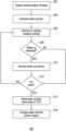
- FIG. 2illustrates an example flow diagram for a process of one embodiment of the present disclosure
- FIG. 3illustrates an example data flow diagram for a process of one embodiment of the present disclosure.
- the present disclosuregenerally provides for a plurality of circuits or other electrical devices. All references to the circuits and other electrical devices, and the functionality provided by each, are not intended to be limited to encompassing only what is illustrated and described herein. While particular labels may be assigned to the various circuits or other electrical devices, such circuits and other electrical devices may be combined with each other and/or separated in any manner based on the particular type of electrical implementation that is desired.
- any circuit or other electrical device disclosed hereinmay include any number of microprocessors, integrated circuits, memory devices (e.g., FLASH, random access memory (RAM), read only memory (ROM), electrically programmable read only memory (EPROM), electrically erasable programmable read only memory (EEPROM), or other suitable variants thereof) and software which co-act with one another to perform operation(s) disclosed herein.
- any one or more of the electric devicesmay be configured to execute a computer-program that is embodied in a non-transitory computer readable medium that is programmed to perform any number of the functions as disclosed.
- the present disclosureproposes an in-vehicle network monitoring system. More specifically, the present disclosure proposes a vehicle system for monitoring an in-vehicle network (e.g. a controller area network (CAN)) for controller activities when the vehicle is in an OFF state.
- an in-vehicle networke.g. a controller area network (CAN)
- CANcontroller area network
- a vehicle 102may include various types of automobile, crossover utility vehicle (CUV), sport utility vehicle (SUV), truck, recreational vehicle (RV), boat, plane, or other mobile machine for transporting people or goods.
- the vehicle 102may be powered by an internal combustion engine.
- the vehicle 102may be battery electric vehicle (BEV), a hybrid electric vehicle (HEV) powered by both an internal combustion engine and one or move electric motors, such as a series hybrid electric vehicle (SHEV), a parallel hybrid electric vehicle (PHEV), or a parallel/series hybrid vehicle (PSHEV), a boat, a plane or other mobile machine for transporting people or goods.
- BEVbattery electric vehicle
- HEVhybrid electric vehicle
- SHEVseries hybrid electric vehicle
- PHEVparallel hybrid electric vehicle
- PSHEVparallel/series hybrid vehicle
- the system 100may include the SYNC system manufactured by The Ford Motor Company of Dearborn, Mich. It should be noted that the illustrated system 100 is merely an example, and more, fewer, and/or differently located elements may be used.
- a computing platform 104may include one or more processors 112 configured to perform instructions, commands, and other routines in support of the processes described herein.
- the computing platform 104may be configured to execute instructions of vehicle applications 108 to provide features such as navigation, telecommunications or the like.
- Such instructions and other datamay be maintained in a non-volatile manner using a variety of types of computer-readable storage medium 106 .
- the computer-readable medium 106also referred to as a processor-readable medium or storage
- Computer-executable instructionsmay be compiled or interpreted from computer programs created using a variety of programming languages and/or technologies, including, without limitation, and either alone or in combination, Java, C, C++, C #, Objective C, Fortran, Pascal, Java Script, Python, Perl, and PL/SQL.
- the computing platform 104may be provided with various features allowing the vehicle occupants/users to interface with the computing platform 104 .
- the computing platform 104may receive input from human-machine interface (HMI) controls 118 configured to provide for occupant interaction with the vehicle 102 .
- HMIhuman-machine interface
- the computing platform 104may interface with one or more buttons (not shown) or other HMI controls configured to invoke functions on the computing platform 104 (e.g., steering wheel audio buttons, a push-to-talk button, instrument panel controls, etc.).
- HMIhuman-machine interface
- the computing platform 104may also drive or otherwise communicate with one or more displays 116 configured to provide visual output to vehicle occupants by way of a video controller 114 .
- the display 116may be a touch screen further configured to receive user touch input via the video controller 114 , while in other cases the display 116 may be a display only, without touch input capabilities.
- the computing platform 104may also drive or otherwise communicate with one or more speakers 122 configured to provide audio output to vehicle occupants by way of an audio controller 120 .
- the computing platform 104may also be provided with navigation and route planning features through a navigation controller 126 configured to calculate navigation routes responsive to user input via e.g., the HMI controls 118 , and output planned routes and instructions via the speaker 122 and the display 116 .
- Location data that is needed for navigationmay be collected from a global navigation satellite system (GNSS) controller 124 configured to communicate with multiple satellites and calculate the location of the vehicle 102 .
- GNSS controllermay be configured to support various current and/or future global or regional location systems such as global positioning system (GPS), Galileo, Beidou, Global Navigation Satellite System (GLONASS) and the like.
- Map data used for route planningmay be stored in the storage 106 as a part of the vehicle data 110 .
- Navigation softwaremay be stored in the storage 116 e.g. as one of the vehicle applications 108 .
- the computing platform 104may be configured to wirelessly communicate with a mobile device 140 of the vehicle users/occupants via a wireless connection 184 through a wireless transceiver 136 .
- the mobile device 140may be any of various types of portable computing device, such as cellular phones, tablet computers, smart watches, laptop computers, portable music players, or other device capable of communication with the computing platform 104 .
- the wireless transceiver 136may be in communication with a Wi-Fi controller 128 , a Bluetooth controller 130 , a radio-frequency identification (RFID) controller 132 , a near-field communication (NFC) controller 134 , and other controllers such as a Zigbee transceiver, an IrDA transceiver (not shown), and configured to communicate with a compatible wireless transceiver (not shown) of the mobile device 140 .
- RFIDradio-frequency identification
- NFCnear-field communication
- the computing platform 104may be further configured to communicate various electronic control units (ECUs) 152 via one or more in-vehicle network 150 .
- the in-vehicle network 150may include, but is not limited to, one or more of a CAN, an Ethernet network, and a media-oriented system transport (MOST), as some examples.
- the ECUs 152may include a telematics control unit (TCU) 154 configured to control telecommunication between vehicle 102 and a cloud 190 through a wireless connection 180 using a modem (not shown). Additionally or alternatively, the computing platform 104 may be configured to communicate with the cloud 190 via the mobile device 140 through a wireless connection 186 . The computing platform 104 may be further configured to directly communicate with the cloud 190 via the wireless transceiver 136 using compatible protocols through a wireless connection 182 .
- the cloud 190may include one or more servers, or computers connected via various types of wired or wireless networks. It is noted that the term cloud is used as a general term throughout the present disclosure and may refer to any cloud-based services involving multiple servers, computers, devices and the like.
- the ECUs 152may further include a powertrain control module (PCM) 156 configured to monitor and control the powertrain operation of the vehicle 102 .
- the PCM 156may include a vehicle immobilizer (not shown) configured to control the operating state of the vehicle 102 .
- the PCM 156may be configured to switch the vehicle 102 between an ON state and an OFF state. In the ON state, the vehicle 102 may have both the vehicle engine (or an electric motor) and the transmission active and the vehicle 102 ready to drive.
- the ECUs 152 and the in-vehicle network 150may be in a wakeup mode to fully perform vehicle functions.
- ECUs 152 and the in-vehicle network 150may be put into a sleep mode to save power, while some ECUs 152 are allowed to perform limited operations according the vehicle features.
- a body control module (BCM) 158(to be discussed below) may be configured to stay partially active to receive remote input (e.g. door lock/unlock) when the vehicle 102 is in the OFF state.
- the PCM 156may be further configured to provide an accessory (ACC) state in which the vehicle engine is not running but some ECUs 152 and the in-vehicle network 150 are waken up to provide limited vehicle features (e.g. radio, telecommunication or the like).
- ACCaccessory
- the ECUs 152may further include the BCM 156 configured to monitor and control body operations of the vehicle 102 .
- the BCM 156may be configured to control and monitor body functions such as door lock/unlock, remote controls, lighting or the like.
- the ECUs 152may further include a heating, ventilation, and air conditioning (HVAC) controllers 160 configured to monitor and control the heating, air conditioning and/or climate operations of vehicle 102 .
- the ECUs 152may further include an autonomous driving controller (ADC) 164 configured to monitor and control the autonomous driving features of the vehicle 102 .
- Some autonomous driving featuremay include lane keep assist, safe distance from other vehicles, cruise control, autobraking, brake mitigation or the like. It is noted that the ECUs 152 illustrated with reference to FIG. 1 are merely examples and the vehicle 102 may including more ECUs 152 connected to the in-vehicle network 150 or other vehicle network configurations to perform various features described or not described herein.
- the ECUs 152may further include a wake monitor 164 configured to monitor the in-vehicle network 150 for ECU activities when the vehicle 102 is in the OFF state.
- the wake monitor 164may be provided with processing power by a processor 166 configured to perform instructions, commands, and other routines in support of the processes described herein using software 168 stored locally in a storage.
- the wake monitor 164may be powered by a power source 170 independent from the power supply for the vehicle 102 .
- the power sourcemay be rechargeable lithium-ion battery or an electric capacitor located inside or attached to the wake monitor 164 to supply power to the wake monitor when the vehicle 102 is in the OFF state.
- the wake monitor 164may be configured to charge the power supply 170 using the power received from the battery or power supply of the vehicle 102 .
- the wake monitor 164may be configured to enter an active mode responsive to detecting the vehicle 102 is in the OFF state to monitor the in-vehicle network 150 for activities to find out which ECUs 152 , if any, are waking up the in-vehicle network 150 from the sleep mode.
- the wake monitor 164may record the activities occurred on the in-vehicle network 150 for future analysis to find the cause. Responsive to detecting the vehicle 102 switching out of the OFF state and entering the ON or ACC state, the wake monitor 164 may be configured to enter an inactive mode to stop monitoring the in-vehicle network 150 .
- the wake monitor 164detects the vehicle 102 enters the OFF state e.g. using signals received from the in-vehicle network 150 or by detecting the power supply from the vehicle 102 is cut off.
- the in-vehicle network 150may be configured to enter the sleep mode responsive to the vehicle 102 entering the off mode. Responsive to detecting the vehicle 102 has entered the off mode, the wake monitor activates the wake monitor feature and detect signals transmitted via the in-vehicle network 150 .
- the wake monitor 164may detect which ECU 152 is waking up the in-vehicle network 150 and what cause the ECU 152 to wake up the in-vehicle network 150 by recording the data on the in-vehicle network 150 .
- the wake monitor 164detects if the vehicle 102 enters the ON state such as when a user starts to use the vehicle 102 . If the answer is a no, the process returns to operation 206 and the wake monitor continues to monitor the in-vehicle network 150 . Otherwise, if the wake monitor 164 detects the vehicle 102 has entered the ON state, the process proceeds to operation 214 and the wake monitor 164 deactivates the monitor feature and sends the recorded wakeup record to computing platform 104 and/or the TCU 154 to send out to the cloud for analysis. As an example, the computing platform 104 may serve an enhanced central gateway to coordinate the telecommunication and data report. At operation 216 , the wake monitor 164 charges the power supply 170 using the power received from the vehicle 102 .
- the operations of the process 200may be applied to various situations. For instance, referring to FIG. 3 , an example data flow diagram 300 of one embodiment of the present disclosure is illustrated.
- the vehicle 102turns off and enters the OFF state.
- the in-vehicle network 150enters a sleep mode to save power.
- the wake monitor 164activates the monitor feature and starts to monitor the in-vehicle network 150 for activities at operation 304 .
- some ECUsmay perform internal operations when the vehicle is in the OFF state.
- the BCM 158may perform some internal operations 306 without communicating with other components of the vehicle 102 via the in-vehicle network 150 at operation 306 .
- the computing platform 104may also perform internal operation 306 .
- Such internal operationsmay not be detectable by the wake monitor because the in-vehicle network 150 is still asleep.
- the BCMsends a signal to the in-vehicle network 150 to communicate with other ECUs/components of the vehicle 102 at operation 312 .
- the in-vehicle network 150wakes up from the sleep mode to perform/facilitate the signal communication between the BCM 158 , the PCM 156 and the computing platform 104 .
- the wake monitor 164records activities on the in-vehicle network 150 . For instance, the wake monitor 164 may record the time of each signal communication 308 and 312 .
- the wake monitor 164may record the identity of the ECUs 152 involved in the transaction, especially the identity of the source ECU initiating the signal communication, which in the present example, is the BCM 158 .
- the in-vehicle network 150is in the wakeup mode, the vehicle 102 is still in the OFF state.
- the wake monitor 164may detect the vehicle 102 the vehicle 102 is still in the OFF state through various means such as the power supply or the like.
- the wake monitor 164may be configured to save the activity record and not send the record out until later when the vehicle 102 enters the ON or ACC state, to save power and avoid contaminating the signals on the in-vehicle network 150 during the vehicle OFF state.
- the vehicle 102is turned on and enters the ON (or ACC) state.
- the wake monitor 164sends the activity record to the TCU 154 (or the computing platform 104 ) via the in-vehicle network 150 at operations 318 and 322 .
- the wake monitor 164deactivates the monitor feature at operation 320 . Since the vehicle 102 is turned on and other ECUs 152 are activated, there will be many signals on the in-vehicle network 150 and keep monitoring will not be very useful.
- the TCU 154sends the activity record to the cloud 190 for analysis to identify patterns of unnecessary or abnormal ECU activities.
- the activity recordmay be sent to the cloud 190 via the mobile device 140 or the wireless transceiver 136 wirelessly connected to the cloud.
- the analysis operation 326 in the cloudmay be automatically performed by a server using a pre-defined algorithm. Additionally or alternatively, the analysis 326 may be performed manually by engineers and technician associated with the cloud 190 .
- the cloud 190sends a software update and/or an instruction to the TCU 154 to address the issue.
- cloudmay detect the abnormal ECU activities to be caused by a software glitch and can be fixed by a software update.
- the cloudmay send an instruction to the vehicle 102 to advise the vehicle user to take the vehicle 102 to a dealer for further examination.
Landscapes
- Engineering & Computer Science (AREA)
- Computer Networks & Wireless Communication (AREA)
- Signal Processing (AREA)
- Mechanical Engineering (AREA)
- Health & Medical Sciences (AREA)
- Computing Systems (AREA)
- General Health & Medical Sciences (AREA)
- Medical Informatics (AREA)
- Automation & Control Theory (AREA)
- Small-Scale Networks (AREA)
- Electric Propulsion And Braking For Vehicles (AREA)
- Traffic Control Systems (AREA)
Abstract
Description
Claims (20)
Priority Applications (3)
| Application Number | Priority Date | Filing Date | Title |
|---|---|---|---|
| US16/245,697US11639142B2 (en) | 2019-01-11 | 2019-01-11 | Electronic control module wake monitor |
| CN202010012737.0ACN111434535A (en) | 2019-01-11 | 2020-01-07 | Electronic control module wake-up monitor |
| DE102020100377.3ADE102020100377A1 (en) | 2019-01-11 | 2020-01-09 | WAKE-UP MONITORING DEVICE FOR ELECTRONIC CONTROL MODULE |
Applications Claiming Priority (1)
| Application Number | Priority Date | Filing Date | Title |
|---|---|---|---|
| US16/245,697US11639142B2 (en) | 2019-01-11 | 2019-01-11 | Electronic control module wake monitor |
Publications (2)
| Publication Number | Publication Date |
|---|---|
| US20200223376A1 US20200223376A1 (en) | 2020-07-16 |
| US11639142B2true US11639142B2 (en) | 2023-05-02 |
Family
ID=71132211
Family Applications (1)
| Application Number | Title | Priority Date | Filing Date |
|---|---|---|---|
| US16/245,697Active2040-08-31US11639142B2 (en) | 2019-01-11 | 2019-01-11 | Electronic control module wake monitor |
Country Status (3)
| Country | Link |
|---|---|
| US (1) | US11639142B2 (en) |
| CN (1) | CN111434535A (en) |
| DE (1) | DE102020100377A1 (en) |
Families Citing this family (11)
| Publication number | Priority date | Publication date | Assignee | Title |
|---|---|---|---|---|
| JP7352166B2 (en)* | 2019-10-31 | 2023-09-28 | 株式会社オートネットワーク技術研究所 | In-vehicle communication system, in-vehicle communication device and communication method for vehicle |
| JP7272295B2 (en)* | 2020-01-31 | 2023-05-12 | トヨタ自動車株式会社 | vehicle |
| FR3122931B1 (en)* | 2021-05-11 | 2024-08-02 | Psa Automobiles Sa | Method and device for controlling a set of calculators of a vehicle |
| JP7517259B2 (en)* | 2021-06-15 | 2024-07-17 | トヨタ自動車株式会社 | Information processing device, vehicle system, information processing method, and program |
| DE102021206982A1 (en) | 2021-07-02 | 2023-01-05 | Universität Paderborn, Körperschaft des öffentlichen Rechts | Transformerless on-board electric vehicle charger and method for driving a DC/DC stage in a transformerless on-board electric vehicle charger |
| CN113715756B (en)* | 2021-08-09 | 2024-04-12 | 阿尔特汽车技术股份有限公司 | Vehicle equipment management method and system and corresponding vehicle |
| US11608028B1 (en)* | 2021-09-03 | 2023-03-21 | Rivian Ip Holdings, Llc | Systems and methods for multi-zoned vehicle wake up |
| JP7643277B2 (en)* | 2021-09-28 | 2025-03-11 | トヨタ自動車株式会社 | VEHICLE CONTROL INTERFACE, AUTONOMOUS DRIVING SYSTEM AND VEHICLE EQUIPPED WITH SAME, AND VEHICLE CONTROL METHOD |
| JP7537402B2 (en)* | 2021-09-28 | 2024-08-21 | トヨタ自動車株式会社 | Vehicle platform, autonomous driving system, and vehicle control interface box |
| CN115208792B (en)* | 2022-06-27 | 2023-11-03 | 东风汽车集团股份有限公司 | Multi-network-segment whole-vehicle CAN network anomaly monitoring method based on Autosar network management |
| CN116319870A (en)* | 2023-02-28 | 2023-06-23 | 重庆长安汽车股份有限公司 | A vehicle abnormal wake-up monitoring method, device, equipment and medium |
Citations (81)
| Publication number | Priority date | Publication date | Assignee | Title |
|---|---|---|---|---|
| US5419824A (en) | 1992-11-12 | 1995-05-30 | Weres; Oleh | Electrode, electrode manufacturing process and electrochemical cell |
| US5531875A (en) | 1993-08-24 | 1996-07-02 | Permelec Electrode Co., Ltd. | Electrode substrate for electrolysis and production method thereof |
| US6063142A (en) | 1994-12-01 | 2000-05-16 | Canon Kabushiki Kaisha | Process for producing a rechargeable lithium battery having an improved anode coated by a film containing a specific metal oxide material |
| US6326098B1 (en) | 1998-04-23 | 2001-12-04 | N. E. Chemcat Corporation | Electrocatalyst, and electrodes, membrane-electrode assembly and solid polymer electrolyte fuel cells, using said electrocatalyst |
| US6430485B1 (en) | 2000-07-06 | 2002-08-06 | International Truck Intellectual Property Company, L.L.C. | Wireless interface adaptor for remote diagnosis and programming of vehicle control systems |
| US20030139939A1 (en) | 2001-05-10 | 2003-07-24 | Spool Peter R. | Business management system and method for a deregulated electric power market using consumer site anomaly detection |
| US20030167354A1 (en) | 2002-03-01 | 2003-09-04 | Dell Products L.P. | Method and apparatus for automated operating systems upgrade |
| US6636790B1 (en) | 2000-07-25 | 2003-10-21 | Reynolds And Reynolds Holdings, Inc. | Wireless diagnostic system and method for monitoring vehicles |
| JP2004099355A (en) | 2002-09-06 | 2004-04-02 | Tsunemi Ochiai | Graphite powder, method for producing the same, and conductive material for battery comprising the same |
| US20040187011A1 (en) | 2003-03-18 | 2004-09-23 | Lee Long K. | Prevention of unauthorized software distribution |
| US20040197641A1 (en) | 2002-10-15 | 2004-10-07 | Polyplus Battery Company | Active metal/aqueous electrochemical cells and systems |
| US20040197541A1 (en) | 2001-08-02 | 2004-10-07 | Joseph Zahka | Selective electroless deposition and interconnects made therefrom |
| US20040261073A1 (en) | 2003-06-20 | 2004-12-23 | Samsung Electronics Co., Ltd. | Apparatus and method for performing a fail-safe over-the-air software update in a mobile station |
| US20050079402A1 (en) | 2002-03-20 | 2005-04-14 | Matsushita Electric Industrial Co., Ltd. | Fuel cell |
| US20050149481A1 (en) | 1999-12-02 | 2005-07-07 | Lambertus Hesselink | Managed peer-to-peer applications, systems and methods for distributed data access and storage |
| US20050152318A1 (en) | 2004-01-13 | 2005-07-14 | General Motors Corporation. | Efficient lightweight information dissemination algorithm for mobile wireless Ad Hoc networks |
| US20050216903A1 (en) | 2004-03-23 | 2005-09-29 | General Motors Corporation | Method and system for vehicle software configuration management |
| US20050216902A1 (en) | 2004-03-23 | 2005-09-29 | General Motors Corporation | Method and system for vehicle software configuration update management |
| DE102004017602A1 (en) | 2004-04-07 | 2005-10-27 | Volkswagen Ag | Direct vehicle to vehicle communication network procedure for traffic, route and incident data receives or updates confidence information and tests it for further use |
| US20050256614A1 (en) | 2004-05-13 | 2005-11-17 | General Motors Corporation | Method and system for remote reflash |
| JP2006228546A (en) | 2005-02-17 | 2006-08-31 | Mitsui Eng & Shipbuild Co Ltd | ELECTRODE CATALYST FOR SOLID POLYMER FUEL CELL AND METHOD FOR PRODUCING THE SAME |
| US20070042252A1 (en) | 2005-08-16 | 2007-02-22 | Kazarinov Rudolf F | Solid state, thin film proton exchange membrane for fuel cells |
| US20070083304A1 (en) | 2005-10-06 | 2007-04-12 | Denso Corporation | On-vehicle network diagnosis system and on-vehicle control apparatus thereof |
| US20070168957A1 (en) | 2005-11-08 | 2007-07-19 | Red Hat, Inc. | Certifying a software application based on identifying interface usage |
| US20070185646A1 (en) | 2006-02-09 | 2007-08-09 | Mario Neugebauer | Transmission of sensor data based on geographical navigation data |
| US20070185624A1 (en) | 2006-02-07 | 2007-08-09 | General Motors Corporation | Method for remote reprogramming of vehicle flash memory |
| US20070248874A1 (en) | 2004-04-26 | 2007-10-25 | Toyota Jidoshia Kabushiki Kaisha | Hydrogen Separation Membrane and Fuel Cell, and Manufacturing Method Therefor |
| US20070259267A1 (en) | 2004-08-19 | 2007-11-08 | Japan Science And Technology Agency | Metal Oxide Electrode Catalyst |
| US20080005733A1 (en) | 2006-06-29 | 2008-01-03 | Balaji Ramachandran | Method and apparatus for updating firmware and software |
| US20080162036A1 (en) | 1997-10-22 | 2008-07-03 | Intelligent Technologies International, Inc. | Vehicular Map Database Management Techniques |
| US20080167758A1 (en) | 2007-01-08 | 2008-07-10 | Ford Global Technologies, Llc | Wireless Gateway Apparatus and Method of Bridging Data Between Vehicle Based and External Data Networks |
| US7426633B2 (en) | 2005-05-12 | 2008-09-16 | Hewlett-Packard Development Company, L.P. | System and method for reflashing disk drive firmware |
| US7449132B2 (en) | 2003-11-28 | 2008-11-11 | Jsr Corporation | Proton conductive composition and proton conductive membrane |
| US20080312070A1 (en) | 2005-05-12 | 2008-12-18 | Peter Cade Talbot | Method for Making a Material |
| WO2009027208A1 (en) | 2007-08-29 | 2009-03-05 | Continental Teves Ag & Co. Ohg | Method and device for adjusting of a driving dynamics system in a motor vehicle |
| US20090081511A1 (en) | 2005-03-18 | 2009-03-26 | Kuninori Miyazaki | Electrode Catalyst for Fuel Cell |
| GB2434884B (en) | 2004-12-02 | 2009-04-08 | Ford Motor Co | Computer system and method for monitoring hydrogen vehicles |
| US20090162750A1 (en) | 2007-09-06 | 2009-06-25 | Canon Kabushiki Kaisha | Method of producing lithium ion-storing/releasing material, lithium ion-storing/releasing material, and electrode structure and energy storage device using the material |
| US20090208780A1 (en) | 2008-02-19 | 2009-08-20 | Cabot Corporation | High surface area graphitized carbon and processes for making same |
| US20090260057A1 (en) | 2008-04-11 | 2009-10-15 | Toyota Motor Engineering & Manufacturing North America, Inc. | Method for distributing a list of certificate revocations in a vanet |
| US20090265633A1 (en) | 2008-04-22 | 2009-10-22 | Hyundai Motor Company | Network gateway for a vehicle |
| US20100021819A1 (en) | 2008-07-28 | 2010-01-28 | Aruna Zhamu | Graphene nanocomposites for electrochemical cell electrodes |
| US7694293B2 (en) | 2003-09-26 | 2010-04-06 | Hewlett-Packard Development Company, L.P. | Update package catalog for update package transfer between generator and content server in a network |
| US7704918B2 (en) | 2005-05-19 | 2010-04-27 | Brookhaven Science Associates, Llc | Synthesis of metal-metal oxide catalysts and electrocatalysts using a metal cation adsorption/reduction and adatom replacement by more noble ones |
| US20100120373A1 (en)* | 2008-11-13 | 2010-05-13 | Timothy John Wheatley | Synchronization of vehicle data |
| US20100127857A1 (en)* | 2008-11-21 | 2010-05-27 | Kilmurray Paul A | Diagnostic system having a wake-up circuit |
| US7848278B2 (en) | 2006-10-23 | 2010-12-07 | Telcordia Technologies, Inc. | Roadside network unit and method of organizing, managing and maintaining local network using local peer groups as network groups |
| US20110033746A1 (en) | 2009-08-10 | 2011-02-10 | Jun Liu | Self assembled multi-layer nanocomposite of graphene and metal oxide materials |
| US20110078675A1 (en) | 2009-09-25 | 2011-03-31 | Fisher-Rosemount Systems, Inc. | Automated Deployment of Computer-Specific Software Updates |
| WO2011056290A2 (en) | 2009-10-07 | 2011-05-12 | Molecular Nanosystems, Inc. | Methods and systems for making battery electrodes and devices arising therefrom |
| CN102142538A (en) | 2011-02-25 | 2011-08-03 | 浙江大学 | A lithium ion battery electrode of graphene/MoS2 and amorphous carbon and its preparation method |
| US20110207019A1 (en) | 2008-09-18 | 2011-08-25 | Sanjeev Mukerjee | Platinum alloy electrocatalyst with enhanced resistance to anion poisoning for low and medium temperature fuel cells |
| US20120077095A1 (en) | 2010-09-09 | 2012-03-29 | Roumi Farshid | Electrochemical Energy Storage Systems and Methods |
| WO2012046138A1 (en) | 2010-10-08 | 2012-04-12 | Toyota Jidosha Kabushiki Kaisha | Catalyst particles, carbon-supported catalyst particles and fuel cell catalysts, and methods of manufacturing such catalyst particles and carbon-supported catalyst particles |
| US20120091425A1 (en) | 2009-06-18 | 2012-04-19 | Yoshio Kawashima | Nonvolatile memory device and manufacturing method thereof |
| CN102423705A (en) | 2011-10-17 | 2012-04-25 | 中国科学院山西煤炭化学研究所 | Oxygen reduction catalyst for fuel cell and preparation method thereof |
| US20120125154A1 (en) | 2009-05-28 | 2012-05-24 | Arumugam Manthiram | Novel composite anode materials for lithium ion batteries |
| US8187745B2 (en) | 2008-06-30 | 2012-05-29 | Kabushiki Kaisha Toshiba | Cathode for fuel cell |
| US20120144378A1 (en) | 2010-12-06 | 2012-06-07 | Red Hat, Inc. | Methods for managing software packages using a version control system |
| US20120145037A1 (en) | 2007-12-21 | 2012-06-14 | Envont Llc | Hybrid Vehicle Systems |
| US20120178018A1 (en) | 2009-09-22 | 2012-07-12 | Basf Se | Catalyst with metal oxide doping for fuel cells |
| US20120183869A1 (en) | 2011-01-13 | 2012-07-19 | Samsung Electronics Co., Ltd. | Catalyst including active particles, method of preparing the catalyst, fuel cell including the catalyst, electrode including the active particles for lithium air battery, and lithium air battery including the electrode |
| US20120189943A1 (en) | 2009-09-30 | 2012-07-26 | Ford Motor Company | Synthesis of stable and durable catalyst composition for fuel cell |
| US8273504B2 (en) | 2004-10-29 | 2012-09-25 | Umicore Ag & Co. Kg | Method for manufacture of noble metal alloy catalysts and catalysts prepared therewith |
| US20120245397A1 (en) | 2011-03-21 | 2012-09-27 | Saudi Arabian Oil Company | Hydrated Niobium Oxide Nanoparticle Containing Catalysts for Olefin Hydration |
| WO2012133136A1 (en) | 2011-03-25 | 2012-10-04 | 学校法人同志社 | Anode for electrowinning and electrowinning method using same |
| US20130005567A1 (en) | 2010-03-17 | 2013-01-03 | Arunachala Kannan | Durable platinum / multi-walled carbon nanotube catalysts |
| US20130031540A1 (en) | 2011-07-26 | 2013-01-31 | Ford Global Technologies, Llc | Method and Apparatus for Automatic Module Upgrade |
| US20130245884A1 (en) | 2012-03-19 | 2013-09-19 | Qualcomm Incorporated | User experience of the connected automobile |
| US8555273B1 (en) | 2003-09-17 | 2013-10-08 | Palm. Inc. | Network for updating electronic devices |
| US20130326495A1 (en) | 2012-06-01 | 2013-12-05 | Nokia Corporation | Wireless programming |
| US8655541B2 (en) | 2011-09-22 | 2014-02-18 | Hyundai Motor Company | Vehicle upgrade system and method thereof |
| US20140245284A1 (en) | 2013-02-25 | 2014-08-28 | GM Global Technology Operations LLC | System and method to improve control module reflash time |
| US20140282467A1 (en) | 2013-03-14 | 2014-09-18 | Ford Global Technologies, Llc | Method and Apparatus for Multiple Vehicle Software Module Reflash |
| US20150128123A1 (en) | 2013-11-06 | 2015-05-07 | General Motors Llc | System and Method for Preparing Vehicle for Remote Reflash Event |
| EP2891581A1 (en) | 2012-08-31 | 2015-07-08 | Hitachi Automotive Systems, Ltd. | Vehicle control system, and vehicular electronic control unit |
| US20160266886A1 (en) | 2015-03-10 | 2016-09-15 | GM Global Technology Operations LLC | Performing a vehicle update |
| US9468909B2 (en) | 2014-06-27 | 2016-10-18 | Ford Global Technologies, Llc | Metal oxide stabilized platinum-based ORR catalyst |
| US9727115B1 (en)* | 2005-05-30 | 2017-08-08 | Invent.Ly, Llc | Smart security device with status communication mode |
| US20180075674A1 (en) | 2015-03-17 | 2018-03-15 | Hitachi Automotive Systems, Ltd. | Vehicular control device and method of controlling vehicular control device |
| US10474213B1 (en)* | 2005-05-30 | 2019-11-12 | Invent.Ly, Llc | Predictive power management in a wireless sensor network using scheduling data |
- 2019
- 2019-01-11USUS16/245,697patent/US11639142B2/enactiveActive
- 2020
- 2020-01-07CNCN202010012737.0Apatent/CN111434535A/enactivePending
- 2020-01-09DEDE102020100377.3Apatent/DE102020100377A1/enactivePending
Patent Citations (87)
| Publication number | Priority date | Publication date | Assignee | Title |
|---|---|---|---|---|
| US5419824A (en) | 1992-11-12 | 1995-05-30 | Weres; Oleh | Electrode, electrode manufacturing process and electrochemical cell |
| US5531875A (en) | 1993-08-24 | 1996-07-02 | Permelec Electrode Co., Ltd. | Electrode substrate for electrolysis and production method thereof |
| US6063142A (en) | 1994-12-01 | 2000-05-16 | Canon Kabushiki Kaisha | Process for producing a rechargeable lithium battery having an improved anode coated by a film containing a specific metal oxide material |
| US20080162036A1 (en) | 1997-10-22 | 2008-07-03 | Intelligent Technologies International, Inc. | Vehicular Map Database Management Techniques |
| US6326098B1 (en) | 1998-04-23 | 2001-12-04 | N. E. Chemcat Corporation | Electrocatalyst, and electrodes, membrane-electrode assembly and solid polymer electrolyte fuel cells, using said electrocatalyst |
| US20050149481A1 (en) | 1999-12-02 | 2005-07-07 | Lambertus Hesselink | Managed peer-to-peer applications, systems and methods for distributed data access and storage |
| US6430485B1 (en) | 2000-07-06 | 2002-08-06 | International Truck Intellectual Property Company, L.L.C. | Wireless interface adaptor for remote diagnosis and programming of vehicle control systems |
| US6636790B1 (en) | 2000-07-25 | 2003-10-21 | Reynolds And Reynolds Holdings, Inc. | Wireless diagnostic system and method for monitoring vehicles |
| US6732031B1 (en) | 2000-07-25 | 2004-05-04 | Reynolds And Reynolds Holdings, Inc. | Wireless diagnostic system for vehicles |
| US20030139939A1 (en) | 2001-05-10 | 2003-07-24 | Spool Peter R. | Business management system and method for a deregulated electric power market using consumer site anomaly detection |
| US20040197541A1 (en) | 2001-08-02 | 2004-10-07 | Joseph Zahka | Selective electroless deposition and interconnects made therefrom |
| US20030167354A1 (en) | 2002-03-01 | 2003-09-04 | Dell Products L.P. | Method and apparatus for automated operating systems upgrade |
| US20050079402A1 (en) | 2002-03-20 | 2005-04-14 | Matsushita Electric Industrial Co., Ltd. | Fuel cell |
| JP2004099355A (en) | 2002-09-06 | 2004-04-02 | Tsunemi Ochiai | Graphite powder, method for producing the same, and conductive material for battery comprising the same |
| US20040197641A1 (en) | 2002-10-15 | 2004-10-07 | Polyplus Battery Company | Active metal/aqueous electrochemical cells and systems |
| US20040187011A1 (en) | 2003-03-18 | 2004-09-23 | Lee Long K. | Prevention of unauthorized software distribution |
| US20040261073A1 (en) | 2003-06-20 | 2004-12-23 | Samsung Electronics Co., Ltd. | Apparatus and method for performing a fail-safe over-the-air software update in a mobile station |
| US8555273B1 (en) | 2003-09-17 | 2013-10-08 | Palm. Inc. | Network for updating electronic devices |
| US7694293B2 (en) | 2003-09-26 | 2010-04-06 | Hewlett-Packard Development Company, L.P. | Update package catalog for update package transfer between generator and content server in a network |
| US7449132B2 (en) | 2003-11-28 | 2008-11-11 | Jsr Corporation | Proton conductive composition and proton conductive membrane |
| US20050152318A1 (en) | 2004-01-13 | 2005-07-14 | General Motors Corporation. | Efficient lightweight information dissemination algorithm for mobile wireless Ad Hoc networks |
| US20050216903A1 (en) | 2004-03-23 | 2005-09-29 | General Motors Corporation | Method and system for vehicle software configuration management |
| US7506309B2 (en) | 2004-03-23 | 2009-03-17 | General Motors Corporation | Method for managing vehicle software configuration updates |
| US20050216902A1 (en) | 2004-03-23 | 2005-09-29 | General Motors Corporation | Method and system for vehicle software configuration update management |
| DE102004017602A1 (en) | 2004-04-07 | 2005-10-27 | Volkswagen Ag | Direct vehicle to vehicle communication network procedure for traffic, route and incident data receives or updates confidence information and tests it for further use |
| US20070248874A1 (en) | 2004-04-26 | 2007-10-25 | Toyota Jidoshia Kabushiki Kaisha | Hydrogen Separation Membrane and Fuel Cell, and Manufacturing Method Therefor |
| US7366589B2 (en) | 2004-05-13 | 2008-04-29 | General Motors Corporation | Method and system for remote reflash |
| US20050256614A1 (en) | 2004-05-13 | 2005-11-17 | General Motors Corporation | Method and system for remote reflash |
| US20070259267A1 (en) | 2004-08-19 | 2007-11-08 | Japan Science And Technology Agency | Metal Oxide Electrode Catalyst |
| US8273504B2 (en) | 2004-10-29 | 2012-09-25 | Umicore Ag & Co. Kg | Method for manufacture of noble metal alloy catalysts and catalysts prepared therewith |
| GB2434884B (en) | 2004-12-02 | 2009-04-08 | Ford Motor Co | Computer system and method for monitoring hydrogen vehicles |
| JP2006228546A (en) | 2005-02-17 | 2006-08-31 | Mitsui Eng & Shipbuild Co Ltd | ELECTRODE CATALYST FOR SOLID POLYMER FUEL CELL AND METHOD FOR PRODUCING THE SAME |
| US20090081511A1 (en) | 2005-03-18 | 2009-03-26 | Kuninori Miyazaki | Electrode Catalyst for Fuel Cell |
| US20080312070A1 (en) | 2005-05-12 | 2008-12-18 | Peter Cade Talbot | Method for Making a Material |
| US7426633B2 (en) | 2005-05-12 | 2008-09-16 | Hewlett-Packard Development Company, L.P. | System and method for reflashing disk drive firmware |
| US7704918B2 (en) | 2005-05-19 | 2010-04-27 | Brookhaven Science Associates, Llc | Synthesis of metal-metal oxide catalysts and electrocatalysts using a metal cation adsorption/reduction and adatom replacement by more noble ones |
| US10474213B1 (en)* | 2005-05-30 | 2019-11-12 | Invent.Ly, Llc | Predictive power management in a wireless sensor network using scheduling data |
| US9727115B1 (en)* | 2005-05-30 | 2017-08-08 | Invent.Ly, Llc | Smart security device with status communication mode |
| US20070042252A1 (en) | 2005-08-16 | 2007-02-22 | Kazarinov Rudolf F | Solid state, thin film proton exchange membrane for fuel cells |
| US20070083304A1 (en) | 2005-10-06 | 2007-04-12 | Denso Corporation | On-vehicle network diagnosis system and on-vehicle control apparatus thereof |
| US8332817B2 (en) | 2005-11-08 | 2012-12-11 | Red Hat, Inc. | Certifying a software application based on identifying interface usage |
| US20070168957A1 (en) | 2005-11-08 | 2007-07-19 | Red Hat, Inc. | Certifying a software application based on identifying interface usage |
| US20070185624A1 (en) | 2006-02-07 | 2007-08-09 | General Motors Corporation | Method for remote reprogramming of vehicle flash memory |
| US20070185646A1 (en) | 2006-02-09 | 2007-08-09 | Mario Neugebauer | Transmission of sensor data based on geographical navigation data |
| US20080005733A1 (en) | 2006-06-29 | 2008-01-03 | Balaji Ramachandran | Method and apparatus for updating firmware and software |
| US7848278B2 (en) | 2006-10-23 | 2010-12-07 | Telcordia Technologies, Inc. | Roadside network unit and method of organizing, managing and maintaining local network using local peer groups as network groups |
| US20080167758A1 (en) | 2007-01-08 | 2008-07-10 | Ford Global Technologies, Llc | Wireless Gateway Apparatus and Method of Bridging Data Between Vehicle Based and External Data Networks |
| WO2009027208A1 (en) | 2007-08-29 | 2009-03-05 | Continental Teves Ag & Co. Ohg | Method and device for adjusting of a driving dynamics system in a motor vehicle |
| US20090162750A1 (en) | 2007-09-06 | 2009-06-25 | Canon Kabushiki Kaisha | Method of producing lithium ion-storing/releasing material, lithium ion-storing/releasing material, and electrode structure and energy storage device using the material |
| US20120145037A1 (en) | 2007-12-21 | 2012-06-14 | Envont Llc | Hybrid Vehicle Systems |
| US20090208780A1 (en) | 2008-02-19 | 2009-08-20 | Cabot Corporation | High surface area graphitized carbon and processes for making same |
| US20090260057A1 (en) | 2008-04-11 | 2009-10-15 | Toyota Motor Engineering & Manufacturing North America, Inc. | Method for distributing a list of certificate revocations in a vanet |
| US20090262714A1 (en) | 2008-04-22 | 2009-10-22 | Hyundai Motor Company | Network gateway and network system for a vehicle |
| US20090265633A1 (en) | 2008-04-22 | 2009-10-22 | Hyundai Motor Company | Network gateway for a vehicle |
| US8187745B2 (en) | 2008-06-30 | 2012-05-29 | Kabushiki Kaisha Toshiba | Cathode for fuel cell |
| US20100021819A1 (en) | 2008-07-28 | 2010-01-28 | Aruna Zhamu | Graphene nanocomposites for electrochemical cell electrodes |
| US20110207019A1 (en) | 2008-09-18 | 2011-08-25 | Sanjeev Mukerjee | Platinum alloy electrocatalyst with enhanced resistance to anion poisoning for low and medium temperature fuel cells |
| US20100120373A1 (en)* | 2008-11-13 | 2010-05-13 | Timothy John Wheatley | Synchronization of vehicle data |
| US20100127857A1 (en)* | 2008-11-21 | 2010-05-27 | Kilmurray Paul A | Diagnostic system having a wake-up circuit |
| US20120125154A1 (en) | 2009-05-28 | 2012-05-24 | Arumugam Manthiram | Novel composite anode materials for lithium ion batteries |
| US20120091425A1 (en) | 2009-06-18 | 2012-04-19 | Yoshio Kawashima | Nonvolatile memory device and manufacturing method thereof |
| US20110033746A1 (en) | 2009-08-10 | 2011-02-10 | Jun Liu | Self assembled multi-layer nanocomposite of graphene and metal oxide materials |
| US20120178018A1 (en) | 2009-09-22 | 2012-07-12 | Basf Se | Catalyst with metal oxide doping for fuel cells |
| US20110078675A1 (en) | 2009-09-25 | 2011-03-31 | Fisher-Rosemount Systems, Inc. | Automated Deployment of Computer-Specific Software Updates |
| US20120189943A1 (en) | 2009-09-30 | 2012-07-26 | Ford Motor Company | Synthesis of stable and durable catalyst composition for fuel cell |
| WO2011056290A2 (en) | 2009-10-07 | 2011-05-12 | Molecular Nanosystems, Inc. | Methods and systems for making battery electrodes and devices arising therefrom |
| US20130005567A1 (en) | 2010-03-17 | 2013-01-03 | Arunachala Kannan | Durable platinum / multi-walled carbon nanotube catalysts |
| US20120077095A1 (en) | 2010-09-09 | 2012-03-29 | Roumi Farshid | Electrochemical Energy Storage Systems and Methods |
| WO2012046138A1 (en) | 2010-10-08 | 2012-04-12 | Toyota Jidosha Kabushiki Kaisha | Catalyst particles, carbon-supported catalyst particles and fuel cell catalysts, and methods of manufacturing such catalyst particles and carbon-supported catalyst particles |
| US20120144378A1 (en) | 2010-12-06 | 2012-06-07 | Red Hat, Inc. | Methods for managing software packages using a version control system |
| US20120183869A1 (en) | 2011-01-13 | 2012-07-19 | Samsung Electronics Co., Ltd. | Catalyst including active particles, method of preparing the catalyst, fuel cell including the catalyst, electrode including the active particles for lithium air battery, and lithium air battery including the electrode |
| CN102142538A (en) | 2011-02-25 | 2011-08-03 | 浙江大学 | A lithium ion battery electrode of graphene/MoS2 and amorphous carbon and its preparation method |
| US20120245397A1 (en) | 2011-03-21 | 2012-09-27 | Saudi Arabian Oil Company | Hydrated Niobium Oxide Nanoparticle Containing Catalysts for Olefin Hydration |
| WO2012133136A1 (en) | 2011-03-25 | 2012-10-04 | 学校法人同志社 | Anode for electrowinning and electrowinning method using same |
| US20140054180A1 (en) | 2011-03-25 | 2014-02-27 | The Doshisha | Anode for electrowinning and method for electrowinning using same |
| US20130031540A1 (en) | 2011-07-26 | 2013-01-31 | Ford Global Technologies, Llc | Method and Apparatus for Automatic Module Upgrade |
| US8655541B2 (en) | 2011-09-22 | 2014-02-18 | Hyundai Motor Company | Vehicle upgrade system and method thereof |
| CN102423705A (en) | 2011-10-17 | 2012-04-25 | 中国科学院山西煤炭化学研究所 | Oxygen reduction catalyst for fuel cell and preparation method thereof |
| US20130245884A1 (en) | 2012-03-19 | 2013-09-19 | Qualcomm Incorporated | User experience of the connected automobile |
| US20130326495A1 (en) | 2012-06-01 | 2013-12-05 | Nokia Corporation | Wireless programming |
| EP2891581A1 (en) | 2012-08-31 | 2015-07-08 | Hitachi Automotive Systems, Ltd. | Vehicle control system, and vehicular electronic control unit |
| US20140245284A1 (en) | 2013-02-25 | 2014-08-28 | GM Global Technology Operations LLC | System and method to improve control module reflash time |
| US20140282467A1 (en) | 2013-03-14 | 2014-09-18 | Ford Global Technologies, Llc | Method and Apparatus for Multiple Vehicle Software Module Reflash |
| US20150128123A1 (en) | 2013-11-06 | 2015-05-07 | General Motors Llc | System and Method for Preparing Vehicle for Remote Reflash Event |
| US9468909B2 (en) | 2014-06-27 | 2016-10-18 | Ford Global Technologies, Llc | Metal oxide stabilized platinum-based ORR catalyst |
| US20160266886A1 (en) | 2015-03-10 | 2016-09-15 | GM Global Technology Operations LLC | Performing a vehicle update |
| US20180075674A1 (en) | 2015-03-17 | 2018-03-15 | Hitachi Automotive Systems, Ltd. | Vehicular control device and method of controlling vehicular control device |
Non-Patent Citations (29)
| Title |
|---|
| Baker et al., Enhanced Oxygen Reduction Activity in Acid by Tin-Oxide Supported Au Nanoparticle Catalysts, Journal of The Electrochemical Society, 153 (9) A1702-A1707 (2006), 6 Pages. |
| Baturina et al., Oxygen Reduction Reaction on Platinum/Tantalum Oxide Electrocatalysts for PEM Fuel Cells, Journal of The Electrochemical Society, 155 (12) B1314-B1321, 2008. |
| Dong et al., Apr. 19, 2011. Graphene-Supported Platinum and Platinum-Ruthenium Nanoparticles for Fuel Cell Applications, Physics and Applications of Graphene—Experiments, Dr. Sergey Mikhailov (Ed.), ISBN 978-953-307-217-3, InTech, p. 525-541, 17 pages total. |
| Drew Technologies—CarDAQ-Plus J2534 Pass-Thru & Hosting Device, printed from allobd.com/proddetail, Oct. 29, 2010, 4 Pages. |
| First Office Action for Chinese Application No. 201210252758.5, dated Jul. 20, 2016, 8 Pages. |
| Ford Motor Company, "SYNC with Navigation System," Owner's Guide Supplement, SYNC System Version 1 (Jul. 2007), 164 Pages. |
| Ford Motor Company, "SYNC with Navigation System," Owner's Guide Supplement, SYNC System Version 2 (Oct. 2008), 194 Pages. |
| Ford Motor Company, "SYNC with Navigation System," Owner's Guide Supplement, SYNC System Version 3 (Jul. 2009), 196 Pages. |
| Ford Motor Company, "SYNC," Owner's Guide Supplement, SYNC System Version 1 (Nov. 2007), 86 Pages. |
| Ford Motor Company, "SYNC," Owner's Guide Supplement, SYNC System Version 2 (Oct. 2008), 83 Pages. |
| Ford Motor Company, "SYNC," Owner's Guide Supplement, SYNC System Version 3 (Aug. 2009), 87 Pages. |
| Garsany et al., High-Activity, Durable Oxygen Reduction Electrocatalyst: Nanoscale Composite of Platinum-Tantalum Dxyphosphate on Vulcan Carbon, DOI: 10.1021/jz100681g J. Phys. Chem. Lett. 2010, 1, 1977-1981. |
| Gatewood et al., Support Effects on Water Activation and Oxygen Reduction over Au—SnOx Electrocatalysts Observed with X-Ray Absorption Spectroscopy, Journal of The Electrochemical Society, 155 (8) B834-B842 (2008). |
| He, Guoqiang et al., Oxygen Reduction Catalyzed By Platinum Nanoparticles Supported On Graphene Quantum Dots, American Chemical Society Catalysis, 2013, 3, pp. 831-838. |
| Korovina et al., Understanding Oxygen Reduction on Tantalum Oxyphosphate and Tantalum Oxide Supported Platinum by X-ray Absorption Spectroscopy, dx.doi.org/10.1021/jp302023h J. Phys. Chem. C 2012, 116, 18175-18183. |
| Kou et al., Stabilization of Electrocatalytic Metal Nanoparticles at Metal-Metal Oxide-Graphene Triple Junction Points, dx.doi.org/10.1021/ja107719u , J. Am. Chem. Soc. 2011, 133, 2541-2547. |
| Lancer Evolution: ECU Reflash Upgrade—2009 Ralliart remote ECU reflashing services, printed from http://www.foridaevosclub.com/f32/2009-ralliart-remote-ecu-relashing-services-41.htm, Sep. 17, 2009, 4 Pages. |
| Li, Yanguang, et al., An Oxygen Reduction Electrocatalyst Based On Carbon Nanotube-Graphene Complexes, Nature Nanotechnology, vol. , Jun. 2012, pp. 394-400. |
| Meng, Xiangbo et al., Non-Aqueous Approach to Synthesize Amorphous/Crystalline Metal Oxide-Graphene Nanosheet Hybrid Composites, 8 Pages. |
| Ramirez et al., Amorphous niobium oxide thin films, Journal of Non-Crystalline Solids 356 (2010) 2714-2721, 8 pages total. |
| Sasaki et al., Niobium oxide-supported platinum ulta-low amount electrocatalysts for oxygen reduction, Phys. Chem Chem. Phys., 2008, 10, 159-167; 9 Pages. |
| Sasaki et al., Ultra-low platinum content fuel cell anode electrocatalyst with a long-term performance stability, Electrochimica Acta 49 (2004) 3873-3877. |
| Second Office Action for Chinese Application No. 201210252758.5, dated Nov. 28, 2016, 8 Pages. |
| Tsuji et al., Electrocatalytic activity of amorphous RuO2 electrode for oxygen evolution in an aqueous solution, Electrochimica Acta 56 (2011) 2009-2016, 8 pages total. |
| Ueda et al., Electrochemical oxidation of CO in sulfuric acid solution over Pt and PtRu catalysts modified with TaOx and NbOx, Catalysis Today 84 (2003) 223-229, 7 pages total. |
| Whitfield, Kermit, "A hitchhiker's guide to the telematics ecosystem," Automotive Design & Production, Oct. 2003, http://findarticles.com, pp. 103, 3 Pages. |
| Wu, Gang et al., A Carbon-Nanotube-Supported Graphene-˜Rich Non-Precious Metal Oxygen Reduction Catalyst With Enhanced Performance Durability, Chemical Communication, vol. 49, No. 32, Apr. 25, 2013, pp. 3265-3364. |
| Zhang et al., Oxygen Reduction Reaction Activity and Electrochemical Stability of Thin-Film Bilayer Systems of Platinm on Niobium Oxide, J. Phys. Chem. C., vol. 114, No. 39, pp. 16463-16474 (2010). |
| Zhang, Li et al., Highly Corrosion Resistant Platinum-Niobium Oxide-Carbon Nanotube Electrodes For The Oxygen Reduction in PEM Fuel Cells, Energy & Environmental Science, 2012, 5, pp. 6156-6172. |
Also Published As
| Publication number | Publication date |
|---|---|
| DE102020100377A1 (en) | 2020-07-16 |
| CN111434535A (en) | 2020-07-21 |
| US20200223376A1 (en) | 2020-07-16 |
Similar Documents
| Publication | Publication Date | Title |
|---|---|---|
| US11639142B2 (en) | Electronic control module wake monitor | |
| US11528330B2 (en) | Upgradeable vehicle | |
| US10486709B1 (en) | Vehicle data snapshot for fleet | |
| CN106004651B (en) | Rear passenger warning system | |
| US10988132B2 (en) | Vehicle user experience enhancement | |
| US10962986B2 (en) | Vehicle network sharing | |
| CN106042948B (en) | Vehicle energy alert system and method | |
| US11169797B2 (en) | Vehicle controller configuration backup and restoration using data snapshots | |
| US10578676B2 (en) | Vehicle monitoring of mobile device state-of-charge | |
| US11628786B2 (en) | Applying user profile to a vehicle | |
| US10394251B2 (en) | Cloud-based connectivity energy budget manager | |
| US10539110B2 (en) | Vehicle battery reporting and auto-charge | |
| US11558808B1 (en) | Systems and methods for restricting the use of a vehicle operator's terminal | |
| US12118836B2 (en) | Probability neural network for reduced battery power drain | |
| US11556329B2 (en) | System for updating vehicle software | |
| JP2020161010A (en) | Vehicle management system | |
| US20160170840A1 (en) | Vehicle information backup unit for storing information of telematics unit, mobile terminal, and vehicle information backup system | |
| US11210722B2 (en) | Adaptive vehicle feature matching system | |
| CN110784850A (en) | Fleet-to-fleet network | |
| US11067048B2 (en) | Vehicle device management | |
| EP4280190A1 (en) | Systems and methods for associating a telematics device with an asset tracker | |
| CN118722658A (en) | Automatic valet parking for vehicles | |
| CN117002315A (en) | Method for locating charging stations using ultra wideband radio | |
| US11614792B2 (en) | Coordinating vehicle controller shutdown | |
| EP4175362B1 (en) | Systems and methods for restricting the use of a vehicle operator's terminal |
Legal Events
| Date | Code | Title | Description |
|---|---|---|---|
| AS | Assignment | Owner name:FORD GLOBAL TECHNOLOGIES, LLC, MICHIGAN Free format text:ASSIGNMENT OF ASSIGNORS INTEREST;ASSIGNORS:TILLMAN, BRIAN DAVID;ABBASS, JAAFAR;MUELLER, PAUL ANTHON;REEL/FRAME:047967/0484 Effective date:20181219 | |
| FEPP | Fee payment procedure | Free format text:ENTITY STATUS SET TO UNDISCOUNTED (ORIGINAL EVENT CODE: BIG.); ENTITY STATUS OF PATENT OWNER: LARGE ENTITY | |
| STPP | Information on status: patent application and granting procedure in general | Free format text:RESPONSE TO NON-FINAL OFFICE ACTION ENTERED AND FORWARDED TO EXAMINER | |
| STPP | Information on status: patent application and granting procedure in general | Free format text:FINAL REJECTION MAILED | |
| STCV | Information on status: appeal procedure | Free format text:NOTICE OF APPEAL FILED | |
| STCV | Information on status: appeal procedure | Free format text:APPEAL BRIEF (OR SUPPLEMENTAL BRIEF) ENTERED AND FORWARDED TO EXAMINER | |
| STPP | Information on status: patent application and granting procedure in general | Free format text:NON FINAL ACTION MAILED | |
| STPP | Information on status: patent application and granting procedure in general | Free format text:RESPONSE TO NON-FINAL OFFICE ACTION ENTERED AND FORWARDED TO EXAMINER | |
| STPP | Information on status: patent application and granting procedure in general | Free format text:FINAL REJECTION MAILED | |
| STCV | Information on status: appeal procedure | Free format text:NOTICE OF APPEAL FILED | |
| STCV | Information on status: appeal procedure | Free format text:APPEAL BRIEF (OR SUPPLEMENTAL BRIEF) ENTERED AND FORWARDED TO EXAMINER | |
| STPP | Information on status: patent application and granting procedure in general | Free format text:NOTICE OF ALLOWANCE MAILED -- APPLICATION RECEIVED IN OFFICE OF PUBLICATIONS | |
| STCF | Information on status: patent grant | Free format text:PATENTED CASE |