US11637337B2 - Accumulator - Google Patents
AccumulatorDownload PDFInfo
- Publication number
- US11637337B2 US11637337B2US16/638,929US201816638929AUS11637337B2US 11637337 B2US11637337 B2US 11637337B2US 201816638929 AUS201816638929 AUS 201816638929AUS 11637337 B2US11637337 B2US 11637337B2
- Authority
- US
- United States
- Prior art keywords
- film
- layer
- rechargeable battery
- resistance element
- electrically contacted
- Prior art date
- Legal status (The legal status is an assumption and is not a legal conclusion. Google has not performed a legal analysis and makes no representation as to the accuracy of the status listed.)
- Active, expires
Links
- 238000010438heat treatmentMethods0.000claimsabstractdescription100
- 229910052751metalInorganic materials0.000claimsdescription25
- 239000002184metalSubstances0.000claimsdescription25
- 239000002985plastic filmSubstances0.000claimsdescription25
- 229920006255plastic filmPolymers0.000claimsdescription25
- 239000002826coolantSubstances0.000claimsdescription24
- 238000001816coolingMethods0.000claimsdescription14
- 239000010410layerSubstances0.000abstractdescription57
- 239000002356single layerSubstances0.000abstractdescription23
- 239000010408filmSubstances0.000description93
- 239000000835fiberSubstances0.000description18
- 230000002787reinforcementEffects0.000description10
- 239000000463materialSubstances0.000description8
- 239000000853adhesiveSubstances0.000description5
- 230000001070adhesive effectEffects0.000description5
- -1polyethylenePolymers0.000description5
- 239000004744fabricSubstances0.000description4
- 239000003365glass fiberSubstances0.000description4
- 238000000576coating methodMethods0.000description3
- 239000004033plasticSubstances0.000description3
- 229920003023plasticPolymers0.000description3
- 239000002759woven fabricSubstances0.000description3
- VTYYLEPIZMXCLO-UHFFFAOYSA-LCalcium carbonateChemical compound[Ca+2].[O-]C([O-])=OVTYYLEPIZMXCLO-UHFFFAOYSA-L0.000description2
- RTZKZFJDLAIYFH-UHFFFAOYSA-NDiethyl etherChemical compoundCCOCCRTZKZFJDLAIYFH-UHFFFAOYSA-N0.000description2
- 229930040373ParaformaldehydeNatural products0.000description2
- 239000004952PolyamideSubstances0.000description2
- 239000004698PolyethyleneSubstances0.000description2
- 239000004743PolypropyleneSubstances0.000description2
- 229910052782aluminiumInorganic materials0.000description2
- XAGFODPZIPBFFR-UHFFFAOYSA-NaluminiumChemical compound[Al]XAGFODPZIPBFFR-UHFFFAOYSA-N0.000description2
- 239000011248coating agentSubstances0.000description2
- 150000001875compoundsChemical class0.000description2
- 229920001971elastomerPolymers0.000description2
- 239000000806elastomerSubstances0.000description2
- 238000005516engineering processMethods0.000description2
- 150000002148estersChemical class0.000description2
- 239000011521glassSubstances0.000description2
- 229910052500inorganic mineralInorganic materials0.000description2
- 239000004922lacquerSubstances0.000description2
- 239000007788liquidSubstances0.000description2
- 238000000034methodMethods0.000description2
- 239000011707mineralSubstances0.000description2
- 229920002647polyamidePolymers0.000description2
- 229920000573polyethylenePolymers0.000description2
- 229920000139polyethylene terephthalatePolymers0.000description2
- 239000005020polyethylene terephthalateSubstances0.000description2
- 229920006324polyoxymethylenePolymers0.000description2
- 229920001155polypropylenePolymers0.000description2
- 229920002725thermoplastic elastomerPolymers0.000description2
- 239000012815thermoplastic materialSubstances0.000description2
- 229920001187thermosetting polymerPolymers0.000description2
- 239000010409thin filmSubstances0.000description2
- 244000198134Agave sisalanaSpecies0.000description1
- 229910000838Al alloyInorganic materials0.000description1
- 239000005995Aluminium silicateSubstances0.000description1
- 229920002748Basalt fiberPolymers0.000description1
- 244000025254Cannabis sativaSpecies0.000description1
- 235000012766Cannabis sativa ssp. sativa var. sativaNutrition0.000description1
- 235000012765Cannabis sativa ssp. sativa var. spontaneaNutrition0.000description1
- OKTJSMMVPCPJKN-UHFFFAOYSA-NCarbonChemical compound[C]OKTJSMMVPCPJKN-UHFFFAOYSA-N0.000description1
- 229920000049Carbon (fiber)Polymers0.000description1
- RYGMFSIKBFXOCR-UHFFFAOYSA-NCopperChemical compound[Cu]RYGMFSIKBFXOCR-UHFFFAOYSA-N0.000description1
- 239000004831Hot glueSubstances0.000description1
- 229920000571Nylon 11Polymers0.000description1
- 229920000299Nylon 12Polymers0.000description1
- 229920002292Nylon 6Polymers0.000description1
- 229920000305Nylon 6,10Polymers0.000description1
- 229920002302Nylon 6,6Polymers0.000description1
- 229920000572Nylon 6/12Polymers0.000description1
- 229920000265PolyparaphenylenePolymers0.000description1
- UCKMPCXJQFINFW-UHFFFAOYSA-NSulphideChemical compound[S-2]UCKMPCXJQFINFW-UHFFFAOYSA-N0.000description1
- 239000004433Thermoplastic polyurethaneSubstances0.000description1
- 235000006085Vigna mungo var mungoNutrition0.000description1
- 240000005616Vigna mungo var. mungoSpecies0.000description1
- 235000012211aluminium silicateNutrition0.000description1
- 125000003277amino groupChemical group0.000description1
- 239000004760aramidSubstances0.000description1
- 229920006231aramid fiberPolymers0.000description1
- 230000005540biological transmissionEffects0.000description1
- 230000015572biosynthetic processEffects0.000description1
- 238000009529body temperature measurementMethods0.000description1
- 229910000019calcium carbonateInorganic materials0.000description1
- 235000009120camoNutrition0.000description1
- 229910052799carbonInorganic materials0.000description1
- 239000004917carbon fiberSubstances0.000description1
- 235000005607chanvre indienNutrition0.000description1
- 239000002131composite materialSubstances0.000description1
- 238000010276constructionMethods0.000description1
- 229910052802copperInorganic materials0.000description1
- 239000010949copperSubstances0.000description1
- 239000012799electrically-conductive coatingSubstances0.000description1
- 230000007613environmental effectEffects0.000description1
- 238000001125extrusionMethods0.000description1
- 238000007765extrusion coatingMethods0.000description1
- 239000011487hempSubstances0.000description1
- 238000009434installationMethods0.000description1
- 238000005304joiningMethods0.000description1
- NLYAJNPCOHFWQQ-UHFFFAOYSA-NkaolinChemical compoundO.O.O=[Al]O[Si](=O)O[Si](=O)O[Al]=ONLYAJNPCOHFWQQ-UHFFFAOYSA-N0.000description1
- 238000003475laminationMethods0.000description1
- 238000004519manufacturing processMethods0.000description1
- 239000010445micaSubstances0.000description1
- 229910052618mica groupInorganic materials0.000description1
- 239000002557mineral fiberSubstances0.000description1
- 239000012764mineral fillerSubstances0.000description1
- 239000000203mixtureSubstances0.000description1
- 239000000178monomerSubstances0.000description1
- 229920005615natural polymerPolymers0.000description1
- 229910052755nonmetalInorganic materials0.000description1
- 239000004745nonwoven fabricSubstances0.000description1
- 229920000098polyolefinPolymers0.000description1
- 229920001296polysiloxanePolymers0.000description1
- 229920002635polyurethanePolymers0.000description1
- 239000004814polyurethaneSubstances0.000description1
- 230000009993protective functionEffects0.000description1
- 239000010453quartzSubstances0.000description1
- 230000000284resting effectEffects0.000description1
- 238000007789sealingMethods0.000description1
- 239000011265semifinished productSubstances0.000description1
- VYPSYNLAJGMNEJ-UHFFFAOYSA-Nsilicon dioxideInorganic materialsO=[Si]=OVYPSYNLAJGMNEJ-UHFFFAOYSA-N0.000description1
- 239000013464silicone adhesiveSubstances0.000description1
- 229920002379silicone rubberPolymers0.000description1
- 229910052709silverInorganic materials0.000description1
- 239000004332silverSubstances0.000description1
- 238000003860storageMethods0.000description1
- 229920006132styrene block copolymerPolymers0.000description1
- 229920001059synthetic polymerPolymers0.000description1
- 239000000454talcSubstances0.000description1
- 229910052623talcInorganic materials0.000description1
- 229920002803thermoplastic polyurethanePolymers0.000description1
- 229920006342thermoplastic vulcanizatePolymers0.000description1
- 238000003466weldingMethods0.000description1
- 239000010456wollastoniteSubstances0.000description1
- 229910052882wollastoniteInorganic materials0.000description1
Images


Classifications
- H—ELECTRICITY
- H01—ELECTRIC ELEMENTS
- H01M—PROCESSES OR MEANS, e.g. BATTERIES, FOR THE DIRECT CONVERSION OF CHEMICAL ENERGY INTO ELECTRICAL ENERGY
- H01M10/00—Secondary cells; Manufacture thereof
- H01M10/60—Heating or cooling; Temperature control
- H01M10/65—Means for temperature control structurally associated with the cells
- H01M10/655—Solid structures for heat exchange or heat conduction
- H01M10/6554—Rods or plates
- H—ELECTRICITY
- H01—ELECTRIC ELEMENTS
- H01M—PROCESSES OR MEANS, e.g. BATTERIES, FOR THE DIRECT CONVERSION OF CHEMICAL ENERGY INTO ELECTRICAL ENERGY
- H01M10/00—Secondary cells; Manufacture thereof
- H01M10/42—Methods or arrangements for servicing or maintenance of secondary cells or secondary half-cells
- H01M10/48—Accumulators combined with arrangements for measuring, testing or indicating the condition of cells, e.g. the level or density of the electrolyte
- H01M10/482—Accumulators combined with arrangements for measuring, testing or indicating the condition of cells, e.g. the level or density of the electrolyte for several batteries or cells simultaneously or sequentially
- H—ELECTRICITY
- H01—ELECTRIC ELEMENTS
- H01M—PROCESSES OR MEANS, e.g. BATTERIES, FOR THE DIRECT CONVERSION OF CHEMICAL ENERGY INTO ELECTRICAL ENERGY
- H01M10/00—Secondary cells; Manufacture thereof
- H01M10/42—Methods or arrangements for servicing or maintenance of secondary cells or secondary half-cells
- H01M10/48—Accumulators combined with arrangements for measuring, testing or indicating the condition of cells, e.g. the level or density of the electrolyte
- H01M10/486—Accumulators combined with arrangements for measuring, testing or indicating the condition of cells, e.g. the level or density of the electrolyte for measuring temperature
- H—ELECTRICITY
- H01—ELECTRIC ELEMENTS
- H01M—PROCESSES OR MEANS, e.g. BATTERIES, FOR THE DIRECT CONVERSION OF CHEMICAL ENERGY INTO ELECTRICAL ENERGY
- H01M10/00—Secondary cells; Manufacture thereof
- H01M10/60—Heating or cooling; Temperature control
- H01M10/61—Types of temperature control
- H01M10/613—Cooling or keeping cold
- H—ELECTRICITY
- H01—ELECTRIC ELEMENTS
- H01M—PROCESSES OR MEANS, e.g. BATTERIES, FOR THE DIRECT CONVERSION OF CHEMICAL ENERGY INTO ELECTRICAL ENERGY
- H01M10/00—Secondary cells; Manufacture thereof
- H01M10/60—Heating or cooling; Temperature control
- H01M10/61—Types of temperature control
- H01M10/615—Heating or keeping warm
- H—ELECTRICITY
- H01—ELECTRIC ELEMENTS
- H01M—PROCESSES OR MEANS, e.g. BATTERIES, FOR THE DIRECT CONVERSION OF CHEMICAL ENERGY INTO ELECTRICAL ENERGY
- H01M10/00—Secondary cells; Manufacture thereof
- H01M10/60—Heating or cooling; Temperature control
- H01M10/61—Types of temperature control
- H01M10/617—Types of temperature control for achieving uniformity or desired distribution of temperature
- H—ELECTRICITY
- H01—ELECTRIC ELEMENTS
- H01M—PROCESSES OR MEANS, e.g. BATTERIES, FOR THE DIRECT CONVERSION OF CHEMICAL ENERGY INTO ELECTRICAL ENERGY
- H01M10/00—Secondary cells; Manufacture thereof
- H01M10/60—Heating or cooling; Temperature control
- H01M10/62—Heating or cooling; Temperature control specially adapted for specific applications
- H01M10/625—Vehicles
- H—ELECTRICITY
- H01—ELECTRIC ELEMENTS
- H01M—PROCESSES OR MEANS, e.g. BATTERIES, FOR THE DIRECT CONVERSION OF CHEMICAL ENERGY INTO ELECTRICAL ENERGY
- H01M10/00—Secondary cells; Manufacture thereof
- H01M10/60—Heating or cooling; Temperature control
- H01M10/63—Control systems
- H01M10/637—Control systems characterised by the use of reversible temperature-sensitive devices, e.g. NTC, PTC or bimetal devices; characterised by control of the internal current flowing through the cells, e.g. by switching
- H—ELECTRICITY
- H01—ELECTRIC ELEMENTS
- H01M—PROCESSES OR MEANS, e.g. BATTERIES, FOR THE DIRECT CONVERSION OF CHEMICAL ENERGY INTO ELECTRICAL ENERGY
- H01M10/00—Secondary cells; Manufacture thereof
- H01M10/60—Heating or cooling; Temperature control
- H01M10/64—Heating or cooling; Temperature control characterised by the shape of the cells
- H01M10/647—Prismatic or flat cells, e.g. pouch cells
- H—ELECTRICITY
- H01—ELECTRIC ELEMENTS
- H01M—PROCESSES OR MEANS, e.g. BATTERIES, FOR THE DIRECT CONVERSION OF CHEMICAL ENERGY INTO ELECTRICAL ENERGY
- H01M10/00—Secondary cells; Manufacture thereof
- H01M10/60—Heating or cooling; Temperature control
- H01M10/65—Means for temperature control structurally associated with the cells
- H01M10/655—Solid structures for heat exchange or heat conduction
- H01M10/6556—Solid parts with flow channel passages or pipes for heat exchange
- H—ELECTRICITY
- H01—ELECTRIC ELEMENTS
- H01M—PROCESSES OR MEANS, e.g. BATTERIES, FOR THE DIRECT CONVERSION OF CHEMICAL ENERGY INTO ELECTRICAL ENERGY
- H01M10/00—Secondary cells; Manufacture thereof
- H01M10/60—Heating or cooling; Temperature control
- H01M10/65—Means for temperature control structurally associated with the cells
- H01M10/656—Means for temperature control structurally associated with the cells characterised by the type of heat-exchange fluid
- H01M10/6567—Liquids
- H01M10/6568—Liquids characterised by flow circuits, e.g. loops, located externally to the cells or cell casings
- H—ELECTRICITY
- H01—ELECTRIC ELEMENTS
- H01M—PROCESSES OR MEANS, e.g. BATTERIES, FOR THE DIRECT CONVERSION OF CHEMICAL ENERGY INTO ELECTRICAL ENERGY
- H01M10/00—Secondary cells; Manufacture thereof
- H01M10/60—Heating or cooling; Temperature control
- H01M10/65—Means for temperature control structurally associated with the cells
- H01M10/657—Means for temperature control structurally associated with the cells by electric or electromagnetic means
- H—ELECTRICITY
- H01—ELECTRIC ELEMENTS
- H01M—PROCESSES OR MEANS, e.g. BATTERIES, FOR THE DIRECT CONVERSION OF CHEMICAL ENERGY INTO ELECTRICAL ENERGY
- H01M2220/00—Batteries for particular applications
- H01M2220/20—Batteries in motive systems, e.g. vehicle, ship, plane
- Y—GENERAL TAGGING OF NEW TECHNOLOGICAL DEVELOPMENTS; GENERAL TAGGING OF CROSS-SECTIONAL TECHNOLOGIES SPANNING OVER SEVERAL SECTIONS OF THE IPC; TECHNICAL SUBJECTS COVERED BY FORMER USPC CROSS-REFERENCE ART COLLECTIONS [XRACs] AND DIGESTS
- Y02—TECHNOLOGIES OR APPLICATIONS FOR MITIGATION OR ADAPTATION AGAINST CLIMATE CHANGE
- Y02E—REDUCTION OF GREENHOUSE GAS [GHG] EMISSIONS, RELATED TO ENERGY GENERATION, TRANSMISSION OR DISTRIBUTION
- Y02E60/00—Enabling technologies; Technologies with a potential or indirect contribution to GHG emissions mitigation
- Y02E60/10—Energy storage using batteries
Definitions
- the inventionrelates to a rechargeable battery having at least one cell for storing electrical energy and at least one heating device for heating or controlling the temperature of the cell.
- the present inventionis based on the object of providing a constructively easy possibly by means of which a rechargeable battery can be heated and/or its temperature can be controlled.
- the object of the inventionis achieved in that the heating device comprises at least one single-layer or multi-layer film with at least one heating element.
- the heating elementcan better rest against the cells, since the film can easier balance tolerances of the cells.
- the filmcan, without further measures (such as the application of leveling compounds) having to be implemented, lie against the cells with a larger surface, which thus allows for an improvement of the heat transmission from the heating element to the cells.
- the filmprovides an easy possibility to arrange the heating element on the cell such that the further fastening for the heating element itself can optionally be dispensed with.
- the heating elementis formed as a metal film or a metalized plastic film or a wire or a grid.
- Such heating elementscan be easily arranged on or in the film, whereby a further constructive simplification of the heating device can be achieved.
- heating elementsare arranged on or in the single-layer or multi-layer film.
- the filmas a delay element or insulating element or by making the transfer of heat energy to the cells more direct.
- controlling the temperature of the cellscan more easily be adapted to the respective cells such that a heating element type can more easily be used for different types of cells.
- a protective function for the heating elementcan be easily realized as well.
- the heating deviceis a part of a cooling device, wherein the at least one single-layer or multi-layer film at least partly forms a coolant channel.
- the heating elementhas an area of at least 90% of the base area of the cooling device.
- the heating elementcan thus be dimensioned relatively large.
- the single-layer or multi-layer filmcomprises a separate heating element for each cell, whereby it can easily be allowed for that each cell can be detected, heated and/or temperature-controlled individually.
- the multi-layer filmcomprises at least two plastic films and that the at least one heating element is arranged between these two plastic films.
- the heating elementcan hence be designed to be more robust since it can be better protected from environmental impacts.
- the single-layer or multi-layer filmcomprises at least one temperature sensor, which is connected to the heating element, such that the heating performance of the heating element is controlled depending on the measured value of the temperature.
- the at least one temperature sensorrests directly against the cell, whereby the temperature measurement can be carried out more precisely and, moreover, temperature changes within the cell can be reacted to more quickly.
- FIG. 1a rechargeable battery in an oblique view with a heating device
- FIG. 2the rechargeable battery according to FIG. 1 in an oblique view without the heating device
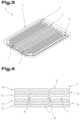
- FIG. 3a cutout from a cooling device for the rechargeable battery
- FIG. 4a cutout from the heating device in combination with a cooling device of the rechargeable battery.
- equal partsare provided with equal reference numbers and/or equal component designations, where the disclosures contained in the entire description may be analogously transferred to equal parts with equal reference numbers and/or equal component designations.
- specifications of locationsuch as at the top, at the bottom, at the side, chosen in the description refer to the directly described and depicted figure and in case of a change of position, these specifications of location are to be analogously transferred to the new position.
- FIGS. 1 and 2show a rechargeable battery 1 , i.e. an accumulator, in an oblique view, with FIG. 1 showing the rechargeable battery 1 with a heating device 2 and FIG. 2 showing the rechargeable battery 1 without this heating device 2 .
- a rechargeable battery 1i.e. an accumulator
- the rechargeable battery 1comprises several cells 3 for electrical energy. In the represented example there are 27 cells 3 . However, this number is not to be considered restricting.
- the cells 3can be formed to be cuboid, cube-shaped, cylindrical, etc.
- the heating device 2is arranged on a side of the rechargeable battery 1 , in particular on the top. However, it can also be provided for that the heating device 2 extends across at least two surfaces of the rechargeable battery 1 , for example on the top and laterally and optionally on the bottom. In the alternative or in addition to this, the heating device 2 can also be arranged between the cells 3 .
- the heating device 2extends across all cells 3 , in particular the upper side of the cells 3 , (as can be seen from FIG. 1 ) such that all cells 3 can be heated or their temperature can be controlled by means of just one heating device 2 .
- the cells 3can be formed modularly such that these can also be referred to as storage modules.
- the rechargeable battery 1is described with several cells 3 .
- the rechargeable battery 1can also comprise merely one cell 3 such that the statements in the description can be correspondingly applied to this embodiment variant.
- the heating device 2comprises a single-layer or multi-layer film 4 or consists thereof, as can be seen from FIGS. 3 and 4 .
- the heating device 2in particular directly, lies against cells 3 .
- the contactis for example established at the upper side of the cells 3 , as was elucidated above.
- the film 4is flexible, i.e. not stiff, said film 4 can better adapt to surface irregularities of the cells 3 or between the cells 3 .
- a leveling compound between the heating device 2 and the cells 3is not required.
- the heating device 2can comprise the and/or a single-layer or multi-layer film 4 on both sides.
- the single-layer or multi-layer film 4is arranged merely on the side of the heating device 2 that faces the cells 3 , and that this film 4 is combined with a stiff metal layer, for example of aluminum and/or an aluminum alloy, which can also form a cover of the rechargeable battery 1 .
- the heating device 2can comprise a cooling device with at least one coolant channel 5 , which extends from at least one inlet 6 to at least one outlet 7 .
- the at least one coolant channel 5can be formed within the single-layer or multi-layer film 4 or between two single-layer or multi-layer films 4 or between this film 4 and the metal layer by a just partial connection of the film(s) 4 or of the film 4 to the metal layer, as can be seen in FIG. 4 .
- the at least one coolant channel 5can be produced by bonding or welding of the film(s) 4 forming webs 8 ( FIG. 4 ). In this regard, the at least one coolant channel 5 emerges in the non-connected regions of the film(s) 4 next to the webs 8 .
- Other suitable connecting techniquescan also be used for connecting the film(s) 4 or the film 4 to the metal layer.
- the at least one coolant channel 5can also be produced differently.
- the metal layercan be reformed, e.g. deep-drawn, accordingly.
- the coolant channel 5can be formed to extend in a meandering manner in the heating device 2 , as can be seen from FIG. 3 .
- the concrete representation of the extent of the at least one coolant channel 5 in FIG. 3is to be understood merely as an example.
- the respectively optimized extent of the at least one coolant channel 5is among other factors determined by the amount of heat that needs to be conducted away, the geometry of the rechargeable battery 1 , etc. It can also be provided for that more than one coolant channel 5 is formed and/or arranged in the heating device 2 .
- a common inlet 6is arranged in front of the several coolant channels 5 and a common outlet 7 behind them, which can each be formed as collecting channels, from which the coolant channels 5 branch out or into which they flow.
- each coolant channel 5has its own inlet 6 and/or its own outlet 7 .
- a liquidsuch as a water-glycol mixture is used as the coolant by which the cooling device is flown through.
- the heating device 2comprises the film 4 and a further single-layer or multi-layer film 9 .
- the film 4 and the further film 9are connected to one another in connection areas 10 forming the at least one coolant channel 5 between the film 4 and the further film 9 .
- the connection areas 10extend along the longitudinal extent of the at least one coolant channel 5 , wherein between the connection areas 10 non-connected areas remain in which the at least one coolant channel 5 is formed by the distancing of the film 4 with respect to the further film 9 .
- the film 4 and the further film 9which is in particular arranged above the film 4 , extend across a surface which preferably at least approximately, in particular to 100%, corresponds to the surface of the connection area 10 (as viewed in a plan view).
- the film 4 and the further film 9can consist of a laminate comprising a first plastic film 11 , 12 , optionally an enforcement layer 13 , 14 connected thereto, a plastic film 11 , 12 or a metal film 15 and/or 16 connected to the enforcement layer 13 and/or 14 or a metalized further plastic film connected to the enforcement layer 13 .
- the film 4 resting against the cells 3can also be formed from the plastic film 11 as a single layer.
- the film 4can be provided with the metal film 15 or merely the further film 9 can be provided with the metal film 16 .
- the film 4can comprise the enforcement layer 13 or merely the further film 9 can comprise the enforcement layer 14 .
- structures of the film 4 and/or the further film 9 with more than three layersare possible. However, preferably, the film 4 and the further film 9 are designed equally.
- the at least one coolant channel 5is not formed by separate components but by the just partial connection of the film 4 to the further film 9 .
- the wall and/or the walls of the at least one coolant channel 5are thus formed by the film 4 and the further film 9 , preferably half by each.
- the first plastic films 11 , 12 and/or the metalized further plastic filmpreferably consists/consist to at least 80 wt. %, in particular at least 90 wt. %, of a thermoplastic material or of an elastomer.
- the thermoplastic materialcan be selected from a group comprising and/or consisting of polyethylene (PE), polyoxymethylene (POM), polyamide (PA), in particular PA 6 , PA 66 , PA 11 , PA 12 , PA 610 , PA 612 , polyphenylene sulphide (PPS), polyethylene terephthalate (PET), crosslinked polyolefins, preferably polypropylene (PP).
- the elastomercan be selected from a group comprising and/or consisting of thermoplastic elastomers such as thermoplastic vulcanizates, olefin-, amine-, ester-based thermoplastic polyurethanes, in particular ether-based/ester-based thermoplastic elastomers, styrene block copolymers, silicone elastomers.
- thermoplastic elastomerssuch as thermoplastic vulcanizates, olefin-, amine-, ester-based thermoplastic polyurethanes, in particular ether-based/ester-based thermoplastic elastomers, styrene block copolymers, silicone elastomers.
- plastic materialis understood as a synthetic or natural polymer produced from corresponding monomers.
- the first plastic film 11 , 12 and/or the metalized further plastic filmconsists/consist of a so-called sealing film. This has the advantage that the respective films can be connected to one another directly.
- thermosetting plastic materialssuch as thermosetting plastic materials and/or thermosetting materials
- thermosetting materialssuch as thermosetting plastic materials and/or thermosetting materials
- thermosetting materialssuch as thermosetting plastic materials and/or thermosetting materials
- thermosetting materialssuch as thermosetting plastic materials and/or thermosetting materials
- the enforcement layer/enforcement layers 13 , 14comprise/comprises a or consist/consists of a fiber reinforcement which is preferably formed as a separate layer.
- the fiber reinforcementcan be formed of fibers and/or threads, which are selected from a group comprising or consisting of glass fibers, aramid fibers, carbon fibers, mineral fibers such as basalt fibers, natural fibers such as hemp, sisal and combinations thereof.
- glass fibersare used as fiber reinforcement.
- the proportion of the fibers, in particular the glass fibers, in the fiber reinforcementcan amount to at least 80 wt. %, in particular at least 90 wt. %.
- the fibers and/or threads of the fiber reinforcementconsist merely of glass fibers.
- the fibers and/or threadscan be present in the fiber reinforcement as roving, for example as a non-woven fabric. However, preferably the fibers and/or threads become a woven fabric or a knitted fabric. In this regard, it is also possible that the woven or knitted fabric is merely present in some regions and that the remaining regions of the fiber reinforcement are formed by a roving.
- rubberized fibers and/or threadsare used as or for the fiber reinforcement.
- a woven fabricWhen using a woven fabric, different types of weaves are possible, in particular plain, twill or satin weave. Preferably, a plain weave is used.
- Coated papercan also be used as fiber reinforcement.
- the paperis equipped to be resistant to liquids by the coating.
- the enforcement layer(s) 13 , 14can comprise a mineral filling.
- a mineral fillingFor example, calcium carbonate, talc, quartz, wollastonite, kaolin or mica can be used as a mineral filling (mineral filler material).
- the metal film 15 , 16in particular is an aluminum film. However, other materials such as copper or silver can also be used.
- the metal film 15 , 16can have a layer thickness of between 5 ⁇ m and 200 ⁇ m in particular of between 60 ⁇ m and 200 ⁇ m.
- the plastic films 11 , 12can have a layer thickness of between 10 ⁇ m and 200 ⁇ m.
- the layer thickness of the enforcement layer(s) 13 , 14can amount to between 5 ⁇ m and 50 ⁇ m.
- the films 4 , 9can in general be used in the form of individual films for producing the cooling device 2 , such that the film laminate(s) are only formed in the course of the production of the cooling device, it is advantageous if the films 4 , 9 are used as a (laminated) semi-finished product.
- adhesivesFor connecting the individual layers of the laminate or the laminates, these can be adhered to one another by means of adhesives.
- the afore-mentioned adhesivesare suitable for this purpose.
- coextrusion and extrusion coatingcan also be used as joining options.
- a combinationis also possible in which several plastic materials are coextruded and adhesively laminated to one another with an extrusion-coated metal or (fiber) enforcement layer.
- all known methodscan be used for producing composite films and/or film laminates.
- the heating device 2can also comprise a further single-layer or multi-layer film, whereby coolant channels 5 can be formed in several planes.
- the heating device 2can also be designed without these coolant channels 5 , i.e. merely comprise the single-layer or multi-layer film 4 .
- the rechargeable battery 1comprises a separate cooling device, which can in particular also be produced from the single-layer or multi-layer films 4 , 9 , as was described above.
- the described combination of the heating device 2 with the cooling deviceis preferred.
- the heating device 2comprises at least one heating element.
- the at least one heating elementis formed by the metal film 15 and/or the metal film 16 and/or the metalized plastic film.
- the at least one heating elementcan, however, be designed differently, in particular as a wire or as a grid.
- the term “grid”also comprises woven fabrics with open mashes (mesh fabrics). Such heating elements are preferably formed from metal.
- the heating elementcan also comprise a non-metal carrier with an electrically conductive coating.
- Such coatingscan, for example, be lacquer-based, as known from Coating Suiss GmbH in the form of carbon-based heating lacquers.
- the at least one heating elementin the form of the metal film 15 , 16
- itcan also be arranged on the single-layer or multi-layer film 4 , 9 , for example on the plastic film 11 , 12 .
- the arrangementcan for example be carried out by lamination or bonding.
- the at least heating elementcan also be arranged with a layer of the single-layer or multi-layer film 4 , 9 by the heating element being already provided during formation of this layer and being enclosed by and/or embedded in the material of this layer.
- the two layers and/or plastic films 11 , 12in particular rest directly against the at least one heating element and/or are directly connected thereto.
- the at least one heating elementcomprises an area and/or circumscribes an area which comprises at least 90%, in particular 100%, of the base area of the film 4 , 9 or of the cooling device.
- the term “circumscribe”is to be understood with regard to the grid-shaped heating element.
- the heating elementcan continuously extend across the entire surface area of the single-layer or multi-layer films 4 , 9 .
- the heating device 2comprises several heating elements and that a separate heating element is assigned to each cell 3 .
- the at least one heating element and/or the heating elementsare electrically contacted, i.e. are resistance heating elements.
- the electrical contactingcan be established via a wiring (shown in FIG. 1 ) or via conducting paths.
- the conducting path(s)can for example be deposited on the single-layer or multi-layer film 4 , 9 and/or on a layer thereof by means of thin film technology.
- the single-layer or multi-layer filmcan comprise at least one temperature sensor, which is connected to the at least one heating element, such that the heating performance of the heating element is controlled depending on the measured value of the temperature.
- the connection between the heating element and the temperature sensorcan be established via an open loop controller and/or a closed loop controller.
- At least one temperature sensoris assigned to each cell 3 , meaning that each cell 3 has a separate temperature sensor.
- the at least one temperature sensorcan also be arranged on or in the film 4 , 9 or within a layer of the film 4 , 9 .
- the at least one temperature sensorcan also be produced by means of thin film technology and preferably be contacted to be electrically conductive by means of one or several conducting path(s), wherein the conductive path(s) can be deposited on a layer of the film 4 , 9 .
- “Arranged on the film”means that the respective component is arranged on an outside, i.e. on an outer surface, of the single-layer or multi-layer film 4 .
- the at least one temperature sensorprefferably be a thin layer sensor element.
- the at least one temperature sensorcan for example be a thermocouple or a thermistor. In general, other suitable temperature sensors can be used as well.
- the temperature sensorcan comprise a negative temperature coefficient thermistor (NTC) or a positive temperature coefficient thermistor (PTC).
- NTCnegative temperature coefficient thermistor
- PTCpositive temperature coefficient thermistor
- the heating device 2is used for heating and/or controlling the temperature of a rechargeable battery 1 .
- the heating device 2can thus represent a separate invention on its own, i.e. without the cells 3 and the rechargeable battery 1 . Therefore, the statements regarding the heating device 2 made above also apply to this separate invention.
- the exemplary embodimentsshow and/or describe possible embodiment variants, while combinations of the individual embodiment variants are also possible.
Landscapes
- Engineering & Computer Science (AREA)
- Manufacturing & Machinery (AREA)
- Chemical & Material Sciences (AREA)
- Chemical Kinetics & Catalysis (AREA)
- Electrochemistry (AREA)
- General Chemical & Material Sciences (AREA)
- Automation & Control Theory (AREA)
- Physics & Mathematics (AREA)
- Electromagnetism (AREA)
- Secondary Cells (AREA)
- Thermotherapy And Cooling Therapy Devices (AREA)
Abstract
Description
- 1 rechargeable battery
- 2 heating device
- 3 cell
- 4 film
- 5 coolant channel
- 6 inlet
- 7 outlet
- 8 web
- 9 film
- 10 connection areas
- 11 plastic film
- 12 plastic film
- 13 enforcement layer
- 14 enforcement layer
- 15 metal film
- 16 metal film
Claims (8)
Applications Claiming Priority (3)
| Application Number | Priority Date | Filing Date | Title |
|---|---|---|---|
| ATA50771/2017AAT520410B1 (en) | 2017-09-14 | 2017-09-14 | accumulator |
| ATA50771/2017 | 2017-09-14 | ||
| PCT/AT2018/060205WO2019051520A1 (en) | 2017-09-14 | 2018-09-11 | ACCUMULATOR |
Publications (2)
| Publication Number | Publication Date |
|---|---|
| US20200227800A1 US20200227800A1 (en) | 2020-07-16 |
| US11637337B2true US11637337B2 (en) | 2023-04-25 |
Family
ID=63962987
Family Applications (1)
| Application Number | Title | Priority Date | Filing Date |
|---|---|---|---|
| US16/638,929Active2039-03-01US11637337B2 (en) | 2017-09-14 | 2018-09-11 | Accumulator |
Country Status (5)
| Country | Link |
|---|---|
| US (1) | US11637337B2 (en) |
| CN (1) | CN111418108A (en) |
| AT (1) | AT520410B1 (en) |
| DE (1) | DE112018005114A5 (en) |
| WO (1) | WO2019051520A1 (en) |
Families Citing this family (5)
| Publication number | Priority date | Publication date | Assignee | Title |
|---|---|---|---|---|
| CA3154258C (en) | 2019-11-06 | 2023-10-10 | Taiga Motors Inc. | Battery cooling panel for electric vehicles |
| DE102020102523A1 (en)* | 2020-01-31 | 2021-08-05 | Kautex Textron Gmbh & Co. Kg | Battery cooling element, battery module unit and method for producing a battery cooling element |
| CN111933854A (en)* | 2020-08-18 | 2020-11-13 | 领航博创新能源电池技术研究院(北京)有限公司 | Battery applicable to alpine regions and preparation method thereof |
| CN113517495B (en)* | 2021-09-14 | 2022-02-22 | 中国华能集团清洁能源技术研究院有限公司 | Liquid cooling assembly |
| CN115275442B (en)* | 2022-08-19 | 2025-05-06 | 一汽解放青岛汽车有限公司 | Composite battery management control system, method and vehicle |
Citations (46)
| Publication number | Priority date | Publication date | Assignee | Title |
|---|---|---|---|---|
| DE9012327U1 (en) | 1990-08-28 | 1990-11-29 | Behnisch, Jürgen, 8500 Nürnberg | Electronic voltage and temperature controlled battery heating |
| FR2782399A1 (en) | 1998-08-13 | 2000-02-18 | Plastiques De France Ind | Device and procedure for thermal regulation of items or products contained in an isolated temperature regulation housing, has heat transfer liquid in contact with the products via a flexible deformable thin wall |
| DE10034134A1 (en) | 2000-07-13 | 2002-01-31 | Daimler Chrysler Ag | Heat exchanger structure for several electrochemical storage cells |
| EP1261065A2 (en) | 2001-05-23 | 2002-11-27 | Alcatel | Thermal management blanketing and jacketing for battery system modules |
| US20040004461A1 (en)* | 2002-05-22 | 2004-01-08 | Matsushita Electric Industrial Co., Ltd. | Cooling device for battery pack and rechargeable battery |
| US20050089750A1 (en)* | 2002-02-19 | 2005-04-28 | Chin-Yee Ng | Temperature control apparatus and method for high energy electrochemical cells |
| CN1745438A (en) | 2003-01-04 | 2006-03-08 | 3M创新有限公司 | A vehicle battery pack insulator |
| JP2006271063A (en) | 2005-03-23 | 2006-10-05 | Mitsubishi Electric Corp | Busbar cooling structure |
| US20070037050A1 (en) | 2005-07-22 | 2007-02-15 | Saft | Thermal control device |
| US20080179315A1 (en) | 2007-01-26 | 2008-07-31 | Panasonic Ev Energy Co., Ltd. | Laminated sheet heater, laminated sheet heater with lead wire, battery structure with heater, and heater unit |
| US20080311468A1 (en) | 2007-06-18 | 2008-12-18 | Weston Arthur Hermann | Optimized cooling tube geometry for intimate thermal contact with cells |
| DE102008053311A1 (en) | 2007-10-27 | 2009-04-30 | Bayerische Motoren Werke Aktiengesellschaft | Device for supplying power to a motor vehicle |
| DE102008034867A1 (en) | 2008-07-26 | 2010-01-28 | Daimler Ag | Battery i.e. lithium ion battery, for vehicle e.g. vehicle with hybrid drive, has conductor rims that are thermally coupled at cooling plate by poles of individual cells which are formed as flat cells |
| WO2010012341A1 (en) | 2008-07-26 | 2010-02-04 | Daimler Ag | Battery cooling in particular for a vehicle battery |
| DE102008059970A1 (en) | 2008-12-02 | 2010-06-10 | Daimler Ag | Battery i.e. lithium-ion-battery, for e.g. fuel cell-vehicle, has flexible cell connectors provided and arranged at upper side of rigid cell connector board such that individual cells are connected in series and/or parallel with each other |
| WO2010108885A1 (en) | 2009-03-24 | 2010-09-30 | Behr Gmbh & Co. Kg | Device for controlling the temperature of an energy store and method for producing the device for controlling temperature |
| WO2011088997A1 (en) | 2010-01-20 | 2011-07-28 | Fraunhofer-Gesellschaft zur Förderung der angewandten Forschung e.V. | Battery cell array the temperature of which can be controlled |
| US20110304297A1 (en) | 2010-06-10 | 2011-12-15 | Kwon Sohn | Charging apparatus |
| US20120021270A1 (en)* | 2010-07-23 | 2012-01-26 | Gm Global Technology Operations, Inc. | Prismatic battery cell with integrated cooling passages and assembly frame |
| DE102010032460A1 (en) | 2010-07-28 | 2012-02-02 | Volkswagen Ag | Battery cell, particularly film cell for lithium-ion batteries of hybrid or electric vehicle, comprises cooling or heating structure for cooling or heating of battery cell |
| EP2451004A1 (en) | 2009-07-03 | 2012-05-09 | Panasonic Corporation | Heating device and battery unit provided therewith |
| WO2012062644A1 (en) | 2010-11-12 | 2012-05-18 | Avl List Gmbh | Cell connector |
| WO2012072348A1 (en) | 2010-11-30 | 2012-06-07 | Behr Gmbh & Co. Kg | Device for conducting a cooling fluid, and cooling system for cooling an electrical component |
| US20120231313A1 (en) | 2011-03-11 | 2012-09-13 | GM Global Technology Operations LLC | Prismatic cell with integrated cooling plate |
| DE102011075820A1 (en) | 2011-05-13 | 2012-11-15 | Lisa Dräxlmaier GmbH | Traction battery for e.g. hybrid car, has opening portion that is formed in housing and is designed such that arrangement of electrochemical cells is not accessible outside of housing in assembled position |
| CN102906933A (en)* | 2010-05-28 | 2013-01-30 | 锂电池科技有限公司 | Cooling element, method for producing same, and electrochemical energy storage device comprising cooling element |
| US20130122331A1 (en) | 2011-11-15 | 2013-05-16 | GM Global Technology Operations LLC | Lithium ion battery cooling system |
| DE102011118686A1 (en) | 2011-11-16 | 2013-05-16 | Audi Ag | Battery for vehicle e.g. motor car, has bus bar that is cooled by coolant flowing into cooling channel in interior of bus bar |
| JP2014078471A (en) | 2012-10-12 | 2014-05-01 | Toshiba Corp | Secondary battery and secondary battery system |
| EP2744033A1 (en) | 2012-12-07 | 2014-06-18 | Obrist Powertrain GmbH | Battery |
| DE102013220044A1 (en) | 2013-10-02 | 2015-04-02 | Elringklinger Ag | Cell contacting system for an electrochemical device and method of making a cell contacting system |
| DE102013221747A1 (en) | 2013-10-25 | 2015-04-30 | Robert Bosch Gmbh | Cell wrapping foil with integrated heating |
| FR3013515A1 (en) | 2013-11-15 | 2015-05-22 | Valeo Systemes Thermiques | COOLING DEVICE FOR AUTOMOTIVE BATTERY |
| DE102013021553A1 (en) | 2013-12-18 | 2015-06-18 | Daimler Ag | High-voltage battery |
| US20150221992A1 (en)* | 2014-01-31 | 2015-08-06 | Lg Chem, Ltd. | Battery cell assembly |
| US20150295287A1 (en)* | 2014-04-09 | 2015-10-15 | MAHLE Behr GmbH & Co. KG | Temperature control device for an electrical energy supply unit |
| US20160233561A1 (en) | 2013-09-25 | 2016-08-11 | Lg Chem, Ltd. | Battery module having temperature sensor |
| US20160233564A1 (en) | 2015-02-05 | 2016-08-11 | GM Global Technology Operations LLC | Micro heat exchangers and methods for use in thermal management of transportation vehicle batteries |
| DE102015204678A1 (en) | 2015-03-16 | 2016-09-22 | Robert Bosch Gmbh | Battery conditioning with sorbent regeneration |
| WO2017015826A1 (en) | 2015-07-27 | 2017-02-02 | 宁德时代新能源科技股份有限公司 | Battery group heat management module |
| US20170104252A1 (en) | 2015-10-07 | 2017-04-13 | Samsung Sdi Co., Ltd. | Battery module including a housing floor with integrated cooling |
| WO2017108581A1 (en)* | 2015-12-24 | 2017-06-29 | Iee International Electronics & Engineering S.A. | Flat built temperature control unit for battery temperature monitoring |
| US20170200926A1 (en) | 2014-08-27 | 2017-07-13 | Panasonic Intellectual Property Management Co., Ltd. | Cell module and cell pack |
| CN206353596U (en) | 2017-01-17 | 2017-07-25 | 华霆(合肥)动力技术有限公司 | Power-supply device and automobile |
| US20170338532A1 (en) | 2016-05-23 | 2017-11-23 | Borgwarner Inc. | Thermal management system and method of making and using the same |
| US20180238632A1 (en) | 2017-02-21 | 2018-08-23 | Lenovo (Beijing) Co., Ltd. | Heat pipe, radiator, and electronic device |
- 2017
- 2017-09-14ATATA50771/2017Apatent/AT520410B1/enactive
- 2018
- 2018-09-11DEDE112018005114.5Tpatent/DE112018005114A5/enactivePending
- 2018-09-11USUS16/638,929patent/US11637337B2/enactiveActive
- 2018-09-11WOPCT/AT2018/060205patent/WO2019051520A1/ennot_activeCeased
- 2018-09-11CNCN201880051342.2Apatent/CN111418108A/enactivePending
Patent Citations (55)
| Publication number | Priority date | Publication date | Assignee | Title |
|---|---|---|---|---|
| DE9012327U1 (en) | 1990-08-28 | 1990-11-29 | Behnisch, Jürgen, 8500 Nürnberg | Electronic voltage and temperature controlled battery heating |
| FR2782399A1 (en) | 1998-08-13 | 2000-02-18 | Plastiques De France Ind | Device and procedure for thermal regulation of items or products contained in an isolated temperature regulation housing, has heat transfer liquid in contact with the products via a flexible deformable thin wall |
| DE10034134A1 (en) | 2000-07-13 | 2002-01-31 | Daimler Chrysler Ag | Heat exchanger structure for several electrochemical storage cells |
| US7291420B2 (en) | 2000-07-13 | 2007-11-06 | Daimlerchrysler Ag | Heat exchanger structure for a plurality of electrochemical storage cells |
| EP1261065A2 (en) | 2001-05-23 | 2002-11-27 | Alcatel | Thermal management blanketing and jacketing for battery system modules |
| US20020177035A1 (en) | 2001-05-23 | 2002-11-28 | Alcatel | Thermal management blanketing and jacketing for battery system modules |
| US20050089750A1 (en)* | 2002-02-19 | 2005-04-28 | Chin-Yee Ng | Temperature control apparatus and method for high energy electrochemical cells |
| US20040004461A1 (en)* | 2002-05-22 | 2004-01-08 | Matsushita Electric Industrial Co., Ltd. | Cooling device for battery pack and rechargeable battery |
| CN1745438A (en) | 2003-01-04 | 2006-03-08 | 3M创新有限公司 | A vehicle battery pack insulator |
| JP2006271063A (en) | 2005-03-23 | 2006-10-05 | Mitsubishi Electric Corp | Busbar cooling structure |
| US20070037050A1 (en) | 2005-07-22 | 2007-02-15 | Saft | Thermal control device |
| US20080179315A1 (en) | 2007-01-26 | 2008-07-31 | Panasonic Ev Energy Co., Ltd. | Laminated sheet heater, laminated sheet heater with lead wire, battery structure with heater, and heater unit |
| US20080311468A1 (en) | 2007-06-18 | 2008-12-18 | Weston Arthur Hermann | Optimized cooling tube geometry for intimate thermal contact with cells |
| DE102008053311A1 (en) | 2007-10-27 | 2009-04-30 | Bayerische Motoren Werke Aktiengesellschaft | Device for supplying power to a motor vehicle |
| US8889282B2 (en) | 2007-10-27 | 2014-11-18 | Bayerische Motoren Werke Aktiengesellschaft | Apparatus for supplying power to a motor vehicle |
| DE102008034867A1 (en) | 2008-07-26 | 2010-01-28 | Daimler Ag | Battery i.e. lithium ion battery, for vehicle e.g. vehicle with hybrid drive, has conductor rims that are thermally coupled at cooling plate by poles of individual cells which are formed as flat cells |
| WO2010012341A1 (en) | 2008-07-26 | 2010-02-04 | Daimler Ag | Battery cooling in particular for a vehicle battery |
| US8962172B2 (en) | 2008-07-26 | 2015-02-24 | Daimler Ag | Battery cooling in particular for a vehicle battery |
| DE102008059970A1 (en) | 2008-12-02 | 2010-06-10 | Daimler Ag | Battery i.e. lithium-ion-battery, for e.g. fuel cell-vehicle, has flexible cell connectors provided and arranged at upper side of rigid cell connector board such that individual cells are connected in series and/or parallel with each other |
| WO2010108885A1 (en) | 2009-03-24 | 2010-09-30 | Behr Gmbh & Co. Kg | Device for controlling the temperature of an energy store and method for producing the device for controlling temperature |
| US20120107635A1 (en) | 2009-03-24 | 2012-05-03 | Stefan Hirsch | Device for controlling the temperature of an energy store and method for producing the device for controlling the temperature |
| EP2451004A1 (en) | 2009-07-03 | 2012-05-09 | Panasonic Corporation | Heating device and battery unit provided therewith |
| WO2011088997A1 (en) | 2010-01-20 | 2011-07-28 | Fraunhofer-Gesellschaft zur Förderung der angewandten Forschung e.V. | Battery cell array the temperature of which can be controlled |
| CN102906933A (en)* | 2010-05-28 | 2013-01-30 | 锂电池科技有限公司 | Cooling element, method for producing same, and electrochemical energy storage device comprising cooling element |
| US20110304297A1 (en) | 2010-06-10 | 2011-12-15 | Kwon Sohn | Charging apparatus |
| US20120021270A1 (en)* | 2010-07-23 | 2012-01-26 | Gm Global Technology Operations, Inc. | Prismatic battery cell with integrated cooling passages and assembly frame |
| DE102010032460A1 (en) | 2010-07-28 | 2012-02-02 | Volkswagen Ag | Battery cell, particularly film cell for lithium-ion batteries of hybrid or electric vehicle, comprises cooling or heating structure for cooling or heating of battery cell |
| WO2012062644A1 (en) | 2010-11-12 | 2012-05-18 | Avl List Gmbh | Cell connector |
| WO2012072348A1 (en) | 2010-11-30 | 2012-06-07 | Behr Gmbh & Co. Kg | Device for conducting a cooling fluid, and cooling system for cooling an electrical component |
| US9546827B2 (en) | 2010-11-30 | 2017-01-17 | Mahle International Gmbh | Device for conducting a cooling fluid, and cooling system for cooling an electrical component |
| US20120231313A1 (en) | 2011-03-11 | 2012-09-13 | GM Global Technology Operations LLC | Prismatic cell with integrated cooling plate |
| DE102011075820A1 (en) | 2011-05-13 | 2012-11-15 | Lisa Dräxlmaier GmbH | Traction battery for e.g. hybrid car, has opening portion that is formed in housing and is designed such that arrangement of electrochemical cells is not accessible outside of housing in assembled position |
| US20130122331A1 (en) | 2011-11-15 | 2013-05-16 | GM Global Technology Operations LLC | Lithium ion battery cooling system |
| US8852772B2 (en) | 2011-11-15 | 2014-10-07 | GM Global Technology Operations LLC | Lithium ion battery cooling system comprising dielectric fluid |
| DE102011118686A1 (en) | 2011-11-16 | 2013-05-16 | Audi Ag | Battery for vehicle e.g. motor car, has bus bar that is cooled by coolant flowing into cooling channel in interior of bus bar |
| JP2014078471A (en) | 2012-10-12 | 2014-05-01 | Toshiba Corp | Secondary battery and secondary battery system |
| EP2744033A1 (en) | 2012-12-07 | 2014-06-18 | Obrist Powertrain GmbH | Battery |
| US9559387B2 (en) | 2012-12-07 | 2017-01-31 | Obrist Technologies Gmbh | Battery |
| US20160233561A1 (en) | 2013-09-25 | 2016-08-11 | Lg Chem, Ltd. | Battery module having temperature sensor |
| DE102013220044A1 (en) | 2013-10-02 | 2015-04-02 | Elringklinger Ag | Cell contacting system for an electrochemical device and method of making a cell contacting system |
| DE102013221747A1 (en) | 2013-10-25 | 2015-04-30 | Robert Bosch Gmbh | Cell wrapping foil with integrated heating |
| FR3013515A1 (en) | 2013-11-15 | 2015-05-22 | Valeo Systemes Thermiques | COOLING DEVICE FOR AUTOMOTIVE BATTERY |
| DE102013021553A1 (en) | 2013-12-18 | 2015-06-18 | Daimler Ag | High-voltage battery |
| US20150221992A1 (en)* | 2014-01-31 | 2015-08-06 | Lg Chem, Ltd. | Battery cell assembly |
| US20150295287A1 (en)* | 2014-04-09 | 2015-10-15 | MAHLE Behr GmbH & Co. KG | Temperature control device for an electrical energy supply unit |
| US20170200926A1 (en) | 2014-08-27 | 2017-07-13 | Panasonic Intellectual Property Management Co., Ltd. | Cell module and cell pack |
| US20160233564A1 (en) | 2015-02-05 | 2016-08-11 | GM Global Technology Operations LLC | Micro heat exchangers and methods for use in thermal management of transportation vehicle batteries |
| DE102015204678A1 (en) | 2015-03-16 | 2016-09-22 | Robert Bosch Gmbh | Battery conditioning with sorbent regeneration |
| WO2017015826A1 (en) | 2015-07-27 | 2017-02-02 | 宁德时代新能源科技股份有限公司 | Battery group heat management module |
| US20180151929A1 (en) | 2015-07-27 | 2018-05-31 | Contemporary Amperex Technology Co., Limited | Battery module heat management assembly |
| US20170104252A1 (en) | 2015-10-07 | 2017-04-13 | Samsung Sdi Co., Ltd. | Battery module including a housing floor with integrated cooling |
| WO2017108581A1 (en)* | 2015-12-24 | 2017-06-29 | Iee International Electronics & Engineering S.A. | Flat built temperature control unit for battery temperature monitoring |
| US20170338532A1 (en) | 2016-05-23 | 2017-11-23 | Borgwarner Inc. | Thermal management system and method of making and using the same |
| CN206353596U (en) | 2017-01-17 | 2017-07-25 | 华霆(合肥)动力技术有限公司 | Power-supply device and automobile |
| US20180238632A1 (en) | 2017-02-21 | 2018-08-23 | Lenovo (Beijing) Co., Ltd. | Heat pipe, radiator, and electronic device |
Non-Patent Citations (3)
| Title |
|---|
| International Search Report in PCT/AT2018/060190, dated Nov. 29, 2018. |
| International Search Report in PCT/AT2018/060204, dated Feb. 4, 2019. |
| International Search Report in PCT/AT2018/060205, dated Feb. 4, 2019. |
Also Published As
| Publication number | Publication date |
|---|---|
| US20200227800A1 (en) | 2020-07-16 |
| AT520410A1 (en) | 2019-03-15 |
| AT520410B1 (en) | 2019-09-15 |
| WO2019051520A1 (en) | 2019-03-21 |
| CN111418108A (en) | 2020-07-14 |
| DE112018005114A5 (en) | 2020-06-18 |
Similar Documents
| Publication | Publication Date | Title |
|---|---|---|
| US11637337B2 (en) | Accumulator | |
| US20200227798A1 (en) | Accumulator | |
| US11296368B2 (en) | Rechargeable battery comprising a cooling device | |
| US11581597B2 (en) | Accumulator | |
| US20230335832A1 (en) | Cooling device for a rechargeable battery | |
| US11444342B2 (en) | Storage battery comprising a cooling device connected to the bus bar | |
| US20210184291A1 (en) | Heat transfer device | |
| CN100558265C (en) | thin film energy fabric | |
| KR20200140335A (en) | Battery unit with integrated temperature control means | |
| US9531039B2 (en) | Battery management system for a battery cell with a pressure-sensitive film sensor | |
| US9660288B2 (en) | Battery subunit having multiple battery modules that are connected to one another in a parallel and/or series manner, battery system and method for producing a battery subunit | |
| CN112262495B (en) | Electric storage device | |
| US20120107665A1 (en) | Heater and battery unit provided therewith | |
| JP2008204708A (en) | Heater with temperature detection device, battery structure with heater, and heater unit | |
| US11533785B2 (en) | Electrical heating device, in particular with PTC effect | |
| CN113629326A (en) | Outer packaging material for electricity storage device and electricity storage device | |
| JP2022542076A (en) | Battery case for secondary battery and method for manufacturing pouch-type secondary battery | |
| KR20200072317A (en) | Sheet type heating element and armrest for vehicle door including the same | |
| JP2024016132A (en) | Adhesive film, adhesive film manufacturing method, power storage device, and power storage device manufacturing method | |
| CN115810855A (en) | Battery assembly, vehicle and liquid supplementing method of battery assembly | |
| CN116210117A (en) | Cooling device for rechargeable battery | |
| AT527873B1 (en) | Heat transfer device | |
| JP7355286B1 (en) | An adhesive film for metal terminals and a method for producing the same, a metal terminal with an adhesive film for metal terminals, an electricity storage device using the adhesive film for metal terminals, a kit including an adhesive film for metal terminals and an exterior material for electricity storage devices, and a method for manufacturing a power storage device |
Legal Events
| Date | Code | Title | Description |
|---|---|---|---|
| AS | Assignment | Owner name:MIBA EMOBILITY GMBH, AUSTRIA Free format text:ASSIGNMENT OF ASSIGNORS INTEREST;ASSIGNORS:GAIGG, STEFAN;HINTRINGER, ROLAND;REEL/FRAME:051813/0183 Effective date:20191216 | |
| FEPP | Fee payment procedure | Free format text:ENTITY STATUS SET TO UNDISCOUNTED (ORIGINAL EVENT CODE: BIG.); ENTITY STATUS OF PATENT OWNER: LARGE ENTITY | |
| STPP | Information on status: patent application and granting procedure in general | Free format text:DOCKETED NEW CASE - READY FOR EXAMINATION | |
| STPP | Information on status: patent application and granting procedure in general | Free format text:NON FINAL ACTION MAILED | |
| STPP | Information on status: patent application and granting procedure in general | Free format text:RESPONSE TO NON-FINAL OFFICE ACTION ENTERED AND FORWARDED TO EXAMINER | |
| STPP | Information on status: patent application and granting procedure in general | Free format text:FINAL REJECTION MAILED | |
| STPP | Information on status: patent application and granting procedure in general | Free format text:RESPONSE AFTER FINAL ACTION FORWARDED TO EXAMINER | |
| STPP | Information on status: patent application and granting procedure in general | Free format text:ADVISORY ACTION MAILED | |
| STPP | Information on status: patent application and granting procedure in general | Free format text:NON FINAL ACTION MAILED | |
| STPP | Information on status: patent application and granting procedure in general | Free format text:RESPONSE TO NON-FINAL OFFICE ACTION ENTERED AND FORWARDED TO EXAMINER | |
| STPP | Information on status: patent application and granting procedure in general | Free format text:FINAL REJECTION MAILED | |
| STCF | Information on status: patent grant | Free format text:PATENTED CASE | |
| CC | Certificate of correction |