US11635868B2 - Managing virtual content displayed to a user based on mapped user location - Google Patents
Managing virtual content displayed to a user based on mapped user locationDownload PDFInfo
- Publication number
- US11635868B2 US11635868B2US16/707,373US201916707373AUS11635868B2US 11635868 B2US11635868 B2US 11635868B2US 201916707373 AUS201916707373 AUS 201916707373AUS 11635868 B2US11635868 B2US 11635868B2
- Authority
- US
- United States
- Prior art keywords
- user
- headset
- mode
- environment
- virtual
- Prior art date
- Legal status (The legal status is an assumption and is not a legal conclusion. Google has not performed a legal analysis and makes no representation as to the accuracy of the status listed.)
- Active
Links
Images


Classifications
- G—PHYSICS
- G06—COMPUTING OR CALCULATING; COUNTING
- G06F—ELECTRIC DIGITAL DATA PROCESSING
- G06F3/00—Input arrangements for transferring data to be processed into a form capable of being handled by the computer; Output arrangements for transferring data from processing unit to output unit, e.g. interface arrangements
- G06F3/01—Input arrangements or combined input and output arrangements for interaction between user and computer
- G06F3/048—Interaction techniques based on graphical user interfaces [GUI]
- G06F3/0481—Interaction techniques based on graphical user interfaces [GUI] based on specific properties of the displayed interaction object or a metaphor-based environment, e.g. interaction with desktop elements like windows or icons, or assisted by a cursor's changing behaviour or appearance
- G06F3/04815—Interaction with a metaphor-based environment or interaction object displayed as three-dimensional, e.g. changing the user viewpoint with respect to the environment or object
- G—PHYSICS
- G06—COMPUTING OR CALCULATING; COUNTING
- G06F—ELECTRIC DIGITAL DATA PROCESSING
- G06F3/00—Input arrangements for transferring data to be processed into a form capable of being handled by the computer; Output arrangements for transferring data from processing unit to output unit, e.g. interface arrangements
- G06F3/01—Input arrangements or combined input and output arrangements for interaction between user and computer
- G06F3/011—Arrangements for interaction with the human body, e.g. for user immersion in virtual reality
- G—PHYSICS
- G06—COMPUTING OR CALCULATING; COUNTING
- G06F—ELECTRIC DIGITAL DATA PROCESSING
- G06F3/00—Input arrangements for transferring data to be processed into a form capable of being handled by the computer; Output arrangements for transferring data from processing unit to output unit, e.g. interface arrangements
- G06F3/01—Input arrangements or combined input and output arrangements for interaction between user and computer
- G06F3/017—Gesture based interaction, e.g. based on a set of recognized hand gestures
- G—PHYSICS
- G06—COMPUTING OR CALCULATING; COUNTING
- G06F—ELECTRIC DIGITAL DATA PROCESSING
- G06F3/00—Input arrangements for transferring data to be processed into a form capable of being handled by the computer; Output arrangements for transferring data from processing unit to output unit, e.g. interface arrangements
- G06F3/01—Input arrangements or combined input and output arrangements for interaction between user and computer
- G06F3/03—Arrangements for converting the position or the displacement of a member into a coded form
- G06F3/033—Pointing devices displaced or positioned by the user, e.g. mice, trackballs, pens or joysticks; Accessories therefor
- G06F3/0346—Pointing devices displaced or positioned by the user, e.g. mice, trackballs, pens or joysticks; Accessories therefor with detection of the device orientation or free movement in a 3D space, e.g. 3D mice, 6-DOF [six degrees of freedom] pointers using gyroscopes, accelerometers or tilt-sensors
- G—PHYSICS
- G06—COMPUTING OR CALCULATING; COUNTING
- G06F—ELECTRIC DIGITAL DATA PROCESSING
- G06F3/00—Input arrangements for transferring data to be processed into a form capable of being handled by the computer; Output arrangements for transferring data from processing unit to output unit, e.g. interface arrangements
- G06F3/01—Input arrangements or combined input and output arrangements for interaction between user and computer
- G06F3/03—Arrangements for converting the position or the displacement of a member into a coded form
- G06F3/033—Pointing devices displaced or positioned by the user, e.g. mice, trackballs, pens or joysticks; Accessories therefor
- G06F3/038—Control and interface arrangements therefor, e.g. drivers or device-embedded control circuitry
- G06F3/0383—Signal control means within the pointing device
- G—PHYSICS
- G06—COMPUTING OR CALCULATING; COUNTING
- G06F—ELECTRIC DIGITAL DATA PROCESSING
- G06F3/00—Input arrangements for transferring data to be processed into a form capable of being handled by the computer; Output arrangements for transferring data from processing unit to output unit, e.g. interface arrangements
- G06F3/01—Input arrangements or combined input and output arrangements for interaction between user and computer
- G06F3/048—Interaction techniques based on graphical user interfaces [GUI]
- G06F3/0481—Interaction techniques based on graphical user interfaces [GUI] based on specific properties of the displayed interaction object or a metaphor-based environment, e.g. interaction with desktop elements like windows or icons, or assisted by a cursor's changing behaviour or appearance
- G06F3/0482—Interaction with lists of selectable items, e.g. menus
- G—PHYSICS
- G06—COMPUTING OR CALCULATING; COUNTING
- G06F—ELECTRIC DIGITAL DATA PROCESSING
- G06F3/00—Input arrangements for transferring data to be processed into a form capable of being handled by the computer; Output arrangements for transferring data from processing unit to output unit, e.g. interface arrangements
- G06F3/01—Input arrangements or combined input and output arrangements for interaction between user and computer
- G06F3/048—Interaction techniques based on graphical user interfaces [GUI]
- G06F3/0484—Interaction techniques based on graphical user interfaces [GUI] for the control of specific functions or operations, e.g. selecting or manipulating an object, an image or a displayed text element, setting a parameter value or selecting a range
- G06F3/04845—Interaction techniques based on graphical user interfaces [GUI] for the control of specific functions or operations, e.g. selecting or manipulating an object, an image or a displayed text element, setting a parameter value or selecting a range for image manipulation, e.g. dragging, rotation, expansion or change of colour
- G—PHYSICS
- G06—COMPUTING OR CALCULATING; COUNTING
- G06T—IMAGE DATA PROCESSING OR GENERATION, IN GENERAL
- G06T17/00—Three dimensional [3D] modelling, e.g. data description of 3D objects
- G06T17/10—Constructive solid geometry [CSG] using solid primitives, e.g. cylinders, cubes
- G—PHYSICS
- G06—COMPUTING OR CALCULATING; COUNTING
- G06T—IMAGE DATA PROCESSING OR GENERATION, IN GENERAL
- G06T19/00—Manipulating 3D models or images for computer graphics
- G06T19/003—Navigation within 3D models or images
- G—PHYSICS
- G06—COMPUTING OR CALCULATING; COUNTING
- G06F—ELECTRIC DIGITAL DATA PROCESSING
- G06F2203/00—Indexing scheme relating to G06F3/00 - G06F3/048
- G06F2203/038—Indexing scheme relating to G06F3/038
- G06F2203/0384—Wireless input, i.e. hardware and software details of wireless interface arrangements for pointing devices
- G—PHYSICS
- G06—COMPUTING OR CALCULATING; COUNTING
- G06T—IMAGE DATA PROCESSING OR GENERATION, IN GENERAL
- G06T19/00—Manipulating 3D models or images for computer graphics
- G06T19/006—Mixed reality
- H—ELECTRICITY
- H04—ELECTRIC COMMUNICATION TECHNIQUE
- H04L—TRANSMISSION OF DIGITAL INFORMATION, e.g. TELEGRAPHIC COMMUNICATION
- H04L67/00—Network arrangements or protocols for supporting network services or applications
- H04L67/01—Protocols
- H04L67/131—Protocols for games, networked simulations or virtual reality
Definitions
- VRvirtual reality
- the VR headsetdisplays images onto opaque screens placed in front of a user's eyes, allowing the user to visualize displayed content in three dimensions.
- the VR headsettypically includes accelerometers and other sensors, which provide input to a 3-D rendering engine, such that the user can change the displayed view of the virtual environment by making natural head movements.
- the VR headsettypically also includes speakers and a microphone, which allow users to hear sounds in the virtual environment and to communicate with others.
- the usermay control a VR application, such as a game, virtual walk-through, or other application using a hand-held controller.
- a well-known example of a VR headsetis the Oculus Rift, available from Oculus VR, LLC.
- ARaugmented reality
- Google GlassAn example of AR technology is Google Glass.
- MRmixed reality
- An MR headsetmay scan local surroundings many times per second to learn the locations of walls, ceilings, floors, and objects. As it does so, the MR headset displays holograms via transparent display screens, such that the holograms appear superimposed on objects in the user's natural environment. Displayed holograms may appear stationary in physical space, even as the user moves, or they may move through the environment in natural-looking ways. MR technology thus provides a means for displaying synthetic content alongside actual, physical objects in a user's own physical environment and creates an illusion that the holograms are part of the physical environment.
- a well-known example of an MR headsetis the Microsoft HoloLens, which is available from Microsoft Corporation of Redmond, Wash.
- VR technologyprovides highly immersive environments, but users must typically stay in fixed locations as they operate the technology. Users of VR headsets cannot generally see their own physical environments while they are wearing the headsets. Indeed, a main objective of VR is to virtually transport users to different spaces.
- AR and MR technologiesmaintain a user's view of the local environment while adding virtual content.
- most current AR and MR applicationsare limited by what can be seen directly by the headsets. Knowledge of local environments is thus highly dependent on images captured by the AR or MR headsets. As a result, these technologies tend to work best in a single room and with a single user. Additional capabilities are required to realize the full promise of AR and MR technologies.
- an improved technique for rendering virtual content to a userstores map data of features in a physical environment of the user and measures the location of the user with stationary sensors placed at respective locations within the environment.
- a serverprovides the location of the user and portions of the map data to a headset worn by the user. The headset is thus enabled to render virtual content at apparent locations that are based on the measured location of the user and the features described by the map data.
- the improved techniquebenefits from a perspective of the user's environment that is more global than what could normally be achieved using an AR or MR headset alone, as such headsets are generally limited to local perspectives from vantage points of the headsets themselves.
- the global perspectiveprovides advantages for many software applications, particularly for games. For example, a user can set up a play zone within the user's own house or apartment, with boundaries and features of the play zone mapped and stored on the server.
- An applicationmay provide virtual content superimposed on physical features in the play zone, with the play zone potentially spanning multiple rooms, stories, and/or outdoor spaces, provided they are mapped and within range of the sensors.
- the servermay track locations of users in the same physical space and maintain a global perspective of all of them, such that the server maintains all user locations even when the user have no line of sight to one another.
- applicationscan span multiple physical spaces, with each physical space mapped and equipped with sensors.
- a usercan share the map of a play zone with other users in other locations.
- the other users' headsetsmay render the sharing user's play zone as a virtual space, and users can interact in the same play zone via avatars.
- the sharing usersees the other users' avatars in the sharing user's own physical space, while each remote user sees the sharing user and the other remote users as avatars in a virtual space, which resembles the physical play zone.
- the servermay filter shared map information sent to other users to protect privacy.
- the servermay also apply artificial content, e.g., coverings, colors, textures, etc., to provide simplified and/or stylized renderings of physical features in the play zone.
- a usercan apply wearable sensors to the user's body and execute a series of predetermined movements, from which the headset and/or server may generate a 3-D skeletal model of the user. Skins and/or clothing may be applied to the skeletal model to create a 3-D avatar, which moves in synchronization with the user. Thus, as the user moves, so too does the avatar move in a like manner.
- the wearable sensors and skeletal modelallow the user to convey control commands by performing predetermined movements.
- the servermaps certain movements of the user's arms, legs, and/or torso to particular commands, e.g., for controlling an application, such as a game, which commands the server may execute upon detection. Because the server detects user movements based on input from the wearable sensors, there is no need for user movements to be within the field of view of the headset.
- the servermay generate virtual content in the form of scenes, where a “scene” includes a collection of holograms and virtual interconnects.
- a “hologram”is a synthesized 3-D image
- a “virtual interconnect”is an identified space in the play zone that a user may enter to perform an action.
- Such actionsmay include, for example, rotating a virtual play zone (e.g., to accommodate a physical space inconsistent with the virtual play zone), teleporting to a different location in the virtual play zone, or entering a VR play area, e.g., an entirely synthetic VR realm.
- Certain embodimentsare directed to a method of managing virtual content to be displayed to users via three-dimensional imaging headsets.
- the methodincludes measuring locations of a user in a physical space as the user moves through the physical space, by a server apparatus receiving inputs from multiple stationary sensors positioned at respective sensor locations within the physical space and processing the inputs to generate the locations of the user.
- the methodfurther includes storing map data that describes a map of the physical space and specifying a set of holograms that have apparent locations that are defined relative to the map data.
- the methodstill further includes providing the measured locations of the user and at least a portion of the map data to a headset worn by the user, to enable the headset to render the set of holograms at the apparent locations relative to the map data and from a user perspective based on the measured locations of the user.
- inventionsare directed to a computerized system constructed and arranged to perform a method of managing virtual content to be displayed to users via headsets, such as the method described above.
- Still other embodimentsare directed to a computer program product.
- the computer program productstores instructions which, when executed on control circuitry of a computerized system, cause the computerized system to perform a method of managing virtual content to be displayed to users via headsets, such as the method described above.
- Further embodimentsinclude methods of generating skeletal models of users, methods of interpreting user movements as control commands, methods of calibrating positions and/or orientations of wearable sensors, methods of reorienting virtually-rendered spaces via virtual interconnects, methods of teleporting users between virtual spaces via virtual interconnects, and methods of entering and exiting VR realms. Still further embodiments are directed to wearable sensors, sensor platters, MR headsets, game consoles, location positioning systems, and security vaults, for implementing any of the above methods, as well as to computer-readable media from which software instructions for carrying out such methods may be installed. Some embodiments involve multiple components, which may be deployed over a computer network.
- FIG. 1is a top, plan view of an example physical space and electronic environment in which the improved technique hereof can be practiced.
- FIG. 2is a block diagram of example electronic componentry that may be used in connection with the electronic environment of FIG. 1 .
- FIG. 3is a schematic view of a user equipped with example wearable sensors.
- FIG. 4is a diagram of an example arrangement for generating a 3-D skeletal model and a 3-D avatar of the user of FIG. 3 .
- FIG. 5is a flowchart showing an example method for tracking 3-D locations of the wearable sensors of FIG. 3 .
- FIG. 6is a top view of an example sensor platter, which is suitable for holding wearable sensors and which may be used for establishing initial locations of the wearable sensors.
- FIG. 7is a flowchart showing an example method for detecting a need to retrain one or more of the wearable sensors and for initiating a retraining operation.
- FIG. 8is a flowchart showing an example method of detecting patterns of changes in locations and/or orientations of wearable sensors and mapping those patterns to user commands.
- FIGS. 9 A and 9 Bare a drawing and flowchart showing an example arrangement for rendering a hologram such that it appears behind a user's hand when viewed through a headset.
- FIG. 10is a top, plan view of a second physical space of a second user, where features of the physical space and user of FIG. 1 are rendered as virtual content.
- FIGS. 11 A and 11 Bare top, plan views showing example operation of a virtual interconnect when used to reorient a virtual space around a user.
- FIGS. 12 A and 12 Bare top, plan views showing an example consequence of a user crossing a barrier hologram or leaving a play zone.
- FIG. 13is a top, plan view of an example play zone showing various uses of virtual interconnects.
- FIG. 14is a perspective view of a user entering a VR realm in a predefined location.
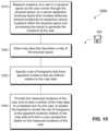
- FIG. 15is a flowchart showing an example method of managing virtual content to be displayed to users via headsets.
- An improved technique for rendering virtual content to a userstores map information describing a physical environment of the user and measures the location of the user with stationary sensors placed at respective locations within the environment.
- the improved techniqueprovides software applications, such as games and virtual walk-throughs, with a global perspective of users and their locations relative to virtual content.
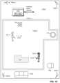
- FIG. 1shows an example environment 100 in which embodiments of the improved technique hereof can be practiced.
- a user 120is seen moving through a physical space 110 .
- the physical space 110includes rooms 110 a and 110 b and walls 112 a and 112 b .
- the user 120wears a three-dimensional imaging headset 130 , such as an AR (augmented reality) or MR (mixed reality) headset, which is capable of displaying holograms via display elements positioned in front of the user's eyes.
- the display elements in the headset 130are transparent or translucent, such that the user 120 is able to look directly through the display elements to see the immediate surroundings.
- the headset 130may project holograms, via the display elements, that appear fixed in relation to physical features in the physical space 110 , such as floors, ceilings, walls, and other physical objects.
- Each of the sensors 140is coupled to a server apparatus 150 using wired and/or wireless connections.
- the sensors 140are configured to detect the presence of the user 120 and to provide detection information as inputs to the server apparatus 150 .
- the server apparatus 150is configured to process the inputs from the sensors 140 and to measure therefrom the 3-D locations of the user 120 in the physical space 110 .
- the server apparatus 150is further configured to store map data 160 , which describes physical features of the physical space 110 , such as locations, sizes, and orientations of walls, floors, ceilings, furniture, stairways, doors, windows, and the like.
- the server apparatus 150specifies holograms (virtual objects) relative to the map data 160 .
- each hologramhas a location, dimensions, and an orientation that is aligned with a coordinate system of the map data 160 .
- Example holograms 114 , 116 , and 118are shown. These holograms are not physical features but rather virtual features that the headset 130 may render such that they appear to be present in the indicated locations from the perspective of the user 120 through the headset 130 .
- the server apparatus 150may further specify holograms as artificial coverings (e.g., skins) on physical objects present in the physical space 110 , such as on walls 112 a and 112 b .
- virtual objectsare constructed around physical objects.
- hologram 114may be shown as a garden whereas in fact it covers a physical object, such as a sofa.
- the server apparatus 150receives a stream of inputs from the sensors 140 and generates measured locations of the user 120 as the user moves around in the physical space 110 .
- the location of the user 120is taken as the location of the headset 130 worn by the user 120 .
- the server apparatus 150sends the measured user location, information about holograms, and map data 160 (or portions thereof) to the headset 130 .
- the headset 130processes the user location and map data 160 to render the holograms.
- the headset 130applies hologram information and map data 160 to generate a virtual model of objects within its line of sight 132 , based on the headset's current 3-D location and orientation.
- the headset 130then renders the holograms that fall within the headset's field of view.
- the user 120is thus able to see virtual objects 114 , 116 , and 118 placed in their proper locations and orientations within the physical space 110 .
- the server apparatus 150By processing the map data 160 , hologram information, and user locations, the server apparatus 150 constructs a global perspective of the physical space 110 that includes all the physical and virtual content within the physical space 110 , including the user 120 .
- the server apparatus 150may share elements of this global perspective with the headset 130 and/or with other components.
- the sensors 140are realized in the form of antennas that detect Wi-Fi (IEEE 802.11) signals emanating from the headset 130 , as well as from other wireless devices in the vicinity.
- Wi-FiIEEE 802.11
- the antennasends information about the detection to the server apparatus 150 , which processes the information along with similar detection information from other antennas to locate the source of the wireless signal.
- a wireless signalsuch as a Wi-Fi packet
- the server apparatus 150uses the approach disclosed in the incorporated document to measure the location of headset 130 to within an accuracy of single centimeters.
- antennascan be used to locate objects using a variety of techniques, and that the invention hereof is not limited to the particular ones disclosed in the incorporated document. Also, sensors besides antennas may be used in various embodiments, such as cameras, sonic transducers, and the like.
- the map data 160may incorporate information from a variety of sources.
- the usermay direct the server apparatus 150 to enter a learning mode, whereupon the user proceeds to walk around a perimeter of the physical space 110 while wearing the headset 130 (or carrying some other wireless device detectable by the sensors 140 ).
- the server apparatus 150receives inputs from the sensors 140 , generates user locations therefrom, and follows the user's movements to define the perimeter of the space.
- input from one or more cameras in the headset 130augments the location information to create a more precise map of the physical space 110 , e.g., the precise locations of walls, floors, ceilings, and the like, as imaged by the camera(s) and aligned with the measured locations.
- the physical space 110may span multiple rooms, stories, and even outdoor spaces, provided such spaces are within range of the sensors 140 .
- additional map data 160may derive from a software application.
- a game or other applicationmay define particular rooms, realms, spaces, and other artificial content, which the server apparatus 150 receives and may integrate into the map data 160 at suitable locations and orientations relative to the physical space 110 .
- the useroperates a software program to define custom features, such as coverings, objects, walls, and the like, which the server apparatus 150 may locate relative to the map data 160 at user-defined locations.
- custom featuressuch as coverings, objects, walls, and the like
- input from other physical spacesmay also be received and located relative to the map data 160 , e.g., to enable the user 120 to visualize features in distinct physical spaces in a manner that is aligned with the user's own physical space 110 .
- FIG. 2shows an example of the server apparatus 150 and related components in additional detail.
- the server apparatus 150includes an LPS (local positioning service) base station 210 , a vault appliance 220 , an application server 230 (such as a game hub), and a switch/router 240 .
- LPSlocal positioning service
- vault appliance 220vault appliance 220
- application server 230such as a game hub
- switch/router 240switch/router
- the LPS base station 210receives inputs from the sensors (e.g., antennas) 140 and generates therefrom locations of the headset 130 , as well as locations of other Wi-Fi devices in the vicinity. In an example, the LPS base station 210 measures device locations using wireless packets (e.g., Ethernet Wi-Fi packets), which the devices emit as part of their normal communications.
- the LPS base station 210maintains a 3-D map of a secured zone 212 within range of the sensors 140 .
- the secured zone 212defines a region relative to the physical space 110 in which Wi-Fi communications with the switch/router 240 are permitted.
- Packets received by the LPS base station 210are allowed to pass to the switch/router 240 only if those packets originate from a device confirmed to be located within the secured zone 212 . Further details of location measurement using antennas and an LPS base station 210 may be found in the above-incorporated U.S. patent application Ser. No. 15/452,451 (“CONTROLLING ACCESS TO A COMPUTER NETWORK USING MEASURED DEVICE LOCATION”).
- the vault appliance 220is a secure hub for storing and dispatching rights. Such rights may include content rights for accessing particular content, communication rights for establishing communications with another party, and action rights for performing actions on particular devices or elements.
- the vault appliance 220may securely store the map data 160 , or portions thereof, and may securely control the release of such map data 160 using content rights and/or communication rights. Further details of the vault appliance 220 may be found in U.S. patent application Ser. No. 15/347,551, filed Nov. 9, 2016 and entitled “VAULT APPLIANCE FOR IDENTITY VERIFICATION AND SECURE DISPATCH OF RIGHTS,” the contents and teachings of which are incorporated by reference herein.
- LPS base station 210 and vault appliance 220promote security and provide other benefits, but their particular details should be regarded as optional unless otherwise specified.
- the application server 230is a computerized device configured to run software applications, such as an application 232 .
- the application server 230may be implemented as a general purpose computer or as a specialized system, such as a game hub.
- the game hubmay be similar to conventional game consoles (e.g., X-BOX, PlayStation, etc.) but is adapted to work with MR (mixed reality) games and to participate in the particular procedures and protocols as described herein.
- MRmixed reality
- the game hubmay download games and other content over the Internet. It may also receive content via conventional software media, DVDs, Blu-ray disks, etc.
- the switch/router 240may have a conventional design.
- the switch/router 240has LAN (Local Area Network) ports for connecting to the LPS base station 210 , vault appliance 220 , and application server 230 , as well as for distributing a wired LAN 170 throughout the physical space 110 .
- the switch/router 240may also have a WAN (Wide Area Network) port, for connecting to a WAN/Internet 250 .
- the switch/router 240is a wired device only, with wireless services performed by the LPS base station 210 , e.g., using one or more of the antennas. In other examples, the switch/router 240 directly supports both wired and wireless communications.
- the switch/router 240may connect to one or more public servers 260 . These may include on-line stores (e.g., for buying games) and various servers to support vault-based communications.
- the switch/router 240also supports communication over the WAN/Internet 250 with similarly-configured networks of other users, e.g., to support multi-player games or other applications across different local networks and locations.
- the LPS base station 210 , the vault appliance 220 , and the application server 230each include their own processing circuitry and memory.
- Each memorymay store instructions which, when run by the respective processing circuitry, cause the processing circuitry to carry out various procedures and activities as described herein.
- any activities ascribed to the server apparatus 150may be performed by any of the included components, or by any combination of such components.
- FIG. 3shows a schematic view of the user 120 wearing the headset 130 as well as various wearable sensors 310 .
- the headset 130 and the wearable sensors 310track the user's movements and enable the server apparatus 250 to construct a skeletal model of the user 120 .
- the resulting skeletal modelhas two main uses. First, it enables the server apparatus 150 to track the user's body pose and movements, such that the server apparatus 150 can construct a sharable model of the user that moves in synchronization with the user. Second, it enables the server apparatus 150 and/or the headset 130 to map user movements to a motion-based set of control commands. For example, the server apparatus 150 and/or headset 130 may interpret particular movements of the user's head, arms, legs, and/or torso as control commands, which are interpreted to initiate particular activities.
- solid rectanglesindicate locations of wearable sensors 310 .
- six wearable sensors 310may be used, one on the torso, one on the waist, one on each wrist, and one on each ankle.
- the wearable sensors 310may be applied to the body using straps, adhesives, using a specialized garment, or in any other suitable way.
- no sensoris shown in the headset 130 , one should appreciate that the headset 130 may include circuitry for performing the functions of a wearable sensor.
- Each wearable sensor 310is seen to include a wireless interface 312 (Wi-Fi, Bluetooth, etc.), measurement circuitry 314 , processing circuitry 316 , memory 318 , and a battery 119 .
- the measurement circuitry 314may include one or more accelerometers, gyroscopes, magnetometers, and the like, for measuring changes in position and orientation in 3-D space.
- each wearable sensor 310is caused to generate sensor output, which may be read by the headset 130 and/or by the server apparatus 150 .
- the wearable sensors 310process raw sensor data and generate their output in the form of higher-order information, such as changes in position (relative to some starting point) and orientation (relative to some starting orientation).
- the user 120may execute a training procedure.
- An objective of the training procedureis to estimate joint locations (shown as solid circles 320 ) and limb lengths of the user, based on how the wearable sensors 310 move during the training procedure.
- the training procedure 412measures 3-D positions 410 of the wearable sensors 310 as the user 120 executes a set of predefined movements.
- the result of the training procedure 412is a 3-D skeletal model 420 of the user, which estimates the user's joint locations and limb lengths.
- a rendering step 422may generate a 3-D avatar 430 of the user 120 .
- the application server 230e.g., a game hub
- generation of the avatar 430 from the skeletal model 420may be initiated by particular applications. For example, users may represent themselves with different avatars 430 in different games, but with all such avatars 430 based on the same body geometries.
- the application server 230 and particular applicationsmay support multiple users, with each user having his or her own skeletal model and avatar.
- the system(headset 130 and server apparatus 150 ) assumes that the user's shoulder, hip, neck, and waist joints are ball-and-socket joints and that knee and elbow joints are hinges.
- the systemguides the user through the training procedure 412 .
- the headset 130projects a mirror image of the skeletal model 420 to the user as the user performs the procedure. Auditory controls may guide the user through the procedure, which may include the following steps:
- location and position of jointsmay also be enhanced by taking into account the user's view of the body as projected by the headset 130 , e.g., by receiving user feedback.
- the order of the above movementscan be varied in any sensible way.
- the antennas 140 and the LPS base station 210may track their locations as described above, e.g., based on packets emitted by the wearable sensors 310 .
- the wearable sensors 310may report their own orientations, e.g., by reading their internal measurement circuitry 314 and transmitting the results.
- the server apparatus 150measures the locations of the wearable sensors 310 the same way it measures the location of the headset 130 (using packets). In other examples, a different approach may be used.
- the accuracy with which a device's location can be measuredmay be proportional to the frequency of the Wi-Fi signals that the device transmits. But Wi-Fi frequency is proportional to power usage. Thus, to conserve battery life, it may be preferred to use lower-power 2.4 GHz Wi-Fi for the wearable sensors applied to the body, but to use 5.0 GHz Wi-Fi for the headset 130 . Although the use of lower-frequency Wi-Fi may result in a loss of location accuracy for wearable sensors 310 , accuracy can be restored using the measurement circuitry 314 within such sensors.
- FIG. 5shows an example arrangement 500 for accurately measuring locations of wearable sensors 310 attached to the body using low-power communications.
- an accurate location of the headset 130is generated based on wireless signals from the headset itself.
- the headset 130emits 5 GHz Wi-Fi packets, which the antennas ( 140 ) detect and which the LPS base station 210 uses to measure the location of the headset 130 precisely, e.g., to within some single number of centimeters.
- an initial 3-D location of each of the wearable sensors 310is established relative to the headset 130 .
- the user 120may place each wearable sensor 310 adjacent to an object having known dimensions.
- the user 120may then point the line of sight 132 of the headset 130 toward the object and direct the headset 130 to compute a precise location in space of the wearable sensor 310 relative to the headset's own location.
- This locationis also relative to the physical space 110 , as it is based on the headset's location as measured by the accurate antenna/LPS system.
- the headset 130may simultaneously query the wearable sensor 310 to obtain its self-reported location as indicated by the measurement circuitry 314 within the wearable sensor. This self-reported location may be used as a baseline going forward.
- the headset 130may compute a 3-D correction vector based on a difference between the initial location of the wearable sensor 310 as reported by the headset 130 and the self-reported location as reported by the wearable sensor 310 .
- the user 120may place the wearable sensor 310 on the body, such as on the wrist.
- the headset 130may again query the wearable sensor 310 for its self-reported location, correcting the measured values by applying the 3-D vector. Similar activities may be performed for other wearable sensors.
- FIG. 6shows an example sensor platter 600 that may be used for establishing initial locations of the wearable sensors 310 .
- the sensor platter 600has a substrate 610 , such as a printed circuit board, and docking locations 612 a - 612 f for receiving wearable sensors 310 .
- the sensor platter 600may also have a grip region 620 and a charging connector 630 .
- Visual identification marks 640are printed on the substrate 610 to facilitate the measurement of distance and perspective by the headset 130 .
- each wearable sensor 310may be inserted into only one docking location.
- each wearable sensorelectrically connects to charging contacts (not shown) within the docking location.
- the charging contactsare coupled to the charging connector 630 , e.g., using circuit board traces.
- the charging connector 630may be plugged into an electrical source, such as an AC adapter or USB connector, such that the sensor platter 600 may also function as a charging port.
- the user 120may calibrate the wearable sensors 310 by wearing the headset 130 and pointing the line of sight 132 toward the visual indication marks 640 .
- the headset 130can compute the location of each wearable sensor 310 relative to the headset 130 , and can thus establish the initial 3-D locations of all of the wearable sensors 310 at once.
- the measurement circuitry 314 within the wearable sensors 310may drift over time. Such drift may degrade proper rendering of avatar movements and may cause errors to arise in interpreting control commands.
- FIG. 7shows an example method 700 for detecting the need to retrain wearable sensors 310 and for initiating such retraining.
- first measurementsare made of wearable sensor locations by querying the measurement circuitry 314 in the wearable sensors 310 and applying correction vectors, e.g., as described in connection with the method 500 above.
- second measurementsare made of wearable sensor locations. In this case, however, the measurements are made more directly using the antennas ( 140 ) and LPS base station 210 , i.e., the same way the location of the headset 130 is measured.
- a 3-D bounding regionis generated for each of the second measurements.
- Each 3-D bounding regionrepresents a volume in space that is predicted to contain the respective wearable sensor 310 .
- This bounding regionmay be regarded as an error band around the second measurements, which may be made, for example, using 2.4 GHz (low power) Wi-Fi.
- the systemdetermines whether the first measurement for any wearable sensor 310 falls outside the respective 3-D bounding region for that wearable sensor. If so, the system initiates a wearable-sensor-retraining operation at the first opportunity. For example, the system may wait until the user 120 enters a designated region, such as the region indicated by object 118 in FIG. 1 . The user 120 may previously have been instructed to assume a neutral body pose when standing within that region, such as standing up straight with arms at the sides. For example, assuming this pose may be pre-arranged as part of normal game play.
- the systemUpon detecting that the user has entered the region indicated by object 118 , the system measures the locations of the wearable sensors 310 using the measurement circuitry 314 (as done in the first measurements, above), and compares the sensor locations with expected locations based on the skeletal model 420 . The system then generates a new correction vector for each wearable sensor 310 and applies the new correction vectors going forward.
- the systemmay issue a command to the user to assume the neutral pose at any suitable time.
- the method 800may detect predetermined patterns of changes in locations and/or orientations of the wearable sensors (step 810 ) based on output from the measurement circuitry 314 in the wearable sensors 310 .
- the measurement circuitry 314 in the wearable sensors 310reports changes in position and/or orientation of each sensor, which the headset 130 and/or server apparatus 150 processes to detect predetermined patterns.
- the systemmay map that pattern to a respective control command and then execute the mapped-to control command (step 820 ).
- predetermined patterns of movementswhich the system may map to user commands.
- Other movements besides thesemay be used, as well, provided they can be detected reliably by the wearable sensors and are not movements that the user is likely to perform accidentally.
- movementsmay be combined in particular sequences to establish predetermined patterns.
- the systemallows users to enter a VR (Virtual Reality) mode and to enter control commands using predetermined movements, such as those described above.
- VR modepredetermined patterns of movement may map intuitively to VR actions. For example, shifting weight to the right leg may map to a command for dodging to the right. Bending forward may map to ducking.
- FIGS. 9 A and 9 Bdepict an example arrangement for displaying holograms through the headset 130 relative to body appendages of the user.
- FIG. 9 Ashows an example user view 900 through the headset 130 .
- the user's arm 910can be seen (with wrist sensor 310 a ), as well as a controller 920 , which is shaped like a sword.
- the controller 920may include buttons and other controls for enhancing game play.
- a hologram 930which represents some virtual object in the background, is also visible in the user's view 900 . Maintaining the hologram 930 in the background relative to the user's arm 910 and the controller 920 is a difficult problem for conventional MR systems but is readily managed here, as shown in FIG. 9 B .
- the headset 130prepares to render the hologram 930 , i.e., on the display elements in the headset 130 . Owing to the close proximity of the wrist sensor 310 a to the user's hand, the headset 130 identifies the arm 910 within the field of view and proceeds to identify pixel locations corresponding to parts of the arm 910 as foreground. The headset 130 also identifies as foreground pixel locations of any object connected to the arm 910 , such as the controller 920 .
- the headset 130renders, in the display elements, pixels of the hologram 930 that do not overlap with the user's arm 910 or with the controller 920 .
- any pixel locations of the hologram 930 not marked as foregroundare rendered in the usual way.
- the headset 130masks those pixels of the hologram 930 and fails to render them.
- the overall effectis to mask out pixels of the hologram 930 that should be blocked by the user's arm and controller, so as to maintain the illusion that the hologram 930 is in the background.
- the particular pixels of the hologram 930 to be displayed or maskedwill be different for left and right display elements, owing to the differences in perspective.
- the pixels of the hologram 930rendered so as to preserve proper background and foreground, but also proper perspective and parallax, such that the user perceives both the arm 910 and the hologram 930 at proper distances.
- FIG. 1multiple users may occupy the physical space 110 shown in FIG. 1 , with each user's location tracked by the sensors 140 and server apparatus 150 , i.e., in the same manner as described for the user 120 .
- Each usermay create a skeletal model 420 , which may be rendered as an avatar 430 ( FIG. 4 ).
- each user in the physical space 110sees all the other users as avatars, which may be superimposed over the user's physical bodies.
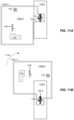
- FIG. 10shows another multi-user scenario.
- a second user 120 - 2is located within a second physical space 110 - 2 , which is discontinuous and remote from the physical space 110 shown in FIG. 1 (hereinafter, the “first” physical space).
- the second physical space 110 - 2is configured similarly to the first, and includes its own sensors 140 a - 2 through 140 d - 2 and server apparatus 150 - 2 .
- the second physical space 110 - 2may have a different shape from the first physical space 110 .
- the “play zone”is an area designated for game play or other activity. Furniture 1020 and 1022 in the second physical space 110 - 2 may be moved out of the way to clear space for the play zone.
- the second server apparatus 150 - 2has obtained shared map data 160 a from the first server apparatus 150 ( FIG. 1 ), e.g., over the WAN/Internet 250 .
- the shared map data 160 aincludes portions of the map data 160 . Sharing may be accomplished, for example, by the owner of the vault appliance 230 in the first physical space 110 granting a content right to the second user 120 - 2 to access particular features in the physical space 110 .
- map data describing features of the first room 110 aare shared, such as walls 112 a
- map data describing other portions of the physical space 110are not shared, such as data describing the room 110 b and walls 112 b (e.g., the first user 120 may wish to keep the room 110 b private).
- map data 160may be shared at any desired level of granularity.
- a second headset 130 - 2 worn by the second user 120 - 2is able to render objects that are physical in the first physical space 120 as virtual objects in the second physical space 110 - 2 .
- the second user 120 - 2is able to visualize the room 110 a and walls 112 a as holograms 110 a -V and 112 a -V, respectively.
- the second server apparatus 150 - 2also receives information about the holograms 114 , 116 , and 118 , allowing the same holograms to be rendered to the second user 120 - 2 as were rendered to the first.
- the second user 120 - 2thus sees, through the second headset 130 - 2 , the same holograms in the same relative positions as they appear to the first user 120 in the first physical space 110 .
- the second server apparatus 150 - 2In addition to receiving shared map data 160 a , the second server apparatus 150 - 2 also receives, over the WAN/Internet 250 , a real-time representation of the avatar 430 of the first user 120 , including its location and orientation relative to the play zone. With this arrangement, the second user 120 - 2 is able to see the avatar 430 of the first user 120 move within the second physical space 110 - 2 (movement shown by arrow 1010 ) in a manner that mirrors the movement of the first user 120 within the first physical space 110 . In a like manner, the first user 120 , within the first physical space 110 , sees an avatar of the second user 120 - 2 displayed and moving in real time in synchronization with the second user 120 - 2 .
- each user's headsetrendering the holograms 114 , 116 , and 118 and the avatars of the other users, with the avatars moving in real time to reflect movements of the users they represent.
- each user's headsetrenders a virtual rendition of the shared portions of the physical space 110 . Owing to the global perspective afforded by the stationary sensors and the computerized apparatus in each physical space, the position and orientation of each avatar relative to the play zone matches the position and orientation of the respective physical user in that user's local play zone.
- the shared map data 160 arepresents physical objects in the first physical location 110 in simplified form, with certain details of the physical space removed to avoid distraction and/or to maintain privacy.
- a wall with a built-in bookshelfmay be represented as a flat wall, or as a wall with a stylized surface texture or synthetic content.
- a desk covered with papersmay be represented as a flat surface.
- Synthetic contentmay be supplied by users, by games, and/or by third-party software, for example. Sharing of content may go in any direction.
- the second user 120 - 2may design a virtual object and place that object in a particular location within the play zone, sharing that object back to other users via respective server apparatus.
- a game or other software applicationmay generate the play zone, which need not correspond to features in any physical space.
- the gamemay define the play zone and share that play zone with all users.
- the server apparatus at each locationmay instantiate the play zone locally. Users can then view features of the play zone and avatars of other users through their respective headsets.
- Games or other software applicationsmay also produce computer-generated avatars, which move through the play zone and can be viewed at corresponding locations by all users.
- FIGS. 11 A and 11 Bshow an example embodiment involving a scene.
- a “scene”is a collection of holograms and virtual interconnects, where a “virtual interconnect” is a designated space that a user may enter to perform an action.
- the virtual object 118depicts a virtual interconnect rendered in a third physical space 110 - 3 .
- the third physical space 110 - 3is smaller than the play zone; it may merely be a hallway.
- a user 120 - 3wears a headset 130 - 3 , which renders the virtual interconnect 118 as a glowing circle on the floor, or in any other suitable manner.
- the third user 120 - 3may enter the virtual interconnect 118 by stepping into the circle.
- the headset 130 - 3presents the user 120 - 3 with various options. There is no limit to these options, but examples may include teleportation (e.g., to a different play zone), entry into a VR realm, and rotation of the play zone. In this example, we assume that the user 120 - 3 selects the rotation option.
- FIG. 11 Bshows an example result of rotation.
- the systemhas rotated the entire play zone, including all virtual objects, ninety degrees about the virtual interconnect 118 .
- the user 120 - 3is then able to exit the virtual interconnect 118 and enter into a main part of the virtual room 110 a -V.
- Multiple virtual interconnectsmay be provided at respective locations to accommodate users in confined physical locations.
- FIGS. 12 A and 12 Bshow an example arrangement for encouraging users to stay within the play zone and to avoid moving to locations that are off-limits.
- the second physical space 110 - 2( FIG. 10 ) is larger than the play zone, such that the second user 120 - 2 is able to physically leave the play zone.
- this freedommay present an unfair advantage for the second user 120 - 2 .
- itis inconsistent with the wish to keep all players in the game.
- the second user 120 - 2 in the second physical space 110 - 2has left the play zone.
- the second user 120 - 2has crossed from a first side 1210 of the virtual wall 112 a -V to a second side 1220 .
- the avatar 430 - 2 of the second user 120 - 2stays behind, i.e., on the first side 1210 of the virtual wall 112 a -V.
- the avatar 430 - 2may remain in this position until the second user 120 - 2 returns to the same location, at which point the avatar 430 - 2 resumes tracking the movements of the second user 120 - 2 .
- FIG. 12 Bshows the same situation from the viewpoint of the first user 120 in the first physical space 110 .
- the first user 120sees, through the headset 130 , the avatar 430 - 2 of the second user 120 - 2 , but the avatar 430 - 2 appears to be standing still—until the second user returns such that tracking can resume.
- hologramsmay be used to represent barriers that users must stay within to participate in a game. Anytime a user crosses a barrier, such as a virtual wall, or otherwise steps out of bounds, the system may freeze that user's avatar, forcing the user to return to the place where the barrier was crossed. This behavior has the effect of enforcing virtual barriers to prevent cheating, e.g., by allowing users to take short cuts.
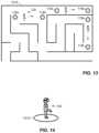
- FIG. 13shows an example of a different play zone, which is laid out as a simple maze 1310 .
- the walls of the mazeare set up as barriers, such that users must stay within the designated paths of the maze to avoid becoming separated from their avatars.
- FIG. 13also shows various uses of virtual interconnects.
- the systemprovides virtual interconnects 118 a and 118 b at maze decision points.
- a user 120 entering these virtual interconnects 118 a and 118 bmay rotate the perspective, as described in connection with FIGS. 11 A and 11 B .
- the usermay also specify a rate of movement.
- the usermay specify accelerated movement, such that each meter the user walks in physical space is translated to N meters of movement in virtual space—through the maze 1310 .
- virtual interconnects 118 c and 118 dspecify a 1:1 scale movement, such that every meter the user walks in physical space is mapped 1:1 to a meter in virtual space.
- Virtual interconnects 118 e and 118 fmay require the user 120 to enter a VR realm to cross the indicated distance.
- the VR realmmay present particular challenges that the user must overcome to cross the indicated distance.
- FIG. 14shows an example spot 1410 that users may step into to enter a VR realm.
- a game or other software applicationmay place such “VR Anywhere” spots 1410 at desired locations within a play zone.
- the user 120is able perform VR commands to navigate a synthetic VR space, e.g., using the above-described physical movements mapped to control commands.
- the VR spaceis not required to have any relationship to the physical space in which the user is located.
- the VR Anywhere spot 1410is preferably a small area, e.g., just large enough to safely accommodate the user 120 executing the predefined movements.
- VR control commandsare enabled only when the user 120 remains within the VR Anywhere spot 1410 and are disabled if the user steps out of the VR Anywhere spot 1410 .
- the systemchecks local map data 160 and locations of other users to ensure that no mapped objects are within some predetermined radius of the VR Anywhere spot 1410 , to protect the user 120 (and other users) from harm that may result from sudden movements of the user's head, arms, legs, or torso.
- portalsview VR realms from AR environments.
- a “portal”is an AR viewable object that provides a VR view of an arbitrary space. The viewed space could be virtual, another LPS Zone or the same LPS Zone.
- Portalscome in pairs: a viewing portal and a capture portal. Observers look into the viewing portal and see what is on the other side of the capture portal. When the word portal is used by itself, it typically refers to the viewing portal.
- a “viewing portal”is defined by:
- portalswill be close to walls, ceilings or other player inaccessible areas.
- a capture portalis defined by:
- the relative position of the viewerdefines the content seen through the portal.
- the capture portalneed not be the equivalent of a fixed camera providing the view for the viewing portal. If the view is provided via AR projection or produced on a physical screen, it must typically be this way. If the portal is viewed via AR glasses, then the viewable content can be different for each viewer. In this case, the view seen through the viewing portal is made using standard ray tracing techniques based on the location of the observer. The only difference is that the rays that hit the observer side of the viewing portal leave the capture side of the capture portal at the same relative angle.
- Virtual objectsmay cross the portal between the two connected LPS Zones.
- an observerwould see a consistent view of the virtual object as it approached the capture side of the capture portal, transitioned through the viewing portal and as it became a full blown AR object in the local LPS Zone of the observer.
- a physical space or environmentis a gaming dimension with infinite variability as follows:
- VRVirtual reality
- ARAugmented reality
- Coextensive Realityconsists of multiple players in PlayZones that are networked together (virtually interconnected).
- the game serveris the master. It keeps the state of each PlayZone. Each player sends his state information to the game server (to track the physical state of each player).
- the game engineis the master of what is seen. If it is a physical area, the player sees AR objects projected. If it is a virtual area, the player sees virtual objects.
- VR Viewthe player sees an avatar as a virtual thing in the virtual world.
- VR Viewoccurs with any of the four virtual interconnect methods that enable connection to VR PlayZones (or Virtual Realms):
- FIG. 15shows an example method 1500 of managing virtual content to be displayed to users via three-dimensional imaging headsets, such as AR and MR headsets.
- the method 1500may be carried out, for example, by the server apparatus 150 described in connection with FIG. 2 .
- the various acts of method 1500may be ordered in any suitable way. Accordingly, embodiments may be constructed in which acts are performed in orders different from that illustrated, which may include performing some acts simultaneously.
- the server apparatus 150measures locations of a user 120 in a physical space 110 as the user 120 moves through the physical space 110 , by receiving inputs from multiple stationary sensors 140 positioned at respective sensor locations within the physical space 110 and processing the inputs to generate the locations of the user 120 .
- map data 160are stored.
- the map data 160describes a map of the physical space 110 .
- a set of holograms(e.g., 114 , 116 , 118 ) are specified.
- the set of hologramshave apparent locations that are defined relative to the map data 160 .
- the measured locations of the user 120 and at least a portion of the map data 160are provided to a headset 130 worn by the user 120 , to enable the headset 130 to render the set of holograms (e.g., 114 , 116 , 118 ) at the apparent locations relative to the map data 160 and from a user perspective based on the measured locations of the user.
- the set of hologramse.g., 114 , 116 , 118
- the improvement or portions thereofmay be embodied as one or more computer program products each including one or more non-transient, computer-readable storage media, such as a magnetic disk, magnetic tape, compact disk, DVD, optical disk, flash drive, solid state drive, SD (Secure Digital) chip or device, Application Specific Integrated Circuit (ASIC), Field Programmable Gate Array (FPGA), and/or the like (shown by way of example as medium 550 in FIGS. 5 , 7 , 8 , 9 B, and 15 ). Any number of computer-readable media may be used.
- the mediamay be encoded with instructions which, when executed on one or more computers or other processors, perform the process or processes described herein. Such media may be considered articles of manufacture or machines, and may be transportable from one machine to another.
- the words “comprising,” “including,” “containing,” and “having”are intended to set forth certain items, steps, elements, or aspects of something in an open-ended fashion.
- the word “set”means one or more of something. This is the case regardless of whether the phrase “set of” is followed by a singular or plural object and regardless of whether it is conjugated with a singular or plural verb.
- ordinal expressionssuch as “first,” “second,” “third,” and so on, may be used as adjectives herein, such ordinal expressions are used for identification purposes and, unless specifically indicated, are not intended to imply any ordering or sequence.
- a “second” eventmay take place before or after a “first event,” or even if no first event ever occurs.
- an identification herein of a particular element, feature, or act as being a “first” such element, feature, or actshould not be construed as requiring that there must also be a “second” or other such element, feature or act. Rather, the “first” item may be the only one.
Landscapes
- Engineering & Computer Science (AREA)
- Theoretical Computer Science (AREA)
- General Engineering & Computer Science (AREA)
- Physics & Mathematics (AREA)
- General Physics & Mathematics (AREA)
- Human Computer Interaction (AREA)
- Software Systems (AREA)
- Computer Graphics (AREA)
- Geometry (AREA)
- Remote Sensing (AREA)
- Radar, Positioning & Navigation (AREA)
- Computer Hardware Design (AREA)
- User Interface Of Digital Computer (AREA)
- Selective Calling Equipment (AREA)
- Processing Or Creating Images (AREA)
- Position Input By Displaying (AREA)
Abstract
Description
- U.S. Provisional Application No. 62/378,486, filed Aug. 23, 2016 and entitled “SECURE HUB FOR DISPATCH OF RIGHTS AND VERIFICATION OF IDENTITY, USING A UNIFORM AUTHENTICATION METHOD WITH MULTI-FACTOR VARIABLE AUTHENTICATION STRENGTH;”
- U.S. Provisional Application No. 62/378,494, filed Aug. 23, 2016 and entitled “VIRTUAL SENSITIVE COMPARTMENTED INFORMATION FACILITY;”
- U.S. Provisional Application No. 62/378,498, filed Aug. 23, 2016 and entitled “UNIVERSAL CONTROLLER FOR REAL AND VIRTUAL OBJECTS IN THREE DIMENSIONAL SPACE;”
- U.S. Provisional Application No. 62/397,226, filed Sep. 20, 2016 and entitled “SYSTEM FOR AUGMENTED REALITY REFERENCED TO A COMMON COORDINATE SYSTEM IN REAL THREE-DIMENSIONAL SPACE, INCLUDING METHOD FOR CONTROL AND MOVEMENT OF VIRTUAL OBJECTS BETWEEN SEPARATE PHYSICAL SPACES;” and
- U.S. Provisional Application No. 62/491,048, filed Apr. 27, 2017 and entitled “COEXTENSIVE REALITY SYSTEM.”
- User stands upright with feet together and arms relaxed to the side. This pose/position provides the baseline height measurements of all
wearable sensors 310. Because the arms are relaxed to the side, the pose also gives an estimate of shoulder width. - User turns head to the left, to the right, touches chin to chest, and tilts head upward. These motions provide an estimate of the neck location (assumed to be a ball joint).
- User bends left elbow and, with left hand extending straight from forearm, touches right elbow crease with middle finger. User repeats on other side. These actions provide locations of the elbows.
- User extends both arms straight in front at shoulder height. This movement provides another estimate of the shoulder joint location. This time, shoulder height and width are estimated from the wrist sensors.
- User rests arms to the side and then bends elbows at 90 degrees. The user rotates palms to face each other, then palms up, and finally palms down. These movements verify the range of motion of the wrist joint and the effect of turning on forearm estimation.
- The user locks both legs straight. The user takes one large side step with a single foot directly to the side, then relocks legs straight. User then brings feet back to neutral underneath the hips. These motions provide an estimate of the leg length (hip height) and hip width.
- User bends knees slightly and touches the wrist bands to the outside of the knee joint. This gives an estimate of knee height.
- User kneels on a single knee with waist as high as possible. This provides an estimate of knee location.
- User stands with feet on the ground, and turns torso to the left, and then back to the right. This provides the range of motion on the joints of the lumbar spine.
- Location and position of joints may also be enhanced by taking into account the headset view of the body, particularly elbow and knee, during the training above.
- User stands upright with feet together and arms relaxed to the side. This pose/position provides the baseline height measurements of all
- Quick internal rotation of wrists;
- Quick external rotation of wrists;
- Raising elbows and bringing forearms to vertical position;
- Moving both arms forward (or back);
- Pushing one wrist forward while pulling the other back.
- Simulating turning a steering wheel (each direction);
- Shift weight onto one leg (each leg);
- Shift weight forward (or back);
- Rotating torso right (or left);
- Bending forward (or leaning back).
- Shape: A surface, typically a planar surface but can be any shape.
- Location: The location is not restricted within the playable area of the LPS Zone.
- Orientation: The orientation of a portal is also not restricted but typically would be oriented in a way to permit ease of use of the players. The orientation is relative to the LPS Zone
- Shape: Identical to the paired viewing portal.
- Location: The location is not restricted. It may in the same or different LPS Zone or in a fully virtual environment.
- Orientation: The orientation is independent of the orientation of the viewing portal.
- A player can put a virtual object in AR space that is aware of its surroundings (e.g. a virtual object of a cat can climb the physical stairs).
- A game can connect to VR spaces (including other PlayZones) using portals, VR Anywhere spots, projected spaces or virtual common rooms.
- Connections to VR spaces can be persistent or temporal (i.e., they can pop up and go away in any place throughout the PlayZone according to the game design). This is a completely new way for the game designer to use physical space as a dimension in the game.
- Players can move their avatars through virtual space.
- Virtual objects can move between the MR environment and virtual spaces (e.g., a virtual ball tossed through a portal).
- Physical spaces can be broken up using the scenes
- The CR Game Hub supports one active game at a time. As such each game has a guaranteed set of resources dedicated to it.
- Every player has exactly one avatar.
- There is exactly one active PlayZone per house.
- The CR Game Hub may define an arbitrary number of PlayZones.
- Every PlayZone has a corresponding virtual model (VR PlayZone) that can be visited by avatars.
- Virtual Realms that do not correspond to physical PlayZones can also be defined in the game and visited by avatars.
- Portal: A camera view into VR. Essentially a “window” that appears as an AR object that shows a view into a virtual space.
- Projected Space: Designated physical space where a player's body motion is mirrored by his avatar in a space of the same size in another PlayZone.
- Virtual Common Room: Projected Space that allows participation by players in all corresponding spaces. There can be two or more corresponding PlayZones/spaces.
- VR Anywhere Spot: Spot where player stands to virtually teleport to another PlayZone (or Virtual Realm), uses motion-control to move his own avatar, and interacts with real players.
- Case 1: They are able to interact physically and seeing the other player permits interaction with the other player.
- Case 2: They are not permitted direct physical-to-physical interaction. In this case the player may be able to be physically seen but the game rules state that the player must be found by using one of the four virtualization methods.
- Case 3: One physical player is hiding using a non-PlayZone “blanket,” so the observer can see the hiding player's avatar (as an AR projected object). The player then interacts with this avatar.
- Case 4: If 2 physical players are in the same PlayZone and one player locks the door, the “attacking” player can himself enter a VR Anywhere spot and explore his own PlayZone as an avatar to find and “get” the other player.
- Environments: The environments in which the games are held use the actual geometry of the users' homes, as well as virtual environments. Legacy games are complete virtual environments. Because the actual user's home is used within a multiplayer multi-location game, a method of modeling the user's PlayZone area is needed. This model is then shared with the game engine as well as other game clients. One user's physical play area is another user's virtual play area.
- Control: CR control is unique in that it naturally supports control in both AR and VR modes. Single point observation systems (i.e. room scale VR) use a combination of body motion control and handheld controls for avatar movement control. The handheld controllers are also used for player/object interaction as well. Legacy console games typically use multifunction controllers that control both avatar movement as well as interactions with other players and game content. In CR control, handheld controllers for player and object interaction should operate identically whether in AR or VR. Furthermore, because the controller is used in AR mode, the controller should physically appear like the object being controlled. A gun should look like a gun. Unique to CR games is the seamless transfer between AR and VR control. In AR control it is impossible to move the avatar separate from the player movement; hence, sensors are used to detect body movement. Coupling the above statements together it only makes sense to separate movement control and player/object interaction control. The wearables are responsible for movement control and the handheld controller is responsible for player/object interaction. Individual games may break this rule with custom controllers.
Claims (25)
Priority Applications (1)
| Application Number | Priority Date | Filing Date | Title |
|---|---|---|---|
| US16/707,373US11635868B2 (en) | 2016-08-23 | 2019-12-09 | Managing virtual content displayed to a user based on mapped user location |
Applications Claiming Priority (7)
| Application Number | Priority Date | Filing Date | Title |
|---|---|---|---|
| US201662378494P | 2016-08-23 | 2016-08-23 | |
| US201662378498P | 2016-08-23 | 2016-08-23 | |
| US201662378486P | 2016-08-23 | 2016-08-23 | |
| US201662397226P | 2016-09-20 | 2016-09-20 | |
| US201762491048P | 2017-04-27 | 2017-04-27 | |
| US15/656,500US10503351B2 (en) | 2016-08-23 | 2017-07-21 | Managing virtual content displayed to a user based on mapped user location |
| US16/707,373US11635868B2 (en) | 2016-08-23 | 2019-12-09 | Managing virtual content displayed to a user based on mapped user location |
Related Parent Applications (1)
| Application Number | Title | Priority Date | Filing Date |
|---|---|---|---|
| US15/656,500ContinuationUS10503351B2 (en) | 2016-08-23 | 2017-07-21 | Managing virtual content displayed to a user based on mapped user location |
Publications (3)
| Publication Number | Publication Date |
|---|---|
| US20200183567A1 US20200183567A1 (en) | 2020-06-11 |
| US20220317856A9 US20220317856A9 (en) | 2022-10-06 |
| US11635868B2true US11635868B2 (en) | 2023-04-25 |
Family
ID=59506377
Family Applications (3)
| Application Number | Title | Priority Date | Filing Date |
|---|---|---|---|
| US15/655,489Active2037-09-04US11269480B2 (en) | 2016-08-23 | 2017-07-20 | Controlling objects using virtual rays |
| US15/656,500Active2037-10-17US10503351B2 (en) | 2016-08-23 | 2017-07-21 | Managing virtual content displayed to a user based on mapped user location |
| US16/707,373ActiveUS11635868B2 (en) | 2016-08-23 | 2019-12-09 | Managing virtual content displayed to a user based on mapped user location |
Family Applications Before (2)
| Application Number | Title | Priority Date | Filing Date |
|---|---|---|---|
| US15/655,489Active2037-09-04US11269480B2 (en) | 2016-08-23 | 2017-07-20 | Controlling objects using virtual rays |
| US15/656,500Active2037-10-17US10503351B2 (en) | 2016-08-23 | 2017-07-21 | Managing virtual content displayed to a user based on mapped user location |
Country Status (4)
| Country | Link |
|---|---|
| US (3) | US11269480B2 (en) |
| JP (1) | JP2019532444A (en) |
| CN (1) | CN109791446A (en) |
| WO (2) | WO2018038834A1 (en) |
Families Citing this family (99)
| Publication number | Priority date | Publication date | Assignee | Title |
|---|---|---|---|---|
| US9652896B1 (en) | 2015-10-30 | 2017-05-16 | Snap Inc. | Image based tracking in augmented reality systems |
| US9984499B1 (en) | 2015-11-30 | 2018-05-29 | Snap Inc. | Image and point cloud based tracking and in augmented reality systems |
| US11625898B2 (en)* | 2016-10-11 | 2023-04-11 | Valve Corporation | Holding and releasing virtual objects |
| US10987573B2 (en) | 2016-10-11 | 2021-04-27 | Valve Corporation | Virtual reality hand gesture generation |
| US10307669B2 (en) | 2016-10-11 | 2019-06-04 | Valve Corporation | Electronic controller with finger sensing and an adjustable hand retainer |
| US10843068B2 (en) | 2017-01-18 | 2020-11-24 | Xvisio Technology Corp. | 6DoF inside-out tracking game controller |
| US10319149B1 (en) | 2017-02-17 | 2019-06-11 | Snap Inc. | Augmented reality anamorphosis system |
| US10074381B1 (en) | 2017-02-20 | 2018-09-11 | Snap Inc. | Augmented reality speech balloon system |
| US10387730B1 (en) | 2017-04-20 | 2019-08-20 | Snap Inc. | Augmented reality typography personalization system |
| US11054272B2 (en)* | 2017-05-11 | 2021-07-06 | Disney Enterprises, Inc. | Physical navigation guided via story-based augmented and/or mixed reality experiences |
| JP6832794B2 (en)* | 2017-06-05 | 2021-02-24 | ルネサスエレクトロニクス株式会社 | Wireless communication system |
| US11184574B2 (en) | 2017-07-17 | 2021-11-23 | Facebook, Inc. | Representing real-world objects with a virtual reality environment |
| US10740974B1 (en) | 2017-09-15 | 2020-08-11 | Snap Inc. | Augmented reality system |
| EP3489882A1 (en)* | 2017-11-27 | 2019-05-29 | Nokia Technologies Oy | An apparatus and associated methods for communication between users experiencing virtual reality |
| KR102028036B1 (en)* | 2018-01-18 | 2019-11-04 | 주식회사 뉴냅스 | Device, method and program for visual perception training by brain connectivity |
| WO2019172874A1 (en) | 2018-03-05 | 2019-09-12 | Reavire, Inc. | Maintaining localization and orientation of an electronic headset after loss of slam tracking |
| US20220215638A1 (en)* | 2018-05-29 | 2022-07-07 | Exploring, Inc. | System and method for haptic mapping of a configurable virtual reality environment |
| US11086124B2 (en) | 2018-06-13 | 2021-08-10 | Reavire, Inc. | Detecting velocity state of a device |
| US11212277B1 (en)* | 2018-07-02 | 2021-12-28 | Knwn Technologies, Inc. | System and method for securing, perfecting and accelerating biometric identification via holographic environmental data |
| EP3599538B1 (en)* | 2018-07-24 | 2023-07-19 | Nokia Technologies Oy | Method and apparatus for adding interactive objects to a virtual reality environment |
| US10997760B2 (en) | 2018-08-31 | 2021-05-04 | Snap Inc. | Augmented reality anthropomorphization system |
| US10939236B1 (en) | 2018-11-30 | 2021-03-02 | Snap Inc. | Position service to determine relative position to map features |
| US10921878B2 (en)* | 2018-12-27 | 2021-02-16 | Facebook, Inc. | Virtual spaces, mixed reality spaces, and combined mixed reality spaces for improved interaction and collaboration |
| EP3680753B1 (en)* | 2019-01-09 | 2022-01-05 | Nokia Technologies Oy | An apparatus and associated methods for presentation of a virtual reality space |
| US11972529B2 (en) | 2019-02-01 | 2024-04-30 | Snap Inc. | Augmented reality system |
| US11442549B1 (en)* | 2019-02-07 | 2022-09-13 | Apple Inc. | Placement of 3D effects based on 2D paintings |
| US10890983B2 (en) | 2019-06-07 | 2021-01-12 | Facebook Technologies, Llc | Artificial reality system having a sliding menu |
| US11334212B2 (en) | 2019-06-07 | 2022-05-17 | Facebook Technologies, Llc | Detecting input in artificial reality systems based on a pinch and pull gesture |
| US11189097B2 (en)* | 2019-06-14 | 2021-11-30 | In It Vr, Llc | Simulated reality transition element location |
| CN110348198B (en) | 2019-06-21 | 2024-04-12 | 华为技术有限公司 | Identity recognition method, related device and system of simulation object |
| US11288868B2 (en) | 2019-07-26 | 2022-03-29 | Foretell Studios, LLC | Simulated reality adaptive user space |
| US11307647B2 (en) | 2019-09-11 | 2022-04-19 | Facebook Technologies, Llc | Artificial reality triggered by physical object |
| US11086406B1 (en) | 2019-09-20 | 2021-08-10 | Facebook Technologies, Llc | Three-state gesture virtual controls |
| US11189099B2 (en) | 2019-09-20 | 2021-11-30 | Facebook Technologies, Llc | Global and local mode virtual object interactions |
| US11170576B2 (en) | 2019-09-20 | 2021-11-09 | Facebook Technologies, Llc | Progressive display of virtual objects |
| US10991163B2 (en) | 2019-09-20 | 2021-04-27 | Facebook Technologies, Llc | Projection casting in virtual environments |
| US10802600B1 (en)* | 2019-09-20 | 2020-10-13 | Facebook Technologies, Llc | Virtual interactions at a distance |
| US11176745B2 (en) | 2019-09-20 | 2021-11-16 | Facebook Technologies, Llc | Projection casting in virtual environments |
| CN110717993B (en)* | 2019-10-12 | 2021-04-02 | 西安维度视界科技有限公司 | Interaction method, system and medium of split type AR glasses system |
| US11086476B2 (en)* | 2019-10-23 | 2021-08-10 | Facebook Technologies, Llc | 3D interactions with web content |
| EP3825792B1 (en)* | 2019-11-21 | 2024-09-04 | Deutsche Telekom AG | Method for controlling at least one actuator of a smart home system and / or for generating and / or transmitting at least one control message to at least one actuator of the smart home system using an operating device, system, use of an operating device, a sensor device or a control device, computer program and computer-readable medium |
| US11175730B2 (en) | 2019-12-06 | 2021-11-16 | Facebook Technologies, Llc | Posture-based virtual space configurations |
| US11475639B2 (en) | 2020-01-03 | 2022-10-18 | Meta Platforms Technologies, Llc | Self presence in artificial reality |
| US11340695B2 (en) | 2020-01-24 | 2022-05-24 | Magic Leap, Inc. | Converting a 2D positional input into a 3D point in space |
| US11660528B2 (en) | 2020-03-12 | 2023-05-30 | Reavire, Inc. | Populating virtual objects in physical environments |
| US11181975B2 (en)* | 2020-03-12 | 2021-11-23 | International Business Machines Corporation | Field of view movement variation-based security profile assignment to physical assets at a location |
| US20210304515A1 (en)* | 2020-03-26 | 2021-09-30 | Wormhole Labs, Inc. | Systems and Methods of User Controlled Viewing of Non-User Avatars |
| JP2023068212A (en)* | 2020-03-31 | 2023-05-17 | 株式会社Nttドコモ | Information processing system |
| US20210358294A1 (en)* | 2020-05-15 | 2021-11-18 | Microsoft Technology Licensing, Llc | Holographic device control |
| US11257280B1 (en) | 2020-05-28 | 2022-02-22 | Facebook Technologies, Llc | Element-based switching of ray casting rules |
| US11256336B2 (en) | 2020-06-29 | 2022-02-22 | Facebook Technologies, Llc | Integration of artificial reality interaction modes |
| US11335068B2 (en)* | 2020-07-27 | 2022-05-17 | Facebook Technologies, Llc. | Systems and methods for user interaction with artificial reality environments |
| US11227445B1 (en) | 2020-08-31 | 2022-01-18 | Facebook Technologies, Llc | Artificial reality augments and surfaces |
| US11176755B1 (en) | 2020-08-31 | 2021-11-16 | Facebook Technologies, Llc | Artificial reality augments and surfaces |
| US11178376B1 (en) | 2020-09-04 | 2021-11-16 | Facebook Technologies, Llc | Metering for display modes in artificial reality |
| US11593994B2 (en)* | 2020-11-05 | 2023-02-28 | Kyndryl, Inc. | Creating working boundaries in a multi-user environment |
| JP7703838B2 (en)* | 2020-11-11 | 2025-07-08 | 株式会社リコー | IMAGE PROCESSING METHOD, PROGRAM, AND IMAGE PROCESSING SYSTEM |
| US11113893B1 (en) | 2020-11-17 | 2021-09-07 | Facebook Technologies, Llc | Artificial reality environment with glints displayed by an extra reality device |
| US11409405B1 (en) | 2020-12-22 | 2022-08-09 | Facebook Technologies, Llc | Augment orchestration in an artificial reality environment |
| US11461973B2 (en) | 2020-12-22 | 2022-10-04 | Meta Platforms Technologies, Llc | Virtual reality locomotion via hand gesture |
| US12223104B2 (en) | 2020-12-22 | 2025-02-11 | Meta Platforms Technologies, Llc | Partial passthrough in virtual reality |
| US11294475B1 (en) | 2021-02-08 | 2022-04-05 | Facebook Technologies, Llc | Artificial reality multi-modal input switching model |
| US12183035B1 (en) | 2021-03-08 | 2024-12-31 | Meta Platforms, Inc. | System and method for positioning a 3D eyeglasses model |
| US11676348B2 (en) | 2021-06-02 | 2023-06-13 | Meta Platforms Technologies, Llc | Dynamic mixed reality content in virtual reality |
| US11295503B1 (en) | 2021-06-28 | 2022-04-05 | Facebook Technologies, Llc | Interactive avatars in artificial reality |
| US11762952B2 (en) | 2021-06-28 | 2023-09-19 | Meta Platforms Technologies, Llc | Artificial reality application lifecycle |
| US11521361B1 (en) | 2021-07-01 | 2022-12-06 | Meta Platforms Technologies, Llc | Environment model with surfaces and per-surface volumes |
| US12008717B2 (en) | 2021-07-07 | 2024-06-11 | Meta Platforms Technologies, Llc | Artificial reality environment control through an artificial reality environment schema |
| US12056268B2 (en) | 2021-08-17 | 2024-08-06 | Meta Platforms Technologies, Llc | Platformization of mixed reality objects in virtual reality environments |
| US11693491B1 (en)* | 2021-08-23 | 2023-07-04 | Waleed Abdulla | Tracking a paired peripheral input device based on a contact criterion |
| US20220011869A1 (en)* | 2021-09-23 | 2022-01-13 | Intel Corporation | Haptic actuator location detection |
| JP6989199B1 (en)* | 2021-10-06 | 2022-01-05 | クラスター株式会社 | Information processing equipment |
| US11798247B2 (en) | 2021-10-27 | 2023-10-24 | Meta Platforms Technologies, Llc | Virtual object structures and interrelationships |
| US11748944B2 (en) | 2021-10-27 | 2023-09-05 | Meta Platforms Technologies, Llc | Virtual object structures and interrelationships |
| TWI817437B (en)* | 2021-11-03 | 2023-10-01 | 宏達國際電子股份有限公司 | Virtual image display system and pointing direction control method of control device thereof |
| US11783555B2 (en)* | 2021-11-16 | 2023-10-10 | Peer Inc | System and method for transferring content from one virtual environment to another |
| KR102513444B1 (en)* | 2021-11-25 | 2023-03-24 | 한국과학기술원 | Method and Apparatus for Assisting Object Registration in a Smart Home System |
| US12093447B2 (en) | 2022-01-13 | 2024-09-17 | Meta Platforms Technologies, Llc | Ephemeral artificial reality experiences |
| US12067688B2 (en) | 2022-02-14 | 2024-08-20 | Meta Platforms Technologies, Llc | Coordination of interactions of virtual objects |
| US20230260239A1 (en)* | 2022-02-14 | 2023-08-17 | Meta Platforms, Inc. | Turning a Two-Dimensional Image into a Skybox |
| US12164741B2 (en) | 2022-04-11 | 2024-12-10 | Meta Platforms Technologies, Llc | Activating a snap point in an artificial reality environment |
| US11836205B2 (en) | 2022-04-20 | 2023-12-05 | Meta Platforms Technologies, Llc | Artificial reality browser configured to trigger an immersive experience |
| US12026527B2 (en) | 2022-05-10 | 2024-07-02 | Meta Platforms Technologies, Llc | World-controlled and application-controlled augments in an artificial-reality environment |
| US20230419617A1 (en) | 2022-06-22 | 2023-12-28 | Meta Platforms Technologies, Llc | Virtual Personal Interface for Control and Travel Between Virtual Worlds |
| WO2024030393A1 (en)* | 2022-07-31 | 2024-02-08 | Walker Stanley | A platform agnostic system for spatially synchronization of physical and virtual locations |
| US20240054737A1 (en)* | 2022-08-11 | 2024-02-15 | Peer Inc | Systems and method for enhanced portal systems in augmented reality virtual environments |
| US12399599B2 (en)* | 2022-08-16 | 2025-08-26 | Apple Inc. | Devices, methods, and graphical user interfaces for improving accessibility of interactions with three-dimensional environments |
| US12277301B2 (en) | 2022-08-18 | 2025-04-15 | Meta Platforms Technologies, Llc | URL access to assets within an artificial reality universe on both 2D and artificial reality interfaces |
| US12175602B2 (en) | 2022-08-19 | 2024-12-24 | Meta Platforms Technologies, Llc | Method of generating a virtual environment by scanning a real-world environment with a first device and displaying the virtual environment on a second device |
| US12097427B1 (en) | 2022-08-26 | 2024-09-24 | Meta Platforms Technologies, Llc | Alternate avatar controls |
| US12175603B2 (en) | 2022-09-29 | 2024-12-24 | Meta Platforms Technologies, Llc | Doors for artificial reality universe traversal |
| US12218944B1 (en) | 2022-10-10 | 2025-02-04 | Meta Platform Technologies, LLC | Group travel between artificial reality destinations |
| US12019793B2 (en)* | 2022-11-22 | 2024-06-25 | VRChat Inc. | Tracked shoulder position in virtual reality multiuser application |
| US11947862B1 (en) | 2022-12-30 | 2024-04-02 | Meta Platforms Technologies, Llc | Streaming native application content to artificial reality devices |
| KR20240109341A (en)* | 2023-01-04 | 2024-07-11 | (주)스코넥엔터테인먼트 | Virtual Reality Control System |
| US12387449B1 (en) | 2023-02-08 | 2025-08-12 | Meta Platforms Technologies, Llc | Facilitating system user interface (UI) interactions in an artificial reality (XR) environment |
| US12400414B2 (en) | 2023-02-08 | 2025-08-26 | Meta Platforms Technologies, Llc | Facilitating system user interface (UI) interactions in an artificial reality (XR) environment |
| US11991222B1 (en) | 2023-05-02 | 2024-05-21 | Meta Platforms Technologies, Llc | Persistent call control user interface element in an artificial reality environment |
| CN119668464A (en)* | 2023-09-21 | 2025-03-21 | 北京字跳网络技术有限公司 | Ray display method, device, equipment, computer readable storage medium and product |
Citations (76)
| Publication number | Priority date | Publication date | Assignee | Title |
|---|---|---|---|---|
| US5917449A (en) | 1995-06-07 | 1999-06-29 | Sanconix Inc. | Enhanced position calculation |
| US5964701A (en) | 1996-10-24 | 1999-10-12 | Massachusetts Institute Of Technology | Patient monitoring finger ring sensor |
| US5999208A (en) | 1998-07-15 | 1999-12-07 | Lucent Technologies Inc. | System for implementing multiple simultaneous meetings in a virtual reality mixed media meeting room |
| US6249680B1 (en) | 1997-01-08 | 2001-06-19 | U.S. Wireless Corporation | Radio transmitter location finding in CDMA wireless communication systems |
| US20020060648A1 (en) | 2000-11-17 | 2002-05-23 | Taichi Matsui | Image-display control apparatus |
| WO2003075125A2 (en) | 2002-03-01 | 2003-09-12 | Enterasys Networks, Inc. | Location aware data network |
| US20040080412A1 (en) | 2002-10-26 | 2004-04-29 | Smith Mark T. | Location requests by a network device |
| US20050093887A1 (en) | 2002-01-23 | 2005-05-05 | Michihiko Shouji | Image processing system, image processing apparatus, and display apparatus |
| US20060143292A1 (en) | 2004-12-28 | 2006-06-29 | Taubenheim David B | Location-based network access |
| US20080235320A1 (en)* | 2005-08-26 | 2008-09-25 | Bruce Joy | Distributed 3D Environment Framework |
| US20090217211A1 (en)* | 2008-02-27 | 2009-08-27 | Gesturetek, Inc. | Enhanced input using recognized gestures |
| US20100070859A1 (en)* | 2007-03-07 | 2010-03-18 | Brian Mark Shuster | Multi-instance, multi-user animation platforms |
| US20100093438A1 (en)* | 2008-10-14 | 2010-04-15 | Baszucki David B | Dynamic and Scalable Topology for Virtual World Environments |
| US20110009241A1 (en)* | 2009-04-10 | 2011-01-13 | Sovoz, Inc. | Virtual locomotion controller apparatus and methods |
| US20110246908A1 (en) | 2010-04-01 | 2011-10-06 | Microsoft Corporation | Interactive and shared viewing experience |
| US20120050257A1 (en)* | 2010-08-24 | 2012-03-01 | International Business Machines Corporation | Virtual world construction |
| US8150384B2 (en) | 2010-06-16 | 2012-04-03 | Qualcomm Incorporated | Methods and apparatuses for gesture based remote control |
| WO2013028908A1 (en) | 2011-08-24 | 2013-02-28 | Microsoft Corporation | Touch and social cues as inputs into a computer |
| US20130117377A1 (en)* | 2011-10-28 | 2013-05-09 | Samuel A. Miller | System and Method for Augmented and Virtual Reality |
| US20130141419A1 (en) | 2011-12-01 | 2013-06-06 | Brian Mount | Augmented reality with realistic occlusion |
| US20130196772A1 (en) | 2012-01-31 | 2013-08-01 | Stephen Latta | Matching physical locations for shared virtual experience |
| US20130230211A1 (en) | 2010-10-08 | 2013-09-05 | Panasonic Corporation | Posture estimation device and posture estimation method |
| US20130244684A1 (en) | 2012-03-13 | 2013-09-19 | Google Inc. | Permissions based on wireless network data |
| US20130326364A1 (en) | 2012-05-31 | 2013-12-05 | Stephen G. Latta | Position relative hologram interactions |
| US20140002439A1 (en)* | 2012-06-28 | 2014-01-02 | James D. Lynch | Alternate Viewpoint Image Enhancement |
| US20140160129A1 (en) | 2012-12-10 | 2014-06-12 | Sony Corporation | Information processing apparatus and recording medium |
| US20140306891A1 (en) | 2013-04-12 | 2014-10-16 | Stephen G. Latta | Holographic object feedback |
| US20150070274A1 (en)* | 2013-06-17 | 2015-03-12 | 3Divi Company | Methods and systems for determining 6dof location and orientation of head-mounted display and associated user movements |
| US9001120B2 (en) | 2008-03-31 | 2015-04-07 | Microsoft Technology Licensing, Llc | Using photo collections for three dimensional modeling |
| US9001129B2 (en) | 2010-10-20 | 2015-04-07 | Samsung Electronics Co., Ltd. | Processing apparatus and method for creating avatar |
| US9041622B2 (en) | 2012-06-12 | 2015-05-26 | Microsoft Technology Licensing, Llc | Controlling a virtual object with a real controller device |
| US9084217B2 (en) | 2012-01-03 | 2015-07-14 | Wavion Ltd. | Single-site localization via multipath fingerprinting |
| US20150205362A1 (en)* | 2014-01-17 | 2015-07-23 | Korea Institute Of Science And Technology | User interface apparatus and method for controlling the same |
| CN104902564A (en) | 2015-05-29 | 2015-09-09 | 东华大学 | High-robustness and high-precision triangle centroid location method |
| US20150352441A1 (en)* | 2014-06-04 | 2015-12-10 | Chih-Feng Lin | Virtual reality avatar traveling control system and virtual reality avatar traveling control method |
| US20150355462A1 (en) | 2014-06-06 | 2015-12-10 | Seiko Epson Corporation | Head mounted display, detection device, control method for head mounted display, and computer program |
| KR20160000873A (en) | 2014-06-25 | 2016-01-05 | 한국과학기술원 | Hand localization system and the method using head worn RGB-D camera, user interaction system |
| US20160026253A1 (en) | 2014-03-11 | 2016-01-28 | Magic Leap, Inc. | Methods and systems for creating virtual and augmented reality |
| US20160042569A1 (en)* | 2014-08-07 | 2016-02-11 | Somo Innovations Ltd. | Augmented reality with graphics rendering controlled by mobile device position |
| US20160041391A1 (en) | 2014-08-08 | 2016-02-11 | Greg Van Curen | Virtual reality system allowing immersion in virtual space to consist with actual movement in actual space |
| US20160049013A1 (en)* | 2014-08-18 | 2016-02-18 | Martin Tosas Bautista | Systems and Methods for Managing Augmented Reality Overlay Pollution |
| US9288632B2 (en) | 2012-05-01 | 2016-03-15 | Intel Corporation | Simultaneous localization and mapping using spatial and temporal coherence for indoor location |
| US20160093108A1 (en) | 2014-09-30 | 2016-03-31 | Sony Computer Entertainment Inc. | Synchronizing Multiple Head-Mounted Displays to a Unified Space and Correlating Movement of Objects in the Unified Space |
| US20160133230A1 (en) | 2014-11-11 | 2016-05-12 | Bent Image Lab, Llc | Real-time shared augmented reality experience |
| US20160171771A1 (en)* | 2014-12-10 | 2016-06-16 | Sixense Entertainment, Inc. | System and Method for Assisting a User in Remaining in a Selected Area While the User is in a Virtual Reality Environment |
| US20160187969A1 (en)* | 2014-12-29 | 2016-06-30 | Sony Computer Entertainment America Llc | Methods and Systems for User Interaction within Virtual Reality Scene using Head Mounted Display |
| US20160196687A1 (en)* | 2015-01-07 | 2016-07-07 | Geopogo, Inc. | Three-dimensional geospatial visualization |
| US20160253745A1 (en)* | 2015-02-26 | 2016-09-01 | Staging Design Inc. | Virtual shopping system and method utilizing virtual reality and augmented reality technology |
| US20160306431A1 (en)* | 2015-04-15 | 2016-10-20 | Sony Computer Entertainment Inc. | Pinch And Hold Gesture Navigation On A Head-Mounted Display |
| US20160321880A1 (en)* | 2015-04-28 | 2016-11-03 | Immersion Corporation | Systems And Methods For Tactile Guidance |
| US9516503B2 (en) | 2013-10-31 | 2016-12-06 | Aruba Networks, Inc. | Location based access |
| US20170032207A1 (en) | 2015-07-27 | 2017-02-02 | Samsung Electronics Co., Ltd. | Electronic device and method for sharing image |
| US20170052373A1 (en) | 2015-08-19 | 2017-02-23 | Robert Courtney Memmott | Mapping input to hologram or two-dimensional display |
| US20170072316A1 (en) | 2014-11-16 | 2017-03-16 | Astral Vision Ltd. | System and method for providing an alternate reality ride experience |
| US20170193289A1 (en) | 2015-12-31 | 2017-07-06 | Microsoft Technology Licensing, Llc | Transform lightweight skeleton and using inverse kinematics to produce articulate skeleton |
| US20170205892A1 (en)* | 2014-11-16 | 2017-07-20 | Eonite Perception Inc. | Active region determination for head mounted displays |
| US20170221379A1 (en) | 2016-02-02 | 2017-08-03 | Seiko Epson Corporation | Information terminal, motion evaluating system, motion evaluating method, and recording medium |
| US20170302709A1 (en)* | 2015-12-31 | 2017-10-19 | Maria Francisca Jones | Virtual meeting participant response indication method and system |
| US20170315620A1 (en) | 2014-11-21 | 2017-11-02 | Abhishek | System and Method for Data and Command Input |
| US20170332946A1 (en)* | 2016-05-17 | 2017-11-23 | Harshavardhana Narayana Kikkeri | Method and program product for multi-joint tracking combining embedded sensors and an external sensor |
| US9843772B2 (en) | 2015-01-09 | 2017-12-12 | Korea Advanced Institute Of Science And Technology | Method for providing telepresence using avatars, and system and computer-readable recording medium using the same |
| US20180005429A1 (en)* | 2016-06-30 | 2018-01-04 | Sony Interactive Entertainment Inc. | Dynamic Entering and Leaving of Virtual-Reality Environments Navigated by Different HMD Users |
| US20180005441A1 (en)* | 2016-06-30 | 2018-01-04 | Glen J. Anderson | Systems and methods for mixed reality transitions |
| US20180005445A1 (en) | 2016-06-30 | 2018-01-04 | Microsoft Technology Licensing, Llc | Augmenting a Moveable Entity with a Hologram |
| US20180082565A1 (en) | 2013-01-31 | 2018-03-22 | Precyse Technologies, Inc. | Method of controlling location monitoring and reporting |
| US20180095635A1 (en)* | 2016-10-04 | 2018-04-05 | Facebook, Inc. | Controls and Interfaces for User Interactions in Virtual Spaces |
| US20180108325A1 (en) | 2016-10-14 | 2018-04-19 | Julia Schwarz | Modifying hand occlusion of holograms based on contextual information |
| US20180137681A1 (en)* | 2016-11-17 | 2018-05-17 | Adobe Systems Incorporated | Methods and systems for generating virtual reality environments from electronic documents |
| US20180157398A1 (en)* | 2016-12-05 | 2018-06-07 | Magic Leap, Inc. | Virtual user input controls in a mixed reality environment |
| US20180161624A1 (en) | 2015-05-27 | 2018-06-14 | Gn Ip Pty Ltd | Frameworks and methodologies configured to enable gamification via sensor-based monitoring of physically performed skills, including location-specific gamification |
| US20180214777A1 (en)* | 2015-07-24 | 2018-08-02 | Silver Curve Games, Inc. | Augmented reality rhythm game |
| US10048761B2 (en) | 2013-09-30 | 2018-08-14 | Qualcomm Incorporated | Classification of gesture detection systems through use of known and yet to be worn sensors |
| US20180268589A1 (en)* | 2017-03-16 | 2018-09-20 | Linden Research, Inc. | Virtual reality presentation of body postures of avatars |
| US10115149B1 (en)* | 2014-12-18 | 2018-10-30 | Amazon Technologies, Inc. | Virtual world electronic commerce platform |
| US10165949B2 (en) | 2015-06-14 | 2019-01-01 | Facense Ltd. | Estimating posture using head-mounted cameras |
| US20190005848A1 (en)* | 2017-06-29 | 2019-01-03 | Verb Surgical Inc. | Virtual reality training, simulation, and collaboration in a robotic surgical system |
Family Cites Families (58)
| Publication number | Priority date | Publication date | Assignee | Title |
|---|---|---|---|---|
| US6720949B1 (en)* | 1997-08-22 | 2004-04-13 | Timothy R. Pryor | Man machine interfaces and applications |
| JP2001258082A (en) | 2000-03-09 | 2001-09-21 | Seiko Epson Corp | Remote control system |
| US6505275B1 (en) | 2000-07-24 | 2003-01-07 | Sun Microsystems, Inc. | Method for scalable memory efficient thread-local object allocation |
| US6990639B2 (en)* | 2002-02-07 | 2006-01-24 | Microsoft Corporation | System and process for controlling electronic components in a ubiquitous computing environment using multimodal integration |
| US20030235172A1 (en)* | 2002-06-24 | 2003-12-25 | Intel Corporation | Asset tracking methods and apparatus |
| JP2004253869A (en)* | 2003-02-18 | 2004-09-09 | Sharp Corp | Remote control device |
| US8745541B2 (en)* | 2003-03-25 | 2014-06-03 | Microsoft Corporation | Architecture for controlling a computer using hand gestures |
| US7038661B2 (en)* | 2003-06-13 | 2006-05-02 | Microsoft Corporation | Pointing device and cursor for use in intelligent computing environments |
| US7042391B2 (en)* | 2003-12-12 | 2006-05-09 | Xerox Corporation | Mobile device and method for determining location of mobile device |
| US7667700B1 (en)* | 2004-03-05 | 2010-02-23 | Hrl Laboratories, Llc | System and method for navigating operating in a virtual environment |
| JP2005354543A (en)* | 2004-06-14 | 2005-12-22 | Sanyo Electric Co Ltd | Remote control device |
| CA2578653A1 (en)* | 2004-07-29 | 2006-02-09 | Kevin Ferguson | A human movement measurement system |
| US7667572B2 (en)* | 2004-07-30 | 2010-02-23 | Reva Systems Corporation | RFID tag data acquisition system |
| JP4516042B2 (en)* | 2006-03-27 | 2010-08-04 | 株式会社東芝 | Apparatus operating device and apparatus operating method |
| JP4302710B2 (en)* | 2006-04-11 | 2009-07-29 | シャープ株式会社 | Image processing device control system |
| US9405372B2 (en)* | 2006-07-14 | 2016-08-02 | Ailive, Inc. | Self-contained inertial navigation system for interactive control using movable controllers |
| US20080052750A1 (en)* | 2006-08-28 | 2008-02-28 | Anders Grunnet-Jepsen | Direct-point on-demand information exchanges |
| US20080094398A1 (en)* | 2006-09-19 | 2008-04-24 | Bracco Imaging, S.P.A. | Methods and systems for interacting with a 3D visualization system using a 2D interface ("DextroLap") |
| US8059111B2 (en)* | 2008-01-21 | 2011-11-15 | Sony Computer Entertainment America Llc | Data transfer using hand-held device |
| US8077157B2 (en)* | 2008-03-31 | 2011-12-13 | Intel Corporation | Device, system, and method of wireless transfer of files |
| US20100083189A1 (en)* | 2008-09-30 | 2010-04-01 | Robert Michael Arlein | Method and apparatus for spatial context based coordination of information among multiple devices |
| JP4936479B2 (en)* | 2009-03-26 | 2012-05-23 | 任天堂株式会社 | Information processing program, information processing apparatus, information processing system, and information processing method |
| US8656473B2 (en)* | 2009-05-14 | 2014-02-18 | Microsoft Corporation | Linking web identity and access to devices |
| US9344510B2 (en)* | 2009-07-03 | 2016-05-17 | International Business Machines Corporation | Pushing content from a local device to a remote display |
| US9571625B2 (en)* | 2009-08-11 | 2017-02-14 | Lg Electronics Inc. | Electronic device and control method thereof |
| US8457651B2 (en)* | 2009-10-02 | 2013-06-04 | Qualcomm Incorporated | Device movement user interface gestures for file sharing functionality |
| US8672763B2 (en)* | 2009-11-20 | 2014-03-18 | Sony Computer Entertainment Inc. | Controller for interfacing with a computing program using position, orientation, or motion |
| US8560012B2 (en) | 2009-11-30 | 2013-10-15 | Panasonic Corporation | Communication device |
| US20110154014A1 (en)* | 2009-12-18 | 2011-06-23 | Sony Ericsson Mobile Communications Ab | Data exchange for mobile devices |
| US8795082B2 (en)* | 2010-01-25 | 2014-08-05 | Rambus Inc. | Directional beam steering system and method to detect location and motion |
| US20120139915A1 (en)* | 2010-06-07 | 2012-06-07 | Masahiro Muikaichi | Object selecting device, computer-readable recording medium, and object selecting method |
| US20110320963A1 (en)* | 2010-06-28 | 2011-12-29 | Rovi Technologies Corporation | Systems and methods for controlling multiple user access to media devices in a connected platform environment |
| US20130044612A1 (en)* | 2011-08-16 | 2013-02-21 | Olaf J. Hirsch | Autonomous wi-fi based ranging device |
| US9048876B2 (en) | 2011-11-18 | 2015-06-02 | Sandisk Enterprise Ip Llc | Systems, methods and devices for multi-tiered error correction |
| JPWO2014002322A1 (en)* | 2012-06-26 | 2016-05-30 | 日本電気株式会社 | Portable terminal, electronic device control system, and electronic device control method |
| US9519344B1 (en)* | 2012-08-14 | 2016-12-13 | Position Imaging, Inc. | User input system for immersive interaction |
| US9477312B2 (en)* | 2012-11-05 | 2016-10-25 | University Of South Australia | Distance based modelling and manipulation methods for augmented reality systems using ultrasonic gloves |
| US9223003B2 (en)* | 2012-12-18 | 2015-12-29 | Intel Corporation | Differentiated station location |
| TWI489126B (en)* | 2012-12-19 | 2015-06-21 | Ind Tech Res Inst | System and method for dynamic correction of wireless signal strength |
| US9342929B2 (en)* | 2013-01-22 | 2016-05-17 | Microsoft Technology Licensing, Llc | Mixed reality experience sharing |
| US9619988B2 (en)* | 2013-01-31 | 2017-04-11 | Precyse Technologies Funding, Llc | Method of controlling location monitoring and reporting |
| US20140349637A1 (en)* | 2013-03-15 | 2014-11-27 | Elwha LLC, a limited liability corporation of the State of Delaware | Facilitating wireless communication in conjunction with orientation position |
| US9793596B2 (en)* | 2013-03-15 | 2017-10-17 | Elwha Llc | Facilitating wireless communication in conjunction with orientation position |
| US20150277699A1 (en)* | 2013-04-02 | 2015-10-01 | Cherif Atia Algreatly | Interaction method for optical head-mounted display |
| WO2014177909A1 (en)* | 2013-04-30 | 2014-11-06 | Nokia Corporation | Controlling operation of a device |
| US9823330B2 (en)* | 2013-05-03 | 2017-11-21 | Cisco Technology, Inc. | Angle of arrival location sensing with antenna array |
| DE102013106119A1 (en)* | 2013-06-12 | 2014-12-18 | Deutsche Telekom Ag | Hierarchical authentication and authorization system |
| CN105308549B (en)* | 2013-06-26 | 2018-08-21 | 索尼公司 | Information processing unit, control method, program and storage medium |
| US20150201443A1 (en)* | 2014-01-10 | 2015-07-16 | Qualcomm Incorporated | Point and share using ir triggered p2p |
| US10386454B2 (en) | 2014-02-07 | 2019-08-20 | Signify Holding B.V. | Network centric localization for determining the location of mobile devices |
| GB2525902A (en)* | 2014-05-08 | 2015-11-11 | Ibm | Mobile device data transfer using location information |
| WO2016032007A1 (en)* | 2014-08-29 | 2016-03-03 | 株式会社 東芝 | Integrated circuit for wireless communication, wireless communication terminal, and wireless communication method |
| US9335862B1 (en)* | 2014-11-14 | 2016-05-10 | International Business Machines Corporation | Virtual multi-device navigation in surface computing system |
| CN105871952A (en)* | 2015-01-20 | 2016-08-17 | 阿里巴巴集团控股有限公司 | Method and device for information processing |
| JP5944600B1 (en)* | 2015-08-28 | 2016-07-05 | 株式会社タカラトミー | Information processing device with head-mounted display |
| IL303608B2 (en)* | 2016-03-31 | 2025-05-01 | Magic Leap Inc | Interactions with 3d virtual objects using poses and multiple-dof controllers |
| US10509487B2 (en)* | 2016-05-11 | 2019-12-17 | Google Llc | Combining gyromouse input and touch input for navigation in an augmented and/or virtual reality environment |
| CN108012324B (en)* | 2016-10-26 | 2021-01-12 | 华为技术有限公司 | Method for obtaining position relation and method, equipment and system for finding object |
- 2017
- 2017-07-20USUS15/655,489patent/US11269480B2/enactiveActive
- 2017-07-21USUS15/656,500patent/US10503351B2/enactiveActive
- 2017-07-21WOPCT/US2017/043286patent/WO2018038834A1/ennot_activeCeased
- 2017-08-16WOPCT/US2017/047154patent/WO2018038997A1/ennot_activeCeased
- 2017-08-16CNCN201780051828.1Apatent/CN109791446A/enactivePending
- 2017-08-16JPJP2019531856Apatent/JP2019532444A/enactivePending
- 2019
- 2019-12-09USUS16/707,373patent/US11635868B2/enactiveActive
Patent Citations (76)
| Publication number | Priority date | Publication date | Assignee | Title |
|---|---|---|---|---|
| US5917449A (en) | 1995-06-07 | 1999-06-29 | Sanconix Inc. | Enhanced position calculation |
| US5964701A (en) | 1996-10-24 | 1999-10-12 | Massachusetts Institute Of Technology | Patient monitoring finger ring sensor |
| US6249680B1 (en) | 1997-01-08 | 2001-06-19 | U.S. Wireless Corporation | Radio transmitter location finding in CDMA wireless communication systems |
| US5999208A (en) | 1998-07-15 | 1999-12-07 | Lucent Technologies Inc. | System for implementing multiple simultaneous meetings in a virtual reality mixed media meeting room |
| US20020060648A1 (en) | 2000-11-17 | 2002-05-23 | Taichi Matsui | Image-display control apparatus |
| US20050093887A1 (en) | 2002-01-23 | 2005-05-05 | Michihiko Shouji | Image processing system, image processing apparatus, and display apparatus |
| WO2003075125A2 (en) | 2002-03-01 | 2003-09-12 | Enterasys Networks, Inc. | Location aware data network |
| US20040080412A1 (en) | 2002-10-26 | 2004-04-29 | Smith Mark T. | Location requests by a network device |
| US20060143292A1 (en) | 2004-12-28 | 2006-06-29 | Taubenheim David B | Location-based network access |
| US20080235320A1 (en)* | 2005-08-26 | 2008-09-25 | Bruce Joy | Distributed 3D Environment Framework |
| US20100070859A1 (en)* | 2007-03-07 | 2010-03-18 | Brian Mark Shuster | Multi-instance, multi-user animation platforms |
| US20090217211A1 (en)* | 2008-02-27 | 2009-08-27 | Gesturetek, Inc. | Enhanced input using recognized gestures |
| US9001120B2 (en) | 2008-03-31 | 2015-04-07 | Microsoft Technology Licensing, Llc | Using photo collections for three dimensional modeling |
| US20100093438A1 (en)* | 2008-10-14 | 2010-04-15 | Baszucki David B | Dynamic and Scalable Topology for Virtual World Environments |
| US20110009241A1 (en)* | 2009-04-10 | 2011-01-13 | Sovoz, Inc. | Virtual locomotion controller apparatus and methods |
| US20110246908A1 (en) | 2010-04-01 | 2011-10-06 | Microsoft Corporation | Interactive and shared viewing experience |
| US8150384B2 (en) | 2010-06-16 | 2012-04-03 | Qualcomm Incorporated | Methods and apparatuses for gesture based remote control |
| US20120050257A1 (en)* | 2010-08-24 | 2012-03-01 | International Business Machines Corporation | Virtual world construction |
| US20130230211A1 (en) | 2010-10-08 | 2013-09-05 | Panasonic Corporation | Posture estimation device and posture estimation method |
| US9001129B2 (en) | 2010-10-20 | 2015-04-07 | Samsung Electronics Co., Ltd. | Processing apparatus and method for creating avatar |
| WO2013028908A1 (en) | 2011-08-24 | 2013-02-28 | Microsoft Corporation | Touch and social cues as inputs into a computer |
| US20130117377A1 (en)* | 2011-10-28 | 2013-05-09 | Samuel A. Miller | System and Method for Augmented and Virtual Reality |
| US20130141419A1 (en) | 2011-12-01 | 2013-06-06 | Brian Mount | Augmented reality with realistic occlusion |
| US9084217B2 (en) | 2012-01-03 | 2015-07-14 | Wavion Ltd. | Single-site localization via multipath fingerprinting |
| US20130196772A1 (en) | 2012-01-31 | 2013-08-01 | Stephen Latta | Matching physical locations for shared virtual experience |
| US20130244684A1 (en) | 2012-03-13 | 2013-09-19 | Google Inc. | Permissions based on wireless network data |
| US9288632B2 (en) | 2012-05-01 | 2016-03-15 | Intel Corporation | Simultaneous localization and mapping using spatial and temporal coherence for indoor location |
| US20130326364A1 (en) | 2012-05-31 | 2013-12-05 | Stephen G. Latta | Position relative hologram interactions |
| US9041622B2 (en) | 2012-06-12 | 2015-05-26 | Microsoft Technology Licensing, Llc | Controlling a virtual object with a real controller device |
| US20140002439A1 (en)* | 2012-06-28 | 2014-01-02 | James D. Lynch | Alternate Viewpoint Image Enhancement |
| US20140160129A1 (en) | 2012-12-10 | 2014-06-12 | Sony Corporation | Information processing apparatus and recording medium |
| US20180082565A1 (en) | 2013-01-31 | 2018-03-22 | Precyse Technologies, Inc. | Method of controlling location monitoring and reporting |
| US20140306891A1 (en) | 2013-04-12 | 2014-10-16 | Stephen G. Latta | Holographic object feedback |
| US20150070274A1 (en)* | 2013-06-17 | 2015-03-12 | 3Divi Company | Methods and systems for determining 6dof location and orientation of head-mounted display and associated user movements |
| US10048761B2 (en) | 2013-09-30 | 2018-08-14 | Qualcomm Incorporated | Classification of gesture detection systems through use of known and yet to be worn sensors |
| US9516503B2 (en) | 2013-10-31 | 2016-12-06 | Aruba Networks, Inc. | Location based access |
| US20150205362A1 (en)* | 2014-01-17 | 2015-07-23 | Korea Institute Of Science And Technology | User interface apparatus and method for controlling the same |
| US20160026253A1 (en) | 2014-03-11 | 2016-01-28 | Magic Leap, Inc. | Methods and systems for creating virtual and augmented reality |
| US20150352441A1 (en)* | 2014-06-04 | 2015-12-10 | Chih-Feng Lin | Virtual reality avatar traveling control system and virtual reality avatar traveling control method |
| US20150355462A1 (en) | 2014-06-06 | 2015-12-10 | Seiko Epson Corporation | Head mounted display, detection device, control method for head mounted display, and computer program |
| KR20160000873A (en) | 2014-06-25 | 2016-01-05 | 한국과학기술원 | Hand localization system and the method using head worn RGB-D camera, user interaction system |
| US20160042569A1 (en)* | 2014-08-07 | 2016-02-11 | Somo Innovations Ltd. | Augmented reality with graphics rendering controlled by mobile device position |
| US20160041391A1 (en) | 2014-08-08 | 2016-02-11 | Greg Van Curen | Virtual reality system allowing immersion in virtual space to consist with actual movement in actual space |
| US20160049013A1 (en)* | 2014-08-18 | 2016-02-18 | Martin Tosas Bautista | Systems and Methods for Managing Augmented Reality Overlay Pollution |
| US20160093108A1 (en) | 2014-09-30 | 2016-03-31 | Sony Computer Entertainment Inc. | Synchronizing Multiple Head-Mounted Displays to a Unified Space and Correlating Movement of Objects in the Unified Space |
| US20160133230A1 (en) | 2014-11-11 | 2016-05-12 | Bent Image Lab, Llc | Real-time shared augmented reality experience |
| US20170205892A1 (en)* | 2014-11-16 | 2017-07-20 | Eonite Perception Inc. | Active region determination for head mounted displays |
| US20170072316A1 (en) | 2014-11-16 | 2017-03-16 | Astral Vision Ltd. | System and method for providing an alternate reality ride experience |
| US20170315620A1 (en) | 2014-11-21 | 2017-11-02 | Abhishek | System and Method for Data and Command Input |
| US20160171771A1 (en)* | 2014-12-10 | 2016-06-16 | Sixense Entertainment, Inc. | System and Method for Assisting a User in Remaining in a Selected Area While the User is in a Virtual Reality Environment |
| US10115149B1 (en)* | 2014-12-18 | 2018-10-30 | Amazon Technologies, Inc. | Virtual world electronic commerce platform |
| US20160187969A1 (en)* | 2014-12-29 | 2016-06-30 | Sony Computer Entertainment America Llc | Methods and Systems for User Interaction within Virtual Reality Scene using Head Mounted Display |
| US20160196687A1 (en)* | 2015-01-07 | 2016-07-07 | Geopogo, Inc. | Three-dimensional geospatial visualization |
| US9843772B2 (en) | 2015-01-09 | 2017-12-12 | Korea Advanced Institute Of Science And Technology | Method for providing telepresence using avatars, and system and computer-readable recording medium using the same |
| US20160253745A1 (en)* | 2015-02-26 | 2016-09-01 | Staging Design Inc. | Virtual shopping system and method utilizing virtual reality and augmented reality technology |
| US20160306431A1 (en)* | 2015-04-15 | 2016-10-20 | Sony Computer Entertainment Inc. | Pinch And Hold Gesture Navigation On A Head-Mounted Display |
| US20160321880A1 (en)* | 2015-04-28 | 2016-11-03 | Immersion Corporation | Systems And Methods For Tactile Guidance |
| US20180161624A1 (en) | 2015-05-27 | 2018-06-14 | Gn Ip Pty Ltd | Frameworks and methodologies configured to enable gamification via sensor-based monitoring of physically performed skills, including location-specific gamification |
| CN104902564A (en) | 2015-05-29 | 2015-09-09 | 东华大学 | High-robustness and high-precision triangle centroid location method |
| US10165949B2 (en) | 2015-06-14 | 2019-01-01 | Facense Ltd. | Estimating posture using head-mounted cameras |
| US20180214777A1 (en)* | 2015-07-24 | 2018-08-02 | Silver Curve Games, Inc. | Augmented reality rhythm game |
| US20170032207A1 (en) | 2015-07-27 | 2017-02-02 | Samsung Electronics Co., Ltd. | Electronic device and method for sharing image |
| US20170052373A1 (en) | 2015-08-19 | 2017-02-23 | Robert Courtney Memmott | Mapping input to hologram or two-dimensional display |
| US20170302709A1 (en)* | 2015-12-31 | 2017-10-19 | Maria Francisca Jones | Virtual meeting participant response indication method and system |
| US20170193289A1 (en) | 2015-12-31 | 2017-07-06 | Microsoft Technology Licensing, Llc | Transform lightweight skeleton and using inverse kinematics to produce articulate skeleton |
| US20170221379A1 (en) | 2016-02-02 | 2017-08-03 | Seiko Epson Corporation | Information terminal, motion evaluating system, motion evaluating method, and recording medium |
| US20170332946A1 (en)* | 2016-05-17 | 2017-11-23 | Harshavardhana Narayana Kikkeri | Method and program product for multi-joint tracking combining embedded sensors and an external sensor |
| US20180005429A1 (en)* | 2016-06-30 | 2018-01-04 | Sony Interactive Entertainment Inc. | Dynamic Entering and Leaving of Virtual-Reality Environments Navigated by Different HMD Users |
| US20180005445A1 (en) | 2016-06-30 | 2018-01-04 | Microsoft Technology Licensing, Llc | Augmenting a Moveable Entity with a Hologram |
| US20180005441A1 (en)* | 2016-06-30 | 2018-01-04 | Glen J. Anderson | Systems and methods for mixed reality transitions |
| US20180095635A1 (en)* | 2016-10-04 | 2018-04-05 | Facebook, Inc. | Controls and Interfaces for User Interactions in Virtual Spaces |
| US20180108325A1 (en) | 2016-10-14 | 2018-04-19 | Julia Schwarz | Modifying hand occlusion of holograms based on contextual information |
| US20180137681A1 (en)* | 2016-11-17 | 2018-05-17 | Adobe Systems Incorporated | Methods and systems for generating virtual reality environments from electronic documents |
| US20180157398A1 (en)* | 2016-12-05 | 2018-06-07 | Magic Leap, Inc. | Virtual user input controls in a mixed reality environment |
| US20180268589A1 (en)* | 2017-03-16 | 2018-09-20 | Linden Research, Inc. | Virtual reality presentation of body postures of avatars |
| US20190005848A1 (en)* | 2017-06-29 | 2019-01-03 | Verb Surgical Inc. | Virtual reality training, simulation, and collaboration in a robotic surgical system |
Non-Patent Citations (6)
| Title |
|---|
| "Best room-scale games for the HTC Vive", Jul. 25, 2017, 9 pages, https://www.vrheads.com/best-room-scale-games-htc-vive. |
| "Hololens Inside-out Tracking Is Game Changing for AR & VR, and No One Is Talking about it", Sep. 20, 2016, 4 pages, https://www.roadtovr.com/microsoft-hololens-inside-out-tracking-augmented-reality-virtual-reality-ar-vr/. |
| "Oculus Rift Officially Brings Room Scale To The VR Platform", May 26, 2017, 4 pages. https://www.gamespot.com/articles/oculus-rift-officially-brings-room-scale-to-the-vr/1100-6450377. |
| "Shared experiences in mixed reality", Mar. 21, 2018, 7 pages, https://developer.microsoft.com/en-us/windows/mixed-reality/shared_experiences_in_mixed_reality. |
| "Virtual reality", Wikipedia, Apr. 22, 2018, 14 pages. https://en.wikipedia.org/wiki/Virtual_reality. |
| International Application No. PCT/US2017/043286 International Search Report and Written Opinion including PCT/SA/220, PCT/ISA/210, and PCT/ISA/237 to Gullicksen Brothers, LLC, dated Jan. 18, 2018, 23 pages. |
Also Published As
| Publication number | Publication date |
|---|---|
| CN109791446A (en) | 2019-05-21 |
| JP2019532444A (en) | 2019-11-07 |
| US20200183567A1 (en) | 2020-06-11 |
| US20220317856A9 (en) | 2022-10-06 |
| WO2018038997A1 (en) | 2018-03-01 |
| US20180061127A1 (en) | 2018-03-01 |
| US10503351B2 (en) | 2019-12-10 |
| WO2018038834A1 (en) | 2018-03-01 |
| US11269480B2 (en) | 2022-03-08 |
| US20180059901A1 (en) | 2018-03-01 |
Similar Documents
| Publication | Publication Date | Title |
|---|---|---|
| US11635868B2 (en) | Managing virtual content displayed to a user based on mapped user location | |
| JP7560568B2 (en) | Systems and methods for virtual and augmented reality | |
| US20220365351A1 (en) | Systems and methods for augmented reality | |
| Yixian et al. | Zoomwalls: Dynamic walls that simulate haptic infrastructure for room-scale vr world | |
| CN109643161B (en) | Dynamic entry and exit from virtual reality environments browsed by different HMD users | |
| KR102181587B1 (en) | Virtual reality control system | |
| JP6690014B2 (en) | Head mounted display tracking | |
| KR101670147B1 (en) | Portable device, virtual reality system and method | |
| CN109799900B (en) | Wrist-mountable computing communication and control device and method of execution thereof | |
| US8405656B2 (en) | Method and system for three dimensional interaction of a subject | |
| US20170352188A1 (en) | Support Based 3D Navigation | |
| US20150070274A1 (en) | Methods and systems for determining 6dof location and orientation of head-mounted display and associated user movements | |
| US20120135803A1 (en) | Game device utilizing stereoscopic display, method of providing game, recording medium storing game program, and game system | |
| JP7351638B2 (en) | Image generation device, image display system, and information presentation method | |
| CN109445596A (en) | A kind of integral type mixed reality wears display system | |
| Sra et al. | Metaspace ii: Object and full-body tracking for interaction and navigation in social vr | |
| Greuter et al. | Spacewalk: Movement and interaction in virtual space with commodity hardware | |
| US20090079745A1 (en) | System and method for intuitive interactive navigational control in virtual environments | |
| US6950116B2 (en) | Interactive virtual portal | |
| US12165265B2 (en) | Method for preventing user collision while playing in a virtual reality environment | |
| Mukhaimar et al. | Multi-person tracking for virtual reality surrounding awareness | |
| JP7412617B1 (en) | Information processing systems and programs | |
| KR102212508B1 (en) | Virtual reality control system | |
| US20200360803A1 (en) | Spatial entertainment platform for interconnected gaming | |
| Branca et al. | Reducing Sickness And Enhancing Virtual Reality Simulation On Mobile Devices By Tracking The Body Rotation. |
Legal Events
| Date | Code | Title | Description |
|---|---|---|---|
| FEPP | Fee payment procedure | Free format text:ENTITY STATUS SET TO UNDISCOUNTED (ORIGINAL EVENT CODE: BIG.); ENTITY STATUS OF PATENT OWNER: SMALL ENTITY | |
| FEPP | Fee payment procedure | Free format text:ENTITY STATUS SET TO SMALL (ORIGINAL EVENT CODE: SMAL); ENTITY STATUS OF PATENT OWNER: SMALL ENTITY | |
| STPP | Information on status: patent application and granting procedure in general | Free format text:DOCKETED NEW CASE - READY FOR EXAMINATION | |
| STPP | Information on status: patent application and granting procedure in general | Free format text:NON FINAL ACTION MAILED | |
| AS | Assignment | Owner name:GULLICKSEN BROTHERS, LLC, CALIFORNIA Free format text:ASSIGNMENT OF ASSIGNORS INTEREST;ASSIGNOR:GULLICKSEN, JEFF;REEL/FRAME:057131/0908 Effective date:20170719 | |
| STPP | Information on status: patent application and granting procedure in general | Free format text:RESPONSE TO NON-FINAL OFFICE ACTION ENTERED AND FORWARDED TO EXAMINER | |
| STPP | Information on status: patent application and granting procedure in general | Free format text:FINAL REJECTION MAILED | |
| STPP | Information on status: patent application and granting procedure in general | Free format text:RESPONSE AFTER FINAL ACTION FORWARDED TO EXAMINER | |
| STPP | Information on status: patent application and granting procedure in general | Free format text:ADVISORY ACTION MAILED | |
| STPP | Information on status: patent application and granting procedure in general | Free format text:DOCKETED NEW CASE - READY FOR EXAMINATION | |
| FEPP | Fee payment procedure | Free format text:PETITION RELATED TO MAINTENANCE FEES GRANTED (ORIGINAL EVENT CODE: PTGR); ENTITY STATUS OF PATENT OWNER: SMALL ENTITY | |
| STPP | Information on status: patent application and granting procedure in general | Free format text:NON FINAL ACTION MAILED | |
| STPP | Information on status: patent application and granting procedure in general | Free format text:RESPONSE TO NON-FINAL OFFICE ACTION ENTERED AND FORWARDED TO EXAMINER | |
| STPP | Information on status: patent application and granting procedure in general | Free format text:FINAL REJECTION MAILED | |
| STCF | Information on status: patent grant | Free format text:PATENTED CASE |