US11635455B2 - System and method for performing data transfers in an intelligent electronic device - Google Patents
System and method for performing data transfers in an intelligent electronic deviceDownload PDFInfo
- Publication number
- US11635455B2 US11635455B2US17/073,663US202017073663AUS11635455B2US 11635455 B2US11635455 B2US 11635455B2US 202017073663 AUS202017073663 AUS 202017073663AUS 11635455 B2US11635455 B2US 11635455B2
- Authority
- US
- United States
- Prior art keywords
- data
- network
- request
- protocol
- interface
- Prior art date
- Legal status (The legal status is an assumption and is not a legal conclusion. Google has not performed a legal analysis and makes no representation as to the accuracy of the status listed.)
- Active
Links
Images


Classifications
- G—PHYSICS
- G01—MEASURING; TESTING
- G01R—MEASURING ELECTRIC VARIABLES; MEASURING MAGNETIC VARIABLES
- G01R21/00—Arrangements for measuring electric power or power factor
- G01R21/133—Arrangements for measuring electric power or power factor by using digital technique
- G—PHYSICS
- G01—MEASURING; TESTING
- G01R—MEASURING ELECTRIC VARIABLES; MEASURING MAGNETIC VARIABLES
- G01R22/00—Arrangements for measuring time integral of electric power or current, e.g. electricity meters
- G01R22/06—Arrangements for measuring time integral of electric power or current, e.g. electricity meters by electronic methods
- G01R22/061—Details of electronic electricity meters
- G01R22/063—Details of electronic electricity meters related to remote communication
- G—PHYSICS
- G01—MEASURING; TESTING
- G01D—MEASURING NOT SPECIALLY ADAPTED FOR A SPECIFIC VARIABLE; ARRANGEMENTS FOR MEASURING TWO OR MORE VARIABLES NOT COVERED IN A SINGLE OTHER SUBCLASS; TARIFF METERING APPARATUS; MEASURING OR TESTING NOT OTHERWISE PROVIDED FOR
- G01D4/00—Tariff metering apparatus
- G01D4/002—Remote reading of utility meters
- G01D4/004—Remote reading of utility meters to a fixed location
- Y—GENERAL TAGGING OF NEW TECHNOLOGICAL DEVELOPMENTS; GENERAL TAGGING OF CROSS-SECTIONAL TECHNOLOGIES SPANNING OVER SEVERAL SECTIONS OF THE IPC; TECHNICAL SUBJECTS COVERED BY FORMER USPC CROSS-REFERENCE ART COLLECTIONS [XRACs] AND DIGESTS
- Y02—TECHNOLOGIES OR APPLICATIONS FOR MITIGATION OR ADAPTATION AGAINST CLIMATE CHANGE
- Y02B—CLIMATE CHANGE MITIGATION TECHNOLOGIES RELATED TO BUILDINGS, e.g. HOUSING, HOUSE APPLIANCES OR RELATED END-USER APPLICATIONS
- Y02B90/00—Enabling technologies or technologies with a potential or indirect contribution to GHG emissions mitigation
- Y02B90/20—Smart grids as enabling technology in buildings sector
- Y—GENERAL TAGGING OF NEW TECHNOLOGICAL DEVELOPMENTS; GENERAL TAGGING OF CROSS-SECTIONAL TECHNOLOGIES SPANNING OVER SEVERAL SECTIONS OF THE IPC; TECHNICAL SUBJECTS COVERED BY FORMER USPC CROSS-REFERENCE ART COLLECTIONS [XRACs] AND DIGESTS
- Y04—INFORMATION OR COMMUNICATION TECHNOLOGIES HAVING AN IMPACT ON OTHER TECHNOLOGY AREAS
- Y04S—SYSTEMS INTEGRATING TECHNOLOGIES RELATED TO POWER NETWORK OPERATION, COMMUNICATION OR INFORMATION TECHNOLOGIES FOR IMPROVING THE ELECTRICAL POWER GENERATION, TRANSMISSION, DISTRIBUTION, MANAGEMENT OR USAGE, i.e. SMART GRIDS
- Y04S20/00—Management or operation of end-user stationary applications or the last stages of power distribution; Controlling, monitoring or operating thereof
- Y04S20/30—Smart metering, e.g. specially adapted for remote reading
Definitions
- the present disclosurerelates generally to intelligent electronic devices (IEDs) and, in particular, to a system and method for sending/receiving data to/from intelligent electronic devices (IEDs) at high speeds over a network.
- IEDsintelligent electronic devices
- IEDsintelligent electronic devices
- Monitoring of electrical energy by consumers and providers of electric poweris a fundamental function within any electric power distribution system. Electrical energy may be monitored for purposes of usage, equipment performance and power quality. Electrical parameters that may be monitored include volts, amps, watts, vars, power factor, harmonics, kilowatt hours, kilovar hours and any other power related measurement parameters. Typically, measurement of the voltage and current at a location within the electric power distribution system may be used to determine the electrical parameters for electrical energy flowing through that location.
- Devices that perform monitoring of electrical energymay be electromechanical devices, such as, for example, a residential billing meter or may be an intelligent electronic device (“IED”).
- Intelligent electronic devicestypically include some form of a processor.
- the processoris capable of using the measured voltage and current to derive the measurement parameters.
- the processoroperates based on a software configuration.
- a typical consumer or supplier of electrical energymay have many intelligent electronic devices installed and operating throughout their operations.
- IEDsmay be positioned along the supplier's distribution path or within a customer's internal distribution system. IEDs include revenue electric watt-hour meters, protection relays, programmable logic controllers, remote terminal units, fault recorders and other devices used to monitor and/or control electrical power distribution and consumption.
- IEDsare widely available that make use of memory and microprocessors to provide increased versatility and additional functionality. Such functionality includes the ability to communicate with remote computing systems, either via a direct connection, e.g., a modem, a wireless connection or a network. IEDs also include legacy mechanical or electromechanical devices that have been retrofitted with appropriate hardware and/or software allowing integration with the power management system.
- an IEDis associated with a particular load or set of loads that are drawing electrical power from the power distribution system.
- the IEDmay also be capable of receiving data from or controlling its associated load.
- the IEDimplements a power management function that is able to respond to a power management command and/or generate power management data.
- Power management functionsinclude measuring power consumption, controlling power distribution such as a relay function, monitoring power quality, measuring power parameters such as phasor components, voltage or current, controlling power generation facilities, computing revenue, controlling electrical power flow and load shedding, or combinations thereof.
- IEDsinclude the ability to communicate with remote computing systems.
- IEDswould transfer data using serial based download commands. These commands would be accessed via an RS232, and RS485 or an Ethernet port encapsulating the serial request with an Ethernet message using any Ethernet protocol such as HTTP or TCP/IP.
- host software or a “master”would make a request for a set of data from one or more memory registers in an IED slave. At that point, the IED slave would then communicate the data stored in the memory registers back to the host software utilizing a serial transfer.
- This technologyis inherently limited because host software traditionally is limited by the amount of memory registers that it would be able to accept at any one time.
- serial based protocolis Modbus, a recognized industry standard protocol
- most software master systemsare limited by the protocol definition to 256 bytes of data that can be transferred at any one time.
- protocol definition256 bytes of data that can be transferred at any one time.
- IEDintelligent electronic device
- an intelligent electronic devicefor responding to user data and information requests regarding power usage and power quality for any metered point within a power distribution system.
- the intelligent electronic deviceincludes a first network interface configured to receive one of a client side information request, data request or configuration request, process the request in accordance with one or more network protocols and forward the request to a second network interface, via a network socket interface translator.
- the intelligent electronic devicefurther including a network socket interface translator coupled to the first network interface and configured to translate management signals between a network interface model of the first network interface and a network interface model of the second network interface to facilitate the transfer of data to/from the electric power meter and a client device, and forward the requests from the first network interface to the second network interface.
- the intelligent electronic devicefurther including a collection of protocol routines coupled to the network socket interface translator via the second network interface, the protocol routines configured to process the client side data requests by identifying the request as one of said information request, data request and configuration request, construct an internal data request in the case where the request is identified as one of a data request or a configuration request, and forward the internal data request to a data interface.
- the data interfaceis coupled to the protocol routines and configured to receive the internal data request, translate the internal data request from a protocol routine format to a native database format, request data from a native database according to the request.
- the intelligent electronic devicefurther including a native database coupled to the data interface and configured to receive the data request from the data interface, retrieve the requested data from a measuring unit of the electric power meter, and forward the requested data to a requesting client via the data interface, protocol routines, network socket interface translator and network interface.
- a native databasecoupled to the data interface and configured to receive the data request from the data interface, retrieve the requested data from a measuring unit of the electric power meter, and forward the requested data to a requesting client via the data interface, protocol routines, network socket interface translator and network interface.
- the present disclosurefurther provides a method for responding to user data and information requests regarding power usage and power quality for any metered point within a power distribution system.
- the methodincludes the steps of receiving a client side request at a first network interface; forwarding the request to a second network interface via a network socket interface; translating management signals between a network interface model of the first network interface and a network interface model of the second network interface, processing the requests including identifying the request as one of an information request, a data request or a configuration request, constructing an internal data request where the request is identified as one of a data request or a configuration request, forwarding the internal data request to a data interface, translating the internal data request from a protocol routine format to a native database format, forwarding the translated request to a native database, retrieving the requested data by the native database from a measuring unit of the electric power meter, and forwarding the requested data to a client device.
- FIG. 1is a block diagram of an intelligent electronic device (IED), according to an embodiment of the present disclosure.
- IEDintelligent electronic device
- FIGS. 2 A- 2 Hillustrate exemplary form factors for an intelligent electronic device (IED) in accordance with an embodiment of the present disclosure.
- FIG. 3illustrates an environment in which the present disclosure may be utilized.
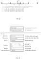
- FIG. 4is a block diagram of a web server power quality and revenue meter, according to an embodiment of the present disclosure.
- FIG. 5is a functional block diagram of the processor of the web server power quality and revenue meter system shown in FIG. 4 , according to the embodiment of the present invention.
- FIG. 6illustrates another environment in which the present disclosure may be utilized.
- FIG. 7is a flow chart illustrating a method for communicating data from an IED on an internal network to a server on an external network through a firewall.
- FIG. 8illustrates yet another environment in which the present disclosure may be utilized.
- FIG. 9illustrates a further environment in which the present disclosure may be utilized.
- FIG. 10is a block diagram of a measuring unit including a network communication network card for responding to user data and information requests regarding power usage and power quality for any metered point within a power distribution system.
- FIG. 11shows a non-limiting and exemplary flowchart illustrating how the IEC 61850 communication protocol is implemented in the network communication card to serve external clients making requests for metering data and other information.
- FIG. 12is a functional block diagram of an IEC 61850 firmware implementation for responding to user data and information requests regarding measured data and others from the measuring unit.
- FIG. 13shows a non-limiting and exemplary flowchart illustrating how the firmware implementation in the network communication network card responds to user data and information requests regarding measured data and others from the measuring unit.
- FIG. 14shows a non-limiting and exemplary data flow diagram that corresponds to the steps of exemplary flowchart of FIG. 13 .
- FIG. 15illustrates an overview of a process for creating a CID file in accordance with an embodiment of the present disclosure.
- FIG. 16is an exemplary CID file in accordance with an embodiment of the present disclosure.
- FIG. 17is an exemplary memory structure in accordance with an embodiment of the present disclosure.
- FIG. 18illustrates a retransmission process in accordance with an embodiment of the present disclosure.
- FIGS. 19 - 25illustrate various implementations of a protocol employed by an intelligent electronic device in accordance with the present disclosure.
- all functions described hereinmay be performed in either hardware or software, or some combination thereof. In one embodiment, however, the functions are performed by at least one processor, such as a computer or an electronic data processor, digital signal processor or embedded micro-controller, in accordance with code, such as computer program code, software, and/or integrated circuits that are coded to perform such functions, unless indicated otherwise.
- processorsuch as a computer or an electronic data processor, digital signal processor or embedded micro-controller
- intelligent electronic devicescan be any device that senses electrical parameters and computes data including, but not limited to, Programmable Logic Controllers (“PLC's”), Remote Terminal Units (“RTU's”), electric power meters, panel meters, protective relays, fault recorders, phase measurement units, serial switches, smart input/output devices and other devices which are coupled with power distribution networks to manage and control the distribution and consumption of electrical power.
- PLC'sProgrammable Logic Controllers
- RTU'sRemote Terminal Units
- a meteris a device that records and measures power events, power quality, current, voltage waveforms, harmonics, transients and other power disturbances.
- Revenue accurate meters(“revenue meter”) relate to revenue accuracy electrical power metering devices with the ability to detect, monitor, report, quantify and communicate power quality information about the power that they are metering.
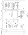
- FIG. 1is a block diagram of an intelligent electronic device (IED) 10 for monitoring and determining power usage and power quality for any metered point within a power distribution system and for providing a data transfer system for faster and more accurate processing of revenue and waveform analysis.
- IEDintelligent electronic device
- the IED 10 of FIG. 1includes a plurality of sensors 12 coupled to various phases A, B, C and neutral N of an electrical distribution system 11 , a plurality of analog-to-digital (ND) converters 14 , including inputs coupled to the sensor 12 outputs, a power supply 16 , a volatile memory 18 , a non-volatile memory 20 , a multimedia user interface 22 , and a processing system that includes at least one central processing unit (CPU) 50 (or host processor) and one or more digital signal processors, two of which are shown, i.e., DSP1 60 and DSP2 70 .
- CPUcentral processing unit
- DSP1 60 and DSP2 70digital signal processor
- the IED 10also includes a Field Programmable Gate Array 80 which performs a number of functions, including, but not limited to, acting as a communications gateway for routing data between the various processors 50 , 60 , 70 , receiving data from the A/D converters 14 performing transient detection and capture and performing memory decoding for CPU 50 and the DSP processor 60 .
- the FPGA 80is internally comprised of two dual port memories to facilitate the various functions. It is to be appreciated that the various components shown in FIG. 1 are contained within housing 90 . Exemplary housings will be described below in relation to FIGS. 2 A- 2 H .
- the plurality of sensors 12sense electrical parameters, e.g., voltage and current, on incoming lines, (i.e., phase A, phase B, phase C, neutral N), from an electrical power distribution system 11 e.g., an electrical circuit.
- the sensors 12will include current transformers and potential transformers, wherein one current transformer and one voltage transformer will be coupled to each phase of the incoming power lines.
- a primary winding of each transformerwill be coupled to the incoming power lines and a secondary winding of each transformer will output a voltage representative of the sensed voltage and current.
- the output of each transformerwill be coupled to the A/D converters 14 configured to convert the analog output voltage from the transformer to a digital signal that can be processed by the CPU 50 , DSP1 60 , DSP2 70 , FPGA 80 or any combination thereof.
- A/D converters 14are respectively configured to convert an analog voltage output to a digital signal that is transmitted to a gate array, such as Field Programmable Gate Array (FPGA) 80 .
- the digital signalis then transmitted from the FPGA 80 to the CPU 50 and/or one or more DSP processors 60 , 70 to be processed in a manner to be described below.
- FPGAField Programmable Gate Array
- the CPU 50 or DSP Processors 60 , 70are configured to operatively receive digital signals from the A/D converters 14 (see FIG. 1 ) to perform calculations necessary to determine power usage and to control the overall operations of the IED 10 .
- CPU 50 , DSP1 60 and DSP2 70may be combined into a single processor, serving the functions of each component.
- the digital samples, which are output from the A/D converters 14are sent directly to the CPU 50 or DSP processors 60 , 70 , effectively bypassing the FPGA 80 as a communications gateway.
- the power supply 16provides power to each component of the IED 10 .
- the power supply 16is a transformer with its primary windings coupled to the incoming power distribution lines and having windings to provide a nominal voltage, e.g., 5 VDC, +12 VDC and ⁇ 12 VDC, at its secondary windings.
- powermay be supplied from an independent power source to the power supply 16 .
- powermay be supplied from a different electrical circuit or an uninterruptible power supply (UPS).
- UPSuninterruptible power supply
- the power supply 16can be a switch mode power supply in which the primary AC signal will be converted to a form of DC signal and then switched at high frequency, such as, for example, 100 Khz, and then brought through a transformer to step the primary voltage down to, for example, 5 Volts AC. A rectifier and a regulating circuit would then be used to regulate the voltage and provide a stable DC low voltage output.
- Other embodiments, such as, but not limited to, linear power supplies or capacitor dividing power suppliesare also contemplated.
- the multimedia user interface 22is shown coupled to the CPU 50 in FIG. 1 for interacting with a user and for communicating events, such as alarms and instructions to the user.
- the multimedia user interface 22may include a display for providing visual indications to the user.
- the displaymay be embodied as a touch screen, a liquid crystal display (LCD), a plurality of LED number segments, individual light bulbs or any combination.
- the displaymay provide information to the user in the form of alphanumeric lines, computer-generated graphics, videos, animations, etc.
- the multimedia user interface 22further includes a speaker or audible output means for audibly producing instructions, alarms, data, etc.
- the speakeris coupled to the CPU 50 via a digital-to-analog converter (D/A) for converting digital audio files stored in a memory 18 or non-volatile memory 20 to analog signals playable by the speaker.
- D/Adigital-to-analog converter
- An exemplary interfaceis disclosed and described in commonly owned pending U.S. application Ser. No. 11/589,381, entitled “POWER METER HAVING AUDIBLE AND VISUAL INTERFACE”, which claims priority to expired U.S. Provisional Patent Appl. No. 60/731,006, filed Oct. 28, 2005, the contents of which are hereby incorporated by reference in their entireties.
- the IED 10will support various file types including but not limited to Microsoft Windows Media Video files (.wmv), Microsoft Photo Story files (.asf), Microsoft Windows Media Audio files (.wma), MP3 audio files (.mp3), JPEG image files (.jpg, .jpeg, .jpe, .jfif), MPEG movie files (.mpeg, .mpg, .mpe, .m1v, .mp2v .mpeg2), Microsoft Recorded TV Show files (.dvr-ms), Microsoft Windows Video files (.avi) and Microsoft Windows Audio files (.wav).
- Microsoft Windows Media Video files.wmv
- Microsoft Photo Story files.asf
- Microsoft Windows Media Audio files.wma
- MP3 audio files.mp3 audio files
- JPEG image files.jpg, .jpeg, .jpe, .jfif
- MPEG movie files.mpeg, .mpg, .mpe, .m1
- the IED 10further comprises a volatile memory 18 and a non-volatile memory 20 .
- volatile memory 18will store the sensed and generated data for further processing and for retrieval when called upon to be displayed at the IED 10 or from a remote location.
- the volatile memory 18includes internal storage memory, e.g., random access memory (RAM), and the non-volatile memory 20 includes removable memory such as magnetic storage memory; optical storage memory, e.g., the various types of CD and DVD media; solid-state storage memory, e.g., a CompactFlash card, a Memory Stick, SmartMedia card, MultiMediaCard (MMC), SD (Secure Digital) memory; or any other memory storage that exists currently or will exist in the future.
- MMCMultiMediaCard
- SDSecure Digital
- the IED 10will include a communication device 24 , also know as a network interface, for enabling communications between the IED or meter, and a remote terminal unit, programmable logic controller and other computing devices, microprocessors, a desktop computer, laptop computer, other meter modules, etc.
- the communication device 24may be a modem, network interface card (NIC), wireless transceiver, etc.
- the communication device 24will perform its functionality by hardwired and/or wireless connectivity.
- the hardwire connectionmay include but is not limited to hard wire cabling e.g., parallel or serial cables, RS232, RS485, USB cable, Firewire (1394 connectivity) cables, Ethernet, and the appropriate communication port configuration.
- the wireless connectionwill operate under any of the various wireless protocols including but not limited to BluetoothTM interconnectivity, infrared connectivity, radio transmission connectivity including computer digital signal broadcasting and reception commonly referred to as Wi-Fi or 802.11.X (where x denotes the type of transmission), satellite transmission or any other type of communication protocols, communication architecture or systems currently existing or to be developed for wirelessly transmitting data including spread spectrum 900 MHz, or other frequencies, Zigbee, WiFi, or any mesh enabled wireless communication.
- BluetoothTM interconnectivityinfrared connectivity
- radio transmission connectivityincluding computer digital signal broadcasting and reception commonly referred to as Wi-Fi or 802.11.X (where x denotes the type of transmission), satellite transmission or any other type of communication protocols, communication architecture or systems currently existing or to be developed for wirelessly transmitting data including spread spectrum 900 MHz, or other frequencies, Zigbee, WiFi, or any mesh enabled wireless communication.
- the IED 10may communicate to a server or other computing device via the communication device 24 .
- the IED 10may be connected to a communications network, e.g., the Internet, by any means, for example, a hardwired or wireless connection, such as dial-up, hardwired, cable, DSL, satellite, cellular, PCS, wireless transmission (e.g., 802.11a/b/g), etc.
- the networkmay be a local area network (LAN), wide area network (WAN), the Internet or any network that couples a plurality of computers to enable various modes of communication via network messages.
- the serverwill communicate using various protocols such as Transmission Control Protocol/Internet Protocol (TCP/IP), File Transfer Protocol (FTP), Hypertext Transfer Protocol (HTTP), etc.
- TCP/IPTransmission Control Protocol/Internet Protocol
- FTPFile Transfer Protocol
- HTTPHypertext Transfer Protocol
- the serverwill further include a storage medium for storing a database of instructional videos, operating manuals, etc., the details of which will be described in detail below.
- the IED 10will also have the capability of not only digitizing waveforms, but storing the waveform and transferring that data upstream to a central computer, e.g., a remote server, when an event occurs such as a voltage surge or sag or a current short circuit.
- This datawill be triggered and captured on an event, stored to memory, e.g., non-volatile RAM, and additionally transferred to a host computer within the existing communication infrastructure either immediately in response to a request from a remote device or computer to receive said data in response to a polled request.
- the digitized waveformwill also allow the CPU 50 to compute other electrical parameters such as harmonics, magnitudes, symmetrical components and phasor analysis. Using the harmonics, the IED 10 will also calculate dangerous heating conditions and can provide harmonic transformer derating based on harmonics found in the current waveform.
- the IED 10will execute an e-mail client and will send e-mails to the utility or to the customer direct on an occasion that a power quality event occurs. This allows utility companies to dispatch crews to repair the condition.
- the data generated by the metersare use to diagnose the cause of the condition.
- the datais transferred through the infrastructure created by the electrical power distribution system.
- the email clientwill utilize a POP3 or other standard mail protocol.
- a userwill program the outgoing mail server and email address into the meter.
- An exemplary embodiment of said meteringis available in U.S. Pat. No. 6,751,563, which all contents thereof are incorporated by reference herein.
- the techniques of the present disclosurecan be used to automatically maintain program data and provide field wide updates upon which IED firmware and/or software can be upgraded.
- An event commandcan be issued by a user, on a schedule or by digital communication that will trigger the IED 10 to access a remote server and obtain the new program code. This will ensure that program data will also be maintained allowing the user to be assured that all information is displayed identically on all units.
- the IED 10also includes an operating system and micro instruction code.
- the various processes and functions described hereinmay either be part of the micro instruction code or part of an application program (or a combination thereof) which is executed via the operating system.
- the components and devices of the IED 10 of FIG. 1may be disposed in various housings depending on the application or environment.
- the IED 10may be configured as a panel meter 900 as shown in FIGS. 2 A and 2 B .
- the panel meter 900 of FIGS. 2 A and 2 Bis described in more detail in commonly owned U.S. Pat. No. 7,271,996, the contents of which are hereby incorporated by reference. As seen in FIGS.
- the IED 900includes a housing 902 defining a front surface 902 a , a rear surface 902 b , a top surface 902 c , a bottom surface 902 d , a right side surface 902 e , and a left side surface (not shown).
- Electrical device 900includes a face plate 904 operatively connected to front surface 902 a of housing 902 .
- Face plate 904includes displays 906 , indicators 908 (e.g., LEDs and the like), buttons 910 , and the like providing a user with an interface for visualization and operation of electrical device 100 . For example, as seen in FIG.
- face plate 904 of electrical device 900includes analog and/or digital displays 906 capable of producing alphanumeric characters.
- Face plate 904includes a plurality of indicators 908 which, when illuminated, indicate to the user the “type of reading”, the “% of load bar”, the “parameter designation” which indicates the reading which is being displayed on displays 906 , a “scale selector” (e.g., Kilo or Mega multiplier of Displayed Readings), etc.
- Face plate 904includes a plurality of buttons 910 (e.g., a “menu” button, an “enter” button, a “down” button, a “right” button, etc.) for performing a plurality of functions, including and not limited to: viewing of meter information; enter display modes; configuring parameters; performing re-sets; performing LED checks; changing settings; viewing parameter values; scrolling parameter values; and viewing limit states.
- the housing 902includes voltage connections or inputs 912 provided on rear surface 902 b thereof, and current inputs 914 provided along right side surface 902 e thereof.
- the IED 900may include a first interface or communication port 916 for connection to a master and/or slave device. Desirably, first communication port 916 is situated in rear surface 902 b of housing 902 . IED 900 may also include a second interface or communication port 918 situated on face plate 904 .
- the IED 10may be configured as a socket meter 920 , also known as a S-base type meter or type S meter, as shown in FIG. 2 C an 2 D.
- the socket meter 920 of FIGS. 2 C and 2 Dis described in more detail in commonly owned application Ser. No. 14/578,062 (U.S. Publication No. 2010/0090680), the contents of which are hereby incorporated by reference.
- the meter 920includes a main housing 922 surrounded by a cover 924 .
- the cover 924is preferably made of a clear material to expose a display 926 disposed on the main body 922 .
- the meter 920further includes a plurality of current terminals 932 and voltage terminals 934 disposed on backside of the meter extending through a base 935 .
- the terminals 932 , 934are designed to mate with matching jaws of a detachable meter-mounting device, such as a revenue meter socket.
- the socketis hard wired to the electrical circuit and is not meant to be removed. To install an S-base meter, the utility need only plug in the meter into the socket. Once installed, a socket-sealing ring 936 is used as a seal between the meter 920 and/or cover 924 and the meter socket to prevent removal of the meter and to indicate tampering with the meter.
- the IED 10 of FIG. 1may be disposed in a switchboard or draw-out type housing 940 as shown in FIGS. 2 E and 2 F , where FIG. 2 E is a front view and FIG. 2 F is a rear view.
- the switchboard enclosure 942usually features a cover 944 with a transparent face 946 to allow the meter display 948 to be read and the user interface 950 to be interacted with by the user.
- the cover 944also has a sealing mechanism (not shown) to prevent unauthorized access to the meter.
- a rear surface 952 of the switchboard enclosure 942provides connections for voltage and current inputs 954 and for various communication interfaces 956 .
- the meter disposed in the switchboard enclosure 942may be mounted on a draw-out chassis which is removable from the switchboard enclosure 942 .
- the draw-out chassisinterconnects the meter electronics with the electrical circuit.
- the draw-out chassiscontains electrical connections which mate with matching connectors 954 , 956 disposed on the rear surface 952 of the enclosure 942 when the chassis is slid into place.
- the IED 10 of FIG. 1may be disposed in an A-base or type A housing as shown in FIGS. 2 G and 2 H .
- A-base meters 960feature bottom connected terminals 962 on the bottom side of the meter housing 964 . These terminals 962 are typically screw terminals for receiving the conductors of the electric circuit (not shown).
- A-base meters 960further include a meter cover 966 , meter body 968 , a display 970 and input/output means 972 . Further, the meter cover 966 includes an input/output interface 974 .
- the cover 966encloses the meter electronics 968 and the display 970 .
- the cover 966has a sealing mechanism (not shown) which prevents unauthorized tampering with the meter electronics.
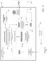
- FIG. 3illustrates an exemplary environment 100 in which the present disclosure may be practiced.
- the network 120may be the Internet, a public or private intranet, an extranet, wide area network (WAN), local area network (LAN) or any other network configuration to enable transfer of data and commands.
- An example network configurationuses the Transport Control Protocol/Internet Protocol (“TCP/IP”) network protocol suite, however, other Internet Protocol based networks are contemplated by the present disclosure.
- Communicationsmay also include IP tunneling protocols such as those that allow virtual private networks coupling multiple intranets or extranets together via the Internet.
- the network 120may support existing or envisioned application protocols, such as, for example, telnet, POP3, Mime, HTTP, HTTPS, PPP, TCP/IP, SMTP, proprietary protocols, or any other network protocols.
- the IED 110may communicate using the network 120 as will be hereinafter discussed.
- client/server networksare at least two basic types of networks, based on the communication patterns between the machines: client/server networks and peer-to-peer networks.
- client/server networksevery computer, device or IED has a distinct role: that of either a client or a server.
- a serveris designed to share its resources among the client computers on the network.
- a dedicated server computeroften has faster processors, more memory, and more storage space than a client because it might have to service dozens or even hundreds of users at the same time.
- High-performance serverstypically use from two to eight processors (and that's not counting multi-core CPUs), have many gigabytes of memory installed, and have one or more server-optimized network interface cards (NICs), RAID (Redundant Array of Independent Drives) storage consisting of multiple drives, and redundant power supplies.
- Serversoften run a special network OS—such as Windows Server, Linux, or UNIX—that is designed solely to facilitate the sharing of its resources. These resources can reside on a single server or on a group of servers. When more than one server is used, each server can “specialize” in a particular task (file server, print server, fax server, email server, and so on) or provide redundancy (duplicate servers) in case of server failure.
- a client devicetypically communicates only with servers, not with other clients.
- a client systemis a standard PC that is running an OS such as Windows.
- Current OSescontain client software that enables the client computers to access the resources that servers share.
- Older OSessuch as Windows 3.x and DOS, required add-on network client software to join a network.
- every computer or deviceis equal and can communicate with any other computer or device on the network to which it has been granted access rights.
- every computer or device on a peer-to-peer networkcan function as both a server and a client; any computer or device on a peer-to-peer network is considered a server if it shares a printer, a folder, a drive, or some other resource with the rest of the network.
- the actual networking hardwareinterface cards, cables, and so on
- the actual networking hardwareis the same in client/server versus peer-to-peer networks, it is only the logical organization, management and control of the network that varies.
- the PC client 102may comprise any computing device, such as a server, mainframe, workstation, personal computer, hand held computer, laptop telephony device, network appliance, other IED, Programmable Logic Controller, Power Meter, Protective Relay etc.
- the PC client 102includes system memory 104 , which may be implemented in volatile and/or non-volatile devices.
- client applications 106which may execute in the system memory 104 is provided.
- client applicationsmay include, for example, FTP client applications.
- File Transfer Protocolis an application for transfer of files between computers attached to Transmission Control Protocol/Internet Protocol (TCP/IP) networks, including the Internet.
- FTPis a “client/server” application, such that a user runs a program on one computer system, the “client”, which communicates with a program running on another computer system, the “server”. Additionally, user interfaces 108 may be included for displaying system configuration, retrieved data and diagnostics associated with the IED 110 .
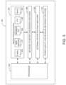
- the intelligent electronic device (IED) 110is comprised of at least an FTP Server 131 including a Virtual Command File Processor 133 , a File System and Driver 135 , a non-volatile memory 137 and a virtual data store 139 .
- the IED 110may contain other hardware/software for performing functions associated with the IED, however, these functions are not relevant to the present application and will therefore not be further discussed.
- IED 110runs the FTP Server 131 as an independent process in the operating system, allowing it to function independently of the other running processes. Additionally, it allows for multiple connections, using the port/socket architecture of TCP/IP.
- FTP Server 131By running the FTP Server 131 as an independent process, this means that other systems, such as a Modbus TCP handler, can run on IED 110 concurrently with the FTP Server 131 . This also means that multiple FTP connections can be made with the only limitation being the system's available resources.
- the FTP Server 131provides access to the file system 135 of the IED 110 on the standard FTP port (port 21).
- PC client 102sends a FTP logon sequence, which includes a USER command and a PASS command.
- the PC client 102then interacts with the IED 110 , requesting information and writing files, ending in a logout.
- the FTP Server 131uses two ports for all actions.
- the first port 21is a clear ASCII telnet channel, and is called the command channel.
- the second portwhich can have a different port number in different applications, is initiated whenever it is necessary to transfer data in clear binary, and is called the data channel.
- the virtual data store 139is an ideal storage medium for files that are written to very frequently, such as, for example, status information, diagnostics, and virtual command files.
- files which require more long term storagesuch as, for example, Logs, settings, and configuration, more suitable to be stored using a compact flash drive.
- FTPFile Transfer Protocol
- Port 21is a network protocol used to transfer data from one computer to another through a network, such as over the Internet.
- FTPis a commonly used protocol for exchanging files over any TCP/IP based network to manipulate files on another computer on that network regardless of which operating systems are involved (if the computers permit FTP access).
- FTP serverscan be set up anywhere between game servers, voice servers, internet hosts, and other physical servers.
- FTPruns exclusively over TCP.
- FTP serversby default listen on port 21 for incoming connections from FTP clients.
- a connection to this port from the FTP Clientforms the control stream on which commands are passed to the FTP server from the FTP client and on occasion from the FTP server to the FTP client.
- FTPuses out-of-band control, which means it uses a separate connection for control and data.
- the data streamis required which is called the data stream.
- the process of setting up the data streamis different.
- the FTP clientIn active mode, the FTP client opens a dynamic port (49152-65535), sends the FTP server the dynamic port number on which it is listening over the control stream and waits for a connection from the FTP server.
- the FTP serverinitiates the data connection to the FTP client it binds the source port to port 21 on the FTP server.
- the clientsends a PORT command, with the IP and port as argument.
- the format for the IP and portis “h1, h2, h3, h4, p1, p2”.
- Each fieldis a decimal representation of 8 bits of the host IP, followed by the chosen data port. For example, a client with an IP of 192.168.0.1, listening on port 49154 for the data connection will send the command “PORT 192, 168, 0, 1, 192, 2”.
- the FTP serveropens a dynamic port (49152-65535), sends the FTP client the server's IP address to connect to and the port on which it is listening (a 16 bit value broken into a high and low byte, like explained before) over the control stream and waits for a connection from the FTP client.
- the FTP clientbinds the source port of the connection to a dynamic port between 49152 and 65535.
- the clientsends the PASV command to which the server would reply with something similar to “227 Entering Passive Mode (127, 0, 0, 1, 192, 52)”.
- the syntax of the IP address and portare the same as for the argument to the PORT command.
- the FTP serveroperates exactly the same as passive mode, however it only transmits the port number (not broken into high and low bytes) and the client is to assume that it connects to the same IP address that was originally connected to.
- the objectives of FTPare to promote sharing of files (computer programs and/or data), to encourage indirect or implicit use of remote computers, to shield a user from variations in file storage systems among different hosts and to transfer data reliably, and efficiently.
- the IED 110has the ability to provide an external PC client 102 with an improved data transfer rate when making data download requests of data stored within an IED. This is achieved by configuring the IED 110 to include an FTP server 131 including a Virtual Command File Processor 133 . An improved data transfer rate from the IED 110 may be realized by the external PC client 102 issuing virtual commands to the IED 110 . In response, the IED 110 processes the received virtual commands in the Virtual Command File processor 133 to construct FTP commands therefrom to be applied to a novel file system 135 of the IED 110 , coupled to the FTP server 131 , wherein the novel file system 135 is configured as a PC file structure amenable to receiving and responding to the constructed FTP commands.
- the Virtual command files and the novel file system 135are discussed in greater detail in co-pending application Ser. No. 12/061,979.
- FTP file transfercomprises one embodiment for encapsulating files to improve a data transfer rate from an IED to external PC clients
- present disclosurecontemplates the use of other file transfer protocols, such as the Ethernet protocol such as HTTP or TCP/IP for example.
- Ethernet protocolsare contemplated for use by the present disclosure.
- HTTP file encapsulationfor the purpose of security and firewall access, it may be preferable to utilize HTTP file encapsulation as opposed to sending the data via FTP.
- datacan be attached as an email and sent via SMTP, for example.
- At least one processor of the IED or meteris configured to collect the at least one parameter and generate data from the sampled at least one parameter, wherein the at least one processor is configured to act as a server for the IED or meter and is further configured for presenting the collected and generated data in the form of web pages.
- FIG. 4is a block diagram of a web server power quality and revenue meter 210 .
- the meteris connected to monitor electric distribution power lines (not shown), to monitor voltage and current at the point of connection.
- digital sampler 220for digitally sampling the voltage and current of the power being supplied to a customer or monitored at the point of the series connection in the power grid.
- Digital sampler 220digitally samples the voltage and current and performs substantially similar to the A/D converters 14 described above in relation to FIG. 1 . The digital samples are then forwarded to processor 230 for processing.
- the processormay be a single processing unit or a processing assembly including at least one CPU 50 , DSP1 60 , DSP2 70 and FPGA 80 , or any combination thereof.
- external device interface 240is also connected to processor 230 for providing an interface for external devices 250 to connect to meter 210 . These external devices might include other power meters, sub-station control circuitry, on/off switches, etc.
- Processor 230receives data packets from digital sampler 220 and external devices 250 , and processes the data packets according to user defined or predefined requirements.
- a memory 260is connected to processor 230 for storing data packets and program algorithms, and to assist in processing functions of processor 230 .
- Processor 130provides processed data to network 280 through network interface 270 .
- Network 280can be the Internet, the World Wide Web (WWW), an intranet, a wide area network (WAN), or local area network (LAN), among others.
- the network interfaceconverts the data to an Ethernet TCP/IP format. The use of the Ethernet TCP/IP format allows multiple users to access the power meter simultaneously.
- network interface 270might be comprised of a modem, cable connection, or other devices that provide formatting functions.
- Computers 290 - 292are shown connected to network 280 .
- a web server program(web server) is contained in memory 260 , and accessed through network interface 270 .
- the web serverprovides real time data through any known web server interface format.
- popular web server interface formatsconsist of HTML and XML formats.
- the actual format of the programming language usedis not essential to the present disclosure, in that any web server format can be incorporated herein.
- the web serverprovides a user friendly interface for the user to interact with the meter 210 .
- the usercan have various access levels to enter limits for e-mail alarms. Additionally, the user can be provided the data in a multiple of formats including raw data, bar graph, charts, etc.
- the currently used HTML or XML programming languagesprovide for easy programming and user friendly user interfaces.
- the processor 230formats the processed data into various network protocols and formats.
- the protocols and formatscan, for example, consist of the web server HTML or XML formats, Modbus TCP, RS-485, FTP or e-mail. Dynamic Host Configuration Protocol (DHCP) can also be used to assign IP addresses.
- DHCPDynamic Host Configuration Protocol
- the network formatted datais now available to users at computers 290 - 292 through network 280 , that connects to meter 210 at the network interface 270 .
- network interface 270is an Ethernet interface that supports, for example, 100 base-T or 10 base-T communications. This type of network interface can send and receive data packets between WAN connections and/or LAN connections and the meter 210 .
- This type of network interfaceallows for situations, for example, where the web server may be accessed by one user while another user is communicating via the Modbus TCP, and a third user may be downloading a stored data file via FTP.
- the ability to provide access to the meter by multiple users, simultaneously,is a great advantage over the prior art. This can allow for a utility company's customer service personnel, a customer, and maintenance personnel to simultaneously and interactively monitor and diagnose possible problems with the power service.
- FIG. 5is a functional block diagram of processor 230 of the web server power quality and revenue meter system according to the embodiment of the present invention.
- Processor 230is shown containing four main processing functions. The functions shown are illustrative and not meant to be inclusive of all possible functions performed by processor 230 .
- Power Quality and Revenue Metering functions (metering functions) 310consists of a complete set of functions which are needed for power quality and revenue metering. Packet data collected by digital sampler 220 is transmitted to processor 230 .
- Processor 230calculates, for example, power reactive power, apparent power, and power factor.
- the metering function 310responds to commands via the network or other interfaces supported by the meter.
- External Device Routing Functions 330handle the interfacing between the external device 250 and meter 210 .
- Raw data from external device 250is fed into meter 210 .
- the external device 250is assigned a particular address. If more than one external device is connected to meter 210 , each device will be assigned a unique particular address.
- the Network Protocol Functions 350 of meter 210are executed by processor 230 which executes multiple networking tasks that are running concurrently. As shown in FIG. 5 , these include, but are not limited to, the following network tasks included in network protocol functions 350 : e-mail 360 , web server 370 , Modbus TCP 380 , FTP 390 , and DHCP 300 .
- the e-mail 360 network protocol functioncan be utilized to send e-mail messages via the network 280 to a user to, for example, notify the user of an emergency situation or if the power consumption reaches a user-set or pre-set high level threshold.
- the processorreceives packets of data it identifies the network processing necessary for the packet by the port number associated with the packet.
- the processorallocates the packet to a task as a function of the port number. Since each task is running independently the meter 210 can accept different types of requests concurrently and process them transparently from each other.
- the web servermay be accessed by one user while another user is communicating via Modbus TCP and at the same time a third user may download a log file via FTP.
- the Network to Meter Protocol Conversion Function 340is used to format and protocol convert the different network protocol messages to a common format understood by the other functional sections of meter 210 . After the basic network processing of the packet of data, any “commands” or data which are to be passed to other functional sections of meter 210 are formatted and protocol converted to a common format for processing by the Network to Meter Protocol Conversion Function 340 . Similarly, commands or data coming from the meter for transfer over the network are pre-processed by this function into the proper format before being sent to the appropriate network task for transmission over the network. In addition this function first protocol converts and then routes data and commands between the meter and external devices.
- a firewallis a system designed to prevent unauthorized access to or from a private network, e.g., an internal network of a building, a corporate network, etc.
- Firewallscan be implemented in both hardware and software, or a combination of both. Firewalls are frequently used to prevent unauthorized Internet users from accessing private networks connected to the Internet, especially intranets. All messages entering or leaving the intranet pass through the firewall, which examines each message and blocks those that do not meet the specified security criteria.
- a firewallmay employ one or more of the following techniques to control the flow of traffic in and of the network it is protecting: 1) packet filtering: looks at each packet entering or leaving the network and accepts or rejects it based on user-defined rules; 2) Application gateway: applies security mechanisms to specific applications, such as FTP and Telnet servers; 3) Circuit-level gateway: applies security mechanisms when a TCP or UDP connection is established, once the connection has been made, packets can flow between the hosts without further checking; 4) Proxy server: intercepts all messages entering and leaving the network, effectively hides the true network addresses; and 5) Stateful inspection: doesn't examine the contents of each packet but instead compares certain key parts of the packet to a database of trusted information; if the comparison yields a reasonable match, the information is allowed through; otherwise, it is discarded. Other techniques and to be developed techniques are contemplated to be within the scope of the present disclosure.
- the present disclosureprovides for overcoming the problem of not being allowed firewall access to an IED or meter installed within a facility, i.e., the meter is residing on a private network, by enabling an IED to initiate one way communication through the firewall.
- the IED or meterposts the monitored and generated data on an Internet site external to the corporate or private network, i.e., on the other side of a firewall.
- the benefitis that any user would be able to view the data on any computer or web enabled smart device without having to pierce or bypass the firewall.
- the features of this embodimentcan be incorporated into any telemetry application including vending, energy metering, telephone systems, medical devices and any application that requires remotely collecting data and posting it on to a public Internet web site.
- the IED or metering devicewill communicate through the firewall using a protocol such as HTTP via a port that is open through the firewall.
- IEDs or meters 410 , 412 414reside on an internal network 416 , e.g., an intranet, private network, corporate network, etc.
- the internal network 416is coupled to an external network 422 , e.g., the Internet, via a router 420 or similar device over any known hardwire or wireless connection 421 .
- a firewall 418is disposed between the internal network 416 and external network 422 to prevent unauthorized access from outside the internal network 416 to the IEDs or meters 410 , 412 , 414 .
- firewall 418is shown between the internal network 416 and the router 420 , it is to be appreciated that other configurations are possible, for example, the firewall 418 being disposed between the router 420 and external network 422 . In other embodiments, the firewall 418 and router 420 may be configured as a single device. It is further to be appreciated that firewall 418 can be implemented in both hardware and software, or a combination of both.
- the communication device or network interface of the meter(as described above in relation to FIG. 1 ) will communicate through the firewall 418 and read a web site or meter server 424 .
- the one way communication from the IED through the firewallmay be enabled by various techniques, for example, by enabling outbound traffic to the IP address or domain name of the server 424 or by using a protocol that has been configured, via the firewall settings, to pass through the firewall such as HTTP (Hyper Text Transfer Protocol), IP (Internet Protocol), TCP (Transmission Control Protocol), FTP (File Transfer Protocol), UDP (User Datagram Protocol), ICMP (Internet Control Message Protocol), SMTP (Simple Mail Transport Protocol), SNMP (Simple Network Management Protocol), Telnet, etc.
- HTTPHyper Text Transfer Protocol
- IPInternet Protocol
- TCPTransmission Control Protocol
- FTPFile Transfer Protocol
- UDPUser Datagram Protocol
- ICMPInternet Control Message Protocol
- SMTPSimple Mail Transport Protocol
- SNMPSimple Network Management Protocol
- the IEDmay have exclusive access to a particular port on the firewall, which is unknown to other users on either the internal or external network.
- Other methods or techniquesare contemplated, for example, e-mail, HTTP tunneling, SNTP trap, MSN, messenger, IRQ, TwitterTM, Bulletin Board System (BBS), forums, Universal Plug and Play (UPnP), User Datagram Protocol (UDP) broadcast, UDP unicast, Virtual Private Networks (VPN), etc.
- the server 424will provide instructions in computer and/or human readable format to the IED or meter.
- the web server 424might have XML tags that state in computer readable format to provide data for the last hour on energy consumption by 15 minute intervals.
- the meter 410 , 412 , 414will then read those instructions on that web server 424 and then post that data up on the server 424 .
- the IED or meterinitiates communication in one direction, e.g., an outbound direction, to the server 424 .
- Another server(or can be in one server) will read the data that the meter 410 , 412 , 414 posts and will format the meter data into data that can be viewed for humans on a web site or a software application, i.e., UI Server 426 .
- Servers 424 , 426can also store the data in a database or perform or execute various control commands on the data.
- Clients 428may access the IED data stored or posted on servers 424 , 426 via a connection to the network 422 .
- the meters 410 , 412 , 414can read data or instructions from an external network application (e.g., server 424 ), the external network application cannot request information directly from the meter.
- the server 424posts the data or instructions on the web site and waits for the meter to check the site to see if there has been a new post, i.e., new instructions for the meter.
- the metercan be programmed at the users discretion as to frequency for which the meter 410 , 412 , 414 exits out to the external network to view the postings.
- the meter instruction server 424will post instructions in a directory programmed/located on the server or into XML or in any fashion that the meter is configured to understand and then the meter will post whatever data it is instructed to do.
- the metercan also be configured to accomplish control commands.
- a user interface (UI) server 426is provided that can be used to enable a user interface to the user. The user can provide input on the UI server 426 that might trigger the meter instruction server 424 to produce a message to control the energy next time the meter reads that server.
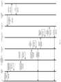
- a method for communicating data from an IED on an internal network to a server on an external network through a firewallis illustrated.
- the IED 410communicates through the firewall 418 to a predetermined server 424 on an external network 422 .
- the IED 410may be programmed to periodically communicate to the server at predefined intervals.
- the IED 410reads instructions disposed in a directory or folder on the predetermined server 424 , step 454 .
- step 456the IED 410 collects data from its internal memory or generates data based on the read instructions.
- the IED 410then transmits the data to the server 424 in a predetermined format, e.g., XML, CSV, etc., step 458 .
- the predetermined server 424posts the received data on a web site accessible from the external network 422 .
- the datamay be posted on the server 424 or a UI (user interface) server 426 configured to provide data for end users, e.g., clients 428 .
- the UI server 426may be configured to post data from several locations in one convenient interface for, for example, an organization managing the several locations.
- a provider of the servers 424 , 426may charge a fee to the end user for the hosting of the web site and providing the data in a convenient and accessible format.
- the IED or metering devicewill communicate through the firewall using a server 530 disposed on an internal network protected by a firewall.
- IEDs or meters 510 , 512 514reside on an internal network 516 , e.g., an intranet, private network, corporate network, etc.
- the internal network 516is coupled to an external network 522 , e.g., the Internet, via a router 520 or similar device over any known hardwire or wireless connection 521 .
- a firewall 518is disposed between the internal network 516 and external network 522 to prevent unauthorized access from outside the internal network 516 to the IEDs or meters 510 , 512 , 514 .
- firewall 518is shown between the internal network 516 and the router 520 , it is to be appreciated that other configurations are possible, for example, the firewall 518 being disposed between the router 520 and external network 522 . In other embodiments, the firewall 518 and router 520 may be configured as a single device. It is further to be appreciated that firewall 518 can be implemented in both hardware and software, or a combination of both.
- server 530aggregates data from the various IEDs 510 , 512 , 514 coupled to the internal or private network 516 . Since the server 530 and the IEDs 510 , 512 , 514 are all on the same side of the firewall 518 , generally communications and data transfers among the server 530 and the IEDs 510 , 512 , 514 are unrestricted. Server 530 then communicates or transfers the data from the IEDs to server 524 on the external network on the other side of the firewall 518 . The communication between servers 530 and 524 may be accomplished by any one of the communication means or protocols described in the present disclosure. The server 524 then posts the data from the IEDs 510 , 512 , 514 making the data accessible to clients 528 on the external network, as described above.
- the IED or metering devicewill communicate through the firewall using a server 630 disposed on an internal network protected by a firewall.
- IEDs or meters 610 , 612 614reside on an internal network 616 , e.g., an intranet, private network, corporate network, etc.
- the internal network 616is coupled to an external network 622 , e.g., the Internet, via a router 620 or similar device over any known hardwire or wireless connection 621 .
- a firewall 618is disposed between the internal network 516 and external network 622 to prevent unauthorized access from outside the internal network 616 to the IEDs or meters 610 , 612 , 614 .
- firewall 618is shown between the internal network 616 and the router 620 , it is to be appreciated that other configurations are possible, for example, the firewall 618 being disposed between the router 620 and external network 622 . In other embodiments, the firewall 618 and router 620 may be configured as a single device. It is further to be appreciated that firewall 618 can be implemented in both hardware and software, or a combination of both.
- server 630aggregates data from the various IEDs 610 , 612 , 614 coupled to the internal or private network 616 . Since the server 630 and the IEDs 610 , 612 , 614 are all on the same side of the firewall 618 , generally communications and data transfers among the server 630 and the IEDs 610 , 612 , 614 are unrestricted. Server 630 then communicates or transfers the data from the IEDs to clients 628 on the external network on the other side of the firewall 618 . The communication between server 630 and clients 628 may be accomplished by any one of the communication means or protocols described in the present disclosure.
- each IED 610 , 612 , 614may be configured to act as a server to perform the functionality described above obviating the need for server 630 .
- each IED 610 , 612 , 614 and each client device 628may be configured as a server to create a peer-to-peer network, token ring or a combination of any such topology.
- the systems and methods of the present disclosuremay utilize one or more protocols and/or communication techniques including, but not limited to, e-mail, File Transfer Protocol (FTP), HTTP tunneling, SNTP trap, MSN, messenger, IRQ, TwitterTM, Bulletin Board System (BBS), forums, Universal Plug and Play (UPnP), User Datagram Protocol (UDP) broadcast, UDP unicast, Virtual Private Networks (VPN), etc.
- FTPFile Transfer Protocol
- HTTP tunnelingSNTP trap
- MSNmessenger
- IRQIRQ
- TwitterTMBulletin Board System
- BSSBulletin Board System
- UPSUniversal Plug and Play
- UDPUser Datagram Protocol
- VPNVirtual Private Networks
- each IEDsends data to a recipient via electronic mail, also known as email or e-mail.
- An Internet email messageconsists of three components, the message envelope, the message header, and the message body.
- the message headercontains control information, including, minimally, an originator's email address and one or more recipient addresses. Usually descriptive information is also added, such as a subject header field and a message submission date/time stamp.
- Network-based emailwas initially exchanged on the ARPANET in extensions to the File Transfer Protocol (FTP), but is now carried by the Simple Mail Transfer Protocol (SMTP), first published as Internet standard 10 (RFC 821) in 1982.
- FTPFile Transfer Protocol
- RRC 821Simple Mail Transfer Protocol
- SMTPcommunicates delivery parameters using a message envelope separate from the message (header and body) itself.
- Messagesare exchanged between hosts using the Simple Mail Transfer Protocol with software programs called mail transfer agents (MTAs); and delivered to a mail store by programs called mail delivery agents (MDAs, also sometimes called local delivery agents, LDAs).
- MTAssoftware programs
- MDAsmail delivery agents
- Userscan retrieve their messages from servers using standard protocols such as POP or IMAP, or, as is more likely in a large corporate environment, with a proprietary protocol specific to Novell Groupwise, Lotus Notes or Microsoft Exchange Servers.
- Webmail interfacesallow users to access their mail with any standard web browser, from any computer, rather than relying on an email client.
- Mailcan be stored on the client, on the server side, or in both places.
- Standard formats for mailboxesinclude Maildir and mbox.
- Several prominent email clientsuse their own proprietary format and require conversion software to transfer email between them.
- Server-side storageis often in a proprietary format but since access is through a standard protocol such as IMAP, moving email from one server to another can be done with any MUA supporting the protocol.
- the IEDcomposes a message using a mail user agent (MUA).
- the IEDenters the email address of a recipient and sends the message.
- the MUAformats the message in email format and uses the submission Protocol (a profile of the Simple Mail Transfer Protocol (SMTP), see RFC 6409) to send the message to the local mail submission agent (MSA), for example, run by the IED's internet service provider (ISP).
- the MSAlooks at the destination address provided in the SMTP protocol (not from the message header).
- An Internet email addressis a string of the form recipient@meter.
- the part before the @ signis the local part of the address, often the username of the recipient, and the part after the @ sign is a domain name or a fully qualified domain name.
- the MSAresolves a domain name to determine the fully qualified domain name of the mail exchange server in the Domain Name System (DNS).
- DNSDomain Name System
- the DNS server for the domainresponds with any MX records listing the mail exchange servers for that domain, for example, a message transfer agent (MTA) server run by the recipient's ISP.
- MTAmessage transfer agent
- the MSAsends the message to MTA using SMTP. This server may need to forward the message to other MTAs before the message reaches the final message delivery agent (MDA).
- MDAfinal message delivery agent
- the MDAdelivers it to the mailbox of the recipient.
- the recipientretrieves the message using either the Post Office Protocol (POP3) or the Internet Message Access Protocol (IMAP4).
- POP3Post Office Protocol
- IMAP4Internet Message Access Protocol
- e-mail systemsmay also be employed, for example, web-based email, POP3 (Post Office Protocol 3) email services, IMAP (Internet Message Protocol) e-mail servers, and MAPI (Messaging Application Programming Interface) email servers to name a few.
- POP3Post Office Protocol 3
- IMAPInternet Message Protocol
- MAPIMobile Application Programming Interface
- File Transfer Protocolmay be employed. Techniques for transferring data from an IED to a device is described in commonly owned pending U.S. patent application Ser. No. 12/061,979, the contents of which are incorporated by reference.
- IEDsemploy Universal Plug and Play (UPnP) protocol, which is a set of networking protocols that permits networked devices to discover each other's presence, and notify clients of services available on these devices.
- UDPUniversal Plug and Play
- UPnPtakes the form of UDP broadcast messages, which are sent across a local network, to notify other devices of available services, and http requests to query the details of those devices and services.
- UPnPis employed to allow the network addresses of devices, such as meters, to automatically be discovered by a client. This enables the client software to display a list of all devices which are available. In addition, this could also allow the client software to enable the user to connect to these devices, without having to configure the network address of that device.
- the UPnP notifymay be used to indicate the health status of the device, including starting up, running, errors in configuration, and resetting.
- UPnPis employed to allow devices, such as meters, to notify the clients of what services they support, such as modbus, dnp, web, ftp, log download, and data streaming.
- Thiscould be extended by including information particular to that service or protocol, such as to allow the client to interface with that service with no user input. This could enable the client software to display the device such that the user can focus on the details of the device, rather then worrying about the minutiae of connection information.
- an automated serveris configured to perform actions related to these automatically discovered services, such as retrieving real time information, downloading logs, or registering for notification of events.
- a server 530could be on a network 516 to collect log information from meters 510 , 512 , 514 , and whenever a meter broadcast that it provided log data, the server 530 could automatically collect that data from the meter.
- the server 530could automatically poll and log the real-time readings of all meters on the network, automatically including them as they become available on the network. As described above, the server 530 may then post the data to server 524 .
- HTTP tunnelingis employed to send a message (including the IED's or meter's data) to a server, which listens for such messages, and parses out the IED's or meter's data. This could be performed by embedding the meter's data in a HTTP message, which could be sent to the server, for example, server 424 as shown in FIG. 6 .
- the HTTP wrapperwould allow this data to pass through firewalls which only allow web traffic.
- IED 410may send a HTTP message containing measured or calculated data through firewall 418 to server 424 or server 430 .
- server 530may collect data from the various IEDs 510 , 512 , 514 and forward the collected data in a HTTP message through firewall 518 to server 524 .
- server 630is the destination (and collects) the messages generated from the various IEDs 610 , 612 , 614 , but device 628 is a client, and without server software, would be unable to receive the messages. However, by programming device 628 with server software, the client device 628 becomes a server and can receive the messages.
- the HTTP messagecan be sent based on various triggers including, but not limited to, time-based trigger, event-based trigger, storage capacity based trigger, etc.
- the IEDscan communicate through to devices using a Simple Network Management Protocol (SNMP) trap.
- SNMP trapsenable an agent, e.g., an agent running on an IED, to notify a management station, e.g., a server, of significant events by way of an unsolicited SNMP message.
- a management statione.g., a server
- NMSnetwork management system
- the managerdisplays it and can choose to take an action based on the event. For instance, the manager can poll the agent or IED directly, or poll other associated device agents to get a better understanding of the event.
- the management systemFor the management system to understand a trap sent to it by an agent, the management system must know what the object identifier (OID) of the trap or message defines. Therefore, the management system or server must have the Management Information Base (MIB) for that trap loaded. This provides the correct OID information so that the network management system can understand the traps sent to it. Additionally, a device does not send a trap to a network management system unless it is configured to do so. A device must know that it should send a trap. The trap destination is usually defined by an IP address, but can be a host name, if the device is set up to query a Domain Name System (DNS) server.
- DNSDomain Name System
- Common chat protocolssuch as MSN, AIM, IRQ, IRC, and Skype, could be used to send a message, containing the meter's data, to a public chat server, e.g., server 440 , 540 , 640 , which could then route that message to any desired client.
- a public chat servere.g., server 440 , 540 , 640
- Another possible implementationcould be to have a special client that listens for these messages, parses the data contents, and presents them an another manner.
- the messagesare proprietary format Ethernet messages, typically sent over TCP. It is to be appreciated that the actual format depends on the specific chat protocol.
- a public social server that supports a common web interface for posting informationcould be used to post a status, containing the meter's data, to a user on the public social server for that service, e.g., server 440 , 540 , 640 .
- This postcould then be viewed by the clients to see the meter's data, or read by another server for further parsing and presentation.
- the HTTP interfacecould be used, which would work the same way as a user updating it from their browser (HTTP push).
- a public social serversuch as the system employed by Facebook may be utilized to post the IEDs data so the data is accessible on the external network outside of the firewall.
- Facebookuses a variety of services, tools and programming languages to make up its infrastructure which may be employed in the systems and methods of the present disclosure to implement the technique described herein.
- the serversrun a LAMP (Linux, Apache, MySQL and PHP) stack with Memcache.
- Linuxis a Unix-like operating system kernel. It is open source, highly customizable, and good for security.
- Facebook's serverruns the Linux operating system Apache HTTP server.
- MySQLis used primarily as a key store of value when the data are randomly distributed among a large number of cases logical.
- Memcacheis a caching system that is used to accelerate dynamic web sites with databases (like Facebook) by caching data and objects in RAM to reduce reading time. Memcache is the main form of caching on Facebook and helps relieve the burden of database. Having a caching system allows Facebook to be as fast as it is to remember information. Furthermore, Facebook backend services are written in a variety of different programming languages like C++, Java, Python, and Erlang.
- Thrifta lightweight remote procedure call framework for scalable cross-language services development, which supports C++, PHP, Python, Perl, Java, Ruby, Erlang, and others
- Escribanoserver logs
- Cassandradatabase
- HipHop for PHPa transformer of source code for PHP script code and was created to save server resources, HipHop transforms PHP source code in C++ optimized, among others.
- a public web sitee.g., hosting on server 440 , 540 , 640 , which allows the posting of information, such as a Forum, could be used to post a message, containing the meter's data, to a group, thread, or other location. This post would take place by a HTTP POST to the web site's server, whereby the server would store that information, and present it on the web site. This message could then be viewed by the clients to see the meter's data, or read by another server for further parsing and presentation.
- the HTTP interfacecould be used, which would work the same way as a user updating it from their browser (HTTP push).
- UDPUser Datagram Protocol
- messagescould be sent from the IEDs or meters to a server, e.g., servers 530 , 630 , since UDP broadcasts do not work across networks.
- the messages containing the IED's or meter's datacan then be sent to external networks via any of the described (or to be developed) communication methods.
- a UDP unicastcould support sending to any server, e.g., server 424 , 524 .
- a Virtual Private Networkcould be created such that each meter on the internal network is part of the same virtual private network as each of the clients.
- a Virtual Private Networkis a technology for using the Internet or another intermediate network to connect computers to isolated remote computer networks that would otherwise be inaccessible.
- a VPNprovides security so that traffic sent through the VPN connection stays isolated from other computers on the intermediate network.
- VPNscan connect individual IEDs or meters to a remote network or connect multiple networks together. Through VPNs, users are able to access resources on remote networks, such as files, printers, databases, or internal websites. VPN remote users get the impression of being directly connected to the central network via a point-to-point link. Any of the other described (or to be developed) protocols could then be used to push data to another server or clients on the VPN.
- Hosted data servicessuch as a hosted database, cloud data storage, Drop-Box, or web service hosting, could be used as an external server to store the meters data, called Hosting.
- Each of these Hostse.g., servers 440 , 540 , 640 , could then be accessed by the clients to query the Hosted Data.
- Many of these hosted data servicessupport HTTP Push messages to upload the data, or direct SQL messages.
- a hosted data servicecould be further extended by placing proprietary software on them, thus allowing them to act as the external meter server for any of the previously mentioned methods (e.g., servers 424 , 524 ).
- the IEDscan communicate to devices using Generic Object Oriented Substation Event (GOOSE) messages, as defined by the IEC-61850 standard, the content of which is herein incorporated by reference.
- a GOOSE messageis a user-defined set of data that is “published” on detection of a change in any of the contained data items sensed or calculated by the IED. Any IED or device on the LAN or network that is interested in the published data can “subscribe” to the publisher's GOOSE message and subsequently use any of the data items in the message as desired.
- GOOSEis known as a Publish-Subscribe message. With binary values, change detect is a False-to-True or True-to-False transition.
- IEC 61850defines a “deadband” whereby if the analog value changes greater than the deadband value, a GOOSE message with the changed analog value is sent.
- a “keep alive” messageis periodically sent by the publisher to detect a potential failure.
- the keep-alive messagethere is a data item that indicates “The NEXT GOOSE will be sent in XX Seconds” (where XX is a user-definable time). If the subscriber fails to receive a message in the specified time frame, it can set an alarm to indicate either a failure of the publisher or the communication network.
- the GOOSE messageobtains high-performance by creating a mapping of the transmitted information directly onto an Ethernet data frame.
- IPInternet Protocol
- TCPTransmission Control Protocol
- an Ethernet addressknown as a Multicast address is used.
- a Multicast addressis normally delivered to all devices on a Local Area Network (LAN). Many times, the message is only meant for a few devices and doesn't need to be delivered to all devices on the LAN.
- LANLocal Area Network
- the concept of a “Virtual” LAN or VLANis employed.
- the GOOSE protocolautomatically repeats messages several times without being asked. As such, if the first GOOSE message gets lost (corrupted), there is a very high probability that the next message or the next or the next will be properly received.
- the above-described one-way communication embodimentsmay apply to systems other than for energy metering.
- the present disclosuremay be applied to a vending machine or system, wherein the vending machine located in a building or structure having a private or corporate network.
- the vending machinewill include, among other data collecting components, at least a communication device or network interface as described above.
- the communication device or network interfacewill coupled the vending machine to the internal network which may be further coupled to the Internet via a firewall.
- the vending machinemay vend or dispense a plurality of items, such as soda cans, candy bars, etc., similar to the vending machine described in U.S. Pat. No. 3,178,055, the contents of which are incorporated by reference.
- the vending machinewill monitor and collect data related to the items sold. Such data may include quantities of items sold, a re-stock limit that has been reached, total revenue generated by the vending machine, etc.
- the vending machinewill post to a web site, residing on a server outside of the internal network such as the Internet, quantities of specific items sold by the vending machine that are required to fill the vending machine. In this manner, an operator that maintains the vending machine can check the web site before going to the location of the vending machine and know exactly how many items are required to fill the vending machine before going to the location to refill the vending machine.
- the teachings of the present disclosuremay be applied to a medical device, for example, a medical monitoring device configured to be worn on a patient.
- the medical monitoring devicewill include at least a communication device or network interface as described above and monitor a certain parameter relating to a patient, e.g., a heartbeat.
- the at least a communication device or network interfaceoperates on a wireless connection and coupled the medical monitoring device to internal network (e.g., a home network) which may be further coupled to the Internet via a firewall, e.g., a router provided by the Internet Service Provider.
- the medical monitoring devicewill communicate to and post the monitored data on a remote website. A user such as a doctor may then view the data of the patient by accessing the web site and not directly connecting to the medical monitoring device.
- Other embodimentsmay include security systems such as fire alarm systems, security alarm systems, etc., which need to report data. Also envisioned are manufacturing sensing equipment, traffic sensing equipment, scientific instrumentation or other types of reporting instrumentation.
- IEDse.g., meters, vending machines, medical monitoring device, etc.
- present disclosureBased on the sensitivity of the data being communicated and posted through the firewall to various external networks, various data security techniques are employed by the IEDs (e.g., meters, vending machines, medical monitoring device, etc.) contemplated by the present disclosure, some of which are described below.
- the original FTP specificationis an inherently insecure method of transferring files because there is no method specified for transferring data in an encrypted fashion. This means that under most network configurations, user names, passwords, FTP commands and transferred files can be “sniffed” or viewed by anyone on the same network using a packet sniffer. This is a problem common to many Internet protocol specifications written prior to the creation of SSL such as HTTP, SMTP and Telnet.
- SSLSecure Socket Transfer Protocol
- FTPSFTP over SSL
- the FTP server 131 in the IED 110 shown in FIG. 3uses a set of username and passwords which are programmed through Modbus. These username and passwords can only be programmed when a user performs a logon with administrative rights. Each programmed user account can be given differing permissions, which grant or restrict access to different roles within the file system. Each role controls read and write access to specific files and directories within the file system through FTP. These roles can be combined to customize the access a specific user is given. When passwords are disabled by the user, a default user account is used, with full permissions, and a username and password of “anonymous”.
- Password protection schemesare measured in terms of their password strength which may be defined as the amount of resiliency a password provides against password attacks. Password strength can be measured in bits of entropy. Password strength is an important component of an overall security posture, but as with any component of security, it is not sufficient in itself. Strong passwords can still be exploited by insider attacks, phishing, keystroke login, social engineering, dumpster diving, or systems with vulnerabilities that allow attackers in without passwords. To overcome these drawbacks it is contemplated to use some form of password encryption scheme (e.g., 8-bit, 10-bit, 16-bit) in concert with the password protection system to facilitate secure communication between an external device, such as PC client 102 and the FTP server 131 .
- some form of password encryption schemee.g., 8-bit, 10-bit, 16-bit
- a username and passwordmay be encoded as a sequence of base-64 characters.
- an encrypted connection schemeis used.
- the FTP server 131 in the IED 110uses some form of FTP security encryption, such as, for example, FTPS (FTP over SSL), Secure FTP (sometimes referred to as FTP over SSH, i.e., FTP over Secure Shell encryption (SSH)), Simple File Transfer Protocol (SFTP), or SSH file transfer protocol (SFTP).
- FTP security encryption protocolsprovide a level of security unattainable with the previously described password encryption schemes.
- FTP over SSHrefers to the practice of tunneling a normal FTP session over an SSH connection. Because FTP uses multiple TCP connections, it is particularly difficult to tunnel over SSH. With many SSH clients, attempting to set up a tunnel for the control channel (the initial client-to-server connection on port 21) will protect only that channel; when data is transferred, the FTP software at either end will set up new TCP connections (data channels) which will bypass the SSH connection, and thus have no confidentiality, integrity protection, etc. If the FTP client, e.g., PC client 102 , is configured to use passive mode and to connect to a SOCKS server interface that many SSH clients can present for tunneling, it is possible to run all the FTP channels over the SSH connection. Otherwise, it is necessary for the SSH client software to have specific knowledge of the FTP protocol, and monitor and rewrite FTP control channel messages and autonomously open new forwardings for FTP data channels.
- the networksmay be configured to adhere to various cyber security standards to minimize the number of successful cyber security attacks.
- the cyber security standardsapply to devices, IEDs, computers and computer networks.
- the objective of cyber security standardsincludes protection of information and property from theft, corruption, or natural disaster, while allowing the information and property to remain accessible and productive to its intended users.
- the term cyber security standardsmeans the collective processes and mechanisms by which sensitive and valuable information and services are protected from publication, tampering or collapse by unauthorized activities or untrustworthy individuals and unplanned events respectively.
- the systems, devices and methodsmay be configured to be in accordance with, for example, the Standard of Good Practice (SoGP) as defined by the Information Security Forum, Critical Infrastructure Protection (CIP) standards as defined by the North American Electric Reliability Corporation (NERC), and the ISA-99 standard as defined by the International Society for Automation (ISA), the contents of each being incorporated by reference herein.
- SoGPStandard of Good Practice
- CIPCritical Infrastructure Protection
- ISA-99Standard of Good Practice
- the IED 10implements the IEC 61850 communication protocol to allow external IEC 61850 clients to make data and information requests to the IED 10 regarding power usage and power quality for any metered point within a power distribution system 11 .
- the IED 10supports IEC 61850 GOOSE, which is a server/client model called publisher/subscriber for fast exchange of information.
- the IED 10 as a publishersends out a new GOOSE message (i.e., publishing), when an event occurs (e.g., data from a referenced dataset changed), with no user intervention, to multiple subscribers using LAN multicast.
- the GOOSE messageis repeatedly sent with no acknowledge message sent by the subscribers.
- the GOOSE messagecontains data, which are values from a referenced dataset.
- the IED 10 as a publishercan listen for GOOSE messages from subscribed publishers.
- the IED 10is configured as a GOOSE publisher/subscriber based upon user's CID file.
- FIG. 10is a block diagram of a measuring unit 1010 , i.e., an IED, including a network communication card 1033 for responding to user data and information requests regarding power usage and power quality for any metered point within a power distribution system 11 . Furthermore, the communication card 1033 is configured for sending/receiving IEC 61850 GOOSE messages.
- a measuring unit 1010i.e., an IED
- the communication card 1033is configured for sending/receiving IEC 61850 GOOSE messages.
- the measuring unit 1010includes at least one sensor & analog front end 1020 , at least one analog processing and ND 1022 , at least one non-volatile log memory 1024 , at least one volatile work memory 1026 , a power supply 1028 , display and user buttons 1030 , and a CPU 1032 .
- An optional network communication card 1033may be coupled to or disposed into the measuring unit 1010 to extend communication capabilities of the measuring unit 1010 . These capabilities include: a Web Server that allows any internet browser to connect to the measuring unit 1010 ; a Modbus Server that allows a Modbus RTU client to connect to the 1010 for transferring data and operation parameters; and other supporting services.
- the network communication card 1033is shown to include, in one embodiment, a serial communication interface 1034 to communicate with the measuring unit 1010 , a CPU 1036 , non-volatile memory 1038 , volatile memory 1040 , an Ethernet physical interface 1042 and a power supply 1044 .
- the network communication card 1033operates in accordance with the IEC 61850 communication protocol, which is not a single protocol, but is instead a suite of protocols.
- the IEC 61850 suite of protocolscollectively provide functionality for different uses in a single application by sharing data from several entities within a substation automation system to make operation more reliable through use of remote and local control and supervising of the working parameters and measurements.
- the IEC 61850is a standard that was created not only as a communication tool but also as a method and a platform for designing, implementing and operation substation and energy-utility automation systems. Flexibly, the IEC 61850 protocol can implement all or a subset of the communication protocols in the suite.
- the network communication card 1033implements the SNTP (Simple Network Time Protocol) client side and the MMS (Manufacturing Message Specification) Server suite with Requested Data Transmission and Reporting. These protocols run over UDP/IP and TCP/IP, respectively. Additionally, IEC 61850 GOOSE runs over Ethernet.
- SNTPSimple Network Time Protocol
- MMSManufacturing Message Specification
- the IEC 61850 communication protocol, protocol routines 1203 (see FIG. 12 ) and certain support functionsare implemented in the network communication card 1033 as a firmware implementation based on an IEC 61850 collection of protocol routines.
- This IEC 61850 collection of protocol routinesis configured to interpret queries and format replies to external users in the IEC 61850 protocol, to be described further below. Additionally, the routines are to generate/interpret GOOSE messages: add/remove VLAN upon transmission/reception, manage retransmission/timeouts, and interface with Ethernet.
- the IEC 61850 protocol routinesperform a variety of tasks, such as, for example, identification, report and log handling, generation and packet validation.
- FIG. 12is a functional block diagram of an IEC 61850 firmware implementation for responding to user data and information requests regarding measured data and others from the measuring unit 1010 as well as send/receive GOOSE messages.
- the communication card 1033includes a network interface 1201 module, an interface translator module 1202 , a collection of protocol routines 1203 , a data interface module 1204 , a native database 1206 , and a data gathering process module 1208 .
- the interface translator 1202translates network handling between the native TCP/IP implantation at interface 1201 , and the internet sockets, e.g., Berkeley sockets model associated with Berkeley Software Distribution (BSD), implemented by the protocol routines 1203 .
- the protocol routines 1203interpret translated requests received from the interface translator 1202 and make function calls from callback function library 1210 .
- the data interface 1204is configured to receive function calls and execute those function calls to make data requests to database 1206 .
- FIG. 11shows a non-limiting and exemplary flowchart 1100 illustrating how the IEC 61850 communications protocol is implemented in the network communication card 1033 to serve external clients making requests for metering data and other information and also sending/receiving GOOSE messages.
- Step S 1102I/O, Peripheral Drivers and low level memory 1040 , 1044 in the network communication card 1033 are initialized.
- Step S 1104side functions and data gathering is initialized.
- Step S 1106Network, File and other services are initialized.
- Network, File and other servicesare initialized.
- TCP/IP, UDP as well as the internal file system and memory resourcesare initialized.
- Step S 1108basic memory allocation and IEC allocation is performed as well as context initialization. Some system calls allocate memory for the MMS context and communication buffers. All application related variables and operational and state parameters are allocated in a global structure, which can be accessed by the protocol routines and by the rest of the network card functions.
- Step S 1110main IEC initialization and pre-verification of configuration files are performed.
- the MMS context and application context datais filled in with IEC 61850 basic data like name of the unit in the IEC 61850 domain, the IED name assigned to the meter, IP address to be used as host server address and other parameters.
- Step S 1112it is determined whether there are any errors associated with the main IEC initialization and pre-verification of configuration files performed at Step S 1110 . If yes, the errors are corrected. In one embodiment, the only correctable error is matching the configured IEC 61850 IP addresses from user configuration file with the IP addresses from the IED 1010 unit profile.
- Step S 1114once basic structures are initialized, the MMS configuration functions are called to build the directory tree with all objects to be supported by the communication functions (e.g., reporting, dead-band checking events, etc.). To achieve this, a number of processes are executed in this step, like parsing the user configuration file, generation of the internal data base, more memory allocation, and callbacks link generation. Each of these processes are described as follows.
- Parsingis the method used to read the user configuration file, i.e., a cid file.
- the user configuration .CIDConfigured IED Description file
- the (.CID) filehas been previously loaded in the communication card 1033 by any other means. By default, there is a (.CID) file, but it can also be uploaded via a web page.
- the parsingidentifies special key words within the XML formatted file, and interprets values and strings from those keywords and structures. There are a limited number of possible keywords, and almost an unlimited number of possible values and strings.
- the parsingcan detect if an expected format is not satisfied in the file, and thus it is a way to verify the validity of the (.CID) file.
- the (.CID) filecan be edited by the user according to particular needs, but its versatility is limited by the hardware capabilities and features of the communication card 1033 itself.
- the IEC 61850 capabilitiesare provided in a .ICD (IED Capabilities Description file).
- the IED 1010is configured as a server based upon (.CID), IED1010.cid.
- the (.CID) fileis derived from the (.ICD) file, ied1010.icd, which defines all server capabilities, such as service and data models. Both files may be stored on a compact flash in the IED.
- To generate the (.CID) filefirstly, the (.ICD) file is downloaded may be via FTP and exported together with other vendor's (.ICD) file to a vendor-independent system configurator tool to produce a system configuration description file (.SCD).
- This tooldefines IEDs by selecting which capabilities from its (.ICD) file each IED is going to have, defines communication addressing (e.g., IP address set here should be the same one set in device profile), data flow between IEDs and so on.
- the (.SCD) fileis imported by the IED configurator tool that will produce the (.CID) file to be upload into the IED 10 .
- FIG. 15gives an overview of the process to generate (.CID) file and
- FIG. 16is a simplified view of (.CID) file.
- the IEC 61850 routineshave internally a database with information about the device and features it is supporting.
- This databasefrom here on in called IEC 61850 database, has the form of a directory and it is part of IEC 61850 collection of routines 1203 in FIG. 12 .
- the IEC 61850 databaseneeds to be built at start up time, this process is called MMS directory build, as shown in S 1118 in FIG. 11 - a .
- the buildingseeks to create a relationship between IEC 61850 known objects (and their attributes) and the internal objects of the communication card 1033 device like voltages, currents, watts, etc. However, these internal objects of the communication card 1033 device are maintained in another database, referred to herein as a native database 1206 , as shown in FIG.
- This native database 1206is a resource used to map each of the internal objects (voltages, current, etc.) with known register numbers for the Modbus protocol, which is the native protocol used by the communication card 1033 to retrieve the values from the measuring unit 1010 . It is noted that the Modbus protocol described herein is just an embodiment, any protocol or list of values in memory can be used. So in summary the IEC 61850 data base is built to relate IEC 61850 objects with the native objects in the communication card 1033 , knowing that the native objects are already in the native database, as shown in FIG. 12 , and described further below.
- the IED 1010has an internal virtual volatile memory, see FIG. 17 , used to hold some or all data contained into received GOOSE messages from a subscribed published. Each subscribed publisher publishes the whole dataset. There is defined a logic node (LN) into (.CID) file that maps this virtual memory. The data from received GOOSE messages that is going to be processed are the ones defined by ⁇ Input> ⁇ ExtRef> tag into (.CID) file. The data type understandable are integer, Boolean, float and SPS (structure of Boolean+quality+timestamp). For each memory position, 3 pieces of information are saved: Value—copy from received GOOSE data; Quality—It has the same format as IEC 61850 quality data attribute.
- SPSFor all data type, excepted SPS, it indicates if the data is valid or not. If the values update at least once, it indicates that the data is valid; otherwise, it is invalid. For SPS data type, this is a copy from the received quality value. If the GOOSE message times out, it indicates that it is invalid for all data types. Timestamp—It has the same format as IEC 61850 timestamp data attribute. For all data types, except SPS, it indicates the timestamp when the value is updated. For SPS data type, this is a copy form the received timestamp value. The data are updated into the internal memory if the data into the memory is different from the received one. All those data can be configured to trigger IEC 61850 reports and GOOSE messages. Also those data can be configured to be internally logged or to generate alarms.
- a voltage valuecould be 123, and once this is changed with the specific function (which is intended to read this value) the raw value 82342 is converted to 127.0 Volts, which is a floating point value scaled to factors derived from sensors and other measurement parameters.
- a callback to these functionsneeds to be linked into the IEC 61850 collection of routines 1203 , thus, the moment the IEC 61850 routines 1203 require a value, it uses the call back and a reference to the mapped object to retrieve the real meaningful value.
- the process to associate the specific functions, and the registers in the native database 1206is referred to herein as callback link generation.
- routines 1203While the directory is being built and the internal routine structure creates links between their internal elements, special functions are called from the routines 1203 for every built Node (e.g., a leap or non-leaf node). These special functions are not part of the routines 1203 , but are instead part of the data interface routines specific to the network communication card 1033 . These functions ensure that every node created in the dictionary routine is initialized, identified as valid and if needed perform a special processing based on the short address (sAddr) attribute found for this node in the (.CID) file, which is based in turn on the capabilities file (.ICD).
- sAddrshort address
- sAddrshort address
- .ICDcapabilities file
- the network communication card 1033 of the IED 1010actually takes the value in the sAddr field and uses it to identify what parameters are being mapped in terms of measurements. Because the sAddr field is a text string, the implementation stores in this file (when the .CID is written) all necessary information to unequivocally identify the value even within a set of data like the 15 th harmonic of voltage within the harmonic array.
- the formatis a form of the text in the sAddr field.
- Step S 1116it is determined whether there are any errors detected by the parsing method at Step S 1114 or if parameters have been exceeded (e.g., too many objects). If yes, the file being parsed is assumed as useless and the process advances to Step S 1118 . Otherwise, the process advances to Step S 1120 .
- Step S 1118after detecting that the user configuration file (uploaded and stored in the communication card 1033 ) failed, the same processing is applied as previously described in Step S 1114 , to a default internal configuration file, which is known to be valid. In this manner, the communication card 1033 will enter into a partial operational state in that it is yet to be configured in accordance with a user preference.
- the partial operational stateallows communication between the requesting client and measuring unit 1010 , which provides the measuring unit 1010 with the ability to communicate the problem with the original user configuration file to the external world.
- Step S 1120“RFC 1006 Layer Configuration”, initialization of the collection of routines continues and the interface between the MMS and the Internet Protocol is created and configured with fixed parameters, such as the maximum number of clients to be simultaneously attended, buffers and maximum size of the messages.
- the network communication card 1033uses a dedicated TCP/IP and UDP/IP stack, which does not have the same interface as, for example, the Berkeley Software Distribution (BSD) sockets.
- a network socket interface translator 1202configured as an inter-layer code translates the native management signals of the TCP/IP protocol in the network communication card 1033 to a form that emulates the behavior of the BSD sockets.
- the IEC 61850 network socket interface translator 1202provides a native translation of the network requests to both sides, without interfering with other network functions.
- the “socket”is a software construct that is a logic insertion point or a network resource entry, where a client and/or server can be connected to.
- the BSD “socket” as used hereinis a set of rules, methods and named processes to access network resources from a programming environment point of view.
- the IEC 61850 collection of routines 1203employs the use of BSD sockets.
- Step S 1122routine startup. If all previous steps were successful, the routine start up function is called and the server functionality enters into a listen mode, waiting for connections. If any problem is detected in the previous steps, and those problems prevent the routines 1203 from working properly, the situation is considered a critical error and a flag and code are stored in the network communication card 1033 . The user will then have to connect to the network communication card 1033 , by other means like the web service, referred to above, and read the flag and code to determine the source of the problem. Possible problems can be lack of memory, lack of network resources, bad .CID file, etc.
- step S 1122the GOOSE published and subscribed publisher lists are obtained from MMS dictionary. If those lists are not empty, GOOSE context and communication are initialized.
- Step S 1124“Watchdog and Blocking Verification”.
- the watchdogis a process that is performed with a certain frequency, e.g., less than 2 seconds. If the time constraints are not satisfied, the processor 1036 is assumed to be blocked, either by CPU crash, or an endless loop, or firmware bug. In this event, the processor 1036 is reset and the network communication card 1033 is restarted from fresh.
- Step S 1126“Attend to Timed Events and other services not related to IEC 61850”, other regular processes for the network communication card 1033 are performed.
- these processesmay include, in one embodiment, keeping up time from the network time protocol, checking time out of gathered data, attending web requests, and handshaking internet network procedures to create an established state for a TCP/IP connection.
- Step S 1128“Process Balancing and Supervision”. This process detects if the IEC 61850 processes are taking too much time away from the system resources. This situation needs to be avoided to allow other processes in the network card (e.g., data gathering, web page services, Modbus functions) to work correctly. If too much processor time is being consumed by the set of functions to implement the IEC 61850, when compared to the other regular processes, the call to these sets of functions to implement the IEC 61850 is skipped until the next check occurs, thereby effectively reducing the rate at which the processing time is being consumed by the IEC 61850 processes on communication card 1033 .
- the network carde.g., data gathering, web page services, Modbus functions
- the main loopusually attends timed events that are not tagged as real time responses.
- a callis made frequently to a function that compares the time spent in low priority processes, in idle processes and in the IEC 61850 routine 1203 calls.
- This functiontries to distribute in an even way, the time spent by all these processes. In this way, none of these processes can saturate or block the other ones.
- the balancing functionalso assures that the IEC 61850 routines 1203 gets called at least once every time the values in the native database 1206 are updated, so the dead band functionality can check for new events.
- All activity in the network communication card 1033is logged into an internal file.
- the IEC 61850 routines 1203has the ability to log its activities as its processes take place. So any error, critical or not, can be traced back in the log system of the network communication card 1033 as long as the file was not overwritten.
- a software interlockis included in the sequence of calls for the IEC 61850 routines to detect stack corruption and out of sequence calls.
- the interlockworks together with the watchdog functions on the network card. In operation, the interlock acts as a nested check. That is, for every function called in the main loop, an interlock variable is set with a specific value by the caller, and this value is checked by the called function. The value is different among the check points. If the value does not match what was expected, the function hangs and waits for a reset coming from the watchdog.
- the internal watchdogis also taken care of, because those functions can take very long to complete (e.g., parsing and dictionary tree building).
- Step S 1130“need skip”. This step is necessary when too much processing is consumed by the IEC 61850 routines 1203 to allow other processes in the network communication card 1033 to run, skips are taken to reduce the processing eager of the IEC 61850 routines 1203 .
- FIG. 13shows a non-limiting and exemplary flowchart 1300 illustrating how the firmware implementation in the network communication card 1033 responds to user data and information requests regarding measured data and others from measuring unit 1010 .
- Step S 1132“service IEC 61850 reception”, the reception service is called at regular intervals from the main loop. This process interacts with the IEC 61850 routines 1203 of FIG. 12 in pursuit of incoming requests 1245 from clients and any received GOOSE messages. If a request is found and if it can be served, the socket is opened and put in to a FIFO to be serviced. Some errors can occur when servicing reception; however, most of them are soft-errors and can be corrected simply by closing the sockets and freeing the resources assigned to it. A critical error can also occur and when it occurs it is related to memory allocation. To avoid this critical error a predetermined function keeps an eye on the socket resources to limit the memory used. If the memory becomes critical, the socket interface will deny more connection requests without intervention of the library, keeping the network communication card 1033 stable.
- Each incoming request from a clientis in the form of an IEC 61850 packet 1245 which is part of a layered packetized message in which an Ethernet packet carrying an IP packet which in turn carries a TCP/IP packet which in turn carries the IEC 61850 MMS packet.
- the IEC 61850 packet 1245arrives at the network communication card 1033 through Ethernet link 1283 and it is processed at the network interface 1201 by the Ethernet layer, IP (internet protocol) layer, and the TCP/IP (transfer control protocol for IP) layer sequentially. (See step 1304 of FIG. 13 )
- Management signalsmay include, for example, signals related to recognition of stat events (e.g., packet received, link lost, etc.) and control commands (e.g., give me the packet, drop the packet, send a new packet).
- stat eventse.g., packet received, link lost, etc.
- control commandse.g., give me the packet, drop the packet, send a new packet.
- each received GOOSE messageis in the form of an Ethernet packet, which arrives at the network communication card 1033 through Ethernet link and it is process by data link layer. Afterwards, this enters into the IEC 61850 routines 1203 , where the GOOSE message is extracted and interpreted. Then the application receives the GOOSE message and processes the data. If a timeout occurs, all data mapped into the internal memory is going to set invalid.
- Step S 1134which is outside the scope of Service IEC 61850 reception, data gathering, data updating and dead-band checks are performed.
- the measuring unit 1010is responsible for measuring and computing all the data values such as, for example, voltage, amperes, power, energy and harmonics. These values are made available to the network communication card 1033 via an internal interface which talks to Modbus RTU. As stated herein, it is envisioned that this could be any protocol or just values of data in memory.
- the network communication card 1033 at the other endis responsible for gathering all usable data produced by the measuring unit 1010 and for keeping this data updated at near 1 second intervals.
- the IEC 61850 routines 1203need to read data, it is done by means of a read handler routine, which is actually a callback function that interfaces with the native database 1206 of the network card. In this way, the read handler does not need to poll the measuring unit 1010 directly to request and wait the data, instead the data is taken immediately from the native database 1206 memory.
- Each datahas a time stamp which is also available to the read handler, and as a consequence to the IEC 61850 routines 1203 .
- the data time stampinforms when the data exceeded its dead band limit.
- the data time stampinforms when the date was updated from the measuring unit 1010 .
- the timestamprepresents a UTC time with the epoch of midnight (00:00:00) of 1970:01:01.
- Each timestamphas associated a clock synchronization and time accuracy information.
- the timestampinforms that it is either not synchronized, based on internal clock, or it is synchronized to external clock, such as SNTP and IRIG-B.
- the timestampalso informs its accuracy based on the synchronization information: 10 msec if it is not synchronized, 1 msec if it is using SNTP and 0.1 msec if it is using IRIG-B.
- This informationis modified according to the current state of meter or IED 1010 , for instance, the meter or IED 1010 has SNTP clock synchronization but lost the connection to SNTP server, then the clock synchronization and accuracy information will be changed, when the timestamp is update according to the above, to no synchronized and 10 msec of accuracy.
- Step S 1136which is outside the scope of Service IEC reception, transmission service is called in a similar manner to how the reception service was called.
- the transmission servicewhich sends pending responses and handshake packets from the IEC 61850 routines 1203 , is frequently called from the main loop.
- the IEC 61850 routines 1203transmit service assures that the sockets with active connections are able to send data before actually sending the data, so the process is never blocked but needs to be polled for checking transmission availability. Transmission errors are handled in a similar way as reception errors, with possible critical errors being detected before they actually happen.
- the applicationmonitors events from the data into a referenced data set. If an event occurs the application informs the IEC 61850 routines that a new GOOSE message needs to be sent. This new GOOSE message is repeatedly sent following some retransmission criteria, as shown, for example, in FIG. 18 .
- the GOOSE messagewill have, among others things, the referenced dataset.
- Step S 1138which is outside the scope of Service IEC reception, regular delayed events, not necessarily related to the IEC are handled.
- Step S 1140“BSD to Native Translation”, a conversion of the management (handling) signals is needed to convert the management signals from a network interface model of the network interface 1201 to the Berkeley socket model version of TCP/IP because the IEC 61850 protocol routines 1203 use the Berkeley Socket model as an interface to communicate with the TCP/IP layer.
- the network socket IEC 61850 interface translator 1202performs this translation of the management (handling) signals. (See Step 1306 of FIG. 13 ).
- the IEC 61850 routines 1203process the incoming request contained within the IEC 61850 MMS packet. (See Step 1308 of FIG. 13 ). The IEC 61850 routines 1203 determines whether to emit a reply, or otherwise perform the actions according to the request. (See Step 1310 of FIG. 13 ). If a reply needs to be sent without accessing data from the native database 1206 (e.g., getting status, directory tree, etc.), the IEC 61850 routines 1203 send the reply back to the requestor through the network interface translator 1202 . (See Step 1312 of FIG. 13 ).
- Step S 1144“Call to IEC 61850 data interface 1204 ”, it is verified that if a reply to a user request requires data such as data which resides in the native database 1206 (e.g., voltages, currents, harmonics, etc.), it creates an internal data request to the IEC 61850 data interface 1204 in order to retrieve the needed data from native database 1206 before sending the reply through the network interface translator 1202 . See Step 1314 of FIG. 13 .
- Step S 1146“Stash replies in output buffer”. Reverse services.
- Step S 1148“Callback and Data formatting”, most of the functions (i.e., the ones that retrieve data from the native database 1206 ), are functions that are linked at compile time with information from the configuration file (.CID). These functions are linked dynamically when the IEC 61850 directory is built at run time, when the IEC 61850 protocol routines start up. The latter ones are referred as callback links; they are mapped through 1210 to the actual functions in internal database 1204 .
- native database 1206has its own interface for facilitating the retrieval of data.
- the IEC 61850 data interface 1204translates requests from the IEC 61850 routines 1203 into a form that the native database 1206 interface understands.
- the native database 1206keeps its internal data up to date by receiving data from the data gathering process module 1208 , which in turn uses the Modbus RTU communication protocol to retrieve data from the measuring unit 1010 of the IED 10 .
- the data gathering process module 1208sends periodic data queries to the measuring unit 1010 of the IED 10 on a regular interval basis. (See Step 1318 of FIG. 13 ).
- the measuring unit 1010 repliesthe data is stripped from the reply by the data gathering process module 1208 and passed back to the native database 1206 . This refresh process is performed on a continuous basis irrespective of whether there are any data requests received from the IEC 61850 routines 1203 .
- the native database 1206can always reply with the newest data (e.g., within a 1 second period) to any requests issued from the IEC 61850 routines 1203 , formatted by the call-back function in the way the IEC 61850 routines 1203 needs it.
- the data gathering process performed by the data gathering process module 1208 and the database 1206 itselfcollectively comprise the means to keep the process efficient and reduce the response time of the IEC 61850 routines 1203 requests.
- the database 1206holds the data, its age, and its status. In this manner, when the IEC 61850 routines 1203 need to retrieve a value, a fresh value may already be stored in database 1206 thereby precluding the need to perform a Modbus RTU transaction with the measurement side of measuring unit 1010 .
- the data gathering module 1208 , the native database 1206 and the measuring unit 1010may all be disposed on the same physical board and may be in at least one processor or spread among separate processors.
- FIG. 14shows a non-limiting and exemplary data flow diagram 1400 that corresponds to the steps of exemplary flowchart 1300 of FIG. 13 .
- the data flowbegins with a user sending a TCP/IP synchronization request in accordance with the standard TCP/IP protocol to port 102 of the network interface 1201 .
- the requestis sent via an IEC 61850 network packet 1245 .
- the network interface 1201sends an ACK and SYN back to the user (not shown).
- the TCP/IP layer on the user sidesends an ACK in response (not shown), thus forming an established state.
- the IEC 61850 network packet 1245comprising one of a user information request, data request or configuration request, is packaged into the TCP/IP layer.
- the IEC 61850 packet 1245is constructed in accordance with the MMS protocol, which is one protocol from among a plurality of protocols supported by the IEC 61850 standard.
- the IEC 61850 network packet 1245is issued from the client side to the network socket IEC 61850 interface translator 1202 via network interface 1201 .
- Requestscan comprise, for example, requests for information about measurements (e.g., voltage, current), requests for unit identifications, and requests for status, or commands to perform an action, such as to configure periodic reports.
- the IEC 61850 network packet 1245is part of a layered packetized message in which an Ethernet packet carries an IP packet which carries a TCP/IP packet which carries the IEC 61850 network packet 1245 .
- the IEC 61850 network packet 1245arrives at the network communication card 1033 through an Ethernet link and it is processed by the Ethernet layer, IP (internet protocol) layer, and the TCP/IP (transfer control protocol for IP) layer sequentially (See Step 1404 ).
- the IEC 61850 protocol routines 1203then process the request contained within the IEC 61850 network packet. (See Step 1408 ). The IEC 61850 protocol routines then either emits a reply or it performs the actions according to the request. If a reply needs to be sent to the requester, the IEC 61850 protocol routines 1203 are used to send the reply through the network back to the requestor via the network socket IEC 61850 interface translator 1202 and the network interface 1201 . (See Step 1412 ).
- the IEC 61850 protocol routines 1203need to get measurement data (voltages, currents, etc.), status information (on-line, faults, electric hook-up type, etc.) or other type of information (name of the unit, model number, time, etc.) from the unit.
- the IEC 61850 protocol routinesare configured to be able to communicate through its internal firmware interface with the rest of the device 10 . Functions specifically created to attend requests from the IEC 61850 protocol routines 1203 were created in the firmware as call-back functions.
- the name of the call-back functionsare registered in the IEC 61850 protocol routines 1203 at compile time, by creating function tables stored in the callback function collection 1210 , and their functionality is implemented outside of the IEC 61850 protocol routines 1203 . Most of these functions, the ones that retrieve data from the measurement side, are functions that read the data from a native database 1206 .
- the IEC 61850 protocol routinescreate an internal data request to be issued to the native database via the IEC 61850 data interface 1204 . (See Step 1414 ).
- the IEC 61850 data interface 1204receives the internal data request constructed by the IEC 61850 protocol routines and forwards it to the native database 1206 for execution. (See Step s 1416 , 1418 )
- This native database 1206has its own interface for retrieving internal data, so an interface translates the requests coming from the IEC 61850 protocol routines 1203 into a form that the native database 1206 understands.
- the native database 1206keeps its internal data up to date by receiving data from the data gathering process module 1208 , which uses the native communication protocol in the measuring unit 1010 to retrieve the data from the measuring side of the measuring unit 1010 .
- the protocol used for this interfaceis Modbus RTU.
- the data gathering process module 1208sends data queries to the measuring unit 1010 on a regular interval basis. (See Step 1410 ) When the measurement unit 1010 replies, (See Step 1411 ) the data is stripped from the reply and passed back to the native database 1208 .
- This refresh processis performed at a regular refresh rate irrespective of receiving requests from the IEC 61850 protocol routines 1203 .
- the refresh rateis on the order of about 1 sec. (See Step 1409 )
- the native database 1208can reply with the freshest data (e.g., within a 1 second period) to the IEC 61850 protocol routines 1203 , formatted by the call-back function in a format required by the IEC 61850 protocol routines 1203 .
- the datais returned to the requestor (user) from the native database 1206 via the IEC 61850 data interface 1204 , the IEC 61850 protocol routines 1203 , the network socket IEC 61850 interface translator 1202 and the network interface 1201 . (See Step 1420 )
- the data gathering module 1208 and the database itself 1206are the means to keep the process efficient and reduce the response time of the IEC 61850 protocol routines 1203 requests.
- the database 1206holds the data, its age, and its status (e.g., valid data in database 1206 are refreshed once per second from the data gathering module 408 ).
- a fresh valuemay already be stored in native database 1206 thereby precluding the need to perform a Modbus RTU transaction with the measurement unit 1010 of IED 10 .
- Information as the time the data value was read, and the status of the data valueis also made available to the IEC 61850 protocol routines 1203 , to make best use of the data by the user.
- the IEC 61850 standardwas created to provide a common methodology for the design and implementation of automation systems. Use of the standard provides both challenges and rewards to the user. The challenge is mainly the rather steep learning curve to understand all aspects of the standard. The reward is a vastly simplified method to create inter-operable automation systems in comparison to previous generations of standards such as DNP3 and Modbus.
- IEC 61850has a number of high-level goals:
- IEC 61850initially targeted the electrical substation as the complete “system” but has evolved into a more general viewpoint to include Distributed Energy Resources, distribution line equipment, Hydro-electric power plants, and wind power plants. From the viewpoint of the individual server devices, IEC 61850 provides a means for device vendors to compete on a level playing field of the protocol while innovating on high-level features.
- the next sectiondiscusses the communication “stack” associated with IEC 61850 devices.
- the importance of this stackis that it provides one of the ways that the standard uses for “future-proofing” by using the independent layering concept.
- ISO/IEC 7498-1(ITU x.200) describes the 7-layer network reference model.
- the layersare summarized in FIG. 19 .
- Lower numbered layersare closest to the physical media; higher numbered layers are closest to the application.
- each of these layerscan be replaced with new layers as technology evolves. For example, there is current work within IEC to replace the MMS application layer with one based on “web-services” to allow easier integration with enterprise-level (“back-office”) applications. This change would leave intact all of the existing object definitions and basic communication mechanisms while allowing migration to modern web-based (HTTP) technology.
- HTTPweb-based
- This layerspecifies the physical interface to the network.
- typical networksutilize RJ-45 connectors to 10/100/1000 Mbit copper twisted-pair infrastructure.
- Most devicesuse a 100 Mbit copper interface with automatic fallback to 10 Mbit and capability to use 1000 Mbit with the same cabling.
- the “other end” of the connectionis typically an Ethernet switch (technically known as a bridge).
- Another common option for physical layers, especially in electrical noisy environments,is optical fiber (10FL, 100FX); each of which used incompatible optical wavelengths. This layer has no addressing information.
- This layerspecifies the conversion of bits presented at the physical interface into “frames” of data.
- the layeralso handles multiplexing/demultiplexing addressing to higher layers as does all layers above layer 1.
- a maximum frame size of 1536 octets (bytes)is defined by IEEE 802.3.
- Typical users of this layerinclude IP (both IPv4 and IPv6), IEC GOOSE, IEEE 1588 (Precision time Protocol), inter-router messages.
- IPboth IPv4 and IPv6
- IEC GOOSEIEC GOOSE
- IEEE 1588Precision time Protocol
- inter-router messagesinter-router messages.
- This layeruses a 48-bit Media Access Control (MAC) address normally written in the form “uu-vv-ww-xx-yy-zz” where each is a hexadecimal (0 . . . 9 and A . . . F) digit.
- MACMedia Access Control
- Unicast addressesare permanently assigned to a specific piece of hardware (for example, a network card) and are unique amongst all possible devices.
- This layeralso provides a service known as Virtual Local Area Networks (VLANs) which allows sharing of the same physical network by multiple groups of devices, each with differing delivery priorities.
- VLANsVirtual Local Area Networks
- EtherTypenumeric “name” of upper-layer protocol
- VLAN addressidentifies one of 4095 “virtual network identifiers” as well as a message priority field with 1 being the lowest priority and 7 the highest priority.
- IP addresswhich are user-defined and not fixed by the hardware.
- IPv4these addresses are commonly written as “ww.xx.yy.zz” where each pair is a decimal number (IPv6 using a similar but different addressing scheme).
- IPv4two types of addresses are used: public addresses which are globally unique and assigned by the Internet authorities IANA) and private addresses which are unique only to local infrastructure. The important difference between these two types of addresses is that private addresses are not allowed to exist on the public internet without “translations”. Examples of private addresses include 10.x.y.z and 192,168.1.x.
- This layerprovides reliable transport of messages to/from upper layers. It is also sometimes used to transport short “best-effort” messages.
- the addressing information used at this layer for IPis “ports”.
- Example applications of this layer, when used with IP,include TCP (for reliable byte level transport) and UDP (for “best-effort” transport). IP uses this layer as the layer directly below the application layer. Examples of TCP and UDP applications include Hyper Text Transport Protocol (TCP port 80), Network Time Protocol (NTP and SNTP at UDP port 123), Modbus (TCP port 502), DNP3 (TCP and UDP ports 20000), and “RFC 1006” (TCP port 102).
- RFC 1006allows an interface to ISO layers (the “other” network standard) which typically connects to the ISO layer 4 protocol known at TPO.
- the ISO layer 4uses an additional addressing scheme known as a “transport selector” (TSEL).
- TSELtransport selector
- a typical value of a TSELis “00 01”.
- This layerprovides transaction-oriented messages for upper-layer protocols such as database transactions.
- IEC 61850uses this layer to establish upper-layer “connections”.
- This layeruses an addressing scheme known as a “session selector” (SSEL) with a typical value of “00 01”.
- This layerconverts abstract upper-layer information (such as “send an integer”) into an architecture-independent sequence of bytes and also establishes encryption and authentication mechanisms.
- IEC 61850uses Basic Encoding Rules (BER) to perform the formatting functions.
- This layeruses “presentation selector” (PSEL) for addressing information with a typical value of “00 00 00 01”.
- IEC 61850uses Manufacturing Messaging Specification (MMS) at this layer to implement the abstract services defined in IEC 61850.
- Example servicesinclude “provide a directory of objects known within the server”, and “return the value of the named object X”.
- MMSManufacturing Messaging Specification
- This layeruses “application process title” (AP Title) and “application entity qualifier” (AE Qual) to optionally distinguish a possible multiple of application layer users.
- a typical AP Titlewould be “1 3 9999 100” and a typical AE Qual value might be “101”.
- the layeris responsible for interpreting commands such as “operate a control output using a select-before-operate protocol”. Addresses used at this layer include Logical Device (LD) name, Logical Node (LN) name, etc. IEC 61850 applications directly utilize this layer.
- LDLogical Device
- LNLogical Node
- Every devicehas a pre-defined (unicast) 48-bit MAC address which is globally unique and often unchangeable (there are some exceptions)
- IPv4-enabled deviceshave a configured “IP address” assigned by IT people and specified in the 61850 System Configuration Language (SCL). Additionally, they require a “subnet mask” and “default gateway”. These values are also assigned by IT people and placed within the IEC 61850 configuration file.
- SCLSystem Configuration Language
- Applications which use TCP/IP or UDP/IPgenerally “know” their port number. TCP/IP and UDP/IP use two sets of port numbers: source port and destination port. Clients use the well-known destination port numbers while picking “random” (ephemeral) source port numbers. Servers reverse these two numbers when responding to clients.
- IEC 61850 devicesrequire that the TSEL and SSEL and PSEL to be specified.
- Some devicesalso require the AP Title and possibly the AE Qual to be specified. These values are specified at the time of system configuration. These are mainly a concern of the system configuration software. 5) Some advanced IEC 61850 services require the use of a multicast MAC address, VLAN addresses, and VLAN priorities. These values are also specified at time of system configuration.
- the ACSIdefines high-level services used by IEC 61850 devices.
- networkingthere are two types of devices:
- An example in the PC worldis the Internet Browser.
- the browseris the client making specific requests (for example “display the Google search page”) and the server is Google (which receives the requests and sends back information on how to build the page along with a “graphic-of-the-day).
- the clientspecifies the IP address of Google along with a TCP destination port of 80 when making the request along with an ephemeral source port number.
- Google serversrespond with a destination port number of the ephemeral port and a source port of TCP 80 .
- IEC 61850operates in the same client/server mode for some of its communication but also adds additional modes such as “reporting”.
- ACSIdefines 14 groups of services with about 56 total services in those groups. Each device vendor chooses components of the service groups which meet the needs of the device.
- IEC 61850 serversare required to implement the service groups: Server, Association, Logical Device, Logical Node, and Data. All other service groups are options. Some services within the mandatory service groups are also optional. The implemented services are specified in the Protocol Implementation Conformance Statement (PICS).
- PICSProtocol Implementation Conformance Statement
- ACSIdefines 17 basic data types and “common ACSI types”.
- the basic data typesare:
- ACSIalso defines “simple” structured data objects:
- ACSIdefines a mechanism to create new structured data objects. This mechanism is used to construct standardized “Common Data Classes” (groups of simple types) which form the type of higher-level “Data Objects”. ACSI uses these Common Data Classes (CDCs) to construct all Data Objects (DOs) which are then used to construct Logical Nodes (LNs).
- CDCsCommon Data Classes
- DOsData Objects
- LNsLogical Nodes
- ACSIuses the concept of “Functional Constraint” to group items at the Common Data Class level.
- Typical Functional Constraintsinclude “MX” (measurements), “ST” (status objects), and “DC” (descriptor elements). Functional Constraints are most important when constructing “datasets” (described later).
- ACSIdefines a data model hierarchy for servers, as shown in FIG. 20 .
- An example of an ACSI objectwould be the measurement of the deadbanded RMS current in Phase C of the measured circuit:
- ACSImaps to the “real world” using different interfaces, as shown in FIG. 21 . Most of ACSI maps through the MMS layer to the ISO application layer. There are two exceptions to this rule:
- ACSI“maps” onto the underlying Layer 7 protocol, Manufacturing Messaging Services (MMS). For the most part, this consists of renaming portions of the model.
- the ACSI server nameis not mapped at all.
- the Access Point nameis mapped onto the full address of the device (IP address, etc.).
- the Logical Deviceis mapped onto MMS “domains”.
- the Logical Nodeis mapped onto MMS “named variables” within a domain. Objects within the Logical Node are mapped as sub-structures within the named variables with the “.” replaced with a “$”. Additionally, the MMS model includes a “functional constraint” which is placed between the Logical Node name and the data object. Datasets are mapped to MMS “Named Variable Lists”.
- FIG. 22shows an image that maps ACSI (left side) to MMS (right side).
- IEC 61850is partitioned into 14 sets of standards as shown in FIG. 23 .
- the most important parts of the standardsare 61850-7-1 through 61850-7-4 which define the ACSI model of servers and the services used to manipulate the model.
- a clientis the requester (sink) of information while the server is the responder (source) of information.
- Informationgenerally flows on a request-response basis with the client issuing the request and the server issuing the response.
- the concept of serversis extended to provide autonomous transmissions when “interesting” events occur within the server. This information flow is always to the client requesting this “interesting information”.
- the publisher/subscriber relationshipdiffers from the client/server in that there is no explicit one-to-one relationship between the information producer and consumer. Publishers issue data without knowledge of which devices will consume the data, and whether the data has been received. Subscribers use internal means to access the published data. From the viewpoint of IEC 61850, the publisher/subscriber mechanism use the Ethernet multicast mechanism (i.e. multicast MAC addresses at layer 2). The communication layer of the system is responsible for transmitting this information to all interested subscribers and the subscribers are responsible for accepting these multicast packets from the Ethernet layer. The publish/subscribe mechanism is used for GOOSE and Sampled Value services.
- Clientsare the devices or services which “talk” to IEC 61850 servers.
- the function of the clientis to configure the server “connection”, set up any dynamic information in the server, enable the reporting mechanisms, and possibly interrogate specific information from the server.
- Most clientsare relatively passive devices which await information from the server but perform little direct ongoing interactions with them except for control operations.
- Some clientsare used for diagnostic purposes. These devices generally perform ongoing direct interrogation of the servers.
- a specific exampleis the “desktop client” where the engineer remotely diagnoses system problems or retrieves data which is not normally sent from the server (for example, power quality information).
- IEC 61850 clientsare highly interoperable with IEC 61850 servers. Clients are able to retrieve the server object directory (when needed) and then perform any allowable operation with that server.
- Example clientsinclude:
- FIG. 24An example of the object model display on a diagnostic client is shown in FIG. 24 .
- IEC 61850provides many services available to clients. These are detailed below.
- IEC 61850allows a client to retrieve online the entire data model of a server.
- the data modelis a hierarchy of objects starting with the Logical Device and working down towards the data attributes.
- the data model of an IEC 61850 servercan be quite complex. It consists of the Logical Devices and Logical Nodes and Data Objects and Data Attributes previously described with additional components.
- Datasetare used to name a group of objects and/or attributes. This name can be used to refer to the group of objects either direct retrieval or incorporation into reports.
- Control Blocksare used to perform administrative functions for reports, GOOSE, and Sampled Values. Examples of the administration include enabling the reports, setting the integrity period, and performing a report “General Interrogation” (request to return every value within the associated dataset).
- Reportsare used to transport data from the server to the client without requiring ongoing client interaction.
- a reportconsists of a dataset along with header information and is sent on the client connection to the server.
- Datasetsare named groups of data objects within a server.
- the datasetexists within Logical Node “LLN0”.
- Control Blocks(such as reports or GOOSE) use datasets as the “payload” reference.
- a datasetmust exist within the same Logical Node as the associated control block.
- Datasetsare generally created at configuration time when the control blocks are defined. There is a practical limit to the number of elements within a control block.
- a dataset elementis described as “Functionally Constrained Data” or a “Functionally Constrained Data Attribute” using the “FCDA” element of the SCL language.
- This FCDA elementnames the Logical Device, Logical Node, Data Object, a Functional Constraint, and optionally a Data Attribute.
- one element of a datasetcould be identified as
- a second dataset elementcould be identified as
- Reportsprovide a method for the server to push data to a client without requiring any active involvement by the client.
- the reportconsists of a list of changed data and is of the form of an “MMS Information Report” (i.e. it is not human readable).
- MMS Information ReportTwo types of reports: buffered and unbuffered.
- Buffered reportsare used in cases where it is important that every event be transmitted to the client even if connectivity has been lost. Examples of this include input transitions. Buffered reports require resources within the server to store the information during times of connectivity loss. Upon the re-establishment of a connection, the client and server perform a re-synchronization process to ensure that the client receives the reports generated while the connection was lost. There is a finite limit to this storage, after which the synchronization will not be perfect.
- Unbuffered reportsare used to communicate present conditions to a client. They are identical to buffered reports except that no re-synchronization is possible (and they consume far less server resources).
- Both report servicesautomatically determine when transmission of the report is required. This is done by monitoring the contents of the dataset for changes and transmitting only the changed values. Clients can choose to optimize network traffic by requesting that report transmission be delayed for a finite time (bufTim) after the first change to the dataset. This allows changes which occur “almost simultaneously” to be sent within the same dataset.
- Another mechanismallows periodic transmission of the entire dataset (intgPd).
- Still another mechanismallows a client to request the contents of the entire dataset (General Interrogation, GI).
- Control Blockswhich define properties of the report such as the dataset name, the control block name, and other properties.
- the control block nameis the communication element used as the basis for data transfer.
- IEC 61850used the sampled value mechanism to report periodic (cyclic) data to a subscriber.
- the period between samplesis fixed by the server at configuration time. Typically, this is used to transmit a fixed number of raw analog samples per nominal power-line cycle. For example, 80 samples per nominal cycle at 60 Hz means that exactly 4800 samples are transmitted per second. High samples rates require a high communication bandwidth.
- Another common use of sampled values transmissionis the use of synchrophasors which are transmitted at a relatively low rate (10-120 samples per second). Sampled Values use control blocks in a similar fashion as reports.
- GOOSEis used to transmit aperiodic information between devices with very low latency.
- GOOSEis similar to reports but uses a publish/subscribe mechanism using LAN multicast. This means that the message originator sends one message without regard to the number of receivers, making it very scalable. GOOSE differs from unbuffered and buffered reports in the following ways:
- the IEC 61850 control modelis used to operate outputs with optional supervision.
- the modelis quite complex with many options.
- securityin this context means that the output operation is verified by the server via input changes sourced by the external devices and the results reported back to the client. Normal security controls are responded as a “best-effort” operation.
- the type of controlsare:
- each control in IEC 61850includes an inherent feedback point. In other words, every control output has a (mandatory) associated input. Some control point do not use any control operations and simply use the mandatory feedback point.
- a valve actuatormight have a limit switch as the feedback point.
- a command to open the valueis expected to result in the limit switch eventually indicating the open position.
- the system designerdecides whether the client will perform this supervision (by periodically polling the limit switch) or whether the server should perform this testing. This fits with the IEC 61850 philosophy of moving intelligence toward the server and leaving the client in a passive role.
- Each control operation initiated by the clientproduces a response from the server indicating whether the server is capable of operating the control.
- Enhanced security operationshave an additional phase where the server sends a report to the client upon either timeout or successful completion.
- IEC 61850provides a well-defined configuration mechanism using text-based (XML) files known as the System Configuration Language (SCL).
- SCLSystem Configuration Language
- the configuration of an IED communication systembegins with the set of vendor-provided ICD files which are combined into a SCD file by a vendor-independent System Configurator.
- the system configuratorassigns addresses to the equipment and sets up datasets, reports, GOOSEs, etc. for inter-device communication.
- the resulting SCD fileis then imported by vendor-specific tools into the various devices.
- Some vendorsadd the additional step of filtering the SCD file into a smaller file containing only information needed by the specific device, resulting in a CID file which is used to configure the device.
- the actual configuration of the deviceis left unspecified by IEC 61850 except to require that the SCD file remains the source of the configuration information. In this way, consistency of the information across the whole system is maintained.
- SCLThe important concept of SCL is that it specifies an interface between the software tools themselves and not the behavior of those tools.
- SCL filesuse the concept of an XML “schema” which describes most (but not all) of the restrictions required to ensure a consistent description file.
- the XML filecan be checked by “validators” against the schema using freely available tools.
- An SCL fileis a well-formed XML file which superficially looks like an HTML file.
- the fileconsists of 6 parts:
- Each type of SCL filehas differing required elements with only the prologue and Header element required in every file type.
- the (vendor supplied) ICD variation of the SCL filecontains a Communication section specifying the lower-layer selectors and default addressing and also an IED section containing the data model of the device.
- the IED templateis provided by the vendor (or sometimes created by a vendor tool).
- This fileis imported into the vendor-independent tool (called a “System Configurator”), along with other device templates into the system configuration tool in step 1 .
- the System Configuratoruses these templates to instantiate the correct number of IEDs in the system and then provides configuration information.
- the configurationconsists of providing addresses for all IEDs in the system, creation of datasets, configuring control blocks, and setting individual device parameters such as analog deadbands.
- the System Configuratorthen creates a SCD file with a consistent view of the entire system.
- the SCD fileis used to configure each device using vendor-supplied tools. Vendors are free to choose the configuration mechanism, but the configuration information MUST be derived from the SCD file.
- This standarddiffers substantially from previous standards. It provides vendors with detailed guidance on the construction of their products which maximize interoperability with other devices. The use of “special implementation features” is strongly discouraged by the standard due to the interference with interoperability.
- the userbegins the configuration process by importing the vendor-supplied IED files into the system configurator.
- the system configuratorwill create an “instance” of the configured device by applying the following information:
- eachimplements a single Logical Device name formed by concatenating the IED name (chosen by the System Configurator) and “Meas” (ex, “MyDeviceMeas”).
- the Logical Nodes implemented withininclude the Logical Device include the standard LLN0 and LPHD1 with optional standard logical nodes in the “M” class (ex, “MMXU”) and “T” class (ex, “TVTR”). Each Logical Node contains only standardized objects of standardized types (Common Data Class, CDC). The device is based upon the first edition of the IEC 61850 standards.
- Examples of Logical Nodes within the IED of the present disclosureinclude eneMMTR1 (energy metering) and nsMMXU1 (normal speed Measurement Unit).
- Example Logical Nodes within another embodiment of an IEDinclude nsMMXU1 (normal speed Measurement Unit) and hsMFLK1 (high-speed flicker measurements).
- the IEDconsists of one access point (i.e. one IP address) and a single Logical Device named “Meas”. It has LLN0 and LPHD1 and many other Logical Nodes.
- One Logical Nodeis named “nsMMXU1” which contains the “normal-speed” basic electrical measurements such as volts/amps/watts/VArs/frequency/power factor/etc.
- the Data Object for total wattsis named “TotW” is of CDC “MV”.
- the CDCcontains the mandatory attribute “mag”, which contains a floating point value of total watts in units of watts.
- This attributecan be placed within a dataset named (for example) “MyUsefulData”, along with other attributes or even data objects.
- the datasetresides within the LN “Meas/LLN0” and is named “Meas/LLN0.MyUsefulData”.
- LLN0could contain a report named “MyClientWantsToSeeBasicData” which references “MyUsefulData”.
- a clientwould then, at runtime, request that the server send changes to the dataset to the client in the form of an unsolicited report.
- the clientcontrols many parameters of how and when the reports are sent.
- the configuration of the devicestakes place by converting the SCD file exported by the System Configuration tool into a CID file.
- This CID filecontains all of the information from the SCD file which is needed by the IED for configuration.
- the toolis named “SCDtoCIDConverter” and is a simple publically available program.
- the resulting CID fileis then sent to the IED 10 using HTTP file transfer.
Landscapes
- Engineering & Computer Science (AREA)
- Power Engineering (AREA)
- Physics & Mathematics (AREA)
- General Physics & Mathematics (AREA)
- Remote Monitoring And Control Of Power-Distribution Networks (AREA)
Abstract
Description
- Specify a design methodology for automation system construction
- Reduce the effort for users to construct automation systems using devices from multiple vendors
- Assure interoperability between components within the automation system
- “Future-proof” the system by providing simple upgrade paths as the underlying technologies change.
- Communicate “information” rather than “data” that requires further processing. The functionality of the components is moved away from the clients toward the servers.
It differs from previous standards in many high-level ways: - It species all aspects of the automation system from system specifications, through device specifications, and then through the testing regime.
- The standard specifies a layered approach to the specification of devices. The layered approach allows “future-proofing” of basic functionality by allowing individual “stack” components to be upgraded as technology progresses.
- The individual objects within devices are addressed through a hierarchy of names rather than numerical indices
- Each object has precise semantics across the entire vendor community
- Devices can provide an online description of their data model
- A complete (offline) description language defines a consistent view of all components within the system
- IED: Intelligent Electronic Device. The “box” which implements a feature set
- SCL: System Configuration Language. An XML (text-based) file interchange format between 61850 tools. 4 types of files: SSD, ICD, SCD, and CID.
- Client: The application which processes the automation information
- Server: The “box” which sources the information processed by clients
- Publisher: A source of information without knowledge of information users
- Subscriber: A destination for information from a publisher
- Logical Device (LD): top-level of the hierarchy of an IED data model
- Logical Node (LN): mid-level collection of structured Data Objects
- Data Objects (DO): logical collections of data grouped by data source
- Data Attribute (DA): more detailed layers in data hierarchy
- MMS: Manufacturing Messaging Specification: Application-layer protocol used by IEC 61850 (ISO/IEC 9506). It specifies many services not used by 61850
- BER: Basic encoding Rules: Presentation layer used to encode “bytes-on-the-wire”. It uses a tag-length-value system to self-describe the data (ISO 8825)
- Dataset: Named grouping of data. Encoded in MMS as named-variable-list
- Reports: Information sets communicated between devices. Consists of header information and the contents of a dataset. These are not human-readable.
- GOOSE: method to transport low-latency data between devices
- Services: the “verb” used in the verb-noun description of 61850 communications. For example: “read-file” when applied to the file system
- Security: the ability to verify that a requested action has taken place; achieved though supervision.
- Supervision: server operation where a feedback point is compared to the desired operation results after the physical operation should succeed.
- Stack: a layered collection of software which implements communication
- Ethertype: an addressing mechanism used at
layer 2 of the communication stack to determine the “type” of the received Ethernet data frame. - VLAN: Virtual Local Area Network: a method to segregate data traffic on a Local Area Network and provide prioritization
- ACSI: Abstract Communication Service Interface: the technology-independent description of services used in
IEC 61850
3) Applications which use TCP/IP or UDP/IP generally “know” their port number. TCP/IP and UDP/IP use two sets of port numbers: source port and destination port. Clients use the well-known destination port numbers while picking “random” (ephemeral) source port numbers. Servers reverse these two numbers when responding to clients.
4)
5) Some
- clients—issue commands or interrogate devices
- servers—respond to requests by the clients.
- Server: Basic directory (retrieve device model) capabilities
- Association: maintenance of connection between servers and clients
- Logical Device: retrieval of Logical Device information (directory)
- Logical Node: retrieval of Logical Node model and information (directory)
- Data: data value read and write
- Data-set: maintenance of named object groupings
- Substitution: capability to temporarily assign fixed values to data
- Setting-group: capability to alter many settings
- Reports and logs: capability of server to autonomously record and transmit to information to clients (includes buffered reporting for SCADA, unbuffered reporting for user interface updates, and logging for SOE reporting)
- GSE: high-speed server-to-server messaging (includes GOOSE and now obsoleted GSSE)
- Sampled values: capability to transmit cyclic (periodic) data
- Controls: capability to change output values with optional supervision
- Time and time synchronization: capability to synchronize time between devices
- File transfer: file directory and file transfer
- Integer: signed and unsigned in various sizes
- Floating point: single and double precision
- Boolean: value of false or true
- Enumerated: well-defined ordered named values (example: “on” and “off”)
- Coded Enumeration: packed bits and enumerations
- Octet strings: arbitrary sequences of bytes
- Visible strings: ASCII printable character sequences
- Unicode strings: strings include foreign language characters such as Cyrillic
- ObjectName: name of a data object from a specific hierarchy level
- ObjectReference: unique name of object within entire system
- ServiceError: protocol error codes
- EntryID: name of a specific data instance within a report
- EntryTime: time associated with a specific EntryID
- Timestamp: time of occurrence with sub-microsecond resolution
- TriggerConditions: reason codes indicating why a report was created
- Server: a physical device or application program. Has an associated user manual
- Access Point: a “connection point” to a communication network.
- Logical Device (LD): a vendor-defined grouping of functions (Logical Nodes)
- Logical Nodes (LN): standardized grouping of Data Objects by function
- Data Object (DO): standardized named objects with a specific type (CDC)
- Data Attributes: the “type” of a Data Object, it is a list of detailed attributes
- Server: “myServer”
- Access Point: “S1”
- Logical Device” “Meas”
- Logical Node: nsMMTR1
- Data Object: A
- Sub-Data Object: phsC
- Data Attribute: cVal
- Sub-Data Attribute: mag
- Basic Data Attribute: f
- GOOSE and Sampled Values map directly onto
Layer 2 - Time Sync maps onto UDP/IP
- GOOSE and Sampled Values map directly onto
- Diagnostic clients: Omicron IED scout, SISCO AX-
S4 61850, TMW Hammer - “Real Clients”: KalkiTech gateway, Siemens DIGSI
- Diagnostic clients: Omicron IED scout, SISCO AX-
- Unbuffered reports—used to transport “best effort” information to a display device or controller. “Best efforts” means that the data will be sent as long as a connection exists between the client and server. If the connection is lost, then all of the information is lost.
- Buffered reports—used to transmit SCADA information to a client. This is similar to unbuffered reports but the server maintains a limited amount of data if the client and server lose the communication link.
- LD=“Meas”, LN=“nsMMXU1”, DO=“TotPF”, FC=“MX”
- LD=“Meas”, LN=“nsMMXU1”, DO=“A.phsC”, DA=“cVal.mag.f” FC=“MX”
which would result in that element containing a single floating-point value of the deadbanded phase-C amperes.
- LD=“Meas”, LN=“nsMMXU1”, DO=“A.phsC”, DA=“cVal.mag.f” FC=“MX”
- Upon any change, the entire GOOSE dataset is transmitted
- Senders of the GOOSE receive no receiver acknowledgement. Reliability of the messaging is accomplished by repeated transmissions of the information with increasing intervals between these repeated transmissions.
- It is not possible to add intentional delay
- The GOOSE packet indicates when the next transmission is expected
- The maximum interval between transmissions is defined on the order of seconds. This allows the integrity testing of the communication link.
- Direct Operate with Normal Security (DOns)—report back whether control COULD operate
- Select-Before-Operate with Normal security (SBOns)—use a two-step operation process. Once a control is selected by a specific client, the control is locked-out from operations by other clients.
- Direct Operate with Enhanced Security (DOes)—single-step operation with the server supervising the resulting operation
- Select-Before-Operate with Enhanced Security (SBOes)—a combination of the above two control types
- SSD—System Specification Description: Used during the specification stage of a system to define physical equipment, connections between physical equipment, and Logical Nodes which will be used by each piece of equipment
- ICD—IED Capability Description: This is provided by the communication equipment vendor to specify the features of the equipment and the data model published by the equipment.
- SCD—System Configuration Description: A complete description of the configured automation system including all devices and all needed inter-device communications. It optionally includes elements of the SSD file.
- CID—Configured IED Description: The file used to configure an individual device. It is a pure subset of the SCD file.
- Prologue: XML declaration, (XML) namespace declarations, etc.
- Header element: Names the system and contains the file version history
- Substation element: defines the physical structure of the system
- Communication element: defines all device-to-device communication aspects
- IED element: defines the data model presented by each communicating device
- DataTypeTemplates element: contains the detailed definition of data models
- Servers perform data processing functions traditionally done by clients. This means that clients can concentrate their efforts on processing useful information and not deriving it from server data streams.
- System integration is eased by using interoperable devices and services
- Servers become very complex devices with a wide range of (optional) capabilities
- Precise object semantics eases integration efforts by removing the barrier of “what does this object mean?” question
- The configuration language describes both device capabilities and the final configured system
- A physical device has a name (IEDname) and consists of one or more AccessPoints
- An AccessPoint has an IP address and consists of one or more Logical Devices
- A Logical Device contains LLN0 and LPHD1 and optional other Logical Nodes.
- LLN0 (Logical Node Zero) is a special object which “controls” the Logical Device. It contains all of the datasets used for unsolicited transmission from the device. It also contains the report, SV, and GOOSE control blocks (which reference the datasets).
- LPHD1 (Physical Device) represents the hardware “box” and contains nameplate information.
- Other Logical Nodes implement the remainder of the data model
- Logical Nodes (LNs) are standardized groups of “Data Objects” (DOs). The grouping is used to assemble complex functions from small groups of objects (think of them as building blocks). The standard defines specific mandatory and optional DOs for each LN. The device may instantiate multiple LNs of the same type differentiated by either a (named) prefix or (numerical) suffix.
- Data Objects represent “real-world” information, possibly grouped by electrical object. The
IEC 61850 standard has specific semantics for each of the DOs. For example, the DO named “PhV” represents the voltage of a point on a three-phase power system. The DOs are composed of standardized Common Data Classes (CDCs) which are groups of low-level attributes of the objects. For example, the DO named “Hz” represents system frequency and is of CDC named “MV” (Measurement Value). - Common Data Classes (CDCs) consists of standardized groups of “attributes” (simple data types). For example, the attribute “instMag” represents the instantaneous magnitude of the underlying quantity. The standard specifies mandatory and optional attributes for each CDC. For example, the DO named “Hz” in Logical Node class MMXU contains a mandatory attribute named “mag” which represents the deadbanded value of the frequency. The physical device contains a database of data values which map to the various structures described above. The database values are manipulated by the device to perform actions such as deadbanding (holding a constant value until the underlying value changes by more than a specified amount) or triggering of reports.
- The name of the device
- IP address, subnet mask, and IP gateway of the device
- Datasets:
- The users must decide which information within the IED will be included in reports, GOOSE, etc. and place this information into datasets. The system configurator should allow the selection of information using a “pick list” from information within the ICD file.
- Report control blocks (unbuffered and buffered):
- The user must allocate the URCBs to each of the clients. Setup information includes the dataset name, a report identifier, the optional fields to be used in the report, the trigger options, buffer time (delay from first event to report issuance), and integrity time (server periodic reports of all data in dataset). The decision whether to use buffered or unbuffered must be decided by the user.
- GOOSE control blocks (GOOSE publisher):
- The user must define the multicast MAC address and AppID which will be used for GOOSE transmission. Additionally, the GOOSE control block requires a dataset name, a GoCBRef, a GOOSE Identifier, and a configuration revision.
- GOOSE subscription information:
- GOOSE subscription is performed by entering information in the ExtRef elements of the Input element within the Logical Nodes. The ICD file will contain templates of these elements. The required data source information needed is:
- IED name
- LD Name
- LN Name (prefix, LN Class, and instance)
- DO Name
- (optionally) a DA name
- Functional Constraint
- The system configurator should perform a consistency check and then output the SCD file.
- The SCD file is imported by the “ScdToCid” tool where the user specifies the device name.
- The resulting CID file is then imported into the target device
Claims (20)
Priority Applications (1)
| Application Number | Priority Date | Filing Date | Title |
|---|---|---|---|
| US17/073,663US11635455B2 (en) | 2007-04-03 | 2020-10-19 | System and method for performing data transfers in an intelligent electronic device |
Applications Claiming Priority (7)
| Application Number | Priority Date | Filing Date | Title |
|---|---|---|---|
| US92165107P | 2007-04-03 | 2007-04-03 | |
| US12/075,690US8190381B2 (en) | 2005-01-27 | 2008-03-13 | Intelligent electronic device with enhanced power quality monitoring and communications capabilities |
| US12/080,479US8160824B2 (en) | 2005-01-27 | 2008-04-03 | Intelligent electronic device with enhanced power quality monitoring and communication capabilities |
| US13/447,346US8862435B2 (en) | 2005-01-27 | 2012-04-16 | Intelligent electronic device with enhanced power quality monitoring and communication capabilities |
| US13/479,916US8700347B2 (en) | 2005-01-27 | 2012-05-24 | Intelligent electronic device with enhanced power quality monitoring and communications capability |
| US13/839,359US10845399B2 (en) | 2007-04-03 | 2013-03-15 | System and method for performing data transfers in an intelligent electronic device |
| US17/073,663US11635455B2 (en) | 2007-04-03 | 2020-10-19 | System and method for performing data transfers in an intelligent electronic device |
Related Parent Applications (1)
| Application Number | Title | Priority Date | Filing Date |
|---|---|---|---|
| US13/839,359ContinuationUS10845399B2 (en) | 2007-04-03 | 2013-03-15 | System and method for performing data transfers in an intelligent electronic device |
Publications (2)
| Publication Number | Publication Date |
|---|---|
| US20210102978A1 US20210102978A1 (en) | 2021-04-08 |
| US11635455B2true US11635455B2 (en) | 2023-04-25 |
Family
ID=49955681
Family Applications (2)
| Application Number | Title | Priority Date | Filing Date |
|---|---|---|---|
| US13/839,359Active2035-11-07US10845399B2 (en) | 2007-04-03 | 2013-03-15 | System and method for performing data transfers in an intelligent electronic device |
| US17/073,663ActiveUS11635455B2 (en) | 2007-04-03 | 2020-10-19 | System and method for performing data transfers in an intelligent electronic device |
Family Applications Before (1)
| Application Number | Title | Priority Date | Filing Date |
|---|---|---|---|
| US13/839,359Active2035-11-07US10845399B2 (en) | 2007-04-03 | 2013-03-15 | System and method for performing data transfers in an intelligent electronic device |
Country Status (1)
| Country | Link |
|---|---|
| US (2) | US10845399B2 (en) |
Families Citing this family (91)
| Publication number | Priority date | Publication date | Assignee | Title |
|---|---|---|---|---|
| US20110125342A1 (en)* | 2007-08-22 | 2011-05-26 | Siemens Aktiengesellschaft | Method for configuration of a switchgear assembly |
| US20090187579A1 (en)* | 2008-01-20 | 2009-07-23 | Brancaccio Daniel S | System, Method and Product for Processing Utility Data |
| US8548607B1 (en)* | 2008-11-03 | 2013-10-01 | Autani Corp. | Automation system network management, architectures, and methods and applications thereof |
| US8977705B2 (en)* | 2009-07-27 | 2015-03-10 | Verisign, Inc. | Method and system for data logging and analysis |
| US9161102B2 (en)* | 2010-01-25 | 2015-10-13 | Honeywell International Inc. | Meter device with supporting communications |
| WO2012116748A1 (en)* | 2011-03-03 | 2012-09-07 | Abb Technology Ag | A control device for controlling a circuit breaker, and methods |
| JP5912018B2 (en)* | 2011-07-14 | 2016-04-27 | 一般財団法人電力中央研究所 | Dynamic equipment management system |
| US12260078B2 (en) | 2011-10-04 | 2025-03-25 | Ei Electronics Llc | Dynamic webpage interface for an intelligent electronic device |
| US20150356104A9 (en) | 2011-10-04 | 2015-12-10 | Electro Industries/Gauge Tech | Systems and methods for collecting, analyzing, billing, and reporting data from intelligent electronic devices |
| US10275840B2 (en) | 2011-10-04 | 2019-04-30 | Electro Industries/Gauge Tech | Systems and methods for collecting, analyzing, billing, and reporting data from intelligent electronic devices |
| US10862784B2 (en) | 2011-10-04 | 2020-12-08 | Electro Industries/Gauge Tech | Systems and methods for processing meter information in a network of intelligent electronic devices |
| EP2701341A1 (en)* | 2012-08-24 | 2014-02-26 | ABB Technology AG | Communication configuration analysis in process control systems |
| US8861360B2 (en)* | 2012-09-05 | 2014-10-14 | Verizon Patent And Licensing Inc. | Device and method for network troubleshooting |
| US8964360B2 (en)* | 2013-02-06 | 2015-02-24 | Jonathan D. Trout | System to connect and multiplex sensor signals |
| US9021574B1 (en) | 2013-03-12 | 2015-04-28 | TrustPipe LLC | Configuration management for network activity detectors |
| US9620955B2 (en) | 2013-03-15 | 2017-04-11 | Schweitzer Engineering Laboratories, Inc. | Systems and methods for communicating data state change information between devices in an electrical power system |
| US9065763B2 (en) | 2013-03-15 | 2015-06-23 | Schweitzer Engineering Laboratories, Inc. | Transmission of data over a low-bandwidth communication channel |
| US9215075B1 (en) | 2013-03-15 | 2015-12-15 | Poltorak Technologies Llc | System and method for secure relayed communications from an implantable medical device |
| US11816465B2 (en) | 2013-03-15 | 2023-11-14 | Ei Electronics Llc | Devices, systems and methods for tracking and upgrading firmware in intelligent electronic devices |
| US9270109B2 (en)* | 2013-03-15 | 2016-02-23 | Schweitzer Engineering Laboratories, Inc. | Exchange of messages between devices in an electrical power system |
| CN104345678A (en)* | 2013-08-02 | 2015-02-11 | 罗克韦尔自动化控制集成(哈尔滨)有限公司 | Control device and control system used for frequency converter |
| CN103427842A (en)* | 2013-08-07 | 2013-12-04 | 上海交通大学 | Coding and decoding method and coding and decoding device for high-precision time transfer |
| US9686121B2 (en)* | 2013-09-23 | 2017-06-20 | Amazon Technologies, Inc. | Client-premise resource control via provider-defined interfaces |
| US9485323B1 (en)* | 2013-09-23 | 2016-11-01 | Amazon Technologies, Inc. | Managing pooled client-premise resources via provider-defined interfaces |
| US9703309B2 (en)* | 2013-12-27 | 2017-07-11 | Abb Schweiz Ag | Method and apparatus for distributed overriding automatic reclosing of fault interrupting devices |
| US20150201045A1 (en)* | 2014-01-13 | 2015-07-16 | Transcirrus | Automatic connection of nodes to a cloud cluster |
| WO2015121705A1 (en)* | 2014-02-11 | 2015-08-20 | Techlan Reti S.R.L. | System for setting up a virtual private network |
| US11734396B2 (en)* | 2014-06-17 | 2023-08-22 | El Electronics Llc | Security through layers in an intelligent electronic device |
| FR3024904B1 (en)* | 2014-08-13 | 2018-11-30 | Rd Tech | MULTI-COUNTER ENERGY DEVICE |
| EP2988183B1 (en) | 2014-08-14 | 2020-04-01 | Siemens Aktiengesellschaft | System for observing and/or controlling a plant |
| AU2014405046B2 (en)* | 2014-08-26 | 2018-06-28 | Accenture Global Services Limited | System, method and apparatuses for data processing in power system |
| US9594649B2 (en) | 2014-10-13 | 2017-03-14 | At&T Intellectual Property I, L.P. | Network virtualization policy management system |
| US9967310B2 (en)* | 2014-10-21 | 2018-05-08 | Dropbox, Inc. | Using an RPC framework to facilitate out-of-band data transfers |
| GB2531795B (en)* | 2014-10-31 | 2018-12-19 | Bae Systems Plc | Communication system |
| US9612270B2 (en)* | 2015-03-10 | 2017-04-04 | Cooper Technologies Company | Metering continuity tester |
| US10158715B2 (en)* | 2015-03-10 | 2018-12-18 | Honeywell International Inc. | Method and apparatus for optimizing memory utilization in gateway of process control and automation system |
| EP3079029B1 (en)* | 2015-04-09 | 2020-07-08 | Newron System | Method for remote notification of user information of a building management system |
| US10033569B1 (en)* | 2015-05-11 | 2018-07-24 | Juniper Networks, Inc. | Automated simple network management protocol variable reset |
| CN105162681B (en)* | 2015-07-29 | 2018-01-09 | 烟台大学文经学院 | The method of dynamic access GOOSE subscription information |
| KR102046326B1 (en)* | 2015-09-02 | 2019-11-19 | 엘에스산전 주식회사 | Apparatus for processing of data |
| CN105119376B (en)* | 2015-09-09 | 2017-08-22 | 许继集团有限公司 | A kind of sampling implementation method and device based on routine sampling GOOSE tripped modes |
| US10474119B2 (en)* | 2015-09-15 | 2019-11-12 | Rockwell Automation Technologies, Inc. | Industrial automation packaged power solution for intelligent motor control and intelligent switchgear with energy management |
| US10303127B2 (en)* | 2015-09-15 | 2019-05-28 | Rockwell Automation Technologies, Inc. | Apparatus to interface process automation and electrical automation systems |
| US10958435B2 (en) | 2015-12-21 | 2021-03-23 | Electro Industries/ Gauge Tech | Providing security in an intelligent electronic device |
| CN106329721B (en)* | 2016-06-01 | 2019-01-04 | 杭州华泰电气技术有限公司 | Integral intelligent electric energy meter and electric-power metering and Control protection system |
| CN106201965B (en)* | 2016-07-14 | 2019-05-21 | 南京国电南自维美德自动化有限公司 | A kind of interior external clock source switching device and switching method based on IRIG-B |
| EP3506569B1 (en)* | 2016-08-23 | 2021-05-05 | Toshiba Mitsubishi-Electric Industrial Systems Corporation | Data transmission apparatus and data transmission method |
| WO2018044334A1 (en)* | 2016-09-02 | 2018-03-08 | Iex Group. Inc. | System and method for creating time-accurate event streams |
| DE202016007423U1 (en)* | 2016-12-03 | 2018-03-06 | WAGO Verwaltungsgesellschaft mit beschränkter Haftung | Modbus network for redundant remote connection |
| EP3336795A1 (en)* | 2016-12-15 | 2018-06-20 | ABB S.p.A. | A computerised system for managing the operation of an electric power distribution grid and a configuration method thereof |
| US10298343B2 (en)* | 2017-03-03 | 2019-05-21 | Schweitzer Engineering Laboratories, Inc. | Systems and methods for time-synchronized communication |
| FR3067148B1 (en)* | 2017-05-30 | 2021-09-17 | Electricite De France | UPDATING OF BUSINESS SOFTWARE AND / OR OF EQUIPMENT CONFIGURATIONS OF AN ELECTRICAL DISTRIBUTION NETWORK |
| CN108287876B (en)* | 2017-12-29 | 2022-02-08 | 国网北京市电力公司 | Method and device for quality of service detection of power quality data supporting multiple formats |
| US11686594B2 (en) | 2018-02-17 | 2023-06-27 | Ei Electronics Llc | Devices, systems and methods for a cloud-based meter management system |
| US11734704B2 (en) | 2018-02-17 | 2023-08-22 | Ei Electronics Llc | Devices, systems and methods for the collection of meter data in a common, globally accessible, group of servers, to provide simpler configuration, collection, viewing, and analysis of the meter data |
| US11754997B2 (en) | 2018-02-17 | 2023-09-12 | Ei Electronics Llc | Devices, systems and methods for predicting future consumption values of load(s) in power distribution systems |
| KR20190118428A (en)* | 2018-04-10 | 2019-10-18 | 에스케이하이닉스 주식회사 | Controller and memory system having the same |
| FR3081271B1 (en)* | 2018-05-17 | 2020-12-04 | Sagemcom Energy & Telecom Sas | EQUIPMENT SUITABLE FOR CONNECTING TO AN AMM TYPE SYSTEM |
| US12288058B2 (en) | 2018-09-20 | 2025-04-29 | Ei Electronics Llc | Devices, systems and methods for tracking and upgrading firmware in intelligent electronic devices |
| US11099604B2 (en)* | 2018-10-03 | 2021-08-24 | Google Llc | Wearable computing device networking system |
| CN109257359A (en)* | 2018-10-09 | 2019-01-22 | 积成电子股份有限公司 | MMS packet parsing to IEC61850 project operation layer method |
| EP3841357B1 (en)* | 2018-10-15 | 2022-11-23 | Refco Manufacturing Ltd. | Intelligent measuring apparatus |
| US10819727B2 (en) | 2018-10-15 | 2020-10-27 | Schweitzer Engineering Laboratories, Inc. | Detecting and deterring network attacks |
| CN109547538B (en)* | 2018-11-05 | 2021-07-09 | 广西大学 | State monitoring system and implementation method of power distribution equipment based on Internet of Things technology |
| CN109460946B (en)* | 2018-12-26 | 2024-09-20 | 北京煜邦电力技术股份有限公司 | Distribution system of collection tasks and electric energy metering system based on domestic operating system |
| US11863589B2 (en) | 2019-06-07 | 2024-01-02 | Ei Electronics Llc | Enterprise security in meters |
| IT201900015758A1 (en)* | 2019-09-06 | 2021-03-06 | Riven S R L | DEVICE FOR DETERMINING AN ENERGY CONSUMPTION PROFILE AND RELATIVE METHOD |
| US20210103978A1 (en) | 2019-10-07 | 2021-04-08 | Instant! Communications LLC | Transactive communication network |
| CN110708319A (en)* | 2019-10-10 | 2020-01-17 | 广州趣丸网络科技有限公司 | Service request processing method and device |
| US20210112130A1 (en)* | 2019-10-15 | 2021-04-15 | UiPath, Inc. | Mobile push notification for robotic process automation (rpa) |
| KR102511419B1 (en)* | 2020-05-11 | 2023-03-17 | 엘에스일렉트릭(주) | Data collection apparatus of power system |
| CN111818521B (en)* | 2020-06-14 | 2022-05-06 | 苏州浪潮智能科技有限公司 | A method and system for authorization authentication based on encrypted multicast of 5G network in data center |
| CN111917511B (en)* | 2020-07-06 | 2024-01-30 | 青岛海尔科技有限公司 | A method of receiving data |
| CN111654426B (en)* | 2020-08-04 | 2020-11-03 | 北京和利时系统工程有限公司 | Event sequence recording event information acquisition method based on Modbus protocol and related equipment |
| EP3961397B1 (en)* | 2020-08-24 | 2025-10-01 | Hitachi Energy Ltd | Remote procedure call between entities in a service bus communication system |
| CN112214449A (en)* | 2020-09-09 | 2021-01-12 | 国网上海市电力公司 | A design method of synchrophasor device for distribution network |
| CN111970128B (en)* | 2020-10-21 | 2021-02-02 | 中国电力科学研究院有限公司 | A high-speed socket receiving method and system |
| CN112332386A (en)* | 2020-11-13 | 2021-02-05 | 广东电网有限责任公司 | Station domain protection system |
| CN112769637A (en)* | 2020-12-15 | 2021-05-07 | 科陆国际技术有限公司 | Ammeter data forwarding method, device and system, electronic equipment and storage medium |
| CN112637311B (en)* | 2020-12-17 | 2022-02-11 | 徐州普罗顿氢能储能产业研究院有限公司 | IEC61850 standard-based energy storage system and comprehensive energy system communication method |
| CN112559250B (en)* | 2020-12-23 | 2023-08-04 | 广州技象科技有限公司 | Configuration data backup method and device for electric power Internet of things |
| US12175311B2 (en) | 2021-01-11 | 2024-12-24 | Iex Group, Inc. | Application code management using an event stream |
| US11537455B2 (en) | 2021-01-11 | 2022-12-27 | Iex Group, Inc. | Schema management using an event stream |
| CN113784325B (en)* | 2021-09-08 | 2022-05-17 | 宁波迦南智能电气股份有限公司 | Electric energy meter and circuit breaker automatic pairing method based on power line carrier |
| CN114329556B (en)* | 2021-12-30 | 2023-03-24 | 江苏瞭望神州大数据科技有限公司 | All-in-one machine with chip data protection function |
| CN114827769A (en)* | 2022-03-31 | 2022-07-29 | 海南电网有限责任公司海口供电局 | Protocol conversion centralized meter reading communication system based on intelligent algorithm |
| US12346742B2 (en) | 2022-05-12 | 2025-07-01 | Bank Of America Corporation | System for intelligent type-based implementation of restrictions on resource transfers |
| CN115550431B (en)* | 2022-08-31 | 2024-11-08 | 山东爱普电气设备有限公司 | A unidirectional data transmission method and system based on power Internet of Things terminal |
| US20240146497A1 (en)* | 2022-10-26 | 2024-05-02 | Schweitzer Engineering Laboratories, Inc. | Communication of network time synchronization |
| US12407682B2 (en) | 2023-10-03 | 2025-09-02 | Bank Of America Corporation | System, device, and method for performing secured operations |
| CN118972167A (en)* | 2024-10-14 | 2024-11-15 | 南方电网科学研究院有限责任公司 | A protocol isolation device, access control method, equipment and medium |
Citations (452)
| Publication number | Priority date | Publication date | Assignee | Title |
|---|---|---|---|---|
| US1863741A (en) | 1926-11-04 | 1932-06-21 | Csf | Directional antenna system |
| US2292163A (en) | 1942-01-27 | 1942-08-04 | Gen Electric | Radio receiver |
| US2435753A (en) | 1943-10-07 | 1948-02-10 | Cutler Hammer Inc | Apparatus for recording the duration of a transient effect |
| US2606943A (en) | 1947-02-06 | 1952-08-12 | Eastern Ind Inc | Automatic range-shifting voltmeter |
| US2883255A (en) | 1954-04-28 | 1959-04-21 | Panellit Inc | Automatic process logging system |
| US2900605A (en) | 1955-05-20 | 1959-08-18 | Westinghouse Electric Corp | Electrical measuring system |
| US2987704A (en) | 1956-12-21 | 1961-06-06 | Information Systems Inc | Variable monitoring and recording apparatus |
| US2992365A (en) | 1955-03-24 | 1961-07-11 | Everett C Brill | Watt-sensing device |
| US3022690A (en) | 1957-03-25 | 1962-02-27 | Jack N Binns | Contour roll-turning lathe |
| US3037173A (en) | 1959-01-23 | 1962-05-29 | Bell Telephone Labor Inc | Hybrid network |
| US3063704A (en) | 1959-08-17 | 1962-11-13 | Universal Air Lift Inc | Inflatable auxiliary load support units |
| US3084863A (en) | 1962-02-19 | 1963-04-09 | W W Henry Company | Analogue computer |
| US3142820A (en) | 1960-01-20 | 1964-07-28 | Scam Instr Corp | Variable monitoring and recording system |
| US3166726A (en) | 1962-12-19 | 1965-01-19 | Garold K Jensen | Automatic sweep tuning circuit with means to change the range of reactance after each sweep through a sub-band |
| US3205439A (en) | 1959-09-23 | 1965-09-07 | Gossen & Co Gmbh P | Multi-purpose electric meter for measuring current, voltage, phase angle, frequency and resistance |
| US3333194A (en) | 1965-08-11 | 1967-07-25 | Batcher Ralph Reynolds | Meter to measure and print-out the ratio of a measured parameter to a calibrated standard value |
| US3453540A (en) | 1965-12-23 | 1969-07-01 | Rca Corp | Circuit that analyzes transient signals in both the time and frequency domains |
| US3458810A (en) | 1964-12-29 | 1969-07-29 | Herman Wald | Remote group metering of electric energy for multistory buildings with current transformer |
| US3467864A (en) | 1965-09-28 | 1969-09-16 | Susquehanna Corp | Method and apparatus for measuring pulse magnitude and charge |
| US3504164A (en) | 1964-04-10 | 1970-03-31 | Sperry Rand Corp | Data processing system for classifying unknown waveform |
| US3534247A (en) | 1968-05-15 | 1970-10-13 | Canadian Patents Dev | Current transformer with internal error compensation |
| US3535637A (en) | 1967-10-26 | 1970-10-20 | Saab Ab | Calibration of electrical measuring transducer devices |
| US3629852A (en) | 1969-02-13 | 1971-12-21 | Pioneer Magnetics Inc | Transient analyzer |
| US3737891A (en) | 1970-05-11 | 1973-06-05 | Solartron Electronic Group | Digital voltmeter |
| US3815013A (en) | 1972-06-14 | 1974-06-04 | Gen Electric | Current transformer with active load termination |
| US3824441A (en) | 1973-01-02 | 1974-07-16 | Honeywell Inf Systems | Multivoltage, regulated power supply with fault protection |
| US3995210A (en) | 1974-11-06 | 1976-11-30 | General Electric Company | Variable gain electronic current transformer |
| US4066960A (en) | 1976-12-29 | 1978-01-03 | General Electric Company | Electronic kilowatt-hour-meter with error correction |
| US4077061A (en) | 1977-03-25 | 1978-02-28 | Westinghouse Electric Corporation | Digital processing and calculating AC electric energy metering system |
| US4140952A (en) | 1977-03-23 | 1979-02-20 | Chrysler Corporation | Offset compensated electronic current sensor and controller |
| US4158810A (en) | 1974-10-21 | 1979-06-19 | Leskovar Silvin M | Telemetering post for measuring variables in a high-voltage overhead line |
| US4182983A (en) | 1978-07-11 | 1980-01-08 | Westinghouse Electric Corp. | Electronic AC electric energy measuring circuit |
| US4215697A (en) | 1978-12-26 | 1980-08-05 | Regents Of The University Of California | Aperiodic analysis system, as for the electroencephalogram |
| US4240149A (en) | 1979-02-16 | 1980-12-16 | Leeds & Northrup Company | Measuring system |
| US4246623A (en) | 1978-09-08 | 1981-01-20 | Westinghouse Electric Corp. | Protective relay device |
| US4255707A (en) | 1979-08-07 | 1981-03-10 | Westinghouse Electric Corp. | Electrical energy meter |
| US4283772A (en) | 1979-03-30 | 1981-08-11 | Westinghouse Electric Corp. | Programmable time registering AC electric energy meter having electronic accumulators and display |
| US4336736A (en) | 1979-01-31 | 1982-06-29 | Kabushiki Kaisha Kawai Gakki Seisakusho | Electronic musical instrument |
| US4345311A (en) | 1979-01-11 | 1982-08-17 | South Eastern Electricity Board | Electronic kilowatt-hour meter for measuring electrical energy consumption |
| US4360879A (en) | 1980-08-28 | 1982-11-23 | The Valeron Corporation | Power measuring device |
| US4415896A (en) | 1981-06-09 | 1983-11-15 | Adec, Inc. | Computer controlled energy monitoring system |
| US4437059A (en) | 1980-10-21 | 1984-03-13 | Rochester Instrument Systems, Inc. | Wattmeter |
| US4442492A (en) | 1979-08-21 | 1984-04-10 | Karlsson Bjoern G E | Device for central reading and registration of customers' power consumption |
| US4463311A (en) | 1980-05-29 | 1984-07-31 | Tokyo Shibaura Denki Kabushiki Kaisha | Electronic electric-energy meter |
| US4466071A (en) | 1981-09-28 | 1984-08-14 | Texas A&M University System | High impedance fault detection apparatus and method |
| US4486707A (en) | 1982-09-24 | 1984-12-04 | Sangamo Weston, Inc. | Gain switching device with reduced error for watt meter |
| US4495463A (en) | 1982-02-24 | 1985-01-22 | General Electric Company | Electronic watt and/or watthour measuring circuit having active load terminated current sensor for sensing current and providing automatic zero-offset of current sensor DC offset error potentials |
| US4608533A (en) | 1983-06-22 | 1986-08-26 | Electric Power Research Institute, Inc. | Automatic compensation circuit for use with analog multiplier |
| US4623997A (en) | 1984-12-13 | 1986-11-18 | United Technologies Corporation | Coherent interface with wraparound receive and transmit memories |
| US4642563A (en) | 1985-05-28 | 1987-02-10 | Basic Measuring Instruments | Power line impulse measurement system |
| US4689752A (en) | 1983-04-13 | 1987-08-25 | Niagara Mohawk Power Corporation | System and apparatus for monitoring and control of a bulk electric power delivery system |
| US4709339A (en) | 1983-04-13 | 1987-11-24 | Fernandes Roosevelt A | Electrical power line parameter measurement apparatus and systems, including compact, line-mounted modules |
| US4713608A (en) | 1986-03-06 | 1987-12-15 | Computer Power Systems Corporation | Apparatus for providing cost efficient power measurement |
| US4713609A (en) | 1985-09-05 | 1987-12-15 | General Electric Company | Battery backup installation for electric meter |
| US4742296A (en) | 1986-02-10 | 1988-05-03 | Lgz Landis & Gyr Zug Ag | Arrangement for measuring electrical power |
| US4799008A (en) | 1986-04-14 | 1989-01-17 | Advantest Corporation | AC level calibration apparatus |
| US4804957A (en) | 1985-11-27 | 1989-02-14 | Triad Communications, Inc. | Utility meter and submetering system |
| US4811011A (en)* | 1986-04-30 | 1989-03-07 | Johann Sollinger | Automatic metering apparatus |
| US4839819A (en) | 1986-08-14 | 1989-06-13 | Cte Valeron Corporation | Intelligent power monitor |
| US4841236A (en) | 1988-03-22 | 1989-06-20 | Canadian Patents And Development Limited-Societe Canadienne Des Brevets Et D'exploitation Limitee | Current ratio device |
| US4843311A (en) | 1986-07-15 | 1989-06-27 | Iskra-Sozd Elektrokovinske Industrije N .Sol.O. | Wattmeter comprising a hall sensor and an A/D converter |
| US4884021A (en) | 1987-04-24 | 1989-11-28 | Transdata, Inc. | Digital power metering |
| US4897599A (en) | 1985-03-27 | 1990-01-30 | Createc Gesellschaft Fur Elektrotechnik Mbh | Signal processing device with a level adapter circuit |
| US4902965A (en) | 1987-06-15 | 1990-02-20 | Bodrug John D | Consumption meter for accumulating digital power consumption signals via telephone lines without disturbing the consumer |
| US4933633A (en) | 1981-06-09 | 1990-06-12 | Adec, Inc. | Computer controlled energy monitoring system |
| US4949029A (en) | 1988-07-15 | 1990-08-14 | Schulmberger Industries, Inc. | Adjustment circuit and method for solid-state electricity meter |
| US4958294A (en) | 1988-04-01 | 1990-09-18 | Wavetek Microwave, Inc. | Swept microwave power measurement system and method |
| US4958640A (en) | 1988-12-23 | 1990-09-25 | Spacelabs, Inc. | Method and apparatus for correlating the display of information contained in two information signals |
| US4979122A (en) | 1989-02-01 | 1990-12-18 | Ge Fanuc Automation North America Inc. | Apparatus and method for monitoring power |
| US4989155A (en) | 1986-08-14 | 1991-01-29 | Gte Valenite Corporation | Intelligent power monitor |
| US4996646A (en) | 1988-03-31 | 1991-02-26 | Square D Company | Microprocessor-controlled circuit breaker and system |
| US4999572A (en) | 1988-09-19 | 1991-03-12 | General Electric Company | Redundant pulse monitoring in electric energy metering system |
| US5006846A (en) | 1987-11-12 | 1991-04-09 | Granville J Michael | Power transmission line monitoring system |
| US5006790A (en) | 1987-10-19 | 1991-04-09 | Appalachian Technologies Corporation | Electronic thermal demand module |
| US5014229A (en) | 1989-02-08 | 1991-05-07 | Basic Measuring Instruments | Method and apparatus for calibrating transducer/amplifier systems |
| US5017860A (en) | 1988-12-02 | 1991-05-21 | General Electric Company | Electronic meter digital phase compensation |
| US5079715A (en) | 1987-12-28 | 1992-01-07 | Krishnan Venkataraman | Electronic data recorder for electric energy metering |
| US5081701A (en) | 1987-04-20 | 1992-01-14 | Tandem Computers Incorporated | System for controlling data transfer using transfer handshake protocol using transfer complete and transfer inhibit signals |
| US5122735A (en) | 1990-06-14 | 1992-06-16 | Transdata, Inc. | Digital power metering |
| US5132609A (en) | 1989-12-22 | 1992-07-21 | Alcatel Cit | Circuit for measuring the level of an electrical signal and including offset correction means, and application thereof to amplifiers having automatic gain control |
| US5132610A (en) | 1990-02-07 | 1992-07-21 | Ying Chang Liu | Digitizing power meter |
| US5166887A (en) | 1988-03-31 | 1992-11-24 | Square D Company | Microcomputer-controlled circuit breaker system |
| US5170360A (en) | 1988-03-31 | 1992-12-08 | Square D Company | Computer-based metering arrangement including a circuit interrupter |
| US5170115A (en) | 1990-08-23 | 1992-12-08 | Yokogawa Electric Corporation | Sampling type measuring device |
| US5185705A (en) | 1988-03-31 | 1993-02-09 | Square D Company | Circuit breaker having serial data communications |
| US5212441A (en) | 1992-02-25 | 1993-05-18 | Basic Measuring Instruments, Inc. | Harmonic-adjusted power factor meter |
| US5220495A (en) | 1991-09-18 | 1993-06-15 | S&C Electric Company | Arrangement and method for accurately sensing voltage of a high-impedance source and supplying power to a variable burden |
| US5224054A (en) | 1990-04-02 | 1993-06-29 | Square D Company | Waveform capturing arrangement in distributed power network |
| US5224006A (en) | 1991-09-26 | 1993-06-29 | Westinghouse Electric Corp. | Electronic circuit breaker with protection against sputtering arc faults and ground faults |
| US5226120A (en) | 1990-05-21 | 1993-07-06 | Synoptics Communications, Inc. | Apparatus and method of monitoring the status of a local area network |
| US5229713A (en) | 1991-04-25 | 1993-07-20 | General Electric Company | Method for determining electrical energy consumption |
| US5233538A (en) | 1990-04-02 | 1993-08-03 | Square D Company | Waveform capturing arrangement in a distributed power network |
| US5237511A (en) | 1990-10-29 | 1993-08-17 | Westronic, Inc. | Distribution automation smart remote terminal unit |
| US5243536A (en) | 1990-08-30 | 1993-09-07 | Metricom, Inc. | Method and apparatus for measuring volt-amps reactive power using synthesized voltage phase shift |
| US5245275A (en) | 1989-09-25 | 1993-09-14 | General Electric Company | Electronic watthour meter |
| US5248967A (en) | 1991-04-26 | 1993-09-28 | Marek Daneshfar | Method and apparatus for monitoring electrical devices |
| US5248935A (en) | 1991-05-20 | 1993-09-28 | Kabushiki Kaisha Toshiba | Electronic type watthour meter including automatic measuring-error correcting function |
| US5258704A (en) | 1989-09-25 | 1993-11-02 | General Electric Company | Electronic watthour meter |
| US5289115A (en) | 1989-09-25 | 1994-02-22 | General Electric Company | Electronic watt-hour meter with selection of time base signals |
| US5298859A (en) | 1992-02-25 | 1994-03-29 | Basic Measuring Instruments | Harmonic-adjusted watt-hour meter |
| US5298885A (en) | 1992-08-21 | 1994-03-29 | Basic Measuring Instruments | Harmonic measuring instrument for AC power systems with poly-phase threshold means |
| US5298888A (en) | 1992-08-21 | 1994-03-29 | Basic Measuring Instruments | Harmonic measuring instrument for AC power systems with latched indicator means |
| US5301121A (en) | 1991-07-11 | 1994-04-05 | General Electric Company | Measuring electrical parameters of power line operation, using a digital computer |
| US5300924A (en) | 1992-08-21 | 1994-04-05 | Basic Measuring Instruments | Harmonic measuring instrument for AC power systems with a time-based threshold means |
| US5315527A (en) | 1992-01-03 | 1994-05-24 | Beckwith Robert W | Method and apparatus providing half-cycle digitization of AC signals by an analog-to-digital converter |
| US5325051A (en) | 1989-09-25 | 1994-06-28 | General Electric Company | Electronic watthour meter |
| US5343143A (en) | 1992-02-11 | 1994-08-30 | Landis & Gyr Metering, Inc. | Shielded current sensing device for a watthour meter |
| US5347464A (en) | 1992-09-22 | 1994-09-13 | Basic Measuring Instruments | High-pass filter for enhancing the resolution of AC power line harmonic measurements |
| US5391983A (en) | 1991-10-08 | 1995-02-21 | K C Corp. | Solid state electric power usage meter and method for determining power usage |
| US5402148A (en) | 1992-10-15 | 1995-03-28 | Hewlett-Packard Corporation | Multi-resolution video apparatus and method for displaying biological data |
| US5406495A (en) | 1993-02-01 | 1995-04-11 | Systems Analysis And Integration, Inc. | Substation load distribution monitor system |
| US5438257A (en) | 1993-09-09 | 1995-08-01 | General Electric Company | Reduced magnetic flux current sensor |
| US5442279A (en) | 1991-11-29 | 1995-08-15 | Tsubakimoto Chain Co. | Apparatus and method for detecting power of a three phase alternating current system |
| US5450007A (en) | 1991-09-19 | 1995-09-12 | Ampy Automation-Digilog Limited | Method and apparatus for power measuring |
| US5453697A (en) | 1993-09-09 | 1995-09-26 | Carma Industries | Technique for calibrating a transformer element |
| US5459459A (en) | 1992-12-28 | 1995-10-17 | General Electric Company | Method and apparatus for transmitting data from an energy meter |
| US5459395A (en) | 1993-07-06 | 1995-10-17 | General Electric Company | Reduced flux current sensor |
| US5475628A (en) | 1992-09-30 | 1995-12-12 | Analog Devices, Inc. | Asynchronous digital sample rate converter |
| US5514958A (en) | 1994-11-22 | 1996-05-07 | General Electric Company | Electrical energy meters having factory set calibration circuits therein and methods of calibrating same |
| US5528507A (en) | 1993-08-11 | 1996-06-18 | First Pacific Networks | System for utility demand monitoring and control using a distribution network |
| US5537340A (en) | 1992-08-20 | 1996-07-16 | Chrysler Corporation | Method for cancellation of error between digital electronics and a non-ratiometric sensor |
| US5544064A (en) | 1994-05-20 | 1996-08-06 | Beckwith; Robert W. | Apparatus and method for sampling signals synchronous with analog to digital converter |
| US5548527A (en) | 1992-02-21 | 1996-08-20 | Abb Power T&D Company Inc. | Programmable electrical energy meter utilizing a non-volatile memory |
| US5559719A (en) | 1994-05-26 | 1996-09-24 | Eaton Corporation | Digitally controlled circuit interrupter with improved automatic selection of sampling interval for 50 Hz and 60 Hz power systems |
| JPH08247783A (en) | 1995-03-13 | 1996-09-27 | Omron Corp | Transducer |
| US5563506A (en) | 1990-07-10 | 1996-10-08 | Polymeters Response International Limited | Electricity meters using current transformers |
| US5568047A (en) | 1994-08-10 | 1996-10-22 | General Electric Company | Current sensor and method using differentially generated feedback |
| US5572438A (en) | 1995-01-05 | 1996-11-05 | Teco Energy Management Services | Engery management and building automation system |
| US5574654A (en) | 1994-02-24 | 1996-11-12 | Dranetz Technologies, Inc. | Electrical parameter analyzer |
| US5581173A (en) | 1991-01-03 | 1996-12-03 | Beckwith Electric Co., Inc. | Microcontroller-based tap changer controller employing half-wave digitization of A.C. signals |
| US5592165A (en) | 1995-08-15 | 1997-01-07 | Sigmatel, Inc. | Method and apparatus for an oversampled digital to analog convertor |
| US5606510A (en) | 1991-12-13 | 1997-02-25 | The Dow Chemical Company | High speed power analyzer |
| US5627759A (en) | 1995-05-31 | 1997-05-06 | Process Systems, Inc. | Electrical energy meters having real-time power quality measurement and reporting capability |
| US5642300A (en) | 1996-01-26 | 1997-06-24 | Rotek Instrument Corp. | Precision voltage/current/power source |
| US5650936A (en) | 1994-12-30 | 1997-07-22 | Cd Power Measurement Limited | Power monitor apparatus and method with object oriented structure |
| US5675754A (en) | 1994-09-30 | 1997-10-07 | Siemens Energy & Automation, Inc. | Graphical display for an energy management device |
| US5706204A (en) | 1996-02-28 | 1998-01-06 | Eaton Corporation | Apparatus for triggering alarms and waveform capture in an electric power system |
| US5706214A (en) | 1995-03-29 | 1998-01-06 | Eaton Corporation | Calibration of microcomputer-based metering apparatus |
| US5734571A (en) | 1995-09-08 | 1998-03-31 | Francotyp-Postalia Ag & Co. | Method for modifying data loaded into memory cells of an electronic postage meter machine |
| US5736847A (en) | 1994-12-30 | 1998-04-07 | Cd Power Measurement Limited | Power meter for determining parameters of muliphase power lines |
| US5737231A (en) | 1993-11-30 | 1998-04-07 | Square D Company | Metering unit with enhanced DMA transfer |
| US5758331A (en) | 1994-08-15 | 1998-05-26 | Clear With Computers, Inc. | Computer-assisted sales system for utilities |
| US5757357A (en) | 1994-06-30 | 1998-05-26 | Moore Products Co. | Method and system for displaying digital data with zoom capability |
| US5764523A (en) | 1993-01-06 | 1998-06-09 | Mitsubishi Denki Kabushiki Kaisha | Electronic watt-hour meter |
| US5768632A (en) | 1996-03-22 | 1998-06-16 | Allen-Bradley Company, Inc. | Method for operating inductrial control with control program and I/O map by transmitting function key to particular module for comparison with function code before operating |
| US5774366A (en) | 1995-06-22 | 1998-06-30 | Beckwith; Robert W. | Method for obtaining the fundamental and odd harmonic components of AC signals |
| US5801643A (en) | 1996-06-20 | 1998-09-01 | Northrop Grumman Corporation | Remote utility meter reading system |
| US5819203A (en) | 1994-05-19 | 1998-10-06 | Reliable Power Meters, Inc. | Apparatus and method for power disturbance analysis and storage |
| US5822165A (en) | 1996-09-16 | 1998-10-13 | Eaton Corporation | Sequence based network protector relay with forward overcurrent protection and antipumping feature |
| US5832210A (en) | 1994-11-21 | 1998-11-03 | Fujitsu Limited | Device and method for controlling communication |
| WO1998054583A1 (en) | 1997-05-27 | 1998-12-03 | Abb Metering Systems Limited | Commodity consumption meter |
| US5862391A (en) | 1996-04-03 | 1999-01-19 | General Electric Company | Power management control system |
| US5874903A (en) | 1997-06-06 | 1999-02-23 | Abb Power T & D Company Inc. | RF repeater for automatic meter reading system |
| US5890097A (en) | 1997-03-04 | 1999-03-30 | Eaton Corporation | Apparatus for waveform disturbance monitoring for an electric power system |
| US5892758A (en) | 1996-07-11 | 1999-04-06 | Qualcomm Incorporated | Concentrated subscriber wireless remote telemetry system |
| US5896547A (en) | 1996-08-06 | 1999-04-20 | Samsung Electronics Co., Ltd. | Method of executing an initialization and calibration routine of a hard disk drive |
| US5897607A (en) | 1997-02-28 | 1999-04-27 | Jenney Systems Associates, Ltd. | Automatic meter reading system |
| US5898387A (en) | 1997-03-26 | 1999-04-27 | Scientific-Atlanta, Inc. | Modular meter based utility gateway enclosure |
| US5907238A (en) | 1996-12-16 | 1999-05-25 | Trw Inc. | Power source monitoring arrangement and method having low power consumption |
| US5933029A (en) | 1996-04-30 | 1999-08-03 | Kabushiki Kaisha Toshiba | Semiconductor integrated circuit device comprising a bias circuit, a driver circuit, and a receiver circuit |
| US5952819A (en) | 1997-07-24 | 1999-09-14 | General Electric Company | Auto-zeroing current sensing element |
| US5963734A (en) | 1997-04-03 | 1999-10-05 | Abb Power T&D Company Inc. | Method and apparatus for configuring an intelligent electronic device for use in supervisory control and data acquisition system verification |
| US5978655A (en) | 1994-11-08 | 1999-11-02 | Kabushiki Kaisha Toshiba | Information processing apparatus |
| US5986574A (en) | 1997-10-16 | 1999-11-16 | Peco Energy Company | System and method for communication between remote locations |
| US5994892A (en) | 1996-07-31 | 1999-11-30 | Sacramento Municipal Utility District | Integrated circuit design automatic utility meter: apparatus & method |
| US5995911A (en) | 1997-02-12 | 1999-11-30 | Power Measurement Ltd. | Digital sensor apparatus and system for protection, control, and management of electricity distribution systems |
| US6000034A (en) | 1997-05-06 | 1999-12-07 | Power Measurement Ltd. | Security system and method for revenue class electricity meter |
| US6005759A (en) | 1998-03-16 | 1999-12-21 | Abb Power T&D Company Inc. | Method and system for monitoring and controlling an electrical distribution network |
| US6011519A (en) | 1998-11-11 | 2000-01-04 | Ericsson, Inc. | Dipole antenna configuration for mobile terminal |
| US6018690A (en) | 1996-09-13 | 2000-01-25 | Kabushiki Kaisha Toshiba | Power supply control method, power supply control system and computer program product |
| US6018700A (en) | 1998-02-19 | 2000-01-25 | Edel; Thomas G. | Self-powered current monitor |
| US6023160A (en) | 1994-12-19 | 2000-02-08 | General Electric Company | Electrical metering system having an electrical meter and an external current sensor |
| US6032109A (en) | 1996-10-21 | 2000-02-29 | Telemonitor, Inc. | Smart sensor module |
| US6038516A (en) | 1998-03-19 | 2000-03-14 | Siemens Energy & Automation, Inc. | Method for graphically displaying a menu for selection and viewing of the load related parameters of a load connected to an AC load control device |
| US6041257A (en) | 1994-09-28 | 2000-03-21 | Heartstream | Method of using a measuring instrument and data gathering system |
| US6064192A (en) | 1998-04-08 | 2000-05-16 | Ohio Semitronics | Revenue meter with integral current transformer |
| US6073169A (en) | 1997-04-08 | 2000-06-06 | Abb Power T&D Company Inc. | Automatic meter reading system employing common broadcast command channel |
| US6098175A (en) | 1998-02-24 | 2000-08-01 | Smartpower Corporation | Energy-conserving power-supply system |
| US6100817A (en) | 1998-03-17 | 2000-08-08 | Abb Power T&D Company Inc. | Fixed network RF communications complaint with CEBus protocol |
| US6112136A (en) | 1998-05-12 | 2000-08-29 | Paul; Steven J. | Software management of an intelligent power conditioner with backup system option employing trend analysis for early prediction of ac power line failure |
| US6133720A (en) | 1995-11-30 | 2000-10-17 | General Electric Company | High speed multifunction testing and calibration of electronic electricity meters |
| US6157329A (en) | 1997-09-15 | 2000-12-05 | Massachusetts Institute Of Technology | Bandpass sigma-delta modulator employing high-Q resonator for narrowband noise suppression |
| US6163243A (en) | 1998-06-30 | 2000-12-19 | Siemens Energy & Automation, Inc. | Toroidal current transformer assembly and method |
| US6167329A (en) | 1998-04-06 | 2000-12-26 | Eaton Corporation | Dual microprocessor electronic trip unit for a circuit interrupter |
| US6186842B1 (en) | 1999-08-09 | 2001-02-13 | Power Measurement Ltd. | Revenue meter bayonet assembly and method of attachment |
| US6195614B1 (en) | 1997-06-02 | 2001-02-27 | Tektronix, Inc. | Method of characterizing events in acquired waveform data from a metallic transmission cable |
| US6262672B1 (en) | 1998-08-14 | 2001-07-17 | General Electric Company | Reduced cost automatic meter reading system and method using locally communicating utility meters |
| US6269316B1 (en) | 1996-10-22 | 2001-07-31 | Abb Power T&D Company Inc. | System and method for detecting flicker in an electrical energy supply |
| WO2001055733A1 (en) | 2000-01-26 | 2001-08-02 | Abb Automation Inc. | System and method for digitally compensating frequency and temperature induced errors in amplitude and phase shift in current sensing of electronic energy meters |
| US6289267B1 (en) | 1998-03-19 | 2001-09-11 | Siemens Energy & Automation, Inc. | Graphical energy information display system having a menu for user selection of energy related information for an AC load control device |
| US6292717B1 (en) | 1998-03-19 | 2001-09-18 | Siemens Energy & Automation, Inc. | Energy information device and graphical display for a circuit breaker |
| US6301527B1 (en) | 1996-04-03 | 2001-10-09 | General Electric Company | Utilities communications architecture compliant power management control system |
| US20010038343A1 (en) | 1998-05-01 | 2001-11-08 | Abb Automation Inc. | Wireless area network communications module for utility meters |
| US20010038689A1 (en) | 2000-02-25 | 2001-11-08 | Pulsar Communications, Inc. | Apparatus and method for providing enhanced telecommunications services |
| US20020014884A1 (en) | 2000-08-02 | 2002-02-07 | Xeline Co., Ltd. | Open type electricity meter |
| US20020018399A1 (en) | 2000-05-26 | 2002-02-14 | Schultz Roger L. | Webserver-based well instrumentation, logging, monitoring and control |
| US20020026957A1 (en) | 1998-05-05 | 2002-03-07 | Mark Reyman | Enhanced and remote meter reading with vibration actuated valve |
| US20020032535A1 (en) | 1998-03-19 | 2002-03-14 | James O. Alexander | Energy information management method for use with a circuit breaker |
| US6363057B1 (en) | 1997-02-12 | 2002-03-26 | Abb Automation Inc. | Remote access to electronic meters using a TCP/IP protocol suite |
| US6374084B1 (en) | 1999-02-01 | 2002-04-16 | Avaya Technology Corp. | Method and system for calibrating electronic devices using polynomial fit calibration scheme |
| US20020048269A1 (en) | 2000-08-04 | 2002-04-25 | Hong Jack L. | Intelligent demand driven recognition of URL objects in connection oriented transactions |
| US6396421B1 (en) | 2001-07-31 | 2002-05-28 | Wind River Systems, Inc. | Method and system for sampling rate conversion in digital audio applications |
| US6397155B1 (en) | 1999-08-09 | 2002-05-28 | Power Measurement Ltd. | Method and apparatus for automatically controlled gain switching of monitors |
| US6401054B1 (en) | 1998-12-28 | 2002-06-04 | General Electric Company | Method of statistical analysis in an intelligent electronic device |
| US20020072868A1 (en) | 2000-07-13 | 2002-06-13 | Bartone Erik J. | System and method for monitoring and controlling energy usage |
| US20020073211A1 (en) | 2000-12-12 | 2002-06-13 | Raymond Lin | System and method for securely communicating between application servers and webservers |
| US6415244B1 (en) | 1998-03-31 | 2002-07-02 | Mehta Tech, Inc. | Power monitoring system and method |
| US6418450B2 (en) | 1998-01-26 | 2002-07-09 | International Business Machines Corporation | Data warehouse programs architecture |
| US6417661B1 (en) | 1997-08-28 | 2002-07-09 | General Electric Company | Self powered current sensor |
| US20020091784A1 (en) | 1997-09-10 | 2002-07-11 | Baker Richard A. | Web interface to a device and an electrical network control system |
| US6423960B1 (en) | 1999-12-31 | 2002-07-23 | Leica Microsystems Heidelberg Gmbh | Method and system for processing scan-data from a confocal microscope |
| US6429637B1 (en) | 2000-08-04 | 2002-08-06 | Analog Devices, Inc. | Electronic power meter with phase and non-linearity compensation |
| US6429785B1 (en) | 1999-01-08 | 2002-08-06 | Siemens Power Transmission & Distribution Inc. | Revenue meter having precision time clock |
| US20020105435A1 (en) | 2001-02-02 | 2002-08-08 | Yee David Moon | Electric power meter including a temperature sensor and controller |
| US6433981B1 (en) | 1999-12-30 | 2002-08-13 | General Electric Company | Modular current sensor and power source |
| US20020109608A1 (en) | 2001-02-09 | 2002-08-15 | Statsignal Systems, Inc. | System and method for accurate reading of rotating disk |
| US6438651B1 (en) | 1999-11-01 | 2002-08-20 | International Business Machines Corporation | Method, system, and program for managing requests to a cache using flags to queue and dequeue data in a buffer |
| US6437692B1 (en) | 1998-06-22 | 2002-08-20 | Statsignal Systems, Inc. | System and method for monitoring and controlling remote devices |
| US20020114326A1 (en) | 2001-02-16 | 2002-08-22 | Rupaka Mahalingaiah | Address mapping mechanism enabling multi-domain addressing in communication networks |
| US20020120723A1 (en) | 2001-02-23 | 2002-08-29 | Forth J. Bradford | Systems for in the field configuration of intelligent electronic devices |
| US6444971B1 (en) | 1999-12-31 | 2002-09-03 | Leica Microsystems Heidelberg Gmbh | Method and system for compensating intensity fluctuations of an illumination system in a confocal microscope |
| US20020129342A1 (en) | 2001-03-07 | 2002-09-12 | David Kil | Data mining apparatus and method with user interface based ground-truth tool and user algorithms |
| US20020162014A1 (en) | 2001-02-23 | 2002-10-31 | Power Measurement, Ltd. | Intelligent electronic device with assured data storage on powerdown |
| US20020161536A1 (en) | 2000-04-25 | 2002-10-31 | Suh Sung L. | Internet ready, energy meter business methods |
| US20020165677A1 (en) | 2001-02-23 | 2002-11-07 | Power Measurement, Ltd. | Apparatus and method for seamlessly upgrading the firmware of an intelligent electronic device |
| US6479976B1 (en) | 2001-06-28 | 2002-11-12 | Thomas G. Edel | Method and apparatus for accurate measurement of pulsed electric currents utilizing ordinary current transformers |
| US20020169570A1 (en) | 2001-05-11 | 2002-11-14 | Joseph Spanier | Electronic power meter |
| US6483291B1 (en) | 2000-05-26 | 2002-11-19 | Chander P. Bhateja | Apparatus for measuring electrical power consumption |
| US20020173927A1 (en) | 2001-05-21 | 2002-11-21 | Benton Vandiver | System for testing of intelligent electronic devices with digital communications |
| US20020180420A1 (en) | 2001-06-01 | 2002-12-05 | Lavoie Gregory P. | Electronic electricity meter configured to correct for transformer inaccuracies |
| US6493644B1 (en) | 1999-08-09 | 2002-12-10 | Power Measurement Ltd. | A-base revenue meter with power quality features |
| US20030009401A1 (en) | 2001-04-27 | 2003-01-09 | Enerwise Global Technologies, Inc. | Computerized utility cost estimation method and system |
| US20030014200A1 (en) | 1999-08-09 | 2003-01-16 | Power Measurement Ltd. | Revenue meter with power quality features |
| US20030018982A1 (en) | 2001-07-23 | 2003-01-23 | General Instrument Corporation | Adjustable video frequency response filter for a set-top terminal |
| US6519537B1 (en) | 2000-05-09 | 2003-02-11 | Eaton Corporation | Apparatus providing on-line indication of frequency of an AC electric power system |
| US6522517B1 (en) | 1999-02-25 | 2003-02-18 | Thomas G. Edel | Method and apparatus for controlling the magnetization of current transformers and other magnetic bodies |
| US6526581B1 (en) | 1999-08-03 | 2003-02-25 | Ucentric Holdings, Llc | Multi-service in-home network with an open interface |
| US6528957B1 (en) | 1999-09-08 | 2003-03-04 | Lutron Electronics, Co., Inc. | Power/energy management control system |
| US6538577B1 (en) | 1997-09-05 | 2003-03-25 | Silver Springs Networks, Inc. | Electronic electric meter for networked meter reading |
| US6542838B1 (en) | 2000-05-12 | 2003-04-01 | National Instruments Corporation | System and method for performing autoranging in a measurement device |
| US20030065459A1 (en) | 2001-02-23 | 2003-04-03 | Power Measurement, Ltd. | Expandable intelligent electronic device |
| US6553418B1 (en) | 1999-01-02 | 2003-04-22 | Daniel J. Collins | Energy information and control system |
| US20030084112A1 (en) | 2001-04-02 | 2003-05-01 | Curray Timothy G. | Ethernet communications for power monitoring system |
| US6563697B1 (en) | 2001-02-23 | 2003-05-13 | Power Measurement, Ltd. | Apparatus for mounting a device on a mounting surface |
| US20030093429A1 (en) | 2001-11-12 | 2003-05-15 | Hitachi, Inc. | Data warehouse system |
| US20030101008A1 (en) | 1994-12-30 | 2003-05-29 | Power Measurement Ltd. | Phasor transducer apparatus and system for protection, control, and management of electricity distribution systems |
| US20030105608A1 (en) | 1997-02-12 | 2003-06-05 | Power Measurement Ltd. | Phasor transducer apparatus and system for protection, control, and management of electricity distribution systems |
| US6577642B1 (en) | 1999-01-15 | 2003-06-10 | 3Com Corporation | Method and system for virtual network administration with a data-over cable system |
| US6590380B2 (en) | 2000-12-11 | 2003-07-08 | Thomas G. Edel | Method and apparatus for compensation of current transformer error |
| US20030132742A1 (en) | 2001-02-23 | 2003-07-17 | Power Measurement Ltd. | Compact intelligent electronic device incorporating transformers |
| US20030154471A1 (en) | 2002-02-13 | 2003-08-14 | Power Measurement Ltd. | Method for upgrading firmware in an electronic device |
| US6611773B2 (en) | 2000-11-28 | 2003-08-26 | Power Measurement Ltd. | Apparatus and method for measuring and reporting the reliability of a power distribution system with improved accuracy |
| US6611922B2 (en) | 1999-08-09 | 2003-08-26 | Power Measurement, Ltd. | Power system time synchronization device and method for sequence of event recording |
| US6621433B1 (en) | 2001-06-22 | 2003-09-16 | Fonar Corporation | Adaptive dynamic range receiver for MRI |
| US20030178985A1 (en) | 1993-03-26 | 2003-09-25 | Briese Forrest Wayne | Electronic revenue meter with automatic service sensing |
| US20030178982A1 (en) | 2002-03-21 | 2003-09-25 | Elms Robert T. | Method and apparatus for determining frequency of an alternating current signal of an electric power system |
| US20030187550A1 (en) | 2002-04-01 | 2003-10-02 | Wilson Thomas L. | Electrical power distribution control systems and processes |
| US20030185110A1 (en) | 2001-07-11 | 2003-10-02 | Hiroshi Fujisawa | Reproducing device and editing device |
| US6636030B1 (en) | 2001-03-28 | 2003-10-21 | Electro Industries/Gauge Technologies | Revenue grade meter with high-speed transient detection |
| US6639538B1 (en) | 2002-05-14 | 2003-10-28 | Sri International | Real-time transient pulse monitoring system and method |
| US20030204756A1 (en) | 1997-02-12 | 2003-10-30 | Ransom Douglas S. | Push communications architecture for intelligent electronic devices |
| US20030210699A1 (en) | 2002-05-08 | 2003-11-13 | Adc Dsl Systems, Inc. | Extending a network management protocol to network nodes without IP address allocations |
| US6657552B2 (en) | 2001-05-04 | 2003-12-02 | Invensys Metering Systems-North America Inc. | System and method for communicating and control of automated meter reading |
| US20030226058A1 (en) | 2002-05-31 | 2003-12-04 | Microsoft Corporation, | Virtual logging system and method |
| US6671635B1 (en) | 2001-02-23 | 2003-12-30 | Power Measurement Ltd. | Systems for improved monitoring accuracy of intelligent electronic devices |
| US6671802B1 (en) | 2000-04-13 | 2003-12-30 | Hewlett-Packard Development Company, L.P. | Performance optimization of computer system by dynamically and immediately updating a configuration setting based on detected change in preferred use |
| US6671654B1 (en) | 2000-11-28 | 2003-12-30 | Power Measurement Ltd. | Apparatus and method for measuring and reporting the reliability of a power distribution system |
| US6674379B1 (en) | 2002-09-30 | 2004-01-06 | Koninklijke Philips Electronics N.V. | Digital controller with two control paths |
| US6675071B1 (en) | 1999-01-08 | 2004-01-06 | Siemens Transmission & Distribution. Llc | Power quality utility metering system having waveform capture |
| US6701264B2 (en) | 2001-07-31 | 2004-03-02 | Trw Northrop | Method of and apparatus for calibrating receive path gain |
| US20040049524A1 (en) | 2000-08-25 | 2004-03-11 | Masatoshi Toyota | Remote control server,center server, and system constituted them |
| US6714881B2 (en) | 2001-08-14 | 2004-03-30 | Square D Company | Time reference compensation for improved metering accuracy |
| US20040064198A1 (en) | 2002-05-06 | 2004-04-01 | Cyber Switching, Inc. | Method and/or system and/or apparatus for remote power management and monitoring supply |
| US20040066311A1 (en) | 1999-08-09 | 2004-04-08 | Power Measurement Ltd. | Interactive user interface for a revenue meter |
| US20040078474A1 (en) | 2002-10-17 | 2004-04-22 | Ramkumar Ramaswamy | Systems and methods for scheduling user access requests |
| US20040083066A1 (en) | 2002-10-25 | 2004-04-29 | Hayes Paul V. | Electrical power metering system |
| US6732124B1 (en) | 1999-03-30 | 2004-05-04 | Fujitsu Limited | Data processing system with mechanism for restoring file systems based on transaction logs |
| US6735535B1 (en) | 2000-05-05 | 2004-05-11 | Electro Industries/Gauge Tech. | Power meter having an auto-calibration feature and data acquisition capabilities |
| US6737855B2 (en) | 2002-03-15 | 2004-05-18 | Power Measurement Ltd. | Electric meter cover including an integrally molded optical port with lens |
| US6751562B1 (en) | 2000-11-28 | 2004-06-15 | Power Measurement Ltd. | Communications architecture for intelligent electronic devices |
| US20040113810A1 (en) | 2002-06-28 | 2004-06-17 | Mason Robert T. | Data collector for an automated meter reading system |
| US6757628B1 (en) | 1998-07-14 | 2004-06-29 | Landis+Gyr Inc. | Multi-level transformer and line loss compensator and method |
| US20040128260A1 (en) | 2002-12-30 | 2004-07-01 | Nokia, Inc. | Method and system for protecting against unauthorized modification of products |
| US6759837B2 (en) | 2001-08-28 | 2004-07-06 | Analog Devices, Inc. | Methods and apparatus for phase compensation in electronic energy meters |
| US6762675B1 (en) | 1999-09-27 | 2004-07-13 | Cisco Technology, Inc. | Method and apparatus for remote powering of device connected to network |
| US20040138786A1 (en) | 1994-12-30 | 2004-07-15 | Power Measurement, Ltd. | Method and system for master slave protocol communication in an intelligent electronic device |
| US20040138787A1 (en) | 1994-12-30 | 2004-07-15 | Power Measurement Ltd. | System and method for implementing XML on an energy management device |
| US20040153594A1 (en) | 2003-01-30 | 2004-08-05 | Rotvold Eric D. | Interface module for use with a Modbus device network and a Fieldbus device network |
| US20040167686A1 (en) | 2001-05-08 | 2004-08-26 | Stephen Baker | Condition monitoring system |
| US20040172207A1 (en) | 2002-12-23 | 2004-09-02 | Power Measurement Ltd. | Integrated circuit with power monitoring/control and device incorporating same |
| US20040177062A1 (en) | 2003-03-03 | 2004-09-09 | Raytheon Company | System and method for processing electronic data from multiple data sources |
| US20040183522A1 (en) | 2003-03-19 | 2004-09-23 | Power Measurement Ltd. | Power line sensors and systems incorporating same |
| US6798191B1 (en) | 1999-08-09 | 2004-09-28 | Power Measurement Ltd. | Revenue meter with a graphic user interface being operative to display scalable objects |
| US20040193329A1 (en) | 1994-12-30 | 2004-09-30 | Ransom Douglas S. | System and method for securing energy management systems |
| US6801865B2 (en) | 2002-03-21 | 2004-10-05 | Engage Networks, Inc. | Meter monitoring and tamper protection system and method |
| US20040208182A1 (en) | 2003-04-16 | 2004-10-21 | Microsoft Corporation | Format independent consumer IR transceiver |
| US6817890B1 (en) | 2003-05-06 | 2004-11-16 | Cisco Technology, Inc. | System and method for providing indicators within a connector assembly |
| US20040229578A1 (en) | 2003-05-12 | 2004-11-18 | Power Measurement Ltd. | Wireless communications system incorporating intelligent electronic devices |
| US6829267B2 (en) | 2001-09-03 | 2004-12-07 | Agilent Technologies Inc. | Control loop circuit and method therefor |
| US6836737B2 (en) | 2000-08-09 | 2004-12-28 | Statsignal Systems, Inc. | Systems and methods for providing remote monitoring of consumption for a utility meter |
| US6842707B2 (en) | 2002-06-27 | 2005-01-11 | Spx Corporation | Apparatus and method for testing and charging a power source with ethernet |
| US20050021252A1 (en) | 2003-07-21 | 2005-01-27 | Rocom Electric Company Ltd. | Power protector controllable via internet |
| US6853978B2 (en) | 2001-02-23 | 2005-02-08 | Power Measurement Ltd. | System and method for manufacturing and configuring intelligent electronic devices to order |
| US20050039040A1 (en) | 2003-03-31 | 2005-02-17 | Ransom Douglas S. | System and method for seal tamper detection for intelligent electronic devices |
| US20050060110A1 (en) | 2003-09-11 | 2005-03-17 | International Business Machines Corporation | Method, apparatus and computer program product for implementing enhanced notification and control features in oscilloscopes |
| US20050093571A1 (en) | 2003-11-05 | 2005-05-05 | Mentor Graphics Corporation | Memory re-implementation for field programmable gate arrays |
| US6894979B1 (en) | 2001-04-24 | 2005-05-17 | Crossroads Systems, Inc. | Network analyzer/sniffer with multiple protocol capabilities |
| US6900738B2 (en) | 2000-06-21 | 2005-05-31 | Henry Crichlow | Method and apparatus for reading a meter and providing customer service via the internet |
| WO2005059572A1 (en) | 2003-12-16 | 2005-06-30 | Pulse Utilities Limited | A power line communication system and an intelligent meter |
| US20050144437A1 (en) | 1994-12-30 | 2005-06-30 | Ransom Douglas S. | System and method for assigning an identity to an intelligent electronic device |
| US6917888B2 (en) | 2002-05-06 | 2005-07-12 | Arkados, Inc. | Method and system for power line network fault detection and quality monitoring |
| US20050165585A1 (en) | 2004-01-26 | 2005-07-28 | Anr, L.P. | Flexible process optimizer |
| US6934754B2 (en) | 2000-04-03 | 2005-08-23 | Ibahn General Holdings, Inc. | Methods and apparatus for processing network data transmissions |
| US20050187725A1 (en) | 2004-02-19 | 2005-08-25 | Cox Roger W. | Method and apparatus for monitoring power quality in an electric power distribution system |
| US6944555B2 (en) | 1994-12-30 | 2005-09-13 | Power Measurement Ltd. | Communications architecture for intelligent electronic devices |
| US20050220079A1 (en) | 2004-03-30 | 2005-10-06 | Ram Asokan | Methods, systems and computer program products for suspending packet-switched sessions to a wireless terminal |
| US6957275B1 (en) | 1999-06-03 | 2005-10-18 | Panasonic Communications Co., Ltd. | Gateway apparatus for controlling apparatuses on home network |
| US6957158B1 (en) | 2002-12-23 | 2005-10-18 | Power Measurement Ltd. | High density random access memory in an intelligent electric device |
| US20050240362A1 (en) | 1999-10-21 | 2005-10-27 | Randall Bruce E | External transformer correction in an electricity meter |
| US6961641B1 (en) | 1994-12-30 | 2005-11-01 | Power Measurement Ltd. | Intra-device communications architecture for managing electrical power distribution and consumption |
| US20050243204A1 (en) | 2004-04-29 | 2005-11-03 | Huaya Microelectronics (Shanghai), Inc. | Conversion of interlaced video streams into progressive video streams |
| US6963195B1 (en) | 1997-08-15 | 2005-11-08 | General Electric Company | Apparatus for sensing current |
| US6972364B2 (en) | 2003-04-30 | 2005-12-06 | Apple Computer, Inc. | User interface and a synthesizer with a user interface |
| US20050273183A1 (en) | 2003-10-06 | 2005-12-08 | Walter Curt | System and method for providing for remote monitoring and controlling of voltage power transmission and distribution devices |
| US20050273280A1 (en) | 2004-06-03 | 2005-12-08 | Cox Roger W | Statistical method and apparatus for monitoring parameters in an electric power distribution system |
| US6975209B2 (en) | 2001-04-30 | 2005-12-13 | Finisar Corporation | In-line power tap device for Ethernet data signal |
| US20050275397A1 (en) | 2004-06-15 | 2005-12-15 | Power Measurement, Ltd. | Non-intrusive power monitor |
| US20050288876A1 (en) | 2004-06-25 | 2005-12-29 | Power Measurement, Ltd | Method and apparatus for instrument transformer reclassification |
| US20050288877A1 (en) | 2004-06-25 | 2005-12-29 | Power Measurement Ltd., | Method and apparatus for instrument transformer reclassification |
| US6985087B2 (en) | 2002-03-15 | 2006-01-10 | Qualcomm Inc. | Method and apparatus for wireless remote telemetry using ad-hoc networks |
| US6989735B2 (en) | 1997-05-29 | 2006-01-24 | 3Com Corporation | Power transfer apparatus for concurrently transmitting data and power over data wires |
| US20060020405A1 (en) | 2004-07-22 | 2006-01-26 | Electro Industries/Gaugetech | System and method utilizing virtual switching for electrical panel metering |
| US20060020634A1 (en) | 2004-07-20 | 2006-01-26 | International Business Machines Corporation | Method, system and program for recording changes made to a database |
| US20060047787A1 (en) | 2004-09-01 | 2006-03-02 | Microsoft Corporation | Hot swap and plug-and-play for RFID devices |
| US20060049694A1 (en) | 2004-09-03 | 2006-03-09 | Lawrence Kates | Method and apparatus for load management in an electric power system |
| US20060066903A1 (en) | 2004-09-24 | 2006-03-30 | Fuji Photo Film Co., Ltd. | Image file recording system and method of controlling same |
| US20060077999A1 (en) | 2004-10-12 | 2006-04-13 | Erran Kagan | System and method for simultaneous communication on modbus and DNP 3.0 over Ethernet for electronic power meter |
| US20060085419A1 (en) | 2004-10-19 | 2006-04-20 | Rosen James S | System and method for location based social networking |
| US20060083260A1 (en) | 2004-10-20 | 2006-04-20 | Electro Industries/Gaugetech | System and method for providing communication between intelligent electronic devices via an open channel |
| US7035593B2 (en) | 2003-07-28 | 2006-04-25 | Cognio, Inc. | Signal classification methods for scanning receiver and other applications |
| US20060086893A1 (en) | 2004-10-27 | 2006-04-27 | Joseph Spanier | System and method for connecting electrical devices using fiber optic serial communication |
| US20060095219A1 (en) | 2004-09-28 | 2006-05-04 | Bruno David A | Electricity metering with a current transformer |
| US7043459B2 (en) | 1997-12-19 | 2006-05-09 | Constellation Energy Group, Inc. | Method and apparatus for metering electricity usage and electronically providing information associated therewith |
| US7047216B2 (en) | 1999-02-26 | 2006-05-16 | Amatsia Kashti | Customer interface unit |
| US7050808B2 (en) | 2000-06-07 | 2006-05-23 | Telemics, Inc. | Method and system for transmitting, receiving and collecting information related to a plurality of working components |
| US7050916B2 (en) | 2003-11-05 | 2006-05-23 | Square D Company | Method for power quality summary and trending |
| US7049975B2 (en) | 2001-02-02 | 2006-05-23 | Fisher Controls International Llc | Reporting regulator for managing a gas transportation system |
| US20060116842A1 (en) | 2004-11-30 | 2006-06-01 | Oracle International Corporation, (A California Corporation) | Systems and methods for sensor-based computing |
| US20060145890A1 (en) | 2001-09-14 | 2006-07-06 | Landisinc. | Utility meter with external signal-powered transceiver |
| US20060161360A1 (en) | 2005-01-18 | 2006-07-20 | Shenzhen Mindray Bio-Medical Electronics Co., Ltd | Method of displaying multi-channel waveforms |
| US20060161400A1 (en) | 2004-10-25 | 2006-07-20 | Erran Kagan | Power meter having multiple Ethernet ports |
| US7085938B1 (en) | 2000-06-27 | 2006-08-01 | General Electric Company | Protective relay with embedded web server |
| US20060170409A1 (en) | 2004-10-20 | 2006-08-03 | Electro Industries/Gauge Tech. | Test pulses for enabling revenue testable panel meters |
| US7089089B2 (en) | 2003-03-31 | 2006-08-08 | Power Measurement Ltd. | Methods and apparatus for retrieving energy readings from an energy monitoring device |
| US20060187956A1 (en) | 1995-06-01 | 2006-08-24 | Padcom, Inc. | Apparatus and method for intelligent routing of data between a remote device and a host system |
| US20060200599A1 (en) | 2005-03-07 | 2006-09-07 | Microsoft Corporation | Portable media synchronization manager |
| US20060224336A1 (en)* | 2005-04-05 | 2006-10-05 | Charles Petras | System and method for transmitting power system data over a wide area network |
| US7127328B2 (en) | 1994-12-30 | 2006-10-24 | Power Measurement Ltd. | System and method for federated security in an energy management system |
| US7126439B2 (en) | 2004-03-10 | 2006-10-24 | Research In Motion Limited | Bow tie coupler |
| US7136384B1 (en) | 2002-03-19 | 2006-11-14 | Cisco Technology, Inc. | System and method for communicating asynchronous transfer mode cells in a network environment |
| US20060261296A1 (en) | 2005-05-18 | 2006-11-23 | Heath Michael D | Mobile radiography image recording system |
| US20060267560A1 (en) | 2005-05-24 | 2006-11-30 | Janos Rajda | Device, system, and method for providing a low-voltage fault ride-through for a wind generator farm |
| US20060271314A1 (en) | 2002-10-25 | 2006-11-30 | Hayes Paul V | Electrical power metering system |
| US7171467B2 (en) | 2002-06-13 | 2007-01-30 | Engedi Technologies, Inc. | Out-of-band remote management station |
| US20070055889A1 (en) | 2002-08-29 | 2007-03-08 | Henneberry Scott M | Multi-function intelligent electronic device with secure access |
| US20070058320A1 (en) | 2005-09-14 | 2007-03-15 | Schweitzer Engineering Laboratories, Inc. | Handheld communication tester and method for testing direct serial communication capability of an intelligent electronic device in a power system |
| US20070058634A1 (en) | 2005-09-09 | 2007-03-15 | Vipul Gupta | Interaction with wireless sensor devices |
| US20070067119A1 (en) | 2005-09-16 | 2007-03-22 | Power Measurement Ltd. | Rack-mounted power meter having removable metering options module |
| US7196673B2 (en) | 2001-11-26 | 2007-03-27 | Itron Electricity Metering, Inc. | Embedded antenna apparatus for utility metering applications |
| US7203736B1 (en) | 1999-10-22 | 2007-04-10 | Roke Manor Research Limited | Fully integrated web activated control and monitoring device |
| US20070081597A1 (en) | 2005-10-12 | 2007-04-12 | Sascha Disch | Temporal and spatial shaping of multi-channel audio signals |
| US7209804B2 (en) | 2003-10-06 | 2007-04-24 | Power Monitors, Inc. | System and method for providing remote monitoring of voltage power transmission and distribution devices |
| US20070096942A1 (en) | 2005-10-28 | 2007-05-03 | Electro Industries/Gauge Tech. | Intelligent electronic device having an XML-based graphical interface |
| US20070096765A1 (en) | 2005-10-28 | 2007-05-03 | Electro Industries/Gauge Tech. | Bluetooth-enable intelligent electronic device |
| US20070112446A1 (en) | 2005-11-14 | 2007-05-17 | General Electric Company | Systems and methods for capturing data within an intelligent electronic device |
| US20070114987A1 (en) | 2005-10-28 | 2007-05-24 | Electro Industries/Gauge Tech. | Intelligent electronic device for providing broadband Internet access |
| US7239184B2 (en) | 2005-04-27 | 2007-07-03 | National Instruments Corporation | Low power and high efficiency voltage-to-current converter with improved power supply rejection |
| US20070156915A1 (en) | 2006-01-05 | 2007-07-05 | Sony Corporation | Information processing apparatus, information processing method, and program |
| US20070152058A1 (en) | 2006-01-05 | 2007-07-05 | Yeakley Daniel D | Data collection system having reconfigurable data collection terminal |
| US7243050B2 (en) | 2005-03-05 | 2007-07-10 | Armstrong Jay T | Devices and systems for remote and automated monitoring and control of water removal, mold remediation, and similar work |
| US7246014B2 (en) | 2003-02-07 | 2007-07-17 | Power Measurement Ltd. | Human machine interface for an energy analytics system |
| US7257107B2 (en) | 2003-07-15 | 2007-08-14 | Highwall Technologies, Llc | Device and method for detecting unauthorized, “rogue” wireless LAN access points |
| US7256709B2 (en) | 2002-04-01 | 2007-08-14 | Electro Industries/Gauge Tech | Meter with IrDA port |
| US7271996B2 (en) | 2004-12-03 | 2007-09-18 | Electro Industries/Gauge Tech | Current inputs interface for an electrical device |
| US20070233323A1 (en) | 2006-04-04 | 2007-10-04 | Panduit Corp. | Building automation system controller |
| US7294997B2 (en) | 2004-07-22 | 2007-11-13 | Electro Industries/Gauge Tech | Electrical meter system with color coding features |
| US7304829B2 (en) | 2005-02-16 | 2007-12-04 | General Electric Company | Apparatus and method for filtering current sensor output signals |
| US7304586B2 (en) | 2004-10-20 | 2007-12-04 | Electro Industries / Gauge Tech | On-line web accessed energy meter |
| US7305310B2 (en) | 2004-10-18 | 2007-12-04 | Electro Industries/Gauge Tech. | System and method for compensating for potential and current transformers in energy meters |
| US7313176B1 (en) | 2003-09-11 | 2007-12-25 | Xilinx, Inc. | Programmable on chip regulators with bypass |
| US7337081B1 (en) | 2005-01-27 | 2008-02-26 | Electro Industries/Gauge Tech | Metering device with control functionality and method thereof |
| US7346786B1 (en) | 2003-10-02 | 2008-03-18 | Autonomic Networks, Inc. | System for providing different polarities of power supplied over ethernet cables |
| US20080071482A1 (en) | 2006-09-19 | 2008-03-20 | Zweigle Gregary C | apparatus, method, and system for wide-area protection and control using power system data having a time component associated therewith |
| US20080075194A1 (en) | 2006-09-27 | 2008-03-27 | Ashoke Ravi | Digital outphasing transmitter architecture |
| US20080086222A1 (en) | 2005-10-28 | 2008-04-10 | Electro Industries/Gauge Tech. | Intelligent electronic device having audible and visual interface |
| US20080091770A1 (en) | 2006-10-12 | 2008-04-17 | Schweitzer Engineering Laboratories, Inc. | Data transfer device for use with an intelligent electronic device (IED) |
| US7369950B2 (en) | 2003-02-07 | 2008-05-06 | Power Measurement Ltd. | System and method for power quality analytics |
| US7372574B2 (en) | 2005-12-09 | 2008-05-13 | Honeywell International Inc. | System and method for stabilizing light sources in resonator gyro |
| US7379997B2 (en) | 2002-03-28 | 2008-05-27 | Robertshaw Controls Company | System and method of controlling delivery and/or usage of a commodity |
| US20080127210A1 (en) | 2006-07-21 | 2008-05-29 | Bosold Mark J | Method of configuring intelligent electronic devices to facilitate standardized communication messages among a plurality of ieds within a network |
| US20080147334A1 (en) | 2005-01-27 | 2008-06-19 | Electro Industries/Gauge Tech. | Metering Device with Control Functionally and Method Thereof |
| US7395323B2 (en) | 2001-08-07 | 2008-07-01 | Hewlett-Packard Development Company, L.P. | System and method for providing network address information in a server system |
| US20080158008A1 (en) | 2004-10-20 | 2008-07-03 | Electro Industries/Gauge Tech. | Multichannel intelligent electronic device with advanced communication capabilities |
| US20080172192A1 (en) | 2005-01-27 | 2008-07-17 | Electro Industries/Gauge Tech. | Intelligent Electronic Device with Board-Range High Accuracy |
| US20080195794A1 (en) | 2006-12-29 | 2008-08-14 | Electro Industries/Gauge Tech | Memory management for an intelligent electronic device |
| US20080215264A1 (en) | 2005-01-27 | 2008-09-04 | Electro Industries/Gauge Tech. | High speed digital transient waveform detection system and method for use in an intelligent device |
| US20080235355A1 (en) | 2004-10-20 | 2008-09-25 | Electro Industries/Gauge Tech. | Intelligent Electronic Device for Receiving and Sending Data at High Speeds Over a Network |
| US20080234957A1 (en) | 2005-01-27 | 2008-09-25 | Electro Industries/Gauge Tech. | Intelligent Electronic Device and Method Thereof |
| US20080240140A1 (en) | 2007-03-29 | 2008-10-02 | Microsoft Corporation | Network interface with receive classification |
| US20080238406A1 (en) | 2007-03-27 | 2008-10-02 | Electro Industries/Gauge Tech. | Intelligent Electronic Device Having Improved Analog Output Resolution |
| US20080238713A1 (en) | 2007-03-27 | 2008-10-02 | Electro Industries/Gauge Tech. | Electronic meter having user-interface and central processing functionality on a single printed circuit board |
| US7436687B2 (en) | 2005-03-23 | 2008-10-14 | International Business Machines Corporation | Intelligent direct current power supplies |
| US20080255782A1 (en)* | 2007-04-12 | 2008-10-16 | Siemens Energy & Automation, Inc. | Devices, Systems, and Methods for Monitoring Energy Systems |
| US20080252481A1 (en) | 2007-04-11 | 2008-10-16 | Dan Vacar | Method and apparatus for dynamically adjusting the resolution of telemetry signals |
| US7444454B2 (en) | 2004-05-11 | 2008-10-28 | L-3 Communications Integrated Systems L.P. | Systems and methods for interconnection of multiple FPGA devices |
| US20090012728A1 (en) | 2005-01-27 | 2009-01-08 | Electro Industries/Gauge Tech. | System and Method for Multi-Rate Concurrent Waveform Capture and Storage for Power Quality Metering |
| US7486624B2 (en) | 2003-09-19 | 2009-02-03 | Shaw Robert E | Multiple and parallel access network tap for gigabit internet LANS |
| US20090066528A1 (en) | 2007-09-11 | 2009-03-12 | Square D Company | Automated configuration of a power monitoring system using hierarchical context |
| US20090072813A1 (en) | 2007-09-19 | 2009-03-19 | Electro Industries/Gauge Tech. | Intelligent Electronic Device Having Circuitry for Reducing the Burden on Current Transformers |
| US7511468B2 (en) | 2006-11-20 | 2009-03-31 | Mceachern Alexander | Harmonics measurement instrument with in-situ calibration |
| US20090096654A1 (en) | 2005-01-27 | 2009-04-16 | Electro Industries/Gauge Tech. | Intelligent Electronic Device Having Circuitry for Noise Reduction for Analog-to-Digital Converters |
| US20090172455A1 (en) | 2005-12-15 | 2009-07-02 | Abb Technology Ltd. | Using Travel-Time as Means for Improving the Accuracy of Simple Network Time Protocol |
| US20090228224A1 (en) | 2005-01-27 | 2009-09-10 | Electro Industries/Gauge Tech. | Intelligent electronic device with enhanced power quality monitoring and communications capabilities |
| US20090247146A1 (en) | 2002-05-21 | 2009-10-01 | Philip Bernard Wesby | System and Method for Remote Asset Management |
| US20100076616A1 (en) | 2006-12-29 | 2010-03-25 | Erran Kagan | Intelligent electronic device capable of operating as a usb master device and a usb slave device |
| US20100082844A1 (en)* | 2008-09-30 | 2010-04-01 | Abb Research Ltd. | Field device controller adapter |
| US20100153036A1 (en) | 2008-12-12 | 2010-06-17 | Square D Company | Power metering and merging unit capabilities in a single ied |
| US20100169876A1 (en) | 2008-12-31 | 2010-07-01 | Square D Company | Automatic firmware updates for intelligent electronic devices |
| US7765127B2 (en) | 2001-04-25 | 2010-07-27 | Siemens Medical Solutions Usa, Inc. | System for processing product information in support of commercial transactions |
| US20100324845A1 (en) | 2005-01-27 | 2010-12-23 | Electro Industries/Gauge Tech. | Intelligent electronic device with enhanced power quality monitoring and communication capabilities |
| US7877169B2 (en) | 2007-08-21 | 2011-01-25 | Electro Industries/ Gauge Tech | System and method for synchronizing an auxiliary electrical generator to an electrical system |
| US7881907B2 (en) | 2003-08-18 | 2011-02-01 | Power Monitors, Inc. | System and method for providing remote monitoring of voltage power transmission and distribution devices |
| US20110040809A1 (en) | 2008-04-03 | 2011-02-17 | Electro Industries/Gauge Tech. | System and method for improved data transfer from an ied |
| US20110119673A1 (en) | 2009-11-15 | 2011-05-19 | Mellanox Technologies Ltd. | Cross-channel network operation offloading for collective operations |
| US7953899B1 (en) | 2002-08-21 | 2011-05-31 | 3Par Inc. | Universal diagnostic hardware space access system for firmware |
| US20110153697A1 (en) | 2005-09-15 | 2011-06-23 | Computer Assoicates Think, Inc. | Automated Filer Technique for Use in Virtualized Appliances and Applications |
| US20110158244A1 (en) | 2009-12-28 | 2011-06-30 | Schneider Electric USA, Inc. | Intelligent ethernet gateway system and method for optimizing serial communication networks |
| US20110260710A1 (en) | 2008-03-13 | 2011-10-27 | Electro Industries/Gauge Tech | Intelligent electronic device having circuitry for highly accurate voltage sensing |
| US20110270551A1 (en) | 2005-01-27 | 2011-11-03 | Electro Industries/Gauge Tech | Metering device with control functionality and method thereof |
| US20120131100A1 (en)* | 2010-11-23 | 2012-05-24 | General Electric Company | Data collection from utility meters over advanced metering infrastructure |
| US20120209057A1 (en) | 2009-09-30 | 2012-08-16 | Abiomed Europe Gmbh | Lockable quick coupling |
| US20120209557A1 (en) | 2011-02-11 | 2012-08-16 | Brian Crandall | Methods, apparatus and articles of manufacture to test batch configurations |
| US20130019042A1 (en) | 2011-07-13 | 2013-01-17 | Microsoft Corporation | Mechanism to save system power using packet filtering by network interface |
| US20130154833A1 (en) | 2011-12-20 | 2013-06-20 | Zoltan Kiss | Meter maintenance and tampering detection system and method |
| EP2618228A1 (en)* | 2012-01-17 | 2013-07-24 | ABB Technology AG | Analysing data communication in a process control or substation automation system |
| US8620608B2 (en) | 2005-01-27 | 2013-12-31 | Electro Industries/Gauge Tech | Intelligent electronic device and method thereof |
| US20140180613A1 (en) | 2012-12-21 | 2014-06-26 | Electro Industries/Gauge Tech | Intelligent electronic device having a touch sensitive user interface |
| US20150172226A1 (en) | 2013-12-18 | 2015-06-18 | Mellanox Technologies Ltd. | Handling transport layer operations received out of order |
| US9092593B2 (en) | 2007-09-25 | 2015-07-28 | Power Analytics Corporation | Systems and methods for intuitive modeling of complex networks in a digital environment |
| US20170046458A1 (en) | 2006-02-14 | 2017-02-16 | Power Analytics Corporation | Systems and methods for real-time dc microgrid power analytics for mission-critical power systems |
| US9897665B2 (en) | 2008-05-09 | 2018-02-20 | Accenture Global Services Limited | Power grid outage and fault condition management |
| US9989618B2 (en) | 2007-04-03 | 2018-06-05 | Electro Industries/Gaugetech | Intelligent electronic device with constant calibration capabilities for high accuracy measurements |
Family Cites Families (2)
| Publication number | Priority date | Publication date | Assignee | Title |
|---|---|---|---|---|
| US8037173B2 (en) | 2008-05-30 | 2011-10-11 | Schneider Electric USA, Inc. | Message monitor, analyzer, recorder and viewer in a publisher-subscriber environment |
| TWI379511B (en) | 2008-08-25 | 2012-12-11 | Realtek Semiconductor Corp | Gain adjusting device and method |
- 2013
- 2013-03-15USUS13/839,359patent/US10845399B2/enactiveActive
- 2020
- 2020-10-19USUS17/073,663patent/US11635455B2/enactiveActive
Patent Citations (567)
| Publication number | Priority date | Publication date | Assignee | Title |
|---|---|---|---|---|
| US1863741A (en) | 1926-11-04 | 1932-06-21 | Csf | Directional antenna system |
| US2292163A (en) | 1942-01-27 | 1942-08-04 | Gen Electric | Radio receiver |
| US2435753A (en) | 1943-10-07 | 1948-02-10 | Cutler Hammer Inc | Apparatus for recording the duration of a transient effect |
| US2606943A (en) | 1947-02-06 | 1952-08-12 | Eastern Ind Inc | Automatic range-shifting voltmeter |
| US2883255A (en) | 1954-04-28 | 1959-04-21 | Panellit Inc | Automatic process logging system |
| US2992365A (en) | 1955-03-24 | 1961-07-11 | Everett C Brill | Watt-sensing device |
| US2900605A (en) | 1955-05-20 | 1959-08-18 | Westinghouse Electric Corp | Electrical measuring system |
| US2987704A (en) | 1956-12-21 | 1961-06-06 | Information Systems Inc | Variable monitoring and recording apparatus |
| US3022690A (en) | 1957-03-25 | 1962-02-27 | Jack N Binns | Contour roll-turning lathe |
| US3037173A (en) | 1959-01-23 | 1962-05-29 | Bell Telephone Labor Inc | Hybrid network |
| US3063704A (en) | 1959-08-17 | 1962-11-13 | Universal Air Lift Inc | Inflatable auxiliary load support units |
| US3205439A (en) | 1959-09-23 | 1965-09-07 | Gossen & Co Gmbh P | Multi-purpose electric meter for measuring current, voltage, phase angle, frequency and resistance |
| US3142820A (en) | 1960-01-20 | 1964-07-28 | Scam Instr Corp | Variable monitoring and recording system |
| US3084863A (en) | 1962-02-19 | 1963-04-09 | W W Henry Company | Analogue computer |
| US3166726A (en) | 1962-12-19 | 1965-01-19 | Garold K Jensen | Automatic sweep tuning circuit with means to change the range of reactance after each sweep through a sub-band |
| US3504164A (en) | 1964-04-10 | 1970-03-31 | Sperry Rand Corp | Data processing system for classifying unknown waveform |
| US3458810A (en) | 1964-12-29 | 1969-07-29 | Herman Wald | Remote group metering of electric energy for multistory buildings with current transformer |
| US3333194A (en) | 1965-08-11 | 1967-07-25 | Batcher Ralph Reynolds | Meter to measure and print-out the ratio of a measured parameter to a calibrated standard value |
| US3467864A (en) | 1965-09-28 | 1969-09-16 | Susquehanna Corp | Method and apparatus for measuring pulse magnitude and charge |
| US3453540A (en) | 1965-12-23 | 1969-07-01 | Rca Corp | Circuit that analyzes transient signals in both the time and frequency domains |
| US3535637A (en) | 1967-10-26 | 1970-10-20 | Saab Ab | Calibration of electrical measuring transducer devices |
| US3534247A (en) | 1968-05-15 | 1970-10-13 | Canadian Patents Dev | Current transformer with internal error compensation |
| US3629852A (en) | 1969-02-13 | 1971-12-21 | Pioneer Magnetics Inc | Transient analyzer |
| US3737891A (en) | 1970-05-11 | 1973-06-05 | Solartron Electronic Group | Digital voltmeter |
| US3815013A (en) | 1972-06-14 | 1974-06-04 | Gen Electric | Current transformer with active load termination |
| US3824441A (en) | 1973-01-02 | 1974-07-16 | Honeywell Inf Systems | Multivoltage, regulated power supply with fault protection |
| US4158810A (en) | 1974-10-21 | 1979-06-19 | Leskovar Silvin M | Telemetering post for measuring variables in a high-voltage overhead line |
| US3995210A (en) | 1974-11-06 | 1976-11-30 | General Electric Company | Variable gain electronic current transformer |
| US4066960A (en) | 1976-12-29 | 1978-01-03 | General Electric Company | Electronic kilowatt-hour-meter with error correction |
| US4140952A (en) | 1977-03-23 | 1979-02-20 | Chrysler Corporation | Offset compensated electronic current sensor and controller |
| US4077061A (en) | 1977-03-25 | 1978-02-28 | Westinghouse Electric Corporation | Digital processing and calculating AC electric energy metering system |
| US4182983A (en) | 1978-07-11 | 1980-01-08 | Westinghouse Electric Corp. | Electronic AC electric energy measuring circuit |
| US4246623A (en) | 1978-09-08 | 1981-01-20 | Westinghouse Electric Corp. | Protective relay device |
| US4215697A (en) | 1978-12-26 | 1980-08-05 | Regents Of The University Of California | Aperiodic analysis system, as for the electroencephalogram |
| US4345311A (en) | 1979-01-11 | 1982-08-17 | South Eastern Electricity Board | Electronic kilowatt-hour meter for measuring electrical energy consumption |
| US4336736A (en) | 1979-01-31 | 1982-06-29 | Kabushiki Kaisha Kawai Gakki Seisakusho | Electronic musical instrument |
| US4240149A (en) | 1979-02-16 | 1980-12-16 | Leeds & Northrup Company | Measuring system |
| US4283772A (en) | 1979-03-30 | 1981-08-11 | Westinghouse Electric Corp. | Programmable time registering AC electric energy meter having electronic accumulators and display |
| US4255707A (en) | 1979-08-07 | 1981-03-10 | Westinghouse Electric Corp. | Electrical energy meter |
| US4442492A (en) | 1979-08-21 | 1984-04-10 | Karlsson Bjoern G E | Device for central reading and registration of customers' power consumption |
| US4463311A (en) | 1980-05-29 | 1984-07-31 | Tokyo Shibaura Denki Kabushiki Kaisha | Electronic electric-energy meter |
| US4360879A (en) | 1980-08-28 | 1982-11-23 | The Valeron Corporation | Power measuring device |
| US4437059A (en) | 1980-10-21 | 1984-03-13 | Rochester Instrument Systems, Inc. | Wattmeter |
| US4415896A (en) | 1981-06-09 | 1983-11-15 | Adec, Inc. | Computer controlled energy monitoring system |
| US4933633A (en) | 1981-06-09 | 1990-06-12 | Adec, Inc. | Computer controlled energy monitoring system |
| US4466071A (en) | 1981-09-28 | 1984-08-14 | Texas A&M University System | High impedance fault detection apparatus and method |
| US4495463A (en) | 1982-02-24 | 1985-01-22 | General Electric Company | Electronic watt and/or watthour measuring circuit having active load terminated current sensor for sensing current and providing automatic zero-offset of current sensor DC offset error potentials |
| US4486707A (en) | 1982-09-24 | 1984-12-04 | Sangamo Weston, Inc. | Gain switching device with reduced error for watt meter |
| US4689752A (en) | 1983-04-13 | 1987-08-25 | Niagara Mohawk Power Corporation | System and apparatus for monitoring and control of a bulk electric power delivery system |
| US4709339A (en) | 1983-04-13 | 1987-11-24 | Fernandes Roosevelt A | Electrical power line parameter measurement apparatus and systems, including compact, line-mounted modules |
| US4608533A (en) | 1983-06-22 | 1986-08-26 | Electric Power Research Institute, Inc. | Automatic compensation circuit for use with analog multiplier |
| US4623997A (en) | 1984-12-13 | 1986-11-18 | United Technologies Corporation | Coherent interface with wraparound receive and transmit memories |
| US4897599A (en) | 1985-03-27 | 1990-01-30 | Createc Gesellschaft Fur Elektrotechnik Mbh | Signal processing device with a level adapter circuit |
| US4642563A (en) | 1985-05-28 | 1987-02-10 | Basic Measuring Instruments | Power line impulse measurement system |
| US4713609A (en) | 1985-09-05 | 1987-12-15 | General Electric Company | Battery backup installation for electric meter |
| US4804957A (en) | 1985-11-27 | 1989-02-14 | Triad Communications, Inc. | Utility meter and submetering system |
| US4742296A (en) | 1986-02-10 | 1988-05-03 | Lgz Landis & Gyr Zug Ag | Arrangement for measuring electrical power |
| US4713608A (en) | 1986-03-06 | 1987-12-15 | Computer Power Systems Corporation | Apparatus for providing cost efficient power measurement |
| US4799008A (en) | 1986-04-14 | 1989-01-17 | Advantest Corporation | AC level calibration apparatus |
| US4811011A (en)* | 1986-04-30 | 1989-03-07 | Johann Sollinger | Automatic metering apparatus |
| US4843311A (en) | 1986-07-15 | 1989-06-27 | Iskra-Sozd Elektrokovinske Industrije N .Sol.O. | Wattmeter comprising a hall sensor and an A/D converter |
| US4989155A (en) | 1986-08-14 | 1991-01-29 | Gte Valenite Corporation | Intelligent power monitor |
| US4839819A (en) | 1986-08-14 | 1989-06-13 | Cte Valeron Corporation | Intelligent power monitor |
| US5081701A (en) | 1987-04-20 | 1992-01-14 | Tandem Computers Incorporated | System for controlling data transfer using transfer handshake protocol using transfer complete and transfer inhibit signals |
| US4884021A (en) | 1987-04-24 | 1989-11-28 | Transdata, Inc. | Digital power metering |
| US4902965A (en) | 1987-06-15 | 1990-02-20 | Bodrug John D | Consumption meter for accumulating digital power consumption signals via telephone lines without disturbing the consumer |
| US5006790A (en) | 1987-10-19 | 1991-04-09 | Appalachian Technologies Corporation | Electronic thermal demand module |
| US5006846A (en) | 1987-11-12 | 1991-04-09 | Granville J Michael | Power transmission line monitoring system |
| US5079715A (en) | 1987-12-28 | 1992-01-07 | Krishnan Venkataraman | Electronic data recorder for electric energy metering |
| US4841236A (en) | 1988-03-22 | 1989-06-20 | Canadian Patents And Development Limited-Societe Canadienne Des Brevets Et D'exploitation Limitee | Current ratio device |
| US5166887A (en) | 1988-03-31 | 1992-11-24 | Square D Company | Microcomputer-controlled circuit breaker system |
| US4996646A (en) | 1988-03-31 | 1991-02-26 | Square D Company | Microprocessor-controlled circuit breaker and system |
| US5185705A (en) | 1988-03-31 | 1993-02-09 | Square D Company | Circuit breaker having serial data communications |
| US5170360A (en) | 1988-03-31 | 1992-12-08 | Square D Company | Computer-based metering arrangement including a circuit interrupter |
| US4958294A (en) | 1988-04-01 | 1990-09-18 | Wavetek Microwave, Inc. | Swept microwave power measurement system and method |
| US4949029A (en) | 1988-07-15 | 1990-08-14 | Schulmberger Industries, Inc. | Adjustment circuit and method for solid-state electricity meter |
| US4999572A (en) | 1988-09-19 | 1991-03-12 | General Electric Company | Redundant pulse monitoring in electric energy metering system |
| US5017860A (en) | 1988-12-02 | 1991-05-21 | General Electric Company | Electronic meter digital phase compensation |
| US4958640A (en) | 1988-12-23 | 1990-09-25 | Spacelabs, Inc. | Method and apparatus for correlating the display of information contained in two information signals |
| US4979122A (en) | 1989-02-01 | 1990-12-18 | Ge Fanuc Automation North America Inc. | Apparatus and method for monitoring power |
| US5014229A (en) | 1989-02-08 | 1991-05-07 | Basic Measuring Instruments | Method and apparatus for calibrating transducer/amplifier systems |
| US5325051A (en) | 1989-09-25 | 1994-06-28 | General Electric Company | Electronic watthour meter |
| US5289115A (en) | 1989-09-25 | 1994-02-22 | General Electric Company | Electronic watt-hour meter with selection of time base signals |
| US5258704A (en) | 1989-09-25 | 1993-11-02 | General Electric Company | Electronic watthour meter |
| US5245275A (en) | 1989-09-25 | 1993-09-14 | General Electric Company | Electronic watthour meter |
| US5132609A (en) | 1989-12-22 | 1992-07-21 | Alcatel Cit | Circuit for measuring the level of an electrical signal and including offset correction means, and application thereof to amplifiers having automatic gain control |
| US5132610A (en) | 1990-02-07 | 1992-07-21 | Ying Chang Liu | Digitizing power meter |
| US5233538A (en) | 1990-04-02 | 1993-08-03 | Square D Company | Waveform capturing arrangement in a distributed power network |
| US5224054A (en) | 1990-04-02 | 1993-06-29 | Square D Company | Waveform capturing arrangement in distributed power network |
| US5226120A (en) | 1990-05-21 | 1993-07-06 | Synoptics Communications, Inc. | Apparatus and method of monitoring the status of a local area network |
| US5122735A (en) | 1990-06-14 | 1992-06-16 | Transdata, Inc. | Digital power metering |
| US5563506A (en) | 1990-07-10 | 1996-10-08 | Polymeters Response International Limited | Electricity meters using current transformers |
| US5170115A (en) | 1990-08-23 | 1992-12-08 | Yokogawa Electric Corporation | Sampling type measuring device |
| US5243536A (en) | 1990-08-30 | 1993-09-07 | Metricom, Inc. | Method and apparatus for measuring volt-amps reactive power using synthesized voltage phase shift |
| US5237511A (en) | 1990-10-29 | 1993-08-17 | Westronic, Inc. | Distribution automation smart remote terminal unit |
| US5581173A (en) | 1991-01-03 | 1996-12-03 | Beckwith Electric Co., Inc. | Microcontroller-based tap changer controller employing half-wave digitization of A.C. signals |
| US5229713A (en) | 1991-04-25 | 1993-07-20 | General Electric Company | Method for determining electrical energy consumption |
| US5248967A (en) | 1991-04-26 | 1993-09-28 | Marek Daneshfar | Method and apparatus for monitoring electrical devices |
| US5248935A (en) | 1991-05-20 | 1993-09-28 | Kabushiki Kaisha Toshiba | Electronic type watthour meter including automatic measuring-error correcting function |
| US5301121A (en) | 1991-07-11 | 1994-04-05 | General Electric Company | Measuring electrical parameters of power line operation, using a digital computer |
| US5220495A (en) | 1991-09-18 | 1993-06-15 | S&C Electric Company | Arrangement and method for accurately sensing voltage of a high-impedance source and supplying power to a variable burden |
| US5450007A (en) | 1991-09-19 | 1995-09-12 | Ampy Automation-Digilog Limited | Method and apparatus for power measuring |
| US5224006A (en) | 1991-09-26 | 1993-06-29 | Westinghouse Electric Corp. | Electronic circuit breaker with protection against sputtering arc faults and ground faults |
| US5391983A (en) | 1991-10-08 | 1995-02-21 | K C Corp. | Solid state electric power usage meter and method for determining power usage |
| US5442279A (en) | 1991-11-29 | 1995-08-15 | Tsubakimoto Chain Co. | Apparatus and method for detecting power of a three phase alternating current system |
| US5606510A (en) | 1991-12-13 | 1997-02-25 | The Dow Chemical Company | High speed power analyzer |
| US5315527A (en) | 1992-01-03 | 1994-05-24 | Beckwith Robert W | Method and apparatus providing half-cycle digitization of AC signals by an analog-to-digital converter |
| US5343143A (en) | 1992-02-11 | 1994-08-30 | Landis & Gyr Metering, Inc. | Shielded current sensing device for a watthour meter |
| US5548527A (en) | 1992-02-21 | 1996-08-20 | Abb Power T&D Company Inc. | Programmable electrical energy meter utilizing a non-volatile memory |
| US5555508A (en) | 1992-02-21 | 1996-09-10 | Abb Power T&D Company Inc. | Programmable electrical energy meter and methods therefor |
| US5298859A (en) | 1992-02-25 | 1994-03-29 | Basic Measuring Instruments | Harmonic-adjusted watt-hour meter |
| US5302890A (en) | 1992-02-25 | 1994-04-12 | Basic Measuring Instruments | Harmonic-adjusted power factor meter |
| US5307009A (en) | 1992-02-25 | 1994-04-26 | Basic Measuring Instruments | Harmonic-adjusted watt-hour meter |
| US5298855A (en) | 1992-02-25 | 1994-03-29 | Basic Measuring Instruments | Harmonic-adjusted power factor meter |
| US5212441A (en) | 1992-02-25 | 1993-05-18 | Basic Measuring Instruments, Inc. | Harmonic-adjusted power factor meter |
| US5298856A (en) | 1992-02-25 | 1994-03-29 | Basic Measuring Instruments | Harmonic-adjusted power factor meter |
| US5298854A (en) | 1992-02-25 | 1994-03-29 | Basic Measuring Instruments | Harmonic-adjusted watt-hour meter |
| US5537340A (en) | 1992-08-20 | 1996-07-16 | Chrysler Corporation | Method for cancellation of error between digital electronics and a non-ratiometric sensor |
| US5298885A (en) | 1992-08-21 | 1994-03-29 | Basic Measuring Instruments | Harmonic measuring instrument for AC power systems with poly-phase threshold means |
| US5298888A (en) | 1992-08-21 | 1994-03-29 | Basic Measuring Instruments | Harmonic measuring instrument for AC power systems with latched indicator means |
| US5300924A (en) | 1992-08-21 | 1994-04-05 | Basic Measuring Instruments | Harmonic measuring instrument for AC power systems with a time-based threshold means |
| US5347464A (en) | 1992-09-22 | 1994-09-13 | Basic Measuring Instruments | High-pass filter for enhancing the resolution of AC power line harmonic measurements |
| US5475628A (en) | 1992-09-30 | 1995-12-12 | Analog Devices, Inc. | Asynchronous digital sample rate converter |
| US5402148A (en) | 1992-10-15 | 1995-03-28 | Hewlett-Packard Corporation | Multi-resolution video apparatus and method for displaying biological data |
| US5459459A (en) | 1992-12-28 | 1995-10-17 | General Electric Company | Method and apparatus for transmitting data from an energy meter |
| US5764523A (en) | 1993-01-06 | 1998-06-09 | Mitsubishi Denki Kabushiki Kaisha | Electronic watt-hour meter |
| US5406495A (en) | 1993-02-01 | 1995-04-11 | Systems Analysis And Integration, Inc. | Substation load distribution monitor system |
| US20030178985A1 (en) | 1993-03-26 | 2003-09-25 | Briese Forrest Wayne | Electronic revenue meter with automatic service sensing |
| US5459395A (en) | 1993-07-06 | 1995-10-17 | General Electric Company | Reduced flux current sensor |
| US5528507A (en) | 1993-08-11 | 1996-06-18 | First Pacific Networks | System for utility demand monitoring and control using a distribution network |
| US5453697A (en) | 1993-09-09 | 1995-09-26 | Carma Industries | Technique for calibrating a transformer element |
| US5619142A (en) | 1993-09-09 | 1997-04-08 | Carma Industries | Technique for calibrating a transformer element |
| US5438257A (en) | 1993-09-09 | 1995-08-01 | General Electric Company | Reduced magnetic flux current sensor |
| US5737231A (en) | 1993-11-30 | 1998-04-07 | Square D Company | Metering unit with enhanced DMA transfer |
| US5574654A (en) | 1994-02-24 | 1996-11-12 | Dranetz Technologies, Inc. | Electrical parameter analyzer |
| US5899960A (en) | 1994-05-19 | 1999-05-04 | Reliable Power Meters, Inc. | Apparatus and method for power disturbance analysis and storage of power quality information |
| US5819203A (en) | 1994-05-19 | 1998-10-06 | Reliable Power Meters, Inc. | Apparatus and method for power disturbance analysis and storage |
| US5825656A (en) | 1994-05-19 | 1998-10-20 | Reliable Power Meters, Inc. | Apparatus and method for power disturbance analysis by display of power quality information |
| US5544064A (en) | 1994-05-20 | 1996-08-06 | Beckwith; Robert W. | Apparatus and method for sampling signals synchronous with analog to digital converter |
| US5559719A (en) | 1994-05-26 | 1996-09-24 | Eaton Corporation | Digitally controlled circuit interrupter with improved automatic selection of sampling interval for 50 Hz and 60 Hz power systems |
| US5757357A (en) | 1994-06-30 | 1998-05-26 | Moore Products Co. | Method and system for displaying digital data with zoom capability |
| US5568047A (en) | 1994-08-10 | 1996-10-22 | General Electric Company | Current sensor and method using differentially generated feedback |
| US5758331A (en) | 1994-08-15 | 1998-05-26 | Clear With Computers, Inc. | Computer-assisted sales system for utilities |
| US6041257A (en) | 1994-09-28 | 2000-03-21 | Heartstream | Method of using a measuring instrument and data gathering system |
| US5675754A (en) | 1994-09-30 | 1997-10-07 | Siemens Energy & Automation, Inc. | Graphical display for an energy management device |
| US5978655A (en) | 1994-11-08 | 1999-11-02 | Kabushiki Kaisha Toshiba | Information processing apparatus |
| US5832210A (en) | 1994-11-21 | 1998-11-03 | Fujitsu Limited | Device and method for controlling communication |
| US5514958A (en) | 1994-11-22 | 1996-05-07 | General Electric Company | Electrical energy meters having factory set calibration circuits therein and methods of calibrating same |
| US6023160A (en) | 1994-12-19 | 2000-02-08 | General Electric Company | Electrical metering system having an electrical meter and an external current sensor |
| US6694270B2 (en) | 1994-12-30 | 2004-02-17 | Power Measurement Ltd. | Phasor transducer apparatus and system for protection, control, and management of electricity distribution systems |
| US5736847A (en) | 1994-12-30 | 1998-04-07 | Cd Power Measurement Limited | Power meter for determining parameters of muliphase power lines |
| US6185508B1 (en) | 1994-12-30 | 2001-02-06 | Power Measurement, Ltd. | Power meter for determining parameters of multi-phase power lines |
| US7761910B2 (en) | 1994-12-30 | 2010-07-20 | Power Measurement Ltd. | System and method for assigning an identity to an intelligent electronic device |
| US20050144437A1 (en) | 1994-12-30 | 2005-06-30 | Ransom Douglas S. | System and method for assigning an identity to an intelligent electronic device |
| US7248977B2 (en) | 1994-12-30 | 2007-07-24 | Power Measurement Ltd. | Phasor transducer apparatus and system for protection, control, and management of electricity distribution systems |
| US6944555B2 (en) | 1994-12-30 | 2005-09-13 | Power Measurement Ltd. | Communications architecture for intelligent electronic devices |
| US20030101008A1 (en) | 1994-12-30 | 2003-05-29 | Power Measurement Ltd. | Phasor transducer apparatus and system for protection, control, and management of electricity distribution systems |
| US5828576A (en) | 1994-12-30 | 1998-10-27 | Cd Power Measurement Limited | Power monitor apparatus and method with object oriented structure |
| US7127328B2 (en) | 1994-12-30 | 2006-10-24 | Power Measurement Ltd. | System and method for federated security in an energy management system |
| US20040193329A1 (en) | 1994-12-30 | 2004-09-30 | Ransom Douglas S. | System and method for securing energy management systems |
| US7188003B2 (en) | 1994-12-30 | 2007-03-06 | Power Measurement Ltd. | System and method for securing energy management systems |
| US6961641B1 (en) | 1994-12-30 | 2005-11-01 | Power Measurement Ltd. | Intra-device communications architecture for managing electrical power distribution and consumption |
| US6792337B2 (en) | 1994-12-30 | 2004-09-14 | Power Measurement Ltd. | Method and system for master slave protocol communication in an intelligent electronic device |
| US20040138787A1 (en) | 1994-12-30 | 2004-07-15 | Power Measurement Ltd. | System and method for implementing XML on an energy management device |
| US20040138786A1 (en) | 1994-12-30 | 2004-07-15 | Power Measurement, Ltd. | Method and system for master slave protocol communication in an intelligent electronic device |
| US6990395B2 (en) | 1994-12-30 | 2006-01-24 | Power Measurement Ltd. | Energy management device and architecture with multiple security levels |
| US5650936A (en) | 1994-12-30 | 1997-07-22 | Cd Power Measurement Limited | Power monitor apparatus and method with object oriented structure |
| US7174258B2 (en) | 1994-12-30 | 2007-02-06 | Power Measurement Ltd. | Apparatus and system for protection, control, and management of electricity distribution systems using time synchronization |
| US5572438A (en) | 1995-01-05 | 1996-11-05 | Teco Energy Management Services | Engery management and building automation system |
| JPH08247783A (en) | 1995-03-13 | 1996-09-27 | Omron Corp | Transducer |
| US5706214A (en) | 1995-03-29 | 1998-01-06 | Eaton Corporation | Calibration of microcomputer-based metering apparatus |
| US5627759A (en) | 1995-05-31 | 1997-05-06 | Process Systems, Inc. | Electrical energy meters having real-time power quality measurement and reporting capability |
| US20060187956A1 (en) | 1995-06-01 | 2006-08-24 | Padcom, Inc. | Apparatus and method for intelligent routing of data between a remote device and a host system |
| US5774366A (en) | 1995-06-22 | 1998-06-30 | Beckwith; Robert W. | Method for obtaining the fundamental and odd harmonic components of AC signals |
| US5592165A (en) | 1995-08-15 | 1997-01-07 | Sigmatel, Inc. | Method and apparatus for an oversampled digital to analog convertor |
| US5734571A (en) | 1995-09-08 | 1998-03-31 | Francotyp-Postalia Ag & Co. | Method for modifying data loaded into memory cells of an electronic postage meter machine |
| US6133720A (en) | 1995-11-30 | 2000-10-17 | General Electric Company | High speed multifunction testing and calibration of electronic electricity meters |
| US5642300A (en) | 1996-01-26 | 1997-06-24 | Rotek Instrument Corp. | Precision voltage/current/power source |
| US5706204A (en) | 1996-02-28 | 1998-01-06 | Eaton Corporation | Apparatus for triggering alarms and waveform capture in an electric power system |
| US5768632A (en) | 1996-03-22 | 1998-06-16 | Allen-Bradley Company, Inc. | Method for operating inductrial control with control program and I/O map by transmitting function key to particular module for comparison with function code before operating |
| US5862391A (en) | 1996-04-03 | 1999-01-19 | General Electric Company | Power management control system |
| US6301527B1 (en) | 1996-04-03 | 2001-10-09 | General Electric Company | Utilities communications architecture compliant power management control system |
| US5933029A (en) | 1996-04-30 | 1999-08-03 | Kabushiki Kaisha Toshiba | Semiconductor integrated circuit device comprising a bias circuit, a driver circuit, and a receiver circuit |
| US5801643A (en) | 1996-06-20 | 1998-09-01 | Northrop Grumman Corporation | Remote utility meter reading system |
| US5892758A (en) | 1996-07-11 | 1999-04-06 | Qualcomm Incorporated | Concentrated subscriber wireless remote telemetry system |
| US5994892A (en) | 1996-07-31 | 1999-11-30 | Sacramento Municipal Utility District | Integrated circuit design automatic utility meter: apparatus & method |
| US5896547A (en) | 1996-08-06 | 1999-04-20 | Samsung Electronics Co., Ltd. | Method of executing an initialization and calibration routine of a hard disk drive |
| US6018690A (en) | 1996-09-13 | 2000-01-25 | Kabushiki Kaisha Toshiba | Power supply control method, power supply control system and computer program product |
| US5822165A (en) | 1996-09-16 | 1998-10-13 | Eaton Corporation | Sequence based network protector relay with forward overcurrent protection and antipumping feature |
| US6032109A (en) | 1996-10-21 | 2000-02-29 | Telemonitor, Inc. | Smart sensor module |
| US6269316B1 (en) | 1996-10-22 | 2001-07-31 | Abb Power T&D Company Inc. | System and method for detecting flicker in an electrical energy supply |
| US5907238A (en) | 1996-12-16 | 1999-05-25 | Trw Inc. | Power source monitoring arrangement and method having low power consumption |
| US7248978B2 (en) | 1997-02-12 | 2007-07-24 | Power Measurement Ltd. | System and method for routing power management data via XML firewall |
| US5995911A (en) | 1997-02-12 | 1999-11-30 | Power Measurement Ltd. | Digital sensor apparatus and system for protection, control, and management of electricity distribution systems |
| US20030105608A1 (en) | 1997-02-12 | 2003-06-05 | Power Measurement Ltd. | Phasor transducer apparatus and system for protection, control, and management of electricity distribution systems |
| US20030212512A1 (en) | 1997-02-12 | 2003-11-13 | Power Measurement Ltd. | Apparatus and system for protection, control, and management of electricity distribution systems over a network |
| US6363057B1 (en) | 1997-02-12 | 2002-03-26 | Abb Automation Inc. | Remote access to electronic meters using a TCP/IP protocol suite |
| US6236949B1 (en) | 1997-02-12 | 2001-05-22 | Power Measurement Ltd. | Digital sensor apparatus and system for protection, control and management of electricity distribution systems |
| US20030220752A1 (en) | 1997-02-12 | 2003-11-27 | Power Measurement Ltd. | Apparatus and system for protection, control, and management of electricity distribution systems using time synchronization |
| US20040138835A1 (en) | 1997-02-12 | 2004-07-15 | Power Measurement Ltd. | Push communications architecture for intelligent electronic devices |
| US7216043B2 (en) | 1997-02-12 | 2007-05-08 | Power Measurement Ltd. | Push communications architecture for intelligent electronic devices |
| US6396839B1 (en) | 1997-02-12 | 2002-05-28 | Abb Automation Inc. | Remote access to electronic meters using a TCP/IP protocol suite |
| US20030204756A1 (en) | 1997-02-12 | 2003-10-30 | Ransom Douglas S. | Push communications architecture for intelligent electronic devices |
| US5897607A (en) | 1997-02-28 | 1999-04-27 | Jenney Systems Associates, Ltd. | Automatic meter reading system |
| US5890097A (en) | 1997-03-04 | 1999-03-30 | Eaton Corporation | Apparatus for waveform disturbance monitoring for an electric power system |
| US5898387A (en) | 1997-03-26 | 1999-04-27 | Scientific-Atlanta, Inc. | Modular meter based utility gateway enclosure |
| US5963734A (en) | 1997-04-03 | 1999-10-05 | Abb Power T&D Company Inc. | Method and apparatus for configuring an intelligent electronic device for use in supervisory control and data acquisition system verification |
| US6073169A (en) | 1997-04-08 | 2000-06-06 | Abb Power T&D Company Inc. | Automatic meter reading system employing common broadcast command channel |
| US6000034A (en) | 1997-05-06 | 1999-12-07 | Power Measurement Ltd. | Security system and method for revenue class electricity meter |
| WO1998054583A1 (en) | 1997-05-27 | 1998-12-03 | Abb Metering Systems Limited | Commodity consumption meter |
| US6989735B2 (en) | 1997-05-29 | 2006-01-24 | 3Com Corporation | Power transfer apparatus for concurrently transmitting data and power over data wires |
| US6195614B1 (en) | 1997-06-02 | 2001-02-27 | Tektronix, Inc. | Method of characterizing events in acquired waveform data from a metallic transmission cable |
| US5874903A (en) | 1997-06-06 | 1999-02-23 | Abb Power T & D Company Inc. | RF repeater for automatic meter reading system |
| US5952819A (en) | 1997-07-24 | 1999-09-14 | General Electric Company | Auto-zeroing current sensing element |
| US6963195B1 (en) | 1997-08-15 | 2005-11-08 | General Electric Company | Apparatus for sensing current |
| US6417661B1 (en) | 1997-08-28 | 2002-07-09 | General Electric Company | Self powered current sensor |
| US6538577B1 (en) | 1997-09-05 | 2003-03-25 | Silver Springs Networks, Inc. | Electronic electric meter for networked meter reading |
| US20020091784A1 (en) | 1997-09-10 | 2002-07-11 | Baker Richard A. | Web interface to a device and an electrical network control system |
| US6157329A (en) | 1997-09-15 | 2000-12-05 | Massachusetts Institute Of Technology | Bandpass sigma-delta modulator employing high-Q resonator for narrowband noise suppression |
| US5986574A (en) | 1997-10-16 | 1999-11-16 | Peco Energy Company | System and method for communication between remote locations |
| US7043459B2 (en) | 1997-12-19 | 2006-05-09 | Constellation Energy Group, Inc. | Method and apparatus for metering electricity usage and electronically providing information associated therewith |
| US6418450B2 (en) | 1998-01-26 | 2002-07-09 | International Business Machines Corporation | Data warehouse programs architecture |
| US6018700A (en) | 1998-02-19 | 2000-01-25 | Edel; Thomas G. | Self-powered current monitor |
| US6098175A (en) | 1998-02-24 | 2000-08-01 | Smartpower Corporation | Energy-conserving power-supply system |
| US6005759A (en) | 1998-03-16 | 1999-12-21 | Abb Power T&D Company Inc. | Method and system for monitoring and controlling an electrical distribution network |
| US6100817A (en) | 1998-03-17 | 2000-08-08 | Abb Power T&D Company Inc. | Fixed network RF communications complaint with CEBus protocol |
| US6292717B1 (en) | 1998-03-19 | 2001-09-18 | Siemens Energy & Automation, Inc. | Energy information device and graphical display for a circuit breaker |
| US6289267B1 (en) | 1998-03-19 | 2001-09-11 | Siemens Energy & Automation, Inc. | Graphical energy information display system having a menu for user selection of energy related information for an AC load control device |
| US20020032535A1 (en) | 1998-03-19 | 2002-03-14 | James O. Alexander | Energy information management method for use with a circuit breaker |
| US6038516A (en) | 1998-03-19 | 2000-03-14 | Siemens Energy & Automation, Inc. | Method for graphically displaying a menu for selection and viewing of the load related parameters of a load connected to an AC load control device |
| US6415244B1 (en) | 1998-03-31 | 2002-07-02 | Mehta Tech, Inc. | Power monitoring system and method |
| US6167329A (en) | 1998-04-06 | 2000-12-26 | Eaton Corporation | Dual microprocessor electronic trip unit for a circuit interrupter |
| US6064192A (en) | 1998-04-08 | 2000-05-16 | Ohio Semitronics | Revenue meter with integral current transformer |
| US20010038343A1 (en) | 1998-05-01 | 2001-11-08 | Abb Automation Inc. | Wireless area network communications module for utility meters |
| US20020026957A1 (en) | 1998-05-05 | 2002-03-07 | Mark Reyman | Enhanced and remote meter reading with vibration actuated valve |
| US6112136A (en) | 1998-05-12 | 2000-08-29 | Paul; Steven J. | Software management of an intelligent power conditioner with backup system option employing trend analysis for early prediction of ac power line failure |
| US6437692B1 (en) | 1998-06-22 | 2002-08-20 | Statsignal Systems, Inc. | System and method for monitoring and controlling remote devices |
| US6163243A (en) | 1998-06-30 | 2000-12-19 | Siemens Energy & Automation, Inc. | Toroidal current transformer assembly and method |
| US6757628B1 (en) | 1998-07-14 | 2004-06-29 | Landis+Gyr Inc. | Multi-level transformer and line loss compensator and method |
| US6262672B1 (en) | 1998-08-14 | 2001-07-17 | General Electric Company | Reduced cost automatic meter reading system and method using locally communicating utility meters |
| US6011519A (en) | 1998-11-11 | 2000-01-04 | Ericsson, Inc. | Dipole antenna configuration for mobile terminal |
| US6401054B1 (en) | 1998-12-28 | 2002-06-04 | General Electric Company | Method of statistical analysis in an intelligent electronic device |
| US20030176952A1 (en) | 1999-01-02 | 2003-09-18 | Collins Daniel J. | Energy information and control system |
| US6553418B1 (en) | 1999-01-02 | 2003-04-22 | Daniel J. Collins | Energy information and control system |
| US6429785B1 (en) | 1999-01-08 | 2002-08-06 | Siemens Power Transmission & Distribution Inc. | Revenue meter having precision time clock |
| US6675071B1 (en) | 1999-01-08 | 2004-01-06 | Siemens Transmission & Distribution. Llc | Power quality utility metering system having waveform capture |
| US6577642B1 (en) | 1999-01-15 | 2003-06-10 | 3Com Corporation | Method and system for virtual network administration with a data-over cable system |
| US6374084B1 (en) | 1999-02-01 | 2002-04-16 | Avaya Technology Corp. | Method and system for calibrating electronic devices using polynomial fit calibration scheme |
| US6522517B1 (en) | 1999-02-25 | 2003-02-18 | Thomas G. Edel | Method and apparatus for controlling the magnetization of current transformers and other magnetic bodies |
| US7047216B2 (en) | 1999-02-26 | 2006-05-16 | Amatsia Kashti | Customer interface unit |
| US6732124B1 (en) | 1999-03-30 | 2004-05-04 | Fujitsu Limited | Data processing system with mechanism for restoring file systems based on transaction logs |
| US6957275B1 (en) | 1999-06-03 | 2005-10-18 | Panasonic Communications Co., Ltd. | Gateway apparatus for controlling apparatuses on home network |
| US6526581B1 (en) | 1999-08-03 | 2003-02-25 | Ucentric Holdings, Llc | Multi-service in-home network with an open interface |
| US7006934B2 (en) | 1999-08-09 | 2006-02-28 | Power Measurement Ltd. | Revenue meter with power quality features |
| US6792364B2 (en) | 1999-08-09 | 2004-09-14 | Power Measurement Ltd. | Revenue meter with power quality features |
| US6825776B2 (en) | 1999-08-09 | 2004-11-30 | Power Measurement Ltd. | External I/O and communications interface for a revenue meter |
| US7342507B2 (en) | 1999-08-09 | 2008-03-11 | Power Measurement Ltd. | Revenue meter with power quality features |
| US6493644B1 (en) | 1999-08-09 | 2002-12-10 | Power Measurement Ltd. | A-base revenue meter with power quality features |
| US6983211B2 (en) | 1999-08-09 | 2006-01-03 | Power Measurement, Ltd. | Revenue meter bayonet assembly and method of attachment |
| US20050027464A1 (en) | 1999-08-09 | 2005-02-03 | Power Measurement Ltd. | Revenue meter with power quality features |
| US20040066311A1 (en) | 1999-08-09 | 2004-04-08 | Power Measurement Ltd. | Interactive user interface for a revenue meter |
| US20060066456A1 (en) | 1999-08-09 | 2006-03-30 | Jonker Rene T | Revenue meter with power quality features |
| US6186842B1 (en) | 1999-08-09 | 2001-02-13 | Power Measurement Ltd. | Revenue meter bayonet assembly and method of attachment |
| US6798191B1 (en) | 1999-08-09 | 2004-09-28 | Power Measurement Ltd. | Revenue meter with a graphic user interface being operative to display scalable objects |
| US6397155B1 (en) | 1999-08-09 | 2002-05-28 | Power Measurement Ltd. | Method and apparatus for automatically controlled gain switching of monitors |
| US20050017874A1 (en) | 1999-08-09 | 2005-01-27 | Power Measurement Ltd. | Revenue meter with fiber connection |
| US7158050B2 (en) | 1999-08-09 | 2007-01-02 | Power Measurement Ltd. | Revenue meter with fiber connection |
| US20030014200A1 (en) | 1999-08-09 | 2003-01-16 | Power Measurement Ltd. | Revenue meter with power quality features |
| US6611922B2 (en) | 1999-08-09 | 2003-08-26 | Power Measurement, Ltd. | Power system time synchronization device and method for sequence of event recording |
| US6615147B1 (en) | 1999-08-09 | 2003-09-02 | Power Measurement Ltd. | Revenue meter with power quality features |
| US6687627B1 (en) | 1999-08-09 | 2004-02-03 | Power Measurement Ltd. | Electric charge storage apparatus and method for an intelligent electronic device |
| US6528957B1 (en) | 1999-09-08 | 2003-03-04 | Lutron Electronics, Co., Inc. | Power/energy management control system |
| US6762675B1 (en) | 1999-09-27 | 2004-07-13 | Cisco Technology, Inc. | Method and apparatus for remote powering of device connected to network |
| US6988043B1 (en) | 1999-10-21 | 2006-01-17 | Landis+Gyr Inc. | External transformer correction in an electricity meter |
| US20050240362A1 (en) | 1999-10-21 | 2005-10-27 | Randall Bruce E | External transformer correction in an electricity meter |
| US7203736B1 (en) | 1999-10-22 | 2007-04-10 | Roke Manor Research Limited | Fully integrated web activated control and monitoring device |
| US6438651B1 (en) | 1999-11-01 | 2002-08-20 | International Business Machines Corporation | Method, system, and program for managing requests to a cache using flags to queue and dequeue data in a buffer |
| US6433981B1 (en) | 1999-12-30 | 2002-08-13 | General Electric Company | Modular current sensor and power source |
| US6444971B1 (en) | 1999-12-31 | 2002-09-03 | Leica Microsystems Heidelberg Gmbh | Method and system for compensating intensity fluctuations of an illumination system in a confocal microscope |
| US6423960B1 (en) | 1999-12-31 | 2002-07-23 | Leica Microsystems Heidelberg Gmbh | Method and system for processing scan-data from a confocal microscope |
| WO2001055733A1 (en) | 2000-01-26 | 2001-08-02 | Abb Automation Inc. | System and method for digitally compensating frequency and temperature induced errors in amplitude and phase shift in current sensing of electronic energy meters |
| US20010038689A1 (en) | 2000-02-25 | 2001-11-08 | Pulsar Communications, Inc. | Apparatus and method for providing enhanced telecommunications services |
| US6934754B2 (en) | 2000-04-03 | 2005-08-23 | Ibahn General Holdings, Inc. | Methods and apparatus for processing network data transmissions |
| US6671802B1 (en) | 2000-04-13 | 2003-12-30 | Hewlett-Packard Development Company, L.P. | Performance optimization of computer system by dynamically and immediately updating a configuration setting based on detected change in preferred use |
| US20020161536A1 (en) | 2000-04-25 | 2002-10-31 | Suh Sung L. | Internet ready, energy meter business methods |
| US6735535B1 (en) | 2000-05-05 | 2004-05-11 | Electro Industries/Gauge Tech. | Power meter having an auto-calibration feature and data acquisition capabilities |
| US6519537B1 (en) | 2000-05-09 | 2003-02-11 | Eaton Corporation | Apparatus providing on-line indication of frequency of an AC electric power system |
| US6542838B1 (en) | 2000-05-12 | 2003-04-01 | National Instruments Corporation | System and method for performing autoranging in a measurement device |
| US20020018399A1 (en) | 2000-05-26 | 2002-02-14 | Schultz Roger L. | Webserver-based well instrumentation, logging, monitoring and control |
| US6483291B1 (en) | 2000-05-26 | 2002-11-19 | Chander P. Bhateja | Apparatus for measuring electrical power consumption |
| US7050808B2 (en) | 2000-06-07 | 2006-05-23 | Telemics, Inc. | Method and system for transmitting, receiving and collecting information related to a plurality of working components |
| US6900738B2 (en) | 2000-06-21 | 2005-05-31 | Henry Crichlow | Method and apparatus for reading a meter and providing customer service via the internet |
| US7085938B1 (en) | 2000-06-27 | 2006-08-01 | General Electric Company | Protective relay with embedded web server |
| US7135956B2 (en) | 2000-07-13 | 2006-11-14 | Nxegen, Inc. | System and method for monitoring and controlling energy usage |
| US20020072868A1 (en) | 2000-07-13 | 2002-06-13 | Bartone Erik J. | System and method for monitoring and controlling energy usage |
| US20020014884A1 (en) | 2000-08-02 | 2002-02-07 | Xeline Co., Ltd. | Open type electricity meter |
| US20020048269A1 (en) | 2000-08-04 | 2002-04-25 | Hong Jack L. | Intelligent demand driven recognition of URL objects in connection oriented transactions |
| US6429637B1 (en) | 2000-08-04 | 2002-08-06 | Analog Devices, Inc. | Electronic power meter with phase and non-linearity compensation |
| US6836737B2 (en) | 2000-08-09 | 2004-12-28 | Statsignal Systems, Inc. | Systems and methods for providing remote monitoring of consumption for a utility meter |
| US20040049524A1 (en) | 2000-08-25 | 2004-03-11 | Masatoshi Toyota | Remote control server,center server, and system constituted them |
| US6611773B2 (en) | 2000-11-28 | 2003-08-26 | Power Measurement Ltd. | Apparatus and method for measuring and reporting the reliability of a power distribution system with improved accuracy |
| US6751562B1 (en) | 2000-11-28 | 2004-06-15 | Power Measurement Ltd. | Communications architecture for intelligent electronic devices |
| US6988025B2 (en) | 2000-11-28 | 2006-01-17 | Power Measurement Ltd. | System and method for implementing XML on an energy management device |
| US6671654B1 (en) | 2000-11-28 | 2003-12-30 | Power Measurement Ltd. | Apparatus and method for measuring and reporting the reliability of a power distribution system |
| US6590380B2 (en) | 2000-12-11 | 2003-07-08 | Thomas G. Edel | Method and apparatus for compensation of current transformer error |
| US20020073211A1 (en) | 2000-12-12 | 2002-06-13 | Raymond Lin | System and method for securely communicating between application servers and webservers |
| US20020105435A1 (en) | 2001-02-02 | 2002-08-08 | Yee David Moon | Electric power meter including a temperature sensor and controller |
| US7049975B2 (en) | 2001-02-02 | 2006-05-23 | Fisher Controls International Llc | Reporting regulator for managing a gas transportation system |
| US20020109608A1 (en) | 2001-02-09 | 2002-08-15 | Statsignal Systems, Inc. | System and method for accurate reading of rotating disk |
| US20020114326A1 (en) | 2001-02-16 | 2002-08-22 | Rupaka Mahalingaiah | Address mapping mechanism enabling multi-domain addressing in communication networks |
| US7249265B2 (en) | 2001-02-23 | 2007-07-24 | Power Measurement, Ltd. | Multi-featured power meter with feature key |
| US20020165677A1 (en) | 2001-02-23 | 2002-11-07 | Power Measurement, Ltd. | Apparatus and method for seamlessly upgrading the firmware of an intelligent electronic device |
| US20050071106A1 (en) | 2001-02-23 | 2005-03-31 | Power Measurement, Ltd. | Expandable intelligent electronic device |
| US20040122833A1 (en)* | 2001-02-23 | 2004-06-24 | Forth J. Bradford | Intelligent electronic device having network access |
| US20080046205A1 (en) | 2001-02-23 | 2008-02-21 | Power Measurement Ltd. | Intelligent electronic device having network access |
| US6853978B2 (en) | 2001-02-23 | 2005-02-08 | Power Measurement Ltd. | System and method for manufacturing and configuring intelligent electronic devices to order |
| US7415368B2 (en) | 2001-02-23 | 2008-08-19 | Power Measurement Ltd. | Intelligent electronic device having network access |
| US6871150B2 (en) | 2001-02-23 | 2005-03-22 | Power Measurement Ltd. | Expandable intelligent electronic device |
| US20060230394A1 (en) | 2001-02-23 | 2006-10-12 | Power Measurement Ltd. | Systems for in the field configuration of intelligent electronic devices |
| US6563697B1 (en) | 2001-02-23 | 2003-05-13 | Power Measurement, Ltd. | Apparatus for mounting a device on a mounting surface |
| US7447760B2 (en) | 2001-02-23 | 2008-11-04 | Power Measurement Ltd. | Systems for in the field configuration of intelligent electronic devices |
| US20030065459A1 (en) | 2001-02-23 | 2003-04-03 | Power Measurement, Ltd. | Expandable intelligent electronic device |
| US6798190B2 (en) | 2001-02-23 | 2004-09-28 | Power Measurement Ltd. | Compact intelligent electronic device incorporating transformers |
| US6671635B1 (en) | 2001-02-23 | 2003-12-30 | Power Measurement Ltd. | Systems for improved monitoring accuracy of intelligent electronic devices |
| US20020162014A1 (en) | 2001-02-23 | 2002-10-31 | Power Measurement, Ltd. | Intelligent electronic device with assured data storage on powerdown |
| US7085824B2 (en) | 2001-02-23 | 2006-08-01 | Power Measurement Ltd. | Systems for in the field configuration of intelligent electronic devices |
| US20020120723A1 (en) | 2001-02-23 | 2002-08-29 | Forth J. Bradford | Systems for in the field configuration of intelligent electronic devices |
| US6813571B2 (en) | 2001-02-23 | 2004-11-02 | Power Measurement, Ltd. | Apparatus and method for seamlessly upgrading the firmware of an intelligent electronic device |
| US6745138B2 (en) | 2001-02-23 | 2004-06-01 | Power Measurement, Ltd. | Intelligent electronic device with assured data storage on powerdown |
| US20030132742A1 (en) | 2001-02-23 | 2003-07-17 | Power Measurement Ltd. | Compact intelligent electronic device incorporating transformers |
| US7191076B2 (en) | 2001-02-23 | 2007-03-13 | Power Measurement Ltd. | Expandable intelligent electronic device |
| US20020129342A1 (en) | 2001-03-07 | 2002-09-12 | David Kil | Data mining apparatus and method with user interface based ground-truth tool and user algorithms |
| US6636030B1 (en) | 2001-03-28 | 2003-10-21 | Electro Industries/Gauge Technologies | Revenue grade meter with high-speed transient detection |
| US7447762B2 (en) | 2001-04-02 | 2008-11-04 | Curray Timothy G | Ethernet communications for power monitoring system |
| US20030084112A1 (en) | 2001-04-02 | 2003-05-01 | Curray Timothy G. | Ethernet communications for power monitoring system |
| US6894979B1 (en) | 2001-04-24 | 2005-05-17 | Crossroads Systems, Inc. | Network analyzer/sniffer with multiple protocol capabilities |
| US7765127B2 (en) | 2001-04-25 | 2010-07-27 | Siemens Medical Solutions Usa, Inc. | System for processing product information in support of commercial transactions |
| US20030009401A1 (en) | 2001-04-27 | 2003-01-09 | Enerwise Global Technologies, Inc. | Computerized utility cost estimation method and system |
| US6975209B2 (en) | 2001-04-30 | 2005-12-13 | Finisar Corporation | In-line power tap device for Ethernet data signal |
| US6657552B2 (en) | 2001-05-04 | 2003-12-02 | Invensys Metering Systems-North America Inc. | System and method for communicating and control of automated meter reading |
| US20040167686A1 (en) | 2001-05-08 | 2004-08-26 | Stephen Baker | Condition monitoring system |
| US6751563B2 (en) | 2001-05-11 | 2004-06-15 | Electro Industries/Gauge Tech | Electronic power meter |
| US20020169570A1 (en) | 2001-05-11 | 2002-11-14 | Joseph Spanier | Electronic power meter |
| US20020173927A1 (en) | 2001-05-21 | 2002-11-21 | Benton Vandiver | System for testing of intelligent electronic devices with digital communications |
| US20020180420A1 (en) | 2001-06-01 | 2002-12-05 | Lavoie Gregory P. | Electronic electricity meter configured to correct for transformer inaccuracies |
| US6621433B1 (en) | 2001-06-22 | 2003-09-16 | Fonar Corporation | Adaptive dynamic range receiver for MRI |
| US6479976B1 (en) | 2001-06-28 | 2002-11-12 | Thomas G. Edel | Method and apparatus for accurate measurement of pulsed electric currents utilizing ordinary current transformers |
| US20030185110A1 (en) | 2001-07-11 | 2003-10-02 | Hiroshi Fujisawa | Reproducing device and editing device |
| US20030018982A1 (en) | 2001-07-23 | 2003-01-23 | General Instrument Corporation | Adjustable video frequency response filter for a set-top terminal |
| US6701264B2 (en) | 2001-07-31 | 2004-03-02 | Trw Northrop | Method of and apparatus for calibrating receive path gain |
| US20030076247A1 (en) | 2001-07-31 | 2003-04-24 | Dennis Bland | Method and system for sampling rate conversion in digital audio applications |
| US6509850B1 (en) | 2001-07-31 | 2003-01-21 | Wind River Systems, Inc. | Method and system for sampling rate conversion in digital audio applications |
| US6661357B2 (en) | 2001-07-31 | 2003-12-09 | Wind River Systems, Inc. | System for sampling rate conversion in digital audio applications |
| US6396421B1 (en) | 2001-07-31 | 2002-05-28 | Wind River Systems, Inc. | Method and system for sampling rate conversion in digital audio applications |
| US20030025620A1 (en) | 2001-07-31 | 2003-02-06 | Dennis Bland | Method and system for sampling rate conversion in digital audio applications |
| US7395323B2 (en) | 2001-08-07 | 2008-07-01 | Hewlett-Packard Development Company, L.P. | System and method for providing network address information in a server system |
| US6714881B2 (en) | 2001-08-14 | 2004-03-30 | Square D Company | Time reference compensation for improved metering accuracy |
| US6759837B2 (en) | 2001-08-28 | 2004-07-06 | Analog Devices, Inc. | Methods and apparatus for phase compensation in electronic energy meters |
| US6829267B2 (en) | 2001-09-03 | 2004-12-07 | Agilent Technologies Inc. | Control loop circuit and method therefor |
| US20060145890A1 (en) | 2001-09-14 | 2006-07-06 | Landisinc. | Utility meter with external signal-powered transceiver |
| US7126493B2 (en) | 2001-09-14 | 2006-10-24 | Landis+Gyr Inc. | Utility meter with external signal-powered transceiver |
| US20030093429A1 (en) | 2001-11-12 | 2003-05-15 | Hitachi, Inc. | Data warehouse system |
| US7196673B2 (en) | 2001-11-26 | 2007-03-27 | Itron Electricity Metering, Inc. | Embedded antenna apparatus for utility metering applications |
| US6988182B2 (en) | 2002-02-13 | 2006-01-17 | Power Measurement Ltd. | Method for upgrading firmware in an electronic device |
| US20030154471A1 (en) | 2002-02-13 | 2003-08-14 | Power Measurement Ltd. | Method for upgrading firmware in an electronic device |
| US6737855B2 (en) | 2002-03-15 | 2004-05-18 | Power Measurement Ltd. | Electric meter cover including an integrally molded optical port with lens |
| US6985087B2 (en) | 2002-03-15 | 2006-01-10 | Qualcomm Inc. | Method and apparatus for wireless remote telemetry using ad-hoc networks |
| US7136384B1 (en) | 2002-03-19 | 2006-11-14 | Cisco Technology, Inc. | System and method for communicating asynchronous transfer mode cells in a network environment |
| US6801865B2 (en) | 2002-03-21 | 2004-10-05 | Engage Networks, Inc. | Meter monitoring and tamper protection system and method |
| US20030178982A1 (en) | 2002-03-21 | 2003-09-25 | Elms Robert T. | Method and apparatus for determining frequency of an alternating current signal of an electric power system |
| US6717394B2 (en) | 2002-03-21 | 2004-04-06 | Eaton Corporation | Method and apparatus for determining frequency of an alternating current signal of an electric power system |
| US7379997B2 (en) | 2002-03-28 | 2008-05-27 | Robertshaw Controls Company | System and method of controlling delivery and/or usage of a commodity |
| US20030187550A1 (en) | 2002-04-01 | 2003-10-02 | Wilson Thomas L. | Electrical power distribution control systems and processes |
| US7256709B2 (en) | 2002-04-01 | 2007-08-14 | Electro Industries/Gauge Tech | Meter with IrDA port |
| US20040064198A1 (en) | 2002-05-06 | 2004-04-01 | Cyber Switching, Inc. | Method and/or system and/or apparatus for remote power management and monitoring supply |
| US6917888B2 (en) | 2002-05-06 | 2005-07-12 | Arkados, Inc. | Method and system for power line network fault detection and quality monitoring |
| US20030210699A1 (en) | 2002-05-08 | 2003-11-13 | Adc Dsl Systems, Inc. | Extending a network management protocol to network nodes without IP address allocations |
| US6639538B1 (en) | 2002-05-14 | 2003-10-28 | Sri International | Real-time transient pulse monitoring system and method |
| US20090247146A1 (en) | 2002-05-21 | 2009-10-01 | Philip Bernard Wesby | System and Method for Remote Asset Management |
| US20030226058A1 (en) | 2002-05-31 | 2003-12-04 | Microsoft Corporation, | Virtual logging system and method |
| US7171467B2 (en) | 2002-06-13 | 2007-01-30 | Engedi Technologies, Inc. | Out-of-band remote management station |
| US6842707B2 (en) | 2002-06-27 | 2005-01-11 | Spx Corporation | Apparatus and method for testing and charging a power source with ethernet |
| US20040113810A1 (en) | 2002-06-28 | 2004-06-17 | Mason Robert T. | Data collector for an automated meter reading system |
| US7953899B1 (en) | 2002-08-21 | 2011-05-31 | 3Par Inc. | Universal diagnostic hardware space access system for firmware |
| US20070055889A1 (en) | 2002-08-29 | 2007-03-08 | Henneberry Scott M | Multi-function intelligent electronic device with secure access |
| US6674379B1 (en) | 2002-09-30 | 2004-01-06 | Koninklijke Philips Electronics N.V. | Digital controller with two control paths |
| US20040078474A1 (en) | 2002-10-17 | 2004-04-22 | Ramkumar Ramaswamy | Systems and methods for scheduling user access requests |
| US20040083066A1 (en) | 2002-10-25 | 2004-04-29 | Hayes Paul V. | Electrical power metering system |
| US20060271314A1 (en) | 2002-10-25 | 2006-11-30 | Hayes Paul V | Electrical power metering system |
| US20060052958A1 (en) | 2002-12-23 | 2006-03-09 | Power Measurement Ltd. | Power management integrated circuit |
| US7010438B2 (en) | 2002-12-23 | 2006-03-07 | Power Measurement Ltd. | Integrated circuit with power monitoring/control and device incorporating same |
| US20040172207A1 (en) | 2002-12-23 | 2004-09-02 | Power Measurement Ltd. | Integrated circuit with power monitoring/control and device incorporating same |
| US7072779B2 (en) | 2002-12-23 | 2006-07-04 | Power Measurement Ltd. | Power management integrated circuit |
| US6957158B1 (en) | 2002-12-23 | 2005-10-18 | Power Measurement Ltd. | High density random access memory in an intelligent electric device |
| US20040128260A1 (en) | 2002-12-30 | 2004-07-01 | Nokia, Inc. | Method and system for protecting against unauthorized modification of products |
| US20040153594A1 (en) | 2003-01-30 | 2004-08-05 | Rotvold Eric D. | Interface module for use with a Modbus device network and a Fieldbus device network |
| US7369950B2 (en) | 2003-02-07 | 2008-05-06 | Power Measurement Ltd. | System and method for power quality analytics |
| US7246014B2 (en) | 2003-02-07 | 2007-07-17 | Power Measurement Ltd. | Human machine interface for an energy analytics system |
| US7409303B2 (en) | 2003-02-07 | 2008-08-05 | Power Measurement Ltd. | Identifying energy drivers in an energy management system |
| US20040177062A1 (en) | 2003-03-03 | 2004-09-09 | Raytheon Company | System and method for processing electronic data from multiple data sources |
| US20070136010A1 (en) | 2003-03-19 | 2007-06-14 | Power Measurement Ltd. | Power line sensor |
| US7174261B2 (en) | 2003-03-19 | 2007-02-06 | Power Measurement Ltd. | Power line sensors and systems incorporating same |
| US20040183522A1 (en) | 2003-03-19 | 2004-09-23 | Power Measurement Ltd. | Power line sensors and systems incorporating same |
| US20050039040A1 (en) | 2003-03-31 | 2005-02-17 | Ransom Douglas S. | System and method for seal tamper detection for intelligent electronic devices |
| US7089089B2 (en) | 2003-03-31 | 2006-08-08 | Power Measurement Ltd. | Methods and apparatus for retrieving energy readings from an energy monitoring device |
| US20060271244A1 (en) | 2003-03-31 | 2006-11-30 | Power Measurement Ltd. | Methods and apparatus for retrieving energy readings from an energy monitoring device |
| US20040208182A1 (en) | 2003-04-16 | 2004-10-21 | Microsoft Corporation | Format independent consumer IR transceiver |
| US6972364B2 (en) | 2003-04-30 | 2005-12-06 | Apple Computer, Inc. | User interface and a synthesizer with a user interface |
| US6817890B1 (en) | 2003-05-06 | 2004-11-16 | Cisco Technology, Inc. | System and method for providing indicators within a connector assembly |
| US20040229578A1 (en) | 2003-05-12 | 2004-11-18 | Power Measurement Ltd. | Wireless communications system incorporating intelligent electronic devices |
| US7257107B2 (en) | 2003-07-15 | 2007-08-14 | Highwall Technologies, Llc | Device and method for detecting unauthorized, “rogue” wireless LAN access points |
| US20050021252A1 (en) | 2003-07-21 | 2005-01-27 | Rocom Electric Company Ltd. | Power protector controllable via internet |
| US7035593B2 (en) | 2003-07-28 | 2006-04-25 | Cognio, Inc. | Signal classification methods for scanning receiver and other applications |
| US7881907B2 (en) | 2003-08-18 | 2011-02-01 | Power Monitors, Inc. | System and method for providing remote monitoring of voltage power transmission and distribution devices |
| US20050060110A1 (en) | 2003-09-11 | 2005-03-17 | International Business Machines Corporation | Method, apparatus and computer program product for implementing enhanced notification and control features in oscilloscopes |
| US7313176B1 (en) | 2003-09-11 | 2007-12-25 | Xilinx, Inc. | Programmable on chip regulators with bypass |
| US7486624B2 (en) | 2003-09-19 | 2009-02-03 | Shaw Robert E | Multiple and parallel access network tap for gigabit internet LANS |
| US7346786B1 (en) | 2003-10-02 | 2008-03-18 | Autonomic Networks, Inc. | System for providing different polarities of power supplied over ethernet cables |
| US7209804B2 (en) | 2003-10-06 | 2007-04-24 | Power Monitors, Inc. | System and method for providing remote monitoring of voltage power transmission and distribution devices |
| US20050273183A1 (en) | 2003-10-06 | 2005-12-08 | Walter Curt | System and method for providing for remote monitoring and controlling of voltage power transmission and distribution devices |
| US7050916B2 (en) | 2003-11-05 | 2006-05-23 | Square D Company | Method for power quality summary and trending |
| US20050093571A1 (en) | 2003-11-05 | 2005-05-05 | Mentor Graphics Corporation | Memory re-implementation for field programmable gate arrays |
| WO2005059572A1 (en) | 2003-12-16 | 2005-06-30 | Pulse Utilities Limited | A power line communication system and an intelligent meter |
| US20050165585A1 (en) | 2004-01-26 | 2005-07-28 | Anr, L.P. | Flexible process optimizer |
| US20050187725A1 (en) | 2004-02-19 | 2005-08-25 | Cox Roger W. | Method and apparatus for monitoring power quality in an electric power distribution system |
| US7126439B2 (en) | 2004-03-10 | 2006-10-24 | Research In Motion Limited | Bow tie coupler |
| US20050220079A1 (en) | 2004-03-30 | 2005-10-06 | Ram Asokan | Methods, systems and computer program products for suspending packet-switched sessions to a wireless terminal |
| US20050243204A1 (en) | 2004-04-29 | 2005-11-03 | Huaya Microelectronics (Shanghai), Inc. | Conversion of interlaced video streams into progressive video streams |
| US7444454B2 (en) | 2004-05-11 | 2008-10-28 | L-3 Communications Integrated Systems L.P. | Systems and methods for interconnection of multiple FPGA devices |
| US20050273280A1 (en) | 2004-06-03 | 2005-12-08 | Cox Roger W | Statistical method and apparatus for monitoring parameters in an electric power distribution system |
| US20050275397A1 (en) | 2004-06-15 | 2005-12-15 | Power Measurement, Ltd. | Non-intrusive power monitor |
| US20080065335A1 (en) | 2004-06-25 | 2008-03-13 | Power Measurement Ltd. | Method and apparatus for legacy comparison |
| US20050288876A1 (en) | 2004-06-25 | 2005-12-29 | Power Measurement, Ltd | Method and apparatus for instrument transformer reclassification |
| US20050288877A1 (en) | 2004-06-25 | 2005-12-29 | Power Measurement Ltd., | Method and apparatus for instrument transformer reclassification |
| US20060020634A1 (en) | 2004-07-20 | 2006-01-26 | International Business Machines Corporation | Method, system and program for recording changes made to a database |
| US7155350B2 (en) | 2004-07-22 | 2006-12-26 | Erran Kagan | System and method utilizing virtual switching for electrical panel metering |
| US7294997B2 (en) | 2004-07-22 | 2007-11-13 | Electro Industries/Gauge Tech | Electrical meter system with color coding features |
| US20060020405A1 (en) | 2004-07-22 | 2006-01-26 | Electro Industries/Gaugetech | System and method utilizing virtual switching for electrical panel metering |
| US20060047787A1 (en) | 2004-09-01 | 2006-03-02 | Microsoft Corporation | Hot swap and plug-and-play for RFID devices |
| US20060049694A1 (en) | 2004-09-03 | 2006-03-09 | Lawrence Kates | Method and apparatus for load management in an electric power system |
| US20060066903A1 (en) | 2004-09-24 | 2006-03-30 | Fuji Photo Film Co., Ltd. | Image file recording system and method of controlling same |
| US7359809B2 (en) | 2004-09-28 | 2008-04-15 | Veris Industries, Llc | Electricity metering with a current transformer |
| US20060095219A1 (en) | 2004-09-28 | 2006-05-04 | Bruno David A | Electricity metering with a current transformer |
| US20060077999A1 (en) | 2004-10-12 | 2006-04-13 | Erran Kagan | System and method for simultaneous communication on modbus and DNP 3.0 over Ethernet for electronic power meter |
| US7305310B2 (en) | 2004-10-18 | 2007-12-04 | Electro Industries/Gauge Tech. | System and method for compensating for potential and current transformers in energy meters |
| US8073642B2 (en) | 2004-10-18 | 2011-12-06 | Electro Industries/Gauge Tech | System and method for compensating for potential and current transformers in energy meters |
| US7660682B2 (en) | 2004-10-18 | 2010-02-09 | Electro Industries/Gauge Tech | System and method for compensating for potential and current transformers in energy meters |
| US20060085419A1 (en) | 2004-10-19 | 2006-04-20 | Rosen James S | System and method for location based social networking |
| US20060083260A1 (en) | 2004-10-20 | 2006-04-20 | Electro Industries/Gaugetech | System and method for providing communication between intelligent electronic devices via an open channel |
| US20080158008A1 (en) | 2004-10-20 | 2008-07-03 | Electro Industries/Gauge Tech. | Multichannel intelligent electronic device with advanced communication capabilities |
| US8107491B2 (en) | 2004-10-20 | 2012-01-31 | Electro Industries/Gauge Tech | System and method for providing communication between intelligent electronic devices via an open channel |
| US7304586B2 (en) | 2004-10-20 | 2007-12-04 | Electro Industries / Gauge Tech | On-line web accessed energy meter |
| US9080894B2 (en) | 2004-10-20 | 2015-07-14 | Electro Industries/Gauge Tech | Intelligent electronic device for receiving and sending data at high speeds over a network |
| US7999696B2 (en) | 2004-10-20 | 2011-08-16 | Electro Industries/Gauge Tech | On-line web accessed energy meter |
| US20080235355A1 (en) | 2004-10-20 | 2008-09-25 | Electro Industries/Gauge Tech. | Intelligent Electronic Device for Receiving and Sending Data at High Speeds Over a Network |
| US20060170409A1 (en) | 2004-10-20 | 2006-08-03 | Electro Industries/Gauge Tech. | Test pulses for enabling revenue testable panel meters |
| US7616656B2 (en) | 2004-10-20 | 2009-11-10 | Electron Industries / Gauge Tech | System and method for providing communication between intelligent electronic devices via an open channel |
| US8599036B2 (en) | 2004-10-20 | 2013-12-03 | Electro Industries/Gauge Tech | On-line web accessed energy meter |
| US20100054276A1 (en) | 2004-10-20 | 2010-03-04 | Electro Industries/Gauge Tech. | System and method for providing communication between intelligent electronic devices via an open channel |
| US9696180B2 (en) | 2004-10-20 | 2017-07-04 | Electro Industries/Gauge Tech. | Portable power quality analyzer with networking capabilities |
| US20060161400A1 (en) | 2004-10-25 | 2006-07-20 | Erran Kagan | Power meter having multiple Ethernet ports |
| US20060086893A1 (en) | 2004-10-27 | 2006-04-27 | Joseph Spanier | System and method for connecting electrical devices using fiber optic serial communication |
| US20060116842A1 (en) | 2004-11-30 | 2006-06-01 | Oracle International Corporation, (A California Corporation) | Systems and methods for sensor-based computing |
| US7271996B2 (en) | 2004-12-03 | 2007-09-18 | Electro Industries/Gauge Tech | Current inputs interface for an electrical device |
| US20060161360A1 (en) | 2005-01-18 | 2006-07-20 | Shenzhen Mindray Bio-Medical Electronics Co., Ltd | Method of displaying multi-channel waveforms |
| US20120209552A1 (en) | 2005-01-27 | 2012-08-16 | Electro Industries/Gauge Tech | Intelligent electronic device with enhanced power quality monitoring and communication capabilities |
| US20130158918A1 (en) | 2005-01-27 | 2013-06-20 | Electro Industries/Gauge Tech | Intelligent electronic device with enhanced power quality monitoring and communications capability |
| US8160824B2 (en) | 2005-01-27 | 2012-04-17 | Electro Industries/Gauge Tech | Intelligent electronic device with enhanced power quality monitoring and communication capabilities |
| US20080147334A1 (en) | 2005-01-27 | 2008-06-19 | Electro Industries/Gauge Tech. | Metering Device with Control Functionally and Method Thereof |
| US8121801B2 (en) | 2005-01-27 | 2012-02-21 | Electro Industries/Gauge Tech | System and method for multi-rate concurrent waveform capture and storage for power quality metering |
| US20120025807A1 (en) | 2005-01-27 | 2012-02-02 | Electro Industries/Gauge Tech. | Intelligent electronic device with broad-range high accuracy |
| US20080172192A1 (en) | 2005-01-27 | 2008-07-17 | Electro Industries/Gauge Tech. | Intelligent Electronic Device with Board-Range High Accuracy |
| US20090228224A1 (en) | 2005-01-27 | 2009-09-10 | Electro Industries/Gauge Tech. | Intelligent electronic device with enhanced power quality monitoring and communications capabilities |
| US9903895B2 (en) | 2005-01-27 | 2018-02-27 | Electro Industries/Gauge Tech | Intelligent electronic device and method thereof |
| US8078418B2 (en) | 2005-01-27 | 2011-12-13 | Electro Industries/Gauge Tech | Intelligent electronic device and method thereof |
| US20080215264A1 (en) | 2005-01-27 | 2008-09-04 | Electro Industries/Gauge Tech. | High speed digital transient waveform detection system and method for use in an intelligent device |
| US20110270551A1 (en) | 2005-01-27 | 2011-11-03 | Electro Industries/Gauge Tech | Metering device with control functionality and method thereof |
| US20080234957A1 (en) | 2005-01-27 | 2008-09-25 | Electro Industries/Gauge Tech. | Intelligent Electronic Device and Method Thereof |
| US8878517B2 (en) | 2005-01-27 | 2014-11-04 | Electro Industries/Gauge Tech | Intelligent electronic device with broad-range high accuracy |
| US7996171B2 (en) | 2005-01-27 | 2011-08-09 | Electro Industries/Gauge Tech | Intelligent electronic device with broad-range high accuracy |
| US9194898B2 (en) | 2005-01-27 | 2015-11-24 | Electro Industries/Gauge Tech | Intelligent electronic device and method thereof |
| US8190381B2 (en) | 2005-01-27 | 2012-05-29 | Electro Industries/Gauge Tech | Intelligent electronic device with enhanced power quality monitoring and communications capabilities |
| US8862435B2 (en) | 2005-01-27 | 2014-10-14 | Electric Industries/Gauge Tech | Intelligent electronic device with enhanced power quality monitoring and communication capabilities |
| US20150019148A1 (en) | 2005-01-27 | 2015-01-15 | Electro Industries/Gauge Tech | Intelligent electronic device with enhanced power quality monitoring and communication capabilities |
| US7916060B2 (en) | 2005-01-27 | 2011-03-29 | Electro Industries/Gauge Tech. | Intelligent electronic device having circuitry for noise reduction for analog-to-digital converters |
| US20140222357A1 (en) | 2005-01-27 | 2014-08-07 | Electro Industries/Gauge Tech | Intelligent electronic device with enhanced power quality monitoring and communications capability |
| US7899630B2 (en) | 2005-01-27 | 2011-03-01 | Electro Industries/Gauge Tech | Metering device with control functionality and method thereof |
| US20090012728A1 (en) | 2005-01-27 | 2009-01-08 | Electro Industries/Gauge Tech. | System and Method for Multi-Rate Concurrent Waveform Capture and Storage for Power Quality Metering |
| US7337081B1 (en) | 2005-01-27 | 2008-02-26 | Electro Industries/Gauge Tech | Metering device with control functionality and method thereof |
| US8620608B2 (en) | 2005-01-27 | 2013-12-31 | Electro Industries/Gauge Tech | Intelligent electronic device and method thereof |
| US8930153B2 (en) | 2005-01-27 | 2015-01-06 | Electro Industries/Gauge Tech | Metering device with control functionality and method thereof |
| US20100324845A1 (en) | 2005-01-27 | 2010-12-23 | Electro Industries/Gauge Tech. | Intelligent electronic device with enhanced power quality monitoring and communication capabilities |
| US8666688B2 (en) | 2005-01-27 | 2014-03-04 | Electro Industries/Gauge Tech | High speed digital transient waveform detection system and method for use in an intelligent electronic device |
| US20090096654A1 (en) | 2005-01-27 | 2009-04-16 | Electro Industries/Gauge Tech. | Intelligent Electronic Device Having Circuitry for Noise Reduction for Analog-to-Digital Converters |
| US8700347B2 (en) | 2005-01-27 | 2014-04-15 | Electro Industries/Gauge Tech | Intelligent electronic device with enhanced power quality monitoring and communications capability |
| US7304829B2 (en) | 2005-02-16 | 2007-12-04 | General Electric Company | Apparatus and method for filtering current sensor output signals |
| US7243050B2 (en) | 2005-03-05 | 2007-07-10 | Armstrong Jay T | Devices and systems for remote and automated monitoring and control of water removal, mold remediation, and similar work |
| US20060200599A1 (en) | 2005-03-07 | 2006-09-07 | Microsoft Corporation | Portable media synchronization manager |
| US7436687B2 (en) | 2005-03-23 | 2008-10-14 | International Business Machines Corporation | Intelligent direct current power supplies |
| US20060224336A1 (en)* | 2005-04-05 | 2006-10-05 | Charles Petras | System and method for transmitting power system data over a wide area network |
| US7239184B2 (en) | 2005-04-27 | 2007-07-03 | National Instruments Corporation | Low power and high efficiency voltage-to-current converter with improved power supply rejection |
| US20060261296A1 (en) | 2005-05-18 | 2006-11-23 | Heath Michael D | Mobile radiography image recording system |
| US7514907B2 (en) | 2005-05-24 | 2009-04-07 | Satcon Technology Corporation | Device, system, and method for providing a low-voltage fault ride-through for a wind generator farm |
| US20060267560A1 (en) | 2005-05-24 | 2006-11-30 | Janos Rajda | Device, system, and method for providing a low-voltage fault ride-through for a wind generator farm |
| US20070058634A1 (en) | 2005-09-09 | 2007-03-15 | Vipul Gupta | Interaction with wireless sensor devices |
| US20070058320A1 (en) | 2005-09-14 | 2007-03-15 | Schweitzer Engineering Laboratories, Inc. | Handheld communication tester and method for testing direct serial communication capability of an intelligent electronic device in a power system |
| US20110153697A1 (en) | 2005-09-15 | 2011-06-23 | Computer Assoicates Think, Inc. | Automated Filer Technique for Use in Virtualized Appliances and Applications |
| US20070067121A1 (en) | 2005-09-16 | 2007-03-22 | Power Measurement Ltd. | Revenue class power meter with frequency rejection |
| US20070067119A1 (en) | 2005-09-16 | 2007-03-22 | Power Measurement Ltd. | Rack-mounted power meter having removable metering options module |
| US7962298B2 (en) | 2005-09-16 | 2011-06-14 | Power Measurement Ltd. | Revenue class power meter with frequency rejection |
| US7974713B2 (en) | 2005-10-12 | 2011-07-05 | Fraunhofer-Gesellschaft Zur Foerderung Der Angewandten Forschung E.V. | Temporal and spatial shaping of multi-channel audio signals |
| US20070081597A1 (en) | 2005-10-12 | 2007-04-12 | Sascha Disch | Temporal and spatial shaping of multi-channel audio signals |
| US20070114987A1 (en) | 2005-10-28 | 2007-05-24 | Electro Industries/Gauge Tech. | Intelligent electronic device for providing broadband Internet access |
| US20070096942A1 (en) | 2005-10-28 | 2007-05-03 | Electro Industries/Gauge Tech. | Intelligent electronic device having an XML-based graphical interface |
| US20080086222A1 (en) | 2005-10-28 | 2008-04-10 | Electro Industries/Gauge Tech. | Intelligent electronic device having audible and visual interface |
| US8515348B2 (en) | 2005-10-28 | 2013-08-20 | Electro Industries/Gauge Tech | Bluetooth-enable intelligent electronic device |
| US8933815B2 (en) | 2005-10-28 | 2015-01-13 | Electro Industries/Gauge Tech | Intelligent electronic device having an XML-based graphical interface |
| US20090265124A1 (en) | 2005-10-28 | 2009-10-22 | Electro Industries/Gauge Tech | Intelligent Electronic Device for Providing Broadband Internet Access |
| US20070096765A1 (en) | 2005-10-28 | 2007-05-03 | Electro Industries/Gauge Tech. | Bluetooth-enable intelligent electronic device |
| US7554320B2 (en) | 2005-10-28 | 2009-06-30 | Electro Industries/Gauge Tech. | Intelligent electronic device for providing broadband internet access |
| US8442660B2 (en) | 2005-10-28 | 2013-05-14 | Electro Industries/Gauge Tech | Intelligent electronic device having audible and visual interface |
| US20070112446A1 (en) | 2005-11-14 | 2007-05-17 | General Electric Company | Systems and methods for capturing data within an intelligent electronic device |
| US7372574B2 (en) | 2005-12-09 | 2008-05-13 | Honeywell International Inc. | System and method for stabilizing light sources in resonator gyro |
| US20090172455A1 (en) | 2005-12-15 | 2009-07-02 | Abb Technology Ltd. | Using Travel-Time as Means for Improving the Accuracy of Simple Network Time Protocol |
| US20070156915A1 (en) | 2006-01-05 | 2007-07-05 | Sony Corporation | Information processing apparatus, information processing method, and program |
| US20070152058A1 (en) | 2006-01-05 | 2007-07-05 | Yeakley Daniel D | Data collection system having reconfigurable data collection terminal |
| US20170046458A1 (en) | 2006-02-14 | 2017-02-16 | Power Analytics Corporation | Systems and methods for real-time dc microgrid power analytics for mission-critical power systems |
| US20070233323A1 (en) | 2006-04-04 | 2007-10-04 | Panduit Corp. | Building automation system controller |
| US20080127210A1 (en) | 2006-07-21 | 2008-05-29 | Bosold Mark J | Method of configuring intelligent electronic devices to facilitate standardized communication messages among a plurality of ieds within a network |
| US7630863B2 (en) | 2006-09-19 | 2009-12-08 | Schweitzer Engineering Laboratories, Inc. | Apparatus, method, and system for wide-area protection and control using power system data having a time component associated therewith |
| US20080071482A1 (en) | 2006-09-19 | 2008-03-20 | Zweigle Gregary C | apparatus, method, and system for wide-area protection and control using power system data having a time component associated therewith |
| US20080075194A1 (en) | 2006-09-27 | 2008-03-27 | Ashoke Ravi | Digital outphasing transmitter architecture |
| US20080091770A1 (en) | 2006-10-12 | 2008-04-17 | Schweitzer Engineering Laboratories, Inc. | Data transfer device for use with an intelligent electronic device (IED) |
| US7511468B2 (en) | 2006-11-20 | 2009-03-31 | Mceachern Alexander | Harmonics measurement instrument with in-situ calibration |
| US20080195794A1 (en) | 2006-12-29 | 2008-08-14 | Electro Industries/Gauge Tech | Memory management for an intelligent electronic device |
| US20100076616A1 (en) | 2006-12-29 | 2010-03-25 | Erran Kagan | Intelligent electronic device capable of operating as a usb master device and a usb slave device |
| US20080238406A1 (en) | 2007-03-27 | 2008-10-02 | Electro Industries/Gauge Tech. | Intelligent Electronic Device Having Improved Analog Output Resolution |
| US7920976B2 (en) | 2007-03-27 | 2011-04-05 | Electro Industries / Gauge Tech. | Averaging in an intelligent electronic device |
| US20080238713A1 (en) | 2007-03-27 | 2008-10-02 | Electro Industries/Gauge Tech. | Electronic meter having user-interface and central processing functionality on a single printed circuit board |
| US20080240140A1 (en) | 2007-03-29 | 2008-10-02 | Microsoft Corporation | Network interface with receive classification |
| US9989618B2 (en) | 2007-04-03 | 2018-06-05 | Electro Industries/Gaugetech | Intelligent electronic device with constant calibration capabilities for high accuracy measurements |
| US20080252481A1 (en) | 2007-04-11 | 2008-10-16 | Dan Vacar | Method and apparatus for dynamically adjusting the resolution of telemetry signals |
| US7577542B2 (en) | 2007-04-11 | 2009-08-18 | Sun Microsystems, Inc. | Method and apparatus for dynamically adjusting the resolution of telemetry signals |
| US20080255782A1 (en)* | 2007-04-12 | 2008-10-16 | Siemens Energy & Automation, Inc. | Devices, Systems, and Methods for Monitoring Energy Systems |
| US7877169B2 (en) | 2007-08-21 | 2011-01-25 | Electro Industries/ Gauge Tech | System and method for synchronizing an auxiliary electrical generator to an electrical system |
| US20090066528A1 (en) | 2007-09-11 | 2009-03-12 | Square D Company | Automated configuration of a power monitoring system using hierarchical context |
| US8269482B2 (en) | 2007-09-19 | 2012-09-18 | Electro Industries/Gauge Tech | Intelligent electronic device having circuitry for reducing the burden on current transformers |
| US20090072813A1 (en) | 2007-09-19 | 2009-03-19 | Electro Industries/Gauge Tech. | Intelligent Electronic Device Having Circuitry for Reducing the Burden on Current Transformers |
| US9092593B2 (en) | 2007-09-25 | 2015-07-28 | Power Analytics Corporation | Systems and methods for intuitive modeling of complex networks in a digital environment |
| US8797202B2 (en) | 2008-03-13 | 2014-08-05 | Electro Industries/Gauge Tech | Intelligent electronic device having circuitry for highly accurate voltage sensing |
| US20110260710A1 (en) | 2008-03-13 | 2011-10-27 | Electro Industries/Gauge Tech | Intelligent electronic device having circuitry for highly accurate voltage sensing |
| US9482555B2 (en) | 2008-04-03 | 2016-11-01 | Electro Industries/Gauge Tech. | System and method for improved data transfer from an IED |
| US20110040809A1 (en) | 2008-04-03 | 2011-02-17 | Electro Industries/Gauge Tech. | System and method for improved data transfer from an ied |
| US9897665B2 (en) | 2008-05-09 | 2018-02-20 | Accenture Global Services Limited | Power grid outage and fault condition management |
| US20100082844A1 (en)* | 2008-09-30 | 2010-04-01 | Abb Research Ltd. | Field device controller adapter |
| US20100153036A1 (en) | 2008-12-12 | 2010-06-17 | Square D Company | Power metering and merging unit capabilities in a single ied |
| US20100169876A1 (en) | 2008-12-31 | 2010-07-01 | Square D Company | Automatic firmware updates for intelligent electronic devices |
| US20120209057A1 (en) | 2009-09-30 | 2012-08-16 | Abiomed Europe Gmbh | Lockable quick coupling |
| US20110119673A1 (en) | 2009-11-15 | 2011-05-19 | Mellanox Technologies Ltd. | Cross-channel network operation offloading for collective operations |
| US20110158244A1 (en) | 2009-12-28 | 2011-06-30 | Schneider Electric USA, Inc. | Intelligent ethernet gateway system and method for optimizing serial communication networks |
| US20120131100A1 (en)* | 2010-11-23 | 2012-05-24 | General Electric Company | Data collection from utility meters over advanced metering infrastructure |
| US20120209557A1 (en) | 2011-02-11 | 2012-08-16 | Brian Crandall | Methods, apparatus and articles of manufacture to test batch configurations |
| US20130019042A1 (en) | 2011-07-13 | 2013-01-17 | Microsoft Corporation | Mechanism to save system power using packet filtering by network interface |
| US20130154833A1 (en) | 2011-12-20 | 2013-06-20 | Zoltan Kiss | Meter maintenance and tampering detection system and method |
| EP2618228A1 (en)* | 2012-01-17 | 2013-07-24 | ABB Technology AG | Analysing data communication in a process control or substation automation system |
| US20140180613A1 (en) | 2012-12-21 | 2014-06-26 | Electro Industries/Gauge Tech | Intelligent electronic device having a touch sensitive user interface |
| US20150172226A1 (en) | 2013-12-18 | 2015-06-18 | Mellanox Technologies Ltd. | Handling transport layer operations received out of order |
Non-Patent Citations (59)
| Title |
|---|
| "muNet Demonstrates End-toEnd IP-Based Energy Management System at DistribuTECH," pp. 1-2 at http://www.munet.com/muNetNewPressReleases.sub.-0205001.htm, May 24, 2001. |
| "muNet's WebGate IRIS Deployed for Utility Trials Across US", pp. 1-2 at http://www.munet.com/muNetNewPressReleases121300.htm. |
| "muNet's WebGate System Finds a Home on the Internet," pp. 1-2 at http://www.munet.com/muNetNewPressReleases031899.htm, May 24, 2001. |
| "Power Quality—A guide to voltage fluctuation and light flicker"; BChydro Power Smart, Vancouver, B.C., Canada; Dated Mar. 2005; pp. 1-12. |
| "Webgate Icis (Internet Commercial Information System)", pp. 1 at http://www.munet.com/munetproductsicisindex.htm, "Products (WebGate ICIS Internet AMR now)," pp. 1-2 at http://www.munet.com/munetproductsicis.htm, Products (Webgate ICIS Control Cenetr Software), pp. 1-2 at http://222.munet.com/munetproductsicisSpec.htm, May 24, 2001. |
| "Webgate Iris (Internet Residential Information System )"; http://www.munet.com/munetproducts.irisindex.html "Products," pp. 1-3; http://www.munet.com/munetproductsiris.html "Preliminary Specification" pp. 1-2; http://www.munet.com/munetproductsiris.sub.-Spec.html. |
| 3720 ACM, 3-phase Power Instruction Package, Power Measurement, specification, 8 pages, revision date Dec. 16, 1998. |
| 3720 ACM, Installation & Operation Manual, Power Measurement, 67 pages, revision date Apr. 4, 2000. |
| 6200 ION, Installation & Basic Setup Instructions, (c)Power Measurement Ltd., Revision Date Apr. 25, 2001, 50 pages. |
| 8400 ION/8500 Ion Instruction Leaflet, Power Measurement, pp. 1-8, Oct. 1999. |
| 8500 ION Technical Documentation, 8500 ION and 8500 ION-PQ Advanced Intelligent Billing Meters, specification, Power Measurement, revision date Apr. 15, 1999. |
| Braden, R (editor), "Requirements for Internet Hosts-Application and Support", RFC 1123, pp. 1-97, Oct. 1989. |
| Brochure, Sentinel TM Electronic "Multimeasurement Meter," Schlumberger, Mar. 2001, 4 pages. |
| Cerf et al., A Protocol for Packet Network Intercommunication, IEEE Trans on Comms, vol. Com-22, No. 5, May 1974, 13 pp. (Year: 1974). |
| Communicator EXT 3.0 User Manual Revision 1.32, Electro Industries/Gauge Tech, 558 pages, Aug. 27, 2007. |
| Communicator EXT 3.0, User Manual Version 1.28; Electro Industries/Gauge Tech; Doc#E107707 V1.28, Nov. 11, 2005. |
| Deutsch, P., Emtage, A., and Marine, A., "How to Use Anonymous FTP", RFC1635, pp. 1-13, May 1994. |
| Electro Industries/Gauge Tech DM Series—specification brochure, "DMMS 425 Low-Cost Multifunction Power Monitoring Outperforms All Others in its Class", 4 pages. |
| Engage Network, Inc., "Internet Protocol Card for Revenue Meters", http://www.engagenet.com. Link present as of Mar. 2000 on http://web.archive.org/web/20010306005433/www.engagenet.com/content/produ-cts.shtml. |
| European Standard EN-50160; "Voltage characteristics of electricity supplied by public distribution networks"; Copyright 2007 CENELEC; published Oct. 31, 2007; pp. 1-23. |
| Futura+Series, "Advanced Power Monitoring and Analysis for the 21st Century", Electro Industries/Gauge Tech, specification, 8 pages, Apr. 13, 2000. |
| Http://www.landisgyr.us/Landis_Gyr/Meters/2510_socket_meter.asp, Apr. 18, 2005, 25 pages. |
| Hubbert, "What is flat file?", WhatIs.com, http://searchsqlserver.techtarget.com/definition/flat-file, Jul. 2006, 1 pp. |
| IEC 61000-4-15: Electromagnetic compatibility (EMC) Part 4: Testing and measuring techniques, Section 15: Flickermeter-Functional and design specifications; CENELEC—European Committee for Electrotechnical Standardization; pp. 1-25; Apr. 1998. |
| IEEE Std 1159-1995; IEEE Recommended Practice for monitoring Electric Power Quality; Copyright the Institute of Electrical and Electronics Engineers, Inc. 1995; New York, NY; pp. 1-76. |
| IEEE Std 519-1992; IEEE Recommended Practices and Requirements for Harmonic Control in Electrical Power Systems; Copyright the Institute of Electrical and Electronics Engineers, Inc. 1993; New York, NY; pp. 1-101. |
| International Standard IEC-1180-1; "High-voltage test techniques for low-voltage equipment"; Copyright Commission Electrotechnique Commission 1992; Geneva, Switzerland; pp. 1-62. |
| International Standard IEC-61000-2-4, Second Edition; "Electromagnetic compatibility (EMC)—Part 2-4:Environment-Compatibility levels in industrial plants for low-frequency conducted disturbances"; Copyright Commission Electrotechnique Commission 2002; GenevaSwitzerland; pp. 1-84. |
| International Standard IEC-61000-4-30, First Edition; "Electromagnetic compatibility (EMC)—Part 4-30:Testing and measurement techniques—Power quality measurement methods"; Copyright Commission Electrotechnique Commission 2003; Geneva, Switzerland; pp. 1-98. |
| International Standard IEC-61000-4-7, Second Edition; "Electromagnetic compatibility (EMC)—Part4-7:Testing and measurement techniques"; Copyright Commission Electrotechnique Commission 2002; Geneva, Switzerland; pp. 1-80. |
| International Standard IEC-687, Second Edition; "Alternating current static watt-hours meters for active energy"; Copyright Commission Electrotechnique Commission 1992; Geneva, Switzeriand; pp. 1-36. |
| ION 7550/ION7650 User Guide Power Measurement—Revision Date Aug. 31, 2004. |
| ION Technology 7700 ION 3-Phase Power Meter, Analyzer and Controller, Power Measurement, specification, pp. 1-10, revision date Dec. 8, 1998. |
| ION Technology 7700 ION Installation & Operation Manual, Power Measurement, revision date Nov. 20, 1996. |
| Ion Technology 8500 ION. 8400 ION Advanced Socket-Mount Meter, specification, Power Measurement, pp. 1-12, revision date Dec. 3, 1999. |
| ION Technology, 7500 ION 7600 ION High Visibility Energy & Power Quality Compliance Meters, Power Measurement, specification, pp. 1-8, revision date Nov. 30, 2000. |
| ION Technology, 7500 ION High Visibility 3-Phase Energy & Power Quality Meter, Power Measurement, specification, pp. 1-8, revision date Mar. 21, 2000. |
| ION(R) Technology, Meter Shop User's Guide, (C)Power Measurement Ltd., Revision Date May 10, 2001, 48 pages. |
| ION7550/ion7650 PowerLogic power-monitoring units, Technical data sheets, pp. 1-12, Copyright 2006 Schneider Electric. |
| Manual, "3300 ACM, Economical Digital Power Meter/Transducer—Installation and Operation Manual, Power Measurement, Ltd.", 1999, pp. 79. |
| Multi-port Communication Card (MPCC), Multi-Port Ethernet Communications Card (MPE), Installation & Configuration Instructions, Power Measurement, pp. 1-9, revision date Jul. 25, 1997. |
| Nagura et al., "Correction method for a single chip power meter", May 10-12, 1994, IEEE, 1994 IEEE Instrumentation and Measurement Technology Conference, 1994. ITMC/94. |
| Nexus 1250 Installation and Operation Manual Revision 1.20, Electro Industries/Gauge Tech, 50 pages, Nov. 8, 2000. |
| Nexus 1250, Precision Power Meter & Data Acquisition Node, Accumeasure Technology, Electro Industries/Gauge Tech, specification, 16 pages, Nov. 1999. |
| Nexus 1250/1252 Installation and Operation Manual Revision 1.31, Electro Industries/Gauge Tech, 146 pages, Jan. 21, 2010. |
| Nexus 1500 Installation and Operation Manual Revision 1.03, Electro Industries/Gauge Tech, 124 pages, Jan. 4, 2010. |
| Performance Power Meter & Data Acquisition Node, Electro Industries/Gauge Tech, Nexus 1250 specification, 8 pages, Dec. 14, 2000. |
| Postel, J.B., and Reynolds, J.K. "File Transfer Protocol (FTP)", RFC959, pp. 1-66, Oct. 1985. |
| Power Platform 4300 Multi-DAQ TASKCard Operator's Manual; Dranetz-BMI, Original Issue—Jul. 2002, pp. 203. |
| Power Platform PP1 &P P1E TASKCard—Inrush Operator's Manual; Dranetz—BMI, Revision A—Apr. 15, 1997, pp. 231. |
| PowerLogic Series 4000 Circuit Monitors, pp. 1-4; Document #3020HO0601; Jan. 2006. |
| Ramboz, J.D. and Petersons, O., Nist Measurement Services: A Calibration Service for Current Transformers, U.S. Dept. of Commerce, National Institute of Standards and Tech., U.S. Gov. PMtg. Ofc., Jun. 1991. |
| Series 5500 InfoNode User's Gide; Dranetz-BMI, Edison, NJ; Copywright 1999, 2002, 2004; pp. 1-220. |
| Speirs, "What is binary file?", WhatIs.com, http://whatis.techtarget.com/definition/binary-file, Apr. 2005, 1 pp. |
| The Dranetz Field Handbook for Power quality Analysis; Dranetz Technologies Incorporated, Edison, NJ; Copyright 1991; pp. 1-271. |
| User's Installation & Operation and User's Programming Manual. The Futura Series, Electro Industries, pp. 1-64, Copyright 1995. |
| Webopedia, https://web.archive.org/web/20021015112112/http://www.webopedia.com/TERM/F/flat_file_system.html, 2 pp., Oct. 15, 2002. |
| Xu Hong, Wang Jianhua, "An Extendable Data Engine based on OPC Specification", Computer Standards & Interfaces 26 (2004) 515-525; Dec. 5, 2003. |
| Zeinalipour-Yazti et ai, MicroHash: An Efficient Index Structure for Flash-Based Sensor Devices, Proceedings of the 4th Conference on USENIX Conference on File and Storage Technologies, vol. 4, Dec. 2005, pp. 14. |
Also Published As
| Publication number | Publication date |
|---|---|
| US20210102978A1 (en) | 2021-04-08 |
| US20140025321A1 (en) | 2014-01-23 |
| US10845399B2 (en) | 2020-11-24 |
Similar Documents
| Publication | Publication Date | Title |
|---|---|---|
| US11635455B2 (en) | System and method for performing data transfers in an intelligent electronic device | |
| US12309047B2 (en) | Systems and methods for processing meter information in a network of intelligent electronic devices | |
| US12332967B2 (en) | Systems and methods for collecting, analyzing, billing, and reporting data from intelligent electronic devices | |
| US12099468B2 (en) | Systems and methods for collecting, analyzing, billing, and reporting data from intelligent electronic devices | |
| US11754997B2 (en) | Devices, systems and methods for predicting future consumption values of load(s) in power distribution systems | |
| US11734704B2 (en) | Devices, systems and methods for the collection of meter data in a common, globally accessible, group of servers, to provide simpler configuration, collection, viewing, and analysis of the meter data | |
| US20130031201A1 (en) | Intelligent electronic device communication solutions for network topologies | |
| US11816465B2 (en) | Devices, systems and methods for tracking and upgrading firmware in intelligent electronic devices | |
| US20170039372A1 (en) | Devices, systems and methods for upgrading firmware in intelligent electronic devices | |
| US10430263B2 (en) | Devices, systems and methods for validating and upgrading firmware in intelligent electronic devices | |
| JP5925774B2 (en) | Intelligent core engine | |
| US10771532B2 (en) | Intelligent electronic devices, systems and methods for communicating messages over a network | |
| Mohagheghi et al. | Communication protocols and networks for power systems-current status and future trends | |
| US20170063566A1 (en) | Internet of things (iot) intelligent electronic devices, systems and methods | |
| US12288058B2 (en) | Devices, systems and methods for tracking and upgrading firmware in intelligent electronic devices | |
| US20250013603A1 (en) | Systems and methods for collecting, analyzing, billing, and reporting data from intelligent electronic devices | |
| Sasikala et al. | Retracted: Synchrophasor data transfer tool IEEE C37. 118.2—Implementation and study of measurement standard for a futuristic substation automation | |
| Shobole et al. | Practical Implementation of Multithreaded Communication Protocols in Modern Protection Relays | |
| Madonsela | Characteristic Performance of Smart Substation | |
| GONZÁLEZ | AN OVERVIEW OF RECOMMENDATIONS FOR |
Legal Events
| Date | Code | Title | Description |
|---|---|---|---|
| AS | Assignment | Owner name:ELECTRO INDUSTRIES/GAUGE TECH, NEW YORK Free format text:ASSIGNMENT OF ASSIGNORS INTEREST;ASSIGNORS:SPANIER, JOSEPH;POLAR SEMINARIO, JORGE A;CANSANCAO, DULCIANE SIQUEIRA;REEL/FRAME:054094/0471 Effective date:20161108 | |
| FEPP | Fee payment procedure | Free format text:ENTITY STATUS SET TO UNDISCOUNTED (ORIGINAL EVENT CODE: BIG.); ENTITY STATUS OF PATENT OWNER: SMALL ENTITY | |
| FEPP | Fee payment procedure | Free format text:ENTITY STATUS SET TO SMALL (ORIGINAL EVENT CODE: SMAL); ENTITY STATUS OF PATENT OWNER: SMALL ENTITY | |
| STPP | Information on status: patent application and granting procedure in general | Free format text:DOCKETED NEW CASE - READY FOR EXAMINATION | |
| STPP | Information on status: patent application and granting procedure in general | Free format text:NON FINAL ACTION MAILED | |
| STPP | Information on status: patent application and granting procedure in general | Free format text:RESPONSE TO NON-FINAL OFFICE ACTION ENTERED AND FORWARDED TO EXAMINER | |
| STPP | Information on status: patent application and granting procedure in general | Free format text:NOTICE OF ALLOWANCE MAILED -- APPLICATION RECEIVED IN OFFICE OF PUBLICATIONS | |
| STPP | Information on status: patent application and granting procedure in general | Free format text:DOCKETED NEW CASE - READY FOR EXAMINATION | |
| STPP | Information on status: patent application and granting procedure in general | Free format text:NOTICE OF ALLOWANCE MAILED -- APPLICATION RECEIVED IN OFFICE OF PUBLICATIONS | |
| AS | Assignment | Owner name:EI ELECTRONICS LLC D/B/A ELECTRO INDUSTRIES/GAUGE TECH, NEW YORK Free format text:ASSIGNMENT OF ASSIGNORS INTEREST;ASSIGNOR:E.I. ELECTRONICS, INC. FORMERLY DOING BUSINESS AS ELECTRO INDUSTRIES/GAUGE TECH;REEL/FRAME:063011/0269 Effective date:20230309 | |
| STCF | Information on status: patent grant | Free format text:PATENTED CASE | |
| FEPP | Fee payment procedure | Free format text:ENTITY STATUS SET TO UNDISCOUNTED (ORIGINAL EVENT CODE: BIG.); ENTITY STATUS OF PATENT OWNER: LARGE ENTITY |