US11635243B2 - Scroll compressors with different volume indexes and systems and methods for same - Google Patents
Scroll compressors with different volume indexes and systems and methods for sameDownload PDFInfo
- Publication number
- US11635243B2 US11635243B2US15/706,392US201715706392AUS11635243B2US 11635243 B2US11635243 B2US 11635243B2US 201715706392 AUS201715706392 AUS 201715706392AUS 11635243 B2US11635243 B2US 11635243B2
- Authority
- US
- United States
- Prior art keywords
- compressors
- compressor
- refrigerant
- operating
- demand
- Prior art date
- Legal status (The legal status is an assumption and is not a legal conclusion. Google has not performed a legal analysis and makes no representation as to the accuracy of the status listed.)
- Active, expires
Links
- 238000000034methodMethods0.000titleclaimsdescription21
- 239000012530fluidSubstances0.000claimsabstractdescription15
- 230000007613environmental effectEffects0.000claimsabstractdescription7
- 239000003507refrigerantSubstances0.000claimsdescription86
- 238000001816coolingMethods0.000claimsdescription25
- 229920006395saturated elastomerPolymers0.000claimsdescription24
- 230000004044responseEffects0.000claimsdescription7
- 230000001932seasonal effectEffects0.000claimsdescription7
- XLYOFNOQVPJJNP-UHFFFAOYSA-NwaterSubstancesOXLYOFNOQVPJJNP-UHFFFAOYSA-N0.000claimsdescription7
- 238000004891communicationMethods0.000claimsdescription5
- 238000011144upstream manufacturingMethods0.000claimsdescription4
- 238000005057refrigerationMethods0.000description13
- 230000006835compressionEffects0.000description8
- 238000007906compressionMethods0.000description8
- 230000008901benefitEffects0.000description7
- 239000000203mixtureSubstances0.000description6
- 230000007423decreaseEffects0.000description3
- 238000006073displacement reactionMethods0.000description3
- 238000004378air conditioningMethods0.000description2
- 230000000694effectsEffects0.000description2
- 239000007788liquidSubstances0.000description2
- 238000012986modificationMethods0.000description2
- 230000004048modificationEffects0.000description2
- 238000005457optimizationMethods0.000description2
- 229910000831SteelInorganic materials0.000description1
- 230000003466anti-cipated effectEffects0.000description1
- 230000000712assemblyEffects0.000description1
- 238000000429assemblyMethods0.000description1
- 230000003750conditioning effectEffects0.000description1
- 238000005516engineering processMethods0.000description1
- 230000006870functionEffects0.000description1
- 239000010687lubricating oilSubstances0.000description1
- 230000002441reversible effectEffects0.000description1
- 239000010959steelSubstances0.000description1
Images


Classifications
- F—MECHANICAL ENGINEERING; LIGHTING; HEATING; WEAPONS; BLASTING
- F25—REFRIGERATION OR COOLING; COMBINED HEATING AND REFRIGERATION SYSTEMS; HEAT PUMP SYSTEMS; MANUFACTURE OR STORAGE OF ICE; LIQUEFACTION SOLIDIFICATION OF GASES
- F25B—REFRIGERATION MACHINES, PLANTS OR SYSTEMS; COMBINED HEATING AND REFRIGERATION SYSTEMS; HEAT PUMP SYSTEMS
- F25B49/00—Arrangement or mounting of control or safety devices
- F25B49/02—Arrangement or mounting of control or safety devices for compression type machines, plants or systems
- F25B49/022—Compressor control arrangements
- F—MECHANICAL ENGINEERING; LIGHTING; HEATING; WEAPONS; BLASTING
- F04—POSITIVE - DISPLACEMENT MACHINES FOR LIQUIDS; PUMPS FOR LIQUIDS OR ELASTIC FLUIDS
- F04C—ROTARY-PISTON, OR OSCILLATING-PISTON, POSITIVE-DISPLACEMENT MACHINES FOR LIQUIDS; ROTARY-PISTON, OR OSCILLATING-PISTON, POSITIVE-DISPLACEMENT PUMPS
- F04C23/00—Combinations of two or more pumps, each being of rotary-piston or oscillating-piston type, specially adapted for elastic fluids; Pumping installations specially adapted for elastic fluids; Multi-stage pumps specially adapted for elastic fluids
- F—MECHANICAL ENGINEERING; LIGHTING; HEATING; WEAPONS; BLASTING
- F04—POSITIVE - DISPLACEMENT MACHINES FOR LIQUIDS; PUMPS FOR LIQUIDS OR ELASTIC FLUIDS
- F04C—ROTARY-PISTON, OR OSCILLATING-PISTON, POSITIVE-DISPLACEMENT MACHINES FOR LIQUIDS; ROTARY-PISTON, OR OSCILLATING-PISTON, POSITIVE-DISPLACEMENT PUMPS
- F04C18/00—Rotary-piston pumps specially adapted for elastic fluids
- F04C18/02—Rotary-piston pumps specially adapted for elastic fluids of arcuate-engagement type, i.e. with circular translatory movement of co-operating members, each member having the same number of teeth or tooth-equivalents
- F04C18/0207—Rotary-piston pumps specially adapted for elastic fluids of arcuate-engagement type, i.e. with circular translatory movement of co-operating members, each member having the same number of teeth or tooth-equivalents both members having co-operating elements in spiral form
- F04C18/0215—Rotary-piston pumps specially adapted for elastic fluids of arcuate-engagement type, i.e. with circular translatory movement of co-operating members, each member having the same number of teeth or tooth-equivalents both members having co-operating elements in spiral form where only one member is moving
- F—MECHANICAL ENGINEERING; LIGHTING; HEATING; WEAPONS; BLASTING
- F04—POSITIVE - DISPLACEMENT MACHINES FOR LIQUIDS; PUMPS FOR LIQUIDS OR ELASTIC FLUIDS
- F04C—ROTARY-PISTON, OR OSCILLATING-PISTON, POSITIVE-DISPLACEMENT MACHINES FOR LIQUIDS; ROTARY-PISTON, OR OSCILLATING-PISTON, POSITIVE-DISPLACEMENT PUMPS
- F04C23/00—Combinations of two or more pumps, each being of rotary-piston or oscillating-piston type, specially adapted for elastic fluids; Pumping installations specially adapted for elastic fluids; Multi-stage pumps specially adapted for elastic fluids
- F04C23/001—Combinations of two or more pumps, each being of rotary-piston or oscillating-piston type, specially adapted for elastic fluids; Pumping installations specially adapted for elastic fluids; Multi-stage pumps specially adapted for elastic fluids of similar working principle
- F—MECHANICAL ENGINEERING; LIGHTING; HEATING; WEAPONS; BLASTING
- F04—POSITIVE - DISPLACEMENT MACHINES FOR LIQUIDS; PUMPS FOR LIQUIDS OR ELASTIC FLUIDS
- F04C—ROTARY-PISTON, OR OSCILLATING-PISTON, POSITIVE-DISPLACEMENT MACHINES FOR LIQUIDS; ROTARY-PISTON, OR OSCILLATING-PISTON, POSITIVE-DISPLACEMENT PUMPS
- F04C23/00—Combinations of two or more pumps, each being of rotary-piston or oscillating-piston type, specially adapted for elastic fluids; Pumping installations specially adapted for elastic fluids; Multi-stage pumps specially adapted for elastic fluids
- F04C23/008—Hermetic pumps
- F—MECHANICAL ENGINEERING; LIGHTING; HEATING; WEAPONS; BLASTING
- F04—POSITIVE - DISPLACEMENT MACHINES FOR LIQUIDS; PUMPS FOR LIQUIDS OR ELASTIC FLUIDS
- F04C—ROTARY-PISTON, OR OSCILLATING-PISTON, POSITIVE-DISPLACEMENT MACHINES FOR LIQUIDS; ROTARY-PISTON, OR OSCILLATING-PISTON, POSITIVE-DISPLACEMENT PUMPS
- F04C28/00—Control of, monitoring of, or safety arrangements for, pumps or pumping installations specially adapted for elastic fluids
- F04C28/02—Control of, monitoring of, or safety arrangements for, pumps or pumping installations specially adapted for elastic fluids specially adapted for several pumps connected in series or in parallel
- F—MECHANICAL ENGINEERING; LIGHTING; HEATING; WEAPONS; BLASTING
- F04—POSITIVE - DISPLACEMENT MACHINES FOR LIQUIDS; PUMPS FOR LIQUIDS OR ELASTIC FLUIDS
- F04C—ROTARY-PISTON, OR OSCILLATING-PISTON, POSITIVE-DISPLACEMENT MACHINES FOR LIQUIDS; ROTARY-PISTON, OR OSCILLATING-PISTON, POSITIVE-DISPLACEMENT PUMPS
- F04C28/00—Control of, monitoring of, or safety arrangements for, pumps or pumping installations specially adapted for elastic fluids
- F04C28/06—Control of, monitoring of, or safety arrangements for, pumps or pumping installations specially adapted for elastic fluids specially adapted for stopping, starting, idling or no-load operation
- F04C28/065—Capacity control using a multiplicity of units or pumping capacities, e.g. multiple chambers, individually switchable or controllable
- F—MECHANICAL ENGINEERING; LIGHTING; HEATING; WEAPONS; BLASTING
- F04—POSITIVE - DISPLACEMENT MACHINES FOR LIQUIDS; PUMPS FOR LIQUIDS OR ELASTIC FLUIDS
- F04C—ROTARY-PISTON, OR OSCILLATING-PISTON, POSITIVE-DISPLACEMENT MACHINES FOR LIQUIDS; ROTARY-PISTON, OR OSCILLATING-PISTON, POSITIVE-DISPLACEMENT PUMPS
- F04C29/00—Component parts, details or accessories of pumps or pumping installations, not provided for in groups F04C18/00 - F04C28/00
- F04C29/04—Heating; Cooling; Heat insulation
- F—MECHANICAL ENGINEERING; LIGHTING; HEATING; WEAPONS; BLASTING
- F25—REFRIGERATION OR COOLING; COMBINED HEATING AND REFRIGERATION SYSTEMS; HEAT PUMP SYSTEMS; MANUFACTURE OR STORAGE OF ICE; LIQUEFACTION SOLIDIFICATION OF GASES
- F25B—REFRIGERATION MACHINES, PLANTS OR SYSTEMS; COMBINED HEATING AND REFRIGERATION SYSTEMS; HEAT PUMP SYSTEMS
- F25B31/00—Compressor arrangements
- F25B31/02—Compressor arrangements of motor-compressor units
- F25B31/026—Compressor arrangements of motor-compressor units with compressor of rotary type
- F—MECHANICAL ENGINEERING; LIGHTING; HEATING; WEAPONS; BLASTING
- F04—POSITIVE - DISPLACEMENT MACHINES FOR LIQUIDS; PUMPS FOR LIQUIDS OR ELASTIC FLUIDS
- F04C—ROTARY-PISTON, OR OSCILLATING-PISTON, POSITIVE-DISPLACEMENT MACHINES FOR LIQUIDS; ROTARY-PISTON, OR OSCILLATING-PISTON, POSITIVE-DISPLACEMENT PUMPS
- F04C2230/00—Manufacture
- F04C2230/60—Assembly methods
- F04C2230/604—Mounting devices for pumps or compressors
- F—MECHANICAL ENGINEERING; LIGHTING; HEATING; WEAPONS; BLASTING
- F04—POSITIVE - DISPLACEMENT MACHINES FOR LIQUIDS; PUMPS FOR LIQUIDS OR ELASTIC FLUIDS
- F04C—ROTARY-PISTON, OR OSCILLATING-PISTON, POSITIVE-DISPLACEMENT MACHINES FOR LIQUIDS; ROTARY-PISTON, OR OSCILLATING-PISTON, POSITIVE-DISPLACEMENT PUMPS
- F04C2240/00—Components
- F04C2240/80—Other components
- F04C2240/81—Sensor, e.g. electronic sensor for control or monitoring
- F—MECHANICAL ENGINEERING; LIGHTING; HEATING; WEAPONS; BLASTING
- F25—REFRIGERATION OR COOLING; COMBINED HEATING AND REFRIGERATION SYSTEMS; HEAT PUMP SYSTEMS; MANUFACTURE OR STORAGE OF ICE; LIQUEFACTION SOLIDIFICATION OF GASES
- F25B—REFRIGERATION MACHINES, PLANTS OR SYSTEMS; COMBINED HEATING AND REFRIGERATION SYSTEMS; HEAT PUMP SYSTEMS
- F25B1/00—Compression machines, plants or systems with non-reversible cycle
- F25B1/04—Compression machines, plants or systems with non-reversible cycle with compressor of rotary type
- F—MECHANICAL ENGINEERING; LIGHTING; HEATING; WEAPONS; BLASTING
- F25—REFRIGERATION OR COOLING; COMBINED HEATING AND REFRIGERATION SYSTEMS; HEAT PUMP SYSTEMS; MANUFACTURE OR STORAGE OF ICE; LIQUEFACTION SOLIDIFICATION OF GASES
- F25B—REFRIGERATION MACHINES, PLANTS OR SYSTEMS; COMBINED HEATING AND REFRIGERATION SYSTEMS; HEAT PUMP SYSTEMS
- F25B2400/00—General features or devices for refrigeration machines, plants or systems, combined heating and refrigeration systems or heat-pump systems, i.e. not limited to a particular subgroup of F25B
- F25B2400/06—Several compression cycles arranged in parallel
- F—MECHANICAL ENGINEERING; LIGHTING; HEATING; WEAPONS; BLASTING
- F25—REFRIGERATION OR COOLING; COMBINED HEATING AND REFRIGERATION SYSTEMS; HEAT PUMP SYSTEMS; MANUFACTURE OR STORAGE OF ICE; LIQUEFACTION SOLIDIFICATION OF GASES
- F25B—REFRIGERATION MACHINES, PLANTS OR SYSTEMS; COMBINED HEATING AND REFRIGERATION SYSTEMS; HEAT PUMP SYSTEMS
- F25B2400/00—General features or devices for refrigeration machines, plants or systems, combined heating and refrigeration systems or heat-pump systems, i.e. not limited to a particular subgroup of F25B
- F25B2400/07—Details of compressors or related parts
- F25B2400/075—Details of compressors or related parts with parallel compressors
- F25B2400/0751—Details of compressors or related parts with parallel compressors the compressors having different capacities
- F—MECHANICAL ENGINEERING; LIGHTING; HEATING; WEAPONS; BLASTING
- F25—REFRIGERATION OR COOLING; COMBINED HEATING AND REFRIGERATION SYSTEMS; HEAT PUMP SYSTEMS; MANUFACTURE OR STORAGE OF ICE; LIQUEFACTION SOLIDIFICATION OF GASES
- F25B—REFRIGERATION MACHINES, PLANTS OR SYSTEMS; COMBINED HEATING AND REFRIGERATION SYSTEMS; HEAT PUMP SYSTEMS
- F25B2600/00—Control issues
- F25B2600/02—Compressor control
- F25B2600/025—Compressor control by controlling speed
- F25B2600/0251—Compressor control by controlling speed with on-off operation
- Y—GENERAL TAGGING OF NEW TECHNOLOGICAL DEVELOPMENTS; GENERAL TAGGING OF CROSS-SECTIONAL TECHNOLOGIES SPANNING OVER SEVERAL SECTIONS OF THE IPC; TECHNICAL SUBJECTS COVERED BY FORMER USPC CROSS-REFERENCE ART COLLECTIONS [XRACs] AND DIGESTS
- Y02—TECHNOLOGIES OR APPLICATIONS FOR MITIGATION OR ADAPTATION AGAINST CLIMATE CHANGE
- Y02B—CLIMATE CHANGE MITIGATION TECHNOLOGIES RELATED TO BUILDINGS, e.g. HOUSING, HOUSE APPLIANCES OR RELATED END-USER APPLICATIONS
- Y02B30/00—Energy efficient heating, ventilation or air conditioning [HVAC]
- Y02B30/70—Efficient control or regulation technologies, e.g. for control of refrigerant flow, motor or heating
Definitions
- the present inventionrelates to scroll compressors for compressing refrigerant and more particularly to efficiency improvements relative to a bank of two or more compressors that may be implemented in a cooling/refrigeration circuit, and is particularly advantageous for such compressors that have a built-in fixed volume index such as scroll or screw compressors.
- a scroll compressoris a certain type of compressor that is used to compress refrigerant for such applications as refrigeration, air conditioning, heat pumps, industrial cooling and freezer applications, and/or other applications where compressed fluid may be used.
- Such prior scroll compressorsare known, for example, as exemplified in U.S. Pat. No. 6,398,530 to Hasemann; U.S. Pat. No. 6,814,551, to Kammhoff et al.; U.S. Pat. No. 6,960,070 to Kammhoff et al.; and U.S. Pat. No. 7,112,046 to Kammhoff et al., all of which are assigned to a Bitzer entity closely related to the present assignee.
- scroll compressorsconventionally include an outer housing having a scroll set contained therein.
- a scroll compressorand more particularly a scroll set, includes first and second scroll compressor members.
- a first compressor memberis typically arranged stationary and fixed in the outer housing.
- a second scroll compressor memberis moveable relative to the first scroll compressor member in order to compress refrigerant between respective scroll ribs which rise above the respective bases and engage in one another.
- the moveable scroll compressor memberis driven about an orbital path about a central axis for the purposes of compressing refrigerant.
- An appropriate drive unittypically an electric motor, is provided usually within the same housing to drive the movable scroll member.
- Scroll compressors and/or other types of compressorsare positive displacement machines and thereby may have a fixed and therefore non-adjustable “volume index”.
- Such compressorstrap a fixed volume of fluid (e.g. typically a pure gas state) on the suction side and increase the pressure by reducing the volume occupied by the fluid in a compression chamber, thereby raising the fluid pressure on the discharge side.
- the volume indexis the ratio of the volume of suction gas in the compression chamber cavity (when it closes) to the volume of gas in the compressor chamber cavity (when it opens). This Volume index (Vi) provides for the internal pressure ratio for the compressor.
- a general objective of the present inventionis to increase efficiency of compressors systems operating in both full or part load conditions. Further, the system can be optimized depending on various environmental conditions.
- one aspect of the present inventionis directed toward a compressor arrangement comprising a plurality of refrigerant compressors connected in parallel circuit in which each refrigerant compressor has a volume index.
- the compressorsinclude at least one first compressor and at least one second compressor in which each first compressor has a volume index different than each second compressor.
- the first and second compressorsmay be fixed volume index compressors, e.g. scroll or screw compressors.
- Each of the first and second compressorshave a volume index different from the other.
- the first compressorhas a higher volume index than the second compressor.
- each second compressormay have a higher isentropic efficiency at a low temperature range for saturated condensing temperature.
- one of the compressorsmay be substantially optimized for air cooling (thereby having a higher condensing temperature) and the other type of compressor substantially optimized for water cooling (thereby having a lower condensing temperature).
- Different volume indexesgenerally indicate different condenser optimizations.
- the systemmay include a combination of air-cooled optimized compressors and water-cooled optimized compressors; or if it is water or liquid cooled, the arrangement may also include compressors optimized for air cooling in combination with compressors optimized for water cooling.
- the combination of compressors selectedis based upon at least, in part, maximizing isentropic efficiency due to operating conditions that are anticipated to be used at a given geographic location.
- the combination of compressors selectedis also based upon at least, in part, maximizing the Seasonal Energy Efficiency Ratio (SEER) and the Integrated Part Load Value (IPLV).
- SEERSeasonal Energy Efficiency Ratio
- IPLVIntegrated Part Load Value
- Yet a further subsidiary aspect of the present inventionmay include a controller that is in operative communication with both types of refrigerant compressors for individually turning the refrigerant compressors on and off (including optionally modulating and otherwise controlling the compressors).
- the controllercan be configured to selectively operate the first and second compressors in response to a demand load and a determination of different saturated condensing temperature conditions.
- the controllerselects between the first and second compressors or combination thereof based upon maximizing isentropic efficiency. For example, when it is determined to be in the first high temperature range, the controller may operate the first compressors to the extent necessitated by the demand load and operate the second compressors only as necessary to meet the demand load when all of the first compressors are already operating.
- the controllermay operate the second compressors to the extent necessitated by a demand load and operate the first compressors only as necessary to meet the demand load when all of the second compressors are already operating. If there is an intermediate range between high and low temperature ranges, different logic or different combinations may either be pre-selected for the compressors depending on other considerations, while still maximizing efficiency given the negligible efficiency differences that may be provided in an intermediate range.
- the sensed pressure of a refrigeration system detected using a pressure sensorcan be indicative of the saturated condensing temperature.
- actual temperature detected using temperature sensors and/or other such datai.e. date or seasonal information indicative of the current environment or climate, can be used to determine whether the compressor arrangement is in a higher temperature range or lower temperature range of condensing temperatures.
- the operating load demandmay also itself indicate the operating condensing temperature such as for an air conditioner system when lower demand loads indicate a lower condensing temperature range and higher demand loads indicate a higher condensing temperature range. Combinations of such sensors and other data or information may be used to derive such a determination.
- the compressor arrangementmay comprise two, three or four or more compressors operating in one, two or more banks and one, two or more different refrigerants circuits, but it is extensible to all different compressor arrangements and technologies with a fixed volume index. Further, the compressors may be arranged in a single bank or divided up among different banks of scroll compressors that may be commonly mounted with common suction and discharge pipes and common mounting rails. Separate or combined circuits may be used with the banks.
- Another aspectis directed toward a method of compressing refrigerant comprising arranging at least two refrigerant compressors in fluid parallel having different built in volume indexes; and selectively operating the at least two refrigerant compressors based on saturated condensing temperature.
- the saturated condensing temperaturemay be determined by at least one factor selected from the group consisting of: demand load, actual temperature, refrigerant pressure, and seasonal date data.
- itis pressure based information that can include sensing a suction pressure upstream of the at least refrigerant compressors; and determining the saturate condensing temperature based on the suction pressure (e.g. with a known refrigerant, suction pressure correlates to and is thus indicative of saturated condensing temperature).
- the above methodmay further include the subsidiary aspect of: selectively operating the refrigerant compressors in response to a load demand; determining which of the different refrigerant compressors are more efficient at a present state of the saturated condensing temperature; operating only the refrigerant compressors determined to be more efficient at the present state of the saturated condensing temperature to satisfy the demand load; and operating the refrigerant compressor determined to be less efficient in the event the demand load cannot be satisfied by the refrigerant compressors determined to be more efficient.
- the methodmay further include: selectively operating the refrigerant compressors in response to a load demand; operating only the refrigerant compressors having a lowest volume index at a low load demand; and operating all of the refrigerant compressors at a maximum load demand. If an intermediate load demand is provided, the method may further involve operating a mix of refrigerant compressors with different volume indexes at an intermediate load demand between lowest and maximum load demand to attempt to optimize efficiency.
- FIG. 1is an isometric view of multiple scroll compressor assemblies that are mounted in parallel fluid circuit and in a common bank that may further be mounted on a common pair of mounting rails in accordance with an embodiment of the present invention
- FIG. 2is a cross section of one of the scroll compressors shown in FIG. 1 ;
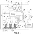
- FIG. 3is a schematic view of a cooling system employing at least one bank of scroll compressors
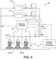
- FIG. 4is a schematic view of a cooling system employing at least one bank of scroll compressors, according to an alternative embodiment of FIG. 3 , but with similar reference numbers indicated to indicate like components;
- FIG. 5is a graph illustrating the isentropic efficiencies of a low volume index compressor and a high volume index compressor at different operating condensing temperatures.
- FIG. 1An embodiment of the present invention has been illustrated in FIG. 1 as at least one bank 10 of compressors of at least two different volume indexes, such as scroll compressors 12 , connected in fluid parallel circuit.
- Each scroll compressor as illustrated in FIG. 1may be a fixed positive displacement machine that has a non-adjustable built in fixed volume index in that the geometry of scrolls and the compressor chambers that are formed are not adjustable during operation.
- the bank 10 of scroll compressorsmay be used in a variety of systems to include air conditioning or chillers, reversible heat pumps, refrigeration units, industrial cooling applications and other such refrigerant circuits (herein cooling and refrigeration and other similar words are used interchangeably and mean the same thing and apply broadly to all such applications indicated).
- the scroll compressor 12generally includes an outer housing 14 that typically comprises one or more stamp-formed sheet steel shell sections 16 that are welded together. Contained within the housing 14 is a drive unit 18 that may take the form of an electrical motor and a pair of scroll compressor bodies to include a fixed scroll compressor body 20 and a movable scroll compressor body 22 .
- the scroll compressor bodies 20 , 22have respective bases 24 and respective scroll ribs 26 that project from the respective bases 24 and which mutually engage for compression of fluid.
- the drive unit 18has a rotational output on a drive shaft 28 that is operable to drive the movable scroll compressor body 22 about an orbital path relative to the fixed scroll compressor body 20 and thereby facilitates the compression of fluid.
- the drive unit 18is electrically connected via wiring to a local electrical panel and box 30 that is carried on the housing 14 . Further details of such a scroll compressor arrangement are further described in the aforementioned patents which have been hereby incorporated by reference in their entireties.
- each scroll compressor 12may be commonly mounted on common mounting rails 32 via mounting bases 40 to form at least one bank 10 of scroll compressors. Multiple banks (as schematically indicated in FIGS. 3 and 4 ) may be employed, with the compressors 12 connected among each other in parallel circuit as shown.
- each scroll compressormay have a suction inlet connected to a common low pressure suction pipe 34 , and a discharge outlet connected to a common high pressure outlet pipe 36 .
- the lubricating oil sumpsmay also optionally be connected via a common line 38 .
- different scroll compressorsmay be different models, sizes or types (e.g. with different scroll member geometry) to provide different fixed built in volume indexes (Vi).
- Vivolume indexes
- one of the illustrated scroll compressorsis shown to have a Vi of 2.3 and in an embodiment may be optimized for water cooling applications (e.g. in which the condensing temperature is lower).
- two of the illustrated scroll compressorsare shown to have a Vi of 2.6 and in an embodiment may be optimized for air cooling applications (i.e. in which the condensing temperature is higher).
- the volume indexis the ratio of the volume of suction gas in the compression chamber 42 when it closes (i.e. see chambers 42 formed between scroll members in FIG.
- This Volume index (Vi)provides for the internal pressure ratio for the compressor.
- a scroll compressor(with reference to FIG. 1 ) the volume of each compression chamber 42 progressively decreases in volume during operation as the compression chamber is moved radially inward due to the movement until it discharges into a discharge port and through a check valve 44 .
- the present inventioncontemplates using compressors of different volume indexes (Vi) for purposes of increasing efficiency due to different condensing temperatures that may be experienced in a given application and/or geographic region.
- Embodimentscontemplate different combinations of compressors with Vi depending upon the typical load demand at different temperature ranges and the time % during a year that will typically be spent in that range.
- FIGS. 3 and 4different refrigeration cooling systems are illustrated showing different embodiments of a system incorporating one or more banks 10 of the scroll compressors 12 .
- FIG. 3illustrates a system employing separate refrigeration circuits for each bank
- FIG. 4illustrates a system wherein the banks are connected in parallel feeding a common refrigeration circuit.
- the illustrated cooling systemincludes two separate banks 10 of scroll compressors 12 connected in parallel circuit, but each feeding a separate dedicated refrigeration circuit 46 .
- Each refrigeration circuit 46includes a condenser 48 connected in series to the high pressure outlet pipe 36 of the scroll compressor bank 10 .
- the condenser 48is illustrated to have fluid flow heat exchanger 50 (e.g. air, or in another embodiment liquid) flow across to cool and thereby condense high pressure refrigerant.
- a pressure sensor 52may be interposed to sense high pressure refrigerant pressure along the outlet pipe 36 (e.g. upstream of the condenser and downstream of the scroll compressors). The pressure sensor 52 provide electrical feedback indicative of sensed pressure to an electronic controller 60 .
- At least one cooling expansion unit 54(if multiple units 54 on a circuit then arranged typically in parallel) is also arranged in fluid series downstream of the condenser 48 .
- Optional control valve unit 56e.g. as in US Patent Publication 2008/0011014) or other controls may optionally be interposed between the expansion unit 54 and the condenser 48 .
- the expansion unit 54typically will include an on/off stop valve 58 controlled by a controller 60 to allow for operation of the expansion unit to produce cooling when necessitated by a demand load or to preclude operation of the expansion unit when not necessitated.
- the expansion unit 54also includes an expansion valve 62 that may be responsive or in part controlled by pressure downstream of the expansion unit heat exchanger) that controls discharge of refrigerant into a heat exchanger 64 , wherein due to the expansion, heat is absorbed to expand the refrigerant to a gas state thereby creating a cooling/refrigeration effect at the heat exchanger 64 .
- the expansion unit 54returns the expanded refrigerant in a gas state along the low pressure suction pipe 34 to the bank 10 of scroll compressors 12 .
- a pressure sensor 66is interposed along the return between the expansion unit 54 and the scroll compressors 12 to sense pressure along the suction side as experienced in the suction pipe 34 .
- the pressure sensor 66provides electrical feedback indicative of sensed pressure to the controller 60 .
- the controller 60is also electrically connected to each electrical box 30 for each of the scroll compressors 12 to individually turn the compressors on and off, and to otherwise control the compressors as may be appropriate.
- both banks 10 of compressors 12may collectively be arranged in parallel in the same circuit alternatively feeding a common condenser 48 that may output to one or more expansion units 54 as illustrated.
- This circuitalso work with the same refrigeration cycle as does the first through compression of refrigerant, condensing of refrigerant, expansion of refrigerant and return of the refrigerant to the beginning of the cycle. This illustrates that different circuit configurations are possible.
- the controller 60can operate according to embodiments of the invention as discussed below.
- the controllerthat is in individual operative communication with both types of refrigerant compressors (both high Vi and low Vi compressors), to individually and selectively control different compressors depending upon load demand and environmental conditions (e.g. condensing temperature).
- the controller 60can thus individually turn the refrigerant compressors 12 on and off (including optionally modulating and otherwise controlling the compressors).
- the controller 60will be preconfigured with logic that automatically selects the compressors based upon demand load and the temperature conditions (as may be determined by being actual or calculated from other data).
- the controller 60is be configured to selectively operate the high Vi or low Vi compressors 12 in response to a demand load and a determination of different saturated condensing temperature conditions. In combination with what is shown in FIG. 5 , preferably the controller 60 selects between the high Vi or low Vi compressors 12 or combination thereof based upon maximizing isentropic efficiency. For example, when it is determined to be in the first high temperature range (see FIG. 5 ), the controller 60 may operate the high Vi compressors to the extent necessitated by the demand load and operate the low Vi compressors only as necessary to meet the demand load when all of the high Vi compressors are already operating.
- the controller 60may operate the high Vi compressors to the extent necessitated by a demand load and operate the low Vi compressors only as necessary to meet the demand load when all of the second compressors are already operating. In this manner, efficiency is maximized. If there is an intermediate range between high and low temperature ranges, different logic or different combinations may either be pre-selected for the compressors depending on other considerations.
- the pressure sensors 52 , 66provide the pressure of the system which is indicative of the saturated condensing temperature.
- an AC systemwill evaporate at a certain temperature which is linked to a precise pressure for the given refrigerant.
- the pressure signal(s)may be used to determine temperature.
- actual temperature sensors and/or other such datasuch as date or seasonal information that would be indicative of the current environmental client and thereby whether the compressor arrangement is in a higher temperature range or lower temperature range. For example, at mid summer for an air cooled system, it would be presumed and thereby determined that a high temperature is experienced.
- the operating load demandmay also itself indicate the operating condensing temperature such as for an air conditioner system when lower demand loads indicate a lower condensing temperature range and higher demand loads indicate a higher condensing temperature range. Thus a determination of temperature may simply be derived from demand load. Combinations of such sensors and other data or information may be used to derive such a temperature determination.
- the system controlwill regulate the supplied cooling capacity by switching off/on the number of compressors required, as commonly already done.
- the advantage of the “scroll mix”is that the system will possibly select only the compressors that are more performing under the required conditions.
- the seasonis hot summer/mid summer which typically experience the highest condensing temperatures.
- the seasonis “fresh summer” beginning of summer and the end of summer, which typically provides for medium condensing temperatures and part load demands. Further, because the condenser size remains fixed, the condensing temperature is lower in part load operation.
- the two compressors with higher V iwill still offer acceptable performances.
- the efficiency increase due to the two compressors with lower V iwill be bigger than the efficiency decrease due to the two compressors with higher V i , or —in the worse case— the two effects will mutually compensate each other (this is function of the real condensing temperature and also depends on the exact behavior of the isentropic efficiency curves of the compressors).
- the seasonis spring, autumn, or very early or very late summer in which low condensing temperatures are typically expected.
Landscapes
- Engineering & Computer Science (AREA)
- Mechanical Engineering (AREA)
- General Engineering & Computer Science (AREA)
- Physics & Mathematics (AREA)
- Thermal Sciences (AREA)
- Applications Or Details Of Rotary Compressors (AREA)
- Control Of Positive-Displacement Pumps (AREA)
Abstract
Description
- System: air cooled chiller supplying around 360 kW (max cooling capacity nominally required)→double circuit with a trio operating on each circuit
- Geographical area: Southern Europe (Italy, Spain)
- Objective: to optimize the system in terms of both EER (full load) and SEER (part load), in agreement to a customer and application requirements
Claims (33)
Priority Applications (1)
| Application Number | Priority Date | Filing Date | Title |
|---|---|---|---|
| US15/706,392US11635243B2 (en) | 2009-01-23 | 2017-09-15 | Scroll compressors with different volume indexes and systems and methods for same |
Applications Claiming Priority (3)
| Application Number | Priority Date | Filing Date | Title |
|---|---|---|---|
| US14694709P | 2009-01-23 | 2009-01-23 | |
| US12/691,887US20100186433A1 (en) | 2009-01-23 | 2010-01-22 | Scroll Compressors with Different Volume Indexes and Systems and Methods for Same |
| US15/706,392US11635243B2 (en) | 2009-01-23 | 2017-09-15 | Scroll compressors with different volume indexes and systems and methods for same |
Related Parent Applications (1)
| Application Number | Title | Priority Date | Filing Date |
|---|---|---|---|
| US12/691,887ContinuationUS20100186433A1 (en) | 2009-01-23 | 2010-01-22 | Scroll Compressors with Different Volume Indexes and Systems and Methods for Same |
Publications (2)
| Publication Number | Publication Date |
|---|---|
| US20180003423A1 US20180003423A1 (en) | 2018-01-04 |
| US11635243B2true US11635243B2 (en) | 2023-04-25 |
Family
ID=42353034
Family Applications (2)
| Application Number | Title | Priority Date | Filing Date |
|---|---|---|---|
| US12/691,887AbandonedUS20100186433A1 (en) | 2009-01-23 | 2010-01-22 | Scroll Compressors with Different Volume Indexes and Systems and Methods for Same |
| US15/706,392Active2030-03-02US11635243B2 (en) | 2009-01-23 | 2017-09-15 | Scroll compressors with different volume indexes and systems and methods for same |
Family Applications Before (1)
| Application Number | Title | Priority Date | Filing Date |
|---|---|---|---|
| US12/691,887AbandonedUS20100186433A1 (en) | 2009-01-23 | 2010-01-22 | Scroll Compressors with Different Volume Indexes and Systems and Methods for Same |
Country Status (6)
| Country | Link |
|---|---|
| US (2) | US20100186433A1 (en) |
| EP (1) | EP2389516B1 (en) |
| JP (1) | JP2012515880A (en) |
| KR (1) | KR20110110812A (en) |
| CN (1) | CN102326000B (en) |
| WO (1) | WO2010085593A2 (en) |
Families Citing this family (42)
| Publication number | Priority date | Publication date | Assignee | Title |
|---|---|---|---|---|
| KR100892574B1 (en)* | 2003-03-26 | 2009-04-10 | 가부시키가이샤 아이에이치아이 | Turbo compressor, and method of packaging the compressor |
| FR2968731B1 (en)* | 2010-12-13 | 2015-02-27 | Danfoss Commercial Compressors | THERMODYNAMIC SYSTEM EQUIPPED WITH A PLURALITY OF COMPRESSORS |
| TWI646264B (en) | 2011-03-04 | 2019-01-01 | 美商布魯克機械公司 | Low temperature refrigeration system and method for controlling supply of helium refrigerant |
| CN103874897B (en) | 2011-10-07 | 2016-04-20 | 丹佛斯公司 | Coordinate the method for the operation of multiple compressor |
| KR101342649B1 (en)* | 2011-10-21 | 2013-12-17 | 엘지전자 주식회사 | Air conditioner |
| JP5758818B2 (en)* | 2012-02-15 | 2015-08-05 | 株式会社日立製作所 | Compressor system and operation control method thereof |
| FR2991733B1 (en)* | 2012-06-12 | 2016-09-02 | Danfoss Commercial Compressors | COMPRESSION DEVICE AND THERMODYNAMIC SYSTEM COMPRISING SUCH A COMPRESSION DEVICE |
| US10634137B2 (en) | 2012-07-31 | 2020-04-28 | Bitzer Kuehlmaschinenbau Gmbh | Suction header arrangement for oil management in multiple-compressor systems |
| US9689386B2 (en) | 2012-07-31 | 2017-06-27 | Bitzer Kuehlmaschinenbau Gmbh | Method of active oil management for multiple scroll compressors |
| US10495089B2 (en) | 2012-07-31 | 2019-12-03 | Bitzer Kuehlmashinenbau GmbH | Oil equalization configuration for multiple compressor systems containing three or more compressors |
| US9051934B2 (en) | 2013-02-28 | 2015-06-09 | Bitzer Kuehlmaschinenbau Gmbh | Apparatus and method for oil equalization in multiple-compressor systems |
| US9759468B2 (en)* | 2014-03-21 | 2017-09-12 | Lennox Industries Inc. | System for controlling operation of an HVAC system having tandem compressors |
| US9581371B2 (en) | 2014-03-21 | 2017-02-28 | Lennox Industries Inc. | System for operating an HVAC system having tandem compressors |
| US9488400B2 (en) | 2014-06-02 | 2016-11-08 | Lennox Industries Inc. | System for managing lubricant levels in tandem compressor assemblies of an HVAC system |
| US10047965B2 (en) | 2014-06-02 | 2018-08-14 | Lennox Industries Inc. | System for managing lubricant levels in tandem compressor assemblies of an HVAC system |
| JP6249932B2 (en)* | 2014-12-04 | 2017-12-20 | 三菱電機株式会社 | Air conditioning system |
| US9783024B2 (en) | 2015-03-09 | 2017-10-10 | Bergstrom Inc. | System and method for remotely managing climate control systems of a fleet of vehicles |
| CA2941479C (en)* | 2015-09-21 | 2019-01-29 | Lennox Industries Inc. | System for managing lubricant levels in tandem compressor assemblies of an hvac system |
| US9939179B2 (en)* | 2015-12-08 | 2018-04-10 | Bitzer Kuehlmaschinenbau Gmbh | Cascading oil distribution system |
| US11149992B2 (en)* | 2015-12-18 | 2021-10-19 | Sumitomo (Shi) Cryogenic Of America, Inc. | Dual helium compressors |
| US10760831B2 (en) | 2016-01-22 | 2020-09-01 | Bitzer Kuehlmaschinenbau Gmbh | Oil distribution in multiple-compressor systems utilizing variable speed |
| US20170241690A1 (en)* | 2016-02-19 | 2017-08-24 | Emerson Climate Technologies, Inc. | Compressor Capacity Modulation System For Multiple Compressors |
| US10436226B2 (en)* | 2016-02-24 | 2019-10-08 | Emerson Climate Technologies, Inc. | Compressor having sound control system |
| US10941772B2 (en)* | 2016-03-15 | 2021-03-09 | Emerson Climate Technologies, Inc. | Suction line arrangement for multiple compressor system |
| US12420616B2 (en)* | 2016-08-22 | 2025-09-23 | Bergstrom, Inc. | Multi-compressor oil migration mitigation climate system |
| US10081226B2 (en)* | 2016-08-22 | 2018-09-25 | Bergstrom Inc. | Parallel compressors climate system |
| US10675948B2 (en) | 2016-09-29 | 2020-06-09 | Bergstrom, Inc. | Systems and methods for controlling a vehicle HVAC system |
| US11204187B2 (en)* | 2017-07-14 | 2021-12-21 | Danfoss A/S | Mixed model compressor |
| US11448441B2 (en) | 2017-07-27 | 2022-09-20 | Bergstrom, Inc. | Refrigerant system for cooling electronics |
| WO2019129113A1 (en)* | 2017-12-28 | 2019-07-04 | 艾默生环境优化技术(苏州)有限公司 | Air intake pipe used for compressor system and compressor system |
| US11420496B2 (en) | 2018-04-02 | 2022-08-23 | Bergstrom, Inc. | Integrated vehicular system for conditioning air and heating water |
| US11421681B2 (en)* | 2018-04-19 | 2022-08-23 | Emerson Climate Technologies, Inc. | Multiple-compressor system with suction valve and method of controlling suction valve |
| RU201645U1 (en)* | 2019-08-29 | 2020-12-24 | Антон Юрьевич Дымов | DOUBLE-CIRCUIT CHILLER WITH THREE COMPRESSORS |
| US12060874B2 (en)* | 2020-02-24 | 2024-08-13 | Goodman Global Group, Inc. | Systems and methods for compressor design |
| CN116420019A (en) | 2020-11-09 | 2023-07-11 | 辟缔熙机械股份有限公司 | Hydraulically driven diaphragm compressor system |
| US11674508B2 (en) | 2021-11-08 | 2023-06-13 | Pdc Machines Inc. | High-throughput diaphragm compressor |
| US12405024B2 (en) | 2022-01-28 | 2025-09-02 | Tyco Fire & Security Gmbh | Heat pump control systems and methods |
| US11906188B2 (en)* | 2022-03-11 | 2024-02-20 | Johnson Controls Tyco IP Holdings LLP | Energy efficient heat pump systems and methods |
| US12422173B2 (en) | 2022-08-19 | 2025-09-23 | Copeland Lp | Multiple-compressor system with oil balance control |
| CN116182419B (en)* | 2023-04-21 | 2023-07-21 | 广东美的暖通设备有限公司 | Control method and device of double-machine-head unit |
| CN116518600A (en)* | 2023-07-05 | 2023-08-01 | 中建环能科技股份有限公司 | Control method for refrigerating performance of compressor of heat pump low-temperature drying equipment and electronic equipment |
| WO2025007305A1 (en)* | 2023-07-05 | 2025-01-09 | 中建环能科技股份有限公司 | Low-energy-consumption control method for heat pump low-temperature dryer, electronic device and storage medium |
Citations (25)
| Publication number | Priority date | Publication date | Assignee | Title |
|---|---|---|---|---|
| US933682A (en) | 1908-07-03 | 1909-09-07 | Gardner Tufts Voorhees | Multiple-effect receiver. |
| US4193270A (en) | 1978-02-27 | 1980-03-18 | Scott Jack D | Refrigeration system with compressor load transfer means |
| JPH01262390A (en) | 1988-04-13 | 1989-10-19 | Sanyo Electric Co Ltd | Controller for refrigerating circuit |
| US5170636A (en)* | 1990-04-24 | 1992-12-15 | Kabushiki Kaisha Toshiba | Heat exchanger |
| JPH0861274A (en) | 1994-08-24 | 1996-03-08 | Toshiba Corp | Rotary compressor |
| CA2312175A1 (en) | 2000-06-23 | 2001-12-23 | Joseph Antoine Michel Grenier | Improved air-to-air heat pump |
| US6398530B1 (en) | 1999-03-10 | 2002-06-04 | Bitzer Kuehlmaschinenbau Gmbh | Scroll compressor having entraining members for radial movement of a scroll rib |
| JP2002257424A (en) | 2001-02-26 | 2002-09-11 | Lg Electronics Inc | Device and method for air conditioning |
| CN1464199A (en) | 2002-06-07 | 2003-12-31 | 乐金电子(天津)电器有限公司 | Expansion apparatus for volume-converting compressor |
| US20040016241A1 (en)* | 2000-03-14 | 2004-01-29 | Hussmann Corporation | Refrigeration system and method of operating the same |
| US6769258B2 (en)* | 1999-08-06 | 2004-08-03 | Tom L. Pierson | System for staged chilling of inlet air for gas turbines |
| CN1517559A (en) | 2003-01-06 | 2004-08-04 | 三星电子株式会社 | variable capacity rotary compressor |
| US6814551B2 (en) | 2000-12-22 | 2004-11-09 | Bitzer Kuehlmaschinenbau Gmbh | Compressor |
| JP2005061784A (en) | 2003-08-20 | 2005-03-10 | Yanmar Co Ltd | Engine heat pump |
| US20050223726A1 (en) | 2004-04-08 | 2005-10-13 | Alexander Lifson | Compressor |
| US6960070B2 (en) | 2002-10-15 | 2005-11-01 | Bitzer Kuehlmaschinenbau Gmbh | Compressor |
| JP2006258330A (en) | 2005-03-15 | 2006-09-28 | Daikin Ind Ltd | Refrigeration equipment |
| EP1361364B1 (en) | 2002-05-08 | 2006-10-25 | Carrier Corporation | Multi-rotor screw compressor |
| JP2007198693A (en) | 2006-01-27 | 2007-08-09 | Mayekawa Mfg Co Ltd | Cascade type heat pump system |
| US20080011014A1 (en) | 2005-02-17 | 2008-01-17 | Bitzer Kuhlmaschinenbau Gmbh | Refrigeration System |
| WO2008082410A1 (en) | 2006-12-31 | 2008-07-10 | Carrier Corporation | Compressor |
| US7409833B2 (en) | 2005-03-10 | 2008-08-12 | Sunpower, Inc. | Dual mode compressor with automatic compression ratio adjustment for adapting to multiple operating conditions |
| US20090185929A1 (en)* | 2008-01-17 | 2009-07-23 | Bitzer Scroll Inc. | Mounting Base and Scroll Compressor Incorporating Same |
| US20090255278A1 (en)* | 2005-10-17 | 2009-10-15 | Carrier Corporation | Refrigerant System With Variable Speed Drive |
| US20100170295A1 (en)* | 2007-05-25 | 2010-07-08 | Mitsubishi Electric Corporation | Refrigeration cycle device |
Family Cites Families (5)
| Publication number | Priority date | Publication date | Assignee | Title |
|---|---|---|---|---|
| JPH0267494A (en)* | 1988-08-31 | 1990-03-07 | Toshiba Corp | Twin compressor |
| JP3036310B2 (en)* | 1992-08-01 | 2000-04-24 | 三菱電機株式会社 | Multi-temperature generation circuit by vapor compression refrigeration cycle |
| JP4300712B2 (en)* | 2000-03-15 | 2009-07-22 | 株式会社日立製作所 | refrigerator |
| US6839816B2 (en)* | 2002-02-26 | 2005-01-04 | International Business Machines Corporation | Shared cache line update mechanism |
| KR101065501B1 (en)* | 2009-02-05 | 2011-09-19 | 엘지전자 주식회사 | Compressor And Air Conditioner Including The Same |
- 2010
- 2010-01-22USUS12/691,887patent/US20100186433A1/ennot_activeAbandoned
- 2010-01-22CNCN201080008987.1Apatent/CN102326000B/enactiveActive
- 2010-01-22WOPCT/US2010/021709patent/WO2010085593A2/enactiveApplication Filing
- 2010-01-22JPJP2011548113Apatent/JP2012515880A/enactivePending
- 2010-01-22EPEP10733867.5Apatent/EP2389516B1/enactiveActive
- 2010-01-22KRKR1020117019192Apatent/KR20110110812A/ennot_activeAbandoned
- 2017
- 2017-09-15USUS15/706,392patent/US11635243B2/enactiveActive
Patent Citations (29)
| Publication number | Priority date | Publication date | Assignee | Title |
|---|---|---|---|---|
| US933682A (en) | 1908-07-03 | 1909-09-07 | Gardner Tufts Voorhees | Multiple-effect receiver. |
| US4193270A (en) | 1978-02-27 | 1980-03-18 | Scott Jack D | Refrigeration system with compressor load transfer means |
| JPH01262390A (en) | 1988-04-13 | 1989-10-19 | Sanyo Electric Co Ltd | Controller for refrigerating circuit |
| US5170636A (en)* | 1990-04-24 | 1992-12-15 | Kabushiki Kaisha Toshiba | Heat exchanger |
| JPH0861274A (en) | 1994-08-24 | 1996-03-08 | Toshiba Corp | Rotary compressor |
| US6398530B1 (en) | 1999-03-10 | 2002-06-04 | Bitzer Kuehlmaschinenbau Gmbh | Scroll compressor having entraining members for radial movement of a scroll rib |
| US6769258B2 (en)* | 1999-08-06 | 2004-08-03 | Tom L. Pierson | System for staged chilling of inlet air for gas turbines |
| US20040016241A1 (en)* | 2000-03-14 | 2004-01-29 | Hussmann Corporation | Refrigeration system and method of operating the same |
| CA2312175A1 (en) | 2000-06-23 | 2001-12-23 | Joseph Antoine Michel Grenier | Improved air-to-air heat pump |
| US6814551B2 (en) | 2000-12-22 | 2004-11-09 | Bitzer Kuehlmaschinenbau Gmbh | Compressor |
| CN1370956A (en) | 2001-02-26 | 2002-09-25 | Lg电子株式会社 | Air conditioning system and method |
| JP2002257424A (en) | 2001-02-26 | 2002-09-11 | Lg Electronics Inc | Device and method for air conditioning |
| EP1361364B1 (en) | 2002-05-08 | 2006-10-25 | Carrier Corporation | Multi-rotor screw compressor |
| CN1464199A (en) | 2002-06-07 | 2003-12-31 | 乐金电子(天津)电器有限公司 | Expansion apparatus for volume-converting compressor |
| US7112046B2 (en) | 2002-10-15 | 2006-09-26 | Bitzer Kuehlmaschinenbau Gmbh | Scroll compressor for refrigerant |
| US6960070B2 (en) | 2002-10-15 | 2005-11-01 | Bitzer Kuehlmaschinenbau Gmbh | Compressor |
| CN1517559A (en) | 2003-01-06 | 2004-08-04 | 三星电子株式会社 | variable capacity rotary compressor |
| JP2005061784A (en) | 2003-08-20 | 2005-03-10 | Yanmar Co Ltd | Engine heat pump |
| US20050223726A1 (en) | 2004-04-08 | 2005-10-13 | Alexander Lifson | Compressor |
| US7178352B2 (en)* | 2004-04-08 | 2007-02-20 | Carrier Corporation | Compressor |
| US20080011014A1 (en) | 2005-02-17 | 2008-01-17 | Bitzer Kuhlmaschinenbau Gmbh | Refrigeration System |
| US7409833B2 (en) | 2005-03-10 | 2008-08-12 | Sunpower, Inc. | Dual mode compressor with automatic compression ratio adjustment for adapting to multiple operating conditions |
| JP2006258330A (en) | 2005-03-15 | 2006-09-28 | Daikin Ind Ltd | Refrigeration equipment |
| US20080163642A1 (en)* | 2005-03-15 | 2008-07-10 | Masakazu Okamoto | Refrigeration Apparatus |
| US20090255278A1 (en)* | 2005-10-17 | 2009-10-15 | Carrier Corporation | Refrigerant System With Variable Speed Drive |
| JP2007198693A (en) | 2006-01-27 | 2007-08-09 | Mayekawa Mfg Co Ltd | Cascade type heat pump system |
| WO2008082410A1 (en) | 2006-12-31 | 2008-07-10 | Carrier Corporation | Compressor |
| US20100170295A1 (en)* | 2007-05-25 | 2010-07-08 | Mitsubishi Electric Corporation | Refrigeration cycle device |
| US20090185929A1 (en)* | 2008-01-17 | 2009-07-23 | Bitzer Scroll Inc. | Mounting Base and Scroll Compressor Incorporating Same |
Non-Patent Citations (4)
| Title |
|---|
| Hans Jorgen Hogaard Knudsen; Comparison of Energy Consumption for Refrigeration in Supermarkets; Sep. 2004, Appendix A, Danish Environmental Protection Agency. |
| Phillippi Greg: "Copyright 2016 by Turbomachinery Laboratory, Texas A&M Engineering Experiment Station Basic Thermodynamics of Reciprocating Compression", Sep. 15, 2016 (Sep. 15, 2016), XP055793350. |
| Reindl Douglas T et al: "IRC TechNote Selection of Screw Compressors for Energy Efficient Operation Screw Compressors: Selection Considerations for Efficient Operation Background", Jan. 1, 2002 (Jan. 1, 2002), XP055793352. |
| Sauble Gary Schrift: "Maximizing Screw Compressor Performance", Jan. 1, 2005 (Jan. 1, 2005), XP055793349. |
Also Published As
| Publication number | Publication date |
|---|---|
| WO2010085593A3 (en) | 2010-11-18 |
| EP2389516B1 (en) | 2024-01-10 |
| EP2389516A4 (en) | 2016-01-06 |
| KR20110110812A (en) | 2011-10-07 |
| EP2389516A2 (en) | 2011-11-30 |
| US20180003423A1 (en) | 2018-01-04 |
| WO2010085593A2 (en) | 2010-07-29 |
| US20100186433A1 (en) | 2010-07-29 |
| CN102326000A (en) | 2012-01-18 |
| CN102326000B (en) | 2014-03-12 |
| JP2012515880A (en) | 2012-07-12 |
Similar Documents
| Publication | Publication Date | Title |
|---|---|---|
| US11635243B2 (en) | Scroll compressors with different volume indexes and systems and methods for same | |
| CN102597524B (en) | The method of operation of heat pump system, compound compressor and heat pump system | |
| EP2302310A1 (en) | Refrigeration cycle device | |
| JP2003279179A (en) | Refrigeration air conditioner | |
| JP5484889B2 (en) | Refrigeration equipment | |
| JP5484890B2 (en) | Refrigeration equipment | |
| JP2011133206A (en) | Refrigerating apparatus | |
| JP4622296B2 (en) | Combined power source heat pump air conditioner | |
| JP2002106986A (en) | Air conditioner and control method thereof | |
| JP5502460B2 (en) | Refrigeration equipment | |
| JP2011133210A (en) | Refrigerating apparatus | |
| JP2011133208A (en) | Refrigerating apparatus | |
| JP5414811B2 (en) | Positive displacement expander and refrigeration cycle apparatus using the positive displacement expander | |
| KR100612809B1 (en) | Heat pump type air conditioner driven by internal combustion engine | |
| JP4738219B2 (en) | Refrigeration equipment | |
| CN209326132U (en) | air conditioning system | |
| JP4585422B2 (en) | Gas heat pump type air conditioner | |
| JP2009236398A (en) | Air conditioner | |
| WO2015122169A1 (en) | Air conditioner | |
| JP2007147228A (en) | Refrigeration equipment | |
| KR100611273B1 (en) | Composite power supply heat pump type airconditioner | |
| JP2017110821A (en) | Air conditioner | |
| JP2011137556A (en) | Refrigerating apparatus | |
| JP2007263562A5 (en) |
Legal Events
| Date | Code | Title | Description |
|---|---|---|---|
| FEPP | Fee payment procedure | Free format text:ENTITY STATUS SET TO UNDISCOUNTED (ORIGINAL EVENT CODE: BIG.); ENTITY STATUS OF PATENT OWNER: LARGE ENTITY | |
| AS | Assignment | Owner name:BITZER KUEHLMASCHINENBAU GMBH, GERMANY Free format text:ASSIGNMENT OF ASSIGNORS INTEREST;ASSIGNORS:GALANTE, FRANCESCO;KOBOR, RICHARD G.;SIGNING DATES FROM 20100211 TO 20100223;REEL/FRAME:043611/0075 | |
| STPP | Information on status: patent application and granting procedure in general | Free format text:NON FINAL ACTION MAILED | |
| STPP | Information on status: patent application and granting procedure in general | Free format text:RESPONSE TO NON-FINAL OFFICE ACTION ENTERED AND FORWARDED TO EXAMINER | |
| STPP | Information on status: patent application and granting procedure in general | Free format text:FINAL REJECTION MAILED | |
| STPP | Information on status: patent application and granting procedure in general | Free format text:RESPONSE AFTER FINAL ACTION FORWARDED TO EXAMINER | |
| STPP | Information on status: patent application and granting procedure in general | Free format text:ADVISORY ACTION MAILED | |
| STCV | Information on status: appeal procedure | Free format text:NOTICE OF APPEAL FILED | |
| STCV | Information on status: appeal procedure | Free format text:APPEAL BRIEF (OR SUPPLEMENTAL BRIEF) ENTERED AND FORWARDED TO EXAMINER | |
| STCV | Information on status: appeal procedure | Free format text:NOTICE OF APPEAL FILED | |
| STCV | Information on status: appeal procedure | Free format text:APPEAL BRIEF (OR SUPPLEMENTAL BRIEF) ENTERED AND FORWARDED TO EXAMINER | |
| STCV | Information on status: appeal procedure | Free format text:EXAMINER'S ANSWER TO APPEAL BRIEF MAILED | |
| STCV | Information on status: appeal procedure | Free format text:APPEAL READY FOR REVIEW | |
| STCV | Information on status: appeal procedure | Free format text:ON APPEAL -- AWAITING DECISION BY THE BOARD OF APPEALS | |
| STCV | Information on status: appeal procedure | Free format text:BOARD OF APPEALS DECISION RENDERED | |
| STPP | Information on status: patent application and granting procedure in general | Free format text:DOCKETED NEW CASE - READY FOR EXAMINATION | |
| STPP | Information on status: patent application and granting procedure in general | Free format text:NON FINAL ACTION MAILED | |
| STPP | Information on status: patent application and granting procedure in general | Free format text:RESPONSE TO NON-FINAL OFFICE ACTION ENTERED AND FORWARDED TO EXAMINER | |
| STCF | Information on status: patent grant | Free format text:PATENTED CASE |