US11633818B2 - Devices, systems, and methods for treatment of intracranial aneurysms - Google Patents
Devices, systems, and methods for treatment of intracranial aneurysmsDownload PDFInfo
- Publication number
- US11633818B2 US11633818B2US16/949,568US202016949568AUS11633818B2US 11633818 B2US11633818 B2US 11633818B2US 202016949568 AUS202016949568 AUS 202016949568AUS 11633818 B2US11633818 B2US 11633818B2
- Authority
- US
- United States
- Prior art keywords
- occlusive member
- aneurysm
- occlusive
- distal
- elongate
- Prior art date
- Legal status (The legal status is an assumption and is not a legal conclusion. Google has not performed a legal analysis and makes no representation as to the accuracy of the status listed.)
- Active
Links
Images


Classifications
- A—HUMAN NECESSITIES
- A61—MEDICAL OR VETERINARY SCIENCE; HYGIENE
- A61B—DIAGNOSIS; SURGERY; IDENTIFICATION
- A61B17/00—Surgical instruments, devices or methods
- A61B17/12—Surgical instruments, devices or methods for ligaturing or otherwise compressing tubular parts of the body, e.g. blood vessels or umbilical cord
- A61B17/12022—Occluding by internal devices, e.g. balloons or releasable wires
- A61B17/12131—Occluding by internal devices, e.g. balloons or releasable wires characterised by the type of occluding device
- A61B17/12181—Occluding by internal devices, e.g. balloons or releasable wires characterised by the type of occluding device formed by fluidized, gelatinous or cellular remodelable materials, e.g. embolic liquids, foams or extracellular matrices
- A61B17/12186—Occluding by internal devices, e.g. balloons or releasable wires characterised by the type of occluding device formed by fluidized, gelatinous or cellular remodelable materials, e.g. embolic liquids, foams or extracellular matrices liquid materials adapted to be injected
- A—HUMAN NECESSITIES
- A61—MEDICAL OR VETERINARY SCIENCE; HYGIENE
- A61B—DIAGNOSIS; SURGERY; IDENTIFICATION
- A61B17/00—Surgical instruments, devices or methods
- A61B17/12—Surgical instruments, devices or methods for ligaturing or otherwise compressing tubular parts of the body, e.g. blood vessels or umbilical cord
- A61B17/12022—Occluding by internal devices, e.g. balloons or releasable wires
- A61B17/12099—Occluding by internal devices, e.g. balloons or releasable wires characterised by the location of the occluder
- A61B17/12109—Occluding by internal devices, e.g. balloons or releasable wires characterised by the location of the occluder in a blood vessel
- A61B17/12113—Occluding by internal devices, e.g. balloons or releasable wires characterised by the location of the occluder in a blood vessel within an aneurysm
- A—HUMAN NECESSITIES
- A61—MEDICAL OR VETERINARY SCIENCE; HYGIENE
- A61B—DIAGNOSIS; SURGERY; IDENTIFICATION
- A61B17/00—Surgical instruments, devices or methods
- A61B17/12—Surgical instruments, devices or methods for ligaturing or otherwise compressing tubular parts of the body, e.g. blood vessels or umbilical cord
- A61B17/12022—Occluding by internal devices, e.g. balloons or releasable wires
- A61B17/12027—Type of occlusion
- A61B17/12031—Type of occlusion complete occlusion
- A—HUMAN NECESSITIES
- A61—MEDICAL OR VETERINARY SCIENCE; HYGIENE
- A61B—DIAGNOSIS; SURGERY; IDENTIFICATION
- A61B17/00—Surgical instruments, devices or methods
- A61B17/12—Surgical instruments, devices or methods for ligaturing or otherwise compressing tubular parts of the body, e.g. blood vessels or umbilical cord
- A61B17/12022—Occluding by internal devices, e.g. balloons or releasable wires
- A61B17/12131—Occluding by internal devices, e.g. balloons or releasable wires characterised by the type of occluding device
- A61B17/1214—Coils or wires
- A61B17/12145—Coils or wires having a pre-set deployed three-dimensional shape
- A—HUMAN NECESSITIES
- A61—MEDICAL OR VETERINARY SCIENCE; HYGIENE
- A61B—DIAGNOSIS; SURGERY; IDENTIFICATION
- A61B17/00—Surgical instruments, devices or methods
- A61B17/12—Surgical instruments, devices or methods for ligaturing or otherwise compressing tubular parts of the body, e.g. blood vessels or umbilical cord
- A61B17/12022—Occluding by internal devices, e.g. balloons or releasable wires
- A61B17/12131—Occluding by internal devices, e.g. balloons or releasable wires characterised by the type of occluding device
- A61B17/12168—Occluding by internal devices, e.g. balloons or releasable wires characterised by the type of occluding device having a mesh structure
- A61B17/12172—Occluding by internal devices, e.g. balloons or releasable wires characterised by the type of occluding device having a mesh structure having a pre-set deployed three-dimensional shape
- A—HUMAN NECESSITIES
- A61—MEDICAL OR VETERINARY SCIENCE; HYGIENE
- A61B—DIAGNOSIS; SURGERY; IDENTIFICATION
- A61B17/00—Surgical instruments, devices or methods
- A61B17/12—Surgical instruments, devices or methods for ligaturing or otherwise compressing tubular parts of the body, e.g. blood vessels or umbilical cord
- A61B17/12022—Occluding by internal devices, e.g. balloons or releasable wires
- A61B17/12131—Occluding by internal devices, e.g. balloons or releasable wires characterised by the type of occluding device
- A61B17/12181—Occluding by internal devices, e.g. balloons or releasable wires characterised by the type of occluding device formed by fluidized, gelatinous or cellular remodelable materials, e.g. embolic liquids, foams or extracellular matrices
- A—HUMAN NECESSITIES
- A61—MEDICAL OR VETERINARY SCIENCE; HYGIENE
- A61B—DIAGNOSIS; SURGERY; IDENTIFICATION
- A61B17/00—Surgical instruments, devices or methods
- A61B17/12—Surgical instruments, devices or methods for ligaturing or otherwise compressing tubular parts of the body, e.g. blood vessels or umbilical cord
- A61B17/12022—Occluding by internal devices, e.g. balloons or releasable wires
- A61B17/12131—Occluding by internal devices, e.g. balloons or releasable wires characterised by the type of occluding device
- A61B17/12168—Occluding by internal devices, e.g. balloons or releasable wires characterised by the type of occluding device having a mesh structure
- A—HUMAN NECESSITIES
- A61—MEDICAL OR VETERINARY SCIENCE; HYGIENE
- A61B—DIAGNOSIS; SURGERY; IDENTIFICATION
- A61B17/00—Surgical instruments, devices or methods
- A61B2017/00526—Methods of manufacturing
- A—HUMAN NECESSITIES
- A61—MEDICAL OR VETERINARY SCIENCE; HYGIENE
- A61B—DIAGNOSIS; SURGERY; IDENTIFICATION
- A61B17/00—Surgical instruments, devices or methods
- A61B2017/00535—Surgical instruments, devices or methods pneumatically or hydraulically operated
- A61B2017/00557—Surgical instruments, devices or methods pneumatically or hydraulically operated inflatable
- A—HUMAN NECESSITIES
- A61—MEDICAL OR VETERINARY SCIENCE; HYGIENE
- A61B—DIAGNOSIS; SURGERY; IDENTIFICATION
- A61B17/00—Surgical instruments, devices or methods
- A61B2017/00831—Material properties
- A61B2017/00862—Material properties elastic or resilient
- A—HUMAN NECESSITIES
- A61—MEDICAL OR VETERINARY SCIENCE; HYGIENE
- A61B—DIAGNOSIS; SURGERY; IDENTIFICATION
- A61B17/00—Surgical instruments, devices or methods
- A61B2017/00831—Material properties
- A61B2017/00929—Material properties isolating electrical current
- A—HUMAN NECESSITIES
- A61—MEDICAL OR VETERINARY SCIENCE; HYGIENE
- A61B—DIAGNOSIS; SURGERY; IDENTIFICATION
- A61B17/00—Surgical instruments, devices or methods
- A61B17/12—Surgical instruments, devices or methods for ligaturing or otherwise compressing tubular parts of the body, e.g. blood vessels or umbilical cord
- A61B17/12022—Occluding by internal devices, e.g. balloons or releasable wires
- A61B2017/1205—Introduction devices
- A61B2017/12054—Details concerning the detachment of the occluding device from the introduction device
- A61B2017/12063—Details concerning the detachment of the occluding device from the introduction device electrolytically detachable
- A—HUMAN NECESSITIES
- A61—MEDICAL OR VETERINARY SCIENCE; HYGIENE
- A61B—DIAGNOSIS; SURGERY; IDENTIFICATION
- A61B17/00—Surgical instruments, devices or methods
- A61B17/12—Surgical instruments, devices or methods for ligaturing or otherwise compressing tubular parts of the body, e.g. blood vessels or umbilical cord
- A61B17/12022—Occluding by internal devices, e.g. balloons or releasable wires
- A61B2017/1205—Introduction devices
- A61B2017/12054—Details concerning the detachment of the occluding device from the introduction device
- A61B2017/1209—Details concerning the detachment of the occluding device from the introduction device detachable by electrical current or potential, e.g. electroactive polymer
- A—HUMAN NECESSITIES
- A61—MEDICAL OR VETERINARY SCIENCE; HYGIENE
- A61B—DIAGNOSIS; SURGERY; IDENTIFICATION
- A61B90/00—Instruments, implements or accessories specially adapted for surgery or diagnosis and not covered by any of the groups A61B1/00 - A61B50/00, e.g. for luxation treatment or for protecting wound edges
- A61B90/36—Image-producing devices or illumination devices not otherwise provided for
- A61B90/37—Surgical systems with images on a monitor during operation
- A61B2090/376—Surgical systems with images on a monitor during operation using X-rays, e.g. fluoroscopy
- A—HUMAN NECESSITIES
- A61—MEDICAL OR VETERINARY SCIENCE; HYGIENE
- A61B—DIAGNOSIS; SURGERY; IDENTIFICATION
- A61B90/00—Instruments, implements or accessories specially adapted for surgery or diagnosis and not covered by any of the groups A61B1/00 - A61B50/00, e.g. for luxation treatment or for protecting wound edges
- A61B90/39—Markers, e.g. radio-opaque or breast lesions markers
- A61B2090/3966—Radiopaque markers visible in an X-ray image
- B—PERFORMING OPERATIONS; TRANSPORTING
- B23—MACHINE TOOLS; METAL-WORKING NOT OTHERWISE PROVIDED FOR
- B23P—METAL-WORKING NOT OTHERWISE PROVIDED FOR; COMBINED OPERATIONS; UNIVERSAL MACHINE TOOLS
- B23P19/00—Machines for simply fitting together or separating metal parts or objects, or metal and non-metal parts, whether or not involving some deformation; Tools or devices therefor so far as not provided for in other classes
- B23P19/04—Machines for simply fitting together or separating metal parts or objects, or metal and non-metal parts, whether or not involving some deformation; Tools or devices therefor so far as not provided for in other classes for assembling or disassembling parts
- B23P19/047—Machines for simply fitting together or separating metal parts or objects, or metal and non-metal parts, whether or not involving some deformation; Tools or devices therefor so far as not provided for in other classes for assembling or disassembling parts for flexible profiles, e.g. sealing or decorating strips in grooves or on other profiles by devices moving along the flexible profile
Definitions
- the present technologyrelates to systems, devices, and methods for treating intracranial aneurysms.
- An intracranial aneurysmis a portion of an intracranial blood vessel that bulges outward from the blood vessel's main channel. This condition often occurs at a portion of a blood vessel that is abnormally weak because of a congenital anomaly, trauma, high blood pressure, or for another reason. Once an intracranial aneurysm forms, there is a significant risk that the aneurysm will eventually rupture and cause a medical emergency with a high risk of mortality due to hemorrhaging. When an unruptured intracranial aneurysm is detected or when a patient survives an initial rupture of an intracranial aneurysm, vascular surgery is often indicated.
- One conventional type of vascular surgery for treating an intracranial aneurysmincludes using a microcatheter to dispose a platinum coil within an interior volume of the aneurysm. Over time, the presence of the coil should induce formation of a thrombus. Ideally, the aneurysm's neck closes at the site of the thrombus and is replaced with new endothelial tissue. Blood then bypasses the aneurysm, thereby reducing the risk of aneurysm rupture (or re-rupture) and associated hemorrhaging.
- Another conventional type of vascular surgery for treating an intracranial aneurysmincludes deploying a flow diverter within the associated intracranial blood vessel.
- the flow diverteris often a mesh tube that causes blood to preferentially flow along a main channel of the blood vessel while blood within the aneurysm stagnates.
- the stagnant blood within the aneurysmshould eventually form a thrombus that leads to closure of the aneurysm's neck and to growth of new endothelial tissue, as with the platinum coil treatment.
- One significant drawback of flow divertersis that it may take weeks or months to form aneurysmal thrombus and significantly longer for the aneurysm neck to be covered with endothelial cells for full effect.
- the subject technologyis illustrated, for example, according to various aspects described below, including with reference to FIGS. 1 A- 7 J .
- Various examples of aspects of the subject technologyare described as numbered clauses (1, 2, 3, etc.) for convenience. These are provided as examples and do not limit the subject technology.
- a method for treating an aneurysmcomprising:
- transforming the occlusive member into the second expanded shapeincludes injecting the embolic material to urge a portion of a sidewall of the expandable mesh in a direction away from a wall of the aneurysm and towards the interior region of the occlusive member.
- transforming the occlusive member into the second expanded shapeincludes injecting the embolic material to invert a portion of a sidewall of the occlusive member such that the portion is convex towards the aneurysm wall in the first expanded state and concave towards the aneurysm wall in the second expanded state.
- embolic elementcomprises one or more embolization coils.
- the occlusive membercomprises a plurality of braided filaments that assume a pre-set, three-dimensional shape in the expanded state.
- the occlusive membercomprises a braid formed of 24, 32, 36, 48, 64, or 72 filaments.
- the occlusive membercomprises a braid formed of a plurality of wires, some or all of which have a diameter of about 0.001 inches (0.00254 cm).
- the occlusive membercomprises a braid formed of a plurality of wires, some or all of which have the same diameter.
- the occlusive membercomprises a braid formed of a plurality of wires, at least some of which have different diameters.
- the occlusive memberforms one of a sphere, a prolate spheroid, or an oblate spheroid.
- the occlusive membercomprises an inner layer and an outer layer that meet at a fold at a distal portion of the occlusive member.
- the occlusive membercomprises an inner layer and an outer layer that meet at a fold at a proximal portion of the occlusive member.
- the occlusive memberhas a maximum cross-sectional dimension of 3.0 mm, 3.5 mm, 4.0 mm, 4.5 mm, 5.0 mm, 5.5 mm, 6.0 mm, 6.5 mm, 7.0 mm, 7.5 mm, or 8.0 mm.
- the occlusive memberis formed of a plurality of filaments formed of an inner core material surrounded by an outer material.
- each of the filamentshas a first end and a second end opposite the first end, and wherein both the first and second ends of the filaments are fixed relative to one another at a coupler.
- embolic elementcomprises a biopolymer and a chemical crosslinking agent.
- the physical crosslinking agentincludes ⁇ glycerophosphate, a derivative of ⁇ glycerophosphate, an analog of ⁇ glycerophosphate, or a combination thereof.
- a method for treating an aneurysmcomprising: positioning an expandable occlusive member in an initial expanded state within an
- a method for imaging treatment of an aneurysmcomprising:
- a method for treating an aneurysmcomprising:
- the occlusive membercomprises a plurality of braided filaments that assume a pre-set, three-dimensional shape in the expanded state.
- a method for treating an aneurysmcomprising:
- a systemcomprising:
- a method for treating an aneurysmcomprising:
- a method for treating an aneurysmcomprising:
- FIG. 1 Ashows a perspective view of a system for treating an aneurysm in accordance with the present technology.
- FIG. 1 Bshows an enlarged view of a distal portion of the treatment system of FIG. 1 A in accordance with the present technology.
- FIGS. 1 C and 1 Dare sectioned views of occlusive members in an expanded state in accordance with the present technology.
- FIG. 2shows an embolic kit according to the present technology.
- FIGS. 3 A- 3 Gdepict an example method of treating an aneurysm with the treatment systems of the present technology.
- FIGS. 4 A- 5 Bshow various types of images that may be employed to confirm and/or monitor deployment of the treatment system of the present technology.
- FIG. 6shows a system for treating an aneurysm in accordance with the present technology.
- FIGS. 7 A- 7 Jdepict an example method of treating an aneurysm with the treatment systems of the present technology.
- Methods for treating intracranial aneurysmsinclude positioning an expandable occlusive member within the aneurysm and introducing an embolic element between the occlusive member and an aneurysm wall.
- Introduction of the embolic elementboth fills space within the aneurysm cavity and deforms the occlusive member from a first expanded state to a second expanded state to fortify the occlusive member at the neck of the aneurysm.
- Deformation of the occlusive member from a first expanded state to a second expanded stateprovides the additional advantage of giving visual confirmation to the physician that the delivered amount of embolic element sufficiently fills the aneurysm cavity.
- the occlusive memberprovides a scaffold for tissue remodeling and diverts blood flow from the aneurysm. Moreover, the embolic element exerts a substantially uniform pressure on the occlusive member towards the neck of the aneurysm, thereby pressing the portions of the occlusive member positioned adjacent the neck against the inner surface of the aneurysm wall such that the occlusive member forms a complete and stable seal at the neck.
- FIGS. 1 A- 7 JSpecific details of systems, devices, and methods for treating intracranial aneurysms in accordance with embodiments of the present technology are described herein with reference to FIGS. 1 A- 7 J . Although these systems, devices, and methods may be described herein primarily or entirely in the context of treating saccular intracranial aneurysms, other contexts are within the scope of the present technology.
- suitable features of described systems, devices, and methods for treating saccular intracranial aneurysmscan be implemented in the context of treating non-saccular intracranial aneurysms, abdominal aortic aneurysms, thoracic aortic aneurysms, renal artery aneurysms, arteriovenous malformations, tumors (e.g. via occlusion of vessel(s) feeding a tumor), perivascular leaks, varicose veins (e.g.
- systems, devices, and methods in addition to those disclosed hereinare within the scope of the present disclosure.
- systems, devices, and methods in accordance with embodiments of the present technologycan have different and/or additional configurations, components, procedures, etc. than those disclosed herein.
- systems, devices, and methods in accordance with embodiments of the present disclosurecan be without one or more of the configurations, components, procedures, etc. disclosed herein without deviating from the present technology.
- FIG. 1 Aillustrates a view of a system 10 for treating intracranial aneurysms according to one or more embodiments of the present technology.
- the system 10comprises a treatment system 100 and an embolic kit 200 for use with one or more components of the treatment system 100 .
- the treatment system 100may comprise an occlusive member 102 (shown in an expanded state) detachably coupled to a delivery system, and the delivery system may be configured to intravascularly position the occlusive member 102 within an aneurysm.
- the embolic kit 200may comprise one or more substances or devices that alone or in combination form an embolic element that is configured to co-occupy the internal volume of the aneurysm with the occlusive member 102 .
- the treatment system 100may be configured to deliver the embolic element (and/or one or more precursors thereof) to the aneurysm. Additionally or alternatively, the system 10 may include a separate delivery system (not shown) for delivering the embolic element (and/or one or more precursors thereof) to the aneurysm cavity.
- the treatment system 100has a proximal portion 100 a configured to be extracorporeally positioned during treatment and a distal portion 100 b configured to be intravascularly positioned within a blood vessel (such as an intracranial blood vessel) at a treatment site at or proximate an aneurysm.
- the treatment system 100may include a handle 103 at the proximal portion 100 a , the occlusive member 102 at the distal portion 100 b , and a plurality of elongated shafts or members extending between the proximal and distal portions 100 a and 100 b .
- a handle 103at the proximal portion 100 a
- the occlusive member 102at the distal portion 100 b
- a plurality of elongated shafts or membersextending between the proximal and distal portions 100 a and 100 b .
- the treatment system 100may include a first elongated shaft 109 (such as a guide catheter or balloon guide catheter), a second elongated shaft 108 (such as a microcatheter) configured to be slidably disposed within a lumen of the first elongated shaft 109 , and an elongated member 106 configured to be slidably disposed within a lumen of the second elongated shaft 108 .
- the treatment system 100does not include the first elongated shaft 109 and only includes the second elongated shaft 108 .
- FIG. 1 Bis an enlarged view of the distal portion 100 b of the treatment system 100 .
- the occlusive member 102may be detachably coupled to a distal end of the elongated member 106 .
- the elongated member 106may include a first coupler 112 at its distal end, and the occlusive member 102 may include a second coupler 114 configured to detachably couple with the first coupler 112 .
- the treatment system 100may further comprise a conduit 116 extending from the handle 103 (for example, via port 110 ) distally to the distal portion 100 b of the treatment system 100 .
- the conduit 116is configured to deliver the embolic element (and/or one or more precursors thereof) through one or more components of the delivery system (e.g., the first or second elongated shafts 109 , 108 , the elongated member 106 , etc.) to a position at the exterior of the occlusive member 102 .
- the embolic elementmay be positioned between the occlusive member 102 and an inner wall of the aneurysm cavity, as described in greater detail below.
- the second elongated shaft 108is generally constructed to track over a conventional guidewire in the cervical anatomy and into the cerebral vessels associated with the brain and may also be chosen according to several standard designs that are generally available. Accordingly, the second elongated shaft 108 can have a length that is at least 125 cm long, and more particularly may be between about 125 cm and about 175 cm long. In some embodiments, the second elongated shaft 108 may have an inner diameter of about 0.015 inches (0.0381 cm), 0.017 inches (0.043 cm), about 0.021 inches (0.053 cm), or about 0.027 inches (0.069 cm). Other designs and dimensions are contemplated.
- the elongated member 106can be movable within the first and/or second elongated shafts 109 , 108 to position the occlusive member 102 at a desired location.
- the elongated member 106can be sufficiently flexible to allow manipulation, e.g., advancement and/or retraction, of the occlusive member 102 through tortuous passages. Tortuous passages can include, for example, catheter lumens, microcatheter lumens, blood vessels, urinary tracts, biliary tracts, and airways.
- the elongated member 106can be formed of any material and in any dimensions suitable for the task(s) for which the system is to be employed.
- the elongated member 106can comprise a solid metal wire.
- the elongated member 106may comprise any other suitable form of shaft such as an elongated tubular shaft.
- the elongated member 106can comprise stainless steel, nitinol, cobalt chrome, or other metal or alloy. In some embodiments, the elongated member 106 can be surrounded over some or all of its length by a coating, such as, for example, polytetrafluoroethylene.
- the elongated member 106may have a diameter that is generally constant along its length, or the elongated member 106 may have a diameter that tapers radially inwardly, along at least a portion of its length, as it extends in a distal direction.
- the conduit 116may be a catheter or elongated shaft that is delivered separately from the second elongated shaft 108 .
- FIG. 1 Cis a sectioned view of the occlusive member 102 , shown in an expanded state and detached from the treatment system 100 .
- the occlusive member 102may comprise an expandable element having a low-profile or constrained state while positioned within a catheter (such as the second elongated shaft 108 ) for delivery to the aneurysm and an expanded state in which the expandable element is configured to be positioned within an aneurysm (such as a cerebral aneurysm).
- the occlusive member 102may comprise a mesh 101 formed of a plurality of braided filaments that have been heat-set to assume a predetermined shape enclosing an interior volume 130 when the mesh 101 is in an expanded, unconstrained state.
- Example shapesinclude a globular shape, such as a sphere, a prolate spheroid, an oblate spheroid, and others.
- the mesh 101may have inner and outer layers 122 , 124 that have proximal ends fixed relative to one another at the second coupler 114 and meet distally at a distal fold 128 surrounding an aperture 126 .
- the inner and outer layers 122 , 124are depicted spaced apart from one another along their lengths, the inner and outer layers 122 , 124 may be in contact with one another along all or a portion of their lengths.
- the inner layer 122may press radially outwardly against the outer layer 124 .
- the occlusive member 102may be formed of a single layer or mesh or braid.
- the inner and outer layers 122 , 124have their distal ends fixed relative to one another at a distal coupler and meet proximally at a proximal fold surrounding an aperture.
- the conduit 116may be configured to be slidably positioned through some or all of the second coupler 114 , the interior volume 130 of the expanded mesh 101 , and the opening 126 .
- the inner and outer layers 122 and 124may conform to one another at the distal portion (for example as shown in FIG. 1 C ) to form a curved distal surface.
- the inner and outer layers 122 and 124may extend distally and radially inwardly, towards the aperture 126 .
- the outer and/or inner layers 122 and 124extend distally and radially outwardly from the second coupler 114 , then extend distally and radially inwardly up to a distal terminus of the occlusive member 102 (e.g., the fold 128 ).
- the occlusive member 102 and/or layers thereofmay be curved along its entire length, or may have one or more generally straight portions.
- the curved surfacetransitions to a flat or substantially flat, distal-most surface that surrounds the aperture 126 .
- the curved surfacetransitions to a distal-most surface that surrounds the aperture 126 and has a radius of curvature that is greater than the average radius of curvature of the rest of the occlusive member 102 .
- Having a flat or substantially flat distal surface, or a distal surface with a radius of curvature that is greater than the average radius of curvature of the rest of the occlusive member 102may be beneficial for delivering the embolic element 230 in that it creates a small gap between the distal surface of the occlusive member 102 and the dome of the aneurysm A (see, for example, FIG. 3 B ).
- the surface of the occlusive member 102 surrounding the aperture 126is curved and/or has generally the same radius of curvature as the remainder of the occlusive member 102 .
- the inner layer 124may have a shape that substantially conforms to the shape of the outer layer 124 , or the inner and outer layers 122 , 124 may have different shapes.
- the inner layer 122may have a diameter or cross-sectional dimension that is less than the outer layer 124 .
- Such a configurationmay be beneficial in that the embolic element 230 experiences less resistance, at least initially, when pushing the distal wall of the occlusion member 102 downwardly towards the neck (as described in greater detail below).
- both the proximal portion and the distal portion of the mesh 101can form generally closed surfaces.
- the portion of the filaments at or near the fold 128 at the distal portion of the mesh 101can move relative to one another.
- the distal portion of the mesh 101has both the properties of a closed end and also some properties of an open end (like a traditional stent), such as some freedom of movement of the distal-most portions of the filaments and an opening through which the conduit 116 , a guidewire, guidetube, or other elongated member may pass through.
- each of the plurality of filamentshave a first end positioned at the proximal portion of the mesh 101 and a second end also positioned at the proximal portion of the mesh 101 .
- Each of the filamentsmay extend from its corresponding first end distally along the body of the mesh 101 to the fold 128 , invert, then extend proximally along the mesh body to its corresponding second end at the proximal portion of the mesh 101 .
- each of the plurality of filamentshave a first length that forms the inner layer 122 of the mesh 101 , a second length that forms the outer layer 124 of the mesh 101 , and both first and second ends fixed at the proximal portion of the mesh 101 .
- the occlusive member 102may comprise a mesh formed of a single layer, or a mesh formed of three or more layers.
- the distal end surface of the mesh 101is completely closed (i.e., does not include an aperture).
- the filamentsare fixed relative to the at both the proximal and distal ends of the occlusive member 102 .
- the mesh 101may be formed of metal wires, polymer wires, or both, and the wires may have shape memory and/or superelastic properties.
- the mesh 101may be formed of 24, 32, 36, 48, 64, 72, 96, 128, or 144 filaments.
- the mesh 101may be formed of a range of filament or wire sizes, such as wires having a diameter of from about 0.0004 inches to about 0.0020 inches, or of from about 0.0009 inches to about 0.0012 inches.
- each of the wires or filamentshave a diameter of about 0.0004 inches, about 0.0005 inches, about 0.0006 inches, about 0.0007 inches, about 0.0008 inches, about 0.0009 inches, about 0.001 inches, about 0.0011 inches, about 0.0012 inches, about 0.0013 inches, about 0.0014 inches, about 0.0015 inches, about 0.0016 inches, about 0.0017 inches, about 0.0018 inches, about 0.0019 inches, or about 0.0020 inches.
- all of the filaments of the braided mesh 101may have the same diameter.
- all of the filamentshave a diameter of about 0.001 inches.
- some of the filamentsmay have different cross-sectional diameters.
- some of the filamentsmay have a slightly thicker diameter to impart additional strength to the braided layers.
- some of the filamentscan have a diameter of about 0.001 inches, and some of the filaments can have a diameter of greater than 0.001 inches.
- the thicker filamentsmay impart greater strength to the braid without significantly increasing the device delivery profile, with the thinner wires offering some strength while filling-out the braid matrix density.
- the occlusive member 102can have different shapes and sizes in an expanded, unconstrained state.
- the occlusive member 102may have a bullet shape, a barrel-shape, an egg shape, a dreidel shape, a bowl shape, a disc shape, a cylindrical or substantially cylindrical shape, a barrel shape, a chalice shape, etc.
- the embolic kit 200may include one or more precursors for creation of a liquid embolic.
- the embolic kit 200may include a first container 202 containing a first precursor material 203 (shown schematically), a second container 204 containing a second precursor material 205 (also shown schematically), and a mixing device 206 suitable for mixing the first and second precursor materials 203 , 205 .
- the mixing device 206can include mixing syringes 208 (individually identified as mixing syringes 208 a , 208 b ) and a coupler 210 extending between respective exit ports (not shown) of the mixing syringes 208 .
- the mixing syringes 208 a , 208 beach include a plunger 212 and a barrel 214 in which the plunger 212 is slidably received.
- the embolic kit 200can further include an injection syringe 216 configured to receive a mixture of the first and second precursor materials 203 , 205 and deliver the mixture to a proximal portion 100 b of the treatment assembly 100 .
- the injection syringe 216can include a barrel 220 , an exit port 222 at one end of the barrel 220 , and a plunger 224 slidably received within the barrel 220 via an opposite end of the barrel 220 .
- the handle 103 of the treatment system 100may have a coupler configured to form a secure fluidic connection between the lumen and the exit port 222 of the injection syringe 216 .
- the first and second precursor materials 203 , 205can include a biopolymer and a chemical crosslinking agent, respectively.
- the chemical crosslinking agentcan be selected to form covalent crosslinks between chains of the biopolymer.
- the biopolymer of the first precursor material 203includes chitosan or a derivative or analog thereof
- the chemical crosslinking agent of the second precursor material 205includes genipin or a derivative or analog thereof.
- Other suitable crosslinking agents for use with chitosaninclude glutaraldehyde, functionalized polyethylene glycol, and derivatives and analogs thereof.
- the biopolymer of the first precursor material 203can include collagen or a derivative or analog thereof
- the chemical crosslinking agent of the second precursor material 205can include hexamethylene diisocyanate or a derivative or analog thereof.
- genipin or a derivative or analog thereofcan be used as a chemical crosslinking agent for a collagen-based biopolymer.
- the biopolymer of the first precursor material 203 and the chemical crosslinking agent of the second precursor material 205can include other suitable compounds alone or in combination.
- the biopolymer of the first precursor material 203 and the chemical crosslinking agent of the second precursor material 205can initiate chemical crosslinking of the biopolymer. After the first and second precursor materials 203 , 205 are mixed, chemical crosslinking of the biopolymer occurs for enough time to allow the resulting embolic element 230 be delivered to the aneurysm before becoming too viscous to move through the lumen of the conduit 116 .
- the period of time during which chemical crosslinking of the biopolymer occurscan be short enough to reach a target deployed viscosity within a reasonable time (e.g., in the range of 10-60 minutes; or at most 40 minutes, 30 minutes, 20 minutes, or 10 minutes) after delivery.
- the target deployed viscositycan be high enough to cause an agglomeration of the embolic element 230 to remain within the internal volume of the aneurysm without reinforcing the neck.
- the biopolymerhas a non-zero degree of chemical crosslinking within the first precursor material 203 before mixing with the chemical crosslinking agent. This can be useful, for example, to customize the curing window for the embolic element 230 so that it corresponds well with an expected amount of time needed to deliver the material to the aneurysm.
- the degree of chemical crosslinking of the biopolymer within the first precursor material 203 before mixing with the chemical crosslinking agent, the ratio of the biopolymer to the chemical crosslinking agent, and/or one or more other variablescan be selected to cause the embolic element 230 to have a viscosity suitable for delivery to the aneurysm via the lumen of the conduit 116 for a suitable period of time (e.g., a period within a range from 10 minutes to 40 minutes) after mixing of the first and second precursor materials 203 , 205 .
- the first and second precursor materials 203 , 205are mixed in proportions that cause a weight ratio of the biopolymer to the chemical crosslinking agent in the resulting embolic element 230 to be within a range from 10:1 to 100:1, such as from 10:1 to 30:1, or from 15:1 to 50:1, or from 15:1 to 25:1.
- the first and second precursor materials 203 , 205are mixed in proportions that cause a weight ratio of the biopolymer to the chemical crosslinking agent in the resulting embolic element 230 to be 30:1.
- a biopolymerinstead of an artificial polymer in the first precursor material 203 may be advantageous because biopolymers tend to be more readily bioabsorbed than artificial polymers and/or for other reasons.
- a chemical crosslinking agentinstead of a physical crosslinking agent (i.e., a crosslinking agent that forms noncovalent crosslinks between chains of the biopolymer) in the second precursor material 205 may be advantageous because chemically crosslinked polymers tend to be more cohesive than physically crosslinked polymers and/or for other reasons.
- high cohesiveness of the embolic element 230may be more important than it is in other contexts to secure the cured embolic element 230 within the aneurysm 302 .
- high cohesiveness of the embolic element 230may reduce or eliminate the possibility of a piece of the embolic element 230 breaking free and entering a patient's intracerebral blood stream during delivery.
- the first and second precursor materials 203 , 205may include other components and/or the system 200 may include other precursor materials intended for mixing with the first and second precursor materials 203 , 205 .
- the first, second, and/or another precursor materialmay include a physical crosslinking agent.
- the presence of a physical crosslinking agentmay be useful to form physical crosslinks that complement chemical crosslinks from the chemical crosslinking agent.
- the combination of chemical and physical crosslinksmay enhance the cohesiveness of the embolic element 230 .
- Suitable physical crosslinking agents for use with chitosan-based biopolymersinclude ⁇ glycerophosphate, mannitol, glucose, and derivatives and analogs thereof.
- the embolic element 230may include multiple chemical crosslinking agents and/or multiple physical crosslinking agents.
- a contrast agentis another component that may be added to the precursor materials.
- the presence of a contrast agent within the embolic element 230can be useful to visualize delivery of the embolic element 230 using fluoroscopy.
- One problem with using conventional platinum coils in intracranial aneurysmsis that the persistent radiopacity of the coils tends to interfere with visualizing other aspects of the treatment in follow-up imaging.
- the presence of platinum coils within an aneurysmmay make it difficult or impossible to detect by fluoroscopy the presence of blood-carried contrast agent that would otherwise indicate recanalization.
- a contrast agent within the embolic element 230is selected to provide radiopacity that diminishes over time.
- the contrast agentmay initially be radiopaque to facilitate delivery of the embolic element 230 and then become less radiopaque to facilitate follow-up imaging.
- the first, second, and/or another precursor materialincludes iohexol or a derivative or analog thereof as a suitable contrast agent.
- the liquid embolics of the present technologywere shown to provide (a) complete or nearly complete volumetric filling of the aneurysm internal volume, and (b) complete or nearly complete coverage of the aneurysm neck with new endothelial tissue.
- These featuresare expected to result in a lower recanalization rate than that of platinum coil treatments and faster aneurysm occlusion than that of flow diverters.
- the injectable scaffold materialis expected to be bioabsorbed and thereby reduced in volume over time.
- the injectable scaffoldis expected to have little or no long-term mass effect.
- the injectable scaffold materialcan be configured to have diminishing radiopacity; therefore, when so configured it will not interfere future CT and MRI imaging and procedures.
- Embodiments of the present technologycan have these and/or other features and advantages relative to conventional counterparts whether or not such features and advantages are described herein.
- the embolic kit 200 and/or embolic element 230may be any embolic or occlusive device, such as one or more embolic coils, polymer hydrogel(s), polymer fibers, mesh devices, or combinations thereof.
- the embolic kit 200may include one or more precursors that, once mixed together, form the embolic element 230 that remains within the aneurysm.
- the embolic kit 200may include the embolic element pre-mixed.
- FIGS. 3 A- 3 Gdepict an example method for treating an aneurysm A with the systems 10 of the present technology.
- a physicianmay intravascularly advance the second elongated shaft 108 towards an intracranial aneurysm (or other treatment location such as any of those described herein) with the occlusive member 102 in a low-profile state.
- a distal portion of the second elongated shaft 108may be advanced through a neck N of the aneurysm A to locate a distal opening of the second elongated shaft 108 within an interior cavity of the aneurysm A.
- the elongated member 106may be advanced distally relative to the second elongated shaft 108 to push the occlusive member 102 through the opening at the distal end of the second elongated shaft 108 , thereby releasing the occlusive member 102 from the shaft 108 and allowing the occlusive member 102 to self-expand into a first expanded state.
- FIG. 3 Ashows the occlusive member 102 in a first expanded state, positioned in an aneurysm cavity and still coupled to the elongated member 106 .
- the occlusive member 102in the first expanded state, may assume a predetermined shape that encloses an internal volume 130 (see FIG. 1 C ).
- the occlusive member 102may generally conform to the shape of the aneurysm A. As illustrated in FIG.
- the conduit 116may be advanced through the internal volume 130 of the occlusive member 102 such that a distal opening of the conduit 116 is at or distal to the aperture 126 at the distal portion of the occlusive member 102 .
- the embolic element 230may be delivered through the conduit 116 to a space between the occlusive member 102 and an inner surface of the aneurysm wall W.
- the methodincludes mixing the first and second precursor materials 203 , 205 ( FIG. 2 ) to form the embolic element 230 .
- Mixing of the first and second precursor materials 203 , 205may occur prior to introducing the embolic element 230 to the treatment system 100 and/or during delivery of the embolic element through the conduit 116 to the aneurysm.
- the first precursor material 203is loaded into one of the barrels 214
- the second precursor materials 205is loaded into the other barrel 214
- the mixing syringes 208are coupled via the coupler 210 .
- the plungers 212are alternately depressed, thereby causing the first and second precursor materials 203 , 205 to move repeatedly from one barrel 214 to the other barrel 214 .
- the resulting embolic element 230can be loaded into the barrel 220 of the injection syringe 216 .
- the injection syringe 216may then be coupled to a proximal end of the conduit 116 to deliver the embolic element 230 through the conduit 116 and into the aneurysm A.
- chemical crosslinking of the biopolymercan continue to occur.
- the embolic element 230exerts a substantially uniform pressure across the distal surface of the occlusive member 102 that collapses the occlusive member 102 inwardly on itself such that the rounded distal wall 132 transitions from concave towards the neck N of the aneurysm A to convex towards the neck N.
- the pressure and inversion of the distal portion of the wall 132creates an annular fold 136 that defines the distal-most edge of the occlusive member 102 .
- the position of the fold 136moves towards the neck N, which continues until a distal-most half of the occlusive member 102 has inverted.
- the occlusive member 102may include one or more portions configured to preferentially flex or bend such that the occlusive member 102 folds at a desired longitude (for example, as discussed in greater detail below with respect to FIGS. 5 - 7 J . Moreover, as the occlusive member 102 collapses, a distance between the wall at the distal portion 132 and the wall at the proximal portion decreases, and thus the internal volume 130 of the occlusive member 102 also decreases. As the occlusive member 102 collapses, the conduit 116 may be held stationary, advanced distally, and/or retracted proximally.
- none or substantially none of the embolic element 230migrates through the pores of the occlusive member 102 and into the internal volume 130 . Said another way, all or substantially all of the embolic element 230 remains at the exterior surface or outside of the occlusive member 102 . Compression of the occlusive member with the embolic element 230 provides a real-time “leveling” or “aneurysm-filling indicator” to the physician under single plane imaging methods (such as fluoroscopy) so that the physician can confirm at what point the volume of the aneurysm is completely filled. Additional details regarding devices, systems, and methods for monitoring and/or confirming deployment are described below with reference to FIGS.
- the conduit 116may be withdrawn.
- the embolic element 230may fill greater than 40% of the aneurysm sac volume. In some embodiments, the embolic element 230 may fill greater than 50% of the aneurysm sac volume. In some embodiments, the embolic element 230 may fill greater than 60% of the aneurysm sac volume. In some embodiments, the embolic element may fill greater than 65%, 70%, 75%, 80%, 85%, or 90% of the aneurysm sac volume.
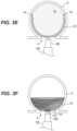
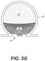
- FIG. 3 Eshows a second expanded state of the occlusive member 102 , shown in cross-section, with the embolic element 230 occupying the remaining volume of the aneurysm A.
- FIG. 3 Fshows the occlusive member 102 in full with the embolic element 230 removed so the second shape of the occlusive member 102 is visible. As shown, the embolic element 230 may be delivered until the occlusive member 102 is fully-collapsed such that the occlusive member 102 has substantially no internal volume.
- the occlusive member 102may form a bowl shape that extends across the neck of the aneurysm A.
- the wall of the occlusive member 102 at the distal portionmay now be positioned in contact with or immediately adjacent the wall of the occlusive member 102 at the proximal portion.
- the distal wall 132may be in contact with the proximal wall 134 along all or substantially all of its length. In some embodiments, the distal wall 132 may be in contact with the proximal wall 134 along only a portion of its length, while the remainder of the length of the distal wall 132 is in close proximity—but not in contact with—the proximal wall 134 .
- Collapse of the occlusive member 102 onto itself, towards the neck N of the aneurysm,may be especially beneficial as it doubles the number of layers across the neck and thus increases occlusion at the neck N.
- the distal wall 132 collapsing or inverting onto the proximal wall 134may decrease the porosity of the occlusive member 102 at the neck N.
- the occlusive member 102is a mesh or braided device such that the distal wall 132 has a first porosity and the proximal wall 134 has a second porosity
- deformation of the distal wall 132 onto or into close proximity within the proximal wall 134decreases the effective porosity of the occlusive member 102 over the neck N.
- the resulting multi-layer structurethus has a lower porosity than the individual first and second porosities.
- the embolic element 230 along the distal wall 132provides additional occlusion.
- the embolic element 230completely or substantially completely occludes the pores of the adjacent layer or wall of the occlusion member 102 such that blood cannot flow past the embolic element 230 into the aneurysm cavity. It is desirable to occlude as much of the aneurysm as possible, as leaving voids of gaps can allow blood to flow in and/or pool, which may continue to stretch out the walls of aneurysm A. Dilation of the aneurysm A can lead to recanalization and/or herniation of the occlusive member 102 and/or embolic element 230 into the parent vessel and/or may cause the aneurysm A to rupture. Both conditions can be fatal to the patient.
- the deformed or second shape of the occlusive member 102forms four layers over the neck N of the aneurysm A
- the deformed or second shape of the occlusive member 102forms two layers over the neck N of the aneurysm A
- the neck coverage provided by the doubled layersprovides additional surface area for endothelial cell growth, decreases the porosity of the occlusive member 102 at the neck N (as compared to two layers or one layer), and prevents herniation of the embolic element 230 into the parent vessel.
- the embolic element 230exerts a substantially uniform pressure on the occlusive member 102 towards the neck N of the aneurysm A, thereby pressing the portions of the occlusive member 102 positioned adjacent the neck against the inner surface of the aneurysm wall such that the occlusive member 102 forms a complete and stable seal at the neck N.
- the first coupler 112may be detached from the second coupler 114 and the elongated member 106 and second elongated shaft 108 may be withdrawn, thereby leaving the occlusive member 102 and embolic element 230 implanted within the aneurysm A.
- vascular remodeling mechanisms and/or bioabsorption of the embolic element 230may lead to formation of a thrombus and/or conversion of entrapped thrombus to fibrous tissue within the internal volume of the aneurysm A. These mechanisms also may lead to cell death at a wall of the aneurysm and growth of new endothelial cells between and over the filaments or struts of the occlusive device 102 . Eventually, the thrombus and the cells at the wall of the aneurysm may fully degrade, leaving behind a successfully remodeled region of the blood vessel.
- contrast agentcan be delivered during advancement of the occlusive member 102 and/or embolic element 230 in the vasculature, deployment of the occlusive member 102 and/or embolic element 230 at the aneurysm A, and/or after deployment of the occlusive member 102 and/or embolic element 230 prior to initiation of withdrawal of the delivery system.
- the contrast agentcan be delivered through the second elongated shaft 108 , the conduit 116 , or through another catheter or device commonly used to delivery contrast agent.
- the aneurysm (and devices therein)may be imaged before, during, and/or after injection of the contrast agent, and the images may be compared to confirm a degree of occlusion of the aneurysm.
- the system 10may comprise separate first and second elongated shafts (e.g., microcatheters) (not shown), the first dedicated to delivery of the embolic element, and the second dedicated to the delivery of the occlusive member.
- the first elongated shaftmay be intravascularly advanced to the aneurysm and through the neck such that that a distal tip of the first elongated shaft is positioned within the aneurysm cavity.
- the first elongated shaftmay be positioned within the aneurysm cavity such that the distal tip of the shaft is near the dome of the aneurysm.
- the second elongated shaft containing the occlusive member(such as occlusive member 102 ) may be intravascularly advanced to the aneurysm and positioned within the aneurysm cavity adjacent the first elongated shaft.
- the occlusive membermay then be deployed within the aneurysm sac. As the occlusive member is deployed, it pushes the first elongated shaft outwardly towards the side of the aneurysm, and when fully deployed the occlusive member holds or “jails” the first elongated shaft between an outer surface of the occlusive member and the inner surface of the aneurysm wall.
- the embolic element(such as embolic element 230 ) may then be delivered through the first elongated shaft to a position between the inner surface of the aneurysm wall and the outer surface of the occlusive member. For this reason, it may be beneficial to initially position the distal tip of the first elongated shaft near the dome (or more distal surface) of the aneurysm wall. This way, the “jailed” first elongated shaft will be secured by the occlusive member such that the embolic element gradually fills the open space in the aneurysm sac between the dome and the occlusive member.
- the filling of the embolic elementpushes and compresses the occlusive member against the tissue surrounding the aneurysm neck as the space in the sac above the occlusive member is being filled from the dome to the neck.
- the compression of the occlusive member with the embolic elementprovides a “leveling or aneurysm filling indicator” which is not provided by conventional single plane imaging methods.
- the filling of the embolic elementmay complete, for example, when it occupies about 50-80% of the volume of the aneurysm.
- FIGS. 4 A- 5 Billustrate examples of various types of fluoroscopic images that may be employed by a physician at different stages of deployment to monitor the position of the occlusive member 102 within the aneurysm A, monitor the degree of filling of the aneurysm A with the embolic element 230 , and/or confirm a degree of occlusion of the aneurysm A by the deployed system.
- the devices and systems of the present technologymay be configured to provide unique visual indicators that provide confirmation to the physician via one or more medical imaging techniques regarding a degree of occlusion of the aneurysm.
- the visual indicatorsmay include a particular change in shape of all or a portion of the occlusive member 102 , a particular change in relative position of one or more radiopaque markers on the occlusive member 102 and/or delivery system (such as the conduit 116 ), a particular change in shape of the embolic element 230 , and others.
- FIGS. 4 A- 5 Brepresent a two-dimensional image in which only a slice of the aneurysm (and devices therein) is visible. While in some cases the inner and outer layers of the occlusive member 102 (when such are present) may be distinguishable from one another in the radiographic image, in the present example the layers appear as one thick layer.
- “proper deployment” or “successful deployment”may refer to (a) complete (e.g., greater than 80%) or substantially complete (e.g., greater than 50%) filling of the aneurysm A with the embolic element 230 , (b) complete or substantially complete inversion or collapse of the occlusive member 102 onto itself over the neck N of the aneurysm A, (c) or both.
- the occlusive member 102may include one or more radiopaque markers, such as markers 402 , 404 , 406 , and 114 (referred to collectively as “markers 401 ”) shown in FIGS. 4 A- 4 C .
- the markers 401may be disposed about the occlusive member 102 in a specific spatial arrangement such that relative movement of the markers is indicative of a degree of stage of deployment of the occlusive member 102 and/or embolic element 230 .
- the markers 401may be positioned at any location along the occlusive member 102 .
- the occlusive member 102may include one or more radiopaque markers 402 at or along its distal wall 132 (only one shown for ease of illustration), one or more radiopaque markers 404 at or along its proximal wall 134 (only one shown for ease of illustration), and one or more radiopaque markers 406 at or along the intermediate portion of the wall (only one shown for ease of illustration).
- the coupler 114 of the occlusive member 102may be radiopaque.
- the markers 401may be positioned at one, some, or all of the layers of the occlusive member 102 (at least in those embodiments where the occlusive member 102 includes multiple layers).
- the individual markers 401may comprise a radiopaque band or clip coupled to the one or more struts, filaments, wires, etc. of the occlusive member 102 .
- the individual markers 401may comprise a radiopaque material coated on or otherwise incorporated into the wall of the occlusive member 102 .
- the individual markers 401may have the same or different shapes, lengths, and/or profiles.
- the occlusive member 102itself may be partially or completely formed of a radiopaque material, such as one or more radiopaque wires.
- the occlusive member 102is formed of a radiopaque material and also includes radiopaque markers 402 , 404 , 406 .
- the occlusive member 102is formed of a plurality of drawn-filled tube (“DFT”) wires, which comprise a core formed of a radiopaque material (such as platinum) surrounded by an outer non-radiopaque material (at least relative to the core material).
- DFTdrawn-filled tube
- the markers 402 , 404 , 406are completely formed of a radiopaque material and thus have a higher density of radiopaque material. As such, the markers 402 , 404 , 406 appear darker than the occlusive member 102 in the images.
- the occlusive member 102may have a radiopacity that is different than the radiopacity of one or more of the markers 402 , 404 , 406 such that the wall of the occlusive member 102 wall and the marker(s) 406 can be distinguished from one another on the radiographic image.
- the wall of the occlusive member 102may be more or less radiopaque than one or more of the markers 402 , 404 , 406 .
- one or more components of the delivery systemmay include one or more radiopaque markers.
- the conduit 116may include one or more radiopaque markers positioned along its length.
- the conduit 116may include a radiopaque marker 400 positioned at or near its distal end.
- the conduit 116may have one or more additional markers (not shown) positioned along its length, such as along the length of the conduit 116 that extends through the interior volume 130 of the occlusive member 102 .
- the radiopaque marker(s) 402 , 404 , 406 of the occlusive member 102will be in a first position relative to one another, and to the radiopaque marker(s) of the conduit 116 .
- markers 402 and 404are separated by a first distance d 1 when the occlusive member 102 is first deployed.
- the embolic element 230is conveyed through the conduit 116 and into the aneurysm sac, the occlusive member 102 may deform as described previously with respect to FIGS. 3 A- 3 G .
- This deformationcan cause the radiopaque marker(s) 401 carried by the occlusive member 102 to move to a second position relative to one another.
- the physicianmay confirm progression of deployment by observing that markers 402 and 404 are now separated by a distance d 2 .
- the radiopaque marker(s) 401may also move relative to the radiopaque marker(s) 400 of the conduit 116 , which may remain in the same or substantially the same place within the aneurysm.
- a cliniciancan visually confirm that the embolic element 230 has filled a certain percentage of the aneurysm A.
- confirmation of sufficient filling of the aneurysmmay be indicated by one or more distal wall markers 402 moving into close proximity to one or more proximal wall markers 404 and/or touching one or more proximal wall markers 404 .
- the movement of one or more distal wall markers 402 to a position adjacent a proximal wall marker 404indicates to a physician that the aneurysm A is substantially filled (e.g., 50% or greater) with the embolic element 230 .
- This relative positioningalso indicates that the distal wall 132 is now providing additional occlusion at the neck N of the aneurysm and that the occlusive member 102 is in its second expanded shape.
- the coupler 114may be used as the proximal indicator instead of or in addition to the one or more proximal markers 404 .
- confirmation of sufficient filling of the aneurysmmay be indicated by one or more distal wall markers 402 moving away from the conduit marker 400 (or marker affixed to another component of the delivery system) by a predetermined distance.
- the distal wall marker 402may be adjacent the conduit marker 400 .
- the distal wall marker 402may be separated from the conduit marker 400 by a distance that is generally equivalent to a diameter D of the occlusive member 102 in its expanded state while initially positioned in the aneurysm A.
- such relative positioning of one or more distal wall markers 402 and conduit marker 400indicates to a physician that the aneurysm A is substantially filled (e.g., 50% or greater) with the embolic element 230 .
- This relative positioningalso indicates that the distal wall 132 is now providing additional occlusion at the neck N of the aneurysm and that the occlusive member 102 is in its second expanded shape.
- one or more intermediate markers 406may be used to confirm and/or monitor deployment.
- one or more intermediate markers 406may be positioned at or near a desired inversion plane of the occlusive member 102 .
- the inversion planeis at or near a midline of the occlusive member 102 in its expanded state. This is because, in a fully inverted state, the distal half of the occlusive member 102 will lie within/conform to the proximal half of the occlusive member 102 (as shown in FIG. 4 C ).
- the midline of the occlusive member 102is the desired plane of inversion.
- the occlusive member 102may be radiopaque (as shown in FIGS. 4 A- 4 C ), but to a lesser extent than the intermediate marker(s) 406 such that the occlusive member 102 wall and the marker(s) 406 can be distinguished from one another on the radiographic image.
- an image showing the top edge 136 ( FIG. 4 C ) of the occlusive member 102 adjacent or at the intermediate marker(s) 406may indicate that the aneurysm A is substantially filled (e.g., 50% or greater) with the embolic element 230 .
- This relative positioningalso indicates that the distal wall 132 is now providing additional occlusion at the neck N of the aneurysm and that the occlusive member 102 is in its second expanded shape.
- the change in shape of the occlusive member 102 and/or change in position of different portions of the occlusive member 102 relatively to one anothermay also indicate proper deployment.
- the occlusive member 102assumes a first expanded shape when initially deployed and has a second expanded shape after deformation by the embolic element 230 .
- the second expanded shaperepresents a partially or completely inverted from of the first expanded shape, which can be confirmed on the radiographic image by observing the changing outline of the occlusive member 102 .
- an image showing a C-shapeas shown in FIG.
- the second expanded shapemay have a bowl shape.
- confirmation of complete or substantially complete deploymentmay be indicated by the distal wall 500 being within a predetermined distance of the proximal wall 502 .
- proper deploymentmay be confirmed by observing a distance between the inverted wall (here, distal wall 132 ) and the relatively stationary wall (here, proximal wall 134 ).
- a distance between the inverted wall (here, distal wall 132 ) and the relatively stationary wall (here, proximal wall 134 )As shown in FIG. 4 C , when the distal wall 132 collapses down onto or near the proximal wall 134 , the occlusive member 102 presents on the image as having twice the thickness at the proximal portion. Moreover, as the occlusive member 102 inverts, the density of the radiopaque material doubles, and thus the doubled-over portions of the occlusive member 102 appear darker on the image.
- certain portions of the occlusive member 102may be coated with a radiopaque material such that change in shape or orientation of those portions indicates a desired position of the occlusive member 102 .
- a distal-most half 500 of the occlusive member 102may be coated with a radiopaque material while a proximal-most half 502 may not be coated or may otherwise be less radiopaque than the distal half 500 .
- confirmation of complete or substantially complete deploymentmay be indicated by the more radiopaque distal wall 500 being adjacent the proximal wall 502 .
- confirmation of complete or substantially complete deploymentmay be indicated by the distal wall 500 being within a predetermined distance of the proximal wall 502 . Confirmation may also be gleaned from the distal wall 500 changing in shape from flat or convex (towards the dome) of the aneurysm A to concave.
- a shape of the embolic element 230may also provide an indication of deployment progress.
- the shape of the lower (closer to the neck N) perimeter of the aneurysm Acan be indicative of a degree of filling of the aneurysm with the embolic element 230 and/or degree of deformation of the occlusive member 102 .
- a lower boundary of the embolic element 230may have a decreasing radius of curvature as more is injected and more of the occlusive member 102 inverts. For example, in FIG.
- the distal wall 132when the aneurysm A is partially filled with the embolic element 230 and the occlusive member 102 is only partially collapsed or inverted, the distal wall 132 has a first radius of curvature.
- the distal wall 132when the aneurysm A is substantially completely or completely filled, the distal wall 132 has a radius of curvature less than the radius of curvature of the distal wall 132 in the partially deformed state.
- the degree of deployment of the occlusive member 102 and/or degree of filling of the aneurysm Acan be further determined by injecting contrast into the parent blood vessel and imaging the aneurysm to determine how much of the contrast enters the aneurysm cavity.
- the devices, systems, and methods of the present technologymay be particularly beneficial over conventional devices for two-dimensional imaging.
- the imagemay reflect only a slice or elevational view of the aneurysm (and device or substance therein).
- any voids or gaps in fillingmay not be apparent in the slice because the image slice does not transect the void within the aneurysm A, or the cross-section or elevational view of the stagnated area may take on different shapes depending on how the image is observed.
- a physicianmay have to take a plurality of images to determine a general amount of filling in the aneurysm.
- the occlusion members 102 of the present technologyhave a unique shape that dynamically adjusts to the introduction of an embolic element 230 in a predictable, measurable way that indicates a degree of filling of the embolic element 230 in a single two-dimensional radiographic image.
- the devices, systems, and methods disclosed hereininclude confirming and/or observing various stages of deployment of the system in an aneurysm, including complete or substantially complete deployment, using one, some, or all of the methods disclosed above.
- FIG. 6shows the distal portion of a treatment system 600 for treating an aneurysm in accordance with the present technology.
- the treatment system 600may be a portion of a system that also includes an embolic kit (not shown).
- the embolic kitmay be substantially the same as the embolic kit 200 described above.
- the treatment system 600may comprise an occlusive member 602 (shown in an expanded state) detachably coupled to a delivery system, and the delivery system may be configured to intravascularly position the occlusive member 602 within an aneurysm.
- the treatment system 600may be configured to deliver the embolic element (and/or one or more precursors thereof) to the aneurysm.
- the systemmay include a separate delivery system (not shown) for delivering the embolic element (and/or one or more precursors thereof) to the aneurysm cavity.
- the treatment system 600has a proximal portion (not shown) configured to be extracorporeally positioned during treatment and a distal portion 600 b configured to be intravascularly positioned within a blood vessel (such as an intracranial blood vessel) at a treatment site at or proximate an aneurysm.
- the treatment system 600may include a handle at the proximal portion, the occlusive member 602 at the distal portion 600 b , and a plurality of elongated shafts or members extending between the proximal and distal portions. In some embodiments, such as that shown in FIG.
- the treatment system 600may include a first elongated shaft (such as a guide catheter or balloon guide catheter) (not depicted), a second elongated shaft 108 (such as a microcatheter) configured to be slidably disposed within a lumen of the first elongated shaft, and an elongated member 616 configured to be slidably disposed within a lumen of the second elongated shaft 108 .
- the elongated member 616also functions as the conduit.
- the treatment system 600does not include a separate elongated member 616 and conduit.
- the treatment system 600does not include the first elongated shaft and only includes the second elongated shaft 108 .
- a distal end of the occlusive member 602may be detachably coupled to a distal end of the elongated member 616 .
- the elongated member 616may include a first coupler 612 at its distal end, and the occlusive member 602 may include a second coupler 614 configured to detachably couple with the first coupler 612 .
- the elongated member 616may be configured to deliver the embolic element (and/or one or more precursors thereof) through one or more components of the delivery system (e.g., the first or second elongated shafts 109 , 108 ) to a position at the exterior of the occlusive member 602 .
- the embolic elementmay be positioned between the occlusive member 102 and an inner wall of the aneurysm cavity, as described in greater detail below.
- the second elongated shaft 108is generally constructed to track over a conventional guidewire in the cervical anatomy and into the cerebral vessels associated with the brain and may also be chosen according to several standard designs that are generally available. Accordingly, the second elongated shaft 108 can have a length that is at least 125 cm long, and more particularly may be between about 125 cm and about 175 cm long. In some embodiments, the second elongated shaft 108 may have an inner diameter of about 0.015 inches (0.0381 cm), 0.017 inches (0.043 cm), about 0.021 inches (0.053 cm), or about 0.027 inches (0.069 cm). Other designs and dimensions are contemplated.
- the elongated member 616can be movable within the first and/or second elongated shafts to position the occlusive member 602 at a desired location.
- the elongated member 616can be sufficiently flexible to allow manipulation, e.g., advancement and/or retraction, of the occlusive member 602 through tortuous passages. Tortuous passages can include, for example, catheter lumens, microcatheter lumens, blood vessels, urinary tracts, biliary tracts, and airways.
- the elongated member 616can be formed of any material and in any dimensions suitable for the task(s) for which the system is to be employed. In some embodiments, the elongated member 616 may comprise any other suitable form of shaft such as an elongated tubular shaft.
- the elongated member 616can comprise stainless steel, nitinol, cobalt-chrome, or other metal or alloy. In some embodiments, the elongated member 616 can be surrounded over some or all of its length by a coating, such as, for example, polytetrafluoroethylene.
- the elongated member 616may have a diameter that is generally constant along its length, or the elongated member 616 may have a diameter that tapers radially inwardly, along at least a portion of its length, as it extends in a distal direction.
- the occlusive member 602may comprise an expandable element having a low-profile or constrained state while positioned within a catheter (such as the second elongated shaft 108 ) for delivery to the aneurysm and an expanded state in which the expandable element is configured to be positioned within an aneurysm (such as a cerebral aneurysm).
- the occlusive member 602may comprise a mesh formed of a plurality of braided filaments that have been heat-set to assume a predetermined shape enclosing an interior volume 130 when the mesh is in an expanded, unconstrained state.
- Example shapesinclude a globular shape, such as a sphere, a prolate spheroid, an oblate spheroid, and others.
- the meshmay have inner and outer layers 622 , 624 that have distal ends fixed relative to one another at the second coupler 614 and meet distally at a proximal fold 628 surrounding a proximal aperture 626 . While the inner and outer layers 622 , 624 are depicted spaced apart from one another along their lengths, the inner and outer layers 622 , 624 may be in contact with one another along all or a portion of their lengths. For example, the inner layer 622 may press radially outwardly against the outer layer 624 .
- the occlusive member 602may be formed of a single layer or mesh or braid.
- the elongated shaft 616may be configured to be slidably positioned through some or all of the second coupler 614 , the interior volume 130 of the expanded mesh, and the opening 626 . Because the occlusive member 602 is coupled to the elongated shaft 616 at its distal end (e.g., via the first and second couplers 612 , 614 ), axial movement of the elongated shaft 616 causes axial movement of at least the distal portion of the occlusive member 602 . The proximal portion of the occlusive member 602 remains free to slide along the elongated shaft 616 via the proximal aperture 626 .
- the occlusive member 602when the occlusive member 602 is loaded in the elongated member 616 , the occlusive member 602 is positioned around the elongated member 616 , between the elongated member 616 and the second elongated shaft 108 .
- the inner and outer layers 622 and 624may conform to one another at the distal portion (for example as shown in FIG. 5 ) to form a curved distal surface.
- the inner and outer layers 622 and 624may extend distally and radially inwardly, towards the aperture 626 .
- the outer and/or inner layers 622 and 624extend distally and radially outwardly from the fold 628 at the aperture 626 , then extend distally and radially inwardly up to ridge, then proximally to the second coupler 614 to create a detent or recess 604 at the distal end of the occlusive member 602 .
- the distal surface of the occlusive member 602may be concave towards the dome of the aneurysm.
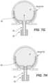
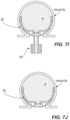
- the distal recess 604may be beneficial for delivering the embolic element 230 in that it creates a small gap between the distal surface of the occlusive member 602 and the dome of the aneurysm A (see, for example, FIG. 7 B ).
- the occlusive member 602 and/or layers thereofmay be curved along its entire length, or may have one or more generally straight portions.
- the curved surfacetransitions to a flat or substantially flat, distal-most surface that surrounds the aperture 626 .
- the curved surfacetransitions to a distal-most surface that surrounds the aperture 626 and has a radius of curvature that is greater than the average radius of curvature of the rest of the occlusive member 602 .
- Having a flat or substantially flat distal surface, or a distal surface with a radius of curvature that is greater than the average radius of curvature of the rest of the occlusive member 602may be beneficial for delivering the embolic element 230 in that it creates a small gap between the distal surface of the occlusive member 602 and the dome of the aneurysm A.
- the surface of the occlusive member 602 surrounding the aperture 626is curved and/or has generally the same radius of curvature as the remainder of the occlusive member 602 .
- the inner layer 624may have a shape that substantially conforms to the shape of the outer layer 624 , or the inner and outer layers 622 , 624 may have different shapes.
- the inner layer 622may have a diameter or cross-sectional dimension that is less than the outer layer 624 (for example, as shown in FIG. 1 D ).
- Such a configurationmay be beneficial in that the embolic element 230 experiences less resistance, at least initially, when pushing the distal wall of the occlusion member 602 downwardly towards the neck (as described in greater detail below).
- both the proximal portion and the distal portion of the meshcan form generally closed surfaces.
- the portion of the filaments at or near the fold 628 at the proximal portion of the meshcan move relative to one another.
- the distal portion of the meshhas both the properties of a closed end and also some properties of an open end (like a traditional stent), such as some freedom of movement of the proximal-most portions of the filaments and an opening through which the elongated shaft 616 , a guidewire, guidetube, or other elongated member may pass through.
- each of the plurality of filamentshave a first end positioned at the distal portion of the mesh and a second end also positioned at the distal portion of the mesh (for example, at the second coupler 614 ).
- Each of the filamentsmay extend from its corresponding first end distally to ridge, then proximally along the body of the mesh to the fold 628 , invert, then extend distally along the mesh body to the ridge, then proximally to its corresponding second end at the distal portion of the mesh.
- each of the plurality of filamentshave a first length that forms the inner layer 622 of the mesh, a second length that forms the outer layer 624 of the mesh, and both first and second ends fixed at the distal portion of the mesh.
- the occlusive member 602may comprise a mesh formed of a single layer, or a mesh formed of three or more layers.
- the proximal and/or distal end surface of the meshis completely closed (i.e., does not include an aperture).
- the filamentsare fixed relative to the at both the proximal and distal ends of the occlusive member 602 and the elongated member 616 is configured to be slidably disposed through each of the proximal and distal hubs.
- the occlusive member 602 and/or meshmay include a preferential bending region 604 at which the occlusive member 602 and/or mesh is configured to preferentially flex or bend when subject to inverting forces (such as that exerted by the embolic element 230 , as described in greater detail below).
- the bending region 604may form a continuous band around the circumference of the occlusive member 602 , or it may be at select locations about the circumference of the occlusive member 602 , all located at generally the same axial location along the mesh. In those embodiments in which the occlusive member 602 comprises multiple layers, none, some, or all of the layers may include the bending region 604 .
- the bending region 604may comprise, for example, a thinned portion of the mesh that is generally weaker than the surrounding portions and thus more likely to bend under stress.
- the bending region 604may also be formed by heat setting the mesh in the inverted or collapsed state such that the mesh preferentially inverts at the desired level.
- the mesh forming the occlusive member 602may be formed of metal wires, polymer wires, or both, and the wires may have shape memory and/or superelastic properties.
- the meshmay be formed of 24, 32, 36, 48, 64, 72, 96, 128, or 144 filaments.
- the meshmay be formed of a range of filament or wire sizes, such as wires having a diameter of from about 0.0004 inches to about 0.0020 inches, or of from about 0.0009 inches to about 0.0012 inches.
- each of the wires or filamentshave a diameter of about 0.0004 inches, about 0.0005 inches, about 0.0006 inches, about 0.0007 inches, about 0.0008 inches, about 0.0009 inches, about 0.001 inches, about 0.0011 inches, about 0.0012 inches, about 0.0013 inches, about 0.0014 inches, about 0.0015 inches, about 0.0016 inches, about 0.0017 inches, about 0.0018 inches, about 0.0019 inches, or about 0.0020 inches.
- all of the filaments of the braided meshmay have the same diameter.
- all of the filamentshave a diameter of about 0.001 inches.
- some of the filamentsmay have different cross-sectional diameters.
- some of the filamentsmay have a slightly thicker diameter to impart additional strength to the braided layers.
- some of the filamentscan have a diameter of about 0.001 inches, and some of the filaments can have a diameter of greater than 0.001 inches.
- the thicker filamentsmay impart greater strength to the braid without significantly increasing the device delivery profile, with the thinner wires offering some strength while filling-out the braid matrix density.
- the occlusive member 602can have different shapes and sizes in an expanded, unconstrained state.
- the occlusive member 602may have a bullet shape, a barrel-shape, an egg shape, a dreidel shape, a bowl shape, a disc shape, a cylindrical or substantially cylindrical shape, a barrel shape, a chalice shape, etc.
- the embolic kit for use with the treatment system shown in FIGS. 6 - 7 Jmay be substantially similar to the embolic kit 200 described above.
- FIGS. 7 A- 7 Jdepict an example method of treating an aneurysm with the treatment systems of the present technology.
- a physicianmay intravascularly advance the second elongated shaft 108 towards an intracranial aneurysm (or other treatment location such as any of those described herein) with the occlusive member 602 in a low-profile state.
- the second elongated shaft 108may be positioned at or just proximal of the neck.
- a distal portion of the second elongated shaft 108may be advanced through a neck N of the aneurysm A to locate a distal opening of the second elongated shaft 108 within an interior cavity of the aneurysm A.
- the elongated member 616may be advanced distally through the neck N and into the aneurysm cavity (if not already in the aneurysm cavity), thereby pulling the distal end of the occlusive member 602 with it.
- the occlusive member 602expands towards the first expanded state, as shown in FIG. 7 B .
- the occlusive member 602may assume a predetermined shape that encloses an internal volume 130 .
- the occlusive member 602may generally conform to the shape of the aneurysm A.
- the physicianmay pull the elongated member 616 proximally to check the positioning of the occlusive member 602 in the aneurysm A. As depicted in FIGS. 7 B and 7 C , for example, the elongated member 616 may be pulled proximally to force the distal wall towards the neck N and proximal wall. Because of the bending region(s) 603 , the occlusive member 602 may preferentially fold and develop a distal edge at the bending regions 603 .
- the ability to check the position of the occlusive member 602 in its collapsed state before delivering the embolic element 230may be beneficial, especially in wide-necked aneurysms, as the initial approach into the aneurysm may be too steep such that the distal edge 136 (see FIG. 7 C ), once the occlusive member 602 is fully collapsed or inverted, is near or aligned with the neck of the aneurysm A. In those cases, the occlusive member 602 may not fully cover the neck N, and thus will not be sufficiently anchored in the aneurysm A. It will be appreciated that the elongated member 616 may be used to check the positioning of the occlusive member 602 even in those embodiments where the occlusive member 602 does not have a bending region 603 .
- the embolic element 230may be delivered through the elongated member 616 to a space between the occlusive member 602 and an inner surface of the aneurysm wall W.
- the methodincludes mixing the first and second precursor materials 203 , 205 ( FIG. 2 ) to form the embolic element 230 . Mixing of the first and second precursor materials 203 , 205 may occur prior to introducing the embolic element 230 to the treatment system 100 and/or during delivery of the embolic element through the elongated member 616 to the aneurysm.
- the first precursor material 203is loaded into one of the barrels 214
- the second precursor materials 205is loaded into the other barrel 214
- the mixing syringes 208are coupled via the coupler 210 .
- the plungers 212are alternately depressed, thereby causing the first and second precursor materials 203 , 205 to move repeatedly from one barrel 214 to the other barrel 214 .
- the resulting embolic element 230can be loaded into the barrel 220 of the injection syringe 216 .
- the injection syringe 216may then be coupled to a proximal end of the elongated member 616 to deliver the embolic element 230 through the elongated member 616 and into the aneurysm A. As the embolic element 230 passes through the lumen of the elongated member 616 , chemical crosslinking of the biopolymer can continue to occur.
- the embolic element 230As the embolic element 230 is delivered between the dome of the aneurysm A and the distal portion of the wall of the occlusive member 602 , pressure builds between the aneurysm wall W and the occlusive member 602 . When the forces on the occlusive member 602 reach a threshold level, the embolic element 230 pushes the distal wall downwardly towards the neck N of the aneurysm A. If desired, the elongated member 616 may be pulled proximally while the embolic element 230 is delivered and/or between different injections of the embolic element 230 , which encourages inversion of the occlusive member 602 .
- the embolic element 230exerts a substantially uniform pressure across the distal surface of the occlusive member 602 that collapses the occlusive member 602 inwardly on itself (with or without the help of the elongated member 616 ).
- the pressure and inversion of the distal portion of the wallcreates an annular fold 136 that defines the distal-most edge of the occlusive member 602 .
- the occlusive member 602continues to invert, the position of the fold moves towards the neck N, which continues until a distal-most half of the occlusive member 602 has inverted.
- the elongated member 616may be held stationary, advanced distally, and/or retracted proximally.
- none or substantially none of the embolic element 230migrates through the pores of the occlusive member 602 and into the internal volume 130 . Said another way, all or substantially all of the embolic element 230 remains at the exterior surface or outside of the occlusive member 602 . Compression of the occlusive member with the embolic element 230 provides a real-time “leveling” or “aneurysm-filling indicator” to the physician under single plane imaging methods (such as fluoroscopy) so that the physician can confirm at what point the volume of the aneurysm is completely filled. Additional details regarding devices, systems, and methods for monitoring and/or confirming deployment are described above with reference to FIGS.
- the embolic element 230may fill greater than 40% of the aneurysm sac volume. In some embodiments, the embolic element 230 may fill greater than 50% of the aneurysm sac volume. In some embodiments, the embolic element 230 may fill greater than 60% of the aneurysm sac volume. In some embodiments, the embolic element may fill greater than 65%, 70%, 75%, 80%, 85%, or 90% of the aneurysm sac volume.
- FIG. 7 Ishows a second expanded state of the occlusive member 602 , shown in cross-section, with the embolic element 230 occupying the remaining volume of the aneurysm A.
- the embolic element 230may be delivered until the occlusive member 602 is fully-collapsed such that the occlusive member 602 has substantially no internal volume.
- the occlusive member 602may form a bowl shape that extends across the neck of the aneurysm A.
- the wall of the occlusive member 602 at the distal portionmay now be positioned in contact with or immediately adjacent the wall of the occlusive member 602 at the proximal portion.
- a small gapmay remain between portions of the distal wall and the proximal wall when the occlusive member 602 is in its second or collapsed state.
- Collapse of the occlusive member 602 onto itself, towards the neck N of the aneurysm,may be especially beneficial as it doubles the number of layers across the neck and thus increases occlusion at the neck N.
- the distal wall 132 collapsing or inverting onto the proximal wallmay decrease the porosity of the occlusive member 602 at the neck N.
- the occlusive member 602is a mesh or braided device such that the distal wall has a first porosity and the proximal wall has a second porosity
- deformation of the distal wall onto or into close proximity within the proximal walldecreases the effective porosity of the occlusive member 602 over the neck N.
- the resulting multi-layer structurethus has a lower porosity than the individual first and second porosities.
- the embolic element 230 along the distal wallprovides additional occlusion.
- the embolic element 230completely or substantially completely occludes the pores of the adjacent layer or wall of the occlusion member 602 such that blood cannot flow past the embolic element 230 into the aneurysm cavity. It is desirable to occlude as much of the aneurysm as possible, as leaving voids of gaps can allow blood to flow in and/or pool, which may continue to stretch out the walls of aneurysm A.
- Dilation of the aneurysm Acan lead to recanalization and/or herniation of the occlusive member 602 and/or embolic element 230 into the parent vessel and/or may cause the aneurysm A to rupture. Both conditions can be fatal to the patient.
- the deformed or second shape of the occlusive member 602forms four layers over the neck N of the aneurysm A
- the deformed or second shape of the occlusive member 602forms two layers over the neck N of the aneurysm A
- the neck coverage provided by the doubled layersprovides additional surface area for endothelial cell growth, decreases the porosity of the occlusive member 602 at the neck N (as compared to two layers or one layer), and prevents herniation of the embolic element 230 into the parent vessel.
- the embolic element 230exerts a substantially uniform pressure on the occlusive member 602 towards the neck N of the aneurysm A, thereby pressing the portions of the occlusive member 602 positioned adjacent the neck against the inner surface of the aneurysm wall such that the occlusive member 602 forms a complete and stable seal at the neck N.
- the elongated member 616may be moved proximally and distally to move the distal wall of the occlusive member 602 to re-distribute the embolic element 230 around the occlusive member 602 and the aneurysm wall.
- the occlusive member 602will be locked and prevent migration after treatment. In this case, the occlusive member 602 may not need to fill the sac completely.
- the first coupler 612may be detached from the second coupler 614 and the elongated member 616 and second elongated shaft 108 may be withdrawn, thereby leaving the occlusive member 602 and embolic element 230 implanted within the aneurysm A.
- Over time natural vascular remodeling mechanisms and/or bioabsorption of the embolic element 230may lead to formation of a thrombus and/or conversion of entrapped thrombus to fibrous tissue within the internal volume of the aneurysm A. These mechanisms also may lead to cell death at a wall of the aneurysm and growth of new endothelial cells between and over the filaments or struts of the occlusive device 602 . Eventually, the thrombus and the cells at the wall of the aneurysm may fully degrade, leaving behind a successfully remodeled region of the blood vessel.
- contrast agentcan be delivered during advancement of the occlusive member 602 and/or embolic element 230 in the vasculature, deployment of the occlusive member 602 and/or embolic element 230 at the aneurysm A, and/or after deployment of the occlusive member 602 and/or embolic element 230 prior to initiation of withdrawal of the delivery system.
- the contrast agentcan be delivered through the second elongated shaft 108 , the elongated member 616 , or through another catheter or device commonly used to delivery contrast agent.
- the aneurysm (and devices therein)may be imaged before, during, and/or after injection of the contrast agent, and the images may be compared to confirm a degree of occlusion of the aneurysm.
Landscapes
- Health & Medical Sciences (AREA)
- Surgery (AREA)
- Life Sciences & Earth Sciences (AREA)
- Engineering & Computer Science (AREA)
- Heart & Thoracic Surgery (AREA)
- Animal Behavior & Ethology (AREA)
- Vascular Medicine (AREA)
- Biomedical Technology (AREA)
- Reproductive Health (AREA)
- Medical Informatics (AREA)
- Molecular Biology (AREA)
- Nuclear Medicine, Radiotherapy & Molecular Imaging (AREA)
- General Health & Medical Sciences (AREA)
- Public Health (AREA)
- Veterinary Medicine (AREA)
- Neurosurgery (AREA)
- Surgical Instruments (AREA)
- Mechanical Engineering (AREA)
Abstract
Description
- positioning a distal end of an elongated shaft in an aneurysm cavity;
- releasing an occlusive member from the elongated shaft while the distal end of the elongated shaft is positioned within the aneurysm cavity such that the occlusive member self-expands to assume a first expanded state in which the occlusive member forms a first shape, wherein, in the first expanded state, the occlusive member encloses an interior region having a first interior volume; and
- delivering an embolic element between the occlusive member and the aneurysm wall to transform the occlusive member into a second expanded state in which the occlusive member defines a second interior volume less than the first interior volume, wherein the occlusive member forms a second shape in the second expanded state that is different than the first shape in the first expanded state.
- the biopolymer includes chitosan, a derivative of chitosan, an analog of chitosan, or a combination thereof;
- the chemical crosslinking agent includes genipin, a derivative of genipin, an analog of genipin, or a combination thereof; and
- the physical crosslinking agent includes β glycerophosphate, a derivative of β glycerophosphate, an analog of β glycerophosphate, or a combination thereof.
- aneurysm, wherein in the initial expanded state the expandable occlusive member
- provides a number of layers across a neck of the aneurysm; and doubling the number of layers of the occlusive device across the neck of the aneurysm by
- introducing an embolic element to the aneurysm cavity.
- acquiring a first image visualizing:
- an occlusive member positioned within an aneurysm, the occlusive member including a first radiopaque marker; and
- a conduit having a distal portion positioned within an aneurysm, the distal portion of the conduit including a second radiopaque marker; and
- acquiring a second image in which the first radiopaque marker is further from the second radiopaque marker than in the first image.
- acquiring a first image visualizing:
- positioning a distal end of an elongated shaft at or near an aneurysm cavity, the distal end of the shaft containing an occlusive member detachably coupled to an elongated member slidably disposed within the elongated shaft, wherein a distal end of the occlusive member is coupled to a distal end of the elongated member and a proximal end of the occlusive member is slidable over the elongated member;
- pushing the elongated member distally from a distal opening in the elongated shaft to pull a distal end of the occlusive member distally through the distal opening to expel the occlusive member from the shaft and allow the occlusive member to self-expand to a first expanded state;
- while the occlusive member is in the first expanded state, pulling the elongated member proximally to bring a distal wall of the occlusive member towards a proximal wall of the occlusive member such that the occlusive member forms a second expanded state in which at least a portion of the occlusive member is inverted; and
- delivering an embolic element through the elongated member to a position between the occlusive member and the aneurysm wall.
- positioning a distal end of an elongated shaft at or near an aneurysm cavity, the distal end of the shaft containing an occlusive member detachably coupled to an elongated member slidably disposed within the elongated shaft, wherein a distal end of the occlusive member is coupled to a distal end of the elongated member and a proximal end of the occlusive member is slidable over the elongated member;
- pushing the elongated member distally from a distal opening in the elongated shaft to pull a distal end of the occlusive member distally through the distal opening to expel the occlusive member from the shaft and allow the occlusive member to self-expand to a first expanded state; and
- while the occlusive member is in the first expanded state, pulling the elongated member proximally to bring a distal wall of the occlusive member towards a proximal wall of the occlusive member such that the occlusive member forms a second expanded state in which the occlusive member is collapsed on itself.
- an elongate shaft defining a lumen;
- an elongate member slidably disposed within the lumen of the elongate shaft, the elongate member having a proximal end region and a distal end region, wherein the distal end region is configured to be intravascularly position at or within an aneurysm cavity;
- an occlusive member constrained within the lumen of the shaft, the occlusive member including a proximal end portion having an opening and a distal end portion detachably coupled to the distal end region of the elongate member, wherein the elongate member extends through the opening such that the
- wherein pushing the elongate member from a distal opening in the elongate shaft pulls the occlusive member distally through the distal opening to expel the occlusive member from the shaft and allow the occlusive member to expand to an expanded state.
- positioning a distal end of an elongate shaft at or near an aneurysm cavity, the distal end of the shaft containing an occlusive member detachably coupled to an elongated member slidably disposed within the elongated shaft, wherein a distal end of the occlusive member is coupled to a distal end of the elongate member and a proximal end of the occlusive member is slidable over the elongate member;
- pushing the elongate member distally from a distal opening in the elongate shaft to pull a distal end of the occlusive member distally through the distal opening to expel the occlusive member from the shaft and allow the occlusive member to self-expand to a first expanded state;
- while the occlusive member is in the first expanded state, pulling the elongate member proximally to bring a distal wall of the occlusive member towards a proximal wall of the occlusive member such that the occlusive member forms a second expanded state in which at least a portion of the occlusive member is inverted; and
- delivering an embolic element through the elongate member to a position between the occlusive member and the aneurysm wall.
- positioning a distal end portion of an elongated shaft at or near an aneurysm cavity, the distal end portion of the shaft containing an occlusive member detachably coupled to an elongated member slidably disposed within the elongated shaft, wherein a distal end region of the occlusive member is coupled to a distal end of the elongated member;
- expanding the occlusive member within the aneurysm cavity;
- pulling the elongate member proximally, thereby causing a first portion of the occlusive member to invert onto a second portion of the occlusive member, wherein the first and second portions meet at a circumferential fold;
- pushing the elongate member distally, thereby causing the second portion to move away from the first portion and at least partially reversing the inversion of the occlusive member; and
- delivering an embolic element through the elongate member to a space between a distal wall of the occlusive member and a wall of the aneurysm.
Claims (18)
Priority Applications (1)
| Application Number | Priority Date | Filing Date | Title |
|---|---|---|---|
| US16/949,568US11633818B2 (en) | 2019-11-04 | 2020-11-03 | Devices, systems, and methods for treatment of intracranial aneurysms |
Applications Claiming Priority (7)
| Application Number | Priority Date | Filing Date | Title |
|---|---|---|---|
| US201962930303P | 2019-11-04 | 2019-11-04 | |
| US201962930324P | 2019-11-04 | 2019-11-04 | |
| US201962930333P | 2019-11-04 | 2019-11-04 | |
| US201962930421P | 2019-11-04 | 2019-11-04 | |
| US201962930357P | 2019-11-04 | 2019-11-04 | |
| US201962930487P | 2019-11-04 | 2019-11-04 | |
| US16/949,568US11633818B2 (en) | 2019-11-04 | 2020-11-03 | Devices, systems, and methods for treatment of intracranial aneurysms |
Publications (3)
| Publication Number | Publication Date |
|---|---|
| US20210128162A1 US20210128162A1 (en) | 2021-05-06 |
| US20220304696A2 US20220304696A2 (en) | 2022-09-29 |
| US11633818B2true US11633818B2 (en) | 2023-04-25 |
Family
ID=73599027
Family Applications (17)
| Application Number | Title | Priority Date | Filing Date |
|---|---|---|---|
| US16/949,566ActiveUS11504816B2 (en) | 2019-11-04 | 2020-11-03 | Systems and methods for treating aneurysms |
| US16/949,567ActiveUS11685007B2 (en) | 2019-11-04 | 2020-11-03 | Devices, systems, and methods for treatment of intracranial aneurysms |
| US16/949,565ActiveUS11541490B2 (en) | 2019-11-04 | 2020-11-03 | Aneurysm treatment device |
| US16/949,561ActiveUS11826863B2 (en) | 2019-11-04 | 2020-11-03 | Systems and methods for treating aneurysms |
| US16/949,564Active2040-11-20US11305387B2 (en) | 2019-11-04 | 2020-11-03 | Systems and methods for treating aneurysms |
| US16/949,563ActiveUS11498165B2 (en) | 2019-11-04 | 2020-11-03 | Systems and methods for treating aneurysms |
| US16/949,570Active2041-09-16US11679458B2 (en) | 2019-11-04 | 2020-11-03 | Devices, systems, and methods for treating aneurysms |
| US16/949,568ActiveUS11633818B2 (en) | 2019-11-04 | 2020-11-03 | Devices, systems, and methods for treatment of intracranial aneurysms |
| US16/949,569Active2041-10-09US11717924B2 (en) | 2019-11-04 | 2020-11-03 | Devices, systems, and methods for treatment of intracranial aneurysms |
| US17/938,143Active2041-07-13US12251110B2 (en) | 2019-11-04 | 2022-10-05 | Systems and methods for treating aneurysms |
| US18/313,530ActiveUS12295582B2 (en) | 2019-11-04 | 2023-05-08 | Devices, systems, and methods for treating aneurysms |
| US18/324,017ActiveUS12256936B2 (en) | 2019-11-04 | 2023-05-25 | Devices, systems, and methods for treatment of intracranial aneurysms |
| US18/334,917PendingUS20230373040A1 (en) | 2019-11-04 | 2023-06-14 | Devices, systems, and methods for treatment of intracranial aneurysms |
| US18/505,645PendingUS20240075565A1 (en) | 2019-11-04 | 2023-11-09 | Systems and methods for treating aneurysms |
| US19/040,623PendingUS20250169824A1 (en) | 2019-11-04 | 2025-01-29 | Devices, systems, and methods for treatment of intracranial aneurysms |
| US19/070,997PendingUS20250195077A1 (en) | 2019-11-04 | 2025-03-05 | Systems and methods for treating aneurysms |
| US19/180,564PendingUS20250241649A1 (en) | 2019-11-04 | 2025-04-16 | Devices, systems, and methods for treating aneurysms |
Family Applications Before (7)
| Application Number | Title | Priority Date | Filing Date |
|---|---|---|---|
| US16/949,566ActiveUS11504816B2 (en) | 2019-11-04 | 2020-11-03 | Systems and methods for treating aneurysms |
| US16/949,567ActiveUS11685007B2 (en) | 2019-11-04 | 2020-11-03 | Devices, systems, and methods for treatment of intracranial aneurysms |
| US16/949,565ActiveUS11541490B2 (en) | 2019-11-04 | 2020-11-03 | Aneurysm treatment device |
| US16/949,561ActiveUS11826863B2 (en) | 2019-11-04 | 2020-11-03 | Systems and methods for treating aneurysms |
| US16/949,564Active2040-11-20US11305387B2 (en) | 2019-11-04 | 2020-11-03 | Systems and methods for treating aneurysms |
| US16/949,563ActiveUS11498165B2 (en) | 2019-11-04 | 2020-11-03 | Systems and methods for treating aneurysms |
| US16/949,570Active2041-09-16US11679458B2 (en) | 2019-11-04 | 2020-11-03 | Devices, systems, and methods for treating aneurysms |
Family Applications After (9)
| Application Number | Title | Priority Date | Filing Date |
|---|---|---|---|
| US16/949,569Active2041-10-09US11717924B2 (en) | 2019-11-04 | 2020-11-03 | Devices, systems, and methods for treatment of intracranial aneurysms |
| US17/938,143Active2041-07-13US12251110B2 (en) | 2019-11-04 | 2022-10-05 | Systems and methods for treating aneurysms |
| US18/313,530ActiveUS12295582B2 (en) | 2019-11-04 | 2023-05-08 | Devices, systems, and methods for treating aneurysms |
| US18/324,017ActiveUS12256936B2 (en) | 2019-11-04 | 2023-05-25 | Devices, systems, and methods for treatment of intracranial aneurysms |
| US18/334,917PendingUS20230373040A1 (en) | 2019-11-04 | 2023-06-14 | Devices, systems, and methods for treatment of intracranial aneurysms |
| US18/505,645PendingUS20240075565A1 (en) | 2019-11-04 | 2023-11-09 | Systems and methods for treating aneurysms |
| US19/040,623PendingUS20250169824A1 (en) | 2019-11-04 | 2025-01-29 | Devices, systems, and methods for treatment of intracranial aneurysms |
| US19/070,997PendingUS20250195077A1 (en) | 2019-11-04 | 2025-03-05 | Systems and methods for treating aneurysms |
| US19/180,564PendingUS20250241649A1 (en) | 2019-11-04 | 2025-04-16 | Devices, systems, and methods for treating aneurysms |
Country Status (4)
| Country | Link |
|---|---|
| US (17) | US11504816B2 (en) |
| EP (3) | EP4054439B1 (en) |
| CN (3) | CN114615943A (en) |
| WO (3) | WO2021092618A1 (en) |
Families Citing this family (32)
| Publication number | Priority date | Publication date | Assignee | Title |
|---|---|---|---|---|
| US12004750B2 (en) | 2008-05-01 | 2024-06-11 | Aneuclose Llc | Methods for creating an expandable two-part intrasacular aneurysm occlusion device from a tubular mesh |
| US11357511B2 (en) | 2008-05-01 | 2022-06-14 | Aneuclose Llc | Intrasacular aneurysm occlusion device with globular first configuration and bowl-shaped second configuration |
| US11583289B2 (en) | 2008-05-01 | 2023-02-21 | Aneuclose Llc | Aneurysm-occluding mesh ribbon with a series of loops or segments having distal-to-proximal variation in size, shape, and/or orientation |
| US11471164B2 (en) | 2008-05-01 | 2022-10-18 | Aneuclose Llc | Methods of occluding a cerebral aneurysm by inserting embolic members or material into an intrasacular implant |
| AU2009242528B2 (en) | 2008-05-02 | 2015-12-10 | Microvention, Inc. | Filamentary devices for treatment of vascular defects |
| US10327781B2 (en) | 2012-11-13 | 2019-06-25 | Covidien Lp | Occlusive devices |
| US9955976B2 (en) | 2013-08-16 | 2018-05-01 | Sequent Medical, Inc. | Filamentary devices for treatment of vascular defects |
| US10130372B2 (en) | 2014-04-30 | 2018-11-20 | Cerus Endovascular Limited | Occlusion Device |
| EP4011303B1 (en) | 2015-12-07 | 2024-06-12 | Cerus Endovascular Limited | Occlusion device |
| WO2017153603A1 (en) | 2016-03-11 | 2017-09-14 | Cerus Endovascular Limited | Occlusion device |
| US10576099B2 (en) | 2016-10-21 | 2020-03-03 | Covidien Lp | Injectable scaffold for treatment of intracranial aneurysms and related technology |
| JP7414710B2 (en) | 2017-08-21 | 2024-01-16 | シーラス エンドバスキュラー リミテッド | occlusion device |
| US11559309B2 (en) | 2019-03-15 | 2023-01-24 | Sequent Medical, Inc. | Filamentary devices for treatment of vascular defects |
| US12102327B2 (en) | 2019-05-25 | 2024-10-01 | Galaxy Therapeutics, Inc. | Systems and methods for treating aneurysms |
| US11202636B2 (en) | 2019-05-25 | 2021-12-21 | Galaxy Therapeutics Inc. | Systems and methods for treating aneurysms |
| WO2021092618A1 (en) | 2019-11-04 | 2021-05-14 | Covidien Lp | Devices, systems, and methods for treatment of intracranial aneurysms |
| DE102020118301A1 (en)* | 2019-12-23 | 2021-06-24 | Femtos Gmbh | Implant for the treatment of aneurysms |
| US11406404B2 (en) | 2020-02-20 | 2022-08-09 | Cerus Endovascular Limited | Clot removal distal protection methods |
| US12023034B2 (en) | 2020-03-11 | 2024-07-02 | Microvention, Inc. | Devices for treatment of vascular defects |
| US20210282789A1 (en) | 2020-03-11 | 2021-09-16 | Microvention, Inc. | Multiple layer devices for treatment of vascular defects |
| US12070220B2 (en) | 2020-03-11 | 2024-08-27 | Microvention, Inc. | Devices having multiple permeable shells for treatment of vascular defects |
| WO2022164957A1 (en) | 2021-01-27 | 2022-08-04 | Galaxy Therapeutics, Inc. | Systems and methods for treating aneurysms |
| EP4308013A1 (en) | 2021-03-16 | 2024-01-24 | Covidien LP | Injectable biopolymer compositions and associated systems and methods |
| WO2023012223A1 (en)* | 2021-08-04 | 2023-02-09 | Surgmark Gmbh | Tissue marker |
| WO2023215225A1 (en)* | 2022-05-02 | 2023-11-09 | Microvention, Inc. | Devices for treatment of vascular defects |
| US20240032932A1 (en)* | 2022-07-29 | 2024-02-01 | Covidien Lp | Devices, systems, and methods for treating aneurysms |
| US12070221B2 (en)* | 2022-07-30 | 2024-08-27 | Covidien Lp | Devices, systems, and methods for treating aneurysms |
| WO2024046551A1 (en)* | 2022-08-31 | 2024-03-07 | Clearstream Technologies Limited | Avp device with lobe/segment designed to fill aneurysm sac |
| EP4615340A1 (en)* | 2022-11-09 | 2025-09-17 | Microvention, Inc. | Devices for treatment of vascular defects |
| CN120052997A (en)* | 2023-11-29 | 2025-05-30 | 赛诺神畅医疗科技有限公司 | Aneurysm plugging device and system for plugging aneurysms |
| CN120324055A (en)* | 2024-01-18 | 2025-07-18 | 赛诺神畅医疗科技有限公司 | Aneurysm occlusion device and system for occluding aneurysm |
| CN118750076B (en)* | 2024-07-01 | 2025-03-11 | 上海形状记忆合金材料有限公司 | An occluder |
Citations (408)
| Publication number | Priority date | Publication date | Assignee | Title |
|---|---|---|---|---|
| US5041090A (en) | 1988-01-12 | 1991-08-20 | Scheglov Viktor I | Occluding device |
| US5250071A (en) | 1992-09-22 | 1993-10-05 | Target Therapeutics, Inc. | Detachable embolic coil assembly using interlocking clasps and method of use |
| US5261916A (en) | 1991-12-12 | 1993-11-16 | Target Therapeutics | Detachable pusher-vasoocclusive coil assembly with interlocking ball and keyway coupling |
| US5284488A (en) | 1992-12-23 | 1994-02-08 | Sideris Eleftherios B | Adjustable devices for the occlusion of cardiac defects |
| WO1994006502A2 (en) | 1992-09-22 | 1994-03-31 | Target Therapeutics, Inc. | Detachable embolic coil assembly |
| US5326350A (en) | 1992-05-11 | 1994-07-05 | Li Shu Tung | Soft tissue closure systems |
| US5354295A (en) | 1990-03-13 | 1994-10-11 | Target Therapeutics, Inc. | In an endovascular electrolytically detachable wire and tip for the formation of thrombus in arteries, veins, aneurysms, vascular malformations and arteriovenous fistulas |
| US5405379A (en) | 1990-07-26 | 1995-04-11 | Lane; Rodney J. | Self expanding vascular endoprosthesis for aneurysms |
| US5417708A (en) | 1994-03-09 | 1995-05-23 | Cook Incorporated | Intravascular treatment system and percutaneous release mechanism therefor |
| EP0717969A2 (en) | 1994-12-22 | 1996-06-26 | Target Therapeutics, Inc. | Implant delivery assembly with expandable coupling/decoupling mechanism |
| US5601600A (en) | 1995-09-08 | 1997-02-11 | Conceptus, Inc. | Endoluminal coil delivery system having a mechanical release mechanism |
| US5645558A (en) | 1995-04-20 | 1997-07-08 | Medical University Of South Carolina | Anatomically shaped vasoocclusive device and method of making the same |
| US5669931A (en) | 1995-03-30 | 1997-09-23 | Target Therapeutics, Inc. | Liquid coils with secondary shape |
| US5725552A (en) | 1994-07-08 | 1998-03-10 | Aga Medical Corporation | Percutaneous catheter directed intravascular occlusion devices |
| US5733294A (en) | 1996-02-28 | 1998-03-31 | B. Braun Medical, Inc. | Self expanding cardiovascular occlusion device, method of using and method of making the same |
| US5741333A (en) | 1995-04-12 | 1998-04-21 | Corvita Corporation | Self-expanding stent for a medical device to be introduced into a cavity of a body |
| US5749919A (en) | 1994-01-10 | 1998-05-12 | Microfil Industries S.A. | Resilient prosthesis for widening a channel, particularly a blood vessel, and method for making same |
| US5749895A (en) | 1991-02-13 | 1998-05-12 | Fusion Medical Technologies, Inc. | Method for bonding or fusion of biological tissue and material |
| US5749891A (en) | 1995-06-06 | 1998-05-12 | Target Therapeutics, Inc. | Multiple layered vaso-occlusive coils |
| US5823198A (en) | 1996-07-31 | 1998-10-20 | Micro Therapeutics, Inc. | Method and apparatus for intravasculer embolization |
| WO1999005977A1 (en) | 1997-08-04 | 1999-02-11 | Boston Scientific Corporation | Occlusion system for aneurysm repair |
| US5911731A (en) | 1995-04-20 | 1999-06-15 | Target Therapeutics, Inc. | Anatomically shaped vasoocclusive devices |
| US5916235A (en) | 1997-08-13 | 1999-06-29 | The Regents Of The University Of California | Apparatus and method for the use of detachable coils in vascular aneurysms and body cavities |
| US5925060A (en) | 1998-03-13 | 1999-07-20 | B. Braun Celsa | Covered self-expanding vascular occlusion device |
| US5928260A (en) | 1997-07-10 | 1999-07-27 | Scimed Life Systems, Inc. | Removable occlusion system for aneurysm neck |
| US5935148A (en) | 1998-06-24 | 1999-08-10 | Target Therapeutics, Inc. | Detachable, varying flexibility, aneurysm neck bridge |
| US5941249A (en) | 1996-09-05 | 1999-08-24 | Maynard; Ronald S. | Distributed activator for a two-dimensional shape memory alloy |
| US5944738A (en) | 1998-02-06 | 1999-08-31 | Aga Medical Corporation | Percutaneous catheter directed constricting occlusion device |
| US5951599A (en) | 1997-07-09 | 1999-09-14 | Scimed Life Systems, Inc. | Occlusion system for endovascular treatment of an aneurysm |
| US5964797A (en) | 1996-08-30 | 1999-10-12 | Target Therapeutics, Inc. | Electrolytically deployable braided vaso-occlusion device |
| US5976169A (en) | 1997-12-16 | 1999-11-02 | Cardiovasc, Inc. | Stent with silver coating and method |
| US5980554A (en) | 1997-05-05 | 1999-11-09 | Micro Therapeutics, Inc. | Wire frame partial flow obstruction for aneurysm treatment |
| US6022374A (en) | 1997-12-16 | 2000-02-08 | Cardiovasc, Inc. | Expandable stent having radiopaque marker and method |
| US6036720A (en) | 1997-12-15 | 2000-03-14 | Target Therapeutics, Inc. | Sheet metal aneurysm neck bridge |
| US6063070A (en) | 1997-08-05 | 2000-05-16 | Target Therapeutics, Inc. | Detachable aneurysm neck bridge (II) |
| US6086577A (en) | 1997-08-13 | 2000-07-11 | Scimed Life Systems, Inc. | Detachable aneurysm neck bridge (III) |
| US6093199A (en) | 1998-08-05 | 2000-07-25 | Endovascular Technologies, Inc. | Intra-luminal device for treatment of body cavities and lumens and method of use |
| US6096021A (en) | 1998-03-30 | 2000-08-01 | The University Of Virginia Patent Foundation | Flow arrest, double balloon technique for occluding aneurysms or blood vessels |
| US6123715A (en) | 1994-07-08 | 2000-09-26 | Amplatz; Curtis | Method of forming medical devices; intravascular occlusion devices |
| US6139564A (en) | 1998-06-16 | 2000-10-31 | Target Therapeutics Inc. | Minimally occlusive flow disruptor stent for bridging aneurysm necks |
| US6152144A (en) | 1998-11-06 | 2000-11-28 | Appriva Medical, Inc. | Method and device for left atrial appendage occlusion |
| US6159531A (en) | 1999-08-30 | 2000-12-12 | Cardiovasc, Inc. | Coating having biological activity and medical implant having surface carrying the same and method |
| US6165193A (en) | 1998-07-06 | 2000-12-26 | Microvention, Inc. | Vascular embolization with an expansible implant |
| US6168615B1 (en) | 1998-05-04 | 2001-01-02 | Micrus Corporation | Method and apparatus for occlusion and reinforcement of aneurysms |
| US6168622B1 (en) | 1996-01-24 | 2001-01-02 | Microvena Corporation | Method and apparatus for occluding aneurysms |
| US6238403B1 (en) | 1999-10-04 | 2001-05-29 | Microvention, Inc. | Filamentous embolic device with expansible elements |
| US6309367B1 (en) | 1999-07-23 | 2001-10-30 | Neurovasx, Inc. | Aneurysm shield |
| US6322576B1 (en) | 1997-08-29 | 2001-11-27 | Target Therapeutics, Inc. | Stable coil designs |
| US6346117B1 (en) | 2000-03-02 | 2002-02-12 | Prodesco, Inc. | Bag for use in the intravascular treatment of saccular aneurysms |
| US6350270B1 (en) | 2000-01-24 | 2002-02-26 | Scimed Life Systems, Inc. | Aneurysm liner |
| US20020026210A1 (en) | 2000-08-11 | 2002-02-28 | Abdel-Gawwad Hesham M. | Endovascular aneurysm treatment device and method |
| EP1188414A1 (en) | 2000-09-18 | 2002-03-20 | Cordis Neurovascular, Inc. | Device for intravascular embolization |
| US6371980B1 (en) | 1999-08-30 | 2002-04-16 | Cardiovasc, Inc. | Composite expandable device with impervious polymeric covering and bioactive coating thereon, delivery apparatus and method |
| US6375668B1 (en) | 1999-06-02 | 2002-04-23 | Hanson S. Gifford | Devices and methods for treating vascular malformations |
| US6379329B1 (en) | 1999-06-02 | 2002-04-30 | Cordis Neurovascular, Inc. | Detachable balloon embolization device and method |
| US6391037B1 (en) | 2000-03-02 | 2002-05-21 | Prodesco, Inc. | Bag for use in the intravascular treatment of saccular aneurysms |
| US6428558B1 (en) | 1999-03-10 | 2002-08-06 | Cordis Corporation | Aneurysm embolization device |
| US20020119177A1 (en) | 2000-12-21 | 2002-08-29 | Bowman Steven M. | Reinforced foam implants with enhanced integrity for soft tissue repair and regeneration |
| US6451050B1 (en) | 2000-04-28 | 2002-09-17 | Cardiovasc, Inc. | Stent graft and method |
| US6454780B1 (en) | 2001-06-21 | 2002-09-24 | Scimed Life Systems, Inc. | Aneurysm neck obstruction device |
| US20020147462A1 (en) | 2000-09-11 | 2002-10-10 | Closure Medical Corporation | Bronchial occlusion method and apparatus |
| US20020165572A1 (en) | 2001-05-01 | 2002-11-07 | Vahid Saadat | Embolic balloon |
| US20020169473A1 (en) | 1999-06-02 | 2002-11-14 | Concentric Medical, Inc. | Devices and methods for treating vascular malformations |
| US6494884B2 (en) | 2001-02-09 | 2002-12-17 | Concentric Medical, Inc. | Methods and devices for delivering occlusion elements |
| US20020193813A1 (en) | 2001-05-04 | 2002-12-19 | Concentric Medical | Hydrogel filament vaso-occlusive device |
| US20020193812A1 (en) | 2001-05-04 | 2002-12-19 | Concentric Medical | Hydrogel vaso-occlusive device |
| US20030004533A1 (en) | 2001-05-04 | 2003-01-02 | Concentric Medical | Bioactive polymer vaso-occlusive device |
| US20030004568A1 (en) | 2001-05-04 | 2003-01-02 | Concentric Medical | Coated combination vaso-occlusive device |
| US20030018294A1 (en) | 2001-07-20 | 2003-01-23 | Cox Brian J. | Aneurysm treatment device and method of use |
| US6511468B1 (en) | 1997-10-17 | 2003-01-28 | Micro Therapeutics, Inc. | Device and method for controlling injection of liquid embolic composition |
| US20030028209A1 (en) | 2001-07-31 | 2003-02-06 | Clifford Teoh | Expandable body cavity liner device |
| US20030040772A1 (en) | 1999-02-01 | 2003-02-27 | Hideki Hyodoh | Delivery devices |
| US20030055440A1 (en) | 2001-09-20 | 2003-03-20 | Jones Donald K. | Stent aneurysm embolization method using collapsible member and embolic coils |
| US20030065303A1 (en) | 2001-09-28 | 2003-04-03 | Wellman Parris S. | Methods and devices for treating diseased blood vessels |
| US6547804B2 (en) | 2000-12-27 | 2003-04-15 | Scimed Life Systems, Inc. | Selectively permeable highly distensible occlusion balloon |
| US6551303B1 (en) | 1999-10-27 | 2003-04-22 | Atritech, Inc. | Barrier device for ostium of left atrial appendage |
| US20030093111A1 (en) | 2001-10-26 | 2003-05-15 | Concentric Medical | Device for vaso-occlusion and interventional therapy |
| US6569179B2 (en) | 1998-11-10 | 2003-05-27 | Scimed Life Systems, Inc. | Bioactive three loop coil |
| US20030114918A1 (en) | 2000-04-28 | 2003-06-19 | Garrison Michi E. | Stent graft assembly and method |
| US20030113478A1 (en) | 2001-12-12 | 2003-06-19 | Dang Mai Huong | Surface coating method and coated device |
| US6585748B1 (en) | 1997-07-18 | 2003-07-01 | King's Healthcare Nhs Trust Of King's College | Device for treating aneurysms |
| US6589265B1 (en) | 2000-10-31 | 2003-07-08 | Endovascular Technologies, Inc. | Intrasaccular embolic device |
| US6591472B1 (en) | 1998-12-08 | 2003-07-15 | Medtronic, Inc. | Multiple segment catheter and method of fabrication |
| US6602261B2 (en) | 1999-10-04 | 2003-08-05 | Microvention, Inc. | Filamentous embolic device with expansile elements |
| US20030149490A1 (en) | 1999-11-24 | 2003-08-07 | Arthur Ashman | Soft tissue substitute and method of soft tissue reformation |
| US6605101B1 (en) | 2000-09-26 | 2003-08-12 | Microvention, Inc. | Microcoil vaso-occlusive device with multi-axis secondary configuration |
| US6605102B1 (en) | 1994-07-08 | 2003-08-12 | Ev3, Inc. | Intravascular trap and method of trapping particles in bodily fluids |
| US6605111B2 (en) | 1998-06-04 | 2003-08-12 | New York University | Endovascular thin film devices and methods for treating and preventing stroke |
| US6613074B1 (en) | 1999-03-10 | 2003-09-02 | Cordis Corporation | Endovascular aneurysm embolization device |
| US20030171739A1 (en) | 1998-09-04 | 2003-09-11 | Richard Murphy | Detachable aneurysm neck bridge |
| US6626939B1 (en) | 1997-12-18 | 2003-09-30 | Boston Scientific Scimed, Inc. | Stent-graft with bioabsorbable structural support |
| US20030187473A1 (en) | 2002-03-27 | 2003-10-02 | Alejandro Berenstein | Expandable body cavity liner device |
| US20030195553A1 (en) | 2002-04-12 | 2003-10-16 | Scimed Life Systems, Inc. | System and method for retaining vaso-occlusive devices within an aneurysm |
| US6635068B1 (en) | 1998-02-10 | 2003-10-21 | Artemis Medical, Inc. | Occlusion, anchoring, tensioning and flow direction apparatus and methods for use |
| US20030212419A1 (en) | 2001-06-14 | 2003-11-13 | West Clinton B. | Aneurysm embolization device and deployment system |
| US6652556B1 (en) | 1999-10-27 | 2003-11-25 | Atritech, Inc. | Filter apparatus for ostium of left atrial appendage |
| US6652555B1 (en) | 1999-10-27 | 2003-11-25 | Atritech, Inc. | Barrier device for covering the ostium of left atrial appendage |
| US6669717B2 (en) | 1998-02-12 | 2003-12-30 | Thomas R. Marotta | Endovascular prosthesis |
| US6689486B2 (en) | 2000-02-29 | 2004-02-10 | Ken K. Ho | Bimorphic, compositionally-graded, sputter-deposited, thin film shape memory device |
| US20040034386A1 (en) | 2002-08-19 | 2004-02-19 | Michael Fulton | Aneurysm stent |
| US20040044361A1 (en) | 1998-11-06 | 2004-03-04 | Frazier Andrew G.C. | Detachable atrial appendage occlusion balloon |
| US20040044391A1 (en) | 2002-08-29 | 2004-03-04 | Stephen Porter | Device for closure of a vascular defect and method of treating the same |
| US20040064093A1 (en) | 2002-08-21 | 2004-04-01 | Hektner Thomas R. | Vascular treatment method and device |
| US6723116B2 (en) | 2002-01-14 | 2004-04-20 | Syde A. Taheri | Exclusion of ascending/descending aorta and/or aortic arch aneurysm |
| US6723112B2 (en) | 1998-11-10 | 2004-04-20 | Scimed Life Systems, Inc. | Bioactive three loop coil |
| US6746890B2 (en) | 2002-07-17 | 2004-06-08 | Tini Alloy Company | Three dimensional thin film devices and methods of fabrication |
| US20040115164A1 (en) | 2002-12-17 | 2004-06-17 | Pierce Ryan K. | Soft filament occlusive device delivery system |
| US20040138758A1 (en) | 2002-06-13 | 2004-07-15 | Evans Douglas G. | Devices and methods for treating defects in the tissue of a living being |
| US20040167597A1 (en) | 2002-10-23 | 2004-08-26 | Costantino Peter D. | Aneurysm treatment devices and methods |
| US20040176798A1 (en) | 1997-02-11 | 2004-09-09 | Cardiva Medical, Inc. | Expansile device for use in blood vessels and tracts in the body and method |
| US6811560B2 (en) | 2001-09-20 | 2004-11-02 | Cordis Neurovascular, Inc. | Stent aneurysm embolization method and device |
| US20040236344A1 (en) | 2001-08-27 | 2004-11-25 | Hermann Monstadt | Device for the implantation of occulusion means |
| US20050038470A1 (en) | 2003-08-15 | 2005-02-17 | Van Der Burg Erik J. | System and method for delivering a left atrial appendage containment device |
| US20050049625A1 (en) | 2003-08-26 | 2005-03-03 | Steven Shaya | Device and method for intradermal cell implantation |
| US6878384B2 (en) | 2001-03-13 | 2005-04-12 | Microvention, Inc. | Hydrogels that undergo volumetric expansion in response to changes in their environment and their methods of manufacture and use |
| US20050119684A1 (en) | 2002-07-12 | 2005-06-02 | Guterman Lee R. | Aneurysm buttress arrangement |
| US6936055B1 (en) | 1997-08-05 | 2005-08-30 | Scime Life Systems, Inc. | Detachable aneurysm neck bridge (III) |
| US6936058B2 (en) | 2000-10-18 | 2005-08-30 | Nmt Medical, Inc. | Over-the-wire interlock attachment/detachment mechanism |
| JP2005261951A (en) | 2004-03-19 | 2005-09-29 | Aga Medical Corp | Multi-layer braiding structure for closing blood vessel deletion |
| US6953473B2 (en) | 2001-12-20 | 2005-10-11 | Boston Scientific Scimed, Inc. | Detachable device with electrically responsive element |
| US20050267527A1 (en) | 2002-04-01 | 2005-12-01 | Bobby Presley | Method and barrier for limiting fluid movement through a tissue rent |
| US20050267510A1 (en) | 2004-05-26 | 2005-12-01 | Nasser Razack | Device for the endovascular treatment of intracranial aneurysms |
| US20050267511A1 (en) | 1999-06-02 | 2005-12-01 | Marks Michael P | Intracorporeal occlusive device and method |
| US20050278023A1 (en) | 2004-06-10 | 2005-12-15 | Zwirkoski Paul A | Method and apparatus for filling a cavity |
| US20050277978A1 (en) | 2004-06-09 | 2005-12-15 | Secant Medical, Llc | Three-dimensional coils for treatment of vascular aneurysms |
| US6994092B2 (en) | 1999-11-08 | 2006-02-07 | Ev3 Sunnyvale, Inc. | Device for containing embolic material in the LAA having a plurality of tissue retention structures |
| US6994717B2 (en) | 1999-03-05 | 2006-02-07 | Board Of Regents, The University Of Texas Systems | Occlusion method and apparatus |
| US20060028209A1 (en) | 2004-08-03 | 2006-02-09 | Michael Walker | Device to identify compression in an automotive engine cylinder |
| US20060034883A1 (en) | 2001-12-21 | 2006-02-16 | Dang Mai H | Composite stent with polymeric covering and bioactive coating |
| US20060052816A1 (en) | 2004-08-31 | 2006-03-09 | Cook Incorporated | Device for treating an aneurysm |
| US7011671B2 (en) | 2001-07-18 | 2006-03-14 | Atritech, Inc. | Cardiac implant device tether system and method |
| US7014645B2 (en) | 1999-10-04 | 2006-03-21 | Microvention Inc. | Method of manufacturing expansile filamentous embolization devices |
| US20060064151A1 (en) | 2004-09-22 | 2006-03-23 | Guterman Lee R | Cranial aneurysm treatment arrangement |
| WO2006034149A2 (en) | 2004-09-17 | 2006-03-30 | Cordis Neurovascular, Inc. | Expandable vascular occlusion device |
| US7029949B2 (en) | 2002-03-06 | 2006-04-18 | Micron Technology, Inc. | Method for fabricating encapsulated semiconductor components having conductive vias |
| US20060106421A1 (en) | 2004-11-16 | 2006-05-18 | Clifford Teoh | Expansible neck bridge |
| US20060116713A1 (en) | 2004-11-26 | 2006-06-01 | Ivan Sepetka | Aneurysm treatment devices and methods |
| US20060116709A1 (en) | 2004-11-26 | 2006-06-01 | Ivan Sepetka | Aneurysm treatment devices and methods |
| US20060116712A1 (en) | 2004-11-26 | 2006-06-01 | Ivan Sepetka | Aneurysm treatment devices and methods |
| US20060116714A1 (en) | 2004-11-26 | 2006-06-01 | Ivan Sepetka | Coupling and release devices and methods for their assembly and use |
| US20060122548A1 (en) | 2004-12-06 | 2006-06-08 | Leonard Abrams | Devices and methods of treatment of wounds and burns and related impaired blood circulation problems |
| US20060155323A1 (en) | 2005-01-07 | 2006-07-13 | Porter Stephen C | Intra-aneurysm devices |
| US7083632B2 (en) | 2001-11-15 | 2006-08-01 | Cordis Neurovascular, Inc. | Aneurysm embolic device with an occlusive member |
| US20060190070A1 (en) | 2005-02-23 | 2006-08-24 | Dieck Martin S | Rail stent and methods of use |
| US20060200234A1 (en) | 2005-03-03 | 2006-09-07 | Hines Richard A | Endovascular aneurysm treatment device and delivery system |
| US20060206198A1 (en) | 2005-03-12 | 2006-09-14 | Churchwell Stacey D | Aneurysm treatment devices and methods |
| US20060206199A1 (en) | 2005-03-12 | 2006-09-14 | Churchwell Stacey D | Aneurysm treatment devices |
| US20060206140A1 (en) | 2005-02-24 | 2006-09-14 | Samuel Shaolian | Adjustable embolic aneurysm coil |
| US20060241686A1 (en) | 1995-04-20 | 2006-10-26 | Ferrera David A | Three dimensional, low friction vasoocclusive coil, and method of manufacture |
| US7128736B1 (en) | 1998-09-04 | 2006-10-31 | Boston Scientific Scimed, Inc. | Detachable aneurysm neck closure patch |
| US7128073B1 (en) | 1998-11-06 | 2006-10-31 | Ev3 Endovascular, Inc. | Method and device for left atrial appendage occlusion |
| US20060247680A1 (en) | 2004-04-08 | 2006-11-02 | Aga Medical Corporation | Flanged occlusion devices and methods |
| US20060271162A1 (en) | 2001-03-09 | 2006-11-30 | Vito Raymond P | Intravascular device for axially stretching blood vessels |
| US20060276830A1 (en) | 2005-06-02 | 2006-12-07 | Keith Balgobin | Stretch resistant embolic coil delivery system with mechanical release mechanism |
| US20060276824A1 (en) | 2005-06-02 | 2006-12-07 | Vladimir Mitelberg | Stretch resistant embolic coil delivery system with mechanical release mechanism |
| US20060276829A1 (en) | 2005-06-02 | 2006-12-07 | Keith Balgobin | Stretch resistant embolic coil delivery system with mechanical release mechanism |
| US7153323B1 (en) | 2000-06-30 | 2006-12-26 | Boston Scientific Scimed, Inc. | Aneurysm liner with multi-segment extender |
| US20070003594A1 (en) | 1999-05-07 | 2007-01-04 | Salviac Limited | Tissue engineering scaffold |
| US20070010850A1 (en) | 2005-06-02 | 2007-01-11 | Keith Balgobin | Stretch resistant embolic coil delivery system with mechanical release mechanism |
| WO2007006139A1 (en) | 2005-07-12 | 2007-01-18 | Smart Biotech Inc. | Aneurysm occlusion device |
| US20070014831A1 (en) | 2005-07-12 | 2007-01-18 | Hsing-Wen Sung | Biodegradable occlusive device with moisture memory |
| US7169177B2 (en) | 2003-01-15 | 2007-01-30 | Boston Scientific Scimed, Inc. | Bifurcated stent |
| US7195636B2 (en) | 2001-11-15 | 2007-03-27 | Cordis Neurovascular, Inc. | Aneurysm neck cover for sealing an aneurysm |
| US20070083226A1 (en) | 2005-10-12 | 2007-04-12 | Buiser Marcia S | Coil assemblies, components and methods |
| US20070100426A1 (en) | 2004-03-31 | 2007-05-03 | Leon Rudakov | Medical device |
| US20070135907A1 (en) | 2003-10-02 | 2007-06-14 | The Regents Of The University Of California | Stent with expandable foam |
| US7232461B2 (en) | 2003-10-29 | 2007-06-19 | Cordis Neurovascular, Inc. | Neck covering device for an aneurysm |
| WO2007079402A2 (en) | 2005-12-31 | 2007-07-12 | Levy Elad I | Bifurcation aneurysm treatment stent with distal web |
| US20070167877A1 (en) | 2006-01-17 | 2007-07-19 | Euteneuer Charles L | Medical catheters and methods |
| US20070167876A1 (en) | 2006-01-17 | 2007-07-19 | Euteneuer Charles L | Occluding guidewire and methods |
| US20070167972A1 (en) | 2006-01-17 | 2007-07-19 | Euteneuer Charles L | Balloon apparatus and methods |
| EP1813213A2 (en) | 2006-01-31 | 2007-08-01 | Cordis Development Corporation | Embolic device delivery system |
| US20070175536A1 (en) | 2005-11-17 | 2007-08-02 | Microvention, Inc. | Three-Dimensional Complex Coil |
| US20070179507A1 (en) | 2006-01-31 | 2007-08-02 | Bhavin Shah | Fistula graft deployment systems and methods |
| US20070185444A1 (en) | 2006-02-03 | 2007-08-09 | Starfire Medical, Inc. | Vascular clip-on occlusion system |
| US20070185457A1 (en) | 2006-02-03 | 2007-08-09 | Starfire Medical, Inc. | Vascular occlusion delivery |
| US20070185442A1 (en) | 2006-02-03 | 2007-08-09 | Starfire Medical, Inc. | Rapid balloon coupling system |
| US20070185443A1 (en) | 2006-02-03 | 2007-08-09 | Starfire Medical, Inc. | Vascular therapy delivery system |
| US20070186933A1 (en) | 2006-01-17 | 2007-08-16 | Pulmonx | Systems and methods for delivering flow restrictive element to airway in lungs |
| US20070191924A1 (en) | 2004-03-21 | 2007-08-16 | Leon Rudakov | Method for treating aneurysms |
| US20070198075A1 (en) | 2005-12-23 | 2007-08-23 | Levy Elad I | Bifurcated aneurysm treatment arrangement |
| US20070198059A1 (en) | 2006-01-31 | 2007-08-23 | Patel Umesh H | Fistula grafts and related methods and systems for treating fistulae |
| US20070219619A1 (en) | 2005-10-27 | 2007-09-20 | Cardiovasc, Inc. | Partially covered stent devices and methods of use |
| US20070221230A1 (en) | 2006-03-13 | 2007-09-27 | David Thompson | Minimally invasive lung volume reduction device and method |
| WO2007121405A2 (en) | 2006-04-17 | 2007-10-25 | Micro Therapeutics, Inc. | System and method for mechanically positioning intravascular implants |
| US20070265656A1 (en) | 2004-03-19 | 2007-11-15 | Aga Medical Corporation | Multi-layer braided structures for occluding vascular defects |
| US20070270902A1 (en) | 2004-09-17 | 2007-11-22 | Slazas Robert R | Thin Film Metallic Devices for Plugging Aneurysms or Vessels |
| US20070276427A1 (en) | 2006-05-26 | 2007-11-29 | Charles Louis Euteneuer | Torquable balloon catheters and methods |
| US20070276426A1 (en) | 2006-05-26 | 2007-11-29 | Charles Louis Euteneuer | Steerable balloon catheters and methods |
| US20070282373A1 (en) | 2003-11-25 | 2007-12-06 | Mark Ashby | Hemostatic Pressure Plug |
| US20070288083A1 (en) | 2006-05-12 | 2007-12-13 | Hines Richard A | Exclusion Device and System For Delivery |
| US20070299461A1 (en) | 2006-06-21 | 2007-12-27 | Boston Scientific Scimed, Inc. | Embolic coils and related components, systems, and methods |
| US7326225B2 (en) | 1997-12-05 | 2008-02-05 | Micrus Endovascular Corporation | Vasoocclusive device for treatment of aneurysms |
| US20080033366A1 (en) | 2006-01-30 | 2008-02-07 | Surgica Corporation | Compressible intravascular embolization particles and related methods and delivery systems |
| US20080065145A1 (en) | 2006-09-11 | 2008-03-13 | Carpenter Judith T | Embolic protection device and method of use |
| US20080082176A1 (en) | 2006-09-29 | 2008-04-03 | Slazas Robert R | Embolic coil delivery system with mechanical release mechanism |
| US20080081763A1 (en) | 2006-09-28 | 2008-04-03 | Swetlin Brian J | Polyester Compositions, Methods of Manufacturing Said Compositions, and Articles Made Therefrom |
| US20080086196A1 (en) | 2002-06-05 | 2008-04-10 | Dfine,Inc. | Polymer matrix devices for treatment of vascular malformations |
| US20080109057A1 (en) | 2003-12-10 | 2008-05-08 | Calabria Marie F | Multiple point detacher system |
| US20080114391A1 (en) | 2006-08-17 | 2008-05-15 | Dieck Martin S | Aneurysm covering devices and delivery devices |
| US20080119886A1 (en) | 2006-11-20 | 2008-05-22 | Stout Medical Group. L.P. | Mechanical tissue device and method |
| US20080132820A1 (en) | 2003-02-04 | 2008-06-05 | Buckman Robert F | Method and apparatus for hemostasis |
| US20080140177A1 (en) | 2006-11-13 | 2008-06-12 | Hines Richard A | Over-the-wire exclusion device and system for delivery |
| WO2008074027A1 (en) | 2006-12-13 | 2008-06-19 | Biomerix Corporation | Aneurysm occlusion devices |
| US20080200945A1 (en) | 2004-03-19 | 2008-08-21 | Aga Medical Corporation | Device for occluding vascular defects |
| US20080200979A1 (en) | 2005-08-10 | 2008-08-21 | Nfocus Neuromedical, Inc. | Anti-restenotic therapeutic device |
| US7419503B2 (en) | 1993-12-28 | 2008-09-02 | Endovascular Technologies, Inc. | Stent |
| US20080221600A1 (en) | 2006-08-17 | 2008-09-11 | Dieck Martin S | Isolation devices for the treatment of aneurysms |
| US20080221554A1 (en) | 2007-03-05 | 2008-09-11 | Boston Scientific Scimed, Inc. | Deploying Embolic Coils |
| US20080221703A1 (en) | 2007-03-09 | 2008-09-11 | Pulmonx | Loading a device for a pulmonary implant |
| US20080283066A1 (en) | 2007-05-17 | 2008-11-20 | Cardiac Pacemakers, Inc. | Delivery device for implantable sensors |
| US7473266B2 (en) | 2003-03-14 | 2009-01-06 | Nmt Medical, Inc. | Collet-based delivery system |
| US20090018637A1 (en) | 2007-07-11 | 2009-01-15 | Paul Jr Ram H | Tubular devices having reversible components for deployment of endoluminal occluders and related methods and systems |
| US20090024224A1 (en) | 2007-07-16 | 2009-01-22 | Chen Silvia S | Implantation of cartilage |
| US7481821B2 (en) | 2002-11-12 | 2009-01-27 | Thomas J. Fogarty | Embolization device and a method of using the same |
| WO2009014528A1 (en) | 2007-07-25 | 2009-01-29 | Aga Medical Corporation | Braided occlusion device having repeating expanded volume segments separated by articulation segments |
| US20090036877A1 (en) | 2007-08-01 | 2009-02-05 | Boston Scientific Scimed, Inc. | Spring detach joint for delivering a detachable implantable device |
| US20090056722A1 (en) | 2007-08-28 | 2009-03-05 | Betsy Swann | Methods and devices for occluding an ovarian pathway |
| US20090099592A1 (en) | 2007-10-15 | 2009-04-16 | Boston Scientific Scimed, Inc. | Detachable Interlock Systems and Methods of Use |
| US20090112251A1 (en) | 2007-07-25 | 2009-04-30 | Aga Medical Corporation | Braided occlusion device having repeating expanded volume segments separated by articulation segments |
| US20090112249A1 (en) | 2007-10-19 | 2009-04-30 | Coherex Medical, Inc. | Medical device for modification of left atrial appendage and related systems and methods |
| US20090125119A1 (en) | 2007-11-13 | 2009-05-14 | Obermiller F Joseph | Fistula grafts and related methods and systems useful for treating gastrointestinal and other fistulae |
| US20090148492A1 (en) | 2007-10-31 | 2009-06-11 | Vipul Bhupendra Dave | Method of making a vascular closure device |
| CN101460102A (en) | 2006-10-05 | 2009-06-17 | 德国pfm医用商品有限责任公司 | Implantable device |
| US20090155367A1 (en) | 2005-10-31 | 2009-06-18 | Neuwirth Robert S | Occlusion of Fallopian Tubes |
| US20090187214A1 (en) | 2008-01-18 | 2009-07-23 | Aga Medical Corporation | Percutaneous catheter directed intravascular occlusion device |
| US7569066B2 (en) | 1997-07-10 | 2009-08-04 | Boston Scientific Scimed, Inc. | Methods and devices for the treatment of aneurysms |
| US7597704B2 (en) | 2003-04-28 | 2009-10-06 | Atritech, Inc. | Left atrial appendage occlusion device with active expansion |
| US7601160B2 (en) | 2005-02-04 | 2009-10-13 | Zuli Holdings, Ltd | Device and methods for non-surgical clipping of aneurysms |
| US20090264978A1 (en) | 2008-03-27 | 2009-10-22 | Dieck Martin S | Friction-Release Distal Latch Implant Delivery System and Components |
| US20090270974A1 (en) | 2004-05-25 | 2009-10-29 | Chestnut Medical Technologies, Inc. | Vascular stenting for aneurysms |
| WO2009134337A1 (en) | 2008-05-01 | 2009-11-05 | Aneuclose Llc | Aneurysm occlusion device |
| US20090275974A1 (en) | 2008-05-02 | 2009-11-05 | Philippe Marchand | Filamentary devices for treatment of vascular defects |
| US20090287292A1 (en) | 2008-05-13 | 2009-11-19 | Becking Frank P | Braid Implant Delivery Systems |
| US20090287294A1 (en) | 2008-04-21 | 2009-11-19 | Rosqueta Arturo S | Braid-Ball Embolic Devices |
| US20090297582A1 (en) | 2004-11-26 | 2009-12-03 | Biomerix Corporation | Vascular occlusion devices and methods |
| US20090306702A1 (en) | 2004-08-23 | 2009-12-10 | Elina Miloslavski | Device for the Removal of Thrombi |
| US20090319023A1 (en) | 2008-03-10 | 2009-12-24 | Hildebrand Daniel K | Stents and Stent Grafts |
| US20090318892A1 (en) | 2008-06-20 | 2009-12-24 | Maria Aboytes | Removable Core Implant Delivery Catheter |
| US20090318941A1 (en) | 2006-03-24 | 2009-12-24 | Biomerix Corporation | Self-Expandable Endovascular Device For Aneurysm Occlusion |
| WO2010009019A1 (en) | 2008-07-15 | 2010-01-21 | Penumbra, Inc. | Embolic coil implant system |
| US20100023048A1 (en) | 2008-07-24 | 2010-01-28 | Aga Medical Corporation | Multi-layered medical device for treating a target site and associated method |
| US20100036410A1 (en) | 2008-07-03 | 2010-02-11 | Hotspur Technologies, Inc. | Apparatus and methods for treating obstructions within body lumens |
| WO2010027363A1 (en) | 2008-09-05 | 2010-03-11 | Merlin Md Pte Ltd | Endovascular device |
| WO2010028300A1 (en) | 2008-09-04 | 2010-03-11 | Curaseal Inc. | Inflatable device for enteric fistula treatment |
| US7699056B2 (en) | 2004-06-10 | 2010-04-20 | Conceptus, Inc. | Medical devices and methods of making and using such devices |
| US20100106178A1 (en) | 2008-10-29 | 2010-04-29 | Obermiller F Joseph | Vascular plugs |
| US7708754B2 (en) | 2005-06-02 | 2010-05-04 | Codman & Shurtleff, Pc | Stretch resistant embolic coil delivery system with mechanical release mechanism |
| US20100121350A1 (en) | 2007-04-12 | 2010-05-13 | Greg Mirigian | Instantaneous mechanical detachment mechanism for vaso-occlusive devices |
| US20100131002A1 (en) | 2008-11-24 | 2010-05-27 | Connor Robert A | Stent with a net layer to embolize and aneurysm |
| US20100144895A1 (en) | 2001-08-20 | 2010-06-10 | Boston Scientific Scimed, Inc. | Embolic compositions with non-cyanoacrylate rheology modifying agents |
| US20100139465A1 (en) | 2008-12-08 | 2010-06-10 | Next Vascular, Llc | Micro-Cutting Machine for Forming Cuts in Products |
| US20100160949A1 (en) | 2008-12-22 | 2010-06-24 | Norikata Takuma | Aneurysm embolization device and operation method thereof |
| US7744583B2 (en) | 2003-02-03 | 2010-06-29 | Boston Scientific Scimed | Systems and methods of de-endothelialization |
| US7744652B2 (en) | 2006-01-23 | 2010-06-29 | Hesham Morsi | Aneurysm sealing device |
| EP2208483A1 (en) | 2009-01-19 | 2010-07-21 | Achieva Medical (Shanghai) Co., Ltd. | Delivery apparatus for a retractable self expanding neurovascular stent and its use |
| US20100249830A1 (en) | 2007-11-30 | 2010-09-30 | Nelson Christopher M | Expandable plugs and related delivery apparatuses and methods |
| US20100256606A1 (en) | 2009-04-03 | 2010-10-07 | Scientia Vascular, Llc | Micro-fabricated Guidewire Devices Formed Having Elastomeric Fill Compositions |
| US20100256604A1 (en) | 2009-04-03 | 2010-10-07 | Scientia Vascular, Llc | Micro-fabricated Catheter Devices Formed Having Elastomeric Compositions |
| US20100256603A1 (en) | 2009-04-03 | 2010-10-07 | Scientia Vascular, Llc | Micro-fabricated Catheter Devices Formed Having Elastomeric Fill Compositions |
| US20100256528A1 (en) | 2009-04-03 | 2010-10-07 | Scientia Vascular, Llc | Micro-fabricated Guidewire Devices Having Varying Diameters |
| US20100256605A1 (en) | 2009-04-03 | 2010-10-07 | Scientia Vascular, Llc | Micro-fabricated Catheter Devices Formed With Hybrid Materials |
| US20100256602A1 (en) | 2009-04-03 | 2010-10-07 | Scientia Vascular, Llc | Micro-fabricated Guidewire Devices Formed With Hybrid Materials |
| US20100256601A1 (en) | 2009-04-03 | 2010-10-07 | Scientia Vascular, Llc | Micro-fabricated Catheter Devices Having Varying Diameters |
| US20100262014A1 (en) | 2007-12-03 | 2010-10-14 | Yongli Huang | Ultrasound Scanner Built with Capacitive Micromachined Ultrasonic Transducers (CMUTS) |
| US20100268201A1 (en) | 2009-04-15 | 2010-10-21 | Microvention, Inc. | Implant Delivery System |
| US20100274276A1 (en) | 2009-04-22 | 2010-10-28 | Ricky Chow | Aneurysm treatment system, device and method |
| US20100298791A1 (en) | 2008-01-08 | 2010-11-25 | Southeastern Medical Technologies, Llc | Methods and Apparatuses for the Treatment of Wounds with Pressures Altered from Atmospheric |
| US20100312061A1 (en) | 2009-06-05 | 2010-12-09 | Ethicon Endo-Surgery, Inc. | Methods and devices for providing access through tissue to a surgical site |
| US20110022149A1 (en) | 2007-06-04 | 2011-01-27 | Cox Brian J | Methods and devices for treatment of vascular defects |
| US7879065B2 (en) | 2004-03-19 | 2011-02-01 | Advanced Cardiovascular Systems, Inc. | Locking component for an embolic filter assembly |
| US20110077620A1 (en) | 2009-09-30 | 2011-03-31 | Debeer Nicholas C | Guide Catheters |
| US20110125110A1 (en) | 2008-07-24 | 2011-05-26 | Brightwake Limited | Material for use as a wound packing element, particularly in negative pressure wound therapy |
| WO2011066962A1 (en) | 2009-12-01 | 2011-06-09 | Acandis Gmbh & Co. Kg | Medical device |
| US20110144669A1 (en) | 2007-09-11 | 2011-06-16 | Nfocus Neuromedical Inc. | Aneurysm cover device for embolic delivery and retention |
| US20110152993A1 (en) | 2009-11-05 | 2011-06-23 | Sequent Medical Inc. | Multiple layer filamentary devices or treatment of vascular defects |
| US20110166588A1 (en) | 2010-01-04 | 2011-07-07 | Connor Robert A | Aneurysm embolization by rotational accumulation of mass |
| WO2011095966A1 (en) | 2010-02-08 | 2011-08-11 | Surpass Medical Ltd. | Method and device for treating cerebrovascular pathologies and delivery system therefor |
| US20110196415A1 (en) | 2003-08-19 | 2011-08-11 | Riken | Material for aneurysm curing |
| USRE42625E1 (en) | 1990-03-13 | 2011-08-16 | The Regents Of The University Of California | Endovascular electrolytically detachable wire and tip for the formation of thrombus in arteries, veins, aneurysms, vascular malformations and arteriovenous fistulas |
| US20110202085A1 (en) | 2009-11-09 | 2011-08-18 | Siddharth Loganathan | Braid Ball Embolic Device Features |
| US8012210B2 (en) | 2004-01-16 | 2011-09-06 | Warsaw Orthopedic, Inc. | Implant frames for use with settable materials and related methods of use |
| CN102202585A (en) | 2008-09-05 | 2011-09-28 | 帕尔萨脉管公司 | Systems and methods for supporting or occluding a physiological opening or cavity |
| US20110238041A1 (en) | 2010-03-24 | 2011-09-29 | Chestnut Medical Technologies, Inc. | Variable flexibility catheter |
| US20110251699A1 (en) | 2008-10-17 | 2011-10-13 | Sofradim Production | Auto-sealant matrix for tissue repair |
| US8043326B2 (en) | 2000-03-22 | 2011-10-25 | Abbott Cardiobascular Systems, Inc. | Self-expanding pseudo-braided intravascular device |
| US8075585B2 (en) | 2002-08-29 | 2011-12-13 | Stryker Corporation | Device and method for treatment of a vascular defect |
| US20120010644A1 (en) | 2009-07-09 | 2012-01-12 | Sideris Eleftherios B | Method and apparatus for occluding a physiological opening |
| US20120022572A1 (en) | 2007-02-16 | 2012-01-26 | Reverse Medical Corporation | Occlusion device and method of use |
| US20120041472A1 (en) | 2009-04-20 | 2012-02-16 | Achieva Medical Limited | Delivery assembly for occlusion device using mechanical interlocking coupling mechanism |
| WO2012034135A1 (en) | 2010-09-10 | 2012-03-15 | Maria Aboytes | Devices and methods for the treatment of vascular defects |
| US8137293B2 (en) | 2009-11-17 | 2012-03-20 | Boston Scientific Scimed, Inc. | Guidewires including a porous nickel-titanium alloy |
| US20120101510A1 (en) | 2008-12-23 | 2012-04-26 | Reverse Medical Corporation | Systems And Methods For Removing Obstructive Matter From Body Lumens And Treating Vascular Defects |
| US20120116350A1 (en) | 2010-07-07 | 2012-05-10 | Reverse Medical Corporation | Translation dilator and stand alone vascular guide catheter |
| US20120123510A1 (en) | 2010-11-15 | 2012-05-17 | Endovascular Development AB | Method of positioning a tubular element in a blood vessel of a person |
| US20120143237A1 (en) | 2010-12-06 | 2012-06-07 | Tyco Healthcare Group Lp | Vascular remodeling device |
| US20120143301A1 (en) | 2009-04-16 | 2012-06-07 | Herbert Maslanka | Implant, Medical Implant, And Method For Delivery Of A Medical Implant |
| US20120143243A1 (en) | 2010-12-03 | 2012-06-07 | Boston Scientific Scimed, Inc. | Closure devices |
| CN202313544U (en) | 2011-04-27 | 2012-07-11 | 郭伟 | Aorta interlayer crevasse plugging umbrella |
| CN102740799A (en) | 2010-01-28 | 2012-10-17 | 泰科保健集团有限合伙公司 | Vascular remodeling device |
| US20120283769A1 (en) | 2006-06-15 | 2012-11-08 | Cruise Gregory M | Embolization Device Constructed From Expansile Polymer |
| US20120283768A1 (en) | 2011-05-05 | 2012-11-08 | Sequent Medical Inc. | Method and apparatus for the treatment of large and giant vascular defects |
| DE102011102933A1 (en) | 2011-05-31 | 2012-12-06 | Acandis Gmbh & Co. Kg | Medical implant for placement within a hollow body, in particular an aneurysm |
| US20120310269A1 (en) | 2011-06-06 | 2012-12-06 | Fearnot Neal E | Vascular occlusion devices and methods |
| US20120316632A1 (en) | 2011-06-13 | 2012-12-13 | Bulang Gao | Retrievable covered stent for bifurcation aneurysms |
| US8333783B2 (en) | 2007-02-16 | 2012-12-18 | Reverse Medical Corporation | Occlusion device and method of use |
| US20120323271A1 (en) | 2011-06-14 | 2012-12-20 | Obermiller F Joseph | Fistula closure devices and methods |
| US20120330348A1 (en) | 2011-06-03 | 2012-12-27 | Reverse Medical Corporation | Embolic Implant and Method of Use |
| US20120330341A1 (en) | 2011-06-22 | 2012-12-27 | Becking Frank P | Folded-Flat Aneurysm Embolization Devices |
| US8343167B2 (en) | 2007-08-06 | 2013-01-01 | Reverse Medical Corporation | Thrombectomy system and method |
| US20130066357A1 (en) | 2010-09-10 | 2013-03-14 | Maria Aboytes | Devices and methods for the treatment of vascular defects |
| US8398670B2 (en) | 2004-03-19 | 2013-03-19 | Aga Medical Corporation | Multi-layer braided structures for occluding vascular defects and for occluding fluid flow through portions of the vasculature of the body |
| US20130073026A1 (en) | 2011-09-20 | 2013-03-21 | Aga Medical Corporation | Device and method for treating vascular abnormalities |
| US8425541B2 (en) | 2007-04-27 | 2013-04-23 | Wisconsin Alumni Research Foundation | Aneurysm occlusion device containing bioactive and biocompatible copolymer shell and a liquid embolic agent |
| US20130116722A1 (en) | 2010-09-10 | 2013-05-09 | Medina Medical | Devices and methods for the treatment of vascular defects |
| US20130138136A1 (en) | 2011-11-30 | 2013-05-30 | Tyco Healthcare Group Lp | Positioning and detaching implants |
| US8470013B2 (en) | 2008-10-20 | 2013-06-25 | Imds Corporation | Systems and methods for aneurysm treatment and vessel occlusion |
| WO2013112944A1 (en) | 2012-01-26 | 2013-08-01 | Endoshape, Inc. | Systems, devices, and methods for delivering a lumen occlusion device using distal and/or proximal control |
| US20130211495A1 (en) | 2009-11-09 | 2013-08-15 | Covidien Lp | Interference-relief type delivery detachment systems |
| WO2013138615A2 (en) | 2012-03-15 | 2013-09-19 | Medina Medical, Inc. | Devices and methods for the treatment of vascular defects |
| US20140012307A1 (en) | 2011-01-17 | 2014-01-09 | Novita Therapeutics, Llc | Detachable metal balloon delivery device and method |
| US20140058420A1 (en) | 2011-02-22 | 2014-02-27 | Ralf Hannes | Implant, especially for the occlusion of bifurcation aneurysms |
| US8690936B2 (en) | 2008-10-10 | 2014-04-08 | Edwards Lifesciences Corporation | Expandable sheath for introducing an endovascular delivery device into a body |
| US8715317B1 (en) | 2013-07-29 | 2014-05-06 | Insera Therapeutics, Inc. | Flow diverting devices |
| US20140135810A1 (en) | 2012-11-13 | 2014-05-15 | Covidien Lp | Occlusive devices |
| US20140200607A1 (en) | 2013-01-14 | 2014-07-17 | Microvention, Inc. | Occlusive Device |
| US20140215792A1 (en) | 2013-02-05 | 2014-08-07 | Artventive Medical Group, Inc. | Bodily lumen occlusion |
| US20140257361A1 (en) | 2013-03-08 | 2014-09-11 | Aga Medical Corporation | Medical device for treating a target site |
| US20140257360A1 (en) | 2013-03-05 | 2014-09-11 | Aga Medical Corporation | Medical device for treating a target site |
| US8834515B2 (en) | 2006-11-20 | 2014-09-16 | Boston Scientific Scimed, Inc. | Mechanically detachable vaso-occlusive device |
| US20140316012A1 (en) | 2013-03-15 | 2014-10-23 | Toby Freyman | In-Situ Forming Foams for Embolizing or Occluding a Cavity |
| WO2014169708A1 (en) | 2013-04-18 | 2014-10-23 | The Hong Kong University Of Science And Technology | Biocompatible in situ hydrogel |
| US20140371734A1 (en) | 2003-06-05 | 2014-12-18 | Dfine, Inc. | Polymer composites for biomedical applications and methods of making |
| US20140377187A1 (en) | 2010-05-20 | 2014-12-25 | Val-Chum Limited Partnership | Embolizing Sclerosing Hydrogel |
| US20150005808A1 (en) | 2013-06-26 | 2015-01-01 | W. L. Gore & Associates, Inc. | Medical device deployment system |
| US20150216684A1 (en) | 2012-08-17 | 2015-08-06 | The Regents Of The University Of California | Dual rotational stent apparatus and method for endovascular treatment of aneurysms |
| US20150250628A1 (en) | 2012-08-22 | 2015-09-10 | Phenox Gmbh | Implant |
| US20150272589A1 (en) | 2014-03-31 | 2015-10-01 | DePuy Synthes Products, LLC | Aneurysm occlusion device |
| WO2015160721A1 (en) | 2014-04-14 | 2015-10-22 | Sequent Medical Inc. | Devices for therapeutic vascular procedures |
| US20150313737A1 (en) | 2012-10-31 | 2015-11-05 | Evysio Medical Devices Ulc | Endovascular prosthesis and method for delivery of an endovascular prosthesis |
| US20150313605A1 (en) | 2014-04-30 | 2015-11-05 | Cerus Endovascular Limited | Occlusion Device |
| US20150327843A1 (en) | 2014-05-16 | 2015-11-19 | Silk Road Medical, Inc. | Vessel access and closure assist system and method |
| US20150335333A1 (en) | 2013-01-03 | 2015-11-26 | Donald K. Jones | Detachable Coil Release System and Handle System |
| CN105105812A (en) | 2015-09-18 | 2015-12-02 | 王奎重 | Intracranial aneurysm interventional embolization treatment device |
| US20150343181A1 (en) | 2014-06-02 | 2015-12-03 | Cook Medical Technologies Llc | Occlusion device and methods of using the same |
| US9211202B2 (en) | 2008-10-24 | 2015-12-15 | Wisconsin Alumni Research Foundation | Apparatus and method for treating an aneurysm |
| US20160022445A1 (en) | 2013-03-15 | 2016-01-28 | Covidien Lp | Occlusive Device |
| US20160030050A1 (en) | 2011-01-17 | 2016-02-04 | Novita Therapeutics, Llc | Expandable body device and method of use |
| US20160066921A1 (en) | 2014-02-21 | 2016-03-10 | Neuravi Limited | DEVICE AND METHOD FOR ENDOVASCULAR TREATMENT OF ANEURYSMS USING EMBOLIC ePTFE |
| US9301769B2 (en) | 2011-03-09 | 2016-04-05 | Neuravi Limited | Clot retrieval device for removing clot from a blood vessel |
| US9314248B2 (en) | 2012-11-06 | 2016-04-19 | Covidien Lp | Multi-pivot thrombectomy device |
| US20160128699A1 (en) | 2014-11-12 | 2016-05-12 | Cook Medical Technologies Llc | Hex capture for self expanding and driven occluder |
| US20160135984A1 (en) | 2010-06-29 | 2016-05-19 | Artventive Medical Group, Inc. | Reversible occlusion device |
| US20160206321A1 (en) | 2008-05-01 | 2016-07-21 | Aneuclose Llc | Aneurysm Occlusion Device with Sequence of Shape-Changing Embolic Members |
| US20160206320A1 (en) | 2008-05-01 | 2016-07-21 | Aneuclose Llc | Coils with a Series of Proximally-and-Distally-Connected Loops for Occluding a Cerebral Aneurysm |
| US20160256170A1 (en) | 2012-06-25 | 2016-09-08 | Rany Busold | Systems and methods for the treatment of aneurysms |
| US9486224B2 (en) | 2007-12-11 | 2016-11-08 | Cornell University | Method and apparatus for restricting flow through an opening in the side wall of a body lumen, and/or for reinforcing a weakness in the side wall of a body lumen, while still maintaining substantially normal flow through the body lumen |
| US20160331381A1 (en) | 2015-05-11 | 2016-11-17 | Covidien Lp | Electrolytic detachment for implant delivery systems |
| US20170105739A1 (en) | 2015-10-14 | 2017-04-20 | Mark Andrew DIAS | Mechanical embolization delivery apparatus and methods |
| WO2017074411A1 (en) | 2015-10-30 | 2017-05-04 | Blockade Medical, LLC | Devices and methods for aneurysm treatment |
| US20170156734A1 (en) | 2015-12-07 | 2017-06-08 | Cerus Endovascular Limited | Occlusion Device |
| US20170156903A1 (en) | 2014-02-19 | 2017-06-08 | Biomedical Solutions Inc. | Highly flexible stent |
| US20170189035A1 (en) | 2015-12-30 | 2017-07-06 | Stryker Corporation | Embolic devices and methods of manufacturing same |
| US9713475B2 (en) | 2014-04-18 | 2017-07-25 | Covidien Lp | Embolic medical devices |
| US20170224350A1 (en) | 2016-02-10 | 2017-08-10 | Microvention, Inc. | Devices for Vascular Occlusion |
| US20170266023A1 (en) | 2014-05-12 | 2017-09-21 | Jeffrey E. Thomas | Photo-Activatable Gel Coated Intracranial Stent and Embolic Coil |
| US20170340333A1 (en) | 2015-02-25 | 2017-11-30 | Galaxy Therapeutics, Llc | System for and method of treating aneurysms |
| US9833309B2 (en) | 2009-03-06 | 2017-12-05 | The Regents Of The University Of California | Thin film vascular stent and biocompatible surface treatment |
| US20170354421A1 (en) | 2016-06-10 | 2017-12-14 | Microvention, Inc. | Vessel Occluder |
| US9844380B2 (en) | 2013-11-15 | 2017-12-19 | Cook Medical Technologies Llc | Aneurysm closure device |
| US20170367708A1 (en) | 2014-12-31 | 2017-12-28 | Endostream Medical Ltd. | Device for restricting blood flow to aneurysms |
| US20170367713A1 (en) | 2016-05-18 | 2017-12-28 | Microvention, Inc. | Embolic Containment |
| US20180049859A1 (en) | 2016-08-16 | 2018-02-22 | Spartan Micro, Inc. | Intravascular flow diversion devices |
| US9907684B2 (en) | 2013-05-08 | 2018-03-06 | Aneuclose Llc | Method of radially-asymmetric stent expansion |
| US20180070955A1 (en) | 2016-05-18 | 2018-03-15 | Microvention, Inc. | Embolic Containment |
| US9918718B2 (en) | 2014-08-08 | 2018-03-20 | DePuy Synthes Products, Inc. | Embolic coil delivery system with retractable mechanical release mechanism |
| WO2018050262A1 (en) | 2016-09-19 | 2018-03-22 | Cti Vascular Ag | Catheter system for treating vascular and non-vascular diseases |
| WO2018051187A1 (en) | 2016-09-14 | 2018-03-22 | Medinol Ltd. | Aneurysm closure device |
| US20180110797A1 (en) | 2016-10-21 | 2018-04-26 | Covidien Lp | Injectable scaffold for treatment of intracranial aneurysms and related technology |
| US9962146B2 (en) | 2015-01-20 | 2018-05-08 | Neurogami Medical, Inc. | Micrograft for the treatment of intracranial aneurysms and method for use |
| US20180125686A1 (en) | 2016-11-08 | 2018-05-10 | Yiran LU | Stent delivery system, corresponding flow diversion device, and assembly method of flow diversion device |
| US20180132856A1 (en) | 2015-04-23 | 2018-05-17 | Mark A. Wierzbicki | Biocompatible biomedical occlusion device |
| US20180140305A1 (en) | 2008-05-01 | 2018-05-24 | Aneuclose Llc | Janjua Aneurysm Net with a Resilient Neck-Bridging Portion for Occluding a Cerebral Aneurysm |
| US20180161185A1 (en) | 2016-12-14 | 2018-06-14 | eLum Technologies, Inc. | Electrospun stents, flow diverters, and occlusion devices and methods of making the same |
| US20180193026A1 (en) | 2017-01-06 | 2018-07-12 | Incept, Llc | Thromboresistant coatings for aneurysm treatment devices |
| US20180193025A1 (en) | 2016-12-05 | 2018-07-12 | Daniel E. Walzman | Alternative use for hydrogel intrasaccular occlusion device with an umbrella member for structural support |
| US10028745B2 (en) | 2011-03-30 | 2018-07-24 | Noha, Llc | Advanced endovascular clip and method of using same |
| US20180206852A1 (en) | 2017-01-20 | 2018-07-26 | Cook Medical Technologies Llc | Aneurysm treatment apparatus |
| US20180242979A1 (en) | 2017-02-23 | 2018-08-30 | DePuy Synthes Products, Inc. | Aneurysm device and delivery system |
| US20180256171A1 (en) | 2017-03-13 | 2018-09-13 | Boston Scientific Scimed, Inc. | Occlusive medical device system |
| US20180317932A1 (en) | 2017-05-08 | 2018-11-08 | Hdoubler William | Aortic Occlusion Balloon Apparatus, System and Method of Making |
| US20190009057A1 (en) | 2015-12-31 | 2019-01-10 | Lifetech Scientific (Shenzhen) Co., Ltd. | Interventional Medical Instrument, Delivery Apparatus, and Interventional Medical System |
| US20190008522A1 (en) | 2014-03-31 | 2019-01-10 | DePuy Synthes Products, Inc. | Aneurysm occlusion device |
| US20190053807A1 (en) | 2017-08-15 | 2019-02-21 | Boston Scientific Scimed, Inc. | Occlusive medical device system |
| US20190053811A1 (en) | 2017-08-17 | 2019-02-21 | Incumedx, Inc. | Flow attenuation device |
| WO2019038293A1 (en) | 2017-08-21 | 2019-02-28 | Cerus Endovascular Limited | Occlusion device |
| US20190223881A1 (en) | 2014-04-14 | 2019-07-25 | Sequent Medical, Inc. | Devices for therapeutic vascular procedures |
| US20190223876A1 (en) | 2018-01-19 | 2019-07-25 | Galaxy Therapeutics, Llc | System for and method of treating aneurysms |
| US20190351107A1 (en) | 2018-05-15 | 2019-11-21 | Incept, Llc | Embolic compositions and methods |
| US20200138448A1 (en) | 2018-11-01 | 2020-05-07 | Terumo Corporation | Occlusion Systems |
| US20200268392A1 (en) | 2015-08-25 | 2020-08-27 | Endoshape, Inc. | Sleeve for delivery of embolic coil |
| US10932933B2 (en) | 2016-07-29 | 2021-03-02 | Shanghai Wallaby Medical Technologies Co., Inc. | Implant delivery systems and methods |
| US10952740B2 (en) | 2017-05-25 | 2021-03-23 | Terumo Corporation | Adhesive occlusion systems |
| US20210128168A1 (en) | 2019-11-04 | 2021-05-06 | Covidien Lp | Systems and methods for treating aneurysms |
| US20210161643A1 (en) | 2018-07-23 | 2021-06-03 | Eolo Medical Inc. | Methods and devices for the treatment of pulmonary disorders with implantable valves |
| US20210196284A1 (en) | 2018-10-12 | 2021-07-01 | DePuy Synthes Products, Inc. | Folded aneurysm treatment device and delivery method |
| US20210212698A1 (en) | 2008-05-01 | 2021-07-15 | Aneuclose Llc | Proximal Concave Neck Bridge with Central Lumen and Distal Net for Occluding Cerebral Aneurysms |
| US11134953B2 (en) | 2019-02-06 | 2021-10-05 | DePuy Synthes Products, Inc. | Adhesive cover occluding device for aneurysm treatment |
Family Cites Families (51)
| Publication number | Priority date | Publication date | Assignee | Title |
|---|---|---|---|---|
| US5336667A (en) | 1991-12-03 | 1994-08-09 | Temple University Of The Commonwealth System Of Higher Education | Method for inhibiting the ahesion of platelet with alboaggregins: platelet agonists which bind to platelet membrane glycoprotein IB |
| US5846261A (en)* | 1994-07-08 | 1998-12-08 | Aga Medical Corp. | Percutaneous catheter directed occlusion devices |
| US5749894A (en) | 1996-01-18 | 1998-05-12 | Target Therapeutics, Inc. | Aneurysm closure method |
| US5944730A (en) | 1997-05-19 | 1999-08-31 | Cardio Medical Solutions, Inc. | Device and method for assisting end-to-side anastomosis |
| US20030158302A1 (en) | 1999-12-09 | 2003-08-21 | Cyric Chaput | Mineral-polymer hybrid composition |
| US8721625B2 (en)* | 2001-01-26 | 2014-05-13 | Cook Medical Technologies Llc | Endovascular medical device with plurality of wires |
| ATE494309T1 (en) | 2001-11-15 | 2011-01-15 | Biosyntech Canada Inc | COMPOSITION AND METHOD FOR HOMOGENEOUSLY MODIFYING OR CROSSLINKING CHITOSAN UNDER NEUTRAL CONDITIONS |
| US7229454B2 (en) | 2003-01-07 | 2007-06-12 | Boston Scientific Scimed, Inc. | Occlusive cinching devices and methods of use |
| WO2006047747A2 (en) | 2004-10-26 | 2006-05-04 | University Of Rochester Medical Center | Devices and methods for aneurysm treatment |
| WO2007087350A2 (en) | 2006-01-25 | 2007-08-02 | University Of Virginia Patent Foundation | Methods for regulating gelation of polysaccharide solutions and uses thereof |
| DE102006040415B3 (en) | 2006-08-29 | 2008-01-24 | Peter Osypka Stiftung Stiftung des bürgerlichen Rechts | Closure element for an occlusion instrument for closing openings in a heart comprises a double-walled tubular braiding having a first braided section with a small cross-section and a second braided section surrounding the first section |
| US8153612B2 (en) | 2006-12-11 | 2012-04-10 | Chi2Gel Ltd. | Injectable chitosan mixtures forming hydrogels |
| US9034348B2 (en) | 2006-12-11 | 2015-05-19 | Chi2Gel Ltd. | Injectable chitosan mixtures forming hydrogels |
| AU2007331071A1 (en) | 2006-12-11 | 2008-06-19 | Mor Research Applications Ltd. | Novel injectable chitosan mixtures forming hydrogels |
| US8221483B2 (en) | 2007-05-18 | 2012-07-17 | Stryker Corporation | Medical implant detachment systems and methods |
| FR2918276B1 (en) | 2007-07-02 | 2010-01-22 | Anteis Sa | "USE OF A NATURAL POLYSACCHARIDE (S) GEL FOR THE PREPARATION OF AN INJECTION FORMULATION FOR THE TREATMENT OF JOINT DEGENERESCENCES" |
| CN101848739A (en) | 2007-08-28 | 2010-09-29 | T·阿萨纳夏季斯 | Surgical hydrogel |
| JP5623291B2 (en) | 2008-01-04 | 2014-11-12 | ボストン サイエンティフィック サイムド,インコーポレイテッドBoston Scientific Scimed,Inc. | Separation mechanism for implantable devices |
| EP2310002B1 (en) | 2008-04-24 | 2016-11-02 | Medtronic, Inc | Protective gel based on chitosan and oxidized polysaccharide |
| JP5757861B2 (en) | 2008-04-24 | 2015-08-05 | メドトロニック,インコーポレイテッド | Chitosan-containing protective composition |
| ES2619515T3 (en) | 2008-04-24 | 2017-06-26 | Medtronic, Inc | Rehydratable and sponge polysaccharide particles |
| US11471164B2 (en) | 2008-05-01 | 2022-10-18 | Aneuclose Llc | Methods of occluding a cerebral aneurysm by inserting embolic members or material into an intrasacular implant |
| US9232992B2 (en) | 2008-07-24 | 2016-01-12 | Aga Medical Corporation | Multi-layered medical device for treating a target site and associated method |
| NZ603479A (en) | 2010-05-04 | 2014-07-25 | Viscogel Ab | Chitosan composition |
| CN101933850B (en)* | 2010-09-16 | 2012-07-18 | 先健科技(深圳)有限公司 | Stopper and manufacturing method thereof |
| ES2543019T3 (en) | 2010-10-27 | 2015-08-14 | Medtronic, Inc. | Artificial crust for use in an airway |
| US20140343602A1 (en)* | 2011-08-19 | 2014-11-20 | Brian J. Cox | Expandable occlusion device and methods |
| WO2013159065A1 (en) | 2012-04-20 | 2013-10-24 | Paul Lubock | Expandable occlusion devices and methods of use |
| US9211132B2 (en) | 2012-06-27 | 2015-12-15 | MicoVention, Inc. | Obstruction removal system |
| US9681861B2 (en) | 2013-03-11 | 2017-06-20 | St. Jude Medical, Cardiology Division, Inc. | Percutaneous catheter directed collapsible medical closure device |
| US9623213B2 (en)* | 2013-03-15 | 2017-04-18 | Acclarent, Inc. | Uncinate process support for ethmoid infundibulum illumination |
| US9955976B2 (en) | 2013-08-16 | 2018-05-01 | Sequent Medical, Inc. | Filamentary devices for treatment of vascular defects |
| US9192574B2 (en) | 2013-10-24 | 2015-11-24 | Medtronic Xomed, Inc. | Chitosan paste wound dressing |
| US9192692B2 (en) | 2013-10-24 | 2015-11-24 | Medtronic Xomed, Inc. | Chitosan stenting paste |
| JP6813357B2 (en) | 2013-12-19 | 2021-01-13 | ノバルティス アーゲー | Drug delivery system |
| US9925210B2 (en) | 2014-02-04 | 2018-03-27 | Tricol Biomedical, Inc. | Chitosan materials from carbonic acid solution |
| FR3024363B1 (en) | 2014-08-01 | 2018-08-10 | Synolyne Pharma | THERMOGELIFIABLE COMPOSITION |
| WO2016066195A1 (en) | 2014-10-29 | 2016-05-06 | Laboratoire Medidom Sa | Heat-sterilized formulation comprising chitosan and process of preparation thereof |
| WO2016098057A1 (en) | 2014-12-17 | 2016-06-23 | Socovar, L.P. | Chitosan-based hydrogel and applications thereof |
| GB2537356A (en) | 2015-04-09 | 2016-10-19 | Conceptomed As | Fluid transfer devices |
| US9655842B1 (en) | 2015-12-04 | 2017-05-23 | Covidien Lp | Injectable non-aqueous compositions and methods of treating vascular disease |
| US20170157283A1 (en) | 2015-12-08 | 2017-06-08 | Medtronic Xomed, Inc. | Dissolvable nasal sinus sponge |
| US10828037B2 (en)* | 2016-06-27 | 2020-11-10 | Covidien Lp | Electrolytic detachment with fluid electrical connection |
| US10751065B2 (en) | 2017-12-22 | 2020-08-25 | DePuy Synthes Products, Inc. | Aneurysm device and delivery system |
| US20220135750A1 (en) | 2019-02-08 | 2022-05-05 | Chitogel Limited | Surgical hydrogel |
| CA3142923A1 (en) | 2019-05-20 | 2020-11-26 | The Regents Of The University Of California | Methods for improving the tissue sealing properties of hydrogels and the use thereof |
| KR102100506B1 (en) | 2019-06-27 | 2020-04-13 | 주식회사 메디팹 | Thermosentitive chitosan hydrogel composition and bioinks composition comprising the same |
| US20210022743A1 (en) | 2019-07-22 | 2021-01-28 | Boston Scientific Scimed, Inc. | In vivo crosslinking of embolic hydrogels using bioorthogonal click chemistry |
| US20230218723A1 (en) | 2019-09-06 | 2023-07-13 | University Of Utah Research Foundation | Compositions and methods for using silk-elastinlike protein-based polymers |
| EP4308013A1 (en) | 2021-03-16 | 2024-01-24 | Covidien LP | Injectable biopolymer compositions and associated systems and methods |
| US20240050099A1 (en) | 2022-07-30 | 2024-02-15 | Covidien Lp | Occlusive devices for treating vascular defects and associated systems and methods |
- 2020
- 2020-11-03WOPCT/US2020/070741patent/WO2021092618A1/ennot_activeCeased
- 2020-11-03WOPCT/US2020/070743patent/WO2021092620A1/ennot_activeCeased
- 2020-11-03USUS16/949,566patent/US11504816B2/enactiveActive
- 2020-11-03USUS16/949,567patent/US11685007B2/enactiveActive
- 2020-11-03USUS16/949,565patent/US11541490B2/enactiveActive
- 2020-11-03CNCN202080076392.3Apatent/CN114615943A/enactivePending
- 2020-11-03USUS16/949,561patent/US11826863B2/enactiveActive
- 2020-11-03CNCN202080076444.7Apatent/CN114667103A/enactivePending
- 2020-11-03USUS16/949,564patent/US11305387B2/enactiveActive
- 2020-11-03USUS16/949,563patent/US11498165B2/enactiveActive
- 2020-11-03USUS16/949,570patent/US11679458B2/enactiveActive
- 2020-11-03USUS16/949,568patent/US11633818B2/enactiveActive
- 2020-11-03USUS16/949,569patent/US11717924B2/enactiveActive
- 2020-11-03CNCN202080076365.6Apatent/CN114630627A/enactivePending
- 2020-11-03EPEP20816074.7Apatent/EP4054439B1/enactiveActive
- 2020-11-03WOPCT/US2020/070742patent/WO2021092619A1/ennot_activeCeased
- 2020-11-03EPEP20816864.1Apatent/EP4054440B1/enactiveActive
- 2020-11-03EPEP20816073.9Apatent/EP4054438A1/enactivePending
- 2022
- 2022-10-05USUS17/938,143patent/US12251110B2/enactiveActive
- 2023
- 2023-05-08USUS18/313,530patent/US12295582B2/enactiveActive
- 2023-05-25USUS18/324,017patent/US12256936B2/enactiveActive
- 2023-06-14USUS18/334,917patent/US20230373040A1/enactivePending
- 2023-11-09USUS18/505,645patent/US20240075565A1/enactivePending
- 2025
- 2025-01-29USUS19/040,623patent/US20250169824A1/enactivePending
- 2025-03-05USUS19/070,997patent/US20250195077A1/enactivePending
- 2025-04-16USUS19/180,564patent/US20250241649A1/enactivePending
Patent Citations (538)
| Publication number | Priority date | Publication date | Assignee | Title |
|---|---|---|---|---|
| US5041090A (en) | 1988-01-12 | 1991-08-20 | Scheglov Viktor I | Occluding device |
| US5354295A (en) | 1990-03-13 | 1994-10-11 | Target Therapeutics, Inc. | In an endovascular electrolytically detachable wire and tip for the formation of thrombus in arteries, veins, aneurysms, vascular malformations and arteriovenous fistulas |
| USRE42625E1 (en) | 1990-03-13 | 2011-08-16 | The Regents Of The University Of California | Endovascular electrolytically detachable wire and tip for the formation of thrombus in arteries, veins, aneurysms, vascular malformations and arteriovenous fistulas |
| US5405379A (en) | 1990-07-26 | 1995-04-11 | Lane; Rodney J. | Self expanding vascular endoprosthesis for aneurysms |
| US5749895A (en) | 1991-02-13 | 1998-05-12 | Fusion Medical Technologies, Inc. | Method for bonding or fusion of biological tissue and material |
| US5261916A (en) | 1991-12-12 | 1993-11-16 | Target Therapeutics | Detachable pusher-vasoocclusive coil assembly with interlocking ball and keyway coupling |
| US5326350A (en) | 1992-05-11 | 1994-07-05 | Li Shu Tung | Soft tissue closure systems |
| WO1994006502A2 (en) | 1992-09-22 | 1994-03-31 | Target Therapeutics, Inc. | Detachable embolic coil assembly |
| US5250071A (en) | 1992-09-22 | 1993-10-05 | Target Therapeutics, Inc. | Detachable embolic coil assembly using interlocking clasps and method of use |
| US5284488A (en) | 1992-12-23 | 1994-02-08 | Sideris Eleftherios B | Adjustable devices for the occlusion of cardiac defects |
| US7419503B2 (en) | 1993-12-28 | 2008-09-02 | Endovascular Technologies, Inc. | Stent |
| US5749919A (en) | 1994-01-10 | 1998-05-12 | Microfil Industries S.A. | Resilient prosthesis for widening a channel, particularly a blood vessel, and method for making same |
| US5417708A (en) | 1994-03-09 | 1995-05-23 | Cook Incorporated | Intravascular treatment system and percutaneous release mechanism therefor |
| US6123715A (en) | 1994-07-08 | 2000-09-26 | Amplatz; Curtis | Method of forming medical devices; intravascular occlusion devices |
| US6368339B1 (en) | 1994-07-08 | 2002-04-09 | Aga Medical Corporation | Method of forming medical devices: intra-vascular occlusion devices |
| US5725552A (en) | 1994-07-08 | 1998-03-10 | Aga Medical Corporation | Percutaneous catheter directed intravascular occlusion devices |
| US6599308B2 (en) | 1994-07-08 | 2003-07-29 | Aga Medical Corporation | Intravascular occlusion devices |
| US6579303B2 (en) | 1994-07-08 | 2003-06-17 | Aga Medical Corporation | Method of forming medical device; intravascular occlusion device |
| US6682546B2 (en) | 1994-07-08 | 2004-01-27 | Aga Medical Corporation | Intravascular occlusion devices |
| US6447531B1 (en) | 1994-07-08 | 2002-09-10 | Aga Medical Corporation | Method of forming medical devices; intravascular occlusion devices |
| US6605102B1 (en) | 1994-07-08 | 2003-08-12 | Ev3, Inc. | Intravascular trap and method of trapping particles in bodily fluids |
| US5814062A (en) | 1994-12-22 | 1998-09-29 | Target Therapeutics, Inc. | Implant delivery assembly with expandable coupling/decoupling mechanism |
| EP0717969A2 (en) | 1994-12-22 | 1996-06-26 | Target Therapeutics, Inc. | Implant delivery assembly with expandable coupling/decoupling mechanism |
| US5669931A (en) | 1995-03-30 | 1997-09-23 | Target Therapeutics, Inc. | Liquid coils with secondary shape |
| US5741333A (en) | 1995-04-12 | 1998-04-21 | Corvita Corporation | Self-expanding stent for a medical device to be introduced into a cavity of a body |
| US6090125A (en) | 1995-04-20 | 2000-07-18 | Musc Foundation For Research Development | Anatomically shaped vasoocclusive device and method of making the same |
| US5645558A (en) | 1995-04-20 | 1997-07-08 | Medical University Of South Carolina | Anatomically shaped vasoocclusive device and method of making the same |
| US20060241686A1 (en) | 1995-04-20 | 2006-10-26 | Ferrera David A | Three dimensional, low friction vasoocclusive coil, and method of manufacture |
| US5911731A (en) | 1995-04-20 | 1999-06-15 | Target Therapeutics, Inc. | Anatomically shaped vasoocclusive devices |
| US5749891A (en) | 1995-06-06 | 1998-05-12 | Target Therapeutics, Inc. | Multiple layered vaso-occlusive coils |
| US6033423A (en) | 1995-06-06 | 2000-03-07 | Target Therapeutics, Inc. | Multiple layered vaso-occlusive coils |
| US5601600A (en) | 1995-09-08 | 1997-02-11 | Conceptus, Inc. | Endoluminal coil delivery system having a mechanical release mechanism |
| US20010000797A1 (en) | 1996-01-24 | 2001-05-03 | Microvena Corporation | Method and apparatus for occluding aneurysms |
| US6168622B1 (en) | 1996-01-24 | 2001-01-02 | Microvena Corporation | Method and apparatus for occluding aneurysms |
| US6506204B2 (en) | 1996-01-24 | 2003-01-14 | Aga Medical Corporation | Method and apparatus for occluding aneurysms |
| US5733294A (en) | 1996-02-28 | 1998-03-31 | B. Braun Medical, Inc. | Self expanding cardiovascular occlusion device, method of using and method of making the same |
| US5823198A (en) | 1996-07-31 | 1998-10-20 | Micro Therapeutics, Inc. | Method and apparatus for intravasculer embolization |
| US5964797A (en) | 1996-08-30 | 1999-10-12 | Target Therapeutics, Inc. | Electrolytically deployable braided vaso-occlusion device |
| US5941249A (en) | 1996-09-05 | 1999-08-24 | Maynard; Ronald S. | Distributed activator for a two-dimensional shape memory alloy |
| US20040176798A1 (en) | 1997-02-11 | 2004-09-09 | Cardiva Medical, Inc. | Expansile device for use in blood vessels and tracts in the body and method |
| US5980554A (en) | 1997-05-05 | 1999-11-09 | Micro Therapeutics, Inc. | Wire frame partial flow obstruction for aneurysm treatment |
| US6592605B2 (en) | 1997-05-05 | 2003-07-15 | Board Of Regents, The University Of Texas System | Wire frame partial flow obstruction device for aneurysm treatment |
| US5951599A (en) | 1997-07-09 | 1999-09-14 | Scimed Life Systems, Inc. | Occlusion system for endovascular treatment of an aneurysm |
| US7569066B2 (en) | 1997-07-10 | 2009-08-04 | Boston Scientific Scimed, Inc. | Methods and devices for the treatment of aneurysms |
| US20020042628A1 (en) | 1997-07-10 | 2002-04-11 | Yem Chin | Removable occlusion system for aneurysm neck |
| US20050021077A1 (en) | 1997-07-10 | 2005-01-27 | Scimed Life Systems, Inc. | Removable occlusion system for aneurysm neck |
| US6780196B2 (en) | 1997-07-10 | 2004-08-24 | Scimed Life Systems, Inc. | Removable occlusion system for aneurysm neck |
| US6344048B1 (en) | 1997-07-10 | 2002-02-05 | Scimed Life Systems, Inc. | Removable occlusion system for aneurysm neck |
| US7229461B2 (en) | 1997-07-10 | 2007-06-12 | Boston Scientific Scimed, Inc. | Removable occlusion system for aneurysm neck |
| US5928260A (en) | 1997-07-10 | 1999-07-27 | Scimed Life Systems, Inc. | Removable occlusion system for aneurysm neck |
| US6585748B1 (en) | 1997-07-18 | 2003-07-01 | King's Healthcare Nhs Trust Of King's College | Device for treating aneurysms |
| WO1999005977A1 (en) | 1997-08-04 | 1999-02-11 | Boston Scientific Corporation | Occlusion system for aneurysm repair |
| US6936055B1 (en) | 1997-08-05 | 2005-08-30 | Scime Life Systems, Inc. | Detachable aneurysm neck bridge (III) |
| US6383174B1 (en) | 1997-08-05 | 2002-05-07 | Scimed Life Systems, Inc. | Detachable aneurysm neck bridge (II) |
| US6063070A (en) | 1997-08-05 | 2000-05-16 | Target Therapeutics, Inc. | Detachable aneurysm neck bridge (II) |
| US6086577A (en) | 1997-08-13 | 2000-07-11 | Scimed Life Systems, Inc. | Detachable aneurysm neck bridge (III) |
| US5916235A (en) | 1997-08-13 | 1999-06-29 | The Regents Of The University Of California | Apparatus and method for the use of detachable coils in vascular aneurysms and body cavities |
| US6322576B1 (en) | 1997-08-29 | 2001-11-27 | Target Therapeutics, Inc. | Stable coil designs |
| US6511468B1 (en) | 1997-10-17 | 2003-01-28 | Micro Therapeutics, Inc. | Device and method for controlling injection of liquid embolic composition |
| US7976527B2 (en) | 1997-10-17 | 2011-07-12 | Micro Therapeutics, Inc. | Device and method for controlling injection of liquid embolic composition |
| US7326225B2 (en) | 1997-12-05 | 2008-02-05 | Micrus Endovascular Corporation | Vasoocclusive device for treatment of aneurysms |
| US6036720A (en) | 1997-12-15 | 2000-03-14 | Target Therapeutics, Inc. | Sheet metal aneurysm neck bridge |
| US6022374A (en) | 1997-12-16 | 2000-02-08 | Cardiovasc, Inc. | Expandable stent having radiopaque marker and method |
| US5976169A (en) | 1997-12-16 | 1999-11-02 | Cardiovasc, Inc. | Stent with silver coating and method |
| US6626939B1 (en) | 1997-12-18 | 2003-09-30 | Boston Scientific Scimed, Inc. | Stent-graft with bioabsorbable structural support |
| US5944738A (en) | 1998-02-06 | 1999-08-31 | Aga Medical Corporation | Percutaneous catheter directed constricting occlusion device |
| US7331980B2 (en) | 1998-02-10 | 2008-02-19 | Ethicon Endo-Surgery, Inc. | Occlusion, anchoring, tensioning and flow direction apparatus and methods for use |
| US6635068B1 (en) | 1998-02-10 | 2003-10-21 | Artemis Medical, Inc. | Occlusion, anchoring, tensioning and flow direction apparatus and methods for use |
| US6669717B2 (en) | 1998-02-12 | 2003-12-30 | Thomas R. Marotta | Endovascular prosthesis |
| US5925060A (en) | 1998-03-13 | 1999-07-20 | B. Braun Celsa | Covered self-expanding vascular occlusion device |
| US6589256B2 (en) | 1998-03-13 | 2003-07-08 | B. Braun Medical Sas | Covered self-expanding vascular occlusion device |
| US6096021A (en) | 1998-03-30 | 2000-08-01 | The University Of Virginia Patent Foundation | Flow arrest, double balloon technique for occluding aneurysms or blood vessels |
| USRE42758E1 (en) | 1998-05-04 | 2011-09-27 | Micrus Corporation | Expandable curvilinear strut arrangement for deployment with a catheter to repair an aneurysm |
| US6168615B1 (en) | 1998-05-04 | 2001-01-02 | Micrus Corporation | Method and apparatus for occlusion and reinforcement of aneurysms |
| US6669721B1 (en) | 1998-06-04 | 2003-12-30 | New York University | Endovascular thin film devices and methods for treating and preventing stroke |
| US6666882B1 (en) | 1998-06-04 | 2003-12-23 | New York University | Endovascular thin film devices and methods for treating and preventing stroke |
| US6605111B2 (en) | 1998-06-04 | 2003-08-12 | New York University | Endovascular thin film devices and methods for treating and preventing stroke |
| US6139564A (en) | 1998-06-16 | 2000-10-31 | Target Therapeutics Inc. | Minimally occlusive flow disruptor stent for bridging aneurysm necks |
| US5935148A (en) | 1998-06-24 | 1999-08-10 | Target Therapeutics, Inc. | Detachable, varying flexibility, aneurysm neck bridge |
| US6063104A (en) | 1998-06-24 | 2000-05-16 | Target Therapeutics, Inc. | Detachable, varying flexibility, aneurysm neck bridge |
| US20010001835A1 (en) | 1998-07-06 | 2001-05-24 | Greene George R. | Vascular embolization with an expansible implant |
| US7029487B2 (en) | 1998-07-06 | 2006-04-18 | Microvention, Inc. | Vascular embolization with an expansible implant |
| US6165193A (en) | 1998-07-06 | 2000-12-26 | Microvention, Inc. | Vascular embolization with an expansible implant |
| US6093199A (en) | 1998-08-05 | 2000-07-25 | Endovascular Technologies, Inc. | Intra-luminal device for treatment of body cavities and lumens and method of use |
| US8372062B2 (en) | 1998-09-04 | 2013-02-12 | Stryker Corporation | Detachable aneurysm neck bridge |
| US7128736B1 (en) | 1998-09-04 | 2006-10-31 | Boston Scientific Scimed, Inc. | Detachable aneurysm neck closure patch |
| US7410482B2 (en) | 1998-09-04 | 2008-08-12 | Boston Scientific-Scimed, Inc. | Detachable aneurysm neck bridge |
| US20030171739A1 (en) | 1998-09-04 | 2003-09-11 | Richard Murphy | Detachable aneurysm neck bridge |
| US20040044361A1 (en) | 1998-11-06 | 2004-03-04 | Frazier Andrew G.C. | Detachable atrial appendage occlusion balloon |
| US20160106437A1 (en) | 1998-11-06 | 2016-04-21 | Atritech, Inc. | Method for left atrial appendage occlusion |
| US7128073B1 (en) | 1998-11-06 | 2006-10-31 | Ev3 Endovascular, Inc. | Method and device for left atrial appendage occlusion |
| US6152144A (en) | 1998-11-06 | 2000-11-28 | Appriva Medical, Inc. | Method and device for left atrial appendage occlusion |
| US6723112B2 (en) | 1998-11-10 | 2004-04-20 | Scimed Life Systems, Inc. | Bioactive three loop coil |
| US6569179B2 (en) | 1998-11-10 | 2003-05-27 | Scimed Life Systems, Inc. | Bioactive three loop coil |
| US6591472B1 (en) | 1998-12-08 | 2003-07-15 | Medtronic, Inc. | Multiple segment catheter and method of fabrication |
| US20030040772A1 (en) | 1999-02-01 | 2003-02-27 | Hideki Hyodoh | Delivery devices |
| US6994717B2 (en) | 1999-03-05 | 2006-02-07 | Board Of Regents, The University Of Texas Systems | Occlusion method and apparatus |
| US6428558B1 (en) | 1999-03-10 | 2002-08-06 | Cordis Corporation | Aneurysm embolization device |
| US6613074B1 (en) | 1999-03-10 | 2003-09-02 | Cordis Corporation | Endovascular aneurysm embolization device |
| US20070003594A1 (en) | 1999-05-07 | 2007-01-04 | Salviac Limited | Tissue engineering scaffold |
| US6746468B1 (en) | 1999-06-02 | 2004-06-08 | Concentric Medical, Inc. | Devices and methods for treating vascular malformations |
| US20110224776A1 (en) | 1999-06-02 | 2011-09-15 | Ivan Sepetka | Devices and methods for treating vascular malformations |
| US6379329B1 (en) | 1999-06-02 | 2002-04-30 | Cordis Neurovascular, Inc. | Detachable balloon embolization device and method |
| US20090076540A1 (en) | 1999-06-02 | 2009-03-19 | Marks Michael P | Intracorporeal Occlusive Device And Method |
| US20050267511A1 (en) | 1999-06-02 | 2005-12-01 | Marks Michael P | Intracorporeal occlusive device and method |
| US8597320B2 (en) | 1999-06-02 | 2013-12-03 | Concentric, Medical, Inc. | Devices and methods for treating vascular malformations |
| US20110137332A1 (en) | 1999-06-02 | 2011-06-09 | Concentric Medical, Inc., A Delaware Corporation. | Devices and methods for treating vascular malformations |
| US20040181253A1 (en) | 1999-06-02 | 2004-09-16 | Ivan Sepetka | Devices and methods for treating vascular malformations |
| US20020169473A1 (en) | 1999-06-02 | 2002-11-14 | Concentric Medical, Inc. | Devices and methods for treating vascular malformations |
| US6375668B1 (en) | 1999-06-02 | 2002-04-23 | Hanson S. Gifford | Devices and methods for treating vascular malformations |
| US6309367B1 (en) | 1999-07-23 | 2001-10-30 | Neurovasx, Inc. | Aneurysm shield |
| US6371980B1 (en) | 1999-08-30 | 2002-04-16 | Cardiovasc, Inc. | Composite expandable device with impervious polymeric covering and bioactive coating thereon, delivery apparatus and method |
| US6159531A (en) | 1999-08-30 | 2000-12-12 | Cardiovasc, Inc. | Coating having biological activity and medical implant having surface carrying the same and method |
| US20090043375A1 (en) | 1999-08-30 | 2009-02-12 | Nfocus Neuromedical, Inc. | Composite expandable device with impervious polymeric covering and bioactive coating thereon, delivery apparatus and method |
| US20020062145A1 (en) | 1999-08-30 | 2002-05-23 | Cardiovasc, Inc. | Composite expandable device with polymeric covering and bioactive coating thereon, delivery apparatus and method |
| US7491214B2 (en) | 1999-10-04 | 2009-02-17 | Microvention, Inc. | Filamentous embolization device with expansible elements |
| US8603128B2 (en) | 1999-10-04 | 2013-12-10 | Microvention, Inc. | Filamentous embolization device with expansible elements |
| US6238403B1 (en) | 1999-10-04 | 2001-05-29 | Microvention, Inc. | Filamentous embolic device with expansible elements |
| US7014645B2 (en) | 1999-10-04 | 2006-03-21 | Microvention Inc. | Method of manufacturing expansile filamentous embolization devices |
| US6602261B2 (en) | 1999-10-04 | 2003-08-05 | Microvention, Inc. | Filamentous embolic device with expansile elements |
| US6299619B1 (en) | 1999-10-04 | 2001-10-09 | Microvention, Inc. | Methods for embolizing a target vascular site |
| US6949113B2 (en) | 1999-10-27 | 2005-09-27 | Atritech, Inc. | Barrier device for ostium of left atrial appendage |
| US6730108B2 (en) | 1999-10-27 | 2004-05-04 | Atritech, Inc. | Barrier device for ostium of left atrial appendage |
| US6551303B1 (en) | 1999-10-27 | 2003-04-22 | Atritech, Inc. | Barrier device for ostium of left atrial appendage |
| US20040122467A1 (en) | 1999-10-27 | 2004-06-24 | Atritech, Inc. | Filter apparatus for ostium of left atrial appendage |
| US6652555B1 (en) | 1999-10-27 | 2003-11-25 | Atritech, Inc. | Barrier device for covering the ostium of left atrial appendage |
| US6652556B1 (en) | 1999-10-27 | 2003-11-25 | Atritech, Inc. | Filter apparatus for ostium of left atrial appendage |
| US7727189B2 (en) | 1999-10-27 | 2010-06-01 | Atritech, Inc. | Filter apparatus for ostium of left atrial appendage |
| US6689150B1 (en) | 1999-10-27 | 2004-02-10 | Atritech, Inc. | Filter apparatus for ostium of left atrial appendage |
| US8221445B2 (en) | 1999-10-27 | 2012-07-17 | Atritech, Inc. | Barrier device for ostium of left atrial appendage |
| US6994092B2 (en) | 1999-11-08 | 2006-02-07 | Ev3 Sunnyvale, Inc. | Device for containing embolic material in the LAA having a plurality of tissue retention structures |
| US20030149490A1 (en) | 1999-11-24 | 2003-08-07 | Arthur Ashman | Soft tissue substitute and method of soft tissue reformation |
| US6350270B1 (en) | 2000-01-24 | 2002-02-26 | Scimed Life Systems, Inc. | Aneurysm liner |
| US6689486B2 (en) | 2000-02-29 | 2004-02-10 | Ken K. Ho | Bimorphic, compositionally-graded, sputter-deposited, thin film shape memory device |
| US6391037B1 (en) | 2000-03-02 | 2002-05-21 | Prodesco, Inc. | Bag for use in the intravascular treatment of saccular aneurysms |
| US6346117B1 (en) | 2000-03-02 | 2002-02-12 | Prodesco, Inc. | Bag for use in the intravascular treatment of saccular aneurysms |
| US8043326B2 (en) | 2000-03-22 | 2011-10-25 | Abbott Cardiobascular Systems, Inc. | Self-expanding pseudo-braided intravascular device |
| US20080125852A1 (en) | 2000-04-28 | 2008-05-29 | Garrison Michi E | Stent graft assembly and method |
| US8211160B2 (en) | 2000-04-28 | 2012-07-03 | Nfocus Neuromedical, Inc. | Stent graft assembly and method |
| US20030114918A1 (en) | 2000-04-28 | 2003-06-19 | Garrison Michi E. | Stent graft assembly and method |
| US6451050B1 (en) | 2000-04-28 | 2002-09-17 | Cardiovasc, Inc. | Stent graft and method |
| US7153323B1 (en) | 2000-06-30 | 2006-12-26 | Boston Scientific Scimed, Inc. | Aneurysm liner with multi-segment extender |
| US20020026210A1 (en) | 2000-08-11 | 2002-02-28 | Abdel-Gawwad Hesham M. | Endovascular aneurysm treatment device and method |
| US7993364B2 (en) | 2000-08-11 | 2011-08-09 | Noha Llc | Aneurysm flow barrier |
| US20050131443A1 (en) | 2000-08-11 | 2005-06-16 | University Of Louisville Research Foundation | Endovascular aneurysm treatment device and method |
| US6855154B2 (en) | 2000-08-11 | 2005-02-15 | University Of Louisville Research Foundation, Inc. | Endovascular aneurysm treatment device and method |
| US20020147462A1 (en) | 2000-09-11 | 2002-10-10 | Closure Medical Corporation | Bronchial occlusion method and apparatus |
| EP1188414A1 (en) | 2000-09-18 | 2002-03-20 | Cordis Neurovascular, Inc. | Device for intravascular embolization |
| US6605101B1 (en) | 2000-09-26 | 2003-08-12 | Microvention, Inc. | Microcoil vaso-occlusive device with multi-axis secondary configuration |
| US6936058B2 (en) | 2000-10-18 | 2005-08-30 | Nmt Medical, Inc. | Over-the-wire interlock attachment/detachment mechanism |
| US6589265B1 (en) | 2000-10-31 | 2003-07-08 | Endovascular Technologies, Inc. | Intrasaccular embolic device |
| US20020119177A1 (en) | 2000-12-21 | 2002-08-29 | Bowman Steven M. | Reinforced foam implants with enhanced integrity for soft tissue repair and regeneration |
| US6547804B2 (en) | 2000-12-27 | 2003-04-15 | Scimed Life Systems, Inc. | Selectively permeable highly distensible occlusion balloon |
| US6905503B2 (en) | 2001-02-09 | 2005-06-14 | Concentric Medical, Inc. | Methods and devices for delivering occlusion elements |
| US6494884B2 (en) | 2001-02-09 | 2002-12-17 | Concentric Medical, Inc. | Methods and devices for delivering occlusion elements |
| US20050222580A1 (en) | 2001-02-09 | 2005-10-06 | Concentric Medical, Inc., A Delaware Corporation | Methods and devices for delivering occlusion elements |
| US20060271162A1 (en) | 2001-03-09 | 2006-11-30 | Vito Raymond P | Intravascular device for axially stretching blood vessels |
| US6878384B2 (en) | 2001-03-13 | 2005-04-12 | Microvention, Inc. | Hydrogels that undergo volumetric expansion in response to changes in their environment and their methods of manufacture and use |
| US6855153B2 (en) | 2001-05-01 | 2005-02-15 | Vahid Saadat | Embolic balloon |
| US20020165572A1 (en) | 2001-05-01 | 2002-11-07 | Vahid Saadat | Embolic balloon |
| US20030004568A1 (en) | 2001-05-04 | 2003-01-02 | Concentric Medical | Coated combination vaso-occlusive device |
| US20020193813A1 (en) | 2001-05-04 | 2002-12-19 | Concentric Medical | Hydrogel filament vaso-occlusive device |
| US20020193812A1 (en) | 2001-05-04 | 2002-12-19 | Concentric Medical | Hydrogel vaso-occlusive device |
| US20030004533A1 (en) | 2001-05-04 | 2003-01-02 | Concentric Medical | Bioactive polymer vaso-occlusive device |
| US20030212419A1 (en) | 2001-06-14 | 2003-11-13 | West Clinton B. | Aneurysm embolization device and deployment system |
| US7070609B2 (en) | 2001-06-14 | 2006-07-04 | Cordis Neurovascular, Inc. | Aneurysm embolization device and deployment system |
| US6454780B1 (en) | 2001-06-21 | 2002-09-24 | Scimed Life Systems, Inc. | Aneurysm neck obstruction device |
| US7011671B2 (en) | 2001-07-18 | 2006-03-14 | Atritech, Inc. | Cardiac implant device tether system and method |
| US20090287297A1 (en) | 2001-07-20 | 2009-11-19 | Cox Brian J | Aneurysm Treatment Device And Method Of Use |
| US7572288B2 (en) | 2001-07-20 | 2009-08-11 | Microvention, Inc. | Aneurysm treatment device and method of use |
| US20030018294A1 (en) | 2001-07-20 | 2003-01-23 | Cox Brian J. | Aneurysm treatment device and method of use |
| WO2003011151A1 (en) | 2001-07-31 | 2003-02-13 | Scimed Life Systems, Inc. | Occlusion device |
| US20030028209A1 (en) | 2001-07-31 | 2003-02-06 | Clifford Teoh | Expandable body cavity liner device |
| US20040098027A1 (en) | 2001-07-31 | 2004-05-20 | Scimed Life Systems, Inc. | Expandable body cavity liner device |
| US20100144895A1 (en) | 2001-08-20 | 2010-06-10 | Boston Scientific Scimed, Inc. | Embolic compositions with non-cyanoacrylate rheology modifying agents |
| US20040236344A1 (en) | 2001-08-27 | 2004-11-25 | Hermann Monstadt | Device for the implantation of occulusion means |
| US6802851B2 (en) | 2001-09-20 | 2004-10-12 | Gordia Neurovascular, Inc. | Stent aneurysm embolization method using collapsible member and embolic coils |
| US20030055440A1 (en) | 2001-09-20 | 2003-03-20 | Jones Donald K. | Stent aneurysm embolization method using collapsible member and embolic coils |
| US7608088B2 (en) | 2001-09-20 | 2009-10-27 | Codman & Shurtleff, Inc. | Stent aneurysm embolization device |
| US7306622B2 (en) | 2001-09-20 | 2007-12-11 | Cordis Neurosvascular, Inc. | Stent embolization device |
| US6811560B2 (en) | 2001-09-20 | 2004-11-02 | Cordis Neurovascular, Inc. | Stent aneurysm embolization method and device |
| US20030065303A1 (en) | 2001-09-28 | 2003-04-03 | Wellman Parris S. | Methods and devices for treating diseased blood vessels |
| US20030093111A1 (en) | 2001-10-26 | 2003-05-15 | Concentric Medical | Device for vaso-occlusion and interventional therapy |
| US7195636B2 (en) | 2001-11-15 | 2007-03-27 | Cordis Neurovascular, Inc. | Aneurysm neck cover for sealing an aneurysm |
| US7083632B2 (en) | 2001-11-15 | 2006-08-01 | Cordis Neurovascular, Inc. | Aneurysm embolic device with an occlusive member |
| US20030113478A1 (en) | 2001-12-12 | 2003-06-19 | Dang Mai Huong | Surface coating method and coated device |
| US6953473B2 (en) | 2001-12-20 | 2005-10-11 | Boston Scientific Scimed, Inc. | Detachable device with electrically responsive element |
| US20090062899A1 (en) | 2001-12-21 | 2009-03-05 | Nfocus Neuromedical, Inc. | Composite stent with polymeric covering and bioactive coating |
| US20060034883A1 (en) | 2001-12-21 | 2006-02-16 | Dang Mai H | Composite stent with polymeric covering and bioactive coating |
| US6723116B2 (en) | 2002-01-14 | 2004-04-20 | Syde A. Taheri | Exclusion of ascending/descending aorta and/or aortic arch aneurysm |
| US7029949B2 (en) | 2002-03-06 | 2006-04-18 | Micron Technology, Inc. | Method for fabricating encapsulated semiconductor components having conductive vias |
| US7695488B2 (en) | 2002-03-27 | 2010-04-13 | Boston Scientific Scimed, Inc. | Expandable body cavity liner device |
| US20030187473A1 (en) | 2002-03-27 | 2003-10-02 | Alejandro Berenstein | Expandable body cavity liner device |
| US20050267527A1 (en) | 2002-04-01 | 2005-12-01 | Bobby Presley | Method and barrier for limiting fluid movement through a tissue rent |
| US20030195553A1 (en) | 2002-04-12 | 2003-10-16 | Scimed Life Systems, Inc. | System and method for retaining vaso-occlusive devices within an aneurysm |
| US20080086196A1 (en) | 2002-06-05 | 2008-04-10 | Dfine,Inc. | Polymer matrix devices for treatment of vascular malformations |
| US20040138758A1 (en) | 2002-06-13 | 2004-07-15 | Evans Douglas G. | Devices and methods for treating defects in the tissue of a living being |
| US20050119684A1 (en) | 2002-07-12 | 2005-06-02 | Guterman Lee R. | Aneurysm buttress arrangement |
| US6746890B2 (en) | 2002-07-17 | 2004-06-08 | Tini Alloy Company | Three dimensional thin film devices and methods of fabrication |
| US20040106945A1 (en) | 2002-08-19 | 2004-06-03 | Thramann Jeffrey J. | Aneurysm stent with growth factor |
| US20040034386A1 (en) | 2002-08-19 | 2004-02-19 | Michael Fulton | Aneurysm stent |
| US6991617B2 (en) | 2002-08-21 | 2006-01-31 | Hektner Thomas R | Vascular treatment method and device |
| US20040064093A1 (en) | 2002-08-21 | 2004-04-01 | Hektner Thomas R. | Vascular treatment method and device |
| US8075585B2 (en) | 2002-08-29 | 2011-12-13 | Stryker Corporation | Device and method for treatment of a vascular defect |
| US20040044391A1 (en) | 2002-08-29 | 2004-03-04 | Stephen Porter | Device for closure of a vascular defect and method of treating the same |
| US20040167597A1 (en) | 2002-10-23 | 2004-08-26 | Costantino Peter D. | Aneurysm treatment devices and methods |
| US9629636B2 (en) | 2002-11-12 | 2017-04-25 | Thomas J. Fogarty | Embolization device and a method of using the same |
| US7481821B2 (en) | 2002-11-12 | 2009-01-27 | Thomas J. Fogarty | Embolization device and a method of using the same |
| US20040161451A1 (en) | 2002-12-17 | 2004-08-19 | Concentric Medical, Inc. | Soft filament occlusive device delivery system |
| US20040115164A1 (en) | 2002-12-17 | 2004-06-17 | Pierce Ryan K. | Soft filament occlusive device delivery system |
| US7169177B2 (en) | 2003-01-15 | 2007-01-30 | Boston Scientific Scimed, Inc. | Bifurcated stent |
| US7744583B2 (en) | 2003-02-03 | 2010-06-29 | Boston Scientific Scimed | Systems and methods of de-endothelialization |
| US20080132820A1 (en) | 2003-02-04 | 2008-06-05 | Buckman Robert F | Method and apparatus for hemostasis |
| US7473266B2 (en) | 2003-03-14 | 2009-01-06 | Nmt Medical, Inc. | Collet-based delivery system |
| US7597704B2 (en) | 2003-04-28 | 2009-10-06 | Atritech, Inc. | Left atrial appendage occlusion device with active expansion |
| US20140371734A1 (en) | 2003-06-05 | 2014-12-18 | Dfine, Inc. | Polymer composites for biomedical applications and methods of making |
| US20050038470A1 (en) | 2003-08-15 | 2005-02-17 | Van Der Burg Erik J. | System and method for delivering a left atrial appendage containment device |
| US20110196415A1 (en) | 2003-08-19 | 2011-08-11 | Riken | Material for aneurysm curing |
| US20050049625A1 (en) | 2003-08-26 | 2005-03-03 | Steven Shaya | Device and method for intradermal cell implantation |
| US20070135907A1 (en) | 2003-10-02 | 2007-06-14 | The Regents Of The University Of California | Stent with expandable foam |
| US20110137405A1 (en) | 2003-10-02 | 2011-06-09 | Lawrence Livermore National Security, Llc | Stent with Expandable Foam |
| US7232461B2 (en) | 2003-10-29 | 2007-06-19 | Cordis Neurovascular, Inc. | Neck covering device for an aneurysm |
| US20070282373A1 (en) | 2003-11-25 | 2007-12-06 | Mark Ashby | Hemostatic Pressure Plug |
| US20080109057A1 (en) | 2003-12-10 | 2008-05-08 | Calabria Marie F | Multiple point detacher system |
| US8012210B2 (en) | 2004-01-16 | 2011-09-06 | Warsaw Orthopedic, Inc. | Implant frames for use with settable materials and related methods of use |
| US20080200945A1 (en) | 2004-03-19 | 2008-08-21 | Aga Medical Corporation | Device for occluding vascular defects |
| US8398670B2 (en) | 2004-03-19 | 2013-03-19 | Aga Medical Corporation | Multi-layer braided structures for occluding vascular defects and for occluding fluid flow through portions of the vasculature of the body |
| US7879065B2 (en) | 2004-03-19 | 2011-02-01 | Advanced Cardiovascular Systems, Inc. | Locking component for an embolic filter assembly |
| JP2005261951A (en) | 2004-03-19 | 2005-09-29 | Aga Medical Corp | Multi-layer braiding structure for closing blood vessel deletion |
| US20070265656A1 (en) | 2004-03-19 | 2007-11-15 | Aga Medical Corporation | Multi-layer braided structures for occluding vascular defects |
| US20070191924A1 (en) | 2004-03-21 | 2007-08-16 | Leon Rudakov | Method for treating aneurysms |
| US20070100426A1 (en) | 2004-03-31 | 2007-05-03 | Leon Rudakov | Medical device |
| US20060247680A1 (en) | 2004-04-08 | 2006-11-02 | Aga Medical Corporation | Flanged occlusion devices and methods |
| US20090270974A1 (en) | 2004-05-25 | 2009-10-29 | Chestnut Medical Technologies, Inc. | Vascular stenting for aneurysms |
| US20050267510A1 (en) | 2004-05-26 | 2005-12-01 | Nasser Razack | Device for the endovascular treatment of intracranial aneurysms |
| US20050277978A1 (en) | 2004-06-09 | 2005-12-15 | Secant Medical, Llc | Three-dimensional coils for treatment of vascular aneurysms |
| US20050278023A1 (en) | 2004-06-10 | 2005-12-15 | Zwirkoski Paul A | Method and apparatus for filling a cavity |
| US7699056B2 (en) | 2004-06-10 | 2010-04-20 | Conceptus, Inc. | Medical devices and methods of making and using such devices |
| US20060028209A1 (en) | 2004-08-03 | 2006-02-09 | Michael Walker | Device to identify compression in an automotive engine cylinder |
| US20090306702A1 (en) | 2004-08-23 | 2009-12-10 | Elina Miloslavski | Device for the Removal of Thrombi |
| US20060052816A1 (en) | 2004-08-31 | 2006-03-09 | Cook Incorporated | Device for treating an aneurysm |
| US8361104B2 (en) | 2004-09-17 | 2013-01-29 | Codman & Shurtleff, Inc. | Vascular occlusion device with an embolic mesh ribbon |
| US20070270902A1 (en) | 2004-09-17 | 2007-11-22 | Slazas Robert R | Thin Film Metallic Devices for Plugging Aneurysms or Vessels |
| EP2468348B1 (en) | 2004-09-17 | 2016-10-26 | Codman & Shurtleff, Inc. | Thin film metallic devices for plugging aneurysms or vessels |
| WO2006034149A2 (en) | 2004-09-17 | 2006-03-30 | Cordis Neurovascular, Inc. | Expandable vascular occlusion device |
| US20060064151A1 (en) | 2004-09-22 | 2006-03-23 | Guterman Lee R | Cranial aneurysm treatment arrangement |
| US20060106421A1 (en) | 2004-11-16 | 2006-05-18 | Clifford Teoh | Expansible neck bridge |
| JP2008521492A (en) | 2004-11-26 | 2008-06-26 | バイオメリックス コーポレーション | Vascular occlusion device and method |
| US20090297582A1 (en) | 2004-11-26 | 2009-12-03 | Biomerix Corporation | Vascular occlusion devices and methods |
| US20060116712A1 (en) | 2004-11-26 | 2006-06-01 | Ivan Sepetka | Aneurysm treatment devices and methods |
| US20060116709A1 (en) | 2004-11-26 | 2006-06-01 | Ivan Sepetka | Aneurysm treatment devices and methods |
| US20060116713A1 (en) | 2004-11-26 | 2006-06-01 | Ivan Sepetka | Aneurysm treatment devices and methods |
| US20060116714A1 (en) | 2004-11-26 | 2006-06-01 | Ivan Sepetka | Coupling and release devices and methods for their assembly and use |
| US20060122548A1 (en) | 2004-12-06 | 2006-06-08 | Leonard Abrams | Devices and methods of treatment of wounds and burns and related impaired blood circulation problems |
| US20060155323A1 (en) | 2005-01-07 | 2006-07-13 | Porter Stephen C | Intra-aneurysm devices |
| US8202280B2 (en) | 2005-02-04 | 2012-06-19 | Zuli Holdings Ltd. | Device and methods for non-surgical clipping of aneurysms |
| US7601160B2 (en) | 2005-02-04 | 2009-10-13 | Zuli Holdings, Ltd | Device and methods for non-surgical clipping of aneurysms |
| US20060190070A1 (en) | 2005-02-23 | 2006-08-24 | Dieck Martin S | Rail stent and methods of use |
| US20060206140A1 (en) | 2005-02-24 | 2006-09-14 | Samuel Shaolian | Adjustable embolic aneurysm coil |
| US20060200234A1 (en) | 2005-03-03 | 2006-09-07 | Hines Richard A | Endovascular aneurysm treatment device and delivery system |
| US20060206198A1 (en) | 2005-03-12 | 2006-09-14 | Churchwell Stacey D | Aneurysm treatment devices and methods |
| US20060206199A1 (en) | 2005-03-12 | 2006-09-14 | Churchwell Stacey D | Aneurysm treatment devices |
| US7708754B2 (en) | 2005-06-02 | 2010-05-04 | Codman & Shurtleff, Pc | Stretch resistant embolic coil delivery system with mechanical release mechanism |
| US20060276824A1 (en) | 2005-06-02 | 2006-12-07 | Vladimir Mitelberg | Stretch resistant embolic coil delivery system with mechanical release mechanism |
| US20070010850A1 (en) | 2005-06-02 | 2007-01-11 | Keith Balgobin | Stretch resistant embolic coil delivery system with mechanical release mechanism |
| US20060276829A1 (en) | 2005-06-02 | 2006-12-07 | Keith Balgobin | Stretch resistant embolic coil delivery system with mechanical release mechanism |
| US20060276830A1 (en) | 2005-06-02 | 2006-12-07 | Keith Balgobin | Stretch resistant embolic coil delivery system with mechanical release mechanism |
| WO2007006139A1 (en) | 2005-07-12 | 2007-01-18 | Smart Biotech Inc. | Aneurysm occlusion device |
| US20070014831A1 (en) | 2005-07-12 | 2007-01-18 | Hsing-Wen Sung | Biodegradable occlusive device with moisture memory |
| US20080200979A1 (en) | 2005-08-10 | 2008-08-21 | Nfocus Neuromedical, Inc. | Anti-restenotic therapeutic device |
| US20070083226A1 (en) | 2005-10-12 | 2007-04-12 | Buiser Marcia S | Coil assemblies, components and methods |
| US20070219619A1 (en) | 2005-10-27 | 2007-09-20 | Cardiovasc, Inc. | Partially covered stent devices and methods of use |
| US20090155367A1 (en) | 2005-10-31 | 2009-06-18 | Neuwirth Robert S | Occlusion of Fallopian Tubes |
| US20070175536A1 (en) | 2005-11-17 | 2007-08-02 | Microvention, Inc. | Three-Dimensional Complex Coil |
| US20070198075A1 (en) | 2005-12-23 | 2007-08-23 | Levy Elad I | Bifurcated aneurysm treatment arrangement |
| WO2007079402A2 (en) | 2005-12-31 | 2007-07-12 | Levy Elad I | Bifurcation aneurysm treatment stent with distal web |
| US20070167972A1 (en) | 2006-01-17 | 2007-07-19 | Euteneuer Charles L | Balloon apparatus and methods |
| US20070167876A1 (en) | 2006-01-17 | 2007-07-19 | Euteneuer Charles L | Occluding guidewire and methods |
| US20070167877A1 (en) | 2006-01-17 | 2007-07-19 | Euteneuer Charles L | Medical catheters and methods |
| US20070186933A1 (en) | 2006-01-17 | 2007-08-16 | Pulmonx | Systems and methods for delivering flow restrictive element to airway in lungs |
| US7744652B2 (en) | 2006-01-23 | 2010-06-29 | Hesham Morsi | Aneurysm sealing device |
| US8062379B2 (en) | 2006-01-23 | 2011-11-22 | Hesham Morsi | Aneurysm sealing device |
| US20080033366A1 (en) | 2006-01-30 | 2008-02-07 | Surgica Corporation | Compressible intravascular embolization particles and related methods and delivery systems |
| US20070179507A1 (en) | 2006-01-31 | 2007-08-02 | Bhavin Shah | Fistula graft deployment systems and methods |
| US20070198059A1 (en) | 2006-01-31 | 2007-08-23 | Patel Umesh H | Fistula grafts and related methods and systems for treating fistulae |
| EP1813213A2 (en) | 2006-01-31 | 2007-08-01 | Cordis Development Corporation | Embolic device delivery system |
| US20070179520A1 (en) | 2006-01-31 | 2007-08-02 | Stephen West | Embolic device delivery system |
| US20070185457A1 (en) | 2006-02-03 | 2007-08-09 | Starfire Medical, Inc. | Vascular occlusion delivery |
| US20070185444A1 (en) | 2006-02-03 | 2007-08-09 | Starfire Medical, Inc. | Vascular clip-on occlusion system |
| US20070185442A1 (en) | 2006-02-03 | 2007-08-09 | Starfire Medical, Inc. | Rapid balloon coupling system |
| US20070185443A1 (en) | 2006-02-03 | 2007-08-09 | Starfire Medical, Inc. | Vascular therapy delivery system |
| US20070221230A1 (en) | 2006-03-13 | 2007-09-27 | David Thompson | Minimally invasive lung volume reduction device and method |
| US20090318941A1 (en) | 2006-03-24 | 2009-12-24 | Biomerix Corporation | Self-Expandable Endovascular Device For Aneurysm Occlusion |
| WO2007121405A2 (en) | 2006-04-17 | 2007-10-25 | Micro Therapeutics, Inc. | System and method for mechanically positioning intravascular implants |
| US20100030200A1 (en) | 2006-04-17 | 2010-02-04 | Micro Therapeutics, Inc. | System and method for mechanically positioning intravascular implants |
| US20170150971A1 (en) | 2006-05-12 | 2017-06-01 | Electroformed Stents, Inc. | Exclusion Device and System for Delivery |
| US20070288083A1 (en) | 2006-05-12 | 2007-12-13 | Hines Richard A | Exclusion Device and System For Delivery |
| US20070276427A1 (en) | 2006-05-26 | 2007-11-29 | Charles Louis Euteneuer | Torquable balloon catheters and methods |
| US20070276426A1 (en) | 2006-05-26 | 2007-11-29 | Charles Louis Euteneuer | Steerable balloon catheters and methods |
| US20120283769A1 (en) | 2006-06-15 | 2012-11-08 | Cruise Gregory M | Embolization Device Constructed From Expansile Polymer |
| US20070299461A1 (en) | 2006-06-21 | 2007-12-27 | Boston Scientific Scimed, Inc. | Embolic coils and related components, systems, and methods |
| US20080114436A1 (en) | 2006-08-17 | 2008-05-15 | Dieck Martin S | Aneurysm covering devices and delivery devices |
| US20080221600A1 (en) | 2006-08-17 | 2008-09-11 | Dieck Martin S | Isolation devices for the treatment of aneurysms |
| US20110245862A1 (en) | 2006-08-17 | 2011-10-06 | Tsunami Innovations Llc | Isolation devices for the treatment of aneurysms |
| US20080114391A1 (en) | 2006-08-17 | 2008-05-15 | Dieck Martin S | Aneurysm covering devices and delivery devices |
| US20080065145A1 (en) | 2006-09-11 | 2008-03-13 | Carpenter Judith T | Embolic protection device and method of use |
| US20080081763A1 (en) | 2006-09-28 | 2008-04-03 | Swetlin Brian J | Polyester Compositions, Methods of Manufacturing Said Compositions, and Articles Made Therefrom |
| US20080082176A1 (en) | 2006-09-29 | 2008-04-03 | Slazas Robert R | Embolic coil delivery system with mechanical release mechanism |
| CN101460102A (en) | 2006-10-05 | 2009-06-17 | 德国pfm医用商品有限责任公司 | Implantable device |
| US20080140177A1 (en) | 2006-11-13 | 2008-06-12 | Hines Richard A | Over-the-wire exclusion device and system for delivery |
| US8834515B2 (en) | 2006-11-20 | 2014-09-16 | Boston Scientific Scimed, Inc. | Mechanically detachable vaso-occlusive device |
| US20080119886A1 (en) | 2006-11-20 | 2008-05-22 | Stout Medical Group. L.P. | Mechanical tissue device and method |
| WO2008074027A1 (en) | 2006-12-13 | 2008-06-19 | Biomerix Corporation | Aneurysm occlusion devices |
| US20080281350A1 (en) | 2006-12-13 | 2008-11-13 | Biomerix Corporation | Aneurysm Occlusion Devices |
| US8333783B2 (en) | 2007-02-16 | 2012-12-18 | Reverse Medical Corporation | Occlusion device and method of use |
| US20120022572A1 (en) | 2007-02-16 | 2012-01-26 | Reverse Medical Corporation | Occlusion device and method of use |
| US20080221554A1 (en) | 2007-03-05 | 2008-09-11 | Boston Scientific Scimed, Inc. | Deploying Embolic Coils |
| US20080221703A1 (en) | 2007-03-09 | 2008-09-11 | Pulmonx | Loading a device for a pulmonary implant |
| US20100121350A1 (en) | 2007-04-12 | 2010-05-13 | Greg Mirigian | Instantaneous mechanical detachment mechanism for vaso-occlusive devices |
| US8425541B2 (en) | 2007-04-27 | 2013-04-23 | Wisconsin Alumni Research Foundation | Aneurysm occlusion device containing bioactive and biocompatible copolymer shell and a liquid embolic agent |
| US20080283066A1 (en) | 2007-05-17 | 2008-11-20 | Cardiac Pacemakers, Inc. | Delivery device for implantable sensors |
| US20120165919A1 (en) | 2007-06-04 | 2012-06-28 | Sequent Medical Inc. | Methods and devices for treatment of vascular defects |
| US20110022149A1 (en) | 2007-06-04 | 2011-01-27 | Cox Brian J | Methods and devices for treatment of vascular defects |
| US11179159B2 (en) | 2007-06-04 | 2021-11-23 | Sequent Medical, Inc. | Methods and devices for treatment of vascular defects |
| US20130274866A1 (en) | 2007-06-04 | 2013-10-17 | Sequent Medical Inc. | Methods and devices for treatment of vascular defects |
| US20090018637A1 (en) | 2007-07-11 | 2009-01-15 | Paul Jr Ram H | Tubular devices having reversible components for deployment of endoluminal occluders and related methods and systems |
| US20090024224A1 (en) | 2007-07-16 | 2009-01-22 | Chen Silvia S | Implantation of cartilage |
| US8361138B2 (en) | 2007-07-25 | 2013-01-29 | Aga Medical Corporation | Braided occlusion device having repeating expanded volume segments separated by articulation segments |
| US20090112251A1 (en) | 2007-07-25 | 2009-04-30 | Aga Medical Corporation | Braided occlusion device having repeating expanded volume segments separated by articulation segments |
| WO2009014528A1 (en) | 2007-07-25 | 2009-01-29 | Aga Medical Corporation | Braided occlusion device having repeating expanded volume segments separated by articulation segments |
| US20090025820A1 (en) | 2007-07-25 | 2009-01-29 | Aga Medical Corporation | Braided occlusion device having repeating expanded volume segments separated by articulation segments |
| US20090036877A1 (en) | 2007-08-01 | 2009-02-05 | Boston Scientific Scimed, Inc. | Spring detach joint for delivering a detachable implantable device |
| US8343167B2 (en) | 2007-08-06 | 2013-01-01 | Reverse Medical Corporation | Thrombectomy system and method |
| US20090056722A1 (en) | 2007-08-28 | 2009-03-05 | Betsy Swann | Methods and devices for occluding an ovarian pathway |
| US20110144669A1 (en) | 2007-09-11 | 2011-06-16 | Nfocus Neuromedical Inc. | Aneurysm cover device for embolic delivery and retention |
| US20090099592A1 (en) | 2007-10-15 | 2009-04-16 | Boston Scientific Scimed, Inc. | Detachable Interlock Systems and Methods of Use |
| US20090112249A1 (en) | 2007-10-19 | 2009-04-30 | Coherex Medical, Inc. | Medical device for modification of left atrial appendage and related systems and methods |
| US20090148492A1 (en) | 2007-10-31 | 2009-06-11 | Vipul Bhupendra Dave | Method of making a vascular closure device |
| US20090125119A1 (en) | 2007-11-13 | 2009-05-14 | Obermiller F Joseph | Fistula grafts and related methods and systems useful for treating gastrointestinal and other fistulae |
| US20100249830A1 (en) | 2007-11-30 | 2010-09-30 | Nelson Christopher M | Expandable plugs and related delivery apparatuses and methods |
| US20100262014A1 (en) | 2007-12-03 | 2010-10-14 | Yongli Huang | Ultrasound Scanner Built with Capacitive Micromachined Ultrasonic Transducers (CMUTS) |
| US9486224B2 (en) | 2007-12-11 | 2016-11-08 | Cornell University | Method and apparatus for restricting flow through an opening in the side wall of a body lumen, and/or for reinforcing a weakness in the side wall of a body lumen, while still maintaining substantially normal flow through the body lumen |
| US20100298791A1 (en) | 2008-01-08 | 2010-11-25 | Southeastern Medical Technologies, Llc | Methods and Apparatuses for the Treatment of Wounds with Pressures Altered from Atmospheric |
| US20090187214A1 (en) | 2008-01-18 | 2009-07-23 | Aga Medical Corporation | Percutaneous catheter directed intravascular occlusion device |
| US20090319023A1 (en) | 2008-03-10 | 2009-12-24 | Hildebrand Daniel K | Stents and Stent Grafts |
| US20090264978A1 (en) | 2008-03-27 | 2009-10-22 | Dieck Martin S | Friction-Release Distal Latch Implant Delivery System and Components |
| US20090287291A1 (en) | 2008-04-21 | 2009-11-19 | Becking Frank P | Embolic Device Delivery Systems |
| US20090287294A1 (en) | 2008-04-21 | 2009-11-19 | Rosqueta Arturo S | Braid-Ball Embolic Devices |
| US20110265943A1 (en) | 2008-04-21 | 2011-11-03 | Rosqueta Arturo S | Methods For Making Braid-Ball Occlusion Devices |
| US20130085522A1 (en) | 2008-04-21 | 2013-04-04 | Nfocus Neuromedical, Inc. | Braid-ball embolic devices |
| US20130066360A1 (en) | 2008-04-21 | 2013-03-14 | Nfocus Neuromedical, Inc. | Braid-Ball Embolic Devices |
| US20110208227A1 (en) | 2008-04-21 | 2011-08-25 | Becking Frank P | Filamentary Devices For Treatment Of Vascular Defects |
| US20120330347A1 (en) | 2008-04-21 | 2012-12-27 | Becking Frank P | Multiple Layer Filamentary Devices for Treatment of Vascular Defects |
| US8142456B2 (en) | 2008-04-21 | 2012-03-27 | Nfocus Neuromedical, Inc. | Braid-ball embolic devices |
| US20120316598A1 (en) | 2008-04-21 | 2012-12-13 | Becking Frank P | Multiple Layer Filamentary Devices for Treatment of Vascular Defects |
| US20160206320A1 (en) | 2008-05-01 | 2016-07-21 | Aneuclose Llc | Coils with a Series of Proximally-and-Distally-Connected Loops for Occluding a Cerebral Aneurysm |
| US20160206321A1 (en) | 2008-05-01 | 2016-07-21 | Aneuclose Llc | Aneurysm Occlusion Device with Sequence of Shape-Changing Embolic Members |
| US20180140305A1 (en) | 2008-05-01 | 2018-05-24 | Aneuclose Llc | Janjua Aneurysm Net with a Resilient Neck-Bridging Portion for Occluding a Cerebral Aneurysm |
| US20110046658A1 (en) | 2008-05-01 | 2011-02-24 | Aneuclose Llc | Aneurysm occlusion device |
| CN102083493A (en) | 2008-05-01 | 2011-06-01 | 安纽克罗斯有限责任公司 | Aneurysm occlusion device |
| WO2009134337A1 (en) | 2008-05-01 | 2009-11-05 | Aneuclose Llc | Aneurysm occlusion device |
| US20210212698A1 (en) | 2008-05-01 | 2021-07-15 | Aneuclose Llc | Proximal Concave Neck Bridge with Central Lumen and Distal Net for Occluding Cerebral Aneurysms |
| US20090275974A1 (en) | 2008-05-02 | 2009-11-05 | Philippe Marchand | Filamentary devices for treatment of vascular defects |
| US20090287292A1 (en) | 2008-05-13 | 2009-11-19 | Becking Frank P | Braid Implant Delivery Systems |
| US20090318892A1 (en) | 2008-06-20 | 2009-12-24 | Maria Aboytes | Removable Core Implant Delivery Catheter |
| US20100036410A1 (en) | 2008-07-03 | 2010-02-11 | Hotspur Technologies, Inc. | Apparatus and methods for treating obstructions within body lumens |
| US20100174269A1 (en) | 2008-07-15 | 2010-07-08 | Penumbra, Inc. | Embolic coil implant system and implantation method |
| WO2010009019A1 (en) | 2008-07-15 | 2010-01-21 | Penumbra, Inc. | Embolic coil implant system |
| US20110125110A1 (en) | 2008-07-24 | 2011-05-26 | Brightwake Limited | Material for use as a wound packing element, particularly in negative pressure wound therapy |
| US20100023048A1 (en) | 2008-07-24 | 2010-01-28 | Aga Medical Corporation | Multi-layered medical device for treating a target site and associated method |
| US20100228184A1 (en) | 2008-09-04 | 2010-09-09 | Curaseal Inc. | Inflatable device for enteric fistula treatment |
| WO2010028300A1 (en) | 2008-09-04 | 2010-03-11 | Curaseal Inc. | Inflatable device for enteric fistula treatment |
| WO2010027363A1 (en) | 2008-09-05 | 2010-03-11 | Merlin Md Pte Ltd | Endovascular device |
| CN102202585A (en) | 2008-09-05 | 2011-09-28 | 帕尔萨脉管公司 | Systems and methods for supporting or occluding a physiological opening or cavity |
| US8690936B2 (en) | 2008-10-10 | 2014-04-08 | Edwards Lifesciences Corporation | Expandable sheath for introducing an endovascular delivery device into a body |
| US20110251699A1 (en) | 2008-10-17 | 2011-10-13 | Sofradim Production | Auto-sealant matrix for tissue repair |
| US8470013B2 (en) | 2008-10-20 | 2013-06-25 | Imds Corporation | Systems and methods for aneurysm treatment and vessel occlusion |
| US9211202B2 (en) | 2008-10-24 | 2015-12-15 | Wisconsin Alumni Research Foundation | Apparatus and method for treating an aneurysm |
| US20100106178A1 (en) | 2008-10-29 | 2010-04-29 | Obermiller F Joseph | Vascular plugs |
| US20100131002A1 (en) | 2008-11-24 | 2010-05-27 | Connor Robert A | Stent with a net layer to embolize and aneurysm |
| US20100139465A1 (en) | 2008-12-08 | 2010-06-10 | Next Vascular, Llc | Micro-Cutting Machine for Forming Cuts in Products |
| US20100160949A1 (en) | 2008-12-22 | 2010-06-24 | Norikata Takuma | Aneurysm embolization device and operation method thereof |
| US20120101510A1 (en) | 2008-12-23 | 2012-04-26 | Reverse Medical Corporation | Systems And Methods For Removing Obstructive Matter From Body Lumens And Treating Vascular Defects |
| WO2010077599A1 (en) | 2008-12-30 | 2010-07-08 | Aga Medical Corporation | Braided occlusion device having repeating expanded volume segments separated by articulation segments |
| EP2208483A1 (en) | 2009-01-19 | 2010-07-21 | Achieva Medical (Shanghai) Co., Ltd. | Delivery apparatus for a retractable self expanding neurovascular stent and its use |
| US20100185271A1 (en) | 2009-01-19 | 2010-07-22 | Achieva Medical (Shanghai) Co., Ltd. | Delivery apparatus for a retractable self expanding neurovascular stent |
| US9833309B2 (en) | 2009-03-06 | 2017-12-05 | The Regents Of The University Of California | Thin film vascular stent and biocompatible surface treatment |
| US20100256602A1 (en) | 2009-04-03 | 2010-10-07 | Scientia Vascular, Llc | Micro-fabricated Guidewire Devices Formed With Hybrid Materials |
| US20100256528A1 (en) | 2009-04-03 | 2010-10-07 | Scientia Vascular, Llc | Micro-fabricated Guidewire Devices Having Varying Diameters |
| US20100256606A1 (en) | 2009-04-03 | 2010-10-07 | Scientia Vascular, Llc | Micro-fabricated Guidewire Devices Formed Having Elastomeric Fill Compositions |
| US20100256604A1 (en) | 2009-04-03 | 2010-10-07 | Scientia Vascular, Llc | Micro-fabricated Catheter Devices Formed Having Elastomeric Compositions |
| US20100256601A1 (en) | 2009-04-03 | 2010-10-07 | Scientia Vascular, Llc | Micro-fabricated Catheter Devices Having Varying Diameters |
| US20100256605A1 (en) | 2009-04-03 | 2010-10-07 | Scientia Vascular, Llc | Micro-fabricated Catheter Devices Formed With Hybrid Materials |
| US20100256603A1 (en) | 2009-04-03 | 2010-10-07 | Scientia Vascular, Llc | Micro-fabricated Catheter Devices Formed Having Elastomeric Fill Compositions |
| US20100256527A1 (en) | 2009-04-03 | 2010-10-07 | Scientia Vascular, Llc | Micro-fabricated Guidewire Devices Formed Having Elastomeric Compositions |
| US20100268201A1 (en) | 2009-04-15 | 2010-10-21 | Microvention, Inc. | Implant Delivery System |
| US20120143301A1 (en) | 2009-04-16 | 2012-06-07 | Herbert Maslanka | Implant, Medical Implant, And Method For Delivery Of A Medical Implant |
| US20120041472A1 (en) | 2009-04-20 | 2012-02-16 | Achieva Medical Limited | Delivery assembly for occlusion device using mechanical interlocking coupling mechanism |
| US20100274276A1 (en) | 2009-04-22 | 2010-10-28 | Ricky Chow | Aneurysm treatment system, device and method |
| US20100312061A1 (en) | 2009-06-05 | 2010-12-09 | Ethicon Endo-Surgery, Inc. | Methods and devices for providing access through tissue to a surgical site |
| US20120010644A1 (en) | 2009-07-09 | 2012-01-12 | Sideris Eleftherios B | Method and apparatus for occluding a physiological opening |
| US20110077620A1 (en) | 2009-09-30 | 2011-03-31 | Debeer Nicholas C | Guide Catheters |
| US20110152993A1 (en) | 2009-11-05 | 2011-06-23 | Sequent Medical Inc. | Multiple layer filamentary devices or treatment of vascular defects |
| US20120197283A1 (en) | 2009-11-05 | 2012-08-02 | Sequent Medical Inc. | Multiple layer filamentary devices for treatment of vascular defects |
| US20110202085A1 (en) | 2009-11-09 | 2011-08-18 | Siddharth Loganathan | Braid Ball Embolic Device Features |
| US20110319926A1 (en) | 2009-11-09 | 2011-12-29 | Becking Frank P | Braid Ball Embolic Device Features |
| US20130211495A1 (en) | 2009-11-09 | 2013-08-15 | Covidien Lp | Interference-relief type delivery detachment systems |
| US8137293B2 (en) | 2009-11-17 | 2012-03-20 | Boston Scientific Scimed, Inc. | Guidewires including a porous nickel-titanium alloy |
| WO2011066962A1 (en) | 2009-12-01 | 2011-06-09 | Acandis Gmbh & Co. Kg | Medical device |
| US20110166588A1 (en) | 2010-01-04 | 2011-07-07 | Connor Robert A | Aneurysm embolization by rotational accumulation of mass |
| US8906057B2 (en) | 2010-01-04 | 2014-12-09 | Aneuclose Llc | Aneurysm embolization by rotational accumulation of mass |
| CN102740799A (en) | 2010-01-28 | 2012-10-17 | 泰科保健集团有限合伙公司 | Vascular remodeling device |
| WO2011095966A1 (en) | 2010-02-08 | 2011-08-11 | Surpass Medical Ltd. | Method and device for treating cerebrovascular pathologies and delivery system therefor |
| US20110238041A1 (en) | 2010-03-24 | 2011-09-29 | Chestnut Medical Technologies, Inc. | Variable flexibility catheter |
| US20140377187A1 (en) | 2010-05-20 | 2014-12-25 | Val-Chum Limited Partnership | Embolizing Sclerosing Hydrogel |
| US20160135984A1 (en) | 2010-06-29 | 2016-05-19 | Artventive Medical Group, Inc. | Reversible occlusion device |
| US20120116350A1 (en) | 2010-07-07 | 2012-05-10 | Reverse Medical Corporation | Translation dilator and stand alone vascular guide catheter |
| US20130116722A1 (en) | 2010-09-10 | 2013-05-09 | Medina Medical | Devices and methods for the treatment of vascular defects |
| US20120239074A1 (en) | 2010-09-10 | 2012-09-20 | Maria Aboytes | Devices and methods for the treatment of vascular defects |
| US20150342613A1 (en) | 2010-09-10 | 2015-12-03 | Medina Medical, Inc. | Devices and methods for the treatment of vascular defects |
| US20150272590A1 (en) | 2010-09-10 | 2015-10-01 | Medina Medical, Inc. | Devices and methods for the treatment of vascular defects |
| US8998947B2 (en) | 2010-09-10 | 2015-04-07 | Medina Medical, Inc. | Devices and methods for the treatment of vascular defects |
| US8974512B2 (en) | 2010-09-10 | 2015-03-10 | Medina Medical, Inc. | Devices and methods for the treatment of vascular defects |
| US20130066357A1 (en) | 2010-09-10 | 2013-03-14 | Maria Aboytes | Devices and methods for the treatment of vascular defects |
| WO2012034135A1 (en) | 2010-09-10 | 2012-03-15 | Maria Aboytes | Devices and methods for the treatment of vascular defects |
| US20120123510A1 (en) | 2010-11-15 | 2012-05-17 | Endovascular Development AB | Method of positioning a tubular element in a blood vessel of a person |
| US20120143243A1 (en) | 2010-12-03 | 2012-06-07 | Boston Scientific Scimed, Inc. | Closure devices |
| US20120143237A1 (en) | 2010-12-06 | 2012-06-07 | Tyco Healthcare Group Lp | Vascular remodeling device |
| US20140012307A1 (en) | 2011-01-17 | 2014-01-09 | Novita Therapeutics, Llc | Detachable metal balloon delivery device and method |
| US20160030050A1 (en) | 2011-01-17 | 2016-02-04 | Novita Therapeutics, Llc | Expandable body device and method of use |
| US20140058420A1 (en) | 2011-02-22 | 2014-02-27 | Ralf Hannes | Implant, especially for the occlusion of bifurcation aneurysms |
| US9301769B2 (en) | 2011-03-09 | 2016-04-05 | Neuravi Limited | Clot retrieval device for removing clot from a blood vessel |
| US10028745B2 (en) | 2011-03-30 | 2018-07-24 | Noha, Llc | Advanced endovascular clip and method of using same |
| CN202313544U (en) | 2011-04-27 | 2012-07-11 | 郭伟 | Aorta interlayer crevasse plugging umbrella |
| US20120283768A1 (en) | 2011-05-05 | 2012-11-08 | Sequent Medical Inc. | Method and apparatus for the treatment of large and giant vascular defects |
| DE102011102933A1 (en) | 2011-05-31 | 2012-12-06 | Acandis Gmbh & Co. Kg | Medical implant for placement within a hollow body, in particular an aneurysm |
| US20120330348A1 (en) | 2011-06-03 | 2012-12-27 | Reverse Medical Corporation | Embolic Implant and Method of Use |
| US20120310269A1 (en) | 2011-06-06 | 2012-12-06 | Fearnot Neal E | Vascular occlusion devices and methods |
| US20120316632A1 (en) | 2011-06-13 | 2012-12-13 | Bulang Gao | Retrievable covered stent for bifurcation aneurysms |
| US20120323271A1 (en) | 2011-06-14 | 2012-12-20 | Obermiller F Joseph | Fistula closure devices and methods |
| US20120330341A1 (en) | 2011-06-22 | 2012-12-27 | Becking Frank P | Folded-Flat Aneurysm Embolization Devices |
| US20130073026A1 (en) | 2011-09-20 | 2013-03-21 | Aga Medical Corporation | Device and method for treating vascular abnormalities |
| US20130138136A1 (en) | 2011-11-30 | 2013-05-30 | Tyco Healthcare Group Lp | Positioning and detaching implants |
| WO2013112944A1 (en) | 2012-01-26 | 2013-08-01 | Endoshape, Inc. | Systems, devices, and methods for delivering a lumen occlusion device using distal and/or proximal control |
| US9339275B2 (en) | 2012-01-26 | 2016-05-17 | Endoshape, Inc. | Systems, devices, and methods for delivering a lumen occlusion device using distal and/or proximal control |
| US20140039542A1 (en) | 2012-01-26 | 2014-02-06 | Endoshape, Inc. | Systems, Devices, And Methods for Delivering A Lumen Occlusion Device Using Distal And/Or Proximal Control |
| WO2013138615A3 (en) | 2012-03-15 | 2014-09-12 | Medina Medical, Inc. | Devices and methods for the treatment of vascular defects |
| WO2013138615A2 (en) | 2012-03-15 | 2013-09-19 | Medina Medical, Inc. | Devices and methods for the treatment of vascular defects |
| US20160256170A1 (en) | 2012-06-25 | 2016-09-08 | Rany Busold | Systems and methods for the treatment of aneurysms |
| US20150216684A1 (en) | 2012-08-17 | 2015-08-06 | The Regents Of The University Of California | Dual rotational stent apparatus and method for endovascular treatment of aneurysms |
| US20150250628A1 (en) | 2012-08-22 | 2015-09-10 | Phenox Gmbh | Implant |
| US20150313737A1 (en) | 2012-10-31 | 2015-11-05 | Evysio Medical Devices Ulc | Endovascular prosthesis and method for delivery of an endovascular prosthesis |
| US9314248B2 (en) | 2012-11-06 | 2016-04-19 | Covidien Lp | Multi-pivot thrombectomy device |
| US20190282242A1 (en) | 2012-11-13 | 2019-09-19 | Covidien Lp | Occlusive devices |
| US20140135810A1 (en) | 2012-11-13 | 2014-05-15 | Covidien Lp | Occlusive devices |
| US20190343532A1 (en) | 2012-11-13 | 2019-11-14 | Covidien Lp | Occlusive devices |
| US20140135812A1 (en) | 2012-11-13 | 2014-05-15 | Covidien Lp | Occlusive devices |
| US20140135811A1 (en) | 2012-11-13 | 2014-05-15 | Covidien Lp | Occlusive devices |
| US20150335333A1 (en) | 2013-01-03 | 2015-11-26 | Donald K. Jones | Detachable Coil Release System and Handle System |
| US20140200607A1 (en) | 2013-01-14 | 2014-07-17 | Microvention, Inc. | Occlusive Device |
| US20140215792A1 (en) | 2013-02-05 | 2014-08-07 | Artventive Medical Group, Inc. | Bodily lumen occlusion |
| US20140257360A1 (en) | 2013-03-05 | 2014-09-11 | Aga Medical Corporation | Medical device for treating a target site |
| US20140257361A1 (en) | 2013-03-08 | 2014-09-11 | Aga Medical Corporation | Medical device for treating a target site |
| US20140316012A1 (en) | 2013-03-15 | 2014-10-23 | Toby Freyman | In-Situ Forming Foams for Embolizing or Occluding a Cavity |
| US20160022445A1 (en) | 2013-03-15 | 2016-01-28 | Covidien Lp | Occlusive Device |
| US11389309B2 (en) | 2013-03-15 | 2022-07-19 | Covidien Lp | Occlusive device |
| WO2014169708A1 (en) | 2013-04-18 | 2014-10-23 | The Hong Kong University Of Science And Technology | Biocompatible in situ hydrogel |
| CN105209075A (en) | 2013-04-18 | 2015-12-30 | 香港科技大学 | Biocompatible in situ hydrogels |
| US9907684B2 (en) | 2013-05-08 | 2018-03-06 | Aneuclose Llc | Method of radially-asymmetric stent expansion |
| US20150005808A1 (en) | 2013-06-26 | 2015-01-01 | W. L. Gore & Associates, Inc. | Medical device deployment system |
| US8715317B1 (en) | 2013-07-29 | 2014-05-06 | Insera Therapeutics, Inc. | Flow diverting devices |
| US9844380B2 (en) | 2013-11-15 | 2017-12-19 | Cook Medical Technologies Llc | Aneurysm closure device |
| US20170156903A1 (en) | 2014-02-19 | 2017-06-08 | Biomedical Solutions Inc. | Highly flexible stent |
| US20160066921A1 (en) | 2014-02-21 | 2016-03-10 | Neuravi Limited | DEVICE AND METHOD FOR ENDOVASCULAR TREATMENT OF ANEURYSMS USING EMBOLIC ePTFE |
| US20150272589A1 (en) | 2014-03-31 | 2015-10-01 | DePuy Synthes Products, LLC | Aneurysm occlusion device |
| US11076860B2 (en) | 2014-03-31 | 2021-08-03 | DePuy Synthes Products, Inc. | Aneurysm occlusion device |
| US20190008522A1 (en) | 2014-03-31 | 2019-01-10 | DePuy Synthes Products, Inc. | Aneurysm occlusion device |
| WO2015160721A1 (en) | 2014-04-14 | 2015-10-22 | Sequent Medical Inc. | Devices for therapeutic vascular procedures |
| US20190223881A1 (en) | 2014-04-14 | 2019-07-25 | Sequent Medical, Inc. | Devices for therapeutic vascular procedures |
| US9713475B2 (en) | 2014-04-18 | 2017-07-25 | Covidien Lp | Embolic medical devices |
| US20150313605A1 (en) | 2014-04-30 | 2015-11-05 | Cerus Endovascular Limited | Occlusion Device |
| WO2015166013A1 (en) | 2014-04-30 | 2015-11-05 | Cerus Endovascular Limited | Occlusion device |
| US10130372B2 (en) | 2014-04-30 | 2018-11-20 | Cerus Endovascular Limited | Occlusion Device |
| US20170266023A1 (en) | 2014-05-12 | 2017-09-21 | Jeffrey E. Thomas | Photo-Activatable Gel Coated Intracranial Stent and Embolic Coil |
| US20150327843A1 (en) | 2014-05-16 | 2015-11-19 | Silk Road Medical, Inc. | Vessel access and closure assist system and method |
| US20150343181A1 (en) | 2014-06-02 | 2015-12-03 | Cook Medical Technologies Llc | Occlusion device and methods of using the same |
| US9918718B2 (en) | 2014-08-08 | 2018-03-20 | DePuy Synthes Products, Inc. | Embolic coil delivery system with retractable mechanical release mechanism |
| US20160128699A1 (en) | 2014-11-12 | 2016-05-12 | Cook Medical Technologies Llc | Hex capture for self expanding and driven occluder |
| US20170367708A1 (en) | 2014-12-31 | 2017-12-28 | Endostream Medical Ltd. | Device for restricting blood flow to aneurysms |
| US9962146B2 (en) | 2015-01-20 | 2018-05-08 | Neurogami Medical, Inc. | Micrograft for the treatment of intracranial aneurysms and method for use |
| US20170340333A1 (en) | 2015-02-25 | 2017-11-30 | Galaxy Therapeutics, Llc | System for and method of treating aneurysms |
| US20180132856A1 (en) | 2015-04-23 | 2018-05-17 | Mark A. Wierzbicki | Biocompatible biomedical occlusion device |
| US20160331381A1 (en) | 2015-05-11 | 2016-11-17 | Covidien Lp | Electrolytic detachment for implant delivery systems |
| US20200268392A1 (en) | 2015-08-25 | 2020-08-27 | Endoshape, Inc. | Sleeve for delivery of embolic coil |
| CN105105812A (en) | 2015-09-18 | 2015-12-02 | 王奎重 | Intracranial aneurysm interventional embolization treatment device |
| US20170105739A1 (en) | 2015-10-14 | 2017-04-20 | Mark Andrew DIAS | Mechanical embolization delivery apparatus and methods |
| WO2017074411A1 (en) | 2015-10-30 | 2017-05-04 | Blockade Medical, LLC | Devices and methods for aneurysm treatment |
| US20170156734A1 (en) | 2015-12-07 | 2017-06-08 | Cerus Endovascular Limited | Occlusion Device |
| US20170189035A1 (en) | 2015-12-30 | 2017-07-06 | Stryker Corporation | Embolic devices and methods of manufacturing same |
| US20190009057A1 (en) | 2015-12-31 | 2019-01-10 | Lifetech Scientific (Shenzhen) Co., Ltd. | Interventional Medical Instrument, Delivery Apparatus, and Interventional Medical System |
| US20170224350A1 (en) | 2016-02-10 | 2017-08-10 | Microvention, Inc. | Devices for Vascular Occlusion |
| US20170224355A1 (en) | 2016-02-10 | 2017-08-10 | Microvention, Inc. | Devices for Vascular Occlusion |
| CA3031482A1 (en) | 2016-02-10 | 2017-08-17 | Microvention, Inc. | Devices for vascular occlusion |
| US20180070955A1 (en) | 2016-05-18 | 2018-03-15 | Microvention, Inc. | Embolic Containment |
| US20170367713A1 (en) | 2016-05-18 | 2017-12-28 | Microvention, Inc. | Embolic Containment |
| US20170354421A1 (en) | 2016-06-10 | 2017-12-14 | Microvention, Inc. | Vessel Occluder |
| US10932933B2 (en) | 2016-07-29 | 2021-03-02 | Shanghai Wallaby Medical Technologies Co., Inc. | Implant delivery systems and methods |
| US20180049859A1 (en) | 2016-08-16 | 2018-02-22 | Spartan Micro, Inc. | Intravascular flow diversion devices |
| WO2018051187A1 (en) | 2016-09-14 | 2018-03-22 | Medinol Ltd. | Aneurysm closure device |
| WO2018050262A1 (en) | 2016-09-19 | 2018-03-22 | Cti Vascular Ag | Catheter system for treating vascular and non-vascular diseases |
| US20180110797A1 (en) | 2016-10-21 | 2018-04-26 | Covidien Lp | Injectable scaffold for treatment of intracranial aneurysms and related technology |
| US20200061099A1 (en) | 2016-10-21 | 2020-02-27 | Covidien Lp | Injectable scaffold for treatment of intracranial aneurysms and related technology |
| US20180125686A1 (en) | 2016-11-08 | 2018-05-10 | Yiran LU | Stent delivery system, corresponding flow diversion device, and assembly method of flow diversion device |
| US20180193025A1 (en) | 2016-12-05 | 2018-07-12 | Daniel E. Walzman | Alternative use for hydrogel intrasaccular occlusion device with an umbrella member for structural support |
| US20180161185A1 (en) | 2016-12-14 | 2018-06-14 | eLum Technologies, Inc. | Electrospun stents, flow diverters, and occlusion devices and methods of making the same |
| US20180193026A1 (en) | 2017-01-06 | 2018-07-12 | Incept, Llc | Thromboresistant coatings for aneurysm treatment devices |
| US20180206852A1 (en) | 2017-01-20 | 2018-07-26 | Cook Medical Technologies Llc | Aneurysm treatment apparatus |
| US20180242979A1 (en) | 2017-02-23 | 2018-08-30 | DePuy Synthes Products, Inc. | Aneurysm device and delivery system |
| US20180256171A1 (en) | 2017-03-13 | 2018-09-13 | Boston Scientific Scimed, Inc. | Occlusive medical device system |
| US20180317932A1 (en) | 2017-05-08 | 2018-11-08 | Hdoubler William | Aortic Occlusion Balloon Apparatus, System and Method of Making |
| US10952740B2 (en) | 2017-05-25 | 2021-03-23 | Terumo Corporation | Adhesive occlusion systems |
| US20190053807A1 (en) | 2017-08-15 | 2019-02-21 | Boston Scientific Scimed, Inc. | Occlusive medical device system |
| US20190053811A1 (en) | 2017-08-17 | 2019-02-21 | Incumedx, Inc. | Flow attenuation device |
| WO2019038293A1 (en) | 2017-08-21 | 2019-02-28 | Cerus Endovascular Limited | Occlusion device |
| US20190223876A1 (en) | 2018-01-19 | 2019-07-25 | Galaxy Therapeutics, Llc | System for and method of treating aneurysms |
| US20190351107A1 (en) | 2018-05-15 | 2019-11-21 | Incept, Llc | Embolic compositions and methods |
| US20210161643A1 (en) | 2018-07-23 | 2021-06-03 | Eolo Medical Inc. | Methods and devices for the treatment of pulmonary disorders with implantable valves |
| US20210196284A1 (en) | 2018-10-12 | 2021-07-01 | DePuy Synthes Products, Inc. | Folded aneurysm treatment device and delivery method |
| US20200138448A1 (en) | 2018-11-01 | 2020-05-07 | Terumo Corporation | Occlusion Systems |
| US11134953B2 (en) | 2019-02-06 | 2021-10-05 | DePuy Synthes Products, Inc. | Adhesive cover occluding device for aneurysm treatment |
| US20210128168A1 (en) | 2019-11-04 | 2021-05-06 | Covidien Lp | Systems and methods for treating aneurysms |
| US20210153872A1 (en) | 2019-11-04 | 2021-05-27 | Covidien Lp | Devices, systems, and methods for treatment of intracranial aneurysms |
| US20210128169A1 (en) | 2019-11-04 | 2021-05-06 | Covidien Lp | Devices, systems, and methods for treatment of intracranial aneurysms |
| US20210128161A1 (en) | 2019-11-04 | 2021-05-06 | Covidien Lp | Aneurysm treatment device |
| US20210128167A1 (en) | 2019-11-04 | 2021-05-06 | Covidien Lp | Systems and methods for treating aneurysms |
| US20210128165A1 (en) | 2019-11-04 | 2021-05-06 | Covidien Lp | Systems and methods for treating aneurysms |
| US20210129275A1 (en) | 2019-11-04 | 2021-05-06 | Covidien Lp | Devices, systems, and methods for treating aneurysms |
| US20210128160A1 (en) | 2019-11-04 | 2021-05-06 | Covidien Lp | Systems and methods for treating aneurysms |
Non-Patent Citations (15)
| Title |
|---|
| Barnett et al., Assessment of EmboGel—A Selectively Dissolvable Radiopaque Hydrogel for Embolic Applications, Journal of Vascular and Interventional Radiology: JVIR, Feb. 2011, 10 pages. |
| Berenstein et al., Treatment of Experimental Aneurysms With an Embolic-Containing Device and Liquid Embolic Agent: Feasibility and Angiographic and Histological Results, Neurosurgery, vol. 64, No. 2, Feb. 2009, 367-373. |
| Brennecka et al., In vivo embolization of lateral wall aneurysms in canines using the liquid-to-solid gelling PPODA-QT polymer system: 6-month pilot study, J Neurosurg, Apr. 5, 2013, pp. 1-11. |
| Brennecka et al., In Vivo Experimental Aneurysm Embolization in a Swine Model with a Liquid-to-Solid Gelling Polymer System: Initial Biocompatibility and Delivery Strategy Analysis, World Neurosurgeiy 78[5]: 469-480, Nov. 2012. |
| International Search Report and Written Opinion dated Apr. 13, 2021, International Application No. PCT/US20/70742, 18 pages. |
| International Search Report and Written Opinion dated Feb. 17, 2021, International Application No. PCT/US20/70741, 6 pages. |
| International Search Report and Written Opinion dated Feb. 23, 2021, International Application No. PCT/US20/70743, 14 pages. |
| Jalani et al., Tough, in-situ thermogelling, injectable hydrogels for biomedical applications, Macromol Biosci. Apr. 2015;15(4):473-80, [Abstract only]. |
| Molyneux, et al., International Subarachnoid Aneurysm Trial (ISAT) of neurosurgical clipping versus endovascular coiling in 2143 patients with ruptured intracranial aneurysms: a randomised trial, Lancet 2002; 360: 1267-74. |
| Murayama, et al., Endovascular Treatment of Experimental Aneurysms by Use of a Combination of Liquid Embolic Agents and Protective Devices, AJNR Am J Neuroradiol 21:1726-1735, Oct. 2000. |
| Murayama, et al., Guglielmi Detachable Coil embolization of cerebral aneurysms: 11 years' experience, J Neurosurg 98:959-966, 2003. |
| Ning et al., Experimental study of temperature-sensitive chitosan/β-glycerophosphate embolic material in embolizing the basicranial rete mirabile in swines, Experimental and Therapeutic Medicine 10: 316-322, 2015. |
| Nonn et al., Feasibility, Safety, and Efficacy of Flow-Diverting Stent-Assisted Microsphere Embolization of Fusiform and Sidewall Aneurysms, www.neurosurgery-online.com, vol. 77, No. 1, Jul. 2015, 11 pages. |
| Wang et al., In Vivo Assessment of Chitosan/β-Glycerophosphate as a New Liquid Embolic Agent, Interventional Neuroradiology 17: 87-92, 2011. |
| Zhen et al., Embolization of aneurysm by chitosan-glycerophosphate-fibroblast tissue hydrogel, a tissue engineering material: experiment with rabbits, Nail Med J China, Mar. 24, 2009, Vo. 89, No. 11, [Abstract only]. |
Also Published As
Similar Documents
| Publication | Publication Date | Title |
|---|---|---|
| US11633818B2 (en) | Devices, systems, and methods for treatment of intracranial aneurysms | |
| US12364708B2 (en) | Injectable scaffold for treatment of intracranial aneurysms and related technology | |
| US20250032121A1 (en) | Systems and methods for treating aneurysms |
Legal Events
| Date | Code | Title | Description |
|---|---|---|---|
| FEPP | Fee payment procedure | Free format text:ENTITY STATUS SET TO UNDISCOUNTED (ORIGINAL EVENT CODE: BIG.); ENTITY STATUS OF PATENT OWNER: LARGE ENTITY | |
| STPP | Information on status: patent application and granting procedure in general | Free format text:APPLICATION DISPATCHED FROM PREEXAM, NOT YET DOCKETED | |
| STPP | Information on status: patent application and granting procedure in general | Free format text:DOCKETED NEW CASE - READY FOR EXAMINATION | |
| AS | Assignment | Owner name:COVIDIEN LP, MASSACHUSETTS Free format text:ASSIGNMENT OF ASSIGNORS INTEREST;ASSIGNOR:RHEE, RICHARD;REEL/FRAME:057734/0484 Effective date:20121231 Owner name:COVIDIEN LP, MASSACHUSETTS Free format text:ASSIGNMENT OF ASSIGNORS INTEREST;ASSIGNORS:DIVINO, VINCENT;NAGESWARAN, ASHOK;LI, JUNWEI;SIGNING DATES FROM 20201202 TO 20201207;REEL/FRAME:057734/0388 | |
| STPP | Information on status: patent application and granting procedure in general | Free format text:NON FINAL ACTION MAILED | |
| STPP | Information on status: patent application and granting procedure in general | Free format text:RESPONSE TO NON-FINAL OFFICE ACTION ENTERED AND FORWARDED TO EXAMINER | |
| STPP | Information on status: patent application and granting procedure in general | Free format text:FINAL REJECTION MAILED | |
| STPP | Information on status: patent application and granting procedure in general | Free format text:RESPONSE AFTER FINAL ACTION FORWARDED TO EXAMINER | |
| STPP | Information on status: patent application and granting procedure in general | Free format text:NOTICE OF ALLOWANCE MAILED -- APPLICATION RECEIVED IN OFFICE OF PUBLICATIONS | |
| STPP | Information on status: patent application and granting procedure in general | Free format text:DOCKETED NEW CASE - READY FOR EXAMINATION | |
| STPP | Information on status: patent application and granting procedure in general | Free format text:NOTICE OF ALLOWANCE MAILED -- APPLICATION RECEIVED IN OFFICE OF PUBLICATIONS | |
| STCF | Information on status: patent grant | Free format text:PATENTED CASE | |
| CC | Certificate of correction |