US11633243B2 - Instrument insertion system, method, and apparatus for performing medical procedures - Google Patents
Instrument insertion system, method, and apparatus for performing medical proceduresDownload PDFInfo
- Publication number
- US11633243B2 US11633243B2US17/404,034US202117404034AUS11633243B2US 11633243 B2US11633243 B2US 11633243B2US 202117404034 AUS202117404034 AUS 202117404034AUS 11633243 B2US11633243 B2US 11633243B2
- Authority
- US
- United States
- Prior art keywords
- opening
- housing
- camera
- instrument
- camera tube
- Prior art date
- Legal status (The legal status is an assumption and is not a legal conclusion. Google has not performed a legal analysis and makes no representation as to the accuracy of the status listed.)
- Active
Links
- 238000003780insertionMethods0.000titleclaimsabstractdescription144
- 230000037431insertionEffects0.000titleclaimsabstractdescription144
- 238000000034methodMethods0.000titledescription26
- 238000005286illuminationMethods0.000claimsabstractdescription55
- 238000002432robotic surgeryMethods0.000claimsabstractdescription29
- 239000012530fluidSubstances0.000claimsdescription15
- 239000007787solidSubstances0.000claimsdescription11
- 239000013307optical fiberSubstances0.000claimsdescription5
- 239000012780transparent materialSubstances0.000claimsdescription3
- 238000012800visualizationMethods0.000description66
- 230000033001locomotionEffects0.000description54
- 230000007246mechanismEffects0.000description14
- 238000001356surgical procedureMethods0.000description12
- 230000004888barrier functionEffects0.000description8
- 239000007789gasSubstances0.000description8
- 239000000463materialSubstances0.000description8
- 230000001012protectorEffects0.000description7
- 230000003287optical effectEffects0.000description6
- 238000012986modificationMethods0.000description5
- 230000004048modificationEffects0.000description5
- 230000006870functionEffects0.000description4
- 238000003384imaging methodMethods0.000description4
- 238000007373indentationMethods0.000description4
- 230000008878couplingEffects0.000description3
- 238000010168coupling processMethods0.000description3
- 238000005859coupling reactionMethods0.000description3
- 230000006378damageEffects0.000description3
- 230000007423decreaseEffects0.000description3
- 230000007257malfunctionEffects0.000description3
- 238000003032molecular dockingMethods0.000description3
- 239000004033plasticSubstances0.000description3
- 239000003566sealing materialSubstances0.000description3
- IAYPIBMASNFSPL-UHFFFAOYSA-NEthylene oxideChemical compoundC1CO1IAYPIBMASNFSPL-UHFFFAOYSA-N0.000description2
- 208000027418Wounds and injuryDiseases0.000description2
- 238000005452bendingMethods0.000description2
- 230000008901benefitEffects0.000description2
- 230000005540biological transmissionEffects0.000description2
- 238000004891communicationMethods0.000description2
- 230000000295complement effectEffects0.000description2
- 238000005516engineering processMethods0.000description2
- 239000000835fiberSubstances0.000description2
- 239000011521glassSubstances0.000description2
- 230000002262irrigationEffects0.000description2
- 238000003973irrigationMethods0.000description2
- 230000013011matingEffects0.000description2
- 238000004091panningMethods0.000description2
- 230000001681protective effectEffects0.000description2
- 238000007665saggingMethods0.000description2
- 239000004065semiconductorSubstances0.000description2
- 238000012546transferMethods0.000description2
- 201000004569BlindnessDiseases0.000description1
- 210000001015abdomenAnatomy0.000description1
- 238000012084abdominal surgeryMethods0.000description1
- 239000000853adhesiveSubstances0.000description1
- 230000001070adhesive effectEffects0.000description1
- 230000004075alterationEffects0.000description1
- 230000006835compressionEffects0.000description1
- 238000007906compressionMethods0.000description1
- 230000003247decreasing effectEffects0.000description1
- 238000013461designMethods0.000description1
- 239000012636effectorSubstances0.000description1
- 239000006260foamSubstances0.000description1
- 208000015181infectious diseaseDiseases0.000description1
- 208000014674injuryDiseases0.000description1
- 238000002357laparoscopic surgeryMethods0.000description1
- 208000018769loss of visionDiseases0.000description1
- 231100000864loss of visionToxicity0.000description1
- 238000004519manufacturing processMethods0.000description1
- 239000003607modifierSubstances0.000description1
- 210000000056organAnatomy0.000description1
- 238000003825pressingMethods0.000description1
- 230000008569processEffects0.000description1
- 230000009467reductionEffects0.000description1
- 238000004904shorteningMethods0.000description1
- 239000007779soft materialSubstances0.000description1
- 230000001954sterilising effectEffects0.000description1
- 238000004659sterilization and disinfectionMethods0.000description1
- 230000000007visual effectEffects0.000description1
- 230000004393visual impairmentEffects0.000description1
Images


Classifications
- A—HUMAN NECESSITIES
- A61—MEDICAL OR VETERINARY SCIENCE; HYGIENE
- A61B—DIAGNOSIS; SURGERY; IDENTIFICATION
- A61B34/00—Computer-aided surgery; Manipulators or robots specially adapted for use in surgery
- A61B34/30—Surgical robots
- A—HUMAN NECESSITIES
- A61—MEDICAL OR VETERINARY SCIENCE; HYGIENE
- A61B—DIAGNOSIS; SURGERY; IDENTIFICATION
- A61B1/00—Instruments for performing medical examinations of the interior of cavities or tubes of the body by visual or photographical inspection, e.g. endoscopes; Illuminating arrangements therefor
- A61B1/00064—Constructional details of the endoscope body
- A61B1/00071—Insertion part of the endoscope body
- A61B1/0008—Insertion part of the endoscope body characterised by distal tip features
- A61B1/00087—Tools
- A—HUMAN NECESSITIES
- A61—MEDICAL OR VETERINARY SCIENCE; HYGIENE
- A61B—DIAGNOSIS; SURGERY; IDENTIFICATION
- A61B1/00—Instruments for performing medical examinations of the interior of cavities or tubes of the body by visual or photographical inspection, e.g. endoscopes; Illuminating arrangements therefor
- A61B1/00147—Holding or positioning arrangements
- A—HUMAN NECESSITIES
- A61—MEDICAL OR VETERINARY SCIENCE; HYGIENE
- A61B—DIAGNOSIS; SURGERY; IDENTIFICATION
- A61B1/00—Instruments for performing medical examinations of the interior of cavities or tubes of the body by visual or photographical inspection, e.g. endoscopes; Illuminating arrangements therefor
- A61B1/005—Flexible endoscopes
- A61B1/0051—Flexible endoscopes with controlled bending of insertion part
- A61B1/0052—Constructional details of control elements, e.g. handles
- A—HUMAN NECESSITIES
- A61—MEDICAL OR VETERINARY SCIENCE; HYGIENE
- A61B—DIAGNOSIS; SURGERY; IDENTIFICATION
- A61B1/00—Instruments for performing medical examinations of the interior of cavities or tubes of the body by visual or photographical inspection, e.g. endoscopes; Illuminating arrangements therefor
- A61B1/012—Instruments for performing medical examinations of the interior of cavities or tubes of the body by visual or photographical inspection, e.g. endoscopes; Illuminating arrangements therefor characterised by internal passages or accessories therefor
- A61B1/018—Instruments for performing medical examinations of the interior of cavities or tubes of the body by visual or photographical inspection, e.g. endoscopes; Illuminating arrangements therefor characterised by internal passages or accessories therefor for receiving instruments
- A—HUMAN NECESSITIES
- A61—MEDICAL OR VETERINARY SCIENCE; HYGIENE
- A61B—DIAGNOSIS; SURGERY; IDENTIFICATION
- A61B1/00—Instruments for performing medical examinations of the interior of cavities or tubes of the body by visual or photographical inspection, e.g. endoscopes; Illuminating arrangements therefor
- A61B1/313—Instruments for performing medical examinations of the interior of cavities or tubes of the body by visual or photographical inspection, e.g. endoscopes; Illuminating arrangements therefor for introducing through surgical openings, e.g. laparoscopes
- A61B1/3132—Instruments for performing medical examinations of the interior of cavities or tubes of the body by visual or photographical inspection, e.g. endoscopes; Illuminating arrangements therefor for introducing through surgical openings, e.g. laparoscopes for laparoscopy
- A—HUMAN NECESSITIES
- A61—MEDICAL OR VETERINARY SCIENCE; HYGIENE
- A61B—DIAGNOSIS; SURGERY; IDENTIFICATION
- A61B34/00—Computer-aided surgery; Manipulators or robots specially adapted for use in surgery
- A61B34/70—Manipulators specially adapted for use in surgery
- A—HUMAN NECESSITIES
- A61—MEDICAL OR VETERINARY SCIENCE; HYGIENE
- A61B—DIAGNOSIS; SURGERY; IDENTIFICATION
- A61B90/00—Instruments, implements or accessories specially adapted for surgery or diagnosis and not covered by any of the groups A61B1/00 - A61B50/00, e.g. for luxation treatment or for protecting wound edges
- A61B90/36—Image-producing devices or illumination devices not otherwise provided for
- A61B90/37—Surgical systems with images on a monitor during operation
- A—HUMAN NECESSITIES
- A61—MEDICAL OR VETERINARY SCIENCE; HYGIENE
- A61B—DIAGNOSIS; SURGERY; IDENTIFICATION
- A61B1/00—Instruments for performing medical examinations of the interior of cavities or tubes of the body by visual or photographical inspection, e.g. endoscopes; Illuminating arrangements therefor
- A61B1/06—Instruments for performing medical examinations of the interior of cavities or tubes of the body by visual or photographical inspection, e.g. endoscopes; Illuminating arrangements therefor with illuminating arrangements
- A61B1/0661—Endoscope light sources
- A—HUMAN NECESSITIES
- A61—MEDICAL OR VETERINARY SCIENCE; HYGIENE
- A61B—DIAGNOSIS; SURGERY; IDENTIFICATION
- A61B17/00—Surgical instruments, devices or methods
- A61B2017/00477—Coupling
- A—HUMAN NECESSITIES
- A61—MEDICAL OR VETERINARY SCIENCE; HYGIENE
- A61B—DIAGNOSIS; SURGERY; IDENTIFICATION
- A61B34/00—Computer-aided surgery; Manipulators or robots specially adapted for use in surgery
- A61B34/30—Surgical robots
- A61B2034/301—Surgical robots for introducing or steering flexible instruments inserted into the body, e.g. catheters or endoscopes
- A—HUMAN NECESSITIES
- A61—MEDICAL OR VETERINARY SCIENCE; HYGIENE
- A61B—DIAGNOSIS; SURGERY; IDENTIFICATION
- A61B90/00—Instruments, implements or accessories specially adapted for surgery or diagnosis and not covered by any of the groups A61B1/00 - A61B50/00, e.g. for luxation treatment or for protecting wound edges
- A61B90/06—Measuring instruments not otherwise provided for
- A61B2090/064—Measuring instruments not otherwise provided for for measuring force, pressure or mechanical tension
- A—HUMAN NECESSITIES
- A61—MEDICAL OR VETERINARY SCIENCE; HYGIENE
- A61B—DIAGNOSIS; SURGERY; IDENTIFICATION
- A61B90/00—Instruments, implements or accessories specially adapted for surgery or diagnosis and not covered by any of the groups A61B1/00 - A61B50/00, e.g. for luxation treatment or for protecting wound edges
- A61B90/30—Devices for illuminating a surgical field, the devices having an interrelation with other surgical devices or with a surgical procedure
- A61B2090/306—Devices for illuminating a surgical field, the devices having an interrelation with other surgical devices or with a surgical procedure using optical fibres
- A—HUMAN NECESSITIES
- A61—MEDICAL OR VETERINARY SCIENCE; HYGIENE
- A61B—DIAGNOSIS; SURGERY; IDENTIFICATION
- A61B90/00—Instruments, implements or accessories specially adapted for surgery or diagnosis and not covered by any of the groups A61B1/00 - A61B50/00, e.g. for luxation treatment or for protecting wound edges
- A61B90/30—Devices for illuminating a surgical field, the devices having an interrelation with other surgical devices or with a surgical procedure
- A61B2090/309—Devices for illuminating a surgical field, the devices having an interrelation with other surgical devices or with a surgical procedure using white LEDs
- A—HUMAN NECESSITIES
- A61—MEDICAL OR VETERINARY SCIENCE; HYGIENE
- A61B—DIAGNOSIS; SURGERY; IDENTIFICATION
- A61B90/00—Instruments, implements or accessories specially adapted for surgery or diagnosis and not covered by any of the groups A61B1/00 - A61B50/00, e.g. for luxation treatment or for protecting wound edges
- A61B90/36—Image-producing devices or illumination devices not otherwise provided for
- A61B90/37—Surgical systems with images on a monitor during operation
- A61B2090/371—Surgical systems with images on a monitor during operation with simultaneous use of two cameras
- A—HUMAN NECESSITIES
- A61—MEDICAL OR VETERINARY SCIENCE; HYGIENE
- A61B—DIAGNOSIS; SURGERY; IDENTIFICATION
- A61B34/00—Computer-aided surgery; Manipulators or robots specially adapted for use in surgery
- A61B34/20—Surgical navigation systems; Devices for tracking or guiding surgical instruments, e.g. for frameless stereotaxis
- A—HUMAN NECESSITIES
- A61—MEDICAL OR VETERINARY SCIENCE; HYGIENE
- A61B—DIAGNOSIS; SURGERY; IDENTIFICATION
- A61B46/00—Surgical drapes
- A61B46/10—Surgical drapes specially adapted for instruments, e.g. microscopes
Definitions
- This disclosurerelates generally to positioning one or more instruments and more particularly to positioning one or more instruments inside a body cavity of a patient for performing a medical procedure.
- Surgical instrumentsare used during investigative medical procedures and surgical procedures, such as laparoscopic surgery and computer assisted robotic surgery, to facilitate performing a procedure within a body cavity of the patient.
- Known instrument insertion systemssuffer from a variety of shortcomings, including difficulties with use in the field, lack of reliability, and the like.
- the present disclosureovercomes these and other problems associated with known instrument insertion systems, methods, and apparatuses.
- an insertion device for a single port robotic surgery apparatusincludes a housing.
- the housingcan include a plurality of instrument channels positioned in an interior of the housing and extending along substantially an entire length of the housing, the plurality of instrument channels configured to removably house a plurality of surgical instruments, a plurality of openings in a rear exterior surface of the housing, the plurality of openings providing access to the plurality of instrument channels and configured to facilitate insertion of the plurality of surgical instruments into the plurality of instrument channels, and an illumination device supported at least partially at the rear exterior surface of the housing and positioned proximal to the plurality of openings, the illumination device configured to illuminate the openings to facilitate insertion of the plurality of instruments through the plurality of openings.
- the insertion device of any of preceding paragraphs and/or any of insertion devices described belowcan include one or more of the following features.
- the illumination devicecan be positioned in a recess in the rear exterior surface of the housing.
- the recesscan be positioned above the plurality of openings.
- the insertion devicecan further include a seal covering the plurality of openings and a closure covering the seal and preventing the seal from being dislodged.
- the sealcan be configured to prevent ingress of fluids or solids into the plurality of openings.
- the closurecan include substantially transparent material that permits viewing of the plurality of openings when illumination is provided by the illumination device.
- the closurecan include a plurality of openings configured to permit access to a plurality of openings in the seal, each of the plurality of openings in the closure being tapered toward the plurality of openings proximal to the plurality of openings in the seal.
- Each of the plurality of openings in the closurecan include a proximal end with a larger opening than an opening in the distal end.
- the closurecan be removable to facilitate removal and replacement of the seal.
- the closurecan be removably fastened to the housing.
- the closurecan include a latch.
- the insertion device of any of preceding paragraphs and/or any of insertion devices described belowcan include one or more of the following features.
- the housingcan further include a camera channel enclosing a camera and a light source configured to provide illumination for the camera.
- the light sourcecan include at least one of an optical fiber or a light emitting diode (LED).
- the illumination devicecan utilize the light source.
- the illumination devicecan include a light source separate from the light source configured to provide illumination for the camera.
- the separate light sourcecan include an LED positioned in a recess in the housing.
- any of the insertion and/or visualization devices of any of preceding paragraphs and/or described belowcan be used with any of insertion devices, visualization devices, and/or robotic surgery systems described herein.
- an insertion device for a single port robotic surgery apparatusincludes a housing.
- the housingcan include a plurality of instrument channels positioned in an interior of the housing and extending along substantially an entire length of the housing, the plurality of instrument channels configured to removably house a plurality of surgical instruments, a plurality of openings in an exterior surface of the housing, the plurality of openings providing access to the plurality of instrument channels and configured to facilitate insertion of the plurality of surgical instruments into the plurality of instrument channels, and a seal covering the plurality of openings and configured to prevent ingress of fluids or solids into the openings, the seal including a plurality of ports, each of the ports covering a respective opening of the plurality of openings.
- Plurality of portscan include first and second ports proximal to each other, and wherein the first and second ports at least partially overlap.
- the first portcan include a first valve
- the second portcan include a second valve.
- Each of the first and second portscan include a proximal end and a distal end positioned proximal to an opening of a respective instrument channel, and wherein the proximal ends of the first and second ports at least partially overlap.
- Each of the first and second portscan be tapered toward the distal end.
- the sealcan be removable.
- the insertion device of any of preceding paragraphs and/or any of insertion devices described belowcan include one or more of the following features.
- the insertion devicecan include a closure covering the seal and preventing the seal from being dislodged.
- the closurecan be removable to permit removal and replacement of the seal.
- the closurecan be removably attached to the housing.
- the closurecan include a latch.
- any of the insertion and/or visualization devices of any of preceding paragraphs and/or described belowcan be used with any of insertion devices, visualization devices, or robotic surgery systems described herein.
- a method of using and/or operating a robotic surgery apparatuscan include attaching an insertion device to a mounting interface of a robotic surgery apparatus.
- the methodcan include inserting at least one instrument into an instrument channel of the insertion device, as described in any of preceding paragraphs or below.
- the opening of the instrument channel and/or the instrument channelcan be illuminated to facilitate insertion of the at least one instrument.
- the methodcan be at least partially performed by a user, such as a nurse, surgeon, or the like.
- a method of using and/or operating a robotic surgery apparatuscan include removing and/or replacing one or more seals of an insertion device, as described in any of preceding paragraphs or below.
- the one or more sealscan include a seal covering an opening associated with at least one instrument channel of the insertion device.
- the methodcan be at least partially performed by a user, such as a nurse, surgeon, or the like.
- a method of using and/or operating a robotic surgery apparatus as described and/or illustratedis provided. In some cases, a method of using and/or operating a visualization device as described and/or illustrated is provided. In some cases, a method of using and/or operating an insertion device as described and/or illustrated is provided.
- FIG. 1 Aillustrates a robotic surgery system in accordance with some embodiments
- FIG. 1 Billustrates a patient cart of a robotic surgery system according to some embodiments
- FIGS. 2 A- 2 Billustrate insertion and visualization devices according to some embodiments
- FIGS. 3 A- 3 Eillustrate an insertion device according to some embodiments
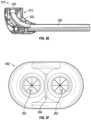
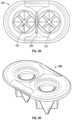
- FIGS. 3 F- 3 Hillustrate a seal of an insertion device according to some embodiments
- FIG. 3 Iillustrates a rear view of a drive unit of a robotic surgery system according to some embodiments
- FIGS. 3 J- 3 Killustrate rear views of an insertion device according to some embodiments
- FIGS. 4 A- 4 Cillustrate a visualization device according to some embodiments
- FIGS. 5 A- 5 Eillustrate a mounting interface of a drive unit of a robotic surgery system according to some embodiments
- FIGS. 6 A- 6 Iillustrate attachment of insertion and visualization devices to a mounting interface of a drive unit of a robotic surgery system according to some embodiments
- FIGS. 7 A- 7 H and 8illustrate visualization devices with imagers according to some embodiments
- FIGS. 9 A- 9 B and 10 A- 10 Billustrate visualization and/or insertion devices according to some embodiments
- FIGS. 11 and 12 A- 12 Dillustrate drive units of a robotic surgery system according to some embodiments.
- one or more instrumentscan be inserted into a body cavity of a patient.
- the insertion processhas some risk since instruments may inadvertently damage organs or tissue while being inserted. Incorrect positioning of the one or more instruments in the body cavity may also result in a limited range of motion within the body cavity.
- a trocar or other access portmay then be inserted through the incision.
- a cameracan be first inserted through the access port and used by a surgeon to capture and relay stereoscopic images of a surgical site.
- One or more instrumentscan be inserted following the camera insertion. Views provided by the camera facilitate insertion of the one or more instruments and their manipulation of the surgical site.
- a robotic surgery system in accordance with some embodimentsis shown generally at 100 .
- the robotic surgery system 100can be configured to facilitate a medical procedure performed via a single incision.
- a single access portcan be inserted into the incision to provide access for one or more instruments and cameras.
- the system 100can include a workstation 102 and a patient cart 104 , which is illustrated in more detail in FIG. 1 B .
- the patient cart 104can include a central unit or drive unit 106 to which instrument insertion and visualization devices 108 can be attached or mounted.
- the workstation 102can include an input device 112 that receives operator input and produces input signals and may also be configured to generate feedback to the operator.
- the feedbackcan be visual, auditory, haptic, or the like.
- the input device 112can be implemented using a haptic interface available from Force Dimension, of Switzerland, for example.
- the workstation 102can further include a master processor circuit 114 in communication with the input device 112 for receiving the input signals and generating control signals for controlling the robotic surgery system, which can be transmitted to the patient cart 104 via an interface cable 116 . In some cases, transmission can be wireless and interface cable 116 may not be present.
- the input device 112can include right and left hand controllers 122 and 124 , which are configured to be grasped by the operator's hands and moved to produce input signals at the input device 112 .
- the patient cart 104can include a slave processor circuit 118 that receives and the control signals from the master processor circuit 114 and produces slave control signals operable to control the instrument insertion and visualization devices 108 and one or more instruments (and their respective end effectors) during a surgical procedure.
- the one or more instrumentscan include dexterous tools, such as grippers, needle drivers, staplers, dissectors, cutters, hooks, graspers, scissors, coagulators, irrigators, suction devices, that are used for performing a surgical procedure. While both master and slave processor circuits are illustrated, in other embodiments a single processor circuit may be used to perform both master and slave functions.
- the workstation 102can also include a user interface, such as a display 120 in communication with the master processor circuit 114 for displaying information (such as, body cavity images) for a region or site of interest (for example, a surgical site, a body cavity, or the like) and other information to an operator.
- the workstation 102can also include one or more controllers, such as one or more pedals 126 , for controlling the robotic surgery system.
- one or more pedals 126can include a clutch pedal that allows repositioning one or more controllers 122 or 124 without corresponding movement of the associated instrument.
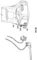
- insertion and visualization devices 108can include an insertion device 210 and a visualization device 220 .
- the insertion device 210can include a housing 212 and a plurality of passages, lumens, or channels 214 for inserting and guiding one or more instruments.
- the plurality of channels 214can be enclosed in another housing. The two housings can be connected. As is illustrated, the plurality of channels, such as radial channels, can be formed within a housing, which can be radially shaped.
- the plurality of channels 214can also permit insertion of a camera lumen, cable, elongate shaft, or tube 224 .
- a distal end 224 B of the camera tubecan extend beyond the housing including the plurality of channels 214 . At least a portion of the distal end 224 B can be positioned near or in the site of interest. One or more cameras can be positioned at the distal end 224 B.
- the camera tube 224can also include a proximal end 224 A as described herein.
- a channel of the plurality of channels 214can house or support a camera in addition to or instead of the one or more cameras of the camera tube 224 .
- the visualization devicecan include a housing 222 to which the proximal end 224 A of the camera tube can be removably (or non-removably) attached.
- the housing 222can include an opening in which a one or more drivers, such as at least one of 232 A or 232 B, can be positioned.
- the one or more driverscan move the camera tube 224 through the opening in the housing 222 and a channel of the plurality of channels 214 so that the distal end 224 B extends away from one or more of the housings 212 or 222 or retracts back toward or into one or more of the housings 212 or 222 .
- the camera tube 224can form a loop around at least a portion of the housing 222 as illustrated in FIGS.
- the diameter of the loopcan be increased when the distal end 224 B is retracted toward or into one or more of the housings 212 or 222 and be decreased when the distal end 224 B is extended away from one or more of the housings 212 or 222 .
- the loopcan have a diameter 262 as shown.
- the diameter 264 of the loopdecreases as compared to the diameter 264 of the loop.
- the diameter 268 of the loopcan be smaller than the diameters 262 and 264 .
- extending the distal end 224 B away from the one or more of the housings 212 or 222causes the length of the proximal end 224 A to decrease, which leads to a decrease in the diameter of the loop.
- One or more cables 240can be used to transmit control signals and data, such as analog or digital image data provided by the one or more cameras positioned at the distal end 224 B or in the insertion device 210 , to the patient cart 104 .
- transmissioncan be wireless and one or more cables 240 may not be present.
- At least a portion of the camera tube 224can be flexible or substantially flexible in order to form a loop and/or be guided through the one or more openings and/or channels are described herein. In some cases, looping the camera tube 224 upward around at least the portion of the housing 222 as described can permit the camera tube to have sufficient length for reaching near and/or into the site of interest, while eliminating or reducing the risk of the camera tube 224 coming into contact with non-sterile object, such as the floor.
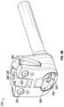
- FIG. 3 Aillustrates a front perspective view of the insertion device 210 according to some embodiments.
- the housing 212 of the insertion devicecan include an opening 330 configured (for example, sized and/or shaped) to permit the camera tube 224 to pass through the housing 212 .
- the opening 330can include a seal, which may be covered by a closure (such as a latch), to prevent ingress of fluid, gas, or solids into the insertion device 210 and/or prevent backflow of fluid, gas, or solids from the insertion device.
- a closuresuch as a latch
- Any of the seals described hereincan include one or more valves, such as a duckbill valve. As illustrated in FIG.
- the housing 212can include an interior passage 322 connecting the opening 330 to a channel 320 configured (for example, sized and/or shaped) to permit the camera tube 224 to pass through the channel.
- the interior passage 322can be a channel positioned in an interior of the housing.
- the interior passage 322can be bent or curved to facilitate various positional configurations of the visualization device 220 with respect to the insertion device 210 and in particular the housing 222 with respect to housing 212 .
- the interior passage 322can include an opening that aligns with or includes the opening 300 and another opening that aligns with or includes opening of the channel 320 .
- sealing materialcan be used on or around the interior passage 322 in addition to or instead of the seal in the opening 330 .
- the distal end 224 B of the camera tube 224can exit the channel 320 and extend away from the insertion device 210 toward a site of interest, such as a surgical site, body cavity, wound, or the like. Also, the distal end 224 B of the camera tube 224 can retract toward or into the channel 320 toward the insertion device 210 and away from the site of interest.
- the plurality of channels 214can include one or more instrument channels 340 configured (for example, sized and/or shaped) to permit one or more instruments to pass through and extend away from the insertion device 210 toward the site of interest. As is illustrated, there can be two channels for left and right instruments.
- the interior passage 322includes at least a portion with a central axis parallel to a central axis of the one or more instrument channels 340 .
- the interior passage 322can include at least a portion (for example, the curved portion illustrated in FIG. 3 E ) with a central axis not parallel to a central axis of the one or more instrument channels 340 .
- the plurality of channels 214can include a channel 310 for one or more cameras of the insertion device 210 .
- a cameracan be positioned at a distal end of the plurality of channels (or at or near position of the arrow 310 ).
- Such one or more cameras(which can be referred to as a secondary camera) can facilitate positioning adjacent to or insertion into the site of interest of at least one of one or more instruments or at least one of the one or more cameras of the visualization device 220 (such cameras can be referred to as a primary camera).
- the secondary cameracan include a substantially flexible or substantially rigid lumen, cable, or elongate shaft that is inserted into the channel 310 .
- the secondary cameracan be integrated with the insertion device 210 or be removable.
- An opening of the channel 310can include one or more seals, which may be covered by a closure (such as a latch), to prevent ingress of fluid, gas, or solids.
- a closuresuch as a latch
- sealing materialcan be used on or around the opening of the channel 310 in addition to or instead of the seal(s) in the opening.
- a secondary camera 324can include a substantially flexible or rigid cable with a proximal end 324 A and a distal end 324 B.
- the distal end 324 Bcan include a protector 370 (such as glass or plastic).
- the protector 370can protect an imager and/or other components of the secondary camera breaking or malfunctions due to, for example, coming into contact with fluid in the site of interest.
- a protectormay be included as part of the insertion device 210 at a distal end of the channel 310 , and accordingly the protector 370 may be optional.
- the secondary cameracan include one or more lenses that focus light from and/or reflected by at least the portion of the site of interest on an image sensor 384 .
- the image sensorcan be positioned at the proximal end 324 A and/or distal end 324 B.
- the one or more lensescan include concave and/or convex lenses. In some cases, one or more lenses can be moved to adjust the zoom (such as, an optical zoom).
- the image sensor 384can detect the light and convert it to image information or data. For instance, the image sensor 384 can measure brightness at a plurality of points.
- the image sensor 384can include at least one of charge-coupled devices (CCDs), complementary metal-oxide-semiconductor (CMOS) image sensors, or the like.
- CMOScomplementary metal-oxide-semiconductor
- the image sensor 384can be a digital and/or analog image sensor.
- the secondary cameracan include two or more cameras (for example, to produce a stereoscopic image).
- the secondary camera 324can include an optical system 382 that redirects the detected light.
- the optical system 382can be a prism that redirects the detected light down onto the image sensor 384 .
- the image sensor 384can be positioned in a different plane than a portion of the surgical site being imaged.
- the optical system 382may be omitted in some implementations.
- the optical system 382may be omitted when the image sensor is positioned in the same plane as the surgical site being imaged.
- the secondary camera 324can be removable.
- the secondary camera cablecan be inserted into and/or removed from the channel 310 .
- the channel 310can be used for one or more of suction or irrigation of the site of interest.
- the channel 310can alternatively or additionally be used to permit an instrument (such as, third instrument) to be inserted.
- the instrumentcan be controlled by the robotic surgery system or manually by a user.
- a protectorwould not be included at a distal end of the channel 310 or would otherwise be removable when the channel 310 is used for one or more of aspiration, irrigation, instrument manipulation, or the like.
- the primary cameracan be a stereo or stereoscopic camera, which can produce three-dimensional representation of at least a portion of the site of interest
- the secondary cameracan be a two-dimensional camera.
- the secondary cameracan have lower resolution than the primary camera.
- the secondary cameracan have 1920 ⁇ 1080 pixels (or 1080p) resolution.
- the primary cameracan have resolution of 1080p, 4K, 8K, or the like.
- the channel 310 for the secondary cameracan be smaller in size (such as, narrower or having smaller diameter) than the channel 320 for the primary camera.
- the secondary cameramay also include an illumination source or device for illuminating the site of interest.
- the illumination devicecan be incorporated as part of the secondary camera such that the illumination device and a lens system of the secondary camera all fit within the diameter of the channel 310 .
- the illumination devicecan include optical fiber(s).
- the illumination devicecan be an annular system with strands of fiber wrapping around a lens system so that illumination is provided to the site of interest, for instance, using known means of fiber illumination.
- close proximity of the instrument channels 340 to one or more camera channels 310 or 320can facilitate single port surgery.
- the housing 212can include one or more attachment mechanisms 360 .
- the one or more attachment mechanisms 360can be buttons positioned on opposite sides of the housing 212 .
- the buttonscan be configured to removably attach the insertion device 210 to a mounting interface of the drive unit 106 (or, in some cases, additionally or alternatively to the housing 222 of the visualization device 220 ). Pushing the buttons can release the insertion device 210 from the mounting interface (and/or the housing 222 of the visualization device 220 ).
- the one or more attachment mechanisms 360can permit attachment to and release of the insertion device 210 from supporting pins of the mounting interface (and/or the housing 222 ).
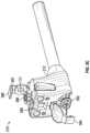
- FIG. 3 Billustrates a rear perspective view of the insertion device 210 according to some embodiments.
- Openings of the one or more instrument channels 340can include one or more seals, which may be covered by a closure (such as a latch), to prevent ingress of fluid, gas, or solids.
- sealing materialcan be used on or around at least one of the one or more openings of the one or more instrument channels 340 in addition to or instead of the seal(s) in the one or more openings.
- the housing 212can include one or more openings 350 for receiving one or more supporting rods of pins, which can be positioned on the mounting interface.
- the one or more attachment mechanisms 360can permit attachment to and release of the insertion device 210 from the supporting pins (and/or from the visualization device 220 ).
- the one or more attachment mechanisms 360can activate or release a latch or lock, such as a cam lock, cam lock with a spring, or the like.
- FIG. 3 Cillustrates a rear perspective view of the insertion device 210 showing seals 392 and 396 according to some embodiments.
- the opening 330(through which the camera tube 224 is inserted as described herein) can be covered by a seal 396 held in place by a closure 398 , which can be a latch, clip, or the like.
- the seal 396can prevent ingress of fluid, gas, or solids into the interior portion of the insertion device 210 and/or prevent backflow of fluid, gas, or solids from the insertion device 210 .
- the seal 396can include a valve, such as a duckbill valve.
- the closure 398can be removably fastened to the housing 212 of the insertion device 210 in order to provide access to the seal 396 , allowing the seal 396 to be cleaned and/or replaced during the same surgical procedure of between surgical procedures (such as, when the insertion device 210 is being cleaned and/or sterilized).
- the closure 398can be removably fastened to the housing 212 by a protrusion or latch 397 of the closure 398 releasably engaging the bottom of a protrusion or projection 399 of the housing 212 .
- FIG. 3 Cthe closure 398 is illustrated in an open configuration or mode in order to show the seal 396 . In operation, the seal 396 is inserted into the opening 330 and the closure 398 is fastened to the housing 212 in order to hold the seal 396 in place.
- FIG. 3 Billustrates the closure 398 in a closed configuration.
- One or more openings in the one or more instrument channels 340 through which the instruments are insertedcan be covered by a seal 392 held in place by a closure 394 , which can be a latch, clip, or the like.
- the seal 392can prevent ingress of fluid, gas, or solids into the interior portion of the insertion device 210 and/or prevent backflow of fluid, gas, or solids from the insertion device 210 .
- the closure 394can be removably fastened to the housing 212 of the insertion device 210 similarly to the closure 398 .
- the closure 394can provide access to the seal 392 , which can be removed and/or replaced during the same surgical procedure of between surgical procedures (such as, when the insertion device 210 is being cleaned and/or sterilized).
- FIG. 3 Cthe closure 394 is illustrated in an open configuration or mode in order to show the seal 392 .
- the seal 392is inserted into the one or more openings of the one or more instrument channels 340 (see FIG. 3 K ) and the closure 394 is fastened to the housing 212 in order to hold the seal 392 in place.
- FIG. 3 Billustrates the closures 394 in a closed configuration.
- One or more of the seals 392 , 396 or the closures 394 , 398can be disposable and/or replaceable.
- the closure 398includes an opening that coincides with the opening 330
- the closure 394includes one or more openings that coincide with the one or more openings in the one or more instrument channels 340 .
- a single seal 392can cover both openings of the one or more instrument channels 340 .
- the seal 392can include a plurality of separate seals.
- the single seal 392can include two ports which are sized and shaped to cover the one or more openings in the one or more instrument channels 340 .
- the ports 352can include openings in the body of the seal 392 and protruding portions.
- the ports 352can be valves, such as duckbill valves, as shown in FIGS. 3 F- 3 H .
- Each of the ports 352can be shaped as a funnel (as described herein), which can facilitate insertion of the instruments.
- the ports 352 of the single seal 392can also positioned close to each other. Such close proximity can cause the ports 352 to at least partially overlap as illustrated by a region 356 in FIG. 3 F (top/rear view) and 3 G (bottom/front view).
- the ports 352can at least partially overlap on one or more of top surface of the single seal 392 ( FIG. 3 F ) or bottom surface of the single seal 392 ( FIG. 3 G ), which faces the one or more openings of the one or more instrument channels 340 .
- a port 352can have a concave shape (or funnel shape) that tapers from a distal end toward a distal end that is positioned distal to and/or is inserted into an opening of the one or more instrument channels 340 .
- the proximal ends of the ports 352can overlap (on one or more of top or bottom surfaces of the single seal 392 ) in the region 356 .
- the proximal ends of the portscan be circular or round, and the circles can overlap in the region 356 , as illustrated in FIGS. 3 F- 3 H . In some cases, the overlap can be smaller or larger than that illustrated in the region 356 .
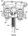
- FIG. 31illustrates a rear view of the drive unit 106 showing loading of one or more instruments 364 into the insertion device 210 .
- Loading of an instrument 364can involve inserting a tip 366 of the instrument into an opening of a corresponding instrument channel 340 .
- a usermay experience difficulties with the insertion of an instrument due to, among others, close proximity of the openings of the one or more instrument channels 340 to each other, having to facilitate the insertion through the rear of the drive unit 106 where light may be lacking, or the like.
- an illumination device 362can be supported by the housing 212 .
- the illumination device 362can be positioned in a recess in the housing 212 .
- the illumination device 362can be positioned in a recess 365 shown in the cross-sectional view of the housing 212 illustrated in FIG. 3 K .
- the illumination device can 362can include one or more light sources, such as one or more light emitting diodes (LEDs) or optical fibers (combined with a remotely located light source), that emit light.
- LEDslight emitting diodes
- optical fiberscombined with a remotely located light source
- the illumination device 362can illuminate one or more of opening(s) in the closure 394 , one or more ports 352 in the seal 392 , or one or more of the openings in the one or more instrument channels 340 . Such illumination can facilitate insertion of one or more instruments into the insertion device 210 .
- the one or more light sourcescan be covered by one or more of a protective cover, lens (which can also serve as a protective cover), or the like.
- FIG. 3 Jillustrates the illumination device 362 positioned above one or more openings of the one or more instrument channels 340 .
- the illumination device 362can be positioned on the bottom, on a side, or the like on the rear of the housing 212 .
- multiple illumination devicescan be supported by the housing 212 .
- Such multiple illumination devicescan be positioned on same or different sides of the rear of the housing 212 .
- two illumination devicescan each be positioned above a respective instrument channel opening.
- an illumination devicecan be positioned at the opening of an instrument channel 340 or inside the instrument channel 340 .
- the closure 394can be made at least partially from transparent or substantially transparent material so that light emitted by the illumination device 362 passes through the closure 394 and illuminates the one or more openings of the one or more instrument channels 340 .
- the closure 394can at least partially cover the illumination device 362 (as shown in FIGS. 3 J- 3 K ).
- the closure 394can include an opening or recess so that the illumination device 362 is at least partially not covered by the closure 394 so that at least some of the emitted light does not pass through the closure 394 .
- FIG. 3 Jillustrates a transparent or substantially transparent closure 394 as the seal 392 is visible through the closure.
- the illumination device 362may include a plurality of illumination devices or be shaped to contact a larger area of the closure 394 .
- the illumination device 362can include one or more light sources, such as LEDs.
- the illumination device 362can alternatively or additionally utilize one or more light sources already present in or incorporated into the insertion device 210 , such as the illumination source of the secondary camera (as described herein), and/or the visualization device 220 , such as the illumination source of the primary camera (as described herein),
- the insertion device 210 and/or the visualization device 220can receive light from one or more external light source(s), such as from the patient cart 104 via one or more cables illustrated in FIGS. 1 A- 1 B , or light source(s) internal to the insertion device 210 and/or the visualization device 220 .
- an illumination device(not shown) can be used to similarly illuminate any of the openings disclosed herein, such as 330 , 410 , 412 , or the like.
- the closure 394can be shaped as a funnel to facilitate insertion of the one or more instruments.
- the closure 394can have a larger opening that is proximal from the one or more openings of the one or more instrument channels 340 than the one or more distal openings.
- the closure 394can be shaped to taper from the proximal to the one or more distal openings, facilitating directing or guiding one or more instruments into the one or more openings of the one or more instrument channels 340 .
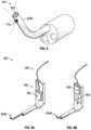
- FIG. 4 Aillustrates a front perspective view of the visualization device 220 according to some embodiments.
- the housing 222 of the visualization devicecan include openings 410 and 412 configured (for example, sized and/or shaped) to permit the camera tube 224 to pass through.
- the proximal end 224 A of the camera tube 224(illustrated for convenience without a middle portion) can be attached to the housing.
- the camera tube 224can loop around at least the portion of the housing 222 when the distal end 224 B is inserted through one or more of the openings 410 and 412 (see FIG. 2 A ).
- the openings 410 and 412can be aligned to permit the camera tube 224 to pass through.
- a bottom opening (not illustrated) aligned with the opening 412can be positioned on the bottom of the housing 222 to permit the camera tube 224 to exit the housing 222 after passing through an interior portion of the housing (such as, the interior portion illustrated in FIG. 4 C ).
- This bottom openingcan be positioned adjacent to (such as over or on top of) the opening 330 in the housing of the insertion device 210 when the visualization device 220 is positioned adjacent to and/or attached to the insertion device.
- One or more of the openings 410 , 412 , or the bottom openingcan include a seal, which may be covered by a closure (such as a latch) as described herein.
- the housing 222can include a drive opening 414 .
- the drive openingcan be positioned on a side of the housing 222 (for example, the back of the housing) that attaches to the mounting interface of the drive unit 106 as described herein.
- the drive opening 414can be configured (for example, sized and/or shaped) to receive one or more drivers (at least one of 232 A or 232 B), such as a plurality of drive rollers as described herein (see, for example, FIG. 2 A ).
- the plurality of drive rollerscan include right drive roller 232 A and left drive roller 232 B (collectively, referred to as 232 ).
- the camera tube 224When inserted through the opening 410 , the camera tube 224 is positioned between the right and left drive rollers 232 A and 232 B and contacts the drive rollers.
- the drive rollers 232can contact, grip, or abut the camera tube 224 .
- the drive rollerscan advance the camera tube 224 down or retract it up through the drive opening 414 . Movement of the drive rollers 232 in a first direction can advance the camera tube 224 forward or down through the drive opening 414 in order to advance the distal end 224 B toward the site of interest.
- the right driver roller 232 Acan spin counterclockwise and the left drive roller 232 B can spin clockwise in order to advance the camera tube 224 forward.
- Such combination of the counterclockwise and clockwise movement of the drive rollerscan constitute the first direction.
- Movement of the drive rollers 232 in a second directioncan retract the camera tube 224 backward or up through the drive opening 414 in order to retract the distal end 224 B away from the site of interest.
- the right drive roller 232 Acan spin clockwise and the left drive roller 232 B can spin counterclockwise in order to retract the camera tube 224 backward.
- Such combination of the clockwise and counterclockwise movement of the drive rollerscan constitute the first direction.
- movement in the second directioncan be opposite to movement in the first direction even in cases where drive rollers spin in opposite directions during movement in the first and/or section direction.
- Drive rollers 232can have an external surface that is made out of and/or is covered by soft material, such as rubber, foam, or the like, that grips an external surface of the camera tube 224 in order to one or more of advance or retract the camera tube.
- a portion of the camera tube 224 positioned between the drive rollers 232can slip along the drive rollers, and as a result the camera tube would not be advanced or retracted.
- slippingcan be advantageous when a user's limb becomes caught in the loop formed by the camera tube 224 or in case of malfunction to prevent or lessen the risk of injury to the user or damage to one or more of the camera tube 224 , the visualization device 220 , the insertion device 210 , or any other part of the system 100 .
- At least one of one or more of the material on the external surface of the drive rollers 232 or on an external surface of the camera tube 224 or a surface pattern on the surface of one or more of the external surface of the drive rollers 232 or the external surface of the camera tube 224can be selected to have a friction coefficient that results in slippage in case force on the camera tube exceeds a maximum force, such as, a maximum frictional force.
- the maximum frictional forcecan depend on one or more of the friction coefficient between the drive rollers 232 and camera tube 224 or a clamping force between the drive rollers 232 and camera tube 224 . In some cases, the maximum frictional force can be 5 N or less or more, 7 N or less or more, 10 N or less or more, or the like.
- Surface pattern on the external surface of the drive rollers 232 (and/or the external surface of the camera tube 224 )can affect the friction coefficient.
- ribbed surface pattern, toothed surface pattern, or the likecan increase the friction coefficient compared to a smooth or substantially smooth surface pattern.
- the housing 222can include one or more actuators 420 configured to control movement of the distal end 224 B of the camera tube 224 , which can include one or more cameras.
- a first actuatorcan control pitch or tilt (up/down movement) of the distal end 224 B
- a second actuatorcan control yaw or pan (left/right movement) of the distal end 224 B.
- the first and second actuatorscan control movement of the distal end 224 B by manipulating links positioned in the interior of the camera tube 224 as described herein (for example, with reference to FIGS. 4 B- 4 C ).
- the housing 222can include one or more attachment mechanisms 428 .
- the one or more attachment mechanisms 428can be buttons positioned on opposite sides of the housing 222 .
- the buttonscan be configured to removably attach the visualization device 220 to the mounting interface of the drive unit 106 (or, in some cases, additionally or alternatively to the housing 212 of the insertion device 210 ). Pushing the buttons can release the insertion device 210 from the mounting interface (and/or the housing 212 ).
- the one or more attachment mechanisms 428can permit attachment to and release of the visualization device 220 from one or more supporting rods or pins (and/or the housing 212 ).
- the one or more attachment mechanisms 428can activate or release a lock, such as a cam lock, cam lock with spring, or the like.
- the housing 222can include one or more openings 424 for receiving one or more the supporting pins that can be positioned on the mounting interface.
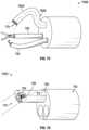
- FIG. 4 Billustrates a perspective view of the distal end 224 B of the camera tube 224 according to some embodiments.
- An imager 430(which can be the primary camera) with one or more cameras can be positioned at or near the tip of the distal end 224 B.
- the distal end 224 Bcan include a pitch or tilt segment or section 442 for controlling up/down movement of the distal end 224 B, and a yaw or pan segment section 444 for controlling left/right movement of the distal end 224 B.
- the tilt section 442can be positioned adjacent the imager 430
- the pan section 444can be positioned adjacent to the tilt section.
- Pan section 444can be positioned farther away from the tip of the distal end 224 B than the tilt section 442 . In some cases, positioning of the sections 442 and 444 relative to the tip can be reversed. In some cases, the sections 442 and 444 can be intermingled with respective couplings or guides (as described below) of the sections 442 and 444 alternating.
- At least one of sections 442 or 444can include one or more couplings or guides 434 .
- the one or more couplings 434can be coupled to each other to allow bending of the distal end 224 B.
- the sections 442 and 444can bend (as described herein) as a result of at least one of pulling or pushing one or more flexible or substantially flexible links 448 positioned in the interior of the camera tube 224 that control, for example, the bend, curvature, or another aspect of spatial orientation of one or more of sections 442 or 444 .
- One or more links 448can include a wire, cable, or the like with elasticity that can support at least one of tension or compression without permanent deformation.
- One or more links 448can be connected to the one or more guides 434 (for example, by being connected to the one or more guides in the interior of the camera tube 224 ). Movement, such as pulling and/or pushing, of the one or more links 448 can cause adjustment of the spatial orientation of the one or more guides 434 and, as a result, one or more sections 442 or 444 .
- one or more actuators 420can pull and/or push the one or more links 448 , for example, via rotation in first and/or second directions. Pulling a link 448 can cause shortening its length, while pushing the link can cause lengthening the link (such as, returning the link substantially to its initial length).
- Segment or section 446can be positioned adjacent the pan section 444 at the distal end 224 B of the camera tube 224 .
- section 446can be flexible or substantially flexible.
- One or more of sections 442 or 444can be rigid or substantially rigid to prevent at least the imager 430 of the distal end 224 B from drooping or sagging as the distal end 224 B exits the channel 320 of the insertion device. Drooping or sagging can undesirably lead to at least a temporary loss of vision of at least a part of the site of interest or inadvertent contact with tissue near or outside the site of interest.
- Rigidity of the one or more sections 442 or 444can prevent movement of the distal end 224 B in a downward direction (for example, in the absence of actively tilting the camera tube 224 as described herein), while permitting movement in the opposite direction as the camera tube 224 is passed through one or more openings or channels, as described herein.
- Rigiditycan help maintain orientation of at least the imager 430 in same plane of the channel 320 or in a plane above the plane of the channel 320 as the distal end 224 B of the camera tube 224 exits the channel 320 .
- the latter planecan be parallel or substantially parallel to the plane of the channel 320 .
- a supporting material or mechanismmay be added to the distal end 224 B to help maintain orientation of at least the imager 430 in the same plane of the channel 320 .
- the supporting material or mechanismcan allow the distal end 224 B to flex (or curve) in one direction in a plane while preventing other flexing (or curving), thereby allowing the distal end 224 B to move through a curved portion of the interior passage 322 of the housing 212 .
- flexing in the direction of the bend or curve of the interior passage 322can be permitted, while flexing in the other direction may not be permitted.
- FIG. 4 Cillustrates a cross-sectional view of the housing 222 and camera tube 224 of the visualization device 220 according to some embodiments.
- the figuredepicts view of an interior portion of the housing 222 looking up through the opening 412 in the housing 222 .
- Proximal end 224 A of the camera tube 224can be attached to the housing 222 as described herein.
- interior of the proximal end 224 Acan include one or more links 448 that extend along the length of the camera tube 224 to the distal end 224 B, as described herein. In use, the camera tube 224 passes through the interior portion illustrated in FIG. 4 C .
- the one or more actuators 420can include first and second actuators that, respectively, control tilting or panning of the distal end 224 B of the camera tube 224 .
- the first actuatorcan control pulling and/or pushing of one or more links 448 connected to a plurality of guides in the tilt section 442 .
- the first actuatorcan control tilting up/down of at least the imager 430 .
- the second actuatorcan control pulling and/or pushing of one or more links 448 connected to a plurality of guides in the pan section 444 .
- the second actuatorcan control left/right movement of at least one of the tilt section 442 and/or the imager 430 .
- Pulling and/or pushing at least one link 448can be performed via actuating the first and/or second actuator 420 .
- first actuatorfor instance, its exterior portion that protrudes from the housing 222 can serve as a shaft connected to a drum 450 located in the interior of the housing 222 .
- Rotation of the shaft and drumcan cause a corresponding link pulley 460 to rotate, for example, in a plane perpendicular to the plan of rotation of the shaft and drum.
- the pulley 460can be connected to the drum 450 such that rotation of the drum causes the pulley to rotate.
- the drum 450can have threading on the surface that contact threading on the surface of the pulley 460 and transfers rotation to the pulley.
- the pulley 460can be connected to at least one link 448 .
- the at least one linkcan be attached to the pulley.
- Rotation of the actuator 420 in a first directioncan cause rotation of the corresponding shaft (for example, in the same clockwise direction).
- Thiscan cause the corresponding pulley 460 to rotate and, for instance, pull (or push) the associated at least one link, which can cause tilting of at least the imager 430 .
- the pulley 460can be connected to a pair of links 448 one of which is pulled while the other is pushed to control the tilting.
- Second actuatorcan operate similarly to control the panning.
- FIG. 5 Aillustrates the drive unit 106 of the robotic surgery system 100 according to some embodiments.
- the drive unit 106can include a mounting interface 500 configured to support one or more of the insertion device 210 or visualization device 220 .
- the mounting interfacecan include an opening or slit 504 for receiving a looped portion of the camera tube 224 (see, for example, FIG. 6 I ).
- FIG. 5 Billustrates a perspective view of the mounting interface 500 according to some embodiments.
- the mounting interface 500can include one or more posts or pins 510 configured to actuate one or more drivers 232 for moving the camera tube 224 as described herein.
- the pins 510can be provided to support the rollers 232 A and 232 B.
- the pins 510can be configured (for example, sized and/or shaped) to attach to the rollers 232 A and 232 B.
- the pins 510can be hexagonal, and the rollers 232 A and 232 B can include hexagonal openings (see, for example, FIG. 5 D ) configured (for example, sized and/or shaped) to be mounted on the hexagonal surface of the pins 510 .
- one or more shapessuch as square, round, triangular, or the like can be used in addition to or instead of hexagonal.
- the mounting interface 500can include one or more actuators 520 for causing movement of the one or more actuators 420 of the visualization device 220 .
- two actuators 520can be provided, and they can include shafts or recesses configured (for example, sized and/or shaped) to receive protruding exterior portions of the actuators 420 .
- the actuators 520can include surfaces configured (for example, sized and/or shaped) to mate with the surfaces of the protruding exterior portions of the actuators 420 . The mating can provide attachment of the actuators 420 of the visualization device 220 to the actuators 520 of the mounting interface 500 .
- the mounting interface 500can support one or more of the insertion device 210 or visualization device 220 .
- the visualization device 220can be at least partially supported by the pins 510 supporting the drivers 232 that are placed in the recess 414 of the housing 222 .
- the mounting interface 500can include one or more pins 530 configured to support the insertion device 210 .
- the one or more pins 530can be configured (for example, sized and/or shaped) to be received in the one or more openings 350 of the insertion device 210 .
- the one or more pinscan have size, shape, and/or surface pattern configured to be attached to insertion device 210 .
- a left pin 530can have a groove, pattern, or indentation 552 at or near its tip.
- the indentation 552can be configured (for example, sized and/or shaped) to mate with a surface in the interior of the left opening 350 (see, for example, FIG. 3 B . This can provide attachment of the insertion device 210 to the mounting interface 500 .
- one or more attachment mechanisms 360can operate to disengage the visualization device 210 from the mounting interface 500 .
- one or more attachment mechanisms 360can be pressed to disengage mating of the surface in the interior of the left opening 350 with the indentation 552 .
- the right pin 530can have a similar groove, pattern, or indentation 552 at its tip on the side facing the left pin.
- FIG. 5 Cillustrates a rear view of the mounting interface 500 according to some embodiments.
- the mounting interfacecan include a first set of actuators 532 , a first set of gears 534 connected to or attached to the first set of actuators 532 , and a second set of gears 536 cooperating with the first set of gears 534 . These components can be collectively configured to actuate the one or more pins 510 .
- the first set of actuators 532can include two actuators
- the first set of gears 534can include two gears
- the second set of gears 536can include two gears.
- the first set of actuatorscan be motors, for example, electric motors.
- the first set of gears 534can interlock with the second set of gears 536 .
- the first set of actuators 532can be configured to rotate the first set of gears 534 attached to the first set of actuators 532 .
- Rotation of the first set of gears 534can cause the second set of gears 536 to rotate in a plane perpendicular to the plane of rotation of the first set of gears 534 .
- the one or more pins 510can be connected or attached to the second set of gears 536 .
- Rotation of the second set of gears 536can cause rotation of the one or more pins 510 .
- Rotation of the one or more pins 510can cause rotation of the one or more drivers 232 and movement of the camera tube 224 , as described herein.
- Rotation of the one or more pins 510 and one or more drivers 232can be in the first and/or second direction to advance and/or retract the camera tube 224 , as described herein. Rotation in the first and/or second direction can be caused by movement of the one or more actuators in at least two directions (for example, clockwise or counterclockwise).
- the mounting interface 500can include a second set of actuators 542 , a third set of gears 544 connected to or attached to the second set of actuators 542 , and a fourth set of gears 546 cooperating with the third set of gears 544 . Collectively these components can be configured to actuate the one or more actuators 520 . As illustrated, the second set of actuators 542 can include two actuators, the third set of gears 544 can include two gears, and the fourth set of gears 546 can include two gears.
- the first set of actuatorscan be motors, for example, electric motors.
- the second set of actuators 542 , third set of gears 544 , and fourth set of gears 546can cooperate with each other and operate to actuate the one or more actuators 520 similarly to the foregoing description of actuating the one or more pins 510 .
- movement of the actuators 520 and corresponding movement of the actuators 420 of the visualization device 220can cause the camera tube 224 to tilt and/or pan.
- FIG. 5 Dillustrates the mounting interface 500 prepared for supporting one or more of the insertion device 210 or visualization device 220 according to some embodiments.
- a sterile barriermay need to be provided between the mounting interface 500 of non-sterile drive unit 106 and the insertion device 210 and/or sterile visualization device 220 .
- the insertion and visualization devices, 210 and 220may be required to be sterile in order to protect the site of interest from infection in case of one or more of the insertion or visualization device coming into contact with the site of interest or with another sterile component of the system 100 (such as, an instrument) that may come into contact with the site of interest, with a user performing or assisting with the surgery.
- One or more drivers 232can be sterile and can be attached to or mounted on the one or more pins 510 of non-sterile mounting interface 500 .
- a sterile cover 550can be attached to or mounted to cover the one or more pins 530 .
- the cover 550can be mounted in a region 560 on a front surface of the mounting interface 500 .
- the cover 550can be secured with one or more closures (not illustrated).
- the one or more closurescan be pins that are pushed in by the cover 550 when it is mounted in the region 560 . Pushing of the pins can cause a closure, such as a latch, to become closed.
- the cover 550can be removed from the region 560 , for example, by pressing a button positioned on the bottom surface of the mounting interface 500 (not shown), which can push the pins against the cover 550 and dislodge the cover.
- the cover 550can include a bottom set of pin covers for covering the one or more pins 530 .
- the cover 550can include a top set of pins 540 that can be configured to support the visualization device 220 when it is attached to the mounting interface 500 .
- the set of pins 540can be sized and/or shaped to be received in the one or more openings 424 of the visualization device 220 .
- the set of pins 540can have size, shape, and/or surface shape configured to be attached to the visualization device 220 , for example, as described herein in connection with the pins 530 .
- the mounting interface 500can include one or more pins 530 ′ configured (for example, sized and/or shaped) to support the visualization device 220 .
- the one or more pins 530 ′can function similar to the one or more pins 540 .
- One or more pins 530 ′can be covered by the cover 550 , such as by pin covers 540 .
- individual covers 550 ′can be used to cover each of the one or more pins 530 and/or 430 ′.
- two separate coverscan be used to cover the one or more pins 530 and 430 ′ respectively.
- a single cover 550(as illustrated in FIG. 5 D ) but with pin covers replacing the top set of pins 540 can be used to cover the one or more pins 530 and 530 ′.
- a sterile barriercan be formed between one or more actuators 420 of the visualization device (see, for example, FIG. 4 A ) and one or more actuators 520 of the mounting interface (see for example, FIG. 5 B ) in one or more of the following ways.
- One or more actuators 420can be covered by one or more sterile covers as described herein.
- a sterile drapecan be placed over the drive unit 106 and the mounting interface. Drape material can flex and/or slip to provide the sterile barrier. Drape material can have appropriate thickness and/or other properties to allow for the flexing and/or slippage.
- the drapecan include one or more sterile covers (which can function as actuators) that transfer motion between the one or more actuators 420 and one or more actuators 520 .
- the one or more sterile coverscan be embedded or integrated into the drape.
- the one or more drivers 232 and one or more covers 550can serve as at least a partial sterile barrier between the mounting interface 500 and the insertion and visualization devices and the camera tube 224 .
- Any one or more of the drivers 232 , one or more of the covers 550 , or any other sterile barriers disclosed hereincan be disposable or can be reused after being sterilized.
- the one or more sterile covers 550can be made out of plastic and be disposable.
- rollers 232 A and 232 Bcan be disposable.
- any of the sterile components described hereincan be sterilized by fluid or gas (such as ethylene oxide (EtO)), heat (such as autoclaving), irradiation (such as gamma irradiation), or the like.
- fluid or gassuch as ethylene oxide (EtO)
- heatsuch as autoclaving
- irradiationsuch as gamma irradiation
- the one or more openings in the insertion device 210 and/or visualization device 220can facilitate fluid or gas to contact exterior and interior surfaces during sterilization.
- FIG. 6 Aillustrates the insertion device 210 , visualization device 220 , one or more covers 550 , drivers (such as rollers) 232 A and 232 B, and the mounting interface 500 of the drive unit 106 according to some embodiments.
- a sterile drape 600can be placed over drive unit 106 (and, in some cases, other parts of the robotic surgery system) to provide additional or alternative sterile barrier.
- the drape 600can act as a sterile barrier permitting a user performing or assisting with the surgery to touch the drive unit 106 .
- One or more holes 610can be made in the drape 600 to permit one or more pins 510 , 530 , and/or 540 or 530 ′ to be accessed.
- Positions and sizes of the one or more holes 610can correspond to positions and sizes of the one or more pins.
- the drape 600can be pulled tight around the drive unit 106 and other components of the system 100 as illustrated in FIG. 6 C .
- the drape 600can be held in place with one or more of ties, adhesive attachments, magnetic attachments, or the like.
- the drivers 232 A and 232 Bcan be mounted on the one or more pins 510 as illustrated in FIG. 6 D and described herein.
- the one or more pins 510can be exposed through corresponding one or more holes 610 in the drape 600 .
- One or more covers 550can be mounted on one or more pins 530 and/or 530 ′ as illustrated in FIG. 6 E and described herein.
- the one or more pins 530 and/or 530 ′can be exposed through corresponding one or more holes 610 in the drape 600 .
- the visualization device 220can be mounted on (or docked to) the mounting interface 500 as illustrated in FIG. 6 F and described herein.
- the camera tube 224(which can be sterile) can be inserted into the visualization device 220 as described herein. At least a portion of the loop of the camera tube 224 can be positioned in the slit 504 as shown.
- the drape 600can include enough slack to allow the camera tube 224 and surrounding drape material to be placed in the slit 504 . In some cases, the drape 600 can include a portion shaped to generally correspond with the slit 504 to facilitate positioning of the portion of the loop of the camera tube 224 in the slit 504 .
- the insertion device 210can be mounted on (or docked to) the mounting interface 500 as illustrated in FIG. 6 G and described herein. In some cases, the insertion device 210 may have already been placed near or into the site of interest prior to being mounted on the mounting interface 500 . In such cases, the drive unit 106 can be brought toward the insertion device 210 for docking the insertion device. The order of the mountings (or connections or dockings) can be interchanged.
- the visualization device 220can be mounted on the mounting interface 500 after the drive unit 106 has been docked with the insertion device 210 .
- the visualization device 220 and insertion device 210can be independent from each other (for example, modular) so that the visualization device 220 can be changed during surgery if it breaks down or otherwise becomes unresponsive without the need to first undock the insertion device 210 (and any instruments which may have been placed through the insertion device).
- Camera tube 224can be advanced though the visualization device 220 and inserted into the interior of the insertion device 210 as illustrated in FIG. 6 H and described herein. Camera tube 224 can be further advanced through the interior of the insertion device 210 so that the distal end 224 B exits the insertion device 210 as illustrated in FIG. 6 I and described herein. The distal end 224 B of the camera tube 224 can be advanced near or into the site of interest. Then, one or more instruments (which can be sterile) can be inserted and advanced near or into the site of interest.
- instrumentswhich can be sterile
- a usersuch as a nurse, can insert one or more instruments, dock one or more of the visualization device or insertion device on the mounting interface 500 , and advance and/or retract the camera tube 224 .
- a surgeon operating the robotic surgical system 100can cause the camera tube 224 to be advanced and/or retracted. For example, the surgeon can operate the camera tube 224 once the distal end 224 B of the camera tube has been inserted into the opening 410 and past opening 412 .
- the visualization device 220can include an imager, such as the imager 430 illustrated in FIG. 4 B .
- the imagercan be positioned at or near the tip of the distal end 224 B of the camera tube 224 . As described below, the imager can be oriented in various positions in the camera tube 224 .
- FIG. 7 Aillustrates a combination 700 A of an image module or imager 702 , which can be similar to the imager 430 , and a proximal end 750 of the insertion device 210 .
- the imager 702can include one or more cameras 710 and one or more illumination channels 720 in which one or more illumination devices can be positioned.
- the one or more illumination sources or devicescan illuminate at least a portion of the site of interest to permit viewing of the at least one portion.
- the one or more illumination devicescan include one or more light sources, such as light emitting diodes (LEDs), optical fiber(s), or the like.
- LEDslight emitting diodes
- two (or more) cameras 710can be used in order for the imager 702 to operate as a stereoscopic imager, and to produce three-dimensional representation of at least a portion of the site of interest.
- Each of the cameras 710can include one or more lenses 730 that focus light from and/or reflected by at least the portion of the site of interest on an image sensor 740 .
- the one or more lenses 730can include concave and/or convex lenses.
- one or more lenses 730can be moved to adjust the zoom (such as, an optical zoom).
- the image sensor 740can detect the light and convert it to image information or data. For instance, the image sensor 740 can measure brightness at a plurality of points.
- the image sensor 740can include at least one of charge-coupled devices (CCDs), complementary metal-oxide-semiconductor (CMOS) image sensors, or the like.
- CCDscharge-coupled devices
- CMOScomplementary metal-oxide-semiconductor
- the image sensor 740can be a digital and/or analog image sensor.
- one camera 710can be used or more than two cameras can be used.
- the imager 702can be positioned in the camera tube 224 , such as at or near the tip of the distal end 224 B of the camera tube.
- the imager 702can be at least partially inserted into the camera tube 224 .
- the camera tube 224 with the distal end 224 Bcan be inserted in a channel of the plurality of channels 214 of the insertion device 210 .
- such channelcan be the channel 320 .
- a protector 760(such as glass or plastic) can be positioned in the camera tube 224 closer to the tip than the imager 702 .
- the protector 760can protect the imager 702 from breaking or malfunctions due to, for example, coming into contact with fluid in the site of interest.
- the imager 702can serve as the primary camera as described herein.
- a secondary cameracan be positioned in the channel 310 as described herein.
- the imager 702can be included inside an imaging module (not shown) that may be hermetically sealed and that is coupled or otherwise mounted to the distal end 224 B of the camera tube.
- the imaging module enclosing the imager 702could be removably mounted and allow the ability to have the imaging module and camera tube 224 manufactured and/or packaged at separate locations.
- a variety of imaging modules(for example, with different orientations) can be provided as described herein.
- the imager 702can be positioned along or substantially along a central axis 792 of the distal end 224 B of the camera tube 224 as illustrated in an arrangement 700 B of FIG. 7 B . In such orientation, the imager is not tilted down or up with respect to the distal end 224 B of the camera tube when the proximal end is extended away from the insertion device 210 toward the site of interest.
- a field of view 770 of the imager 702which can represent an area or region in which the imager obtains or captures image data, can be oriented along or substantially along the central axis 792 . The field of view 770 can encompass a region straight ahead of the distal end 224 B of the camera tube 224 .
- the imager 702 of the arrangement 700 Bcan provide image data of at least a portion of the site of interest when the site is positioned in front of the insertion device 210 .
- the imager 702can “look straight ahead” or provide image data of a region in front as the distal end 224 B of the camera tube 224 exits the channel of the insertion device 210 .
- imager positioning in the arrangement 700 Bcan permit viewing the site of interest. This can be important, for example, to facilitate safe insertion of at least a portion of the distal end 224 B (along with, for example, the primary camera) into the site of interest.
- the one or more instrument channels 340are positioned below the channel 320 through which the distal end 224 B of the camera tube 224 is passed.
- the imager 702can be positioned to “look down” at the one or more instruments. Orienting the field of view 770 at least partially downward can advantageously permit viewing of the insertion of one or more instruments 758 into the site of interest. This can facilitate safe insertion of the one or more instruments into the site of interest.
- the distal end 224 B of the camera tube 224may be bent along a plurality of segments or sections 762 B and 764 B.
- section 764 Bcan correspond to the tilt section 442
- section 762 Bcan correspond to the pan section 444 .
- Both sections 762 B and 764 Bmay be bent to orient the imager 702 to provide image data relating to the position of the one or more instruments 758 .
- FIG. 7 Dillustrates an arrangement 700 D in which the imager 702 is tilted downward at an angle ⁇ relative to the central axis 792 .
- the angle ⁇is formed between the central axis 792 and a central axis 794 of the imager 702 .
- the angle ⁇can be 10 degrees or less or more, 15 degrees or less or more, 20 degrees or less or more, or the like.
- Tilting the imager 702 downwardcan cause the field of view 770 to be oriented at least partially downward.
- the field of view 770can capture at least a portion of the region in front (which, for example, can be the site of interest as described herein) as well as at least a portion of the region below the imager 702 .
- the arrangement 700 Dcan permit viewing of the position of the one or more instruments 758 as well as viewing of at least the portion of the site of interest. This can facilitate insertion of both the primary camera and the one or more instruments 758 .
- the field of view 770 in the arrangement 700 Dcan be further oriented downward by bending the distal end 224 B of the camera tube 224 along a plurality of segments or sections 762 D and 764 D. These sections can be similar to sections 762 B and 764 B of the arrangement 700 B (shown in FIG. 7 C ), respectively.
- the angle or curvature of the bend in at least one of the sections 762 D and 764 Dcan be smaller than in at least one of the sections 762 B and 764 B, respectively. This reduction can be due to initially tilting the imager 702 downward at the angle ⁇ .
- FIG. 7 Fillustrates an arrangement 700 F in which the imager 702 is positioned downward at approximately 90 degree angle relative to the central axis 792 .
- the field of view 770captures a region below the imager 702 . This can be advantageous to facilitate insertion of the one or more instruments 758 .
- the field of view 770may not capture or substantially not capture at least a portion of the region in front of the imager 702 .
- the distal end 224 B of the camera tube 224can be bent along a segment or section 762 F as illustrated in FIG. 7 G . This orientation can facilitate insertion of the primary camera. Comparing with the arrangements 700 B and 700 D, adjustment of the orientation of a single segment 762 F may be sufficient.
- the distal end 224 B of the camera tube 224may be bent along a plurality of segments or sections 762 H and 764 H. These sections can similar to sections 762 B and 764 B of the arrangement 700 B, respectively.
- the field of view 770 of the arrangement 700 Hcan permit viewing of the one or more instruments 758 being advanced through the one or more instrument channels in the insertion device 210 .
- a second or another imagercan be provided in the arrangement 700 F, in which the imager 702 is positioned substantially downward.
- such second imager 802can be positioned along or substantially along the central axis of the distal end 224 B of the camera tube 224 similarly to the arrangement 700 B.
- the second imager 802can provide an additional field of view 870 to the field of view 770 of the imager 702 .
- the field of view 870can capture at least a portion of the region in front of the second imager 802 . This can facilitate insertion of the primary camera, which can include both imagers 702 and 802 .
- the imager 702can be tilted up. For example, this can be advantageous when one or more instrument channels through which one or more instruments are inserted are positioned above the channel 320 through which the distal end 224 B of the camera tube 224 is passed.
- the imager 702can be oriented differently relative to the central axis 792 of the distal end 224 B of the camera tube 224 .
- the imager 702can be positioned substantially along the central axis 792 , perpendicular to the central axis, or at any angle between 0 degrees and 90 degrees (facing up or down) relative to the central axis. Varying the orientation of the imager 702 can adjust the orientation of the field of view 770 of the imager. A suitable orientation of the imager 702 can be selected based on a desired field of view 770 .
- one or more actuatorsconfigured to adjust orientation of the imager 702 can be provided.
- the one or more actuatorscan include one or more motors.
- orientation of the imager 702can be adjusted in operation.
- FIGS. 9 A- 9 Billustrate an insertion and/or visualization device 920 with a movement device 930 configured to travel vertically (or, in some cases, horizontally) to advance and/or retract a camera tube 924 .
- FIG. 9 Aillustrates a distal end 924 B of the camera tube 924 extending at a maximum distance toward the site of interest (such as, fully extended). In this position, the movement device 930 is moved downward, such as to the bottom position in a housing 922 , to advance the distal end 924 B.
- FIG. 9 Aillustrates a distal end 924 B of the camera tube 924 extending at a maximum distance toward the site of interest (such as, fully extended). In this position, the movement device 930 is moved downward, such as to the bottom position in a housing 922 , to advance the distal end 924 B.
- FIG. 9 Billustrates the distal end 924 B of the camera tube 924 extending at a maximum distance away from the site of interest (such as, fully retracted). In this position, the movement device 930 is moved upward, such as to the top position in the housing 922 , to retract the distal end 924 B.
- the movement device 930can include one or more actuators (for example, one or more motors) that move the movement device up and/or down (or, in some cases, left and/or right) within the housing 922 .
- the movement device 930can move along a rail or post 940 .
- the rail 940can include a chain for facilitating or guiding movement of the movement device.
- the movement devicecan include additional one or more actuators configured to tilt and/or pan one or more cameras positioned in the camera tube 924 .
- a movement device 1030may be positioned outside and/or away from a housing of an insertion and/or visualization device 1020 .
- the movement device 1030can move downward to advance a distal end 1024 B of a camera tube toward the site of interest.
- the movement device 1030can move upward to retract the distal end 1024 B.
- the movement device 1030can downward and/or upward at an angle to the vertical axis.
- a movement devicecan be substantially stationary and the camera tube may not form a loop as described herein.
- FIG. 11illustrates a drive unit 1106 supporting (for example, on top) a movement device 1130 configured to advance and/or retract a camera tube 1124 that includes a proximal end 1124 A and a distal end 1124 B.
- the movement device 1130can advance and/or retract the distal end 1124 B of the camera tube 1124 along substantially horizontal direction (or, in some cases, a vertical direction).
- the proximal end 1124 A of the camera tube 1124can provide “slack” or sufficient camera tube length to advance the distal end 1124 B to a maximum distance toward the site of interest (or away from the drive unit 1106 ).
- the movement device 1130can be positioned at another location on the drive unit 1106 or be supported by another component of a robotic surgery system.
- FIG. 12 Aillustrates perspective view of a movement device 1230 supported by a drive unit 1206 .
- the movement device 1230can be positioned at the rear of the drive unit 1206 .
- the movement device 1230can be configured to advance and/or retract a camera tube 1224 that includes a proximal end 1224 A and a distal end 1224 B.
- FIG. 12 Billustrates a bottom view showing one or more openings 1240 for one or more instruments (not shown). In operation, the one or more instruments can be positioned adjacent to the camera tube 1224 .
- the movement device 1230can be positioned at another location on the drive unit 1206 or be supported by another component of a robotic surgery system.
- FIG. 12 Cillustrates the camera tube extending at maximum distance away from the site of interest (such as, fully retracted).
- a movement portion or mover 1232can be fully retracted.
- the mover 1232can retracted backward and oriented outside an interior portion of the drive unit 1206 . Movement of the mover 1232 can cause the movement device 1230 to move in the same direction.
- the camera tube 1224can be attached or connected to the movement device 1230 , and movement of the movement device 1230 can cause the camera tube 1224 to move in the same direction.
- one or more actuators 1220configured to control tilt and/or pan of one or more cameras positioned in the camera tube 1224 .
- the mover 1232can be fully extended.
- the mover 1232can be extended forward and oriented in the interior portion of the drive unit 1206 .
- at least a portion of the camera tube 1224can be substantially rigid at least because the proximal end 1224 A may be maintained as substantially straight.
- the proximal end 1224 Amay not be bent in contrast with, for example, in FIG. 11 ).
- the proximal end 1224 Acan include the substantially rigid portion.
- having the substantially rigid portionmay prevent the camera tube 1224 coming into contact with unsterile surface or object, such as the floor, because of the length of the slack.
- a visualization deviceconfigured to cause the camera tube to form a loop as described herein can reduce or eliminate the risk of a camera tube coming into contact with an unsterile surface or object.
- drivers configured to rotate (such as, rollers) to advance/retract the camera tube as described hereincan facilitate reducing the size of a visualization device.
- any of the actuators described hereincan include one or more motors, such as electrical motors.
- roll (or spin)can be controlled.
- one or more actuatorscan be provided for controlling the spin.
- Conditional languagesuch as “can,” “could,” “might,” or “may,” unless specifically stated otherwise, or otherwise understood within the context as used, is generally intended to convey that certain embodiments include, while other embodiments do not include, certain features, elements, and/or steps. Thus, such conditional language is not generally intended to imply that features, elements, and/or steps are in any way required for one or more embodiments or that one or more embodiments necessarily include logic for deciding, with or without user input or prompting, whether these features, elements, and/or steps are included or are to be performed in any particular embodiment.
- the phrase “A or B”will be understood to include the possibilities of “A” or “B” or “A and B.”
- the term “each,” as used herein, in addition to having its ordinary meaning,can mean any subset of a set of elements to which the term “each” is applied.
Landscapes
- Health & Medical Sciences (AREA)
- Life Sciences & Earth Sciences (AREA)
- Surgery (AREA)
- Engineering & Computer Science (AREA)
- Nuclear Medicine, Radiotherapy & Molecular Imaging (AREA)
- Animal Behavior & Ethology (AREA)
- Heart & Thoracic Surgery (AREA)
- Medical Informatics (AREA)
- Molecular Biology (AREA)
- Biomedical Technology (AREA)
- General Health & Medical Sciences (AREA)
- Public Health (AREA)
- Veterinary Medicine (AREA)
- Radiology & Medical Imaging (AREA)
- Pathology (AREA)
- Physics & Mathematics (AREA)
- Optics & Photonics (AREA)
- Biophysics (AREA)
- Robotics (AREA)
- Oral & Maxillofacial Surgery (AREA)
- Gynecology & Obstetrics (AREA)
- Endoscopes (AREA)
Abstract
Description
Claims (13)
Priority Applications (1)
| Application Number | Priority Date | Filing Date | Title |
|---|---|---|---|
| US17/404,034US11633243B2 (en) | 2018-10-10 | 2021-08-17 | Instrument insertion system, method, and apparatus for performing medical procedures |
Applications Claiming Priority (4)
| Application Number | Priority Date | Filing Date | Title |
|---|---|---|---|
| US16/156,625US10398287B1 (en) | 2018-10-10 | 2018-10-10 | Camera positioning system, method, and apparatus for capturing images during a medical procedure |
| US16/156,651US10624532B1 (en) | 2018-10-10 | 2018-10-10 | Camera positioning system, method, and apparatus for capturing images during a medical procedure |
| US16/299,834US11109746B2 (en) | 2018-10-10 | 2019-03-12 | Instrument insertion system, method, and apparatus for performing medical procedures |
| US17/404,034US11633243B2 (en) | 2018-10-10 | 2021-08-17 | Instrument insertion system, method, and apparatus for performing medical procedures |
Related Parent Applications (1)
| Application Number | Title | Priority Date | Filing Date |
|---|---|---|---|
| US16/299,834ContinuationUS11109746B2 (en) | 2018-10-10 | 2019-03-12 | Instrument insertion system, method, and apparatus for performing medical procedures |
Publications (2)
| Publication Number | Publication Date |
|---|---|
| US20210369083A1 US20210369083A1 (en) | 2021-12-02 |
| US11633243B2true US11633243B2 (en) | 2023-04-25 |
Family
ID=70159279
Family Applications (2)
| Application Number | Title | Priority Date | Filing Date |
|---|---|---|---|
| US16/299,834Active2039-05-28US11109746B2 (en) | 2018-10-10 | 2019-03-12 | Instrument insertion system, method, and apparatus for performing medical procedures |
| US17/404,034ActiveUS11633243B2 (en) | 2018-10-10 | 2021-08-17 | Instrument insertion system, method, and apparatus for performing medical procedures |
Family Applications Before (1)
| Application Number | Title | Priority Date | Filing Date |
|---|---|---|---|
| US16/299,834Active2039-05-28US11109746B2 (en) | 2018-10-10 | 2019-03-12 | Instrument insertion system, method, and apparatus for performing medical procedures |
Country Status (1)
| Country | Link |
|---|---|
| US (2) | US11109746B2 (en) |
Families Citing this family (4)
| Publication number | Priority date | Publication date | Assignee | Title |
|---|---|---|---|---|
| US11109746B2 (en) | 2018-10-10 | 2021-09-07 | Titan Medical Inc. | Instrument insertion system, method, and apparatus for performing medical procedures |
| CA3213332A1 (en)* | 2021-03-25 | 2022-09-29 | Kazuo Iijima | Endoscope |
| FR3121829A1 (en)* | 2021-04-16 | 2022-10-21 | Robocath | ROBOT FOR TRAINING AN EXTENDED FLEXIBLE MEDICAL DEVICE, ASSOCIATED TRAINING METHOD, AND METHOD OF DESIGNING SUCH A ROBOT |
| WO2025057025A1 (en)* | 2023-09-11 | 2025-03-20 | Valuebiotech S.R.L. | Vision system for robotic surgery |
Citations (204)
| Publication number | Priority date | Publication date | Assignee | Title |
|---|---|---|---|---|
| US5235965A (en) | 1990-05-02 | 1993-08-17 | Olympus Optical Co., Ltd. | Video endoscope |
| US5299559A (en) | 1992-03-13 | 1994-04-05 | Acuson Corporation | Endoscope with overload protective device |
| US6132368A (en) | 1996-12-12 | 2000-10-17 | Intuitive Surgical, Inc. | Multi-component telepresence system and method |
| US6206903B1 (en) | 1999-10-08 | 2001-03-27 | Intuitive Surgical, Inc. | Surgical tool with mechanical advantage |
| US6246200B1 (en) | 1998-08-04 | 2001-06-12 | Intuitive Surgical, Inc. | Manipulator positioning linkage for robotic surgery |
| US6312435B1 (en) | 1999-10-08 | 2001-11-06 | Intuitive Surgical, Inc. | Surgical instrument with extended reach for use in minimally invasive surgery |
| US6331181B1 (en) | 1998-12-08 | 2001-12-18 | Intuitive Surgical, Inc. | Surgical robotic tools, data architecture, and use |
| US6352503B1 (en) | 1998-07-17 | 2002-03-05 | Olympus Optical Co., Ltd. | Endoscopic surgery apparatus |
| US6394998B1 (en) | 1999-01-22 | 2002-05-28 | Intuitive Surgical, Inc. | Surgical tools for use in minimally invasive telesurgical applications |
| US6424885B1 (en) | 1999-04-07 | 2002-07-23 | Intuitive Surgical, Inc. | Camera referenced control in a minimally invasive surgical apparatus |
| US6459926B1 (en) | 1998-11-20 | 2002-10-01 | Intuitive Surgical, Inc. | Repositioning and reorientation of master/slave relationship in minimally invasive telesurgery |
| US6491691B1 (en) | 1999-10-08 | 2002-12-10 | Intuitive Surgical, Inc. | Minimally invasive surgical hook apparatus and method for using same |
| US6493608B1 (en) | 1999-04-07 | 2002-12-10 | Intuitive Surgical, Inc. | Aspects of a control system of a minimally invasive surgical apparatus |
| US6565554B1 (en) | 1999-04-07 | 2003-05-20 | Intuitive Surgical, Inc. | Friction compensation in a minimally invasive surgical apparatus |
| US6645196B1 (en) | 2000-06-16 | 2003-11-11 | Intuitive Surgical, Inc. | Guided tool change |
| US6659939B2 (en) | 1998-11-20 | 2003-12-09 | Intuitive Surgical, Inc. | Cooperative minimally invasive telesurgical system |
| US20030233024A1 (en) | 2002-06-14 | 2003-12-18 | Fuji Photo Optical Co., Ltd. | Electronic endoscope for stereoscopic endoscope system |
| US6676684B1 (en) | 2001-09-04 | 2004-01-13 | Intuitive Surgical, Inc. | Roll-pitch-roll-yaw surgical tool |
| US6685698B2 (en) | 2000-07-27 | 2004-02-03 | Intuitive Surgical, Inc. | Roll-pitch-roll surgical tool |
| US6699235B2 (en) | 2001-06-29 | 2004-03-02 | Intuitive Surgical, Inc. | Platform link wrist mechanism |
| US6714839B2 (en) | 1998-12-08 | 2004-03-30 | Intuitive Surgical, Inc. | Master having redundant degrees of freedom |
| US6716233B1 (en) | 1999-06-02 | 2004-04-06 | Power Medical Interventions, Inc. | Electromechanical driver and remote surgical instrument attachment having computer assisted control capabilities |
| US6728599B2 (en) | 2001-09-07 | 2004-04-27 | Computer Motion, Inc. | Modularity system for computer assisted surgery |
| US6766204B2 (en) | 1998-12-08 | 2004-07-20 | Intuitive Surgical, Inc. | Alignment of master and slave in a minimally invasive surgical apparatus |
| US6770081B1 (en) | 2000-01-07 | 2004-08-03 | Intuitive Surgical, Inc. | In vivo accessories for minimally invasive robotic surgery and methods |
| US6783524B2 (en) | 2001-04-19 | 2004-08-31 | Intuitive Surgical, Inc. | Robotic surgical tool with ultrasound cauterizing and cutting instrument |
| US6793653B2 (en) | 2001-12-08 | 2004-09-21 | Computer Motion, Inc. | Multifunctional handle for a medical robotic system |
| US6793652B1 (en) | 1999-06-02 | 2004-09-21 | Power Medical Interventions, Inc. | Electro-mechanical surgical device |
| US6799065B1 (en) | 1998-12-08 | 2004-09-28 | Intuitive Surgical, Inc. | Image shifting apparatus and method for a telerobotic system |
| US6839612B2 (en) | 2001-12-07 | 2005-01-04 | Institute Surgical, Inc. | Microwrist system for surgical procedures |
| US6840938B1 (en) | 2000-12-29 | 2005-01-11 | Intuitive Surgical, Inc. | Bipolar cauterizing instrument |
| US6843403B2 (en) | 1999-06-02 | 2005-01-18 | Power Medical Interventions, Inc. | Surgical clamping, cutting and stapling device |
| US20050065496A1 (en) | 2002-03-06 | 2005-03-24 | Simon James S. | Chemiluminescently illuminated suction appliances |
| US6879880B2 (en) | 1999-04-07 | 2005-04-12 | Intuitive Surgical, Inc. | Grip strength with tactile feedback for robotic surgery |
| US6902560B1 (en) | 2000-07-27 | 2005-06-07 | Intuitive Surgical, Inc. | Roll-pitch-roll surgical tool |
| US6951535B2 (en) | 2002-01-16 | 2005-10-04 | Intuitive Surgical, Inc. | Tele-medicine system that transmits an entire state of a subsystem |
| US20050267417A1 (en) | 2004-05-25 | 2005-12-01 | Secrest Dean J | Irrigating biopsy inlet valve |
| US6991627B2 (en) | 1996-05-20 | 2006-01-31 | Intuitive Surgical Inc. | Articulated surgical instrument for performing minimally invasive surgery with enhanced dexterity and sensitivity |
| US6994708B2 (en) | 2001-04-19 | 2006-02-07 | Intuitive Surgical | Robotic tool with monopolar electro-surgical scissors |
| US7118582B1 (en) | 1996-02-20 | 2006-10-10 | Computer Motion, Inc. | Method and apparatus for performing minimally invasive cardiac procedures |
| US7125403B2 (en) | 1998-12-08 | 2006-10-24 | Intuitive Surgical | In vivo accessories for minimally invasive robotic surgery |
| US20060252993A1 (en) | 2005-03-23 | 2006-11-09 | Freed David I | Medical devices and systems |
| US20070043338A1 (en) | 2004-03-05 | 2007-02-22 | Hansen Medical, Inc | Robotic catheter system and methods |
| US20070135803A1 (en) | 2005-09-14 | 2007-06-14 | Amir Belson | Methods and apparatus for performing transluminal and other procedures |
| US20070238927A1 (en) | 2004-12-03 | 2007-10-11 | Olympus Corporation | Power driven bending endoscope with detachable insertion portion |
| US20080033450A1 (en) | 2006-08-04 | 2008-02-07 | Lex Bayer | Surgical Port With Embedded Imaging Device |
| US7379790B2 (en) | 2004-05-04 | 2008-05-27 | Intuitive Surgical, Inc. | Tool memory-based software upgrades for robotic surgery |
| US7386365B2 (en) | 2004-05-04 | 2008-06-10 | Intuitive Surgical, Inc. | Tool grip calibration for robotic surgery |
| US7391173B2 (en) | 2006-06-30 | 2008-06-24 | Intuitive Surgical, Inc | Mechanically decoupled capstan drive |
| US20080249362A1 (en) | 2004-12-14 | 2008-10-09 | Kerang Jiang | Endoscope System with a Disposal Sheath |
| US7453227B2 (en) | 2005-12-20 | 2008-11-18 | Intuitive Surgical, Inc. | Medical robotic system with sliding mode control |
| US20080287961A1 (en) | 2005-12-01 | 2008-11-20 | Olympus Medical Systems Corp. | Elongated medical member and procedure method using elongated medical member |
| US7594912B2 (en) | 2004-09-30 | 2009-09-29 | Intuitive Surgical, Inc. | Offset remote center manipulator for robotic surgery |
| US7607440B2 (en) | 2001-06-07 | 2009-10-27 | Intuitive Surgical, Inc. | Methods and apparatus for surgical planning |
| US7666191B2 (en) | 1996-12-12 | 2010-02-23 | Intuitive Surgical, Inc. | Robotic surgical system with sterile surgical adaptor |
| US7689320B2 (en) | 2005-12-20 | 2010-03-30 | Intuitive Surgical Operations, Inc. | Robotic surgical system with joint motion controller adapted to reduce instrument tip vibrations |
| US7695481B2 (en) | 1996-02-20 | 2010-04-13 | Intuitive Surgical, Inc. | Medical robotic system with different scaling factors |
| US7695485B2 (en) | 2001-11-30 | 2010-04-13 | Power Medical Interventions, Llc | Surgical device |
| US7699855B2 (en) | 1996-12-12 | 2010-04-20 | Intuitive Surgical Operations, Inc. | Sterile surgical adaptor |
| US7725214B2 (en) | 2006-06-13 | 2010-05-25 | Intuitive Surgical Operations, Inc. | Minimally invasive surgical system |
| US7727244B2 (en) | 1997-11-21 | 2010-06-01 | Intuitive Surgical Operation, Inc. | Sterile surgical drape |
| US7741802B2 (en) | 2005-12-20 | 2010-06-22 | Intuitive Surgical Operations, Inc. | Medical robotic system with programmably controlled constraints on error dynamics |
| US7757028B2 (en) | 2005-12-22 | 2010-07-13 | Intuitive Surgical Operations, Inc. | Multi-priority messaging |
| US7756036B2 (en) | 2005-12-22 | 2010-07-13 | Intuitive Surgical Operations, Inc. | Synchronous data communication |
| US7762825B2 (en) | 2005-12-20 | 2010-07-27 | Intuitive Surgical Operations, Inc. | Electro-mechanical interfaces to mount robotic surgical arms |
| US7803151B2 (en) | 2001-12-04 | 2010-09-28 | Power Medical Interventions, Llc | System and method for calibrating a surgical instrument |
| US7819859B2 (en) | 2005-12-20 | 2010-10-26 | Intuitive Surgical Operations, Inc. | Control system for reducing internally generated frictional and inertial resistance to manual positioning of a surgical manipulator |
| US7824401B2 (en) | 2004-10-08 | 2010-11-02 | Intuitive Surgical Operations, Inc. | Robotic tool with wristed monopolar electrosurgical end effectors |
| US7835823B2 (en) | 2006-01-05 | 2010-11-16 | Intuitive Surgical Operations, Inc. | Method for tracking and reporting usage events to determine when preventive maintenance is due for a medical robotic system |
| US7843158B2 (en) | 2008-03-31 | 2010-11-30 | Intuitive Surgical Operations, Inc. | Medical robotic system adapted to inhibit motions resulting in excessive end effector forces |
| US7886743B2 (en) | 2008-03-31 | 2011-02-15 | Intuitive Surgical Operations, Inc. | Sterile drape interface for robotic surgical instrument |
| US7907166B2 (en) | 2005-12-30 | 2011-03-15 | Intuitive Surgical Operations, Inc. | Stereo telestration for robotic surgery |
| US7935130B2 (en) | 2006-11-16 | 2011-05-03 | Intuitive Surgical Operations, Inc. | Two-piece end-effectors for robotic surgical tools |
| US7963913B2 (en) | 1996-12-12 | 2011-06-21 | Intuitive Surgical Operations, Inc. | Instrument interface of a robotic surgical system |
| US8004229B2 (en) | 2005-05-19 | 2011-08-23 | Intuitive Surgical Operations, Inc. | Software center and highly configurable robotic systems for surgery and other uses |
| US20110208000A1 (en) | 2009-06-23 | 2011-08-25 | Olympus Medical Systems Corp. | Medical system |
| US8012170B2 (en) | 2009-04-27 | 2011-09-06 | Tyco Healthcare Group Lp | Device and method for controlling compression of tissue |
| US8054752B2 (en) | 2005-12-22 | 2011-11-08 | Intuitive Surgical Operations, Inc. | Synchronous data communication |
| US8079950B2 (en) | 2005-09-29 | 2011-12-20 | Intuitive Surgical Operations, Inc. | Autofocus and/or autoscaling in telesurgery |
| US8100133B2 (en) | 2005-06-30 | 2012-01-24 | Intuitive Surgical Operations | Indicator for tool state and communication in multi-arm robotic telesurgery and method of use |
| US8108072B2 (en) | 2007-09-30 | 2012-01-31 | Intuitive Surgical Operations, Inc. | Methods and systems for robotic instrument tool tracking with adaptive fusion of kinematics information and image information |
| US8120301B2 (en) | 2009-03-09 | 2012-02-21 | Intuitive Surgical Operations, Inc. | Ergonomic surgeon control console in robotic surgical systems |
| US8147503B2 (en) | 2007-09-30 | 2012-04-03 | Intuitive Surgical Operations Inc. | Methods of locating and tracking robotic instruments in robotic surgical systems |
| US8151661B2 (en) | 2006-06-30 | 2012-04-10 | Intuituve Surgical Operations, Inc. | Compact capstan |
| US8155479B2 (en) | 2008-03-28 | 2012-04-10 | Intuitive Surgical Operations Inc. | Automated panning and digital zooming for robotic surgical systems |
| US8182469B2 (en) | 1997-11-21 | 2012-05-22 | Intuitive Surgical Operations, Inc. | Surgical accessory clamp and method |
| US8206406B2 (en) | 1996-12-12 | 2012-06-26 | Intuitive Surgical Operations, Inc. | Disposable sterile surgical adaptor |
| US8315720B2 (en) | 2008-09-26 | 2012-11-20 | Intuitive Surgical Operations, Inc. | Method for graphically providing continuous change of state directions to a user of a medical robotic system |
| US8335590B2 (en) | 2008-12-23 | 2012-12-18 | Intuitive Surgical Operations, Inc. | System and method for adjusting an image capturing device attribute using an unused degree-of-freedom of a master control device |
| US8347757B2 (en) | 2008-12-22 | 2013-01-08 | Intuitive Surgical Operations, Inc. | Method and apparatus for reducing at least one friction force opposing an axial force exerted through an actuator element |
| US8374723B2 (en) | 2008-12-31 | 2013-02-12 | Intuitive Surgical Operations, Inc. | Obtaining force information in a minimally invasive surgical procedure |
| US8418073B2 (en) | 2009-03-09 | 2013-04-09 | Intuitive Surgical Operations, Inc. | User interfaces for electrosurgical tools in robotic surgical systems |
| US8423182B2 (en) | 2009-03-09 | 2013-04-16 | Intuitive Surgical Operations, Inc. | Adaptable integrated energy control system for electrosurgical tools in robotic surgical systems |
| US8419717B2 (en) | 2006-06-13 | 2013-04-16 | Intuitive Surgical Operations, Inc. | Control system configured to compensate for non-ideal actuator-to-joint linkage characteristics in a medical robotic system |
| US8454585B2 (en) | 2004-07-30 | 2013-06-04 | Covidien Lp | Flexible shaft extender and method of using same |
| US8529582B2 (en) | 1996-12-12 | 2013-09-10 | Intuitive Surgical Operations, Inc. | Instrument interface of a robotic surgical system |
| US8540748B2 (en) | 2008-07-07 | 2013-09-24 | Intuitive Surgical Operations, Inc. | Surgical instrument wrist |
| US20130282041A1 (en) | 2012-04-20 | 2013-10-24 | Erhan H. Gunday | Viewing Trocar |
| US8594841B2 (en) | 2008-12-31 | 2013-11-26 | Intuitive Surgical Operations, Inc. | Visual force feedback in a minimally invasive surgical procedure |
| US8597280B2 (en) | 2006-06-13 | 2013-12-03 | Intuitive Surgical Operations, Inc. | Surgical instrument actuator |
| US8597182B2 (en) | 2006-04-28 | 2013-12-03 | Intuitive Surgical Operations, Inc. | Robotic endoscopic retractor for use in minimally invasive surgery |
| US8600551B2 (en) | 1998-11-20 | 2013-12-03 | Intuitive Surgical Operations, Inc. | Medical robotic system with operatively couplable simulator unit for surgeon training |
| US8620473B2 (en) | 2007-06-13 | 2013-12-31 | Intuitive Surgical Operations, Inc. | Medical robotic system with coupled control modes |
| US8644988B2 (en) | 2010-05-14 | 2014-02-04 | Intuitive Surgical Operations, Inc. | Drive force control in medical instrument providing position measurements |
| US8668638B2 (en) | 2010-02-11 | 2014-03-11 | Intuitive Surgical Operations, Inc. | Method and system for automatically maintaining an operator selected roll orientation at a distal tip of a robotic endoscope |
| US20140107417A1 (en) | 2009-03-27 | 2014-04-17 | EndoSphere Surgical, Inc. | Cannula with Integrated Camera and Illumination |
| US8746252B2 (en) | 2010-05-14 | 2014-06-10 | Intuitive Surgical Operations, Inc. | Surgical system sterile drape |
| US8768516B2 (en) | 2009-06-30 | 2014-07-01 | Intuitive Surgical Operations, Inc. | Control of medical robotic system manipulator about kinematic singularities |
| US8790243B2 (en) | 2002-12-06 | 2014-07-29 | Intuitive Surgical Operations, Inc. | Flexible wrist for surgical tool |
| US8808164B2 (en) | 2008-03-28 | 2014-08-19 | Intuitive Surgical Operations, Inc. | Controlling a robotic surgical tool with a display monitor |
| US8821480B2 (en) | 2008-07-16 | 2014-09-02 | Intuitive Surgical Operations, Inc. | Four-cable wrist with solid surface cable channels |
| US8852174B2 (en) | 2009-11-13 | 2014-10-07 | Intuitive Surgical Operations, Inc. | Surgical tool with a two degree of freedom wrist |
| US8858547B2 (en) | 2009-03-05 | 2014-10-14 | Intuitive Surgical Operations, Inc. | Cut and seal instrument |
| US8903549B2 (en) | 2009-06-30 | 2014-12-02 | Intuitive Surgical Opeations, Inc. | Ratcheting for master alignment of a teleoperated minimally invasive surgical instrument |
| US8903546B2 (en) | 2009-08-15 | 2014-12-02 | Intuitive Surgical Operations, Inc. | Smooth control of an articulated instrument across areas with different work space conditions |
| US8912746B2 (en) | 2011-10-26 | 2014-12-16 | Intuitive Surgical Operations, Inc. | Surgical instrument motor pack latch |
| US8911428B2 (en) | 2001-06-29 | 2014-12-16 | Intuitive Surgical Operations, Inc. | Apparatus for pitch and yaw rotation |
| US8944070B2 (en) | 1999-04-07 | 2015-02-03 | Intuitive Surgical Operations, Inc. | Non-force reflecting method for providing tool force information to a user of a telesurgical system |
| US8989903B2 (en) | 2011-02-15 | 2015-03-24 | Intuitive Surgical Operations, Inc. | Methods and systems for indicating a clamping prediction |
| US9002518B2 (en) | 2003-06-30 | 2015-04-07 | Intuitive Surgical Operations, Inc. | Maximum torque driving of robotic surgical tools in robotic surgical systems |
| US9019345B2 (en) | 2010-07-02 | 2015-04-28 | Intuitive Surgical Operations, Inc. | Imaging mode blooming suppression |
| US9043027B2 (en) | 2011-05-31 | 2015-05-26 | Intuitive Surgical Operations, Inc. | Positive control of robotic surgical instrument end effector |
| US9050120B2 (en) | 2007-09-30 | 2015-06-09 | Intuitive Surgical Operations, Inc. | Apparatus and method of user interface with alternate tool mode for robotic surgical tools |
| US9055961B2 (en) | 2011-02-18 | 2015-06-16 | Intuitive Surgical Operations, Inc. | Fusing and cutting surgical instrument and related methods |
| US9068628B2 (en) | 2004-09-30 | 2015-06-30 | Intuitive Surgical Operations, Inc. | Robotic arms with strap drive trains |
| US9084623B2 (en) | 2009-08-15 | 2015-07-21 | Intuitive Surgical Operations, Inc. | Controller assisted reconfiguration of an articulated instrument during movement into and out of an entry guide |
| US9095362B2 (en) | 2010-11-15 | 2015-08-04 | Intutitive Surgical Operations, Inc. | Method for passively decoupling torque applied by a remote actuator into an independently rotating member |
| US9138284B2 (en) | 2010-07-09 | 2015-09-22 | Intuitive Surgical Operations, Inc. | Electrosurgical tool cover |
| US9144456B2 (en) | 2012-04-09 | 2015-09-29 | Intuitive Surgical Operations, Inc. | Surgical instrument control |
| US9204923B2 (en) | 2008-07-16 | 2015-12-08 | Intuitive Surgical Operations, Inc. | Medical instrument electronically energized using drive cables |
| US9226761B2 (en) | 2009-11-13 | 2016-01-05 | Intuitive Surgical Operations, Inc. | End effector with redundant closing mechanisms |
| US9226648B2 (en) | 2006-12-21 | 2016-01-05 | Intuitive Surgical Operations, Inc. | Off-axis visualization systems |
| US9226750B2 (en) | 2011-02-15 | 2016-01-05 | Intuitive Surgical Operations,Inc. | Methods and systems for detecting clamping or firing failure |
| US9241767B2 (en) | 2005-12-20 | 2016-01-26 | Intuitive Surgical Operations, Inc. | Method for handling an operator command exceeding a medical device state limitation in a medical robotic system |
| US9241769B2 (en) | 2005-12-30 | 2016-01-26 | Intuitive Surgical Operations, Inc. | Robotic surgery system including position sensors using fiber bragg gratings |
| US9241766B2 (en) | 2010-12-22 | 2016-01-26 | Intuitive Surgical Operations, Inc. | Alternate instrument removal |
| US9259277B2 (en) | 2011-05-13 | 2016-02-16 | Intuitive Surgical Operations, Inc. | Instrument actuation interface |
| US9259282B2 (en) | 2012-12-10 | 2016-02-16 | Intuitive Surgical Operations, Inc. | Collision avoidance during controlled movement of image capturing device and manipulatable device movable arms |
| US9259275B2 (en) | 2009-11-13 | 2016-02-16 | Intuitive Surgical Operations, Inc. | Wrist articulation by linked tension members |
| US9259281B2 (en) | 2012-08-15 | 2016-02-16 | Intuitive Surgical Operations, Inc. | Movable surgical mounting platform controlled by manual motion of robotic arms |
| US9265567B2 (en) | 2008-06-30 | 2016-02-23 | Intuitive Surgical Operations, Inc. | Vessel sealing instrument with stepped jaw |
| US9271637B2 (en) | 2004-09-24 | 2016-03-01 | Vivid Medical Inc. | Solid state illumination for endoscopy |
| US9301811B2 (en) | 2012-09-17 | 2016-04-05 | Intuitive Surgical Operations, Inc. | Methods and systems for assigning input devices to teleoperated surgical instrument functions |
| US9314307B2 (en) | 2011-10-21 | 2016-04-19 | Intuitive Surgical Operations, Inc. | Grip force control for robotic surgical instrument end effector |
| US20160143633A1 (en) | 2013-06-19 | 2016-05-26 | Titan Medical Inc. | Articulated tool positioner and system employing same |
| US9393017B2 (en) | 2011-02-15 | 2016-07-19 | Intuitive Surgical Operations, Inc. | Methods and systems for detecting staple cartridge misfire or failure |
| US9424303B2 (en) | 2013-02-15 | 2016-08-23 | Intuitive Surgical Operations, Inc. | Systems and methods for synchronizing nodes of a robotic system |
| US9446517B2 (en) | 2013-10-17 | 2016-09-20 | Intuitive Surgical Operations, Inc. | Fault reaction, fault isolation, and graceful degradation in a robotic system |
| US9452020B2 (en) | 2012-08-15 | 2016-09-27 | Intuitive Surgical Operations, Inc. | User initiated break-away clutching of a surgical mounting platform |
| US9480533B2 (en) | 2005-12-20 | 2016-11-01 | Intuitive Surgical Operations, Inc. | Telescoping insertion axis of a robotic surgical system |
| US9503713B2 (en) | 2011-11-02 | 2016-11-22 | Intuitive Surgical Operations, Inc. | Method and system for stereo gaze tracking |
| US9550300B2 (en) | 2003-05-23 | 2017-01-24 | Intuitive Surgical Operations, Inc. | Articulating retractors |
| US9615883B2 (en) | 2013-05-15 | 2017-04-11 | Intuitive Surgical Operations, Inc. | Surgical patient side cart with suspension system |
| US9623902B2 (en) | 2013-03-15 | 2017-04-18 | Intuitive Surgical Operations, Inc. | Surgical patient side cart with steering interface |
| US9629520B2 (en) | 2007-06-13 | 2017-04-25 | Intuitive Surgical Operations, Inc. | Method and system for moving an articulated instrument back towards an entry guide while automatically reconfiguring the articulated instrument for retraction into the entry guide |
| US9629688B2 (en) | 2014-12-11 | 2017-04-25 | Titan Medical Inc. | Actuator and drive for manipulating a tool |
| US9664262B2 (en) | 2013-05-15 | 2017-05-30 | Intuitive Surgical Operations, Inc. | Force transmission mechanism for teleoperated surgical system |
| US9687312B2 (en) | 2014-03-17 | 2017-06-27 | Intuitive Surgical Operations, Inc. | Detection pins to determine presence of surgical instrument and adapter on manipulator |
| US9700334B2 (en) | 2004-11-23 | 2017-07-11 | Intuitive Surgical Operations, Inc. | Articulating mechanisms and link systems with torque transmission in remote manipulation of instruments and tools |
| US9718190B2 (en) | 2006-06-29 | 2017-08-01 | Intuitive Surgical Operations, Inc. | Tool position and identification indicator displayed in a boundary area of a computer display screen |
| US9730719B2 (en) | 2011-05-31 | 2017-08-15 | Intuitive Surgical Operations, Inc. | Surgical instrument with single drive input for two end effector mechanisms |
| US9737199B2 (en) | 2008-11-11 | 2017-08-22 | Intuitive Surgical Operations, Inc. | Robotic linkage |
| US9795446B2 (en) | 2005-06-06 | 2017-10-24 | Intuitive Surgical Operations, Inc. | Systems and methods for interactive user interfaces for robotic minimally invasive surgical systems |
| US9801690B2 (en) | 2006-06-29 | 2017-10-31 | Intuitive Surgical Operations, Inc. | Synthetic representation of a surgical instrument |
| US9801551B2 (en) | 2012-07-20 | 2017-10-31 | Intuitive Sugical Operations, Inc. | Annular vision system |
| US9839481B2 (en) | 2013-03-07 | 2017-12-12 | Intuitive Surgical Operations, Inc. | Hybrid manual and robotic interventional instruments and methods of use |
| US9850994B2 (en) | 2006-10-12 | 2017-12-26 | Intuitive Surgical Operations, Inc. | Compact cable tension tender device |
| US9855102B2 (en) | 2007-12-18 | 2018-01-02 | Intuitive Surgical Operations, Inc. | Force sensor temperature compensation |
| US9855107B2 (en) | 2013-08-09 | 2018-01-02 | Intuitive Surgical Operations, Inc. | Medical robotic system with remote current controller for controlling a plurality of distally housed motors |
| US9877744B2 (en) | 2010-02-12 | 2018-01-30 | Intuitive Surgical Operations, Inc. | Entry guide for multiple instruments in a single port surgical system |
| US9883920B2 (en) | 2005-03-30 | 2018-02-06 | Intuitive Surgical Operations, Inc. | Cleaning of a surgical instrument force sensor |
| US9895813B2 (en) | 2008-03-31 | 2018-02-20 | Intuitive Surgical Operations, Inc. | Force and torque sensing in a surgical robot setup arm |
| US9918800B2 (en) | 2014-03-17 | 2018-03-20 | Intuitive Surgical Operations, Inc. | Surgical system with obstacle indication system |
| US9943375B2 (en) | 2005-12-30 | 2018-04-17 | Intuitive Surgical Operations, Inc. | Wireless force sensor on a distal portion of a surgical instrument and method |
| US9948852B2 (en) | 2013-03-15 | 2018-04-17 | Intuitive Surgical Operations, Inc. | Intelligent manual adjustment of an image control element |
| US9949798B2 (en) | 2016-01-06 | 2018-04-24 | Ethicon Endo-Surgery, Llc | Methods, systems, and devices for controlling movement of a robotic surgical system |
| US9952107B2 (en) | 2007-12-18 | 2018-04-24 | Intuitive Surgical Operations, Inc | Ribbed force sensor |
| US9980778B2 (en) | 2003-03-07 | 2018-05-29 | Intuitive Surgical Operations, Inc. | Instrument having radio frequency identification systems and methods for use |
| US10008017B2 (en) | 2006-06-29 | 2018-06-26 | Intuitive Surgical Operations, Inc. | Rendering tool information as graphic overlays on displayed images of tools |
| US10011018B2 (en) | 2014-08-15 | 2018-07-03 | Intuitive Surgical Operations, Inc. | Entry guide manipulator with a roll system and an instrument manipulator positioning system |
| US10028793B2 (en) | 2014-03-17 | 2018-07-24 | Intuitive Surgical Operations, Inc. | Automatic push-out to avoid range of motion limits |
| US10033308B2 (en) | 2015-03-17 | 2018-07-24 | Intuitive Surgical Operations, Inc. | Systems and methods for motor torque compensation |
| US10052167B2 (en) | 1999-09-17 | 2018-08-21 | Intuitive Surgical Operations, Inc. | Phantom degrees of freedom in joint estimation and control |
| US10085811B2 (en) | 2014-03-17 | 2018-10-02 | Intuitive Surgical Operations Inc. | Restoring instrument control input position/orientation during midprocedure restart |
| US10188471B2 (en) | 1999-09-17 | 2019-01-29 | Intuitive Surgical Operations, Inc. | Tele-operative surgical systems and methods of control at joint limits using inverse kinematics |
| US10201390B2 (en) | 2014-03-17 | 2019-02-12 | Intuitive Surgical Operations, Inc. | Command shaping to dampen vibrations in mode transitions |
| US10278782B2 (en) | 2014-03-19 | 2019-05-07 | Intuitive Surgical Operations, Inc. | Medical devices, systems, and methods using eye gaze tracking |
| US10335242B2 (en) | 2005-06-30 | 2019-07-02 | Intuitive Surgical Operations, Inc. | Indicator for tool state and communication in multi-arm robotic telesurgery |
| US10398287B1 (en) | 2018-10-10 | 2019-09-03 | Titan Medical Inc. | Camera positioning system, method, and apparatus for capturing images during a medical procedure |
| US10433922B2 (en) | 2015-03-17 | 2019-10-08 | Intuitive Surgical Operations, Inc. | Systems and methods for rendering onscreen identification of instruments in a teleoperational medical system |
| US10464219B2 (en) | 2014-03-17 | 2019-11-05 | Intuitive Surgical Operations, Inc. | Wheeled cart with vibration reduction device, and related systems and methods |
| US10500004B2 (en) | 2014-03-17 | 2019-12-10 | Intuitive Surgical Operations, Inc. | Guided setup for teleoperated medical device |
| US10510267B2 (en) | 2013-12-20 | 2019-12-17 | Intuitive Surgical Operations, Inc. | Simulator system for medical procedure training |
| US10507066B2 (en) | 2013-02-15 | 2019-12-17 | Intuitive Surgical Operations, Inc. | Providing information of tools by filtering image areas adjacent to or on displayed images of the tools |
| US10524871B2 (en) | 2015-06-10 | 2020-01-07 | Intuitive Surgical Operations, Inc. | Master-to-slave orientation mapping when misaligned |
| US10548459B2 (en) | 2014-03-17 | 2020-02-04 | Intuitive Surgical Operations, Inc. | Systems and methods for control of imaging instrument orientation |
| US10881469B2 (en) | 2011-02-15 | 2021-01-05 | Intuitive Surgical Operations, Inc. | System for moveable element position indication |
| US10898189B2 (en) | 2015-11-13 | 2021-01-26 | Intuitive Surgical Operations, Inc. | Push-pull stapler with two degree of freedom wrist |
| US10912544B2 (en) | 2015-06-11 | 2021-02-09 | Intuitive Surgical Operations, Inc | Systems and methods for instrument engagement |
| US10912619B2 (en) | 2015-11-12 | 2021-02-09 | Intuitive Surgical Operations, Inc. | Surgical system with training or assist functions |
| US10918387B2 (en) | 2012-12-31 | 2021-02-16 | Intuitive Surgical Operations, Inc. | Surgical staple cartridge with enhanced knife clearance |
| US10932873B2 (en) | 2014-03-17 | 2021-03-02 | Intuitive Surgical Operations, Inc. | Automated structure with pre-established arm positions in a teleoperated medical system |
| US10932877B2 (en) | 2014-03-17 | 2021-03-02 | Intuitive Surgical Operations, Inc. | Surgical drape and systems including surgical drape and attachment sensor |
| US11109746B2 (en) | 2018-10-10 | 2021-09-07 | Titan Medical Inc. | Instrument insertion system, method, and apparatus for performing medical procedures |
- 2019
- 2019-03-12USUS16/299,834patent/US11109746B2/enactiveActive
- 2021
- 2021-08-17USUS17/404,034patent/US11633243B2/enactiveActive
Patent Citations (325)
| Publication number | Priority date | Publication date | Assignee | Title |
|---|---|---|---|---|
| US5235965A (en) | 1990-05-02 | 1993-08-17 | Olympus Optical Co., Ltd. | Video endoscope |
| US5299559A (en) | 1992-03-13 | 1994-04-05 | Acuson Corporation | Endoscope with overload protective device |
| US7695481B2 (en) | 1996-02-20 | 2010-04-13 | Intuitive Surgical, Inc. | Medical robotic system with different scaling factors |
| US7118582B1 (en) | 1996-02-20 | 2006-10-10 | Computer Motion, Inc. | Method and apparatus for performing minimally invasive cardiac procedures |
| US6991627B2 (en) | 1996-05-20 | 2006-01-31 | Intuitive Surgical Inc. | Articulated surgical instrument for performing minimally invasive surgery with enhanced dexterity and sensitivity |
| US8206406B2 (en) | 1996-12-12 | 2012-06-26 | Intuitive Surgical Operations, Inc. | Disposable sterile surgical adaptor |
| US9949802B2 (en) | 1996-12-12 | 2018-04-24 | Intuitive Surgical Operations, Inc. | Multi-component telepresence system and method |
| US6132368A (en) | 1996-12-12 | 2000-10-17 | Intuitive Surgical, Inc. | Multi-component telepresence system and method |
| US8529582B2 (en) | 1996-12-12 | 2013-09-10 | Intuitive Surgical Operations, Inc. | Instrument interface of a robotic surgical system |
| US6866671B2 (en) | 1996-12-12 | 2005-03-15 | Intuitive Surgical, Inc. | Surgical robotic tools, data architecture, and use |
| US7699855B2 (en) | 1996-12-12 | 2010-04-20 | Intuitive Surgical Operations, Inc. | Sterile surgical adaptor |
| US7357774B2 (en) | 1996-12-12 | 2008-04-15 | Intuitive Surgical Inc. | Multi-component telepresence system and method |
| US8216250B2 (en) | 1996-12-12 | 2012-07-10 | Intuitive Surgical Operations, Inc. | Sterile surgical adaptor |
| US7819885B2 (en) | 1996-12-12 | 2010-10-26 | Intuitive Surgical Operations, Inc. | Multi-component telepresence system and method |
| US8608773B2 (en) | 1996-12-12 | 2013-12-17 | Intuitive Surgical Operations, Inc. | Surgical robotic tools, data architecture, and use |
| US7666191B2 (en) | 1996-12-12 | 2010-02-23 | Intuitive Surgical, Inc. | Robotic surgical system with sterile surgical adaptor |
| US7963913B2 (en) | 1996-12-12 | 2011-06-21 | Intuitive Surgical Operations, Inc. | Instrument interface of a robotic surgical system |
| US8202278B2 (en) | 1997-11-21 | 2012-06-19 | Intuitive Surgical Operations, Inc. | Sterile surgical drape |
| US7727244B2 (en) | 1997-11-21 | 2010-06-01 | Intuitive Surgical Operation, Inc. | Sterile surgical drape |
| US8182469B2 (en) | 1997-11-21 | 2012-05-22 | Intuitive Surgical Operations, Inc. | Surgical accessory clamp and method |
| US6352503B1 (en) | 1998-07-17 | 2002-03-05 | Olympus Optical Co., Ltd. | Endoscopic surgery apparatus |
| US6246200B1 (en) | 1998-08-04 | 2001-06-12 | Intuitive Surgical, Inc. | Manipulator positioning linkage for robotic surgery |
| US6441577B2 (en) | 1998-08-04 | 2002-08-27 | Intuitive Surgical, Inc. | Manipulator positioning linkage for robotic surgery |
| US6459926B1 (en) | 1998-11-20 | 2002-10-01 | Intuitive Surgical, Inc. | Repositioning and reorientation of master/slave relationship in minimally invasive telesurgery |
| US6659939B2 (en) | 1998-11-20 | 2003-12-09 | Intuitive Surgical, Inc. | Cooperative minimally invasive telesurgical system |
| US8666544B2 (en) | 1998-11-20 | 2014-03-04 | Intuitive Surgical Operations, Inc. | Cooperative minimally invasive telesurgical system |
| US7865266B2 (en) | 1998-11-20 | 2011-01-04 | Intuitive Surgical Operations, Inc. | Cooperative minimally invasive telesurgical system |
| US8600551B2 (en) | 1998-11-20 | 2013-12-03 | Intuitive Surgical Operations, Inc. | Medical robotic system with operatively couplable simulator unit for surgeon training |
| US6837883B2 (en) | 1998-11-20 | 2005-01-04 | Intuitive Surgical, Inc. | Arm cart for telerobotic surgical system |
| US7806891B2 (en) | 1998-11-20 | 2010-10-05 | Intuitive Surgical Operations, Inc. | Repositioning and reorientation of master/slave relationship in minimally invasive telesurgery |
| US7524320B2 (en) | 1998-12-08 | 2009-04-28 | Intuitive Surgical, Inc. | Mechanical actuator interface system for robotic surgical tools |
| US6766204B2 (en) | 1998-12-08 | 2004-07-20 | Intuitive Surgical, Inc. | Alignment of master and slave in a minimally invasive surgical apparatus |
| US6714839B2 (en) | 1998-12-08 | 2004-03-30 | Intuitive Surgical, Inc. | Master having redundant degrees of freedom |
| US6799065B1 (en) | 1998-12-08 | 2004-09-28 | Intuitive Surgical, Inc. | Image shifting apparatus and method for a telerobotic system |
| US6772053B2 (en) | 1998-12-08 | 2004-08-03 | Visx, Incorporated | Aspects of a control system of a minimally invasive surgical apparatus |
| US6491701B2 (en) | 1998-12-08 | 2002-12-10 | Intuitive Surgical, Inc. | Mechanical actuator interface system for robotic surgical tools |
| US7574250B2 (en) | 1998-12-08 | 2009-08-11 | Intuitive Surgical, Inc. | Image shifting apparatus and method for a telerobotic system |
| US8142447B2 (en) | 1998-12-08 | 2012-03-27 | Intuitive Surgical Operations Inc. | Mechanical actuator interface system for robotic surgical tools |
| US8551116B2 (en) | 1998-12-08 | 2013-10-08 | Intuitive Surgical Operations, Inc | In vivo accessories for minimally invasive robotic surgery |
| US8758352B2 (en) | 1998-12-08 | 2014-06-24 | Intuitive Surgical Operations, Inc. | Mechanical actuator interface system for robotic surgical tools |
| US7048745B2 (en) | 1998-12-08 | 2006-05-23 | Intuitive Surgical | Surgical robotic tools, data architecture, and use |
| US7125403B2 (en) | 1998-12-08 | 2006-10-24 | Intuitive Surgical | In vivo accessories for minimally invasive robotic surgery |
| US6331181B1 (en) | 1998-12-08 | 2001-12-18 | Intuitive Surgical, Inc. | Surgical robotic tools, data architecture, and use |
| US6394998B1 (en) | 1999-01-22 | 2002-05-28 | Intuitive Surgical, Inc. | Surgical tools for use in minimally invasive telesurgical applications |
| US6936042B2 (en) | 1999-01-22 | 2005-08-30 | Intuitive Surgical | Surgical tools for use in minimally invasive telesurgical applications |
| US9888974B2 (en) | 1999-04-07 | 2018-02-13 | Intuitive Surgical Operations, Inc. | Friction compensation in a minimally invasive surgical apparatus |
| US6493608B1 (en) | 1999-04-07 | 2002-12-10 | Intuitive Surgical, Inc. | Aspects of a control system of a minimally invasive surgical apparatus |
| US9232984B2 (en) | 1999-04-07 | 2016-01-12 | Intuitive Surgical Operations, Inc. | Real-time generation of three-dimensional ultrasound image using a two-dimensional ultrasound transducer in a robotic system |
| US6974449B2 (en) | 1999-04-07 | 2005-12-13 | Intuitive Surgical, Inc | Friction compensation in a minimally invasive surgical apparatus |
| US8944070B2 (en) | 1999-04-07 | 2015-02-03 | Intuitive Surgical Operations, Inc. | Non-force reflecting method for providing tool force information to a user of a telesurgical system |
| US8827989B2 (en) | 1999-04-07 | 2014-09-09 | Intuitive Surgical Operations, Inc. | Friction compensation in a minimally invasive surgical apparatus |
| US6899705B2 (en) | 1999-04-07 | 2005-05-31 | Intuitive Surgical | Friction compensation in a minimally invasive surgical apparatus |
| US6424885B1 (en) | 1999-04-07 | 2002-07-23 | Intuitive Surgical, Inc. | Camera referenced control in a minimally invasive surgical apparatus |
| US6879880B2 (en) | 1999-04-07 | 2005-04-12 | Intuitive Surgical, Inc. | Grip strength with tactile feedback for robotic surgery |
| US7373219B2 (en) | 1999-04-07 | 2008-05-13 | Intuitive Surgical, Inc. | Grip strength with tactile feedback for robotic surgery |
| US7778733B2 (en) | 1999-04-07 | 2010-08-17 | Intuitive Surgical Operations, Inc. | Grip strength with tactile feedback for robotic surgery |
| US7155315B2 (en) | 1999-04-07 | 2006-12-26 | Intuitive Surgical, Inc. | Camera referenced control in a minimally invasive surgical apparatus |
| US6565554B1 (en) | 1999-04-07 | 2003-05-20 | Intuitive Surgical, Inc. | Friction compensation in a minimally invasive surgical apparatus |
| US7713263B2 (en) | 1999-04-07 | 2010-05-11 | Intuitive Surgical Operations, Inc. | Friction compensation in a minimally invasive surgical apparatus |
| US6671581B2 (en) | 1999-04-07 | 2003-12-30 | Intuitive Surgical, Inc. | Camera referenced control in a minimally invasive surgical apparatus |
| US6843403B2 (en) | 1999-06-02 | 2005-01-18 | Power Medical Interventions, Inc. | Surgical clamping, cutting and stapling device |
| US6846309B2 (en) | 1999-06-02 | 2005-01-25 | Power Medical Interventions, Inc. | Electro-mechanical surgical device |
| US6716233B1 (en) | 1999-06-02 | 2004-04-06 | Power Medical Interventions, Inc. | Electromechanical driver and remote surgical instrument attachment having computer assisted control capabilities |
| US6793652B1 (en) | 1999-06-02 | 2004-09-21 | Power Medical Interventions, Inc. | Electro-mechanical surgical device |
| US10188471B2 (en) | 1999-09-17 | 2019-01-29 | Intuitive Surgical Operations, Inc. | Tele-operative surgical systems and methods of control at joint limits using inverse kinematics |
| US10052167B2 (en) | 1999-09-17 | 2018-08-21 | Intuitive Surgical Operations, Inc. | Phantom degrees of freedom in joint estimation and control |
| US6312435B1 (en) | 1999-10-08 | 2001-11-06 | Intuitive Surgical, Inc. | Surgical instrument with extended reach for use in minimally invasive surgery |
| US6491691B1 (en) | 1999-10-08 | 2002-12-10 | Intuitive Surgical, Inc. | Minimally invasive surgical hook apparatus and method for using same |
| US6206903B1 (en) | 1999-10-08 | 2001-03-27 | Intuitive Surgical, Inc. | Surgical tool with mechanical advantage |
| US6770081B1 (en) | 2000-01-07 | 2004-08-03 | Intuitive Surgical, Inc. | In vivo accessories for minimally invasive robotic surgery and methods |
| US6645196B1 (en) | 2000-06-16 | 2003-11-11 | Intuitive Surgical, Inc. | Guided tool change |
| US8528440B2 (en) | 2000-07-27 | 2013-09-10 | Intuitive Surgical Operations, Inc. | Method for minimally invasive surgery |
| US6902560B1 (en) | 2000-07-27 | 2005-06-07 | Intuitive Surgical, Inc. | Roll-pitch-roll surgical tool |
| US6746443B1 (en) | 2000-07-27 | 2004-06-08 | Intuitive Surgical Inc. | Roll-pitch-roll surgical tool |
| US7398707B2 (en) | 2000-07-27 | 2008-07-15 | Intuitive Surgical Inc. | Roll-pitch-roll surgical tool |
| US6685698B2 (en) | 2000-07-27 | 2004-02-03 | Intuitive Surgical, Inc. | Roll-pitch-roll surgical tool |
| US6840938B1 (en) | 2000-12-29 | 2005-01-11 | Intuitive Surgical, Inc. | Bipolar cauterizing instrument |
| US6783524B2 (en) | 2001-04-19 | 2004-08-31 | Intuitive Surgical, Inc. | Robotic surgical tool with ultrasound cauterizing and cutting instrument |
| US6994708B2 (en) | 2001-04-19 | 2006-02-07 | Intuitive Surgical | Robotic tool with monopolar electro-surgical scissors |
| US7306597B2 (en) | 2001-04-19 | 2007-12-11 | Intuitive Surgical,Inc | Robotic tool with monopolar electro-surgical scissors |
| US7607440B2 (en) | 2001-06-07 | 2009-10-27 | Intuitive Surgical, Inc. | Methods and apparatus for surgical planning |
| US8911428B2 (en) | 2001-06-29 | 2014-12-16 | Intuitive Surgical Operations, Inc. | Apparatus for pitch and yaw rotation |
| US6699235B2 (en) | 2001-06-29 | 2004-03-02 | Intuitive Surgical, Inc. | Platform link wrist mechanism |
| US7066926B2 (en) | 2001-06-29 | 2006-06-27 | Intuitive Surgical Inc | Platform link wrist mechanism |
| US6676684B1 (en) | 2001-09-04 | 2004-01-13 | Intuitive Surgical, Inc. | Roll-pitch-roll-yaw surgical tool |
| US6728599B2 (en) | 2001-09-07 | 2004-04-27 | Computer Motion, Inc. | Modularity system for computer assisted surgery |
| US7239940B2 (en) | 2001-09-07 | 2007-07-03 | Intuitive Surgical, Inc | Modularity system for computer assisted surgery |
| US6871117B2 (en) | 2001-09-07 | 2005-03-22 | Intuitive Surgical, Inc. | Modularity system for computer assisted surgery |
| US7695485B2 (en) | 2001-11-30 | 2010-04-13 | Power Medical Interventions, Llc | Surgical device |
| US7803151B2 (en) | 2001-12-04 | 2010-09-28 | Power Medical Interventions, Llc | System and method for calibrating a surgical instrument |
| US6839612B2 (en) | 2001-12-07 | 2005-01-04 | Institute Surgical, Inc. | Microwrist system for surgical procedures |
| US6793653B2 (en) | 2001-12-08 | 2004-09-21 | Computer Motion, Inc. | Multifunctional handle for a medical robotic system |
| US8002767B2 (en) | 2001-12-08 | 2011-08-23 | Intuitive Surgical Operations, Inc. | Multifunctional handle for a medical robotic system |
| US6951535B2 (en) | 2002-01-16 | 2005-10-04 | Intuitive Surgical, Inc. | Tele-medicine system that transmits an entire state of a subsystem |
| US7682357B2 (en) | 2002-01-16 | 2010-03-23 | Intuitive Surgical, Inc. | Tele-medicine system that transmits an entire state of a subsystem |
| US7413565B2 (en) | 2002-01-16 | 2008-08-19 | Intuitive Surgical, Inc. | Minimally invasive surgical training using robotics and telecollaboration |
| US20050065496A1 (en) | 2002-03-06 | 2005-03-24 | Simon James S. | Chemiluminescently illuminated suction appliances |
| US20030233024A1 (en) | 2002-06-14 | 2003-12-18 | Fuji Photo Optical Co., Ltd. | Electronic endoscope for stereoscopic endoscope system |
| US8790243B2 (en) | 2002-12-06 | 2014-07-29 | Intuitive Surgical Operations, Inc. | Flexible wrist for surgical tool |
| US9585641B2 (en) | 2002-12-06 | 2017-03-07 | Intuitive Surgical Operations, Inc. | Flexible wrist for surgical tool |
| US9623563B2 (en) | 2002-12-06 | 2017-04-18 | Intuitive Surgical Operations, Inc. | Tool grip calibration for robotic surgery |
| US9980778B2 (en) | 2003-03-07 | 2018-05-29 | Intuitive Surgical Operations, Inc. | Instrument having radio frequency identification systems and methods for use |
| US9550300B2 (en) | 2003-05-23 | 2017-01-24 | Intuitive Surgical Operations, Inc. | Articulating retractors |
| US9002518B2 (en) | 2003-06-30 | 2015-04-07 | Intuitive Surgical Operations, Inc. | Maximum torque driving of robotic surgical tools in robotic surgical systems |
| US9014856B2 (en) | 2003-06-30 | 2015-04-21 | Intuitive Surgical Operations, Inc. | Methods for maximum torque driving of robotic surgical tools |
| US20070043338A1 (en) | 2004-03-05 | 2007-02-22 | Hansen Medical, Inc | Robotic catheter system and methods |
| US7379790B2 (en) | 2004-05-04 | 2008-05-27 | Intuitive Surgical, Inc. | Tool memory-based software upgrades for robotic surgery |
| US8634957B2 (en) | 2004-05-04 | 2014-01-21 | Intuitive Surgical Operations, Inc. | Tool memory-based software upgrades for robotic surgery |
| US10595946B2 (en) | 2004-05-04 | 2020-03-24 | Intuitive Surgical Operations, Inc. | Tool grip calibration for robotic surgery |
| US8452447B2 (en) | 2004-05-04 | 2013-05-28 | Intuitive Surgical Operations, Inc. | Tool grip calibration for robotic surgery |
| US7386365B2 (en) | 2004-05-04 | 2008-06-10 | Intuitive Surgical, Inc. | Tool grip calibration for robotic surgery |
| US7983793B2 (en) | 2004-05-04 | 2011-07-19 | Intuitive Surgical Operations, Inc. | Tool memory-based software upgrades for robotic surgery |
| US9317651B2 (en) | 2004-05-04 | 2016-04-19 | Intuitive Surgical Operations, Inc. | Tool grip calibration for robotic surgery |
| US9345546B2 (en) | 2004-05-04 | 2016-05-24 | Intuitive Surgical Operations, Inc. | Tool memory-based software upgrades for robotic surgery |
| US8761930B2 (en) | 2004-05-04 | 2014-06-24 | Intuitive Surgical Operations, Inc. | Tool grip calibration for robotic surgery |
| US9872737B2 (en) | 2004-05-04 | 2018-01-23 | Intuitive Surgical Operations, Inc. | Tool grip calibration for robotic surgery |
| US20050267417A1 (en) | 2004-05-25 | 2005-12-01 | Secrest Dean J | Irrigating biopsy inlet valve |
| US8454585B2 (en) | 2004-07-30 | 2013-06-04 | Covidien Lp | Flexible shaft extender and method of using same |
| US9271637B2 (en) | 2004-09-24 | 2016-03-01 | Vivid Medical Inc. | Solid state illumination for endoscopy |
| US9068628B2 (en) | 2004-09-30 | 2015-06-30 | Intuitive Surgical Operations, Inc. | Robotic arms with strap drive trains |
| US7594912B2 (en) | 2004-09-30 | 2009-09-29 | Intuitive Surgical, Inc. | Offset remote center manipulator for robotic surgery |
| US8062288B2 (en) | 2004-09-30 | 2011-11-22 | Intuitive Surgical Operations, Inc. | Offset remote center manipulator for robotic surgery |
| US9261172B2 (en) | 2004-09-30 | 2016-02-16 | Intuitive Surgical Operations, Inc. | Multi-ply strap drive trains for surgical robotic arms |
| US8256319B2 (en) | 2004-09-30 | 2012-09-04 | Intuitive Surgical Operations, Inc. | Offset remote center manipulator for robotic surgery |
| US8562594B2 (en) | 2004-09-30 | 2013-10-22 | Intuitive Surgical Operations, Inc. | Offset remote center manipulator for robotic surgery |
| US9797484B2 (en) | 2004-09-30 | 2017-10-24 | Intuitive Surgical Operations, Inc. | Methods for robotic arms with strap drive trains |
| US7824401B2 (en) | 2004-10-08 | 2010-11-02 | Intuitive Surgical Operations, Inc. | Robotic tool with wristed monopolar electrosurgical end effectors |
| US9700334B2 (en) | 2004-11-23 | 2017-07-11 | Intuitive Surgical Operations, Inc. | Articulating mechanisms and link systems with torque transmission in remote manipulation of instruments and tools |
| US20070238927A1 (en) | 2004-12-03 | 2007-10-11 | Olympus Corporation | Power driven bending endoscope with detachable insertion portion |
| US20080249362A1 (en) | 2004-12-14 | 2008-10-09 | Kerang Jiang | Endoscope System with a Disposal Sheath |
| US20060252993A1 (en) | 2005-03-23 | 2006-11-09 | Freed David I | Medical devices and systems |
| US9883920B2 (en) | 2005-03-30 | 2018-02-06 | Intuitive Surgical Operations, Inc. | Cleaning of a surgical instrument force sensor |
| US8749189B2 (en) | 2005-05-19 | 2014-06-10 | Intuitive Surgical Operations, Inc. | Software center and highly configurable robotic systems for surgery and other uses |
| US8749190B2 (en) | 2005-05-19 | 2014-06-10 | Intuitive Surgical Operations, Inc. | Software center and highly configurable robotic systems for surgery and other uses |
| US8823308B2 (en) | 2005-05-19 | 2014-09-02 | Intuitive Surgical Operations, Inc. | Software center and highly configurable robotic systems for surgery and other uses |
| US8816628B2 (en) | 2005-05-19 | 2014-08-26 | Intuitive Surgical Operations, Inc. | Software center and highly configurable robotic systems for surgery and other uses |
| US8624537B2 (en) | 2005-05-19 | 2014-01-07 | Intuitive Surgical Operations, Inc. | Software center and highly configurable robotic systems for surgery and other uses |
| US9554859B2 (en) | 2005-05-19 | 2017-01-31 | Intuitive Surgical Operations, Inc. | Software center and highly configurable robotic systems for surgery and other uses |
| US10123844B2 (en) | 2005-05-19 | 2018-11-13 | Intuitive Surgical Operations, Inc. | Software center and highly configurable robotic systems for surgery and other uses |
| US8786241B2 (en) | 2005-05-19 | 2014-07-22 | Intuitive Surgical Operations, Inc. | Software center and highly configurable robotic systems for surgery and other uses |
| US8004229B2 (en) | 2005-05-19 | 2011-08-23 | Intuitive Surgical Operations, Inc. | Software center and highly configurable robotic systems for surgery and other uses |
| US9795446B2 (en) | 2005-06-06 | 2017-10-24 | Intuitive Surgical Operations, Inc. | Systems and methods for interactive user interfaces for robotic minimally invasive surgical systems |
| US10335242B2 (en) | 2005-06-30 | 2019-07-02 | Intuitive Surgical Operations, Inc. | Indicator for tool state and communication in multi-arm robotic telesurgery |
| US10258416B2 (en) | 2005-06-30 | 2019-04-16 | Intuitive Surgical Operations, Inc. | Indicator for tool state and communication in multiarm robotic telesurgery |
| US8100133B2 (en) | 2005-06-30 | 2012-01-24 | Intuitive Surgical Operations | Indicator for tool state and communication in multi-arm robotic telesurgery and method of use |
| US20070135803A1 (en) | 2005-09-14 | 2007-06-14 | Amir Belson | Methods and apparatus for performing transluminal and other procedures |
| US8079950B2 (en) | 2005-09-29 | 2011-12-20 | Intuitive Surgical Operations, Inc. | Autofocus and/or autoscaling in telesurgery |
| US20080287961A1 (en) | 2005-12-01 | 2008-11-20 | Olympus Medical Systems Corp. | Elongated medical member and procedure method using elongated medical member |
| US9402689B2 (en) | 2005-12-20 | 2016-08-02 | Intuitive Surgical Operations, Inc. | Control system for reducing internally generated frictional and inertial resistance to manual positioning of a surgical manipulator |
| US9198730B2 (en) | 2005-12-20 | 2015-12-01 | Intuitive Surgical Operations, Inc. | Control system for reducing internally generated frictional and inertial resistance to manual positioning of a surgical manipulator |
| US7819859B2 (en) | 2005-12-20 | 2010-10-26 | Intuitive Surgical Operations, Inc. | Control system for reducing internally generated frictional and inertial resistance to manual positioning of a surgical manipulator |
| US9241767B2 (en) | 2005-12-20 | 2016-01-26 | Intuitive Surgical Operations, Inc. | Method for handling an operator command exceeding a medical device state limitation in a medical robotic system |
| US9566124B2 (en) | 2005-12-20 | 2017-02-14 | Intuitive Surgical Operations, Inc. | Methods for handling an operator command exceeding a medical device state limitation in a medical robotic system |
| US9480533B2 (en) | 2005-12-20 | 2016-11-01 | Intuitive Surgical Operations, Inc. | Telescoping insertion axis of a robotic surgical system |
| US8864751B2 (en) | 2005-12-20 | 2014-10-21 | Intuitive Surgical Operations, Inc. | Control system for reducing internally generated frictional and inertial resistance to manual positioning of a surgical manipulator |
| US10405934B2 (en) | 2005-12-20 | 2019-09-10 | Intuitive Surgical Operations, Inc. | Method for handling an operator command exceeding a medical device state limitation in a medical robotic system |
| US7689320B2 (en) | 2005-12-20 | 2010-03-30 | Intuitive Surgical Operations, Inc. | Robotic surgical system with joint motion controller adapted to reduce instrument tip vibrations |
| US7762825B2 (en) | 2005-12-20 | 2010-07-27 | Intuitive Surgical Operations, Inc. | Electro-mechanical interfaces to mount robotic surgical arms |
| US7453227B2 (en) | 2005-12-20 | 2008-11-18 | Intuitive Surgical, Inc. | Medical robotic system with sliding mode control |
| US7741802B2 (en) | 2005-12-20 | 2010-06-22 | Intuitive Surgical Operations, Inc. | Medical robotic system with programmably controlled constraints on error dynamics |
| US7899578B2 (en) | 2005-12-20 | 2011-03-01 | Intuitive Surgical Operations, Inc. | Medical robotic system with sliding mode control |
| US7865269B2 (en) | 2005-12-20 | 2011-01-04 | Intuitive Surgical Operations, Inc. | Robotic surgical system with joint motion controller adapted to reduce instrument tip vibrations |
| US8054752B2 (en) | 2005-12-22 | 2011-11-08 | Intuitive Surgical Operations, Inc. | Synchronous data communication |
| US7757028B2 (en) | 2005-12-22 | 2010-07-13 | Intuitive Surgical Operations, Inc. | Multi-priority messaging |
| US8838270B2 (en) | 2005-12-22 | 2014-09-16 | Intuitive Surgical Operations, Inc. | Synchronous data communication |
| US7756036B2 (en) | 2005-12-22 | 2010-07-13 | Intuitive Surgical Operations, Inc. | Synchronous data communication |
| US9943375B2 (en) | 2005-12-30 | 2018-04-17 | Intuitive Surgical Operations, Inc. | Wireless force sensor on a distal portion of a surgical instrument and method |
| US7907166B2 (en) | 2005-12-30 | 2011-03-15 | Intuitive Surgical Operations, Inc. | Stereo telestration for robotic surgery |
| US9241769B2 (en) | 2005-12-30 | 2016-01-26 | Intuitive Surgical Operations, Inc. | Robotic surgery system including position sensors using fiber bragg gratings |
| US8285517B2 (en) | 2006-01-05 | 2012-10-09 | Intuitive Surgical Operations, Inc. | Method for tracking and reporting usage events to determine when preventive maintenance is due for a medical robotic system |
| US7835823B2 (en) | 2006-01-05 | 2010-11-16 | Intuitive Surgical Operations, Inc. | Method for tracking and reporting usage events to determine when preventive maintenance is due for a medical robotic system |
| US8597182B2 (en) | 2006-04-28 | 2013-12-03 | Intuitive Surgical Operations, Inc. | Robotic endoscopic retractor for use in minimally invasive surgery |
| US7725214B2 (en) | 2006-06-13 | 2010-05-25 | Intuitive Surgical Operations, Inc. | Minimally invasive surgical system |
| US8597280B2 (en) | 2006-06-13 | 2013-12-03 | Intuitive Surgical Operations, Inc. | Surgical instrument actuator |
| US9283049B2 (en) | 2006-06-13 | 2016-03-15 | Intuitive Surgical Operations, Inc. | Control system configured to compensate for non-ideal actuator-to-joint linkage characteristics in a medical robotic system |
| US8419717B2 (en) | 2006-06-13 | 2013-04-16 | Intuitive Surgical Operations, Inc. | Control system configured to compensate for non-ideal actuator-to-joint linkage characteristics in a medical robotic system |
| US8864752B2 (en) | 2006-06-13 | 2014-10-21 | Intuitive Surgical Operations, Inc. | Control system configured to compensate for non-ideal actuator-to-joint linkage characteristics in a medical robotic system |
| US9718190B2 (en) | 2006-06-29 | 2017-08-01 | Intuitive Surgical Operations, Inc. | Tool position and identification indicator displayed in a boundary area of a computer display screen |
| US9801690B2 (en) | 2006-06-29 | 2017-10-31 | Intuitive Surgical Operations, Inc. | Synthetic representation of a surgical instrument |
| US10008017B2 (en) | 2006-06-29 | 2018-06-26 | Intuitive Surgical Operations, Inc. | Rendering tool information as graphic overlays on displayed images of tools |
| US7391173B2 (en) | 2006-06-30 | 2008-06-24 | Intuitive Surgical, Inc | Mechanically decoupled capstan drive |
| US8151661B2 (en) | 2006-06-30 | 2012-04-10 | Intuituve Surgical Operations, Inc. | Compact capstan |
| US20080033450A1 (en) | 2006-08-04 | 2008-02-07 | Lex Bayer | Surgical Port With Embedded Imaging Device |
| US9850994B2 (en) | 2006-10-12 | 2017-12-26 | Intuitive Surgical Operations, Inc. | Compact cable tension tender device |
| US9078684B2 (en) | 2006-11-16 | 2015-07-14 | Intuitive Surgical Operations, Inc. | Methods for two-piece end-effectors of robotic surgical tools |
| US7935130B2 (en) | 2006-11-16 | 2011-05-03 | Intuitive Surgical Operations, Inc. | Two-piece end-effectors for robotic surgical tools |
| US9226648B2 (en) | 2006-12-21 | 2016-01-05 | Intuitive Surgical Operations, Inc. | Off-axis visualization systems |
| US9629520B2 (en) | 2007-06-13 | 2017-04-25 | Intuitive Surgical Operations, Inc. | Method and system for moving an articulated instrument back towards an entry guide while automatically reconfiguring the articulated instrument for retraction into the entry guide |
| US8620473B2 (en) | 2007-06-13 | 2013-12-31 | Intuitive Surgical Operations, Inc. | Medical robotic system with coupled control modes |
| US9901408B2 (en) | 2007-06-13 | 2018-02-27 | Intuitive Surgical Operations, Inc. | Preventing instrument/tissue collisions |
| US9096033B2 (en) | 2007-06-13 | 2015-08-04 | Intuitive Surgical Operations, Inc. | Surgical system instrument sterile adapter |
| US8147503B2 (en) | 2007-09-30 | 2012-04-03 | Intuitive Surgical Operations Inc. | Methods of locating and tracking robotic instruments in robotic surgical systems |
| US9050120B2 (en) | 2007-09-30 | 2015-06-09 | Intuitive Surgical Operations, Inc. | Apparatus and method of user interface with alternate tool mode for robotic surgical tools |
| US8108072B2 (en) | 2007-09-30 | 2012-01-31 | Intuitive Surgical Operations, Inc. | Methods and systems for robotic instrument tool tracking with adaptive fusion of kinematics information and image information |
| US9952107B2 (en) | 2007-12-18 | 2018-04-24 | Intuitive Surgical Operations, Inc | Ribbed force sensor |
| US9855102B2 (en) | 2007-12-18 | 2018-01-02 | Intuitive Surgical Operations, Inc. | Force sensor temperature compensation |
| US8155479B2 (en) | 2008-03-28 | 2012-04-10 | Intuitive Surgical Operations Inc. | Automated panning and digital zooming for robotic surgical systems |
| US8808164B2 (en) | 2008-03-28 | 2014-08-19 | Intuitive Surgical Operations, Inc. | Controlling a robotic surgical tool with a display monitor |
| US7843158B2 (en) | 2008-03-31 | 2010-11-30 | Intuitive Surgical Operations, Inc. | Medical robotic system adapted to inhibit motions resulting in excessive end effector forces |
| US8220468B2 (en) | 2008-03-31 | 2012-07-17 | Intuitive Surgical Operations, Inc. | Sterile drape interface for robotic surgical instrument |
| US9895813B2 (en) | 2008-03-31 | 2018-02-20 | Intuitive Surgical Operations, Inc. | Force and torque sensing in a surgical robot setup arm |
| US7886743B2 (en) | 2008-03-31 | 2011-02-15 | Intuitive Surgical Operations, Inc. | Sterile drape interface for robotic surgical instrument |
| US9265567B2 (en) | 2008-06-30 | 2016-02-23 | Intuitive Surgical Operations, Inc. | Vessel sealing instrument with stepped jaw |
| US8540748B2 (en) | 2008-07-07 | 2013-09-24 | Intuitive Surgical Operations, Inc. | Surgical instrument wrist |
| US8821480B2 (en) | 2008-07-16 | 2014-09-02 | Intuitive Surgical Operations, Inc. | Four-cable wrist with solid surface cable channels |
| US9204923B2 (en) | 2008-07-16 | 2015-12-08 | Intuitive Surgical Operations, Inc. | Medical instrument electronically energized using drive cables |
| US8315720B2 (en) | 2008-09-26 | 2012-11-20 | Intuitive Surgical Operations, Inc. | Method for graphically providing continuous change of state directions to a user of a medical robotic system |
| US9737199B2 (en) | 2008-11-11 | 2017-08-22 | Intuitive Surgical Operations, Inc. | Robotic linkage |
| US8347757B2 (en) | 2008-12-22 | 2013-01-08 | Intuitive Surgical Operations, Inc. | Method and apparatus for reducing at least one friction force opposing an axial force exerted through an actuator element |
| US8335590B2 (en) | 2008-12-23 | 2012-12-18 | Intuitive Surgical Operations, Inc. | System and method for adjusting an image capturing device attribute using an unused degree-of-freedom of a master control device |
| US8594841B2 (en) | 2008-12-31 | 2013-11-26 | Intuitive Surgical Operations, Inc. | Visual force feedback in a minimally invasive surgical procedure |
| US8374723B2 (en) | 2008-12-31 | 2013-02-12 | Intuitive Surgical Operations, Inc. | Obtaining force information in a minimally invasive surgical procedure |
| US8858547B2 (en) | 2009-03-05 | 2014-10-14 | Intuitive Surgical Operations, Inc. | Cut and seal instrument |
| US8423182B2 (en) | 2009-03-09 | 2013-04-16 | Intuitive Surgical Operations, Inc. | Adaptable integrated energy control system for electrosurgical tools in robotic surgical systems |
| US8638057B2 (en) | 2009-03-09 | 2014-01-28 | Intuitive Surgical Operations, Inc. | Selective additional control in a control console for surgical instruments |
| US8862268B2 (en) | 2009-03-09 | 2014-10-14 | Intuitive Surgical Operations, Inc. | Adaptable integrated energy control system for electrosurgical tools in robotic surgical systems |
| US8418073B2 (en) | 2009-03-09 | 2013-04-09 | Intuitive Surgical Operations, Inc. | User interfaces for electrosurgical tools in robotic surgical systems |
| US10575909B2 (en) | 2009-03-09 | 2020-03-03 | Intuitive Surgical Operations, Inc. | Adaptable integrated energy control system for electrosurgical tools in robotic surgical systems |
| US10092344B2 (en) | 2009-03-09 | 2018-10-09 | Intuitive Surgical Operations, Inc. | Surgical system with user interfaces for electrosurgical tools |
| US8508173B2 (en) | 2009-03-09 | 2013-08-13 | Intuitive Surgical Operations, Inc. | Adjustable ergonomic control console with user login |
| US8638056B2 (en) | 2009-03-09 | 2014-01-28 | Intuitive Surgical Operations, Inc. | Control panel for an adjustable ergonomic control console |
| US9827059B2 (en) | 2009-03-09 | 2017-11-28 | Intuitive Surgical Operations, Inc. | Adaptable integrated energy control system for electrosurgical tools in robotic surgical systems |
| US8120301B2 (en) | 2009-03-09 | 2012-02-21 | Intuitive Surgical Operations, Inc. | Ergonomic surgeon control console in robotic surgical systems |
| US20140107417A1 (en) | 2009-03-27 | 2014-04-17 | EndoSphere Surgical, Inc. | Cannula with Integrated Camera and Illumination |
| US10282881B2 (en) | 2009-03-31 | 2019-05-07 | Intuitive Surgical Operations, Inc. | Rendering tool information as graphic overlays on displayed images of tools |
| US8210413B2 (en) | 2009-04-27 | 2012-07-03 | Tyco Healthcare Group Lp | Device and method for controlling compression of tissue |
| US8499992B2 (en) | 2009-04-27 | 2013-08-06 | Covidien Lp | Device and method for controlling compression of tissue |
| US9113877B1 (en) | 2009-04-27 | 2015-08-25 | Covidien Lp | Device and method for controlling compression of tissue |
| US9433418B2 (en) | 2009-04-27 | 2016-09-06 | Covidien Lp | Device and method for controlling compression of tissue |
| US8012170B2 (en) | 2009-04-27 | 2011-09-06 | Tyco Healthcare Group Lp | Device and method for controlling compression of tissue |
| US9016540B2 (en) | 2009-04-27 | 2015-04-28 | Covidien Lp | Device and method for controlling compression of tissue |
| US20110208000A1 (en) | 2009-06-23 | 2011-08-25 | Olympus Medical Systems Corp. | Medical system |
| US8449455B2 (en) | 2009-06-23 | 2013-05-28 | Olympus Medical Systems Corp. | Medical system for a plurality of operators to perform an operation of one medical instrument in collaboration |
| US8903549B2 (en) | 2009-06-30 | 2014-12-02 | Intuitive Surgical Opeations, Inc. | Ratcheting for master alignment of a teleoperated minimally invasive surgical instrument |
| US10881473B2 (en) | 2009-06-30 | 2021-01-05 | Intuitive Surgical Operations, Inc. | Ratcheting for master alignment of a teleoperated minimally-invasive surgical instrument |
| US10278783B2 (en) | 2009-06-30 | 2019-05-07 | Intuitive Surgical Operations, Inc. | Ratcheting for master alignment of a teleoperated minimally invasive surgical instrument |
| US9417621B2 (en) | 2009-06-30 | 2016-08-16 | Intuitive Surgical Operations, Inc. | Control of medical robotic system manipulator about kinematic singularities |
| US9579164B2 (en) | 2009-06-30 | 2017-02-28 | Intuitive Surgical Operations, Inc. | Ratcheting for master alignment of a teleoperated minimally invasive surgical instrument |
| US9265584B2 (en) | 2009-06-30 | 2016-02-23 | Intuitive Surgical Operations, Inc. | Ratcheting for master alignment of a teleoperated minimally-invasive surgical instrument |
| US9814537B2 (en) | 2009-06-30 | 2017-11-14 | Intuitive Surgical Operations, Inc. | Ratcheting for master alignment of a teleoperated minimally invasive surgical instrument |
| US8768516B2 (en) | 2009-06-30 | 2014-07-01 | Intuitive Surgical Operations, Inc. | Control of medical robotic system manipulator about kinematic singularities |
| US8903546B2 (en) | 2009-08-15 | 2014-12-02 | Intuitive Surgical Operations, Inc. | Smooth control of an articulated instrument across areas with different work space conditions |
| US9084623B2 (en) | 2009-08-15 | 2015-07-21 | Intuitive Surgical Operations, Inc. | Controller assisted reconfiguration of an articulated instrument during movement into and out of an entry guide |
| US9956044B2 (en) | 2009-08-15 | 2018-05-01 | Intuitive Surgical Operations, Inc. | Controller assisted reconfiguration of an articulated instrument during movement into and out of an entry guide |
| US8852174B2 (en) | 2009-11-13 | 2014-10-07 | Intuitive Surgical Operations, Inc. | Surgical tool with a two degree of freedom wrist |
| US9259275B2 (en) | 2009-11-13 | 2016-02-16 | Intuitive Surgical Operations, Inc. | Wrist articulation by linked tension members |
| US10898188B2 (en) | 2009-11-13 | 2021-01-26 | Intuitive Surgical Operations, Inc. | End effector with redundant closing mechanisms |
| US9226761B2 (en) | 2009-11-13 | 2016-01-05 | Intuitive Surgical Operations, Inc. | End effector with redundant closing mechanisms |
| US9101381B2 (en) | 2009-11-13 | 2015-08-11 | Intuitive Surgical Operations, Inc. | Double universal joint |
| US8668638B2 (en) | 2010-02-11 | 2014-03-11 | Intuitive Surgical Operations, Inc. | Method and system for automatically maintaining an operator selected roll orientation at a distal tip of a robotic endoscope |
| US9877744B2 (en) | 2010-02-12 | 2018-01-30 | Intuitive Surgical Operations, Inc. | Entry guide for multiple instruments in a single port surgical system |
| US8644988B2 (en) | 2010-05-14 | 2014-02-04 | Intuitive Surgical Operations, Inc. | Drive force control in medical instrument providing position measurements |
| US8746252B2 (en) | 2010-05-14 | 2014-06-10 | Intuitive Surgical Operations, Inc. | Surgical system sterile drape |
| US10918449B2 (en) | 2010-05-14 | 2021-02-16 | Intuitive Surgical Operations, Inc | Surgical system instrument manipulator |
| US9019345B2 (en) | 2010-07-02 | 2015-04-28 | Intuitive Surgical Operations, Inc. | Imaging mode blooming suppression |
| US9138284B2 (en) | 2010-07-09 | 2015-09-22 | Intuitive Surgical Operations, Inc. | Electrosurgical tool cover |
| US9095362B2 (en) | 2010-11-15 | 2015-08-04 | Intutitive Surgical Operations, Inc. | Method for passively decoupling torque applied by a remote actuator into an independently rotating member |
| US9241766B2 (en) | 2010-12-22 | 2016-01-26 | Intuitive Surgical Operations, Inc. | Alternate instrument removal |
| US9814530B2 (en) | 2011-02-15 | 2017-11-14 | Intuitive Surgical Operations, Inc. | Methods and systems for indicating a clamping prediction |
| US10213202B2 (en) | 2011-02-15 | 2019-02-26 | Intuitive Surgical Operations, Inc. | Methods and systems for detecting staple cartridge misfire or failure |
| US9393017B2 (en) | 2011-02-15 | 2016-07-19 | Intuitive Surgical Operations, Inc. | Methods and systems for detecting staple cartridge misfire or failure |
| US10881469B2 (en) | 2011-02-15 | 2021-01-05 | Intuitive Surgical Operations, Inc. | System for moveable element position indication |
| US9226750B2 (en) | 2011-02-15 | 2016-01-05 | Intuitive Surgical Operations,Inc. | Methods and systems for detecting clamping or firing failure |
| US9877718B2 (en) | 2011-02-15 | 2018-01-30 | Intuitive Surgical Operations, Inc. | Methods and systems for detecting clamping or firing failure |
| US9662177B2 (en) | 2011-02-15 | 2017-05-30 | Intuitive Surgical Operations, Inc. | Methods and systems for indicating a clamping prediction |
| US8989903B2 (en) | 2011-02-15 | 2015-03-24 | Intuitive Surgical Operations, Inc. | Methods and systems for indicating a clamping prediction |
| US9055961B2 (en) | 2011-02-18 | 2015-06-16 | Intuitive Surgical Operations, Inc. | Fusing and cutting surgical instrument and related methods |
| US9474569B2 (en) | 2011-02-18 | 2016-10-25 | Intuitive Surgical Operations, Inc. | Surgical instrument with end effector comprising jaw mechanism and translating component, and related methods |
| US9259277B2 (en) | 2011-05-13 | 2016-02-16 | Intuitive Surgical Operations, Inc. | Instrument actuation interface |
| US9043027B2 (en) | 2011-05-31 | 2015-05-26 | Intuitive Surgical Operations, Inc. | Positive control of robotic surgical instrument end effector |
| US9730719B2 (en) | 2011-05-31 | 2017-08-15 | Intuitive Surgical Operations, Inc. | Surgical instrument with single drive input for two end effector mechanisms |
| US10500007B2 (en) | 2011-10-21 | 2019-12-10 | Intuitive Surgical Operations, Inc. | Grip force control for robotic surgical instrument end effector |
| US10034719B2 (en) | 2011-10-21 | 2018-07-31 | Intuitive Surgical Operations, Inc. | Grip force control for robotic surgical instrument end effector |
| US9820823B2 (en) | 2011-10-21 | 2017-11-21 | Intuitive Surgical Operations, Inc. | Grip force control for robotic surgical instrument end effector |
| US9314307B2 (en) | 2011-10-21 | 2016-04-19 | Intuitive Surgical Operations, Inc. | Grip force control for robotic surgical instrument end effector |
| US8912746B2 (en) | 2011-10-26 | 2014-12-16 | Intuitive Surgical Operations, Inc. | Surgical instrument motor pack latch |
| US9503713B2 (en) | 2011-11-02 | 2016-11-22 | Intuitive Surgical Operations, Inc. | Method and system for stereo gaze tracking |
| US9144456B2 (en) | 2012-04-09 | 2015-09-29 | Intuitive Surgical Operations, Inc. | Surgical instrument control |
| US20130282041A1 (en) | 2012-04-20 | 2013-10-24 | Erhan H. Gunday | Viewing Trocar |
| US9801551B2 (en) | 2012-07-20 | 2017-10-31 | Intuitive Sugical Operations, Inc. | Annular vision system |
| US9452020B2 (en) | 2012-08-15 | 2016-09-27 | Intuitive Surgical Operations, Inc. | User initiated break-away clutching of a surgical mounting platform |
| US9259281B2 (en) | 2012-08-15 | 2016-02-16 | Intuitive Surgical Operations, Inc. | Movable surgical mounting platform controlled by manual motion of robotic arms |
| US9301811B2 (en) | 2012-09-17 | 2016-04-05 | Intuitive Surgical Operations, Inc. | Methods and systems for assigning input devices to teleoperated surgical instrument functions |
| US9814536B2 (en) | 2012-09-17 | 2017-11-14 | Intuitive Surgical Operations, Inc. | Methods and systems for assigning input devices to teleoperated surgical instrument functions |
| US9259282B2 (en) | 2012-12-10 | 2016-02-16 | Intuitive Surgical Operations, Inc. | Collision avoidance during controlled movement of image capturing device and manipulatable device movable arms |
| US10918387B2 (en) | 2012-12-31 | 2021-02-16 | Intuitive Surgical Operations, Inc. | Surgical staple cartridge with enhanced knife clearance |
| US10592529B2 (en) | 2013-02-15 | 2020-03-17 | Intuitive Surgical Operations, Inc. | Systems and methods for synchronizing nodes of a robotic system |
| US9424303B2 (en) | 2013-02-15 | 2016-08-23 | Intuitive Surgical Operations, Inc. | Systems and methods for synchronizing nodes of a robotic system |
| US10507066B2 (en) | 2013-02-15 | 2019-12-17 | Intuitive Surgical Operations, Inc. | Providing information of tools by filtering image areas adjacent to or on displayed images of the tools |
| US9830371B2 (en) | 2013-02-15 | 2017-11-28 | Intuitive Surgical Operations, Inc. | Systems and methods for synchronizing nodes of a robotic system |
| US9839481B2 (en) | 2013-03-07 | 2017-12-12 | Intuitive Surgical Operations, Inc. | Hybrid manual and robotic interventional instruments and methods of use |
| US9623902B2 (en) | 2013-03-15 | 2017-04-18 | Intuitive Surgical Operations, Inc. | Surgical patient side cart with steering interface |
| US9948852B2 (en) | 2013-03-15 | 2018-04-17 | Intuitive Surgical Operations, Inc. | Intelligent manual adjustment of an image control element |
| US9615883B2 (en) | 2013-05-15 | 2017-04-11 | Intuitive Surgical Operations, Inc. | Surgical patient side cart with suspension system |
| US9664262B2 (en) | 2013-05-15 | 2017-05-30 | Intuitive Surgical Operations, Inc. | Force transmission mechanism for teleoperated surgical system |
| US20160143633A1 (en) | 2013-06-19 | 2016-05-26 | Titan Medical Inc. | Articulated tool positioner and system employing same |
| US9855107B2 (en) | 2013-08-09 | 2018-01-02 | Intuitive Surgical Operations, Inc. | Medical robotic system with remote current controller for controlling a plurality of distally housed motors |
| US9446517B2 (en) | 2013-10-17 | 2016-09-20 | Intuitive Surgical Operations, Inc. | Fault reaction, fault isolation, and graceful degradation in a robotic system |
| US10510267B2 (en) | 2013-12-20 | 2019-12-17 | Intuitive Surgical Operations, Inc. | Simulator system for medical procedure training |
| US10028793B2 (en) | 2014-03-17 | 2018-07-24 | Intuitive Surgical Operations, Inc. | Automatic push-out to avoid range of motion limits |
| US10548459B2 (en) | 2014-03-17 | 2020-02-04 | Intuitive Surgical Operations, Inc. | Systems and methods for control of imaging instrument orientation |
| US10464219B2 (en) | 2014-03-17 | 2019-11-05 | Intuitive Surgical Operations, Inc. | Wheeled cart with vibration reduction device, and related systems and methods |
| US10485621B2 (en) | 2014-03-17 | 2019-11-26 | Intuitive Surgical Operations, Inc. | Sterile barrier between surgical instrument and teleoperated actuator |
| US10500005B2 (en) | 2014-03-17 | 2019-12-10 | Intuitive Surgical Operations, Inc. | Restoring instrument control input position/orientation during midprocedure restart |
| US10932877B2 (en) | 2014-03-17 | 2021-03-02 | Intuitive Surgical Operations, Inc. | Surgical drape and systems including surgical drape and attachment sensor |
| US10500004B2 (en) | 2014-03-17 | 2019-12-10 | Intuitive Surgical Operations, Inc. | Guided setup for teleoperated medical device |
| US9839487B2 (en) | 2014-03-17 | 2017-12-12 | Intuitive Surgical Operations, Inc. | Backup latch release for surgical instrument |
| US10201390B2 (en) | 2014-03-17 | 2019-02-12 | Intuitive Surgical Operations, Inc. | Command shaping to dampen vibrations in mode transitions |
| US10932873B2 (en) | 2014-03-17 | 2021-03-02 | Intuitive Surgical Operations, Inc. | Automated structure with pre-established arm positions in a teleoperated medical system |
| US9918800B2 (en) | 2014-03-17 | 2018-03-20 | Intuitive Surgical Operations, Inc. | Surgical system with obstacle indication system |
| US10085811B2 (en) | 2014-03-17 | 2018-10-02 | Intuitive Surgical Operations Inc. | Restoring instrument control input position/orientation during midprocedure restart |
| US9687312B2 (en) | 2014-03-17 | 2017-06-27 | Intuitive Surgical Operations, Inc. | Detection pins to determine presence of surgical instrument and adapter on manipulator |
| US10278782B2 (en) | 2014-03-19 | 2019-05-07 | Intuitive Surgical Operations, Inc. | Medical devices, systems, and methods using eye gaze tracking |
| US10011018B2 (en) | 2014-08-15 | 2018-07-03 | Intuitive Surgical Operations, Inc. | Entry guide manipulator with a roll system and an instrument manipulator positioning system |
| US9629688B2 (en) | 2014-12-11 | 2017-04-25 | Titan Medical Inc. | Actuator and drive for manipulating a tool |
| US10433922B2 (en) | 2015-03-17 | 2019-10-08 | Intuitive Surgical Operations, Inc. | Systems and methods for rendering onscreen identification of instruments in a teleoperational medical system |
| US10905506B2 (en) | 2015-03-17 | 2021-02-02 | Intuitive Surgical Operations, Inc | Systems and methods for rendering onscreen identification of instruments in a teleoperational medical system |
| US10033308B2 (en) | 2015-03-17 | 2018-07-24 | Intuitive Surgical Operations, Inc. | Systems and methods for motor torque compensation |
| US10524871B2 (en) | 2015-06-10 | 2020-01-07 | Intuitive Surgical Operations, Inc. | Master-to-slave orientation mapping when misaligned |
| US10912544B2 (en) | 2015-06-11 | 2021-02-09 | Intuitive Surgical Operations, Inc | Systems and methods for instrument engagement |
| US10912619B2 (en) | 2015-11-12 | 2021-02-09 | Intuitive Surgical Operations, Inc. | Surgical system with training or assist functions |
| US10898189B2 (en) | 2015-11-13 | 2021-01-26 | Intuitive Surgical Operations, Inc. | Push-pull stapler with two degree of freedom wrist |
| US9949798B2 (en) | 2016-01-06 | 2018-04-24 | Ethicon Endo-Surgery, Llc | Methods, systems, and devices for controlling movement of a robotic surgical system |
| US10398287B1 (en) | 2018-10-10 | 2019-09-03 | Titan Medical Inc. | Camera positioning system, method, and apparatus for capturing images during a medical procedure |
| US11109746B2 (en) | 2018-10-10 | 2021-09-07 | Titan Medical Inc. | Instrument insertion system, method, and apparatus for performing medical procedures |
Non-Patent Citations (6)
| Title |
|---|
| Advanced Sterilization Products, "Sterrad 100NX," downloaded on Oct. 8, 2018 from https://www.emea.aspjj.com/sites/aspjj.com.emea/files/pdf/STERR- ADFF_FamilyOfProducts_0.pdf, in 12 pages. |
| Canadian Office Action dated Apr. 5, 2022 corresponding to counterpart Patent Application CA 3,111,579. |
| Extended European Search Report dated Jun. 21, 2022 corresponding to counterpart Patent Application EP 19872077.3. |
| International Search Report dated Jan. 23, 2020 in International Application No. PCT/US2019/055255, in 5 pages. |
| Intuitive Surgical, "da Vinci SP," downloaded on Oct. 9, 2018 from https://www.intuitivesurgical.com/sp/, in 5 pages. |
| Olympus America, "Rigid Laparoscopes," downloaded on Oct. 8, 2018 from http://medical.olympusamerica.com/products/rgid-laparoscopes in 2 pages. |
Also Published As
| Publication number | Publication date |
|---|---|
| US20210369083A1 (en) | 2021-12-02 |
| US20200113414A1 (en) | 2020-04-16 |
| US11109746B2 (en) | 2021-09-07 |
Similar Documents
| Publication | Publication Date | Title |
|---|---|---|
| US11653818B2 (en) | Camera positioning system, method, and apparatus for capturing images during a medical procedure | |
| US11633243B2 (en) | Instrument insertion system, method, and apparatus for performing medical procedures | |
| US11751961B2 (en) | Systems, methods, and apparatuses for capturing images during a medical procedure | |
| US11872090B2 (en) | Robotic surgical devices, systems, and related methods | |
| US6554766B2 (en) | Endoscope device | |
| US20200077880A1 (en) | Portable endoscope with disposable steerable cannula | |
| US20180228557A1 (en) | Articulating robotic probes, systems and methods incorporating the same, and methods for performing surgical procedures | |
| CN114449939A (en) | Endoscopic Components and Systems | |
| KR20120089852A (en) | Curved cannula and robotic manipulator | |
| EP3873317B1 (en) | An orientation controller and a disposable endoscope | |
| US20250185891A1 (en) | Portable medical devices and systems | |
| US20230309796A1 (en) | Endoscope system | |
| US10624532B1 (en) | Camera positioning system, method, and apparatus for capturing images during a medical procedure | |
| US11547281B2 (en) | Sheath assembly for a rigid endoscope | |
| US20230087044A1 (en) | Systems, methods, and apparatuses for cleaning a camera during a medical procedure | |
| HK40068755A (en) | Robotic surgical devices systems and related methods | |
| CN117015331A (en) | endoscope system |
Legal Events
| Date | Code | Title | Description |
|---|---|---|---|
| FEPP | Fee payment procedure | Free format text:ENTITY STATUS SET TO UNDISCOUNTED (ORIGINAL EVENT CODE: BIG.); ENTITY STATUS OF PATENT OWNER: LARGE ENTITY | |
| AS | Assignment | Owner name:TITAN MEDICAL INC., CANADA Free format text:ASSIGNMENT OF ASSIGNORS INTEREST;ASSIGNORS:PFLAUMER, HANS CHRISTIAN;LAAKSO, AKI HANNU EINARI;HOFFMAN, DANIEL;AND OTHERS;SIGNING DATES FROM 20190326 TO 20190501;REEL/FRAME:057526/0442 Owner name:TITAN MEDICAL INC., CANADA Free format text:ASSIGNMENT OF ASSIGNORS INTEREST;ASSIGNOR:GENOVA, PERRY A.;REEL/FRAME:057505/0609 Effective date:20190502 Owner name:TITAN MEDICAL INC., CANADA Free format text:ASSIGNMENT OF ASSIGNORS INTEREST;ASSIGNORS:KATZ, ALLAN;LONG ISLAND TECHNOLOGY GROUP LLC;REEL/FRAME:057505/0488 Effective date:20190402 Owner name:TITAN MEDICAL INC., CANADA Free format text:ASSIGNMENT OF ASSIGNORS INTEREST;ASSIGNORS:ESPINOSA, ALEJANDRO;AMPUERO, EDUARDO A.;NAGLREITER CONSULTING, LLC;AND OTHERS;SIGNING DATES FROM 20190319 TO 20190501;REEL/FRAME:057505/0226 | |
| STPP | Information on status: patent application and granting procedure in general | Free format text:DOCKETED NEW CASE - READY FOR EXAMINATION | |
| AS | Assignment | Owner name:CORPORATION SERVICE COMPANY C/O PROJECT TIME LLC, DELAWARE Free format text:SECURITY INTEREST;ASSIGNOR:TITAN MEDICAL INC.;REEL/FRAME:059113/0213 Effective date:20200508 | |
| STPP | Information on status: patent application and granting procedure in general | Free format text:NON FINAL ACTION MAILED | |
| STPP | Information on status: patent application and granting procedure in general | Free format text:RESPONSE TO NON-FINAL OFFICE ACTION ENTERED AND FORWARDED TO EXAMINER | |
| STPP | Information on status: patent application and granting procedure in general | Free format text:NOTICE OF ALLOWANCE MAILED -- APPLICATION RECEIVED IN OFFICE OF PUBLICATIONS | |
| AS | Assignment | Owner name:TITAN MEDICAL INC., CANADA Free format text:RELEASE BY SECURED PARTY;ASSIGNOR:PROJECT TIME LLC;REEL/FRAME:062387/0692 Effective date:20220131 | |
| STCF | Information on status: patent grant | Free format text:PATENTED CASE | |
| AS | Assignment | Owner name:COVIDIEN LP, MASSACHUSETTS Free format text:ASSIGNMENT OF ASSIGNORS INTEREST;ASSIGNOR:TITAN MEDICAL INC.;REEL/FRAME:064347/0923 Effective date:20230605 |