US11633215B2 - Needle assembly for pleural space insufflation and methods thereof - Google Patents
Needle assembly for pleural space insufflation and methods thereofDownload PDFInfo
- Publication number
- US11633215B2 US11633215B2US16/197,524US201816197524AUS11633215B2US 11633215 B2US11633215 B2US 11633215B2US 201816197524 AUS201816197524 AUS 201816197524AUS 11633215 B2US11633215 B2US 11633215B2
- Authority
- US
- United States
- Prior art keywords
- needle
- outer shaft
- distal end
- fluid communication
- proximal
- Prior art date
- Legal status (The legal status is an assumption and is not a legal conclusion. Google has not performed a legal analysis and makes no representation as to the accuracy of the status listed.)
- Active, expires
Links
Images


Classifications
- A—HUMAN NECESSITIES
- A61—MEDICAL OR VETERINARY SCIENCE; HYGIENE
- A61B—DIAGNOSIS; SURGERY; IDENTIFICATION
- A61B17/00—Surgical instruments, devices or methods
- A61B17/34—Trocars; Puncturing needles
- A61B17/3474—Insufflating needles, e.g. Veress needles
- A—HUMAN NECESSITIES
- A61—MEDICAL OR VETERINARY SCIENCE; HYGIENE
- A61B—DIAGNOSIS; SURGERY; IDENTIFICATION
- A61B17/00—Surgical instruments, devices or methods
- A61B17/00234—Surgical instruments, devices or methods for minimally invasive surgery
- A—HUMAN NECESSITIES
- A61—MEDICAL OR VETERINARY SCIENCE; HYGIENE
- A61B—DIAGNOSIS; SURGERY; IDENTIFICATION
- A61B17/00—Surgical instruments, devices or methods
- A61B17/34—Trocars; Puncturing needles
- A61B17/3403—Needle locating or guiding means
- A—HUMAN NECESSITIES
- A61—MEDICAL OR VETERINARY SCIENCE; HYGIENE
- A61B—DIAGNOSIS; SURGERY; IDENTIFICATION
- A61B17/00—Surgical instruments, devices or methods
- A61B17/34—Trocars; Puncturing needles
- A61B17/3417—Details of tips or shafts, e.g. grooves, expandable, bendable; Multiple coaxial sliding cannulas, e.g. for dilating
- A—HUMAN NECESSITIES
- A61—MEDICAL OR VETERINARY SCIENCE; HYGIENE
- A61M—DEVICES FOR INTRODUCING MEDIA INTO, OR ONTO, THE BODY; DEVICES FOR TRANSDUCING BODY MEDIA OR FOR TAKING MEDIA FROM THE BODY; DEVICES FOR PRODUCING OR ENDING SLEEP OR STUPOR
- A61M13/00—Insufflators for therapeutic or disinfectant purposes, i.e. devices for blowing a gas, powder or vapour into the body
- A61M13/003—Blowing gases other than for carrying powders, e.g. for inflating, dilating or rinsing
- A—HUMAN NECESSITIES
- A61—MEDICAL OR VETERINARY SCIENCE; HYGIENE
- A61B—DIAGNOSIS; SURGERY; IDENTIFICATION
- A61B17/00—Surgical instruments, devices or methods
- A61B17/34—Trocars; Puncturing needles
- A61B17/3494—Trocars; Puncturing needles with safety means for protection against accidental cutting or pricking, e.g. limiting insertion depth, pressure sensors
- A61B17/3496—Protecting sleeves or inner probes; Retractable tips
- A—HUMAN NECESSITIES
- A61—MEDICAL OR VETERINARY SCIENCE; HYGIENE
- A61B—DIAGNOSIS; SURGERY; IDENTIFICATION
- A61B17/00—Surgical instruments, devices or methods
- A61B17/00234—Surgical instruments, devices or methods for minimally invasive surgery
- A61B2017/00238—Type of minimally invasive operation
- A61B2017/00243—Type of minimally invasive operation cardiac
- A—HUMAN NECESSITIES
- A61—MEDICAL OR VETERINARY SCIENCE; HYGIENE
- A61B—DIAGNOSIS; SURGERY; IDENTIFICATION
- A61B17/00—Surgical instruments, devices or methods
- A61B2017/00743—Type of operation; Specification of treatment sites
- A61B2017/00809—Lung operations
- A—HUMAN NECESSITIES
- A61—MEDICAL OR VETERINARY SCIENCE; HYGIENE
- A61B—DIAGNOSIS; SURGERY; IDENTIFICATION
- A61B17/00—Surgical instruments, devices or methods
- A61B17/30—Surgical pincettes, i.e. surgical tweezers without pivotal connections
- A61B2017/306—Surgical pincettes, i.e. surgical tweezers without pivotal connections holding by means of suction
- A—HUMAN NECESSITIES
- A61—MEDICAL OR VETERINARY SCIENCE; HYGIENE
- A61B—DIAGNOSIS; SURGERY; IDENTIFICATION
- A61B17/00—Surgical instruments, devices or methods
- A61B17/34—Trocars; Puncturing needles
- A61B17/3403—Needle locating or guiding means
- A61B2017/3413—Needle locating or guiding means guided by ultrasound
- A—HUMAN NECESSITIES
- A61—MEDICAL OR VETERINARY SCIENCE; HYGIENE
- A61M—DEVICES FOR INTRODUCING MEDIA INTO, OR ONTO, THE BODY; DEVICES FOR TRANSDUCING BODY MEDIA OR FOR TAKING MEDIA FROM THE BODY; DEVICES FOR PRODUCING OR ENDING SLEEP OR STUPOR
- A61M2202/00—Special media to be introduced, removed or treated
- A61M2202/0007—Special media to be introduced, removed or treated introduced into the body
- A—HUMAN NECESSITIES
- A61—MEDICAL OR VETERINARY SCIENCE; HYGIENE
- A61M—DEVICES FOR INTRODUCING MEDIA INTO, OR ONTO, THE BODY; DEVICES FOR TRANSDUCING BODY MEDIA OR FOR TAKING MEDIA FROM THE BODY; DEVICES FOR PRODUCING OR ENDING SLEEP OR STUPOR
- A61M2202/00—Special media to be introduced, removed or treated
- A61M2202/0014—Special media to be introduced, removed or treated removed from the body
- A—HUMAN NECESSITIES
- A61—MEDICAL OR VETERINARY SCIENCE; HYGIENE
- A61M—DEVICES FOR INTRODUCING MEDIA INTO, OR ONTO, THE BODY; DEVICES FOR TRANSDUCING BODY MEDIA OR FOR TAKING MEDIA FROM THE BODY; DEVICES FOR PRODUCING OR ENDING SLEEP OR STUPOR
- A61M2202/00—Special media to be introduced, removed or treated
- A61M2202/02—Gases
- A61M2202/0225—Carbon oxides, e.g. Carbon dioxide
- A—HUMAN NECESSITIES
- A61—MEDICAL OR VETERINARY SCIENCE; HYGIENE
- A61M—DEVICES FOR INTRODUCING MEDIA INTO, OR ONTO, THE BODY; DEVICES FOR TRANSDUCING BODY MEDIA OR FOR TAKING MEDIA FROM THE BODY; DEVICES FOR PRODUCING OR ENDING SLEEP OR STUPOR
- A61M2202/00—Special media to be introduced, removed or treated
- A61M2202/04—Liquids
- A61M2202/0468—Liquids non-physiological
- A—HUMAN NECESSITIES
- A61—MEDICAL OR VETERINARY SCIENCE; HYGIENE
- A61M—DEVICES FOR INTRODUCING MEDIA INTO, OR ONTO, THE BODY; DEVICES FOR TRANSDUCING BODY MEDIA OR FOR TAKING MEDIA FROM THE BODY; DEVICES FOR PRODUCING OR ENDING SLEEP OR STUPOR
- A61M2210/00—Anatomical parts of the body
- A61M2210/10—Trunk
- A61M2210/101—Pleural cavity
Definitions
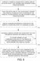
- FIG. 2schematically illustrates the needle assembly of FIG. 1 as being placed against the parietal pleura (an outer surface of a membrane which covers a lung).
- the outer shaft 22also defines one or more pliable-tissue receivers 34 which extend proximally from the distal end 30 of the shaft 22 .
- the distal end 30 of the shaft 22is preferably blunted so that it does not act as a sharp surface.
Landscapes
- Health & Medical Sciences (AREA)
- Life Sciences & Earth Sciences (AREA)
- Surgery (AREA)
- General Health & Medical Sciences (AREA)
- Veterinary Medicine (AREA)
- Engineering & Computer Science (AREA)
- Biomedical Technology (AREA)
- Animal Behavior & Ethology (AREA)
- Heart & Thoracic Surgery (AREA)
- Public Health (AREA)
- Nuclear Medicine, Radiotherapy & Molecular Imaging (AREA)
- Medical Informatics (AREA)
- Molecular Biology (AREA)
- Pathology (AREA)
- Anesthesiology (AREA)
- Hematology (AREA)
- Surgical Instruments (AREA)
- Media Introduction/Drainage Providing Device (AREA)
Abstract
Description
Claims (14)
Priority Applications (1)
| Application Number | Priority Date | Filing Date | Title |
|---|---|---|---|
| US16/197,524US11633215B2 (en) | 2016-04-19 | 2018-11-21 | Needle assembly for pleural space insufflation and methods thereof |
Applications Claiming Priority (3)
| Application Number | Priority Date | Filing Date | Title |
|---|---|---|---|
| US201662324751P | 2016-04-19 | 2016-04-19 | |
| US15/731,093US10179008B2 (en) | 2016-04-19 | 2017-04-17 | Needle assembly for pleural space insufflation and methods thereof |
| US16/197,524US11633215B2 (en) | 2016-04-19 | 2018-11-21 | Needle assembly for pleural space insufflation and methods thereof |
Related Parent Applications (1)
| Application Number | Title | Priority Date | Filing Date |
|---|---|---|---|
| US15/731,093DivisionUS10179008B2 (en) | 2016-04-19 | 2017-04-17 | Needle assembly for pleural space insufflation and methods thereof |
Publications (2)
| Publication Number | Publication Date |
|---|---|
| US20190083131A1 US20190083131A1 (en) | 2019-03-21 |
| US11633215B2true US11633215B2 (en) | 2023-04-25 |
Family
ID=60040226
Family Applications (2)
| Application Number | Title | Priority Date | Filing Date |
|---|---|---|---|
| US15/731,093ActiveUS10179008B2 (en) | 2016-04-19 | 2017-04-17 | Needle assembly for pleural space insufflation and methods thereof |
| US16/197,524Active2037-08-02US11633215B2 (en) | 2016-04-19 | 2018-11-21 | Needle assembly for pleural space insufflation and methods thereof |
Family Applications Before (1)
| Application Number | Title | Priority Date | Filing Date |
|---|---|---|---|
| US15/731,093ActiveUS10179008B2 (en) | 2016-04-19 | 2017-04-17 | Needle assembly for pleural space insufflation and methods thereof |
Country Status (1)
| Country | Link |
|---|---|
| US (2) | US10179008B2 (en) |
Citations (15)
| Publication number | Priority date | Publication date | Assignee | Title |
|---|---|---|---|---|
| US2728341A (en)* | 1951-11-05 | 1955-12-27 | Zbislaw M Roehr | Hypodermic syringe |
| US3540112A (en)* | 1967-01-18 | 1970-11-17 | Knox Lab Inc | Method for manufacturing a hypodermic needle |
| US5071412A (en)* | 1991-03-01 | 1991-12-10 | Laparomed Corporation | Device and method for performing cholangiography |
| US5374250A (en)* | 1993-11-01 | 1994-12-20 | Dixon; Richard E. | Safety syringe |
| US5588432A (en)* | 1988-03-21 | 1996-12-31 | Boston Scientific Corporation | Catheters for imaging, sensing electrical potentials, and ablating tissue |
| US6471688B1 (en)* | 2000-02-15 | 2002-10-29 | Microsolutions, Inc. | Osmotic pump drug delivery systems and methods |
| US6592552B1 (en)* | 1997-09-19 | 2003-07-15 | Cecil C. Schmidt | Direct pericardial access device and method |
| US6733479B1 (en) | 1999-07-30 | 2004-05-11 | Douglas E. Ott | Perforated trocar sleeve and method of use |
| US20050165366A1 (en)* | 2004-01-28 | 2005-07-28 | Brustad John R. | Medical tubing having variable characteristics and method of making same |
| US20070112325A1 (en) | 2005-11-16 | 2007-05-17 | Wieselthaler Georg M | Implantation procedure for blood pumps |
| US20080312611A1 (en)* | 2007-06-13 | 2008-12-18 | Nicholas Sandor Racz | Retrofitted neural injection system and related methods |
| US20110166509A1 (en) | 2008-09-15 | 2011-07-07 | Lamodel Ltd. | Painless injector |
| US20130006189A1 (en)* | 2010-03-12 | 2013-01-03 | Sid Technologies, Llc | Assembly for use with a syringe |
| US8758299B2 (en)* | 2002-02-11 | 2014-06-24 | Antares Pharma, Inc. | Intradermal injector |
| US20160331910A1 (en)* | 2014-01-31 | 2016-11-17 | Terumo Kabushiki Kaisha | Puncture assisting device and puncture device set |
Family Cites Families (5)
| Publication number | Priority date | Publication date | Assignee | Title |
|---|---|---|---|---|
| US4393870A (en)* | 1974-11-19 | 1983-07-19 | Wolfgang Wagner | Suction injector |
| US6287290B1 (en)* | 1999-07-02 | 2001-09-11 | Pulmonx | Methods, systems, and kits for lung volume reduction |
| WO2009088923A1 (en)* | 2008-01-03 | 2009-07-16 | Maquet Cardiovascular, Llc | Endoscope instruments systems and methods for closed chest epicardial ablation |
| US20120203164A1 (en)* | 2009-10-02 | 2012-08-09 | Gabriel Bitton | Device and method for drug delivery to a targeted skin layer |
| US20160022923A1 (en)* | 2014-07-28 | 2016-01-28 | Russell Curtis | Vein stabilizer device |
- 2017
- 2017-04-17USUS15/731,093patent/US10179008B2/enactiveActive
- 2018
- 2018-11-21USUS16/197,524patent/US11633215B2/enactiveActive
Patent Citations (16)
| Publication number | Priority date | Publication date | Assignee | Title |
|---|---|---|---|---|
| US2728341A (en)* | 1951-11-05 | 1955-12-27 | Zbislaw M Roehr | Hypodermic syringe |
| US3540112A (en)* | 1967-01-18 | 1970-11-17 | Knox Lab Inc | Method for manufacturing a hypodermic needle |
| US5588432A (en)* | 1988-03-21 | 1996-12-31 | Boston Scientific Corporation | Catheters for imaging, sensing electrical potentials, and ablating tissue |
| US5071412A (en)* | 1991-03-01 | 1991-12-10 | Laparomed Corporation | Device and method for performing cholangiography |
| US5374250A (en)* | 1993-11-01 | 1994-12-20 | Dixon; Richard E. | Safety syringe |
| US6592552B1 (en)* | 1997-09-19 | 2003-07-15 | Cecil C. Schmidt | Direct pericardial access device and method |
| US6733479B1 (en) | 1999-07-30 | 2004-05-11 | Douglas E. Ott | Perforated trocar sleeve and method of use |
| US6471688B1 (en)* | 2000-02-15 | 2002-10-29 | Microsolutions, Inc. | Osmotic pump drug delivery systems and methods |
| US8758299B2 (en)* | 2002-02-11 | 2014-06-24 | Antares Pharma, Inc. | Intradermal injector |
| US10646662B2 (en)* | 2002-02-11 | 2020-05-12 | Antares Pharma, Inc. | Intradermal injector |
| US20050165366A1 (en)* | 2004-01-28 | 2005-07-28 | Brustad John R. | Medical tubing having variable characteristics and method of making same |
| US20070112325A1 (en) | 2005-11-16 | 2007-05-17 | Wieselthaler Georg M | Implantation procedure for blood pumps |
| US20080312611A1 (en)* | 2007-06-13 | 2008-12-18 | Nicholas Sandor Racz | Retrofitted neural injection system and related methods |
| US20110166509A1 (en) | 2008-09-15 | 2011-07-07 | Lamodel Ltd. | Painless injector |
| US20130006189A1 (en)* | 2010-03-12 | 2013-01-03 | Sid Technologies, Llc | Assembly for use with a syringe |
| US20160331910A1 (en)* | 2014-01-31 | 2016-11-17 | Terumo Kabushiki Kaisha | Puncture assisting device and puncture device set |
Non-Patent Citations (1)
| Title |
|---|
| Jun. 5, 2018 Office Action; U.S. Appl. No. 15/731,093. |
Also Published As
| Publication number | Publication date |
|---|---|
| US20190083131A1 (en) | 2019-03-21 |
| US10179008B2 (en) | 2019-01-15 |
| US20170296231A1 (en) | 2017-10-19 |
Similar Documents
| Publication | Publication Date | Title |
|---|---|---|
| US10004533B2 (en) | Surgical tools and system for safely accessing body cavities and methods of using the same | |
| US11234734B2 (en) | Obturator having an insufflation pathway and an instrument guide | |
| US7135010B2 (en) | Method and apparatus for rapid deployment chest drainage | |
| JP6411626B2 (en) | Replaceable surgical access port assembly | |
| US3459188A (en) | Paracentesis stylet catheter | |
| US6905484B2 (en) | Method and apparatus for rapid deployment chest drainage | |
| US8292919B2 (en) | Skin seal with inflatable membrane | |
| US8252057B2 (en) | Surgical access device | |
| US6517519B1 (en) | Device and method for rapid chest tube insertion | |
| JP3924033B2 (en) | Device for forming a hole in the tracheal wall | |
| EP2391286B1 (en) | Transapical mini-introducer homeostasis valve and punch | |
| US20190008551A1 (en) | Surgical tools and system for safely accessing body cavities and methods of using the same | |
| US20060079845A1 (en) | Movable inflatable anchor for medical devices | |
| JPH0263471A (en) | Gas blow-in needle having instrument port | |
| JP2020500078A (en) | Surgical system and method of use | |
| WO2011146332A1 (en) | Dilating device | |
| US11633215B2 (en) | Needle assembly for pleural space insufflation and methods thereof | |
| US11439430B2 (en) | Surgical access device with air release mechanism | |
| US9089663B2 (en) | Percutaneous access device | |
| KR20160088860A (en) | Exchanger surgical access port assembly and methods of use | |
| CN111479526B (en) | Fine cannula trocars and methods | |
| US9295489B2 (en) | Guide tube system for forming pneumoperitoneum and providing route for accessing body cavity | |
| US10485961B2 (en) | Medical procedure for inserting a chest drainage tube | |
| EP3725245A1 (en) | Balloon trocar including a pin | |
| JP2015051279A (en) | Trocar |
Legal Events
| Date | Code | Title | Description |
|---|---|---|---|
| FEPP | Fee payment procedure | Free format text:ENTITY STATUS SET TO UNDISCOUNTED (ORIGINAL EVENT CODE: BIG.); ENTITY STATUS OF PATENT OWNER: SMALL ENTITY | |
| AS | Assignment | Owner name:LSI SOLUTIONS, INC., NEW YORK Free format text:ASSIGNMENT OF ASSIGNORS INTEREST;ASSIGNOR:SAUER, MD, JUDE S.;REEL/FRAME:047729/0145 Effective date:20181207 | |
| FEPP | Fee payment procedure | Free format text:ENTITY STATUS SET TO SMALL (ORIGINAL EVENT CODE: SMAL); ENTITY STATUS OF PATENT OWNER: SMALL ENTITY | |
| STPP | Information on status: patent application and granting procedure in general | Free format text:DOCKETED NEW CASE - READY FOR EXAMINATION | |
| STPP | Information on status: patent application and granting procedure in general | Free format text:NON FINAL ACTION MAILED | |
| STPP | Information on status: patent application and granting procedure in general | Free format text:RESPONSE TO NON-FINAL OFFICE ACTION ENTERED AND FORWARDED TO EXAMINER | |
| STPP | Information on status: patent application and granting procedure in general | Free format text:FINAL REJECTION MAILED | |
| STCF | Information on status: patent grant | Free format text:PATENTED CASE |