US11631421B2 - Apparatuses and methods for enhanced speech recognition in variable environments - Google Patents
Apparatuses and methods for enhanced speech recognition in variable environmentsDownload PDFInfo
- Publication number
- US11631421B2 US11631421B2US14/886,080US201514886080AUS11631421B2US 11631421 B2US11631421 B2US 11631421B2US 201514886080 AUS201514886080 AUS 201514886080AUS 11631421 B2US11631421 B2US 11631421B2
- Authority
- US
- United States
- Prior art keywords
- signal
- threshold value
- background noise
- voice activity
- filter
- Prior art date
- Legal status (The legal status is an assumption and is not a legal conclusion. Google has not performed a legal analysis and makes no representation as to the accuracy of the status listed.)
- Active
Links
- 238000000034methodMethods0.000titleclaimsabstractdescription41
- 230000000694effectsEffects0.000claimsabstractdescription85
- 238000007493shaping processMethods0.000claimsabstractdescription45
- 230000003044adaptive effectEffects0.000claimsabstractdescription42
- 238000012935AveragingMethods0.000claimsabstractdescription12
- 238000012545processingMethods0.000claimsdescription34
- 238000005259measurementMethods0.000claimsdescription19
- 230000015654memoryEffects0.000claimsdescription18
- 230000006870functionEffects0.000claimsdescription16
- 230000006835compressionEffects0.000claimsdescription12
- 238000007906compressionMethods0.000claimsdescription12
- 238000001914filtrationMethods0.000claimsdescription10
- 230000008569processEffects0.000claimsdescription10
- 238000001514detection methodMethods0.000claimsdescription9
- 238000009499grossingMethods0.000claimsdescription8
- 238000012360testing methodMethods0.000claimsdescription5
- 238000004590computer programMethods0.000claimsdescription3
- 108091006146ChannelsProteins0.000description139
- 230000004044responseEffects0.000description17
- 238000013459approachMethods0.000description6
- 238000010586diagramMethods0.000description6
- 238000004891communicationMethods0.000description5
- 230000014509gene expressionEffects0.000description5
- 230000003287optical effectEffects0.000description5
- 230000009467reductionEffects0.000description5
- 230000003321amplificationEffects0.000description4
- 230000009977dual effectEffects0.000description4
- 230000007774longtermEffects0.000description4
- 230000007246mechanismEffects0.000description4
- 238000003199nucleic acid amplification methodMethods0.000description4
- 230000009471actionEffects0.000description3
- 230000007423decreaseEffects0.000description3
- 238000000605extractionMethods0.000description3
- 230000005291magnetic effectEffects0.000description3
- 238000003491arrayMethods0.000description2
- 230000008859changeEffects0.000description2
- 230000000052comparative effectEffects0.000description2
- 238000010276constructionMethods0.000description2
- 238000013461designMethods0.000description2
- 230000003595spectral effectEffects0.000description2
- 244000261422Lysimachia clethroidesSpecies0.000description1
- 239000000654additiveSubstances0.000description1
- 230000000996additive effectEffects0.000description1
- 230000004075alterationEffects0.000description1
- 230000006399behaviorEffects0.000description1
- 230000008901benefitEffects0.000description1
- 230000005540biological transmissionEffects0.000description1
- 230000015556catabolic processEffects0.000description1
- 229910010293ceramic materialInorganic materials0.000description1
- 238000006731degradation reactionMethods0.000description1
- 230000003292diminished effectEffects0.000description1
- 239000011521glassSubstances0.000description1
- 230000010354integrationEffects0.000description1
- 239000000463materialSubstances0.000description1
- 230000004048modificationEffects0.000description1
- 238000012986modificationMethods0.000description1
- 230000000737periodic effectEffects0.000description1
- 230000002093peripheral effectEffects0.000description1
- 229910021420polycrystalline siliconInorganic materials0.000description1
- 229920005591polysiliconPolymers0.000description1
- 230000000644propagated effectEffects0.000description1
- 230000008707rearrangementEffects0.000description1
- 229910052710siliconInorganic materials0.000description1
- 239000010703siliconSubstances0.000description1
- 230000005236sound signalEffects0.000description1
- 238000001228spectrumMethods0.000description1
- 239000000126substanceSubstances0.000description1
- 230000001052transient effectEffects0.000description1
- 230000000007visual effectEffects0.000description1
Images


Classifications
- G—PHYSICS
- G10—MUSICAL INSTRUMENTS; ACOUSTICS
- G10L—SPEECH ANALYSIS TECHNIQUES OR SPEECH SYNTHESIS; SPEECH RECOGNITION; SPEECH OR VOICE PROCESSING TECHNIQUES; SPEECH OR AUDIO CODING OR DECODING
- G10L21/00—Speech or voice signal processing techniques to produce another audible or non-audible signal, e.g. visual or tactile, in order to modify its quality or its intelligibility
- G10L21/02—Speech enhancement, e.g. noise reduction or echo cancellation
- G10L21/0208—Noise filtering
- G10L21/0216—Noise filtering characterised by the method used for estimating noise
- G—PHYSICS
- G10—MUSICAL INSTRUMENTS; ACOUSTICS
- G10L—SPEECH ANALYSIS TECHNIQUES OR SPEECH SYNTHESIS; SPEECH RECOGNITION; SPEECH OR VOICE PROCESSING TECHNIQUES; SPEECH OR AUDIO CODING OR DECODING
- G10L25/00—Speech or voice analysis techniques not restricted to a single one of groups G10L15/00 - G10L21/00
- G10L25/78—Detection of presence or absence of voice signals
- G10L25/84—Detection of presence or absence of voice signals for discriminating voice from noise
- G—PHYSICS
- G10—MUSICAL INSTRUMENTS; ACOUSTICS
- G10L—SPEECH ANALYSIS TECHNIQUES OR SPEECH SYNTHESIS; SPEECH RECOGNITION; SPEECH OR VOICE PROCESSING TECHNIQUES; SPEECH OR AUDIO CODING OR DECODING
- G10L21/00—Speech or voice signal processing techniques to produce another audible or non-audible signal, e.g. visual or tactile, in order to modify its quality or its intelligibility
- G10L21/02—Speech enhancement, e.g. noise reduction or echo cancellation
- G10L21/0208—Noise filtering
- G10L21/0216—Noise filtering characterised by the method used for estimating noise
- G10L2021/02161—Number of inputs available containing the signal or the noise to be suppressed
- G10L2021/02165—Two microphones, one receiving mainly the noise signal and the other one mainly the speech signal
- G—PHYSICS
- G10—MUSICAL INSTRUMENTS; ACOUSTICS
- G10L—SPEECH ANALYSIS TECHNIQUES OR SPEECH SYNTHESIS; SPEECH RECOGNITION; SPEECH OR VOICE PROCESSING TECHNIQUES; SPEECH OR AUDIO CODING OR DECODING
- G10L25/00—Speech or voice analysis techniques not restricted to a single one of groups G10L15/00 - G10L21/00
- G10L25/78—Detection of presence or absence of voice signals
- G10L2025/783—Detection of presence or absence of voice signals based on threshold decision
- G10L2025/786—Adaptive threshold
Definitions
- the inventionrelates generally to detecting and processing acoustic signal data and more specifically to reducing noise in acoustic systems.
- Acoustic systemsemploy acoustic sensors such as microphones to receive audio signals. Often, these systems are used in real world environments which present desired audio and undesired audio (also referred to as noise) to a receiving microphone simultaneously. Such receiving microphones are part of a variety of systems such as a mobile phone, a handheld microphone, a hearing aid, etc. These systems often perform speech recognition processing on the received acoustic signals. Simultaneous reception of desired audio and undesired audio have a negative impact on the quality of the desired audio. Degradation of the quality of the desired audio can result in desired audio which is output to a user and is hard for the user to understand. Degraded desired audio used by an algorithm such as in speech recognition (SR) or Automatic Speech Recognition (ASR) can result in an increased error rate which can render the reconstructed speech hard to understand. Either of which presents a problem.
- SRspeech recognition
- ASRAutomatic Speech Recognition
- Undesired audiocan originate from a variety of sources, which are not the source of the desired audio.
- the sources of undesired audioare statistically uncorrelated with the desired audio.
- the sourcescan be of a non-stationary origin or from a stationary origin. Stationary applies to time and space where amplitude, frequency, and direction of an acoustic signal do not vary appreciably. For example, in an automobile environment engine noise at constant speed is stationary as is road noise or wind noise, etc. In the case of a non-stationary signal, noise amplitude, frequency distribution, and direction of the acoustic signal vary as a function of time and or space.
- Non-stationary noiseoriginates for example, from a car stereo, noise from a transient such as a bump, door opening or closing, conversation in the background such as chit chat in a back seat of a vehicle, etc.
- Stationary and non-stationary sources of undesired audioexist in office environments, concert halls, football stadiums, airplane cabins, everywhere that a user will go with an acoustic system (e.g., mobile phone, tablet computer etc. equipped with a microphone, a headset, an ear bud microphone, etc.)
- an acoustic systeme.g., mobile phone, tablet computer etc. equipped with a microphone, a headset, an ear bud microphone, etc.
- the environment that the acoustic system is used inis reverberant, thereby causing the noise to reverberate within the environment, with multiple paths of undesired audio arriving at the microphone location.
- Either source of noisei.e., non-stationary or stationary undesired audio
- increases the error rate of speech recognition algorithmssuch as SR or ASR or can simply make it difficult for a system to output desired audio to a user which can be understood. All of this can present a problem.
- noise cancellation approacheshave been employed to reduce noise from stationary and non-stationary sources.
- Existing noise cancellation approacheswork better in environments where the magnitude of the noise is less than the magnitude of the desired audio, e.g., in relatively low noise environments.
- Spectral subtractionis used to reduce noise in speech recognition algorithms and in various acoustic systems such as in hearing aids. Systems employing Spectral Subtraction do not produce acceptable error rates when used in Automatic Speech Recognition (ASR) applications when a magnitude of the undesired audio becomes large. This can present a problem.
- ASRAutomatic Speech Recognition
- VADVoice Activity Detector
- a VADattempts to detect when desired speech is present and when undesired audio is present. Thereby, only accepting desired speech and treating as noise by not transmitting the undesired audio.
- Traditional voice activity detectiononly works well for a single sound source or a stationary noise (undesired audio) whose magnitude is small relative to the magnitude of the desired audio. Therefore, traditional voice activity detection renders a VAD a poor performer in a noisy environment.
- using a VAD to remove undesired audiodoes not work well when the desired audio and the undesired audio are arriving simultaneously at a receive microphone. This can present a problem.
- an energy level ratio between a main microphone and a reference microphoneis compared with a preset threshold to determine when desired voice activity is present. If the energy level ratio is greater than the preset threshold, then desired voice activity is detected. If the energy level ratio does not exceed the preset threshold then desired audio is not detected.
- a preset thresholdcan either fail to detect desired voice activity or undesired audio can be accepted as desired voice activity. In either case, the system's ability to properly detect desired voice activity is diminished, thereby negatively effecting system performance. This can present a problem.
- FIG. 1illustrates system architecture, according to embodiments of the invention.
- FIG. 2illustrates a filter control/adaptive threshold module, according to embodiments of the invention.
- FIG. 3illustrates a background noise estimation module, according to embodiments of the invention.
- FIG. 4 Aillustrates a 75 dB background noise measurement, according to embodiments of the invention.
- FIG. 4 Billustrates a 90 dB background noise measurement, according to embodiments of the invention.
- FIG. 5illustrates threshold value as a function of background noise level according to embodiments of the invention.
- FIG. 6illustrates an adaptive threshold applied to voice activity detection according to embodiments of the invention.
- FIG. 7illustrates a process for providing an adaptive threshold according to embodiments of the invention.
- FIG. 8illustrates another diagram of system architecture, according to embodiments of the invention.
- FIG. 9illustrates desired and undesired audio on two acoustic channels, according to embodiments of the invention.
- FIG. 10 Aillustrates a shaping filter response, according to embodiments of the invention.
- FIG. 10 Billustrates another shaping filter response, according to embodiments of the invention.
- FIG. 11illustrates the signals from FIG. 9 filtered by the filter of FIG. 10 , according to embodiments of the invention.
- FIG. 12illustrates an acoustic signal processing system, according to embodiments of the invention.
- Apparatuses and methodsare described for detecting and processing acoustic signals containing both desired audio and undesired audio.
- apparatuses and methodsare described which increase the performance of noise cancellation systems by increasing the signal-to-noise ratio difference between multiple channels and adaptively changing a threshold value of a voice activity detector based on the background noise of the environment.
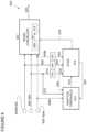
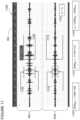
- FIG. 1illustrates, generally at 100 , system architecture, according to embodiments of the invention.
- two acoustic channelsare input into a noise cancellation module 103 .
- a first acoustic channelreferred to herein as main channel 102
- main channel 102contains both desired audio and undesired audio.
- the acoustic signal input on the main channel 102arises from the presence of both desired audio and undesired audio on one or more acoustic elements as described more fully below in the figures that follow.
- the microphone elementscan output an analog signal.
- the analog signalis converted to a digital signal with an analog-to-digital converter (ADC) (not shown). Additionally, amplification can be located proximate to the microphone element(s) or ADC.
- a second acoustic channelreferred to herein as reference channel 104 provides an acoustic signal which also arises from the presence of desired audio and undesired audio.
- a second reference channel 104 bcan be input into the noise cancellation module 103 . Similar to the main channel and depending on the configuration of a microphone or microphones used for the reference channel, the microphone elements can output an analog signal.
- the analog signalis converted to a digital signal with an analog-to-digital converter (ADC) (not shown). Additionally, amplification can be located proximate to the microphone element(s) or AD converter.
- ADCanalog-to-digital converter
- the main channel 102has an omni-directional response and the reference channel 104 has an omni-directional response.
- the acoustic beam patterns for the acoustic elements of the main channel 102 and the reference channel 104are different.
- the beam patterns for the main channel 102 and the reference channel 104are the same; however, desired audio received on the main channel 102 is different from desired audio received on the reference channel 104 . Therefore, a signal-to-noise ratio for the main channel 102 and a signal-to-noise ratio for the reference channel 104 are different. In general, the signal-to-noise ratio for the reference channel is less than the signal-to-noise-ratio of the main channel.
- a difference between a main channel signal-to-noise ratio and a reference channel signal-to-noise ratiois approximately 1 or 2 decibels (dB) or more. In other non-limiting examples, a difference between a main channel signal-to-noise ratio and a reference channel signal-to-noise ratio is 1 decibel (dB) or less.
- dBdecibel
- embodiments of the inventionare suited for high noise environments, which can result in low signal-to-noise ratios with respect to desired audio as well as low noise environments, which can have higher signal-to-noise ratios.
- signal-to-noise ratiomeans the ratio of desired audio to undesired audio in a channel.
- main channel signal-to-noise ratiois used interchangeably with the term “main signal-to-noise ratio.”
- reference channel signal-to-noise ratiois used interchangeably with the term “reference signal-to-noise ratio.”
- the main channel 102 , the reference channel 104 , and optionally a second reference channel 104 bprovide inputs to the noise cancellation module 103 . While an optional second reference channel is shown in the figures, in various embodiments, more than two reference channels are used.
- the noise cancellation module 103includes an adaptive noise cancellation unit 106 which filters undesired audio from the main channel 102 , thereby providing a first stage of filtering with multiple acoustic channels of input.
- the adaptive noise cancellation unit 106utilizes an adaptive finite impulse response (FIR) filter.
- FIRadaptive finite impulse response
- the adaptive noise cancellation unit 106includes a delay for the main channel sufficient to approximate the impulse response of the environment in which the system is used.
- a magnitude of the delay usedwill vary depending on the particular application that a system is designed for including whether or not reverberation must be considered in the design.
- a magnitude of the delaycan be on the order of a fraction of a millisecond. Note that at the low end of a range of values, which could be used for a delay, an acoustic travel time between channels can represent a minimum delay value.
- a delay valuecan range from approximately a fraction of a millisecond to approximately 500 milliseconds or more depending on the application.
- An output 107 of the adaptive noise cancellation unit 106is input into a single channel noise cancellation unit 118 .
- the single channel noise cancellation unit 118filters the output 107 and provides a further reduction of undesired audio from the output 107 , thereby providing a second stage of filtering.
- the single channel noise cancellation unit 118filters mostly stationary contributions to undesired audio.
- the single channel noise cancellation unit 118includes a linear filter, such as for example a Wiener filter, a Minimum Mean Square Error (MMSE) filter implementation, a linear stationary noise filter, or other Bayesian filtering approaches which use prior information about the parameters to be estimated. Further description of the adaptive noise cancellation unit 106 and the components associated therewith and the filters used in the single channel noise cancellation unit 118 are described in U.S. Pat.
- Acoustic signals from the main channel 102are input at 108 into a filter control which includes a desired voice activity detector 114 .
- acoustic signals from the reference channel 104are input at 110 into the desired voice activity detector 114 and into adaptive threshold module 112 .
- An optional second reference channelis input at 108 b into desired voice activity detector 114 and into adaptive threshold module 112 .
- the desired voice activity detector 114provides control signals 116 to the noise cancellation module 103 , which can include control signals for the adaptive noise cancellation unit 106 and the single channel noise cancellation unit 118 .
- the desired voice activity detector 114provides a signal at 122 to the adaptive threshold module 112 .
- the signal 122indicates when desired voice activity is present and not present. In one or more embodiments a logical convention is used wherein a “1” indicates voice activity is present and a “0” indicates voice activity is not present. In other embodiments other logical conventions can be used for the signal 122 .
- the adaptive threshold module 112includes a background noise estimation module and selection logic which provides a threshold value which corresponds to a given estimated average background noise level.
- a threshold value corresponding to an estimated average background noise levelis passed at 118 to the desired voice activity detector 114 .
- the threshold valueis used by the desired voice activity detector 114 to determine when voice activity is present.
- An output 120 of the noise cancellation module 103provides an acoustic signal which contains mostly desired audio and a reduced amount of undesired audio.
- the system architecture shown in FIG. 1can be used in a variety of different systems used to process acoustic signals according to various embodiments of the invention.
- Some examples of the different acoustic systemsare, but are not limited to, a mobile phone, a handheld microphone, a boom microphone, a microphone headset, a hearing aid, a hands free microphone device, a wearable system embedded in a frame of an eyeglass, a near-to-eye (NTE) headset display or headset computing device, any wearable device, etc.
- the environments that these acoustic systems are used incan have multiple sources of acoustic energy incident upon the acoustic elements that provide the acoustic signals for the main channel 102 and the reference channel 104 as well as optional channels 104 b .
- the desired audiois usually the result of a user's own voice.
- the undesired audiois usually the result of the combination of the undesired acoustic energy from the multiple sources that are incident upon the acoustic elements used for both the main channel and the reference channel.
- the undesired audiois statistically uncorrelated with the desired audio.
- FIG. 2illustrates, generally at 112 , an adaptive threshold module, according to embodiments of the invention.
- a background noise estimation module 202receives a reference acoustic signal 110 and one or more optional additional reference acoustic signals represented by 108 b .
- a signal 122 from a desired voice activity detector(e.g., such as 114 in FIG. 1 or 814 in FIG. 8 below) provides a signal to the background noise estimation module which indicates when voice activity is present or not present.
- the background noise estimation module 202averages the background noise from 110 and 108 b to provide an estimated average background noise level at 204 to selection logic 210 .
- Selection logic 210selects a threshold value which corresponds to the estimated average background noise level passed at 204 .
- An association of various estimated average background noise levelshas been previously made with the threshold values 206 by means of empirical measurements.
- the selection logic 210 together with the threshold values 206provide a threshold value at 208 which adapts to the estimated average background noise level measured by the system.
- the threshold value 208is provided to a desired voice activity detector, such as 114 in FIG. 1 or elsewhere in the figures that follow for use in detecting when desired voice activity is present.
- the amplitude of the reference signals 110 / 108 bwill vary depending on the noise environment that the system is used in. For example, in a quiet environment, such as in some office settings, the background noise will be lower than for example in some outdoor environments subject to for example road noise or the noise generated at a construction site. In such varying environments, a different background noise level will be estimated by 202 and different threshold values will be selected by selection logic 210 based on the estimated average background noise level. The relationship between background noise level and threshold value is discussed more fully below in conjunction with FIG. 5 .
- FIG. 3illustrates, generally at 202 , a background noise estimation module, according to embodiments of the invention.
- a reference microphone signal 110is input to a buffer 304 .
- one or more additional reference microphonesare input to the buffer 304 as represented by 108 b .
- the buffer 304can be configured in different ways to accept different amounts of data.
- the buffer 304processes one frame of data at a time.
- the energy represented by the frame of datacan be calculated in various ways.
- the frame energyis obtained by squaring the amplitude of each sample and then summing the absolute value of each squared sample in the frame.
- the frame energyis compressed at a signal compressor 306 where the energy is scaled to a different range.
- the compressed datais smoothed by a smoothing stage 308 where the high frequency fluctuations are reduced.
- smoothingis accomplished by a simple moving average, as shown by an equation 320 .
- smoothingis accomplished by an exponential moving average as shown by an equation 330 .
- the smoothed frame energyis output at 310 as the estimated average background energy level which used by selection logic to select a threshold value that corresponds to the estimated average background energy level as described above in conjunction with FIG. 2 .
- the estimated average background energy levelis only calculated and updated across 302 when voice activity is not present, which in some logical implementations occurs when the signal 122 is at zero.
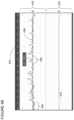
- FIG. 4 Aillustrates, generally at 400 , a 75 dB (decibel) background noise measurement, according to embodiments of the invention.
- a main microphone signal 406is displayed with amplitude on the vertical axis 402 and time on the horizontal axis 404 .
- the time record displayed in FIG. 4 Arepresents approximately 30 seconds on data and the units associated with vertical axis are decibels.
- the figures FIG. 4 A and FIG. 4 Bare provided for relative amplitude comparison therebetween on vertical axes having the same absolute range; however neither the absolute scale nor the decibels per division are indicated thereon for clarity in presentation. Referring back to FIG.
- the main microphone signal 406was acquired with intermittent speech spoken in the presence of a background noise level of 75 dB.
- the main microphone signal 406includes segments of voice activity such as for example 408 , and sections of no voice activity, such as for example 410 . Only 408 and 410 have been marked as such to preserve clarity in the illustration.
- An estimate of the average estimated background noise levelis plotted at 422 with vertical scale 420 plotted with units of dB.
- the average estimated background noise level 422has been estimated using the teachings presented above in conjunction with the preceding figures. Note that in the case of FIG. 4 A and FIG. 4 B the main microphone signal has been processed to produce the estimated average background noise level. This is an alternative embodiment relative to processing the reference microphone signal in order to obtain an estimated average background noise level.
- FIG. 4 Billustrates, generally at 450 , a 90 dB background noise measurement, according to embodiments of the invention.
- an increased background noise level of 90 dB(increased from 75 dB used in FIG. 4 A ) was used as a background level when speech was spoken.
- a main microphone signal 456includes segments of voice activity such as for example 458 , and sections of no voice activity, such as for example 460 . Only 458 and 460 have been marked as such to preserve clarity in the illustration.
- An estimate of the average estimated background noise levelis plotted at 472 with vertical scale 420 plotted with units of dB.
- the average estimated background noise level 472has been estimated using the teachings presented above in conjunction with the preceding figures.
- Visual comparison of 422 ( FIG. 4 A ) with 472 ( FIG. 4 B )indicate that the amplitude of 472 is greater than the amplitude of 422 , noting that the average estimated background noise level has moved in the vertical direction representing an increase in level, which is consistent with a 90 dB background noise level being greater than a 75 dB background noise level.
- Different speech signalswere collected during the measurement of FIG. 4 A verses the measurement of FIG. 4 B , therefore the segments of voice activity are different in each plot.
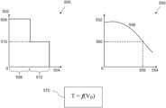
- FIG. 5illustrates threshold value as a function of background noise level according to embodiments of the invention.
- two different threshold valueshave been plotted as a function of average estimated background noise level.
- Increasing threshold valueis indicated on a vertical axis at 502
- increasing noise levelis indicated on a horizontal axis at 504 .
- a first threshold value indicated at 506is used for a range of estimated average noise level shown at 508 .
- a second threshold value 510is used for a range of estimated average noise level shown at 512 . Note that as the estimated average noise level increases the threshold value decreases. Underlying this system behavior is the observation that a difference in signal-to-noise ratio (between the main and reference microphones) is greater when the background noise level is lower and the difference in signal-to-noise ratio decreases as the background noise level increases.
- a continuous variation in threshold valueis plotted as a function of estimated average background noise level at 556 .
- threshold valueis plotted on the vertical axis at 552 and noise level is plotted on the horizontal axis at 554 .
- Any threshold value corresponding to an estimated average background noise levelis obtained from the curve 556 such as for example a threshold value 560 corresponding with an average estimated background noise level 558 .
- a relationship between threshold value “T” and estimated average background noise level V Bis shown qualitatively by equation 570 where f(V B ) is defined by the functional relationship illustrated in the plot at 550 by the curve 556 .
- the threshold valueis selected which provides the greatest accuracy for the speech recognition test.
- the associations of threshold value and estimated average background noise levelare obtained empirically in a variety of ways.
- the associationis created by operating a noise cancellation system at different known levels of background noise and establishing threshold values which provide enhanced noise cancellation operation. This can be done in various ways such as by testing the accuracy of speech recognition on a set of test words as a function of threshold value for fixed background noise level and then repeating over a range of background noise level.
- the threshold valuesare stored and are available for use by the data processing system.
- the threshold valuesare stored in a look-up table at 206 ( FIG. 2 ) or a functional relationship 570 ( FIG. 5 ) can be provided at 206 ( FIG. 2 ).
- logicsuch as selection logic 210 in FIG. 2 ) retrieves a threshold value corresponding to a given estimated average background noise level for use during noise cancellation.
- Implementation of an adaptive threshold for the desired voice detection circuitenables a data processing system employing such functionality to operate over a greater range of background noise operating conditions ranging from a quiet whisper to loud construction noise. Such functionality improves the accuracy of the voice recognition and decreases a speech recognition error rate.
- FIG. 6illustrates, generally at 600 , an adaptive threshold applied to voice activity detection, according to embodiments of the invention.
- a normalized main signal 602obtained from the desired voice activity detector, is input into a long-term normalized power estimator 604 .
- the long-term normalized power estimator 604provides a running estimate of the normalized main signal 602 .
- the running estimateprovides a floor for desired audio.
- An offset value 610is added in an adder 608 to a running estimate of the output of the long-term normalized power estimator 604 .
- the output of the adder 612is input to comparator 616 .
- An instantaneous estimate 614 of the normalized main signal 602is input to the comparator 616 .
- the comparator 616contains logic that compares the instantaneous value at 614 to the running ratio plus offset at 612 . If the value at 614 is greater than the value at 612 , desired audio is detected and a flag is set accordingly and transmitted as part of the normalized desired voice activity detection signal 618 . If the value at 614 is less than the value at 612 desired audio is not detected and a flag is set accordingly and transmitted as part of the normalized desired voice activity detection signal 618 .
- the long-term normalized power estimator 604averages the normalized main signal 602 for a length of time sufficiently long in order to slow down the change in amplitude fluctuations.
- amplitude fluctuationsare slowly changing at 606 .
- the averaging timecan vary from a fraction of a second to minutes, by way of non-limiting examples. In various embodiments, an averaging time is selected to provide slowly changing amplitude fluctuations at the output of 606 .
- the threshold offset 610is provided as described above, for example at 118 ( FIG. 1 ), at 208 ( FIG. 2 ), or at 818 ( FIG. 8 ). Note that the threshold offset 610 will adaptively change in response to an estimated average background noise level as calculated based on the noise received on either the reference microphone or the main microphone channels.
- the estimated average background noise levelwas made using the reference microphone channel as described above in FIG. 1 and below in FIG. 8 , however in alternative embodiments an estimated average background noise level can be estimated from the main microphone channel.
- FIG. 7illustrates, generally at 700 , a process for providing an adaptive threshold according to embodiments of the invention.
- a processbegins at a block 702 .
- an average background noise levelis estimated from either a reference microphone channel or a main microphone channel when voice activity is not detected.
- multiple reference channelsare used to perform this estimation.
- the main microphone channelis used to provide the estimation.
- a threshold value(used synonymously with the term threshold offset value) is selected based on the estimated average background noise level computed from the channel used in the block 704 .
- the threshold value selected in block 706is used to obtain a signal that indicates the presence of desired voice activity.
- the desired voice activity signalis used during noise cancellation as described in U.S. Pat. No. 9,633,670 B2, titled DUAL STAGE NOISE REDUCTION ARCHITECTURE FOR DESIRED SIGNAL EXTRACTION, which is hereby incorporated by reference.
- FIG. 8illustrates another diagram of system architecture, according to embodiments of the invention.
- two acoustic channelsare input into a noise cancellation module 803 .
- a first acoustic channelreferred to herein as main channel 802
- main channel 802contains both desired audio and undesired audio.
- the acoustic signal input on the main channel 802arises from the presence of both desired audio and undesired audio on one or more acoustic elements as described more fully below in the figures that follow.
- the microphone elementscan output an analog signal.
- the analog signalis converted to a digital signal with an analog-to-digital converter (ADC) (not shown). Additionally, amplification can be located proximate to the microphone element(s) or ADC.
- a second acoustic channel, referred to herein as reference channel 804provides an acoustic signal which also arises from the presence of desired audio and undesired audio.
- a second reference channel 804 bcan be input into the noise cancellation module 803 . Similar to the main channel and depending on the configuration of a microphone or microphones used for the reference channel, the microphone elements can output an analog signal.
- the analog signalis converted to a digital signal with an analog-to-digital converter (ADC) (not shown). Additionally, amplification can be located proximate to the microphone element(s) or ADC.
- ADCanalog-to-digital converter
- the main channel 802has an omni-directional response and the reference channel 804 has an omni-directional response.
- the acoustic beam patterns for the acoustic elements of the main channel 802 and the reference channel 804are different.
- the beam patterns for the main channel 802 and the reference channel 804are the same; however, desired audio received on the main channel 802 is different from desired audio received on the reference channel 804 . Therefore, a signal-to-noise ratio for the main channel 802 and a signal-to-noise ratio for the reference channel 804 are different. In general, the signal-to-noise ratio for the reference channel is less than the signal-to-noise-ratio of the main channel.
- a difference between a main channel signal-to-noise ratio and a reference channel signal-to-noise ratiois approximately 1 or 2 decibels (dB) or more. In other non-limiting examples, a difference between a main channel signal-to-noise ratio and a reference channel signal-to-noise ratio is 1 decibel (dB) or less.
- dBdecibel
- embodiments of the inventionare suited for high noise environments, which can result in low signal-to-noise ratios with respect to desired audio as well as low noise environments, which can have higher signal-to-noise ratios.
- signal-to-noise ratiomeans the ratio of desired audio to undesired audio in a channel.
- main channel signal-to-noise ratiois used interchangeably with the term “main signal-to-noise ratio.”
- reference channel signal-to-noise ratiois used interchangeably with the term “reference signal-to-noise ratio.”
- the main channel 802 , the reference channel 804 , and optionally a second reference channel 804 bprovide inputs to the noise cancellation module 803 . While an optional second reference channel is shown in the figures, in various embodiments, more than two reference channels are used.
- the noise cancellation module 803includes an adaptive noise cancellation unit 806 which filters undesired audio from the main channel 802 , thereby providing a first stage of filtering with multiple acoustic channels of input.
- the adaptive noise cancellation unit 806utilizes an adaptive finite impulse response (FIR) filter.
- FIRadaptive finite impulse response
- the adaptive noise cancellation unit 806includes a delay for the main channel sufficient to approximate the impulse response of the environment in which the system is used.
- a magnitude of the delay usedwill vary depending on the particular application that a system is designed for including whether or not reverberation must be considered in the design.
- a magnitude of the delaycan be on the order of a fraction of a millisecond. Note that at the low end of a range of values, which could be used for a delay, an acoustic travel time between channels can represent a minimum delay value.
- a delay valuecan range from approximately a fraction of a millisecond to approximately 500 milliseconds or more depending on the application.
- An output 807 of the adaptive noise cancellation unit 806is input into a single channel noise cancellation unit 818 .
- the single channel noise cancellation unit 818filters the output 807 and provides a further reduction of undesired audio from the output 807 , thereby providing a second stage of filtering.
- the single channel noise cancellation unit 818filters mostly stationary contributions to undesired audio.
- the single channel noise cancellation unit 818includes a linear filter, such as for example a Wiener filter, a Minimum Mean Square Error (MMSE) filter implementation, a linear stationary noise filter, or other Bayesian filtering approaches which use prior information about the parameters to be estimated. Further description of the adaptive noise cancellation unit 806 and the components associated therewith and the filters used in the single channel noise cancellation unit 818 are described in U.S. Pat. No. 9,633,670, titled DUAL STAGE NOISE REDUCTION ARCHITECTURE FOR DESIRED SIGNAL EXTRACTION, which is hereby incorporated by reference.
- Acoustic signals from the main channel 802are input at 808 into a filter 840 .
- An output 842 of the filter 840is input into a filter control which includes a desired voice activity detector 814 .
- acoustic signals from the reference channel 804are input at 810 into a filter 830 .
- An output 832 of the filter 830is input into the desired voice activity detector 814 .
- the acoustic signals from the reference channel 804are input at 810 into adaptive threshold module 812 .
- An optional second reference channelis input at 808 b into a filter 850 .
- An output 852 of the filter 850is input into the desired voice activity detector 814 and 808 b is input into adaptive threshold module 812 .
- the desired voice activity detector 814provides control signals 816 to the noise cancellation module 803 , which can include control signals for the adaptive noise cancellation unit 806 and the single channel noise cancellation unit 818 .
- the desired voice activity detector 814provides a signal at 822 to the adaptive threshold module 812 .
- the signal 822indicates when desired voice activity is present and not present. In one or more embodiments a logical convention is used wherein a “I” indicates voice activity is present and a “0” indicates voice activity is not present. In other embodiments other logical conventions can be used for the signal 822 .
- the signal input from the reference channel 804 to the adaptive threshold module 812can be taken from the output of the filter 830 , as indicated at 832 .
- the filtered version of these signals at 852can be input to the adaptive threshold module 812 (path not shown to preserve clarity in the illustration). If the filtered version of the signals (e.g., any of 832 , 852 , or 842 ) are input into the adaptive threshold module 812 a set of threshold values will be obtained which are different in magnitude from the threshold values which are obtained utilizing the unfiltered version of the signals. Adaptive threshold functionality is still provided in either case.
- Each of the filters 830 , 840 , and 850provide shaping to their respective input signals, i.e., 810 , 808 , and 808 b and are referred to collectively as shaping filters.
- a shaping filteris used to remove a noise component from the signal that it filters.
- Each of the shaping filters, 830 , 840 , and 850apply substantially the same filtering to their respective input signals.
- Filter characteristicsare selected based on a desired noise mechanism for filtering.
- road noise from a vehicleis often low frequency in nature and sometimes characterized by a 1/f roll-off where f is frequency.
- road noisecan have a peak at low-frequency (approximately zero frequency or at some off-set thereto) with a roll-off as frequency increases.
- a high pass filteris useful to remove the contribution of road noise from the signals 810 , 808 , and optionally 808 b if present.
- a shaping filter used for road noisecan have a response as shown in FIG. 10 A described below.
- a noise componentcan exist over a band of frequency.
- a notch filteris used to filter the signals accordingly.
- filtersare combined such as for example a high-pass filter and a notch filter.
- other filter characteristicsare combined to present a shaping filter designed for the noise environment that the system is deployed into.
- shaping filterscan be programmable so that the data processing system can be adapted for multiple environments where the background noise spectrum is known to have different structure.
- the programmable functionality of a shaping filtercan be accomplished by external jumpers to the integrated circuit containing the filters, adjustment by firmware download, to programmable functionality which is adjusted by a user via voice command according to the environment the system is deployed in. For example, a user can instruct the data processing system via voice command to adjust for road noise, periodic noise, etc. and the appropriate shaping filter is switched in and out according to the command.
- the adaptive threshold module 812includes a background noise estimation module and selection logic which provides a threshold value which corresponds to a given estimated average background noise level.
- a threshold value corresponding to an estimated average background noise levelis passed at 818 to the desired voice activity detector 814 .
- the threshold valueis used by the desired voice activity detector 814 to determine when voice activity is present.
- An output 820 of the noise cancellation module 803provides an acoustic signal which contains mostly desired audio and a reduced amount of undesired audio.
- the system architecture shown in FIG. 1can be used in a variety of different systems used to process acoustic signals according to various embodiments of the invention.
- Some examples of the different acoustic systemsare, but are not limited to, a mobile phone, a handheld microphone, a boom microphone, a microphone headset, a hearing aid, a hands free microphone device, a wearable system embedded in a frame of an eyeglass, a near-to-eye (NTE) headset display or headset computing device, any wearable device, etc.
- the environments that these acoustic systems are used incan have multiple sources of acoustic energy incident upon the acoustic elements that provide the acoustic signals for the main channel 802 and the reference channel 804 as well as optional channels 804 b .
- the desired audiois usually the result of a users own voice.
- the undesired audiois usually the result of the combination of the undesired acoustic energy from the multiple sources that are incident upon the acoustic elements used for both the main channel and the reference channel.
- the undesired audiois statistically uncorrelated with the desired audio.
- FIG. 9illustrates, generally at 900 , desired and undesired audio on two acoustic channels, according to embodiments of the invention.
- a time record of a main microphone signalis plotted with amplitude 904 on a vertical axis
- a reference microphone signalis plotted with amplitude 904 b on a vertical axis
- time 902on a horizontal axis.
- the main microphone signalcontains desired speech in the presence of background noise at a level of 85 dB.
- a signal-to-noise ratio of the main microphone signalis constructed by dividing an amplitude of a speech region 906 by an amplitude of a region of noise 908 .
- the resulting signal-to-noise ratio for the main microphone channelis given by equation 914 .
- a signal-to-noise ratio for the reference channelis obtained by dividing an amplitude of a speech region 910 by an amplitude of a noise region 912 .
- the resulting signal-to-noise ratiois given by equation 916 .
- a signal-to-noise ratio difference between these two channelsis given by equation 918 , where subtraction is used when the quantities are expressed in the log domain and division would be used if the quantities were expressed in the linear domain.
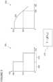
- FIG. 10 Aillustrates, generally at 1000 , a shaping filter response, according to embodiments of the invention.
- filter attenuation magnitudeis plotted on the vertical axis 1002 and frequency is plotted on the horizontal axis 1004 .
- the filter responseis plotted as curve 1006 having a cut-off frequency (3 dB down point relative to unity gain) at 700 Hz as indicated at 1008 .
- Both the main microphone signal and the reference microphone signals from FIG. 9are filtered by a shaping filter having the filter characteristics as illustrated in FIG. 10 A resulting in the filtered time series plots illustrated in FIG. 11 .
- FIG. 10 Billustrates, generally at 1050 , another shaping filter response, according to embodiments of the invention.
- filter attenuation magnitudeis plotted on the vertical axis 1052 and frequency is plotted on the horizontal axis 1054 .
- the filter responseis plotted as a curve 1056 having a cut-off frequency (3 dB down point relative to unity gain) at 700 Hz indicated at 1058 .
- kHzkilohertz
- FIG. 11illustrates, generally at 1100 , the signals from FIG. 9 filtered by the filter of FIG. 10 A , according to embodiments of the invention.
- a time record of a main microphone signalis plotted with amplitude 904 on a vertical axis and time 902 on a horizontal axis.
- the main microphone signalcontains desired speech in the presence of background noise at the level of 85 dB (from FIG. 9 ).
- a signal-to-noise ratio of the main microphone signalis constructed by dividing an amplitude of a speech region 1106 by an amplitude of a region of noise 1108 .
- the resulting signal-to-noise ratio for the main microphone channelis given by equation 1120 .
- a signal-to-noise ratio for the reference channelis obtained by dividing an amplitude of a speech region 1110 by an amplitude of a noise region 1112 .
- the resulting signal-to-noise ratiois given by equation 1130 .
- a signal-to-noise ratio difference between these two channelsis given by equation 1140 , where subtraction is used when the quantities are expressed in the log domain and division would be used if the quantities were expressed in the linear domain.
- FIG. 12illustrates, generally at 1200 , an acoustic signal processing system, according to embodiments of the invention.
- the block diagramis a high-level conceptual representation and may be implemented in a variety of ways and by various architectures.
- bus system 1202interconnects a Central Processing Unit (CPU) 1204 , Read Only Memory (ROM) 1206 , Random Access Memory (RAM) 1208 , storage 1210 , display 1220 , audio 1222 , keyboard 1224 , pointer 1226 , data acquisition unit (DAU) 1228 , and communications 1230 .
- CPUCentral Processing Unit
- ROMRead Only Memory
- RAMRandom Access Memory
- the bus system 1202may be for example, one or more of such buses as a system bus, Peripheral Component Interconnect (PCI), Advanced Graphics Port (AGP), Small Computer System Interface (SCSI), Institute of Electrical and Electronics Engineers (IEEE) standard number 1394 (FireWire), Universal Serial Bus (USB), or a dedicated bus designed for a custom application, etc.
- the CPU 1204may be a single, multiple, or even a distributed computing resource or a digital signal processing (DSP) chip.
- Storage 1210may be Compact Disc (CD), Digital Versatile Disk (DVD), hard disks (HD), optical disks, tape, flash, memory sticks, video recorders, etc.
- the acoustic signal processing system 1200can be used to receive acoustic signals that are input from a plurality of microphones (e.g., a first microphone, a second microphone, etc.) or from a main acoustic channel and a plurality of reference acoustic channels as described above in conjunction with the preceding figures. Note that depending upon the actual implementation of the acoustic signal processing system, the acoustic signal processing system may include some, all, more, or a rearrangement of components in the block diagram. In some embodiments, aspects of the system 1200 are performed in software. While in some embodiments, aspects of the system 1200 are performed in dedicated hardware such as a digital signal processing (DSP) chip, etc. as well as combinations of dedicated hardware and software as is known and appreciated by those of ordinary skill in the art.
- DSPdigital signal processing
- acoustic signal datais received at 1229 for processing by the acoustic signal processing system 1200 .
- Such datacan be transmitted at 1232 via communications interface 1230 for further processing in a remote location.
- Connection with a network, such as an intranet or the Internetis obtained via 1232 , as is recognized by those of skill in the art, which enables the acoustic signal processing system 1200 to communicate with other data processing devices or systems in remote locations.
- embodiments of the inventioncan be implemented on a computer system 1200 configured as a desktop computer or work station, on for example a WINDOWS® compatible computer running operating systems such as WINDOWS' XP Home or WINDOWS® XP Professional, Linux, Unix, etc. as well as computers from APPLE COMPUTER, Inc. running operating systems such as OS X, etc.
- embodiments of the inventioncan be configured with devices such as speakers, earphones, video monitors, etc. configured for use with a Bluetooth communication channel.
- embodiments of the inventionare configured to be implemented by mobile devices such as a smart phone, a tablet computer, a wearable device, such as eye glasses, a near-to-eye (NTE) headset, or the like.
- SRSpeech Recognition
- ASRAutomatic Speech Recognition
- microphonescan be used to provide the acoustic signals needed for the embodiments of the invention presented herein. Any transducer that converts a sound wave to an electrical signal is suitable for use with embodiments of the invention.
- Some non-limiting examples of microphonesare, but are not limited to, a dynamic microphone, a condenser microphone, an Electret Condenser Microphone (ECM), and a microelectromechanical systems (MEMS) microphone.
- ECMElectret Condenser Microphone
- MEMSmicroelectromechanical systems
- CMcondenser microphone
- micro-machined microphonesare used.
- Microphones based on a piezoelectric filmare used with other embodiments. Piezoelectric elements are made out of ceramic materials, plastic material, or film.
- micro-machined arrays of microphonesare used.
- silicon or polysilicon micro-machined microphonesare used.
- bi-directional pressure gradient microphonesare used to provide multiple acoustic channels.
- Various microphones or microphone arrays including the systems described hereincan be mounted on or within structures such as eyeglasses, headsets, wearable devices, etc.
- Various directional microphonescan be used, such as but not limited to, microphones having a cardioid beam pattern, a dipole beam pattern, an omni-directional beam pattern, or a user defined beam pattern.
- one or more acoustic elementsare configured to provide the microphone inputs.
- the components of the adaptive threshold moduleare implemented in an integrated circuit device, which may include an integrated circuit package containing the integrated circuit.
- the adaptive threshold moduleis implemented in a single integrated circuit die.
- the adaptive threshold moduleis implemented in more than one integrated circuit die of an integrated circuit device which may include a multi-chip package containing the integrated circuit.
- the components of the desired voice activity detectorare implemented in an integrated circuit device, which may include an integrated circuit package containing the integrated circuit.
- the desired voice activity detectoris implemented in a single integrated circuit die.
- the desired voice activity detectoris implemented in more than one integrated circuit die of an integrated circuit device which may include a multi-chip package containing the integrated circuit.
- the components of the background noise estimation moduleare implemented in an integrated circuit device, which may include an integrated circuit package containing the integrated circuit.
- the background noise estimation moduleis implemented in a single integrated circuit die.
- the background noise estimation moduleis implemented in more than one integrated circuit die of an integrated circuit device which may include a multi-chip package containing the integrated circuit.
- the components of the noise cancellation moduleare implemented in an integrated circuit device, which may include an integrated circuit package containing the integrated circuit.
- the noise cancellation moduleis implemented in a single integrated circuit die.
- the noise cancellation moduleis implemented in more than one integrated circuit die of an integrated circuit device which may include a multi-chip package containing the integrated circuit.
- the components of the selection logicare implemented in an integrated circuit device, which may include an integrated circuit package containing the integrated circuit.
- the selection logicis implemented in a single integrated circuit die.
- the selection logicis implemented in more than one integrated circuit die of an integrated circuit device which may include a multi-chip package containing the integrated circuit.
- the components of the shaping filterare implemented in an integrated circuit device, which may include an integrated circuit package containing the integrated circuit.
- the shaping filteris implemented in a single integrated circuit die.
- the shaping filteris implemented in more than one integrated circuit die of an integrated circuit device which may include a multi-chip package containing the integrated circuit.
- An apparatus for performing the operations hereincan implement the present invention.
- This apparatusmay be specially constructed for the required purposes, or it may comprise a general-purpose computer, selectively activated or reconfigured by a computer program stored in the computer.
- a computer programmay be stored in a computer readable storage medium, such as, but not limited to, any type of disk including floppy disks, hard disks, optical disks, compact disk read-only memories (CD-ROMs), and magnetic-optical disks, read-only memories (ROMs), random access memories (RAMs), electrically programmable read-only memories (EPROM)s, electrically erasable programmable read-only memories (EEPROMs), FLASH memories, magnetic or optical cards, etc., or any type of media suitable for storing electronic instructions either local to the computer or remote to the computer.
- ROMsread-only memories
- RAMsrandom access memories
- EPROMelectrically programmable read-only memories
- EEPROMselectrically erasable programmable read-only memories
- the inventioncan also be practiced in distributed computing environments where tasks are performed by remote processing devices that are linked through a communications network.
- embodiments of the invention as described above in FIG. 1 through FIG. 12can be implemented using a system on chip (SOC), a Bluetooth chip, a digital signal processing (DSP) chip, a codec with integrated circuits (ICs) or in other implementations of hardware and software.
- SOCsystem on chip
- DSPdigital signal processing
- ICsintegrated circuits
- the methods of the inventionmay be implemented using computer software. If written in a programming language conforming to a recognized standard, sequences of instructions designed to implement the methods can be compiled for execution on a variety of hardware platforms and for interface to a variety of operating systems.
- the present inventionis not described with reference to any particular programming language. It will be appreciated that a variety of programming languages may be used to implement the teachings of the invention as described herein.
- Non-transitory machine-readable mediais understood to include any mechanism for storing information in a form readable by a machine (e.g., a computer).
- a machine-readable mediumsynonymously referred to as a computer-readable medium, includes read only memory (ROM); random access memory (RAM); magnetic disk storage media; optical storage media; flash memory devices; except electrical, optical, acoustical or other forms of transmitting information via propagated signals (e.g., carrier waves, infrared signals, digital signals, etc.); etc.
- one embodiment or “an embodiment” or similar phrasesmeans that the feature(s) being described are included in at least one embodiment of the invention. References to “one embodiment” in this description do not necessarily refer to the same embodiment; however, neither are such embodiments mutually exclusive. Nor does “one embodiment” imply that there is but a single embodiment of the invention. For example, a feature, structure, act, etc. described in “one embodiment” may also be included in other embodiments. Thus, the invention may include a variety of combinations and/or integrations of the embodiments described herein.
- embodiments of the inventioncan be used to reduce or eliminate undesired audio from acoustic systems that process and deliver desired audio.
- Some non-limiting examples of systemsare, but are not limited to, use in short boom headsets, such as an audio headset for telephony suitable for enterprise call centers, industrial and general mobile usage, an in-line “ear buds” headset with an input line (wire, cable, or other connector), mounted on or within the frame of eyeglasses, a near-to-eye (NTE) headset display, headset computing device or wearable device, a long boom headset for very noisy environments such as industrial, military, and aviation applications as well as a gooseneck desktop-style microphone which can be used to provide theater or symphony-hall type quality acoustics without the structural costs.
- short boom headsetssuch as an audio headset for telephony suitable for enterprise call centers, industrial and general mobile usage, an in-line “ear buds” headset with an input line (wire, cable, or other connector), mounted on or within the frame of eyeglasses, a
Landscapes
- Engineering & Computer Science (AREA)
- Computational Linguistics (AREA)
- Health & Medical Sciences (AREA)
- Audiology, Speech & Language Pathology (AREA)
- Human Computer Interaction (AREA)
- Physics & Mathematics (AREA)
- Acoustics & Sound (AREA)
- Multimedia (AREA)
- Signal Processing (AREA)
- Quality & Reliability (AREA)
- Soundproofing, Sound Blocking, And Sound Damping (AREA)
- Circuit For Audible Band Transducer (AREA)
Abstract
Description
Claims (38)
Priority Applications (1)
| Application Number | Priority Date | Filing Date | Title |
|---|---|---|---|
| US14/886,080US11631421B2 (en) | 2015-10-18 | 2015-10-18 | Apparatuses and methods for enhanced speech recognition in variable environments |
Applications Claiming Priority (1)
| Application Number | Priority Date | Filing Date | Title |
|---|---|---|---|
| US14/886,080US11631421B2 (en) | 2015-10-18 | 2015-10-18 | Apparatuses and methods for enhanced speech recognition in variable environments |
Publications (2)
| Publication Number | Publication Date |
|---|---|
| US20170110142A1 US20170110142A1 (en) | 2017-04-20 |
| US11631421B2true US11631421B2 (en) | 2023-04-18 |
Family
ID=58523140
Family Applications (1)
| Application Number | Title | Priority Date | Filing Date |
|---|---|---|---|
| US14/886,080ActiveUS11631421B2 (en) | 2015-10-18 | 2015-10-18 | Apparatuses and methods for enhanced speech recognition in variable environments |
Country Status (1)
| Country | Link |
|---|---|
| US (1) | US11631421B2 (en) |
Cited By (1)
| Publication number | Priority date | Publication date | Assignee | Title |
|---|---|---|---|---|
| US20230000439A1 (en)* | 2019-12-09 | 2023-01-05 | Sony Group Corporation | Information processing apparatus, biological data measurement system, information processing method, and program |
Families Citing this family (20)
| Publication number | Priority date | Publication date | Assignee | Title |
|---|---|---|---|---|
| US11445305B2 (en)* | 2016-02-04 | 2022-09-13 | Magic Leap, Inc. | Technique for directing audio in augmented reality system |
| EP4075826A1 (en)* | 2016-02-04 | 2022-10-19 | Magic Leap, Inc. | Technique for directing audio in augmented reality system |
| EP3223279B1 (en)* | 2016-03-21 | 2019-01-09 | Nxp B.V. | A speech signal processing circuit |
| US9749733B1 (en)* | 2016-04-07 | 2017-08-29 | Harman Intenational Industries, Incorporated | Approach for detecting alert signals in changing environments |
| US10362392B2 (en)* | 2016-05-18 | 2019-07-23 | Georgia Tech Research Corporation | Aerial acoustic sensing, acoustic sensing payload and aerial vehicle including the same |
| JP6759898B2 (en)* | 2016-09-08 | 2020-09-23 | 富士通株式会社 | Utterance section detection device, utterance section detection method, and computer program for utterance section detection |
| US10237654B1 (en) | 2017-02-09 | 2019-03-19 | Hm Electronics, Inc. | Spatial low-crosstalk headset |
| CN118873933A (en) | 2017-02-28 | 2024-11-01 | 奇跃公司 | Recording of virtual and real objects in mixed reality installations |
| US20180350344A1 (en)* | 2017-05-30 | 2018-12-06 | Motorola Solutions, Inc | System, device, and method for an electronic digital assistant having a context driven natural language vocabulary |
| WO2019126569A1 (en)* | 2017-12-21 | 2019-06-27 | Synaptics Incorporated | Analog voice activity detector systems and methods |
| US10887685B1 (en)* | 2019-07-15 | 2021-01-05 | Motorola Solutions, Inc. | Adaptive white noise gain control and equalization for differential microphone array |
| US11418875B2 (en) | 2019-10-14 | 2022-08-16 | VULAI Inc | End-fire array microphone arrangements inside a vehicle |
| US11064294B1 (en) | 2020-01-10 | 2021-07-13 | Synaptics Incorporated | Multiple-source tracking and voice activity detections for planar microphone arrays |
| US11754616B2 (en)* | 2020-05-27 | 2023-09-12 | Taiwan Semiconductor Manufacturing Company Limited | Methods and systems to test semiconductor devices based on dynamically updated boundary values |
| CN111800712B (en)* | 2020-06-30 | 2022-05-31 | 联想(北京)有限公司 | Audio processing method and electronic equipment |
| WO2022009008A1 (en) | 2020-07-10 | 2022-01-13 | 3M Innovative Properties Company | Breathing apparatus and method of communicating using breathing apparatus |
| TWI770922B (en) | 2021-03-31 | 2022-07-11 | 財團法人工業技術研究院 | Data feature augmentation system and method for low-precision neural network |
| US12057138B2 (en) | 2022-01-10 | 2024-08-06 | Synaptics Incorporated | Cascade audio spotting system |
| US12154585B2 (en)* | 2022-02-25 | 2024-11-26 | Bose Corporation | Voice activity detection |
| CN117686086B (en)* | 2024-02-02 | 2024-06-04 | 北京谛声科技有限责任公司 | Equipment running state monitoring method, device, equipment and system |
Citations (122)
| Publication number | Priority date | Publication date | Assignee | Title |
|---|---|---|---|---|
| US3378649A (en) | 1964-09-04 | 1968-04-16 | Electro Voice | Pressure gradient directional microphone |
| US3789163A (en) | 1972-07-31 | 1974-01-29 | A Dunlavy | Hearing aid construction |
| US3919481A (en) | 1975-01-03 | 1975-11-11 | Meguer V Kalfaian | Phonetic sound recognizer |
| US3946168A (en) | 1974-09-16 | 1976-03-23 | Maico Hearing Instruments Inc. | Directional hearing aids |
| JPS5813008A (en) | 1981-07-16 | 1983-01-25 | Mitsubishi Electric Corp | Audio signal control circuit |
| US4773095A (en) | 1985-10-16 | 1988-09-20 | Siemens Aktiengesellschaft | Hearing aid with locating microphones |
| US4904078A (en) | 1984-03-22 | 1990-02-27 | Rudolf Gorike | Eyeglass frame with electroacoustic device for the enhancement of sound intelligibility |
| US4966252A (en) | 1989-08-28 | 1990-10-30 | Drever Leslie C | Microphone windscreen and method of fabricating the same |
| JPH06338827A (en) | 1993-05-28 | 1994-12-06 | Matsushita Electric Ind Co Ltd | Echo controller |
| US5657420A (en)* | 1991-06-11 | 1997-08-12 | Qualcomm Incorporated | Variable rate vocoder |
| JPH09252340A (en) | 1996-03-18 | 1997-09-22 | Mitsubishi Electric Corp | Mobile phone radio transmitter |
| US5825898A (en) | 1996-06-27 | 1998-10-20 | Lamar Signal Processing Ltd. | System and method for adaptive interference cancelling |
| JPH10301600A (en) | 1997-04-30 | 1998-11-13 | Oki Electric Ind Co Ltd | Voice detecting device |
| WO2000002419A1 (en) | 1998-07-01 | 2000-01-13 | Resound Corporation | External microphone protective membrane |
| US6023674A (en)* | 1998-01-23 | 2000-02-08 | Telefonaktiebolaget L M Ericsson | Non-parametric voice activity detection |
| US6091546A (en) | 1997-10-30 | 2000-07-18 | The Microoptical Corporation | Eyeglass interface system |
| US6266422B1 (en) | 1997-01-29 | 2001-07-24 | Nec Corporation | Noise canceling method and apparatus for the same |
| US20020106091A1 (en) | 2001-02-02 | 2002-08-08 | Furst Claus Erdmann | Microphone unit with internal A/D converter |
| US20020184015A1 (en)* | 2001-06-01 | 2002-12-05 | Dunling Li | Method for converging a G.729 Annex B compliant voice activity detection circuit |
| US20030040908A1 (en) | 2001-02-12 | 2003-02-27 | Fortemedia, Inc. | Noise suppression for speech signal in an automobile |
| US20030147538A1 (en) | 2002-02-05 | 2003-08-07 | Mh Acoustics, Llc, A Delaware Corporation | Reducing noise in audio systems |
| US20030179888A1 (en)* | 2002-03-05 | 2003-09-25 | Burnett Gregory C. | Voice activity detection (VAD) devices and methods for use with noise suppression systems |
| JP2003271191A (en) | 2002-03-15 | 2003-09-25 | Toshiba Corp | Noise suppression device and method for speech recognition, speech recognition device and method, and program |
| US6678657B1 (en)* | 1999-10-29 | 2004-01-13 | Telefonaktiebolaget Lm Ericsson(Publ) | Method and apparatus for a robust feature extraction for speech recognition |
| US6694293B2 (en)* | 2001-02-13 | 2004-02-17 | Mindspeed Technologies, Inc. | Speech coding system with a music classifier |
| US6707910B1 (en)* | 1997-09-04 | 2004-03-16 | Nokia Mobile Phones Ltd. | Detection of the speech activity of a source |
| US20040111258A1 (en) | 2002-12-10 | 2004-06-10 | Zangi Kambiz C. | Method and apparatus for noise reduction |
| US20050063552A1 (en) | 2003-09-24 | 2005-03-24 | Shuttleworth Timothy J. | Ambient noise sound level compensation |
| US20050069156A1 (en) | 2003-09-30 | 2005-03-31 | Etymotic Research, Inc. | Noise canceling microphone with acoustically tuned ports |
| US20050096899A1 (en)* | 2003-11-04 | 2005-05-05 | Stmicroelectronics Asia Pacific Pte., Ltd. | Apparatus, method, and computer program for comparing audio signals |
| US20050248717A1 (en) | 2003-10-09 | 2005-11-10 | Howell Thomas A | Eyeglasses with hearing enhanced and other audio signal-generating capabilities |
| US20060020451A1 (en)* | 2004-06-30 | 2006-01-26 | Kushner William M | Method and apparatus for equalizing a speech signal generated within a pressurized air delivery system |
| US20060217973A1 (en)* | 2005-03-24 | 2006-09-28 | Mindspeed Technologies, Inc. | Adaptive voice mode extension for a voice activity detector |
| US20060285714A1 (en) | 2005-02-18 | 2006-12-21 | Kabushiki Kaisha Audio-Technica | Narrow directional microphone |
| US7174022B1 (en) | 2002-11-15 | 2007-02-06 | Fortemedia, Inc. | Small array microphone for beam-forming and noise suppression |
| US20070160254A1 (en) | 2004-03-31 | 2007-07-12 | Swisscom Mobile Ag | Glasses frame comprising an integrated acoustic communication system for communication with a mobile radio appliance, and corresponding method |
| US7359504B1 (en) | 2002-12-03 | 2008-04-15 | Plantronics, Inc. | Method and apparatus for reducing echo and noise |
| US20080137874A1 (en) | 2005-03-21 | 2008-06-12 | Markus Christoph | Audio enhancement system and method |
| KR100857822B1 (en) | 2007-03-27 | 2008-09-10 | 에스케이 텔레콤주식회사 | A method for automatically adjusting the output signal level according to the ambient noise signal level in a voice communication device and a voice communication device therefor |
| US20080249779A1 (en)* | 2003-06-30 | 2008-10-09 | Marcus Hennecke | Speech dialog system |
| US20080260189A1 (en) | 2005-11-01 | 2008-10-23 | Koninklijke Philips Electronics, N.V. | Hearing Aid Comprising Sound Tracking Means |
| US20080267427A1 (en) | 2007-04-26 | 2008-10-30 | Microsoft Corporation | Loudness-based compensation for background noise |
| US20080317260A1 (en) | 2007-06-21 | 2008-12-25 | Short William R | Sound discrimination method and apparatus |
| US20080317259A1 (en) | 2006-05-09 | 2008-12-25 | Fortemedia, Inc. | Method and apparatus for noise suppression in a small array microphone system |
| US20090089053A1 (en)* | 2007-09-28 | 2009-04-02 | Qualcomm Incorporated | Multiple microphone voice activity detector |
| US20090089054A1 (en)* | 2007-09-28 | 2009-04-02 | Qualcomm Incorporated | Apparatus and method of noise and echo reduction in multiple microphone audio systems |
| US20090112579A1 (en) | 2007-10-24 | 2009-04-30 | Qnx Software Systems (Wavemakers), Inc. | Speech enhancement through partial speech reconstruction |
| US20090129582A1 (en) | 1999-01-07 | 2009-05-21 | Tellabs Operations, Inc. | Communication system tonal component maintenance techniques |
| US20090154726A1 (en)* | 2007-08-22 | 2009-06-18 | Step Labs Inc. | System and Method for Noise Activity Detection |
| WO2009076016A1 (en) | 2007-12-13 | 2009-06-18 | Symbol Technologies, Inc. | Modular mobile computing headset |
| US20090190774A1 (en) | 2008-01-29 | 2009-07-30 | Qualcomm Incorporated | Enhanced blind source separation algorithm for highly correlated mixtures |
| US20090299739A1 (en)* | 2008-06-02 | 2009-12-03 | Qualcomm Incorporated | Systems, methods, and apparatus for multichannel signal balancing |
| KR100936772B1 (en) | 2008-05-29 | 2010-01-15 | 주식회사 비손에이엔씨 | Ambient Noise Reduction Device and Method |
| US20100100386A1 (en)* | 2007-03-19 | 2010-04-22 | Dolby Laboratories Licensing Corporation | Noise Variance Estimator for Speech Enhancement |
| US20100198590A1 (en) | 1999-11-18 | 2010-08-05 | Onur Tackin | Voice and data exchange over a packet based network with voice detection |
| US20100208928A1 (en) | 2007-04-10 | 2010-08-19 | Richard Chene | Member for transmitting the sound of a loud-speaker to the ear and equipment fitted with such member |
| US20100241426A1 (en) | 2009-03-23 | 2010-09-23 | Vimicro Electronics Corporation | Method and system for noise reduction |
| US20100280824A1 (en)* | 2007-05-25 | 2010-11-04 | Nicolas Petit | Wind Suppression/Replacement Component for use with Electronic Systems |
| US20100278352A1 (en)* | 2007-05-25 | 2010-11-04 | Nicolas Petit | Wind Suppression/Replacement Component for use with Electronic Systems |
| JP2011015018A (en) | 2009-06-30 | 2011-01-20 | Clarion Co Ltd | Automatic sound volume controller |
| US7881927B1 (en)* | 2003-09-26 | 2011-02-01 | Plantronics, Inc. | Adaptive sidetone and adaptive voice activity detect (VAD) threshold for speech processing |
| US20110038489A1 (en)* | 2008-10-24 | 2011-02-17 | Qualcomm Incorporated | Systems, methods, apparatus, and computer-readable media for coherence detection |
| US20110066429A1 (en)* | 2007-07-10 | 2011-03-17 | Motorola, Inc. | Voice activity detector and a method of operation |
| US20110071825A1 (en) | 2008-05-28 | 2011-03-24 | Tadashi Emori | Device, method and program for voice detection and recording medium |
| US20110081026A1 (en)* | 2009-10-01 | 2011-04-07 | Qualcomm Incorporated | Suppressing noise in an audio signal |
| US7929714B2 (en) | 2004-08-11 | 2011-04-19 | Qualcomm Incorporated | Integrated audio codec with silicon audio transducer |
| US20110091057A1 (en) | 2009-10-16 | 2011-04-21 | Nxp B.V. | Eyeglasses with a planar array of microphones for assisting hearing |
| US20110099010A1 (en)* | 2009-10-22 | 2011-04-28 | Broadcom Corporation | Multi-channel noise suppression system |
| US20110106533A1 (en)* | 2008-06-30 | 2011-05-05 | Dolby Laboratories Licensing Corporation | Multi-Microphone Voice Activity Detector |
| EP2323422A1 (en) | 2008-07-30 | 2011-05-18 | Funai Electric Co., Ltd. | Differential microphone |
| WO2011087770A2 (en) | 2009-12-22 | 2011-07-21 | Mh Acoustics, Llc | Surface-mounted microphone arrays on flexible printed circuit boards |
| US20110243349A1 (en) | 2010-03-30 | 2011-10-06 | Cambridge Silicon Radio Limited | Noise Estimation |
| US20110293103A1 (en)* | 2010-06-01 | 2011-12-01 | Qualcomm Incorporated | Systems, methods, devices, apparatus, and computer program products for audio equalization |
| CN202102188U (en) | 2010-06-21 | 2012-01-04 | 杨华强 | Glasses leg, glasses frame and glasses |
| US20120010881A1 (en)* | 2010-07-12 | 2012-01-12 | Carlos Avendano | Monaural Noise Suppression Based on Computational Auditory Scene Analysis |
| US20120051548A1 (en)* | 2010-02-18 | 2012-03-01 | Qualcomm Incorporated | Microphone array subset selection for robust noise reduction |
| US20120075168A1 (en) | 2010-09-14 | 2012-03-29 | Osterhout Group, Inc. | Eyepiece with uniformly illuminated reflective display |
| WO2012040386A1 (en) | 2010-09-21 | 2012-03-29 | 4Iiii Innovations Inc. | Head-mounted peripheral vision display systems and methods |
| US20120084084A1 (en)* | 2010-10-04 | 2012-04-05 | LI Creative Technologies, Inc. | Noise cancellation device for communications in high noise environments |
| US20120123775A1 (en)* | 2010-11-12 | 2012-05-17 | Carlo Murgia | Post-noise suppression processing to improve voice quality |
| US20120123773A1 (en) | 2010-11-12 | 2012-05-17 | Broadcom Corporation | System and Method for Multi-Channel Noise Suppression |
| US8184983B1 (en) | 2010-11-12 | 2012-05-22 | Google Inc. | Wireless directional identification and subsequent communication between wearable electronic devices |
| EP2469323A1 (en) | 2010-12-24 | 2012-06-27 | Sony Corporation | Sound information display device, sound information display method, and program |
| WO2012097014A1 (en) | 2011-01-10 | 2012-07-19 | Aliphcom | Acoustic voice activity detection |
| US20120215519A1 (en)* | 2011-02-23 | 2012-08-23 | Qualcomm Incorporated | Systems, methods, apparatus, and computer-readable media for spatially selective audio augmentation |
| US20120215536A1 (en)* | 2009-10-19 | 2012-08-23 | Martin Sehlstedt | Methods and Voice Activity Detectors for Speech Encoders |
| US20120239394A1 (en)* | 2011-03-18 | 2012-09-20 | Fujitsu Limited | Erroneous detection determination device, erroneous detection determination method, and storage medium storing erroneous detection determination program |
| US20120259631A1 (en) | 2010-06-14 | 2012-10-11 | Google Inc. | Speech and Noise Models for Speech Recognition |
| US20120282976A1 (en) | 2011-05-03 | 2012-11-08 | Suhami Associates Ltd | Cellphone managed Hearing Eyeglasses |
| US20130030803A1 (en)* | 2011-07-26 | 2013-01-31 | Industrial Technology Research Institute | Microphone-array-based speech recognition system and method |
| US20130034243A1 (en) | 2010-04-12 | 2013-02-07 | Telefonaktiebolaget L M Ericsson | Method and Arrangement For Noise Cancellation in a Speech Encoder |
| US20130142343A1 (en)* | 2010-08-25 | 2013-06-06 | Asahi Kasei Kabushiki Kaisha | Sound source separation device, sound source separation method and program |
| US20130314280A1 (en) | 2012-05-23 | 2013-11-28 | Alexander Maltsev | Multi-element antenna beam forming configurations for millimeter wave systems |
| US20130332157A1 (en)* | 2012-06-08 | 2013-12-12 | Apple Inc. | Audio noise estimation and audio noise reduction using multiple microphones |
| US20140006019A1 (en)* | 2011-03-18 | 2014-01-02 | Nokia Corporation | Apparatus for audio signal processing |
| US20140003622A1 (en) | 2012-06-28 | 2014-01-02 | Broadcom Corporation | Loudspeaker beamforming for personal audio focal points |
| US20140010373A1 (en) | 2012-07-06 | 2014-01-09 | Gn Resound A/S | Binaural hearing aid with frequency unmasking |
| US20140056435A1 (en)* | 2012-08-24 | 2014-02-27 | Retune DSP ApS | Noise estimation for use with noise reduction and echo cancellation in personal communication |
| US20140081631A1 (en)* | 2010-10-04 | 2014-03-20 | Manli Zhu | Wearable Communication System With Noise Cancellation |
| US8744113B1 (en) | 2012-12-13 | 2014-06-03 | Energy Telecom, Inc. | Communication eyewear assembly with zone of safety capability |
| US20140236590A1 (en)* | 2013-02-20 | 2014-08-21 | Htc Corporation | Communication apparatus and voice processing method therefor |
| US20140270244A1 (en) | 2013-03-13 | 2014-09-18 | Kopin Corporation | Eye Glasses With Microphone Array |
| US20140278391A1 (en)* | 2013-03-12 | 2014-09-18 | Intermec Ip Corp. | Apparatus and method to classify sound to detect speech |
| US20140337021A1 (en)* | 2013-05-10 | 2014-11-13 | Qualcomm Incorporated | Systems and methods for noise characteristic dependent speech enhancement |
| US20140358526A1 (en)* | 2013-05-31 | 2014-12-04 | Sonus Networks, Inc. | Methods and apparatus for signal quality analysis |
| US20150012269A1 (en) | 2013-07-08 | 2015-01-08 | Honda Motor Co., Ltd. | Speech processing device, speech processing method, and speech processing program |
| US20150032451A1 (en)* | 2013-07-23 | 2015-01-29 | Motorola Mobility Llc | Method and Device for Voice Recognition Training |
| US8958572B1 (en) | 2010-04-19 | 2015-02-17 | Audience, Inc. | Adaptive noise cancellation for multi-microphone systems |
| US20150106088A1 (en)* | 2013-10-10 | 2015-04-16 | Nokia Corporation | Speech processing |
| US20150172807A1 (en)* | 2013-12-13 | 2015-06-18 | Gn Netcom A/S | Apparatus And A Method For Audio Signal Processing |
| US20150215700A1 (en)* | 2012-08-01 | 2015-07-30 | Dolby Laboratories Licensing Corporation | Percentile filtering of noise reduction gains |
| US20150221322A1 (en)* | 2014-01-31 | 2015-08-06 | Apple Inc. | Threshold adaptation in two-channel noise estimation and voice activity detection |
| US20150230023A1 (en)* | 2014-02-10 | 2015-08-13 | Oki Electric Industry Co., Ltd. | Noise estimation apparatus of obtaining suitable estimated value about sub-band noise power and noise estimating method |
| US20150262590A1 (en)* | 2012-11-21 | 2015-09-17 | Huawei Technologies Co., Ltd. | Method and Device for Reconstructing a Target Signal from a Noisy Input Signal |
| US20150262591A1 (en)* | 2014-03-17 | 2015-09-17 | Sharp Laboratories Of America, Inc. | Voice Activity Detection for Noise-Canceling Bioacoustic Sensor |
| US20150269954A1 (en)* | 2014-03-21 | 2015-09-24 | Joseph F. Ryan | Adaptive microphone sampling rate techniques |
| US20150287406A1 (en)* | 2012-03-23 | 2015-10-08 | Google Inc. | Estimating Speech in the Presence of Noise |
| US20150294674A1 (en)* | 2012-10-03 | 2015-10-15 | Oki Electric Industry Co., Ltd. | Audio signal processor, method, and program |
| US20150318902A1 (en)* | 2012-11-27 | 2015-11-05 | Nec Corporation | Signal processing apparatus, signal processing method, and signal processing program |
| US20160005422A1 (en)* | 2014-07-02 | 2016-01-07 | Syavosh Zad Issa | User environment aware acoustic noise reduction |
| US20160029121A1 (en)* | 2014-07-24 | 2016-01-28 | Conexant Systems, Inc. | System and method for multichannel on-line unsupervised bayesian spectral filtering of real-world acoustic noise |
| US9280982B1 (en)* | 2011-03-29 | 2016-03-08 | Google Technology Holdings LLC | Nonstationary noise estimator (NNSE) |
- 2015
- 2015-10-18USUS14/886,080patent/US11631421B2/enactiveActive
Patent Citations (132)
| Publication number | Priority date | Publication date | Assignee | Title |
|---|---|---|---|---|
| US3378649A (en) | 1964-09-04 | 1968-04-16 | Electro Voice | Pressure gradient directional microphone |
| US3789163A (en) | 1972-07-31 | 1974-01-29 | A Dunlavy | Hearing aid construction |
| US3946168A (en) | 1974-09-16 | 1976-03-23 | Maico Hearing Instruments Inc. | Directional hearing aids |
| US3919481A (en) | 1975-01-03 | 1975-11-11 | Meguer V Kalfaian | Phonetic sound recognizer |
| JPS5813008A (en) | 1981-07-16 | 1983-01-25 | Mitsubishi Electric Corp | Audio signal control circuit |
| US4904078A (en) | 1984-03-22 | 1990-02-27 | Rudolf Gorike | Eyeglass frame with electroacoustic device for the enhancement of sound intelligibility |
| US4773095A (en) | 1985-10-16 | 1988-09-20 | Siemens Aktiengesellschaft | Hearing aid with locating microphones |
| US4966252A (en) | 1989-08-28 | 1990-10-30 | Drever Leslie C | Microphone windscreen and method of fabricating the same |
| US5657420A (en)* | 1991-06-11 | 1997-08-12 | Qualcomm Incorporated | Variable rate vocoder |
| JPH06338827A (en) | 1993-05-28 | 1994-12-06 | Matsushita Electric Ind Co Ltd | Echo controller |
| JPH09252340A (en) | 1996-03-18 | 1997-09-22 | Mitsubishi Electric Corp | Mobile phone radio transmitter |
| US5825898A (en) | 1996-06-27 | 1998-10-20 | Lamar Signal Processing Ltd. | System and method for adaptive interference cancelling |
| US6266422B1 (en) | 1997-01-29 | 2001-07-24 | Nec Corporation | Noise canceling method and apparatus for the same |
| JPH10301600A (en) | 1997-04-30 | 1998-11-13 | Oki Electric Ind Co Ltd | Voice detecting device |
| US6707910B1 (en)* | 1997-09-04 | 2004-03-16 | Nokia Mobile Phones Ltd. | Detection of the speech activity of a source |
| US6091546A (en) | 1997-10-30 | 2000-07-18 | The Microoptical Corporation | Eyeglass interface system |
| US6349001B1 (en) | 1997-10-30 | 2002-02-19 | The Microoptical Corporation | Eyeglass interface system |
| US6023674A (en)* | 1998-01-23 | 2000-02-08 | Telefonaktiebolaget L M Ericsson | Non-parametric voice activity detection |
| WO2000002419A1 (en) | 1998-07-01 | 2000-01-13 | Resound Corporation | External microphone protective membrane |
| US20090129582A1 (en) | 1999-01-07 | 2009-05-21 | Tellabs Operations, Inc. | Communication system tonal component maintenance techniques |
| US6678657B1 (en)* | 1999-10-29 | 2004-01-13 | Telefonaktiebolaget Lm Ericsson(Publ) | Method and apparatus for a robust feature extraction for speech recognition |
| US20100198590A1 (en) | 1999-11-18 | 2010-08-05 | Onur Tackin | Voice and data exchange over a packet based network with voice detection |
| US20020106091A1 (en) | 2001-02-02 | 2002-08-08 | Furst Claus Erdmann | Microphone unit with internal A/D converter |
| US20030040908A1 (en) | 2001-02-12 | 2003-02-27 | Fortemedia, Inc. | Noise suppression for speech signal in an automobile |
| US6694293B2 (en)* | 2001-02-13 | 2004-02-17 | Mindspeed Technologies, Inc. | Speech coding system with a music classifier |
| US20020184015A1 (en)* | 2001-06-01 | 2002-12-05 | Dunling Li | Method for converging a G.729 Annex B compliant voice activity detection circuit |
| US20030147538A1 (en) | 2002-02-05 | 2003-08-07 | Mh Acoustics, Llc, A Delaware Corporation | Reducing noise in audio systems |
| US20030179888A1 (en)* | 2002-03-05 | 2003-09-25 | Burnett Gregory C. | Voice activity detection (VAD) devices and methods for use with noise suppression systems |
| JP2003271191A (en) | 2002-03-15 | 2003-09-25 | Toshiba Corp | Noise suppression device and method for speech recognition, speech recognition device and method, and program |
| US7174022B1 (en) | 2002-11-15 | 2007-02-06 | Fortemedia, Inc. | Small array microphone for beam-forming and noise suppression |
| US7359504B1 (en) | 2002-12-03 | 2008-04-15 | Plantronics, Inc. | Method and apparatus for reducing echo and noise |
| US20040111258A1 (en) | 2002-12-10 | 2004-06-10 | Zangi Kambiz C. | Method and apparatus for noise reduction |
| US20080249779A1 (en)* | 2003-06-30 | 2008-10-09 | Marcus Hennecke | Speech dialog system |
| US20050063552A1 (en) | 2003-09-24 | 2005-03-24 | Shuttleworth Timothy J. | Ambient noise sound level compensation |
| US7881927B1 (en)* | 2003-09-26 | 2011-02-01 | Plantronics, Inc. | Adaptive sidetone and adaptive voice activity detect (VAD) threshold for speech processing |
| US20050069156A1 (en) | 2003-09-30 | 2005-03-31 | Etymotic Research, Inc. | Noise canceling microphone with acoustically tuned ports |
| US20050248717A1 (en) | 2003-10-09 | 2005-11-10 | Howell Thomas A | Eyeglasses with hearing enhanced and other audio signal-generating capabilities |
| US20050096899A1 (en)* | 2003-11-04 | 2005-05-05 | Stmicroelectronics Asia Pacific Pte., Ltd. | Apparatus, method, and computer program for comparing audio signals |
| US20070160254A1 (en) | 2004-03-31 | 2007-07-12 | Swisscom Mobile Ag | Glasses frame comprising an integrated acoustic communication system for communication with a mobile radio appliance, and corresponding method |
| US20060020451A1 (en)* | 2004-06-30 | 2006-01-26 | Kushner William M | Method and apparatus for equalizing a speech signal generated within a pressurized air delivery system |
| US7929714B2 (en) | 2004-08-11 | 2011-04-19 | Qualcomm Incorporated | Integrated audio codec with silicon audio transducer |
| US20060285714A1 (en) | 2005-02-18 | 2006-12-21 | Kabushiki Kaisha Audio-Technica | Narrow directional microphone |
| US20080137874A1 (en) | 2005-03-21 | 2008-06-12 | Markus Christoph | Audio enhancement system and method |
| US20060217973A1 (en)* | 2005-03-24 | 2006-09-28 | Mindspeed Technologies, Inc. | Adaptive voice mode extension for a voice activity detector |
| US20080260189A1 (en) | 2005-11-01 | 2008-10-23 | Koninklijke Philips Electronics, N.V. | Hearing Aid Comprising Sound Tracking Means |
| US20080317259A1 (en) | 2006-05-09 | 2008-12-25 | Fortemedia, Inc. | Method and apparatus for noise suppression in a small array microphone system |
| US20100100386A1 (en)* | 2007-03-19 | 2010-04-22 | Dolby Laboratories Licensing Corporation | Noise Variance Estimator for Speech Enhancement |
| KR100857822B1 (en) | 2007-03-27 | 2008-09-10 | 에스케이 텔레콤주식회사 | A method for automatically adjusting the output signal level according to the ambient noise signal level in a voice communication device and a voice communication device therefor |
| US20100208928A1 (en) | 2007-04-10 | 2010-08-19 | Richard Chene | Member for transmitting the sound of a loud-speaker to the ear and equipment fitted with such member |
| US20080267427A1 (en) | 2007-04-26 | 2008-10-30 | Microsoft Corporation | Loudness-based compensation for background noise |
| US20100278352A1 (en)* | 2007-05-25 | 2010-11-04 | Nicolas Petit | Wind Suppression/Replacement Component for use with Electronic Systems |
| US20100280824A1 (en)* | 2007-05-25 | 2010-11-04 | Nicolas Petit | Wind Suppression/Replacement Component for use with Electronic Systems |
| US20080317260A1 (en) | 2007-06-21 | 2008-12-25 | Short William R | Sound discrimination method and apparatus |
| US20110066429A1 (en)* | 2007-07-10 | 2011-03-17 | Motorola, Inc. | Voice activity detector and a method of operation |
| US20090154726A1 (en)* | 2007-08-22 | 2009-06-18 | Step Labs Inc. | System and Method for Noise Activity Detection |
| US20090089053A1 (en)* | 2007-09-28 | 2009-04-02 | Qualcomm Incorporated | Multiple microphone voice activity detector |
| US20090089054A1 (en)* | 2007-09-28 | 2009-04-02 | Qualcomm Incorporated | Apparatus and method of noise and echo reduction in multiple microphone audio systems |
| US20090112579A1 (en) | 2007-10-24 | 2009-04-30 | Qnx Software Systems (Wavemakers), Inc. | Speech enhancement through partial speech reconstruction |
| WO2009076016A1 (en) | 2007-12-13 | 2009-06-18 | Symbol Technologies, Inc. | Modular mobile computing headset |
| US20090190774A1 (en) | 2008-01-29 | 2009-07-30 | Qualcomm Incorporated | Enhanced blind source separation algorithm for highly correlated mixtures |
| US20110071825A1 (en) | 2008-05-28 | 2011-03-24 | Tadashi Emori | Device, method and program for voice detection and recording medium |
| KR100936772B1 (en) | 2008-05-29 | 2010-01-15 | 주식회사 비손에이엔씨 | Ambient Noise Reduction Device and Method |
| US20090299739A1 (en)* | 2008-06-02 | 2009-12-03 | Qualcomm Incorporated | Systems, methods, and apparatus for multichannel signal balancing |
| US20110106533A1 (en)* | 2008-06-30 | 2011-05-05 | Dolby Laboratories Licensing Corporation | Multi-Microphone Voice Activity Detector |
| EP2323422A1 (en) | 2008-07-30 | 2011-05-18 | Funai Electric Co., Ltd. | Differential microphone |
| US20110038489A1 (en)* | 2008-10-24 | 2011-02-17 | Qualcomm Incorporated | Systems, methods, apparatus, and computer-readable media for coherence detection |
| US20100241426A1 (en) | 2009-03-23 | 2010-09-23 | Vimicro Electronics Corporation | Method and system for noise reduction |
| JP2011015018A (en) | 2009-06-30 | 2011-01-20 | Clarion Co Ltd | Automatic sound volume controller |
| US20110081026A1 (en)* | 2009-10-01 | 2011-04-07 | Qualcomm Incorporated | Suppressing noise in an audio signal |
| US20110091057A1 (en) | 2009-10-16 | 2011-04-21 | Nxp B.V. | Eyeglasses with a planar array of microphones for assisting hearing |
| US20120215536A1 (en)* | 2009-10-19 | 2012-08-23 | Martin Sehlstedt | Methods and Voice Activity Detectors for Speech Encoders |
| US20110099010A1 (en)* | 2009-10-22 | 2011-04-28 | Broadcom Corporation | Multi-channel noise suppression system |
| WO2011087770A2 (en) | 2009-12-22 | 2011-07-21 | Mh Acoustics, Llc | Surface-mounted microphone arrays on flexible printed circuit boards |
| US20120051548A1 (en)* | 2010-02-18 | 2012-03-01 | Qualcomm Incorporated | Microphone array subset selection for robust noise reduction |
| US20110243349A1 (en) | 2010-03-30 | 2011-10-06 | Cambridge Silicon Radio Limited | Noise Estimation |
| US20130034243A1 (en) | 2010-04-12 | 2013-02-07 | Telefonaktiebolaget L M Ericsson | Method and Arrangement For Noise Cancellation in a Speech Encoder |
| US8958572B1 (en) | 2010-04-19 | 2015-02-17 | Audience, Inc. | Adaptive noise cancellation for multi-microphone systems |
| US20110293103A1 (en)* | 2010-06-01 | 2011-12-01 | Qualcomm Incorporated | Systems, methods, devices, apparatus, and computer program products for audio equalization |
| US20120259631A1 (en) | 2010-06-14 | 2012-10-11 | Google Inc. | Speech and Noise Models for Speech Recognition |
| CN202102188U (en) | 2010-06-21 | 2012-01-04 | 杨华强 | Glasses leg, glasses frame and glasses |
| US20120010881A1 (en)* | 2010-07-12 | 2012-01-12 | Carlos Avendano | Monaural Noise Suppression Based on Computational Auditory Scene Analysis |
| US20130142343A1 (en)* | 2010-08-25 | 2013-06-06 | Asahi Kasei Kabushiki Kaisha | Sound source separation device, sound source separation method and program |
| US20120075168A1 (en) | 2010-09-14 | 2012-03-29 | Osterhout Group, Inc. | Eyepiece with uniformly illuminated reflective display |
| WO2012040386A1 (en) | 2010-09-21 | 2012-03-29 | 4Iiii Innovations Inc. | Head-mounted peripheral vision display systems and methods |
| US20120084084A1 (en)* | 2010-10-04 | 2012-04-05 | LI Creative Technologies, Inc. | Noise cancellation device for communications in high noise environments |
| US20140081631A1 (en)* | 2010-10-04 | 2014-03-20 | Manli Zhu | Wearable Communication System With Noise Cancellation |
| US20120123775A1 (en)* | 2010-11-12 | 2012-05-17 | Carlo Murgia | Post-noise suppression processing to improve voice quality |
| US20120123773A1 (en) | 2010-11-12 | 2012-05-17 | Broadcom Corporation | System and Method for Multi-Channel Noise Suppression |
| US8184983B1 (en) | 2010-11-12 | 2012-05-22 | Google Inc. | Wireless directional identification and subsequent communication between wearable electronic devices |
| EP2469323A1 (en) | 2010-12-24 | 2012-06-27 | Sony Corporation | Sound information display device, sound information display method, and program |
| US20120162259A1 (en) | 2010-12-24 | 2012-06-28 | Sakai Juri | Sound information display device, sound information display method, and program |
| WO2012097014A1 (en) | 2011-01-10 | 2012-07-19 | Aliphcom | Acoustic voice activity detection |
| US20120209601A1 (en)* | 2011-01-10 | 2012-08-16 | Aliphcom | Dynamic enhancement of audio (DAE) in headset systems |
| US20120215519A1 (en)* | 2011-02-23 | 2012-08-23 | Qualcomm Incorporated | Systems, methods, apparatus, and computer-readable media for spatially selective audio augmentation |
| US20120239394A1 (en)* | 2011-03-18 | 2012-09-20 | Fujitsu Limited | Erroneous detection determination device, erroneous detection determination method, and storage medium storing erroneous detection determination program |
| US20140006019A1 (en)* | 2011-03-18 | 2014-01-02 | Nokia Corporation | Apparatus for audio signal processing |
| US9280982B1 (en)* | 2011-03-29 | 2016-03-08 | Google Technology Holdings LLC | Nonstationary noise estimator (NNSE) |
| US20120282976A1 (en) | 2011-05-03 | 2012-11-08 | Suhami Associates Ltd | Cellphone managed Hearing Eyeglasses |
| US8543061B2 (en) | 2011-05-03 | 2013-09-24 | Suhami Associates Ltd | Cellphone managed hearing eyeglasses |
| US20130030803A1 (en)* | 2011-07-26 | 2013-01-31 | Industrial Technology Research Institute | Microphone-array-based speech recognition system and method |
| US20150287406A1 (en)* | 2012-03-23 | 2015-10-08 | Google Inc. | Estimating Speech in the Presence of Noise |
| US20130314280A1 (en) | 2012-05-23 | 2013-11-28 | Alexander Maltsev | Multi-element antenna beam forming configurations for millimeter wave systems |
| US20130332157A1 (en)* | 2012-06-08 | 2013-12-12 | Apple Inc. | Audio noise estimation and audio noise reduction using multiple microphones |
| US20140003622A1 (en) | 2012-06-28 | 2014-01-02 | Broadcom Corporation | Loudspeaker beamforming for personal audio focal points |
| US20140010373A1 (en) | 2012-07-06 | 2014-01-09 | Gn Resound A/S | Binaural hearing aid with frequency unmasking |
| US20150215700A1 (en)* | 2012-08-01 | 2015-07-30 | Dolby Laboratories Licensing Corporation | Percentile filtering of noise reduction gains |
| US20140056435A1 (en)* | 2012-08-24 | 2014-02-27 | Retune DSP ApS | Noise estimation for use with noise reduction and echo cancellation in personal communication |
| US20150294674A1 (en)* | 2012-10-03 | 2015-10-15 | Oki Electric Industry Co., Ltd. | Audio signal processor, method, and program |
| US20150262590A1 (en)* | 2012-11-21 | 2015-09-17 | Huawei Technologies Co., Ltd. | Method and Device for Reconstructing a Target Signal from a Noisy Input Signal |
| US20150318902A1 (en)* | 2012-11-27 | 2015-11-05 | Nec Corporation | Signal processing apparatus, signal processing method, and signal processing program |
| US8744113B1 (en) | 2012-12-13 | 2014-06-03 | Energy Telecom, Inc. | Communication eyewear assembly with zone of safety capability |
| US20140236590A1 (en)* | 2013-02-20 | 2014-08-21 | Htc Corporation | Communication apparatus and voice processing method therefor |
| US20140278391A1 (en)* | 2013-03-12 | 2014-09-18 | Intermec Ip Corp. | Apparatus and method to classify sound to detect speech |
| WO2014158426A1 (en) | 2013-03-13 | 2014-10-02 | Kopin Corporation | Eye glasses with microphone array |
| WO2014163794A2 (en) | 2013-03-13 | 2014-10-09 | Kopin Corporation | Sound induction ear speaker for eye glasses |
| WO2014163797A1 (en) | 2013-03-13 | 2014-10-09 | Kopin Corporation | Noise cancelling microphone apparatus |
| WO2014163796A1 (en) | 2013-03-13 | 2014-10-09 | Kopin Corporation | Eyewear spectacle with audio speaker in the temple |
| US20140268016A1 (en) | 2013-03-13 | 2014-09-18 | Kopin Corporation | Eyewear spectacle with audio speaker in the temple |
| US20140270316A1 (en) | 2013-03-13 | 2014-09-18 | Kopin Corporation | Sound Induction Ear Speaker for Eye Glasses |
| US20140270244A1 (en) | 2013-03-13 | 2014-09-18 | Kopin Corporation | Eye Glasses With Microphone Array |
| US20140337021A1 (en)* | 2013-05-10 | 2014-11-13 | Qualcomm Incorporated | Systems and methods for noise characteristic dependent speech enhancement |
| US20140358526A1 (en)* | 2013-05-31 | 2014-12-04 | Sonus Networks, Inc. | Methods and apparatus for signal quality analysis |
| US20150012269A1 (en) | 2013-07-08 | 2015-01-08 | Honda Motor Co., Ltd. | Speech processing device, speech processing method, and speech processing program |
| US20150032451A1 (en)* | 2013-07-23 | 2015-01-29 | Motorola Mobility Llc | Method and Device for Voice Recognition Training |
| US20150106088A1 (en)* | 2013-10-10 | 2015-04-16 | Nokia Corporation | Speech processing |
| US20150172807A1 (en)* | 2013-12-13 | 2015-06-18 | Gn Netcom A/S | Apparatus And A Method For Audio Signal Processing |
| US20150221322A1 (en)* | 2014-01-31 | 2015-08-06 | Apple Inc. | Threshold adaptation in two-channel noise estimation and voice activity detection |
| US20150230023A1 (en)* | 2014-02-10 | 2015-08-13 | Oki Electric Industry Co., Ltd. | Noise estimation apparatus of obtaining suitable estimated value about sub-band noise power and noise estimating method |
| US20150262591A1 (en)* | 2014-03-17 | 2015-09-17 | Sharp Laboratories Of America, Inc. | Voice Activity Detection for Noise-Canceling Bioacoustic Sensor |
| US20150269954A1 (en)* | 2014-03-21 | 2015-09-24 | Joseph F. Ryan | Adaptive microphone sampling rate techniques |
| US20160005422A1 (en)* | 2014-07-02 | 2016-01-07 | Syavosh Zad Issa | User environment aware acoustic noise reduction |
| US20160029121A1 (en)* | 2014-07-24 | 2016-01-28 | Conexant Systems, Inc. | System and method for multichannel on-line unsupervised bayesian spectral filtering of real-world acoustic noise |
Non-Patent Citations (8)
| Title |
|---|
| Internation Search Report & Written Opinion for PCT/US2014/026332, Entitled "Dual Stage Noise Reduction Architecture for Desired Signal Extraction," dated Jul. 24, 2014. |
| Internation Search Report & Written Opinion for PCT/US2014/028605, Entitled "Apparatuses and Methods for Multi-Channel Signal Compression During Desired . . . ," dated Jul. 24, 2014. |
| Internation Search Report & Written Opinion, PCT/US2014/016547, Entitled, "Sound Induction Ear Speaker for Eye Glasses," dated Apr. 29, 2014 (15 pages). |
| Internation Search Report & Written Opinion, PCT/US2014/016557, Entitled, "Sound Induction Ear Speaker for Eye Glasses," dated Sep. 24, 2014 (15 pages). |
| Internation Search Report & Written Opinion, PCT/US2014/016558, Entitled, "Eye Glasses With Microphone Array" dated Jun. 12, 2014 (12 pages). |
| Internation Search Report & Written Opinion, PCT/US2014/016570, Entitled, "Noise Cancelling Microphone Apparatus," Jun. 25, 2014 (19 pages). |
| International Search Report & Written Opinion for PCT/US2014/026332, Entitled "Apparatuses and Methods for Acoustic Channel Auto-Balancing During Mult- . . . ," dated Jul. 30, 2014. |
| Zhang, Xianxian, Noise Estimation Based on an Adaptive Smoothing Factor for Improving Speech Quality in a Dual-Microphone Noise-Suppression System, 2011, IEEE, 5 PGS, US. |
Cited By (1)
| Publication number | Priority date | Publication date | Assignee | Title |
|---|---|---|---|---|
| US20230000439A1 (en)* | 2019-12-09 | 2023-01-05 | Sony Group Corporation | Information processing apparatus, biological data measurement system, information processing method, and program |
Also Published As
| Publication number | Publication date |
|---|---|
| US20170110142A1 (en) | 2017-04-20 |
Similar Documents
| Publication | Publication Date | Title |
|---|---|---|
| US11631421B2 (en) | Apparatuses and methods for enhanced speech recognition in variable environments | |
| US10339952B2 (en) | Apparatuses and systems for acoustic channel auto-balancing during multi-channel signal extraction | |
| US9633670B2 (en) | Dual stage noise reduction architecture for desired signal extraction | |
| US10306389B2 (en) | Head wearable acoustic system with noise canceling microphone geometry apparatuses and methods | |
| US8620672B2 (en) | Systems, methods, apparatus, and computer-readable media for phase-based processing of multichannel signal | |
| JP5007442B2 (en) | System and method using level differences between microphones for speech improvement | |
| KR101470262B1 (en) | Systems, methods, apparatus, and computer-readable media for multi-microphone location-selective processing | |
| EP2244254B1 (en) | Ambient noise compensation system robust to high excitation noise | |
| US11854565B2 (en) | Wrist wearable apparatuses and methods with desired signal extraction | |
| JP5834088B2 (en) | Dynamic microphone signal mixer | |
| EP2463856B1 (en) | Method to reduce artifacts in algorithms with fast-varying gain | |
| CA2824439A1 (en) | Dynamic enhancement of audio (dae) in headset systems | |
| US12380906B2 (en) | Microphone configurations for eyewear devices, systems, apparatuses, and methods | |
| CA2798282A1 (en) | Wind suppression/replacement component for use with electronic systems | |
| US9532138B1 (en) | Systems and methods for suppressing audio noise in a communication system | |
| WO2014171920A1 (en) | System and method for addressing acoustic signal reverberation | |
| Jin et al. | Multi-channel noise reduction for hands-free voice communication on mobile phones | |
| JP7350092B2 (en) | Microphone placement for eyeglass devices, systems, apparatus, and methods | |
| US9729967B2 (en) | Feedback canceling system and method | |
| CN120472919A (en) | Using voice accelerometer signals to reduce noise in headsets | |
| KR20200054754A (en) | Audio signal processing method and apparatus for enhancing speech recognition in noise environments |
Legal Events
| Date | Code | Title | Description |
|---|---|---|---|
| AS | Assignment | Owner name:KOPIN CORPORATION, MASSACHUSETTS Free format text:ASSIGNMENT OF ASSIGNORS INTEREST;ASSIGNOR:BAO, HUA;REEL/FRAME:037404/0477 Effective date:20151106 Owner name:KOPIN CORPORATION, MASSACHUSETTS Free format text:ASSIGNMENT OF ASSIGNORS INTEREST;ASSIGNOR:CHEN, XI;REEL/FRAME:037404/0460 Effective date:20151106 Owner name:KOPIN CORPORATION, MASSACHUSETTS Free format text:ASSIGNMENT OF ASSIGNORS INTEREST;ASSIGNOR:FAN, DASHEN;REEL/FRAME:037404/0414 Effective date:20151106 | |
| FEPP | Fee payment procedure | Free format text:ENTITY STATUS SET TO SMALL (ORIGINAL EVENT CODE: SMAL); ENTITY STATUS OF PATENT OWNER: SMALL ENTITY | |
| STPP | Information on status: patent application and granting procedure in general | Free format text:FINAL REJECTION MAILED | |
| STPP | Information on status: patent application and granting procedure in general | Free format text:DOCKETED NEW CASE - READY FOR EXAMINATION | |
| AS | Assignment | Owner name:SOLOS TECHNOLOGY LIMITED, HONG KONG Free format text:ASSIGNMENT OF ASSIGNORS INTEREST;ASSIGNOR:KOPIN CORPORATION;REEL/FRAME:051280/0099 Effective date:20191122 | |
| STPP | Information on status: patent application and granting procedure in general | Free format text:NON FINAL ACTION MAILED | |
| STCB | Information on status: application discontinuation | Free format text:ABANDONED -- FAILURE TO RESPOND TO AN OFFICE ACTION | |
| STCC | Information on status: application revival | Free format text:WITHDRAWN ABANDONMENT, AWAITING EXAMINER ACTION | |
| STPP | Information on status: patent application and granting procedure in general | Free format text:NON FINAL ACTION MAILED | |
| STPP | Information on status: patent application and granting procedure in general | Free format text:RESPONSE TO NON-FINAL OFFICE ACTION ENTERED AND FORWARDED TO EXAMINER | |
| STCF | Information on status: patent grant | Free format text:PATENTED CASE |