US11628058B2 - Helicoil interference fixation system for attaching a graft ligament to a bone - Google Patents
Helicoil interference fixation system for attaching a graft ligament to a boneDownload PDFInfo
- Publication number
- US11628058B2 US11628058B2US16/206,046US201816206046AUS11628058B2US 11628058 B2US11628058 B2US 11628058B2US 201816206046 AUS201816206046 AUS 201816206046AUS 11628058 B2US11628058 B2US 11628058B2
- Authority
- US
- United States
- Prior art keywords
- anchor component
- anchor
- helicoil
- cannulated shaft
- drive surface
- Prior art date
- Legal status (The legal status is an assumption and is not a legal conclusion. Google has not performed a legal analysis and makes no representation as to the accuracy of the status listed.)
- Active, expires
Links
Images


Classifications
- A—HUMAN NECESSITIES
- A61—MEDICAL OR VETERINARY SCIENCE; HYGIENE
- A61F—FILTERS IMPLANTABLE INTO BLOOD VESSELS; PROSTHESES; DEVICES PROVIDING PATENCY TO, OR PREVENTING COLLAPSING OF, TUBULAR STRUCTURES OF THE BODY, e.g. STENTS; ORTHOPAEDIC, NURSING OR CONTRACEPTIVE DEVICES; FOMENTATION; TREATMENT OR PROTECTION OF EYES OR EARS; BANDAGES, DRESSINGS OR ABSORBENT PADS; FIRST-AID KITS
- A61F2/00—Filters implantable into blood vessels; Prostheses, i.e. artificial substitutes or replacements for parts of the body; Appliances for connecting them with the body; Devices providing patency to, or preventing collapsing of, tubular structures of the body, e.g. stents
- A61F2/02—Prostheses implantable into the body
- A61F2/08—Muscles; Tendons; Ligaments
- A61F2/0811—Fixation devices for tendons or ligaments
- A—HUMAN NECESSITIES
- A61—MEDICAL OR VETERINARY SCIENCE; HYGIENE
- A61B—DIAGNOSIS; SURGERY; IDENTIFICATION
- A61B17/00—Surgical instruments, devices or methods
- A61B17/56—Surgical instruments or methods for treatment of bones or joints; Devices specially adapted therefor
- A61B17/58—Surgical instruments or methods for treatment of bones or joints; Devices specially adapted therefor for osteosynthesis, e.g. bone plates, screws or setting implements
- A61B17/68—Internal fixation devices, including fasteners and spinal fixators, even if a part thereof projects from the skin
- A61B17/80—Cortical plates, i.e. bone plates; Instruments for holding or positioning cortical plates, or for compressing bones attached to cortical plates
- A61B17/809—Cortical plates, i.e. bone plates; Instruments for holding or positioning cortical plates, or for compressing bones attached to cortical plates with bone-penetrating elements, e.g. blades or prongs
- A—HUMAN NECESSITIES
- A61—MEDICAL OR VETERINARY SCIENCE; HYGIENE
- A61B—DIAGNOSIS; SURGERY; IDENTIFICATION
- A61B17/00—Surgical instruments, devices or methods
- A61B17/56—Surgical instruments or methods for treatment of bones or joints; Devices specially adapted therefor
- A61B17/58—Surgical instruments or methods for treatment of bones or joints; Devices specially adapted therefor for osteosynthesis, e.g. bone plates, screws or setting implements
- A61B17/68—Internal fixation devices, including fasteners and spinal fixators, even if a part thereof projects from the skin
- A61B17/84—Fasteners therefor or fasteners being internal fixation devices
- A61B17/86—Pins or screws or threaded wires; nuts therefor
- A61B17/8605—Heads, i.e. proximal ends projecting from bone
- A61B17/861—Heads, i.e. proximal ends projecting from bone specially shaped for gripping driver
- A—HUMAN NECESSITIES
- A61—MEDICAL OR VETERINARY SCIENCE; HYGIENE
- A61B—DIAGNOSIS; SURGERY; IDENTIFICATION
- A61B17/00—Surgical instruments, devices or methods
- A61B17/56—Surgical instruments or methods for treatment of bones or joints; Devices specially adapted therefor
- A61B17/58—Surgical instruments or methods for treatment of bones or joints; Devices specially adapted therefor for osteosynthesis, e.g. bone plates, screws or setting implements
- A61B17/68—Internal fixation devices, including fasteners and spinal fixators, even if a part thereof projects from the skin
- A61B17/84—Fasteners therefor or fasteners being internal fixation devices
- A61B17/86—Pins or screws or threaded wires; nuts therefor
- A61B17/869—Pins or screws or threaded wires; nuts therefor characterised by an open form, e.g. wire helix
- A—HUMAN NECESSITIES
- A61—MEDICAL OR VETERINARY SCIENCE; HYGIENE
- A61B—DIAGNOSIS; SURGERY; IDENTIFICATION
- A61B17/00—Surgical instruments, devices or methods
- A61B17/56—Surgical instruments or methods for treatment of bones or joints; Devices specially adapted therefor
- A61B17/58—Surgical instruments or methods for treatment of bones or joints; Devices specially adapted therefor for osteosynthesis, e.g. bone plates, screws or setting implements
- A61B17/88—Osteosynthesis instruments; Methods or means for implanting or extracting internal or external fixation devices
- A61B17/8875—Screwdrivers, spanners or wrenches
- A61B17/8877—Screwdrivers, spanners or wrenches characterised by the cross-section of the driver bit
- A—HUMAN NECESSITIES
- A61—MEDICAL OR VETERINARY SCIENCE; HYGIENE
- A61B—DIAGNOSIS; SURGERY; IDENTIFICATION
- A61B17/00—Surgical instruments, devices or methods
- A61B17/56—Surgical instruments or methods for treatment of bones or joints; Devices specially adapted therefor
- A61B17/58—Surgical instruments or methods for treatment of bones or joints; Devices specially adapted therefor for osteosynthesis, e.g. bone plates, screws or setting implements
- A61B17/88—Osteosynthesis instruments; Methods or means for implanting or extracting internal or external fixation devices
- A61B17/8875—Screwdrivers, spanners or wrenches
- A61B17/8886—Screwdrivers, spanners or wrenches holding the screw head
- A—HUMAN NECESSITIES
- A61—MEDICAL OR VETERINARY SCIENCE; HYGIENE
- A61F—FILTERS IMPLANTABLE INTO BLOOD VESSELS; PROSTHESES; DEVICES PROVIDING PATENCY TO, OR PREVENTING COLLAPSING OF, TUBULAR STRUCTURES OF THE BODY, e.g. STENTS; ORTHOPAEDIC, NURSING OR CONTRACEPTIVE DEVICES; FOMENTATION; TREATMENT OR PROTECTION OF EYES OR EARS; BANDAGES, DRESSINGS OR ABSORBENT PADS; FIRST-AID KITS
- A61F2/00—Filters implantable into blood vessels; Prostheses, i.e. artificial substitutes or replacements for parts of the body; Appliances for connecting them with the body; Devices providing patency to, or preventing collapsing of, tubular structures of the body, e.g. stents
- A61F2/02—Prostheses implantable into the body
- A61F2/08—Muscles; Tendons; Ligaments
- A61F2/0805—Implements for inserting tendons or ligaments
- A—HUMAN NECESSITIES
- A61—MEDICAL OR VETERINARY SCIENCE; HYGIENE
- A61B—DIAGNOSIS; SURGERY; IDENTIFICATION
- A61B17/00—Surgical instruments, devices or methods
- A61B17/04—Surgical instruments, devices or methods for suturing wounds; Holders or packages for needles or suture materials
- A61B17/0401—Suture anchors, buttons or pledgets, i.e. means for attaching sutures to bone, cartilage or soft tissue; Instruments for applying or removing suture anchors
- A61B2017/044—Suture anchors, buttons or pledgets, i.e. means for attaching sutures to bone, cartilage or soft tissue; Instruments for applying or removing suture anchors with a threaded shaft, e.g. screws
- A61B2017/0441—Suture anchors, buttons or pledgets, i.e. means for attaching sutures to bone, cartilage or soft tissue; Instruments for applying or removing suture anchors with a threaded shaft, e.g. screws the shaft being a rigid coil or spiral
- A—HUMAN NECESSITIES
- A61—MEDICAL OR VETERINARY SCIENCE; HYGIENE
- A61F—FILTERS IMPLANTABLE INTO BLOOD VESSELS; PROSTHESES; DEVICES PROVIDING PATENCY TO, OR PREVENTING COLLAPSING OF, TUBULAR STRUCTURES OF THE BODY, e.g. STENTS; ORTHOPAEDIC, NURSING OR CONTRACEPTIVE DEVICES; FOMENTATION; TREATMENT OR PROTECTION OF EYES OR EARS; BANDAGES, DRESSINGS OR ABSORBENT PADS; FIRST-AID KITS
- A61F2/00—Filters implantable into blood vessels; Prostheses, i.e. artificial substitutes or replacements for parts of the body; Appliances for connecting them with the body; Devices providing patency to, or preventing collapsing of, tubular structures of the body, e.g. stents
- A61F2/02—Prostheses implantable into the body
- A61F2/30—Joints
- A61F2/30721—Accessories
- A61F2/30744—End caps, e.g. for closing an endoprosthetic cavity
- A—HUMAN NECESSITIES
- A61—MEDICAL OR VETERINARY SCIENCE; HYGIENE
- A61F—FILTERS IMPLANTABLE INTO BLOOD VESSELS; PROSTHESES; DEVICES PROVIDING PATENCY TO, OR PREVENTING COLLAPSING OF, TUBULAR STRUCTURES OF THE BODY, e.g. STENTS; ORTHOPAEDIC, NURSING OR CONTRACEPTIVE DEVICES; FOMENTATION; TREATMENT OR PROTECTION OF EYES OR EARS; BANDAGES, DRESSINGS OR ABSORBENT PADS; FIRST-AID KITS
- A61F2/00—Filters implantable into blood vessels; Prostheses, i.e. artificial substitutes or replacements for parts of the body; Appliances for connecting them with the body; Devices providing patency to, or preventing collapsing of, tubular structures of the body, e.g. stents
- A61F2/02—Prostheses implantable into the body
- A61F2/30—Joints
- A61F2/38—Joints for elbows or knees
- A61F2/389—Tibial components
- A—HUMAN NECESSITIES
- A61—MEDICAL OR VETERINARY SCIENCE; HYGIENE
- A61F—FILTERS IMPLANTABLE INTO BLOOD VESSELS; PROSTHESES; DEVICES PROVIDING PATENCY TO, OR PREVENTING COLLAPSING OF, TUBULAR STRUCTURES OF THE BODY, e.g. STENTS; ORTHOPAEDIC, NURSING OR CONTRACEPTIVE DEVICES; FOMENTATION; TREATMENT OR PROTECTION OF EYES OR EARS; BANDAGES, DRESSINGS OR ABSORBENT PADS; FIRST-AID KITS
- A61F2/00—Filters implantable into blood vessels; Prostheses, i.e. artificial substitutes or replacements for parts of the body; Appliances for connecting them with the body; Devices providing patency to, or preventing collapsing of, tubular structures of the body, e.g. stents
- A61F2/02—Prostheses implantable into the body
- A61F2/08—Muscles; Tendons; Ligaments
- A61F2/0811—Fixation devices for tendons or ligaments
- A61F2002/0817—Structure of the anchor
- A61F2002/0841—Longitudinal channel for insertion tool running through the whole tendon anchor, e.g. for accommodating bone drill, guidewire
- A—HUMAN NECESSITIES
- A61—MEDICAL OR VETERINARY SCIENCE; HYGIENE
- A61F—FILTERS IMPLANTABLE INTO BLOOD VESSELS; PROSTHESES; DEVICES PROVIDING PATENCY TO, OR PREVENTING COLLAPSING OF, TUBULAR STRUCTURES OF THE BODY, e.g. STENTS; ORTHOPAEDIC, NURSING OR CONTRACEPTIVE DEVICES; FOMENTATION; TREATMENT OR PROTECTION OF EYES OR EARS; BANDAGES, DRESSINGS OR ABSORBENT PADS; FIRST-AID KITS
- A61F2/00—Filters implantable into blood vessels; Prostheses, i.e. artificial substitutes or replacements for parts of the body; Appliances for connecting them with the body; Devices providing patency to, or preventing collapsing of, tubular structures of the body, e.g. stents
- A61F2/02—Prostheses implantable into the body
- A61F2/08—Muscles; Tendons; Ligaments
- A61F2/0811—Fixation devices for tendons or ligaments
- A61F2002/0847—Mode of fixation of anchor to tendon or ligament
- A61F2002/0858—Fixation of tendon or ligament between anchor and bone, e.g. interference screws, wedges
- A—HUMAN NECESSITIES
- A61—MEDICAL OR VETERINARY SCIENCE; HYGIENE
- A61F—FILTERS IMPLANTABLE INTO BLOOD VESSELS; PROSTHESES; DEVICES PROVIDING PATENCY TO, OR PREVENTING COLLAPSING OF, TUBULAR STRUCTURES OF THE BODY, e.g. STENTS; ORTHOPAEDIC, NURSING OR CONTRACEPTIVE DEVICES; FOMENTATION; TREATMENT OR PROTECTION OF EYES OR EARS; BANDAGES, DRESSINGS OR ABSORBENT PADS; FIRST-AID KITS
- A61F2/00—Filters implantable into blood vessels; Prostheses, i.e. artificial substitutes or replacements for parts of the body; Appliances for connecting them with the body; Devices providing patency to, or preventing collapsing of, tubular structures of the body, e.g. stents
- A61F2/02—Prostheses implantable into the body
- A61F2/08—Muscles; Tendons; Ligaments
- A61F2/0811—Fixation devices for tendons or ligaments
- A61F2002/0876—Position of anchor in respect to the bone
- A61F2002/0882—Anchor in or on top of a bone tunnel, i.e. a hole running through the entire bone
- A—HUMAN NECESSITIES
- A61—MEDICAL OR VETERINARY SCIENCE; HYGIENE
- A61F—FILTERS IMPLANTABLE INTO BLOOD VESSELS; PROSTHESES; DEVICES PROVIDING PATENCY TO, OR PREVENTING COLLAPSING OF, TUBULAR STRUCTURES OF THE BODY, e.g. STENTS; ORTHOPAEDIC, NURSING OR CONTRACEPTIVE DEVICES; FOMENTATION; TREATMENT OR PROTECTION OF EYES OR EARS; BANDAGES, DRESSINGS OR ABSORBENT PADS; FIRST-AID KITS
- A61F2/00—Filters implantable into blood vessels; Prostheses, i.e. artificial substitutes or replacements for parts of the body; Appliances for connecting them with the body; Devices providing patency to, or preventing collapsing of, tubular structures of the body, e.g. stents
- A61F2/02—Prostheses implantable into the body
- A61F2/28—Bones
- A61F2002/2817—Bone stimulation by chemical reactions or by osteogenic or biological products for enhancing ossification, e.g. by bone morphogenetic or morphogenic proteins [BMP] or by transforming growth factors [TGF]
- A—HUMAN NECESSITIES
- A61—MEDICAL OR VETERINARY SCIENCE; HYGIENE
- A61F—FILTERS IMPLANTABLE INTO BLOOD VESSELS; PROSTHESES; DEVICES PROVIDING PATENCY TO, OR PREVENTING COLLAPSING OF, TUBULAR STRUCTURES OF THE BODY, e.g. STENTS; ORTHOPAEDIC, NURSING OR CONTRACEPTIVE DEVICES; FOMENTATION; TREATMENT OR PROTECTION OF EYES OR EARS; BANDAGES, DRESSINGS OR ABSORBENT PADS; FIRST-AID KITS
- A61F2/00—Filters implantable into blood vessels; Prostheses, i.e. artificial substitutes or replacements for parts of the body; Appliances for connecting them with the body; Devices providing patency to, or preventing collapsing of, tubular structures of the body, e.g. stents
- A61F2/02—Prostheses implantable into the body
- A61F2/28—Bones
- A61F2002/2835—Bone graft implants for filling a bony defect or an endoprosthesis cavity, e.g. by synthetic material or biological material
- A—HUMAN NECESSITIES
- A61—MEDICAL OR VETERINARY SCIENCE; HYGIENE
- A61F—FILTERS IMPLANTABLE INTO BLOOD VESSELS; PROSTHESES; DEVICES PROVIDING PATENCY TO, OR PREVENTING COLLAPSING OF, TUBULAR STRUCTURES OF THE BODY, e.g. STENTS; ORTHOPAEDIC, NURSING OR CONTRACEPTIVE DEVICES; FOMENTATION; TREATMENT OR PROTECTION OF EYES OR EARS; BANDAGES, DRESSINGS OR ABSORBENT PADS; FIRST-AID KITS
- A61F2/00—Filters implantable into blood vessels; Prostheses, i.e. artificial substitutes or replacements for parts of the body; Appliances for connecting them with the body; Devices providing patency to, or preventing collapsing of, tubular structures of the body, e.g. stents
- A61F2/02—Prostheses implantable into the body
- A61F2/30—Joints
- A61F2002/30001—Additional features of subject-matter classified in A61F2/28, A61F2/30 and subgroups thereof
- A61F2002/30003—Material related properties of the prosthesis or of a coating on the prosthesis
- A61F2002/3006—Properties of materials and coating materials
- A61F2002/30062—(bio)absorbable, biodegradable, bioerodable, (bio)resorbable, resorptive
- A—HUMAN NECESSITIES
- A61—MEDICAL OR VETERINARY SCIENCE; HYGIENE
- A61F—FILTERS IMPLANTABLE INTO BLOOD VESSELS; PROSTHESES; DEVICES PROVIDING PATENCY TO, OR PREVENTING COLLAPSING OF, TUBULAR STRUCTURES OF THE BODY, e.g. STENTS; ORTHOPAEDIC, NURSING OR CONTRACEPTIVE DEVICES; FOMENTATION; TREATMENT OR PROTECTION OF EYES OR EARS; BANDAGES, DRESSINGS OR ABSORBENT PADS; FIRST-AID KITS
- A61F2/00—Filters implantable into blood vessels; Prostheses, i.e. artificial substitutes or replacements for parts of the body; Appliances for connecting them with the body; Devices providing patency to, or preventing collapsing of, tubular structures of the body, e.g. stents
- A61F2/02—Prostheses implantable into the body
- A61F2/30—Joints
- A61F2002/30001—Additional features of subject-matter classified in A61F2/28, A61F2/30 and subgroups thereof
- A61F2002/30108—Shapes
- A61F2002/30199—Three-dimensional shapes
- A61F2002/30261—Three-dimensional shapes parallelepipedal
- A61F2002/30266—Three-dimensional shapes parallelepipedal wedge-shaped parallelepipeds
- A—HUMAN NECESSITIES
- A61—MEDICAL OR VETERINARY SCIENCE; HYGIENE
- A61F—FILTERS IMPLANTABLE INTO BLOOD VESSELS; PROSTHESES; DEVICES PROVIDING PATENCY TO, OR PREVENTING COLLAPSING OF, TUBULAR STRUCTURES OF THE BODY, e.g. STENTS; ORTHOPAEDIC, NURSING OR CONTRACEPTIVE DEVICES; FOMENTATION; TREATMENT OR PROTECTION OF EYES OR EARS; BANDAGES, DRESSINGS OR ABSORBENT PADS; FIRST-AID KITS
- A61F2/00—Filters implantable into blood vessels; Prostheses, i.e. artificial substitutes or replacements for parts of the body; Appliances for connecting them with the body; Devices providing patency to, or preventing collapsing of, tubular structures of the body, e.g. stents
- A61F2/02—Prostheses implantable into the body
- A61F2/30—Joints
- A61F2002/30001—Additional features of subject-matter classified in A61F2/28, A61F2/30 and subgroups thereof
- A61F2002/30108—Shapes
- A61F2002/30199—Three-dimensional shapes
- A61F2002/30299—Three-dimensional shapes umbrella-shaped or mushroom-shaped
- A—HUMAN NECESSITIES
- A61—MEDICAL OR VETERINARY SCIENCE; HYGIENE
- A61F—FILTERS IMPLANTABLE INTO BLOOD VESSELS; PROSTHESES; DEVICES PROVIDING PATENCY TO, OR PREVENTING COLLAPSING OF, TUBULAR STRUCTURES OF THE BODY, e.g. STENTS; ORTHOPAEDIC, NURSING OR CONTRACEPTIVE DEVICES; FOMENTATION; TREATMENT OR PROTECTION OF EYES OR EARS; BANDAGES, DRESSINGS OR ABSORBENT PADS; FIRST-AID KITS
- A61F2/00—Filters implantable into blood vessels; Prostheses, i.e. artificial substitutes or replacements for parts of the body; Appliances for connecting them with the body; Devices providing patency to, or preventing collapsing of, tubular structures of the body, e.g. stents
- A61F2/02—Prostheses implantable into the body
- A61F2/30—Joints
- A61F2002/30001—Additional features of subject-matter classified in A61F2/28, A61F2/30 and subgroups thereof
- A61F2002/30316—The prosthesis having different structural features at different locations within the same prosthesis; Connections between prosthetic parts; Special structural features of bone or joint prostheses not otherwise provided for
- A61F2002/30329—Connections or couplings between prosthetic parts, e.g. between modular parts; Connecting elements
- A—HUMAN NECESSITIES
- A61—MEDICAL OR VETERINARY SCIENCE; HYGIENE
- A61F—FILTERS IMPLANTABLE INTO BLOOD VESSELS; PROSTHESES; DEVICES PROVIDING PATENCY TO, OR PREVENTING COLLAPSING OF, TUBULAR STRUCTURES OF THE BODY, e.g. STENTS; ORTHOPAEDIC, NURSING OR CONTRACEPTIVE DEVICES; FOMENTATION; TREATMENT OR PROTECTION OF EYES OR EARS; BANDAGES, DRESSINGS OR ABSORBENT PADS; FIRST-AID KITS
- A61F2/00—Filters implantable into blood vessels; Prostheses, i.e. artificial substitutes or replacements for parts of the body; Appliances for connecting them with the body; Devices providing patency to, or preventing collapsing of, tubular structures of the body, e.g. stents
- A61F2/02—Prostheses implantable into the body
- A61F2/30—Joints
- A61F2002/30001—Additional features of subject-matter classified in A61F2/28, A61F2/30 and subgroups thereof
- A61F2002/30316—The prosthesis having different structural features at different locations within the same prosthesis; Connections between prosthetic parts; Special structural features of bone or joint prostheses not otherwise provided for
- A61F2002/30535—Special structural features of bone or joint prostheses not otherwise provided for
- A61F2002/30593—Special structural features of bone or joint prostheses not otherwise provided for hollow
- A—HUMAN NECESSITIES
- A61—MEDICAL OR VETERINARY SCIENCE; HYGIENE
- A61F—FILTERS IMPLANTABLE INTO BLOOD VESSELS; PROSTHESES; DEVICES PROVIDING PATENCY TO, OR PREVENTING COLLAPSING OF, TUBULAR STRUCTURES OF THE BODY, e.g. STENTS; ORTHOPAEDIC, NURSING OR CONTRACEPTIVE DEVICES; FOMENTATION; TREATMENT OR PROTECTION OF EYES OR EARS; BANDAGES, DRESSINGS OR ABSORBENT PADS; FIRST-AID KITS
- A61F2/00—Filters implantable into blood vessels; Prostheses, i.e. artificial substitutes or replacements for parts of the body; Appliances for connecting them with the body; Devices providing patency to, or preventing collapsing of, tubular structures of the body, e.g. stents
- A61F2/02—Prostheses implantable into the body
- A61F2/30—Joints
- A61F2/30721—Accessories
- A61F2/30734—Modular inserts, sleeves or augments, e.g. placed on proximal part of stem for fixation purposes or wedges for bridging a bone defect
- A61F2002/30736—Augments or augmentation pieces, e.g. wedges or blocks for bridging a bone defect
- A—HUMAN NECESSITIES
- A61—MEDICAL OR VETERINARY SCIENCE; HYGIENE
- A61F—FILTERS IMPLANTABLE INTO BLOOD VESSELS; PROSTHESES; DEVICES PROVIDING PATENCY TO, OR PREVENTING COLLAPSING OF, TUBULAR STRUCTURES OF THE BODY, e.g. STENTS; ORTHOPAEDIC, NURSING OR CONTRACEPTIVE DEVICES; FOMENTATION; TREATMENT OR PROTECTION OF EYES OR EARS; BANDAGES, DRESSINGS OR ABSORBENT PADS; FIRST-AID KITS
- A61F2/00—Filters implantable into blood vessels; Prostheses, i.e. artificial substitutes or replacements for parts of the body; Appliances for connecting them with the body; Devices providing patency to, or preventing collapsing of, tubular structures of the body, e.g. stents
- A61F2/02—Prostheses implantable into the body
- A61F2/30—Joints
- A61F2/30767—Special external or bone-contacting surface, e.g. coating for improving bone ingrowth
- A61F2/30771—Special external or bone-contacting surface, e.g. coating for improving bone ingrowth applied in original prostheses, e.g. holes or grooves
- A61F2002/30772—Apertures or holes, e.g. of circular cross section
- A—HUMAN NECESSITIES
- A61—MEDICAL OR VETERINARY SCIENCE; HYGIENE
- A61F—FILTERS IMPLANTABLE INTO BLOOD VESSELS; PROSTHESES; DEVICES PROVIDING PATENCY TO, OR PREVENTING COLLAPSING OF, TUBULAR STRUCTURES OF THE BODY, e.g. STENTS; ORTHOPAEDIC, NURSING OR CONTRACEPTIVE DEVICES; FOMENTATION; TREATMENT OR PROTECTION OF EYES OR EARS; BANDAGES, DRESSINGS OR ABSORBENT PADS; FIRST-AID KITS
- A61F2/00—Filters implantable into blood vessels; Prostheses, i.e. artificial substitutes or replacements for parts of the body; Appliances for connecting them with the body; Devices providing patency to, or preventing collapsing of, tubular structures of the body, e.g. stents
- A61F2/02—Prostheses implantable into the body
- A61F2/30—Joints
- A61F2/30767—Special external or bone-contacting surface, e.g. coating for improving bone ingrowth
- A61F2/30771—Special external or bone-contacting surface, e.g. coating for improving bone ingrowth applied in original prostheses, e.g. holes or grooves
- A61F2002/3085—Special external or bone-contacting surface, e.g. coating for improving bone ingrowth applied in original prostheses, e.g. holes or grooves with a threaded, e.g. self-tapping, bone-engaging surface, e.g. external surface
- A—HUMAN NECESSITIES
- A61—MEDICAL OR VETERINARY SCIENCE; HYGIENE
- A61F—FILTERS IMPLANTABLE INTO BLOOD VESSELS; PROSTHESES; DEVICES PROVIDING PATENCY TO, OR PREVENTING COLLAPSING OF, TUBULAR STRUCTURES OF THE BODY, e.g. STENTS; ORTHOPAEDIC, NURSING OR CONTRACEPTIVE DEVICES; FOMENTATION; TREATMENT OR PROTECTION OF EYES OR EARS; BANDAGES, DRESSINGS OR ABSORBENT PADS; FIRST-AID KITS
- A61F2210/00—Particular material properties of prostheses classified in groups A61F2/00 - A61F2/26 or A61F2/82 or A61F9/00 or A61F11/00 or subgroups thereof
- A61F2210/0004—Particular material properties of prostheses classified in groups A61F2/00 - A61F2/26 or A61F2/82 or A61F9/00 or A61F11/00 or subgroups thereof bioabsorbable
- A—HUMAN NECESSITIES
- A61—MEDICAL OR VETERINARY SCIENCE; HYGIENE
- A61F—FILTERS IMPLANTABLE INTO BLOOD VESSELS; PROSTHESES; DEVICES PROVIDING PATENCY TO, OR PREVENTING COLLAPSING OF, TUBULAR STRUCTURES OF THE BODY, e.g. STENTS; ORTHOPAEDIC, NURSING OR CONTRACEPTIVE DEVICES; FOMENTATION; TREATMENT OR PROTECTION OF EYES OR EARS; BANDAGES, DRESSINGS OR ABSORBENT PADS; FIRST-AID KITS
- A61F2220/00—Fixations or connections for prostheses classified in groups A61F2/00 - A61F2/26 or A61F2/82 or A61F9/00 or A61F11/00 or subgroups thereof
- A61F2220/0025—Connections or couplings between prosthetic parts, e.g. between modular parts; Connecting elements
- A—HUMAN NECESSITIES
- A61—MEDICAL OR VETERINARY SCIENCE; HYGIENE
- A61F—FILTERS IMPLANTABLE INTO BLOOD VESSELS; PROSTHESES; DEVICES PROVIDING PATENCY TO, OR PREVENTING COLLAPSING OF, TUBULAR STRUCTURES OF THE BODY, e.g. STENTS; ORTHOPAEDIC, NURSING OR CONTRACEPTIVE DEVICES; FOMENTATION; TREATMENT OR PROTECTION OF EYES OR EARS; BANDAGES, DRESSINGS OR ABSORBENT PADS; FIRST-AID KITS
- A61F2230/00—Geometry of prostheses classified in groups A61F2/00 - A61F2/26 or A61F2/82 or A61F9/00 or A61F11/00 or subgroups thereof
- A61F2230/0063—Three-dimensional shapes
- A61F2230/0082—Three-dimensional shapes parallelepipedal
- A—HUMAN NECESSITIES
- A61—MEDICAL OR VETERINARY SCIENCE; HYGIENE
- A61F—FILTERS IMPLANTABLE INTO BLOOD VESSELS; PROSTHESES; DEVICES PROVIDING PATENCY TO, OR PREVENTING COLLAPSING OF, TUBULAR STRUCTURES OF THE BODY, e.g. STENTS; ORTHOPAEDIC, NURSING OR CONTRACEPTIVE DEVICES; FOMENTATION; TREATMENT OR PROTECTION OF EYES OR EARS; BANDAGES, DRESSINGS OR ABSORBENT PADS; FIRST-AID KITS
- A61F2230/00—Geometry of prostheses classified in groups A61F2/00 - A61F2/26 or A61F2/82 or A61F9/00 or A61F11/00 or subgroups thereof
- A61F2230/0063—Three-dimensional shapes
- A61F2230/0091—Three-dimensional shapes helically-coiled or spirally-coiled, i.e. having a 2-D spiral cross-section
- A—HUMAN NECESSITIES
- A61—MEDICAL OR VETERINARY SCIENCE; HYGIENE
- A61F—FILTERS IMPLANTABLE INTO BLOOD VESSELS; PROSTHESES; DEVICES PROVIDING PATENCY TO, OR PREVENTING COLLAPSING OF, TUBULAR STRUCTURES OF THE BODY, e.g. STENTS; ORTHOPAEDIC, NURSING OR CONTRACEPTIVE DEVICES; FOMENTATION; TREATMENT OR PROTECTION OF EYES OR EARS; BANDAGES, DRESSINGS OR ABSORBENT PADS; FIRST-AID KITS
- A61F2230/00—Geometry of prostheses classified in groups A61F2/00 - A61F2/26 or A61F2/82 or A61F9/00 or A61F11/00 or subgroups thereof
- A61F2230/0063—Three-dimensional shapes
- A61F2230/0093—Umbrella-shaped, e.g. mushroom-shaped
- A—HUMAN NECESSITIES
- A61—MEDICAL OR VETERINARY SCIENCE; HYGIENE
- A61F—FILTERS IMPLANTABLE INTO BLOOD VESSELS; PROSTHESES; DEVICES PROVIDING PATENCY TO, OR PREVENTING COLLAPSING OF, TUBULAR STRUCTURES OF THE BODY, e.g. STENTS; ORTHOPAEDIC, NURSING OR CONTRACEPTIVE DEVICES; FOMENTATION; TREATMENT OR PROTECTION OF EYES OR EARS; BANDAGES, DRESSINGS OR ABSORBENT PADS; FIRST-AID KITS
- A61F2310/00—Prostheses classified in A61F2/28 or A61F2/30 - A61F2/44 being constructed from or coated with a particular material
- A61F2310/00005—The prosthesis being constructed from a particular material
- A61F2310/00011—Metals or alloys
- A61F2310/00017—Iron- or Fe-based alloys, e.g. stainless steel
Definitions
- This inventionrelates to medical apparatus and procedures in general, and more particularly to medical apparatus and procedures for reconstructing a ligament.
- Ligamentsare tough bands of tissue which serve to connect the articular extremities of bones, and/or to support and/or retain organs in place within the body.
- Ligamentsare typically made up of coarse bundles of dense fibrous tissue which are disposed in a parallel or closely interlaced manner, with the fibrous tissue being pliant and flexible but not significantly extensible.
- ligamentsare torn or ruptured as the result of an accident. Accordingly, various procedures have been developed to repair or replace such damaged ligaments.
- the anterior and posterior cruciate ligamentsextend between the top end of the tibia and the bottom end of the femur.
- the ACL and PCLserve, together with other ligaments and soft tissue, to provide both static and dynamic stability to the knee.
- the anterior cruciate ligamenti.e., the ACL
- the ACLis ruptured or torn as the result of, for example, a sports-related injury. Consequently, various surgical procedures have been developed for reconstructing the ACL so as to restore substantially normal function to the knee.
- the ACLmay be reconstructed by replacing the ruptured ACL with a graft ligament. More particularly, in such a procedure, bone tunnels tire generally formed in both the top of the tibia and the bottom of the femur, with one end of the graft ligament being positioned in the femoral tunnel and the other end of the graft ligament being positioned in the tibial tunnel, and with the intermediate portion of the graft ligament spanning the distance between the bottom of the femur and the top of the tibia.
- the two ends of the graft ligamentare anchored in their respective bone tunnels in various ways well known in the art so that the graft ligament extends between the bottom end of the femur and the top end of the tibia in substantially the same way, and with substantially the same function, as the original ACL.
- This graft ligamentthen cooperates with the surrounding anatomical structures so as to restore substantially normal function to the knee.
- the graft ligamentmay be a ligament or tendon which is harvested from elsewhere within the patient's body, e.g., a patella tendon with or without bone blocks attached, a semitendinosus tendon and/or a gracilis tendon.
- the graft ligamentmay be harvested from a cadaver.
- the graft ligamentmay be a synthetic device.
- all of the foregoingmay be collectively referred to herein as a “graft ligament”.
- the end of the graft ligamentis placed in the bone tunnel, and then the graft ligament is fixed in place using a headless orthopedic screw, generally known in the art as an “interference” screw. More particularly, with this approach, the end of the graft ligament is placed in the bone tunnel and then the interference screw is advanced into the bone tunnel so that the interference screw extends parallel to the bone tunnel and simultaneously engages both the graft ligament and the side wall of the bone tunnel.
- the interference screwessentially drives the graft ligament laterally, into engagement with the opposing side wall of the bone tunnel, whereby to secure the graft ligament to the host bone with a so-called “interference fit”. Thereafter, over time (e.g., several months), the graft ligament and the host bone grow together at their points of contact so as to provide a strong, natural joinder between the ligament and the bone.
- Interference screwshave proven to be an effective means for securing a graft ligament in a bone tunnel.
- the interference screwitself generally takes up a substantial amount of space within the bone tunnel, which can limit the surface area contact established between the graft ligament and the side wall of the bone tunnel. This in turn limits the region of bone-to-ligament in-growth, and hence can affect the strength of the joinder.
- interference screwsfabricated from absorbable materials, so that the interference screw can eventually disappear over time and bone-to-ligament in-growth can take place about the entire perimeter of the bone tunnel.
- various absorbable interference screwshave been developed which are made from biocompatible, bioabsorbable polymers, e.g., polylactic acid (PLA), polyglycolic acid (PGA), etc. These polymers generally provide the substantial mechanical strength needed to advance the interference screw into position, and to thereafter hold the graft ligament in position while bone-to-ligament in-growth occurs, without remaining in position on a permanent basis.
- PLApolylactic acid
- PGApolyglycolic acid
- interference screws made from such biocompatible, bioabsorbable polymershave proven clinically successful.
- these absorbable interference screwsstill suffer from several disadvantages.
- clinical evidencesuggests that the quality of the bone-to-ligament in-growth is somewhat different than natural bone-to-ligament in-growth, in the sense that the aforementioned bioabsorbable polymers tend to be replaced by a fibrous mass rather than a well-ordered tissue matrix.
- Second, clinical evidencesuggests that absorption generally takes a substantial period of time, e.g., on the order of three years or so. Thus, during this absorption time, the bone-to-ligament in-growth is still significantly limited by the presence of the interference screw.
- absorbable interference screwsgenerally tend to be fairly large in order to provide them with adequate strength, e.g., it is common for an interference screw to have a diameter (i.e., an outer diameter) of 8-12 mm and a length of 20-25 mm.
- a novel helicoil interference fixation systemcomprising:
- a helicoilcomprising a helical body comprising a plurality of turns separated by spaces therebetween, the helical body terminating in a proximal end and a distal end, and at least one internal strut extending between at least two turns of the helical body;
- an inserter for turning the helicoilcomprising at least one groove for receiving the at least one strut
- the helicoilbeing mounted on the inserter such that the at least one strut of the helicoil is mounted in the at least one groove of the inserter, such that rotation of the inserter causes rotation of the helicoil.
- a novel method for attaching a graft ligament to a bonecomprising:
- helicoil interference fixation systemcomprising:
- a novel helicoilcomprising a helical body comprising a plurality of turns separated by spaces therebetween, the helical body terminating in a proximal end and a distal end, and at least one internal strut extending between at least two turns of the helical body, wherein the at least one internal strut comprises a helical construction.
- FIGS. 1 - 7are schematic views showing a first helicoil interference fixation system formed in accordance with the present invention
- FIGS. 8 - 13are schematic views showing a second helicoil interference fixation system formed in accordance with the present invention.
- FIGS. 14 - 20are schematic views showing a femoral fixation using the second helicoil interference fixation system of FIGS. 8 - 13 ;
- FIGS. 21 - 25are schematic views showing a full ACL reconstruction using the second helicoil interference fixation system of FIGS. 8 - 13 ;
- FIGS. 26 - 28are schematic views showing a soft tissue ACL fixation using the second helicoil interference fixation system of FIGS. 8 - 13 ;
- FIGS. 29 - 31are schematic views showing a third helicoil interference fixation system formed in accordance with the present invention.
- FIG. 32is schematic view showing a fourth helicoil interference fixation system formed in accordance with the present invention.
- FIG. 33is a schematic view showing a fifth helicoil interference fixation system formed in accordance with the present invention.
- FIGS. 34 - 36are schematic views showing a sixth helicoil interference fixation system formed in accordance with the present invention.
- FIG. 37is a schematic view showing a seventh helicoil interference fixation system formed in accordance with the present invention.
- FIG. 38is a schematic view showing an eighth helicoil interference fixation system formed in accordance with the present invention.
- FIG. 39is a schematic view showing a ninth helicoil interference fixation system formed in accordance with the present invention.
- the present inventioncomprises the provision and use of a novel helicoil interference fixation system for attaching a graft ligament to a bone or other tissue.
- the present inventionwill hereinafter be discussed in the context of its use for an ACL tibial and/or femoral fixation; however, it should be appreciated that the present invention may also be used for the fixation of other graft ligaments to the tibia and/or the femur; and/or the fixation of other graft ligaments to other bones or to other tissue such as organs.
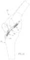
- Helicoil interference fixation system 5for securing a graft ligament to a bone.
- Helicoil interference fixation system 5generally comprises a helicoil 10 for disposition in a bone tunnel so as to hold the graft ligament in position while bone-to-ligament in-growth occurs.
- Helicoil interference fixation system 5also comprises an inserter 15 for deploying helicoil 10 in the bone tunnel.
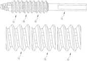
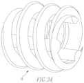
- helicoil 10generally comprises a helical body 20 terminating in a distal end 25 and a proximal end 30 .
- Helical body 20is constructed so that there are substantial spaces or gaps 35 between the turns 40 of the helical body. Spaces or gaps 35 facilitate bone-to-ligament in-growth, i.e., by providing large openings through the helical body. These large openings facilitate the flow of cell- and nutrient-bearing fluids through the helicoil, and permit the in-growth of tissue across the helicoil, so as to enhance bone-to-ligament in-growth.
- One or more struts 45are disposed within the interior of helical body 20 , with the one or more struts 45 being secured to the interior surfaces 50 of helical body 20 .
- the one or more struts 45provide a means for turning helicoil 10 during deployment within the body, as will hereinafter be discussed in further detail.
- the one or more struts 45can provide structural support for the turns 40 of helical body 20 .
- the one or more struts 45may be formed integral with helical body 20 (e.g., by a molding process), or they may be formed separately from helical body 20 and then attached to helical body 20 in a separate manufacturing process (e.g., by welding). Where the one or more struts 45 are formed integral with helical body 20 , the one or more struts 45 can be used to help flow melt into position.
- the one or more struts 45comprise helical structures. And in one particularly preferred form of the invention, the one or more struts 45 comprise helical structures which spiral in the opposite direction from the spiral of helical body 20 , and the one or more struts 45 have a pitch which is substantially greater than the pitch of helical body 20 . See FIG. 5 .
- the number of struts 45are selected so as to close off an insignificant portion of the spaces or gaps 35 between the turns 40 of helical body 20 , whereby to substantially not impede the passage of fluids and tissue through the helicoil.
- the number of struts 45 , their size, and compositionare selected so as to provide an adequate means for turning helicoil 10 during deployment, and to provide any necessary support for the turns 40 of helical body 20 .
- one strut 45is provided.
- a plurality of struts 45(e.g., two, three four or more struts) are provided.
- the struts 45collectively close off less than fifty percent (50%) of the spaces or gaps 35 between the turns 40 of helical body 20 .
- the struts 45collectively close off less than twenty percent (20%) of the spaces or gaps 35 between the turns 40 of helical body 20 .
- Helicoil 10is formed out of one or more biocompatible materials. These biocompatible materials may be non-absorbable (e.g., stainless steel or plastic) or absorbable (e.g., a bioabsorbable polymer).
- helicoil 10preferably comprises a bioabsorbable polymer such as polylactic acid (PLA), polyglycolic acid (PGA), etc.
- PLApolylactic acid
- PGApolyglycolic acid
- helicoil 10comprises a material which is capable of providing the strength needed to set the fixation device into position and to hold the graft ligament in position while bone-to-ligament in-growth occurs.
- Inserter 15is shown in FIGS. 1 - 4 and 7 .
- Inserter 15generally comprises a shaft 55 having a distal end 60 and a proximal end 65 .
- One or more grooves 70are formed on the distal end of shaft 55 .
- Grooves 70receive the one or more struts 45 of helicoil 10 , in order that helicoil 10 may be mounted on the distal end of shaft 55 and rotated by rotation of shaft 55 .
- a tapered seat-forming thread 75(e.g., a tapered cutting thread, a tapered opening or dilating thread, etc.) is formed in shaft 55 distal to grooves 70 .
- Tapered seat-forming thread 75serves to precede helicoil 10 into the space between the graft ligament and the wall of the bone tunnel, and then to form a lead-in or opening in the graft ligament and the wall of the bone tunnel for receiving the turns 40 of helical body 20 , in much the same manner as a tap that creates the thread form, as will hereinafter be discussed in further detail.
- a handle 80is mounted on the proximal end of shaft 55 in order to facilitate rotation of shaft 55 by the surgeon.
- tapered seat-forming thread 75is matched to helicoil 10 so that when helicoil 10 is mounted on inserter 15 , tapered seat-forming thread 75 provides the proper lead-in for helicoil 10 .
- interior surfaces 50 of helical body 20 and distal end 60 of inserter 15are tapered, expanding outwardly in the proximal direction, so that helicoil 10 and inserter 15 form a positive seat such that the interior surface of the helicoil is in direct contact with the tapered body diameter of the inserter.
- inserter 15may be used to advance the helicoil to a surgical site and, via rotation of handle 80 , turn helicoil 10 into the gap between a graft ligament and the wall of a bone tunnel, whereby to create an interference fixation of the graft ligament in the bone tunnel.
- inserter 15has a tapered seat-forming thread 75 formed on its distal end in advance of helicoil 10
- the tapered seat-forming threadcan form a seat into the tissue in advance of helicoil 10 , whereby to permit the helicoil to advance easily into the tissue and create the desired interference fixation.
- helicoil 10does not need to have any penetrating point on its distal end in order to penetrate the tissue.
- inserter 15may be cannulated so that the inserter and helicoil 10 may be deployed over a guidewire, as will hereinafter be discussed.
- FIGS. 8 - 13show another helicoil interference fixation system 5 , wherein helicoil 10 comprises two struts 45 and inserter 15 comprises two grooves 70 .
- the use of two struts 45may be advantageous since it may distribute the load imposed during rotation over a larger surface area. This may be important where helicoil 10 is formed out of a bioabsorbable polymer.
- Helicoil interference fixation system 5may be utilized in a manner generally similar to that, of a conventional interference screw system in order to attach a graft ligament to a bone.
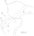
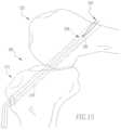
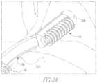
- FIGS. 14 - 25there are shown various aspects of an ACL reconstruction effected using helicoil interference fixation system 5 .
- FIG. 14shows a typical knee joint 205 , with the joint having been prepared for an ACL reconstruction, i.e., with the natural ACL having been removed, and with a tibial bone tunnel 210 having been formed in tibia 215 , and with a femoral bone tunnel 220 having been formed in femur 225 .
- FIG. 15is a view similar to that of FIG. 14 , except that a graft ligament 230 has been positioned in femoral bone tunnel 220 and tibial bone tunnel 210 in accordance with ways well known in the art.
- graft ligament 230may be “towed” up through tibial bone tunnel 210 and into femoral bone tunnel 220 using a tow suture 235 .
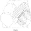
- FIGS. 16 and 17show graft ligament 230 being made fast in femoral tunnel 220 using helicoil interference fixation system 5 .
- helicoil 10is mounted on the distal end of inserter 15 by fitting the struts 45 of helicoil 10 into the grooves 70 of the inserter. Then the inserter is used to advance helicoil 10 through tibial tunnel 210 , across the interior of knee joint 205 , and up into the femoral, tunnel 220 .
- inserter 15may be cannulated, so that the inserter and helicoil are advanced over a guidewire of the sort well known in the art.
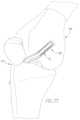
- the tapered seat-forming thread 75first finds its way into the space between the graft ligament 230 and the side wall of femoral bone tunnel 220 . Then, as the inserter is turned, tapered seat-forming thread 75 forms a seat into the tissue in advance of helicoil 10 , and helicoil 10 is advanced into the tissue so that the turns of helical body 20 seat themselves in the seat formed by seat-forming thread 75 . As this occurs, the graft ligament is driven laterally, into engagement with the opposing side wall of the bone tunnel.
- This actionsets helicoil 10 between the side wall of femoral bone tunnel 220 and graft ligament 230 , thereby securing the interference fit between graft ligament 230 and the side wall of the bone tunnel, whereby to secure graft ligament 230 to the bone.
- inserter 15is withdrawn, leaving helicoil 10 lodged in position between the graft ligament and the side wall of the bone tunnel.
- helicoil 10maintains the interference fit established between graft ligament 220 and the side wall of the bone tunnel, thereby securing the graft ligament to the bone.
- helicoil interference fixation system 5can then be used in a similar manner to form a tibial fixation. See FIGS. 21 - 25 .
- fixation devicein the form of an open helical coil has proven particularly advantageous, inasmuch as the open helical coil provides the strength needed to set the fixation device into position, and hold the graft ligament in position while bone-to-ligament in-growth occurs, while still providing extraordinary access through the body or the fixation device.
- cell- and nutrient-bearing fluidscan move substantially unimpeded through the body of helicoil 10 , and tissue in-growth can occur across the body of helicoil 10 .
- struts 45help maintain the structural integrity of turns 40 of helical body 20 , whereby to ensure the integrity of the interference fit.
- graft ligament 230is shown to include bone blocks at the ends of the ligament, e.g., graft ligament 10 may be a patella tendon with bone blocks attached. However, as seen in FIGS. 26 - 28 , graft ligament 230 can also constitute only soft tissue, e.g., graft ligament 230 may comprise a semitendinosus tendon and/or a gracilis tendon, and/or a synthetic device.
- the one or more struts 45are shown as having a helical structure. However, the one or more struts 45 may also be formed with a straight configuration. See, for example, FIGS. 29 - 30 , which show a helicoil 10 with a single straight strut 45 , and FIG. 31 which shows a helicoil 10 with multiple straight struts 45 .
- the one or more struts 45may be interrupted between turns 40 or, as seen in FIG. 33 , the one or more struts 45 may be selectively interrupted between turns 40 .
- an interference fitmay be formed using a plurality or helicoils 10 .
- a plurality of helicoils 10may be loaded on an inserter 15 and used for a collective interference fit.
- the one or more struts 45may be replaced with recesses 45 A.
- grooves 70 on inserter 15are replaced by corresponding ribs (not shown), whereby to permit inserter 15 to rotatably drive helicoil 10 .
- the period of turns 40may change along the length of helicoil 10 .
- helicoil 10can be tapered between its distal end 25 and its proximal end 30 .
Landscapes
- Health & Medical Sciences (AREA)
- Orthopedic Medicine & Surgery (AREA)
- Life Sciences & Earth Sciences (AREA)
- Surgery (AREA)
- Animal Behavior & Ethology (AREA)
- General Health & Medical Sciences (AREA)
- Biomedical Technology (AREA)
- Heart & Thoracic Surgery (AREA)
- Veterinary Medicine (AREA)
- Engineering & Computer Science (AREA)
- Public Health (AREA)
- Molecular Biology (AREA)
- Nuclear Medicine, Radiotherapy & Molecular Imaging (AREA)
- Medical Informatics (AREA)
- Rehabilitation Therapy (AREA)
- Rheumatology (AREA)
- Cardiology (AREA)
- Oral & Maxillofacial Surgery (AREA)
- Transplantation (AREA)
- Vascular Medicine (AREA)
- Neurology (AREA)
- Prostheses (AREA)
- Surgical Instruments (AREA)
Abstract
Description
- a helicoil comprising a helical body comprising a plurality of turns separated by spaces therebetween, the helical body terminating in a proximal end and a distal end, and at least one internal strut extending between at least two turns of the helical body; and
- an inserter for turning the helicoil, the inserter comprising at least one groove for receiving the at least one strut;
- the helicoil being mounted on the inserter such that the at least one strut of the helicoil is mounted in the at least one groove of the inserter, such that rotation of the inserter causes rotation of the helicoil;
Claims (32)
Priority Applications (1)
| Application Number | Priority Date | Filing Date | Title |
|---|---|---|---|
| US16/206,046US11628058B2 (en) | 2006-08-16 | 2018-11-30 | Helicoil interference fixation system for attaching a graft ligament to a bone |
Applications Claiming Priority (7)
| Application Number | Priority Date | Filing Date | Title |
|---|---|---|---|
| US83811906P | 2006-08-16 | 2006-08-16 | |
| US11/893,440US20080154314A1 (en) | 2006-08-16 | 2007-08-16 | Composite interference screw for attaching a graft ligament to a bone, and other apparatus for making attachments to bone |
| US20028508P | 2008-11-26 | 2008-11-26 | |
| US12/392,804US8894661B2 (en) | 2007-08-16 | 2009-02-25 | Helicoil interference fixation system for attaching a graft ligament to a bone |
| US14/550,248US9579189B2 (en) | 2007-08-16 | 2014-11-21 | Helicoil interference fixation system for attaching a graft ligament to a bone |
| US15/225,033US20180214260A9 (en) | 2006-08-16 | 2016-08-01 | Helicoil Interference Fixation System For Attaching a Graft Ligament to a Bone |
| US16/206,046US11628058B2 (en) | 2006-08-16 | 2018-11-30 | Helicoil interference fixation system for attaching a graft ligament to a bone |
Related Parent Applications (1)
| Application Number | Title | Priority Date | Filing Date |
|---|---|---|---|
| US15/225,033ContinuationUS20180214260A9 (en) | 2006-08-16 | 2016-08-01 | Helicoil Interference Fixation System For Attaching a Graft Ligament to a Bone |
Publications (2)
| Publication Number | Publication Date |
|---|---|
| US20190099257A1 US20190099257A1 (en) | 2019-04-04 |
| US11628058B2true US11628058B2 (en) | 2023-04-18 |
Family
ID=41432023
Family Applications (7)
| Application Number | Title | Priority Date | Filing Date |
|---|---|---|---|
| US12/392,804Active2029-01-12US8894661B2 (en) | 2006-08-16 | 2009-02-25 | Helicoil interference fixation system for attaching a graft ligament to a bone |
| US13/962,580ActiveUS8992612B2 (en) | 2006-08-16 | 2013-08-08 | Helicoil interference fixation system for attaching a graft ligament to a bone |
| US14/550,248Active2027-09-15US9579189B2 (en) | 2006-08-16 | 2014-11-21 | Helicoil interference fixation system for attaching a graft ligament to a bone |
| US15/225,033AbandonedUS20180214260A9 (en) | 2006-08-16 | 2016-08-01 | Helicoil Interference Fixation System For Attaching a Graft Ligament to a Bone |
| US16/205,939ActiveUS10820983B2 (en) | 2006-08-16 | 2018-11-30 | Helicoil interference fixation system for attaching a graft ligament to a bone |
| US16/206,008PendingUS20190099256A1 (en) | 2006-08-16 | 2018-11-30 | Helicoil interference fixation system for attaching a graft ligament to a bone |
| US16/206,046Active2027-10-08US11628058B2 (en) | 2006-08-16 | 2018-11-30 | Helicoil interference fixation system for attaching a graft ligament to a bone |
Family Applications Before (6)
| Application Number | Title | Priority Date | Filing Date |
|---|---|---|---|
| US12/392,804Active2029-01-12US8894661B2 (en) | 2006-08-16 | 2009-02-25 | Helicoil interference fixation system for attaching a graft ligament to a bone |
| US13/962,580ActiveUS8992612B2 (en) | 2006-08-16 | 2013-08-08 | Helicoil interference fixation system for attaching a graft ligament to a bone |
| US14/550,248Active2027-09-15US9579189B2 (en) | 2006-08-16 | 2014-11-21 | Helicoil interference fixation system for attaching a graft ligament to a bone |
| US15/225,033AbandonedUS20180214260A9 (en) | 2006-08-16 | 2016-08-01 | Helicoil Interference Fixation System For Attaching a Graft Ligament to a Bone |
| US16/205,939ActiveUS10820983B2 (en) | 2006-08-16 | 2018-11-30 | Helicoil interference fixation system for attaching a graft ligament to a bone |
| US16/206,008PendingUS20190099256A1 (en) | 2006-08-16 | 2018-11-30 | Helicoil interference fixation system for attaching a graft ligament to a bone |
Country Status (6)
| Country | Link |
|---|---|
| US (7) | US8894661B2 (en) |
| EP (1) | EP2385801B1 (en) |
| JP (1) | JP5851840B2 (en) |
| CN (1) | CN102325505B (en) |
| AU (1) | AU2009319879B2 (en) |
| WO (1) | WO2010062833A1 (en) |
Families Citing this family (72)
| Publication number | Priority date | Publication date | Assignee | Title |
|---|---|---|---|---|
| US6497726B1 (en) | 2000-01-11 | 2002-12-24 | Regeneration Technologies, Inc. | Materials and methods for improved bone tendon bone transplantation |
| US20030023304A1 (en)* | 2000-01-11 | 2003-01-30 | Carter Kevin C. | Materials and methods for improved bone tendon bone transplantation |
| US20180228621A1 (en) | 2004-08-09 | 2018-08-16 | Mark A. Reiley | Apparatus, systems, and methods for the fixation or fusion of bone |
| US20080154314A1 (en)* | 2006-08-16 | 2008-06-26 | Mcdevitt Dennis M | Composite interference screw for attaching a graft ligament to a bone, and other apparatus for making attachments to bone |
| US8894661B2 (en) | 2007-08-16 | 2014-11-25 | Smith & Nephew, Inc. | Helicoil interference fixation system for attaching a graft ligament to a bone |
| US8449612B2 (en) | 2009-11-16 | 2013-05-28 | Arthrocare Corporation | Graft pulley and methods of use |
| US9308080B2 (en) | 2010-03-10 | 2016-04-12 | Smith & Nephew Inc. | Composite interference screws and drivers |
| US8979865B2 (en) | 2010-03-10 | 2015-03-17 | Smith & Nephew, Inc. | Composite interference screws and drivers |
| US9579188B2 (en) | 2010-03-10 | 2017-02-28 | Smith & Nephew, Inc. | Anchor having a controlled driver orientation |
| US9775702B2 (en) | 2010-03-10 | 2017-10-03 | Smith & Nephew, Inc. | Composite interference screws and drivers |
| US8900251B2 (en) | 2010-05-28 | 2014-12-02 | Zyga Technology, Inc | Radial deployment surgical tool |
| MX344606B (en) | 2011-03-11 | 2016-12-20 | Smith & Nephew Inc | Trephine. |
| CA2833543A1 (en) | 2011-05-05 | 2012-11-08 | Zyga Technology, Inc. | Sacroiliac fusion system |
| US20140222088A1 (en)* | 2011-05-08 | 2014-08-07 | Spinal Ventures, Llc | Implant and Fastener Fixation Devices and Delivery Instrumentation |
| AU2012267924B2 (en) | 2011-06-07 | 2016-08-11 | Smith & Nephew, Inc. | Surgical anchor delivery system |
| US8900279B2 (en)* | 2011-06-09 | 2014-12-02 | Zyga Technology, Inc. | Bone screw |
| US9089416B2 (en) | 2011-06-20 | 2015-07-28 | Anatomacl, Llc | Apparatus and method for ligament reconstruction |
| US10939992B2 (en) | 2011-06-20 | 2021-03-09 | Anatomacl, Llc | Apparatus and method for ligament reconstruction |
| US9918828B2 (en) | 2011-06-20 | 2018-03-20 | Anatomacl, Llc | Apparatus and method for anatomic ACL reconstruction |
| EP2596758A1 (en)* | 2011-11-24 | 2013-05-29 | Sysorb GmbH | Bone screw |
| US10363140B2 (en) | 2012-03-09 | 2019-07-30 | Si-Bone Inc. | Systems, device, and methods for joint fusion |
| US9044321B2 (en) | 2012-03-09 | 2015-06-02 | Si-Bone Inc. | Integrated implant |
| EP2841016B1 (en)* | 2012-04-26 | 2019-09-18 | Jortek Surgical Inc. | Apparatus for ligament reconstruction |
| EP3818947B1 (en) | 2012-05-04 | 2023-08-30 | SI-Bone, Inc. | Fenestrated implant |
| BR112014032440A2 (en)* | 2012-06-27 | 2017-06-27 | Shino Konsei | ligament reconstruction fixation system |
| US9554836B2 (en)* | 2012-06-29 | 2017-01-31 | The Cleveland Clinic Foundation | Intramedullary bone stent |
| FR2997623B1 (en)* | 2012-11-05 | 2015-12-18 | Lavigne Sainte Suzanne Christophe De | INTRAOSSIBLE SCREW FOR ATTACHING TO A BONE A BONE FRAGMENT OR TRANSPLANT AND METHOD OF MAKING SUCH AN INTRAOSSEVER SCREW |
| US9056014B2 (en)* | 2012-12-27 | 2015-06-16 | Wright Medical Technology, Inc. | Device and method for fixation for bone or soft tissue deformity of digits |
| KR20150128684A (en)* | 2013-03-06 | 2015-11-18 | 스미스 앤드 네퓨, 인크. | Composite interference screws and drivers |
| US9427270B2 (en)* | 2013-03-14 | 2016-08-30 | Smith & Nephew, Inc. | Reduced area thread profile for an open architecture anchor |
| US9155531B2 (en) | 2013-03-15 | 2015-10-13 | Smith & Nephew, Inc. | Miniaturized dual drive open architecture suture anchor |
| WO2014145902A1 (en) | 2013-03-15 | 2014-09-18 | Si-Bone Inc. | Implants for spinal fixation or fusion |
| US9526488B2 (en)* | 2013-03-15 | 2016-12-27 | Smith & Nephew, Inc. | Fenestrated locking suture anchor assembly |
| WO2014169058A1 (en) | 2013-04-09 | 2014-10-16 | Smith & Nephew, Inc | Open-architecture interference screw |
| CN103340702A (en)* | 2013-07-24 | 2013-10-09 | 中南大学湘雅医院 | Implanting device for reconstruction of knee joint cruciate ligament |
| US11147688B2 (en) | 2013-10-15 | 2021-10-19 | Si-Bone Inc. | Implant placement |
| KR20160088314A (en)* | 2013-11-20 | 2016-07-25 | 스미스 앤드 네퓨, 인크. | Anchor having a controlled driver orientation |
| US9861375B2 (en) | 2014-01-09 | 2018-01-09 | Zyga Technology, Inc. | Undercutting system for use in conjunction with sacroiliac fusion |
| US10045803B2 (en) | 2014-07-03 | 2018-08-14 | Mayo Foundation For Medical Education And Research | Sacroiliac joint fusion screw and method |
| US10166033B2 (en) | 2014-09-18 | 2019-01-01 | Si-Bone Inc. | Implants for bone fixation or fusion |
| JP6542362B2 (en) | 2014-09-18 | 2019-07-10 | エスアイ−ボーン・インコーポレイテッドSi−Bone, Inc. | Matrix implant |
| WO2016160445A1 (en)* | 2015-03-23 | 2016-10-06 | Conmed Corporation | Securing graft tissue in a bone tunnel and implementations thereof |
| US10449051B2 (en)* | 2015-04-29 | 2019-10-22 | Institute for Musculoskeletal Science and Education, Ltd. | Implant with curved bone contacting elements |
| JP6768001B2 (en) | 2015-04-29 | 2020-10-14 | インスティテュート フォー マスキュロスケレタル サイエンス アンド エジュケイション,リミテッド | Coiled implants and systems and how to make them |
| US10492921B2 (en) | 2015-04-29 | 2019-12-03 | Institute for Musculoskeletal Science and Education, Ltd. | Implant with arched bone contacting elements |
| FR3036030B1 (en) | 2015-05-11 | 2021-01-29 | Lokou David Fischer | IMPLANT FOR FIXING BONE ELEMENTS |
| US10413332B2 (en) | 2016-04-25 | 2019-09-17 | Imds Llc | Joint fusion implant and methods |
| US9833321B2 (en) | 2016-04-25 | 2017-12-05 | Imds Llc | Joint fusion instrumentation and methods |
| FR3054428B1 (en)* | 2016-07-29 | 2021-09-10 | Spine Arch Brevet | ANCILLARY FOR THE PLACEMENT OF AN IMPLANT |
| FR3054427B1 (en)* | 2016-07-29 | 2021-10-15 | Spine Arch Brevet | HELICOIDAL IMPLANT FOR FIXATION OF BONE ELEMENTS |
| US11033394B2 (en) | 2016-10-25 | 2021-06-15 | Institute for Musculoskeletal Science and Education, Ltd. | Implant with multi-layer bone interfacing lattice |
| US10478312B2 (en) | 2016-10-25 | 2019-11-19 | Institute for Musculoskeletal Science and Education, Ltd. | Implant with protected fusion zones |
| US10512549B2 (en) | 2017-03-13 | 2019-12-24 | Institute for Musculoskeletal Science and Education, Ltd. | Implant with structural members arranged around a ring |
| US11116519B2 (en) | 2017-09-26 | 2021-09-14 | Si-Bone Inc. | Systems and methods for decorticating the sacroiliac joint |
| US10940015B2 (en) | 2017-11-21 | 2021-03-09 | Institute for Musculoskeletal Science and Education, Ltd. | Implant with improved flow characteristics |
| US10744001B2 (en) | 2017-11-21 | 2020-08-18 | Institute for Musculoskeletal Science and Education, Ltd. | Implant with improved bone contact |
| ES3011907T3 (en) | 2018-03-28 | 2025-04-08 | Si Bone Inc | Threaded implants for use across bone segments |
| GB2593324B (en)* | 2018-11-08 | 2023-03-22 | Nextremity Solutions Inc | Bone fixation device and method |
| TWI689281B (en)* | 2018-12-21 | 2020-04-01 | 財團法人工業技術研究院 | Bone implant |
| EP3669824B1 (en)* | 2018-12-21 | 2025-09-10 | Industrial Technology Research Institute | Bone implant |
| US11141262B2 (en)* | 2018-12-21 | 2021-10-12 | Industrial Technology Research Institute | Bone implant |
| US11369419B2 (en) | 2019-02-14 | 2022-06-28 | Si-Bone Inc. | Implants for spinal fixation and or fusion |
| EP4613244A2 (en) | 2019-02-14 | 2025-09-10 | SI-Bone Inc. | Implants for spinal fixation and or fusion |
| JP7646654B2 (en) | 2019-11-21 | 2025-03-17 | エスアイ-ボーン・インコーポレイテッド | Rod coupling assembly for bone stabilization construct - Patent application |
| AU2020392121B2 (en) | 2019-11-27 | 2025-05-22 | Si-Bone, Inc. | Bone stabilizing implants and methods of placement across SI joints |
| EP4072452A4 (en) | 2019-12-09 | 2023-12-20 | SI-Bone, Inc. | Sacro-iliac joint stabilizing implants and methods of implantation |
| EP4117743A1 (en) | 2020-03-12 | 2023-01-18 | Smith&Nephew, Inc. | Tissue repair implant and compositions and method of implantation |
| EP4231926A1 (en)* | 2020-10-26 | 2023-08-30 | Smith & Nephew, Inc. | Tissue repair systems and methods of assembly |
| EP4259015A4 (en) | 2020-12-09 | 2024-09-11 | SI-Bone, Inc. | SACROILIAC JOINT STABILIZATION IMPLANTS AND METHODS OF IMPLANTATION |
| FR3129283B1 (en)* | 2021-11-24 | 2023-11-24 | Imprint Medical | Surgical system ensuring the reversible connection between two implants or between an implant and an instrument of the surgical system |
| DE102022101556B4 (en)* | 2022-01-24 | 2024-07-18 | Karl Storz Se & Co. Kg | Bone anchor element for insertion into a bone and/or fixation of tissue to the bone and bone anchor system |
| WO2025038769A1 (en) | 2023-08-15 | 2025-02-20 | Si-Bone Inc. | Pelvic stabilization implants, methods of use and manufacture |
Citations (9)
| Publication number | Priority date | Publication date | Assignee | Title |
|---|---|---|---|---|
| US4961740A (en)* | 1988-10-17 | 1990-10-09 | Surgical Dynamics, Inc. | V-thread fusion cage and method of fusing a bone joint |
| US5499984A (en)* | 1994-04-07 | 1996-03-19 | Snap-On Incorporated | Universal modular reamer system |
| US20030065332A1 (en)* | 2001-09-28 | 2003-04-03 | Ethicon, Inc. | Self-tapping resorbable two-piece bone screw |
| US20030125749A1 (en)* | 2001-12-27 | 2003-07-03 | Ethicon, Inc. | Cannulated screw and associated driver system |
| US20040102780A1 (en)* | 2002-11-26 | 2004-05-27 | West Hugh S. | Protective devices for use with angled interference screws |
| US20050055026A1 (en)* | 2002-10-02 | 2005-03-10 | Biedermann Motech Gmbh | Bone anchoring element |
| US20050222575A1 (en)* | 2004-04-06 | 2005-10-06 | Paul Ciccone | Adjustable tool for cannulated fasteners |
| US20060247642A1 (en)* | 2004-11-09 | 2006-11-02 | Stone Kevin T | Tissue fixation device |
| US20110295319A1 (en)* | 2008-08-15 | 2011-12-01 | Kinetic Spine Technologies Inc. | Dynamic pedicle screw |
Family Cites Families (213)
| Publication number | Priority date | Publication date | Assignee | Title |
|---|---|---|---|---|
| US2288864A (en) | 1940-12-03 | 1942-07-07 | Whitehead Walter John | Means for holding parts together |
| US3499222A (en) | 1965-08-17 | 1970-03-10 | Leonard I Linkow | Intra-osseous pins and posts and their use and techniques thereof |
| US3320783A (en) | 1966-12-09 | 1967-05-23 | Chicago Lock Co | Key for an axial tumbler type lock |
| US3716058A (en) | 1970-07-17 | 1973-02-13 | Atlanta Res Inst | Barbed suture |
| US3821975A (en) | 1972-11-16 | 1974-07-02 | L Haker | Automotive wheel lock means |
| US3874258A (en) | 1973-05-21 | 1975-04-01 | Stallion Enterprises Inc | Keyed attachment device for vehicle wheels |
| US3869942A (en) | 1974-02-04 | 1975-03-11 | Textron Inc | Driving tool |
| US4027572A (en) | 1974-05-13 | 1977-06-07 | Burge William G | Theft-prevention screw fastenings |
| US4177797A (en) | 1977-03-04 | 1979-12-11 | Shelby M. Baylis | Rotary biopsy device and method of using same |
| USRE33114E (en) | 1983-03-17 | 1989-11-21 | Tamper-proof threaded fastenings | |
| USD288777S (en) | 1983-11-22 | 1987-03-17 | Kwon Kee J | Vehicle wheel locking nut |
| CA1227902A (en) | 1984-04-02 | 1987-10-13 | Raymond G. Tronzo | Fenestrated hip screw and method of augmented internal fixation |
| US4854311A (en) | 1986-01-09 | 1989-08-08 | Acro Med Corporation | Bone screw |
| US4738255A (en) | 1986-04-07 | 1988-04-19 | Biotron Labs, Inc. | Suture anchor system |
| US4741651A (en) | 1986-04-25 | 1988-05-03 | Despres Roger J | Hole saw |
| US4913143A (en) | 1986-05-28 | 1990-04-03 | The United States Of America As Represented By The Secretary Of The Air Force | Trephine assembly |
| CH672058A5 (en) | 1986-08-05 | 1989-10-31 | Synthes Ag | |
| US4834757A (en) | 1987-01-22 | 1989-05-30 | Brantigan John W | Prosthetic implant |
| US5609635A (en) | 1988-06-28 | 1997-03-11 | Michelson; Gary K. | Lordotic interbody spinal fusion implants |
| US4988351A (en) | 1989-01-06 | 1991-01-29 | Concept, Inc. | Washer for use with cancellous screw for attaching soft tissue to bone |
| US5129906A (en) | 1989-09-08 | 1992-07-14 | Linvatec Corporation | Bioabsorbable tack for joining bodily tissue and in vivo method and apparatus for deploying same |
| US5055104A (en) | 1989-11-06 | 1991-10-08 | Surgical Dynamics, Inc. | Surgically implanting threaded fusion cages between adjacent low-back vertebrae by an anterior approach |
| US5139520A (en) | 1990-01-31 | 1992-08-18 | American Cyanamid Company | Method for acl reconstruction |
| US5258016A (en) | 1990-07-13 | 1993-11-02 | American Cyanamid Company | Suture anchor and driver assembly |
| ATE159163T1 (en) | 1990-09-04 | 1997-11-15 | Hip Dev Pty Ltd | SURGICAL SCREW |
| CA2062012C (en) | 1991-03-05 | 2003-04-29 | Randall D. Ross | Bioabsorbable interference bone fixation screw |
| US5197967A (en) | 1991-04-02 | 1993-03-30 | Synthes (U.S.A.) | Trephine instrument and method for cutting annular holes |
| US5116337A (en) | 1991-06-27 | 1992-05-26 | Johnson Lanny L | Fixation screw and method for ligament reconstruction |
| US5236431A (en) | 1991-07-22 | 1993-08-17 | Synthes | Resorbable fixation device with controlled stiffness for treating bodily material in vivo and introducer therefor |
| DE4135310A1 (en) | 1991-10-25 | 1993-04-29 | Habermeyer Peter | CEMENT-FREE ENDOPROTHESIS |
| US5242447A (en) | 1992-02-06 | 1993-09-07 | Howmedica Inc. | Pin with tapered root diameter |
| AU672596B2 (en) | 1992-02-14 | 1996-10-10 | Smith & Nephew, Inc. | Polymeric screws and coatings for surgical uses |
| US5407427A (en) | 1992-06-16 | 1995-04-18 | Loma Linda University Medical Center | Trocar facilitator for endoscopic surgery |
| US5447533A (en) | 1992-09-03 | 1995-09-05 | Pacesetter, Inc. | Implantable stimulation lead having an advanceable therapeutic drug delivery system |
| US5354299A (en) | 1992-12-07 | 1994-10-11 | Linvatec Corporation | Method of revising a screw in a tunnel |
| US5814073A (en) | 1996-12-13 | 1998-09-29 | Bonutti; Peter M. | Method and apparatus for positioning a suture anchor |
| US5423823A (en) | 1993-02-18 | 1995-06-13 | Arthrex Inc. | Coring reamer |
| US5370662A (en) | 1993-06-23 | 1994-12-06 | Kevin R. Stone | Suture anchor assembly |
| WO1995003843A1 (en) | 1993-07-30 | 1995-02-09 | The Regents Of The University Of California | Endocardial infusion catheter |
| US5921982A (en) | 1993-07-30 | 1999-07-13 | Lesh; Michael D. | Systems and methods for ablating body tissue |
| US5456685A (en) | 1994-02-14 | 1995-10-10 | Smith & Nephew Dyonics, Inc. | Interference screw having a tapered back root |
| AU689846B2 (en)* | 1994-03-29 | 1998-04-09 | Zimmer Gmbh | Screw made of biodegradable material for bone surgery purposes, and screwdriver suitable therefor |
| US5411523A (en) | 1994-04-11 | 1995-05-02 | Mitek Surgical Products, Inc. | Suture anchor and driver combination |
| US5411506A (en) | 1994-04-11 | 1995-05-02 | Mitek Surgical Products, Inc. | Anchor driver |
| DE59503119D1 (en) | 1994-04-22 | 1998-09-17 | Straumann Inst Ag | Screwing tool for a screw, consisting of a bolt part and a nut that can be screwed onto it |
| US5573548A (en) | 1994-06-09 | 1996-11-12 | Zimmer, Inc. | Suture anchor |
| US5676545A (en) | 1994-08-15 | 1997-10-14 | Jones; Shedrick D. | Method and apparatus for implantation |
| US6604945B1 (en) | 1994-08-15 | 2003-08-12 | Shedrick D. Jones | Method and apparatus for implantation |
| DE69526094T2 (en) | 1994-09-15 | 2002-11-21 | Surgical Dynamics, Inc. | CONICAL FUSION CAGE |
| US5464427A (en) | 1994-10-04 | 1995-11-07 | Synthes (U.S.A.) | Expanding suture anchor |
| FR2726171B1 (en) | 1994-10-28 | 1997-01-24 | Jbs Sa | REHABITABLE CONNECTING SCREW DEVICE FOR BONE JOINT, IN PARTICULAR FOR STABILIZING AT LEAST TWO VERTEBRES |
| AR000417A1 (en) | 1994-12-23 | 1997-06-18 | Inst Straumann A G | An improved implant for oral-dental application |
| US6235057B1 (en) | 1995-01-24 | 2001-05-22 | Smith & Nephew, Inc. | Method for soft tissue reconstruction |
| CN1134810A (en) | 1995-02-17 | 1996-11-06 | 索发默达纳集团股份有限公司 | Improved interbody spinal fusion implants |
| US5632747A (en) | 1995-03-15 | 1997-05-27 | Osteotech, Inc. | Bone dowel cutter |
| AU705930B2 (en) | 1995-03-27 | 1999-06-03 | Warsaw Orthopedic, Inc. | Interbody fusion device and method for restoration of normal spinal anatomy |
| US5782919A (en) | 1995-03-27 | 1998-07-21 | Sdgi Holdings, Inc. | Interbody fusion device and method for restoration of normal spinal anatomy |
| US5626613A (en) | 1995-05-04 | 1997-05-06 | Arthrex, Inc. | Corkscrew suture anchor and driver |
| US5688285A (en) | 1995-08-29 | 1997-11-18 | Yamada; Ikufumi | Graft bone fixation tool |
| US5571139A (en) | 1995-05-19 | 1996-11-05 | Jenkins, Jr.; Joseph R. | Bidirectional suture anchor |
| US6039762A (en) | 1995-06-07 | 2000-03-21 | Sdgi Holdings, Inc. | Reinforced bone graft substitutes |
| US5662683A (en) | 1995-08-22 | 1997-09-02 | Ortho Helix Limited | Open helical organic tissue anchor and method of facilitating healing |
| KR100415064B1 (en) | 1995-10-20 | 2005-04-06 | 신테스 아게 츄어 | Intervertebral implant |
| US5709683A (en) | 1995-12-19 | 1998-01-20 | Spine-Tech, Inc. | Interbody bone implant having conjoining stabilization features for bony fusion |
| US5702397A (en) | 1996-02-20 | 1997-12-30 | Medicinelodge, Inc. | Ligament bone anchor and method for its use |
| US5681352A (en) | 1996-03-06 | 1997-10-28 | Kinetikos Medical Incorporated | Method and apparatus for anchoring surgical ties to bone |
| CA2199462C (en) | 1996-03-14 | 2006-01-03 | Charles J. Winslow | Method and instrumentation for implant insertion |
| US5868749A (en) | 1996-04-05 | 1999-02-09 | Reed; Thomas M. | Fixation devices |
| DE19628473C1 (en) | 1996-07-15 | 1998-04-23 | Aesculap Ag & Co Kg | Implant to fuse vertebrae |
| US6117162A (en) | 1996-08-05 | 2000-09-12 | Arthrex, Inc. | Corkscrew suture anchor |
| US6569188B2 (en) | 1996-08-05 | 2003-05-27 | Arthrex, Inc. | Hex drive bioabsorbable tissue anchor |
| DE69738227T2 (en) | 1996-08-26 | 2008-07-17 | Shedrick D. Los Angeles Jones | Drilling apparatus for embedding an implant in bone tissue |
| US5968098A (en) | 1996-10-22 | 1999-10-19 | Surgical Dynamics, Inc. | Apparatus for fusing adjacent bone structures |
| US7083647B1 (en) | 1996-11-27 | 2006-08-01 | Sklar Joseph H | Fixation screw, graft ligament anchor assembly, and method for securing a graft ligament in a bone tunnel |
| FI111802B (en) | 1996-12-19 | 2003-09-30 | Biocon Oy | Suture anchors |
| FR2760355B1 (en) | 1997-03-07 | 2000-02-25 | Serge Schrayer | INTERSOMATIC CAGE FORMING DEVICE WITH INTERNAL PROVISIONAL SOLIDARIZATION OF A TIGHTENING TOOL |
| AU744371B2 (en) | 1997-04-25 | 2002-02-21 | Stryker European Holdings I, Llc | Two-part intersomatic implant |
| US5802794A (en) | 1997-05-05 | 1998-09-08 | Jayne Industries Inc. | Ceramic fiber securing device |
| US5876405A (en) | 1997-09-17 | 1999-03-02 | The Anspach Effort, Inc. | Perforator |
| US5891146A (en) | 1997-10-15 | 1999-04-06 | Applied Biological Concepts, Inc. | Wedge orthopedic screw |
| US5964783A (en) | 1997-11-07 | 1999-10-12 | Arthrex, Inc. | Suture anchor with insert-molded suture |
| US6097986A (en) | 1997-12-17 | 2000-08-01 | Cardiac Pacemakers, Inc. | Retractable lead with mesh screen |
| JP3930960B2 (en) | 1998-01-26 | 2007-06-13 | 若井産業株式会社 | Threaded anchor |
| US5961524A (en) | 1998-03-11 | 1999-10-05 | Stryker Technologies Corporation | Screw and method of attachment to a substrate |
| US6008433A (en) | 1998-04-23 | 1999-12-28 | Stone; Kevin R. | Osteotomy wedge device, kit and methods for realignment of a varus angulated knee |
| US6086593A (en) | 1998-06-30 | 2000-07-11 | Bonutti; Peter M. | Method and apparatus for use in operating on a bone |
| US6648903B1 (en) | 1998-09-08 | 2003-11-18 | Pierson, Iii Raymond H. | Medical tensioning system |
| US6302632B1 (en) | 1998-11-17 | 2001-10-16 | Chao-Wei Lin | Screw with compound recesses |
| US6283973B1 (en) | 1998-12-30 | 2001-09-04 | Depuy Orthopaedics, Inc. | Strength fixation device |
| US8343186B2 (en) | 2004-04-06 | 2013-01-01 | Arthrex, Inc. | Fully threaded suture anchor with transverse anchor pin |
| US7226469B2 (en) | 1999-02-02 | 2007-06-05 | Arthrex, Inc. | Insert molded suture anchor |
| US6096060A (en) | 1999-05-20 | 2000-08-01 | Linvatec Corporation | Bioabsorbable threaded soft tissue anchor system |
| US7033372B1 (en) | 1999-08-04 | 2006-04-25 | Percardia, Inc. | Corkscrew reinforced left ventricle to coronary artery channel |
| US6517542B1 (en) | 1999-08-04 | 2003-02-11 | The Cleveland Clinic Foundation | Bone anchoring system |
| US20040122424A1 (en) | 2000-01-15 | 2004-06-24 | Ferree Bret A. | Enhanced surface area spinal fusion devices and alignment apparatus therefor |
| DE59901812D1 (en) | 1999-10-21 | 2002-07-25 | Storz Karl Gmbh & Co Kg | interference screw |
| EP1093773B1 (en) | 1999-10-21 | 2001-10-04 | Karl Storz GmbH & Co. KG | Biodegradable fixation device |
| US6626917B1 (en) | 1999-10-26 | 2003-09-30 | H. Randall Craig | Helical suture instrument |
| DE60026136T2 (en) | 1999-11-15 | 2006-11-23 | Arthrex Inc., Naples | Rejuvenating bioabsorbing interference screw for the osteal attachment of ligaments |
| US7887551B2 (en) | 1999-12-02 | 2011-02-15 | Smith & Nephew, Inc. | Soft tissue attachment and repair |
| US6360129B1 (en) | 1999-12-13 | 2002-03-19 | Cardiac Pacemakers, Inc. | Mannitol/hydrogel cap for tissue-insertable connections |
| FR2803739B1 (en) | 2000-01-13 | 2002-02-15 | Denis Bertin | THREADED IMPLANT FOR MEDICAL USE |
| US6554830B1 (en) | 2000-04-10 | 2003-04-29 | Sdgi Holdings, Inc. | Fenestrated surgical anchor and method |
| US6610067B2 (en) | 2000-05-01 | 2003-08-26 | Arthrosurface, Incorporated | System and method for joint resurface repair |
| US6823871B2 (en) | 2000-06-01 | 2004-11-30 | Arthrex, Inc. | Allograft bone or synthetic wedges for osteotomy |
| US6447545B1 (en) | 2000-07-01 | 2002-09-10 | George W. Bagby | Self-aligning bone implant |
| US9387094B2 (en) | 2000-07-19 | 2016-07-12 | Warsaw Orthopedic, Inc. | Osteoimplant and method of making same |
| US6923824B2 (en) | 2000-09-12 | 2005-08-02 | Axya Medical, Inc. | Apparatus and method for securing suture to bone |
| US6953462B2 (en) | 2000-10-05 | 2005-10-11 | The Cleveland Clinic Foundation | Apparatus for implantation into bone |
| US20040073216A1 (en) | 2000-10-05 | 2004-04-15 | The Cleveland Clinic Foundation | Apparatus and method for attaching adjacent bones |
| US6551322B1 (en) | 2000-10-05 | 2003-04-22 | The Cleveland Clinic Foundation | Apparatus for implantation into bone |
| US6551320B2 (en) | 2000-11-08 | 2003-04-22 | The Cleveland Clinic Foundation | Method and apparatus for correcting spinal deformity |
| US6544265B2 (en) | 2000-11-08 | 2003-04-08 | The Cleveland Clinic Foundation | Apparatus for implantation into bone related applications |
| US6488683B2 (en) | 2000-11-08 | 2002-12-03 | Cleveland Clinic Foundation | Method and apparatus for correcting spinal deformity |
| US6527774B2 (en) | 2000-11-08 | 2003-03-04 | The Cleveland Clinic Foundation | Apparatus for attaching fractured sections of bone |
| US6551319B2 (en) | 2000-11-08 | 2003-04-22 | The Cleveland Clinic Foundation | Apparatus for implantation into bone |
| FR2816824B1 (en) | 2000-11-23 | 2003-05-23 | Michel Kurc | BONE RECOVERY BIT AND DRILLING DEVICE COMPRISING SUCH A BIT |
| US6443989B1 (en) | 2000-12-04 | 2002-09-03 | Roger P. Jackson | Posterior expandable fusion cage |
| US6451023B1 (en) | 2001-01-25 | 2002-09-17 | Linvatec Corporation | Guide bushing for coring reamer, storage package for reamer assembly, and method of use |
| US7083638B2 (en) | 2001-02-12 | 2006-08-01 | Arthrocare Corporation | Method and apparatus for attaching connective tissues to bone using a knotless suture anchoring device |
| US6663656B2 (en) | 2001-02-26 | 2003-12-16 | Arthrex, Inc. | Torque driver for interference screw |
| US6511481B2 (en)* | 2001-03-30 | 2003-01-28 | Triage Medical, Inc. | Method and apparatus for fixation of proximal femoral fractures |
| US6620195B2 (en) | 2001-04-18 | 2003-09-16 | Medicinelodge, Inc. | Apparatus and method for attaching a graft ligament to a bone |
| US7235079B2 (en)* | 2004-11-18 | 2007-06-26 | Acumed Llc | Composite bone fasteners |
| US20050234458A1 (en) | 2004-04-19 | 2005-10-20 | Huebner Randall J | Expanded stabilization of bones |
| ITBO20010263A1 (en) | 2001-05-02 | 2002-11-02 | Citieffe Srl | DEVICE FOR ANCHORING AN ELEMENT TENSILE AND FLEXIBLE ELEMENT FOR THE RECONSTRUCTION OF A TEARED LIGAMENT |
| US7018412B2 (en) | 2001-08-20 | 2006-03-28 | Ebi, L.P. | Allograft spinal implant |
| US20030055431A1 (en) | 2001-09-19 | 2003-03-20 | James Kevin Brannon | Bone cutting assembly |
| US20030065374A1 (en) | 2001-10-01 | 2003-04-03 | Medtronic, Inc. | Active fixation lead with helix extension indicator |
| US6652563B2 (en) | 2001-10-02 | 2003-11-25 | Arthrex, Inc. | Suture anchor with internal suture loop |
| US6986781B2 (en) | 2001-11-08 | 2006-01-17 | Smith & Nephew, Inc. | Tissue repair system |
| US6685728B2 (en) | 2002-01-25 | 2004-02-03 | Stryker Endoscopy | Threaded suture anchor and method of use |
| JP3890589B2 (en) | 2002-04-15 | 2007-03-07 | ニプロ株式会社 | Intracardiac suture device |
| ES2279156T3 (en) | 2002-06-11 | 2007-08-16 | Tyco Healthcare Group Lp | MALE TIGHTS FOR HERNIAS. |
| WO2003105673A2 (en) | 2002-06-17 | 2003-12-24 | Trimedyne, Inc. | Devices and methods for minimally invasive treatment of degenerated spinal discs |
| US7442202B2 (en) | 2002-08-26 | 2008-10-28 | Arthrex, Inc. | Suture anchor attached to tissue-fixation disk without top knot |
| FR2846867B1 (en) | 2002-11-08 | 2005-09-09 | Textile Hi Tec | ANCHOR INSERTED INTO A BONE CAVITY AND TOOL FOR INSERTING SUCH ANCHOR |
| US7090690B2 (en) | 2002-11-19 | 2006-08-15 | Arthrocare Corporation | Devices and methods for repairing soft tissue |
| FR2847456B1 (en) | 2002-11-21 | 2005-01-28 | Michel Collette | SCREWS FOR FIXING A LIGAMENT GRAFT |
| US6887194B2 (en) | 2003-01-17 | 2005-05-03 | Applied Medical Resources Corporation | Surgical access apparatus and method |
| US7070586B2 (en) | 2003-01-17 | 2006-07-04 | Applied Medical Resources Corporation | Surgical access apparatus and method |
| US9314235B2 (en) | 2003-02-05 | 2016-04-19 | Smith & Nephew, Inc. | Tissue anchor and insertion tool |
| US7141051B2 (en) | 2003-02-05 | 2006-11-28 | Pioneer Laboratories, Inc. | Low profile spinal fixation system |
| EP1628702B1 (en) | 2003-04-28 | 2013-05-01 | Erwin De Winter | Anchoring screw device |
| US7608097B2 (en) | 2003-04-29 | 2009-10-27 | Millennium Medical Technologies | Bone screw with fluid delivery structure |
| IL156033A0 (en) | 2003-05-21 | 2004-03-28 | Ophir Fromovich Ophir Fromovic | Dental implant |
| US7670362B2 (en) | 2003-06-13 | 2010-03-02 | Tyco Healthcare Group Lp | Multiple member interconnect for surgical instrument and absorbable screw fastener |
| US20050203513A1 (en) | 2003-09-24 | 2005-09-15 | Tae-Ahn Jahng | Spinal stabilization device |
| US8016865B2 (en) | 2003-09-29 | 2011-09-13 | Depuy Mitek, Inc. | Method of performing anterior cruciate ligament reconstruction using biodegradable interference screw |
| US7217279B2 (en) | 2003-11-14 | 2007-05-15 | Ethicon, Inc. | Suture loop anchor |
| WO2006073413A1 (en) | 2004-02-20 | 2006-07-13 | The Board Of Trustees Of The University Of Illinois | Blood pressure reduction in salt-sensitive |
| US7390332B2 (en) | 2004-02-24 | 2008-06-24 | Depuy Mitek, Inc. | Methods and devices for repairing tissue |
| DE102004009429A1 (en)* | 2004-02-24 | 2005-09-22 | Biedermann Motech Gmbh | Bone anchoring element |
| US20050250984A1 (en) | 2004-05-07 | 2005-11-10 | Usgi Medical Inc. | Multiple removable apparatus and methods for manipulating and securing tissue |
| US20050250987A1 (en) | 2004-05-07 | 2005-11-10 | Usgi Medical Inc. | Removable apparatus and methods for manipulating and securing tissue |
| US20050250988A1 (en) | 2004-05-07 | 2005-11-10 | Usgi Medical Inc. | Removable apparatus for manipulating and securing tissue within a treatment space |
| US7322978B2 (en) | 2004-06-22 | 2008-01-29 | Hs West Investments, Llc | Bone anchors for use in attaching soft tissue to a bone |
| US20060184175A1 (en) | 2004-07-29 | 2006-08-17 | X-Sten, Inc. | Spinal ligament modification devices |
| US20060058788A1 (en) | 2004-08-27 | 2006-03-16 | Hammer Michael A | Multi-axial connection system |
| US20060079895A1 (en) | 2004-09-30 | 2006-04-13 | Mcleer Thomas J | Methods and devices for improved bonding of devices to bone |
| US7905903B2 (en) | 2006-02-03 | 2011-03-15 | Biomet Sports Medicine, Llc | Method for tissue fixation |
| US7658751B2 (en) | 2006-09-29 | 2010-02-09 | Biomet Sports Medicine, Llc | Method for implanting soft tissue |
| US7909851B2 (en) | 2006-02-03 | 2011-03-22 | Biomet Sports Medicine, Llc | Soft tissue repair device and associated methods |
| US7905904B2 (en) | 2006-02-03 | 2011-03-15 | Biomet Sports Medicine, Llc | Soft tissue repair device and associated methods |
| US8088130B2 (en) | 2006-02-03 | 2012-01-03 | Biomet Sports Medicine, Llc | Method and apparatus for coupling soft tissue to a bone |
| US7749250B2 (en) | 2006-02-03 | 2010-07-06 | Biomet Sports Medicine, Llc | Soft tissue repair assembly and associated method |
| US7857830B2 (en) | 2006-02-03 | 2010-12-28 | Biomet Sports Medicine, Llc | Soft tissue repair and conduit device |
| US7914539B2 (en) | 2004-11-09 | 2011-03-29 | Biomet Sports Medicine, Llc | Tissue fixation device |
| US7608098B1 (en) | 2004-11-09 | 2009-10-27 | Biomet Sports Medicine, Llc | Bone fixation device |
| CN101573078B (en) | 2004-11-15 | 2011-10-12 | 斯坎迪乌斯生物医药公司 | Apparatus for the repair of a rotator cuff (RTC) tendon or ligament |
| US20060149266A1 (en) | 2004-12-10 | 2006-07-06 | New York Society For The Ruptured And Crippled Maintaining The Hospital For Special Surgery | Anchor for screw fixation of soft tissue to bone |
| FR2879915B1 (en) | 2004-12-24 | 2008-02-15 | Advanced Biomaterials Soc Par | INTERFERENCE SCREW AND ADJUSTABLE SCREWDRIVER |
| US8496662B2 (en) | 2005-01-31 | 2013-07-30 | Arthrex, Inc. | Method and apparatus for forming a wedge-like opening in a bone for an open wedge osteotomy |
| JP2008535544A (en) | 2005-03-10 | 2008-09-04 | タイコ ヘルスケア グループ リミテッド パートナーシップ | Suture anchor |
| US8252006B2 (en) | 2005-08-05 | 2012-08-28 | Ethicon Endo-Surgery, Inc. | Single pass gastric restriction with a corkscrew style wall anchor |
| EP1762186B1 (en) | 2005-09-12 | 2011-02-16 | Arthrex, Inc. | Suture anchor with eyelet |
| US20070122764A1 (en) | 2005-11-28 | 2007-05-31 | Ace Surgical Supply Co., Inc. | Orthodontic bone screw |
| US20070142849A1 (en) | 2005-12-16 | 2007-06-21 | Usgi Medical, Inc. | Helical tissue manipulation instruments and methods of use |
| US8251998B2 (en) | 2006-08-16 | 2012-08-28 | Biomet Sports Medicine, Llc | Chondral defect repair |
| US7959650B2 (en) | 2006-09-29 | 2011-06-14 | Biomet Sports Medicine, Llc | Adjustable knotless loops |
| US20090228012A1 (en) | 2006-02-16 | 2009-09-10 | Universite Libre De Bruxelles | Surgical boring tool set |
| US8118312B2 (en) | 2006-06-14 | 2012-02-21 | American Torch Tip Co. | Quick change centering tool holder |
| US8894661B2 (en) | 2007-08-16 | 2014-11-25 | Smith & Nephew, Inc. | Helicoil interference fixation system for attaching a graft ligament to a bone |
| US20080154314A1 (en) | 2006-08-16 | 2008-06-26 | Mcdevitt Dennis M | Composite interference screw for attaching a graft ligament to a bone, and other apparatus for making attachments to bone |
| US8167906B2 (en) | 2006-11-01 | 2012-05-01 | Depuy Mitek, Inc. | Suture anchor with pulley |
| US8055104B2 (en)* | 2007-03-02 | 2011-11-08 | Adi, Llc | Process performance evaluation for Enterprise data systems |
| US20110319933A1 (en) | 2007-04-21 | 2011-12-29 | Slobodan Tepic | Suture bone anchor |
| US8845685B2 (en) | 2007-05-03 | 2014-09-30 | Biomet Sports Medicine, Llc | Anchor assembly and method of use |
| US20090024174A1 (en) | 2007-07-17 | 2009-01-22 | Stark John G | Bone screws and particular applications to sacroiliac joint fusion |
| US8882801B2 (en) | 2007-09-14 | 2014-11-11 | Depuy Mitek, Llc | Dual thread cannulated suture anchor |
| AU2008304181B2 (en) | 2007-09-26 | 2013-12-05 | Redyns Medical Llc | Method and apparatus for attaching soft tissue to bone |
| US8814935B2 (en) | 2008-03-31 | 2014-08-26 | The Lonnie and Shannon Paulos Trust | Interference screw driver assembly and method of use |
| CN102098968B (en) | 2008-07-17 | 2015-07-22 | 史密夫和内修有限公司 | Anchor |
| US8262675B2 (en) | 2008-10-29 | 2012-09-11 | Ethicon Endo-Surgery, Inc. | Methods and devices for applying multiple suture anchors |
| CA2757554A1 (en) | 2009-04-03 | 2010-10-07 | Cook Medical Technologies Llc | Tissue anchors and medical devices for rapid deployment of tissue anchors |
| CN201436022U (en) | 2009-04-20 | 2010-04-07 | 李光磊 | Directional wire extending device |
| WO2011056701A1 (en) | 2009-10-28 | 2011-05-12 | Smith & Nephew, Inc. | Threaded suture anchor |
| AU2010319662B2 (en) | 2009-11-10 | 2015-11-19 | Smith & Nephew, Inc. | Locking suture anchor assembly |
| JP2013510659A (en) | 2009-11-10 | 2013-03-28 | スミス アンド ネフュー インコーポレーテッド | Tissue repair device |
| CN102068305B (en) | 2009-11-20 | 2016-01-20 | 上海微创骨科医疗科技有限公司 | Bone screw |
| US8979865B2 (en) | 2010-03-10 | 2015-03-17 | Smith & Nephew, Inc. | Composite interference screws and drivers |
| US9308080B2 (en) | 2010-03-10 | 2016-04-12 | Smith & Nephew Inc. | Composite interference screws and drivers |
| JP5797748B2 (en) | 2010-05-19 | 2015-10-21 | デピュイ・シンセス・プロダクツ・インコーポレイテッド | Bone anchor |
| US8460340B2 (en) | 2010-08-30 | 2013-06-11 | Depuy Mitek, Llc | Knotless suture anchor |
| US8821543B2 (en) | 2010-12-23 | 2014-09-02 | Depuy Mitek, Llc | Adjustable anchor systems and methods |
| EP2596758A1 (en) | 2011-11-24 | 2013-05-29 | Sysorb GmbH | Bone screw |
| EP2601894B1 (en) | 2011-12-09 | 2018-08-29 | Arthrex, Inc. | Tensionable knotless anchor systems |
| US9408613B2 (en) | 2011-12-13 | 2016-08-09 | Biomet Manufacturing, Llc | Glenoid reamer |
| US20130158610A1 (en) | 2011-12-16 | 2013-06-20 | Depuy Mitek, Inc. | Bone graft fixation systems and methods |
| US9788844B2 (en) | 2011-12-16 | 2017-10-17 | Medos International Sarl | Methods and systems for attaching tissue to bone |
| US9138220B2 (en) | 2011-12-19 | 2015-09-22 | Medos International Sarl | Knotless suture anchor |
| US9439644B2 (en) | 2011-12-20 | 2016-09-13 | Medos International Sàrl | Systems and methods for repairing tissue |
| US9265494B2 (en) | 2011-12-20 | 2016-02-23 | Medos International Sarl | Knotless instability anchor |
- 2009
- 2009-02-25USUS12/392,804patent/US8894661B2/enactiveActive
- 2009-11-20CNCN200980155954.7Apatent/CN102325505B/enactiveActive
- 2009-11-20AUAU2009319879Apatent/AU2009319879B2/enactiveActive
- 2009-11-20WOPCT/US2009/065304patent/WO2010062833A1/enactiveApplication Filing
- 2009-11-20EPEP09761114.9Apatent/EP2385801B1/enactiveActive
- 2009-11-20JPJP2011538642Apatent/JP5851840B2/enactiveActive
- 2013
- 2013-08-08USUS13/962,580patent/US8992612B2/enactiveActive
- 2014
- 2014-11-21USUS14/550,248patent/US9579189B2/enactiveActive
- 2016
- 2016-08-01USUS15/225,033patent/US20180214260A9/ennot_activeAbandoned
- 2018
- 2018-11-30USUS16/205,939patent/US10820983B2/enactiveActive
- 2018-11-30USUS16/206,008patent/US20190099256A1/enactivePending
- 2018-11-30USUS16/206,046patent/US11628058B2/enactiveActive
Patent Citations (10)
| Publication number | Priority date | Publication date | Assignee | Title |
|---|---|---|---|---|
| US4961740A (en)* | 1988-10-17 | 1990-10-09 | Surgical Dynamics, Inc. | V-thread fusion cage and method of fusing a bone joint |
| US4961740B1 (en)* | 1988-10-17 | 1997-01-14 | Surgical Dynamics Inc | V-thread fusion cage and method of fusing a bone joint |
| US5499984A (en)* | 1994-04-07 | 1996-03-19 | Snap-On Incorporated | Universal modular reamer system |
| US20030065332A1 (en)* | 2001-09-28 | 2003-04-03 | Ethicon, Inc. | Self-tapping resorbable two-piece bone screw |
| US20030125749A1 (en)* | 2001-12-27 | 2003-07-03 | Ethicon, Inc. | Cannulated screw and associated driver system |
| US20050055026A1 (en)* | 2002-10-02 | 2005-03-10 | Biedermann Motech Gmbh | Bone anchoring element |
| US20040102780A1 (en)* | 2002-11-26 | 2004-05-27 | West Hugh S. | Protective devices for use with angled interference screws |
| US20050222575A1 (en)* | 2004-04-06 | 2005-10-06 | Paul Ciccone | Adjustable tool for cannulated fasteners |
| US20060247642A1 (en)* | 2004-11-09 | 2006-11-02 | Stone Kevin T | Tissue fixation device |
| US20110295319A1 (en)* | 2008-08-15 | 2011-12-01 | Kinetic Spine Technologies Inc. | Dynamic pedicle screw |
Non-Patent Citations (1)
| Title |
|---|
| Japanese Application No. 2018-203778 Appeal Decision dated Aug. 23, 2021. |
Also Published As
| Publication number | Publication date |
|---|---|
| JP2012509744A (en) | 2012-04-26 |
| US8992612B2 (en) | 2015-03-31 |
| CN102325505A (en) | 2012-01-18 |
| EP2385801A1 (en) | 2011-11-16 |
| US10820983B2 (en) | 2020-11-03 |
| AU2009319879A1 (en) | 2010-06-03 |
| AU2009319879B2 (en) | 2015-11-26 |
| EP2385801B1 (en) | 2020-03-25 |
| JP5851840B2 (en) | 2016-02-03 |
| US20190099255A1 (en) | 2019-04-04 |
| US20150081020A1 (en) | 2015-03-19 |
| US9579189B2 (en) | 2017-02-28 |
| US20180214260A9 (en) | 2018-08-02 |
| US20160374794A1 (en) | 2016-12-29 |
| US20190099256A1 (en) | 2019-04-04 |
| WO2010062833A1 (en) | 2010-06-03 |
| US20190099257A1 (en) | 2019-04-04 |
| US20090319043A1 (en) | 2009-12-24 |
| US8894661B2 (en) | 2014-11-25 |
| CN102325505B (en) | 2014-06-25 |
| US20130325125A1 (en) | 2013-12-05 |
Similar Documents
| Publication | Publication Date | Title |
|---|---|---|
| US11628058B2 (en) | Helicoil interference fixation system for attaching a graft ligament to a bone | |
| US11337793B2 (en) | Composite interference screws and drivers | |
| US20080154314A1 (en) | Composite interference screw for attaching a graft ligament to a bone, and other apparatus for making attachments to bone | |
| US9949820B2 (en) | Composite interference screws and drivers | |
| US8979865B2 (en) | Composite interference screws and drivers | |
| US20170020589A1 (en) | Anchor having a controlled driver orientation | |
| EP2964149B1 (en) | Composite interference screws and drivers | |
| WO2021154517A1 (en) | Graft fixation devices |
Legal Events
| Date | Code | Title | Description |
|---|---|---|---|
| FEPP | Fee payment procedure | Free format text:ENTITY STATUS SET TO UNDISCOUNTED (ORIGINAL EVENT CODE: BIG.); ENTITY STATUS OF PATENT OWNER: LARGE ENTITY | |
| STPP | Information on status: patent application and granting procedure in general | Free format text:RESPONSE TO NON-FINAL OFFICE ACTION ENTERED AND FORWARDED TO EXAMINER | |
| STPP | Information on status: patent application and granting procedure in general | Free format text:NON FINAL ACTION MAILED | |
| STPP | Information on status: patent application and granting procedure in general | Free format text:RESPONSE TO NON-FINAL OFFICE ACTION ENTERED AND FORWARDED TO EXAMINER | |
| STPP | Information on status: patent application and granting procedure in general | Free format text:FINAL REJECTION MAILED | |
| STPP | Information on status: patent application and granting procedure in general | Free format text:ADVISORY ACTION MAILED | |
| STPP | Information on status: patent application and granting procedure in general | Free format text:DOCKETED NEW CASE - READY FOR EXAMINATION | |
| STPP | Information on status: patent application and granting procedure in general | Free format text:NON FINAL ACTION MAILED | |
| STPP | Information on status: patent application and granting procedure in general | Free format text:RESPONSE TO NON-FINAL OFFICE ACTION ENTERED AND FORWARDED TO EXAMINER | |
| STPP | Information on status: patent application and granting procedure in general | Free format text:FINAL REJECTION MAILED | |
| STPP | Information on status: patent application and granting procedure in general | Free format text:RESPONSE AFTER FINAL ACTION FORWARDED TO EXAMINER | |
| STPP | Information on status: patent application and granting procedure in general | Free format text:ADVISORY ACTION MAILED | |
| STPP | Information on status: patent application and granting procedure in general | Free format text:DOCKETED NEW CASE - READY FOR EXAMINATION | |
| STPP | Information on status: patent application and granting procedure in general | Free format text:NON FINAL ACTION MAILED | |
| STPP | Information on status: patent application and granting procedure in general | Free format text:RESPONSE TO NON-FINAL OFFICE ACTION ENTERED AND FORWARDED TO EXAMINER | |
| STPP | Information on status: patent application and granting procedure in general | Free format text:FINAL REJECTION MAILED | |
| STCF | Information on status: patent grant | Free format text:PATENTED CASE |