US11624828B2 - Method and system for adaptive scanning with optical ranging systems - Google Patents
Method and system for adaptive scanning with optical ranging systemsDownload PDFInfo
- Publication number
- US11624828B2 US11624828B2US16/464,108US201716464108AUS11624828B2US 11624828 B2US11624828 B2US 11624828B2US 201716464108 AUS201716464108 AUS 201716464108AUS 11624828 B2US11624828 B2US 11624828B2
- Authority
- US
- United States
- Prior art keywords
- range
- angular resolution
- scanning
- resolution
- measurements
- Prior art date
- Legal status (The legal status is an assumption and is not a legal conclusion. Google has not performed a legal analysis and makes no representation as to the accuracy of the status listed.)
- Active, expires
Links
Images


Classifications
- G—PHYSICS
- G01—MEASURING; TESTING
- G01S—RADIO DIRECTION-FINDING; RADIO NAVIGATION; DETERMINING DISTANCE OR VELOCITY BY USE OF RADIO WAVES; LOCATING OR PRESENCE-DETECTING BY USE OF THE REFLECTION OR RERADIATION OF RADIO WAVES; ANALOGOUS ARRANGEMENTS USING OTHER WAVES
- G01S7/00—Details of systems according to groups G01S13/00, G01S15/00, G01S17/00
- G01S7/48—Details of systems according to groups G01S13/00, G01S15/00, G01S17/00 of systems according to group G01S17/00
- G01S7/481—Constructional features, e.g. arrangements of optical elements
- G01S7/4817—Constructional features, e.g. arrangements of optical elements relating to scanning
- G—PHYSICS
- G01—MEASURING; TESTING
- G01S—RADIO DIRECTION-FINDING; RADIO NAVIGATION; DETERMINING DISTANCE OR VELOCITY BY USE OF RADIO WAVES; LOCATING OR PRESENCE-DETECTING BY USE OF THE REFLECTION OR RERADIATION OF RADIO WAVES; ANALOGOUS ARRANGEMENTS USING OTHER WAVES
- G01S17/00—Systems using the reflection or reradiation of electromagnetic waves other than radio waves, e.g. lidar systems
- G01S17/88—Lidar systems specially adapted for specific applications
- G01S17/89—Lidar systems specially adapted for specific applications for mapping or imaging
- G—PHYSICS
- G01—MEASURING; TESTING
- G01S—RADIO DIRECTION-FINDING; RADIO NAVIGATION; DETERMINING DISTANCE OR VELOCITY BY USE OF RADIO WAVES; LOCATING OR PRESENCE-DETECTING BY USE OF THE REFLECTION OR RERADIATION OF RADIO WAVES; ANALOGOUS ARRANGEMENTS USING OTHER WAVES
- G01S17/00—Systems using the reflection or reradiation of electromagnetic waves other than radio waves, e.g. lidar systems
- G01S17/02—Systems using the reflection of electromagnetic waves other than radio waves
- G01S17/06—Systems determining position data of a target
- G01S17/08—Systems determining position data of a target for measuring distance only
- G01S17/10—Systems determining position data of a target for measuring distance only using transmission of interrupted, pulse-modulated waves
- G01S17/18—Systems determining position data of a target for measuring distance only using transmission of interrupted, pulse-modulated waves wherein range gates are used
- G—PHYSICS
- G01—MEASURING; TESTING
- G01S—RADIO DIRECTION-FINDING; RADIO NAVIGATION; DETERMINING DISTANCE OR VELOCITY BY USE OF RADIO WAVES; LOCATING OR PRESENCE-DETECTING BY USE OF THE REFLECTION OR RERADIATION OF RADIO WAVES; ANALOGOUS ARRANGEMENTS USING OTHER WAVES
- G01S17/00—Systems using the reflection or reradiation of electromagnetic waves other than radio waves, e.g. lidar systems
- G01S17/02—Systems using the reflection of electromagnetic waves other than radio waves
- G01S17/06—Systems determining position data of a target
- G01S17/08—Systems determining position data of a target for measuring distance only
- G01S17/32—Systems determining position data of a target for measuring distance only using transmission of continuous waves, whether amplitude-, frequency-, or phase-modulated, or unmodulated
- G01S17/34—Systems determining position data of a target for measuring distance only using transmission of continuous waves, whether amplitude-, frequency-, or phase-modulated, or unmodulated using transmission of continuous, frequency-modulated waves while heterodyning the received signal, or a signal derived therefrom, with a locally-generated signal related to the contemporaneously transmitted signal
- G—PHYSICS
- G01—MEASURING; TESTING
- G01S—RADIO DIRECTION-FINDING; RADIO NAVIGATION; DETERMINING DISTANCE OR VELOCITY BY USE OF RADIO WAVES; LOCATING OR PRESENCE-DETECTING BY USE OF THE REFLECTION OR RERADIATION OF RADIO WAVES; ANALOGOUS ARRANGEMENTS USING OTHER WAVES
- G01S17/00—Systems using the reflection or reradiation of electromagnetic waves other than radio waves, e.g. lidar systems
- G01S17/02—Systems using the reflection of electromagnetic waves other than radio waves
- G01S17/06—Systems determining position data of a target
- G01S17/42—Simultaneous measurement of distance and other co-ordinates
- G—PHYSICS
- G01—MEASURING; TESTING
- G01S—RADIO DIRECTION-FINDING; RADIO NAVIGATION; DETERMINING DISTANCE OR VELOCITY BY USE OF RADIO WAVES; LOCATING OR PRESENCE-DETECTING BY USE OF THE REFLECTION OR RERADIATION OF RADIO WAVES; ANALOGOUS ARRANGEMENTS USING OTHER WAVES
- G01S7/00—Details of systems according to groups G01S13/00, G01S15/00, G01S17/00
- G01S7/48—Details of systems according to groups G01S13/00, G01S15/00, G01S17/00 of systems according to group G01S17/00
- G01S7/497—Means for monitoring or calibrating
Definitions
- LIDARrange-in-dimeter-in-dimeter-in-dimeter-in-dimeter-in-dimeter-in-dimeter-in-dimeter-in-dimeter-in-dimeter-in-dimeter-in-dimeter-in-dimeter-in-dimeter-in-dimeter-in-dimeter-in-dimeter-in-dimeter-in-dimeter-based on a frequency difference between a transmitted chirped optical signal and a returned signal scattered from an object, and phase encoded detection based on a sequence of single frequency phase changes that are distinguishable from natural signals.
- direct rangingbased on round trip travel time of an optical pulse to an object
- chirped detectionbased on a frequency difference between a transmitted chirped optical signal and a returned signal scattered from an object
- phase encoded detectionbased on a sequence of single frequency phase changes that are distinguishable from natural signals.
- direct long range LIDAR systemsuse short pulse lasers with low pulse repetition rate and extremely high pulse peak power.
- the high pulse powercan lead to rapid degradation of optical components.
- Chirped and phase encoded LIDAR systemsuse long optical pulses with relatively low peak optical power. In this configuration, the range accuracy increases with the chirp bandwidth or length of the phase codes rather than the pulse duration, and therefore excellent range accuracy can still be obtained.
- LIDAR detection with phase encoded microwave signals modulated onto an optical carrierhave been used as well.
- This techniquerelies on correlating a sequence of phases (or phase changes) of a particular frequency in a return signal with that in the transmitted signal.
- a time delay associated with a peak in correlationis related to range by the speed of light in the medium. Advantages of this technique include the need for fewer components, and the use of mass produced hardware components developed for phase encoded microwave and optical communications.
- the current inventorshave recognized that changes are desirable in order to scan objects with a target spatial resolution in less time than current methods; and, that advances in this goal can be achieved by concentrating scanning by optical ranging systems within angular ranges associated with desired objects, called adaptive scanning.
- Techniquesare provided for adaptive scanning with a scanning laser ranging system.
- a method of operating a scanning laser ranging systemincludes determining a target spatial resolution for range measurements on an object at a target maximum range within view of a scanning laser ranging system and a coarse angular resolution for the system that causes the system to produce a coarse spatial resolution at the target maximum range, wherein the coarse spatial resolution is larger than the target spatial resolution.
- the methodalso includes operating the scanning laser ranging system to obtain a coarse plurality of range measurements in a first dimension at a coarse first dimension angular resolution based on the coarse angular resolution between a first dimension coarse start angle and a first dimension coarse stop angle and in a second dimension at a coarse second dimension angular resolution based on the coarse angular resolution between a coarse second dimension start angle and a coarse second dimension stop angle. Further, the method includes determining a range gate subset of the coarse plurality of range measurements, wherein each range measurement in the range gate subset is greater than or equal to a subset minimum range and less than a subset maximum range. Still further, the method includes determining a characteristic range between the subset minimum range and the subset maximum range based on the range gate subset.
- the methodincludes determining a fine first dimension angular resolution and a fine second dimension angular resolution based on the characteristic range and the target spatial resolution. Even further, if the fine first dimension angular resolution is finer than the coarse first dimension angular resolution or if the fine second dimension angular resolution is finer than the coarse second dimension angular resolution, then the method also includes the following steps. A subset first dimension angular bin size is determined based on the coarse first dimension angular resolution. A fine first dimension start angle and a fine first dimension stop angle separated by the subset first dimension angular bin size are determined.
- a slice of the subset of the coarse plurality of range measurementsis determined wherein each range measurement in the slice is in the subset from the fine first dimension start angle to the fine first dimension stop angle.
- a minimum second dimension angle in the slice and a maximum second dimension angle in the sliceare also determined.
- the scanning laser ranging systemis operated to obtain a fine plurality of range measurements at the fine first dimension angular resolution in the slice and at the fine second dimension angular resolution between the minimum second dimension angle and the maximum second dimension angle for the slice.
- the first dimensionis horizontal and second dimension is vertical.
- stepsare repeated for multiple contiguous slices in the range gate subset.
- the subset horizontal angular bin sizeis approximately equal to half of the first horizontal angular resolution at a minimum vertical angle.
- a systemin a second set of embodiments, includes a laser source; a splitter, an electrical waveform generator, two modulators and a processor.
- the splitteris configured to divide an optical signal from the laser source into a transmit path optical signal and a reference path optical signal.
- the electrical waveform generatoris configured to produce an electrical waveform for laser ranging at a time indicated in data received from a processor.
- the first optical modulatoris configured to impose a first optical waveform on the transmit path optical signal based on a first output from the electrical waveform generator.
- a different second optical modulatoris configured to impose a second optical waveform on the reference path optical signal based on a second output from the electrical waveform generator.
- the processoris configured to send data that indicates a first time for the first output from the electrical waveform generator and a second time for a second output from the electrical waveform generator.
- the second timeis delayed relative to the first time by a reference path delay time favorable for measuring a characteristic range.
- a system or apparatus or computer-readable mediumis configured to perform one or more steps of the above methods.
- FIG. 1 Ais a set of graphs that illustrates an example optical chirp measurement of range, according to an embodiment
- FIG. 1 Bis a graph that illustrates an example measurement of a beat frequency resulting from de-chirping, which indicates range, according to an embodiment
- FIG. 2 A and FIG. 2 Bare block diagrams that illustrate example components of a high resolution LIDAR system, according to various embodiments
- FIG. 3 Ais an image that illustrates an example scene to be scanned with a scanning laser ranging system, according to an embodiment
- FIG. 3 Bis an image that illustrates an example horizontal portion of the scene in FIG. 3 A to be adaptively scanned, according to an embodiment
- FIG. 3 Cis a block diagram that illustrates example sets or areas in angle space for features evident in FIG. 3 B , according to an embodiment
- FIG. 3 Dis a block diagram that illustrates example coarse angular scanning over the features depicted in FIG. 3 D , according to an embodiment
- FIG. 3 Eis a block diagram that illustrates example contiguous areas of scanned ranges in angular scan space within a block of ranges for a range gate over the features depicted in FIG. 3 D , according to an embodiment
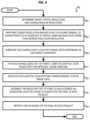
- FIG. 4is a flow chart that illustrates an example method for adaptive scanning with a scanning laser ranging system, according to an embodiment
- FIG. 5is an image that illustrates example ranges to backscattered returns in an overhead view and an angled perspective view, according to an embodiment
- FIG. 6 Ais an image that illustrates example range gates for ranges to backscattered returns in an angled perspective view from FIG. 5 , according to an embodiment
- FIG. 6 B through FIG. 6 Eare masks in scanning angle space that show example returns in each of four range gates illustrated in FIG. 6 A , according to an embodiment
- FIG. 7 A and FIG. 7 Bare graphs that illustrate example adaptive scanning patterns in multiple contiguous horizontal slices in a portion of the range gate depicted in FIG. 6 E for different characteristic ranges (or different target spatial resolutions) respectively, according to an embodiment
- FIG. 8is a block diagram that illustrates a computer system upon which an embodiment of the invention may be implemented.
- FIG. 9is a block diagram that illustrates a chip set upon which an embodiment of the invention may be implemented.
- FIG. 10is a graph that illustrates an example histogram of ranges in a course angular scanning of a scene, according to an embodiment.
- a method and apparatus and system and computer-readable mediumare described for adaptive scanning with laser range detection systems.
- numerous specific detailsare set forth in order to provide a thorough understanding of the present invention. It will be apparent, however, to one skilled in the art that the present invention may be practiced without these specific details. In other instances, well-known structures and devices are shown in block diagram form in order to avoid unnecessarily obscuring the present invention.
- the term “about”implies a factor of two, e.g., “about X” implies a value in the range from 0.5 ⁇ to 2 ⁇ , for example, about 100 implies a value in a range from 50 to 200.
- all ranges disclosed hereinare to be understood to encompass any and all sub-ranges subsumed therein.
- a range of “less than 10”can include any and all sub-ranges between (and including) the minimum value of zero and the maximum value of 10, that is, any and all sub-ranges having a minimum value of equal to or greater than zero and a maximum value of equal to or less than 10, e.g., 1 to 4.
- amplitude pulsed or phase encoded optical signalsare used.
- Embodimentsare described in the context of a stationary scanning laser scanning over a limited horizontal angle sweep.
- a moving laser range detection systemis used with narrower or wider horizontal angular sweeps, including full 360 degree horizontal angular sweeps.
- Many embodimentsare described in terms of a vertical saw-tooth scan trajectory.
- a vertical column-order scan trajectory, or horizontal row-order scan trajectory, or horizontal saw-toothed scan trajectory, or some combination,are used.
- the vertical saw tooth projectionwas used with an embodiment having a hardware configuration with a rotation stage for horizontal motion (slow) and a galvanometer scan mirror for vertical (fast).
- Another embodimentuses a 2-axis fast steering mirror (fast scanning in two dimensions, limited FOV) or a 2-axis pan tilt unit (slower motion in 2 dimensions, huge FOV), or some combination.
- FIG. 1 Ais a set of graphs 110 , 120 , 130 , 140 that illustrates an example optical chirp measurement of range, according to an embodiment.
- Graph 110indicates the power of a beam of light used as a transmitted optical signal.
- the vertical axis 114 in graph 110indicates power of the transmitted signal in arbitrary units.
- Trace 116indicates that the power is on for a limited pulse duration, ⁇ starting at time 0.
- Graph 120indicates the frequency of the transmitted signal.
- the vertical axis 124indicates the frequency transmitted in arbitrary units.
- the frequency rate of changeis (f 2 ⁇ f 1 )/ ⁇
- the returned signalis depicted in graph 130 which has a horizontal axis 112 that indicates time and a vertical axis 124 that indicates frequency as in graph 120 .
- the chirp 126 of graph 120is also plotted as a dotted line on graph 130 .
- a first returned signalis given by trace 136 a , which is just the transmitted reference signal diminished in intensity (not shown) and delayed by ⁇ t.
- the returned signalis received from an external object after covering a distance of 2R, where R is the range to the target, the returned signal starts at the delayed time ⁇ t given by 2R/c, were c is the speed of light in the medium (approximately 3 ⁇ 10 8 meters per second, m/s).
- Equation 1a and 1bare not valid.
- the reference signalalso called a local oscillator (LO)
- LOlocal oscillator
- the fixed or known delay time, ⁇ t LO , of the reference signalis multiplied by the speed of light, c, to give an additional range that is added to range computed from Equation 1b. While the absolute range may be off due to uncertainty of the speed of light in the medium, this is a near-constant error and the relative ranges based on the frequency difference are still very precise.
- a spot illuminated by the transmitted light beamencounters two or more different scatterers at different ranges, such as a front and a back of a semitransparent object, or the closer and farther portions of an object at varying distances from the LIDAR, or two separate objects within the illuminated spot.
- a second diminished intensity and differently delayed signalwill also be received, indicated in graph 130 by trace 136 b . This will have a different measured value of f R that gives a different range using Equation 1b.
- multiple returned signalsare received.
- Graph 140depicts the difference frequency f R between a first returned signal 136 a and the reference chirp 126 .
- the horizontal axis 112indicates time as in all the other aligned graphs in FIG. 1 A , and the vertical axis 134 indicates frequency difference on a much expanded scale.
- Trace 146depicts the constant frequency f R measured during the transmitted, or reference, chirp, which indicates a particular range as given by Equation 1b.
- the second returned signal 136 bif present, would give rise to a different, larger value of f R (not shown) during de-chirping; and, as a consequence yield a larger range using Equation 1b.
- a common method for de-chirpingis to direct both the reference optical signal and the returned optical signal to the same optical detector.
- the electrical output of the detectoris dominated by a beat frequency that is equal to, or otherwise depends on, the difference in the frequencies, phases and amplitudes of the two signals converging on the detector.
- a Fourier transform of this electrical output signalwill yield a peak at the beat frequency.
- Such signalsare readily processed by common and inexpensive RF components, such as a Fast Fourier Transform (FFT) algorithm running on a microprocessor or a specially built FFT or other digital signal processing (DSP) integrated circuit.
- FFTFast Fourier Transform
- DSPdigital signal processing
- the return signalis mixed with a continuous wave (CW) tone acting as the local oscillator (versus a chirp as the local oscillator).
- CWcontinuous wave
- the detected signalwhich itself is a chirp (or whatever waveform was transmitted).
- the detected signalwould undergo matched filtering in the digital domain as described in Kachelmyer 1990.
- the disadvantageis that the digitizer bandwidth requirement is generally higher. The positive aspects of coherent detection are otherwise retained.
- FIG. 1 Bis a graph that illustrates an example measurement of a beat frequency resulting from de-chirping, which indicates range, according to an embodiment.
- Trace 156is the Fourier transform of the electrical signal output by the optical detector, such as produced by a FFT circuit; and, the data plotted is based on data published by Adany et al., 2009. The horizontal location of the peak gives f R that indicates the range, using Equation 1b. In addition, other characteristics of the peak can be used to describe the returned signal.
- the power value at the peakis characterized by the maximum value of trace 156 , or, more usually, by the difference 157 (about 19 dB in FIG. 1 B ) between the peak value (about ⁇ 31 dB in FIG. 1 B ) and a noise floor (about ⁇ 50 dB in FIG. 1 B ) at the shoulders of the peak; and, the width of the peak is characterized by the frequency width 158 (about 0.08 MHz in FIG. 1 B ) at half maximum (FWHM). If there are multiple discernable returns, there will be multiple peaks in the FFT of the electrical output of the optical detector, likely with multiple different power levels and widths. Any method may be used to automatically identify peaks in traces, and characterize those peaks by location, height and width.
- FFTW or Peak detection by MATLAB—Signal Processing Toolboxis used, available from MTLABTM of MATHWORKSTM of Natick, Mass.
- MATLABTMof MATHWORKSTM of Natick, Mass.
- custom implementationsthat rely on FFTW in CUDA and custom peak detection in CUDATM available from NVIDIATM of Santa Clara, Calif.
- Custom implementationshave been programmed on field programmable gate arrays (FPGAs).
- a commonly used algorithmis to threshold the range profile and run a center of mass algorithm, peak fitting algorithm (3-point Gaussian fit), or nonlinear fit of the peak for some function (such as a Gaussian) to determine the location of the peak more precisely.
- a new independent measurementis made at a different angle, or translated position of a moving LIDAR system, using a different pulse after an interlude of ti, so that the pulse rate (PR) is given by the expression 1/( ⁇ +ti).
- a frameis a 2 dimensional image of ranges in which each pixel of the image indicates a range to a different portion of an object viewed by the transmitted beam. For a frame assembled from transmitted signals at each of 1000 horizontal angles by 1000 vertical angles, the frame includes 10 6 pixels and the frame rate (FR) is 10 ⁇ 6 of the pulse rate, e.g., is 10 ⁇ 6 /( ⁇ +ti).
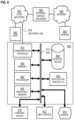
- FIG. 2 A and FIG. 2 Bare block diagrams that illustrate example components of a high resolution LIDAR system, according to various embodiments.
- a laser source 212emits a carrier wave 201 that is amplitude or frequency or phase modulated, or some combination, in the modulator 214 based on input from a RF waveform generator 215 to produce an optical signal 203 with a pulse that has a bandwidth B and a duration ⁇ .
- the RF waveform generator 215is software controlled with commands from processing system 250 .
- a splitter 216splits the modulated optical waveform into a transmitted signal 205 with most of the energy of the optical signal 203 and a reference signal 207 with a much smaller amount of energy that is nonetheless enough to produce good heterodyne or homodyne interference with the returned light 291 scattered from a target (not shown).
- the transmitted beamis scanned over multiple angles to profile any object in its path using scanning optics 218 .
- the reference signalis delayed in a reference path 220 sufficiently to arrive at the detector array 230 with the scattered light.
- the splitter 216is upstream of the modulator 214 , and the reference beam 207 is unmodulated.
- the reference signalis independently generated using a new laser (not shown) and separately modulated using a separate modulator (not shown) in the reference path 220 and the RF waveform from generator 215 .
- the output from the single laser source 212is independently modulated in reference path 220 .
- the referenceis caused to arrive with the scattered or reflected field by: 1) putting a mirror in the scene to reflect a portion of the transmit beam back at the detector array so that path lengths are well matched; 2) using a fiber delay to closely match the path length and broadcast the reference beam with optics near the detector array, as suggested in FIG.
- the targetis close enough and the pulse duration long enough that the returns sufficiently overlap the reference signal without a delay.
- the reference signal 207 bis optically mixed with the return signal 291 at one or more optical mixers 232 .
- multiple portions of the targetscatter a respective returned light 291 signal back to the detector array 230 for each scanned beam resulting in a point cloud based on the multiple ranges of the respective multiple portions of the target illuminated by multiple beams and multiple returns.
- the detector array 230is a single or balanced pair optical detector or a 1D or 2D array of such optical detectors arranged in a plane roughly perpendicular to returned beams 291 from the target.
- the phase or amplitude of the interface pattern, or some combination,is recorded by acquisition system 240 for each detector at multiple times during the pulse duration ⁇ .
- the number of temporal samples per pulse durationaffects the down-range extent. The number is often a practical consideration chosen based on pulse repetition rate and available camera frame rate.
- the frame rateis the sampling bandwidth, often called “digitizer frequency.” Basically, if X number of detector array frames are collected during a pulse with resolution bins of Y range width, then a X*Y range extent can be observed.
- the acquired datais made available to a processing system 250 , such as a computer system described below with reference to FIG. 8 , or a chip set described below with reference to FIG. 9 .
- the acquired datais a point cloud based on the multiple ranges of the respective multiple portions of the target.
- An adaptive scanning module 270determines whether non-uniform scanning by scanning optics is desirable for a particular scene being scanned, as described in more detail below. For example, the adaptive scanning module 270 determines what scanning angles and resolutions to use for different portions of a scene, so that the valuable pulses for constructing a frame, e.g., the millions of beams transmitted during a few seconds, are concentrated in directions where there are returns from objects to be scanned and avoid directions where there is only sky or nearby ground of little interest. In some embodiments, the adaptive scanning module 270 controls the RF waveform generator 215 .
- FIG. 2 Bdepicts an alternative hardware arrangement that allows software controlled delays to be introduced into the reference path that produces the reference signal, also called the local oscillator (LO) signal.
- the laser source 212 , splitter 216 , transmit signal 205 , scanning optics 218 , optical mixers 232 , detector array 230 , acquisition system 240 and processing system 250are as described above with reference to FIG. 2 A .
- the splitter 216is moved between the laser source 212 and the modulators 214 a and 214 b to produce optical signal 283 that impinges on modulator 214 a and lower amplitude reference path signal 287 a that impinges on modulator 214 b in a revised reference path 282 .
- the light 201is split into a transmit (TX) path beam 283 and reference/local oscillator (LO) path beam 287 a before the modulation occurs; and, separate modulators are used in each path.
- TXtransmit
- LOlocal oscillator
- either pathcan be programmed with chirps at offset starting frequencies and/or offset starting times. This can be used to allow the adaptive scanning approach to be adaptive in the down-range dimension.
- a revised adaptive scanning module 278controls the RF waveform generator to impose the delay time appropriate for each range gate produced by the adaptive scanning described below.
- the software controlled delay reference signal 287 bis then mixed with the return signals 291 , as described above.
- the software controlled delay of the LO reference path 282allows the system 280 to garner range delay effects for chirp Doppler compensation as well.
- the laser usedwas actively linearized with the modulation applied to the current driving the laser.
- electro-optic modulatorsproviding the modulation.
- the systemis configured to produce a chirp of bandwidth B and duration ⁇ , suitable for the down-range resolution desired, as described in more detail below for various embodiments. This technique will work for chirp bandwidths from 10 MHz to 5 THz.
- the targethas a minimum range, such as 400 meters (m). It is noted that the range window can be made to extend to several kilometers under these conditions.
- FIG. 2 A and FIG. 2 Bprocesses, equipment, and data structures are depicted in FIG. 2 A and FIG. 2 B as integral blocks in a particular arrangement for purposes of illustration, in other embodiments one or more processes or data structures, or portions thereof, are arranged in a different manner, on the same or different hosts, in one or more databases, or are omitted, or one or more different processes or data structures are included on the same or different hosts.
- splitter 216 and reference path 220include zero or more optical couplers.
- FIG. 3 Ais an image that illustrates an example scene to be scanned with a scanning laser ranging system, according to an embodiment. This image was produced using maximum horizontal and vertical angular resolution of a scanning 3D laser ranging system configured for ranges of up to about 1 kilometer (e.g., 0.5 to 2 km) with about 10 centimeter range resolution (e.g., 5 to 20 cm).
- FIG. 3 Bis an image that illustrates an example horizontal portion of the scene in FIG. 3 A to be adaptively scanned, according to an embodiment. The horizontal dimension indicates horizontal angle in relative units and the vertical dimension indicates vertical angle in relative units as viewed from a stationary LIDAR system.
- the adaptive scanningis undertaken to speed the collection of desired ranging information by avoiding measurements at angles of no return; by using high angular resolution sampling only for the more distant targets where such sampling is desirable to obtain a target spatial resolution; and by using lower angular resolution sampling at closer objects where the lower angular resolution suffices to provide the target spatial resolution.
- FIG. 3 Cis a block diagram that illustrates example sets of ranges for features evident in FIG. 3 B , according to an embodiment.
- FIG. 3 Crepresents sampling angle space.
- area 310there are no returns and it is desirable not to scan this area of angle space.
- area 320there is only the ground immediately in front of the system of little interest (e.g., the area is well understood or includes only small features of no particular interest). It is desirable not to scan this area of angle space either.
- the distant domed structureoccupies area 332 of angle space
- the structures in front of the domeoccupy area 330 of angle space
- a wall or fence in front of theseoccupies area 328 of angle space
- a closer structure and poleoccupies area 322 of angle space.
- the terrainis evident at ever increasing ranges marked as areas 321 , 323 , 325 and 327 in angle space.
- the angular resolution, ⁇to use is a function of range R to an object, as given by Equation 2.
- any given laser ranging systemhas a minimum angular width of an individual optical beam, and an angular resolution cannot practically be defined that is much smaller than such an angular beam width. Thus at some large ranges the target spatial resolution, s, may not be achievable. For simplicity in the following description, it is assumed that the computed ⁇ is always greater than the beam angular width.
- Equations 2a through 2cimply that the ranges to various objects in the scene are known.
- the ranges involved in the sceneare determined by a first-pass, coarse, angular resolution. It is common for ranges in a scene to extend further in one dimension than the other, or for the apparatus to have greater control in one dimension compared to the other; so, in some embodiments, the coarse horizontal angular resolution is different from the course vertical angular resolution.
- FIG. 3 Dis a block diagram that illustrates example coarse angular scanning over the features depicted in FIG. 3 C , according to an embodiment.
- the horizontal axis 342indicates horizontal angle (also called azimuth) and the vertical axis indicates vertical angle (also called elevation).
- a vertical saw-tooth scan trajectoryis indicated by dotted line 346 .
- the scan trajectory 346is a vertical saw-tooth pattern with a horizontal repeat separation angle 347 , designated A HR .
- the scan trajectory 346is widely spaced in the horizontal compared to the finest horizontal scanning that could be performed by a scanning LIDAR ranging system.
- range measurementsare taken along the path 346 at the coarse vertical sampling resolution.
- the horizontal resolutionis variable but is characterized by two samples per horizontal repeat separation, A HR ; thus, the average horizontal resolution is A HR /2.
- a row-order or column-order scan trajectoryis used in which both the horizontal samples separation and the vertical samples separation are constant over the scan.
- both the horizontal and vertical separationsare set to ⁇ .
- Ranges in area 320are excluded. The remaining ranges are divided into multiple range intervals, called range gates, each range gate defined by a different, non-overlapping interval given by a different, non-overlapping Rnear and Rfar.
- a range R( ⁇ , ⁇ )is a member of range gate number n, a set designated RGn, of N range gates, then it satisfies Equation 3.
- R near n ⁇ RGn ⁇ R far n(3)
- the values Rnear ncan be used as gates for assigning a range R( ⁇ , ⁇ ) and its associated angular coordinates ( ⁇ , ⁇ ) to one range gate set, using instructions such as
- each range gate areais outlined by a minimum vertical angle for each horizontal angle and a maximum vertical angle for each horizontal angle based on the coarse sampling. Each of the minimum vertical angles and maximum vertical angles are interpolated to the target horizontal angular spacing (a spacing given by Equation 2b where Rfar is given by Rfar n ). Then, each range gate area is scanned separately with a saw-toothed scanning pattern (or other scanning pattern) using horizontal and vertical angular resolution given by Equation 2b where Rfar is given by Rfar n . A scanning pattern is also called a scan trajectory.
- FIG. 4is a flow chart that illustrates an example method for adaptive scanning with a scanning laser ranging system, according to an embodiment.
- stepsare depicted in FIG. 4 , and in subsequent flowchart FIG. 14 , as integral steps in a particular order for purposes of illustration, in other embodiments, one or more steps, or portions thereof, are performed in a different order, or overlapping in time, in series or in parallel, or are omitted, or one or more additional steps are added, or the method is changed in some combination of ways.
- a target spatial resolution, sis determined. Any method can be used. This can be input manually by a user or retrieved from storage on a computer-readable medium or received from a local or remote database or server, either unsolicited or in response to a query.
- a size range for objects, Os, of interestis input and the target spatial resolution, s, is determined based on a predetermined or specified fraction, such as one hundredth or one thousandth, of an indicated object size, Os.
- a maximum range, Rmaxfor detecting such objects is also determined using one or more of the above methods.
- the coarse angular resolutionis also provided, using any of the above methods.
- the coarse angular resolutionis determined based on one or more other inputs. For example, if the desired target spatial resolution is s and the greatest range of interest is Rmax, then the finest angular resolution, ⁇ best, is given by Equation 2a with R replaced by Rmax. In this case, the coarse angular resolution is a multiple of this finest resolution, ⁇ best. In order to complete this coarse scan in a small amount of time compared to a frame rate, the multiple is large, e.g., in a range from about 10 to about 100 times the finest resolution (completing a coarse frame in one 100th to one 10,000 th of a high resolution frame).
- spatial resolution on targetis about 1 cm or more with 10 cm on target considered to be rather large final resolution for the experimental imager.
- the multiple used for coarse scan resolutionis between about 10 to about 25 times the fine resolution on target. The coarse scan will still then be a fraction of the total scan time but will provide good information for adaptive scan pattern generation.
- a coarse resolution imaging scanis performed to acquire general 3D characteristics of scene but at spatial sampling much less dense than a desired final scan angular resolution.
- the result of this coarse scanis a coarse three dimensional (3D) point cloud, each point in the cloud indicating a location in 3D coordinates of an illuminated spot on a laser backscattering surface.
- the 3D coordinatesmay be polar coordinates, such as azimuth ⁇ , elevation ⁇ , and range R from the ranging system, or Cartesian coordinates, such as x horizontal (e.g., distance north from some reference point, e.g., the location of the ranging system), y horizontal (e.g., distance east from the reference point), and z (e.g., altitude above the horizontal plane).
- x horizontale.g., distance north from some reference point, e.g., the location of the ranging system
- y horizontale.g., distance east from the reference point
- ze.g., altitude above the horizontal plane
- the coarse point cloudis subdivided into range gates depending on the range coordinate, e.g., using Equation 3, above, and the pseudo code immediately following Equation 3.
- Subdivisionmay be hard coded with N fixed values of Rnear n or adaptive based on one to N computed values for the Rnear n .
- the N range gatesare evenly distributed between R 5 and R 99 .
- step 405includes converting a Cartesian representation of the acquired coarse point cloud data to spherical coordinates relative to the LIDAR ranging system before determining the range gates.
- determining the N rage gateswas done through basic data analysis of the point density as a function of range.
- An example adaptive data analysisplaced range gates at ranges in the density distribution the where there was a minimal number of points. This was done so that range gate “seams” are placed where there is a minimum density of objects visible to the system.
- step 411for each range gated set of points, RGn, an adaptive scan trajectory is determined for improved scene sampling.
- a characteristic range in the range gateis used, in place of Rfar, with Equation 2b or Equation 2c, to determine angular resolution for vertical and horizontal scan properties.
- the characteristic rangeis Rfar n ; and, Equation 2b or Equation 2c is used.
- the horizontal repeat separation angle, A HRof the saw-tooth pattern is set to the angular resolution ⁇ , so that the worst horizontal resolution is ⁇ and the average horizontal resolution is even better at ⁇ /2.
- a HRis set to 2 ⁇ , because the average horizontal resolution is then ⁇ .
- other characteristic rangesare used, such as the middle range, Rmid n , defined to be halfway between Rnear n and Rfar n .
- the adaptive scan trajectoryis determined between the minimum vertical angle and the maximum vertical angle at all horizontal angles in the range gate area in angle space.
- a delay time for the local oscillator, ⁇ t LOnis determined for each range gate sampling trajectory for range gate n using a range gate range, RGRn, of the nth range gate, RGn, e.g., RGRn equals or is a function of Rnear n or of a characteristic range as defined above, according to Equation 4.
- ⁇ t LOnRGRn/c (4)
- step 421commands for the scanning optics based on each adaptive scan pattern corresponding to each range gate is forwarded to the ranging system, or the scanning optics within the system, to operate the scanning laser ranging system to obtain range measurements along the adaptive scan trajectory at the adaptive horizontal angular resolution and at the adaptive vertical angular resolution.
- step 421includes sending data indicating the delay time ⁇ t LOn from Equation 4 for the current range gate, or more of the N different range gates.
- the ranging systemmodulates the laser light using RF waveform generator 215 a and modulator 214 b in FIG. 2 B to impose the computed delay time ⁇ t LOn .
- step 431the resultant set of point cloud points acquired via sequential adaptive scans for all of the range gate areas in angle space are assembled to constitute the final 3D data product which is a collection of one or more point clouds that preserves the target spatial resolution, s, for all scanned objects. Simultaneously, the adaptive scans avoid scanning angle spaces with no returns or too close to the ranging system, or some combination.
- a deviceis operated based on the final 3D data product. In some embodiments, this involves presenting on a display device an image that indicates the 3D data product. In some embodiments, this involves communicating, to the device, data that identifies at least one object based on a point cloud of the 3D data product. In some embodiments, this involves moving a vehicle to approach or to avoid a collision with the object identified or operating a weapons system to direct ordnance onto the identified object.
- FMCWfrequency modulated continuous wave
- PRFpulse repetition frequency
- the time delay of the LO waveformallows the ranging frequency bandwidth, B, for the given range delay to be reduced so that it is in the band of the detector/digitizer system.
- This conceptenables rapid range data acquisition within range windows at non-zero range delays. This can be paired with the adaptive scan algorithms to more quickly acquire data in a volume of interest, e.g., using a different reference path delay for the scan trajectory of each different range gate.
- the adaptive angular scan procedureis designed to produce (within the abilities of the beam scanning hardware) a scan pattern that conforms to the angular boundaries of the volume under interrogation. This prevents the system from “scanning the sky” or “scanning the ground”.
- the scan patternsare constructed by considering coarse non-adaptive scans of the volume. This is used to define the boundary of the actual hard targets within the range window in question. Research software was implemented to demonstrate the speed and utility of the approach.
- FIG. 5is an image that illustrates example ranges to backscattered returns in an overhead view and an angled perspective view, according to an embodiment.
- the grey pixels in the upper portion of FIG. 5 Adepict an overhead view 501 of horizontal angles and ranges where a return was detected by the scanning laser ranging system in an experimental embodiment.
- the scanning laser ranging systemincluded a model HRS-3D-AS adaptive scanner from BLACKMORE SENSORS AND ANALYTICSTM Inc of Bozeman, Mont.
- the range windowwas 3 meters to 96 meters.
- the horizontal angle rangeis about 370 degree coverage with the rotation stage and the vertical angel range is about 60 degrees.
- the range resolutionis about 7.5 cm.
- FIG. 5 Adepict a perspective angled view 511 of ranges and elevations and relative horizontal positions where a return was detected by the scanning laser ranging system in the same experiment.
- the scanning laser ranging system location 503is at the left edge of the image.
- the returns 505provide high spatial density, even higher than desired for some embodiments and thus finer spatial resolution than the corresponding target spatial resolution s.
- the returns 507provide low spatial density, below the desired spatial density, and thus coarser than the corresponding target spatial resolution s, for some embodiments.
- FIG. 6 Ais an image that illustrates example range gates for ranges to backscattered returns in an angled perspective view from FIG. 5 , according to an embodiment.
- the grey pixelsdepict a perspective angled view 511 of ranges and elevations and relative horizontal positions where a return was detected by the scanning laser ranging system in the same experiment as in the lower portion of FIG. 5 A .
- FIG. 6 B through FIG. 6 Eare masks in scanning angle space that show example locations of returns in each of four range gates illustrated in FIG. 6 A , according to an embodiment.
- the black areas in angle spaceindicate azimuthal and elevation angles, a and E, where there are range returns in the first range gate, and, thus indicate areas where fine resolution scanning is useful.
- the coarse maskshave 10 ⁇ 3 radians (about 0.06 degrees) resolution horizontally with not more than 10 ⁇ 4 radians (about 0.006 degrees) resolution vertically.
- the horizontal axis 632indicates azimuth ⁇ from about ⁇ 0.2 to about +0.2 radians, corresponding to about ⁇ 11.5 degrees to +11.5 degrees.
- the vertical axesindicate elevation c and vary slightly in extent among the four masks.
- the vertical axis 634extends from about ⁇ 0.12 to about 0 radians, corresponding to about ⁇ 7 degrees to 0 degrees, level. There are no returns above ⁇ 0.05 radians (about ⁇ 3 degrees).
- a characteristic range in the black mask area 635is used with the target spatial resolution, s, and Equation 2a or 2c to determine an angular resolution ⁇ .
- the area to be coveredis between the minimum vertical angle at about ⁇ 0.12 radians and a maximum vertical angle traced out by the dashed trace 636 .
- the minimum and maximum azimuthal angleswould be ⁇ 0.2 radians and +0.2 radians, respectively, for elevations below ⁇ 0.05 radians.
- the vertical axis 644extends from about ⁇ 0.06 to about 0.11 radians, corresponding to about ⁇ 3.5 degrees to 6.3 degrees. There are no returns below about ⁇ 0.05 radians (about ⁇ 3 degrees) the maximum elevation angle for the first range gate.
- Returns in the second range gateare indicated by the black area 645 and suggest a lamp post and a tree to the right of the lamp post with a ground level below 0 radians.
- a characteristic range in the black mask area 645is used with the target spatial resolution, s, and Equation 2a or 2c to determine an angular resolution ⁇ .
- the area to be coveredis between the minimum vertical angle at about ⁇ 0.5 radians and a maximum vertical angle traced out by the dashed trace 646 that is single valued at each azimuthal angle ⁇ .
- the minimum and maximum azimuthal anglesare each single valued in elevation angle ⁇ . The minimum azimuthal angle would trace the left side of the lamp post and the maximum azimuthal angle would trace the right side of the tree.
- the vertical axis 654extends from about ⁇ 0.01 to about 0.11 radians, corresponding to about ⁇ 0.6 degrees to 6.3 degrees. There are no returns below about ⁇ 0.01 radians (about ⁇ 0.6 degrees), which is about the maximum elevation angle for the ground level of the second range gate.
- Returns in the third range gateare indicated by the black area 655 and suggest a copse of trees, several lamps and sign posts to the right of the copse and a bush to the far right, with a ground level topping off at about 0 radians.
- a characteristic range in the black mask areais used with the target spatial resolution, s, and Equation 2a or 2c to determine an angular resolution ⁇ .
- the area to be coveredis between the minimum vertical angle given by trace 658 and a maximum vertical angle given by the dashed trace 656 that is single valued at each azimuthal angle ⁇ .
- the minimum and maximum azimuthal anglesare each single valued in elevation angle ⁇ .
- the minimum azimuthal anglewould trace the left side of copse of trees and the maximum azimuthal angle would trace the right side of the trees down to the elevation of the posts, from there to the right side of the posts down to the elevation of the bush, and from there to the right side of the bush.
- the vertical axis 664extends from about 0 to about 0.08 radians (because of perspective, farther objects appear smaller and extend a shorter distance in vertical angles), corresponding to about 0 degrees to about 4.5 degrees. There are no returns below about 0 radians, which is about the maximum elevation angle for the ground level of the third range gate.
- Returns in the fourth range gateare indicated by the black area 665 and suggest a copse of trees, a clearing and then a wide stand of trees, with a ground level topping off at about 0.01 radians.
- a characteristic range in the black mask area 665is used with the target spatial resolution, s, and Equation 2a to determine an angular resolution ⁇ .
- the area to be coveredis between the minimum vertical angle given by trace 668 and a maximum vertical angle given by the dashed trace 666 that is single valued at each azimuthal angle ⁇ .
- the minimum and maximum azimuthal anglesare each single valued in elevation angle ⁇ . The minimum azimuthal angle would trace the left side of copse of trees and the maximum azimuthal angle would trace the right side of the trees down to the elevation of the stand of trees, from there to the right edge at 0.20 radians.
- a dotted box 669indicates a horizontal portion of the area displayed with a high precision scan trajectory in FIG. 7 A and FIG. 7 B .
- FIG. 7 A and FIG. 7 Bare graphs that illustrate example adaptive scanning patterns in multiple contiguous horizontal slices in a portion of the range gate depicted in FIG. 6 E for different characteristic ranges (or different target spatial resolutions) respectively, according to an embodiment.
- the horizontal axis 712indicates azimuthal angle in radians from about ⁇ 0.085 radians to about 0.005 radians, corresponding to a window from about ⁇ 5 degrees to about 0.3 degrees, and depicted as horizontal extent of dotted rectangle 669 in FIG. 6 E .
- the vertical axis 714indicates elevation angle in radians from about ⁇ 0.01 radians to about 0.06 radians, corresponding to a window from about ⁇ 0.6 degrees to about 3.5 degrees.
- FIG. 7 Ais a graph 710 of a high resolution scan trajectory 716 between the minimum and maximum elevation angles.
- the horizontal repeat separation angle, A HRis about 0.0005 radians (note there are 20 repeats between tick marks that are 0.01 radians apart), corresponding to a separation angle of about 0.03 degrees. Assuming this repeat separation angle is equal to ⁇ , then ⁇ also equals 0.03 degrees. Thus, ranges are measured every 0.03 degrees in the vertical along this saw-tooth scan trajectory.
- FIG. 7 Bis a graph 720 of a high resolution scan trajectory 726 between the minimum and maximum elevation angles under different range or target resolution conditions.
- the characteristic rangeis much smaller, or the target spatial resolution, s, is much courser than the values used to generate FIG. 7 A .
- the angle resolution determined from Equation 2ais much less fine.
- the horizontal repeat separation angle, A HRis about 0.003 radians (note there are about 3.3 repeats between tick marks that are 0.01 radians apart), corresponding to a separation angle of about 0.17 degrees, about six times less fine than in FIG. 7 A .
- the range gatese.g., value of N and the N values of Rnear n are predetermined or set manually before the adaptive scanning.
- the value for N, or the N values for Rnear n , or bothare determined automatically and adaptively based on the observed ranges R( ⁇ , ⁇ ) in the coarsely spaced range measurements.
- N and Rnear nare determined based on low and high percentiles (e.g., 5 th and 99 th percentiles) of the observed ranges.
- FIG. 10is a graph 1010 that illustrates an example histogram of ranges in a course angular scanning of a scene, according to an embodiment. It is assumed that the scanning laser ranging system is configured for ranges up to Rmax.
- the horizontal axis 1012indicates a range bin having a bin width that is small compared to Rmax, e.g. having a bin width of one tenth to one hundredth or even one thousandth of Rmax.
- the vertical axis 1014indicates the number of occurrences of measured ranges that falls within any range bin.
- Trace 1016depicts an example histogram.
- the number of occurrencesis not flat but has several peaks 1017 and valleys 1015 . Large features are likely to generate a peak in the histogram while open areas are likely to generate valleys.
- the range histogramwas re-scaled as a function of range to account for the fact that the coarse scan is performed with constant angular density. The re-scaling weights more distant point measurements more heavily in the histogram to account for this discrepancy.
- one or more range gate values Rnear nare determined to be at the occurrence valleys in the histogram 1016 , as indicated by the vertical dotted lines.
- the characteristic range for the range gateis then the range of maximum occurrence (e.g., Rpeak n ) in the range gate. Both the minima and the peak values are quickly and automatically determined using a variety of available software routines.
- FIG. 8is a block diagram that illustrates a computer system 800 upon which an embodiment of the invention may be implemented.
- Computer system 800includes a communication mechanism such as a bus 810 for passing information between other internal and external components of the computer system 800 .
- Informationis represented as physical signals of a measurable phenomenon, typically electric voltages, but including, in other embodiments, such phenomena as magnetic, electromagnetic, pressure, chemical, molecular atomic and quantum interactions. For example, north and south magnetic fields, or a zero and non-zero electric voltage, represent two states (0, 1) of a binary digit (bit). Other phenomena can represent digits of a higher base.
- a superposition of multiple simultaneous quantum states before measurementrepresents a quantum bit (qubit).
- a sequence of one or more digitsconstitutes digital data that is used to represent a number or code for a character.
- information called analog datais represented by a near continuum of measurable values within a particular range.
- Computer system 800or a portion thereof, constitutes a means for performing one or more steps of one or more methods described herein.
- a sequence of binary digitsconstitutes digital data that is used to represent a number or code for a character.
- a bus 810includes many parallel conductors of information so that information is transferred quickly among devices coupled to the bus 810 .
- One or more processors 802 for processing informationare coupled with the bus 810 .
- a processor 802performs a set of operations on information.
- the set of operationsinclude bringing information in from the bus 810 and placing information on the bus 810 .
- the set of operationsalso typically include comparing two or more units of information, shifting positions of units of information, and combining two or more units of information, such as by addition or multiplication.
- a sequence of operations to be executed by the processor 802constitutes computer instructions.
- Computer system 800also includes a memory 804 coupled to bus 810 .
- the memory 804such as a random access memory (RAM) or other dynamic storage device, stores information including computer instructions. Dynamic memory allows information stored therein to be changed by the computer system 800 . RAM allows a unit of information stored at a location called a memory address to be stored and retrieved independently of information at neighboring addresses.
- the memory 804is also used by the processor 802 to store temporary values during execution of computer instructions.
- the computer system 800also includes a read only memory (ROM) 806 or other static storage device coupled to the bus 810 for storing static information, including instructions, that is not changed by the computer system 800 .
- ROMread only memory
- Also coupled to bus 810is a non-volatile (persistent) storage device 808 , such as a magnetic disk or optical disk, for storing information, including instructions, that persists even when the computer system 800 is turned off or otherwise loses power.
- Informationis provided to the bus 810 for use by the processor from an external input device 812 , such as a keyboard containing alphanumeric keys operated by a human user, or a sensor.
- an external input device 812such as a keyboard containing alphanumeric keys operated by a human user, or a sensor.
- a sensordetects conditions in its vicinity and transforms those detections into signals compatible with the signals used to represent information in computer system 800 .
- a display device 814such as a cathode ray tube (CRT) or a liquid crystal display (LCD), for presenting images
- a pointing device 816such as a mouse or a trackball or cursor direction keys, for controlling a position of a small cursor image presented on the display 814 and issuing commands associated with graphical elements presented on the display 814 .
- special purpose hardwaresuch as an application specific integrated circuit (IC) 820 , is coupled to bus 810 .
- the special purpose hardwareis configured to perform operations not performed by processor 802 quickly enough for special purposes.
- application specific ICsinclude graphics accelerator cards for generating images for display 814 , cryptographic boards for encrypting and decrypting messages sent over a network, speech recognition, and interfaces to special external devices, such as robotic arms and medical scanning equipment that repeatedly perform some complex sequence of operations that are more efficiently implemented in hardware.
- Computer system 800also includes one or more instances of a communications interface 870 coupled to bus 810 .
- Communication interface 870provides a two-way communication coupling to a variety of external devices that operate with their own processors, such as printers, scanners and external disks. In general the coupling is with a network link 878 that is connected to a local network 880 to which a variety of external devices with their own processors are connected.
- communication interface 870may be a parallel port or a serial port or a universal serial bus (USB) port on a personal computer.
- communications interface 870is an integrated services digital network (ISDN) card or a digital subscriber line (DSL) card or a telephone modem that provides an information communication connection to a corresponding type of telephone line.
- ISDNintegrated services digital network
- DSLdigital subscriber line
- a communication interface 870is a cable modem that converts signals on bus 810 into signals for a communication connection over a coaxial cable or into optical signals for a communication connection over a fiber optic cable.
- communications interface 870may be a local area network (LAN) card to provide a data communication connection to a compatible LAN, such as Ethernet.
- LANlocal area network
- Wireless linksmay also be implemented.
- Carrier waves, such as acoustic waves and electromagnetic waves, including radio, optical and infrared wavestravel through space without wires or cables. Signals include man-made variations in amplitude, frequency, phase, polarization or other physical properties of carrier waves.
- the communications interface 870sends and receives electrical, acoustic or electromagnetic signals, including infrared and optical signals, that carry information streams, such as digital data.
- Non-volatile mediainclude, for example, optical or magnetic disks, such as storage device 808 .
- Volatile mediainclude, for example, dynamic memory 804 .
- Transmission mediainclude, for example, coaxial cables, copper wire, fiber optic cables, and waves that travel through space without wires or cables, such as acoustic waves and electromagnetic waves, including radio, optical and infrared waves.
- the term computer-readable storage mediumis used herein to refer to any medium that participates in providing information to processor 802 , except for transmission media.
- Computer-readable mediainclude, for example, a floppy disk, a flexible disk, a hard disk, a magnetic tape, or any other magnetic medium, a compact disk ROM (CD-ROM), a digital video disk (DVD) or any other optical medium, punch cards, paper tape, or any other physical medium with patterns of holes, a RAM, a programmable ROM (PROM), an erasable PROM (EPROM), a FLASH-EPROM, or any other memory chip or cartridge, a carrier wave, or any other medium from which a computer can read.
- the term non-transitory computer-readable storage mediumis used herein to refer to any medium that participates in providing information to processor 802 , except for carrier waves and other signals.
- Logic encoded in one or more tangible mediaincludes one or both of processor instructions on a computer-readable storage media and special purpose hardware, such as ASIC 820 .
- Network link 878typically provides information communication through one or more networks to other devices that use or process the information.
- network link 878may provide a connection through local network 880 to a host computer 882 or to equipment 884 operated by an Internet Service Provider (ISP).
- ISP equipment 884in turn provides data communication services through the public, world-wide packet-switching communication network of networks now commonly referred to as the Internet 890 .
- a computer called a server 892 connected to the Internetprovides a service in response to information received over the Internet.
- server 892provides information representing video data for presentation at display 814 .
- the inventionis related to the use of computer system 800 for implementing the techniques described herein. According to one embodiment of the invention, those techniques are performed by computer system 800 in response to processor 802 executing one or more sequences of one or more instructions contained in memory 804 . Such instructions, also called software and program code, may be read into memory 804 from another computer-readable medium such as storage device 808 . Execution of the sequences of instructions contained in memory 804 causes processor 802 to perform the method steps described herein.
- hardwaresuch as application specific integrated circuit 820 , may be used in place of or in combination with software to implement the invention. Thus, embodiments of the invention are not limited to any specific combination of hardware and software.
- the signals transmitted over network link 878 and other networks through communications interface 870carry information to and from computer system 800 .
- Computer system 800can send and receive information, including program code, through the networks 880 , 890 among others, through network link 878 and communications interface 870 .
- a server 892transmits program code for a particular application, requested by a message sent from computer 800 , through Internet 890 , ISP equipment 884 , local network 880 and communications interface 870 .
- the received codemay be executed by processor 802 as it is received, or may be stored in storage device 808 or other non-volatile storage for later execution, or both. In this manner, computer system 800 may obtain application program code in the form of a signal on a carrier wave.
- instructions and datamay initially be carried on a magnetic disk of a remote computer such as host 882 .
- the remote computerloads the instructions and data into its dynamic memory and sends the instructions and data over a telephone line using a modem.
- a modem local to the computer system 800receives the instructions and data on a telephone line and uses an infra-red transmitter to convert the instructions and data to a signal on an infra-red a carrier wave serving as the network link 878 .
- An infrared detector serving as communications interface 870receives the instructions and data carried in the infrared signal and places information representing the instructions and data onto bus 810 .
- Bus 810carries the information to memory 804 from which processor 802 retrieves and executes the instructions using some of the data sent with the instructions.
- the instructions and data received in memory 804may optionally be stored on storage device 808 , either before or after execution by the processor 802 .
- FIG. 9illustrates a chip set 900 upon which an embodiment of the invention may be implemented.
- Chip set 900is programmed to perform one or more steps of a method described herein and includes, for instance, the processor and memory components described with respect to FIG. 8 incorporated in one or more physical packages (e.g., chips).
- a physical packageincludes an arrangement of one or more materials, components, and/or wires on a structural assembly (e.g., a baseboard) to provide one or more characteristics such as physical strength, conservation of size, and/or limitation of electrical interaction.
- the chip setcan be implemented in a single chip.
- Chip set 900or a portion thereof, constitutes a means for performing one or more steps of a method described herein.
- the chip set 900includes a communication mechanism such as a bus 901 for passing information among the components of the chip set 900 .
- a processor 903has connectivity to the bus 901 to execute instructions and process information stored in, for example, a memory 905 .
- the processor 903may include one or more processing cores with each core configured to perform independently.
- a multi-core processorenables multiprocessing within a single physical package. Examples of a multi-core processor include two, four, eight, or greater numbers of processing cores.
- the processor 903may include one or more microprocessors configured in tandem via the bus 901 to enable independent execution of instructions, pipelining, and multithreading.
- the processor 903may also be accompanied with one or more specialized components to perform certain processing functions and tasks such as one or more digital signal processors (DSP) 907 , or one or more application-specific integrated circuits (ASIC) 909 .
- DSPdigital signal processor
- ASICapplication-specific integrated circuits
- a DSP 907typically is configured to process real-world signals (e.g., sound) in real time independently of the processor 903 .
- an ASIC 909can be configured to performed specialized functions not easily performed by a general purposed processor.
- Other specialized components to aid in performing the inventive functions described hereininclude one or more field programmable gate arrays (FPGA) (not shown), one or more controllers (not shown), or one or more other special-purpose computer chips.
- FPGAfield programmable gate arrays
- the processor 903 and accompanying componentshave connectivity to the memory 905 via the bus 901 .
- the memory 905includes both dynamic memory (e.g., RAM, magnetic disk, writable optical disk, etc.) and static memory (e.g., ROM, CD-ROM, etc.) for storing executable instructions that when executed perform one or more steps of a method described herein.
- the memory 905also stores the data associated with or generated by the execution of one or more steps of the methods described herein.
- indefinite article “a” or “an”is meant to indicate one or more of the item, element or step modified by the article.
- a valueis “about” another value if it is within a factor of two (twice or half) of the other value. While example ranges are given, unless otherwise clear from the context, any contained ranges are also intended in various embodiments. Thus, a range from 0 to 10 includes the range 1 to 4 in some embodiments.
Landscapes
- Physics & Mathematics (AREA)
- Engineering & Computer Science (AREA)
- Electromagnetism (AREA)
- Computer Networks & Wireless Communication (AREA)
- General Physics & Mathematics (AREA)
- Radar, Positioning & Navigation (AREA)
- Remote Sensing (AREA)
- Optical Radar Systems And Details Thereof (AREA)
Abstract
Description
fR=(f2−f1)/τ*2R/c=2BR/cτ (1a)
The value of fRis measured by the frequency difference between the transmitted
R=fRcτ/2B (1b)
Of course, if the returned signal arrives after the pulse is completely transmitted, that is, if 2R/c is greater than τ, then Equations 1a and 1b are not valid. In this case, the reference signal, also called a local oscillator (LO), is delayed a known or fixed amount to ensure the returned signal overlaps the reference signal. The fixed or known delay time, ΔtLO, of the reference signal is multiplied by the speed of light, c, to give an additional range that is added to range computed from Equation 1b. While the absolute range may be off due to uncertainty of the speed of light in the medium, this is a near-constant error and the relative ranges based on the frequency difference are still very precise.
Δθ=arctan(s/R) (2a)
For small values of the ratio s/R, Δθ≈s/R. In most circumstances, s is much smaller than R and the approximation Δθ=s/R is used to speed processing in many embodiments. To ensure that at least the target spatial resolution, s, or better is achieved for all objects in a range interval from a near range Rnear to a far range Rfar, the far range is used in Equation 2a to give Equation 2b.
Δθ=arctan(s/Rfar) (2b)
When the small angle approximation is valid, Equation 2b reduces to Equation 2c.
Δθ=s/Rfar (2c)
Of course, any given laser ranging system has a minimum angular width of an individual optical beam, and an angular resolution cannot practically be defined that is much smaller than such an angular beam width. Thus at some large ranges the target spatial resolution, s, may not be achievable. For simplicity in the following description, it is assumed that the computed Δθ is always greater than the beam angular width.
Rnearn≤RGn<Rfarn (3)
The values Rnearncan be used as gates for assigning a range R(α,ε) and its associated angular coordinates (α,ε) to one range gate set, using instructions such as
- n=0
- for i=1 to N, if R(α,ε)≥Rneari, then n=i
- add R(α,ε) to set RGn
Each portion of the angular space, made up of all the angular coordinates (α,ε) in the range gate set, can then be associated with one of the range gates. The area associated with each range gate is called a range gate area.FIG.3E is a block diagram that illustrates example contiguous areas of scanned ranges in angular scan space within a block of ranges for a range gate over the features depicted inFIG.3D , according to an embodiment. Thearea 356ais assigned to RG1 that includes the near building andpole area 322; thearea 356bis assigned to RG2, thearea 356cis assigned to RG3 that includes thewall structure area 328, thearea 356dis assigned to RG4, thearea 356eis assigned to RG5 that includes thebuildings area 330, and thearea 356fis assigned to RG6 that includes thedomed structure 332.
ΔtLOn=RGRn/c (4)
- Adany, P., C. Allen, and R. Hui, “Chirped Lidar Using Simplified Homodyne Detection,” Jour. Lightwave Tech., v. 27 (16), 15 Aug. 2009.
- Haralick, R. M., S. R. Sternberg and X. Zhuang, “Image Analysis Using Mathematical Morphology,” IEEE Transactions on Pattern Analysis and Machine Intelligence, v. PAMI-9 (4), July 1987.
- Hui, R., C. Allen, and P. Adany, “Coherent detection scheme for FM Chirped laser RADAR,” U.S. Pat. No. 7,742,152, 22 Jun. 2010.
Claims (20)
Priority Applications (1)
| Application Number | Priority Date | Filing Date | Title |
|---|---|---|---|
| US16/464,108US11624828B2 (en) | 2016-11-30 | 2017-11-21 | Method and system for adaptive scanning with optical ranging systems |
Applications Claiming Priority (3)
| Application Number | Priority Date | Filing Date | Title |
|---|---|---|---|
| US201662428122P | 2016-11-30 | 2016-11-30 | |
| PCT/US2017/062714WO2018125438A2 (en) | 2016-11-30 | 2017-11-21 | Method and system for adaptive scanning with optical ranging systems |
| US16/464,108US11624828B2 (en) | 2016-11-30 | 2017-11-21 | Method and system for adaptive scanning with optical ranging systems |
Publications (2)
| Publication Number | Publication Date |
|---|---|
| US20190383913A1 US20190383913A1 (en) | 2019-12-19 |
| US11624828B2true US11624828B2 (en) | 2023-04-11 |
Family
ID=62709802
Family Applications (1)
| Application Number | Title | Priority Date | Filing Date |
|---|---|---|---|
| US16/464,108Active2040-04-17US11624828B2 (en) | 2016-11-30 | 2017-11-21 | Method and system for adaptive scanning with optical ranging systems |
Country Status (6)
| Country | Link |
|---|---|
| US (1) | US11624828B2 (en) |
| EP (1) | EP3548926B1 (en) |
| JP (1) | JP6811862B2 (en) |
| KR (1) | KR102252219B1 (en) |
| CN (1) | CN110140063B (en) |
| WO (1) | WO2018125438A2 (en) |
Families Citing this family (32)
| Publication number | Priority date | Publication date | Assignee | Title |
|---|---|---|---|---|
| US10036812B2 (en) | 2015-06-24 | 2018-07-31 | Blackmore Sensors and Analytics Inc. | Method and system for three dimensional digital holographic aperture synthesis |
| KR102380216B1 (en) | 2016-11-29 | 2022-03-28 | 블랙모어 센서스 앤드 애널리틱스, 엘엘씨 | Method and system for classification of an object in a point cloud data set |
| KR102252219B1 (en) | 2016-11-30 | 2021-05-13 | 블랙모어 센서스 앤드 애널리틱스, 엘엘씨 | Adaptive scanning method and system using optical distance measurement system |
| EP3548841A4 (en) | 2016-11-30 | 2020-06-10 | Blackmore Sensors And Analytics Inc. | Method and system for doppler detection and doppler correction of optical chirped range detection |
| CN110140064B (en) | 2016-11-30 | 2023-07-18 | 布莱克莫尔传感器和分析有限责任公司 | Method and system for automatic real-time adaptive scanning using optical ranging system |
| US10422880B2 (en) | 2017-02-03 | 2019-09-24 | Blackmore Sensors and Analytics Inc. | Method and system for doppler detection and doppler correction of optical phase-encoded range detection |
| US10401495B2 (en) | 2017-07-10 | 2019-09-03 | Blackmore Sensors and Analytics Inc. | Method and system for time separated quadrature detection of doppler effects in optical range measurements |
| US10534084B2 (en) | 2017-07-27 | 2020-01-14 | Blackmore Sensors & Analytics, Llc | Method and system for using square wave digital chirp signal for optical chirped range detection |
| US10935670B2 (en) | 2018-03-28 | 2021-03-02 | Psionic, Llc | Navigation system for GPS denied environments |
| CN115079195A (en) | 2018-04-23 | 2022-09-20 | 布莱克莫尔传感器和分析有限责任公司 | Method and system for controlling autonomous vehicle with coherent range-doppler optical sensor |
| KR102623533B1 (en) | 2018-08-10 | 2024-01-11 | 오로라 오퍼레이션스, 인크. | Method and system for scanning of coherent lidar with fan of collimated beams |
| KR102363751B1 (en) | 2018-09-05 | 2022-02-15 | 블랙모어 센서스 앤드 애널리틱스, 엘엘씨 | Method and system for pitch-catch scanning of coherent LIDAR |
| US11822010B2 (en) | 2019-01-04 | 2023-11-21 | Blackmore Sensors & Analytics, Llc | LIDAR system |
| WO2020150574A1 (en)* | 2019-01-18 | 2020-07-23 | Sense Photonics, Inc. | Digital pixels and operating methods thereof |
| US11656342B2 (en)* | 2019-01-21 | 2023-05-23 | Nxp B.V. | Histogram-based signal detection with sub-regions corresponding to adaptive bin widths |
| JP7324097B2 (en)* | 2019-09-13 | 2023-08-09 | 株式会社トプコン | Three-dimensional surveying device, three-dimensional surveying method and three-dimensional surveying program |
| JP7313998B2 (en)* | 2019-09-18 | 2023-07-25 | 株式会社トプコン | Survey data processing device, survey data processing method and program for survey data processing |
| CN110824456B (en)* | 2019-11-05 | 2023-05-30 | 广西大学 | An Adaptive Resolution 3D Laser Scanning Method |
| US11231489B2 (en)* | 2019-12-05 | 2022-01-25 | Aeva, Inc. | Selective subband processing for a LIDAR system |
| EP4088140A4 (en)* | 2020-01-07 | 2024-01-31 | Baraja Pty Ltd | Adaptive spatial estimation system |
| US11047963B1 (en) | 2020-08-21 | 2021-06-29 | Aeva, Inc. | Selective sub-band processing for angular resolution and detection sensitivity in a LIDAR system |
| CN112099038B (en)* | 2020-09-17 | 2023-11-10 | 上海波汇科技有限公司 | A multi-object recognition method and device based on FMCW lidar |
| CN112162296B (en)* | 2020-09-29 | 2024-05-31 | 香港中文大学(深圳) | Laser ranging system |
| CN112711027B (en)* | 2020-12-08 | 2024-05-10 | 北京市首都公路发展集团有限公司 | Tunnel inner transverse positioning method based on laser radar point cloud data |
| CN112748417B (en)* | 2020-12-28 | 2023-06-06 | 北京一径科技有限公司 | Laser radar control method and device, electronic equipment and storage medium |
| DE102021103952A1 (en) | 2021-02-19 | 2022-08-25 | Sick Ag | Optoelectronic safety device |
| EP4388354A4 (en) | 2021-08-18 | 2025-08-20 | Lyte Ai Inc | INTEGRATED ARRAYS FOR COHERENT OPTICAL DETECTION |
| JP2023060730A (en)* | 2021-10-18 | 2023-04-28 | ソニーセミコンダクタソリューションズ株式会社 | Photodetector and photodetector |
| US20230176393A1 (en)* | 2021-12-04 | 2023-06-08 | PetaRay Inc. | Near-eye light-field display apparatus and method for displaying light field |
| US12130363B2 (en) | 2022-02-03 | 2024-10-29 | Aurora Operations, Inc. | LIDAR system |
| CN114812391B (en)* | 2022-04-19 | 2023-10-20 | 广东电网有限责任公司 | Minimum safe distance measuring method, device, equipment and storage medium for power equipment |
| CN120202422A (en)* | 2022-11-17 | 2025-06-24 | 莱特人工智能公司 | Compact, energy-efficient sensing array |
Citations (197)
| Publication number | Priority date | Publication date | Assignee | Title |
|---|---|---|---|---|
| US4099249A (en) | 1977-02-22 | 1978-07-04 | The United States Of America As Represented By The Secretary Of The Navy | Doppler processing method and apparatus |
| US4620192A (en) | 1983-09-29 | 1986-10-28 | Raytheon Company | Continuous wave radar with ranging capability |
| US4648276A (en) | 1984-01-27 | 1987-03-10 | Klepper John R | Apparatus for measuring the characteristics of an ultrasonic wave medium |
| JPS6371674A (en) | 1986-09-16 | 1988-04-01 | Matsushita Electric Ind Co Ltd | Laser distance measuring instrument |
| US4804893A (en) | 1987-05-11 | 1989-02-14 | Caterpillar Industrial Inc. | Electric braking control |
| US5075864A (en) | 1988-10-03 | 1991-12-24 | Lucas Industries Public Limited Company | Speed and direction sensing apparatus for a vehicle |
| US5216534A (en) | 1992-04-24 | 1993-06-01 | E-Systems, Inc. | Read-write head for an optical tape recorder |
| US5223986A (en) | 1990-08-09 | 1993-06-29 | Kaman Aerospace Corporation | Radiation projecting device |
| US5227910A (en) | 1992-03-27 | 1993-07-13 | Khattak Anwar S | High resolution laser beam scanner and method for operation thereof |
| US5231401A (en) | 1990-08-10 | 1993-07-27 | Kaman Aerospace Corporation | Imaging lidar system |
| JPH06148556A (en) | 1992-11-10 | 1994-05-27 | Canon Inc | Optical scanning device |
| JPH09257415A (en) | 1996-03-25 | 1997-10-03 | Senshin Zairyo Riyou Gas Jienereeta Kenkyusho:Kk | Optical fiber sensor |
| US5687017A (en) | 1995-09-11 | 1997-11-11 | Fujitsu Limited | Rotary polyhedral mirror and method for producing the mirror |
| JP2765767B2 (en) | 1991-05-20 | 1998-06-18 | 富士通テン株式会社 | FM-CW radar device |
| US5781156A (en) | 1995-10-09 | 1998-07-14 | Snaptrack, Inc. | GPS receiver and method for processing GPS signals |
| US5828585A (en) | 1997-01-17 | 1998-10-27 | Delco Electronics Corporation | Vehicle speed signal calibration |
| JPH11153664A (en) | 1997-09-30 | 1999-06-08 | Sumitomo Electric Ind Ltd | Object detection device using repetitive pulsed light |
| US5947903A (en) | 1997-07-07 | 1999-09-07 | Ohtsuki; Shigeo | Method to estimate planar flow from Doppler velocity distribution in an observation plane |
| US5999302A (en) | 1997-06-27 | 1999-12-07 | Speedring Systems, Inc. | Polygon scanner having a fluid film bearing and active correction of cross-scan and in-scan errors |
| US6029496A (en) | 1996-09-16 | 2000-02-29 | Robert Bosch Gmbh | Method and device for automatic calibration of an odometer |
| GB2349231A (en) | 1999-04-22 | 2000-10-25 | Thomas Swan & Company Limited | Phase modulator |
| JP2000338244A (en) | 1999-05-28 | 2000-12-08 | Mitsubishi Electric Corp | Coherent laser radar device |
| US6211888B1 (en) | 1997-09-30 | 2001-04-03 | Kotaro Fukuda | Planar flow display method |
| US20020071109A1 (en) | 2000-07-24 | 2002-06-13 | Christopher Allen | Laser radar system and method |
| JP2002249058A (en) | 2001-02-26 | 2002-09-03 | Koyo Seiko Co Ltd | Electric power steering device |
| US20020140924A1 (en) | 1999-01-08 | 2002-10-03 | Richard J. Wangler | Vehicle classification and axle counting sensor system and method |
| EP1298453A2 (en) | 2001-09-28 | 2003-04-02 | IBEO Automobile Sensor GmbH | Method for recognising and tracking objects |
| US20030117312A1 (en) | 2001-12-13 | 2003-06-26 | Murata Manufacturing Co., Ltd. | Radar system |
| JP3422720B2 (en) | 1999-04-13 | 2003-06-30 | 富士通株式会社 | Laser module and optical scanning device having the same |
| US20040034304A1 (en) | 2001-12-21 | 2004-02-19 | Chikayoshi Sumi | Displacement measurement method and apparatus, strain measurement method and apparatus elasticity and visco-elasticity constants measurement apparatus, and the elasticity and visco-elasticity constants measurement apparatus-based treatment apparatus |
| US20040109155A1 (en) | 2002-05-29 | 2004-06-10 | Deines Kent L. | System and method for measuring velocity using frequency modulation of laser output |
| US6753950B2 (en) | 2000-01-26 | 2004-06-22 | Instro Precision Limited | Optical distance measurement |
| US20040158155A1 (en) | 2002-04-01 | 2004-08-12 | Njemanze Philip Chidi | Transcranial doppler spectroscopy for assessment of brain cognitive functions |
| US20040222366A1 (en) | 2001-08-09 | 2004-11-11 | Rainer Frick | Device for distance measurement |
| US6871148B2 (en) | 2002-07-02 | 2005-03-22 | Battelle Memorial Institute | Ultrasonic system and technique for fluid characterization |
| US20050149240A1 (en) | 2004-01-07 | 2005-07-07 | Tseng Hongtei E. | Attitude sensing system for an automotive vehicle relative to the road |
| US6931055B1 (en) | 2000-04-18 | 2005-08-16 | Sirf Technology, Inc. | Signal detector employing a doppler phase correction system |
| JP2006148556A (en) | 2004-11-19 | 2006-06-08 | Yaskawa Electric Corp | Monitor data acquisition device |
| US20060132752A1 (en) | 2004-12-16 | 2006-06-22 | Kane David M | Micromechanical and related lidar apparatus and method, and fast light-routing components |
| JP2006226931A (en) | 2005-02-21 | 2006-08-31 | Denso Corp | On-vehicle radar system |
| US7122691B2 (en) | 2004-03-30 | 2006-10-17 | Sumitomo Chemical Company, Limited | Process for producing compound, catalyst component for addition polymerization, process for producing catalyst for addition polymerization, and process for producing addition polymer |
| US20060239312A1 (en) | 2005-04-23 | 2006-10-26 | Telaris Inc. | Semiconductor Lasers in Optical Phase-Locked Loops |
| US7152490B1 (en) | 2005-08-15 | 2006-12-26 | Daniel Measurement And Control, Inc. | Methods for determining transducer delay time and transducer separation in ultrasonic flow meters |
| US20070005212A1 (en) | 2005-06-10 | 2007-01-04 | Ford Global Technologies, Llc | Lateral and longitudinal velocity determination for an automotive vehicle |
| JP2007155467A (en) | 2005-12-05 | 2007-06-21 | Nidec Sankyo Corp | Light beam scanner |
| JP2007214564A (en) | 2006-02-06 | 2007-08-23 | Avago Technologies General Ip (Singapore) Private Ltd | Vertical cavity surface-emitting laser (vcsel) array and laser scanner |
| JP2007214694A (en) | 2006-02-07 | 2007-08-23 | Fujitsu General Ltd | Remote control signal receiving circuit and remote control signal receiving method used therefor |
| US20080018881A1 (en) | 2006-06-23 | 2008-01-24 | Rongqing Hui | Coherent Detection Scheme For FM Chirped Laser Radar |
| US20080024756A1 (en) | 2002-12-20 | 2008-01-31 | Rogers Philip L | Quadrature processed lidar system |
| US20080040029A1 (en) | 1997-10-22 | 2008-02-14 | Intelligent Technologies International, Inc. | Vehicle Position Determining System and Method |
| US20080100822A1 (en) | 2002-11-26 | 2008-05-01 | Munro James F | Apparatus for high accuracy distance and velocity measurement and methods thereof |
| DE102007001103A1 (en) | 2007-01-04 | 2008-07-10 | Siemens Ag | Vertical alignment of a lidar sensor |
| US20090002679A1 (en)* | 2007-06-26 | 2009-01-01 | William Charles Ruff | Systems for doppler tracking using photonic mixing detectors |
| US20090009842A1 (en) | 2007-07-02 | 2009-01-08 | Texas Instruments Incorporated | Optical architecture having a rotating polygon for use in imaging systems |
| CN101346773A (en) | 2005-12-28 | 2009-01-14 | 桑迪士克股份有限公司 | Reference sense amplifier in nonvolatile memory and method of compensating sensing |
| US20090030605A1 (en) | 1997-10-22 | 2009-01-29 | Intelligent Technologies International, Inc. | Positioning System |
| US7486802B2 (en) | 2004-06-07 | 2009-02-03 | Ford Global Technologies Llc | Adaptive template object classification system with a template generator |
| US7511824B2 (en) | 2005-02-14 | 2009-03-31 | Digital Signal Corporation | Chirped coherent laser radar system and method |
| JP2009257415A (en) | 2008-04-15 | 2009-11-05 | Toyota Motor Corp | Control device for continuously variable transmission |
| JP2009291294A (en) | 2008-06-03 | 2009-12-17 | Aloka Co Ltd | Ultrasonic diagnostic apparatus |
| US20100094499A1 (en) | 2008-10-15 | 2010-04-15 | Noel Wayne Anderson | High Integrity Coordination for Multiple Off-Road Vehicles |
| US20100183309A1 (en) | 2005-02-18 | 2010-07-22 | Telcordia Technologies, Inc. | System and Method for OCDM-Based Photonic Layer Security Robustness to Archival Attack |
| US20100188504A1 (en) | 2004-07-06 | 2010-07-29 | Dimsdale Engineering, Llc | Method and apparatus for high resolution 3d imaging as a function of camera position, camera trajectory and range |
| WO2010127151A2 (en) | 2009-04-29 | 2010-11-04 | Montana State University | Precise broadband frequency modulated laser |
| US20100312432A1 (en) | 2008-02-25 | 2010-12-09 | Mitsubishi Electric Corporation | On-vehicle communication device |
| US20110007299A1 (en) | 2008-01-16 | 2011-01-13 | Koninklijke Philips Electronics N.V. | Laser sensor system based on self-mixing interference |
| US20110015526A1 (en) | 2009-07-16 | 2011-01-20 | Tadashi Tamura | Methods and apparatus for ultrasound imaging |
| US20110026007A1 (en) | 2009-07-28 | 2011-02-03 | Gammenthaler Robert S | Lidar Measurement Device for Vehicular Traffic Surveillance and Method for Use of Same |
| US20110026008A1 (en) | 2009-07-28 | 2011-02-03 | Gammenthaler Robert S | Lidar Measurement Device with Target Tracking and Method for Use of Same |
| JP2011044750A (en) | 2010-11-30 | 2011-03-03 | Sanyo Electric Co Ltd | Solar cell module |
| US7917039B1 (en) | 2007-02-09 | 2011-03-29 | University Of Central Florida Research Foundation, Inc. | Signal processing using spectrally phase-encoded optical frequency combs |
| JP2011107165A (en) | 2005-03-31 | 2011-06-02 | Panasonic Corp | Spread spectrum type radar apparatus |
| CN102150007A (en) | 2008-09-11 | 2011-08-10 | 尼康计量公众有限公司 | Compact fiber optic geometry for a counter chirp fmcw coherent laser radar |
| WO2011102130A1 (en) | 2010-02-18 | 2011-08-25 | パナソニック株式会社 | Ultrasonic measurement method and ultrasonic measurement device |
| JP2011203122A (en) | 2010-03-25 | 2011-10-13 | Nippon Soken Inc | Optical radar apparatus |
| US20110292371A1 (en) | 2010-05-28 | 2011-12-01 | Optical Air Data Systems, Llc | Method and Apparatus for a Pulsed Coherent Laser Range Finder |
| US20120038902A1 (en) | 2010-08-13 | 2012-02-16 | Ryan Dotson | Enhancement of range measurement resolution using imagery |
| US20120127252A1 (en) | 2010-11-24 | 2012-05-24 | Samsung Electronics Co., Ltd. | Polygon mirror assembly, light scanning unit employing polygon mirror assembly, and image forming apparatus |
| JP2012103118A (en) | 2010-11-10 | 2012-05-31 | Fujitsu Ten Ltd | Radar apparatus |
| JP2012154863A (en) | 2011-01-28 | 2012-08-16 | Tohoku Univ | Laser radar apparatus and laser synthetic aperture radar apparatus |
| US20120229627A1 (en) | 2007-01-05 | 2012-09-13 | American Traffic Solutions, Inc. | Video speed detection system |
| JP2012196436A (en) | 2011-03-09 | 2012-10-18 | Toshiba Corp | Medical image processing apparatus |
| US20120274922A1 (en) | 2011-03-28 | 2012-11-01 | Bruce Hodge | Lidar methods and apparatus |
| US20120281907A1 (en) | 2011-05-06 | 2012-11-08 | Toyota Motor Engin. & Manufact. N.A.(TEMA) | Real-time 3d point cloud obstacle discriminator apparatus and associated methodology for training a classifier via bootstrapping |
| US20120306383A1 (en) | 2011-05-31 | 2012-12-06 | RNY Solar LLC | Selective radiation utilization apparatuses for high-efficiency photobioreactor illumination and methods thereof |
| US20130120989A1 (en) | 2011-11-16 | 2013-05-16 | National Central University | Atmosphere Light with Interacting Functions |
| CN103227559A (en) | 2012-01-31 | 2013-07-31 | 半导体元件工业有限责任公司 | Method of forming a switched mode power supply controller device with an off mode and structure therefor |
| US8531650B2 (en) | 2008-07-08 | 2013-09-10 | Chiaro Technologies LLC | Multiple channel locating |
| US20130268163A1 (en) | 2012-04-04 | 2013-10-10 | Ford Global Technologies, Llc | Panoramic Roof Module for a Vehicle |
| US20130325244A1 (en) | 2011-01-28 | 2013-12-05 | Intouch Health | Time-dependent navigation of telepresence robots |
| US20140036252A1 (en) | 2012-08-03 | 2014-02-06 | U.S.A. As Represented By The Administrator Of The National Aeronautics And Space Administration | Coherent Doppler Lidar for Measuring Altitude, Ground Velocity, and Air Velocity of Aircraft and Spaceborne Vehicles |
| US20140064607A1 (en) | 2012-03-28 | 2014-03-06 | Etienne G. Grossmann | Systems, methods, and computer program products for low-latency warping of a depth map |
| US8751155B2 (en) | 2008-10-01 | 2014-06-10 | Lg Electronics Inc. | Mobile vehicle navigation method and apparatus thereof |
| US8818609B1 (en) | 2012-11-15 | 2014-08-26 | Google Inc. | Using geometric features and history information to detect features such as car exhaust in point maps |
| WO2014132020A1 (en) | 2013-02-27 | 2014-09-04 | Arithmetica Ltd | Image processing |
| US20150005993A1 (en) | 2012-01-05 | 2015-01-01 | Holger Breuing | Method and device for measuring speed in a vehicle independently of the wheels |
| US8954252B1 (en) | 2012-09-27 | 2015-02-10 | Google Inc. | Pedestrian notifications |
| US20150046119A1 (en) | 2013-08-09 | 2015-02-12 | Xerox Corporation | Vehicle classification from laser scanners using fisher and profile signatures |
| TW201516612A (en) | 2013-10-23 | 2015-05-01 | Ind Tech Res Inst | Voltage compensation circuit and control method thereof |
| US20150130607A1 (en) | 2013-11-11 | 2015-05-14 | David MacArthur | Rear Brake Light System |
| US9041915B2 (en) | 2008-05-09 | 2015-05-26 | Ball Aerospace & Technologies Corp. | Systems and methods of scene and action capture using imaging system incorporating 3D LIDAR |
| US9046909B2 (en) | 2011-09-02 | 2015-06-02 | Rambus Inc. | On-chip regulator with variable load compensation |
| US20150160332A1 (en) | 2012-08-13 | 2015-06-11 | Digital Signal Corporation | System and Method for Calibrating Video and Lidar Subsystems |
| US20150177379A1 (en) | 2012-11-21 | 2015-06-25 | Nikon Metrology Nv | Laser radar with remote local oscillator |
| US20150185244A1 (en) | 2013-12-26 | 2015-07-02 | Kabushiki Kaisha Toyota Chuo Kenkyusho | Radar apparatus and method of determining sign of velocity |
| US9086273B1 (en) | 2013-03-08 | 2015-07-21 | Google Inc. | Microrod compression of laser beam in combination with transmit lens |
| CN104793619A (en) | 2015-04-17 | 2015-07-22 | 上海交通大学 | Warehouse roadway automatic guided vehicle navigation device based on swing single-line laser radar |
| US9097800B1 (en) | 2012-10-11 | 2015-08-04 | Google Inc. | Solid object detection system using laser and radar sensor fusion |
| US20150267433A1 (en) | 2012-06-27 | 2015-09-24 | Alexander Leonessa | Pool Cleaner with Laser Range Finder System and Method |
| US20150269438A1 (en) | 2014-03-18 | 2015-09-24 | Sri International | Real-time system for multi-modal 3d geospatial mapping, object recognition, scene annotation and analytics |
| US20150270838A1 (en) | 2012-12-12 | 2015-09-24 | Hong H. Chan | Programmable equalization with compensated impedance |
| CN104956400A (en) | 2012-11-19 | 2015-09-30 | 株式会社理光 | Moving object recognizer |
| JP2015172510A (en) | 2014-03-11 | 2015-10-01 | 日本電気株式会社 | Moving object extraction system, moving object extraction method, information processing device and information processing device control method as well as control program |
| US20150282707A1 (en) | 2014-04-08 | 2015-10-08 | Kabushiki Kaisha Topcon | Ophthalmologic apparatus |
| US20150323660A1 (en) | 2014-05-12 | 2015-11-12 | Autoliv Asp, Inc. | Radar system and method for determining range, relative velocity and bearing of an object using continuous-wave and chirp signals |
| US20150331103A1 (en) | 2012-11-28 | 2015-11-19 | B-K Medical Aps | Angle Independent Velocity Spectrum Determination |
| US20150331111A1 (en) | 2012-04-02 | 2015-11-19 | The Chancellor Masters And Scholars Of The University Of Oxford | Method For Localizing A Vehicle Equipped With Two Lidar Systems |
| JP2015212942A (en) | 2014-04-25 | 2015-11-26 | グーグル インコーポレイテッド | Methods and systems for object detection using laser point clouds |
| US20160078303A1 (en) | 2006-12-01 | 2016-03-17 | Sri International | Unified framework for precise vision-aided navigation |
| CN105425245A (en) | 2015-11-06 | 2016-03-23 | 中国人民解放军空军装备研究院雷达与电子对抗研究所 | Long-distance high-repetition-frequency laser three-dimensional scanning device based on coherent detection |
| US20160084946A1 (en) | 2014-09-19 | 2016-03-24 | Institut National D'optique | Phase error correction in synthetic aperture imaging |
| US20160091599A1 (en) | 2013-05-23 | 2016-03-31 | Alan Jenkins | FMCW Radar Blocking Detection |
| US20160123720A1 (en) | 2014-10-29 | 2016-05-05 | Bridger Photonics, Inc. | Length metrology apparatus and methods for suppressing phase noise-induced distance measurement errors |
| US9348137B2 (en) | 2011-06-10 | 2016-05-24 | Hewlett-Packard Development Company, L.P. | Optical scanning apparatus, system and method |
| CN105629258A (en) | 2016-03-02 | 2016-06-01 | 东华大学 | Speed measurement and distance measurement system and speed measurement and distance measurement method based on pseudo-random code phase modulation and heterodyne detection |
| CN105652282A (en) | 2015-12-29 | 2016-06-08 | 电子科技大学 | Laser phase ranging module |
| US9383753B1 (en) | 2012-09-26 | 2016-07-05 | Google Inc. | Wide-view LIDAR with areas of special attention |
| US20160216366A1 (en) | 2015-01-23 | 2016-07-28 | Navico Holding As | Amplitude Envelope Correction |
| US20160245903A1 (en) | 2015-02-20 | 2016-08-25 | Apple Inc. | Dynamic beam spot size for light beam scanning device |
| WO2016134321A1 (en) | 2015-02-20 | 2016-08-25 | Apple Inc. | Actuated optical element for light beam scanning device |
| US20160260324A1 (en) | 2015-03-03 | 2016-09-08 | Honda Motor Co., Ltd. | Methods and apparatus for enabling mobile communication device based secure interaction from vehicles through motion signatures |
| US20160266243A1 (en) | 2015-03-10 | 2016-09-15 | Raytheon Company | Coherent ladar using intra-pixel quadrature detection |
| WO2016164435A1 (en) | 2015-04-07 | 2016-10-13 | Oewaves, Inc. | Compact lidar system |
| US20160350926A1 (en) | 2013-08-12 | 2016-12-01 | Apple Inc. | Visual-Based Inertial Navigation |
| US20160377721A1 (en) | 2015-06-26 | 2016-12-29 | Mezmeriz Inc. | Beat signal bandwidth compression method, apparatus, and applications |
| US20160377724A1 (en) | 2015-06-24 | 2016-12-29 | Blackmore Sensors and Analytics Inc. | Method and system for three dimensional digital holographic aperture synthesis |
| WO2017018065A1 (en) | 2015-07-27 | 2017-02-02 | コニカミノルタ株式会社 | Mirror unit and optical-scanning-type object detection device |
| US9607220B1 (en) | 2015-01-08 | 2017-03-28 | Vaas, Inc. | Image-based vehicle speed estimation |
| US9618742B1 (en) | 2013-03-08 | 2017-04-11 | Google Inc. | Rotatable mirror assemblies |
| US20170160541A1 (en) | 2015-12-02 | 2017-06-08 | Texas Instruments Incorporated | Compact wedge prism beam steering |
| US20170248691A1 (en) | 2014-10-17 | 2017-08-31 | Commonwealth Scientific And Industrial Research Organisation | Range finding apparatus and system |
| CN107193011A (en) | 2016-03-15 | 2017-09-22 | 山东理工大学 | A kind of method for being used to quickly calculate car speed in automatic driving car area-of-interest |
| US20170299697A1 (en) | 2013-06-23 | 2017-10-19 | Eric Swanson | Light Detection and Ranging System with Photonic Integrated Circuit |
| US20170329332A1 (en) | 2016-05-10 | 2017-11-16 | Uber Technologies, Inc. | Control system to adjust operation of an autonomous vehicle based on a probability of interference by a dynamic object |
| US20170329014A1 (en) | 2016-05-13 | 2017-11-16 | Korea Electronics Technology Institute | Light detection and ranging (lidar) time of flight (tof) sensor capable of inputting and outputting simultaneously and 3-dimensional laser scanning system including the same |
| US20170343652A1 (en) | 2016-05-24 | 2017-11-30 | Autoliv Asp, Inc. | Direct detection lidar system and method with frequency modulation (fm) transmitter and quadrature receiver |
| US20170350964A1 (en)* | 2016-06-03 | 2017-12-07 | Alcatel-Lucent Usa Inc. | Coherent lidar system using tunable carrier-suppressed single-sideband modulation |
| US20170350979A1 (en) | 2016-06-07 | 2017-12-07 | Raytheon Company | Optical system for object detection and location |
| US20170356983A1 (en) | 2016-06-08 | 2017-12-14 | Lg Electronics Inc. | Lidar apparatus for vehicles and vehicle having the same |
| US20180003805A1 (en) | 2015-01-20 | 2018-01-04 | Digilens, Inc. | Holographic waveguide lidar |
| WO2018067158A1 (en) | 2016-10-06 | 2018-04-12 | Strobe, Inc. | Lidar system |
| CN207318710U (en) | 2017-11-02 | 2018-05-04 | 厦门市和奕华光电科技有限公司 | A kind of more harness hybrid laser radars of list laser |
| TW201818183A (en) | 2016-11-03 | 2018-05-16 | 緯創資通股份有限公司 | Voltage regulator circuit and control method therefor |
| US20180136000A1 (en) | 2016-11-14 | 2018-05-17 | Lyft, Inc. | Identifying Objects for Display in a Situational-Awareness View of an Autonomous-Vehicle Environment |
| WO2018102190A1 (en) | 2016-11-29 | 2018-06-07 | Blackmore Sensors and Analytics Inc. | Method and system for classification of an object in a point cloud data set |
| WO2018102188A1 (en) | 2016-11-30 | 2018-06-07 | Blackmore Sensors and Analytics Inc. | Method and system for automatic real-time adaptive scanning with optical ranging systems |
| WO2018107237A1 (en) | 2016-12-16 | 2018-06-21 | Baraja Pty Ltd | Estimation of spatial profile of environment |
| WO2018125438A2 (en) | 2016-11-30 | 2018-07-05 | Blackmore Sensors and Analytics Inc. | Method and system for adaptive scanning with optical ranging systems |
| US20180188355A1 (en) | 2016-12-31 | 2018-07-05 | Innovusion Ireland Limited | 2D SCANNING HIGH PRECISION LiDAR USING COMBINATION OF ROTATING CONCAVE MIRROR AND BEAM STEERING DEVICES |
| DE102017200692A1 (en) | 2017-01-17 | 2018-07-19 | Fraunhofer-Gesellschaft zur Förderung der angewandten Forschung e.V. | Omnidirectional lighting device and method for scanning a solid angle range |
| WO2018144853A1 (en) | 2017-02-03 | 2018-08-09 | Blackmore Sensors and Analytics Inc. | Method and system for doppler detection and doppler correction of optical phase-encoded range detection |
| TW201832039A (en) | 2017-02-17 | 2018-09-01 | 旺宏電子股份有限公司 | Low dropout regulating device and operating method thereof |
| WO2018160240A2 (en) | 2016-11-30 | 2018-09-07 | Blackmore Sensors and Analytics Inc. | Method and system for doppler detection and doppler correction of optical chirped range detection |
| TW201833706A (en) | 2017-03-03 | 2018-09-16 | 智原科技股份有限公司 | Voltage regulator |
| US20180276986A1 (en) | 2017-03-22 | 2018-09-27 | Toyota Research Institute, Inc. | Vehicle-to-human communication in an autonomous vehicle operation |
| US20180284286A1 (en) | 2017-03-31 | 2018-10-04 | Luminar Technologies, Inc. | Multi-eye lidar system |
| US20180299534A1 (en) | 2017-04-14 | 2018-10-18 | Luminar Technologies, Inc. | Combining Lidar and Camera Data |
| US20180307913A1 (en) | 2015-01-15 | 2018-10-25 | Carrier Corporation | Methods and systems for auto-commissioning people counting systems |
| JP2018204970A (en) | 2017-05-30 | 2018-12-27 | あおみ建設株式会社 | Underwater acoustic positioning system and method |
| WO2019014177A1 (en) | 2017-07-10 | 2019-01-17 | Blackmore Sensors and Analytics Inc. | Method and system for time separated quadrature detection of doppler effects in optical range measurements |
| US20190064831A1 (en) | 2017-08-25 | 2019-02-28 | Magna Electronics Inc. | Vehicle and trailer maneuver assist system |
| US10231705B2 (en) | 2014-01-28 | 2019-03-19 | Samsung Medison Co., Ltd. | Ultrasound diagnostic apparatus and operating method thereof |
| US20190086514A1 (en) | 2017-09-15 | 2019-03-21 | Aeye, Inc. | Low Latency Intra-Frame Motion Estimation Based on Clusters of Ladar Pulses |
| US20190107606A1 (en) | 2017-10-09 | 2019-04-11 | Luminar Technologies, Inc. | Lidar system with adjustable pulse period |
| US20190154835A1 (en) | 2016-10-06 | 2019-05-23 | GM Global Technology Operations LLC | Lidar system |
| US20190154439A1 (en) | 2016-03-04 | 2019-05-23 | May Patents Ltd. | A Method and Apparatus for Cooperative Usage of Multiple Distance Meters |
| US20190154832A1 (en) | 2016-10-06 | 2019-05-23 | GM Global Technology Operations LLC | Lidar system |
| US10345434B2 (en)* | 2015-07-17 | 2019-07-09 | Hexagon Technology Center Gmbh | Time-of-flight measurement apparatus and time-of-flight measurement method with ambiguity resolution in real time |
| US20190258251A1 (en) | 2017-11-10 | 2019-08-22 | Nvidia Corporation | Systems and methods for safe and reliable autonomous vehicles |
| US10422649B2 (en) | 2014-02-24 | 2019-09-24 | Ford Global Technologies, Llc | Autonomous driving sensing system and method |
| US20190317219A1 (en) | 2018-04-11 | 2019-10-17 | Aurora Innovation, Inc. | Control of Autonomous Vehicle Based on Environmental Object Classification Determined Using Phase Coherent LIDAR Data |
| US20190318206A1 (en) | 2018-04-11 | 2019-10-17 | Aurora Innovation, Inc. | Training Machine Learning Model Based On Training Instances With: Training Instance Input Based On Autonomous Vehicle Sensor Data, and Training Instance Output Based On Additional Vehicle Sensor Data |
| US20190346856A1 (en) | 2018-05-08 | 2019-11-14 | Continental Automotive Systems, Inc. | Visual Object Tracker |
| US10485508B2 (en) | 2014-06-27 | 2019-11-26 | Hitachi, Ltd. | Ultrasonic diagnostic device |
| US20190361119A1 (en) | 2018-05-24 | 2019-11-28 | Samsung Electronics Co., Ltd. | Lidar device |
| US10520602B2 (en)* | 2015-11-30 | 2019-12-31 | Luminar Technologies, Inc. | Pulsed laser for lidar system |
| US10534084B2 (en) | 2017-07-27 | 2020-01-14 | Blackmore Sensors & Analytics, Llc | Method and system for using square wave digital chirp signal for optical chirped range detection |
| US20200025879A1 (en) | 2017-12-07 | 2020-01-23 | Ouster, Inc. | Light ranging system with opposing circuit boards |
| US20200049819A1 (en) | 2018-08-07 | 2020-02-13 | Samsung Electronics Co., Ltd. | Optical scanner and lidar system including the same |
| TW202008702A (en) | 2018-08-08 | 2020-02-16 | 華邦電子股份有限公司 | Voltage regulator and dynamic bleeder current circuit |
| US10568258B2 (en) | 2014-12-23 | 2020-02-25 | Husqvarna Ab | Robotic vehicle with adjustable operating area |
| US10571567B2 (en) | 2017-11-22 | 2020-02-25 | Luminar Technologies, Inc. | Low profile lidar scanner with polygon mirror |
| WO2020062301A1 (en) | 2018-09-30 | 2020-04-02 | 深圳市大疆创新科技有限公司 | Distance detection device |
| US20210089047A1 (en) | 2017-09-22 | 2021-03-25 | Waymo Llc | Calculating Velocity of an Autonomous Vehicle Using Radar Technology |
| US11002856B2 (en) | 2015-08-07 | 2021-05-11 | King Abdullah University Of Science And Technology | Doppler time-of-flight imaging |
| US20210165102A1 (en) | 2018-08-10 | 2021-06-03 | Blackmore Sensors And Analytics Llc | Autonomous vehicle lidar system using a waveguide array |
| US20210325664A1 (en) | 2020-04-20 | 2021-10-21 | Lockheed Martin Corporation | Rotating steering mirror and methods, assemblies, and systems thereof |
Family Cites Families (3)
| Publication number | Priority date | Publication date | Assignee | Title |
|---|---|---|---|---|
| JPH0512414A (en)* | 1991-07-02 | 1993-01-22 | Kubota Corp | 3D image input device |
| JP2002022425A (en)* | 2000-07-12 | 2002-01-23 | Asahi Optical Co Ltd | 3D image input device |
| JP2008241273A (en)* | 2007-03-26 | 2008-10-09 | Ihi Corp | Laser radar device and its control method |
- 2017
- 2017-11-21KRKR1020197019062Apatent/KR102252219B1/enactiveActive
- 2017-11-21WOPCT/US2017/062714patent/WO2018125438A2/ennot_activeCeased
- 2017-11-21CNCN201780081807.4Apatent/CN110140063B/enactiveActive
- 2017-11-21JPJP2019527214Apatent/JP6811862B2/enactiveActive
- 2017-11-21EPEP17888807.9Apatent/EP3548926B1/enactiveActive
- 2017-11-21USUS16/464,108patent/US11624828B2/enactiveActive
Patent Citations (212)
| Publication number | Priority date | Publication date | Assignee | Title |
|---|---|---|---|---|
| US4099249A (en) | 1977-02-22 | 1978-07-04 | The United States Of America As Represented By The Secretary Of The Navy | Doppler processing method and apparatus |
| US4620192A (en) | 1983-09-29 | 1986-10-28 | Raytheon Company | Continuous wave radar with ranging capability |
| US4648276A (en) | 1984-01-27 | 1987-03-10 | Klepper John R | Apparatus for measuring the characteristics of an ultrasonic wave medium |
| JPS6371674A (en) | 1986-09-16 | 1988-04-01 | Matsushita Electric Ind Co Ltd | Laser distance measuring instrument |
| US4804893A (en) | 1987-05-11 | 1989-02-14 | Caterpillar Industrial Inc. | Electric braking control |
| US5075864A (en) | 1988-10-03 | 1991-12-24 | Lucas Industries Public Limited Company | Speed and direction sensing apparatus for a vehicle |
| US5223986A (en) | 1990-08-09 | 1993-06-29 | Kaman Aerospace Corporation | Radiation projecting device |
| US5231401A (en) | 1990-08-10 | 1993-07-27 | Kaman Aerospace Corporation | Imaging lidar system |
| JP2765767B2 (en) | 1991-05-20 | 1998-06-18 | 富士通テン株式会社 | FM-CW radar device |
| US5227910A (en) | 1992-03-27 | 1993-07-13 | Khattak Anwar S | High resolution laser beam scanner and method for operation thereof |
| US5216534A (en) | 1992-04-24 | 1993-06-01 | E-Systems, Inc. | Read-write head for an optical tape recorder |
| JPH06148556A (en) | 1992-11-10 | 1994-05-27 | Canon Inc | Optical scanning device |
| US5687017A (en) | 1995-09-11 | 1997-11-11 | Fujitsu Limited | Rotary polyhedral mirror and method for producing the mirror |
| US5781156A (en) | 1995-10-09 | 1998-07-14 | Snaptrack, Inc. | GPS receiver and method for processing GPS signals |
| JPH09257415A (en) | 1996-03-25 | 1997-10-03 | Senshin Zairyo Riyou Gas Jienereeta Kenkyusho:Kk | Optical fiber sensor |
| US6029496A (en) | 1996-09-16 | 2000-02-29 | Robert Bosch Gmbh | Method and device for automatic calibration of an odometer |
| US5828585A (en) | 1997-01-17 | 1998-10-27 | Delco Electronics Corporation | Vehicle speed signal calibration |
| US5999302A (en) | 1997-06-27 | 1999-12-07 | Speedring Systems, Inc. | Polygon scanner having a fluid film bearing and active correction of cross-scan and in-scan errors |
| US5947903A (en) | 1997-07-07 | 1999-09-07 | Ohtsuki; Shigeo | Method to estimate planar flow from Doppler velocity distribution in an observation plane |
| US6211888B1 (en) | 1997-09-30 | 2001-04-03 | Kotaro Fukuda | Planar flow display method |
| JPH11153664A (en) | 1997-09-30 | 1999-06-08 | Sumitomo Electric Ind Ltd | Object detection device using repetitive pulsed light |
| US20080040029A1 (en) | 1997-10-22 | 2008-02-14 | Intelligent Technologies International, Inc. | Vehicle Position Determining System and Method |
| US20090030605A1 (en) | 1997-10-22 | 2009-01-29 | Intelligent Technologies International, Inc. | Positioning System |
| US20020140924A1 (en) | 1999-01-08 | 2002-10-03 | Richard J. Wangler | Vehicle classification and axle counting sensor system and method |
| JP3422720B2 (en) | 1999-04-13 | 2003-06-30 | 富士通株式会社 | Laser module and optical scanning device having the same |
| GB2349231A (en) | 1999-04-22 | 2000-10-25 | Thomas Swan & Company Limited | Phase modulator |
| JP2000338244A (en) | 1999-05-28 | 2000-12-08 | Mitsubishi Electric Corp | Coherent laser radar device |
| US6753950B2 (en) | 2000-01-26 | 2004-06-22 | Instro Precision Limited | Optical distance measurement |
| US6931055B1 (en) | 2000-04-18 | 2005-08-16 | Sirf Technology, Inc. | Signal detector employing a doppler phase correction system |
| US20020071109A1 (en) | 2000-07-24 | 2002-06-13 | Christopher Allen | Laser radar system and method |
| JP2002249058A (en) | 2001-02-26 | 2002-09-03 | Koyo Seiko Co Ltd | Electric power steering device |
| US20040222366A1 (en) | 2001-08-09 | 2004-11-11 | Rainer Frick | Device for distance measurement |
| EP1298453A2 (en) | 2001-09-28 | 2003-04-02 | IBEO Automobile Sensor GmbH | Method for recognising and tracking objects |
| JP2003185738A (en) | 2001-12-13 | 2003-07-03 | Murata Mfg Co Ltd | Radar |
| US20030117312A1 (en) | 2001-12-13 | 2003-06-26 | Murata Manufacturing Co., Ltd. | Radar system |
| US20040034304A1 (en) | 2001-12-21 | 2004-02-19 | Chikayoshi Sumi | Displacement measurement method and apparatus, strain measurement method and apparatus elasticity and visco-elasticity constants measurement apparatus, and the elasticity and visco-elasticity constants measurement apparatus-based treatment apparatus |
| US20040158155A1 (en) | 2002-04-01 | 2004-08-12 | Njemanze Philip Chidi | Transcranial doppler spectroscopy for assessment of brain cognitive functions |
| US20040109155A1 (en) | 2002-05-29 | 2004-06-10 | Deines Kent L. | System and method for measuring velocity using frequency modulation of laser output |
| US6871148B2 (en) | 2002-07-02 | 2005-03-22 | Battelle Memorial Institute | Ultrasonic system and technique for fluid characterization |
| US20080100822A1 (en) | 2002-11-26 | 2008-05-01 | Munro James F | Apparatus for high accuracy distance and velocity measurement and methods thereof |
| US20080024756A1 (en) | 2002-12-20 | 2008-01-31 | Rogers Philip L | Quadrature processed lidar system |
| US20050149240A1 (en) | 2004-01-07 | 2005-07-07 | Tseng Hongtei E. | Attitude sensing system for an automotive vehicle relative to the road |
| US7122691B2 (en) | 2004-03-30 | 2006-10-17 | Sumitomo Chemical Company, Limited | Process for producing compound, catalyst component for addition polymerization, process for producing catalyst for addition polymerization, and process for producing addition polymer |
| US7486802B2 (en) | 2004-06-07 | 2009-02-03 | Ford Global Technologies Llc | Adaptive template object classification system with a template generator |
| US20100188504A1 (en) | 2004-07-06 | 2010-07-29 | Dimsdale Engineering, Llc | Method and apparatus for high resolution 3d imaging as a function of camera position, camera trajectory and range |
| JP2006148556A (en) | 2004-11-19 | 2006-06-08 | Yaskawa Electric Corp | Monitor data acquisition device |
| US20060132752A1 (en) | 2004-12-16 | 2006-06-22 | Kane David M | Micromechanical and related lidar apparatus and method, and fast light-routing components |
| US7511824B2 (en) | 2005-02-14 | 2009-03-31 | Digital Signal Corporation | Chirped coherent laser radar system and method |
| US20100183309A1 (en) | 2005-02-18 | 2010-07-22 | Telcordia Technologies, Inc. | System and Method for OCDM-Based Photonic Layer Security Robustness to Archival Attack |
| JP2006226931A (en) | 2005-02-21 | 2006-08-31 | Denso Corp | On-vehicle radar system |
| JP2011107165A (en) | 2005-03-31 | 2011-06-02 | Panasonic Corp | Spread spectrum type radar apparatus |
| US20060239312A1 (en) | 2005-04-23 | 2006-10-26 | Telaris Inc. | Semiconductor Lasers in Optical Phase-Locked Loops |
| US20070005212A1 (en) | 2005-06-10 | 2007-01-04 | Ford Global Technologies, Llc | Lateral and longitudinal velocity determination for an automotive vehicle |
| US7152490B1 (en) | 2005-08-15 | 2006-12-26 | Daniel Measurement And Control, Inc. | Methods for determining transducer delay time and transducer separation in ultrasonic flow meters |
| JP2007155467A (en) | 2005-12-05 | 2007-06-21 | Nidec Sankyo Corp | Light beam scanner |
| CN101346773A (en) | 2005-12-28 | 2009-01-14 | 桑迪士克股份有限公司 | Reference sense amplifier in nonvolatile memory and method of compensating sensing |
| JP2007214564A (en) | 2006-02-06 | 2007-08-23 | Avago Technologies General Ip (Singapore) Private Ltd | Vertical cavity surface-emitting laser (vcsel) array and laser scanner |
| JP2007214694A (en) | 2006-02-07 | 2007-08-23 | Fujitsu General Ltd | Remote control signal receiving circuit and remote control signal receiving method used therefor |
| WO2007124063A2 (en) | 2006-04-20 | 2007-11-01 | Telaris Inc. | Semiconductor lasers in optical phase-locked loops |
| US7742152B2 (en) | 2006-06-23 | 2010-06-22 | University Of Kansas | Coherent detection scheme for FM chirped laser radar |
| US20080018881A1 (en) | 2006-06-23 | 2008-01-24 | Rongqing Hui | Coherent Detection Scheme For FM Chirped Laser Radar |
| US20160078303A1 (en) | 2006-12-01 | 2016-03-17 | Sri International | Unified framework for precise vision-aided navigation |
| DE102007001103A1 (en) | 2007-01-04 | 2008-07-10 | Siemens Ag | Vertical alignment of a lidar sensor |
| US8135513B2 (en) | 2007-01-04 | 2012-03-13 | Continental Automotive Gmbh | Vertical alignment of a lidar sensor |
| US20120229627A1 (en) | 2007-01-05 | 2012-09-13 | American Traffic Solutions, Inc. | Video speed detection system |
| US8805197B2 (en) | 2007-02-09 | 2014-08-12 | University Of Central Florida Research Foundation, Inc. | Signal processing using spectrally phase encoded optical frequency combs |
| US7917039B1 (en) | 2007-02-09 | 2011-03-29 | University Of Central Florida Research Foundation, Inc. | Signal processing using spectrally phase-encoded optical frequency combs |
| US20090002679A1 (en)* | 2007-06-26 | 2009-01-01 | William Charles Ruff | Systems for doppler tracking using photonic mixing detectors |
| US20090009842A1 (en) | 2007-07-02 | 2009-01-08 | Texas Instruments Incorporated | Optical architecture having a rotating polygon for use in imaging systems |
| US20110007299A1 (en) | 2008-01-16 | 2011-01-13 | Koninklijke Philips Electronics N.V. | Laser sensor system based on self-mixing interference |
| US20100312432A1 (en) | 2008-02-25 | 2010-12-09 | Mitsubishi Electric Corporation | On-vehicle communication device |
| JP2009257415A (en) | 2008-04-15 | 2009-11-05 | Toyota Motor Corp | Control device for continuously variable transmission |
| US9041915B2 (en) | 2008-05-09 | 2015-05-26 | Ball Aerospace & Technologies Corp. | Systems and methods of scene and action capture using imaging system incorporating 3D LIDAR |
| JP2009291294A (en) | 2008-06-03 | 2009-12-17 | Aloka Co Ltd | Ultrasonic diagnostic apparatus |
| US8531650B2 (en) | 2008-07-08 | 2013-09-10 | Chiaro Technologies LLC | Multiple channel locating |
| CN102150007A (en) | 2008-09-11 | 2011-08-10 | 尼康计量公众有限公司 | Compact fiber optic geometry for a counter chirp fmcw coherent laser radar |
| US20110205523A1 (en) | 2008-09-11 | 2011-08-25 | Nikon Metrology N.V. | Compact fiber optic geometry for a counter chirp fmcw coherent laser radar |
| JP2012502301A (en) | 2008-09-11 | 2012-01-26 | ニコン・メトロロジー・エヌヴェ | Compact optical fiber arrangement for anti-chirp FMCW coherent laser radar |
| US8751155B2 (en) | 2008-10-01 | 2014-06-10 | Lg Electronics Inc. | Mobile vehicle navigation method and apparatus thereof |
| US20100094499A1 (en) | 2008-10-15 | 2010-04-15 | Noel Wayne Anderson | High Integrity Coordination for Multiple Off-Road Vehicles |
| WO2010127151A2 (en) | 2009-04-29 | 2010-11-04 | Montana State University | Precise broadband frequency modulated laser |
| US20110015526A1 (en) | 2009-07-16 | 2011-01-20 | Tadashi Tamura | Methods and apparatus for ultrasound imaging |
| US20110026007A1 (en) | 2009-07-28 | 2011-02-03 | Gammenthaler Robert S | Lidar Measurement Device for Vehicular Traffic Surveillance and Method for Use of Same |
| US20110026008A1 (en) | 2009-07-28 | 2011-02-03 | Gammenthaler Robert S | Lidar Measurement Device with Target Tracking and Method for Use of Same |
| WO2011102130A1 (en) | 2010-02-18 | 2011-08-25 | パナソニック株式会社 | Ultrasonic measurement method and ultrasonic measurement device |
| JP2011203122A (en) | 2010-03-25 | 2011-10-13 | Nippon Soken Inc | Optical radar apparatus |
| US20110292371A1 (en) | 2010-05-28 | 2011-12-01 | Optical Air Data Systems, Llc | Method and Apparatus for a Pulsed Coherent Laser Range Finder |
| US20120038902A1 (en) | 2010-08-13 | 2012-02-16 | Ryan Dotson | Enhancement of range measurement resolution using imagery |
| JP2012103118A (en) | 2010-11-10 | 2012-05-31 | Fujitsu Ten Ltd | Radar apparatus |
| US20120127252A1 (en) | 2010-11-24 | 2012-05-24 | Samsung Electronics Co., Ltd. | Polygon mirror assembly, light scanning unit employing polygon mirror assembly, and image forming apparatus |
| JP2011044750A (en) | 2010-11-30 | 2011-03-03 | Sanyo Electric Co Ltd | Solar cell module |
| JP2012154863A (en) | 2011-01-28 | 2012-08-16 | Tohoku Univ | Laser radar apparatus and laser synthetic aperture radar apparatus |
| US20130325244A1 (en) | 2011-01-28 | 2013-12-05 | Intouch Health | Time-dependent navigation of telepresence robots |
| JP2012196436A (en) | 2011-03-09 | 2012-10-18 | Toshiba Corp | Medical image processing apparatus |
| US20120274922A1 (en) | 2011-03-28 | 2012-11-01 | Bruce Hodge | Lidar methods and apparatus |
| US20120281907A1 (en) | 2011-05-06 | 2012-11-08 | Toyota Motor Engin. & Manufact. N.A.(TEMA) | Real-time 3d point cloud obstacle discriminator apparatus and associated methodology for training a classifier via bootstrapping |
| US20120306383A1 (en) | 2011-05-31 | 2012-12-06 | RNY Solar LLC | Selective radiation utilization apparatuses for high-efficiency photobioreactor illumination and methods thereof |
| US9348137B2 (en) | 2011-06-10 | 2016-05-24 | Hewlett-Packard Development Company, L.P. | Optical scanning apparatus, system and method |
| US9046909B2 (en) | 2011-09-02 | 2015-06-02 | Rambus Inc. | On-chip regulator with variable load compensation |
| US20130120989A1 (en) | 2011-11-16 | 2013-05-16 | National Central University | Atmosphere Light with Interacting Functions |
| US20150005993A1 (en) | 2012-01-05 | 2015-01-01 | Holger Breuing | Method and device for measuring speed in a vehicle independently of the wheels |
| CN103227559A (en) | 2012-01-31 | 2013-07-31 | 半导体元件工业有限责任公司 | Method of forming a switched mode power supply controller device with an off mode and structure therefor |
| US20140064607A1 (en) | 2012-03-28 | 2014-03-06 | Etienne G. Grossmann | Systems, methods, and computer program products for low-latency warping of a depth map |
| US20150331111A1 (en) | 2012-04-02 | 2015-11-19 | The Chancellor Masters And Scholars Of The University Of Oxford | Method For Localizing A Vehicle Equipped With Two Lidar Systems |
| US20130268163A1 (en) | 2012-04-04 | 2013-10-10 | Ford Global Technologies, Llc | Panoramic Roof Module for a Vehicle |
| US20150267433A1 (en) | 2012-06-27 | 2015-09-24 | Alexander Leonessa | Pool Cleaner with Laser Range Finder System and Method |
| US20140036252A1 (en) | 2012-08-03 | 2014-02-06 | U.S.A. As Represented By The Administrator Of The National Aeronautics And Space Administration | Coherent Doppler Lidar for Measuring Altitude, Ground Velocity, and Air Velocity of Aircraft and Spaceborne Vehicles |
| US20150160332A1 (en) | 2012-08-13 | 2015-06-11 | Digital Signal Corporation | System and Method for Calibrating Video and Lidar Subsystems |
| US20160274589A1 (en) | 2012-09-26 | 2016-09-22 | Google Inc. | Wide-View LIDAR With Areas of Special Attention |
| US9383753B1 (en) | 2012-09-26 | 2016-07-05 | Google Inc. | Wide-view LIDAR with areas of special attention |
| US20180267556A1 (en) | 2012-09-26 | 2018-09-20 | Waymo Llc | Wide-View LIDAR with Areas of Special Attention |
| US8954252B1 (en) | 2012-09-27 | 2015-02-10 | Google Inc. | Pedestrian notifications |
| US9097800B1 (en) | 2012-10-11 | 2015-08-04 | Google Inc. | Solid object detection system using laser and radar sensor fusion |
| US8818609B1 (en) | 2012-11-15 | 2014-08-26 | Google Inc. | Using geometric features and history information to detect features such as car exhaust in point maps |
| CN104956400A (en) | 2012-11-19 | 2015-09-30 | 株式会社理光 | Moving object recognizer |
| US20150177379A1 (en) | 2012-11-21 | 2015-06-25 | Nikon Metrology Nv | Laser radar with remote local oscillator |
| US20150331103A1 (en) | 2012-11-28 | 2015-11-19 | B-K Medical Aps | Angle Independent Velocity Spectrum Determination |
| US20150270838A1 (en) | 2012-12-12 | 2015-09-24 | Hong H. Chan | Programmable equalization with compensated impedance |
| WO2014132020A1 (en) | 2013-02-27 | 2014-09-04 | Arithmetica Ltd | Image processing |
| US9086273B1 (en) | 2013-03-08 | 2015-07-21 | Google Inc. | Microrod compression of laser beam in combination with transmit lens |
| US9618742B1 (en) | 2013-03-08 | 2017-04-11 | Google Inc. | Rotatable mirror assemblies |
| US20160091599A1 (en) | 2013-05-23 | 2016-03-31 | Alan Jenkins | FMCW Radar Blocking Detection |
| US20170299697A1 (en) | 2013-06-23 | 2017-10-19 | Eric Swanson | Light Detection and Ranging System with Photonic Integrated Circuit |
| US20150046119A1 (en) | 2013-08-09 | 2015-02-12 | Xerox Corporation | Vehicle classification from laser scanners using fisher and profile signatures |
| US20160350926A1 (en) | 2013-08-12 | 2016-12-01 | Apple Inc. | Visual-Based Inertial Navigation |
| TW201516612A (en) | 2013-10-23 | 2015-05-01 | Ind Tech Res Inst | Voltage compensation circuit and control method thereof |
| US20150130607A1 (en) | 2013-11-11 | 2015-05-14 | David MacArthur | Rear Brake Light System |
| US20150185244A1 (en) | 2013-12-26 | 2015-07-02 | Kabushiki Kaisha Toyota Chuo Kenkyusho | Radar apparatus and method of determining sign of velocity |
| JP2015125062A (en) | 2013-12-26 | 2015-07-06 | 株式会社豊田中央研究所 | Radar apparatus and speed direction measuring method |
| US10231705B2 (en) | 2014-01-28 | 2019-03-19 | Samsung Medison Co., Ltd. | Ultrasound diagnostic apparatus and operating method thereof |
| US10422649B2 (en) | 2014-02-24 | 2019-09-24 | Ford Global Technologies, Llc | Autonomous driving sensing system and method |
| JP2015172510A (en) | 2014-03-11 | 2015-10-01 | 日本電気株式会社 | Moving object extraction system, moving object extraction method, information processing device and information processing device control method as well as control program |
| US20150269438A1 (en) | 2014-03-18 | 2015-09-24 | Sri International | Real-time system for multi-modal 3d geospatial mapping, object recognition, scene annotation and analytics |
| US20150282707A1 (en) | 2014-04-08 | 2015-10-08 | Kabushiki Kaisha Topcon | Ophthalmologic apparatus |
| JP2015212942A (en) | 2014-04-25 | 2015-11-26 | グーグル インコーポレイテッド | Methods and systems for object detection using laser point clouds |
| US20150323660A1 (en) | 2014-05-12 | 2015-11-12 | Autoliv Asp, Inc. | Radar system and method for determining range, relative velocity and bearing of an object using continuous-wave and chirp signals |
| US10485508B2 (en) | 2014-06-27 | 2019-11-26 | Hitachi, Ltd. | Ultrasonic diagnostic device |
| US20160084946A1 (en) | 2014-09-19 | 2016-03-24 | Institut National D'optique | Phase error correction in synthetic aperture imaging |
| US20170248691A1 (en) | 2014-10-17 | 2017-08-31 | Commonwealth Scientific And Industrial Research Organisation | Range finding apparatus and system |
| US20160123720A1 (en) | 2014-10-29 | 2016-05-05 | Bridger Photonics, Inc. | Length metrology apparatus and methods for suppressing phase noise-induced distance measurement errors |
| US10568258B2 (en) | 2014-12-23 | 2020-02-25 | Husqvarna Ab | Robotic vehicle with adjustable operating area |
| US9607220B1 (en) | 2015-01-08 | 2017-03-28 | Vaas, Inc. | Image-based vehicle speed estimation |
| US20180307913A1 (en) | 2015-01-15 | 2018-10-25 | Carrier Corporation | Methods and systems for auto-commissioning people counting systems |
| US20180003805A1 (en) | 2015-01-20 | 2018-01-04 | Digilens, Inc. | Holographic waveguide lidar |
| US20160216366A1 (en) | 2015-01-23 | 2016-07-28 | Navico Holding As | Amplitude Envelope Correction |
| WO2016134321A1 (en) | 2015-02-20 | 2016-08-25 | Apple Inc. | Actuated optical element for light beam scanning device |
| US20160245903A1 (en) | 2015-02-20 | 2016-08-25 | Apple Inc. | Dynamic beam spot size for light beam scanning device |
| US20160260324A1 (en) | 2015-03-03 | 2016-09-08 | Honda Motor Co., Ltd. | Methods and apparatus for enabling mobile communication device based secure interaction from vehicles through motion signatures |
| US20160266243A1 (en) | 2015-03-10 | 2016-09-15 | Raytheon Company | Coherent ladar using intra-pixel quadrature detection |
| WO2016164435A1 (en) | 2015-04-07 | 2016-10-13 | Oewaves, Inc. | Compact lidar system |
| CN104793619A (en) | 2015-04-17 | 2015-07-22 | 上海交通大学 | Warehouse roadway automatic guided vehicle navigation device based on swing single-line laser radar |
| US20160377724A1 (en) | 2015-06-24 | 2016-12-29 | Blackmore Sensors and Analytics Inc. | Method and system for three dimensional digital holographic aperture synthesis |
| US10036812B2 (en) | 2015-06-24 | 2018-07-31 | Blackmore Sensors and Analytics Inc. | Method and system for three dimensional digital holographic aperture synthesis |
| US20160377721A1 (en) | 2015-06-26 | 2016-12-29 | Mezmeriz Inc. | Beat signal bandwidth compression method, apparatus, and applications |
| US10345434B2 (en)* | 2015-07-17 | 2019-07-09 | Hexagon Technology Center Gmbh | Time-of-flight measurement apparatus and time-of-flight measurement method with ambiguity resolution in real time |
| WO2017018065A1 (en) | 2015-07-27 | 2017-02-02 | コニカミノルタ株式会社 | Mirror unit and optical-scanning-type object detection device |
| EP3330766A1 (en) | 2015-07-27 | 2018-06-06 | Konica Minolta, Inc. | Mirror unit and optical-scanning-type object detection device |
| US11002856B2 (en) | 2015-08-07 | 2021-05-11 | King Abdullah University Of Science And Technology | Doppler time-of-flight imaging |
| CN105425245A (en) | 2015-11-06 | 2016-03-23 | 中国人民解放军空军装备研究院雷达与电子对抗研究所 | Long-distance high-repetition-frequency laser three-dimensional scanning device based on coherent detection |
| US10520602B2 (en)* | 2015-11-30 | 2019-12-31 | Luminar Technologies, Inc. | Pulsed laser for lidar system |
| US20170160541A1 (en) | 2015-12-02 | 2017-06-08 | Texas Instruments Incorporated | Compact wedge prism beam steering |
| CN105652282A (en) | 2015-12-29 | 2016-06-08 | 电子科技大学 | Laser phase ranging module |
| CN105629258A (en) | 2016-03-02 | 2016-06-01 | 东华大学 | Speed measurement and distance measurement system and speed measurement and distance measurement method based on pseudo-random code phase modulation and heterodyne detection |
| US20190154439A1 (en) | 2016-03-04 | 2019-05-23 | May Patents Ltd. | A Method and Apparatus for Cooperative Usage of Multiple Distance Meters |
| CN107193011A (en) | 2016-03-15 | 2017-09-22 | 山东理工大学 | A kind of method for being used to quickly calculate car speed in automatic driving car area-of-interest |
| US20170329332A1 (en) | 2016-05-10 | 2017-11-16 | Uber Technologies, Inc. | Control system to adjust operation of an autonomous vehicle based on a probability of interference by a dynamic object |
| US20170329014A1 (en) | 2016-05-13 | 2017-11-16 | Korea Electronics Technology Institute | Light detection and ranging (lidar) time of flight (tof) sensor capable of inputting and outputting simultaneously and 3-dimensional laser scanning system including the same |
| US20170343652A1 (en) | 2016-05-24 | 2017-11-30 | Autoliv Asp, Inc. | Direct detection lidar system and method with frequency modulation (fm) transmitter and quadrature receiver |
| US20170350964A1 (en)* | 2016-06-03 | 2017-12-07 | Alcatel-Lucent Usa Inc. | Coherent lidar system using tunable carrier-suppressed single-sideband modulation |
| US20170350979A1 (en) | 2016-06-07 | 2017-12-07 | Raytheon Company | Optical system for object detection and location |
| US20170356983A1 (en) | 2016-06-08 | 2017-12-14 | Lg Electronics Inc. | Lidar apparatus for vehicles and vehicle having the same |
| WO2018067158A1 (en) | 2016-10-06 | 2018-04-12 | Strobe, Inc. | Lidar system |
| US20190154832A1 (en) | 2016-10-06 | 2019-05-23 | GM Global Technology Operations LLC | Lidar system |
| US20190154835A1 (en) | 2016-10-06 | 2019-05-23 | GM Global Technology Operations LLC | Lidar system |
| TW201818183A (en) | 2016-11-03 | 2018-05-16 | 緯創資通股份有限公司 | Voltage regulator circuit and control method therefor |
| US20180136000A1 (en) | 2016-11-14 | 2018-05-17 | Lyft, Inc. | Identifying Objects for Display in a Situational-Awareness View of an Autonomous-Vehicle Environment |
| WO2018102190A1 (en) | 2016-11-29 | 2018-06-07 | Blackmore Sensors and Analytics Inc. | Method and system for classification of an object in a point cloud data set |
| WO2018160240A2 (en) | 2016-11-30 | 2018-09-07 | Blackmore Sensors and Analytics Inc. | Method and system for doppler detection and doppler correction of optical chirped range detection |
| WO2018125438A2 (en) | 2016-11-30 | 2018-07-05 | Blackmore Sensors and Analytics Inc. | Method and system for adaptive scanning with optical ranging systems |
| WO2018102188A1 (en) | 2016-11-30 | 2018-06-07 | Blackmore Sensors and Analytics Inc. | Method and system for automatic real-time adaptive scanning with optical ranging systems |
| US11249192B2 (en)* | 2016-11-30 | 2022-02-15 | Blackmore Sensors & Analytics, Llc | Method and system for automatic real-time adaptive scanning with optical ranging systems |
| WO2018107237A1 (en) | 2016-12-16 | 2018-06-21 | Baraja Pty Ltd | Estimation of spatial profile of environment |
| US20180188355A1 (en) | 2016-12-31 | 2018-07-05 | Innovusion Ireland Limited | 2D SCANNING HIGH PRECISION LiDAR USING COMBINATION OF ROTATING CONCAVE MIRROR AND BEAM STEERING DEVICES |
| DE102017200692A1 (en) | 2017-01-17 | 2018-07-19 | Fraunhofer-Gesellschaft zur Förderung der angewandten Forschung e.V. | Omnidirectional lighting device and method for scanning a solid angle range |
| WO2018144853A1 (en) | 2017-02-03 | 2018-08-09 | Blackmore Sensors and Analytics Inc. | Method and system for doppler detection and doppler correction of optical phase-encoded range detection |
| US20180224547A1 (en) | 2017-02-03 | 2018-08-09 | Blackmore Sensors and Analytics Inc. | Method and system for doppler detection and doppler correction of optical phase-encoded range detection |
| TW201832039A (en) | 2017-02-17 | 2018-09-01 | 旺宏電子股份有限公司 | Low dropout regulating device and operating method thereof |
| TW201833706A (en) | 2017-03-03 | 2018-09-16 | 智原科技股份有限公司 | Voltage regulator |
| US20180276986A1 (en) | 2017-03-22 | 2018-09-27 | Toyota Research Institute, Inc. | Vehicle-to-human communication in an autonomous vehicle operation |
| US20180284286A1 (en) | 2017-03-31 | 2018-10-04 | Luminar Technologies, Inc. | Multi-eye lidar system |
| US20180299534A1 (en) | 2017-04-14 | 2018-10-18 | Luminar Technologies, Inc. | Combining Lidar and Camera Data |
| JP2018204970A (en) | 2017-05-30 | 2018-12-27 | あおみ建設株式会社 | Underwater acoustic positioning system and method |
| US11041954B2 (en) | 2017-07-10 | 2021-06-22 | Blackmore Sensors & Analytics, Llc | Lidar system to detect doppler effects |
| WO2019014177A1 (en) | 2017-07-10 | 2019-01-17 | Blackmore Sensors and Analytics Inc. | Method and system for time separated quadrature detection of doppler effects in optical range measurements |
| US10534084B2 (en) | 2017-07-27 | 2020-01-14 | Blackmore Sensors & Analytics, Llc | Method and system for using square wave digital chirp signal for optical chirped range detection |
| US20190064831A1 (en) | 2017-08-25 | 2019-02-28 | Magna Electronics Inc. | Vehicle and trailer maneuver assist system |
| US20190086514A1 (en) | 2017-09-15 | 2019-03-21 | Aeye, Inc. | Low Latency Intra-Frame Motion Estimation Based on Clusters of Ladar Pulses |
| US20210089047A1 (en) | 2017-09-22 | 2021-03-25 | Waymo Llc | Calculating Velocity of an Autonomous Vehicle Using Radar Technology |
| US20190107606A1 (en) | 2017-10-09 | 2019-04-11 | Luminar Technologies, Inc. | Lidar system with adjustable pulse period |
| CN207318710U (en) | 2017-11-02 | 2018-05-04 | 厦门市和奕华光电科技有限公司 | A kind of more harness hybrid laser radars of list laser |
| US20190258251A1 (en) | 2017-11-10 | 2019-08-22 | Nvidia Corporation | Systems and methods for safe and reliable autonomous vehicles |
| US10571567B2 (en) | 2017-11-22 | 2020-02-25 | Luminar Technologies, Inc. | Low profile lidar scanner with polygon mirror |
| US20200025879A1 (en) | 2017-12-07 | 2020-01-23 | Ouster, Inc. | Light ranging system with opposing circuit boards |
| US20190317219A1 (en) | 2018-04-11 | 2019-10-17 | Aurora Innovation, Inc. | Control of Autonomous Vehicle Based on Environmental Object Classification Determined Using Phase Coherent LIDAR Data |
| US20190318206A1 (en) | 2018-04-11 | 2019-10-17 | Aurora Innovation, Inc. | Training Machine Learning Model Based On Training Instances With: Training Instance Input Based On Autonomous Vehicle Sensor Data, and Training Instance Output Based On Additional Vehicle Sensor Data |
| US20190346856A1 (en) | 2018-05-08 | 2019-11-14 | Continental Automotive Systems, Inc. | Visual Object Tracker |
| US20190361119A1 (en) | 2018-05-24 | 2019-11-28 | Samsung Electronics Co., Ltd. | Lidar device |
| US20200049819A1 (en) | 2018-08-07 | 2020-02-13 | Samsung Electronics Co., Ltd. | Optical scanner and lidar system including the same |
| TW202008702A (en) | 2018-08-08 | 2020-02-16 | 華邦電子股份有限公司 | Voltage regulator and dynamic bleeder current circuit |
| US20210165102A1 (en) | 2018-08-10 | 2021-06-03 | Blackmore Sensors And Analytics Llc | Autonomous vehicle lidar system using a waveguide array |
| WO2020062301A1 (en) | 2018-09-30 | 2020-04-02 | 深圳市大疆创新科技有限公司 | Distance detection device |
| US20210325664A1 (en) | 2020-04-20 | 2021-10-21 | Lockheed Martin Corporation | Rotating steering mirror and methods, assemblies, and systems thereof |
Non-Patent Citations (106)
| Title |
|---|
| "Fundamentals of Direct Digital Synthesis," Analog Devices, MT-085 Tutorial Rev. D, Oct. 2008, pp. 1-9. |
| Adany et al., "Chirped Lidar Using Simplified Homodyne Detection," Jour. Lightwave Tech., Aug. 2009; vol. 27, Issue 26, pp. 1-7. |
| Anonymous, "Occlusion—Shadows and Occlusion—Peachpit", Jul. 3, 2006 (Jul. 3, 2006), P055697780,Retrieved from the Internet:URL:https://www.peachpit.com/articles/article.aspx?p=486505&seqNum=7[retrieved on May 25, 2020] 2 pages. |
| Aull et al., "Geiger-Mode avalanche photodiodes for three-dimensional imaging," Lincoln Lab. J., Jan. 1, 2002, vol. 13, pp. 335-350. |
| Bashkannky et al., "RF phase-coded random-modulation LIDAR," Optics Communications, Feb. 15, 2004, vol. 231, pp. 93-98. |
| Beck et al., "Synthetic-aperture imaging laser radar: laboratory demonstration and signal processing," Appl. Opt., Dec. 10, 2005, vol. 44, pp. 7621-7629. |
| Berkovic, G. and Shafir, E., "Optical methods for distance and displacement measurements", Adv. Opt. Photon., Dec. 2012, vol. 4, Issue 4, pp. 441-471. |
| Besl, P.J. and N.D. McKay, "Method for registration of 3-D shapes", Feb. 1992, vol. 1611, No. 2, pp. 586-606. |
| Campbell et al., "Super-resolution technique for CW lidar using Fourier transform reordering and Richardson-Lucy deconvolution." Opt Lett. Dec. 15, 2014, vol. 39, No. 24, pp. 6981-6984. |
| Cao et al., "Lidar Signal Depolarization by Solid Targets and its Application to Terrain Mapping and 3D Imagery," Defence R&D, Contract Report DRDC Valcartier CR 2011-236, Mar. 2011, pp. 1-74, URL:http://publications.gc.ca/collections/collection_2016/rddc-drdc/D68-3-236-2011-eng.pdf. |
| Cheng, H., "Autonomous Intelligent Vehicles: Theory, Algorithms, and Implementation", copyright 2011, Springer, retrieved from http://ebookcentral.proquest.com, created from epo-ebooks on Jun. 1, 2020, 24 pages. |
| Chinese Office Action issued in related CN Appl. Ser. No. 201780081804.0 dated Dec. 1, 2022 (20 pages). |
| Contu, F., "The Do's and Don'ts of High Speed Serial Design in FPGA's". Xilinix All Programmable, Copyright J013, High Speed Digital Design & Validation Seminars 2013, pp. 1-61. |
| Crouch et al., "Three dimensional digital holographic aperture synthesis", Sep. 7, 2015, Optics Express, vol. 23, No. 18, pp. 3811-23816. |
| Crouch, S. and Barber, Z. W., "Laboratory demonstrations of interferometric and spotlight synthetic aperture ladar techniques," Opt. Express, Oct. 22, 2012, vol. 20, No. 22, pp. 24237-24246. |
| Dapore et al., "Phase noise analysis of two wavelength coherent imaging system," Dec. 16, 2013, Opt. Express, vol. 21, No. 25, pp. 30642-30652. |
| Decision of Rejection on JP 2020-559530 dated Aug. 31, 2021 (13 pages). |
| Decision of Rejection on JP Appl. Ser. No. 2019-527155 dated Jun. 8, 2021 (8 pages). |
| Duncan et al., "Holographic aperture ladar", Applied Optics, Feb. 19, 2009, vol. 48, Issue 6, pp. 1-10. |
| Duncan, B.D. and Dierking, M. P., "Holographic aperture ladar: erratum," Feb. 1, 2013, Appl. Opt. 52, No. 4, pp. 706-708. |
| El Gayar, N. (Ed.) et al., "Multiple Classifier Systems", 9th International Workshop, MCS 2010, Cairo, Egypt, Apr. 7-9, 2010, 337 pages. |
| Examination Report on EP Appl. Ser. No. 17898933.1 dated May 25, 2022 (5 pages). |
| Examination Report on EP Appl. Ser. No. 19791789.1 dated Dec. 21, 2021 (12 pages). |
| Extended European Search Report on EP Appl. Ser. No. 17876731.5 dated Jun. 17, 2020 (14 pages). |
| Extended European Search Report on EP Appl. Ser. No. 17898933.1 dated May 12, 2020 (7 pages). |
| Farhad Samadzadegan et al., "A Multiple Classifier System for Classification of LIDAR Remote Sensing Data Using Multi-class SVM", International Workshop on Multiple Classifier Systems, MCS 2010, Lecture Notes in Computer Science, 2010, vol. 5997, pp. 254-263. |
| Fehr et al., "Compact Covariance descriptors in 3D point clouds for object recognition," presented at the Robotics and Automation (ICRA), May 14, 2012, IEEE International Conference, pp. 1793-1798. |
| First Office Action on CN Appl. Ser. No. 201780081215.2 dated Mar. 3, 2021 (14 pages). |
| First Office Action on CN Appl. Ser. No. 201980033898.3 dated Apr. 20, 2021 (14 pages). |
| Foreign Action other than Search Report on KR 10-2019-7018575 dated Jun. 23, 2020. |
| Foreign Action other than Search Report on KR 10-2019-7019062 dated Oct. 5, 2020. |
| Foreign Action other than Search Report on KR 10-2019-7022921 dated Aug. 26, 2020. |
| Foreign Search Report on EP Appl. Ser. No. 17876081.5 dated Jun. 3, 2020 (9 pages). |
| Foreign Search Report on EP Appl. Ser. No. 17888807.9 dated Jun. 3, 2020 (9 pages). |
| Foucras et al., "Detailed Analysis of the Impact of the Code Doppler on the Acquisition Performance of New GNSS Signals," ION ITM, International Technical Meeting of The Institute of Navigation, San Diego, California, Jan. 27, 2014, pp. 1-13. |
| Google Patents Machine Translation of German Patent Pub. No.: DE102007001103A1 to Bauer. |
| Haralick et al., "Image Analysis Using Mathematical Morphology," IEEE Transactions Jn Pattern Analysis and Machine Intelligence, Jul. 1987, v. PAMI-9, pp. 532-550. |
| International Preliminary Report on Patentability issued on PCT/US2018/041388 dated Jan. 23, 2020, 11 pages. |
| International Preliminary Report on Patentability on Appl. Ser. No. PCT/US2019/068351 dated Jul. 15, 2021 (8 pages). |
| International Preliminary Report on Patentability on PCT/US2019/028532 dated Oct. 27, 2020 (11 pages). |
| International Search Report and Written Opinion for PCT/US2018/44007, dated Oct. 25, 2018, 17 pages. |
| International Search Report and Written Opinion issued on PCT/US2019/068351 dated Apr. 9, 2020 pp. 1-14. |
| International Search Report and Written Opinion on Appl. Ser. No. PCT/US2021/032515 dated Aug. 3, 2021 (18 pages). |
| International Search Report and Written Opinion on PCT/US2017/062703, dated Aug. 27, 2018, 13 pages. |
| International Search Report and Written Opinion on PCT/US2017/062708, dated Mar. 16, 2018, 14 pages. |
| International Search Report and Written Opinion on PCT/US2017/062721, dated Feb. 6, 2018, 12 pages. |
| International Search Report and Written Opinion on PCT/US2018/016632, dated Apr. 24, 2018, 6 pages. |
| International Search Report and Written Opinion on PCT/US2018/041388, dated Sep. 20, 2018, 13 pages. |
| International Search Report and Written Opinion on PCT/US2019/28532, dated Aug. 16, 2019, 16 pages. |
| International Search Report in International Application No. PCT/US17/62714 dated Aug. 23, 2018. |
| Johnson, A. et al., "Using spin images for efficient object recognition in cluttered 3D scenes", IEEE Trans. Pattern Anal. Mach. Intell., vol. 21, No. 5, May 1999, pp. 433-448. |
| Johnson, A., "Spin-Images: A Representation for 3-D Surface Matching," doctoral dissertation, tech. report CMU-RI-TR-97-47, Robotics Institute, Carnegie Mellon University, Aug. 1997, pp. 1-288. |
| Kachelmyer, "Range-Doppler Imaging with a Laser Radar," The Lincoln Laboratory Journal, 1990, vol. 3, No. 1, pp. 87-118. |
| Klasing et al., "Comparison of Surface Normal Estimation Methods for Range Sensing Applications," in Proceedings of the 2009 IEEE International Conference on Robotics and Automation May 12, 2009, pp. 1977-1982. |
| Krause et al., "Motion compensated frequency modulated continuous wave 3D coherent imaging ladar with scannerless architecture", Appl. Opt., Dec. 20, 2012, vol. 51, No. 36, pp. 8745-8761. |
| Le, Trung-Thanh., "Arbitrary Power Splitting Couplers Based on 3x3 Multimode Interference Structures for All-Optical Computing", IACSIT International Journal of Engineering and Technology, Oct. 2011, vol. 3, No. 5, pp. 565-569. |
| Lin, C. et al.; "Eigen-feature analysis of weighted covariance matrices for LiDAR point cloud classification", ISPRS Journal of Photogrammetry and Remote Sensing, vol. 94, Aug. 1, 2014, pp. 70-79. |
| Lu et al., "Recognizing objects in 3D point clouds with multi-scale features", Sensors 2014, 14, 24156-24173; doi: 10.3390/s141224156 (Year: 2014). |
| Lu et al., "Recognizing Objects in 3D Point Clouds with Multi-Scale Local Features," Sensors 2014, Dec. 15, 2014, pp. 24156-24173 URL:www.mdpi.com/1424-8220/14/12/24156/pdf. |
| Mackinnon et al: "Adaptive laser range scanning", American Control Conference, Piscataway, NJ, 2008, pp. 3857-3862. |
| Maroon et al., "Three-dimensional Lensless Imaging Using Laser Frequency Diversity", Appl. Opt., vol. 31, Jan. 10, 1992, pp. 255-262. |
| Miyasaka, T. et al., "Moving Object Tracking and Identification in Traveling Environment Using High Resolution Laser Radar", Graphic Information Industrial, vol. 43, No. 2, pp. 61-69, Feb. 1, 2011. |
| Monreal et al., "Detection of Three Dimensional Objects Based on Phase Encoded Range Images," Sixth nternational Conference on Correlation Optics, Jun. 4, 2004, vol. 5477, pp. 269-280. |
| Munkres, J., "Algorithms for the Assignment and Transportation Problems", Journal of the Society for Industrial and Applied Mathematics, Mar. 1957, vol. 5, No. 1, pp. 32-38. |
| Notice of Allowance on KR Appl. Ser. No. 10-2019-7019062 dated Feb. 10, 2021 (4 Pages). |
| Notice of Allowance on KR Appl. Ser. No. 10-2019-7019076 dated Feb. 15, 2021 (4 pages). |
| Notice of Allowance on KR Appl. Ser. No. 10-2019-7019078 dated Feb. 15, 2021 (4 pages). |
| Notice of Preliminary Rejection on KR 10-2021-7014545 dated Aug. 19, 2021 (17 pages). |
| Notice of Preliminary Rejection on KR 10-2021-7014560 dated Aug. 19, 2021 (5 pages). |
| Notice of Preliminary Rejection on KR 10-2021-7019744 dated Aug. 19, 2021 (15 pages). |
| Notice of Reasons for Refusal on JP Appl. Ser. No. 2019-527156 dated Dec. 1, 2020 (12 pages). |
| Notice of Reasons for Refusal on JP Appl. Ser. No. 2021-118743 dated Jun. 7, 2022 (9 pages). |
| Notice of Reasons for Refusal on JP Appl. Ser. No. 2021-165072 dated Apr. 19, 2022 (10 pages). |
| Notice of Reasons for Refusal on JP Appl. Ser. No. 2021-165072 dated Nov. 30, 2021 (9 pages). |
| Notice of Reasons for Refusal on JP Appl. Ser. No. 2021-538998 dated Apr. 26, 2022 (11 pages). |
| Notice of Reasons for Refusal on JP Appl. Ser. No. 2021-538998 dated Nov. 30, 2021 (20 pages). |
| Notice of Reasons for Rejection issued in connection with JP Appl. Ser. No. JP 2021-126516 dated Jun. 21, 2022 (16 pages). |
| O'Donnell, R.M., "Radar Systems Engineering Lecture 11 Waveforms and Pulse Compression," IEE New Hampshire Section, Jan. 1, 2010, pp. 1-58. |
| Office Action on JP App. Ser. No. 2019-527155 dated Dec. 1, 2020 (10 pages). |
| Office Action on JP Appl. Ser. No. 2019527155 dated Dec. 1, 2020 (8 pages). |
| Office Action on JP Appl. Ser. No. 2019-527224 dated Dec. 1, 2020 (6 pages). |
| Office Action on JP Appl. Ser. No. 2019-538482 dated Feb. 2, 2021 (6 pages). |
| Office Action on JP Patent Appl. Ser. No. 2020-559530 dated Apr. 4, 2021 (11 pages). |
| Office Action on KR Appl. Ser. No. 10-2019-7019076 dated Jun. 9, 2020 (18 pages). |
| Office Action on KR Appl. Ser. No. 10-2019-7019078 dated Jun. 9, 2020 (14 pages). |
| OIF (Optical Internetworking Forum), "Implementation Agreement for Integrated Dual Polarization Micro-Intradyne Coherent Receivers," R. Griggs, Ed., IA# OIF-DPC-MRX-01.0, published by Optical Internetworking Forum available at domain oiforum at category com, Mar. 31, 2015, pp. 1-32. |
| Optoplex Corporation. "90 degree Optical Hybrid". Nov. 9, 2016, 2 pages. |
| Rabb et al., "Multi-transmitter aperture synthesis", Opt. Express 18, Nov. 22, 2010, vol. 28, No. 24, pp. 24937-24945. |
| Roos et al., "Ultrabroadband optical chirp linearization for precision melrology applications", Opt. Lett. vol. 34, No. 23, Dec. 1, 2009, 3pages 692-3694. |
| Salehian et al., "Recursive Estimation of the Stein Center of SPD Matrices and Its Applications," in 2013 IEEE International Conference on Computer Vision {ICCV), Dec. 1, 2013, pp. 1793-1800. |
| Samadzadegan, F. et al., "A Multiple Classifier System for Classification of LIDAR Remote Sensing Data Using Multi-class SVM", Multiple Classifier Systems, 9th International Workshop, MCS 2010, Cairo, Egypt, Apr. 7-9, 2010, pp. 254-263. |
| Satyan et al., "Precise control of broadband frequency chirps using optoelectronic feedback", Opt. Express, Aug. 31, 2009, vol. 17, No. 18, pp. 15991-15999. |
| Second Office Action for KR Appl. Ser. No. 10-2021-7020076 dated Jun. 30, 2021 (5 pages). |
| Second Office Action on CN Patent App. Ser. No. 201780081968.3 dated May 12, 2021 (7 pages). |
| Stafford et al., "Holographic aperture ladarwith range compression," Journal of Optical Society of America, May 1, 2017, vol. 34, No. 5, pp. A1-A9. |
| Supplementary European Search Report on EP Appl. Ser. No. 18748729.3 dated Nov. 20, 2020 (2 pages). |
| Supplementary European Search Report on EP Appl. Ser. No. 18748729.3 dated Nov. 20, 2020 (37 pages). |
| Supplementary European Search Report on EP Appl. Ser. No. 18831205.2 dated Feb. 12, 2021 (7 pages). |
| Supplementary European Search Report on EP Appl. Ser. No. 19791789.1 dated Dec. 9, 2021 (4 pages). |
| Tippie et al., "High-resolution synthetic-aperture digital holography with digital phase and pupil correction", Optics Express, Jun. 20, 2011, vol. 19, No. 13, pp. 12027-12038. |
| Weinmann, M. et al., "Semantic point cloud interpretation based on optimal neighborhoods, relevant features and efficient classifiers", ISPRS Journal of Photogrammetry and Remote Sensing, vol. 105, Feb. 27, 2015, pp. 286-304. |
| Wikipedia, Digital-to-analog converter, https://en.wikipedia.org/wiki/Digital-to-analog_converter, 7 pages (as of Apr. 15, 2017). |
| Wikipedia, Field-programmable gate array, https://en.wikipedia.org/wiki/Field-programmable_gate_array, 13 pages (as of Apr. 15, 2017). |
| Wikipedia, In-phase and quadrature components, https://en.wikipedia.org/wiki/In-phase_and_quadrature_components (as of Jan. 26, 2018 20:41 GMT), 3 pages. |
| Wikipedia, Phase-shift keying, https://en.wikipedia.org/wiki/Phase-shift_keying#Binary_phase-shift_keying.28BPSK.29 (as of Oct. 23, 2016), 9 pages. |
| Ye, J., "Least Squares Linear Discriminant Analysis," Proceedings of the 24th International Conference on Machine Learning, pp. 1087-1093 (as of Nov. 27, 2016). |
Also Published As
| Publication number | Publication date |
|---|---|
| CN110140063A (en) | 2019-08-16 |
| CN110140063B (en) | 2023-10-13 |
| JP6811862B2 (en) | 2021-01-13 |
| JP2020501130A (en) | 2020-01-16 |
| WO2018125438A2 (en) | 2018-07-05 |
| EP3548926A4 (en) | 2020-07-01 |
| WO2018125438A3 (en) | 2018-10-04 |
| KR102252219B1 (en) | 2021-05-13 |
| EP3548926A2 (en) | 2019-10-09 |
| KR20190089970A (en) | 2019-07-31 |
| US20190383913A1 (en) | 2019-12-19 |
| EP3548926B1 (en) | 2024-05-29 |
Similar Documents
| Publication | Publication Date | Title |
|---|---|---|
| US11624828B2 (en) | Method and system for adaptive scanning with optical ranging systems | |
| US11874375B2 (en) | Method and system for automatic real-time adaptive scanning with optical ranging systems | |
| US11714173B2 (en) | LIDAR system for autonomous vehicle | |
| US11852724B2 (en) | LIDAR system | |
| US20240241256A1 (en) | Method And System For Doppler Detection And Doppler Correction Of Optical Chirped Range Detection | |
| CN110869798B (en) | Method and system for optical chirp distance detection using square wave digital chirp signals | |
| WO2019209727A1 (en) | Method and system for controlling autonomous vehicle using coherent range doppler optical sensors | |
| Zhu et al. | High anti-interference 3D imaging LIDAR system based on digital chaotic pulse position modulation |
Legal Events
| Date | Code | Title | Description |
|---|---|---|---|
| FEPP | Fee payment procedure | Free format text:ENTITY STATUS SET TO UNDISCOUNTED (ORIGINAL EVENT CODE: BIG.); ENTITY STATUS OF PATENT OWNER: LARGE ENTITY | |
| FEPP | Fee payment procedure | Free format text:ENTITY STATUS SET TO SMALL (ORIGINAL EVENT CODE: SMAL); ENTITY STATUS OF PATENT OWNER: LARGE ENTITY | |
| AS | Assignment | Owner name:BLACKMORE SENSORS & ANALYTICS, LLC, CALIFORNIA Free format text:MERGER;ASSIGNOR:BLACKMORE SENSORS & ANALYTICS, INC.;REEL/FRAME:050470/0576 Effective date:20190826 | |
| FEPP | Fee payment procedure | Free format text:ENTITY STATUS SET TO UNDISCOUNTED (ORIGINAL EVENT CODE: BIG.); ENTITY STATUS OF PATENT OWNER: LARGE ENTITY | |
| STPP | Information on status: patent application and granting procedure in general | Free format text:NON FINAL ACTION MAILED | |
| STPP | Information on status: patent application and granting procedure in general | Free format text:RESPONSE TO NON-FINAL OFFICE ACTION ENTERED AND FORWARDED TO EXAMINER | |
| STPP | Information on status: patent application and granting procedure in general | Free format text:NOTICE OF ALLOWANCE MAILED -- APPLICATION RECEIVED IN OFFICE OF PUBLICATIONS | |
| STPP | Information on status: patent application and granting procedure in general | Free format text:AWAITING TC RESP., ISSUE FEE NOT PAID | |
| STPP | Information on status: patent application and granting procedure in general | Free format text:NOTICE OF ALLOWANCE MAILED -- APPLICATION RECEIVED IN OFFICE OF PUBLICATIONS | |
| STCF | Information on status: patent grant | Free format text:PATENTED CASE | |
| AS | Assignment | Owner name:AURORA OPERATIONS, INC., PENNSYLVANIA Free format text:PATENT ASSIGNMENT AGREEMENT;ASSIGNOR:BLACKMORE SENSORS & ANALYTICS, LLC;REEL/FRAME:065849/0949 Effective date:20231201 | |
| AS | Assignment | Owner name:BLACKMORE SENSORS & ANALYTICS, LLC, MONTANA Free format text:MERGER;ASSIGNOR:BLACKMORE SENSORS & ANALYTICS INC.;REEL/FRAME:065795/0966 Effective date:20190826 | |
| AS | Assignment | Owner name:AURORA OPERATIONS, INC., PENNSYLVANIA Free format text:CHANGE OF NAME;ASSIGNOR:BLACKMORE SENSORS & ANALYTICS, LLC.;REEL/FRAME:066043/0885 Effective date:20231201 | |
| AS | Assignment | Owner name:AURORA OPERATIONS, INC., PENNSYLVANIA Free format text:PATENT ASSIGNMENT AGREEMENT;ASSIGNOR:BLACKMORE SENSORS & ANALYTICS, LLC;REEL/FRAME:066156/0246 Effective date:20231201 | |
| CC | Certificate of correction | ||
| AS | Assignment | Owner name:BLACKMORE SENSORS AND ANALYTICS INC., MONTANA Free format text:ASSIGNMENT OF ASSIGNORS INTEREST;ASSIGNORS:CROUCH, STEPHEN C.;REIBEL, RANDY R.;CURRY, JAMES;AND OTHERS;SIGNING DATES FROM 20170127 TO 20170130;REEL/FRAME:072091/0186 |