US11622864B2 - Expandable intervertebral implant - Google Patents
Expandable intervertebral implantDownload PDFInfo
- Publication number
- US11622864B2 US11622864B2US16/912,463US202016912463AUS11622864B2US 11622864 B2US11622864 B2US 11622864B2US 202016912463 AUS202016912463 AUS 202016912463AUS 11622864 B2US11622864 B2US 11622864B2
- Authority
- US
- United States
- Prior art keywords
- plate
- bore
- inferior
- inferior plate
- intervertebral implant
- Prior art date
- Legal status (The legal status is an assumption and is not a legal conclusion. Google has not performed a legal analysis and makes no representation as to the accuracy of the status listed.)
- Active
Links
Images


Classifications
- A—HUMAN NECESSITIES
- A61—MEDICAL OR VETERINARY SCIENCE; HYGIENE
- A61F—FILTERS IMPLANTABLE INTO BLOOD VESSELS; PROSTHESES; DEVICES PROVIDING PATENCY TO, OR PREVENTING COLLAPSING OF, TUBULAR STRUCTURES OF THE BODY, e.g. STENTS; ORTHOPAEDIC, NURSING OR CONTRACEPTIVE DEVICES; FOMENTATION; TREATMENT OR PROTECTION OF EYES OR EARS; BANDAGES, DRESSINGS OR ABSORBENT PADS; FIRST-AID KITS
- A61F2/00—Filters implantable into blood vessels; Prostheses, i.e. artificial substitutes or replacements for parts of the body; Appliances for connecting them with the body; Devices providing patency to, or preventing collapsing of, tubular structures of the body, e.g. stents
- A61F2/02—Prostheses implantable into the body
- A61F2/30—Joints
- A61F2/44—Joints for the spine, e.g. vertebrae, spinal discs
- A61F2/442—Intervertebral or spinal discs, e.g. resilient
- A61F2/4425—Intervertebral or spinal discs, e.g. resilient made of articulated components
- A—HUMAN NECESSITIES
- A61—MEDICAL OR VETERINARY SCIENCE; HYGIENE
- A61F—FILTERS IMPLANTABLE INTO BLOOD VESSELS; PROSTHESES; DEVICES PROVIDING PATENCY TO, OR PREVENTING COLLAPSING OF, TUBULAR STRUCTURES OF THE BODY, e.g. STENTS; ORTHOPAEDIC, NURSING OR CONTRACEPTIVE DEVICES; FOMENTATION; TREATMENT OR PROTECTION OF EYES OR EARS; BANDAGES, DRESSINGS OR ABSORBENT PADS; FIRST-AID KITS
- A61F2/00—Filters implantable into blood vessels; Prostheses, i.e. artificial substitutes or replacements for parts of the body; Appliances for connecting them with the body; Devices providing patency to, or preventing collapsing of, tubular structures of the body, e.g. stents
- A61F2/02—Prostheses implantable into the body
- A61F2/30—Joints
- A61F2/44—Joints for the spine, e.g. vertebrae, spinal discs
- A61F2/4455—Joints for the spine, e.g. vertebrae, spinal discs for the fusion of spinal bodies, e.g. intervertebral fusion of adjacent spinal bodies, e.g. fusion cages
- A—HUMAN NECESSITIES
- A61—MEDICAL OR VETERINARY SCIENCE; HYGIENE
- A61F—FILTERS IMPLANTABLE INTO BLOOD VESSELS; PROSTHESES; DEVICES PROVIDING PATENCY TO, OR PREVENTING COLLAPSING OF, TUBULAR STRUCTURES OF THE BODY, e.g. STENTS; ORTHOPAEDIC, NURSING OR CONTRACEPTIVE DEVICES; FOMENTATION; TREATMENT OR PROTECTION OF EYES OR EARS; BANDAGES, DRESSINGS OR ABSORBENT PADS; FIRST-AID KITS
- A61F2/00—Filters implantable into blood vessels; Prostheses, i.e. artificial substitutes or replacements for parts of the body; Appliances for connecting them with the body; Devices providing patency to, or preventing collapsing of, tubular structures of the body, e.g. stents
- A61F2/02—Prostheses implantable into the body
- A61F2/30—Joints
- A61F2002/30001—Additional features of subject-matter classified in A61F2/28, A61F2/30 and subgroups thereof
- A61F2002/30316—The prosthesis having different structural features at different locations within the same prosthesis; Connections between prosthetic parts; Special structural features of bone or joint prostheses not otherwise provided for
- A61F2002/30329—Connections or couplings between prosthetic parts, e.g. between modular parts; Connecting elements
- A61F2002/30405—Connections or couplings between prosthetic parts, e.g. between modular parts; Connecting elements made by screwing complementary threads machined on the parts themselves
- A61F2002/30421—Rounded threads
- A—HUMAN NECESSITIES
- A61—MEDICAL OR VETERINARY SCIENCE; HYGIENE
- A61F—FILTERS IMPLANTABLE INTO BLOOD VESSELS; PROSTHESES; DEVICES PROVIDING PATENCY TO, OR PREVENTING COLLAPSING OF, TUBULAR STRUCTURES OF THE BODY, e.g. STENTS; ORTHOPAEDIC, NURSING OR CONTRACEPTIVE DEVICES; FOMENTATION; TREATMENT OR PROTECTION OF EYES OR EARS; BANDAGES, DRESSINGS OR ABSORBENT PADS; FIRST-AID KITS
- A61F2/00—Filters implantable into blood vessels; Prostheses, i.e. artificial substitutes or replacements for parts of the body; Appliances for connecting them with the body; Devices providing patency to, or preventing collapsing of, tubular structures of the body, e.g. stents
- A61F2/02—Prostheses implantable into the body
- A61F2/30—Joints
- A61F2002/30001—Additional features of subject-matter classified in A61F2/28, A61F2/30 and subgroups thereof
- A61F2002/30316—The prosthesis having different structural features at different locations within the same prosthesis; Connections between prosthetic parts; Special structural features of bone or joint prostheses not otherwise provided for
- A61F2002/30329—Connections or couplings between prosthetic parts, e.g. between modular parts; Connecting elements
- A61F2002/30471—Connections or couplings between prosthetic parts, e.g. between modular parts; Connecting elements connected by a hinged linkage mechanism, e.g. of the single-bar or multi-bar linkage type
- A—HUMAN NECESSITIES
- A61—MEDICAL OR VETERINARY SCIENCE; HYGIENE
- A61F—FILTERS IMPLANTABLE INTO BLOOD VESSELS; PROSTHESES; DEVICES PROVIDING PATENCY TO, OR PREVENTING COLLAPSING OF, TUBULAR STRUCTURES OF THE BODY, e.g. STENTS; ORTHOPAEDIC, NURSING OR CONTRACEPTIVE DEVICES; FOMENTATION; TREATMENT OR PROTECTION OF EYES OR EARS; BANDAGES, DRESSINGS OR ABSORBENT PADS; FIRST-AID KITS
- A61F2/00—Filters implantable into blood vessels; Prostheses, i.e. artificial substitutes or replacements for parts of the body; Appliances for connecting them with the body; Devices providing patency to, or preventing collapsing of, tubular structures of the body, e.g. stents
- A61F2/02—Prostheses implantable into the body
- A61F2/30—Joints
- A61F2002/30001—Additional features of subject-matter classified in A61F2/28, A61F2/30 and subgroups thereof
- A61F2002/30316—The prosthesis having different structural features at different locations within the same prosthesis; Connections between prosthetic parts; Special structural features of bone or joint prostheses not otherwise provided for
- A61F2002/30329—Connections or couplings between prosthetic parts, e.g. between modular parts; Connecting elements
- A61F2002/30476—Connections or couplings between prosthetic parts, e.g. between modular parts; Connecting elements locked by an additional locking mechanism
- A61F2002/30507—Connections or couplings between prosthetic parts, e.g. between modular parts; Connecting elements locked by an additional locking mechanism using a threaded locking member, e.g. a locking screw or a set screw
- A—HUMAN NECESSITIES
- A61—MEDICAL OR VETERINARY SCIENCE; HYGIENE
- A61F—FILTERS IMPLANTABLE INTO BLOOD VESSELS; PROSTHESES; DEVICES PROVIDING PATENCY TO, OR PREVENTING COLLAPSING OF, TUBULAR STRUCTURES OF THE BODY, e.g. STENTS; ORTHOPAEDIC, NURSING OR CONTRACEPTIVE DEVICES; FOMENTATION; TREATMENT OR PROTECTION OF EYES OR EARS; BANDAGES, DRESSINGS OR ABSORBENT PADS; FIRST-AID KITS
- A61F2/00—Filters implantable into blood vessels; Prostheses, i.e. artificial substitutes or replacements for parts of the body; Appliances for connecting them with the body; Devices providing patency to, or preventing collapsing of, tubular structures of the body, e.g. stents
- A61F2/02—Prostheses implantable into the body
- A61F2/30—Joints
- A61F2002/30001—Additional features of subject-matter classified in A61F2/28, A61F2/30 and subgroups thereof
- A61F2002/30316—The prosthesis having different structural features at different locations within the same prosthesis; Connections between prosthetic parts; Special structural features of bone or joint prostheses not otherwise provided for
- A61F2002/30329—Connections or couplings between prosthetic parts, e.g. between modular parts; Connecting elements
- A61F2002/30518—Connections or couplings between prosthetic parts, e.g. between modular parts; Connecting elements with possibility of relative movement between the prosthetic parts
- A61F2002/30523—Connections or couplings between prosthetic parts, e.g. between modular parts; Connecting elements with possibility of relative movement between the prosthetic parts by means of meshing gear teeth
- A61F2002/30525—Worm gears
- A—HUMAN NECESSITIES
- A61—MEDICAL OR VETERINARY SCIENCE; HYGIENE
- A61F—FILTERS IMPLANTABLE INTO BLOOD VESSELS; PROSTHESES; DEVICES PROVIDING PATENCY TO, OR PREVENTING COLLAPSING OF, TUBULAR STRUCTURES OF THE BODY, e.g. STENTS; ORTHOPAEDIC, NURSING OR CONTRACEPTIVE DEVICES; FOMENTATION; TREATMENT OR PROTECTION OF EYES OR EARS; BANDAGES, DRESSINGS OR ABSORBENT PADS; FIRST-AID KITS
- A61F2/00—Filters implantable into blood vessels; Prostheses, i.e. artificial substitutes or replacements for parts of the body; Appliances for connecting them with the body; Devices providing patency to, or preventing collapsing of, tubular structures of the body, e.g. stents
- A61F2/02—Prostheses implantable into the body
- A61F2/30—Joints
- A61F2002/30001—Additional features of subject-matter classified in A61F2/28, A61F2/30 and subgroups thereof
- A61F2002/30316—The prosthesis having different structural features at different locations within the same prosthesis; Connections between prosthetic parts; Special structural features of bone or joint prostheses not otherwise provided for
- A61F2002/30535—Special structural features of bone or joint prostheses not otherwise provided for
- A61F2002/30537—Special structural features of bone or joint prostheses not otherwise provided for adjustable
- A61F2002/30538—Special structural features of bone or joint prostheses not otherwise provided for adjustable for adjusting angular orientation
- A—HUMAN NECESSITIES
- A61—MEDICAL OR VETERINARY SCIENCE; HYGIENE
- A61F—FILTERS IMPLANTABLE INTO BLOOD VESSELS; PROSTHESES; DEVICES PROVIDING PATENCY TO, OR PREVENTING COLLAPSING OF, TUBULAR STRUCTURES OF THE BODY, e.g. STENTS; ORTHOPAEDIC, NURSING OR CONTRACEPTIVE DEVICES; FOMENTATION; TREATMENT OR PROTECTION OF EYES OR EARS; BANDAGES, DRESSINGS OR ABSORBENT PADS; FIRST-AID KITS
- A61F2/00—Filters implantable into blood vessels; Prostheses, i.e. artificial substitutes or replacements for parts of the body; Appliances for connecting them with the body; Devices providing patency to, or preventing collapsing of, tubular structures of the body, e.g. stents
- A61F2/02—Prostheses implantable into the body
- A61F2/30—Joints
- A61F2002/30001—Additional features of subject-matter classified in A61F2/28, A61F2/30 and subgroups thereof
- A61F2002/30316—The prosthesis having different structural features at different locations within the same prosthesis; Connections between prosthetic parts; Special structural features of bone or joint prostheses not otherwise provided for
- A61F2002/30535—Special structural features of bone or joint prostheses not otherwise provided for
- A61F2002/30537—Special structural features of bone or joint prostheses not otherwise provided for adjustable
- A61F2002/30556—Special structural features of bone or joint prostheses not otherwise provided for adjustable for adjusting thickness
- A—HUMAN NECESSITIES
- A61—MEDICAL OR VETERINARY SCIENCE; HYGIENE
- A61F—FILTERS IMPLANTABLE INTO BLOOD VESSELS; PROSTHESES; DEVICES PROVIDING PATENCY TO, OR PREVENTING COLLAPSING OF, TUBULAR STRUCTURES OF THE BODY, e.g. STENTS; ORTHOPAEDIC, NURSING OR CONTRACEPTIVE DEVICES; FOMENTATION; TREATMENT OR PROTECTION OF EYES OR EARS; BANDAGES, DRESSINGS OR ABSORBENT PADS; FIRST-AID KITS
- A61F2/00—Filters implantable into blood vessels; Prostheses, i.e. artificial substitutes or replacements for parts of the body; Appliances for connecting them with the body; Devices providing patency to, or preventing collapsing of, tubular structures of the body, e.g. stents
- A61F2/02—Prostheses implantable into the body
- A61F2/30—Joints
- A61F2/30767—Special external or bone-contacting surface, e.g. coating for improving bone ingrowth
- A61F2/30771—Special external or bone-contacting surface, e.g. coating for improving bone ingrowth applied in original prostheses, e.g. holes or grooves
- A61F2002/30904—Special external or bone-contacting surface, e.g. coating for improving bone ingrowth applied in original prostheses, e.g. holes or grooves serrated profile, i.e. saw-toothed
- A—HUMAN NECESSITIES
- A61—MEDICAL OR VETERINARY SCIENCE; HYGIENE
- A61F—FILTERS IMPLANTABLE INTO BLOOD VESSELS; PROSTHESES; DEVICES PROVIDING PATENCY TO, OR PREVENTING COLLAPSING OF, TUBULAR STRUCTURES OF THE BODY, e.g. STENTS; ORTHOPAEDIC, NURSING OR CONTRACEPTIVE DEVICES; FOMENTATION; TREATMENT OR PROTECTION OF EYES OR EARS; BANDAGES, DRESSINGS OR ABSORBENT PADS; FIRST-AID KITS
- A61F2/00—Filters implantable into blood vessels; Prostheses, i.e. artificial substitutes or replacements for parts of the body; Appliances for connecting them with the body; Devices providing patency to, or preventing collapsing of, tubular structures of the body, e.g. stents
- A61F2/02—Prostheses implantable into the body
- A61F2/30—Joints
- A61F2/44—Joints for the spine, e.g. vertebrae, spinal discs
- A61F2/442—Intervertebral or spinal discs, e.g. resilient
- A61F2/4425—Intervertebral or spinal discs, e.g. resilient made of articulated components
- A61F2002/443—Intervertebral or spinal discs, e.g. resilient made of articulated components having two transversal endplates and at least one intermediate component
Definitions
- the present disclosurerelates to expandable intervertebral implants and, more specifically, to expandable intervertebral implants that incorporate a worm drive and related method of use and assembly.
- the spinal columnis made up of thirty-three vertebra each separated by a cushioning disc. Disease and trauma can damage these discs, creating instability that leads to loss of function and excruciating pain.
- Spinal fusion implantsprovide a successful surgical outcome by replacing the damaged disc and restoring the spacing between the vertebrae.
- the implantalso eliminates spinal instability and removes pressure on neurological elements that cause pain.
- the fusionis accomplished by providing an implant that recreates the natural intervertebral spacing and which has an internal cavity with outwardly extending openings.
- the internal cavityis commonly filled with an osteogenic material, such as autogenous bone graft or bone allograft, to cause the rapid growth of a bony column through the openings of the implant.
- Fixed shaped implantsThere are a number of different fixed shaped implants that can be placed between adjacent vertebra for fusing the vertebra together. Fixed shaped implants, however, have the disadvantage that a hospital must store and track multiple different sizes of implants since the size of the implant needed can vary based on patient and intended use. Fixed shaped implants can also be difficult to select and position since little tolerance is available.
- adjustable fusion implantshave been developed that allow the surgeon to adjust the height of the implant after the implant has been inserted. This provides the ability to intra-operatively tailor the implant height to match the natural spacing between the vertebrae. The ability to adjust the implant reduces the number and sizes of implants that the hospital must keep on hand to match the variable anatomy of the patients.
- adjustable fusion implantshave an active mechanism in the form of a mechanical structure for expanding the implant to change its height. The presence of the active mechanism can significantly decrease the amount of internal space available for placement of bone graft and other osteogenic material to encourage the bony fusion between the adjacent vertebrae. Furthermore, the active mechanism can often be complicated and difficult to use. Likewise, an insertion tool used to operate the active mechanism can often be bulky and thereby obscure the insertion, placement, and adjusting of the implant.
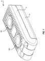
- FIG. 1is a top perspective view of an expandable intervertebral implant in a collapsed state
- FIG. 2is a bottom perspective view of the implant shown in FIG. 1 ;
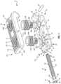
- FIG. 3is an exploded view of the implant shown in FIG. 1 ;
- FIG. 4is a top perspective view of the inferior plate of the implant shown in FIG. 3 ;
- FIG. 5is a perspective view of one of the lift screws of the implant shown in FIG. 3 ;
- FIG. 6is a perspective view of the implant shown in FIG. 3 in a partially assembled state
- FIG. 7is a top perspective view of the superior plate of the implant shown in FIG. 3 ;
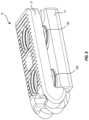
- FIG. 8is a top perspective view of the implant shown in FIG. 1 in an expanded state.
- Coupledis used to indicate either a direct connection between two components or, where appropriate, an indirect connection to one another through intervening or intermediate components.
- connectiondoes not necessarily imply direct contact between the two or more elements.
- coupling, attaching, connecting, and/or joiningcan comprise placing, positioning, and/or disposing the components together or otherwise adjacent in some implementations.
- directional and/or arbitrary termssuch as “top,” “bottom,” “front,” “back,” “left,” “right,” “up,” “down,” “upper,” “lower,” “inner,” “outer,” “internal,” “external,” “interior,” “exterior,” “proximal,” “distal” and the like can be used solely to indicate relative directions and/or orientations and may not otherwise be intended to limit the scope of the disclosure, including the specification, invention, and/or claims.
- Element labels including an appended lettercan be used to refer to a specific instance of the element or to distinguish or draw attention to multiple uses of the element.
- element labels including an appended letterare not meant to be limited to the specific and/or particular embodiment(s) in which they are illustrated. In other words, reference to a specific feature in relation to one embodiment should not be construed as being limited to applications only within said embodiment.
- disclosure of an illustrative measurement or distance less than or equal to about 10 units or between 0 and 10 unitsincludes, illustratively, a specific disclosure of: (i) a measurement of 9 units, 5 units, 1 units, or any other value between 0 and 10 units, including 0 units and/or 10 units; and/or (ii) a measurement between 9 units and 1 units, between 8 units and 2 units, between 6 units and 4 units, and/or any other range of values between 0 and 10 units.
- systems, methods, apparatus, devices, products, processes, compositions, and/or kits, etc.may include, incorporate, or otherwise comprise properties, features, aspects, steps, components, members, and/or elements described in other embodiments disclosed and/or described herein.
- reference to a specific feature, aspect, steps, component, member, element, etc. in relation to one embodimentshould not be construed as being limited to applications only within said embodiment.
- reference to a specific benefit, advantage, problem, solution, method of use, etc. in relation to one embodimentshould not be construed as being limited to applications only within said embodiment.
- FIGS. 1 and 2Depicted in FIGS. 1 and 2 is one embodiment of an expandable intervertebral implant 10 incorporating features of the present disclosure.
- Implant 10is designed for placement and expansion between adjacent vertebra of a spine to facilitate fusion of the adjacent vertebra.
- implant 10generally comprises a superior plate 12 that overlays an inferior plate 14 .
- a first lift screw 16 A and a second lift screw 16 Bare used to selectively raise and lower superior plate 12 relative to inferior plate 14 .
- a drive screw 18is used to selectively rotate lift screws 16 A and 16 B.
- inferior plate 14comprises an inferior body plate 20 having a bottom surface 22 and an opposing interior surface 24 that longitudinally extend between a proximal end 26 and an opposing distal end 28 .
- Proximal end 26terminates at a proximal end face 30 while distal end 28 terminates at a distal end face 32 .
- Body plate 20also includes opposing side surfaces 34 and 36 that likewise extend between proximal end 26 and distal end 28 .
- Teeth 58are used to facilitate securing inferior plate 14 to an adjacent vertebra.
- Bottom surfacecan be planar or can be curved, such as have a convex curvature.
- first bore 38 Aextending through body plate 20 between bottom surface 22 and interior surface 24 is a first bore 38 A and a space apart second bore 38 B.
- First bore 38 Ais disposed at or toward proximal end 26 and comprises a recess 40 A that is recessed into interior surface 24 to annular shoulder 42 A. Bore 38 A also includes a passage 44 A that centrally extends through shoulder 42 A to bottom surface 22 .
- recess 40 A and passage 44 Aboth have a cylindrical configuration and are concentrically aligned with passage 44 A having a smaller diameter than recess 40 A.
- Second bore 38 Bis disposed at or toward distal end 28 and is spaced apart from first bore 38 A. Second bore 38 B has the same configuration as first bore 38 A and like elements are identified by like reference characters. However, the reference characters of second bore 38 B incorporate the suffix “B”.
- body plate 20 of inferior plate 14also has an interior surface 46 that encircles and at least partially bounds a channel 48 that longitudinally extends between proximal end 26 and distal end 28 adjacent to side 36 .
- channel 48has a cylindrical configuration.
- An opening 50 to channel 48is formed on proximal end face 30 .
- bores 38 A and 38 Bare formed so as to partially intersect with channel 48 .
- an opening 52 Aextends between first bore 38 A/passage 44 A and channel 48 while an opening 52 B extends between second bore 38 B/passage 44 B and channel 48 .
- An elongated slot 54is also recessed into proximal end face 30 and is spaced apart from opening 50 . Slot 54 is used to receive an inserter that can be used in the placement of implant 10 .
- bores 38 A and 38 Bare typically not threaded but are designed to freely rotatably receive lift screws 16 A and 16 B.
- a fill hole 56is disposed between bores 38 A and 38 B and likewise extends between bottom surface 22 and interior surface 24 .
- fill hole 56can be packed with an osteogenic material to facilitate the rapid growth of a bony column through implant 10 for fusing the adjacent vertebra.
- osteogenic materialis broadly intended to include natural bone, such as autogenous bone graft or bone allograft, synthetic hone, growth factors and cytokines (including bone morphogenic proteins), and/or combinations thereof.
- FIG. 4also shows a recesses 148 that is recessed into interior surface 24 of inferior plate 14 at a location between first bore 38 A and proximal end face 30 .
- Recess 148reveals and provides access to a retention opening 150 that extends through inferior plate 14 from recess 148 to channel 48 .
- retention opening 150is configured to receive a retention pin 152 ( FIG. 3 ) that secures drive screw 18 within channel 48 .
- a tongue 60Centrally outwardly projecting from distal end face 32 of inferior body plate 20 is a tongue 60 having opposing sides 62 and 64 .
- a hole 66passes through tongue 60 between opposing sides 62 and 64 .
- Tongue 60projects both distally from body plate 20 and upwardly towards superior plate 12 .
- hole 66is configured to receive a guide pin 68 .
- Guide pin 68is sized so that opposing ends of guide pin 68 can outwardly project from opposing sides 62 and 64 of tongue 60 .
- first lift screw 16 Agenerally has a first end 70 A that terminates at a first end face 72 A and an opposing second end 74 A that terminates at a second end face 76 A.
- a passage 78 Aextends entirely through first lift screw 16 A between first end 70 A and second end 74 A and, more specifically, between first end face 72 A and second end face 76 A.
- passage 78 Acan be packed with an osteogenic material to facilitate the rapid growth of a bony column through implant 10 for fusing adjacent vertebra.
- First lift screw 16 Acan further be defined as comprising a gear wheel 80 A disposed at first end 70 A.
- Gear wheel 80 Ahas a cylindrical body 82 A with a plurality of teeth 84 A that are disposed around an outer perimeter of body 82 A.
- Teeth 84 Aare typically linear and are orientated so as to longitudinally extend toward first end 70 A and opposing second end 74 A.
- Teeth 84 Acan be curved and can be sloped to a desired orientation. For example, teeth 84 A can be sloped relative to a central longitudinal axis 79 of passage 78 A.
- Teeth 84 Aare bounded at first end 70 A by an annular stop plate 85 A.
- gear wheel 80 AProjecting from gear wheel 80 A is a threaded stem 86 A.
- Gear wheel 80 A and threaded stem 86 Aare concentric in that they commonly share central longitudinal axis 79 .
- threaded stem 86 Ahas a maximum outer diameter that is larger than a maximum outer diameter of gear wheel 80 A.
- an annular shoulder 88 Aextends between gear wheel 80 A and the perimeter surface of threaded stem 86 A.
- lift screw 16 Ais configured so that gear wheel 80 A can be freely and rotatably received within passage 44 A of first bore 38 A and the lower end of threaded stem 86 A can be freely and rotatably received within recess 40 A of first bore 38 A.
- shoulder 88 A of lift screw 16 Arests against shoulder 42 A of inferior plate 14 .
- second lift screw 16 Bhas the identical configuration to first lift screw 16 A and thus like elements are identified by like reference characters. However, the references elements for second lift screw 16 B include the suffix “B”. Lift screw 16 B is also configured to similarly fit within second bore 38 B.
- drive screw 18is elongated and longitudinally extends between a proximal end 92 and an opposing distal end 94 . Disposed at proximal end 92 is a head 96 that terminates at a proximal end face 98 .
- a blind socket 100is recessed into proximal end face 98 and is configured to receive a driver for rotating drive screw 18 .
- socket 100has a polygonal configuration to assist in engaging the driver. However, other non-circular configurations can also be used.
- Drive screw 18also includes an elongated worm 102 disposed at or toward distal end 94 .
- Worm 102includes an elongated shaft 104 having on or more helical gears 106 extending along the length thereof.
- An annular constricted neck 108is formed between head 96 and worm 102 and is surrounded by an annular groove 109 .
- Drive screw 18is configured so that it can be freely rotatably disposed within channel 48 of inferior plate 14 . More specifically, bores 38 A and 38 B intersect with channel 48 so that when drive screw 18 is received within channel 48 , worm 102 (more specifically, helical gears 106 ) projects into bores 38 A and 38 B through openings 52 A and 52 B, respectively. In turn, when lift screws 16 A and 16 B are received within bores 38 A and 38 B, respectively, worm 102 (more specifically, helical gears 106 ) engages with teeth 84 of gear wheels 80 so that rotation of drive screw 18 within channel 48 facilitates rotation of lift screws 16 A and 16 B within bores 38 A and 38 B, respectively.
- worm 102more specifically, helical gears 106
- superior plate 12comprises a superior body plate 112 having a top surface 114 and an opposing interior surface 116 that longitudinally extend between a proximal end 118 and an opposing distal end 120 .
- Proximal end 118terminates at a proximal end face 122 while distal end 120 terminates at a distal end face 124 .
- Superior body plate 112also includes opposing side surfaces 123 and 125 that likewise extend between proximal end 118 and distal end 120 .
- a threaded first hole 128 Aextends through body plate 112 from top surface 114 to interior surface 116 at or towards proximal end 118 .
- a threaded second hole 128 Bextends through body plate 112 between top surface 114 and interior surface 116 at our toward distal end 120 .
- Threaded holes 128 A and 128 Bare spaced apart from each other. Threaded hole 128 A is configured to threadedly receive threaded stem 86 A of lift screw 16 A while threaded hole 128 B is configured to threadedly received threaded stem 86 B of lift screw 16 B.
- a fill hole 130extends through body plate 112 between top surface 114 and interior surface 116 and is disposed between threaded holes 128 A and 128 B. Again, fill hole 130 is configured to receive an osteogenic material for facilitating bone grow through implant 10 to facilitate fusing of adjacent vertebra.
- a pair of spaced apart arms 132 A and 132 Bprojecting from distal end face 124 of body plate 112 are a pair of spaced apart arms 132 A and 132 B.
- a gap 134is formed between arms 132 A and 132 B and is configured to receive tongue 60 ( FIG. 3 ) of inferior plate 14 .
- Arms 132 A and 132 Bproject distally and downwardly towards inferior plate 14 .
- Arm 132 Ahas a top face 140 A and an opposing bottom face 142 A and an inside face 144 A that extends therebetween. Inside face 144 A faces arm 132 B.
- a slot 146 Ais recessed into top face 140 and also passes through inside face 144 A. Slot 146 A is configured to freely slidably receive an end of guide pin 68 ( FIG. 6 ).
- Arm 132 Bhas the same configuration as arm 132 A except that slots 146 A and 146 B are opposingly facing. Thus, like elements between arms 132 A and 132 B are identify like reference characters except that the reference characters for arm 132 B include the suffix “B”.
- Implant 10can be assembled in a variety of different ways.
- guide pin 68is passed through hole 66 of tongue 60 of inferior plate 14 so that the opposing ends of guide pin 68 outwardly project from opposing sides of tongue 60 , as shown in FIG. 6 .
- superior plate 12is inverted, relative to how shown in FIG. 3 , and then advanced over inferior plate 14 so that tongue 60 is received within gap 134 between arms 132 A and 132 B and the opposing ends of guide pin 68 are received within slots 146 A and 146 B of arms 132 A and 132 B, respectively.
- guide pin 68is received within slots 146 A and 146 B, superior plate 12 can be rotated to the orientation as shown in FIG. 1 .
- superior plate 12can be vertically raised and lowered relative to inferior plate 14 by guide pin 68 freely sliding within slots 146 A and 146 B.
- superior plate 12can be raised vertically relative to inferior plate 14 so that plates 12 and 14 remain in parallel or horizontal alignment.
- guide pin 68prevents complete separation of superior plate 12 from inferior plate 14 by vertical raising of superior plate 12 .
- lift screws 16 A and 16 Bcan be threaded into threaded holes 128 A and 128 B of superior plate 12 from interior surface 116 .
- superior plate 12can be advanced against inferior plate 14 (as shown in FIG. 1 ) so that gear wheels 80 A and 80 B ( FIG. 3 ) are received within bores 38 A and 38 B, respectively.
- gear wheels 80 A and 80 Bare received within passages 44 A and 44 B, respectively, while lower ends of threaded stems 86 A and 86 B are received within recesses 40 A and 40 B, respectively.
- shoulders 88 ( FIG. 5 ) of lift screws 16are sitting on shoulders 42 ( FIG. 3 ) of inferior plate 14 .
- drive screw 18is advanced within channel 48 of inferior plate 14 .
- worm 102reaches opening 52 A that extends between first bore 38 A and channel 48
- helical gear 106 of worm 102will strike against teeth 84 A of gear wheel 80 A.
- drive screw 18is rotated.
- helical gear 106meshes with teeth 84 A of gear wheel 80 A which enables drive screw 18 to thread into channel 48 .
- Drive screw 18is further advanced by rotation into channel 48 so that worm 102 also meshes with teeth 84 B of gear wheel 80 B of lift screw 16 B.
- Drive screw 18is continued to advance until drive screw 18 is properly disposed within channel 48 and annular groove that encircles neck 108 is aligned with retention opening 150 ( FIG. 4 ).
- Retention pin 152is then press fit or otherwise secured within retention opening 150 to that retention pin 152 is at least partially disposed within annular grove 109 but does not interfere with the rotation of drive screw 18 .
- drive screw 18can still be freely rotated within channel 48 but retention pin 152 blocks longitudinal movement of drive screw 18 within channel 48 . That is, except for any play that retention pin 152 may have within annular groove 109 , retention pin 152 prevents drive screw 18 from retracting out of or advancing further into channel 48 .
- Stop plates 85function to retain lift screws 16 within bores 38 . That is, although lift screws 16 can freely rotate within bores 38 , any lifting of lift screws 16 within bores 38 result in worm 102 striking against stop plates 85 which prevents any further lifting of lift screws 16 . As such, stop plates 85 secure lift screws 16 within bores 38 by preventing lift screws 16 from being raised out of bores 38 .
- Implant 10is now in a fully assembled configuration as shown in FIGS. 1 and 2 .
- rotation of drive screw 18 in a first directioncauses drive screw 18 to engage and concurrently rotate lift screw 16 A and 16 B in a first direction.
- the concurrent rotation of lift screw 16 A and 16 Bcauses superior plate 12 , into which the lift screws 16 A and B are threaded, to vertically rise relative to inferior plate 14 , as shown in FIG. 8 .
- rotation of drive screw 18 in the opposite directioncauses lift screws 16 A and B to concurrently rotate in an opposite direction which in turn lowers superior plate 12 towards inferior plate 14 , as shown in FIG. 1 .
- implant 10can be selectively moved between a collapsed position as shown in FIGS. 1 and 2 and an expanded position as shown in FIG. 8 .
- drive screw 18As drive screw 18 is rotated in a first direction, helical gear 106 of worm 102 meshes with teeth 84 on gear wheel 80 to form a worm drive. Accordingly, because drive screw 18 is held stationary along its longitudinal direction, the rotation of drive screw 18 results in the concurrent rotation of gear wheels 80 in a first direction. In turn, the concurrent rotation of gear wheels 80 results in the simultaneous concurrent rotation of threaded stems 86 which, because lift screws 16 /gear wheels 80 are held securely within bores 38 , results in the raising or lowering of superior plate 12 relative to inferior plate 14 .
- One of the advantages of use a worm driveis that by adjusting the size of worm 102 and gear wheels 80 and/or the gears/teeth thereon, the speed of movement and torque applied can be adjusted. As such, a mechanical advantage can be achieved through the use of the worm drive.
- the extent to which superior plate 12 can be raised relative to inferior plate 14is in part limited by the movement of guide pin 69 within slots 146 ( FIG. 7 ). That is, once guide pin 69 hits against the bottom slots 146 , further raising of superior plate 12 relative to inferior plate 14 is restrained.
- Implant 10can also be assembled in other ordered steps. For example, prior to or after attaching superior plate 12 to inferior plate 14 using guide pin 68 , lift screws 16 can first be received within bores 38 A and 38 B and then secured in place by the insertion and locking of drive screw 18 within channel 48 . Superior plate 12 can then be advanced on top of lift screw 16 A and 16 B which, when rotated by drive screw 18 , thread into superior plate 12 so as to draw superior plate 12 towards inferior plate 14 . Again, implant 10 can be selectively moved between the expanded and contracted position by selective rotating of drive screw 18 . Other method steps of assembly can also be used.
- each of the components of implant 10is made from a medical grade biocompatible material.
- the componentsare molded from a reinforced polyetheretherketone (PEEK) polymer.
- PEEKpolyetheretherketone
- the componentscan be formed from a carbon fiber reinforced PEEK.
- the componentscan be molded, cut, machined, or otherwise formed from medical grade biocompatible metals, polymers, ceramics, or other materials that have adequate strength. It is also appreciated that different components can be made from different materials.
- the pinscan be made of metal while the remainder is formed from a plastic.
- implant 10is first moved to or towards that collapsed position. Osteogenic material can then be packed within passages 78 A and 78 B of lift screws 16 and within fill holes 56 and 130 of inferior plate 14 and superior plate 12 , respectively.
- fill holes 56 and 130are aligned when implant 10 is assembly. As such, three separate bony columns can be formed that pass completely through implant 10 for fusing together the two adjacent vertebrae.
- An insert toolis secured to implant 10 by being received within slot 54 .
- the insert toolcan also include a driver that engages with blind socket 100 of drive screw 18 .
- the insert toolis then used to advance implant 10 between two adjacent vertebrae. Once implant 10 is properly positioned, the insert tool is used to rotate drive screw 18 which, as previously discussed, facilitates moving implant 10 from the contacted position to an expanded position. Implant 10 is selectively expanded until it is properly biased against the adjacent vertebra. Once implant 10 is sufficiently expanded, the insert tool is removed from the implant.
- Embodiments of disclosed implant 10can achieve a number of novel, unique, and/or beneficial properties. For example, because implant 10 is selectively expandable, it can be used in a variety of situations. As such, less storage of multiple different sizes of implants at a hospital is required. Furthermore, because the implant can be initially installed in a clasped position, which is smaller than is needed, implant 10 can be easily inserted. In addition, because the expansion of implant 10 only requires the rotation of drive screw 18 , implant 10 can be easily expanded and requires a tool that occupies minimal space, thereby enable greater visual inspection of implant 10 during insertion and expansion.
- implant 10is also unique in that it provides multiple separate channels extending completely through the implant through which osteogenic material can be packed for enabling bone to pass through implant 10 and fused together adjacent vertebra. Other benefits also exist.
- systems, processes, and/or products according to certain embodiments of the present disclosuremay include, incorporate, or otherwise comprise properties features (e.g., components, members, elements, parts, and/or portions) described in other embodiments disclosed and/or described herein. Accordingly, the various features of certain embodiments can be compatible with, combined with, included in, and/or incorporated into other embodiments of the present disclosure. Thus, disclosure of certain features relative to a specific embodiment of the present disclosure should not be construed as limiting application or inclusion of said features to the specific embodiment. Rather, it will be appreciated that other embodiments can also include said features without necessarily departing from the scope of the present disclosure.
- any feature hereinmay be combined with any other feature of a same or different embodiment disclosed herein.
- various well-known aspects of illustrative systems, processes, products, and the likeare not described herein in particular detail in order to avoid obscuring aspects of the example embodiments. Such aspects are, however, also contemplated herein.
Landscapes
- Health & Medical Sciences (AREA)
- Engineering & Computer Science (AREA)
- Biomedical Technology (AREA)
- Neurology (AREA)
- Orthopedic Medicine & Surgery (AREA)
- Cardiology (AREA)
- Oral & Maxillofacial Surgery (AREA)
- Transplantation (AREA)
- Heart & Thoracic Surgery (AREA)
- Vascular Medicine (AREA)
- Life Sciences & Earth Sciences (AREA)
- Animal Behavior & Ethology (AREA)
- General Health & Medical Sciences (AREA)
- Public Health (AREA)
- Veterinary Medicine (AREA)
- Prostheses (AREA)
Abstract
Description
Claims (20)
Priority Applications (1)
| Application Number | Priority Date | Filing Date | Title |
|---|---|---|---|
| US16/912,463US11622864B2 (en) | 2019-06-28 | 2020-06-25 | Expandable intervertebral implant |
Applications Claiming Priority (2)
| Application Number | Priority Date | Filing Date | Title |
|---|---|---|---|
| US201962868618P | 2019-06-28 | 2019-06-28 | |
| US16/912,463US11622864B2 (en) | 2019-06-28 | 2020-06-25 | Expandable intervertebral implant |
Publications (2)
| Publication Number | Publication Date |
|---|---|
| US20200405499A1 US20200405499A1 (en) | 2020-12-31 |
| US11622864B2true US11622864B2 (en) | 2023-04-11 |
Family
ID=74043444
Family Applications (1)
| Application Number | Title | Priority Date | Filing Date |
|---|---|---|---|
| US16/912,463ActiveUS11622864B2 (en) | 2019-06-28 | 2020-06-25 | Expandable intervertebral implant |
Country Status (1)
| Country | Link |
|---|---|
| US (1) | US11622864B2 (en) |
Cited By (1)
| Publication number | Priority date | Publication date | Assignee | Title |
|---|---|---|---|---|
| USD1098430S1 (en)* | 2022-12-13 | 2025-10-14 | Mirus Llc | Expandable medical device |
Families Citing this family (30)
| Publication number | Priority date | Publication date | Assignee | Title |
|---|---|---|---|---|
| AU2012362524B2 (en) | 2011-12-30 | 2018-12-13 | Relievant Medsystems, Inc. | Systems and methods for treating back pain |
| WO2014071161A1 (en) | 2012-11-05 | 2014-05-08 | Relievant Medsystems, Inc. | System and methods for creating curved paths through bone and modulating nerves within the bone |
| US11806250B2 (en) | 2018-02-22 | 2023-11-07 | Warsaw Orthopedic, Inc. | Expandable spinal implant system and method of using same |
| USD948050S1 (en)* | 2020-02-12 | 2022-04-05 | Warsaw Orthopedic, Inc. | Spinal implant |
| US12082876B1 (en) | 2020-09-28 | 2024-09-10 | Relievant Medsystems, Inc. | Introducer drill |
| US11583411B2 (en)* | 2020-10-27 | 2023-02-21 | Loubert S. Suddaby | Expandable intervertebral fusion implant |
| US11638653B2 (en) | 2020-11-05 | 2023-05-02 | Warsaw Orthopedic, Inc. | Surgery instruments with a movable handle |
| US11291554B1 (en) | 2021-05-03 | 2022-04-05 | Medtronic, Inc. | Unibody dual expanding interbody implant |
| US11517363B2 (en) | 2020-11-05 | 2022-12-06 | Warsaw Orthopedic, Inc. | Screw driver and complimentary screws |
| US11395743B1 (en) | 2021-05-04 | 2022-07-26 | Warsaw Orthopedic, Inc. | Externally driven expandable interbody and related methods |
| US11285014B1 (en) | 2020-11-05 | 2022-03-29 | Warsaw Orthopedic, Inc. | Expandable inter-body device, system, and method |
| US11963881B2 (en) | 2020-11-05 | 2024-04-23 | Warsaw Orthopedic, Inc. | Expandable inter-body device, system, and method |
| US12171439B2 (en) | 2020-11-05 | 2024-12-24 | Warsaw Orthopedic, Inc. | Protected drill |
| US11517443B2 (en) | 2020-11-05 | 2022-12-06 | Warsaw Orthopedic, Inc. | Dual wedge expandable implant, system and method of use |
| US12318308B2 (en) | 2020-11-05 | 2025-06-03 | Warsaw Orthopedic, Inc. | Dual expandable inter-body device |
| US11833059B2 (en) | 2020-11-05 | 2023-12-05 | Warsaw Orthopedic, Inc. | Expandable inter-body device, expandable plate system, and associated methods |
| US12239544B2 (en) | 2020-11-05 | 2025-03-04 | Warsaw Orthopedic, Inc. | Rhomboid shaped implants |
| US11376134B1 (en) | 2020-11-05 | 2022-07-05 | Warsaw Orthopedic, Inc. | Dual expanding spinal implant, system, and method of use |
| US12121453B2 (en) | 2020-11-05 | 2024-10-22 | Warsaw Orthopedic, Inc. | Dual wedge expandable implant with eyelets, system, and method of use |
| EP4268150A4 (en) | 2020-12-22 | 2024-12-18 | Relievant Medsystems, Inc. | PREDICTION OF CANDIDATES FOR SPINAL NEUROMODULATION |
| US11612499B2 (en) | 2021-06-24 | 2023-03-28 | Warsaw Orthopedic, Inc. | Expandable interbody implant |
| US12268614B2 (en) | 2021-06-24 | 2025-04-08 | Warsaw Orthopedic, Inc. | Interbody implant with adjusting shims |
| WO2022271280A1 (en) | 2021-06-24 | 2022-12-29 | Warsaw Orthopedic, Inc. | Expandable interbody implant and corresponding surgical tool |
| US12295865B2 (en) | 2021-06-24 | 2025-05-13 | Warsaw Orthopedic, Inc. | Expandable interbody implant and corresponding inserter |
| US11730608B2 (en) | 2021-07-13 | 2023-08-22 | Warsaw Orthopedic, Inc. | Monoblock expandable interbody implant |
| WO2023285675A1 (en) | 2021-07-16 | 2023-01-19 | Blue Ocean Spine Gmbh | Adjustable intervertebral cage, associated instrument and manufacturing process therefor |
| US12433668B1 (en) | 2021-11-08 | 2025-10-07 | Relievant Medsystems, Inc. | Impedance stoppage mitigation during radiofrequency tissue ablation procedures |
| US11850163B2 (en) | 2022-02-01 | 2023-12-26 | Warsaw Orthopedic, Inc. | Interbody implant with adjusting shims |
| US12370058B2 (en) | 2022-04-05 | 2025-07-29 | Spine Wave, Inc. | Belt driven expandable interbody fusion device |
| US20250261967A1 (en)* | 2022-04-11 | 2025-08-21 | Relievant Medsystems, Inc. | Controlled bone access and operator feedback features |
Citations (58)
| Publication number | Priority date | Publication date | Assignee | Title |
|---|---|---|---|---|
| US4309777A (en) | 1980-11-13 | 1982-01-12 | Patil Arun A | Artificial intervertebral disc |
| US4759769A (en)* | 1987-02-12 | 1988-07-26 | Health & Research Services Inc. | Artificial spinal disc |
| US5458642A (en) | 1994-01-18 | 1995-10-17 | Beer; John C. | Synthetic intervertebral disc |
| US6190414B1 (en)* | 1996-10-31 | 2001-02-20 | Surgical Dynamics Inc. | Apparatus for fusion of adjacent bone structures |
| US6193756B1 (en) | 1997-09-30 | 2001-02-27 | Sulzer Orthopaedie Ag | Tubular support body for bridging two vertebrae |
| US6200348B1 (en) | 1998-02-06 | 2001-03-13 | Biedermann, Motech Gmbh | Spacer with adjustable axial length |
| US20010012966A1 (en) | 1999-12-15 | 2001-08-09 | Armin Studer | Intervertebral implant |
| US20020082695A1 (en) | 2000-12-27 | 2002-06-27 | Ulrich Gmbh & Co. Kg | Vertebral implant and setting tool therefor |
| US20020161441A1 (en) | 1998-10-15 | 2002-10-31 | Bruno Lang | Telescopic vertebral prosthesis |
| US20030074063A1 (en) | 2001-10-17 | 2003-04-17 | Medicinelodge, Inc. | Adjustable bone fusion implant and method |
| US6730088B2 (en) | 2001-08-29 | 2004-05-04 | Chung-Chun Yeh | Device for fixing spinal column under treatment |
| US20040254644A1 (en) | 2002-10-21 | 2004-12-16 | Taylor Brett Allison | Intervertebral disk prosthesis |
| US20050010295A1 (en) | 2001-03-27 | 2005-01-13 | Michelson Gary K. | Radially expanding interbody spinal fusion implants, instrumentation, and method of insertion |
| US20050015149A1 (en) | 2001-02-04 | 2005-01-20 | Michelson Gary K. | Instrumentation with inwardly moveable extensions for inserting an expandable interbody spinal fusion implant |
| US20050021144A1 (en) | 2003-07-23 | 2005-01-27 | Malberg Marc I. | Expandable spinal implant |
| US20050261769A1 (en) | 2004-05-13 | 2005-11-24 | Moskowitz Nathan C | Artificial expansile total lumbar and thoracic discs for posterior placement without supplemental instrumentation and its adaptation for anterior placement of artificial cervical, thoracic and lumbar discs |
| US20050273167A1 (en) | 2004-06-02 | 2005-12-08 | Triplett Daniel J | Surgical measurement and resection framework |
| US20060122703A1 (en) | 2002-12-17 | 2006-06-08 | Max Aebi | Intervertebral implant |
| US20060149383A1 (en) | 2003-11-07 | 2006-07-06 | Impliant Ltd. | Spinal prostheses |
| US20060167547A1 (en) | 2005-01-21 | 2006-07-27 | Loubert Suddaby | Expandable intervertebral fusion implants having hinged sidewalls |
| US7094257B2 (en) | 2003-02-14 | 2006-08-22 | Zimmer Spine, Inc. | Expandable intervertebral implant cage |
| US20060195191A1 (en) | 2005-01-08 | 2006-08-31 | Alphaspine Inc. | Modular disc device |
| US20060265068A1 (en) | 2005-05-17 | 2006-11-23 | Schwab Frank J | Intervertebral implant |
| US20070028710A1 (en) | 2003-05-14 | 2007-02-08 | Kilian Kraus | Height-adjustable implant to be inserted between vertebral bodies and corresponding handling tool |
| US7204853B2 (en) | 2003-08-05 | 2007-04-17 | Flexuspine, Inc. | Artificial functional spinal unit assemblies |
| US7217291B2 (en) | 2003-12-08 | 2007-05-15 | St. Francis Medical Technologies, Inc. | System and method for replacing degenerated spinal disks |
| US20070239279A1 (en) | 2006-04-06 | 2007-10-11 | Sdgi Holdings, Inc. | Intervertebral disc nucleus replacement implants and methods |
| US20070255415A1 (en) | 2006-05-01 | 2007-11-01 | Sdgi Holdings, Inc. | Expandable intervertebral spacers and methods of use |
| US20070288092A1 (en) | 2006-06-01 | 2007-12-13 | Bambakidis Nicholas | Expandable intervertebral implant and method |
| US20080027468A1 (en) | 2006-07-27 | 2008-01-31 | Axya Medical Inc. | Suture needle, suture needle/suture assembly and suture passer device |
| US20080103601A1 (en)* | 1999-07-26 | 2008-05-01 | Ladislau Biro | Corpectomy vertebral body replacement implant system |
| US20080140207A1 (en) | 2006-12-07 | 2008-06-12 | Interventional Spine, Inc. | Intervertebral implant |
| US20080147193A1 (en) | 2006-11-23 | 2008-06-19 | Wilfried Matthis | Expandable intervertebral implant |
| US7569074B2 (en) | 2003-12-11 | 2009-08-04 | Warsaw Orthopedic, Inc. | Expandable intervertebral implant |
| US20090210061A1 (en)* | 2008-02-14 | 2009-08-20 | U. S. Spinal Technologies, L.L.C. | Anterior lumbar interbody fusion cage device and associated method |
| US20090222100A1 (en) | 2008-02-28 | 2009-09-03 | Stryker Spine | Tool for implanting expandable intervertebral implant |
| US20090281625A1 (en) | 2008-05-06 | 2009-11-12 | Rhausler, Inc. | Expandable intervertebral implant |
| US7641693B2 (en) | 2003-04-28 | 2010-01-05 | Synthes Usa, Llc | Intervertebral implant |
| US7674296B2 (en) | 2005-04-21 | 2010-03-09 | Globus Medical, Inc. | Expandable vertebral prosthesis |
| US20100082109A1 (en) | 2008-09-22 | 2010-04-01 | Stout Medical Group, L.P. | Expandable intervertebral implant |
| US7749270B2 (en) | 2005-04-29 | 2010-07-06 | Warsaw Orthopedic, Inc. | Expandable intervertebral implant and associated instrumentation |
| US7753958B2 (en) | 2003-08-05 | 2010-07-13 | Gordon Charles R | Expandable intervertebral implant |
| US20110035011A1 (en) | 2008-04-05 | 2011-02-10 | Synthes Usa, Llc | Expandable intervertebral implant |
| US20110160861A1 (en)* | 2009-07-22 | 2011-06-30 | Jimenez Omar F | Methods and apparatuses for vertebral body distraction and fusion employing a coaxial screw gear sleeve mechanism |
| US20110172716A1 (en)* | 2010-01-12 | 2011-07-14 | Chad Glerum | Expandable Spacer and Method For Use Thereof |
| US20110172774A1 (en) | 2010-01-11 | 2011-07-14 | Armando Varela | Expandable intervertebral implant and associated surgical method |
| USD643115S1 (en) | 2010-06-04 | 2011-08-09 | Entrigue Surgical, Inc. | Insertion device |
| US20110301714A1 (en) | 2010-06-04 | 2011-12-08 | Spartan Cage, LLC | Expandable intervertebral implant |
| US20120265303A1 (en)* | 2007-10-30 | 2012-10-18 | Aesculap Implant Systems, Llc | Vertebral body replacement device and method for use to maintain a space between two vertebral bodies within a spine |
| US20120310350A1 (en)* | 2011-06-03 | 2012-12-06 | Biospine, Llc | Unidirectional dynamic interbody fusion device and method of use |
| US20130158668A1 (en)* | 2011-12-14 | 2013-06-20 | Biospine, Llc | Unilateral moveable interbody fusion device and method of use |
| US20150094814A1 (en)* | 2012-04-16 | 2015-04-02 | Biomet Spine, Llc | Multiple spindle adjustable interbody fusion devices and methods of use |
| US9044218B2 (en)* | 2010-04-14 | 2015-06-02 | Depuy (Ireland) | Distractor |
| US20150351925A1 (en)* | 2013-01-24 | 2015-12-10 | Biomet Spine, Llc | Adjustable interbody fusion device and method of use |
| US20160089247A1 (en)* | 2013-05-13 | 2016-03-31 | Biomet Spine, Llc | Adjustable interbody fusion devices |
| US9827107B1 (en)* | 2016-05-19 | 2017-11-28 | Apifix Ltd. | Adjustable spinal cage |
| US9839527B2 (en)* | 2012-10-24 | 2017-12-12 | Spectrum Spine Ip Holdings, Llc | Expandable inter-body fusion devices and methods |
| US20180133024A1 (en)* | 2005-03-31 | 2018-05-17 | Life Spine, Inc. | Expandable interbody and intravertebral body devices |
- 2020
- 2020-06-25USUS16/912,463patent/US11622864B2/enactiveActive
Patent Citations (62)
| Publication number | Priority date | Publication date | Assignee | Title |
|---|---|---|---|---|
| US4309777A (en) | 1980-11-13 | 1982-01-12 | Patil Arun A | Artificial intervertebral disc |
| US4759769A (en)* | 1987-02-12 | 1988-07-26 | Health & Research Services Inc. | Artificial spinal disc |
| US5458642A (en) | 1994-01-18 | 1995-10-17 | Beer; John C. | Synthetic intervertebral disc |
| US6190414B1 (en)* | 1996-10-31 | 2001-02-20 | Surgical Dynamics Inc. | Apparatus for fusion of adjacent bone structures |
| US6193756B1 (en) | 1997-09-30 | 2001-02-27 | Sulzer Orthopaedie Ag | Tubular support body for bridging two vertebrae |
| US6200348B1 (en) | 1998-02-06 | 2001-03-13 | Biedermann, Motech Gmbh | Spacer with adjustable axial length |
| US20020161441A1 (en) | 1998-10-15 | 2002-10-31 | Bruno Lang | Telescopic vertebral prosthesis |
| US20080103601A1 (en)* | 1999-07-26 | 2008-05-01 | Ladislau Biro | Corpectomy vertebral body replacement implant system |
| US20010012966A1 (en) | 1999-12-15 | 2001-08-09 | Armin Studer | Intervertebral implant |
| US20020082695A1 (en) | 2000-12-27 | 2002-06-27 | Ulrich Gmbh & Co. Kg | Vertebral implant and setting tool therefor |
| US20050015149A1 (en) | 2001-02-04 | 2005-01-20 | Michelson Gary K. | Instrumentation with inwardly moveable extensions for inserting an expandable interbody spinal fusion implant |
| US20050010295A1 (en) | 2001-03-27 | 2005-01-13 | Michelson Gary K. | Radially expanding interbody spinal fusion implants, instrumentation, and method of insertion |
| US6730088B2 (en) | 2001-08-29 | 2004-05-04 | Chung-Chun Yeh | Device for fixing spinal column under treatment |
| US20030074063A1 (en) | 2001-10-17 | 2003-04-17 | Medicinelodge, Inc. | Adjustable bone fusion implant and method |
| US20040254644A1 (en) | 2002-10-21 | 2004-12-16 | Taylor Brett Allison | Intervertebral disk prosthesis |
| US20060122703A1 (en) | 2002-12-17 | 2006-06-08 | Max Aebi | Intervertebral implant |
| US7094257B2 (en) | 2003-02-14 | 2006-08-22 | Zimmer Spine, Inc. | Expandable intervertebral implant cage |
| US7641693B2 (en) | 2003-04-28 | 2010-01-05 | Synthes Usa, Llc | Intervertebral implant |
| US20070028710A1 (en) | 2003-05-14 | 2007-02-08 | Kilian Kraus | Height-adjustable implant to be inserted between vertebral bodies and corresponding handling tool |
| US20050021144A1 (en) | 2003-07-23 | 2005-01-27 | Malberg Marc I. | Expandable spinal implant |
| US7753958B2 (en) | 2003-08-05 | 2010-07-13 | Gordon Charles R | Expandable intervertebral implant |
| US7204853B2 (en) | 2003-08-05 | 2007-04-17 | Flexuspine, Inc. | Artificial functional spinal unit assemblies |
| US20060149383A1 (en) | 2003-11-07 | 2006-07-06 | Impliant Ltd. | Spinal prostheses |
| US7217291B2 (en) | 2003-12-08 | 2007-05-15 | St. Francis Medical Technologies, Inc. | System and method for replacing degenerated spinal disks |
| US7569074B2 (en) | 2003-12-11 | 2009-08-04 | Warsaw Orthopedic, Inc. | Expandable intervertebral implant |
| US20050261769A1 (en) | 2004-05-13 | 2005-11-24 | Moskowitz Nathan C | Artificial expansile total lumbar and thoracic discs for posterior placement without supplemental instrumentation and its adaptation for anterior placement of artificial cervical, thoracic and lumbar discs |
| US20050273167A1 (en) | 2004-06-02 | 2005-12-08 | Triplett Daniel J | Surgical measurement and resection framework |
| US20060195191A1 (en) | 2005-01-08 | 2006-08-31 | Alphaspine Inc. | Modular disc device |
| US20060167547A1 (en) | 2005-01-21 | 2006-07-27 | Loubert Suddaby | Expandable intervertebral fusion implants having hinged sidewalls |
| US20180133024A1 (en)* | 2005-03-31 | 2018-05-17 | Life Spine, Inc. | Expandable interbody and intravertebral body devices |
| US7674296B2 (en) | 2005-04-21 | 2010-03-09 | Globus Medical, Inc. | Expandable vertebral prosthesis |
| US7749270B2 (en) | 2005-04-29 | 2010-07-06 | Warsaw Orthopedic, Inc. | Expandable intervertebral implant and associated instrumentation |
| US20060265068A1 (en) | 2005-05-17 | 2006-11-23 | Schwab Frank J | Intervertebral implant |
| US20070239279A1 (en) | 2006-04-06 | 2007-10-11 | Sdgi Holdings, Inc. | Intervertebral disc nucleus replacement implants and methods |
| US20070255415A1 (en) | 2006-05-01 | 2007-11-01 | Sdgi Holdings, Inc. | Expandable intervertebral spacers and methods of use |
| US7708779B2 (en) | 2006-05-01 | 2010-05-04 | Warsaw Orthopedic, Inc. | Expandable intervertebral spacers and methods of use |
| US20070288092A1 (en) | 2006-06-01 | 2007-12-13 | Bambakidis Nicholas | Expandable intervertebral implant and method |
| US20080027468A1 (en) | 2006-07-27 | 2008-01-31 | Axya Medical Inc. | Suture needle, suture needle/suture assembly and suture passer device |
| US20080147193A1 (en) | 2006-11-23 | 2008-06-19 | Wilfried Matthis | Expandable intervertebral implant |
| US20080140207A1 (en) | 2006-12-07 | 2008-06-12 | Interventional Spine, Inc. | Intervertebral implant |
| US20120265303A1 (en)* | 2007-10-30 | 2012-10-18 | Aesculap Implant Systems, Llc | Vertebral body replacement device and method for use to maintain a space between two vertebral bodies within a spine |
| US20090210061A1 (en)* | 2008-02-14 | 2009-08-20 | U. S. Spinal Technologies, L.L.C. | Anterior lumbar interbody fusion cage device and associated method |
| US8323345B2 (en) | 2008-02-14 | 2012-12-04 | U.S. Spine, Inc. | Anterior lumbar interbody fusion cage device and associated method |
| US20090222100A1 (en) | 2008-02-28 | 2009-09-03 | Stryker Spine | Tool for implanting expandable intervertebral implant |
| USD626233S1 (en) | 2008-02-28 | 2010-10-26 | Stryker Spine | Expandable intervertebral implant |
| US20110035011A1 (en) | 2008-04-05 | 2011-02-10 | Synthes Usa, Llc | Expandable intervertebral implant |
| US20090281625A1 (en) | 2008-05-06 | 2009-11-12 | Rhausler, Inc. | Expandable intervertebral implant |
| US20100082109A1 (en) | 2008-09-22 | 2010-04-01 | Stout Medical Group, L.P. | Expandable intervertebral implant |
| US20110160861A1 (en)* | 2009-07-22 | 2011-06-30 | Jimenez Omar F | Methods and apparatuses for vertebral body distraction and fusion employing a coaxial screw gear sleeve mechanism |
| US8303663B2 (en) | 2009-07-22 | 2012-11-06 | Spinex Tec, Llc | Methods and apparatuses for vertebral body distraction and fusion employing a coaxial screw gear sleeve mechanism |
| US20110172774A1 (en) | 2010-01-11 | 2011-07-14 | Armando Varela | Expandable intervertebral implant and associated surgical method |
| US20110172716A1 (en)* | 2010-01-12 | 2011-07-14 | Chad Glerum | Expandable Spacer and Method For Use Thereof |
| US9044218B2 (en)* | 2010-04-14 | 2015-06-02 | Depuy (Ireland) | Distractor |
| USD643115S1 (en) | 2010-06-04 | 2011-08-09 | Entrigue Surgical, Inc. | Insertion device |
| US20110301714A1 (en) | 2010-06-04 | 2011-12-08 | Spartan Cage, LLC | Expandable intervertebral implant |
| US20120310350A1 (en)* | 2011-06-03 | 2012-12-06 | Biospine, Llc | Unidirectional dynamic interbody fusion device and method of use |
| US20130158668A1 (en)* | 2011-12-14 | 2013-06-20 | Biospine, Llc | Unilateral moveable interbody fusion device and method of use |
| US20150094814A1 (en)* | 2012-04-16 | 2015-04-02 | Biomet Spine, Llc | Multiple spindle adjustable interbody fusion devices and methods of use |
| US9839527B2 (en)* | 2012-10-24 | 2017-12-12 | Spectrum Spine Ip Holdings, Llc | Expandable inter-body fusion devices and methods |
| US20150351925A1 (en)* | 2013-01-24 | 2015-12-10 | Biomet Spine, Llc | Adjustable interbody fusion device and method of use |
| US20160089247A1 (en)* | 2013-05-13 | 2016-03-31 | Biomet Spine, Llc | Adjustable interbody fusion devices |
| US9827107B1 (en)* | 2016-05-19 | 2017-11-28 | Apifix Ltd. | Adjustable spinal cage |
Cited By (1)
| Publication number | Priority date | Publication date | Assignee | Title |
|---|---|---|---|---|
| USD1098430S1 (en)* | 2022-12-13 | 2025-10-14 | Mirus Llc | Expandable medical device |
Also Published As
| Publication number | Publication date |
|---|---|
| US20200405499A1 (en) | 2020-12-31 |
Similar Documents
| Publication | Publication Date | Title |
|---|---|---|
| US11622864B2 (en) | Expandable intervertebral implant | |
| US12011367B2 (en) | Expandable intervertebral device | |
| US11938036B2 (en) | Expandable interbody device | |
| US10492912B2 (en) | Interbody spinal fusion implant having locking elements with lateral displacement | |
| US20220354661A1 (en) | Flexible anchoring and fusion devices and methods of using the same | |
| US10799367B2 (en) | Bone fusion system | |
| US10363144B2 (en) | Expandable spinal implant | |
| US10898344B2 (en) | Expandable implant | |
| CN104955409B (en) | Expandable intervertebral cage assembly and method | |
| CN104755037B (en) | Anchor button anchor system | |
| US20100036495A1 (en) | Device and method for treating spine | |
| US20160022434A1 (en) | Expandable intervertebral cage assemblies | |
| KR100953930B1 (en) | An expandable cage for spinal implants and a holder | |
| EP3135254B1 (en) | Intervertebral implant and device for inserting an intervertebral implant | |
| US20160228163A1 (en) | Dynamic Bone Fixation Element | |
| US20100168858A1 (en) | Expandable interbody implant and method | |
| EP3614974A1 (en) | Expandable spinal interbody assembly | |
| KR20120028878A (en) | Arcuate spinal fixation member | |
| AU2005272596A1 (en) | Therapy provision to adjacent motion segments | |
| CN102481161A (en) | Implant with an interference fit fastener | |
| WO2010077359A1 (en) | Expandable interbody implant and method | |
| US12023017B1 (en) | Apparatus, methods and systems for spine surgery | |
| US10555764B2 (en) | Interbody spinal fusion implant having locking elements that outwardly displace for locking | |
| Vrionis et al. | Bone fusion system |
Legal Events
| Date | Code | Title | Description |
|---|---|---|---|
| FEPP | Fee payment procedure | Free format text:ENTITY STATUS SET TO UNDISCOUNTED (ORIGINAL EVENT CODE: BIG.); ENTITY STATUS OF PATENT OWNER: SMALL ENTITY | |
| FEPP | Fee payment procedure | Free format text:ENTITY STATUS SET TO SMALL (ORIGINAL EVENT CODE: SMAL); ENTITY STATUS OF PATENT OWNER: SMALL ENTITY | |
| AS | Assignment | Owner name:INNOVASIS, INC., UTAH Free format text:ASSIGNMENT OF ASSIGNORS INTEREST;ASSIGNORS:GERBEC, DANIEL E.;ROBBINS, JAMES;WIESER, ERIC;AND OTHERS;SIGNING DATES FROM 20200720 TO 20200730;REEL/FRAME:053368/0571 | |
| STPP | Information on status: patent application and granting procedure in general | Free format text:DOCKETED NEW CASE - READY FOR EXAMINATION | |
| STPP | Information on status: patent application and granting procedure in general | Free format text:NON FINAL ACTION MAILED | |
| STPP | Information on status: patent application and granting procedure in general | Free format text:RESPONSE TO NON-FINAL OFFICE ACTION ENTERED AND FORWARDED TO EXAMINER | |
| STPP | Information on status: patent application and granting procedure in general | Free format text:FINAL REJECTION MAILED | |
| STPP | Information on status: patent application and granting procedure in general | Free format text:DOCKETED NEW CASE - READY FOR EXAMINATION | |
| STPP | Information on status: patent application and granting procedure in general | Free format text:NON FINAL ACTION MAILED | |
| STPP | Information on status: patent application and granting procedure in general | Free format text:RESPONSE TO NON-FINAL OFFICE ACTION ENTERED AND FORWARDED TO EXAMINER | |
| STPP | Information on status: patent application and granting procedure in general | Free format text:NOTICE OF ALLOWANCE MAILED -- APPLICATION RECEIVED IN OFFICE OF PUBLICATIONS | |
| STCF | Information on status: patent grant | Free format text:PATENTED CASE |