US11622793B2 - Tissue retraction and vertebral displacement devices, systems, and methods for posterior spinal fusion - Google Patents
Tissue retraction and vertebral displacement devices, systems, and methods for posterior spinal fusionDownload PDFInfo
- Publication number
- US11622793B2 US11622793B2US16/715,006US201916715006AUS11622793B2US 11622793 B2US11622793 B2US 11622793B2US 201916715006 AUS201916715006 AUS 201916715006AUS 11622793 B2US11622793 B2US 11622793B2
- Authority
- US
- United States
- Prior art keywords
- blade
- passageway
- connecting element
- engagement portion
- extender
- Prior art date
- Legal status (The legal status is an assumption and is not a legal conclusion. Google has not performed a legal analysis and makes no representation as to the accuracy of the status listed.)
- Active, expires
Links
Images


Classifications
- A—HUMAN NECESSITIES
- A61—MEDICAL OR VETERINARY SCIENCE; HYGIENE
- A61B—DIAGNOSIS; SURGERY; IDENTIFICATION
- A61B17/00—Surgical instruments, devices or methods
- A61B17/02—Surgical instruments, devices or methods for holding wounds open, e.g. retractors; Tractors
- A61B17/0206—Surgical instruments, devices or methods for holding wounds open, e.g. retractors; Tractors with antagonistic arms as supports for retractor elements
- A—HUMAN NECESSITIES
- A61—MEDICAL OR VETERINARY SCIENCE; HYGIENE
- A61B—DIAGNOSIS; SURGERY; IDENTIFICATION
- A61B17/00—Surgical instruments, devices or methods
- A61B17/56—Surgical instruments or methods for treatment of bones or joints; Devices specially adapted therefor
- A61B17/58—Surgical instruments or methods for treatment of bones or joints; Devices specially adapted therefor for osteosynthesis, e.g. bone plates, screws or setting implements
- A61B17/68—Internal fixation devices, including fasteners and spinal fixators, even if a part thereof projects from the skin
- A61B17/70—Spinal positioners or stabilisers, e.g. stabilisers comprising fluid filler in an implant
- A61B17/7074—Tools specially adapted for spinal fixation operations other than for bone removal or filler handling
- A61B17/7076—Tools specially adapted for spinal fixation operations other than for bone removal or filler handling for driving, positioning or assembling spinal clamps or bone anchors specially adapted for spinal fixation
- A61B17/7077—Tools specially adapted for spinal fixation operations other than for bone removal or filler handling for driving, positioning or assembling spinal clamps or bone anchors specially adapted for spinal fixation for moving bone anchors attached to vertebrae, thereby displacing the vertebrae
- A61B17/7079—Tools requiring anchors to be already mounted on an implanted longitudinal or transverse element, e.g. where said element guides the anchor motion
- A—HUMAN NECESSITIES
- A61—MEDICAL OR VETERINARY SCIENCE; HYGIENE
- A61B—DIAGNOSIS; SURGERY; IDENTIFICATION
- A61B17/00—Surgical instruments, devices or methods
- A61B17/56—Surgical instruments or methods for treatment of bones or joints; Devices specially adapted therefor
- A61B17/58—Surgical instruments or methods for treatment of bones or joints; Devices specially adapted therefor for osteosynthesis, e.g. bone plates, screws or setting implements
- A61B17/68—Internal fixation devices, including fasteners and spinal fixators, even if a part thereof projects from the skin
- A61B17/70—Spinal positioners or stabilisers, e.g. stabilisers comprising fluid filler in an implant
- A61B17/7074—Tools specially adapted for spinal fixation operations other than for bone removal or filler handling
- A61B17/7076—Tools specially adapted for spinal fixation operations other than for bone removal or filler handling for driving, positioning or assembling spinal clamps or bone anchors specially adapted for spinal fixation
- A61B17/7077—Tools specially adapted for spinal fixation operations other than for bone removal or filler handling for driving, positioning or assembling spinal clamps or bone anchors specially adapted for spinal fixation for moving bone anchors attached to vertebrae, thereby displacing the vertebrae
- A61B17/708—Tools specially adapted for spinal fixation operations other than for bone removal or filler handling for driving, positioning or assembling spinal clamps or bone anchors specially adapted for spinal fixation for moving bone anchors attached to vertebrae, thereby displacing the vertebrae with tubular extensions coaxially mounted on the bone anchors
- A—HUMAN NECESSITIES
- A61—MEDICAL OR VETERINARY SCIENCE; HYGIENE
- A61B—DIAGNOSIS; SURGERY; IDENTIFICATION
- A61B90/00—Instruments, implements or accessories specially adapted for surgery or diagnosis and not covered by any of the groups A61B1/00 - A61B50/00, e.g. for luxation treatment or for protecting wound edges
- A61B90/30—Devices for illuminating a surgical field, the devices having an interrelation with other surgical devices or with a surgical procedure
- A—HUMAN NECESSITIES
- A61—MEDICAL OR VETERINARY SCIENCE; HYGIENE
- A61B—DIAGNOSIS; SURGERY; IDENTIFICATION
- A61B17/00—Surgical instruments, devices or methods
- A61B2017/00526—Methods of manufacturing
- A—HUMAN NECESSITIES
- A61—MEDICAL OR VETERINARY SCIENCE; HYGIENE
- A61B—DIAGNOSIS; SURGERY; IDENTIFICATION
- A61B17/00—Surgical instruments, devices or methods
- A61B17/02—Surgical instruments, devices or methods for holding wounds open, e.g. retractors; Tractors
- A61B17/025—Joint distractors
- A61B2017/0256—Joint distractors for the spine
- A—HUMAN NECESSITIES
- A61—MEDICAL OR VETERINARY SCIENCE; HYGIENE
- A61B—DIAGNOSIS; SURGERY; IDENTIFICATION
- A61B90/00—Instruments, implements or accessories specially adapted for surgery or diagnosis and not covered by any of the groups A61B1/00 - A61B50/00, e.g. for luxation treatment or for protecting wound edges
- A61B90/30—Devices for illuminating a surgical field, the devices having an interrelation with other surgical devices or with a surgical procedure
- A61B2090/306—Devices for illuminating a surgical field, the devices having an interrelation with other surgical devices or with a surgical procedure using optical fibres
Definitions
- the present inventionrelates to devices, systems, and methods in connection with posterior spinal fusion.
- Pedicle screw fixation constructshave been in use for decades in conjunction with spinal fusion procedures, in which adjacent vertebral segments are fused to improve spinal stability or correct certain spinal deformities.
- Older approaches for inserting these pedicle screw fixation constructsinvolved open procedures, in which relatively large skin incisions were created to expose a substantial portion of the patient's spinal column, in order to allow for insertion of the pedicle screws and manipulation of spinal rods through openings adjacent to the heads of the screws.
- pedicle screwsare inserted into the pedicles of the same or adjacent vertebrae of a patient's spine through individual percutaneous incisions corresponding to the pedicle screws.
- Fixation or fusion rodsare then inserted into the body through one of those incisions, or through an additional incision adjacent to the most cephalad or caudal pedicle screw, and the rod is rigidly connected to the pedicle screws such that the rod extends along the longitudinal axis of the spine (i.e., along the cephalad/caudal direction) in order to fix the relative positions of the adjacent vertebrae to which the rod is connected.
- a devicee.g., a cannula, tower, or portal
- a deviceis connected to each of the pedicle screws and extends through the respective percutaneous incision.
- Such devicesprovide a percutaneous passageway through the tissue from each incision to the respective pedicle screw, in order to aid in the insertion of a spinal rod. Examples of such passageway devices are described in commonly-assigned U.S. Pat. No. 7,955,355 (“the '355 patent”) and U.S. Pat. No. 8,002,798 (“the '798 patent”), the entireties of which are hereby incorporated by reference herein as if fully set forth herein.
- pedicle screw fixation constructsare used in conjunction with an interbody fusion technique, where the fixation constructs provide additional stability to the interbody fusion.
- interbody fusion techniques performed along a posterior approachinclude posterior lumbar interbody fusion (PLIF) and transforaminal lumbar interbody fusion (TLIF).
- PLIFposterior lumbar interbody fusion
- TLIFtransforaminal lumbar interbody fusion
- interbody fusion techniques along other approaches to the spineinclude anterior lumbar interbody fusion (ALIF) and lateral interbody fusion.
- all of such interbody fusion techniquesinvolve removing at least a portion of the intervertebral disc between two adjacent vertebral bodies and then positioning an interbody implant (such as a cage, which may be packed with bone graft material) into the intervertebral space created by the removal of the disc material.
- an interbody implantsuch as a cage, which may be packed with bone graft material
- the connecting elementpreferably has a passageway device connected thereto and extending proximally therefrom along a longitudinal axis.
- the passageway devicepreferably has at least one longitudinal opening extending along at least a portion of its longitudinal axis.
- the retractor device according to this aspect of the inventiondesirably includes an engagement portion and a retractor blade connected to the engagement portion.
- the engagement portionis desirably adapted to receive at least a portion of the passageway device therein such that the retractor blade is positioned so as to cover at least a portion of the longitudinal opening of the passageway device.
- the width of the retractor bladeis wider than the width of the passageway device.
- the engagement portionextends along the passageway device to the connecting element.
- a distal end of the engagement portionis adapted to securely engage the connecting element.
- a proximal end of the retractor deviceincludes a connector for engagement by a manipulation device.
- the passageway deviceincludes a first blade and a second blade, and the engagement portion includes a first blade receiver and a second blade receiver adapted to receive the respective first and second blades therein.
- an exterior of the engagement portiondefines a second longitudinal opening between the first and second blade receivers.
- a retraction systemincluding a retractor device and a passageway device having first and second blades.
- at least one of the first and second bladeshas a step where the width of the blade changes, and a distal end of the engagement portion of the retractor device is engageable with that step.
- the distal end of the retractor bladeis positionable proximate a proximal end of the connecting element.
- the distal end of the retractor bladeis rounded.
- the distal end of the retractor bladeincludes a slot alignable with an opening in the connecting element.
- a proximal portion of the retractor deviceincludes at least one gripping portion shaped to be gripped by hand.
- the retractor bladehas an arcuate shape.
- the retractor blade of the retractor deviceis longer than the engagement portion.
- a retraction systemincluding first and second retractor devices and first and second shafts.
- the first and second shaftsare receivable within the respective passageway devices such that a distal portion of each of the shafts is positioned proximate the respective connecting element and a proximal portion of each of the shafts is engageable by a manipulation device.
- the first and second shaftsare desirably adapted to transfer a sufficient force to the respective connecting elements to displace the vertebrae with respect to one another in response to relative displacement of the first and second shafts induced by the manipulation device.
- the distal portion of the first shaftincludes a threaded portion engageable with threads in the connecting element or the passageway device.
- the retraction systemfurther includes the manipulation device.
- the retraction systemmay further include a plurality of shafts receivable within a respective one of the passageway devices such that a distal portion of each one of the plurality of shafts is positioned proximate the respective connecting element and a proximal portion of each one of the plurality of shafts is engageable by a manipulation device.
- At least one of the shaftsmay include a plurality of markings, each of which corresponds to a longitudinal length of one of the retractor devices.
- the method according to this aspect of the inventiondesirably includes connecting first and second connecting elements to respective first and second vertebrae of a spine within the body, the first and second connecting elements each having a respective first and second passageway device connected thereto and extending proximally therefrom, and the method also desirably includes positioning first and second retractor blades along at least a portion of respective longitudinal openings extending along at least a portion of the longitudinal axes of the respective first and second passageway devices.
- the steps of positioning the retractor bladesinclude coupling the retractor blades with the respective passageway devices.
- coupling the retractor blades with the passageway devicesincludes receiving at least a portion of each of the passageway devices with a respective engagement portion connected to each of the respective blades.
- the methodfurther includes forming an opening in skin of the body extending between the first and second passageway devices.
- the methodfurther includes enlarging the opening with an intermediate retractor blade positioned between the first and second passageway devices.
- the methodincludes inserting an interbody implant through the opening and into an intervertebral space between the first and second vertebrae.
- the methodfurther includes moving at least a portion of a spinal fusion rod within at least one of the first and second passageway devices, and securing the spinal fusion rod to the first and second connecting elements.
- the method according to this aspect of the inventiondesirably includes securing a distal end of each of a first extender and a second extender within a respective first and second cage of a respective first and second connecting element affixed to a respective first and second vertebra of a spine, and the method also desirably includes displacing the first extender with respect to the second extender to displace the first and second vertebrae with respect to one another.
- the connecting elementsinclude pedicle screws.
- the cagesare polyaxially coupled to the respective pedicle screws.
- the steps of securing the distal ends of the extenders within the cageslock polyaxial movement of the cages with respect to the respective pedicle screws.
- the extenderseach include a shaft.
- the connecting elementseach have a respective passageway device connected thereto and extending proximally therefrom.
- securing the distal ends of the extenders within the cagesincludes securing a distal portion of each of the shafts within the respective cage such that the shafts extend within and along the longitudinal axes of the respective passageway devices.
- securing the distal ends of the extenders within the cagesincludes securing each shaft within the respective cage with a respective set screw such that the shafts each extend transverse to the longitudinal axis of the respective extender.
- the extendersare each integrally formed with a respective retractor blade.
- the systemdesirably includes a first extender, a second extender, and a manipulation device.
- the distal ends of each of the first and second extendersare preferably configured to be securely engaged within a respective first and second cage of a respective first and second connecting element affixable to a respective first and second vertebra of the spine.
- the manipulation deviceis preferably engageable with the first and second extenders such that the manipulation device is configured to displace the first and second vertebrae with respect to one another by inducing movement of the first extender with respect to the second extender when the first and second extenders are securely engaged with the first and second connecting elements when affixed to the spine.
- the extenderseach include a shaft, at least a portion of which is configured to be securely engaged within the respective cage.
- each of the connecting elementshave a respective passageway device connected thereto and extending proximally therefrom.
- the shaftsare each receivable within and along the longitudinal axis of a respective passageway device.
- a distal portion of at least one of the shaftsincludes a threaded portion engageable with threads in the one of the connecting elements or the associated passageway device.
- the shaftseach extend transverse to a longitudinal axis of the associated extender, and the shafts are each configured to be securely engaged within the respective cage by a respective set screw.
- the extendersare each integrally formed with a respective retractor blade.
- FIG. 1is a perspective view of a system of blade-screws connected to a spine, in accordance with an embodiment of the present invention.
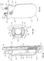
- FIG. 2 Ais a perspective view of a blade-screw of FIG. 1 .
- FIG. 2 Bis a sectional view of the blade-screw of FIG. 2 A .
- FIG. 3 Ais a perspective view of a compression/distraction system in engagement with a set of blade-screws, in accordance with an embodiment of the present invention.
- FIG. 3 Bis a perspective, exploded view of the components of the compression/distraction system and blade-screws illustrated in FIG. 3 A .
- FIG. 4 Ais a perspective view of a retraction blade engaged with a portion of a blade-screw, in accordance with the embodiment of FIG. 3 A .
- FIG. 4 Bis a plan view of the arrangement of FIG. 4 A .
- FIG. 4 Cis a perspective view of a retraction blade, in accordance with the embodiment of FIG. 3 A .
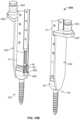
- FIG. 5is a side elevational view of a system of retraction blades engaged with respective blade-screws, in accordance with an embodiment of the present invention.
- FIG. 6includes front and rear elevational views of a system of retraction blades and shafts engaged with respective blade-screws, in accordance with an embodiment of the present invention.
- FIG. 7is a perspective view of a compression/distraction system in engagement with a set of blade-screws, in accordance with another embodiment of the present invention.
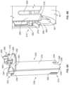
- FIG. 8 Ais a perspective view of a docking member, in accordance with the embodiment of FIG. 7 .
- FIG. 8 Bis a partial, perspective view of a docking member in engagement with a blade-screw, in accordance with the embodiment of FIG. 7 .
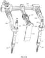
- FIG. 9is a schematic, plan view of an embodiment of a compression/distraction system in engagement with a set of blade-screws, in accordance with another embodiment of the present invention.
- FIG. 10 Ais a perspective view of a retractor component, in accordance with the embodiment FIG. 10 B .
- FIG. 10 Bis a perspective view of components of a compression/distraction system in engagement with a set of blade-screws, in accordance with another embodiment of the present invention
- FIG. 11 Ais a perspective view of an assembly of components of the compression/distraction system of FIG. 9 .
- FIG. 11 Bis a perspective view of the assembly of FIG. 11 A positioned in an incision in a patient.
- proximal and proximal mostrefer to locations closer to a user or operator of the device or method being described and that “distal” and “distal most” refer to locations further from a user or operator of the device or method being described.
- FIG. 1illustrates a system of connecting elements 30 , passageway devices 31 , and a spinal fusion element or rod 44 connected to a spine 10 .
- the spine 10has a cephalad direction 12 , a caudal direction 14 , an anterior direction 16 , a posterior direction 18 , and a medial/lateral axis 20 , all of which are oriented as shown by the arrows bearing the same reference numerals.
- “left” and “right”are used with reference to a posterior view, i.e., a view from behind the spine 10 .
- Medialrefers to a position or orientation toward a sagittal plane (i.e., plane of symmetry that separates left and right sides from each other) of the spine 10
- lateralrefers to a position or orientation relatively further from the sagittal plane.
- the spine 10includes a first vertebra 22 , a second vertebra 24 , and a third vertebra 26 .
- a first intervertebral disc 23Between the first and second vertebrae 22 , 24 is a first intervertebral disc 23 , and between the second and third vertebrae 24 , 26 is a second intervertebral disc 25 .
- the systems and methods hereinmay be applicable to any vertebra or vertebrae of the spine 10 and/or the sacrum 11 .
- the term “vertebrae”may be broadly interpreted to include all vertebrae, as well as the sacrum.
- the connecting elements 30 and associated passageway devices 31are connected to respective pedicles 36 , 38 , 40 on the right side of the respective first, second, and third vertebrae 22 , 24 , 26 .
- the system illustrated in FIG. 1spans three vertebrae, other embodiments of systems in accordance with the present invention may span fewer or more vertebrae.
- additional connecting elements 30 and passageway devices 31may be connected to additional vertebrae along the spine 10 .
- Other embodiments of systems in accordance with the present inventionmay include multiple systems of connecting elements 30 , passageway devices 31 , and spinal fusion rods 44 , each of which may span any number of vertebrae.
- systems of connecting elements 30 , passageway devices 31 , and spinal fusion rods 44may be positioned on both sides of the spinous processes along the spine (i.e., on both the left and right sides of the spine).
- the connecting elements 30each include an anchoring element or screw 32 (see FIGS. 2 A-B ) implanted in the respective pedicles 36 , 38 , 40 and a coupling element or cage 42 for receiving the spinal fusion rod 44 therein.
- the cages 42may be coupled to the respective screws 32 in various ways known in the art. For example, as shown in FIG. 2 B , the cages 42 and the screws 32 may be polyaxially coupled. In other embodiments (not shown), the coupling between the cages 42 and the screws 32 may be a monoaxial coupling or a uniplanar coupling, or the cages 42 may be rigidly fixed to (e.g., integrally formed with) the screws 32 .
- Each connecting element 30may also include a set screw 45 for securing the rod 44 within the cage 42 .
- the connecting elements 30may have the same or similar structure as the connecting elements described in the '798 patent.
- the connecting elements 30may have the same or similar structure as the pedicle screws described in U.S. Pat. No. 7,988,713 (“the '713 patent”) or the pedicle screws, pedicle hooks, or lamina hooks described in U.S. Pat. No. 6,074,391 (“the '391 patent”).
- the entire disclosures of the '713 patent and the '391 patentare hereby incorporated by reference herein as if fully set forth herein.
- anchoring elementsare illustrated herein as screws 32 , it is to be understood that other types of anchoring elements capable of being secured to vertebral bone may be used, such as the above-referenced hooks described in the '391 patent.
- spinal fusion element 44is illustrated herein as a rod 44 , it is to be understood that other types of elements capable of securing together adjacent vertebrae may be used, such as plates, wires, rods, or articulating versions thereof.
- the connecting elements 30may be percutaneously inserted in the body in the same manner as described in the '798 patent. That is, each of the connecting elements 30 may be inserted along a respective guide wire through a separate incision 46 , 48 , 50 in the skin 51 . Sequential dilators may be used to enlarge the passageway between the incisions 46 , 48 , 50 and the respective pedicles 36 , 38 , 40 .
- the screws 32 of the connecting elements 30may be implanted in previously tapped bores in the associated pedicles, or the screws 32 may self-tap into the pedicles.
- each screw 32 into a pediclemay be driven by a driver (not shown) having a distal end engaged with a driver interface 34 on the head 35 of the screw 32 (see FIG. 2 B ), such that a shaft of the driver extends proximally within the passageway device 31 .
- the driver interface 34 of the head 35may take the form of that disclosed in U.S. Pat. No. 8,231,635 (“the '635 patent”), the entire disclosure of which is hereby incorporated by reference herein as if fully set forth herein, and the driver may take the form of any one of the screwdrivers disclosed in that patent.
- the drivermay be a powered or a manually operated driver.
- spinal navigation software and/or roboticsmay be used to help locate the appropriate pedicles 36 , 38 , 40 and to implant or help guide the implantation of the connecting elements 30 into the pedicles.
- the passageway devices 31are connected to the connecting elements 30 such that the passageway devices 31 extend proximally from the connecting elements 30 though the respective incisions 46 , 48 , 50 .
- the distal ends 52 of the passageway devices 31are connected to the proximal ends 54 of the cages 42 .
- the passageway devices 31each provide a passageway 55 extending along an axis 57 from the incision 46 , 48 , 50 to the respective connecting element 30 to aid the percutaneous insertion of the rod 44 .
- the axis 57(and the associated passageway device 31 ) may be straight, as illustrated in the figures herein, or the passageway device 31 may define an angled or curved longitudinal axis, as disclosed in certain embodiments of U.S. patent application Ser. No. 14/034,021 (“the '021 application”), filed on Sep. 23, 2013 and entitled “Lumbar-Sacral Screw Insertion and Manipulation,” the entire disclosure of which is hereby incorporated by reference herein as if fully set forth herein.
- Each passageway device 31may take the form of two blades 56 attached to opposing arms 58 of the associated cage 42 .
- the blades 56may be separately formed from and detachably connectible to the cages 42 , as described in the '798 patent.
- the blades 56may be formed as a single piece with the associated cages 42 , as also described in the '798 patent.
- FIGS. 1 - 2 Billustrate an embodiment in which the blades 56 are integrally connected to the associated cages 42 to form monolithic blade-screws 60 .
- the blades 56may be connected to the cages 42 by frangible portions 62 .
- Each frangible portion 62may include a reduced thickness portion, which may be defined by grooves formed in either or both of the interior and exterior surfaces of the blade-screws 60 at the junction between the blades 56 and the respective arms 58 of the cages 42 .
- FIG. 1illustrates an embodiment in which the blades 56 are integrally connected to the associated cages 42 to form monolithic blade-screws 60 .
- the blades 56may be connected to the cages 42 by frangible portions 62 .
- Each frangible portion 62may include a reduced thickness portion, which may be defined by grooves formed in either or both of
- the frangible portions 62are defined by a groove 64 along the exterior of the blade-screw 60 and a groove 66 along the interior of the blade-screw 60 that is aligned with the exterior groove 64 .
- the frangible portions 62provide a location for the blades 56 to be broken away from the cages 42 when desired.
- each cage 42may include threads 68 along the arms 58 , and the passageway device 31 may include reduction threads 70 at least along the distal end 52 thereof.
- the reduction threads 70 of the passageway device 31may not be present while the threads 68 of the cage 42 are present.
- the set screw 45is an externally threaded component structured to engage the reduction threads 70 of the passageway device 31 and the threads 68 of the cage 42 . Both threads 68 and 70 are aligned such that the set screw 45 can be rotatably advanced distally along the reduction threads 70 of the passageway device 31 , after which continued rotation of the set screw 45 will cause the set screw 45 to engage and advance along the threads 68 of the cage 42 .
- the threads 68 and/or the reduction threads 70may have a tooth shape as disclosed in the '391 patent. That is, as disclosed in the '391 patent, and as illustrated in FIG. 2 B herein, the flank of each thread facing in the distal direction (i.e., towards the screw 32 ) may be steep and, preferably, is generally horizontal, and the flank of each thread facing in the proximal direction (i.e., away from the screw 32 ) may be angled at about 30° with respect to the horizontal.
- the threads 106 of the set screw 45are preferably complementary to the threads 68 and/or the reduction threads 70 (i.e., the steep flank of each thread 106 of the set screw 45 may be aligned oppositely to the steep flanks of the threads 68 , 70 ).
- the blades 56 of the passageway devices 31are integrally connected to the cages 42 in the monolithic blade-screws 60 .
- Such blade-screws 60may be constructed by fabricating each cage 42 with its respective passageway device 31 as one piece.
- a cage 42 with two blades 56 extending therefrommay be machined out of a single piece of material.
- the cage 42 with both blades 56may be cast or molded as a unitary component.
- subcomponents of the cage 42 and passageway device 31may be formed separately and then integrally connected together, such as by welding.
- each cage 42may be integrally formed (e.g., by machining, casting, or molding) with two reduction portions 61 extending proximally from the proximal ends 54 of each of the arms 58 of the cage 42 .
- the reduction portions 61desirably include the reduction threads 70 of what will become the blades 56 .
- Two blade extensions 63may be separately formed, and the distal ends 65 of those extensions 63 may be integrally connected (e.g., welded) to the proximal ends 67 of the reduction portions 61 at connection 69 .
- each blade extension 63may have a particular shape or profile that changes along its length. For example, as shown in those figures, the width of each blade 56 may become narrower at one or more steps 71 along its length.
- the final shape of the blade extensions 63may be created when the separately formed blade extensions 63 are initially fabricated (e.g., machined, casted, or molded). Alternatively, the blade extensions 63 may initially be formed into larger pieces, which are then further refined to arrive at their final shape.
- wire-cut electrical discharge machiningmay be used to modify the shape of the initially formed larger pieces in order to arrive at the final shape of the blade extensions 63 .
- EDMelectrical discharge machining
- Such modificationsmay be performed either before or after the blade extensions 63 are integrally connected to the reduction portions 61 .
- the height of the cages 42(i.e., the length along longitudinal axis 57 ) may be about 1.5 cm.
- the blades 56may range between about 5 cm long and about 15 cm long.
- the reduction portions 61may represent any portion of the length of the blades 56 , e.g., about 1 cm to about 4 cm, but may preferably be about 2 cm in length.
- Systems in accordance with embodiments of the inventionmay include blade-screws 60 having blades 56 of different lengths, for example, because the distances to be traversed between the skin along a patient's back and the underlying pedicles may be different for different sized patients.
- such systemsmay include blades 56 of two different lengths (i.e., long blades and short blades), as shown in FIGS. 5 - 6 .
- the long bladesmay be about 11 cm long, and the short blades may be about 7 cm long.
- the reduction portions 61may represent any portion of that length, the reduction portions 61 may have the same length in both the long and short blades.
- the blade extensions 64 of the short bladesmay be about 5 cm long and the blade extensions 64 of the long blades may be about 9 cm long.
- a coupling 72may be connected to the blades 56 of each passageway device 31 along the length of the passageway device 31 .
- the couplings 72may take the form of those disclosed in U.S. Provisional Patent Application No. 61/783,098 (“the '098 application”), filed on Mar. 14, 2013 and entitled “Systems and Methods for Percutaneous Spinal Fusion,” the entire disclosure of which is hereby incorporated by reference herein as if fully set forth herein.
- the couplingmay take the form of the abutment members disclosed in the '798 patent.
- the couplings 72may be connected to the blades 56 in the same manner as disclosed in the '098 application or the '798 patent.
- the couplings 72may include flexible tabs 74 having a boss or protuberance (not shown) extending inwardly therefrom for engaging holes 76 along the length of the blades 56 .
- the couplings 72may also include recesses 78 to provide an extracorporeal template for contouring or selecting the rod 44 to be implanted, as disclosed in the '098 application. Such contouring or selection may also be done in the manner disclosed in commonly owned U.S. Pat. No. 8,177,817 (“the '817 patent”) or U.S. Patent Application Publication No. 2007/0233079 (“the '079 Publication”), the entireties of which are hereby incorporated by reference herein as if fully set forth herein.
- a rod 44 having the desired contourmay be inserted into the body and advanced towards the cages 42 of the implanted connecting elements 30 , using the passageways 55 through the body tissue provided by the passageway devices 31 , until the rod 44 extends between the cages 42 .
- the rod 44may be secured within the cages 42 by a set screw 45 to thereby stabilize the vertebrae 22 , 24 , 26 to which the connecting elements 30 are attached. If, after being inserted in the body, the rod 44 is not fully seated in one or more of the cages 42 (e.g., the rod 44 is slightly proud), the rod 44 can be further directed into a particular cage 42 in various ways.
- the advancement of the set screw 45 distally along the reduction threads 70 of a passageway device 31 and then into the cage 42may help to push the rod 44 towards and into the cage 42 .
- a counter torque tube(not shown) can be used to help with the advancement and/or securement of the rod 44 to the cage 42 , as disclosed in U.S. Patent Application Ser. No. 14/099,159 (“the '159 application”), filed on Dec. 6, 2013 and entitled “Compression and Distraction System for Percutaneous Posterior Spinal Fusion,” the entire disclosure of which is hereby incorporated by reference herein as if fully set forth herein.
- the relative positions of the vertebraemay be adjusted. For example, while the rod 44 is positioned within the cages 42 but before the set screw 45 is tightened to the point that the cages 42 are locked with respect to the rod 44 , two or more vertebrae may be moved in the cephalad and caudal directions 12 , 14 towards one another (i.e., compression) and/or away from one another (i.e., distraction).
- compressioni.e., compression
- distractioni.e., distraction
- One system and method for performing such compression and distractionis disclosed in U.S. Pat. No. 8,157,809 (“the '809 patent”), the entire disclosure of which is hereby incorporated by reference herein as if fully set forth herein. Another such system is disclosed in the '159 application. Other systems and methods for performing compression and distraction are illustrated in FIGS. 3 - 9 and are discussed herein.
- FIG. 3 Adiscloses a compression/distraction system 100 in accordance with one embodiment of the invention.
- the system 100includes a set of retraction blades 102 engageable with respective passageway devices 31 of the blade-screws 60 .
- the systemalso includes shafts 104 securely engageable with and receivable within the blade-screws 60 .
- the shafts 104are engageable by a manipulation device 106 , which is structured to move the shafts 104 towards and away from one another in order to displace the vertebrae to which the connecting elements 30 are connected.
- the shafts 104thus form extenders for transferring displacement forces (e.g., compression and/or distraction forces) from the manipulation device positioned outside the body to the connecting elements 30 connected to vertebrae within the body, to thereby displace the vertebrae with respect to one another.
- the manipulation device 106may take any form suitable for engaging the shafts 104 and displacing them relative to one another.
- the manipulation device 106includes two arms 108 , 109 movably connected to one another by a rack 110 . Each arm 108 , 109 has a proximal end 112 connected to the rack 110 and a distal end 114 engageable with one of the shafts 104 .
- the distal ends 114may each include an opening 116 shaped and sized to securely receive a respective one of the shafts 104 therethrough. As illustrated in FIG. 3 A , the openings 116 may each be sized and shaped to securely receive a respective one of the passageway devices 31 therethrough while a shaft 104 is positioned within the passageway device 31 .
- Either or both of the arms 108 , 109may be pivotably connected to the rack 110 , which pivoting may be controlled by a respective actuation mechanism (not shown).
- one of the arms 108may be translationally connected to the rack 110 for movement along the length of the rack 110 , while the other arm 109 may have a fixed position at one end of the rack 110 .
- the translating arm 108may be moved along the rack 110 by actuating a drive mechanism 118 , which may rotate a toothed pinion connected to the arm 108 to advance the pinion along corresponding teeth of the rack 110 .
- the shafts 104each have a distal portion 120 and a proximal portion 122 .
- the distal portion 120may be positionable within a respective access device 31 proximate the connecting element 30 and securable, directly or indirectly, to the connecting element 30 .
- the distal portion 120may include a threaded portion 124 for securing the shaft 104 with respect to the connecting element 30 .
- the threaded portion 124may engage the threads 68 of the connecting element 30 or it may engage the reduction threads 70 of the passageway device 31 , which passageway device 31 is in turn secured to the connecting element 30 , as discussed above.
- the shafts 104may also be positioned such that the threaded portion 124 extends at least partially along the threads 68 of the connecting element 30 and at least partially along the reduction threads 70 of the passageway device 31 .
- the distal portion 120 of each shaft 104may also include a distal extension 126 extending distally of the threaded portion 124 .
- the distal extension 126may be structured such that it engages the head 35 of the screw 32 when the threaded portion 124 is secured to the threads 68 and/or 70 . By advancing the threaded portion 124 along the threads 68 and/or 70 , the distal extension 126 may forcibly press against the head 35 of the screw 32 .
- This forcible engagementdesirably helps to secure the shaft 104 with respect to the connecting element 30 . That engagement may also force the head 35 of the screw 32 against the cage 42 within which it is received, which may desirably lock the polyaxial movement of the cage 42 with respect to the screw 32 .
- each shaft 104includes an engagement portion 128 for engagement by a respective arm 108 , 109 of the manipulation device 106 .
- the engagement portion 128may be shaped and sized to be securely received within the opening 116 of the respective arm 108 , 109 .
- the engagement portion 128may have an outer dimension sized to be closely received within the passageway device 31 .
- the width of the shafts 104may vary along their lengths, which may beneficially reduce material where not needed.
- the engagement portion 128may be wider than other portions of the shaft 104 , and the shaft may include a tapered portion 130 distally of the engagement portion 128 and another tapered portion 132 proximally of the engagement portion 128 .
- the retraction blades 102may each include a blade portion 134 and an engagement portion 136 .
- the engagement portion 136may be structured to secure the retraction blade 102 to the passageway device 31 .
- the engagement portion 136may include a tubular body having grooves or channels therein for receiving the blades 56 of the passageway device 31 , similar to the tubular bodies disclosed in the '159 application.
- the engagement portion 136may include two blade receivers 138 for receiving a respective one of the two blades 56 of a passageway device 31 .
- Each blade receiver 138may include an outer portion 140 extending around the outside of a blade 56 , as shown in the plan view of FIG. 4 B , and each blade receiver 138 may include at least one inner extension 142 (e.g., one such inner extension 142 on each side of the blade 56 ) wrapping around an edge 144 of the blade 56 and along at least a portion of the inside of the blade 56 .
- the inner extension 142 adjacent to the blade portion 134may be defined by a thicker portion 143 of the blade portion 134 , which thicker portion 143 may extend across the space between the blades 56 and define both inner extensions 142 adjacent to the blade portion 134 .
- each blade receiver 138desirably defines a channel 146 structured to receive a blade 56 of the passageway device 31 .
- the channel 146may have an arcuate shape along the plane normal to the axis 57 of the passageway device 31 , which shape substantially matches the shape of the blades 56 in that plane.
- the inner extensions 142desirably constrain the blades 56 to remain in the channels 146 .
- the blade portion 134 of the retraction blade 102is preferably positioned alongside the passageway device 31 , as shown in FIGS. 3 A and 4 A , to retract adjacent body tissue.
- the blade portion 134is preferably wider than the passageway device 31 along a direction transverse to the axis 57 of the passageway device 31 , and the blade portion 134 may be arcuate along that width dimension.
- the blade portion 134may be about 2 to 3 cm wide, while the passageway device 31 of the blade-screw 60 may be about 1 to 1.5 cm wide.
- the blade portion 134also preferably extends along a significant portion of the passageway device 31 positioned beneath the skin 51 , so as to keep tissue out of the passageway 55 defined between the blades 56 .
- the distal end 148 of the blade portion 134is preferably rounded to reduce trauma to the tissue upon insertion of the retraction blade 102 into the body.
- the retraction blade 102is rigid, such that, when the blades 56 are positioned in the channels 146 of the engagement portion 136 , the retraction blade 102 stabilizes the blades 56 and prevents them from prematurely disconnecting from the connecting element 30 , particularly when the coupling 72 is not positioned on the blades 56 .
- the distal end 148 of the blade portion 134may be positioned proximate the proximal ends 54 of the arms 58 of the cage 42 , as shown in FIG. 3 A . That position desirably allows a rod 44 positioned between the arms 58 to extend through and beyond the cage 42 without interference from the blade portion 134 .
- the retraction blade 102may be shaped to engage a feature of the passageway device 31 .
- a distal end 150 of the engagement portion 136may engage the widening step 71 along the blades 56 , as shown in FIG. 4 A , at which point further distal movement of the retraction blade 102 along the passageway device 31 will be resisted.
- the proximal end 152 of the blade portion 134may include cutouts 154 for gripping by hand or by a tool.
- a hole 156 through the blade portion 134 near the proximal end 150may also assist with removal of the retraction blade 102 by providing a feature that can be engaged by a tool.
- a system in accordance with an embodiment of the inventionmay include blade-screws 60 having blades of two different lengths (i.e., long blades and short blades).
- the systemmay also include different length retraction blades 102 for use with differing anatomies.
- the systemmay include more types of retraction blade lengths than lengths of blade-screws 60 .
- a system having two lengths of blade-screws 60may have four lengths of retraction blades 102 (e.g., two retraction blade lengths for use with each blade-screw length), as shown in FIGS. 5 - 6 .
- the four lengths of retraction blades 102may include: a blade portion 134 about 3 to 4 cm long; a blade portion 134 about 5 to 6 cm long; a blade portion 134 about 7 to 8 cm long; and a blade portion 134 about 9-10 cm long. Although only two lengths of blade-screws 60 may be included in the system, the additional lengths of retraction blades 102 may allow for closer tailoring to the specific distance between the skin surface 51 and the implanted connecting element 30 .
- an appropriate length of retraction blade 102may be selected by the surgeon or other user so that, when the retraction blade 102 is fully advanced along the passageway device 31 , the proximal end 152 of the blade portion 134 may be positioned above the skin surface 51 and as close to the skin as possible.
- each different length retraction blade 102may have a different length engagement portion 136 , as shown in FIGS. 5 - 6 , based on the appropriate distance that the proximal end 152 of the blade portion 134 is to be positioned above the step 71 when the retraction blade 102 is fully advanced along the passageway device 31 .
- the retraction blades 102may be identified based on a distance d from the proximal end 152 of the blade portion 134 to one of the holes 76 along the blades 56 , as shown in FIG. 5 .
- each length blade portion 134may be indicated by one or more markings 158 (e.g., laser markings) on the shaft 104 , as shown in FIG. 6 .
- markings 158e.g., laser markings
- different length shafts 104may be provided in the system, which blade shaft lengths may correspond to the different lengths of blade-screws 60 .
- FIG. 7discloses a compression/distraction system 200 in accordance with another embodiment of the invention.
- the system 200includes a set of docking members 203 engageable with respective passageway devices 31 and connecting elements 30 of the blade-screws 60 , which docking members 203 are also engageable by a manipulation device for moving the docking members 203 towards and away from one another in order to displace the vertebrae to which the connecting elements 30 are connected.
- the docking members 203thus form extenders for transferring displacement forces (e.g., compression and/or distraction forces) from the manipulation device positioned outside the body to the connecting elements 30 connected to vertebrae within the body, to thereby displace the vertebrae with respect to one another.
- displacement forcese.g., compression and/or distraction forces
- the manipulation devicemay take any form suitable for engaging the docking members 203 and displacing them relative to one another.
- the manipulation devicemay include two arms 208 , 209 , each having a distal end 214 engageable with one of the docking members 203 and a proximal end 212 connected to a rack (not shown), which may be similar to the rack 110 of the manipulation device 106 illustrated in FIGS. 3 A-B .
- the arms 208 , 209may similarly be pivotably and translationally connected to the rack.
- the distal ends 214 of the arms 208 , 209may each engage a connector 260 of the respective docking member 203 .
- the distal ends 214may each include an opening 216 shaped and sized to securely receive a respective one of the connectors 260 therein.
- Each connector 260may be structured as a shaft 262 projecting proximally from a lateral extension 264 at the proximal end 252 of the docking member 203 .
- the shaft 262may be hollow.
- the shaft 262may also include at least one (e.g., two) flexible tabs 266 , each of which may have an exterior face 268 shaped to securely engage a feature (not shown) in the opening 216 of the respective arm 208 , 209 .
- the proximal ends of the tabs 266may project proximally from the openings 216 .
- each shaft 262may also include at least one outwardly projecting boss 270 shaped to be received within a corresponding channel 272 in each opening 216 . In that way, the rotational orientation of each docking member 203 with respect to the corresponding arm 208 , 209 may be fixed.
- Each docking member 203may include a blade portion 234 and an engagement portion 236 .
- the docking member 203may be structured to securely engage the respective connecting element 30 at its distal end 274 .
- the distal end 274 of the docking member 203may include one or more (e.g., two) tabs 276 projecting inwardly and structured for engagement with corresponding structures on the exterior surface of the cage 42 of the connecting element 30 , as shown in FIG. 8 B .
- Each tab 276which may be located on the engagement portion 236 of the docking member 203 , may be structured to engage a respective recess 278 along an edge 280 of an arm 58 of the cage 42 .
- the tabs 276may each be positioned on a flexible prong 282 defined by a slot 284 formed in the distal end 274 of the docking member 203 .
- the tabs 276may each have an angled chamfer 286 on their distal ends to ease insertion of the distal end 274 of the docking member 203 over the cage 42 .
- the chamfer 286may be arranged such that, as the distal end 274 of the docking member 203 is moved distally over the proximal end 54 of the cage 42 , the chamfer 286 will cause the prong 282 to flex outward. Further distal movement of the docking member 203 will move the tabs 276 into engagement with the corresponding recesses 278 of the cage 42 .
- the distal end 274 of the docking member 203will preferably at least somewhat resist unwanted separation of the docking member 203 from the cage 42 . That is, lateral surfaces on the proximal ends of the tabs 276 will desirably engage lateral surfaces at the proximal ends of the recesses 278 to prevent the docking member 203 from moving proximally and disengaging the cage 42 .
- the docking member 203is preferably also structured to receive the passageway device 31 therein when its distal end 274 is docked to the cage 42 of the connecting element 30 .
- the engagement portion 236may include a tubular body having grooves or channels therein for receiving the blades 56 of the passageway device 31 , similar to the tubular bodies disclosed in the '159 application.
- the engagement portion 236may include two blade receivers 238 for receiving a respective one of the two blades 56 of a passageway device 31 .
- the blade receivers 238may have a similar or identical structure to the blade receivers 138 illustrated in FIG. 4 B .
- a cross-section of each docking member 203 in a plane perpendicular to the longitudinal axis 57 of the passageway device 31may be similar or identical to the plan view of the retraction blade 102 illustrated in FIG. 4 B .
- the engagement portion 236extends distally along the entire passageway device 31 and into engagement with the cage 42 of the connecting element 30
- the blade-receiving channels 246 of the blade receivers 238 of the docking member 203are preferably shaped to receive the wider portions of the blades 56 distally of the steps 71 .
- the blade receivers 238 of the docking members 203may include a flexible tab 292 having a boss or protuberance (not shown) extending inwardly therefrom for engaging one of the holes 76 along the length of the blades 56 .
- One blade receiver 238 per docking member 203may include such a flexible tab 292 , as shown in FIG. 7 , or both blade receivers 238 of each docking member 203 may include a flexible tab 292 .
- the blade portion 234 of the docking member 203is desirably positioned alongside the passageway device 31 , as shown in FIG. 7 , in order to retract adjacent body tissue.
- the blade portion 234is preferably wider than the passageway device 31 along a direction transverse to the axis 57 of the passageway device 31 , and the blade portion 234 may be arcuate along that width dimension.
- the blade portion 234may be about 2 to 3 cm wide, while the passageway device 31 of the blade-screw 60 may be about 1 to 1.5 cm wide.
- the blade portion 234also preferably extends along a significant portion of the passageway device 31 positioned beneath the skin 51 , so as to keep tissue out of the passageway 55 defined between the blades 56 . As shown in FIG. 7 , the blade portion 234 may extend the entire length of the engagement portion 236 so that the distal end 248 of the blade portion 234 is proximate the cage 42 of the connecting element 30 when the distal end 274 of the docking member 203 is docked to the cage 42 . The distal end 248 of the blade portion 234 may be rounded to reduce trauma to the tissue upon insertion of the docking member 203 into the body.
- the distal end 248 of the blade portion 234may be shaped similarly to the distal end 148 of the blade portion 134 of the retraction blade 102 illustrated in FIG. 4 C .
- the distal corners 249 of the blade portion 234may be rounded.
- the docking member 203is rigid, such that, when the blades 56 are received by the blade receivers 238 , the docking member 203 stabilizes the blades 56 and prevents them from prematurely disconnecting from the connecting element 30 , particularly when the coupling 72 is not positioned on the blades 56 .
- the distal end 274 of the docking member 203may include a slot 288 aligned with the opening 290 defined between the arms 58 of the cage 42 .
- the slot 288may pass through the distal end 248 of the blade portion 234 .
- that slot 288allows a rod 44 positioned between the arms 58 to extend through the opening 290 and beyond the cage 42 without interference from the blade portion 234 .
- the docking member 203may also include cutouts and/or a hole similar to those in the retraction blade 102 of FIGS. 3 A- 6 , in order to assist with insertion and removal of the docking member 203 .
- the blade receivers 238may also be connected together at the proximal end 252 of the docking member 203 in such a way that the engagement portion 236 forms a tubular portion at the proximal end 252 .
- a system in accordance with an embodiment of the inventionmay include docking members 203 of different lengths, in order to correspond to different length blade-screws 60 that may be provided with the system.
- the compression/distraction system 200 of FIGS. 7 - 8 Bmay be used in conjunction with shafts like those shown in FIGS. 3 A-B .
- Such shaftsmay be connected directly or indirectly with the manipulation device in order to transfer displacement forces from the manipulation device to the connecting elements 30 .
- a compression/distraction systemmay include a retraction blade having a blade portion and an engagement portion.
- the blade portionmay be similar or identical to the blade portion 134 of system 100 or the blade portion 234 of system 200 .
- the engagement portionrather than being structured to engage the passageway devices 31 and/or the connecting elements 30 , may be structured to removably secure the retraction blade to one of the couplings 72 (see FIG. 1 ).
- the engagement portionmay be in the form of a clip at the proximal end of the retraction blade.
- the clipwould be structured such that, when it is secured to one of the couplings 72 , the proximal end of the retraction blade is positioned at least slightly distally of the distal end of the recess 78 , so as to not interfere with any contouring or selection of the rod 44 using the recesses 78 , as discussed above.
- attachment of such retraction blades to the couplings 72may allow for increased intraoperative flexibility, by allowing translation of the retraction blades along with the couplings 72 along the length of the blades 56 .
- Such retraction bladesmay be single-use components and may be made of plastic or polymer, although they may alternatively be made of stainless steel or other biocompatible materials.
- bladesmay themselves transfer the displacement forces (e.g., compression or distraction forces) from the manipulation device to the implanted connecting elements 30 .
- displacement forcese.g., compression or distraction forces
- such a compression/distraction system 400may include a plurality of retractor components 440 , each of which may comprise a blade portion 442 like the vertically elongated blades disclosed in the '443 application.
- each blade portion 442preferably has an arc-shaped horizontal cross-section, such that the blade portion 442 has a convex tissue-engaging surface 444 and an opposite concave surface 446 .
- Each blade portion 442is preferably tapered and/or rounded at the distal end 447 of the retractor component 440 , which may reduce trauma to the tissue upon insertion of the retractor component 440 into the body.
- Each retractor component 440may also include a foot or shaft 448 , preferably in the shape of a short cylindrical rod fixed to the blade portion 442 , extending laterally (e.g., perpendicularly) from the blade portion 442 adjacent the distal end 447 of the retractor component 440 .
- a proximal end 449 of each retractor component 440may include a lateral extension or bracket 450 , which may be formed as a unit with the blade portion 442 .
- the bracket 450may extend laterally (e.g., perpendicularly) from the blade portion 442 adjacent the proximal end 449 of the retractor component 440 .
- a connector 452 for connection with a manipulation devicemay be provided at the proximal end 449 of each retractor component 440 , such as on the bracket 450 , as shown in FIG. 10 A .
- the connectors 452might, for example, take the form of a post or they might take the form of the connectors 260 of system 200 discussed above.
- the retractor component 440may also include cutouts and/or a hole similar to those in the retraction blade 102 of FIGS. 3 A- 6 , in order to assist with insertion and removal of the retractor component 440 .
- each retractor component 440preferably has the same diameter as that of the spinal fusion rod 44 , which the opening 290 defined between the arms 58 of the cage 42 is designed to receive.
- the retractor components 440can be securely engaged with the respective connecting elements 30 by positioning the shafts 448 in the respective openings 290 of the cages 42 of the connecting elements 30 and advancing the set screws 45 along the threads 68 of the cages 42 to secure the shafts 448 , and thus the respective retractor components 440 , to the cages 42 , as shown in FIG. 10 B .
- each blade portion 442 of the retractor components 440is preferably positioned alongside the respective passageway devices 31 , as shown in FIG. 10 B , in order to retract adjacent body tissue.
- each blade portion 442is preferably wider than the passageway device 31 along a direction transverse to the axis 57 of the passageway device 31 .
- the blade portion 442may be about 2 to 3 cm wide, while the passageway device 31 of the blade-screw 60 may be about 1 to 1.5 cm wide.
- the retractor components 440are engageable by a manipulation device (not shown) at connectors 452 , such that the manipulation device can move the retractor components 440 towards and away from one another in order to displace the vertebrae to which the connecting elements 30 are connected.
- the retractor components 440thus form extenders for transferring displacement forces (e.g., compression and/or distraction forces) from the manipulation device positioned outside the body to the connecting elements 30 connected to vertebrae within the body, to thereby displace the vertebrae with respect to one another.
- the manipulation devicemay take any form suitable for engaging the retractor components 440 and displacing them relative to one another.
- the manipulation devicemay take the form of the manipulation devices 106 , 206 discussed above.
- a system in accordance with an embodiment of the inventionmay include retractor components 440 of different lengths, in order to correspond to different length blade-screws 60 that may be provided with the system.
- any of the compression/distraction systemsmay be used in conjunction with additional tissue retraction. That is, in addition to the tissue retraction provided by the blade portions 134 , 234 , and 442 , additional retractor blades may be used.
- a manipulation device 306 for use with either or all of system 100 , system 200 , and system 400may include an intermediate retractor blade 334 positioned between two adjacent blade-screws 60 .
- the intermediate retractor blade 334may be supported by an intermediate arm 307 , which, as shown in FIG.
- the intermediate arm 307may extend transversely from the rack 310 of the manipulation device 306 .
- the intermediate arm 307may be structured to move the intermediate retractor blade 334 along the axis of the intermediate arm 307 (i.e., along the medial/lateral axis 20 ), and/or the intermediate retractor blade 334 may be pivotable, such that the distal end of the blade 334 can be arranged to retract body tissue further than the proximal end of the blade 334 .
- the intermediate arm 307may also support a light for providing supplemental illumination of the surgical site. For example, as shown in FIGS.
- the intermediate retractor blade 334may include one or more connectors 394 (e.g., one connector 394 on each side of the proximal end of the intermediate retractor blade 334 ).
- the connectors 394may be shaped as hollow, cylindrical components adapted to receive the distal ends of lighting elements 396 (such as fiber optic lighting elements) therein, so as to direct the light from the lighting elements 396 into the surgical site, as shown in FIG. 11 B .
- the manipulation device 306need not be arranged as illustrated in FIG. 9 , however, as any structure may be used which is suitable for engaging (either directly or indirectly) the blade-screws 60 and displacing them relative to one another while also providing an intermediate retractor blade 334 therebetween.
- Such manipulation devices 306 having intermediate retractor blades 334may be particularly useful when performing an interbody fusion technique, such as PLIF or TLIF.
- At least two blade-screws 60may be inserted into the body and connected to adjacent vertebrae, as discussed above. Then, one of the compression/distraction systems discussed above (e.g, systems 100 , 200 , or 400 ) may be connected to the blade-screws 60 as follows.
- the shafts 104may be inserted into and threadedly engaged with the respective blade-screws 60 , as discussed above.
- the shafts 104may not be fully advanced initially, such that the polyaxial movement of the cages 42 with respect to the screws 32 is not yet locked. That may beneficially allow the blade-screws 60 to be moved and/or angled into desirable positions, so as to partially retract the adjacent tissue or otherwise define a desired profile for the adjacent retracted tissue.
- Such movement and/or angling of the blade-screws 60may be induced by actuation of the manipulation device.
- the shafts 104may then be fully advanced to lock the polyaxial movement of the cages 42 with respect to the screws 32 before distracting the vertebrae to which the connecting elements 30 are connected. Shafts 104 need not be inserted into the blade-screws 60 , however, particularly when using the compression/distraction system 200 .
- Appropriate length componentsmay also be selected by the surgeon or other user.
- retraction blades 102 , docking members 203 , or retractor components 440having respective blade portions 134 , 234 , 442 with appropriate lengths to the specific anatomy of the patient may be selected.
- the retraction blades 102may be advanced into position on the passageway devices 31 of the blade-screws 60 .
- the blade portions 134are desirably positioned away from one another, as illustrated in FIG. 3 A , but each blade portion 134 may be rotated, along with the cage 42 and blades 56 to which it is connected, about the respective screw 52 and into a desired orientation.
- the arms 108 , 109 of the manipulation device 106may then be securely engaged with the shafts 104 .
- the docking members 203may be inserted over the passageway devices 31 of the blade-screws 60 and securely engaged with the connecting elements 30 , with the blade portions 234 positioned away from one another, as shown in FIG. 7 .
- the docking members 203may be inserted with the arms 208 , 209 attached to the connectors 260 , or the arms 208 , 209 of the manipulation device may be engaged with the connectors 260 after the docking members 203 have been inserted.
- the retractor components 440may be advanced into position such that the shafts 448 are received in the openings 290 of the cages 42 , after which the retractor components 440 may be secured to the cages 42 by advancing set screws 45 into the cages 42 with one or more set screw drivers.
- the blade portions 442 of the retractor components 440may be positioned alongside the respective passageway devices 31 , as shown in FIG. 10 B .
- the passageway devices 31may not be positioned alongside the blade portions 442 .
- the passageway devices 31may be detached from the respective connecting elements 30 , either before or after the retractor components 440 are positioned in engagement with the connecting elements 30 , in which case the blade portions 442 may provide substantially all of the tissue retraction near the connecting elements 30 .
- the blade portions 442are desirably positioned away from one another, as illustrated in FIG. 10 B , but each retractor component 440 may be rotated, along with the cage 42 to which it is connected, about the respective screw 52 and into a desired orientation. The arms of the manipulation device may then be securely engaged with the connectors 452 .
- an incision Imay be made extending from one of the blade-screws 60 to the other.
- An intermediate retractor blade 334may then be positioned in the incision I between the blade-screws 60 .
- the intermediate retractor blade 334may be positioned in the incision I first and then connected to the intermediate arm 307 , or the intermediate arm 307 with blade 334 attached to it may be connected to the rack 310 such that the blade 334 is positioned in the incision I.
- Lighting elements 396may be connected to the connectors 394 of the intermediate retractor blade 334 either before or after the intermediate retractor blade 334 is positioned in the incision I.
- the intermediate retractor blade 334may move in order to open up the incision I and expose a portion of the spine 10 that includes the intervertebral disc between the vertebrae to which the two blade-screws 60 are connected.
- the intermediate arm 307may move the intermediate retractor blade 334 along the medial/lateral axis 20 (e.g., towards the rack 310 ) and/or the intermediate retractor blade 334 may pivot such that the distal end of the blade 334 retracts the body tissue proximate the spine 10 to a larger degree than the retraction of the body tissue proximate the proximal end of the blade 334 .
- Additional toolsmay be used to help sweep and retract tissue and muscle while positioning the intermediate retractor blade 334 in the incision I and/or while opening up the incision I with the blade 334 .
- the incision Iis desirably defined between the intermediate retractor blade 334 and the blade portions 134 , 234 , or 442 . It is noted that having blade portions positioned adjacent to the blade-screws 60 is not necessary, however.
- the retraction blades 102may not be used, as shown in FIGS. 11 A-B . In that case, as shown in FIG. 11 B , the tissue surrounding the surgical site will be held back by the blade-screws 60 themselves, as well as the intermediate retractor blade 334 (if used).
- the manipulation devicemay be actuated to displace the vertebrae connected to the blade-screws 60 relative to one another.
- the vertebraemay be distracted away from one another, for example to decompress a degenerated intervertebral disc and/or to provide space for the insertion of an interbody implant between the vertebrae. That distraction may also serve to further open up the incision I between the blade-screws 60 by further separating the blade portions 134 , 234 , or 442 .
- paddle distractor(s), reamer distractor(s), and/or trial(s), which may be used to size the disc space between the vertebrae,may also be used to create an initial or full distraction of the disc space, after which the manipulation device may be actuated to provide additional distraction, if desired. Once the desired amount of distraction has been achieved, the manipulation device may be locked to maintain the positions of the vertebrae.
- An interbody fusion techniquesuch as PLIF or TLIF, may then be performed through the incision I between the blade-screws 60 and the intermediate retractor blade 334 .
- Such an interbody fusion techniquemay involve some or all of the steps of: removing portions of vertebral bone (e.g., portions of the lamina and/or facet joints); removing at least a portion of the intervertebral disc; positioning an interbody implant into the intervertebral space; and applying bone graft material to one or more locations in and around the intervertebral space.
- interbody implantsmay be constructed of allograft bone, polyether ether ketone (PEEK), titanium, or other biocompatible materials. Additionally, biologics may be placed in the intervertebral space.
- a rod 44may be inserted into the body and secured within the cages 42 to provide stability to the vertebrae, particularly while the vertebrae fuse.
- a rod 44 having the desired contourmay be advanced towards the cages 42 of the implanted connecting elements 30 using the passageways 55 through the body tissue provided by the passageway devices 31 , until the rod 44 extends between the cages 42 .
- the steps of inserting the rod 44may be performed while the components of one of the compression/distraction systems 100 , 200 (including the retraction blade 102 or the docking member 203 ) are in place over the blade-screws 60 .
- the shafts 104may need to be removed before the rod 44 is installed.
- the shafts 104may be removed after completion of the interbody fusion technique and before the rod 44 is installed.
- the retractor components 440may need to be removed (after first removing the set screws 45 ) in order to free the openings 290 of the cages 42 to receive the rod 44 .
- the interbody implantshould provide enough stability, however, to maintain the intervertebral space after the retractor components 440 or shafts 104 have been removed.
- set screws 45may be inserted into the cages 42 .
- the set screws 45may be inserted into the passageway devices 31 and advanced along the threads 68 and/or 70 using a set screw driver like that disclosed in the '159 application.
- the set screw driversmay have a shaft, a proximal driving interface for engagement with a tool for rotating the drivers during advancement, and a distal interface for engagement with an interface (not shown) on set screw 45 .
- the set screw 45may include a shaped recess (e.g., hexagonal recess) for receiving a correspondingly shaped projection of the distal end of the set screw driver shaft.
- Multiple set screw driversmay be provided, and each set screw 45 may be inserted with its own corresponding set screw driver. After the set screws 45 are inserted, the set screw driver(s) may be removed.
- the set screws 45may, at first, be only partially advanced along the threads 68 and/or 70 , or only one of the set screws 45 may be fully tightened against the rod 44 , so that the vertebrae can be further displaced with respect to one another.
- the vertebraemay be compressed towards one another using a compression/distraction system, such as system 100 or system 200 .
- a compression and distraction systemsuch as that disclosed in the '159 application may be used to compress the vertebrae towards one another, in which case the retraction blades 102 or docking members 203 may be removed before inserting such compression and distraction system.
- the shafts 104may be re-inserted into and threadedly engaged with the respective blade-screws 60 .
- the set screw driversmay be left in the passageways 55 defined by the passageway devices 31 .
- the set screw driversare desirably structured to provide strength to the blade-screws 60 during application of force by the arms of the manipulation device and to help transfer at least some of the force applied by the arms of the manipulation device to the connecting elements 30 .
- the set screw driversmay be sized similarly to the shafts 104 , such that the set screw drivers are closely received within the passageways 55 of the blade-screws 60 .
- the set screw driversmay help transfer at least some of the force applied by the arms of the manipulation device to the connecting elements 30 .
- torque wrenchessuch as those used for final tightening (discussed below), may be positioned within the passageways 55 to transfer at least some force applied by the manipulation device.
- Each torque wrenchmay have a similar structure to the set screw driver, including a shaft, proximal driving interface, and distal interface.
- the torque wrenchesare desirably constructed such that the torque applied by the torque wrench to the set screw 45 is limited to a pre-selected amount (e.g., 8 Nm (newton-meters)).
- one set screw driver and one torque wrenchmay be positioned in respective passageways 55 of the blade-screws 60 to transfer force from the manipulation device. That arrangement may particularly be used in “one-way” compression, where one of the set screws 45 is tightened and the other is not tightened during compression, such that the non-tightened connecting element 30 is moved along the rod 44 during compression.
- one of the set screws 45may be finally tightened with a torque wrench, after which the torque wrench is left in place in the passageway 55 or is replaced by a set screw driver.
- the set screw 45 for the connecting element on the other side of the intervertebral space being compressedis partially inserted along threads 68 and/or 70 with a set screw driver, after which the set screw driver is left in place in the passageway 55 or is replaced by a torque wrench. Compression may then be performed using the manipulation device, after which the non-tightened set screw 45 may be finally tightened.
- each set screw 45may be finally tightened with its own corresponding torque wrench. It is noted that the torque wrench(es) may have been inserted earlier and remained in place during one or more steps, such as the step of compressing the vertebrae towards one another.
- the compression/distraction systemmay be removed from the body.
- the retraction blade 102 or the docking element 203may be removed by hand or with the use of a tool, for example by using cutouts 154 and/or holes 156 provided on those components as shown in FIGS. 3 A- 6 .
- the torque wrench(es)may also be removed from the body.
- the passageway devices 31can be detached from the respective connecting elements 30 and removed from the body.
- the blades 56may be disconnected from the connecting elements 30 by breaking each of the blades 56 away from the connecting elements 30 at the frangible portions 62 .
- the engagement portions 136 and 236 of the retraction blade 102 and the docking member 203may be structured to engage such other types of passageway devices, and the interior surfaces of those engagement portions may have a correspondingly different shape or some other structure(s) for receiving or otherwise engaging corresponding structure(s) of the passageway device.
- the shafts 104may be structured to be received within such other types of passageway devices.
- the various components described hereinare preferably constructed of materials safe for use in the body.
- many of the components to be permanently implanted in the bodysuch as the blade-screws 60 and the rod 44 , may be constructed from titanium or a titanium alloy.
- some or all of such permanently implantable componentsmay be constructed from a cobalt-chromium alloy, such as the material sold under the trademark VITALLIUM® by Howmedica Osteonics Corp.
- Some or all of the instruments for use in implanting and manipulating the permanently implantable componentsmay be entirely, largely, or partially constructed from stainless steel.
Landscapes
- Health & Medical Sciences (AREA)
- Orthopedic Medicine & Surgery (AREA)
- Neurology (AREA)
- Surgery (AREA)
- Life Sciences & Earth Sciences (AREA)
- Molecular Biology (AREA)
- Veterinary Medicine (AREA)
- Medical Informatics (AREA)
- Biomedical Technology (AREA)
- Animal Behavior & Ethology (AREA)
- General Health & Medical Sciences (AREA)
- Public Health (AREA)
- Heart & Thoracic Surgery (AREA)
- Nuclear Medicine, Radiotherapy & Molecular Imaging (AREA)
- Engineering & Computer Science (AREA)
- Pathology (AREA)
- Oral & Maxillofacial Surgery (AREA)
- Surgical Instruments (AREA)
- Prostheses (AREA)
Abstract
Description
Claims (9)
Priority Applications (2)
| Application Number | Priority Date | Filing Date | Title |
|---|---|---|---|
| US16/715,006US11622793B2 (en) | 2013-12-13 | 2019-12-16 | Tissue retraction and vertebral displacement devices, systems, and methods for posterior spinal fusion |
| US18/128,724US20230233235A1 (en) | 2013-12-13 | 2023-03-30 | Tissue Retraction And Vertebral Displacement Devices, Systems, And Methods For Posterior Spinal Fusion |
Applications Claiming Priority (4)
| Application Number | Priority Date | Filing Date | Title |
|---|---|---|---|
| US201361915635P | 2013-12-13 | 2013-12-13 | |
| US14/569,013US9622795B2 (en) | 2013-12-13 | 2014-12-12 | Tissue retraction and vertebral displacement devices, systems, and methods for posterior spinal fusion |
| US15/466,302US10507046B2 (en) | 2013-12-13 | 2017-03-22 | Tissue retraction and vertebral displacement devices, systems, and methods for posterior spinal fusion |
| US16/715,006US11622793B2 (en) | 2013-12-13 | 2019-12-16 | Tissue retraction and vertebral displacement devices, systems, and methods for posterior spinal fusion |
Related Parent Applications (1)
| Application Number | Title | Priority Date | Filing Date |
|---|---|---|---|
| US15/466,302ContinuationUS10507046B2 (en) | 2013-12-13 | 2017-03-22 | Tissue retraction and vertebral displacement devices, systems, and methods for posterior spinal fusion |
Related Child Applications (1)
| Application Number | Title | Priority Date | Filing Date |
|---|---|---|---|
| US18/128,724DivisionUS20230233235A1 (en) | 2013-12-13 | 2023-03-30 | Tissue Retraction And Vertebral Displacement Devices, Systems, And Methods For Posterior Spinal Fusion |
Publications (2)
| Publication Number | Publication Date |
|---|---|
| US20200113606A1 US20200113606A1 (en) | 2020-04-16 |
| US11622793B2true US11622793B2 (en) | 2023-04-11 |
Family
ID=52101166
Family Applications (4)
| Application Number | Title | Priority Date | Filing Date |
|---|---|---|---|
| US14/569,013Active2035-03-10US9622795B2 (en) | 2013-12-13 | 2014-12-12 | Tissue retraction and vertebral displacement devices, systems, and methods for posterior spinal fusion |
| US15/466,302Active2035-02-13US10507046B2 (en) | 2013-12-13 | 2017-03-22 | Tissue retraction and vertebral displacement devices, systems, and methods for posterior spinal fusion |
| US16/715,006Active2036-06-06US11622793B2 (en) | 2013-12-13 | 2019-12-16 | Tissue retraction and vertebral displacement devices, systems, and methods for posterior spinal fusion |
| US18/128,724PendingUS20230233235A1 (en) | 2013-12-13 | 2023-03-30 | Tissue Retraction And Vertebral Displacement Devices, Systems, And Methods For Posterior Spinal Fusion |
Family Applications Before (2)
| Application Number | Title | Priority Date | Filing Date |
|---|---|---|---|
| US14/569,013Active2035-03-10US9622795B2 (en) | 2013-12-13 | 2014-12-12 | Tissue retraction and vertebral displacement devices, systems, and methods for posterior spinal fusion |
| US15/466,302Active2035-02-13US10507046B2 (en) | 2013-12-13 | 2017-03-22 | Tissue retraction and vertebral displacement devices, systems, and methods for posterior spinal fusion |
Family Applications After (1)
| Application Number | Title | Priority Date | Filing Date |
|---|---|---|---|
| US18/128,724PendingUS20230233235A1 (en) | 2013-12-13 | 2023-03-30 | Tissue Retraction And Vertebral Displacement Devices, Systems, And Methods For Posterior Spinal Fusion |
Country Status (5)
| Country | Link |
|---|---|
| US (4) | US9622795B2 (en) |
| EP (2) | EP2898836B1 (en) |
| JP (2) | JP6465638B2 (en) |
| AU (3) | AU2014274626B2 (en) |
| CA (2) | CA2874390C (en) |
Cited By (1)
| Publication number | Priority date | Publication date | Assignee | Title |
|---|---|---|---|---|
| US20220023063A1 (en)* | 2014-05-15 | 2022-01-27 | Globus Medical, Inc. | Laterally insertable intervertebral spinal implant |
Families Citing this family (71)
| Publication number | Priority date | Publication date | Assignee | Title |
|---|---|---|---|---|
| WO2006058221A2 (en) | 2004-11-24 | 2006-06-01 | Abdou Samy M | Devices and methods for inter-vertebral orthopedic device placement |
| US8992558B2 (en) | 2008-12-18 | 2015-03-31 | Osteomed, Llc | Lateral access system for the lumbar spine |
| DE112010004338B4 (en)* | 2009-11-10 | 2019-06-27 | Nuvasive, Inc. | DEVICE FOR IMPLEMENTING SPINE SURGERY |
| US8764806B2 (en) | 2009-12-07 | 2014-07-01 | Samy Abdou | Devices and methods for minimally invasive spinal stabilization and instrumentation |
| US8845728B1 (en) | 2011-09-23 | 2014-09-30 | Samy Abdou | Spinal fixation devices and methods of use |
| US20130226240A1 (en) | 2012-02-22 | 2013-08-29 | Samy Abdou | Spinous process fixation devices and methods of use |
| US9198767B2 (en) | 2012-08-28 | 2015-12-01 | Samy Abdou | Devices and methods for spinal stabilization and instrumentation |
| US9320617B2 (en) | 2012-10-22 | 2016-04-26 | Cogent Spine, LLC | Devices and methods for spinal stabilization and instrumentation |
| US9770272B2 (en) | 2012-12-12 | 2017-09-26 | Wright Medical Technology, Inc. | Orthopedic compression/distraction device |
| WO2015116624A1 (en)* | 2014-01-29 | 2015-08-06 | Spinal Usa, Inc. | Minimally invasive devices, systems and methods for treating the spine |
| US10285680B2 (en)* | 2014-02-18 | 2019-05-14 | Globus Medical, Inc. | Retracting tissue |
| JP2016528993A (en)* | 2014-03-14 | 2016-09-23 | ライト メディカル テクノロジー インコーポレイテッドWright Medical Technology, Inc. | Orthopedic compression / distraction device |
| FR3018678B1 (en)* | 2014-03-20 | 2016-03-11 | Spineway | SURGICAL ASSEMBLY, BONE ANCHORING SCREW AND DEVICE FOR EXTENSION OF SUCH SCREWS FORMING PART OF SAID SURGICAL ASSEMBLY |
| US10172601B2 (en)* | 2014-04-22 | 2019-01-08 | University Hospitals Cleveland Medical Center | Spine retractor |
| US9795370B2 (en) | 2014-08-13 | 2017-10-24 | Nuvasive, Inc. | Minimally disruptive retractor and associated methods for spinal surgery |
| JP6475449B2 (en)* | 2014-09-18 | 2019-02-27 | 賢 石井 | Spine surgery instrument |
| US10028772B2 (en)* | 2014-10-07 | 2018-07-24 | Alphatec Spine, Inc. | Osteotomy instrument |
| ZA201603814B (en)* | 2015-06-04 | 2019-08-28 | Minimal Invasive Tech Pty Ltd | Pedicle mountable retractor system |
| JP2018517507A (en) | 2015-06-11 | 2018-07-05 | ハウメディカ・オステオニクス・コーポレイション | Spinal fixation targeting system and method for posterior spine surgery |
| DE102015212050B3 (en)* | 2015-06-29 | 2016-08-18 | Silony Medical International AG | 3 Apparatus for performing distraction or compression of vertebral bodies in a spinal surgery |
| US9700293B2 (en)* | 2015-08-18 | 2017-07-11 | Globus Medical, Inc. | Devices and systems for surgical retraction |
| US10278687B2 (en)* | 2015-08-18 | 2019-05-07 | Globus Medical, Inc. | Devices and systems for surgical retraction |
| US10857003B1 (en) | 2015-10-14 | 2020-12-08 | Samy Abdou | Devices and methods for vertebral stabilization |
| US20190336182A1 (en)* | 2015-10-27 | 2019-11-07 | Ctl Medical Corporation | Modular rod reduction tower and related methods |
| US9924932B2 (en)* | 2015-12-01 | 2018-03-27 | Seth K. WILLIAMS | Technique and system for lateral lumbar spine fusion |
| WO2018039228A1 (en) | 2016-08-23 | 2018-03-01 | Stryker European Holdings I, Llc | Instrumentation for the implantation of spinal implants |
| DE102016118718A1 (en)* | 2016-10-04 | 2018-04-05 | Zbigniew Combrowski | Surgical instrument |
| US10744000B1 (en) | 2016-10-25 | 2020-08-18 | Samy Abdou | Devices and methods for vertebral bone realignment |
| US10973648B1 (en) | 2016-10-25 | 2021-04-13 | Samy Abdou | Devices and methods for vertebral bone realignment |
| US10779866B2 (en)* | 2016-12-29 | 2020-09-22 | K2M, Inc. | Rod reducer assembly |
| US20200315602A1 (en)* | 2017-02-03 | 2020-10-08 | K2M, Inc. | Retractor Blade Including A Pair Of Clips |
| US11484349B2 (en) | 2017-02-17 | 2022-11-01 | Warsaw Orthopedic, Inc. | Surgical system and method |
| US11191533B2 (en)* | 2017-04-23 | 2021-12-07 | Retrospine Pty Ltd | Retraction assembly for surgery |
| EP3415107B1 (en)* | 2017-06-12 | 2021-08-04 | Biedermann Technologies GmbH & Co. KG | Bone anchor |
| US10973558B2 (en)* | 2017-06-12 | 2021-04-13 | K2M, Inc. | Screw insertion instrument and methods of use |
| US11020102B2 (en) | 2017-07-10 | 2021-06-01 | K2M, Inc. | Swivel retractor and rigid connection system for retractors |
| US10363022B2 (en) | 2017-10-18 | 2019-07-30 | Spine Wave, Inc. | Screw based retractor with expandable blades |
| US11413028B2 (en) | 2017-10-18 | 2022-08-16 | Spine Wave, Inc. | Screw-based retractor having arms with plural discrete selectively lockable positions |
| EP3517062B1 (en)* | 2018-01-26 | 2021-03-17 | Aesculap AG | Spinal repositioning instrument and spinal repositioning system |
| EP3545857B1 (en) | 2018-03-30 | 2024-01-03 | Stryker European Operations Holdings LLC | Lateral access retractor and core insertion |
| US10959859B2 (en)* | 2018-07-25 | 2021-03-30 | Warsaw Orthopedic, Inc. | Spinal implant system and method |
| US11179248B2 (en) | 2018-10-02 | 2021-11-23 | Samy Abdou | Devices and methods for spinal implantation |
| US11413029B2 (en) | 2018-10-24 | 2022-08-16 | Stryker European Operations Holdings Llc | Anterior to psoas instrumentation |
| US10660631B1 (en) | 2018-12-13 | 2020-05-26 | Invictus Development & Engineering, Inc. | Pedicle screw mounted retractor system |
| US11065065B2 (en)* | 2019-02-22 | 2021-07-20 | Warsaw Orthopedic, Inc. | Spinal implant system and methods of use |
| WO2020176695A2 (en)* | 2019-02-27 | 2020-09-03 | Lenkbar Llc | Spinal fixation assembly |
| WO2020219019A1 (en)* | 2019-04-23 | 2020-10-29 | Warsaw Orthopedic, Inc. | Surgical system and method |
| EP3958761B1 (en)* | 2019-04-23 | 2023-11-15 | Warsaw Orthopedic, Inc. | Surgical system |
| EP3958757B1 (en)* | 2019-04-23 | 2024-11-27 | Warsaw Orthopedic, Inc. | Surgical system |
| EP3958758A4 (en) | 2019-04-23 | 2022-12-07 | Warsaw Orthopedic, Inc. | Surgical system and method |
| EP3958762B1 (en)* | 2019-04-23 | 2024-11-20 | Warsaw Orthopedic, Inc. | Surgical system |
| EP3958759A4 (en)* | 2019-04-23 | 2022-12-07 | Warsaw Orthopedic, Inc. | SURGICAL SYSTEM AND METHOD |
| US10893894B2 (en)* | 2019-04-24 | 2021-01-19 | Aesculap Implant Systems, Llc | Transverse coupling for surgical implant extensions |
| CN110507453B (en)* | 2019-08-30 | 2021-10-29 | 中国人民解放军北部战区总医院 | An intervertebral reducer |
| US11564674B2 (en) | 2019-11-27 | 2023-01-31 | K2M, Inc. | Lateral access system and method of use |
| US11134994B2 (en)* | 2020-01-30 | 2021-10-05 | Warsaw Orthopedic, Inc. | Spinal-correction system having threaded extender tabs and reduction tab extenders |
| WO2021206723A1 (en) | 2020-04-09 | 2021-10-14 | Warsaw Orthopedic, Inc. | Surgical system and method |
| US11617602B2 (en)* | 2020-04-16 | 2023-04-04 | Medtronic, Inc. | Systems, methods of use and surgical instruments employing a secure slide lock to fasten a head |
| US11439442B2 (en)* | 2020-04-16 | 2022-09-13 | Warsaw Orthopedic, Inc. | Modular screw system with head locker and derotator |
| EP4008284B1 (en) | 2020-12-02 | 2024-10-23 | Biedermann Technologies GmbH & Co. KG | Connection device for use with extension members of a bone anchor |
| US11826031B2 (en) | 2020-12-09 | 2023-11-28 | Alphatec Spine, Inc. | Surgical retractors and methods of using the same |
| US12262927B2 (en) | 2020-12-10 | 2025-04-01 | K2M, Inc. | Screw insertion instrument and methods of use |
| US11350922B1 (en)* | 2021-02-03 | 2022-06-07 | Warsaw Orthopedic, Inc. | Modular surgical instrument system and method for shank-based retraction and distraction |
| US11432852B1 (en)* | 2021-03-22 | 2022-09-06 | Warsaw Orthopedic, Inc. | Screw shank based tissue retraction |
| US12324610B2 (en) | 2021-04-28 | 2025-06-10 | Spinal Elements, Inc. | Lever reducer |
| CN113208720A (en)* | 2021-05-11 | 2021-08-06 | 中国人民解放军联勤保障部队第九二〇医院 | Traction screw for bone removal operation |
| US20230032049A1 (en)* | 2021-07-29 | 2023-02-02 | David Skaggs | Systems and methods for treatment of spinal deformities |
| CN113907860B (en)* | 2021-09-14 | 2023-03-31 | 郑州大学第一附属医院 | Auxiliary positioning device for embedding sacroiliac screw |
| US12226131B2 (en) | 2021-10-18 | 2025-02-18 | Charles KANALY | Spinal fixation tool, system and method |
| US11737795B1 (en)* | 2022-02-28 | 2023-08-29 | Globus Medical, Inc. | System and methods for rod insertion using a screw tower |
| DE102023133356A1 (en)* | 2023-11-29 | 2025-06-05 | Humantech Spine Gmbh | Medical set for distraction of vertebral bodies |
Citations (102)
| Publication number | Priority date | Publication date | Assignee | Title |
|---|---|---|---|---|
| US3002798A (en) | 1958-10-30 | 1961-10-03 | Corley Clifton | Toothbrush holder and paste dispenser |
| US3002802A (en) | 1958-01-22 | 1961-10-03 | Philips Corp | Amplifier for electrically heated stylus |
| US3052720A (en) | 1961-07-06 | 1962-09-04 | Tesi Giorgio | Preparation of bis(trifluoromethyl) phosphinous amide |
| US3997138A (en) | 1974-06-18 | 1976-12-14 | Henry Vernon Crock | Securing devices and structures |
| US4382438A (en) | 1979-09-11 | 1983-05-10 | Synthes Ag | Instrument for treatment of spinal fractures, scoliosis and the like |
| US4409968A (en) | 1980-02-04 | 1983-10-18 | Drummond Denis S | Method and apparatus for engaging a hook assembly to a spinal column |
| US4411259A (en) | 1980-02-04 | 1983-10-25 | Drummond Denis S | Apparatus for engaging a hook assembly to a spinal column |
| US4733657A (en) | 1984-04-16 | 1988-03-29 | Patrick Kluger | Apparatus for aligning a spinal column having damaged vertebrae |
| US4957495A (en) | 1987-04-01 | 1990-09-18 | Patrick Kluger | Device for setting the spinal column |
| US5010879A (en) | 1989-03-31 | 1991-04-30 | Tanaka Medical Instrument Manufacturing Co. | Device for correcting spinal deformities |
| US5059194A (en) | 1990-02-12 | 1991-10-22 | Michelson Gary K | Cervical distractor |
| US5167662A (en) | 1992-01-24 | 1992-12-01 | Zimmer, Inc. | Temporary clamp and inserter for a posterior midline spinal clamp |
| EP0528177A2 (en) | 1991-08-17 | 1993-02-24 | Aesculap Ag | Internal fixator for the correction of a lumbar spondyldisthesis |
| US5219349A (en) | 1991-02-15 | 1993-06-15 | Howmedica, Inc. | Spinal fixator reduction frame |
| US5242443A (en) | 1991-08-15 | 1993-09-07 | Smith & Nephew Dyonics, Inc. | Percutaneous fixation of vertebrae |
| US5281223A (en) | 1992-09-21 | 1994-01-25 | Ray R Charles | Tool and method for derotating scoliotic spine |
| WO1994009726A1 (en) | 1992-10-23 | 1994-05-11 | Smith & Nephew Richards Inc. | Internal fixators |
| EP0611116A1 (en) | 1993-02-11 | 1994-08-17 | SMITH & NEPHEW RICHARDS, INC. | Spinal column retaining apparatus |
| US5478340A (en) | 1992-01-31 | 1995-12-26 | Kluger; Patrick | Vertebral column implant and repositioning instrument |
| US5487743A (en) | 1994-02-15 | 1996-01-30 | Sofamore, S.N.C. | Anterior dorso-lumbar spinal osteosynthesis instrumentation for the correction of kyphosis |
| US5728046A (en) | 1995-06-23 | 1998-03-17 | Aesculap Ag | Surgical retractor |
| US5846193A (en) | 1997-05-01 | 1998-12-08 | Wright; John T. M. | Midcab retractor |
| DE19726754A1 (en) | 1997-06-24 | 1999-02-04 | Aesculap Ag & Co Kg | Implant for fixing parts of bones in particular at spine |
| USRE36221E (en) | 1989-02-03 | 1999-06-01 | Breard; Francis Henri | Flexible inter-vertebral stabilizer as well as process and apparatus for determining or verifying its tension before installation on the spinal column |
| US5928139A (en) | 1998-04-24 | 1999-07-27 | Koros; Tibor B. | Retractor with adjustable length blades and light pipe guides |
| US5944658A (en) | 1997-09-23 | 1999-08-31 | Koros; Tibor B. | Lumbar spinal fusion retractor and distractor system |
| US6074391A (en) | 1997-06-16 | 2000-06-13 | Howmedica Gmbh | Receiving part for a retaining component of a vertebral column implant |
| US6083154A (en) | 1997-10-23 | 2000-07-04 | Sofamor S.N.C. | Surgical instrumentation and method for retracting and shifting tissues |
| US6090113A (en) | 1996-12-27 | 2000-07-18 | Stryker France S.A. | Adjustable osteosynthesis system of the rachis |
| US6123707A (en) | 1999-01-13 | 2000-09-26 | Spinal Concepts, Inc. | Reduction instrument |
| US6139493A (en) | 1998-07-08 | 2000-10-31 | Koros; Tibor B. | Retractor with adjustable length blades and light pipe guides |
| US6146386A (en) | 1999-02-04 | 2000-11-14 | Sdgi Holdings, Inc. | Cable operated bone anchor compressor |
| WO2001041681A1 (en) | 1999-12-10 | 2001-06-14 | Nuvasive, Inc. | Facet screw and bone allograft intervertebral support and fusion system |
| DE10027988A1 (en) | 2000-06-06 | 2002-01-10 | Arkadiusz Kosmala | Appliance for percutaneous insertion of connection of pedicle screws has two arms of equal length with transverse connection, circular arm and circular support, |
| US6506151B2 (en) | 1998-04-09 | 2003-01-14 | Sdgi Holdings, Inc. | Method and instrumentation for posterior interbody fusion |
| US6530929B1 (en) | 1999-10-20 | 2003-03-11 | Sdgi Holdings, Inc. | Instruments for stabilization of bony structures |
| US20030055430A1 (en) | 2001-09-14 | 2003-03-20 | Kim Kee D. | System and method for fusing spinal vertebrae |
| US20030073998A1 (en) | 2000-08-01 | 2003-04-17 | Endius Incorporated | Method of securing vertebrae |
| US6616666B1 (en) | 1997-02-11 | 2003-09-09 | Gary K. Michelson | Apparatus for compressing a spinal disc space disposed between two adjacent vertebral bodies of a cervical spine |
| US6616667B1 (en) | 1999-11-25 | 2003-09-09 | Sulzer Orthopedics, Ltd. | Surgical instrument for tensioning a cable-like tensioning element |
| US20030187436A1 (en) | 1999-07-01 | 2003-10-02 | Ciaran Bolger | Interbody spinal stabilization cage and spinal stabilization method |
| US20040034351A1 (en) | 2002-08-14 | 2004-02-19 | Sherman Michael C. | Techniques for spinal surgery and attaching constructs to vertebral elements |
| WO2004021899A1 (en) | 2002-09-05 | 2004-03-18 | Endius Incorporated | System and methods for performing minimally-invasive surgical procedures |
| WO2004041100A1 (en) | 2002-10-30 | 2004-05-21 | Spinal Concepts, Inc. | Spinal stabilization system insertion and methods |
| US20040147928A1 (en) | 2002-10-30 | 2004-07-29 | Landry Michael E. | Spinal stabilization system using flexible members |
| WO2004080318A1 (en) | 2003-03-10 | 2004-09-23 | Sdgi Holdings Inc. | Posterior pedicle screw and plate system and methods |
| US20040215190A1 (en) | 2003-04-25 | 2004-10-28 | Nguyen Thanh V. | System and method for minimally invasive posterior fixation |
| US20040230191A1 (en) | 2002-11-23 | 2004-11-18 | George Frey | Distraction and retraction system for spinal surgery |
| US20040260287A1 (en) | 2001-03-26 | 2004-12-23 | Nuvasive, Inc. | Spinal alignment system and related methods |
| US20050010221A1 (en) | 2003-07-07 | 2005-01-13 | Dalton Brian E. | Spinal stabilization implant and method of application |
| US20050010220A1 (en) | 2003-04-24 | 2005-01-13 | Simon Casutt | Instrument system for pedicle screws |
| US20050021040A1 (en) | 2003-07-21 | 2005-01-27 | Rudolf Bertagnoli | Vertebral retainer-distracter and method of using same |
| WO2005018466A2 (en) | 2003-08-26 | 2005-03-03 | Endius, Inc. | Access systems and methods for minimally invasive surgery |
| WO2005023123A1 (en) | 2003-09-09 | 2005-03-17 | Endius, Inc. | Apparatuses and methods for treating the spine through an access device |
| US20050070917A1 (en) | 2003-09-29 | 2005-03-31 | Justis Jeff R. | Instruments and methods for securing a connecting element along a bony segment |
| WO2005032358A2 (en) | 2003-10-02 | 2005-04-14 | Endius, Inc. | Methods, systems and apparatuses for performing minimally invasive spinal procedures |
| US20050090822A1 (en) | 2003-10-24 | 2005-04-28 | Dipoto Gene | Methods and apparatus for stabilizing the spine through an access device |
| US20050090833A1 (en) | 2003-10-24 | 2005-04-28 | Dipoto Gene | Methods and apparatuses for fixation of the spine through an access device |
| US20050131422A1 (en) | 2003-12-16 | 2005-06-16 | Anderson David G. | Methods and devices for spinal fixation element placement |
| US20050131421A1 (en) | 2003-12-16 | 2005-06-16 | Anderson David G. | Methods and devices for minimally invasive spinal fixation element placement |
| WO2005060534A2 (en) | 2003-12-16 | 2005-07-07 | Depuy Spine, Inc. | Methods and devices for minimally invasive spinal fixation element placement |
| US20050245928A1 (en) | 2004-05-03 | 2005-11-03 | Innovative Spinal Technologies | System and method for displacement of bony structures |
| US20060069391A1 (en) | 2004-02-27 | 2006-03-30 | Jackson Roger P | Spinal fixation tool attachment structure |
| WO2006060430A1 (en) | 2004-12-02 | 2006-06-08 | Abbott Laboratories | Instruments and methods for adjusting separation distance of vertebral bodies with a minimally invasive spinal stabilization procedure |
| US20060247645A1 (en) | 2005-04-29 | 2006-11-02 | Wilcox Bryan S | Orthopedic instrument |
| US20060264934A1 (en) | 2005-05-18 | 2006-11-23 | Medicinelodge, Inc. | System and method for orthopedic implant configuration |
| US20070106123A1 (en) | 2005-09-26 | 2007-05-10 | Josef Gorek | Minimally invasive retractor and methods of use |
| WO2007092056A1 (en) | 2006-02-06 | 2007-08-16 | Stryker Spine | Rod contouring apparatus and method for percutaneous pedicle screw extension |
| US20080077138A1 (en) | 2006-09-26 | 2008-03-27 | Cohen Dan S | Percutaneous instrument assembly |
| US20080125788A1 (en) | 2006-09-26 | 2008-05-29 | Cohen Dan S | Percutaneous instrument assembly |
| US20080125817A1 (en) | 2006-09-25 | 2008-05-29 | Stryker Spine | Rod contouring alignment linkage |
| US7578822B2 (en) | 2005-04-29 | 2009-08-25 | Warsaw Orthopedic, Inc. | Instrument for compression or distraction |
| US20090216327A1 (en) | 2007-04-11 | 2009-08-27 | Pacific Research Laboratories, Inc. | Artificial bones and methods of making same |
| US7621918B2 (en) | 2004-11-23 | 2009-11-24 | Jackson Roger P | Spinal fixation tool set and method |
| US20100036443A1 (en) | 2007-10-23 | 2010-02-11 | Alphatec Spine, Inc. | Systems and methods for spinal fixation |
| WO2010121291A1 (en) | 2009-04-19 | 2010-10-28 | Kevin Seex | Assembly for spinal surgery including cannulated retractor blade |
| US20100298647A1 (en) | 2009-05-15 | 2010-11-25 | Michael Black | Screw Guide and Tissue Retractor Instrument |
| WO2010135537A2 (en) | 2009-05-20 | 2010-11-25 | Synthes Usa, Llc | Patient-mounted retraction |
| US7914536B2 (en) | 2005-03-11 | 2011-03-29 | Aesculap Ag | Bone repair device and method |
| US7922727B2 (en) | 2005-02-23 | 2011-04-12 | Pioneer Surgical Technology, Inc. | Minimally invasive surgical system |
| WO2011059491A1 (en) | 2009-11-10 | 2011-05-19 | Nuvasive Inc. | Method and apparatus for performing spinal surgery |
| US7955355B2 (en) | 2003-09-24 | 2011-06-07 | Stryker Spine | Methods and devices for improving percutaneous access in minimally invasive surgeries |
| US20110172494A1 (en) | 2010-01-12 | 2011-07-14 | Tedan Surgical | Surgical retractor with curved rotating blades |
| US7988713B2 (en) | 1992-03-02 | 2011-08-02 | Stryker Trauma Gmbh | Apparatus for bracing vertebrae |
| US8118737B2 (en) | 2007-01-30 | 2012-02-21 | Mi4Spine, Llc | Retractor device for cervical spinal fusion |
| US8157809B2 (en) | 2006-09-25 | 2012-04-17 | Stryker Spine | Percutaneous compression and distraction system |
| US8197488B2 (en) | 2006-10-16 | 2012-06-12 | Depuy Spine, Inc. | Automatic locking casper distractor |
| US8231635B2 (en) | 2007-01-18 | 2012-07-31 | Stryker Spine | Polyaxial screwdriver for a pedicle screw system |
| US8287546B2 (en) | 2008-07-31 | 2012-10-16 | Zimmer Spine, Inc. | Surgical instrument with integrated compression and distraction mechanisms |
| US20120296171A1 (en) | 2011-05-10 | 2012-11-22 | Nathan Lovell | Method and Apparatus for Performing Spinal Fusion Surgery |
| US8403940B2 (en) | 2007-02-19 | 2013-03-26 | Lanx, Inc. | Tool to dissect or compress and measure a vertebral body segment |
| US20130096637A1 (en) | 2011-10-18 | 2013-04-18 | Intelligent Implant Systems, Llc | Percutaneous Instrumentation and Surgical Procedure |
| US20130110184A1 (en) | 2011-10-26 | 2013-05-02 | Alphatec Spine, Inc. | Systems for vertebral adjustments and rod reduction |
| US20130110113A1 (en) | 2011-11-02 | 2013-05-02 | Paul Glazer | Translational instrumentation for spondylolisthesis and scoliosis reduction |
| US20130184763A1 (en) | 2012-01-16 | 2013-07-18 | K2M, Inc. | Rod reducer, compressor, distractor system |
| US20130238037A1 (en) | 2008-07-07 | 2013-09-12 | Depuy Spine, Inc. | System and Method for Manipulating a Spinal Construct |
| US20130310942A1 (en) | 2009-12-07 | 2013-11-21 | Samy Abdou | Devices and methods for minimally invasive spinal stabilization and instrumentation |
| WO2013178940A1 (en) | 2012-05-28 | 2013-12-05 | Safe Orthopaedics | Spinal device comprising means of reversible fastening |
| US20140277206A1 (en) | 2013-03-14 | 2014-09-18 | Stryker Spine | Systems and methods for percutaneous spinal fusion |
| US20150066088A1 (en) | 2013-09-05 | 2015-03-05 | Warsaw Orthopedic, Inc. | Surgical instrument and method |
| US20150088210A1 (en) | 2013-09-23 | 2015-03-26 | Stryker Spine | Lumbar-sacral screw insertion and manipulation |
| US9408716B1 (en) | 2013-12-06 | 2016-08-09 | Stryker European Holdings I, Llc | Percutaneous posterior spinal fusion implant construction and method |
Family Cites Families (5)
| Publication number | Priority date | Publication date | Assignee | Title |
|---|---|---|---|---|
| US8002798B2 (en) | 2003-09-24 | 2011-08-23 | Stryker Spine | System and method for spinal implant placement |
| US7666189B2 (en)* | 2004-09-29 | 2010-02-23 | Synthes Usa, Llc | Less invasive surgical system and methods |
| EP1968466A2 (en) | 2005-12-19 | 2008-09-17 | M. S. Abdou | Devices for inter-vertebral orthopedic device placement |
| US8052720B2 (en) | 2006-11-09 | 2011-11-08 | Zimmer Spine, Inc. | Minimally invasive pedicle screw access system and associated method |
| EP2705799B1 (en)* | 2012-09-06 | 2015-05-13 | Medacta International S.A. | Surgical device for minimally invasive spinal fusion and surgical system comprising the same |
- 2014
- 2014-12-12CACA2874390Apatent/CA2874390C/enactiveActive
- 2014-12-12CACA2992336Apatent/CA2992336C/enactiveActive
- 2014-12-12AUAU2014274626Apatent/AU2014274626B2/enactiveActive
- 2014-12-12JPJP2014251968Apatent/JP6465638B2/ennot_activeExpired - Fee Related
- 2014-12-12USUS14/569,013patent/US9622795B2/enactiveActive
- 2014-12-15EPEP14197996.3Apatent/EP2898836B1/enactiveActive
- 2014-12-15EPEP20152805.6Apatent/EP3659525B1/enactiveActive
- 2017
- 2017-03-22USUS15/466,302patent/US10507046B2/enactiveActive
- 2019
- 2019-01-08JPJP2019000939Apatent/JP6728411B2/ennot_activeExpired - Fee Related
- 2019-12-16USUS16/715,006patent/US11622793B2/enactiveActive
- 2020
- 2020-02-14AUAU2020201092Apatent/AU2020201092B2/enactiveActive
- 2022
- 2022-03-02AUAU2022201443Apatent/AU2022201443B2/ennot_activeCeased
- 2023
- 2023-03-30USUS18/128,724patent/US20230233235A1/enactivePending
Patent Citations (148)
| Publication number | Priority date | Publication date | Assignee | Title |
|---|---|---|---|---|
| US3002802A (en) | 1958-01-22 | 1961-10-03 | Philips Corp | Amplifier for electrically heated stylus |
| US3002798A (en) | 1958-10-30 | 1961-10-03 | Corley Clifton | Toothbrush holder and paste dispenser |
| US3052720A (en) | 1961-07-06 | 1962-09-04 | Tesi Giorgio | Preparation of bis(trifluoromethyl) phosphinous amide |
| US3997138A (en) | 1974-06-18 | 1976-12-14 | Henry Vernon Crock | Securing devices and structures |
| US4382438A (en) | 1979-09-11 | 1983-05-10 | Synthes Ag | Instrument for treatment of spinal fractures, scoliosis and the like |
| US4409968A (en) | 1980-02-04 | 1983-10-18 | Drummond Denis S | Method and apparatus for engaging a hook assembly to a spinal column |
| US4411259A (en) | 1980-02-04 | 1983-10-25 | Drummond Denis S | Apparatus for engaging a hook assembly to a spinal column |
| US4733657A (en) | 1984-04-16 | 1988-03-29 | Patrick Kluger | Apparatus for aligning a spinal column having damaged vertebrae |
| US4957495A (en) | 1987-04-01 | 1990-09-18 | Patrick Kluger | Device for setting the spinal column |
| USRE36221E (en) | 1989-02-03 | 1999-06-01 | Breard; Francis Henri | Flexible inter-vertebral stabilizer as well as process and apparatus for determining or verifying its tension before installation on the spinal column |
| US5010879A (en) | 1989-03-31 | 1991-04-30 | Tanaka Medical Instrument Manufacturing Co. | Device for correcting spinal deformities |
| US5059194A (en) | 1990-02-12 | 1991-10-22 | Michelson Gary K | Cervical distractor |
| US5219349A (en) | 1991-02-15 | 1993-06-15 | Howmedica, Inc. | Spinal fixator reduction frame |
| US5242443A (en) | 1991-08-15 | 1993-09-07 | Smith & Nephew Dyonics, Inc. | Percutaneous fixation of vertebrae |
| EP0528177A2 (en) | 1991-08-17 | 1993-02-24 | Aesculap Ag | Internal fixator for the correction of a lumbar spondyldisthesis |
| US5167662A (en) | 1992-01-24 | 1992-12-01 | Zimmer, Inc. | Temporary clamp and inserter for a posterior midline spinal clamp |
| US5478340A (en) | 1992-01-31 | 1995-12-26 | Kluger; Patrick | Vertebral column implant and repositioning instrument |
| US7988713B2 (en) | 1992-03-02 | 2011-08-02 | Stryker Trauma Gmbh | Apparatus for bracing vertebrae |
| US5281223A (en) | 1992-09-21 | 1994-01-25 | Ray R Charles | Tool and method for derotating scoliotic spine |
| US5385565A (en) | 1992-09-21 | 1995-01-31 | Danek Medical, Inc. | Tool and method for derotating scoliotic spine |
| WO1994009726A1 (en) | 1992-10-23 | 1994-05-11 | Smith & Nephew Richards Inc. | Internal fixators |
| EP0665731A1 (en) | 1992-10-23 | 1995-08-09 | Smith & Nephew, Inc. | Internal fixators |
| EP0611116A1 (en) | 1993-02-11 | 1994-08-17 | SMITH & NEPHEW RICHARDS, INC. | Spinal column retaining apparatus |
| US5487743A (en) | 1994-02-15 | 1996-01-30 | Sofamore, S.N.C. | Anterior dorso-lumbar spinal osteosynthesis instrumentation for the correction of kyphosis |
| US5591167A (en) | 1994-02-15 | 1997-01-07 | Sofamor, S.N.C. | Anterior dorso-lumbar spinal osteosynthesis instrumentation for the correction of kyphosis |
| US5728046A (en) | 1995-06-23 | 1998-03-17 | Aesculap Ag | Surgical retractor |
| US6090113A (en) | 1996-12-27 | 2000-07-18 | Stryker France S.A. | Adjustable osteosynthesis system of the rachis |
| US20050038436A1 (en) | 1997-02-11 | 2005-02-17 | Michelson Gary K. | System and method for stabilizing a portion of the spine |
| US6616666B1 (en) | 1997-02-11 | 2003-09-09 | Gary K. Michelson | Apparatus for compressing a spinal disc space disposed between two adjacent vertebral bodies of a cervical spine |
| US6712818B1 (en) | 1997-02-11 | 2004-03-30 | Gary K. Michelson | Method for connecting adjacent vertebral bodies of a human spine with a plating system |
| US5846193A (en) | 1997-05-01 | 1998-12-08 | Wright; John T. M. | Midcab retractor |
| US6074391A (en) | 1997-06-16 | 2000-06-13 | Howmedica Gmbh | Receiving part for a retaining component of a vertebral column implant |
| DE19726754A1 (en) | 1997-06-24 | 1999-02-04 | Aesculap Ag & Co Kg | Implant for fixing parts of bones in particular at spine |
| US5944658A (en) | 1997-09-23 | 1999-08-31 | Koros; Tibor B. | Lumbar spinal fusion retractor and distractor system |
| US6083154A (en) | 1997-10-23 | 2000-07-04 | Sofamor S.N.C. | Surgical instrumentation and method for retracting and shifting tissues |
| US6506151B2 (en) | 1998-04-09 | 2003-01-14 | Sdgi Holdings, Inc. | Method and instrumentation for posterior interbody fusion |
| US5928139A (en) | 1998-04-24 | 1999-07-27 | Koros; Tibor B. | Retractor with adjustable length blades and light pipe guides |
| US6139493A (en) | 1998-07-08 | 2000-10-31 | Koros; Tibor B. | Retractor with adjustable length blades and light pipe guides |
| US6123707A (en) | 1999-01-13 | 2000-09-26 | Spinal Concepts, Inc. | Reduction instrument |
| US6146386A (en) | 1999-02-04 | 2000-11-14 | Sdgi Holdings, Inc. | Cable operated bone anchor compressor |
| US20030187436A1 (en) | 1999-07-01 | 2003-10-02 | Ciaran Bolger | Interbody spinal stabilization cage and spinal stabilization method |
| US7008422B2 (en) | 1999-10-20 | 2006-03-07 | Sdgi Holdings, Inc. | Instruments and methods for stabilization of bony structures |
| US20060111714A1 (en) | 1999-10-20 | 2006-05-25 | Foley Kevin T | Instruments and methods for stabilization of bony structures |
| US20060200135A1 (en) | 1999-10-20 | 2006-09-07 | Sherman Michael C | Instruments and methods for stabilization of bony structures |
| US7188626B2 (en) | 1999-10-20 | 2007-03-13 | Warsaw Orthopedic, Inc. | Instruments and methods for stabilization of bony structures |
| US7011660B2 (en) | 1999-10-20 | 2006-03-14 | Sdgi Holdings, Inc. | Instruments and methods for stabilization of bony structures |
| US6530929B1 (en) | 1999-10-20 | 2003-03-11 | Sdgi Holdings, Inc. | Instruments for stabilization of bony structures |
| US7867259B2 (en) | 1999-10-20 | 2011-01-11 | Warsaw Orthopedic, Inc. | Instruments and methods for stabilization of bony structures |
| US20050021031A1 (en) | 1999-10-20 | 2005-01-27 | Foley Kevin T. | Instruments and methods for stabilization of bony structures |
| US6616667B1 (en) | 1999-11-25 | 2003-09-09 | Sulzer Orthopedics, Ltd. | Surgical instrument for tensioning a cable-like tensioning element |
| US6485518B1 (en) | 1999-12-10 | 2002-11-26 | Nuvasive | Facet screw and bone allograft intervertebral support and fusion system |
| WO2001041681A1 (en) | 1999-12-10 | 2001-06-14 | Nuvasive, Inc. | Facet screw and bone allograft intervertebral support and fusion system |
| DE10027988A1 (en) | 2000-06-06 | 2002-01-10 | Arkadiusz Kosmala | Appliance for percutaneous insertion of connection of pedicle screws has two arms of equal length with transverse connection, circular arm and circular support, |
| US20030073998A1 (en) | 2000-08-01 | 2003-04-17 | Endius Incorporated | Method of securing vertebrae |
| US20050021030A1 (en) | 2000-08-01 | 2005-01-27 | Endius Incorporated | Method of securing vertebrae |
| US20040260287A1 (en) | 2001-03-26 | 2004-12-23 | Nuvasive, Inc. | Spinal alignment system and related methods |
| US20030055430A1 (en) | 2001-09-14 | 2003-03-20 | Kim Kee D. | System and method for fusing spinal vertebrae |
| US20040034351A1 (en) | 2002-08-14 | 2004-02-19 | Sherman Michael C. | Techniques for spinal surgery and attaching constructs to vertebral elements |
| WO2004021899A1 (en) | 2002-09-05 | 2004-03-18 | Endius Incorporated | System and methods for performing minimally-invasive surgical procedures |
| WO2004037074A2 (en) | 2002-10-25 | 2004-05-06 | Endius Incorporated | Method of securing vertebrae |
| US20040138662A1 (en) | 2002-10-30 | 2004-07-15 | Landry Michael E. | Spinal stabilization systems and methods |
| US20040172022A1 (en) | 2002-10-30 | 2004-09-02 | Landry Michael E. | Bone fastener assembly for a spinal stabilization system |
| US20040147928A1 (en) | 2002-10-30 | 2004-07-29 | Landry Michael E. | Spinal stabilization system using flexible members |
| US7250052B2 (en) | 2002-10-30 | 2007-07-31 | Abbott Spine Inc. | Spinal stabilization systems and methods |
| US20040143265A1 (en) | 2002-10-30 | 2004-07-22 | Landry Michael E. | Spinal stabilization systems and methods using minimally invasive surgical procedures |
| WO2004041100A1 (en) | 2002-10-30 | 2004-05-21 | Spinal Concepts, Inc. | Spinal stabilization system insertion and methods |
| JP2006507099A (en) | 2002-11-23 | 2006-03-02 | エスディージーアイ・ホールディングス・インコーポレーテッド | Distraction and traction system for performing surgical procedures on the spine |
| US20040230191A1 (en) | 2002-11-23 | 2004-11-18 | George Frey | Distraction and retraction system for spinal surgery |
| WO2004080318A1 (en) | 2003-03-10 | 2004-09-23 | Sdgi Holdings Inc. | Posterior pedicle screw and plate system and methods |
| US20050010220A1 (en) | 2003-04-24 | 2005-01-13 | Simon Casutt | Instrument system for pedicle screws |
| US20040215190A1 (en) | 2003-04-25 | 2004-10-28 | Nguyen Thanh V. | System and method for minimally invasive posterior fixation |
| US20050010221A1 (en) | 2003-07-07 | 2005-01-13 | Dalton Brian E. | Spinal stabilization implant and method of application |
| US20060195114A1 (en) | 2003-07-21 | 2006-08-31 | Rudolf Bertagnoli | Method of using a vertebral retainer-distracter |
| US20050021040A1 (en) | 2003-07-21 | 2005-01-27 | Rudolf Bertagnoli | Vertebral retainer-distracter and method of using same |
| WO2005018466A2 (en) | 2003-08-26 | 2005-03-03 | Endius, Inc. | Access systems and methods for minimally invasive surgery |
| WO2005023123A1 (en) | 2003-09-09 | 2005-03-17 | Endius, Inc. | Apparatuses and methods for treating the spine through an access device |
| US7955355B2 (en) | 2003-09-24 | 2011-06-07 | Stryker Spine | Methods and devices for improving percutaneous access in minimally invasive surgeries |
| US20050070917A1 (en) | 2003-09-29 | 2005-03-31 | Justis Jeff R. | Instruments and methods for securing a connecting element along a bony segment |
| WO2005032358A2 (en) | 2003-10-02 | 2005-04-14 | Endius, Inc. | Methods, systems and apparatuses for performing minimally invasive spinal procedures |
| US20050090833A1 (en) | 2003-10-24 | 2005-04-28 | Dipoto Gene | Methods and apparatuses for fixation of the spine through an access device |
| US20050090822A1 (en) | 2003-10-24 | 2005-04-28 | Dipoto Gene | Methods and apparatus for stabilizing the spine through an access device |
| US20050154389A1 (en) | 2003-12-16 | 2005-07-14 | Depuy Spine, Inc. | Methods and devices for minimally invasive spinal fixation element placement |
| US20050131422A1 (en) | 2003-12-16 | 2005-06-16 | Anderson David G. | Methods and devices for spinal fixation element placement |
| US7666188B2 (en) | 2003-12-16 | 2010-02-23 | Depuy Spine, Inc. | Methods and devices for spinal fixation element placement |
| US8523916B2 (en) | 2003-12-16 | 2013-09-03 | DePuy Synthes Products, LLC | Methods and devices for spinal fixation element placement |
| WO2005060534A2 (en) | 2003-12-16 | 2005-07-07 | Depuy Spine, Inc. | Methods and devices for minimally invasive spinal fixation element placement |
| US20050131421A1 (en) | 2003-12-16 | 2005-06-16 | Anderson David G. | Methods and devices for minimally invasive spinal fixation element placement |
| US20060069391A1 (en) | 2004-02-27 | 2006-03-30 | Jackson Roger P | Spinal fixation tool attachment structure |
| US20050245928A1 (en) | 2004-05-03 | 2005-11-03 | Innovative Spinal Technologies | System and method for displacement of bony structures |
| US7621918B2 (en) | 2004-11-23 | 2009-11-24 | Jackson Roger P | Spinal fixation tool set and method |
| WO2006060430A1 (en) | 2004-12-02 | 2006-06-08 | Abbott Laboratories | Instruments and methods for adjusting separation distance of vertebral bodies with a minimally invasive spinal stabilization procedure |
| US7922727B2 (en) | 2005-02-23 | 2011-04-12 | Pioneer Surgical Technology, Inc. | Minimally invasive surgical system |
| US7914536B2 (en) | 2005-03-11 | 2011-03-29 | Aesculap Ag | Bone repair device and method |
| US7578822B2 (en) | 2005-04-29 | 2009-08-25 | Warsaw Orthopedic, Inc. | Instrument for compression or distraction |
| US20060247645A1 (en) | 2005-04-29 | 2006-11-02 | Wilcox Bryan S | Orthopedic instrument |
| US8177817B2 (en) | 2005-05-18 | 2012-05-15 | Stryker Spine | System and method for orthopedic implant configuration |
| US20060264934A1 (en) | 2005-05-18 | 2006-11-23 | Medicinelodge, Inc. | System and method for orthopedic implant configuration |
| US7846093B2 (en) | 2005-09-26 | 2010-12-07 | K2M, Inc. | Minimally invasive retractor and methods of use |
| US20070106123A1 (en) | 2005-09-26 | 2007-05-10 | Josef Gorek | Minimally invasive retractor and methods of use |
| US8734338B2 (en) | 2005-09-26 | 2014-05-27 | K2M, Inc. | Minimally invasive retractor and methods of use |
| US8298138B2 (en) | 2005-09-26 | 2012-10-30 | K2M, Inc. | Minimally invasive retractor and methods of use |
| US9161779B2 (en) | 2005-09-26 | 2015-10-20 | K2M, Inc. | Minimally invasive retractor and methods of use |
| US9510858B2 (en) | 2005-09-26 | 2016-12-06 | K2M, Inc. | Minimally invasive retractor and methods of use |
| US20070233079A1 (en) | 2006-02-06 | 2007-10-04 | Stryker Spine | Rod contouring apparatus and method for percutaneous pedicle screw extension |
| WO2007092056A1 (en) | 2006-02-06 | 2007-08-16 | Stryker Spine | Rod contouring apparatus and method for percutaneous pedicle screw extension |
| US20090099605A1 (en) | 2006-02-06 | 2009-04-16 | Stryker Spine | Rod contouring apparatus for percutaneous pedicle screw extension |
| US8894655B2 (en) | 2006-02-06 | 2014-11-25 | Stryker Spine | Rod contouring apparatus and method for percutaneous pedicle screw extension |
| US20080125817A1 (en) | 2006-09-25 | 2008-05-29 | Stryker Spine | Rod contouring alignment linkage |
| US8506574B2 (en) | 2006-09-25 | 2013-08-13 | Stryker Spine | Percutaneous compression and distraction system |
| US8157809B2 (en) | 2006-09-25 | 2012-04-17 | Stryker Spine | Percutaneous compression and distraction system |
| US20140018860A1 (en) | 2006-09-25 | 2014-01-16 | Stryker Spine | Percutaneous compression and distraction system |
| US8915925B2 (en) | 2006-09-25 | 2014-12-23 | Stryker Spine | Percutaneous compression and distraction system |
| JP2010504771A (en) | 2006-09-26 | 2010-02-18 | ケー2エム, インコーポレイテッド | Minimally invasive retractor and method of use |
| US20080077138A1 (en) | 2006-09-26 | 2008-03-27 | Cohen Dan S | Percutaneous instrument assembly |
| US8162952B2 (en) | 2006-09-26 | 2012-04-24 | Ebi, Llc | Percutaneous instrument assembly |
| US20080125788A1 (en) | 2006-09-26 | 2008-05-29 | Cohen Dan S | Percutaneous instrument assembly |
| US8197488B2 (en) | 2006-10-16 | 2012-06-12 | Depuy Spine, Inc. | Automatic locking casper distractor |
| US20120226284A1 (en) | 2006-10-16 | 2012-09-06 | Depuy Spine, Inc. | Automatic locking casper distractor |
| US8231635B2 (en) | 2007-01-18 | 2012-07-31 | Stryker Spine | Polyaxial screwdriver for a pedicle screw system |
| US8118737B2 (en) | 2007-01-30 | 2012-02-21 | Mi4Spine, Llc | Retractor device for cervical spinal fusion |
| US8403940B2 (en) | 2007-02-19 | 2013-03-26 | Lanx, Inc. | Tool to dissect or compress and measure a vertebral body segment |
| US20090216327A1 (en) | 2007-04-11 | 2009-08-27 | Pacific Research Laboratories, Inc. | Artificial bones and methods of making same |
| US20100036443A1 (en) | 2007-10-23 | 2010-02-11 | Alphatec Spine, Inc. | Systems and methods for spinal fixation |
| US20130238037A1 (en) | 2008-07-07 | 2013-09-12 | Depuy Spine, Inc. | System and Method for Manipulating a Spinal Construct |
| US8287546B2 (en) | 2008-07-31 | 2012-10-16 | Zimmer Spine, Inc. | Surgical instrument with integrated compression and distraction mechanisms |
| WO2010121291A1 (en) | 2009-04-19 | 2010-10-28 | Kevin Seex | Assembly for spinal surgery including cannulated retractor blade |
| US20100298647A1 (en) | 2009-05-15 | 2010-11-25 | Michael Black | Screw Guide and Tissue Retractor Instrument |
| WO2010135537A2 (en) | 2009-05-20 | 2010-11-25 | Synthes Usa, Llc | Patient-mounted retraction |
| US20120303034A1 (en) | 2009-11-10 | 2012-11-29 | Woolley Troy B | Method and apparatus for performing spinal surgery |
| WO2011059491A1 (en) | 2009-11-10 | 2011-05-19 | Nuvasive Inc. | Method and apparatus for performing spinal surgery |
| JP2013509982A (en) | 2009-11-10 | 2013-03-21 | ニューベイシブ・インコーポレイテッド | Method and apparatus for performing spinal surgery |
| US8357184B2 (en) | 2009-11-10 | 2013-01-22 | Nuvasive, Inc. | Method and apparatus for performing spinal surgery |
| US20130310942A1 (en) | 2009-12-07 | 2013-11-21 | Samy Abdou | Devices and methods for minimally invasive spinal stabilization and instrumentation |
| US20110172494A1 (en) | 2010-01-12 | 2011-07-14 | Tedan Surgical | Surgical retractor with curved rotating blades |
| US20120296171A1 (en) | 2011-05-10 | 2012-11-22 | Nathan Lovell | Method and Apparatus for Performing Spinal Fusion Surgery |
| US9307972B2 (en) | 2011-05-10 | 2016-04-12 | Nuvasive, Inc. | Method and apparatus for performing spinal fusion surgery |
| US20130096637A1 (en) | 2011-10-18 | 2013-04-18 | Intelligent Implant Systems, Llc | Percutaneous Instrumentation and Surgical Procedure |
| US20130110184A1 (en) | 2011-10-26 | 2013-05-02 | Alphatec Spine, Inc. | Systems for vertebral adjustments and rod reduction |
| US20130110113A1 (en) | 2011-11-02 | 2013-05-02 | Paul Glazer | Translational instrumentation for spondylolisthesis and scoliosis reduction |
| US20130184763A1 (en) | 2012-01-16 | 2013-07-18 | K2M, Inc. | Rod reducer, compressor, distractor system |
| WO2013178940A1 (en) | 2012-05-28 | 2013-12-05 | Safe Orthopaedics | Spinal device comprising means of reversible fastening |
| US20150164495A1 (en) | 2012-05-28 | 2015-06-18 | Safe Orthopaidics | Spinal Device Comprising Means of Reversible Fastening |
| US20140277206A1 (en) | 2013-03-14 | 2014-09-18 | Stryker Spine | Systems and methods for percutaneous spinal fusion |
| US9510875B2 (en) | 2013-03-14 | 2016-12-06 | Stryker European Holdings I, Llc | Systems and methods for percutaneous spinal fusion |
| US20150066088A1 (en) | 2013-09-05 | 2015-03-05 | Warsaw Orthopedic, Inc. | Surgical instrument and method |
| US20150088210A1 (en) | 2013-09-23 | 2015-03-26 | Stryker Spine | Lumbar-sacral screw insertion and manipulation |
| US9402661B2 (en) | 2013-09-23 | 2016-08-02 | Stryker European Holdings I, LCC | Lumbar-sacral screw insertion and manipulation |
| US9408716B1 (en) | 2013-12-06 | 2016-08-09 | Stryker European Holdings I, Llc | Percutaneous posterior spinal fusion implant construction and method |
Non-Patent Citations (14)
| Title |
|---|
| Charles Hartjen; The Atavi System, Surgical Technique Brochure. Endius, p. 1-I7, undated. |
| Diapason, Surgical Texchnique Catalog, Diapasan Spinal System, Jan. 2002. |
| Engineering drawing of parallel post distractor (discussed in accompanying letter). |
| European Search Report and Written Opinion for Application No. EP20152805, dated Apr. 21, 2020, 9 pages. |
| Extended European Search Report for Application No. 14197996.3 dated Jun. 29, 2015. |
| Japanese Office Action for Application No. 2019-000939 dated Dec. 25, 2019, 3 pages. |
| Kambin et al., "Percutaneous Posterolateral Lumbar Discectomy and Decompression with a 6.9-millimeter cannula", The Journal of Bone and Joint Surgery, pp. 822-831, Jul. 1991. |
| Kambin, Minimally Invasive Techniques in Spinal Surgery Current Practice, Neurosurgical Focus, wwwspineuniversecom, 16 pages, printed Aug. 24, 2005. |
| Leu et al., Percutaneous Fusion of the Lumbar Spine, State of the Art Reviews, vol. 6, No. 3, pp. 593-604, Sep. 1992. |
| Pathfinder; Minimally Invasive Pedicie Fixation System. Spinal Concepts Product Brochure p. 1-4, May 2003. |
| Prybis, U.S. Appl. No. 61/515,443, filed Aug. 5, 2011. |
| Reitblat et al., U.S. Appl. No. 14/034,021, filed Sep. 23, 2013. |
| Reitblat et al., U.S. Appl. No. 14/099,159 filed Dec. 6, 2013. |
| Reitblat et al., U.S. Appl. No. 61/783,098, filed Mar. 14, 2013. |
Cited By (2)
| Publication number | Priority date | Publication date | Assignee | Title |
|---|---|---|---|---|
| US20220023063A1 (en)* | 2014-05-15 | 2022-01-27 | Globus Medical, Inc. | Laterally insertable intervertebral spinal implant |
| US11833060B2 (en)* | 2014-05-15 | 2023-12-05 | Globus Medical, Inc. | Laterally insertable intervertebral spinal implant |
Also Published As
| Publication number | Publication date |
|---|---|
| EP3659525B1 (en) | 2023-12-20 |
| US20200113606A1 (en) | 2020-04-16 |
| AU2020201092B2 (en) | 2021-12-02 |
| EP2898836B1 (en) | 2020-01-22 |
| JP2019093158A (en) | 2019-06-20 |
| CA2874390C (en) | 2018-03-06 |
| AU2014274626B2 (en) | 2019-12-12 |
| JP2015128581A (en) | 2015-07-16 |
| JP6465638B2 (en) | 2019-02-06 |
| US20170189080A1 (en) | 2017-07-06 |
| US20230233235A1 (en) | 2023-07-27 |
| EP3659525A1 (en) | 2020-06-03 |
| US10507046B2 (en) | 2019-12-17 |
| US9622795B2 (en) | 2017-04-18 |
| CA2874390A1 (en) | 2015-06-13 |
| AU2014274626A1 (en) | 2015-07-02 |
| JP6728411B2 (en) | 2020-07-22 |
| AU2022201443B2 (en) | 2024-05-23 |
| AU2020201092A1 (en) | 2020-03-05 |
| AU2022201443A1 (en) | 2022-03-24 |
| CA2992336A1 (en) | 2015-06-13 |
| CA2992336C (en) | 2020-04-14 |
| EP2898836A1 (en) | 2015-07-29 |
| US20150164569A1 (en) | 2015-06-18 |
Similar Documents
| Publication | Publication Date | Title |
|---|---|---|
| US11622793B2 (en) | Tissue retraction and vertebral displacement devices, systems, and methods for posterior spinal fusion | |
| US10729472B2 (en) | Surgical connectors and instrumentation | |
| US9408716B1 (en) | Percutaneous posterior spinal fusion implant construction and method | |
| CA2581882A1 (en) | Connector transfer tool for internal structure stabilization systems | |
| US12127949B1 (en) | Percutaneous posterior spinal fusion implant construction and method | |
| US10973552B2 (en) | Surgical system for bone screw insertion and rod reduction | |
| US20130150864A1 (en) | Surgical instrument and method | |
| AU2016245772B2 (en) | Spinal stabilization device, system, and method of use | |
| US9744050B1 (en) | Compression and distraction system for percutaneous posterior spinal fusion |
Legal Events
| Date | Code | Title | Description |
|---|---|---|---|
| FEPP | Fee payment procedure | Free format text:ENTITY STATUS SET TO UNDISCOUNTED (ORIGINAL EVENT CODE: BIG.); ENTITY STATUS OF PATENT OWNER: LARGE ENTITY | |
| STPP | Information on status: patent application and granting procedure in general | Free format text:DOCKETED NEW CASE - READY FOR EXAMINATION | |
| AS | Assignment | Owner name:STRYKER EUROPEAN HOLDINGS I, LLC, MICHIGAN Free format text:ASSIGNMENT OF ASSIGNORS INTEREST;ASSIGNORS:REITBLAT, ABRAM;KRAUSE, STEVEN F.;PEDRICK, DOUGLAS G.;AND OTHERS;SIGNING DATES FROM 20151202 TO 20151217;REEL/FRAME:051632/0306 | |
| AS | Assignment | Owner name:STRYKER EUROPEAN HOLDINGS III, LLC, DELAWARE Free format text:NUNC PRO TUNC ASSIGNMENT;ASSIGNOR:STRYKER EUROPEAN HOLDINGS I, LLC;REEL/FRAME:060084/0026 Effective date:20210219 | |
| AS | Assignment | Owner name:STRYKER EUROPEAN OPERATIONS HOLDINGS LLC, MICHIGAN Free format text:CHANGE OF NAME;ASSIGNOR:STRYKER EUROPEAN HOLDINGS III, LLC;REEL/FRAME:059523/0895 Effective date:20190226 | |
| STPP | Information on status: patent application and granting procedure in general | Free format text:NON FINAL ACTION MAILED | |
| STPP | Information on status: patent application and granting procedure in general | Free format text:RESPONSE TO NON-FINAL OFFICE ACTION ENTERED AND FORWARDED TO EXAMINER | |
| STPP | Information on status: patent application and granting procedure in general | Free format text:NOTICE OF ALLOWANCE MAILED -- APPLICATION RECEIVED IN OFFICE OF PUBLICATIONS | |
| STCF | Information on status: patent grant | Free format text:PATENTED CASE | |
| AS | Assignment | Owner name:STRYKER EUROPEAN OPERATIONS HOLDINGS LLC, MICHIGAN Free format text:CHANGE OF ADDRESS;ASSIGNOR:STRYKER EUROPEAN OPERATIONS HOLDINGS LLC;REEL/FRAME:069730/0754 Effective date:20241217 | |
| AS | Assignment | Owner name:VB SPINE US OPCO LLC, DELAWARE Free format text:ASSIGNMENT OF ASSIGNORS INTEREST;ASSIGNOR:STRYKER EUROPEAN OPERATIONS HOLDINGS LLC;REEL/FRAME:071267/0099 Effective date:20250401 | |
| AS | Assignment | Owner name:ANKURA TRUST COMPANY, LLC, AS COLLATERAL AGENT, CONNECTICUT Free format text:PATENT SECURITY AGREEMENT;ASSIGNORS:K2M, INC.;VB SPINE US OPCO LLC;VB SPINE LLC;REEL/FRAME:071682/0116 Effective date:20250616 | |
| AS | Assignment | Owner name:TEXAS CAPITAL BANK, AS COLLATERAL AGENT, TEXAS Free format text:SECURITY INTEREST;ASSIGNORS:K2M, INC.;VB SPINE US OPCO LLC;REEL/FRAME:072340/0397 Effective date:20250401 |