US11620714B2 - Systems and methods for estimation of building floor area - Google Patents
Systems and methods for estimation of building floor areaDownload PDFInfo
- Publication number
- US11620714B2 US11620714B2US16/717,259US201916717259AUS11620714B2US 11620714 B2US11620714 B2US 11620714B2US 201916717259 AUS201916717259 AUS 201916717259AUS 11620714 B2US11620714 B2US 11620714B2
- Authority
- US
- United States
- Prior art keywords
- roof
- floor area
- building
- estimated
- area measurement
- Prior art date
- Legal status (The legal status is an assumption and is not a legal conclusion. Google has not performed a legal analysis and makes no representation as to the accuracy of the status listed.)
- Active, expires
Links
Images


Classifications
- G—PHYSICS
- G06—COMPUTING OR CALCULATING; COUNTING
- G06Q—INFORMATION AND COMMUNICATION TECHNOLOGY [ICT] SPECIALLY ADAPTED FOR ADMINISTRATIVE, COMMERCIAL, FINANCIAL, MANAGERIAL OR SUPERVISORY PURPOSES; SYSTEMS OR METHODS SPECIALLY ADAPTED FOR ADMINISTRATIVE, COMMERCIAL, FINANCIAL, MANAGERIAL OR SUPERVISORY PURPOSES, NOT OTHERWISE PROVIDED FOR
- G06Q40/00—Finance; Insurance; Tax strategies; Processing of corporate or income taxes
- G06Q40/08—Insurance
- C—CHEMISTRY; METALLURGY
- C01—INORGANIC CHEMISTRY
- C01B—NON-METALLIC ELEMENTS; COMPOUNDS THEREOF; METALLOIDS OR COMPOUNDS THEREOF NOT COVERED BY SUBCLASS C01C
- C01B21/00—Nitrogen; Compounds thereof
- C01B21/20—Nitrogen oxides; Oxyacids of nitrogen; Salts thereof
- C01B21/24—Nitric oxide (NO)
- C01B21/26—Preparation by catalytic or non-catalytic oxidation of ammonia
- C01B21/28—Apparatus
- G—PHYSICS
- G01—MEASURING; TESTING
- G01B—MEASURING LENGTH, THICKNESS OR SIMILAR LINEAR DIMENSIONS; MEASURING ANGLES; MEASURING AREAS; MEASURING IRREGULARITIES OF SURFACES OR CONTOURS
- G01B21/00—Measuring arrangements or details thereof, where the measuring technique is not covered by the other groups of this subclass, unspecified or not relevant
- G01B21/28—Measuring arrangements or details thereof, where the measuring technique is not covered by the other groups of this subclass, unspecified or not relevant for measuring areas
- G—PHYSICS
- G06—COMPUTING OR CALCULATING; COUNTING
- G06Q—INFORMATION AND COMMUNICATION TECHNOLOGY [ICT] SPECIALLY ADAPTED FOR ADMINISTRATIVE, COMMERCIAL, FINANCIAL, MANAGERIAL OR SUPERVISORY PURPOSES; SYSTEMS OR METHODS SPECIALLY ADAPTED FOR ADMINISTRATIVE, COMMERCIAL, FINANCIAL, MANAGERIAL OR SUPERVISORY PURPOSES, NOT OTHERWISE PROVIDED FOR
- G06Q10/00—Administration; Management
- G06Q10/06—Resources, workflows, human or project management; Enterprise or organisation planning; Enterprise or organisation modelling
- G—PHYSICS
- G06—COMPUTING OR CALCULATING; COUNTING
- G06Q—INFORMATION AND COMMUNICATION TECHNOLOGY [ICT] SPECIALLY ADAPTED FOR ADMINISTRATIVE, COMMERCIAL, FINANCIAL, MANAGERIAL OR SUPERVISORY PURPOSES; SYSTEMS OR METHODS SPECIALLY ADAPTED FOR ADMINISTRATIVE, COMMERCIAL, FINANCIAL, MANAGERIAL OR SUPERVISORY PURPOSES, NOT OTHERWISE PROVIDED FOR
- G06Q40/00—Finance; Insurance; Tax strategies; Processing of corporate or income taxes
- G—PHYSICS
- G06—COMPUTING OR CALCULATING; COUNTING
- G06Q—INFORMATION AND COMMUNICATION TECHNOLOGY [ICT] SPECIALLY ADAPTED FOR ADMINISTRATIVE, COMMERCIAL, FINANCIAL, MANAGERIAL OR SUPERVISORY PURPOSES; SYSTEMS OR METHODS SPECIALLY ADAPTED FOR ADMINISTRATIVE, COMMERCIAL, FINANCIAL, MANAGERIAL OR SUPERVISORY PURPOSES, NOT OTHERWISE PROVIDED FOR
- G06Q50/00—Information and communication technology [ICT] specially adapted for implementation of business processes of specific business sectors, e.g. utilities or tourism
- G06Q50/10—Services
- G06Q50/16—Real estate
Definitions
- This inventionis in the field of building size estimation, and in particular, building floor area estimation.
- Building floor areais used throughout the construction, real estate, insurance and finance industries. For example, the square footage measurement of a building is used as a main factor in quickly determining the market value of real estate, estimating costs of materials to repair or replace flooring and make other improvements or modifications to the entire building. Thus, accurate floor area measurements are instrumental in these calculations. Current methods of measuring floor area often involve a person having to visit the building and manually measure particular dimensions within the building, or by referring to original plans or blueprints of the building. Manually measuring the dimensions for verification of building floor area is costly and original plans for the building may be unavailable or out of date. Therefore, accurate methods for estimating and verifying floor area, and for using such floor area estimation and verification in the construction, real estate, insurance and finance industries, which avoid these drawbacks are desirable.
- TLAtotal living area
- Underwritersalso factor in overall condition of the property to be insured which includes, among other things, a visual assessment of the number of buildings such as detached garages and barns on the property; building features such as roofs, chimneys, siding, skylights, windows and doors; items on the property such as recreational vehicles, abandoned cars, and animal pens; and distances from the property to features such as steep ground slopes, water hazards, greenbelt areas, and fire hydrants.
- Underwritersmay also factor in data from government records pertaining to the property and buildings on it.
- TLAtotal living area
- a floor area measurement systemreceives a first and a second aerial image of the building, each of the aerial images providing a different view of the roof of the building.
- the systemcorrelates the first aerial image with the second aerial image to generate a three-dimensional model of the roof that includes a plurality of planar roof sections that each have a corresponding slope, area, and edges.
- An adjusted roof modelis generated by adjusting a slope of the planar roof sections in the three dimensional model of the roof to substantially zero. This may be performed in a variety of manners, including, in one embodiment, removing particular roof features from the model that would not be present in a flat roof, namely a roof with zero slope.
- one stepis to remove ridge lines or other features distinguishing individual planar roof sections resulting in a virtual fusing of the individual roof sections in the model into one flat roof. This may be performed instead of or in addition to adjusting a slope parameter or variable of each roof section within the roof model to zero. In other embodiments, this step may be performed with just one initial aerial image of the building showing a substantially orthogonal view of the building since roof pitch need not be determined and can be assumed to be zero.
- the systemgenerates the estimated floor area measurement of the building based on the calculated estimated total roof area of the roof after the roof model has been adjusted. This is based on a correlation between the size of the building roof and the size of the building. Typically, the floor area of a single full floor of the building is roughly the size of the roof of the building if the roof were assumed to be flat, namely a slope of zero. This will turn the roof into another floor in the virtual space. With additional adjustments to the roof area measurements to account for multiple floors, roof overhang, wall width, internal building features such as walls and staircases, and/or obstructed views of the building in the aerial image(s), etc., an even more accurate floor area estimation is generated.
- a floor area measurement estimation systemmay be a system integrated with a roof estimation system or other system that provides roof measurements.
- the roof area measurementsmay be provided by an external source, system or entity, or may be input manually by an operator of the floor area measurement estimation system.
- Various received roof measurementsmay often correspond closely to external dimensions of the building such as the width and length of the building and/or lengths of exterior walls or sections of exterior walls of the building.
- the output of the floor area measurementmay take the form of an electronic or printed report that includes, but is not limited to geocoding information of the property, images of the property from one or more views, diagrams showing the area and dimensions of living area on different floors.
- One embodimentis a computing system for generating an estimated floor area measurement, the computing system comprising: a memory; a floor area measurement estimation module that is stored on the memory and that is configured, when executed, to: receive one or more aerial images of a roof of a building including a substantially top-down image of the roof; and generate, based at least in part on the received aerial images, an estimated floor area measurement of the building.
- One embodimentis a computer-implemented method for generating an estimated floor area measurement, the method comprising: receiving one or more aerial images of a roof of a building including a substantially top-down image of the roof; using the substantially top-down image of the roof to calculate an estimated total roof area of the roof assuming each section of the roof has no slope; and generating the estimated floor area measurement of the building based on the calculated estimate total roof area of the roof.
- One embodimentis a computer-readable medium whose contents enable a computing system to generate an estimated floor area measurement, by performing a method comprising: receiving one or more aerial images of a roof of a building including a substantially top-down image; using the substantially top-down image to calculate an estimated total roof area of the roof assuming each section of the roof has no slope; using the one or more aerial images of the roof to determine the number of floors of the building that are under the roof; and generating, based at least in part on the estimated total roof area measurement and the number of floors that are under the roof, an estimated floor area measurement of the building.
- One embodimentis a computing system for generating a risk management report, the computer system comprising: a memory; a risk management report module that is stored on the memory and that is configured, when executed, to:
- One embodimentis a computer-implemented method for generating a risk management report, the method comprising: receiving features and conditions data about a property; receiving risk management criteria for the property; and generating, based at least in part on the received features and conditions data and risk management criteria, a risk management report for the property.
- One embodimentis a computer-readable medium whose contents enable a computing system to generate an estimated floor area measurement, by performing a method comprising: receiving features and conditions data about a property; receiving risk management criteria for the property; and generating, based at least in part on the received features and conditions data and risk management criteria, a risk management report for the property.
- One embodimentis a computing system for generating a risk management report, the computing system comprising: a memory; a risk management report module that is stored on the memory and that is configured, when executed, to: receive features and conditions data about a property; receive risk management criteria for the property; receive one or more aerial images of a roof of a building on the property including a substantially top-down image of the roof; generate, based at least in part on the received aerial images, an estimated floor area measurement of the building; and generate, based at least in part on the received features and conditions data, estimated floor area measurement of the building and risk management criteria, a risk management report for the property.
- One embodimentis a computer-implemented method for generating a risk management report, the method comprising: receiving features and conditions data about a property; receiving risk management criteria for the property; receiving one or more aerial images of a roof of a building on the property including a substantially top-down image; using the substantially top-down image of the roof to calculate an estimated total roof area of the roof assuming each section of the roof has no slope; using the one or more aerial images of the roof to determine the number of floors of the building that are under the roof; generating, based at least in part on the estimated total roof area measurement and the number of floors that are under the roof, an estimated floor area measurement of the building; and generating, based at least in part on the received features and conditions data, estimated floor area measurement of the building and risk management criteria, a risk management report for the property.
- a computer-readable mediumwhose contents enable a computing system to generate an estimated floor area measurement, by performing a method comprising: receiving features and conditions data about a property; receiving risk management criteria for the property; receiving one or more aerial images of a roof of a building on the property including a substantially top-down image; using the substantially top-down image of the roof to calculate an estimated total roof area of the roof assuming each section of the roof has no slope; using the one or more aerial images of the roof to determine the number of floors of the building that are under the roof; and generating, based at least in part on the received features and conditions data, estimated floor area measurement of the building and risk management criteria, a risk management report for the property.
- the output of the floor area measurementmay take the form of an electronic or printed report that includes, but is not limited to geocoding information of the property, images of the property from one or more views, diagrams showing the area and dimensions of living area on different floors, number of stories.
- the output of the overall property condition evaluationincludes structural observations such as type of structure, corners, estimated roof pitch, roof shape, structure footprint, basement area and basement type; and property observations, such as whether there is building permit, roof or wall report available, distances to commercial exposures or natural hazards, and/or other property observations.
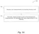
- FIG. 1 Ais a flow diagram showing an example method of generating an estimated floor area measurement, according to one non-limiting illustrated embodiment.
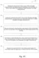
- FIG. 1 Bis a flow diagram showing a method that may be included as part of the generating floor area measurement step of the method shown in FIG. 1 A , according to one non-limiting illustrated embodiment.
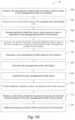
- FIG. 1 Cis a flow diagram showing a method that may be included as part of the generating total roof area step of the method shown in FIG. 1 B , according to one non-limiting illustrated embodiment.
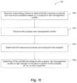
- FIG. 1 Dis a flow diagram showing an example method of generating a risk management report and determining insurance product offers, which in some instances may use the floor area measurements or methods for generating the floor area measurements described herein, according to one non-limiting illustrated embodiment.
- FIG. 1 Eis a flow diagram showing a method that may be included as a part of the receive risk management criteria step of the method shown in FIG. 1 D , according to one non-limiting illustrated embodiment.
- FIG. 1 Fis a flow diagram showing a method that may be included as a part of the receive additional data from one or more sources step of the method shown in FIG. 1 D , according to one non-limiting illustrated embodiment.
- FIG. 1 Gis a flow diagram showing a method that may be included as a part of the evaluate the aerial views and received additional data in light of the risk management criteria step of the method shown in FIG. 1 D , according to one non-limiting illustrated embodiment.
- FIG. 1 His a flow diagram showing a method that may be included as a part of the provide additions, updates, and/or corrections to the data step of the method shown in FIG. 1 D , according to one non-limiting illustrated embodiment.
- FIG. 1 Iis a flow diagram showing a method that may be included as a part of the receive underwriting criteria step of the method shown in FIG. 1 D , according to one non-limiting illustrated embodiment.
- FIG. 2is an example screenshot of a user interface of a system for generating floor area measurements, which may be used independently of, as part of, or integrated with the systems and methods for generating a risk management report described herein, showing roof sections annotated on an aerial image of the roof, according to one non-limiting illustrated embodiment.
- FIG. 3is an example screenshot of a user interface of the system of FIG. 2 for generating floor area measurements with area measurements of roof sections annotated on an aerial image of the roof, according to one non-limiting illustrated embodiment.
- FIG. 4is an example screenshot of a user interface of the system of FIG. 2 for generating floor area measurements showing the roof annotated with an estimated total roof area on which to base an estimated floor area measurement, such as that estimated in the method of FIGS. 1 A- 1 C , according to one non-limiting illustrated embodiment.
- FIG. 5is an example screenshot of a user interface of the system of FIG. 2 for generating floor area measurements showing the building annotated with an adjusted estimated floor area measurement, such as that estimated in the method of FIGS. 1 A- 1 C , according to one non-limiting illustrated embodiment.
- FIG. 6is an example screenshot of a user interface of the system of FIG. 2 for generating floor area measurements showing the building annotated with adjusted estimated first and second floor area measurements, such as that estimated in the method of FIGS. 1 A- 1 C , according to one non-limiting illustrated embodiment.
- FIG. 7is an example screenshot of a user interface of the system of FIG. 2 for generating floor area measurements showing a line drawing of a top plan view of each the first and second floor of the building annotated with corresponding floor area measurements, such as that estimated in the method of FIGS. 1 A- 1 C , according to one non-limiting illustrated embodiment.
- FIG. 8is an example screenshot of a user interface of the system of FIG. 2 for generating floor area measurements showing a line drawing of a top perspective view of the first and second floor of the building annotated with corresponding floor area measurements, such as that estimated in the method of FIGS. 1 A- 1 C , according to one non-limiting illustrated embodiment.
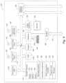
- FIG. 9is a schematic diagram of a computing environment in which systems and methods for estimation of building floor area and generating a risk management report may be implemented or of which they may be a part.
- FIG. 10is an example screenshot of a user interface of a system for generating floor area measurements which may be used independently of, as part of, or integrated with the systems and methods for generating a risk management report described herein, showing roof sections annotated on an aerial image of the roof, according to one non-limiting illustrated embodiment.
- FIG. 11is an example screenshot of a user interface of the system of FIG. 10 for generating floor area measurements showing an aerial view used to identify floors and the roof section areas, dimensions, and levels annotated on which to base an estimated floor area measurement or a risk management report, such as that estimated in the method of FIGS. 1 A- 1 I , according to one non-limiting illustrated embodiment.
- FIG. 12is an example screenshot of a user interface of the system of FIG. 10 for generating floor area measurements showing an aerial view used to identify floors and the roof section areas, dimensions, and levels annotated on which to base an estimated floor area measurement or a risk management report, such as that estimated in the methods of FIGS. 1 A- 1 I , according to one non-limiting illustrated embodiment.
- FIG. 13is an example screenshot of a user interface of the system of FIG. 10 for generating floor area measurements showing an aerial view used to identify floors and the roof section areas, dimensions, and levels annotated on which to base an estimated floor area measurement or a risk management report, such as that estimated in the methods of FIGS. 1 A- 1 I , according to one non-limiting illustrated embodiment.
- FIG. 14is an example screenshot of a user interface of the system of FIG. 10 for generating floor area measurements showing an aerial view used to identify floors and the roof section areas, dimensions, and levels annotated on which to base an estimated floor area measurement or a risk management report, such as that estimated in the methods of FIGS. 1 A- 1 I , according to one non-limiting illustrated embodiment.
- FIG. 15is an example screenshot of a user interface of the system of FIG. 10 for generating floor area measurements showing an aerial view used to identify floors and the roof section areas, dimensions, and levels annotated on which to base an estimated floor area measurement or a risk management report, such as that estimated in the method of FIGS. 1 A- 1 I , according to one non-limiting illustrated embodiment.
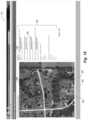
- FIG. 16is an example screenshot of a user interface of a system for gathering property risk assessment data using one or more aerial images of the property, which may be used independently of, as part of, or integrated with the systems and methods for generating a risk management report described herein, according to one non-limiting illustrated embodiment.
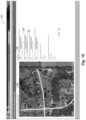
- FIG. 17is an example screenshot of a user interface of the system of FIG. 16 for gathering property risk assessment data, such as that described in the method of FIGS. 1 A- 1 I , according to one non-limiting illustrated embodiment.
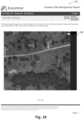
- FIG. 18is an example screenshot of a user interface of the system of FIG. 16 for gathering property assessment data, using measurement tools to estimate distance, such as that described in the method of FIGS. 1 A- 1 I , according to one non-limiting illustrated embodiment.
- FIG. 19is an example screenshot of a user interface of the system of FIG. 16 for gathering property risk assessment data, showing data entered from other sources, such as that described in the method of FIGS. 1 A- 1 I , according to one non-limiting illustrated embodiment.
- FIG. 20is an example screenshot of a user interface of the system of FIG. 16 for gathering property risk assessment data, including roof characteristics, such as that estimated in the method of FIGS. 1 A- 1 I , according to one non-limiting illustrated embodiment.
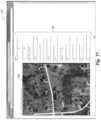
- FIG. 21is an example screenshot of a user interface of the system of FIG. 16 for gathering property risk assessment data including property ground characteristics, such as that described in the method of FIGS. 1 A- 1 I , according to one non-limiting illustrated embodiment.
- FIG. 22is an example page of a report that provides floor area and property assessment data, such as that estimated in the method of FIGS. 1 A- 1 I , according to one non-limiting illustrated embodiment.
- FIG. 23is an example page of a report to provide floor area and property risk assessment data, including report details and building summary, such as that estimated in the method of FIGS. 1 A- 1 I , according to one non-limiting illustrated embodiment.
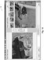
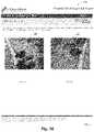
- FIG. 24is an example page of a report to provide floor area and property risk assessment data, including report images, such as that described in the method of FIGS. 1 A- 1 I , according to one non-limiting illustrated embodiment.
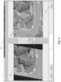
- FIG. 25is an example page of a report to provide floor area and property risk assessment data, including multiple aerial angles of the property, such as that described in the method of FIGS. 1 A- 1 I , according to one non-limiting illustrated embodiment.
- FIG. 26is an example page of a report to provide floor area and property risk assessment data, including multiple aerial angle images, such as that described in the method of FIGS. 1 A- 1 I , according to one non-limiting illustrated embodiment.
- FIG. 27is an example page of a report to provide floor area and property risk assessment data, including the dimensions and the area for different sections of a floor of a building, such as that estimated in the method of FIGS. 1 A- 1 I , according to one non-limiting illustrated embodiment.
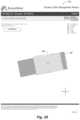
- FIG. 28is an example page of a report to provide floor area and property risk assessment data, including dimensions and area by sections for a particular floor of a building, such as that estimated in the method of FIGS. 1 A- 1 F , according to one non-limiting illustrated embodiment.
- FIG. 29is an example page of a report to provide floor area and property assessment data, including structural observations, property observations, and confidence rating of the floor area and property assessment data, such as that described in the method of FIGS. 1 A- 1 I , according to one non-limiting illustrated embodiment.
- FIG. 30is a flow diagram showing an exemplary method for producing a floor area measurement in accordance with the present disclosure.
- FIG. 1 Ais a flow diagram showing an example method 100 of generating an estimated floor area measurement, according to one non-limiting illustrated embodiment.
- each of the steps shown in FIG. 1 Acontributes to the overall solution, each can be used independently or in various combinations to yield improvements in estimating floor area measurements as discussed below. Below is an overview of each step in the process, which will be followed by a more detailed discussion of each step.
- the processreceives roof measurements of a building having a roof.
- These measurementsmay be estimated or actual dimensional and/or area measurements of the roof such as one or more of: roof edge lengths, ridge lengths, gable lengths, hip lengths, valley lengths, roof section pitch, roof area measurements, planar roof section area measurements, planar roof section dimension measurements, etc.
- These roof measurementsmay be generated internally by a component of a system that estimates floor area measurements (i.e., a floor area measurement estimation system) and received from such an internal component, or may be generated and received from an external component or entity separate from the floor area measurement estimation system.
- the external componentis located remotely from the floor area measurement estimation system.
- the floor area measurement estimation systemmay be a system integrated with a roof estimation system or other system that provides roof measurements.
- the roof area measurementsmay be provided by an external source, system or entity, or may be input manually by an operator of the floor area measurement estimation system.
- Various received roof measurementsmay often correspond closely to external dimensions of the building such as the width and length of the building and/or lengths of exterior walls or sections of exterior walls of the building.
- the processgenerates, based at least in part on the received roof measurements, an estimated floor area measurement of the building.
- the received roof measurementsmay include roof edge measurements of the roof.
- a floor area measurement estimation module of the floor area measurement estimation systemis configured to generate, based at least in part on the received roof measurements, an estimated floor area measurement.
- the received roof measurementsmay include roof area measurements.
- the floor area measurement estimation module of the floor area measurement estimation systemis configured to generate, based at least in part on the received roof area measurements, an estimated floor area measurement.
- the roof measurementsmay be generated by the roof estimation system described in U.S. Pat. No. 8,078,436 issued Dec.
- one or more of the roof measurementsare based on aerial photographs of the building via manual or automated analysis of roof features, such as by using the roof estimation system or modules described in one or more of U.S. patent application Ser. No. 12/148,439 filed on Apr. 17, 2008 and entitled AERIAL ROOF ESTIMATION SYSTEM AND METHOD, U.S. Pat. No. 8,078,436 issued Dec. 13, 2011, and entitled AERIAL ROOF ESTIMATION SYSTEMS AND METHODS, U.S. patent application Ser. No. 12/467,244 filed May 15, 2009 and entitled PITCH DETERMINATION SYSTEMS AND METHODS FOR AERIAL ROOF ESTIMATION, U.S. patent application Ser. No.
- such measurementsmay be made by an operator or an automated system actually or virtually outlining, drawing and/or otherwise detecting the perimeter of the roof on, or based on, an aerial image of the roof to indicate an initial estimated floor shape or foot print, and providing such data as input used by the system for estimating floor area described herein which would otherwise use the roof edge measurements from a two or three dimensional model of the roof.
- outlining or drawing the perimeter on the roofmay be performed within a graphical user interface displaying the image of the roof such as that shown in FIGS. 10 - 15 below.
- onemay estimate floor area measurements of a building merely using one or more aerial photographs of the building, with little or no additional information initially needed.
- FIG. 1 Bis a flow diagram showing a method 110 that may be included as part of the generating floor area measurement step of the method shown in FIG. 1 A , according to one non-limiting illustrated embodiment.
- each of the steps shown in FIG. 1 Bcontributes to the overall solution, each can be used independently or in various combinations to yield improvements in estimating floor area measurements as discussed below.
- the processgenerates roof edge measurements based on initial roof edge measurements included in the received roof measurements, assuming each section of the roof has no slope regardless of an actual slope of each section of the roof. For example, if the two edges of the gable of a pitched roof are 20 feet and the gable has a pitch angle of 90 degrees, then instead of two edges of 20 feet, the process generates a single roof edge of sqrt(800) ⁇ 28.3 feet. The process generates roof edge measurements as if the entire roof was flat.
- the processuses the roof edge measurements to calculate an estimated total roof area of the roof assuming each section of the roof has no slope. Thus, the process generates roof area measurements as if the entire roof was flat.
- a roof estimation systemis integrated with the floor area measurement system, such as a method 120 a as shown in FIG. 30
- the floor area measurement systemfirst receives a first and a second aerial image of the building, each of the aerial images providing a different view of the roof of the building.
- the systemcorrelates the first aerial image with the second aerial image to generate a three-dimensional model of the roof, in a step 114 b , that includes a plurality of planar roof sections that each have a corresponding slope, area, and edges.
- an adjusted roof modelis generated by adjusting a slope of the planar roof sections in the three dimensional model of the roof to substantially zero.
- Thismay be performed in a variety of manners, including, for example, removing particular roof features from the model that would not be present in a roof with a slope of zero.
- the planar roof sections in the modelbecome one large flat roof section.
- the systemwill remove ridge lines, valleys or other features distinguishing individual planar roof sections. This creates the effect of having fused all roof sections together which can be termed as fusing them in a virtual software computer sense.
- Thismay be also performed instead of or in addition to by just adjusting a slope parameter or variable of each roof section within the roof model to zero. In other embodiments, this step may be performed with just one initial aerial image of the building showing a substantially orthogonal view of the building since roof pitch need not be determined and can be assumed to be zero.
- the processgenerates the estimated floor area measurement based on the calculated estimated total roof area of the roof. This is based on a correlation between the size of the building roof and the size of the building. Typically, the floor area of a single full floor of the building is roughly the size of the roof of the building if the roof were flat with no slope (i.e., virtually turning the roof into another floor). With additional adjustments to the roof area measurements described below (e.g., with respect to FIG. 1 C ) to account for multiple floors (e.g., FIG. 30 , step 116 b ), roof overhang, wall width, internal building features such as walls and staircases, and/or obstructed views of the building in the aerial image(s), etc., an even more accurate floor area estimation is generated.
- the received roof measurementsmay instead or additionally include at least one of: a plurality of dimensional measurements of a two-dimensional outline of the roof from a top plan view of the roof and an area of the two-dimensional outline of the roof from the top plan view of the roof.
- the dimensions of the two-dimensional outline of the roof from a top plan view of the roofmay be used as the roof edge measurements on which to base the estimated floor area.
- these dimensional measurements of a two-dimensional outline of the roofneed not be referred to as “roof edge measurements” or “roof measurements” to fall within the scope of the embodiments described herein.
- FIG. 1 Cis a flow diagram showing a method 120 that may be included as part of the generating total roof area step of the method shown in FIG. 1 B , according to one non-limiting illustrated embodiment. While each of the steps shown in FIG. 1 C contributes to the overall solution, each can be used independently or in various combinations to yield improvements in estimating floor area measurements as discussed herein.
- the processsubtracts an amount from one or more of the roof edge measurements corresponding to an estimated roof overhang over one or more walls of the building to obtain adjusted roof edge measurements.
- each roof edge measurementmay be reduced by 6 inches to 18 inches corresponding to an estimated roof overhang, which is selectable by a user of the floor area measurement estimation system. This can be considered to be eroding the length in a virtual sense by some amount.
- any variety of other lengths or ranges of lengthsmay be used including, for example a zero length or those of standard or typical roof overhang lengths.
- each roof edge measurementmay be reduced by 6 inches to 18 inches corresponding to an estimated wall width, which is selectable by a user of the floor area measurement estimation system.
- other lengths or ranges of lengthsmay be used (e.g., those of standard or typical wall widths).
- the processreceives information regarding floor area spaces of the building that are not to be included in the estimated floor area measurement of the building.
- these areasmay be areas of the building that are not used for living inside the building or areas outside the building including, but not limited to: garages; attics; unfinished rooms above the garage or other locations; covered balconies; patios, decks or porches, unfinished basements; crawl spaces; etc.
- This informationmay be received from an external system, source or entity; input by a user (e.g., identified or marked by a user on an image or drawing of the building displayed within a graphical user interface of the system); and/or identified by the system via analysis of an image of the building.
- the processgenerates an initial estimated floor area measurement based on an area corresponding to an extent to which the spaces that are not to be included in the estimated floor area measurement extend under the roof and based on the adjusted roof edge measurements.
- the roof edge measurementsmay be used to calculate an estimated roof area with assumed slope of zero.
- areas corresponding to an extent to which such spaces extend under the roofmay be subtracted from the estimated roof area. This also may be performed in response to a user marking or otherwise identifying such areas on an image or drawing of the building displayed within a graphical user interface of the system.
- the entire process of generating an initial estimated floor areais automated by the system recognizing these particular features in one or more images of the building through image analysis that utilizes typical characteristics of such features as viewed from the various angles of those in the one or more images of the building.
- the processgenerates the estimated floor area measurement based on information received regarding a number of stories or floors of the building.
- the floor area measurement estimation systemmay receive information regarding how many stories the building has and regarding one or more sections of the roof below which one or more of the stories extends.
- the systemmay then generate the estimated floor area measurement based on a total area of the one or more sections of the roof under which each of the stories extends and based on the generated estimated total roof area of the roof.
- This total area of the one or more sections of the roof under which each of the stories extendsmay be calculated using the adjusted roof edge measurements and then adjusted according to various other features of the building identified in the an image of the building or otherwise received by the system.
- These various other features of the buildingindicate one or more sections of the roof below which one or more of the stories extends. Such features identify split level homes, homes with lofts, vaulted ceilings, etc.
- the systemmay determine how many stories the building has, for example, in a step 130 a , using a second aerial image of the building representing a view from a different angle than the substantially orthogonal view of the top of the building such that the building height and other features related to how many stories the building has may at least be partially seen.
- This determinationmay be performed in response to a user inputting a value representing the number of stories or by the user marking or otherwise identifying such areas corresponding to the different stories on an image or drawing of the building displayed within the graphical user interface of the system.
- the shape and perimeter of each building storymay be annotated on a drawing or image of the building displayed in the graphical user interface and manipulated by a user of the system collectively and/or individually to make the adjustments described herein.
- the adjustmentswill indicate one or more sections of the roof below which one or more of the stories laterally extends.
- the estimated total floor area of the buildingis then calculated by adding the areas of each identified floor together to get the total area.
- the resulting changes in estimated total floor areaare generated by the floor area estimation system and displayed on the drawing or image of the building displayed in the graphical user interface.
- the entire process of generating an initial estimated floor areais automated by the system recognizing these particular building features (e.g., building stories, floors, etc.) in one or more images of the building through image analysis that utilizes typical characteristics of such features as viewed from the various angles of those in the one or more images.
- building featurese.g., building stories, floors, etc.
- Examples of using the estimated floor area of a structure (e.g., a building) and/or the processes and systems to generate estimated floor area described hereininclude using such estimated floor area, processes and/or systems as part of generating estimates for and/or data for generating estimates or assessments regarding insurance coverage for the structure or real estate including the structure, property risk assessment, and/or construction and repair of the structure.
- estimates and/or assessmentsinclude, but not limited to, estimates and/or assessments regarding: the overall value of a structure; the overall value of real estate including the structure; cost of replacing or repairing the structure; insurance rates or premiums for insuring the structure; determining, predicting and/or calculating costs of replacing or repairing the structure pursuant to processing or paying insurance claims regarding the structure; processing insurance claims regarding the structure; managing risk with respect to the structure becoming or being damaged and/or risk with respect to insuring and/or paying existing or potential insurance claims on the structure; etc.
- FIG. 1 Dis a flow diagram showing method 135 of generating a risk management report, which in some instances may use the floor area measurements or methods for generating the floor area measurements described herein, according to one non-limiting illustrated embodiment.
- the processreceives risk management criteria from an entity, wherein the risk management criteria are used to create a risk management profile of a particular property.
- an insurance companymay have risk management criteria that it uses to evaluate a property to create a risk management profile of the property. This permits an insurance company to manage the risk with respect to the structure on the property or other features of the property becoming or being damaged and/or risk with respect to insuring and/or paying existing or potential insurance claims on the property.
- This profilecan be used, for example, to determine which insurance products and at what premiums it will offer the owner.
- the risk management criteriamay include but is not limited to conditions of aspects of buildings on the property, density and size of vegetation on the property, property terrain features such as steepness of slope or water features, and nearness to commercial areas or fire stations.
- the processreceives one or more aerial views of the property and surrounding area.
- these aerial viewsmay include top-down, substantially orthogonal views, or oblique views showing the property and buildings at an angle.
- these aerial viewsmay be used to evaluate the features and conditions of the property.
- the processreceives additional data from one or more sources.
- sourcesmay include, but are not limited to, insurance companies, government entities, contractors, and the like.
- the sourcesmay also include systems that have generated roof estimations, wall estimations, or floor estimations.
- the processevaluates the received aerial views and received additional data using the risk management criteria to determine the risk management profile of the property.
- this evaluationinvolves a human operator viewing the aerial images and the additional data to answer questions about the property that correspond to risk management criteria used to assess the risk management profile of the property.
- this evaluationinvolves graphical image processing, data management, and/or statistical methods to answer the questions.
- the processgenerates a risk management profile report for the property based on the evaluation completed in the previous step.
- the processstores the risk management profile information.
- this informationis stored along with profiles of other properties to be used for various purposes such as property risk history.
- the processdistributes the risk management profile report.
- the reportis sent to the insurance company, the insurance agent, the property owner, or other entity that uses the risk profile to make decisions concerning the property.
- the processprovides additions, updates, and/or corrections to the data received.
- the evaluation process which uses property data from many sourcesmay uncover errors or other problems which the source of the data may wish to know about and correct. For example, a building's total living area as determined by an operator using current aerial views may not match the total living area documented in county tax records. The county may wish to update their records to determine a fair tax valuation for the property.
- discrepancies discovered in data that exceed a tolerance thresholdmay generate an automatic notification to the source of the data.
- the datamay be directly updated by the process.
- the processreceives underwriting criteria from insurance companies that describes the insurance products and premium amounts the company offers based on the features and risk management profile of a property.
- the criteriadetermines the features or combination of features on the property that will cause it to the insurable, and provides the formulas that use the conditions of features on the property to determine insurance premium cost.
- the processdetermines the insurance products to offer and the pricing of the products for the property.
- certain features and conditions of the propertywill be associated with certain insurance products. For example, if a residential property also has one or more commercial buildings on it, than a commercial insurance product may be appropriate. In another example, if the residential property has an RV parked in the yard, offering an auto insurance product that covers the RV may be appropriate.
- criteria involving conditions of features on the propertymay determine the premium amounts offered for a particular policy. For example, if the condition of the roof of a residential building appears excessively worn or damaged, the premiums for ensuring that building will be higher than if the roof was not damaged.
- FIG. 1 Eis a flow diagram showing an example method 140 of receiving risk management criteria used to create a risk management profile of a property step of the method shown in FIG. 1 D , according to one non-limiting illustrated embodiment. While each of the steps shown in FIG. 1 E contributes to the overall solution, each can be used independently or in various combinations to yield improvements in receiving risk management criteria from an entity as discussed below.
- the processreceives risk management criteria from an entity used to create a risk management profile of a property.
- the criteriaare used to evaluate features of the property to create a risk management profile of the property.
- Features of the propertymay include but are not limited to buildings, vegetation, terrain, distance to water, distance to commercial areas, and distance to a fire station.
- Features of a buildingmay include but are not limited to year built, number of stories, style of roof, floor area, and number of windows.
- the criteriamay also describe various conditions of the features of a property.
- the criteriamay be received as a data file that may be imported into an evaluation system.
- the processstores the risk management criteria received from each company.
- the criteria from each companyare stored in a database and used during the evaluation process, described below, when the property risk assessment profile is being created.
- the processdetermines the criteria elements that are common among companies. In one embodiment, elements are reviewed by an operator to determine the common elements. In another embodiment elements are compared electronically.
- the processuses the common criteria elements to allow risk management profile evaluation comparison among companies. In one embodiment, this allows the evaluation process, described below, to efficiently produce risk management profile reports for a number of insurance companies.
- FIG. 1 Fis a flow diagram showing an example method 150 of receiving additional data from one or more sources to used to determine a risk management profile step of the method shown in FIG. 1 D , according to one non-limiting illustrated embodiment. While each of the steps shown in FIG. 1 F contributes to the overall solution, each can be used independently or in various combinations to yield improvements in receiving additional data from one or more sources as discussed below.
- the processreceives one or more aerial views of the property.
- these aerial viewsmay include a top-down, or substantially orthogonal view of the property, and/or oblique views of the property taken at angles from different directions.
- an oblique aerial view of the propertymay be taken at a 45° angle from the north, and another taken at a 50° angle from the west.
- these aerial viewsare provided in a digital format.
- the processreceives floorplan estimates and total living area estimates for buildings on the property.
- these estimatesare received from the roof estimation system or a floor area measurement system described herein.
- the estimatesmay come from county records.
- the processreceives data generated from modeling or estimation software for buildings.
- this datamay be generated by a roof estimation systems, wall estimation systems, 3D modeling systems, CAD systems, or the like.
- the processreceives data on file for similar houses in the community.
- this datamay include the date the neighborhood was developed, the average age of houses, typical improvements done to property, and the like.
- the processreceives government records on the property.
- these recordsmay include but are not limited to information received from county or city building departments, which include building plans, building permit information, as-built information and the like.
- the recordsmay also include government tax records that include estimated total living area of buildings on the property.
- the processreceives data from contractor or construction firms.
- thismay include but is not limited to blueprints, as-built information, landscape elevations, and repair information.
- the processreceives data from scans of the property.
- these scansmay include but are not limited to infrared scans, thermal imaging scans, and the like.
- the processreceives property data collected on-site.
- this dataincludes but is not limited to visual information on property features, for example external and internal property features of buildings.
- external featuresare the condition of walls, roofs, chimneys, skylights, porches, patio, decks, garages, and other exterior features.
- Example of internal featuresare the conditions of walls, ceilings, floors, carpeting, windows, fixtures, skylights, and other interior features.
- Conditions of other property featuresmay include but are not limited to terrain, vegetation, water hazards, trampolines, hot tubs, swimming pools, outbuildings, automobiles, or other outside features relevant to determine a risk management profile.
- this visual informationmay be captured using an image or video recording device by the property owner or one or more other individuals evaluating the property.
- the data collectedmay include but is not limited to interviews with property owners, tenants, or one or more neighbors.
- data collectedmay include data from chemical samples, odor detectors, radiation detectors, radon detectors, moisture detectors, RFI detectors and the like.
- additional data required during the evaluation processmay be requested from one or more individuals who are evaluating the property.
- the processreceives data collected from insurance companies.
- this datamay include but is not limited to existing photographs of the property, descriptions and measurements of features on the property, insurance claims history of the property and the like.
- this datamay include insurance data available for buildings or property near the property being evaluated.
- FIG. 1 Gis a flow diagram showing a method 155 that may be included as a part of the evaluate the aerial views and received data in light of risk management criteria step of the method shown in FIG. 1 D , according to one non-limiting illustrated embodiment. While each of the steps shown in FIG. 1 G contributes to the overall solution, each can be used independently or in various combinations to yield improvements in evaluating the aerial views and received data as discussed below.
- the processgenerates questions for assessing the individual elements of the risk management criteria for the property.
- a questionis created for each criteria element. For example, if an element is the age of a building, a generated question may be “what year was the building built?”
- the processuses the aerial views and received data to provide answers to the generated questions.
- the answers to the questionsmay be but are not limited to being provided by an operator at a workstation viewing the images and the data, an automated system analyzing the aerial views and received data, and one or more individuals viewing the aerial views and receive data according to a crowd sourcing model.
- the processreceives questions to answer.
- an individual at a workstationis viewing the aerial images and the received data.
- this processmay be automated.
- the processevaluates data and aerial images to answer the received questions.
- an operator at a workstationis viewing the aerial images, the received data and the received questions, and is answering the questions based on the operator's evaluation of the images and data.
- the processprovides a confidence rating for answers to the questions.
- the operatorenters a confidence rating for each individual question answered.
- the operatorenters an overall confidence rating once all questions are answered.
- the processreceives questions to answer.
- the aerial images and received dataare analyzed by an automated system to determine the answers.
- a feature of the propertymay be a building, terrain, water feature, vegetation, or other characteristic of the property relevant to a risk management assessment.
- the processuses visual recognition, graphical analysis, and the like to identify features and conditions of the property to determine answers to the questions. For example, to identify roof wear or prior patch made to the roof by analyzing the pattern or color differences identified on the roof or to identify the condition of the skylight or window by using optical density analysis. In another example, to use visual analysis to determine the distance to the nearest water feature or to determine the style of a building, or to identify if a trampoline or swimming pool is located on the property.
- the processuses graphical processing to compare similar aerial views of the property taken at different times to determine answers to the questions. Examples include but are not limited to identifying the rate of deterioration of an outbuilding roof, the rate of growth of vegetation, whether any structures have been newly built or modified, whether damage to a structure has been sustained but unrepaired over time such as hailstorm damage, and the like.
- the processuses data processing to analyze data about neighboring properties to estimate answers to the questions. Examples include but are not limited to the age of surrounding buildings, the age of the neighborhood, the condition of surrounding property, and the like.
- the processuses statistical techniques to determine the confidence rating for answers to the questions. These techniques include but are not limited to analyzing the resolution of aerial views, any obstruction by trees of views to the buildings, age of data received indicating it may be out of date, and the like.
- the processreceives questions to answer.
- the evaluationis performed using a crowd sourcing model, in which, for example a number of individuals view the aerial views and additional data, and answer the questions.
- the processidentifies the evaluators that will receive the questions, the additional data, and aerial images.
- the evaluatorsmay be but are not limited to volunteers, paid contractors, the property owner, to the property tenant, to neighbors of the property, and the like.
- the processsends the questions, data, and aerial images to the evaluators. In one or more non-limiting embodiments, this may be done electronically via email, a Smartphone application, on paper, or the like.
- the processevaluates the data and aerial images to answer the questions. In one or more non-limiting embodiments, this may be done by an individual operator at a workstation, by an automated process, or by a combination of both.
- the processprovides a confidence rating for answers to the questions.
- the operatormay enter either a confidence rating for each individual question answered, or an overall confidence rating once all questions are answered. Or, if using an automated process, statistical techniques may be used to determine the confidence rating.
- the processreceives the answers from the evaluators. In one or more non-limiting embodiments, this may be done electronically, via email, a Smartphone application, on paper, or the like.
- the processassesses the accuracy of each evaluator for use in selecting future evaluators.
- the assessmentmay take the form of, but not limited to, several techniques.
- statistical techniquesmay be used to generate the most likely correct answer for each question answered by the evaluator and compare that answer to the evaluator's answer.
- individualsmay review the evaluations done by each evaluator and vote on the accuracy of the each evaluation.
- FIG. 1 His a flow diagram showing a method 160 that may be included as part of providing additions, updates, and/or corrections to the data received step of the method shown in FIG. 1 D , according to one non-limiting illustrated embodiment. While each of the steps shown in FIG. 1 H contributes to the overall solution, each can be used independently or in various combinations to yield improvements in providing additions, updates, and/or corrections to the data received as discussed below.
- the processidentifies data that has been found during the evaluation process to be incorrect.
- examples of this datainclude but are not limited to images that are out of date, area estimates of buildings that are incorrect, number of listed outbuildings that is not correct, and the like.
- the term “correct”may include a deviation within a certain tolerance level.
- the processreports to the source of the data that the data is not correct.
- thismay include but is not limited to notifying the source of the data (e.g. an insurance company) that the data is not correct, sending the source the correct data, updating the source with the correct data, and the like.
- FIG. 1 Iis a flow diagram showing a method 165 that may be included as part of the receiving underwriting criteria for insurance product offers and pricing for the property step of the method shown in FIG. 1 D , according to one non-limiting illustrated embodiment. While each of the steps shown in FIG. 1 I contributes to the overall solution, each can be used independently or in various combinations to yield improvements in estimating floor area measurements as discussed below.
- the processreceives underwriting criteria to determine the insurance products and premiums available based on a property's risk assessment profile.
- underwriting criteriainclude but are not limited to a list of the features of a property that corresponds to a particular insurance products offered by the company and the various conditions of the features of the property that affect premium cost of each insurance product.
- the processreceives the property risk management profile.
- the property risk management profileis retrieved from a database containing property risk management profiles.
- the processdetermines the insurance products and pricing for the property.
- the processcompares the features and conditions of the property found in the property risk management profile to the received underwriting criteria to determine what insurance products are available for the property and the premium cost of each insurance product.
- the processdetermines if the confidence rating for the property risk management profile is high enough to not send a person to the property for an on-site inspection.
- the confidence rating that is part of the properties risk management profileis compared with other factors including but not limited to the features of the property, the condition of the features of the property, the dollar cost of the insurance products being quoted, cost to send someone for an on-site inspection, and the like.
- a companymay, based on the comparison, either choose to not send a person on-site and instead “desk underwrite” the insurance products.
- FIG. 2is an example screenshot of a user interface of a system for generating floor area measurements with roof sections annotated on an aerial image of the roof, according to one non-limiting illustrated embodiment.
- the screenshots of FIGS. 2 - 8are screenshots of the graphical user interface of the floor area measurement system which performs the processes described in FIGS. 1 A- 1 C above.
- an annotation 212which is a line drawing of a three dimensional model of the roof.
- the annotation 212is an adjustable graphical user interface element overlaid on the roof of the building in each image corresponding to the angle of view 202 and view 204 of the roof in each image.
- the annotation 212also shows various planar sections of the roof as delineated by the roof features and roof lines, such as the ridge line, valley lines and roof eaves, etc.
- This annotation 212is an interactive graphical user interface feature and may be manipulated by a user of the system to make various adjustments to roof features and characteristics for the purpose of generating roof measurements, such as those used in the processes shown in FIGS. 1 A- 1 C and other embodiment described herein. These may be performed by user interaction with the annotation itself and/or various selectable controls 206 .
- image selection bars 208 and 210which display thumbnail or reduced-size images of various other images showing the building from other perspectives and view angles.
- Selection bar 208is located above view 202 .
- selection bar 210is located above view 204 .
- the image showing the current view 204is replaced with that of the selected image.
- FIG. 3is an example screenshot 300 of a user interface of the system of FIG. 2 for generating floor area measurements with area measurements 302 , 304 and 306 of roof sections annotated on an aerial image of the roof, according to one non-limiting illustrated embodiment.
- the floor area measurement estimation systemcalculates the areas 302 , 304 and 306 of each roof section according to the roof annotation 212 , as adjusted by the user, and displays these area values 302 , 304 and 306 on the corresponding sections of the roof in the displayed image.
- a “Fuse” button 308the selection of which causes results to be displayed as shown in FIG. 4 .
- FIG. 4is an example screenshot 400 of a user interface of the system of FIG. 2 for generating floor area measurements showing the roof annotated with an estimated total roof area 402 on which to base an estimated floor area measurement, such as that estimated in the method of FIGS. 1 A- 1 C , according to one non-limiting illustrated embodiment.
- the floor area measurement estimation systemmay perform the acts 112 and 114 of the process shown in FIG. 1 B to calculate an estimated total roof area of the roof by setting each section of the roof to a zero slope.
- the floor area measurement estimation systemgenerates an adjusted roof model by adjusting the slope to substantially zero of the planar roof sections having areas 302 , 304 and 306 shown in FIG. 3 in the three dimensional model of the roof represented by annotation 212 .
- Thismay be performed in a variety of manners, including, for example, by removing particular roof features from the model represented by annotation 212 in FIG. 3 that would not be present in a flat roof with no slope.
- Thiscould be considered “fusing” individual planar roof sections in the model into one flat roof section, such as by removing ridge lines or other features distinguishing individual planar roof sections instead of, or in addition to, adjusting a slope parameter or variable within the model to zero.
- This processresults in the adjusted annotation 212 displayed by the system as shown in FIG. 4 without lines indicating roof features such as ridge lines associated the pitched roof.
- the systemgenerates and provides roof edge measurements using the roof model as if the entire roof was flat with no slope, as shown by the annotation 212 representing the roof model in FIG. 4 .
- screenshot of the graphical user interface 300shows both the orthogonal view 202 and oblique view 204 , in other embodiments, this action may be performed with just one initial aerial image of the building using and/or showing only the substantially orthogonal view 202 of the building since roof pitch need not be determined and can be assumed to be zero.
- Electrode button 402the selection of which causes results to be displayed as shown in FIG. 5 , as will be explained in conjunction with FIG. 5 below.
- FIG. 5is an example screenshot 500 of a user interface of the system of FIG. 2 for generating floor area measurements showing the building annotated with an adjusted estimated floor area measurement, such as that estimated in the method of FIGS. 1 A- 1 C , according to one non-limiting illustrated embodiment.
- the floor area measurement estimation systemwill perform the acts 122 and 124 of the process shown in FIG. 1 C to calculate an adjusted estimated total roof area of the roof by subtracting an amount from each section of the roof to account for an eave overhang distance.
- the floor area measurement estimation systemsubtracts an amount from one or more of the roof edge measurements in the roof model represented by annotation 212 corresponding to an estimated roof overhang over one or more walls of the building to obtain adjusted roof edge measurements.
- each roof edge measurementmay be reduced (i.e., “eroded”) by 6 inches to 18 inches corresponding to an estimated roof overhang, which is selectable by a user of the floor area measurement estimation system.
- other lengths or ranges of lengthsmay be used.
- the floor area measurement estimation systemmay also subtract an amount from one or more of the adjusted roof edge measurements in the roof model represented by annotation 212 corresponding to an estimated wall width to obtain adjusted roof edge measurements.
- each roof edge measurementmay be reduced (i.e., “eroded”) by 6 inches to 18 inches corresponding to an estimated wall width, which is selectable by a user of the floor area measurement estimation system.
- other lengths or ranges of lengthsmay be used.
- the amount of length subtracted from a line to obtain a more accurate measure of the internal footprint of the homewill vary depending on the factor being subtracted for. If the factor being subtracted for is an eave, the value may be 2 feet, 3 feet, or another selected amount which may be a default value, such as 2 feet, or a value selected by an operator from seeing a second image of the home, which provides an oblique view of the overhang difference, which in some homes might be 4 feet. On the other hand, if the subtraction is for a wall thickness, the amount will usually be 6 inches or at most 10 inches. For a porch or deck, the amount might be 10 feet, 12 feet or some other value, based on an estimate of the true distance from an operator viewing one or more oblique images.
- each time a user selects the “erode” button 402an additional adjustment shortening the lengths of the roof edges will be performed by the system.
- the annotation 212 in FIG. 5is now adjusted corresponding to the adjusted roof edge lengths such that the actual edges of the roof in the image shown in both the orthogonal view 202 and oblique view 204 extend beyond the borders of the annotation 212 .
- the corresponding roof area measurement 502is also therefore adjusted accordingly by the floor area measurement estimation system (e.g., from 2144 square feet down to 1855 square feet as shown in FIGS. 4 and 5 , respectively).
- FIG. 6is an example screenshot 600 of a user interface of the system of FIG. 2 for generating floor area measurements showing the building annotated with adjusted estimated first floor and second floor area measurements, such as that estimated in the method of FIGS. 1 A- 1 C , according to one non-limiting illustrated embodiment.
- the usermay manipulate or otherwise adjust the annotation 212 , or add additional annotations to represent multiple floors of the building as identified in the oblique view 204 of the building. Based on these adjustments, the floor area measurement estimation system may perform act 130 of the process shown in FIG. 1 C to generate the estimated floor area measurement based on information received regarding a number of stories of the building.
- the floor area measurement estimation systemmay receive information regarding how many stories the building has and regarding one or more sections of the roof below which one or more of the stories laterally extends. The system may then generate the estimated floor area measurement based on a total area of the one or more sections of the roof under which each of the stories extends and based on the generated estimated total roof area of the roof.
- first floor annotation 602 and a second floor annotation 604that combined form annotation 212 .
- the relationship between the first floor, second floor and roofcan be seen form a different perspective in the oblique view 204 as the second floor annotation 604 shows that the second floor laterally extends substantially the entire length of the roof.
- the first floor annotation 602shows that the first floor laterally extends about half way the length of the roof and the second floor due to the garage.
- the first floor annotation 602 and a second floor annotation 604may be directly or indirectly manipulated and adjusted resulting in different area measurements of the floor represented by these annotations.
- first floor annotation 602 and second floor annotation 604may be directly or indirectly manipulated and adjusted to account for spaces that are not to be included in the estimated floor area measurement.
- these areasmay be areas of the building that are not used for living inside the building or areas outside the building, including but not limited to: garages; attics; unfinished rooms above the garage or other unfinished spaces; covered balconies; patios, decks or porches, basements; crawl spaces; etc. This also may be performed in response to a user marking or otherwise identifying such areas on the first floor annotation 602 and second floor annotation 604 , or otherwise adjusting the dimensions of the sides of the first floor annotation 602 and second floor annotation 604 to “notch” out or “cut” out such areas.
- selectable graphical user interface itemsare provided representing such spaces.
- a an area corresponding to a standard size and/or shape of such a spacewill be removed from the first floor annotation 602 and second floor annotation 604 , and the floor area measurements will be adjusted accordingly.
- a selectable graphical user interface item representing a standard two-car garagemay be selected by a user and placed in a position on the first floor annotation 604 overlaid on the image of the building corresponding to where a garage of the building is located.
- the floor area measurement estimation systemwill then subtract an area corresponding to the area of the standard two-car garage from the area of the first floor according to the position of the graphical user interface item representing the standard two-car garage on the first floor annotation 604 .
- FIG. 7is an example screenshot 700 of a user interface of the system of FIG. 2 for generating floor area measurements showing a line drawing of a top plan view of each the first and second floor of the building annotated with corresponding floor area measurements of the building shown in FIG. 6 , such as that estimated in the method of FIGS. 1 A- 1 C , according to one non-limiting illustrated embodiment.
- the line drawingrepresents the first floor annotation 602 and the second floor annotation 604 shown in FIG. 6 .
- the corresponding estimated floor areasare displayed on each annotation. These are adjusted by the floor area measurement estimation system upon manipulation of the corresponding first floor annotation 602 or second floor annotation 604 by the user.
- FIG. 8is an example screenshot 800 of a user interface of the system of FIG. 2 for generating floor area measurements showing a line drawing of a top perspective view of the first and second floor of the building shown in FIG. 6 annotated with corresponding floor area measurements, such as that estimated in the method of FIGS. 1 A- 1 C , according to one non-limiting illustrated embodiment.
- a usermay manipulate the corresponding first floor annotation 602 and/or second floor annotation 604 and see the visual effects of the changes according to the positional relationships between the first and second floors corresponding to the oblique view 204 shown in FIG. 6 .
- the total estimated floor area of the buildingis 2866 square feet (1076 square feet as noted on the first floor annotation 602 plus 1790 square feet as noted on the second floor annotation 604 ).
- Various reportsmay be generated showing the estimated areas of the various floor and/or the estimated total floor area of the building.
- a reportmay be generated by the building floor area measurement estimation system or by using the data provided by the building floor area measurement estimation system that includes diagrams similar to the screenshots 700 and 800 shown in FIGS. 7 and 8 , respectively either alone or overlaid on the corresponding images of the building shown in FIG. 6 .
- FIG. 9is a schematic diagram of a computing environment in which systems and methods for estimation of building floor area may be implemented or of which they may be a part.
- processes 100 , 110 and 120 described above in conjunction with FIGS. 1 A- 1 Cmay be performed or implemented by, for example, one or more software modules or components or any combination of suitable hardware, firmware or software components or devices including those that are a part of, stored in, or configure the computing environment of FIG. 9 .
- the graphical user interface functions and featuresmay be performed or implemented by, for example, one or more software modules or components or any combination of suitable hardware, firmware or software components or devices including those that are a part of, stored in, or configure the computing environment of FIG. 9 .
- the computing environment 900will at times be referred to in the singular herein, but this is not intended to limit the embodiments to a single device since in typical embodiments there may be more than one computer system or device involved. Unless described otherwise, the construction and operation of the various blocks shown in FIG. 9 are of conventional design. As a result, such blocks need not be described in further detail herein, as they will be understood by those skilled in the relevant art.
- the computing environment 900may include one or more processing units 912 a , 912 b (collectively 912 ), a system memory 914 and a system bus 916 that couples various system components including the system memory 914 to the processing units 912 .
- the processing units 912may be any logic processing unit, such as one or more central processing units (CPUs) 912 a , digital signal processors (DSPs) 912 b , digital video or audio processing units such as coder-decoders (codecs) or compression-decompression units, application-specific integrated circuits (ASICs), field programmable gate arrays (FPGAs), etc.
- CPUscentral processing units
- DSPsdigital signal processors
- codecscoder-decoders
- ASICsapplication-specific integrated circuits
- FPGAsfield programmable gate arrays
- the system bus 916can employ any known bus structures or architectures, including a memory bus with memory controller, a peripheral bus, and a local bus.
- the system memory 914includes read-only memory (“ROM”) 918 and random access memory (“RAM”) 920 .
- ROMread-only memory
- RAMrandom access memory
- a basic input/output system (“BIOS”) 922which can form part of the ROM 918 , contains basic routines that help transfer information between elements within the computing environment 900 , such as during start-up.
- the computing environment 900may include a hard disk drive 924 for reading from and writing to a hard disk 926 (including a solid state memory device), an optical disk drive 928 for reading from and writing to removable optical disks 932 , and/or a magnetic disk drive 930 for reading from and writing to magnetic disks 934 .
- the optical disk 932can be a CD-ROM
- the magnetic disk 934can be a magnetic floppy disk or diskette.
- the hard disk drive 924 , optical disk drive 928 and magnetic disk drive 930may communicate with the processing unit 912 via the system bus 916 .
- the hard disk drive 924 , optical disk drive 928 and magnetic disk drive 930may include interfaces or controllers (not shown) coupled between such drives and the system bus 916 , as is known by those skilled in the relevant art.
- the drives 924 , 928 and 930 , and their associated computer-readable storage media 926 , 932 , 934may provide nonvolatile and non-transitory storage of computer readable instructions, data structures, program modules and other data for the computing environment 900 .
- FIG. 924Although the depicted computing environment 900 is illustrated employing a hard disk 924 , optical disk 928 and magnetic disk 930 , those skilled in the relevant art will appreciate that other types of computer-readable storage media that can store data accessible by a computer may be employed, such as magnetic cassettes, flash memory, solid state drives, digital video disks (“DVD”), Bernoulli cartridges, RAMs, ROMs, smart cards, etc.
- DVDdigital video disks
- RAMsrandom access memory
- ROMsread-only memory
- smart cardsetc.
- computer-readable storage mediamay include, but is not limited to, random access memory (RAM), read-only memory (ROM), electrically erasable programmable read-only memory (EEPROM), flash memory, compact disc ROM (CD-ROM), digital versatile disks (DVD) or other optical disk storage, magnetic cassettes, magnetic tape, magnetic disk storage or other magnetic storage devices, solid state memory or any other medium which can be used to store the desired information and which may be accessed by processing unit 912 a.
- RAMrandom access memory
- ROMread-only memory
- EEPROMelectrically erasable programmable read-only memory
- CD-ROMcompact disc ROM
- DVDdigital versatile disks
- magnetic cassettesmagnetic tape
- magnetic disk storagemagnetic disk storage devices
- solid state memorysolid state memory or any other medium which can be used to store the desired information and which may be accessed by processing unit 912 a.
- Program modulescan be stored in the system memory 914 , such as an operating system 936 , one or more application programs 938 , other programs or modules 940 and program data 942 .
- Application programs 938may include instructions that cause the processor(s) 912 to perform generating digital roof models, generating roof and floor area measurements, and store and display input images or images generated by generating digital roof models and generating roof and floor area measurements, including the processes described herein.
- Other program modules 940may include instructions for handling security such as password or other access protection and communications encryption.
- the system memory 914may also include communications programs, for example, a Web client or browser 944 for permitting the computing environment 900 to access and exchange data including digital images, roof measurements and other building data with sources such as Web sites of the Internet, corporate intranets, extranets, or other networks and devices, as well as other server applications on server computing systems.
- the browser 944 in the depicted embodimentis markup language based, such as Hypertext Markup Language (HTML), Extensible Markup Language (XML) or Wireless Markup Language (WML), and operates with markup languages that use syntactically delimited characters added to the data of a document to represent the structure of the document.
- HTMLHypertext Markup Language
- XMLExtensible Markup Language
- WMLWireless Markup Language
- a number of Web clients or browsersare commercially available such as those from Mozilla, Google, and Microsoft of Redmond, Wash.
- the operating system 936can be stored on the hard disk 926 of the hard disk drive 924 , the optical disk 932 of the optical disk drive 928 and/or the magnetic disk 934 of the magnetic disk drive 930 .
- An operatorcan enter commands and information into the computing environment 900 through input devices such as a touch screen or keyboard 946 and/or a pointing device such as a mouse 948 , and/or via a graphical user interface in order to receive, process, store and send data on which floor area measurement estimation has been or will be performed as described herein.
- Other input devicescan include a microphone, joystick, game pad, tablet, scanner, etc.
- These and other input devicesare connected to one or more of the processing units 912 through an interface 950 such as a serial port interface that couples to the system bus 916 , although other interfaces such as a parallel port, a game port or a wireless interface or a universal serial bus (“USB”) can be used.
- an interface 950such as a serial port interface that couples to the system bus 916 , although other interfaces such as a parallel port, a game port or a wireless interface or a universal serial bus (“USB”) can be used.
- a monitor 952 or other display deviceis coupled to the system bus 916 via a video interface 954 , such as a video adapter which may be configured to display images used by or generated by floor area measurement estimation as described herein.
- the computing environment 900can include other output devices, such as speakers, printers, etc.
- the computing environment 900can operate in a networked environment using logical connections to one or more remote computers and/or devices.
- the computing environment 900can operate in a networked environment using logical connections to one or more other computing systems, mobile devices and other service providers or information servers that provide the digital images in various format or by other electronic delivery methods.
- Communicationsmay be via a wired and/or wireless network architecture, for instance wired and wireless enterprise-wide computer networks, intranets, extranets, telecommunications networks, cellular networks, paging networks, and other mobile networks.
- FIG. 10is an example screenshot 702 of a user interface of a floor plan editor tool for generating floor area measurements, which may be used independently of, as part of, or integrated with the systems and methods for generating a risk management report described herein.
- the toolconsists of a floor plan editor 300 , a facet label editor 302 , and control buttons 304 .
- the floor plan editor 300consists of an approximately orthogonal view of the property 306 over which the software operator can draw shapes, such as rectangles, to outline the dimensions and area of different approximate floor areas of different sections of the house or building 308 .
- the facet label editor 302is a window that displays multiple aerial views of the property. In this example, the operator is looking at a West view which is indicated in area 310 .
- thumbnail images 314Below this area there are a series of thumbnail images 314 , with the current image being viewed highlighted 312 .
- the highlighted image 312indicates the expanded view of the image shown below 320 .
- the operatorwhen drawing the floor areas 308 , uses the multiple views of the property that are referenced by the thumbnail images 314 to determine the various features and facet types of the building for which the operator wants to estimate a floor area.
- facet type buttons 316An example of these facet types and features are listed in the facet label editor as facet type buttons 316 .
- These facet typesinclude, but are not limited to, footprint 316 a , outbuilding 316 b , garage 316 c , first floor 316 d , second floor 316 e , third floor 316 f , deck 316 g , patio 316 h , and porch 316 i .
- the operatormay select one of these buttons to associate one floor plan shape drawn on the building 308 .
- Control buttons 304allow the operator to adjust floor plan shapes and choose different views of the property to show on the facet label editor 302 .
- the operatorcan select the image 320 to display by using either the left arrow 318 a or the right arrow 318 b to move the selected thumbnail image, in this case image 312 , to the desired image to be shown. Selecting different aerial images of the property taken at different angles allows the operator to better understand the structure of the building to determine the number of floors, the levels, garages, decks, patios, porches, or other features of the building.
- the erode button 330allows a floor plan shape that is selected from among the number of floor plan shapes 308 to have its edges slightly reduced, for example, by 16 inches to 18 inches.
- the dilate button 332will enlarge the size of the selected shape by a small amount.
- the erode and dilate featuresare used as fine-tune adjustments by the operator to adjust the rectangle shape to the approximate floor plan of the building section that is being estimated.
- the checklist button 322will take the user to the gathering property assessment screens described starting in FIG. 16 .
- the operatorselects the finish button 326 .
- the reject button 324selects the reject button 324 .
- FIG. 11is an example screenshot 704 of the user interface of the system described in FIG. 10 .
- the operatorhas zoomed in, using the floor plan editor, on the image showing the top of the building being measured 306 .
- the operatoruses a mouse to move cursor 336 to different locations over the house to draw rectangles that represents floor areas the operator wishes to measure. For example, if the operator wished to estimate the measurement of the deck 338 , the operator would first select the deck facet types button 316 g , then on the floor plan editor image 306 select the four corners that appear to the operator to be the corners of deck 338 .
- the operatorcan go to the facet label editor thumbnail images 314 and select the top view, in this example by selecting thumbnail 340 , which shows the top view of the building in the facet label editor overlaid with the different facet types as identified by the operator.
- the facet typesare differentiated by different names, such as garage, footprint, first floor, second floor, deck, etc. and are also distinguished by color: magenta, beige, blue, dark blue, gray, etc.
- the dimensions and the areas associated with each facet type footprintalso appear in the same color in the floor plan editor overlaid on the top-down image 306 .
- FIG. 12is an example screenshot 706 of the user interface of the system from FIG. 10 .
- the userhas selected thumbnail 342 , which is an oblique aerial view of the property facing east. The operator may use this view to verify the operator's choices of the different facet types for the floor areas.
- FIG. 13is an example screenshot 708 of the user interface of the system of FIG. 10 .
- the operatorhas selected thumbnail 344 , which is a oblique aerial view of the property facing north, again to check whether the facet type selections for the floor area need any adjustment.
- FIG. 14is an example screenshot 710 of a user interface of the system of FIG. 10 .
- the operatorhas zoomed in further on the north oblique-facing image 348 to better check and review the operator's assessment of the features of the building.
- FIG. 15is an example screenshot 712 of a user interface of the system of FIG. 10 .
- the operatorhas selected the top thumbnail 340 to review the final floor plan selections and facet type selections for any final changes. If the operator is satisfied with the floor plan, the operator selects the finish button 326 .
- FIG. 16is an example screenshot 714 of a user interface of a system for gathering property assessment data for a property and the buildings on the property, which may be used independently of, as part of, or integrated with the systems and methods for generating a risk management report described herein, according to one non-limiting illustrated embodiment.
- the screenshots of FIGS. 16 - 21are screenshots of the graphical user interface of the gathering property assessment data, which performs the processes described in FIGS. 1 A- 1 I above.
- the answersmay be provided by other data sources, or by the operator in viewing the pictures of the property in panel 346 .
- the panel 346may display various images of the property which can be viewed by selecting a tab 342 .
- the available imagesmay come from different sources, may be of different perspectives (e.g. top-down versus oblique), and may have different image manipulation methods, for example viewing an image in Bing vs. Google.
- the operatorcan select a view of 342 and use the image displayed to answer questions 348 about the property.
- the questions 348have to do with a house on the property.
- the operatoris asked a series of questions to be answered based on the operator's visual assessment of the property from the given aerial images. For example, the number of stories in the house, the type of structure, the number of corners, and total living area information of the structure, which can be either estimated or taken from the floor plan editor tool.
- FIG. 17is an example screenshot 716 of a user interface of the system for FIG. 16 for gathering property assessment data, according to one non-limiting illustrated embodiment.
- additional questions 350 regarding the house on the propertyhave been answered by the operator.
- FIG. 18is an example screenshot 718 of a user interface of the system of FIG. 16 for gathering property assessment data according to one non-limiting embodiment.
- the operatoris asked for data regarding exposures to the property and to the house 352 , for example, the nearest nonresidential exposures, nearest steep slope, nearest water hazard, nearest natural vegetation exposure.
- the operatormay either estimate and type the number directly into the answer area 354 , or the operator can use the get distance tool by clicking 356 .
- the systempresents the operator an image of the property and surrounding area 346 as well as a marker indicating the location of the property that is being evaluated 358 .
- the systemdisplays a marker 360 which can be moved within the image to indicate the location that the distance should be measured to.
- Line 362connects the marker showing the location of the property 358 to the floating marker that the user is able to place at the location of the exposure to which the distance needs to be determined.
- FIG. 19is an example screenshot 720 of a user interface of the system of FIG. 16 for gathering property assessment data according to one non-limiting illustrated embodiment.
- Screen 720shows the results of using the get distance tool which was selected by pressing button 356 in screen 718 .
- the toolestimated the distance based on the top-down image scale 346 , and put the result in answer box 358 .
- the operatoris asked to identify the type of vegetation present around the property and also if there are any recreational vehicles, boats or motorcycles on the property.
- FIG. 20is an example screenshot 722 of a user interface for of the system of FIG. 16 for gathering property assessment data according to one non-limiting illustrated embodiment.
- the operatoris asked about roof characteristics including how steep the roof is, the pitch of the roof (estimate), the type or style of the roof, for example, a hip or gabled roof versus a flat roof, the number of chimneys in the house, and the number of outbuildings on the property 360 .
- FIG. 21is an example screenshot 724 of a user interface of the system of FIG. 16 for gathering property assessment data according to one non-limiting illustrated embodiment.
- the operatoris asked for additional information on the property 362 . For example, ground slope beneath the main structure on the property, whether there is a trampoline on the property, and whether there is a pool or hot-tub on the property.
- the operatoris able to go back to previous screens by selecting previous button 364 . Otherwise, if the operator is finished with the property assessment data, the operator selects the finish button 366 .
- FIG. 22is an example page of a report 726 of a property risk management report according to one non-limiting illustrated embodiment.
- FIGS. 22 - 29are examples of the presentation of data which is received from the processes described in FIGS. 1 A- 1 F .
- This exampleshows a top-down view of the property 368 , a title of the report 370 , the type of report 372 , in this case a custom residential report, a report date, property address, and insurance policy number related to the property, if available.
- the exampleincludes the name and address of the individual or company for which the report was prepared 374 .
- FIG. 23is an example page 728 of a property risk management report example of FIG. 22 , according to one non-limiting illustrated embodiment.
- This example pageshows, the date of the report, report details including a report number, an insurance policy number that is related, if any, the renewal date of the insurance policy related, if any, the date of the photo, and the geocoded location, for example, in latitude and longitude, of where the property exists.
- a building summaryis presented which includes the year built, the number of stories, the estimated living area, whether or not there is a garage, and whether the garage is attached.
- FIG. 24is an example page 730 of a property risk management report of FIG. 22 , according to one non-limiting illustrated embodiment.
- This example pagecontains a top view or orthogonal view 380 of the property.
- FIG. 25is an example page 732 of a property risk management report of FIG. 22 , according to one non-limiting illustrated embodiment.
- This example pageshows two orthogonal views of the property: a north view 382 , and a south view 384 .
- FIG. 26is an example page 734 of a property risk management report of FIG. 22 , according to one non-limiting illustrated embodiment.
- This example pageshows two additional aerial oblique views of the property: an east view 386 , and a west view of the property 388 .
- FIG. 27is an example page 736 of a property risk management report, according to one non-limiting illustrated embodiment.
- the example pageincludes total estimated living area 390 , number of stories 392 , and an indicator of the floor level 393 and the area and dimension diagram of the features for that floor in diagram form 404 .
- a color-coded key 394is used to identify the different features of the floor diagram 404 being shown.
- the example of this reporthas a color key 394 for each feature area, which corresponds to colors of the features shown in diagram 404 , namely the living area 398 in light blue, the garage area 396 in peach, the deck area 400 in maroon, etc.
- FIG. 28is an example page 738 of a property risk management report of FIG. 22 , according to one non-limiting illustrated embodiment.
- This example pagedescribes the second floor and shows the dimensions and area for the living area in light blue 406 and the footprint in grey 408 .
- FIG. 29is an example page 740 of a property risk management report of FIG. 22 , according to one non-limiting illustrated embodiment.
- This examples pageincludes a confidence rating 410 that allows the operator in the gathering property assessment data tool discussed above to indicate the operator's level of confidence in the ratings and estimations given for the property.
- Structural observations 412include year built, number of stories, type of family structure, footprint, number of corners, estimated total living area, garage area, garage type, deck area, patio area, porch area, estimated roof pitch, roof shape, number of chimneys, outbuilding count, outbuilding total area, basement area, finished basement area, basement type, basement description.
- Property observations 413include whether there is a building permit, whether an EagleView roof report was completed, whether an EagleView wall report was completed, property distance to a commercial exposure, property distance to a steep slope, property distance to a water hazard, property distance to vegetation, type of vegetation, cross-sell identification, slope on property, existence of a trampoline, swimming pool/hot tub, the location of the nearest responding fire station, the type of responding fire station, property distance of the responding fire station, and whether the structure is owner occupied.
Landscapes
- Business, Economics & Management (AREA)
- Engineering & Computer Science (AREA)
- Strategic Management (AREA)
- Economics (AREA)
- General Physics & Mathematics (AREA)
- Physics & Mathematics (AREA)
- Theoretical Computer Science (AREA)
- Marketing (AREA)
- General Business, Economics & Management (AREA)
- Finance (AREA)
- Accounting & Taxation (AREA)
- Development Economics (AREA)
- Tourism & Hospitality (AREA)
- Human Resources & Organizations (AREA)
- Chemical & Material Sciences (AREA)
- Technology Law (AREA)
- Entrepreneurship & Innovation (AREA)
- Organic Chemistry (AREA)
- Health & Medical Sciences (AREA)
- Educational Administration (AREA)
- Game Theory and Decision Science (AREA)
- Operations Research (AREA)
- Quality & Reliability (AREA)
- Primary Health Care (AREA)
- Chemical Kinetics & Catalysis (AREA)
- Inorganic Chemistry (AREA)
- General Health & Medical Sciences (AREA)
- Image Analysis (AREA)
- Length Measuring Devices By Optical Means (AREA)
Abstract
Description
Claims (16)
Priority Applications (1)
| Application Number | Priority Date | Filing Date | Title |
|---|---|---|---|
| US16/717,259US11620714B2 (en) | 2012-02-03 | 2019-12-17 | Systems and methods for estimation of building floor area |
Applications Claiming Priority (8)
| Application Number | Priority Date | Filing Date | Title |
|---|---|---|---|
| US13/385,606US9933257B2 (en) | 2012-02-03 | 2012-02-03 | Systems and methods for estimation of building wall area |
| US13/385,607US20130204575A1 (en) | 2012-02-03 | 2012-02-03 | Systems and methods for estimation of building floor area |
| PCT/US2013/023502WO2013116164A1 (en) | 2012-02-03 | 2013-01-28 | Systems and methods for estimation of building wall area |
| PCT/US2013/023503WO2013116165A1 (en) | 2012-02-03 | 2013-01-28 | Systems and methods for estimation of building floor area |
| US13/757,694US9599466B2 (en) | 2012-02-03 | 2013-02-01 | Systems and methods for estimation of building wall area |
| US13/757,712US8774525B2 (en) | 2012-02-03 | 2013-02-01 | Systems and methods for estimation of building floor area |
| US13/844,467US10515414B2 (en) | 2012-02-03 | 2013-03-15 | Systems and methods for performing a risk management assessment of a property |
| US16/717,259US11620714B2 (en) | 2012-02-03 | 2019-12-17 | Systems and methods for estimation of building floor area |
Related Parent Applications (1)
| Application Number | Title | Priority Date | Filing Date |
|---|---|---|---|
| US13/844,467ContinuationUS10515414B2 (en) | 2012-02-03 | 2013-03-15 | Systems and methods for performing a risk management assessment of a property |
Related Child Applications (1)
| Application Number | Title | Priority Date | Filing Date |
|---|---|---|---|
| PCT/US2013/023502ContinuationWO2013116164A1 (en) | 2012-02-03 | 2013-01-28 | Systems and methods for estimation of building wall area |
Publications (2)
| Publication Number | Publication Date |
|---|---|
| US20200202448A1 US20200202448A1 (en) | 2020-06-25 |
| US11620714B2true US11620714B2 (en) | 2023-04-04 |
Family
ID=49236162
Family Applications (3)
| Application Number | Title | Priority Date | Filing Date |
|---|---|---|---|
| US13/844,467Active2034-08-14US10515414B2 (en) | 2012-02-03 | 2013-03-15 | Systems and methods for performing a risk management assessment of a property |
| US14/204,142Active2032-10-16US9953370B2 (en) | 2012-02-03 | 2014-03-11 | Systems and methods for performing a risk management assessment of a property |
| US16/717,259Active2032-12-04US11620714B2 (en) | 2012-02-03 | 2019-12-17 | Systems and methods for estimation of building floor area |
Family Applications Before (2)
| Application Number | Title | Priority Date | Filing Date |
|---|---|---|---|
| US13/844,467Active2034-08-14US10515414B2 (en) | 2012-02-03 | 2013-03-15 | Systems and methods for performing a risk management assessment of a property |
| US14/204,142Active2032-10-16US9953370B2 (en) | 2012-02-03 | 2014-03-11 | Systems and methods for performing a risk management assessment of a property |
Country Status (1)
| Country | Link |
|---|---|
| US (3) | US10515414B2 (en) |
Cited By (1)
| Publication number | Priority date | Publication date | Assignee | Title |
|---|---|---|---|---|
| US12429322B2 (en) | 2022-03-15 | 2025-09-30 | Carlisle Construction Materials, LLC | Locating, measuring, and error-checking system |
Families Citing this family (80)
| Publication number | Priority date | Publication date | Assignee | Title |
|---|---|---|---|---|
| US8078436B2 (en) | 2007-04-17 | 2011-12-13 | Eagle View Technologies, Inc. | Aerial roof estimation systems and methods |
| US8145578B2 (en) | 2007-04-17 | 2012-03-27 | Eagel View Technologies, Inc. | Aerial roof estimation system and method |
| US8209152B2 (en) | 2008-10-31 | 2012-06-26 | Eagleview Technologies, Inc. | Concurrent display systems and methods for aerial roof estimation |
| US8170840B2 (en) | 2008-10-31 | 2012-05-01 | Eagle View Technologies, Inc. | Pitch determination systems and methods for aerial roof estimation |
| AU2011210538B2 (en) | 2010-02-01 | 2015-03-26 | Eagle View Technologies, Inc. | Geometric correction of rough wireframe models derived from photographs |
| US12140419B2 (en) | 2012-02-03 | 2024-11-12 | Eagle View Technologies, Inc. | Systems and methods for estimation of building wall area and producing a wall estimation report |
| US8774525B2 (en)* | 2012-02-03 | 2014-07-08 | Eagle View Technologies, Inc. | Systems and methods for estimation of building floor area |
| US9599466B2 (en) | 2012-02-03 | 2017-03-21 | Eagle View Technologies, Inc. | Systems and methods for estimation of building wall area |
| US10515414B2 (en) | 2012-02-03 | 2019-12-24 | Eagle View Technologies, Inc. | Systems and methods for performing a risk management assessment of a property |
| US9933257B2 (en) | 2012-02-03 | 2018-04-03 | Eagle View Technologies, Inc. | Systems and methods for estimation of building wall area |
| US10663294B2 (en) | 2012-02-03 | 2020-05-26 | Eagle View Technologies, Inc. | Systems and methods for estimation of building wall area and producing a wall estimation report |
| US9002719B2 (en) | 2012-10-08 | 2015-04-07 | State Farm Mutual Automobile Insurance Company | Device and method for building claim assessment |
| US9959581B2 (en) | 2013-03-15 | 2018-05-01 | Eagle View Technologies, Inc. | Property management on a smartphone |
| US11587176B2 (en) | 2013-03-15 | 2023-02-21 | Eagle View Technologies, Inc. | Price estimation model |
| WO2014151122A1 (en)* | 2013-03-15 | 2014-09-25 | Eagle View Technologies, Inc. | Methods for risk management assessment of property |
| US10909482B2 (en) | 2013-03-15 | 2021-02-02 | Pictometry International Corp. | Building materials estimation |
| US8874454B2 (en) | 2013-03-15 | 2014-10-28 | State Farm Mutual Automobile Insurance Company | Systems and methods for assessing a roof |
| US10529026B2 (en)* | 2013-07-16 | 2020-01-07 | Esurance Insurance Services, Inc. | Property inspection using aerial imagery |
| US10268691B2 (en) | 2014-01-03 | 2019-04-23 | BuildFax | Method of modeling roof age of a structure |
| US10552911B1 (en)* | 2014-01-10 | 2020-02-04 | United Services Automobile Association (Usaa) | Determining status of building modifications using informatics sensor data |
| WO2015123348A1 (en) | 2014-02-11 | 2015-08-20 | Xactware Solutions, Inc. | System and method for generating computerized floor plans |
| US10062118B1 (en)* | 2014-04-02 | 2018-08-28 | Liberty Mutual Insurance Company | Concepts for providing an insurance quote |
| US9978030B2 (en) | 2014-06-11 | 2018-05-22 | Hartford Fire Insurance Company | System and method for processing of UAV based data for risk mitigation and loss control |
| US9152863B1 (en)* | 2014-07-18 | 2015-10-06 | State Farm Mutual Automobile Insurance Company | Systems and methods for remotely assessing roof condition |
| US20160283875A1 (en)* | 2014-09-07 | 2016-09-29 | Birdi & Associates, Inc. | Risk Management Tool |
| US10861115B1 (en) | 2014-09-26 | 2020-12-08 | Allstate Insurance Company | Home assessment |
| US10453146B1 (en)* | 2014-09-26 | 2019-10-22 | Allstate Insurance Company | Home assessment and issue probability generation |
| US10453147B1 (en)* | 2014-10-15 | 2019-10-22 | State Farm Mutual Automobile Insurance Company | Methods and systems to generate property insurance data based on aerial images |
| US9830724B2 (en)* | 2014-11-21 | 2017-11-28 | Mastercard International Incorporated | Detecting real estate vacancies using satellite imagery |
| US20160155097A1 (en)* | 2014-12-02 | 2016-06-02 | Ebay Inc. | Reports of repairable objects and events |
| US9710867B2 (en) | 2015-03-20 | 2017-07-18 | Tata Consultancy Services, Ltd. | Computer implemented system and method for determining geospatial fire hazard rating of an entity |
| US10489851B2 (en)* | 2015-07-28 | 2019-11-26 | Brandon Dierickx | Submission and management of project bids |
| EP3345129A4 (en) | 2015-08-31 | 2019-07-24 | Cape Analytics, Inc. | SYSTEMS AND METHODS FOR ANALYZING REMOTE DETECTION IMAGING |
| US9965159B2 (en)* | 2015-09-30 | 2018-05-08 | Ricoh Company, Ltd. | Automatic measurement of objects in images |
| US20230177616A1 (en)* | 2015-11-17 | 2023-06-08 | State Farm Mutual Automobile Insurance Company | System and computer-implemented method for using images to evaluate property damage claims and perform related actions |
| AU2016366537B2 (en)* | 2015-12-09 | 2021-09-09 | Geomni, Inc. | System and method for generating computerized models of structures using geometry extraction and reconstruction techniques |
| US10521865B1 (en) | 2015-12-11 | 2019-12-31 | State Farm Mutual Automobile Insurance Company | Structural characteristic extraction and insurance quote generation using 3D images |
| US11131597B1 (en)* | 2015-12-21 | 2021-09-28 | United Services Automobile Association (Usaa) | Detecting and repairing damage to building materials |
| AU2017206097B2 (en) | 2016-01-08 | 2021-07-08 | Pictometry International Corp. | Systems and methods for taking, processing, retrieving, and displaying images from unmanned aerial vehicles |
| WO2017142788A1 (en)* | 2016-02-15 | 2017-08-24 | Pictometry International Corp. | Automated system and methodology for feature extraction |
| US11481968B2 (en)* | 2016-02-29 | 2022-10-25 | Accurence, Inc. | Systems and methods for improving property inspection efficiency |
| US10176527B1 (en) | 2016-04-27 | 2019-01-08 | State Farm Mutual Automobile Insurance Company | Providing shade for optical detection of structural features |
| US10726492B2 (en)* | 2016-08-15 | 2020-07-28 | Allstate Insurance Company | Customized platform for host protection in home sharing |
| US10650285B1 (en)* | 2016-09-23 | 2020-05-12 | Aon Benfield Inc. | Platform, systems, and methods for identifying property characteristics and property feature conditions through aerial imagery analysis |
| US10672081B1 (en) | 2017-01-04 | 2020-06-02 | State Farm Mutual Automobile Insurance Company | Providing data associated with insured losses |
| US10984182B2 (en)* | 2017-05-12 | 2021-04-20 | Loveland Innovations, LLC | Systems and methods for context-rich annotation and report generation for UAV microscan data |
| US20180373931A1 (en)* | 2017-06-21 | 2018-12-27 | Panton, Inc. | Image recognition system for roof damage detection and management |
| US11783422B1 (en) | 2017-09-27 | 2023-10-10 | State Farm Mutual Automobile Insurance Company | Implementing machine learning for life and health insurance claims handling |
| EP3710963A4 (en) | 2017-11-13 | 2021-08-04 | Geomni, Inc. | SYSTEMS AND METHODS FOR RAPID DEVELOPMENT OF COMMENTED COMPUTER MODELS OF STRUCTURES |
| US12314635B2 (en) | 2017-11-13 | 2025-05-27 | Insurance Services Office, Inc. | Systems and methods for rapidly developing annotated computer models of structures |
| US10936176B1 (en)* | 2017-11-17 | 2021-03-02 | United Services Automobile Association (Usaa) | Systems and methods for interactive maps |
| JP7115702B2 (en)* | 2017-11-21 | 2022-08-09 | トヨタホーム株式会社 | Airtight performance prediction device |
| US10503843B2 (en)* | 2017-12-19 | 2019-12-10 | Eagle View Technologies, Inc. | Supervised automatic roof modeling |
| CA3030513A1 (en) | 2018-01-19 | 2019-07-19 | Sofdesk Inc. | Automated roof surface measurement from combined aerial lidar data and imagery |
| US11442982B2 (en)* | 2018-01-25 | 2022-09-13 | Andrea-Luca Crisci | Method and system for acquiring data files of blocks of land and of building plans and for making matches thereof |
| EP3776493B1 (en)* | 2018-03-28 | 2025-08-20 | Munic | Method and system to improve driver information and vehicle maintenance |
| CA2999665A1 (en)* | 2018-03-29 | 2019-09-29 | 757706 Ontario Inc. | Qea tech (quantifiable energy audit) system |
| US10769307B2 (en) | 2018-05-30 | 2020-09-08 | Bank Of America Corporation | Processing system using natural language processing for performing dataset filtering and sanitization |
| EP3881161A1 (en) | 2018-11-14 | 2021-09-22 | Cape Analytics, Inc. | Systems, methods, and computer readable media for predictive analytics and change detection from remotely sensed imagery |
| WO2020106984A1 (en) | 2018-11-21 | 2020-05-28 | Eagle View Technologies, Inc. | Navigating unmanned aircraft using pitch |
| US11200353B2 (en) | 2018-12-21 | 2021-12-14 | Geospan Corporation | Geographic information system for creating 3D structure models using perspective view drafting |
| US10712923B1 (en)* | 2019-04-02 | 2020-07-14 | Magick Woods Exports Private Limited | System and method for designing interior space |
| US12354250B1 (en) | 2019-06-20 | 2025-07-08 | Raze Motorsports Inc. | Automated damage severity assessment system and method |
| US11222464B2 (en) | 2019-08-22 | 2022-01-11 | The Travelers Indemnity Company | Intelligent imagery |
| US11257166B2 (en) | 2019-12-18 | 2022-02-22 | Hartford Fire Insurance Company | Roof risk data analytics system to accurately estimate roof risk information |
| EP4133235A4 (en) | 2020-04-10 | 2024-04-03 | Cape Analytics, Inc. | GEOCODING SYSTEM AND METHOD |
| WO2021247603A1 (en) | 2020-06-02 | 2021-12-09 | Cape Analytics, Inc. | Method for property feature segmentation |
| WO2022082007A1 (en) | 2020-10-15 | 2022-04-21 | Cape Analytics, Inc. | Method and system for automated debris detection |
| WO2022125787A1 (en)* | 2020-12-09 | 2022-06-16 | Zesty.Ai, Inc. | Determining 3d structure features from dsm data |
| CA3212216A1 (en) | 2021-03-25 | 2022-09-29 | Jeffery D. Lewis | Computer vision systems and methods for generating building models using three-dimensional sensing and augmented reality techniques |
| US12125139B2 (en) | 2021-03-25 | 2024-10-22 | Insurance Services Office, Inc. | Computer vision systems and methods for generating building models using three-dimensional sensing and augmented reality techniques |
| CA3219424A1 (en)* | 2021-05-24 | 2022-12-01 | Jacob JENSON | Systems and methods for rapidly developing annotated computer models of structures |
| US11875413B2 (en) | 2021-07-06 | 2024-01-16 | Cape Analytics, Inc. | System and method for property condition analysis |
| WO2023114027A1 (en) | 2021-12-16 | 2023-06-22 | Cape Analytics, Inc. | System and method for change analysis |
| AU2023208758A1 (en) | 2022-01-19 | 2024-06-20 | Cape Analytics, Inc. | System and method for object analysis |
| US20230230007A1 (en)* | 2022-01-19 | 2023-07-20 | Nufam Llc | Systems and methods for predictive holistic facility management |
| US11935276B2 (en) | 2022-01-24 | 2024-03-19 | Cape Analytics, Inc. | System and method for subjective property parameter determination |
| US12229845B2 (en) | 2022-06-13 | 2025-02-18 | Cape Analytics, Inc. | System and method for property group analysis |
| US12360287B2 (en) | 2022-10-14 | 2025-07-15 | Zesty.Ai, Inc. | Hail frequency predictions using artificial intelligence |
| US12360286B2 (en) | 2022-10-14 | 2025-07-15 | Zesty.Ai, Inc. | Hail predictions using artificial intelligence |
Citations (121)
| Publication number | Priority date | Publication date | Assignee | Title |
|---|---|---|---|---|
| US2791151A (en) | 1953-05-06 | 1957-05-07 | John T Pennington | Method of and apparatus for aerotriangulation with convergent photography |
| US3617016A (en) | 1968-05-27 | 1971-11-02 | Emil J Bolsey | Image motion and change transducers and systems controlled thereby |
| US4096670A (en) | 1975-10-03 | 1978-06-27 | Fuller Ronald E | Building structural system |
| US4344142A (en) | 1974-05-23 | 1982-08-10 | Federal-Mogul Corporation | Direct digital control of rubber molding presses |
| US4586299A (en) | 1979-07-19 | 1986-05-06 | Helmuth Bayer | Building system of interconnected block elements |
| US5247356A (en) | 1992-02-14 | 1993-09-21 | Ciampa John A | Method and apparatus for mapping and measuring land |
| US5379105A (en) | 1991-10-24 | 1995-01-03 | Asahi Kogaku Kogyo Kabushiki Kaisha | Roof surface measuring apparatus |
| CA2191954A1 (en) | 1994-06-03 | 1995-12-14 | Wolfram Kirchner | Method for the collection, analysis, measurement and storage of geographical data |
| US5596494A (en) | 1994-11-14 | 1997-01-21 | Kuo; Shihjong | Method and apparatus for acquiring digital maps |
| US5633946A (en) | 1994-05-19 | 1997-05-27 | Geospan Corporation | Method and apparatus for collecting and processing visual and spatial position information from a moving platform |
| US5633995A (en) | 1991-06-19 | 1997-05-27 | Martin Marietta Corporation | Camera system and methods for extracting 3D model of viewed object |
| US5983010A (en) | 1996-01-24 | 1999-11-09 | Jeffrey Earl Murdock | Method of describing a building structure |
| WO2000029806A2 (en) | 1998-11-06 | 2000-05-25 | Friedhelm Gante | Method for measuring the surfaces of a house roof |
| US6073404A (en) | 1997-12-12 | 2000-06-13 | Norfleet; George | Model building |
| DE19857667A1 (en) | 1998-12-15 | 2000-08-17 | Aerowest Photogrammetrie H Ben | Process for creating a three-dimensional object description |
| US6323885B1 (en) | 1998-09-18 | 2001-11-27 | Steven Paul Wiese | Real estate value map computer system |
| US6333749B1 (en) | 1998-04-17 | 2001-12-25 | Adobe Systems, Inc. | Method and apparatus for image assisted modeling of three-dimensional scenes |
| US6385541B1 (en) | 2000-02-29 | 2002-05-07 | Brad Wayne Blumberg | Global positioning-based real estate database access device and method |
| US6396491B2 (en) | 1998-08-20 | 2002-05-28 | Fujitsu Limited | Method and apparatus for reproducing a shape and a pattern in a three-dimensional scene |
| US20020101594A1 (en) | 2001-01-31 | 2002-08-01 | Slatter David Neil | Measurement apparatus |
| US6446053B1 (en) | 1999-08-06 | 2002-09-03 | Michael Elliott | Computer-implemented method and system for producing a proposal for a construction project |
| US20020143669A1 (en) | 2001-01-22 | 2002-10-03 | Scheer Robert H. | Method for managing inventory within an integrated supply chain |
| US20020154174A1 (en) | 2001-04-23 | 2002-10-24 | Redlich Arthur Norman | Method and system for providing a service in a photorealistic, 3-D environment |
| US6496184B1 (en) | 1998-11-30 | 2002-12-17 | William T. Freeman | Method for inferring scenes from test images and training data using probability propagation in a markov network |
| US20030014224A1 (en)* | 2001-07-06 | 2003-01-16 | Yanlin Guo | Method and apparatus for automatically generating a site model |
| US20030028393A1 (en) | 2001-06-18 | 2003-02-06 | Coulston Robert Michael | Method and computer program for estimating project costs and time factors and facilitating management of remodeling and construction projects |
| US20030103651A1 (en) | 2001-12-03 | 2003-06-05 | Kurt Novak | Photogrammetric apparatus |
| US20030171957A1 (en) | 2002-03-11 | 2003-09-11 | Watrous Leslie P. | Process for inspecting and certifying roofs for structures and repairing leaking roofs during the certification period |
| US6636803B1 (en) | 2001-11-30 | 2003-10-21 | Corus Home Realty | Real-estate information search and retrieval system |
| US20030233310A1 (en) | 2002-06-17 | 2003-12-18 | Boris Stavrovski | Method and system for implementing a business transaction over the internet with use and consecutive transformation of information from publicly available databases, actual preferences of potential customers and statistical models of the market situation |
| US6836270B2 (en) | 2001-07-10 | 2004-12-28 | Geojet Information Solutions, Inc. | 3-D map data visualization |
| US20050267657A1 (en) | 2004-05-04 | 2005-12-01 | Devdhar Prashant P | Method for vehicle classification |
| US6980690B1 (en) | 2000-01-20 | 2005-12-27 | Canon Kabushiki Kaisha | Image processing apparatus |
| WO2005124276A2 (en) | 2004-06-15 | 2005-12-29 | Heins Burkhard | Method for the measurement of objects with the aid of a camera, and calibration means |
| US20050288959A1 (en) | 2004-06-16 | 2005-12-29 | David Eraker | Map-based search for real estate service providers |
| EP1619610A1 (en) | 2003-04-22 | 2006-01-25 | Sharp Kabushiki Kaisha | Solar cell ordering system |
| US7003400B2 (en) | 2003-10-22 | 2006-02-21 | Bryant Consultants, Inc. | Apparatus and method for displaying subsurface anomalies and surface features |
| US7006977B1 (en) | 2000-02-03 | 2006-02-28 | Cory Attra | System for automating and improving home design and construction |
| WO2006040775A2 (en) | 2004-10-15 | 2006-04-20 | Ofek Aerial Photography International Ltd. | Computational solution of and building of three dimensional virtual models from aerial photographs |
| US20060137736A1 (en) | 2004-12-28 | 2006-06-29 | Sharp Kabushiki Kaisha | Support system and program for installing photovoltaic power generator |
| US20060169775A1 (en) | 2005-01-31 | 2006-08-03 | Gray Jeffrey S | System and method for evaluating inventory |
| WO2006090132A2 (en) | 2005-02-28 | 2006-08-31 | Spelthorne Borough Council | Method of assessing energy efficiency of buildings |
| US20060200311A1 (en) | 2005-03-03 | 2006-09-07 | Arutunian Ethan B | Enhanced imagery, such as for lead generation for service providers who provide services associated with real estate |
| US20060232605A1 (en) | 1999-11-02 | 2006-10-19 | Matsushita Electric Works, Ltd. | Housing-related commodity sales support system, housing-related commodity sales support method, housing-related commodity sales support program, and computer-readable storage medium storing such program |
| US7133551B2 (en) | 2002-02-07 | 2006-11-07 | National Central University | Semi-automatic reconstruction method of 3-D building models using building outline segments |
| US20060262112A1 (en) | 2005-05-23 | 2006-11-23 | Carnegie Mellon University | System and method for three-dimensional shape generation from partial and incomplete views, and interactive design system using same |
| US7233691B2 (en) | 1999-12-29 | 2007-06-19 | Geospan Corporation | Any aspect passive volumetric image processing method |
| US20070179757A1 (en) | 2006-01-13 | 2007-08-02 | Chief Architect, Inc. | Architectural structure design methods, architectural structure design apparatuses and articles of manufacture |
| US20070220174A1 (en) | 2006-03-17 | 2007-09-20 | Fatdoor, Inc. | Marker placement in a mapping environment |
| US7305983B1 (en) | 2003-07-08 | 2007-12-11 | University Of Hawai'i | Assessment of solar energy potential on existing buildings in a region |
| US7324666B2 (en) | 2002-11-15 | 2008-01-29 | Whitegold Solutions, Inc. | Methods for assigning geocodes to street addressable entities |
| US7327880B2 (en) | 2004-03-12 | 2008-02-05 | Siemens Medical Solutions Usa, Inc. | Local watershed operators for image segmentation |
| US7333963B2 (en) | 2004-10-07 | 2008-02-19 | Bernard Widrow | Cognitive memory and auto-associative neural network based search engine for computer and network located images and photographs |
| US7343268B2 (en) | 2001-06-20 | 2008-03-11 | Zenrin Co., Ltd. | Three-dimensional electronic map data creation method |
| US20080089610A1 (en) | 2004-01-16 | 2008-04-17 | Geotango International Corp. | System, computer program and method for 3d object measurement, modeling and mapping from single imagery |
| US7373303B2 (en) | 2001-12-10 | 2008-05-13 | E2Value, Inc. | Methods and systems for estimating building reconstruction costs |
| US20080162380A1 (en) | 2006-12-28 | 2008-07-03 | Sharp Kabushiki Kaisha | Support system and program for installing photovoltaic power generator |
| US20080204570A1 (en) | 2007-02-15 | 2008-08-28 | Stephen Schultz | Event Multiplexer For Managing The Capture of Images |
| US20080208637A1 (en) | 2007-01-03 | 2008-08-28 | American International Group, Inc. | Method And System For Assessing Environmental Risk Associated With Parcel Of Real Property |
| US7424133B2 (en) | 2002-11-08 | 2008-09-09 | Pictometry International Corporation | Method and apparatus for capturing, geolocating and measuring oblique images |
| US20080221843A1 (en) | 2005-09-01 | 2008-09-11 | Victor Shenkar | System and Method for Cost-Effective, High-Fidelity 3D-Modeling of Large-Scale Urban Environments |
| US20080231700A1 (en) | 2007-02-01 | 2008-09-25 | Stephen Schultz | Computer System for Continuous Oblique Panning |
| US20080262789A1 (en) | 2007-04-17 | 2008-10-23 | Chris Pershing | Aerial roof estimation system and method |
| US7460214B2 (en) | 2004-02-19 | 2008-12-02 | Measurix | Surface metering device |
| US7487114B2 (en) | 2000-10-23 | 2009-02-03 | Costar Group, Inc. | System and method for associating aerial images, map features, and information |
| US7500391B2 (en) | 2006-04-27 | 2009-03-10 | Ecometriks, Llc | System and method for identifying the solar potential of rooftops |
| US7515153B2 (en) | 2003-05-19 | 2009-04-07 | Hitachi, Ltd. | Map generation device, map delivery method, and map generation program |
| US7519206B2 (en) | 2000-11-22 | 2009-04-14 | Siemens Medical Solutions Usa, Inc. | Detection of features in images |
| US20090141020A1 (en) | 2007-12-03 | 2009-06-04 | Freund Joseph G | Systems and methods for rapid three-dimensional modeling with real facade texture |
| US20090160856A1 (en) | 2006-11-27 | 2009-06-25 | Designin Corporation | Systems, methods, and computer program products for home and landscape design |
| US7570785B2 (en) | 1995-06-07 | 2009-08-04 | Automotive Technologies International, Inc. | Face monitoring system and method for vehicular occupants |
| US7583275B2 (en) | 2002-10-15 | 2009-09-01 | University Of Southern California | Modeling and video projection for augmented virtual environments |
| US20090265193A1 (en) | 2008-04-17 | 2009-10-22 | Collins Dean | Methods and systems for automated property insurance inspection |
| US7629985B2 (en) | 2006-01-26 | 2009-12-08 | Autodesk, Inc. | Method for creation of architectural space objects for area and volume calculation |
| US20090304227A1 (en) | 2008-02-01 | 2009-12-10 | Daniel Ian Kennedy | Methods and Systems for Provisioning Energy Systems |
| US7639842B2 (en) | 2002-05-03 | 2009-12-29 | Imagetree Corp. | Remote sensing and probabilistic sampling based forest inventory method |
| US20100034483A1 (en) | 2008-08-05 | 2010-02-11 | Frank Giuffrida | Cut-line steering methods for forming a mosaic image of a geographical area |
| US7705863B2 (en)* | 2005-11-15 | 2010-04-27 | Honeywell International Inc. | Systems and methods for rendering building spaces |
| US20100110074A1 (en)* | 2008-10-31 | 2010-05-06 | Eagle View Technologies, Inc. | Pitch determination systems and methods for aerial roof estimation |
| US20100114537A1 (en)* | 2008-10-31 | 2010-05-06 | Eagle View Technologies, Inc. | Concurrent display systems and methods for aerial roof estimation |
| US7728833B2 (en) | 2004-08-18 | 2010-06-01 | Sarnoff Corporation | Method for generating a three-dimensional model of a roof structure |
| US7752018B2 (en) | 2006-07-20 | 2010-07-06 | Harris Corporation | Geospatial modeling system providing building roof type identification features and related methods |
| AU2008230031B8 (en) | 2008-04-17 | 2010-07-15 | Eagle View Technologies, Inc. | Aerial roof estimation systems and methods |
| EP2251833A2 (en) | 2009-05-15 | 2010-11-17 | Eagle View Technologies, Inc. | Pitch determination systems and methods for aerial roof estimation |
| US7844499B2 (en) | 2005-12-23 | 2010-11-30 | Sharp Electronics Corporation | Integrated solar agent business model |
| US7869944B2 (en) | 2005-04-18 | 2011-01-11 | Roof Express, Llc | Systems and methods for recording and reporting data collected from a remote location |
| US7873238B2 (en) | 2006-08-30 | 2011-01-18 | Pictometry International Corporation | Mosaic oblique images and methods of making and using same |
| US20110086201A1 (en) | 2009-09-22 | 2011-04-14 | Ming Liang Shiao | Solar heat-reflective roofing granules, solar heat-reflective shingles, and process for producing the same |
| US20110096083A1 (en) | 2009-10-26 | 2011-04-28 | Stephen Schultz | Method for the automatic material classification and texture simulation for 3d models |
| US7991226B2 (en) | 2007-10-12 | 2011-08-02 | Pictometry International Corporation | System and process for color-balancing a series of oblique images |
| WO2011094760A2 (en) | 2010-02-01 | 2011-08-04 | Eagle View Technologies | Geometric correction of rough wireframe models derived from photographs |
| US20110205245A1 (en) | 2007-10-04 | 2011-08-25 | Sungevity | System and Method for Provisioning Energy Systems |
| US20110216962A1 (en) | 2009-10-16 | 2011-09-08 | Taejung Kim | Method of extracting three-dimensional objects information from a single image without meta information |
| CN102194120A (en) | 2011-01-24 | 2011-09-21 | 武汉理工大学 | Method for extracting land for teaching by using remote sensing image, relative elevation and geographic ontology |
| US8051089B2 (en) | 2003-04-30 | 2011-11-01 | Hewlett-Packard Development Company, L.P. | Systems and methods for location-based real estate service |
| US8081798B2 (en) | 2007-11-20 | 2011-12-20 | Lawrence Livermore National Security, Llc | Method and system for detecting polygon boundaries of structures in images as particle tracks through fields of corners and pixel gradients |
| US20120007982A1 (en) | 2010-07-07 | 2012-01-12 | Giuffrida Frank D | Real-Time moving platform management system |
| US20120035887A1 (en) | 2010-08-03 | 2012-02-09 | Joseph Augenbraun | Shading analysis software |
| US8113840B2 (en) | 2007-01-22 | 2012-02-14 | SnapHouse, LLC | Method and apparatus for an architectural design aid system |
| US8131514B2 (en) | 2005-10-11 | 2012-03-06 | France Telecom | Methods, devices and programs for transmitting roof and building structure of a 3D representation of a building roof based on said structure |
| US8229769B1 (en) | 2007-06-13 | 2012-07-24 | United Services Automobile Association | Systems and methods for processing overhead imagery |
| US20120224770A1 (en) | 2011-03-02 | 2012-09-06 | Harman Becker Automotive Systems Gmbh | System for floor number determination in buildings |
| US8346578B1 (en) | 2007-06-13 | 2013-01-01 | United Services Automobile Association | Systems and methods for using unmanned aerial vehicles |
| US8385672B2 (en) | 2007-05-01 | 2013-02-26 | Pictometry International Corp. | System for detecting image abnormalities |
| US8401222B2 (en) | 2009-05-22 | 2013-03-19 | Pictometry International Corp. | System and process for roof measurement using aerial imagery |
| US20130155109A1 (en) | 2011-11-29 | 2013-06-20 | Pictometry International Corp. | System for automatic structure footprint detection from oblique imagery |
| US8471854B2 (en) | 2007-09-28 | 2013-06-25 | Harris Corporation | Geospatial modeling system providing user-selectable building shape options and related methods |
| US20130202157A1 (en) | 2012-02-03 | 2013-08-08 | Chris Pershing | Systems and methods for estimation of building wall area |
| US20130204575A1 (en) | 2012-02-03 | 2013-08-08 | Chris Pershing | Systems and methods for estimation of building floor area |
| US20130211790A1 (en) | 2012-02-15 | 2013-08-15 | James Edward Loveland | System and Method for Construction Estimation Using Aerial Images |
| US20130216089A1 (en) | 2010-04-22 | 2013-08-22 | The University Of North Carolina At Charlotte | Method and System for Remotely Inspecting Bridges and Other Structures |
| US20130226515A1 (en) | 2012-02-03 | 2013-08-29 | Eagle View Technologies, Inc. | Systems and methods for estimation of building wall area and producing a wall estimation report |
| US8526733B2 (en) | 2010-06-03 | 2013-09-03 | The United States Of America As Represented By The Administrator Of The National Aeronautics Space Administration | System and method for improved computational processing efficiency in the HSEG algorithm |
| US20130304617A1 (en) | 2012-05-10 | 2013-11-14 | Schlumberger Technology Corporation | Method of valuation of geological asset or information relating thereto in the presence of uncertainties |
| US20130346020A1 (en) | 2012-02-03 | 2013-12-26 | Eagle View Technologies, Inc. | Systems and methods for estimation of building floor area |
| US20140279593A1 (en) | 2013-03-15 | 2014-09-18 | Eagle View Technologies, Inc. | Property management on a smartphone |
| CN206205148U (en) | 2016-07-31 | 2017-05-31 | 蔡火足 | Prefabricated buildings |
| US9734733B2 (en) | 2012-01-04 | 2017-08-15 | Mbm Building Systems Limited | Modelling assembly |
| US10282490B2 (en) | 2013-11-04 | 2019-05-07 | Aurora Solar Inc. | Estimation of three-dimensional models of roofs from spatial two-dimensional graphs |
| US10346935B2 (en)* | 2012-03-19 | 2019-07-09 | Pictometry International Corp. | Medium and method for quick square roof reporting |
| US10387582B2 (en) | 2015-12-09 | 2019-08-20 | Geomni, Inc. | System and method for generating computerized models of structures using geometry extraction and reconstruction techniques |
Family Cites Families (15)
| Publication number | Priority date | Publication date | Assignee | Title |
|---|---|---|---|---|
| US3680908A (en)* | 1970-08-11 | 1972-08-01 | Duane C Bowen | Cantilevered camping vehicle bed construction |
| US8458082B2 (en) | 2001-11-13 | 2013-06-04 | Interthinx, Inc. | Automated loan risk assessment system and method |
| US7421125B1 (en) | 2004-03-10 | 2008-09-02 | Altor Systems Inc. | Image analysis, editing and search techniques |
| US7664690B2 (en) | 2005-07-29 | 2010-02-16 | Accenture Global Services Gmbh | Insurance claim management |
| US8027850B1 (en) | 2005-11-28 | 2011-09-27 | Millennium Information Services | Property insurance risk assessment processing system and method |
| JP4624287B2 (en) | 2006-03-17 | 2011-02-02 | 株式会社パスコ | Building shape change detection method and building shape change detection system |
| US8538918B1 (en) | 2006-12-05 | 2013-09-17 | Corelogic Solutions, Llc | Systems and methods for tracking parcel data acquisition |
| US20100070309A1 (en) | 2008-04-15 | 2010-03-18 | Deede Martin W | Method and System for Assessing Insurance Risk |
| JP2011009949A (en) | 2009-06-24 | 2011-01-13 | Toshiba Corp | Video processor and video processing method |
| US8352332B2 (en) | 2010-05-11 | 2013-01-08 | John Pesicek | Method and apparatus for ordering paint using a portable self-contained tool |
| US9109877B2 (en) | 2010-05-21 | 2015-08-18 | Jonathan S. Thierman | Method and apparatus for dimensional measurement |
| US9396583B2 (en) | 2011-07-22 | 2016-07-19 | Thales | Method of modelling buildings on the basis of a georeferenced image |
| US10515414B2 (en) | 2012-02-03 | 2019-12-24 | Eagle View Technologies, Inc. | Systems and methods for performing a risk management assessment of a property |
| US9599466B2 (en) | 2012-02-03 | 2017-03-21 | Eagle View Technologies, Inc. | Systems and methods for estimation of building wall area |
| US9710858B1 (en) | 2013-08-16 | 2017-07-18 | United Services Automobile Association (Usaa) | Insurance policy alterations using informatic sensor data |
- 2013
- 2013-03-15USUS13/844,467patent/US10515414B2/enactiveActive
- 2014
- 2014-03-11USUS14/204,142patent/US9953370B2/enactiveActive
- 2019
- 2019-12-17USUS16/717,259patent/US11620714B2/enactiveActive
Patent Citations (144)
| Publication number | Priority date | Publication date | Assignee | Title |
|---|---|---|---|---|
| US2791151A (en) | 1953-05-06 | 1957-05-07 | John T Pennington | Method of and apparatus for aerotriangulation with convergent photography |
| US3617016A (en) | 1968-05-27 | 1971-11-02 | Emil J Bolsey | Image motion and change transducers and systems controlled thereby |
| US4344142A (en) | 1974-05-23 | 1982-08-10 | Federal-Mogul Corporation | Direct digital control of rubber molding presses |
| US4096670A (en) | 1975-10-03 | 1978-06-27 | Fuller Ronald E | Building structural system |
| US4586299A (en) | 1979-07-19 | 1986-05-06 | Helmuth Bayer | Building system of interconnected block elements |
| US5633995A (en) | 1991-06-19 | 1997-05-27 | Martin Marietta Corporation | Camera system and methods for extracting 3D model of viewed object |
| US5379105A (en) | 1991-10-24 | 1995-01-03 | Asahi Kogaku Kogyo Kabushiki Kaisha | Roof surface measuring apparatus |
| US5247356A (en) | 1992-02-14 | 1993-09-21 | Ciampa John A | Method and apparatus for mapping and measuring land |
| US5633946A (en) | 1994-05-19 | 1997-05-27 | Geospan Corporation | Method and apparatus for collecting and processing visual and spatial position information from a moving platform |
| CA2191954A1 (en) | 1994-06-03 | 1995-12-14 | Wolfram Kirchner | Method for the collection, analysis, measurement and storage of geographical data |
| US5596494A (en) | 1994-11-14 | 1997-01-21 | Kuo; Shihjong | Method and apparatus for acquiring digital maps |
| US7570785B2 (en) | 1995-06-07 | 2009-08-04 | Automotive Technologies International, Inc. | Face monitoring system and method for vehicular occupants |
| US5983010A (en) | 1996-01-24 | 1999-11-09 | Jeffrey Earl Murdock | Method of describing a building structure |
| US6073404A (en) | 1997-12-12 | 2000-06-13 | Norfleet; George | Model building |
| US6333749B1 (en) | 1998-04-17 | 2001-12-25 | Adobe Systems, Inc. | Method and apparatus for image assisted modeling of three-dimensional scenes |
| US6396491B2 (en) | 1998-08-20 | 2002-05-28 | Fujitsu Limited | Method and apparatus for reproducing a shape and a pattern in a three-dimensional scene |
| US6323885B1 (en) | 1998-09-18 | 2001-11-27 | Steven Paul Wiese | Real estate value map computer system |
| WO2000029806A2 (en) | 1998-11-06 | 2000-05-25 | Friedhelm Gante | Method for measuring the surfaces of a house roof |
| US6496184B1 (en) | 1998-11-30 | 2002-12-17 | William T. Freeman | Method for inferring scenes from test images and training data using probability propagation in a markov network |
| EP1010966B1 (en) | 1998-12-15 | 2002-10-23 | Aerowest GmbH | Method for generating a three dimensional object description |
| DE19857667A1 (en) | 1998-12-15 | 2000-08-17 | Aerowest Photogrammetrie H Ben | Process for creating a three-dimensional object description |
| US6446053B1 (en) | 1999-08-06 | 2002-09-03 | Michael Elliott | Computer-implemented method and system for producing a proposal for a construction project |
| US20060232605A1 (en) | 1999-11-02 | 2006-10-19 | Matsushita Electric Works, Ltd. | Housing-related commodity sales support system, housing-related commodity sales support method, housing-related commodity sales support program, and computer-readable storage medium storing such program |
| US7233691B2 (en) | 1999-12-29 | 2007-06-19 | Geospan Corporation | Any aspect passive volumetric image processing method |
| US6980690B1 (en) | 2000-01-20 | 2005-12-27 | Canon Kabushiki Kaisha | Image processing apparatus |
| US7006977B1 (en) | 2000-02-03 | 2006-02-28 | Cory Attra | System for automating and improving home design and construction |
| US6385541B1 (en) | 2000-02-29 | 2002-05-07 | Brad Wayne Blumberg | Global positioning-based real estate database access device and method |
| US7487114B2 (en) | 2000-10-23 | 2009-02-03 | Costar Group, Inc. | System and method for associating aerial images, map features, and information |
| US7519206B2 (en) | 2000-11-22 | 2009-04-14 | Siemens Medical Solutions Usa, Inc. | Detection of features in images |
| US20020143669A1 (en) | 2001-01-22 | 2002-10-03 | Scheer Robert H. | Method for managing inventory within an integrated supply chain |
| US20020101594A1 (en) | 2001-01-31 | 2002-08-01 | Slatter David Neil | Measurement apparatus |
| US20020154174A1 (en) | 2001-04-23 | 2002-10-24 | Redlich Arthur Norman | Method and system for providing a service in a photorealistic, 3-D environment |
| US20030028393A1 (en) | 2001-06-18 | 2003-02-06 | Coulston Robert Michael | Method and computer program for estimating project costs and time factors and facilitating management of remodeling and construction projects |
| US7343268B2 (en) | 2001-06-20 | 2008-03-11 | Zenrin Co., Ltd. | Three-dimensional electronic map data creation method |
| US7509241B2 (en) | 2001-07-06 | 2009-03-24 | Sarnoff Corporation | Method and apparatus for automatically generating a site model |
| US20030014224A1 (en)* | 2001-07-06 | 2003-01-16 | Yanlin Guo | Method and apparatus for automatically generating a site model |
| US6836270B2 (en) | 2001-07-10 | 2004-12-28 | Geojet Information Solutions, Inc. | 3-D map data visualization |
| US6636803B1 (en) | 2001-11-30 | 2003-10-21 | Corus Home Realty | Real-estate information search and retrieval system |
| US20030103651A1 (en) | 2001-12-03 | 2003-06-05 | Kurt Novak | Photogrammetric apparatus |
| US7373303B2 (en) | 2001-12-10 | 2008-05-13 | E2Value, Inc. | Methods and systems for estimating building reconstruction costs |
| US7133551B2 (en) | 2002-02-07 | 2006-11-07 | National Central University | Semi-automatic reconstruction method of 3-D building models using building outline segments |
| US20030171957A1 (en) | 2002-03-11 | 2003-09-11 | Watrous Leslie P. | Process for inspecting and certifying roofs for structures and repairing leaking roofs during the certification period |
| US7639842B2 (en) | 2002-05-03 | 2009-12-29 | Imagetree Corp. | Remote sensing and probabilistic sampling based forest inventory method |
| US20030233310A1 (en) | 2002-06-17 | 2003-12-18 | Boris Stavrovski | Method and system for implementing a business transaction over the internet with use and consecutive transformation of information from publicly available databases, actual preferences of potential customers and statistical models of the market situation |
| US7583275B2 (en) | 2002-10-15 | 2009-09-01 | University Of Southern California | Modeling and video projection for augmented virtual environments |
| US7424133B2 (en) | 2002-11-08 | 2008-09-09 | Pictometry International Corporation | Method and apparatus for capturing, geolocating and measuring oblique images |
| US8233666B2 (en) | 2002-11-08 | 2012-07-31 | Pictometry International Corp. | Method and apparatus for capturing, geolocating and measuring oblique images |
| US7787659B2 (en) | 2002-11-08 | 2010-08-31 | Pictometry International Corp. | Method and apparatus for capturing, geolocating and measuring oblique images |
| US8204341B2 (en) | 2002-11-08 | 2012-06-19 | Pictometry International Corp. | Method and apparatus for capturing, geolocating and measuring oblique images |
| US8068643B2 (en) | 2002-11-08 | 2011-11-29 | Pictometry International Corp. | Method and apparatus for capturing, geolocating and measuring oblique images |
| US7995799B2 (en) | 2002-11-08 | 2011-08-09 | Pictometry International Corporation | Method and apparatus for capturing geolocating and measuring oblique images |
| US7324666B2 (en) | 2002-11-15 | 2008-01-29 | Whitegold Solutions, Inc. | Methods for assigning geocodes to street addressable entities |
| US20060265287A1 (en) | 2003-04-22 | 2006-11-23 | Sharp Kabushiki Kaisha | Solar cell ordering system |
| EP1619610A1 (en) | 2003-04-22 | 2006-01-25 | Sharp Kabushiki Kaisha | Solar cell ordering system |
| US8051089B2 (en) | 2003-04-30 | 2011-11-01 | Hewlett-Packard Development Company, L.P. | Systems and methods for location-based real estate service |
| US7515153B2 (en) | 2003-05-19 | 2009-04-07 | Hitachi, Ltd. | Map generation device, map delivery method, and map generation program |
| US7305983B1 (en) | 2003-07-08 | 2007-12-11 | University Of Hawai'i | Assessment of solar energy potential on existing buildings in a region |
| US7003400B2 (en) | 2003-10-22 | 2006-02-21 | Bryant Consultants, Inc. | Apparatus and method for displaying subsurface anomalies and surface features |
| US7995862B2 (en) | 2004-01-16 | 2011-08-09 | Microsoft Corporation | System, computer program and method for 3D object measurement, modeling and mapping from single imagery |
| US20080089610A1 (en) | 2004-01-16 | 2008-04-17 | Geotango International Corp. | System, computer program and method for 3d object measurement, modeling and mapping from single imagery |
| US7460214B2 (en) | 2004-02-19 | 2008-12-02 | Measurix | Surface metering device |
| US7327880B2 (en) | 2004-03-12 | 2008-02-05 | Siemens Medical Solutions Usa, Inc. | Local watershed operators for image segmentation |
| US20050267657A1 (en) | 2004-05-04 | 2005-12-01 | Devdhar Prashant P | Method for vehicle classification |
| WO2005124276A2 (en) | 2004-06-15 | 2005-12-29 | Heins Burkhard | Method for the measurement of objects with the aid of a camera, and calibration means |
| US20050288959A1 (en) | 2004-06-16 | 2005-12-29 | David Eraker | Map-based search for real estate service providers |
| US7728833B2 (en) | 2004-08-18 | 2010-06-01 | Sarnoff Corporation | Method for generating a three-dimensional model of a roof structure |
| US7333963B2 (en) | 2004-10-07 | 2008-02-19 | Bernard Widrow | Cognitive memory and auto-associative neural network based search engine for computer and network located images and photographs |
| WO2006040775A2 (en) | 2004-10-15 | 2006-04-20 | Ofek Aerial Photography International Ltd. | Computational solution of and building of three dimensional virtual models from aerial photographs |
| US20060137736A1 (en) | 2004-12-28 | 2006-06-29 | Sharp Kabushiki Kaisha | Support system and program for installing photovoltaic power generator |
| US20060169775A1 (en) | 2005-01-31 | 2006-08-03 | Gray Jeffrey S | System and method for evaluating inventory |
| WO2006090132A2 (en) | 2005-02-28 | 2006-08-31 | Spelthorne Borough Council | Method of assessing energy efficiency of buildings |
| US20060200311A1 (en) | 2005-03-03 | 2006-09-07 | Arutunian Ethan B | Enhanced imagery, such as for lead generation for service providers who provide services associated with real estate |
| US7869944B2 (en) | 2005-04-18 | 2011-01-11 | Roof Express, Llc | Systems and methods for recording and reporting data collected from a remote location |
| US20060262112A1 (en) | 2005-05-23 | 2006-11-23 | Carnegie Mellon University | System and method for three-dimensional shape generation from partial and incomplete views, and interactive design system using same |
| US20080221843A1 (en) | 2005-09-01 | 2008-09-11 | Victor Shenkar | System and Method for Cost-Effective, High-Fidelity 3D-Modeling of Large-Scale Urban Environments |
| US8131514B2 (en) | 2005-10-11 | 2012-03-06 | France Telecom | Methods, devices and programs for transmitting roof and building structure of a 3D representation of a building roof based on said structure |
| US7705863B2 (en)* | 2005-11-15 | 2010-04-27 | Honeywell International Inc. | Systems and methods for rendering building spaces |
| US7844499B2 (en) | 2005-12-23 | 2010-11-30 | Sharp Electronics Corporation | Integrated solar agent business model |
| US20070179757A1 (en) | 2006-01-13 | 2007-08-02 | Chief Architect, Inc. | Architectural structure design methods, architectural structure design apparatuses and articles of manufacture |
| US7629985B2 (en) | 2006-01-26 | 2009-12-08 | Autodesk, Inc. | Method for creation of architectural space objects for area and volume calculation |
| US20070220174A1 (en) | 2006-03-17 | 2007-09-20 | Fatdoor, Inc. | Marker placement in a mapping environment |
| US7500391B2 (en) | 2006-04-27 | 2009-03-10 | Ecometriks, Llc | System and method for identifying the solar potential of rooftops |
| US7752018B2 (en) | 2006-07-20 | 2010-07-06 | Harris Corporation | Geospatial modeling system providing building roof type identification features and related methods |
| US20100241406A1 (en) | 2006-07-20 | 2010-09-23 | Harris Corporation | Geospatial modeling system providing building roof type identification features and related methods |
| US7873238B2 (en) | 2006-08-30 | 2011-01-18 | Pictometry International Corporation | Mosaic oblique images and methods of making and using same |
| US8081841B2 (en) | 2006-08-30 | 2011-12-20 | Pictometry International Corp. | Mosaic oblique images and methods of making and using same |
| US20090160856A1 (en) | 2006-11-27 | 2009-06-25 | Designin Corporation | Systems, methods, and computer program products for home and landscape design |
| US20080162380A1 (en) | 2006-12-28 | 2008-07-03 | Sharp Kabushiki Kaisha | Support system and program for installing photovoltaic power generator |
| US20080208637A1 (en) | 2007-01-03 | 2008-08-28 | American International Group, Inc. | Method And System For Assessing Environmental Risk Associated With Parcel Of Real Property |
| US8113840B2 (en) | 2007-01-22 | 2012-02-14 | SnapHouse, LLC | Method and apparatus for an architectural design aid system |
| US20080231700A1 (en) | 2007-02-01 | 2008-09-25 | Stephen Schultz | Computer System for Continuous Oblique Panning |
| US20080204570A1 (en) | 2007-02-15 | 2008-08-28 | Stephen Schultz | Event Multiplexer For Managing The Capture of Images |
| US20080262789A1 (en) | 2007-04-17 | 2008-10-23 | Chris Pershing | Aerial roof estimation system and method |
| US8078436B2 (en) | 2007-04-17 | 2011-12-13 | Eagle View Technologies, Inc. | Aerial roof estimation systems and methods |
| US20130311240A1 (en) | 2007-04-17 | 2013-11-21 | Eagle View Technologies, Inc. | Aerial roof estimation system and method |
| US8145578B2 (en) | 2007-04-17 | 2012-03-27 | Eagel View Technologies, Inc. | Aerial roof estimation system and method |
| US20120170797A1 (en) | 2007-04-17 | 2012-07-05 | Eagle View Technologies, Inc. | Aerial roof estimation systems and methods |
| US20120209782A1 (en) | 2007-04-17 | 2012-08-16 | Eagle View Technologies, Inc. | Aerial roof estimation system and method |
| US8385672B2 (en) | 2007-05-01 | 2013-02-26 | Pictometry International Corp. | System for detecting image abnormalities |
| US8346578B1 (en) | 2007-06-13 | 2013-01-01 | United Services Automobile Association | Systems and methods for using unmanned aerial vehicles |
| US8229769B1 (en) | 2007-06-13 | 2012-07-24 | United Services Automobile Association | Systems and methods for processing overhead imagery |
| US8471854B2 (en) | 2007-09-28 | 2013-06-25 | Harris Corporation | Geospatial modeling system providing user-selectable building shape options and related methods |
| US20110205245A1 (en) | 2007-10-04 | 2011-08-25 | Sungevity | System and Method for Provisioning Energy Systems |
| US7991226B2 (en) | 2007-10-12 | 2011-08-02 | Pictometry International Corporation | System and process for color-balancing a series of oblique images |
| US8081798B2 (en) | 2007-11-20 | 2011-12-20 | Lawrence Livermore National Security, Llc | Method and system for detecting polygon boundaries of structures in images as particle tracks through fields of corners and pixel gradients |
| US20090141020A1 (en) | 2007-12-03 | 2009-06-04 | Freund Joseph G | Systems and methods for rapid three-dimensional modeling with real facade texture |
| US20090304227A1 (en) | 2008-02-01 | 2009-12-10 | Daniel Ian Kennedy | Methods and Systems for Provisioning Energy Systems |
| US8417061B2 (en) | 2008-02-01 | 2013-04-09 | Sungevity Inc. | Methods and systems for provisioning energy systems |
| AU2008230031B8 (en) | 2008-04-17 | 2010-07-15 | Eagle View Technologies, Inc. | Aerial roof estimation systems and methods |
| US20090265193A1 (en) | 2008-04-17 | 2009-10-22 | Collins Dean | Methods and systems for automated property insurance inspection |
| US20100034483A1 (en) | 2008-08-05 | 2010-02-11 | Frank Giuffrida | Cut-line steering methods for forming a mosaic image of a geographical area |
| US8209152B2 (en) | 2008-10-31 | 2012-06-26 | Eagleview Technologies, Inc. | Concurrent display systems and methods for aerial roof estimation |
| US8170840B2 (en) | 2008-10-31 | 2012-05-01 | Eagle View Technologies, Inc. | Pitch determination systems and methods for aerial roof estimation |
| US20100114537A1 (en)* | 2008-10-31 | 2010-05-06 | Eagle View Technologies, Inc. | Concurrent display systems and methods for aerial roof estimation |
| US20150370929A1 (en)* | 2008-10-31 | 2015-12-24 | Eagle View Technologies, Inc. | Pitch determination systems and methods for aerial roof estimation |
| US20100110074A1 (en)* | 2008-10-31 | 2010-05-06 | Eagle View Technologies, Inc. | Pitch determination systems and methods for aerial roof estimation |
| US20120191424A1 (en) | 2008-10-31 | 2012-07-26 | Eagle View Technologies, Inc. | Pitch determination systems and methods for aerial roof estimation |
| US20120223965A1 (en) | 2008-10-31 | 2012-09-06 | Eagle View Technologies, Inc. | Concurrent display systems and methods for aerial roof estimation |
| EP2251833A2 (en) | 2009-05-15 | 2010-11-17 | Eagle View Technologies, Inc. | Pitch determination systems and methods for aerial roof estimation |
| US8401222B2 (en) | 2009-05-22 | 2013-03-19 | Pictometry International Corp. | System and process for roof measurement using aerial imagery |
| US20110086201A1 (en) | 2009-09-22 | 2011-04-14 | Ming Liang Shiao | Solar heat-reflective roofing granules, solar heat-reflective shingles, and process for producing the same |
| US20110216962A1 (en) | 2009-10-16 | 2011-09-08 | Taejung Kim | Method of extracting three-dimensional objects information from a single image without meta information |
| US20110096083A1 (en) | 2009-10-26 | 2011-04-28 | Stephen Schultz | Method for the automatic material classification and texture simulation for 3d models |
| US20110187713A1 (en) | 2010-02-01 | 2011-08-04 | Eagle View Technologies, Inc. | Geometric correction of rough wireframe models derived from photographs |
| WO2011094760A2 (en) | 2010-02-01 | 2011-08-04 | Eagle View Technologies | Geometric correction of rough wireframe models derived from photographs |
| US20130216089A1 (en) | 2010-04-22 | 2013-08-22 | The University Of North Carolina At Charlotte | Method and System for Remotely Inspecting Bridges and Other Structures |
| US8526733B2 (en) | 2010-06-03 | 2013-09-03 | The United States Of America As Represented By The Administrator Of The National Aeronautics Space Administration | System and method for improved computational processing efficiency in the HSEG algorithm |
| US20120007982A1 (en) | 2010-07-07 | 2012-01-12 | Giuffrida Frank D | Real-Time moving platform management system |
| US20120035887A1 (en) | 2010-08-03 | 2012-02-09 | Joseph Augenbraun | Shading analysis software |
| CN102194120A (en) | 2011-01-24 | 2011-09-21 | 武汉理工大学 | Method for extracting land for teaching by using remote sensing image, relative elevation and geographic ontology |
| US20120224770A1 (en) | 2011-03-02 | 2012-09-06 | Harman Becker Automotive Systems Gmbh | System for floor number determination in buildings |
| US20130155109A1 (en) | 2011-11-29 | 2013-06-20 | Pictometry International Corp. | System for automatic structure footprint detection from oblique imagery |
| US9734733B2 (en) | 2012-01-04 | 2017-08-15 | Mbm Building Systems Limited | Modelling assembly |
| US20130226515A1 (en) | 2012-02-03 | 2013-08-29 | Eagle View Technologies, Inc. | Systems and methods for estimation of building wall area and producing a wall estimation report |
| US20130346020A1 (en) | 2012-02-03 | 2013-12-26 | Eagle View Technologies, Inc. | Systems and methods for estimation of building floor area |
| US20130204575A1 (en) | 2012-02-03 | 2013-08-08 | Chris Pershing | Systems and methods for estimation of building floor area |
| US20130202157A1 (en) | 2012-02-03 | 2013-08-08 | Chris Pershing | Systems and methods for estimation of building wall area |
| US20130211790A1 (en) | 2012-02-15 | 2013-08-15 | James Edward Loveland | System and Method for Construction Estimation Using Aerial Images |
| US10346935B2 (en)* | 2012-03-19 | 2019-07-09 | Pictometry International Corp. | Medium and method for quick square roof reporting |
| US20130304617A1 (en) | 2012-05-10 | 2013-11-14 | Schlumberger Technology Corporation | Method of valuation of geological asset or information relating thereto in the presence of uncertainties |
| US20140279593A1 (en) | 2013-03-15 | 2014-09-18 | Eagle View Technologies, Inc. | Property management on a smartphone |
| US10282490B2 (en) | 2013-11-04 | 2019-05-07 | Aurora Solar Inc. | Estimation of three-dimensional models of roofs from spatial two-dimensional graphs |
| US10387582B2 (en) | 2015-12-09 | 2019-08-20 | Geomni, Inc. | System and method for generating computerized models of structures using geometry extraction and reconstruction techniques |
| CN206205148U (en) | 2016-07-31 | 2017-05-31 | 蔡火足 | Prefabricated buildings |
Non-Patent Citations (260)
| Title |
|---|
| "3D Reconstruction," retrieved Oct. 25, 2013, from http://www8cs.umu.se/kurser/TDBD19/V705/reconstruct-4.pdf, 5 pages. |
| "8. Epipolar Geometry and the Fundamental Matrix," retrieved Oct. 25, 2013, from http://www.robtos.ox.ac.uk/˜vgg/hzbook/hzbook1/HZepipolar.pdf, 25 pages. |
| "AeroDach® Online Dachauswertung: Standardlieferformat und 3D-Datensatz," Aerowest GMBH,Version 01.00.2002, 6 pages. |
| "AERODACH® Online Roof Analysis: Standard Delivery Format and 3D Dataset," AEROWESTGmbH, Version as of 00-01-2002, 6 pages. |
| "AeroDach® Online Roof Evaluation Standard Delivery Format and 3D Data File," Document Version 01.00.2002 with alleged publication in 2002, 21 pages. |
| "AppliCad Software and EagleView® Technologies Partner for Metal Roofing Contractors," EagleView Technologies and AppliCad Software, retrieved from blog, eagleview.com/?=614 on Feb. 1, 2012, 2 pages. |
| "Definitions of Surveving and Associated Terms," American Congress on Surveying and Mapping, reprinted 1989, p. 3, 2 pages. |
| "Glossary of the Mapping Sciences," American Society of Civil Engineering, ASCE Publications, 1994, pp. 9-10, 3 pages. |
| "Microsoft's MSN Virtual Earth: The Map is the Search Platform," Directions Magazine URL=http://www.directionsmag.com/article.php?article_id=873&trv=1, retrieved Feb. 6, 2009, 10 pages. |
| "Photo Tours Google," Web Search, retrieved Oct. 25, 2013, from http://www.google.com/search?q=photo+tours+google, 2 pages. |
| "Pictometry—In the News," URL=http://204.8.121.114/pressrelease%20archived/pressrelease_aec.asp, retrieved Feb. 6, 2009, 3 pages. |
| "Software; New Products," LexisNexis Roofing Contractor article 23(2): 121(2), Jan. 3, 2006, 1 page. |
| "Sorcerer: Nobody builds roofs like this builds roofs," retrieved from URL=http://web.archive.org/web/2006021409237/http://www.applicad.com.au/product-features . . . on Mar. 29, 2012, 2 pages. |
| Aerodach, "Protokoll zur Dachauswertung," Oct. 19, 2010, 12 pages. |
| Aerowest GMBH, "AeroDach—das patentierte Dachaufmass," Jan. 1, 2006, retrieved from URL=http://web.archive.org/web/20060101021543/http://www.aerowest.de/aerodach.html on Mar. 25, 2012, 2 pages. |
| Aerowest GMBH, "Aerowest Pricelist of Geodata," Oct. 21, 2005, 2 pages. |
| Aerowest GMBH, "Geodata Service; AeroDach—Patented Roof Dimensions," Jan. 1, 2006, retrieved from URL=http://web.archive.org/web/20060101021543/http://www.aerowest.de/aerodach.html, on Mar. 25, 2012, 2 pages. |
| Aerowest GMBH, "Prcisliste Geodaten Aerowest," Oct. 21, 2005, 1 page. |
| Agarwal et al., "Building Rome in a Day," Communications of the ACM 54(10): 105-112, Oct. 2011. |
| Agarwal et al., "Reconstructing Rome," IEEE Computer 43(6): 40-47, Jun. 2010. |
| Agarwala et al., "Interactive Digital Photomontage," ACM SIGGRAPH 2004, Los Angeles, CA, Aug. 2004, 9 pages. |
| Agarwala et al., "Panoramic Video Textures," SIGGRAPH 2005, Los Angeles, CA, Aug. 2005, 8 pages. |
| Ameri et al., "Automatic Building Reconstruction Using Plane-Roof Structures," ASPRS, Washington D.C., 2000. |
| Appli-cad Australia, "Linear Nesting Reports," AppliCad Sample Reports, Jul. 18, 2000, 9 pages. |
| Appli-cad Australia, "Roof Magician: Especially suited to single, shake and tile roofing," Sample Reports, Jun. 24, 2004, 13 pages. |
| Appli-cad Australia, "Roof Wizard: Advanced Software for Roof Modeling and Estimating." Document Issue 1.0.0, Sep. 25, 2004, 10 pages. |
| Appli-cad Australia, "Roof Wizard: Especially suited to metal roofing," Generate Offcuts Reports, Mar. 9, 2005, 7 pages. |
| Appli-cad Australia, "Roof Wizard: Especially suited to metal roofing," Generate Offcuts Reports, Sep. 14, 2006, 7 pages. |
| Appli-cad Australia, "Roof Wizard: Especially suited to metal roofing," Sample Reports, Jul. 13, 2004, 24 pages. |
| Appli-cad Australia, "Roof Wizard: Especially suited to metal roofing," Sample Reports, Sep. 17, 2002, 12 pages. |
| Appli-cad Australia, "Sorcerer: Advanced Software for Roof Modeling and Estimating," Reference Guide Version 3, Sep. 8, 1999, 142 pages. |
| Appli-cad Australia, "Sorcerer: The complete solution for professional roof estimating," Demonstration Kit, Mar. 9, 2005, 15 pages. |
| AppliCad Roofing, sample report dated Jul. 30, 2007, 1 page. |
| Applicad Roofing, sample report dated Mar. 2, 2005, 28 pages. |
| AppliCad USA, "Linear Nesting Reports," AppliCad Sample Reports, Nov. 25, 1999, 9 pages. |
| Applicad webpage 2005 snip different color lines, 1 page. |
| AppliCad, "Example Output and Brochures," retrieved from URL=http://www.applicad.com/au/product-reports.html on Apr. 16, 2012, 2 pages. |
| AppliCad, "Product Overview—Sorcerer: Advanced Software for Roofing Modeling, Estimating, Presentation and Installation," Issue 5, Mar. 2, 2001, 15 pages. |
| AppliCad, "Roofing Software: Product Bulletin Section 1—Modeling the Roof," Dec. 20, 2005, retrieved from URL=htpp://web.archive.org/web/20021122204408/http://www.applicad.com.au/ on Apr. 16, 2012, 3 pages. |
| AppliCad, "Roofing Software: Product Bulletin Section 1—Modeling the Roof," Jan. 7, 2002, retrieved from URL=htpp://web.archive.org/web/20021122204408/http://www.applicad.com.au/ on Apr. 16, 2012, 3 pages. |
| AppliCad, "Roofing Software: Product Bulletin Section 2—Modifying the Model," Dec. 20, 2005, retrieved from URL=http://web.archive.org/web/20051210130430/http://www.applicad.com.au/ on Apr. 16, 2012, 2 pages. |
| AppliCad, "RoofScape: Advanced Software for Roof Modeling and Estimating," Learning Guide (English Units), Revision 1.1, Aug. 2007, 48 pages. |
| Atkinson, "Therory of Close Range Photogrammetry," Chapter 2, Section 1, Coordinate Transformations, retrieved Oct. 21, 2013, from http://www.lems.brown.edu/vision/people/leymarie/Refs/Photogrammetry/Atkinson90/C . . . , 5 pages. |
| Australian Examination Report, dated Dec. 18, 2014, for corresponding Australian Patent Application No. 2013205518, 8 pages. |
| Australian Office Action for Australian Application No. 2010201839, dated Apr. 14, 2011, 2 pages. |
| Australian Office Action, dated Oct. 1, 2013, for Australian Application No. 2010219392, 4 Pages. |
| Autodesk, "Autodesk ImageModeler—Features," retrieved on Sep. 30, 2008, from http:///usa.autodesk.com/adsk/servlet/index?siteID=123112&id=115639 . . . , 1 page. |
| Autodesk, Inc., "AutoCAD 2011: User's Guide," Feb. 2010, retrieved from htp://docs.autodesk.com/ACD/2011/ENU/pdfs/acad_aug.pdf, on Dec. 15, 2014, 2280 pages. |
| Automatic House Reconstruction, retrieved on Sep. 29, 2008, from http://www.vision.ee.ethz.ch/projects/Amobe_I/recons.html, 7 pages. |
| Azuma et al., "View-dependent refinement of multiresolution meshes with subdivision connectivity," Proceedings of the Second International Conference on Computer Graphics, Virtual Reality, Visualization, and Interaction (Afigraph 2003), Capetown, South Africa, Feb. 2003, pp. 69-78. |
| Baillard et al., :Automatic reconstruction of piecewise planar models from multiple views, CVPR99, vol. 2, 1999, pp. 559-565, 7 pages. |
| Bazaraa et al., Nonlinear Programming Theory and Algorithms, Second Edition, John Wiley & Sons, Inc., New York, 1993, 330 pages. |
| Bhat et al, "Fourier Analysis of the 2D Screened Poisson Equation for Gradient Domain Problems," ECCV 2008, 14 pages. |
| Bhat et al., "A Perceptually-Motivated Optimization-Framework for Image and Video Processing," Computer Science & Engineering Technical Report, UW-CSE-08-06-02, Universitv of Washington, Seattle, WA, Jun. 2008, 10 pages. |
| Bhat et al., "GradientShop: A Gradient-Domain Optimization Framework for Image and Video Filtering," ACM TOG 29(2), Mar. 2010, 14 pages. |
| Bhat et al., "Piecewise Image Registration in the Presence of Large Motions," CVPR 2006, New York, NY, Jun. 2006, 7 pages. |
| Bhat et al., "Using Photographs to Enhance Videos of a Static Scene," Eurographics Symposium on Rendering 2007, 12 pages. |
| Bignone et al., "Automatic Extraction of Generic House Roofs from High Resolution Aerial Imagery," Proc. ECCV, 1996, 12 pages. |
| Canadian Intellectual Property Office, Office Action regarding Canadian Patent Application 2,862,870, dated Aug. 12, 2021. |
| Canadian Intellectual Property Office, Office Action regarding Canadian Patent Application 2,862,870, dated Dec. 15, 2020. |
| Canadian Intellectual Property Office, Office Action regarding Canadian Patent Application 3,071,512, dated Jun. 16, 2021. |
| Canadian Intellectual Property Office, Office Action regarding Canadian Patent Application No. 2,901,448, dated Jan. 12, 2021. |
| Canadian Office Action, dated Sep. 24, 2013, for Canadian Application No. 2,641,373, 4 pages. |
| Canadian Office Action, for Canadian Application No. 2,641,373, dated Jan. 9, 2012, 4 pages. |
| Capell et al., "A Multiresolution Framework for Dynamic Deformations," Computer Science & Engineering Technical Report, UW-CSE-02-04-02, University of Washington, Seattle, WA, Apr. 2002, 8 pages. |
| Charaniya et al., "3D Urban Reconstruction from Aerial LiDAR data," Computer Science, University of California, Santa Cruz, pp. 1-43, IEEE, 2004. |
| Chevrier et al., "Interactive 3D reconstruction for urban areas—An image based tool," CAAD Futures, 2001, 13 pages. |
| Chuang et al., "A Bayesian Approach to Digital Matting," IEEE Computer Vision and Pattern Recognition 2001, Kauai, Hawaii, Dec. 2001, 8 pages. |
| Chuang et al., "Animatine Pictures with Stochastic Motion Textures," SIGGRAPH 2005, Los Angeles, CA, Aug. 2005, 8 pages. |
| Chuang et al., "Animating Pictures with Stochastic Motion Textures," Technical Report UW-CSE-04-02-02, SIGGRAPH 2005, Los Angeles, CA, Aug. 2005, 7 pages. |
| Chuang et al., "Environment Matting Extensions: Towards Higher Accuracy and Real-Time Capture," SIGGRAPH 2000, New Orleans, LA, Jul. 24-28, 2000, 11 pages. |
| Chuang et al., "Environment Matting Extensions: Towards Higher Accuracy and Real-Time Capture," Tech Report, SIGGRAPH 2000, New Orleans, LA, Jul. 24-28, 2000, 10 pages. |
| Chuang et al., "Shadow Matting and Compositing," SIGGRAPH 2003, San Diego, CA, Jul. 2003, 7 pages. |
| Ciarcia et al., "Automated Roof Identification Systems and Methods," Office Action dated Jan. 9, 2013, for U.S. Appl. No. 12/590,131, 14 pages. |
| Ciarcia et al., "Automated Roof Identification Systems and Methods," U.S. Appl. No. 12/590,131, filed Nov. 2, 2009, 74 pages. |
| Ciarcia et al., "Automated Roof Identification Systems and Methods," U.S. Appl. No. 12/590,131, Notice of Allowance, dated Aug. 26, 2013, 9 pages. |
| Ciarcia, "Systems and Methods for Point-To-Point Registration Using Perspective Imagery From Independent Sources Without Image Acquisition Metadata," U.S. Appl. No. 13/646,466, filed Oct. 5, 2012, 41 pages. |
| Colburn et al., "Image-Based Remodeling," IEEE Transactions on Visualization and Computer Graphics, vol. 19, No. 1, Jan. 2013, 11 pages. |
| Curless et al., "A Volumetric Method for Building Complex Models from Range Images," SIGGRAPH '96, New Orleans, LA, Aug. 4-9, 1996, 10 pages. |
| Curless et al., "Better Optical Triangulation through Spacetime Analysis," 1995 5th International Conference on Computer Vision, Boston, MA, Jun. 20-23, 1995, 8 pages. |
| Curless et al., "Better Optical Triangulation Through Spacetime Analysis," Computer Systems Laboratory Technical Report CSL-TR-95-667, Stanford University, Stanford, CA, Apr. 1995, 12 pages. |
| Curless et al., "Computer model and 3D fax of Happy Buddha," retrieved Oct. 25, 2013, from http://www-graphics.stanford.edu/projects/faxing/happy/, 4 pages. |
| Curless, "From Range Scans to 3D Models," ACM SIGGRAPH Computer Graphics 33(4): 38-41, 1999. |
| Curless, "New Methods for Surface Reconstraction from Range Images,"' Dissertation, Submitted to the Department of Electrical Engineering and the Committee of Graduate Studies of Stanford University, Jun. 1997, 209 pages. |
| Debevec et al., "Modeling and Rendering Architecture from Photographs: A hybrid geometry - and image-based approach," SIGGRAPH conference proceedings, retrieved, from www.cs.berkeley.edu/˜malik/papers/debevecTM96.pdf., 1996, 10 pages. |
| Delaney, "Searching for Clients From Above—More Small Businesspeople Use Aerial Mapping Services to Scout Potential Customers," The Wall Street Journal, Jul. 31, 2007, retrieved on Feb. 25, 2010, from http://online.wsj.com/public/article/SB118584306224482891.html?mod=yahoo_free, 3 pages. |
| Drawing. |
| Eagle View Tech. v. Aerialogics LLC, Case No. 2:12-cv-00618-RAJ, Prior Art Presentation, Aug. 17, 2012, 61 pages. |
| Eagle View Technologies, Inc., Response to Dec. 15, 2020 Office Action regarding Canadian Patent Application 2,862,870, dated Apr. 6, 2021. |
| Eagle View Technologies, Inc., Response to Feb. 25, 2021 First Examination Report regarding Australian Patent Application AU 2020200677, dated Sep. 17, 2021. |
| Eagle View Technologies, Inc., Response to Jan. 12, 2021 Office Action regarding Canadian Patent Application No. 2,901,448, dated May 11, 2021. |
| Eagle View Technologies, Inc., Response to Jun. 16, 2021 Office Action regarding Canadian Patent Application No. 3,071,512, Oct. 15, 2021. |
| Eagle View Technologies, Inc., Response to Mar. 18, 2021 Examination Report No. 1 regarding Australian Patent Application No. 2020200676, Oct. 15, 2021. |
| Eagle View Technologies, Inc., Response to Nov. 24, 2021 Office Action regarding U.S. Appl. No. 13/385,607, dated Apr. 25, 2022. |
| Eagle View Technologies, Inc., Response to Oct. 22, 2020 Office Action regarding U.S. Appl. No. 13/385,607, dated Apr. 21, 2021. |
| ECE 390, Introduction to Optimization, Spring 2004, Introductory Course, retrieved Oct. 25, 2013, from http://liberzon.csl.illinois.edu/04ECE390.html, 1 page. |
| Ekman, "Price Estimation Tool," Office Action for U.S. Appl. No. 13/843,437, dated Aug. 14, 2013, 9 pages. |
| Falkner et al., Aerial Mapping 2nd Edition, Lewis Publishers (CRC Press LLC), 2002, "Chapter 11—Aerotriangulation," 23 pages. |
| Faugeras et al., "3-D reconstruction of Urban Scenes from Sequences of Images." Institut National De Recherche En Informatique Et En Automatique, No. 2572, Jun. 1995, 27 pages. |
| Faugeras, "What can be seen in three dimensions with an uncalibrated stereo rig?," Computer Vision—ECCV '92: 563-578, 1992. (18 pages). |
| Fisher et al., Dictionary of Computer Vision and Image Processing, John Wiley & Sons, Ltd., West Sussex, England, 2005, 182 pages. |
| Fritsch, "Introduction into Digital Aerotriangulation," Photogrammetric Week '95, Wichman Verlag, Heidelberg, 1995, pp. 165-171, 7 pages. |
| Furukawa et al., "Manhattan-world Stereo," CVPR 2009, Miami, Florida, Jun. 2009, 8 pages. |
| Furukawa et al., "Reconstructing Building Interiors from Images," ICCV 2009, Kyoto, Japan, Sep. 2009, 8 pages. |
| Futukawa et al., "Towards Internet-scale Multi-view Stereo," CVPR 2010, Jun. 2010, 8 pages. |
| Georgeiv et al., Spatio-Angular Resolution Tradeoff in Integral Photography, Proceedings of Eurographics Symposium on Rendering, 2006, 10 pages. |
| GEOSPAN Corporation, "Digital Geo-Referenced Oblique Aerial Imagery Solution EPP-REP No. 8444 5/13," GEO-NY0000868, 2007, 28 pages. |
| Goesele et al., "Multi-View Stereo for Community Photo Collections," Proceedings of ICCV 2007. Rio de Janeiro, Brazil, Oct. 2007, 8 pages. |
| Goesele et al., "Multi-View Stereo Revisited," CVPR 2006, New York, NY, Jun. 2006, 8 pages. |
| Goldman et al., "Interactive Video Object Annotation," Computer Science & Engineering Technical Report, UW-CSE-07-04-01, University of Washington, Seattle, WA, Apr. 2007, 7 pages. |
| Goldman et al., "Schematic Storyboarding for Video Editing and Visualization." SIGGRAPH 2006, Boston, MA, Aug. 2006, 10 pages. |
| Goldman et al., "Shape and Spatially-Varying BRDFs From Photometric Stereo," ICCV 2005, Beijing, China. Oct. 2005, 8 pages. |
| Goldman et al., "Shape and Spatially-Varying BRDFs From Photometric Stereo," IEEE Transactions on Pattern Analysis and Machine Intelligence, vol. 32, No. 6, Jun. 2010, 12 pages. |
| Goldman et al., "Video Object Annotation, Navigation, and Composition," UIST 2008, 10 pages. |
| Gonzalez et al., Digital Image Processing, Addison-Wesley Publishing Company, Inc., Reading, Massachusetts, 1993, 372 pages. |
| Gülch et al., "On the Performance of Semi-Automatic Building Extraction," In the International Archives of Photogrammetry and Remote Sensing, vol. 23, 8 pages, 1998. |
| Gupta et al., "DuploTrack: A Real-time System for Authoring and Guiding Duplo Block Assembly," UIST 2012, Boston, MA, Oct. 2012, 13 pages. |
| Gupta et al., "Enhancing and Experiencing Spacetime Resolution with Video and Stills," ICCP 2009, San Francisco, CA, Apr. 2009, 9 pages. |
| Gupta et al., "Enhancing and Experiencing Spacetime Resolution with Videos and Stills," Computer Science & Engineering Technical Report, UW-CSE-08-04-01, University of Washington, Seattle, WA, Apr. 2008, 6 pages. |
| Gupta et al., "Single Image Deblurring Using Motion Density Functions," ECCV 2010, Crete, Greece, Sep. 2010, 14 pages. |
| Hartley et al., "2.4 A Hierarchy of Transformations", Multiple View Geometry in Computer Vision, Cambridge University Press, Second Edition, 2003, 9 pages. |
| Hartley et al., "Appendix 6: Iterative Estimation Methods," Multiple View Geometry in Computer Vision, Cambridge University Press, Second Edition, 2003, 34 pages. |
| Hartley et al., "Invariant and Calibration-Free Methods in Scene Reconstruction and Object Recognition," Final Technical Report, Feb. 28, 1997, 266 pages. |
| Hartley et el., Multiple View Geometry in Computer Vision, Second Edition, Cambridge University Press, Cambridge, England, 2003, 672 pages. |
| Hatter, "How do I figure Square Footage for Painting the Outside of a House?" Dec. 2, 2010, retrieved from http://web.archive.org/web/20101202033520/http://homegmdes.sfgate.com/figure-square-footage-painting-outside-house-8721.html, on Apr. 26, 2015, 2 pages. |
| Held et al., "3D Puppetry: A Kinect-based Interface for 3D Animation." UIST 2012, Boston, MA, Oct. 2012, 11 pages. |
| Henricsson et al., "3-D Building Reconstruction with ARUBA: A Qualitative and Quantitative Evaluation," Institute of Geodesy and Photoerammerty, Swiss Federal Institute of Technology, 2001, 13 pages. |
| Hudson, "Merging VRML Models: Extending the Use of Photomodeller," Thesis, in TCC 402, Presented to the Faculty of the School of Engineering and Applied Science, University of Virginia, Mar. 23, 1998, 23 pages. |
| International Preliminary Report on Patentability for International Application No. PCT/US2011/023408, dated Aug. 16, 2012, 7 pages. |
| International Search Report and Written Opinion for International Application No. PCT/US2013/024523, dated Nov. 13, 2013, 15 pages. |
| International Search Report for International Application No. PCT/US11/23408, dated Aug. 11, 2011, 2 pages. |
| International Search Report for International Application No. PCT/US2013/023503, dated Apr. 30, 2013, 5 pages. |
| International Search Report, and Written Opinion for International Application No. PCT/US2013/023502, dated Apr. 30, 2013, 8 pages. |
| IP Australia, Examination Report No. 1 regarding Australian Patent Application No. 2020200676, dated Mar. 18, 2021. |
| IP Australia, Examination Report No. 2 regarding Australian Patent Application No. 2020200676, dated Nov. 12, 2021. |
| IP Australia, First Examination Report regarding Australian patent application AU 2020200676, Mar. 18, 2021. |
| IP Australia, First Examination Report regarding Australian patent application AU 2020200677, dated Feb. 25, 2021. |
| John Doe Roofing, "Premium Roof and Walls Report," Oct. 8, 2012, Eagle View Technologies, Inc., Report 1234567, retrieved from http://web.archive.org/web/20121116170417/http://www.eagleview.com/portals/0/portalcontent/SR-2400%20Prem&Wall.pdf, on Dec. 15, 2014, 18 pages. |
| Khoshelham et al., "A Model-Based Approach to Semi-Automated Reconstruction of Buildings from Aerial Images," The Photogrammetric Record, 19.108, pp. 342-359, 2004. |
| Kim et al., "Building Roof Modeling from Airborne Laser Scanning Data Based on Level Set Approach," ISPRS Journal of Photogrammetry and Remote Sensing, 66.4, pp. 484-497, 2011. |
| Kolman, "Chapter 4, Linear Transformations and Matrices, 4.1: Definition and Examples," Elementary Linear Algebra, Second Edition, Macmillan Publishing Co,. Inc., 1997, 12 pages. |
| KP Building Products, "Vinyl Siding Estimating and Installation Guide," 2007, 32 pages. |
| Krainin et al., "Autonomous Generation of Complete 3D Object Models Using Next Best View Manipulation Planning," ICRA 2011, Shanghai, China, May 2011, 7 pages. |
| Kushal et al., "Photo Tours," 3DimPVT, Oct. 2012, 8 pages. |
| Lam et al., "Task 2.2 12—CMU Report 02: Identification and Analysis of Interoperability Gaps between Nbims/Open Standards and Building Performance Simulation Tools," Feb. 2012, Carnegie Mellon University, Greater Philadelphia Innovation Cluster for Energy-Efficient Buildings, retrieved from http://www.andrew.cmu.edu/user/okaraguz/TechnicalWritingSamples/Interoperability_Identification.pdf, on Dec. 15, 2014, 25 pages. |
| Levoy et al., "The Digital Michelangelo Project: 3D Scanning of Large Statues," SIGGRAPH 2000, New Orleans, LA, Jul. 24-28, 2000, 14 pages. |
| Levoy, "The Digital Michelangelo Project," retrieved Oct. 25, 2013, from http://www-graphics.stanford.edu/projects/mich/, 10 pages. |
| Li et al., "Automated. Generation of Interactive 3D Exploded View Diagrams," ACM Transactions on Graphics 27(3), SIGGRAPH 2007, Aug. 2007, 7 pages. |
| Li et al., "Interactive Cutaway Illustration of Complex 3D Models," ACM Transactions on Graphics 26(3), SIGGRAPH 2007, Aug. 2007, 11 pages. |
| Lueders, "Infringement Allegations by EagleView Technologies." Feb. 10, 2009, 3 pages. |
| Mahajan et al., "A Theory of Frequency Domain Invariants: Spherical Harmonic Identities for BRDF / Lighting Transfer and Image Consistency," IEEE Pattern Analysis and Machine Intelligence, 30(2), Feb. 2008, 14 pages. |
| Mahajan et al., "A Theory of Spherical Harmonic Identities for BRDF/Lighting Transfer and Image Consistency," ECCV 2006, Graz, Austria, May 2006, 14 pages. |
| Mann, "Roof with a view," Contract Journal 431(6552):29, Nov. 23, 2005, 2 pages. |
| Mikhail et al., Introduction to Modern Photogrammetry, John Wiley & Sons, Inc., New York, 2001, 247 pages. |
| Miller et al., "Miller's Guide to Framing and Roofing," McGraw Hill, New York, pp. 131-136 and 162-163, 2005, 9 pages. |
| Minialoff, "Introduction to Computer Aided Design," Apr. 2000, 4 pages. |
| Noronha et al., "Detection and Modeling of Buildings from Multiple Aerial Images," IEEE Transactions on Pattern Analysis and Machine Intelligence 23(5):501-518, 2001, 32 pages. |
| Noronha et al., "Detection and Modeling of Buildings from Multiple Aerial Images," Institute for Robotics and Intelligent Systems, University of Southern California, Nov. 27, 2001, 32 pages. |
| NoviDesign, "Drawing 3D Roofs with AutoCAD Architecture," Uploaded on Dec. 14, 2010, retrieved from https://www.youtube.com/watch?v=0huJUPfK4w0, YouTube Video. |
| Office Action received in Reexamination of U.S. Pat. No. 8,078,436 B2, Supplemental Reexamination Patent, dated Jul. 25, 2013, 72 pages. |
| Office Action received in Reexamination of U.S. Pat. No. 8,145,578 B2. Supplemental Reexamination Patent, dated Jul. 25, 2013, 24 pages. |
| Patent Examination Report No. 3, dated Sep. 13, 2016, for Australian Application No. 2013205518, 3 pages. |
| Pershing et al., "Aerial Roof Estimation System and Method," Amendment filed Mar. 11, 2013, for U.S. Appl. No. 13/371,271, 34 pages. |
| Pershing et al., "Aerial Roof Estimation System and Method," Amendment in Response to Office Action received in Reexamination of U.S. Pat. No. 8,078,436 B2, Control No. 96/000,004, filed Oct. 25, 2013, 229 pages. |
| Pershing et al., "Aerial Roof Estimation System and Method," Amendment in Response to Office Action received in Reexamination of U.S. Pat. No. 8,145,578 B2, Control No. 96/000,005, filed Oct. 25, 2013, 318 pages. |
| Pershing et al., "Aerial Roof Estimation System and Method," Notice of Allowance dated Feb. 3, 2012, for U.S. Appl. No. 12/148,439, 35 pages. |
| Pershing et al., "Aerial Roof Estimation System and Method," Notice of Allowance dated Jul. 29, 2013, for U.S. Appl. No. 13/371,271, 15 pages. |
| Pershing et al., "Aerial Roof Estimation System and Method," Office Action dated Apr. 25, 2011, for U.S. Appl. No. 12/148,439, 52 pages. |
| Pershing et al., "Aerial Roof Estimation System and Method," Office Action dated Aug. 16, 2010, for U.S. Appl. No. 12/148,439, 47 pages. |
| Pershing et al., "Aerial Roof Estimation System and Method," Office Action dated Aug. 25, 2011, for U.S. Appl. No. 12/148,439, 77 pages. |
| Pershing et al., "Aerial Roof Estimation System and Method," Office Action dated Oct. 10, 2012, for U.S. Appl. No. 13/371,271, 7 pages. |
| Pershing et al., "Aerial Roof Estimation System and Method," U.S. Appl. No. 60/925,072, filed Apr. 17, 2007, 16 pages. |
| Pershing et al., "Aerial Roof Estimation System and Methods," Office Action dated Aug. 28, 2012, for U.S. Appl. No. 13/287,954, 12 pages. |
| Pershing et al., "Aerial Roof Estimation System and Methods," Office Action dated May 22, 2013, for U.S. Appl. No. 13/287,954, 25 pages. |
| Pershing et al., "Aerial Roof Estimation Systems and Methods," Notice of Allowance dated Oct. 14, 2011, for U.S. Appl. No. 12/253,092, 30 pages. |
| Pershing et al., "Aerial Roof Estimation Systems and Methods," Office Action dated May 10, 2011, for U.S. Appl. No. 12/253,092, 26 pages. |
| Pershing et al., "Automated Techniques for Roof Estimation," U.S. Appl. No. 61/197,072, filed Oct. 31, 2008, 32 pages. |
| Pershing et al., "Geometric Correction of Rough Wireframe Models Derived From Photographs," U.S. Appl. No. 61/300,414, filed Feb. 1, 2010, 22 pages. |
| Pershing et al., "Systems and Methods for Estimation of Building Wall Area and Producing a Wall Estimation Report," U.S. Appl. No. 13/844,684, Non Final Action dated Dec. 1, 2015, 19 pages. |
| Pershing, "Concurrent Display Systems and Methods for Aerial Roof Estimation," Office Action dated Aug. 28, 2012, for U.S. Appl. No. 13/474,504, 8 pages. |
| Pershing, "Concurrent Display Systems and Methods for Aerial Roof Estimation," Office Action dated Jun. 19, 2013, for U.S. Appl. No. 13/474,504, 14 pages. |
| Pershing, "Concurrent Display Systems ANF Methods for Aerial Roof Estimation," Notice of Allowance dated Feb. 16, 2012, for U.S. Appl. No. 12/467,250, 19 pages. |
| Pershing, "Concurrent Display Systems ANF Methods for Aerial Roof Estimation," Office Action dated Sep. 7, 2011, for U.S. Appl. No. 12/467,250, 14 pages. |
| Pershing, "Pitch Determination Systems and Methods for Aerial Roof Estimation," Notice of Allowance dated Feb. 16, 2012, for U.S. Appl. No. 12/467,244, 20 pages. |
| Pershing, "Pitch Determination Systems and Methods for Aerial Roof Estimation," Office Action dated Aug. 26, 2011, for U.S. Appl. No. 12/467,244, 17 pages. |
| Pershing, "Pitch Determination Systems and Methods for Aerial Roof Estimation," Office Action dated May 21, 2013, for U.S. Appl. No. 13/438,288, 11 pages. |
| Pershing, "Pitch Determination Systems and Methods for Aerial Roof Estimation," Office Action for U.S. Appl. No. 13/438,288, filed Aug. 24, 2012, 8 pages. |
| Pershing, "Systems and Methods for Estimation of Building Floor Area," Notice of Allowance for U.S. Appl. No. 13/757,712, dated Dec. 26, 2013, 18 pages. |
| Pershing, "Systems and Methods for Estimation of Building Floor Area," Notice of Allowance for U.S. Appl. No. 13/757,712, dated Nov. 25, 2013, 15 pages. |
| Pershing, "Systems and Methods for Estimation of Building Floor Area," Office Action for U.S. Appl. No. 13/757,712, dated Jul. 18, 2013, 18 pages. |
| Pershing, "Systems and Methods for Estimation of Building Floor Area," U.S. Appl. No. 13/385,607, filed Feb. 3, 2012, 41 pages. |
| Pershing, "Systems and Methods for Estimation of Building Floor Area," U.S. Appl. No. 13/385,607, Final Rejection dated Nov. 17, 2015, 17 pages. |
| Pershing, "Systems and Methods for Estimation of Building Wall Area," Office Action for U.S. Appl. No. 13/757,694, dated Jan. 15, 2014, 34 pages. |
| Pershing, "Systems and Methods for Estimation of Building Wall Area," Office Action for U.S. Appl. No. 13/757,694, dated Oct. 8, 2013, 15 pages. |
| Pershing, "Systems and Methods for Estimation of Building Wall Area," Office Action, dated May 6, 2015, for U.S. Appl. No. 13/385,606, 20 pages. |
| Pershing, "Systems and Methods for Estimation of Building Wall Area," U.S. Appl. No. 13/385,606, Final Rejection dated Nov. 3, 2015, 33 pages. |
| Pershing, "Systems and Methods for Estimation of Building Wall Area," U.S. Appl. No. 13/757,694, filed Feb. 1, 2013, 96 pages. |
| Pershing, "Systems and Methods for Estimation of Building Wall Area," U.S. Appl. No. 13/757,694, Final Rejection dated Nov. 9, 2015, 14 pages. |
| Pershing, "Systems and Methods Forestimation of Building Floor Area," U.S. Appl. No. 13/757,712, filed Feb. 1, 2013, 95 pages. |
| Pershing, "User Interface Techniques for Roof Estimation," U.S. Appl. No. 61/197,904, filed Oct. 31, 2008, 62 pages. |
| PhotoModeler, "Measuring & Modeling the Real World," retrieved Sep. 30, 2008, from http://www.photomodeler.com/products/photomodeler.htm, 2 pages. |
| Pictometry Online, "Government," Oct. 7, 2008, retrieved Aug. 10, 2011, from http://web.archive.org/web/20081007111115/http:/www.pictometry.com/govemment/prod . . . , 3 pages. |
| Pictometry, "Electronics Field Study™ Getting Started Guide," Version 2.7, Jul. 2007, 15 pages. |
| Pictometry, "FAQs," Sep. 22, 2008, retrieved on Aug. 10, 2011, from http://www.web.archive.org/web/20080922013233/http://www.pictometry.com/about_us/faqs.sht . . . , 3 pages. |
| Pictometry, "Frequently Asked Questions," Dec. 2006, retrieved Apr. 9, 2011, from http://replay.waybackmachine.org/20050801231818/http://www.pictometry.com/faq.asp, 10 pages. |
| Pictometry.com, "Frequently Asked Questions," May 24, 2005, retrieved Mar. 28, 2012, from URL=http://web.archive.org/web/20050524205653/http://pictometry.com/faq.asp, 9 pages. |
| Pictometry.com, "Frequently Asked Questions," retrieved on Apr. 9, 2011, from http://replay.waybackmachine.org/20050801231818/http:///www.pictometry.com/faq.asp, 10 pages. |
| Pictometry.com, "Frequently Asked Questions," retrieved on Aug. 1, 2005, from http://replay.waybackmachine.org/20050801231818/http:///www.pictometry.com/faq.asp, 10 pages. |
| Pictometry.com, "Frequently Asked Questions," retrieved on Feb. 10, 2012, from http://replay.waybackmachine.org/20050801231818/http:///www.pictometry.com/faq.asp, 6 pages. |
| Pictometry.com, "Pictometry Announces Software and Web-based Solution for Engineers, Architects, and Planners," Press Release, Jan. 22, 2004, 3 pages. |
| Poullis et al., "Photogrammetric Modeling and Image-Based Rendering for Rapid Virtual Environment Creation," http://handle.dtic.mil/100.2/ADA433420, 1998, 7 pages. |
| Precigeo.com, "Welcome to precigeoRoof," URL=http://web.archive.org/web/20070106063144/roof.precigeo.com, retrieved Apr. 30, 2009, 1 page. |
| Precigeo.com, "Welcome to precigeo™," "Welcome to precigeoRoof," "Why precigeoRoof," "How precigeoRoof Works," "How precigeoRoof Can Help Me," all retrieved on Feb. 26, 2010, from http://web.archive.org/, pp. 1-5; "Why precigeoRisk Works" and :Welcome to precigeoRisk, retrieved on Aug. 14, 2010, from http://web.archive.org, pp. 6-11, 11 pages total. |
| Precigeo.com, "Welcome to precigeo™," URL=http://web.archive.org/20080110074814/http://www.precigeo.com, retrieved Feb. 17, 2009, 1 page. |
| Precigo.com, "How precigeoRoof Works," URL=http://web.archive.org/web/20070107012311/roof.precigeo.com/how-precigeo-roof-works.htm, retrieved Apr. 30, 2009, 2 pages. |
| Rau et al., "Robust Reconstruction of Building Models from Three-Dimensional Line Segments," Photogrammetric Engineering & Remote Sensing, 69(2), pp. 181-188, 2003. |
| Reddy et al., "Frequency-Space Decomposition and Acquisition of Light Transport under Spatially Varying Illumination." ECCV 2012, Florence, Italy, Oct. 2012, 15 pages. |
| RoofCad, "Satellite Takeoff Tutorial-Pitched Roof," 25 pages. |
| S. Phaiboon, Path Loss Prediction for Low-Rise Buildings With Image Classification on 2-D Aerial Photographs, Progress in Electromagnetics Research, PIER 95, 135{152, 2009 (Year: 2009).* |
| Scholze et al., "A Probabilistic Approach to building Roof Reconstruction Using Semantic Labeling," Pattern Recognition 2449/2002, Springer Berlin/Heidelberg, 2002, 8 pages. |
| Schutzberg et al., "Microsoft's MSN Virtual Earth: The Map is the Search Platform," Directions Magazine, retrieved Feb. 6, 2009, from http://www.directionsmag.com/article.php?article_id=873&try=1, 10 pages. |
| Seitz et al., "A Comparison and Evaluation of Multi-view Stereo Reconstruction Algorithms," CVPR 2006, New- York, NY, Jun. 2006, 8 pages. |
| Sengül, "Extracting Semantic Building Models From Aerial Stereo Images and Convesionto Citygml," Thesis, Istanbul Technical Universitv Institute of Science and Technology, May 2010, 138 pages. |
| Shan et al., "Refractive Height Fields from Single and Multiple Images," CVPR 2012, Providence, RI, Jun. 2012, 8 pages. |
| Shan et al., "Refractive Height Fields from Single and Multiple Images," CVPR 2012, Providence, RI, Jun. 2012, poster, 1 page. |
| Sorcerer software screenshot, modified on Sep. 6, 2012, 1 page. |
| Steuer, "Heigh Snakes: 3D Building Reconstraction from Aerial Image and Laser Scanner Data," Joint Urban Remote Sensing Event (JURSE 2011), Munich, Germany, Apr. 11-13, 2011, pp. 113-116. |
| U.S. Appl. No. 13/844,684, Office Action Summary dated Feb. 8, 2017, 24 pages. |
| U.S. Appl. No. 14/204,142, Office Action Summary dated Dec. 20, 2016, 77 pages. |
| U.S. Appl. No. 60/425,275, filed Nov. 8, 2002, 32 pages. |
| University of Washington, College of Arts & Sciences, Mathematics, Course Offerings, Autumn Quarter 2013 and Winter Quarter 2014, retrieved Oct. 25, 2013, from http://www.washington.edu/students/crscat/math.html, 16 pages. |
| USPTO Decision on Appeal regarding U.S. Appl. No. 13/385,606 dated Jun. 19, 2017. |
| USPTO, Notice of Allowance for U.S. Appl. No. 16/882,033, dated Mar. 10, 2022. |
| USPTO, Office Action regarding U.S. Appl. No. 13/385,607, dated May 12, 2021. |
| USPTO, Office Action regarding U.S. Appl. No. 13/385,607, dated May 18, 2022. |
| USPTO, Office Action regarding U.S. Appl. No. 13/385,607, dated Nov. 24, 2021. |
| USPTO, Office Action regarding U.S. Appl. No. 16/882,033, dated Dec. 2, 2021. |
| Wattenberg et al., "Area, Volume, and Torque in Three Dimensions," retrieved on Sep. 24, 2013, from http://www.math.montana.edu/frankw/ccp/multiworld/twothree/atv/learn.htm. 14 pages. |
| Weeks et al., "A Real-Time, Multichannel System with Parallel Digital Signal Processors," Proceedings of IEEE International Conference on Acoustics, Speech and Signal Processing (ICASSP 1990) 3: 1787-1790, Apr. 1990. |
| Wikihow, "How to Calculate Amount of Paint to Paint a Room." Jul. 11, 2011, retrieved from http://web.archive.org/web/201107110709/http://www.wikihow.com/Calculate-Amount-of-paint-to-paint-a-room, on Apr. 9, 2015, 2 pages. |
| Wolf, Elements of Photogrammetry, McGraw-Hill Kogakusha, 1974, "Chapter Fourteen: Aerotriangulation: 41-1 Introduction," pp. 351-352, 3 pages. |
| Wood et al., "Surface Light Fields for 3D Photography," SIGGRAPH 2000, New Orleans, LA, Jul. 24-28, 2000, 10 pages. |
| Written Opinion for International Application No. PCT/US11/23408, dated Aug. 11, 2011, 5 pages. |
| Written Opinion for International Application No. PCT/US2013/023502, dated Apr. 30, 2013, 3 pages. |
| Written Opinion for International Application No. PCT/US2013/023503, dated Apr. 30, 2013, 4 pages. |
| Wu et al., "Multicore Bundle Adjustment," CVPR 2011, Colorado Springs, CO, Jun. 2011, 8 pages. |
| Wu et al., "Schematic Surface Reconstruction," CVPR 2012, Providence, RI, Jun. 2012, 1 page. |
| www.archive.org Web site showing alleged archive of German AeroDach Web Site http://www.areodach.de from Jun. 13, 2004 (retrieved Sep. 20, 2012) and translations to English, 21 pages. |
| www.archive.org Web site showing alleged archive of German Aerowest Web Site http://aerowest.de/ from Feb. 6, 2006 (retrieved Sep. 20, 2012) and translated to English, 61 pages. |
| www.archive.org Web site showing alleged archive of PhotoModeler Web Site http://www.photomodeler.com/pmpro08.html from Feb. 9, 2006 (retrieved Oct. 21, 2013), 4 pages. |
| YouTube, "Pictometry Online Demo," DVD, Feb. 25, 2010. |
| YouTube, "Pictometry Online Demo," retrieved on Feb. 6, 2006, from http://www.youtube.com/watch?v=jURSKo0OD0, 1 page. |
| YouTube, "Pictometry Online Webinar for MAIA Members," uploaded Apr. 8, 2011, retrieved from http://www.youtube.com/watch?v=RzAXK2avqQQ, 2 pages. |
| Zhang et al., "Rapid Shape Acquisition Using Color Structured Light and Multi-Pass Dynamic Programming," International Symposium on 3D Data Processing Visualization and Transmission, Padova, Italy, Jun. 2002, 13 pages. |
| Zhang et al., "Shape and Motion Under Varying Illumination: Unifying Structure from Motion, Photometric Stereo, and Multi-view Stereo," ICCV 2003, Nice, France, Oct. 2003, 8 pages. |
| Zhang et al., "Spacetime Stereo: Shape Recovery for Dynamic Scenes," CVPR 2003, Madison, Wisconsin, Jun. 2003, 8 pages. |
| Zheng et al., "A Consistent Segmentation Approach to Image-based Rendering," Technical Report CSE-09-03-02, 2002, 8 pages. |
| Zheng et al., "Parallax Photography: Creating 3D Cinematic Effects form Stills," Proceedings of Graphics Interface 2009, Kelowna, BC, CA, May 2009, 8 pages. |
| Ziegler et al., "3D Reconstruction Using Labeled Image Regions," Mitsubishi Research Laboratories, http://www.merl.com, Jun. 2003, 14 pages. |
| Zongker et al., "Environment Matting and Compositing," SIGGRAPH '99, Los Angeles, CA, Aug. 9-13, 1999, 10 pages. |
Cited By (1)
| Publication number | Priority date | Publication date | Assignee | Title |
|---|---|---|---|---|
| US12429322B2 (en) | 2022-03-15 | 2025-09-30 | Carlisle Construction Materials, LLC | Locating, measuring, and error-checking system |
Also Published As
| Publication number | Publication date |
|---|---|
| US20200202448A1 (en) | 2020-06-25 |
| US10515414B2 (en) | 2019-12-24 |
| US20130262029A1 (en) | 2013-10-03 |
| US20140195275A1 (en) | 2014-07-10 |
| US9953370B2 (en) | 2018-04-24 |
Similar Documents
| Publication | Publication Date | Title |
|---|---|---|
| US11620714B2 (en) | Systems and methods for estimation of building floor area | |
| US8774525B2 (en) | Systems and methods for estimation of building floor area | |
| CA2862868C (en) | Systems and methods for estimation of building floor area | |
| AU2022201851A1 (en) | Systems and methods for performing a risk management assessment of a property | |
| US20200111113A1 (en) | Aerial roof estimation system and method | |
| US9753950B2 (en) | Virtual property reporting for automatic structure detection | |
| US20130204575A1 (en) | Systems and methods for estimation of building floor area | |
| US9933257B2 (en) | Systems and methods for estimation of building wall area | |
| US9599466B2 (en) | Systems and methods for estimation of building wall area | |
| US9536148B2 (en) | Property assessment and prospecting tool | |
| AU2020200677B2 (en) | Systems and methods for estimation of building wall area | |
| US10664849B2 (en) | Automation assisted elevation certificate production system | |
| Orgeira Pillai et al. | Implementing a Points-Based Valuation System for Property Taxation | |
| WO2024102457A1 (en) | System and method of providing exterior work estimate |
Legal Events
| Date | Code | Title | Description |
|---|---|---|---|
| AS | Assignment | Owner name:EAGLE VIEW TECHNOLOGIES, INC., WASHINGTON Free format text:ASSIGNMENT OF ASSIGNORS INTEREST;ASSIGNOR:PERSHING, CHRIS;REEL/FRAME:051307/0698 Effective date:20130528 | |
| FEPP | Fee payment procedure | Free format text:ENTITY STATUS SET TO UNDISCOUNTED (ORIGINAL EVENT CODE: BIG.); ENTITY STATUS OF PATENT OWNER: LARGE ENTITY | |
| STPP | Information on status: patent application and granting procedure in general | Free format text:DOCKETED NEW CASE - READY FOR EXAMINATION | |
| STPP | Information on status: patent application and granting procedure in general | Free format text:NON FINAL ACTION MAILED | |
| STPP | Information on status: patent application and granting procedure in general | Free format text:NON FINAL ACTION MAILED | |
| STPP | Information on status: patent application and granting procedure in general | Free format text:RESPONSE TO NON-FINAL OFFICE ACTION ENTERED AND FORWARDED TO EXAMINER | |
| STPP | Information on status: patent application and granting procedure in general | Free format text:NOTICE OF ALLOWANCE MAILED -- APPLICATION RECEIVED IN OFFICE OF PUBLICATIONS | |
| STPP | Information on status: patent application and granting procedure in general | Free format text:NOTICE OF ALLOWANCE MAILED -- APPLICATION RECEIVED IN OFFICE OF PUBLICATIONS | |
| STPP | Information on status: patent application and granting procedure in general | Free format text:DOCKETED NEW CASE - READY FOR EXAMINATION | |
| STPP | Information on status: patent application and granting procedure in general | Free format text:NOTICE OF ALLOWANCE MAILED -- APPLICATION RECEIVED IN OFFICE OF PUBLICATIONS | |
| STPP | Information on status: patent application and granting procedure in general | Free format text:PUBLICATIONS -- ISSUE FEE PAYMENT RECEIVED | |
| STPP | Information on status: patent application and granting procedure in general | Free format text:PUBLICATIONS -- ISSUE FEE PAYMENT VERIFIED | |
| STCF | Information on status: patent grant | Free format text:PATENTED CASE | |
| CC | Certificate of correction | ||
| AS | Assignment | Owner name:MORGAN STANLEY SENIOR FUNDING, INC. AS COLLATERAL AGENT, NEW YORK Free format text:FIRST LIEN PATENT SECURITY AGREEMENT SUPPLEMENT;ASSIGNORS:EAGLE VIEW TECHNOLOGIES, INC.;OMNIEARTH, INC.;PICTOMETRY INTERNATIONAL CORP.;REEL/FRAME:070096/0485 Effective date:20210224 | |
| AS | Assignment | Owner name:MORGAN STANLEY SENIOR FUNDING, INC., MARYLAND Free format text:FIRST LIEN SECURITY AGREEMENT;ASSIGNORS:EAGLE VIEW TECHNOLOGIES, INC.;PICTOMETRY INTERNATIONAL CORP.;REEL/FRAME:070671/0078 Effective date:20250327 | |
| AS | Assignment | Owner name:OMNIEARTH, INC., VIRGINIA Free format text:RELEASE OF FIRST LIEN SECURITY INTEREST IN PATENTS;ASSIGNOR:MORGAN STANLEY SENIOR FUNDING, INC.;REEL/FRAME:070786/0022 Effective date:20250407 Owner name:EAGLE VIEW TECHNOLOGIES, INC., WASHINGTON Free format text:RELEASE OF FIRST LIEN SECURITY INTEREST IN PATENTS;ASSIGNOR:MORGAN STANLEY SENIOR FUNDING, INC.;REEL/FRAME:070786/0022 Effective date:20250407 Owner name:PICTOMETRY INTERNATIONAL CORP., NEW YORK Free format text:RELEASE OF FIRST LIEN SECURITY INTEREST IN PATENTS;ASSIGNOR:MORGAN STANLEY SENIOR FUNDING, INC.;REEL/FRAME:070786/0022 Effective date:20250407 |