US11617611B2 - Hand-held instrument with dual zone fluid removal - Google Patents
Hand-held instrument with dual zone fluid removalDownload PDFInfo
- Publication number
- US11617611B2 US11617611B2US15/599,273US201715599273AUS11617611B2US 11617611 B2US11617611 B2US 11617611B2US 201715599273 AUS201715599273 AUS 201715599273AUS 11617611 B2US11617611 B2US 11617611B2
- Authority
- US
- United States
- Prior art keywords
- conduit
- hand
- extendable section
- held instrument
- distal opening
- Prior art date
- Legal status (The legal status is an assumption and is not a legal conclusion. Google has not performed a legal analysis and makes no representation as to the accuracy of the status listed.)
- Active, expires
Links
- 239000012530fluidSubstances0.000titleclaimsdescription43
- 230000009977dual effectEffects0.000titleabstractdescription9
- 239000000779smokeSubstances0.000claimsabstractdescription144
- 238000004891communicationMethods0.000claimsdescription11
- 239000004020conductorSubstances0.000claimsdescription3
- 238000000034methodMethods0.000abstractdescription21
- 238000001356surgical procedureMethods0.000description6
- 230000008901benefitEffects0.000description4
- 235000019645odorNutrition0.000description4
- 239000000523sampleSubstances0.000description4
- 238000005498polishingMethods0.000description3
- 238000002560therapeutic procedureMethods0.000description3
- XKRFYHLGVUSROY-UHFFFAOYSA-NArgonChemical compound[Ar]XKRFYHLGVUSROY-UHFFFAOYSA-N0.000description2
- 241001631457CannulaSpecies0.000description2
- 239000000853adhesiveSubstances0.000description2
- 230000001070adhesive effectEffects0.000description2
- 230000015271coagulationEffects0.000description2
- 238000005345coagulationMethods0.000description2
- 230000000694effectsEffects0.000description2
- 238000005516engineering processMethods0.000description2
- 210000003811fingerAnatomy0.000description2
- 239000007789gasSubstances0.000description2
- 230000005484gravityEffects0.000description2
- 238000010438heat treatmentMethods0.000description2
- 239000007788liquidSubstances0.000description2
- 239000012811non-conductive materialSubstances0.000description2
- 238000005476solderingMethods0.000description2
- -1vaporsSubstances0.000description2
- 238000003466weldingMethods0.000description2
- 206010040954Skin wrinklingDiseases0.000description1
- 241000700605VirusesSpecies0.000description1
- 230000004913activationEffects0.000description1
- 229910052786argonInorganic materials0.000description1
- 230000015572biosynthetic processEffects0.000description1
- 238000005422blastingMethods0.000description1
- 230000000740bleeding effectEffects0.000description1
- 230000000903blocking effectEffects0.000description1
- 210000004204blood vesselAnatomy0.000description1
- 230000000711cancerogenic effectEffects0.000description1
- 231100000315carcinogenicToxicity0.000description1
- 230000001413cellular effectEffects0.000description1
- 230000001112coagulating effectEffects0.000description1
- 230000003247decreasing effectEffects0.000description1
- 238000001514detection methodMethods0.000description1
- 238000001125extrusionMethods0.000description1
- 230000005294ferromagnetic effectEffects0.000description1
- 239000003292glueSubstances0.000description1
- 210000004247handAnatomy0.000description1
- 230000002262irrigationEffects0.000description1
- 238000003973irrigationMethods0.000description1
- 238000013532laser treatmentMethods0.000description1
- 230000003902lesionEffects0.000description1
- 238000007443liposuctionMethods0.000description1
- 238000007726management methodMethods0.000description1
- 239000000463materialSubstances0.000description1
- 239000000203mixtureSubstances0.000description1
- 230000000399orthopedic effectEffects0.000description1
- 239000002245particleSubstances0.000description1
- 239000002861polymer materialSubstances0.000description1
- 230000009467reductionEffects0.000description1
- 230000000241respiratory effectEffects0.000description1
- 239000000126substanceSubstances0.000description1
- 210000003813thumbAnatomy0.000description1
- 230000003612virological effectEffects0.000description1
- XLYOFNOQVPJJNP-UHFFFAOYSA-NwaterSubstancesOXLYOFNOQVPJJNP-UHFFFAOYSA-N0.000description1
- 239000002023woodSubstances0.000description1
- 230000037303wrinklesEffects0.000description1
Images


Classifications
- A—HUMAN NECESSITIES
- A61—MEDICAL OR VETERINARY SCIENCE; HYGIENE
- A61B—DIAGNOSIS; SURGERY; IDENTIFICATION
- A61B18/00—Surgical instruments, devices or methods for transferring non-mechanical forms of energy to or from the body
- A61B18/04—Surgical instruments, devices or methods for transferring non-mechanical forms of energy to or from the body by heating
- A61B18/12—Surgical instruments, devices or methods for transferring non-mechanical forms of energy to or from the body by heating by passing a current through the tissue to be heated, e.g. high-frequency current
- A61B18/14—Probes or electrodes therefor
- A61B18/1402—Probes for open surgery
- A—HUMAN NECESSITIES
- A61—MEDICAL OR VETERINARY SCIENCE; HYGIENE
- A61B—DIAGNOSIS; SURGERY; IDENTIFICATION
- A61B18/00—Surgical instruments, devices or methods for transferring non-mechanical forms of energy to or from the body
- A61B18/04—Surgical instruments, devices or methods for transferring non-mechanical forms of energy to or from the body by heating
- A61B18/12—Surgical instruments, devices or methods for transferring non-mechanical forms of energy to or from the body by heating by passing a current through the tissue to be heated, e.g. high-frequency current
- A61B18/14—Probes or electrodes therefor
- A61B18/148—Probes or electrodes therefor having a short, rigid shaft for accessing the inner body transcutaneously, e.g. for neurosurgery or arthroscopy
- A—HUMAN NECESSITIES
- A61—MEDICAL OR VETERINARY SCIENCE; HYGIENE
- A61M—DEVICES FOR INTRODUCING MEDIA INTO, OR ONTO, THE BODY; DEVICES FOR TRANSDUCING BODY MEDIA OR FOR TAKING MEDIA FROM THE BODY; DEVICES FOR PRODUCING OR ENDING SLEEP OR STUPOR
- A61M1/00—Suction or pumping devices for medical purposes; Devices for carrying-off, for treatment of, or for carrying-over, body-liquids; Drainage systems
- A61M1/71—Suction drainage systems
- A61M1/76—Handpieces
- A—HUMAN NECESSITIES
- A61—MEDICAL OR VETERINARY SCIENCE; HYGIENE
- A61B—DIAGNOSIS; SURGERY; IDENTIFICATION
- A61B17/00—Surgical instruments, devices or methods
- A61B2017/0042—Surgical instruments, devices or methods with special provisions for gripping
- A61B2017/00424—Surgical instruments, devices or methods with special provisions for gripping ergonomic, e.g. fitting in fist
- A—HUMAN NECESSITIES
- A61—MEDICAL OR VETERINARY SCIENCE; HYGIENE
- A61B—DIAGNOSIS; SURGERY; IDENTIFICATION
- A61B18/00—Surgical instruments, devices or methods for transferring non-mechanical forms of energy to or from the body
- A61B2018/00571—Surgical instruments, devices or methods for transferring non-mechanical forms of energy to or from the body for achieving a particular surgical effect
- A61B2018/00589—Coagulation
- A—HUMAN NECESSITIES
- A61—MEDICAL OR VETERINARY SCIENCE; HYGIENE
- A61B—DIAGNOSIS; SURGERY; IDENTIFICATION
- A61B18/00—Surgical instruments, devices or methods for transferring non-mechanical forms of energy to or from the body
- A61B2018/00571—Surgical instruments, devices or methods for transferring non-mechanical forms of energy to or from the body for achieving a particular surgical effect
- A61B2018/00601—Cutting
- A—HUMAN NECESSITIES
- A61—MEDICAL OR VETERINARY SCIENCE; HYGIENE
- A61B—DIAGNOSIS; SURGERY; IDENTIFICATION
- A61B18/00—Surgical instruments, devices or methods for transferring non-mechanical forms of energy to or from the body
- A61B2018/00571—Surgical instruments, devices or methods for transferring non-mechanical forms of energy to or from the body for achieving a particular surgical effect
- A61B2018/00607—Coagulation and cutting with the same instrument
- A—HUMAN NECESSITIES
- A61—MEDICAL OR VETERINARY SCIENCE; HYGIENE
- A61B—DIAGNOSIS; SURGERY; IDENTIFICATION
- A61B18/00—Surgical instruments, devices or methods for transferring non-mechanical forms of energy to or from the body
- A61B2018/00636—Sensing and controlling the application of energy
- A61B2018/00696—Controlled or regulated parameters
- A61B2018/00702—Power or energy
- A61B2018/00708—Power or energy switching the power on or off
- A—HUMAN NECESSITIES
- A61—MEDICAL OR VETERINARY SCIENCE; HYGIENE
- A61B—DIAGNOSIS; SURGERY; IDENTIFICATION
- A61B18/00—Surgical instruments, devices or methods for transferring non-mechanical forms of energy to or from the body
- A61B2018/0091—Handpieces of the surgical instrument or device
- A61B2018/00916—Handpieces of the surgical instrument or device with means for switching or controlling the main function of the instrument or device
- A61B2018/00922—Handpieces of the surgical instrument or device with means for switching or controlling the main function of the instrument or device by switching or controlling the treatment energy directly within the hand-piece
- A—HUMAN NECESSITIES
- A61—MEDICAL OR VETERINARY SCIENCE; HYGIENE
- A61B—DIAGNOSIS; SURGERY; IDENTIFICATION
- A61B18/00—Surgical instruments, devices or methods for transferring non-mechanical forms of energy to or from the body
- A61B2018/0091—Handpieces of the surgical instrument or device
- A61B2018/00916—Handpieces of the surgical instrument or device with means for switching or controlling the main function of the instrument or device
- A61B2018/00958—Handpieces of the surgical instrument or device with means for switching or controlling the main function of the instrument or device for switching between different working modes of the main function
- A—HUMAN NECESSITIES
- A61—MEDICAL OR VETERINARY SCIENCE; HYGIENE
- A61B—DIAGNOSIS; SURGERY; IDENTIFICATION
- A61B18/00—Surgical instruments, devices or methods for transferring non-mechanical forms of energy to or from the body
- A61B18/04—Surgical instruments, devices or methods for transferring non-mechanical forms of energy to or from the body by heating
- A61B18/12—Surgical instruments, devices or methods for transferring non-mechanical forms of energy to or from the body by heating by passing a current through the tissue to be heated, e.g. high-frequency current
- A61B18/14—Probes or electrodes therefor
- A61B2018/1475—Electrodes retractable in or deployable from a housing
- A—HUMAN NECESSITIES
- A61—MEDICAL OR VETERINARY SCIENCE; HYGIENE
- A61B—DIAGNOSIS; SURGERY; IDENTIFICATION
- A61B2218/00—Details of surgical instruments, devices or methods for transferring non-mechanical forms of energy to or from the body
- A61B2218/001—Details of surgical instruments, devices or methods for transferring non-mechanical forms of energy to or from the body having means for irrigation and/or aspiration of substances to and/or from the surgical site
- A61B2218/007—Aspiration
- A61B2218/008—Aspiration for smoke evacuation
Definitions
- This disclosurerelates to hand-held instruments. More particularly, the disclosure relates to fluid removal components of hand-held instruments.
- a monopolar electrosurgical generator systemhas an active electrode, such as in the form of an electrosurgical instrument having a hand piece and a conductive electrode or tip, which is applied by the surgeon to the patient at the surgical site to perform surgery and a return electrode to connect the patient back to the generator.
- the electrode or tip of the electrosurgical instrumentis small at the point of contact with the patient to produce an RF current with a high current density in order to produce a surgical effect of cutting or coagulating tissue.
- the return electrodecarries the same RF current provided to the electrode or tip of the electrosurgical instrument, thus providing a path back to the electrosurgical generator.
- a cable having an electrically conductive coreextends from the electrosurgical generator to the electrosurgical instrument.
- smoke evacuation devicesWhen an electrosurgical instrument is used for cutting or coagulation, smoke is commonly produced.
- a surgeon or assistantoften uses a separate smoke evacuation device to remove the smoke from the surgical field.
- Smoke evacuation devicescommonly include a suction wand connected to a vacuum device via tubing. The surgeon or assistant holds the suction wand close to the surgical site and the smoke is drawn into the suction wand and through the tubing.
- using a smoke evacuation device separate from the electrosurgical instrumentis not ideal. Using a separate smoke evacuation device requires additional hands and instruments near the surgical site, which can obscure the surgeon's view of the surgical site and reduce the room available around the surgical site for the surgeon to move.
- combination electrosurgical instrument and smoke evacuation deviceshave been developed. These combination devices often include a hand piece that can receive an electrode or tip in a distal end thereof for performing electrosurgical procedures.
- the hand pieceis connected to a generator via a power cable to convey RF current to the electrode or tip.
- a smoke evacuation hoseis connected between the hand piece and a vacuum to draw smoke away from the surgical site.
- FIG. 1illustrates an exemplary electrosurgical system
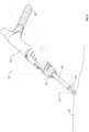
- FIG. 2illustrates an electrosurgical instrument as held by an operator
- FIG. 3illustrates an electrosurgical instrument having a dual zone smoke evacuation assembly
- FIG. 4illustrates a cross-sectional view of the electrosurgical instrument of FIG. 3 , showing an extendable section positioned in a retracted position;
- FIG. 5illustrates a cross-sectional view of the electrosurgical instrument of FIGS. 3 and 4 , showing the extendable section positioned in an extended position;
- FIG. 6illustrates an electrosurgical instrument in use, showing efficient smoke evacuation via a dual zone smoke evacuation assembly of the electrosurgical instrument.
- the present disclosurerelates to electrosurgical instruments and other hand-held instruments having dual zone fluid evacuation functionality.
- the hand-held instrumentis an electrosurgical instrument having a dual zone fluid evacuation assembly configured to efficiently remove smoke generated during an electrosurgical procedure.
- an electrosurgical instrumentincludes a first smoke evacuation component and a second smoke evacuation component, the first smoke evacuation component being disposed at a distal portion of the electrosurgical instrument and the second smoke evacuation component being disposed proximal of the first smoke evacuation component.
- One or more embodimentsbeneficially enable the capture and evacuation of smoke generated during an electrosurgical procedure.
- smoke which is generated near the first smoke evacuation component but which is not captured by the first smoke evacuation componentcan be captured by the second smoke evacuation component.
- electrosurgical instruments having a dual zone smoke evacuation assemblycan enable greater capture of smoke generated in an electrosurgical procedure, reducing the amount of smoke available for reducing visibility, irritating operators and/or assistants, causing odors, and/or limiting the effectiveness of an electrosurgical procedure in other ways.
- references to “smoke”is merely for simplicity and convenience, and is not intended to limit the disclosed and claimed embodiments to evacuation of only smoke. Rather, the disclosed and claimed embodiments may be used to evacuate substantially any type of fluid, including liquids, gases, vapors, smoke, or combinations thereof. Additionally, rather than simply evacuating fluid, it is contemplated that at least some of the embodiments may be used to deliver fluids to a desired location, such as a surgical site.
- FIG. 1illustrates an exemplary electrosurgical system 100 .
- the illustrated embodimentincludes a signal generator 102 , an electrosurgical instrument 104 , and a return electrode 106 .
- Generator 102in one embodiment, is an RF wave generator that produces RF electrical energy.
- Connected to electrosurgical instrument 104is a utility conduit 108 .
- utility conduit 108includes a cable 110 that communicates electrical energy from generator 102 to electrosurgical instrument 104 .
- the illustrated utility conduit 108also includes a vacuum hose 112 that conveys captured/collected smoke and/or fluid away from a surgical site.
- cable 110can extend through at least a portion of vacuum hose 112 .
- electrosurgical instrument 104includes a hand piece or pencil 114 and an electrode tip 116 .
- Electrosurgical instrument 104communicates electrical energy to a target tissue of a patient to cut the tissue and/or cauterize blood vessels within and/or near the target tissue.
- an electrical dischargeis delivered from electrode tip 116 to the patient in order to cause heating of cellular matter of the patient that is in close contact with electrode tip 116 .
- the heatingtakes place at an appropriately high temperature to allow electrosurgical instrument 104 to be used to perform electrosurgery.
- Return electrode 106is connected to generator 102 by a cable 118 in order to complete the circuit and provide a return electrical path to wave generator 102 for energy that passes into the patient's body.
- embodiments of electrosurgical instruments according to the present disclosureenable efficient capture of smoke generated during an electrosurgical procedure, such that smoke that is not immediately captured near the site of smoke generation (e.g., at the tissue/electrode tip interface) can still be captured and evacuated away from the operating environment.
- Electrosurgical instrument 120used to perform electrosurgical procedures and evacuate smoke from a surgical site.
- Electrosurgical instrument 120includes a hand piece 122 having a proximal end 124 and a distal end 126 .
- An extendable section 128is selectively extendable (e.g., translatable along an axis running in the proximal/distal direction) and includes a channel or conduit extending therethrough.
- An electrode tip 130is received within the distal end of the extendable section 128 .
- One or more power cables, one or more vacuum hoses, and/or other connectionscan be directed to the hand piece 122 through the utility conduit 140 , which in the illustrated embodiment, is coupled to the hand piece 122 near the proximal end 124 and on an underside of the hand piece 122 .
- Alternative embodimentscan include utility conduit connections on a top and/or side section of a hand piece, at the proximal end extending proximally, or at other locations of the hand piece.
- the power cablecommunicates electrical energy from an electrosurgical generator to electrosurgical instrument 120 . During an electrosurgical procedure, the electrical energy is passed through electrode tip 130 and into a patient's tissue.
- Electrosurgical instrumentssuch as electrosurgical instrument 120
- electrosurgical pencils or pensare commonly referred to as electrosurgical pencils or pens because in use they are often held in the same manner that a pencil or pen is held when writing.
- FIG. 2illustrates a common manner by which an operator can hold an electrosurgical instrument during an electrosurgical procedure.
- hand piece 122is laid through the crook of the hand and is held in place by the middle finger and thumb.
- the index fingercan be placed on top of hand piece 122 to further hold hand piece 122 in place as well as to control certain actions of the electrosurgical device through selective activation of one or more controls 136 .
- FIG. 3illustrates an embodiment of an electrosurgical instrument 220 configured with dual zone smoke evacuation.
- the illustrated embodimentincludes a hand piece 222 having a proximal end 224 and a distal end 226 .
- An extendable section 228is disposed at least partially within the interior of the hand piece 222 and extends distally out of the hand piece 222 .
- the extendable section 228is configured to receive an electrode tip 230 .
- the extendable section 228is formed from a conductive material and is configured to pass electrical current from a power cable (e.g., a power cable disposed within the illustrated utility conduit 240 ) to the electrode tip 230 .
- a power cablee.g., a power cable disposed within the illustrated utility conduit 240
- the extendable section 228is preferably configured as a conduit (e.g., tube or other shape having a hollow or partially hollow cross-section).
- the conduit of the extendable section 228is configured to pass at least partially into an internal chamber of the hand piece 222 and to be in fluid communication with the utility conduit 240 (and/or with a vacuum hose attached/disposed in the utility conduit 240 ).
- the extendable section 228also includes a distal end opening providing fluid communication between the interior of the extendable section and the atmosphere exterior to the extendable section 228 .
- the electrode tip 230can be coupled to the extendable section 228 (e.g., via adhesive, welding, mechanical fastening, notches, slots, and/or friction fitting, or through integral formation of a single piece) in a manner that leaves one or more aperture spaces for smoke capture into the interior of the extendable section 228 .
- the illustrated embodimentcan also include a front piece 250 having an opening for the extendable section 228 to pass through.
- the front piece 250is formed with a tapered profile that tapers inwardly in the distal direction.
- the front piece 250is formed without a tapered shape (e.g., a squared or straight edge profile), or with a different taper or curved profile.
- the illustrated front piece 250includes one or more supports 252 configured to hold or stabilize the extendable section 228 in position with respect to the front piece 250 (e.g., in the illustrated coaxial position with an interior conduit of the hand piece 222 ).
- the one or more supports 252can be configured to frictionally maintain the position of the extendable section 228 .
- the one or more supports 252can be configured to allow a user to adjust the extendable section 228 when desired, while otherwise maintaining the position of the extendable section 228 during normal operation of the instrument (e.g., securing against movement caused by gravity or other relatively minor forces).
- the illustrated front piece 250includes supports 252 formed as radial extensions. Other embodiments can include one or more legs, braces, helical extrusions, and/or other support structures. As shown, the front piece 250 includes an opening 256 to enable fluid communication between the atmosphere exterior to the hand piece 222 and the interior of the hand piece 222 .
- the embodiment shown in FIG. 3also includes a grip 254 configured to provide a tactile surface for a user to hold and/or control the electrosurgical instrument 220 .
- the grip 254can be formed from a rubber or polymer material, for example, and can include one or more ridges, grooves, and/or other surface features for providing comfort and/or tactile gripping enhancement to a user while holding the instrument.
- the illustrated embodimentalso includes one or more controls 238 enabling a user to adjust one or more parameters of the electrosurgical instrument 220 , such as increasing or decreasing electrical power delivery through the instrument, turning the instrument on and off, adjusting the instrument for different operating modes (cut, coagulate, cut-coagulate blend), etc.
- the controls 238can provide a connection for transmitting control signals from the electrosurgical instrument 220 to an electrosurgical generator and/or other controller.
- FIG. 4illustrates a cross-sectional view of the electrosurgical instrument 220 shown in FIG. 3 .
- FIG. 4illustrates the extendable section 228 in a retracted position, showing that much of the extendable section 228 can be positioned within the interior of the hand piece 222 .
- the illustrated embodimentalso includes an interior conduit 242 disposed within the interior of the hand piece 222 and configured in size and shape to enclose the extendable section 228 (e.g., at least the portions not extending distally beyond the hand piece 222 ) so that the extendable section 228 fits within the interior conduit 242 and is selectively translatable within the interior conduit 242 .
- the interior conduit 242is in fluid communication with the atmosphere exterior to the hand piece 222 via one or more openings 256 at the front piece 250 , enabling the capture of smoke into the interior conduit 242 through the one or more openings 256 .
- the electrosurgical instrument 220includes a back stop 244 positioned to limit proximal translation of the extendable section 228 within the interior conduit 242 .
- the back stop 244can be disposed at a position such that when the extendable section 228 is fully retracted, the electrode tip 230 is at or near the distal portion of the hand piece 222 but is not retracted into the interior of the hand piece 222 .
- the illustrated back stop 244is formed as a crosspiece to prevent proximal movement of the extendable section 228 past the back stop 244 .
- the back stop 244can be formed as a wall, rib, detent, abutment, catch, brace, and/or other means of preventing relative movement.
- the illustrated electrosurgical instrument 220also includes a connector 246 coupled to the extendable section 228 at the proximal end of the extendable section 228 .
- the connector 246has one or more projections extending radially outwardly to the wall of the interior conduit 242 .
- the one or more projectionsfunction as friction fitting components for maintaining the position of the extendable section 228 relative to the interior conduit 242 (e.g., in addition to, or as an alternative to, frictional securement through engagement between the supports 252 and the extendable section 228 ).
- the connector 246can be configured to hold the extendable section 228 in position during normal operation and movement of the electrosurgical instrument 220 (e.g., to hold position against gravity and/or against lighter forces resulting from movement of the hand piece 222 ) while still allowing user adjustment of the extendable section 228 under directed (e.g., hand-applied) force.
- the connector 246is electrically conductive and is configured to pass electrical current to the extendable section 228 .
- the extendable section 228is also electrically conductive and is able to pass electrical current to the electrode tip 230 .
- a power cablecan extend into the interior of the hand piece 222 (e.g., through a utility conduit) to be coupled to the connector 246 and/or extendable section 228 .
- the connector 246 and/or extendable section 228can be formed of a non-conductive material, and a power cable can extend to the electrode tip 230 or to other intermediate components in order to deliver electrical current to the electrode tip 230 .
- the extendable section 228 and/or connector 246may be formed from a conductive material that is at least partially coated with a non-conductive material to prevent the transfer of current from the extendable section 228 to patient tissue during an electrosurgical procedure.
- the extendable section 228can be formed with a length (measured along the proximal-distal axis) to be about the same length (e.g., within 99% of, 95% of, 90% of, 80% of, or 75%) of the hand piece 222 in which it can selectively translate within.
- the extendable section 228may be shorter or longer, such as about 0.75 times or 0.5 times the length of the hand piece 222 , or about 1.25, 1.5, 2, or 2.5 times longer than the length of the hand piece 222 .
- FIG. 5illustrates the electrosurgical instrument 220 with the extendable section 228 in an extended position.
- the embodiment shown in FIG. 5includes a front stop 248 configured to prevent distal movement of the extendable section 228 past the front stop 248 .
- the front stop 248is configured as an annular structure having an inner diameter that is smaller than the inner diameter of the interior conduit 242 .
- the extendable section 228is prevented from passing further distally through the front stop 248 when the connector 246 is brought into contact with the front stop 248 .
- the projections of the connector 246extend to the wall of the interior conduit 242 , they cannot pass through the smaller diameter of the front stop 248 and thereby limit the distal extension of the extendable section 228 .
- movement of the extendable section 228can be limited in other ways.
- the extendable section 228can include a key or keyway matched to a corresponding keyway or key of the hand piece 222 and/or front piece 250 , and a track/rail system can be formed to limit translation of the extendable section 228 to a desired range.
- moving the extendable section 228 to the fully extended positionmay close off or block the one or more openings 256 at the front piece 250 .
- the projections or other components near the proximal end of the extendable section 228 engage the front stop 248may close off or block the one or more openings 256 , thereby preventing capture of smoke through the one or more openings 256 .
- closing off or blocking the one or more openings 256may increase the negative pressure applied through the conduit of the extendable section 228 , thereby increasing the amount of smoke captured through the extendable section 228 . This negative pressure increase through the conduit of extendable section 228 may be particularly helpful when working in a pocket to increase the airflow into the pocket, thus capturing more smoke through the distal end of extendable section 228 .
- FIG. 6illustrates an embodiment of an electrosurgical instrument 320 being used to treat a target tissue 400 during an electrosurgical procedure.
- negative pressureis applied via a vacuum hose, which, in this embodiment is located within a utility conduit 340 .
- the vacuum hoseis in fluid communication with the conduit of the extendable section 328 and the interior conduit (not shown in this view).
- the applied negative pressureenables the extendable section 328 to capture some of the smoke 500 generated in the vicinity of the electrode tip 330 during an electrosurgical procedure.
- the captured smoke 500can pass through the conduit of the extendable section 228 and into utility conduit 340 . In this manner, the extendable section 328 functions as a first smoke evacuation component.
- generated smokeis dispersed away from the distal opening of the extendable section 328 prior to being captured by and evacuated by the extendable section 328 .
- generated smokemay disperse outwardly from the point of generation near the electrode tip 330 at an angle that prevents a portion of the generated smoke from passing close enough to the distal opening of the extendable section 328 to be captured by the extendable section 328 .
- some portions of the generated smokemay not be captured by the distal opening of the extendable section 328 when the electrode tip 330 is angled away from the general direction of smoke travel (e.g., when the electrosurgical instrument 320 is positioned so as to put the electrode tip 330 at a low angle relative to the treated tissue). Further, in some instances drafts or other disturbances in the atmosphere of the operating environment may direct generated smoke away from the distal opening of the extendable portion 328 , preventing capture of at least a portion of the generated smoke.
- movement of the electrode tip 330occurs across the tissue 400 at such a rate that smoke 500 emanating from the treated tissue 400 is not captured prior to movement of the distal opening of the extendable section 328 away from the treated tissue 400 , and a portion of smoke 500 escapes capture.
- the front piece 350 and the interior conduit (not shown in this view) to which it is in fluid communication withfunction as a second smoke evacuation component.
- the second smoke evacuation componentcan beneficially function to capture at least a portion of generated smoke that is not captured by the first smoke evacuation component.
- the distal opening of the front piece 350enables the capture of smoke into the interior conduit of the electrosurgical instrument 320 .
- the interior conduitis in fluid communication with the utility conduit 340 (e.g., with a vacuum hose disposed within the utility conduit 340 ) such that the captured smoke can be evacuated through the utility conduit 340 .
- the first smoke evacuation componente.g., the extendable section 328
- the second smoke evacuation componente.g., the front piece 350 and the interior conduit
- the first smoke evacuation componentis configured to be selectively translatable relative to the body of the hand piece 322
- the second smoke evacuation componente.g., the front piece 350 and the interior conduit
- the first smoke evacuation componentis configured to be selectively translatable relative to the body of the hand piece 322
- the second smoke evacuation componente.g., the front piece 350 and the interior conduit
- the relative position of the first smoke evacuation component with respect to the body of the hand piece 322is readjusted, while the relative position of the second smoke evacuation component with respect to the body of the hand piece 322 is maintained.
- the first smoke evacuation componentis configured to be stationary relative to the electrode tip 330 while the second smoke evacuation component is configured to be selectively translatable relative to the electrode tip 330 .
- the extendable section 328is translated (extended or retracted)
- the relative position of the first smoke evacuation component with respect to the electrode tip 330is maintained, while the relative position of the second smoke evacuation component with respect to the electrode tip 330 is readjusted.
- the second smoke evacuation componentis positioned proximal to the first smoke evacuation component, enabling the capture of smoke which passes proximally beyond the first smoke evacuation component without capture.
- the second smoke evacuation componentis configured with a capture diameter that is larger than a capture diameter of the first smoke evacuation component (e.g., the diameter of the distal opening of the front piece 350 is larger than the diameter of the distal opening of the extendable section 328 ), enabling the capture of smoke which passes outwardly beyond the first smoke evacuation component without capture.
- the ratio of the diameter of the distal opening of the front piece 350 to the diameter of the distal opening of the extendable section 328is about 10:1 to about 1.1:1, or about 3:1 to about 2:1.
- first and second smoke evacuation componentshaving conduits formed with a circular cross-section shape.
- Alternative embodimentsinclude first and/or second smoke evacuation components having different sizes and/or shapes.
- the first and/or second smoke evacuation componentsmay have conduits with a rectangular, square, ovoid, polygonal, or other shaped cross-section.
- Embodiments described hereincan provide a number of benefits. For example, during an electrosurgical procedure, a portion of the generated smoke can be captured by the first smoke evacuation component (e.g., to be channeled through the conduit of an extendable section). At least a portion of the smoke not captured by the first smoke evacuation component, such as smoke that is dispersed proximally and/or outwardly at too great an angle to be directed into the first smoke evacuation component, can then be captured by the second smoke evacuation component.
- the first smoke evacuation componente.g., to be channeled through the conduit of an extendable section.
- At least a portion of the smoke not captured by the first smoke evacuation componentsuch as smoke that is dispersed proximally and/or outwardly at too great an angle to be directed into the first smoke evacuation component, can then be captured by the second smoke evacuation component.
- first and second smoke evacuations componentsare beneficially configured such that for a given reference point, one smoke evacuation component maintains a stationary positional relationship to the reference point while the other smoke evacuation component provides a dynamically adjustable positional relationship.
- the first smoke evacuation componentmaintains a positional relationship with the electrode tip 330 while the second smoke evacuation component provides an adjustable positional relationship with the electrode tip 330 . This can enable greater smoke capture and evacuation.
- such a configurationallows the second smoke evacuation component to be oriented (e.g., by extending or retracting the extendable portion 328 and/or by angling the hand piece 322 ) relative to the electrode tip 330 to a position that increases or maximizes capture of dispersed smoke, while at the same time maintaining the first smoke evacuation component near the electrode tip 330 in order to more immediately capture a portion of the generated smoke.
- the illustrated embodimentenables an operator to dynamically adjust the electrosurgical instrument 320 during an electrosurgical procedure to increase the capture and evacuation of generated smoke. For example, an operator may notice that a portion of the generated smoke is being directed away from the treated tissue in a given direction before the first smoke evacuation component can capture it. The operator may reorient the hand piece 322 toward the direction the portion of smoke is traveling so as to increase the amount of that smoke captured by the second smoke evacuation device (e.g., enough to bring the smoke under the influence of the negative pressure zone near the distal opening of the front piece 350 ).
- the operatormay extend or retract the extendable section 328 in order to adjust the positional relationship between the electrode tip 330 and the second smoke evacuation component. For example, the operator may notice that a portion of the generated smoke not captured by the first smoke evacuation component is dispersing in such a way that capture could be increased by retracing or extending the extendable section 328 in order to bring the second smoke evacuation component closer to or farther from the electrode tip 330 .
- one or more embodiments described hereincan beneficially reduce or eliminate the amount of generated smoke passing to the operating environment without capture, thereby reducing the visibility reduction, odor, and other problems associated with smoke generation. In some instances this can enable electrosurgical procedures that generate greater amounts of smoke to be performed or to be performed with less ancillary equipment (e.g., less additional independent vacuum hoses, fans, and other air management equipment).
- ancillary equipmente.g., less additional independent vacuum hoses, fans, and other air management equipment.
- One or more embodiments described hereincan also enable an electrosurgical instrument to have an extendable section with a smaller diameter.
- the size and shape of the extendable sectionneed not be limited by its smoke evacuation ability.
- the present disclosureis not intended to be so limited. Rather, the present disclosure is broadly directed to any hand-held instrument that includes fluid (e.g., liquids, gases, vapors, smoke, or combinations thereof) evacuation or delivery features as described herein.
- fluide.g., liquids, gases, vapors, smoke, or combinations thereof
- such hand-held instrumentsmay include dental instruments (e.g., drills, polishing tools, scalers, compressed air tools, suction tools, irrigation tools, carries detection tools, water flossing tool (e.g., waterpik)), soldering tools (e.g., heated tools, smoke collection tools, de-soldering tools), high speed grinding and polishing tools (e.g., Dremel tools, carving tools, manicure tools, dental lab grinders/polishers), laser treatment instruments, laser surgical instruments, light probes, suction handles (e.g., Yankauer), blasting tools (e.g., sandblast, gritblast), shockwave therapy tools, ultrasonic therapy tools, ultrasonic probe tools, ultrasonic surgical tools, adhesive application instruments, glue guns, pneumatic pipettes, welding tools, RF wrinkle therapy hand pieces, phaco hand pieces, shears, shaver, or razor hand pieces, micro drill hand pieces, vacuum hand pieces, small parts handling hand pieces, tattoo needle handles, small torch hand pieces, micro drill hand pieces, vacuum
Landscapes
- Health & Medical Sciences (AREA)
- Life Sciences & Earth Sciences (AREA)
- Engineering & Computer Science (AREA)
- Surgery (AREA)
- Heart & Thoracic Surgery (AREA)
- Public Health (AREA)
- Biomedical Technology (AREA)
- Animal Behavior & Ethology (AREA)
- General Health & Medical Sciences (AREA)
- Veterinary Medicine (AREA)
- Medical Informatics (AREA)
- Molecular Biology (AREA)
- Physics & Mathematics (AREA)
- Plasma & Fusion (AREA)
- Nuclear Medicine, Radiotherapy & Molecular Imaging (AREA)
- Otolaryngology (AREA)
- Neurology (AREA)
- Neurosurgery (AREA)
- Anesthesiology (AREA)
- Vascular Medicine (AREA)
- Hematology (AREA)
- Surgical Instruments (AREA)
Abstract
Description
Claims (31)
Priority Applications (11)
| Application Number | Priority Date | Filing Date | Title |
|---|---|---|---|
| US15/599,273US11617611B2 (en) | 2016-06-17 | 2017-05-18 | Hand-held instrument with dual zone fluid removal |
| TW106119930ATW201803528A (en) | 2016-06-17 | 2017-06-15 | Hand-held instrument with dual zone fluid removal |
| KR1020187036352AKR20190021235A (en) | 2016-06-17 | 2017-06-19 | A handheld device having an extendible component and having a negative pressure source |
| BR112018076129ABR112018076129A2 (en) | 2016-06-17 | 2017-06-19 | portable dual zone fluid removal instrument |
| EP17733329.1AEP3471641A1 (en) | 2016-06-17 | 2017-06-19 | Hand-held instrument with an extendable part and with a negative pressure source |
| MX2018015525AMX2018015525A (en) | 2016-06-17 | 2017-06-19 | Hand-held instrument with an extendable part and with a negative pressure source. |
| CA3027724ACA3027724A1 (en) | 2016-06-17 | 2017-06-19 | Hand-held instrument with dual zone fluid removal |
| AU2017286808AAU2017286808A1 (en) | 2016-06-17 | 2017-06-19 | Hand-held instrument with dual zone fluid removal |
| PCT/US2017/038090WO2017219014A1 (en) | 2016-06-17 | 2017-06-19 | Hand-held instrument with an extendable part and with a negative pressure source |
| JP2018565875AJP7118899B2 (en) | 2016-06-17 | 2017-06-19 | Handheld instrument with dual zone fluid removal |
| CN201780037728.3ACN109328040B (en) | 2016-06-17 | 2017-06-19 | Hand-held instrument with expandable portion and negative pressure source |
Applications Claiming Priority (2)
| Application Number | Priority Date | Filing Date | Title |
|---|---|---|---|
| US201662351811P | 2016-06-17 | 2016-06-17 | |
| US15/599,273US11617611B2 (en) | 2016-06-17 | 2017-05-18 | Hand-held instrument with dual zone fluid removal |
Publications (2)
| Publication Number | Publication Date |
|---|---|
| US20170360499A1 US20170360499A1 (en) | 2017-12-21 |
| US11617611B2true US11617611B2 (en) | 2023-04-04 |
Family
ID=60661487
Family Applications (1)
| Application Number | Title | Priority Date | Filing Date |
|---|---|---|---|
| US15/599,273Active2038-05-03US11617611B2 (en) | 2016-06-17 | 2017-05-18 | Hand-held instrument with dual zone fluid removal |
Country Status (11)
| Country | Link |
|---|---|
| US (1) | US11617611B2 (en) |
| EP (1) | EP3471641A1 (en) |
| JP (1) | JP7118899B2 (en) |
| KR (1) | KR20190021235A (en) |
| CN (1) | CN109328040B (en) |
| AU (1) | AU2017286808A1 (en) |
| BR (1) | BR112018076129A2 (en) |
| CA (1) | CA3027724A1 (en) |
| MX (1) | MX2018015525A (en) |
| TW (1) | TW201803528A (en) |
| WO (1) | WO2017219014A1 (en) |
Families Citing this family (141)
| Publication number | Priority date | Publication date | Assignee | Title |
|---|---|---|---|---|
| US11871901B2 (en) | 2012-05-20 | 2024-01-16 | Cilag Gmbh International | Method for situational awareness for surgical network or surgical network connected device capable of adjusting function based on a sensed situation or usage |
| US11504192B2 (en) | 2014-10-30 | 2022-11-22 | Cilag Gmbh International | Method of hub communication with surgical instrument systems |
| USD803396S1 (en)* | 2015-12-10 | 2017-11-21 | Ethicon Llc | Handle for an endoscopic surgical instrument |
| USD865964S1 (en) | 2017-01-05 | 2019-11-05 | Ethicon Llc | Handle for electrosurgical instrument |
| US11564756B2 (en) | 2017-10-30 | 2023-01-31 | Cilag Gmbh International | Method of hub communication with surgical instrument systems |
| US11026687B2 (en) | 2017-10-30 | 2021-06-08 | Cilag Gmbh International | Clip applier comprising clip advancing systems |
| US11291510B2 (en) | 2017-10-30 | 2022-04-05 | Cilag Gmbh International | Method of hub communication with surgical instrument systems |
| US11229436B2 (en) | 2017-10-30 | 2022-01-25 | Cilag Gmbh International | Surgical system comprising a surgical tool and a surgical hub |
| US11510741B2 (en) | 2017-10-30 | 2022-11-29 | Cilag Gmbh International | Method for producing a surgical instrument comprising a smart electrical system |
| US11317919B2 (en) | 2017-10-30 | 2022-05-03 | Cilag Gmbh International | Clip applier comprising a clip crimping system |
| US11801098B2 (en) | 2017-10-30 | 2023-10-31 | Cilag Gmbh International | Method of hub communication with surgical instrument systems |
| US11925373B2 (en) | 2017-10-30 | 2024-03-12 | Cilag Gmbh International | Surgical suturing instrument comprising a non-circular needle |
| US11311342B2 (en) | 2017-10-30 | 2022-04-26 | Cilag Gmbh International | Method for communicating with surgical instrument systems |
| US11911045B2 (en) | 2017-10-30 | 2024-02-27 | Cllag GmbH International | Method for operating a powered articulating multi-clip applier |
| US11419630B2 (en) | 2017-12-28 | 2022-08-23 | Cilag Gmbh International | Surgical system distributed processing |
| US11998193B2 (en) | 2017-12-28 | 2024-06-04 | Cilag Gmbh International | Method for usage of the shroud as an aspect of sensing or controlling a powered surgical device, and a control algorithm to adjust its default operation |
| US11304763B2 (en) | 2017-12-28 | 2022-04-19 | Cilag Gmbh International | Image capturing of the areas outside the abdomen to improve placement and control of a surgical device in use |
| US11633237B2 (en) | 2017-12-28 | 2023-04-25 | Cilag Gmbh International | Usage and technique analysis of surgeon / staff performance against a baseline to optimize device utilization and performance for both current and future procedures |
| US10918310B2 (en) | 2018-01-03 | 2021-02-16 | Biosense Webster (Israel) Ltd. | Fast anatomical mapping (FAM) using volume filling |
| US20190201112A1 (en) | 2017-12-28 | 2019-07-04 | Ethicon Llc | Computer implemented interactive surgical systems |
| US11744604B2 (en) | 2017-12-28 | 2023-09-05 | Cilag Gmbh International | Surgical instrument with a hardware-only control circuit |
| US11786245B2 (en) | 2017-12-28 | 2023-10-17 | Cilag Gmbh International | Surgical systems with prioritized data transmission capabilities |
| US11389164B2 (en) | 2017-12-28 | 2022-07-19 | Cilag Gmbh International | Method of using reinforced flexible circuits with multiple sensors to optimize performance of radio frequency devices |
| US11559308B2 (en) | 2017-12-28 | 2023-01-24 | Cilag Gmbh International | Method for smart energy device infrastructure |
| US11026751B2 (en) | 2017-12-28 | 2021-06-08 | Cilag Gmbh International | Display of alignment of staple cartridge to prior linear staple line |
| US20190201142A1 (en) | 2017-12-28 | 2019-07-04 | Ethicon Llc | Automatic tool adjustments for robot-assisted surgical platforms |
| US11013563B2 (en) | 2017-12-28 | 2021-05-25 | Ethicon Llc | Drive arrangements for robot-assisted surgical platforms |
| US11308075B2 (en) | 2017-12-28 | 2022-04-19 | Cilag Gmbh International | Surgical network, instrument, and cloud responses based on validation of received dataset and authentication of its source and integrity |
| US11069012B2 (en) | 2017-12-28 | 2021-07-20 | Cilag Gmbh International | Interactive surgical systems with condition handling of devices and data capabilities |
| US10892995B2 (en) | 2017-12-28 | 2021-01-12 | Ethicon Llc | Surgical network determination of prioritization of communication, interaction, or processing based on system or device needs |
| US11304745B2 (en) | 2017-12-28 | 2022-04-19 | Cilag Gmbh International | Surgical evacuation sensing and display |
| US11304699B2 (en) | 2017-12-28 | 2022-04-19 | Cilag Gmbh International | Method for adaptive control schemes for surgical network control and interaction |
| US11324557B2 (en) | 2017-12-28 | 2022-05-10 | Cilag Gmbh International | Surgical instrument with a sensing array |
| US11179175B2 (en) | 2017-12-28 | 2021-11-23 | Cilag Gmbh International | Controlling an ultrasonic surgical instrument according to tissue location |
| WO2019133144A1 (en) | 2017-12-28 | 2019-07-04 | Ethicon Llc | Detection and escalation of security responses of surgical instruments to increasing severity threats |
| US11696760B2 (en) | 2017-12-28 | 2023-07-11 | Cilag Gmbh International | Safety systems for smart powered surgical stapling |
| US11464535B2 (en) | 2017-12-28 | 2022-10-11 | Cilag Gmbh International | Detection of end effector emersion in liquid |
| US10943454B2 (en) | 2017-12-28 | 2021-03-09 | Ethicon Llc | Detection and escalation of security responses of surgical instruments to increasing severity threats |
| US11234756B2 (en) | 2017-12-28 | 2022-02-01 | Cilag Gmbh International | Powered surgical tool with predefined adjustable control algorithm for controlling end effector parameter |
| US11202570B2 (en) | 2017-12-28 | 2021-12-21 | Cilag Gmbh International | Communication hub and storage device for storing parameters and status of a surgical device to be shared with cloud based analytics systems |
| US11056244B2 (en) | 2017-12-28 | 2021-07-06 | Cilag Gmbh International | Automated data scaling, alignment, and organizing based on predefined parameters within surgical networks |
| US11076921B2 (en) | 2017-12-28 | 2021-08-03 | Cilag Gmbh International | Adaptive control program updates for surgical hubs |
| US10966791B2 (en) | 2017-12-28 | 2021-04-06 | Ethicon Llc | Cloud-based medical analytics for medical facility segmented individualization of instrument function |
| US11659023B2 (en) | 2017-12-28 | 2023-05-23 | Cilag Gmbh International | Method of hub communication |
| US11284936B2 (en) | 2017-12-28 | 2022-03-29 | Cilag Gmbh International | Surgical instrument having a flexible electrode |
| US11571234B2 (en) | 2017-12-28 | 2023-02-07 | Cilag Gmbh International | Temperature control of ultrasonic end effector and control system therefor |
| US11291495B2 (en) | 2017-12-28 | 2022-04-05 | Cilag Gmbh International | Interruption of energy due to inadvertent capacitive coupling |
| US11786251B2 (en) | 2017-12-28 | 2023-10-17 | Cilag Gmbh International | Method for adaptive control schemes for surgical network control and interaction |
| US10944728B2 (en) | 2017-12-28 | 2021-03-09 | Ethicon Llc | Interactive surgical systems with encrypted communication capabilities |
| US11051876B2 (en) | 2017-12-28 | 2021-07-06 | Cilag Gmbh International | Surgical evacuation flow paths |
| US11464559B2 (en) | 2017-12-28 | 2022-10-11 | Cilag Gmbh International | Estimating state of ultrasonic end effector and control system therefor |
| US20190206569A1 (en) | 2017-12-28 | 2019-07-04 | Ethicon Llc | Method of cloud based data analytics for use with the hub |
| US11903601B2 (en) | 2017-12-28 | 2024-02-20 | Cilag Gmbh International | Surgical instrument comprising a plurality of drive systems |
| US11529187B2 (en) | 2017-12-28 | 2022-12-20 | Cilag Gmbh International | Surgical evacuation sensor arrangements |
| US11602393B2 (en) | 2017-12-28 | 2023-03-14 | Cilag Gmbh International | Surgical evacuation sensing and generator control |
| US11166772B2 (en) | 2017-12-28 | 2021-11-09 | Cilag Gmbh International | Surgical hub coordination of control and communication of operating room devices |
| US11832899B2 (en) | 2017-12-28 | 2023-12-05 | Cilag Gmbh International | Surgical systems with autonomously adjustable control programs |
| US11364075B2 (en) | 2017-12-28 | 2022-06-21 | Cilag Gmbh International | Radio frequency energy device for delivering combined electrical signals |
| US11540855B2 (en) | 2017-12-28 | 2023-01-03 | Cilag Gmbh International | Controlling activation of an ultrasonic surgical instrument according to the presence of tissue |
| US12396806B2 (en) | 2017-12-28 | 2025-08-26 | Cilag Gmbh International | Adjustment of a surgical device function based on situational awareness |
| US20190201039A1 (en) | 2017-12-28 | 2019-07-04 | Ethicon Llc | Situational awareness of electrosurgical systems |
| US11832840B2 (en) | 2017-12-28 | 2023-12-05 | Cilag Gmbh International | Surgical instrument having a flexible circuit |
| US11666331B2 (en) | 2017-12-28 | 2023-06-06 | Cilag Gmbh International | Systems for detecting proximity of surgical end effector to cancerous tissue |
| US11317937B2 (en) | 2018-03-08 | 2022-05-03 | Cilag Gmbh International | Determining the state of an ultrasonic end effector |
| US12376855B2 (en) | 2017-12-28 | 2025-08-05 | Cilag Gmbh International | Safety systems for smart powered surgical stapling |
| US11857152B2 (en) | 2017-12-28 | 2024-01-02 | Cilag Gmbh International | Surgical hub spatial awareness to determine devices in operating theater |
| US11896322B2 (en) | 2017-12-28 | 2024-02-13 | Cilag Gmbh International | Sensing the patient position and contact utilizing the mono-polar return pad electrode to provide situational awareness to the hub |
| US11419667B2 (en) | 2017-12-28 | 2022-08-23 | Cilag Gmbh International | Ultrasonic energy device which varies pressure applied by clamp arm to provide threshold control pressure at a cut progression location |
| US11132462B2 (en) | 2017-12-28 | 2021-09-28 | Cilag Gmbh International | Data stripping method to interrogate patient records and create anonymized record |
| US12062442B2 (en) | 2017-12-28 | 2024-08-13 | Cilag Gmbh International | Method for operating surgical instrument systems |
| US12127729B2 (en) | 2017-12-28 | 2024-10-29 | Cilag Gmbh International | Method for smoke evacuation for surgical hub |
| US11266468B2 (en) | 2017-12-28 | 2022-03-08 | Cilag Gmbh International | Cooperative utilization of data derived from secondary sources by intelligent surgical hubs |
| US11410259B2 (en) | 2017-12-28 | 2022-08-09 | Cilag Gmbh International | Adaptive control program updates for surgical devices |
| US12096916B2 (en) | 2017-12-28 | 2024-09-24 | Cilag Gmbh International | Method of sensing particulate from smoke evacuated from a patient, adjusting the pump speed based on the sensed information, and communicating the functional parameters of the system to the hub |
| US11424027B2 (en) | 2017-12-28 | 2022-08-23 | Cilag Gmbh International | Method for operating surgical instrument systems |
| US10987178B2 (en) | 2017-12-28 | 2021-04-27 | Ethicon Llc | Surgical hub control arrangements |
| US20190201090A1 (en) | 2017-12-28 | 2019-07-04 | Ethicon Llc | Capacitive coupled return path pad with separable array elements |
| US11937769B2 (en) | 2017-12-28 | 2024-03-26 | Cilag Gmbh International | Method of hub communication, processing, storage and display |
| US11273001B2 (en) | 2017-12-28 | 2022-03-15 | Cilag Gmbh International | Surgical hub and modular device response adjustment based on situational awareness |
| US11179208B2 (en) | 2017-12-28 | 2021-11-23 | Cilag Gmbh International | Cloud-based medical analytics for security and authentication trends and reactive measures |
| US11969216B2 (en) | 2017-12-28 | 2024-04-30 | Cilag Gmbh International | Surgical network recommendations from real time analysis of procedure variables against a baseline highlighting differences from the optimal solution |
| US11818052B2 (en) | 2017-12-28 | 2023-11-14 | Cilag Gmbh International | Surgical network determination of prioritization of communication, interaction, or processing based on system or device needs |
| US11160605B2 (en) | 2017-12-28 | 2021-11-02 | Cilag Gmbh International | Surgical evacuation sensing and motor control |
| US11559307B2 (en) | 2017-12-28 | 2023-01-24 | Cilag Gmbh International | Method of robotic hub communication, detection, and control |
| US11253315B2 (en) | 2017-12-28 | 2022-02-22 | Cilag Gmbh International | Increasing radio frequency to create pad-less monopolar loop |
| US11147607B2 (en) | 2017-12-28 | 2021-10-19 | Cilag Gmbh International | Bipolar combination device that automatically adjusts pressure based on energy modality |
| US10932872B2 (en) | 2017-12-28 | 2021-03-02 | Ethicon Llc | Cloud-based medical analytics for linking of local usage trends with the resource acquisition behaviors of larger data set |
| US11864728B2 (en) | 2017-12-28 | 2024-01-09 | Cilag Gmbh International | Characterization of tissue irregularities through the use of mono-chromatic light refractivity |
| US11576677B2 (en) | 2017-12-28 | 2023-02-14 | Cilag Gmbh International | Method of hub communication, processing, display, and cloud analytics |
| US11096693B2 (en) | 2017-12-28 | 2021-08-24 | Cilag Gmbh International | Adjustment of staple height of at least one row of staples based on the sensed tissue thickness or force in closing |
| US11100631B2 (en) | 2017-12-28 | 2021-08-24 | Cilag Gmbh International | Use of laser light and red-green-blue coloration to determine properties of back scattered light |
| US11896443B2 (en) | 2017-12-28 | 2024-02-13 | Cilag Gmbh International | Control of a surgical system through a surgical barrier |
| US11423007B2 (en) | 2017-12-28 | 2022-08-23 | Cilag Gmbh International | Adjustment of device control programs based on stratified contextual data in addition to the data |
| US11589888B2 (en) | 2017-12-28 | 2023-02-28 | Cilag Gmbh International | Method for controlling smart energy devices |
| US10758310B2 (en) | 2017-12-28 | 2020-09-01 | Ethicon Llc | Wireless pairing of a surgical device with another device within a sterile surgical field based on the usage and situational awareness of devices |
| US11678881B2 (en) | 2017-12-28 | 2023-06-20 | Cilag Gmbh International | Spatial awareness of surgical hubs in operating rooms |
| US11376002B2 (en) | 2017-12-28 | 2022-07-05 | Cilag Gmbh International | Surgical instrument cartridge sensor assemblies |
| US11311306B2 (en) | 2017-12-28 | 2022-04-26 | Cilag Gmbh International | Surgical systems for detecting end effector tissue distribution irregularities |
| US11278281B2 (en) | 2017-12-28 | 2022-03-22 | Cilag Gmbh International | Interactive surgical system |
| US11432885B2 (en) | 2017-12-28 | 2022-09-06 | Cilag Gmbh International | Sensing arrangements for robot-assisted surgical platforms |
| US11612444B2 (en) | 2017-12-28 | 2023-03-28 | Cilag Gmbh International | Adjustment of a surgical device function based on situational awareness |
| US11969142B2 (en) | 2017-12-28 | 2024-04-30 | Cilag Gmbh International | Method of compressing tissue within a stapling device and simultaneously displaying the location of the tissue within the jaws |
| US10898622B2 (en) | 2017-12-28 | 2021-01-26 | Ethicon Llc | Surgical evacuation system with a communication circuit for communication between a filter and a smoke evacuation device |
| US11109866B2 (en) | 2017-12-28 | 2021-09-07 | Cilag Gmbh International | Method for circular stapler control algorithm adjustment based on situational awareness |
| US11446052B2 (en) | 2017-12-28 | 2022-09-20 | Cilag Gmbh International | Variation of radio frequency and ultrasonic power level in cooperation with varying clamp arm pressure to achieve predefined heat flux or power applied to tissue |
| US11257589B2 (en) | 2017-12-28 | 2022-02-22 | Cilag Gmbh International | Real-time analysis of comprehensive cost of all instrumentation used in surgery utilizing data fluidity to track instruments through stocking and in-house processes |
| US11304720B2 (en) | 2017-12-28 | 2022-04-19 | Cilag Gmbh International | Activation of energy devices |
| US11534196B2 (en) | 2018-03-08 | 2022-12-27 | Cilag Gmbh International | Using spectroscopy to determine device use state in combo instrument |
| US12303159B2 (en) | 2018-03-08 | 2025-05-20 | Cilag Gmbh International | Methods for estimating and controlling state of ultrasonic end effector |
| US11259830B2 (en) | 2018-03-08 | 2022-03-01 | Cilag Gmbh International | Methods for controlling temperature in ultrasonic device |
| US11986233B2 (en) | 2018-03-08 | 2024-05-21 | Cilag Gmbh International | Adjustment of complex impedance to compensate for lost power in an articulating ultrasonic device |
| US11219453B2 (en) | 2018-03-28 | 2022-01-11 | Cilag Gmbh International | Surgical stapling devices with cartridge compatible closure and firing lockout arrangements |
| US11207067B2 (en) | 2018-03-28 | 2021-12-28 | Cilag Gmbh International | Surgical stapling device with separate rotary driven closure and firing systems and firing member that engages both jaws while firing |
| US11471156B2 (en) | 2018-03-28 | 2022-10-18 | Cilag Gmbh International | Surgical stapling devices with improved rotary driven closure systems |
| US11090047B2 (en) | 2018-03-28 | 2021-08-17 | Cilag Gmbh International | Surgical instrument comprising an adaptive control system |
| US11278280B2 (en) | 2018-03-28 | 2022-03-22 | Cilag Gmbh International | Surgical instrument comprising a jaw closure lockout |
| US10973520B2 (en) | 2018-03-28 | 2021-04-13 | Ethicon Llc | Surgical staple cartridge with firing member driven camming assembly that has an onboard tissue cutting feature |
| US11589865B2 (en) | 2018-03-28 | 2023-02-28 | Cilag Gmbh International | Methods for controlling a powered surgical stapler that has separate rotary closure and firing systems |
| US11213294B2 (en) | 2018-03-28 | 2022-01-04 | Cilag Gmbh International | Surgical instrument comprising co-operating lockout features |
| US11096688B2 (en) | 2018-03-28 | 2021-08-24 | Cilag Gmbh International | Rotary driven firing members with different anvil and channel engagement features |
| USD895112S1 (en) | 2018-11-15 | 2020-09-01 | Ethicon Llc | Laparoscopic bipolar electrosurgical device |
| KR102254266B1 (en)* | 2019-02-11 | 2021-05-21 | 강호상 | Electrosurgical pencil |
| US11464511B2 (en) | 2019-02-19 | 2022-10-11 | Cilag Gmbh International | Surgical staple cartridges with movable authentication key arrangements |
| US11317915B2 (en) | 2019-02-19 | 2022-05-03 | Cilag Gmbh International | Universal cartridge based key feature that unlocks multiple lockout arrangements in different surgical staplers |
| US11369377B2 (en) | 2019-02-19 | 2022-06-28 | Cilag Gmbh International | Surgical stapling assembly with cartridge based retainer configured to unlock a firing lockout |
| US11357503B2 (en) | 2019-02-19 | 2022-06-14 | Cilag Gmbh International | Staple cartridge retainers with frangible retention features and methods of using same |
| US11331100B2 (en) | 2019-02-19 | 2022-05-17 | Cilag Gmbh International | Staple cartridge retainer system with authentication keys |
| USD952144S1 (en) | 2019-06-25 | 2022-05-17 | Cilag Gmbh International | Surgical staple cartridge retainer with firing system authentication key |
| USD964564S1 (en) | 2019-06-25 | 2022-09-20 | Cilag Gmbh International | Surgical staple cartridge retainer with a closure system authentication key |
| USD950728S1 (en) | 2019-06-25 | 2022-05-03 | Cilag Gmbh International | Surgical staple cartridge |
| US11364076B2 (en) | 2019-12-12 | 2022-06-21 | Covidien Lp | Monopolar return pad |
| US20210251732A1 (en)* | 2020-02-14 | 2021-08-19 | Parkell, Inc. | Handpieces for medical and dental devices |
| US20230200885A1 (en)* | 2020-06-15 | 2023-06-29 | Covidien Lp | Electrosurgical pencil with blowing and suction |
| USD1032839S1 (en) | 2021-02-16 | 2024-06-25 | Parkell, Inc. | Dental scaler handpiece |
| USD1014757S1 (en) | 2021-02-16 | 2024-02-13 | Parkell, Inc. | Dental scaler handpiece |
| USD1033634S1 (en) | 2021-02-16 | 2024-07-02 | Parkell, Inc. | Dental air polisher |
| KR102595178B1 (en)* | 2021-05-21 | 2023-10-26 | 최인상 | Cable assembly for electrosurgical handpiece |
| TWI788915B (en)* | 2021-07-14 | 2023-01-01 | 國立成功大學 | Razor tool for shaving subcutaneous tissue |
| KR102595076B1 (en)* | 2021-09-27 | 2023-10-27 | 주식회사 프라즈마태우 | Handle of Plasma Torch |
| US20240180609A1 (en)* | 2022-10-20 | 2024-06-06 | Covidien Lp | Electrosurgical pencil with smoke evacuation and electrode visualization |
| CN115590615A (en)* | 2022-10-25 | 2023-01-13 | 南华大学附属第一医院(Cn) | Laser Fiber Manipulator |
Citations (26)
| Publication number | Priority date | Publication date | Assignee | Title |
|---|---|---|---|---|
| US4719914A (en)* | 1986-12-24 | 1988-01-19 | Johnson Gerald W | Electrosurgical instrument |
| US4850352A (en)* | 1986-12-24 | 1989-07-25 | Johnson Gerald W | Laser-surgical instrument with evacuation tip |
| US5234428A (en)* | 1991-06-11 | 1993-08-10 | Kaufman David I | Disposable electrocautery/cutting instrument with integral continuous smoke evacuation |
| US5265840A (en)* | 1992-10-09 | 1993-11-30 | Symbiosis Corporation | Pinch valve |
| US6099525A (en)* | 1996-10-07 | 2000-08-08 | Cosmescu; Ioan | Removable shroud for receiving a pencil used in electro-surgery |
| US6146353A (en)* | 1998-09-22 | 2000-11-14 | Sherwood Services Ag | Smoke extraction device |
| US20020103485A1 (en)* | 2000-12-05 | 2002-08-01 | Ivan Melnyk | Electrosurgical pencil with a smoke evacuating blade |
| US6458125B1 (en)* | 1995-07-10 | 2002-10-01 | I. C. Medical, Inc. | Electro-surgical unit pencil apparatus and method therefor |
| US20040034339A1 (en)* | 2002-08-16 | 2004-02-19 | The Regents Of The University Of California | Device for improved visualization of operative sites during surgery |
| US20070129722A1 (en)* | 2005-12-02 | 2007-06-07 | Ioan Cosmescu | Swivel device for improved surgical smoke evacuation |
| US20090018539A1 (en)* | 2005-12-02 | 2009-01-15 | Ioan Cosmescu | Swivel Device for Electrosurgery Pencil and Surgical Smoke Evacuation |
| US20090062791A1 (en)* | 2007-08-30 | 2009-03-05 | Lee Alan R | Integrated smoke evacuation electrosurgical pencil and method |
| US7500974B2 (en)* | 2005-06-28 | 2009-03-10 | Covidien Ag | Electrode with rotatably deployable sheath |
| US20100160911A1 (en) | 2008-12-22 | 2010-06-24 | Wilson-Cook Medical, Inc. | Electrosurgical rotating cutting device |
| US20120203165A1 (en)* | 2011-02-04 | 2012-08-09 | Nathan Andrew Terry | Apparatus and method for electrosurgical suction |
| US20120283728A1 (en)* | 2011-05-02 | 2012-11-08 | Ioan Cosmescu | Electrosurgical unit pencil apparatus and shroud having directed illumination |
| US20140257273A1 (en)* | 2013-03-06 | 2014-09-11 | I.C. Medical, Inc. | Argon beam assisted electrosurgery pencil with smoke evacuation |
| US20140276763A1 (en)* | 2013-03-14 | 2014-09-18 | Megadyne Medical Products, Inc. | Electrosurgical instrument |
| US20150005761A1 (en)* | 2012-08-10 | 2015-01-01 | William J. Zinnanti | Electrosurgery probes with smoke and liquid evacuation |
| US20150112323A1 (en)* | 2013-10-18 | 2015-04-23 | Erbe Elektromedizin Gmbh | Adapter element, hf surgical instrument, adapter attachment and system |
| US20150209100A1 (en)* | 2012-08-28 | 2015-07-30 | Instruventional Inc. | Adjustable electrosurgical pencil with slidable vent tube |
| US9101363B2 (en)* | 2012-08-10 | 2015-08-11 | William J. Zinnanti | Cautery electrode with multi-channel insulated shaft |
| US20150335376A1 (en)* | 2014-05-21 | 2015-11-26 | Covidien Lp | Multipurpose electrosurgical instrument with telescoping aspiration cannula |
| US20160206361A1 (en)* | 2015-01-21 | 2016-07-21 | Covidien Lp | Monopolar electrode with suction ability for cabg surgery |
| US20180028255A1 (en)* | 2016-08-01 | 2018-02-01 | Buffalo Filter Llc | Electrosurgical device with vacuum port having multiple swivel connections |
| US10405917B2 (en)* | 2010-02-04 | 2019-09-10 | Buffalo Filter, Llc | Electrosurgical device with vacuum port |
Family Cites Families (4)
| Publication number | Priority date | Publication date | Assignee | Title |
|---|---|---|---|---|
| US4936842A (en) | 1987-05-08 | 1990-06-26 | Circon Corporation | Electrosurgical probe apparatus |
| DE4439553C1 (en)* | 1994-11-05 | 1996-04-04 | Sutter Hermann Select Med Tech | Bipolar coagulation instrument with two electrodes separated by insulating material |
| US6293945B1 (en)* | 2000-03-06 | 2001-09-25 | Everest Medical Corporation | Electrosurgical instrument with suction capability |
| US8932292B2 (en)* | 2011-02-04 | 2015-01-13 | Integrated Surgical LLC | Apparatus and method for electrosurgical suction |
- 2017
- 2017-05-18USUS15/599,273patent/US11617611B2/enactiveActive
- 2017-06-15TWTW106119930Apatent/TW201803528A/enunknown
- 2017-06-19MXMX2018015525Apatent/MX2018015525A/enunknown
- 2017-06-19BRBR112018076129Apatent/BR112018076129A2/ennot_activeApplication Discontinuation
- 2017-06-19AUAU2017286808Apatent/AU2017286808A1/ennot_activeAbandoned
- 2017-06-19KRKR1020187036352Apatent/KR20190021235A/ennot_activeCeased
- 2017-06-19WOPCT/US2017/038090patent/WO2017219014A1/ennot_activeCeased
- 2017-06-19CACA3027724Apatent/CA3027724A1/ennot_activeAbandoned
- 2017-06-19CNCN201780037728.3Apatent/CN109328040B/enactiveActive
- 2017-06-19JPJP2018565875Apatent/JP7118899B2/enactiveActive
- 2017-06-19EPEP17733329.1Apatent/EP3471641A1/ennot_activeWithdrawn
Patent Citations (26)
| Publication number | Priority date | Publication date | Assignee | Title |
|---|---|---|---|---|
| US4719914A (en)* | 1986-12-24 | 1988-01-19 | Johnson Gerald W | Electrosurgical instrument |
| US4850352A (en)* | 1986-12-24 | 1989-07-25 | Johnson Gerald W | Laser-surgical instrument with evacuation tip |
| US5234428A (en)* | 1991-06-11 | 1993-08-10 | Kaufman David I | Disposable electrocautery/cutting instrument with integral continuous smoke evacuation |
| US5265840A (en)* | 1992-10-09 | 1993-11-30 | Symbiosis Corporation | Pinch valve |
| US6458125B1 (en)* | 1995-07-10 | 2002-10-01 | I. C. Medical, Inc. | Electro-surgical unit pencil apparatus and method therefor |
| US6099525A (en)* | 1996-10-07 | 2000-08-08 | Cosmescu; Ioan | Removable shroud for receiving a pencil used in electro-surgery |
| US6146353A (en)* | 1998-09-22 | 2000-11-14 | Sherwood Services Ag | Smoke extraction device |
| US20020103485A1 (en)* | 2000-12-05 | 2002-08-01 | Ivan Melnyk | Electrosurgical pencil with a smoke evacuating blade |
| US20040034339A1 (en)* | 2002-08-16 | 2004-02-19 | The Regents Of The University Of California | Device for improved visualization of operative sites during surgery |
| US7500974B2 (en)* | 2005-06-28 | 2009-03-10 | Covidien Ag | Electrode with rotatably deployable sheath |
| US20090018539A1 (en)* | 2005-12-02 | 2009-01-15 | Ioan Cosmescu | Swivel Device for Electrosurgery Pencil and Surgical Smoke Evacuation |
| US20070129722A1 (en)* | 2005-12-02 | 2007-06-07 | Ioan Cosmescu | Swivel device for improved surgical smoke evacuation |
| US20090062791A1 (en)* | 2007-08-30 | 2009-03-05 | Lee Alan R | Integrated smoke evacuation electrosurgical pencil and method |
| US20100160911A1 (en) | 2008-12-22 | 2010-06-24 | Wilson-Cook Medical, Inc. | Electrosurgical rotating cutting device |
| US10405917B2 (en)* | 2010-02-04 | 2019-09-10 | Buffalo Filter, Llc | Electrosurgical device with vacuum port |
| US20120203165A1 (en)* | 2011-02-04 | 2012-08-09 | Nathan Andrew Terry | Apparatus and method for electrosurgical suction |
| US20120283728A1 (en)* | 2011-05-02 | 2012-11-08 | Ioan Cosmescu | Electrosurgical unit pencil apparatus and shroud having directed illumination |
| US20150005761A1 (en)* | 2012-08-10 | 2015-01-01 | William J. Zinnanti | Electrosurgery probes with smoke and liquid evacuation |
| US9101363B2 (en)* | 2012-08-10 | 2015-08-11 | William J. Zinnanti | Cautery electrode with multi-channel insulated shaft |
| US20150209100A1 (en)* | 2012-08-28 | 2015-07-30 | Instruventional Inc. | Adjustable electrosurgical pencil with slidable vent tube |
| US20140257273A1 (en)* | 2013-03-06 | 2014-09-11 | I.C. Medical, Inc. | Argon beam assisted electrosurgery pencil with smoke evacuation |
| US20140276763A1 (en)* | 2013-03-14 | 2014-09-18 | Megadyne Medical Products, Inc. | Electrosurgical instrument |
| US20150112323A1 (en)* | 2013-10-18 | 2015-04-23 | Erbe Elektromedizin Gmbh | Adapter element, hf surgical instrument, adapter attachment and system |
| US20150335376A1 (en)* | 2014-05-21 | 2015-11-26 | Covidien Lp | Multipurpose electrosurgical instrument with telescoping aspiration cannula |
| US20160206361A1 (en)* | 2015-01-21 | 2016-07-21 | Covidien Lp | Monopolar electrode with suction ability for cabg surgery |
| US20180028255A1 (en)* | 2016-08-01 | 2018-02-01 | Buffalo Filter Llc | Electrosurgical device with vacuum port having multiple swivel connections |
Also Published As
| Publication number | Publication date |
|---|---|
| TW201803528A (en) | 2018-02-01 |
| US20170360499A1 (en) | 2017-12-21 |
| JP2019520137A (en) | 2019-07-18 |
| MX2018015525A (en) | 2019-03-18 |
| WO2017219014A1 (en) | 2017-12-21 |
| CN109328040A (en) | 2019-02-12 |
| CN109328040B (en) | 2022-03-01 |
| KR20190021235A (en) | 2019-03-05 |
| EP3471641A1 (en) | 2019-04-24 |
| AU2017286808A1 (en) | 2018-12-06 |
| BR112018076129A2 (en) | 2019-03-26 |
| JP7118899B2 (en) | 2022-08-16 |
| CA3027724A1 (en) | 2017-12-21 |
Similar Documents
| Publication | Publication Date | Title |
|---|---|---|
| US11617611B2 (en) | Hand-held instrument with dual zone fluid removal | |
| AU2018203693B2 (en) | Electrosurgical instrument | |
| JP6591575B2 (en) | Fluid discharge device | |
| US11039876B2 (en) | Hand-held instrument with extendable shaft locking mechanism | |
| US20180333195A1 (en) | Hand-held instrument with body-swivel | |
| JP7184807B2 (en) | Locking mechanism for extendable shaft | |
| US20240261020A1 (en) | Locking mechanism and sliding conductor for extendable shaft | |
| CN109310464B (en) | Hand-held instrument with body swivel |
Legal Events
| Date | Code | Title | Description |
|---|---|---|---|
| AS | Assignment | Owner name:MEGADYNE MEDICAL PRODUCTS, INC., UTAH Free format text:ASSIGNMENT OF ASSIGNORS INTEREST;ASSIGNORS:GREEP, DARCY W.;FRAMPTON, CHAD S.;REEL/FRAME:042539/0707 Effective date:20160713 | |
| STPP | Information on status: patent application and granting procedure in general | Free format text:DOCKETED NEW CASE - READY FOR EXAMINATION | |
| STPP | Information on status: patent application and granting procedure in general | Free format text:NON FINAL ACTION MAILED | |
| STPP | Information on status: patent application and granting procedure in general | Free format text:RESPONSE TO NON-FINAL OFFICE ACTION ENTERED AND FORWARDED TO EXAMINER | |
| STPP | Information on status: patent application and granting procedure in general | Free format text:FINAL REJECTION MAILED | |
| STPP | Information on status: patent application and granting procedure in general | Free format text:DOCKETED NEW CASE - READY FOR EXAMINATION | |
| STPP | Information on status: patent application and granting procedure in general | Free format text:RESPONSE TO NON-FINAL OFFICE ACTION ENTERED AND FORWARDED TO EXAMINER | |
| STPP | Information on status: patent application and granting procedure in general | Free format text:DOCKETED NEW CASE - READY FOR EXAMINATION | |
| STPP | Information on status: patent application and granting procedure in general | Free format text:NON FINAL ACTION MAILED | |
| STPP | Information on status: patent application and granting procedure in general | Free format text:RESPONSE TO NON-FINAL OFFICE ACTION ENTERED AND FORWARDED TO EXAMINER | |
| STPP | Information on status: patent application and granting procedure in general | Free format text:FINAL REJECTION MAILED | |
| STCV | Information on status: appeal procedure | Free format text:NOTICE OF APPEAL FILED | |
| STCV | Information on status: appeal procedure | Free format text:APPEAL BRIEF (OR SUPPLEMENTAL BRIEF) ENTERED AND FORWARDED TO EXAMINER | |
| STPP | Information on status: patent application and granting procedure in general | Free format text:NOTICE OF ALLOWANCE MAILED -- APPLICATION RECEIVED IN OFFICE OF PUBLICATIONS | |
| STCF | Information on status: patent grant | Free format text:PATENTED CASE |