US11614626B2 - Augmented reality systems and methods with variable focus lens elements - Google Patents
Augmented reality systems and methods with variable focus lens elementsDownload PDFInfo
- Publication number
- US11614626B2 US11614626B2US17/461,732US202117461732AUS11614626B2US 11614626 B2US11614626 B2US 11614626B2US 202117461732 AUS202117461732 AUS 202117461732AUS 11614626 B2US11614626 B2US 11614626B2
- Authority
- US
- United States
- Prior art keywords
- focus lens
- variable focus
- lens element
- viewer
- light
- Prior art date
- Legal status (The legal status is an assumption and is not a legal conclusion. Google has not performed a legal analysis and makes no representation as to the accuracy of the status listed.)
- Active
Links
Images


Classifications
- G—PHYSICS
- G02—OPTICS
- G02B—OPTICAL ELEMENTS, SYSTEMS OR APPARATUS
- G02B27/00—Optical systems or apparatus not provided for by any of the groups G02B1/00 - G02B26/00, G02B30/00
- G02B27/01—Head-up displays
- G02B27/017—Head mounted
- G02B27/0172—Head mounted characterised by optical features
- G—PHYSICS
- G02—OPTICS
- G02B—OPTICAL ELEMENTS, SYSTEMS OR APPARATUS
- G02B27/00—Optical systems or apparatus not provided for by any of the groups G02B1/00 - G02B26/00, G02B30/00
- G02B27/0093—Optical systems or apparatus not provided for by any of the groups G02B1/00 - G02B26/00, G02B30/00 with means for monitoring data relating to the user, e.g. head-tracking, eye-tracking
- G—PHYSICS
- G02—OPTICS
- G02C—SPECTACLES; SUNGLASSES OR GOGGLES INSOFAR AS THEY HAVE THE SAME FEATURES AS SPECTACLES; CONTACT LENSES
- G02C11/00—Non-optical adjuncts; Attachment thereof
- G02C11/10—Electronic devices other than hearing aids
- G—PHYSICS
- G02—OPTICS
- G02F—OPTICAL DEVICES OR ARRANGEMENTS FOR THE CONTROL OF LIGHT BY MODIFICATION OF THE OPTICAL PROPERTIES OF THE MEDIA OF THE ELEMENTS INVOLVED THEREIN; NON-LINEAR OPTICS; FREQUENCY-CHANGING OF LIGHT; OPTICAL LOGIC ELEMENTS; OPTICAL ANALOGUE/DIGITAL CONVERTERS
- G02F1/00—Devices or arrangements for the control of the intensity, colour, phase, polarisation or direction of light arriving from an independent light source, e.g. switching, gating or modulating; Non-linear optics
- G02F1/01—Devices or arrangements for the control of the intensity, colour, phase, polarisation or direction of light arriving from an independent light source, e.g. switching, gating or modulating; Non-linear optics for the control of the intensity, phase, polarisation or colour
- G02F1/13—Devices or arrangements for the control of the intensity, colour, phase, polarisation or direction of light arriving from an independent light source, e.g. switching, gating or modulating; Non-linear optics for the control of the intensity, phase, polarisation or colour based on liquid crystals, e.g. single liquid crystal display cells
- G02F1/133—Constructional arrangements; Operation of liquid crystal cells; Circuit arrangements
- G02F1/1333—Constructional arrangements; Manufacturing methods
- G02F1/1335—Structural association of cells with optical devices, e.g. polarisers or reflectors
- G02F1/133502—Antiglare, refractive index matching layers
- G—PHYSICS
- G06—COMPUTING OR CALCULATING; COUNTING
- G06F—ELECTRIC DIGITAL DATA PROCESSING
- G06F1/00—Details not covered by groups G06F3/00 - G06F13/00 and G06F21/00
- G06F1/16—Constructional details or arrangements
- G06F1/1613—Constructional details or arrangements for portable computers
- G06F1/163—Wearable computers, e.g. on a belt
- G—PHYSICS
- G06—COMPUTING OR CALCULATING; COUNTING
- G06F—ELECTRIC DIGITAL DATA PROCESSING
- G06F3/00—Input arrangements for transferring data to be processed into a form capable of being handled by the computer; Output arrangements for transferring data from processing unit to output unit, e.g. interface arrangements
- G06F3/01—Input arrangements or combined input and output arrangements for interaction between user and computer
- G06F3/011—Arrangements for interaction with the human body, e.g. for user immersion in virtual reality
- G06F3/013—Eye tracking input arrangements
- G—PHYSICS
- G06—COMPUTING OR CALCULATING; COUNTING
- G06F—ELECTRIC DIGITAL DATA PROCESSING
- G06F3/00—Input arrangements for transferring data to be processed into a form capable of being handled by the computer; Output arrangements for transferring data from processing unit to output unit, e.g. interface arrangements
- G06F3/01—Input arrangements or combined input and output arrangements for interaction between user and computer
- G06F3/03—Arrangements for converting the position or the displacement of a member into a coded form
- G06F3/0304—Detection arrangements using opto-electronic means
- G—PHYSICS
- G02—OPTICS
- G02B—OPTICAL ELEMENTS, SYSTEMS OR APPARATUS
- G02B27/00—Optical systems or apparatus not provided for by any of the groups G02B1/00 - G02B26/00, G02B30/00
- G02B27/01—Head-up displays
- G02B27/0101—Head-up displays characterised by optical features
- G02B2027/011—Head-up displays characterised by optical features comprising device for correcting geometrical aberrations, distortion
- G—PHYSICS
- G02—OPTICS
- G02B—OPTICAL ELEMENTS, SYSTEMS OR APPARATUS
- G02B27/00—Optical systems or apparatus not provided for by any of the groups G02B1/00 - G02B26/00, G02B30/00
- G02B27/01—Head-up displays
- G02B27/0101—Head-up displays characterised by optical features
- G02B2027/0138—Head-up displays characterised by optical features comprising image capture systems, e.g. camera
- G—PHYSICS
- G02—OPTICS
- G02B—OPTICAL ELEMENTS, SYSTEMS OR APPARATUS
- G02B27/00—Optical systems or apparatus not provided for by any of the groups G02B1/00 - G02B26/00, G02B30/00
- G02B27/01—Head-up displays
- G02B27/0101—Head-up displays characterised by optical features
- G02B2027/014—Head-up displays characterised by optical features comprising information/image processing systems
- G—PHYSICS
- G02—OPTICS
- G02B—OPTICAL ELEMENTS, SYSTEMS OR APPARATUS
- G02B27/00—Optical systems or apparatus not provided for by any of the groups G02B1/00 - G02B26/00, G02B30/00
- G02B27/01—Head-up displays
- G02B27/017—Head mounted
- G02B2027/0178—Eyeglass type
- G—PHYSICS
- G02—OPTICS
- G02F—OPTICAL DEVICES OR ARRANGEMENTS FOR THE CONTROL OF LIGHT BY MODIFICATION OF THE OPTICAL PROPERTIES OF THE MEDIA OF THE ELEMENTS INVOLVED THEREIN; NON-LINEAR OPTICS; FREQUENCY-CHANGING OF LIGHT; OPTICAL LOGIC ELEMENTS; OPTICAL ANALOGUE/DIGITAL CONVERTERS
- G02F1/00—Devices or arrangements for the control of the intensity, colour, phase, polarisation or direction of light arriving from an independent light source, e.g. switching, gating or modulating; Non-linear optics
- G02F1/29—Devices or arrangements for the control of the intensity, colour, phase, polarisation or direction of light arriving from an independent light source, e.g. switching, gating or modulating; Non-linear optics for the control of the position or the direction of light beams, i.e. deflection
- G02F1/294—Variable focal length devices
- G—PHYSICS
- G02—OPTICS
- G02F—OPTICAL DEVICES OR ARRANGEMENTS FOR THE CONTROL OF LIGHT BY MODIFICATION OF THE OPTICAL PROPERTIES OF THE MEDIA OF THE ELEMENTS INVOLVED THEREIN; NON-LINEAR OPTICS; FREQUENCY-CHANGING OF LIGHT; OPTICAL LOGIC ELEMENTS; OPTICAL ANALOGUE/DIGITAL CONVERTERS
- G02F2202/00—Materials and properties
- G02F2202/09—Materials and properties inorganic glass
Definitions
- the present disclosurerelates to optical devices, including augmented reality imaging and visualization systems.
- a virtual reality, or “VR”, scenariotypically involves the presentation of digital or virtual image information without transparency to other actual real-world visual input;
- an augmented reality, or “AR”, scenariotypically involves presentation of digital or virtual image information as an augmentation to visualization of the actual world around the user.
- a mixed reality, or “MR”, scenariois a type of AR scenario and typically involves virtual objects that are integrated into, and responsive to, the natural world.
- an MR scenariomay include AR image content that appears to be blocked by or is otherwise perceived to interact with objects in the real world.
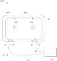
- an augmented reality scene 10is depicted.
- the user of an AR technologysees a real-world park-like setting 20 featuring people, trees, buildings in the background, and a concrete platform 30 .
- the useralso perceives that he/she “sees” “virtual content” such as a robot statue 40 standing upon the real-world platform 30 , and a flying cartoon-like avatar character 50 which seems to be a personification of a bumble bee.
- These elements 50 , 40are “virtual” in that they do not exist in the real world.
- the human visual perception systemis complex, it is challenging to produce AR technology that facilitates a comfortable, natural-feeling, rich presentation of virtual image elements amongst other virtual or real-world imagery elements.
- a display systemcomprising a head-mountable display configured to project light to a viewer to display image information on one or more depth planes.
- the displaycomprises one or more waveguides configured to project the light to the viewer.
- the one or more waveguidesare further configured to transmit light from objects in a surrounding environment to the viewer.
- the displayalso comprises a first variable focus lens element between the one or more waveguides and a first eye of the viewer; and a second variable focus lens element between the one or more waveguides and the surrounding environment.
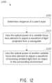
- An eye tracking systemis configured to determine vergence of the viewer's eyes.
- the display systemis configured to correct a refractive error of the user's eyes by adjusting an optical power of the first and second variable focus lens elements based on the determined vergence of the viewer's eyes.
- a method for displaying image information on a head-mountable displaycomprises providing the display mounted on a head of a viewer, with the display configured to display image information on one or more depth planes.
- the displaycomprises one or more waveguides configured to project light to the viewer to display the image information.
- the one or more waveguidesare further configured to transmit light from objects in a surrounding environment to the viewer.
- the methodfurther comprises determining a vergence point of eyes of the viewer and correcting a refractive error of an eye of the viewer.
- the refractive errormay be corrected by varying optical power of a first variable focus lens element disposed between the one or more waveguides and an eye of the viewer based on the determined vergence point; and varying optical power of a second variable focus lens element disposed between the one or more waveguides and an environment surrounding the viewer based on the determined vergence point.
- Example 1A display system comprising:
- Example 2The display system of Example 1, wherein the display system is configured to modify the optical power of the first and second variable focus lens elements depending on a depth plane for displaying the image information.
- Example 3The display system of any of Examples 1-2, wherein the display system is configured to adjust an optical power of the second variable focus lens element in response to an optical power of the first variable focus lens element.
- Example 4The display system of any of Examples 1-3, wherein the one or more waveguides are configured to project divergent light to the viewer to display the image information.
- Example 5The display system of any of Example 1-4, wherein each of the one or more waveguides has a fixed optical power.
- Example 6The display system of any of Examples 1-5, further comprising a third variable focus element between the one or more waveguides and a second eye of the viewer.
- Example 7The display system of Example 6, further comprising a fourth variable focus element between the one or more waveguides and the surrounding environment.
- Example 8The display system of any of Examples 6-7, wherein the system is configured to adjust an optical power of the third variable focus lens element to vary the wavefront of the projected light based on the determined vergence.
- Example 9The display system of any of Examples 6-8, wherein the system is configured to adjust an optical power of the fourth variable focus lens element to vary the wavefront of incoming light from the object in the surrounding environment based on the determined vergence.
- Example 10The display system of any of Examples 1-9, wherein eye tracking system comprises one or more cameras.
- Example 11The display system of any of Examples 1-10, wherein an optical power of the first and/or second variable focus lens element is adjusted in accordance with a prescription for correcting the viewer's vision at two or more distances.
- Example 12The display system of any of Examples 1-11, wherein the system has three or more preset prescription optical powers for each of the first and second variable focus lens elements.
- Example 13The display system of any of Examples 1-12, wherein a number of available prescription optical powers is equal to at least a total number of depth planes for the display.
- Example 14The display system of any of Examples 1-13, wherein the first and/or second variable focus lens elements comprises a layer of liquid crystal sandwiched between two substrates.
- Example 15The display system of the Example 14, wherein the first and/or second variable focus lens elements comprise electrodes for altering a refractive index of the liquid crystal layer upon application of a voltage.
- Example 16The display system of Examples 14-15, wherein the substrates comprise glass.
- Example 17The display system of any of Examples 1-16, further comprising an electronic hardware control system configured to vary the refractive index of the first and/or second variable focus lens element by application of an electrical current or voltage.
- Example 18The display system of Example 17, wherein the eye tracking system forms a feedback loop to the electronic hardware control system to vary the refractive index of the first and/or second variable focus lens element in accordance with the determined vergence of the viewer's eyes.
- Example 19A method for displaying image information on a head-mountable display, the method comprising:
- Example 20The method of Example 19, further comprising:
- Example 21The method of Example 20, wherein determining the vergence point comprises tracking a vergence of the eye and the other eye of the viewer using one or more cameras.
- Example 22The method of any of Examples 19-21, wherein the optical power of the first variable focus lens element is varied simultaneously with the optical power of the second variable focus lens element.
- Example 23The method of any of Examples 19-22, wherein the one or more waveguides each comprises diffractive optical elements configured to output divergent light from the waveguides.
- FIG. 1illustrates a user's view of augmented reality (AR) through an AR device.
- ARaugmented reality
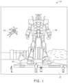
- FIG. 2illustrates an example of wearable display system.
- FIG. 3illustrates a conventional display system for simulating three-dimensional imagery for a user.
- FIG. 4illustrates aspects of an approach for simulating three-dimensional imagery using multiple depth planes.
- FIGS. 5 A- 5 Cillustrate relationships between radius of curvature and focal radius.
- FIG. 6illustrates an example of a waveguide stack for outputting image information to a user.
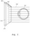
- FIG. 7illustrates an example of exit beams outputted by a waveguide.
- FIG. 8illustrates an example of a stacked waveguide assembly in which each depth plane includes images formed using multiple different component colors.
- FIG. 9 Aillustrates a cross-sectional side view of an example of a set of stacked waveguides that each includes an incoupling optical element.
- FIG. 9 Billustrates a perspective view of an example of the plurality of stacked waveguides of FIG. 9 A .
- FIG. 9 Cillustrates a top-down plan view of an example of the plurality of stacked waveguides of FIGS. 9 A and 9 B .
- FIGS. 10 A and 10 Bare schematic illustrations of examples of displays having variable focus lens elements and one or more waveguides.
- FIG. 10 Ashows a waveguide stack with a single waveguide
- FIG. 10 Bshows a waveguide stack with a plurality of waveguides.
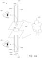
- FIG. 11shows a schematic view of various components of an augmented reality system comprising an eye tracking system.
- FIG. 12depicts an example of a method for varying optical power of variable focus lens elements based on the vergence of a user's eyes.
- AR systemsmay display virtual content to a viewer while still allowing the viewer to see the world around them.
- this contentis displayed on a head-mountable display, e.g., as part of eyewear, that projects image information to the viewer's eyes, while also transmitting light from the surrounding environment to those eyes, to allow a view of that surrounding environment.
- refractive errorsinclude myopia, hyperopia, presbyopia, and astigmatism.
- These viewersmay require lens elements with a particular prescription optical power to clearly view the image information projected by the display.
- lens elementsmay be positioned between a waveguide for projecting the image information and the viewer's eyes.
- these lens elements and possibly other optically transmissive parts of the display, such as the waveguidesmay cause aberrations in the viewer's view of the surrounding environment.
- many lens elementshave a fixed optical power that may not address all of the refractive errors experienced by a viewer.
- a display systemincludes first and second variable focus lens elements that sandwich (are positioned on either side of) a waveguide or plurality of waveguides.
- the first lens elementmay be between the one or more waveguides and an eye of the viewer, and may be configured to correct for refractive errors in the focusing of light projected from the one or more waveguides to that eye.
- the first lens elementsmay be configured to provide an appropriate amount of optical power to place displayed virtual content on a desired depth plane.
- the second lens elementmay be between the surrounding environment and the one or more waveguides, and may be configured to provide optical power to compensate for aberrations in the transmission of light from the surrounding environment through the waveguides and first lens element.
- refractive errors in the viewer's other eyemay be separately corrected.
- a third variable focus lens elements between the other eye and the waveguides, and fourth variable focus lens elements between the waveguides and the surrounding environmentmay be used to correct for refractive errors in this other eye.
- the focal length/optical power of the variable focus elementsmay be varied such that the real world and/or the virtual content are focused on the retina of the user's eye, thereby allowing the user to view both the real and virtual objects with high optical image quality.
- the displayis part of a display system that includes an eye tracking system configured to determine the vergence of the viewer's eye.
- the eye tracking systemmay be, e.g., one or more cameras that determine the vergence point of the eyes and, as a result, may be utilized to determine the distance at which the eyes are focused, to derive the appropriate correction for the eyes for that distance.
- different correctionsmay be required for different vergence points, e.g., different corrections may be required for the viewer's eyes to properly focus on near, far, or intermediate objects (whether real or virtual objects).
- the ability of the variable focus lens elements to provide variable optical powermay allow gradations of correction not readily available for, e.g., prescription eye glasses or contact lenses. For example, two or more, three or more, four or more, or five or more unique corrections (for each eye, in some embodiments) may be available.
- variable focus lens elementsmay be configured to provide the desired correction to the user.
- the augmented reality display systemmay be configured to provide different optical power for virtual objects projected from different depth planes and/or for real-world objects at different distances.
- the variable focus lens elementsmay be configured to provide a near vision optical power when the user is viewing virtual objects or real-world objects located at distances corresponding to near vision zone.
- the variable focus lens elementsmay be configured to provide an intermediate distance vision optical power when the user is viewing virtual objects or real-world objects located at distances corresponding to intermediate distance vision zone.
- variable focus lens elementsmay be configured to provide a far vision optical power when the user is viewing virtual objects or real-world objects located at distances corresponding to a far vision zone.
- a user's prescription for near vision correction, intermediate distance vision correction and far vision correctionmay be accessed by the display system and the system may vary the optical power of the variable focus lens elements in accordance with the user's prescription when the user is viewing virtual objects or real-world objects located at distances corresponding to the near vision zone, intermediate distance vision zone, and far vision zone.
- the first and/or second lens elementsmay allow the same head-mountable display to be used by a variety of users, without physically changing out corrective lens elements. Rather, the displays adapt to the user.
- the variable focus lens elementsmay be configured to provide the appropriate optical power to place image information projected from the one or more waveguides on a desired depth plane.
- the variable focus lens elementsmay be configured to vary the divergence of light projected from the one or more waveguides to the viewer.
- the adaptability provided by the variable focus lens elementsmay provide advantages for simplifying the manufacture and design of the display, since the same display may be provided to and used by different users and fewer optical structures may be required to display image information on a range of depth planes.
- variable focus lens elementsmay be configured with different prescriptions by simply changing preset corrections programmed into the display system, thereby allowing the display to readily adapt to new user prescriptions as, e.g., the user ages and the condition of one or both eyes changes.
- FIG. 2illustrates an example of wearable display system 60 .
- the display system 60includes a display 70 , and various mechanical and electronic modules and systems to support the functioning of that display 70 .
- the display 70may be coupled to a frame 80 , which is wearable by a display system user or viewer 90 and which is configured to position the display 70 in front of the eyes of the user 90 .
- the display 70may be considered eyewear in some embodiments.
- a speaker 100is coupled to the frame 80 and configured to be positioned adjacent the ear canal of the user 90 (in some embodiments, another speaker, not shown, may optionally be positioned adjacent the other ear canal of the user to provide stereo/shapeable sound control).
- the display systemmay also include one or more microphones 110 or other devices to detect sound.
- the microphoneis configured to allow the user to provide inputs or commands to the system 60 (e.g., the selection of voice menu commands, natural language questions, etc.), and/or may allow audio communication with other persons (e.g., with other users of similar display systems.
- the microphonemay further be configured as a peripheral sensor to collect audio data (e.g., sounds from the user and/or environment).
- the display systemmay also include a peripheral sensor 120 a , which may be separate from the frame 80 and attached to the body of the user 90 (e.g., on the head, torso, an extremity, etc. of the user 90 ).
- the peripheral sensor 120 amay be configured to acquire data characterizing a physiological state of the user 90 in some embodiments.
- the sensor 120 amay be an electrode.
- the display 70is operatively coupled by communications link 130 , such as by a wired lead or wireless connectivity, to a local data processing module 140 which may be mounted in a variety of configurations, such as fixedly attached to the frame 80 , fixedly attached to a helmet or hat worn by the user, embedded in headphones, or otherwise removably attached to the user 90 (e.g., in a backpack-style configuration, in a belt-coupling style configuration).
- the sensor 120 amay be operatively coupled by communications link 120 b , e.g., a wired lead or wireless connectivity, to the local processor and data module 140 .
- the local processing and data module 140may comprise a hardware processor, as well as digital memory, such as non-volatile memory (e.g., flash memory or hard disk drives), both of which may be utilized to assist in the processing, caching, and storage of data.
- the datainclude data a) captured from sensors (which may be, e.g., operatively coupled to the frame 80 or otherwise attached to the user 90 ), such as image capture devices (such as cameras), microphones, inertial measurement units, accelerometers, compasses, GPS units, radio devices, gyros, and/or other sensors disclosed herein; and/or b) acquired and/or processed using remote processing module 150 and/or remote data repository 160 (including data relating to virtual content), possibly for passage to the display 70 after such processing or retrieval.
- sensorswhich may be, e.g., operatively coupled to the frame 80 or otherwise attached to the user 90
- image capture devicessuch as cameras
- microphonessuch as cameras
- inertial measurement unitssuch as cameras
- accelerometerscompasse
- the local processing and data module 140may be operatively coupled by communication links 170 , 180 , such as via a wired or wireless communication links, to the remote processing module 150 and remote data repository 160 such that these remote modules 150 , 160 are operatively coupled to each other and available as resources to the local processing and data module 140 .
- the local processing and data module 140may include one or more of the image capture devices, microphones, inertial measurement units, accelerometers, compasses, GPS units, radio devices, and/or gyros. In some other embodiments, one or more of these sensors may be attached to the frame 80 , or may be standalone structures that communicate with the local processing and data module 140 by wired or wireless communication pathways.
- the remote processing module 150may comprise one or more processors configured to analyze and process data and/or image information.
- the remote data repository 160may comprise a digital data storage facility, which may be available through the internet or other networking configuration in a “cloud” resource configuration.
- the remote data repository 160may include one or more remote servers, which provide information, e.g., information for generating augmented reality content, to the local processing and data module 140 and/or the remote processing module 150 .
- all datais stored and all computations are performed in the local processing and data module, allowing fully autonomous use from a remote module.
- FIG. 3illustrates a conventional display system for simulating three-dimensional imagery for a user.
- Two distinct images 190 , 200are outputted to the user.
- the images 190 , 200are spaced from the eyes 210 , 220 by a distance 230 along an optical or z-axis that is parallel to the line of sight of the viewer.
- the images 190 , 200are flat and the eyes 210 , 220 may focus on the images by assuming a single accommodated state.
- Such 3-D display systemsrely on the human visual system to combine the images 190 , 200 to provide a perception of depth and/or scale for the combined image.
- Such systemsare uncomfortable for many viewers, however, since they, among other things, simply provide different presentations of a scene, but with the eyes viewing all the image information at a single accommodated state, and work against the “accommodation-vergence reflex.” Display systems that provide a better match between accommodation and vergence may form more realistic and comfortable simulations of three-dimensional imagery.
- FIG. 4illustrates aspects of an approach for simulating three-dimensional imagery using multiple depth planes.
- objects at various distances from eyes 210 , 220 on the z-axisare accommodated by the eyes 210 , 220 so that those objects are in focus.
- the eyes 210 , 220assume particular accommodated states to bring into focus objects at different distances along the z-axis. Consequently, a particular accommodated state may be said to be associated with a particular one of depth planes 240 , with has an associated focal distance, such that objects or parts of objects in a particular depth plane are in focus when the eye is in the accommodated state for that depth plane.
- three-dimensional imagerymay be simulated by providing different presentations of an image for each of the eyes 210 , 220 , and also by providing different presentations of the image corresponding to each of the depth planes. While shown as being separate for clarity of illustration, it will be appreciated that the fields of view of the eyes 210 , 220 may overlap, for example, as distance along the z-axis increases. In addition, while shown as flat for ease of illustration, it will be appreciated that the contours of a depth plane may be curved in physical space, such that all features in a depth plane are in focus with the eye in a particular accommodated state.
- the distance between an object and the eye 210 or 220may also change the amount of divergence of light from that object, as viewed by that eye.
- FIGS. 5 A- 5 Cillustrate relationships between distance and the divergence of light rays.
- the distance between the object and the eye 210is represented by, in order of decreasing distance, R 1 , R 2 , and R 3 .
- R 1 , R 2 , and R 3the distance between the object and the eye 210
- the light raysbecome more divergent as distance to the object decreases.
- the light raysbecome more collimated.
- the light field produced by a point(the object or a part of the object) has a spherical wavefront curvature, which is a function of how far away the point is from the eye of the user.
- the curvatureincreases with decreasing distance between the object and the eye 210 . Consequently, at different depth planes, the degree of divergence of light rays is also different, with the degree of divergence increasing with decreasing distance between depth planes and the viewer's eye 210 . While only a single eye 210 is illustrated for clarity of illustration in FIGS. 5 A- 5 C and other figures herein, it will be appreciated that the discussions regarding eye 210 may be applied to both eyes 210 and 220 of a viewer.
- the human eyetypically can interpret a finite number of depth planes to provide depth perception. Consequently, a highly believable simulation of perceived depth may be achieved by providing, to the eye, different presentations of an image corresponding to each of these limited number of depth planes.
- the different presentationsmay be separately focused by the viewer's eyes, thereby helping to provide the user with depth cues based on the accommodation of the eye required to bring into focus different image features for the scene located on different depth plane and/or based on observing different image features on different depth planes being out of focus.
- FIG. 6illustrates an example of a waveguide stack for outputting image information to a user.
- a display system 250includes a stack of waveguides, or stacked waveguide assembly, 260 that may be utilized to provide three-dimensional perception to the eye/brain using a plurality of waveguides 270 , 280 , 290 , 300 , 310 .
- the display system 250is the system 60 of FIG. 2 , with FIG. 6 schematically showing some parts of that system 60 in greater detail.
- the waveguide assembly 260may be part of the display 70 of FIG. 2 .
- the display system 250may be considered a light field display in some embodiments.
- the waveguide assembly 260may also be referred to as an eyepiece.
- the waveguide assembly 260may also include a plurality of features 320 , 330 , 340 , 350 between the waveguides.
- the features 320 , 330 , 340 , 350may be one or more lenses.
- the waveguides 270 , 280 , 290 , 300 , 310 and/or the plurality of lenses 320 , 330 , 340 , 350may be configured to send image information to the eye with various levels of wavefront curvature or light ray divergence. Each waveguide level may be associated with a particular depth plane and may be configured to output image information corresponding to that depth plane.
- Image injection devices 360 , 370 , 380 , 390 , 400may function as a source of light for the waveguides and may be utilized to inject image information into the waveguides 270 , 280 , 290 , 300 , 310 , each of which may be configured, as described herein, to distribute incoming light across each respective waveguide, for output toward the eye 210 .
- each of the input surfaces 460 , 470 , 480 , 490 , 500may be an edge of a corresponding waveguide, or may be part of a major surface of the corresponding waveguide (that is, one of the waveguide surfaces directly facing the world 510 or the viewer's eye 210 ).
- a single beam of light(e.g. a collimated beam) may be injected into each waveguide to output an entire field of cloned collimated beams that are directed toward the eye 210 at particular angles (and amounts of divergence) corresponding to the depth plane associated with a particular waveguide.
- a single one of the image injection devices 360 , 370 , 380 , 390 , 400may be associated with and inject light into a plurality (e.g., three) of the waveguides 270 , 280 , 290 , 300 , 310 .
- the image injection devices 360 , 370 , 380 , 390 , 400are discrete displays that each produce image information for injection into a corresponding waveguide 270 , 280 , 290 , 300 , 310 , respectively.
- the image injection devices 360 , 370 , 380 , 390 , 400are the output ends of a single multiplexed display which may, e.g., pipe image information via one or more optical conduits (such as fiber optic cables) to each of the image injection devices 360 , 370 , 380 , 390 , 400 .
- the image information provided by the image injection devices 360 , 370 , 380 , 390 , 400may include light of different wavelengths, or colors (e.g., different component colors, as discussed herein).
- the light injected into the waveguides 270 , 280 , 290 , 300 , 310is provided by a light projector system 520 , which comprises a light module 540 , which may include a light emitter, such as a light emitting diode (LED).
- the light from the light module 540may be directed to and modified by a light modulator 530 , e.g., a spatial light modulator, via a beam splitter 550 .
- the light modulator 530may be configured to change the perceived intensity of the light injected into the waveguides 270 , 280 , 290 , 300 , 310 .
- Examples of spatial light modulatorsinclude liquid crystal displays (LCD) including a liquid crystal on silicon (LCOS) displays.
- LCDliquid crystal displays
- LCOSliquid crystal on silicon
- the image injection devices 360 , 370 , 380 , 390 , 400are illustrated schematically and, in some embodiments, these image injection devices may represent different light paths and locations in a common projection system configured to output light into associated ones of the waveguides 270 , 280 , 290 , 300 , 310 .
- the display system 250may be a scanning fiber display comprising one or more scanning fibers configured to project light in various patterns (e.g., raster scan, spiral scan, Lissajous patterns, etc.) into one or more waveguides 270 , 280 , 290 , 300 , 310 and ultimately to the eye 210 of the viewer.
- the illustrated image injection devices 360 , 370 , 380 , 390 , 400may schematically represent a single scanning fiber or a bundle of scanning fibers configured to inject light into one or a plurality of the waveguides 270 , 280 , 290 , 300 , 310 .
- the illustrated image injection devices 360 , 370 , 380 , 390 , 400may schematically represent a plurality of scanning fibers or a plurality of bundles of scanning fibers, each of which are configured to inject light into an associated one of the waveguides 270 , 280 , 290 , 300 , 310 .
- one or more optical fibersmay be configured to transmit light from the light module 540 to the one or more waveguides 270 , 280 , 290 , 300 , 310 .
- one or more intervening optical structuresmay be provided between the scanning fiber, or fibers, and the one or more waveguides 270 , 280 , 290 , 300 , 310 to, e.g., redirect light exiting the scanning fiber into the one or more waveguides 270 , 280 , 290 , 300 , 310 .
- a controller 560controls the operation of one or more of the stacked waveguide assembly 260 , including operation of the image injection devices 360 , 370 , 380 , 390 , 400 , the light source 540 , and the light modulator 530 .
- the controller 560is part of the local data processing module 140 .
- the controller 560includes programming (e.g., instructions in a non-transitory medium) that regulates the timing and provision of image information to the waveguides 270 , 280 , 290 , 300 , 310 according to, e.g., any of the various schemes disclosed herein.
- the controllermay be a single integral device, or a distributed system connected by wired or wireless communication channels.
- the controller 560may be part of the processing modules 140 or 150 ( FIG. 2 ) in some embodiments.
- the waveguides 270 , 280 , 290 , 300 , 310may be configured to propagate light within each respective waveguide by total internal reflection (TIR).
- the waveguides 270 , 280 , 290 , 300 , 310may each be planar or have another shape (e.g., curved), with major top and bottom surfaces and edges extending between those major top and bottom surfaces.
- the waveguides 270 , 280 , 290 , 300 , 310may each include out-coupling optical elements 570 , 580 , 590 , 600 , 610 that are configured to extract light out of a waveguide by redirecting the light, propagating within each respective waveguide, out of the waveguide to output image information to the eye 210 .
- Extracted lightmay also be referred to as out-coupled light and the out-coupling optical elements light may also be referred to light extracting optical elements.
- An extracted beam of lightmay be outputted by the waveguide at locations at which the light propagating in the waveguide strikes a light extracting optical element.
- the out-coupling optical elements 570 , 580 , 590 , 600 , 610may, for example, be gratings, including diffractive optical features, as discussed further herein. While illustrated disposed at the bottom major surfaces of the waveguides 270 , 280 , 290 , 300 , 310 , for ease of description and drawing clarity, in some embodiments, the out-coupling optical elements 570 , 580 , 590 , 600 , 610 may be disposed at the top and/or bottom major surfaces, and/or may be disposed directly in the volume of the waveguides 270 , 280 , 290 , 300 , 310 , as discussed further herein.
- the out-coupling optical elements 570 , 580 , 590 , 600 , 610may be formed in a layer of material that is attached to a transparent substrate to form the waveguides 270 , 280 , 290 , 300 , 310 .
- the waveguides 270 , 280 , 290 , 300 , 310may be a monolithic piece of material and the out-coupling optical elements 570 , 580 , 590 , 600 , 610 may be formed on a surface and/or in the interior of that piece of material.
- each waveguide 270 , 280 , 290 , 300 , 310is configured to output light to form an image corresponding to a particular depth plane.
- the waveguide 270 nearest the eyemay be configured to deliver collimated light (which was injected into such waveguide 270 ), to the eye 210 .
- the collimated lightmay be representative of the optical infinity focal plane.
- the next waveguide up 280may be configured to send out collimated light which passes through the first lens 350 (e.g., a negative lens) before it can reach the eye 210 ; such first lens 350 may be configured to create a slight convex wavefront curvature so that the eye/brain interprets light coming from that next waveguide up 280 as coming from a first focal plane closer inward toward the eye 210 from optical infinity.
- first lens 350e.g., a negative lens
- the third up waveguide 290passes its output light through both the first 350 and second 340 lenses before reaching the eye 210 ; the combined optical power of the first 350 and second 340 lenses may be configured to create another incremental amount of wavefront curvature so that the eye/brain interprets light coming from the third waveguide 290 as coming from a second focal plane that is even closer inward toward the person from optical infinity than was light from the next waveguide up 280 .
- the other waveguide layers 300 , 310 and lenses 330 , 320are similarly configured, with the highest waveguide 310 in the stack sending its output through all of the lenses between it and the eye for an aggregate focal power representative of the closest focal plane to the person.
- a compensating lens layer 620may be disposed at the top of the stack to compensate for the aggregate power of the lens stack 320 , 330 , 340 , 350 below.
- Such a configurationprovides as many perceived focal planes as there are available waveguide/lens pairings.
- Both the out-coupling optical elements of the waveguides and the focusing aspects of the lensesmay be static (i.e., not dynamic or electro-active). In some alternative embodiments, either or both may be dynamic using electro-active features.
- two or more of the waveguides 270 , 280 , 290 , 300 , 310may have the same associated depth plane.
- multiple waveguides 270 , 280 , 290 , 300 , 310may be configured to output images set to the same depth plane, or multiple subsets of the waveguides 270 , 280 , 290 , 300 , 310 may be configured to output images set to the same plurality of depth planes, with one set for each depth plane. This can provide advantages for forming a tiled image to provide an expanded field of view at those depth planes.
- the out-coupling optical elements 570 , 580 , 590 , 600 , 610may be configured to both redirect light out of their respective waveguides and to output this light with the appropriate amount of divergence or collimation for a particular depth plane associated with the waveguide.
- waveguides having different associated depth planesmay have different configurations of out-coupling optical elements 570 , 580 , 590 , 600 , 610 , which output light with a different amount of divergence depending on the associated depth plane.
- the light extracting optical elements 570 , 580 , 590 , 600 , 610may be volumetric or surface features, which may be configured to output light at specific angles.
- the light extracting optical elements 570 , 580 , 590 , 600 , 610may be volume holograms, surface holograms, and/or diffraction gratings.
- the features 320 , 330 , 340 , 350may not be lenses; rather, they may simply be spacers (e.g., cladding layers and/or structures for forming air gaps).
- the out-coupling optical elements 570 , 580 , 590 , 600 , 610are diffractive features that form a diffraction pattern, or “diffractive optical element” (also referred to herein as a “DOE”).
- the DOE'shave a sufficiently low diffraction efficiency so that only a portion of the light of the beam is deflected away toward the eye 210 with each intersection of the DOE, while the rest continues to move through a waveguide via TIR.
- the light carrying the image informationis thus divided into a number of related exit beams that exit the waveguide at a multiplicity of locations and the result is a fairly uniform pattern of exit emission toward the eye 210 for this particular collimated beam bouncing around within a waveguide.
- one or more DOEsmay be switchable between “on” states in which they actively diffract, and “off” states in which they do not significantly diffract.
- a switchable DOEmay comprise a layer of polymer dispersed liquid crystal, in which microdroplets comprise a diffraction pattern in a host medium, and the refractive index of the microdroplets may be switched to substantially match the refractive index of the host material (in which case the pattern does not appreciably diffract incident light) or the microdroplet may be switched to an index that does not match that of the host medium (in which case the pattern actively diffracts incident light).
- a camera assembly 630may be provided to capture images of the eye 210 and/or tissue around the eye 210 to, e.g., detect user inputs and/or to monitor the physiological state of the user.
- a cameramay be any image capture device.
- the camera assembly 630may include an image capture device and a light source to project light (e.g., infrared light) to the eye, which may then be reflected by the eye and detected by the image capture device.
- the camera assembly 630may be attached to the frame 80 ( FIG. 2 ) and may be in electrical communication with the processing modules 140 and/or 150 , which may process image information from the camera assembly 630 .
- one camera assembly 630may be utilized for each eye, to separately monitor each eye.
- FIG. 7an example of exit beams outputted by a waveguide is shown.
- One waveguideis illustrated, but it will be appreciated that other waveguides in the waveguide assembly 260 ( FIG. 6 ) may function similarly, where the waveguide assembly 260 includes multiple waveguides.
- Light 640is injected into the waveguide 270 at the input surface 460 of the waveguide 270 and propagates within the waveguide 270 by TIR. At points where the light 640 impinges on the DOE 570 , a portion of the light exits the waveguide as exit beams 650 .
- the exit beams 650are illustrated as substantially parallel but, as discussed herein, they may also be redirected to propagate to the eye 210 at an angle (e.g., forming divergent exit beams), depending on the depth plane associated with the waveguide 270 . It will be appreciated that substantially parallel exit beams may be indicative of a waveguide with out-coupling optical elements that out-couple light to form images that appear to be set on a depth plane at a large distance (e.g., optical infinity) from the eye 210 .
- waveguides or other sets of out-coupling optical elementsmay output an exit beam pattern that is more divergent, which would require the eye 210 to accommodate to a closer distance to bring it into focus on the retina and would be interpreted by the brain as light from a distance closer to the eye 210 than optical infinity.
- a full color imagemay be formed at each depth plane by overlaying images in each of the component colors, e.g., three or more component colors.
- FIG. 8illustrates an example of a stacked waveguide assembly in which each depth plane includes images formed using multiple different component colors.
- the illustrated embodimentshows depth planes 240 a - 240 f , although more or fewer depths are also contemplated.
- Each depth planemay have three or more component color images associated with it, including: a first image of a first color, G; a second image of a second color, R; and a third image of a third color, B.
- Different depth planesare indicated in the figure by different numbers for diopters (dpt) following the letters G, R, and B.
- the numbers following each of these lettersindicate diopters (1/m), or inverse distance of the depth plane from a viewer, and each box in the figures represents an individual component color image.
- the exact placement of the depth planes for different component colorsmay vary. For example, different component color images for a given depth plane may be placed on depth planes corresponding to different distances from the user. Such an arrangement may increase visual acuity and user comfort and/or may decrease chromatic aberrations.
- each depth planemay have multiple waveguides associated with it.
- each box in the figures including the letters G, R, or Bmay be understood to represent an individual waveguide, and three waveguides may be provided per depth plane where three component color images are provided per depth plane. While the waveguides associated with each depth plane are shown adjacent to one another in this drawing for ease of description, it will be appreciated that, in a physical device, the waveguides may all be arranged in a stack with one waveguide per level. In some other embodiments, multiple component colors may be outputted by the same waveguide, such that, e.g., only a single waveguide may be provided per depth plane.
- Gis the color green
- Ris the color red
- Bis the color blue.
- other colors associated with other wavelengths of lightincluding magenta and cyan, may be used in addition to or may replace one or more of red, green, or blue.
- references to a given color of light throughout this disclosurewill be understood to encompass light of one or more wavelengths within a range of wavelengths of light that are perceived by a viewer as being of that given color.
- red lightmay include light of one or more wavelengths in the range of about 620-780 nm
- green lightmay include light of one or more wavelengths in the range of about 492-577 nm
- blue lightmay include light of one or more wavelengths in the range of about 435-493 nm.
- the light source 540may be configured to emit light of one or more wavelengths outside the visual perception range of the viewer, for example, infrared and/or ultraviolet wavelengths.
- the in-coupling, out-coupling, and other light redirecting structures of the waveguides of the display 250may be configured to direct and emit this light out of the display towards the user's eye 210 , e.g., for imaging and/or user stimulation applications.
- FIG. 9 Aillustrates a cross-sectional side view of an example of a plurality or set 660 of stacked waveguides that each includes an in-coupling optical element.
- the waveguidesmay each be configured to output light of one or more different wavelengths, or one or more different ranges of wavelengths. It will be appreciated that the stack 660 may correspond to the stack 260 ( FIG.
- the illustrated waveguides of the stack 660may correspond to part of the plurality of waveguides 270 , 280 , 290 , 300 , 310 , except that light from one or more of the image injection devices 360 , 370 , 380 , 390 , 400 is injected into the waveguides from a position that requires light to be redirected for in-coupling.
- the illustrated set 660 of stacked waveguidesincludes waveguides 670 , 680 , and 690 .
- Each waveguideincludes an associated in-coupling optical element (which may also be referred to as a light input area on the waveguide), with, e.g., in-coupling optical element 700 disposed on a major surface (e.g., an upper major surface) of waveguide 670 , in-coupling optical element 710 disposed on a major surface (e.g., an upper major surface) of waveguide 680 , and in-coupling optical element 720 disposed on a major surface (e.g., an upper major surface) of waveguide 690 .
- in-coupling optical element 700disposed on a major surface (e.g., an upper major surface) of waveguide 670
- in-coupling optical element 710disposed on a major surface (e.g., an upper major surface) of waveguide 680
- in-coupling optical element 720disposed on a major surface (e.g
- one or more of the in-coupling optical elements 700 , 710 , 720may be disposed on the bottom major surface of the respective waveguide 670 , 680 , 690 (particularly where the one or more in-coupling optical elements are reflective, deflecting optical elements). As illustrated, the in-coupling optical elements 700 , 710 , 720 may be disposed on the upper major surface of their respective waveguide 670 , 680 , 690 (or the top of the next lower waveguide), particularly where those in-coupling optical elements are transmissive, deflecting optical elements. In some embodiments, the in-coupling optical elements 700 , 710 , 720 may be disposed in the body of the respective waveguide 670 , 680 , 690 .
- the in-coupling optical elements 700 , 710 , 720are wavelength selective, such that they selectively redirect one or more wavelengths of light, while transmitting other wavelengths of light. While illustrated on one side or corner of their respective waveguide 670 , 680 , 690 , it will be appreciated that the in-coupling optical elements 700 , 710 , 720 may be disposed in other areas of their respective waveguide 670 , 680 , 690 in some embodiments.
- each in-coupling optical element 700 , 710 , 720may be laterally offset from one another.
- each in-coupling optical elementmay be offset such that it receives light without that light passing through another in-coupling optical element.
- each in-coupling optical element 700 , 710 , 720may be configured to receive light from a different image injection device 360 , 370 , 380 , 390 , and 400 as shown in FIG. 6 , and may be separated (e.g., laterally spaced apart) from other in-coupling optical elements 700 , 710 , 720 such that it substantially does not receive light from the other ones of the in-coupling optical elements 700 , 710 , 720 .
- Each waveguidealso includes associated light distributing elements, with, e.g., light distributing elements 730 disposed on a major surface (e.g., a top major surface) of waveguide 670 , light distributing elements 740 disposed on a major surface (e.g., a top major surface) of waveguide 680 , and light distributing elements 750 disposed on a major surface (e.g., a top major surface) of waveguide 690 .
- the light distributing elements 730 , 740 , 750may be disposed on a bottom major surface of associated waveguides 670 , 680 , 690 , respectively.
- the light distributing elements 730 , 740 , 750may be disposed on both top and bottom major surface of associated waveguides 670 , 680 , 690 , respectively; or the light distributing elements 730 , 740 , 750 , may be disposed on different ones of the top and bottom major surfaces in different associated waveguides 670 , 680 , 690 , respectively.
- the waveguides 670 , 680 , 690may be spaced apart and separated by, e.g., gas, liquid, and/or solid layers of material.
- layer 760 amay separate waveguides 670 and 680 ; and layer 760 b may separate waveguides 680 and 690 .
- the layers 760 a and 760 bare formed of low refractive index materials (that is, materials having a lower refractive index than the material forming the immediately adjacent one of waveguides 670 , 680 , 690 ).
- the refractive index of the material forming the layers 760 a , 760 bis 0.05 or more, or 0.10 or less than the refractive index of the material forming the waveguides 670 , 680 , 690 .
- the lower refractive index layers 760 a , 760 bmay function as cladding layers that facilitate total internal reflection (TIR) of light through the waveguides 670 , 680 , 690 (e.g., TIR between the top and bottom major surfaces of each waveguide).
- the layers 760 a , 760 bare formed of air. While not illustrated, it will be appreciated that the top and bottom of the illustrated set 660 of waveguides may include immediately neighboring cladding layers.
- the material forming the waveguides 670 , 680 , 690are similar or the same, and the material forming the layers 760 a , 760 b are similar or the same.
- the material forming the waveguides 670 , 680 , 690may be different between one or more waveguides, and/or the material forming the layers 760 a , 760 b may be different, while still holding to the various refractive index relationships noted above.
- light rays 770 , 780 , 790are incident on the set 660 of waveguides. It will be appreciated that the light rays 770 , 780 , 790 may be injected into the waveguides 670 , 680 , 690 by one or more image injection devices 360 , 370 , 380 , 390 , 400 ( FIG. 6 ).
- the light rays 770 , 780 , 790have different properties, e.g., different wavelengths or different ranges of wavelengths, which may correspond to different colors.
- the in-coupling optical elements 700 , 710 , 720each deflect the incident light such that the light propagates through a respective one of the waveguides 670 , 680 , 690 by TIR.
- the incoupling optical elements 700 , 710 , 720each selectively deflect one or more particular wavelengths of light, while transmitting other wavelengths to an underlying waveguide and associated incoupling optical element.
- in-coupling optical element 700may be configured to deflect ray 770 , which has a first wavelength or range of wavelengths, while transmitting rays 780 and 790 , which have different second and third wavelengths or ranges of wavelengths, respectively.
- the transmitted ray 780impinges on and is deflected by the in-coupling optical element 710 , which is configured to deflect light of a second wavelength or range of wavelengths.
- the ray 790is deflected by the in-coupling optical element 720 , which is configured to selectively deflect light of third wavelength or range of wavelengths.
- the deflected light rays 770 , 780 , 790are deflected so that they propagate through a corresponding waveguide 670 , 680 , 690 ; that is, the in-coupling optical elements 700 , 710 , 720 of each waveguide deflects light into that corresponding waveguide 670 , 680 , 690 to in-couple light into that corresponding waveguide.
- the light rays 770 , 780 , 790are deflected at angles that cause the light to propagate through the respective waveguide 670 , 680 , 690 by TIR.
- the light rays 770 , 780 , 790propagate through the respective waveguide 670 , 680 , 690 by TIR until impinging on the waveguide's corresponding light distributing elements 730 , 740 , 750 .
- FIG. 9 Ba perspective view of an example of the plurality of stacked waveguides of FIG. 9 A is illustrated.
- the in-coupled light rays 770 , 780 , 790are deflected by the in-coupling optical elements 700 , 710 , 720 , respectively, and then propagate by TIR within the waveguides 670 , 680 , 690 , respectively.
- the light rays 770 , 780 , 790then impinge on the light distributing elements 730 , 740 , 750 , respectively.
- the light distributing elements 730 , 740 , 750deflect the light rays 770 , 780 , 790 so that they propagate towards the out-coupling optical elements 800 , 810 , 820 , respectively.
- the light distributing elements 730 , 740 , 750are orthogonal pupil expanders (OPE's).
- OPE'sdeflect or distribute light to the out-coupling optical elements 800 , 810 , 820 and, in some embodiments, may also increase the beam or spot size of this light as it propagates to the out-coupling optical elements.
- the light distributing elements 730 , 740 , 750may be omitted and the in-coupling optical elements 700 , 710 , 720 may be configured to deflect light directly to the out-coupling optical elements 800 , 810 , 820 .
- the light distributing elements 730 , 740 , 750may be replaced with out-coupling optical elements 800 , 810 , 820 , respectively.
- the out-coupling optical elements 800 , 810 , 820are exit pupils (EP's) or exit pupil expanders (EPE's) that direct light in a viewer's eye 210 ( FIG. 7 ).
- the OPE'smay be configured to increase the dimensions of the eye box in at least one axis and the EPE's may be to increase the eye box in an axis crossing, e.g., orthogonal to, the axis of the OPEs.
- each OPEmay be configured to redirect a portion of the light striking the OPE to an EPE of the same waveguide, while allowing the remaining portion of the light to continue to propagate down the waveguide.
- another portion of the remaining lightis redirected to the EPE, and the remaining portion of that portion continues to propagate further down the waveguide, and so on.
- a portion of the impinging lightis directed out of the waveguide towards the user, and a remaining portion of that light continues to propagate through the waveguide until it strikes the EP again, at which time another portion of the impinging light is directed out of the waveguide, and so on.
- a single beam of incoupled lightmay be “replicated” each time a portion of that light is redirected by an OPE or EPE, thereby forming a field of cloned beams of light, as shown in FIG. 6 .
- the OPE and/or EPEmay be configured to modify a size of the beams of light.
- the set 660 of waveguidesincludes waveguides 670 , 680 , 690 ; in-coupling optical elements 700 , 710 , 720 ; light distributing elements (e.g., OPE's) 730 , 740 , 750 ; and out-coupling optical elements (e.g., EP's) 800 , 810 , 820 for each component color.
- the waveguides 670 , 680 , 690may be stacked with an air gap/cladding layer between each one.
- the in-coupling optical elements 700 , 710 , 720redirect or deflect incident light (with different in-coupling optical elements receiving light of different wavelengths) into its waveguide. The light then propagates at an angle which will result in TIR within the respective waveguide 670 , 680 , 690 .
- light ray 770e.g., blue light
- the first in-coupling optical element 700is deflected by the first in-coupling optical element 700 , and then continues to bounce down the waveguide, interacting with the light distributing element (e.g., OPE's) 730 and then the out-coupling optical element (e.g., EPs) 800 , in a manner described earlier.
- the light distributing elemente.g., OPE's
- the out-coupling optical elemente.g., EPs
- the light rays 780 and 790(e.g., green and red light, respectively) will pass through the waveguide 670 , with light ray 780 impinging on and being deflected by in-coupling optical element 710 .
- the light ray 780then bounces down the waveguide 680 via TIR, proceeding on to its light distributing element (e.g., OPEs) 740 and then the out-coupling optical element (e.g., EP's) 810 .
- light ray 790(e.g., red light) passes through the waveguide 690 to impinge on the light in-coupling optical elements 720 of the waveguide 690 .
- the light in-coupling optical elements 720deflect the light ray 790 such that the light ray propagates to light distributing element (e.g., OPEs) 750 by TIR, and then to the out-coupling optical element (e.g., EPs) 820 by TIR.
- the out-coupling optical element 820then finally out-couples the light ray 790 to the viewer, who also receives the out-coupled light from the other waveguides 670 , 680 .
- FIG. 9 Cillustrates a top-down plan view of an example of the plurality of stacked waveguides of FIGS. 9 A and 9 B .
- the waveguides 670 , 680 , 690along with each waveguide's associated light distributing element 730 , 740 , 750 and associated out-coupling optical element 800 , 810 , 820 , may be vertically aligned.
- the in-coupling optical elements 700 , 710 , 720are not vertically aligned; rather, the in-coupling optical elements are preferably non-overlapping (e.g., laterally spaced apart as seen in the top-down view).
- this nonoverlapping spatial arrangementfacilitates the injection of light from different resources into different waveguides on a one-to-one basis, thereby allowing a specific light source to be uniquely coupled to a specific waveguide.
- arrangements including nonoverlapping spatially-separated in-coupling optical elementsmay be referred to as a shifted pupil system, and the in-coupling optical elements within these arrangements may correspond to sub pupils.
- augmented reality devicesmay be configured to adjust the wavefront of light (including light for image information projected from the augmented reality system as well as incoming light from objects in the surrounding real world) by tuning focal lengths of variable focus lens elements included in the augmented reality system.
- the augmented reality systemmay comprise a display device that may include a plurality of stacked waveguides (e.g., corresponding to the plurality or set 660 of stacked waveguides of FIGS. 9 A and 9 B , or corresponding to the stacked waveguide assembly 260 of FIG.
- the display devicemay include only a single waveguide. Consequently, while plural waveguides are referenced in various parts of the disclosure herein, it will be appreciated that the plural waveguides may be replaced by a singular waveguide.
- the projected light from the waveguidesmay be used to provide virtual, augmented reality image information to the viewer.
- the lightmay be projected such that the user perceives the light to originate from one or more different depths, or distances from the viewer.
- the display devicemay be optically transmissive, such that the user can see real-world objects in the surrounding environment through the display device.
- the waveguidesmay be configured to have fixed optical power. To provide the appearance that the projected light is originating from different depths, the waveguides may be configured to output divergent beams of light, with different amounts of divergence corresponding to different depth planes.
- a first variable focus lens elementmay be provided between the waveguide and the viewer's eye to provide an appropriate adjustment to the wavefront of the light outputted by the waveguide, to allow this light to be correctly focused by the viewer's eye.
- This first lens elementis also in the path of light propagating from the surrounding environment to the viewer's eye.
- the first lens elementmay modify the wavefront of the light from the surrounding environment and, thereby cause aberrations in the viewer's view of the world.
- a second variable focus lens elementmay be disposed on the opposite side of the plurality of stacked waveguides from the first variable focus lens element; that is, the second variable focus lens element may be between the plurality of stacked waveguides and the surrounding real world to adjust the wavefront of light from real-world objects in the surrounding environment.
- the second variable focus lens elementmay be configured to compensate for aberrations caused by the first variable focus lens element.
- the second variable focus lensmay also be configured to compensate for aberrations caused by the waveguides.
- the focus of the second variable focus lens elementmay be inverse or opposite the focus of the first variable focus lens element.
- the second variable focus lens elementmay have a negative optical power, which may be of similar magnitude.
- the optical power of the second lens elementsmay be opposite to and of similar magnitude as the aggregate optical power of the first lens element and the waveguides.
- the waveguidesmay not have optical power (e.g., the waveguides may be configured to output collimated light), and the first variable focus lens elements may be configured to modify the wavefront of light emitted from the waveguides to provide the appropriate amount of divergence for image information to be interpreted by the viewer as being on a particular depth plane. It will be appreciated that the appropriate amount of divergence may vary for different viewers since optical power for placing image information on a particular depth plane will be adjusted by a particular differential to account for a viewer's optical prescription for that depth plane. In such embodiments, the waveguide stack between the first and second variable focus lens elements may simply be formed by a single waveguide.
- first and second variable focus lens elementsmay be provided for one of the viewer's eyes, and that third and fourth variable focus lens elements that are similar to the first and second variable focus lens elements, respectively, may be provided for the other of the viewer's eyes.
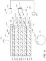
- FIGS. 10 A and 10 Bshow schematic illustrations of examples of display systems (e.g., augmented reality display systems) having variable focus lens elements and a waveguide stack.
- the display system 2010may correspond to the display system 250 ( FIG. 6 ).
- the example display system 2010 of FIG. 10 Ashows a waveguide stack with a single waveguide
- the example of FIG. 10 Bshows a waveguide stack with a plurality of waveguides.
- a first variable focus lens element 2007 a and a second variable focus lens element 2007 bare disposed on either side of a waveguide stack 2005 ( FIG. 10 A )
- a third variable focus lens element 2008 a and a fourth variable focus lens element 2008 bare disposed on either side of a waveguide stack 2006 ( FIG. 10 B ).
- the various illustrated waveguides 2005 a , 2005 b , 2006 a , 2006 b of FIGS. 10 A and 10 Bmay have characteristics and/or features similar to individual ones of waveguides 270 , 280 , 290 , 300 , 310 of FIG. 6 and/or waveguides 670 , 680 , and 690 of FIGS. 9 A and 9 B .
- the waveguide stacks 2005 , 2006may have characteristics and/or features similar to the plurality or set 660 of stacked waveguides of FIGS. 9 A and 9 B or to the stacked waveguide assembly 260 of FIG. 6 .
- the waveguides 2005 a , 2005 b , 2006 a , 2006 bmay include optical elements, such as diffractive optical elements, that provide the waveguides with optical power, e.g., a fixed optical power.
- optical elementssuch as diffractive optical elements
- one or more of these waveguidesmay have an optical power in the range between 0 Diopter and about 5.0 Diopters, between about 0.5 Diopters and about 4.5 Diopters, between about 1.0 Diopters and about 4.0 Diopters, between about 1.5 Diopters and about 3.5 Diopters, between about 2.0 Diopters and about 3.0 Diopters, or any value in these ranges or sub-ranges.
- each of the waveguidesmay have an optical power of 1.5 Diopters.
- light providing image informatione.g., virtual content
- an optical source 2003 or 2004may be injected into the waveguide 2005 a or 2006 a , respectively, such that the light propagates through each of those waveguides by total internal reflection.
- the propagating lightmay be projected out of the waveguide 2005 a (or waveguide 2005 b ) by out-coupling elements (e.g., corresponding to out-coupling elements 800 , 810 , 820 of FIGS. 9 A and 9 B ) towards the user's eye 2001 .
- the optical sources 2003 , 2004may be fiber scanning devices (FSD) that utilize a moving fiber to create a 2D image pattern, as disclosed herein.
- FSDfiber scanning devices
- the FSDmay create the 2D image pattern by projecting light in a variety of patterns, such as, for example, raster scan, spiral scan, Lissajous, etc.
- the optical source 2003 a (and/or 2003 b )may be an image projection system, e.g. in which a full image is projected onto a waveguide, as also disclosed herein. It will be appreciated that light from the optical source 2003 a (and/or 2003 b ) may be injected into the waveguide stack 2005 through edges of the waveguides or through a major surface of the waveguide. Where the waveguide stack includes a plurality of waveguides, the optical source 2003 and/or 2004 may be configured to inject light into multiple ones of these waveguides, or additional optical sources, e.g., one optical source for each waveguide, may be provided.
- the first variable focus lens element 2007 amay be disposed between the waveguide stack 2005 and the user's eye 2001
- the second variable focus lens element 2007 bmay be disposed between the waveguide stack 2005 and the real world surrounding the user.
- the eye 2001may correspond to the viewer's eye 210 of FIG. 6 .
- the third variable focus lens element 2008 amay be disposed between the waveguide stack 2006 and the user's eye 2002 and the second variable focus lens element 2008 b may be disposed between the waveguide stack 2006 and the real world surrounding the user.
- the first and the second variable focus lens elements 2007 a and 2007 b , and third and fourth variable focus lens elements 2008 a and 2008 bmay be adaptable optical elements.
- the adaptable optical elementsmay be dynamically altered, for example, by applying an electrical signal thereto, to change the shape of a wavefront that is incident thereon.
- the adaptable optical elementsmay comprise a transmissive optical element such as a dynamic lens (e.g., a liquid crystal lens, an electro-active lens, a conventional refractive lens with moving elements, a mechanical-deformation-based lens, an electrowetting lens, an elastomeric lens, or a plurality of fluids with different refractive indices).
- a dynamic lense.g., a liquid crystal lens, an electro-active lens, a conventional refractive lens with moving elements, a mechanical-deformation-based lens, an electrowetting lens, an elastomeric lens, or a plurality of fluids with different refractive indices.
- variable focus lens elements 2007 a , 2007 b , 2008 a , 2008 bmay comprise a layer of liquid crystal sandwiched between two substrates.
- the substratesmay comprise an optically transmissive material such as, for example, glass, plastic, acrylic, etc.
- the substratesmay be flat.
- the substratesmay have curved regions such that portions of the substrates may have fixed optical power.
- the optical power of the variable focus lens elements 2007 a , 2007 b , 2008 a , 2008 bmay be varied by adjusting an electrical signal (e.g., current and/or voltage) applied to the liquid crystal layer via, e.g., one or more thin film transistors (TFTs) and/or electrodes integrated with the liquid crystal layer and/or the substrates.
- an electrical signale.g., current and/or voltage
- TFTsthin film transistors
- the orientations of liquid crystal species in the liquid crystal layerdetermines the refractive index of the layer.
- the applied electrical signalsets the orientation of the liquid crystal species, thereby allowing the refractive index of the liquid crystal layer to be varied as desired by altering the applied electrical signal.
- the optical power of the variable focus lens elements 2007 a , 2007 b , 2008 a , 2008 bmay be varied between about ⁇ 5.0 Diopters (e.g., between about ⁇ 4.0 Diopters and +4.0 Diopters; between about ⁇ 3.5 Diopters and about +3.5 Diopters, between about ⁇ 3.0 Diopters and about +3.0 Diopters, between about ⁇ 2.0 Diopters and about +2.0 Diopters, between about ⁇ 1.5 Diopters and about +1.5 Diopters, including values in any of these ranges or sub-ranges).
- ⁇ 5.0 Diopterse.g., between about ⁇ 4.0 Diopters and +4.0 Diopters; between about ⁇ 3.5 Diopters and about +3.5 Diopters, between about ⁇ 3.0 Diopters and about +3.0 Diopters, between about ⁇ 2.0 Diopters and about +2.0 Diopters, between about ⁇ 1.5 Diopters and about +1.5 Diopters, including values in any of these ranges or sub-ranges).
- variable focus lens elements 2007 a , 2007 b , 2008 a , 2008 bmay have a wide aperture that is substantially matched to the aperture of the waveguides of their respective associated waveguide stacks 2005 , 2006 .
- the apertures of the variable focus lens elements 2007 a , 2007 b , 2008 a , 2008 bmay be substantially equal (e.g., within about ⁇ 20%, about ⁇ 15%, or about ⁇ 10%) to the surface areas of the waveguides of the waveguide stacks 2005 , 2006 . Consequently, the areas over which the variable focus lens elements 2007 a , 2007 b , 2008 a , 2008 b and the waveguide stacks 2005 , 2206 transmit light to an associated eye 2001 , 2002 may be substantially equal.
- the first and third variable focus lens elements 2007 a , 2008 amay each have its optical power varied to adjust the wavefront of light projected from a waveguide of the waveguide stacks 2005 , 2006 , respectively, to properly focus that light onto the retina of the eyes 2001 , 2002 , respectively.
- the first and third variable focus lens elements 2007 a , 2008 amay cause aberrations in the wavefront of incoming light from an object 2009 in the surrounding environment, thereby diminishing the optical image quality of real-world objects 2009 viewed through the first variable focus lens element 2007 a .
- the second and fourth variable focus lens elements 2007 b , 2008 bmay advantageously compensate for the aberrations introduced by the first and third variable focus lens elements 2007 a , 2008 a , respectively, and any waveguides when viewing the object 2009 .
- the second and fourth variable focus lens elements 2007 b , 2008 bmay be configured to provide an optical power opposite to the optical power provided by the first and third variable focus lens elements 2007 a , 2008 a , respectively, and the associated waveguide stack 2005 , 2006 .
- the magnitude of the opposite optical poweris such that the net optical power of the display system 2010 , for each eye 2001 , 2002 , is equal to an optical prescription for the eye at the depth plane that the eye is verging towards.
- the optical power provided by the first and the second variable focus lens elements 2007 a and 2007 bmay be varied and controlled by an electronic hardware control system 2011 .
- the electronic hardware control system 2011may correspond to the local processing and data module 140 and/or the remote processing module 150 of FIG. 2 .
- the augmented reality display system 2010may be configured to determine vergence of the user's eyes.
- the optical power of the first and the second variable focus lens elements 2007 a , 2007 bmay be set based upon the vergence point of the eyes 2001 , 2002 .
- the optical power of the third and the fourth variable focus lens elements 2008 a , 2008 bmay also be set based upon this vergence point. It will be appreciated that the vergence point is the point in space at which the lines of sight of the eyes 2001 , 2002 converge and may correspond to the physiologic accommodation target of those eyes.
- the distance that the point is away from the eyes 2001 , 2002may be calculated based, e.g., on the known quantities of the separation between the eyes 2001 , 2002 and the angles made out by the each eye. Once that distance is calculated, an appropriate correction for the viewer for that distance may be determined.
- the display system 2010may be programmed with one or more optical prescriptions.
- the optical prescriptionsmay be stored in the local processing and data module 140 and/or the remote data repository 160 .
- the distance between the eyes 2001 , 2002 and the vergence pointmay be matched with the appropriate correction for that distance, and the variable focus lens elements 2007 a , 2007 b , 2008 a , 2008 b may be adjusted to provide the correction.
- the eyes 2001 , 2002may have different prescribed corrections and, as a result, the pairs of variable focus lens elements 2007 a , 2007 b , and 2008 a , 2008 b , may provide different optical power.
- variable focus lens elements 2007 a , 2007 b , 2008 a , 2008 bprovide for a large number of possible corrections since their optical power can be adjusted as desired by, e.g., the application of different voltages.
- the total number of corrections per eyemay be 1, 2, 3, or 4 more.
- the total number of corrections per eyemay be equal to the number of depth planes that the display system 2010 is configured to display image information on. It will be appreciated that these corrections may correspond to optical prescriptions, which may be determined for objects at various distances from the eyes 2001 , 2002 .
- four prescriptionsmay be obtained by determining corrections for refractive errors at four progressively farther distances (e.g., close, close intermediate, far intermediate, and far distances) from the eyes 2001 , 2002 .
- the number of possible corrections for viewing image content outputted by the waveguide stack 2005may be different from the number of possible corrections when viewing objects 2009 in the surrounding environment.
- the focus, or optical power, of the variable focus lens elements 2007 a , 2007 b , 2008 a , 2008 bmay each be set based upon the determined vergence of the user's eyes 2001 , 2004 .
- the optical power of the first and the second variable focus lens elements 2007 a and 2007 bmay be varied based on the vergence of the user's eyes 2001 without specific reference to the optical power of the other lens element.
- one of the first and the second variable focus lens elements 2007 a , 2007 b , or one of the third and the fourth variable focus elements 2008 a , 2008 bmay be designated as a master and the other of the first and the second variable focus lens elements 2007 a , 2007 b , or the third and the fourth variable focus elements 2008 a , 2008 b , may be designated as a slave.
- the variable focus lens element designated as the slavemay be configured to follow the master variable focus lens element.
- the second and the fourth variable focus lens elements 2007 b , 2008 bmay be slaved to the first and third variable focus lens elements 2007 a , 2008 a , and the focus of the first and third variable focus lens elements 2007 a , 2008 a may be set based upon the determined vergence point of the user's eyes 2001 , 2002 .
- the waveguide 2005 aand/or waveguide 2005 b ) has an optical power of about 1.5 Diopters and the user is verging at 2.0 Diopters
- the first variable focus lens element 2007 amay have an optical power of +0.5 Diopters
- the second variable focus lens element 2007 bmay have an optical power ⁇ 0.5 Diopters.
- the optical powers of the variable focus lens elements 2007 a , 2007 b , 2008 a , 2008 bmay be varied in real time, and may preferably be changed at a rate equal to or greater than the rate at which the human eye changes accommodation states.
- the first and second variable focus lens elementscan change their optical power before the human eye changes accommodation states, such that the user does not experience a delay in receiving the appropriate correction for a given vergence point.
- the first and second variable focus lens elementscan change in optical power in less than about 300 ms, less than about 275 ms, or less than about 250 ms.
- the electronic hardware control system 2011may drive the variable focus lens elements 2007 a , 2007 b , 2008 a , 2008 b such that the optical powers of the variable focus lens elements 2007 a , 2007 b , 2008 a , 2008 b may be varied simultaneously.
- augmented reality display systems described hereinmay include an eye tracking system comprising one or more eye tracking cameras or imaging systems to track one or more eyes of the user to determine/measure the vergence of the user's eyes.
- An example embodiment of an augmented reality system 2010 including an eye tracking system 22is illustrated in FIG. 11 .
- the eye tracking system 22may include cameras 24 (e.g., infrared cameras) paired with light sources 26 (e.g., infrared light sources) directed at and configured to monitor and track the eyes 2001 , 2002 of the user. These cameras 24 and light sources 26 may be operatively coupled to the local processing module 140 .
- Such cameras 24may monitor one or more of the orientations, pupil sizes, and the corresponding direction of the line of sight of the respective eyes.
- the cameras 24may be configured to determine the vergence point of the eyes 2001 , 2002 .
- the cameras 24 and light sources 26may be mounted on the frame 80 , which may also hold the waveguide stacks 2005 , 2006 .
- the cameras 24may communicate with the local processing and data module 140 through communication links 170 , 180 .
- the cameras 24may be utilized to track the eyes to provide user input.
- the eye-tracking system 22may be utilized to select items on virtual menus, and/or provide other input to the display system 2010 .
- a flowchart 2200depicting an example method of varying the optical power of variable focus lens elements based on the determined vergence of a user.
- the vergence point of the user's eyesmay be determined or measured. Such a determination may be made using, e.g., the eye-tracking systems described herein. Based on this determination, the distance and/or depth plane at which the user's eyes are directed may be estimated.
- the optical power of a pair of variable lens elementsmay be varied in accordance with the determined vergence to improve the image quality of the virtual objects and/or real-world objects viewed by the user.
- the optical power of a variable focus lens element(e.g., one of the variable focus lens elements 2007 a , 2007 b , 2008 a , 2008 b ) is varied to adjust a wavefront of light projected from a waveguide, such as a waveguide of the waveguide stacks 2005 , 2006 ( FIGS. 10 A and 10 B ).
- the optical power of another variable focus lens elemente.g., a different one of the variable focus lens elements 2007 a , 2007 b , 2008 a , 2008 b
- the optical power of another variable focus lens elementis varied to adjust a wavefront of incoming ambient light from an object in the surrounding environment.
- blocks 2215 , 2220may be performed sequentially (e.g., with 2215 performed before 2220 , or vice versa), or these blocks 2215 , 2220 may be performed concurrently.
- blocks 2205 , 2215 , 2220may be performed continuously by the display system 2010 to automatically and continuously adjust the optical powers of the variable focus lens elements to provide a comfortable viewing experience for the user.
- each of the processes, methods, and algorithms described herein and/or depicted in the figuresmay be embodied in, and fully or partially automated by, code modules executed by one or more physical computing systems, hardware computer processors, application-specific circuitry, and/or electronic hardware configured to execute specific and particular computer instructions.
- computing systemsmay include general purpose computers (e.g., servers) programmed with specific computer instructions or special purpose computers, special purpose circuitry, and so forth.
- a code modulemay be compiled and linked into an executable program, installed in a dynamic link library, or may be written in an interpreted programming language.
- particular operations and methodsmay be performed by circuitry that is specific to a given function.
- a videomay include many frames, with each frame having millions of pixels, and specifically programmed computer hardware is necessary to process the video data to provide a desired image processing task or application in a commercially reasonable amount of time.
- Code modules or any type of datamay be stored on any type of non-transitory computer-readable medium, such as physical computer storage including hard drives, solid state memory, random access memory (RAM), read only memory (ROM), optical disc, volatile or non-volatile storage, combinations of the same and/or the like.
- the non-transitory computer-readable mediummay be part of one or more of the local processing and data module ( 140 ), the remote processing module ( 150 ), and remote data repository ( 160 ).
- the methods and modulesmay also be transmitted as generated data signals (e.g., as part of a carrier wave or other analog or digital propagated signal) on a variety of computer-readable transmission mediums, including wireless-based and wired/cable-based mediums, and may take a variety of forms (e.g., as part of a single or multiplexed analog signal, or as multiple discrete digital packets or frames).
- generated data signalse.g., as part of a carrier wave or other analog or digital propagated signal
- computer-readable transmission mediumsincluding wireless-based and wired/cable-based mediums, and may take a variety of forms (e.g., as part of a single or multiplexed analog signal, or as multiple discrete digital packets or frames).
- the results of the disclosed processes or process stepsmay be stored, persistently or otherwise, in any type of non-transitory, tangible computer storage or may be communicated via a computer-readable transmission medium.
- any processes, blocks, states, steps, or functionalities in flow diagrams described herein and/or depicted in the attached figuresshould be understood as potentially representing code modules, segments, or portions of code which include one or more executable instructions for implementing specific functions (e.g., logical or arithmetical) or steps in the process.
- the various processes, blocks, states, steps, or functionalitiesmay be combined, rearranged, added to, deleted from, modified, or otherwise changed from the illustrative examples provided herein.
- additional or different computing systems or code modulesmay perform some or all of the functionalities described herein.
- conditional language used hereinsuch as, among others, “can,” “could,” “might,” “may,” “e.g.,” and the like, unless specifically stated otherwise, or otherwise understood within the context as used, is generally intended to convey that certain embodiments include, while other embodiments do not include, certain features, elements and/or steps. Thus, such conditional language is not generally intended to imply that features, elements and/or steps are in any way required for one or more embodiments or that one or more embodiments necessarily include logic for deciding, with or without author input or prompting, whether these features, elements and/or steps are included or are to be performed in any particular embodiment.
Landscapes
- Engineering & Computer Science (AREA)
- Physics & Mathematics (AREA)
- General Physics & Mathematics (AREA)
- Theoretical Computer Science (AREA)
- General Engineering & Computer Science (AREA)
- Optics & Photonics (AREA)
- Human Computer Interaction (AREA)
- Nonlinear Science (AREA)
- Computer Hardware Design (AREA)
- Health & Medical Sciences (AREA)
- Ophthalmology & Optometry (AREA)
- General Health & Medical Sciences (AREA)
- Otolaryngology (AREA)
- Mathematical Physics (AREA)
- Chemical & Material Sciences (AREA)
- Crystallography & Structural Chemistry (AREA)
- Acoustics & Sound (AREA)
- Lenses (AREA)
- Mechanical Optical Scanning Systems (AREA)
- Eye Examination Apparatus (AREA)
- Optical Elements Other Than Lenses (AREA)
- Computer Graphics (AREA)
- Software Systems (AREA)
Abstract
Description
- a head-mountable display configured to project light to a viewer to display image information on one or more depth planes, the display comprising:
- one or more waveguides configured to project the light to the viewer, wherein the one or more waveguides are further configured to transmit light from objects in a surrounding environment to the viewer;
- a first variable focus lens element between the one or more waveguides and a first eye of the viewer; and
- a second variable focus lens element between the one or more waveguides and the surrounding environment; and
- an eye tracking system configured to determine vergence of the viewer's eyes, wherein the display system is configured to correct a refractive error of the user's eyes by adjusting an optical power of the first and second variable focus lens elements based on the determined vergence of the viewer's eyes.
- providing the display mounted on a head of a viewer, the display configured to display image information on one or more depth planes and comprising:
- one or more waveguides configured to project light to the viewer to display the image information,
- wherein the one or more waveguides are further configured to transmit light from objects in a surrounding environment to the viewer;
- determining a vergence point of eyes of the viewer; and
- correcting a refractive error of an eye of the viewer by:
- varying optical power of a first variable focus lens element disposed between the one or more waveguides and an eye of the viewer based on the determined vergence point; and
- varying optical power of a second variable focus lens element disposed between the one or more waveguides and an environment surrounding the viewer based on the determined vergence point.
- a third variable focus lens element and a fourth variable focus lens element, wherein the third variable focus lens element is between the one or more waveguides and an other eye of the viewer, and wherein the fourth variable focus lens element is directly forward of the third variable focus lens and between the one or more waveguides and the surrounding environment; and
- correcting a refractive error of the other eye by varying an optical power of the third and fourth variable focus lens elements based on the determined vergence point.
Claims (20)
Priority Applications (1)
| Application Number | Priority Date | Filing Date | Title |
|---|---|---|---|
| US17/461,732US11614626B2 (en) | 2016-04-08 | 2021-08-30 | Augmented reality systems and methods with variable focus lens elements |
Applications Claiming Priority (4)
| Application Number | Priority Date | Filing Date | Title |
|---|---|---|---|
| US201662320375P | 2016-04-08 | 2016-04-08 | |
| US15/481,255US10459231B2 (en) | 2016-04-08 | 2017-04-06 | Augmented reality systems and methods with variable focus lens elements |
| US16/664,191US11106041B2 (en) | 2016-04-08 | 2019-10-25 | Augmented reality systems and methods with variable focus lens elements |
| US17/461,732US11614626B2 (en) | 2016-04-08 | 2021-08-30 | Augmented reality systems and methods with variable focus lens elements |
Related Parent Applications (1)
| Application Number | Title | Priority Date | Filing Date |
|---|---|---|---|
| US16/664,191ContinuationUS11106041B2 (en) | 2016-04-08 | 2019-10-25 | Augmented reality systems and methods with variable focus lens elements |
Publications (2)
| Publication Number | Publication Date |
|---|---|
| US20210389593A1 US20210389593A1 (en) | 2021-12-16 |
| US11614626B2true US11614626B2 (en) | 2023-03-28 |
Family
ID=59998079
Family Applications (3)
| Application Number | Title | Priority Date | Filing Date |
|---|---|---|---|
| US15/481,255Active2037-06-22US10459231B2 (en) | 2016-04-08 | 2017-04-06 | Augmented reality systems and methods with variable focus lens elements |
| US16/664,191ActiveUS11106041B2 (en) | 2016-04-08 | 2019-10-25 | Augmented reality systems and methods with variable focus lens elements |
| US17/461,732ActiveUS11614626B2 (en) | 2016-04-08 | 2021-08-30 | Augmented reality systems and methods with variable focus lens elements |
Family Applications Before (2)
| Application Number | Title | Priority Date | Filing Date |
|---|---|---|---|
| US15/481,255Active2037-06-22US10459231B2 (en) | 2016-04-08 | 2017-04-06 | Augmented reality systems and methods with variable focus lens elements |
| US16/664,191ActiveUS11106041B2 (en) | 2016-04-08 | 2019-10-25 | Augmented reality systems and methods with variable focus lens elements |
Country Status (10)
| Country | Link |
|---|---|
| US (3) | US10459231B2 (en) |
| EP (2) | EP4273615A3 (en) |
| JP (3) | JP6923552B2 (en) |
| KR (4) | KR20250054839A (en) |
| CN (2) | CN114236812A (en) |
| AU (2) | AU2017246901B2 (en) |
| CA (1) | CA3019946C (en) |
| IL (2) | IL299497B2 (en) |
| NZ (1) | NZ747005A (en) |
| WO (1) | WO2017176898A1 (en) |
Cited By (1)
| Publication number | Priority date | Publication date | Assignee | Title |
|---|---|---|---|---|
| US20240085707A1 (en)* | 2020-05-22 | 2024-03-14 | Magic Leap, Inc. | Augmented and virtual reality display systems with correlated in-coupling and out-coupling optical regions for efficient light utilization |
Families Citing this family (81)
| Publication number | Priority date | Publication date | Assignee | Title |
|---|---|---|---|---|
| NZ773836A (en) | 2015-03-16 | 2022-07-01 | Magic Leap Inc | Methods and systems for diagnosing and treating health ailments |
| AU2017224107B2 (en) | 2016-02-26 | 2021-11-04 | Magic Leap, Inc. | Display system having a plurality of light pipes for a plurality of light emitters |
| JP6923552B2 (en)* | 2016-04-08 | 2021-08-18 | マジック リープ, インコーポレイテッドMagic Leap,Inc. | Augmented reality systems and methods with varifocal lens elements |
| US10901205B1 (en)* | 2016-08-09 | 2021-01-26 | Facebook Technologies, Llc | Focus adjusting liquid crystal lenses in a head-mounted display |
| KR102805976B1 (en) | 2016-10-28 | 2025-05-09 | 매직 립, 인코포레이티드 | Method and system for large field of view display with scanning reflector |
| US10248001B1 (en) | 2016-11-16 | 2019-04-02 | Facebook Technologies, Llc | Varifocal structure comprising a liquid lens structure in optical series with a liquid crystal lens in a head-mounted display |
| US10379419B1 (en)* | 2016-11-23 | 2019-08-13 | Facebook Technologies, Llc | Focus adjusting pancharatnam berry phase liquid crystal lenses in a head-mounted display |
| US10429652B2 (en) | 2016-12-12 | 2019-10-01 | Facebook Technologies, Llc | Tiled waveguide display with a wide field-of-view |
| US10885676B2 (en)* | 2016-12-27 | 2021-01-05 | Samsung Electronics Co., Ltd. | Method and apparatus for modifying display settings in virtual/augmented reality |
| US10151961B2 (en) | 2016-12-29 | 2018-12-11 | Facebook Technologies, Llc | Switchable bragg gratings for chromatic error correction of pancharatnam berry phase (PBP) components |
| IL311431A (en) | 2017-02-23 | 2024-05-01 | Magic Leap Inc | Display system with variable power reflector |
| AU2018284089B2 (en) | 2017-06-12 | 2022-12-15 | Magic Leap, Inc. | Augmented reality display having multi-element adaptive lens for changing depth planes |
| US10859834B2 (en) | 2017-07-03 | 2020-12-08 | Holovisions | Space-efficient optical structures for wide field-of-view augmented reality (AR) eyewear |
| US10338400B2 (en) | 2017-07-03 | 2019-07-02 | Holovisions LLC | Augmented reality eyewear with VAPE or wear technology |
| US10546430B1 (en) | 2017-08-29 | 2020-01-28 | Facebook Technologies, Llc | Image plane adjustment in a near-eye display |
| US11733516B2 (en) | 2017-10-11 | 2023-08-22 | Magic Leap, Inc. | Augmented reality display comprising eyepiece having a transparent emissive display |
| EP3697286A4 (en)* | 2017-10-19 | 2021-07-28 | Virginia Commonwealth University | EYE TRACKING PROCEDURES AND SYSTEMS ACTIVATED BY EYE VERGENCE |
| US10890769B2 (en)* | 2017-10-26 | 2021-01-12 | Magic Leap, Inc. | Augmented reality display having liquid crystal variable focus element and roll-to-roll method and apparatus for forming the same |
| CN119717285A (en)* | 2017-10-26 | 2025-03-28 | 奇跃公司 | Broadband adaptive lens assembly for augmented reality displays |
| CN111587392B (en) | 2017-12-11 | 2025-05-23 | 奇跃公司 | Waveguide illuminator |
| US12372793B2 (en) | 2017-12-11 | 2025-07-29 | Magic Leap, Inc. | Illumination layout for compact projection system |
| KR102096928B1 (en) | 2017-12-18 | 2020-04-03 | 삼성전자주식회사 | Optical system and Wearable display apparatus haivng the same |
| US10422989B2 (en)* | 2018-02-06 | 2019-09-24 | Microsoft Technology Licensing, Llc | Optical systems including a single actuator and multiple fluid-filled optical lenses for near-eye-display devices |
| US20210325575A1 (en)* | 2018-02-10 | 2021-10-21 | Optotune Ag | Orientation independent coma compensating liquid lens |
| WO2019178060A1 (en)* | 2018-03-12 | 2019-09-19 | Magic Leap, Inc. | Tilting array based display |
| EP4510558A3 (en) | 2018-03-14 | 2025-05-07 | Magic Leap, Inc. | Display systems and methods for clipping content to increase viewing comfort |
| US20190295507A1 (en)* | 2018-03-21 | 2019-09-26 | International Business Machines Corporation | Adaptive Rendering of Virtual and Augmented Displays to Improve Display Quality for Users Having Different Visual Abilities |
| EP3776058B1 (en) | 2018-03-26 | 2024-01-24 | Adlens Ltd. | Improvements in or relating to augmented reality display units and augmented reality headsets comprising the same |
| US10747309B2 (en)* | 2018-05-10 | 2020-08-18 | Microsoft Technology Licensing, Llc | Reconfigurable optics for switching between near-to-eye display modes |
| KR102664392B1 (en) | 2018-06-28 | 2024-05-08 | 삼성전자주식회사 | Display apparatus |
| JP7456995B2 (en) | 2018-07-24 | 2024-03-27 | マジック リープ, インコーポレイテッド | Display system and method for determining vertical alignment between left and right displays and a user's eyes |
| WO2020023546A1 (en)* | 2018-07-24 | 2020-01-30 | Magic Leap, Inc. | Diffractive optical elements with mitigation of rebounce-induced light loss and related systems and methods |
| KR102673817B1 (en) | 2018-07-30 | 2024-06-10 | 삼성전자주식회사 | 3-dimensional image display device and image processing method |
| KR102546321B1 (en) | 2018-07-30 | 2023-06-21 | 삼성전자주식회사 | 3-dimensional image display device and method |
| US11822079B2 (en)* | 2018-08-10 | 2023-11-21 | Apple Inc. | Waveguided display system with adjustable lenses |
| EP4560444A3 (en) | 2018-08-31 | 2025-07-16 | Magic Leap, Inc. | Spatially-resolved dynamic dimming for augmented reality device |
| US10979681B2 (en)* | 2018-09-13 | 2021-04-13 | Varjo Technologies Oy | Display apparatus and method of displaying using light source and beam scanning arrangement |
| US10627901B2 (en)* | 2018-09-14 | 2020-04-21 | Facebook Technologies, Llc | Vergence determination |
| CN113168009A (en)* | 2018-09-26 | 2021-07-23 | 奇跃公司 | Diffractive optical element with refractive power |
| US11315325B2 (en) | 2018-10-09 | 2022-04-26 | Magic Leap, Inc. | Systems and methods for artificial intelligence-based virtual and augmented reality |
| US10852619B1 (en)* | 2018-11-01 | 2020-12-01 | Facebook Technologies, Llc | Multifocal system using adaptive lenses |
| US10778953B2 (en) | 2018-12-10 | 2020-09-15 | Universal City Studios Llc | Dynamic convergence adjustment in augmented reality headsets |
| KR102748631B1 (en) | 2018-12-18 | 2024-12-31 | 삼성전자주식회사 | Apparatus and method for displaying image and computer program thereof |
| US11977230B2 (en)* | 2018-12-28 | 2024-05-07 | Magic Leap, Inc. | Virtual and augmented reality display systems with emissive micro-displays |
| CN119902373A (en) | 2019-01-11 | 2025-04-29 | 奇跃公司 | Time-multiplexed display of virtual content at various depths |
| CN113439231A (en) | 2019-02-13 | 2021-09-24 | 康宁股份有限公司 | Waveguide for transmitting light |
| TWI832976B (en)* | 2019-02-27 | 2024-02-21 | 美商愛奎有限公司 | Method and apparatus for measuring vision function |
| US20200275071A1 (en)* | 2019-03-20 | 2020-08-27 | Anton Zavoyskikh | Electronic visual headset |
| US11973375B2 (en) | 2019-05-24 | 2024-04-30 | Magic Leap, Inc. | Annular axial flux motors |
| US11624919B2 (en) | 2019-05-24 | 2023-04-11 | Magic Leap, Inc. | Variable focus assemblies |
| KR102858205B1 (en)* | 2019-05-27 | 2025-09-09 | 삼성전자주식회사 | Augmented reality device for adjusting a focus region according to a direction of an user's view and method for operating the same |
| US11467370B2 (en) | 2019-05-27 | 2022-10-11 | Samsung Electronics Co., Ltd. | Augmented reality device for adjusting focus region according to direction of user's view and operating method of the same |
| CN113892050B (en)* | 2019-07-04 | 2025-01-14 | 三星电子株式会社 | Electronic device and method for displaying augmented reality |
| JP7406622B2 (en) | 2019-08-21 | 2023-12-27 | マジック リープ, インコーポレイテッド | Flat spectrally responsive gratings using high refractive index materials |
| JP7582675B2 (en) | 2019-11-06 | 2024-11-13 | ヒーズ アイピー ホールディングス エルエルシー | System and method for displaying objects with depth |
| JP7676400B2 (en) | 2019-12-09 | 2025-05-14 | マジック リープ, インコーポレイテッド | SYSTEM AND METHOD FOR OPERATING A HEAD MOUNTED DISPLAY SYSTEM BASED ON USER IDENTIFICATION - Patent application |
| JP2023520461A (en) | 2020-04-03 | 2023-05-17 | マジック リープ, インコーポレイテッド | Wearable display system with nanowire LED microdisplay |
| WO2021246777A1 (en) | 2020-06-03 | 2021-12-09 | Samsung Electronics Co., Ltd. | Device and method for displaying augmented reality |
| US11662810B2 (en)* | 2020-06-05 | 2023-05-30 | Magic Leap, Inc. | Enhanced eye tracking techniques based on neural network analysis of images |
| CN111629198B (en)* | 2020-06-08 | 2022-08-09 | 京东方科技集团股份有限公司 | Imaging system, control method, control device and storage medium thereof |
| WO2022032198A1 (en) | 2020-08-07 | 2022-02-10 | Magic Leap, Inc. | Tunable cylindrical lenses and head-mounted display including the same |
| KR102858097B1 (en) | 2020-08-07 | 2025-09-09 | 매직 립, 인코포레이티드 | Multi-object alignment management for imprinting |
| US12271062B1 (en)* | 2020-08-12 | 2025-04-08 | Apple Inc. | System for calibrating adjustable lenses |
| RU2757072C1 (en)* | 2020-08-19 | 2021-10-11 | Самсунг Электроникс Ко., Лтд. | Multi-zone adjustable lens |
| US12099282B2 (en) | 2020-08-19 | 2024-09-24 | Samsung Electronics Co., Ltd. | Tunable optical lens and electronic apparatus employing the same |
| CN111812847B (en)* | 2020-08-20 | 2025-03-25 | 杭州光粒科技有限公司 | A waveguide device and an AR display device |
| US11360346B2 (en) | 2020-08-27 | 2022-06-14 | Samsung Electronics Co., Ltd. | Optical lens having a tunable focal length and display device including the same |
| RU2757074C1 (en)* | 2020-08-27 | 2021-10-11 | Самсунг Электроникс Ко., Лтд. | Adjustable lens with superimposed electrode structures |
| JP2024514416A (en) | 2021-03-15 | 2024-04-02 | マジック リープ, インコーポレイテッド | Optical devices and head-mounted displays employing adjustable cylindrical lenses |
| CN115145028A (en)* | 2021-03-31 | 2022-10-04 | 华为技术有限公司 | Augmented reality device and display method thereof |
| US11663941B2 (en)* | 2021-03-31 | 2023-05-30 | Snap Inc. | Eyewear projector brightness control |
| CN113281906A (en)* | 2021-04-25 | 2021-08-20 | 凤凰光学股份有限公司 | Detachable augmented reality display equipment and system thereof |
| US12147043B2 (en)* | 2021-04-26 | 2024-11-19 | Meta Platforms Technologies, Llc | Apparatus, system, and method for disposing photonic integrated circuits on surfaces |
| CN113253459A (en)* | 2021-05-20 | 2021-08-13 | 深圳市光舟半导体技术有限公司 | Optical waveguide sheet and lens integrated lens, integration method and AR display module |
| EP4392821A1 (en)* | 2021-08-26 | 2024-07-03 | Google LLC | Variable world blur for occlusion and contrast enhancement via tunable lens elements |
| EP4381340A4 (en)* | 2021-09-22 | 2024-11-20 | Samsung Electronics Co., Ltd. | AUGMENTED REALITY DEVICE BASED ON A VARIABLE CURVATURE WAVEGUIDE, METHOD OF OPERATING THE AUGMENTED REALITY DEVICE, AUGMENTED REALITY GLASSES, OPTICAL COMPENSATOR |
| US12055835B2 (en)* | 2021-09-24 | 2024-08-06 | Arm Limited | Apparatus and method of focusing light |
| CN114236819B (en)* | 2021-12-29 | 2022-09-27 | 东南大学 | Waveguide display two-dimensional pupil expanding method based on polarizer holographic grating |
| TWI818537B (en)* | 2022-05-06 | 2023-10-11 | 國立陽明交通大學 | Optical display system |
| CN115079484A (en)* | 2022-06-29 | 2022-09-20 | Oppo广东移动通信有限公司 | Lens Modules and Glasses |
| ES3030938A1 (en) | 2023-12-28 | 2025-07-02 | Univ Murcia | Binocular optoelectronic instrument of the eyeglass type for the visual improvement of both eyes and method for visual improvement |
Citations (534)
| Publication number | Priority date | Publication date | Assignee | Title |
|---|---|---|---|---|
| US3309162A (en) | 1963-06-28 | 1967-03-14 | Ibm | Electro-optical high speed adjustable focusing zone plate |
| US3724938A (en) | 1969-11-28 | 1973-04-03 | D Nepela | Variable contrast image projection |
| US4065208A (en) | 1974-10-29 | 1977-12-27 | Currey Thomas A | Ophthalmoscope |
| JPS5576323A (en) | 1978-12-01 | 1980-06-09 | Seiko Epson Corp | Electronic spectacles |
| EP0132077A1 (en) | 1983-07-12 | 1985-01-23 | The Secretary of State for Defence in Her Britannic Majesty's Government of the United Kingdom of Great Britain and | Thermochromic liquid crystal displays |
| US4573982A (en) | 1983-11-10 | 1986-03-04 | Merck & Co., Inc. | Eye frame ophthalmic drug delivery device |
| JPS61156227A (en) | 1984-12-28 | 1986-07-15 | Olympus Optical Co Ltd | Fresnel liquid crystal spectacle |
| US4601545A (en) | 1984-05-16 | 1986-07-22 | Kern Seymour P | Variable power lens system |
| US4669836A (en) | 1984-09-28 | 1987-06-02 | The United States Of America As Represented By The Administrator Of The National Aeronautics And Space Administration | Photorefractor ocular screening system |
| US4693544A (en) | 1982-12-14 | 1987-09-15 | Nippon Sheet Glass Co., Ltd. | Optical branching device with internal waveguide |
| JPS62269174A (en) | 1986-05-18 | 1987-11-21 | Ricoh Co Ltd | Optical path splitting and color separating optical device in color copying machine |
| US4711512A (en) | 1985-07-12 | 1987-12-08 | Environmental Research Institute Of Michigan | Compact head-up display |
| US4726667A (en) | 1984-10-19 | 1988-02-23 | Asahi Kogaku Kogyo Kabushiki Kaisha | Focusing method in optical lens system with variable focal length |
| US4737053A (en) | 1985-11-05 | 1988-04-12 | Ivano Paolini | Automatic machine for shaping the external profile of spectacle lenses |
| US4756605A (en) | 1985-02-01 | 1988-07-12 | Olympus Optical Co., Ltd. | Liquid crystal spectacles |
| US4826308A (en) | 1985-12-31 | 1989-05-02 | University Of Southern California | Method and system for detecting, characterizing and monitoring optic nerve diseases |
| US4848898A (en) | 1987-06-30 | 1989-07-18 | Lkc Technologies, Inc. | Apparatus for testing color vision |
| US4919520A (en) | 1984-08-31 | 1990-04-24 | Olympus Optical Company | Liquid crystal eyeglass |
| US4968127A (en) | 1988-11-23 | 1990-11-06 | Russell James P | Controllable, variable transmissivity eyewear |
| US4991924A (en) | 1989-05-19 | 1991-02-12 | Cornell Research Foundation, Inc. | Optical switches using cholesteric or chiral nematic liquid crystals and method of using same |
| EP0415735A2 (en) | 1989-08-29 | 1991-03-06 | KAISER AEROSPACE & ELECTRONICS CORPORATION | Optical switch and color selection assembly |
| JPH0384516A (en) | 1989-08-29 | 1991-04-10 | Fujitsu Ltd | 3D display device |
| US5142411A (en) | 1987-09-24 | 1992-08-25 | Werner J. Fiala | Multifocal birefringent lens system |
| US5166778A (en) | 1991-09-05 | 1992-11-24 | General Electric Company | Single-lens color video stereoscopic helmet mountable display |
| US5187372A (en) | 1990-10-11 | 1993-02-16 | Holtronic Technologies Ltd. | Apparatus for and a method of transverse position measurement in proximity lithographic systems |
| US5223971A (en) | 1991-12-31 | 1993-06-29 | Texas Instruments Incorporated | Light beam steering with deformable membrane device |
| EP0549283A2 (en) | 1991-12-20 | 1993-06-30 | Fujitsu Limited | Domain divided liquid crystal display device |
| WO1994023334A1 (en) | 1993-04-07 | 1994-10-13 | The Technology Partnership Plc | Switchable lens |
| US5359444A (en) | 1992-12-24 | 1994-10-25 | Motorola, Inc. | Auto-focusing optical apparatus |
| US5491492A (en) | 1992-02-05 | 1996-02-13 | Biocontrol Systems, Inc. | Method and apparatus for eye tracking for convergence and strabismus measurement |
| JPH08154924A (en) | 1994-12-05 | 1996-06-18 | Konan:Kk | Retinal camera having measuring function |
| US5537162A (en) | 1993-12-17 | 1996-07-16 | Carl Zeiss, Inc. | Method and apparatus for optical coherence tomographic fundus imaging without vignetting |
| US5544268A (en) | 1994-09-09 | 1996-08-06 | Deacon Research | Display panel with electrically-controlled waveguide-routing |
| US5566982A (en) | 1993-07-16 | 1996-10-22 | Idmatics S. A. | Flexible card with validity checking device |
| US5583670A (en) | 1992-01-10 | 1996-12-10 | Dia Nippon Printing Co., Ltd. | Polymer dispersed liquid crystal information recording medium with information recording layer comprising acrylic or methacrylic resin having molecular weight of 25,000 to 100,000 and information recording and reproducing method |
| US5654786A (en) | 1996-01-11 | 1997-08-05 | Robert C. Burlingame | Optical lens structure and control system for maintaining a selected constant level of transmitted light at a wearer's eyes |
| US5776068A (en) | 1997-06-19 | 1998-07-07 | Cornell Research Foundation | Ultrasonic scanning of the eye using a stationary transducer |
| JPH10232364A (en) | 1996-07-26 | 1998-09-02 | Universal Ventures | Focus adjustment by spatial relation of eyes |
| US5808797A (en) | 1992-04-28 | 1998-09-15 | Silicon Light Machines | Method and apparatus for modulating a light beam |
| US5825448A (en) | 1995-05-19 | 1998-10-20 | Kent State University | Reflective optically active diffractive device |
| US5847798A (en) | 1991-05-02 | 1998-12-08 | Kent State University | Polymer stabilized black-white cholesteric reflective display |
| US5915051A (en) | 1997-01-21 | 1999-06-22 | Massascusetts Institute Of Technology | Wavelength-selective optical add/drop switch |
| US5997141A (en) | 1998-03-06 | 1999-12-07 | Odyssey Optical Systems, Llc | System for treating the fundus of an eye |
| US6003991A (en) | 1996-02-17 | 1999-12-21 | Erik Scott Viirre | Eye examination apparatus and method for remote examination of a patient by a health professional |
| US6014197A (en) | 1995-02-28 | 2000-01-11 | U.S. Philips Corporation | Electro-optical device wherein orientation layers have grating structure and comprises birefringent material with refractive indices equal to electro-optic medium |
| US6015507A (en) | 1994-11-08 | 2000-01-18 | Minolta Co., Ltd. | Liquid crystal element having composite layer |
| US6040885A (en) | 1996-09-19 | 2000-03-21 | Fujitsu Limited | Liquid crystal display with three domains wherein molecules in the third domain are substantially vertically aligned regardless of voltage application |
| US6045515A (en) | 1997-04-07 | 2000-04-04 | Lawton; Teri A. | Methods and apparatus for diagnosing and remediating reading disorders |
| JP2000249902A (en) | 1999-03-02 | 2000-09-14 | Japan Science & Technology Corp | Auto focus glasses |
| US6151167A (en) | 1998-08-05 | 2000-11-21 | Microvision, Inc. | Scanned display with dual signal fiber transmission |
| US6181393B1 (en) | 1997-12-26 | 2001-01-30 | Kabushiki Kaisha Toshiba | Liquid crystal display device and method of manufacturing the same |
| US6188462B1 (en) | 1998-09-02 | 2001-02-13 | Kent State University | Diffraction grating with electrically controlled periodicity |
| CA2385849A1 (en) | 1999-09-23 | 2001-03-29 | Richard G. Nadeau | Medical applications of orthogonal polarization spectral imaging |
| US6217792B1 (en) | 1996-07-01 | 2001-04-17 | Merck Patent Gmbh | Chiral dopants |
| US6235014B1 (en) | 1998-03-31 | 2001-05-22 | Nidek Co., Ltd. | Laser treatment apparatus |
| US6251101B1 (en) | 1998-06-26 | 2001-06-26 | Visx, Incorporated | Surgical laser system microscope with separated ocular and objective lenses |
| WO2001047463A1 (en) | 1999-12-27 | 2001-07-05 | Neurovision, Inc. | Systems and methods for improving visual perception |
| US20010009973A1 (en) | 1991-08-31 | 2001-07-26 | Nidek Co., Ltd. | Noncontact type tonometer |
| JP2001290101A (en) | 2000-04-06 | 2001-10-19 | Tomohiko Hattori | Depth direction viewpoint adjustment intention detection and will drive method and automatic perspective correction glasses |
| US6307682B1 (en) | 2000-02-16 | 2001-10-23 | Silicon Valley Group, Inc. | Zoom illumination system for use in photolithography |
| US6334960B1 (en) | 1999-03-11 | 2002-01-01 | Board Of Regents, The University Of Texas System | Step and flash imprint lithography |
| US20020036750A1 (en) | 2000-09-23 | 2002-03-28 | Eberl Heinrich A. | System and method for recording the retinal reflex image |
| US6386706B1 (en) | 1996-07-31 | 2002-05-14 | Virtual-Eye.Com | Visual function testing with virtual retinal display |
| US20020064341A1 (en) | 2000-11-27 | 2002-05-30 | Fauver Mark E. | Micro-fabricated optical waveguide for use in scanning fiber displays and scanned fiber image acquisition |
| US20020072658A1 (en) | 1999-03-25 | 2002-06-13 | Fovioptics, Inc. | Non-invasive measurement of blood components using retinal imaging |
| US6414666B1 (en) | 1998-04-15 | 2002-07-02 | Minolta Co., Ltd. | Liquid crystal display device and method of driving a liquid crystal display element |
| US20020097962A1 (en) | 1998-10-09 | 2002-07-25 | Tetsuzo Yoshimura | Single and multilayer waveguides and fabrication process |
| US20020109819A1 (en) | 2001-02-15 | 2002-08-15 | Tveye Inc. | Method and apparatus for low bandwidth transmission of data utilizing of the human eye anatomy |
| US6437762B1 (en) | 1995-01-11 | 2002-08-20 | William A. Birdwell | Dynamic diffractive optical transform |
| US6447119B1 (en) | 1996-08-12 | 2002-09-10 | Visionrx, Inc. | Apparatus for visualizing the eye's tear film |
| US20020126249A1 (en) | 2001-01-11 | 2002-09-12 | Rong-Chang Liang | Transmissive or reflective liquid crystal display and novel process for its manufacture |
| US20020124843A1 (en) | 2001-02-01 | 2002-09-12 | Skiba Jeffry B. | Eye medication delivery system |
| US20020167638A1 (en) | 2001-05-10 | 2002-11-14 | Young-Sang Byun | Method of forming a liquid crystal layer using an ink jet system |
| US20020172237A1 (en) | 2001-03-01 | 2002-11-21 | Applied Optoelectronics, Inc. | Planar lightwave circuit for conditioning tunable laser output |
| US6490319B1 (en) | 1999-06-22 | 2002-12-03 | Intel Corporation | Region of interest video coding |
| US6491394B1 (en) | 1999-07-02 | 2002-12-10 | E-Vision, Llc | Method for refracting and dispensing electro-active spectacles |
| US6491391B1 (en) | 1999-07-02 | 2002-12-10 | E-Vision Llc | System, apparatus, and method for reducing birefringence |
| US20030009156A1 (en) | 2001-06-05 | 2003-01-09 | Adaptive Optics Associates, Inc. | Method of treating the human eye with a wavefront sensor-based ophthalmic instrument |
| US20030020873A1 (en) | 2000-03-27 | 2003-01-30 | Wolfgang Fink | Computer-based 3D visual field testing with peripheral fixation points |
| US6517203B1 (en) | 1999-07-02 | 2003-02-11 | E-Vision, Llc | System, apparatus, and method for correcting vision using electro-active spectacles |
| JP2003085289A (en) | 2001-09-13 | 2003-03-20 | Matsushita Electric Ind Co Ltd | Eating habits improvement support device |
| US6542671B1 (en) | 2001-12-12 | 2003-04-01 | Super Light Wave Corp. | Integrated 3-dimensional multi-layer thin-film optical couplers and attenuators |
| US20030071969A1 (en) | 2001-08-31 | 2003-04-17 | Levine Bruce M. | Ophthalmic instrument with adaptive optic subsystem that measures aberrations (including higher order aberrations) of a human eye and that provides a view of compensation of such aberrations to the human eye |
| US20030081170A1 (en) | 2001-10-29 | 2003-05-01 | Zolten Avram J. | Occluded contact lens with peripheral vision functionality |
| US6579235B1 (en) | 1999-11-01 | 2003-06-17 | The Johns Hopkins University | Method for monitoring intraocular pressure using a passive intraocular pressure sensor and patient worn monitoring recorder |
| US20030147112A1 (en) | 2000-07-05 | 2003-08-07 | Hiroshi Mukawa | Image display element, and image display device |
| US20030161573A1 (en) | 2002-02-28 | 2003-08-28 | Kaoru Ishida | Three-dimensional optical waveguide, method of manufacturing same, optical module, and optical transmission system |
| US6619799B1 (en) | 1999-07-02 | 2003-09-16 | E-Vision, Llc | Optical lens system with electro-active lens having alterably different focal lengths |
| US20030187503A1 (en) | 2002-03-29 | 2003-10-02 | Isaac Lipshitz | Intraocular lens implant with mirror |
| US20030210378A1 (en) | 2002-01-17 | 2003-11-13 | Riza Nabeel Agha | Optoelectronic eye examination system |
| US20040007465A1 (en) | 2000-08-01 | 2004-01-15 | Doron Goldberg | Electrophoresis apparatus and a plate therefor |
| US6680767B2 (en) | 2001-04-06 | 2004-01-20 | Central Research Laboratories Limited | Method of forming a liquid crystal polymer layer without support substrate |
| US20040022888A1 (en) | 2002-08-01 | 2004-02-05 | Sreenivasan Sidlgata V. | Alignment systems for imprint lithography |
| US6690845B1 (en) | 1998-10-09 | 2004-02-10 | Fujitsu Limited | Three-dimensional opto-electronic modules with electrical and optical interconnections and methods for making |
| US20040085648A1 (en) | 2002-11-06 | 2004-05-06 | Samsung Electronics Co., Ltd. | Head-mounted display |
| US6733130B2 (en) | 1999-07-02 | 2004-05-11 | E-Vision, Llc | Method for refracting and dispensing electro-active spectacles |
| US6736510B1 (en) | 2003-02-04 | 2004-05-18 | Ware Tec Vision Systems, Inc. | Ophthalmic talbot-moire wavefront sensor |
| US6750941B2 (en) | 1999-09-27 | 2004-06-15 | Nippon Mitsubishi Oil Corporation | Complex diffraction device |
| US20040114242A1 (en) | 2002-09-06 | 2004-06-17 | Sharp Gary D. | Filter for enhancing vision and/or protecting the eyes and method of making a filter |
| US20040120647A1 (en) | 2002-11-28 | 2004-06-24 | Seiko Epson Corporation | Optical element and illuminator and projection display device |
| US20040130783A1 (en) | 2002-12-02 | 2004-07-08 | Solomon Dennis J | Visual display with full accommodation |
| US20040129949A1 (en) | 2001-05-17 | 2004-07-08 | Shrenik Deliwala | Hybrid active and electronic circuit with evanescent coupling |
| US20040136570A1 (en) | 2002-04-30 | 2004-07-15 | Shimon Ullman | Method and apparatus for image enhancement for the visually impaired |
| US20040151466A1 (en) | 2003-01-24 | 2004-08-05 | Janet Crossman-Bosworth | Optical beam scanning system for compact image display or image acquisition |
| US20040150141A1 (en) | 2003-01-17 | 2004-08-05 | Chih-Yu Chao | Non-rubbing liquid crystal alignment method |
| US20040156021A1 (en) | 1999-07-02 | 2004-08-12 | Blum Ronald D. | Method and apparatus for correcting vision using an electro-active phoropter |
| US20040184163A1 (en) | 2003-02-13 | 2004-09-23 | Olympus Corporation | Optical apparatus |
| US20040191429A1 (en) | 1999-08-17 | 2004-09-30 | Western Washington University | Liquid crystal imprinting |
| JP2004294654A (en) | 2003-03-26 | 2004-10-21 | Mitsubishi Cable Ind Ltd | Optical fiber |
| US20040223113A1 (en) | 2001-10-05 | 2004-11-11 | Blum Ronald D. | Hybrid electro-active lens |
| US20040254438A1 (en) | 2003-01-09 | 2004-12-16 | The Regents Of The University Of California | Implantable devices and methods for measuring intraocular, subconjunctival or subdermal pressure and/or analyte concentration |
| US20040257958A1 (en) | 2003-06-18 | 2004-12-23 | Konica Minolta Opto, Inc. | Optical element, aberration correcting element, light converging element, objective optical system, optical pickup device, and optical information recording reproducing device |
| US20050015120A1 (en) | 2003-07-11 | 2005-01-20 | Seibel Eric J. | Scanning laser device and methods of use |
| US6850221B1 (en) | 1995-09-05 | 2005-02-01 | Interlink Electronics, Inc. | Trigger operated electronic device |
| US6851805B2 (en) | 1999-07-02 | 2005-02-08 | E-Vision, Llc | Stabilized electro-active contact lens |
| US20050036109A1 (en) | 2003-08-15 | 2005-02-17 | Blum Ronald D. | Enhanced electro-active lens system |
| US6857741B2 (en) | 2002-01-16 | 2005-02-22 | E-Vision, Llc | Electro-active multi-focal spectacle lens |
| US20050042391A1 (en) | 2002-01-18 | 2005-02-24 | Ryan Timothy George | Method of making a patterned optical element |
| WO2005024469A2 (en) | 2003-09-04 | 2005-03-17 | Sioptical, Inc. | Interfacing multiple wavelength sources to thin optical waveguides utilizing evanescent coupling |
| US6873087B1 (en) | 1999-10-29 | 2005-03-29 | Board Of Regents, The University Of Texas System | High precision orientation alignment and gap control stages for imprint lithography processes |
| US6871951B2 (en) | 2000-06-23 | 2005-03-29 | E-Vision, Llc | Electro-optic lens with integrated components |
| US20050073577A1 (en) | 2003-09-03 | 2005-04-07 | Toshiyuki Sudo | Stereoscopic image display device |
| US20050072959A1 (en) | 2001-01-29 | 2005-04-07 | Franco Moia | Optical device and method for manufacturing same |
| US6900881B2 (en) | 2002-07-11 | 2005-05-31 | Molecular Imprints, Inc. | Step and repeat imprint lithography systems |
| US20050122475A1 (en) | 2003-12-05 | 2005-06-09 | Imedos Gmbh | Universal ophthalmic examination device and ophthalmic examination method |
| US20050159662A1 (en) | 2004-01-21 | 2005-07-21 | Yoshikazu Imanishi | Methods for assessing a physiological state of a mammalian retina |
| US6927894B2 (en) | 2001-05-23 | 2005-08-09 | E-Vision, Llc | Mirror assemblies incorporating variable index of refraction materials |
| US20050185135A1 (en) | 1999-07-02 | 2005-08-25 | Blum Ronald D. | Electro-active spectacle employing modal liquid crystal lenses |
| US20050232530A1 (en) | 2004-04-01 | 2005-10-20 | Jason Kekas | Electronically controlled volume phase grating devices, systems and fabrication methods |
| US20050237485A1 (en) | 2004-04-21 | 2005-10-27 | Blum Ronald D | Method and apparatus for correcting vision |
| US20050244476A1 (en) | 2004-04-30 | 2005-11-03 | Allergan, Inc. | Intraocular implants and methods for improving vision |
| US20050246783A1 (en) | 2001-02-13 | 2005-11-03 | Avigenics, Inc. | Microinjection devices and methods of use |
| US20050242771A1 (en) | 2004-04-30 | 2005-11-03 | Blum Ronald D | Method and apparatus for recharging eyeglasses |
| JP2005316304A (en) | 2004-04-30 | 2005-11-10 | Sony Corp | Image display apparatus |
| JP2005316314A (en) | 2004-04-30 | 2005-11-10 | Casio Comput Co Ltd | Imaging device |
| US20050253112A1 (en) | 2002-07-01 | 2005-11-17 | Kelly Stephen M | Luminescent compositions |
| US20050270461A1 (en) | 2000-03-27 | 2005-12-08 | Kitson Stephen C | Liquid crystal alignment |
| US20050270312A1 (en) | 2004-06-03 | 2005-12-08 | Molecular Imprints, Inc. | Fluid dispensing and drop-on-demand dispensing for nano-scale manufacturing |
| US6975898B2 (en) | 2000-06-19 | 2005-12-13 | University Of Washington | Medical imaging, diagnosis, and therapy using a scanning single optical fiber system |
| US20050280777A1 (en) | 2004-06-17 | 2005-12-22 | Visx, Incorporated | Correction of presbyopia using adaptive optics and associated methods |
| US20050286019A1 (en) | 2004-06-10 | 2005-12-29 | Wiltberger Michael W | Scanning ophthalmic fixation method and apparatus |
| US6982818B2 (en) | 2002-10-10 | 2006-01-03 | Nuonics, Inc. | Electronically tunable optical filtering modules |
| US6986579B2 (en) | 1999-07-02 | 2006-01-17 | E-Vision, Llc | Method of manufacturing an electro-active lens |
| US20060028436A1 (en) | 1992-03-05 | 2006-02-09 | Armstrong Brad A | Image controller |
| US20060033992A1 (en) | 2002-12-02 | 2006-02-16 | Solomon Dennis J | Advanced integrated scanning focal immersive visual display |
| US7009757B2 (en) | 1997-06-10 | 2006-03-07 | Olympus Corporation | Optimal elements (such as vari focal lens component, vari-focal diffractive optical element and variable declination prism) and electronic image pickup unit using optical elements |
| US7019890B2 (en) | 2001-10-05 | 2006-03-28 | E-Vision, Llc | Hybrid electro-active lens |
| US7023466B2 (en) | 2000-11-03 | 2006-04-04 | Actuality Systems, Inc. | Three-dimensional display systems |
| US7023594B2 (en) | 2000-06-23 | 2006-04-04 | E-Vision, Llc | Electro-optic lens with integrated components |
| US7036931B2 (en) | 2003-01-29 | 2006-05-02 | Novartis Ag | Ophthalmic lenses |
| US20060098089A1 (en) | 2002-06-13 | 2006-05-11 | Eli Sofer | Method and apparatus for a multisensor imaging and scene interpretation system to aid the visually impaired |
| CN1774661A (en) | 2004-03-29 | 2006-05-17 | 索尼株式会社 | Optical device and virtual image display device |
| US20060114585A1 (en) | 2004-11-30 | 2006-06-01 | Northrop Grumman Corporation | Bi-directionally actuated thin membrane mirror |
| US20060114411A1 (en) | 2004-11-08 | 2006-06-01 | Jay Wei | Optical apparatus and method for comprehensive eye diagnosis |
| US20060121358A1 (en) | 2001-12-28 | 2006-06-08 | Chris Rich | Diffractive optical element and method of manufacture |
| US20060120247A1 (en) | 2004-12-03 | 2006-06-08 | Konica Minolta Photo Imaging, Inc. | Method for producing an optical device, optical device, image display apparatus, and head-mounted display |
| US20060126179A1 (en) | 2004-12-13 | 2006-06-15 | Nokia Corporation | Method and system for beam expansion in a display device |
| WO2006064301A1 (en) | 2004-12-13 | 2006-06-22 | Nokia Corporation | System and method for beam expansion with near focus in a display device |
| JPWO2004088616A1 (en) | 2003-03-28 | 2006-07-06 | シャープ株式会社 | Display device |
| US20060152525A1 (en) | 2005-01-13 | 2006-07-13 | Woog Kenneth M | Viewing screen color limiting device and method |
| US20060157443A1 (en) | 2005-01-18 | 2006-07-20 | Ping Mei | Pattern reversal process for self aligned imprint lithography and device |
| US20060159395A1 (en) | 2004-04-20 | 2006-07-20 | Alan Hnatiw | Optical compensator array for dispersive element arrays |
| US7082000B2 (en) | 2003-06-06 | 2006-07-25 | Hon Hai Precision Ind. Co., Ltd. | Aspherical lens with grating |
| US20060186325A1 (en) | 2005-02-23 | 2006-08-24 | University Of Washington | Scanning beam device with detector assembly |
| WO2006092758A2 (en) | 2005-03-01 | 2006-09-08 | Dutch Polymer Institute | Polarization gratings in mesogenic films |
| US20060203196A1 (en) | 2003-12-02 | 2006-09-14 | Van Heugten Anthony Y | Interactive refractor incorporating wavefront sensing and adaptive optics |
| US20060221448A1 (en) | 2005-04-04 | 2006-10-05 | Mirage Innovations Ltd. | Multi-plane optical apparatus |
| US20060227283A1 (en) | 2003-11-27 | 2006-10-12 | Asahi Glass Company Limited | Optical element employing liquid crystal having optical isotropy |
| US7122482B2 (en) | 2003-10-27 | 2006-10-17 | Molecular Imprints, Inc. | Methods for fabricating patterned features utilizing imprint lithography |
| US7140861B2 (en) | 2004-04-27 | 2006-11-28 | Molecular Imprints, Inc. | Compliant hard template for UV imprinting |
| US20070010748A1 (en) | 2005-07-06 | 2007-01-11 | Rauch Steven D | Ambulatory monitors |
| US20070027442A1 (en) | 2005-07-29 | 2007-02-01 | Alcon Refractivehorizons, Inc. | Ophthalmic device positioning system and associated methods |
| US20070031097A1 (en) | 2003-12-08 | 2007-02-08 | University Of Cincinnati | Light Emissive Signage Devices Based on Lightwave Coupling |
| US20070081123A1 (en) | 2005-10-07 | 2007-04-12 | Lewis Scott W | Digital eyewear |
| US20070115432A1 (en) | 2003-12-12 | 2007-05-24 | Thibos Larry N | System and method for Optimizing clinical optic prescriptions |
| US20070121120A1 (en) | 2005-11-16 | 2007-05-31 | Schachar Ronald A | Apparatus and method for measuring scleral curvature and velocity of tissues of the eye |
| US20070139613A1 (en) | 2004-02-20 | 2007-06-21 | Riken | Method and apparatus for optical imaging of retinal function |
| US20070182915A1 (en) | 2004-10-19 | 2007-08-09 | Asahi Glass Co., Ltd. | Liquid crystal diffraction lens element and optical head device |
| US20070200927A1 (en) | 2006-02-27 | 2007-08-30 | Krenik William R | Vision Measurement and Training System and Method of Operation Thereof |
| US20070229955A1 (en) | 2006-03-30 | 2007-10-04 | Fujinon Sano Corporation | Diffraction device |
| US20070236661A1 (en) | 2006-04-07 | 2007-10-11 | Yasufumi Fukuma | Opthalmologic Apparatus |
| US20070273957A1 (en) | 2003-10-17 | 2007-11-29 | Zeev Zalevsky | Optical System and Method for Use in Projection Systems |
| US20080043166A1 (en) | 2006-07-28 | 2008-02-21 | Hewlett-Packard Development Company Lp | Multi-level layer |
| US20080043334A1 (en) | 2006-08-18 | 2008-02-21 | Mirage Innovations Ltd. | Diffractive optical relay and method for manufacturing the same |
| US7341348B2 (en) | 2003-03-25 | 2008-03-11 | Bausch & Lomb Incorporated | Moiré aberrometer |
| US20080091250A1 (en) | 2002-09-26 | 2008-04-17 | Lumiport, Llc | Light therapy desk lamp |
| US7375784B2 (en) | 2004-03-06 | 2008-05-20 | Sharp Kabushiki Kaisha | Control of liquid crystal alignment in an optical device |
| US20080117384A1 (en) | 2004-09-15 | 2008-05-22 | Satoru Inakagata | Perimeter |
| US20080117289A1 (en) | 2004-08-06 | 2008-05-22 | Schowengerdt Brian T | Variable Fixation Viewing Distance Scanned Light Displays |
| US20080124787A1 (en) | 2001-02-13 | 2008-05-29 | Avigenics, Inc. | Microinjection devices and methods of use |
| US20080137031A1 (en) | 2004-12-03 | 2008-06-12 | Searete Llc, A Limited Liability Corporation Of The State Of Delaware | Vision modification with reflected image |
| US20080169479A1 (en) | 2007-01-12 | 2008-07-17 | Tsinghua University | Light-emitting diode |
| US20080212738A1 (en) | 2006-12-13 | 2008-09-04 | Oraya Therapeutics, Inc. | Orthovoltage radiotherapy |
| US20080213904A1 (en) | 2006-08-24 | 2008-09-04 | Sliwa John W | Monitoring drug compliance, food-intake or toxin-intake using non-invasively-read labels |
| US20080218685A1 (en) | 2004-06-25 | 2008-09-11 | Erez Ribak | Goggles for Improved Ocular Vision |
| US7425067B2 (en) | 2003-11-14 | 2008-09-16 | Ophthonix, Inc. | Ophthalmic diagnostic instrument |
| US20080266530A1 (en) | 2004-10-07 | 2008-10-30 | Japan Science And Technology Agency | Image Display Unit and Electronic Glasses |
| WO2008130561A1 (en) | 2007-04-16 | 2008-10-30 | North Carolina State University | Multi-layer achromatic liquid crystal polarization gratings and related fabrication methods |
| WO2008130555A1 (en) | 2007-04-16 | 2008-10-30 | North Carolina State University | Low-twist chiral liquid crystal polarization gratings and related fabrication methods |
| US20080277601A1 (en) | 2007-05-09 | 2008-11-13 | Honeywell International Inc. | Eye-safe near infra-red imaging illumination method and system |
| US20080309879A1 (en) | 2007-06-13 | 2008-12-18 | Rahim Hirji | Near eye opthalmic device |
| US7471362B1 (en) | 1999-11-30 | 2008-12-30 | Qinetiq Limited | Bistable nematic liquid crystal device |
| US20090024191A1 (en) | 2006-03-03 | 2009-01-22 | University Of Washington | Multi-cladding optical fiber scanner |
| US20090030299A1 (en) | 2007-07-27 | 2009-01-29 | Kabushiki Kaisha Topcon | Non-contact type tonometer |
| CN101359098A (en) | 2008-09-09 | 2009-02-04 | 东南大学 | A coherent light imaging device |
| US20090036955A1 (en) | 2007-08-03 | 2009-02-05 | Xiang Simon Han | Method, System and Apparatus For Guaranteeing Laser Shut-Down Time |
| US20090073428A1 (en) | 2007-08-22 | 2009-03-19 | Steven Magnus | Rail measurement system |
| US20090082829A1 (en) | 2007-09-26 | 2009-03-26 | Medtronic, Inc. | Patient directed therapy control |
| US7519096B2 (en) | 2003-06-06 | 2009-04-14 | The General Hospital Corporation | Process and apparatus for a wavelength tuning source |
| KR20090051111A (en) | 2006-09-01 | 2009-05-20 | 존슨 앤드 존슨 비젼 케어, 인코포레이티드 | Electro-optical lens with resistive electrode |
| EP2065750A2 (en) | 2007-11-29 | 2009-06-03 | Sony Corporation | Image display apparatus |
| US20090141216A1 (en) | 2006-04-26 | 2009-06-04 | Consiglio Nazionale Delle Ricerche | Liquid crystal geometrical phase optical elements and a system for generating and rapidly switching helical modes of an electromagnetic wave, based on these optical elements |
| US20090153796A1 (en) | 2005-09-02 | 2009-06-18 | Arthur Rabner | Multi-functional optometric-ophthalmic system for testing diagnosing, or treating, vision or eyes of a subject, and methodologies thereof |
| US20090182291A1 (en) | 2006-05-11 | 2009-07-16 | Eran Eilat | Eye medicament dispenser |
| US20090219486A1 (en) | 2006-05-29 | 2009-09-03 | Essilor International (Compagnie Generale D'optique) | Method for optimizing and/or manufacturing eyeglass lenses |
| US20090231545A1 (en) | 2008-03-11 | 2009-09-17 | Minu, L.L.C. | Ocular centration of visual axis and evaluation of retinal funciton |
| US20090268162A1 (en) | 2008-04-24 | 2009-10-29 | Carl Zeiss Meditec, Inc. | Method for finding the lateral position of the fovea in an sdoct image volume |
| JP2009268651A (en) | 2008-05-03 | 2009-11-19 | Nidek Co Ltd | Non-contact ultrasonic tonometer |
| CN101589326A (en) | 2006-12-28 | 2009-11-25 | 诺基亚公司 | Device for expanding the exit pupil in two dimensions |
| US20100004537A1 (en) | 2008-04-03 | 2010-01-07 | Arcscan, Inc. | Procedures for an ultrasonic arc scanning apparatus |
| US20100033676A1 (en) | 2007-03-20 | 2010-02-11 | Topcon Europe Medical Bv. | Apparatus and method for observing an eye, as well as oct-module |
| US20100069775A1 (en) | 2007-11-13 | 2010-03-18 | Michael Milgramm | EEG-Related Methods |
| US7705943B2 (en) | 2003-12-08 | 2010-04-27 | Sharp Kabushiki Kaisha | LCD device having vertically aligned liquid crystal layer between first and second substrates in which the first substrate has a first opening and a second opening and/or cut in which the second opening and/or cut width is greater than the first opening width |
| US20100142570A1 (en) | 2007-01-18 | 2010-06-10 | Epicrystals Oy | Pulsed laser light source based on frequency conversion |
| US20100149073A1 (en) | 2008-11-02 | 2010-06-17 | David Chaum | Near to Eye Display System and Appliance |
| WO2010067114A1 (en) | 2008-12-12 | 2010-06-17 | Bae Systems Plc | Improvements in or relating to waveguides |
| US20100177113A1 (en) | 2007-06-01 | 2010-07-15 | Gregory Gay | Optical system and display |
| US20100201944A1 (en) | 2005-12-20 | 2010-08-12 | James Waller Lambuth Lewis | Adaptive infrared retinoscopic device for detecting ocular aberrations |
| US20100207964A1 (en) | 2007-06-14 | 2010-08-19 | Jyrki Kimmel | Displays with integrated backlighting |
| US20100214635A1 (en) | 2007-11-22 | 2010-08-26 | Kabushiki Kaisha Toshiba | Display device, display method and head-up display |
| US20100220914A1 (en) | 2009-03-02 | 2010-09-02 | Canon Kabushiki Kaisha | Image processing apparatus and method for controlling the same |
| US20100245765A1 (en) | 2008-10-28 | 2010-09-30 | Dyer Holdings, Llc | Video infrared ophthalmoscope |
| US20100277803A1 (en) | 2006-12-14 | 2010-11-04 | Nokia Corporation | Display Device Having Two Operating Modes |
| US20100284090A1 (en) | 2007-10-18 | 2010-11-11 | Michael David Simmonds | Improvements in or relating to display systems |
| US20100283969A1 (en) | 2007-10-23 | 2010-11-11 | Mcgill University | Binocular vision assessment and/or therapy |
| US20100289970A1 (en) | 2008-01-29 | 2010-11-18 | Brother Kogyo Kabushiki Kaisha | Image display device using variable-focus lens at conjugate image plane |
| JP2010271565A (en) | 2009-05-22 | 2010-12-02 | Seiko Epson Corp | Head-mounted display device |
| US20110002143A1 (en) | 2006-12-28 | 2011-01-06 | Nokia Corporation | Light guide plate and a method of manufacturing thereof |
| CN101945612A (en) | 2008-02-14 | 2011-01-12 | 诺基亚公司 | Device and method for determining gaze direction |
| US20110007277A1 (en) | 1991-11-27 | 2011-01-13 | Solomon Dennis J | Advanced immersive visual display system |
| US20110018903A1 (en) | 2004-08-03 | 2011-01-27 | Silverbrook Research Pty Ltd | Augmented reality device for presenting virtual imagery registered to a viewed surface |
| US20110024950A1 (en) | 2009-07-29 | 2011-02-03 | Ezekiel Kruglick | Self-assembled nano-lithographic imprint masks |
| US7883505B2 (en) | 2004-04-20 | 2011-02-08 | Wavetec Vision Systems, Inc. | Integrated surgical microscope and wavefront sensor |
| JP2011033400A (en) | 2009-07-30 | 2011-02-17 | Weather Service Co Ltd | Environmental information providing apparatus, system, method and program |
| US20110049761A1 (en) | 2009-08-31 | 2011-03-03 | Fujifilm Corporation | Pattern transfer apparatus and pattern forming method |
| US20110063571A1 (en) | 2009-09-16 | 2011-03-17 | Duffy Charles J | Method and system for quantitative assessment of visual contrast sensitivity |
| US20110075257A1 (en) | 2009-09-14 | 2011-03-31 | The Arizona Board Of Regents On Behalf Of The University Of Arizona | 3-Dimensional electro-optical see-through displays |
| US20110109877A1 (en) | 2008-04-30 | 2011-05-12 | Universitat Politecnica De Catalunya | Method and system for the objective measurement of ocular accommodation |
| US20110110207A1 (en) | 2008-07-28 | 2011-05-12 | Ryuichi Katayama | Optical unit, control method, and optical information recording/reproducing device |
| US20110118556A1 (en) | 2009-11-13 | 2011-05-19 | Siegel Peter H | Systems and Methods for Diagnostics, Control and Treatment of Neurological Functions and Disorders by Exposure to Electromagnetic Waves |
| US20110178815A1 (en) | 2009-08-07 | 2011-07-21 | Rene Levett | Method for estimating the health risk of a test subject |
| US20110194058A1 (en) | 2002-10-17 | 2011-08-11 | Zbd Displays Ltd. | Liquid crystal alignment layer |
| US20110213664A1 (en) | 2010-02-28 | 2011-09-01 | Osterhout Group, Inc. | Local advertising content on an interactive head-mounted eyepiece |
| US20110218456A1 (en) | 2000-04-17 | 2011-09-08 | The University Of Sydney | Method and apparatus for objective electrophysiological assessment of visual function |
| US20110242461A1 (en) | 2005-03-01 | 2011-10-06 | Michael James Escuti | Polarization-Independent Liquid Crystal Display Devices Including Multiple Polarization Grating Arrangements and Related Devices |
| US20110242306A1 (en) | 2008-12-19 | 2011-10-06 | The Johns Hopkins University | System and method for automated detection of age related macular degeneration and other retinal abnormalities |
| US20110267663A1 (en) | 2009-12-21 | 2011-11-03 | Olympus Corporation | Holographic image projection method and holographic image projection system |
| US20110276312A1 (en) | 2007-06-08 | 2011-11-10 | Tadmor Shalon | Device for monitoring and modifying eating behavior |
| US20110299027A1 (en) | 2011-08-16 | 2011-12-08 | Shantha Totada R | Cooling and heating eyeglasses |
| US8076386B2 (en) | 2004-02-23 | 2011-12-13 | Molecular Imprints, Inc. | Materials for imprint lithography |
| US20120019703A1 (en) | 2010-07-22 | 2012-01-26 | Thorn Karl Ola | Camera system and method of displaying photos |
| US20120021140A1 (en) | 2010-07-26 | 2012-01-26 | Amsl Netherlands B.V. | Imprint lithography alignment method and apparatus |
| US20120033306A1 (en) | 2009-04-14 | 2012-02-09 | Bae Systems Plc | Optical waveguide and display device |
| US20120050685A1 (en) | 2009-05-09 | 2012-03-01 | Vital Art And Science Incorporated | Shape discrimination vision assessment and tracking system |
| US8128606B2 (en) | 2003-07-03 | 2012-03-06 | Hewlett-Packard Development Company, L.P. | Ophthalmic apparatus and method for administering agents to the eye |
| US20120069413A1 (en) | 2010-09-22 | 2012-03-22 | Vuzix Corporation | Near-eye display with on-axis symmetry |
| US20120083718A1 (en) | 2010-10-05 | 2012-04-05 | Cerevast Therapeutics | Hands-Free Operator-Independent Transcranial Ultrasound Apparatus and Methods |
| US20120086847A1 (en) | 2010-10-12 | 2012-04-12 | Research In Motion Limited | Convergence feedback indicator, provided when taking a picture in a camera application |
| US20120113092A1 (en) | 2010-11-08 | 2012-05-10 | Avi Bar-Zeev | Automatic variable virtual focus for augmented reality displays |
| US20120127062A1 (en) | 2010-11-18 | 2012-05-24 | Avi Bar-Zeev | Automatic focus improvement for augmented reality displays |
| US20120127426A1 (en) | 2010-11-22 | 2012-05-24 | The Research Foundation Of State University Of New York | Method and system for treating binocular anomalies |
| US20120133890A1 (en) | 2010-11-19 | 2012-05-31 | Christian Rathjen | Device and method for determining the visual field |
| WO2012078410A1 (en) | 2010-12-08 | 2012-06-14 | Microsoft Corporation | Sympathetic optic adaptation for see-through display |
| US20120147163A1 (en) | 2010-11-08 | 2012-06-14 | DAN KAMINSKY HOLDINGS LLC, a corporation of the State of Delaware | Methods and systems for creating augmented reality for color blindness |
| US20120162549A1 (en) | 2010-12-24 | 2012-06-28 | Chunyu Gao | Ergonomic Head Mounted Display Device And Optical System |
| US20120172854A1 (en) | 2010-12-30 | 2012-07-05 | Amo Wavefront Sciences, Llc | treatment planning method and system for controlling laser refractive surgery |
| US20120188637A1 (en) | 2011-01-20 | 2012-07-26 | Disney Enterprises, Inc. | Three dimensional display with multiplane image display elements |
| US8233204B1 (en) | 2009-09-30 | 2012-07-31 | Rockwell Collins, Inc. | Optical displays |
| US20120194781A1 (en) | 2011-01-28 | 2012-08-02 | Light Prescriptions Innovators, Llc | Autofocusing eyewear, especially for presbyopia correction |
| US20120206485A1 (en) | 2010-02-28 | 2012-08-16 | Osterhout Group, Inc. | Ar glasses with event and sensor triggered user movement control of ar eyepiece facilities |
| US20120206812A1 (en) | 2009-10-21 | 2012-08-16 | Canon Kabushiki Kaisha | Laminated diffractive optical element and optical system |
| US20120212399A1 (en) | 2010-02-28 | 2012-08-23 | Osterhout Group, Inc. | See-through near-eye display glasses wherein image light is transmitted to and reflected from an optically flat film |
| US20120218301A1 (en) | 2010-02-28 | 2012-08-30 | Osterhout Group, Inc. | See-through display with an optical assembly including a wedge-shaped illumination system |
| US20120226267A1 (en) | 2009-11-13 | 2012-09-06 | Carl Zeiss Meditec Ag | Surgical Device and Surgical Method |
| CN102683803A (en) | 2012-04-28 | 2012-09-19 | 深圳光启创新技术有限公司 | Commercial liquid crystal display screen based on metamaterial satellite antenna |
| US20120236257A1 (en) | 2004-12-03 | 2012-09-20 | Hillis W Daniel | Vision Modification with reflected image |
| US20120242918A1 (en) | 2011-03-24 | 2012-09-27 | The Hong Kong University Of Science And Technology | Cholesteric liquid crystal structure |
| US8279544B1 (en) | 2011-03-18 | 2012-10-02 | Premier Systems USA, Inc | Selectively attachable and removable lenses for communication devices |
| US20120249956A1 (en) | 2011-03-30 | 2012-10-04 | Carl Zeiss Meditec, Inc. | Systems and methods for efficiently obtaining measurements of the human eye using tracking |
| US20120274897A1 (en) | 2011-04-27 | 2012-11-01 | Carl Zeiss Meditec, Inc. | Systems and methods for improved ophthalmic imaging |
| US20120293773A1 (en) | 2011-05-20 | 2012-11-22 | Eye-Com Corporation | Systems and methods for measuring reactions of head, eyes, eyelids and pupils |
| US20120307203A1 (en) | 2009-12-02 | 2012-12-06 | Joar Vendel | Apparatus and method for establishing and/or improving binocular vision |
| US20120327330A1 (en) | 2010-03-03 | 2012-12-27 | Ken Takahashi | Lighting device and liquid-crystal display device with the same |
| US20120330387A1 (en) | 2010-01-21 | 2012-12-27 | Koninklijke Philips Electronics N.V. | Control device, wearable device and lighting system for light therapy purposes |
| US20130004485A1 (en) | 2008-03-03 | 2013-01-03 | Rekha Bansal | Humanized and chimeric anti-properdin antibodies |
| US8348429B2 (en) | 2008-03-27 | 2013-01-08 | Doheny Eye Institute | Optical coherence tomography device, method, and system |
| US20130016292A1 (en) | 2011-07-15 | 2013-01-17 | Google Inc. | Eyepiece for near-to-eye display with multi-reflectors |
| US20130023966A1 (en) | 2011-07-20 | 2013-01-24 | Telesto GmbH | Laser therapy system with uva and ir laser light for directional generation of a dermal collagen matrix |
| US20130051730A1 (en) | 2011-08-23 | 2013-02-28 | Vuzix Corporation | Dynamic apertured waveguide for near-eye display |
| US20130070338A1 (en) | 2011-09-21 | 2013-03-21 | Google Inc. | Lightweight eyepiece for head mounted display |
| US20130072916A1 (en) | 2010-03-20 | 2013-03-21 | Mark Bischoff | Ophthalmological laser treatment device |
| WO2013049248A2 (en) | 2011-09-26 | 2013-04-04 | Osterhout Group, Inc. | Video display modification based on sensor input for a see-through near-to-eye display |
| US20130082922A1 (en) | 2011-09-29 | 2013-04-04 | Samuel A. Miller | Tactile glove for human-computer interaction |
| WO2013054115A1 (en) | 2011-10-10 | 2013-04-18 | Lamda Guard Canada Inc | Filter made of metamaterials |
| US20130100401A1 (en) | 2011-10-21 | 2013-04-25 | Kent Tabor | Functional vision tester |
| US20130125027A1 (en) | 2011-05-06 | 2013-05-16 | Magic Leap, Inc. | Massive simultaneous remote digital presence world |
| US20130144137A1 (en) | 2011-01-28 | 2013-06-06 | Universitat De Valencia | Method and system for non-invasively monitoring biological or biochemical parameters of individual |
| US20130169930A1 (en) | 2011-12-29 | 2013-07-04 | Elwha LLC a limited liability company of the State of Delaware | Optical device with active user-based aberration correction |
| US20130169909A1 (en) | 2011-12-29 | 2013-07-04 | The Hong Kong University Of Science And Technology | Fast Switchable and High Diffraction Efficiency Grating Ferroelectric Liquid Crystal Cell |
| US20130177883A1 (en) | 2012-01-11 | 2013-07-11 | Axio, Inc. | Systems and Methods for Directing Brain Activity |
| CN103207458A (en) | 2013-03-25 | 2013-07-17 | 李志扬 | Three-dimensional imaging method and device utilizing planar lightwave circuit |
| US20130184554A1 (en) | 2010-10-20 | 2013-07-18 | Ahmed Elsheikh | Device for monitoring intraocular pressure |
| US8508848B2 (en) | 2007-12-18 | 2013-08-13 | Nokia Corporation | Exit pupil expanders with wide field-of-view |
| US20130208234A1 (en) | 2005-10-07 | 2013-08-15 | Percept Technologies Inc. | Enhanced optical and perceptual digital eyewear |
| WO2013123461A1 (en) | 2012-02-16 | 2013-08-22 | University Of Washington Through Its Center For Commercialization | Extended depth of focus for high-resolution image scanning |
| US20130222384A1 (en) | 2010-11-08 | 2013-08-29 | Seereal Technologies S.A. | Display device, in particular a head-mounted display, based on temporal and spatial multiplexing of hologram tiles |
| US20130235440A1 (en) | 2012-03-07 | 2013-09-12 | Seiko Epson Corporation | Virtual image display device |
| US20130245505A1 (en) | 2011-04-08 | 2013-09-19 | The Board of Trustees of the Leland Stanford Junior University | Noninvasive Ultrasound-Based Retinal Stimulator: Ultrasonic Eye |
| US20130242392A1 (en) | 2012-03-15 | 2013-09-19 | Google Inc. | Near-to-eye display with diffractive lens |
| US20130242262A1 (en) | 2005-10-07 | 2013-09-19 | Percept Technologies Inc. | Enhanced optical and perceptual digital eyewear |
| US20130253330A1 (en) | 2004-11-17 | 2013-09-26 | Lawrence Livermore National Security, Llc | Assessment of tissue or lesion depth using temporally resolved light scattering spectroscopy |
| US20130250430A1 (en) | 2012-03-21 | 2013-09-26 | Steve Robbins | Increasing field of view of reflective waveguide |
| US20130250207A1 (en) | 2012-03-21 | 2013-09-26 | David D. Bohn | Freeform-prism eyepiece with illumination waveguide |
| US20130250431A1 (en) | 2012-03-21 | 2013-09-26 | Steve Robbins | Two-dimensional exit-pupil expansion |
| US20130261612A1 (en) | 2011-03-31 | 2013-10-03 | Nidek Co., Ltd. | Ophthalmic laser treatment apparatus |
| US20130257312A1 (en) | 2010-07-23 | 2013-10-03 | Lighting Science Group Corporation | System for generating non-homogenous biologically-adjusted light and associated methods |
| US20130286053A1 (en) | 2012-04-25 | 2013-10-31 | Rod G. Fleck | Direct view augmented reality eyeglass-type display |
| US20130285885A1 (en) | 2012-04-25 | 2013-10-31 | Andreas G. Nowatzyk | Head-mounted light-field display |
| US20130296710A1 (en) | 2008-08-10 | 2013-11-07 | Board Of Regents, The University Of Texas System | Digital light processing hyperspectral imaging apparatus |
| US20130300635A1 (en) | 2012-05-09 | 2013-11-14 | Nokia Corporation | Method and apparatus for providing focus correction of displayed information |
| EP2664430A1 (en) | 2011-01-14 | 2013-11-20 | JX Nippon Oil & Energy Corporation | Method for producing mold for fine pattern transfer, method for producing diffraction grating using same, and method for manufacturing organic el element which comprises the diffraction grating |
| US20130308094A1 (en) | 2013-07-29 | 2013-11-21 | Bausch & Lomb Incorporated | Use of an optical system simulating behavior of human eye to generate retinal images and an image quality metric to evaluate same |
| US20130314789A1 (en) | 2010-03-04 | 2013-11-28 | Nokia Corporation | Optical Apparatus and Method for Expanding an Exit Pupil |
| US20130314793A1 (en) | 2012-05-22 | 2013-11-28 | Steven John Robbins | Waveguide optics focus elements |
| US20130314765A1 (en) | 2012-05-25 | 2013-11-28 | The Trustees Of Boston College | Metamaterial Devices with Environmentally Responsive Materials |
| US20130322810A1 (en) | 2012-06-04 | 2013-12-05 | Steven John Robbins | Multiple waveguide imaging structure |
| US20130321265A1 (en) | 2011-02-09 | 2013-12-05 | Primesense Ltd. | Gaze-Based Display Control |
| US20130321747A1 (en) | 2011-02-15 | 2013-12-05 | Sharp Kabushiki Kaisha | Liquid crystal display device |
| WO2013188464A1 (en) | 2012-06-11 | 2013-12-19 | Magic Leap, Inc. | Multiple depth plane three-dimensional display using a wave guide reflector array projector |
| US20140009741A1 (en) | 2012-07-09 | 2014-01-09 | Arcscan, Inc. | Combination optical and ultrasonic imaging of an eye |
| US20140016093A1 (en) | 2012-05-04 | 2014-01-16 | Tearscience, Inc. | Apparatuses and methods for determining tear film break-up time and/or for detecting lid margin contact and blink rates, particulary for diagnosing, measuring, and/or analyzing dry eye conditions and symptoms |
| WO2014015378A1 (en) | 2012-07-24 | 2014-01-30 | Nexel Pty Ltd. | A mobile computing device, application server, computer readable storage medium and system for calculating a vitality indicia, detecting an environmental hazard, vision assistance and detecting disease |
| WO2014016403A1 (en) | 2012-07-27 | 2014-01-30 | Seereal Technologies S.A. | Polarization gratings for oblique incidence angles |
| US20140039309A1 (en) | 2012-04-26 | 2014-02-06 | Evena Medical, Inc. | Vein imaging systems and methods |
| US20140043320A1 (en) | 2012-08-08 | 2014-02-13 | Carol Ann Tosaya | Beamed-Pixel Retinal Displays |
| US20140046291A1 (en) | 2012-04-26 | 2014-02-13 | Evena Medical, Inc. | Vein imaging systems and methods |
| US20140055740A1 (en) | 2012-08-27 | 2014-02-27 | Russell T. Spaulding | Usage compliance indicator for contact lenses |
| US20140055746A1 (en) | 2011-03-18 | 2014-02-27 | Sensomotoric Instruments Gesellschaft Fur Innovative Sensorik Mbh | Optical measuring device and system |
| US20140058483A1 (en) | 2012-08-25 | 2014-02-27 | National Chiao Tung University | Stimuli generating methods, devices and control systems to induce visual evoked potentials using imperceptible flickering multi-color lights |
| WO2014031961A1 (en) | 2012-08-23 | 2014-02-27 | University Of Washington Through Its Center For Commercialization | Methods and systems for determining volumetric properties of a tissue |
| WO2014036537A1 (en) | 2012-08-31 | 2014-03-06 | Nguyen Ian A | Polarization system for wavelength pass-through in a near-to-eye display |
| US20140063005A1 (en) | 2012-09-03 | 2014-03-06 | Samsung Electronics Co., Ltd. | Apparatus and method for display |
| US20140068513A1 (en) | 2012-08-30 | 2014-03-06 | Canon Kabushiki Kaisha | Interactive control apparatus |
| US20140071539A1 (en) | 2012-09-11 | 2014-03-13 | Magic Leap, Inc. | Ergonomic head mounted display device and optical system |
| US20140098010A1 (en) | 2012-10-05 | 2014-04-10 | Microsoft Corporation | Backlight for viewing three-dimensional images from a display from variable viewing angles |
| US20140104665A1 (en) | 2012-04-25 | 2014-04-17 | Milan Momcilo Popovich | Holographic wide angle display |
| US20140129259A1 (en) | 2012-11-06 | 2014-05-08 | 20/20 Vision Center LLC | Systems and methods for enabling customers to obtain vision and eye health examinations |
| US8721572B1 (en) | 2010-06-10 | 2014-05-13 | Eyedetec Medical, Inc. | Systems, devices, kits and methods for therapy of the eye |
| US20140140654A1 (en) | 2012-11-16 | 2014-05-22 | Sbg Labs, Inc. | Transparent waveguide display |
| US20140140653A1 (en) | 2012-11-16 | 2014-05-22 | Rockwell Collins, Inc. | Transparent waveguide display |
| US20140152531A1 (en) | 2011-12-01 | 2014-06-05 | John T. Murray | Head Mounted Display With Remote Control |
| US20140160283A1 (en) | 2010-03-16 | 2014-06-12 | Hi-Tech Solutions Ltd. | Dynamic image capture and processing |
| US20140168783A1 (en) | 2012-07-02 | 2014-06-19 | Nvidia Corporation | Near-eye microlens array displays |
| WO2014091204A1 (en) | 2012-12-10 | 2014-06-19 | Bae Systems Plc | Display comprising an optical waveguide and switchable diffraction gratings and method of producing the same |
| US8757812B2 (en) | 2008-05-19 | 2014-06-24 | University of Washington UW TechTransfer—Invention Licensing | Scanning laser projection display devices and methods for projecting one or more images onto a surface with a light-scanning optical fiber |
| US20140177023A1 (en) | 2012-04-05 | 2014-06-26 | Augmented Vision Inc. | Apparatus for optical see-through head mounted display with mutual occlusion and opaqueness control capability |
| US20140178861A1 (en) | 2006-03-10 | 2014-06-26 | Reuven Duer | Waveguide-based detection system with scanning light source |
| US20140186348A1 (en) | 2010-03-10 | 2014-07-03 | Novelmed Therapeutics, Inc. | Humanized and chimeric anti-properdin antibodies |
| US20140194702A1 (en) | 2006-05-12 | 2014-07-10 | Bao Tran | Health monitoring appliance |
| US20140194740A1 (en) | 2013-01-07 | 2014-07-10 | Cerebrosonics, Llc | Emboli detection in the brain using a transcranial doppler photoacoustic device capable of vasculature and perfusion measurement |
| US20140198017A1 (en) | 2013-01-12 | 2014-07-17 | Mathew J. Lamb | Wearable Behavior-Based Vision System |
| CN103959133A (en) | 2011-10-04 | 2014-07-30 | Bae系统公共有限公司 | Optical waveguide and display device |
| US20140211322A1 (en) | 2013-01-28 | 2014-07-31 | David D. Bohn | Projection optical system for coupling image light to a near-eye display |
| US20140233879A1 (en) | 2011-10-31 | 2014-08-21 | Gary Gibson | Luminescent Stacked Waveguide Display |
| US20140232993A1 (en) | 2013-02-15 | 2014-08-21 | Samsung Electronics Co., Ltd. | Fiber scanning projector |
| US20140240842A1 (en) | 2013-02-22 | 2014-08-28 | Ian Nguyen | Alignment-insensitive image input coupling |
| US8820931B2 (en) | 2008-07-18 | 2014-09-02 | Doheny Eye Institute | Optical coherence tomography-based ophthalmic testing methods, devices and systems |
| US8824779B1 (en) | 2011-12-20 | 2014-09-02 | Christopher Charles Smyth | Apparatus and method for determining eye gaze from stereo-optic views |
| US20140275935A1 (en) | 2013-03-14 | 2014-09-18 | Envision Diagnostics, Inc. | Inflatable medical interfaces and other medcal devices, systems, and methods |
| WO2014144940A2 (en) | 2013-03-15 | 2014-09-18 | Percept Technologies, Inc. | Enhanced optical and perceptual digital eyewear |
| US20140285769A1 (en) | 2011-10-17 | 2014-09-25 | Digisight Technologies, Inc. | System and method for providing analysis of visual function using a mobile device with display |
| US20140285429A1 (en) | 2013-03-15 | 2014-09-25 | John Castle Simmons | Light Management for Image and Data Control |
| CN104090372A (en) | 2014-07-11 | 2014-10-08 | 北京理工大学 | Waveguide type integrated imaging three-dimensional display system based on diffraction optical element |
| WO2014164901A1 (en) | 2013-03-11 | 2014-10-09 | Magic Leap, Inc. | System and method for augmented and virtual reality |
| US20140300695A1 (en) | 2007-08-11 | 2014-10-09 | Massachusetts Institute Of Technology | Full-Parallax Acousto-Optic/Electro-Optic Holographic Video Display |
| US20140306874A1 (en) | 2013-04-12 | 2014-10-16 | Mark Finocchio | Near-plane segmentation using pulsed light source |
| WO2014172252A1 (en) | 2013-04-15 | 2014-10-23 | Kent State University | Patterned liquid crystal alignment using ink-jet printed nanoparticles and use thereof to produce patterned, electro-optically addressable devices; ink-jet printable compositions |
| US20140313484A1 (en) | 2013-03-15 | 2014-10-23 | Amo Groningen B.V. | Wavefront generation for ophthalmic applications |
| US8885161B2 (en) | 2011-10-12 | 2014-11-11 | Spectroclick, Inc. | Energy dispersion device |
| WO2014179857A1 (en) | 2013-05-07 | 2014-11-13 | Ravenni Technology Inc. | Autofocus eyeglass system |
| WO2014182769A1 (en) | 2013-05-07 | 2014-11-13 | The Johns Hopkins University | Automated and non-mydriatic fundus-perimetry camera for irreversible eye diseases |
| US20140340390A1 (en) | 2013-05-17 | 2014-11-20 | Nvidia Corporation | System, method, and computer program product to produce images for a near-eye light field display having a defect |
| JP2014224846A (en) | 2013-05-15 | 2014-12-04 | セイコーエプソン株式会社 | Display device |
| US20140354514A1 (en) | 2012-02-06 | 2014-12-04 | Sony Corporation | Gaze tracking with projector |
| US8909327B1 (en) | 2010-06-23 | 2014-12-09 | Allergan, Inc. | Instrument and method for diagnosing dry eye in a patient |
| WO2014199180A1 (en) | 2013-06-14 | 2014-12-18 | Adlens Limited | Focal length adjustment |
| US20140372944A1 (en) | 2013-06-12 | 2014-12-18 | Kathleen Mulcahy | User focus controlled directional user input |
| US20140368793A1 (en) | 2013-06-18 | 2014-12-18 | Avedro, Inc. | Systems and methods for determining biomechanical properties of the eye for applying treatment |
| US20140375790A1 (en) | 2013-06-25 | 2014-12-25 | Steve Robbins | Eye-tracking system for head-mounted display |
| US20150002528A1 (en) | 2013-06-28 | 2015-01-01 | David D. Bohn | Display efficiency optimization by color filtering |
| US20150016777A1 (en)* | 2012-06-11 | 2015-01-15 | Magic Leap, Inc. | Planar waveguide apparatus with diffraction element(s) and system employing same |
| US20150015879A1 (en) | 2012-03-29 | 2015-01-15 | Ecole Polytechnique Federale De Lausanne (Epfl) | Methods and apparatus for imaging with multimode optical fibers |
| US20150018781A1 (en) | 2013-04-10 | 2015-01-15 | California Institute Of Technology | Systems, devices, and methods for topical drug delivery to the eye |
| US20150038869A1 (en) | 2011-07-16 | 2015-02-05 | Cerora, Inc. | Systems and methods for the physiological assessment of brain health and the remote quality control of eeg systems |
| US20150035744A1 (en) | 2013-07-30 | 2015-02-05 | Steve Robbins | Near-eye optic positioning in display devices |
| US8950867B2 (en) | 2011-11-23 | 2015-02-10 | Magic Leap, Inc. | Three dimensional virtual and augmented reality display system |
| US8956396B1 (en) | 2005-10-24 | 2015-02-17 | Lockheed Martin Corporation | Eye-tracking visual prosthetic and method |
| WO2015025251A1 (en) | 2013-08-22 | 2015-02-26 | Zhou Dylan | Wearable augmented reality eyeglass communication device including mobile phone and mobile computing via virtual touch screen gesture control and neuron command |
| US20150062500A1 (en) | 2013-08-27 | 2015-03-05 | Samsung Electronics Co., Ltd. | Wire grid polarizer and liquid crystal display panel and liquid crystal display device having the same |
| CN104434058A (en) | 2013-09-24 | 2015-03-25 | 广达电脑股份有限公司 | head-mounted system |
| US20150088546A1 (en) | 2013-09-22 | 2015-03-26 | Ricoh Company, Ltd. | Mobile Information Gateway for Use by Medical Personnel |
| US20150103306A1 (en) | 2013-10-16 | 2015-04-16 | Magic Leap, Inc. | Virtual or augmented reality headsets having adjustable interpupillary distance |
| US20150124073A1 (en) | 2012-08-29 | 2015-05-07 | Canon Kabushiki Kaisha | Illumination optical system and microscope |
| US20150146147A1 (en) | 2013-11-27 | 2015-05-28 | Lg Display Co., Ltd. | Liquid Crystal Display Device and Method for Manufacturing the Same |
| US20150146301A1 (en) | 2012-03-13 | 2015-05-28 | Google Inc. | Lighting adjustment for head mounted display |
| US20150150444A1 (en) | 2012-05-09 | 2015-06-04 | The Schepens Eye Research Institute, Inc. | Rapid measurement of visual sensitivity |
| WO2015081313A2 (en) | 2013-11-27 | 2015-06-04 | Magic Leap, Inc. | Virtual and augmented reality systems and methods |
| US20150178923A1 (en) | 2013-12-24 | 2015-06-25 | Lytro, Inc. | Light-field aberration correction |
| US20150178939A1 (en) | 2013-11-27 | 2015-06-25 | Magic Leap, Inc. | Virtual and augmented reality systems and methods |
| US20150185475A1 (en)* | 2013-12-26 | 2015-07-02 | Pasi Saarikko | Eye tracking apparatus, method and system |
| US20150182118A1 (en) | 2013-12-31 | 2015-07-02 | Memorial Sloan Kettering Cancer Center | Systems, methods, and apparatus for multichannel imaging of fluorescent sources in real time |
| US20150185503A1 (en) | 2013-12-27 | 2015-07-02 | Larry R. Tate | Automatic focus prescription lens eyeglasses |
| US20150222884A1 (en) | 2014-01-31 | 2015-08-06 | Magic Leap, Inc. | Multi-focal display system and method |
| US20150222883A1 (en) | 2014-01-31 | 2015-08-06 | Magic Leap, Inc. | Multi-focal display system and method |
| US20150234188A1 (en) | 2014-02-18 | 2015-08-20 | Aliphcom | Control of adaptive optics |
| US20150238362A1 (en) | 2012-08-24 | 2015-08-27 | Ic Inside Ltd | Visual aid projector |
| US20150241705A1 (en) | 2013-07-12 | 2015-08-27 | Magic Leap, Inc. | Planar waveguide apparatus having a plurality of diffractive optical elements |
| US20150241614A1 (en) | 2013-07-26 | 2015-08-27 | Citizen Holdings Co., Ltd. | Light source device and projection device |
| US20150248826A1 (en) | 2012-09-27 | 2015-09-03 | Krones Ag | Operator system for a machine |
| US9125724B2 (en) | 2012-03-09 | 2015-09-08 | John Berdahi | Intraocular pressure modification |
| US20150262424A1 (en) | 2013-01-31 | 2015-09-17 | Google Inc. | Depth and Focus Discrimination for a Head-mountable device using a Light-Field Display System |
| US20150257735A1 (en) | 2013-10-24 | 2015-09-17 | Evena Medical, Inc. | Systems and methods for displaying medical images |
| US20150268415A1 (en) | 2013-01-15 | 2015-09-24 | Magic Leap, Inc. | Ultra-high resolution scanning fiber display |
| US20150265146A1 (en) | 2012-10-02 | 2015-09-24 | University Hospitals Of Cleveland | Apparatus and methods for diagnosis of strabismus |
| US20150277121A1 (en) | 2014-03-29 | 2015-10-01 | Ron Fridental | Method and apparatus for displaying video data |
| US20150277151A1 (en) | 2012-09-30 | 2015-10-01 | Optica Amuka (A.A.) Ltd. | Lenses with electrically-tunable power and alignment |
| US20150293409A1 (en) | 2012-09-05 | 2015-10-15 | Naru Usukura | Spatial light modulator comprising a liquid crystal device having reduced stray light |
| US20150289762A1 (en) | 2012-05-11 | 2015-10-15 | Milan Momcilo Popovich | Apparatus for eye tracking |
| US20150302652A1 (en) | 2014-04-18 | 2015-10-22 | Magic Leap, Inc. | Systems and methods for augmented and virtual reality |
| US20150301249A1 (en) | 2012-11-19 | 2015-10-22 | The Arizona Board Of Regents On Behalf Of The University Of Arizona | Optical elements comprising cholesteric liquid crystal polymers |
| US20150313949A1 (en) | 2014-05-02 | 2015-11-05 | Infinity Health Advisors, LLC | Method for Metabolic Correction |
| US20150326570A1 (en) | 2014-05-09 | 2015-11-12 | Eyefluence, Inc. | Systems and methods for discerning eye signals and continuous biometric identification |
| US9195092B2 (en) | 2008-10-09 | 2015-11-24 | North Carolina State University | Polarization-independent liquid crystal display devices including multiple polarizing grating arrangements and related devices |
| US20150346490A1 (en) | 2014-05-30 | 2015-12-03 | Magic Leap, Inc. | Methods and systems for generating virtual content display with a virtual or augmented reality apparatus |
| US20150346495A1 (en) | 2014-05-30 | 2015-12-03 | Magic Leap, Inc. | Methods and system for creating focal planes in virtual and augmented reality |
| US20150351690A1 (en) | 2013-06-06 | 2015-12-10 | Tricord Holdings, Llc | Modular physiologic monitoring systems, kits, and methods |
| US9215293B2 (en) | 2011-10-28 | 2015-12-15 | Magic Leap, Inc. | System and method for augmented and virtual reality |
| US20150378074A1 (en) | 2014-06-30 | 2015-12-31 | Joel S. Kollin | Eyepiece for near eye display system |
| US20160011375A1 (en) | 2014-07-14 | 2016-01-14 | Cisco Technology, Inc. | Multi-Axis Graded-Index Photonic Coupling |
| US20160011419A1 (en) | 2010-12-24 | 2016-01-14 | Magic Leap, Inc. | Methods and systems for displaying stereoscopy with a freeform optical system with addressable focus for virtual and augmented reality |
| US20160008169A1 (en) | 2014-07-14 | 2016-01-14 | Novartis Ag | Movable wide-angle ophthalmic surgical system |
| US20160026253A1 (en) | 2014-03-11 | 2016-01-28 | Magic Leap, Inc. | Methods and systems for creating virtual and augmented reality |
| US20160033698A1 (en) | 2014-07-31 | 2016-02-04 | North Carolina State University | Bragg liquid crystal polarization gratings |
| US20160033771A1 (en) | 2013-03-25 | 2016-02-04 | Ecole Polytechnique Federale De Lausanne | Method and apparatus for head worn display with multiple exit pupils |
| US20160041390A1 (en) | 2014-08-07 | 2016-02-11 | Yarn Chee Poon | Spherical Birdbath Mirror Having A Decoupled Aspheric |
| WO2016025443A1 (en) | 2014-08-13 | 2016-02-18 | 3M Innovative Properties Company | Head-mounted display system and components |
| US20160055801A1 (en) | 2014-08-22 | 2016-02-25 | Samsung Electronics Co., Ltd. | Acousto-optic element array, display apparatus including an acousto-optic element array and method for driving an acousto-optic element array |
| US20160067087A1 (en) | 2014-09-09 | 2016-03-10 | LumiThera, Inc. | Wearable devices and methods for multi-wavelength photobiomodulation for ocular treatments |
| US20160066780A1 (en) | 2013-04-10 | 2016-03-10 | Eyenetra, Inc. | Methods and Apparatus for Assessment of Refractive Condition |
| US20160077338A1 (en) | 2014-09-16 | 2016-03-17 | Steven John Robbins | Compact Projection Light Engine For A Diffractive Waveguide Display |
| US20160085300A1 (en) | 2014-09-24 | 2016-03-24 | Steven Robbins | Waveguide eye tracking employing switchable diffraction gratings |
| US9295388B2 (en) | 2012-02-13 | 2016-03-29 | Massachusetts Institute Of Technology | Methods and apparatus for retinal imaging |
| US20160089023A1 (en) | 2014-09-25 | 2016-03-31 | Canon Kabushiki Kaisha | Deformable mirror system, control method therefor, and ophthalmic apparatus |
| US20160097930A1 (en) | 2014-10-06 | 2016-04-07 | Steven John Robbins | Microdisplay optical system having two microlens arrays |
| WO2016054092A1 (en) | 2014-09-29 | 2016-04-07 | Magic Leap, Inc. | Architectures and methods for outputting different wavelength light out of waveguides |
| US20160104453A1 (en) | 2014-10-14 | 2016-04-14 | Digital Vision Enhancement Inc | Image transforming vision enhancement device |
| US20160106591A1 (en) | 2013-04-19 | 2016-04-21 | Nexxtvision Llc | Methods for preventing or treating posterior capsular opacification |
| US20160116979A1 (en) | 2014-01-21 | 2016-04-28 | Osterhout Group, Inc. | Eye glint imaging in see-through computer display systems |
| WO2016070188A1 (en) | 2014-11-02 | 2016-05-06 | Kim Revyn | Smart audio headphone system |
| US9345402B2 (en) | 2012-09-11 | 2016-05-24 | Augmented Vision, Inc. | Compact eye imaging and eye tracking apparatus |
| WO2016082031A1 (en) | 2014-11-24 | 2016-06-02 | Lensvector Inc. | Liquid crystal beam control device with improved zone transition and method of manufacture thereof |
| USD758367S1 (en) | 2015-05-14 | 2016-06-07 | Magic Leap, Inc. | Virtual reality headset |
| US20160159276A1 (en) | 2014-12-08 | 2016-06-09 | The Boeing Company | Ambient lighting system to mitigate the impact of travel across time zones |
| US20160167422A1 (en) | 2013-05-22 | 2016-06-16 | Leonhard Kurz Stiftung & Co. Kg | Optically Variable Element |
| US20160209648A1 (en) | 2010-02-28 | 2016-07-21 | Microsoft Technology Licensing, Llc | Head-worn adaptive display |
| WO2016113533A2 (en) | 2015-01-12 | 2016-07-21 | Milan Momcilo Popovich | Holographic waveguide light field displays |
| US20160216515A1 (en) | 2013-09-04 | 2016-07-28 | Essilor International (Compagnie Generale D'optique) | Methods And Systems For Augmented Reality |
| US9417452B2 (en) | 2013-03-15 | 2016-08-16 | Magic Leap, Inc. | Display system and method |
| CN205485048U (en) | 2015-09-03 | 2016-08-17 | 3M创新有限公司 | Optics piles up and optical system |
| CN105911697A (en) | 2016-07-05 | 2016-08-31 | 苏州市齐科光学科技有限公司 | Pancharatnam-Berry phase liquid crystal lens-based smart glasses |
| US20160256086A1 (en) | 2015-03-03 | 2016-09-08 | Co-Optical | Non-Invasive, Bioelectric Lifestyle Management Device |
| WO2016149416A1 (en) | 2015-03-16 | 2016-09-22 | Magic Leap, Inc. | Methods and systems for diagnosing and treating health ailments |
| US20160270648A1 (en) | 2015-03-17 | 2016-09-22 | Ocutrx Vision Technologies, LLC | System, method, and non-transitory computer-readable storage media related to correction of vision defects using a visual display |
| US20160282808A1 (en) | 2015-03-24 | 2016-09-29 | Brigham Young University | Tileable, coplanar, flat-panel 3-d display with tactile and audio interfaces |
| US9462262B1 (en) | 2011-08-29 | 2016-10-04 | Amazon Technologies, Inc. | Augmented reality environment with environmental condition control |
| US9462945B1 (en) | 2013-04-22 | 2016-10-11 | VisionQuest Biomedical LLC | System and methods for automatic processing of digital retinal images in conjunction with an imaging device |
| US20160320536A1 (en) | 2013-12-19 | 2016-11-03 | Bae Systems Plc | Improvements in and relating to waveguides |
| US9489044B2 (en) | 2014-11-07 | 2016-11-08 | Eye Labs, LLC | Visual stabilization system for head-mounted displays |
| US20160324416A1 (en) | 2015-05-07 | 2016-11-10 | Kali Care, Inc. | Head-mounted display for performing ophthalmic examinations |
| US20160324403A1 (en) | 2013-12-27 | 2016-11-10 | University Of Washington Through Its Center For Commercialization | Adaptive control of a fiber scanner with piezoelectric sensing |
| WO2016182974A1 (en) | 2015-05-08 | 2016-11-17 | Ngoggle | Head-mounted display eeg device |
| WO2016205249A1 (en) | 2015-06-15 | 2016-12-22 | Magic Leap, Inc. | Virtual and augmented reality systems and methods |
| JPWO2014156167A1 (en) | 2013-03-28 | 2017-02-16 | パナソニックIpマネジメント株式会社 | Image display device |
| US20170078652A1 (en) | 2014-03-05 | 2017-03-16 | The Arizona Board Of Regents On Behalf Of The University Of Arizona | A wearable 3d augmented reality display |
| US20170112666A1 (en) | 2015-10-23 | 2017-04-27 | Eye Labs, LLC | Head-mounted device providing diagnosis and treatment and multisensory experience |
| US20170127932A1 (en) | 2014-09-12 | 2017-05-11 | Alexander C. Walsh | Medical interfaces and other medical devices, systems, and methods for performing eye exams |
| US20170131595A1 (en) | 2015-11-06 | 2017-05-11 | Samsung Display Co., Ltd. | Display substrate and liquid crystal display device comprising the same |
| US20170135896A1 (en) | 2014-03-19 | 2017-05-18 | Copa Animal Health, Llc | Sensory stimulation or monitoring apparatus for the back of neck |
| US20170205618A1 (en) | 2014-03-20 | 2017-07-20 | Csem Centre Suisse D'electronique Et De Microtechnique Sa - Recherche Et Développpement | Imaging system |
| US9720238B2 (en) | 2007-04-02 | 2017-08-01 | Esight Corp. | Method and apparatus for a dynamic “region of interest” in a display system |
| USD794288S1 (en) | 2016-03-11 | 2017-08-15 | Nike, Inc. | Shoe with illuminable sole light sequence |
| US20170293145A1 (en) | 2016-04-08 | 2017-10-12 | Magic Leap, Inc. | Augmented reality systems and methods with variable focus lens elements |
| US20170299869A1 (en) | 2014-12-26 | 2017-10-19 | Hakan Urey | Near-to-eye display device |
| USD805734S1 (en) | 2016-03-04 | 2017-12-26 | Nike, Inc. | Shirt |
| US20170373459A1 (en) | 2016-06-27 | 2017-12-28 | University Of Central Florida Research Foundation, Inc. | Volume polarization grating, methods of making, and applications |
| US20180004289A1 (en) | 2016-07-01 | 2018-01-04 | Fove, Inc. | Video display system, video display method, video display program |
| US20180011324A1 (en) | 2015-01-12 | 2018-01-11 | Digilens, Inc. | Environmentally isolated waveguide display |
| WO2018022521A1 (en) | 2016-07-25 | 2018-02-01 | Magic Leap, Inc. | Light field processor system |
| US20180046859A1 (en) | 2015-02-26 | 2018-02-15 | Nokia Technologies Oy | Apparatus for a Near-Eye Display |
| US20180113310A1 (en) | 2015-04-02 | 2018-04-26 | University Of Rochester | Freeform nanostructured surface for virtual and augmented reality near eye display |
| US20180113309A1 (en) | 2016-10-26 | 2018-04-26 | Microsoft Technology Licensing, Llc | Field of view tiling in waveguide-based near-eye displays |
| US20180136471A1 (en) | 2016-11-16 | 2018-05-17 | Magic Leap, Inc. | Multi-resolution display assembly for head-mounted display systems |
| WO2018094079A1 (en) | 2016-11-18 | 2018-05-24 | Magic Leap, Inc. | Spatially variable liquid crystal diffraction gratings |
| US20180143438A1 (en) | 2016-11-18 | 2018-05-24 | Magic Leap, Inc. | Multilayer liquid crystal diffractive gratings for redirecting light of wide incident angle ranges |
| US20180143509A1 (en) | 2016-11-18 | 2018-05-24 | Magic Leap, Inc. | Waveguide light multiplexer using crossed gratings |
| WO2018093730A1 (en) | 2016-11-18 | 2018-05-24 | Magic Leap, Inc. | Liquid crystal diffractive devices with nano-scale pattern and methods of manufacturing the same |
| US20180164645A1 (en) | 2016-12-14 | 2018-06-14 | Magic Leap, Inc. | Patterning of liquid crystals using soft-imprint replication of surface alignment patterns |
| US20180164627A1 (en) | 2016-12-08 | 2018-06-14 | Magic Leap, Inc. | Diffractive devices based on cholesteric liquid crystal |
| US20180188542A1 (en) | 2017-01-05 | 2018-07-05 | Digilens, Inc. | Wearable Heads Up Displays |
| US20180188528A1 (en) | 2016-12-28 | 2018-07-05 | Magic Leap, Inc. | Dual depth exit pupil expander |
| US10025160B2 (en) | 2015-08-26 | 2018-07-17 | Samsung Electronics Co., Ltd. | Backlight unit and 3D image display apparatus |
| US20180217395A1 (en) | 2017-01-27 | 2018-08-02 | Magic Leap, Inc. | Antireflection coatings for metasurfaces |
| US20180239147A1 (en) | 2017-02-23 | 2018-08-23 | Magic Leap, Inc. | Display system with variable power reflector |
| US20180275409A1 (en) | 2017-03-21 | 2018-09-27 | Magic Leap, Inc. | Eye-imaging apparatus using diffractive optical elements |
| WO2018175488A1 (en) | 2017-03-21 | 2018-09-27 | Magic Leap, Inc. | Stacked waveguides having different diffraction gratings for combined field of view |
| US20180279870A1 (en) | 2015-09-17 | 2018-10-04 | Envision Diagnostics, Inc. | Medical interfaces and other medical devices, systems, and methods for performing eye exams |
| US10191288B2 (en) | 2015-12-17 | 2019-01-29 | Carl Zeiss Ag | Optical system and method for transmitting a source image |
| US20190033684A1 (en) | 2017-01-30 | 2019-01-31 | The Charles Stark Draper Laboratory, Inc. | Saw Modulator Having Optical Power Component for Extended Angular Redirection of Light |
| US20190086674A1 (en) | 2017-09-21 | 2019-03-21 | Magic Leap, Inc. | Augmented reality display with waveguide configured to capture images of eye and/or environment |
| US10260864B2 (en) | 2015-11-04 | 2019-04-16 | Magic Leap, Inc. | Dynamic display calibration based on eye-tracking |
| US20190317352A1 (en) | 2016-12-27 | 2019-10-17 | Fujifilm Corporation | Optical film and method of producing same |
| US10466478B2 (en) | 2015-09-23 | 2019-11-05 | Magic Leap, Inc. | Eye imaging with an off-axis imager |
| US20200073123A1 (en) | 2018-08-31 | 2020-03-05 | Google Llc | Near-eye display system with polarization-based optical path folding and variable focus catadioptric lens assembly |
| WO2020069026A1 (en) | 2018-09-26 | 2020-04-02 | Magic Leap, Inc. | Diffractive optical elements with optical power |
Family Cites Families (3)
| Publication number | Priority date | Publication date | Assignee | Title |
|---|---|---|---|---|
| US6309350B1 (en) | 1999-05-03 | 2001-10-30 | Tricardia, L.L.C. | Pressure/temperature/monitor device for heart implantation |
| US7621887B2 (en) | 2000-10-10 | 2009-11-24 | Meridian Medical Technologies, Inc. | Wet/dry automatic injector assembly |
| US9439044B2 (en) | 2015-01-14 | 2016-09-06 | Tektronix Texas, Llc | Mechanism for determining location history via multiple historical predictors |
- 2017
- 2017-04-05JPJP2018552046Apatent/JP6923552B2/enactiveActive
- 2017-04-05EPEP23191596.8Apatent/EP4273615A3/enactivePending
- 2017-04-05KRKR1020257012449Apatent/KR20250054839A/enactivePending
- 2017-04-05WOPCT/US2017/026171patent/WO2017176898A1/ennot_activeCeased
- 2017-04-05CACA3019946Apatent/CA3019946C/enactiveActive
- 2017-04-05KRKR1020237018411Apatent/KR102798670B1/enactiveActive
- 2017-04-05CNCN202111313667.3Apatent/CN114236812A/enactivePending
- 2017-04-05KRKR1020227009492Apatent/KR20220040511A/ennot_activeCeased
- 2017-04-05EPEP17779755.2Apatent/EP3440497B1/enactiveActive
- 2017-04-05KRKR1020187032354Apatent/KR102379691B1/enactiveActive
- 2017-04-05NZNZ747005Apatent/NZ747005A/enunknown
- 2017-04-05ILIL299497Apatent/IL299497B2/enunknown
- 2017-04-05AUAU2017246901Apatent/AU2017246901B2/enactiveActive
- 2017-04-05CNCN201780035485.XApatent/CN109313341B/enactiveActive
- 2017-04-06USUS15/481,255patent/US10459231B2/enactiveActive
- 2018
- 2018-10-04ILIL262132Apatent/IL262132B2/enunknown
- 2019
- 2019-10-25USUS16/664,191patent/US11106041B2/enactiveActive
- 2021
- 2021-07-29JPJP2021124069Apatent/JP7171849B2/enactiveActive
- 2021-08-30USUS17/461,732patent/US11614626B2/enactiveActive
- 2022
- 2022-08-17AUAU2022218527Apatent/AU2022218527B2/enactiveActive
- 2022-11-02JPJP2022176192Apatent/JP7402960B2/enactiveActive
Patent Citations (711)
| Publication number | Priority date | Publication date | Assignee | Title |
|---|---|---|---|---|
| US3309162A (en) | 1963-06-28 | 1967-03-14 | Ibm | Electro-optical high speed adjustable focusing zone plate |
| US3724938A (en) | 1969-11-28 | 1973-04-03 | D Nepela | Variable contrast image projection |
| US4065208A (en) | 1974-10-29 | 1977-12-27 | Currey Thomas A | Ophthalmoscope |
| JPS5576323A (en) | 1978-12-01 | 1980-06-09 | Seiko Epson Corp | Electronic spectacles |
| US4693544A (en) | 1982-12-14 | 1987-09-15 | Nippon Sheet Glass Co., Ltd. | Optical branching device with internal waveguide |
| EP0132077A1 (en) | 1983-07-12 | 1985-01-23 | The Secretary of State for Defence in Her Britannic Majesty's Government of the United Kingdom of Great Britain and | Thermochromic liquid crystal displays |
| US4573982A (en) | 1983-11-10 | 1986-03-04 | Merck & Co., Inc. | Eye frame ophthalmic drug delivery device |
| US4601545A (en) | 1984-05-16 | 1986-07-22 | Kern Seymour P | Variable power lens system |
| US4919520A (en) | 1984-08-31 | 1990-04-24 | Olympus Optical Company | Liquid crystal eyeglass |
| US4669836A (en) | 1984-09-28 | 1987-06-02 | The United States Of America As Represented By The Administrator Of The National Aeronautics And Space Administration | Photorefractor ocular screening system |
| US4726667A (en) | 1984-10-19 | 1988-02-23 | Asahi Kogaku Kogyo Kabushiki Kaisha | Focusing method in optical lens system with variable focal length |
| JPS61156227A (en) | 1984-12-28 | 1986-07-15 | Olympus Optical Co Ltd | Fresnel liquid crystal spectacle |
| US4756605A (en) | 1985-02-01 | 1988-07-12 | Olympus Optical Co., Ltd. | Liquid crystal spectacles |
| US4711512A (en) | 1985-07-12 | 1987-12-08 | Environmental Research Institute Of Michigan | Compact head-up display |
| US4737053A (en) | 1985-11-05 | 1988-04-12 | Ivano Paolini | Automatic machine for shaping the external profile of spectacle lenses |
| US4826308A (en) | 1985-12-31 | 1989-05-02 | University Of Southern California | Method and system for detecting, characterizing and monitoring optic nerve diseases |
| JPS62269174A (en) | 1986-05-18 | 1987-11-21 | Ricoh Co Ltd | Optical path splitting and color separating optical device in color copying machine |
| US4848898A (en) | 1987-06-30 | 1989-07-18 | Lkc Technologies, Inc. | Apparatus for testing color vision |
| US5142411A (en) | 1987-09-24 | 1992-08-25 | Werner J. Fiala | Multifocal birefringent lens system |
| US4968127A (en) | 1988-11-23 | 1990-11-06 | Russell James P | Controllable, variable transmissivity eyewear |
| US4991924A (en) | 1989-05-19 | 1991-02-12 | Cornell Research Foundation, Inc. | Optical switches using cholesteric or chiral nematic liquid crystals and method of using same |
| EP0415735A2 (en) | 1989-08-29 | 1991-03-06 | KAISER AEROSPACE & ELECTRONICS CORPORATION | Optical switch and color selection assembly |
| JPH0384516A (en) | 1989-08-29 | 1991-04-10 | Fujitsu Ltd | 3D display device |
| US5187372A (en) | 1990-10-11 | 1993-02-16 | Holtronic Technologies Ltd. | Apparatus for and a method of transverse position measurement in proximity lithographic systems |
| US5847798A (en) | 1991-05-02 | 1998-12-08 | Kent State University | Polymer stabilized black-white cholesteric reflective display |
| US20010009973A1 (en) | 1991-08-31 | 2001-07-26 | Nidek Co., Ltd. | Noncontact type tonometer |
| US5166778A (en) | 1991-09-05 | 1992-11-24 | General Electric Company | Single-lens color video stereoscopic helmet mountable display |
| US20110007277A1 (en) | 1991-11-27 | 2011-01-13 | Solomon Dennis J | Advanced immersive visual display system |
| EP0549283A2 (en) | 1991-12-20 | 1993-06-30 | Fujitsu Limited | Domain divided liquid crystal display device |
| US5223971A (en) | 1991-12-31 | 1993-06-29 | Texas Instruments Incorporated | Light beam steering with deformable membrane device |
| US5583670A (en) | 1992-01-10 | 1996-12-10 | Dia Nippon Printing Co., Ltd. | Polymer dispersed liquid crystal information recording medium with information recording layer comprising acrylic or methacrylic resin having molecular weight of 25,000 to 100,000 and information recording and reproducing method |
| US5491492A (en) | 1992-02-05 | 1996-02-13 | Biocontrol Systems, Inc. | Method and apparatus for eye tracking for convergence and strabismus measurement |
| US9081426B2 (en) | 1992-03-05 | 2015-07-14 | Anascape, Ltd. | Image controller |
| US20060028436A1 (en) | 1992-03-05 | 2006-02-09 | Armstrong Brad A | Image controller |
| US5808797A (en) | 1992-04-28 | 1998-09-15 | Silicon Light Machines | Method and apparatus for modulating a light beam |
| US5359444A (en) | 1992-12-24 | 1994-10-25 | Motorola, Inc. | Auto-focusing optical apparatus |
| WO1994023334A1 (en) | 1993-04-07 | 1994-10-13 | The Technology Partnership Plc | Switchable lens |
| US5712721A (en) | 1993-04-07 | 1998-01-27 | Technology Partnership, Plc | Switchable lens |
| US5566982A (en) | 1993-07-16 | 1996-10-22 | Idmatics S. A. | Flexible card with validity checking device |
| US5537162A (en) | 1993-12-17 | 1996-07-16 | Carl Zeiss, Inc. | Method and apparatus for optical coherence tomographic fundus imaging without vignetting |
| US5544268A (en) | 1994-09-09 | 1996-08-06 | Deacon Research | Display panel with electrically-controlled waveguide-routing |
| US6015507A (en) | 1994-11-08 | 2000-01-18 | Minolta Co., Ltd. | Liquid crystal element having composite layer |
| JPH08154924A (en) | 1994-12-05 | 1996-06-18 | Konan:Kk | Retinal camera having measuring function |
| US6437762B1 (en) | 1995-01-11 | 2002-08-20 | William A. Birdwell | Dynamic diffractive optical transform |
| US6014197A (en) | 1995-02-28 | 2000-01-11 | U.S. Philips Corporation | Electro-optical device wherein orientation layers have grating structure and comprises birefringent material with refractive indices equal to electro-optic medium |
| US5825448A (en) | 1995-05-19 | 1998-10-20 | Kent State University | Reflective optically active diffractive device |
| US6850221B1 (en) | 1995-09-05 | 2005-02-01 | Interlink Electronics, Inc. | Trigger operated electronic device |
| US5654786A (en) | 1996-01-11 | 1997-08-05 | Robert C. Burlingame | Optical lens structure and control system for maintaining a selected constant level of transmitted light at a wearer's eyes |
| US6003991A (en) | 1996-02-17 | 1999-12-21 | Erik Scott Viirre | Eye examination apparatus and method for remote examination of a patient by a health professional |
| US6217792B1 (en) | 1996-07-01 | 2001-04-17 | Merck Patent Gmbh | Chiral dopants |
| JPH10232364A (en) | 1996-07-26 | 1998-09-02 | Universal Ventures | Focus adjustment by spatial relation of eyes |
| US6386706B1 (en) | 1996-07-31 | 2002-05-14 | Virtual-Eye.Com | Visual function testing with virtual retinal display |
| US6447119B1 (en) | 1996-08-12 | 2002-09-10 | Visionrx, Inc. | Apparatus for visualizing the eye's tear film |
| US6040885A (en) | 1996-09-19 | 2000-03-21 | Fujitsu Limited | Liquid crystal display with three domains wherein molecules in the third domain are substantially vertically aligned regardless of voltage application |
| US5915051A (en) | 1997-01-21 | 1999-06-22 | Massascusetts Institute Of Technology | Wavelength-selective optical add/drop switch |
| US6045515A (en) | 1997-04-07 | 2000-04-04 | Lawton; Teri A. | Methods and apparatus for diagnosing and remediating reading disorders |
| US7009757B2 (en) | 1997-06-10 | 2006-03-07 | Olympus Corporation | Optimal elements (such as vari focal lens component, vari-focal diffractive optical element and variable declination prism) and electronic image pickup unit using optical elements |
| US5776068A (en) | 1997-06-19 | 1998-07-07 | Cornell Research Foundation | Ultrasonic scanning of the eye using a stationary transducer |
| US6181393B1 (en) | 1997-12-26 | 2001-01-30 | Kabushiki Kaisha Toshiba | Liquid crystal display device and method of manufacturing the same |
| US5997141A (en) | 1998-03-06 | 1999-12-07 | Odyssey Optical Systems, Llc | System for treating the fundus of an eye |
| US6235014B1 (en) | 1998-03-31 | 2001-05-22 | Nidek Co., Ltd. | Laser treatment apparatus |
| US6414666B1 (en) | 1998-04-15 | 2002-07-02 | Minolta Co., Ltd. | Liquid crystal display device and method of driving a liquid crystal display element |
| US6251101B1 (en) | 1998-06-26 | 2001-06-26 | Visx, Incorporated | Surgical laser system microscope with separated ocular and objective lenses |
| US6151167A (en) | 1998-08-05 | 2000-11-21 | Microvision, Inc. | Scanned display with dual signal fiber transmission |
| US6188462B1 (en) | 1998-09-02 | 2001-02-13 | Kent State University | Diffraction grating with electrically controlled periodicity |
| US6690845B1 (en) | 1998-10-09 | 2004-02-10 | Fujitsu Limited | Three-dimensional opto-electronic modules with electrical and optical interconnections and methods for making |
| US20020097962A1 (en) | 1998-10-09 | 2002-07-25 | Tetsuzo Yoshimura | Single and multilayer waveguides and fabrication process |
| JP2000249902A (en) | 1999-03-02 | 2000-09-14 | Japan Science & Technology Corp | Auto focus glasses |
| US6334960B1 (en) | 1999-03-11 | 2002-01-01 | Board Of Regents, The University Of Texas System | Step and flash imprint lithography |
| US20020072658A1 (en) | 1999-03-25 | 2002-06-13 | Fovioptics, Inc. | Non-invasive measurement of blood components using retinal imaging |
| US6490319B1 (en) | 1999-06-22 | 2002-12-03 | Intel Corporation | Region of interest video coding |
| US20050140924A1 (en) | 1999-07-02 | 2005-06-30 | E-Vision, Llc | Electro-active multi-focal spectacle lens |
| US7018040B2 (en) | 1999-07-02 | 2006-03-28 | E-Vision, Llc | Stabilized electro-active contact lens |
| US6851805B2 (en) | 1999-07-02 | 2005-02-08 | E-Vision, Llc | Stabilized electro-active contact lens |
| US20050099594A1 (en) | 1999-07-02 | 2005-05-12 | E-Vision, Llc | Stabilized electro-active contact lens |
| US6733130B2 (en) | 1999-07-02 | 2004-05-11 | E-Vision, Llc | Method for refracting and dispensing electro-active spectacles |
| US20040156021A1 (en) | 1999-07-02 | 2004-08-12 | Blum Ronald D. | Method and apparatus for correcting vision using an electro-active phoropter |
| US6491394B1 (en) | 1999-07-02 | 2002-12-10 | E-Vision, Llc | Method for refracting and dispensing electro-active spectacles |
| US6491391B1 (en) | 1999-07-02 | 2002-12-10 | E-Vision Llc | System, apparatus, and method for reducing birefringence |
| US6918670B2 (en) | 1999-07-02 | 2005-07-19 | E-Vision, Llc | System, apparatus, and method for correcting vision using an electro-active lens |
| US6619799B1 (en) | 1999-07-02 | 2003-09-16 | E-Vision, Llc | Optical lens system with electro-active lens having alterably different focal lengths |
| US20140218647A1 (en) | 1999-07-02 | 2014-08-07 | E-Vision Smart Optics, Inc. | System, Apparatus, and Method for Correcting Vision Using an Electro-Active Lens |
| US6517203B1 (en) | 1999-07-02 | 2003-02-11 | E-Vision, Llc | System, apparatus, and method for correcting vision using electro-active spectacles |
| US20050185135A1 (en) | 1999-07-02 | 2005-08-25 | Blum Ronald D. | Electro-active spectacle employing modal liquid crystal lenses |
| US20050206844A1 (en) | 1999-07-02 | 2005-09-22 | E-Vision, Llc | System, apparatus, and method for correcting vision using an electro-active lens |
| US6986579B2 (en) | 1999-07-02 | 2006-01-17 | E-Vision, Llc | Method of manufacturing an electro-active lens |
| US20050213027A1 (en) | 1999-07-02 | 2005-09-29 | E-Vision, Llc | System, apparatus, and method for correcting vision using an electro-active lens |
| US20050219460A1 (en) | 1999-07-02 | 2005-10-06 | E-Vision, Llc | System, apparatus, and method for correcting vision using an electro-active lens |
| US20040191429A1 (en) | 1999-08-17 | 2004-09-30 | Western Washington University | Liquid crystal imprinting |
| CA2385849A1 (en) | 1999-09-23 | 2001-03-29 | Richard G. Nadeau | Medical applications of orthogonal polarization spectral imaging |
| WO2001022741A2 (en) | 1999-09-23 | 2001-03-29 | Nadeau Richard G | Medical applications of orthogonal polarization spectral imaging |
| US6750941B2 (en) | 1999-09-27 | 2004-06-15 | Nippon Mitsubishi Oil Corporation | Complex diffraction device |
| US7098572B2 (en) | 1999-10-29 | 2006-08-29 | Board Of Regents, The University Of Texas System | Apparatus to control displacement of a body spaced-apart from a surface |
| US6873087B1 (en) | 1999-10-29 | 2005-03-29 | Board Of Regents, The University Of Texas System | High precision orientation alignment and gap control stages for imprint lithography processes |
| US6579235B1 (en) | 1999-11-01 | 2003-06-17 | The Johns Hopkins University | Method for monitoring intraocular pressure using a passive intraocular pressure sensor and patient worn monitoring recorder |
| US7471362B1 (en) | 1999-11-30 | 2008-12-30 | Qinetiq Limited | Bistable nematic liquid crystal device |
| WO2001047463A1 (en) | 1999-12-27 | 2001-07-05 | Neurovision, Inc. | Systems and methods for improving visual perception |
| US6307682B1 (en) | 2000-02-16 | 2001-10-23 | Silicon Valley Group, Inc. | Zoom illumination system for use in photolithography |
| US20050270461A1 (en) | 2000-03-27 | 2005-12-08 | Kitson Stephen C | Liquid crystal alignment |
| US20030020873A1 (en) | 2000-03-27 | 2003-01-30 | Wolfgang Fink | Computer-based 3D visual field testing with peripheral fixation points |
| JP2001290101A (en) | 2000-04-06 | 2001-10-19 | Tomohiko Hattori | Depth direction viewpoint adjustment intention detection and will drive method and automatic perspective correction glasses |
| US20110218456A1 (en) | 2000-04-17 | 2011-09-08 | The University Of Sydney | Method and apparatus for objective electrophysiological assessment of visual function |
| US6975898B2 (en) | 2000-06-19 | 2005-12-13 | University Of Washington | Medical imaging, diagnosis, and therapy using a scanning single optical fiber system |
| US6871951B2 (en) | 2000-06-23 | 2005-03-29 | E-Vision, Llc | Electro-optic lens with integrated components |
| US7023594B2 (en) | 2000-06-23 | 2006-04-04 | E-Vision, Llc | Electro-optic lens with integrated components |
| US20050270481A1 (en) | 2000-06-23 | 2005-12-08 | E-Vision, L.L.C. | Electro-optic lens with integrated components |
| US20030147112A1 (en) | 2000-07-05 | 2003-08-07 | Hiroshi Mukawa | Image display element, and image display device |
| US20040007465A1 (en) | 2000-08-01 | 2004-01-15 | Doron Goldberg | Electrophoresis apparatus and a plate therefor |
| US20020036750A1 (en) | 2000-09-23 | 2002-03-28 | Eberl Heinrich A. | System and method for recording the retinal reflex image |
| US7023466B2 (en) | 2000-11-03 | 2006-04-04 | Actuality Systems, Inc. | Three-dimensional display systems |
| US20020064341A1 (en) | 2000-11-27 | 2002-05-30 | Fauver Mark E. | Micro-fabricated optical waveguide for use in scanning fiber displays and scanned fiber image acquisition |
| US20020126249A1 (en) | 2001-01-11 | 2002-09-12 | Rong-Chang Liang | Transmissive or reflective liquid crystal display and novel process for its manufacture |
| US20050072959A1 (en) | 2001-01-29 | 2005-04-07 | Franco Moia | Optical device and method for manufacturing same |
| US20020124843A1 (en) | 2001-02-01 | 2002-09-12 | Skiba Jeffry B. | Eye medication delivery system |
| US20080124787A1 (en) | 2001-02-13 | 2008-05-29 | Avigenics, Inc. | Microinjection devices and methods of use |
| US20050246783A1 (en) | 2001-02-13 | 2005-11-03 | Avigenics, Inc. | Microinjection devices and methods of use |
| US20020109819A1 (en) | 2001-02-15 | 2002-08-15 | Tveye Inc. | Method and apparatus for low bandwidth transmission of data utilizing of the human eye anatomy |
| US6735224B2 (en) | 2001-03-01 | 2004-05-11 | Applied Optoelectronics, Inc. | Planar lightwave circuit for conditioning tunable laser output |
| US20020172237A1 (en) | 2001-03-01 | 2002-11-21 | Applied Optoelectronics, Inc. | Planar lightwave circuit for conditioning tunable laser output |
| US6680767B2 (en) | 2001-04-06 | 2004-01-20 | Central Research Laboratories Limited | Method of forming a liquid crystal polymer layer without support substrate |
| US20020167638A1 (en) | 2001-05-10 | 2002-11-14 | Young-Sang Byun | Method of forming a liquid crystal layer using an ink jet system |
| US20040129949A1 (en) | 2001-05-17 | 2004-07-08 | Shrenik Deliwala | Hybrid active and electronic circuit with evanescent coupling |
| US6927894B2 (en) | 2001-05-23 | 2005-08-09 | E-Vision, Llc | Mirror assemblies incorporating variable index of refraction materials |
| US20030009156A1 (en) | 2001-06-05 | 2003-01-09 | Adaptive Optics Associates, Inc. | Method of treating the human eye with a wavefront sensor-based ophthalmic instrument |
| US20030007124A1 (en) | 2001-06-05 | 2003-01-09 | Adaptive Optics Associates, Inc. | Modular adaptive optical subsystem for integration with a fundus camera body and CCD camera unit and improved fundus camera employing same |
| US20030071969A1 (en) | 2001-08-31 | 2003-04-17 | Levine Bruce M. | Ophthalmic instrument with adaptive optic subsystem that measures aberrations (including higher order aberrations) of a human eye and that provides a view of compensation of such aberrations to the human eye |
| JP2003085289A (en) | 2001-09-13 | 2003-03-20 | Matsushita Electric Ind Co Ltd | Eating habits improvement support device |
| US20040223113A1 (en) | 2001-10-05 | 2004-11-11 | Blum Ronald D. | Hybrid electro-active lens |
| US7019890B2 (en) | 2001-10-05 | 2006-03-28 | E-Vision, Llc | Hybrid electro-active lens |
| US20030081170A1 (en) | 2001-10-29 | 2003-05-01 | Zolten Avram J. | Occluded contact lens with peripheral vision functionality |
| US6542671B1 (en) | 2001-12-12 | 2003-04-01 | Super Light Wave Corp. | Integrated 3-dimensional multi-layer thin-film optical couplers and attenuators |
| US20060121358A1 (en) | 2001-12-28 | 2006-06-08 | Chris Rich | Diffractive optical element and method of manufacture |
| US6857741B2 (en) | 2002-01-16 | 2005-02-22 | E-Vision, Llc | Electro-active multi-focal spectacle lens |
| US20030210378A1 (en) | 2002-01-17 | 2003-11-13 | Riza Nabeel Agha | Optoelectronic eye examination system |
| US20050042391A1 (en) | 2002-01-18 | 2005-02-24 | Ryan Timothy George | Method of making a patterned optical element |
| US20030161573A1 (en) | 2002-02-28 | 2003-08-28 | Kaoru Ishida | Three-dimensional optical waveguide, method of manufacturing same, optical module, and optical transmission system |
| US20030187503A1 (en) | 2002-03-29 | 2003-10-02 | Isaac Lipshitz | Intraocular lens implant with mirror |
| US20040136570A1 (en) | 2002-04-30 | 2004-07-15 | Shimon Ullman | Method and apparatus for image enhancement for the visually impaired |
| US20060098089A1 (en) | 2002-06-13 | 2006-05-11 | Eli Sofer | Method and apparatus for a multisensor imaging and scene interpretation system to aid the visually impaired |
| US20050253112A1 (en) | 2002-07-01 | 2005-11-17 | Kelly Stephen M | Luminescent compositions |
| US6900881B2 (en) | 2002-07-11 | 2005-05-31 | Molecular Imprints, Inc. | Step and repeat imprint lithography systems |
| US20040022888A1 (en) | 2002-08-01 | 2004-02-05 | Sreenivasan Sidlgata V. | Alignment systems for imprint lithography |
| US7070405B2 (en) | 2002-08-01 | 2006-07-04 | Molecular Imprints, Inc. | Alignment systems for imprint lithography |
| US20040114242A1 (en) | 2002-09-06 | 2004-06-17 | Sharp Gary D. | Filter for enhancing vision and/or protecting the eyes and method of making a filter |
| US20080091250A1 (en) | 2002-09-26 | 2008-04-17 | Lumiport, Llc | Light therapy desk lamp |
| US6982818B2 (en) | 2002-10-10 | 2006-01-03 | Nuonics, Inc. | Electronically tunable optical filtering modules |
| US20110194058A1 (en) | 2002-10-17 | 2011-08-11 | Zbd Displays Ltd. | Liquid crystal alignment layer |
| US20040085648A1 (en) | 2002-11-06 | 2004-05-06 | Samsung Electronics Co., Ltd. | Head-mounted display |
| US20040120647A1 (en) | 2002-11-28 | 2004-06-24 | Seiko Epson Corporation | Optical element and illuminator and projection display device |
| US20040130783A1 (en) | 2002-12-02 | 2004-07-08 | Solomon Dennis J | Visual display with full accommodation |
| US20060033992A1 (en) | 2002-12-02 | 2006-02-16 | Solomon Dennis J | Advanced integrated scanning focal immersive visual display |
| US20040254438A1 (en) | 2003-01-09 | 2004-12-16 | The Regents Of The University Of California | Implantable devices and methods for measuring intraocular, subconjunctival or subdermal pressure and/or analyte concentration |
| US20040150141A1 (en) | 2003-01-17 | 2004-08-05 | Chih-Yu Chao | Non-rubbing liquid crystal alignment method |
| US20040151466A1 (en) | 2003-01-24 | 2004-08-05 | Janet Crossman-Bosworth | Optical beam scanning system for compact image display or image acquisition |
| US7036931B2 (en) | 2003-01-29 | 2006-05-02 | Novartis Ag | Ophthalmic lenses |
| US6736510B1 (en) | 2003-02-04 | 2004-05-18 | Ware Tec Vision Systems, Inc. | Ophthalmic talbot-moire wavefront sensor |
| US20040184163A1 (en) | 2003-02-13 | 2004-09-23 | Olympus Corporation | Optical apparatus |
| US7341348B2 (en) | 2003-03-25 | 2008-03-11 | Bausch & Lomb Incorporated | Moiré aberrometer |
| JP2004294654A (en) | 2003-03-26 | 2004-10-21 | Mitsubishi Cable Ind Ltd | Optical fiber |
| JPWO2004088616A1 (en) | 2003-03-28 | 2006-07-06 | シャープ株式会社 | Display device |
| US7082000B2 (en) | 2003-06-06 | 2006-07-25 | Hon Hai Precision Ind. Co., Ltd. | Aspherical lens with grating |
| US7519096B2 (en) | 2003-06-06 | 2009-04-14 | The General Hospital Corporation | Process and apparatus for a wavelength tuning source |
| US20040257958A1 (en) | 2003-06-18 | 2004-12-23 | Konica Minolta Opto, Inc. | Optical element, aberration correcting element, light converging element, objective optical system, optical pickup device, and optical information recording reproducing device |
| US8128606B2 (en) | 2003-07-03 | 2012-03-06 | Hewlett-Packard Development Company, L.P. | Ophthalmic apparatus and method for administering agents to the eye |
| US20050015120A1 (en) | 2003-07-11 | 2005-01-20 | Seibel Eric J. | Scanning laser device and methods of use |
| US20050036109A1 (en) | 2003-08-15 | 2005-02-17 | Blum Ronald D. | Enhanced electro-active lens system |
| US20050073577A1 (en) | 2003-09-03 | 2005-04-07 | Toshiyuki Sudo | Stereoscopic image display device |
| WO2005024469A2 (en) | 2003-09-04 | 2005-03-17 | Sioptical, Inc. | Interfacing multiple wavelength sources to thin optical waveguides utilizing evanescent coupling |
| US20070273957A1 (en) | 2003-10-17 | 2007-11-29 | Zeev Zalevsky | Optical System and Method for Use in Projection Systems |
| US7122482B2 (en) | 2003-10-27 | 2006-10-17 | Molecular Imprints, Inc. | Methods for fabricating patterned features utilizing imprint lithography |
| US7425067B2 (en) | 2003-11-14 | 2008-09-16 | Ophthonix, Inc. | Ophthalmic diagnostic instrument |
| US20060227283A1 (en) | 2003-11-27 | 2006-10-12 | Asahi Glass Company Limited | Optical element employing liquid crystal having optical isotropy |
| US20060203196A1 (en) | 2003-12-02 | 2006-09-14 | Van Heugten Anthony Y | Interactive refractor incorporating wavefront sensing and adaptive optics |
| US20050122475A1 (en) | 2003-12-05 | 2005-06-09 | Imedos Gmbh | Universal ophthalmic examination device and ophthalmic examination method |
| US20070031097A1 (en) | 2003-12-08 | 2007-02-08 | University Of Cincinnati | Light Emissive Signage Devices Based on Lightwave Coupling |
| US7705943B2 (en) | 2003-12-08 | 2010-04-27 | Sharp Kabushiki Kaisha | LCD device having vertically aligned liquid crystal layer between first and second substrates in which the first substrate has a first opening and a second opening and/or cut in which the second opening and/or cut width is greater than the first opening width |
| US20070115432A1 (en) | 2003-12-12 | 2007-05-24 | Thibos Larry N | System and method for Optimizing clinical optic prescriptions |
| US20050159662A1 (en) | 2004-01-21 | 2005-07-21 | Yoshikazu Imanishi | Methods for assessing a physiological state of a mammalian retina |
| US20070139613A1 (en) | 2004-02-20 | 2007-06-21 | Riken | Method and apparatus for optical imaging of retinal function |
| US8076386B2 (en) | 2004-02-23 | 2011-12-13 | Molecular Imprints, Inc. | Materials for imprint lithography |
| US7375784B2 (en) | 2004-03-06 | 2008-05-20 | Sharp Kabushiki Kaisha | Control of liquid crystal alignment in an optical device |
| US7418170B2 (en) | 2004-03-29 | 2008-08-26 | Sony Corporation | Optical device and virtual image display device |
| CN1774661A (en) | 2004-03-29 | 2006-05-17 | 索尼株式会社 | Optical device and virtual image display device |
| US20050232530A1 (en) | 2004-04-01 | 2005-10-20 | Jason Kekas | Electronically controlled volume phase grating devices, systems and fabrication methods |
| US7883505B2 (en) | 2004-04-20 | 2011-02-08 | Wavetec Vision Systems, Inc. | Integrated surgical microscope and wavefront sensor |
| US20060159395A1 (en) | 2004-04-20 | 2006-07-20 | Alan Hnatiw | Optical compensator array for dispersive element arrays |
| US20050237485A1 (en) | 2004-04-21 | 2005-10-27 | Blum Ronald D | Method and apparatus for correcting vision |
| US7140861B2 (en) | 2004-04-27 | 2006-11-28 | Molecular Imprints, Inc. | Compliant hard template for UV imprinting |
| JP2005316304A (en) | 2004-04-30 | 2005-11-10 | Sony Corp | Image display apparatus |
| US20050242771A1 (en) | 2004-04-30 | 2005-11-03 | Blum Ronald D | Method and apparatus for recharging eyeglasses |
| US20050244476A1 (en) | 2004-04-30 | 2005-11-03 | Allergan, Inc. | Intraocular implants and methods for improving vision |
| JP2005316314A (en) | 2004-04-30 | 2005-11-10 | Casio Comput Co Ltd | Imaging device |
| US20050270312A1 (en) | 2004-06-03 | 2005-12-08 | Molecular Imprints, Inc. | Fluid dispensing and drop-on-demand dispensing for nano-scale manufacturing |
| US20050286019A1 (en) | 2004-06-10 | 2005-12-29 | Wiltberger Michael W | Scanning ophthalmic fixation method and apparatus |
| US20050280777A1 (en) | 2004-06-17 | 2005-12-22 | Visx, Incorporated | Correction of presbyopia using adaptive optics and associated methods |
| US20080218685A1 (en) | 2004-06-25 | 2008-09-11 | Erez Ribak | Goggles for Improved Ocular Vision |
| US20110018903A1 (en) | 2004-08-03 | 2011-01-27 | Silverbrook Research Pty Ltd | Augmented reality device for presenting virtual imagery registered to a viewed surface |
| US8248458B2 (en) | 2004-08-06 | 2012-08-21 | University Of Washington Through Its Center For Commercialization | Variable fixation viewing distance scanned light displays |
| US20080117289A1 (en) | 2004-08-06 | 2008-05-22 | Schowengerdt Brian T | Variable Fixation Viewing Distance Scanned Light Displays |
| US20080117384A1 (en) | 2004-09-15 | 2008-05-22 | Satoru Inakagata | Perimeter |
| US20080266530A1 (en) | 2004-10-07 | 2008-10-30 | Japan Science And Technology Agency | Image Display Unit and Electronic Glasses |
| US20070182915A1 (en) | 2004-10-19 | 2007-08-09 | Asahi Glass Co., Ltd. | Liquid crystal diffraction lens element and optical head device |
| US20060114411A1 (en) | 2004-11-08 | 2006-06-01 | Jay Wei | Optical apparatus and method for comprehensive eye diagnosis |
| US20130253330A1 (en) | 2004-11-17 | 2013-09-26 | Lawrence Livermore National Security, Llc | Assessment of tissue or lesion depth using temporally resolved light scattering spectroscopy |
| US20060114585A1 (en) | 2004-11-30 | 2006-06-01 | Northrop Grumman Corporation | Bi-directionally actuated thin membrane mirror |
| US20060120247A1 (en) | 2004-12-03 | 2006-06-08 | Konica Minolta Photo Imaging, Inc. | Method for producing an optical device, optical device, image display apparatus, and head-mounted display |
| US20120236257A1 (en) | 2004-12-03 | 2012-09-20 | Hillis W Daniel | Vision Modification with reflected image |
| US20080137031A1 (en) | 2004-12-03 | 2008-06-12 | Searete Llc, A Limited Liability Corporation Of The State Of Delaware | Vision modification with reflected image |
| US20060126179A1 (en) | 2004-12-13 | 2006-06-15 | Nokia Corporation | Method and system for beam expansion in a display device |
| WO2006064301A1 (en) | 2004-12-13 | 2006-06-22 | Nokia Corporation | System and method for beam expansion with near focus in a display device |
| US7206107B2 (en) | 2004-12-13 | 2007-04-17 | Nokia Corporation | Method and system for beam expansion in a display device |
| US20060152525A1 (en) | 2005-01-13 | 2006-07-13 | Woog Kenneth M | Viewing screen color limiting device and method |
| US20060157443A1 (en) | 2005-01-18 | 2006-07-20 | Ping Mei | Pattern reversal process for self aligned imprint lithography and device |
| US20060186325A1 (en) | 2005-02-23 | 2006-08-24 | University Of Washington | Scanning beam device with detector assembly |
| US7692759B2 (en) | 2005-03-01 | 2010-04-06 | Stichting Dutch Polymer Institute | Polarization gratings in mesogenic films |
| US8064035B2 (en) | 2005-03-01 | 2011-11-22 | Stichting Dutch Polymer Institute | Polarization gratings in mesogenic films |
| CN101133348B (en) | 2005-03-01 | 2010-09-08 | 荷兰聚合物研究所 | Polarization Gratings in Mesogenic Films |
| CN101133348A (en) | 2005-03-01 | 2008-02-27 | 荷兰聚合物研究所 | Polarization grating in mesomorphic films |
| WO2006092758A2 (en) | 2005-03-01 | 2006-09-08 | Dutch Polymer Institute | Polarization gratings in mesogenic films |
| US20110242461A1 (en) | 2005-03-01 | 2011-10-06 | Michael James Escuti | Polarization-Independent Liquid Crystal Display Devices Including Multiple Polarization Grating Arrangements and Related Devices |
| US20060221448A1 (en) | 2005-04-04 | 2006-10-05 | Mirage Innovations Ltd. | Multi-plane optical apparatus |
| WO2006106501A1 (en) | 2005-04-04 | 2006-10-12 | Mirage Innovations Ltd. | Multi-plane optical apparatus |
| US7573640B2 (en) | 2005-04-04 | 2009-08-11 | Mirage Innovations Ltd. | Multi-plane optical apparatus |
| US20070010748A1 (en) | 2005-07-06 | 2007-01-11 | Rauch Steven D | Ambulatory monitors |
| US20070027442A1 (en) | 2005-07-29 | 2007-02-01 | Alcon Refractivehorizons, Inc. | Ophthalmic device positioning system and associated methods |
| US20090153796A1 (en) | 2005-09-02 | 2009-06-18 | Arthur Rabner | Multi-functional optometric-ophthalmic system for testing diagnosing, or treating, vision or eyes of a subject, and methodologies thereof |
| US20070081123A1 (en) | 2005-10-07 | 2007-04-12 | Lewis Scott W | Digital eyewear |
| US20130242262A1 (en) | 2005-10-07 | 2013-09-19 | Percept Technologies Inc. | Enhanced optical and perceptual digital eyewear |
| US20130208234A1 (en) | 2005-10-07 | 2013-08-15 | Percept Technologies Inc. | Enhanced optical and perceptual digital eyewear |
| US8956396B1 (en) | 2005-10-24 | 2015-02-17 | Lockheed Martin Corporation | Eye-tracking visual prosthetic and method |
| US20070121120A1 (en) | 2005-11-16 | 2007-05-31 | Schachar Ronald A | Apparatus and method for measuring scleral curvature and velocity of tissues of the eye |
| US20100201944A1 (en) | 2005-12-20 | 2010-08-12 | James Waller Lambuth Lewis | Adaptive infrared retinoscopic device for detecting ocular aberrations |
| US20070200927A1 (en) | 2006-02-27 | 2007-08-30 | Krenik William R | Vision Measurement and Training System and Method of Operation Thereof |
| US20090024191A1 (en) | 2006-03-03 | 2009-01-22 | University Of Washington | Multi-cladding optical fiber scanner |
| US20140178861A1 (en) | 2006-03-10 | 2014-06-26 | Reuven Duer | Waveguide-based detection system with scanning light source |
| US20070229955A1 (en) | 2006-03-30 | 2007-10-04 | Fujinon Sano Corporation | Diffraction device |
| US20070236661A1 (en) | 2006-04-07 | 2007-10-11 | Yasufumi Fukuma | Opthalmologic Apparatus |
| US8264623B2 (en) | 2006-04-26 | 2012-09-11 | Consiglio Nazionale Delle Ricerche—INFM Instituo Nazionale per la Fisica Della Materia | Liquid crystal geometrical phase optical elements and a system for generating and rapidly switching helical modes of an electromagnetic wave, based on these optical elements |
| US20090141216A1 (en) | 2006-04-26 | 2009-06-04 | Consiglio Nazionale Delle Ricerche | Liquid crystal geometrical phase optical elements and a system for generating and rapidly switching helical modes of an electromagnetic wave, based on these optical elements |
| US20090182291A1 (en) | 2006-05-11 | 2009-07-16 | Eran Eilat | Eye medicament dispenser |
| US20140194702A1 (en) | 2006-05-12 | 2014-07-10 | Bao Tran | Health monitoring appliance |
| US20090219486A1 (en) | 2006-05-29 | 2009-09-03 | Essilor International (Compagnie Generale D'optique) | Method for optimizing and/or manufacturing eyeglass lenses |
| US20080043166A1 (en) | 2006-07-28 | 2008-02-21 | Hewlett-Packard Development Company Lp | Multi-level layer |
| US20080043334A1 (en) | 2006-08-18 | 2008-02-21 | Mirage Innovations Ltd. | Diffractive optical relay and method for manufacturing the same |
| US20080213904A1 (en) | 2006-08-24 | 2008-09-04 | Sliwa John W | Monitoring drug compliance, food-intake or toxin-intake using non-invasively-read labels |
| KR20090051111A (en) | 2006-09-01 | 2009-05-20 | 존슨 앤드 존슨 비젼 케어, 인코포레이티드 | Electro-optical lens with resistive electrode |
| US20080212738A1 (en) | 2006-12-13 | 2008-09-04 | Oraya Therapeutics, Inc. | Orthovoltage radiotherapy |
| US20100277803A1 (en) | 2006-12-14 | 2010-11-04 | Nokia Corporation | Display Device Having Two Operating Modes |
| CN101589326A (en) | 2006-12-28 | 2009-11-25 | 诺基亚公司 | Device for expanding the exit pupil in two dimensions |
| US8160411B2 (en) | 2006-12-28 | 2012-04-17 | Nokia Corporation | Device for expanding an exit pupil in two dimensions |
| US20110002143A1 (en) | 2006-12-28 | 2011-01-06 | Nokia Corporation | Light guide plate and a method of manufacturing thereof |
| US20100321781A1 (en) | 2006-12-28 | 2010-12-23 | Nokia Corporation | Device for expanding an exit pupil in two dimensions |
| US20080169479A1 (en) | 2007-01-12 | 2008-07-17 | Tsinghua University | Light-emitting diode |
| US20100142570A1 (en) | 2007-01-18 | 2010-06-10 | Epicrystals Oy | Pulsed laser light source based on frequency conversion |
| US20100033676A1 (en) | 2007-03-20 | 2010-02-11 | Topcon Europe Medical Bv. | Apparatus and method for observing an eye, as well as oct-module |
| US9720238B2 (en) | 2007-04-02 | 2017-08-01 | Esight Corp. | Method and apparatus for a dynamic “region of interest” in a display system |
| US20100225876A1 (en) | 2007-04-16 | 2010-09-09 | Michael James Escuti | Low-twist chiral liquid crystal polarization gratings and related fabrication methods |
| US8339566B2 (en) | 2007-04-16 | 2012-12-25 | North Carolina State University | Low-twist chiral liquid crystal polarization gratings and related fabrication methods |
| WO2008130555A1 (en) | 2007-04-16 | 2008-10-30 | North Carolina State University | Low-twist chiral liquid crystal polarization gratings and related fabrication methods |
| WO2008130561A1 (en) | 2007-04-16 | 2008-10-30 | North Carolina State University | Multi-layer achromatic liquid crystal polarization gratings and related fabrication methods |
| US20080277601A1 (en) | 2007-05-09 | 2008-11-13 | Honeywell International Inc. | Eye-safe near infra-red imaging illumination method and system |
| US20100177113A1 (en) | 2007-06-01 | 2010-07-15 | Gregory Gay | Optical system and display |
| US20110276312A1 (en) | 2007-06-08 | 2011-11-10 | Tadmor Shalon | Device for monitoring and modifying eating behavior |
| US20080309879A1 (en) | 2007-06-13 | 2008-12-18 | Rahim Hirji | Near eye opthalmic device |
| US20100207964A1 (en) | 2007-06-14 | 2010-08-19 | Jyrki Kimmel | Displays with integrated backlighting |
| US20090030299A1 (en) | 2007-07-27 | 2009-01-29 | Kabushiki Kaisha Topcon | Non-contact type tonometer |
| US20090036955A1 (en) | 2007-08-03 | 2009-02-05 | Xiang Simon Han | Method, System and Apparatus For Guaranteeing Laser Shut-Down Time |
| US20140300695A1 (en) | 2007-08-11 | 2014-10-09 | Massachusetts Institute Of Technology | Full-Parallax Acousto-Optic/Electro-Optic Holographic Video Display |
| US20090073428A1 (en) | 2007-08-22 | 2009-03-19 | Steven Magnus | Rail measurement system |
| US20090082829A1 (en) | 2007-09-26 | 2009-03-26 | Medtronic, Inc. | Patient directed therapy control |
| US20100284090A1 (en) | 2007-10-18 | 2010-11-11 | Michael David Simmonds | Improvements in or relating to display systems |
| US20100283969A1 (en) | 2007-10-23 | 2010-11-11 | Mcgill University | Binocular vision assessment and/or therapy |
| US20100069775A1 (en) | 2007-11-13 | 2010-03-18 | Michael Milgramm | EEG-Related Methods |
| US20100214635A1 (en) | 2007-11-22 | 2010-08-26 | Kabushiki Kaisha Toshiba | Display device, display method and head-up display |
| EP2065750A2 (en) | 2007-11-29 | 2009-06-03 | Sony Corporation | Image display apparatus |
| US8508848B2 (en) | 2007-12-18 | 2013-08-13 | Nokia Corporation | Exit pupil expanders with wide field-of-view |
| US20100289970A1 (en) | 2008-01-29 | 2010-11-18 | Brother Kogyo Kabushiki Kaisha | Image display device using variable-focus lens at conjugate image plane |
| US8494229B2 (en) | 2008-02-14 | 2013-07-23 | Nokia Corporation | Device and method for determining gaze direction |
| CN101945612A (en) | 2008-02-14 | 2011-01-12 | 诺基亚公司 | Device and method for determining gaze direction |
| US20130004485A1 (en) | 2008-03-03 | 2013-01-03 | Rekha Bansal | Humanized and chimeric anti-properdin antibodies |
| US20090231545A1 (en) | 2008-03-11 | 2009-09-17 | Minu, L.L.C. | Ocular centration of visual axis and evaluation of retinal funciton |
| US8348429B2 (en) | 2008-03-27 | 2013-01-08 | Doheny Eye Institute | Optical coherence tomography device, method, and system |
| US20100004537A1 (en) | 2008-04-03 | 2010-01-07 | Arcscan, Inc. | Procedures for an ultrasonic arc scanning apparatus |
| US20090268162A1 (en) | 2008-04-24 | 2009-10-29 | Carl Zeiss Meditec, Inc. | Method for finding the lateral position of the fovea in an sdoct image volume |
| US20110109877A1 (en) | 2008-04-30 | 2011-05-12 | Universitat Politecnica De Catalunya | Method and system for the objective measurement of ocular accommodation |
| JP2009268651A (en) | 2008-05-03 | 2009-11-19 | Nidek Co Ltd | Non-contact ultrasonic tonometer |
| US20150281630A1 (en) | 2008-05-19 | 2015-10-01 | University Of Washington | Scanning laser projection display devices and methods for projecting one or more images onto a surface with light-scanning optical fiber |
| US8757812B2 (en) | 2008-05-19 | 2014-06-24 | University of Washington UW TechTransfer—Invention Licensing | Scanning laser projection display devices and methods for projecting one or more images onto a surface with a light-scanning optical fiber |
| US8820931B2 (en) | 2008-07-18 | 2014-09-02 | Doheny Eye Institute | Optical coherence tomography-based ophthalmic testing methods, devices and systems |
| US20110110207A1 (en) | 2008-07-28 | 2011-05-12 | Ryuichi Katayama | Optical unit, control method, and optical information recording/reproducing device |
| US20130296710A1 (en) | 2008-08-10 | 2013-11-07 | Board Of Regents, The University Of Texas System | Digital light processing hyperspectral imaging apparatus |
| CN101359098A (en) | 2008-09-09 | 2009-02-04 | 东南大学 | A coherent light imaging device |
| US9195092B2 (en) | 2008-10-09 | 2015-11-24 | North Carolina State University | Polarization-independent liquid crystal display devices including multiple polarizing grating arrangements and related devices |
| US20100245765A1 (en) | 2008-10-28 | 2010-09-30 | Dyer Holdings, Llc | Video infrared ophthalmoscope |
| US20100149073A1 (en) | 2008-11-02 | 2010-06-17 | David Chaum | Near to Eye Display System and Appliance |
| WO2010067114A1 (en) | 2008-12-12 | 2010-06-17 | Bae Systems Plc | Improvements in or relating to waveguides |
| US20110242306A1 (en) | 2008-12-19 | 2011-10-06 | The Johns Hopkins University | System and method for automated detection of age related macular degeneration and other retinal abnormalities |
| US20100220914A1 (en) | 2009-03-02 | 2010-09-02 | Canon Kabushiki Kaisha | Image processing apparatus and method for controlling the same |
| US20120033306A1 (en) | 2009-04-14 | 2012-02-09 | Bae Systems Plc | Optical waveguide and display device |
| US20120050685A1 (en) | 2009-05-09 | 2012-03-01 | Vital Art And Science Incorporated | Shape discrimination vision assessment and tracking system |
| JP2010271565A (en) | 2009-05-22 | 2010-12-02 | Seiko Epson Corp | Head-mounted display device |
| US20110024950A1 (en) | 2009-07-29 | 2011-02-03 | Ezekiel Kruglick | Self-assembled nano-lithographic imprint masks |
| JP2011033400A (en) | 2009-07-30 | 2011-02-17 | Weather Service Co Ltd | Environmental information providing apparatus, system, method and program |
| US20110178815A1 (en) | 2009-08-07 | 2011-07-21 | Rene Levett | Method for estimating the health risk of a test subject |
| US20110049761A1 (en) | 2009-08-31 | 2011-03-03 | Fujifilm Corporation | Pattern transfer apparatus and pattern forming method |
| US20110075257A1 (en) | 2009-09-14 | 2011-03-31 | The Arizona Board Of Regents On Behalf Of The University Of Arizona | 3-Dimensional electro-optical see-through displays |
| US20110063571A1 (en) | 2009-09-16 | 2011-03-17 | Duffy Charles J | Method and system for quantitative assessment of visual contrast sensitivity |
| US8233204B1 (en) | 2009-09-30 | 2012-07-31 | Rockwell Collins, Inc. | Optical displays |
| US20120206812A1 (en) | 2009-10-21 | 2012-08-16 | Canon Kabushiki Kaisha | Laminated diffractive optical element and optical system |
| US20120226267A1 (en) | 2009-11-13 | 2012-09-06 | Carl Zeiss Meditec Ag | Surgical Device and Surgical Method |
| US20110118556A1 (en) | 2009-11-13 | 2011-05-19 | Siegel Peter H | Systems and Methods for Diagnostics, Control and Treatment of Neurological Functions and Disorders by Exposure to Electromagnetic Waves |
| US20120307203A1 (en) | 2009-12-02 | 2012-12-06 | Joar Vendel | Apparatus and method for establishing and/or improving binocular vision |
| US20110267663A1 (en) | 2009-12-21 | 2011-11-03 | Olympus Corporation | Holographic image projection method and holographic image projection system |
| US20120330387A1 (en) | 2010-01-21 | 2012-12-27 | Koninklijke Philips Electronics N.V. | Control device, wearable device and lighting system for light therapy purposes |
| US20160209648A1 (en) | 2010-02-28 | 2016-07-21 | Microsoft Technology Licensing, Llc | Head-worn adaptive display |
| US20120218301A1 (en) | 2010-02-28 | 2012-08-30 | Osterhout Group, Inc. | See-through display with an optical assembly including a wedge-shaped illumination system |
| US20120212399A1 (en) | 2010-02-28 | 2012-08-23 | Osterhout Group, Inc. | See-through near-eye display glasses wherein image light is transmitted to and reflected from an optically flat film |
| US20110213664A1 (en) | 2010-02-28 | 2011-09-01 | Osterhout Group, Inc. | Local advertising content on an interactive head-mounted eyepiece |
| US20120206485A1 (en) | 2010-02-28 | 2012-08-16 | Osterhout Group, Inc. | Ar glasses with event and sensor triggered user movement control of ar eyepiece facilities |
| US20120327330A1 (en) | 2010-03-03 | 2012-12-27 | Ken Takahashi | Lighting device and liquid-crystal display device with the same |
| US20130314789A1 (en) | 2010-03-04 | 2013-11-28 | Nokia Corporation | Optical Apparatus and Method for Expanding an Exit Pupil |
| US20140186348A1 (en) | 2010-03-10 | 2014-07-03 | Novelmed Therapeutics, Inc. | Humanized and chimeric anti-properdin antibodies |
| US20140160283A1 (en) | 2010-03-16 | 2014-06-12 | Hi-Tech Solutions Ltd. | Dynamic image capture and processing |
| US20130072916A1 (en) | 2010-03-20 | 2013-03-21 | Mark Bischoff | Ophthalmological laser treatment device |
| US8721572B1 (en) | 2010-06-10 | 2014-05-13 | Eyedetec Medical, Inc. | Systems, devices, kits and methods for therapy of the eye |
| US8909327B1 (en) | 2010-06-23 | 2014-12-09 | Allergan, Inc. | Instrument and method for diagnosing dry eye in a patient |
| US20120019703A1 (en) | 2010-07-22 | 2012-01-26 | Thorn Karl Ola | Camera system and method of displaying photos |
| US20130257312A1 (en) | 2010-07-23 | 2013-10-03 | Lighting Science Group Corporation | System for generating non-homogenous biologically-adjusted light and associated methods |
| US20120021140A1 (en) | 2010-07-26 | 2012-01-26 | Amsl Netherlands B.V. | Imprint lithography alignment method and apparatus |
| US20120069413A1 (en) | 2010-09-22 | 2012-03-22 | Vuzix Corporation | Near-eye display with on-axis symmetry |
| US20120083718A1 (en) | 2010-10-05 | 2012-04-05 | Cerevast Therapeutics | Hands-Free Operator-Independent Transcranial Ultrasound Apparatus and Methods |
| US20120086847A1 (en) | 2010-10-12 | 2012-04-12 | Research In Motion Limited | Convergence feedback indicator, provided when taking a picture in a camera application |
| US20130184554A1 (en) | 2010-10-20 | 2013-07-18 | Ahmed Elsheikh | Device for monitoring intraocular pressure |
| US20130222384A1 (en) | 2010-11-08 | 2013-08-29 | Seereal Technologies S.A. | Display device, in particular a head-mounted display, based on temporal and spatial multiplexing of hologram tiles |
| US20120113092A1 (en) | 2010-11-08 | 2012-05-10 | Avi Bar-Zeev | Automatic variable virtual focus for augmented reality displays |
| US20120147163A1 (en) | 2010-11-08 | 2012-06-14 | DAN KAMINSKY HOLDINGS LLC, a corporation of the State of Delaware | Methods and systems for creating augmented reality for color blindness |
| US20120127062A1 (en) | 2010-11-18 | 2012-05-24 | Avi Bar-Zeev | Automatic focus improvement for augmented reality displays |
| US20120133890A1 (en) | 2010-11-19 | 2012-05-31 | Christian Rathjen | Device and method for determining the visual field |
| US20120127426A1 (en) | 2010-11-22 | 2012-05-24 | The Research Foundation Of State University Of New York | Method and system for treating binocular anomalies |
| KR20130130735A (en) | 2010-12-08 | 2013-12-02 | 마이크로소프트 코포레이션 | Sympathetic optic adaptation for see-through display |
| WO2012078410A1 (en) | 2010-12-08 | 2012-06-14 | Microsoft Corporation | Sympathetic optic adaptation for see-through display |
| US20120147038A1 (en) | 2010-12-08 | 2012-06-14 | Microsoft Corporation | Sympathetic optic adaptation for see-through display |
| US20120162549A1 (en) | 2010-12-24 | 2012-06-28 | Chunyu Gao | Ergonomic Head Mounted Display Device And Optical System |
| US20160011419A1 (en) | 2010-12-24 | 2016-01-14 | Magic Leap, Inc. | Methods and systems for displaying stereoscopy with a freeform optical system with addressable focus for virtual and augmented reality |
| US9348143B2 (en) | 2010-12-24 | 2016-05-24 | Magic Leap, Inc. | Ergonomic head mounted display device and optical system |
| US20120172854A1 (en) | 2010-12-30 | 2012-07-05 | Amo Wavefront Sciences, Llc | treatment planning method and system for controlling laser refractive surgery |
| EP2664430A1 (en) | 2011-01-14 | 2013-11-20 | JX Nippon Oil & Energy Corporation | Method for producing mold for fine pattern transfer, method for producing diffraction grating using same, and method for manufacturing organic el element which comprises the diffraction grating |
| US20120188637A1 (en) | 2011-01-20 | 2012-07-26 | Disney Enterprises, Inc. | Three dimensional display with multiplane image display elements |
| US20130144137A1 (en) | 2011-01-28 | 2013-06-06 | Universitat De Valencia | Method and system for non-invasively monitoring biological or biochemical parameters of individual |
| US20120194781A1 (en) | 2011-01-28 | 2012-08-02 | Light Prescriptions Innovators, Llc | Autofocusing eyewear, especially for presbyopia correction |
| US20130321265A1 (en) | 2011-02-09 | 2013-12-05 | Primesense Ltd. | Gaze-Based Display Control |
| US20130321747A1 (en) | 2011-02-15 | 2013-12-05 | Sharp Kabushiki Kaisha | Liquid crystal display device |
| US20140055746A1 (en) | 2011-03-18 | 2014-02-27 | Sensomotoric Instruments Gesellschaft Fur Innovative Sensorik Mbh | Optical measuring device and system |
| US8279544B1 (en) | 2011-03-18 | 2012-10-02 | Premier Systems USA, Inc | Selectively attachable and removable lenses for communication devices |
| US20120242918A1 (en) | 2011-03-24 | 2012-09-27 | The Hong Kong University Of Science And Technology | Cholesteric liquid crystal structure |
| US20120249956A1 (en) | 2011-03-30 | 2012-10-04 | Carl Zeiss Meditec, Inc. | Systems and methods for efficiently obtaining measurements of the human eye using tracking |
| US20130261612A1 (en) | 2011-03-31 | 2013-10-03 | Nidek Co., Ltd. | Ophthalmic laser treatment apparatus |
| US20130245505A1 (en) | 2011-04-08 | 2013-09-19 | The Board of Trustees of the Leland Stanford Junior University | Noninvasive Ultrasound-Based Retinal Stimulator: Ultrasonic Eye |
| US20120274897A1 (en) | 2011-04-27 | 2012-11-01 | Carl Zeiss Meditec, Inc. | Systems and methods for improved ophthalmic imaging |
| US20130125027A1 (en) | 2011-05-06 | 2013-05-16 | Magic Leap, Inc. | Massive simultaneous remote digital presence world |
| US20120293773A1 (en) | 2011-05-20 | 2012-11-22 | Eye-Com Corporation | Systems and methods for measuring reactions of head, eyes, eyelids and pupils |
| US20130016292A1 (en) | 2011-07-15 | 2013-01-17 | Google Inc. | Eyepiece for near-to-eye display with multi-reflectors |
| US20150038869A1 (en) | 2011-07-16 | 2015-02-05 | Cerora, Inc. | Systems and methods for the physiological assessment of brain health and the remote quality control of eeg systems |
| US20130023966A1 (en) | 2011-07-20 | 2013-01-24 | Telesto GmbH | Laser therapy system with uva and ir laser light for directional generation of a dermal collagen matrix |
| US20110299027A1 (en) | 2011-08-16 | 2011-12-08 | Shantha Totada R | Cooling and heating eyeglasses |
| US20130051730A1 (en) | 2011-08-23 | 2013-02-28 | Vuzix Corporation | Dynamic apertured waveguide for near-eye display |
| US9462262B1 (en) | 2011-08-29 | 2016-10-04 | Amazon Technologies, Inc. | Augmented reality environment with environmental condition control |
| US20130070338A1 (en) | 2011-09-21 | 2013-03-21 | Google Inc. | Lightweight eyepiece for head mounted display |
| WO2013049248A2 (en) | 2011-09-26 | 2013-04-04 | Osterhout Group, Inc. | Video display modification based on sensor input for a see-through near-to-eye display |
| JP2015504616A (en) | 2011-09-26 | 2015-02-12 | マイクロソフト コーポレーション | Video display correction based on sensor input of transmission myopia display |
| US20130082922A1 (en) | 2011-09-29 | 2013-04-04 | Samuel A. Miller | Tactile glove for human-computer interaction |
| CN103959133A (en) | 2011-10-04 | 2014-07-30 | Bae系统公共有限公司 | Optical waveguide and display device |
| WO2013054115A1 (en) | 2011-10-10 | 2013-04-18 | Lamda Guard Canada Inc | Filter made of metamaterials |
| US8885161B2 (en) | 2011-10-12 | 2014-11-11 | Spectroclick, Inc. | Energy dispersion device |
| US20140285769A1 (en) | 2011-10-17 | 2014-09-25 | Digisight Technologies, Inc. | System and method for providing analysis of visual function using a mobile device with display |
| US20130100401A1 (en) | 2011-10-21 | 2013-04-25 | Kent Tabor | Functional vision tester |
| US9215293B2 (en) | 2011-10-28 | 2015-12-15 | Magic Leap, Inc. | System and method for augmented and virtual reality |
| US20140233879A1 (en) | 2011-10-31 | 2014-08-21 | Gary Gibson | Luminescent Stacked Waveguide Display |
| US8950867B2 (en) | 2011-11-23 | 2015-02-10 | Magic Leap, Inc. | Three dimensional virtual and augmented reality display system |
| US20140152531A1 (en) | 2011-12-01 | 2014-06-05 | John T. Murray | Head Mounted Display With Remote Control |
| US8824779B1 (en) | 2011-12-20 | 2014-09-02 | Christopher Charles Smyth | Apparatus and method for determining eye gaze from stereo-optic views |
| US20130169930A1 (en) | 2011-12-29 | 2013-07-04 | Elwha LLC a limited liability company of the State of Delaware | Optical device with active user-based aberration correction |
| US20130169909A1 (en) | 2011-12-29 | 2013-07-04 | The Hong Kong University Of Science And Technology | Fast Switchable and High Diffraction Efficiency Grating Ferroelectric Liquid Crystal Cell |
| US9575366B2 (en) | 2011-12-29 | 2017-02-21 | The Hong Kong University Of Science And Technology | Fast switchable and high diffraction efficiency grating ferroelectric liquid crystal cell |
| US20130177883A1 (en) | 2012-01-11 | 2013-07-11 | Axio, Inc. | Systems and Methods for Directing Brain Activity |
| US20140354514A1 (en) | 2012-02-06 | 2014-12-04 | Sony Corporation | Gaze tracking with projector |
| US9295388B2 (en) | 2012-02-13 | 2016-03-29 | Massachusetts Institute Of Technology | Methods and apparatus for retinal imaging |
| WO2013123461A1 (en) | 2012-02-16 | 2013-08-22 | University Of Washington Through Its Center For Commercialization | Extended depth of focus for high-resolution image scanning |
| US20130235440A1 (en) | 2012-03-07 | 2013-09-12 | Seiko Epson Corporation | Virtual image display device |
| US9125724B2 (en) | 2012-03-09 | 2015-09-08 | John Berdahi | Intraocular pressure modification |
| US20150146301A1 (en) | 2012-03-13 | 2015-05-28 | Google Inc. | Lighting adjustment for head mounted display |
| US20130242392A1 (en) | 2012-03-15 | 2013-09-19 | Google Inc. | Near-to-eye display with diffractive lens |
| CN104145208A (en) | 2012-03-15 | 2014-11-12 | 谷歌公司 | Near-to-eye display with diffractive lens |
| US20130250430A1 (en) | 2012-03-21 | 2013-09-26 | Steve Robbins | Increasing field of view of reflective waveguide |
| US20130250207A1 (en) | 2012-03-21 | 2013-09-26 | David D. Bohn | Freeform-prism eyepiece with illumination waveguide |
| US20130250431A1 (en) | 2012-03-21 | 2013-09-26 | Steve Robbins | Two-dimensional exit-pupil expansion |
| US20150015879A1 (en) | 2012-03-29 | 2015-01-15 | Ecole Polytechnique Federale De Lausanne (Epfl) | Methods and apparatus for imaging with multimode optical fibers |
| US20140218468A1 (en) | 2012-04-05 | 2014-08-07 | Augmented Vision Inc. | Wide-field of view (fov) imaging devices with active foveation capability |
| US9851563B2 (en) | 2012-04-05 | 2017-12-26 | Magic Leap, Inc. | Wide-field of view (FOV) imaging devices with active foveation capability |
| US20140177023A1 (en) | 2012-04-05 | 2014-06-26 | Augmented Vision Inc. | Apparatus for optical see-through head mounted display with mutual occlusion and opaqueness control capability |
| US9547174B2 (en) | 2012-04-05 | 2017-01-17 | Magic Leap, Inc. | Apparatus for optical see-through head mounted display with mutual occlusion and opaqueness control capability |
| US20130285885A1 (en) | 2012-04-25 | 2013-10-31 | Andreas G. Nowatzyk | Head-mounted light-field display |
| US20140104665A1 (en) | 2012-04-25 | 2014-04-17 | Milan Momcilo Popovich | Holographic wide angle display |
| US20130286053A1 (en) | 2012-04-25 | 2013-10-31 | Rod G. Fleck | Direct view augmented reality eyeglass-type display |
| US20140046291A1 (en) | 2012-04-26 | 2014-02-13 | Evena Medical, Inc. | Vein imaging systems and methods |
| US20140039309A1 (en) | 2012-04-26 | 2014-02-06 | Evena Medical, Inc. | Vein imaging systems and methods |
| CN102683803A (en) | 2012-04-28 | 2012-09-19 | 深圳光启创新技术有限公司 | Commercial liquid crystal display screen based on metamaterial satellite antenna |
| US20140016093A1 (en) | 2012-05-04 | 2014-01-16 | Tearscience, Inc. | Apparatuses and methods for determining tear film break-up time and/or for detecting lid margin contact and blink rates, particulary for diagnosing, measuring, and/or analyzing dry eye conditions and symptoms |
| US20150150444A1 (en) | 2012-05-09 | 2015-06-04 | The Schepens Eye Research Institute, Inc. | Rapid measurement of visual sensitivity |
| US20130300635A1 (en) | 2012-05-09 | 2013-11-14 | Nokia Corporation | Method and apparatus for providing focus correction of displayed information |
| JP2015525365A (en) | 2012-05-09 | 2015-09-03 | ノキア コーポレイション | Method and apparatus for performing focus correction of display information |
| US20150289762A1 (en) | 2012-05-11 | 2015-10-15 | Milan Momcilo Popovich | Apparatus for eye tracking |
| US20130314793A1 (en) | 2012-05-22 | 2013-11-28 | Steven John Robbins | Waveguide optics focus elements |
| US20130314765A1 (en) | 2012-05-25 | 2013-11-28 | The Trustees Of Boston College | Metamaterial Devices with Environmentally Responsive Materials |
| US20130322810A1 (en) | 2012-06-04 | 2013-12-05 | Steven John Robbins | Multiple waveguide imaging structure |
| US20150168731A1 (en) | 2012-06-04 | 2015-06-18 | Microsoft Technology Licensing, Llc | Multiple Waveguide Imaging Structure |
| US9310559B2 (en) | 2012-06-11 | 2016-04-12 | Magic Leap, Inc. | Multiple depth plane three-dimensional display using a wave guide reflector array projector |
| WO2013188464A1 (en) | 2012-06-11 | 2013-12-19 | Magic Leap, Inc. | Multiple depth plane three-dimensional display using a wave guide reflector array projector |
| US20150016777A1 (en)* | 2012-06-11 | 2015-01-15 | Magic Leap, Inc. | Planar waveguide apparatus with diffraction element(s) and system employing same |
| US9671566B2 (en) | 2012-06-11 | 2017-06-06 | Magic Leap, Inc. | Planar waveguide apparatus with diffraction element(s) and system employing same |
| US20150309263A2 (en) | 2012-06-11 | 2015-10-29 | Magic Leap, Inc. | Planar waveguide apparatus with diffraction element(s) and system employing same |
| US20140168783A1 (en) | 2012-07-02 | 2014-06-19 | Nvidia Corporation | Near-eye microlens array displays |
| US20140009741A1 (en) | 2012-07-09 | 2014-01-09 | Arcscan, Inc. | Combination optical and ultrasonic imaging of an eye |
| WO2014015378A1 (en) | 2012-07-24 | 2014-01-30 | Nexel Pty Ltd. | A mobile computing device, application server, computer readable storage medium and system for calculating a vitality indicia, detecting an environmental hazard, vision assistance and detecting disease |
| US20150205182A1 (en) | 2012-07-27 | 2015-07-23 | Seereal Technologies S.A. | Polarization gratings for oblique incidence angles |
| WO2014016403A1 (en) | 2012-07-27 | 2014-01-30 | Seereal Technologies S.A. | Polarization gratings for oblique incidence angles |
| US20140043320A1 (en) | 2012-08-08 | 2014-02-13 | Carol Ann Tosaya | Beamed-Pixel Retinal Displays |
| WO2014031961A1 (en) | 2012-08-23 | 2014-02-27 | University Of Washington Through Its Center For Commercialization | Methods and systems for determining volumetric properties of a tissue |
| US20150238362A1 (en) | 2012-08-24 | 2015-08-27 | Ic Inside Ltd | Visual aid projector |
| US20140058483A1 (en) | 2012-08-25 | 2014-02-27 | National Chiao Tung University | Stimuli generating methods, devices and control systems to induce visual evoked potentials using imperceptible flickering multi-color lights |
| US20140055740A1 (en) | 2012-08-27 | 2014-02-27 | Russell T. Spaulding | Usage compliance indicator for contact lenses |
| US20150124073A1 (en) | 2012-08-29 | 2015-05-07 | Canon Kabushiki Kaisha | Illumination optical system and microscope |
| US20140068513A1 (en) | 2012-08-30 | 2014-03-06 | Canon Kabushiki Kaisha | Interactive control apparatus |
| US20140064655A1 (en) | 2012-08-31 | 2014-03-06 | Ian A. Nguyen | Ned polarization system for wavelength pass-through |
| WO2014036537A1 (en) | 2012-08-31 | 2014-03-06 | Nguyen Ian A | Polarization system for wavelength pass-through in a near-to-eye display |
| US8885997B2 (en) | 2012-08-31 | 2014-11-11 | Microsoft Corporation | NED polarization system for wavelength pass-through |
| US20140063005A1 (en) | 2012-09-03 | 2014-03-06 | Samsung Electronics Co., Ltd. | Apparatus and method for display |
| US20150293409A1 (en) | 2012-09-05 | 2015-10-15 | Naru Usukura | Spatial light modulator comprising a liquid crystal device having reduced stray light |
| US20140071539A1 (en) | 2012-09-11 | 2014-03-13 | Magic Leap, Inc. | Ergonomic head mounted display device and optical system |
| US9740006B2 (en) | 2012-09-11 | 2017-08-22 | Magic Leap, Inc. | Ergonomic head mounted display device and optical system |
| US9345402B2 (en) | 2012-09-11 | 2016-05-24 | Augmented Vision, Inc. | Compact eye imaging and eye tracking apparatus |
| US20150248826A1 (en) | 2012-09-27 | 2015-09-03 | Krones Ag | Operator system for a machine |
| US20150277151A1 (en) | 2012-09-30 | 2015-10-01 | Optica Amuka (A.A.) Ltd. | Lenses with electrically-tunable power and alignment |
| US20150265146A1 (en) | 2012-10-02 | 2015-09-24 | University Hospitals Of Cleveland | Apparatus and methods for diagnosis of strabismus |
| US20140098010A1 (en) | 2012-10-05 | 2014-04-10 | Microsoft Corporation | Backlight for viewing three-dimensional images from a display from variable viewing angles |
| US20140129259A1 (en) | 2012-11-06 | 2014-05-08 | 20/20 Vision Center LLC | Systems and methods for enabling customers to obtain vision and eye health examinations |
| US20140140653A1 (en) | 2012-11-16 | 2014-05-22 | Rockwell Collins, Inc. | Transparent waveguide display |
| US20140140654A1 (en) | 2012-11-16 | 2014-05-22 | Sbg Labs, Inc. | Transparent waveguide display |
| US9933684B2 (en) | 2012-11-16 | 2018-04-03 | Rockwell Collins, Inc. | Transparent waveguide display providing upper and lower fields of view having a specific light output aperture configuration |
| JP2014132328A (en) | 2012-11-16 | 2014-07-17 | Rockwell Collins Inc | Transparent waveguide display |
| US20150301249A1 (en) | 2012-11-19 | 2015-10-22 | The Arizona Board Of Regents On Behalf Of The University Of Arizona | Optical elements comprising cholesteric liquid crystal polymers |
| WO2014091204A1 (en) | 2012-12-10 | 2014-06-19 | Bae Systems Plc | Display comprising an optical waveguide and switchable diffraction gratings and method of producing the same |
| US20140194740A1 (en) | 2013-01-07 | 2014-07-10 | Cerebrosonics, Llc | Emboli detection in the brain using a transcranial doppler photoacoustic device capable of vasculature and perfusion measurement |
| US20140198017A1 (en) | 2013-01-12 | 2014-07-17 | Mathew J. Lamb | Wearable Behavior-Based Vision System |
| US20150268415A1 (en) | 2013-01-15 | 2015-09-24 | Magic Leap, Inc. | Ultra-high resolution scanning fiber display |
| US20140211322A1 (en) | 2013-01-28 | 2014-07-31 | David D. Bohn | Projection optical system for coupling image light to a near-eye display |
| US20150262424A1 (en) | 2013-01-31 | 2015-09-17 | Google Inc. | Depth and Focus Discrimination for a Head-mountable device using a Light-Field Display System |
| US20140232993A1 (en) | 2013-02-15 | 2014-08-21 | Samsung Electronics Co., Ltd. | Fiber scanning projector |
| US20140240842A1 (en) | 2013-02-22 | 2014-08-28 | Ian Nguyen | Alignment-insensitive image input coupling |
| US20140306866A1 (en) | 2013-03-11 | 2014-10-16 | Magic Leap, Inc. | System and method for augmented and virtual reality |
| WO2014164901A1 (en) | 2013-03-11 | 2014-10-09 | Magic Leap, Inc. | System and method for augmented and virtual reality |
| US20140275935A1 (en) | 2013-03-14 | 2014-09-18 | Envision Diagnostics, Inc. | Inflatable medical interfaces and other medcal devices, systems, and methods |
| US20140313484A1 (en) | 2013-03-15 | 2014-10-23 | Amo Groningen B.V. | Wavefront generation for ophthalmic applications |
| US20140285429A1 (en) | 2013-03-15 | 2014-09-25 | John Castle Simmons | Light Management for Image and Data Control |
| US9417452B2 (en) | 2013-03-15 | 2016-08-16 | Magic Leap, Inc. | Display system and method |
| WO2014144940A2 (en) | 2013-03-15 | 2014-09-18 | Percept Technologies, Inc. | Enhanced optical and perceptual digital eyewear |
| CN103207458A (en) | 2013-03-25 | 2013-07-17 | 李志扬 | Three-dimensional imaging method and device utilizing planar lightwave circuit |
| US20160033771A1 (en) | 2013-03-25 | 2016-02-04 | Ecole Polytechnique Federale De Lausanne | Method and apparatus for head worn display with multiple exit pupils |
| JPWO2014156167A1 (en) | 2013-03-28 | 2017-02-16 | パナソニックIpマネジメント株式会社 | Image display device |
| US20150018781A1 (en) | 2013-04-10 | 2015-01-15 | California Institute Of Technology | Systems, devices, and methods for topical drug delivery to the eye |
| US20160066780A1 (en) | 2013-04-10 | 2016-03-10 | Eyenetra, Inc. | Methods and Apparatus for Assessment of Refractive Condition |
| US20140306874A1 (en) | 2013-04-12 | 2014-10-16 | Mark Finocchio | Near-plane segmentation using pulsed light source |
| WO2014172252A1 (en) | 2013-04-15 | 2014-10-23 | Kent State University | Patterned liquid crystal alignment using ink-jet printed nanoparticles and use thereof to produce patterned, electro-optically addressable devices; ink-jet printable compositions |
| US20160106591A1 (en) | 2013-04-19 | 2016-04-21 | Nexxtvision Llc | Methods for preventing or treating posterior capsular opacification |
| US9462945B1 (en) | 2013-04-22 | 2016-10-11 | VisionQuest Biomedical LLC | System and methods for automatic processing of digital retinal images in conjunction with an imaging device |
| WO2014182769A1 (en) | 2013-05-07 | 2014-11-13 | The Johns Hopkins University | Automated and non-mydriatic fundus-perimetry camera for irreversible eye diseases |
| WO2014179857A1 (en) | 2013-05-07 | 2014-11-13 | Ravenni Technology Inc. | Autofocus eyeglass system |
| JP2014224846A (en) | 2013-05-15 | 2014-12-04 | セイコーエプソン株式会社 | Display device |
| US20140340390A1 (en) | 2013-05-17 | 2014-11-20 | Nvidia Corporation | System, method, and computer program product to produce images for a near-eye light field display having a defect |
| US20160167422A1 (en) | 2013-05-22 | 2016-06-16 | Leonhard Kurz Stiftung & Co. Kg | Optically Variable Element |
| US20150351690A1 (en) | 2013-06-06 | 2015-12-10 | Tricord Holdings, Llc | Modular physiologic monitoring systems, kits, and methods |
| US20140372944A1 (en) | 2013-06-12 | 2014-12-18 | Kathleen Mulcahy | User focus controlled directional user input |
| WO2014199180A1 (en) | 2013-06-14 | 2014-12-18 | Adlens Limited | Focal length adjustment |
| US20140368793A1 (en) | 2013-06-18 | 2014-12-18 | Avedro, Inc. | Systems and methods for determining biomechanical properties of the eye for applying treatment |
| US20140375790A1 (en) | 2013-06-25 | 2014-12-25 | Steve Robbins | Eye-tracking system for head-mounted display |
| US9664905B2 (en) | 2013-06-28 | 2017-05-30 | Microsoft Technology Licensing, Llc | Display efficiency optimization by color filtering |
| US20150002528A1 (en) | 2013-06-28 | 2015-01-01 | David D. Bohn | Display efficiency optimization by color filtering |
| US20150248793A1 (en) | 2013-07-12 | 2015-09-03 | Magic Leap, Inc. | Method and system for facilitating surgery using an augmented reality system |
| US20150248169A1 (en) | 2013-07-12 | 2015-09-03 | Magic Leap, Inc. | Method and system for generating a virtual user interface related to a physical entity |
| US20150248788A1 (en) | 2013-07-12 | 2015-09-03 | Magic Leap, Inc. | Method and system for retrieving data in response to user activity |
| US20150241705A1 (en) | 2013-07-12 | 2015-08-27 | Magic Leap, Inc. | Planar waveguide apparatus having a plurality of diffractive optical elements |
| US20150248170A1 (en) | 2013-07-12 | 2015-09-03 | Magic Leap, Inc. | Method and system for generating a virtual user interface related to a totem |
| US20150241614A1 (en) | 2013-07-26 | 2015-08-27 | Citizen Holdings Co., Ltd. | Light source device and projection device |
| US20130308094A1 (en) | 2013-07-29 | 2013-11-21 | Bausch & Lomb Incorporated | Use of an optical system simulating behavior of human eye to generate retinal images and an image quality metric to evaluate same |
| US20150035744A1 (en) | 2013-07-30 | 2015-02-05 | Steve Robbins | Near-eye optic positioning in display devices |
| WO2015025251A1 (en) | 2013-08-22 | 2015-02-26 | Zhou Dylan | Wearable augmented reality eyeglass communication device including mobile phone and mobile computing via virtual touch screen gesture control and neuron command |
| US20150062500A1 (en) | 2013-08-27 | 2015-03-05 | Samsung Electronics Co., Ltd. | Wire grid polarizer and liquid crystal display panel and liquid crystal display device having the same |
| US20160216515A1 (en) | 2013-09-04 | 2016-07-28 | Essilor International (Compagnie Generale D'optique) | Methods And Systems For Augmented Reality |
| US20150088546A1 (en) | 2013-09-22 | 2015-03-26 | Ricoh Company, Ltd. | Mobile Information Gateway for Use by Medical Personnel |
| CN104434058A (en) | 2013-09-24 | 2015-03-25 | 广达电脑股份有限公司 | head-mounted system |
| US20150103306A1 (en) | 2013-10-16 | 2015-04-16 | Magic Leap, Inc. | Virtual or augmented reality headsets having adjustable interpupillary distance |
| US9470906B2 (en) | 2013-10-16 | 2016-10-18 | Magic Leap, Inc. | Virtual or augmented reality headsets having adjustable interpupillary distance |
| US20150257735A1 (en) | 2013-10-24 | 2015-09-17 | Evena Medical, Inc. | Systems and methods for displaying medical images |
| US9846967B2 (en) | 2013-11-27 | 2017-12-19 | Magic Leap, Inc. | Varying a focus through a variable focus element based on user accommodation |
| US20150146147A1 (en) | 2013-11-27 | 2015-05-28 | Lg Display Co., Ltd. | Liquid Crystal Display Device and Method for Manufacturing the Same |
| US9791700B2 (en) | 2013-11-27 | 2017-10-17 | Magic Leap, Inc. | Virtual and augmented reality systems and methods |
| WO2015081313A2 (en) | 2013-11-27 | 2015-06-04 | Magic Leap, Inc. | Virtual and augmented reality systems and methods |
| US9874749B2 (en) | 2013-11-27 | 2018-01-23 | Magic Leap, Inc. | Virtual and augmented reality systems and methods |
| US20150178939A1 (en) | 2013-11-27 | 2015-06-25 | Magic Leap, Inc. | Virtual and augmented reality systems and methods |
| US20150235431A1 (en) | 2013-11-27 | 2015-08-20 | Magic Leap, Inc. | Varying a focus through a variable focus element based on user accommodation |
| US20150234205A1 (en) | 2013-11-27 | 2015-08-20 | Magic Leap, Inc. | Contact lens device for displaying augmented or virtual reality |
| US20150205126A1 (en) | 2013-11-27 | 2015-07-23 | Magic Leap, Inc. | Virtual and augmented reality systems and methods |
| US20160320536A1 (en) | 2013-12-19 | 2016-11-03 | Bae Systems Plc | Improvements in and relating to waveguides |
| US20150178923A1 (en) | 2013-12-24 | 2015-06-25 | Lytro, Inc. | Light-field aberration correction |
| US20150185475A1 (en)* | 2013-12-26 | 2015-07-02 | Pasi Saarikko | Eye tracking apparatus, method and system |
| US20160324403A1 (en) | 2013-12-27 | 2016-11-10 | University Of Washington Through Its Center For Commercialization | Adaptive control of a fiber scanner with piezoelectric sensing |
| US20150185503A1 (en) | 2013-12-27 | 2015-07-02 | Larry R. Tate | Automatic focus prescription lens eyeglasses |
| US20150182118A1 (en) | 2013-12-31 | 2015-07-02 | Memorial Sloan Kettering Cancer Center | Systems, methods, and apparatus for multichannel imaging of fluorescent sources in real time |
| US20160116979A1 (en) | 2014-01-21 | 2016-04-28 | Osterhout Group, Inc. | Eye glint imaging in see-through computer display systems |
| US20150222884A1 (en) | 2014-01-31 | 2015-08-06 | Magic Leap, Inc. | Multi-focal display system and method |
| US20150222883A1 (en) | 2014-01-31 | 2015-08-06 | Magic Leap, Inc. | Multi-focal display system and method |
| US20150234188A1 (en) | 2014-02-18 | 2015-08-20 | Aliphcom | Control of adaptive optics |
| US20170078652A1 (en) | 2014-03-05 | 2017-03-16 | The Arizona Board Of Regents On Behalf Of The University Of Arizona | A wearable 3d augmented reality display |
| US20160026253A1 (en) | 2014-03-11 | 2016-01-28 | Magic Leap, Inc. | Methods and systems for creating virtual and augmented reality |
| US20170135896A1 (en) | 2014-03-19 | 2017-05-18 | Copa Animal Health, Llc | Sensory stimulation or monitoring apparatus for the back of neck |
| US20170205618A1 (en) | 2014-03-20 | 2017-07-20 | Csem Centre Suisse D'electronique Et De Microtechnique Sa - Recherche Et Développpement | Imaging system |
| US20150277121A1 (en) | 2014-03-29 | 2015-10-01 | Ron Fridental | Method and apparatus for displaying video data |
| US20150356781A1 (en) | 2014-04-18 | 2015-12-10 | Magic Leap, Inc. | Rendering an avatar for a user in an augmented or virtual reality system |
| US20150302652A1 (en) | 2014-04-18 | 2015-10-22 | Magic Leap, Inc. | Systems and methods for augmented and virtual reality |
| US20150356782A1 (en) | 2014-04-18 | 2015-12-10 | Magic Leap, Inc. | Creating a topological map for localization in augmented or virtual reality systems |
| US20150313949A1 (en) | 2014-05-02 | 2015-11-05 | Infinity Health Advisors, LLC | Method for Metabolic Correction |
| US20150326570A1 (en) | 2014-05-09 | 2015-11-12 | Eyefluence, Inc. | Systems and methods for discerning eye signals and continuous biometric identification |
| US20150346495A1 (en) | 2014-05-30 | 2015-12-03 | Magic Leap, Inc. | Methods and system for creating focal planes in virtual and augmented reality |
| US9857591B2 (en) | 2014-05-30 | 2018-01-02 | Magic Leap, Inc. | Methods and system for creating focal planes in virtual and augmented reality |
| US20150346490A1 (en) | 2014-05-30 | 2015-12-03 | Magic Leap, Inc. | Methods and systems for generating virtual content display with a virtual or augmented reality apparatus |
| US20150378074A1 (en) | 2014-06-30 | 2015-12-31 | Joel S. Kollin | Eyepiece for near eye display system |
| CN104090372A (en) | 2014-07-11 | 2014-10-08 | 北京理工大学 | Waveguide type integrated imaging three-dimensional display system based on diffraction optical element |
| US20160008169A1 (en) | 2014-07-14 | 2016-01-14 | Novartis Ag | Movable wide-angle ophthalmic surgical system |
| US20160011375A1 (en) | 2014-07-14 | 2016-01-14 | Cisco Technology, Inc. | Multi-Axis Graded-Index Photonic Coupling |
| US20160033698A1 (en) | 2014-07-31 | 2016-02-04 | North Carolina State University | Bragg liquid crystal polarization gratings |
| US20160041390A1 (en) | 2014-08-07 | 2016-02-11 | Yarn Chee Poon | Spherical Birdbath Mirror Having A Decoupled Aspheric |
| WO2016025443A1 (en) | 2014-08-13 | 2016-02-18 | 3M Innovative Properties Company | Head-mounted display system and components |
| US20160055801A1 (en) | 2014-08-22 | 2016-02-25 | Samsung Electronics Co., Ltd. | Acousto-optic element array, display apparatus including an acousto-optic element array and method for driving an acousto-optic element array |
| US20160067087A1 (en) | 2014-09-09 | 2016-03-10 | LumiThera, Inc. | Wearable devices and methods for multi-wavelength photobiomodulation for ocular treatments |
| US20170127932A1 (en) | 2014-09-12 | 2017-05-11 | Alexander C. Walsh | Medical interfaces and other medical devices, systems, and methods for performing eye exams |
| US20160077338A1 (en) | 2014-09-16 | 2016-03-17 | Steven John Robbins | Compact Projection Light Engine For A Diffractive Waveguide Display |
| US20160085300A1 (en) | 2014-09-24 | 2016-03-24 | Steven Robbins | Waveguide eye tracking employing switchable diffraction gratings |
| US20160089023A1 (en) | 2014-09-25 | 2016-03-31 | Canon Kabushiki Kaisha | Deformable mirror system, control method therefor, and ophthalmic apparatus |
| US20190243142A1 (en) | 2014-09-29 | 2019-08-08 | Magic Leap, Inc. | Architectures and methods for outputting different wavelength light out of waveguides |
| US10261318B2 (en) | 2014-09-29 | 2019-04-16 | Magic Leap, Inc. | Architectures and methods for outputting different wavelength light out of waveguides |
| US20190121142A1 (en) | 2014-09-29 | 2019-04-25 | Magic Leap, Inc. | Architectures and methods for outputting different wavelength light out of waveguides |
| US20190243141A1 (en) | 2014-09-29 | 2019-08-08 | Magic Leap, Inc. | Architectures and methods for outputting different wavelength light out of waveguides |
| WO2016054092A1 (en) | 2014-09-29 | 2016-04-07 | Magic Leap, Inc. | Architectures and methods for outputting different wavelength light out of waveguides |
| US20170322419A1 (en) | 2014-09-29 | 2017-11-09 | Magic Leap, Inc. | Architectures and methods for outputting different wavelength light out of waveguides |
| US10156725B2 (en) | 2014-09-29 | 2018-12-18 | Magic Leap, Inc. | Architectures and methods for outputting different wavelength light out of waveguides |
| US20160116739A1 (en) | 2014-09-29 | 2016-04-28 | Magic Leap, Inc. | Architectures and methods for outputting different wavelength light out of waveguides |
| US20160097930A1 (en) | 2014-10-06 | 2016-04-07 | Steven John Robbins | Microdisplay optical system having two microlens arrays |
| US20160379593A1 (en) | 2014-10-14 | 2016-12-29 | Digital Vision Enhancement Inc | Image transforming vision enhancement device |
| US20160104453A1 (en) | 2014-10-14 | 2016-04-14 | Digital Vision Enhancement Inc | Image transforming vision enhancement device |
| WO2016070188A1 (en) | 2014-11-02 | 2016-05-06 | Kim Revyn | Smart audio headphone system |
| US9489044B2 (en) | 2014-11-07 | 2016-11-08 | Eye Labs, LLC | Visual stabilization system for head-mounted displays |
| WO2016082031A1 (en) | 2014-11-24 | 2016-06-02 | Lensvector Inc. | Liquid crystal beam control device with improved zone transition and method of manufacture thereof |
| US20160159276A1 (en) | 2014-12-08 | 2016-06-09 | The Boeing Company | Ambient lighting system to mitigate the impact of travel across time zones |
| US20170299869A1 (en) | 2014-12-26 | 2017-10-19 | Hakan Urey | Near-to-eye display device |
| US20180011324A1 (en) | 2015-01-12 | 2018-01-11 | Digilens, Inc. | Environmentally isolated waveguide display |
| WO2016113533A2 (en) | 2015-01-12 | 2016-07-21 | Milan Momcilo Popovich | Holographic waveguide light field displays |
| US20180046859A1 (en) | 2015-02-26 | 2018-02-15 | Nokia Technologies Oy | Apparatus for a Near-Eye Display |
| US20160256086A1 (en) | 2015-03-03 | 2016-09-08 | Co-Optical | Non-Invasive, Bioelectric Lifestyle Management Device |
| US10345591B2 (en) | 2015-03-16 | 2019-07-09 | Magic Leap, Inc. | Methods and systems for performing retinoscopy |
| US10386640B2 (en) | 2015-03-16 | 2019-08-20 | Magic Leap, Inc. | Methods and systems for determining intraocular pressure |
| US20170000341A1 (en) | 2015-03-16 | 2017-01-05 | Magic Leap, Inc. | Methods and systems for diagnosing eye conditions such as red reflex using light reflected from the eyes |
| US20170000334A1 (en) | 2015-03-16 | 2017-01-05 | Magic Leap, Inc. | Methods and systems for diagnosing and treating higher order refractive aberrations of an eye |
| US20170001032A1 (en) | 2015-03-16 | 2017-01-05 | Magic Leap, Inc. | Methods and systems for diagnosing and treating eyes using light therapy |
| US11156835B2 (en) | 2015-03-16 | 2021-10-26 | Magic Leap, Inc. | Methods and systems for diagnosing and treating health ailments |
| US20170007182A1 (en) | 2015-03-16 | 2017-01-12 | Magic Leap, Inc. | Augmented and virtual reality display systems and methods for diagnosing a user using electrical potentials |
| US20170007115A1 (en) | 2015-03-16 | 2017-01-12 | Magic Leap, Inc. | Augmented and virtual reality display systems and methods for diagnosing health conditions based on visual fields |
| US20170007123A1 (en) | 2015-03-16 | 2017-01-12 | Magic Leap, Inc. | Methods and systems for performing confocal microscopy |
| US20170010469A1 (en) | 2015-03-16 | 2017-01-12 | Magic Leap, Inc. | Augmented reality display systems and methods for re-rendering the world |
| US20170007122A1 (en) | 2015-03-16 | 2017-01-12 | Magic Leap, Inc. | Methods and systems for performing two-photon microscopy |
| US20170007450A1 (en) | 2015-03-16 | 2017-01-12 | Magic Leap, Inc. | Augmented and virtual reality display systems and methods for delivery of medication to eyes |
| US20170007843A1 (en) | 2015-03-16 | 2017-01-12 | Magic Leap, Inc. | Methods and systems for diagnosing and treating eyes using laser therapy |
| US20170007799A1 (en) | 2015-03-16 | 2017-01-12 | Magic Leap, Inc. | Augmented and virtual reality display platforms and methods for delivering health treatments to a user |
| US20170007111A1 (en) | 2015-03-16 | 2017-01-12 | Magic Leap, Inc. | Methods and systems for diagnosing eye conditions, including macular degeneration |
| US20170007116A1 (en) | 2015-03-16 | 2017-01-12 | Magic Leap, Inc. | Methods and systems for diagnosing contrast sensitivity |
| US20210286180A1 (en) | 2015-03-16 | 2021-09-16 | Magic Leap, Inc. | Augmented and virtual reality display systems and methods for diagnosing health conditions based on visual fields |
| US20170010470A1 (en) | 2015-03-16 | 2017-01-12 | Magic Leap, Inc. | Methods and systems for providing augmented reality content for treatment of macular degeneration |
| US20170000330A1 (en) | 2015-03-16 | 2017-01-05 | Magic Leap, Inc. | Methods and systems for diagnosing color blindness |
| US20170017083A1 (en) | 2015-03-16 | 2017-01-19 | Magic Leap, Inc. | Methods and systems for providing augmented reality content for treating color blindness |
| US20170000340A1 (en) | 2015-03-16 | 2017-01-05 | Magic Leap, Inc. | Methods and systems for performing slit lamp examination |
| US20170000683A1 (en) | 2015-03-16 | 2017-01-05 | Magic Leap, Inc. | Methods and systems for modifying eye convergence for diagnosing and treating conditions including strabismus and/or amblyopia |
| US20170000335A1 (en) | 2015-03-16 | 2017-01-05 | Magic Leap, Inc. | Methods and systems for performing retinoscopy |
| US10983351B2 (en) | 2015-03-16 | 2021-04-20 | Magic Leap, Inc. | Augmented and virtual reality display systems and methods for diagnosing health conditions based on visual fields |
| US20170000342A1 (en) | 2015-03-16 | 2017-01-05 | Magic Leap, Inc. | Methods and systems for detecting health conditions by imaging portions of the eye, including the fundus |
| US10969588B2 (en) | 2015-03-16 | 2021-04-06 | Magic Leap, Inc. | Methods and systems for diagnosing contrast sensitivity |
| US20170000345A1 (en) | 2015-03-16 | 2017-01-05 | Magic Leap, Inc. | Methods and systems for determining intraocular pressure |
| US20170000343A1 (en) | 2015-03-16 | 2017-01-05 | Magic Leap, Inc. | Augmented and virtual reality display systems and methods for determining optical prescriptions by imaging retina |
| US20170000331A1 (en) | 2015-03-16 | 2017-01-05 | Magic Leap, Inc. | Methods and systems for diagnosing binocular vision conditions |
| US20170000454A1 (en) | 2015-03-16 | 2017-01-05 | Magic Leap, Inc. | Methods and systems for diagnosing eyes using ultrasound |
| US20170000326A1 (en) | 2015-03-16 | 2017-01-05 | Magic Leap, Inc. | Methods and systems for diagnosing and treating chromatic aberrations of an eye |
| US20200409159A1 (en) | 2015-03-16 | 2020-12-31 | Magic Leap, Inc. | Methods and systems for diagnosing and treating presbyopia |
| US20170000325A1 (en) | 2015-03-16 | 2017-01-05 | Magic Leap, Inc. | Augmented and virtual reality display systems and methods for diagnosing using occluder |
| US10788675B2 (en) | 2015-03-16 | 2020-09-29 | Magic Leap, Inc. | Methods and systems for diagnosing and treating eyes using light therapy |
| US10775628B2 (en) | 2015-03-16 | 2020-09-15 | Magic Leap, Inc. | Methods and systems for diagnosing and treating presbyopia |
| US20200081256A1 (en) | 2015-03-16 | 2020-03-12 | Magic Leap, Inc. | Methods and systems for diagnosing and treating eyes using light therapy |
| US20170000332A1 (en) | 2015-03-16 | 2017-01-05 | Magic Leap, Inc. | Methods and systems for diagnosing and treating presbyopia |
| US20170000324A1 (en) | 2015-03-16 | 2017-01-05 | Magic Leap, Inc. | Methods and systems for providing wavefront corrections for treating conditions including myopia, hyperopia, and/or astigmatism |
| US20170000337A1 (en) | 2015-03-16 | 2017-01-05 | Magic Leap, Inc. | Methods and systems for diagnosing eyes using aberrometer |
| US20170000329A1 (en) | 2015-03-16 | 2017-01-05 | Magic Leap, Inc. | Augmented and virtual reality display systems and methods for determining optical prescriptions |
| US10564423B2 (en) | 2015-03-16 | 2020-02-18 | Magic Leap, Inc. | Augmented and virtual reality display systems and methods for delivery of medication to eyes |
| US20200041797A1 (en) | 2015-03-16 | 2020-02-06 | Magic Leap, Inc. | Augmented and virtual reality display systems and methods for diagnosing health conditions based on visual fields |
| US20200041796A1 (en) | 2015-03-16 | 2020-02-06 | Magic Leap, Inc. | Methods and systems for diagnosing contrast sensitivity |
| US10545341B2 (en) | 2015-03-16 | 2020-01-28 | Magic Leap, Inc. | Methods and systems for diagnosing eye conditions, including macular degeneration |
| US10539794B2 (en) | 2015-03-16 | 2020-01-21 | Magic Leap, Inc. | Methods and systems for detecting health conditions by imaging portions of the eye, including the fundus |
| US10539795B2 (en) | 2015-03-16 | 2020-01-21 | Magic Leap, Inc. | Methods and systems for diagnosing and treating eyes using laser therapy |
| US10527850B2 (en) | 2015-03-16 | 2020-01-07 | Magic Leap, Inc. | Augmented and virtual reality display systems and methods for determining optical prescriptions by imaging retina |
| US20190391399A1 (en) | 2015-03-16 | 2019-12-26 | Magic Leap, Inc. | Methods and systems for diagnosing and treating presbyopia |
| US20160287153A1 (en) | 2015-03-16 | 2016-10-06 | Magic Leap, Inc. | Augmented reality pulse oximetry |
| US10473934B2 (en) | 2015-03-16 | 2019-11-12 | Magic Leap, Inc. | Methods and systems for performing slit lamp examination |
| US10466477B2 (en) | 2015-03-16 | 2019-11-05 | Magic Leap, Inc. | Methods and systems for providing wavefront corrections for treating conditions including myopia, hyperopia, and/or astigmatism |
| US10459229B2 (en) | 2015-03-16 | 2019-10-29 | Magic Leap, Inc. | Methods and systems for performing two-photon microscopy |
| US10451877B2 (en) | 2015-03-16 | 2019-10-22 | Magic Leap, Inc. | Methods and systems for diagnosing and treating presbyopia |
| US10444504B2 (en) | 2015-03-16 | 2019-10-15 | Magic Leap, Inc. | Methods and systems for performing optical coherence tomography |
| US10429649B2 (en) | 2015-03-16 | 2019-10-01 | Magic Leap, Inc. | Augmented and virtual reality display systems and methods for diagnosing using occluder |
| US20170000333A1 (en) | 2015-03-16 | 2017-01-05 | Magic Leap, Inc. | Methods and systems for performing optical coherence tomography |
| US10386641B2 (en) | 2015-03-16 | 2019-08-20 | Magic Leap, Inc. | Methods and systems for providing augmented reality content for treatment of macular degeneration |
| US10386639B2 (en) | 2015-03-16 | 2019-08-20 | Magic Leap, Inc. | Methods and systems for diagnosing eye conditions such as red reflex using light reflected from the eyes |
| US10379353B2 (en) | 2015-03-16 | 2019-08-13 | Magic Leap, Inc. | Augmented and virtual reality display systems and methods for diagnosing health conditions based on visual fields |
| US10379350B2 (en) | 2015-03-16 | 2019-08-13 | Magic Leap, Inc. | Methods and systems for diagnosing eyes using ultrasound |
| US10379354B2 (en) | 2015-03-16 | 2019-08-13 | Magic Leap, Inc. | Methods and systems for diagnosing contrast sensitivity |
| US10379351B2 (en) | 2015-03-16 | 2019-08-13 | Magic Leap, Inc. | Methods and systems for diagnosing and treating eyes using light therapy |
| US10371945B2 (en) | 2015-03-16 | 2019-08-06 | Magic Leap, Inc. | Methods and systems for diagnosing and treating higher order refractive aberrations of an eye |
| US10371947B2 (en) | 2015-03-16 | 2019-08-06 | Magic Leap, Inc. | Methods and systems for modifying eye convergence for diagnosing and treating conditions including strabismus and/or amblyopia |
| US10371946B2 (en) | 2015-03-16 | 2019-08-06 | Magic Leap, Inc. | Methods and systems for diagnosing binocular vision conditions |
| US10371948B2 (en) | 2015-03-16 | 2019-08-06 | Magic Leap, Inc. | Methods and systems for diagnosing color blindness |
| US10371949B2 (en) | 2015-03-16 | 2019-08-06 | Magic Leap, Inc. | Methods and systems for performing confocal microscopy |
| US10365488B2 (en) | 2015-03-16 | 2019-07-30 | Magic Leap, Inc. | Methods and systems for diagnosing eyes using aberrometer |
| US10359631B2 (en) | 2015-03-16 | 2019-07-23 | Magic Leap, Inc. | Augmented reality display systems and methods for re-rendering the world |
| US10345590B2 (en) | 2015-03-16 | 2019-07-09 | Magic Leap, Inc. | Augmented and virtual reality display systems and methods for determining optical prescriptions |
| US10345593B2 (en) | 2015-03-16 | 2019-07-09 | Magic Leap, Inc. | Methods and systems for providing augmented reality content for treating color blindness |
| US10345592B2 (en) | 2015-03-16 | 2019-07-09 | Magic Leap, Inc. | Augmented and virtual reality display systems and methods for diagnosing a user using electrical potentials |
| WO2016149416A1 (en) | 2015-03-16 | 2016-09-22 | Magic Leap, Inc. | Methods and systems for diagnosing and treating health ailments |
| US20160270656A1 (en) | 2015-03-16 | 2016-09-22 | Magic Leap, Inc. | Methods and systems for diagnosing and treating health ailments |
| US20160270648A1 (en) | 2015-03-17 | 2016-09-22 | Ocutrx Vision Technologies, LLC | System, method, and non-transitory computer-readable storage media related to correction of vision defects using a visual display |
| US20160282808A1 (en) | 2015-03-24 | 2016-09-29 | Brigham Young University | Tileable, coplanar, flat-panel 3-d display with tactile and audio interfaces |
| US20180113310A1 (en) | 2015-04-02 | 2018-04-26 | University Of Rochester | Freeform nanostructured surface for virtual and augmented reality near eye display |
| US20160324416A1 (en) | 2015-05-07 | 2016-11-10 | Kali Care, Inc. | Head-mounted display for performing ophthalmic examinations |
| WO2016182974A1 (en) | 2015-05-08 | 2016-11-17 | Ngoggle | Head-mounted display eeg device |
| USD758367S1 (en) | 2015-05-14 | 2016-06-07 | Magic Leap, Inc. | Virtual reality headset |
| US20170010466A1 (en) | 2015-06-15 | 2017-01-12 | Magic Leap, Inc. | Display system with optical elements for in-coupling multiplexed light streams |
| WO2016205256A1 (en) | 2015-06-15 | 2016-12-22 | Magic Leap, Inc. | Display system with optical elements for in-coupling multiplexed light streams |
| US20190227211A1 (en) | 2015-06-15 | 2019-07-25 | Magic Leap, Inc. | Display system with optical elements for in-coupling multiplexed light streams |
| US10254454B2 (en) | 2015-06-15 | 2019-04-09 | Magic Leap, Inc. | Display system with optical elements for in-coupling multiplexed light streams |
| US20170010488A1 (en) | 2015-06-15 | 2017-01-12 | Magic Leap, Inc. | Virtual and augmented reality systems and methods |
| WO2016205249A1 (en) | 2015-06-15 | 2016-12-22 | Magic Leap, Inc. | Virtual and augmented reality systems and methods |
| US10690826B2 (en) | 2015-06-15 | 2020-06-23 | Magic Leap, Inc. | Virtual and augmented reality systems and methods |
| US10025160B2 (en) | 2015-08-26 | 2018-07-17 | Samsung Electronics Co., Ltd. | Backlight unit and 3D image display apparatus |
| US20170269368A1 (en) | 2015-09-03 | 2017-09-21 | 3M Innovative Properties Company | Optical stack and optical system |
| CN205485048U (en) | 2015-09-03 | 2016-08-17 | 3M创新有限公司 | Optics piles up and optical system |
| US20180279870A1 (en) | 2015-09-17 | 2018-10-04 | Envision Diagnostics, Inc. | Medical interfaces and other medical devices, systems, and methods for performing eye exams |
| US10466478B2 (en) | 2015-09-23 | 2019-11-05 | Magic Leap, Inc. | Eye imaging with an off-axis imager |
| US20170112666A1 (en) | 2015-10-23 | 2017-04-27 | Eye Labs, LLC | Head-mounted device providing diagnosis and treatment and multisensory experience |
| US10260864B2 (en) | 2015-11-04 | 2019-04-16 | Magic Leap, Inc. | Dynamic display calibration based on eye-tracking |
| US20170131595A1 (en) | 2015-11-06 | 2017-05-11 | Samsung Display Co., Ltd. | Display substrate and liquid crystal display device comprising the same |
| US10191288B2 (en) | 2015-12-17 | 2019-01-29 | Carl Zeiss Ag | Optical system and method for transmitting a source image |
| USD805734S1 (en) | 2016-03-04 | 2017-12-26 | Nike, Inc. | Shirt |
| USD794288S1 (en) | 2016-03-11 | 2017-08-15 | Nike, Inc. | Shoe with illuminable sole light sequence |
| US20200057309A1 (en) | 2016-04-08 | 2020-02-20 | Magic Leap, Inc. | Augmented reality systems and methods with variable focus lens elements |
| US11106041B2 (en) | 2016-04-08 | 2021-08-31 | Magic Leap, Inc. | Augmented reality systems and methods with variable focus lens elements |
| US20170293145A1 (en) | 2016-04-08 | 2017-10-12 | Magic Leap, Inc. | Augmented reality systems and methods with variable focus lens elements |
| WO2017176898A1 (en) | 2016-04-08 | 2017-10-12 | Magic Leap, Inc. | Augmented reality systems and methods with variable focus lens elements |
| US10459231B2 (en) | 2016-04-08 | 2019-10-29 | Magic Leap, Inc. | Augmented reality systems and methods with variable focus lens elements |
| US20170373459A1 (en) | 2016-06-27 | 2017-12-28 | University Of Central Florida Research Foundation, Inc. | Volume polarization grating, methods of making, and applications |
| US20180004289A1 (en) | 2016-07-01 | 2018-01-04 | Fove, Inc. | Video display system, video display method, video display program |
| CN105911697A (en) | 2016-07-05 | 2016-08-31 | 苏州市齐科光学科技有限公司 | Pancharatnam-Berry phase liquid crystal lens-based smart glasses |
| WO2018022521A1 (en) | 2016-07-25 | 2018-02-01 | Magic Leap, Inc. | Light field processor system |
| US20180136486A1 (en) | 2016-07-25 | 2018-05-17 | Magic Leap, Inc. | Light field processor system |
| US20180113309A1 (en) | 2016-10-26 | 2018-04-26 | Microsoft Technology Licensing, Llc | Field of view tiling in waveguide-based near-eye displays |
| US20180136471A1 (en) | 2016-11-16 | 2018-05-17 | Magic Leap, Inc. | Multi-resolution display assembly for head-mounted display systems |
| US20180143470A1 (en) | 2016-11-18 | 2018-05-24 | Magic Leap, Inc. | Liquid crystal diffractive devices with nano-scale pattern and methods of manufacturing the same |
| US20180143509A1 (en) | 2016-11-18 | 2018-05-24 | Magic Leap, Inc. | Waveguide light multiplexer using crossed gratings |
| WO2018094079A1 (en) | 2016-11-18 | 2018-05-24 | Magic Leap, Inc. | Spatially variable liquid crystal diffraction gratings |
| WO2018093730A1 (en) | 2016-11-18 | 2018-05-24 | Magic Leap, Inc. | Liquid crystal diffractive devices with nano-scale pattern and methods of manufacturing the same |
| US20180143438A1 (en) | 2016-11-18 | 2018-05-24 | Magic Leap, Inc. | Multilayer liquid crystal diffractive gratings for redirecting light of wide incident angle ranges |
| WO2018094093A1 (en) | 2016-11-18 | 2018-05-24 | Magic Leap, Inc. | Waveguide light multiplexer using crossed gratings |
| US20180143485A1 (en) | 2016-11-18 | 2018-05-24 | Magic Leap, Inc. | Spatially variable liquid crystal diffraction gratings |
| WO2018106963A1 (en) | 2016-12-08 | 2018-06-14 | Magic Leap, Inc. | Diffractive devices based on cholesteric liquid crystal |
| US10466561B2 (en) | 2016-12-08 | 2019-11-05 | Magic Leap, Inc. | Diffractive devices based on cholesteric liquid crystal |
| US20180164627A1 (en) | 2016-12-08 | 2018-06-14 | Magic Leap, Inc. | Diffractive devices based on cholesteric liquid crystal |
| US20200174304A1 (en) | 2016-12-08 | 2020-06-04 | Magic Leap, Inc. | Diffractive devices based on cholesteric liquid crystal |
| US20180164645A1 (en) | 2016-12-14 | 2018-06-14 | Magic Leap, Inc. | Patterning of liquid crystals using soft-imprint replication of surface alignment patterns |
| WO2018112101A1 (en) | 2016-12-14 | 2018-06-21 | Magic Leap, Inc. | Patterning of liquid crystals using soft-imprint replication of surface alignment patterns |
| US20190317352A1 (en) | 2016-12-27 | 2019-10-17 | Fujifilm Corporation | Optical film and method of producing same |
| US20180188528A1 (en) | 2016-12-28 | 2018-07-05 | Magic Leap, Inc. | Dual depth exit pupil expander |
| US20180188542A1 (en) | 2017-01-05 | 2018-07-05 | Digilens, Inc. | Wearable Heads Up Displays |
| US20180217395A1 (en) | 2017-01-27 | 2018-08-02 | Magic Leap, Inc. | Antireflection coatings for metasurfaces |
| US20190033684A1 (en) | 2017-01-30 | 2019-01-31 | The Charles Stark Draper Laboratory, Inc. | Saw Modulator Having Optical Power Component for Extended Angular Redirection of Light |
| WO2018156779A1 (en) | 2017-02-23 | 2018-08-30 | Magic Leap, Inc. | Display system with variable power reflector |
| US20180239177A1 (en) | 2017-02-23 | 2018-08-23 | Magic Leap, Inc. | Variable-focus virtual image devices based on polarization conversion |
| US20180239147A1 (en) | 2017-02-23 | 2018-08-23 | Magic Leap, Inc. | Display system with variable power reflector |
| US20200393709A1 (en) | 2017-02-23 | 2020-12-17 | Magic Leap, Inc. | Variable-focus virtual image devices based on polarization conversion |
| WO2018156784A1 (en) | 2017-02-23 | 2018-08-30 | Magic Leap, Inc. | Variable-focus virtual image devices based on polarization conversion |
| US10962855B2 (en) | 2017-02-23 | 2021-03-30 | Magic Leap, Inc. | Display system with variable power reflector |
| US11036109B2 (en) | 2017-02-23 | 2021-06-15 | Magic Leap, Inc. | Variable-focus virtual image devices based on polarization conversion |
| US20210240018A1 (en) | 2017-02-23 | 2021-08-05 | Magic Leap, Inc. | Display system with variable power reflector |
| US20180275350A1 (en) | 2017-03-21 | 2018-09-27 | Magic Leap, Inc. | Stacked waveguides having different diffraction gratings for combined field of view |
| WO2018175488A1 (en) | 2017-03-21 | 2018-09-27 | Magic Leap, Inc. | Stacked waveguides having different diffraction gratings for combined field of view |
| WO2018175343A1 (en) | 2017-03-21 | 2018-09-27 | Magic Leap, Inc. | Eye-imaging apparatus using diffractive optical elements |
| US20180275409A1 (en) | 2017-03-21 | 2018-09-27 | Magic Leap, Inc. | Eye-imaging apparatus using diffractive optical elements |
| US20190086674A1 (en) | 2017-09-21 | 2019-03-21 | Magic Leap, Inc. | Augmented reality display with waveguide configured to capture images of eye and/or environment |
| US20200073123A1 (en) | 2018-08-31 | 2020-03-05 | Google Llc | Near-eye display system with polarization-based optical path folding and variable focus catadioptric lens assembly |
| WO2020069026A1 (en) | 2018-09-26 | 2020-04-02 | Magic Leap, Inc. | Diffractive optical elements with optical power |
Non-Patent Citations (210)
| Title |
|---|
| "Eye Chromatism", Telescope-Optics.net, archived Mar. 10, 2016, in 5 pages. URL: http://web.archive.org/web/20160310131809/http://www.telescopeoptics.net/eye__chromatism.htm. |
| "Feature Extraction Using Convolution", Ufldl, printed Sep. 1, 2016, in 3 pages. URL:http://deeplearning.stanford.edu/wiki/index.php/Feature_extraction_using_convolution. |
| "Machine Learning", Wikipedia, printed Oct. 3, 2017, in 14 pages. URL: https://en.wikipedia.org/wiki/Machine_learning. |
| "Metamaterials". Duke University. Center forMetamaterials and Integrated Plasmonics. May 11, 2015 (Retrieved from the internet Aug. 12, 2016). URL: http://web.archive.org/web/20150511045547/http://metamaterials.duke.edu/research/metamaterials. |
| Abdulhalim, I., "Liquid crystal devices tailored for specific imaging applications", SPIE Newsroom, published Sep. 5, 2014, in 4 pages. URL: http://spie.org/newsroom/5605-liquid-crystal-devices-tailored-for-specific-imaging-applications. |
| Aieta, F. et al., "Multiwavelength achromatic metasurfaces by dispersive phase compensation," Science, vol. 347, Issue 6228, Mar. 20, 2015, in 5 pages. URL: www.sciencemag.org. |
| All About Vision, Wavefront Technology in Eye Exams, https://web.archive.org/web/20160314205244/https://www.allaboutvision.com/eye-exam/wavefront.htm as archived Mar. 14, 2016. |
| American Academy of Ophthalmology, EyeWiki, Worth 4 dot, https://web.archive.org/web/20160305174751/http://eyewiki.aao.org/Worth_4_dot as archived Mar. 5, 2016 |
| Anthony, S., "MIT releases open-source software that reveals invisible motion and detail in video", Extreme Tech, Feb. 28, 2013, as accessed Aug. 4, 2017, in 5 pages. |
| Arbabi, A. et al., "Dielectric metasurfaces for complete control of phase and polarization with subwavelength spatial resolution and high transmission," Nature Nanotechnology, published online Aug. 31, 2015, in 8 pages. URL: www.nature.com/naturenanotechnology. |
| Arterial Ultrasound Scan, https://web.archive.org/web/20160301083227/http://hyperphysics.phy-astr.gsu.edu/hbase/sound/usound2.html as archived Mar. 1, 2016. |
| ARToolKit: https://web.archive.org/web/20051013062315/http://www.hitl.washington.edu:80/artoolkit/documentation/hardware.htm, archived Oct. 13, 2005. |
| Aubry M. et al., "Seeing 3D chairs: exemplar part-based 2D-3D alignment using a large dataset of CAD models", Proceedings of the IEEE Conference on Computer Vision and Pattern Recognition (Jun. 23-28, 2014); Computer Vision Foundation—Open Access Version in 8 pages. |
| Azuma, "A Survey of Augmented Reality," Teleoperators and Virtual Environments 6, (Aug. 4, 1997), pp. 355-385. https://web.archive.org/web/20010604100006/http://www.cs.unc.edu/˜azuma/ARpresence.pdf. |
| Azuma, "Predictive Tracking for Augmented Realty," TR95-007, Department of Computer Science, UNC-Chapel Hill, NC, Feb. 1995. |
| Bartsch, D. et al., "Confocal Scanning Infrared Laser Ophthalmoscopy for Indocyanine Green Angiography", American Journal of Ophthalmology, vol. 120, Nov. 1995, in 10 pages. |
| Bennett, T., "Scanning Laser Ophthalmoscopy" https://web.archive.org/web/20151107054433/http://www.opsweb.org/?page=SLO as archived Nov. 7, 2015. |
| Bimber, et al., "Spatial Augmented Reality—Merging Real and Virtual Worlds," 2005 https://web.media.mit.edu/˜raskar/book/BimberRaskarAugmentedRealityBook.pdf. |
| BiomedEngg, "How does ocular response analyser works", YouTube, published Mar. 14, 2014, in 15 pages (with video transcription). URL: https://www.youtube.com/watch?v=gfHr_XCOcYl.—. |
| Black J.M. et al., "The Measurement and Treatment of Suppression in Amblyopia", J. Vis. Exp. (JoVE) Dec. 14, 2012; 70:3927 in 7 pages. |
| Browne, J. "Direct Ophthalmoscope: The Ultimate Pediatric Screening Tool" dated Jul. 9, 2013 https://web.archive.org/web/20150709202404/http://www.optometrystudents.com/direct-ophthalmoscope-the-ultimate-pediatric˜screening-tool/#sthash.O3Ed3a58.dpuf as archived Jul. 9, 2015. |
| bsigroup.com, "Ophthalmic Devices", https://web.archlve.org/web/20160118063943/http://www.bsigroup.com/en-GB/medical-devices/technologies/ophthalmic/ as archived Jan. 18, 2016 in 10 pages. |
| Carleton Optical, "Vision Screening | PlusoptiX A09 Paediatric Binocular Autorefractor", https://web.archive.org/web/20170326175824/http://carletonitd.com/products/sight-testing-and-refraction/vision-screening/plusoptix-paediatric-binocular-autorefractor as archived Mar. 26, 2017. |
| Carreira J. et al., "Human Pose Estimation with Iterative Error Feedback", In Proceedings of the IEEE Conference on Computer Vision and Pattern Recognition, Jun. 27-30, 2016, pp. 4733-4742. |
| Cedars-Sinai, "Keith Black, MD & The First Eye Test for Alzheimer's | Cedars-Sinai", YouTube, published Nov. 23, 2015, in 8 pages (with video transcription). https://www.youtube.com/watch?v=XpzkZLo3yQk. |
| Chan, E. et al., "Pulse oximetry: Understanding its basic principles facilitates appreciation of its limitations", Respiratory Medicine, Mar. 13, 2013, vol. 107, in 11 pages. URL: http://www.sciencedirect.com/science/article/pii/S095461111300053. |
| Chigrinov, V.: Photoaligning and Photopatterning Technology: Applications in Displays and Photonics, Proceedings of SPIE, Emerging Liquid Crystal Technologies I, vol. 9769, Mar. 7, 2016, in 11 pages. |
| Childs, et al.: "Retinal imaging: a first report of the retinal microvasculature in acute mild traumatic brain injury," Eur J Emerg Med., vol. 2, No. 5, Aug. 28, 2014, in 2 pages. |
| Chiu et al.: "P-33: Large Area Seif-aligning of Liquid Crystal Molecules induced by Nanoimprinting Lithography and a Multiple Function Film Made Therein," EURODISPLAY, Sep. 20, 2005-Sep. 22, 2020, pp. 323-325. |
| Choi, Y. et al.: "Determination of Surface Nematic Liquid Crystal Anchoring Strength Using Nano-scale Surface Grooves," Optical Society of America, May 2013, in 10 pages. |
| Choy et al., "3D-R2N2: A Unified Approach for Single and Multi-view 3D Object Reconstruction", arXiv; e-print arXiv:1604.00449v1, Apr. 2, 2016 in 17 pages. |
| Christensen, Dana, "V-Beam Laser", https://web.archive.org/web/20160130091016/presstelegraph.com/2016/01/23/v-beam-laser.html archived Jan. 30, 2016 in 5 pages. |
| Collet et al., "The MOPED framework: Object Recognition and Pose Estimation for Manipulation", The International Journal of Robotics Research. (Sep. 2011) 30(10):1284-306; preprint Apr. 11, 2011 in 22 pages. |
| Convex Lens http://web.archive.org/web/20160426123327/http://cbakken.net/obookshelf/cvreal.html as archived Apr. 26, 2016. |
| Crawford, et al.: "Liquid-crystal diffraction gratings using polarization holography alignment techniques," Journal of Applied Physics 98, 123102, 2005. |
| Creel, D., "The Electroretinogram and Electro-oculogram: Clinical Applications", Webvision, updated Jul. 14, 2015, in 25 pages. URL: http://webvision.med.utah.edu/book/electrophysiology/the-electroretinogram-clinical-applications/. |
| Cunningham et al., "A plastic colorimetric resonant optical biosensor for multiparallel detection of label-free biochemical interactions," Sensors and Actuators B, vol. 85, 2190226, Jul. 2002, in 8 pages. |
| Dai J, et al., "Instance-aware Semantic Segmentation via Multi-task Network Cascades", In Proceedings of the IEEE Conference on Computer Vision and Pattern Recognition; Jun. 27-30, 2016 (pp. 3150-3158). |
| Dierking. I.: "Chiral Liquid Crystals: Structures, Phases, Effects." Symmetry, (Jun. 2014) 6(2): 444-472. |
| Dunaief, MD, PhD, Joshua, "Low-Vision Therapy for Macular Degeneration: How It Can Help", BrightFocus Foundation, published Nov. 30, 2016 in 5 pages. |
| EnChroma, "Technology", retrieved Sep. 6, 2016, in 10 pages. URL: http://enchroma.com/technology/. |
| Escuti J., "Polarization-independent Modulation & Simplified Spectropolarimetry Using LC Polarization Gratings," paper #39.4, posters P-209, P-167, SID Symposium Digest, 2006. |
| Escuti, M. et al., "39.4: Polarization-independent switching with high contrast from a liquid crystal polarization grating", SID Symposium Digest, vol. 37, pp. 1443-1446, Jun. 2006, in 5 pages. |
| Escuti, M. et al., "Polarization-Independent LC Microdisplays Using Liquid Crystal Polarization Gratings: A Viable Solution", ILCC presentation, Jul. 1, 2008, in 15 pages. |
| Everingham M. et al., "The PASCAL Visual Object Classes (VOC) Challenge", Int J Comput Vis (Jun. 2010) 88(2):303-38. |
| Extended European Search Report, re EP Application No. 177779755, dated Nov. 13, 2019. |
| Eye Tech Care, Unique Technology for Non-Invasive Treatment, https://web.archive.org/web/20160121200140/http://www.eyetechcare.com/en/treatment/the-medical-device/ as archived Jan. 21, 2016. |
| Eyenetra, NETRA Refraction For Anyone Anywhere, https://web.archive.org/web/20150617231941/http://eyenetra.com/product-netra.html as archived Jun. 17, 2015. "The Blink Process", https://web.archive.org/web/20160328164326/https://vimeo.com/117414944 as archived Mar. 28, 2016. |
| Felleman, D. et al., "Distributed Hierarchical Processing in the Primate Cerebral Corte", Cerebral Corte , Jan./Feb. 1991, in 47 pages. URL: http://cercor.o.fordjournals.org/content/1/1/1.1.full.pdf+html. |
| Flusberg, et al., "Fiber-optic fluorescence imaging," Nat Methods. Dec. 2005; 2(12): 941-950. |
| Fyola, "Ultrasound Therapy With Fyola Facial Machine", http://www.fyola.com/facialtreatment/ultrasound-facial.shtml printed Feb. 6, 2019. |
| Gear, C. et al.: "Engineered Liquid Crystal Anchoring Energies with Nanopatterned Surfaces," Optical Society of America, Jan. 2015, in 8 pages. |
| Goldman-Rakic, P. et al., "Preface: Cerebral Cortex Has Come of Age", Cerebral Cortex , vol. 1, Jan. 1991, in 2 pages. URL: http://cercor.o fordjournals.org/content/1/1/1.1.full.pdf+html. |
| GuldenOpthalmics, "trial Frame Multi-Pinhole Occluder", http://web.archive.org/web/20180321141447/http://www.guldenophthalmics.com/products/index.php/trial-lens-multi-pinhole-occluder.html as archived Mar. 21, 2018. |
| Haller et al., "Better Imaging, Better Detection and Treatment", Medscape, Dec. 28, 2015, in 3 pages. URL: http://www.medscape.com/viewarticle/856387_print. |
| Hayes, T., "EyeSelfie Gives Patients Control Over Retinal Imaging", Optics.org, Jul. 8, 2015, in 2 pages. URL: http://optics.org/news/6/7/5. |
| Heiting, G., "Contrast Sensitivity Testing", All About Vision, updated Jan. 2016, in 4 pages. URL: http://www.allaboutvision.com/eye-e am/contrast-sensitivity.htm. |
| Hoerauf, et al., "Slit-lamp-adapted optical coherence tomography of the anterior segment," 2000, Graefe's Arch Clin Exp Opthalmol, Springer-Veriag, pp. 238-18 (Year: 2000). |
| Hutton et al., "Undestanding Electric Viewing", RNIB, Sep. 5, 2014 in 4 pages. |
| Ibrahim et al., "Assessment of oxygen saturation in retinal vessels of normal subjects and diabetic patients with and without retinopathy using Flow Oximetry System" Quantitative Imaging In Medicine and Surgery, vol. 5, No. 1, Feb. 2015. https://web.archive.org/web/20151019073656/http://www.amepc.org/qims/article/view/5359/6245 as archived Oct. 19, 2015. |
| International Preliminary Report on Patentability for PCT Application No. PCT/US17/26171, dated Oct. 9, 2018. |
| International Search Report and Written Opinion for PCT Application No. PCT/US17/26171, dated Jun. 21, 2017. |
| Introduction to Ultrasound, https://web.archive.org/web/20160124030833/http://www.brooksidepress.org/Products/OBGYN_101/MyDocuments4/Ultrasound/basic_ultrasound.htm as archived Jan. 24, 2016. |
| Jacob, "Eye Tracking in Advanced Interface Design," Human-Computer Interaction Lab Naval Research Laboratory, Washington, D.C. / paper/ in Virtual Environments and Advanced Interface Design, ed. by W. Barfield and T.A. Furness, pp. 258-288, Oxford University Press, New York (1995). |
| Jacques, S.L., "Optical properties of biological tissues: a review", Phys. Med. Biol., published May 10, 2013, vol. 58, R37, in 28 pages. URL: http://iopscience.iop.org/article/10.1088/0031-9155/58/11/R37. |
| Johnsen, M. "Contact lens with built-in sensor can measure risk of glaucoma progression, study finds" dated Feb. 4, 2016 https://web.archive.org/web/20160205100510/http://www.drugstorenews.com/article/contact-lens-built-sensor-can-measure-risk-glaucoma-progression-study-finds as archived Feb. 5, 2016. |
| Kar A. et al., "Category-specific object reconstruction from a single image", in Proceedings of the IEEE Conference on Computer Vision and Pattern Recognition. Jun. 7-12, 2015 (pp. 1966-1974). |
| Karp, Andrew, "How wearables and eye tracking are adding new dimensions to ocular health", Vision Monday, http://visionmonday.com/article/from-eye2-to-eyecare/, published Jul. 20, 2015. |
| Kern, "Bifocal, electrically switched intraocular and eyeglasses molecular lenses," Proceedings vol. 601, Ophthalmic Optics, Cannes, France Dec. 3-4, 1985. |
| Kim, J. et al., "Wide-angle, nonmechanical beam steering with high throughput utilizing polarization gratings", Applied Optics, vol. 50, No. 17, Jun. 10, 2011, in 4 pages. |
| Kirkpatrick, C. et al., "How to Perform a Basic Cover Test in Ocular Misalignment or Strabismus", Apr. 24, 2015, in 4 pages. URL: http://www.eyerounds.org/video/basic-cover-test.htm, Apr. 24, 2015. |
| Kodak, "In-Vivo Multispectral System FX", http://clab.ajums.ac.ir/_clab/documents/Multispectral_In-Vivo_Imaging.pdf, Carestream Health, Inc., 2008 in 8 pages. |
| Komanduri, et al., "Multi-twist retarders: broadband retadation control using self-aligning reactive liquid crystal layers," Optical Society of America, Optics Express 404, vol. 21, No. 1, Jan. 14, 2013. |
| Komanduri, R. et al., "18:3: Late-News Paper: Polarization Independent Liquid Crystal Microdisplays", SID Digest, vol. 39, No. 1, pp. 236-239, May 2008, in 4 pages. |
| Komanduri, R. et al., "34.4L: Late-News Paper: Polarization Independent Projection Systems using Thin Film Polymer Polarization Gratings and Standard Liquid Crystal Microdisplays", SID Digest, vol. 40, No. 1, Jun. 2009, in 4 pages. |
| Komanduri, R. et al., "Elastic Continuum Analysis of the Liquid Crystal Polarization Grating", Physical review. E, Statistical, nonlinear, and soft matter physics, May 25, 2007, in 8 pages. |
| Komanduri, R. et al., "Polarization Independent Projection Systems using Thin Film Polymer Polarization Gratings and Standard Liquid Crystal Microdisplays", SID-Display week presentation, Jun. 3, 2009, in 12 pages. |
| Komanduri, R. et al., "Polarization-independent modulation for projection displays using small-period LC polarization gratings", Journal of the Society for information display, vol. 15, No. 8, pp. 589-594, Aug. 2007, in 7 pages. |
| Koronyo-Hamaoui et al., "Identification of amyloid plaques in retinas from Alzheimer's patients and noninvasive in vivo optical imaging of retinal plaques in a mouse model". Neuroimage; Jan. 2011; 54 Suppl 1:S204-17. doi: 10.1016/j.neuroimage.2010.06.020. |
| Kovacs, I. et al., "When the brain changes its mind: Interocular grouping during binocular rivalry", Proc. Natl. Acad. Sci., Dec. 1996, vol. 93, in 4 pages. URL: http://www.pnas.org/content/93/26/15508.full.pdf. |
| Kurioz, Y. et al.: "P-128: Orientation of a Reactive Mesogen on Photosensitive Surface," Society for Information Display (SID) Symposium Digest of Technical Papers, May 2007, in 3 pages. |
| La Trobe University, "Maddox Rod Test (Tutorial)", YouTube, published Sep. 24, 2014, in 1 page. URL: https://www.youtube.com/watch?v=Y4Gm GErosw. |
| Laboratory for Functional Optical Imaging, "Imaging Technology", https://web.archive.org/web/20151224023624/http://orion.bme.columbia.edu/˜hillman/Instrumentation.html, Hillman Lab 2012, Columbia University Department of Biomedical Engineering, New York, as archived Dec. 24, 2015 in 6 pages. |
| Labrigger, "Fast Z-Galvo for 3D Two-Photon Imaging", https://web.archive.org/web/20151031101132/http://labrigger.com/blog/2012/02/17/fast-z-galvo-for-3d-two-photon-imaging/ as archived Oct. 31, 2015. |
| Lam, Steven, "Orthoptical Clinical Skills—Assessment of Binocular", YouTube, published Sep. 2, 2013, in 14 pages (with video transcription). https://www.youtube.com/watch?v˜iZYB3UON0HM. |
| Lee et al., "Scanning Fiber Endoscopy with Highly Flexible, 1-mm Catheterscopes for Wide-Field, Full-Color Imaging", J Biophotonics: Jun. 2010 3(5-6): 385-407. |
| Lee, et al., "Negative dispersion of birefringence in two-dimensionaily self-organized smectic liquid crystal and monomer thin film," Optics Letters, vol. 39, No. 17, Sep. 1, 2014. |
| Levoy et al., "Light Field Microscopy", ACM Transaction on Graphics 25(3), Proc. SIGGRAPH 2006 in 11 pages. |
| Levoy, Marc, "Optical recipes for light field microscopes", Stanford Computer Graphics Laboratory Technical Memo 2006-001, Computer Science Department, Stanford University, Jun. 20, 2006 (revised Jun. 28 and Aug. 9) in 5 pages. |
| Lim, Y. et al., "Anisotropic Nano-Imprinting Technique for Fabricating a Patterned Optical Film of a Liquid Crystalline Polymer", Journal of Nanoscience and Nanotechnology, vol. 8, pp. 4775-4778, Oct. 2008, in 4 pages. |
| Lin, D. et al., "Dielectric gradient metasurface optical elements", Science, vol. 345, Issue 6194, Jul. 18, 2014, in 6 pages. |
| Lin, D. et al., "Supplementary Materials for Dielectric gradient metasurface optical elements", Science, vol. 345, Issue 6194, Jul. 18, 2014, in 22 pages. |
| Lin, R. et al. Molecular-Scale soft imprint lithography for alignment layers in liquid crystal devices; Nano Letters, vol. 7, No. 6; Publication [online]. May 23, 2007 [retrieved Feb. 7, 2018]. Retrieved from the Internet: URL:https://pubs.acs.org/doi/abs/10.1021/nl070559y; pp. 1613-1621. |
| Lub J. et al.: "Formation of Optical Films by Photo-Polymerisation of Liquid Crystalline Acrylates and Application of These Films in Liquid Crystal Display Technology," Mol Cryst Liq Cryst., (May 2005) 429(1):77-99. |
| Lumus, "The Lumus Solution", https://web.archive.org/web/20150212093731/http:/www.lumus-optical.com/index.php?option=com_content&task=view&id=5&Itemid=8 as archived Feb. 12, 2015 in 2 pages. |
| Malara, Marilyn, "Simple eye test may detect autism in children sooner", http://www.upi.com/Health_News/2016/04/02/Simple-eye-test-ma . . . , UPI.com in 3 pages printed Apr. 4, 2016. |
| Mansurov, N., "What is Chromatic Aberration?", Photography Life, Nov. 8, 2011, in 14 pages. URL: https://photographylife.com/what-is-chromatic-aberration. |
| Martin, B., "In-Depth: Cognitive Behavioral Therapy", Psych Central, published on May 17, 2016, retrieved on Oct. 13, 2016, in 8 pages. URL: http://psychcentral.com/lib/in-depth-cognitive-behavioral-therapy/. |
| Medical Device Depot, Inc. Welch Allyn Binocular Indirect Ophthalmoscopes, https://web.archive.org/web/20150909051129/https://www.medicaldevicedepot.com/Welch-Allyn-Binocular-Indirect-Ophthalmoscopes-p/wabio.htm?1=1&CartID=0 as archived Sep. 9, 2015. |
| MedlinePlus, U.S. National Library for Medicine, "Fluorescein eye stain", https://web.archive.org/web/20160105060436/https://www.nlm.nih.gov/medlineplus/ency/article/003845.htm as archived Jan. 5, 2016. |
| Memim Encyclopedia, "Anomaloscope", https://memim.com/anomaloscope.html in 3 pages printed Feb. 11, 2019. |
| MIT Media Lab Camera Culture, "Snapshots—Camera Culture News", Aug. 18, 2015, in 5 pages. |
| Mordant et al., "Spectral imaging of the retina", Eye (2011) 25, pp. 309-320. |
| Mordant et al., "Validation of Human Whole Blood Oximetry, Using a Hyperspectral Fundus Camera with a Model Eye", Investigative Opthalmology & Visual Science, Apr. 2011, vol. 52, No. 5, pp. 2851-2859. |
| Mukamal, R. "Photos Can Help Diagnose Children's Eye Problems and Save Sight" dated Jul. 28, 2014, https://web.archive.org/web/20160307060813/http://www.aao.org/eye-health/tips-prevention/diagnosing-children-from-photographs as archived Mar. 7, 2016. |
| National Instruments, "Electrooculogram Measurement", published Jul. 29, 2010, in 2 pages. URL: http://www.ni.com/white-paper/11958/en/. |
| Nikolova et al., "Diffraction Efficiency and Selectivity of Polarization Holographic Recording", Optica Acta: Int'l J Optics (1984) 31(5):579-588. |
| Notice of Allowance for U.S. Appl. No. 15/072,290, dated Jun. 28, 2021. |
| Notice of Allowance in Korean Appln. No. 10-2018-7032354, dated Dec. 28, 2021, 4 pages (with English translation). |
| Notice of Allowance in U.S. Appl. No. 16/986,106, dated May 3, 2021. |
| NTNU, Cardiac Ultrasound, https://web.archive.org/web/20150915045624/https://www.ntnu.edu/isb/echocardiography as archived Sep. 15, 2015. |
| Office Action in Japanese Appln. No. 2021-124069, dated Jun. 21, 2022, 5 pages (with English translation). |
| Office Action in Korean Appln. No. 10-2022-7009492, dated Jun. 7, 2022, 17 pages (with English translation). |
| Oh C. et al.: "Achromatic Diffraction from Polarization Gratings with High Efficiency", Opt Lett. (Oct. 2008) 33(20):2287-2289 & Erratum Opt Lett. (Dec. 2009) 34(23):3637. |
| Oh C., Thesis: "Broadband Polarization Gratings for Efficient Liquid Crystal Display, Beam Steering, Spectropolarimetry, and Fresnel Zone Plate", N. C. State University, Electrical Engineering (2009) in 190 pages. |
| Oh et al., "Polarization-Independent Modulation Using Standard Liquid Crystal Microdispiays and Polymer Polarization Gratings," NC State University; International Display Research Conference, vol. 28, pp. 298-301, 2008. in 16 pages. |
| Oh, C. et al., "Numerical analysis of polarization gratings using the finite-difference time-domain method", Physical review A, vol. 76, Oct. 12, 2007, in 8 pages. |
| Oh, C. et al., "Polarization-Independent Modulation using Standard LCDs and Polymer PGs", 2008, in 6 pages. |
| Oh, C. et al., 16.2: Polarization-Independent Modulation Using Standard Liquid Crystal Microdisplays and Polymer Polarization Gratings, IDRC, 2008, in 4 pages. |
| Ophthalmoscope, https://web.archive.org/web/20150826030102/http://www.yorku.ca/eye/ophthal.htm as archived Aug. 26, 2015. |
| Optics and optical instruments—Ophthalmic optics—Formers, International Standard, ISO 11380, First Edition, Oct. 1, 1994. |
| Patil, et al., "Slit-lamp adapted, video-correlated real-time optical coherence tomorgraphy of the anterior segment," 2002, OSA/BoSD, AOIMP, TLA 2002, pp. 322-324 (Year: 2002). |
| Paton, J. et al., "The primate amygdala represents the positive and negative value of stimuli during learning", Nature, Feb. 16, 2006, vol. 439, in 6 pages. URL: http://www.nature.com/nature/journal/v439/n7078/full/nature04490.html. |
| Pietrangelo, A., "Eye and Orbit Ultrasound" https://web.archive.org/web/20160216123839/http://www.healthline.com/health/eye-and-orbit-ultrasound as archived Feb. 16, 2016. |
| Plainis et al., CRSTEurope, "The Physiologic Mechanism of Accommodation", Apr. 2014, http://crstodayeurope.com/2014/04/the-physiologic-mechanism-of-accommodation. |
| Radhakrishnan, et al., "Real-time optical coherence tomography of the anterior segment using hand-held and slit-lapm adapted systems," 2002, Proc. SPIE vol. 4619, pp. 227-229 (Year: 2002). |
| Reichert Technologies, Tonometry, http://web.archive.org/web/20160716015310/http://www.reichert.com/product_details.cfm?pcld=304&skuld=4376&skuTk=1286486472 as archived Jul. 16, 2016. a. Reichert—Eye Care, "The Rote of Corneal Hysteresis in Glaucoma Progression with Ocular Response Analyzer", YouTube, published Jul. 17, 2015, in 7 pages (with video transcription). https://www.youtube.com/watch?v=UnUmXoS3h54 b. Reichert—Eye Care, "Corneal Hysteresis: Clinical Relevance in Glaucoma in 90 Seconds", YouTube, published May 13, 2015, in 4 pages (with video transcription). https://www.youtube.com/watch?v=4h_0G0vlVxU c. Reichert—Eye Care, "Corneal Hysteresis and IOPcc: Clinical Applications in Glaucoma", YouTube, published Mar. 12, 2015, in 14 pages (with video transcription). https://www.youtube.com/watch?v=qOLcpWB2MbM d. Reichert—Eye Care, "Understanding Corneal Hysteresis in Glaucoma", YouTube, published Apr. 23, 2010, in 13 pages (with video transcription). https://www.youtube.com/watch?v= |
| Retinal Oximetry, http://web.archive.org/web/20170703083202/http://eyewiki.org/Retinal_Oximetry as archived Jul. 3, 2017. |
| Robertson, C. et al., "Reduced GABAergic Action in the Autistic Brain", Current Biology, 2016, in 7 pages. URL: http://www.cell.com/current-biology/abstract/S0960-9822(15)01413-X. |
| Rosen et al., "Multidimensional en-Face OCT imaging of the retina," Opt. Express 17, 4112-4133 (2009). |
| Roux, P. Ophthalmoscopy for the general practitioner, South African Family Practice, Published Aug. 15, 2014 available at https://doi.org/10.1080/20786204.2004.10873079. |
| Salomon, R. et al., "The Insula Mediates Access to Awareness of Visual Stimuli Presented Synchronously to the Heartbeat", Journal of Neuroscience, May 6, 2016, vol. 36(18), in 13 pages. URL: http://www.jneurosci.org/content/36/18/5115.short |
| Scheeline, et al., "Stacked Mutually Rotated Diffraction Gratings as Enablers of Portable Visible Spectrometry," Appl. Spectrosc. 70, 766-777, May 11, 2016. |
| Schwartz, et al. Therapeutic ultrasound for glaucoma: clinical use of a low-frequency low-power ultrasound device. |
| So, Peter TC, "Two-photon Fluorescence Light Microscopy" Massachusetts Institute of Technology, Encyclopedia of Life Sciences. Published 2002. |
| Sunnex Technologies, "The Role of Blue Light in the Pathogenesis of AMD", https://web.archive.org/web/20151212232525/http://www.sunnexbiotech.com/therapist/blue%20light%20and%20amd.html as archived Dec. 12, 2015 in 13 pages. |
| Tan, J., "Eye Clinic tests New Myopia treatment Using Vitamin B2 and Ultraviolet Light", The New Paper, published Dec. 28, 2015, in 5 pages. URL: http://www.tnp.sg/news/singaporenews/eyeclinictestsnewmyoplatreatmentusingvitaminb2andultravioletlight. |
| Tanriverdi and Jacob, "Interacting With Eye Movements in Virtual Environments," Department of Electrical Engineering and Computer Science, Tufts University, Medford, MA—paper/Proc. ACM CHI 2000 Human Factors in Computing Systems Conference, pp. 265-272. Addison-Wesley/ACM Press (2000). |
| Tavakoli M, Hossain P, Malik RA. Clinical applications of corneal confocal microscopy. Clin Ophthalmol. Jun. 2008;2(2):435-45. |
| Telescope-optics.net, "Eye Chromatism", https://web.archive.org/web/20160310131809/http://www.telescope-optics.net/eye_chromatism.htm as archived Mar. 10, 2016 in 5 pages. |
| Telescope-optics.net, "Notes on Amateur Telescope Optics", http://www.tetescope.optics.net/index.htm web-published on Jul. 14, 2006, updated Mar.-Jun. 2015 in 3 pages. |
| Telescope-optics.net., "Eye Spectral Response", http://www.telescope-oplics.net/eye_spectral_response.htm accessed on Dec. 8, 2015 in 9 pages. |
| The Free Dictionary by Farlex, Scheiner's Experiment, https://web.archive.org/web/20150923200056/http://medical-dictionary.thefreedictionary.com/Scheiner's+experiment as archived Sep. 23, 2015. |
| The Free Dictionary, Accommodation, https://web.archive.org/web/20150906042456/http://medical-dictionary.thefreedictionary.com/accommodation as archived Sep. 6, 2015. |
| Tonometry Presentation published Apr. 22, 2015 available at http://www.slideshare.net/mandakini000/tonometry-47300598. |
| Tyson, J., "Lasik Surgery" https://web.archive.org/web/20150906190835/http://health.howstuffworks.com/medicine/surgeries-procedures/lasik6.htm as archived Sep. 6, 2015. |
| U.S. Final Office Action for U.S. Appl. No. 15/072,290, dated Oct. 16, 2018. |
| U.S. Final Office Action for U.S. Appl. No. 15/269,335, dated Nov. 2, 2017. |
| U.S. Final Office Action for U.S. Appl. No. 15/269,374, dated Jun. 15, 2018. |
| U.S. Notice of Allowance for U.S, U.S. Appl. No. 15/269,374, dated Jun. 5, 2019. |
| U.S. Notice of Allowance for U.S. Appl. No. 15/269,335, dated Apr. 27, 2018. |
| U.S. Notice of Allowance for U.S. Appl. No. 15/269,335, dated Aug. 14, 2018. |
| U.S. Notice of Allowance for U.S. Appl. No. 15/269,335, dated Jan. 23, 2019. |
| U.S. Notice of Allowance for U.S. Appl. No. 15/269,335, dated Mar. 15, 2019. |
| U.S. Notice of Allowance for U.S. Appl. No. 15/269,351 dated Aug. 14, 2018. |
| U.S. Notice of Allowance for U.S. Appl. No. 15/269,351 dated Jan. 18, 2019. |
| U.S. Notice of Allowance for U.S. Appl. No. 15/269,351 dated Jun. 18, 2019. |
| U.S. Notice of Allowance for U.S. Appl. No. 15/269,374, dated Feb. 21, 2019. |
| U.S. Notice of Allowance for U.S. Appl. No. 15/269,374, dated Oct. 3, 2018. |
| U.S. Notice of Allowance for U.S. Appl. No. 15/481,255, dated Jun. 18, 2019. |
| U.S. Office Action for U.S. Appl. No. 15/269,335, dated Jun. 15, 2017. |
| U.S. Office Action for U.S. Appl. No. 15/269,351, dated Mar. 12, 2018. |
| U.S. Office Action for U.S. Appl. No. 15/269,374, dated Jan. 30, 2018. |
| U.S. Office Action for U.S. Appl. No. 15/481,255, dated Nov. 5, 2018. |
| U.S. Supplemental Notice of Allowance for U.S. Appl. No. 15/269,335, dated May 22, 2018. |
| U.S. Supplemental Notice of Allowance for U.S. Appl. No. 15/269,351 dated Aug. 28, 2018. |
| U.S. Supplemental Notice of Allowance for U.S. Appl. No. 15/269,351 dated Sep. 13, 2018. |
| Vessel, Madeleine, "Wavefront technology in Eye Exams", https://web.archive.org/web/20160314205244/https://www.allaboutvision.com/eye-exam/wavefront.htm as archived Mar. 14, 2016 in 5 pages. |
| Villanueva et al., "A Novel Gaze Estimation System With One Calibration Point", IEEE Transactions on Systems, Man, and Cybernetics—Part B: Cybernetics, vol. 38, No. 4, Aug. 2008, pp. 1123-1138. |
| Vision-Systems, "Leading Edge Views: 3-D Imaging Advances Capabilities of Machine Vision: Part I", http://www.vision-systems.com/artides/print/volume-17/issue-4/departments/leading-edge-views/3-d-imaging-advances-capabilities-of-machine-vision-part-i.html ,Apr. 1, 2012. |
| WebMD, "Laser Photocoagulation for Diabetic Retinopathy", https://web.archive.org/web/20160104133456/http://www.webmd.com/diabetes/laser-photocoagulation-for-diabetic-retinopathy as archived Jan. 4, 2016 in 4 pages. |
| Wikipedia Blind spot (vision), archived Jun. 9, 2016, in 2 pages. URL: https://web.archive.org/web/20160609224858/https:en.wikipedia.org./wiki/Blind_spot(vision). |
| Wikipedia, "Astigmatism", https://web.archive.org/web/20160223084059/https://en.wikipedia.org/wiki/Astigmatism as archived Feb. 23, 2016 in 5 pages. |
| Wikipedia, "Ganzfeld effect", https://web.archive.org/web/20160305082958/https://en.wikipedia.org/wiki/Ganzfeld_effect as archived Mar. 5, 2016 in 2 pages. |
| Wikipedia, "Haploscope", https://web.archive.org/web/20151023085410/https://en.wikipedla.org/wiki/Haploscope as archived Oct. 23, 2015 in 2 pages. |
| Wikipedia, "Hirschberg test", https://web.archive.org/web/20151220061524/https://en.wikipedia.org/wiki/hirschberg_test archived Dec. 20, 2015 in 2 pages. |
| Wikipedia, "Ishihara test", https://web.archive.org/web/20160302073646/https://en.wikipedia.org/wiki/Ishihara_test as archived Mar. 2, 2016 in 4 pages. |
| Wikipedia, "Myopia", https://web.archive.org/web/20150527122730/https://en.wikipedia.org/wiki/Near-sightedness as archived May 27, 2015 in 21 pages. |
| Wikipedia, "Phoropter", https://web.archive.org/web/20160122152227/https://en.wikipedia.org/wiki/Phoropter as archived Jan. 22, 2016 in 5 pages. |
| Wikipedia, "Red reflex", https://en.wikipedia.org/wiki/Red_reflex accessed on Feb. 25, 2016 in 2 pages. |
| Wikipedia, "Retinoscopy", https://web.archive.org/web/20151019024742/https://en.wikipedia.org/wiki/Retinoscopy as archived Oct. 19, 2015 in 2 pages. |
| Wikipedia, "Slit lamp", https://web.archive.org/web/20160224172608/https://en.wikipedia.org/wiki/Slit_lamp as archived Feb. 24, 2016 in 5 pages. |
| Wikipedia, "Stereoscopy", https://web.archive.org/web/20160309170108/https://en.wikipedia.org/wiki/Stereoscopy as archived Mar. 9, 2016 in 8 pages. |
| Wikipedia, Accommodation Reflex, https://web.archive.org/web/20160312224519/https://en.wikipedia.org/wiki/Accommodation_reflex as archived Mar. 12, 2016. |
| Wikipedia, Bagolini Striated Glasses Test, https://web.archive.org/web/20151201023513/https://en.wikipedia.org/wiki/Bagolini_Striated_Glasses_Test as archived Dec. 1, 2015. |
| Wikipedia, Binocular Rivalry, https://web.archive.org/web/20160112024410/https://en.wikipedia.org/wiki/Binocular_rivalry as archived Jan. 12, 2016. |
| Wikipedia, Confocal Microscopy, https://web.archive.org/web/20151121002858/https://en.wikipedia.org/wiki/Confocal_microscopy as archived Nov. 21, 2015. |
| Wikipedia, Cover Test, https://web.archive.org/web/20151204195654/https://en.wikipedia.org/wiki/Cover_test as archived Dec. 4, 2015. |
| Wikipedia, Electrooculography, https://web.archive.org/web/20160118002107/https://en.wikipedia.org/wiki/Electrooculography as archived Jan. 18, 2016. |
| Wikipedia, Electroretinography, https://web.archive.org/web/20160117075807/https://en.wikipedia.org/wiki/Electroretinography as archived Jan. 17, 2016. |
| Wikipedia, Non-Contact Ultrasound, https://web.archive.org/web/20151126014623/https://en.wikipedia.org/wiki/wiki/Non-contact_ultrasound as archived Nov. 26, 2015. |
| Wikipedia, Optical Coherence tomography, https://web.archive.org/web/20160309023843/https://en.wikipedia.org/wiki/Optical_coherence_tomography as archived Mar. 9, 2016. |
| Wikipedia, Optogenetics, https://web.archive.org/web/20160304035328/https://en.wikipedia.org/wiki/optogenetics as archived Mar. 4, 2016. |
| Wikipedia, Pinhole Glasses, https://web.archive.org/web/20151211100505/https://en.wikipedia.org/wiki/Pinhole_glasses as archived Dec. 11, 2015. |
| Wikipedia, Red-eye effect, https://web.archive.org/web/20160113194839/https://en.wikipedia.org/wiki/Red-eye_effect as archived Jan. 13, 2016. |
| Wikipedia, Retinal Scan, https://web.archive.org/web/20160108023330/https://en.wikipedia.org/wiki/Retinal_scan as archived Jan. 8, 2016. |
| Wikipedia, Scanning laser ophthalmoscopy, https://web.archive.org/web/20150603044310/https://en.wikipedia.org/wiki/Scanning_laser_ophthalmos copy as archived Jun. 3, 2015. |
| Wikipedia, Two-Photon Excitation Microscopy, https://web.archive.org/web/20160124131037/https://en.wikipedia.org/wiki/Two-photon_excitation_microscopy as archived Jan. 24, 2016. |
| Wikipedia, Worth 4 dot test, https://web.archive.org/web/20150114111313/http://en.wikipedia.org/wiki/Worth_4_dot_test as archived Jan. 14, 2015. |
| Wikipedia: "Deep Learning", Wikipedia, printed Apr. 27, 2016, In 40 pages. URL: https://en.wikipedia.og/wiki/Deep_learning#deep_neural_networks. |
| Wikipedia: "Deep Learning", Wikipedia, printed Oct. 3, 2017, in 23 pages. URL: https://en.wikipedia.org/wiki/Deep_Learning. |
| Willekens et al., Ophthalmic Research, Review on Dynamic Contour Tonometry and Ocular Pulse Amplitude, Published Dec. 10, 2015. |
| Women's and Children's Hospital, "Electro-retinography & Electro-oculography", https://web.archive.org/web/20160304171451/http://www.wch.sa.gov.au/services/az/divisions/paedm/neurology/electro.html as archived Mar. 4, 2016 in 5 pages. |
| Worth 4-dot test, https://www.aao.org/bcscsnippetdetail.aspx?id=8200e4a2-f7ee-47f4-b8b7-985b30b52f67 printed Feb. 11, 2019. |
| Xiang Y. et al., "Data-Driven 3D Vox el Patterns for Object Category Recognition", in Proceedings of the IEEE Conference on Computer Vision and Pattern Recognition, Jun. 7-12, 2015 (pp. 1903-1911). |
| Xiao J. et al., "Localizing 3D cuboids in single-view images", in Advances in Neural Information Processing Systems 25. F. Pereira et al. [Eds.] Dec. 2012 (pp. 746-754). |
| Yang et al. Negative dispersion of birefringence of smectic liquid crystal-polymer compostie: dependence on the constituent molecules and temperature, Optical Society of America, Optics Express 2466, vol. 23, No. 3, Feb. 9, 2015. |
| Yim et al., "On the Modeling of Light Interactions with Human Blood", Natural Phenomena Simulation Group, D.R. Cheriton School of Computer Science, University of Waterloo Technical Report CS-2011-30, Dec. 2011, in 19 pages. URL: https://cs.uwaterloo.ca/research/tr/2011/CS-2011-30.pdf. |
| Yu, N. et al., "Flat optics with designer metasurfaces", Review Article; Nature Materials, (Feb. 2014) 13: 139-150. |
| Yu, N. et al., "Light Propagation with Phase Discontinuities: Generalized Laws of Reflection and Refraction," Science, vol. 334, No. 333, Oct. 21, 2011, in 6 pages. URL: www.sciencemag.org. |
Cited By (2)
| Publication number | Priority date | Publication date | Assignee | Title |
|---|---|---|---|---|
| US20240085707A1 (en)* | 2020-05-22 | 2024-03-14 | Magic Leap, Inc. | Augmented and virtual reality display systems with correlated in-coupling and out-coupling optical regions for efficient light utilization |
| US12282170B2 (en)* | 2020-05-22 | 2025-04-22 | Magic Leap, Inc. | Augmented and virtual reality display systems with correlated in-coupling and out-coupling optical regions for efficient light utilization |
Also Published As
Similar Documents
| Publication | Publication Date | Title |
|---|---|---|
| US11614626B2 (en) | Augmented reality systems and methods with variable focus lens elements | |
| US12182945B2 (en) | Multi-depth plane display system with reduced switching between depth planes | |
| US11138793B2 (en) | Multi-depth plane display system with reduced switching between depth planes | |
| JP2024026685A (en) | Eyepieces for virtual reality, augmented reality, and mixed reality systems |
Legal Events
| Date | Code | Title | Description |
|---|---|---|---|
| FEPP | Fee payment procedure | Free format text:ENTITY STATUS SET TO UNDISCOUNTED (ORIGINAL EVENT CODE: BIG.); ENTITY STATUS OF PATENT OWNER: LARGE ENTITY | |
| STPP | Information on status: patent application and granting procedure in general | Free format text:DOCKETED NEW CASE - READY FOR EXAMINATION | |
| AS | Assignment | Owner name:MAGIC LEAP, INC., FLORIDA Free format text:ASSIGNMENT OF ASSIGNORS INTEREST;ASSIGNORS:MILLER, SAMUEL A.;GRECO, PAUL M.;SCHOWENGERDT, BRIAN T.;SIGNING DATES FROM 20170428 TO 20170802;REEL/FRAME:059088/0801 | |
| AS | Assignment | Owner name:CITIBANK, N.A., AS COLLATERAL AGENT, NEW YORK Free format text:SECURITY INTEREST;ASSIGNORS:MOLECULAR IMPRINTS, INC.;MENTOR ACQUISITION ONE, LLC;MAGIC LEAP, INC.;REEL/FRAME:060338/0665 Effective date:20220504 | |
| STPP | Information on status: patent application and granting procedure in general | Free format text:NON FINAL ACTION MAILED | |
| STPP | Information on status: patent application and granting procedure in general | Free format text:RESPONSE TO NON-FINAL OFFICE ACTION ENTERED AND FORWARDED TO EXAMINER | |
| STPP | Information on status: patent application and granting procedure in general | Free format text:NOTICE OF ALLOWANCE MAILED -- APPLICATION RECEIVED IN OFFICE OF PUBLICATIONS | |
| STPP | Information on status: patent application and granting procedure in general | Free format text:AWAITING TC RESP., ISSUE FEE NOT PAID | |
| STPP | Information on status: patent application and granting procedure in general | Free format text:NOTICE OF ALLOWANCE MAILED -- APPLICATION RECEIVED IN OFFICE OF PUBLICATIONS | |
| STCF | Information on status: patent grant | Free format text:PATENTED CASE |