US11614609B2 - Sample carrier for microscopy measurements - Google Patents
Sample carrier for microscopy measurementsDownload PDFInfo
- Publication number
- US11614609B2 US11614609B2US17/083,659US202017083659AUS11614609B2US 11614609 B2US11614609 B2US 11614609B2US 202017083659 AUS202017083659 AUS 202017083659AUS 11614609 B2US11614609 B2US 11614609B2
- Authority
- US
- United States
- Prior art keywords
- sample
- sample carrier
- microscopy
- chambers
- applications
- Prior art date
- Legal status (The legal status is an assumption and is not a legal conclusion. Google has not performed a legal analysis and makes no representation as to the accuracy of the status listed.)
- Active, expires
Links
Images


Classifications
- G—PHYSICS
- G01—MEASURING; TESTING
- G01N—INVESTIGATING OR ANALYSING MATERIALS BY DETERMINING THEIR CHEMICAL OR PHYSICAL PROPERTIES
- G01N21/00—Investigating or analysing materials by the use of optical means, i.e. using sub-millimetre waves, infrared, visible or ultraviolet light
- G01N21/62—Systems in which the material investigated is excited whereby it emits light or causes a change in wavelength of the incident light
- G01N21/63—Systems in which the material investigated is excited whereby it emits light or causes a change in wavelength of the incident light optically excited
- G01N21/64—Fluorescence; Phosphorescence
- G01N21/645—Specially adapted constructive features of fluorimeters
- G01N21/6456—Spatial resolved fluorescence measurements; Imaging
- G—PHYSICS
- G02—OPTICS
- G02B—OPTICAL ELEMENTS, SYSTEMS OR APPARATUS
- G02B21/00—Microscopes
- G02B21/0004—Microscopes specially adapted for specific applications
- G02B21/002—Scanning microscopes
- G02B21/0024—Confocal scanning microscopes (CSOMs) or confocal "macroscopes"; Accessories which are not restricted to use with CSOMs, e.g. sample holders
- G02B21/0052—Optical details of the image generation
- G02B21/0076—Optical details of the image generation arrangements using fluorescence or luminescence
- B—PERFORMING OPERATIONS; TRANSPORTING
- B01—PHYSICAL OR CHEMICAL PROCESSES OR APPARATUS IN GENERAL
- B01L—CHEMICAL OR PHYSICAL LABORATORY APPARATUS FOR GENERAL USE
- B01L3/00—Containers or dishes for laboratory use, e.g. laboratory glassware; Droppers
- B01L3/50—Containers for the purpose of retaining a material to be analysed, e.g. test tubes
- B01L3/502—Containers for the purpose of retaining a material to be analysed, e.g. test tubes with fluid transport, e.g. in multi-compartment structures
- B01L3/5027—Containers for the purpose of retaining a material to be analysed, e.g. test tubes with fluid transport, e.g. in multi-compartment structures by integrated microfluidic structures, i.e. dimensions of channels and chambers are such that surface tension forces are important, e.g. lab-on-a-chip
- G—PHYSICS
- G01—MEASURING; TESTING
- G01N—INVESTIGATING OR ANALYSING MATERIALS BY DETERMINING THEIR CHEMICAL OR PHYSICAL PROPERTIES
- G01N21/00—Investigating or analysing materials by the use of optical means, i.e. using sub-millimetre waves, infrared, visible or ultraviolet light
- G01N21/01—Arrangements or apparatus for facilitating the optical investigation
- G01N21/03—Cuvette constructions
- G—PHYSICS
- G02—OPTICS
- G02B—OPTICAL ELEMENTS, SYSTEMS OR APPARATUS
- G02B21/00—Microscopes
- G02B21/36—Microscopes arranged for photographic purposes or projection purposes or digital imaging or video purposes including associated control and data processing arrangements
- B—PERFORMING OPERATIONS; TRANSPORTING
- B01—PHYSICAL OR CHEMICAL PROCESSES OR APPARATUS IN GENERAL
- B01L—CHEMICAL OR PHYSICAL LABORATORY APPARATUS FOR GENERAL USE
- B01L2200/00—Solutions for specific problems relating to chemical or physical laboratory apparatus
- B01L2200/06—Fluid handling related problems
- B01L2200/0689—Sealing
- B—PERFORMING OPERATIONS; TRANSPORTING
- B01—PHYSICAL OR CHEMICAL PROCESSES OR APPARATUS IN GENERAL
- B01L—CHEMICAL OR PHYSICAL LABORATORY APPARATUS FOR GENERAL USE
- B01L2300/00—Additional constructional details
- B01L2300/08—Geometry, shape and general structure
- B01L2300/0809—Geometry, shape and general structure rectangular shaped
- B01L2300/0822—Slides
- B—PERFORMING OPERATIONS; TRANSPORTING
- B01—PHYSICAL OR CHEMICAL PROCESSES OR APPARATUS IN GENERAL
- B01L—CHEMICAL OR PHYSICAL LABORATORY APPARATUS FOR GENERAL USE
- B01L2300/00—Additional constructional details
- B01L2300/08—Geometry, shape and general structure
- B01L2300/0861—Configuration of multiple channels and/or chambers in a single devices
- B01L2300/0877—Flow chambers
- B—PERFORMING OPERATIONS; TRANSPORTING
- B01—PHYSICAL OR CHEMICAL PROCESSES OR APPARATUS IN GENERAL
- B01L—CHEMICAL OR PHYSICAL LABORATORY APPARATUS FOR GENERAL USE
- B01L2300/00—Additional constructional details
- B01L2300/08—Geometry, shape and general structure
- B01L2300/0887—Laminated structure
- B—PERFORMING OPERATIONS; TRANSPORTING
- B01—PHYSICAL OR CHEMICAL PROCESSES OR APPARATUS IN GENERAL
- B01L—CHEMICAL OR PHYSICAL LABORATORY APPARATUS FOR GENERAL USE
- B01L9/00—Supporting devices; Holding devices
- B01L9/52—Supports specially adapted for flat sample carriers, e.g. for plates, slides, chips
- G—PHYSICS
- G01—MEASURING; TESTING
- G01N—INVESTIGATING OR ANALYSING MATERIALS BY DETERMINING THEIR CHEMICAL OR PHYSICAL PROPERTIES
- G01N21/00—Investigating or analysing materials by the use of optical means, i.e. using sub-millimetre waves, infrared, visible or ultraviolet light
- G01N21/01—Arrangements or apparatus for facilitating the optical investigation
- G01N21/03—Cuvette constructions
- G01N2021/0321—One time use cells, e.g. integrally moulded
- G—PHYSICS
- G01—MEASURING; TESTING
- G01N—INVESTIGATING OR ANALYSING MATERIALS BY DETERMINING THEIR CHEMICAL OR PHYSICAL PROPERTIES
- G01N21/00—Investigating or analysing materials by the use of optical means, i.e. using sub-millimetre waves, infrared, visible or ultraviolet light
- G01N21/62—Systems in which the material investigated is excited whereby it emits light or causes a change in wavelength of the incident light
- G01N21/63—Systems in which the material investigated is excited whereby it emits light or causes a change in wavelength of the incident light optically excited
- G01N21/64—Fluorescence; Phosphorescence
- G01N21/645—Specially adapted constructive features of fluorimeters
- G01N2021/6482—Sample cells, cuvettes
Definitions
- Some applications of the presently disclosed subject matterrelate generally to sample carriers that are used for optical measurements, and in particular, to sample carriers that are used for microscopic measurements that are performed upon bodily samples.
- a property of a biological sampleis determined by performing an optical measurement.
- the density of a componente.g., a count of the component per unit volume
- the concentration and/or density of a componentmay be measured by performing optical absorption, transmittance, fluorescence, and/or luminescence measurements upon the sample.
- the sampleis placed into a sample carrier and the measurements are performed with respect to a portion of the sample that is contained within a chamber of the sample carrier. The measurements that are performed upon the portion of the sample that is contained within the chamber of the sample carrier are analyzed in order to determine a property of the sample.
- diagnostic testsare performed on a sample carrier that is filled with a bodily sample that is taken from a subject.
- a userwill try to reuse the cartridge (e.g. after washing it). This could lead to the risk of erroneous results in diagnosing a subsequent sample that is placed in the sample carrier after is has already been used, e.g. due to cross-contamination, and/or debris being left in the sample carrier from its previous use.
- a sample carrieris configured to house the bodily sample, and at least a portion of the sample carrier is configured to fluoresce, at least under certain conditions.
- the portion of the sample carrieris analyzed, in order to determine whether the portion or an area thereof has undergone photobleaching. In response to detecting that the portion or the area thereof has undergone photobleaching, it is determined that the sample carrier, or a portion thereof (e.g., a chamber thereof) has already been used, and/or the number of times the sample carrier or the portion thereof (e.g., a chamber thereof) has been used.
- the above stepsare performed by a computer processor.
- the computer processorin response to detecting that the sample carrier, or a portion thereof (e.g., a chamber thereof) has already been used, or that the usage of the sample carrier, or a portion thereof (e.g., a chamber thereof) has exceeded a given threshold, the computer processor (a) generates an output indicating that the sample carrier, or the portion thereof (e.g., the chamber thereof), should not be used, (b) generates an output indicating that the sample carrier, or the portion thereof (e.g., the chamber thereof) is contaminated, and/or (c) prevents the optical measurement device from performing optical measurements upon the sample carrier, or the portion thereof (e.g., the chamber thereof).
- a given area of the sample carrieris marked by photobleaching the area when the sample carrier is used.
- an optical measurement devicemay be configured to photobleach a given area of the sample carrier, when the sample carrier is placed inside the optical measurement device, and/or when the optical measurement device performs an optical measurement on the sample carrier.
- the optical measurementis configured to photobleach a given area of the sample carrier automatically, by virtue of performing optical measurements upon the sample carrier.
- the optical measurement devicemay be a microscope system that performs fluorescent imaging upon the sample.
- the excitation wavelength that is emitted by the microscope system, in order to cause the sample to fluorescealso photobleaches the given area of the sample carrier.
- the computer processorverifies that the sample carrier has not already been used, using the techniques described hereinabove.
- the sample carrieris configured to be reused, but only a limited number of times. For some such applications, each time the sample carrier is used, a respective different area of the sample carrier is photobleached, such that the computer processor may then determine how many times the sample carrier has been used by detecting the number and/or locations of photobleached areas upon the sample carrier.
- the above-described photobleaching effectis used by a manufacturer of sample carriers to encode manufacturing information regarding the sample carrier, in a manner that is not visible to the naked eye.
- manufacturing informationmay include an authenticity mark (to reduce the likelihood of counterfeit sample carriers being utilized), sample carrier type, manufacturing date, expiry date, manufacturing location, date required for accurate performance of the test (e.g. calibration date pertaining to the sample carrier, or batch of sample carriers).
- the markis marked using a geometric pattern that includes lines, figures, barcodes, alphanumeric characters, etc.
- apparatus for use with a bodily sampleincluding:
- sample carrierconfigured to carry a portion of the bodily sample, at least a portion of the sample carrier being configured to fluoresce, at least under certain conditions
- an optical measurement deviceconfigured to:
- the apparatusfurther includes an optical measurement unit that is configured to house the sample carrier while the optical measurement device performs the optical measurements upon the portion of the bodily sample, and the optical measurement device is configured to photobleach the given area of the sample carrier, in response to the sample carrier being placed inside the optical measurement unit.
- the sample carrieris configured to be used for a plurality of measurements by the optical measurement device, and wherein the optical measurement device is configured to photobleach a respective different area of the sample carrier, each time the sample carrier is used for measurements by the optical measurement device.
- the apparatusfurther includes:
- At least one computer processorthat is operatively coupled to the optical measurement device, the computer processor being configured:
- the computer processoris configured:
- the apparatusfurther includes:
- At least one computer processorthat is operatively coupled to the optical measurement device, the computer processor being configured:
- the computer processoris configured:
- the apparatusfurther includes at least one computer processor that is operatively coupled to the optical measurement device, the computer processor being configured:
- the optical measurement devicein response thereto, to prevent the optical measurement device from performing optical measurements upon at least a portion of the sample that is housed within a given portion of the sample carrier.
- the computer processoris configured:
- the optical measurement deviceis configured to photobleach the given area of the sample carrier by virtue of performing optical measurements upon the sample.
- the optical measurement deviceis configured to illuminate the sample, in order to perform optical measurements on the sample, and the optical measurement device is configured to photobleach the given area of the sample carrier by virtue of illuminating the sample.
- a method for use with a bodily sampleincluding:
- sample carrierplacing a portion of the bodily sample within a sample carrier, at least a portion of the sample carrier being configured to fluoresce, at least under certain conditions
- apparatus for use with a bodily sample and an output deviceincluding:
- sample carrierconfigured to carry the bodily sample, at least a portion of the sample carrier being configured to fluoresce, at least under certain conditions
- an optical measurement deviceconfigured to perform optical measurements upon the portion of the bodily sample that is housed within the sample carrier
- At least one computer processorthat is operatively coupled to the optical measurement device, the computer processor being configured, in response to detecting that an area within the portion of the sample carrier has been photobleached, to perform an action selected from the group consisting of: generating an output upon the output device indicating that at least a portion of the sample carrier is contaminated, generating an output upon the output device indicating that optical measurements cannot be performed on at least a portion of the sample that is housed within a given portion of the sample carrier, and preventing the optical measurement device from performing optical measurements upon at least a portion of the sample that is housed within a given portion of the sample carrier.
- the computer processoris configured:
- a method for use with a bodily sample and an output deviceincluding:
- sample carrierplacing a portion of the bodily sample inside a sample carrier, at least a portion of the sample carrier being configured to fluoresce, at least under certain conditions
- the sample carrieruses at least one computer processor, in response to detecting that an area within the portion of the sample carrier has been photobleached, performing an action selected from the group consisting of: generating an output upon the output device indicating that at least a portion of the sample carrier is contaminated, generating an output upon the output device indicating that optical measurements cannot be performed on at least a portion of the sample that is housed within a given portion of the sample carrier, and preventing the optical measurement device from performing optical measurements upon at least a portion of the sample that is housed within a given portion of the sample carrier.
- apparatus for use with a bodily sample and a microscope having an imaging moduleincluding:
- the chamberconfigured for housing therein a portion of the bodily sample, the chamber including an upper inner surface, and a lower inner surface,
- a computer processorconfigured to:
- a method for use with a bodily sample and a microscope having an imaging moduleincluding:
- the chamberincluding an upper inner surface, and a lower inner surface, the upper inner surface including a first mark and the lower inner surface including a second mark;
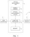
- FIG. 1is a block diagram showing components of a biological sample analysis system, in accordance some applications of the present invention
- FIGS. 2 A, 2 B, 2 C, and 2 Dare schematic illustrations of respective views of a sample carrier, in accordance with some applications of the present invention.
- FIGS. 3 A and 3 Bshow photobleaching patterns that were detected upon a sample carrier immediately after being exposed to short-term fluorescent excitation ( FIG. 3 A ), and one week after the exposure ( FIG. 3 B ), in accordance with some applications of the present invention
- FIG. 3 Cis a plot of the fluorescent emission from the sample carrier measured along the length of the sample carrier, immediately after the sample carrier was exposed to the short-term fluorescent excitation, one week after the sample carrier was exposed to the short-term fluorescent excitation, and three weeks after the sample carrier was exposed to the short-term fluorescent excitation, in accordance with some applications of the present invention
- FIGS. 4 A, 4 B, and 4 Care schematic illustrations of respective views of a sample carrier that is used for performing both microscopic measurements and optical density measurements, in accordance with some applications of the present invention
- FIGS. 5 A, 5 B, and 5 Care schematic illustrations of respective views of a sample carrier that is used for performing both microscopic measurements and optical density measurements, in accordance with some applications of the present invention
- FIG. 6is a schematic illustration of a sample carrier that includes markings on its upper and lower surfaces, in accordance with some applications of the present invention
- FIG. 7 Ais a schematic top view of an irregular pattern of a sample carrier, in accordance with some applications of the present invention.
- FIG. 7 Bis a schematic diagram illustrating the irregular pattern shown in FIG. 7 A when tilted, in accordance with some applications of the present invention.
- FIGS. 8 A, 8 B, 8 C, and 8 Dare schematic top views of portions of the irregular pattern shown in FIG. 7 A as viewed through an observation field of an imaging module of an optical measurement device, in accordance with some applications of the present invention
- FIGS. 9 A, 9 B, 9 C, and 9 Dare schematic top views of portions of the irregular pattern shown in FIG. 7 B as viewed through an observation field of an imaging module of an optical measurement device, in accordance with some applications of the present invention
- FIGS. 10 A, 10 B, and 10 Care schematic top views of some examples of irregular patterns, in accordance with some applications of the present invention.
- FIG. 11 Ais a schematic illustration of a 3D irregular pattern on a sample carrier, in accordance with some applications of the present invention.
- FIG. 11 Bis a schematic 3D illustration of a portion of the 3D irregular pattern shown in FIG. 11 A , in accordance with some applications of the present invention.
- FIGS. 11 C, 11 D, 11 E, and 11 Fare schematic 2D top views of the portion shown in FIG. 11 B , taken at respective different focal lengths of an optical field of an imaging module of an optical measurement device, in accordance with some applications of the present invention
- FIG. 12is a schematic XY position chart demonstrating some possible planar positions of a sample carrier with respect to an imaging module of an optical measurement device, in accordance with some applications of the present invention.
- FIG. 1is block diagram showing components of a biological sample analysis system 20 , in accordance with some applications of the present invention.
- a biological samplee.g., a blood sample
- a sample carrier 22While the sample is disposed in the sample carrier, optical measurements are performed upon the sample using one or more optical measurement devices 24 .
- the optical measurement devicesmay include a microscope (e.g., a digital microscope), a spectrophotometer, a photometer, a spectrometer, a camera, a spectral camera, a hyperspectral camera, a fluorometer, a spectrofluorometer, and/or a photodetector (such as a photodiode, a photoresistor, and/or a phototransistor).
- the optical measurement devicesinclude dedicated light sources (such as light emitting diodes, incandescent light sources, etc.) and/or optical elements for manipulating light collection and/or light emission (such as lenses, diffusers, filters, etc.).
- a microscope systemis used that is generally similar to the microscope system described in US 2014/0347459 to Greenfield, which is incorporated herein by reference.
- a computer processor 28typically receives and processes optical measurements that are performed by the optical measurement device. Further typically, the computer processor controls the acquisition of optical measurements that are performed by the one or more optical measurement devices. The computer processor communicates with a memory 30 .
- a usere.g., a laboratory technician
- the user interfaceincludes a keyboard, a mouse, a joystick, a touchscreen device (such as a smartphone or a tablet computer), a touchpad, a trackball, a voice-command interface, and/or other types of user interfaces that are known in the art.
- the computer processorgenerates an output via an output device 34 .
- the output deviceincludes a display, such as a monitor, and the output includes an output that is displayed on the display.
- the processorgenerates an output on a different type of visual, text, graphics, tactile, audio, and/or video output device, e.g., speakers, headphones, a smartphone, or a tablet computer.
- user interface 32acts as both an input interface and an output interface, i.e., it acts as an input/output interface.
- the processorgenerates an output on a computer-readable medium (e.g., a non-transitory computer-readable medium), such as a disk, or a portable USB drive, and/or generates an output on a printer.
- optical measurement device 24(and/or computer processor 28 and memory 30 ) is housed inside an optical measurement unit 31 .
- sample carrier 22is placed inside the optical measurement unit.
- FIGS. 2 A and 2 Bare schematic illustrations of respective views of sample carrier 22 , in accordance with some applications of the present invention.
- FIG. 2 Ashows a top view of the sample carrier (the top cover of the sample carrier being shown as being opaque in FIG. 2 A , for illustrative purposes), and
- FIG. 2 Bshows a bottom view (in which the sample carrier has been rotated around its short edge with respect to the view shown in FIG. 2 A ).
- sample carrier 22includes a plurality of chambers 36 , e.g., five chambers as shown in FIG. 2 A .
- the chambersare filled with a bodily sample, such as blood via sample inlet holes 38 .
- the chambersdefine one or more outlet holes 40 .
- the outlet holesare configured to facilitate filling of the chambers with the bodily sample, by allowing air that is present in the chambers to be released from the chambers.
- the outlet holesare located longitudinally opposite the inlet holes (with respect to a sample chamber of the sample carrier). For some applications, the outlet holes thus provide a more efficient mechanism of air escape than if the outlet holes were to be disposed closer to the inlet holes.
- FIG. 2 Cshows an exploded view of sample carrier 22 , in accordance with some applications of the present invention.
- the sample carrierincludes at least three components: a molded component 42 , a glass sheet 44 , and an adhesive layer 46 configured to adhere the glass sheet to an underside of the molded component.
- FIG. 2 Dshows the molded component and the adhesive layer in the absence of the glass sheet, for illustrative purposes.
- the molded componentis typically made of a polymer (e.g., a plastic) that is molded (e.g., via injection molding) to provide the chambers with a desired geometrical shape.
- the molded componentis typically molded to define inlet holes 38 , outlet holes 40 , and gutters 48 which surround the central portion of each of the chambers.
- the gutterstypically facilitate filling of the chambers with the bodily sample, by allowing air to flow to the outlet holes, and/or by allowing the bodily sample to flow around the central portion of the chamber.
- optical measurementsare performed upon the sample using one or more optical measurement devices 24 .
- the sampleis viewed by the optical measurement device via the glass layer, glass being transparent at least to wavelengths that are typically used by the optical measurement device.
- the sample carrieris inserted into optical measurement unit 31 , which houses the optical measurement device while the optical measurements are performed.
- the optical measurement unithouses the sample carrier such that the molded layer is disposed above the glass layer, and such that the optical measurement unit is disposed below the glass layer of the sample carrier and is able to perform optical measurements upon the sample via the glass layer.
- the sample carrieris formed by adhering the glass sheet to the molded component.
- the glass sheet and the molded componentmay be bonded to each other during manufacture or assembly (e.g. using thermal bonding, solvent-assisted bonding, ultrasonic welding, laser welding, heat staking, adhesive, mechanical clamping and/or additional substrates).
- the glass layer and the molded componentare bonded to each other during manufacture or assembly using adhesive layer 46 .
- a sample carrierdefines a plurality of chambers, which facilitates multiple samples being placed within respective chambers of a single cartridge, and/or multiple types of diagnostic tests being performed on respective portions of a single sample that is placed in respective chambers.
- a sample carriermay be configured to be reused, but for a limited number of times.
- photobleaching apparatus and techniquesare used, as described in further detail hereinbelow with reference to FIGS. 3 A, 3 B, and 3 C .
- a portion of sample carrier 22is configured to fluoresce, at least under certain conditions.
- the portion of the sample carriermay be configured to fluoresce when exposed to light emitted by optical measurement device 24 (e.g., brightfield light or fluorescent light that is emitted by a microscope system).
- the portion of the sample carriermay be configured to fluoresce when placed within optical measurement unit 31 in which optical measurement device 24 is housed.
- sample carrier 22includes adhesive layer 46 .
- the adhesive layeris configured to fluoresce in the above-described manner (e.g., by an adhesive material within the adhesive layer being configured to fluoresce, by the adhesive layer containing an additional material that is configured to fluoresce, and/or by the adhesive layer being coated with such a material).
- the adhesive layeris a pressure-sensitive adhesive, at least a portion of which is configured to fluoresce.
- the pressure-sensitive adhesivemay be an acrylic-based pressure-sensitive adhesive, at least a portion of which is configured to fluoresce.
- the portion of the sample carrier that is configured to fluoresceis further configured to undergo photobleaching in areas that are exposed to fluorescent excitation (e.g. in the UV part of the electromagnetic spectrum).
- such areasmay be configured to undergo photobleaching when exposed to fluorescent excitation for less than one minute, less than 10 seconds, or less than 1 second.
- the area that is photobleachedcan be viewed using the optical measurement device 24 (e.g., the microscope system), and further typically, the photobleaching remains visible for at least one week, e.g., at least one month, or one year.
- FIGS. 3 A and 3 Bshow photobleached spots 50 on microscope images of a sample carrier immediately after being exposed to short-term fluorescent excitation ( FIG. 3 A ), and one week after the exposure ( FIG. 3 B ), in accordance with some applications of the present invention.
- the diameter of the spot shown in FIGS. 3 A and 3 Bis approximately 2 mm, and as shown, it is visible in the microscope images.
- FIG. 3 Cis a plot of the fluorescent emission from the sample carrier (y-axis) measured along the length of the sample carrier (x-axis), immediately after the sample carrier was exposed to the short-term fluorescent excitation (the curve with the uppermost peak between 200 and 300 along the x-axis), one week after the sample carrier was exposed to the short-term fluorescent excitation (the curve with the middle peak between 200 and 300 along the x-axis), and three weeks after the sample carrier was exposed to the short-term fluorescent excitation (the curve with the lowest peak between 200 and 300 along the x-axis), in accordance with some applications of the present invention.
- the plotswere normalized to have equal intensities at the darkest spot.
- a portion of a sample carrieris analyzed, in order to determine whether the portion or an area thereof has undergone photobleaching.
- the above stepsare performed by computer processor 28 .
- the computer processorin response to detecting that the sample carrier, or a portion thereof (e.g., a chamber thereof) has already been used, or that the usage of the sample carrier, or a portion thereof (e.g., a chamber thereof) has exceeded a given threshold, the computer processor generates an output indicating that the sample carrier, or the portion thereof (e.g., the chamber thereof), should not be used, generates an output indicating that the sample carrier, or the portion thereof (e.g., the chamber thereof) is contaminated, and/or prevents the optical measurement device from performing optical measurements upon the sample carrier, or the portion thereof (e.g., the chamber thereof).
- a given area of the sample carrieris marked by photobleaching the area when the sample carrier is used.
- optical measurement device 24may be configured to photobleach a given area of the sample carrier when the sample carrier is placed inside optical measurement unit 31 that houses the sample carrier while optical measurements are performed upon the portion of the sample.
- optical measurement device 24may be configured to photobleach a given area of the sample carrier when the optical measurement device performs an optical measurement on the sample carrier.
- the optical measurement deviceis configured to photobleach a given area of the sample carrier automatically, by virtue of performing optical measurements upon the sample carrier (i.e., without having to perform any activity specifically for the purpose of causing the photobleaching, which the optical measurement device would not have been performing in any event, in order to perform the optical measurements).
- the optical measurement devicemay be a microscope system that performs fluorescent imaging upon the sample by exciting the sample and/or a stained portion of the sample with light that corresponds to an excitation wavelength of the sample and/or the stained portion of the sample, such that the light causes the sample and/or the stained portion of the sample to fluoresce.
- the light that is emitted by the microscope system, in order to cause the sample and/or the stained portion of the sample to fluoresce,may also photobleach the given area of the sample carrier.
- the computer processorverifies that the sample carrier has not already been used, using the techniques described hereinabove.
- the sample carrieris configured to be reused, but only a limited number of times. For some such applications, each time the sample carrier is used, a respective different area of the sample carrier is photobleached, such that the computer processor may then determine how many times the sample carrier has been used by detecting the number and/or locations of photobleached areas upon the sample carrier.
- the above-described photobleaching effectis used by a manufacturer of sample carriers to encode manufacturing information regarding the sample carrier, in a manner which is not visible to the naked eye.
- manufacturing informationmay include an authenticity mark (to reduce the likelihood of counterfeit sample carriers being utilized), sample carrier type, manufacturing date, expiry date, manufacturing location, date required for accurate performance of the test (e.g. calibration date pertaining to the sample carrier, or batch of sample carriers).
- the markingis marked using a geometric pattern that includes lines, figures, barcodes, alphanumeric characters, etc.
- a sample carrier that contains a given sampleis analyzed more than once by the optical measurement devices.
- the samplemay be analyzed and then re-analyzed at certain time intervals.
- respective portions of the same sampleare placed in respective chambers of the sample carrier and are analyzed at respective time intervals.
- the optical measurement deviceis configured to mark the sample carrier, via photobleaching, in a given manner. Subsequently, when the sample carrier is placed back inside the optical measurement unit, or a different optical measurement unit for the re-analysis, the computer processor verifies that it is the same sample carrier by identifying the marks on the sample carrier.
- the above-described apparatus and methodswhich relate to photobleaching a portion of a sample carrier that is configured to fluoresce at least under certain conditions, is not limited to any particular design of the sample carrier. Rather, any design of sample carrier may be configured to incorporate such a portion.
- the above-described apparatus and methods, which relate to photobleaching a portion of a sample carrier that is configured to fluoresce at least under certain conditionsis not limited to any particular portion of a sample carrier. Rather, any portion of a sample carrier may be configured to have such characteristics. For example, any portion of the molded component, the adhesive layer, or the glass sheet of a sample carrier as described herein may be configured in this manner.
- FIGS. 4 A, 4 B, 4 C, and 4 Dare schematic illustrations of respective views of sample carrier 22 , the sample carrier being configured for facilitating both microscopic measurements, and optical density measurements with respect to the sample, in accordance with some applications of the present invention.
- FIG. 4 Ashows a top view of the sample carrier (the top cover of the sample carrier being shown as being opaque in FIG. 4 A , for illustrative purposes)
- FIG. 4 Bshows a bottom view (in which the sample carrier has been rotated around its long edge with respect to the view shown in FIG. 4 A )
- FIG. 4 Cshows an exploded side view.
- a sample carrier as shown in FIGS. 4 A-Cis used when performing a complete blood count on a blood sample.
- the sample carrierincludes a first set 52 of chambers, which are used for performing microscopic analysis upon the sample, and a second set 54 of chambers, which are used for performing optical density measurements upon the sample.
- the sample carrieris made of a molded component 42 , a glass sheet 44 and an adhesive layer 46 , as shown in FIG. 4 C .
- the adhesive layeris configured to fluoresce and/or to become photobleached, as described hereinabove.
- the molded componentis configured to define inlet holes 38 , outlet holes 40 , and/or gutters 48 , which are generally as described hereinabove.
- chambers belonging to set 54typically define at least a first region 56 (which is typically deeper) and a second region 58 (which is typically shallower), the height of the chambers varying between the first and second regions in a predefined manner.
- the optical path length, the volume, and/or the thickness of the portion of the sample upon which the optical measurements were performedare precisely as possible.
- the optical measurementsare performed upon a portion of the sample disposed in a sample carrier that is defined by two or more opposing surfaces.
- the two or more opposing surfacesare separated by a distance that is correspondingly tightly set or tightly controlled.
- the distance between the opposing surfacesmay vary substantially. For example, the upper and lower surfaces of the chambers as shown in FIGS.
- the adhesive layerhas a nominal thickness, it is typically the case that, for example, due to variation in the manufactured thickness of the pressure-sensitive adhesive or in the pressure applied during its application, the actual thickness of the layer is different from the nominal thickness.
- molded component and the glass sheetmay be bonded using a pressure-sensitive adhesive layer with a nominal thickness that is configured to separate the opposing surfaces by a separation of 100 micrometers.
- variation in the manufactured thickness of the pressure-sensitive adhesive layer or in the pressure applied during its applicationmay result in a final thickness that may lie, for example, as far as 20 micrometers greater or less than the nominal thickness.
- an optical measurementis performed on the sample.
- the density of a componentmay be determined by performing a count of the component within a microscopic image.
- the concentration and/or density of a componentmay be measured by performing optical absorption, transmittance, fluorescence, and/or luminescence measurements upon the sample.
- an uncertainty of 20 percent in the distance separating the two opposing surfacesmay, in turn, correspond to 20 percent uncertainty in parameters of the sample that are derived from the optical measurements that are performed upon the sample (such as, the derived concentration and/or density of a component within the sample), e.g., as described in WO 17/195205 to Pollack, which is incorporated herein by reference.
- sample chambers belonging to set 54define first region 56 and second region 58 .
- the heights of first region 56 and second region 58 of the sample chamberare defined by a lower surface that is defined by the glass sheet and by an upper surface that is defined by the molded component.
- the upper surface at the second regionis stepped with respect to the upper surface at the first region.
- the step between the upper surface at the first and second regionsprovides a predefined height difference ⁇ h between the regions, such that even if the absolute height of the regions is not known to a sufficient degree of accuracy, the height difference ⁇ h is known to a sufficient degree of accuracy to determine a parameter of the sample, using the techniques described herein, and as described in WO 17/195205 to Pollack, which is incorporated herein by reference.
- the molded componentis shaped to define a stepped surface such as to define the manner in which the height of the chambers belonging to set 54 varies between the first and second regions.
- a stepped surfacesuch as to define the manner in which the height of the chambers belonging to set 54 varies between the first and second regions.
- relative manufacturing tolerances within a single substrate, and especially between nearby surfacesare tighter than manufacturing tolerances on positioning between different substrates or even between opposing surfaces lying within the same substrate. Therefore, it is typically the case that by having a single substrate define the manner in which the height of the one or more sample chambers varies between the first and second regions, the height difference between the first and second regions is relatively precise.
- the molded componentmay be manufactured with relatively tight tolerances, for example, using injection molding, embossing or machining.
- chambers belonging to set 52have different heights from each other, in order to facilitate different measurands being measured using microscope images of respective chambers, and/or different chambers being used for microscopic analysis of respective sample types. For example, if a blood sample, and/or a monolayer formed by the sample, has a relatively low density of red blood cells, then measurements may be performed within a chamber of the sample carrier having a relatively great height, such that there is a sufficient density of cells, and/or such that there is a sufficient density of cells within the monolayer formed by the sample, to provide statistically reliable data.
- Such measurementsmay include, for example red blood cell density measurements, measurements of other cellular attributes, (such as counts of abnormal red blood cells, red blood cells that include intracellular bodies (e.g., pathogens, Howell-Jolly bodies), etc.), and/or hemoglobin concentration.
- measurements of other cellular attributessuch as counts of abnormal red blood cells, red blood cells that include intracellular bodies (e.g., pathogens, Howell-Jolly bodies), etc.
- hemoglobin concentratione.g., hemoglobin concentration
- the chamber within the sample carrier upon which to perform optical measurementsis selected.
- a chamber of the sample carrier having a relatively great heightmay be used to perform a white blood cell count (e.g., to reduce statistical errors which may result from a low count in a shallower region), white blood cell differentiation, and/or to detect more rare forms of white blood cells.
- microscopic imagesmay be obtained from a chamber of the sample chamber having a relatively low height, since in such chambers the cells are relatively sparsely distributed across the area of the region, and/or form a monolayer in which the cells are relatively sparsely distributed.
- microscopic imagesmay be obtained from a chamber of the sample chamber having a relatively low height, since within such chambers there are fewer red blood cells which overlap (fully or partially) with the platelets in microscopic images, and/or in a monolayer.
- a chamber of the sample carrierhaving a lower height for performing optical measurements for measuring some measurands within a sample (such as a blood sample), whereas it is preferable to use a chamber of the sample carrier having a greater height for performing optical measurements for measuring other measurands within such a sample.
- a first measurand within a sampleis measured, by performing a first optical measurement upon (e.g., by acquiring microscopic images of) a portion of the sample that is disposed within a first chamber belonging to set 52 of the sample carrier, and a second measurand of the same sample measured, by performing a second optical measurement upon (e.g., by acquiring microscopic images of) a portion of the sample that is disposed within a second chamber of set 52 of the sample carrier.
- the first and second measurandsare normalized with respect to each other, for example, using techniques as described in WO 17/195208 to Zait, which is incorporated herein by reference.
- FIGS. 5 A, 5 B, and 5 Care schematic illustrations of respective views of sample carrier 22 , the sample carrier being configured for use in performing both microscopic measurements, and optical density measurements, in accordance with some applications of the present invention.
- FIG. 5 Ashows a bottom view of the sample carrier, with the bottom surface being transparent, such that features of the chambers of the sample carrier may be observed.
- FIGS. 5 B and 5 Cshow top views of the sample carrier in which the top layer of the sample carrier is opaque (and in which the sample carrier has been rotated around its long edge with respect to the view shown in FIG. 5 A ).
- Sample carrier as shown in FIGS. 5 A, 5 B, and 5 Cis generally similar to that shown in FIGS. 4 A-C , and described with reference thereto, except for differences described hereinbelow.
- the sample carrierincludes first set 52 of chambers, which are used for performing microscopic analysis upon the sample, and second set 54 of chambers, which are used for performing optical density measurements upon the sample.
- the second set of chambers, which are used for performing optical density measurements upon the sampleincludes only a single chamber, as shown.
- the outlet holes of each of the chambers belonging to the first set of chambersare disposed in close proximity to each other (as shown in FIG. 5 B ), e.g., such that the holes are disposed along a line measuring less than 1 cm long.
- a cover 60(shown in FIG. 5 C ) is reversibly (or, optionally, irreversibly) coupled to the sample carrier, such as to cover the outlet holes.
- the covermay include paper, sponge or filter material that has an adhesive backing.
- the coveris configured to prevent the sample from leaking out of the sample carrier, thereby reducing the likelihood of the optical measuring device becoming contaminated by leakage from the sample carrier.
- the coveris configured to control the rate of filling of the first set 52 of chambers, by limiting the rate of air flow out of the chambers.
- a cover that is generally similar to cover 60is placed over outlet holes associated with second set 54 of chambers.
- sample carrier 22is shaped to define a reservoir 39 that is adjacent to inlet hole 38 .
- the reservoiris configured to allow the user to fill the chambers of the sample carrier with the bodily sample, such that, on the one hand, the user is not required to insert a precise volume of the bodily sample into the inlet hole, and yet, on the other hand, the inlet hole is left substantially free of liquids.
- FIG. 6is a schematic illustration showing a bottom view of sample carrier 22 , a chamber of the sample carrier including a first marking 62 on its lower inner surface (i.e., the inner surface of the glass layer), and a second marking 64 on its upper inner surface (e.g., the inner surface of the substrate layer), in accordance with some applications of the present invention.
- the inner surface of the substrate layeris visible through the transparent glass layer.
- the markingsmay constitute lines, or other shapes (e.g., alphanumeric characters).
- the markingsmay be imprinted on the sample carrier, drawn on the sample carrier, etched on the sample carrier, engraved on the sample carrier, glued on the sample carrier, embedded within the sample carrier, may constitute protrusions and/or indentations within the sample carrier and/or other visible features of the sample carrier, and/or may be attached to the sample carrier.
- a samplefills a volume having a height that is defined by the upper and lower surfaces.
- the volume of a portion of the sample in one of the chambersis defined by the area of the chamber multiplied by the height of the chamber.
- the exact height of the chamberis not known, for example, for the reasons provided hereinabove.
- the computer processordetermines the height of the chamber by focusing an imaging module of the optical measurement device on first marking 62 and registering an indication of the focusing distance F1 associated with the first marking.
- the computer processoralso focuses the imaging module of the optical measurement device on second marking 64 and registers an indication of the focusing distance F2 associated with the second marking.
- the computer processordetermines the height of the chamber, based upon the difference between F1 and F2. For some applications, the computer processor determines the volume of the chamber, or a portion thereof, based upon the determined height of the chamber. Typically, the computer processor determines a property of the sample at least partially based upon the determined height of the chamber, for example, using techniques as described hereinabove.
- the positioning of the sample carrier with respect to an imaging module of optical measurement device 24is typically a degree of variation in the positioning of the sample carrier with respect to an imaging module of optical measurement device 24 .
- placement of the sample carrier on a microscope stagecan vary significantly in view of the required imaging resolution (due for example to limitations of the microscope, variation in the sample carrier, variations in placement by an operator of the device, etc.). Therefore, in accordance with some applications, the positioning of the sample carrier with respect to an imaging module of optical measurement device 24 is determined, in accordance with the techniques described herein.
- the imaging module of the optical measurement device and a stage upon which the sample carrier is placedare initially positioned such that a visible mark on the sample carrier appears within the observation field of the imaging module. This is followed by scanning a portion of the sample carrier surface until sufficient information is available to define the sample carrier's position and/or orientation at least with respect to the X-Y plane.
- the term Z-axisis used to refer to the optical axis of the optical system
- the X-Y planeis used to denote the plane that is perpendicular to the optical axis, as is common in the art.
- FIGS. 7 A and 7 Bin which an example of an irregular pattern 70 is shown, the pattern including a set of vertical lines 72 and horizontal lines 74 confined within a square boundary 76 , in accordance with some applications of the present invention.
- FIG. 7 Bshows the irregular pattern shown in FIG. 7 A in an orientation that is tilted with respect to that shown in FIG. 7 A .
- an irregular patternsuch as that shown in FIGS. 7 A-B , is marked upon sample carrier 22 .
- Optical measurement devicewhich typically includes a microscope system, images the sample carrier via an observation field. Typically, such observation fields image sub-portions within chambers of the sample carrier.
- the spacing between the vertical lines 72is irregular, i.e. the distance between each two neighboring vertical lines 72 is different than any of two other neighboring vertical lines 72 .
- the same designis applied to the horizontal lines.
- the irregular patternmay measure about 2.7 ⁇ 2.7 mm 2
- the observation fieldmay measure about 0.6 ⁇ 0.8 mm 2 .
- irregular pattern 70 and the observation fieldare shown as being essentially rectangular or square, any other shape may be used.
- a round or other shape observation fieldmay be selected, for example based on optical limitations which may provide a better image in a portion of a diagnostic field.
- the optical measurement deviceis typically used to capture images of the sample using an observation field O.F. (also referred herein as an orientation field), which has a predetermined size and shape, and through which (when properly place above the sample carrier) a portion of the sample carrier can be viewed.
- the irregular patternis designed with a resolution that is complementary to the observation field size so that in any lateral X-Y position of the observation field over the irregular pattern, the portion of the irregular pattern observed through the observation field is unique to that specific position and detectable at the set resolution of the device.
- an observation fieldmay be a diagnostic field or a portion thereof.
- an observation fieldis assembled using a plurality of adjacent diagnostic fields, such that the combined information from two or more diagnostic fields is used as an observation field.
- FIGS. 8 A, 8 B, 8 C, and 8 Din which examples of the pattern corresponding to respective observation fields are shown, in accordance with some applications of the present invention. It may be observed that the image of the portion of the irregular pattern captured at different positions of the observation field is different for each such position.
- the irregular patternis designed so that the images captured at any two different X-Y positions will yield different visible portions of the irregular pattern.
- the resolution of the irregular patternis designed to be complementary to the size and shape of the observation field, such that it is typically not the case that the observation field is smaller than the distance between two neighboring lines of the pattern (either horizontal or vertical), so that an observation field never includes a single line, an empty space or the sole thickness of a single line.
- the only exception to this configurationis an irregular pattern designed specifically so that such a single line, empty space and/or sole thickness can occur in a single position of the observation field across the entire irregular pattern.
- the computer processortypically determines the position of the irregular pattern with respect to the observation field. Since the irregular pattern is fixedly associated with the sample carrier, the computer processor thereby determines the location, and optionally orientation, of the sample carrier that is imaged within the observation field.
- FIGS. 9 A, 9 B, 9 C, and 9 Din which some additional examples of the pattern corresponding to respective observation fields are shown, in accordance with some applications of the present invention. It is noted, with reference to the examples shown in FIGS. 9 A-D , that not only the X-Y position of the irregular pattern be determined via the observation field, but also the orientation thereof. Thus, for some applications, the computer processor determines which portion of the sample carrier is being imaged in a given observation field, as well as the orientation of the sample carrier within the observation field, based upon the irregular pattern that is identified within the observation field.
- the irregular patternis imprinted on the sample carrier, drawn on the sample carrier, etched on the sample carrier, engraved on the sample carrier, glued on the sample carrier, embedded within the sample carrier, constitutes protrusions and/or indentations within the sample carrier, and/or other visible features of the sample carrier, and/or is attached to the sample carrier.
- the irregular patterne.g., a 2D pattern as described with reference to FIGS. 7 A- 10 C , and/or a 3D pattern as described with reference to FIG. 11 A- 11 F
- the irregular patternis formed upon the inner surface of the molded layer of the sample carrier.
- the irregular patternis formed on a surface of the glass layer of the sample carrier.
- an irregular pattern as described with reference to any one of FIG. 7 A- 12is used on a sample carrier having different characteristics to the sample carriers described with reference to FIGS. 2 A- 6 .
- FIGS. 10 A, 10 B and 10 Cin which three additional examples of irregular patterns are shown, in accordance with some applications of the present invention.
- FIG. 10 Aa set of concentric circles of uniquely different diameters, and being overlapped by a rectangular wave pattern
- FIG. 10 Ba set of circles of uniquely different diameters and varying line thicknesses, and which are not concentric;
- FIG. 10 Ca spiral configuration of varying line thickness.
- each of the patterns shown in FIGS. 10 A to 10 Cprovides a unique image to respective observation fields that are disposed at different X-Y positions above the irregular pattern.
- each of the patterns shown in FIGS. 10 A to 10 Cprovides a unique image to respective observation fields that are disposed at different angular orientations above the irregular pattern, such that it is possible to distinguish between angular positions that are separated by less than 5 degrees.
- the irregular patternis a 3D pattern having elements thereof located at different heights along the Z-axis.
- the maximum height of the 3D pattern relative to the minimum heightmeasures about 10 ⁇ m.
- the 3D patternis marked on a surface having the same position along the optical axis of the imaging module of the optical measurement device as the surface upon which the sample is to be imaged.
- the 3D patternmay be located on the surface and/or be embedded within the material.
- a 3D patternis used such that even a single image, or no more than 10 images, are needed to provide sufficient information to determine the position, and optionally also orientation of the sample carrier, with respect to an imaging module of an optical measurement device, both with respect to an XY plane of the observation field and along the optical axis of the imaging module.
- the 3D patternis associated with a 2D pattern or mark as described above (either juxtaposed therewith or being a part thereof), so that once information is gathered from the 2D mark or pattern (regarding the position, and optionally orientation, of the sample carrier with respect to an X-Y plane of the visual examination zone), a single image of the 3D pattern is enough to determine the location of the sample carrier along the optical axis of an imaging module.
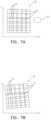
- FIG. 11 Aa 3D pattern 80 is shown, in which the irregular pattern is reflected not only in the 2D grid design, but also in varying depths of different areas of the pattern, in accordance with some applications of the present invention.
- the 3D patternis in the form of an irregular grid of rectangular portions, each rectangle having a top at a certain depth from the surface, such that at least some different rectangles have different depths.
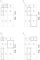
- FIG. 11 Bin which a portion of the 3D pattern is shown (e.g. a portion of the pattern observed by the observation field O.F.), comprising nine rectangles sq1 to sq9, each rectangle being at one of four depths D0 to D3, in accordance with some applications of the present invention.
- the arrangement shown in FIG. 11 Bis as follows:
- FIGS. 11 C to 11 Feach showing an example of an image of the 3D portion taken by the imaging module of the optical measurement device at depths D0 to D3 respectively, in accordance with some applications of the present invention. It may be observed that, at each focal length of the imaging module of the optical measurement device, corresponding to each of the depths D0 to D3, the image received is such that the boundaries of the rectangles at that depth/focal length are clearly visible (indicated by the solid lines), while the remainder of the rectangles (which are not located at that depth/focal length) are not in focus (indicated by the dashed lines).
- the 3D feature of the irregular patternis used by computer processor 28 to provide an additional degree of accuracy for determining the position of the sample carrier with respect to the imaging module of the optical measurement device.
- the 3D feature of the irregular patternis used by computer processor 28 to provide an indication as to the focal length of the imaging module of the optical measurement device.
- a single image taken of the 3D patternmay provide sufficient information regarding the position of the grid in the X-Y plane as well as along the optical axis of the imaging module of the optical measurement device.
- an imagee.g., a single image
- the computer processorderives the location of the 3D pattern along the optical axis of the imaging module of the optical measurement device using the image.
- depths D0 to D3are not necessarily equally spaced, and the height differences between respective pairs of consecutive height levels can be different from each other.
- FIG. 12is a schematic illustration of the spatial arrangement of an irregular pattern of a sample carrier with respect to an observation field O.F. of the imaging module of optical measurement device 24 , in accordance with some applications of the present invention.
- a sample carriermay be located in one of a plurality of X-Y positions with respect to the observation field.
- Position A and Position Btwo extreme positions, Position A and Position B, of the sample carrier with respect to the observation field are depicted, the positions differing in location by a length Lx along the X-axis, and by a length Ly along the Y-axis.
- the spatial arrangement of the irregular pattern along the carrieris typically such that at least a portion of the irregular pattern falls within the observation field, regardless of the relative position of the carrier with respect to the optical device.
- the position of the sample carrier with respect to the imaging module of the optical measurement devicedoes not affect the optical measurement device's ability to operate properly.
- the sample as described hereinis a sample that includes blood or components thereof (e.g., a diluted or non-diluted whole blood sample, a sample including predominantly red blood cells, or a diluted sample including predominantly red blood cells), and parameters are determined relating to components in the blood such as platelets, white blood cells, anomalous white blood cells, circulating tumor cells, red blood cells, reticulocytes, Howell-Jolly bodies, etc.
- blood or components thereofe.g., a diluted or non-diluted whole blood sample, a sample including predominantly red blood cells, or a diluted sample including predominantly red blood cells
- parametersare determined relating to components in the blood such as platelets, white blood cells, anomalous white blood cells, circulating tumor cells, red blood cells, reticulocytes, Howell-Jolly bodies, etc.
- the sampleis a biological sample, such as, blood, saliva, semen, sweat, sputum, vaginal fluid, stool, breast milk, bronchoalveolar lavage, gastric lavage, tears and/or nasal discharge.
- the biological samplemay be from any living creature, and is typically from warm blooded animals.
- the biological sampleis a sample from a mammal, e.g., from a human body.
- the sampleis taken from any domestic animal, zoo animals and farm animals, including but not limited to dogs, cats, horses, cows and sheep.
- the biological sampleis taken from animals that act as disease vectors including deer or rats.
- the sampleis an environmental sample, such as, a water (e.g. groundwater) sample, surface swab, soil sample, air sample, or any combination thereof.
- the sampleis a food sample, such as, a meat sample, dairy sample, water sample, wash-liquid sample, beverage sample, and/or any combination thereof.
- a computer-usable or computer-readable mediumcan be any apparatus that can comprise, store, communicate, propagate, or transport the program for use by or in connection with the instruction execution system, apparatus, or device.
- the mediumcan be an electronic, magnetic, optical, electromagnetic, infrared, or semiconductor system (or apparatus or device) or a propagation medium.
- the computer-usable or computer readable mediumis a non-transitory computer-usable or computer readable medium.
- Examples of a computer-readable mediuminclude a semiconductor or solid state memory, magnetic tape, a removable computer diskette, a random-access memory (RAM), a read-only memory (ROM), a rigid magnetic disk and an optical disk.
- Current examples of optical disksinclude compact disk-read only memory (CD-ROM), compact disk-read/write (CD-R/W) and DVD.
- a data processing system suitable for storing and/or executing program codewill include at least one processor (e.g., computer processor 28 ) coupled directly or indirectly to memory elements (e.g., memory 30 ) through a system bus.
- the memory elementscan include local memory employed during actual execution of the program code, bulk storage, and cache memories which provide temporary storage of at least some program code in order to reduce the number of times code must be retrieved from bulk storage during execution.
- the systemcan read the inventive instructions on the program storage devices and follow these instructions to execute the methodology of the embodiments of the invention.
- Network adaptersmay be coupled to the processor to enable the processor to become coupled to other processors or remote printers or storage devices through intervening private or public networks.
- Modems, cable modem and Ethernet cardsare just a few of the currently available types of network adapters.
- Computer program code for carrying out operations of the present inventionmay be written in any combination of one or more programming languages, including an object-oriented programming language such as Java, Smalltalk, C++ or the like and conventional procedural programming languages, such as the C programming language or similar programming languages.
- object-oriented programming languagesuch as Java, Smalltalk, C++ or the like
- conventional procedural programming languagessuch as the C programming language or similar programming languages.
- These computer program instructionsmay also be stored in a computer-readable medium (e.g., a non-transitory computer-readable medium) that can direct a computer or other programmable data processing apparatus to function in a particular manner, such that the instructions stored in the computer-readable medium produce an article of manufacture including instruction means which implement the function/act specified in the flowchart blocks and algorithms.
- the computer program instructionsmay also be loaded onto a computer or other programmable data processing apparatus to cause a series of operational steps to be performed on the computer or other programmable apparatus to produce a computer implemented process such that the instructions which execute on the computer or other programmable apparatus provide processes for implementing the functions/acts specified in the algorithms described in the present application.
- Computer processor 28is typically a hardware device programmed with computer program instructions to produce a special purpose computer. For example, when programmed to perform the algorithms described herein, computer processor 28 typically acts as a special purpose sample-analysis computer processor. Typically, the operations described herein that are performed by computer processor 28 transform the physical state of memory 30 , which is a real physical article, to have a different magnetic polarity, electrical charge, or the like depending on the technology of the memory that is used.
- a sample carrierconfigured to carry a sample
- an optical measurement deviceconfigured to perform optical measurements upon the sample, the optical measurement device defining an observation field
- a controllerconfigured to:
- the sample carriercomprises at least one irregular pattern and the irregular pattern is sized and positioned on a sample carrier surface such that at least one of said ten orientation images or less shows the irregular pattern or a part thereof without searching.
- Inventive concept 17An automated microscope according to inventive concept 16, wherein the irregular pattern is patterned such that any portion of an orientation image that shows the irregular pattern or a part thereof shows a geometric pattern unique to that portion.
- Inventive concept 18An automated microscope according to inventive concept 16, wherein the irregular pattern is sized, shaped and positioned such that one image per pattern is sufficient for determining at least one of a position and orientation of the sample carrier.
- a sample carrier for a microscopecomprising at least one chamber configured for containing therein a sample to be analyzed, said chamber comprising:
- said platform surfacecomprises a first mark and a said cover comprises on a surface thereof a second mark, wherein the focusing distance between the first mark and the second mark allows determining a vertical length of the space between said platform surface and a bottom surface of said cover.
- Inventive concept 20A sample carrier for a microscope according to inventive concept 19, wherein the second mark is on the bottom surface of said cover.
- Inventive concept 21A sample carrier for a microscope according to inventive concept 19, wherein the first mark and second mark overlap along the Z axis.
- Inventive concept 22A sample carrier for a microscope according to inventive concept 19, wherein at least one of the first mark and second mark comprises an irregular pattern.
- Inventive concept 23A method for determining a volume of a portion of a fluid sample in a sample carrier of inventive concept 19, comprising:
Landscapes
- Chemical & Material Sciences (AREA)
- Physics & Mathematics (AREA)
- Health & Medical Sciences (AREA)
- Analytical Chemistry (AREA)
- General Physics & Mathematics (AREA)
- General Health & Medical Sciences (AREA)
- Immunology (AREA)
- Life Sciences & Earth Sciences (AREA)
- Biochemistry (AREA)
- Pathology (AREA)
- Optics & Photonics (AREA)
- Nuclear Medicine, Radiotherapy & Molecular Imaging (AREA)
- Multimedia (AREA)
- Engineering & Computer Science (AREA)
- Dispersion Chemistry (AREA)
- Hematology (AREA)
- Clinical Laboratory Science (AREA)
- Chemical Kinetics & Catalysis (AREA)
- Investigating Or Analysing Materials By Optical Means (AREA)
- Investigating, Analyzing Materials By Fluorescence Or Luminescence (AREA)
- Optical Measuring Cells (AREA)
- Automatic Analysis And Handling Materials Therefor (AREA)
Abstract
Description
- perform optical measurements upon the portion of the bodily sample that is housed within the sample carrier; and
- at least partially photobleach an area within the portion of the sample carrier by causing the area to fluoresce.
- to detect that the area within the portion of the sample carrier has been photobleached, and
- in response thereto, to generate an output upon the output device indicating that at least a portion of the sample carrier is contaminated.
- to detect that the area within the portion of the sample carrier has been photobleached, and
- in response thereto, to generate an output upon the output device indicating that optical measurements cannot be performed on at least a portion of the sample that is housed within a given portion of the sample carrier.
- wherein the upper inner surface includes a first mark and the lower inner surface includes a second mark; and
- focus the imaging module on the first marking and register an indication of a first focusing distance between the imaging module and the first marking;
- focus the imaging module on the second marking and register an indication of a second focusing distance between the imaging module and the second marking; and
- determine a height of the chamber, based upon a difference between the first focusing distance and the second focusing distance.
- focusing the imaging module on the first marking and registering an indication of a first focusing distance between the imaging module and the first marking;
- focusing the imaging module on the second marking and registering an indication of a second focusing distance between the imaging module and the second marking; and
- determining a height of the chamber, based upon a difference between the first focusing distance and the second focusing distance.
| Rectangle No. | Depth | ||
| sq1, sq3, sq8 | D0 | ||
| sq2, sq6 | D1 | ||
| sq4, sq9 | D2 | ||
| sq5, sq7 | D3 | ||
- the sample carrier comprising a surface that comprises at least one irregular pattern, such that any portion of the surface of the sample carrier having a shape and area that corresponds to the observation field of the optical measurement device and that contains at least a portion of the pattern has a geometric pattern unique to that portion.
Inventive concept 2. The apparatus according toinventive concept 1, wherein the irregular pattern is configured to facilitate determining a position of the sample carrier with respect to a plane of the observation field, based on a single image of any portion of the surface of the sample carrier that contains a portion of the pattern having a geometric pattern unique to that portion.
Inventive concept 3. The apparatus according toinventive concept 1, wherein the irregular pattern has a given orientation with respect to the surface of the sample carrier, such that the sample carrier facilitates determining orientation of the sample carrier with respect to the observation field of the optical measurement device
Inventive concept 4. The apparatus according toinventive concept 1, wherein the irregular pattern is present on the surface of the carrier using one or more techniques selected from the group consisting of: drawing, embossing, etching, carving, and adhering.
Inventive concept 5. The apparatus according toinventive concept 1, wherein the surface of the sample carrier that comprise the irregular pattern comprises a surface of a sample chamber that is configured to carry the sample therein.
Inventive concept 6. The apparatus according toinventive concept 1, wherein the carrier comprises a cover, and wherein the surface of the sample carrier that comprise the irregular pattern comprises a surface of the cover.
Inventive concept 7. The apparatus according toinventive concept 1, wherein the surface of the sample carrier that comprise the irregular pattern comprises a surface of the sample carrier that is located on the sample carrier outside any chamber.
Inventive concept 8. The apparatus according toinventive concept 1, wherein the optical measurement device comprises a microscope.
Inventive concept 9. The apparatus according toinventive concept 1, wherein the sample carrier comprises two or more irregular patterns.
Inventive concept 10. The apparatus according toinventive concept 1, wherein the said sample carrier comprises two or more chambers, each configured to carry a portion of the sample therein.
Inventive concept 11. The sample carrier according to inventive concept 10, wherein at least one of said at least one irregular pattern is located on a surface of each of said two or more chambers.
Inventive concept 12. A sample carrier configured for containing a sample to be analyzed by an optical measurement device having a maximal visual examining zone of area A at a diagnostic imaging magnification, wherein the initial imaging position of the carrier may vary by a length L in at least one of the X and Y axis of a plane being perpendicular to the optic axis of the optic device and having a visual examining zone of area S, said sample carrier comprising at least one irregular pattern having an area A′, where A′=f(A,L); such that any image having the same shape and area as that of the visual examining zone taken at an expected initial location of the irregular pattern would comprise a portion of the pattern that has a geometric pattern unique to that portion.
Inventive concept 13. A sample carrier configured for containing a sample to be analyzed by an optical measurement device the carrier comprising at least one irregular geometric pattern having an area of at least 6 mm2such that any portion of the pattern having the same size and shape and having an area of 0.3 mm2or more and comprising at least a portion of the pattern has a geometric pattern unique to that portion.
Inventive concept 14. The sample carrier of inventive concept 13, wherein an inscribing circle of said irregular geometric pattern measures at least 3 mm in diameter, and does not measure less than 2 mm in two perpendicular directions.
Inventive concept 15. The sample carrier of inventive concept 13, wherein the inscribing circle of said portion measures at least 0.5 mm in diameter, and does not measure less than 0.4 mm in two perpendicular directions.
Inventive concept 16. An automated microscope configured to analyze a sample within a sample carrier comprising:
- the sample carrier comprising a surface that comprises at least one irregular pattern, such that any portion of the surface of the sample carrier having a shape and area that corresponds to the observation field of the optical measurement device and that contains at least a portion of the pattern has a geometric pattern unique to that portion.
- operate the optical module to capture ten orientation images or less of the sample carrier at a predetermined location; and
- analyze the images to deduce at least one of a position and orientation of the carrier or a portion thereof with respect to at least one of an XY plane and a z axis of the microscope,
Inventive concept 18. An automated microscope according to inventive concept 16, wherein the irregular pattern is sized, shaped and positioned such that one image per pattern is sufficient for determining at least one of a position and orientation of the sample carrier.
Inventive concept 19. A sample carrier for a microscope, comprising at least one chamber configured for containing therein a sample to be analyzed, said chamber comprising:
- US 2012/0169863 to Bachelet;
- US 2014/0347459 to Greenfield;
- US 2015/0037806 to Pollak;
- US 2015/0316477 to Pollak;
- US 2016/0208306 to Pollak;
- US 2016/0246046 to Yorav Raphael;
- US 2016/0279633 to Bachelet;
- US 2018/0246313 to Eshel;
- WO 16/030897 to Yorav Raphael;
- WO 17/046799 to Eshel;
- WO 17/168411 to Eshel;
- WO 17/195205 to Pollack; and
- WO 17/195208 to Zait.
Claims (21)
Priority Applications (1)
| Application Number | Priority Date | Filing Date | Title |
|---|---|---|---|
| US17/083,659US11614609B2 (en) | 2017-11-14 | 2020-10-29 | Sample carrier for microscopy measurements |
Applications Claiming Priority (4)
| Application Number | Priority Date | Filing Date | Title |
|---|---|---|---|
| US201762585621P | 2017-11-14 | 2017-11-14 | |
| PCT/IB2018/058861WO2019097387A1 (en) | 2017-11-14 | 2018-11-12 | Sample carrier for optical measurements |
| US202016763810A | 2020-05-13 | 2020-05-13 | |
| US17/083,659US11614609B2 (en) | 2017-11-14 | 2020-10-29 | Sample carrier for microscopy measurements |
Related Parent Applications (2)
| Application Number | Title | Priority Date | Filing Date |
|---|---|---|---|
| PCT/IB2018/058861ContinuationWO2019097387A1 (en) | 2017-11-14 | 2018-11-12 | Sample carrier for optical measurements |
| US16/763,810ContinuationUS11921272B2 (en) | 2017-11-14 | 2018-11-12 | Sample carrier for optical measurements |
Publications (2)
| Publication Number | Publication Date |
|---|---|
| US20210072526A1 US20210072526A1 (en) | 2021-03-11 |
| US11614609B2true US11614609B2 (en) | 2023-03-28 |
Family
ID=64477225
Family Applications (5)
| Application Number | Title | Priority Date | Filing Date |
|---|---|---|---|
| US16/763,810Active2039-07-05US11921272B2 (en) | 2017-11-14 | 2018-11-12 | Sample carrier for optical measurements |
| US17/083,775Active2038-11-25US11609413B2 (en) | 2017-11-14 | 2020-10-29 | Sample carrier for microscopy and optical density measurements |
| US17/083,659Active2038-12-02US11614609B2 (en) | 2017-11-14 | 2020-10-29 | Sample carrier for microscopy measurements |
| US18/397,324ActiveUS12196940B2 (en) | 2017-11-14 | 2023-12-27 | Sample carrier for microscopy and optical density measurements |
| US18/956,363PendingUS20250085525A1 (en) | 2017-11-14 | 2024-11-22 | Sample carrier for measurements on a bodily sample |
Family Applications Before (2)
| Application Number | Title | Priority Date | Filing Date |
|---|---|---|---|
| US16/763,810Active2039-07-05US11921272B2 (en) | 2017-11-14 | 2018-11-12 | Sample carrier for optical measurements |
| US17/083,775Active2038-11-25US11609413B2 (en) | 2017-11-14 | 2020-10-29 | Sample carrier for microscopy and optical density measurements |
Family Applications After (2)
| Application Number | Title | Priority Date | Filing Date |
|---|---|---|---|
| US18/397,324ActiveUS12196940B2 (en) | 2017-11-14 | 2023-12-27 | Sample carrier for microscopy and optical density measurements |
| US18/956,363PendingUS20250085525A1 (en) | 2017-11-14 | 2024-11-22 | Sample carrier for measurements on a bodily sample |
Country Status (7)
| Country | Link |
|---|---|
| US (5) | US11921272B2 (en) |
| EP (1) | EP3710810B1 (en) |
| JP (1) | JP7214729B2 (en) |
| CN (1) | CN111788471B (en) |
| AU (1) | AU2018369859B2 (en) |
| CA (1) | CA3081669A1 (en) |
| WO (1) | WO2019097387A1 (en) |
Cited By (2)
| Publication number | Priority date | Publication date | Assignee | Title |
|---|---|---|---|---|
| WO2024127207A1 (en) | 2022-12-12 | 2024-06-20 | S.D. Sight Diagnostics Ltd | System and method for analyzing bodily samples |
| WO2024236537A1 (en) | 2023-05-18 | 2024-11-21 | S.D. Sight Diagnostics Ltd | Apparatus and methods for microscopic analysis of a biological sample |
Families Citing this family (19)
| Publication number | Priority date | Publication date | Assignee | Title |
|---|---|---|---|---|
| US9522396B2 (en) | 2010-12-29 | 2016-12-20 | S.D. Sight Diagnostics Ltd. | Apparatus and method for automatic detection of pathogens |
| BR112014016072B1 (en) | 2011-12-29 | 2021-01-12 | Sight Diagnostics Ltd. | method and system for detecting a plasmodium infection in a blood sample |
| EP2999988A4 (en) | 2013-05-23 | 2017-01-11 | S.D. Sight Diagnostics Ltd. | Method and system for imaging a cell sample |
| IL227276A0 (en) | 2013-07-01 | 2014-03-06 | Parasight Ltd | A method and system for preparing a monolayer of cells, particularly suitable for diagnosis |
| US10831013B2 (en) | 2013-08-26 | 2020-11-10 | S.D. Sight Diagnostics Ltd. | Digital microscopy systems, methods and computer program products |
| EP3186778B1 (en) | 2014-08-27 | 2023-01-11 | S.D. Sight Diagnostics Ltd. | System and method for calculating focus variation for a digital microscope |
| EP3350644B1 (en) | 2015-09-17 | 2021-04-28 | S.D. Sight Diagnostics Ltd. | Methods and apparatus for detecting an entity in a bodily sample |
| CA3018536A1 (en) | 2016-03-30 | 2017-10-05 | S.D. Sight Diagnostics Ltd | Distinguishing between blood sample components |
| EP4177593A1 (en) | 2016-05-11 | 2023-05-10 | S.D. Sight Diagnostics Ltd. | Sample carrier for optical measurements |
| JP6942148B2 (en) | 2016-05-11 | 2021-09-29 | エス.ディー.サイト ダイアグノスティクス リミテッド | Performing optical measurements on the sample |
| AU2018369859B2 (en) | 2017-11-14 | 2024-01-25 | S.D. Sight Diagnostics Ltd | Sample carrier for optical measurements |
| BR112022007708A2 (en) | 2019-10-22 | 2022-07-12 | S D Sight Diagnostics Ltd | ACCOUNTING OF ERRORS IN OPTICAL MEASUREMENTS |
| WO2021116959A1 (en) | 2019-12-12 | 2021-06-17 | S.D. Sight Diagnostics Ltd | Analyzing an analyte disposed within a medium |
| EP4073491A1 (en) | 2019-12-12 | 2022-10-19 | S.D. Sight Diagnostics Ltd. | Off-focus microscopic images of a sample |
| AU2020400400A1 (en) | 2019-12-12 | 2022-05-26 | S.D. Sight Diagnostics Ltd | Detecting platelets in a blood sample |
| MX2022007125A (en) | 2019-12-12 | 2022-07-11 | S D Sight Diagnostics Ltd | Classification models for analyzing a sample. |
| EP4073566B1 (en) | 2019-12-12 | 2025-04-23 | S.D. Sight Diagnostics Ltd. | Artificial generation of color blood smear image |
| WO2022009104A2 (en) | 2020-07-07 | 2022-01-13 | S.D. Sight Diagnostics Ltd | Focusing a microscope using fluorescent images |
| US20250108367A1 (en) | 2022-01-25 | 2025-04-03 | S.D. Sight Diagnostics Ltd. | Sample carrier for use with a bodily sample |
Citations (365)
| Publication number | Priority date | Publication date | Assignee | Title |
|---|---|---|---|---|
| US3203768A (en) | 1961-08-01 | 1965-08-31 | Westinghouse Electric Corp | Apparatus of zone refining and controlling solute segregation in solidifying melts by electromagnetic means |
| US3603156A (en) | 1970-02-04 | 1971-09-07 | Gradko Glass Lab Inc | Disposable dilution system |
| US3676076A (en) | 1970-09-24 | 1972-07-11 | Gradko Glass Lab Inc | Disposable container |
| US3786184A (en) | 1971-02-05 | 1974-01-15 | Image Analysing Computers Ltd | Focusing |
| US3916205A (en) | 1973-05-31 | 1975-10-28 | Block Engineering | Differential counting of leukocytes and other cells |
| US3967056A (en) | 1973-02-26 | 1976-06-29 | Minolta Camera Kabushiki Kaisha | Automatic focusing apparatus |
| US4030888A (en) | 1975-02-28 | 1977-06-21 | Toa Medical Electronics Co., Ltd. | Automatic blood analyzer |
| US4076419A (en) | 1976-07-12 | 1978-02-28 | Kleker Richard G | Method and apparatus for hematology |
| US4097845A (en) | 1976-11-01 | 1978-06-27 | Rush-Presbyterian-St. Luke's Medical Center | Method of and an apparatus for automatic classification of red blood cells |
| US4199748A (en) | 1976-11-01 | 1980-04-22 | Rush-Presbyterian-St. Luke's Medical Center | Automated method and apparatus for classification of cells with application to the diagnosis of anemia |
| US4209548A (en) | 1976-11-01 | 1980-06-24 | Rush-Presbyterian-St. Luke's Medical Center | Method for the preparation of blood samples for automated analysis |
| US4350884A (en) | 1979-03-20 | 1982-09-21 | Kernforschungszentrum Karlsruhe Gesellschaft Mit Beschrankter Haftung | Automatic focusing of every image point in an image |
| EP0073551A2 (en) | 1981-08-27 | 1983-03-09 | Becton Dickinson and Company | Sample collection container |
| US4453266A (en) | 1980-04-21 | 1984-06-05 | Rush-Presbyterian-St. Luke's Medical Center | Method and apparatus for measuring mean cell volume of red blood cells |
| US4454235A (en) | 1982-06-01 | 1984-06-12 | Miles Laboratories, Inc. | Capillary tube holder for liquid transfer in immunoassay |
| US4494479A (en) | 1982-10-14 | 1985-01-22 | Coulter Electronics, Inc. | Slide preparation apparatus |
| WO1985005446A1 (en) | 1984-05-15 | 1985-12-05 | Merck Patent Gmbh | Single dye replacement for romanowsky plural dye variable compositions in human biopsy specimen constituent identifications |
| US4580895A (en) | 1983-10-28 | 1986-04-08 | Dynatech Laboratories, Incorporated | Sample-scanning photometer |
| JPS61198204A (en) | 1985-02-28 | 1986-09-02 | Disco Abrasive Sys Ltd | Microscope autofocus method |
| US4700298A (en) | 1984-09-14 | 1987-10-13 | Branko Palcic | Dynamic microscope image processing scanner |
| US4761381A (en) | 1985-09-18 | 1988-08-02 | Miles Inc. | Volume metering capillary gap device for applying a liquid sample onto a reactive surface |
| US4774192A (en) | 1987-01-28 | 1988-09-27 | Technimed Corporation | A dry reagent delivery system with membrane having porosity gradient |
| US4803352A (en) | 1986-05-16 | 1989-02-07 | Fritz Bierleutgeb | Autofocusing system for a microscope and method of using the same |
| US4849430A (en) | 1988-03-09 | 1989-07-18 | Monsanto Company | Method of inhibiting virus |
| US4851330A (en) | 1983-01-10 | 1989-07-25 | Kohne David E | Method for detection, identification and quantitation of non-viral organisms |
| US4902101A (en) | 1986-10-16 | 1990-02-20 | Olympus Optical Co., Ltd. | Automatic focusing method |
| US5001067A (en) | 1989-09-18 | 1991-03-19 | Nova Biomedical Corporation | Determining the concentration of water soluble species in biological fluid |
| US5064282A (en) | 1989-09-26 | 1991-11-12 | Artel, Inc. | Photometric apparatus and method for measuring hemoglobin |
| EP0479231A1 (en) | 1990-10-01 | 1992-04-08 | Canon Kabushiki Kaisha | Apparatus and method for measuring specimen |
| US5229265A (en) | 1990-03-13 | 1993-07-20 | Litron Laboratories | Process for analyzing clastogenic agents |
| US5300779A (en) | 1985-08-05 | 1994-04-05 | Biotrack, Inc. | Capillary flow device |
| US5331958A (en) | 1992-03-31 | 1994-07-26 | University Of Manitoba | Spectrophotometric blood analysis |
| US5430542A (en) | 1992-04-10 | 1995-07-04 | Avox Systems, Inc. | Disposable optical cuvette |
| US5470751A (en) | 1993-02-22 | 1995-11-28 | Toa Medical Electronics Co., Ltd. | Reagent for detecting malaria infected cells and a detecting method for malaria infected cells using the same |
| WO1996001438A1 (en) | 1994-07-01 | 1996-01-18 | Price Jeffrey H | Autofocus system for scanning microscopy |
| WO1996012981A1 (en) | 1994-10-21 | 1996-05-02 | Kla Instruments Corporation | Autofocusing apparatus and method for high resolution microscope system |
| WO1996013615A1 (en) | 1994-10-27 | 1996-05-09 | Entremed, Inc. | Identification of infection with flow cytometry |
| JPH0954083A (en) | 1995-08-11 | 1997-02-25 | Mamoru Ishizawa | Method for inspecting platelet and blood collection tube for inspecting platelet |
| US5663057A (en) | 1994-11-17 | 1997-09-02 | Chemunex | Process for rapid and ultrasensitive detection and counting of microorganisms by fluorescence |
| US5672861A (en) | 1994-01-18 | 1997-09-30 | Ultrapointe Corporation | Method and apparatus for automatic focusing of a confocal laser microscope |
| US5674457A (en) | 1995-04-21 | 1997-10-07 | Hemocue Ab | Capillary microcuvette |
| US5745804A (en) | 1994-05-31 | 1998-04-28 | Nikon Corporation | Automatic focus device |
| US5782770A (en) | 1994-05-12 | 1998-07-21 | Science Applications International Corporation | Hyperspectral imaging methods and apparatus for non-invasive diagnosis of tissue for cancer |
| US5827190A (en) | 1994-03-28 | 1998-10-27 | Xillix Technologies Corp. | Endoscope having an integrated CCD sensor |
| US5834217A (en) | 1992-10-30 | 1998-11-10 | Becton Dickinson And Co. | Assay of blood or other biologic samples for target analytes |
| GB2329014A (en) | 1997-09-05 | 1999-03-10 | Colin Campbell | Automated identification of tubercle bacilli |
| JPH1173903A (en) | 1997-08-28 | 1999-03-16 | Jeol Ltd | Autofocus method for scanning electron microscope |
| US5932872A (en) | 1994-07-01 | 1999-08-03 | Jeffrey H. Price | Autofocus system for scanning microscopy having a volume image formation |
| US5948686A (en) | 1998-03-07 | 1999-09-07 | Robert A. Leuine | Method for performing blood cell counts |
| US5978497A (en) | 1994-09-20 | 1999-11-02 | Neopath, Inc. | Apparatus for the identification of free-lying cells |
| US5985595A (en) | 1995-06-07 | 1999-11-16 | The University Of Connecticut | Early detection of Borrelia infection |
| US6005964A (en) | 1996-01-24 | 1999-12-21 | The Board Of Trustees Of The University Of Illinois | Automatic machine vision microscope slide inspection system and method |
| WO2000006765A1 (en) | 1998-07-29 | 2000-02-10 | Paolo Fazii | Differential staining of bacteria using fluorescence |
| US6027695A (en) | 1998-04-01 | 2000-02-22 | Dupont Pharmaceuticals Company | Apparatus for holding small volumes of liquids |
| US6064474A (en) | 1998-02-06 | 2000-05-16 | Optical Sensors, Inc. | Optical measurement of blood hematocrit incorporating a self-calibration algorithm |
| US6074789A (en) | 1994-03-08 | 2000-06-13 | Philips Electronics N.A. Corp. | Method for producing phosphor screens, and color cathode ray tubes incorporating same |
| JP2000199845A (en) | 1999-01-05 | 2000-07-18 | Ricoh Co Ltd | Automatic focusing device and automatic focusing method |
| US6101104A (en) | 1998-06-04 | 2000-08-08 | Hughes Electronics Corporation | Predictive threshold synchronous rectifier control |
| WO2000052195A1 (en) | 1999-03-01 | 2000-09-08 | Novus International, Inc. | Viability assay for sporocyst-forming protozoa |
| WO2000055572A1 (en) | 1999-03-18 | 2000-09-21 | Zetetic Institute | Multiple layer confocal interference microscopy using wavenumber domain reflectometry and background amplitude reduction and compensation |
| US6235536B1 (en) | 1998-03-07 | 2001-05-22 | Robert A. Levine | Analysis of quiescent anticoagulated whole blood samples |
| US6262798B1 (en) | 1992-09-29 | 2001-07-17 | Board Of Regents, The University Of Texas System | Method and apparatus for direct spectrophotometric measurements in unaltered whole blood |
| US6320979B1 (en) | 1998-10-06 | 2001-11-20 | Canon Kabushiki Kaisha | Depth of field enhancement |
| US6339472B1 (en) | 1998-12-23 | 2002-01-15 | Dean G. Hafeman | Determination of light absorption pathlength in a vertical-beam photometer |
| US20020009711A1 (en) | 2000-01-06 | 2002-01-24 | Wada H. Garrett | Methods and systems for monitoring intracellular binding reactions |
| US6350613B1 (en) | 1998-03-07 | 2002-02-26 | Belton Dickinson & Co. | Determination of white blood cell differential and reticulocyte counts |
| US20020028158A1 (en) | 1998-03-07 | 2002-03-07 | Wardlaw Stephen C. | Apparatus for analyzing biologic fluids |
| US20020028471A1 (en) | 1998-02-20 | 2002-03-07 | Oberhardt Bruce J. | Cell analysis methods and apparatus |
| US6448024B1 (en) | 2000-10-03 | 2002-09-10 | Roche Diagnostics Corporation | Method, reagent, cartridge, and device for determining fibrinogen |
| US20030017085A1 (en) | 1998-08-10 | 2003-01-23 | Caliper Technologies Corp. | High throughput microfluidic systems and methods |
| US6519355B2 (en) | 2001-03-28 | 2003-02-11 | Alan C. Nelson | Optical projection imaging system and method for automatically detecting cells having nuclear and cytoplasmic densitometric features associated with disease |
| US6554788B1 (en) | 2000-06-02 | 2003-04-29 | Cobe Cardiovascular, Inc. | Hematocrit sampling system |
| US6582964B1 (en) | 1999-05-12 | 2003-06-24 | Cme Telemetrix Inc. | Method and apparatus for rapid measurement of HbA1c |
| WO2003056327A1 (en) | 2001-12-28 | 2003-07-10 | Hemocue Ab | Method for quantitative hemoglobin determination in undiluted unhemolyzed whole blood |
| US6611777B2 (en) | 1999-11-23 | 2003-08-26 | James Samsoondar | Method for calibrating spectrophotometric apparatus |
| US20030161514A1 (en) | 2002-02-28 | 2003-08-28 | Curry Bo U. | Bi-directional scanner control system |
| WO2003073365A1 (en) | 2002-02-22 | 2003-09-04 | Bacus Research Laboratories, Inc. | Focusable virtual microscopy apparatus and method |
| US20030170613A1 (en) | 2001-09-06 | 2003-09-11 | Don Straus | Rapid and sensitive detection of cells and viruses |
| WO2003081525A1 (en) | 2002-03-21 | 2003-10-02 | Endress + Hauser Wetzer Gmbh + Co. Kg | Device for identifying a sampler container |
| US6632681B1 (en) | 2000-07-24 | 2003-10-14 | Ey Laboratories | Reagent delivery device and method of use |
| US20030197925A1 (en) | 2002-04-18 | 2003-10-23 | Leica Microsystems Wetzlar Gmbh | Autofocus method for a microscope, and system for adjusting the focus for a microscope |
| US6658143B2 (en) | 2002-04-29 | 2003-12-02 | Amersham Biosciences Corp. | Ray-based image analysis for biological specimens |
| US20030224522A1 (en) | 2002-05-01 | 2003-12-04 | De Jong Gary | Methods for delivering nucleic acid molecules into cells and assessment thereof |
| US20030227673A1 (en) | 2001-03-01 | 2003-12-11 | Olympus Optical Co., Ltd. | System and method for controlling microscope |
| US20030227612A1 (en) | 2002-06-10 | 2003-12-11 | Howard Fein | Imaging system for examining biological material |
| US6664528B1 (en) | 2001-07-06 | 2003-12-16 | Palantyr Research, Llc | Imaging system and methodology employing reciprocal space optical design |
| US20030231791A1 (en) | 2002-06-12 | 2003-12-18 | Torre-Bueno Jose De La | Automated system for combining bright field and fluorescent microscopy |
| EP1381229A1 (en) | 2001-03-30 | 2004-01-14 | National Institute of Advanced Industrial Science and Technology | Real-time omnifocus microscope camera |
| US6711516B2 (en) | 1999-11-23 | 2004-03-23 | Spectromedical Inc. | Method for calibrating spectrophotometric apparatus |
| JP2004144526A (en) | 2002-10-22 | 2004-05-20 | Japan Science & Technology Agency | Malaria infection diagnostic agent and malaria parasite stain |
| US20040122216A1 (en) | 2002-07-01 | 2004-06-24 | Jacob Nielsen | Recombinant tissue protective cytokines and encoding nucleic acids thereof for protection, restoration, and enhancement of responsive cells, tissues, and organs |
| US20040132171A1 (en) | 2003-01-06 | 2004-07-08 | Peter Rule | Wearable device for measuring analyte concentration |
| US20040170312A1 (en) | 2000-05-03 | 2004-09-02 | Soenksen Dirk G. | Fully automatic rapid microscope slide scanner |
| JP2004257768A (en) | 2003-02-24 | 2004-09-16 | Horiba Ltd | Micro blood cell counter |
| US20040185447A1 (en) | 2003-03-20 | 2004-09-23 | Coulter International Corp. | Dye compositions which provide enhanced differential fluorescence and light scatter characteristics |
| US6799119B1 (en) | 2000-05-15 | 2004-09-28 | Colorado School Of Mines | Method for detection of biological related materials using biomarkers |
| US20040218804A1 (en) | 2003-01-31 | 2004-11-04 | Affleck Rhett L. | Image analysis system and method |
| US6819408B1 (en) | 2000-09-27 | 2004-11-16 | Becton, Dickinson And Company | Method for obtaining a monolayer of desired particles in a liquid sample |
| US20040241677A1 (en) | 2003-05-29 | 2004-12-02 | Lin Jeffrey S | Techniques for automated diagnosis of cell-borne anomalies with digital optical microscope |
| US20040240050A1 (en) | 2002-07-30 | 2004-12-02 | Nikon Corporation | Microscope system |
| US6834237B2 (en) | 2000-06-02 | 2004-12-21 | Medicometrics Aps | Method and system for classifying a biological sample |
| WO2004111610A2 (en) | 2003-06-12 | 2004-12-23 | Accupath Diagnostic Laboratories, Inc. | Method and system for the analysis of high density cells samples |
| US6836559B2 (en) | 2000-03-09 | 2004-12-28 | The Regents Of The University Of California | Automated video-microscopic imaging and data acquisition system for colloid deposition measurements |
| US6842233B2 (en) | 2001-07-26 | 2005-01-11 | Sysmex Corporation | Method of classifying particles on two-dimensional frequency distribution map and blood analyzer utilizing the same |
| US6872930B2 (en) | 2003-03-31 | 2005-03-29 | Palantyr Research, Llc | Imaging system and methodology employing reciprocal space optical design |
| US20050089208A1 (en) | 2003-07-22 | 2005-04-28 | Rui-Tao Dong | System and method for generating digital images of a microscope slide |
| US6898451B2 (en) | 2001-03-21 | 2005-05-24 | Minformed, L.L.C. | Non-invasive blood analyte measuring system and method utilizing optical absorption |
| US20050109959A1 (en) | 2003-11-24 | 2005-05-26 | Mitutoyo Corporation | Systems and methods for rapidly automatically focusing a machine vision inspection system |
| US20050175992A1 (en) | 2004-02-09 | 2005-08-11 | Rapid Pathogen Screening Inc. | Method for the rapid diagnosis of targets in human body fluids |
| US6949384B2 (en) | 2001-12-21 | 2005-09-27 | Spectromedical Inc. | Method for monitoring degradation of Hb-based blood substitutes |
| US6956650B2 (en) | 2001-01-12 | 2005-10-18 | General Hospital Corporation | System and method for enabling simultaneous calibration and imaging of a medium |
| WO2005121863A1 (en) | 2004-06-11 | 2005-12-22 | Nicholas Etienne Ross | Automated diagnosis of malaria and other infections |
| US20050286800A1 (en) | 2004-06-24 | 2005-12-29 | Fujifilm Electronic Imaging Ltd. | Method and apparatus for forming a multiple focus stack image |
| US20060003458A1 (en) | 2003-08-15 | 2006-01-05 | Golovchenko Jene A | Study of polymer molecules and conformations with a nanopore |
| US20060002817A1 (en)* | 2004-06-30 | 2006-01-05 | Sebastian Bohm | Flow modulation devices |
| US6989891B2 (en) | 2001-11-08 | 2006-01-24 | Optiscan Biomedical Corporation | Device and method for in vitro determination of analyte concentrations within body fluids |
| US20060045505A1 (en) | 2004-08-31 | 2006-03-02 | Zeineh Jack A | System and method for creating magnified images of a microscope slide |
| US20060051778A1 (en) | 2004-03-31 | 2006-03-09 | Kallick Charles A | Diagnosis of systemic lupus erythematosus |
| US20060063185A1 (en) | 2004-09-09 | 2006-03-23 | Edouard Vannier | Methods for detection of pathogens in red blood cells |
| US7027628B1 (en) | 2000-11-14 | 2006-04-11 | The United States Of America As Represented By The Department Of Health And Human Services | Automated microscopic image acquisition, compositing, and display |
| US7034883B1 (en) | 1999-08-10 | 2006-04-25 | Cellavision Ab | Automatic focusing |
| US20060190226A1 (en) | 2004-10-29 | 2006-08-24 | Microsoft Corporation | Systems and methods that utilize machine learning algorithms to facilitate assembly of aids vaccine cocktails |
| US20060187442A1 (en) | 2003-07-19 | 2006-08-24 | Digital Bio Technology | Device for counting micro particles |
| US7105795B2 (en) | 2001-07-06 | 2006-09-12 | Palantyr Research, Llc | Imaging system, methodology, and applications employing reciprocal space optical design |
| US20060223052A1 (en) | 2005-03-30 | 2006-10-05 | Kimberly-Clark Worldwide, Inc. | Technique for detecting microorganisms |
| US20060223165A1 (en) | 2003-07-18 | 2006-10-05 | Digital Bio Technology | Device for counting cells and method for manufacturing the same |
| US20060222567A1 (en) | 2005-04-01 | 2006-10-05 | Hafellner | Body fluid testing component for simultaneous analyte detection |
| JP2006301270A (en) | 2005-04-20 | 2006-11-02 | Hitachi Kokusai Electric Inc | Autofocus device and autofocus method |
| US7133547B2 (en) | 2002-01-24 | 2006-11-07 | Tripath Imaging, Inc. | Method for quantitative video-microscopy and associated system and computer software program product |
| US7132636B1 (en) | 2001-07-06 | 2006-11-07 | Palantyr Research, Llc | Imaging system and methodology employing reciprocal space optical design |
| WO2006121266A1 (en) | 2005-05-06 | 2006-11-16 | Jae Chern Yoo | Digital bio disc(dbd), dbd driver apparatus, and assay method using the same |
| US7151246B2 (en) | 2001-07-06 | 2006-12-19 | Palantyr Research, Llc | Imaging system and methodology |
| US7155049B2 (en) | 2001-01-11 | 2006-12-26 | Trestle Acquisition Corp. | System for creating microscopic digital montage images |
| JP2007040814A (en) | 2005-08-03 | 2007-02-15 | Matsushita Electric Ind Co Ltd | Absorbance measurement sensor and absorbance measurement method |
| CN1918501A (en) | 2004-02-09 | 2007-02-21 | 皇家飞利浦电子股份有限公司 | Fluorescence microscope arrangement |
| US20070054350A1 (en) | 2003-03-27 | 2007-03-08 | Walker Fitz Jr | System and method for rapidly identifying pathogens, bacteria and abnormal cells |
| US20070076190A1 (en) | 2005-09-28 | 2007-04-05 | Sysmex Corporation | Apparatus for obtaining an image of a blood cell and method for obtaining an image of a blood cell |
| US7248716B2 (en) | 2001-07-06 | 2007-07-24 | Palantyr Research, Llc | Imaging system, methodology, and applications employing reciprocal space optical design |
| US20070172956A1 (en) | 2006-01-20 | 2007-07-26 | Beckman Coulter, Inc. | Methods of Detection of Iron Deficiency |
| US7274810B2 (en) | 2000-04-11 | 2007-09-25 | Cornell Research Foundation, Inc. | System and method for three-dimensional image rendering and analysis |
| US7283217B2 (en) | 2004-03-11 | 2007-10-16 | Sysmex Corporation | Sample analyzer and computer product |
| US20070243117A1 (en) | 2004-04-07 | 2007-10-18 | Wardlaw Stephen C | Disposable Chamber for Analyzing Biologic Fluids |
| US20070250301A1 (en) | 2006-03-09 | 2007-10-25 | Cytokinetics, Inc., A Delaware Corporation | Normalizing cell assay data for models |
| US7288751B2 (en) | 2001-07-06 | 2007-10-30 | Palantyr Research, Llc | Imaging system, methodology, and applications employing reciprocal space optical design |
| US20070252984A1 (en) | 2004-06-17 | 2007-11-01 | Koninklijke Philips Electronics N.V. | Autofocus Mechanism for Spectroscopic System |
| US20080020128A1 (en) | 2006-07-24 | 2008-01-24 | Van Ryper William John | Automated microscope for blood cell analysis |
| US7324694B2 (en) | 2003-05-23 | 2008-01-29 | International Remote Imaging Systems, Inc. | Fluid sample analysis using class weights |
| US7329537B2 (en) | 2003-04-17 | 2008-02-12 | Nexcelom Bioscience, Llc | Micro-pattern embedded plastic optical film device for cell-based assays |
| US7338168B2 (en) | 2001-07-06 | 2008-03-04 | Palantyr Research, Llc | Particle analyzing system and methodology |
| US20080059135A1 (en) | 2006-07-24 | 2008-03-06 | Sangeeta Murugkar | Pathogen Detection Using Coherent Anti-Stokes Raman Scattering Microscopy |
| US7344890B2 (en) | 2005-11-09 | 2008-03-18 | Beckman Coulter, Inc. | Method for discriminating platelets from red blood cells |
| US7369696B2 (en) | 2003-04-02 | 2008-05-06 | Ge Healthcare Uk Limited | Classification of cells into subpopulations using cell classifying data |
| US20080118399A1 (en) | 2004-12-13 | 2008-05-22 | Roger Fleming | Self-Contained Test Sensor |
| WO2008063135A1 (en) | 2006-11-24 | 2008-05-29 | Agency For Science, Technology And Research | Apparatus for processing a sample in a liquid droplet and method of using the same |
| US7385168B2 (en) | 2001-07-06 | 2008-06-10 | Palantyr Research, Llc | Imaging system, methodology, and applications employing reciprocal space optical design |
| US7387898B1 (en)* | 1996-10-08 | 2008-06-17 | Burstein Technologies, Inc. | Apparatus and method for conducting assays |
| US20080187466A1 (en) | 1998-03-07 | 2008-08-07 | Wardlaw Stephen C | Container for holding biologic fluid for analysis |
| US7417213B2 (en) | 2005-06-22 | 2008-08-26 | Tripath Imaging, Inc. | Apparatus and method for rapid microscopic image focusing having a movable objective |
| US20080212069A1 (en) | 2007-01-26 | 2008-09-04 | Becton, Dickinson And Company | Method, system, and compositions for cell counting and analysis |
| US7425421B2 (en) | 2003-06-26 | 2008-09-16 | Litron Laboratories, Ltd. | Method for the enumeration of micronucleated erythrocyte populations while distinguishing platelets and/or platelet-associated aggregates |
| US7439478B2 (en) | 2001-07-06 | 2008-10-21 | Palantyr Research, Llc | Imaging system, methodology, and applications employing reciprocal space optical design having at least one pixel being scaled to about a size of a diffraction-limited spot defined by a microscopic optical system |
| US20080260369A1 (en) | 2007-04-19 | 2008-10-23 | Canon Kabushiki Kaisha | Camera having an image blur reducing function and rotation means |
| US7450762B2 (en) | 2003-07-21 | 2008-11-11 | Cellavision Ab | Method and arrangement for determining an object contour |
| US7460222B2 (en) | 2002-11-22 | 2008-12-02 | Roche Diagnostics Operations, Inc. | Measuring device for the optical analysis of a test strip |
| US20080305514A1 (en) | 2007-06-06 | 2008-12-11 | Alcon Research, Ltd. | Method for detecting microbes |
| US7490085B2 (en) | 2002-12-18 | 2009-02-10 | Ge Medical Systems Global Technology Company, Llc | Computer-assisted data processing system and method incorporating automated learning |
| US7493219B1 (en) | 2007-09-13 | 2009-02-17 | Shenzhen Mindray Bio-Medical Electronics Co. | Method of discriminating particle groups and particle analyzer |
| US20090066934A1 (en) | 2005-07-14 | 2009-03-12 | Johnway Gao | Optical devices for biological and chemical detection |
| US20090075324A1 (en) | 2006-05-05 | 2009-03-19 | Hemocue Ab | Method and System for Quantitative Hemoglobin Determination |
| US20090086314A1 (en) | 2006-05-31 | 2009-04-02 | Olympus Corporation | Biological specimen imaging method and biological specimen imaging apparatus |
| CN101403650A (en) | 2008-11-21 | 2009-04-08 | 北京理工大学 | Differential confocal combination ultra-long focal length measuring method and apparatus |
| US20090128618A1 (en) | 2007-11-16 | 2009-05-21 | Samsung Electronics Co., Ltd. | System and method for object selection in a handheld image capture device |
| US20090185734A1 (en) | 2008-01-18 | 2009-07-23 | Hemocue Ab | Apparatus and method for analysis of particles in a liquid sample |
| US20090191098A1 (en) | 2003-09-19 | 2009-07-30 | Life Technologies Corporation | High Density Plate Filler |
| CN101501785A (en) | 2006-06-02 | 2009-08-05 | 维克托·B·克利 | System and method for high speed measurement, analysis and imaging in the meter to sub-nanometer length range |
| US20090195688A1 (en) | 2007-08-23 | 2009-08-06 | General Electric Company | System and Method for Enhanced Predictive Autofocusing |
| JP2009180539A (en) | 2008-01-29 | 2009-08-13 | Nec Corp | Pathological diagnosis support apparatus, pathological diagnosis support method, and program |
| US7580120B2 (en) | 2005-04-07 | 2009-08-25 | Sysmex Corporation | Blood analyzer, sample analyzer, and flow cytometer |
| US20090213214A1 (en) | 2008-01-23 | 2009-08-27 | Tatsuki Yamada | Microscope System, Image Generating Method, and Program for Practising the Same |
| US7599893B2 (en) | 2005-10-13 | 2009-10-06 | Aureon Laboratories, Inc. | Methods and systems for feature selection in machine learning based on feature contribution and model fitness |
| US20090258347A1 (en) | 2004-12-14 | 2009-10-15 | University Of The Witwatersrand | Method for diagnosing and monitoring cellular reservoirs of disease |
| US7609369B2 (en) | 2005-09-24 | 2009-10-27 | Beckman Coulter, Inc. | Methods of detection of iron deficiency and hemochromatosis |
| US20090269799A1 (en) | 2008-04-25 | 2009-10-29 | Constitutional Medical Investors, Inc. | Method of determining a complete blood count and a white blood cell differential count |
| US20090291854A1 (en) | 2006-07-05 | 2009-11-26 | Austrian Research Centers Gmbh - Arc | Identification of Pathogens |
| US7630063B2 (en) | 2000-08-02 | 2009-12-08 | Honeywell International Inc. | Miniaturized cytometer for detecting multiple species in a sample |
| US20100003265A1 (en) | 2006-09-11 | 2010-01-07 | University Of Florida Research Foundation | Isolation, expansion and uses of tumor stem cells |
| EP2145684A2 (en) | 2008-07-14 | 2010-01-20 | Samsung Electronics Co., Ltd. | Microfluidic device, sample analyzing method using the same, and dilution ration measuring method |
| US7663738B2 (en) | 2004-10-11 | 2010-02-16 | Thermo Fisher Scientific Oy | Method for automatically detecting factors that disturb analysis by a photometer |
| US7668362B2 (en) | 2000-05-03 | 2010-02-23 | Aperio Technologies, Inc. | System and method for assessing virtual slide image quality |
| US20100068747A1 (en) | 2005-12-01 | 2010-03-18 | Evotec Technologies Gmbh | Generic Assay for Monitoring Endocytosis |
| WO2010036827A1 (en) | 2008-09-24 | 2010-04-01 | Straus Holdings Inc. | Method for detecting analytes |
| US7697764B2 (en) | 2003-11-21 | 2010-04-13 | National University Corporation Kochi University | Similar pattern searching apparatus, method of similar pattern searching, program for similar pattern searching, and fractionation apparatus |
| US7706862B2 (en) | 2003-04-17 | 2010-04-27 | Research Foundation Of The City University Of New York | Detecting human cancer through spectral optical imaging using key water absorption wavelengths |
| US20100104169A1 (en) | 2008-10-28 | 2010-04-29 | Sysmex Corporation | Specimen processing system and blood cell image classifying apparatus |
| US20100112631A1 (en) | 2007-01-09 | 2010-05-06 | Digital Bio Technology | Chip Having Microchannel For Counting Specific Micro Particles Among Floating Micro Particle Mixture By Optical Means And A Method For Counting Micro Particles Using The Same |
| US7713474B2 (en) | 2002-01-15 | 2010-05-11 | Siemens Healthcare Diagnostics Inc. | Liquid permeable composition in dry reagent devices |
| US20100120129A1 (en) | 2008-08-27 | 2010-05-13 | Life Technologies Corporation | Apparatus for and method of processing biological samples |
| WO2010056740A1 (en) | 2008-11-13 | 2010-05-20 | Beckman Coulter, Inc. | Method of correction of particle interference to hemoglobin measurement |
| US20100136570A1 (en) | 2003-07-12 | 2010-06-03 | Goldberg David A | Sensitive and rapid determination of antimicrobial susceptibility |
| US20100136556A1 (en) | 2007-05-04 | 2010-06-03 | Eads Deutschland Gmbh | Detection device for detecting biological microparticles such as bacteria, viruses, spores, pollen or biological toxins, and detection method |
| US20100152054A1 (en)* | 2005-09-16 | 2010-06-17 | Love J Christopher | Screening assays and methods |
| US20100157086A1 (en) | 2008-12-15 | 2010-06-24 | Illumina, Inc | Dynamic autofocus method and system for assay imager |
| US20100172020A1 (en) | 2008-10-14 | 2010-07-08 | Burnham Institute For Medical Research | Automated scanning cytometry using chromatic aberrtation for multiplanar image acquisition |
| US7765069B2 (en) | 2002-10-18 | 2010-07-27 | Abaxis, Inc. | Systems for the detection of short and long samples |
| EP2211165A2 (en) | 2009-01-21 | 2010-07-28 | Sysmex Corporation | Cell image processing apparatus, cell image processing method and computer program product |
| US20100192706A1 (en) | 2007-03-02 | 2010-08-05 | Smiths Detection-Watford Limited | Sample preparation apparatus |
| US7777869B2 (en) | 2005-04-21 | 2010-08-17 | Horiba Abx Sas | Device and method for multiparametric analysis of microscopic elements |
| US7787109B2 (en) | 2004-12-13 | 2010-08-31 | Bayer Healthcare Llc | Transmission spectroscopy system for use in the determination of analytes in body fluid |
| US20100232675A1 (en) | 1999-01-25 | 2010-09-16 | Amnis Corporation | Blood and cell analysis using an imaging flow cytometer |
| US20100234703A1 (en) | 2005-02-14 | 2010-09-16 | Sterling Bernhard B | Method and apparatus for detection of multiple analytes |
| US20100256918A1 (en) | 2009-03-11 | 2010-10-07 | Industrial Technology Research Institute | Apparatus and method for detection and discrimination molecular object |
| US20100253907A1 (en) | 2009-04-01 | 2010-10-07 | Tearscience, Inc. | Ocular surface interferometery (OSI) devices and systems for imaging, processing, and/or displaying an ocular tear film |
| US20100254596A1 (en) | 2007-09-26 | 2010-10-07 | Wei Xiong | Method and system for generating an entirely well-focused image of a large three-dimensional scene |
| US20100256323A1 (en) | 2007-09-21 | 2010-10-07 | Dow Global Technologies Inc. | Prepolymers and polymers for elastomers |
| WO2010116341A1 (en) | 2009-04-09 | 2010-10-14 | Koninklijke Philips Electronics N.V. | Preparation of thin layers of a fluid containing cells for analysis |
| US20100272334A1 (en) | 1993-10-22 | 2010-10-28 | Tatsuki Yamada | Microscope System, Specimen Observation Method, and Computer Program Product |
| WO2010126903A1 (en) | 2009-04-27 | 2010-11-04 | Constitution Medical Investors, Inc. | Systems and methods for analyzing body fluids |
| US20100295998A1 (en) | 2009-05-21 | 2010-11-25 | Canon Kabushiki Kaisha | Image processing apparatus and method of controlling the apparatus and program thereof |
| US20100300563A1 (en) | 2009-05-27 | 2010-12-02 | John Ramunas | Modular device and method for moving fluids to and from a sample delivery element |
| US7863552B2 (en) | 2001-07-06 | 2011-01-04 | Palantyr Research Llc | Digital images and related methodologies |
| US20110007178A1 (en) | 2008-03-12 | 2011-01-13 | Koninklijke Philips Electronics N.V. | Correction of spot area in measuring brightness of sample in biosensing device |
| US20110009163A1 (en) | 2008-01-02 | 2011-01-13 | The Regents Of The University Of California | High numerical aperture telemicroscopy apparatus |
| US20110030458A1 (en) | 2007-07-23 | 2011-02-10 | Digital Bio Technology Co., Ltd. | Chip for analyzing fluids |
| US20110059481A1 (en) | 2008-03-21 | 2011-03-10 | Abbott Point Of Care, Inc. | Method and apparatus for determining red blood cell indices of a blood sample utilizing the intrinsic pigmentation of hemoglobin contained within the red blood cells |
| US7925070B2 (en) | 2004-03-30 | 2011-04-12 | Sysmex Corporation | Method for displaying virtual slide and terminal device for displaying virtual slide |
| US7929121B2 (en) | 2008-03-21 | 2011-04-19 | Abbott Point Of Care, Inc. | Method and apparatus for detecting and counting platelets individually and in aggregate clumps |
| US7933435B2 (en) | 2005-11-21 | 2011-04-26 | Vala Sciences, Inc. | System, method, and kit for processing a magnified image of biological material to identify components of a biological object |
| US7936913B2 (en) | 2007-08-07 | 2011-05-03 | Nextslide Imaging Llc | Network image review in clinical hematology |
| US20110102571A1 (en) | 2009-10-29 | 2011-05-05 | Olympus Corporation | Microscope Apparatus and Microscope Observation Method |
| WO2011056658A1 (en) | 2009-10-27 | 2011-05-12 | Duke University | Multi-photon microscopy via air interface objective lens |
| US20110123398A1 (en) | 2008-03-27 | 2011-05-26 | President And Fellows Of Harvard College | Three-dimensional microfluidic devices |
| US7951599B2 (en) | 2008-03-21 | 2011-05-31 | Abbott Point Of Care, Inc. | Method and apparatus for determining the hematocrit of a blood sample utilizing the intrinsic pigmentation of hemoglobin contained within the red blood cells |
| US20110144480A1 (en) | 2009-12-10 | 2011-06-16 | Siemens Corporation | Stent marker detection using a learning based classifier in medical imaging |
| US20110149097A1 (en) | 2009-12-23 | 2011-06-23 | Gaudenz Danuser | System and method for dense-stochastic-sampling imaging |
| US20110151502A1 (en) | 2009-12-22 | 2011-06-23 | Abbott Laboratories | Method for performing a blood count and determining the morphology of a blood smear |
| WO2011076413A1 (en) | 2009-12-22 | 2011-06-30 | Universität Heidelberg | Means and methods for detecting plasmodia and for screening or diagnosing drug resistance or altered drug responsiveness of plasmodia |
| US20110178716A1 (en) | 2010-01-15 | 2011-07-21 | Martin Krockenberger | Method for determining volume and hemoglobin content of individual red blood cells |
| US7995200B2 (en) | 2007-10-26 | 2011-08-09 | Arkray, Inc. | Analyzer |
| US7998435B2 (en) | 2003-09-19 | 2011-08-16 | Life Technologies Corporation | High density plate filler |
| US8000511B2 (en) | 2005-08-02 | 2011-08-16 | Carl Zeiss Microimaging Gmbh | System for and method of focusing in automated microscope systems |
| US20110212486A1 (en) | 2010-02-26 | 2011-09-01 | Olympus Corporation | Microscope System, Specimen Observation Method, and Computer Program Product |
| WO2011123070A1 (en) | 2010-03-31 | 2011-10-06 | Agency For Science, Technology And Research | A method of monitoring parasite development in blood |
| US20110243794A1 (en)* | 2010-03-31 | 2011-10-06 | Abbott Point Of Care, Inc. | Biologic fluid analysis cartridge with deflecting top panel |
| US20110249910A1 (en) | 2010-04-08 | 2011-10-13 | General Electric Company | Image quality assessment including comparison of overlapped margins |
| US8044974B2 (en) | 2005-04-20 | 2011-10-25 | Sysmex Corporation | Image creating apparatus and image creating method |
| US8045782B2 (en) | 2004-12-07 | 2011-10-25 | Ge Healthcare Niagara, Inc. | Method of, and apparatus and computer software for, implementing image analysis protocols |
| US20110275111A1 (en) | 2009-01-27 | 2011-11-10 | Koninklijke Philips Electronics N.V. | Microfluidic device for full blood count |
| WO2011143075A2 (en) | 2010-05-08 | 2011-11-17 | Veridex, Llc | A simple and affordable method for immuophenotyping using a microfluidic chip sample preparation with image cytometry |
| US8064680B2 (en) | 2005-06-15 | 2011-11-22 | Tissue Gnostics Gmbh | Process for segmenting leukocytes |
| US8081303B2 (en) | 2008-03-21 | 2011-12-20 | Abbott Point Of Care, Inc. | Method and apparatus for analyzing individual cells or particulates using fluorescent quenching and/or bleaching |
| WO2012000102A1 (en) | 2010-06-30 | 2012-01-05 | The Governors Of The University Of Alberta | Apparatus and method for microscope-based label-free microflutdic cytometry |
| US20120002195A1 (en) | 2010-04-30 | 2012-01-05 | General Electric Company | Arc flash detection method |
| US20120021951A1 (en) | 2000-10-10 | 2012-01-26 | Life Technologies Corporation | Apparatus for Assay, Synthesis and Storage, and Methods of Manufacture, Use, and Manipulation Thereof |
| US8105554B2 (en) | 2004-03-12 | 2012-01-31 | Life Technologies Corporation | Nanoliter array loading |
| US20120030618A1 (en) | 2010-07-08 | 2012-02-02 | Life Technologies Corporation | Systems and methods for assigning attributes to a plurality of samples |
| US20120044342A1 (en) | 2010-08-20 | 2012-02-23 | Sakura Finetek U.S.A., Inc. | Digital microscope |
| US8125643B2 (en) | 1997-05-05 | 2012-02-28 | Chemometec A/S | Method and a system for determination of particles in a liquid sample |
| USD655421S1 (en) | 2010-11-03 | 2012-03-06 | Life Technologies Corporation | Cell counter |
| US8131035B2 (en) | 2007-02-05 | 2012-03-06 | Siemens Healthcare Diagnostics Inc. | Cell analysis using isoperimetric graph partitioning |
| US8131052B2 (en) | 2005-10-20 | 2012-03-06 | Ge Healthcare Uk Limited | Method of processing an image |
| US20120058504A1 (en) | 2009-10-30 | 2012-03-08 | Simon Fraser University | Methods and apparatus for dielectrophoretic shuttling and measurement of single cells or other particles in microfluidic chips |
| WO2012029269A1 (en) | 2010-09-02 | 2012-03-08 | 国立大学法人東北大学 | Method for determining cancer onset or cancer onset risk |
| US8150114B2 (en) | 2006-01-25 | 2012-04-03 | Hemocue Ab | Method for ensuring quality of a sample carrier |
| US20120092477A1 (en) | 2010-10-18 | 2012-04-19 | Olympus America Inc. | Wide field microscopic imaging system and method |
| US8175353B2 (en) | 2006-07-06 | 2012-05-08 | Carl Zeiss Meditec Ag | Method and device for producing an image of a thin layer of an object |
| US20120120221A1 (en) | 2009-10-30 | 2012-05-17 | Siemens Aktiengesellschaft | Body Fluid Analyzing System and an Imaging Processing Device and Method for Analyzing Body Fluids |
| US20120169863A1 (en) | 2010-12-29 | 2012-07-05 | Ido Bachelet | Apparatus and method for automatic detection of pathogens |
| US8216832B2 (en) | 2007-07-31 | 2012-07-10 | Micronics, Inc. | Sanitary swab collection system, microfluidic assay device, and methods for diagnostic assays |
| US8224058B2 (en) | 2006-07-19 | 2012-07-17 | Hemocue Ab | Measurement apparatus, method and computer program |
| US20120237107A1 (en) | 2010-09-16 | 2012-09-20 | University Of Kansas | System and methods for digital evaluation of cellblock preparations |
| US8280134B2 (en) | 2008-09-22 | 2012-10-02 | Cambridge Research & Instrumentation, Inc. | Multi-spectral imaging including at least one common stain |
| WO2012154333A1 (en) | 2011-04-07 | 2012-11-15 | The Uwm Research Foundation, Inc. | High speed microscope with spectral resolution |
| US8320655B2 (en) | 2009-10-16 | 2012-11-27 | General Electric Company | Process and system for analyzing the expression of biomarkers in cells |
| US8331642B2 (en) | 2008-06-30 | 2012-12-11 | Fraunhofer-Gesellschaft Zur Foerderung Der Angewandten Forschung E.V. | Method and device for determining a contour and a center of an object |
| US20120312957A1 (en) | 2009-10-19 | 2012-12-13 | Loney Gregory L | Imaging system and techniques |
| US20120320045A1 (en) | 2011-06-20 | 2012-12-20 | Mstar Semiconductor, Inc. | Image Processing Method and Apparatus Thereof |
| US8339586B2 (en) | 2011-04-15 | 2012-12-25 | Constitution Medical, Inc. | Measuring volume and constituents of cells |
| US8351676B2 (en) | 2010-10-12 | 2013-01-08 | Sony Corporation | Digital image analysis using multi-step analysis |
| US20130023007A1 (en) | 2011-07-22 | 2013-01-24 | Constitution Medical, Inc. | Identifying and measuring reticulocytes |
| US8379944B2 (en) | 2008-04-29 | 2013-02-19 | Siemens Healthcare Diagnostics Inc. | Identification, classification and counting of targets of interest in multispectral image data |
| US20130078668A1 (en) | 2011-09-28 | 2013-03-28 | Abbott Point Of Care, Inc. | Method and apparatus for detecting the presence of intraerythrocytic parasites |
| WO2013041951A1 (en) | 2011-09-22 | 2013-03-28 | Foce Technology International Bv | Optical platelet counter method |
| US8428331B2 (en) | 2006-08-07 | 2013-04-23 | Northeastern University | Phase subtraction cell counting method |
| US8432392B2 (en) | 2010-09-02 | 2013-04-30 | Samsung Electronics Co., Ltd. | Display system with image conversion mechanism and method of operation thereof |
| US20130130262A1 (en) | 2010-01-29 | 2013-05-23 | C. Frederick Battrell | Sample-to-answer microfluidic cartridge |
| US20130169948A1 (en)* | 2011-12-30 | 2013-07-04 | Abbott Point Of Care, Inc. | Method for rapid imaging of biologic fluid samples |
| US20130170730A1 (en) | 2011-12-30 | 2013-07-04 | Abbott Point Of Care, Inc. | Method and apparatus for automated platelet identification within a whole blood sample from microscopy images |
| WO2013098821A1 (en) | 2011-12-29 | 2013-07-04 | Parasight Ltd. | Methods and systems for detecting a pathogen in a biological sample |
| US8481303B2 (en) | 2009-10-12 | 2013-07-09 | Corning Incorporated | Microfluidic device for cell culture |
| US20130177974A1 (en) | 2011-12-28 | 2013-07-11 | Abbott Laboratories | Accelerated Wright-Giemsa and May-Grunwald Staining Methods |
| US8491499B2 (en) | 2007-11-12 | 2013-07-23 | Boditechmed Inc | Biological fluid sampling and pretreating system and a method thereof |
| US8526704B2 (en) | 2007-01-11 | 2013-09-03 | Intellectual Property Mvm B.V. | Measurement of functional microcirculatory geometry and velocity distributions using automated image analysis |
| US20130273968A1 (en) | 2008-08-19 | 2013-10-17 | Digimarc Corporation | Methods and systems for content processing |
| US8570496B2 (en) | 2011-10-20 | 2013-10-29 | Lite-On It Corporation | Optical detection apparatus and optical measurement system |
| US20130284924A1 (en) | 2011-01-14 | 2013-10-31 | Hitachi High-Technologies Corporation | Charged particle beam apparatus |
| US20130290225A1 (en) | 2010-07-23 | 2013-10-31 | General Electric Company | Systems and methods for selecting and analyzing particles in a biological tissue |
| US8582924B2 (en) | 2004-06-30 | 2013-11-12 | Carl Zeiss Microimaging Gmbh | Data structure of an image storage and retrieval system |
| US20130323757A1 (en) | 2012-06-01 | 2013-12-05 | Commissariat à I'energie atomique et aux énergies alternatives | Method and System for Characterizing the Movement Speed of Particles Contained in a Liquid, such as Blood Particles |
| US8712142B2 (en) | 2011-03-14 | 2014-04-29 | The University Of Warwick | Method and apparatus for analysis of histopathology images and its application to cancer diagnosis and grading |
| US20140139630A1 (en) | 2012-11-19 | 2014-05-22 | Raytheon Company | Methods and apparatus for imaging without retro-reflection |
| US20140139625A1 (en) | 2011-07-19 | 2014-05-22 | Ovizio Imaging Systems NV/SA | Method and system for detecting and/or classifying cancerous cells in a cell sample |
| US8736824B2 (en) | 2011-08-08 | 2014-05-27 | Sony Corporation | Blood analysis apparatus and blood analysis method |
| US8744165B2 (en) | 2012-07-19 | 2014-06-03 | Sony Corporation | Method and apparatus for stain separation in digital pathology images |
| US20140186859A1 (en) | 2012-05-09 | 2014-07-03 | Advanced Animal Diagnostic, Inc. | Autofocus method for imaging a biological sample and cartridge for use therein |
| US20140185906A1 (en) | 2011-09-16 | 2014-07-03 | Changsha High-Tech Industrial Development Zone Ave Science & Technology Industry Co., Ltd. | Device and Method for Erythrocyte Morphology Analysis |
| US8792693B2 (en) | 2011-07-09 | 2014-07-29 | Gauss Surgical | System and method for estimating extracorporeal blood volume in a physical sample |
| US8837803B2 (en) | 2009-12-31 | 2014-09-16 | Abbott Point Of Care, Inc. | Method and apparatus for determining mean cell volume of red blood cells |
| US8849024B2 (en) | 2008-09-25 | 2014-09-30 | Nikon Corporation | Image processing device and medium storing image processing program |
| WO2014159620A1 (en) | 2013-03-14 | 2014-10-02 | Samuels Mark A | Encoded calibration device and systems and methods thereof |
| US8873827B2 (en) | 2012-06-29 | 2014-10-28 | General Electric Company | Determination of spatial proximity between features of interest in biological tissue |
| US8877458B2 (en) | 2007-02-02 | 2014-11-04 | Canadian Blood Services | Method of detecting bacterial contamination using dynamic light scattering |
| US8885912B2 (en) | 2011-11-03 | 2014-11-11 | General Electric Company | Generate percentage of positive cells for biomarkers by normalizing and autothresholding the image intensity produced by immunohistochemistry technique |
| US8891851B2 (en) | 2009-07-15 | 2014-11-18 | Glenn F. Spaulding | Home healthcare management system and hardware |
| US20140347463A1 (en) | 2008-04-09 | 2014-11-27 | Nexcelom Bioscience Llc | Systems and methods for counting cells and biomolecules |
| US20140347459A1 (en) | 2013-05-23 | 2014-11-27 | Parasight Ltd. | Method and System for Imaging a Cell Sample |
| WO2015001553A1 (en) | 2013-07-01 | 2015-01-08 | Sight Diagnostics Ltd. | A method, kit and system for imaging a blood sample |
| US8942458B2 (en) | 2008-06-27 | 2015-01-27 | Furukawa Electric Co., Ltd. | Method for distinguishing and sorting of cells and device therefor |
| WO2015029032A1 (en) | 2013-08-26 | 2015-03-05 | Parasight Ltd. | Digital microscopy systems, methods and computer program products |
| US8992750B1 (en) | 2012-07-02 | 2015-03-31 | Roche Diagnostics Operations, Inc. | Biosensor and methods for manufacturing |
| US9012868B2 (en) | 2009-01-14 | 2015-04-21 | Perkinelmer Singapore Pte Ltd. | Fluorescence microscopy methods and apparatus |
| US20150124082A1 (en) | 2012-08-24 | 2015-05-07 | Fuji Xerox Co., Ltd. | Image processing device, program, image processing method, computer-readable medium, and image processing system |
| US9041792B2 (en) | 2008-11-27 | 2015-05-26 | Koninklijke Philips N.V. | Generation of a multicolour image of an unstained biological specimen |
| US9050595B2 (en) | 2010-12-03 | 2015-06-09 | Abbott Point Of Care Inc. | Assay devices with integrated sample dilution and dilution verification and methods of using same |
| US9064301B2 (en) | 2011-04-14 | 2015-06-23 | Abbott Point Of Care, Inc. | Method and apparatus for compressing imaging data of whole blood sample analyses |
| WO2015089632A1 (en) | 2013-12-17 | 2015-06-25 | Alentic Microscience Inc. | Dosimeters including lensless imaging systems |
| US20150190063A1 (en) | 2011-10-19 | 2015-07-09 | Biovotion Ag | System for noninvasive optical measurements of physiological properties in tissue |
| US20150246170A1 (en) | 2011-06-14 | 2015-09-03 | Hangzhou Everlong Biotechnics, Co., Ltd. | Target-directed, magnetically enhanced system for detoxification of patients |
| US20150278575A1 (en) | 2012-11-07 | 2015-10-01 | bioMérieux | Bio-imaging method |
| US20150302237A1 (en) | 2012-11-28 | 2015-10-22 | Japan Science And Technology Agency | Cell monitoring device, cell monitoring method and program thereof |
| US9176121B2 (en) | 2004-02-13 | 2015-11-03 | Roche Diagnostics Hematology, Inc. | Identification of blood elements using inverted microscopy |
| US9186843B2 (en) | 2010-01-20 | 2015-11-17 | Nexcelom Bioscience Llc | Cell counting and sample chamber and methods of fabrication |
| US9240043B2 (en) | 2008-09-16 | 2016-01-19 | Novartis Ag | Reproducible quantification of biomarker expression |
| US20160042507A1 (en) | 2013-03-15 | 2016-02-11 | Richard Harry TURNER | System and methods for the in vitro detection of particles and soluble chemical entities in body fluids |
| WO2016030897A1 (en) | 2014-08-27 | 2016-03-03 | S.D. Sight Diagnostics Ltd | System and method for calculating focus variation for a digital microscope |
| EP3001174A1 (en) | 2014-09-26 | 2016-03-30 | Sysmex Corporation | Blood analyzer and blood analyzing method |
| US9322767B2 (en) | 2012-04-17 | 2016-04-26 | i-calQ, LLC | Device for performing a blood, cell, and/or pathogen count and methods for use thereof |
| US20160187235A1 (en) | 2013-02-06 | 2016-06-30 | Alentic Microscience Inc. | Sample processing improvements for quantitative microscopy |
| US20160250312A1 (en) | 2013-10-11 | 2016-09-01 | Isis Innovation Limited | Malaria vaccination |
| EP3123927A1 (en) | 2015-07-28 | 2017-02-01 | FUJIFILM Corporation | Image processing device, method for operating the same, and endoscope system |
| US20170052110A1 (en) | 2015-08-17 | 2017-02-23 | Gerresheimer Regensburg Gmbh | Sampling Apparatus Comprising a Reference Marker |
| WO2017046799A1 (en) | 2015-09-17 | 2017-03-23 | S.D. Sight Diagnostics Ltd | Methods and apparatus for detecting an entity in a bodily sample |
| US20170160185A1 (en) | 2015-12-02 | 2017-06-08 | Hitachi-Lg Data Storage, Inc. | Optical measurement method and apparatus |
| US20170218425A1 (en) | 2014-09-29 | 2017-08-03 | Chipcare Corporation | Methods and devices for cell detection |
| US9767343B1 (en) | 2014-11-26 | 2017-09-19 | Medica Corporation | Automated microscopic cell analysis |
| WO2017168411A1 (en) | 2016-03-30 | 2017-10-05 | S.D. Sight Diagnostics Ltd | Image processing device for identifying blood parasites |
| WO2017195205A1 (en) | 2016-05-11 | 2017-11-16 | S.D. Sight Diagnostics Ltd | Sample carrier for optical measurements |
| US20170328924A1 (en) | 2014-11-26 | 2017-11-16 | Ronald Jones | Automated microscopic cell analysis |
| WO2017195208A1 (en) | 2016-05-11 | 2017-11-16 | S.D. Sight Diagnostics Ltd | Performing optical measurements on a sample |
| US9820990B2 (en) | 2009-11-05 | 2017-11-21 | The University of Pittsburgh—Of the Commonwealth System of Higher Education | Methods of treating disorders associated with protein aggregation |
| JP2017209530A (en) | 2017-08-29 | 2017-11-30 | 富士フイルム株式会社 | Endoscope light source device and endoscope system |
| WO2018009920A1 (en) | 2016-07-08 | 2018-01-11 | Medica Corporation | Automated microscopic cell analysis |
| US9934571B2 (en) | 2012-08-23 | 2018-04-03 | Fuji Xerox Co., Ltd. | Image processing device, program, image processing method, computer-readable medium, and image processing system |
| US10024858B2 (en) | 2013-03-13 | 2018-07-17 | Tahoe Institute For Rural Health, Llc | Portable blood count monitor |
| US10061972B2 (en) | 2015-05-28 | 2018-08-28 | Tokitae Llc | Image analysis systems and related methods |
| US20180296102A1 (en) | 2011-07-09 | 2018-10-18 | Gauss Surgical, Inc. | Method for estimating a quantity of a blood component in a fluid receiver and corresponding error |
| US20180297024A1 (en)* | 2014-11-12 | 2018-10-18 | Phuong Lan TRAN | Method and device for selective, specific and simultaneous sorting of rare target cells in a biological sample |
| US10169861B2 (en) | 2013-12-27 | 2019-01-01 | Fujifilm Corporation | Image processing apparatus, non-transitory computer readable medium, and image processing method |
| WO2019035084A1 (en) | 2017-08-17 | 2019-02-21 | Abbott Point Of Care Inc. | A single-use test device for imaging blood cells |
| US10281386B2 (en) | 2016-05-11 | 2019-05-07 | Bonraybio Co., Ltd. | Automated testing apparatus |
| WO2019097387A1 (en) | 2017-11-14 | 2019-05-23 | S.D. Sight Diagnostics Ltd | Sample carrier for optical measurements |
| WO2019102277A1 (en) | 2017-11-23 | 2019-05-31 | Sigtuple Technologies Private Limited | Method and system for determining hematological parameters in a peripheral blood smear |
| WO2019198094A1 (en) | 2018-04-09 | 2019-10-17 | Sigtuple Technologies Private Limited | Method and system for estimating total count of blood cells in a blood smear |
| US20190347467A1 (en) | 2018-05-10 | 2019-11-14 | Juntendo Educational Foundation | Image analysis method, apparatus, non-transitory computer readable medium, and deep learning algorithm generation method |
| EP1873232B1 (en) | 2006-06-29 | 2020-02-26 | Fujitsu Limited | Microinjection apparatus and automatic focal point adjustment method |
| WO2021079306A1 (en) | 2019-10-22 | 2021-04-29 | S.D. Sight Diagnostics Ltd | Accounting for errors in optical measurements |
Family Cites Families (48)
| Publication number | Priority date | Publication date | Assignee | Title |
|---|---|---|---|---|
| JPS60162955A (en) | 1984-02-03 | 1985-08-24 | Hitachi Ltd | Blood cell automatic analyzer |
| US4849340A (en) | 1987-04-03 | 1989-07-18 | Cardiovascular Diagnostics, Inc. | Reaction system element and method for performing prothrombin time assay |
| ATE195810T1 (en) | 1992-02-24 | 2000-09-15 | Coulter Corp | HEMATOLOGICAL CONTROL PRODUCT WITH LEUKOCYTE ANALOGUES; AND METHODS FOR THEIR PRODUCTION AND USE |
| US5499097A (en) | 1994-09-19 | 1996-03-12 | Neopath, Inc. | Method and apparatus for checking automated optical system performance repeatability |
| US5566249A (en) | 1994-09-20 | 1996-10-15 | Neopath, Inc. | Apparatus for detecting bubbles in coverslip adhesive |
| JPH08313340A (en) | 1995-05-23 | 1996-11-29 | Eresu Trading Kk | Ultraviolet ray measuring sheet and sunburn device having ultraviolet ray measuring function |
| US5625706A (en) | 1995-05-31 | 1997-04-29 | Neopath, Inc. | Method and apparatus for continously monitoring and forecasting slide and specimen preparation for a biological specimen population |
| US5671288A (en) | 1995-05-31 | 1997-09-23 | Neopath, Inc. | Method and apparatus for assessing slide and specimen preparation quality |
| US5670240A (en) | 1995-11-09 | 1997-09-23 | Flex Products, Inc. | Embossed substrate and photoreceptor device incorporating the same and method |
| KR0165522B1 (en) | 1996-05-23 | 1999-03-20 | 김광호 | Optimal Spot Searching Device for Blood-Free Diagnosis and Blood-Free Diagnose Using the Same |
| DE19653413C2 (en) | 1996-12-22 | 2002-02-07 | Stefan Hell | Scanning microscope, in which a sample is simultaneously optically excited in several sample points |
| US6074879A (en) | 1997-06-23 | 2000-06-13 | Bayer Corporation | Synthetic polymer particles for use as standards and calibrators in flow cytometry |
| US6330348B1 (en) | 1999-01-21 | 2001-12-11 | Resolution Sciences Corporation | Method and apparatus for measurement of microtome performance |
| US20040264323A1 (en)* | 2002-01-28 | 2004-12-30 | Worthington Mark Oscar | Methods and apparatus for logical triggering |
| US6945943B2 (en)* | 2002-05-01 | 2005-09-20 | Lifescan, Inc. | Analyte concentration determination devices and methods of using the same |
| US7838296B2 (en) | 2002-08-28 | 2010-11-23 | Separation Technology, Inc. | Methods and apparatus for ultrasonic determination of red blood cell indices |
| DE10324248A1 (en) | 2003-05-28 | 2005-01-05 | Bayerische Motoren Werke Ag | Plastic carrier and method for its production |
| MXPA06013233A (en) | 2004-05-14 | 2007-02-28 | Bayer Healthcare Llc | Methods for performing hematocrit adjustment in glucose assays and devices for same. |
| CA2604317C (en) | 2007-08-06 | 2017-02-28 | Historx, Inc. | Methods and system for validating sample images for quantitative immunoassays |
| US8088593B2 (en)* | 2007-10-02 | 2012-01-03 | Theranos, Inc. | Modular point-of-care devices, systems, and uses thereof |
| JP2009233927A (en) | 2008-03-26 | 2009-10-15 | Toshiba Tec Corp | Manufacturing method for inkjet head |
| JP2009268432A (en)* | 2008-05-09 | 2009-11-19 | Canon Inc | Method for measuring target nucleic acid |
| CA3194784A1 (en) | 2008-05-20 | 2009-11-26 | University Health Network | Device and method for fluorescence-based imaging and monitoring |
| JP2011095225A (en) | 2009-11-02 | 2011-05-12 | Olympus Corp | Apparatus and method for processing image, and microscope system |
| WO2010137543A1 (en)* | 2009-05-27 | 2010-12-02 | 株式会社日立ハイテクノロジーズ | Nucleic acid analysis device, nucleic acid analysis apparatus, and nucleic acid analysis method |
| JP5864559B2 (en) | 2010-06-04 | 2016-02-17 | ライカ バイオシステムズ イメージング インコーポレイテッドAperio Technologies, Inc. | System and method for judging slide quality of digitized microscope slide |
| WO2011156068A1 (en) | 2010-06-07 | 2011-12-15 | Caridianbct, Inc. | Multi-unit blood processor with volume prediction |
| CA2848737A1 (en) | 2011-09-15 | 2013-03-21 | The Trustees Of Columbia University In The City Of New York | Measurement of a fluorescent analyte using tissue excitation |
| CN105051531B (en) | 2012-12-06 | 2018-05-15 | 艾博特健康公司 | Imaging biological fluids using predetermined distributions |
| US9316635B2 (en) | 2013-03-15 | 2016-04-19 | Iris International, Inc. | Sheath fluid systems and methods for particle analysis in blood samples |
| US9064304B2 (en) | 2013-03-18 | 2015-06-23 | General Electric Company | Image quality assessment of microscopy images |
| JP6411763B2 (en) | 2013-07-18 | 2018-10-24 | オリンパス株式会社 | Microscope system and objective lens unit |
| DE102013216362A1 (en) | 2013-08-19 | 2015-02-19 | Siemens Healthcare Diagnostics Products Gmbh | Analysis method for classification support |
| EP3155592B1 (en) | 2014-06-10 | 2019-09-11 | Leland Stanford Junior University | Predicting breast cancer recurrence directly from image features computed from digitized immunohistopathology tissue slides |
| JP6312835B2 (en) | 2014-08-05 | 2018-04-18 | 富士フイルム株式会社 | Method for sorting nucleated red blood cells |
| MX392272B (en) | 2014-11-25 | 2025-03-24 | Polymer Technology Systems Inc | SYSTEMS AND METHODS FOR THE ELECTROCHEMICAL DETERMINATION OF HEMATOCRIT BY MEANS OF ALTERNATING CURRENT IMPEDANCE PHASE ANGLE DETERMINATIONS. |
| US10584370B2 (en)* | 2014-12-16 | 2020-03-10 | Soft Cell Biological Research, Llc | Screening for L-form bacteria |
| US10161890B2 (en)* | 2015-04-08 | 2018-12-25 | The Regents Of The University Of California | Cathodoluminescence-activated nanoscale imaging |
| WO2016203320A2 (en) | 2015-06-19 | 2016-12-22 | Andrew Alliance S.A. | Devices and methods for measurement of liquid volumes |
| EP3350542B1 (en) | 2015-09-17 | 2022-07-27 | Technion Research & Development Foundation Limited | Reflectance confocal microscopy of blood cells |
| EP3391285B1 (en) | 2015-12-18 | 2020-10-21 | Abbott Laboratories | Methods and systems for assessing histological stains |
| US10527635B1 (en) | 2015-12-31 | 2020-01-07 | Cerner Innovation, Inc. | Specimen integrity monitoring device for automated blood sample processing systems |
| US10416087B2 (en) | 2016-01-01 | 2019-09-17 | Kla-Tencor Corporation | Systems and methods for defect detection using image reconstruction |
| US10872410B2 (en) | 2016-09-29 | 2020-12-22 | Animantis, Llc | Methods and apparatus for assessing immune system activity and therapeutic efficacy |
| IL267009B (en) | 2016-12-01 | 2022-07-01 | Berkeley Lights Inc | Automatic detection and repositioning of micro-objects in micropoloidal devices |
| DE102018205894B4 (en) | 2018-04-18 | 2025-08-14 | Carl Zeiss Microscopy Gmbh | Objective changing device for a microscope system and method for adjusting an objective |
| EP4073566B1 (en) | 2019-12-12 | 2025-04-23 | S.D. Sight Diagnostics Ltd. | Artificial generation of color blood smear image |
| WO2022009104A2 (en) | 2020-07-07 | 2022-01-13 | S.D. Sight Diagnostics Ltd | Focusing a microscope using fluorescent images |
- 2018
- 2018-11-12AUAU2018369859Apatent/AU2018369859B2/enactiveActive
- 2018-11-12USUS16/763,810patent/US11921272B2/enactiveActive
- 2018-11-12JPJP2020526176Apatent/JP7214729B2/enactiveActive
- 2018-11-12WOPCT/IB2018/058861patent/WO2019097387A1/ennot_activeCeased
- 2018-11-12EPEP18808508.8Apatent/EP3710810B1/enactiveActive
- 2018-11-12CNCN201880079888.9Apatent/CN111788471B/enactiveActive
- 2018-11-12CACA3081669Apatent/CA3081669A1/enactivePending
- 2020
- 2020-10-29USUS17/083,775patent/US11609413B2/enactiveActive
- 2020-10-29USUS17/083,659patent/US11614609B2/enactiveActive
- 2023
- 2023-12-27USUS18/397,324patent/US12196940B2/enactiveActive
- 2024
- 2024-11-22USUS18/956,363patent/US20250085525A1/enactivePending
Patent Citations (465)
| Publication number | Priority date | Publication date | Assignee | Title |
|---|---|---|---|---|
| US3203768A (en) | 1961-08-01 | 1965-08-31 | Westinghouse Electric Corp | Apparatus of zone refining and controlling solute segregation in solidifying melts by electromagnetic means |
| US3603156A (en) | 1970-02-04 | 1971-09-07 | Gradko Glass Lab Inc | Disposable dilution system |
| US3676076A (en) | 1970-09-24 | 1972-07-11 | Gradko Glass Lab Inc | Disposable container |
| US3786184A (en) | 1971-02-05 | 1974-01-15 | Image Analysing Computers Ltd | Focusing |
| US3967056A (en) | 1973-02-26 | 1976-06-29 | Minolta Camera Kabushiki Kaisha | Automatic focusing apparatus |
| US3916205A (en) | 1973-05-31 | 1975-10-28 | Block Engineering | Differential counting of leukocytes and other cells |
| US4030888A (en) | 1975-02-28 | 1977-06-21 | Toa Medical Electronics Co., Ltd. | Automatic blood analyzer |
| US4076419A (en) | 1976-07-12 | 1978-02-28 | Kleker Richard G | Method and apparatus for hematology |
| US4209548A (en) | 1976-11-01 | 1980-06-24 | Rush-Presbyterian-St. Luke's Medical Center | Method for the preparation of blood samples for automated analysis |
| US4199748A (en) | 1976-11-01 | 1980-04-22 | Rush-Presbyterian-St. Luke's Medical Center | Automated method and apparatus for classification of cells with application to the diagnosis of anemia |
| US4097845A (en) | 1976-11-01 | 1978-06-27 | Rush-Presbyterian-St. Luke's Medical Center | Method of and an apparatus for automatic classification of red blood cells |
| US4350884A (en) | 1979-03-20 | 1982-09-21 | Kernforschungszentrum Karlsruhe Gesellschaft Mit Beschrankter Haftung | Automatic focusing of every image point in an image |
| US4453266A (en) | 1980-04-21 | 1984-06-05 | Rush-Presbyterian-St. Luke's Medical Center | Method and apparatus for measuring mean cell volume of red blood cells |
| EP0073551A2 (en) | 1981-08-27 | 1983-03-09 | Becton Dickinson and Company | Sample collection container |
| US4454235A (en) | 1982-06-01 | 1984-06-12 | Miles Laboratories, Inc. | Capillary tube holder for liquid transfer in immunoassay |
| US4494479A (en) | 1982-10-14 | 1985-01-22 | Coulter Electronics, Inc. | Slide preparation apparatus |
| US4851330A (en) | 1983-01-10 | 1989-07-25 | Kohne David E | Method for detection, identification and quantitation of non-viral organisms |
| US4580895A (en) | 1983-10-28 | 1986-04-08 | Dynatech Laboratories, Incorporated | Sample-scanning photometer |
| WO1985005446A1 (en) | 1984-05-15 | 1985-12-05 | Merck Patent Gmbh | Single dye replacement for romanowsky plural dye variable compositions in human biopsy specimen constituent identifications |
| US4700298A (en) | 1984-09-14 | 1987-10-13 | Branko Palcic | Dynamic microscope image processing scanner |
| JPS61198204A (en) | 1985-02-28 | 1986-09-02 | Disco Abrasive Sys Ltd | Microscope autofocus method |
| US5300779A (en) | 1985-08-05 | 1994-04-05 | Biotrack, Inc. | Capillary flow device |
| US4761381A (en) | 1985-09-18 | 1988-08-02 | Miles Inc. | Volume metering capillary gap device for applying a liquid sample onto a reactive surface |
| US4803352A (en) | 1986-05-16 | 1989-02-07 | Fritz Bierleutgeb | Autofocusing system for a microscope and method of using the same |
| US4902101A (en) | 1986-10-16 | 1990-02-20 | Olympus Optical Co., Ltd. | Automatic focusing method |
| US4774192A (en) | 1987-01-28 | 1988-09-27 | Technimed Corporation | A dry reagent delivery system with membrane having porosity gradient |
| US4849430A (en) | 1988-03-09 | 1989-07-18 | Monsanto Company | Method of inhibiting virus |
| US5001067A (en) | 1989-09-18 | 1991-03-19 | Nova Biomedical Corporation | Determining the concentration of water soluble species in biological fluid |
| US5064282A (en) | 1989-09-26 | 1991-11-12 | Artel, Inc. | Photometric apparatus and method for measuring hemoglobin |
| US5229265A (en) | 1990-03-13 | 1993-07-20 | Litron Laboratories | Process for analyzing clastogenic agents |
| EP0479231A1 (en) | 1990-10-01 | 1992-04-08 | Canon Kabushiki Kaisha | Apparatus and method for measuring specimen |
| US5331958A (en) | 1992-03-31 | 1994-07-26 | University Of Manitoba | Spectrophotometric blood analysis |
| US5430542A (en) | 1992-04-10 | 1995-07-04 | Avox Systems, Inc. | Disposable optical cuvette |
| US6262798B1 (en) | 1992-09-29 | 2001-07-17 | Board Of Regents, The University Of Texas System | Method and apparatus for direct spectrophotometric measurements in unaltered whole blood |
| US5834217A (en) | 1992-10-30 | 1998-11-10 | Becton Dickinson And Co. | Assay of blood or other biologic samples for target analytes |
| US5470751A (en) | 1993-02-22 | 1995-11-28 | Toa Medical Electronics Co., Ltd. | Reagent for detecting malaria infected cells and a detecting method for malaria infected cells using the same |
| US20100272334A1 (en) | 1993-10-22 | 2010-10-28 | Tatsuki Yamada | Microscope System, Specimen Observation Method, and Computer Program Product |
| US5672861A (en) | 1994-01-18 | 1997-09-30 | Ultrapointe Corporation | Method and apparatus for automatic focusing of a confocal laser microscope |
| US6074789A (en) | 1994-03-08 | 2000-06-13 | Philips Electronics N.A. Corp. | Method for producing phosphor screens, and color cathode ray tubes incorporating same |
| US5827190A (en) | 1994-03-28 | 1998-10-27 | Xillix Technologies Corp. | Endoscope having an integrated CCD sensor |
| US5782770A (en) | 1994-05-12 | 1998-07-21 | Science Applications International Corporation | Hyperspectral imaging methods and apparatus for non-invasive diagnosis of tissue for cancer |
| US5745804A (en) | 1994-05-31 | 1998-04-28 | Nikon Corporation | Automatic focus device |
| US5932872A (en) | 1994-07-01 | 1999-08-03 | Jeffrey H. Price | Autofocus system for scanning microscopy having a volume image formation |
| WO1996001438A1 (en) | 1994-07-01 | 1996-01-18 | Price Jeffrey H | Autofocus system for scanning microscopy |
| US5978497A (en) | 1994-09-20 | 1999-11-02 | Neopath, Inc. | Apparatus for the identification of free-lying cells |
| WO1996012981A1 (en) | 1994-10-21 | 1996-05-02 | Kla Instruments Corporation | Autofocusing apparatus and method for high resolution microscope system |
| WO1996013615A1 (en) | 1994-10-27 | 1996-05-09 | Entremed, Inc. | Identification of infection with flow cytometry |
| US5663057A (en) | 1994-11-17 | 1997-09-02 | Chemunex | Process for rapid and ultrasensitive detection and counting of microorganisms by fluorescence |
| US5674457A (en) | 1995-04-21 | 1997-10-07 | Hemocue Ab | Capillary microcuvette |
| US5985595A (en) | 1995-06-07 | 1999-11-16 | The University Of Connecticut | Early detection of Borrelia infection |
| JPH0954083A (en) | 1995-08-11 | 1997-02-25 | Mamoru Ishizawa | Method for inspecting platelet and blood collection tube for inspecting platelet |
| US6005964A (en) | 1996-01-24 | 1999-12-21 | The Board Of Trustees Of The University Of Illinois | Automatic machine vision microscope slide inspection system and method |
| US7387898B1 (en)* | 1996-10-08 | 2008-06-17 | Burstein Technologies, Inc. | Apparatus and method for conducting assays |
| US8363221B2 (en) | 1997-05-05 | 2013-01-29 | Chemometec A/S | Method and a system for determination of particles in a liquid sample |
| US8125643B2 (en) | 1997-05-05 | 2012-02-28 | Chemometec A/S | Method and a system for determination of particles in a liquid sample |
| JPH1173903A (en) | 1997-08-28 | 1999-03-16 | Jeol Ltd | Autofocus method for scanning electron microscope |
| GB2329014A (en) | 1997-09-05 | 1999-03-10 | Colin Campbell | Automated identification of tubercle bacilli |
| US6064474A (en) | 1998-02-06 | 2000-05-16 | Optical Sensors, Inc. | Optical measurement of blood hematocrit incorporating a self-calibration algorithm |
| US20020028471A1 (en) | 1998-02-20 | 2002-03-07 | Oberhardt Bruce J. | Cell analysis methods and apparatus |
| US20080187466A1 (en) | 1998-03-07 | 2008-08-07 | Wardlaw Stephen C | Container for holding biologic fluid for analysis |
| US5948686A (en) | 1998-03-07 | 1999-09-07 | Robert A. Leuine | Method for performing blood cell counts |
| US6866823B2 (en) | 1998-03-07 | 2005-03-15 | Robert A. Levine | Apparatus for analyzing biologic fluids |
| US6929953B1 (en) | 1998-03-07 | 2005-08-16 | Robert A. Levine | Apparatus for analyzing biologic fluids |
| US6235536B1 (en) | 1998-03-07 | 2001-05-22 | Robert A. Levine | Analysis of quiescent anticoagulated whole blood samples |
| JP2002516982A (en) | 1998-03-07 | 2002-06-11 | ウォードロウ、スチーブン、シー | Analysis of anticoagulated whole blood quiescent samples |
| US6350613B1 (en) | 1998-03-07 | 2002-02-26 | Belton Dickinson & Co. | Determination of white blood cell differential and reticulocyte counts |
| US20020028158A1 (en) | 1998-03-07 | 2002-03-07 | Wardlaw Stephen C. | Apparatus for analyzing biologic fluids |
| US6027695A (en) | 1998-04-01 | 2000-02-22 | Dupont Pharmaceuticals Company | Apparatus for holding small volumes of liquids |
| US6101104A (en) | 1998-06-04 | 2000-08-08 | Hughes Electronics Corporation | Predictive threshold synchronous rectifier control |
| WO2000006765A1 (en) | 1998-07-29 | 2000-02-10 | Paolo Fazii | Differential staining of bacteria using fluorescence |
| US20030017085A1 (en) | 1998-08-10 | 2003-01-23 | Caliper Technologies Corp. | High throughput microfluidic systems and methods |
| US6320979B1 (en) | 1998-10-06 | 2001-11-20 | Canon Kabushiki Kaisha | Depth of field enhancement |
| US6339472B1 (en) | 1998-12-23 | 2002-01-15 | Dean G. Hafeman | Determination of light absorption pathlength in a vertical-beam photometer |
| JP2000199845A (en) | 1999-01-05 | 2000-07-18 | Ricoh Co Ltd | Automatic focusing device and automatic focusing method |
| US8406498B2 (en) | 1999-01-25 | 2013-03-26 | Amnis Corporation | Blood and cell analysis using an imaging flow cytometer |
| US20100232675A1 (en) | 1999-01-25 | 2010-09-16 | Amnis Corporation | Blood and cell analysis using an imaging flow cytometer |
| WO2000052195A1 (en) | 1999-03-01 | 2000-09-08 | Novus International, Inc. | Viability assay for sporocyst-forming protozoa |
| WO2000055572A1 (en) | 1999-03-18 | 2000-09-21 | Zetetic Institute | Multiple layer confocal interference microscopy using wavenumber domain reflectometry and background amplitude reduction and compensation |
| US6582964B1 (en) | 1999-05-12 | 2003-06-24 | Cme Telemetrix Inc. | Method and apparatus for rapid measurement of HbA1c |
| US7034883B1 (en) | 1999-08-10 | 2006-04-25 | Cellavision Ab | Automatic focusing |
| US6611777B2 (en) | 1999-11-23 | 2003-08-26 | James Samsoondar | Method for calibrating spectrophotometric apparatus |
| US6711516B2 (en) | 1999-11-23 | 2004-03-23 | Spectromedical Inc. | Method for calibrating spectrophotometric apparatus |
| US20020009711A1 (en) | 2000-01-06 | 2002-01-24 | Wada H. Garrett | Methods and systems for monitoring intracellular binding reactions |
| US6836559B2 (en) | 2000-03-09 | 2004-12-28 | The Regents Of The University Of California | Automated video-microscopic imaging and data acquisition system for colloid deposition measurements |
| US7274810B2 (en) | 2000-04-11 | 2007-09-25 | Cornell Research Foundation, Inc. | System and method for three-dimensional image rendering and analysis |
| US8165385B2 (en) | 2000-04-11 | 2012-04-24 | Cornell Research Foundation, Inc. | System and method for three-dimensional image rendering and analysis |
| US20040170312A1 (en) | 2000-05-03 | 2004-09-02 | Soenksen Dirk G. | Fully automatic rapid microscope slide scanner |
| US7668362B2 (en) | 2000-05-03 | 2010-02-23 | Aperio Technologies, Inc. | System and method for assessing virtual slide image quality |
| US6799119B1 (en) | 2000-05-15 | 2004-09-28 | Colorado School Of Mines | Method for detection of biological related materials using biomarkers |
| US6834237B2 (en) | 2000-06-02 | 2004-12-21 | Medicometrics Aps | Method and system for classifying a biological sample |
| US6554788B1 (en) | 2000-06-02 | 2003-04-29 | Cobe Cardiovascular, Inc. | Hematocrit sampling system |
| US6632681B1 (en) | 2000-07-24 | 2003-10-14 | Ey Laboratories | Reagent delivery device and method of use |
| US7630063B2 (en) | 2000-08-02 | 2009-12-08 | Honeywell International Inc. | Miniaturized cytometer for detecting multiple species in a sample |
| US7911617B2 (en) | 2000-08-02 | 2011-03-22 | Honeywell International Inc. | Miniaturized cytometer for detecting multiple species in a sample |
| US6819408B1 (en) | 2000-09-27 | 2004-11-16 | Becton, Dickinson And Company | Method for obtaining a monolayer of desired particles in a liquid sample |
| US6448024B1 (en) | 2000-10-03 | 2002-09-10 | Roche Diagnostics Corporation | Method, reagent, cartridge, and device for determining fibrinogen |
| US20120021951A1 (en) | 2000-10-10 | 2012-01-26 | Life Technologies Corporation | Apparatus for Assay, Synthesis and Storage, and Methods of Manufacture, Use, and Manipulation Thereof |
| US7027628B1 (en) | 2000-11-14 | 2006-04-11 | The United States Of America As Represented By The Department Of Health And Human Services | Automated microscopic image acquisition, compositing, and display |
| US7305109B1 (en) | 2000-11-14 | 2007-12-04 | The Government of the United States of America as represented by the Secretary of Health and Human Services, Centers for Disease Control and Prevention | Automated microscopic image acquisition compositing, and display |
| US7155049B2 (en) | 2001-01-11 | 2006-12-26 | Trestle Acquisition Corp. | System for creating microscopic digital montage images |
| US6956650B2 (en) | 2001-01-12 | 2005-10-18 | General Hospital Corporation | System and method for enabling simultaneous calibration and imaging of a medium |
| US20030227673A1 (en) | 2001-03-01 | 2003-12-11 | Olympus Optical Co., Ltd. | System and method for controlling microscope |
| US6898451B2 (en) | 2001-03-21 | 2005-05-24 | Minformed, L.L.C. | Non-invasive blood analyte measuring system and method utilizing optical absorption |
| US6519355B2 (en) | 2001-03-28 | 2003-02-11 | Alan C. Nelson | Optical projection imaging system and method for automatically detecting cells having nuclear and cytoplasmic densitometric features associated with disease |
| EP1381229A1 (en) | 2001-03-30 | 2004-01-14 | National Institute of Advanced Industrial Science and Technology | Real-time omnifocus microscope camera |
| US6903323B2 (en) | 2001-07-06 | 2005-06-07 | Palantyr Research, Llc | Imaging system and methodology employing reciprocal space optical design |
| US7151246B2 (en) | 2001-07-06 | 2006-12-19 | Palantyr Research, Llc | Imaging system and methodology |
| US7105795B2 (en) | 2001-07-06 | 2006-09-12 | Palantyr Research, Llc | Imaging system, methodology, and applications employing reciprocal space optical design |
| US7385168B2 (en) | 2001-07-06 | 2008-06-10 | Palantyr Research, Llc | Imaging system, methodology, and applications employing reciprocal space optical design |
| US7132636B1 (en) | 2001-07-06 | 2006-11-07 | Palantyr Research, Llc | Imaging system and methodology employing reciprocal space optical design |
| US7439478B2 (en) | 2001-07-06 | 2008-10-21 | Palantyr Research, Llc | Imaging system, methodology, and applications employing reciprocal space optical design having at least one pixel being scaled to about a size of a diffraction-limited spot defined by a microscopic optical system |
| US7692131B2 (en) | 2001-07-06 | 2010-04-06 | Palantyr Research, Llc | Imaging system and methodology with projected pixels mapped to the diffraction limited spot |
| US7338168B2 (en) | 2001-07-06 | 2008-03-04 | Palantyr Research, Llc | Particle analyzing system and methodology |
| US6664528B1 (en) | 2001-07-06 | 2003-12-16 | Palantyr Research, Llc | Imaging system and methodology employing reciprocal space optical design |
| US7601938B2 (en) | 2001-07-06 | 2009-10-13 | Palantyr Research, Llc | Imaging system, methodology, and applications employing reciprocal space optical design |
| US7288751B2 (en) | 2001-07-06 | 2007-10-30 | Palantyr Research, Llc | Imaging system, methodology, and applications employing reciprocal space optical design |
| US7863552B2 (en) | 2001-07-06 | 2011-01-04 | Palantyr Research Llc | Digital images and related methodologies |
| US7248716B2 (en) | 2001-07-06 | 2007-07-24 | Palantyr Research, Llc | Imaging system, methodology, and applications employing reciprocal space optical design |
| US6842233B2 (en) | 2001-07-26 | 2005-01-11 | Sysmex Corporation | Method of classifying particles on two-dimensional frequency distribution map and blood analyzer utilizing the same |
| US20030170613A1 (en) | 2001-09-06 | 2003-09-11 | Don Straus | Rapid and sensitive detection of cells and viruses |
| US9404852B2 (en) | 2001-11-08 | 2016-08-02 | Optiscan Biomedical Corporation | Analyte monitoring systems and methods |
| US6989891B2 (en) | 2001-11-08 | 2006-01-24 | Optiscan Biomedical Corporation | Device and method for in vitro determination of analyte concentrations within body fluids |
| US6949384B2 (en) | 2001-12-21 | 2005-09-27 | Spectromedical Inc. | Method for monitoring degradation of Hb-based blood substitutes |
| WO2003056327A1 (en) | 2001-12-28 | 2003-07-10 | Hemocue Ab | Method for quantitative hemoglobin determination in undiluted unhemolyzed whole blood |
| US6831733B2 (en) | 2001-12-28 | 2004-12-14 | Hemocue Ab | Analysis method and system therefor |
| EP1698883A1 (en) | 2001-12-28 | 2006-09-06 | Hemocue AB | Method of determining hemoglobin concentration in undiluted and unhemolyzed whole blood |
| US7713474B2 (en) | 2002-01-15 | 2010-05-11 | Siemens Healthcare Diagnostics Inc. | Liquid permeable composition in dry reagent devices |
| US7602954B2 (en) | 2002-01-24 | 2009-10-13 | Tripath Imaging, Inc. | Method for quantitative video-microscopy and associated system and computer software program product |
| US7133547B2 (en) | 2002-01-24 | 2006-11-07 | Tripath Imaging, Inc. | Method for quantitative video-microscopy and associated system and computer software program product |
| WO2003073365A1 (en) | 2002-02-22 | 2003-09-04 | Bacus Research Laboratories, Inc. | Focusable virtual microscopy apparatus and method |
| US20030161514A1 (en) | 2002-02-28 | 2003-08-28 | Curry Bo U. | Bi-directional scanner control system |
| WO2003081525A1 (en) | 2002-03-21 | 2003-10-02 | Endress + Hauser Wetzer Gmbh + Co. Kg | Device for identifying a sampler container |
| US20030197925A1 (en) | 2002-04-18 | 2003-10-23 | Leica Microsystems Wetzlar Gmbh | Autofocus method for a microscope, and system for adjusting the focus for a microscope |
| US6658143B2 (en) | 2002-04-29 | 2003-12-02 | Amersham Biosciences Corp. | Ray-based image analysis for biological specimens |
| US20030224522A1 (en) | 2002-05-01 | 2003-12-04 | De Jong Gary | Methods for delivering nucleic acid molecules into cells and assessment thereof |
| US20030227612A1 (en) | 2002-06-10 | 2003-12-11 | Howard Fein | Imaging system for examining biological material |
| US20030231791A1 (en) | 2002-06-12 | 2003-12-18 | Torre-Bueno Jose De La | Automated system for combining bright field and fluorescent microscopy |
| US20040122216A1 (en) | 2002-07-01 | 2004-06-24 | Jacob Nielsen | Recombinant tissue protective cytokines and encoding nucleic acids thereof for protection, restoration, and enhancement of responsive cells, tissues, and organs |
| US20040240050A1 (en) | 2002-07-30 | 2004-12-02 | Nikon Corporation | Microscope system |
| US7765069B2 (en) | 2002-10-18 | 2010-07-27 | Abaxis, Inc. | Systems for the detection of short and long samples |
| JP2004144526A (en) | 2002-10-22 | 2004-05-20 | Japan Science & Technology Agency | Malaria infection diagnostic agent and malaria parasite stain |
| US7460222B2 (en) | 2002-11-22 | 2008-12-02 | Roche Diagnostics Operations, Inc. | Measuring device for the optical analysis of a test strip |
| US7490085B2 (en) | 2002-12-18 | 2009-02-10 | Ge Medical Systems Global Technology Company, Llc | Computer-assisted data processing system and method incorporating automated learning |
| US20040132171A1 (en) | 2003-01-06 | 2004-07-08 | Peter Rule | Wearable device for measuring analyte concentration |
| US20040218804A1 (en) | 2003-01-31 | 2004-11-04 | Affleck Rhett L. | Image analysis system and method |
| JP2004257768A (en) | 2003-02-24 | 2004-09-16 | Horiba Ltd | Micro blood cell counter |
| US6955872B2 (en) | 2003-03-20 | 2005-10-18 | Coulter International Corp. | Dye compositions which provide enhanced differential fluorescence and light scatter characteristics |
| US20040185447A1 (en) | 2003-03-20 | 2004-09-23 | Coulter International Corp. | Dye compositions which provide enhanced differential fluorescence and light scatter characteristics |
| US20070054350A1 (en) | 2003-03-27 | 2007-03-08 | Walker Fitz Jr | System and method for rapidly identifying pathogens, bacteria and abnormal cells |
| US7346205B2 (en) | 2003-03-27 | 2008-03-18 | Bartron Medical Imaging, Llc | System and method for rapidly identifying pathogens, bacteria and abnormal cells |
| US6872930B2 (en) | 2003-03-31 | 2005-03-29 | Palantyr Research, Llc | Imaging system and methodology employing reciprocal space optical design |
| US7369696B2 (en) | 2003-04-02 | 2008-05-06 | Ge Healthcare Uk Limited | Classification of cells into subpopulations using cell classifying data |
| US7706862B2 (en) | 2003-04-17 | 2010-04-27 | Research Foundation Of The City University Of New York | Detecting human cancer through spectral optical imaging using key water absorption wavelengths |
| US7329537B2 (en) | 2003-04-17 | 2008-02-12 | Nexcelom Bioscience, Llc | Micro-pattern embedded plastic optical film device for cell-based assays |
| US7324694B2 (en) | 2003-05-23 | 2008-01-29 | International Remote Imaging Systems, Inc. | Fluid sample analysis using class weights |
| US20040241677A1 (en) | 2003-05-29 | 2004-12-02 | Lin Jeffrey S | Techniques for automated diagnosis of cell-borne anomalies with digital optical microscope |
| WO2004111610A2 (en) | 2003-06-12 | 2004-12-23 | Accupath Diagnostic Laboratories, Inc. | Method and system for the analysis of high density cells samples |
| US7425421B2 (en) | 2003-06-26 | 2008-09-16 | Litron Laboratories, Ltd. | Method for the enumeration of micronucleated erythrocyte populations while distinguishing platelets and/or platelet-associated aggregates |
| US20100136570A1 (en) | 2003-07-12 | 2010-06-03 | Goldberg David A | Sensitive and rapid determination of antimicrobial susceptibility |
| US20060223165A1 (en) | 2003-07-18 | 2006-10-05 | Digital Bio Technology | Device for counting cells and method for manufacturing the same |
| US20060187442A1 (en) | 2003-07-19 | 2006-08-24 | Digital Bio Technology | Device for counting micro particles |
| US7411680B2 (en) | 2003-07-19 | 2008-08-12 | Digital Bio Technology | Device for counting micro particles |
| US7450762B2 (en) | 2003-07-21 | 2008-11-11 | Cellavision Ab | Method and arrangement for determining an object contour |
| US20050089208A1 (en) | 2003-07-22 | 2005-04-28 | Rui-Tao Dong | System and method for generating digital images of a microscope slide |
| US20060003458A1 (en) | 2003-08-15 | 2006-01-05 | Golovchenko Jene A | Study of polymer molecules and conformations with a nanopore |
| US20090191098A1 (en) | 2003-09-19 | 2009-07-30 | Life Technologies Corporation | High Density Plate Filler |
| US7998435B2 (en) | 2003-09-19 | 2011-08-16 | Life Technologies Corporation | High density plate filler |
| US7697764B2 (en) | 2003-11-21 | 2010-04-13 | National University Corporation Kochi University | Similar pattern searching apparatus, method of similar pattern searching, program for similar pattern searching, and fractionation apparatus |
| US7030351B2 (en) | 2003-11-24 | 2006-04-18 | Mitutoyo Corporation | Systems and methods for rapidly automatically focusing a machine vision inspection system |
| US20050109959A1 (en) | 2003-11-24 | 2005-05-26 | Mitutoyo Corporation | Systems and methods for rapidly automatically focusing a machine vision inspection system |
| US20050175992A1 (en) | 2004-02-09 | 2005-08-11 | Rapid Pathogen Screening Inc. | Method for the rapid diagnosis of targets in human body fluids |
| CN1918501A (en) | 2004-02-09 | 2007-02-21 | 皇家飞利浦电子股份有限公司 | Fluorescence microscope arrangement |
| US20070161075A1 (en) | 2004-02-09 | 2007-07-12 | Koninklijke Philips Electronic, N.V. | Fluorescence microscope arrangement |
| US9176121B2 (en) | 2004-02-13 | 2015-11-03 | Roche Diagnostics Hematology, Inc. | Identification of blood elements using inverted microscopy |
| US7283217B2 (en) | 2004-03-11 | 2007-10-16 | Sysmex Corporation | Sample analyzer and computer product |
| US7450223B2 (en) | 2004-03-11 | 2008-11-11 | Sysmex Corporation | Sample analyzer |
| US7633604B2 (en) | 2004-03-11 | 2009-12-15 | Sysmex Corporation | Sample analyzer and computer program product |
| US8105554B2 (en) | 2004-03-12 | 2012-01-31 | Life Technologies Corporation | Nanoliter array loading |
| US7925070B2 (en) | 2004-03-30 | 2011-04-12 | Sysmex Corporation | Method for displaying virtual slide and terminal device for displaying virtual slide |
| US20060051778A1 (en) | 2004-03-31 | 2006-03-09 | Kallick Charles A | Diagnosis of systemic lupus erythematosus |
| US20070243117A1 (en) | 2004-04-07 | 2007-10-18 | Wardlaw Stephen C | Disposable Chamber for Analyzing Biologic Fluids |
| WO2005121863A1 (en) | 2004-06-11 | 2005-12-22 | Nicholas Etienne Ross | Automated diagnosis of malaria and other infections |
| US20070252984A1 (en) | 2004-06-17 | 2007-11-01 | Koninklijke Philips Electronics N.V. | Autofocus Mechanism for Spectroscopic System |
| US20050286800A1 (en) | 2004-06-24 | 2005-12-29 | Fujifilm Electronic Imaging Ltd. | Method and apparatus for forming a multiple focus stack image |
| US7702181B2 (en) | 2004-06-24 | 2010-04-20 | Ffei Limited | Method and apparatus for forming a multiple focus stack image |
| US20060002817A1 (en)* | 2004-06-30 | 2006-01-05 | Sebastian Bohm | Flow modulation devices |
| US8582924B2 (en) | 2004-06-30 | 2013-11-12 | Carl Zeiss Microimaging Gmbh | Data structure of an image storage and retrieval system |
| US20060045505A1 (en) | 2004-08-31 | 2006-03-02 | Zeineh Jack A | System and method for creating magnified images of a microscope slide |
| US20060063185A1 (en) | 2004-09-09 | 2006-03-23 | Edouard Vannier | Methods for detection of pathogens in red blood cells |
| US7663738B2 (en) | 2004-10-11 | 2010-02-16 | Thermo Fisher Scientific Oy | Method for automatically detecting factors that disturb analysis by a photometer |
| US20060190226A1 (en) | 2004-10-29 | 2006-08-24 | Microsoft Corporation | Systems and methods that utilize machine learning algorithms to facilitate assembly of aids vaccine cocktails |
| US8045782B2 (en) | 2004-12-07 | 2011-10-25 | Ge Healthcare Niagara, Inc. | Method of, and apparatus and computer software for, implementing image analysis protocols |
| US7787109B2 (en) | 2004-12-13 | 2010-08-31 | Bayer Healthcare Llc | Transmission spectroscopy system for use in the determination of analytes in body fluid |
| US7869009B2 (en) | 2004-12-13 | 2011-01-11 | Bayer Healthcare Llc | Method for determining an analyte concentration in a fluid |
| US8184273B2 (en) | 2004-12-13 | 2012-05-22 | Bayer Healthcare Llc | Method of determining glucose concentration of a whole blood sample |
| US20080118399A1 (en) | 2004-12-13 | 2008-05-22 | Roger Fleming | Self-Contained Test Sensor |
| US20090258347A1 (en) | 2004-12-14 | 2009-10-15 | University Of The Witwatersrand | Method for diagnosing and monitoring cellular reservoirs of disease |
| US20100234703A1 (en) | 2005-02-14 | 2010-09-16 | Sterling Bernhard B | Method and apparatus for detection of multiple analytes |
| US20060223052A1 (en) | 2005-03-30 | 2006-10-05 | Kimberly-Clark Worldwide, Inc. | Technique for detecting microorganisms |
| US20060222567A1 (en) | 2005-04-01 | 2006-10-05 | Hafellner | Body fluid testing component for simultaneous analyte detection |
| US7580120B2 (en) | 2005-04-07 | 2009-08-25 | Sysmex Corporation | Blood analyzer, sample analyzer, and flow cytometer |
| US7894047B2 (en) | 2005-04-07 | 2011-02-22 | Sysmex Corporation | Blood analyzer, sample analyzer, and flow cytometer |
| JP2006301270A (en) | 2005-04-20 | 2006-11-02 | Hitachi Kokusai Electric Inc | Autofocus device and autofocus method |
| US8044974B2 (en) | 2005-04-20 | 2011-10-25 | Sysmex Corporation | Image creating apparatus and image creating method |
| US7777869B2 (en) | 2005-04-21 | 2010-08-17 | Horiba Abx Sas | Device and method for multiparametric analysis of microscopic elements |
| WO2006121266A1 (en) | 2005-05-06 | 2006-11-16 | Jae Chern Yoo | Digital bio disc(dbd), dbd driver apparatus, and assay method using the same |
| US8064680B2 (en) | 2005-06-15 | 2011-11-22 | Tissue Gnostics Gmbh | Process for segmenting leukocytes |
| US20080273776A1 (en) | 2005-06-22 | 2008-11-06 | Tripath Imaging, Inc. | Apparatus and Method for Rapid Microscopic Image Focusing |
| US7417213B2 (en) | 2005-06-22 | 2008-08-26 | Tripath Imaging, Inc. | Apparatus and method for rapid microscopic image focusing having a movable objective |
| US7638748B2 (en) | 2005-06-22 | 2009-12-29 | TriPath Imaging | Method of capturing a focused image of a movable slide via an objective of a microscopy device |
| US7605356B2 (en) | 2005-06-22 | 2009-10-20 | Tripath Imaging, Inc. | Apparatus and method for rapid microscopic image focusing |
| US20090066934A1 (en) | 2005-07-14 | 2009-03-12 | Johnway Gao | Optical devices for biological and chemical detection |
| US8000511B2 (en) | 2005-08-02 | 2011-08-16 | Carl Zeiss Microimaging Gmbh | System for and method of focusing in automated microscope systems |
| JP2007040814A (en) | 2005-08-03 | 2007-02-15 | Matsushita Electric Ind Co Ltd | Absorbance measurement sensor and absorbance measurement method |
| US20100152054A1 (en)* | 2005-09-16 | 2010-06-17 | Love J Christopher | Screening assays and methods |
| US8154713B2 (en) | 2005-09-24 | 2012-04-10 | Beckman Coulter, Inc. | Methods of determination of iron deficiency and hemochromatosis |
| US7609369B2 (en) | 2005-09-24 | 2009-10-27 | Beckman Coulter, Inc. | Methods of detection of iron deficiency and hemochromatosis |
| US20070076190A1 (en) | 2005-09-28 | 2007-04-05 | Sysmex Corporation | Apparatus for obtaining an image of a blood cell and method for obtaining an image of a blood cell |
| US7796797B2 (en) | 2005-09-28 | 2010-09-14 | Sysmex Corporation | Apparatus for obtaining an image of a blood cell and method for obtaining an image of a blood cell |
| US7599893B2 (en) | 2005-10-13 | 2009-10-06 | Aureon Laboratories, Inc. | Methods and systems for feature selection in machine learning based on feature contribution and model fitness |
| US8131052B2 (en) | 2005-10-20 | 2012-03-06 | Ge Healthcare Uk Limited | Method of processing an image |
| US7344890B2 (en) | 2005-11-09 | 2008-03-18 | Beckman Coulter, Inc. | Method for discriminating platelets from red blood cells |
| US7933435B2 (en) | 2005-11-21 | 2011-04-26 | Vala Sciences, Inc. | System, method, and kit for processing a magnified image of biological material to identify components of a biological object |
| US20100068747A1 (en) | 2005-12-01 | 2010-03-18 | Evotec Technologies Gmbh | Generic Assay for Monitoring Endocytosis |
| US20070172956A1 (en) | 2006-01-20 | 2007-07-26 | Beckman Coulter, Inc. | Methods of Detection of Iron Deficiency |
| US8150114B2 (en) | 2006-01-25 | 2012-04-03 | Hemocue Ab | Method for ensuring quality of a sample carrier |
| US20070250301A1 (en) | 2006-03-09 | 2007-10-25 | Cytokinetics, Inc., A Delaware Corporation | Normalizing cell assay data for models |
| US20090075324A1 (en) | 2006-05-05 | 2009-03-19 | Hemocue Ab | Method and System for Quantitative Hemoglobin Determination |
| US20090086314A1 (en) | 2006-05-31 | 2009-04-02 | Olympus Corporation | Biological specimen imaging method and biological specimen imaging apparatus |
| US8179597B2 (en) | 2006-05-31 | 2012-05-15 | Olympus Corporation | Biological specimen imaging method and biological specimen imaging apparatus |
| CN101501785A (en) | 2006-06-02 | 2009-08-05 | 维克托·B·克利 | System and method for high speed measurement, analysis and imaging in the meter to sub-nanometer length range |
| EP1873232B1 (en) | 2006-06-29 | 2020-02-26 | Fujitsu Limited | Microinjection apparatus and automatic focal point adjustment method |
| US20090291854A1 (en) | 2006-07-05 | 2009-11-26 | Austrian Research Centers Gmbh - Arc | Identification of Pathogens |
| US8175353B2 (en) | 2006-07-06 | 2012-05-08 | Carl Zeiss Meditec Ag | Method and device for producing an image of a thin layer of an object |
| US8224058B2 (en) | 2006-07-19 | 2012-07-17 | Hemocue Ab | Measurement apparatus, method and computer program |
| CA2655024C (en) | 2006-07-19 | 2014-11-18 | Hemocue Ab | Measurement apparatus for enumeration of white blood cells and related method |
| US20080059135A1 (en) | 2006-07-24 | 2008-03-06 | Sangeeta Murugkar | Pathogen Detection Using Coherent Anti-Stokes Raman Scattering Microscopy |
| US20080020128A1 (en) | 2006-07-24 | 2008-01-24 | Van Ryper William John | Automated microscope for blood cell analysis |
| US8428331B2 (en) | 2006-08-07 | 2013-04-23 | Northeastern University | Phase subtraction cell counting method |
| US20100003265A1 (en) | 2006-09-11 | 2010-01-07 | University Of Florida Research Foundation | Isolation, expansion and uses of tumor stem cells |
| WO2008063135A1 (en) | 2006-11-24 | 2008-05-29 | Agency For Science, Technology And Research | Apparatus for processing a sample in a liquid droplet and method of using the same |
| US20100112631A1 (en) | 2007-01-09 | 2010-05-06 | Digital Bio Technology | Chip Having Microchannel For Counting Specific Micro Particles Among Floating Micro Particle Mixture By Optical Means And A Method For Counting Micro Particles Using The Same |
| US8526704B2 (en) | 2007-01-11 | 2013-09-03 | Intellectual Property Mvm B.V. | Measurement of functional microcirculatory geometry and velocity distributions using automated image analysis |
| US20080212069A1 (en) | 2007-01-26 | 2008-09-04 | Becton, Dickinson And Company | Method, system, and compositions for cell counting and analysis |
| US8877458B2 (en) | 2007-02-02 | 2014-11-04 | Canadian Blood Services | Method of detecting bacterial contamination using dynamic light scattering |
| US8131035B2 (en) | 2007-02-05 | 2012-03-06 | Siemens Healthcare Diagnostics Inc. | Cell analysis using isoperimetric graph partitioning |
| US8327724B2 (en) | 2007-03-02 | 2012-12-11 | Smiths Detection-Watford Limited | Sample preparation apparatus |
| US20100192706A1 (en) | 2007-03-02 | 2010-08-05 | Smiths Detection-Watford Limited | Sample preparation apparatus |
| US20080260369A1 (en) | 2007-04-19 | 2008-10-23 | Canon Kabushiki Kaisha | Camera having an image blur reducing function and rotation means |
| US7747153B2 (en) | 2007-04-19 | 2010-06-29 | Canon Kabushiki Kaisha | Camera having an image blur reducing function and rotation means |
| US20100136556A1 (en) | 2007-05-04 | 2010-06-03 | Eads Deutschland Gmbh | Detection device for detecting biological microparticles such as bacteria, viruses, spores, pollen or biological toxins, and detection method |
| US20080305514A1 (en) | 2007-06-06 | 2008-12-11 | Alcon Research, Ltd. | Method for detecting microbes |
| US20110030458A1 (en) | 2007-07-23 | 2011-02-10 | Digital Bio Technology Co., Ltd. | Chip for analyzing fluids |
| US8216832B2 (en) | 2007-07-31 | 2012-07-10 | Micronics, Inc. | Sanitary swab collection system, microfluidic assay device, and methods for diagnostic assays |
| US7936913B2 (en) | 2007-08-07 | 2011-05-03 | Nextslide Imaging Llc | Network image review in clinical hematology |
| US8878923B2 (en) | 2007-08-23 | 2014-11-04 | General Electric Company | System and method for enhanced predictive autofocusing |
| US20090195688A1 (en) | 2007-08-23 | 2009-08-06 | General Electric Company | System and Method for Enhanced Predictive Autofocusing |
| US7493219B1 (en) | 2007-09-13 | 2009-02-17 | Shenzhen Mindray Bio-Medical Electronics Co. | Method of discriminating particle groups and particle analyzer |
| US8055471B2 (en) | 2007-09-13 | 2011-11-08 | Shenzhen Mindray Bio-Medical Electronics Co., Ltd. | Method of discriminating particle groups and particle analyzer |
| US20100256323A1 (en) | 2007-09-21 | 2010-10-07 | Dow Global Technologies Inc. | Prepolymers and polymers for elastomers |
| US20100254596A1 (en) | 2007-09-26 | 2010-10-07 | Wei Xiong | Method and system for generating an entirely well-focused image of a large three-dimensional scene |
| US7995200B2 (en) | 2007-10-26 | 2011-08-09 | Arkray, Inc. | Analyzer |
| US8491499B2 (en) | 2007-11-12 | 2013-07-23 | Boditechmed Inc | Biological fluid sampling and pretreating system and a method thereof |
| US20090128618A1 (en) | 2007-11-16 | 2009-05-21 | Samsung Electronics Co., Ltd. | System and method for object selection in a handheld image capture device |
| US20110009163A1 (en) | 2008-01-02 | 2011-01-13 | The Regents Of The University Of California | High numerical aperture telemicroscopy apparatus |
| US20090185734A1 (en) | 2008-01-18 | 2009-07-23 | Hemocue Ab | Apparatus and method for analysis of particles in a liquid sample |
| US20090213214A1 (en) | 2008-01-23 | 2009-08-27 | Tatsuki Yamada | Microscope System, Image Generating Method, and Program for Practising the Same |
| JP2009180539A (en) | 2008-01-29 | 2009-08-13 | Nec Corp | Pathological diagnosis support apparatus, pathological diagnosis support method, and program |
| US8787650B2 (en) | 2008-01-29 | 2014-07-22 | Nec Corporation | Pathological diagnosis support |
| US20110007178A1 (en) | 2008-03-12 | 2011-01-13 | Koninklijke Philips Electronics N.V. | Correction of spot area in measuring brightness of sample in biosensing device |
| US8885154B2 (en) | 2008-03-21 | 2014-11-11 | Abbott Point Of Care, Inc. | Method and apparatus for identifying reticulocytes within a blood sample |
| US8638427B2 (en) | 2008-03-21 | 2014-01-28 | Abbott Point Of Care, Inc. | Method and apparatus for detecting and counting platelets individually and in aggregate clumps |
| US8994930B2 (en) | 2008-03-21 | 2015-03-31 | Abbott Point Of Care, Inc. | Method and apparatus for analyzing individual cells or particulates using fluorescent quenching and/or bleaching |
| JP2014041139A (en) | 2008-03-21 | 2014-03-06 | Abbott Point Of Care Inc | Method and apparatus for determining red blood cell indices of blood sample utilizing intrinsic pigmentation of hemoglobin contained within red blood cells |
| US8269954B2 (en) | 2008-03-21 | 2012-09-18 | Abbott Point Of Care, Inc. | Method and apparatus for analyzing individual cells or particulates using fluorescent quenching and/or bleaching |
| US8778687B2 (en) | 2008-03-21 | 2014-07-15 | Abbott Point Of Care, Inc. | Method and apparatus for determining the hematocrit of a blood sample utilizing the intrinsic pigmentation of hemoglobin contained within the red blood cells |
| US8310659B2 (en) | 2008-03-21 | 2012-11-13 | Abbott Point Of Care, Inc. | Method and apparatus for detecting and counting platelets individually and in aggregate clumps |
| US8077296B2 (en) | 2008-03-21 | 2011-12-13 | Abbott Point Of Care, Inc. | Method and apparatus for detecting and counting platelets individually and in aggregate clumps |
| US7951599B2 (en) | 2008-03-21 | 2011-05-31 | Abbott Point Of Care, Inc. | Method and apparatus for determining the hematocrit of a blood sample utilizing the intrinsic pigmentation of hemoglobin contained within the red blood cells |
| US8081303B2 (en) | 2008-03-21 | 2011-12-20 | Abbott Point Of Care, Inc. | Method and apparatus for analyzing individual cells or particulates using fluorescent quenching and/or bleaching |
| US20130176551A1 (en) | 2008-03-21 | 2013-07-11 | Abbott Point Of Care, Inc. | Method and apparatus for detecting and counting platelets individually and in aggregate clumps |
| US20110059481A1 (en) | 2008-03-21 | 2011-03-10 | Abbott Point Of Care, Inc. | Method and apparatus for determining red blood cell indices of a blood sample utilizing the intrinsic pigmentation of hemoglobin contained within the red blood cells |
| US7929121B2 (en) | 2008-03-21 | 2011-04-19 | Abbott Point Of Care, Inc. | Method and apparatus for detecting and counting platelets individually and in aggregate clumps |
| US20110123398A1 (en) | 2008-03-27 | 2011-05-26 | President And Fellows Of Harvard College | Three-dimensional microfluidic devices |
| US20140347463A1 (en) | 2008-04-09 | 2014-11-27 | Nexcelom Bioscience Llc | Systems and methods for counting cells and biomolecules |
| US9342734B2 (en) | 2008-04-09 | 2016-05-17 | Nexcelom Bioscience Llc | Systems and methods for counting cells and biomolecules |
| US20090269799A1 (en) | 2008-04-25 | 2009-10-29 | Constitutional Medical Investors, Inc. | Method of determining a complete blood count and a white blood cell differential count |
| WO2012030313A1 (en) | 2008-04-25 | 2012-03-08 | James Winkelman | Method of determining a complete blood count and a white blood cell differential count |
| US8379944B2 (en) | 2008-04-29 | 2013-02-19 | Siemens Healthcare Diagnostics Inc. | Identification, classification and counting of targets of interest in multispectral image data |
| US8942458B2 (en) | 2008-06-27 | 2015-01-27 | Furukawa Electric Co., Ltd. | Method for distinguishing and sorting of cells and device therefor |
| US8331642B2 (en) | 2008-06-30 | 2012-12-11 | Fraunhofer-Gesellschaft Zur Foerderung Der Angewandten Forschung E.V. | Method and device for determining a contour and a center of an object |
| EP2145684A2 (en) | 2008-07-14 | 2010-01-20 | Samsung Electronics Co., Ltd. | Microfluidic device, sample analyzing method using the same, and dilution ration measuring method |
| US20130273968A1 (en) | 2008-08-19 | 2013-10-17 | Digimarc Corporation | Methods and systems for content processing |
| US20100120129A1 (en) | 2008-08-27 | 2010-05-13 | Life Technologies Corporation | Apparatus for and method of processing biological samples |
| US9240043B2 (en) | 2008-09-16 | 2016-01-19 | Novartis Ag | Reproducible quantification of biomarker expression |
| US8280134B2 (en) | 2008-09-22 | 2012-10-02 | Cambridge Research & Instrumentation, Inc. | Multi-spectral imaging including at least one common stain |
| WO2010036827A1 (en) | 2008-09-24 | 2010-04-01 | Straus Holdings Inc. | Method for detecting analytes |
| US8849024B2 (en) | 2008-09-25 | 2014-09-30 | Nikon Corporation | Image processing device and medium storing image processing program |
| US20100172020A1 (en) | 2008-10-14 | 2010-07-08 | Burnham Institute For Medical Research | Automated scanning cytometry using chromatic aberrtation for multiplanar image acquisition |
| US20100104169A1 (en) | 2008-10-28 | 2010-04-29 | Sysmex Corporation | Specimen processing system and blood cell image classifying apparatus |
| WO2010056740A1 (en) | 2008-11-13 | 2010-05-20 | Beckman Coulter, Inc. | Method of correction of particle interference to hemoglobin measurement |
| CN102282467A (en) | 2008-11-13 | 2011-12-14 | 贝克曼考尔特公司 | Method of correction of particle interference to hemoglobin measurement |
| US8192995B2 (en) | 2008-11-13 | 2012-06-05 | Beckman Coulter, Inc. | Method of correction of particle interference to hemoglobin measurement |
| CN101403650B (en) | 2008-11-21 | 2010-06-23 | 北京理工大学 | Differential confocal combination ultra-long focal length measuring method and apparatus |
| CN101403650A (en) | 2008-11-21 | 2009-04-08 | 北京理工大学 | Differential confocal combination ultra-long focal length measuring method and apparatus |
| US9041792B2 (en) | 2008-11-27 | 2015-05-26 | Koninklijke Philips N.V. | Generation of a multicolour image of an unstained biological specimen |
| US20100157086A1 (en) | 2008-12-15 | 2010-06-24 | Illumina, Inc | Dynamic autofocus method and system for assay imager |
| US9012868B2 (en) | 2009-01-14 | 2015-04-21 | Perkinelmer Singapore Pte Ltd. | Fluorescence microscopy methods and apparatus |
| EP2211165A2 (en) | 2009-01-21 | 2010-07-28 | Sysmex Corporation | Cell image processing apparatus, cell image processing method and computer program product |
| US20110275111A1 (en) | 2009-01-27 | 2011-11-10 | Koninklijke Philips Electronics N.V. | Microfluidic device for full blood count |
| US20100256918A1 (en) | 2009-03-11 | 2010-10-07 | Industrial Technology Research Institute | Apparatus and method for detection and discrimination molecular object |
| US20100253907A1 (en) | 2009-04-01 | 2010-10-07 | Tearscience, Inc. | Ocular surface interferometery (OSI) devices and systems for imaging, processing, and/or displaying an ocular tear film |
| WO2010116341A1 (en) | 2009-04-09 | 2010-10-14 | Koninklijke Philips Electronics N.V. | Preparation of thin layers of a fluid containing cells for analysis |
| US9470609B2 (en) | 2009-04-09 | 2016-10-18 | Koninklijke Philips N. V. | Preparation of thin layers of a fluid containing cells for analysis |
| US20120225446A1 (en) | 2009-04-09 | 2012-09-06 | Koninklijke Philips Electronics N.V. | Preparation of thin layers of a fluid containing cells for analysis |
| WO2010126903A1 (en) | 2009-04-27 | 2010-11-04 | Constitution Medical Investors, Inc. | Systems and methods for analyzing body fluids |
| US20100295998A1 (en) | 2009-05-21 | 2010-11-25 | Canon Kabushiki Kaisha | Image processing apparatus and method of controlling the apparatus and program thereof |
| US20100300563A1 (en) | 2009-05-27 | 2010-12-02 | John Ramunas | Modular device and method for moving fluids to and from a sample delivery element |
| US8891851B2 (en) | 2009-07-15 | 2014-11-18 | Glenn F. Spaulding | Home healthcare management system and hardware |
| US8481303B2 (en) | 2009-10-12 | 2013-07-09 | Corning Incorporated | Microfluidic device for cell culture |
| US8320655B2 (en) | 2009-10-16 | 2012-11-27 | General Electric Company | Process and system for analyzing the expression of biomarkers in cells |
| US20120312957A1 (en) | 2009-10-19 | 2012-12-13 | Loney Gregory L | Imaging system and techniques |
| WO2011056658A1 (en) | 2009-10-27 | 2011-05-12 | Duke University | Multi-photon microscopy via air interface objective lens |
| US20110102571A1 (en) | 2009-10-29 | 2011-05-05 | Olympus Corporation | Microscope Apparatus and Microscope Observation Method |
| US20120058504A1 (en) | 2009-10-30 | 2012-03-08 | Simon Fraser University | Methods and apparatus for dielectrophoretic shuttling and measurement of single cells or other particles in microfluidic chips |
| US20120120221A1 (en) | 2009-10-30 | 2012-05-17 | Siemens Aktiengesellschaft | Body Fluid Analyzing System and an Imaging Processing Device and Method for Analyzing Body Fluids |
| US9820990B2 (en) | 2009-11-05 | 2017-11-21 | The University of Pittsburgh—Of the Commonwealth System of Higher Education | Methods of treating disorders associated with protein aggregation |
| US20110144480A1 (en) | 2009-12-10 | 2011-06-16 | Siemens Corporation | Stent marker detection using a learning based classifier in medical imaging |
| US10508983B2 (en) | 2009-12-22 | 2019-12-17 | Abbott Laboratories | Method for performing a blood count and determining the morphology of a blood smear |
| US20110151502A1 (en) | 2009-12-22 | 2011-06-23 | Abbott Laboratories | Method for performing a blood count and determining the morphology of a blood smear |
| JP2013515264A (en) | 2009-12-22 | 2013-05-02 | アボット・ラボラトリーズ | Method for determining blood smear morphology by blood cell count |
| WO2011076413A1 (en) | 2009-12-22 | 2011-06-30 | Universität Heidelberg | Means and methods for detecting plasmodia and for screening or diagnosing drug resistance or altered drug responsiveness of plasmodia |
| US20110149097A1 (en) | 2009-12-23 | 2011-06-23 | Gaudenz Danuser | System and method for dense-stochastic-sampling imaging |
| US8837803B2 (en) | 2009-12-31 | 2014-09-16 | Abbott Point Of Care, Inc. | Method and apparatus for determining mean cell volume of red blood cells |
| US20110178716A1 (en) | 2010-01-15 | 2011-07-21 | Martin Krockenberger | Method for determining volume and hemoglobin content of individual red blood cells |
| US9186843B2 (en) | 2010-01-20 | 2015-11-17 | Nexcelom Bioscience Llc | Cell counting and sample chamber and methods of fabrication |
| US20130130262A1 (en) | 2010-01-29 | 2013-05-23 | C. Frederick Battrell | Sample-to-answer microfluidic cartridge |
| US20110212486A1 (en) | 2010-02-26 | 2011-09-01 | Olympus Corporation | Microscope System, Specimen Observation Method, and Computer Program Product |
| WO2011123070A1 (en) | 2010-03-31 | 2011-10-06 | Agency For Science, Technology And Research | A method of monitoring parasite development in blood |
| US20110243794A1 (en)* | 2010-03-31 | 2011-10-06 | Abbott Point Of Care, Inc. | Biologic fluid analysis cartridge with deflecting top panel |
| US20110249910A1 (en) | 2010-04-08 | 2011-10-13 | General Electric Company | Image quality assessment including comparison of overlapped margins |
| US20120002195A1 (en) | 2010-04-30 | 2012-01-05 | General Electric Company | Arc flash detection method |
| WO2011143075A2 (en) | 2010-05-08 | 2011-11-17 | Veridex, Llc | A simple and affordable method for immuophenotyping using a microfluidic chip sample preparation with image cytometry |
| WO2012000102A1 (en) | 2010-06-30 | 2012-01-05 | The Governors Of The University Of Alberta | Apparatus and method for microscope-based label-free microflutdic cytometry |
| US20120030618A1 (en) | 2010-07-08 | 2012-02-02 | Life Technologies Corporation | Systems and methods for assigning attributes to a plurality of samples |
| US20130290225A1 (en) | 2010-07-23 | 2013-10-31 | General Electric Company | Systems and methods for selecting and analyzing particles in a biological tissue |
| US20120044342A1 (en) | 2010-08-20 | 2012-02-23 | Sakura Finetek U.S.A., Inc. | Digital microscope |
| WO2012029269A1 (en) | 2010-09-02 | 2012-03-08 | 国立大学法人東北大学 | Method for determining cancer onset or cancer onset risk |
| US20130203082A1 (en) | 2010-09-02 | 2013-08-08 | Tohoku University | Method for determining cancer onset or cancer onset risk |
| US8432392B2 (en) | 2010-09-02 | 2013-04-30 | Samsung Electronics Co., Ltd. | Display system with image conversion mechanism and method of operation thereof |
| US20120237107A1 (en) | 2010-09-16 | 2012-09-20 | University Of Kansas | System and methods for digital evaluation of cellblock preparations |
| JP2013541767A (en) | 2010-09-16 | 2013-11-14 | ユニバーシティ・オブ・カンザス | System and method for digital evaluation of cell block preparations |
| US8351676B2 (en) | 2010-10-12 | 2013-01-08 | Sony Corporation | Digital image analysis using multi-step analysis |
| US20120092477A1 (en) | 2010-10-18 | 2012-04-19 | Olympus America Inc. | Wide field microscopic imaging system and method |
| USD655421S1 (en) | 2010-11-03 | 2012-03-06 | Life Technologies Corporation | Cell counter |
| US9050595B2 (en) | 2010-12-03 | 2015-06-09 | Abbott Point Of Care Inc. | Assay devices with integrated sample dilution and dilution verification and methods of using same |
| US10843190B2 (en) | 2010-12-29 | 2020-11-24 | S.D. Sight Diagnostics Ltd. | Apparatus and method for analyzing a bodily sample |
| US20160279633A1 (en) | 2010-12-29 | 2016-09-29 | S.D. Sight Diagnostics Ltd | Apparatus and Method for Analyzing a Bodily Sample |
| WO2012090198A2 (en) | 2010-12-29 | 2012-07-05 | Parasight Ltd | An apparatus and method for automatic detection of pathogens |
| US20120169863A1 (en) | 2010-12-29 | 2012-07-05 | Ido Bachelet | Apparatus and method for automatic detection of pathogens |
| WO2012090198A3 (en) | 2010-12-29 | 2012-11-15 | Parasight Ltd | An apparatus and method for automatic detection of pathogens |
| US9522396B2 (en) | 2010-12-29 | 2016-12-20 | S.D. Sight Diagnostics Ltd. | Apparatus and method for automatic detection of pathogens |
| US20130284924A1 (en) | 2011-01-14 | 2013-10-31 | Hitachi High-Technologies Corporation | Charged particle beam apparatus |
| US8712142B2 (en) | 2011-03-14 | 2014-04-29 | The University Of Warwick | Method and apparatus for analysis of histopathology images and its application to cancer diagnosis and grading |
| WO2012154333A1 (en) | 2011-04-07 | 2012-11-15 | The Uwm Research Foundation, Inc. | High speed microscope with spectral resolution |
| US9064301B2 (en) | 2011-04-14 | 2015-06-23 | Abbott Point Of Care, Inc. | Method and apparatus for compressing imaging data of whole blood sample analyses |
| US8477294B2 (en) | 2011-04-15 | 2013-07-02 | Constitution Medical, Inc. | Measuring volume and constituents of cells |
| US20170307496A1 (en) | 2011-04-15 | 2017-10-26 | Roche Diagnostics Hematology, Inc. | Measuring Volume and Constituents of Cells |
| US8339586B2 (en) | 2011-04-15 | 2012-12-25 | Constitution Medical, Inc. | Measuring volume and constituents of cells |
| US8922761B2 (en) | 2011-04-15 | 2014-12-30 | Roche Diagnostics Hematology, Inc. | Measuring volume and constituents of cells |
| US8488111B2 (en) | 2011-04-15 | 2013-07-16 | Constitution Medical, Inc. | Measuring volume and constituents of cells |
| US9588033B2 (en) | 2011-04-15 | 2017-03-07 | Roche Diagnostics Hematology, Inc. | Measuring volume and constituents of cells |
| US8345227B2 (en) | 2011-04-15 | 2013-01-01 | Constitution Medical, Inc. | Measuring volume and constituents of cells |
| US20150246170A1 (en) | 2011-06-14 | 2015-09-03 | Hangzhou Everlong Biotechnics, Co., Ltd. | Target-directed, magnetically enhanced system for detoxification of patients |
| US20120320045A1 (en) | 2011-06-20 | 2012-12-20 | Mstar Semiconductor, Inc. | Image Processing Method and Apparatus Thereof |
| US20180296102A1 (en) | 2011-07-09 | 2018-10-18 | Gauss Surgical, Inc. | Method for estimating a quantity of a blood component in a fluid receiver and corresponding error |
| US8792693B2 (en) | 2011-07-09 | 2014-07-29 | Gauss Surgical | System and method for estimating extracorporeal blood volume in a physical sample |
| US20140139625A1 (en) | 2011-07-19 | 2014-05-22 | Ovizio Imaging Systems NV/SA | Method and system for detecting and/or classifying cancerous cells in a cell sample |
| US20130023007A1 (en) | 2011-07-22 | 2013-01-24 | Constitution Medical, Inc. | Identifying and measuring reticulocytes |
| US8964171B2 (en) | 2011-07-22 | 2015-02-24 | Roche Diagnostics Hematology, Inc. | Identifying and measuring reticulocytes |
| US8736824B2 (en) | 2011-08-08 | 2014-05-27 | Sony Corporation | Blood analysis apparatus and blood analysis method |
| US20140185906A1 (en) | 2011-09-16 | 2014-07-03 | Changsha High-Tech Industrial Development Zone Ave Science & Technology Industry Co., Ltd. | Device and Method for Erythrocyte Morphology Analysis |
| US20140205176A1 (en) | 2011-09-22 | 2014-07-24 | Foce Technology International Bv | Optical platelet counter method |
| WO2013041951A1 (en) | 2011-09-22 | 2013-03-28 | Foce Technology International Bv | Optical platelet counter method |
| US9046473B2 (en) | 2011-09-28 | 2015-06-02 | Abbott Point Of Care, Inc. | Method and apparatus for detecting the presence of intraerythrocytic parasites |
| US20130078668A1 (en) | 2011-09-28 | 2013-03-28 | Abbott Point Of Care, Inc. | Method and apparatus for detecting the presence of intraerythrocytic parasites |
| US20150190063A1 (en) | 2011-10-19 | 2015-07-09 | Biovotion Ag | System for noninvasive optical measurements of physiological properties in tissue |
| US8570496B2 (en) | 2011-10-20 | 2013-10-29 | Lite-On It Corporation | Optical detection apparatus and optical measurement system |
| US8885912B2 (en) | 2011-11-03 | 2014-11-11 | General Electric Company | Generate percentage of positive cells for biomarkers by normalizing and autothresholding the image intensity produced by immunohistochemistry technique |
| US20130177974A1 (en) | 2011-12-28 | 2013-07-11 | Abbott Laboratories | Accelerated Wright-Giemsa and May-Grunwald Staining Methods |
| US10640807B2 (en) | 2011-12-29 | 2020-05-05 | S.D. Sight Diagnostics Ltd | Methods and systems for detecting a pathogen in a biological sample |
| US20150037806A1 (en) | 2011-12-29 | 2015-02-05 | Sight Diagnostics Ltd. | Methods and systems for detecting a pathogen in a biological sample |
| WO2013098821A1 (en) | 2011-12-29 | 2013-07-04 | Parasight Ltd. | Methods and systems for detecting a pathogen in a biological sample |
| US20130169948A1 (en)* | 2011-12-30 | 2013-07-04 | Abbott Point Of Care, Inc. | Method for rapid imaging of biologic fluid samples |
| US20130170730A1 (en) | 2011-12-30 | 2013-07-04 | Abbott Point Of Care, Inc. | Method and apparatus for automated platelet identification within a whole blood sample from microscopy images |
| US9322767B2 (en) | 2012-04-17 | 2016-04-26 | i-calQ, LLC | Device for performing a blood, cell, and/or pathogen count and methods for use thereof |
| US20140186859A1 (en) | 2012-05-09 | 2014-07-03 | Advanced Animal Diagnostic, Inc. | Autofocus method for imaging a biological sample and cartridge for use therein |
| US20130323757A1 (en) | 2012-06-01 | 2013-12-05 | Commissariat à I'energie atomique et aux énergies alternatives | Method and System for Characterizing the Movement Speed of Particles Contained in a Liquid, such as Blood Particles |
| US8873827B2 (en) | 2012-06-29 | 2014-10-28 | General Electric Company | Determination of spatial proximity between features of interest in biological tissue |
| US8992750B1 (en) | 2012-07-02 | 2015-03-31 | Roche Diagnostics Operations, Inc. | Biosensor and methods for manufacturing |
| US8744165B2 (en) | 2012-07-19 | 2014-06-03 | Sony Corporation | Method and apparatus for stain separation in digital pathology images |
| US9934571B2 (en) | 2012-08-23 | 2018-04-03 | Fuji Xerox Co., Ltd. | Image processing device, program, image processing method, computer-readable medium, and image processing system |
| US20150124082A1 (en) | 2012-08-24 | 2015-05-07 | Fuji Xerox Co., Ltd. | Image processing device, program, image processing method, computer-readable medium, and image processing system |
| US20150278575A1 (en) | 2012-11-07 | 2015-10-01 | bioMérieux | Bio-imaging method |
| US20140139630A1 (en) | 2012-11-19 | 2014-05-22 | Raytheon Company | Methods and apparatus for imaging without retro-reflection |
| US9477875B2 (en) | 2012-11-28 | 2016-10-25 | Japan Science And Technology Agency | Cell monitoring device, cell monitoring method and program thereof |
| US20150302237A1 (en) | 2012-11-28 | 2015-10-22 | Japan Science And Technology Agency | Cell monitoring device, cell monitoring method and program thereof |
| US20160187235A1 (en) | 2013-02-06 | 2016-06-30 | Alentic Microscience Inc. | Sample processing improvements for quantitative microscopy |
| US10024858B2 (en) | 2013-03-13 | 2018-07-17 | Tahoe Institute For Rural Health, Llc | Portable blood count monitor |
| WO2014159620A1 (en) | 2013-03-14 | 2014-10-02 | Samuels Mark A | Encoded calibration device and systems and methods thereof |
| US20160042507A1 (en) | 2013-03-15 | 2016-02-11 | Richard Harry TURNER | System and methods for the in vitro detection of particles and soluble chemical entities in body fluids |
| US10176565B2 (en) | 2013-05-23 | 2019-01-08 | S.D. Sight Diagnostics Ltd. | Method and system for imaging a cell sample |
| WO2014188405A1 (en) | 2013-05-23 | 2014-11-27 | Parasight Ltd. | Method and system for imaging a cell sample |
| US20200111209A1 (en) | 2013-05-23 | 2020-04-09 | S.D. Sight Diagnostics Ltd. | Method and system for imaging a cell sample |
| US20140347459A1 (en) | 2013-05-23 | 2014-11-27 | Parasight Ltd. | Method and System for Imaging a Cell Sample |
| US20190130567A1 (en) | 2013-05-23 | 2019-05-02 | S.D. Sight Diagnostics Ltd. | Method and system for imaging a cell sample |
| US10093957B2 (en) | 2013-07-01 | 2018-10-09 | S.D. Sight Diagnostics Ltd. | Method, kit and system for imaging a blood sample |
| US20150316477A1 (en) | 2013-07-01 | 2015-11-05 | S.D. Sight Diagnostics Ltd. | Method, kit and system for imaging a blood sample |
| WO2015001553A1 (en) | 2013-07-01 | 2015-01-08 | Sight Diagnostics Ltd. | A method, kit and system for imaging a blood sample |
| US20190002950A1 (en) | 2013-07-01 | 2019-01-03 | S.D. Sight Diagnostics Ltd. | Method and system for imaging a blood sample |
| US9329129B2 (en) | 2013-07-01 | 2016-05-03 | S.D. Sight Diagnostics Ltd. | Method, kit and system for imaging a blood sample |
| US20160208306A1 (en) | 2013-07-01 | 2016-07-21 | S.D. Sight Diagnostics Ltd. | Method, kit and system for imaging a blood sample |
| US20160246046A1 (en) | 2013-08-26 | 2016-08-25 | S.D. Sight Diagnostics Ltd. | Digital microscopy systems, methods and computer program products |
| WO2015029032A1 (en) | 2013-08-26 | 2015-03-05 | Parasight Ltd. | Digital microscopy systems, methods and computer program products |
| US20160250312A1 (en) | 2013-10-11 | 2016-09-01 | Isis Innovation Limited | Malaria vaccination |
| WO2015089632A1 (en) | 2013-12-17 | 2015-06-25 | Alentic Microscience Inc. | Dosimeters including lensless imaging systems |
| US10169861B2 (en) | 2013-12-27 | 2019-01-01 | Fujifilm Corporation | Image processing apparatus, non-transitory computer readable medium, and image processing method |
| WO2016030897A1 (en) | 2014-08-27 | 2016-03-03 | S.D. Sight Diagnostics Ltd | System and method for calculating focus variation for a digital microscope |
| US10482595B2 (en) | 2014-08-27 | 2019-11-19 | S.D. Sight Diagnostics Ltd. | System and method for calculating focus variation for a digital microscope |
| US20190087953A1 (en) | 2014-08-27 | 2019-03-21 | S.D. Sight Diagnostics Ltd | System and method for calculating focus variation for a digital microscope |
| US20200034967A1 (en) | 2014-08-27 | 2020-01-30 | S.D. Sight Diagnostics Ltd. | System and method for calculating focus variation for a digital microscope |
| EP3001174A1 (en) | 2014-09-26 | 2016-03-30 | Sysmex Corporation | Blood analyzer and blood analyzing method |
| JP2016070658A (en) | 2014-09-26 | 2016-05-09 | シスメックス株式会社 | Blood analyzer and blood analyzing method |
| US9528978B2 (en) | 2014-09-26 | 2016-12-27 | Sysmex Corporation | Blood analyzer and blood analyzing method |
| US20170218425A1 (en) | 2014-09-29 | 2017-08-03 | Chipcare Corporation | Methods and devices for cell detection |
| US20180297024A1 (en)* | 2014-11-12 | 2018-10-18 | Phuong Lan TRAN | Method and device for selective, specific and simultaneous sorting of rare target cells in a biological sample |
| US9767343B1 (en) | 2014-11-26 | 2017-09-19 | Medica Corporation | Automated microscopic cell analysis |
| US20170328924A1 (en) | 2014-11-26 | 2017-11-16 | Ronald Jones | Automated microscopic cell analysis |
| US10061972B2 (en) | 2015-05-28 | 2018-08-28 | Tokitae Llc | Image analysis systems and related methods |
| EP3123927A1 (en) | 2015-07-28 | 2017-02-01 | FUJIFILM Corporation | Image processing device, method for operating the same, and endoscope system |
| US20170052110A1 (en) | 2015-08-17 | 2017-02-23 | Gerresheimer Regensburg Gmbh | Sampling Apparatus Comprising a Reference Marker |
| US20200049970A1 (en) | 2015-09-17 | 2020-02-13 | S.D. Sight Diagnostics Ltd. | Methods and apparatus for detecting an entity in a bodily sample |
| US20180246313A1 (en) | 2015-09-17 | 2018-08-30 | S.D. Sight Diagnostics Ltd | Methods and apparatus for detecting an entity in a bodily sample |
| US11199690B2 (en) | 2015-09-17 | 2021-12-14 | S.D. Sight Diagnostics Ltd. | Determining a degree of red blood cell deformity within a blood sample |
| US20200249458A1 (en) | 2015-09-17 | 2020-08-06 | S.D. Sight Diagnostics Ltd. | Determining a degree of red blood cell deformity within a blood sample |
| US10663712B2 (en) | 2015-09-17 | 2020-05-26 | S.D. Sight Diagnostics Ltd. | Methods and apparatus for detecting an entity in a bodily sample |
| WO2017046799A1 (en) | 2015-09-17 | 2017-03-23 | S.D. Sight Diagnostics Ltd | Methods and apparatus for detecting an entity in a bodily sample |
| US10488644B2 (en) | 2015-09-17 | 2019-11-26 | S.D. Sight Diagnostics Ltd. | Methods and apparatus for detecting an entity in a bodily sample |
| US20170160185A1 (en) | 2015-12-02 | 2017-06-08 | Hitachi-Lg Data Storage, Inc. | Optical measurement method and apparatus |
| WO2017168411A1 (en) | 2016-03-30 | 2017-10-05 | S.D. Sight Diagnostics Ltd | Image processing device for identifying blood parasites |
| WO2017195205A1 (en) | 2016-05-11 | 2017-11-16 | S.D. Sight Diagnostics Ltd | Sample carrier for optical measurements |
| US10281386B2 (en) | 2016-05-11 | 2019-05-07 | Bonraybio Co., Ltd. | Automated testing apparatus |
| US20190302099A1 (en) | 2016-05-11 | 2019-10-03 | S.D. Sight Diagnostics Ltd. | Sample carrier for optical measurements |
| US20190145963A1 (en) | 2016-05-11 | 2019-05-16 | S.D. Sight Diagnostics Ltd. | Performing optical measurements on a sample |
| WO2017195208A1 (en) | 2016-05-11 | 2017-11-16 | S.D. Sight Diagnostics Ltd | Performing optical measurements on a sample |
| EP3482189A1 (en) | 2016-07-08 | 2019-05-15 | Medica Corporation | Automated microscopic cell analysis |
| WO2018009920A1 (en) | 2016-07-08 | 2018-01-11 | Medica Corporation | Automated microscopic cell analysis |
| WO2019035084A1 (en) | 2017-08-17 | 2019-02-21 | Abbott Point Of Care Inc. | A single-use test device for imaging blood cells |
| JP2017209530A (en) | 2017-08-29 | 2017-11-30 | 富士フイルム株式会社 | Endoscope light source device and endoscope system |
| WO2019097387A1 (en) | 2017-11-14 | 2019-05-23 | S.D. Sight Diagnostics Ltd | Sample carrier for optical measurements |
| WO2019102277A1 (en) | 2017-11-23 | 2019-05-31 | Sigtuple Technologies Private Limited | Method and system for determining hematological parameters in a peripheral blood smear |
| WO2019198094A1 (en) | 2018-04-09 | 2019-10-17 | Sigtuple Technologies Private Limited | Method and system for estimating total count of blood cells in a blood smear |
| US20190347467A1 (en) | 2018-05-10 | 2019-11-14 | Juntendo Educational Foundation | Image analysis method, apparatus, non-transitory computer readable medium, and deep learning algorithm generation method |
| WO2021079306A1 (en) | 2019-10-22 | 2021-04-29 | S.D. Sight Diagnostics Ltd | Accounting for errors in optical measurements |
| WO2021079305A1 (en) | 2019-10-22 | 2021-04-29 | S.D. Sight Diagnostics Ltd | Accounting for errors in optical measurements |
Non-Patent Citations (167)
| Title |
|---|
| "Blood specimens:Microscopic Examination", Centers for Disease Control and Prevention CDC, Diagnostic Procedures, 2009, http://www.dpd.cdc.gov/dpdx/HTML/Frames/DiagnosticProcedures/body_dp_bloodexamin.htm, 2 pages. |
| "Zahniser et al., Automated Slide Preparation System for the Clinical Laboratory", Cytometry, vol. 26, No. 10, pp. 60-64, (1996). |
| A Chinese Office Action and dated May 22, 2020. which issued during the prosecution of Chinese Application No. 201680053431.1. |
| A European Examination Report dated Apr. 6, 2020. which issued during the prosecution of Applicant's European App No. 17726036.1. |
| A European Examination Report dated Apr. 8, 2020. which issued during the prosecution of Applicant's European App No. 17717000.8. |
| A European Examination Report dated Dec. 9, 2019. which issued during the prosecution of Applicant's European App No. 16782094.3. |
| A European Examination Report dated Feb. 1, 2019. which issued during the prosecution of Applicant's European App No. 17717000.8. |
| A European Examination Report dated Feb. 11, 2020. which issued during the prosecution of Applicant's European App No. 17728277.9. |
| A European Examination Report dated Sep. 3, 2019. which issued during the prosecution of Applicant's European App No. 17717000.8. |
| A European Examination Report issued for European Patent Application No. 17728277.9 dated Dec. 23, 2021. |
| A Final Office Action dated Jun. 17, 2021 which issued during the prosecution of U.S. Appl. No. 16/088,321. |
| A Japanese Office Action dated Mar. 30, 2021, which issued during the prosecution of Application No. 2018/558180. |
| A Non-Final Office Action dated May 26, 2022 which issued during the prosecution of U.S. Appl. No. 17/083,775. |
| A Restriction Requirement issued by the USPTO dated Aug. 24, 2020 for U.S. Appl. No. 16/088,321. |
| A Restriction Requirement issued by the USPTO dated Oct. 19, 2020 for U.S. Appl. No. 16/099,270. |
| Agero, U., Mesquita, L.G., Neves, B.R.A., Gazzinelli, R.T. and Mesquita, O.N., 2004, "Defocusing microscopy", Microscopy research and technique, 65(3), pp. 159-165. |
| Ahirwar, Neetu et al., "Advanced Image Analysis Based System for Automatic Detection and Classification of Malarial Parasite in Blood Images", International Journal of Information Technology and Knowledge Management Jan.-Jun. 2012, vol. 5, No. 1, pp. 59-64, Serial Publications Pvt. Ltd, India. |
| An Examination Report dated Apr. 29, 2021 for Australian Patent Application No. 2016322966. |
| An Examination Report dated Dec. 7, 2020 for Australian Patent Application No. 2016322966. |
| An Examination Report dated Mar. 4, 2021 which issued during the prosecution of Indian Patent Application No. 201817036130. |
| An Examination Report dated May 5, 2021 which issued during the prosecution of Indian Patent Application No. 201817012117. |
| An Extended European Search Report issued for European Patent Application No. 21164814.2 dated Jun. 9, 2021. |
| An International Preliminary Report on Patentability dated Feb. 28, 2017, which issued during the prosecution of Applicant's PCT/IL2015/050864. |
| An International Search Report and a Written Opinion both dated Apr. 18, 2013, for International Application No. PCT/IL2012/050556. |
| An International Search Report and a Written Opinion both dated Feb. 12, 2015, for International Application No. PCT/IL2014/050770. |
| An International Search Report and a Written Opinion both dated Jan. 15, 2016, for International Application No. PCT/IL2015/050864. |
| An International Search Report and a Written Opinion both dated Jan. 23, 2017. which issued during the prosecution of Applicant's PCT/IL2016/051025. |
| An International Search Report and a Written Opinion both dated Oct. 30, 2014 , for International Application No. PCT/IL2014/050585. |
| An International Search Report and a Written Opinion both dated Sep. 24, 2014, for International Application No. PCT/IL2012/050423. |
| An International Search Report and a Written Opinion dated Jul. 27, 2012 for International Application No. PCT/IL2011/000973. |
| An International Search Report and Written Opinion for Application No. PCT/IB2020/061731 dated Feb. 10, 2021. |
| An International Search Report and Written Opinion for PCT Application No. PCT/IB2020/061732 dated May 7, 2021. |
| An International Search Report and Written Opinion in International Application No. PCT/IB2018/058861, dated Apr. 8, 2019. |
| An International Search Report and Written Opinion, dated Aug. 30, 2017 from the International Bureau in counterpart International application No. PCT/IL2017/050526. |
| An International Search Report and Written Opinion, dated Aug. 8, 2017 from the International Bureau in counterpart International application No. PCT/IL2017/050523. |
| An International Search Report and Written Opinion, dated May 18, 2017 from the International Bureau in counterpart International application No. PCT/IL2017/050363. |
| An Office Action dated Apr. 2, 2015, which issued during the prosecution of U.S. Appl. No. 13/338,291. |
| An Office Action dated Apr. 4, 2019 which issued during the prosecution of U.S. Appl. No. 14/914,329. |
| An Office Action dated Aug. 24, 2020 for U.S. Appl. No. 16/098,893. |
| An Office Action dated Aug. 4, 2017. which issued during the prosecution of U.S. Appl. No. 14/369,251. |
| An Office Action dated Dec. 21, 2018, issued by the United States Patent and Trademark Office in the prosecution of U.S. Appl. No. 14/369,251. |
| An Office Action dated Dec. 8, 2020 for Japanese Patent Application No. 2018/512961. |
| An Office Action dated Feb. 16, 2022 which issued during the prosecution of U.S. Appl. No. 16/088,321. |
| An Office Action dated Feb. 22, 2018 which issued during the prosecution of U.S. Appl. No. 14/369,251. |
| An Office Action dated Jan. 10, 2018. which issued during the prosecution of U.S. Appl. No. 15/083,610. |
| An Office Action dated Jan. 11, 2021 for U.S. Appl. No. 16/098,893. |
| An Office Action dated Jan. 28, 2019 which issued during the prosecution of U.S. Appl. No. 15/174,490. |
| An Office Action dated Jan. 29, 2021 for U.S. Appl. No. 16/099,270. |
| An Office Action dated Jul. 11, 2017. which issued during the prosecution of U.S. Appl. No. 15/174,672. |
| An Office Action dated Jun. 13, 2017. which issued during the prosecution of U.S. Appl. No. 14/285,672. |
| An Office Action dated Jun. 15, 2018 from the United States Patent and Trademark Office in copending U.S. Appl. No. 14/369,251. |
| An Office Action dated Jun. 29, 2018 from the United States Patent and Trademark Office in copending U.S. Appl. No. 15/174,490. |
| An Office Action dated Jun. 4, 2019, which issued during the prosecution of U.S. Appl. No. 14/369,251. |
| An Office Action dated Jun. 5, 2019, which issued during the prosecution of U.S. Appl. No. 15/174,490. |
| An Office Action dated Mar. 2, 2017, which issued during the prosecution of U.S. Appl. No. 14/369,251. |
| An Office Action dated Mar. 9, 2021 for U.S. Appl. No. 16/088,321. |
| An Office Action dated May 6, 2022 which issued during the prosecution of U.S. Appl. No. 16/763,810. |
| An Office Action dated Nov. 16, 2018 which issued during the prosecution of U.S. Appl. No. 14/914,329. |
| An Office Action dated Oct. 29, 2014, which issued during the prosecution of U.S. Appl. No. 13/338,291. |
| An Office Action dated Oct. 5, 2016, which issued during the prosecution of U.S. Appl. No. 14/285,672. |
| An Office Action dated Sep. 25, 2015, which issued during the prosecution of U.S. Appl. No. 13/338,291. |
| Anand, A., et al. "Automatic Identification of Malaria-Infected RBC with Digital Holographic Microscopy Using Correlation Algorithms." Photonics Journal, IEEE 4.5 (2012): 1456-1464. |
| Bacus, J.W., 1985, "Cytometric approaches to red blood cells", Pure and Applied AL Chemistry, 57(4), pp. 593-598. |
| Ben-Suliman-2018—"Computerized Counting-Based System for Acute Lymphoblastic Leukemia Detection in Microscopic Blood Images" 27th International Conference on Artificial Neural Networks, Rhodes, Greece, Oct. 4-7, 2018, Proceedings, Part II, pp. 167-178. |
| Biéler, Sylvain et al. "Improved detection of Trypanosoma brucei by lysis of red blood cells, concentration and LED fluorescence microscopy"; Acta Tropica; vol. 121, Issue 2, Feb. 2012, pp. 135-140. |
| Bravo-Zanoguera, M.E., Laris, C.A., Nguyen, L.K., Oliva, M. and Price, J.H., 2007, "Dynamic autofocus for continuous-scanning time-delay-and-integration image acquisition in automated microscopy", Journal of biomedical optics, 12(3), pp. 034011-034011. |
| Brenner et al., "An Automated Microscope for Cytologic Research a Preliminary Evaluation", The Journal of Histochecmistry and Cytochemistry, vol. 24, No. 1, pp. 100-111, 1976. |
| Briggs, C., et al., "Continuing developments with the automated platelet count", Blackwell Publishing Ltd, International Journal of Laboratory Hematology, Jan. 18, 2007, pp. 77-91, vol. 29 (15 pages total). |
| Centers for Disease Control and Prevention, "DPDx—Laboratory Identification of Parasitic Diseases of Public Health Concern" <http://www.cdc.gov/dpdx/diagnosticProcedures/blood/microexam.html>, Nov. 29, 2013, 4 pages. |
| Cervantes, Serena , Jacques Prudhomme, David Carter, Krishna G Gopi, Qian Li, Young-Tae Chang, and Karine G Le Roch, "High-content live cell imaging with RNA probes: advancements in high-throughput antimalarial drug discovery", BMC Cell Biology 2009, 10:45, https://bmcmolcellbiol.biomedcentral.com/track/pdf/10.1186/1471-2121-10-45, (Jun. 10, 2009), 9 pages. |
| Chiodini, P.L. et al., "Rapid diagnosis of malaria by fluorescence microscopy", The Lancet, vol. 337, Issue 8741, pp. 624-625, Mar. 9, 1991. |
| Chong, Shau Poh, Shilpa Pant, and Nanguang Chen, "Line-scan Focal Modulation Microscopy for Rapid Imaging of Thick Biological Specimens", SPIE/OSA/IEEE Asia Communications and Photonics, International Society for Optics and Photonics, 2011, 5 pages. |
| Emma Eriksson et al: "Automated focusing of nuclei for time lapse experiments on single cells using holographic optical tweezers", Optics Express , vol. 17, No. 7, Mar. 24, 2009, pp. 5585-5594. |
| Examination Report issued by the Indian Patent Office dated Jun. 28, 2022 in Indian Patent Application No. 202047019700. |
| F. Boray Tek et al. "Parasite detection and identification for automated thin blood film malaria diagnosis", Computer Vision and Image Understanding, vol. 114, Issue 1, Jan. 2010, pp. 21-32. |
| First Office Action dated Aug. 4, 2021 which issued during the prosecution of Chinese Patent Application No. 201780027908.3. |
| Fohlen-Walter, Anne PhD, et al., "Laboratory Identification of Cryoglobulinemia From Automated Blood Cell Counts, Fresh Blood Samples, and Blood Films", American Society for Clinical Pathology, Am J Clin Pathol, 2002, pp. 606-614, vol. 117 (9 pages total). |
| Frean, John. "Microscopic Determination of Malaria Parasite Load: Role of Image Analysis", Microscopy: Science, technology, Applications, and Education, (2010), pp. 862-866. |
| Gallo, V., Skorokhod, O.A., Schwarzer, E, and Arese, P. "Simultaneous determination of phagocytosis of Plasmodium falciparum-parasitized and non-parasitized red blood cells by flow cytometry", Malaria Journal 2012, 11:428, 11 pages. |
| Garcia, et al. "Laboratory Diagnosis of Blood-borne Parasitic Diseases; Approved Guideline", NCCLS Documents M115-a, Jun. 2000, 13 pages. |
| Gordon, Andrew et al. "Supplementary Note to Gordon et al: "Single-cell quantification of molecules"" Nature Methods, Jan. 21, 2007, pp. 1-35. |
| Gordon, Andrew et al., "Single-cell quantification of molecules", Nature Methods 4, Jan. 21, 2007, pp. 175-181. |
| Groen, F.C.A., et al. "A comparison of different focus functions for use in autofocus algorithms", Cytometry, Alan Liss, New York, US, vol. 6, No. 2, Mar. 1, 1985 (Mar. 1, 1985) pp. 81-91. |
| Guy, Rebecca, Paul Liu, Peter Pennefather and Ian Crandall, "The use of fluorescence enhancement to improve the microscopic diagnosis of falciparum malaria", Malaria Journal 2007 6:89, https://malariajournal.biomedcentral.com/articles/10.1186/1475-2875-6-89, (Jul. 9, 2007), 8 pages. |
| Hiremath, P.S,. et al., "Automated Identification and Classification of White Blood Cells (Leukocytes) in Digital Microscopic Images", IJCA Special Issue on "Recent Trends in Image Processing and Pattern Recognition" RTIPPR, 2010, pp. 59-63. |
| Houri-Yafin, A., et al. "An enhanced computer vision platform for clinical diagnosis of malaria" Malaria Control and Elimination, 2016, p. 138, Vo. 5, Issue 1, omics International, India, 5 pages. |
| International Search Report and Written Opinion for PCT Application No. PCT/IB2020/061728 dated May 7, 2021. |
| International Search Report and Written Opinion for PCT Application No. PCT/IB2020/061736 dated May 3, 2021. |
| International Search Report issued for PCT Application No. PCT/IB2020/059924 dated Mar. 22, 2021. |
| International Search Report issued for PCT Application No. PCT/IB2020/059925 dated Mar. 26, 2021. |
| International Search Report issued for PCT Application No. PCT/IB2020/061724 dated Mar. 10, 2021. |
| Invitation to pay fees and Partial Search Report issued for PCT Application No. PCT/IB2020/059924 dated Jan. 28, 2021. |
| Invitation to pay fees and Partial Search Report issued for PCT Application No. PCT/IB2020/059925 dated Feb. 4, 2021. |
| Invitation to pay fees and Partial Search Report issued for PCT Application No. PCT/IB2020/061728 dated Mar. 15, 2021. |
| Invitation to pay fees and Partial Search Report issued for PCT Application No. PCT/IB2020/061732 dated Mar. 10, 2021. |
| Invitation to pay fees and Partial Search Report issued for PCT Application No. PCT/IB2020/061736 dated Mar. 12, 2021. |
| Jager et al. "Five-minute Giemsa stain for rapid detection of malaria parasites in blood smears", Tropical Doctor, Vo. 41, pp. 33-35, Jan. 2011. |
| Jahanmehr,S A H et al., "Simple Technique for Fluorescence Staining of Blood Cells with Acridine Orange", Journal of Clinical Pathology, Feb. 12, 1987, pp. 926-929 (4 pages total). |
| Joanny, Fanny, Held Jana, and Benjamin Mordmullera, "In Vitro Activity of Fluorescent Dyes against Asexual Blood Stages of Plasmodium falciparum", 'DOI: 10.1128/AAC.00709-12, vol. 56, No. 11, Nov. 2012, pp. 5982-5985. |
| Kawamoto, F. and P.F.Billingsley, "Rapid diagnosis of malaria by fluorescence microscopy", Parasitology Today, 8.2 (1992): pp. 69-71. |
| Kawamoto,F. "Rapid diagnosis of malaria by fluorescence microscopy with light microscope and interference filter", The Lancet, vol. 337, pp. 200-202, Jan. 26, 1991. |
| Keiser, J. et al., "Acridine Orange for malaria diagnosis: its diagnostic performance, its promotion and implementation in Tanzania, and the implications for malaria control", Annals of Tropical Medicine and parasitology, 96.7, (2002), pp. 643-654. |
| Knesel, "Roche Image Analysis Systems, Inc.", Acta Cytologica, vol. 40, pp. 60-66, (1996). |
| Kumar, Amit et al. "Enhanced Identification of Malarial Infected Objects using Otsu Algorithm from Thin Smear Digital Images", International Journal of Latest Research in Science and Technology, vol. 1,Issue 2, pp. 159-163, Jul.-Aug. 2012). |
| Le, Minh-Tam et al., "A novel semi-automatic image processing approach to determine Plasmodium falciparum parasitemia in Giemsa-stained thin blood smears", BMC Cell Biology, published Mar. 28, 2008, 12 pages. |
| Leif, "Methods for Preparing Sorted Cells as Monolayer Specimens", Springer Lab Manuals, Section 7—Chapter 5, pp. 592-619, (2000). |
| Life Technologies Corporation, "Counting blood cells with Countless Automated Cell Counter" found at http://www.lifetechnologies.com/content/dam/LifeTech/migration/files/cell-tissue-analysis/pdfs.par.83996.file.dat/w-082149-countless-application-blood-cells.pdf, 4 pages, (2009). |
| Matcher, S.J., et al. "Use of the water absorption spectrum to quantify tissue chromophore concentration changes in near-infrared spectroscopy", Physics in Medicine & Biology, vol. 39, No. 1, 1994 pp. 177-196, IOP Publishing Ltd., UK. |
| Mendiratta, D.K. et al. Evaluation of different methods for diagnosis of P. falciparum malaria; Indian J Med Microbiol. Jan. 24, 2006, (1), pp. 49-51. |
| Merchant et al., "The Essential Guide to Image Processing", Chapter 27, Computer Assisted Microscopy, pp. 777-831; Academic Press, 2009. |
| Moody , "Rapid Diagnostic Tests for Malaria Parasites", Clinical Microbiology Reviews, vol. 15, No. 1, pp. 66-78, 12 (2002). |
| Moon S, Lee S, Kim H, Freitas-Junior LH, Kang M, Ayong L, et al. (2013) "An Image Analysis Algorithm for Malaria Parasite Stage Classification and Viability Quantification", PLoS ONE 8(4): e61812. https://doi.org/10.1371/journal.pone.0061812, 12 pages. |
| Non-Final Office Action dated Aug. 19, 2021, which issued during the prosecution of U.S. Appl. No. 16/098,893. |
| Non-Final Office Action dated Jul. 27, 2021, which issued during the prosecution of U.S. Appl. No. 16/851,686. |
| Non-Final Office Action dated Jun. 17, 2021 which issued during the prosecution of U.S. Appl. No. 16/851,410. |
| Non-Final Office Action dated Oct. 6, 2021, which issued during the prosecution of U.S. Appl. No. 17/063,320. |
| Non-Final Office Action dated Sep. 1, 2021 which issued during the prosecution of U.S. Appl. No. 16/088,321. |
| Notice of Allowance dated Aug. 3, 2021, which issued during the prosecution of U.S. Appl. No. 16/851,410. |
| Notice of Allowance dated Dec. 30, 2015 , which issued during the prosecution of U.S. Appl. No. 14/440,864. |
| Notice of Allowance dated Jan. 11, 2016, which issued during the prosecution of U.S. Appl. No. 14/440,864. |
| Notice of Allowance dated Jan. 19, 2016, which issued during the prosecution of U.S. Appl. No. 13/338,291. |
| Notice of Allowance dated Jan. 21, 2022, which issued during the prosecution of U.S. Appl. No. 16/098,893. |
| Notice of Allowance dated Jul. 10, 2019 , which issued during the prosecution of US Patent Application No. U.S. Appl. No. 15/506,997. |
| Notice of Allowance dated Mar. 10, 2016, which issued during the prosecution of U.S. Appl. No. 13/338,291. |
| Notice of Allowance dated Mar. 2, 2020, which issued during the prosecution of U.S. Appl. No. 16/657,473. |
| Notice of Allowance dated Mar. 20, 2019, which issued during the prosecution of U.S. Appl. No. 15/506,997. |
| Notice of Allowance dated May 19, 2021 which issued during the prosecution of U.S. Appl. No. 16/099,270. |
| Notice of Allowance dated Nov. 10, 2021, which issued during the prosecution of U.S. Appl. No. 16/851,686. |
| Notice of Allowance dated Nov. 5, 2021, which issued during the prosecution of U.S. Appl. No. 16/851,410. |
| Office Action dated Nov. 25, 2022 issued by the United States Patent Office in U.S. Appl. No. 17/082,483. |
| Omucheni et al. "Application of principal component analysis to multispectral-multimodal optical image analysis for malaria diagnostics", Malaria Journal 2014, 13:485 http://www.malariajournal.com/content/13/1/485 (11 pages total). |
| Ortyn, William E., et al. "Extended Depth of Field Imaging for High Speed Cell Analysis", Cytometry Part A 71.4, 2007), pp. 215-231. |
| Osibote, O. A., et al. "Automated focusing in bright-field microscopy for tuberculosis detection", Journal of Microscopy 240.2 (2010), pp. 155-163. |
| Pasini, Erica M. et al. "A novel live-dead staining methodology to study malaria parasite viability", Malaria Journal 2013, 12:190, 10 pages. |
| Piruska, Aigars et al., "The autofluorescence of plastic materials and chips measured under laser irradiation" Lab on a Chip, 2005, 5, pp. 1348-1354, published Nov. 1, 2005. |
| Poon et al., "Automated Image Detection and Segmentation in Blood Smears", Cytometry, 1992, 13, pp. 766-774. |
| Price Jeffrey H. and David A. Gough, "Comparison of phase-contrast and fluorescence digital autofocus for scanning microscopy", Cytometry 16.4 (1994), pp. 283-297. |
| Purwar, Yashasvi, et al. "Automated and Unsupervised Detection of Malarial Parasites in Microscopic Images", Malaria Journal, 10.1, 364, (2011), 10 pages. |
| Putzu, et al., "Leucocyte classification for leukaemia detection using image processing techniques.", Artificial Intelligence in Medicine, vol. 63, No. 3, Nov. 1, 2014, pp. 1-31. |
| Ran, Qiong et al. "Spatial-spectral blood cell classification with microscopic hyperspectral imagery", Proc. SPIE 10461, AOPC 2017: Optical Spectroscopy and Imaging, 1046102 (Oct. 24, 2017) (12 pages total). |
| Rappaz, Benjamin et al., "Comparative study of human erythrocytes by digital holographic microscopy, confocal microscopy, and impedance volume analyzer", Cytometry Part A, 2008, vol. 73, Issue 10, pp. 895-903, John Wiley & Sons, US. |
| Roma, P. M. S., et al. "Total three-dimensional imaging of phase objects using defocusing microscopy Application to red blood cells", Applied Physics Letters 104,25 (2014): 251107, 7 pages. |
| Ross, Nichoals E., et al., "Automated image processing method for the diagnosis and classification of malaria on thin blood smears", Medical and Biological Engineering and Computing, May 2006, vol. 44, Issue 5, pp. 427-436, Springer Publishing Company, US. |
| Saraswat, et al. "Automated microscopic image analysis for leukocytes identification: A survey", ABV-Indian Institute of Information Technology and Management, Gwalior, India, Micron, 2014, vol. 65, pp. 20-33. |
| Sheikh , H., Bin Zhu, Micheli-Tzanakou, E. (1996) "Blood cell identification using neural networks", Proceedings of the IEEE 22nd Annual Northeast Bioengineering Conference, pp. 119-120. |
| Shen, Feimo, Louis Hodgson and Klaus Hahn, "Digital autofocus method for automated microscopy", Methods in Enzymology, vol. 414, 2006, pp. 620-632. |
| Shute G. T. and T. M. Sodeman, "Identification of malaria parasites by fluorescence microscopy and acridine orange staining", Bulletin of the World Health Organ, 1973; 48(5), pp. 591-596. |
| Sun,Yu, S. Duthaler and B.J. Nelson, "Autofocusing algorithm selection in computer microscopy", 2005 IEEE/RSJ International Conference on Intelligent Robots and Systems, 7 pages. |
| Supplemental Notice of Allowance dated Nov. 12, 2021, which issued during the prosecution of U.S. Appl. No. 16/851,686. |
| Tek, F. Boray, Andrew G. Dempster, and Izzet Kale, "Computer Vision for Microscopy Diagnosis of Malaria", Malaria Journal 8.1, (2009): 153, 14 pages. |
| Third Office Action dated Jul. 12, 2021 which issued during the prosecution of Chinese Patent Application No. 201680053431.1. |
| Thung, Ferdian, and Iping Supriana Suwardi, "Blood Parasite Identification Using Feature Based Recognition", Electrical Engineering and Informatics (ICEEI), 2011 International Conference on IEEE, 2011, 7 pages. |
| U.S. Appl. No. 61/427,809, filed Dec. 29, 2010. |
| U.S. Appl. No. 61/870,106, filed Aug. 26, 2013. |
| U.S. Appl. No. 62/042,388, filed Aug. 27, 2014. |
| Unitaid "Malaria Diagnostic Technology And Market Landscape, 2nd Edition" (2014), 148 pages. |
| Varga, et al., "An automated scoring procedure for the micronucleus test by image analysis", Mutagenesis vol. 19 No. 5 pp. 391-397, 2004. |
| Vink, J.P et al., "An automatic vision-based malaria diagnosis system", Journal of Microscopy 250.3 (2013), pp. 166-178. |
| Wissing, Frank et al. "Illumination of the Malaria Parasite Plasmodium falciparum AltersIntracellular pH", Implications for Live Cell Imaging; published Jul. 24, 2002,JBS Papers in Press, vol. 277 No. 40, pp. 27747-37755. |
| Witt, et al. "Establishing traceability of photometric absorbance values for accurate measurements of the haemoglobin concentration in blood.", Metrologia 50 (2013) 539-548. |
| Wright, J H. "A Rapid Method for the Differential Staining of Blood Films and Malarial Parasites" Journal of medical research, vol. 7,1, (1902): pp. 138-144. |
| Wu, Caicai et al., "Feasibility study of the spectroscopic measurement of oxyhemoglobin using whole blood without pre-treatment", The Analyst, Mar. 1998, pp. 477-481, vol. 123 (5 pages total). |
| Wu, Qiang, Fatima Mechant, and Kenneth Castleman, "Microscope Image Processing. Chapter 16, Autofocusing", pp. 441-467, Academic Press, 2010. |
| Xu, Lili, Asok Chaudhuri, "Plasmodium yoelii: A differential fluorescent technique using Acridine Orange to identify infected erythrocytes and reticulocytes in Duffy knockout mouse", Experimental Parasitology, vol. 110, Issue 1, May 2005, pp. 80-87, https://www.sciencedirect.com/science/article/pii/S001448940500038X, (May 31, 2005). |
| Yang, Ming, and Li Luo, "A Rapid Auto-Focus Method in Automatic Microscope", Signal Processing, 2008. ICSP 2008. 9th International Conference on IEEE,2008, pp. 502-505. |
| Yao, LN et al. "Pathogen identification and clinical diagnosis for one case infected with Babesia". Chinese journal of parasitology parasitic diseases, Aug. 2012, pp. 118-121. |
| Yazdanfar, S., Kenny, K.B., Tasimi, K., Corwin, A.D., Dixon, E.L. and Filkins, R.J., 2008, "Simple and robust image-based autofocusing for digital microscopy", Optics express, 16(12), pp. 8670-8677. |
Cited By (2)
| Publication number | Priority date | Publication date | Assignee | Title |
|---|---|---|---|---|
| WO2024127207A1 (en) | 2022-12-12 | 2024-06-20 | S.D. Sight Diagnostics Ltd | System and method for analyzing bodily samples |
| WO2024236537A1 (en) | 2023-05-18 | 2024-11-21 | S.D. Sight Diagnostics Ltd | Apparatus and methods for microscopic analysis of a biological sample |
Also Published As
| Publication number | Publication date |
|---|---|
| EP3710810B1 (en) | 2023-09-06 |
| US20210072526A1 (en) | 2021-03-11 |
| US20240126060A1 (en) | 2024-04-18 |
| US12196940B2 (en) | 2025-01-14 |
| AU2018369859B2 (en) | 2024-01-25 |
| US20200386976A1 (en) | 2020-12-10 |
| CN111788471A (en) | 2020-10-16 |
| CN111788471B (en) | 2023-12-12 |
| EP3710810A1 (en) | 2020-09-23 |
| US11609413B2 (en) | 2023-03-21 |
| CA3081669A1 (en) | 2019-05-23 |
| WO2019097387A1 (en) | 2019-05-23 |
| AU2018369859A1 (en) | 2020-05-21 |
| JP7214729B2 (en) | 2023-01-30 |
| US11921272B2 (en) | 2024-03-05 |
| JP2021503078A (en) | 2021-02-04 |
| US20250085525A1 (en) | 2025-03-13 |
| US20210055533A1 (en) | 2021-02-25 |
Similar Documents
| Publication | Publication Date | Title |
|---|---|---|
| US12196940B2 (en) | Sample carrier for microscopy and optical density measurements | |
| AU2020370212B2 (en) | Accounting for errors in optical measurements | |
| EP4073508B1 (en) | Detecting platelets in a blood sample | |
| JP7677972B2 (en) | Artificial generation of color blood smear images | |
| EP3455610B1 (en) | Sample carrier for optical measurements | |
| US10807087B2 (en) | Lateral flow device, assay device and kit and method for analyzing a fluid sample | |
| KR20230049094A (en) | Test strip fixture for optical measurement of analytes | |
| CN113631911B (en) | Fluorescence observation device |
Legal Events
| Date | Code | Title | Description |
|---|---|---|---|
| AS | Assignment | Owner name:S.D. SIGHT DIAGNOSTICS LTD., ISRAEL Free format text:ASSIGNMENT OF ASSIGNORS INTEREST;ASSIGNORS:YORAV-RAPHAEL, NOAM;POLLAK, JOSEPH JOEL;LEVY SCHREIER, SARAH;AND OTHERS;SIGNING DATES FROM 20200610 TO 20200611;REEL/FRAME:054210/0523 | |
| FEPP | Fee payment procedure | Free format text:ENTITY STATUS SET TO UNDISCOUNTED (ORIGINAL EVENT CODE: BIG.); ENTITY STATUS OF PATENT OWNER: LARGE ENTITY | |
| FEPP | Fee payment procedure | Free format text:ENTITY STATUS SET TO SMALL (ORIGINAL EVENT CODE: SMAL); ENTITY STATUS OF PATENT OWNER: LARGE ENTITY | |
| STPP | Information on status: patent application and granting procedure in general | Free format text:APPLICATION DISPATCHED FROM PREEXAM, NOT YET DOCKETED | |
| STPP | Information on status: patent application and granting procedure in general | Free format text:DOCKETED NEW CASE - READY FOR EXAMINATION | |
| FEPP | Fee payment procedure | Free format text:ENTITY STATUS SET TO UNDISCOUNTED (ORIGINAL EVENT CODE: BIG.); ENTITY STATUS OF PATENT OWNER: LARGE ENTITY | |
| STPP | Information on status: patent application and granting procedure in general | Free format text:NON FINAL ACTION MAILED | |
| AS | Assignment | Owner name:BANK LEUMI LE-ISRAEL B.M., ISRAEL Free format text:SECURITY INTEREST;ASSIGNOR:S.D. SIGHT DIAGNOSTICS LTD.;REEL/FRAME:060393/0580 Effective date:20220628 | |
| STPP | Information on status: patent application and granting procedure in general | Free format text:RESPONSE TO NON-FINAL OFFICE ACTION ENTERED AND FORWARDED TO EXAMINER | |
| STPP | Information on status: patent application and granting procedure in general | Free format text:NOTICE OF ALLOWANCE MAILED -- APPLICATION RECEIVED IN OFFICE OF PUBLICATIONS | |
| STPP | Information on status: patent application and granting procedure in general | Free format text:AWAITING TC RESP., ISSUE FEE NOT PAID | |
| STPP | Information on status: patent application and granting procedure in general | Free format text:AWAITING TC RESP, ISSUE FEE PAYMENT VERIFIED | |
| STPP | Information on status: patent application and granting procedure in general | Free format text:PUBLICATIONS -- ISSUE FEE PAYMENT VERIFIED | |
| STCF | Information on status: patent grant | Free format text:PATENTED CASE | |
| AS | Assignment | Owner name:S.D. SIGHT DIAGNOSTICS LTD., ISRAEL Free format text:RELEASE BY SECURED PARTY;ASSIGNOR:BANK LEUMI LE-ISRAEL B.M.;REEL/FRAME:065673/0880 Effective date:20231127 | |
| AS | Assignment | Owner name:KREOS CAPITAL VII AGGREGATOR SCSP, LUXEMBOURG Free format text:SECURITY INTEREST;ASSIGNOR:S.D. SIGHT DIAGNOSTICS LTD;REEL/FRAME:065788/0001 Effective date:20231204 | |
| AS | Assignment | Owner name:S.D. SIGHT DIAGNOSTICS LTD., ISRAEL Free format text:RELEASE OF INTELLECTUAL PROPERTY SECURITY AGREEMENT;ASSIGNOR:KREOS CAPITAL VII AGGREGATOR SCSP;REEL/FRAME:069993/0260 Effective date:20241201 |