US11614526B1 - Virtual windows for LIDAR safety systems and methods - Google Patents
Virtual windows for LIDAR safety systems and methodsDownload PDFInfo
- Publication number
- US11614526B1 US11614526B1US16/546,702US201916546702AUS11614526B1US 11614526 B1US11614526 B1US 11614526B1US 201916546702 AUS201916546702 AUS 201916546702AUS 11614526 B1US11614526 B1US 11614526B1
- Authority
- US
- United States
- Prior art keywords
- light pulses
- lidar
- energy density
- virtual window
- detection
- Prior art date
- Legal status (The legal status is an assumption and is not a legal conclusion. Google has not performed a legal analysis and makes no representation as to the accuracy of the status listed.)
- Active, expires
Links
Images


Classifications
- G—PHYSICS
- G01—MEASURING; TESTING
- G01S—RADIO DIRECTION-FINDING; RADIO NAVIGATION; DETERMINING DISTANCE OR VELOCITY BY USE OF RADIO WAVES; LOCATING OR PRESENCE-DETECTING BY USE OF THE REFLECTION OR RERADIATION OF RADIO WAVES; ANALOGOUS ARRANGEMENTS USING OTHER WAVES
- G01S7/00—Details of systems according to groups G01S13/00, G01S15/00, G01S17/00
- G01S7/48—Details of systems according to groups G01S13/00, G01S15/00, G01S17/00 of systems according to group G01S17/00
- G01S7/497—Means for monitoring or calibrating
- G—PHYSICS
- G01—MEASURING; TESTING
- G01S—RADIO DIRECTION-FINDING; RADIO NAVIGATION; DETERMINING DISTANCE OR VELOCITY BY USE OF RADIO WAVES; LOCATING OR PRESENCE-DETECTING BY USE OF THE REFLECTION OR RERADIATION OF RADIO WAVES; ANALOGOUS ARRANGEMENTS USING OTHER WAVES
- G01S17/00—Systems using the reflection or reradiation of electromagnetic waves other than radio waves, e.g. lidar systems
- G01S17/88—Lidar systems specially adapted for specific applications
- G01S17/93—Lidar systems specially adapted for specific applications for anti-collision purposes
- G01S17/931—Lidar systems specially adapted for specific applications for anti-collision purposes of land vehicles
- G—PHYSICS
- G01—MEASURING; TESTING
- G01S—RADIO DIRECTION-FINDING; RADIO NAVIGATION; DETERMINING DISTANCE OR VELOCITY BY USE OF RADIO WAVES; LOCATING OR PRESENCE-DETECTING BY USE OF THE REFLECTION OR RERADIATION OF RADIO WAVES; ANALOGOUS ARRANGEMENTS USING OTHER WAVES
- G01S17/00—Systems using the reflection or reradiation of electromagnetic waves other than radio waves, e.g. lidar systems
- G01S17/02—Systems using the reflection of electromagnetic waves other than radio waves
- G01S17/06—Systems determining position data of a target
- G01S17/08—Systems determining position data of a target for measuring distance only
- G01S17/10—Systems determining position data of a target for measuring distance only using transmission of interrupted, pulse-modulated waves
- G—PHYSICS
- G01—MEASURING; TESTING
- G01S—RADIO DIRECTION-FINDING; RADIO NAVIGATION; DETERMINING DISTANCE OR VELOCITY BY USE OF RADIO WAVES; LOCATING OR PRESENCE-DETECTING BY USE OF THE REFLECTION OR RERADIATION OF RADIO WAVES; ANALOGOUS ARRANGEMENTS USING OTHER WAVES
- G01S17/00—Systems using the reflection or reradiation of electromagnetic waves other than radio waves, e.g. lidar systems
- G01S17/02—Systems using the reflection of electromagnetic waves other than radio waves
- G01S17/06—Systems determining position data of a target
- G01S17/42—Simultaneous measurement of distance and other co-ordinates
- G—PHYSICS
- G01—MEASURING; TESTING
- G01S—RADIO DIRECTION-FINDING; RADIO NAVIGATION; DETERMINING DISTANCE OR VELOCITY BY USE OF RADIO WAVES; LOCATING OR PRESENCE-DETECTING BY USE OF THE REFLECTION OR RERADIATION OF RADIO WAVES; ANALOGOUS ARRANGEMENTS USING OTHER WAVES
- G01S7/00—Details of systems according to groups G01S13/00, G01S15/00, G01S17/00
- G01S7/48—Details of systems according to groups G01S13/00, G01S15/00, G01S17/00 of systems according to group G01S17/00
- G01S7/481—Constructional features, e.g. arrangements of optical elements
- G01S7/4817—Constructional features, e.g. arrangements of optical elements relating to scanning
- G—PHYSICS
- G01—MEASURING; TESTING
- G01S—RADIO DIRECTION-FINDING; RADIO NAVIGATION; DETERMINING DISTANCE OR VELOCITY BY USE OF RADIO WAVES; LOCATING OR PRESENCE-DETECTING BY USE OF THE REFLECTION OR RERADIATION OF RADIO WAVES; ANALOGOUS ARRANGEMENTS USING OTHER WAVES
- G01S7/00—Details of systems according to groups G01S13/00, G01S15/00, G01S17/00
- G01S7/48—Details of systems according to groups G01S13/00, G01S15/00, G01S17/00 of systems according to group G01S17/00
- G01S7/483—Details of pulse systems
- G01S7/484—Transmitters
Definitions
- the present disclosurerelates to light detection and ranging (LiDAR), and in particular to LIDAR systems and methods that use virtual windows to enhance safety.
- LiDARlight detection and ranging
- LiDAR systemscan use one or more range finding, mapping, or object detection systems to provide sensory input to assist in semi-autonomous or fully autonomous vehicle control.
- LiDAR systemscan provide the sensory input required by a semi-autonomous or fully autonomous vehicle.
- LiDAR systemscan use a laser that projects beams of light. As LiDAR system become more ubiquitous, safe operation of the laser is desired.
- Embodiments discussed hereinrefer to LiDAR systems and methods that use a virtual window to monitor for potentially unsafe operation of a laser.
- a system for use in a vehiclecan include a LiDAR system operative to direct light pulses originating from a light source to specific locations within a field of view, proximity detection system operative to detect presence of an object within a fixed distance of the LiDAR system, and control system operative to instruct the LiDAR system to deactivate the light source in response to detection of the object within the fixed distance.
- a method for selectively disabling a LiDAR systemcan include monitoring a virtual window with a proximity detection system, wherein the virtual window extends a fixed distance beyond a periphery of the LiDAR system, detecting, via the proximity detection system, presence of an object within the virtual window, and deactivating a portion of the LiDAR system in response to detecting the object within the virtual window, wherein the portion prevents emission of light pulses from the LiDAR system.
- a method for enforcing safe operation of a LiDAR systemby transmitting light pulses from the LiDAR system, detecting whether a person is located within a virtual window zone of the LiDAR system, and deactivating the LiDAR system when the person is detected to be within the virtual window zone.
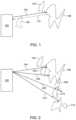
- FIGS. 1 - 3illustrate an exemplary LiDAR system using pulse signals to measure distances to points in the outside environment.
- FIG. 4depicts a logical block diagram of the exemplary LiDAR system.
- FIG. 5shows an illustrative vehicle according to an embodiment
- FIG. 6shows an illustrative virtual window zone according to an embodiment
- FIGS. 7 A- 7 Cshow different illustrative scenarios of when a LiDAR system is deactivated in response to a detected object, according to various embodiments
- FIG. 8shows illustrative process for selectively disabling a LiDAR system, according to an embodiment
- FIG. 9shows illustrative process for enforcing safe operation of a LiDAR system, according to an embodiment.
- LiDARlight detection and ranging
- some embodiments of the present technologyuse one or more light sources that produce light of different wavelengths and/or along different optical paths. These light sources send light to a steering system at different angles so that the scan areas for the light signals are different (e.g., if two light sources are used to create two light signals, the scan area associated with each light source is different). This allows for tuning the signals to appropriate transmit powers and the possibility of having overlapping scan areas that cover scans of different distances. Longer ranges can be scanned with signals having higher power and/or slower repetition rate (e.g., when using pulsed light signals). Shorter ranges can be scanned with signals having lower power and/or high repetition rate (e.g., when using pulse light signals) to increase point density.
- some embodiments of the present technologyuse signal steering systems with one or more dispersion elements (e.g., gratings, optical combs, prisms, etc.) to direct pulse signals based on the wavelength of the pulse.
- a dispersion elementcan make fine adjustments to a pulse's optical path, which may be difficult or impossible with mechanical systems.
- using one or more dispersion elementsallows the signal steering system to use few mechanical components to achieve the desired scanning capabilities. This results in a simpler, more efficient (e.g., lower power) design that is potentially more reliable (due to few moving components).
- an exemplary LiDAR system 100includes a laser light source (e.g., a fiber laser), a steering system (e.g., a system of one or more moving mirrors), and a light detector (e.g., a photon detector with one or more optics).
- a laser light sourcee.g., a fiber laser
- a steering systeme.g., a system of one or more moving mirrors
- a light detectore.g., a photon detector with one or more optics.
- LiDAR system 100transmits light pulse 102 along path 104 as determined by the steering system of LiDAR system 100 .
- light pulse 102which is generated by the laser light source, is a short pulse of laser light.
- the signal steering system of the LiDAR system 100is a pulse signal steering system.
- LiDAR systemscan operate by generating, transmitting, and detecting light signals that are not pulsed can be used to derive ranges to object in the surrounding environment using techniques other than time-of-flight.
- some LiDAR systemsuse frequency modulated continuous waves (i.e., “FMCW”).
- FMCWfrequency modulated continuous waves
- any of the techniques described herein with respect to time-of-flight based systems that use pulsesalso may be applicable to LiDAR systems that do not use one or both of these techniques.
- LiDAR system 100scans the external environment (e.g., by directing light pulses 102 , 202 , 206 , 210 along paths 104 , 204 , 208 , 212 , respectively).
- LiDAR system 100receives returned light pulses 108 , 302 , 306 (which correspond to transmitted light pulses 102 , 202 , 210 , respectively) back after objects 106 and 214 scatter the transmitted light pulses and reflect pulses back along paths 110 , 304 , 308 , respectively.
- the surroundings within the detection rangee.g., the field of view between path 104 and 212 , inclusively
- the surroundings within the detection rangecan be precisely plotted (e.g., a point cloud or image can be created).
- a corresponding light pulseis not received for a particular transmitted light pulse, then it can be determined that there are no objects that can scatter sufficient amount of signal for the LiDAR light pulse within a certain range of LiDAR system 100 (e.g., the max scanning distance of LiDAR system 100 ).
- a certain range of LiDAR system 100e.g., the max scanning distance of LiDAR system 100
- light pulse 206will not have a corresponding returned light pulse (as depicted in FIG. 3 ) because it did not produce a scattering event along its transmission path 208 within the predetermined detection range.
- LiDAR system 100(or an external system communication with LiDAR system 100 ) can interpret this as no object being along path 208 within the detection range of LiDAR system 100 .
- transmitted light pulses 102 , 202 , 206 , 210can be transmitted in any order, serially, in parallel, or based on other timings with respect to each other.
- LiDAR system 100optionally also directs similar arrays of transmitted light pulses along other planes so that a 2-dimensional array of light pulses is transmitted.
- This 2-dimensional arraycan be transmitted point-by-point, line-by-line, all at once, or in some other manner.
- the point cloud or image from a 1-dimensional array(e.g., a single horizontal line) will produce 2-dimensional information (e.g., (1) the horizontal transmission direction and (2) the range to objects).
- the point cloud or image from a 2-dimensional arraywill have 3-dimensional information (e.g., (1) the horizontal transmission direction, (2) the vertical transmission direction, and (3) the range to objects).
- the density of points in point cloud or image from a LiDAR system 100is equal to the number of pulses within a frame divided by the field of view. Given that the field of view is fixed, to increase the density of points generated by one set of transmission-receiving optics, the LiDAR system should fire a pulse more frequently, in other words, a light source with a higher repetition rate is needed. However, by sending pulses more frequently the farthest distance that the LiDAR system can detect may be more limited by speed of light. For example, if a returned signal from a far object is received after the system transmits the next pulse, the return signals may be detected in a different order than the order in which the corresponding signals are transmitted and get mixed up if the system cannot correctly correlate the returned signals with the transmitted signals.
- the farthest distance the LiDAR system can detectmay be 300 meters and 150 meters for 500 kHz and 1 Mhz, respectively.
- the density of points of a LiDAR system with 500 kHz repetition rateis half of that with 1 MHz.
- FIG. 4depicts a logical block diagram of LiDAR system 100 , which includes light source 402 , signal steering system 404 , pulse detector 406 , and controller 408 . These components are coupled together using communications paths 410 , 412 , 414 , 416 , and 418 . These communications paths represent communication (bidirectional or unidirectional) among the various LiDAR system components but need not be physical components themselves. While the communications paths can be implemented by one or more electrical wires, busses, or optical fibers, the communication paths can also be wireless channels or open-air optical paths so that no physical communication medium is present.
- communication path 410is one or more optical fibers
- communication path 412represents an optical path
- communication paths 414 , 416 , 418 , and 420are all one or more electrical wires that carry electrical signals.
- the communications pathscan also include more than one of the above types of communication mediums (e.g., they can include an optical fiber and an optical path or one or more optical fibers and one or more electrical wires).
- LiDAR system 100can also include other components not depicted in FIG. 4 , such as power buses, power supplies, LED indicators, switches, etc. Additionally, other connections among components may be present, such as a direct connection between light source 402 and light detector 406 so that light detector 406 can accurately measure the time from when light source 402 transmits a light pulse until light detector 406 detects a returned light pulse.
- Light source 402may use diode lasers or fiber lasers to generate light pulses.
- Signal steering system 404includes any number of components for steering light signals generated by light source 402 .
- signal steering system 404may include one or more optical redirection elements (e.g., mirrors or lens) that steer light pulses (e.g., by rotating, vibrating, or directing) along a transmit path to scan the external environment.
- optical redirection elementsmay include MEMS mirrors, rotating polyhedron mirrors, or stationary mirrors to steer the transmitted pulse signals to different directions.
- Signal steering system 404optionally also includes other optical components, such as dispersion optics (e.g., diffuser lenses, prisms, or gratings) to further expand the coverage of the transmitted signal in order to increase the LiDAR system 100 's transmission area (i.e., field of view).
- dispersion opticse.g., diffuser lenses, prisms, or gratings
- An example signal steering systemis described in U.S. Patent Application Publication No. 2018/0188355, entitled “2D Scanning High Precision LiDAR Using Combination of Rotating Concave Mirror and Beam Steering Devices,” the content of which is incorporated by reference in its entirety herein for all purposes.
- signal steering system 404does not contain any active optical components (e.g., it does not contain any amplifiers).
- one or more of the components from light source 402such as a booster amplifier, may be included in signal steering system 404 .
- signal steering system 404can be considered a LiDAR head or LiD
- Some implementations of signal steering systemsinclude one or more optical redirection elements (e.g., mirrors or lens) that steers returned light signals (e.g., by rotating, vibrating, or directing) along a receive path to direct the returned light signals to the light detector.
- the optical redirection elements that direct light signals along the transmit and receive pathsmay be the same components (e.g., shared), separate components (e.g., dedicated), and/or a combination of shared and separate components. This means that in some cases the transmit and receive paths are different although they may partially overlap (or in some cases, substantially overlap).
- Controller 408contains components for the control of LiDAR system 100 and communication with external devices that use the system.
- controller 408optionally includes one or more processors, memories, communication interfaces, sensors, storage devices, clocks, ASICs, FPGAs, and/or other devices that control light source 402 , signal steering system 404 , and/or light detector 406 .
- controller 408controls the power, rate, timing, and/or other properties of light signals generated by light source 402 ; controls the speed, transmit direction, and/or other parameters of light steering system 404 ; and/or controls the sensitivity and/or other parameters of light detector 406 .
- Controller 408optionally is also configured to process data received from these components. In some examples, controller determines the time it takes from transmitting a light pulse until a corresponding returned light pulse is received; determines when a returned light pulse is not received for a transmitted light pulse; determines the transmitted direction (e.g., horizontal and/or vertical information) for a transmitted/returned light pulse; determines the estimated range in a particular direction; and/or determines any other type of data relevant to LiDAR system 100 .
- controllerdetermines the time it takes from transmitting a light pulse until a corresponding returned light pulse is received; determines when a returned light pulse is not received for a transmitted light pulse; determines the transmitted direction (e.g., horizontal and/or vertical information) for a transmitted/returned light pulse; determines the estimated range in a particular direction; and/or determines any other type of data relevant to LiDAR system 100 .
- FIG. 5shows an illustrative vehicle 500 according to an embodiment.
- Vehicle 500can include LiDAR system 510 , proximity detection system 520 , and control system 530 .
- LiDAR system 510 and proximity detection system 520can be mounted internally within vehicle 500 , externally to vehicle 500 , or mounted both internally within and externally to vehicle 500 .
- LiDAR system 500may perform the tasks discussed above in connection with FIGS. 1 - 4 .
- Proximity detection system 520is operative to perform short range detection of objects within a fixed distance of vehicle 500 or LiDAR system 510 . In accordance with embodiments discussed herein, when an object is detected within the fixed distance, a laser being emitted by LiDAR system 510 can be turned OFF.
- Control system 530may communicate with LiDAR system 510 and proximity detection system 520 .
- control system 530may be able to instruct LiDAR system 510 to turn ON or OFF based on signals received from proximity detection system 520 .
- control system 530may be included as part of LiDAR system 510 .
- Proximity detection system 520may use any suitable detection sensor or detection means to determine whether an object is located within a fixed distance of LiDAR system 510 .
- proximity detection system 520may use one or more infrared sensors, ultrasonic sensors, cameras, proximity sensors, facial recognition systems, thermal sensors, radar, LiDAR, or any combination thereof.
- proximity detection system 520may be specifically configured for detection of human beings.
- detection system 520may be able to apply analytics to data to distinguish between persons and non-persons.
- Proximity detection system 520may be able to project a virtual window beyond a periphery of LiDAR system 510 .
- the virtual windowmay define a zone that is monitored for the presence of an object.
- detection system 520may communicate a signal indicating detection of the object to control system 530 , which may instruct LiDAR system 510 to deactivate, or least deactivate a light source responsible for transmitting light pulses.
- control system 530may instruct LiDAR system 510 to deactivate, or least deactivate a light source responsible for transmitting light pulses.
- a shutter or other light blocking mechanismmay be used to prevent transmission of the light pulses in response to detection of the object within the virtual window zone.
- FIG. 6shows an illustrative virtual window zone according to an embodiment.
- FIG. 6shows LiDAR system 610 that can project light pulses according to field of view (FOV) 612 or FOV 614 .
- FOV 612has less range than FOV 614 .
- an energy density or laser powermay be greater with FOV 614 than it is with FOV 612 .
- Energy densitymay be based on a combination of laser power, angular resolution and distance to the sensor. Denser angular resolution can result in greater energy density. Energy density will decrease as the distance increases.
- Also shown in FIG. 6are illustrative virtual windows 612 and 614 .
- Virtual windows 612 and 614may define a virtual window zone that is monitored for presence of an object (e.g., human being). Two different virtual windows are shown to illustrate that different sized virtual window zones may be paired with different FOVs. In particular, the size of the virtual window zone may be proportional to the laser power or the energy density. In some embodiments, it only needs to cover near distance below a certain limit. As shown, virtual window 612 may be used when LiDAR 610 is operating with FOV 612 , and virtual window 614 may be used when LiDAR 610 is operating with FOV 614 . When an object is detected within virtual windows 612 or 614 , LiDAR 610 is instructed to cease transmitting light pulses, for example, to comply with laser safety rules and regulations.
- FIGS. 7 A- 7 Cshow different illustrative scenarios of when a LiDAR system is deactivated in response to a detected object, according to various embodiments.
- Each of FIGS. 7 A- 7 Cshows a LiDAR system (as shown by the generic box, a person, a distance the person is from the LiDAR, and an indication of whether the laser density being emitted by the LiDAR is less than or more than a safety level.
- the safety levelmay be based on laser safety rules and regulations that may be issued by various governments, government organizations or agencies, treaties, standards bodies, or the like. For example, one laser safety rules require that a 1550 nm laser energy density be 10 mW or less within a 3.5 mm aperture at a distance of 100 mm.
- FIG. 7 Ashows a scenario in which the person is at a distance greater than X, where X may be defined by a virtual window (not shown) and laser density is greater than a safety level. In this scenario, the LiDAR system need not be deactivated because the person is not within the virtual window.
- FIG. 7 Bshows a scenario in which the person is within the virtual window (as indicated by the distance, D, being less than or equal to X) and the laser density is greater than the safety level. In this scenario, the LiDAR system is deactivated because the person is within the virtual window.
- FIG. 7 Cshows a scenario where the person is within the virtual window, but the energy density is less than the safety level. Thus, even though the person is within the virtual window, the laser density is sufficiently low enough to not merit deactivation of the LiDAR system.
- FIG. 8shows illustrative process 800 for selectively disabling a LiDAR system.
- a virtual windowis monitored with a proximity detection system, wherein the virtual window extends a fixed distance beyond a periphery of the LiDAR system.
- presence of an objectis detected, via the proximity detection system, within the virtual window.
- a portion of the LiDAR systemcan be deactivated in response to detecting the object within the virtual window, wherein the portion prevents emission of light pulses from the LiDAR system.
- FIG. 9shows illustrative process 900 for enforcing safe operation of a LiDAR system, according to an embodiment.
- light pulsescan be transmitted from the LiDAR system.
- a determinationis made as to whether a person is located within a virtual window zone of the LiDAR system.
- the LiDAR systemcan be deactivated when the person is detected to be within the virtual window zone.
- any processes described with respect to FIGS. 1 - 9may each be implemented by software, but may also be implemented in hardware, firmware, or any combination of software, hardware, and firmware. They each may also be embodied as machine- or computer-readable code recorded on a machine- or computer-readable medium.
- the computer-readable mediummay be any data storage device that can store data or instructions which can thereafter be read by a computer system. Examples of the computer-readable medium may include, but are not limited to, read-only memory, random-access memory, flash memory, CD-ROMs, DVDs, magnetic tape, and optical data storage devices.
- the computer-readable mediumcan also be distributed over network-coupled computer systems so that the computer readable code is stored and executed in a distributed fashion.
- the computer-readable mediummay be communicated from one electronic subsystem or device to another electronic subsystem or device using any suitable communications protocol.
- the computer-readable mediummay embody computer-readable code, instructions, data structures, program modules, or other data in a modulated data signal, such as a carrier wave or other transport mechanism, and may include any information delivery media.
- a modulated data signalmay be a signal that has one or more of its characteristics set or changed in such a manner as to encode information in the signal.
- any or each module or state machine discussed hereinmay be provided as a software construct, firmware construct, one or more hardware components, or a combination thereof.
- any one or more of the state machines or modulesmay be described in the general context of computer-executable instructions, such as program modules, that may be executed by one or more computers or other devices.
- a program modulemay include one or more routines, programs, objects, components, and/or data structures that may perform one or more particular tasks or that may implement one or more particular abstract data types.
- modules or state machinesare merely illustrative, and that the number, configuration, functionality, and interconnection of existing modules may be modified or omitted, additional modules may be added, and the interconnection of certain modules may be altered.
Landscapes
- Engineering & Computer Science (AREA)
- Physics & Mathematics (AREA)
- Computer Networks & Wireless Communication (AREA)
- General Physics & Mathematics (AREA)
- Radar, Positioning & Navigation (AREA)
- Remote Sensing (AREA)
- Electromagnetism (AREA)
- Optical Radar Systems And Details Thereof (AREA)
Abstract
Description
This application claims the benefit of U.S. Provisional Application No. 62/722,480, filed Aug. 24, 2018, the disclosure of which is incorporated herein in its entirety.
The present disclosure relates to light detection and ranging (LiDAR), and in particular to LIDAR systems and methods that use virtual windows to enhance safety.
Systems exist that enable vehicles to be driven semi-autonomously or fully autonomously. Such systems may use one or more range finding, mapping, or object detection systems to provide sensory input to assist in semi-autonomous or fully autonomous vehicle control. LiDAR systems, for example, can provide the sensory input required by a semi-autonomous or fully autonomous vehicle. LiDAR systems can use a laser that projects beams of light. As LiDAR system become more ubiquitous, safe operation of the laser is desired.
Embodiments discussed herein refer to LiDAR systems and methods that use a virtual window to monitor for potentially unsafe operation of a laser.
In one embodiment, a system for use in a vehicle is provided that can include a LiDAR system operative to direct light pulses originating from a light source to specific locations within a field of view, proximity detection system operative to detect presence of an object within a fixed distance of the LiDAR system, and control system operative to instruct the LiDAR system to deactivate the light source in response to detection of the object within the fixed distance.
In another embodiment, a method for selectively disabling a LiDAR system is provided. This method can include monitoring a virtual window with a proximity detection system, wherein the virtual window extends a fixed distance beyond a periphery of the LiDAR system, detecting, via the proximity detection system, presence of an object within the virtual window, and deactivating a portion of the LiDAR system in response to detecting the object within the virtual window, wherein the portion prevents emission of light pulses from the LiDAR system.
In another embodiment, a method for enforcing safe operation of a LiDAR system is provided by transmitting light pulses from the LiDAR system, detecting whether a person is located within a virtual window zone of the LiDAR system, and deactivating the LiDAR system when the person is detected to be within the virtual window zone.
A further understanding of the nature and advantages of the embodiments discussed herein may be realized by reference to the remaining portions of the specification and the drawings.
Illustrative embodiments are now described more fully hereinafter with reference to the accompanying drawings, in which representative examples are shown. Indeed, the disclosed LiDAR systems and methods may be embodied in many different forms and should not be construed as limited to the embodiments set forth herein. Like numbers refer to like elements throughout.
In the following detailed description, for purposes of explanation, numerous specific details are set forth to provide a thorough understanding of the various embodiments. Those of ordinary skill in the art will realize that these various embodiments are illustrative only and are not intended to be limiting in any way. Other embodiments will readily suggest themselves to such skilled persons having the benefit of this disclosure.
In addition, for clarity purposes, not all of the routine features of the embodiments described herein are shown or described. One of ordinary skill in the art would readily appreciate that in the development of any such actual embodiment, numerous embodiment-specific decisions may be required to achieve specific design objectives. These design objectives will vary from one embodiment to another and from one developer to another. Moreover, it will be appreciated that such a development effort might be complex and time-consuming but would nevertheless be a routine engineering undertaking for those of ordinary skill in the art having the benefit of this disclosure.
Some light detection and ranging (LiDAR) systems use a single light source to produce one or more light signals of a single wavelength that scan the surrounding environment. The signals are scanned using steering systems that direct the pulses in one or two dimensions to cover an area of the surrounding environment (the scan area). When these systems use mechanical means to direct the pulses, the system complexity increases because more moving parts are required. Additionally, only a single signal can be emitted at any one time because two or more identical signals would introduce ambiguity in returned signals. In some embodiments of the present technology, these disadvantages and/or others are overcome.
For example, some embodiments of the present technology use one or more light sources that produce light of different wavelengths and/or along different optical paths. These light sources send light to a steering system at different angles so that the scan areas for the light signals are different (e.g., if two light sources are used to create two light signals, the scan area associated with each light source is different). This allows for tuning the signals to appropriate transmit powers and the possibility of having overlapping scan areas that cover scans of different distances. Longer ranges can be scanned with signals having higher power and/or slower repetition rate (e.g., when using pulsed light signals). Shorter ranges can be scanned with signals having lower power and/or high repetition rate (e.g., when using pulse light signals) to increase point density.
As another example, some embodiments of the present technology use signal steering systems with one or more dispersion elements (e.g., gratings, optical combs, prisms, etc.) to direct pulse signals based on the wavelength of the pulse. A dispersion element can make fine adjustments to a pulse's optical path, which may be difficult or impossible with mechanical systems. Additionally, using one or more dispersion elements allows the signal steering system to use few mechanical components to achieve the desired scanning capabilities. This results in a simpler, more efficient (e.g., lower power) design that is potentially more reliable (due to few moving components).
Some LiDAR systems use the time-of-flight of light signals (e.g., light pulses) to determine the distance to objects in the path of the light. For example, with respect toFIG.1 , an exemplary LiDARsystem 100 includes a laser light source (e.g., a fiber laser), a steering system (e.g., a system of one or more moving mirrors), and a light detector (e.g., a photon detector with one or more optics). LiDARsystem 100 transmitslight pulse 102 alongpath 104 as determined by the steering system of LiDARsystem 100. In the depicted example,light pulse 102, which is generated by the laser light source, is a short pulse of laser light. Further, the signal steering system of the LiDARsystem 100 is a pulse signal steering system. However, it should be appreciated that LiDAR systems can operate by generating, transmitting, and detecting light signals that are not pulsed can be used to derive ranges to object in the surrounding environment using techniques other than time-of-flight. For example, some LiDAR systems use frequency modulated continuous waves (i.e., “FMCW”). It should be further appreciated that any of the techniques described herein with respect to time-of-flight based systems that use pulses also may be applicable to LiDAR systems that do not use one or both of these techniques.
Referring back toFIG.1 (a time-of-flight LiDAR system that uses light pulses) whenlight pulse 102 reachesobject 106,light pulse 102 scatters and returnedlight pulse 108 will be reflected back tosystem 100 alongpath 110. The time from when transmittedlight pulse 102 leaves LiDARsystem 100 to when returnedlight pulse 108 arrives back at LiDARsystem 100 can be measured (e.g., by a processor or other electronics within the LiDAR system). This time-of-flight combined with the knowledge of the speed of light can be used to determine the range/distance from LiDARsystem 100 to the point onobject 106 wherelight pulse 102 scattered.
By directing many light pulses, as depicted inFIG.2 , LiDARsystem 100 scans the external environment (e.g., by directinglight pulses paths FIG.3 , LiDARsystem 100 receives returnedlight pulses light pulses objects paths system 100 to the points on objects that scatter the light pulses (e.g., the points onobjects 106 and214), the surroundings within the detection range (e.g., the field of view betweenpath
If a corresponding light pulse is not received for a particular transmitted light pulse, then it can be determined that there are no objects that can scatter sufficient amount of signal for the LiDAR light pulse within a certain range of LiDAR system100 (e.g., the max scanning distance of LiDAR system100). For example, inFIG.2 ,light pulse 206 will not have a corresponding returned light pulse (as depicted inFIG.3 ) because it did not produce a scattering event along itstransmission path 208 within the predetermined detection range. LiDAR system100 (or an external system communication with LiDAR system100) can interpret this as no object being alongpath 208 within the detection range ofLiDAR system 100.
InFIG.2 , transmittedlight pulses FIG.2 depicts a 1-dimensional array of transmitted light pulses,LiDAR system 100 optionally also directs similar arrays of transmitted light pulses along other planes so that a 2-dimensional array of light pulses is transmitted. This 2-dimensional array can be transmitted point-by-point, line-by-line, all at once, or in some other manner. The point cloud or image from a 1-dimensional array (e.g., a single horizontal line) will produce 2-dimensional information (e.g., (1) the horizontal transmission direction and (2) the range to objects). The point cloud or image from a 2-dimensional array will have 3-dimensional information (e.g., (1) the horizontal transmission direction, (2) the vertical transmission direction, and (3) the range to objects).
The density of points in point cloud or image from aLiDAR system 100 is equal to the number of pulses within a frame divided by the field of view. Given that the field of view is fixed, to increase the density of points generated by one set of transmission-receiving optics, the LiDAR system should fire a pulse more frequently, in other words, a light source with a higher repetition rate is needed. However, by sending pulses more frequently the farthest distance that the LiDAR system can detect may be more limited by speed of light. For example, if a returned signal from a far object is received after the system transmits the next pulse, the return signals may be detected in a different order than the order in which the corresponding signals are transmitted and get mixed up if the system cannot correctly correlate the returned signals with the transmitted signals. To illustrate, consider an exemplary LiDAR system that can transmit laser pulses with a repetition rate between 500 kHz and 1 MHz. Based on the time it takes for a pulse to return to the LiDAR system and to avoid mix-up of returned pulses from consecutive pulses in conventional LiDAR design, the farthest distance the LiDAR system can detect may be 300 meters and 150 meters for 500 kHz and 1 Mhz, respectively. The density of points of a LiDAR system with 500 kHz repetition rate is half of that with 1 MHz. Thus, this example demonstrates that, if the system cannot correctly correlate returned signals that arrive out of order, increasing the repetition rate from 500 kHz to 1 MHz (and thus improving the density of points of the system) would significantly reduce the detection range of the system.
Some implementations of signal steering systems include one or more optical redirection elements (e.g., mirrors or lens) that steers returned light signals (e.g., by rotating, vibrating, or directing) along a receive path to direct the returned light signals to the light detector. The optical redirection elements that direct light signals along the transmit and receive paths may be the same components (e.g., shared), separate components (e.g., dedicated), and/or a combination of shared and separate components. This means that in some cases the transmit and receive paths are different although they may partially overlap (or in some cases, substantially overlap).
It should be understood that the steps inFIG.8 are merely illustrative and that additional steps may be added and the order to the steps may be rearranged.
It should be understood that the steps inFIG.9 are merely illustrative and that additional steps may be added and the order to the steps may be rearranged.
The embodiments discussed herein provide the necessary monitoring capabilities and laser shutdown mechanism to prevent unsafe laser exposure. It is believed that the disclosure set forth herein encompasses multiple distinct inventions with independent utility. While each of these inventions has been disclosed in its preferred form, the specific embodiments thereof as disclosed and illustrated herein are not to be considered in a limiting sense as numerous variations are possible. Each example defines an embodiment disclosed in the foregoing disclosure, but any one example does not necessarily encompass all features or combinations that may be eventually claimed. Where the description recites “a” or “a first” element or the equivalent thereof, such description includes one or more such elements, neither requiring nor excluding two or more such elements. Further, ordinal indicators, such as first, second or third, for identified elements are used to distinguish between the elements, and do not indicate a required or limited number of such elements, and do not indicate a particular position or order of such elements unless otherwise specifically stated.
Moreover, any processes described with respect toFIGS.1-9 , as well as any other aspects of the invention, may each be implemented by software, but may also be implemented in hardware, firmware, or any combination of software, hardware, and firmware. They each may also be embodied as machine- or computer-readable code recorded on a machine- or computer-readable medium. The computer-readable medium may be any data storage device that can store data or instructions which can thereafter be read by a computer system. Examples of the computer-readable medium may include, but are not limited to, read-only memory, random-access memory, flash memory, CD-ROMs, DVDs, magnetic tape, and optical data storage devices. The computer-readable medium can also be distributed over network-coupled computer systems so that the computer readable code is stored and executed in a distributed fashion. For example, the computer-readable medium may be communicated from one electronic subsystem or device to another electronic subsystem or device using any suitable communications protocol. The computer-readable medium may embody computer-readable code, instructions, data structures, program modules, or other data in a modulated data signal, such as a carrier wave or other transport mechanism, and may include any information delivery media. A modulated data signal may be a signal that has one or more of its characteristics set or changed in such a manner as to encode information in the signal.
It is to be understood that any or each module or state machine discussed herein may be provided as a software construct, firmware construct, one or more hardware components, or a combination thereof. For example, any one or more of the state machines or modules may be described in the general context of computer-executable instructions, such as program modules, that may be executed by one or more computers or other devices. Generally, a program module may include one or more routines, programs, objects, components, and/or data structures that may perform one or more particular tasks or that may implement one or more particular abstract data types. It is also to be understood that the number, configuration, functionality, and interconnection of the modules or state machines are merely illustrative, and that the number, configuration, functionality, and interconnection of existing modules may be modified or omitted, additional modules may be added, and the interconnection of certain modules may be altered.
Whereas many alterations and modifications of the present invention will no doubt become apparent to a person of ordinary skill in the art after having read the foregoing description, it is to be understood that the particular embodiments shown and described by way of illustration are in no way intended to be considered limiting. Therefore, reference to the details of the preferred embodiments is not intended to limit their scope.
Claims (20)
1. A system for use in a vehicle, comprising:
a light detection and ranging (LiDAR) system operative to direct light pulses originating from a light source to one or more locations within a field of view;
a proximity detection system operative to detect presence of an object within a fixed distance of the LiDAR system; and
a control system operative to instruct the LiDAR system to:
determine whether an object is detected within the fixed distance and whether an energy density of the light pulses is greater than a safety level;
deactivate the light source in response to a detection that an object is within the fixed distance and that the energy density of the light pulses is greater than the safety level; and
continue to direct light pulses to the field of view in response to:
a detection that the object is located greater than the fixed distance and the energy density of the light pulses is greater than the safety level, or
a detection that the object is located within the fixed distance and the energy density of the light pulses is less than the safety level.
2. The system ofclaim 1 , wherein the energy density of the light pulses within the field of view exceeds 10 milliWatts within a 3.5 mm aperture at a distance of 100 mm external to the LiDAR system.
3. The system ofclaim 1 , wherein the fixed distance is proportional to the energy density of the light pulses within the field of view.
4. The system ofclaim 1 , wherein the fixed distance ranges between 0.1 meters and 1 meter.
5. The system ofclaim 1 , wherein the object is a human being.
6. The system ofclaim 1 , wherein the proximity detection system comprises an infrared sensor.
7. The system ofclaim 1 , wherein the proximity detection system comprises at least one of an infrared sensor, an ultrasonic sensor, a camera, a proximity sensor, a facial recognition system, a thermal sensor, a radar, a LiDAR, or any combination thereof.
8. A method for selectively disabling a light detection and ranging (LiDAR) system, comprising:
monitoring a virtual window with a proximity detection system, wherein the virtual window extends a fixed distance beyond a periphery of the LiDAR system;
detecting, via the proximity detection system, presence of an object within the virtual window;
determining whether an object is detected within the virtual window and whether an energy density of light pulses is greater than a safety level;
deactivating a portion of the LiDAR system in response to a detection that an object is within the virtual window and that the energy density of the light pulses is greater than the safety level, wherein the portion prevents emission of the light pulses from the LiDAR system; and
continuing to direct light pulses to the virtual window in response to:
a detection that the object is not within the virtual window and the energy density of the light pulses is greater than the safety level, or
a detection that the object is located within the virtual window and the energy density of the light pulses is less than the safety level.
9. The method ofclaim 8 , further comprising:
projecting the light pulses from a light source to one or more locations within a field of view.
10. The method ofclaim 9 , wherein the energy density of the light pulses within the field of view exceeds 10 milliWatts within 3.5 mm aperture at a distance of 100 mm external to the LiDAR system.
11. The method ofclaim 9 , wherein the fixed distance is proportional to the energy density of the light pulses within the field of view.
12. The method ofclaim 8 , wherein the portion of the LiDAR system comprises a light source.
13. The method ofclaim 8 , wherein the fixed distance ranges between 0.1 meters and 1 meter.
14. The method ofclaim 8 , further comprising:
discriminating whether the object is a human being; and
rejecting objects determined not to be a human being.
15. A method for enforcing safe operation of a light detection and ranging (LiDAR) system, comprising:
transmitting light pulses from the LiDAR system;
detecting whether a person is located within a virtual window zone of the LiDAR system;
determining whether an energy density of light pulses is greater than a safety level;
deactivating the LiDAR system when the person is detected to be within the virtual window zone and that the energy density of the light pulses is greater than the safety level; and
continuing to transmit light pulses to the virtual window zone in response to:
a detection that the person is not within the virtual window zone and the energy density of the light pulses is greater than the safety level, or
a detection that the person is located within the virtual window zone and the energy density of the light pulses is less than the safety level.
16. The method ofclaim 15 , wherein the virtual window zone extends beyond a periphery of the LiDAR system.
17. The method ofclaim 16 , wherein the virtual window zone extends beyond the periphery of the LiDAR system by a fixed distance.
18. The method ofclaim 17 , wherein the fixed distance is less than 1 meter.
19. The method ofclaim 15 , wherein the transmitted light pulses are emitted at a power level that exceeds a laser safety standard.
20. The method ofclaim 15 , wherein the transmitted light pulses are emitted such that an energy density exceeds a laser safety standard.
Priority Applications (2)
| Application Number | Priority Date | Filing Date | Title |
|---|---|---|---|
| US16/546,702US11614526B1 (en) | 2018-08-24 | 2019-08-21 | Virtual windows for LIDAR safety systems and methods |
| US18/101,083US11940570B2 (en) | 2018-08-24 | 2023-01-24 | Virtual windows for LiDAR safety systems and methods |
Applications Claiming Priority (2)
| Application Number | Priority Date | Filing Date | Title |
|---|---|---|---|
| US201862722480P | 2018-08-24 | 2018-08-24 | |
| US16/546,702US11614526B1 (en) | 2018-08-24 | 2019-08-21 | Virtual windows for LIDAR safety systems and methods |
Related Child Applications (1)
| Application Number | Title | Priority Date | Filing Date |
|---|---|---|---|
| US18/101,083ContinuationUS11940570B2 (en) | 2018-08-24 | 2023-01-24 | Virtual windows for LiDAR safety systems and methods |
Publications (1)
| Publication Number | Publication Date |
|---|---|
| US11614526B1true US11614526B1 (en) | 2023-03-28 |
Family
ID=85722592
Family Applications (2)
| Application Number | Title | Priority Date | Filing Date |
|---|---|---|---|
| US16/546,702Active2041-09-17US11614526B1 (en) | 2018-08-24 | 2019-08-21 | Virtual windows for LIDAR safety systems and methods |
| US18/101,083ActiveUS11940570B2 (en) | 2018-08-24 | 2023-01-24 | Virtual windows for LiDAR safety systems and methods |
Family Applications After (1)
| Application Number | Title | Priority Date | Filing Date |
|---|---|---|---|
| US18/101,083ActiveUS11940570B2 (en) | 2018-08-24 | 2023-01-24 | Virtual windows for LiDAR safety systems and methods |
Country Status (1)
| Country | Link |
|---|---|
| US (2) | US11614526B1 (en) |
Citations (219)
| Publication number | Priority date | Publication date | Assignee | Title |
|---|---|---|---|---|
| US3897150A (en) | 1972-04-03 | 1975-07-29 | Hughes Aircraft Co | Scanned laser imaging and ranging system |
| GB1427164A (en) | 1972-02-19 | 1976-03-10 | Nippon Electric Co | Interference eliminating system for radars |
| GB2000411A (en) | 1977-06-15 | 1979-01-04 | Impulsphysik Gmbh | Ceilometric method and apparatus |
| US4464048A (en) | 1981-03-25 | 1984-08-07 | Barr & Stroud Limited | Laser rangefinders |
| US4923263A (en) | 1988-09-22 | 1990-05-08 | The United States Of America As Represented By The Secretary Of The Army | Rotating mirror optical scanning device |
| US5006721A (en) | 1990-03-23 | 1991-04-09 | Perceptron, Inc. | Lidar scanning system |
| US5006711A (en) | 1988-10-05 | 1991-04-09 | Fujitsu Limited | Multielement infrared detector for thermal imaging |
| US5157451A (en) | 1991-04-01 | 1992-10-20 | John Taboada | Laser imaging and ranging system using two cameras |
| US5319434A (en) | 1992-12-30 | 1994-06-07 | Litton Systems, Inc. | Laser rangefinder apparatus with fiber optic interface |
| US5369661A (en) | 1991-02-07 | 1994-11-29 | Nippon Steel Corporation | Semiconductor laser-pumped solid state laser system and optical coupling system coupling semiconductor laser with optical fiber |
| US5442358A (en) | 1991-08-16 | 1995-08-15 | Kaman Aerospace Corporation | Imaging lidar transmitter downlink for command guidance of underwater vehicle |
| US5546188A (en) | 1992-11-23 | 1996-08-13 | Schwartz Electro-Optics, Inc. | Intelligent vehicle highway system sensor and method |
| US5579153A (en) | 1992-04-27 | 1996-11-26 | Pirelli Cavi S.P.A. | Optical power limiting amplifier |
| EP0757257A2 (en) | 1995-07-31 | 1997-02-05 | HE HOLDINGS, INC. dba HUGHES ELECTRONICS | Laser range finder receiver |
| US5657077A (en) | 1993-02-18 | 1997-08-12 | Deangelis; Douglas J. | Event recording system with digital line camera |
| US5793491A (en) | 1992-12-30 | 1998-08-11 | Schwartz Electro-Optics, Inc. | Intelligent vehicle highway system multi-lane sensor and method |
| US5838239A (en) | 1992-10-20 | 1998-11-17 | Robotic Vision Systems, Inc. | System for detecting ice or snow on surface which specularly reflects light |
| US5864391A (en) | 1996-04-04 | 1999-01-26 | Denso Corporation | Radar apparatus and a vehicle safe distance control system using this radar apparatus |
| US5926259A (en) | 1995-05-04 | 1999-07-20 | Bushnell Corporation | Laser range finder with target quality display |
| US5936756A (en) | 1996-01-10 | 1999-08-10 | Ricoh Company Ltd. | Compact scanning optical system |
| US6163378A (en) | 1999-06-14 | 2000-12-19 | Khoury; Jehad | Spectroscopic time integrative correlation for rapid medical diagnostic and universal image analysis |
| US6317202B1 (en) | 1998-11-12 | 2001-11-13 | Denso Corporation | Automotive radar detecting lane mark and frontal obstacle |
| EP1237305A2 (en) | 2001-02-28 | 2002-09-04 | KiloLambda IP Limited | Multi-wavelength light source |
| US20020136251A1 (en) | 2001-01-25 | 2002-09-26 | Science And Technology Corporation | Automatic gain control system for use with multiple wavelength signal detector |
| WO2002101408A1 (en) | 2001-06-12 | 2002-12-19 | Citech Sports Corporation Pty Ltd | System and method for monitoring and displaying athlete characteristics |
| US6650404B1 (en) | 2002-05-28 | 2003-11-18 | Analog Modules, Inc. | Laser rangefinder receiver |
| US20040135992A1 (en) | 2002-11-26 | 2004-07-15 | Munro James F. | Apparatus for high accuracy distance and velocity measurement and methods thereof |
| US20050033497A1 (en) | 2003-08-06 | 2005-02-10 | Stopczynski Lawrence Gerard | Method of controlling an external object sensor for an automotive vehicle |
| US20050190424A1 (en) | 2004-02-27 | 2005-09-01 | Sick Ag | Method and device for optical scanning of objects |
| US20050195383A1 (en) | 1994-05-23 | 2005-09-08 | Breed David S. | Method for obtaining information about objects in a vehicular blind spot |
| US20060071846A1 (en) | 2003-05-30 | 2006-04-06 | Yakayuki Yanagisawa | Coherent laser radar |
| US20060109536A1 (en)* | 2004-11-16 | 2006-05-25 | Zzoller & Froehlich Gmbh | Method for driving a laser scanner |
| US20060132752A1 (en) | 2004-12-16 | 2006-06-22 | Kane David M | Micromechanical and related lidar apparatus and method, and fast light-routing components |
| US7128267B2 (en) | 2003-07-11 | 2006-10-31 | Sick Ag | Device for optical scanning of objects, especially markings |
| US20070091948A1 (en) | 2005-07-29 | 2007-04-26 | Aculight Corporation | Multi-stage optical amplifier having photonic-crystal waveguides for generation of high-power pulsed radiation and associated method |
| JP2007144667A (en) | 2005-11-24 | 2007-06-14 | Fuji Xerox Co Ltd | Image forming apparatus and formed image correcting method |
| US20070216995A1 (en) | 2006-03-16 | 2007-09-20 | Bollond Paul G | Optical fiber laser having improved efficiency |
| US7345271B2 (en) | 2002-09-25 | 2008-03-18 | Ibeo Automobile Sensor Gmbh | Optoelectric sensing device with common deflection device |
| EP1923721A1 (en) | 2005-08-15 | 2008-05-21 | Topcon Corporation | Measuring device |
| US20080174762A1 (en) | 2006-08-29 | 2008-07-24 | Jony Jiang Liu | Micro-mirror optical tracking and ranging system |
| US20080193135A1 (en) | 2007-02-14 | 2008-08-14 | Finisar Corporation | Collimated ball lenses for optical triplexers |
| US20090010644A1 (en) | 2002-02-01 | 2009-01-08 | Cubic Corporation | Integrated optical communication and range finding system and applications thereof |
| US20090051926A1 (en) | 2007-04-13 | 2009-02-26 | United States Of America As Represented By The Administrator Of The National Aeronautics And Spac | Multiple frequency optical mixer and demultiplexer and apparatus for remote sensing |
| US20090059201A1 (en) | 2007-08-28 | 2009-03-05 | Science Applications International Corporation | Full-Field Light Detection and Ranging Imaging System |
| US7502395B2 (en) | 2006-08-08 | 2009-03-10 | Northrop Grumman Space & Mission Systems Corp. | Pulsed coherent fiber array and method |
| US20090067453A1 (en) | 2005-04-07 | 2009-03-12 | Matsushita Electric Industrial Co., Ltd. | Laser Light Source and Optical Device |
| US20090147239A1 (en) | 2005-09-02 | 2009-06-11 | Neptec | Apparatus and method for tracking an object |
| US20090262760A1 (en) | 2005-01-20 | 2009-10-22 | Vladimir Krupkin | Laser Obstacle Ranging and Display |
| US20090316134A1 (en) | 2004-07-08 | 2009-12-24 | Michael Christopher E | Fiber laser ladar |
| US20100006760A1 (en) | 2004-04-13 | 2010-01-14 | Science & Engineering Services, Inc. | Ultraviolet lidar for detection of biological warfare agents |
| US20100020306A1 (en) | 2006-07-13 | 2010-01-28 | Velodyne Acoustics, Inc. | High definition lidar system |
| US20100020377A1 (en) | 2008-07-25 | 2010-01-28 | Spudnik, Inc. | Beam Scanning Based on Two-Dimensional Polygon Scanner for Display and Other Applications |
| US20100027602A1 (en) | 2008-07-31 | 2010-02-04 | United States Of America As Represented By The Administrator Of The National Aeronautics And Spac | Time delay and distance measurement |
| JP2010035385A (en) | 2008-07-31 | 2010-02-12 | Kyocera Mita Corp | Motor drive controller |
| EP2157445A2 (en) | 2008-08-19 | 2010-02-24 | Rosemount Aerospace Inc. | Lidar system using a pseudo-random pulse sequence |
| US20100053715A1 (en) | 2006-10-30 | 2010-03-04 | O'neill James | Scanning system for lidar |
| US20100128109A1 (en) | 2008-11-25 | 2010-05-27 | Banks Paul S | Systems And Methods Of High Resolution Three-Dimensional Imaging |
| KR20100096931A (en) | 2009-02-25 | 2010-09-02 | (주)하드램 | Laser direct imaging system having multi scanner unit |
| US20100271614A1 (en) | 2006-01-27 | 2010-10-28 | Vijay Albuquerque | LIDAR system utilizing SOI-based opto-electronic components |
| US20110181864A1 (en) | 2008-07-04 | 2011-07-28 | Eads Deutschland Gmbh | Lidar method for measuring speeds and lidar device with time-controlled detection |
| EP2395368A1 (en) | 2010-06-11 | 2011-12-14 | Sick AG | Distance-measuring laser scanner for detecting objects in a surveillance range |
| KR20120013515A (en) | 2010-08-05 | 2012-02-15 | (주)이오시스템 | Avalanche Photodiode Gain Compensation Device of Optical Measuring Equipment |
| US20120038903A1 (en) | 2010-08-16 | 2012-02-16 | Ball Aerospace & Technologies Corp. | Electronically steered flash lidar |
| US20120124113A1 (en) | 2010-11-05 | 2012-05-17 | University of Maribor | LIGHT DETECTION AND RANGING (LiDAR)DATA COMPRESSION AND DECOMPRESSION METHODS AND APPARATUS |
| US20120221142A1 (en) | 2011-02-24 | 2012-08-30 | Mss, Inc. | Sequential Scanning Of Multiple Wavelengths |
| US20130107016A1 (en) | 2010-05-17 | 2013-05-02 | Iee International Electronics & Engineering S.A. | Scanning 3d imager |
| US20130116971A1 (en) | 2010-06-28 | 2013-05-09 | Fraunhofer-Gesellschaft Zur Foerderung Der Angewandten Forschung E.V. | Method for generating a signal for a distance measurement and method and system for distance measurement between a transmitter and a receiver |
| KR20130068224A (en) | 2011-12-15 | 2013-06-26 | 여우순엽 | The apparatus and method of monitoring with terrestrial lidar and reflectless totalstation |
| US20130241761A1 (en) | 2012-03-16 | 2013-09-19 | Nikon Corporation | Beam steering for laser radar and other uses |
| US20130293946A1 (en) | 2012-05-01 | 2013-11-07 | Imra America, Inc. | Optical frequency ruler |
| US20130293867A1 (en) | 2009-09-23 | 2013-11-07 | Pixart Imaging Inc. | Distance-measuring device of measuring distance according to variation of imaging location and calibrating method thereof |
| US20130329279A1 (en) | 2004-03-31 | 2013-12-12 | Imra America, Inc. | Method and apparatus for controlling and protecting pulsed high power fiber amplifier systems |
| US20130342822A1 (en) | 2011-03-02 | 2013-12-26 | Toyota Jidosha Kabushiki Kaisha | Laser radar device |
| US20140078514A1 (en) | 2010-10-22 | 2014-03-20 | Neptec Design Group Ltd. | Wide angle bistatic scanning optical ranging sensor |
| US20140104594A1 (en) | 2009-07-28 | 2014-04-17 | Applied Concepts, Inc. | Lidar Measurement Device with Target Tracking and Method for Use of Same |
| US20140347650A1 (en) | 2011-12-23 | 2014-11-27 | Leica Geosystems Ag | Distance-measuring device alignment |
| US20140350836A1 (en) | 2013-05-24 | 2014-11-27 | Advance Scientific Concepts, Inc. | Automotive auxiliary ladar sensor |
| US20140375752A1 (en)* | 2012-12-14 | 2014-12-25 | Biscotti Inc. | Virtual Window |
| US20150078123A1 (en) | 2013-09-16 | 2015-03-19 | Appareo Systems, Llc | Synthetic underwater visualization system |
| US20150084805A1 (en) | 2012-03-19 | 2015-03-26 | Qinetiq Limited | Detection Techniques |
| US20150109603A1 (en) | 2013-10-21 | 2015-04-23 | Electronics And Telecommunications Research Institute | Multi-wavelength image lidar sensor apparatus and signal processing method thereof |
| US20150116692A1 (en) | 2012-04-30 | 2015-04-30 | Michigan Aerospace Corporation | System and method for scan range gating |
| US20150139259A1 (en) | 2013-11-21 | 2015-05-21 | Christie Digital Systems Canada Inc. | Method, system and apparatus for automatically determining operating conditions of a periodically poled lithium niobate crystal in a laser system |
| US20150158489A1 (en) | 2013-12-09 | 2015-06-11 | Hyundai Motor Company | Method for object processing and vehicle supporting the same |
| US9065243B2 (en) | 2011-01-20 | 2015-06-23 | Nippon Telegraph And Telephone Corporation | Optical amplifier |
| EP2889642A1 (en) | 2013-12-16 | 2015-07-01 | Riegl Laser Measurement Systems GmbH | Method for distance measurement |
| US9086273B1 (en) | 2013-03-08 | 2015-07-21 | Google Inc. | Microrod compression of laser beam in combination with transmit lens |
| US9121703B1 (en)* | 2013-06-13 | 2015-09-01 | Google Inc. | Methods and systems for controlling operation of a laser device |
| CN204758260U (en) | 2015-07-21 | 2015-11-11 | 北京杏林睿光科技有限公司 | Semiconductor laser structure of multitube core characteristic monitoring |
| US20150338270A1 (en) | 2012-05-10 | 2015-11-26 | Voxtel, Inc. | Discriminating photo counts and dark counts in an avalanche photodiode |
| US20150355327A1 (en) | 2012-11-21 | 2015-12-10 | Nikon Metrology Nv | Scan mirrors for laser radar |
| CN204885804U (en) | 2015-07-21 | 2015-12-16 | 北京杏林睿光科技有限公司 | A narrow linewidth beam combining module and a multi-wavelength Raman laser with the module |
| US20160003946A1 (en) | 2014-07-03 | 2016-01-07 | Advanced Scientific Concepts, Inc. | Ladar sensor for a dense environment |
| US20160033644A1 (en)* | 2014-07-31 | 2016-02-04 | Stmicroelectronics (Research & Development) Ltd. | Time of flight determination |
| US20160047900A1 (en) | 2014-08-15 | 2016-02-18 | US LADAR, Inc. | Method and System for Scanning Ladar Transmission with Pulse Modulation |
| US20160061655A1 (en) | 2014-09-03 | 2016-03-03 | Panasonic Intellectual Property Management Co., Ltd. | Measurement system |
| US20160061935A1 (en) | 2014-08-28 | 2016-03-03 | Google Inc. | Methods and Systems for Vehicle Radar Coordination and Interference Reduction |
| US9304316B2 (en) | 2004-11-15 | 2016-04-05 | Apple Inc. | Method and device for scanning light |
| US20160100521A1 (en) | 2014-10-10 | 2016-04-14 | Irobot Corporation | Autonomous Robot Localization |
| US9316724B2 (en) | 2012-12-18 | 2016-04-19 | Sick Ag | Optoelectronic sensor for the detection of objects |
| US20160117048A1 (en) | 2014-09-26 | 2016-04-28 | Cypress Semiconductor Corporation | Background Light Detection for Optical Navigation Systems |
| US20160172819A1 (en) | 2014-12-12 | 2016-06-16 | Omron Corporation | Light amplifying device and laser processing apparatus |
| US20160178736A1 (en) | 2014-12-19 | 2016-06-23 | Hanwha Techwin Co., Ltd. | Lidar system |
| US20160226210A1 (en) | 2015-01-29 | 2016-08-04 | John J. Zayhowski | Systems and methods for light amplification |
| US20160245902A1 (en) | 2015-02-25 | 2016-08-25 | Abbie T. Watnik | Real-time processing and adaptable illumination lidar camera using a spatial light modulator |
| US20160291134A1 (en) | 2015-04-06 | 2016-10-06 | Google Inc. | Long Range Steerable LIDAR System |
| US20160313445A1 (en) | 2012-03-16 | 2016-10-27 | Advanced Scientific Concepts, Inc. | Personal ladar sensor |
| US20160327646A1 (en) | 2015-05-07 | 2016-11-10 | GM Global Technology Operations LLC | Pseudo random sequences in array lidar systems |
| JP2017003347A (en) | 2015-06-08 | 2017-01-05 | 日本信号株式会社 | Object detection device and object detection method |
| US20170003116A1 (en) | 2015-06-30 | 2017-01-05 | Korea Research Institute Of Standards And Science | Apparatus for real-time non-contact non-destructive thickness measurement using terahertz wave |
| US20170061219A1 (en)* | 2015-08-28 | 2017-03-02 | Hyundai Motor Company | Object recognition device, vehicle having the same and method of controlling the same |
| CN106597471A (en) | 2016-11-08 | 2017-04-26 | 上海禾赛光电科技有限公司 | Vehicle with automatic detection function of transparent barrier and work method thereof |
| US20170153319A1 (en) | 2015-11-30 | 2017-06-01 | Luminar Technologies, Inc. | Lidar system with distributed laser and multiple sensor heads |
| WO2017110417A1 (en) | 2015-12-21 | 2017-06-29 | 株式会社小糸製作所 | Image acquisition device for vehicles, control device, vehicle provided with image acquisition device for vehicles and control device, and image acquisition method for vehicles |
| JP2017138301A (en) | 2016-01-28 | 2017-08-10 | 株式会社デンソー | Laser radar equipment |
| US20170242104A1 (en) | 2016-02-18 | 2017-08-24 | Aeye, Inc. | Ladar Transmitter with Induced Phase Drift for Improved Gaze on Scan Area Portions |
| US20170307738A1 (en) | 2013-11-22 | 2017-10-26 | Uber Technologies, Inc. | Lidar scanner calibration |
| US9810786B1 (en) | 2017-03-16 | 2017-11-07 | Luminar Technologies, Inc. | Optical parametric oscillator for lidar system |
| US20170365105A1 (en) | 2016-06-17 | 2017-12-21 | Ford Global Technologies, Llc | Method and apparatus for inter-vehicular safety awareness and alert |
| US9869754B1 (en) | 2017-03-22 | 2018-01-16 | Luminar Technologies, Inc. | Scan patterns for lidar systems |
| US9880278B2 (en) | 2013-08-01 | 2018-01-30 | Robert Bosch Gmbh | Object determination using a radar sensor |
| US9884585B1 (en)* | 2016-09-19 | 2018-02-06 | Faraday & Future Inc. | Exterior vehicle alerting system |
| US20180040171A1 (en) | 2016-08-02 | 2018-02-08 | International Business Machines Corporation | Self-driving vehicle sensor fault remediation |
| US20180050704A1 (en) | 2016-08-16 | 2018-02-22 | Uber Technologies, Inc. | Autonomous vehicle diagnostic system |
| US20180088214A1 (en)* | 2016-08-29 | 2018-03-29 | James Thomas O'Keeffe | Laser range finder with smart safety-conscious laser intensity |
| CN108089201A (en) | 2017-12-08 | 2018-05-29 | 上海禾赛光电科技有限公司 | Obstacle information acquisition methods, the launching technique of laser pulse and device |
| US20180152691A1 (en) | 2015-09-24 | 2018-05-31 | Ouster, Inc. | Optical system for collecting distance information within a field |
| CN207457508U (en) | 2017-08-08 | 2018-06-05 | 上海禾赛光电科技有限公司 | Laser radar system based on two-dimensional scanning mirrors |
| US20180156896A1 (en) | 2016-05-18 | 2018-06-07 | James Thomas O'Keeffe | Dynamically steered lidar adapted to vehicle shape |
| US20180158471A1 (en) | 2016-12-02 | 2018-06-07 | Breakaway Records, L.L.C. | Record Stabilizer for Multiple Vinyl Sizes |
| CN108132472A (en) | 2017-12-08 | 2018-06-08 | 上海禾赛光电科技有限公司 | Laser radar system |
| US20180164439A1 (en) | 2016-12-13 | 2018-06-14 | Waymo Llc | Power Modulation for a Rotary Light Detection and Ranging (LIDAR) Device |
| US10007001B1 (en) | 2017-03-28 | 2018-06-26 | Luminar Technologies, Inc. | Active short-wave infrared four-dimensional camera |
| CN207557465U (en) | 2017-08-08 | 2018-06-29 | 上海禾赛光电科技有限公司 | Laser radar system based on tilting mirror |
| US20180188355A1 (en) | 2016-12-31 | 2018-07-05 | Innovusion Ireland Limited | 2D SCANNING HIGH PRECISION LiDAR USING COMBINATION OF ROTATING CONCAVE MIRROR AND BEAM STEERING DEVICES |
| US20180188371A1 (en) | 2016-12-30 | 2018-07-05 | Innovusion Ireland Limited | Multiwavelength lidar design |
| WO2018126248A1 (en) | 2017-01-02 | 2018-07-05 | Okeeffe James | Micromirror array for feedback-based image resolution enhancement |
| US20180188358A1 (en) | 2017-01-05 | 2018-07-05 | Innovusion Ireland Limited | METHOD AND SYSTEM FOR ENCODING AND DECODING LiDAR |
| US20180188357A1 (en) | 2017-01-05 | 2018-07-05 | Innovusion Ireland Limited | HIGH RESOLUTION LiDAR USING HIGH FREQUENCY PULSE FIRING |
| WO2018129410A1 (en) | 2017-01-05 | 2018-07-12 | Innovusion Ireland Limited | Mems beam steering and fisheye receiving lens for lidar system |
| US20180210084A1 (en) | 2017-01-26 | 2018-07-26 | Sick Ag | Optoelectronic sensor and method of determining the distance of an object in a monitored zone |
| US10042159B2 (en) | 2016-02-18 | 2018-08-07 | Aeye, Inc. | Ladar transmitter with optical field splitter/inverter |
| US20180231653A1 (en)* | 2017-02-14 | 2018-08-16 | Microsoft Technology Licensing, Llc | Entity-tracking computing system |
| CN108445468A (en) | 2018-04-03 | 2018-08-24 | 上海禾赛光电科技有限公司 | A kind of distribution type laser radar |
| US10061019B1 (en) | 2017-03-28 | 2018-08-28 | Luminar Technologies, Inc. | Diffractive optical element in a lidar system to correct for backscan |
| WO2018175990A1 (en) | 2017-03-23 | 2018-09-27 | Innovusion Ireland Limited | High resolution lidar using multi-stage multi-phase signal modulation, integration, sampling, and analysis |
| KR20180107673A (en) | 2017-03-22 | 2018-10-02 | (주) 위키옵틱스 | LIDAR light-emitting system improved pattern rotation |
| US20180284241A1 (en) | 2017-03-29 | 2018-10-04 | Luminar Technologies, Inc. | Sizing the Field of View of a Detector to Improve Operation of a Lidar System |
| US20180284286A1 (en) | 2017-03-31 | 2018-10-04 | Luminar Technologies, Inc. | Multi-eye lidar system |
| US20180284242A1 (en) | 2017-03-30 | 2018-10-04 | Luminar Technologies, Inc. | Protecting Detector in a Lidar System Using Off-Axis Illumination |
| US10094925B1 (en) | 2017-03-31 | 2018-10-09 | Luminar Technologies, Inc. | Multispectral lidar system |
| US20180329060A1 (en) | 2017-05-15 | 2018-11-15 | Ouster, Inc. | Lidar unit with an optical link between controller and photosensor layer |
| CN208314210U (en) | 2018-06-29 | 2019-01-01 | 上海禾赛光电科技有限公司 | laser radar system |
| CN109116366A (en) | 2018-06-27 | 2019-01-01 | 上海禾赛光电科技有限公司 | A kind of multi-thread beam laser radar of non-homogeneous pulse energy |
| CN109116331A (en) | 2018-06-27 | 2019-01-01 | 上海禾赛光电科技有限公司 | A kind of coded laser light R-T unit, range unit and laser radar system |
| CN109116367A (en) | 2018-06-27 | 2019-01-01 | 上海禾赛光电科技有限公司 | A kind of laser radar |
| CN109188397A (en) | 2018-08-29 | 2019-01-11 | 上海禾赛光电科技有限公司 | Laser transmitting-receiving device and laser radar |
| CN208421228U (en) | 2018-06-29 | 2019-01-22 | 上海禾赛光电科技有限公司 | laser radar system |
| US10191155B2 (en) | 2017-03-29 | 2019-01-29 | Luminar Technologies, Inc. | Optical resolution in front of a vehicle |
| CN208705506U (en) | 2018-08-28 | 2019-04-05 | 上海禾赛光电科技有限公司 | A kind of lens group for laser radar |
| US20190107607A1 (en) | 2017-10-09 | 2019-04-11 | Luminar Technologies, Inc. | Interlaced scan patterns for lidar system |
| US20190120942A1 (en) | 2017-10-19 | 2019-04-25 | Innovusion Ireland Limited | Lidar with large dynamic range |
| US20190120962A1 (en) | 2017-10-20 | 2019-04-25 | Sick Ag | Transmission/reception module for an optoelectronic sensor and method of detecting objects |
| CN109725320A (en) | 2017-10-27 | 2019-05-07 | 上海禾赛光电科技有限公司 | A kind of laser radar |
| US10295656B1 (en) | 2018-06-13 | 2019-05-21 | Hesai Photonics Technology Co., Ltd. | Lidar systems and methods |
| US20190154807A1 (en) | 2017-11-21 | 2019-05-23 | Sick Ag | Polygon scanner and method of detecting objects in a monitored zone |
| US20190154804A1 (en) | 2017-11-22 | 2019-05-23 | Luminar Technologies, Inc. | Efficient orientation of a lidar system in a vehicle |
| CN109814082A (en) | 2019-01-21 | 2019-05-28 | 上海禾赛光电科技有限公司 | Optical receiver module and laser radar system |
| CN109814086A (en) | 2019-01-07 | 2019-05-28 | 上海禾赛光电科技有限公司 | Laser radar |
| US10324170B1 (en) | 2018-04-05 | 2019-06-18 | Luminar Technologies, Inc. | Multi-beam lidar system with polygon mirror |
| CN109917408A (en) | 2019-03-28 | 2019-06-21 | 上海禾赛光电科技有限公司 | Echo processing techniques, distance measuring method and the laser radar of laser radar |
| CN109917348A (en) | 2019-01-25 | 2019-06-21 | 上海禾赛光电科技有限公司 | A kind of laser radar system |
| CN109950784A (en) | 2019-04-10 | 2019-06-28 | 上海禾赛光电科技有限公司 | Laser and laser radar |
| US20190212416A1 (en) | 2018-01-09 | 2019-07-11 | Innovusion Ireland Limited | Lidar detection systems and methods |
| CN110031823A (en) | 2019-04-22 | 2019-07-19 | 上海禾赛光电科技有限公司 | Noise point identification method for laser radar and laser radar system |
| CN110031822A (en) | 2019-04-22 | 2019-07-19 | 上海禾赛光电科技有限公司 | Noise identification method and lidar system that can be used in lidar |
| CN209280923U (en) | 2018-10-16 | 2019-08-20 | 上海禾赛光电科技有限公司 | It is a kind of for the receiving terminal circuit of laser radar, reception device and laser radar |
| US20190257924A1 (en) | 2018-02-22 | 2019-08-22 | Innovusion Ireland Limited | Receive path for lidar system |
| US10393877B2 (en) | 2016-06-01 | 2019-08-27 | Velodyne Lidar, Inc. | Multiple pixel scanning LIDAR |
| US20190265334A1 (en) | 2018-02-23 | 2019-08-29 | Innovusion Ireland Limited | Distributed lidar systems |
| US20190265337A1 (en) | 2018-02-23 | 2019-08-29 | Innovusion Ireland Limited | Multi-wavelength pulse steering in lidar systems |
| US20190265336A1 (en) | 2018-02-23 | 2019-08-29 | Innovusion Ireland Limited | 2-dimensional steering system for lidar systems |
| US20190277952A1 (en) | 2018-03-08 | 2019-09-12 | Zf Friedrichshafen Ag | Receiver arrangement for the reception of light impulses, lidar module and method for receiving light impulses |
| US10422865B2 (en) | 2016-09-07 | 2019-09-24 | Qualcomm Incorporated | Time-dependent filtering for lidar signals |
| US10429425B2 (en) | 2016-05-20 | 2019-10-01 | Tsinghua University | Method for detecting surface electric field distribution of nanostructures |
| US20190310368A1 (en) | 2018-04-06 | 2019-10-10 | Luminar Technologies, Inc. | Lidar System with AlInAsSb Avalanche Photodiode |
| US10451716B2 (en) | 2017-11-22 | 2019-10-22 | Luminar Technologies, Inc. | Monitoring rotation of a mirror in a lidar system |
| US10466342B1 (en) | 2018-09-30 | 2019-11-05 | Hesai Photonics Technology Co., Ltd. | Adaptive coding for lidar systems |
| CN110492349A (en) | 2019-08-20 | 2019-11-22 | 上海禾赛光电科技有限公司 | Driving circuit, driving method and Optical Maser System |
| CN110492856A (en) | 2019-08-12 | 2019-11-22 | 上海禾赛光电科技有限公司 | Across resistance amplifying unit electronic feedback circuit, photodetection circuit and laser radar system |
| US20190369215A1 (en) | 2018-04-03 | 2019-12-05 | Hesai Photonics Technology Co., Ltd. | Lidar system and method |
| US10509112B1 (en) | 2019-04-02 | 2019-12-17 | Hesai Photonics Technology Co., Ltd. | Laser system for Lidar |
| CN110736975A (en) | 2019-11-07 | 2020-01-31 | 上海禾赛光电科技有限公司 | Receiver module and lidar including it |
| CN110784220A (en) | 2019-11-07 | 2020-02-11 | 上海禾赛光电科技有限公司 | Dynamic threshold timing circuit, laser radar and method for acquiring time information |
| CN110780284A (en) | 2019-11-22 | 2020-02-11 | 上海禾赛光电科技有限公司 | Receiving system, laser radar including the same, and method of echo reception processing |
| CN110780283A (en) | 2019-11-22 | 2020-02-11 | 上海禾赛光电科技有限公司 | Receiving system, laser radar comprising same and echo receiving method |
| US10627491B2 (en) | 2017-03-31 | 2020-04-21 | Velodyne Lidar, Inc. | Integrated LIDAR illumination power control |
| US10641872B2 (en) | 2016-02-18 | 2020-05-05 | Aeye, Inc. | Ladar receiver with advanced optics |
| US10663596B2 (en) | 2017-09-15 | 2020-05-26 | Aeye, Inc. | Ladar receiver with co-bore sited camera |
| US10663564B2 (en) | 2017-03-30 | 2020-05-26 | Luminar Technologies, Inc. | Cross-talk mitigation using wavelength switching |
| US10732281B2 (en) | 2017-03-28 | 2020-08-04 | Luminar Technologies, Inc. | Lidar detector system having range walk compensation |
| US20200319310A1 (en) | 2016-01-31 | 2020-10-08 | Velodyne Lidar, Inc. | Multiple pulse, lidar based 3-d imaging |
| CN211655309U (en) | 2019-12-23 | 2020-10-09 | 上海禾赛光电科技有限公司 | Laser and laser radar including the same |
| US20200400798A1 (en) | 2019-06-21 | 2020-12-24 | Aeva, Inc. | Lidar system with solid state spectral scanning |
| CN212623082U (en) | 2020-04-29 | 2021-02-26 | 上海禾赛光电科技有限公司 | Scanning device for laser radar and laser radar |
| US20210088630A9 (en) | 2017-04-19 | 2021-03-25 | Surestar Laser Technology (Suzhou) Co., Ltd. | Laser scanning device, radar device and scanning method thereof |
| CN112578396A (en) | 2019-09-30 | 2021-03-30 | 上海禾赛科技股份有限公司 | Method and device for coordinate transformation between radars and computer-readable storage medium |
| CN213182011U (en) | 2020-04-26 | 2021-05-11 | 上海禾赛光电科技有限公司 | Laser radar's transmitting unit, receiving element and laser radar |
| US11016192B2 (en) | 2017-07-05 | 2021-05-25 | Ouster, Inc. | Light ranging device with MEMS scanned emitter array and synchronized electronically scanned sensor array |
| US11035935B2 (en) | 2015-11-03 | 2021-06-15 | Hexagon Technology Center Gmbh | Optoelectronic surveying device |
| CN213750313U (en) | 2020-11-27 | 2021-07-20 | 上海禾赛科技有限公司 | Optical window and laser radar |
| CN214151038U (en) | 2020-12-11 | 2021-09-07 | 上海禾赛科技有限公司 | Laser radar |
| CN214795200U (en) | 2021-04-30 | 2021-11-19 | 上海禾赛科技有限公司 | Window for laser radar and laser radar |
| CN214795206U (en) | 2021-04-07 | 2021-11-19 | 上海禾赛科技股份有限公司 | Laser radar |
| CN214895784U (en) | 2021-04-30 | 2021-11-26 | 上海禾赛科技有限公司 | Optical detection device and running vehicle |
| CN214895810U (en) | 2021-04-30 | 2021-11-26 | 上海禾赛科技有限公司 | Light splitting device and laser radar |
| US11194048B1 (en) | 2020-05-13 | 2021-12-07 | Luminar, Llc | Lidar system with high-resolution scan pattern |
| CN215641806U (en) | 2021-04-30 | 2022-01-25 | 上海禾赛科技有限公司 | Laser radar |
| CN215932142U (en) | 2021-09-15 | 2022-03-01 | 上海禾赛科技有限公司 | Laser radar |
Family Cites Families (40)
| Publication number | Priority date | Publication date | Assignee | Title |
|---|---|---|---|---|
| US5023818A (en) | 1989-09-21 | 1991-06-11 | Ncr Corporation | Laser scanner safety apparatus and method |
| JP3839932B2 (en) | 1996-09-26 | 2006-11-01 | キヤノン株式会社 | Process cartridge, electrophotographic image forming apparatus, electrophotographic photosensitive drum and coupling |
| US6584000B1 (en) | 2002-01-18 | 2003-06-24 | Ching-Chung Lee | Electronic stabilizer |
| US20040189195A1 (en) | 2003-03-24 | 2004-09-30 | Osram Opto Semiconductors Gmbh | Devices including, methods using, and compositions of reflowable getters |
| JP2005291787A (en) | 2004-03-31 | 2005-10-20 | Denso Corp | Distance detection device |
| JP2007144687A (en) | 2005-11-25 | 2007-06-14 | Nihon Tetra Pak Kk | Retort food packaging container and packaging laminate material |
| US9880283B2 (en) | 2007-02-13 | 2018-01-30 | Zih Corp. | System, apparatus and method for locating and/or tracking assets |
| US7880865B2 (en) | 2007-02-28 | 2011-02-01 | Denso Wave Incorporated | Laser radar apparatus for three-dimensional detection of objects |
| US7882861B2 (en) | 2007-03-23 | 2011-02-08 | Swanson David C | Vacuum storage system |
| IL183385A0 (en)* | 2007-05-24 | 2007-09-20 | Yosef Cohen | Security systems and methods |
| US7919764B2 (en) | 2008-05-06 | 2011-04-05 | The United States Of America As Represented By The Secretary Of The Army | Method and apparatus for enhanced terahertz radiation from high stacking fault density |
| US20100158055A1 (en) | 2008-12-18 | 2010-06-24 | Symbol Technologies, Inc. | Method and apparatus for controlling and monitoring laser power in barcode readers |
| KR101419556B1 (en) | 2009-03-02 | 2014-07-16 | 주식회사 엘지화학 | Battery pack for self temperature control electromobile using thermoelectric effect |
| CN103283087B (en) | 2010-11-25 | 2016-03-16 | 诺基亚技术有限公司 | Antenna assembly and method |
| US8576382B2 (en)* | 2011-03-22 | 2013-11-05 | Exelis, Inc. | Method and apparatus for controlling laser transmissions for enhanced safety |
| US8835945B2 (en) | 2013-01-11 | 2014-09-16 | Lighting Science Group Corporation | Serially-connected light emitting diodes, methods of forming same, and luminaires containing same |
| US8740237B2 (en) | 2011-09-23 | 2014-06-03 | Specialized Bicycle Components, Inc. | Bicycle with suspension |
| JP5968137B2 (en) | 2012-07-20 | 2016-08-10 | ナミックス株式会社 | Liquid encapsulant and electronic parts using it |
| KR102070089B1 (en) | 2013-10-23 | 2020-01-29 | 삼성전자주식회사 | Semiconductor light emitting diode package and lighting device using the same |
| KR102083993B1 (en) | 2013-10-31 | 2020-03-03 | 삼성전기주식회사 | Multi-layered ceramic capacitor and board for mounting the same |
| US9454054B2 (en) | 2013-11-18 | 2016-09-27 | Magna Mirrors Of America, Inc. | Electro-optic mirror element and process of making same |
| US10459114B2 (en)* | 2015-05-18 | 2019-10-29 | Lasermotive, Inc. | Wireless power transmitter and receiver |
| US10641672B2 (en) | 2015-09-24 | 2020-05-05 | Silicon Microstructures, Inc. | Manufacturing catheter sensors |
| CN108369282B (en) | 2015-11-11 | 2021-10-19 | 西门子保健有限责任公司 | Detector element for detecting incident X-rays |
| EP3377918B1 (en) | 2015-11-18 | 2020-01-08 | Scint-X AB | System and method for melting and solidification of scintillating material in micromechanical structures |
| DE102016207009A1 (en) | 2016-04-26 | 2017-10-26 | Krones Aktiengesellschaft | Operating system for a machine of the food industry, in particular the beverage industry |
| WO2017217663A1 (en) | 2016-06-13 | 2017-12-21 | 엘지이노텍(주) | Method for detecting foreign material, and apparatus and system therefor |
| CN106658366B (en) | 2016-11-30 | 2020-05-22 | 建荣半导体(深圳)有限公司 | Bluetooth working mode switching method and device, Bluetooth chip and electronic equipment |
| KR102619582B1 (en)* | 2017-03-13 | 2024-01-02 | 옵시스 테크 엘티디 | Eye-Safe Scanning LIDAR System |
| US10081019B1 (en) | 2017-05-25 | 2018-09-25 | Lucian D. Whitman | Modular portable sluice box |
| EP3710855A4 (en)* | 2017-11-15 | 2021-08-04 | Opsys Tech Ltd. | Noise adaptive solid-state lidar system |
| US10513272B2 (en)* | 2017-12-27 | 2019-12-24 | Intel Corporation | Safety inference engine for autonomous systems |
| US10884115B2 (en)* | 2018-03-09 | 2021-01-05 | Waymo Llc | Tailoring sensor emission power to map, vehicle state, and environment |
| WO2019245614A2 (en) | 2018-03-09 | 2019-12-26 | Innovusion Ireland Limited | Lidar safety systems and methods |
| KR102450299B1 (en) | 2018-05-15 | 2022-10-05 | 에스케이하이닉스 주식회사 | Amplifier, and signal receiving circuit, semiconductor apparatus and system using the same |
| KR20210071989A (en) | 2018-10-05 | 2021-06-16 | 하우스 웰니스 푸드 코퍼레이션 | Method for producing granules containing plant extract, method for suppressing generation of fine powder from granules containing plant extract, and method for suppressing unpleasant taste of granules containing plant extract |
| CN109116368B (en) | 2018-10-10 | 2023-12-12 | 福建汇川物联网技术科技股份有限公司 | Displacement monitoring system and method |
| JP7277266B2 (en) | 2019-06-05 | 2023-05-18 | キヤノン株式会社 | PWM output circuit and image forming apparatus having the same |
| US10508319B1 (en) | 2019-06-27 | 2019-12-17 | MM Metals USA, LLC | Method and system for producing low carbon ferrochrome from chromite ore and low carbon ferrochrome produced thereby |
| CN214785200U (en) | 2021-05-18 | 2021-11-19 | 四川擎远建筑工程有限公司 | Steel bar truss floor support plate for fabricated building house |
- 2019
- 2019-08-21USUS16/546,702patent/US11614526B1/enactiveActive
- 2023
- 2023-01-24USUS18/101,083patent/US11940570B2/enactiveActive
Patent Citations (335)
| Publication number | Priority date | Publication date | Assignee | Title |
|---|---|---|---|---|
| GB1427164A (en) | 1972-02-19 | 1976-03-10 | Nippon Electric Co | Interference eliminating system for radars |
| US3897150A (en) | 1972-04-03 | 1975-07-29 | Hughes Aircraft Co | Scanned laser imaging and ranging system |
| GB2000411A (en) | 1977-06-15 | 1979-01-04 | Impulsphysik Gmbh | Ceilometric method and apparatus |
| US4464048A (en) | 1981-03-25 | 1984-08-07 | Barr & Stroud Limited | Laser rangefinders |
| US4923263A (en) | 1988-09-22 | 1990-05-08 | The United States Of America As Represented By The Secretary Of The Army | Rotating mirror optical scanning device |
| US5006711A (en) | 1988-10-05 | 1991-04-09 | Fujitsu Limited | Multielement infrared detector for thermal imaging |
| US5006721A (en) | 1990-03-23 | 1991-04-09 | Perceptron, Inc. | Lidar scanning system |
| US5369661A (en) | 1991-02-07 | 1994-11-29 | Nippon Steel Corporation | Semiconductor laser-pumped solid state laser system and optical coupling system coupling semiconductor laser with optical fiber |
| US5157451A (en) | 1991-04-01 | 1992-10-20 | John Taboada | Laser imaging and ranging system using two cameras |
| US5442358A (en) | 1991-08-16 | 1995-08-15 | Kaman Aerospace Corporation | Imaging lidar transmitter downlink for command guidance of underwater vehicle |
| US5579153A (en) | 1992-04-27 | 1996-11-26 | Pirelli Cavi S.P.A. | Optical power limiting amplifier |
| US5838239A (en) | 1992-10-20 | 1998-11-17 | Robotic Vision Systems, Inc. | System for detecting ice or snow on surface which specularly reflects light |
| US5546188A (en) | 1992-11-23 | 1996-08-13 | Schwartz Electro-Optics, Inc. | Intelligent vehicle highway system sensor and method |
| US5319434A (en) | 1992-12-30 | 1994-06-07 | Litton Systems, Inc. | Laser rangefinder apparatus with fiber optic interface |
| US5793491A (en) | 1992-12-30 | 1998-08-11 | Schwartz Electro-Optics, Inc. | Intelligent vehicle highway system multi-lane sensor and method |
| US5657077A (en) | 1993-02-18 | 1997-08-12 | Deangelis; Douglas J. | Event recording system with digital line camera |
| US20050195383A1 (en) | 1994-05-23 | 2005-09-08 | Breed David S. | Method for obtaining information about objects in a vehicular blind spot |
| US5926259A (en) | 1995-05-04 | 1999-07-20 | Bushnell Corporation | Laser range finder with target quality display |
| EP0757257A2 (en) | 1995-07-31 | 1997-02-05 | HE HOLDINGS, INC. dba HUGHES ELECTRONICS | Laser range finder receiver |
| US5936756A (en) | 1996-01-10 | 1999-08-10 | Ricoh Company Ltd. | Compact scanning optical system |
| US5864391A (en) | 1996-04-04 | 1999-01-26 | Denso Corporation | Radar apparatus and a vehicle safe distance control system using this radar apparatus |
| US6317202B1 (en) | 1998-11-12 | 2001-11-13 | Denso Corporation | Automotive radar detecting lane mark and frontal obstacle |
| US6163378A (en) | 1999-06-14 | 2000-12-19 | Khoury; Jehad | Spectroscopic time integrative correlation for rapid medical diagnostic and universal image analysis |
| US20020136251A1 (en) | 2001-01-25 | 2002-09-26 | Science And Technology Corporation | Automatic gain control system for use with multiple wavelength signal detector |
| US6594000B2 (en) | 2001-01-25 | 2003-07-15 | Science And Technology Corporation | Automatic gain control system for use with multiple wavelength signal detector |
| EP1237305A2 (en) | 2001-02-28 | 2002-09-04 | KiloLambda IP Limited | Multi-wavelength light source |
| WO2002101408A1 (en) | 2001-06-12 | 2002-12-19 | Citech Sports Corporation Pty Ltd | System and method for monitoring and displaying athlete characteristics |
| US7489865B2 (en) | 2002-02-01 | 2009-02-10 | Cubic Corporation | Integrated optical communication and range finding system and applications thereof |
| US20090010644A1 (en) | 2002-02-01 | 2009-01-08 | Cubic Corporation | Integrated optical communication and range finding system and applications thereof |
| US6650404B1 (en) | 2002-05-28 | 2003-11-18 | Analog Modules, Inc. | Laser rangefinder receiver |
| US7345271B2 (en) | 2002-09-25 | 2008-03-18 | Ibeo Automobile Sensor Gmbh | Optoelectric sensing device with common deflection device |
| US7202941B2 (en) | 2002-11-26 | 2007-04-10 | Munro James F | Apparatus for high accuracy distance and velocity measurement and methods thereof |
| US20040135992A1 (en) | 2002-11-26 | 2004-07-15 | Munro James F. | Apparatus for high accuracy distance and velocity measurement and methods thereof |
| US20060071846A1 (en) | 2003-05-30 | 2006-04-06 | Yakayuki Yanagisawa | Coherent laser radar |
| US7128267B2 (en) | 2003-07-11 | 2006-10-31 | Sick Ag | Device for optical scanning of objects, especially markings |
| US20050033497A1 (en) | 2003-08-06 | 2005-02-10 | Stopczynski Lawrence Gerard | Method of controlling an external object sensor for an automotive vehicle |
| US6950733B2 (en) | 2003-08-06 | 2005-09-27 | Ford Global Technologies, Llc | Method of controlling an external object sensor for an automotive vehicle |
| US20050190424A1 (en) | 2004-02-27 | 2005-09-01 | Sick Ag | Method and device for optical scanning of objects |
| US20130329279A1 (en) | 2004-03-31 | 2013-12-12 | Imra America, Inc. | Method and apparatus for controlling and protecting pulsed high power fiber amplifier systems |
| US20100006760A1 (en) | 2004-04-13 | 2010-01-14 | Science & Engineering Services, Inc. | Ultraviolet lidar for detection of biological warfare agents |
| US20090316134A1 (en) | 2004-07-08 | 2009-12-24 | Michael Christopher E | Fiber laser ladar |
| US9304316B2 (en) | 2004-11-15 | 2016-04-05 | Apple Inc. | Method and device for scanning light |
| US20060109536A1 (en)* | 2004-11-16 | 2006-05-25 | Zzoller & Froehlich Gmbh | Method for driving a laser scanner |
| US7508496B2 (en) | 2004-11-16 | 2009-03-24 | Z+F Zoller & Froelich Gmbh | Method for driving a laser scanner |
| US7440084B2 (en) | 2004-12-16 | 2008-10-21 | Arete' Associates | Micromechanical and related lidar apparatus and method, and fast light-routing components |
| US20060132752A1 (en) | 2004-12-16 | 2006-06-22 | Kane David M | Micromechanical and related lidar apparatus and method, and fast light-routing components |
| US7847235B2 (en) | 2005-01-20 | 2010-12-07 | Elbit Systems Electro-Optics Elop Ltd. | Laser obstacle ranging and display |
| US20090262760A1 (en) | 2005-01-20 | 2009-10-22 | Vladimir Krupkin | Laser Obstacle Ranging and Display |
| US20090067453A1 (en) | 2005-04-07 | 2009-03-12 | Matsushita Electric Industrial Co., Ltd. | Laser Light Source and Optical Device |
| US7440175B2 (en) | 2005-07-29 | 2008-10-21 | Aculight Corporation | Multi-stage optical amplifier having photonic-crystal waveguides for generation of high-power pulsed radiation and associated method |
| US7835068B1 (en) | 2005-07-29 | 2010-11-16 | Lockheed Martin Corporation | Photonic-crystal-rod optical amplifier with sealed-hole endcap and associated method |
| US20070091948A1 (en) | 2005-07-29 | 2007-04-26 | Aculight Corporation | Multi-stage optical amplifier having photonic-crystal waveguides for generation of high-power pulsed radiation and associated method |
| EP1923721A1 (en) | 2005-08-15 | 2008-05-21 | Topcon Corporation | Measuring device |
| US20090147239A1 (en) | 2005-09-02 | 2009-06-11 | Neptec | Apparatus and method for tracking an object |
| JP2007144667A (en) | 2005-11-24 | 2007-06-14 | Fuji Xerox Co Ltd | Image forming apparatus and formed image correcting method |
| US20100271614A1 (en) | 2006-01-27 | 2010-10-28 | Vijay Albuquerque | LIDAR system utilizing SOI-based opto-electronic components |
| US7936448B2 (en) | 2006-01-27 | 2011-05-03 | Lightwire Inc. | LIDAR system utilizing SOI-based opto-electronic components |
| US20070216995A1 (en) | 2006-03-16 | 2007-09-20 | Bollond Paul G | Optical fiber laser having improved efficiency |
| US7969558B2 (en) | 2006-07-13 | 2011-06-28 | Velodyne Acoustics Inc. | High definition lidar system |
| US20100020306A1 (en) | 2006-07-13 | 2010-01-28 | Velodyne Acoustics, Inc. | High definition lidar system |
| US7502395B2 (en) | 2006-08-08 | 2009-03-10 | Northrop Grumman Space & Mission Systems Corp. | Pulsed coherent fiber array and method |
| US20080174762A1 (en) | 2006-08-29 | 2008-07-24 | Jony Jiang Liu | Micro-mirror optical tracking and ranging system |
| US7576837B2 (en) | 2006-08-29 | 2009-08-18 | The United States Of America As Represented By The Secretary Of The Army | Micro-mirror optical tracking and ranging system |
| US20100053715A1 (en) | 2006-10-30 | 2010-03-04 | O'neill James | Scanning system for lidar |
| US20080193135A1 (en) | 2007-02-14 | 2008-08-14 | Finisar Corporation | Collimated ball lenses for optical triplexers |
| US20090051926A1 (en) | 2007-04-13 | 2009-02-26 | United States Of America As Represented By The Administrator Of The National Aeronautics And Spac | Multiple frequency optical mixer and demultiplexer and apparatus for remote sensing |
| US7830527B2 (en) | 2007-04-13 | 2010-11-09 | The United States Of America As Represented By The Administrator Of The National Aeronautics And Space Administration | Multiple frequency optical mixer and demultiplexer and apparatus for remote sensing |
| US20090059201A1 (en) | 2007-08-28 | 2009-03-05 | Science Applications International Corporation | Full-Field Light Detection and Ranging Imaging System |
| US20110181864A1 (en) | 2008-07-04 | 2011-07-28 | Eads Deutschland Gmbh | Lidar method for measuring speeds and lidar device with time-controlled detection |
| US20100020377A1 (en) | 2008-07-25 | 2010-01-28 | Spudnik, Inc. | Beam Scanning Based on Two-Dimensional Polygon Scanner for Display and Other Applications |
| US20100027602A1 (en) | 2008-07-31 | 2010-02-04 | United States Of America As Represented By The Administrator Of The National Aeronautics And Spac | Time delay and distance measurement |
| US7982861B2 (en) | 2008-07-31 | 2011-07-19 | The United States Of America As Represented By The Administrator Of The National Aeronautics And Space Administration | Time delay and distance measurement |
| JP2010035385A (en) | 2008-07-31 | 2010-02-12 | Kyocera Mita Corp | Motor drive controller |
| US20100045965A1 (en) | 2008-08-19 | 2010-02-25 | Rosemount Aerospace Inc. | Lidar system using a pseudo-random pulse sequence |
| US8072582B2 (en) | 2008-08-19 | 2011-12-06 | Rosemount Aerospace Inc. | Lidar system using a pseudo-random pulse sequence |
| EP2157445A2 (en) | 2008-08-19 | 2010-02-24 | Rosemount Aerospace Inc. | Lidar system using a pseudo-random pulse sequence |
| US8471895B2 (en) | 2008-11-25 | 2013-06-25 | Paul S. Banks | Systems and methods of high resolution three-dimensional imaging |
| US20100128109A1 (en) | 2008-11-25 | 2010-05-27 | Banks Paul S | Systems And Methods Of High Resolution Three-Dimensional Imaging |
| KR20100096931A (en) | 2009-02-25 | 2010-09-02 | (주)하드램 | Laser direct imaging system having multi scanner unit |
| US20140104594A1 (en) | 2009-07-28 | 2014-04-17 | Applied Concepts, Inc. | Lidar Measurement Device with Target Tracking and Method for Use of Same |
| US20130293867A1 (en) | 2009-09-23 | 2013-11-07 | Pixart Imaging Inc. | Distance-measuring device of measuring distance according to variation of imaging location and calibrating method thereof |
| US8749764B2 (en) | 2009-09-23 | 2014-06-10 | Pixart Imaging Inc. | Distance-measuring device of measuring distance according to variation of imaging location and calibrating method thereof |
| US20130107016A1 (en) | 2010-05-17 | 2013-05-02 | Iee International Electronics & Engineering S.A. | Scanning 3d imager |
| US9621876B2 (en) | 2010-05-17 | 2017-04-11 | Iee International Electronics & Engineering S.A. | Scanning 3D imager |
| EP2395368A1 (en) | 2010-06-11 | 2011-12-14 | Sick AG | Distance-measuring laser scanner for detecting objects in a surveillance range |
| US20130116971A1 (en) | 2010-06-28 | 2013-05-09 | Fraunhofer-Gesellschaft Zur Foerderung Der Angewandten Forschung E.V. | Method for generating a signal for a distance measurement and method and system for distance measurement between a transmitter and a receiver |
| KR20120013515A (en) | 2010-08-05 | 2012-02-15 | (주)이오시스템 | Avalanche Photodiode Gain Compensation Device of Optical Measuring Equipment |
| US20120038903A1 (en) | 2010-08-16 | 2012-02-16 | Ball Aerospace & Technologies Corp. | Electronically steered flash lidar |
| US8736818B2 (en) | 2010-08-16 | 2014-05-27 | Ball Aerospace & Technologies Corp. | Electronically steered flash LIDAR |
| US9255790B2 (en) | 2010-10-22 | 2016-02-09 | Neptec Design Group Ltd. | Wide angle bistatic scanning optical ranging sensor |
| US20140078514A1 (en) | 2010-10-22 | 2014-03-20 | Neptec Design Group Ltd. | Wide angle bistatic scanning optical ranging sensor |
| US20120124113A1 (en) | 2010-11-05 | 2012-05-17 | University of Maribor | LIGHT DETECTION AND RANGING (LiDAR)DATA COMPRESSION AND DECOMPRESSION METHODS AND APPARATUS |
| US9300321B2 (en) | 2010-11-05 | 2016-03-29 | University of Maribor | Light detection and ranging (LiDAR)data compression and decompression methods and apparatus |
| US9065243B2 (en) | 2011-01-20 | 2015-06-23 | Nippon Telegraph And Telephone Corporation | Optical amplifier |
| US20120221142A1 (en) | 2011-02-24 | 2012-08-30 | Mss, Inc. | Sequential Scanning Of Multiple Wavelengths |
| US8812149B2 (en) | 2011-02-24 | 2014-08-19 | Mss, Inc. | Sequential scanning of multiple wavelengths |
| US20130342822A1 (en) | 2011-03-02 | 2013-12-26 | Toyota Jidosha Kabushiki Kaisha | Laser radar device |
| US8994928B2 (en) | 2011-03-02 | 2015-03-31 | Toyota Jidosha Kabushiki Kaisha | Laser radar device |
| KR20130068224A (en) | 2011-12-15 | 2013-06-26 | 여우순엽 | The apparatus and method of monitoring with terrestrial lidar and reflectless totalstation |
| US20140347650A1 (en) | 2011-12-23 | 2014-11-27 | Leica Geosystems Ag | Distance-measuring device alignment |
| US9194701B2 (en) | 2011-12-23 | 2015-11-24 | Leica Geosystems Ag | Distance-measuring device alignment |
| US9915726B2 (en) | 2012-03-16 | 2018-03-13 | Continental Advanced Lidar Solutions Us, Llc | Personal LADAR sensor |
| US20160313445A1 (en) | 2012-03-16 | 2016-10-27 | Advanced Scientific Concepts, Inc. | Personal ladar sensor |
| US20130241761A1 (en) | 2012-03-16 | 2013-09-19 | Nikon Corporation | Beam steering for laser radar and other uses |
| US20150084805A1 (en) | 2012-03-19 | 2015-03-26 | Qinetiq Limited | Detection Techniques |
| US9696426B2 (en) | 2012-04-30 | 2017-07-04 | Michigan Aerospace Corporation | System and method for scan range gating |
| US20150116692A1 (en) | 2012-04-30 | 2015-04-30 | Michigan Aerospace Corporation | System and method for scan range gating |
| US9354485B2 (en) | 2012-05-01 | 2016-05-31 | Imra America, Inc. | Optical frequency ruler |
| US20130293946A1 (en) | 2012-05-01 | 2013-11-07 | Imra America, Inc. | Optical frequency ruler |
| US20150338270A1 (en) | 2012-05-10 | 2015-11-26 | Voxtel, Inc. | Discriminating photo counts and dark counts in an avalanche photodiode |
| US9638799B2 (en) | 2012-11-21 | 2017-05-02 | Nikon Corporation | Scan mirrors for laser radar |
| US20150355327A1 (en) | 2012-11-21 | 2015-12-10 | Nikon Metrology Nv | Scan mirrors for laser radar |
| US20140375752A1 (en)* | 2012-12-14 | 2014-12-25 | Biscotti Inc. | Virtual Window |
| US9316724B2 (en) | 2012-12-18 | 2016-04-19 | Sick Ag | Optoelectronic sensor for the detection of objects |
| US9086273B1 (en) | 2013-03-08 | 2015-07-21 | Google Inc. | Microrod compression of laser beam in combination with transmit lens |
| US20140350836A1 (en) | 2013-05-24 | 2014-11-27 | Advance Scientific Concepts, Inc. | Automotive auxiliary ladar sensor |
| US9121703B1 (en)* | 2013-06-13 | 2015-09-01 | Google Inc. | Methods and systems for controlling operation of a laser device |
| US9880278B2 (en) | 2013-08-01 | 2018-01-30 | Robert Bosch Gmbh | Object determination using a radar sensor |
| US20150078123A1 (en) | 2013-09-16 | 2015-03-19 | Appareo Systems, Llc | Synthetic underwater visualization system |
| US9702966B2 (en) | 2013-09-16 | 2017-07-11 | Appareo Systems, Llc | Synthetic underwater visualization system |
| US20150109603A1 (en) | 2013-10-21 | 2015-04-23 | Electronics And Telecommunications Research Institute | Multi-wavelength image lidar sensor apparatus and signal processing method thereof |
| US20150139259A1 (en) | 2013-11-21 | 2015-05-21 | Christie Digital Systems Canada Inc. | Method, system and apparatus for automatically determining operating conditions of a periodically poled lithium niobate crystal in a laser system |
| US9048616B1 (en) | 2013-11-21 | 2015-06-02 | Christie Digital Systems Usa, Inc. | Method, system and apparatus for automatically determining operating conditions of a periodically poled lithium niobate crystal in a laser system |
| US20170307738A1 (en) | 2013-11-22 | 2017-10-26 | Uber Technologies, Inc. | Lidar scanner calibration |
| US20150158489A1 (en) | 2013-12-09 | 2015-06-11 | Hyundai Motor Company | Method for object processing and vehicle supporting the same |
| EP2889642A1 (en) | 2013-12-16 | 2015-07-01 | Riegl Laser Measurement Systems GmbH | Method for distance measurement |
| US9575184B2 (en) | 2014-07-03 | 2017-02-21 | Continental Advanced Lidar Solutions Us, Inc. | LADAR sensor for a dense environment |
| US20160003946A1 (en) | 2014-07-03 | 2016-01-07 | Advanced Scientific Concepts, Inc. | Ladar sensor for a dense environment |
| US20160033644A1 (en)* | 2014-07-31 | 2016-02-04 | Stmicroelectronics (Research & Development) Ltd. | Time of flight determination |
| US10908265B2 (en) | 2014-08-15 | 2021-02-02 | Aeye, Inc. | Ladar transmitter with feedback control of dynamic scan patterns |
| US20160047896A1 (en) | 2014-08-15 | 2016-02-18 | US LADAR, Inc. | Method and System for Ladar Transmission with Spinning Polygon Mirror for Dynamic Scan Patterns |
| US10073166B2 (en) | 2014-08-15 | 2018-09-11 | Aeye, Inc. | Method and system for ladar transmission with spinning polygon mirror for dynamic scan patterns |
| US10078133B2 (en) | 2014-08-15 | 2018-09-18 | Aeye, Inc. | Method and system for ladar transmission with closed loop feedback control of dynamic scan patterns |
| US9885778B2 (en) | 2014-08-15 | 2018-02-06 | Aeye, Inc. | Method and system for scanning ladar transmission with pulse modulation |
| US9897689B2 (en) | 2014-08-15 | 2018-02-20 | Aeye, Inc. | Method and system for ladar transmission with interline skipping for dynamic scan patterns |
| US20160047900A1 (en) | 2014-08-15 | 2016-02-18 | US LADAR, Inc. | Method and System for Scanning Ladar Transmission with Pulse Modulation |
| US20160061935A1 (en) | 2014-08-28 | 2016-03-03 | Google Inc. | Methods and Systems for Vehicle Radar Coordination and Interference Reduction |
| US20160061655A1 (en) | 2014-09-03 | 2016-03-03 | Panasonic Intellectual Property Management Co., Ltd. | Measurement system |
| US9605998B2 (en) | 2014-09-03 | 2017-03-28 | Panasonic Intellectual Property Management Co., Ltd. | Measurement system |
| US20160117048A1 (en) | 2014-09-26 | 2016-04-28 | Cypress Semiconductor Corporation | Background Light Detection for Optical Navigation Systems |
| US9927915B2 (en) | 2014-09-26 | 2018-03-27 | Cypress Semiconductor Corporation | Optical navigation systems and methods for background light detection and avoiding false detection and auto-movement |
| US9510505B2 (en) | 2014-10-10 | 2016-12-06 | Irobot Corporation | Autonomous robot localization |
| US20160100521A1 (en) | 2014-10-10 | 2016-04-14 | Irobot Corporation | Autonomous Robot Localization |
| US20160172819A1 (en) | 2014-12-12 | 2016-06-16 | Omron Corporation | Light amplifying device and laser processing apparatus |
| US20160178736A1 (en) | 2014-12-19 | 2016-06-23 | Hanwha Techwin Co., Ltd. | Lidar system |
| US20160226210A1 (en) | 2015-01-29 | 2016-08-04 | John J. Zayhowski | Systems and methods for light amplification |
| US10557923B2 (en) | 2015-02-25 | 2020-02-11 | The Government Of The United States Of America, As Represented By The Secretary Of The Navy | Real-time processing and adaptable illumination lidar camera using a spatial light modulator |
| US20160245902A1 (en) | 2015-02-25 | 2016-08-25 | Abbie T. Watnik | Real-time processing and adaptable illumination lidar camera using a spatial light modulator |
| US9880263B2 (en) | 2015-04-06 | 2018-01-30 | Waymo Llc | Long range steerable LIDAR system |
| US20160291134A1 (en) | 2015-04-06 | 2016-10-06 | Google Inc. | Long Range Steerable LIDAR System |
| US20160327646A1 (en) | 2015-05-07 | 2016-11-10 | GM Global Technology Operations LLC | Pseudo random sequences in array lidar systems |
| US10215847B2 (en) | 2015-05-07 | 2019-02-26 | GM Global Technology Operations LLC | Pseudo random sequences in array lidar systems |
| JP2017003347A (en) | 2015-06-08 | 2017-01-05 | 日本信号株式会社 | Object detection device and object detection method |
| US20170003116A1 (en) | 2015-06-30 | 2017-01-05 | Korea Research Institute Of Standards And Science | Apparatus for real-time non-contact non-destructive thickness measurement using terahertz wave |
| CN204885804U (en) | 2015-07-21 | 2015-12-16 | 北京杏林睿光科技有限公司 | A narrow linewidth beam combining module and a multi-wavelength Raman laser with the module |
| CN204758260U (en) | 2015-07-21 | 2015-11-11 | 北京杏林睿光科技有限公司 | Semiconductor laser structure of multitube core characteristic monitoring |
| US20170061219A1 (en)* | 2015-08-28 | 2017-03-02 | Hyundai Motor Company | Object recognition device, vehicle having the same and method of controlling the same |
| US20180359460A1 (en) | 2015-09-24 | 2018-12-13 | Ouster, Inc. | Optical imaging system with a plurality of sense channels |
| US20180152691A1 (en) | 2015-09-24 | 2018-05-31 | Ouster, Inc. | Optical system for collecting distance information within a field |
| US11035935B2 (en) | 2015-11-03 | 2021-06-15 | Hexagon Technology Center Gmbh | Optoelectronic surveying device |
| US20180069367A1 (en) | 2015-11-30 | 2018-03-08 | Luminar Technologies, Inc. | Pulsed laser for lidar system |
| US11022689B2 (en) | 2015-11-30 | 2021-06-01 | Luminar, Llc | Pulsed laser for lidar system |
| US9804264B2 (en) | 2015-11-30 | 2017-10-31 | Luminar Technologies, Inc. | Lidar system with distributed laser and multiple sensor heads |
| US20170299721A1 (en) | 2015-11-30 | 2017-10-19 | Luminar Technologies, Inc. | Lidar system |
| US9857468B1 (en) | 2015-11-30 | 2018-01-02 | Luminar Technologies, Inc. | Lidar system |
| US10520602B2 (en) | 2015-11-30 | 2019-12-31 | Luminar Technologies, Inc. | Pulsed laser for lidar system |
| US10012732B2 (en) | 2015-11-30 | 2018-07-03 | Luminar Technologies, Inc. | Lidar system |
| US9823353B2 (en) | 2015-11-30 | 2017-11-21 | Luminar Technologies, Inc. | Lidar system |
| US9812838B2 (en) | 2015-11-30 | 2017-11-07 | Luminar Technologies, Inc. | Pulsed laser for lidar system |
| US20170153319A1 (en) | 2015-11-30 | 2017-06-01 | Luminar Technologies, Inc. | Lidar system with distributed laser and multiple sensor heads |
| US9958545B2 (en) | 2015-11-30 | 2018-05-01 | Luminar Technologies, Inc. | Lidar system |
| US10591600B2 (en) | 2015-11-30 | 2020-03-17 | Luminar Technologies, Inc. | Lidar system with distributed laser and multiple sensor heads |
| WO2017110417A1 (en) | 2015-12-21 | 2017-06-29 | 株式会社小糸製作所 | Image acquisition device for vehicles, control device, vehicle provided with image acquisition device for vehicles and control device, and image acquisition method for vehicles |
| JP2017138301A (en) | 2016-01-28 | 2017-08-10 | 株式会社デンソー | Laser radar equipment |
| US20200319310A1 (en) | 2016-01-31 | 2020-10-08 | Velodyne Lidar, Inc. | Multiple pulse, lidar based 3-d imaging |
| US10641872B2 (en) | 2016-02-18 | 2020-05-05 | Aeye, Inc. | Ladar receiver with advanced optics |
| US10908262B2 (en) | 2016-02-18 | 2021-02-02 | Aeye, Inc. | Ladar transmitter with optical field splitter/inverter for improved gaze on scan area portions |
| US20170242104A1 (en) | 2016-02-18 | 2017-08-24 | Aeye, Inc. | Ladar Transmitter with Induced Phase Drift for Improved Gaze on Scan Area Portions |
| US10042159B2 (en) | 2016-02-18 | 2018-08-07 | Aeye, Inc. | Ladar transmitter with optical field splitter/inverter |
| US20180156896A1 (en) | 2016-05-18 | 2018-06-07 | James Thomas O'Keeffe | Dynamically steered lidar adapted to vehicle shape |
| US10429425B2 (en) | 2016-05-20 | 2019-10-01 | Tsinghua University | Method for detecting surface electric field distribution of nanostructures |
| US20190369258A1 (en) | 2016-06-01 | 2019-12-05 | Velodyne Lidar, Inc. | Multiple Pixel Scanning LIDAR |
| US10393877B2 (en) | 2016-06-01 | 2019-08-27 | Velodyne Lidar, Inc. | Multiple pixel scanning LIDAR |
| US10983218B2 (en) | 2016-06-01 | 2021-04-20 | Velodyne Lidar Usa, Inc. | Multiple pixel scanning LIDAR |
| US20200142070A1 (en) | 2016-06-01 | 2020-05-07 | Velodyne Lidar, Inc. | Multiple Pixel Scanning LIDAR |
| US20170365105A1 (en) | 2016-06-17 | 2017-12-21 | Ford Global Technologies, Llc | Method and apparatus for inter-vehicular safety awareness and alert |
| US20180040171A1 (en) | 2016-08-02 | 2018-02-08 | International Business Machines Corporation | Self-driving vehicle sensor fault remediation |
| US20180050704A1 (en) | 2016-08-16 | 2018-02-22 | Uber Technologies, Inc. | Autonomous vehicle diagnostic system |
| US10185027B2 (en) | 2016-08-29 | 2019-01-22 | James Thomas O'Keeffe | Lidar with smart safety-conscious laser intensity |
| US20180088214A1 (en)* | 2016-08-29 | 2018-03-29 | James Thomas O'Keeffe | Laser range finder with smart safety-conscious laser intensity |
| US10422865B2 (en) | 2016-09-07 | 2019-09-24 | Qualcomm Incorporated | Time-dependent filtering for lidar signals |
| US9884585B1 (en)* | 2016-09-19 | 2018-02-06 | Faraday & Future Inc. | Exterior vehicle alerting system |
| CN106597471A (en) | 2016-11-08 | 2017-04-26 | 上海禾赛光电科技有限公司 | Vehicle with automatic detection function of transparent barrier and work method thereof |
| CN106597471B (en) | 2016-11-08 | 2019-05-24 | 上海禾赛光电科技有限公司 | Vehicle and method with transparent barriers object automatic detection function |
| US20180158471A1 (en) | 2016-12-02 | 2018-06-07 | Breakaway Records, L.L.C. | Record Stabilizer for Multiple Vinyl Sizes |
| US10157630B2 (en) | 2016-12-02 | 2018-12-18 | Breakaway Records, L.L.C. | Record stabilizer for multiple vinyl sizes |
| US20180164439A1 (en) | 2016-12-13 | 2018-06-14 | Waymo Llc | Power Modulation for a Rotary Light Detection and Ranging (LIDAR) Device |
| US20180188371A1 (en) | 2016-12-30 | 2018-07-05 | Innovusion Ireland Limited | Multiwavelength lidar design |
| WO2018182812A2 (en) | 2016-12-30 | 2018-10-04 | Innovusion Ireland Limited | Multiwavelength lidar design |
| WO2018125725A1 (en) | 2016-12-31 | 2018-07-05 | Innovusion Ireland Limited | 2D SCANNING HIGH PRECISION LiDAR USING COMBINATION OR ROTATING CONCAVE MIRROR AND BEAM STEERING DEVICES |
| US20180188355A1 (en) | 2016-12-31 | 2018-07-05 | Innovusion Ireland Limited | 2D SCANNING HIGH PRECISION LiDAR USING COMBINATION OF ROTATING CONCAVE MIRROR AND BEAM STEERING DEVICES |
| WO2018126248A1 (en) | 2017-01-02 | 2018-07-05 | Okeeffe James | Micromirror array for feedback-based image resolution enhancement |
| WO2018129408A1 (en) | 2017-01-05 | 2018-07-12 | Innovusion Ireland Limited | Method and system for encoding and decoding lidar |
| US20180188357A1 (en) | 2017-01-05 | 2018-07-05 | Innovusion Ireland Limited | HIGH RESOLUTION LiDAR USING HIGH FREQUENCY PULSE FIRING |
| WO2018129409A1 (en) | 2017-01-05 | 2018-07-12 | Innovusion Ireland Limited | High resolution lidar using high frequency pulse firing |
| US20180188358A1 (en) | 2017-01-05 | 2018-07-05 | Innovusion Ireland Limited | METHOD AND SYSTEM FOR ENCODING AND DECODING LiDAR |
| US10969475B2 (en) | 2017-01-05 | 2021-04-06 | Innovusion Ireland Limited | Method and system for encoding and decoding LiDAR |
| WO2018129410A1 (en) | 2017-01-05 | 2018-07-12 | Innovusion Ireland Limited | Mems beam steering and fisheye receiving lens for lidar system |
| US20190025428A1 (en) | 2017-01-05 | 2019-01-24 | Innovusion Ireland Limited | MEMS BEAM STEERING AND FISHEYE RECEIVING LENS FOR LiDAR SYSTEM |
| US11009605B2 (en) | 2017-01-05 | 2021-05-18 | Innovusion Ireland Limited | MEMS beam steering and fisheye receiving lens for LiDAR system |
| US20180210084A1 (en) | 2017-01-26 | 2018-07-26 | Sick Ag | Optoelectronic sensor and method of determining the distance of an object in a monitored zone |
| US20180231653A1 (en)* | 2017-02-14 | 2018-08-16 | Microsoft Technology Licensing, Llc | Entity-tracking computing system |
| US9810786B1 (en) | 2017-03-16 | 2017-11-07 | Luminar Technologies, Inc. | Optical parametric oscillator for lidar system |
| KR20180107673A (en) | 2017-03-22 | 2018-10-02 | (주) 위키옵틱스 | LIDAR light-emitting system improved pattern rotation |
| US20190250254A1 (en) | 2017-03-22 | 2019-08-15 | Luminar Technologies, Inc. | Scan patterns for lidar systems |
| US9869754B1 (en) | 2017-03-22 | 2018-01-16 | Luminar Technologies, Inc. | Scan patterns for lidar systems |
| US10267898B2 (en) | 2017-03-22 | 2019-04-23 | Luminar Technologies, Inc. | Scan patterns for lidar systems |
| WO2018175990A1 (en) | 2017-03-23 | 2018-09-27 | Innovusion Ireland Limited | High resolution lidar using multi-stage multi-phase signal modulation, integration, sampling, and analysis |
| US20180275274A1 (en) | 2017-03-23 | 2018-09-27 | Innovusion Ireland Limited | High resolution lidar using multi-stage multi-phase signal modulation, integration, sampling, and analysis |
| US10007001B1 (en) | 2017-03-28 | 2018-06-26 | Luminar Technologies, Inc. | Active short-wave infrared four-dimensional camera |
| US10061019B1 (en) | 2017-03-28 | 2018-08-28 | Luminar Technologies, Inc. | Diffractive optical element in a lidar system to correct for backscan |
| US10732281B2 (en) | 2017-03-28 | 2020-08-04 | Luminar Technologies, Inc. | Lidar detector system having range walk compensation |
| US20180284241A1 (en) | 2017-03-29 | 2018-10-04 | Luminar Technologies, Inc. | Sizing the Field of View of a Detector to Improve Operation of a Lidar System |
| US10191155B2 (en) | 2017-03-29 | 2019-01-29 | Luminar Technologies, Inc. | Optical resolution in front of a vehicle |
| US20200256964A1 (en) | 2017-03-29 | 2020-08-13 | Luminar Technologies, Inc. | Sizing the field of view of a detector to improve operation of a lidar system |
| US20180284242A1 (en) | 2017-03-30 | 2018-10-04 | Luminar Technologies, Inc. | Protecting Detector in a Lidar System Using Off-Axis Illumination |
| US10663564B2 (en) | 2017-03-30 | 2020-05-26 | Luminar Technologies, Inc. | Cross-talk mitigation using wavelength switching |
| US10684360B2 (en) | 2017-03-30 | 2020-06-16 | Luminar Technologies, Inc. | Protecting detector in a lidar system using off-axis illumination |
| US10094925B1 (en) | 2017-03-31 | 2018-10-09 | Luminar Technologies, Inc. | Multispectral lidar system |
| US10627491B2 (en) | 2017-03-31 | 2020-04-21 | Velodyne Lidar, Inc. | Integrated LIDAR illumination power control |
| US20180284286A1 (en) | 2017-03-31 | 2018-10-04 | Luminar Technologies, Inc. | Multi-eye lidar system |
| US20210088630A9 (en) | 2017-04-19 | 2021-03-25 | Surestar Laser Technology (Suzhou) Co., Ltd. | Laser scanning device, radar device and scanning method thereof |
| US20180329060A1 (en) | 2017-05-15 | 2018-11-15 | Ouster, Inc. | Lidar unit with an optical link between controller and photosensor layer |
| US11016192B2 (en) | 2017-07-05 | 2021-05-25 | Ouster, Inc. | Light ranging device with MEMS scanned emitter array and synchronized electronically scanned sensor array |
| CN207557465U (en) | 2017-08-08 | 2018-06-29 | 上海禾赛光电科技有限公司 | Laser radar system based on tilting mirror |
| CN207457508U (en) | 2017-08-08 | 2018-06-05 | 上海禾赛光电科技有限公司 | Laser radar system based on two-dimensional scanning mirrors |
| US10663596B2 (en) | 2017-09-15 | 2020-05-26 | Aeye, Inc. | Ladar receiver with co-bore sited camera |
| US20190107607A1 (en) | 2017-10-09 | 2019-04-11 | Luminar Technologies, Inc. | Interlaced scan patterns for lidar system |
| US20190107623A1 (en) | 2017-10-09 | 2019-04-11 | Luminar Technologies, Inc. | Adjustable scan patterns for lidar system |
| US10444356B2 (en) | 2017-10-16 | 2019-10-15 | Hesai Photonics Technology Co., Ltd. | Lidar system and method |
| US20190120942A1 (en) | 2017-10-19 | 2019-04-25 | Innovusion Ireland Limited | Lidar with large dynamic range |
| WO2019079642A1 (en) | 2017-10-19 | 2019-04-25 | Innovusion Ireland Limited | Lidar with large dynamic range |
| US20190120962A1 (en) | 2017-10-20 | 2019-04-25 | Sick Ag | Transmission/reception module for an optoelectronic sensor and method of detecting objects |
| CN109725320A (en) | 2017-10-27 | 2019-05-07 | 上海禾赛光电科技有限公司 | A kind of laser radar |
| CN109725320B (en) | 2017-10-27 | 2020-12-29 | 上海禾赛光电科技有限公司 | Laser radar |
| US20190154807A1 (en) | 2017-11-21 | 2019-05-23 | Sick Ag | Polygon scanner and method of detecting objects in a monitored zone |
| US20200284906A1 (en) | 2017-11-22 | 2020-09-10 | Luminar Technologies, Inc. | Lidar system with polygon mirror |
| US20190154804A1 (en) | 2017-11-22 | 2019-05-23 | Luminar Technologies, Inc. | Efficient orientation of a lidar system in a vehicle |
| US10571567B2 (en) | 2017-11-22 | 2020-02-25 | Luminar Technologies, Inc. | Low profile lidar scanner with polygon mirror |
| US10310058B1 (en) | 2017-11-22 | 2019-06-04 | Luminar Technologies, Inc. | Concurrent scan of multiple pixels in a lidar system equipped with a polygon mirror |
| US10324185B2 (en) | 2017-11-22 | 2019-06-18 | Luminar Technologies, Inc. | Reducing audio noise in a lidar scanner with a polygon mirror |
| US10663585B2 (en) | 2017-11-22 | 2020-05-26 | Luminar Technologies, Inc. | Manufacturing a balanced polygon mirror |
| US10502831B2 (en) | 2017-11-22 | 2019-12-10 | Luminar Technologies, Inc. | Scan sensors on the exterior surfaces of a vehicle |
| US10451716B2 (en) | 2017-11-22 | 2019-10-22 | Luminar Technologies, Inc. | Monitoring rotation of a mirror in a lidar system |
| CN108089201A (en) | 2017-12-08 | 2018-05-29 | 上海禾赛光电科技有限公司 | Obstacle information acquisition methods, the launching technique of laser pulse and device |
| CN108089201B (en) | 2017-12-08 | 2020-04-24 | 上海禾赛光电科技有限公司 | Obstacle information acquisition method, laser pulse emission method and device |
| CN108132472A (en) | 2017-12-08 | 2018-06-08 | 上海禾赛光电科技有限公司 | Laser radar system |
| US20190212416A1 (en) | 2018-01-09 | 2019-07-11 | Innovusion Ireland Limited | Lidar detection systems and methods |
| US20190257924A1 (en) | 2018-02-22 | 2019-08-22 | Innovusion Ireland Limited | Receive path for lidar system |
| WO2019165289A1 (en) | 2018-02-22 | 2019-08-29 | Innovusion Ireland Limited | Receive path for lidar system |
| WO2020013890A2 (en) | 2018-02-23 | 2020-01-16 | Innovusion Ireland Limited | Multi-wavelength pulse steering in lidar systems |
| WO2019165294A1 (en) | 2018-02-23 | 2019-08-29 | Innovusion Ireland Limited | 2-dimensional steering system for lidar systems |
| WO2019165095A1 (en) | 2018-02-23 | 2019-08-29 | Innovusion Ireland Limited | Distributed lidar systems |
| US20190265336A1 (en) | 2018-02-23 | 2019-08-29 | Innovusion Ireland Limited | 2-dimensional steering system for lidar systems |
| US20190265339A1 (en) | 2018-02-23 | 2019-08-29 | Innovusion Ireland Limited | Distributed lidar systems |
| US20190265334A1 (en) | 2018-02-23 | 2019-08-29 | Innovusion Ireland Limited | Distributed lidar systems |
| US20190265337A1 (en) | 2018-02-23 | 2019-08-29 | Innovusion Ireland Limited | Multi-wavelength pulse steering in lidar systems |
| US20190277952A1 (en) | 2018-03-08 | 2019-09-12 | Zf Friedrichshafen Ag | Receiver arrangement for the reception of light impulses, lidar module and method for receiving light impulses |
| US11002835B2 (en) | 2018-04-03 | 2021-05-11 | Hesai Photonics Technology Co., Ltd. | Distributed laser radar |
| US20190369215A1 (en) | 2018-04-03 | 2019-12-05 | Hesai Photonics Technology Co., Ltd. | Lidar system and method |
| CN108445468A (en) | 2018-04-03 | 2018-08-24 | 上海禾赛光电科技有限公司 | A kind of distribution type laser radar |
| US10578720B2 (en) | 2018-04-05 | 2020-03-03 | Luminar Technologies, Inc. | Lidar system with a polygon mirror and a noise-reducing feature |
| US10324170B1 (en) | 2018-04-05 | 2019-06-18 | Luminar Technologies, Inc. | Multi-beam lidar system with polygon mirror |
| US20190310368A1 (en) | 2018-04-06 | 2019-10-10 | Luminar Technologies, Inc. | Lidar System with AlInAsSb Avalanche Photodiode |
| US10295656B1 (en) | 2018-06-13 | 2019-05-21 | Hesai Photonics Technology Co., Ltd. | Lidar systems and methods |
| US20190383915A1 (en) | 2018-06-13 | 2019-12-19 | Hesai Photonics Technology Co., Ltd. | Lidar systems and methods |
| CN109116331A (en) | 2018-06-27 | 2019-01-01 | 上海禾赛光电科技有限公司 | A kind of coded laser light R-T unit, range unit and laser radar system |
| CN109116367A (en) | 2018-06-27 | 2019-01-01 | 上海禾赛光电科技有限公司 | A kind of laser radar |
| CN109116366A (en) | 2018-06-27 | 2019-01-01 | 上海禾赛光电科技有限公司 | A kind of multi-thread beam laser radar of non-homogeneous pulse energy |
| CN112639527B (en) | 2018-06-27 | 2022-02-25 | 上海禾赛科技有限公司 | Adaptive Coding for LiDAR Systems |
| CN109116331B (en) | 2018-06-27 | 2020-04-24 | 上海禾赛光电科技有限公司 | Coding laser transceiver, distance measuring device and laser radar system |
| CN109116367B (en) | 2018-06-27 | 2020-05-19 | 上海禾赛光电科技有限公司 | Laser radar |
| CN112639527A (en) | 2018-06-27 | 2021-04-09 | 上海禾赛科技股份有限公司 | Adaptive coding for lidar systems |
| CN109116366B (en) | 2018-06-27 | 2020-05-19 | 上海禾赛光电科技有限公司 | Multi-beam laser radar with non-uniform pulse energy |
| CN208421228U (en) | 2018-06-29 | 2019-01-22 | 上海禾赛光电科技有限公司 | laser radar system |
| CN208314210U (en) | 2018-06-29 | 2019-01-01 | 上海禾赛光电科技有限公司 | laser radar system |
| CN208705506U (en) | 2018-08-28 | 2019-04-05 | 上海禾赛光电科技有限公司 | A kind of lens group for laser radar |
| CN109188397B (en) | 2018-08-29 | 2020-11-24 | 上海禾赛科技股份有限公司 | Laser transmitter-receiver and laser radar |
| CN109188397A (en) | 2018-08-29 | 2019-01-11 | 上海禾赛光电科技有限公司 | Laser transmitting-receiving device and laser radar |
| US10466342B1 (en) | 2018-09-30 | 2019-11-05 | Hesai Photonics Technology Co., Ltd. | Adaptive coding for lidar systems |
| CN209280923U (en) | 2018-10-16 | 2019-08-20 | 上海禾赛光电科技有限公司 | It is a kind of for the receiving terminal circuit of laser radar, reception device and laser radar |
| CN109814086A (en) | 2019-01-07 | 2019-05-28 | 上海禾赛光电科技有限公司 | Laser radar |
| CN109814086B (en) | 2019-01-07 | 2020-11-03 | 上海禾赛科技股份有限公司 | a lidar |
| CN109814082A (en) | 2019-01-21 | 2019-05-28 | 上海禾赛光电科技有限公司 | Optical receiver module and laser radar system |
| CN109814082B (en) | 2019-01-21 | 2021-10-22 | 上海禾赛科技有限公司 | Light receiving module and laser radar system |
| CN109917348A (en) | 2019-01-25 | 2019-06-21 | 上海禾赛光电科技有限公司 | A kind of laser radar system |
| CN109917348B (en) | 2019-01-25 | 2020-11-03 | 上海禾赛科技股份有限公司 | Laser radar system |
| CN109917408A (en) | 2019-03-28 | 2019-06-21 | 上海禾赛光电科技有限公司 | Echo processing techniques, distance measuring method and the laser radar of laser radar |
| CN109917408B (en) | 2019-03-28 | 2020-04-24 | 上海禾赛光电科技有限公司 | Echo processing method and distance measuring method of laser radar and laser radar |
| CN113491043A (en) | 2019-04-02 | 2021-10-08 | 上海禾赛科技有限公司 | Laser system for laser radar |
| US10509112B1 (en) | 2019-04-02 | 2019-12-17 | Hesai Photonics Technology Co., Ltd. | Laser system for Lidar |
| CN109950784A (en) | 2019-04-10 | 2019-06-28 | 上海禾赛光电科技有限公司 | Laser and laser radar |
| CN109950784B (en) | 2019-04-10 | 2021-05-28 | 上海禾赛科技股份有限公司 | Laser and laser radar |
| US10908268B2 (en) | 2019-04-22 | 2021-02-02 | Velodyne Lidar Usa, Inc. | Method for identification of a noise point used for LiDAR, and LiDAR system |
| CN110031823B (en) | 2019-04-22 | 2020-03-24 | 上海禾赛光电科技有限公司 | Noise point identification method for laser radar and laser radar system |
| CN110031823A (en) | 2019-04-22 | 2019-07-19 | 上海禾赛光电科技有限公司 | Noise point identification method for laser radar and laser radar system |
| CN110031822B (en) | 2019-04-22 | 2020-05-22 | 上海禾赛光电科技有限公司 | Noise identification method and lidar system that can be used in lidar |
| CN110031822A (en) | 2019-04-22 | 2019-07-19 | 上海禾赛光电科技有限公司 | Noise identification method and lidar system that can be used in lidar |
| US20200400798A1 (en) | 2019-06-21 | 2020-12-24 | Aeva, Inc. | Lidar system with solid state spectral scanning |
| CN110492856A (en) | 2019-08-12 | 2019-11-22 | 上海禾赛光电科技有限公司 | Across resistance amplifying unit electronic feedback circuit, photodetection circuit and laser radar system |
| CN110492856B (en) | 2019-08-12 | 2020-11-13 | 上海禾赛光电科技有限公司 | Transimpedance amplification unit circuit feedback circuit, photoelectric detection circuit and laser radar system |
| CN110492349B (en) | 2019-08-20 | 2021-03-19 | 上海禾赛科技股份有限公司 | Driving circuit, driving method and laser system |
| CN110492349A (en) | 2019-08-20 | 2019-11-22 | 上海禾赛光电科技有限公司 | Driving circuit, driving method and Optical Maser System |
| CN112578396A (en) | 2019-09-30 | 2021-03-30 | 上海禾赛科技股份有限公司 | Method and device for coordinate transformation between radars and computer-readable storage medium |
| CN112578396B (en) | 2019-09-30 | 2022-04-19 | 上海禾赛科技有限公司 | Method and device for coordinate transformation between radars and computer-readable storage medium |
| CN110784220B (en) | 2019-11-07 | 2021-02-02 | 上海禾赛光电科技有限公司 | Dynamic threshold timing circuit, laser radar and method for acquiring time information |
| CN110736975A (en) | 2019-11-07 | 2020-01-31 | 上海禾赛光电科技有限公司 | Receiver module and lidar including it |
| CN110784220A (en) | 2019-11-07 | 2020-02-11 | 上海禾赛光电科技有限公司 | Dynamic threshold timing circuit, laser radar and method for acquiring time information |
| CN110736975B (en) | 2019-11-07 | 2020-11-27 | 上海禾赛光电科技有限公司 | Receiver module and lidar including it |
| CN110780284A (en) | 2019-11-22 | 2020-02-11 | 上海禾赛光电科技有限公司 | Receiving system, laser radar including the same, and method of echo reception processing |
| CN110780283A (en) | 2019-11-22 | 2020-02-11 | 上海禾赛光电科技有限公司 | Receiving system, laser radar comprising same and echo receiving method |
| CN110780284B (en) | 2019-11-22 | 2020-12-29 | 上海禾赛光电科技有限公司 | Receiving system, laser radar including the same, and method of echo reception processing |
| CN110780283B (en) | 2019-11-22 | 2021-01-26 | 上海禾赛光电科技有限公司 | Receiving system, laser radar comprising same and echo receiving method |
| CN211655309U (en) | 2019-12-23 | 2020-10-09 | 上海禾赛光电科技有限公司 | Laser and laser radar including the same |
| CN213182011U (en) | 2020-04-26 | 2021-05-11 | 上海禾赛光电科技有限公司 | Laser radar's transmitting unit, receiving element and laser radar |
| CN212623082U (en) | 2020-04-29 | 2021-02-26 | 上海禾赛光电科技有限公司 | Scanning device for laser radar and laser radar |
| US11194048B1 (en) | 2020-05-13 | 2021-12-07 | Luminar, Llc | Lidar system with high-resolution scan pattern |
| CN213750313U (en) | 2020-11-27 | 2021-07-20 | 上海禾赛科技有限公司 | Optical window and laser radar |
| CN214151038U (en) | 2020-12-11 | 2021-09-07 | 上海禾赛科技有限公司 | Laser radar |
| CN214795206U (en) | 2021-04-07 | 2021-11-19 | 上海禾赛科技股份有限公司 | Laser radar |
| CN214795200U (en) | 2021-04-30 | 2021-11-19 | 上海禾赛科技有限公司 | Window for laser radar and laser radar |
| CN214895784U (en) | 2021-04-30 | 2021-11-26 | 上海禾赛科技有限公司 | Optical detection device and running vehicle |
| CN214895810U (en) | 2021-04-30 | 2021-11-26 | 上海禾赛科技有限公司 | Light splitting device and laser radar |
| CN215641806U (en) | 2021-04-30 | 2022-01-25 | 上海禾赛科技有限公司 | Laser radar |
| CN215932142U (en) | 2021-09-15 | 2022-03-01 | 上海禾赛科技有限公司 | Laser radar |
Non-Patent Citations (26)
| Title |
|---|
| "Fiber laser," Wikipedia, https://en.wikipedia.org/wiki/Fiber_laser, 6 pages. |
| "Mirrors", Physics LibreTexts, https://physlibretexts.org/Bookshelves/Optics/Supplemental_Modules_(Components)/Mirrors, (2021), 2 pages. |
| "Why Wavelengths Matter in Fiber Optics", FirstLight, https://www.firstlight.net/why-wavelengths-matter-in-fiber-optics/, (2021), 5 pages. |
| Chen, X, et al. (Feb. 2010). "Polarization Coupling of Light and Optoelectronics Devices Based on Periodically Poled Lithium Niobate," Shanghai Jiao Tong University, China, Frontiers in Guided Wave Optics and Optoelectronics, 24 pages. |
| European Search Report, dated Jul. 17, 2020, for EP Application No. 18776977.3, 12 pages. |
| European Search Report, dated Jun. 17, 2021, for EP Application No. 18868896.4, 7 pages. |
| Extended European Search Report, dated Jul. 10, 2020, for EP Application No. 18736738.8, 9 pages. |
| Extended European Search Report, dated Jul. 22, 2020, for EP Application No. 18736685.1, 10 pages. |
| Gluckman, J. (May 13, 2016). "Design of the processing chain for a high-altitude, airborne, single-photon lidar mapping instrument," Proceedings of SPIE; [Proceedings of SPIE ISSN 0277-786X vol. 10524], SPIE, US, vol. 9832, 9 pages. |
| Goldstein, R. (Apr. 1986) "Electro-Optic Devices in Review, The Linear Electro-Optic (Pockels) Effect Forms the Basis for a Family of Active Devices," Laser & Applications, FastPulse Technology, Inc., 6 pages. |
| Gunzung, Kim, et al. (Mar. 2, 2016). "A hybrid 3D LIDAR imager based on pixel-by-pixel scanning and DS-OCDMA," pages Proceedings of SPIE [Proceedings of SPIE ISSN 0277-786X vol. 10524], SPIE, US, vol. 9751, pp. 975119-975119-8. |
| International Preliminary Report on Patentability, dated Apr. 30, 2020, for International Application No. PCT/US2018/056577, 8 pages. |
| International Preliminary Report on Patentability, dated Jul. 9, 2019, for International Application No. PCT/US2018/012703, 10 pages. |
| International Preliminary Report on Patentability, dated Jul. 9, 2019, for International Application No. PCT/US2018/012704, 7 pages. |
| International Preliminary Report on Patentability, dated Jul. 9, 2019, for International Application No. PCT/US2018/012705, 7 pages. |
| International Search Report and Written Opinion, dated Jan. 17, 2020, for International Application No. PCT/US2019/019276, 14 pages. |
| International Search Report and Written Opinion, dated Jan. 3, 2019, for international Application No. PCT/US2018/056577, 15 pages. |
| International Search Report and Written Opinion, dated Jul. 9, 2019, for international Application No. PCT/US2019/018987, 17 pages. |
| International Search Report and Written Opinion, dated Jun. 7, 2018, for International Application No. PCT/US2018/024185, 9 pages. |
| International Search Report and Written Opinion, dated Mar. 19, 2018, for international Application No. PCT/US2018/012705, 12 pages. |
| International Search Report and Written Opinion, dated Mar. 20, 2018, for international Application No. PCT/US2018/012703, 13 pages. |
| International Search Report and Written Opinion, dated Mar. 23, 2018, for international Application No. PCT/US2018/012704, 12 pages. |
| International Search Report and Written Opinion, dated May 3, 2019, for International Application No. PCT/US2019/019272, 16 pages. |
| International Search Report and Written Opinion, dated May 6, 2019, for International Application No. PCT/US2019/019264, 15 pages. |
| International Search Report and Written Opinion, dated Sep. 18, 2018, for International Application No. PCT/US2018/012116, 12 pages. |
| Office Action Issued in Japanese Patent Application No. 2019-536019 dated Nov. 30, 2021, 6 pages. |
Also Published As
| Publication number | Publication date |
|---|---|
| US11940570B2 (en) | 2024-03-26 |
| US20230168353A1 (en) | 2023-06-01 |
Similar Documents
| Publication | Publication Date | Title |
|---|---|---|
| US20240027588A1 (en) | Multi-wavelength pulse steering in lidar systems | |
| US12242020B2 (en) | Multi-layered safety system | |
| US11988773B2 (en) | 2-dimensional steering system for lidar systems | |
| US12298399B2 (en) | Receive path for LiDAR system | |
| US9891432B2 (en) | Object detection device and sensing apparatus | |
| US11644543B2 (en) | LiDAR systems and methods that use a multi-facet mirror | |
| US20200033474A1 (en) | Lidar system with flexible scan parameters | |
| US9869767B2 (en) | Laser radar device | |
| US20210333370A1 (en) | Light emission method, device, and scanning system | |
| JP2018059846A (en) | Laser radar system | |
| KR20170134945A (en) | Lidar optical apparatus including improved structure | |
| US6208270B1 (en) | Device and method for detection of aircraft wire hazard | |
| US11940570B2 (en) | Virtual windows for LiDAR safety systems and methods | |
| CN114114305A (en) | Laser light path system and lidar | |
| US11914076B2 (en) | Solid state pulse steering in LiDAR systems | |
| US11796645B1 (en) | Systems and methods for tuning filters for use in lidar systems | |
| KR102186830B1 (en) | A lidar system for artificial intelligent | |
| US20240426979A1 (en) | Method for detecting anomalies of lidar point cloud data and related device | |
| CN117178200A (en) | Dynamic pulse control for light detection and ranging light sources | |
| CN111033302A (en) | Distance measuring device and moving body |
Legal Events
| Date | Code | Title | Description |
|---|---|---|---|
| FEPP | Fee payment procedure | Free format text:ENTITY STATUS SET TO UNDISCOUNTED (ORIGINAL EVENT CODE: BIG.); ENTITY STATUS OF PATENT OWNER: LARGE ENTITY | |
| FEPP | Fee payment procedure | Free format text:ENTITY STATUS SET TO SMALL (ORIGINAL EVENT CODE: SMAL); ENTITY STATUS OF PATENT OWNER: LARGE ENTITY | |
| FEPP | Fee payment procedure | Free format text:ENTITY STATUS SET TO UNDISCOUNTED (ORIGINAL EVENT CODE: BIG.); ENTITY STATUS OF PATENT OWNER: LARGE ENTITY | |
| STCF | Information on status: patent grant | Free format text:PATENTED CASE |