US11613985B2 - Well alarms and event detection - Google Patents
Well alarms and event detectionDownload PDFInfo
- Publication number
- US11613985B2 US11613985B2US15/035,698US201415035698AUS11613985B2US 11613985 B2US11613985 B2US 11613985B2US 201415035698 AUS201415035698 AUS 201415035698AUS 11613985 B2US11613985 B2US 11613985B2
- Authority
- US
- United States
- Prior art keywords
- alarm
- data
- pumping system
- well
- threshold
- Prior art date
- Legal status (The legal status is an assumption and is not a legal conclusion. Google has not performed a legal analysis and makes no representation as to the accuracy of the status listed.)
- Active, expires
Links
Images


Classifications
- E—FIXED CONSTRUCTIONS
- E21—EARTH OR ROCK DRILLING; MINING
- E21B—EARTH OR ROCK DRILLING; OBTAINING OIL, GAS, WATER, SOLUBLE OR MELTABLE MATERIALS OR A SLURRY OF MINERALS FROM WELLS
- E21B47/00—Survey of boreholes or wells
- E21B47/008—Monitoring of down-hole pump systems, e.g. for the detection of "pumped-off" conditions
- E—FIXED CONSTRUCTIONS
- E21—EARTH OR ROCK DRILLING; MINING
- E21B—EARTH OR ROCK DRILLING; OBTAINING OIL, GAS, WATER, SOLUBLE OR MELTABLE MATERIALS OR A SLURRY OF MINERALS FROM WELLS
- E21B21/00—Methods or apparatus for flushing boreholes, e.g. by use of exhaust air from motor
- E21B21/08—Controlling or monitoring pressure or flow of drilling fluid, e.g. automatic filling of boreholes, automatic control of bottom pressure
- E—FIXED CONSTRUCTIONS
- E21—EARTH OR ROCK DRILLING; MINING
- E21B—EARTH OR ROCK DRILLING; OBTAINING OIL, GAS, WATER, SOLUBLE OR MELTABLE MATERIALS OR A SLURRY OF MINERALS FROM WELLS
- E21B43/00—Methods or apparatus for obtaining oil, gas, water, soluble or meltable materials or a slurry of minerals from wells
- E21B43/12—Methods or apparatus for controlling the flow of the obtained fluid to or in wells
- E21B43/121—Lifting well fluids
- E21B43/128—Adaptation of pump systems with down-hole electric drives
- G—PHYSICS
- G08—SIGNALLING
- G08B—SIGNALLING OR CALLING SYSTEMS; ORDER TELEGRAPHS; ALARM SYSTEMS
- G08B21/00—Alarms responsive to a single specified undesired or abnormal condition and not otherwise provided for
- G08B21/18—Status alarms
- G08B21/182—Level alarms, e.g. alarms responsive to variables exceeding a threshold
- E—FIXED CONSTRUCTIONS
- E21—EARTH OR ROCK DRILLING; MINING
- E21B—EARTH OR ROCK DRILLING; OBTAINING OIL, GAS, WATER, SOLUBLE OR MELTABLE MATERIALS OR A SLURRY OF MINERALS FROM WELLS
- E21B47/00—Survey of boreholes or wells
- E21B47/06—Measuring temperature or pressure
- E—FIXED CONSTRUCTIONS
- E21—EARTH OR ROCK DRILLING; MINING
- E21B—EARTH OR ROCK DRILLING; OBTAINING OIL, GAS, WATER, SOLUBLE OR MELTABLE MATERIALS OR A SLURRY OF MINERALS FROM WELLS
- E21B47/00—Survey of boreholes or wells
- E21B47/06—Measuring temperature or pressure
- E21B47/07—Temperature
Definitions
- Various well installationsmay be equipped with control and monitoring equipment.
- electric submersible pump (ESP) installationsmay be equipped with devices for monitoring flow, pressure, temperature, or other operational parameters.
- the devicesmay comprise a variety of gauges and sensors deployed both downhole with the electric submersible pump and on the surface to detect and monitor the desired parameters.
- the control and monitoring equipmentmay be programmed with alarm set points based on knowledge of prior installations and equipment behavior.
- existing alarm systemstend to be static and do not factor in changing local conditions or changing well environments. Consequently, traditional alarm systems may be prone to false positive alarms which are triggered due to changes in local conditions or well environments rather than in response to an actual occurrence of equipment or operational abnormalities.
- a system and methodologyare provided for facilitating smart alarming, event detection, and/or event mitigation.
- the smart alarmingmay be achieved by, for example, automating detection processes and using advanced signal processing techniques.
- event detectionis enhanced by combining different alarms to facilitate diagnosis of a condition, e.g. a pump condition. The occurrence of certain unwanted events can be mitigated by automatically adjusting operation of a well system according to suitable protocols for a given event.
- FIG. 1is an illustration of an example of a well system that may be used for dynamic alarm setting, according to an embodiment of the disclosure
- FIG. 2is a flowchart illustrating an operational example employing the well system illustrated in FIG. 1 , according to an embodiment of the disclosure
- FIG. 3is a flowchart illustrating an operational example employing event detection and event mitigation, according to an embodiment of the disclosure
- FIG. 4is a diagram of a monitored signal which enables detection of an alarm event based on a pattern in the monitored signal, according to an embodiment of the disclosure
- FIG. 5is a schematic illustration of a well system utilizing a plurality of sensors providing data to a control system which, in turn, to dynamically adjusts alarm thresholds, according to an embodiment of the disclosure
- FIG. 6is a graphical illustration of changing parameter data which may be used to adjust alarm thresholds for an electric submersible pumping system, according to an embodiment of the disclosure.
- FIG. 7is a graphical illustration of dynamic adjustment of alarm thresholds during operation of a well system, according to an embodiment of the disclosure.
- the disclosure hereingenerally involves a system and methodology for facilitating smart alarming, event detection, and/or event mitigation.
- the smart alarmingmay be achieved by, for example, automating detection processes and using advanced signal processing techniques. Examples of such advanced signal processing techniques include rate of change analysis and reference learning.
- event detectionis enhanced by combining different alarms to facilitate diagnosis of a condition, e.g. a pump condition.
- a conditione.g. a pump condition.
- the output signals of different types of sensorsmay be monitored for specific signal combinations indicative of an event that would benefit from an operational modification of the well system.
- a controllere.g. a suitable surface controller or other platform, may be programmed with alarm combinations using logical statements such as AND, OR, IF, NOT, and ELSE statements to create composite alarms. Additionally, the controller may be programmed to look for event signatures beyond a simple difference of the signal relative to a reference point.
- the event signature detectionmay comprise detecting at least one of: signal patterns; rate of change in an individual signal or multiple signals; rate of change in a derived value based on multiple signals; rate at which a predicted signal deviates from a defined, learned, or predicted model; and other suitable event signatures.
- Certain embodiments described hereinutilize signal processing combined with well and equipment information to establish dynamic alarms.
- the signal processingmay use historical data and current operating conditions while the well and equipment information may comprise test data, pump details, and other data useful for analysis.
- the adjustments to operation of an electric submersible pumping system or other type of well systemmay be automated.
- the alarm systemmay be combined with “safe mode” operation to facilitate event mitigation.
- a smart alarm systemis used to detect whether a parameter is within a determined safe range. If not, a control system detects the abnormal event and institutes a mitigation measure without stopping the pumping operation. The mitigation measure may be initiated in an automated manner, and the pumping operation is then further monitored to determine whether further mitigation should be used, whether the pumping operation should be stopped, and when normal operation may be resumed.
- the monitoring, alarming, and/or mitigation operationsmay be performed on various platforms, such as a local controller, a surface controller, a server, a supervisory control and data acquisition (SCADA) system, an office system via a satellite link, or other suitable platforms.
- SCADAsupervisory control and data acquisition
- oil well installationsmay be equipped with control and monitoring equipment.
- electric submersible pump installationsmay be equipped with control and monitoring equipment to monitor flow, pressure, temperature, electrical parameters, and/or other operational parameters.
- control and monitoring equipmentcomprises alarms that may be triggered when certain changes in operational parameters are detected by a control system.
- the control and monitoring systemsmay comprise controllers, e.g. microprocessors, which employ closed loop monitoring and control over well system operations.
- the control and monitoring systemsmay be used to sense trigger levels, rates of change, signal patterns, and/or other indicators used in establishing dynamic alarm settings while avoiding false-positive alarms.
- the alarm systemmay include the capability of automatic alarm setting during startup of well equipment in which the alarm setting is based on pumping system specifications and information on local well conditions.
- Some embodimentsmay provide for alarm setting changes based on historical parameter measurements, including recent history and data from the current run of an oil well production cycle.
- Certain embodimentsalso may provide for alarm setting changes based on operational parameters other than the operational parameter for which the alarm is designated, e.g. flow measurements.
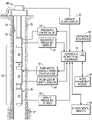
- a well system 20is illustrated as comprising a completion 22 deployed in a wellbore 24 which may be lined with a casing 26 having perforations 27 .
- the well system 20comprises an artificial lift system 28 in the form of an electric submersible pumping system.
- the electric submersible pumping system 28may have a variety of components including, for example, a submersible pump 30 , a motor 32 to power the submersible pump 30 , a motor protector 34 , and a sensor system 36 , such as a multisensory gauge 38 .
- the multisensory gauge 38may be in the form of or comprise elements of the Phoenix Multisensor xt150 Digital Downhole Monitoring SystemTM for electric submersible pumps and manufactured by Schlumberger Technology Corporation.
- the multisensory gauge 38may comprise sensors for monitoring downhole parameters, such as temperature, flow, pressure, electrical parameters, and various other parameters depending on the application.
- the multisensory gauge 38may have an intake pressure sensor 40 for measuring an inlet pressure of the electric submersible pumping system 28 .
- a power sourcesuch as a surface power source may be used to provide electrical power to the downhole components, including power to the submersible motor 32 via a suitable power cable or other conductor.
- the motor 32may be controlled with a variable speed drive (VSD) system 42 .
- VSDvariable speed drive
- An example of the VSD system 42is described in U.S. Pat. No. 8,527,219.
- the VSD system 42may be used to provide a variable frequency signal to motor 32 so as to increase or decrease the motor speed.
- the well system 20also may comprise control and monitoring equipment 44 which is placed in communication, e.g. electrical communication, with desired sensors, such as multisensory gauge 38 , a discharge pressure sensor 46 , and/or other sensors positioned to detect desired parameters.
- the control and monitoring equipment 44may be in the form of a processor, e.g. microprocessor, programmed to process sensor data according to desired algorithms, models, or other processing techniques.
- the control and monitoring equipment 44may comprise a surface controller, a downhole controller, a server, an office system coupled through a satellite link or a variety of other types of communication systems, and/or a supervisory control and data acquisition (SCADA) system (examples of an SCADA system and other industrial control systems are described in US Patent Publication 2013/0090853).
- SCADAsupervisory control and data acquisition
- the controller/monitoring equipment 44is constructed to enable control of downhole components and monitoring of various downhole parameters via selected sensors.
- Control and monitoring equipment 44may incorporate one or more processing units for executing software application instructions, storing and retrieving data from memory, and rapidly and continuously processing input signals from sensors, such as intake pressure sensor 40 , discharge pressure sensor 46 , a pump motor speed sensor 48 , and/or a surface flow sensor 50 .
- the equipment 44also may output control signals to control various components, such as the pump motor variable speed drive system 42 and a pressure choke valve 52 .
- the control and monitoring equipment 44may be coupled with environmental sensors 54 which are constructed for sensing environmental conditions.
- the output signals from the various downhole sensorsmay be conveyed to the control and monitoring equipment 44 via a suitable communication line, such as a downhole wireline.
- Output control signalsare generated by the processor or processors of equipment 44 according to algorithms, models, and/or other applications, and those output control signals are used to initiate automated procedures with respect to operation of the electric submersible pumping system 28 , including control over the pump motor 32 .
- Control and monitoring equipment 44also may comprise an operator interface 56 and an alarm management module 58 for processing information received from the various sensors, e.g. sensors 40 , 46 , 48 , 50 and 54 .
- the data received from the sensorsmay be received in real time and in a continuous manner to enable the alarm management module 58 to dynamically adjust alarm settings based on well conditions and environmental conditions.
- alarm management module 58may comprise or cooperate with a memory 60 of control and monitoring equipment 44 which enable storage and retrieval of, for example, historical data.
- the historical datamay be long-term historical data or short-term historical data, e.g. data from a current run cycle of the well.
- the alarm management module 58also may be programmed to support or perform methods of dynamically setting alarms, as illustrated in the operational example of FIG. 2 .
- Other dataalso may be stored in memory 60 of control and monitoring equipment 44 , e.g. in alarm management module 58 , and may include data representing different alarm levels.
- control and monitoring equipment 44may process signals from the various sensors, e.g. sensors 40 , 46 , 48 , 50 , 54 , continuously and in real-time so as to provide closed loop control of various operating parameters associated with the electric submersible pumping system 28 .
- the closed loop control of the electric submersible pumping system 28may be utilized during, for example, commissioning and subsequent operation of the pumping system 28 .
- the closed loop controlmay include obtaining sensor readings for the sensed operating and environmental parameters. This information may be further utilized in the alarm management module 58 of control and monitoring equipment 44 to dynamically manage and set alarms.
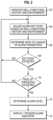
- a flowchartis used to illustrate an example of a methodology for dynamically setting alarms.
- various data obtained from the sensorsis stored.
- well conditions, history data, and/or environmental conditionsmay be monitored and recorded/stored in memory 60 , as represented by block 62 .
- alarm set pointsare dynamically determined based on the well conditions, history data, and/or environmental conditions, as represented by block 64 .
- the processor of equipment 44may be programmed to monitor a rate of change of alarm parameters to detect potentially anomalous or erroneous (e.g. false positive) alarm triggering input signals, data, or other information, as represented by block 66 .
- the particular alarm levelmay be selected according to an alarm level hierarchy, as explained in greater detail below. Once the particular alarm level is determined, the alarm is triggered and the alarm level/type is output, as represented by block 74 .
- the outputcan be in the form of data displayed to an operator and/or control signals used to automatically adjust operation of the electric submersible pumping system 28 .
- low-level alarmsmay simply be flagged or used to initiate output of a suitable control signal which is sent by the system to an appropriate target control or other component.
- the methodologydirects a return to block 64 to again adjust alarm set points and to repeat the process.
- the methodology illustrated in the embodiment of FIG. 2may be repeated in a high-speed and continuous manner by the control and monitoring equipment 44 via alarm management module 58 .
- Alarm management module 58may be constructed, e.g. programmed, to classify alarms according to various hierarchies of alarm settings.
- the hierarchymay comprise a high level or “danger” level alarm that results in immediate stoppage of the pumping system 28 .
- a lower or “warning” level alarmmay be used to indicate an issue which does not provide for immediate stoppage of an operation and may result in adjustment to the operation of the pumping system 28 .
- a still lower level or “control” level alarmmay be used to cause the output of a control signal which changes a control parameter related to operation of the electric submersible pumping system 28 but without providing, for example, notice to an operator.
- such a “control” level alarmmay cause the control and monitoring equipment 44 to change a speed of the pump 30 based on a change in sensed pressure, flow, temperature, electrical parameters, and/or other parameters.
- the alarm hierarchyalso may comprise an “unreliable signal” alarm which indicates the basis for the alarm is not reliable and controls may not be responding appropriately.
- the operator interface 56may be used to display alarm information in a variety of formats. In some applications, the operator interface 56 is used to display the alarm information according to the hierarchy described above or according to another suitable hierarchy so that an operator may observe comprehensive status information on the system and on the alarm settings and status. In some applications, the operator interface 56 also may be used to input changes which allow the operator to classify alarm settings according to a desired hierarchy.
- Sensed parametersmay be used by the control and monitoring equipment 44 and alarm management module 58 to automatically establish alarm set points upon start-up of a well operation. Dynamic alarm settings may then be adjusted according to changing well and environmental conditions automatically and/or through the input of an operator. The methodology reduces or eliminates false positive alarms while providing a more comprehensive system and alarm status for an operator.
- a controllere.g. control and monitoring equipment 44
- the controller 44may include an additional “safe” mode.
- the safe modeis a mode in which an automatic adjustment is made to the pumping system 28 to enable continued operation of the pumping system 28 in a limited capacity or with another appropriate adjustment to that operation.
- the frequency of the variable speed drive system 42may be changed to reduce the motor speed so that the motor 32 operates at a predetermined safe speed and direction.
- the safe mode operationavoids a complete stop and subsequent restart of the pumping system 28 . Avoidance of the stop and restart reduces the total number of starts to which the motor 32 and pump 30 are subjected, thus enhancing pumping system life. By maintaining the pumping system 28 in an adjusted, operating mode, the interruption to production also is reduced.
- the sensor data processed by control and monitoring equipment 44 to determine whether safe mode operation should be initiatedmay vary depending on the specifics of a given application.
- one monitored parametermay be the temperature of motor 32 referred to as Tm.
- Tmthe temperature of motor 32
- safe mode operationmay be set to begin at a predetermined value less than X, e.g. 0.9X.
- a rising Tmcan be caused by gassy or sandy production, and safe mode operation can provide a mechanism to reduce total starts and to keep production interruptions to a minimum.
- the safe mode operationalso may be used in connection with additional and/or other parameters, such as pressure, flow, other temperature readings, and/or other desired parameters.
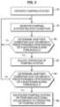
- the pumping system 20is started and operated, as represented by block 76 .
- a parameter or conditionis monitored by control and monitoring equipment 44 via the appropriate sensors, e.g. sensors 40 , 42 , 46 , 50 , 54 , as represented by block 78 .
- the controller 44continually monitors the sensor data to determine whether the parameter/condition is above a predetermined percentage of X, as represented by decision block 80 . If not, the monitoring is continued and no changes are made to the operation of the pumping system 28 . However, if the sensor data indicates a level above the predetermined percentage of X, then an adjustment is made automatically to the operation of pumping system 28 , e.g. the variable speed drive frequency is reduced to run motor 32 at a lower speed, as represented by block 82 .
- the controller 44again monitors the sensor data to determine whether the parameter/condition is above the predetermined percentage of X, as indicated by decision block 84 . If not, the monitoring is continued with no further changes, as described above with reference to block 78 . However, if the measured parameter/condition remains above the predetermined percentage, additional adjustments to the operation of pumping system 28 may be made, as indicated by block 86 . If, however, level X is reached or if the level remains above the predetermined percentage for longer than a predetermined time period, the pumping system 28 may be shut down. In many applications, normal operation may be resumed after the event, e.g. abnormal parameter, has passed or after an operational adjustment has been performed.
- a controllere.g. control and monitoring equipment 44
- the advanced alarming techniquemay comprise defining alarm conditions which are based on historical trend data of a measured parameter instead of a single instantaneous sample.
- This type of advanced alarming techniquecan be used to provide better protection and increased longevity of the pumping system 28 .
- the advanced alarming techniquecan be used to recognize harmful conditions which would otherwise go unnoticed, and these conditions can be acted on by tripping the pumping system 28 to a stopped position, by logging the condition as part of a continual effort to optimize production, and/or to initiate an altered mode, e.g. safe mode, of operation with respect to the pumping system 28 .
- the advanced alarming techniquemay utilize a composite alarm which is based upon more than a single live value of sensor data.
- logical operatorssuch as AND, OR, NOT, ELSE and IF may be used to chain together multiple single alarms into a composite alarm condition.
- the processor of control and monitoring equipment 44may be programmed to monitor for the desired combination of sensor data signals obtained from the relevant sensors.
- a combination of sensors and sensor datamay be used to indicate a condition of gas lock. No single measurement is effective at measuring gas lock, but a combination of live values, e.g. motor load data, motor temperature data, and flow data, can be used to provide the indication of gas lock.
- these three types of datacan be logically chained together to indicate gas lock is present if the motor load is too low AND the motor temperature is too high AND the flow is too low.
- the advanced alarming techniquemay utilize a behavior alarm which examines the behavior of live value readings.
- control and monitoring equipment 44may be programmed to obtain a sampling of live values represented by sensor data so that the slope of the live parameter can be checked.
- the advanced alarming techniquemonitors for harmful conditions based on historical trend data rather than simple instantaneous readings of the sensor data.
- sensors 40 , 46 , 48 , 50 , 54remain fairly constant during stable operating conditions with respect to electric pumping system 28 . Accordingly, a sufficiently large discontinuity or excessive ripple in the sensor data/values may indicate a pending problem even if the absolute value of the live reading has not yet exceeded predetermined maximum alarm set points or limits.
- the control and monitoring equipment 44may be programmed to output an alarm if sensor data crosses a lower alarm limit 88 or an upper alarm limit 90 .
- a pressure or pressures associated with operation of the electric submersible pumping system 28may be tracked and an alarm alert may be output if the pressure falls below lower limit 88 or rises above upper limit 90 .
- a discontinuity 92 in the live values, e.g. pressure readings, provided by the appropriate sensorsalso may be indicative of an alarm condition.
- the control and monitoring equipment 44is programmed to detect predetermined discontinuities 92 which merit output of an alarm condition. As described above, the alarm condition level may vary depending on the specific discontinuity 92 detected.
- the electric submersible pumping system 28is protected by monitoring parameters, e.g. motor current, motor voltage, and/or other parameters, related to operation of the electric submersible pumping system 28 .
- monitoring parameterse.g. motor current, motor voltage, and/or other parameters, related to operation of the electric submersible pumping system 28 .
- operation of the electric submersible pumping system 28is adjusted, e.g. motor speed is slowed. If maximum or extreme alarm thresholds are crossed, operation of the pumping system 28 may then be stopped.
- the electric submersible pumping system 28is vulnerable during initial start-up and ramp-up phases and during periods of changing load.
- the changing loadmay result from fluid composition changes, e.g. solids, gas, water, and oil composition changes, and/or specific gravity changes resulting from changing well conditions or other phenomena.
- the motor 32 of electric submersible pumping system 28may be protected during these phases and during changing loads by adjusting alarm thresholds.
- the alarm thresholdsmay be adjusted by generating and maintaining over time a model of the motor's electrical inputs, e.g. voltage, current, and frequency, versus the expected pump outputs of pumps 30 .
- appropriate adjustmentsmay be made, such as modifying the rotational speed of the motor 32 , including full stoppage of the motor 32 under certain conditions. Tracking of the system behavior over time enables the model and the associated alarm thresholds to be dynamically adjusted, e.g. to evolve. The evolving occurs over the operational life of the electric submersible pumping system 28 and the surrounding reservoir as, for example, equipment degrades and well conditions and reservoir fluids change.
- control and monitoring equipment 44again receives a variety of data related to operation of the electric submersible pumping system 28 or other artificial lift system.
- the control and monitoring equipment 44may receive electrical measurements 94 obtained from appropriate sensors, such as three-phase current sensors 96 , three-phase voltage sensors 98 , harmonic distortion sensors 100 , frequency sensors 102 , and/or other suitable sensors.
- downhole production measurements 104may be received from suitable sensors, such as a pump intake pressure sensor 40 and the pump discharge pressure sensor 46 .
- a plurality of well attribute measurements 106also may be received from suitable sensors, such as specific gravity sensors 108 , phase/water cut sensors 110 , and downhole flow rate sensors 112 .
- surface production measurements 114may be obtained from suitable sensors, such as a wellhead pressure sensor 116 and surface or wellhead flow rate sensor 50 .
- the data from the various sensorsmay be delivered to control and monitoring equipment 44 for appropriate processing according to desired algorithms, models, and/or other processing techniques.
- the sensor datamay be modeled by an initial-start, pump-load, modeling module 118 .
- the sensor datamay be modeled by a subsequent-start/operational, pump-load modeling module 120 .
- the alarm management module 58 or other suitable processing modulemay be used to establish a log 122 of electrical inputs versus modeled load based on data from the initial start module 118 .
- the data from module 118may further be used to establish an initial pre-start estimate 123 .
- the alarm management module 58also may be employed to provide a time-based weighting 124 of the measurements and calculations based on data from the subsequent start/operation module 120 and from the log 122 .
- the time-based weighting 124also receives log data 126 of electrical inputs versus modeled load. (The log data 126 is obtained from the subsequent-start/operation module 120 .) Based on this collection of data and modeling of data, the time-based weighting 124 of measurements and calculations can be used to establish and dynamically adjust alarm thresholds 128 .
- the alarm thresholds 128may be adjusted via control and monitoring equipment 44 throughout the life and operation of electric submersible pumping system 28 .
- Thisallows the control and monitoring equipment 44 to adjust operation of the pumping system 28 as appropriate for a given set of conditions related to operation of the pumping system 28 and/or conditions related to the well and surrounding reservoir.
- the systemenables tracking data, storing data, and modeling data related to motor current and motor frequency over time, as shown graphically in FIG. 6 .
- the datachanges over time as electric submersible pumping system 28 is continuously operated.
- the control and monitoring equipment 44may adjust to these changes and, in turn, dynamically adjust alarm thresholds, as indicated by arrows 130 in FIG. 7 .
- the alarm thresholds indicated by arrows 130are adjusted relative to initial thresholds indicated by arrow 132 .
- the datamay be modeled or otherwise processed to determine a plurality of alarm threshold levels which may be used to output appropriate control signals for adjusting operation of pumping system 28 , stopping operation of pumping system 28 , and/or outputting appropriate alarm indicators to an operator.
- the smart alarming techniquesmay utilize static data, modeling, actual measurements, and/or other data to determine alarm conditions.
- signal processingis used to automatically determine reference levels as well as alarm levels for a single sensor signal or a combination of sensor signals.
- the processing system of control and monitoring equipment 44may be used to apply a raw parameter measurement, a calculated/modeled parameter, or a combination of raw parameter measurements and other parameter data.
- Various signal processing techniquese.g. rate of change techniques, may be used to detect alarm conditions and, in some applications, to automatically adjust operation of the electric submersible pumping system or other artificial lift system.
- control and monitoring equipment 44 and the associated sensors and modulesmay be used for event detection and mitigation based on single alarms or combinations of smart alarms.
- the equipment 44may be programmed to use event specific signal processing which analyzes the timing of the event, scale of the event, and/or other data to determine whether an alarm action and/or mitigating action should be taken with respect to operation of the pumping system 28 .
- the control and monitoring equipment 44may be used to apply a mitigation protocol which depends on the type of event detected. In many applications, the control and monitoring equipment 44 learns from the history of the well and the impact of previous mitigation measures, thus enabling the system to dynamically adapt various smart alarms according to the mitigation protocol.
- the well system 20 and artificial lift system 28may have a variety of configurations and comprise numerous types of components. Additionally, various sensors and combinations of sensors may be employed. The procedures for obtaining and analyzing the data also may be adjusted according to the parameters of a given well, completion system, and/or reservoir. Similarly, the control and monitoring equipment 44 may be programmed to detect various events, trends, discontinuities, and/or other changes in the data from individual or plural sensors to determine an alarm condition. The equipment 44 also may be used to determine various levels of alarm which may be output to an operator and/or used to initiate automatic adjustments to operation of pumping system 28 . Various closed loop control strategies may be used to continually monitor operation of the pumping system following the adjustments so as to determine future actions with respect to operation of the pumping system.
Landscapes
- Engineering & Computer Science (AREA)
- Geology (AREA)
- Life Sciences & Earth Sciences (AREA)
- Mining & Mineral Resources (AREA)
- Physics & Mathematics (AREA)
- Geochemistry & Mineralogy (AREA)
- Fluid Mechanics (AREA)
- General Life Sciences & Earth Sciences (AREA)
- Environmental & Geological Engineering (AREA)
- Geophysics (AREA)
- Business, Economics & Management (AREA)
- Emergency Management (AREA)
- General Physics & Mathematics (AREA)
- Mechanical Engineering (AREA)
- Control Of Non-Positive-Displacement Pumps (AREA)
- Control Of Positive-Displacement Pumps (AREA)
- Testing And Monitoring For Control Systems (AREA)
- Debugging And Monitoring (AREA)
Abstract
Description
Claims (20)
Priority Applications (1)
| Application Number | Priority Date | Filing Date | Title |
|---|---|---|---|
| US15/035,698US11613985B2 (en) | 2013-11-13 | 2014-11-13 | Well alarms and event detection |
Applications Claiming Priority (3)
| Application Number | Priority Date | Filing Date | Title |
|---|---|---|---|
| US201361903941P | 2013-11-13 | 2013-11-13 | |
| PCT/US2014/065338WO2015073600A1 (en) | 2013-11-13 | 2014-11-13 | Well alarms and event detection |
| US15/035,698US11613985B2 (en) | 2013-11-13 | 2014-11-13 | Well alarms and event detection |
Publications (2)
| Publication Number | Publication Date |
|---|---|
| US20160281479A1 US20160281479A1 (en) | 2016-09-29 |
| US11613985B2true US11613985B2 (en) | 2023-03-28 |
Family
ID=53057982
Family Applications (1)
| Application Number | Title | Priority Date | Filing Date |
|---|---|---|---|
| US15/035,698Active2035-01-06US11613985B2 (en) | 2013-11-13 | 2014-11-13 | Well alarms and event detection |
Country Status (4)
| Country | Link |
|---|---|
| US (1) | US11613985B2 (en) |
| CA (1) | CA2930426A1 (en) |
| GB (1) | GB2535380B (en) |
| WO (1) | WO2015073600A1 (en) |
Cited By (1)
| Publication number | Priority date | Publication date | Assignee | Title |
|---|---|---|---|---|
| US11962957B1 (en)* | 2023-02-17 | 2024-04-16 | Schlumberger Technology Corporation | Systems and methods for wellsite control |
Families Citing this family (10)
| Publication number | Priority date | Publication date | Assignee | Title |
|---|---|---|---|---|
| BR112016022984B1 (en)* | 2014-04-03 | 2022-08-02 | Schlumberger Technology B.V. | METHOD FOR EVALUATION OF AN OPERATION OF A PUMPING SYSTEM, METHOD, AND METHOD FOR IMPROVING A LIFE EXPECTATION OF A PUMPING SYSTEM |
| GB2547852B (en) | 2014-12-09 | 2020-09-09 | Sensia Netherlands Bv | Electric submersible pump event detection |
| WO2019108177A1 (en)* | 2017-11-29 | 2019-06-06 | Halliburton Energy Services, Inc. | Automated pressure control system |
| CN110847884B (en)* | 2018-08-01 | 2023-02-28 | 中国石油天然气股份有限公司 | Method and device for diagnosing collapse time of oil well |
| US11041349B2 (en) | 2018-10-11 | 2021-06-22 | Schlumberger Technology Corporation | Automatic shift detection for oil and gas production system |
| AR118151A1 (en)* | 2019-04-19 | 2021-09-22 | Halliburton Energy Services Inc | SELECTIVE ENERGY SUPPLY FROM THE DOWN-OF-WELL GAUGE DURING INSTALLATION DOWN IN THE WELL |
| CN110284875A (en)* | 2019-06-13 | 2019-09-27 | 中国石油化工股份有限公司 | A kind of Diagnosing The Faults of Esp ' method and apparatus based on current parameters |
| US11448206B2 (en)* | 2020-03-31 | 2022-09-20 | Jesus S. Armacanqui | Gas lock removal method for electrical submersible pumps |
| US12180825B2 (en) | 2022-03-21 | 2024-12-31 | Saudi Arabian Oil Company | Advanced diagnostics and control system for artificial lift systems |
| EP4575688A1 (en)* | 2023-12-19 | 2025-06-25 | Schneider Electric Systems USA, Inc. | Predictive maintenance and anomaly detection of pump systems |
Citations (37)
| Publication number | Priority date | Publication date | Assignee | Title |
|---|---|---|---|---|
| US4821580A (en) | 1988-01-27 | 1989-04-18 | Jorritsma Johannes N | Method and apparatus for calculating flow rates through a pumping station |
| US5353646A (en) | 1994-01-10 | 1994-10-11 | Atlantic Richfield Company | Multiphase fluid flow measurement |
| US5466127A (en) | 1992-12-30 | 1995-11-14 | Wilo Gmbh | Device for switching a submersible motor-driven pump on and off |
| US5668420A (en) | 1995-04-06 | 1997-09-16 | The Penn State Research Foundation | Magnetohydrodynamic apparatus |
| US5952569A (en) | 1996-10-21 | 1999-09-14 | Schlumberger Technology Corporation | Alarm system for wellbore site |
| US20020145423A1 (en)* | 1999-04-05 | 2002-10-10 | Halliburton Energy Services | Magnetically activated well tool |
| US20040064292A1 (en) | 2002-09-27 | 2004-04-01 | Beck Thomas L. | Control system for centrifugal pumps |
| US20050031443A1 (en) | 2001-10-09 | 2005-02-10 | Bertil Ohlsson | Device, system and method for on-line monitoring of flow quantities |
| US20050216229A1 (en) | 2004-03-24 | 2005-09-29 | Industrial Technology Research Institute | Monitoring systems and methods thereof |
| US20060052903A1 (en) | 2000-11-01 | 2006-03-09 | Weatherford/Lamb, Inc. | Controller system for downhole applications |
| US7114557B2 (en)* | 2004-02-03 | 2006-10-03 | Schlumberger Technology Corporation | System and method for optimizing production in an artificially lifted well |
| US20070150113A1 (en) | 2005-12-02 | 2007-06-28 | Chi-Yi Wang | System of energy-efficient and constant-pressure parallel-coupled fluid-transport machines |
| US20070175633A1 (en)* | 2006-01-30 | 2007-08-02 | Schlumberger Technology Corporation | System and Method for Remote Real-Time Surveillance and Control of Pumped Wells |
| US7258164B2 (en) | 2002-06-13 | 2007-08-21 | Schlumberger Technology Corporation | Pumping system for oil wells |
| US20070221173A1 (en) | 2006-03-23 | 2007-09-27 | Denso Corporation | Fluid apparatus having pumps and method for controlling the same |
| US20070252717A1 (en) | 2006-03-23 | 2007-11-01 | Schlumberger Technology Corporation | System and Method for Real-Time Monitoring and Failure Prediction of Electrical Submersible Pumps |
| US20070289740A1 (en)* | 1998-12-21 | 2007-12-20 | Baker Hughes Incorporated | Apparatus and Method for Managing Supply of Additive at Wellsites |
| US20080067116A1 (en) | 2002-11-26 | 2008-03-20 | Unico, Inc. | Determination And Control Of Wellbore Fluid Level, Output Flow, And Desired Pump Operating Speed, Using A Control System For A Centrifugal Pump Disposed Within The Wellbore |
| WO2008069695A2 (en) | 2006-12-07 | 2008-06-12 | Schlumberger Canada Limited | Method of measuring of production rate for a well cluster |
| US20080260540A1 (en) | 2003-12-08 | 2008-10-23 | Koehl Robert M | Pump controller system and method |
| US20090000789A1 (en) | 2007-06-26 | 2009-01-01 | Baker Hughes Incorporated | Device, Method And Program Product To Automatically Detect And Break Gas Locks In An ESP |
| US20090044938A1 (en) | 2007-08-16 | 2009-02-19 | Baker Hughes Incorporated | Smart motor controller for an electrical submersible pump |
| US20090173166A1 (en) | 2008-01-08 | 2009-07-09 | Fluonic Inc. | Multi-sensor mass flow meter along with method for accomplishing same |
| US7562723B2 (en) | 2006-01-05 | 2009-07-21 | At Balance Americas, Llc | Method for determining formation fluid entry into or drilling fluid loss from a borehole using a dynamic annular pressure control system |
| US20090223662A1 (en) | 2008-03-05 | 2009-09-10 | Baker Hughes Incorporated | System, method and apparatus for controlling the flow rate of an electrical submersible pump based on fluid density |
| RU2368772C1 (en) | 2008-04-29 | 2009-09-27 | Открытое Акционерное Общество "Газпромнефть-Ноябрьскнефтегазгеофизика" | Monitoring method of multi-bed well with elimination of cross-flows between beds |
| US20090250210A1 (en) | 2007-06-26 | 2009-10-08 | Baker Hughes Incorporated | Device and Method For Gas Lock Detection In An Electrical Submersible Pump Assembly |
| US20100206039A1 (en)* | 2005-06-06 | 2010-08-19 | Lawrence Kates | System and method for variable threshold sensor |
| US20100247335A1 (en)* | 2007-06-15 | 2010-09-30 | Eric Atherton | System for Monitoring an Electrical Submersible Pump |
| US20100263442A1 (en)* | 2009-04-17 | 2010-10-21 | Kai Hsu | Methods and apparatus for analyzing a downhole fluid |
| US20110168391A1 (en) | 2008-02-25 | 2011-07-14 | QRI Group, LLC | Method for dynamically assessing petroleum reservoir competency and increasing production and recovery through asymmetric analysis of performance metrics |
| US20130025940A1 (en)* | 2011-07-28 | 2013-01-31 | Baker Hughes Incorporated | Active equivalent circulating density control with real-time data connection |
| US20130090853A1 (en) | 2011-10-06 | 2013-04-11 | Jeffery P. Anderson | High-Frequency Data Capture for Diagnostics |
| US8527219B2 (en) | 2009-10-21 | 2013-09-03 | Schlumberger Technology Corporation | System, method, and computer readable medium for calculating well flow rates produced with electrical submersible pumps |
| US20160265321A1 (en) | 2015-03-11 | 2016-09-15 | Encline Artificial Lift Technologies LLC | Well Pumping System Having Pump Speed Optimization |
| US20170363088A1 (en) | 2014-12-09 | 2017-12-21 | Schlumberger Technology Corporation | Electric submersible pump event detection |
| WO2018129349A1 (en) | 2017-01-05 | 2018-07-12 | Summit Esp, Llc | Dynamic power optimization system and method for electric submersible motors |
- 2014
- 2014-11-13CACA2930426Apatent/CA2930426A1/ennot_activeAbandoned
- 2014-11-13USUS15/035,698patent/US11613985B2/enactiveActive
- 2014-11-13WOPCT/US2014/065338patent/WO2015073600A1/enactiveApplication Filing
- 2014-11-13GBGB1608333.9Apatent/GB2535380B/enactiveActive
Patent Citations (41)
| Publication number | Priority date | Publication date | Assignee | Title |
|---|---|---|---|---|
| US4821580A (en) | 1988-01-27 | 1989-04-18 | Jorritsma Johannes N | Method and apparatus for calculating flow rates through a pumping station |
| US5466127A (en) | 1992-12-30 | 1995-11-14 | Wilo Gmbh | Device for switching a submersible motor-driven pump on and off |
| US5353646A (en) | 1994-01-10 | 1994-10-11 | Atlantic Richfield Company | Multiphase fluid flow measurement |
| US5668420A (en) | 1995-04-06 | 1997-09-16 | The Penn State Research Foundation | Magnetohydrodynamic apparatus |
| US5952569A (en) | 1996-10-21 | 1999-09-14 | Schlumberger Technology Corporation | Alarm system for wellbore site |
| US20070289740A1 (en)* | 1998-12-21 | 2007-12-20 | Baker Hughes Incorporated | Apparatus and Method for Managing Supply of Additive at Wellsites |
| US20020145423A1 (en)* | 1999-04-05 | 2002-10-10 | Halliburton Energy Services | Magnetically activated well tool |
| US20060052903A1 (en) | 2000-11-01 | 2006-03-09 | Weatherford/Lamb, Inc. | Controller system for downhole applications |
| US20050031443A1 (en) | 2001-10-09 | 2005-02-10 | Bertil Ohlsson | Device, system and method for on-line monitoring of flow quantities |
| US7258164B2 (en) | 2002-06-13 | 2007-08-21 | Schlumberger Technology Corporation | Pumping system for oil wells |
| US20110106452A1 (en) | 2002-09-27 | 2011-05-05 | Unico, Inc. | Determination and Control of Wellbore Fluid Level, Output Flow, and Desired Pump Operating Speed, Using a Control System for a Centrifugal Pump Disposed Within the Wellbore |
| US20040064292A1 (en) | 2002-09-27 | 2004-04-01 | Beck Thomas L. | Control system for centrifugal pumps |
| US7117120B2 (en) | 2002-09-27 | 2006-10-03 | Unico, Inc. | Control system for centrifugal pumps |
| US20080067116A1 (en) | 2002-11-26 | 2008-03-20 | Unico, Inc. | Determination And Control Of Wellbore Fluid Level, Output Flow, And Desired Pump Operating Speed, Using A Control System For A Centrifugal Pump Disposed Within The Wellbore |
| US20080260540A1 (en) | 2003-12-08 | 2008-10-23 | Koehl Robert M | Pump controller system and method |
| US7114557B2 (en)* | 2004-02-03 | 2006-10-03 | Schlumberger Technology Corporation | System and method for optimizing production in an artificially lifted well |
| US20050216229A1 (en) | 2004-03-24 | 2005-09-29 | Industrial Technology Research Institute | Monitoring systems and methods thereof |
| US20100206039A1 (en)* | 2005-06-06 | 2010-08-19 | Lawrence Kates | System and method for variable threshold sensor |
| US20070150113A1 (en) | 2005-12-02 | 2007-06-28 | Chi-Yi Wang | System of energy-efficient and constant-pressure parallel-coupled fluid-transport machines |
| US7562723B2 (en) | 2006-01-05 | 2009-07-21 | At Balance Americas, Llc | Method for determining formation fluid entry into or drilling fluid loss from a borehole using a dynamic annular pressure control system |
| US20070175633A1 (en)* | 2006-01-30 | 2007-08-02 | Schlumberger Technology Corporation | System and Method for Remote Real-Time Surveillance and Control of Pumped Wells |
| US20070252717A1 (en) | 2006-03-23 | 2007-11-01 | Schlumberger Technology Corporation | System and Method for Real-Time Monitoring and Failure Prediction of Electrical Submersible Pumps |
| US20070221173A1 (en) | 2006-03-23 | 2007-09-27 | Denso Corporation | Fluid apparatus having pumps and method for controlling the same |
| WO2008069695A2 (en) | 2006-12-07 | 2008-06-12 | Schlumberger Canada Limited | Method of measuring of production rate for a well cluster |
| WO2008150811A1 (en) | 2007-05-31 | 2008-12-11 | Baker Hughes Incorporated | Apparatus and method for managings supply of additive at wellsites |
| US20100247335A1 (en)* | 2007-06-15 | 2010-09-30 | Eric Atherton | System for Monitoring an Electrical Submersible Pump |
| US20090250210A1 (en) | 2007-06-26 | 2009-10-08 | Baker Hughes Incorporated | Device and Method For Gas Lock Detection In An Electrical Submersible Pump Assembly |
| US20090000789A1 (en) | 2007-06-26 | 2009-01-01 | Baker Hughes Incorporated | Device, Method And Program Product To Automatically Detect And Break Gas Locks In An ESP |
| US20090044938A1 (en) | 2007-08-16 | 2009-02-19 | Baker Hughes Incorporated | Smart motor controller for an electrical submersible pump |
| US20090173166A1 (en) | 2008-01-08 | 2009-07-09 | Fluonic Inc. | Multi-sensor mass flow meter along with method for accomplishing same |
| US20110168391A1 (en) | 2008-02-25 | 2011-07-14 | QRI Group, LLC | Method for dynamically assessing petroleum reservoir competency and increasing production and recovery through asymmetric analysis of performance metrics |
| US20090223662A1 (en) | 2008-03-05 | 2009-09-10 | Baker Hughes Incorporated | System, method and apparatus for controlling the flow rate of an electrical submersible pump based on fluid density |
| RU2368772C1 (en) | 2008-04-29 | 2009-09-27 | Открытое Акционерное Общество "Газпромнефть-Ноябрьскнефтегазгеофизика" | Monitoring method of multi-bed well with elimination of cross-flows between beds |
| US20100263442A1 (en)* | 2009-04-17 | 2010-10-21 | Kai Hsu | Methods and apparatus for analyzing a downhole fluid |
| US8527219B2 (en) | 2009-10-21 | 2013-09-03 | Schlumberger Technology Corporation | System, method, and computer readable medium for calculating well flow rates produced with electrical submersible pumps |
| US9476742B2 (en) | 2009-10-21 | 2016-10-25 | Schlumberger Technology Corporation | System, method, and computer readable medium for calculating well flow rates produced with electrical submersible pumps |
| US20130025940A1 (en)* | 2011-07-28 | 2013-01-31 | Baker Hughes Incorporated | Active equivalent circulating density control with real-time data connection |
| US20130090853A1 (en) | 2011-10-06 | 2013-04-11 | Jeffery P. Anderson | High-Frequency Data Capture for Diagnostics |
| US20170363088A1 (en) | 2014-12-09 | 2017-12-21 | Schlumberger Technology Corporation | Electric submersible pump event detection |
| US20160265321A1 (en) | 2015-03-11 | 2016-09-15 | Encline Artificial Lift Technologies LLC | Well Pumping System Having Pump Speed Optimization |
| WO2018129349A1 (en) | 2017-01-05 | 2018-07-12 | Summit Esp, Llc | Dynamic power optimization system and method for electric submersible motors |
Non-Patent Citations (11)
| Title |
|---|
| 2007 ESP Workshop Agenda, ESP Workshop, Apr. 26, 2007, Woodland, TX USA, 3 pages. |
| Bolin, Using The Calibrated-Tested Pumping Instrument (Electrical Submersible Pump) For Continuous Fluid Measurement When Producing Heavy Oil Wells, ESP Workshop, Apr. 26, 2007, The Woodlands, TX, USA. |
| CA Examination Report in CA Appl. Ser. No. CA 2930426 dated Jan. 5, 2021 (3 pages). |
| Camilleri, et al., "First installation of Five ESPs Offshore Romania—A Case Study and Lesson Learned," Petrom_ESP, Apr. 29-May 1, 2009, pp. 1-22. |
| Camilleri, et al., "First Installation of Five ESPs Offshore Romania—A Case Study and Lesson Learned," SPE127593, Intelligent Energy Conference and Exhibition held in Utrecht, The Netherlands, Mar. 23-25, 2010. |
| International Preliminary Report on Patentability for PCT Appl. Ser. No. PCT/US2014/065338, dated May 17, 2016 (10 pages). |
| International Preliminary Report on Patentability on PCT Appl. Ser. No. PCT/US2019/055017 dated Apr. 8, 2021, (8 pages). |
| International Search Report and Written Opinion on PCT Appl. Ser. No. PCT/US2019/055017 dated Jan. 31, 2020 (9 pages). |
| Olsen, et al., "Production Allocation Using ESP in the Peregrino Field," SPE Gulf Coast Section Electric Submersible Pump Workshop, The Woodlands, TX, Apr. 25-29, 2011. |
| PCT/US2014/065338, International Search Report and Written Opinion, dated Mar. 31, 2015, 15 pgs. |
| Saudi Arabian Examination Report for Application No. SA 516371113 dated Jul. 25, 2020, 5 pages (No English Translation). |
Cited By (1)
| Publication number | Priority date | Publication date | Assignee | Title |
|---|---|---|---|---|
| US11962957B1 (en)* | 2023-02-17 | 2024-04-16 | Schlumberger Technology Corporation | Systems and methods for wellsite control |
Also Published As
| Publication number | Publication date |
|---|---|
| GB2535380A (en) | 2016-08-17 |
| US20160281479A1 (en) | 2016-09-29 |
| GB2535380B (en) | 2017-05-24 |
| CA2930426A1 (en) | 2015-05-21 |
| GB201608333D0 (en) | 2016-06-29 |
| WO2015073600A1 (en) | 2015-05-21 |
Similar Documents
| Publication | Publication Date | Title |
|---|---|---|
| US11613985B2 (en) | Well alarms and event detection | |
| US11236751B2 (en) | Electric submersible pump event detection | |
| US10677041B2 (en) | Fault detection in electric submersible pumps | |
| US7030746B2 (en) | Method and system for generating automatic alarms based on trends detected in machine operation | |
| US12180822B2 (en) | System and method to predict value and timing of drilling operational parameters | |
| US7632059B2 (en) | Systems and methods for detecting undesirable operation of a turbine | |
| US11408270B2 (en) | Well testing and monitoring | |
| WO2016153895A1 (en) | System and method for monitoring an electric submersible pump | |
| US10900489B2 (en) | Automatic pumping system commissioning | |
| CN114280969A (en) | Control loop performance monitoring in variable frequency drives | |
| US20210062803A1 (en) | Method and system for monitoring the condition of rotating systems | |
| AU2022270932B2 (en) | Method and system for predicting sand failure in a hydrocarbon production well and method and system for producing hydrocarbon fluids from an earth formation | |
| US12253075B2 (en) | Detecting events in progressing cavity pump operation and maintenance based on anomaly and drift detection | |
| US20200122859A1 (en) | Predictive monitoring system and method | |
| CN118468544A (en) | Process parameter optimization and control method and system for preventing aluminum liquid leakage in deep well casting of aluminum processing | |
| WO2025109639A1 (en) | Method and system for evaluating the energy performance of a pumping unit | |
| CN119021677A (en) | A method for eliminating the floating of the well rod of the pumping unit based on the motor torque feedback | |
| CN119575909A (en) | A mining equipment control system and method | |
| WO2014177902A1 (en) | Method for monitoring a pumping device |
Legal Events
| Date | Code | Title | Description |
|---|---|---|---|
| AS | Assignment | Owner name:SCHLUMBERGER TECHNOLOGY CORPORATION, TEXAS Free format text:ASSIGNMENT OF ASSIGNORS INTEREST;ASSIGNORS:RENDUSARA, DUDI ABDULLAH;PARRA, LUIS;MACKAY, RODERICK IAN;AND OTHERS;SIGNING DATES FROM 20151126 TO 20151214;REEL/FRAME:038751/0075 | |
| STPP | Information on status: patent application and granting procedure in general | Free format text:NON FINAL ACTION MAILED | |
| STPP | Information on status: patent application and granting procedure in general | Free format text:RESPONSE TO NON-FINAL OFFICE ACTION ENTERED AND FORWARDED TO EXAMINER | |
| STPP | Information on status: patent application and granting procedure in general | Free format text:FINAL REJECTION MAILED | |
| STPP | Information on status: patent application and granting procedure in general | Free format text:DOCKETED NEW CASE - READY FOR EXAMINATION | |
| AS | Assignment | Owner name:SENSIA LLC, TEXAS Free format text:ASSIGNMENT OF ASSIGNORS INTEREST;ASSIGNOR:SCHLUMBERGER TECHNOLOGY CORPORATION;REEL/FRAME:051370/0374 Effective date:20190927 | |
| STPP | Information on status: patent application and granting procedure in general | Free format text:NON FINAL ACTION MAILED | |
| STPP | Information on status: patent application and granting procedure in general | Free format text:RESPONSE TO NON-FINAL OFFICE ACTION ENTERED AND FORWARDED TO EXAMINER | |
| STPP | Information on status: patent application and granting procedure in general | Free format text:ADVISORY ACTION MAILED | |
| STPP | Information on status: patent application and granting procedure in general | Free format text:DOCKETED NEW CASE - READY FOR EXAMINATION | |
| STPP | Information on status: patent application and granting procedure in general | Free format text:NON FINAL ACTION MAILED | |
| STPP | Information on status: patent application and granting procedure in general | Free format text:RESPONSE TO NON-FINAL OFFICE ACTION ENTERED AND FORWARDED TO EXAMINER | |
| STPP | Information on status: patent application and granting procedure in general | Free format text:FINAL REJECTION MAILED | |
| STPP | Information on status: patent application and granting procedure in general | Free format text:RESPONSE AFTER FINAL ACTION FORWARDED TO EXAMINER | |
| STPP | Information on status: patent application and granting procedure in general | Free format text:ADVISORY ACTION MAILED | |
| STPP | Information on status: patent application and granting procedure in general | Free format text:DOCKETED NEW CASE - READY FOR EXAMINATION | |
| STPP | Information on status: patent application and granting procedure in general | Free format text:NOTICE OF ALLOWANCE MAILED -- APPLICATION RECEIVED IN OFFICE OF PUBLICATIONS | |
| STCF | Information on status: patent grant | Free format text:PATENTED CASE |