US11612492B2 - Zero-profile interbody spacer and coupled plate assembly - Google Patents
Zero-profile interbody spacer and coupled plate assemblyDownload PDFInfo
- Publication number
- US11612492B2 US11612492B2US16/558,670US201916558670AUS11612492B2US 11612492 B2US11612492 B2US 11612492B2US 201916558670 AUS201916558670 AUS 201916558670AUS 11612492 B2US11612492 B2US 11612492B2
- Authority
- US
- United States
- Prior art keywords
- bone fixation
- implant
- plate portion
- spring
- propeller
- Prior art date
- Legal status (The legal status is an assumption and is not a legal conclusion. Google has not performed a legal analysis and makes no representation as to the accuracy of the status listed.)
- Active, expires
Links
- 125000006850spacer groupChemical group0.000titleclaimsabstractdescription64
- 210000000988bone and boneAnatomy0.000claimsabstractdescription278
- 239000007943implantSubstances0.000claimsabstractdescription161
- 241001417534LutjanidaeSpecies0.000claimsabstractdescription71
- 238000003780insertionMethods0.000claimsabstractdescription54
- 230000007246mechanismEffects0.000claimsabstractdescription53
- 230000037431insertionEffects0.000claimsabstractdescription42
- 238000004891communicationMethods0.000claimsabstractdescription7
- 239000000463materialSubstances0.000claimsdescription19
- 230000000903blocking effectEffects0.000claimsdescription14
- 230000014759maintenance of locationEffects0.000abstractdescription23
- 238000002513implantationMethods0.000description17
- 239000004696Poly ether ether ketoneSubstances0.000description13
- 229920002530polyetherether ketonePolymers0.000description13
- JUPQTSLXMOCDHR-UHFFFAOYSA-Nbenzene-1,4-diol;bis(4-fluorophenyl)methanoneChemical compoundOC1=CC=C(O)C=C1.C1=CC(F)=CC=C1C(=O)C1=CC=C(F)C=C1JUPQTSLXMOCDHR-UHFFFAOYSA-N0.000description12
- 230000008878couplingEffects0.000description12
- 238000010168coupling processMethods0.000description12
- 238000005859coupling reactionMethods0.000description12
- 230000035876healingEffects0.000description6
- 230000004927fusionEffects0.000description5
- 230000003993interactionEffects0.000description5
- 238000000034methodMethods0.000description4
- RTAQQCXQSZGOHL-UHFFFAOYSA-NTitaniumChemical compound[Ti]RTAQQCXQSZGOHL-UHFFFAOYSA-N0.000description3
- 230000015572biosynthetic processEffects0.000description3
- 230000008468bone growthEffects0.000description3
- 238000005553drillingMethods0.000description3
- 230000013011matingEffects0.000description3
- 230000037361pathwayEffects0.000description3
- 229920000642polymerPolymers0.000description3
- 239000010936titaniumSubstances0.000description3
- 229910052719titaniumInorganic materials0.000description3
- 229910001069Ti alloyInorganic materials0.000description2
- 239000000919ceramicSubstances0.000description2
- 238000010348incorporationMethods0.000description2
- 239000007769metal materialSubstances0.000description2
- 238000012986modificationMethods0.000description2
- 230000004048modificationEffects0.000description2
- 230000002980postoperative effectEffects0.000description2
- 230000001737promoting effectEffects0.000description2
- 238000012552reviewMethods0.000description2
- 238000001356surgical procedureMethods0.000description2
- 229910000838Al alloyInorganic materials0.000description1
- 229920000049Carbon (fiber)Polymers0.000description1
- JVTAAEKCZFNVCJ-REOHCLBHSA-NL-lactic acidChemical compoundC[C@H](O)C(O)=OJVTAAEKCZFNVCJ-REOHCLBHSA-N0.000description1
- FYYHWMGAXLPEAU-UHFFFAOYSA-NMagnesiumChemical compound[Mg]FYYHWMGAXLPEAU-UHFFFAOYSA-N0.000description1
- 208000014604Specific Language diseaseDiseases0.000description1
- HZEWFHLRYVTOIW-UHFFFAOYSA-N[Ti].[Ni]Chemical compound[Ti].[Ni]HZEWFHLRYVTOIW-UHFFFAOYSA-N0.000description1
- 230000001154acute effectEffects0.000description1
- 238000007792additionMethods0.000description1
- 230000002411adverseEffects0.000description1
- 229910052782aluminiumInorganic materials0.000description1
- XAGFODPZIPBFFR-UHFFFAOYSA-NaluminiumChemical compound[Al]XAGFODPZIPBFFR-UHFFFAOYSA-N0.000description1
- 210000003484anatomyAnatomy0.000description1
- 201000007201aphasiaDiseases0.000description1
- 238000013459approachMethods0.000description1
- 230000003416augmentationEffects0.000description1
- 230000008901benefitEffects0.000description1
- 239000000560biocompatible materialSubstances0.000description1
- 239000005312bioglassSubstances0.000description1
- 239000008280bloodSubstances0.000description1
- 210000004369bloodAnatomy0.000description1
- 239000004917carbon fiberSubstances0.000description1
- 239000002131composite materialSubstances0.000description1
- 150000001875compoundsChemical class0.000description1
- 229910000701elgiloys (Co-Cr-Ni Alloy)Inorganic materials0.000description1
- 229910052588hydroxylapatiteInorganic materials0.000description1
- 230000003116impacting effectEffects0.000description1
- 230000008676importEffects0.000description1
- 238000007373indentationMethods0.000description1
- 230000001788irregularEffects0.000description1
- 210000003127kneeAnatomy0.000description1
- 239000011777magnesiumSubstances0.000description1
- 229910052749magnesiumInorganic materials0.000description1
- 229910052751metalInorganic materials0.000description1
- 239000002184metalSubstances0.000description1
- 150000002739metalsChemical class0.000description1
- VNWKTOKETHGBQD-UHFFFAOYSA-NmethaneChemical compoundCVNWKTOKETHGBQD-UHFFFAOYSA-N0.000description1
- HLXZNVUGXRDIFK-UHFFFAOYSA-Nnickel titaniumChemical compound[Ti].[Ti].[Ti].[Ti].[Ti].[Ti].[Ti].[Ti].[Ti].[Ti].[Ti].[Ni].[Ni].[Ni].[Ni].[Ni].[Ni].[Ni].[Ni].[Ni].[Ni].[Ni].[Ni].[Ni].[Ni]HLXZNVUGXRDIFK-UHFFFAOYSA-N0.000description1
- 229910001000nickel titaniumInorganic materials0.000description1
- XYJRXVWERLGGKC-UHFFFAOYSA-Dpentacalcium;hydroxide;triphosphateChemical compound[OH-].[Ca+2].[Ca+2].[Ca+2].[Ca+2].[Ca+2].[O-]P([O-])([O-])=O.[O-]P([O-])([O-])=O.[O-]P([O-])([O-])=OXYJRXVWERLGGKC-UHFFFAOYSA-D0.000description1
- 238000009832plasma treatmentMethods0.000description1
- 229920001432poly(L-lactide)Polymers0.000description1
- 230000002265preventionEffects0.000description1
- 238000009718spray depositionMethods0.000description1
- 239000010935stainless steelSubstances0.000description1
- 229910001220stainless steelInorganic materials0.000description1
- 238000006467substitution reactionMethods0.000description1
- 229910052715tantalumInorganic materials0.000description1
- GUVRBAGPIYLISA-UHFFFAOYSA-Ntantalum atomChemical compound[Ta]GUVRBAGPIYLISA-UHFFFAOYSA-N0.000description1
- -1titaniumChemical class0.000description1
Images


Classifications
- A—HUMAN NECESSITIES
- A61—MEDICAL OR VETERINARY SCIENCE; HYGIENE
- A61F—FILTERS IMPLANTABLE INTO BLOOD VESSELS; PROSTHESES; DEVICES PROVIDING PATENCY TO, OR PREVENTING COLLAPSING OF, TUBULAR STRUCTURES OF THE BODY, e.g. STENTS; ORTHOPAEDIC, NURSING OR CONTRACEPTIVE DEVICES; FOMENTATION; TREATMENT OR PROTECTION OF EYES OR EARS; BANDAGES, DRESSINGS OR ABSORBENT PADS; FIRST-AID KITS
- A61F2/00—Filters implantable into blood vessels; Prostheses, i.e. artificial substitutes or replacements for parts of the body; Appliances for connecting them with the body; Devices providing patency to, or preventing collapsing of, tubular structures of the body, e.g. stents
- A61F2/02—Prostheses implantable into the body
- A61F2/30—Joints
- A61F2/44—Joints for the spine, e.g. vertebrae, spinal discs
- A61F2/4455—Joints for the spine, e.g. vertebrae, spinal discs for the fusion of spinal bodies, e.g. intervertebral fusion of adjacent spinal bodies, e.g. fusion cages
- A—HUMAN NECESSITIES
- A61—MEDICAL OR VETERINARY SCIENCE; HYGIENE
- A61B—DIAGNOSIS; SURGERY; IDENTIFICATION
- A61B17/00—Surgical instruments, devices or methods
- A61B17/56—Surgical instruments or methods for treatment of bones or joints; Devices specially adapted therefor
- A61B17/58—Surgical instruments or methods for treatment of bones or joints; Devices specially adapted therefor for osteosynthesis, e.g. bone plates, screws or setting implements
- A61B17/68—Internal fixation devices, including fasteners and spinal fixators, even if a part thereof projects from the skin
- A61B17/80—Cortical plates, i.e. bone plates; Instruments for holding or positioning cortical plates, or for compressing bones attached to cortical plates
- A61B17/809—Cortical plates, i.e. bone plates; Instruments for holding or positioning cortical plates, or for compressing bones attached to cortical plates with bone-penetrating elements, e.g. blades or prongs
- A—HUMAN NECESSITIES
- A61—MEDICAL OR VETERINARY SCIENCE; HYGIENE
- A61B—DIAGNOSIS; SURGERY; IDENTIFICATION
- A61B17/00—Surgical instruments, devices or methods
- A61B17/16—Instruments for performing osteoclasis; Drills or chisels for bones; Trepans
- A61B17/17—Guides or aligning means for drills, mills, pins or wires
- A61B17/1728—Guides or aligning means for drills, mills, pins or wires for holes for bone plates or plate screws
- A—HUMAN NECESSITIES
- A61—MEDICAL OR VETERINARY SCIENCE; HYGIENE
- A61B—DIAGNOSIS; SURGERY; IDENTIFICATION
- A61B17/00—Surgical instruments, devices or methods
- A61B17/16—Instruments for performing osteoclasis; Drills or chisels for bones; Trepans
- A61B17/17—Guides or aligning means for drills, mills, pins or wires
- A61B17/1739—Guides or aligning means for drills, mills, pins or wires specially adapted for particular parts of the body
- A61B17/1757—Guides or aligning means for drills, mills, pins or wires specially adapted for particular parts of the body for the spine
- A—HUMAN NECESSITIES
- A61—MEDICAL OR VETERINARY SCIENCE; HYGIENE
- A61B—DIAGNOSIS; SURGERY; IDENTIFICATION
- A61B17/00—Surgical instruments, devices or methods
- A61B17/56—Surgical instruments or methods for treatment of bones or joints; Devices specially adapted therefor
- A61B17/58—Surgical instruments or methods for treatment of bones or joints; Devices specially adapted therefor for osteosynthesis, e.g. bone plates, screws or setting implements
- A61B17/68—Internal fixation devices, including fasteners and spinal fixators, even if a part thereof projects from the skin
- A61B17/70—Spinal positioners or stabilisers, e.g. stabilisers comprising fluid filler in an implant
- A61B17/7059—Cortical plates
- A—HUMAN NECESSITIES
- A61—MEDICAL OR VETERINARY SCIENCE; HYGIENE
- A61B—DIAGNOSIS; SURGERY; IDENTIFICATION
- A61B17/00—Surgical instruments, devices or methods
- A61B17/56—Surgical instruments or methods for treatment of bones or joints; Devices specially adapted therefor
- A61B17/58—Surgical instruments or methods for treatment of bones or joints; Devices specially adapted therefor for osteosynthesis, e.g. bone plates, screws or setting implements
- A61B17/68—Internal fixation devices, including fasteners and spinal fixators, even if a part thereof projects from the skin
- A61B17/80—Cortical plates, i.e. bone plates; Instruments for holding or positioning cortical plates, or for compressing bones attached to cortical plates
- A61B17/8033—Cortical plates, i.e. bone plates; Instruments for holding or positioning cortical plates, or for compressing bones attached to cortical plates having indirect contact with screw heads, or having contact with screw heads maintained with the aid of additional components, e.g. nuts, wedges or head covers
- A61B17/8042—Cortical plates, i.e. bone plates; Instruments for holding or positioning cortical plates, or for compressing bones attached to cortical plates having indirect contact with screw heads, or having contact with screw heads maintained with the aid of additional components, e.g. nuts, wedges or head covers the additional component being a cover over the screw head
- A—HUMAN NECESSITIES
- A61—MEDICAL OR VETERINARY SCIENCE; HYGIENE
- A61B—DIAGNOSIS; SURGERY; IDENTIFICATION
- A61B17/00—Surgical instruments, devices or methods
- A61B17/56—Surgical instruments or methods for treatment of bones or joints; Devices specially adapted therefor
- A61B17/58—Surgical instruments or methods for treatment of bones or joints; Devices specially adapted therefor for osteosynthesis, e.g. bone plates, screws or setting implements
- A61B17/68—Internal fixation devices, including fasteners and spinal fixators, even if a part thereof projects from the skin
- A61B17/80—Cortical plates, i.e. bone plates; Instruments for holding or positioning cortical plates, or for compressing bones attached to cortical plates
- A61B17/8052—Cortical plates, i.e. bone plates; Instruments for holding or positioning cortical plates, or for compressing bones attached to cortical plates immobilised relative to screws by interlocking form of the heads and plate holes, e.g. conical or threaded
- A61B17/8057—Cortical plates, i.e. bone plates; Instruments for holding or positioning cortical plates, or for compressing bones attached to cortical plates immobilised relative to screws by interlocking form of the heads and plate holes, e.g. conical or threaded the interlocking form comprising a thread
- A—HUMAN NECESSITIES
- A61—MEDICAL OR VETERINARY SCIENCE; HYGIENE
- A61B—DIAGNOSIS; SURGERY; IDENTIFICATION
- A61B17/00—Surgical instruments, devices or methods
- A61B17/56—Surgical instruments or methods for treatment of bones or joints; Devices specially adapted therefor
- A61B17/58—Surgical instruments or methods for treatment of bones or joints; Devices specially adapted therefor for osteosynthesis, e.g. bone plates, screws or setting implements
- A61B17/68—Internal fixation devices, including fasteners and spinal fixators, even if a part thereof projects from the skin
- A61B17/84—Fasteners therefor or fasteners being internal fixation devices
- A61B17/86—Pins or screws or threaded wires; nuts therefor
- A—HUMAN NECESSITIES
- A61—MEDICAL OR VETERINARY SCIENCE; HYGIENE
- A61B—DIAGNOSIS; SURGERY; IDENTIFICATION
- A61B17/00—Surgical instruments, devices or methods
- A61B17/56—Surgical instruments or methods for treatment of bones or joints; Devices specially adapted therefor
- A61B17/58—Surgical instruments or methods for treatment of bones or joints; Devices specially adapted therefor for osteosynthesis, e.g. bone plates, screws or setting implements
- A61B17/88—Osteosynthesis instruments; Methods or means for implanting or extracting internal or external fixation devices
- A—HUMAN NECESSITIES
- A61—MEDICAL OR VETERINARY SCIENCE; HYGIENE
- A61F—FILTERS IMPLANTABLE INTO BLOOD VESSELS; PROSTHESES; DEVICES PROVIDING PATENCY TO, OR PREVENTING COLLAPSING OF, TUBULAR STRUCTURES OF THE BODY, e.g. STENTS; ORTHOPAEDIC, NURSING OR CONTRACEPTIVE DEVICES; FOMENTATION; TREATMENT OR PROTECTION OF EYES OR EARS; BANDAGES, DRESSINGS OR ABSORBENT PADS; FIRST-AID KITS
- A61F2/00—Filters implantable into blood vessels; Prostheses, i.e. artificial substitutes or replacements for parts of the body; Appliances for connecting them with the body; Devices providing patency to, or preventing collapsing of, tubular structures of the body, e.g. stents
- A61F2/02—Prostheses implantable into the body
- A61F2/30—Joints
- A61F2/44—Joints for the spine, e.g. vertebrae, spinal discs
- A61F2/4455—Joints for the spine, e.g. vertebrae, spinal discs for the fusion of spinal bodies, e.g. intervertebral fusion of adjacent spinal bodies, e.g. fusion cages
- A61F2/4465—Joints for the spine, e.g. vertebrae, spinal discs for the fusion of spinal bodies, e.g. intervertebral fusion of adjacent spinal bodies, e.g. fusion cages having a circular or kidney shaped cross-section substantially perpendicular to the axis of the spine
- A—HUMAN NECESSITIES
- A61—MEDICAL OR VETERINARY SCIENCE; HYGIENE
- A61F—FILTERS IMPLANTABLE INTO BLOOD VESSELS; PROSTHESES; DEVICES PROVIDING PATENCY TO, OR PREVENTING COLLAPSING OF, TUBULAR STRUCTURES OF THE BODY, e.g. STENTS; ORTHOPAEDIC, NURSING OR CONTRACEPTIVE DEVICES; FOMENTATION; TREATMENT OR PROTECTION OF EYES OR EARS; BANDAGES, DRESSINGS OR ABSORBENT PADS; FIRST-AID KITS
- A61F2/00—Filters implantable into blood vessels; Prostheses, i.e. artificial substitutes or replacements for parts of the body; Appliances for connecting them with the body; Devices providing patency to, or preventing collapsing of, tubular structures of the body, e.g. stents
- A61F2/02—Prostheses implantable into the body
- A61F2/30—Joints
- A61F2/46—Special tools for implanting artificial joints
- A61F2/4603—Special tools for implanting artificial joints for insertion or extraction of endoprosthetic joints or of accessories thereof
- A61F2/4611—Special tools for implanting artificial joints for insertion or extraction of endoprosthetic joints or of accessories thereof of spinal prostheses
- A—HUMAN NECESSITIES
- A61—MEDICAL OR VETERINARY SCIENCE; HYGIENE
- A61F—FILTERS IMPLANTABLE INTO BLOOD VESSELS; PROSTHESES; DEVICES PROVIDING PATENCY TO, OR PREVENTING COLLAPSING OF, TUBULAR STRUCTURES OF THE BODY, e.g. STENTS; ORTHOPAEDIC, NURSING OR CONTRACEPTIVE DEVICES; FOMENTATION; TREATMENT OR PROTECTION OF EYES OR EARS; BANDAGES, DRESSINGS OR ABSORBENT PADS; FIRST-AID KITS
- A61F2/00—Filters implantable into blood vessels; Prostheses, i.e. artificial substitutes or replacements for parts of the body; Appliances for connecting them with the body; Devices providing patency to, or preventing collapsing of, tubular structures of the body, e.g. stents
- A61F2/02—Prostheses implantable into the body
- A61F2/30—Joints
- A61F2/3094—Designing or manufacturing processes
- A61F2/30965—Reinforcing the prosthesis by embedding particles or fibres during moulding or dipping
- A—HUMAN NECESSITIES
- A61—MEDICAL OR VETERINARY SCIENCE; HYGIENE
- A61F—FILTERS IMPLANTABLE INTO BLOOD VESSELS; PROSTHESES; DEVICES PROVIDING PATENCY TO, OR PREVENTING COLLAPSING OF, TUBULAR STRUCTURES OF THE BODY, e.g. STENTS; ORTHOPAEDIC, NURSING OR CONTRACEPTIVE DEVICES; FOMENTATION; TREATMENT OR PROTECTION OF EYES OR EARS; BANDAGES, DRESSINGS OR ABSORBENT PADS; FIRST-AID KITS
- A61F2/00—Filters implantable into blood vessels; Prostheses, i.e. artificial substitutes or replacements for parts of the body; Appliances for connecting them with the body; Devices providing patency to, or preventing collapsing of, tubular structures of the body, e.g. stents
- A61F2/02—Prostheses implantable into the body
- A61F2/30—Joints
- A61F2002/30001—Additional features of subject-matter classified in A61F2/28, A61F2/30 and subgroups thereof
- A61F2002/30316—The prosthesis having different structural features at different locations within the same prosthesis; Connections between prosthetic parts; Special structural features of bone or joint prostheses not otherwise provided for
- A61F2002/30329—Connections or couplings between prosthetic parts, e.g. between modular parts; Connecting elements
- A61F2002/30383—Connections or couplings between prosthetic parts, e.g. between modular parts; Connecting elements made by laterally inserting a protrusion, e.g. a rib into a complementarily-shaped groove
- A61F2002/30387—Dovetail connection
- A—HUMAN NECESSITIES
- A61—MEDICAL OR VETERINARY SCIENCE; HYGIENE
- A61F—FILTERS IMPLANTABLE INTO BLOOD VESSELS; PROSTHESES; DEVICES PROVIDING PATENCY TO, OR PREVENTING COLLAPSING OF, TUBULAR STRUCTURES OF THE BODY, e.g. STENTS; ORTHOPAEDIC, NURSING OR CONTRACEPTIVE DEVICES; FOMENTATION; TREATMENT OR PROTECTION OF EYES OR EARS; BANDAGES, DRESSINGS OR ABSORBENT PADS; FIRST-AID KITS
- A61F2/00—Filters implantable into blood vessels; Prostheses, i.e. artificial substitutes or replacements for parts of the body; Appliances for connecting them with the body; Devices providing patency to, or preventing collapsing of, tubular structures of the body, e.g. stents
- A61F2/02—Prostheses implantable into the body
- A61F2/30—Joints
- A61F2002/30001—Additional features of subject-matter classified in A61F2/28, A61F2/30 and subgroups thereof
- A61F2002/30316—The prosthesis having different structural features at different locations within the same prosthesis; Connections between prosthetic parts; Special structural features of bone or joint prostheses not otherwise provided for
- A61F2002/30329—Connections or couplings between prosthetic parts, e.g. between modular parts; Connecting elements
- A61F2002/30476—Connections or couplings between prosthetic parts, e.g. between modular parts; Connecting elements locked by an additional locking mechanism
- A61F2002/305—Snap connection
- A—HUMAN NECESSITIES
- A61—MEDICAL OR VETERINARY SCIENCE; HYGIENE
- A61F—FILTERS IMPLANTABLE INTO BLOOD VESSELS; PROSTHESES; DEVICES PROVIDING PATENCY TO, OR PREVENTING COLLAPSING OF, TUBULAR STRUCTURES OF THE BODY, e.g. STENTS; ORTHOPAEDIC, NURSING OR CONTRACEPTIVE DEVICES; FOMENTATION; TREATMENT OR PROTECTION OF EYES OR EARS; BANDAGES, DRESSINGS OR ABSORBENT PADS; FIRST-AID KITS
- A61F2/00—Filters implantable into blood vessels; Prostheses, i.e. artificial substitutes or replacements for parts of the body; Appliances for connecting them with the body; Devices providing patency to, or preventing collapsing of, tubular structures of the body, e.g. stents
- A61F2/02—Prostheses implantable into the body
- A61F2/30—Joints
- A61F2002/30001—Additional features of subject-matter classified in A61F2/28, A61F2/30 and subgroups thereof
- A61F2002/30316—The prosthesis having different structural features at different locations within the same prosthesis; Connections between prosthetic parts; Special structural features of bone or joint prostheses not otherwise provided for
- A61F2002/30329—Connections or couplings between prosthetic parts, e.g. between modular parts; Connecting elements
- A61F2002/30476—Connections or couplings between prosthetic parts, e.g. between modular parts; Connecting elements locked by an additional locking mechanism
- A61F2002/30505—Connections or couplings between prosthetic parts, e.g. between modular parts; Connecting elements locked by an additional locking mechanism spring biased
- A—HUMAN NECESSITIES
- A61—MEDICAL OR VETERINARY SCIENCE; HYGIENE
- A61F—FILTERS IMPLANTABLE INTO BLOOD VESSELS; PROSTHESES; DEVICES PROVIDING PATENCY TO, OR PREVENTING COLLAPSING OF, TUBULAR STRUCTURES OF THE BODY, e.g. STENTS; ORTHOPAEDIC, NURSING OR CONTRACEPTIVE DEVICES; FOMENTATION; TREATMENT OR PROTECTION OF EYES OR EARS; BANDAGES, DRESSINGS OR ABSORBENT PADS; FIRST-AID KITS
- A61F2/00—Filters implantable into blood vessels; Prostheses, i.e. artificial substitutes or replacements for parts of the body; Appliances for connecting them with the body; Devices providing patency to, or preventing collapsing of, tubular structures of the body, e.g. stents
- A61F2/02—Prostheses implantable into the body
- A61F2/30—Joints
- A61F2002/30001—Additional features of subject-matter classified in A61F2/28, A61F2/30 and subgroups thereof
- A61F2002/30316—The prosthesis having different structural features at different locations within the same prosthesis; Connections between prosthetic parts; Special structural features of bone or joint prostheses not otherwise provided for
- A61F2002/30329—Connections or couplings between prosthetic parts, e.g. between modular parts; Connecting elements
- A61F2002/30476—Connections or couplings between prosthetic parts, e.g. between modular parts; Connecting elements locked by an additional locking mechanism
- A61F2002/30507—Connections or couplings between prosthetic parts, e.g. between modular parts; Connecting elements locked by an additional locking mechanism using a threaded locking member, e.g. a locking screw or a set screw
- A—HUMAN NECESSITIES
- A61—MEDICAL OR VETERINARY SCIENCE; HYGIENE
- A61F—FILTERS IMPLANTABLE INTO BLOOD VESSELS; PROSTHESES; DEVICES PROVIDING PATENCY TO, OR PREVENTING COLLAPSING OF, TUBULAR STRUCTURES OF THE BODY, e.g. STENTS; ORTHOPAEDIC, NURSING OR CONTRACEPTIVE DEVICES; FOMENTATION; TREATMENT OR PROTECTION OF EYES OR EARS; BANDAGES, DRESSINGS OR ABSORBENT PADS; FIRST-AID KITS
- A61F2/00—Filters implantable into blood vessels; Prostheses, i.e. artificial substitutes or replacements for parts of the body; Appliances for connecting them with the body; Devices providing patency to, or preventing collapsing of, tubular structures of the body, e.g. stents
- A61F2/02—Prostheses implantable into the body
- A61F2/30—Joints
- A61F2002/30001—Additional features of subject-matter classified in A61F2/28, A61F2/30 and subgroups thereof
- A61F2002/30316—The prosthesis having different structural features at different locations within the same prosthesis; Connections between prosthetic parts; Special structural features of bone or joint prostheses not otherwise provided for
- A61F2002/30329—Connections or couplings between prosthetic parts, e.g. between modular parts; Connecting elements
- A61F2002/30476—Connections or couplings between prosthetic parts, e.g. between modular parts; Connecting elements locked by an additional locking mechanism
- A61F2002/30517—Connections or couplings between prosthetic parts, e.g. between modular parts; Connecting elements locked by an additional locking mechanism using a locking plate
- A—HUMAN NECESSITIES
- A61—MEDICAL OR VETERINARY SCIENCE; HYGIENE
- A61F—FILTERS IMPLANTABLE INTO BLOOD VESSELS; PROSTHESES; DEVICES PROVIDING PATENCY TO, OR PREVENTING COLLAPSING OF, TUBULAR STRUCTURES OF THE BODY, e.g. STENTS; ORTHOPAEDIC, NURSING OR CONTRACEPTIVE DEVICES; FOMENTATION; TREATMENT OR PROTECTION OF EYES OR EARS; BANDAGES, DRESSINGS OR ABSORBENT PADS; FIRST-AID KITS
- A61F2/00—Filters implantable into blood vessels; Prostheses, i.e. artificial substitutes or replacements for parts of the body; Appliances for connecting them with the body; Devices providing patency to, or preventing collapsing of, tubular structures of the body, e.g. stents
- A61F2/02—Prostheses implantable into the body
- A61F2/30—Joints
- A61F2002/30001—Additional features of subject-matter classified in A61F2/28, A61F2/30 and subgroups thereof
- A61F2002/30316—The prosthesis having different structural features at different locations within the same prosthesis; Connections between prosthetic parts; Special structural features of bone or joint prostheses not otherwise provided for
- A61F2002/30535—Special structural features of bone or joint prostheses not otherwise provided for
- A61F2002/30576—Special structural features of bone or joint prostheses not otherwise provided for with extending fixation tabs
- A—HUMAN NECESSITIES
- A61—MEDICAL OR VETERINARY SCIENCE; HYGIENE
- A61F—FILTERS IMPLANTABLE INTO BLOOD VESSELS; PROSTHESES; DEVICES PROVIDING PATENCY TO, OR PREVENTING COLLAPSING OF, TUBULAR STRUCTURES OF THE BODY, e.g. STENTS; ORTHOPAEDIC, NURSING OR CONTRACEPTIVE DEVICES; FOMENTATION; TREATMENT OR PROTECTION OF EYES OR EARS; BANDAGES, DRESSINGS OR ABSORBENT PADS; FIRST-AID KITS
- A61F2/00—Filters implantable into blood vessels; Prostheses, i.e. artificial substitutes or replacements for parts of the body; Appliances for connecting them with the body; Devices providing patency to, or preventing collapsing of, tubular structures of the body, e.g. stents
- A61F2/02—Prostheses implantable into the body
- A61F2/30—Joints
- A61F2002/30001—Additional features of subject-matter classified in A61F2/28, A61F2/30 and subgroups thereof
- A61F2002/30316—The prosthesis having different structural features at different locations within the same prosthesis; Connections between prosthetic parts; Special structural features of bone or joint prostheses not otherwise provided for
- A61F2002/30535—Special structural features of bone or joint prostheses not otherwise provided for
- A61F2002/30593—Special structural features of bone or joint prostheses not otherwise provided for hollow
- A—HUMAN NECESSITIES
- A61—MEDICAL OR VETERINARY SCIENCE; HYGIENE
- A61F—FILTERS IMPLANTABLE INTO BLOOD VESSELS; PROSTHESES; DEVICES PROVIDING PATENCY TO, OR PREVENTING COLLAPSING OF, TUBULAR STRUCTURES OF THE BODY, e.g. STENTS; ORTHOPAEDIC, NURSING OR CONTRACEPTIVE DEVICES; FOMENTATION; TREATMENT OR PROTECTION OF EYES OR EARS; BANDAGES, DRESSINGS OR ABSORBENT PADS; FIRST-AID KITS
- A61F2/00—Filters implantable into blood vessels; Prostheses, i.e. artificial substitutes or replacements for parts of the body; Appliances for connecting them with the body; Devices providing patency to, or preventing collapsing of, tubular structures of the body, e.g. stents
- A61F2/02—Prostheses implantable into the body
- A61F2/30—Joints
- A61F2002/30001—Additional features of subject-matter classified in A61F2/28, A61F2/30 and subgroups thereof
- A61F2002/30316—The prosthesis having different structural features at different locations within the same prosthesis; Connections between prosthetic parts; Special structural features of bone or joint prostheses not otherwise provided for
- A61F2002/30535—Special structural features of bone or joint prostheses not otherwise provided for
- A61F2002/30604—Special structural features of bone or joint prostheses not otherwise provided for modular
- A—HUMAN NECESSITIES
- A61—MEDICAL OR VETERINARY SCIENCE; HYGIENE
- A61F—FILTERS IMPLANTABLE INTO BLOOD VESSELS; PROSTHESES; DEVICES PROVIDING PATENCY TO, OR PREVENTING COLLAPSING OF, TUBULAR STRUCTURES OF THE BODY, e.g. STENTS; ORTHOPAEDIC, NURSING OR CONTRACEPTIVE DEVICES; FOMENTATION; TREATMENT OR PROTECTION OF EYES OR EARS; BANDAGES, DRESSINGS OR ABSORBENT PADS; FIRST-AID KITS
- A61F2/00—Filters implantable into blood vessels; Prostheses, i.e. artificial substitutes or replacements for parts of the body; Appliances for connecting them with the body; Devices providing patency to, or preventing collapsing of, tubular structures of the body, e.g. stents
- A61F2/02—Prostheses implantable into the body
- A61F2/30—Joints
- A61F2/30767—Special external or bone-contacting surface, e.g. coating for improving bone ingrowth
- A61F2/30771—Special external or bone-contacting surface, e.g. coating for improving bone ingrowth applied in original prostheses, e.g. holes or grooves
- A61F2002/30772—Apertures or holes, e.g. of circular cross section
- A61F2002/30784—Plurality of holes
- A61F2002/30787—Plurality of holes inclined obliquely with respect to each other
- A—HUMAN NECESSITIES
- A61—MEDICAL OR VETERINARY SCIENCE; HYGIENE
- A61F—FILTERS IMPLANTABLE INTO BLOOD VESSELS; PROSTHESES; DEVICES PROVIDING PATENCY TO, OR PREVENTING COLLAPSING OF, TUBULAR STRUCTURES OF THE BODY, e.g. STENTS; ORTHOPAEDIC, NURSING OR CONTRACEPTIVE DEVICES; FOMENTATION; TREATMENT OR PROTECTION OF EYES OR EARS; BANDAGES, DRESSINGS OR ABSORBENT PADS; FIRST-AID KITS
- A61F2/00—Filters implantable into blood vessels; Prostheses, i.e. artificial substitutes or replacements for parts of the body; Appliances for connecting them with the body; Devices providing patency to, or preventing collapsing of, tubular structures of the body, e.g. stents
- A61F2/02—Prostheses implantable into the body
- A61F2/30—Joints
- A61F2/30767—Special external or bone-contacting surface, e.g. coating for improving bone ingrowth
- A61F2/30771—Special external or bone-contacting surface, e.g. coating for improving bone ingrowth applied in original prostheses, e.g. holes or grooves
- A61F2002/30772—Apertures or holes, e.g. of circular cross section
- A61F2002/3079—Stepped or enlarged apertures, e.g. having discrete diameter changes
- A—HUMAN NECESSITIES
- A61—MEDICAL OR VETERINARY SCIENCE; HYGIENE
- A61F—FILTERS IMPLANTABLE INTO BLOOD VESSELS; PROSTHESES; DEVICES PROVIDING PATENCY TO, OR PREVENTING COLLAPSING OF, TUBULAR STRUCTURES OF THE BODY, e.g. STENTS; ORTHOPAEDIC, NURSING OR CONTRACEPTIVE DEVICES; FOMENTATION; TREATMENT OR PROTECTION OF EYES OR EARS; BANDAGES, DRESSINGS OR ABSORBENT PADS; FIRST-AID KITS
- A61F2/00—Filters implantable into blood vessels; Prostheses, i.e. artificial substitutes or replacements for parts of the body; Appliances for connecting them with the body; Devices providing patency to, or preventing collapsing of, tubular structures of the body, e.g. stents
- A61F2/02—Prostheses implantable into the body
- A61F2/30—Joints
- A61F2/30767—Special external or bone-contacting surface, e.g. coating for improving bone ingrowth
- A61F2/30771—Special external or bone-contacting surface, e.g. coating for improving bone ingrowth applied in original prostheses, e.g. holes or grooves
- A61F2002/30841—Sharp anchoring protrusions for impaction into the bone, e.g. sharp pins, spikes
- A—HUMAN NECESSITIES
- A61—MEDICAL OR VETERINARY SCIENCE; HYGIENE
- A61F—FILTERS IMPLANTABLE INTO BLOOD VESSELS; PROSTHESES; DEVICES PROVIDING PATENCY TO, OR PREVENTING COLLAPSING OF, TUBULAR STRUCTURES OF THE BODY, e.g. STENTS; ORTHOPAEDIC, NURSING OR CONTRACEPTIVE DEVICES; FOMENTATION; TREATMENT OR PROTECTION OF EYES OR EARS; BANDAGES, DRESSINGS OR ABSORBENT PADS; FIRST-AID KITS
- A61F2/00—Filters implantable into blood vessels; Prostheses, i.e. artificial substitutes or replacements for parts of the body; Appliances for connecting them with the body; Devices providing patency to, or preventing collapsing of, tubular structures of the body, e.g. stents
- A61F2/02—Prostheses implantable into the body
- A61F2/30—Joints
- A61F2/44—Joints for the spine, e.g. vertebrae, spinal discs
- A61F2002/448—Joints for the spine, e.g. vertebrae, spinal discs comprising multiple adjacent spinal implants within the same intervertebral space or within the same vertebra, e.g. comprising two adjacent spinal implants
- A—HUMAN NECESSITIES
- A61—MEDICAL OR VETERINARY SCIENCE; HYGIENE
- A61F—FILTERS IMPLANTABLE INTO BLOOD VESSELS; PROSTHESES; DEVICES PROVIDING PATENCY TO, OR PREVENTING COLLAPSING OF, TUBULAR STRUCTURES OF THE BODY, e.g. STENTS; ORTHOPAEDIC, NURSING OR CONTRACEPTIVE DEVICES; FOMENTATION; TREATMENT OR PROTECTION OF EYES OR EARS; BANDAGES, DRESSINGS OR ABSORBENT PADS; FIRST-AID KITS
- A61F2/00—Filters implantable into blood vessels; Prostheses, i.e. artificial substitutes or replacements for parts of the body; Appliances for connecting them with the body; Devices providing patency to, or preventing collapsing of, tubular structures of the body, e.g. stents
- A61F2/02—Prostheses implantable into the body
- A61F2/30—Joints
- A61F2/46—Special tools for implanting artificial joints
- A61F2/4603—Special tools for implanting artificial joints for insertion or extraction of endoprosthetic joints or of accessories thereof
- A61F2002/4615—Special tools for implanting artificial joints for insertion or extraction of endoprosthetic joints or of accessories thereof of spacers
- A—HUMAN NECESSITIES
- A61—MEDICAL OR VETERINARY SCIENCE; HYGIENE
- A61F—FILTERS IMPLANTABLE INTO BLOOD VESSELS; PROSTHESES; DEVICES PROVIDING PATENCY TO, OR PREVENTING COLLAPSING OF, TUBULAR STRUCTURES OF THE BODY, e.g. STENTS; ORTHOPAEDIC, NURSING OR CONTRACEPTIVE DEVICES; FOMENTATION; TREATMENT OR PROTECTION OF EYES OR EARS; BANDAGES, DRESSINGS OR ABSORBENT PADS; FIRST-AID KITS
- A61F2220/00—Fixations or connections for prostheses classified in groups A61F2/00 - A61F2/26 or A61F2/82 or A61F9/00 or A61F11/00 or subgroups thereof
- A61F2220/0008—Fixation appliances for connecting prostheses to the body
- A61F2220/0016—Fixation appliances for connecting prostheses to the body with sharp anchoring protrusions, e.g. barbs, pins, spikes
- A—HUMAN NECESSITIES
- A61—MEDICAL OR VETERINARY SCIENCE; HYGIENE
- A61F—FILTERS IMPLANTABLE INTO BLOOD VESSELS; PROSTHESES; DEVICES PROVIDING PATENCY TO, OR PREVENTING COLLAPSING OF, TUBULAR STRUCTURES OF THE BODY, e.g. STENTS; ORTHOPAEDIC, NURSING OR CONTRACEPTIVE DEVICES; FOMENTATION; TREATMENT OR PROTECTION OF EYES OR EARS; BANDAGES, DRESSINGS OR ABSORBENT PADS; FIRST-AID KITS
- A61F2220/00—Fixations or connections for prostheses classified in groups A61F2/00 - A61F2/26 or A61F2/82 or A61F9/00 or A61F11/00 or subgroups thereof
- A61F2220/0025—Connections or couplings between prosthetic parts, e.g. between modular parts; Connecting elements
- A—HUMAN NECESSITIES
- A61—MEDICAL OR VETERINARY SCIENCE; HYGIENE
- A61F—FILTERS IMPLANTABLE INTO BLOOD VESSELS; PROSTHESES; DEVICES PROVIDING PATENCY TO, OR PREVENTING COLLAPSING OF, TUBULAR STRUCTURES OF THE BODY, e.g. STENTS; ORTHOPAEDIC, NURSING OR CONTRACEPTIVE DEVICES; FOMENTATION; TREATMENT OR PROTECTION OF EYES OR EARS; BANDAGES, DRESSINGS OR ABSORBENT PADS; FIRST-AID KITS
- A61F2230/00—Geometry of prostheses classified in groups A61F2/00 - A61F2/26 or A61F2/82 or A61F9/00 or A61F11/00 or subgroups thereof
- A61F2230/0002—Two-dimensional shapes, e.g. cross-sections
- A61F2230/0028—Shapes in the form of latin or greek characters
- A61F2230/0034—D-shaped
- A—HUMAN NECESSITIES
- A61—MEDICAL OR VETERINARY SCIENCE; HYGIENE
- A61F—FILTERS IMPLANTABLE INTO BLOOD VESSELS; PROSTHESES; DEVICES PROVIDING PATENCY TO, OR PREVENTING COLLAPSING OF, TUBULAR STRUCTURES OF THE BODY, e.g. STENTS; ORTHOPAEDIC, NURSING OR CONTRACEPTIVE DEVICES; FOMENTATION; TREATMENT OR PROTECTION OF EYES OR EARS; BANDAGES, DRESSINGS OR ABSORBENT PADS; FIRST-AID KITS
- A61F2310/00—Prostheses classified in A61F2/28 or A61F2/30 - A61F2/44 being constructed from or coated with a particular material
- A61F2310/00005—The prosthesis being constructed from a particular material
- A61F2310/00011—Metals or alloys
- A61F2310/00017—Iron- or Fe-based alloys, e.g. stainless steel
- A—HUMAN NECESSITIES
- A61—MEDICAL OR VETERINARY SCIENCE; HYGIENE
- A61F—FILTERS IMPLANTABLE INTO BLOOD VESSELS; PROSTHESES; DEVICES PROVIDING PATENCY TO, OR PREVENTING COLLAPSING OF, TUBULAR STRUCTURES OF THE BODY, e.g. STENTS; ORTHOPAEDIC, NURSING OR CONTRACEPTIVE DEVICES; FOMENTATION; TREATMENT OR PROTECTION OF EYES OR EARS; BANDAGES, DRESSINGS OR ABSORBENT PADS; FIRST-AID KITS
- A61F2310/00—Prostheses classified in A61F2/28 or A61F2/30 - A61F2/44 being constructed from or coated with a particular material
- A61F2310/00005—The prosthesis being constructed from a particular material
- A61F2310/00011—Metals or alloys
- A61F2310/00023—Titanium or titanium-based alloys, e.g. Ti-Ni alloys
- A—HUMAN NECESSITIES
- A61—MEDICAL OR VETERINARY SCIENCE; HYGIENE
- A61F—FILTERS IMPLANTABLE INTO BLOOD VESSELS; PROSTHESES; DEVICES PROVIDING PATENCY TO, OR PREVENTING COLLAPSING OF, TUBULAR STRUCTURES OF THE BODY, e.g. STENTS; ORTHOPAEDIC, NURSING OR CONTRACEPTIVE DEVICES; FOMENTATION; TREATMENT OR PROTECTION OF EYES OR EARS; BANDAGES, DRESSINGS OR ABSORBENT PADS; FIRST-AID KITS
- A61F2310/00—Prostheses classified in A61F2/28 or A61F2/30 - A61F2/44 being constructed from or coated with a particular material
- A61F2310/00005—The prosthesis being constructed from a particular material
- A61F2310/00011—Metals or alloys
- A61F2310/00029—Cobalt-based alloys, e.g. Co-Cr alloys or Vitallium
- A—HUMAN NECESSITIES
- A61—MEDICAL OR VETERINARY SCIENCE; HYGIENE
- A61F—FILTERS IMPLANTABLE INTO BLOOD VESSELS; PROSTHESES; DEVICES PROVIDING PATENCY TO, OR PREVENTING COLLAPSING OF, TUBULAR STRUCTURES OF THE BODY, e.g. STENTS; ORTHOPAEDIC, NURSING OR CONTRACEPTIVE DEVICES; FOMENTATION; TREATMENT OR PROTECTION OF EYES OR EARS; BANDAGES, DRESSINGS OR ABSORBENT PADS; FIRST-AID KITS
- A61F2310/00—Prostheses classified in A61F2/28 or A61F2/30 - A61F2/44 being constructed from or coated with a particular material
- A61F2310/00005—The prosthesis being constructed from a particular material
- A61F2310/00011—Metals or alloys
- A61F2310/00035—Other metals or alloys
- A61F2310/00131—Tantalum or Ta-based alloys
- A—HUMAN NECESSITIES
- A61—MEDICAL OR VETERINARY SCIENCE; HYGIENE
- A61F—FILTERS IMPLANTABLE INTO BLOOD VESSELS; PROSTHESES; DEVICES PROVIDING PATENCY TO, OR PREVENTING COLLAPSING OF, TUBULAR STRUCTURES OF THE BODY, e.g. STENTS; ORTHOPAEDIC, NURSING OR CONTRACEPTIVE DEVICES; FOMENTATION; TREATMENT OR PROTECTION OF EYES OR EARS; BANDAGES, DRESSINGS OR ABSORBENT PADS; FIRST-AID KITS
- A61F2310/00—Prostheses classified in A61F2/28 or A61F2/30 - A61F2/44 being constructed from or coated with a particular material
- A61F2310/00389—The prosthesis being coated or covered with a particular material
- A61F2310/00395—Coating or prosthesis-covering structure made of metals or of alloys
- A61F2310/00407—Coating made of titanium or of Ti-based alloys
- A—HUMAN NECESSITIES
- A61—MEDICAL OR VETERINARY SCIENCE; HYGIENE
- A61F—FILTERS IMPLANTABLE INTO BLOOD VESSELS; PROSTHESES; DEVICES PROVIDING PATENCY TO, OR PREVENTING COLLAPSING OF, TUBULAR STRUCTURES OF THE BODY, e.g. STENTS; ORTHOPAEDIC, NURSING OR CONTRACEPTIVE DEVICES; FOMENTATION; TREATMENT OR PROTECTION OF EYES OR EARS; BANDAGES, DRESSINGS OR ABSORBENT PADS; FIRST-AID KITS
- A61F2310/00—Prostheses classified in A61F2/28 or A61F2/30 - A61F2/44 being constructed from or coated with a particular material
- A61F2310/00389—The prosthesis being coated or covered with a particular material
- A61F2310/00592—Coating or prosthesis-covering structure made of ceramics or of ceramic-like compounds
- A61F2310/00796—Coating or prosthesis-covering structure made of a phosphorus-containing compound, e.g. hydroxy(l)apatite
Definitions
- Intervertebral implantsincluding interbody spacer portions and mechanically coupled plate portions are known in the art for restoring disc height, allowing fusion to occur between the adjacent vertebral bodies, and for providing stable fixation during healing.
- a zero-profile implantthat includes polyaxial bone fixation element couplings and features that prevent the implant from being implanted too deeply into a prepared disc space. Both screw back-out and over-insertion of the implant into a prepared disc space can have an adverse impact on the performance of the implant.
- the present inventionrelates generally to a spinal implant. More specifically, the present invention relates to a zero profile interbody spacer and coupled plate assembly for insertion into a disc space between adjacent superior and inferior vertebral bodies.
- the implantpreferably includes a spacer portion, a plate portion coupled to the spacer portion, a plurality of bone fixation elements for engaging the vertebral bodies and a retention mechanism for preventing the bone fixation elements from postoperatively uncoupling from the implant.
- the implantincludes first and second bone fixation elements, a spacer portion, a plate portion coupled to the spacer portion, and first and second spring-biased snapper elements for preventing the first and second bone fixation elements from backing-out of bone fixation holes formed in the plate portion (e.g., from postoperatively uncoupling from the implant).
- the spacer portionpreferably includes a top surface for contacting the superior vertebral body, a bottom surface for contacting the inferior vertebral body, a first side surface, a second side surface, a leading surface and a trailing surface.
- the plate portionincludes a top surface, a bottom surface, a first side surface, a second side surface, a leading surface, a trailing surface, first and second bone fixation holes and first and second boreholes.
- the first and second bone fixation holesare sized and adapted for receiving the first and second bone fixation elements, respectively.
- the first bone fixation holeis angled so that the first bone fixation element engages the superior vertebral body while the second bone fixation hole is angled so that the second bone fixation element engages the inferior vertebral body.
- the first boreholeis in communication with the first bone fixation hole and the second borehole is in communication with the second bone fixation hole.
- the first and second spring-biased snapper elementsare located in the first and second boreholes, respectively.
- the first and second spring biased snapper elementsare moveable from a first position to a second position. In the first position, at least a portion of the first and second snapper elements protrude into the first and second bone fixation holes, respectively, so that once the first and second bone fixation elements have been inserted into the first and second bone fixation holes, respectively, the first and second snapper elements at least partially cover the first and second bone fixation elements, respectively, to prevent backing-out.
- the first and second spring biased snapper elementsare preferably biased to the first position.
- insertion of the first and second bone fixation elementscauses a head portion of the first and second bone fixation elements to contact the first and second spring biased snapper elements, respectively, to cause the first and second spring biased snapper elements to recoil from their first positions to the their second positions.
- further insertion of the first and second bone fixation elementscauses the head portions of the first and second bone fixation elements to move distally of the first and second spring biased snapper elements resulting in the first and second snapper elements automatically moving from their second position to their first position.
- the implantpreferably further includes first and second stops to prevent over-insertion of the implant during implantation and to assist in securing a position of the implant during insertion of the first and second bone fixation elements.
- the first stoppreferably extends superiorly of the top surface of the plate portion for contacting the superior vertebral body while the second stop extends inferiorly of the bottom surface of the plate portion for contacting the inferior vertebral body.
- the first and second stopsare preferably integrally formed with the plate portion.
- the implantpreferably includes first and second bone fixation elements, a spacer portion, a plate portion coupled to the spacer portion and a propeller element for preventing the first and second bone fixation elements from backing-out and over-insertion of the plate portion.
- the spacer portionincludes a top surface for contacting the superior vertebral body, a bottom surface for contacting the inferior vertebral body, a first side surface, a second side surface, a leading surface and a trailing surface.
- the plate portionincludes a top surface, a bottom surface, a first side surface, a second side surface, a leading surface, a trailing surface, and first and second bone fixation holes.
- the first and second bone fixation holesare sized and adapted for receiving the first and second bone fixation elements, respectively.
- the first bone fixation holeis angled so that the first bone fixation element engages the superior vertebral body while the second bone fixation hole is angled so that the second bone fixation element engages the inferior vertebral body.
- the propellerpreferably includes a longitudinal axis extending between a first end and a second end.
- the propelleris coupled to the plate portion in-between the first and second bone fixation holes.
- the propelleris rotatable between a first position wherein the propeller does not interfere with first and second bone fixation holes so that the first and second bone fixation elements can be inserted into the first and second bone fixation holes, respectively, to a second position wherein the first end of the propeller at least partially covers at least a portion of the first bone fixation hole and the second end of the propeller at least partially covers at least a portion of the second bone fixation hole to prevent backing-out of the first and second bone fixation elements once implanted.
- the propelleris preferably rotated through a range of about ninety degrees (90°) from the first position to the second position.
- the propellerpreferably includes a threaded screw for engaging a threaded borehole formed in the plate portion.
- the longitudinal axis of the propelleris preferably oriented generally parallel to an axis of the implant and parallel to a cranial-caudal axis of the vertebral bodies so that the first end of the propeller extends superiorly of the top surface of the plate portion and the second end of the propeller extends inferiorly of the bottom surface of the plate portion so that the propeller acts as a stop during implantation of the implant to prevent over-insertion and to assist in securing a position of the implant during insertion of the first and second bone fixation elements.
- the implant sized and adapted for insertion into an intervertebral disc space between superior and inferior vertebral bodiesincludes: (a) first and second bone fixation elements; (b) a spacer portion including a top surface for contacting the superior vertebral body, a bottom surface for contacting the inferior vertebral body, a first side surface, a second side surface, a leading surface and a trailing surface; and (c) a plate portion coupled to the spacer portion.
- the plate portionincluding a top surface, a bottom surface, a first side surface, a second side surface, a leading surface and a trailing surface.
- the plate portionfurther including first and second bone fixation holes and first and second boreholes, the first and second bone fixation holes sized and adapted for receiving the first and second bone fixation elements, respectively.
- the first bone fixation holeis angled so that the first bone fixation element engages the superior vertebral body while the second bone fixation hole is angled so that the second bone fixation element engages the inferior vertebral body.
- the first boreholeis in communication with the first bone fixation hole and the second borehole is in communication with the second bone fixation hole.
- the implantfurther including first and second spring-biased snapper elements for preventing the first and second bone fixation elements, respectively, from backing out.
- the first spring biased snapper elementis located in the first borehole and the second spring biased snapper element is located in the second borehole.
- the first and second spring biased snapper elementsare moveable from a first position to a second position, in the first position, at least a portion of the first and second snapper elements protrude into the first and second bone fixation holes, respectively, so that once the first and second bone fixation elements have been inserted into the first and second bone fixation holes, respectively, the first and second snapper elements at least partially cover the first and second bone fixation elements, respectively, to prevent backing-out, the first and second spring biased snapper elements being biased to the first position.
- the height of the plate portionis preferably substantially equal to a height of the spacer portion and a width of the plate portion is preferably substantially equal to a width of the spacer portion.
- the spacer portionpreferably includes first and second recesses formed in the first and second side surfaces thereof, respectively, and the plate portion preferably includes first and second projections extending from the plate portion for engaging the first and second recesses.
- Each of the first and second spring biased snapper elementspreferably includes a spring and a snapper element.
- the snapper elementpreferably including a tapered first end that protrudes into the first and second bone fixation holes for interacting with the first and second bone fixation elements, respectively, and a second end for interacting with the spring.
- the first and second spring biased snapper elementsare preferably secured within the first and second boreholes, respectively, via first and second pins, respectively.
- insertion of the first and second bone fixation elementspreferably causes the first and second spring biased snapper elements to move from their respective first position to their respective second positions. Insertion of the first and second bone fixation elements preferably causes a head portion of the first and second bone fixation elements to contact the first and second spring biased snapper elements, respectively, to cause the first and second spring biased snapper elements to recoil from their first positions to the their second positions. Further insertion of the first and second bone fixation elements preferably causes the head portions of the first and second bone fixation elements to move distally of the first and second spring biased snapper elements resulting in the first and second snapper elements automatically moving from their second position to their first positions.
- the implantpreferably also includes first and second stops to prevent over insertion of the implant during implantation and to assist in securing a position of the implant during insertion of the first and second bone fixation elements, the first stop extending superiorly of the top surface of the plate portion for contacting the superior vertebral body, the second stop extending inferiorly of the bottom surface of the plate portion for contacting the inferior vertebral body.
- the first and second stopsare preferably integrally formed with the plate portion.
- the implant sized and adapted for insertion into an intervertebral disc space between superior and inferior vertebral bodiesincludes (a) first and second bone fixation elements; (b) a spacer portion including a top surface for contacting the superior vertebral body, a bottom surface for contacting the inferior vertebral body, a first side surface, a second side surface, a leading surface and a trailing surface; and (c) a plate portion coupled to the spacer portion.
- the plate portionincludes a top surface, a bottom surface, a first side surface, a second side surface, a leading surface, a trailing surface, and first and second bone fixation holes.
- the first and second bone fixation holessized and adapted for receiving the first and second bone fixation elements, respectively.
- the first bone fixation holeis angled so that the first bone fixation element engages the superior vertebral body and the second bone fixation hole is angled so that the second bone fixation element engages the inferior vertebral body.
- the implantfurther including (d) a propeller element having a longitudinal axis extending between a first end and a second end. The propeller element being coupled to the plate portion in-between the first and second bone fixation holes.
- the propellerbeing rotatable between a first position wherein the propeller does not interfere with first and second bone fixation holes so that the first and second bone fixation elements can be inserted into the first and second bone fixation holes, respectively, to a second position wherein the first end of the propeller at least partially covers at least a portion of the first bone fixation hole and the second end of the propeller at least partially covers at least a portion of the second bone fixation hole to prevent backing out of the first and second bone fixation elements once implanted.
- the longitudinal axis of the propelleris preferably oriented generally parallel to an axis of the implant so that the first end of the propeller extends superiorly of the top surface of the plate portion and the second end of the propeller extends inferiorly of the bottom surface of the plate portion so that the propeller acts as a stop during implantation of the implant to prevent over insertion of the implant and to assist in securing a position of the implant during insertion of the first and second bone fixation elements.
- the propelleris preferably rotated through a range of about ninety degrees (90°) from the first position to the second position.
- the propellerpreferably includes a threaded screw for engaging a threaded borehole formed in the plate portion.
- the trailing surface of the plate portionpreferably includes tapered recesses that form guide ramps for the first and second ends of the propeller as the propeller is being rotated from the first position to the second position and so that in the second position, the propeller lies flush with the trailing surface of the plate portion.
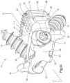
- FIG. 1 Aillustrates an anterior perspective view of an implant according to a first preferred embodiment of the present application
- FIG. 1 Billustrates a side elevational view of the implant of FIG. 1 A ;
- FIG. 1 Cillustrates a top plan view of the implant of FIG. 1 A ;
- FIG. 1 Dillustrates an anterior elevational view of the implant of FIG. 1 A ;
- FIG. 1 Eillustrates a cross-sectional view of the implant of FIG. 1 A , taken along line 1 E- 1 E of FIG. 1 C ;
- FIG. 1 Fillustrates a cross-sectional view of the implant of FIG. 1 A , taken along line 1 F- 1 F of FIG. 1 A ;
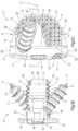
- FIG. 2 Aillustrates an anterior perspective view of a plate portion of the implant of FIG. 1 A ;
- FIG. 2 Billustrates a cross-sectional view of the plate portion of FIG. 2 A , taken along line 2 B- 2 B of FIG. 2 A ;
- FIG. 2 Cillustrates a magnified, cross-sectional view of a retention mechanism used in connection with the implant of FIG. 1 A ;
- FIG. 2 Dillustrates a perspective view of the retention mechanism of FIG. 2 C ;
- FIGS. 2 E- 2 Jillustrate various alternate views of the implant shown in FIG. 1 A incorporating various alternate designs of a stop member configured for embedding at least partially into the vertebral bodies during impaction;
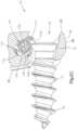
- FIG. 3 Aillustrates a top plan view of an exemplary removal instrument for contacting and recoiling the retention mechanism of FIG. 2 D to enable removal of the bone fixation elements from the implant;
- FIG. 3 Billustrates a magnified, cross-sectional view of the removal instrument of FIG. 3 A , taken along line 3 B- 3 B of FIG. 3 A ;
- FIG. 4 Aillustrates an anterior perspective view of an implant according to a second preferred embodiment of the present application, the retention mechanism being in a first position;
- FIG. 4 Billustrates a side elevational view of the implant shown in FIG. 4 A , the retention mechanism being in the first position;
- FIG. 4 Cillustrates an anterior perspective view of the implant shown in FIG. 4 A , the retention mechanism being in a second position;
- FIG. 4 Dillustrates a side elevational view of the implant shown in FIG. 4 A , the retention mechanism being in the second position;
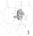
- FIG. 5 Aillustrates an anterior perspective view of the implant shown in FIG. 4 A inserted into an intervertebral disc space between adjacent vertebral bodies, the retention mechanism being in the first position wherein the retention mechanism acts as a stop preventing over-insertion of the implant into the disc space;
- FIG. 5 Billustrates an anterior perspective view of the implant shown in FIG. 4 A inserted into an intervertebral disc space between adjacent vertebral bodies, the retention mechanism being in the second position;
- FIG. 6 Aillustrates a top perspective view of the implant shown in FIG. 4 A , the plate portion incorporating an optional thread blocking mechanism;
- FIG. 6 Billustrates an alternate top perspective view of the implant shown in FIG. 6 A illustrating the optional thread blocking mechanism in contact with an implanted bone fixation element;
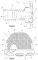
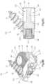
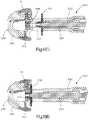
- FIG. 7 Aillustrates an anterior exploded perspective view of the plate portion used in connection with the implant of FIG. 4 A , the retention mechanism incorporating a second exemplary coupling mechanism for engaging the plate portion;
- FIG. 7 Billustrates a cross-section view of the plate portion and retention mechanism shown in FIG. 7 A , taken along line 7 B- 7 B of FIG. 7 A ;
- FIG. 8illustrates a partial cross-sectional view of a plate portion used in connection with the implant of FIG. 4 A , the retention mechanism incorporating a third exemplary coupling mechanism for engaging the plate portion;
- FIG. 9 Aillustrates an anterior perspective view of the implant shown in FIG. 4 A , the implant incorporating a second exemplary spacer portion;
- FIG. 9 Billustrates a top perspective view of the implant shown in FIG. 9 A with an optional porous PEEK portion omitted;
- FIG. 9 Cillustrates a cross-sectional view of the implant shown in FIG. 9 A , taken along line 9 C- 9 C in FIG. 9 A with the optional porous PEEK portion omitted;
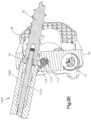
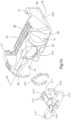
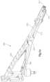
- FIGS. 10 A- 10 Eillustrate various views of an exemplary insertion instrument and method for inserting the implant of FIG. 4 A ;
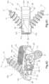
- FIGS. 11 A- 11 Cillustrate various views of an exemplary inserter and drill guide instrument for inserting an implant.
- Preferred embodiments of the present applicationare directed to an implant 10 , 200 (“ 10 - 200 ”). It should be understood that while the various embodiments of the implant 10 - 200 will be described in connection with spinal surgery, those skilled in the art will appreciate that the implant 10 - 200 , as well as the components thereof, may be used for implantation into other parts of the body, including, for example, long bones or bones in knee, hip, shoulder, or other joint replacement or for bone augmentation.
- the various embodiments of the implant 10 - 200are preferably sized and configured to be implanted between adjacent vertebral bodies V.
- the implant 10 - 200may be sized and configured to replace all or substantially all of an intervertebral disc space D between adjacent vertebral bodies V or only part of the intervertebral disc space D.
- the preferred implant 10 - 200may be configured to replace an entire vertebral body V and related disc spaces D or multiple disc spaces D in a patient's spine, as would be apparent to one having ordinary skill in the art based upon a review of the present application.
- the implant 10 - 200may be adapted for use in the anterior, antero-lateral, direct lateral, extra-foraminal, transforaminal, and posterior approaches for insertion into the spine.
- the implant 10 - 200 of each of the preferred embodimentsincludes an interbody spacer portion 20 , 220 , 220 ′ (“ 20 - 220 ”) and a plate portion 50 , 250 , 250 ′, 250 ′′, 250 ′′′ (“ 50 - 250 ”).
- the spacer portion 20 - 220is preferably sized and configured for implantation into the intervertebral disc space D between adjacent vertebral bodies V.
- the spacer portion 20 - 220 of each of the preferred embodimentsincludes a top surface 22 , a bottom surface 24 , a first side surface 26 , a second side surface 28 , a leading surface 30 and a trailing surface 32 .
- the top and bottom surfaces 22 , 24are suitable for contacting and are adapted for being secured relative to the end plates of adjacent vertebral bodies V.
- the spacer portion 20 - 220is preferably sized and configured to maintain and/or restore a desired intervertebral disc height between the adjacent vertebral bodies V.
- the top and bottom surfaces 22 , 24may include a series of teeth, ridges, spikes or other similar projections 25 to aid in securing the implant 10 - 200 to the endplates of the adjacent vertebral bodies V.
- the top and bottom surfaces 22 , 24may also include a curved or a tapered surface to help provide an anatomical shape for mating with the patient's spine or to orient the endplates of the adjacent vertebral bodies V in a desired manner.
- the particular surface shape and curvature, taper or alternate surface feature in the anterior-posterior direction, as well as the particular surface shape and curvature, taper or alternate surface feature in the medial-lateral directionwill depend upon the location where the implant 10 - 200 is intended to be implanted and/or surgeon preferences or whether the implant 10 - 200 is utilized in another area in the body.
- the spacer portion 20 - 220may also include one or more boreholes, openings, windows or channels 34 for receiving bone graft material.
- the implant 10 - 200may include one or more vertical openings, windows or channels extending through the spacer portion 20 - 220 from the top surface 22 to the bottom surface 24 for insertion of bone graft material, such that bone growth is promoted through the vertical openings, windows or channels 34 following implantation of the implant 10 - 200 .
- One or more boreholes, openings, windows or channels 34is especially preferred if the spacer portion 20 - 220 is constructed of a non-allograft or non-bone-growth material, such as Polyetheretherketone (“PEEK”).
- PEEKPolyetheretherketone
- the plate portion 50 - 250is preferably coupled to the spacer portion 20 - 220 to provide increased implant stability during healing as well as to optimally orient the trajectory of bone fixation elements 70 during implantation.
- the plate portion 50 - 250 of each of the preferred embodimentsincludes a top surface 52 , a bottom surface 54 , a first side surface 56 , a second side surface 58 , a leading surface 60 and a trailing surface 62 .
- the plate portion 50 - 250preferably contacts the trailing surface 32 of the spacer portion 20 - 220 and preferably does not extend beyond or does not increase greatly the vertical or lateral perimeter of the spacer portion 20 - 220 . In this manner, the implant 10 - 200 has a low profile.
- the plate portion 50 - 250is preferably entirely implanted within the intervertebral disc space D between the adjacent vertebral bodies V such that the plate portion 50 - 250 has little or no external profile (e.g., the plate portion 50 - 250 does not extend anterior beyond an edge of the disc space D). In this manner, little or no structure protrudes outside of the bounds of the disc space D or the profile of the vertebral bodies V, thereby limiting dysphasia and patient discomfort.
- the plate portion 50 - 250may be sized and configured so that the top and bottom surfaces 52 , 54 of the plate portion 50 - 250 contact the endplates of the adjacent vertebral bodies V.
- the plate portion 50 - 250may be sized and configured so that only the spacer portion 20 - 220 contacts the adjacent vertebral bodies V.
- the height of the plate portion 50 - 250may be small enough so that it does not contact the vertebral bodies V when connected to the spacer portion 20 - 220 in an implanted position.
- the plate portion 50 - 250may be coupled to the spacer portion 20 - 220 by any coupling mechanism now or hereafter known.
- the spacer portion 20 - 220may include one or more recesses 36 formed in the side or trailing surfaces for engaging one or more projections 64 extending from the plate portion 50 - 250 .
- the spacer portion 20includes a recess 36 formed in each of the side surfaces 26 , 28 thereof for engaging projections 64 extending from the plate portion 50 - 250 .
- the recesses 36may extend completely from the top surface 22 to the bottom surface of the spacer portion 20 or may extend only partially from either the top or bottom surface 20 , 22 .
- the trailing surface 62 of the plate portion 50 - 250preferably includes a tool engagement feature 80 for engaging one or more insertion tools.
- the tool engagement feature 80may be in any form now or hereafter known for such purpose including one or more recesses formed in the trailing surface 62 of the plate portion 50 - 250 , the recesses extending from top and bottom surfaces 52 , 54 , respectively, for engaging arms of the insertion tool.
- the tool engagement feature 80may be a threaded bore (not shown) formed in the trailing surface 62 of the plate portion 50 - 250 for engaging a threaded stem extending from the insertion tool, etc.
- the implant 10 - 200preferably includes one or more bone fixation holes 40 for receiving one or more bone fixation elements 70 , preferably bone screws so that, in use, after the implant 10 - 200 has been inserted into the intervertebral disc space D between adjacent vertebral bodies V, the implant 10 - 200 may be secured to the adjacent vertebral bodies V.
- the bone fixation elements 70preferably include a threaded shaft 72 and a partially spherical head portion 74 that is generally smooth where it contacts the bone fixation hole 40 .
- the threaded shaft 72may be self-drilling, i.e. does not necessitate the drilling of pilot holes, but are not so limited.
- the bone fixation elements 70are not limited to bone screws 70 and may be comprised of a helical nail, a distally expanding nail or screw, etc.
- the bone fixation holes 40are preferably sized and configured so that the head portion 74 of the bone fixation elements 70 do not protrude proximally beyond the trailing surface 62 of the plate portion 50 , when the bone fixation elements 70 have been fully implanted.
- the bone fixation holes 40preferably include a curved or frusta-spherical surface for contacting an underside of the generally smooth or frusta-spherical surface of the head portion 74 of the bone fixation elements 70 so that the bone fixation elements 70 can polyaxially rotate with respect to the plate portion 50 - 250 and a variety of trajectory angles can be chosen for the bone fixation elements 70 according to surgeons' preferences or needs as well as to enable the implant 10 - 200 to settle during healing.
- the plate portion 50 - 250preferably includes first and second bone fixation holes 40 for receiving first and second bone fixation elements 70 with the first bone fixation element 70 being angled upwardly for engaging the superior vertebral body V and the second bone fixation element 70 being angled downwardly for engaging the inferior vertebral body V.
- the bone fixation holes 40preferably have a longitudinal axis 41 that is oriented obliquely with respect to the implant 10 - 200 so that the bone fixation elements 70 form a fastener angle with respect to the top and bottom surfaces 22 , 24 of the spacer portion 20 wherein bone fixation angle may be in the range between twenty degrees (20°) and sixty degrees (60°), and more preferably between thirty degrees (30°) and fifty degrees (50°).
- the bone fixation anglemay be the same for all of the holes 40 or may be different for each of the holes 40 .
- the bone fixation holes 40may be directed inwardly toward the center of the implant 10 - 200 or outwardly away from the center of the implant 10 - 200 , preferably at a lateral bone fixation angle ⁇ so that the bone fixation elements 70 extend laterally inward toward a center plane of the implant 10 - 200 or laterally outward away from the center plane of the implant 10 - 200 .
- the lateral bone fixation angle ⁇may be in the range between plus sixty degrees (60°) and minus sixty degrees ( ⁇ 60°), preferably between zero degrees (0°) and plus or minus thirty degrees (30°), and more preferably about plus or minus fifteen degrees (15°).
- the lateral bone fixation angle ⁇may be the same for all holes 40 or may be different for each hole 40 . However, as would be understood by one of ordinary skill in the art based upon a reading of this disclosure, a plurality of potential angles is possible since the bone fixation elements 70 are polyaxial, as will be described in greater detail below.
- the implant 10 - 200may include three, four, five or more bone fixation holes 40 configured to receive a corresponding number of bone fixation elements 70 in any number of configurations.
- the number of bone fixation elements 70 extending from the top and bottom surfaces 22 , 24may be varied and the number of bone fixation elements 70 extending from the top surface 22 need not equal the number of bone fixation elements 70 extending from the bottom surface 24 .
- Exit openings for the bone fixation holes 40preferably are formed at least partially in the top or bottom surfaces 52 , 54 of the plate portion 50 - 250 .
- the exit openingsmay also be formed at least partially or entirely in the top or bottom surfaces 22 , 24 of the spacer portion 20 - 220 .
- the bone fixation holes 40may also include a partially spherical interior volume to accommodate the partially spherical geometry of the head portion 74 of the bone fixation elements 70 to enable a range of polyaxial orientations to be chosen for the bone fixation elements 70 with respect to the vertebral bodies V.
- the implant 10 - 200preferably also includes a retention mechanism for reducing the likelihood that the bone fixation elements 70 may postoperatively uncouple from the implant 10 - 200 and migrate from the disc space D.
- the retention mechanismpreferably covers at least a portion of the bone fixation holes 40 and hence the bone fixation elements 70 to prevent the bone fixation elements 70 from backing-out, as will be described in greater detail below.
- the implant 10 - 200 including the spacer portion 20 - 220 and the plate portion 50 - 250may be constructed of any suitable biocompatible material or combination of materials including, but not limited to one or more of the following metals such as titanium, titanium alloys, stainless steel, aluminum, aluminum alloy, magnesium, etc., polymers such as, PEEK, porous PEEK, carbon fiber PEEK, resorbable polymers, PLLA, etc., allograft, synthetic allograft substitute, ceramics in the form of bioglass, tantalum, Nitinol, or alternative bone growth material or some composite material or combination of these materials.
- metalssuch as titanium, titanium alloys, stainless steel, aluminum, aluminum alloy, magnesium, etc.
- polymerssuch as, PEEK, porous PEEK, carbon fiber PEEK, resorbable polymers, PLLA, etc., allograft, synthetic allograft substitute, ceramics in the form of bioglass, tantalum, Nitinol, or alternative bone growth material or some composite material
- the spacer portion 20 - 220may be formed of a different material than the plate portion 50 - 250 .
- the plate portion 50 - 250may be formed of a metallic material such as, a titanium or a titanium alloy, and the spacer portion 20 - 220 may be formed of a non-metallic material such as, a polymer such as, PEEK, an allograft, a bioresorbable material, a ceramic, etc.
- the plate portion 50 - 250 and the spacer portion 20 - 220may be formed from the same material.
- the plate portion 50 - 250 and spacer portion 20 - 220may be integrally formed, pre-assembled or separately provided to a surgeon and assembled in the operating room.
- the implant 10 - 200may also be coated with various compounds to increase bony on-growth or bony in-growth, to promote healing or to allow for revision of the implant 10 - 200 , including hydroxyapatite, titanium-nickel, vapor plasma spray deposition of titanium, or plasma treatment to make the surface hydrophilic.
- the intervertebral implant 10 of a first preferred embodimentincludes the spacer portion 20 , the plate portion 50 , first and second bone fixation elements 70 and the retention mechanism.
- the retention mechanismis in the form of a spring biased snapper element 110 .
- the plate portion 50includes a borehole 112 in communication with each of the bone fixation holes 40 for receiving a spring 114 and a snapper element 116 .
- the borehole 112defines a longitudinal axis that intersects the longitudinal axis 41 of the bone fixation hole 40 and hence the bone fixation element 70 .
- the intersection anglemay be transverse, perpendicular or acute.
- the snapper 116preferably includes a first end 118 for contacting or interacting with the head portion 74 of the bone fixation element 70 and a second end 120 for receiving, contacting or interacting with the spring 114 .
- the spring 114is preferably sized and configured to bias the snapper 116 so that the snapper 116 protrudes into the bone fixation hole 40 and over the head portion 74 of the bone fixation element 70 , once the bone fixation element 70 has been inserted into the bone fixation hole 40 to prevent back-out.
- the spring-biased snapper 116is preferably secured within the borehole 112 via a pin or set screw 125 .
- the plate portion 50also includes first and second stops 65 , wherein the first stop 65 protrudes superiorly from the top surface 52 of the plate portion 50 for contacting the superior vertebral body V and the second stop 65 protrudes inferiorly from the bottom surface 54 of the plate portion 50 for contacting the inferior vertebral body V. Incorporation of more or less stops 65 is envisioned. Incorporation of the first and second stops 65 facilitates fully seating the implant 10 with respect to the adjacent vertebral bodies V regardless of the irregular anatomy of a patient's spine, which often characterizes the outer surface of the vertebral bodies V.
- the stops 65are preferably integrally formed on the plate portion 50 .
- the stops 65are configured to abut the anterior aspects of the vertebral bodies V during implantation, although the stops 65 may abut the lateral or antero-lateral aspects of the vertebral bodies V depending upon the surgical procedure and insertion path being utilized.
- the stops 65assist in preventing over-insertion of the implant 10 during implantation and assist in securing the position of the implant 10 during insertion of the bone fixation elements 70 , as will be described in greater detail below.
- the implant 10due to the disposition of the stops 65 , the implant 10 generally has a zero-profile external to the disc space D at least along a cranial-caudal midline, because the trailing surface 62 of the plate portion 50 can be designed to be convex to match the disc space D. Referring to FIGS.
- a distal surface 65 a of the stops 65can be configured to embed at least partially into the vertebral bodies V during impaction to further reduce the profile of the plate portion 50 exterior to the disc space D, if so desired.
- the distal surface 65 a of the stops 65may include a pyramid shaped projection or tooth 66 extending therefrom for embedding at least partially into the vertebral bodies V during impaction.
- the distal surface 65 a of the stops 65may include a plurality of projections or teeth 67 (as shown in FIG. 2 F ), a vertical blade type projection 68 (as shown in FIGS. 2 G and 2 H ) or a transverse blade type projection 69 (as shown in FIGS. 2 I and 2 J ) extending therefrom for embedding at least partially into the vertebral bodies V during impaction.
- a surgeonprepares a pathway or channel to the disc space D, performs at least a partial discectomy, and inserts the implant 10 including the spacer portion 20 and the plate portion 50 into the disc space D until the stops 65 contact the adjacent vertebral bodes V.
- the surgeonadvances the first and second bone fixation elements 70 into and through the bone fixation holes 40 at the selected angle, with or without the prior formation of pilot holes.
- Advancement of the bone fixation elements 70 into the bone fixation holes 40causes the head portion 74 of the bone fixation elements 70 to contact the inner spherical portions of the bone fixation holes 40 and tends to draw the vertebral bodies V into alignment as opposed to resulting in the over-insertion of the implant 100 since the stops 65 guide the movement of the vertebral bodies V during bone fixation manipulation. That is, because the stops 65 contact the adjacent vertebral bodies V and prevents over-insertion of the implant 10 into the disc space D, advancement of the bone fixation elements 70 tends to pull and/or reposition the adjacent vertebral bodies V together to promote fusion.
- the bone fixation elements 70are advanced until the vertebral bodies V are optimally aligned and the head portions 74 of the bone fixation elements 70 are advanced into the spherical portions of the bone fixation holes 70 .
- the underside of the head portion 74 of the bone fixation elements 70contact the first end 118 , preferably a tapered end portion 117 , of the snapper elements 116 that protrude into the bone fixation holes 40 , thereby urging the snapper elements 116 to recoil upon the spring 114 and retracting the snapper elements 116 from the bone fixation holes 40 so that the bone fixation elements 70 can be implanted.
- the spring 114forces the snapper elements 116 back to their initial position in which the snapper elements 116 protrude at least partially into the bone fixation holes 40 .
- the first end 118 of the snapper element 116is designed to cover at least a portion, contact and/or interact with the top surface of the head portions 74 of the bone fixation elements 70 to block the head portions 74 of the bone fixation elements 70 and limit the bone fixation elements 70 from backing-out of the bone fixation holes 40 .
- the first end 118 of the snapper element 110preferably extends into the bone fixation hole 40 such that the head portion 74 of the bone fixation element 70 is unable to move out of the bone fixation hole 40 without impacting the first end 118 .
- the bone fixation elements 70are preferably free to toggle to allow for settling during postoperative healing.
- adjustmentscan be made by compressing the snapper elements 116 with a blunt instrument or a sleeve thereby allowing the bone fixation elements 70 to be removed.
- a removal instrument 1000may include an inner shaft 1010 for engaging the bone fixation element 70 and an outer shaft 1020 for contacting and recoiling the snapper element 116 so that the bone fixation element 70 may be removed from the plate portion 50 .
- the intervertebral implant 200 of a second preferred embodimentincludes the interbody spacer portion 220 , the plate portion 250 , first and second bone fixation elements 70 and the retention mechanism.
- the retention mechanismis in the form of a propeller 310 moveable, more preferably rotatable, between a first position (illustrated in FIGS. 4 A, 4 B and 5 A ) and a second position (illustrated in FIGS. 4 C, 4 D and 5 B ).
- the propeller 310In the first position, the propeller 310 does not interfere with first and second bone fixation holes 40 so that the first and second bone fixation elements 70 can be inserted into the adjacent vertebral bodies V.
- the propeller 310blocks or covers at least a portion of the bone fixation holes 40 and hence at least a portion of the implanted bone fixation elements 70 to prevent backing-out.
- the propeller 310is preferably preassembled or pre-attached to the plate portion 250 .
- the propeller 310may be attached to the plate portion 250 by any coupling mechanism now or hereafter known in the art including those described below.
- the propeller 310is preassembled to the plate portion 250 via a retaining screw 320 that interfaces with a threaded borehole (not shown) disposed between the bone fixation holes 40 formed in the plate portion 250 .
- the retaining screw 320may extend into and be threadably coupled to the spacer portion 220 , but is not so limited.
- the retaining screw 320may be securely coupled with respect to the plate portion 250 by a cross-pinned shaft, a rivet, a helical wedge attached to the shaft of the retaining screw 320 , etc.
- the propeller 310includes first and second ends 312 , 314 defining a longitudinal axis that is generally transverse to the longitudinal axis of the retaining screw 320 .
- the propeller 310 and the retaining screw 320are preferably rotatable through a range of about ninety degrees (90°) from the first position to the second position.
- the longitudinal axis of the propeller 310is oriented generally parallel to a longitudinal axis of the implant 200 and generally parallel to the cranial-caudal axis of the spine so that the propeller 310 does not interfere with the bone fixation holes 40 or bone fixation elements 70 to enable insertion of the bone fixation elements 70 into the adjacent vertebral bodies V.
- the longitudinal axis of the propeller 310is generally oriented perpendicular to the cranial-caudal axis of the spine so that the propeller 310 blocks or covers at least a portion of the bone fixation holes 40 and the bone fixation elements 70 to prevent backing-out. That is, in the second position, the propeller 310 covers at least a portion of the head portion 74 of the bone fixation elements 70 while in the first position, the propeller 310 permits insertion of the bone fixation elements 70 into the bone fixation holes 40 and into the adjacent vertebral bodies V.
- the retaining screw 320preferably includes an engagement feature 321 for engaging an insertion instrument 500 , as will be described in greater detail below, to rotate the retaining screw 320 and the propeller 310 to and between the first and second positions.
- the retaining screw 320 and the propeller 310are coupled to one another and preferably rotate together via a two point interference fit between the outer diameter of the retaining screw 320 and the diameter of a counterbore (not shown) through the propeller 310 .
- the plate portion 250preferably includes a tapered recess 330 that forms a guide ramp so that in the second position, the propeller 310 preferably lies flush with the trailing surface 62 of the plate portion 250 (as best shown in FIG. 4 D ). Accordingly, in the first position ( FIGS. 4 A and 4 B ), the propeller 310 extends from the trailing surface 62 of the plate portion 250 and in the second position ( FIGS. 4 C and 4 D ), the anterior surface of the propeller 310 lies generally flush or somewhat recessed with respect to the trailing surface 62 . Therefore, in an implanted configuration when the propeller 310 is in the second position, the entire implant 200 , including the propeller 310 , lies within the bounds of the patient's spine or posteriorly relative to the anterior aspect of the vertebrae V.
- a surgeonprepares a pathway or channel to the disc space D, performs at least a partial discectomy, and inserts the implant 200 including the spacer portion 220 and the plate portion 250 into the disc space D with the propeller 310 in the first position.
- the propeller 310is sized to act as a stop during implantation of the implant 200 to prevent over-insertion of the implant 200 , as well as to secure the position of the implant 200 during the insertion of the bone fixation elements 70 .
- the ends 312 , 314 of the propeller 310contact and/or engage the adjacent vertebral bodies V to mechanically block further insertion of the implant 200 into the disc space D (as best shown in FIG. 5 A ).
- the surgeonadvances the first and second bone fixation elements 70 into and through the bone fixation holes 40 at the selected angle, with or without the prior formation of pilot holes. Advancement of the bone fixation elements 70 into the bone fixation holes 40 causes the head portion 74 of the bone fixation elements 70 to contact the inner spherical portions of the bone fixation holes 40 and tends to draw the vertebral bodies V into alignment as opposed to resulting in the over-insertion of the implant 200 since the propeller 310 preferably guides the movement of the vertebral bodies V during bone fixation manipulation.
- the bone fixation elements 70are advanced until the vertebral bodies V are optimally aligned and the head portions 74 of the bone fixation elements 70 are advanced into the spherical portions of the bone fixation holes 70 .
- the retaining screw 320 and the propeller 310are then rotated ninety degrees (90°) from the first position to the second position, guided by the recesses 330 formed in the trailing surface 62 of the plate portion 250 , by mating an insertion instrument to the instrument engagement feature 321 on the retaining screw 320 .
- the retaining screw 320As the retaining screw 320 is rotated from the first position to the second position, the retaining screw 320 preferably advances distally, based on the pitch of the threading formed on its shaft, and the propeller 310 rotates down the guide ramp formed by the recesses 330 and comes to rest therein while overlying the head portions 74 of the bone fixation elements 70 .
- the shape of the guide ramp formed by the recesses 330preferably stops the propeller 310 from over rotating past the second position, such that the ends of the propeller 310 at least partially cover the head portions 74 of the bone fixation elements 70 . As such, the bone fixation elements 70 are prevented from backing-out of the plate portion 250 and the spacer portion 220 by the propeller 310 .
- the bone fixation elements 70are preferably free to toggle to allow for settling during postoperative healing. If a surgeon decides the placement of the implant 200 is not optimal, adjustments can be made by rotating the propeller 310 back to the first position, thereby unblocking the head portions 74 of the bone fixation elements 70 and allowing adjustments thereto.
- the bone fixation holes 40include a protruding thread blocking mechanism 350 that is sized and configured to permit the threaded advancement of the first and second bone fixation elements 70 with respect to the bone fixation holes 40 until the proximal most thread 73 formed on the shaft 72 of the bone fixation element 70 advances distally past the thread blocking mechanism 350 , at which point the distal surface of the thread blocking mechanism 350 contacts a proximal side of the proximal most thread 73 to inhibit the first and second bone fixation elements 70 from backing-out of the bone fixation holes 40 .
- the thread blocking mechanism 350may assume the form of a raised ridge or interrupted ring of material or a variety of other protruding features configured to allow the proximal most thread 73 of the bone fixation element 70 to advance to a point from which retreat in the opposite direction is inhibited.
- the thread blocking mechanism 350can be disposed within the bone fixation holes 40 to block the proximal surface of the head portions 74 of the bone fixation elements 70 , as opposed to the proximal most threads 73 .
- the thread blocking mechanism 350can be configured to engage a corresponding indentation (not shown) formed on the sides of the head portions 74 of the bone fixation elements 70 .
- the bone fixation elements 70may further include an undercut 75 between the proximal most thread 73 and the distal portion of the head portion 74 for enabling the bone fixation element 70 to generally rotate freely after being fully seated in the bone fixation hole 40 to thereby permit lagging of the vertebral bodies V with respect to the implant 200 during implantation.
- the implant 200is positioned between the adjacent vertebral bodies V and the bone fixation elements 70 are advanced into the bone fixation holes 40 until the proximal most thread 73 formed on the shaft portion 72 of the bone fixation elements 70 advance past the protruding thread blocking mechanism 350 .
- the bone fixation elements 70are fully seated with respect to the plate portion 250 ′ in this position.
- the distal surface of the thread blocking mechanism 350contacts the proximal side of the proximal most thread 73 formed on the shaft portions 72 of the bone fixation elements 70 to limit the bone fixation elements 70 from backing-out of the bone fixation holes 40 .
- the bone fixation elements 70are generally free to rotate after being fully seated due to the inclusion of the undercuts 75 between the proximal most thread 73 and the head portion 74 of each bone fixation elements 70 to permit lagging of the vertebral bodies V with respect to the implant 200 during implantation.
- the propeller 310can then be utilized in conjunction with the thread blocking mechanism 350 to secure the position of the implant 200 during the insertion of the bone fixation elements 270 , as well as to add additional back-out prevention.
- the thread blocking mechanism 350can be incorporated into the first preferred embodiment of the implant 10 .
- the third preferred embodiment of the plate portion 250 ′′includes an alternate coupling mechanism for coupling the propeller 310 ′′ to the plate portion 250 ′′.
- the propeller 310 ′′includes a plurality of slots 317 ′′ extending from a distal end 316 ′′ of the propeller 310 ′′ so that the propeller 310 ′′ includes a plurality of spring-like fingers 315 ′′ oriented along an axis that extends distally, generally perpendicular to the longitudinal axis of the ends 312 ′′, 314 ′′ of the propeller 310 ′′.
- the spring fingers 315 ′′preferably include an outwardly extending flange 318 ′′ at the distal end 316 ′′ thereof.
- the plate portion 250 ′′preferably includes a non-threaded borehole 263 ′′ disposed between the bone fixation holes 40 .
- the non-threaded borehole 263 ′′preferably includes one or more ramps 263 a ′′ and one or more steps 263 b ′′ for interfacing with the spring fingers 315 ′′ for securing the propeller 310 ′′ to the plate portion 250 ′′.
- An optional retaining clip 340 ′′such as a wishbone clip formed of, for example, elgiloy, may be mounted in the borehole 263 ′′ to further assist in securing the propeller 310 ′′ to the plate portion 250 ′′ by allowing insertion of the propeller 310 ′′ into the borehole 263 ′′ while providing additional protection against the propeller 310 ′′ from backing-out of the borehole 263 ′′.
- a wishbone clip formed of, for example, elgiloymay be mounted in the borehole 263 ′′ to further assist in securing the propeller 310 ′′ to the plate portion 250 ′′ by allowing insertion of the propeller 310 ′′ into the borehole 263 ′′ while providing additional protection against the propeller 310 ′′ from backing-out of the borehole 263 ′′.
- the propeller 310 ′′is assembled to the plate portion 250 ′′ by inserting the spring fingers 315 ′′ into the borehole 263 ′′ until the propeller 310 ′′ snaps into the borehole 263 ′′, retaining the propeller 310 ′′ therein. That is, as the spring fingers 315 ′′ advance into the borehole 263 ′′, the tapered flanges 318 ′′ formed on the distal end 316 ′′ of the propeller 310 ′′ and the spring fingers 315 ′′ compress so that the fingers 315 ′′ pass through the optional retaining clip 340 ′′ after which the spring fingers 315 ′′ partially spring back outwardly.
- the retaining clip 340 ′′may additionally flex slightly outwardly as the flange 318 ′′ passes therethrough, after which the retaining clip 340 ′′ springs back to its initial configuration. As the spring fingers 315 ′′ continue to advance into the borehole 263 ′′, the fingers 315 ′′ pass over the step 263 b ′′ and subsequently flex outwardly to their non-deflected configuration adjacent the ramp 263 a ′′. In this manner, the propeller 310 ′′ is prevented from backing-out through the borehole 263 ′′ via interaction between the flanges 318 ′′ and the step 263 b′′.
- the fourth preferred embodiment of the plate portion 250 ′′′ for use with the implant 200is illustrated.
- the fourth preferred embodiment of the plate portion 250 ′′′includes a third alternate coupling mechanism for coupling the propeller 310 ′′′ to the plate portion 250 ′′′.
- the non-threaded borehole 263 ′′′includes a first ramp 263 a ′′′, a first step 263 b ′′′, a second preferred helical ramp 263 c ′′′, and a second step 263 d ′′′′ as one moves from the trailing surface 62 of the plate portion 250 ′′′.
- the configuration of the propeller 310 ′′′is substantially identical to the propeller 310 ′′ of the second exemplary coupling mechanism described above.
- the propeller 310 ′′′is assembled to the plate portion 250 ′′′ by inserting the spring fingers 315 ′′′ into the non-threaded borehole 263 ′′′ until the propeller 310 ′′′ snaps into the borehole 263 ′′′, which retains the propeller 310 ′′′ therein.
- the spring fingers 315 ′′′advance into the borehole 263 ′′′, the spring fingers 315 ′′′ compress as the tapered flanges 318 ′′′ pass along the first ramp 263 a ′′′ and over the first step 263 b ′′′, at which point the spring fingers 315 ′′′ and the flanges 318 ′′′ partially spring outwardly thereby securing the propeller 310 ′′′ to the plate portion 250 ′′′.
- the propeller 310 ′′′is prevented from backing-out through the borehole 263 ′′′ via interaction between the flanges 318 ′′′ and the first step 263 a ′′′.
- the spring fingers 315 ′′′further advance into the borehole 263 ′′′, wherein the flange 318 ′′′ is guided by the preferred helically formed second ramp 263 c ′′′, until the flange 318 ′′′ passes over the second step 263 d ′′′.
- the spring fingers 315 ′′′ and the flanges 318 ′′′flex outwardly into their non-deflected configuration to block the propeller 310 ′′′ from backing-out through the borehole 263 ′′′ via interaction between the flanges 318 ′′′ and the second step 263 d′′′.
- an alternate embodiment of the spacer portion 220 ′ for use with the first and second preferred embodiments of the intervertebral implant 10 - 200includes a centralized porous PEEK region 422 concentrically surrounded by a conventional PEEK portion 420 .
- the implant 200is implanted and secured within the disc space D in a similar manner as previously described.
- the central porous PEEK portion 422 of the spacer portion 220 ′has a porosity that provides a suitable pathway through which blood is able to flow and bone is able to grow to assist in promoting fusion with and between the adjacent vertebral bodies V.
- the porous PEEK portion 422may extend from the top surface 22 to the bottom surface 24 of the spacer portion 220 ′.
- the spacer portion 220 ′may include a bridge 424 .
- first and second blind boreholes 426 , 428preferably extend from the top and bottom surfaces 22 , 24 , respectively, to the bridge 424 .
- the blind boreholes 426 , 428may include tapered sidewalls 430 such that a diameter of the blind boreholes 426 , 428 increases toward the center of the spacer portion 220 ′.
- the bridge 424may be formed of the same material as the rest of the spacer portion 220 ′, but is preferably constructed of porous PEEK. Alternately, the bridge 424 may be removable, e.g., capable of being popped out of the spacer portion 220 ′ to provide an axial throughbore.
- the blind boreholes 426 , 428are preferably filled with bone graft or other fusion promoting material and the implant 200 ′ is implanted into the disc space D between the adjacent vertebral bodies V.
- the optional tapered sidewalls 430 of the blind bores 426 , 428facilitate securing the position of the implant 200 ′ within the disc space D as fusion occurs into the blind boreholes 426 , 428 .
- an exemplary insertion instrument 500 and method for inserting the implant 200will now be described.
- the propeller 310will be described and illustrated as unattached to the plate portion 250 .
- the exemplary methodcan be easily adapted to operate with the propeller 310 pre-attached to the plate portion 250 or adapted to operate with the first preferred embodiment of the implant 10 , as would be apparent to one having ordinary skill in the art based upon a review of the present application.
- the insertion instrument 500is configured to couple to the propeller 310 , to couple to the plate portion 250 , to insert the implant 200 at least partially into the disc space D, to permit insertion of the bone fixation elements 70 into the bone fixation holes 40 , to secure the propeller 310 to the plate portion 250 , if necessary, and to rotate the propeller 310 from the first position to the second position, if necessary.
- the insertion instrument 500preferably includes an inner shaft 520 and an outer tubular member 530 .
- the inner shaft 520preferably includes a distal engagement feature 525 , such as a star drive, for interfacing with the engagement feature 321 formed on the retaining screw 320 .
- the outer tubular member 530preferably includes a distal engagement feature 535 for interfacing with a corresponding engagement feature (not shown) formed on the plate portion 250 . Accordingly, the instrument 500 retains the propeller 310 by securing the engagement feature 525 formed on the inner shaft 520 of the instrument 500 to the propeller 310 .
- the instrument 500retains the implant 200 by grasping the plate portion 250 with the engagement feature 535 formed on the outer tubular member 530 .
- the inner shaft 520is configured to translate within the outer tubular member 530 along a longitudinal axis 501 of the instrument 500 . Accordingly, the inner shaft 520 , and hence the propeller 310 , may be translated proximally with respect to the outer tubular member 530 , and hence with respect to the implant 200 .
- the instrument 500may also include one or more stops (not shown) to prevent over-insertion of the implant 200 into the disc space D as well as to secure the position of the implant 200 with respect to the disc space D during the implantation of the bone fixation elements 70 .
- the surgeoninserts the implant 200 into the disc space D by using the instrument 500 to advance the implant 200 into the disc space D between the adjacent vertebral bodies V until one or more stops (not shown) abut the anterior (or lateral or antero-lateral) aspects of the vertebral bodies V.
- the bone fixation elements 70are then inserted through the bone fixation holes 40 and into the vertebral bodies V while lagging of the implant 200 is limited by the interaction of the stops with the vertebral bodies V.
- the propeller 310 and the retaining screw 320may then be advanced into a corresponding borehole 263 formed in the plate portion 250 by translating the inner shaft 520 distally with respect to the outer tubular member 530 .
- the inner shaft 250is then rotated so that the propeller 310 moves from its first position to its second position to prevent back-out of the implanted bone fixation elements 70 .
- the instrument 500is then decoupled from the propeller 310 and the retaining screw 320 .
- an optional inserter and drill guide instrument 600can be utilized to insert any of the previously described implants 10 - 200 and to align the trajectory of an awl, drill, driver instrument, etc. for pilot hole formation and/or bone fixation element insertion.
- the inserter and drill guide instrument 600includes a pair of arms 610 , 615 extending from a pair of handles 620 , 625 that are coupled at a pivot point 630 .
- the arms 610 , 615include aiming barrels 612 , 616 at their distal ends, respectively, for aligning the trajectory of the awl, drill, bone fixation elements, etc.
- the barrels 612 , 616include guide ribs 613 , 617 , respectively, disposed on their outer surface for interfacing with a key 625 formed in the bone fixation holes 40 of the implant 200 .
- the interfacing guide ribs 613 , 617 and keys 625are configured to limit rotation of the implant 10 - 200 relative to the instrument 600 , a feature that is especially preferred for implants 10 - 200 having only two bone fixation holes 40 .
- the arms 610 , 615 of the inserter and drill guide instrument 600are opened by squeezing the handles 620 , 625 together and the barrels 612 , 616 are inserted into the bone fixation holes 40 formed in the plate portion 250 such that the guide ribs 613 , 617 interface with the keys 625 .
- the arms 610 , 615are locked into place and the instrument 600 may be used to insert the implant 10 - 200 into an at least partially cleared out disc space D between the vertebral bodies V.
- the barrels 612 , 616can then be used to align the trajectory of an awl, drill, etc.
- the arms 610 , 615are unlocked and the inserter and drill guide instrument 600 is decoupled from the implant assembly.
Landscapes
- Health & Medical Sciences (AREA)
- Orthopedic Medicine & Surgery (AREA)
- Life Sciences & Earth Sciences (AREA)
- Surgery (AREA)
- Engineering & Computer Science (AREA)
- Biomedical Technology (AREA)
- General Health & Medical Sciences (AREA)
- Veterinary Medicine (AREA)
- Heart & Thoracic Surgery (AREA)
- Public Health (AREA)
- Animal Behavior & Ethology (AREA)
- Neurology (AREA)
- Molecular Biology (AREA)
- Medical Informatics (AREA)
- Nuclear Medicine, Radiotherapy & Molecular Imaging (AREA)
- Oral & Maxillofacial Surgery (AREA)
- Transplantation (AREA)
- Cardiology (AREA)
- Vascular Medicine (AREA)
- Dentistry (AREA)
- Physical Education & Sports Medicine (AREA)
- Prostheses (AREA)
- Surgical Instruments (AREA)
Abstract
Description
This application is a continuation of U.S. patent application Ser. No. 15/217,198, filed Jul. 22, 2016, which is a continuation of U.S. patent application Ser. No. 14/689,614, filed Apr. 17, 2015, now U.S. Pat. No. 9,414,935 issued on Aug. 16, 2016, which is a continuation of U.S. patent application Ser. No. 12/613,866, filed Nov. 6, 2009, now U.S. Pat. No. 9,192,419 issued on Nov. 24, 2015, which claims benefit of U.S. Provisional Patent Application No. 61/139,920, filed Dec. 22, 2008, and U.S. Provisional Patent Application No. 61/112,441, filed Nov. 7, 2008, the contents of all of which are hereby incorporated by reference as if set forth in their entireties herein.
Intervertebral implants including interbody spacer portions and mechanically coupled plate portions are known in the art for restoring disc height, allowing fusion to occur between the adjacent vertebral bodies, and for providing stable fixation during healing.
It is desirable to construct a zero-profile implant wherein bone fixation elements that secure the implant to the vertebral bodies are blocked from backing-out of the bone and/or plate.
Additionally, it is desirable to construct a zero-profile implant that includes polyaxial bone fixation element couplings and features that prevent the implant from being implanted too deeply into a prepared disc space. Both screw back-out and over-insertion of the implant into a prepared disc space can have an adverse impact on the performance of the implant.
The present invention relates generally to a spinal implant. More specifically, the present invention relates to a zero profile interbody spacer and coupled plate assembly for insertion into a disc space between adjacent superior and inferior vertebral bodies. The implant preferably includes a spacer portion, a plate portion coupled to the spacer portion, a plurality of bone fixation elements for engaging the vertebral bodies and a retention mechanism for preventing the bone fixation elements from postoperatively uncoupling from the implant.
In one exemplary embodiment, the implant includes first and second bone fixation elements, a spacer portion, a plate portion coupled to the spacer portion, and first and second spring-biased snapper elements for preventing the first and second bone fixation elements from backing-out of bone fixation holes formed in the plate portion (e.g., from postoperatively uncoupling from the implant). The spacer portion preferably includes a top surface for contacting the superior vertebral body, a bottom surface for contacting the inferior vertebral body, a first side surface, a second side surface, a leading surface and a trailing surface.
The plate portion includes a top surface, a bottom surface, a first side surface, a second side surface, a leading surface, a trailing surface, first and second bone fixation holes and first and second boreholes. The first and second bone fixation holes are sized and adapted for receiving the first and second bone fixation elements, respectively. The first bone fixation hole is angled so that the first bone fixation element engages the superior vertebral body while the second bone fixation hole is angled so that the second bone fixation element engages the inferior vertebral body. The first borehole is in communication with the first bone fixation hole and the second borehole is in communication with the second bone fixation hole.
The first and second spring-biased snapper elements are located in the first and second boreholes, respectively. The first and second spring biased snapper elements are moveable from a first position to a second position. In the first position, at least a portion of the first and second snapper elements protrude into the first and second bone fixation holes, respectively, so that once the first and second bone fixation elements have been inserted into the first and second bone fixation holes, respectively, the first and second snapper elements at least partially cover the first and second bone fixation elements, respectively, to prevent backing-out. The first and second spring biased snapper elements are preferably biased to the first position.
Preferably, insertion of the first and second bone fixation elements causes a head portion of the first and second bone fixation elements to contact the first and second spring biased snapper elements, respectively, to cause the first and second spring biased snapper elements to recoil from their first positions to the their second positions. Thereafter, further insertion of the first and second bone fixation elements causes the head portions of the first and second bone fixation elements to move distally of the first and second spring biased snapper elements resulting in the first and second snapper elements automatically moving from their second position to their first position.
The implant preferably further includes first and second stops to prevent over-insertion of the implant during implantation and to assist in securing a position of the implant during insertion of the first and second bone fixation elements. The first stop preferably extends superiorly of the top surface of the plate portion for contacting the superior vertebral body while the second stop extends inferiorly of the bottom surface of the plate portion for contacting the inferior vertebral body. The first and second stops are preferably integrally formed with the plate portion.
In another exemplary embodiment, the implant preferably includes first and second bone fixation elements, a spacer portion, a plate portion coupled to the spacer portion and a propeller element for preventing the first and second bone fixation elements from backing-out and over-insertion of the plate portion. The spacer portion includes a top surface for contacting the superior vertebral body, a bottom surface for contacting the inferior vertebral body, a first side surface, a second side surface, a leading surface and a trailing surface.
The plate portion includes a top surface, a bottom surface, a first side surface, a second side surface, a leading surface, a trailing surface, and first and second bone fixation holes. The first and second bone fixation holes are sized and adapted for receiving the first and second bone fixation elements, respectively. The first bone fixation hole is angled so that the first bone fixation element engages the superior vertebral body while the second bone fixation hole is angled so that the second bone fixation element engages the inferior vertebral body.
The propeller preferably includes a longitudinal axis extending between a first end and a second end. The propeller is coupled to the plate portion in-between the first and second bone fixation holes. In use, the propeller is rotatable between a first position wherein the propeller does not interfere with first and second bone fixation holes so that the first and second bone fixation elements can be inserted into the first and second bone fixation holes, respectively, to a second position wherein the first end of the propeller at least partially covers at least a portion of the first bone fixation hole and the second end of the propeller at least partially covers at least a portion of the second bone fixation hole to prevent backing-out of the first and second bone fixation elements once implanted. The propeller is preferably rotated through a range of about ninety degrees (90°) from the first position to the second position. The propeller preferably includes a threaded screw for engaging a threaded borehole formed in the plate portion. In use, in the first position, the longitudinal axis of the propeller is preferably oriented generally parallel to an axis of the implant and parallel to a cranial-caudal axis of the vertebral bodies so that the first end of the propeller extends superiorly of the top surface of the plate portion and the second end of the propeller extends inferiorly of the bottom surface of the plate portion so that the propeller acts as a stop during implantation of the implant to prevent over-insertion and to assist in securing a position of the implant during insertion of the first and second bone fixation elements.
In another exemplary embodiment, the implant sized and adapted for insertion into an intervertebral disc space between superior and inferior vertebral bodies includes: (a) first and second bone fixation elements; (b) a spacer portion including a top surface for contacting the superior vertebral body, a bottom surface for contacting the inferior vertebral body, a first side surface, a second side surface, a leading surface and a trailing surface; and (c) a plate portion coupled to the spacer portion. The plate portion including a top surface, a bottom surface, a first side surface, a second side surface, a leading surface and a trailing surface. The plate portion further including first and second bone fixation holes and first and second boreholes, the first and second bone fixation holes sized and adapted for receiving the first and second bone fixation elements, respectively. The first bone fixation hole is angled so that the first bone fixation element engages the superior vertebral body while the second bone fixation hole is angled so that the second bone fixation element engages the inferior vertebral body. The first borehole is in communication with the first bone fixation hole and the second borehole is in communication with the second bone fixation hole. The implant further including first and second spring-biased snapper elements for preventing the first and second bone fixation elements, respectively, from backing out. The first spring biased snapper element is located in the first borehole and the second spring biased snapper element is located in the second borehole. The first and second spring biased snapper elements are moveable from a first position to a second position, in the first position, at least a portion of the first and second snapper elements protrude into the first and second bone fixation holes, respectively, so that once the first and second bone fixation elements have been inserted into the first and second bone fixation holes, respectively, the first and second snapper elements at least partially cover the first and second bone fixation elements, respectively, to prevent backing-out, the first and second spring biased snapper elements being biased to the first position.
The height of the plate portion is preferably substantially equal to a height of the spacer portion and a width of the plate portion is preferably substantially equal to a width of the spacer portion. The spacer portion preferably includes first and second recesses formed in the first and second side surfaces thereof, respectively, and the plate portion preferably includes first and second projections extending from the plate portion for engaging the first and second recesses.
Each of the first and second spring biased snapper elements preferably includes a spring and a snapper element. The snapper element preferably including a tapered first end that protrudes into the first and second bone fixation holes for interacting with the first and second bone fixation elements, respectively, and a second end for interacting with the spring. The first and second spring biased snapper elements are preferably secured within the first and second boreholes, respectively, via first and second pins, respectively.
In use, insertion of the first and second bone fixation elements preferably causes the first and second spring biased snapper elements to move from their respective first position to their respective second positions. Insertion of the first and second bone fixation elements preferably causes a head portion of the first and second bone fixation elements to contact the first and second spring biased snapper elements, respectively, to cause the first and second spring biased snapper elements to recoil from their first positions to the their second positions. Further insertion of the first and second bone fixation elements preferably causes the head portions of the first and second bone fixation elements to move distally of the first and second spring biased snapper elements resulting in the first and second snapper elements automatically moving from their second position to their first positions.
The implant preferably also includes first and second stops to prevent over insertion of the implant during implantation and to assist in securing a position of the implant during insertion of the first and second bone fixation elements, the first stop extending superiorly of the top surface of the plate portion for contacting the superior vertebral body, the second stop extending inferiorly of the bottom surface of the plate portion for contacting the inferior vertebral body. The first and second stops are preferably integrally formed with the plate portion.
In another exemplary embodiment, the implant sized and adapted for insertion into an intervertebral disc space between superior and inferior vertebral bodies includes (a) first and second bone fixation elements; (b) a spacer portion including a top surface for contacting the superior vertebral body, a bottom surface for contacting the inferior vertebral body, a first side surface, a second side surface, a leading surface and a trailing surface; and (c) a plate portion coupled to the spacer portion. The plate portion includes a top surface, a bottom surface, a first side surface, a second side surface, a leading surface, a trailing surface, and first and second bone fixation holes. The first and second bone fixation holes sized and adapted for receiving the first and second bone fixation elements, respectively. The first bone fixation hole is angled so that the first bone fixation element engages the superior vertebral body and the second bone fixation hole is angled so that the second bone fixation element engages the inferior vertebral body. The implant further including (d) a propeller element having a longitudinal axis extending between a first end and a second end. The propeller element being coupled to the plate portion in-between the first and second bone fixation holes. The propeller being rotatable between a first position wherein the propeller does not interfere with first and second bone fixation holes so that the first and second bone fixation elements can be inserted into the first and second bone fixation holes, respectively, to a second position wherein the first end of the propeller at least partially covers at least a portion of the first bone fixation hole and the second end of the propeller at least partially covers at least a portion of the second bone fixation hole to prevent backing out of the first and second bone fixation elements once implanted. In the first position, the longitudinal axis of the propeller is preferably oriented generally parallel to an axis of the implant so that the first end of the propeller extends superiorly of the top surface of the plate portion and the second end of the propeller extends inferiorly of the bottom surface of the plate portion so that the propeller acts as a stop during implantation of the implant to prevent over insertion of the implant and to assist in securing a position of the implant during insertion of the first and second bone fixation elements.
The propeller is preferably rotated through a range of about ninety degrees (90°) from the first position to the second position. The propeller preferably includes a threaded screw for engaging a threaded borehole formed in the plate portion. The trailing surface of the plate portion preferably includes tapered recesses that form guide ramps for the first and second ends of the propeller as the propeller is being rotated from the first position to the second position and so that in the second position, the propeller lies flush with the trailing surface of the plate portion.
The foregoing summary, as well as the following detailed description of preferred embodiments of the application, will be better understood when read in conjunction with the appended drawings. For the purposes of illustrating the implant of the present application, there is shown in the drawings preferred embodiments. It should be understood, however, that the application is not limited to the precise arrangements and instrumentalities shown. In the drawings:
Certain terminology is used in the following description for convenience only and is not limiting. The words “right”, “left”, “lower” and “upper” designate directions in the drawings to which reference is made. The words “inwardly” or “distally” and “outwardly” or “proximally” refer to directions toward and away from, respectively, the geometric center of the implant and related parts thereof. The words, “anterior”, “posterior”, “superior,” “inferior” and related words and/or phrases designate preferred positions and orientations in the human body to which reference is made and are not meant to be limiting. The terminology includes the above-listed words, derivatives thereof and words of similar import.
Similar reference numerals will be utilized throughout the application to describe similar or the same components of each of the preferred embodiments of the implant described herein and the descriptions will focus on the specific features of the individual embodiments that distinguish the particular embodiment from the others.
Preferred embodiments of the present application are directed to animplant 10,200 (“10-200”). It should be understood that while the various embodiments of the implant10-200 will be described in connection with spinal surgery, those skilled in the art will appreciate that the implant10-200, as well as the components thereof, may be used for implantation into other parts of the body, including, for example, long bones or bones in knee, hip, shoulder, or other joint replacement or for bone augmentation.
The various embodiments of the implant10-200 are preferably sized and configured to be implanted between adjacent vertebral bodies V. The implant10-200 may be sized and configured to replace all or substantially all of an intervertebral disc space D between adjacent vertebral bodies V or only part of the intervertebral disc space D. In addition, the preferred implant10-200 may be configured to replace an entire vertebral body V and related disc spaces D or multiple disc spaces D in a patient's spine, as would be apparent to one having ordinary skill in the art based upon a review of the present application. The implant10-200 may be adapted for use in the anterior, antero-lateral, direct lateral, extra-foraminal, transforaminal, and posterior approaches for insertion into the spine.
The implant10-200 of each of the preferred embodiments includes aninterbody spacer portion plate portion top surface 22, abottom surface 24, afirst side surface 26, asecond side surface 28, a leadingsurface 30 and a trailingsurface 32. The top andbottom surfaces bottom surfaces similar projections 25 to aid in securing the implant10-200 to the endplates of the adjacent vertebral bodies V.
The top andbottom surfaces
The spacer portion20-220 may also include one or more boreholes, openings, windows orchannels 34 for receiving bone graft material. For example, the implant10-200 may include one or more vertical openings, windows or channels extending through the spacer portion20-220 from thetop surface 22 to thebottom surface 24 for insertion of bone graft material, such that bone growth is promoted through the vertical openings, windows orchannels 34 following implantation of the implant10-200. One or more boreholes, openings, windows orchannels 34 is especially preferred if the spacer portion20-220 is constructed of a non-allograft or non-bone-growth material, such as Polyetheretherketone (“PEEK”).
The plate portion50-250 is preferably coupled to the spacer portion20-220 to provide increased implant stability during healing as well as to optimally orient the trajectory ofbone fixation elements 70 during implantation.
The plate portion50-250 of each of the preferred embodiments includes atop surface 52, abottom surface 54, afirst side surface 56, asecond side surface 58, a leadingsurface 60 and a trailingsurface 62. The plate portion50-250 preferably contacts the trailingsurface 32 of the spacer portion20-220 and preferably does not extend beyond or does not increase greatly the vertical or lateral perimeter of the spacer portion20-220. In this manner, the implant10-200 has a low profile. Additionally, in this manner, the plate portion50-250 is preferably entirely implanted within the intervertebral disc space D between the adjacent vertebral bodies V such that the plate portion50-250 has little or no external profile (e.g., the plate portion50-250 does not extend anterior beyond an edge of the disc space D). In this manner, little or no structure protrudes outside of the bounds of the disc space D or the profile of the vertebral bodies V, thereby limiting dysphasia and patient discomfort. In use, the plate portion50-250 may be sized and configured so that the top andbottom surfaces
The plate portion50-250 may be coupled to the spacer portion20-220 by any coupling mechanism now or hereafter known. For example, the spacer portion20-220 may include one ormore recesses 36 formed in the side or trailing surfaces for engaging one ormore projections 64 extending from the plate portion50-250. Preferably thespacer portion 20 includes arecess 36 formed in each of the side surfaces26,28 thereof for engagingprojections 64 extending from the plate portion50-250. Therecesses 36 may extend completely from thetop surface 22 to the bottom surface of thespacer portion 20 or may extend only partially from either the top orbottom surface
The trailingsurface 62 of the plate portion50-250 preferably includes atool engagement feature 80 for engaging one or more insertion tools. Thetool engagement feature 80 may be in any form now or hereafter known for such purpose including one or more recesses formed in the trailingsurface 62 of the plate portion50-250, the recesses extending from top andbottom surfaces tool engagement feature 80 may be a threaded bore (not shown) formed in the trailingsurface 62 of the plate portion50-250 for engaging a threaded stem extending from the insertion tool, etc.
The implant10-200 preferably includes one or more bone fixation holes40 for receiving one or morebone fixation elements 70, preferably bone screws so that, in use, after the implant10-200 has been inserted into the intervertebral disc space D between adjacent vertebral bodies V, the implant10-200 may be secured to the adjacent vertebral bodies V. Thebone fixation elements 70 preferably include a threadedshaft 72 and a partiallyspherical head portion 74 that is generally smooth where it contacts thebone fixation hole 40. The threadedshaft 72 may be self-drilling, i.e. does not necessitate the drilling of pilot holes, but are not so limited. Thebone fixation elements 70 are not limited to bone screws70 and may be comprised of a helical nail, a distally expanding nail or screw, etc. The bone fixation holes40 are preferably sized and configured so that thehead portion 74 of thebone fixation elements 70 do not protrude proximally beyond the trailingsurface 62 of theplate portion 50, when thebone fixation elements 70 have been fully implanted.
The bone fixation holes40 preferably include a curved or frusta-spherical surface for contacting an underside of the generally smooth or frusta-spherical surface of thehead portion 74 of thebone fixation elements 70 so that thebone fixation elements 70 can polyaxially rotate with respect to the plate portion50-250 and a variety of trajectory angles can be chosen for thebone fixation elements 70 according to surgeons' preferences or needs as well as to enable the implant10-200 to settle during healing.
The plate portion50-250 preferably includes first and second bone fixation holes40 for receiving first and secondbone fixation elements 70 with the firstbone fixation element 70 being angled upwardly for engaging the superior vertebral body V and the secondbone fixation element 70 being angled downwardly for engaging the inferior vertebral body V. That is, the bone fixation holes40 preferably have alongitudinal axis 41 that is oriented obliquely with respect to the implant10-200 so that thebone fixation elements 70 form a fastener angle with respect to the top andbottom surfaces spacer portion 20 wherein bone fixation angle may be in the range between twenty degrees (20°) and sixty degrees (60°), and more preferably between thirty degrees (30°) and fifty degrees (50°). The bone fixation angle may be the same for all of theholes 40 or may be different for each of theholes 40. In addition, the bone fixation holes40 may be directed inwardly toward the center of the implant10-200 or outwardly away from the center of the implant10-200, preferably at a lateral bone fixation angle α so that thebone fixation elements 70 extend laterally inward toward a center plane of the implant10-200 or laterally outward away from the center plane of the implant10-200. The lateral bone fixation angle α may be in the range between plus sixty degrees (60°) and minus sixty degrees (−60°), preferably between zero degrees (0°) and plus or minus thirty degrees (30°), and more preferably about plus or minus fifteen degrees (15°). The lateral bone fixation angle α may be the same for allholes 40 or may be different for eachhole 40. However, as would be understood by one of ordinary skill in the art based upon a reading of this disclosure, a plurality of potential angles is possible since thebone fixation elements 70 are polyaxial, as will be described in greater detail below.
It should be understood however that the implant10-200 may include three, four, five or more bone fixation holes40 configured to receive a corresponding number ofbone fixation elements 70 in any number of configurations. In addition, the number ofbone fixation elements 70 extending from the top andbottom surfaces bone fixation elements 70 extending from thetop surface 22 need not equal the number ofbone fixation elements 70 extending from thebottom surface 24.
Exit openings for the bone fixation holes40 preferably are formed at least partially in the top orbottom surfaces bottom surfaces head portion 74 of thebone fixation elements 70 to enable a range of polyaxial orientations to be chosen for thebone fixation elements 70 with respect to the vertebral bodies V.
The implant10-200 preferably also includes a retention mechanism for reducing the likelihood that thebone fixation elements 70 may postoperatively uncouple from the implant10-200 and migrate from the disc space D. In use, the retention mechanism preferably covers at least a portion of the bone fixation holes40 and hence thebone fixation elements 70 to prevent thebone fixation elements 70 from backing-out, as will be described in greater detail below.
The implant10-200 including the spacer portion20-220 and the plate portion50-250 may be constructed of any suitable biocompatible material or combination of materials including, but not limited to one or more of the following metals such as titanium, titanium alloys, stainless steel, aluminum, aluminum alloy, magnesium, etc., polymers such as, PEEK, porous PEEK, carbon fiber PEEK, resorbable polymers, PLLA, etc., allograft, synthetic allograft substitute, ceramics in the form of bioglass, tantalum, Nitinol, or alternative bone growth material or some composite material or combination of these materials.
The spacer portion20-220 may be formed of a different material than the plate portion50-250. For example, the plate portion50-250 may be formed of a metallic material such as, a titanium or a titanium alloy, and the spacer portion20-220 may be formed of a non-metallic material such as, a polymer such as, PEEK, an allograft, a bioresorbable material, a ceramic, etc. Alternatively, the plate portion50-250 and the spacer portion20-220 may be formed from the same material. In addition, the plate portion50-250 and spacer portion20-220 may be integrally formed, pre-assembled or separately provided to a surgeon and assembled in the operating room.
As will be appreciated by one of ordinary skill in the art, the implant10-200, or portions thereof, may also be coated with various compounds to increase bony on-growth or bony in-growth, to promote healing or to allow for revision of the implant10-200, including hydroxyapatite, titanium-nickel, vapor plasma spray deposition of titanium, or plasma treatment to make the surface hydrophilic.
Referring toFIGS.1A-2J , theintervertebral implant 10 of a first preferred embodiment includes thespacer portion 20, theplate portion 50, first and secondbone fixation elements 70 and the retention mechanism. In the first preferred embodiment, the retention mechanism is in the form of a springbiased snapper element 110. More preferably, theplate portion 50 includes a borehole112 in communication with each of the bone fixation holes40 for receiving aspring 114 and asnapper element 116. Theborehole 112 defines a longitudinal axis that intersects thelongitudinal axis 41 of thebone fixation hole 40 and hence thebone fixation element 70. The intersection angle may be transverse, perpendicular or acute.
Thesnapper 116 preferably includes afirst end 118 for contacting or interacting with thehead portion 74 of thebone fixation element 70 and asecond end 120 for receiving, contacting or interacting with thespring 114. Thespring 114 is preferably sized and configured to bias thesnapper 116 so that thesnapper 116 protrudes into thebone fixation hole 40 and over thehead portion 74 of thebone fixation element 70, once thebone fixation element 70 has been inserted into thebone fixation hole 40 to prevent back-out. The spring-biasedsnapper 116 is preferably secured within theborehole 112 via a pin or setscrew 125. That is, thesnapper 116 may include a groove or arecess 126 formed therein for mating with a pin or setscrew 125, which is located within a borehole125a. The interaction of the pin or setscrew 125 and the groove orrecess 126 preventing thesnapper 116 from falling out of theborehole 112. For example, thesnapper 116 preferably includes a rounded milledslot 126 and the pin or setscrew 125 may be threaded and preferably includes a form fit so that thesnapper 116 may be received and caught inside of theslot 126 formed in thesnapper 116. Other mechanism for securing the spring-biasedsnapper 116 to theplate portion 50 may be used.
In the first preferred embodiment, theplate portion 50 also includes first and second stops65, wherein thefirst stop 65 protrudes superiorly from thetop surface 52 of theplate portion 50 for contacting the superior vertebral body V and thesecond stop 65 protrudes inferiorly from thebottom surface 54 of theplate portion 50 for contacting the inferior vertebral body V. Incorporation of more or less stops65 is envisioned. Incorporation of the first and second stops65 facilitates fully seating theimplant 10 with respect to the adjacent vertebral bodies V regardless of the irregular anatomy of a patient's spine, which often characterizes the outer surface of the vertebral bodies V. The stops65 are preferably integrally formed on theplate portion 50.
In use, thestops 65 are configured to abut the anterior aspects of the vertebral bodies V during implantation, although thestops 65 may abut the lateral or antero-lateral aspects of the vertebral bodies V depending upon the surgical procedure and insertion path being utilized. The stops65 assist in preventing over-insertion of theimplant 10 during implantation and assist in securing the position of theimplant 10 during insertion of thebone fixation elements 70, as will be described in greater detail below. In part, due to the disposition of thestops 65, theimplant 10 generally has a zero-profile external to the disc space D at least along a cranial-caudal midline, because the trailingsurface 62 of theplate portion 50 can be designed to be convex to match the disc space D. Referring toFIGS.2E-2J , adistal surface 65aof thestops 65 can be configured to embed at least partially into the vertebral bodies V during impaction to further reduce the profile of theplate portion 50 exterior to the disc space D, if so desired. For example, as shown inFIG.2E , thedistal surface 65aof thestops 65 may include a pyramid shaped projection ortooth 66 extending therefrom for embedding at least partially into the vertebral bodies V during impaction. Alternatively, thedistal surface 65aof thestops 65 may include a plurality of projections or teeth67 (as shown inFIG.2F ), a vertical blade type projection68 (as shown inFIGS.2G and2H ) or a transverse blade type projection69 (as shown inFIGS.2I and2J ) extending therefrom for embedding at least partially into the vertebral bodies V during impaction.
In operation, a surgeon prepares a pathway or channel to the disc space D, performs at least a partial discectomy, and inserts theimplant 10 including thespacer portion 20 and theplate portion 50 into the disc space D until thestops 65 contact the adjacent vertebral bodes V. After the surgeon has chosen a desirable entry angle for thebone fixation elements 70, the surgeon advances the first and secondbone fixation elements 70 into and through the bone fixation holes40 at the selected angle, with or without the prior formation of pilot holes. Advancement of thebone fixation elements 70 into the bone fixation holes40 causes thehead portion 74 of thebone fixation elements 70 to contact the inner spherical portions of the bone fixation holes40 and tends to draw the vertebral bodies V into alignment as opposed to resulting in the over-insertion of the implant100 since thestops 65 guide the movement of the vertebral bodies V during bone fixation manipulation. That is, because thestops 65 contact the adjacent vertebral bodies V and prevents over-insertion of theimplant 10 into the disc space D, advancement of thebone fixation elements 70 tends to pull and/or reposition the adjacent vertebral bodies V together to promote fusion. Thebone fixation elements 70 are advanced until the vertebral bodies V are optimally aligned and thehead portions 74 of thebone fixation elements 70 are advanced into the spherical portions of the bone fixation holes70.
As thebone fixation elements 70 advance through the bone fixation holes40, the underside of thehead portion 74 of thebone fixation elements 70 contact thefirst end 118, preferably atapered end portion 117, of thesnapper elements 116 that protrude into the bone fixation holes40, thereby urging thesnapper elements 116 to recoil upon thespring 114 and retracting thesnapper elements 116 from the bone fixation holes40 so that thebone fixation elements 70 can be implanted. Once thehead portions 74 of thebone fixation elements 70 advance past thetapered end portion 117 of thesnapper elements 116, thespring 114 forces thesnapper elements 116 back to their initial position in which thesnapper elements 116 protrude at least partially into the bone fixation holes40. In this position, thefirst end 118 of thesnapper element 116 is designed to cover at least a portion, contact and/or interact with the top surface of thehead portions 74 of thebone fixation elements 70 to block thehead portions 74 of thebone fixation elements 70 and limit thebone fixation elements 70 from backing-out of the bone fixation holes40. Specifically, thefirst end 118 of thesnapper element 110 preferably extends into thebone fixation hole 40 such that thehead portion 74 of thebone fixation element 70 is unable to move out of thebone fixation hole 40 without impacting thefirst end 118.
Post implantation, thebone fixation elements 70 are preferably free to toggle to allow for settling during postoperative healing. Referring toFIGS.3A and3B , if a surgeon decides the placement of theimplant 10 is not optimal, adjustments can be made by compressing thesnapper elements 116 with a blunt instrument or a sleeve thereby allowing thebone fixation elements 70 to be removed. For example, aremoval instrument 1000 may include aninner shaft 1010 for engaging thebone fixation element 70 and anouter shaft 1020 for contacting and recoiling thesnapper element 116 so that thebone fixation element 70 may be removed from theplate portion 50.
Referring toFIGS.4A-5B , theintervertebral implant 200 of a second preferred embodiment includes theinterbody spacer portion 220, theplate portion 250, first and secondbone fixation elements 70 and the retention mechanism. In the second preferred embodiment, the retention mechanism is in the form of apropeller 310 moveable, more preferably rotatable, between a first position (illustrated inFIGS.4A,4B and5A ) and a second position (illustrated inFIGS.4C,4D and5B ). In the first position, thepropeller 310 does not interfere with first and second bone fixation holes40 so that the first and secondbone fixation elements 70 can be inserted into the adjacent vertebral bodies V. In the second position, thepropeller 310 blocks or covers at least a portion of the bone fixation holes40 and hence at least a portion of the implantedbone fixation elements 70 to prevent backing-out.
Thepropeller 310 is preferably preassembled or pre-attached to theplate portion 250. Thepropeller 310 may be attached to theplate portion 250 by any coupling mechanism now or hereafter known in the art including those described below. In the second preferred embodiment, thepropeller 310 is preassembled to theplate portion 250 via a retainingscrew 320 that interfaces with a threaded borehole (not shown) disposed between the bone fixation holes40 formed in theplate portion 250. The retainingscrew 320 may extend into and be threadably coupled to thespacer portion 220, but is not so limited. Alternatively, the retainingscrew 320 may be securely coupled with respect to theplate portion 250 by a cross-pinned shaft, a rivet, a helical wedge attached to the shaft of the retainingscrew 320, etc. Thepropeller 310 includes first and second ends312,314 defining a longitudinal axis that is generally transverse to the longitudinal axis of the retainingscrew 320.
Thepropeller 310 and the retainingscrew 320 are preferably rotatable through a range of about ninety degrees (90°) from the first position to the second position. In the first position, the longitudinal axis of thepropeller 310 is oriented generally parallel to a longitudinal axis of theimplant 200 and generally parallel to the cranial-caudal axis of the spine so that thepropeller 310 does not interfere with the bone fixation holes40 orbone fixation elements 70 to enable insertion of thebone fixation elements 70 into the adjacent vertebral bodies V. In the second position, the longitudinal axis of thepropeller 310 is generally oriented perpendicular to the cranial-caudal axis of the spine so that thepropeller 310 blocks or covers at least a portion of the bone fixation holes40 and thebone fixation elements 70 to prevent backing-out. That is, in the second position, thepropeller 310 covers at least a portion of thehead portion 74 of thebone fixation elements 70 while in the first position, thepropeller 310 permits insertion of thebone fixation elements 70 into the bone fixation holes40 and into the adjacent vertebral bodies V.
The retainingscrew 320 preferably includes anengagement feature 321 for engaging aninsertion instrument 500, as will be described in greater detail below, to rotate the retainingscrew 320 and thepropeller 310 to and between the first and second positions. The retainingscrew 320 and thepropeller 310 are coupled to one another and preferably rotate together via a two point interference fit between the outer diameter of the retainingscrew 320 and the diameter of a counterbore (not shown) through thepropeller 310.
Theplate portion 250 preferably includes atapered recess 330 that forms a guide ramp so that in the second position, thepropeller 310 preferably lies flush with the trailingsurface 62 of the plate portion250 (as best shown inFIG.4D ). Accordingly, in the first position (FIGS.4A and4B ), thepropeller 310 extends from the trailingsurface 62 of theplate portion 250 and in the second position (FIGS.4C and4D ), the anterior surface of thepropeller 310 lies generally flush or somewhat recessed with respect to the trailingsurface 62. Therefore, in an implanted configuration when thepropeller 310 is in the second position, theentire implant 200, including thepropeller 310, lies within the bounds of the patient's spine or posteriorly relative to the anterior aspect of the vertebrae V.
In operation, a surgeon prepares a pathway or channel to the disc space D, performs at least a partial discectomy, and inserts theimplant 200 including thespacer portion 220 and theplate portion 250 into the disc space D with thepropeller 310 in the first position. In the first position, thepropeller 310 is sized to act as a stop during implantation of theimplant 200 to prevent over-insertion of theimplant 200, as well as to secure the position of theimplant 200 during the insertion of thebone fixation elements 70. Specifically, theends propeller 310 contact and/or engage the adjacent vertebral bodies V to mechanically block further insertion of theimplant 200 into the disc space D (as best shown inFIG.5A ).
After the surgeon has chosen a desirable entry angle for thebone fixation elements 70, the surgeon advances the first and secondbone fixation elements 70 into and through the bone fixation holes40 at the selected angle, with or without the prior formation of pilot holes. Advancement of thebone fixation elements 70 into the bone fixation holes40 causes thehead portion 74 of thebone fixation elements 70 to contact the inner spherical portions of the bone fixation holes40 and tends to draw the vertebral bodies V into alignment as opposed to resulting in the over-insertion of theimplant 200 since thepropeller 310 preferably guides the movement of the vertebral bodies V during bone fixation manipulation. Thebone fixation elements 70 are advanced until the vertebral bodies V are optimally aligned and thehead portions 74 of thebone fixation elements 70 are advanced into the spherical portions of the bone fixation holes70. The retainingscrew 320 and thepropeller 310 are then rotated ninety degrees (90°) from the first position to the second position, guided by therecesses 330 formed in the trailingsurface 62 of theplate portion 250, by mating an insertion instrument to theinstrument engagement feature 321 on the retainingscrew 320. As the retainingscrew 320 is rotated from the first position to the second position, the retainingscrew 320 preferably advances distally, based on the pitch of the threading formed on its shaft, and thepropeller 310 rotates down the guide ramp formed by therecesses 330 and comes to rest therein while overlying thehead portions 74 of thebone fixation elements 70. The shape of the guide ramp formed by therecesses 330 preferably stops thepropeller 310 from over rotating past the second position, such that the ends of thepropeller 310 at least partially cover thehead portions 74 of thebone fixation elements 70. As such, thebone fixation elements 70 are prevented from backing-out of theplate portion 250 and thespacer portion 220 by thepropeller 310.
Post implantation, thebone fixation elements 70 are preferably free to toggle to allow for settling during postoperative healing. If a surgeon decides the placement of theimplant 200 is not optimal, adjustments can be made by rotating thepropeller 310 back to the first position, thereby unblocking thehead portions 74 of thebone fixation elements 70 and allowing adjustments thereto.
Referring toFIGS.6A and6B , a second preferred embodiment of theplate portion 250′ for use withimplant 200 is illustrated. In the second preferred embodiment of theplate portion 250′, the bone fixation holes40 include a protrudingthread blocking mechanism 350 that is sized and configured to permit the threaded advancement of the first and secondbone fixation elements 70 with respect to the bone fixation holes40 until the proximalmost thread 73 formed on theshaft 72 of thebone fixation element 70 advances distally past thethread blocking mechanism 350, at which point the distal surface of thethread blocking mechanism 350 contacts a proximal side of the proximalmost thread 73 to inhibit the first and secondbone fixation elements 70 from backing-out of the bone fixation holes40. Thethread blocking mechanism 350 may assume the form of a raised ridge or interrupted ring of material or a variety of other protruding features configured to allow the proximalmost thread 73 of thebone fixation element 70 to advance to a point from which retreat in the opposite direction is inhibited. Alternatively, thethread blocking mechanism 350 can be disposed within the bone fixation holes40 to block the proximal surface of thehead portions 74 of thebone fixation elements 70, as opposed to the proximalmost threads 73. Alternatively, thethread blocking mechanism 350 can be configured to engage a corresponding indentation (not shown) formed on the sides of thehead portions 74 of thebone fixation elements 70.
Thebone fixation elements 70 may further include an undercut75 between the proximalmost thread 73 and the distal portion of thehead portion 74 for enabling thebone fixation element 70 to generally rotate freely after being fully seated in thebone fixation hole 40 to thereby permit lagging of the vertebral bodies V with respect to theimplant 200 during implantation.
In operation, theimplant 200 is positioned between the adjacent vertebral bodies V and thebone fixation elements 70 are advanced into the bone fixation holes40 until the proximalmost thread 73 formed on theshaft portion 72 of thebone fixation elements 70 advance past the protrudingthread blocking mechanism 350. Thebone fixation elements 70 are fully seated with respect to theplate portion 250′ in this position. The distal surface of thethread blocking mechanism 350 contacts the proximal side of the proximalmost thread 73 formed on theshaft portions 72 of thebone fixation elements 70 to limit thebone fixation elements 70 from backing-out of the bone fixation holes40. Thebone fixation elements 70 are generally free to rotate after being fully seated due to the inclusion of the undercuts75 between the proximalmost thread 73 and thehead portion 74 of eachbone fixation elements 70 to permit lagging of the vertebral bodies V with respect to theimplant 200 during implantation. Thepropeller 310 can then be utilized in conjunction with thethread blocking mechanism 350 to secure the position of theimplant 200 during the insertion of the bone fixation elements270, as well as to add additional back-out prevention. Alternatively, it is envisioned that thethread blocking mechanism 350 can be incorporated into the first preferred embodiment of theimplant 10.
Referring toFIGS.7A and7B , a third preferred embodiment of theplate portion 250″ for use with theimplant 200 is illustrated. The third preferred embodiment of theplate portion 250″ includes an alternate coupling mechanism for coupling thepropeller 310″ to theplate portion 250″. In this embodiment, thepropeller 310″ includes a plurality ofslots 317″ extending from adistal end 316″ of thepropeller 310″ so that thepropeller 310″ includes a plurality of spring-like fingers 315″ oriented along an axis that extends distally, generally perpendicular to the longitudinal axis of theends 312″,314″ of thepropeller 310″. Thespring fingers 315″ preferably include an outwardly extendingflange 318″ at thedistal end 316″ thereof. Theplate portion 250″ preferably includes anon-threaded borehole 263″ disposed between the bone fixation holes40. Thenon-threaded borehole 263″ preferably includes one or more ramps263a″ and one ormore steps 263b″ for interfacing with thespring fingers 315″ for securing thepropeller 310″ to theplate portion 250″.
Anoptional retaining clip 340″, such as a wishbone clip formed of, for example, elgiloy, may be mounted in the borehole263″ to further assist in securing thepropeller 310″ to theplate portion 250″ by allowing insertion of thepropeller 310″ into the borehole263″ while providing additional protection against thepropeller 310″ from backing-out of the borehole263″.
In operation, thepropeller 310″ is assembled to theplate portion 250″ by inserting thespring fingers 315″ into the borehole263″ until thepropeller 310″ snaps into the borehole263″, retaining thepropeller 310″ therein. That is, as thespring fingers 315″ advance into the borehole263″, the taperedflanges 318″ formed on thedistal end 316″ of thepropeller 310″ and thespring fingers 315″ compress so that thefingers 315″ pass through theoptional retaining clip 340″ after which thespring fingers 315″ partially spring back outwardly. The retainingclip 340″ may additionally flex slightly outwardly as theflange 318″ passes therethrough, after which theretaining clip 340″ springs back to its initial configuration. As thespring fingers 315″ continue to advance into the borehole263″, thefingers 315″ pass over thestep 263b″ and subsequently flex outwardly to their non-deflected configuration adjacent the ramp263a″. In this manner, thepropeller 310″ is prevented from backing-out through the borehole263″ via interaction between theflanges 318″ and thestep 263b″.
Referring toFIG.8 , a fourth preferred embodiment of theplate portion 250′″ for use with theimplant 200 is illustrated. The fourth preferred embodiment of theplate portion 250′″ includes a third alternate coupling mechanism for coupling thepropeller 310′″ to theplate portion 250′″. In this embodiment, thenon-threaded borehole 263′″ includes a first ramp263a′″, afirst step 263b′″, a second preferredhelical ramp 263c′″, and asecond step 263d″″ as one moves from the trailingsurface 62 of theplate portion 250′″. The configuration of thepropeller 310′″ is substantially identical to thepropeller 310″ of the second exemplary coupling mechanism described above.
In operation, thepropeller 310′″ is assembled to theplate portion 250′″ by inserting thespring fingers 315′″ into thenon-threaded borehole 263′″ until thepropeller 310′″ snaps into the borehole263′″, which retains thepropeller 310′″ therein. As thespring fingers 315′″ advance into the borehole263′″, thespring fingers 315′″ compress as thetapered flanges 318′″ pass along the first ramp263a′″ and over thefirst step 263b′″, at which point thespring fingers 315′″ and theflanges 318′″ partially spring outwardly thereby securing thepropeller 310′″ to theplate portion 250′″. Thepropeller 310′″ is prevented from backing-out through the borehole263′″ via interaction between theflanges 318′″ and the first step263a′″. In addition, as thepropeller 310′″ is moved from the first position to the second position, thespring fingers 315′″ further advance into the borehole263′″, wherein theflange 318′″ is guided by the preferred helically formedsecond ramp 263c′″, until theflange 318′″ passes over thesecond step 263d′″. Thespring fingers 315′″ and theflanges 318′″ flex outwardly into their non-deflected configuration to block thepropeller 310′″ from backing-out through the borehole263′″ via interaction between theflanges 318′″ and thesecond step 263d′″.
Referring toFIGS.9A-9C , an alternate embodiment of thespacer portion 220′ for use with the first and second preferred embodiments of the intervertebral implant10-200 (second preferred embodiment illustrated) includes a centralizedporous PEEK region 422 concentrically surrounded by aconventional PEEK portion 420.
In operation, theimplant 200 is implanted and secured within the disc space D in a similar manner as previously described. The centralporous PEEK portion 422 of thespacer portion 220′ has a porosity that provides a suitable pathway through which blood is able to flow and bone is able to grow to assist in promoting fusion with and between the adjacent vertebral bodies V. Theporous PEEK portion 422 may extend from thetop surface 22 to thebottom surface 24 of thespacer portion 220′. Alternatively, thespacer portion 220′ may include abridge 424. When thespacer portion 220′ includes thebridge 424, first and secondblind boreholes bottom surfaces bridge 424. Theblind boreholes sidewalls 430 such that a diameter of theblind boreholes spacer portion 220′. Thebridge 424 may be formed of the same material as the rest of thespacer portion 220′, but is preferably constructed of porous PEEK. Alternately, thebridge 424 may be removable, e.g., capable of being popped out of thespacer portion 220′ to provide an axial throughbore. In operation, theblind boreholes implant 200′ is implanted into the disc space D between the adjacent vertebral bodies V. The optional taperedsidewalls 430 of the blind bores426,428 facilitate securing the position of theimplant 200′ within the disc space D as fusion occurs into theblind boreholes
Referring toFIGS.10A-10E , anexemplary insertion instrument 500 and method for inserting theimplant 200 will now be described. In connection with the exemplary method, thepropeller 310 will be described and illustrated as unattached to theplate portion 250. However the exemplary method can be easily adapted to operate with thepropeller 310 pre-attached to theplate portion 250 or adapted to operate with the first preferred embodiment of theimplant 10, as would be apparent to one having ordinary skill in the art based upon a review of the present application.
Theinsertion instrument 500 is configured to couple to thepropeller 310, to couple to theplate portion 250, to insert theimplant 200 at least partially into the disc space D, to permit insertion of thebone fixation elements 70 into the bone fixation holes40, to secure thepropeller 310 to theplate portion 250, if necessary, and to rotate thepropeller 310 from the first position to the second position, if necessary.
Theinsertion instrument 500 preferably includes aninner shaft 520 and an outertubular member 530. Theinner shaft 520 preferably includes adistal engagement feature 525, such as a star drive, for interfacing with theengagement feature 321 formed on the retainingscrew 320. The outertubular member 530 preferably includes adistal engagement feature 535 for interfacing with a corresponding engagement feature (not shown) formed on theplate portion 250. Accordingly, theinstrument 500 retains thepropeller 310 by securing theengagement feature 525 formed on theinner shaft 520 of theinstrument 500 to thepropeller 310. Theinstrument 500 retains theimplant 200 by grasping theplate portion 250 with theengagement feature 535 formed on the outertubular member 530.
Theinner shaft 520 is configured to translate within the outertubular member 530 along a longitudinal axis501 of theinstrument 500. Accordingly, theinner shaft 520, and hence thepropeller 310, may be translated proximally with respect to the outertubular member 530, and hence with respect to theimplant 200. For embodiments where thepropeller 310 is unattached to theplate portion 250 and where theplate portion 250 does not include one or more stops, theinstrument 500 may also include one or more stops (not shown) to prevent over-insertion of theimplant 200 into the disc space D as well as to secure the position of theimplant 200 with respect to the disc space D during the implantation of thebone fixation elements 70.
In operation, the surgeon inserts theimplant 200 into the disc space D by using theinstrument 500 to advance theimplant 200 into the disc space D between the adjacent vertebral bodies V until one or more stops (not shown) abut the anterior (or lateral or antero-lateral) aspects of the vertebral bodies V. Thebone fixation elements 70 are then inserted through the bone fixation holes40 and into the vertebral bodies V while lagging of theimplant 200 is limited by the interaction of the stops with the vertebral bodies V.
If unattached, thepropeller 310 and the retainingscrew 320 may then be advanced into acorresponding borehole 263 formed in theplate portion 250 by translating theinner shaft 520 distally with respect to the outertubular member 530. Theinner shaft 250 is then rotated so that thepropeller 310 moves from its first position to its second position to prevent back-out of the implantedbone fixation elements 70. Theinstrument 500 is then decoupled from thepropeller 310 and the retainingscrew 320.
Referring toFIGS.11A-11C , an optional inserter anddrill guide instrument 600 can be utilized to insert any of the previously described implants10-200 and to align the trajectory of an awl, drill, driver instrument, etc. for pilot hole formation and/or bone fixation element insertion. The inserter anddrill guide instrument 600 includes a pair ofarms handles 620,625 that are coupled at apivot point 630. Thearms barrels barrels implant 200. The interfacing guide ribs613,617 andkeys 625 are configured to limit rotation of the implant10-200 relative to theinstrument 600, a feature that is especially preferred for implants10-200 having only two bone fixation holes40.
In operation, thearms drill guide instrument 600 are opened by squeezing thehandles 620,625 together and thebarrels plate portion 250 such that the guide ribs613,617 interface with thekeys 625. Upon secure grasping of the implant10-200, thearms instrument 600 may be used to insert the implant10-200 into an at least partially cleared out disc space D between the vertebral bodies V. Thebarrels bone fixation elements 70 or may align the trajectory of thebone fixation elements 70 in the case where self-drillingbone fixation elements 70 are utilized. Subsequent to the implantation of thebone fixation elements 70, thearms drill guide instrument 600 is decoupled from the implant assembly.
While the foregoing description and drawings represent the preferred embodiments of the present invention, it will be understood that various additions, modifications, combinations and/or substitutions may be made therein without departing from the spirit and scope of the present invention as defined in the accompanying claims. In particular, it will be clear to those skilled in the art that the present invention may be embodied in other specific forms, structures, arrangements, proportions, and with other elements, materials, and components, without departing from the spirit or essential characteristics thereof. One skilled in the art will appreciate that the invention may be used with many modifications of structure, arrangement, proportions, materials, and components and otherwise, used in the practice of the invention, which are particularly adapted to specific environments and operative requirements without departing from the principles of the present invention. In addition, features described herein may be used singularly or in combination with other features. The presently disclosed embodiments are therefore to be considered in all respects as illustrative and not restrictive, the scope of the invention being indicated by the appended claims, and not limited to the foregoing description.
Claims (17)
1. An implant for insertion into an intervertebral disc space between superior and inferior vertebral bodies, the implant comprising:
a spacer portion including a top surface configured to contact the superior vertebral body, and a bottom surface configured to contact the inferior vertebral body;
a plate portion configured to be coupled to the spacer portion, the plate portion including a bone fixation hole and a borehole, the bone fixation hole sized and adapted for receiving a bone fixation element, the bone fixation hole being angled so that the bone fixation element engages one of the superior and inferior vertebral bodies, wherein the borehole is in communication with the bone fixation hole; and
a spring-biased snapper element disposed in the borehole and configured to prevent the bone fixation element from backing-out of the bone fixation hole, wherein the spring biased snapper element is biased toward a first position whereby at least a portion of the spring-biased snapper element protrudes into the bone fixation hole so that once the bone fixation element is inserted into the bone fixation hole, the spring-biased snapper element at least partially covers the bone fixation element to prevent the bone fixation element from backing-out;
a mechanism that is located at least partially within the borehole, the mechanism moveable with respect to the spring biased snapper element and configured to be positioned at least partially within the borehole such that the mechanism: 1) permits movement of the spring biased snapper element toward the first position; and 2) prevents the spring biased snapper element from exiting the borehole entirely; and
a stop that protrudes from the plate portion and is configured to abut one of the superior and inferior vertebral bodies so as to prevent over-insertion of the implant into the intervertebral disc space.
2. The implant ofclaim 1 , wherein the spring-biased snapper element is movable between the first position and a second position, the spring-biased snapper element being removed from the bone fixation hole in the second position.
3. The implant ofclaim 2 , wherein insertion of the bone fixation element into the bone fixation hole causes the spring biased snapper element to move from the first position to the second position.
4. The implant ofclaim 1 , wherein the spring biased snapper element includes a spring and a snapper element, the snapper element protrudes into the bone fixation hole when the spring-biased snapper element is in the first position, and the spring biases the spring-biased snapper element to the first position.
5. The implant ofclaim 1 , further comprising a pin that secures the spring biased snapper element within the borehole.
6. The implant ofclaim 1 , wherein the plate portion further includes a thread blocking mechanism that is configured to permit advancement of the bone fixation element into the bone fixation hole to a desired depth, and once the fixation element has reached the desired depth the thread blocking mechanism inhibits the bone fixation element from backing out of the bone fixation hole.
7. The implant ofclaim 1 , wherein the spacer portion defines a recess that receives a projection of that extends from the plate portion.
8. The implant ofclaim 1 , wherein the spacer portion further includes a centralized region comprising a first material concentrically surrounded by a portion comprising a second material that is different from the first material.
9. The implant ofclaim 8 , wherein the first material is more porous than the second material.
10. The implant ofclaim 1 , wherein the mechanism is configured to be actuated from a first configuration to a second configuration, such that when the mechanism is in the first configuration the mechanism is located at least partially within the borehole, and when the mechanism is in the second configuration the spring-biased snapper element is capable of being inserted into or removed from the borehole.
11. The implant ofclaim 1 , wherein the spring-biased snapper element comprises a pair of spring-biased snapper elements and the bone fixation hole comprises a pair of bone fixation holes that are configured to receive respective bone fixation elements such that the bone fixation elements extend into different ones of the superior and inferior vertebral bodies.
12. The implant ofclaim 1 , wherein the plate portion defines a leading surface and a trailing surface with respect to a direction of insertion into the intervertebral disc space, and the stop is confined to a location that is between the leading surface and the trailing surface with respect to the direction of insertion.
13. The implant ofclaim 1 , wherein the top and bottom surfaces of the spacer portion are opposite each other along a direction, and the stop protrudes from the plate portion along the direction.
14. The implant ofclaim 12 , wherein the stop has different thicknesses along its length, the thicknesses measured along the direction of insertion.
15. The implant ofclaim 1 , wherein the stop is devoid of any bone fixation holes configured to receive a bone fixation element.
16. The implant ofclaim 1 , wherein the stop is a first stop that projects in an upward direction, and the plate portion further comprises a second stop that projects in a downward direction, the top surface being spaced from the bottom surface in the upward direction, and the bottom surface being spaced from the top surface in the downward direction.
17. The implant ofclaim 1 , wherein the plate portion defines a recess configured to receive an implant insertion tool.
Priority Applications (2)
| Application Number | Priority Date | Filing Date | Title |
|---|---|---|---|
| US16/558,670US11612492B2 (en) | 2008-11-07 | 2019-09-03 | Zero-profile interbody spacer and coupled plate assembly |
| US18/190,215US12263096B2 (en) | 2008-11-07 | 2023-03-27 | Zero-profile interbody spacer and coupled plate assembly |
Applications Claiming Priority (6)
| Application Number | Priority Date | Filing Date | Title |
|---|---|---|---|
| US11244108P | 2008-11-07 | 2008-11-07 | |
| US13992008P | 2008-12-22 | 2008-12-22 | |
| US12/613,866US9192419B2 (en) | 2008-11-07 | 2009-11-06 | Zero-profile interbody spacer and coupled plate assembly |
| US14/689,614US9414935B2 (en) | 2008-11-07 | 2015-04-17 | Zero-profile interbody spacer and coupled plate assembly |
| US15/217,198US10433976B2 (en) | 2008-11-07 | 2016-07-22 | Zero-profile interbody spacer and coupled plate assembly |
| US16/558,670US11612492B2 (en) | 2008-11-07 | 2019-09-03 | Zero-profile interbody spacer and coupled plate assembly |
Related Parent Applications (1)
| Application Number | Title | Priority Date | Filing Date |
|---|---|---|---|
| US15/217,198ContinuationUS10433976B2 (en) | 2008-11-07 | 2016-07-22 | Zero-profile interbody spacer and coupled plate assembly |
Related Child Applications (1)
| Application Number | Title | Priority Date | Filing Date |
|---|---|---|---|
| US18/190,215ContinuationUS12263096B2 (en) | 2008-11-07 | 2023-03-27 | Zero-profile interbody spacer and coupled plate assembly |
Publications (2)
| Publication Number | Publication Date |
|---|---|
| US20200015980A1 US20200015980A1 (en) | 2020-01-16 |
| US11612492B2true US11612492B2 (en) | 2023-03-28 |
Family
ID=41622748
Family Applications (9)
| Application Number | Title | Priority Date | Filing Date |
|---|---|---|---|
| US12/614,082AbandonedUS20100145460A1 (en) | 2008-11-07 | 2009-11-06 | Zero-profile interbody spacer and coupled plate assembly |
| US12/613,866Active2031-06-01US9192419B2 (en) | 2008-11-07 | 2009-11-06 | Zero-profile interbody spacer and coupled plate assembly |
| US13/901,002Active2030-06-13US9402735B2 (en) | 2008-11-07 | 2013-05-23 | Zero-profile interbody spacer and coupled plate assembly |
| US14/689,614ActiveUS9414935B2 (en) | 2008-11-07 | 2015-04-17 | Zero-profile interbody spacer and coupled plate assembly |
| US15/205,173Expired - Fee RelatedUS10531960B2 (en) | 2008-11-07 | 2016-07-08 | Zero-profile interbody spacer and coupled plate assembly |
| US15/217,198ActiveUS10433976B2 (en) | 2008-11-07 | 2016-07-22 | Zero-profile interbody spacer and coupled plate assembly |
| US16/558,670Active2030-08-07US11612492B2 (en) | 2008-11-07 | 2019-09-03 | Zero-profile interbody spacer and coupled plate assembly |
| US16/737,676Active2029-12-20US11517444B2 (en) | 2008-11-07 | 2020-01-08 | Zero-profile interbody spacer and coupled plate assembly |
| US18/190,215ActiveUS12263096B2 (en) | 2008-11-07 | 2023-03-27 | Zero-profile interbody spacer and coupled plate assembly |
Family Applications Before (6)
| Application Number | Title | Priority Date | Filing Date |
|---|---|---|---|
| US12/614,082AbandonedUS20100145460A1 (en) | 2008-11-07 | 2009-11-06 | Zero-profile interbody spacer and coupled plate assembly |
| US12/613,866Active2031-06-01US9192419B2 (en) | 2008-11-07 | 2009-11-06 | Zero-profile interbody spacer and coupled plate assembly |
| US13/901,002Active2030-06-13US9402735B2 (en) | 2008-11-07 | 2013-05-23 | Zero-profile interbody spacer and coupled plate assembly |
| US14/689,614ActiveUS9414935B2 (en) | 2008-11-07 | 2015-04-17 | Zero-profile interbody spacer and coupled plate assembly |
| US15/205,173Expired - Fee RelatedUS10531960B2 (en) | 2008-11-07 | 2016-07-08 | Zero-profile interbody spacer and coupled plate assembly |
| US15/217,198ActiveUS10433976B2 (en) | 2008-11-07 | 2016-07-22 | Zero-profile interbody spacer and coupled plate assembly |
Family Applications After (2)
| Application Number | Title | Priority Date | Filing Date |
|---|---|---|---|
| US16/737,676Active2029-12-20US11517444B2 (en) | 2008-11-07 | 2020-01-08 | Zero-profile interbody spacer and coupled plate assembly |
| US18/190,215ActiveUS12263096B2 (en) | 2008-11-07 | 2023-03-27 | Zero-profile interbody spacer and coupled plate assembly |
Country Status (10)
| Country | Link |
|---|---|
| US (9) | US20100145460A1 (en) |
| EP (4) | EP2352462B1 (en) |
| JP (2) | JP5681636B2 (en) |
| KR (1) | KR20110081351A (en) |
| CN (2) | CN102256570B (en) |
| BR (2) | BRPI0921485A2 (en) |
| CA (2) | CA2742812A1 (en) |
| CO (1) | CO6361875A2 (en) |
| RU (1) | RU2506930C2 (en) |
| WO (2) | WO2010054208A1 (en) |
Families Citing this family (232)
| Publication number | Priority date | Publication date | Assignee | Title |
|---|---|---|---|---|
| US6206922B1 (en)* | 1995-03-27 | 2001-03-27 | Sdgi Holdings, Inc. | Methods and instruments for interbody fusion |
| FR2897259B1 (en) | 2006-02-15 | 2008-05-09 | Ldr Medical Soc Par Actions Si | INTERSOMATIC TRANSFORAMINAL CAGE WITH INTERBREBAL FUSION GRAFT AND CAGE IMPLANTATION INSTRUMENT |
| FR2824261B1 (en) | 2001-05-04 | 2004-05-28 | Ldr Medical | INTERVERTEBRAL DISC PROSTHESIS AND IMPLEMENTATION METHOD AND TOOLS |
| FR2827156B1 (en) | 2001-07-13 | 2003-11-14 | Ldr Medical | VERTEBRAL CAGE DEVICE WITH MODULAR FASTENING |
| AR038680A1 (en) | 2002-02-19 | 2005-01-26 | Synthes Ag | INTERVERTEBRAL IMPLANT |
| FR2846550B1 (en) | 2002-11-05 | 2006-01-13 | Ldr Medical | INTERVERTEBRAL DISC PROSTHESIS |
| CA2515247C (en) | 2003-02-06 | 2010-10-05 | Synthes (U.S.A.) | Intervertebral implant |
| US20170020683A1 (en) | 2003-04-21 | 2017-01-26 | Rsb Spine Llc | Bone plate stabilization system and method for its use |
| US7985255B2 (en)* | 2003-04-21 | 2011-07-26 | Rsb Spine Llc | Implant subsidence control |
| FR2865629B1 (en) | 2004-02-04 | 2007-01-26 | Ldr Medical | INTERVERTEBRAL DISC PROSTHESIS |
| EP2113227B1 (en) | 2004-02-04 | 2015-07-29 | LDR Medical | Intervertebral disc prosthesis |
| FR2869528B1 (en) | 2004-04-28 | 2007-02-02 | Ldr Medical | INTERVERTEBRAL DISC PROSTHESIS |
| FR2879436B1 (en) | 2004-12-22 | 2007-03-09 | Ldr Medical | INTERVERTEBRAL DISC PROSTHESIS |
| US11903849B2 (en) | 2005-04-12 | 2024-02-20 | Moskowitz Family Llc | Intervertebral implant and tool assembly |
| US9532821B2 (en) | 2005-04-12 | 2017-01-03 | Nathan C. Moskowitz | Bi-directional fixating/locking transvertebral body screw/intervertebral cage stand-alone constructs with vertical hemi-bracket screw locking mechanism |
| US9744052B2 (en) | 2005-04-12 | 2017-08-29 | Nathan C. Moskowitz | Bi-directional fixating/locking transvertebral body screw/intervertebral cage stand-alone constructs |
| US9675385B2 (en) | 2005-04-12 | 2017-06-13 | Nathan C. Moskowitz | Spinous process staple with interdigitating-interlocking hemi-spacers for adjacent spinous process separation and distraction |
| US9888918B2 (en)* | 2005-04-12 | 2018-02-13 | Nathan C. Moskowitz | Horizontal-transvertebral curvilinear nail-screws with inter-locking rigid or jointed flexible rods for spinal fusion |
| US9814601B2 (en)* | 2005-04-12 | 2017-11-14 | Nathan C. Moskowitz | Bi-directional fixating/locking transvertebral body screw/intervertebral cage stand-alone constructs |
| US7972363B2 (en) | 2005-04-12 | 2011-07-05 | Moskowitz Ahmnon D | Bi-directional fixating/locking transvertebral body screw/intervertebral cage stand-alone constructs and posterior cervical and lumbar interarticulating joint stapling guns and devices for spinal fusion |
| US7846188B2 (en) | 2005-04-12 | 2010-12-07 | Moskowitz Nathan C | Bi-directional fixating transvertebral body screws, zero-profile horizontal intervertebral miniplates, total intervertebral body fusion devices, and posterior motion-calibrating interarticulating joint stapling device for spinal fusion |
| US7942903B2 (en) | 2005-04-12 | 2011-05-17 | Moskowitz Ahmnon D | Bi-directional fixating transvertebral body screws and posterior cervical and lumbar interarticulating joint calibrated stapling devices for spinal fusion |
| US7704279B2 (en) | 2005-04-12 | 2010-04-27 | Moskowitz Mosheh T | Bi-directional fixating transvertebral body screws, zero-profile horizontal intervertebral miniplates, expansile intervertebral body fusion devices, and posterior motion-calibrating interarticulating joint stapling device for spinal fusion |
| US9848993B2 (en) | 2005-04-12 | 2017-12-26 | Nathan C. Moskowitz | Zero-profile expandable intervertebral spacer devices for distraction and spinal fusion and a universal tool for their placement and expansion |
| FR2891135B1 (en) | 2005-09-23 | 2008-09-12 | Ldr Medical Sarl | INTERVERTEBRAL DISC PROSTHESIS |
| FR2893838B1 (en) | 2005-11-30 | 2008-08-08 | Ldr Medical Soc Par Actions Si | PROSTHESIS OF INTERVERTEBRAL DISC AND INSTRUMENTATION OF INSERTION OF THE PROSTHESIS BETWEEN VERTEBRATES |
| US7887595B1 (en) | 2005-12-05 | 2011-02-15 | Nuvasive, Inc. | Methods and apparatus for spinal fusion |
| AU2007206904B2 (en)* | 2006-01-20 | 2012-08-02 | Zimmer Gmbh | Humeral component |
| EP1988855A2 (en) | 2006-02-27 | 2008-11-12 | Synthes GmbH | Intervertebral implant with fixation geometry |
| US7854765B2 (en) | 2006-04-20 | 2010-12-21 | Moskowitz Mosheh T | Electronically controlled artificial intervertebral disc with motor assisted actuation systems |
| US8114162B1 (en) | 2006-08-09 | 2012-02-14 | Nuvasive, Inc. | Spinal fusion implant and related methods |
| WO2008070863A2 (en) | 2006-12-07 | 2008-06-12 | Interventional Spine, Inc. | Intervertebral implant |
| US9039768B2 (en) | 2006-12-22 | 2015-05-26 | Medos International Sarl | Composite vertebral spacers and instrument |
| US20080161929A1 (en) | 2006-12-29 | 2008-07-03 | Mccormack Bruce | Cervical distraction device |
| US8465546B2 (en) | 2007-02-16 | 2013-06-18 | Ldr Medical | Intervertebral disc prosthesis insertion assemblies |
| FR2916956B1 (en) | 2007-06-08 | 2012-12-14 | Ldr Medical | INTERSOMATIC CAGE, INTERVERTEBRAL PROSTHESIS, ANCHORING DEVICE AND IMPLANTATION INSTRUMENTATION |
| US12186201B2 (en) | 2007-07-02 | 2025-01-07 | Theken Spine, Llc | Spinal cage having deployable member |
| US10342674B2 (en)* | 2007-07-02 | 2019-07-09 | Theken Spine, Llc | Spinal cage having deployable member |
| JP2011502708A (en) | 2007-11-16 | 2011-01-27 | ジンテス ゲゼルシャフト ミット ベシュレンクテル ハフツング | Low profile intervertebral implant |
| WO2009089367A2 (en) | 2008-01-09 | 2009-07-16 | Providence Medical Technology, Inc. | Methods and apparatus for accessing and treating the facet joint |
| US20090248092A1 (en) | 2008-03-26 | 2009-10-01 | Jonathan Bellas | Posterior Intervertebral Disc Inserter and Expansion Techniques |
| US8333804B1 (en)* | 2008-03-27 | 2012-12-18 | Spinelogik, Inc. | Intervertebral fusion device and method of use |
| CA2725811A1 (en) | 2008-06-06 | 2009-12-10 | Providence Medical Technology, Inc. | Facet joint implants and delivery tools |
| US8361152B2 (en) | 2008-06-06 | 2013-01-29 | Providence Medical Technology, Inc. | Facet joint implants and delivery tools |
| US8267966B2 (en) | 2008-06-06 | 2012-09-18 | Providence Medical Technology, Inc. | Facet joint implants and delivery tools |
| US11224521B2 (en) | 2008-06-06 | 2022-01-18 | Providence Medical Technology, Inc. | Cervical distraction/implant delivery device |
| US9333086B2 (en) | 2008-06-06 | 2016-05-10 | Providence Medical Technology, Inc. | Spinal facet cage implant |
| US8328872B2 (en) | 2008-09-02 | 2012-12-11 | Globus Medical, Inc. | Intervertebral fusion implant |
| US8709083B2 (en)* | 2009-06-04 | 2014-04-29 | William E. Duffield | Intervertebral fusion implant |
| CN102256570B (en) | 2008-11-07 | 2015-09-02 | 斯恩蒂斯有限公司 | Spacer and connecting plate assembly between vertebral bodies |
| US8721723B2 (en) | 2009-01-12 | 2014-05-13 | Globus Medical, Inc. | Expandable vertebral prosthesis |
| WO2010096773A1 (en)* | 2009-02-20 | 2010-08-26 | Spartan Cage Holding, Llc | Interbody fusion system with intervertebral implant retention assembly |
| US9526620B2 (en) | 2009-03-30 | 2016-12-27 | DePuy Synthes Products, Inc. | Zero profile spinal fusion cage |
| US9408715B2 (en) | 2009-04-15 | 2016-08-09 | DePuy Synthes Products, Inc. | Arcuate fixation member |
| US8641766B2 (en) | 2009-04-15 | 2014-02-04 | DePuy Synthes Products, LLC | Arcuate fixation member |
| US10842642B2 (en) | 2009-04-16 | 2020-11-24 | Nuvasive, Inc. | Methods and apparatus of performing spine surgery |
| CN105326585B (en) | 2009-09-17 | 2018-12-11 | Ldr控股公司 | Intervertebral implant with extensible bone anchoring element |
| EP2498721B1 (en)* | 2009-11-09 | 2015-10-14 | Centinel Spine Inc. | Spinal implant with attachment system |
| US8840668B1 (en) | 2009-11-11 | 2014-09-23 | Nuvasive, Inc. | Spinal implants, instruments and related methods |
| US8740983B1 (en)* | 2009-11-11 | 2014-06-03 | Nuvasive, Inc. | Spinal fusion implants and related methods |
| US9393129B2 (en) | 2009-12-10 | 2016-07-19 | DePuy Synthes Products, Inc. | Bellows-like expandable interbody fusion cage |
| WO2011080535A1 (en) | 2009-12-31 | 2011-07-07 | Lrd Medical | Anchoring device, intervertebral implant and implantation instrument |
| US9155631B2 (en) | 2010-04-08 | 2015-10-13 | Globus Medical Inc. | Intervertbral implant |
| US8591585B2 (en) | 2010-04-12 | 2013-11-26 | Globus Medical, Inc. | Expandable vertebral implant |
| US11426287B2 (en) | 2010-04-12 | 2022-08-30 | Globus Medical Inc. | Expandable vertebral implant |
| US9301850B2 (en) | 2010-04-12 | 2016-04-05 | Globus Medical, Inc. | Expandable vertebral implant |
| US8870880B2 (en) | 2010-04-12 | 2014-10-28 | Globus Medical, Inc. | Angling inserter tool for expandable vertebral implant |
| US9579211B2 (en) | 2010-04-12 | 2017-02-28 | Globus Medical, Inc. | Expandable vertebral implant |
| US8460387B2 (en) | 2010-06-04 | 2013-06-11 | Spartan Cage, LLC | Intervertebral implant and face plate combination |
| US8920471B2 (en) | 2010-07-12 | 2014-12-30 | K2M, Inc. | Transverse connector |
| US20120065734A1 (en)* | 2010-09-15 | 2012-03-15 | Spinal USA LLC | Intervertebral plate system |
| US11529241B2 (en) | 2010-09-23 | 2022-12-20 | DePuy Synthes Products, Inc. | Fusion cage with in-line single piece fixation |
| US20120078373A1 (en)* | 2010-09-23 | 2012-03-29 | Thomas Gamache | Stand alone intervertebral fusion device |
| US20120078372A1 (en) | 2010-09-23 | 2012-03-29 | Thomas Gamache | Novel implant inserter having a laterally-extending dovetail engagement feature |
| US9241809B2 (en) | 2010-12-21 | 2016-01-26 | DePuy Synthes Products, Inc. | Intervertebral implants, systems, and methods of use |
| WO2012088238A2 (en) | 2010-12-21 | 2012-06-28 | Synthes Usa, Llc | Intervertebral implants, systems, and methods of use |
| US8852281B2 (en)* | 2011-01-18 | 2014-10-07 | Globus Medical, Inc. | Artificial spinal disk prosthesis |
| US20120197401A1 (en)* | 2011-01-27 | 2012-08-02 | Warsaw Orthopedic, Inc. | Interbody spinal implants with modular add-on devices |
| US8940030B1 (en) | 2011-01-28 | 2015-01-27 | Nuvasive, Inc. | Spinal fixation system and related methods |
| CA2829565A1 (en)* | 2011-03-10 | 2012-09-13 | DePuy Synthes Products, LLC | Awl screw fixation members and related systems |
| US20120245693A1 (en)* | 2011-03-25 | 2012-09-27 | Josef Gorek | Spinal fixation device |
| WO2012141715A1 (en)* | 2011-04-15 | 2012-10-18 | Synthes Usa, Llc | Fixation assembly |
| US8882775B2 (en) | 2011-04-15 | 2014-11-11 | DePuy Synthes Products, LLC | Fixation assembly |
| US9017409B2 (en)* | 2011-04-22 | 2015-04-28 | K2M, Inc. | Spinal interbody spacer with semi-constrained screws |
| WO2012148838A1 (en) | 2011-04-26 | 2012-11-01 | Alphatec Spine, Inc. | Stand alone interbody fixation system |
| US9017412B2 (en) | 2011-04-29 | 2015-04-28 | Life Spine, Inc. | Spinal interbody implant with bone screw retention |
| US9005292B2 (en)* | 2011-05-10 | 2015-04-14 | Hooman M. MELAMED | Vertebral spacer |
| US20120310351A1 (en)* | 2011-06-02 | 2012-12-06 | Farley Daniel K | Lordotic spacer |
| FR2978347B1 (en) | 2011-07-25 | 2013-08-23 | Medicrea International | MATERIAL OF VERTEBRAL OSTEOSYNTHESIS |
| US10881526B2 (en) | 2011-09-16 | 2021-01-05 | Globus Medical, Inc. | Low profile plate |
| US9681959B2 (en) | 2011-09-16 | 2017-06-20 | Globus Medical, Inc. | Low profile plate |
| US9848994B2 (en)* | 2011-09-16 | 2017-12-26 | Globus Medical, Inc. | Low profile plate |
| US10245155B2 (en) | 2011-09-16 | 2019-04-02 | Globus Medical, Inc. | Low profile plate |
| US9149365B2 (en) | 2013-03-05 | 2015-10-06 | Globus Medical, Inc. | Low profile plate |
| US9539109B2 (en) | 2011-09-16 | 2017-01-10 | Globus Medical, Inc. | Low profile plate |
| US9237957B2 (en) | 2011-09-16 | 2016-01-19 | Globus Medical, Inc. | Low profile plate |
| US10098760B2 (en) | 2011-09-16 | 2018-10-16 | Globus Medical, Inc. | Low profile plate |
| US9248028B2 (en) | 2011-09-16 | 2016-02-02 | DePuy Synthes Products, Inc. | Removable, bone-securing cover plate for intervertebral fusion cage |
| US20140058446A1 (en)* | 2011-09-28 | 2014-02-27 | Avi Bernstein | Spinal implant system |
| WO2013052654A1 (en)* | 2011-10-04 | 2013-04-11 | Beacon Biomedical, Llc | Spinal plate assembly |
| US9370435B2 (en)* | 2011-11-17 | 2016-06-21 | Zimmer Biomet Spine, Inc. | Modular anchor bone fusion cage |
| US9750616B2 (en) | 2012-02-17 | 2017-09-05 | Spinal Elements, Inc. | Interbody fusion device |
| FR2987256B1 (en) | 2012-02-24 | 2014-08-08 | Ldr Medical | ANCHORING DEVICE FOR INTERVERTEBRAL IMPLANT, INTERVERTEBRAL IMPLANT AND IMPLANTATION INSTRUMENTATION |
| US9271836B2 (en) | 2012-03-06 | 2016-03-01 | DePuy Synthes Products, Inc. | Nubbed plate |
| US9693876B1 (en) | 2012-03-30 | 2017-07-04 | Ali H. MESIWALA | Spinal fusion implant and related methods |
| US9615934B2 (en)* | 2012-04-06 | 2017-04-11 | Sanjay K. KHURANA | Protective cover for interbody fusion devices |
| US9173692B1 (en)* | 2012-06-15 | 2015-11-03 | Stc.Unm | Composite metal and bone orthopedic fixation devices |
| AU2013282268A1 (en)* | 2012-06-29 | 2015-01-22 | DePuy Synthes Products, LLC | Lateral insertion spinal implant |
| US8814912B2 (en)* | 2012-07-27 | 2014-08-26 | Zimmer Spine, Inc. | Bone stabilization member with bone screw retention mechanism |
| US9326861B2 (en) | 2012-08-03 | 2016-05-03 | Globus Medical, Inc. | Stabilizing joints |
| US9987142B2 (en) | 2012-08-31 | 2018-06-05 | Institute for Musculoskeletal Science and Education, Ltd. | Fixation devices for anterior lumbar or cervical interbody fusion |
| US9186257B2 (en)* | 2012-10-11 | 2015-11-17 | Rhausler, Inc. | Bone plate and fusion cage interface |
| USD732667S1 (en) | 2012-10-23 | 2015-06-23 | Providence Medical Technology, Inc. | Cage spinal implant |
| US10182921B2 (en)* | 2012-11-09 | 2019-01-22 | DePuy Synthes Products, Inc. | Interbody device with opening to allow packing graft and other biologics |
| US20150327894A1 (en)* | 2012-12-19 | 2015-11-19 | Mauricio TORO | Plate centering device for orthopedic surgery |
| EP2945574B1 (en)* | 2013-01-16 | 2019-12-18 | Retrospine Pty Ltd. | Spinal plate selection and positioning system |
| US9107767B2 (en) | 2013-01-16 | 2015-08-18 | DePuy Synthes Products, Inc. | Intervertebral cage with anterior fixation and stabilization |
| US10105239B2 (en)* | 2013-02-14 | 2018-10-23 | Globus Medical, Inc. | Devices and methods for correcting vertebral misalignment |
| US9402738B2 (en)* | 2013-02-14 | 2016-08-02 | Globus Medical, Inc. | Devices and methods for correcting vertebral misalignment |
| US9585765B2 (en)* | 2013-02-14 | 2017-03-07 | Globus Medical, Inc | Devices and methods for correcting vertebral misalignment |
| US10849667B2 (en)* | 2013-02-22 | 2020-12-01 | University of Pittsburgh—of the Commonwealth System of Higher Education | Biodegradable, magnesium-containing bone screws, methods for their preparation and medical applications therefor |
| US9717601B2 (en) | 2013-02-28 | 2017-08-01 | DePuy Synthes Products, Inc. | Expandable intervertebral implant, system, kit and method |
| WO2014138311A1 (en) | 2013-03-05 | 2014-09-12 | Globus Medical, Inc. | Low profile plate |
| US20140277478A1 (en)* | 2013-03-13 | 2014-09-18 | K2M, Inc. | Spinal implant and surgical method |
| US10327910B2 (en)* | 2013-03-14 | 2019-06-25 | X-Spine Systems, Inc. | Spinal implant and assembly |
| US10322006B2 (en)* | 2013-03-15 | 2019-06-18 | Globus Medical, Inc. | Interbody standalone intervertebral implant |
| FR3005569B1 (en) | 2013-05-16 | 2021-09-03 | Ldr Medical | VERTEBRAL IMPLANT, VERTEBRAL IMPLANT FIXATION DEVICE AND IMPLANTATION INSTRUMENTATION |
| US20160151171A1 (en)* | 2013-07-17 | 2016-06-02 | Spinal Usa, Inc. | Modular intervertebral cage system |
| JP6514697B2 (en)* | 2013-08-07 | 2019-05-15 | グローバス メディカル インコーポレイティッド | Extensible fixing device and installation method thereof |
| US9351847B2 (en)* | 2013-08-22 | 2016-05-31 | Globus Medical, Inc. | Interbody fusion devices with self-affixing mechanisms |
| EP3052036B1 (en)* | 2013-10-01 | 2020-01-01 | DeGen Medical, Inc. | Osteosynthesis system, assemblies and components |
| WO2015051080A1 (en)* | 2013-10-02 | 2015-04-09 | Renovis Surgical Technologies, Inc. | Surgical implant devices incorporating porous surfaces and a locking plate |
| US10863976B2 (en) | 2013-10-07 | 2020-12-15 | Warsaw Orthopedic, Inc. | Spinal implant system and method for lumbar and lumbosacral fusion |
| US9918848B2 (en)* | 2013-10-07 | 2018-03-20 | Warsaw Orthopedic, Inc. | Spinal implant system and method |
| WO2015054066A1 (en) | 2013-10-07 | 2015-04-16 | Warsaw Orthopedic, Inc. | Spinal implant system and method for lumbar and lumbosacral fusion |
| US9283091B2 (en)* | 2013-10-07 | 2016-03-15 | Warsaw Orthopedic, Inc. | Spinal implant system and method |
| USD745159S1 (en) | 2013-10-10 | 2015-12-08 | Nuvasive, Inc. | Intervertebral implant |
| US9968464B2 (en) | 2014-01-17 | 2018-05-15 | Spine Wave, Inc. | Spinal fusion system |
| FR3016793B1 (en) | 2014-01-30 | 2021-05-07 | Ldr Medical | ANCHORING DEVICE FOR SPINAL IMPLANT, SPINAL IMPLANT AND IMPLANTATION INSTRUMENTATION |
| US9877759B2 (en) | 2014-02-06 | 2018-01-30 | Life Spine, Inc. | Foot implant for bone fixation |
| US9889014B2 (en) | 2014-02-06 | 2018-02-13 | Life Spine, Inc. | Implant for bone fixation |
| CN106413607A (en)* | 2014-02-21 | 2017-02-15 | 悉尼儿童医院网络(兰德威克和韦斯米) | An implantable device |
| FR3020756B1 (en) | 2014-05-06 | 2022-03-11 | Ldr Medical | VERTEBRAL IMPLANT, VERTEBRAL IMPLANT FIXATION DEVICE AND IMPLANT INSTRUMENTATION |
| US9545320B2 (en) | 2014-05-15 | 2017-01-17 | Globus Medical, Inc. | Standalone interbody implants |
| US9968461B2 (en) | 2014-05-15 | 2018-05-15 | Globus Medical, Inc. | Standalone interbody implants |
| US11160666B2 (en) | 2014-05-15 | 2021-11-02 | Globus Medical, Inc. | Laterally insertable intervertebral spinal implant |
| US9486327B2 (en) | 2014-05-15 | 2016-11-08 | Globus Medical, Inc. | Standalone interbody implants |
| AU2015267055B2 (en) | 2014-05-27 | 2020-04-02 | Christopher U. Phan | Lateral mass fixation implant |
| JP2017520357A (en) | 2014-05-28 | 2017-07-27 | プロビデンス メディカル テクノロジー インコーポレイテッド | Outer mass fixing system |
| US20160151166A1 (en)* | 2014-07-01 | 2016-06-02 | Alliance Partners, Llc | Low profile standalone cervical interbody with screw locking clips and method of using same |
| US20160058563A1 (en)* | 2014-09-03 | 2016-03-03 | Globus Medical Inc. | Intervertebral Implants and Related Methods of Use |
| US10568672B2 (en)* | 2014-10-16 | 2020-02-25 | Arthrex, Inc. | Anatomic osteotomy wedge |
| US9867718B2 (en) | 2014-10-22 | 2018-01-16 | DePuy Synthes Products, Inc. | Intervertebral implants, systems, and methods of use |
| USD858769S1 (en) | 2014-11-20 | 2019-09-03 | Nuvasive, Inc. | Intervertebral implant |
| US10342678B2 (en) | 2015-02-02 | 2019-07-09 | Spinal Elements, Inc. | Interbody implant inserter |
| US10238502B2 (en) | 2015-03-13 | 2019-03-26 | Xenco Medical LLC | Devices, methods, systems, and kits for the surgical treatment of cervical disc disease |
| US9901461B2 (en)* | 2015-04-21 | 2018-02-27 | Warsaw Orthopedic, Inc. | Spinal implant system and method of use |
| US10039648B2 (en) | 2015-05-06 | 2018-08-07 | Choice Spine, Lp | Intervertebral implant device |
| US9820867B2 (en)* | 2015-05-13 | 2017-11-21 | Gil Tepper | Three column spinal fixation implants and associated surgical methods |
| CN108289689A (en) | 2015-10-13 | 2018-07-17 | 普罗维登斯医疗技术公司 | Joint of vertebral column implantation material conveying device and system |
| USD841165S1 (en) | 2015-10-13 | 2019-02-19 | Providence Medical Technology, Inc. | Cervical cage |
| US20170156882A1 (en)* | 2015-12-07 | 2017-06-08 | Ctl Medical Corporation | Plate and cage system with standalone effects and related methods |
| US10064741B2 (en) | 2015-12-28 | 2018-09-04 | Titan Spine, Inc. | Clamping device for affixing a stop plate to an interbody implant |
| US9962191B2 (en)* | 2016-01-19 | 2018-05-08 | K2M, Inc. | Spinal implant and methods of use thereof |
| US10842633B2 (en) | 2016-02-23 | 2020-11-24 | Life Spine, Inc. | Spinal interbody cage implant with flexible barbs |
| US20200000595A1 (en) | 2016-06-07 | 2020-01-02 | HD LifeSciences LLC | High X-Ray Lucency Lattice Structures |
| TW201806562A (en) | 2016-06-28 | 2018-03-01 | 普羅維登斯醫療科技公司 | Spinal implant and methods of using the same |
| USD887552S1 (en) | 2016-07-01 | 2020-06-16 | Providence Medical Technology, Inc. | Cervical cage |
| WO2018006429A1 (en)* | 2016-07-08 | 2018-01-11 | 北京爱康宜诚医疗器材有限公司 | Ilium repair device |
| US10500063B2 (en) | 2016-10-14 | 2019-12-10 | Spine Wave, Inc. | Modular interbody fusion device |
| US10307265B2 (en) | 2016-10-18 | 2019-06-04 | Institute for Musculoskeletal Science and Education, Ltd. | Implant with deployable blades |
| US10405992B2 (en) | 2016-10-25 | 2019-09-10 | Institute for Musculoskeletal Science and Education, Ltd. | Spinal fusion implant |
| US10449060B2 (en) | 2016-10-25 | 2019-10-22 | Institute for Musculoskeletal Science and Education, Ltd. | Spinal fusion implant |
| US11491025B2 (en) | 2016-10-25 | 2022-11-08 | Elevation Spine, Inc. | Intervertebral implant and method of use |
| US9937055B1 (en) | 2016-11-28 | 2018-04-10 | Spine Wave, Inc. | Scoring implant trial and implant inserter for spinal fusion system |
| CA3061043A1 (en) | 2017-02-14 | 2018-08-23 | HD LifeSciences LLC | High x-ray lucency lattice structures and variably x-ray lucent markers |
| CA3058365A1 (en) | 2017-04-01 | 2018-10-04 | HD LifeSciences LLC | Three-dimensional lattice structures for implants |
| EP3606473A4 (en) | 2017-04-01 | 2020-12-30 | HD Lifesciences LLC | FLUID INTERFACE SYSTEM FOR IMPLANTS |
| US10376385B2 (en) | 2017-04-05 | 2019-08-13 | Globus Medical, Inc. | Decoupled spacer and plate and method of installing the same |
| US11452608B2 (en) | 2017-04-05 | 2022-09-27 | Globus Medical, Inc. | Decoupled spacer and plate and method of installing the same |
| EP3612138A1 (en) | 2017-04-19 | 2020-02-26 | Life Spine, Inc. (a Delaware Corporation) | Stand-alone alif spine implants |
| US11672674B2 (en) | 2017-04-19 | 2023-06-13 | Life Spine Inc. | Implant with bone screw retention |
| US10980641B2 (en)* | 2017-05-04 | 2021-04-20 | Neurostructures, Inc. | Interbody spacer |
| KR101889365B1 (en)* | 2017-05-10 | 2018-08-17 | 안경기 | Structure of plate hybrid cage |
| US11871968B2 (en) | 2017-05-19 | 2024-01-16 | Providence Medical Technology, Inc. | Spinal fixation access and delivery system |
| RU176259U1 (en)* | 2017-05-31 | 2018-01-12 | Федеральное государственное бюджетное учреждение "Российский ордена Трудового Красного Знамени научно-исследовательский институт травматологии и ортопедии им. Р.Р. Вредена" Министерства здравоохранения Российской Федерации (ФГБУ "РНИИТО им. Р.Р. Вредена" Минздрава России) | Implant for anterior spinal fusion in the lumbar spine |
| US10758370B2 (en) | 2017-06-30 | 2020-09-01 | Elevation Spine, Inc. | Interbody spacer and bone plate assembly |
| US10940016B2 (en) | 2017-07-05 | 2021-03-09 | Medos International Sarl | Expandable intervertebral fusion cage |
| US10492912B2 (en) | 2017-08-18 | 2019-12-03 | Innovasis, Inc. | Interbody spinal fusion implant having locking elements with lateral displacement |
| US10555764B2 (en) | 2017-08-22 | 2020-02-11 | Innovasis, Inc. | Interbody spinal fusion implant having locking elements that outwardly displace for locking |
| US10888435B2 (en) | 2017-10-05 | 2021-01-12 | Spine Wave, Inc. | Modular inserter for anterior cervical cage |
| US11766339B1 (en)* | 2017-10-24 | 2023-09-26 | Omnia Medical, LLC | Multi-material multi-component spinal implant |
| US10736752B1 (en) | 2017-10-24 | 2020-08-11 | Omnia Medical, LLC | Multi-material multi-component spinal implant |
| US10973658B2 (en) | 2017-11-27 | 2021-04-13 | Titan Spine, Inc. | Rotating implant and associated instrumentation |
| CA3078902A1 (en)* | 2017-11-30 | 2019-06-06 | DePuy Synthes Products, Inc. | Bone fracture fixation clamp with bone remodeling adaptability |
| CN108969163B (en)* | 2017-12-28 | 2021-06-25 | 浙江德康医疗器械有限公司 | A zero-notch fusion device |
| US11648128B2 (en) | 2018-01-04 | 2023-05-16 | Providence Medical Technology, Inc. | Facet screw and delivery device |
| US11135070B2 (en) | 2018-02-14 | 2021-10-05 | Titan Spine, Inc. | Modular adjustable corpectomy cage |
| EP4108194A1 (en) | 2018-03-02 | 2022-12-28 | Stryker European Holdings I, LLC | Bone plates and associated screws |
| EP3826582A4 (en) | 2018-07-26 | 2022-05-25 | Nanohive Medical LLC | DYNAMIC IMPLANT FIXATION PLATE |
| US10849758B2 (en) | 2018-08-22 | 2020-12-01 | Institute for Musculoskeletal Science and Education, Ltd. | Spinal fusion implant |
| TW202008968A (en)* | 2018-08-23 | 2020-03-01 | 台灣微創醫療器材股份有限公司 | Vertebral implant and method for manufacturing the same |
| AU2019342137A1 (en) | 2018-09-20 | 2021-03-25 | Spinal Elements, Inc. | Spinal implant device |
| WO2020061464A1 (en) | 2018-09-21 | 2020-03-26 | Providence Medical Technology, Inc. | Vertebral joint access and decortication devices and methods of using |
| US11071629B2 (en)* | 2018-10-13 | 2021-07-27 | Neurostructures Inc. | Interbody spacer |
| US11779378B2 (en) | 2019-01-11 | 2023-10-10 | Medcom Advisors, Llc | Self-aligning plating system and method |
| US11497617B2 (en) | 2019-01-16 | 2022-11-15 | Nanohive Medical Llc | Variable depth implants |
| US11298244B2 (en) | 2019-01-31 | 2022-04-12 | K2M, Inc. | Interbody implants and instrumentation |
| CN109806034A (en)* | 2019-03-28 | 2019-05-28 | 西安市红会医院 | Posterior Lumbar Interbody Fusion System |
| USD933230S1 (en) | 2019-04-15 | 2021-10-12 | Providence Medical Technology, Inc. | Cervical cage |
| JP2022531020A (en) | 2019-05-07 | 2022-07-05 | スパイナル・エレメンツ・インコーポレーテッド | Neck plate and inserter |
| USD911525S1 (en) | 2019-06-21 | 2021-02-23 | Providence Medical Technology, Inc. | Spinal cage |
| WO2021030644A1 (en)* | 2019-08-15 | 2021-02-18 | Spineex, Inc. | Translating dual axis adjustable interbody fusion spinal system |
| US11534307B2 (en) | 2019-09-16 | 2022-12-27 | K2M, Inc. | 3D printed cervical standalone implant |
| CN110538014B (en)* | 2019-10-08 | 2024-05-14 | 宋兴华 | Fusion device and fusion device assembly for minimally invasive surgery |
| EP4044940A4 (en)* | 2019-10-18 | 2023-11-01 | Orthosoft ULC | PATIENT-SPECIFIC INSTRUMENTS AND PROCEDURES FOR ARTHROPLASTY OF THE ANKLE JOINT |
| US11278426B2 (en) | 2019-11-26 | 2022-03-22 | GetSet Surgical SA | Spinal surgery assemblies, systems, and methods |
| US11173042B2 (en)* | 2019-11-26 | 2021-11-16 | GetSet Surgical SA | Spinal surgery devices, systems, and methods |
| US11273057B2 (en)* | 2019-11-26 | 2022-03-15 | GetSet Surgical SA | Spinal surgery instruments, systems, and methods |
| USD925740S1 (en) | 2019-11-26 | 2021-07-20 | GetSet Surgical SA | Spinal fusion cage |
| EP4103084A4 (en)* | 2020-02-14 | 2024-03-13 | Kyocera Medical Technologies, Inc. | LATERAL LUMBAR PLATE SYSTEM WITH INTEGRATED ROTATION CONTROL MECHANISM FOR SCREW FIXATION |
| USD945621S1 (en) | 2020-02-27 | 2022-03-08 | Providence Medical Technology, Inc. | Spinal cage |
| US11382761B2 (en) | 2020-04-11 | 2022-07-12 | Neurostructures, Inc. | Expandable interbody spacer |
| US11304817B2 (en) | 2020-06-05 | 2022-04-19 | Neurostructures, Inc. | Expandable interbody spacer |
| EP4216876A2 (en) | 2020-09-24 | 2023-08-02 | Alphatec Spine, Inc. | Composite porous interbodies and methods of manufacture |
| US11911284B2 (en) | 2020-11-19 | 2024-02-27 | Spinal Elements, Inc. | Curved expandable interbody devices and deployment tools |
| US11717419B2 (en) | 2020-12-10 | 2023-08-08 | Neurostructures, Inc. | Expandable interbody spacer |
| WO2022133456A1 (en) | 2020-12-17 | 2022-06-23 | Spinal Elements, Inc. | Spinal implant device |
| CN112618117B (en)* | 2020-12-31 | 2024-08-13 | 北京市春立正达医疗器械股份有限公司 | Zero notch fusion device |
| CN113230003B (en)* | 2021-05-10 | 2022-06-14 | 北京爱康宜诚医疗器材有限公司 | acetabular prosthesis |
| US20230165690A1 (en)* | 2021-11-29 | 2023-06-01 | Spinal Elements, Inc. | Spinal implant device |
| US20250127626A1 (en)* | 2023-10-18 | 2025-04-24 | Lincotek Medical LLC | Interbody spacer and bone plate assembly |
Citations (589)
| Publication number | Priority date | Publication date | Assignee | Title |
|---|---|---|---|---|
| US424836A (en) | 1890-04-01 | Nut-lock | ||
| US438892A (en) | 1890-10-21 | Suspender-buckle | ||
| US1105105A (en) | 1912-02-10 | 1914-07-28 | William O'n Sherman | Surgical appliance. |
| US1200797A (en) | 1915-09-30 | 1916-10-10 | David Barbe | Nut-lock. |
| GB157668A (en) | 1920-04-14 | 1921-01-27 | John Horsfall | Improvements in and relating to nut locks |
| GB265592A (en) | 1926-02-05 | 1927-08-18 | Lorenz Hayd | Improvements in nut locks |
| US2151919A (en) | 1935-03-25 | 1939-03-28 | Illinois Tool Works | Locking device |
| US2372888A (en) | 1944-04-20 | 1945-04-03 | Duggan James Edward | Nut structure |
| US2621145A (en) | 1949-08-17 | 1952-12-09 | Machteld E Sano | Bone mat compositions |
| US2782827A (en) | 1953-06-12 | 1957-02-26 | Rosan Joseph | Snap ring connection between threaded fastener and locking collar |
| US2906311A (en) | 1956-11-01 | 1959-09-29 | Illinois Tool Works | Stud carried locking detents with means to hold the detents in lock position |
| US2972367A (en) | 1957-07-18 | 1961-02-21 | United Carr Fastener Corp | Fastening device |
| US3062253A (en) | 1958-08-26 | 1962-11-06 | Waldes Kohinoor Inc | Bolt and shear sleeve with shear sleeve retracting means |
| US3272249A (en) | 1963-09-09 | 1966-09-13 | Slater Steel Ind Ltd | Locking device for use on suspension clamps and the like |
| US3350103A (en) | 1965-08-02 | 1967-10-31 | Ventura Tool Company | Seal ring holding device |
| US3426364A (en) | 1966-08-25 | 1969-02-11 | Colorado State Univ Research F | Prosthetic appliance for replacing one or more natural vertebrae |
| US3561075A (en) | 1969-07-15 | 1971-02-09 | Motorola Inc | Threaded fastener captivating device |
| US3579831A (en) | 1969-03-05 | 1971-05-25 | Irving J Stevens | Bone implant |
| US3707303A (en) | 1971-03-10 | 1972-12-26 | Petri Johnson Inc | Means for securing an insert to a base piece |
| US3810703A (en)* | 1969-06-20 | 1974-05-14 | M Pasbrig | Releasable joints with male and female elements |
| US3867728A (en) | 1971-12-30 | 1975-02-25 | Cutter Lab | Prosthesis for spinal repair |
| US3899897A (en) | 1974-04-03 | 1975-08-19 | Ford Motor Co | By-pass suction throttling valve in a refrigeration system |
| US3945671A (en) | 1974-10-23 | 1976-03-23 | Emhart Corporation | Seal lock and the like incorporating permanently secured single engagement |
| US4017946A (en) | 1976-03-01 | 1977-04-19 | Alta Engineering, Inc. | Lock screw for rigging connector or the like |
| US4056301A (en) | 1976-03-11 | 1977-11-01 | Norden Alexander | Retained screw assembly |
| US4123132A (en) | 1976-10-12 | 1978-10-31 | Pye (Electronic Products Ltd.) | Screw or nut and a captive washer |
| US4135506A (en) | 1976-03-16 | 1979-01-23 | Ulrich Max B | Method of and device for pinning a fractured vertebra |
| DE2821678A1 (en) | 1978-05-12 | 1979-11-22 | Sulzer Ag | IMPLANT THAT CAN BE INSERTED BETWEEN NEIGHBORING Vertebrae |
| US4278120A (en) | 1978-10-05 | 1981-07-14 | Hi Shear Corporation | Safety bolt |
| US4280875A (en) | 1977-10-26 | 1981-07-28 | Kraftwerk Union Aktiengesellschaft | Safety device for preventing unscrewing of cylinder-head screws having an inner polygon, and plastic deformation tool for use with the device |
| US4285377A (en) | 1977-03-28 | 1981-08-25 | Hi-Shear Corporation | Safety bolt |
| US4288902A (en) | 1979-10-05 | 1981-09-15 | Franz Louis J | Method of forming a notched edge lock screw |
| US4297063A (en) | 1979-06-11 | 1981-10-27 | Hi Shear Corporation | Telescoping self-retaining safety bolt assembly |
| US4298993A (en) | 1980-02-06 | 1981-11-10 | Kovaleva Irina D | Endoprosthesis of the body of the innominate bone |
| US4299902A (en) | 1977-07-26 | 1981-11-10 | Canon Kabushiki Kaisha | Image forming process and apparatus therefor |
| DE3042003A1 (en) | 1980-10-10 | 1982-07-15 | Hans Dr. 5609 Hückeswagen Reimer | Bone cement reinforcing component - comprises thread structure compatible with body tissue forming soft sponge |
| US4349921A (en) | 1980-06-13 | 1982-09-21 | Kuntz J David | Intervertebral disc prosthesis |
| US4388921A (en) | 1980-05-28 | 1983-06-21 | Institut Straumann Ag | Device comprising a plate and screws for fastening a plate to a bone |
| US4394370A (en) | 1981-09-21 | 1983-07-19 | Jefferies Steven R | Bone graft material for osseous defects and method of making same |
| US4450591A (en) | 1981-12-10 | 1984-05-29 | Rappaport Mark J | Internal anti-proratory plug assembly and process of installing the same |
| US4484570A (en) | 1980-05-28 | 1984-11-27 | Synthes Ltd. | Device comprising an implant and screws for fastening said implant to a bone, and a device for connecting two separated pieces of bone |
| US4488543A (en) | 1982-01-19 | 1984-12-18 | Tornier S.A. France | Device for osteosynthesis of fractures of the extremities of the femur |
| US4501269A (en) | 1981-12-11 | 1985-02-26 | Washington State University Research Foundation, Inc. | Process for fusing bone joints |
| US4503848A (en) | 1981-04-08 | 1985-03-12 | Aesculap-Werke Aktiengesellschaft | Osteosynthesis plate |
| FR2552659A3 (en) | 1983-09-30 | 1985-04-05 | Gendler El | BONE MATRIX COMPRISING A PLURALITY OF ARTIFICIAL PERFORATIONS AND METHOD OF PREPARATION |
| US4512038A (en) | 1979-04-27 | 1985-04-23 | University Of Medicine And Dentistry Of New Jersey | Bio-absorbable composite tissue scaffold |
| US4545374A (en) | 1982-09-03 | 1985-10-08 | Jacobson Robert E | Method and instruments for performing a percutaneous lumbar diskectomy |
| US4553890A (en) | 1982-06-14 | 1985-11-19 | Bulent Gulistan | Captive panel screw |
| EP0179695A1 (en) | 1984-09-26 | 1986-04-30 | Pierre Kehr | Vertebral prosthesis, in particular for cervical vertebrae |
| US4599086A (en) | 1985-06-07 | 1986-07-08 | Doty James R | Spine stabilization device and method |
| US4627853A (en) | 1985-05-29 | 1986-12-09 | American Hospital Supply Corporation | Method of producing prostheses for replacement of articular cartilage and prostheses so produced |
| US4640524A (en) | 1984-04-04 | 1987-02-03 | Marker International | Ski binding with screw retaining construction |
| US4648768A (en) | 1984-05-15 | 1987-03-10 | Hambric James C | Locknut assembly for high-speed rotary components |
| US4678470A (en) | 1985-05-29 | 1987-07-07 | American Hospital Supply Corporation | Bone-grafting material |
| US4708377A (en) | 1986-11-28 | 1987-11-24 | Aeroquip Corporation | Contractible coupling |
| US4711760A (en) | 1986-02-27 | 1987-12-08 | Westinghouse Electric Corp. | Nuclear reactor incorporating locking device for threaded bolt connections |
| US4714469A (en) | 1987-02-26 | 1987-12-22 | Pfizer Hospital Products Group, Inc. | Spinal implant |
| US4717115A (en) | 1986-10-14 | 1988-01-05 | The United States Of America As Represented By The Secretary Of The Army | Adjustable mold for fabricating bone replacements |
| US4743256A (en) | 1985-10-04 | 1988-05-10 | Brantigan John W | Surgical prosthetic implant facilitating vertebral interbody fusion and method |
| WO1988003417A1 (en) | 1986-11-03 | 1988-05-19 | Material Consultants Oy | Surgical biocomposite material and a method for producing the material |
| US4781721A (en) | 1981-02-25 | 1988-11-01 | S+G Implants | Bone-graft material and method of manufacture |
| US4793335A (en) | 1986-01-28 | 1988-12-27 | Sulzer Brothers Limited | Bone implant for fixing artificial tendons or ligaments with application and extraction means |
| WO1988010100A1 (en) | 1987-06-15 | 1988-12-29 | Yli Urpo Antti | An implant for the replacement of a tooth or a part of the bone tissue |
| EP0298233A1 (en) | 1987-07-09 | 1989-01-11 | GebràDer Sulzer Aktiengesellschaft | Metallic spinal disc prosthesis |
| GB2207607A (en) | 1987-08-06 | 1989-02-08 | Showell A W | Spinal implants |
| US4804290A (en) | 1986-08-22 | 1989-02-14 | Peter J. Balsells | Latching and sealing device |
| US4812094A (en) | 1987-09-24 | 1989-03-14 | Maclean-Fogg Company | Locking fastener assembly for threaded joint |
| SU1465040A1 (en) | 1987-02-27 | 1989-03-15 | Ленинградский санитарно-гигиенический медицинский институт | Method of closing defects in case of osteomyelitis of tubular bones |
| US4829152A (en) | 1987-11-16 | 1989-05-09 | Rostoker, Inc. | Method of resistance welding a porous body to a substrate |
| US4834757A (en) | 1987-01-22 | 1989-05-30 | Brantigan John W | Prosthetic implant |
| US4858603A (en) | 1988-06-06 | 1989-08-22 | Johnson & Johnson Orthopaedics, Inc. | Bone pin |
| US4872452A (en) | 1989-01-09 | 1989-10-10 | Minnesota Mining And Manufacturing Company | Bone rasp |
| WO1990000037A1 (en) | 1988-06-28 | 1990-01-11 | Michelson Gary K | Artificial spinal fusion implants |
| US4917704A (en) | 1987-07-09 | 1990-04-17 | Sulzer Brothers Limited | Intervertebral prosthesis |
| US4932973A (en) | 1983-09-30 | 1990-06-12 | El Gendler | Cartilage and bone induction by artificially perforated organic bone matrix |
| US4936851A (en) | 1988-08-26 | 1990-06-26 | Colin Electronics Co., Ltd. | Analytic bone implant |
| US4946378A (en) | 1987-11-24 | 1990-08-07 | Asahi Kogaku Kogyo Kabushiki Kaisha | Artificial intervertebral disc |
| US4950296A (en) | 1988-04-07 | 1990-08-21 | Mcintyre Jonathan L | Bone grafting units |
| US4961740A (en) | 1988-10-17 | 1990-10-09 | Surgical Dynamics, Inc. | V-thread fusion cage and method of fusing a bone joint |
| US4976576A (en) | 1988-02-24 | 1990-12-11 | The Boeing Company | Captive self-locking mechanism |
| US4978350A (en) | 1986-10-13 | 1990-12-18 | Jaquet Orthopedie S.A. | Transcutaneous pin for fixation of a bone part or fragment |
| US4994084A (en) | 1989-06-23 | 1991-02-19 | Brennan H George | Reconstructive surgery method and implant |
| US4997432A (en) | 1988-03-23 | 1991-03-05 | Waldemar Link Gmbh & Co. | Surgical instrument set |
| US5006120A (en) | 1989-10-10 | 1991-04-09 | Carter Peter R | Distal radial fracture set and method for repairing distal radial fractures |
| DE3933459A1 (en) | 1989-10-06 | 1991-04-18 | Karsten Dipl Ing Reumann | Biomedical implant production equipment - uses computer tomographic image to generate implant profile for component mfr. |
| US5010783A (en) | 1990-07-02 | 1991-04-30 | Caterpillar Inc. | Tappet retainer assembly |
| US5017069A (en) | 1989-08-30 | 1991-05-21 | Northrop Corporation | Sleeve bolt |
| US5020949A (en) | 1989-03-08 | 1991-06-04 | Davidson Eugene P | Controlled-torque fastener |
| GB2239482A (en) | 1989-11-21 | 1991-07-03 | Aberdeen Scaffolding Company L | Scaffolding fastening; tamper proof nuts |
| US5030220A (en) | 1990-03-29 | 1991-07-09 | Advanced Spine Fixation Systems Incorporated | Spine fixation system |
| US5047058A (en) | 1988-04-08 | 1991-09-10 | Smith & Nephew Richards, Inc. | System of inserts for the tibial component of a knee prosthesis |
| US5053049A (en) | 1985-05-29 | 1991-10-01 | Baxter International | Flexible prostheses of predetermined shapes and process for making same |
| US5062850A (en) | 1990-01-16 | 1991-11-05 | University Of Florida | Axially-fixed vertebral body prosthesis and method of fixation |
| US5071437A (en) | 1989-02-15 | 1991-12-10 | Acromed Corporation | Artificial disc |
| US5085660A (en) | 1990-11-19 | 1992-02-04 | Lin Kwan C | Innovative locking plate system |
| WO1992001428A1 (en) | 1990-07-24 | 1992-02-06 | Mohamed Ibrahim Rasheed | Artificial vertebra |
| US5096150A (en) | 1984-11-29 | 1992-03-17 | Westwood Samuel M | Clamp device |
| WO1992006005A1 (en) | 1990-10-04 | 1992-04-16 | Canadian Space Agency | Interface for orbital replacement units |
| US5108438A (en) | 1989-03-02 | 1992-04-28 | Regen Corporation | Prosthetic intervertebral disc |
| US5112354A (en) | 1989-11-16 | 1992-05-12 | Northwestern University | Bone allograft material and method |
| US5116374A (en) | 1989-03-02 | 1992-05-26 | Regen Corporation | Prosthetic meniscus |
| US5118235A (en) | 1991-02-11 | 1992-06-02 | Illinois Tool Works Inc. | Washer with integral flap and fastening assembly combining fastener with such washer |
| US5147404A (en) | 1987-12-07 | 1992-09-15 | Downey Ernest L | Vertebra prosthesis |
| EP0505634A1 (en) | 1991-03-29 | 1992-09-30 | Kyocera Corporation | A prosthesis |
| US5163949A (en) | 1990-03-02 | 1992-11-17 | Bonutti Peter M | Fluid operated retractors |
| US5163960A (en) | 1990-06-28 | 1992-11-17 | Bonutti Peter M | Surgical devices assembled using heat bondable materials |
| US5180381A (en) | 1991-09-24 | 1993-01-19 | Aust Gilbert M | Anterior lumbar/cervical bicortical compression plate |
| WO1993001771A1 (en) | 1991-07-22 | 1993-02-04 | Calcitek, Inc. | Spinal disk implant |
| US5192327A (en) | 1991-03-22 | 1993-03-09 | Brantigan John W | Surgical prosthetic implant for vertebrae |
| US5197971A (en) | 1990-03-02 | 1993-03-30 | Bonutti Peter M | Arthroscopic retractor and method of using the same |
| US5201736A (en) | 1992-01-13 | 1993-04-13 | Strauss Sorrell I | Maxillofacial bone clamp |
| US5207543A (en) | 1991-06-28 | 1993-05-04 | Deutsche Aerospace Airbus Gmbh | Connecting device with a nut and bolt to prevent loosening and losing the nut |
| US5211664A (en) | 1992-01-14 | 1993-05-18 | Forschungsinstitut, Davos Laboratorium Fur Experimentelle Chirugie | Shell structure for bone replacement |
| US5235034A (en) | 1989-11-06 | 1993-08-10 | Phillips Petroleum Company | Treatment of polyarylene sulfide/sulfone polymers with zinc compound and acidic solution |
| US5238342A (en) | 1993-01-06 | 1993-08-24 | Monogram Aerospace Industries, Inc. | Blind fastener with mechanical thread lock |
| GB2266246A (en) | 1992-03-27 | 1993-10-27 | Jesse Shirley & Son Limited | Fracture fixation device |
| US5258031A (en) | 1992-01-06 | 1993-11-02 | Danek Medical | Intervertebral disk arthroplasty |
| US5269785A (en) | 1990-06-28 | 1993-12-14 | Bonutti Peter M | Apparatus and method for tissue removal |
| US5275601A (en) | 1991-09-03 | 1994-01-04 | Synthes (U.S.A) | Self-locking resorbable screws and plates for internal fixation of bone fractures and tendon-to-bone attachment |
| EP0577178A1 (en) | 1992-06-20 | 1994-01-05 | ESKA Implants GmbH & Co. | An implant having an open-cell or open-pore metal structure |
| US5281226A (en) | 1989-03-31 | 1994-01-25 | Davydov Anatoly B | Missing portion of a tubular bone |
| US5282861A (en) | 1992-03-11 | 1994-02-01 | Ultramet | Open cell tantalum structures for cancellous bone implants and cell and tissue receptors |
| US5284655A (en) | 1989-09-21 | 1994-02-08 | Osteotech, Inc. | Swollen demineralized bone particles, flowable osteogenic composition containing same and use of the composition in the repair of osseous defects |
| US5290312A (en) | 1991-09-03 | 1994-03-01 | Alphatec | Artificial vertebral body |
| US5295994A (en) | 1991-11-15 | 1994-03-22 | Bonutti Peter M | Active cannulas |
| US5304021A (en) | 1991-10-02 | 1994-04-19 | British Aerospace Public Limited Company | Screw threaded locking bolt assembly |
| US5306309A (en) | 1992-05-04 | 1994-04-26 | Calcitek, Inc. | Spinal disk implant and implantation kit |
| US5306308A (en) | 1989-10-23 | 1994-04-26 | Ulrich Gross | Intervertebral implant |
| FR2697996A1 (en) | 1992-11-17 | 1994-05-20 | Medinov Sa | Femoral prosthesis assembly - has shank whose end can receive series of necks connected to spherical head in variety of positions |
| US5314477A (en) | 1990-03-07 | 1994-05-24 | J.B.S. Limited Company | Prosthesis for intervertebral discs and instruments for implanting it |
| US5314476A (en) | 1992-02-04 | 1994-05-24 | Osteotech, Inc. | Demineralized bone particles and flowable osteogenic composition containing same |
| CA2111598A1 (en) | 1992-12-18 | 1994-06-19 | Berthold Nies | Hollow endoprotheses with filling which promotes bone growth |
| US5329846A (en) | 1991-08-12 | 1994-07-19 | Bonutti Peter M | Tissue press and system |
| US5330535A (en) | 1991-03-07 | 1994-07-19 | Sulzer Brothers Limited | Screw-nut for screwing implants together |
| US5331975A (en) | 1990-03-02 | 1994-07-26 | Bonutti Peter M | Fluid operated retractors |
| FR2700947A1 (en) | 1993-02-03 | 1994-08-05 | Noyer Daniel | Prosthetic femoral implant for dysplastic hip |
| US5345927A (en) | 1990-03-02 | 1994-09-13 | Bonutti Peter M | Arthroscopic retractors |
| US5348788A (en) | 1991-01-30 | 1994-09-20 | Interpore Orthopaedics, Inc. | Mesh sheet with microscopic projections and holes |
| FR2703580A1 (en) | 1993-03-03 | 1994-10-14 | Robert Gilles | Intersomatic cervical cage |
| US5368593A (en) | 1992-07-07 | 1994-11-29 | Stark; John G. | Devices and methods for attachment of spine fixation devices |
| US5380323A (en) | 1993-06-16 | 1995-01-10 | Advanced Spine Fixation Systems, Inc. | Clamps for spinal fixation systems |
| US5385583A (en) | 1991-08-19 | 1995-01-31 | Sofamor | Implant for an osteosynthesis device, particular for the spine |
| EP0639351A2 (en) | 1993-08-20 | 1995-02-22 | ULRICH, Heinrich | Implant for the replacement of a vertebra and/or stabilisation and fixation of the spinal column |
| US5397364A (en) | 1993-10-12 | 1995-03-14 | Danek Medical, Inc. | Anterior interbody fusion device |
| US5403348A (en) | 1993-05-14 | 1995-04-04 | Bonutti; Peter M. | Suture anchor |
| WO1995008964A2 (en) | 1993-09-20 | 1995-04-06 | Brantigan John W | Prosthetic implant for intervertebral spinal fusion |
| US5405391A (en) | 1993-02-16 | 1995-04-11 | Hednerson; Fraser C. | Fusion stabilization chamber |
| US5411348A (en) | 1993-10-26 | 1995-05-02 | Bal Seal Engineering Company, Inc. | Spring mechanism to connect, lock and unlock, members |
| US5423817A (en) | 1993-07-29 | 1995-06-13 | Lin; Chih-I | Intervertebral fusing device |
| US5431658A (en) | 1994-02-14 | 1995-07-11 | Moskovich; Ronald | Facilitator for vertebrae grafts and prostheses |
| WO1995020370A1 (en) | 1994-01-26 | 1995-08-03 | Implex Corporation | Vertebral body prosthetic implant |
| WO1995021053A1 (en) | 1994-02-04 | 1995-08-10 | Klaus Draenert | Material and process for producing the same |
| US5441538A (en) | 1993-04-12 | 1995-08-15 | Bonutti; Peter M. | Bone implant and method of securing |
| US5443514A (en) | 1993-10-01 | 1995-08-22 | Acromed Corporation | Method for using spinal implants |
| DE4409392A1 (en) | 1994-03-18 | 1995-09-21 | Biedermann Motech Gmbh | Adjustable vertebral body |
| US5454365A (en) | 1990-11-05 | 1995-10-03 | Bonutti; Peter M. | Mechanically expandable arthroscopic retractors |
| WO1995026164A1 (en) | 1994-03-28 | 1995-10-05 | Michelson Gary K | Apparatus, instrumentation and method for spinal fixation |
| US5458638A (en) | 1989-07-06 | 1995-10-17 | Spine-Tech, Inc. | Non-threaded spinal implant |
| US5458641A (en) | 1993-09-08 | 1995-10-17 | Ramirez Jimenez; Juan J. | Vertebral body prosthesis |
| US5464426A (en) | 1993-05-14 | 1995-11-07 | Bonutti; Peter M. | Method of closing discontinuity in tissue |
| US5478342A (en) | 1994-06-30 | 1995-12-26 | Spinetech, Inc. | Reversible bone screw lock |
| DE4423257A1 (en) | 1994-07-02 | 1996-01-04 | Ulrich Heinrich | Implant to be inserted between the vertebral body of the spine as a placeholder |
| US5484437A (en) | 1988-06-13 | 1996-01-16 | Michelson; Gary K. | Apparatus and method of inserting spinal implants |
| US5487744A (en) | 1993-04-08 | 1996-01-30 | Advanced Spine Fixation Systems, Inc. | Closed connector for spinal fixation systems |
| DE19504867C1 (en) | 1995-02-14 | 1996-02-29 | Harms Juergen | Position retainer for spine |
| US5507818A (en) | 1994-06-30 | 1996-04-16 | Mclaughlin; John A. | Multipolar joint endoprosthesis |
| US5514180A (en) | 1994-01-14 | 1996-05-07 | Heggeness; Michael H. | Prosthetic intervertebral devices |
| US5514153A (en) | 1990-03-02 | 1996-05-07 | General Surgical Innovations, Inc. | Method of dissecting tissue layers |
| FR2727003A1 (en) | 1994-11-18 | 1996-05-24 | Euros Sa | Lumbar-sacral vertebrae anterior stabiliser |
| US5520690A (en) | 1995-04-13 | 1996-05-28 | Errico; Joseph P. | Anterior spinal polyaxial locking screw plate assembly |
| US5534031A (en) | 1992-01-28 | 1996-07-09 | Asahi Kogaku Kogyo Kabushiki Kaisha | Prosthesis for spanning a space formed upon removal of an intervertebral disk |
| US5534030A (en) | 1993-02-09 | 1996-07-09 | Acromed Corporation | Spine disc |
| US5534012A (en) | 1993-05-14 | 1996-07-09 | Bonutti; Peter M. | Method and apparatus for anchoring a suture |
| US5534032A (en) | 1993-06-21 | 1996-07-09 | Zimmer, Inc. | Orthopaedic implant assembly |
| US5545842A (en) | 1993-10-26 | 1996-08-13 | Bal Seal Engineering Company, Inc. | Radially mounted spring to connect, lock and unlock, and for snap-on fastening, and for mechanical, electromagnetic shielding, electrical conductivity, and thermal dissipation with environmental sealing |
| US5549679A (en) | 1994-05-20 | 1996-08-27 | Kuslich; Stephen D. | Expandable fabric implant for stabilizing the spinal motion segment |
| US5550172A (en) | 1995-02-07 | 1996-08-27 | Ethicon, Inc. | Utilization of biocompatible adhesive/sealant materials for securing surgical devices |
| US5549612A (en) | 1992-11-25 | 1996-08-27 | Codman & Shurtleff, Inc. | Osteosynthesis plate system |
| EP0517030B1 (en) | 1991-06-04 | 1996-09-04 | MAN Ceramics GmbH | Vertebral implant |
| US5554191A (en) | 1994-01-26 | 1996-09-10 | Biomat | Intersomatic vertebral cage |
| US5556431A (en) | 1992-03-13 | 1996-09-17 | B+E,Uml U+Ee Ttner-Janz; Karin | Intervertebral disc endoprosthesis |
| US5556430A (en) | 1990-10-31 | 1996-09-17 | Gendler; El | Flexible membranes produced from organic bone matrix for skeletal repair and reconstruction |
| US5569308A (en) | 1992-03-06 | 1996-10-29 | Sottosanti; John S. | Methods for use in bone tissue regeneration |
| US5571109A (en) | 1993-08-26 | 1996-11-05 | Man Ceramics Gmbh | System for the immobilization of vertebrae |
| US5570983A (en) | 1994-09-27 | 1996-11-05 | Hollander; Andrew A. | Reduced-friction screw |
| US5578034A (en) | 1995-06-07 | 1996-11-26 | Danek Medical, Inc. | Apparatus for preventing screw backout in a bone plate fixation system |
| WO1996040015A1 (en) | 1995-06-07 | 1996-12-19 | Michelson Gary K | Lordotic interbody spinal fusion implants |
| WO1996039988A2 (en) | 1995-06-07 | 1996-12-19 | Michelson Gary K | Translateral spinal implant |
| US5593425A (en) | 1990-06-28 | 1997-01-14 | Peter M. Bonutti | Surgical devices assembled using heat bonable materials |
| US5593409A (en) | 1988-06-13 | 1997-01-14 | Sofamor Danek Group, Inc. | Interbody spinal fusion implants |
| US5597278A (en) | 1995-07-24 | 1997-01-28 | Maclean-Fogg Company | Locking fastener assembly for threaded joint |
| US5601554A (en) | 1993-03-04 | 1997-02-11 | Advanced Spine Fixation Systems, Inc. | Branch connector for spinal fixation systems |
| US5601553A (en) | 1994-10-03 | 1997-02-11 | Synthes (U.S.A.) | Locking plate and bone screw |
| US5607428A (en) | 1995-05-01 | 1997-03-04 | Lin; Kwan C. | Orthopedic fixation device having a double-threaded screw |
| US5607474A (en) | 1992-02-14 | 1997-03-04 | Board Of Regents, University Of Texas System | Multi-phase bioerodible implant/carrier and method of manufacturing and using same |
| US5609636A (en) | 1994-05-23 | 1997-03-11 | Spine-Tech, Inc. | Spinal implant |
| US5609637A (en) | 1993-07-09 | 1997-03-11 | Biedermann; Lutz | Space keeper, in particular for an intervertebral disk |
| US5620448A (en) | 1995-03-24 | 1997-04-15 | Arthrex, Inc. | Bone plate system for opening wedge proximal tibial osteotomy |
| WO1997020526A1 (en) | 1995-12-08 | 1997-06-12 | Bray Robert S Jr | Anterior stabilization device |
| US5642960A (en) | 1994-08-09 | 1997-07-01 | Arturo Salice S.P.A. | Fastening element |
| WO1997023175A1 (en) | 1995-12-21 | 1997-07-03 | Colorado | Interbody vertebral implant |
| US5645606A (en) | 1994-02-07 | 1997-07-08 | Sulzer Medizinaltechnik Ag | Outer shell for an at least two-shell joint socket of a hip joint prosthesis |
| US5645596A (en) | 1993-07-07 | 1997-07-08 | Asahi Kogaku Kogyo Kabushiki Kaisha | Ceramic vertebrae prosthesis |
| WO1997025945A1 (en) | 1996-01-16 | 1997-07-24 | University Of Florida, Tissue Bank, Inc. | Diaphysial cortical dowel |
| WO1997025941A1 (en) | 1996-01-17 | 1997-07-24 | Osteotech, Inc. | Process and apparatus for producing flexible sheets from demineralized, elongate, bone particles |
| US5653708A (en) | 1992-12-28 | 1997-08-05 | Advanced Spine Fixation Systems, Inc. | Cervical spine rod fixation system |
| US5669909A (en) | 1995-03-27 | 1997-09-23 | Danek Medical, Inc. | Interbody fusion device and method for restoration of normal spinal anatomy |
| US5674296A (en) | 1994-11-14 | 1997-10-07 | Spinal Dynamics Corporation | Human spinal disc prosthesis |
| FR2747034A1 (en) | 1996-04-03 | 1997-10-10 | Scient X | INTERSOMATIC CONTAINMENT AND MERGER SYSTEM |
| US5676666A (en) | 1994-08-23 | 1997-10-14 | Spinetech, Inc. | Cervical spine stabilization system |
| US5676699A (en) | 1990-09-10 | 1997-10-14 | Laboratorium fur experimentalle Chirurgie, Forschungsinstitut | Bone regeneration membrane |
| JPH09280219A (en) | 1996-02-14 | 1997-10-28 | Sekisui Chem Co Ltd | Easy release joint |
| US5681311A (en) | 1994-09-15 | 1997-10-28 | Smith & Nephew, Inc. | Osteosynthesis apparatus |
| WO1997039693A1 (en) | 1996-04-25 | 1997-10-30 | Nuvana Medical Innovations, L.L.C. | Intermedullary rod apparatus and methods of repairing proximal humerus fractures |
| US5683394A (en) | 1995-09-29 | 1997-11-04 | Advanced Spine Fixation Systems, Inc. | Fusion mass constrainer |
| US5683463A (en) | 1993-08-06 | 1997-11-04 | Advanced Technical Fabrication | Intersomatic vertebral column implant |
| US5683216A (en) | 1995-02-02 | 1997-11-04 | General Electric Company | Spring latching mechanisms for preventing relative movement of assembled components |
| US5702453A (en) | 1994-12-09 | 1997-12-30 | Sofamor Danek Group | Adjustable vertebral body replacement |
| US5702449A (en) | 1995-06-07 | 1997-12-30 | Danek Medical, Inc. | Reinforced porous spinal implants |
| US5702455A (en) | 1996-07-03 | 1997-12-30 | Saggar; Rahul | Expandable prosthesis for spinal fusion |
| US5713899A (en) | 1995-04-27 | 1998-02-03 | Societe Jbs Sa | Cervical cage designed for the performance of intersomatic arthrodesis |
| US5713900A (en) | 1996-05-31 | 1998-02-03 | Acromed Corporation | Apparatus for retaining bone portions in a desired spatial relationship |
| US5725531A (en) | 1995-12-27 | 1998-03-10 | Shapiro; Jules S. | Reaming device |
| US5728159A (en) | 1997-01-02 | 1998-03-17 | Musculoskeletal Transplant Foundation | Serrated bone graft |
| FR2753368A1 (en) | 1996-09-13 | 1998-03-20 | Chauvin Jean Luc | EXPANSIONAL OSTEOSYNTHESIS CAGE |
| US5735853A (en) | 1994-06-17 | 1998-04-07 | Olerud; Sven | Bone screw for osteosynthesis |
| US5735905A (en) | 1995-04-27 | 1998-04-07 | Southwest Research Institute | Shock absorbing element for a load bearing prosthesis |
| WO1998017209A2 (en) | 1996-10-23 | 1998-04-30 | Sdgi Holdings, Inc. | Spinal spacer |
| WO1998017208A2 (en) | 1996-10-22 | 1998-04-30 | Surgical Dynamics, Inc. | Apparatus for fusing adjacent bone structures |
| US5755798A (en) | 1995-10-26 | 1998-05-26 | Artos Medizinische Produkte Gmbh | Intervertebral implant |
| US5755796A (en) | 1996-06-06 | 1998-05-26 | Ibo; Ivo | Prosthesis of the cervical intervertebralis disk |
| US5766252A (en) | 1995-01-24 | 1998-06-16 | Osteonics Corp. | Interbody spinal prosthetic implant and method |
| US5766253A (en) | 1996-01-16 | 1998-06-16 | Surgical Dynamics, Inc. | Spinal fusion device |
| US5766251A (en) | 1992-03-13 | 1998-06-16 | Tomihisa Koshino | Wedge-shaped spacer for correction of deformed extremities |
| US5772661A (en) | 1988-06-13 | 1998-06-30 | Michelson; Gary Karlin | Methods and instrumentation for the surgical correction of human thoracic and lumbar spinal disease from the antero-lateral aspect of the spine |
| US5776197A (en) | 1994-12-09 | 1998-07-07 | Sdgi Holdings, Inc. | Adjustable vertebral body replacement |
| US5778804A (en) | 1995-11-17 | 1998-07-14 | Read; Donald E. | Fastening apparatus |
| US5782915A (en) | 1995-09-15 | 1998-07-21 | Stone; Kevin R. | Articular cartilage heterografts |
| US5800433A (en) | 1996-05-31 | 1998-09-01 | Acromed Corporation | Spinal column retaining apparatus |
| US5836948A (en) | 1997-01-02 | 1998-11-17 | Saint Francis Medical Technologies, Llc | Spine distraction implant and method |
| US5845645A (en) | 1993-05-14 | 1998-12-08 | Bonutti; Peter M. | Method of anchoring a suture |
| WO1998055052A1 (en) | 1997-06-03 | 1998-12-10 | Sdgi Holdings, Inc. | Open intervertebral spacer |
| WO1998056433A1 (en) | 1997-06-11 | 1998-12-17 | Sdgi Holdings, Inc. | Bone graft composites and spacers |
| WO1998056319A1 (en) | 1997-06-11 | 1998-12-17 | Sdgi Holdings, Inc. | Reinforced bone graft sustitutes |
| US5860973A (en) | 1995-02-27 | 1999-01-19 | Michelson; Gary Karlin | Translateral spinal implant |
| US5861041A (en) | 1997-04-07 | 1999-01-19 | Arthit Sitiso | Intervertebral disk prosthesis and method of making the same |
| US5865849A (en) | 1995-06-07 | 1999-02-02 | Crosscart, Inc. | Meniscal heterografts |
| US5865845A (en) | 1996-03-05 | 1999-02-02 | Thalgott; John S. | Prosthetic intervertebral disc |
| US5872915A (en) | 1996-12-23 | 1999-02-16 | International Business Machines Corporation | Computer apparatus and method for providing security checking for software applications accessed via the World-Wide Web |
| EP0897697A1 (en) | 1997-05-09 | 1999-02-24 | Spinal Innovations | Spinal fixation plate |
| US5876452A (en) | 1992-02-14 | 1999-03-02 | Board Of Regents, University Of Texas System | Biodegradable implant |
| WO1999009896A1 (en) | 1997-08-29 | 1999-03-04 | Sulzer Spine-Tech Inc. | Apparatus and method for spinal stabilization |
| WO1999009903A1 (en) | 1997-08-27 | 1999-03-04 | Synthes Ag Chur | Locking ring with bayonet for plate osteosynthesis |
| US5879389A (en) | 1995-04-07 | 1999-03-09 | Koshino; Tomihisa | Medical substituting element for hard tissues and artificial joint |
| US5885299A (en) | 1994-09-15 | 1999-03-23 | Surgical Dynamics, Inc. | Apparatus and method for implant insertion |
| US5888224A (en) | 1993-09-21 | 1999-03-30 | Synthesis (U.S.A.) | Implant for intervertebral space |
| US5888227A (en) | 1995-10-20 | 1999-03-30 | Synthes (U.S.A.) | Inter-vertebral implant |
| US5888222A (en) | 1995-10-16 | 1999-03-30 | Sdgi Holding, Inc. | Intervertebral spacers |
| US5895426A (en) | 1996-09-06 | 1999-04-20 | Osteotech, Inc. | Fusion implant device and method of use |
| US5899939A (en) | 1998-01-21 | 1999-05-04 | Osteotech, Inc. | Bone-derived implant for load-supporting applications |
| US5902338A (en) | 1995-09-15 | 1999-05-11 | Crosscart, Inc. | Anterior cruciate ligament heterograft |
| US5902303A (en) | 1997-01-23 | 1999-05-11 | Aesculap Ag & Co. Kg | Pin-type holding element for an orthopaedic holding system |
| US5904719A (en) | 1997-07-24 | 1999-05-18 | Techsys Medical, Llc | Interbody fusion device having partial circular section cross-sectional segments |
| US5904683A (en) | 1998-07-10 | 1999-05-18 | Sulzer Spine-Tech Inc. | Anterior cervical vertebral stabilizing device |
| US5906616A (en) | 1994-09-15 | 1999-05-25 | Surgical Dynamics, Inc. | Conically shaped anterior fusion cage and method of implantation |
| US5910315A (en) | 1997-07-18 | 1999-06-08 | Stevenson; Sharon | Allograft tissue material for filling spinal fusion cages or related surgical spaces |
| WO1999027864A2 (en) | 1997-11-29 | 1999-06-10 | Surgicraft Limited | Surgical implant and surgical fixing screw |
| US5911758A (en) | 1995-06-21 | 1999-06-15 | Sulzer Orthopaedie Ag | Tibia platform for a knee joint prosthesis and knee joint prosthesis with such a tibia platform |
| WO1999029271A1 (en) | 1997-12-10 | 1999-06-17 | Sdgi Holdings, Inc. | Osteogenic fusion device |
| WO1999032055A1 (en) | 1997-12-23 | 1999-07-01 | Depuy Acromed, Inc. | Spacer assembly for use in spinal surgeries |
| US5920312A (en) | 1996-10-31 | 1999-07-06 | Ncr Corporation | System and method for building testing and integrating a graphical dynakey user interface |
| US5931838A (en) | 1997-01-28 | 1999-08-03 | Vito; Raymond P. | Fixation assembly for orthopedic applications |
| WO1999038461A2 (en) | 1998-01-30 | 1999-08-05 | Synthes Ag Chur | Allogenic intervertebral implant |
| CA2317791A1 (en) | 1998-01-28 | 1999-08-05 | Sdgi Holdings, Inc. | Methods and instruments for interbody fusion |
| US5944755A (en) | 1995-09-15 | 1999-08-31 | Crosscart, Inc. | Articular cartilage xenografts |
| US5951558A (en) | 1998-04-22 | 1999-09-14 | Fiz; Daniel | Bone fixation device |
| US5954722A (en) | 1997-07-29 | 1999-09-21 | Depuy Acromed, Inc. | Polyaxial locking plate |
| US5954739A (en) | 1990-03-02 | 1999-09-21 | General Surgical Innovations, Inc. | Method of dissecting tissue layers |
| DE29913200U1 (en) | 1999-07-28 | 1999-09-23 | Tutogen Medical GmbH, 91077 Neunkirchen | Bone material implant |
| US5964807A (en) | 1996-08-08 | 1999-10-12 | Trustees Of The University Of Pennsylvania | Compositions and methods for intervertebral disc reformation |
| US5968098A (en) | 1996-10-22 | 1999-10-19 | Surgical Dynamics, Inc. | Apparatus for fusing adjacent bone structures |
| US5976141A (en) | 1995-02-23 | 1999-11-02 | Synthes (U.S.A.) | Threaded insert for bone plate screw hole |
| US5976187A (en) | 1997-01-21 | 1999-11-02 | Spinal Innovations, L.L.C. | Fusion implant |
| US5981828A (en) | 1996-03-11 | 1999-11-09 | Board Of Trustees Of The University Of Arkansas | Composite allograft, press, and methods |
| US5980522A (en) | 1994-07-22 | 1999-11-09 | Koros; Tibor | Expandable spinal implants |
| US5989289A (en) | 1995-10-16 | 1999-11-23 | Sdgi Holdings, Inc. | Bone grafts |
| US6001099A (en) | 1998-06-08 | 1999-12-14 | Huebner; Randall J. | Bone plate with varying rigidity |
| WO1999063914A1 (en) | 1998-06-09 | 1999-12-16 | Henderson Fraser C | Fusion stabilization chamber |
| US6008433A (en) | 1998-04-23 | 1999-12-28 | Stone; Kevin R. | Osteotomy wedge device, kit and methods for realignment of a varus angulated knee |
| EP0966930A1 (en) | 1998-06-23 | 1999-12-29 | Biomet Merck Limited | Vertebral body replacement |
| US6010525A (en) | 1997-08-01 | 2000-01-04 | Peter M. Bonutti | Method and apparatus for securing a suture |
| EP0968692A1 (en) | 1998-06-29 | 2000-01-05 | Christos Kalaitzis | Plate-cylinder vertebral prosthesis system |
| US6013853A (en) | 1992-02-14 | 2000-01-11 | The University Of Texas System | Continuous release polymeric implant carrier |
| EP0974319A2 (en) | 1998-07-23 | 2000-01-26 | Howmedica GmbH | A reconstruction system for vertebra |
| US6025538A (en) | 1998-11-20 | 2000-02-15 | Musculoskeletal Transplant Foundation | Compound bone structure fabricated from allograft tissue |
| WO2000007527A1 (en) | 1998-08-03 | 2000-02-17 | Synthes Ag Chur | Intervertebral allograft spacer |
| WO2000007528A1 (en) | 1998-08-06 | 2000-02-17 | Sdgi Holdings, Inc. | Composited intervertebral bone spacers |
| US6033405A (en) | 1994-09-15 | 2000-03-07 | Surgical Dynamics, Inc. | Apparatus and method for implant insertion |
| US6045579A (en) | 1997-05-01 | 2000-04-04 | Spinal Concepts, Inc. | Adjustable height fusion device |
| US6056749A (en) | 1999-03-15 | 2000-05-02 | Spineology, Inc. | Method and device for fixing and correcting spondylolisthesis anteriorly |
| WO2000025706A1 (en) | 1998-10-29 | 2000-05-11 | Sdgi Holdings, Inc. | Expandable intervertebral spacers |
| US6080158A (en) | 1999-08-23 | 2000-06-27 | Lin; Chih-I | Intervertebral fusion device |
| US6086593A (en) | 1998-06-30 | 2000-07-11 | Bonutti; Peter M. | Method and apparatus for use in operating on a bone |
| US6086614A (en) | 1998-01-23 | 2000-07-11 | Sulzer Orthopedics Inc. | Orthopedic prosthesis having anti-backout screw |
| WO2000040177A1 (en) | 1999-01-05 | 2000-07-13 | Lifenet | Composite bone graft, method of making and using same |
| US6090998A (en) | 1997-10-27 | 2000-07-18 | University Of Florida | Segmentally demineralized bone implant |
| WO2000041654A2 (en) | 1999-01-11 | 2000-07-20 | Sdgi Holdings, Inc. | Truncated open intervertebral spacers |
| US6096080A (en) | 1998-05-06 | 2000-08-01 | Cortek, Inc. | Apparatus for spinal fusion using implanted devices |
| US6099531A (en) | 1998-08-20 | 2000-08-08 | Bonutti; Peter M. | Changing relationship between bones |
| US6110482A (en) | 1994-06-03 | 2000-08-29 | Styker Corporation | Manufacture of autogenous replacement body parts |
| US6113638A (en) | 1999-02-26 | 2000-09-05 | Williams; Lytton A. | Method and apparatus for intervertebral implant anchorage |
| US6113637A (en) | 1998-10-22 | 2000-09-05 | Sofamor Danek Holdings, Inc. | Artificial intervertebral joint permitting translational and rotational motion |
| US6120503A (en) | 1994-03-28 | 2000-09-19 | Michelson; Gary Karlin | Apparatus instrumentation, and method for spinal fixation |
| US6123731A (en) | 1998-02-06 | 2000-09-26 | Osteotech, Inc. | Osteoimplant and method for its manufacture |
| WO2000059412A1 (en) | 1999-04-05 | 2000-10-12 | Raymedica, Inc. | Prosthetic spinal disc nucleus having a shape change characteristic |
| US6139550A (en) | 1997-02-11 | 2000-10-31 | Michelson; Gary K. | Skeletal plating system |
| US6143030A (en) | 1999-03-26 | 2000-11-07 | Bristol-Myers Squibb Co. | Impaction allograft form and method of orthopaedic surgery using same |
| WO2000066044A1 (en) | 1999-05-05 | 2000-11-09 | Michelson Gary K | Nested interbody spinal fusion implants |
| WO2000066045A1 (en) | 1999-05-05 | 2000-11-09 | Michelson Gary K | Spinal fusion implants with opposed locking screws |
| US6146421A (en) | 1997-08-04 | 2000-11-14 | Gordon, Maya, Roberts And Thomas, Number 1, Llc | Multiple axis intervertebral prosthesis |
| US6156070A (en) | 1999-03-26 | 2000-12-05 | Howmedica Osteonics Corp. | Allograft prosthetic joints and method |
| US6159234A (en) | 1997-08-01 | 2000-12-12 | Peter M. Bonutti | Method and apparatus for securing a suture |
| US6159215A (en) | 1997-12-19 | 2000-12-12 | Depuy Acromed, Inc. | Insertion instruments and method for delivering a vertebral body spacer |
| WO2000074607A1 (en) | 1999-06-08 | 2000-12-14 | Osteotech, Inc. | Keyed intervertebral dowel |
| WO2001003615A1 (en) | 1999-07-09 | 2001-01-18 | Scient'x | Anatomical interbody implant and gripper for same |
| US6193721B1 (en) | 1997-02-11 | 2001-02-27 | Gary K. Michelson | Multi-lock anterior cervical plating system |
| US6193756B1 (en) | 1997-09-30 | 2001-02-27 | Sulzer Orthopaedie Ag | Tubular support body for bridging two vertebrae |
| US6203565B1 (en) | 1990-06-28 | 2001-03-20 | Peter M. Bonutti | Surgical devices assembled using heat bondable materials |
| US6224602B1 (en) | 1999-10-11 | 2001-05-01 | Interpore Cross International | Bone stabilization plate with a secured-locking mechanism for cervical fixation |
| US20010001129A1 (en) | 1997-12-10 | 2001-05-10 | Mckay William F. | Osteogenic fusion device |
| US6231610B1 (en) | 1999-08-25 | 2001-05-15 | Allegiance Corporation | Anterior cervical column support device |
| US6235033B1 (en) | 2000-04-19 | 2001-05-22 | Synthes (Usa) | Bone fixation assembly |
| US6235034B1 (en) | 1997-10-24 | 2001-05-22 | Robert S. Bray | Bone plate and bone screw guide mechanism |
| US6241731B1 (en) | 1998-08-11 | 2001-06-05 | Daniel Fiz | Plate and screw assembly for fixing bones |
| US6245108B1 (en) | 1999-02-25 | 2001-06-12 | Spineco | Spinal fusion implant |
| US6258089B1 (en) | 1998-05-19 | 2001-07-10 | Alphatec Manufacturing, Inc. | Anterior cervical plate and fixation system |
| US6261291B1 (en) | 1999-07-08 | 2001-07-17 | David J. Talaber | Orthopedic implant assembly |
| US6264695B1 (en) | 1999-09-30 | 2001-07-24 | Replication Medical, Inc. | Spinal nucleus implant |
| US20010010021A1 (en) | 1999-01-08 | 2001-07-26 | Boyd Lawrence M. | Flexible implant using partially demineralized bone |
| WO2001056497A2 (en) | 2000-02-04 | 2001-08-09 | Michelson Gary K | Expandable interbody spinal fusion implant |
| US6277136B1 (en) | 1990-03-02 | 2001-08-21 | General Surgical Innovations, Inc. | Method for developing an anatomic space |
| WO2001062190A1 (en) | 2000-02-24 | 2001-08-30 | Stryker Spine Sa | Intervertebral implant with rigid body and support surfaces |
| US20010031254A1 (en) | 1998-11-13 | 2001-10-18 | Bianchi John R. | Assembled implant |
| US6306139B1 (en) | 1998-10-19 | 2001-10-23 | Scint'x | Intervertebral connection device with an anti-extraction device to prevent extraction of anchoring screws |
| WO2001080785A1 (en) | 2000-04-24 | 2001-11-01 | Simpson Nathan S | Anterior lumbar interbody fusion implant |
| US20010039456A1 (en) | 2000-03-22 | 2001-11-08 | Boyer Michael L. | Tissue forms |
| US6322562B1 (en) | 1998-12-19 | 2001-11-27 | Dietmar Wolter | Fixation system for bones |
| US20010049560A1 (en) | 1998-01-30 | 2001-12-06 | Paul David C. | Intervertebral allograft spacer |
| WO2001093742A2 (en) | 2000-06-05 | 2001-12-13 | Boris Sudakov | Multifunctional medical tool |
| US6331179B1 (en) | 2000-01-06 | 2001-12-18 | Spinal Concepts, Inc. | System and method for stabilizing the human spine with a bone plate |
| WO2001095837A1 (en) | 2000-06-13 | 2001-12-20 | Michelson Gary K | Manufactured major long bone ring implant shaped to conform to a prepared intervertebral implantation space |
| US20020004683A1 (en) | 2000-07-10 | 2002-01-10 | Michelson Gary K. | Flanged interbody spinal fusion implants |
| US20020010511A1 (en) | 2000-07-07 | 2002-01-24 | Michelson Gary Karlin | Expandable implant with interlocking walls |
| US20020016595A1 (en) | 1999-05-05 | 2002-02-07 | Gary K. Michelson | Screws of cortical bone and method of manufacture thereof |
| US20020029084A1 (en) | 1998-08-03 | 2002-03-07 | Paul David C. | Bone implants with central chambers |
| US6368343B1 (en) | 2000-03-13 | 2002-04-09 | Peter M. Bonutti | Method of using ultrasonic vibration to secure body tissue |
| US6371987B1 (en) | 1998-04-23 | 2002-04-16 | Medinorm Ag Medizintechnische Produkte | Device for connecting vertebrae of the vertebral column |
| US6371986B1 (en) | 1998-10-27 | 2002-04-16 | George W. Bagby | Spinal fusion device, bone joining implant, and vertebral fusion implant |
| US20020049497A1 (en) | 2000-10-11 | 2002-04-25 | Mason Michael D. | Graftless spinal fusion device |
| US6387130B1 (en) | 1999-04-16 | 2002-05-14 | Nuvasive, Inc. | Segmented linked intervertebral implant systems |
| US20020065517A1 (en) | 2000-11-28 | 2002-05-30 | Paul Kamaljit S. | Bone support assembly |
| US20020082803A1 (en) | 2000-10-26 | 2002-06-27 | The Secretary Of The Department Of Health And Human Services, | Non-directional magnet field based proximity receiver with multiple warning and machine shutdown capabilty |
| US20020082603A1 (en) | 2000-11-22 | 2002-06-27 | Dixon Robert A. | Method and device utilizing tapered screw shanks for spinal stabilization |
| US20020082597A1 (en) | 1999-11-24 | 2002-06-27 | Robert Fraser | Anterior lumbar interbody fusion cage with locking plate |
| US6413259B1 (en) | 2000-12-14 | 2002-07-02 | Blackstone Medical, Inc | Bone plate assembly including a screw retaining member |
| US20020091447A1 (en) | 2000-11-03 | 2002-07-11 | Osteotech, Inc. | Spinal intervertebral implant and method of making |
| US20020099444A1 (en) | 2001-01-22 | 2002-07-25 | Boyd Lawrence M. | Modular interbody fusion implant |
| US20020099376A1 (en) | 2001-01-23 | 2002-07-25 | Michelson Gary K. | Interbody spinal implant with trailing end adapted to receive bone screws |
| US20020106393A1 (en) | 2000-02-10 | 2002-08-08 | Bianchi John R. | Assembled implant, including mixed-composition segment |
| US20020107571A1 (en) | 2001-02-06 | 2002-08-08 | Foley Kevin T. | Spinal bone implant |
| US20020111680A1 (en) | 2000-06-13 | 2002-08-15 | Michelson Gary K. | Ratcheted bone dowel |
| US6443987B1 (en) | 2000-09-15 | 2002-09-03 | Donald W. Bryan | Spinal vertebral implant |
| US6447512B1 (en) | 2000-01-06 | 2002-09-10 | Spinal Concepts, Inc. | Instrument and method for implanting an interbody fusion device |
| US6447516B1 (en) | 1999-08-09 | 2002-09-10 | Peter M. Bonutti | Method of securing tissue |
| US6447546B1 (en) | 2000-08-11 | 2002-09-10 | Dale G. Bramlet | Apparatus and method for fusing opposing spinal vertebrae |
| US20020128717A1 (en) | 2000-03-09 | 2002-09-12 | Alfaro Arthur A. | Anterior lumbar spacer |
| US20020128712A1 (en) | 2001-03-09 | 2002-09-12 | Michelson Gary K. | Expansion constraining member adapted for use with an expandable interbody spinal fusion implant |
| US6461359B1 (en) | 1999-11-10 | 2002-10-08 | Clifford Tribus | Spine stabilization device |
| US20020147450A1 (en) | 2001-04-06 | 2002-10-10 | Lehuec Jean-Charles | Anterior plating system and method |
| US6464713B2 (en) | 1990-06-28 | 2002-10-15 | Peter M. Bonutti | Body tissue fastening |
| US20020161444A1 (en) | 2001-04-28 | 2002-10-31 | Gil-Woon Choi | Spine fusion implant |
| US6475230B1 (en) | 1997-08-01 | 2002-11-05 | Peter M. Bonutti | Method and apparatus for securing a suture |
| US20020169508A1 (en) | 1998-06-18 | 2002-11-14 | Pioneer Laboratories, Inc. | Spinal fixation system |
| US6482233B1 (en) | 1998-01-29 | 2002-11-19 | Synthes(U.S.A.) | Prosthetic interbody spacer |
| US20030004576A1 (en) | 2001-06-28 | 2003-01-02 | Thalgott John S. | Modular anatomic fusion device |
| US6503277B2 (en) | 1991-08-12 | 2003-01-07 | Peter M. Bonutti | Method of transplanting human body tissue |
| US6511509B1 (en) | 1997-10-20 | 2003-01-28 | Lifenet | Textured bone allograft, method of making and using same |
| US20030045939A1 (en) | 2001-08-24 | 2003-03-06 | Simon Casutt | Artificial intervertebral disc |
| US20030078666A1 (en) | 2001-10-18 | 2003-04-24 | Ralph James D. | Intervertebral spacer device having a slotted partial circular domed arch strip spring |
| US6558387B2 (en) | 2001-01-30 | 2003-05-06 | Fastemetix, Llc | Porous interbody fusion device having integrated polyaxial locking interference screws |
| US6565605B2 (en) | 2000-12-13 | 2003-05-20 | Medicinelodge, Inc. | Multiple facet joint replacement |
| US6569201B2 (en) | 2001-09-28 | 2003-05-27 | Depuy Acromed, Inc. | Hybrid composite interbody fusion device |
| US6576017B2 (en) | 2001-02-06 | 2003-06-10 | Sdgi Holdings, Inc. | Spinal implant with attached ligament and methods |
| US20030125739A1 (en) | 2001-12-12 | 2003-07-03 | Bagga Charanpreet S. | Bioactive spinal implants and method of manufacture thereof |
| US6592624B1 (en) | 1999-11-24 | 2003-07-15 | Depuy Acromed, Inc. | Prosthetic implant element |
| US6592609B1 (en) | 1999-08-09 | 2003-07-15 | Bonutti 2003 Trust-A | Method and apparatus for securing tissue |
| US20030135277A1 (en) | 2001-11-26 | 2003-07-17 | Sdgi Holdings, Inc. | Implantable joint prosthesis and associated instrumentation |
| US20030149484A1 (en) | 2002-02-02 | 2003-08-07 | Michelson Gary K. | Spinal fusion implant having deployable bone engaging projections, instrumentation, and methods for use thereof |
| US6605090B1 (en) | 2000-10-25 | 2003-08-12 | Sdgi Holdings, Inc. | Non-metallic implant devices and intra-operative methods for assembly and fixation |
| US20030153975A1 (en) | 2002-02-12 | 2003-08-14 | Byrd John Abbott | Vertebral Interbody cage with translatable locking screw |
| US6623486B1 (en) | 1999-09-13 | 2003-09-23 | Synthes (U.S.A.) | bone plating system |
| US20030181981A1 (en) | 2000-05-11 | 2003-09-25 | Jean-Philippe Lemaire | Anterior lumbar interbody implant |
| US6629998B1 (en) | 2000-08-23 | 2003-10-07 | Chih-I Lin | Intervertebral retrieval device |
| US20030195626A1 (en) | 2000-05-18 | 2003-10-16 | Jean Huppert | Intersomatic cage with unified grafts |
| US6635073B2 (en) | 2000-05-03 | 2003-10-21 | Peter M. Bonutti | Method of securing body tissue |
| US6638310B2 (en) | 2000-07-26 | 2003-10-28 | Osteotech, Inc. | Intervertebral spacer and implant insertion instrumentation |
| US6645212B2 (en) | 2000-04-20 | 2003-11-11 | Synthes (U.S.A.) | Device for fixing implants on or in a bone |
| US6652525B1 (en) | 1998-04-30 | 2003-11-25 | Sofamor S.N.C. | Anterior implant for the spine |
| US6682563B2 (en) | 2002-03-04 | 2004-01-27 | Michael S. Scharf | Spinal fixation device |
| US6695846B2 (en) | 2002-03-12 | 2004-02-24 | Spinal Innovations, Llc | Bone plate and screw retaining mechanism |
| EP1393689A2 (en) | 1997-02-11 | 2004-03-03 | MICHELSON, Gary Karlin | Anterior cervical plating system and bone screw |
| US6702821B2 (en) | 2000-01-14 | 2004-03-09 | The Bonutti 2003 Trust A | Instrumentation for minimally invasive joint replacement and methods for using same |
| US6709456B2 (en) | 2000-01-31 | 2004-03-23 | Ev3 Santa Rosa, Inc. | Percutaneous mitral annuloplasty with hemodynamic monitoring |
| US20040078078A1 (en) | 2002-10-18 | 2004-04-22 | Shepard Yolanda Denise | Cortical and cancellous allograft cervical fusion block |
| US20040078081A1 (en) | 2002-09-09 | 2004-04-22 | Ferree Bret A. | Bioresorbable components and methods for spinal arthroplasty |
| US20040092929A1 (en) | 2002-09-27 | 2004-05-13 | Zindrick Michael R. | Spinal plate with means to secure a graft |
| US20040093084A1 (en) | 2001-02-04 | 2004-05-13 | Michelson Gary K. | Method for inserting and deploying an expandable interbody spinal fusion implant |
| US6736850B2 (en) | 2001-12-28 | 2004-05-18 | Spinal Concepts, Inc. | Vertebral pseudo arthrosis device and method |
| US20040102850A1 (en) | 2002-11-25 | 2004-05-27 | Shepard Yolanda Denise | Cortical and cancellous allograft spacer |
| RU2229271C1 (en) | 2002-09-09 | 2004-05-27 | Государственное федеральное учреждение науки Уральский научно-исследовательский институт травматологии и ортопедии им. В.Д. Чаклина | Method and device for treating the cases of retrospondylolisthesis |
| US6743257B2 (en) | 2000-12-19 | 2004-06-01 | Cortek, Inc. | Dynamic implanted intervertebral spacer |
| US20040126407A1 (en) | 2002-10-23 | 2004-07-01 | Falahee Mark H. | Intervertebral cage designs |
| US20040133278A1 (en) | 2002-10-31 | 2004-07-08 | Marino James F. | Spinal disc implant |
| US6761738B1 (en) | 2000-09-19 | 2004-07-13 | Sdgi Holdings, Inc. | Reinforced molded implant formed of cortical bone |
| US20040138690A1 (en) | 1995-06-05 | 2004-07-15 | Bonutti Peter M. | Fluid operated retractors |
| US20040143270A1 (en) | 2002-10-29 | 2004-07-22 | St. Francis Medical Technologies, Inc. | Tools for implanting artificial vertebral disk and method |
| US6770078B2 (en) | 2000-01-14 | 2004-08-03 | Peter M. Bonutti | Movable knee implant and methods therefor |
| US6770096B2 (en) | 1999-07-01 | 2004-08-03 | Spinevision S.A. | Interbody spinal stabilization cage and spinal stabilization method |
| WO2004069106A1 (en) | 2003-02-06 | 2004-08-19 | Synthes Ag Chur | Intervertebral implant |
| US6786909B1 (en) | 1999-10-27 | 2004-09-07 | Sepitec Foundation | Implant for osteosyntheses |
| US20040176853A1 (en) | 2003-03-05 | 2004-09-09 | Sennett Andrew R. | Apparatus and method for spinal fusion using posteriorly implanted devices |
| US6800093B2 (en) | 1998-05-06 | 2004-10-05 | Cortek, Inc. | Device for spinal fusion |
| US20040199254A1 (en) | 2001-07-13 | 2004-10-07 | Christian Louis | Vertebral cage device with modular fixation |
| US6805714B2 (en) | 2001-04-02 | 2004-10-19 | Ulrich Gmbh & Co. Kg | Anchorable vertebral implant |
| US20040210310A1 (en) | 2002-12-10 | 2004-10-21 | Trieu Hai H. | Implant system and method for intervertebral disc augmentation |
| US20040210219A1 (en) | 2003-04-21 | 2004-10-21 | Bray Robert S. | Bone plate stabilization system and method for its use |
| US20040220668A1 (en) | 2003-02-12 | 2004-11-04 | Sdgi Holdings, Inc. | Method and device for correcting spondylolisthesis from the lateral approach |
| US20040230223A1 (en) | 2000-03-13 | 2004-11-18 | Bonutti Peter M. | Method and device for securing body tissue |
| US6824564B2 (en) | 1997-04-25 | 2004-11-30 | Stryker France, Sas | Two-part intersomatic implant |
| US20040249377A1 (en) | 2001-07-12 | 2004-12-09 | Kaes David R. | Intervertebral implant with movement resistant structure |
| US20040254644A1 (en) | 2002-10-21 | 2004-12-16 | Taylor Brett Allison | Intervertebral disk prosthesis |
| US20040260427A1 (en) | 2003-04-08 | 2004-12-23 | William Wimsatt | Home automation contextual user interface |
| US6837905B1 (en) | 2002-09-26 | 2005-01-04 | Daniel M. Lieberman | Spinal vertebral fusion implant and method |
| RU2244527C2 (en) | 2003-01-21 | 2005-01-20 | Научно-исследовательский центр Татарстана "Восстановительная травматология и ортопедия" | Device for fixing the vertebral column and device for setting it |
| WO2005007040A1 (en) | 2003-07-22 | 2005-01-27 | Synthes Gmbh | Intervertebral implant comprising dome-shaped joint surfaces |
| US20050021042A1 (en) | 2003-07-21 | 2005-01-27 | Theirry Marnay | Instruments and method for inserting an intervertebral implant |
| US20050021143A1 (en) | 2003-07-22 | 2005-01-27 | Cervitech, Inc. | Intervertebral disc prosthesis |
| US6855167B2 (en) | 2001-12-05 | 2005-02-15 | Osteotech, Inc. | Spinal intervertebral implant, interconnections for such implant and processes for making |
| US20050049593A1 (en) | 2003-09-03 | 2005-03-03 | Duong Lan Anh Nguyen | Bone plate with captive clips |
| US20050049595A1 (en) | 2003-09-03 | 2005-03-03 | Suh Sean S. | Track-plate carriage system |
| US6863673B2 (en) | 2001-10-17 | 2005-03-08 | Movdice Holding, Inc. | Methods for adjustable bone fusion implants |
| WO2005020861A1 (en) | 2003-09-02 | 2005-03-10 | Hfsc Company | Multipiece allograft implant |
| US20050065608A1 (en) | 2000-02-04 | 2005-03-24 | Michelson Gary K. | Expandable threaded arcuate interbody spinal fusion implant with lordotic configuration during insertion |
| US20050065605A1 (en) | 2003-09-18 | 2005-03-24 | Jackson Roger P. | Threaded center line cage with funnel shaped profile |
| US20050065607A1 (en) | 2003-09-24 | 2005-03-24 | Gross Jeffrey M. | Assembled fusion implant |
| US6872915B2 (en) | 2000-03-01 | 2005-03-29 | Kabushiki Kaisha Yaskawa Denki | High speed carbon dioxide gas welding method |
| US20050071008A1 (en) | 2003-09-30 | 2005-03-31 | Kirschman David Louis | Spinal fusion system and method for fusing spinal bones |
| US20050085913A1 (en) | 2003-03-31 | 2005-04-21 | Robert Fraser | Spinal fixation plate |
| US20050101960A1 (en) | 2001-04-03 | 2005-05-12 | Vincent Fiere | Stabilised interbody fusion system for vertebrae |
| US6899735B2 (en) | 2002-10-02 | 2005-05-31 | Sdgi Holdings, Inc. | Modular intervertebral prosthesis system |
| US6908466B1 (en) | 1990-06-28 | 2005-06-21 | Bonutti Ip, Llc | Surgical devices having a biodegradable material with a therapeutic agent |
| US20050149193A1 (en) | 2003-11-20 | 2005-07-07 | St. Francis Medical Technology, Inc. | Intervertebral body fusion cage with keels and implantation methods |
| US20050154391A1 (en) | 2003-12-30 | 2005-07-14 | Thomas Doherty | Bone anchor assemblies |
| US20050159818A1 (en) | 2002-06-26 | 2005-07-21 | Jason Blain | Total disc replacement system and related methods |
| US20050159813A1 (en) | 2004-01-15 | 2005-07-21 | Molz Fred J.Iv | Spinal implant construct and method for implantation |
| US20050159819A1 (en) | 2003-09-10 | 2005-07-21 | Sdgi Holdings, Inc. | Adjustable drill guide |
| US20050177236A1 (en) | 2002-02-19 | 2005-08-11 | Claude Mathieu | Intervertebral implant |
| US20050216059A1 (en) | 2002-09-05 | 2005-09-29 | Bonutti Peter M | Method and apparatus for securing a suture |
| US20050222683A1 (en) | 2004-03-31 | 2005-10-06 | Sdgi Holdings | Shape memory alloy disc replacement device |
| US6953477B2 (en) | 2002-11-01 | 2005-10-11 | Sdgi Holdings, Inc. | Laterally expandable cage |
| US20050240267A1 (en) | 2004-03-26 | 2005-10-27 | Randall Brandon L | Allograft implant |
| US20050240271A1 (en) | 2003-03-06 | 2005-10-27 | Spinecore, Inc. | Cervical disc replacement |
| US6962606B2 (en) | 2000-02-04 | 2005-11-08 | Gary Karlin Michelson | Expandable push-in interbody spinal fusion implant |
| US6972035B2 (en) | 2000-04-19 | 2005-12-06 | Michelson Gary K | Expandable threaded arcuate interbody spinal fusion implant with cylindrical configuration during insertion |
| US6974479B2 (en) | 2002-12-10 | 2005-12-13 | Sdgi Holdings, Inc. | System and method for blocking and/or retaining a prosthetic spinal implant |
| US20050283236A1 (en) | 2002-11-12 | 2005-12-22 | Hassan Razian | Intervertebral cage with medial fixing plate |
| US20060020342A1 (en) | 2004-07-21 | 2006-01-26 | Ferree Bret A | Facet-preserving artificial disc replacements |
| US6990982B1 (en) | 1990-06-28 | 2006-01-31 | Bonutti Ip, Llc | Method for harvesting and processing cells from tissue fragments |
| US20060030851A1 (en) | 2003-04-21 | 2006-02-09 | Rsb Spine Llc | Implant subsidence control |
| US7001432B2 (en) | 2002-03-12 | 2006-02-21 | Cervitech, Inc. | Intervertebral prosthesis |
| US7018412B2 (en) | 2001-08-20 | 2006-03-28 | Ebi, L.P. | Allograft spinal implant |
| US7018416B2 (en) | 2000-07-06 | 2006-03-28 | Zimmer Spine, Inc. | Bone implants and methods |
| US20060089717A1 (en) | 2004-10-15 | 2006-04-27 | Manoj Krishna | Spinal prosthesis and facet joint prosthesis |
| DE202004020209U1 (en) | 2004-12-30 | 2006-05-04 | Mathys Medizinaltechnik Ag | Aiming device for surgical drills and introduction of bone fixing means has aiming body comprising positioning device arranged at front surfaces which are insertable in hole on an implant |
| US7044972B2 (en) | 2001-01-30 | 2006-05-16 | Synthes Ag Chur | Bone implant, in particular, an inter-vertebral implant |
| US7048765B1 (en) | 1997-08-27 | 2006-05-23 | Regeneration Technologies, Inc. | Intervertebral spacers |
| US7060097B2 (en) | 2003-03-31 | 2006-06-13 | Depuy Spine, Inc. | Method and apparatus for implant stability |
| US20060129240A1 (en) | 2004-12-10 | 2006-06-15 | Joe Lessar | Implants based on engineered composite materials having enhanced imaging and wear resistance |
| US20060136063A1 (en) | 2004-12-22 | 2006-06-22 | Ldr Medical | Intervertebral disc prosthesis |
| US20060142765A9 (en) | 2001-10-15 | 2006-06-29 | Dixon Robert A | Vertebral implant for bone fixation or interbody use |
| US7094251B2 (en) | 2002-08-27 | 2006-08-22 | Marctec, Llc. | Apparatus and method for securing a suture |
| US20060195193A1 (en) | 2003-08-26 | 2006-08-31 | Aesculap Ag & Co. Kg | Implant for closing an opening in the annulus fibrosus |
| US20060195189A1 (en) | 2003-04-07 | 2006-08-31 | Cervitech, Inc. | Prosthetic joint of cervical intervertebral for a cervical spine |
| US7104996B2 (en) | 2000-01-14 | 2006-09-12 | Marctec. Llc | Method of performing surgery |
| US7114500B2 (en) | 2001-08-28 | 2006-10-03 | Marctec, Llc | Surgical draping system |
| US7119999B2 (en) | 2004-03-20 | 2006-10-10 | Texas Instruments Incorporated | Pre-regulator with reverse current blocking |
| US7135024B2 (en) | 1999-09-03 | 2006-11-14 | Cookgas, L.L.C. | Lumbar spine fixation device |
| US7135043B2 (en) | 2002-08-20 | 2006-11-14 | Showa Ika Kohgyo Co., Ltd. | Intervertebral cage |
| US7147665B1 (en) | 1998-07-22 | 2006-12-12 | Sdgi Holdings, Inc. | Threaded cylindrical multidiscoid single or multiple array disc prosthesis |
| WO2006138500A2 (en) | 2005-06-16 | 2006-12-28 | Robinson James C | Bone screw retaining system |
| US7172672B2 (en) | 2000-11-20 | 2007-02-06 | Silverbrook Research Pty Ltd | Method of adhesively binding a stack of sheets |
| US20070088441A1 (en) | 2004-06-30 | 2007-04-19 | Synergy Disc Replacement, Inc. | Artificial Spinal Disc |
| US20070088358A1 (en) | 2005-03-22 | 2007-04-19 | Hansen Yuan | Minimally Invasive Spine Restoration Systems, Devices, Methods and Kits |
| US20070093819A1 (en) | 2005-09-19 | 2007-04-26 | Albert Todd J | Bone screw apparatus, system and method |
| US20070106384A1 (en) | 2003-04-21 | 2007-05-10 | Rsb Spine Llc | Implant subsidence control |
| US20070118125A1 (en) | 2005-10-24 | 2007-05-24 | Orbay Jorge L | Bone fixation system and bone screws having anti-back out feature |
| US20070123987A1 (en) | 2005-11-02 | 2007-05-31 | Bernstein Avi J | Curvilinear cervical interbody device |
| US20070162130A1 (en) | 2005-11-30 | 2007-07-12 | Ralph Rashbaum | Intervertebral disc prosthesis and instrumentation for insertion of the prosthesis between the vertebrae |
| US20070168032A1 (en) | 2006-01-13 | 2007-07-19 | Nabil L. Muhanna, M.D. | Flexible vertebral implant |
| US20070177236A1 (en) | 2006-01-27 | 2007-08-02 | Eastman Kodak Company | Image sensor with improved light sensitivity |
| WO2007098288A2 (en) | 2006-02-27 | 2007-08-30 | Synthes (U.S.A.) | Intervertebral implant with fixation geometry |
| US20070219365A1 (en) | 1994-12-02 | 2007-09-20 | The Scripps Research Institute | Enzymatic nucleic acid molecules |
| US20070225806A1 (en) | 2006-03-24 | 2007-09-27 | Sdgi Holdings, Inc. | Arthroplasty device |
| US20070225812A1 (en) | 2003-10-30 | 2007-09-27 | Gill Steven S | Intervertebral Prosthesis |
| US7276082B2 (en) | 2003-09-10 | 2007-10-02 | Warsaw Orthopedic, Inc. | Artificial spinal discs and associated implantation and revision methods |
| RU2307625C1 (en) | 2006-01-10 | 2007-10-10 | Государственное образовательное учреждение дополнительного профессионального образования "Новокузнецкий государственный институт усовершенствования врачей Федерального агентства по здравоохранению и социальному развитию" | Arrangement for spondylosyndesis |
| EP1847240A1 (en) | 2006-04-21 | 2007-10-24 | RSB Spine, LLC | Spine implants |
| US20070270961A1 (en) | 2006-04-25 | 2007-11-22 | Sdgi Holdings, Inc. | Spinal implant with deployable and retractable barbs |
| US7320708B1 (en) | 2002-11-13 | 2008-01-22 | Sdgi Holdings, Inc. | Cervical interbody device |
| WO2008014258A2 (en) | 2006-07-24 | 2008-01-31 | Spine Solutions, Inc. | Intervertebral implant with keel |
| US20080033440A1 (en) | 2005-04-12 | 2008-02-07 | Moskowitz Ahmnon D | Bi-directional fixating transvertebral body screws and posterior cervical and lumbar interarticulating joint calibrated stapling devices for spinal fusion |
| US7329263B2 (en) | 2000-03-13 | 2008-02-12 | Marctec, Llc | Method and device for securing body tissue |
| US20080039873A1 (en) | 2004-03-09 | 2008-02-14 | Marctec, Llc. | Method and device for securing body tissue |
| US20080051890A1 (en) | 2006-08-11 | 2008-02-28 | Warsaw Orthopedic, Inc. | Intervertebral Implants with Attachable Flanges and Methods of Use |
| US20080082169A1 (en) | 2006-09-28 | 2008-04-03 | Gittings Darin C | Tool systems for implanting prosthetic intervertebral discs |
| US20080119933A1 (en) | 2002-12-17 | 2008-05-22 | Mathys Medizinaltechnik Ag | Intervertebral Implant Comprising Joint Parts That Are Mounted To Form A Universal Joint |
| US20080132949A1 (en) | 2005-12-29 | 2008-06-05 | Joseph Aferzon | Apparatus and method for anterior intervertebral spinal fixation and fusion |
| US20080133013A1 (en) | 2004-06-30 | 2008-06-05 | Synergy Disc Replacement, Inc. | Artificial Spinal Disc |
| US20080161925A1 (en) | 2006-10-04 | 2008-07-03 | Seaspine, Inc. | Articulating spinal implant |
| WO2008082473A1 (en) | 2006-12-29 | 2008-07-10 | Owens Corning Intellectual Capital, Llc | Veneer panel |
| US7398623B2 (en) | 2004-05-12 | 2008-07-15 | Tiger Claw, Inc. | Deck board fastener with concave prongs |
| US20080177307A1 (en) | 2005-04-12 | 2008-07-24 | Moskowitz Ahmnon D | Bi-directional fixating/locking transvertebral body screw/intervertebral cage stand-alone constructs and posterior cervical and lumbar interarticulating joint stapling guns and devices for spinal fusion |
| US20080188940A1 (en) | 2007-02-01 | 2008-08-07 | Zimmer Spine, Inc. | Spinal Implant |
| US20080200984A1 (en) | 2007-02-16 | 2008-08-21 | Ldr Medical | Intervertebral Disc Prosthesis Insertion Assemblies |
| US20080206297A1 (en)* | 2007-02-28 | 2008-08-28 | Roeder Ryan K | Porous composite biomaterials and related methods |
| WO2008102174A2 (en) | 2007-02-21 | 2008-08-28 | Surgicraft Limited | Orthopaedic implants and prostheses |
| US20080234822A1 (en) | 2007-01-26 | 2008-09-25 | Tutogen Medical, U.S., Inc. | Method and Apparatus for Stabilization and Fusion of Adjacent Bone Segments |
| US20080249569A1 (en) | 2007-04-03 | 2008-10-09 | Warsaw Orthopedic, Inc. | Implant Face Plates |
| US20080249575A1 (en)* | 2007-04-03 | 2008-10-09 | Warsaw Orthopedic, Inc. | Anchor Member Locking Features |
| US20080249625A1 (en)* | 2007-04-03 | 2008-10-09 | Warsaw Orthopedic, Inc. | Composite Interbody Spacer |
| US20080249622A1 (en) | 2007-04-05 | 2008-10-09 | Gray Wayne P | Interbody implant |
| US20080269806A1 (en) | 2007-04-24 | 2008-10-30 | Jeffrey Zhang | Prostheses for locking an artificial disc in an intervertebral disc space |
| US20080275455A1 (en) | 2006-08-16 | 2008-11-06 | Amicus, Llc | Apparatus and Methods for Inserting an Implant |
| US20080306596A1 (en) | 2007-06-06 | 2008-12-11 | Jones Robert J | Interbody fusion device and associated methods |
| US20080312742A1 (en)* | 2007-06-12 | 2008-12-18 | Dennis Lee Abernathie | Anterior Spinal Fusion and Fixation Cage with Integrated Plate and Method of Use |
| US7485145B2 (en) | 2004-02-23 | 2009-02-03 | Alphatec Spine, Incorporated | Artificial intervertebral disc assembly |
| US20090076608A1 (en)* | 2007-09-17 | 2009-03-19 | Vermillion Technologies, Llc | Intervertebral disc replacement prosthesis |
| US7510557B1 (en) | 2000-01-14 | 2009-03-31 | Bonutti Research Inc. | Cutting guide |
| US20090088849A1 (en) | 2007-09-27 | 2009-04-02 | Warsaw Orthopedic, Inc. | Intervertebral Implant |
| US20090099661A1 (en) | 2007-08-14 | 2009-04-16 | Jinia Bhattacharya | Multiple component osteoimplant |
| US20090099601A1 (en) | 2007-10-11 | 2009-04-16 | International Spinal Innovations, Llc | Minimally invasive lateral intervertbral fixation system, device and method |
| US20090132051A1 (en) | 2006-04-04 | 2009-05-21 | Moskowitz Nathan C | Artificial cervical and lumbar discs, disc plate insertion gun for performing sequential single plate intervertebral implantation enabling symmetric bi-disc plate alignment for interplate mobile core placement |
| WO2009064644A1 (en) | 2007-11-16 | 2009-05-22 | Synthes(U.S.A.) | Low profile intervertebral implant |
| US20090192613A1 (en) | 2008-01-16 | 2009-07-30 | Aesculap Implant Systems, Inc. | Standalone dynamic interbody |
| US20090210062A1 (en) | 2008-02-20 | 2009-08-20 | John Thalgott | Orthopaedic Implants and Prostheses |
| US7625380B2 (en) | 2004-07-21 | 2009-12-01 | Warsaw Orthopedic, Inc. | Dual distractor inserter |
| WO2009158319A1 (en) | 2008-06-25 | 2009-12-30 | Westmark Medical, Llc | Spinal fixation device |
| US7704279B2 (en) | 2005-04-12 | 2010-04-27 | Moskowitz Mosheh T | Bi-directional fixating transvertebral body screws, zero-profile horizontal intervertebral miniplates, expansile intervertebral body fusion devices, and posterior motion-calibrating interarticulating joint stapling device for spinal fusion |
| US7708741B1 (en) | 2001-08-28 | 2010-05-04 | Marctec, Llc | Method of preparing bones for knee replacement surgery |
| WO2010054208A1 (en) | 2008-11-07 | 2010-05-14 | Synthes Usa, Llc | Vertebral interbody spacer and coupled plate assembly |
| US20100125334A1 (en) | 2008-11-14 | 2010-05-20 | David Krueger | Spinal fusion device |
| US7776067B2 (en) | 2005-05-27 | 2010-08-17 | Jackson Roger P | Polyaxial bone screw with shank articulation pressure insert and method |
| US7833271B2 (en) | 2004-05-04 | 2010-11-16 | Zimmer Spine, Inc. | Spinal implants with body and insert |
| US7846188B2 (en) | 2005-04-12 | 2010-12-07 | Moskowitz Nathan C | Bi-directional fixating transvertebral body screws, zero-profile horizontal intervertebral miniplates, total intervertebral body fusion devices, and posterior motion-calibrating interarticulating joint stapling device for spinal fusion |
| US20110137417A1 (en) | 2009-12-04 | 2011-06-09 | Transplant Technologies of Texas | Multiple wafer cortical bone and cancellous bone allograft with cortical pins |
| US20110166660A1 (en) | 2008-09-02 | 2011-07-07 | Synthes Usa, Llc | Implant with spiral anchor |
| US20110230971A1 (en) | 2009-04-15 | 2011-09-22 | Synthes Usa, Llc | Arcuate fixation member |
| US8128700B2 (en) | 2006-09-13 | 2012-03-06 | Synthes Usa, Llc | Allograft intervertebral implant and method of manufacturing the same |
| US8187329B2 (en) | 2009-02-20 | 2012-05-29 | Spartan Cage Holding, Llc | Interbody fusion system with intervertebral implant retention assembly |
| WO2012088238A2 (en) | 2010-12-21 | 2012-06-28 | Synthes Usa, Llc | Intervertebral implants, systems, and methods of use |
| US20120197401A1 (en) | 2011-01-27 | 2012-08-02 | Warsaw Orthopedic, Inc. | Interbody spinal implants with modular add-on devices |
| US8328872B2 (en) | 2008-09-02 | 2012-12-11 | Globus Medical, Inc. | Intervertebral fusion implant |
| US8343222B2 (en) | 2005-04-28 | 2013-01-01 | Aiden Cope | Spinal disc prosthesis and instruments |
| US20130073047A1 (en) | 2011-09-16 | 2013-03-21 | Daniel Laskowitz | Multi-piece Intervertebral Implants |
| US20130073046A1 (en) | 2011-09-16 | 2013-03-21 | Jillian Zaveloff | Multi-piece Intervertebral Implants |
| US20130166032A1 (en) | 2010-12-21 | 2013-06-27 | William P. McDonough | Intervertebral implants, systems, and methods of use |
| US8545567B1 (en) | 2008-11-14 | 2013-10-01 | David Krueger | Spinal fusion device |
| US8613772B2 (en) | 2003-04-21 | 2013-12-24 | Rsb Spine Llc | Lateral mount implant device |
| US20140025168A1 (en) | 2011-09-16 | 2014-01-23 | Jennifer Klimek | Multi-Piece Intervertebral Implants |
| US20140025111A1 (en) | 2000-03-10 | 2014-01-23 | Bonutti Skeletal Innovations Llc | Anchor for securing a suture |
| US20140121777A1 (en) | 2011-09-16 | 2014-05-01 | Kyle Rosen | Multi-Piece Intervertebral Implants |
| US20140180422A1 (en) | 2011-09-16 | 2014-06-26 | Globus Medical, Inc. | Low Profile Plate |
| US20140214166A1 (en) | 2013-01-25 | 2014-07-31 | K2M, Inc. | Spinal implants, spinal implant kits, and surgical methods |
| US20140257487A1 (en) | 2013-03-05 | 2014-09-11 | Globus Medical, Inc. | Low Profile Plate |
| US20140277456A1 (en) | 2013-03-14 | 2014-09-18 | X-Spine Systems, Inc. | Spinal implant and assembly |
| US20140336770A1 (en) | 2011-09-16 | 2014-11-13 | Globus Medical, Inc | Low Profile Plate |
| US20140371859A1 (en) | 2011-09-16 | 2014-12-18 | Globus Medical, Inc | Low Profile Plate |
| US20150257893A1 (en) | 2014-03-13 | 2015-09-17 | Michael Mazzuca | ACIS Allograft Designs |
| US20160113774A1 (en) | 2014-10-22 | 2016-04-28 | DePuy Synthes Products, LLC | Intervertebral implants, systems, and methods of use |
Family Cites Families (12)
| Publication number | Priority date | Publication date | Assignee | Title |
|---|---|---|---|---|
| US1332464A (en)* | 1918-11-14 | 1920-03-02 | Duncan Electric Mfg Co | Electricity-meter |
| US4248936A (en)* | 1979-05-29 | 1981-02-03 | Owens-Corning Fiberglas Corporation | Asphalt-coated glass fibers |
| EP0028466B1 (en)* | 1979-10-31 | 1983-10-12 | Colibri Lighters Limited | Smokers' lighter |
| AU705930B2 (en) | 1995-03-27 | 1999-06-03 | Warsaw Orthopedic, Inc. | Interbody fusion device and method for restoration of normal spinal anatomy |
| JP3505416B2 (en) | 1999-01-25 | 2004-03-08 | 古河電気工業株式会社 | Optical cable winding and laying method on overhead line |
| FR2841124B1 (en) | 2002-06-25 | 2007-04-13 | Eurosurgical | REVERSIBLE INTERSOMATIC CAGE AND DEVICE FOR PLACING IT BETWEEN THE VERTEBRAL BODY OF A VERTEBRAL COLUMN |
| US7112222B2 (en) | 2003-03-31 | 2006-09-26 | Depuy Spine, Inc. | Anterior lumbar interbody fusion cage with locking plate |
| US20140081406A1 (en) | 2006-11-07 | 2014-03-20 | Biomedflex, Llc | Prosthetic joint with alignment feature |
| US8545562B1 (en) | 2007-07-02 | 2013-10-01 | Theken Spine, Llc | Deployable member for use with an intervertebral cage |
| WO2012148838A1 (en) | 2011-04-26 | 2012-11-01 | Alphatec Spine, Inc. | Stand alone interbody fixation system |
| US8900310B2 (en) | 2012-04-05 | 2014-12-02 | Zimmer Spine, Inc. | Interbody spacer |
| US9198774B2 (en) | 2013-11-21 | 2015-12-01 | Perumala Corporation | Intervertebral disk cage and stabilizer |
- 2009
- 2009-11-06CNCN200980150740.0Apatent/CN102256570B/enactiveActive
- 2009-11-06USUS12/614,082patent/US20100145460A1/ennot_activeAbandoned
- 2009-11-06RURU2011122797/14Apatent/RU2506930C2/ennot_activeIP Right Cessation
- 2009-11-06BRBRPI0921485Apatent/BRPI0921485A2/ennot_activeApplication Discontinuation
- 2009-11-06CACA2742812Apatent/CA2742812A1/ennot_activeAbandoned
- 2009-11-06EPEP09752630.5Apatent/EP2352462B1/enactiveActive
- 2009-11-06EPEP20155633.9Apatent/EP3788973B1/enactiveActive
- 2009-11-06JPJP2011534926Apatent/JP5681636B2/enactiveActive
- 2009-11-06KRKR1020117012835Apatent/KR20110081351A/ennot_activeAbandoned
- 2009-11-06EPEP09752623.0Apatent/EP2352461B1/enactiveActive
- 2009-11-06WOPCT/US2009/063570patent/WO2010054208A1/enactiveApplication Filing
- 2009-11-06CNCN201510377908.9Apatent/CN105055054B/enactiveActive
- 2009-11-06WOPCT/US2009/063529patent/WO2010054181A1/enactiveApplication Filing
- 2009-11-06CACA2743247Apatent/CA2743247A1/ennot_activeAbandoned
- 2009-11-06USUS12/613,866patent/US9192419B2/enactiveActive
- 2009-11-06JPJP2011534928Apatent/JP2012508044A/enactivePending
- 2009-11-06EPEP17165834.7Apatent/EP3219293B1/enactiveActive
- 2009-11-06BRBRPI0921486Apatent/BRPI0921486A2/ennot_activeIP Right Cessation
- 2011
- 2011-06-07COCO11070179Apatent/CO6361875A2/ennot_activeApplication Discontinuation
- 2013
- 2013-05-23USUS13/901,002patent/US9402735B2/enactiveActive
- 2015
- 2015-04-17USUS14/689,614patent/US9414935B2/enactiveActive
- 2016
- 2016-07-08USUS15/205,173patent/US10531960B2/ennot_activeExpired - Fee Related
- 2016-07-22USUS15/217,198patent/US10433976B2/enactiveActive
- 2019
- 2019-09-03USUS16/558,670patent/US11612492B2/enactiveActive
- 2020
- 2020-01-08USUS16/737,676patent/US11517444B2/enactiveActive
- 2023
- 2023-03-27USUS18/190,215patent/US12263096B2/enactiveActive
Patent Citations (1005)
| Publication number | Priority date | Publication date | Assignee | Title |
|---|---|---|---|---|
| US424836A (en) | 1890-04-01 | Nut-lock | ||
| US438892A (en) | 1890-10-21 | Suspender-buckle | ||
| US1105105A (en) | 1912-02-10 | 1914-07-28 | William O'n Sherman | Surgical appliance. |
| US1200797A (en) | 1915-09-30 | 1916-10-10 | David Barbe | Nut-lock. |
| GB157668A (en) | 1920-04-14 | 1921-01-27 | John Horsfall | Improvements in and relating to nut locks |
| GB265592A (en) | 1926-02-05 | 1927-08-18 | Lorenz Hayd | Improvements in nut locks |
| US2151919A (en) | 1935-03-25 | 1939-03-28 | Illinois Tool Works | Locking device |
| US2372888A (en) | 1944-04-20 | 1945-04-03 | Duggan James Edward | Nut structure |
| US2621145A (en) | 1949-08-17 | 1952-12-09 | Machteld E Sano | Bone mat compositions |
| US2782827A (en) | 1953-06-12 | 1957-02-26 | Rosan Joseph | Snap ring connection between threaded fastener and locking collar |
| US2906311A (en) | 1956-11-01 | 1959-09-29 | Illinois Tool Works | Stud carried locking detents with means to hold the detents in lock position |
| US2972367A (en) | 1957-07-18 | 1961-02-21 | United Carr Fastener Corp | Fastening device |
| US3062253A (en) | 1958-08-26 | 1962-11-06 | Waldes Kohinoor Inc | Bolt and shear sleeve with shear sleeve retracting means |
| US3272249A (en) | 1963-09-09 | 1966-09-13 | Slater Steel Ind Ltd | Locking device for use on suspension clamps and the like |
| US3350103A (en) | 1965-08-02 | 1967-10-31 | Ventura Tool Company | Seal ring holding device |
| US3426364A (en) | 1966-08-25 | 1969-02-11 | Colorado State Univ Research F | Prosthetic appliance for replacing one or more natural vertebrae |
| US3579831A (en) | 1969-03-05 | 1971-05-25 | Irving J Stevens | Bone implant |
| US3810703A (en)* | 1969-06-20 | 1974-05-14 | M Pasbrig | Releasable joints with male and female elements |
| US3561075A (en) | 1969-07-15 | 1971-02-09 | Motorola Inc | Threaded fastener captivating device |
| US3707303A (en) | 1971-03-10 | 1972-12-26 | Petri Johnson Inc | Means for securing an insert to a base piece |
| US3867728A (en) | 1971-12-30 | 1975-02-25 | Cutter Lab | Prosthesis for spinal repair |
| US3899897A (en) | 1974-04-03 | 1975-08-19 | Ford Motor Co | By-pass suction throttling valve in a refrigeration system |
| US3945671A (en) | 1974-10-23 | 1976-03-23 | Emhart Corporation | Seal lock and the like incorporating permanently secured single engagement |
| US4017946A (en) | 1976-03-01 | 1977-04-19 | Alta Engineering, Inc. | Lock screw for rigging connector or the like |
| US4056301A (en) | 1976-03-11 | 1977-11-01 | Norden Alexander | Retained screw assembly |
| US4135506A (en) | 1976-03-16 | 1979-01-23 | Ulrich Max B | Method of and device for pinning a fractured vertebra |
| US4123132A (en) | 1976-10-12 | 1978-10-31 | Pye (Electronic Products Ltd.) | Screw or nut and a captive washer |
| US4285377A (en) | 1977-03-28 | 1981-08-25 | Hi-Shear Corporation | Safety bolt |
| US4299902A (en) | 1977-07-26 | 1981-11-10 | Canon Kabushiki Kaisha | Image forming process and apparatus therefor |
| US4280875A (en) | 1977-10-26 | 1981-07-28 | Kraftwerk Union Aktiengesellschaft | Safety device for preventing unscrewing of cylinder-head screws having an inner polygon, and plastic deformation tool for use with the device |
| DE2821678A1 (en) | 1978-05-12 | 1979-11-22 | Sulzer Ag | IMPLANT THAT CAN BE INSERTED BETWEEN NEIGHBORING Vertebrae |
| US4278120A (en) | 1978-10-05 | 1981-07-14 | Hi Shear Corporation | Safety bolt |
| US4512038A (en) | 1979-04-27 | 1985-04-23 | University Of Medicine And Dentistry Of New Jersey | Bio-absorbable composite tissue scaffold |
| US4297063A (en) | 1979-06-11 | 1981-10-27 | Hi Shear Corporation | Telescoping self-retaining safety bolt assembly |
| US4288902A (en) | 1979-10-05 | 1981-09-15 | Franz Louis J | Method of forming a notched edge lock screw |
| US4298993A (en) | 1980-02-06 | 1981-11-10 | Kovaleva Irina D | Endoprosthesis of the body of the innominate bone |
| US4388921A (en) | 1980-05-28 | 1983-06-21 | Institut Straumann Ag | Device comprising a plate and screws for fastening a plate to a bone |
| US4484570A (en) | 1980-05-28 | 1984-11-27 | Synthes Ltd. | Device comprising an implant and screws for fastening said implant to a bone, and a device for connecting two separated pieces of bone |
| US4349921A (en) | 1980-06-13 | 1982-09-21 | Kuntz J David | Intervertebral disc prosthesis |
| DE3042003A1 (en) | 1980-10-10 | 1982-07-15 | Hans Dr. 5609 Hückeswagen Reimer | Bone cement reinforcing component - comprises thread structure compatible with body tissue forming soft sponge |
| US4781721A (en) | 1981-02-25 | 1988-11-01 | S+G Implants | Bone-graft material and method of manufacture |
| US4503848A (en) | 1981-04-08 | 1985-03-12 | Aesculap-Werke Aktiengesellschaft | Osteosynthesis plate |
| US4394370A (en) | 1981-09-21 | 1983-07-19 | Jefferies Steven R | Bone graft material for osseous defects and method of making same |
| US4450591A (en) | 1981-12-10 | 1984-05-29 | Rappaport Mark J | Internal anti-proratory plug assembly and process of installing the same |
| US4501269A (en) | 1981-12-11 | 1985-02-26 | Washington State University Research Foundation, Inc. | Process for fusing bone joints |
| US4488543A (en) | 1982-01-19 | 1984-12-18 | Tornier S.A. France | Device for osteosynthesis of fractures of the extremities of the femur |
| US4553890A (en) | 1982-06-14 | 1985-11-19 | Bulent Gulistan | Captive panel screw |
| US4545374A (en) | 1982-09-03 | 1985-10-08 | Jacobson Robert E | Method and instruments for performing a percutaneous lumbar diskectomy |
| FR2552659A3 (en) | 1983-09-30 | 1985-04-05 | Gendler El | BONE MATRIX COMPRISING A PLURALITY OF ARTIFICIAL PERFORATIONS AND METHOD OF PREPARATION |
| GB2148122A (en) | 1983-09-30 | 1985-05-30 | Gendler El | Process for stimulating induction of bone formation and stimulation of bone regeneration by artificially perforated bone matrix |
| US4932973A (en) | 1983-09-30 | 1990-06-12 | El Gendler | Cartilage and bone induction by artificially perforated organic bone matrix |
| US4640524A (en) | 1984-04-04 | 1987-02-03 | Marker International | Ski binding with screw retaining construction |
| US4648768A (en) | 1984-05-15 | 1987-03-10 | Hambric James C | Locknut assembly for high-speed rotary components |
| EP0179695A1 (en) | 1984-09-26 | 1986-04-30 | Pierre Kehr | Vertebral prosthesis, in particular for cervical vertebrae |
| US5096150A (en) | 1984-11-29 | 1992-03-17 | Westwood Samuel M | Clamp device |
| US4627853A (en) | 1985-05-29 | 1986-12-09 | American Hospital Supply Corporation | Method of producing prostheses for replacement of articular cartilage and prostheses so produced |
| US4678470A (en) | 1985-05-29 | 1987-07-07 | American Hospital Supply Corporation | Bone-grafting material |
| US5053049A (en) | 1985-05-29 | 1991-10-01 | Baxter International | Flexible prostheses of predetermined shapes and process for making same |
| US4599086A (en) | 1985-06-07 | 1986-07-08 | Doty James R | Spine stabilization device and method |
| US4743256A (en) | 1985-10-04 | 1988-05-10 | Brantigan John W | Surgical prosthetic implant facilitating vertebral interbody fusion and method |
| US4793335A (en) | 1986-01-28 | 1988-12-27 | Sulzer Brothers Limited | Bone implant for fixing artificial tendons or ligaments with application and extraction means |
| US4711760A (en) | 1986-02-27 | 1987-12-08 | Westinghouse Electric Corp. | Nuclear reactor incorporating locking device for threaded bolt connections |
| US4804290A (en) | 1986-08-22 | 1989-02-14 | Peter J. Balsells | Latching and sealing device |
| US4978350A (en) | 1986-10-13 | 1990-12-18 | Jaquet Orthopedie S.A. | Transcutaneous pin for fixation of a bone part or fragment |
| US4717115A (en) | 1986-10-14 | 1988-01-05 | The United States Of America As Represented By The Secretary Of The Army | Adjustable mold for fabricating bone replacements |
| US5084051A (en) | 1986-11-03 | 1992-01-28 | Toermaelae Pertti | Layered surgical biocomposite material |
| WO1988003417A1 (en) | 1986-11-03 | 1988-05-19 | Material Consultants Oy | Surgical biocomposite material and a method for producing the material |
| US4708377A (en) | 1986-11-28 | 1987-11-24 | Aeroquip Corporation | Contractible coupling |
| US4834757A (en) | 1987-01-22 | 1989-05-30 | Brantigan John W | Prosthetic implant |
| US4878915A (en) | 1987-01-22 | 1989-11-07 | Brantigan John W | Surgical prosthetic implant facilitating vertebral interbody fusion |
| US4714469A (en) | 1987-02-26 | 1987-12-22 | Pfizer Hospital Products Group, Inc. | Spinal implant |
| SU1465040A1 (en) | 1987-02-27 | 1989-03-15 | Ленинградский санитарно-гигиенический медицинский институт | Method of closing defects in case of osteomyelitis of tubular bones |
| WO1988010100A1 (en) | 1987-06-15 | 1988-12-29 | Yli Urpo Antti | An implant for the replacement of a tooth or a part of the bone tissue |
| US5139424A (en) | 1987-06-15 | 1992-08-18 | Yli Urpo Antti | Implant for the replacement of a tooth or a part of the bone tissue |
| US4955908A (en) | 1987-07-09 | 1990-09-11 | Sulzer Brothers Limited | Metallic intervertebral prosthesis |
| EP0298233A1 (en) | 1987-07-09 | 1989-01-11 | GebràDer Sulzer Aktiengesellschaft | Metallic spinal disc prosthesis |
| US4917704A (en) | 1987-07-09 | 1990-04-17 | Sulzer Brothers Limited | Intervertebral prosthesis |
| EP0302719A1 (en) | 1987-08-06 | 1989-02-08 | Surgicraft Limited | Spinal implants |
| GB2207607A (en) | 1987-08-06 | 1989-02-08 | Showell A W | Spinal implants |
| US4904261A (en) | 1987-08-06 | 1990-02-27 | A. W. Showell (Surgicraft) Limited | Spinal implants |
| WO1989009035A1 (en) | 1987-09-11 | 1989-10-05 | Brantigan John W | Surgical prosthetic implant facilitating vertebral interbody fusion |
| US4812094A (en) | 1987-09-24 | 1989-03-14 | Maclean-Fogg Company | Locking fastener assembly for threaded joint |
| US4829152A (en) | 1987-11-16 | 1989-05-09 | Rostoker, Inc. | Method of resistance welding a porous body to a substrate |
| US4946378A (en) | 1987-11-24 | 1990-08-07 | Asahi Kogaku Kogyo Kabushiki Kaisha | Artificial intervertebral disc |
| US5147404A (en) | 1987-12-07 | 1992-09-15 | Downey Ernest L | Vertebra prosthesis |
| US4976576A (en) | 1988-02-24 | 1990-12-11 | The Boeing Company | Captive self-locking mechanism |
| US4997432A (en) | 1988-03-23 | 1991-03-05 | Waldemar Link Gmbh & Co. | Surgical instrument set |
| US4950296A (en) | 1988-04-07 | 1990-08-21 | Mcintyre Jonathan L | Bone grafting units |
| US5047058A (en) | 1988-04-08 | 1991-09-10 | Smith & Nephew Richards, Inc. | System of inserts for the tibial component of a knee prosthesis |
| US4858603A (en) | 1988-06-06 | 1989-08-22 | Johnson & Johnson Orthopaedics, Inc. | Bone pin |
| US5593409A (en) | 1988-06-13 | 1997-01-14 | Sofamor Danek Group, Inc. | Interbody spinal fusion implants |
| US5484437A (en) | 1988-06-13 | 1996-01-16 | Michelson; Gary K. | Apparatus and method of inserting spinal implants |
| US5772661A (en) | 1988-06-13 | 1998-06-30 | Michelson; Gary Karlin | Methods and instrumentation for the surgical correction of human thoracic and lumbar spinal disease from the antero-lateral aspect of the spine |
| US5785710A (en) | 1988-06-13 | 1998-07-28 | Sofamor Danek Group, Inc. | Interbody spinal fusion implants |
| US7066961B2 (en) | 1988-06-28 | 2006-06-27 | Gary Karlin Michelson | Spinal implant |
| US20030065396A1 (en) | 1988-06-28 | 2003-04-03 | Sofamor Danek Group, Inc. | Artificial spinal fusion implant |
| EP0425542B1 (en) | 1988-06-28 | 1995-03-01 | Karlin Technology, Inc. | Artificial spinal fusion implants |
| US5776199A (en) | 1988-06-28 | 1998-07-07 | Sofamor Danek Properties | Artificial spinal fusion implants |
| US5609635A (en) | 1988-06-28 | 1997-03-11 | Michelson; Gary K. | Lordotic interbody spinal fusion implants |
| JPH03505416A (en) | 1988-06-28 | 1991-11-28 | マイケルスン、ガーリー、カーリン | Artificial spinal fusion insert |
| US5522899A (en) | 1988-06-28 | 1996-06-04 | Sofamor Danek Properties, Inc. | Artificial spinal fusion implants |
| WO1990000037A1 (en) | 1988-06-28 | 1990-01-11 | Michelson Gary K | Artificial spinal fusion implants |
| US4936851A (en) | 1988-08-26 | 1990-06-26 | Colin Electronics Co., Ltd. | Analytic bone implant |
| US5026373A (en) | 1988-10-17 | 1991-06-25 | Surgical Dynamics, Inc. | Surgical method and apparatus for fusing adjacent bone structures |
| US4961740A (en) | 1988-10-17 | 1990-10-09 | Surgical Dynamics, Inc. | V-thread fusion cage and method of fusing a bone joint |
| US4961740B1 (en) | 1988-10-17 | 1997-01-14 | Surgical Dynamics Inc | V-thread fusion cage and method of fusing a bone joint |
| US4872452A (en) | 1989-01-09 | 1989-10-10 | Minnesota Mining And Manufacturing Company | Bone rasp |
| US5071437A (en) | 1989-02-15 | 1991-12-10 | Acromed Corporation | Artificial disc |
| US5116374A (en) | 1989-03-02 | 1992-05-26 | Regen Corporation | Prosthetic meniscus |
| US5108438A (en) | 1989-03-02 | 1992-04-28 | Regen Corporation | Prosthetic intervertebral disc |
| US5020949A (en) | 1989-03-08 | 1991-06-04 | Davidson Eugene P | Controlled-torque fastener |
| US5281226A (en) | 1989-03-31 | 1994-01-25 | Davydov Anatoly B | Missing portion of a tubular bone |
| US4994084A (en) | 1989-06-23 | 1991-02-19 | Brennan H George | Reconstructive surgery method and implant |
| US5489308A (en) | 1989-07-06 | 1996-02-06 | Spine-Tech, Inc. | Spinal implant |
| US5458638A (en) | 1989-07-06 | 1995-10-17 | Spine-Tech, Inc. | Non-threaded spinal implant |
| US5017069A (en) | 1989-08-30 | 1991-05-21 | Northrop Corporation | Sleeve bolt |
| US5298254A (en) | 1989-09-21 | 1994-03-29 | Osteotech, Inc. | Shaped, swollen demineralized bone and its use in bone repair |
| US5439684A (en) | 1989-09-21 | 1995-08-08 | Osteotech, Inc. | Shaped, swollen demineralized bone and its use in bone repair |
| US5284655A (en) | 1989-09-21 | 1994-02-08 | Osteotech, Inc. | Swollen demineralized bone particles, flowable osteogenic composition containing same and use of the composition in the repair of osseous defects |
| DE3933459A1 (en) | 1989-10-06 | 1991-04-18 | Karsten Dipl Ing Reumann | Biomedical implant production equipment - uses computer tomographic image to generate implant profile for component mfr. |
| US5006120A (en) | 1989-10-10 | 1991-04-09 | Carter Peter R | Distal radial fracture set and method for repairing distal radial fractures |
| US5306308A (en) | 1989-10-23 | 1994-04-26 | Ulrich Gross | Intervertebral implant |
| US5235034A (en) | 1989-11-06 | 1993-08-10 | Phillips Petroleum Company | Treatment of polyarylene sulfide/sulfone polymers with zinc compound and acidic solution |
| US5112354A (en) | 1989-11-16 | 1992-05-12 | Northwestern University | Bone allograft material and method |
| GB2239482A (en) | 1989-11-21 | 1991-07-03 | Aberdeen Scaffolding Company L | Scaffolding fastening; tamper proof nuts |
| US5062850A (en) | 1990-01-16 | 1991-11-05 | University Of Florida | Axially-fixed vertebral body prosthesis and method of fixation |
| US6358266B1 (en) | 1990-03-02 | 2002-03-19 | General Surgical Innovations, Inc. | Active cannulas |
| US7311719B2 (en) | 1990-03-02 | 2007-12-25 | General Surgical Innovations, Inc. | Active cannulas |
| US5954739A (en) | 1990-03-02 | 1999-09-21 | General Surgical Innovations, Inc. | Method of dissecting tissue layers |
| US6017305A (en) | 1990-03-02 | 2000-01-25 | General Surgical Innovations, Inc. | Method of retracting bones |
| US5827318A (en) | 1990-03-02 | 1998-10-27 | General Surgical Innovations, Inc. | Method of dissecting tissue layers |
| US6042596A (en) | 1990-03-02 | 2000-03-28 | General Surgical Innovations, Inc. | Method of performing balloon dissection |
| US20040138689A1 (en) | 1990-03-02 | 2004-07-15 | Bonutti Peter M. | Fluid operated retractors |
| US20040143285A1 (en) | 1990-03-02 | 2004-07-22 | Bonutti Peter M. | Fluid operated retractors |
| US20040097794A1 (en) | 1990-03-02 | 2004-05-20 | Bonutti Peter M. | Fluid operated retractors |
| US20040098016A1 (en) | 1990-03-02 | 2004-05-20 | Bonutti Peter M. | Fluid operated retractors |
| US5888196A (en) | 1990-03-02 | 1999-03-30 | General Surgical Innovations, Inc. | Mechanically expandable arthroscopic retractors |
| US20040193181A1 (en) | 1990-03-02 | 2004-09-30 | Bonutti Peter M. | Active cannulas |
| US6102928A (en) | 1990-03-02 | 2000-08-15 | General Surgical Innovations, Inc. | Method of dissecting tissue layers |
| US5197971A (en) | 1990-03-02 | 1993-03-30 | Bonutti Peter M | Arthroscopic retractor and method of using the same |
| US6171236B1 (en) | 1990-03-02 | 2001-01-09 | General Surgical Innovations, Inc. | Method of retracting soft tissue from a bone |
| US20080103519A1 (en) | 1990-03-02 | 2008-05-01 | Bonutti Peter M | Active cannulas |
| US6171299B1 (en) | 1990-03-02 | 2001-01-09 | General Surgical Innovations, Inc. | Method of providing surgical access through an incision |
| US6620181B1 (en) | 1990-03-02 | 2003-09-16 | General Surgical Innovations, Inc. | Method of dissecting tissue layers |
| US6187023B1 (en) | 1990-03-02 | 2001-02-13 | General Surgical Innovations, Inc. | Method of dissecting tissue layers |
| US20080065140A1 (en) | 1990-03-02 | 2008-03-13 | Bonutti Peter M | Active cannulas |
| US5514153A (en) | 1990-03-02 | 1996-05-07 | General Surgical Innovations, Inc. | Method of dissecting tissue layers |
| US5331975A (en) | 1990-03-02 | 1994-07-26 | Bonutti Peter M | Fluid operated retractors |
| US7217273B2 (en) | 1990-03-02 | 2007-05-15 | General Surgical Innovations, Inc. | Fluid operated retractors |
| US5345927A (en) | 1990-03-02 | 1994-09-13 | Bonutti Peter M | Arthroscopic retractors |
| US5667520A (en) | 1990-03-02 | 1997-09-16 | General Surgical Innovations, Inc. | Method of performing balloon dissection |
| US6277136B1 (en) | 1990-03-02 | 2001-08-21 | General Surgical Innovations, Inc. | Method for developing an anatomic space |
| US5716325A (en) | 1990-03-02 | 1998-02-10 | General Surgical Innovations, Inc. | Arthroscopic retractors and method of using the same |
| US5163949A (en) | 1990-03-02 | 1992-11-17 | Bonutti Peter M | Fluid operated retractors |
| US5707390A (en) | 1990-03-02 | 1998-01-13 | General Surgical Innovations, Inc. | Arthroscopic retractors |
| US20030023260A1 (en) | 1990-03-02 | 2003-01-30 | Bonutti Peter M. | Method and apparatus for dissecting tissue layers |
| US5860997A (en) | 1990-03-02 | 1999-01-19 | General Surgical Innovations, Inc. | Method of dissecting tissue layers |
| US20020095160A1 (en) | 1990-03-02 | 2002-07-18 | General Surgical Innovations, Inc. | Active cannulas |
| US6451042B1 (en) | 1990-03-02 | 2002-09-17 | General Surgical Innovations, Inc. | Method and apparatus for dissecting tissue layers |
| US5314477A (en) | 1990-03-07 | 1994-05-24 | J.B.S. Limited Company | Prosthesis for intervertebral discs and instruments for implanting it |
| US5030220A (en) | 1990-03-29 | 1991-07-09 | Advanced Spine Fixation Systems Incorporated | Spine fixation system |
| US7217290B2 (en) | 1990-06-28 | 2007-05-15 | Bonutti Peter M | Surgical devices containing a heat bondable material with a therapeutic agent |
| US5593425A (en) | 1990-06-28 | 1997-01-14 | Peter M. Bonutti | Surgical devices assembled using heat bonable materials |
| US5935131A (en) | 1990-06-28 | 1999-08-10 | Bonutti; Peter M. | Apparatus and method for tissue removal |
| US5403317A (en) | 1990-06-28 | 1995-04-04 | Bonutti; Peter M. | Apparatus and method for tissue removal |
| US6464713B2 (en) | 1990-06-28 | 2002-10-15 | Peter M. Bonutti | Body tissue fastening |
| US6468289B1 (en) | 1990-06-28 | 2002-10-22 | Peter M. Bonutti | Apparatus and method for tissue removal |
| US6908466B1 (en) | 1990-06-28 | 2005-06-21 | Bonutti Ip, Llc | Surgical devices having a biodegradable material with a therapeutic agent |
| US6059817A (en) | 1990-06-28 | 2000-05-09 | Peter M. Bonutti | Surgical devices assembled using heat bondable materials |
| US5928267A (en) | 1990-06-28 | 1999-07-27 | Peter M. Bonutti | Interconnecting bone across a fracture |
| US5163960A (en) | 1990-06-28 | 1992-11-17 | Bonutti Peter M | Surgical devices assembled using heat bondable materials |
| US6503267B2 (en) | 1990-06-28 | 2003-01-07 | Peter M. Bonutti | Surgical devices assembled using heat bondable materials |
| US20030009147A1 (en) | 1990-06-28 | 2003-01-09 | Bonutti Peter M. | Biodegradable sac and method of using same |
| US7128753B1 (en) | 1990-06-28 | 2006-10-31 | Bonutti Peter M | Surgical devices having a polymeric material with a therapeutic agent and methods for making same |
| US7134437B2 (en) | 1990-06-28 | 2006-11-14 | Bonutti Ip, Llc | Method for utilizing human tissue |
| US5577517A (en) | 1990-06-28 | 1996-11-26 | Bonutti; Peter M. | Method of grafting human tissue particles |
| US5694951A (en) | 1990-06-28 | 1997-12-09 | Bonutti; Peter M. | Method for tissue removal and transplantation |
| US20020029055A1 (en) | 1990-06-28 | 2002-03-07 | Bonutti Peter M. | Apparatus and method for tissue removal |
| US6719803B2 (en) | 1990-06-28 | 2004-04-13 | Bonutti 2003 Trust-A | Method for forming and implanting a grafting material containing tissue |
| US6652532B2 (en) | 1990-06-28 | 2003-11-25 | Bonutti 2003 Trust A | Tissue repair method |
| US7896880B2 (en) | 1990-06-28 | 2011-03-01 | P Tech, Llc | Apparatus and method for tissue removal |
| US7208013B1 (en) | 1990-06-28 | 2007-04-24 | Bonutti Ip, Llc | Composite surgical devices |
| US6203565B1 (en) | 1990-06-28 | 2001-03-20 | Peter M. Bonutti | Surgical devices assembled using heat bondable materials |
| US6174313B1 (en) | 1990-06-28 | 2001-01-16 | Peter M. Bonutti | Apparatus and method for tissue removal |
| US6543455B2 (en) | 1990-06-28 | 2003-04-08 | Peter M. Bonutti | Cell harvesting method |
| US6990982B1 (en) | 1990-06-28 | 2006-01-31 | Bonutti Ip, Llc | Method for harvesting and processing cells from tissue fragments |
| US6607534B2 (en) | 1990-06-28 | 2003-08-19 | Peter M. Bonutti | Tissue engagement method |
| US6592531B2 (en) | 1990-06-28 | 2003-07-15 | Bonutti 2003 Trust-A | Surgical instrument positioning system |
| US6835198B2 (en) | 1990-06-28 | 2004-12-28 | The Bonutti 2003 Trust A | Apparatus and method for tissue removal |
| US20070208378A1 (en) | 1990-06-28 | 2007-09-06 | Bonutti Peter M | Suture anchor and methods for implanting same |
| US5735875A (en) | 1990-06-28 | 1998-04-07 | Peter M. Bonutti | Surgical devices assembled using heat bondable materials |
| US5269785A (en) | 1990-06-28 | 1993-12-14 | Bonutti Peter M | Apparatus and method for tissue removal |
| US5010783A (en) | 1990-07-02 | 1991-04-30 | Caterpillar Inc. | Tappet retainer assembly |
| WO1992001428A1 (en) | 1990-07-24 | 1992-02-06 | Mohamed Ibrahim Rasheed | Artificial vertebra |
| US5676699A (en) | 1990-09-10 | 1997-10-14 | Laboratorium fur experimentalle Chirurgie, Forschungsinstitut | Bone regeneration membrane |
| WO1992006005A1 (en) | 1990-10-04 | 1992-04-16 | Canadian Space Agency | Interface for orbital replacement units |
| EP0504346B1 (en) | 1990-10-04 | 1995-05-10 | Canadian Space Agency | Interface for orbital replacement units |
| US5556430A (en) | 1990-10-31 | 1996-09-17 | Gendler; El | Flexible membranes produced from organic bone matrix for skeletal repair and reconstruction |
| US5685826A (en) | 1990-11-05 | 1997-11-11 | General Surgical Innovations, Inc. | Mechanically expandable arthroscopic retractors and method of using the same |
| US5454365A (en) | 1990-11-05 | 1995-10-03 | Bonutti; Peter M. | Mechanically expandable arthroscopic retractors |
| US5085660A (en) | 1990-11-19 | 1992-02-04 | Lin Kwan C | Innovative locking plate system |
| US5348788A (en) | 1991-01-30 | 1994-09-20 | Interpore Orthopaedics, Inc. | Mesh sheet with microscopic projections and holes |
| US5118235A (en) | 1991-02-11 | 1992-06-02 | Illinois Tool Works Inc. | Washer with integral flap and fastening assembly combining fastener with such washer |
| US5330535A (en) | 1991-03-07 | 1994-07-19 | Sulzer Brothers Limited | Screw-nut for screwing implants together |
| US5192327A (en) | 1991-03-22 | 1993-03-09 | Brantigan John W | Surgical prosthetic implant for vertebrae |
| EP0505634A1 (en) | 1991-03-29 | 1992-09-30 | Kyocera Corporation | A prosthesis |
| US5458643A (en) | 1991-03-29 | 1995-10-17 | Kyocera Corporation | Artificial intervertebral disc |
| EP0517030B1 (en) | 1991-06-04 | 1996-09-04 | MAN Ceramics GmbH | Vertebral implant |
| US5207543A (en) | 1991-06-28 | 1993-05-04 | Deutsche Aerospace Airbus Gmbh | Connecting device with a nut and bolt to prevent loosening and losing the nut |
| US5306307A (en) | 1991-07-22 | 1994-04-26 | Calcitek, Inc. | Spinal disk implant |
| WO1993001771A1 (en) | 1991-07-22 | 1993-02-04 | Calcitek, Inc. | Spinal disk implant |
| US6702856B2 (en) | 1991-08-12 | 2004-03-09 | The Bonutti 2003 Trust A | Method of using Tissue |
| US5662710A (en) | 1991-08-12 | 1997-09-02 | Bonutti; Peter M. | Tissue press method of use |
| US6989029B2 (en) | 1991-08-12 | 2006-01-24 | Bonutti Ip, Llc | Tissue cage |
| US20020040246A1 (en) | 1991-08-12 | 2002-04-04 | Bonutti Peter M. | Tissue press and system |
| US5888219A (en) | 1991-08-12 | 1999-03-30 | Bonutti; Peter M. | Method of using human tissue with a tissue press and system |
| US7462200B2 (en) | 1991-08-12 | 2008-12-09 | Marctec, Llc | Method for tissue grafting |
| US6361565B1 (en) | 1991-08-12 | 2002-03-26 | Peter M. Bonutti | Expandable hip implant |
| US6503277B2 (en) | 1991-08-12 | 2003-01-07 | Peter M. Bonutti | Method of transplanting human body tissue |
| US6905517B2 (en) | 1991-08-12 | 2005-06-14 | Bonutti Ip, Llp | Tissue grafting material |
| US7070557B2 (en) | 1991-08-12 | 2006-07-04 | Marctec, Llc | Tissue graft material and method of making |
| US6860904B2 (en) | 1991-08-12 | 2005-03-01 | Bonutti 2003 Trust-A | Method for tissue grafting |
| US6736853B2 (en) | 1991-08-12 | 2004-05-18 | The Bonutti 2003 Trust A | Method of using tissue cage |
| US6776938B2 (en) | 1991-08-12 | 2004-08-17 | Bonutti 2003 Trust-A | Method for forming implant containing tissue |
| US20040172033A1 (en) | 1991-08-12 | 2004-09-02 | Bonutti Peter M. | Tissue stabilization device and method |
| US5545222A (en) | 1991-08-12 | 1996-08-13 | Bonutti; Peter M. | Method using human tissue |
| US7727283B2 (en) | 1991-08-12 | 2010-06-01 | P Tech, Llc. | Tissue stabilizing implant method |
| US5329846A (en) | 1991-08-12 | 1994-07-19 | Bonutti Peter M | Tissue press and system |
| US6132472A (en) | 1991-08-12 | 2000-10-17 | Bonutti; Peter M. | Tissue press and system |
| US6630000B1 (en) | 1991-08-12 | 2003-10-07 | Bonutti 2003 Trust-A | Method of using body tissue |
| US6638309B2 (en) | 1991-08-12 | 2003-10-28 | Bonutti 2003 Trust A | Method of using body tissue |
| US5385583A (en) | 1991-08-19 | 1995-01-31 | Sofamor | Implant for an osteosynthesis device, particular for the spine |
| US5275601A (en) | 1991-09-03 | 1994-01-04 | Synthes (U.S.A) | Self-locking resorbable screws and plates for internal fixation of bone fractures and tendon-to-bone attachment |
| US5290312A (en) | 1991-09-03 | 1994-03-01 | Alphatec | Artificial vertebral body |
| US5180381A (en) | 1991-09-24 | 1993-01-19 | Aust Gilbert M | Anterior lumbar/cervical bicortical compression plate |
| US5304021A (en) | 1991-10-02 | 1994-04-19 | British Aerospace Public Limited Company | Screw threaded locking bolt assembly |
| US5295994A (en) | 1991-11-15 | 1994-03-22 | Bonutti Peter M | Active cannulas |
| US5258031A (en) | 1992-01-06 | 1993-11-02 | Danek Medical | Intervertebral disk arthroplasty |
| US5201736A (en) | 1992-01-13 | 1993-04-13 | Strauss Sorrell I | Maxillofacial bone clamp |
| US5211664A (en) | 1992-01-14 | 1993-05-18 | Forschungsinstitut, Davos Laboratorium Fur Experimentelle Chirugie | Shell structure for bone replacement |
| US5534031A (en) | 1992-01-28 | 1996-07-09 | Asahi Kogaku Kogyo Kabushiki Kaisha | Prosthesis for spanning a space formed upon removal of an intervertebral disk |
| US5776196A (en) | 1992-01-28 | 1998-07-07 | Asahi Kogaku Kogyo Kabushiki Kaisha | Prosthesis for spanning a space formed upon removal of an intervertebral disk |
| US5314476A (en) | 1992-02-04 | 1994-05-24 | Osteotech, Inc. | Demineralized bone particles and flowable osteogenic composition containing same |
| US5876452A (en) | 1992-02-14 | 1999-03-02 | Board Of Regents, University Of Texas System | Biodegradable implant |
| US6013853A (en) | 1992-02-14 | 2000-01-11 | The University Of Texas System | Continuous release polymeric implant carrier |
| US5607474A (en) | 1992-02-14 | 1997-03-04 | Board Of Regents, University Of Texas System | Multi-phase bioerodible implant/carrier and method of manufacturing and using same |
| US5569308A (en) | 1992-03-06 | 1996-10-29 | Sottosanti; John S. | Methods for use in bone tissue regeneration |
| US5282861A (en) | 1992-03-11 | 1994-02-01 | Ultramet | Open cell tantalum structures for cancellous bone implants and cell and tissue receptors |
| US5766251A (en) | 1992-03-13 | 1998-06-16 | Tomihisa Koshino | Wedge-shaped spacer for correction of deformed extremities |
| US5556431A (en) | 1992-03-13 | 1996-09-17 | B+E,Uml U+Ee Ttner-Janz; Karin | Intervertebral disc endoprosthesis |
| GB2266246A (en) | 1992-03-27 | 1993-10-27 | Jesse Shirley & Son Limited | Fracture fixation device |
| US5306309A (en) | 1992-05-04 | 1994-04-26 | Calcitek, Inc. | Spinal disk implant and implantation kit |
| WO1995015133A1 (en) | 1992-05-04 | 1995-06-08 | Calcitek, Inc. | Spinal disk implant and kit |
| EP0577178A1 (en) | 1992-06-20 | 1994-01-05 | ESKA Implants GmbH & Co. | An implant having an open-cell or open-pore metal structure |
| US5368593A (en) | 1992-07-07 | 1994-11-29 | Stark; John G. | Devices and methods for attachment of spine fixation devices |
| FR2697996A1 (en) | 1992-11-17 | 1994-05-20 | Medinov Sa | Femoral prosthesis assembly - has shank whose end can receive series of necks connected to spherical head in variety of positions |
| US5616144A (en) | 1992-11-25 | 1997-04-01 | Codman & Shurtleff, Inc. | Osteosynthesis plate system |
| US5549612A (en) | 1992-11-25 | 1996-08-27 | Codman & Shurtleff, Inc. | Osteosynthesis plate system |
| CA2111598A1 (en) | 1992-12-18 | 1994-06-19 | Berthold Nies | Hollow endoprotheses with filling which promotes bone growth |
| EP0605799B1 (en) | 1992-12-18 | 1999-04-14 | MERCK PATENT GmbH | Hollow endoprosthesis with a filling favouring bone growth |
| DE4242889A1 (en) | 1992-12-18 | 1994-06-23 | Merck Patent Gmbh | Hollow endoprostheses with filling that promotes bone growth |
| US5653708A (en) | 1992-12-28 | 1997-08-05 | Advanced Spine Fixation Systems, Inc. | Cervical spine rod fixation system |
| US5238342A (en) | 1993-01-06 | 1993-08-24 | Monogram Aerospace Industries, Inc. | Blind fastener with mechanical thread lock |
| FR2700947A1 (en) | 1993-02-03 | 1994-08-05 | Noyer Daniel | Prosthetic femoral implant for dysplastic hip |
| US5534030A (en) | 1993-02-09 | 1996-07-09 | Acromed Corporation | Spine disc |
| US6066175A (en) | 1993-02-16 | 2000-05-23 | Henderson; Fraser C. | Fusion stabilization chamber |
| US5405391A (en) | 1993-02-16 | 1995-04-11 | Hednerson; Fraser C. | Fusion stabilization chamber |
| FR2703580A1 (en) | 1993-03-03 | 1994-10-14 | Robert Gilles | Intersomatic cervical cage |
| US5601554A (en) | 1993-03-04 | 1997-02-11 | Advanced Spine Fixation Systems, Inc. | Branch connector for spinal fixation systems |
| US5487744A (en) | 1993-04-08 | 1996-01-30 | Advanced Spine Fixation Systems, Inc. | Closed connector for spinal fixation systems |
| US5624462A (en) | 1993-04-12 | 1997-04-29 | Bonutti; Peter M. | Bone implant and method of securing |
| US5441538A (en) | 1993-04-12 | 1995-08-15 | Bonutti; Peter M. | Bone implant and method of securing |
| US20010023371A1 (en) | 1993-04-12 | 2001-09-20 | Bonutti Peter M. | Bone implant and method of securing |
| US6217617B1 (en) | 1993-04-12 | 2001-04-17 | Peter M. Bonutti | Bone implant and method of securing |
| US5584862A (en) | 1993-05-14 | 1996-12-17 | Bonutti; Peter M. | Method and apparatus for anchoring a suture |
| US5534012A (en) | 1993-05-14 | 1996-07-09 | Bonutti; Peter M. | Method and apparatus for anchoring a suture |
| US5733306A (en) | 1993-05-14 | 1998-03-31 | Bonutti; Peter M. | Method and apparatus for anchoring a suture |
| US6287325B1 (en) | 1993-05-14 | 2001-09-11 | Peter M. Bonutti | Method and apparatus for anchoring a suture |
| US5569305A (en) | 1993-05-14 | 1996-10-29 | Bonutti; Peter M. | Apparatus for anchoring a suture |
| USRE36974E (en) | 1993-05-14 | 2000-11-28 | Bonutti; Peter M. | Suture anchor |
| US5496348A (en) | 1993-05-14 | 1996-03-05 | Bonutti; Peter M. | Suture anchor |
| US5549630A (en) | 1993-05-14 | 1996-08-27 | Bonutti; Peter M. | Method and apparatus for anchoring a suture |
| US6077292A (en) | 1993-05-14 | 2000-06-20 | Bonutti; Peter M. | Method and apparatus for anchoring a suture |
| US5522846A (en) | 1993-05-14 | 1996-06-04 | Bonutti; Peter M. | Suture anchor |
| US5527343A (en) | 1993-05-14 | 1996-06-18 | Bonutti; Peter M. | Suture anchor |
| US5845645A (en) | 1993-05-14 | 1998-12-08 | Bonutti; Peter M. | Method of anchoring a suture |
| US5403348A (en) | 1993-05-14 | 1995-04-04 | Bonutti; Peter M. | Suture anchor |
| US5941900A (en) | 1993-05-14 | 1999-08-24 | Bonutti; Peter M. | Method and apparatus for anchoring a suture |
| US6500195B2 (en) | 1993-05-14 | 2002-12-31 | Peter M. Bonutti | Method and apparatus for anchoring a suture |
| US5464426A (en) | 1993-05-14 | 1995-11-07 | Bonutti; Peter M. | Method of closing discontinuity in tissue |
| US5549631A (en) | 1993-05-14 | 1996-08-27 | Bonutti; Peter M. | Method of closing discontinuity in tissue |
| US5380323A (en) | 1993-06-16 | 1995-01-10 | Advanced Spine Fixation Systems, Inc. | Clamps for spinal fixation systems |
| US5534032A (en) | 1993-06-21 | 1996-07-09 | Zimmer, Inc. | Orthopaedic implant assembly |
| US5645596A (en) | 1993-07-07 | 1997-07-08 | Asahi Kogaku Kogyo Kabushiki Kaisha | Ceramic vertebrae prosthesis |
| US5609637A (en) | 1993-07-09 | 1997-03-11 | Biedermann; Lutz | Space keeper, in particular for an intervertebral disk |
| US5423817A (en) | 1993-07-29 | 1995-06-13 | Lin; Chih-I | Intervertebral fusing device |
| US5683463A (en) | 1993-08-06 | 1997-11-04 | Advanced Technical Fabrication | Intersomatic vertebral column implant |
| EP0639351A2 (en) | 1993-08-20 | 1995-02-22 | ULRICH, Heinrich | Implant for the replacement of a vertebra and/or stabilisation and fixation of the spinal column |
| US5571190A (en) | 1993-08-20 | 1996-11-05 | Heinrich Ulrich | Implant for the replacement of vertebrae and/or stabilization and fixing of the spinal column |
| EP0641547B1 (en) | 1993-08-26 | 1999-05-19 | MAN Ceramics GmbH | Implantation system for vertebral fusion |
| US5571109A (en) | 1993-08-26 | 1996-11-05 | Man Ceramics Gmbh | System for the immobilization of vertebrae |
| US5458641A (en) | 1993-09-08 | 1995-10-17 | Ramirez Jimenez; Juan J. | Vertebral body prosthesis |
| US5425772A (en) | 1993-09-20 | 1995-06-20 | Brantigan; John W. | Prosthetic implant for intervertebral spinal fusion |
| WO1995008964A2 (en) | 1993-09-20 | 1995-04-06 | Brantigan John W | Prosthetic implant for intervertebral spinal fusion |
| US5888224A (en) | 1993-09-21 | 1999-03-30 | Synthesis (U.S.A.) | Implant for intervertebral space |
| US5443514A (en) | 1993-10-01 | 1995-08-22 | Acromed Corporation | Method for using spinal implants |
| US5397364A (en) | 1993-10-12 | 1995-03-14 | Danek Medical, Inc. | Anterior interbody fusion device |
| US5411348A (en) | 1993-10-26 | 1995-05-02 | Bal Seal Engineering Company, Inc. | Spring mechanism to connect, lock and unlock, members |
| US5545842A (en) | 1993-10-26 | 1996-08-13 | Bal Seal Engineering Company, Inc. | Radially mounted spring to connect, lock and unlock, and for snap-on fastening, and for mechanical, electromagnetic shielding, electrical conductivity, and thermal dissipation with environmental sealing |
| US5514180A (en) | 1994-01-14 | 1996-05-07 | Heggeness; Michael H. | Prosthetic intervertebral devices |
| US5554191A (en) | 1994-01-26 | 1996-09-10 | Biomat | Intersomatic vertebral cage |
| WO1995020370A1 (en) | 1994-01-26 | 1995-08-03 | Implex Corporation | Vertebral body prosthetic implant |
| US5443515A (en) | 1994-01-26 | 1995-08-22 | Implex Corporation | Vertebral body prosthetic implant with slidably positionable stabilizing member |
| WO1995021053A1 (en) | 1994-02-04 | 1995-08-10 | Klaus Draenert | Material and process for producing the same |
| US5958314A (en) | 1994-02-04 | 1999-09-28 | Draenert; Klaus | Process for the preparation of porous material |
| US5645606A (en) | 1994-02-07 | 1997-07-08 | Sulzer Medizinaltechnik Ag | Outer shell for an at least two-shell joint socket of a hip joint prosthesis |
| US5431658A (en) | 1994-02-14 | 1995-07-11 | Moskovich; Ronald | Facilitator for vertebrae grafts and prostheses |
| DE4409392A1 (en) | 1994-03-18 | 1995-09-21 | Biedermann Motech Gmbh | Adjustable vertebral body |
| US7255698B2 (en) | 1994-03-28 | 2007-08-14 | Warsaw Orthopedic, Inc. | Apparatus and method for anterior spinal stabilization |
| WO1995026164A1 (en) | 1994-03-28 | 1995-10-05 | Michelson Gary K | Apparatus, instrumentation and method for spinal fixation |
| US6364880B1 (en) | 1994-03-28 | 2002-04-02 | Gary Karlin Michelson | Spinal implant with bone screws |
| US6136001A (en) | 1994-03-28 | 2000-10-24 | Michelson; Gary Karlin | Apparatus and method for linking spinal implants |
| US20020095155A1 (en) | 1994-03-28 | 2002-07-18 | Michelson Gary Karlin | Spinal implant containing bone morphogenetic protein |
| US6120503A (en) | 1994-03-28 | 2000-09-19 | Michelson; Gary Karlin | Apparatus instrumentation, and method for spinal fixation |
| US20020099378A1 (en) | 1994-03-28 | 2002-07-25 | Michelson Gary Karlin | Apparatus, instrumentation and method for spinal fixation |
| US5549679A (en) | 1994-05-20 | 1996-08-27 | Kuslich; Stephen D. | Expandable fabric implant for stabilizing the spinal motion segment |
| US5609636A (en) | 1994-05-23 | 1997-03-11 | Spine-Tech, Inc. | Spinal implant |
| US6110482A (en) | 1994-06-03 | 2000-08-29 | Styker Corporation | Manufacture of autogenous replacement body parts |
| US5735853A (en) | 1994-06-17 | 1998-04-07 | Olerud; Sven | Bone screw for osteosynthesis |
| US5478342A (en) | 1994-06-30 | 1995-12-26 | Spinetech, Inc. | Reversible bone screw lock |
| US5507818A (en) | 1994-06-30 | 1996-04-16 | Mclaughlin; John A. | Multipolar joint endoprosthesis |
| DE4423257A1 (en) | 1994-07-02 | 1996-01-04 | Ulrich Heinrich | Implant to be inserted between the vertebral body of the spine as a placeholder |
| US5571192A (en) | 1994-07-02 | 1996-11-05 | Heinrich Ulrich | Prosthetic vertebral implant |
| US5980522A (en) | 1994-07-22 | 1999-11-09 | Koros; Tibor | Expandable spinal implants |
| US5642960A (en) | 1994-08-09 | 1997-07-01 | Arturo Salice S.P.A. | Fastening element |
| US5676666A (en) | 1994-08-23 | 1997-10-14 | Spinetech, Inc. | Cervical spine stabilization system |
| US6033405A (en) | 1994-09-15 | 2000-03-07 | Surgical Dynamics, Inc. | Apparatus and method for implant insertion |
| US5885299A (en) | 1994-09-15 | 1999-03-23 | Surgical Dynamics, Inc. | Apparatus and method for implant insertion |
| US5681311A (en) | 1994-09-15 | 1997-10-28 | Smith & Nephew, Inc. | Osteosynthesis apparatus |
| US5906616A (en) | 1994-09-15 | 1999-05-25 | Surgical Dynamics, Inc. | Conically shaped anterior fusion cage and method of implantation |
| US5570983A (en) | 1994-09-27 | 1996-11-05 | Hollander; Andrew A. | Reduced-friction screw |
| US5601553A (en) | 1994-10-03 | 1997-02-11 | Synthes (U.S.A.) | Locking plate and bone screw |
| US5674296A (en) | 1994-11-14 | 1997-10-07 | Spinal Dynamics Corporation | Human spinal disc prosthesis |
| FR2727003A1 (en) | 1994-11-18 | 1996-05-24 | Euros Sa | Lumbar-sacral vertebrae anterior stabiliser |
| US20070219365A1 (en) | 1994-12-02 | 2007-09-20 | The Scripps Research Institute | Enzymatic nucleic acid molecules |
| US5776198A (en) | 1994-12-09 | 1998-07-07 | Sdgi Holdings, Inc. | Adjustable vertebral body replacement |
| US5776197A (en) | 1994-12-09 | 1998-07-07 | Sdgi Holdings, Inc. | Adjustable vertebral body replacement |
| US5702453A (en) | 1994-12-09 | 1997-12-30 | Sofamor Danek Group | Adjustable vertebral body replacement |
| WO1999056675A1 (en) | 1994-12-09 | 1999-11-11 | Sdgi Holdings, Inc. | Adjustable vertebral body replacement |
| US5766252A (en) | 1995-01-24 | 1998-06-16 | Osteonics Corp. | Interbody spinal prosthetic implant and method |
| US5683216A (en) | 1995-02-02 | 1997-11-04 | General Electric Company | Spring latching mechanisms for preventing relative movement of assembled components |
| US5550172A (en) | 1995-02-07 | 1996-08-27 | Ethicon, Inc. | Utilization of biocompatible adhesive/sealant materials for securing surgical devices |
| US5702451A (en) | 1995-02-14 | 1997-12-30 | Biedermann; Lutz | Space holder, in particular for a vertebra or an intervertebral disk |
| DE19504867C1 (en) | 1995-02-14 | 1996-02-29 | Harms Juergen | Position retainer for spine |
| US5972031A (en) | 1995-02-14 | 1999-10-26 | Biedermann; Lutz | Space holder in particular for a vertebra or an intervertebral disk |
| US5976141A (en) | 1995-02-23 | 1999-11-02 | Synthes (U.S.A.) | Threaded insert for bone plate screw hole |
| US5860973A (en) | 1995-02-27 | 1999-01-19 | Michelson; Gary Karlin | Translateral spinal implant |
| US5620448A (en) | 1995-03-24 | 1997-04-15 | Arthrex, Inc. | Bone plate system for opening wedge proximal tibial osteotomy |
| US5669909A (en) | 1995-03-27 | 1997-09-23 | Danek Medical, Inc. | Interbody fusion device and method for restoration of normal spinal anatomy |
| US5782919A (en) | 1995-03-27 | 1998-07-21 | Sdgi Holdings, Inc. | Interbody fusion device and method for restoration of normal spinal anatomy |
| US6206922B1 (en) | 1995-03-27 | 2001-03-27 | Sdgi Holdings, Inc. | Methods and instruments for interbody fusion |
| US6695851B2 (en) | 1995-03-27 | 2004-02-24 | Sdgi Holdings, Inc. | Methods and instruments for interbody fusion |
| US20110238184A1 (en) | 1995-03-27 | 2011-09-29 | Thomas Zdeblick | Methods and instruments for interbody fusion |
| US20010005796A1 (en) | 1995-03-27 | 2001-06-28 | Thomas Zdeblick | Methods and instruments for interbody fusion |
| US5984967A (en) | 1995-03-27 | 1999-11-16 | Sdgi Holdings, Inc. | Osteogenic fusion devices |
| US6471724B2 (en) | 1995-03-27 | 2002-10-29 | Sdgi Holdings, Inc. | Methods and instruments for interbody fusion |
| US5879389A (en) | 1995-04-07 | 1999-03-09 | Koshino; Tomihisa | Medical substituting element for hard tissues and artificial joint |
| US5725588A (en) | 1995-04-13 | 1998-03-10 | Fastenetix, Llc | Acetabular cup having polyaxial locking screws |
| US5531746A (en) | 1995-04-13 | 1996-07-02 | Fastenetix, L.L.C. | Posterior spinal polyaxial locking lateral mass screw plate assembly |
| US5876402A (en) | 1995-04-13 | 1999-03-02 | Errico; Joseph P. | Anterior spinal polyaxial locking screw plate assembly having recessed retaining rings |
| US5520690A (en) | 1995-04-13 | 1996-05-28 | Errico; Joseph P. | Anterior spinal polyaxial locking screw plate assembly |
| US5735905A (en) | 1995-04-27 | 1998-04-07 | Southwest Research Institute | Shock absorbing element for a load bearing prosthesis |
| US5713899A (en) | 1995-04-27 | 1998-02-03 | Societe Jbs Sa | Cervical cage designed for the performance of intersomatic arthrodesis |
| US5607428A (en) | 1995-05-01 | 1997-03-04 | Lin; Kwan C. | Orthopedic fixation device having a double-threaded screw |
| US20040138690A1 (en) | 1995-06-05 | 2004-07-15 | Bonutti Peter M. | Fluid operated retractors |
| US5865849A (en) | 1995-06-07 | 1999-02-02 | Crosscart, Inc. | Meniscal heterografts |
| US20030040798A1 (en) | 1995-06-07 | 2003-02-27 | Michelson Gary Karlin | Lordotic interbody spinal fusion implants |
| US6039762A (en) | 1995-06-07 | 2000-03-21 | Sdgi Holdings, Inc. | Reinforced bone graft substitutes |
| US5578034A (en) | 1995-06-07 | 1996-11-26 | Danek Medical, Inc. | Apparatus for preventing screw backout in a bone plate fixation system |
| WO1996040015A1 (en) | 1995-06-07 | 1996-12-19 | Michelson Gary K | Lordotic interbody spinal fusion implants |
| US5702449A (en) | 1995-06-07 | 1997-12-30 | Danek Medical, Inc. | Reinforced porous spinal implants |
| US8444696B2 (en) | 1995-06-07 | 2013-05-21 | Warsaw Orthopedic, Inc. | Anatomic spinal implant having anatomic bearing surfaces |
| WO1996039988A2 (en) | 1995-06-07 | 1996-12-19 | Michelson Gary K | Translateral spinal implant |
| US5911758A (en) | 1995-06-21 | 1999-06-15 | Sulzer Orthopaedie Ag | Tibia platform for a knee joint prosthesis and knee joint prosthesis with such a tibia platform |
| US5597278A (en) | 1995-07-24 | 1997-01-28 | Maclean-Fogg Company | Locking fastener assembly for threaded joint |
| US5944755A (en) | 1995-09-15 | 1999-08-31 | Crosscart, Inc. | Articular cartilage xenografts |
| US5782915A (en) | 1995-09-15 | 1998-07-21 | Stone; Kevin R. | Articular cartilage heterografts |
| US5922027A (en) | 1995-09-15 | 1999-07-13 | Crosscart, Inc. | Articular cartilage heterografts |
| US5902338A (en) | 1995-09-15 | 1999-05-11 | Crosscart, Inc. | Anterior cruciate ligament heterograft |
| US5683394A (en) | 1995-09-29 | 1997-11-04 | Advanced Spine Fixation Systems, Inc. | Fusion mass constrainer |
| US5989289A (en) | 1995-10-16 | 1999-11-23 | Sdgi Holdings, Inc. | Bone grafts |
| US5888222A (en) | 1995-10-16 | 1999-03-30 | Sdgi Holding, Inc. | Intervertebral spacers |
| US5888227A (en) | 1995-10-20 | 1999-03-30 | Synthes (U.S.A.) | Inter-vertebral implant |
| US5755798A (en) | 1995-10-26 | 1998-05-26 | Artos Medizinische Produkte Gmbh | Intervertebral implant |
| US5778804A (en) | 1995-11-17 | 1998-07-14 | Read; Donald E. | Fastening apparatus |
| WO1997020526A1 (en) | 1995-12-08 | 1997-06-12 | Bray Robert S Jr | Anterior stabilization device |
| US5888223A (en) | 1995-12-08 | 1999-03-30 | Bray, Jr.; Robert S. | Anterior stabilization device |
| WO1997023175A1 (en) | 1995-12-21 | 1997-07-03 | Colorado | Interbody vertebral implant |
| US5725531A (en) | 1995-12-27 | 1998-03-10 | Shapiro; Jules S. | Reaming device |
| US6096081A (en) | 1996-01-16 | 2000-08-01 | University Of Florida Tissue Bank, Inc. | Diaphysial cortical dowel |
| WO1997025945A1 (en) | 1996-01-16 | 1997-07-24 | University Of Florida, Tissue Bank, Inc. | Diaphysial cortical dowel |
| US5766253A (en) | 1996-01-16 | 1998-06-16 | Surgical Dynamics, Inc. | Spinal fusion device |
| WO1997025941A1 (en) | 1996-01-17 | 1997-07-24 | Osteotech, Inc. | Process and apparatus for producing flexible sheets from demineralized, elongate, bone particles |
| JPH09280219A (en) | 1996-02-14 | 1997-10-28 | Sekisui Chem Co Ltd | Easy release joint |
| US5865845A (en) | 1996-03-05 | 1999-02-02 | Thalgott; John S. | Prosthetic intervertebral disc |
| US5981828A (en) | 1996-03-11 | 1999-11-09 | Board Of Trustees Of The University Of Arkansas | Composite allograft, press, and methods |
| US6235059B1 (en) | 1996-04-03 | 2001-05-22 | Scient'x (Societe A Responsabilite Limitee) | Intersomatic setting and fusion system |
| WO1997037620A1 (en) | 1996-04-03 | 1997-10-16 | Scient'x S.A.R.L. | Intersomatic setting and fusion system |
| FR2747034A1 (en) | 1996-04-03 | 1997-10-10 | Scient X | INTERSOMATIC CONTAINMENT AND MERGER SYSTEM |
| WO1997039693A1 (en) | 1996-04-25 | 1997-10-30 | Nuvana Medical Innovations, L.L.C. | Intermedullary rod apparatus and methods of repairing proximal humerus fractures |
| EP0906065B1 (en) | 1996-04-25 | 2004-09-01 | Nuvana Medical Innovations, L.L.C. | Intermedullary rod apparatus for repairing proximal humerus fractures |
| US5776194A (en) | 1996-04-25 | 1998-07-07 | Nuvana Medical Innovations, Llc | Intermedullary rod apparatus and methods of repairing proximal humerus fractures |
| US5800433A (en) | 1996-05-31 | 1998-09-01 | Acromed Corporation | Spinal column retaining apparatus |
| US5713900A (en) | 1996-05-31 | 1998-02-03 | Acromed Corporation | Apparatus for retaining bone portions in a desired spatial relationship |
| US5755796A (en) | 1996-06-06 | 1998-05-26 | Ibo; Ivo | Prosthesis of the cervical intervertebralis disk |
| US5702455A (en) | 1996-07-03 | 1997-12-30 | Saggar; Rahul | Expandable prosthesis for spinal fusion |
| US5964807A (en) | 1996-08-08 | 1999-10-12 | Trustees Of The University Of Pennsylvania | Compositions and methods for intervertebral disc reformation |
| US6045580A (en) | 1996-09-06 | 2000-04-04 | Osteotech, Inc. | Fusion implant device and method of use |
| US5895426A (en) | 1996-09-06 | 1999-04-20 | Osteotech, Inc. | Fusion implant device and method of use |
| US6371989B1 (en) | 1996-09-13 | 2002-04-16 | Jean-Luc Chauvin | Method of providing proper vertebral spacing |
| FR2753368A1 (en) | 1996-09-13 | 1998-03-20 | Chauvin Jean Luc | EXPANSIONAL OSTEOSYNTHESIS CAGE |
| US6129763A (en) | 1996-09-13 | 2000-10-10 | Chauvin; Jean-Luc | Expandable osteosynthesis cage |
| US5968098A (en) | 1996-10-22 | 1999-10-19 | Surgical Dynamics, Inc. | Apparatus for fusing adjacent bone structures |
| WO1998017208A2 (en) | 1996-10-22 | 1998-04-30 | Surgical Dynamics, Inc. | Apparatus for fusing adjacent bone structures |
| US6371988B1 (en) | 1996-10-23 | 2002-04-16 | Sdgi Holdings, Inc. | Bone grafts |
| WO1998017209A2 (en) | 1996-10-23 | 1998-04-30 | Sdgi Holdings, Inc. | Spinal spacer |
| US5920312A (en) | 1996-10-31 | 1999-07-06 | Ncr Corporation | System and method for building testing and integrating a graphical dynakey user interface |
| US5872915A (en) | 1996-12-23 | 1999-02-16 | International Business Machines Corporation | Computer apparatus and method for providing security checking for software applications accessed via the World-Wide Web |
| US5836948A (en) | 1997-01-02 | 1998-11-17 | Saint Francis Medical Technologies, Llc | Spine distraction implant and method |
| US5728159A (en) | 1997-01-02 | 1998-03-17 | Musculoskeletal Transplant Foundation | Serrated bone graft |
| US5976187A (en) | 1997-01-21 | 1999-11-02 | Spinal Innovations, L.L.C. | Fusion implant |
| US5902303A (en) | 1997-01-23 | 1999-05-11 | Aesculap Ag & Co. Kg | Pin-type holding element for an orthopaedic holding system |
| US5931838A (en) | 1997-01-28 | 1999-08-03 | Vito; Raymond P. | Fixation assembly for orthopedic applications |
| EP1402836A2 (en) | 1997-02-11 | 2004-03-31 | MICHELSON, Gary Karlin | Single-lock anterior cervical plate |
| US7137984B2 (en) | 1997-02-11 | 2006-11-21 | Warsaw Orthopedic, Inc. | Single-lock anterior cervical plate and method |
| US6916320B2 (en) | 1997-02-11 | 2005-07-12 | Gary K. Michelson | Anterior cervical plate system |
| US6383186B1 (en) | 1997-02-11 | 2002-05-07 | Gary K. Michelson | Single-lock skeletal plating system |
| US6139550A (en) | 1997-02-11 | 2000-10-31 | Michelson; Gary K. | Skeletal plating system |
| US6193721B1 (en) | 1997-02-11 | 2001-02-27 | Gary K. Michelson | Multi-lock anterior cervical plating system |
| US6712818B1 (en) | 1997-02-11 | 2004-03-30 | Gary K. Michelson | Method for connecting adjacent vertebral bodies of a human spine with a plating system |
| EP1393689A2 (en) | 1997-02-11 | 2004-03-03 | MICHELSON, Gary Karlin | Anterior cervical plating system and bone screw |
| US6620163B1 (en) | 1997-02-11 | 2003-09-16 | Gary K. Michelson | Anterior cervical plating system and bone screw |
| US8641743B2 (en) | 1997-02-11 | 2014-02-04 | Warsaw Orthopedic, Inc. | Orthopedic implant with locking element |
| US6454771B1 (en) | 1997-02-11 | 2002-09-24 | Gary K. Michelson | Anterior cervical plating system |
| US5861041A (en) | 1997-04-07 | 1999-01-19 | Arthit Sitiso | Intervertebral disk prosthesis and method of making the same |
| US6824564B2 (en) | 1997-04-25 | 2004-11-30 | Stryker France, Sas | Two-part intersomatic implant |
| US6855168B2 (en) | 1997-04-25 | 2005-02-15 | Stryker France | Intersomatic implants in two parts |
| US6080193A (en) | 1997-05-01 | 2000-06-27 | Spinal Concepts, Inc. | Adjustable height fusion device |
| US6045579A (en) | 1997-05-01 | 2000-04-04 | Spinal Concepts, Inc. | Adjustable height fusion device |
| EP0897697A1 (en) | 1997-05-09 | 1999-02-24 | Spinal Innovations | Spinal fixation plate |
| US6017345A (en) | 1997-05-09 | 2000-01-25 | Spinal Innovations, L.L.C. | Spinal fixation plate |
| WO1998055052A1 (en) | 1997-06-03 | 1998-12-10 | Sdgi Holdings, Inc. | Open intervertebral spacer |
| US6033438A (en) | 1997-06-03 | 2000-03-07 | Sdgi Holdings, Inc. | Open intervertebral spacer |
| WO1998056433A1 (en) | 1997-06-11 | 1998-12-17 | Sdgi Holdings, Inc. | Bone graft composites and spacers |
| WO1998056319A1 (en) | 1997-06-11 | 1998-12-17 | Sdgi Holdings, Inc. | Reinforced bone graft sustitutes |
| US6261586B1 (en) | 1997-06-11 | 2001-07-17 | Sdgi Holdings, Inc. | Bone graft composites and spacers |
| US5972368A (en) | 1997-06-11 | 1999-10-26 | Sdgi Holdings, Inc. | Bone graft composites and spacers |
| US5910315A (en) | 1997-07-18 | 1999-06-08 | Stevenson; Sharon | Allograft tissue material for filling spinal fusion cages or related surgical spaces |
| US5904719A (en) | 1997-07-24 | 1999-05-18 | Techsys Medical, Llc | Interbody fusion device having partial circular section cross-sectional segments |
| US5954722A (en) | 1997-07-29 | 1999-09-21 | Depuy Acromed, Inc. | Polyaxial locking plate |
| US6231592B1 (en) | 1997-08-01 | 2001-05-15 | Peter M. Bonutti | Method and apparatus for securing a suture |
| US20140025110A1 (en) | 1997-08-01 | 2014-01-23 | Bonutti Skeletal Innovations Llc | Apparatus and method for securing a suture |
| US6159234A (en) | 1997-08-01 | 2000-12-12 | Peter M. Bonutti | Method and apparatus for securing a suture |
| US20050267534A1 (en) | 1997-08-01 | 2005-12-01 | Bonutti Peter M | Surgical fastener |
| US6569187B1 (en) | 1997-08-01 | 2003-05-27 | Peter M. Bonutti | Method and apparatus for securing a suture |
| US20080140117A1 (en) | 1997-08-01 | 2008-06-12 | Peter M Bonutti | Method and apparatus for securing a suture |
| US7147652B2 (en) | 1997-08-01 | 2006-12-12 | Bonutti Ip, Llc | Method and apparatus for securing a suture |
| US7048755B2 (en) | 1997-08-01 | 2006-05-23 | Bonutti Peter M | Method and apparatus for securing a suture |
| US6932835B2 (en) | 1997-08-01 | 2005-08-23 | Bonutti Ip, Llc | Suture securing tool |
| US7879072B2 (en) | 1997-08-01 | 2011-02-01 | P Tech, Llc. | Method for implanting a flowable fastener |
| US6475230B1 (en) | 1997-08-01 | 2002-11-05 | Peter M. Bonutti | Method and apparatus for securing a suture |
| US20140018854A1 (en) | 1997-08-01 | 2014-01-16 | Bonutti Skeletal Innovations Llc | Device and method for securing a suture |
| US6010525A (en) | 1997-08-01 | 2000-01-04 | Peter M. Bonutti | Method and apparatus for securing a suture |
| US6468293B2 (en) | 1997-08-01 | 2002-10-22 | Peter M. Bonutti | Method and apparatus for securing a suture |
| US6146421A (en) | 1997-08-04 | 2000-11-14 | Gordon, Maya, Roberts And Thomas, Number 1, Llc | Multiple axis intervertebral prosthesis |
| US7048765B1 (en) | 1997-08-27 | 2006-05-23 | Regeneration Technologies, Inc. | Intervertebral spacers |
| WO1999009903A1 (en) | 1997-08-27 | 1999-03-04 | Synthes Ag Chur | Locking ring with bayonet for plate osteosynthesis |
| WO1999009896A1 (en) | 1997-08-29 | 1999-03-04 | Sulzer Spine-Tech Inc. | Apparatus and method for spinal stabilization |
| US6193756B1 (en) | 1997-09-30 | 2001-02-27 | Sulzer Orthopaedie Ag | Tubular support body for bridging two vertebrae |
| US6511509B1 (en) | 1997-10-20 | 2003-01-28 | Lifenet | Textured bone allograft, method of making and using same |
| US6235034B1 (en) | 1997-10-24 | 2001-05-22 | Robert S. Bray | Bone plate and bone screw guide mechanism |
| US6090998A (en) | 1997-10-27 | 2000-07-18 | University Of Florida | Segmentally demineralized bone implant |
| EP1033941B1 (en) | 1997-11-29 | 2004-08-04 | Surgicraft Limited | Surgical implant and surgical fixing screw |
| WO1999027864A2 (en) | 1997-11-29 | 1999-06-10 | Surgicraft Limited | Surgical implant and surgical fixing screw |
| US6579290B1 (en) | 1997-11-29 | 2003-06-17 | Surgicraft Limited | Surgical implant and surgical fixing screw |
| WO1999029271A1 (en) | 1997-12-10 | 1999-06-17 | Sdgi Holdings, Inc. | Osteogenic fusion device |
| US20010001129A1 (en) | 1997-12-10 | 2001-05-10 | Mckay William F. | Osteogenic fusion device |
| US6159215A (en) | 1997-12-19 | 2000-12-12 | Depuy Acromed, Inc. | Insertion instruments and method for delivering a vertebral body spacer |
| WO1999032055A1 (en) | 1997-12-23 | 1999-07-01 | Depuy Acromed, Inc. | Spacer assembly for use in spinal surgeries |
| US5899939A (en) | 1998-01-21 | 1999-05-04 | Osteotech, Inc. | Bone-derived implant for load-supporting applications |
| US6086614A (en) | 1998-01-23 | 2000-07-11 | Sulzer Orthopedics Inc. | Orthopedic prosthesis having anti-backout screw |
| CA2317791A1 (en) | 1998-01-28 | 1999-08-05 | Sdgi Holdings, Inc. | Methods and instruments for interbody fusion |
| WO1999038463A2 (en) | 1998-01-28 | 1999-08-05 | Sdgi Holdings, Inc. | Methods and instruments for interbody fusion |
| EP1051133B1 (en) | 1998-01-28 | 2004-10-27 | SDGI Holdings, Inc. | Interbody fusion apparatus |
| US6482233B1 (en) | 1998-01-29 | 2002-11-19 | Synthes(U.S.A.) | Prosthetic interbody spacer |
| WO1999038461A2 (en) | 1998-01-30 | 1999-08-05 | Synthes Ag Chur | Allogenic intervertebral implant |
| US6143033A (en) | 1998-01-30 | 2000-11-07 | Synthes (Usa) | Allogenic intervertebral implant |
| US20010049560A1 (en) | 1998-01-30 | 2001-12-06 | Paul David C. | Intervertebral allograft spacer |
| US6123731A (en) | 1998-02-06 | 2000-09-26 | Osteotech, Inc. | Osteoimplant and method for its manufacture |
| US5951558A (en) | 1998-04-22 | 1999-09-14 | Fiz; Daniel | Bone fixation device |
| US6008433A (en) | 1998-04-23 | 1999-12-28 | Stone; Kevin R. | Osteotomy wedge device, kit and methods for realignment of a varus angulated knee |
| US6371987B1 (en) | 1998-04-23 | 2002-04-16 | Medinorm Ag Medizintechnische Produkte | Device for connecting vertebrae of the vertebral column |
| US6652525B1 (en) | 1998-04-30 | 2003-11-25 | Sofamor S.N.C. | Anterior implant for the spine |
| US6096080A (en) | 1998-05-06 | 2000-08-01 | Cortek, Inc. | Apparatus for spinal fusion using implanted devices |
| US6800093B2 (en) | 1998-05-06 | 2004-10-05 | Cortek, Inc. | Device for spinal fusion |
| US6679887B2 (en) | 1998-05-06 | 2004-01-20 | Cortek, Inc. | Surgical procedure for implanting spinal fusion device |
| US6241769B1 (en) | 1998-05-06 | 2001-06-05 | Cortek, Inc. | Implant for spinal fusion |
| US6258089B1 (en) | 1998-05-19 | 2001-07-10 | Alphatec Manufacturing, Inc. | Anterior cervical plate and fixation system |
| US6001099A (en) | 1998-06-08 | 1999-12-14 | Huebner; Randall J. | Bone plate with varying rigidity |
| WO1999063914A1 (en) | 1998-06-09 | 1999-12-16 | Henderson Fraser C | Fusion stabilization chamber |
| US6682561B2 (en) | 1998-06-18 | 2004-01-27 | Pioneer Laboratories, Inc. | Spinal fixation system |
| US20020169508A1 (en) | 1998-06-18 | 2002-11-14 | Pioneer Laboratories, Inc. | Spinal fixation system |
| US6375681B1 (en) | 1998-06-23 | 2002-04-23 | Ebi, L.P. | Vertebral body replacement |
| EP0966930A1 (en) | 1998-06-23 | 1999-12-29 | Biomet Merck Limited | Vertebral body replacement |
| EP0968692A1 (en) | 1998-06-29 | 2000-01-05 | Christos Kalaitzis | Plate-cylinder vertebral prosthesis system |
| US8486066B2 (en) | 1998-06-30 | 2013-07-16 | Bonutti Skeletal Innovations Llc | Spacer |
| US6575982B1 (en) | 1998-06-30 | 2003-06-10 | Bonutti 2003 Trust-A | Method and apparatus for use in operating on a bone |
| US8690944B2 (en) | 1998-06-30 | 2014-04-08 | Bonutti Skeletal Innovations, LLC | Wedge apparatus for use in operating on a bone |
| US9044322B2 (en) | 1998-06-30 | 2015-06-02 | Bonutti Skeletal Innovations Llc | Method and apparatus for use in operating on a bone |
| US6086593A (en) | 1998-06-30 | 2000-07-11 | Bonutti; Peter M. | Method and apparatus for use in operating on a bone |
| US20030199881A1 (en) | 1998-06-30 | 2003-10-23 | Bonutti Peter M. | Method and apparatus for use in operating on a bone |
| US8795363B2 (en) | 1998-06-30 | 2014-08-05 | Bonutti Skeletal Innovations Llc | Wedge apparatus for use in operating on a bone |
| US9050152B2 (en) | 1998-06-30 | 2015-06-09 | Bonutti Skeletal Innovations Llc | Method and apparatus for use in operating on a bone |
| US5904683A (en) | 1998-07-10 | 1999-05-18 | Sulzer Spine-Tech Inc. | Anterior cervical vertebral stabilizing device |
| US7147665B1 (en) | 1998-07-22 | 2006-12-12 | Sdgi Holdings, Inc. | Threaded cylindrical multidiscoid single or multiple array disc prosthesis |
| EP0974319A2 (en) | 1998-07-23 | 2000-01-26 | Howmedica GmbH | A reconstruction system for vertebra |
| WO2000007527A1 (en) | 1998-08-03 | 2000-02-17 | Synthes Ag Chur | Intervertebral allograft spacer |
| US20020029084A1 (en) | 1998-08-03 | 2002-03-07 | Paul David C. | Bone implants with central chambers |
| US6258125B1 (en) | 1998-08-03 | 2001-07-10 | Synthes (U.S.A.) | Intervertebral allograft spacer |
| WO2000007528A1 (en) | 1998-08-06 | 2000-02-17 | Sdgi Holdings, Inc. | Composited intervertebral bone spacers |
| US6398811B1 (en) | 1998-08-06 | 2002-06-04 | Sdgi Holdings, Inc. | Composited intervertebral bone spacers |
| US6270528B1 (en) | 1998-08-06 | 2001-08-07 | Sdgi Holdings, Inc. | Composited intervertebral bone spacers |
| US6241731B1 (en) | 1998-08-11 | 2001-06-05 | Daniel Fiz | Plate and screw assembly for fixing bones |
| US7892261B2 (en) | 1998-08-20 | 2011-02-22 | P Tech, Llc | Spinal implant and methods for changing spatial relationships between vertebrae |
| US6099531A (en) | 1998-08-20 | 2000-08-08 | Bonutti; Peter M. | Changing relationship between bones |
| US9044341B2 (en) | 1998-08-20 | 2015-06-02 | Bonutti Skeletal Innovations Llc | Joint spacer |
| US7001385B2 (en) | 1998-08-20 | 2006-02-21 | Bonutti Ip, Llc | Joint spacer with compartment for orthobiologic material |
| US6423063B1 (en) | 1998-08-20 | 2002-07-23 | Peter M. Bonutti | Changing relationship between bones |
| US8956417B2 (en) | 1998-08-20 | 2015-02-17 | Bonutti Skeletal Innovations Llc | Joint spacer |
| US7780670B2 (en) | 1998-08-20 | 2010-08-24 | P Tech, Llc | Changing relationship between bones |
| US20080058822A1 (en) | 1998-08-20 | 2008-03-06 | Bonutti Peter M | Joint spacer |
| US6306139B1 (en) | 1998-10-19 | 2001-10-23 | Scint'x | Intervertebral connection device with an anti-extraction device to prevent extraction of anchoring screws |
| US6113637A (en) | 1998-10-22 | 2000-09-05 | Sofamor Danek Holdings, Inc. | Artificial intervertebral joint permitting translational and rotational motion |
| US6371986B1 (en) | 1998-10-27 | 2002-04-16 | George W. Bagby | Spinal fusion device, bone joining implant, and vertebral fusion implant |
| US7993403B2 (en) | 1998-10-29 | 2011-08-09 | Warsaw Orthopedic, Inc. | Expandable intervertebral spacers |
| US6193757B1 (en) | 1998-10-29 | 2001-02-27 | Sdgi Holdings, Inc. | Expandable intervertebral spacers |
| US20050113920A1 (en) | 1998-10-29 | 2005-05-26 | Kevin Foley | Expandable intervertebral spacers |
| EP1459711B1 (en) | 1998-10-29 | 2007-07-04 | Warsaw Orthopedic, Inc. | Expandable intervertebral spacers |
| US6833006B2 (en) | 1998-10-29 | 2004-12-21 | Sdgi Holdings, Inc. | Expandable intervertebral spacers |
| US6395031B1 (en) | 1998-10-29 | 2002-05-28 | Sdgi Holdings, Inc. | Expandable intervertebral spacers |
| US7655042B2 (en) | 1998-10-29 | 2010-02-02 | Warsaw Orthopedic, Inc. | Expandable intervertebral spacers |
| WO2000025706A1 (en) | 1998-10-29 | 2000-05-11 | Sdgi Holdings, Inc. | Expandable intervertebral spacers |
| EP1124512A1 (en) | 1998-10-29 | 2001-08-22 | SDGI Holdings, Inc. | Expandable intervertebral spacers |
| US20010031254A1 (en) | 1998-11-13 | 2001-10-18 | Bianchi John R. | Assembled implant |
| WO2000030568A1 (en) | 1998-11-20 | 2000-06-02 | Musculoskeletal Transplant Foundation Edison Corporate Center | Compound bone structure fabricated from allograft tissue |
| US7044968B1 (en) | 1998-11-20 | 2006-05-16 | Musculoskeletal Transplant Foundation | Compound bone structure of allograft tissue with threaded fasteners |
| US6025538A (en) | 1998-11-20 | 2000-02-15 | Musculoskeletal Transplant Foundation | Compound bone structure fabricated from allograft tissue |
| US6322562B1 (en) | 1998-12-19 | 2001-11-27 | Dietmar Wolter | Fixation system for bones |
| US20050261767A1 (en) | 1999-01-05 | 2005-11-24 | Lifenet | Composite bone graft, method of making and using same |
| WO2000040177A1 (en) | 1999-01-05 | 2000-07-13 | Lifenet | Composite bone graft, method of making and using same |
| US6458158B1 (en) | 1999-01-05 | 2002-10-01 | Lifenet | Composite bone graft, method of making and using same |
| US8182532B2 (en) | 1999-01-05 | 2012-05-22 | Lifenet Health | Composite bone graft, method of making and using same |
| US6902578B1 (en) | 1999-01-05 | 2005-06-07 | Lifenet | Composite bone graft, method of making and using same |
| US20130173013A1 (en) | 1999-01-05 | 2013-07-04 | Lifenet Health | Composite Bone Graft, Method of Making and Using the Same |
| US6200347B1 (en) | 1999-01-05 | 2001-03-13 | Lifenet | Composite bone graft, method of making and using same |
| US20010010021A1 (en) | 1999-01-08 | 2001-07-26 | Boyd Lawrence M. | Flexible implant using partially demineralized bone |
| US7534265B1 (en) | 1999-01-11 | 2009-05-19 | Warsaw Orthopedic, Inc. | Intervertebral spacers with side wall accessible interior cavity |
| WO2000041654A2 (en) | 1999-01-11 | 2000-07-20 | Sdgi Holdings, Inc. | Truncated open intervertebral spacers |
| US6245108B1 (en) | 1999-02-25 | 2001-06-12 | Spineco | Spinal fusion implant |
| US20010016777A1 (en) | 1999-02-25 | 2001-08-23 | Spineco | Spinal fusion implant |
| US6113638A (en) | 1999-02-26 | 2000-09-05 | Williams; Lytton A. | Method and apparatus for intervertebral implant anchorage |
| US6800092B1 (en) | 1999-02-26 | 2004-10-05 | Lytton A. Williams | Method and apparatus for intervertebral implant anchorage |
| US6056749A (en) | 1999-03-15 | 2000-05-02 | Spineology, Inc. | Method and device for fixing and correcting spondylolisthesis anteriorly |
| US6143030A (en) | 1999-03-26 | 2000-11-07 | Bristol-Myers Squibb Co. | Impaction allograft form and method of orthopaedic surgery using same |
| US6156070A (en) | 1999-03-26 | 2000-12-05 | Howmedica Osteonics Corp. | Allograft prosthetic joints and method |
| WO2000059412A1 (en) | 1999-04-05 | 2000-10-12 | Raymedica, Inc. | Prosthetic spinal disc nucleus having a shape change characteristic |
| US6602291B1 (en) | 1999-04-05 | 2003-08-05 | Raymedica, Inc. | Prosthetic spinal disc nucleus having a shape change characteristic |
| US6387130B1 (en) | 1999-04-16 | 2002-05-14 | Nuvasive, Inc. | Segmented linked intervertebral implant systems |
| US6342074B1 (en) | 1999-04-30 | 2002-01-29 | Nathan S. Simpson | Anterior lumbar interbody fusion implant and method for fusing adjacent vertebrae |
| US7041135B2 (en) | 1999-05-05 | 2006-05-09 | Sdgi Holdings, Inc. | Interbody spinal fusion implants with single-lock for locking opposed screws |
| US20020016595A1 (en) | 1999-05-05 | 2002-02-07 | Gary K. Michelson | Screws of cortical bone and method of manufacture thereof |
| US20020022843A1 (en) | 1999-05-05 | 2002-02-21 | Michelson Gary K. | Screws of cortical bone and method of manufacture thereof |
| US7033394B2 (en) | 1999-05-05 | 2006-04-25 | Sdgi Holdings, Inc. | Interbody spinal fusion implants with end cap for locking vertebral body penetrating members |
| US7637951B2 (en) | 1999-05-05 | 2009-12-29 | Warsaw Orthopedic, Inc. | Nested interbody spinal fusion implants |
| WO2000066044A1 (en) | 1999-05-05 | 2000-11-09 | Michelson Gary K | Nested interbody spinal fusion implants |
| US20050033433A1 (en) | 1999-05-05 | 2005-02-10 | Michelson Gary K. | Implant having upper and lower extended members and method for use thereof |
| US20030199983A1 (en) | 1999-05-05 | 2003-10-23 | Michelson Gary K. | Interbody spinal fusion implants with end cap for locking vertebral body penetrating members |
| US8343220B2 (en) | 1999-05-05 | 2013-01-01 | Warsaw Orthopedic, Inc. | Nested interbody spinal fusion implants |
| US6558423B1 (en) | 1999-05-05 | 2003-05-06 | Gary K. Michelson | Interbody spinal fusion implants with multi-lock for locking opposed screws |
| US20030078668A1 (en) | 1999-05-05 | 2003-04-24 | Michelson Gary K. | Interbody spinal fusion implants with single-lock for locking opposed screws |
| US20060206208A1 (en) | 1999-05-05 | 2006-09-14 | Sdgi Holdings, Inc. | Push-in interbody spinal fusion implant with multi-lock for locking opposed screws and method for use thereof |
| WO2000066045A1 (en) | 1999-05-05 | 2000-11-09 | Michelson Gary K | Spinal fusion implants with opposed locking screws |
| WO2000074607A1 (en) | 1999-06-08 | 2000-12-14 | Osteotech, Inc. | Keyed intervertebral dowel |
| US20010020186A1 (en) | 1999-06-08 | 2001-09-06 | Boyce Todd M. | Keyed intervertebral dowel |
| US6770096B2 (en) | 1999-07-01 | 2004-08-03 | Spinevision S.A. | Interbody spinal stabilization cage and spinal stabilization method |
| US6261291B1 (en) | 1999-07-08 | 2001-07-17 | David J. Talaber | Orthopedic implant assembly |
| EP1194087A1 (en) | 1999-07-09 | 2002-04-10 | Scient'x | Anatomical interbody implant and gripper for same |
| WO2001003615A1 (en) | 1999-07-09 | 2001-01-18 | Scient'x | Anatomical interbody implant and gripper for same |
| US20050125029A1 (en) | 1999-07-09 | 2005-06-09 | Bernard Pierre M. | Anatomical interbody implant and gripper for same |
| US6964687B1 (en) | 1999-07-09 | 2005-11-15 | Scient'x | Anatomical interbody implant and gripper for same |
| DE29913200U1 (en) | 1999-07-28 | 1999-09-23 | Tutogen Medical GmbH, 91077 Neunkirchen | Bone material implant |
| WO2001008611A1 (en) | 1999-07-28 | 2001-02-08 | Tutogen Medical Gmbh | Implant from osseous material |
| US20080140116A1 (en) | 1999-08-09 | 2008-06-12 | Bonutti Peter M | Method and apparatus for securing tissue |
| US6860885B2 (en) | 1999-08-09 | 2005-03-01 | Bonutti Ip, Llc | Method of securing tissue |
| US6447516B1 (en) | 1999-08-09 | 2002-09-10 | Peter M. Bonutti | Method of securing tissue |
| US6592609B1 (en) | 1999-08-09 | 2003-07-15 | Bonutti 2003 Trust-A | Method and apparatus for securing tissue |
| US20140257380A1 (en) | 1999-08-09 | 2014-09-11 | Bonutti Skeletal Innovations Llc | Method of connecting body tissue to a bone |
| US8845699B2 (en) | 1999-08-09 | 2014-09-30 | Bonutti Skeletal Innovations Llc | Method of securing tissue |
| US8128669B2 (en) | 1999-08-09 | 2012-03-06 | P Tech, Llc. | Method of securing tissue |
| US20040010287A1 (en) | 1999-08-09 | 2004-01-15 | Bonutti Peter M. | Method and apparatus for securing tissue |
| US7481831B2 (en) | 1999-08-09 | 2009-01-27 | Marctec, Llc. | Method of securing tissue |
| US6080158A (en) | 1999-08-23 | 2000-06-27 | Lin; Chih-I | Intervertebral fusion device |
| US6231610B1 (en) | 1999-08-25 | 2001-05-15 | Allegiance Corporation | Anterior cervical column support device |
| US7135024B2 (en) | 1999-09-03 | 2006-11-14 | Cookgas, L.L.C. | Lumbar spine fixation device |
| US6623486B1 (en) | 1999-09-13 | 2003-09-23 | Synthes (U.S.A.) | bone plating system |
| US6264695B1 (en) | 1999-09-30 | 2001-07-24 | Replication Medical, Inc. | Spinal nucleus implant |
| US6224602B1 (en) | 1999-10-11 | 2001-05-01 | Interpore Cross International | Bone stabilization plate with a secured-locking mechanism for cervical fixation |
| US6786909B1 (en) | 1999-10-27 | 2004-09-07 | Sepitec Foundation | Implant for osteosyntheses |
| US6461359B1 (en) | 1999-11-10 | 2002-10-08 | Clifford Tribus | Spine stabilization device |
| EP1103236B1 (en) | 1999-11-24 | 2006-08-23 | DePuy Spine, Inc. | Anterior lumbar interbody fusion cage with locking plate |
| US20020193880A1 (en) | 1999-11-24 | 2002-12-19 | Robert Fraser | Anterior lumbar interbody fusion cage with locking plate |
| US20020082597A1 (en) | 1999-11-24 | 2002-06-27 | Robert Fraser | Anterior lumbar interbody fusion cage with locking plate |
| US6432106B1 (en) | 1999-11-24 | 2002-08-13 | Depuy Acromed, Inc. | Anterior lumbar interbody fusion cage with locking plate |
| US6592624B1 (en) | 1999-11-24 | 2003-07-15 | Depuy Acromed, Inc. | Prosthetic implant element |
| US6616671B2 (en) | 2000-01-06 | 2003-09-09 | Spinal Concepts, Inc. | Instrument and method for implanting an interbody fusion device |
| US6524312B2 (en) | 2000-01-06 | 2003-02-25 | Spinal Concepts, Inc. | Instrument and method for implanting an interbody fusion device |
| US6964664B2 (en) | 2000-01-06 | 2005-11-15 | Spinal Concepts Inc. | System and method for stabilizing the human spine with a bone plate |
| US6331179B1 (en) | 2000-01-06 | 2001-12-18 | Spinal Concepts, Inc. | System and method for stabilizing the human spine with a bone plate |
| US6447512B1 (en) | 2000-01-06 | 2002-09-10 | Spinal Concepts, Inc. | Instrument and method for implanting an interbody fusion device |
| US8425522B2 (en) | 2000-01-14 | 2013-04-23 | Bonutti Skeletal Innovations Llc | Joint replacement method |
| US20130289729A1 (en) | 2000-01-14 | 2013-10-31 | Bonutti Skeletal Innovations Llc | Joint replacement implant |
| US7635390B1 (en) | 2000-01-14 | 2009-12-22 | Marctec, Llc | Joint replacement component having a modular articulating surface |
| US7708740B1 (en) | 2000-01-14 | 2010-05-04 | Marctec, Llc | Method for total knee arthroplasty and resecting bone in situ |
| US20130226185A1 (en) | 2000-01-14 | 2013-08-29 | Bonutti Skeletal Innovations Llc | Femoral guide for knee surgery |
| US7749229B1 (en) | 2000-01-14 | 2010-07-06 | Marctec, Llc | Total knee arthroplasty through shortened incision |
| US7806897B1 (en) | 2000-01-14 | 2010-10-05 | Marctec, Llc | Knee arthroplasty and preservation of the quadriceps mechanism |
| US7806896B1 (en) | 2000-01-14 | 2010-10-05 | Marctec, Llc | Knee arthroplasty method |
| US20130237989A1 (en) | 2000-01-14 | 2013-09-12 | Bonutti Skeletal Innovations Llc | Tibial guide for knee surgery |
| US7615054B1 (en) | 2000-01-14 | 2009-11-10 | Martec, LLC | Bicompartmental knee implant and method |
| US7828852B2 (en) | 2000-01-14 | 2010-11-09 | Marctec, Llc. | Inlaid articular implant |
| US6702821B2 (en) | 2000-01-14 | 2004-03-09 | The Bonutti 2003 Trust A | Instrumentation for minimally invasive joint replacement and methods for using same |
| US7837736B2 (en) | 2000-01-14 | 2010-11-23 | Marctec, Llc | Minimally invasive surgical systems and methods |
| US7510557B1 (en) | 2000-01-14 | 2009-03-31 | Bonutti Research Inc. | Cutting guide |
| US7892236B1 (en) | 2000-01-14 | 2011-02-22 | Marctec, Llc | System and method for total joint replacement |
| US20140228963A1 (en) | 2000-01-14 | 2014-08-14 | Bonutti Skeletal Innovations Llc | Method of performing total knee arthroplasty |
| US8784495B2 (en) | 2000-01-14 | 2014-07-22 | Bonutti Skeletal Innovations Llc | Segmental knee arthroplasty |
| US7931690B1 (en) | 2000-01-14 | 2011-04-26 | Marctec, Llc | Method of resurfacing an articular surface of a bone |
| US7104996B2 (en) | 2000-01-14 | 2006-09-12 | Marctec. Llc | Method of performing surgery |
| US6770078B2 (en) | 2000-01-14 | 2004-08-03 | Peter M. Bonutti | Movable knee implant and methods therefor |
| US20120221017A1 (en) | 2000-01-14 | 2012-08-30 | Bonutti Peter M | Methods for robotic arthroplasty |
| US7959635B1 (en) | 2000-01-14 | 2011-06-14 | Marctec, Llc. | Limited incision total joint replacement methods |
| US20120010623A1 (en) | 2000-01-14 | 2012-01-12 | Bonutti Peter M | Cannulated systems |
| US8133229B1 (en) | 2000-01-14 | 2012-03-13 | Marctec, Llc. | Knee arthroplasty method |
| US8632552B2 (en) | 2000-01-14 | 2014-01-21 | Bonutti Skeletal Innovations Llc | Method of preparing a femur and tibia in knee arthroplasty |
| US20120215226A1 (en) | 2000-01-14 | 2012-08-23 | Bonutti Peter M | Methods for using a patient specific alignment device |
| US6709456B2 (en) | 2000-01-31 | 2004-03-23 | Ev3 Santa Rosa, Inc. | Percutaneous mitral annuloplasty with hemodynamic monitoring |
| US20050065608A1 (en) | 2000-02-04 | 2005-03-24 | Michelson Gary K. | Expandable threaded arcuate interbody spinal fusion implant with lordotic configuration during insertion |
| US6962606B2 (en) | 2000-02-04 | 2005-11-08 | Gary Karlin Michelson | Expandable push-in interbody spinal fusion implant |
| WO2001056497A2 (en) | 2000-02-04 | 2001-08-09 | Michelson Gary K | Expandable interbody spinal fusion implant |
| US20020106393A1 (en) | 2000-02-10 | 2002-08-08 | Bianchi John R. | Assembled implant, including mixed-composition segment |
| WO2001062190A1 (en) | 2000-02-24 | 2001-08-30 | Stryker Spine Sa | Intervertebral implant with rigid body and support surfaces |
| US6872915B2 (en) | 2000-03-01 | 2005-03-29 | Kabushiki Kaisha Yaskawa Denki | High speed carbon dioxide gas welding method |
| US20020128717A1 (en) | 2000-03-09 | 2002-09-12 | Alfaro Arthur A. | Anterior lumbar spacer |
| US20140025111A1 (en) | 2000-03-10 | 2014-01-23 | Bonutti Skeletal Innovations Llc | Anchor for securing a suture |
| US20060235470A1 (en) | 2000-03-13 | 2006-10-19 | Bonutti Peter M | Method of using ultrasonic vibration to secure implantable member to body tissue |
| US20060167495A1 (en) | 2000-03-13 | 2006-07-27 | Bonutti Peter M | Method of using ultrasonic vibration to secure body tissue |
| US20080108916A1 (en) | 2000-03-13 | 2008-05-08 | Bonutti Peter M | Method of using ultrasonic vibration to secure body tissue with fastening element |
| US6368343B1 (en) | 2000-03-13 | 2002-04-09 | Peter M. Bonutti | Method of using ultrasonic vibration to secure body tissue |
| US7429266B2 (en) | 2000-03-13 | 2008-09-30 | Marctec, Llc | Method of using ultrasonic vibration to secure body tissue |
| US8747439B2 (en) | 2000-03-13 | 2014-06-10 | P Tech, Llc | Method of using ultrasonic vibration to secure body tissue with fastening element |
| US6585750B2 (en) | 2000-03-13 | 2003-07-01 | Bonutti 2003 Trust-A | Method of using ultrasonic vibration to secure body tissue |
| US7329263B2 (en) | 2000-03-13 | 2008-02-12 | Marctec, Llc | Method and device for securing body tissue |
| US20040230223A1 (en) | 2000-03-13 | 2004-11-18 | Bonutti Peter M. | Method and device for securing body tissue |
| US20010039456A1 (en) | 2000-03-22 | 2001-11-08 | Boyer Michael L. | Tissue forms |
| US20010041941A1 (en) | 2000-03-22 | 2001-11-15 | Boyer Michael L. | Multipiece implants formed of bone material |
| US6235033B1 (en) | 2000-04-19 | 2001-05-22 | Synthes (Usa) | Bone fixation assembly |
| US6575975B2 (en) | 2000-04-19 | 2003-06-10 | Synthes (U.S.A.) | Bone fixation method |
| US6972035B2 (en) | 2000-04-19 | 2005-12-06 | Michelson Gary K | Expandable threaded arcuate interbody spinal fusion implant with cylindrical configuration during insertion |
| US6890334B2 (en) | 2000-04-19 | 2005-05-10 | Synthes (U.S.A.) | Bone fixation assembly |
| US6645212B2 (en) | 2000-04-20 | 2003-11-11 | Synthes (U.S.A.) | Device for fixing implants on or in a bone |
| WO2001080785A1 (en) | 2000-04-24 | 2001-11-01 | Simpson Nathan S | Anterior lumbar interbody fusion implant |
| US6635073B2 (en) | 2000-05-03 | 2003-10-21 | Peter M. Bonutti | Method of securing body tissue |
| US8814902B2 (en) | 2000-05-03 | 2014-08-26 | Bonutti Skeletal Innovations Llc | Method of securing body tissue |
| US20080114399A1 (en) | 2000-05-03 | 2008-05-15 | Bonutti Peter M | Method of securing body tissue |
| US20060265009A1 (en) | 2000-05-03 | 2006-11-23 | Bonutti Peter M | Method of securing body tissue |
| US7087073B2 (en) | 2000-05-03 | 2006-08-08 | Marctec, Llc | Method of securing body tissue |
| US20030181981A1 (en) | 2000-05-11 | 2003-09-25 | Jean-Philippe Lemaire | Anterior lumbar interbody implant |
| US20030195626A1 (en) | 2000-05-18 | 2003-10-16 | Jean Huppert | Intersomatic cage with unified grafts |
| WO2001093742A2 (en) | 2000-06-05 | 2001-12-13 | Boris Sudakov | Multifunctional medical tool |
| US6923756B2 (en) | 2000-06-05 | 2005-08-02 | Boris Sudakov | Multifunctional medical tool |
| US20020111680A1 (en) | 2000-06-13 | 2002-08-15 | Michelson Gary K. | Ratcheted bone dowel |
| US8105383B2 (en) | 2000-06-13 | 2012-01-31 | Warsaw Orthopedic, Inc. | Manufactured bone composite implant shaped to conform to a prepared implantation space |
| WO2001095837A1 (en) | 2000-06-13 | 2001-12-20 | Michelson Gary K | Manufactured major long bone ring implant shaped to conform to a prepared intervertebral implantation space |
| US20050171606A1 (en) | 2000-06-13 | 2005-08-04 | Michelson Gary K. | Method for installation of manufactured implants shaped to conform to a prepared implantation space |
| US20050171607A1 (en) | 2000-06-13 | 2005-08-04 | Michelson Gary K. | Manufactured bone composite implant shaped to conform to a prepared implantation space |
| US7018416B2 (en) | 2000-07-06 | 2006-03-28 | Zimmer Spine, Inc. | Bone implants and methods |
| US6808537B2 (en) | 2000-07-07 | 2004-10-26 | Gary Karlin Michelson | Expandable implant with interlocking walls |
| US7608107B2 (en) | 2000-07-07 | 2009-10-27 | Warsaw Orthopedic, Inc. | Expandable implant with interlocking walls and method for use thereof |
| US20020010511A1 (en) | 2000-07-07 | 2002-01-24 | Michelson Gary Karlin | Expandable implant with interlocking walls |
| US20040210314A1 (en) | 2000-07-10 | 2004-10-21 | Michelson Gary K. | Flanged interbody spinal fusion implants |
| US7163561B2 (en) | 2000-07-10 | 2007-01-16 | Warsaw Orthopedic, Inc. | Flanged interbody spinal fusion implants |
| US6730127B2 (en) | 2000-07-10 | 2004-05-04 | Gary K. Michelson | Flanged interbody spinal fusion implants |
| US20020004683A1 (en) | 2000-07-10 | 2002-01-10 | Michelson Gary K. | Flanged interbody spinal fusion implants |
| US6638310B2 (en) | 2000-07-26 | 2003-10-28 | Osteotech, Inc. | Intervertebral spacer and implant insertion instrumentation |
| US6447546B1 (en) | 2000-08-11 | 2002-09-10 | Dale G. Bramlet | Apparatus and method for fusing opposing spinal vertebrae |
| US6629998B1 (en) | 2000-08-23 | 2003-10-07 | Chih-I Lin | Intervertebral retrieval device |
| US6443987B1 (en) | 2000-09-15 | 2002-09-03 | Donald W. Bryan | Spinal vertebral implant |
| US6761738B1 (en) | 2000-09-19 | 2004-07-13 | Sdgi Holdings, Inc. | Reinforced molded implant formed of cortical bone |
| US20020049497A1 (en) | 2000-10-11 | 2002-04-25 | Mason Michael D. | Graftless spinal fusion device |
| US6605090B1 (en) | 2000-10-25 | 2003-08-12 | Sdgi Holdings, Inc. | Non-metallic implant devices and intra-operative methods for assembly and fixation |
| US20020082803A1 (en) | 2000-10-26 | 2002-06-27 | The Secretary Of The Department Of Health And Human Services, | Non-directional magnet field based proximity receiver with multiple warning and machine shutdown capabilty |
| US6706067B2 (en) | 2000-11-03 | 2004-03-16 | Osteotech, Inc. | Spinal intervertebral implant and method of making |
| US20020091447A1 (en) | 2000-11-03 | 2002-07-11 | Osteotech, Inc. | Spinal intervertebral implant and method of making |
| US7172672B2 (en) | 2000-11-20 | 2007-02-06 | Silverbrook Research Pty Ltd | Method of adhesively binding a stack of sheets |
| US6656181B2 (en) | 2000-11-22 | 2003-12-02 | Robert A Dixon | Method and device utilizing tapered screw shanks for spinal stabilization |
| US20020082603A1 (en) | 2000-11-22 | 2002-06-27 | Dixon Robert A. | Method and device utilizing tapered screw shanks for spinal stabilization |
| US6503250B2 (en) | 2000-11-28 | 2003-01-07 | Kamaljit S. Paul | Bone support assembly |
| US20020065517A1 (en) | 2000-11-28 | 2002-05-30 | Paul Kamaljit S. | Bone support assembly |
| US6565605B2 (en) | 2000-12-13 | 2003-05-20 | Medicinelodge, Inc. | Multiple facet joint replacement |
| US6413259B1 (en) | 2000-12-14 | 2002-07-02 | Blackstone Medical, Inc | Bone plate assembly including a screw retaining member |
| US6743257B2 (en) | 2000-12-19 | 2004-06-01 | Cortek, Inc. | Dynamic implanted intervertebral spacer |
| US7621960B2 (en) | 2001-01-22 | 2009-11-24 | Warsaw Orthopedic, Inc. | Modular interbody fusion implant |
| US6896701B2 (en) | 2001-01-22 | 2005-05-24 | Sdgi Holdings, Inc. | Modular interbody fusion implant |
| US6468311B2 (en) | 2001-01-22 | 2002-10-22 | Sdgi Holdings, Inc. | Modular interbody fusion implant |
| US20020099444A1 (en) | 2001-01-22 | 2002-07-25 | Boyd Lawrence M. | Modular interbody fusion implant |
| US6972019B2 (en) | 2001-01-23 | 2005-12-06 | Michelson Gary K | Interbody spinal implant with trailing end adapted to receive bone screws |
| US20020099376A1 (en) | 2001-01-23 | 2002-07-25 | Michelson Gary K. | Interbody spinal implant with trailing end adapted to receive bone screws |
| US7442209B2 (en) | 2001-01-23 | 2008-10-28 | Warsaw Orthopedic, Inc. | Implant with trailing end adapted to receive bone screws |
| US20060079961A1 (en) | 2001-01-23 | 2006-04-13 | Michelson Gary K | Implant with trailing end adapted to receive bone screws |
| US6558387B2 (en) | 2001-01-30 | 2003-05-06 | Fastemetix, Llc | Porous interbody fusion device having integrated polyaxial locking interference screws |
| US7044972B2 (en) | 2001-01-30 | 2006-05-16 | Synthes Ag Chur | Bone implant, in particular, an inter-vertebral implant |
| US20050015149A1 (en) | 2001-02-04 | 2005-01-20 | Michelson Gary K. | Instrumentation with inwardly moveable extensions for inserting an expandable interbody spinal fusion implant |
| US20040093084A1 (en) | 2001-02-04 | 2004-05-13 | Michelson Gary K. | Method for inserting and deploying an expandable interbody spinal fusion implant |
| US20030167092A1 (en) | 2001-02-06 | 2003-09-04 | Foley Kevin T. | Spinal bone implant |
| US6562073B2 (en) | 2001-02-06 | 2003-05-13 | Sdgi Holding, Inc. | Spinal bone implant |
| US20020107571A1 (en) | 2001-02-06 | 2002-08-08 | Foley Kevin T. | Spinal bone implant |
| US6576017B2 (en) | 2001-02-06 | 2003-06-10 | Sdgi Holdings, Inc. | Spinal implant with attached ligament and methods |
| US20030195632A1 (en) | 2001-02-06 | 2003-10-16 | Foley Kevin T. | Spinal implant with attached ligament |
| US20140025112A1 (en) | 2001-02-21 | 2014-01-23 | Bonutti Skeletal Innovations Llc | Anchor and method for securing a suture |
| US20040102848A1 (en) | 2001-03-09 | 2004-05-27 | Michelson Gary K. | Expandable interbody spinal fusion implant with expansion constraining member and method for use thereof |
| US6849093B2 (en) | 2001-03-09 | 2005-02-01 | Gary K. Michelson | Expansion constraining member adapted for use with an expandable interbody spinal fusion implant and method for use thereof |
| US20020128712A1 (en) | 2001-03-09 | 2002-09-12 | Michelson Gary K. | Expansion constraining member adapted for use with an expandable interbody spinal fusion implant |
| US6805714B2 (en) | 2001-04-02 | 2004-10-19 | Ulrich Gmbh & Co. Kg | Anchorable vertebral implant |
| US20050101960A1 (en) | 2001-04-03 | 2005-05-12 | Vincent Fiere | Stabilised interbody fusion system for vertebrae |
| US7172627B2 (en) | 2001-04-03 | 2007-02-06 | Scient'x | Stabilized interbody fusion system for vertebrae |
| US20020147450A1 (en) | 2001-04-06 | 2002-10-10 | Lehuec Jean-Charles | Anterior plating system and method |
| US6884242B2 (en) | 2001-04-06 | 2005-04-26 | Society De Fabrication De Materiel Orthopedique, S.A. | Anterior plating system and method |
| US20020161444A1 (en) | 2001-04-28 | 2002-10-31 | Gil-Woon Choi | Spine fusion implant |
| US6558424B2 (en) | 2001-06-28 | 2003-05-06 | Depuy Acromed | Modular anatomic fusion device |
| US20030004576A1 (en) | 2001-06-28 | 2003-01-02 | Thalgott John S. | Modular anatomic fusion device |
| US20040249377A1 (en) | 2001-07-12 | 2004-12-09 | Kaes David R. | Intervertebral implant with movement resistant structure |
| US20040199254A1 (en) | 2001-07-13 | 2004-10-07 | Christian Louis | Vertebral cage device with modular fixation |
| US7018412B2 (en) | 2001-08-20 | 2006-03-28 | Ebi, L.P. | Allograft spinal implant |
| US20030045939A1 (en) | 2001-08-24 | 2003-03-06 | Simon Casutt | Artificial intervertebral disc |
| US20140343573A1 (en) | 2001-08-28 | 2014-11-20 | Bonutti Skeletal Innovations Llc | Method of preparing a femur and tibia in knee arthroplasty |
| US8834490B2 (en) | 2001-08-28 | 2014-09-16 | Bonutti Skeletal Innovations Llc | Method for robotic arthroplasty using navigation |
| US8739797B2 (en) | 2001-08-28 | 2014-06-03 | Bonutti Skeletal Innovations Llc | Surgical draping system |
| US8840629B2 (en) | 2001-08-28 | 2014-09-23 | Bonutti Skeletal Innovations Llc | Robotic arthroplasty system including navigation |
| US8858557B2 (en) | 2001-08-28 | 2014-10-14 | Bonutti Skeletal Innovations Llc | Method of preparing a femur and tibia in knee arthroplasty |
| US8623030B2 (en) | 2001-08-28 | 2014-01-07 | Bonutti Skeletal Innovations Llc | Robotic arthroplasty system including navigation |
| US7114500B2 (en) | 2001-08-28 | 2006-10-03 | Marctec, Llc | Surgical draping system |
| US20080047567A1 (en) | 2001-08-28 | 2008-02-28 | Bonutti Peter M | Surgical draping system |
| US8641726B2 (en) | 2001-08-28 | 2014-02-04 | Bonutti Skeletal Innovations Llc | Method for robotic arthroplasty using navigation |
| US7708741B1 (en) | 2001-08-28 | 2010-05-04 | Marctec, Llc | Method of preparing bones for knee replacement surgery |
| US20140309560A1 (en) | 2001-08-28 | 2014-10-16 | Bonutti Skeletal Innovations Llc | Apparatus and method for measuring forces in a knee joint |
| US6569201B2 (en) | 2001-09-28 | 2003-05-27 | Depuy Acromed, Inc. | Hybrid composite interbody fusion device |
| US20060142765A9 (en) | 2001-10-15 | 2006-06-29 | Dixon Robert A | Vertebral implant for bone fixation or interbody use |
| US6863673B2 (en) | 2001-10-17 | 2005-03-08 | Movdice Holding, Inc. | Methods for adjustable bone fusion implants |
| US20030078666A1 (en) | 2001-10-18 | 2003-04-24 | Ralph James D. | Intervertebral spacer device having a slotted partial circular domed arch strip spring |
| US20030135277A1 (en) | 2001-11-26 | 2003-07-17 | Sdgi Holdings, Inc. | Implantable joint prosthesis and associated instrumentation |
| US6855167B2 (en) | 2001-12-05 | 2005-02-15 | Osteotech, Inc. | Spinal intervertebral implant, interconnections for such implant and processes for making |
| US7238203B2 (en) | 2001-12-12 | 2007-07-03 | Vita Special Purpose Corporation | Bioactive spinal implants and method of manufacture thereof |
| US20030125739A1 (en) | 2001-12-12 | 2003-07-03 | Bagga Charanpreet S. | Bioactive spinal implants and method of manufacture thereof |
| US6736850B2 (en) | 2001-12-28 | 2004-05-18 | Spinal Concepts, Inc. | Vertebral pseudo arthrosis device and method |
| US7112223B2 (en) | 2001-12-28 | 2006-09-26 | Abbott Spine Inc. | Pseudo arthrosis device |
| US20030149484A1 (en) | 2002-02-02 | 2003-08-07 | Michelson Gary K. | Spinal fusion implant having deployable bone engaging projections, instrumentation, and methods for use thereof |
| US20030153975A1 (en) | 2002-02-12 | 2003-08-14 | Byrd John Abbott | Vertebral Interbody cage with translatable locking screw |
| US7077864B2 (en) | 2002-02-12 | 2006-07-18 | Cross Medical Products, Inc. | Vertebral interbody cage with translatable locking screw |
| US20120109312A1 (en) | 2002-02-19 | 2012-05-03 | Claude Mathieu | Intervertebral implant |
| US7232464B2 (en) | 2002-02-19 | 2007-06-19 | Synthes (Usa) | Intervertebral implant |
| US20110118843A1 (en) | 2002-02-19 | 2011-05-19 | Claude Mathieu | Intervertebral implant |
| US20050177236A1 (en) | 2002-02-19 | 2005-08-11 | Claude Mathieu | Intervertebral implant |
| US7875076B2 (en) | 2002-02-19 | 2011-01-25 | Synthes Usa, Llc | Intervertebral implant |
| US20120109310A1 (en) | 2002-02-19 | 2012-05-03 | Claude Mathieu | Intervertebral Implant |
| US20120109309A1 (en) | 2002-02-19 | 2012-05-03 | Claude Mathieu | Intervertebral implant |
| US20120109311A1 (en) | 2002-02-19 | 2012-05-03 | Claude Mathieu | Intervertebral Implant |
| US10492922B2 (en) | 2002-02-19 | 2019-12-03 | DePuy Synthes Products, Inc. | Intervertebral implant |
| US20070219635A1 (en) | 2002-02-19 | 2007-09-20 | Claude Mathieu | Intervertebral implant |
| US20120109313A1 (en) | 2002-02-19 | 2012-05-03 | Claude Mathieu | Intervertebral Implant |
| US20120101581A1 (en) | 2002-02-19 | 2012-04-26 | Claude Mathieu | Intervertebral implant |
| US7618456B2 (en) | 2002-02-19 | 2009-11-17 | Synthes Usa, Llc | Intervertebral implant |
| US6682563B2 (en) | 2002-03-04 | 2004-01-27 | Michael S. Scharf | Spinal fixation device |
| US6695846B2 (en) | 2002-03-12 | 2004-02-24 | Spinal Innovations, Llc | Bone plate and screw retaining mechanism |
| US7001432B2 (en) | 2002-03-12 | 2006-02-21 | Cervitech, Inc. | Intervertebral prosthesis |
| US20050159818A1 (en) | 2002-06-26 | 2005-07-21 | Jason Blain | Total disc replacement system and related methods |
| US7135043B2 (en) | 2002-08-20 | 2006-11-14 | Showa Ika Kohgyo Co., Ltd. | Intervertebral cage |
| US7094251B2 (en) | 2002-08-27 | 2006-08-22 | Marctec, Llc. | Apparatus and method for securing a suture |
| US7854750B2 (en) | 2002-08-27 | 2010-12-21 | P Tech, Llc. | Apparatus and method for securing a suture |
| US8162977B2 (en) | 2002-08-27 | 2012-04-24 | P Tech, Llc. | Method for joining implants |
| US20120215233A1 (en) | 2002-08-27 | 2012-08-23 | Bonutti Peter M | System for securing a portion of a body |
| US20050216059A1 (en) | 2002-09-05 | 2005-09-29 | Bonutti Peter M | Method and apparatus for securing a suture |
| US20040078081A1 (en) | 2002-09-09 | 2004-04-22 | Ferree Bret A. | Bioresorbable components and methods for spinal arthroplasty |
| RU2229271C1 (en) | 2002-09-09 | 2004-05-27 | Государственное федеральное учреждение науки Уральский научно-исследовательский институт травматологии и ортопедии им. В.Д. Чаклина | Method and device for treating the cases of retrospondylolisthesis |
| US6837905B1 (en) | 2002-09-26 | 2005-01-04 | Daniel M. Lieberman | Spinal vertebral fusion implant and method |
| US20040092929A1 (en) | 2002-09-27 | 2004-05-13 | Zindrick Michael R. | Spinal plate with means to secure a graft |
| US6899735B2 (en) | 2002-10-02 | 2005-05-31 | Sdgi Holdings, Inc. | Modular intervertebral prosthesis system |
| US7323011B2 (en) | 2002-10-18 | 2008-01-29 | Musculoskeletal Transplant Foundation | Cortical and cancellous allograft cervical fusion block |
| US20040078078A1 (en) | 2002-10-18 | 2004-04-22 | Shepard Yolanda Denise | Cortical and cancellous allograft cervical fusion block |
| US20040254644A1 (en) | 2002-10-21 | 2004-12-16 | Taylor Brett Allison | Intervertebral disk prosthesis |
| US7232463B2 (en) | 2002-10-23 | 2007-06-19 | U.S. Spinal Technologies, Llc | Intervertebral cage designs |
| US20040126407A1 (en) | 2002-10-23 | 2004-07-01 | Falahee Mark H. | Intervertebral cage designs |
| US20040143270A1 (en) | 2002-10-29 | 2004-07-22 | St. Francis Medical Technologies, Inc. | Tools for implanting artificial vertebral disk and method |
| US20040133278A1 (en) | 2002-10-31 | 2004-07-08 | Marino James F. | Spinal disc implant |
| US6953477B2 (en) | 2002-11-01 | 2005-10-11 | Sdgi Holdings, Inc. | Laterally expandable cage |
| US20050283236A1 (en) | 2002-11-12 | 2005-12-22 | Hassan Razian | Intervertebral cage with medial fixing plate |
| US7320708B1 (en) | 2002-11-13 | 2008-01-22 | Sdgi Holdings, Inc. | Cervical interbody device |
| US6761739B2 (en) | 2002-11-25 | 2004-07-13 | Musculoskeletal Transplant Foundation | Cortical and cancellous allograft spacer |
| US20040102850A1 (en) | 2002-11-25 | 2004-05-27 | Shepard Yolanda Denise | Cortical and cancellous allograft spacer |
| US20040210310A1 (en) | 2002-12-10 | 2004-10-21 | Trieu Hai H. | Implant system and method for intervertebral disc augmentation |
| US6974479B2 (en) | 2002-12-10 | 2005-12-13 | Sdgi Holdings, Inc. | System and method for blocking and/or retaining a prosthetic spinal implant |
| US20080119933A1 (en) | 2002-12-17 | 2008-05-22 | Mathys Medizinaltechnik Ag | Intervertebral Implant Comprising Joint Parts That Are Mounted To Form A Universal Joint |
| RU2244527C2 (en) | 2003-01-21 | 2005-01-20 | Научно-исследовательский центр Татарстана "Восстановительная травматология и ортопедия" | Device for fixing the vertebral column and device for setting it |
| US20110087327A1 (en) | 2003-02-06 | 2011-04-14 | Beat Lechmann | Intervertebral implant |
| WO2004069106A1 (en) | 2003-02-06 | 2004-08-19 | Synthes Ag Chur | Intervertebral implant |
| US20150320571A1 (en) | 2003-02-06 | 2015-11-12 | DePuy Synthes Products, Inc. | Intervertebral Implant |
| US9463097B2 (en) | 2003-02-06 | 2016-10-11 | DePuy Synthes Products, Inc. | Intervertebral implant |
| US7862616B2 (en) | 2003-02-06 | 2011-01-04 | Synthes Usa, Llc | Intervertebral implant |
| US20060085071A1 (en) | 2003-02-06 | 2006-04-20 | Beat Lechmann | Intervertebral implant |
| JP2006513752A (en) | 2003-02-06 | 2006-04-27 | ジンテーズ アクチエンゲゼルシャフト クール | Intervertebral implant |
| US8764831B2 (en) | 2003-02-06 | 2014-07-01 | DePuy Synthes Products, LLC | Intervertebral implant |
| US20140243985A1 (en) | 2003-02-06 | 2014-08-28 | DePuy Synthes Products, LLC | Intervertebral Implant |
| US7846207B2 (en) | 2003-02-06 | 2010-12-07 | Synthes Usa, Llc | Intervertebral implant |
| US20090210064A1 (en) | 2003-02-06 | 2009-08-20 | Beat Lechmann | Intervertebral implant |
| US20040220668A1 (en) | 2003-02-12 | 2004-11-04 | Sdgi Holdings, Inc. | Method and device for correcting spondylolisthesis from the lateral approach |
| US20040176853A1 (en) | 2003-03-05 | 2004-09-09 | Sennett Andrew R. | Apparatus and method for spinal fusion using posteriorly implanted devices |
| US7226452B2 (en) | 2003-03-06 | 2007-06-05 | Spinecore, Inc. | Instrumentation and methods for use in implanting a cervical disc replacement device |
| US20050240271A1 (en) | 2003-03-06 | 2005-10-27 | Spinecore, Inc. | Cervical disc replacement |
| US20050085913A1 (en) | 2003-03-31 | 2005-04-21 | Robert Fraser | Spinal fixation plate |
| US7060097B2 (en) | 2003-03-31 | 2006-06-13 | Depuy Spine, Inc. | Method and apparatus for implant stability |
| US20060195189A1 (en) | 2003-04-07 | 2006-08-31 | Cervitech, Inc. | Prosthetic joint of cervical intervertebral for a cervical spine |
| US20040260427A1 (en) | 2003-04-08 | 2004-12-23 | William Wimsatt | Home automation contextual user interface |
| US20040210219A1 (en) | 2003-04-21 | 2004-10-21 | Bray Robert S. | Bone plate stabilization system and method for its use |
| US7985255B2 (en) | 2003-04-21 | 2011-07-26 | Rsb Spine Llc | Implant subsidence control |
| US20070250167A1 (en) | 2003-04-21 | 2007-10-25 | Rsb Spine Llc | Spine implants |
| AU2004232317A1 (en) | 2003-04-21 | 2004-11-04 | Rsb Spine, Llc | Bone plate stabilization system and method for its use |
| US8613772B2 (en) | 2003-04-21 | 2013-12-24 | Rsb Spine Llc | Lateral mount implant device |
| US6984234B2 (en) | 2003-04-21 | 2006-01-10 | Rsb Spine Llc | Bone plate stabilization system and method for its use |
| US20060030851A1 (en) | 2003-04-21 | 2006-02-09 | Rsb Spine Llc | Implant subsidence control |
| US20070106384A1 (en) | 2003-04-21 | 2007-05-10 | Rsb Spine Llc | Implant subsidence control |
| US8100976B2 (en) | 2003-04-21 | 2012-01-24 | Rsb Spine Llc | Implant subsidence control |
| US20050021042A1 (en) | 2003-07-21 | 2005-01-27 | Theirry Marnay | Instruments and method for inserting an intervertebral implant |
| US20060229725A1 (en) | 2003-07-22 | 2006-10-12 | Beat Lechmann | Intervertebral implant comprising dome-shaped joint surfaces |
| WO2005007040A1 (en) | 2003-07-22 | 2005-01-27 | Synthes Gmbh | Intervertebral implant comprising dome-shaped joint surfaces |
| US20050021143A1 (en) | 2003-07-22 | 2005-01-27 | Cervitech, Inc. | Intervertebral disc prosthesis |
| US20060195193A1 (en) | 2003-08-26 | 2006-08-31 | Aesculap Ag & Co. Kg | Implant for closing an opening in the annulus fibrosus |
| US7226482B2 (en) | 2003-09-02 | 2007-06-05 | Synthes (U.S.A.) | Multipiece allograft implant |
| WO2005020861A1 (en) | 2003-09-02 | 2005-03-10 | Hfsc Company | Multipiece allograft implant |
| US7601173B2 (en) | 2003-09-02 | 2009-10-13 | Synthes Usa, Llc | Multipiece allograft implant |
| US20050113918A1 (en) | 2003-09-02 | 2005-05-26 | Dominique Messerli | Multipiece allograft implant |
| US20060079901A1 (en) | 2003-09-03 | 2006-04-13 | Ryan Christopher J | Translatable carriage fixation system |
| US20050049595A1 (en) | 2003-09-03 | 2005-03-03 | Suh Sean S. | Track-plate carriage system |
| US20050049593A1 (en) | 2003-09-03 | 2005-03-03 | Duong Lan Anh Nguyen | Bone plate with captive clips |
| US7276082B2 (en) | 2003-09-10 | 2007-10-02 | Warsaw Orthopedic, Inc. | Artificial spinal discs and associated implantation and revision methods |
| US20050159819A1 (en) | 2003-09-10 | 2005-07-21 | Sdgi Holdings, Inc. | Adjustable drill guide |
| US20050065605A1 (en) | 2003-09-18 | 2005-03-24 | Jackson Roger P. | Threaded center line cage with funnel shaped profile |
| US20050065607A1 (en) | 2003-09-24 | 2005-03-24 | Gross Jeffrey M. | Assembled fusion implant |
| US20050071008A1 (en) | 2003-09-30 | 2005-03-31 | Kirschman David Louis | Spinal fusion system and method for fusing spinal bones |
| US20070225812A1 (en) | 2003-10-30 | 2007-09-27 | Gill Steven S | Intervertebral Prosthesis |
| US20050149193A1 (en) | 2003-11-20 | 2005-07-07 | St. Francis Medical Technology, Inc. | Intervertebral body fusion cage with keels and implantation methods |
| US20050154391A1 (en) | 2003-12-30 | 2005-07-14 | Thomas Doherty | Bone anchor assemblies |
| US20050159813A1 (en) | 2004-01-15 | 2005-07-21 | Molz Fred J.Iv | Spinal implant construct and method for implantation |
| US7485145B2 (en) | 2004-02-23 | 2009-02-03 | Alphatec Spine, Incorporated | Artificial intervertebral disc assembly |
| US20080039873A1 (en) | 2004-03-09 | 2008-02-14 | Marctec, Llc. | Method and device for securing body tissue |
| US7119999B2 (en) | 2004-03-20 | 2006-10-10 | Texas Instruments Incorporated | Pre-regulator with reverse current blocking |
| US7491237B2 (en) | 2004-03-26 | 2009-02-17 | Synthes Usa, Llc | Allograft implant |
| US20050240267A1 (en) | 2004-03-26 | 2005-10-27 | Randall Brandon L | Allograft implant |
| US20050222683A1 (en) | 2004-03-31 | 2005-10-06 | Sdgi Holdings | Shape memory alloy disc replacement device |
| US7833271B2 (en) | 2004-05-04 | 2010-11-16 | Zimmer Spine, Inc. | Spinal implants with body and insert |
| US7398623B2 (en) | 2004-05-12 | 2008-07-15 | Tiger Claw, Inc. | Deck board fastener with concave prongs |
| US20070088441A1 (en) | 2004-06-30 | 2007-04-19 | Synergy Disc Replacement, Inc. | Artificial Spinal Disc |
| US20080133013A1 (en) | 2004-06-30 | 2008-06-05 | Synergy Disc Replacement, Inc. | Artificial Spinal Disc |
| US20060020342A1 (en) | 2004-07-21 | 2006-01-26 | Ferree Bret A | Facet-preserving artificial disc replacements |
| US7625380B2 (en) | 2004-07-21 | 2009-12-01 | Warsaw Orthopedic, Inc. | Dual distractor inserter |
| US20060089717A1 (en) | 2004-10-15 | 2006-04-27 | Manoj Krishna | Spinal prosthesis and facet joint prosthesis |
| US20060129240A1 (en) | 2004-12-10 | 2006-06-15 | Joe Lessar | Implants based on engineered composite materials having enhanced imaging and wear resistance |
| US20060136063A1 (en) | 2004-12-22 | 2006-06-22 | Ldr Medical | Intervertebral disc prosthesis |
| DE202004020209U1 (en) | 2004-12-30 | 2006-05-04 | Mathys Medizinaltechnik Ag | Aiming device for surgical drills and introduction of bone fixing means has aiming body comprising positioning device arranged at front surfaces which are insertable in hole on an implant |
| US20070088358A1 (en) | 2005-03-22 | 2007-04-19 | Hansen Yuan | Minimally Invasive Spine Restoration Systems, Devices, Methods and Kits |
| US20080033440A1 (en) | 2005-04-12 | 2008-02-07 | Moskowitz Ahmnon D | Bi-directional fixating transvertebral body screws and posterior cervical and lumbar interarticulating joint calibrated stapling devices for spinal fusion |
| US20110295371A1 (en) | 2005-04-12 | 2011-12-01 | Moskowitz Ahmnon D | Bi-directional fixating transvertebral body screws and posterior cervical and lumbar interarticulating joint calibrated stapling devices for spinal fusion |
| US20080177307A1 (en) | 2005-04-12 | 2008-07-24 | Moskowitz Ahmnon D | Bi-directional fixating/locking transvertebral body screw/intervertebral cage stand-alone constructs and posterior cervical and lumbar interarticulating joint stapling guns and devices for spinal fusion |
| US7846188B2 (en) | 2005-04-12 | 2010-12-07 | Moskowitz Nathan C | Bi-directional fixating transvertebral body screws, zero-profile horizontal intervertebral miniplates, total intervertebral body fusion devices, and posterior motion-calibrating interarticulating joint stapling device for spinal fusion |
| US8353913B2 (en) | 2005-04-12 | 2013-01-15 | Moskowitz Ahmnon D | Bi-directional fixating transvertebral body screws and posterior cervical and lumbar interarticulating joint calibrated stapling devices for spinal fusion |
| US7704279B2 (en) | 2005-04-12 | 2010-04-27 | Moskowitz Mosheh T | Bi-directional fixating transvertebral body screws, zero-profile horizontal intervertebral miniplates, expansile intervertebral body fusion devices, and posterior motion-calibrating interarticulating joint stapling device for spinal fusion |
| US20090234455A1 (en) | 2005-04-12 | 2009-09-17 | Moskowitz Ahmnon D | Bi-directional fixating/locking transvertebral body screw/intervertebral cage stand-alone constructs having a central screw locking lever, and pliers and devices for spinal fusion |
| US7942903B2 (en) | 2005-04-12 | 2011-05-17 | Moskowitz Ahmnon D | Bi-directional fixating transvertebral body screws and posterior cervical and lumbar interarticulating joint calibrated stapling devices for spinal fusion |
| US8343222B2 (en) | 2005-04-28 | 2013-01-01 | Aiden Cope | Spinal disc prosthesis and instruments |
| US7776067B2 (en) | 2005-05-27 | 2010-08-17 | Jackson Roger P | Polyaxial bone screw with shank articulation pressure insert and method |
| US20100016901A1 (en) | 2005-06-16 | 2010-01-21 | Robinson James C | Bone screw retaining system |
| WO2006138500A2 (en) | 2005-06-16 | 2006-12-28 | Robinson James C | Bone screw retaining system |
| US20070093819A1 (en) | 2005-09-19 | 2007-04-26 | Albert Todd J | Bone screw apparatus, system and method |
| US20070118125A1 (en) | 2005-10-24 | 2007-05-24 | Orbay Jorge L | Bone fixation system and bone screws having anti-back out feature |
| US20070123987A1 (en) | 2005-11-02 | 2007-05-31 | Bernstein Avi J | Curvilinear cervical interbody device |
| US20070162130A1 (en) | 2005-11-30 | 2007-07-12 | Ralph Rashbaum | Intervertebral disc prosthesis and instrumentation for insertion of the prosthesis between the vertebrae |
| US20080132949A1 (en) | 2005-12-29 | 2008-06-05 | Joseph Aferzon | Apparatus and method for anterior intervertebral spinal fixation and fusion |
| US7594932B2 (en) | 2005-12-29 | 2009-09-29 | International Spinal Innovations, Llc | Apparatus for anterior intervertebral spinal fixation and fusion |
| RU2307625C1 (en) | 2006-01-10 | 2007-10-10 | Государственное образовательное учреждение дополнительного профессионального образования "Новокузнецкий государственный институт усовершенствования врачей Федерального агентства по здравоохранению и социальному развитию" | Arrangement for spondylosyndesis |
| US20070168032A1 (en) | 2006-01-13 | 2007-07-19 | Nabil L. Muhanna, M.D. | Flexible vertebral implant |
| US20070177236A1 (en) | 2006-01-27 | 2007-08-02 | Eastman Kodak Company | Image sensor with improved light sensitivity |
| US20140100663A1 (en) | 2006-02-27 | 2014-04-10 | DePuy Synthes Products, LLC | Intervertebral implant with fixation geometry |
| WO2007098288A2 (en) | 2006-02-27 | 2007-08-30 | Synthes (U.S.A.) | Intervertebral implant with fixation geometry |
| US20100305704A1 (en) | 2006-02-27 | 2010-12-02 | Synthes Gmbh | Intervertebral implant with fixation geometry |
| US20070225806A1 (en) | 2006-03-24 | 2007-09-27 | Sdgi Holdings, Inc. | Arthroplasty device |
| US20090132051A1 (en) | 2006-04-04 | 2009-05-21 | Moskowitz Nathan C | Artificial cervical and lumbar discs, disc plate insertion gun for performing sequential single plate intervertebral implantation enabling symmetric bi-disc plate alignment for interplate mobile core placement |
| EP1847240A1 (en) | 2006-04-21 | 2007-10-24 | RSB Spine, LLC | Spine implants |
| US20070270961A1 (en) | 2006-04-25 | 2007-11-22 | Sdgi Holdings, Inc. | Spinal implant with deployable and retractable barbs |
| WO2008014258A2 (en) | 2006-07-24 | 2008-01-31 | Spine Solutions, Inc. | Intervertebral implant with keel |
| US9883950B2 (en) | 2006-07-24 | 2018-02-06 | Centinel Spine Llc | Intervertebral implant with keel |
| US20080051890A1 (en) | 2006-08-11 | 2008-02-28 | Warsaw Orthopedic, Inc. | Intervertebral Implants with Attachable Flanges and Methods of Use |
| US20080275455A1 (en) | 2006-08-16 | 2008-11-06 | Amicus, Llc | Apparatus and Methods for Inserting an Implant |
| US8062303B2 (en) | 2006-08-16 | 2011-11-22 | K2M, Inc. | Apparatus and methods for inserting an implant |
| US8382768B2 (en) | 2006-08-16 | 2013-02-26 | K2M, Inc. | Apparatus and methods for inserting an implant |
| US8128700B2 (en) | 2006-09-13 | 2012-03-06 | Synthes Usa, Llc | Allograft intervertebral implant and method of manufacturing the same |
| US20080082169A1 (en) | 2006-09-28 | 2008-04-03 | Gittings Darin C | Tool systems for implanting prosthetic intervertebral discs |
| US20080161925A1 (en) | 2006-10-04 | 2008-07-03 | Seaspine, Inc. | Articulating spinal implant |
| WO2008082473A1 (en) | 2006-12-29 | 2008-07-10 | Owens Corning Intellectual Capital, Llc | Veneer panel |
| US20080234822A1 (en) | 2007-01-26 | 2008-09-25 | Tutogen Medical, U.S., Inc. | Method and Apparatus for Stabilization and Fusion of Adjacent Bone Segments |
| US20080188940A1 (en) | 2007-02-01 | 2008-08-07 | Zimmer Spine, Inc. | Spinal Implant |
| US20080200984A1 (en) | 2007-02-16 | 2008-08-21 | Ldr Medical | Intervertebral Disc Prosthesis Insertion Assemblies |
| US8465546B2 (en) | 2007-02-16 | 2013-06-18 | Ldr Medical | Intervertebral disc prosthesis insertion assemblies |
| WO2008102174A2 (en) | 2007-02-21 | 2008-08-28 | Surgicraft Limited | Orthopaedic implants and prostheses |
| US20080281425A1 (en) | 2007-02-21 | 2008-11-13 | John Thalgott | Orthopaedic Implants and Prostheses |
| US20080206297A1 (en)* | 2007-02-28 | 2008-08-28 | Roeder Ryan K | Porous composite biomaterials and related methods |
| WO2008124355A1 (en) | 2007-04-03 | 2008-10-16 | Warsaw Orthopedic, Inc. | Implant face plates |
| US20080249625A1 (en)* | 2007-04-03 | 2008-10-09 | Warsaw Orthopedic, Inc. | Composite Interbody Spacer |
| US20080249569A1 (en) | 2007-04-03 | 2008-10-09 | Warsaw Orthopedic, Inc. | Implant Face Plates |
| US20080249575A1 (en)* | 2007-04-03 | 2008-10-09 | Warsaw Orthopedic, Inc. | Anchor Member Locking Features |
| US8425607B2 (en) | 2007-04-03 | 2013-04-23 | Warsaw Orthopedic, Inc. | Anchor member locking features |
| US20080249622A1 (en) | 2007-04-05 | 2008-10-09 | Gray Wayne P | Interbody implant |
| US8211148B2 (en) | 2007-04-24 | 2012-07-03 | Warsaw Orthopedic | Prostheses for locking an artificial disc in an intervertebral disc space |
| US20080269806A1 (en) | 2007-04-24 | 2008-10-30 | Jeffrey Zhang | Prostheses for locking an artificial disc in an intervertebral disc space |
| US20080306596A1 (en) | 2007-06-06 | 2008-12-11 | Jones Robert J | Interbody fusion device and associated methods |
| WO2008154326A1 (en) | 2007-06-06 | 2008-12-18 | Spinesmith L.P. | Interbody fusion device, integral retention device, and associated methods |
| US8273127B2 (en) | 2007-06-06 | 2012-09-25 | Spinesmith Partners, L.P. | Interbody fusion device and associated methods |
| US20090105830A1 (en) | 2007-06-06 | 2009-04-23 | Jones Robert J | Interbody fusion device, integral retention device, and associated methods |
| US20080312742A1 (en)* | 2007-06-12 | 2008-12-18 | Dennis Lee Abernathie | Anterior Spinal Fusion and Fixation Cage with Integrated Plate and Method of Use |
| US20090099661A1 (en) | 2007-08-14 | 2009-04-16 | Jinia Bhattacharya | Multiple component osteoimplant |
| US20090076608A1 (en)* | 2007-09-17 | 2009-03-19 | Vermillion Technologies, Llc | Intervertebral disc replacement prosthesis |
| US20090088849A1 (en) | 2007-09-27 | 2009-04-02 | Warsaw Orthopedic, Inc. | Intervertebral Implant |
| US20090099601A1 (en) | 2007-10-11 | 2009-04-16 | International Spinal Innovations, Llc | Minimally invasive lateral intervertbral fixation system, device and method |
| US8540774B2 (en) | 2007-11-16 | 2013-09-24 | DePuy Synthes Products, LLC | Low profile intervertebral implant |
| US9005295B2 (en) | 2007-11-16 | 2015-04-14 | DePuy Synthes Products, LLC | Low profile intervertebral implant |
| US20100312346A1 (en) | 2007-11-16 | 2010-12-09 | Thomas Kueenzi | Low profile intervertebral implant |
| US20120323330A1 (en) | 2007-11-16 | 2012-12-20 | Synthes Usa, Llc | Low profile intervertebral implant |
| US9744049B2 (en) | 2007-11-16 | 2017-08-29 | DePuy Synthes Products, Inc. | Low profile intervertebral implant |
| WO2009064644A1 (en) | 2007-11-16 | 2009-05-22 | Synthes(U.S.A.) | Low profile intervertebral implant |
| US20090192613A1 (en) | 2008-01-16 | 2009-07-30 | Aesculap Implant Systems, Inc. | Standalone dynamic interbody |
| US20090210062A1 (en) | 2008-02-20 | 2009-08-20 | John Thalgott | Orthopaedic Implants and Prostheses |
| US20090326580A1 (en) | 2008-06-25 | 2009-12-31 | Anderson Mark E | Spinal fixation device |
| WO2009158319A1 (en) | 2008-06-25 | 2009-12-30 | Westmark Medical, Llc | Spinal fixation device |
| US20110166660A1 (en) | 2008-09-02 | 2011-07-07 | Synthes Usa, Llc | Implant with spiral anchor |
| US8641768B2 (en) | 2008-09-02 | 2014-02-04 | Globus Medical, Inc. | Intervertebral fusion implant |
| US8328872B2 (en) | 2008-09-02 | 2012-12-11 | Globus Medical, Inc. | Intervertebral fusion implant |
| US9192419B2 (en) | 2008-11-07 | 2015-11-24 | DePuy Synthes Products, Inc. | Zero-profile interbody spacer and coupled plate assembly |
| US9414935B2 (en) | 2008-11-07 | 2016-08-16 | DePuy Synthes Products, Inc. | Zero-profile interbody spacer and coupled plate assembly |
| US20100145460A1 (en) | 2008-11-07 | 2010-06-10 | Mcdonough William P | Zero-profile interbody spacer and coupled plate assembly |
| US20100145459A1 (en) | 2008-11-07 | 2010-06-10 | Mcdonough William P | Zero-profile interbody spacer and coupled plate assembly |
| US20130268008A1 (en) | 2008-11-07 | 2013-10-10 | William P. McDonough | Zero-Profile Interbody Spacer and Coupled Plate Assembly |
| WO2010054181A1 (en) | 2008-11-07 | 2010-05-14 | Synthes Usa, Llc | Vertebral interbody spacer and coupled plate assembly |
| WO2010054208A1 (en) | 2008-11-07 | 2010-05-14 | Synthes Usa, Llc | Vertebral interbody spacer and coupled plate assembly |
| US8308804B2 (en) | 2008-11-14 | 2012-11-13 | David Krueger | Spinal fusion device |
| US8545567B1 (en) | 2008-11-14 | 2013-10-01 | David Krueger | Spinal fusion device |
| US20100125334A1 (en) | 2008-11-14 | 2010-05-20 | David Krueger | Spinal fusion device |
| US8187329B2 (en) | 2009-02-20 | 2012-05-29 | Spartan Cage Holding, Llc | Interbody fusion system with intervertebral implant retention assembly |
| US20110230971A1 (en) | 2009-04-15 | 2011-09-22 | Synthes Usa, Llc | Arcuate fixation member |
| US20110137417A1 (en) | 2009-12-04 | 2011-06-09 | Transplant Technologies of Texas | Multiple wafer cortical bone and cancellous bone allograft with cortical pins |
| US9848992B2 (en) | 2010-12-21 | 2017-12-26 | DePuy Synthes Products, Inc. | Intervertebral implants, systems, and methods of use |
| US10507117B2 (en) | 2010-12-21 | 2019-12-17 | DePuy Synthes Products, Inc. | Intervertebral implants, systems, and methods of use |
| US20130166032A1 (en) | 2010-12-21 | 2013-06-27 | William P. McDonough | Intervertebral implants, systems, and methods of use |
| US9241809B2 (en) | 2010-12-21 | 2016-01-26 | DePuy Synthes Products, Inc. | Intervertebral implants, systems, and methods of use |
| WO2012088238A2 (en) | 2010-12-21 | 2012-06-28 | Synthes Usa, Llc | Intervertebral implants, systems, and methods of use |
| US20120179259A1 (en) | 2010-12-21 | 2012-07-12 | Mcdonough William P | Intervertebral implants, systems, and methods of use |
| US9220604B2 (en) | 2010-12-21 | 2015-12-29 | DePuy Synthes Products, Inc. | Intervertebral implants, systems, and methods of use |
| US20120197401A1 (en) | 2011-01-27 | 2012-08-02 | Warsaw Orthopedic, Inc. | Interbody spinal implants with modular add-on devices |
| US20140180422A1 (en) | 2011-09-16 | 2014-06-26 | Globus Medical, Inc. | Low Profile Plate |
| US20140371859A1 (en) | 2011-09-16 | 2014-12-18 | Globus Medical, Inc | Low Profile Plate |
| US20130073046A1 (en) | 2011-09-16 | 2013-03-21 | Jillian Zaveloff | Multi-piece Intervertebral Implants |
| US20130073047A1 (en) | 2011-09-16 | 2013-03-21 | Daniel Laskowitz | Multi-piece Intervertebral Implants |
| US20140336770A1 (en) | 2011-09-16 | 2014-11-13 | Globus Medical, Inc | Low Profile Plate |
| US20140025168A1 (en) | 2011-09-16 | 2014-01-23 | Jennifer Klimek | Multi-Piece Intervertebral Implants |
| US20140121777A1 (en) | 2011-09-16 | 2014-05-01 | Kyle Rosen | Multi-Piece Intervertebral Implants |
| US20140214166A1 (en) | 2013-01-25 | 2014-07-31 | K2M, Inc. | Spinal implants, spinal implant kits, and surgical methods |
| US9149365B2 (en) | 2013-03-05 | 2015-10-06 | Globus Medical, Inc. | Low profile plate |
| US9364340B2 (en) | 2013-03-05 | 2016-06-14 | Globus Medical, Inc. | Low profile plate |
| US20140257487A1 (en) | 2013-03-05 | 2014-09-11 | Globus Medical, Inc. | Low Profile Plate |
| US20140277456A1 (en) | 2013-03-14 | 2014-09-18 | X-Spine Systems, Inc. | Spinal implant and assembly |
| US20150257893A1 (en) | 2014-03-13 | 2015-09-17 | Michael Mazzuca | ACIS Allograft Designs |
| US20160113774A1 (en) | 2014-10-22 | 2016-04-28 | DePuy Synthes Products, LLC | Intervertebral implants, systems, and methods of use |
| US20180000607A1 (en) | 2014-10-22 | 2018-01-04 | DePuy Synthes Products, Inc. | Intervertebral implants, systems, and methods of use |
| US9867718B2 (en) | 2014-10-22 | 2018-01-16 | DePuy Synthes Products, Inc. | Intervertebral implants, systems, and methods of use |
| US10010432B2 (en) | 2014-10-22 | 2018-07-03 | DePuy Synthes Products, Inc. | Intervertebral implants, systems, and methods of use |
| US20180271672A1 (en) | 2014-10-22 | 2018-09-27 | DePuy Synthes Products, Inc. | Intervertebral implants, systems, and methods of use |
| US10130492B2 (en) | 2014-10-22 | 2018-11-20 | DePuy Synthes Products, Inc. | Intervertebral implants, systems, and methods of use |
| US10702394B2 (en) | 2014-10-22 | 2020-07-07 | DePuy Synthes Products, Inc. | Intervertebral implants, systems, and methods of use |
| US20200281740A1 (en) | 2014-10-22 | 2020-09-10 | DePuy Synthes Products, Inc. | Intervertebral implants, systems, and methods of use |
Non-Patent Citations (117)
| Title |
|---|
| AcroMed Carbon Fiber Interbody Fusion Devices; Jan. 1998, 8 pages. |
| Al-Sanabani, Application of Calcium Phosphate Materials in Dentistry, vol. 2013, Int. J. Biomaterials, 1-12, 2013. |
| Appendix 1 to Joint Claim Construction Brief,A- Synthes' Exhibits A-9, In the United States District Court for the District of Delaware Civil Action No. 1 :11-cv-00652-LPS, Jun. 8, 2012, 192 pages. |
| Appendix 2 to Joint Claim Construction Brief, Globus' Exhibits A-F, In the United States District Court for the District of Delaware Civil Action No. 1 :11-cv-00652-LPS, Jun. 8, 2012, 146 pages. |
| Appendix 3 to Joint Claim Construction Brief, Exhibits A-C, In the United States District Court for the District of Delaware Civil Action No. 1:11-cv-00652-LPS, Jun. 8, 2012, 38 pages. |
| Bailey, Stabilzation of the Cervical Spine by Anterior Fusion, 42-A(4), J. Bone Joint Surg., 565-594, Jun. 1960. |
| Banward, Iliac Crest Bone Gian Harvest Donor Site Morbidity, 20(9) Spine 1055-1060, May 1995. |
| Benezech, L'arthrodese Cervicale Par Voie Anterieure a L'Aide de Plaque-Cage P.C.B., 9(1) Rach is 1, 47, 1997 (w/Translation). |
| Brantigan 1/F Cage for PLIF Surgical Technique Guide; Apr. 1991, 22 pages. |
| Brantigan, A Carbon Fiber Implant to Aid Interbody Lumbar Fusion, 16(6S) Spine S277-S282, Jul. 1991. |
| Brantigan, Compression Strength of Donor Bone for Posterior Lumbar Interbody Fusion, 18(9) Spine 1213-1221, 1993. |
| Brantigan, Interbody Lumbar Fusion Using a Carbon Fiber Cage Implant Versus Allograft Bone, 19(13) Spine 1436-1444, 1994. |
| Brantigan, Intervertebral Fusion,Chapter 27, posterior Lumbar Interbody Fusion Using the Lumber Interbody Fusion Cage , 437-466, Jul. 2006. |
| Brantigan, Pseudarthrosis Rate After Allograft Posterior Lumbar Interbody Fusion with Pedicle Screw and Plate Fixation , 19(11) Spine 1270-1280, Jun. 1994. |
| Bray, "InterPlate Spine Fusion Device: Subsidence Control Without Stress Shielding", Orthopaedic Product News, Sep./Oct. 2006, pp. 22-25. |
| Bray, InterPlate Vertebral Body Replacement; website accessed May 4, 2017; http://rsbspine.com/Products.aspx, 2 pages. |
| Carbon Fiber Composite Ramps for Lumbar Interbody Fusion; Apr. 1997, 2 pages. |
| Chadwick et al., "Radiolucent Structural Materials for Medical Application", www.mddionline.com/print/238,, Jun. 2001, accessed Jul. 31, 2012, 9 pages. |
| Cloward, Gas-Sterilized Cadaver Bone Grafts for Spinal Fusion Operations, 5(1) Spine 4-10 Jan./Feb. 1980. |
| Cloward, The Anterior Approach for Removal of Ruptured Cervical Disks, vol. 15, J. Neuro. 302-617, 1958. |
| Dabrowski, Highly Porous Titanium Scaffolds for Orthopaedic Applications, J. Biomed Mater. Res. B. Appl. Biomat. Oct.;95(1):53-61, 2010. |
| Delecrin, Morbidite du Prelevement de Greffons osseuz au Niveau des Cretes Iliaques dans la Chirurgie Du Rachis; Justification du recours aux substituts osseuz, 13(3) Rachis 167-174, 2001 (w/Translation). |
| DePuy Motech Surgical Titanium Mesh Brochure; 1998, 13 pages. |
| Dereymaeker, Nouvelle Cure neuro-Chirurgicale de discopathies Cervicales, 2 Neurochimrgie 226-234; 1956 (w/Translation). |
| Dickman, Internal Fixation and Fusion of the Lumbar Spine Using Threaded Interbody Cages, 13(3) Barrow Quarterly 1997); http://www.thebarrow.org/Education And Resources/Barrow Quarterly/204837. |
| Enker, Interbody Fusion and Instrumentation, No. 300 Clin. Orth. Rel. Res. 90-101, Mar. 1994. |
| Expert Report of Dr. Domagoj Carie Regarding the Invalidity of U.S. Pat. No. 7,846,207, U.S. Pat. No. 7,862,616 and U.S. Pat. No. 7,875,076, In the United States District Court for the District of Delaware, Civil Action No. 1:11 -cv-00652-LPS, Nov. 5, 2012, 149 pages. |
| Expert Report of John F. Hall, M.D., United States District Court for the District of Delaware,Civil Action No.: 1 :11-cv-00652-LPS, Dec. 14, 2012, 27 pages. |
| Expert Report of Paul Ducheyne, Ph D. Concerning Patent Validity, United States District Court District of Delaware, Civil Action No. 1 :11-cv-00652-LPS,Dec. 13, 2012, 155pages. |
| Expert Report of Richard J. Gering, Ph.D., CLP In the United States District Court for the District of Delaware, Civil Action No. 1:11-CV-00652-LPS, Dec. 14, 2012, 39 pages. |
| Fassio, Use of Cervical Plate-Cage PCB and Results for Anterior Fusion in Cervical Disk Syndrome, 15(6) Rachis 355-361, Dec. 2003 Translation. |
| Fowler, Complications Associated with Harvesting Autogenous Iliac Bone Graft, 24(12) Am. J. Ortho. 895- 904, Dec. 1995. |
| Fuentes, Les Complications de la Chirurgie Par Voie Anterieure du Rachis Cervical, 8(1) Rachis 3 -14, 1996 (w/Translation). |
| Germay, Resultats Cliniques de Ceramiques D'hydroxyapatite dans les arthrodeses Inter-somatiques du Rachis Dervical Par Voie Anterieure. Etude Retrospective a Propose de 67 cas. 13(3), Rachis 189-195, 2001 (w/Translation). |
| Graham, Lateral Extracavitary Approach to the Thoracic and Thoracolumbar Spine, 20(7) Orthopedics, 605-610, Jul. 1997. |
| Gunatillake, Biodegradable Synthetic Polymers for Tissue Engineering, vol. 5, Eur. Cells Materials, 1-16, 2003. |
| Huttner, Spinal Stenosis & Posterior Lumbar Interbody Fusion, No. 193, Clinical Ortho ReL Res. 103-114, Mar. 1985. |
| International Patent Application No. PCT /US2011/066421; International Search Report and Written Opinion dated Jun. 14, 2012, 31 pages. |
| International Patent Application No. PCT/CH2003/00089, International Search Report, dated Dec. 3, 2003, 3 pages. |
| International Search Report, completed Aug. 16, 2007 for International Application No. PCT/US2007/005098, filed Feb. 27, 2007, 5 pgs. |
| International Search Report, dated Mar. 20, 2009, for PCT International Application No. PCT/US08/82473, filed Nov. 5, 2008. |
| Japanese Patent Application No. 2011-534926: Office Action dated Oct. 30, 2013, 7 pages. |
| Japanese Patent Application No. 2011-534928: Office Action dated Sep. 30, 2013, 11 pages. |
| Joint Claim Construction Brief, In the United States District Court for the District of Delaware, Civil Action No. 1:11-,v-00652-LPS, Jun. 14, 2012, 97 pages. |
| Jonbergen et al., "Anterior Cervicallnterbody fusion with a titanium box cage: Early radiological assessment of fusion and subsidence". The Spine Journal 5, Jul. 2005, 645-649. |
| Jost, Compressive Strength of Interbody Cages in the Lumbar Spine: the Effect of Cage Shape, Posterior Instrumentation and Bone Density, 7 Eur. Spine J. 132-141, 1998. |
| Jury Trial Demanded, In the United States District Court for the District of Delaware, Case No. 1:11-cv-00652-LPS, filed Jul. 22, 2011,8 pages. |
| Jury Verdict Form, United States District Court District of Delaware, Civil Action No. 1:11-cv-00652-LPS, Jun. 14, 2013, 20 pages. |
| Kastner, Advanced X-Ray Tomographic Methods for Quantitative Charecterisation of Barbon Fibre Reinforced Polymers, 4th Annual Intern. Symposium on NDT in Aerospace, 2012, 9 pages. |
| Khan, Chapter 2—Implantable Medical Devices, Focal Controlled Drug Delivery, Advances in Delivery Science and Technology, A.J. Domb and W. Khan (eds.) 2014. |
| Kozak, Anterior Lumbar Fusion Options, No. 300, Clin. Orth. Rel. Res., 45-51, 1994. |
| Kroppenstedt, Radiological Comparison of Instrumented Posterior Lumbar Interbody Fusion with One or Two Closed-3ox Plasmapore Coated Titanium Cages, 33(19) Spine, 2083-2088, Sep. 2008. |
| Lund, Interbody Cage Stabilisation in the Lumbar Spine, 80-8(2) J Bone Joint Surg., 351-359, Mar. 1998. |
| Lyu, Degradability of Polymers for Implantable Biomedical Devices, 10, Int. J. Mol. Sci., 4033-4065, 2009. |
| Malca, Cervical Interbody Xenografl with Plate Fixation, 21 (6) Spine, 685-690, Mar. 1996. |
| Marcolongo et al., "Trends in Materials for Spine Surgery", Comprehensive Biomaterials, Biomaterials and Clinical Use, 6.610, Oct. 2011, 21 pages. |
| McAfee, Minimally Invasive Anterior Retroperitoneal Approach to the Lumbar Spine, 21(13) Spine, 1476-1484, 1998. |
| Memorandum Opinion, United States District Court District of Delaware, Civil Action No. 1:11-cv-00652-LPS, May 7, 2013, 33 pages. |
| Nasca, Newer Lumbar Interbody Fusion Techniques, 22(2) J. Surg. Ortho. Advances, 113-117, 2013. |
| Order, United States District Court District of Delaware, Civil Action No. 1:11-cv-00652-LPS, May 15, 2013, 4 pages. |
| Order, United States District Court District of Delaware, Civil Action No. 1:11-cv-00652-LPS, May 7, 2013, 7 pages. |
| Parlov et al., "Anterior Lumbar Interbody Fusion with Threaded Fusion Cages and Autologous Grafts", Eur. Spine J., 1000, 9, 224-229. |
| PCB Evolution Surgical Technique Guide 2010. |
| PCT International Application No. PCT/US2009/063529: International Search Report and Written Opinion dated Apr. 14, 2010, 19 pages. |
| Plaintiffs' Responses and Objections to Defendant Globus Medical, Inc.'s First Set of Interrogatories (Nos. 1-11), United States District Court for the District of Delaware, Civil Action No. 1:11-cv-00652-LPS, Nov. 14, 2011, 18 pages. |
| Plaintiffs' Supplemental Responses and Objections to Defendant Globus Medical Inc.'s Interrogatories Nos. 6-10 and Second Supplemental Responses and Objections to Interrogatory No. 5, United States District Court for the District of Delaware, Civil Action No. 11-cv-652-LPS, Sep. 1, 2012, 12 pages. |
| Polysciences Inc. Info Sheet 2012. |
| Porex Website, http://www.porex.com/technologies/materials/porous-plastics, Porous Elastic Materials, accessed Aug. 21, 2015, 2 pages. |
| Redacted version of "Defendant Globus Medical, Inc.'s Answering Brief in Opposition to Plaintiffs Motion for Summary Judgment of No Anticipation by the Kozak and Michelson References", Mar. 12, 2013, 233 pages. |
| Redacted version of "Opening Brief in Support of Plaintiffs' Motion for Summary Judgment of No Anticipation by the Kozak and Michelson References", United States District Court District of Delaware, Civil Action No. 1:11-cv-00652-LPS, Feb. 13, 2013, 66 pages. |
| Redacted version of "Plaintiffs Reply Brief in Support of Plaintiffs Motion for Summary Judgment of No Anticipation by the Kozak and Michelson References", Mar. 21, 2013, 11 pages. |
| Reply Report of Dr. Domagoj Carie Regarding the Invalidity of U.S. Patent No. 7,846,207, U.S. Pat. No. 7,862,616 and U.S. Pat. No. 7,875,076, In the United States District Court for the District of Delaware,Civil Action No. 1 :11-cv-00652-LPS, Jan. 4, 2013, 81 pages. |
| Russian Patent Application No. 2011-1122797: Decision to Grant dated Oct. 9, 2013, 20 page. |
| Samandouras, A New Anterior Cervical Instrumentation System Combinin an Intradiscal Cage with an Integrated plate, 26(10) Spine, 1188-1192, 2001. |
| Schleicher et al., "Biomechanical Comparison of Two Different Concepts for Stand alone anterior lumbar interbody fusion", Eur Spine J , Sep. 2008, 17, 1757-1765. |
| Scholz et al., "A New Stand-Alone Cervical Anterior Interbody Fusion Device", Spine, Jan. 2009, 34(2), 6 pages. |
| Second Expert Report of Wilson C. Hayes, Ph.D., United States District Court for the District of Delaware, Civil Action No. 1:11-cv-00652-LPS, Dec. 14, 2012, 22 pages. |
| Sonntag, Controversy in Spine Care, Is Fusion Necessary Arter Anterior Cervical Discectomy 21(9) Spine, 1111-1113, May 1996. |
| Spruit et al., "The in Vitro Stabilizing Effect of Polyether-etherketone Cages Versus a Titanium Cage of similar design for anterior lumbar interbody fusion", Eur. Spine J., Aug. 2005, 14 752-758. |
| Synthes History and Evolution of LBIF Brochure; Nov. 2015, 30 pages. |
| Synthes Spine Cervical Stand-Alone Devices Presentation Brochure; 2010, 40 pages. |
| Synthes Spine, "CorticoCancellous ACF Spacer. An allograft space or anterior fusion of the cervical spine," brochure, Musculoskeletal Transplant Foundationm, 2003, 6 pages. |
| Synthes Spine, "SynFix-LR System, Instruments and Implants for Stand-Alone Anterior Lumbar Interbody Fusion(ALIF)", Technique Guide dated 2008, pp. 2-40, Published by Synthes Spine (USA). |
| Synthes Spine, "Zero-P Instruments and Implants. Zero-Profile Anterior Cervical Interbody Fusion (ACIF) device", Technique Guide dated 2008, pp. 2-32, Published by Synthes Spine (USA). |
| Takahama, A New Improved Biodegradable Tracheal Prosthesis Using Hydroxy Apatite and Barbon Fiber 35(3) ASAIO Trans, 291-293, Jul.-Sep. 1989. |
| Tamariz, Biodegradation of Medical Purpose Polymeric Materials and Their Impacton Biocompatibility, Chapter 1, Intech-bio degradation Life of Science, 2013; 28 pages. |
| Tan, A Modified Technique of Anterior Lumbar Fusion with Femoral Cortical Allograft, 5(3) J. Ortho. Surg. Tech., 83-93, 1990. |
| Trial Transcript, United States District Court District of Delaware, Civil Action No. 1:11-cv- 00652-LPS, Jun. 11, 2013, 98 pages. |
| Trial Transcript, United States District Court District of Delaware, Civil Action No. 1:11-cv-00652-LPS, Jun. 10, 2013, 114 pages. |
| Trial Transcript, United States District Court District of Delaware, Civil Action No. 1:11-cv-00652-LPS, Jun. 12, 2013, 75 pages. |
| Trial Transcript, United States District Court District of Delaware, Civil Action No. 1:11-cv-00652-LPS, Jun. 13, 2013, 94 pages. |
| Trial Transcript, United States District Court District of Delaware, Civil Action No. 1:11-cv-00652-LPS, Jun. 14, 2013, 26 pages. |
| Trial Transcript, United States District Court District of Delaware, Civil Action No. 1:11-cv-00652-LPS, Jun. 3, 2013, 98 pages. |
| Trial Transcript, United States District Court District of Delaware, Civil Action No. 1:11-cv-00652-LPS, Jun. 4, 2013, 110 pages. |
| Trial Transcript, United States District Court District of Delaware, Civil Action No. 1:11-cv-00652-LPS, Jun. 5, 2013, 99 pages. |
| Trial Transcript, United States District Court District of Delaware, Civil Action No. 1:11-cv-00652-LPS, Jun. 6, 2013, 80 pages. |
| Trial Transcript, United States District Court District of Delaware, Civil Action No. 1:11-cv-00652-LPS, Jun. 7, 2013, 97 pages. |
| U.S. Appl. No. 11/199,599: Amendment/Request for Reconsideration after Non-Final Rejection, dated Sep. 29, 2009, 30 pages. |
| U.S. Appl. No. 11/199,599: Appeal Brief, dated Apr. 15, 2010, 51 pages. |
| U.S. Appl. No. 11/199,599: Final Rejection, dated Dec. 24, 2009, 21 pages. |
| U.S. Appl. No. 11/199,599: Interview Summary included Draft Amendments, dated Sep. 24, 2009, 16 pages. |
| U.S. Appl. No. 11/199,599: Non-Final Rejection, dated Apr. 1, 2009, 20 pages. |
| U.S. Appl. No. 11/199,599: Preliminary Amendment, dated Jan. 9, 2008, 11 pages. |
| U.S. Provisional Application Filed on Dec. 19, 1997 by David J. Urbahns et al., entitled "Insertion Instruments and Method for Delivering a Vertebral Body Spacer", U.S. Appl. No. 60/068,205. |
| U.S. Provisional Application Filed on Jan. 15, 1998 by David J. Urbahns et al., entitled "Insertion Instruments and Method for Delivering a Vertebral Body Spacer", U.S. Appl. No. 60/071,527. |
| U.S. Provisional Application Filed on Nov. 16, 2007 by Thomas Kueenzi et al., entitled "Low profile intervertebral implant", U.S. Appl. No. 60/988,661. |
| U.S. Provisional Application Filed on Sep. 16, 2011 by Jillian Zaveloff et al., entitled "Multi-Piece Intervertebral Implants", U.S. Appl. No. 61/535,726. |
| Verbiest H., La Chirurgie Anterieure et Laterale du Rachis Cervical,16(S2) Neurochirurgie 1-212; 1970 (w/Translation). |
| Wang, Determination of Cortical Bone Porosity and Pore Size Distribution using a Low Field Pulsed NMR Approach, J. Orthop Res., Mar; 21(2):312-9 Mar. 2003. |
| Wang, Increased Fusion Rates with Cervical Plating for Two-Level Anterior Cervical Discectomy and Fusion, 25(1) Spine 41-45, Jan. 2000. |
| Watters, Anterior Cervical Discectomy with and without Fusion, 19(20) Spine 2343-2347 Oct. 1994. |
| Weiner, Spinde Update Lumbar Interbody Cages, 23(5) Spine, 634-640, Mar. 1998. |
| White, Relief of Pain by Anterior Cervical-Spine Fusion for Spondylosis, 55-A(3) J. Bone Joint Surg. 525-534, Apr. 1973. |
| Whitesides, Lateral Approach to the Upper Cervical Spine for Anterior Fusion, vol. 59, South Med J, 879-883, Aug. 1966. |
| Wilson, Anterior Cervical Discetomy without Bone Graft, 47(4) J. Neurosurg. 551-555, Oct. 1977. |
| Written Opinion, dated Mar. 20, 2009, for PCT International Application No. PCT/US08/82473, filed Nov. 5, 2008. |
| Younger, Morbidity at Bone Graft Donor Sites, 3(3) J. Orth. Trauma, 192-195, 1989. |
Also Published As
Similar Documents
| Publication | Publication Date | Title |
|---|---|---|
| US12263096B2 (en) | Zero-profile interbody spacer and coupled plate assembly | |
| US11969356B2 (en) | Intervertebral implant with blades for connecting to adjacent vertebral bodies | |
| US12318123B2 (en) | Cervical plate and inserter |
Legal Events
| Date | Code | Title | Description |
|---|---|---|---|
| FEPP | Fee payment procedure | Free format text:ENTITY STATUS SET TO UNDISCOUNTED (ORIGINAL EVENT CODE: BIG.); ENTITY STATUS OF PATENT OWNER: LARGE ENTITY | |
| STPP | Information on status: patent application and granting procedure in general | Free format text:DOCKETED NEW CASE - READY FOR EXAMINATION | |
| STPP | Information on status: patent application and granting procedure in general | Free format text:NON FINAL ACTION MAILED | |
| STPP | Information on status: patent application and granting procedure in general | Free format text:RESPONSE TO NON-FINAL OFFICE ACTION ENTERED AND FORWARDED TO EXAMINER | |
| STPP | Information on status: patent application and granting procedure in general | Free format text:FINAL REJECTION MAILED | |
| STPP | Information on status: patent application and granting procedure in general | Free format text:DOCKETED NEW CASE - READY FOR EXAMINATION | |
| STPP | Information on status: patent application and granting procedure in general | Free format text:NOTICE OF ALLOWANCE MAILED -- APPLICATION RECEIVED IN OFFICE OF PUBLICATIONS | |
| STCF | Information on status: patent grant | Free format text:PATENTED CASE |