US11612437B2 - Location pad with improved immunity to interference - Google Patents
Location pad with improved immunity to interferenceDownload PDFInfo
- Publication number
- US11612437B2 US11612437B2US15/855,265US201715855265AUS11612437B2US 11612437 B2US11612437 B2US 11612437B2US 201715855265 AUS201715855265 AUS 201715855265AUS 11612437 B2US11612437 B2US 11612437B2
- Authority
- US
- United States
- Prior art keywords
- frame
- generators
- location pad
- field
- interest
- Prior art date
- Legal status (The legal status is an assumption and is not a legal conclusion. Google has not performed a legal analysis and makes no representation as to the accuracy of the status listed.)
- Active, expires
Links
- 230000036039immunityEffects0.000title1
- 238000000034methodMethods0.000claimsdescription36
- 238000005286illuminationMethods0.000claimsdescription16
- 239000012780transparent materialSubstances0.000claimsdescription8
- 238000004519manufacturing processMethods0.000claimsdescription2
- 239000007769metal materialSubstances0.000claims1
- 230000000284resting effectEffects0.000claims1
- 210000003128headAnatomy0.000description16
- 210000001331noseAnatomy0.000description3
- 229920005439Perspex®Polymers0.000description2
- 230000006870functionEffects0.000description2
- 238000003384imaging methodMethods0.000description2
- 238000005259measurementMethods0.000description2
- 239000002184metalSubstances0.000description2
- 238000001356surgical procedureMethods0.000description2
- 230000008901benefitEffects0.000description1
- 229910003460diamondInorganic materials0.000description1
- 239000010432diamondSubstances0.000description1
- 208000037265diseases, disorders, signs and symptomsDiseases0.000description1
- 210000005069earsAnatomy0.000description1
- 238000002594fluoroscopyMethods0.000description1
- 230000003116impacting effectEffects0.000description1
- 238000013152interventional procedureMethods0.000description1
- 238000002595magnetic resonance imagingMethods0.000description1
- 239000000463materialSubstances0.000description1
- 238000002324minimally invasive surgeryMethods0.000description1
- 238000012986modificationMethods0.000description1
- 230000004048modificationEffects0.000description1
- 230000003287optical effectEffects0.000description1
- 210000003695paranasal sinusAnatomy0.000description1
- 210000003800pharynxAnatomy0.000description1
- 230000008569processEffects0.000description1
- 230000004044responseEffects0.000description1
- 201000009890sinusitisDiseases0.000description1
- 238000003325tomographyMethods0.000description1
Images


Classifications
- A—HUMAN NECESSITIES
- A61—MEDICAL OR VETERINARY SCIENCE; HYGIENE
- A61B—DIAGNOSIS; SURGERY; IDENTIFICATION
- A61B34/00—Computer-aided surgery; Manipulators or robots specially adapted for use in surgery
- A61B34/20—Surgical navigation systems; Devices for tracking or guiding surgical instruments, e.g. for frameless stereotaxis
- A—HUMAN NECESSITIES
- A61—MEDICAL OR VETERINARY SCIENCE; HYGIENE
- A61B—DIAGNOSIS; SURGERY; IDENTIFICATION
- A61B17/00—Surgical instruments, devices or methods
- A61B17/24—Surgical instruments, devices or methods for use in the oral cavity, larynx, bronchial passages or nose; Tongue scrapers
- A—HUMAN NECESSITIES
- A61—MEDICAL OR VETERINARY SCIENCE; HYGIENE
- A61B—DIAGNOSIS; SURGERY; IDENTIFICATION
- A61B5/00—Measuring for diagnostic purposes; Identification of persons
- A61B5/06—Devices, other than using radiation, for detecting or locating foreign bodies ; Determining position of diagnostic devices within or on the body of the patient
- A61B5/061—Determining position of a probe within the body employing means separate from the probe, e.g. sensing internal probe position employing impedance electrodes on the surface of the body
- A61B5/062—Determining position of a probe within the body employing means separate from the probe, e.g. sensing internal probe position employing impedance electrodes on the surface of the body using magnetic field
- A—HUMAN NECESSITIES
- A61—MEDICAL OR VETERINARY SCIENCE; HYGIENE
- A61B—DIAGNOSIS; SURGERY; IDENTIFICATION
- A61B90/00—Instruments, implements or accessories specially adapted for surgery or diagnosis and not covered by any of the groups A61B1/00 - A61B50/00, e.g. for luxation treatment or for protecting wound edges
- A61B90/30—Devices for illuminating a surgical field, the devices having an interrelation with other surgical devices or with a surgical procedure
- A—HUMAN NECESSITIES
- A61—MEDICAL OR VETERINARY SCIENCE; HYGIENE
- A61B—DIAGNOSIS; SURGERY; IDENTIFICATION
- A61B90/00—Instruments, implements or accessories specially adapted for surgery or diagnosis and not covered by any of the groups A61B1/00 - A61B50/00, e.g. for luxation treatment or for protecting wound edges
- A61B90/50—Supports for surgical instruments, e.g. articulated arms
- A—HUMAN NECESSITIES
- A61—MEDICAL OR VETERINARY SCIENCE; HYGIENE
- A61B—DIAGNOSIS; SURGERY; IDENTIFICATION
- A61B17/00—Surgical instruments, devices or methods
- A61B2017/00017—Electrical control of surgical instruments
- A61B2017/00199—Electrical control of surgical instruments with a console, e.g. a control panel with a display
- A—HUMAN NECESSITIES
- A61—MEDICAL OR VETERINARY SCIENCE; HYGIENE
- A61B—DIAGNOSIS; SURGERY; IDENTIFICATION
- A61B17/00—Surgical instruments, devices or methods
- A61B2017/00681—Aspects not otherwise provided for
- A61B2017/00725—Calibration or performance testing
- A—HUMAN NECESSITIES
- A61—MEDICAL OR VETERINARY SCIENCE; HYGIENE
- A61B—DIAGNOSIS; SURGERY; IDENTIFICATION
- A61B17/00—Surgical instruments, devices or methods
- A61B17/34—Trocars; Puncturing needles
- A61B17/3403—Needle locating or guiding means
- A61B2017/3413—Needle locating or guiding means guided by ultrasound
- A—HUMAN NECESSITIES
- A61—MEDICAL OR VETERINARY SCIENCE; HYGIENE
- A61B—DIAGNOSIS; SURGERY; IDENTIFICATION
- A61B34/00—Computer-aided surgery; Manipulators or robots specially adapted for use in surgery
- A61B34/20—Surgical navigation systems; Devices for tracking or guiding surgical instruments, e.g. for frameless stereotaxis
- A61B2034/2046—Tracking techniques
- A61B2034/2051—Electromagnetic tracking systems
- A—HUMAN NECESSITIES
- A61—MEDICAL OR VETERINARY SCIENCE; HYGIENE
- A61B—DIAGNOSIS; SURGERY; IDENTIFICATION
- A61B90/00—Instruments, implements or accessories specially adapted for surgery or diagnosis and not covered by any of the groups A61B1/00 - A61B50/00, e.g. for luxation treatment or for protecting wound edges
- A61B90/30—Devices for illuminating a surgical field, the devices having an interrelation with other surgical devices or with a surgical procedure
- A61B2090/309—Devices for illuminating a surgical field, the devices having an interrelation with other surgical devices or with a surgical procedure using white LEDs
Definitions
- the present inventionrelates generally to position tracking systems, and particularly to methods and systems for improving the resilience of magnetic position tracking systems to magnetic interference.
- Magnetic position tracking systemsare used in various medical procedures, such as in sinuplasty, and are required to withstand various types of interferences.
- U.S. Patent Application Publication 2003/0200052issued as U.S. Pat. No. 6,836,745 on Dec. 28, 2004, whose disclosure is incorporated herein by reference, describes a method for determining the position of a sensor element, according to which a magnetic alternating field emitted by at least one field generating unit is measured.
- the inventive methodis characterized in interference fields are calculated, preferably to a first approximation, said interference fields being caused by eddy currents produced in electrically conductive objects.
- the position that can be determined on the basis of the signal received in the sensor elementis corrected on the basis of the calculated interference fields.
- An embodiment of the present inventionthat is described herein provides a location pad including multiple field-generators, a frame and a mounting fixture.
- the multiple field-generatorsare configured to generate respective magnetic fields in a region-of-interest of a patient body, for measuring a position of a medical instrument in the region-of-interest.
- the frameis configured to fix the multiple field-generators at respective positions surrounding the region-of-interest.
- the mounting fixtureis configured to position the frame above the patient body.
- the location padincludes one or more illumination elements, which are mounted in the frame and are configured to illuminate the patient body.
- each of the illumination elementsincludes one or more light emitting diodes (LEDs).
- the frameincludes transparent material.
- the frameincludes transparent material having expansion coefficient higher than 74*10 ⁇ 6 [1/° K].
- the mounting fixtureis configured to reduce a level of interference caused to the magnetic field, by positioning the frame at a distance larger than 5 cm from a metallic part.
- a method for producing a location padincludes providing multiple field-generators, which generate respective magnetic fields in a region-of-interest of a patient body, for measuring a position of a medical instrument in the region-of-interest.
- the multiple field-generatorsare fixed on a frame, at respective positions surrounding the region-of-interest.
- the frameis positioned above the patient body using a mounting fixture.
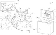
- FIG. 1is a schematic, pictorial illustration of a sinuplasty surgical system, in accordance with an embodiment of the present invention.
- FIG. 2is a schematic, exploded view of a location pad for sinuplasty procedures, in accordance with an embodiment of the present invention.
- Embodiments of the present inventionthat are described hereinbelow provide improved techniques for reducing interference in magnetic position tracking systems.
- Magnetic position tracking systemsare used in various medical procedures, such as in sinuplasty procedures.
- multiple field-generators that apply magnetic fieldsare mounted on a location pad.
- a sinuplasty tool that comprises a position sensoris inserted into the patient nose, and the position tracking system tracks the position of the sinuplasty tool using the position sensor, which is configured to detect the magnetic fields applied by the field-generators.
- a position tracking systemmay be surrounded by metallic parts and/or electrical signals that may interfere with the magnetic fields, and degrade the performance of the positioning system.
- the location padmay comprise illumination elements that may interfere with the magnetic fields produced by the field-generators.
- these elementsmay be made from metallic parts and (ii) when lit up, these elements conduct electrical signals that may interfere with the magnetic fields.
- the location padis mounted above the patient head so as to set the field-generators far away from the metallic parts of the operating chair.
- a pillowthat supports the patient head during the procedure, interposes between the location pad and the metallic parts of the chair, so as to further reduce the level of interference caused by the metallic parts of the chair.
- the location padcomprises illumination elements, such as light emitting diodes (LEDs).
- LEDslight emitting diodes
- the location padcomprises a frame, made from materials having low thermal expansion coefficient, such as Perspex®, which is transparent to pass the light from the LEDs and remains almost un-deformed even at relatively high temperatures.
- FIG. 1is a schematic pictorial illustration of a sinuplasty surgical system 20 , in accordance with an embodiment of the present invention.
- System 20comprises a magnetic position tracking system (not shown), which is configured to track the position of one or more position sensors in a head 41 of a patient 22 .
- the magnetic position tracking systemcomprises magnetic field-generators 44 and one or more position sensors (not shown).
- the position sensorsgenerate position signals in response to sensing external magnetic fields of field-generators 44 , thereby enabling a processor 34 to map the position of each sensor in the coordinate system of the position tracking system as will be described below.
- system 20comprises a location pad 40 , which is mounted on a chair 28 using a mounting fixture.
- the mounting fixturecomprises a mounting pole 70 , although other suitable types of mounting fixtures can also be used.
- poleis configured to mount location pad above patient head 41 , which is placed on a pillow 42 of chair 28 . In this configuration, pillow 42 and patient head 41 interpose between location pad 40 and chair 28 .
- system 20comprises location pad 40 , which is mounted on a chair 28 using a mounting pole 70 .
- pole 70is configured to hold the location pad above patient head 41 , which is placed on a pillow 42 of chair 28 .
- pillow 42 and patient head 41interpose between location pad 40 and chair 28 .
- location pad 40comprises multiple field-generators 44 fixed on a frame 46 .
- pad 40comprises five field-generators 44 , but any other suitable number of generators 44 can be used.
- generators 44are located at fixed, known positions external to the patient.
- System 20further comprises a console 33 , which comprises a driver circuit (not shown) configured to drive field-generators 44 with suitable signals so as to generate magnetic fields in a predefined working volume around head 41 .
- console 33comprises a display 36 , which is configured to display an anatomical image 35 obtained using an external imaging system, such as a computerized tomography (CT) system (not shown).
- CTcomputerized tomography
- system 20comprises a sinuplasty tool 30 , such as a diagnostic and/or surgical tool, inserted by a physician 24 through a nose 26 of patient 22 .
- Tool 30is used to carry out the sinuplasty procedure in patient head 41 .
- a position sensor(not shown) is coupled to a distal end of tool 30 .
- the position sensoris configured to generate position signals indicative of the position of the distal end of tool 30 in the coordinate system of the magnetic position tracking system.
- processor 34is configured to register image 35 with the coordinate system of the position tracking system.
- the registration processis typically performed before the actual sinuplasty procedure.
- physician 24inserts tool 30 into head 41 . Since the CT image is already registered with the position-tracking system, physician 24 may navigate the medical device whose distal end is displayed on image 35 , to a desired location in head 41 .
- processor 34is configured to receive one or more images acquired using another suitable anatomical imaging technique, such as fluoroscopy or magnetic resonance imaging (MRI), and to register these anatomical images with the coordinate system as described above.
- another suitable anatomical imaging techniquesuch as fluoroscopy or magnetic resonance imaging (MRI)
- Chair 28typically comprises several parts, such as a base of the chair, adjustable headrest, backrest, seat and their respective motors, of which one or more parts are metallic. In case the location pad would be positioned under the patient's head, these metallic parts would interfere with the magnetic fields generated by field-generators 44 of location pad 40 , and therefor degrade the positioning accuracy.
- location pad 40is fitted above head 41 , so as to set it at sufficiently large distance from the metallic parts of chair 28 to avoid interference, and yet keep it in close proximity to the position sensor coupled to tool 30 .
- pole 70is configured to hold location pad 40 above patient head 41 at a distance larger than 5 cm from metallic objects, such as metallic objects of pillow 42 and chair 28 , so as to reduce the level of interference to the magnetic fields produced by field-generators 44 , without negatively impacting the positioning accuracy of the position tracking system.
- pole 70is configured to adjust the distance between pad 40 and metallic objects, to any suitable value that provides a desired combination of sufficient illumination and positioning accuracy, at sufficiently reduced interference.
- processor 34is typically a general-purpose computer comprising suitable front end and interface circuits for receiving data from external sources, as well as measurements from the position sensor of tool 30 , via a cable 32 , and for controlling other components of system 20 .
- Console 33further comprises input devices 39 and a user display 36 , which is configured to display the data.
- FIG. 1shows only elements related to the disclosed techniques, for the sake of simplicity and clarity.
- System 20typically comprises additional modules and elements that are not directly related to the disclosed techniques, and thus, intentionally omitted from FIG. 1 and from the corresponding description.
- Processor 34may be programmed in software to carry out the functions that are used by the system, and to store data in a memory (not shown) to be processed or otherwise used by the software.
- the softwaremay be downloaded to the processor in electronic form, over a network, for example, or it may be provided on non-transitory tangible media, such as optical, magnetic or electronic memory media.
- some or all of the functions of processor 34may be carried out by dedicated or programmable digital hardware components.
- FIG. 2is a schematic, exploded view illustration of location pad 40 , in accordance with an embodiment of the present invention.
- the upper and lower parts of location pad 40are shown in the upper and lower parts of FIG. 2 , respectively.
- five field generators 44are fitted into five respective recesses 48 of frame 46 .
- frame 46comprises illumination elements 50 , such as one or more light emitting diodes (LEDs), fitted in one or more trenches 52 formed in frame 46 .
- illumination elements 50are adapted to illuminate head 41 of patient 22 , so as to assist physician 24 in carrying out the sinuplasty procedure.
- one or more conducting cablesare threaded through a trench 54 of frame 46 , so as to conduct signals to field-generators 44 and to illumination elements 50 .
- the cablesare fitted into trenches 52 , and are configured to conduct electrical signals to field-generators 44 and to illumination elements 50 .
- field-generators 44are configured to operate using alternating current (AC) signals at a selected frequency, such as 17-19 kilohertz (KHz). These operating frequencies are used by the magnetic position tracking system to track the position sensor coupled to the distal end of tool 30 .
- ACalternating current
- the magnetic fields produced by field-generators 44are subject to external and internal interferences that may negatively impact the positioning accuracy of the position tracking system.
- external interferencerefers to interference caused by elements that are external to the structure of location pad 40
- internal interferencerefers to interference caused by elements that are part of the structure of location pad 40 .
- the metal parts of chair 28may cause (external) interference to the magnetic field produced by field-generators 44 .
- pole 70is configured to mount location pad 40 at a given distance from the metallic parts of chair 28 , so that pillow 42 and patient head 41 interpose between location pad 40 and chair 28 , thereby further reducing the level of interference caused by the metallic parts of chair 28 .
- the configuration of location pad 40may cause internal interference.
- illumination elements 50such as LEDs, typically comprise metal parts that may interfere with the AC fields applied by field-generators 44 .
- the LEDsare typically operated by direct current (DC) signals that do not interfere with the AC signals transmitted by field-generators 44 .
- DCdirect current
- field-generators 44receive power from the drive circuit of console 33 , and may heat up during operation.
- frame 46comprises a transparent material having low thermal expansion coefficient, such as Perspex®, having thermal expansion coefficient of 75*10 ⁇ 6 [1/° K].
- frame 46exhibits an unnoticeable level of deformation even when the temperature of field-generators 44 increases to 100° C.
- a deformation level of up to 0.84 mmis expected at each edge of a 300 mm long frame (i.e., extending 150 mm to each side of pole 70 .)
- frame 46may comprise any other suitable transparent material having thermal expansion coefficient higher than 74*10 ⁇ 6 [1/° K].
- location pad 40is calibrated before applying the sinuplasty procedure, so as to compensate for the internal interferences caused by the metallic parts of illumination elements 50 .
- location pad 40is activated the distribution of the magnetic field along the entire length of location pad 40 is measured, e.g., by a scanning robot or any other suitable means.
- processor 34is configured to convert these magnetic field measurements into a three-dimensional (3D) calibration map.
- processor 34applies the 3D map so as to compensate for the internal interference caused to the magnetic fields of location pad 40 .
- the disclosed techniquescan be used, mutatis mutandis, in various other medical procedures applying magnetic position tracking techniques.
- the embodiments described hereinmainly address sinuplasty procedures
- the methods and systems described hereincan also be used in other applications, such as neuro-surgery, Ear-Nose-Throat (ENT), Cardiology, ophthalmology, or in any other minimally invasive procedure that applies magnetic position tracking techniques.
Landscapes
- Health & Medical Sciences (AREA)
- Life Sciences & Earth Sciences (AREA)
- Surgery (AREA)
- Engineering & Computer Science (AREA)
- General Health & Medical Sciences (AREA)
- Biomedical Technology (AREA)
- Heart & Thoracic Surgery (AREA)
- Medical Informatics (AREA)
- Molecular Biology (AREA)
- Animal Behavior & Ethology (AREA)
- Public Health (AREA)
- Veterinary Medicine (AREA)
- Nuclear Medicine, Radiotherapy & Molecular Imaging (AREA)
- Pathology (AREA)
- Oral & Maxillofacial Surgery (AREA)
- Robotics (AREA)
- Human Computer Interaction (AREA)
- Physics & Mathematics (AREA)
- Biophysics (AREA)
- Dentistry (AREA)
- Otolaryngology (AREA)
- Pulmonology (AREA)
- Surgical Instruments (AREA)
- Magnetic Resonance Imaging Apparatus (AREA)
- Media Introduction/Drainage Providing Device (AREA)
- Accommodation For Nursing Or Treatment Tables (AREA)
Abstract
Description
Claims (20)
Priority Applications (9)
| Application Number | Priority Date | Filing Date | Title |
|---|---|---|---|
| US15/855,265US11612437B2 (en) | 2017-05-10 | 2017-12-27 | Location pad with improved immunity to interference |
| IL259168AIL259168B (en) | 2017-05-10 | 2018-05-06 | Location pad with improved immunity to interference |
| JP2018090422AJP2018187395A (en) | 2017-05-10 | 2018-05-09 | Location pad with improved immunity to interference |
| AU2018203229AAU2018203229A1 (en) | 2017-05-10 | 2018-05-09 | Location pad with improved immunity to interference |
| CA3004280ACA3004280A1 (en) | 2017-05-10 | 2018-05-09 | Location pad with improved immunity to interference |
| CN201810443823.XACN108852512B (en) | 2017-05-10 | 2018-05-10 | Positioning pads with improved interference immunity |
| EP18176319.4AEP3400871B1 (en) | 2017-12-27 | 2018-06-06 | Location pad with improved immunity to interference |
| US18/081,764US12048495B2 (en) | 2017-05-10 | 2022-12-15 | Location pad with improved immunity to interference |
| JP2023010129AJP7379736B2 (en) | 2017-05-10 | 2023-01-26 | Locating pad with improved electromagnetic immunity to interference |
Applications Claiming Priority (2)
| Application Number | Priority Date | Filing Date | Title |
|---|---|---|---|
| US201762504404P | 2017-05-10 | 2017-05-10 | |
| US15/855,265US11612437B2 (en) | 2017-05-10 | 2017-12-27 | Location pad with improved immunity to interference |
Related Child Applications (1)
| Application Number | Title | Priority Date | Filing Date |
|---|---|---|---|
| US18/081,764ContinuationUS12048495B2 (en) | 2017-05-10 | 2022-12-15 | Location pad with improved immunity to interference |
Publications (2)
| Publication Number | Publication Date |
|---|---|
| US20180325603A1 US20180325603A1 (en) | 2018-11-15 |
| US11612437B2true US11612437B2 (en) | 2023-03-28 |
Family
ID=62630935
Family Applications (2)
| Application Number | Title | Priority Date | Filing Date |
|---|---|---|---|
| US15/855,265Active2039-03-10US11612437B2 (en) | 2017-05-10 | 2017-12-27 | Location pad with improved immunity to interference |
| US18/081,764ActiveUS12048495B2 (en) | 2017-05-10 | 2022-12-15 | Location pad with improved immunity to interference |
Family Applications After (1)
| Application Number | Title | Priority Date | Filing Date |
|---|---|---|---|
| US18/081,764ActiveUS12048495B2 (en) | 2017-05-10 | 2022-12-15 | Location pad with improved immunity to interference |
Country Status (7)
| Country | Link |
|---|---|
| US (2) | US11612437B2 (en) |
| EP (1) | EP3400871B1 (en) |
| JP (2) | JP2018187395A (en) |
| CN (1) | CN108852512B (en) |
| AU (1) | AU2018203229A1 (en) |
| CA (1) | CA3004280A1 (en) |
| IL (1) | IL259168B (en) |
Families Citing this family (5)
| Publication number | Priority date | Publication date | Assignee | Title |
|---|---|---|---|---|
| US11612437B2 (en) | 2017-05-10 | 2023-03-28 | Biosense Webster (Israel) Ltd. | Location pad with improved immunity to interference |
| US11806083B2 (en)* | 2018-05-14 | 2023-11-07 | Biosense Webster (Israel) Ltd. | Correcting map shifting of a position tracking system including repositioning the imaging system and the patient in response to detecting magnetic interference |
| US11832883B2 (en) | 2020-04-23 | 2023-12-05 | Johnson & Johnson Surgical Vision, Inc. | Using real-time images for augmented-reality visualization of an ophthalmology surgical tool |
| US12201265B2 (en) | 2020-04-23 | 2025-01-21 | Johnson & Johnson Surgical Vision, Inc. | Location pad surrounding at least part of patient eye for tracking position of a medical instrument |
| CN118267123B (en)* | 2024-05-31 | 2024-09-24 | 科弛医疗科技(北京)有限公司 | Medical instrument installation recognition device, installation recognition method and surgical robot device |
Citations (30)
| Publication number | Priority date | Publication date | Assignee | Title |
|---|---|---|---|---|
| US5309913A (en) | 1992-11-30 | 1994-05-10 | The Cleveland Clinic Foundation | Frameless stereotaxy system |
| US5391199A (en) | 1993-07-20 | 1995-02-21 | Biosense, Inc. | Apparatus and method for treating cardiac arrhythmias |
| WO1996005768A1 (en) | 1994-08-19 | 1996-02-29 | Biosense, Inc. | Medical diagnosis, treatment and imaging systems |
| JPH0871086A (en) | 1994-09-06 | 1996-03-19 | Shimadzu Corp | Position display device for surgical instruments |
| US5831260A (en) | 1996-09-10 | 1998-11-03 | Ascension Technology Corporation | Hybrid motion tracker |
| US6239724B1 (en) | 1997-12-30 | 2001-05-29 | Remon Medical Technologies, Ltd. | System and method for telemetrically providing intrabody spatial position |
| US6332089B1 (en) | 1996-02-15 | 2001-12-18 | Biosense, Inc. | Medical procedures and apparatus using intrabody probes |
| US6366799B1 (en) | 1996-02-15 | 2002-04-02 | Biosense, Inc. | Movable transmit or receive coils for location system |
| US20020065455A1 (en) | 1995-01-24 | 2002-05-30 | Shlomo Ben-Haim | Medical diagnosis, treatment and imaging systems |
| US6484118B1 (en) | 2000-07-20 | 2002-11-19 | Biosense, Inc. | Electromagnetic position single axis system |
| US20030120150A1 (en) | 2001-12-21 | 2003-06-26 | Assaf Govari | Wireless position sensor |
| US6618612B1 (en)* | 1996-02-15 | 2003-09-09 | Biosense, Inc. | Independently positionable transducers for location system |
| US20030200052A1 (en) | 2000-07-26 | 2003-10-23 | Seiler Paul G. | Method for determing the position of a sensor element |
| US20040068178A1 (en) | 2002-09-17 | 2004-04-08 | Assaf Govari | High-gradient recursive locating system |
| US20040147839A1 (en)* | 2002-10-25 | 2004-07-29 | Moctezuma De La Barrera Jose Luis | Flexible tracking article and method of using the same |
| US20060004286A1 (en) | 2004-04-21 | 2006-01-05 | Acclarent, Inc. | Methods and devices for performing procedures within the ear, nose, throat and paranasal sinuses |
| JP2006271520A (en) | 2005-03-28 | 2006-10-12 | Olympus Corp | Position detection system of capsule medical device, guidance system of capsule medical device, and position detection method of capsule medical device |
| US20070094798A1 (en)* | 2005-10-28 | 2007-05-03 | Yu Chun H | Platform assembly for an operating bed |
| US20070260296A1 (en)* | 2004-09-13 | 2007-11-08 | William Porter | Apparatus for Photodynamic Therapy |
| US20070265526A1 (en)* | 2006-05-11 | 2007-11-15 | Assaf Govari | Low-profile location pad |
| US20080009713A1 (en) | 2006-05-16 | 2008-01-10 | Gregor Tuma | Medical pelvic positioning and tracking device |
| US20110072586A1 (en)* | 2009-09-25 | 2011-03-31 | Chun Ho Yu | Surgical station |
| US8421569B1 (en)* | 2011-12-02 | 2013-04-16 | Hong Fu Jin Precision Industry (Shenzhen) Co., Ltd. | Magnetic field generator for measuring immunity of eletronic devices to electromagnetic fields |
| US20130318714A1 (en)* | 2009-09-25 | 2013-12-05 | Chun Ho Yu | Surgical Station |
| US20140194734A1 (en)* | 2011-07-28 | 2014-07-10 | Brainlab Ag | Patient positioning system with an electromagnetic field generator of an electromagnetic tracking system |
| US20150297303A1 (en)* | 2012-10-31 | 2015-10-22 | Brainlab AG, | Positioning device for a medical field generator |
| WO2016007591A1 (en) | 2014-07-09 | 2016-01-14 | Acclarent, Inc. | Guidewire navigation for sinuplasty |
| US20160008083A1 (en)* | 2014-07-09 | 2016-01-14 | Acclarent, Inc. | Guidewire navigation for sinuplasty |
| CN106333750A (en) | 2015-07-06 | 2017-01-18 | 韦伯斯特生物官能(以色列)有限公司 | Flat Location Pad Using Nonconcentric Coils |
| US20180310886A1 (en)* | 2017-04-26 | 2018-11-01 | Acclarent, Inc. | Apparatus to secure field generating device to chair |
Family Cites Families (4)
| Publication number | Priority date | Publication date | Assignee | Title |
|---|---|---|---|---|
| US20140138269A1 (en)* | 2012-11-16 | 2014-05-22 | Krishnan K. Ghosh | Surgical tray system |
| DE102013221026A1 (en)* | 2013-10-16 | 2015-04-16 | Fiagon Gmbh | Field generator and position detection system |
| US10779891B2 (en) | 2015-10-30 | 2020-09-22 | Acclarent, Inc. | System and method for navigation of surgical instruments |
| US11612437B2 (en) | 2017-05-10 | 2023-03-28 | Biosense Webster (Israel) Ltd. | Location pad with improved immunity to interference |
- 2017
- 2017-12-27USUS15/855,265patent/US11612437B2/enactiveActive
- 2018
- 2018-05-06ILIL259168Apatent/IL259168B/enunknown
- 2018-05-09JPJP2018090422Apatent/JP2018187395A/enactivePending
- 2018-05-09CACA3004280Apatent/CA3004280A1/ennot_activeAbandoned
- 2018-05-09AUAU2018203229Apatent/AU2018203229A1/ennot_activeAbandoned
- 2018-05-10CNCN201810443823.XApatent/CN108852512B/enactiveActive
- 2018-06-06EPEP18176319.4Apatent/EP3400871B1/enactiveActive
- 2022
- 2022-12-15USUS18/081,764patent/US12048495B2/enactiveActive
- 2023
- 2023-01-26JPJP2023010129Apatent/JP7379736B2/enactiveActive
Patent Citations (31)
| Publication number | Priority date | Publication date | Assignee | Title |
|---|---|---|---|---|
| US5309913A (en) | 1992-11-30 | 1994-05-10 | The Cleveland Clinic Foundation | Frameless stereotaxy system |
| US5391199A (en) | 1993-07-20 | 1995-02-21 | Biosense, Inc. | Apparatus and method for treating cardiac arrhythmias |
| WO1996005768A1 (en) | 1994-08-19 | 1996-02-29 | Biosense, Inc. | Medical diagnosis, treatment and imaging systems |
| JPH0871086A (en) | 1994-09-06 | 1996-03-19 | Shimadzu Corp | Position display device for surgical instruments |
| US6690963B2 (en) | 1995-01-24 | 2004-02-10 | Biosense, Inc. | System for determining the location and orientation of an invasive medical instrument |
| US20020065455A1 (en) | 1995-01-24 | 2002-05-30 | Shlomo Ben-Haim | Medical diagnosis, treatment and imaging systems |
| US6332089B1 (en) | 1996-02-15 | 2001-12-18 | Biosense, Inc. | Medical procedures and apparatus using intrabody probes |
| US6366799B1 (en) | 1996-02-15 | 2002-04-02 | Biosense, Inc. | Movable transmit or receive coils for location system |
| US6618612B1 (en)* | 1996-02-15 | 2003-09-09 | Biosense, Inc. | Independently positionable transducers for location system |
| US5831260A (en) | 1996-09-10 | 1998-11-03 | Ascension Technology Corporation | Hybrid motion tracker |
| US6239724B1 (en) | 1997-12-30 | 2001-05-29 | Remon Medical Technologies, Ltd. | System and method for telemetrically providing intrabody spatial position |
| US6484118B1 (en) | 2000-07-20 | 2002-11-19 | Biosense, Inc. | Electromagnetic position single axis system |
| US20030200052A1 (en) | 2000-07-26 | 2003-10-23 | Seiler Paul G. | Method for determing the position of a sensor element |
| US20030120150A1 (en) | 2001-12-21 | 2003-06-26 | Assaf Govari | Wireless position sensor |
| US20040068178A1 (en) | 2002-09-17 | 2004-04-08 | Assaf Govari | High-gradient recursive locating system |
| US20040147839A1 (en)* | 2002-10-25 | 2004-07-29 | Moctezuma De La Barrera Jose Luis | Flexible tracking article and method of using the same |
| US20060004286A1 (en) | 2004-04-21 | 2006-01-05 | Acclarent, Inc. | Methods and devices for performing procedures within the ear, nose, throat and paranasal sinuses |
| US20070260296A1 (en)* | 2004-09-13 | 2007-11-08 | William Porter | Apparatus for Photodynamic Therapy |
| JP2006271520A (en) | 2005-03-28 | 2006-10-12 | Olympus Corp | Position detection system of capsule medical device, guidance system of capsule medical device, and position detection method of capsule medical device |
| US20070094798A1 (en)* | 2005-10-28 | 2007-05-03 | Yu Chun H | Platform assembly for an operating bed |
| US20070265526A1 (en)* | 2006-05-11 | 2007-11-15 | Assaf Govari | Low-profile location pad |
| US20080009713A1 (en) | 2006-05-16 | 2008-01-10 | Gregor Tuma | Medical pelvic positioning and tracking device |
| US20110072586A1 (en)* | 2009-09-25 | 2011-03-31 | Chun Ho Yu | Surgical station |
| US20130318714A1 (en)* | 2009-09-25 | 2013-12-05 | Chun Ho Yu | Surgical Station |
| US20140194734A1 (en)* | 2011-07-28 | 2014-07-10 | Brainlab Ag | Patient positioning system with an electromagnetic field generator of an electromagnetic tracking system |
| US8421569B1 (en)* | 2011-12-02 | 2013-04-16 | Hong Fu Jin Precision Industry (Shenzhen) Co., Ltd. | Magnetic field generator for measuring immunity of eletronic devices to electromagnetic fields |
| US20150297303A1 (en)* | 2012-10-31 | 2015-10-22 | Brainlab AG, | Positioning device for a medical field generator |
| WO2016007591A1 (en) | 2014-07-09 | 2016-01-14 | Acclarent, Inc. | Guidewire navigation for sinuplasty |
| US20160008083A1 (en)* | 2014-07-09 | 2016-01-14 | Acclarent, Inc. | Guidewire navigation for sinuplasty |
| CN106333750A (en) | 2015-07-06 | 2017-01-18 | 韦伯斯特生物官能(以色列)有限公司 | Flat Location Pad Using Nonconcentric Coils |
| US20180310886A1 (en)* | 2017-04-26 | 2018-11-01 | Acclarent, Inc. | Apparatus to secure field generating device to chair |
Non-Patent Citations (5)
| Title |
|---|
| Barratt D C et al; "Optimisation and evaluation of an electromagnetic tracking device for high-accuracy three-dimensional ultrasound imaging of the carotid arteries", Ultrasound in Medicine and Biol, New York, NY, US, vol. 27, No. 7, Jul. 1, 2001. |
| Chinese Office Action and Search Report dated Aug. 22, 2022, for Application No. 201810443823.X, 10 pages. |
| European Search Report dated Sep. 12, 2018 from corresponding European Patent Application No. 18176319.4. |
| Japanese Final Office Action dated Sep. 27, 2022, for Application No. 2018-090422, 4 pages. |
| Japanese Notification of Reasons for Refusal dated Mar. 15, 2022, for Application No. 2018-090422, 5 pages. |
Also Published As
| Publication number | Publication date |
|---|---|
| IL259168A (en) | 2018-06-28 |
| AU2018203229A1 (en) | 2018-11-29 |
| CN108852512A (en) | 2018-11-23 |
| JP7379736B2 (en) | 2023-11-14 |
| JP2018187395A (en) | 2018-11-29 |
| EP3400871B1 (en) | 2021-09-08 |
| JP2023038346A (en) | 2023-03-16 |
| US12048495B2 (en) | 2024-07-30 |
| CN108852512B (en) | 2024-01-12 |
| US20180325603A1 (en) | 2018-11-15 |
| CA3004280A1 (en) | 2018-11-10 |
| US20230113226A1 (en) | 2023-04-13 |
| EP3400871A1 (en) | 2018-11-14 |
| IL259168B (en) | 2021-12-01 |
Similar Documents
| Publication | Publication Date | Title |
|---|---|---|
| US12048495B2 (en) | Location pad with improved immunity to interference | |
| US8483434B2 (en) | Technique for registering image data of an object | |
| RU2434578C2 (en) | Apparatus for local error compensation in electromagnetic tracking systems | |
| US10064687B2 (en) | Estimation and compensation of tracking inaccuracies | |
| US8644570B2 (en) | System and method for automatic registration between an image and a subject | |
| CN103767683B (en) | Integration between 3D scaling graphs and fluoroscopic image | |
| US20100228117A1 (en) | System And Method For Image-Guided Navigation | |
| US20180098816A1 (en) | Pre-Operative Registration of Anatomical Images with a Position-Tracking System Using Ultrasound | |
| US8712503B2 (en) | Pelvic registration device for medical navigation | |
| CN108720924B (en) | Improving registration of anatomical images to a position tracking coordinate system based on visual proximity to bone tissue | |
| US11051713B2 (en) | Immunity from magnetic disturbance for a magnetic location tracker | |
| CA2940602A1 (en) | Adding a tracking sensor to a rigid tool | |
| AU2015200913A1 (en) | Calibration jig for a flat location pad | |
| CN114901149A (en) | Positioning pad for neurosurgery | |
| US20180113180A1 (en) | Magnetic resonance imaging apparatus | |
| JP2018069052A (en) | Magnetic resonance imaging system |
Legal Events
| Date | Code | Title | Description |
|---|---|---|---|
| FEPP | Fee payment procedure | Free format text:ENTITY STATUS SET TO UNDISCOUNTED (ORIGINAL EVENT CODE: BIG.); ENTITY STATUS OF PATENT OWNER: LARGE ENTITY | |
| STPP | Information on status: patent application and granting procedure in general | Free format text:DOCKETED NEW CASE - READY FOR EXAMINATION | |
| AS | Assignment | Owner name:BIOSENSE WEBSTER (ISRAEL) LTD., ISRAEL Free format text:ASSIGNMENT OF ASSIGNORS INTEREST;ASSIGNORS:GLINER, VADIM;GOVARI, ASSAF;SIGNING DATES FROM 20180507 TO 20180522;REEL/FRAME:046848/0863 | |
| STPP | Information on status: patent application and granting procedure in general | Free format text:NON FINAL ACTION MAILED | |
| STPP | Information on status: patent application and granting procedure in general | Free format text:RESPONSE TO NON-FINAL OFFICE ACTION ENTERED AND FORWARDED TO EXAMINER | |
| STPP | Information on status: patent application and granting procedure in general | Free format text:FINAL REJECTION MAILED | |
| STPP | Information on status: patent application and granting procedure in general | Free format text:DOCKETED NEW CASE - READY FOR EXAMINATION | |
| STPP | Information on status: patent application and granting procedure in general | Free format text:NON FINAL ACTION MAILED | |
| STPP | Information on status: patent application and granting procedure in general | Free format text:RESPONSE TO NON-FINAL OFFICE ACTION ENTERED AND FORWARDED TO EXAMINER | |
| STPP | Information on status: patent application and granting procedure in general | Free format text:FINAL REJECTION MAILED | |
| STPP | Information on status: patent application and granting procedure in general | Free format text:RESPONSE AFTER FINAL ACTION FORWARDED TO EXAMINER | |
| STPP | Information on status: patent application and granting procedure in general | Free format text:NOTICE OF ALLOWANCE MAILED -- APPLICATION RECEIVED IN OFFICE OF PUBLICATIONS | |
| STPP | Information on status: patent application and granting procedure in general | Free format text:NOTICE OF ALLOWANCE MAILED -- APPLICATION RECEIVED IN OFFICE OF PUBLICATIONS | |
| STCF | Information on status: patent grant | Free format text:PATENTED CASE |