US11612416B2 - Systems and methods for vertebral adjustment - Google Patents
Systems and methods for vertebral adjustmentDownload PDFInfo
- Publication number
- US11612416B2 US11612416B2US16/270,976US201916270976AUS11612416B2US 11612416 B2US11612416 B2US 11612416B2US 201916270976 AUS201916270976 AUS 201916270976AUS 11612416 B2US11612416 B2US 11612416B2
- Authority
- US
- United States
- Prior art keywords
- rod
- housing
- spinal
- vertebra
- threaded
- Prior art date
- Legal status (The legal status is an assumption and is not a legal conclusion. Google has not performed a legal analysis and makes no representation as to the accuracy of the status listed.)
- Active, expires
Links
- 238000000034methodMethods0.000titledescription15
- 230000008878couplingEffects0.000claimsdescription23
- 238000010168coupling processMethods0.000claimsdescription23
- 238000005859coupling reactionMethods0.000claimsdescription23
- 239000007943implantSubstances0.000description210
- 230000033001locomotionEffects0.000description62
- 230000006835compressionEffects0.000description49
- 238000007906compressionMethods0.000description49
- 239000012530fluidSubstances0.000description45
- 230000009467reductionEffects0.000description42
- 230000004927fusionEffects0.000description34
- 238000001356surgical procedureMethods0.000description24
- 230000007246mechanismEffects0.000description22
- 230000008859changeEffects0.000description21
- 208000007623LordosisDiseases0.000description18
- 230000001965increasing effectEffects0.000description18
- 230000001045lordotic effectEffects0.000description13
- 210000000988bone and boneAnatomy0.000description12
- 239000000463materialSubstances0.000description12
- 230000000875corresponding effectEffects0.000description10
- HLXZNVUGXRDIFK-UHFFFAOYSA-Nnickel titaniumChemical compound[Ti].[Ti].[Ti].[Ti].[Ti].[Ti].[Ti].[Ti].[Ti].[Ti].[Ti].[Ni].[Ni].[Ni].[Ni].[Ni].[Ni].[Ni].[Ni].[Ni].[Ni].[Ni].[Ni].[Ni].[Ni]HLXZNVUGXRDIFK-UHFFFAOYSA-N0.000description10
- 238000002513implantationMethods0.000description9
- 229910001000nickel titaniumInorganic materials0.000description9
- 206010061246Intervertebral disc degenerationDiseases0.000description8
- 239000011436cobSubstances0.000description8
- 208000018180degenerative disc diseaseDiseases0.000description8
- 208000021600intervertebral disc degenerative diseaseDiseases0.000description8
- 208000031481Pathologic ConstrictionDiseases0.000description6
- 238000006243chemical reactionMethods0.000description6
- 230000003247decreasing effectEffects0.000description6
- 230000036262stenosisEffects0.000description6
- 208000037804stenosisDiseases0.000description6
- 208000032170Congenital AbnormalitiesDiseases0.000description5
- 239000002131composite materialSubstances0.000description5
- 238000006073displacement reactionMethods0.000description5
- 125000006850spacer groupChemical group0.000description5
- 238000013519translationMethods0.000description5
- 206010061619DeformityDiseases0.000description4
- 239000004696Poly ether ether ketoneSubstances0.000description4
- 230000008901benefitEffects0.000description4
- 238000010348incorporationMethods0.000description4
- 230000001939inductive effectEffects0.000description4
- 210000004705lumbosacral regionAnatomy0.000description4
- 229920002530polyetherether ketonePolymers0.000description4
- 230000002829reductive effectEffects0.000description4
- 229910001220stainless steelInorganic materials0.000description4
- 239000010935stainless steelSubstances0.000description4
- 230000035882stressEffects0.000description4
- 208000008035Back PainDiseases0.000description3
- 206010052904Musculoskeletal stiffnessDiseases0.000description3
- 229910001069Ti alloyInorganic materials0.000description3
- 230000004913activationEffects0.000description3
- 238000013459approachMethods0.000description3
- 239000004020conductorSubstances0.000description3
- 238000012937correctionMethods0.000description3
- 230000006837decompressionEffects0.000description3
- 230000006870functionEffects0.000description3
- 230000004048modificationEffects0.000description3
- 238000012986modificationMethods0.000description3
- 210000005036nerveAnatomy0.000description3
- 238000005381potential energyMethods0.000description3
- 238000004904shorteningMethods0.000description3
- 208000024891symptomDiseases0.000description3
- 210000001519tissueAnatomy0.000description3
- 241001631457CannulaSpecies0.000description2
- 239000004606Fillers/ExtendersSubstances0.000description2
- 206010068219Flatback syndromeDiseases0.000description2
- PXHVJJICTQNCMI-UHFFFAOYSA-NNickelChemical compound[Ni]PXHVJJICTQNCMI-UHFFFAOYSA-N0.000description2
- 229910018503SF6Inorganic materials0.000description2
- FAPWRFPIFSIZLT-UHFFFAOYSA-MSodium chlorideChemical compound[Na+].[Cl-]FAPWRFPIFSIZLT-UHFFFAOYSA-M0.000description2
- RTAQQCXQSZGOHL-UHFFFAOYSA-NTitaniumChemical compound[Ti]RTAQQCXQSZGOHL-UHFFFAOYSA-N0.000description2
- 210000001124body fluidAnatomy0.000description2
- 230000001010compromised effectEffects0.000description2
- 238000013461designMethods0.000description2
- PCHJSUWPFVWCPO-UHFFFAOYSA-NgoldChemical compound[Au]PCHJSUWPFVWCPO-UHFFFAOYSA-N0.000description2
- 229910052737goldInorganic materials0.000description2
- 239000010931goldSubstances0.000description2
- 238000003780insertionMethods0.000description2
- 230000037431insertionEffects0.000description2
- OBACEDMBGYVZMP-UHFFFAOYSA-Niron platinumChemical compound[Fe].[Fe].[Pt]OBACEDMBGYVZMP-UHFFFAOYSA-N0.000description2
- 210000003041ligamentAnatomy0.000description2
- 239000011553magnetic fluidSubstances0.000description2
- 238000002324minimally invasive surgeryMethods0.000description2
- 229910001172neodymium magnetInorganic materials0.000description2
- QYSGYZVSCZSLHT-UHFFFAOYSA-NoctafluoropropaneChemical compoundFC(F)(F)C(F)(F)C(F)(F)FQYSGYZVSCZSLHT-UHFFFAOYSA-N0.000description2
- 230000000399orthopedic effectEffects0.000description2
- 230000036961partial effectEffects0.000description2
- 238000007747platingMethods0.000description2
- 229910052761rare earth metalInorganic materials0.000description2
- 150000002910rare earth metalsChemical class0.000description2
- 206010039722scoliosisDiseases0.000description2
- 239000011780sodium chlorideSubstances0.000description2
- 210000005070sphincterAnatomy0.000description2
- SFZCNBIFKDRMGX-UHFFFAOYSA-Nsulfur hexafluorideChemical compoundFS(F)(F)(F)(F)FSFZCNBIFKDRMGX-UHFFFAOYSA-N0.000description2
- 239000010936titaniumSubstances0.000description2
- 229910052719titaniumInorganic materials0.000description2
- 238000003466weldingMethods0.000description2
- 229910000619316 stainless steelInorganic materials0.000description1
- -1Aluminum Nickel CobaltChemical compound0.000description1
- RYGMFSIKBFXOCR-UHFFFAOYSA-NCopperChemical compound[Cu]RYGMFSIKBFXOCR-UHFFFAOYSA-N0.000description1
- 208000034347Faecal incontinenceDiseases0.000description1
- 206010016654FibrosisDiseases0.000description1
- 208000018522Gastrointestinal diseaseDiseases0.000description1
- 208000003618Intervertebral Disc DisplacementDiseases0.000description1
- 206010023509KyphosisDiseases0.000description1
- 206010052658MacrognathiaDiseases0.000description1
- 206010049565Muscle fatigueDiseases0.000description1
- 208000000112MyalgiaDiseases0.000description1
- 208000008589ObesityDiseases0.000description1
- 208000008558OsteophyteDiseases0.000description1
- 208000002193PainDiseases0.000description1
- 206010033425Pain in extremityDiseases0.000description1
- 208000002607PseudarthrosisDiseases0.000description1
- 208000017375Scheuermann DiseaseDiseases0.000description1
- 208000007103SpondylolisthesisDiseases0.000description1
- 206010046543Urinary incontinenceDiseases0.000description1
- 208000027418Wounds and injuryDiseases0.000description1
- QJVKUMXDEUEQLH-UHFFFAOYSA-N[B].[Fe].[Nd]Chemical compound[B].[Fe].[Nd]QJVKUMXDEUEQLH-UHFFFAOYSA-N0.000description1
- 239000000654additiveSubstances0.000description1
- 230000000996additive effectEffects0.000description1
- 239000000853adhesiveSubstances0.000description1
- 230000001070adhesive effectEffects0.000description1
- 230000032683agingEffects0.000description1
- 229910000828alnicoInorganic materials0.000description1
- 229920000249biocompatible polymerPolymers0.000description1
- 230000015572biosynthetic processEffects0.000description1
- 230000002051biphasic effectEffects0.000description1
- 239000000919ceramicSubstances0.000description1
- 239000003638chemical reducing agentSubstances0.000description1
- 239000000788chromium alloySubstances0.000description1
- KPLQYGBQNPPQGA-UHFFFAOYSA-Ncobalt samariumChemical compound[Co].[Sm]KPLQYGBQNPPQGA-UHFFFAOYSA-N0.000description1
- 238000004891communicationMethods0.000description1
- 230000000295complement effectEffects0.000description1
- 230000001276controlling effectEffects0.000description1
- 238000007796conventional methodMethods0.000description1
- 229910052802copperInorganic materials0.000description1
- 239000010949copperSubstances0.000description1
- 230000002596correlated effectEffects0.000description1
- 230000007797corrosionEffects0.000description1
- 238000005260corrosionMethods0.000description1
- 230000006378damageEffects0.000description1
- 230000007850degenerationEffects0.000description1
- 230000003412degenerative effectEffects0.000description1
- 238000011161developmentMethods0.000description1
- 230000018109developmental processEffects0.000description1
- 238000002059diagnostic imagingMethods0.000description1
- 208000037265diseases, disorders, signs and symptomsDiseases0.000description1
- 208000035475disorderDiseases0.000description1
- 238000009826distributionMethods0.000description1
- 230000000694effectsEffects0.000description1
- 230000004761fibrosisEffects0.000description1
- 208000021302gastroesophageal reflux diseaseDiseases0.000description1
- 239000000017hydrogelSubstances0.000description1
- 230000002401inhibitory effectEffects0.000description1
- 238000002347injectionMethods0.000description1
- 239000007924injectionSubstances0.000description1
- 230000000670limiting effectEffects0.000description1
- 239000000314lubricantSubstances0.000description1
- 239000000696magnetic materialSubstances0.000description1
- 230000005389magnetismEffects0.000description1
- 238000004519manufacturing processMethods0.000description1
- 230000013011matingEffects0.000description1
- 239000012528membraneSubstances0.000description1
- 208000013465muscle painDiseases0.000description1
- 210000000944nerve tissueAnatomy0.000description1
- 229910052759nickelInorganic materials0.000description1
- 235000020824obesityNutrition0.000description1
- 230000011164ossificationEffects0.000description1
- 201000008482osteoarthritisDiseases0.000description1
- 238000004806packaging method and processMethods0.000description1
- 230000007170pathologyEffects0.000description1
- 229960004065perflutrenDrugs0.000description1
- BASFCYQUMIYNBI-UHFFFAOYSA-NplatinumSubstances[Pt]BASFCYQUMIYNBI-UHFFFAOYSA-N0.000description1
- 230000001376precipitating effectEffects0.000description1
- 230000008569processEffects0.000description1
- 230000004044responseEffects0.000description1
- 230000002441reversible effectEffects0.000description1
- 229910000938samarium–cobalt magnetInorganic materials0.000description1
- 238000007789sealingMethods0.000description1
- 230000035939shockEffects0.000description1
- 239000007787solidSubstances0.000description1
- 210000000278spinal cordAnatomy0.000description1
- 208000005198spinal stenosisDiseases0.000description1
- 238000009987spinningMethods0.000description1
- 230000003068static effectEffects0.000description1
- 229960000909sulfur hexafluorideDrugs0.000description1
- 230000008719thickeningEffects0.000description1
- 229910052720vanadiumInorganic materials0.000description1
- LEONUFNNVUYDNQ-UHFFFAOYSA-Nvanadium atomChemical compound[V]LEONUFNNVUYDNQ-UHFFFAOYSA-N0.000description1
- 230000000007visual effectEffects0.000description1
Images


Classifications
- A—HUMAN NECESSITIES
- A61—MEDICAL OR VETERINARY SCIENCE; HYGIENE
- A61B—DIAGNOSIS; SURGERY; IDENTIFICATION
- A61B17/00—Surgical instruments, devices or methods
- A61B17/56—Surgical instruments or methods for treatment of bones or joints; Devices specially adapted therefor
- A61B17/58—Surgical instruments or methods for treatment of bones or joints; Devices specially adapted therefor for osteosynthesis, e.g. bone plates, screws or setting implements
- A61B17/68—Internal fixation devices, including fasteners and spinal fixators, even if a part thereof projects from the skin
- A61B17/70—Spinal positioners or stabilisers, e.g. stabilisers comprising fluid filler in an implant
- A61B17/7001—Screws or hooks combined with longitudinal elements which do not contact vertebrae
- A61B17/7002—Longitudinal elements, e.g. rods
- A61B17/7014—Longitudinal elements, e.g. rods with means for adjusting the distance between two screws or hooks
- A61B17/7016—Longitudinal elements, e.g. rods with means for adjusting the distance between two screws or hooks electric or electromagnetic means
- A—HUMAN NECESSITIES
- A61—MEDICAL OR VETERINARY SCIENCE; HYGIENE
- A61B—DIAGNOSIS; SURGERY; IDENTIFICATION
- A61B17/00—Surgical instruments, devices or methods
- A61B2017/00017—Electrical control of surgical instruments
- A61B2017/00212—Electrical control of surgical instruments using remote controls
- A—HUMAN NECESSITIES
- A61—MEDICAL OR VETERINARY SCIENCE; HYGIENE
- A61B—DIAGNOSIS; SURGERY; IDENTIFICATION
- A61B17/00—Surgical instruments, devices or methods
- A61B2017/00017—Electrical control of surgical instruments
- A61B2017/00221—Electrical control of surgical instruments with wireless transmission of data, e.g. by infrared radiation or radiowaves
- A—HUMAN NECESSITIES
- A61—MEDICAL OR VETERINARY SCIENCE; HYGIENE
- A61B—DIAGNOSIS; SURGERY; IDENTIFICATION
- A61B17/00—Surgical instruments, devices or methods
- A61B17/56—Surgical instruments or methods for treatment of bones or joints; Devices specially adapted therefor
- A61B17/58—Surgical instruments or methods for treatment of bones or joints; Devices specially adapted therefor for osteosynthesis, e.g. bone plates, screws or setting implements
- A61B17/68—Internal fixation devices, including fasteners and spinal fixators, even if a part thereof projects from the skin
- A61B2017/681—Alignment, compression, or distraction mechanisms
Definitions
- the present disclosurerelates to systems and methods for distraction within the human body.
- the present inventionrelates to distraction devices for the adjustment of sagittal curvature in a spine.
- Degenerative disc diseaseaffects 65 million Americans. Up to 85% of the population over the age of 50 will suffer from back pain each year. Degenerative disc disease is part of the natural process of aging. As people age, their intervertebral discs lose their flexibility, elasticity, and shock absorbing characteristics. The ligaments that surround the disc, known as the annulus fibrosis, become brittle and are more easily torn. At the same time, the soft gel-like center of the disc, known as the nucleus pulposus, starts to dry out and shrink. The combination of damage to the intervertebral discs, the development of bone spurs, and a gradual thickening of the ligaments that support the spine can all contribute to degenerative arthritis of the lumbar spine.
- degenerative disc diseaseWhen degenerative disc disease becomes painful or symptomatic, it can cause several different symptoms, including back pain, leg pain, and weakness that are due to compression of the nerve roots. These symptoms are caused by the fact that worn out discs are a source of pain because they do not function as well as they once did, and as they shrink, the space available for the nerve roots also shrinks. As the discs between the intervertebral bodies start to wear out, the entire lumbar spine becomes less flexible. As a result, people complain of back pain and stiffness, especially towards the end of each day.
- stenosis of the spineAnother spinal malady that commonly affects patients is stenosis of the spine. Stenosis is related to degeneration of the spine and typically presents itself in later life. Spinal stenosis can occur in a variety of ways in the spine. Most cases of stenosis occur in the lumbar region (i.e., lower back) of the spine although stenosis is also common in the cervical region of the spine. Central stenosis is a choking of the central canal that compresses the nerve tissue within the spinal canal. Lateral stenosis occurs due to trapping or compression of nerves after they have left the spinal canal. This can be caused by bony spur protrusions, or bulging or herniated discs.
- Non-invasively adjustable devices of the type presentedmay also be used in patients having scoliosis, spondylolisthesis, Scheuermann's kyphosis, limb length deformity, limb angle deformity, limb rotational deformity, macrognathia, high tibial osteotomy, or other orthopedic deformities.
- the present disclosureprovides various systems for non-invasively adjusting the curvature of a spine.
- One or more embodiments of those systemsinclude a housing having a first end and a second end and a cavity between the first end and the second end, a first rod having a first end telescopically disposed within the cavity of the housing along a first longitudinal axis at the first end of the housing and having a first threaded portion extending thereon, and a second end configured to be coupled to a first portion of a spinal system of a subject, a second rod having a first end telescopically disposed within the cavity of the housing along a second longitudinal axis at the second end of the housing and having a second threaded portion extending thereon, and a second end configured to be coupled to a second portion of the spinal system of the subject, a driving member rotatably disposed within the cavity of the housing and configured to be activated from a location external to the body of the subject, a first interface rotationally coupling a first threade
- the present disclosurefurther provides for a method for adjusting the curvature of a spine includes providing a non-invasively adjustable system including a housing having a first end and a second end and a cavity extending between the first end and the second end, a first rod having a first end telescopically disposed within the cavity of the housing along a first longitudinal axis at the first end of the housing and having a first threaded portion extending thereon, and a second end configured to be coupled to a first portion of a spinal system of a subject, a second rod having a first end telescopically disposed within the cavity of the housing along a second longitudinal axis at the second end of the housing and having a second threaded portion extending thereon, and a second end configured to be coupled to a second portion of the spinal system of the subject, a driving member rotatably disposed within the cavity of the housing and configured to be activated from a location external to the body of the subject, a first interface rotationally coupling a first threade
- the present disclosurestill further provides for s system for adjusting the curvature of a spine includes a housing having a first end and a second end and a cavity between the first end and the second end, a first rod having a first end telescopically disposed within the cavity of the housing along a first longitudinal axis at the first end of the housing and having a first threaded portion extending thereon, and a second end configured to be coupled to a first portion of a spinal system of a subject, a second rod having a first end telescopically disposed within the cavity of the housing along a second longitudinal axis at the second end of the housing and having a second threaded portion extending thereon, and a second end configured to be coupled to a second portion of the spinal system of the subject, a driving member rotatably disposed within the cavity of the housing and configured to be activated from a location external to the body of the subject, a first interface rotationally coupling a first threaded driver to the driving member, the first threade
- a method for adjusting the curvature of a spineincludes providing a non-invasively adjustable system including a housing having a first end and a second end and a cavity extending between the first end and the second end, a first rod having a first end telescopically disposed within the cavity of the housing along a first longitudinal axis at the first end of the housing and having a first threaded portion extending thereon, and a second end configured to be coupled to a first portion of a spinal system of a subject, a second rod having a first end telescopically disposed within the cavity of the housing along a second longitudinal axis at the second end of the housing and having a second threaded portion extending thereon, and a second end configured to be coupled to a second portion of the spinal system of the subject, a driving member rotatably disposed within the cavity of the housing and configured to be activated from a location external to the body of the subject, a first interface rotationally coupling a first threade
- the present disclosureadditionally provides for a system for adjusting the curvature of a spine including a housing having a first end and a second end and a cavity extending therein, a first rod having a first end telescopically disposed within the cavity of the housing along a longitudinal axis at the first end of the housing and having a first threaded portion extending thereon, and a second end configured to be coupled to a first vertebra of a spinal system of a subject, a driving member rotatably disposed within the cavity of the housing and configured to be activated from a location external to the body of the subject, a second rod extending in a direction generally parallel to the longitudinal axis, the second rod having a first end coupled to the housing and a second end configured to be coupled to a second vertebra of the spinal system of the subject, the second vertebra immediately adjacent the first vertebra, and wherein the direction from the first end to the second end of the first rod is generally parallel to the direction from the first end to the second end of the second rod.
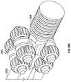
- FIG. 1shows an embodiment of a spinal adjustment implant.
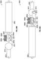
- FIG. 2is a side view of the spinal adjustment implant of FIG. 1 .
- FIG. 3 Ais a cross-sectional view of the spinal adjustment implant of FIG. 2 , taken along line 3 - 3 .
- FIGS. 3 B and 3 Care enlarged views of the spinal adjustment implant of FIG. 3 A taken from circles 3 B and 3 C, respectively.
- FIG. 4is an embodiment of an external remote controller for use with an implantable device.
- FIG. 5shows the internal components of a handpiece of the external remote controller of FIG. 4 .
- FIG. 6 A- 6 Dshow embodiments of spinal adjustment implants, some being coupled to lumbar vertebrae.
- FIG. 7is a radiographic image of a spinal fusion segment.
- FIG. 8shows another embodiment of a spinal adjustment implant.
- FIG. 9shows an embodiment of a spinal adjustment implant having a pivotable interface.
- FIG. 10shows another embodiment of a spinal adjustment implant.
- FIG. 11is a side view of the spinal adjustment implant of FIG. 10 .
- FIG. 12is a cross-sectional view of the spinal adjustment implant of FIG. 11 , taken along line 12 - 12 .
- FIGS. 13 - 16schematically illustrate various embodiments of a driving element of a non-invasively adjustable spinal implant.
- FIG. 17shows another embodiment of a spinal adjustment implant.
- FIG. 18 - 19are sectional views of the implant of FIG. 17 , taken along line 18 - 18 .
- FIG. 20illustrates two devices of the embodiment shown in FIG. 19 secured to the spinal column in series and having a shared base between them.
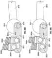
- FIGS. 21 A- 21 Dillustrate an embodiment of a spinal adjustment implant including a worm gear and a linkage system that are configured to adjust the lordotic angle of a vertebra system.
- FIG. 22 Aillustrates the spinal adjustment implant of FIGS. 21 A- 21 D secured to a plurality of vertebra of the spinal system.
- FIGS. 22 B- 22 Cillustrate the implanted spinal adjustment implant of FIG. 22 A before and after actuation of a drive member that adjusts the lordotic angle of the attached vertebra.
- FIGS. 22 D- 22 Eillustrate an enlarged view of the implanted spinal adjustment implant of FIG. 22 A before and after actuation of a drive member that adjusts the lordotic angle of the attached vertebra.
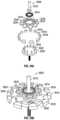
- FIG. 23 Aillustrates an embodiment of a spinal adjustment implant including one or more gear modules.
- FIG. 23 Bshows the internal components of the spinal adjustment implant of FIG. 23 A .
- FIG. 23 Cshows a gear module and other internal components of the spinal adjustment implant of FIGS. 23 A and 23 B .
- FIGS. 24 A-Dillustrate another embodiment of the spinal adjustment implant.
- FIG. 25 Aillustrates an embodiment of a spinal adjustment implant including a Torsen differential that is configured to adjust the lordotic angle of a vertebra system.
- the Torsen differentialallows a drive member to drive the two ends of the spinal adjustment implant at the same or different rate to provide for the same or different displacement rate or angulation rate of change.
- FIG. 25 Billustrates a top view of the spinal adjustment implant of FIG. 25 A where the internal gears and drive systems of the spinal adjustment implant are visible.
- FIG. 25 Cillustrates a perspective view of the spinal adjustment implant of FIG. 25 A with the housing removed.
- FIG. 25 Dillustrates an enlarged view of the Torsen differential of the spinal adjustment implant of the FIG. 25 A .
- FIG. 25 Eillustrates a cross-sectional view of the spinal system with the spinal adjustment implant of FIG. 25 A attached and indicating the angles of rotation of the spinal adjustment implant.
- FIGS. 26 A- 26 Hillustrate a motor or magnet is able to intermittently lock o unlock a mechanism, as it is adjusted.
- the unlockingmay temporarily allow for change in angulation, which is then locked again, after the change occurs.
- FIG. 27illustrates a hydraulic activated adjustment structure for use in an adjustable spinal implant.
- FIG. 28illustrates a magnetic fluid pump activated adjustment structure for use in an adjustable spinal implant.
- FIG. 29illustrates a composite fluid coil spring assembly with a skeleton structure.
- FIG. 30illustrates a composite fluid coil spring assembly with a compression spring.
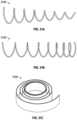
- FIGS. 31 A- 31 Cillustrate different types of springs that may be incorporated, for example into the embodiment of FIG. 30 , to vary the application of force as conditions are varied.
- FIG. 32illustrates an implant having a Nitinol spring.
- FIG. 33illustrates an implant having a magnetically operated rotational ratchet.
- FIGS. 34 A and 34 Bshow various embodiments of harmonic drives that may be used together with any of the embodiments described herein.
- FIG. 35 Ais an exploded view of a cycloidal drive that may be used together with any of the embodiments described herein.
- FIG. 35 Bis an assembled view of the embodiment illustrated in FIG. 35 B .
- FIG. 36shows an embodiment of a roller screw drive that may be used together with any of the embodiments described herein.
- FIG. 37shows a cut-away view of a spur gear that may be used together with any of the embodiments described herein.
- FIG. 38shows a cut-away view of a Torsen-type differential, or worm gear, that may be used together with any of the embodiments described herein.
- FIG. 39shows a differential screw that may be used together with any of the embodiments described herein.
- FIGS. 40 A- 40 Cillustrate various embodiments of clutches which may be used together with any of the embodiments described herein.
- FIG. 41shows a partial cut-away and partial cross-sectional view of a ball screw mechanism that may be used together with any of the embodiments described herein.
- FIGS. 42 - 44are flow charts, illustrating embodiments of systems of torque split, differential, and/or gear reduction.
- FIGS. 45 A- 45 Cshow various pivots for coupling rods to pedicle screws.
- FIGS. 46 A and 46 Bare detailed views of an embodiment of a pivot having a sprag clutch.
- FIG. 47shows another embodiment of a pivot coupled to pedicle screws and vertebrae.
- FIG. 48illustrates an embodiment of a torque-limiting brake is configured to lock and unlock a pivot.
- One or more embodiments of the present inventionprovide for implantable and adjustable devices that provide fixation and non-invasive adjustment of the sagittal curvature of the spine.
- Sagittal imbalancecan be a negative aftereffect of some spinal fusion surgeries. Patient satisfaction with surgery has been correlated with proper restoration of sagittal balance—patients having a sagittal imbalance have been known to express dissatisfaction with their surgery.
- Bone graft materiale.g., an interbody graft
- a portion of the spinee.g., one of more segments or vertebrae of the spine
- precipitating a physiologic response to initiate bone ingrowthe.g., causing osteogenesis into or from or through the bone graft material
- causing a solid bony fusionto form thereby stopping motion or fusing the portion of the spine being treated. If compression of the interbody graft is not maintained during/after fusion surgery, instability and/or non-union may result.
- sagittal balancemay be compromised, leading to potential muscle fatigue and pain, among other potential consequences. In some cases, the sagittal balance may be sufficiently compromised to merit/require revision surgery.
- Proximal junctional kyphosisinsufficient lumbar lordosis
- Some embodiments of the present inventionmay be used to non-invasively maintain or change the magnitude of compression between two vertebrae. For example, following a fusion surgery (post-operatively) and/or non-invasively changing the magnitude of lordosis. This may be done to maintain a desired degree of lordosis or to regain a desired degree of lordosis after it has been lost. It may also be done to achieve the desired degree of lordosis when post-surgical studies (e.g., medical imaging) demonstrate that the desired degree of lordosis was not achieved during surgery (e.g., fusion surgery).
- post-surgical studiese.g., medical imaging
- Some embodiments of the systems and devices disclosed hereincan be used to increase the success of fusion, reduce pseudo-arthrosis (e.g., non-union), and/or increase or preserve sagittal balance. “Fine tuning” the magnitude of compression and/or degree of lordosis may allow for reduced symptoms in portions of the spine, such as those adjacent to the fusion.
- FIGS. 1 - 3 Cillustrate a spinal adjustment implant 500 for implantation along or attachment/coupling to the spinal system of a subject (e.g., one or more vertebrae).
- the subjectmay be a patient having degenerative disc disease that necessitates fusion of some or all of the lumbar vertebrae through fusion surgery.
- the spinal adjustment implant 500can be used in place of traditional rods, which are used to maintain posterior decompression and stabilize during fusion surgery.
- Some embodiments of the spinal adjustment implant 500are compatible with interbody spacers placed between the vertebrae being treated.
- the spinal adjustment implant 500includes a housing 502 having a first end 504 and a second end 506 .
- the housing 502that has a cavity 508 generally defining an inner wall 510 and extending between the first end 504 of the housing 502 and the second end 506 of the housing 502 .
- the cavity 508may have a variable inner diameter along its length (e.g., the inner diameter of the cavity 508 changes along its length) or may have a generally constant inner diameter.
- Variable inner diameter cavities 508may include one or more ledges, steps, abutments, ramps, chamfered or sloped surfaces, and/or radiused or rounded surfaces, which may be used and/or helpful to hold inner components of the spinal adjustment implant 500 , as will be discussed in further detail, below.
- the inner wall 510 of the housing 502has circumferential grooves and/or abutments 512 that axially maintain certain elements of the assembly (e.g., internal elements).
- the abutments 512include one or more retaining rings or snap rings.
- a driving member 514may be disposed, placed, or located within the cavity 508 (e.g., rotatably disposed).
- the driving member 514includes a non-invasively rotatable element, such as described with respect to FIGS. 20 - 23 .
- the driving member 514may include a cylindrical, radially-poled permanent magnet 516 secured within a first magnet housing 518 and a second magnet housing 520 .
- the radially-poled permanent magnetmay be a cylindrical or partially cylindrical rare earth magnet and may have two poles, four poles, or more.
- the permanent magnetmay be constructed from rare earth magnet materials, such as Neodymium-Iron-Boron (Nd—Fe—B), which have exceptionally high coercive strengths.
- the individual magnetsmay be enclosed within a stainless steel casing or various layers of nickel, gold or copper plating to protect the magnet material from the environment inside the body (or vice versa).
- other magnetic materialsmay be used, including, but not necessarily limited to, SmCo5 (Samarium Cobalt) or AlNiCo (Aluminum Nickel Cobalt).
- Iron Platinum (Fe—Pt) magnetsmay be used. Iron platinum magnets achieve a high level of magnetism without the risk of corrosion, and may possibly preclude the need to encapsulate.
- the permanent magnetmay be replaced by magnetically responsive materials such as Vanadium Permendur (also known as Hiperco).
- the first and second magnet housings 518 , 520may, together, provide an internal cavity to hold the cylindrical, radially-poled, permanent magnet 516 .
- the internal cavity created by the housings 518 , 520is longer than the length of the cylindrical, radially-poled, permanent magnet 516 , thus leaving at least some longitudinal space 522 .
- the internal cavityis substantially the same side as the cylindrical, radially-poled, permanent magnet 516 .
- the first and second magnet housings 518 , 520may be welded or bonded to each other, as well as to the cylindrical, radially-poled, permanent magnet 516 .
- first and second housingthat are fixed to each other and/or the magnet may together serve to limit or eliminate compressive and/or tensile stresses on the cylindrical, radially-poled permanent magnet 516 .
- the first and second magnet housings 518 , 520may be made from robust materials (e.g., titanium alloys) in order to provide strength at a comparatively small wall thickness. Of course, as will be readily understood, any of a number of other materials may be used.
- the driving member 514e.g., drive system, actuator, motor, driver
- the abutments 512incorporate a cornered surface, such as, for example, ledges, steps, corners, etc.
- the abutments 512incorporate a flat or curved surface, including, for example, ramps, chamfered or sloped surfaces, and/or radiused or rounded surfaces.
- one or more of the radial bearings 524are replaced by thrust bearings and/or angular bushings.
- the bearingscomprise stainless steel.
- the bearingscomprise 400 series stainless steel.
- the bearingscomprise electro-polished 316 stainless steel, PEEK, or a combination of these. Forming the bearings out of PEEK and/or plating the bearings may increase efficiency by as much as about 50% or up to about 80% or more.
- the bearingsmay advantageously serve to minimize axial stresses on one or more portions of the drive train of the spinal adjustment implant 500 , including, but not limited to one or more of the radially-poled permanent magnet 516 , the housings 518 , 520 , the lead screw(s) (to be discussed in additional detail, below), the connection(s) between the magnet and the lead screw (i.e., the pin-based connection). Additionally, the bearings generally allow the system to minimize frictional resistance, thereby reducing the amount of torque required to operate the system, or increasing the possible resultant amount of torque/force that can be generated.
- a first threaded driver 528(e.g., a lead screw, a screw, a threaded rod, a rotating driver) is connected to the first magnet housing 518 and, therefore, also, the cylindrical, radially-poled permanent magnet 516 .
- the first threaded driver 528is connected to the first magnet housing 518 using a connection that allows some axial movement, play, or slop between the two (e.g., leaving the two not axially over-constrained).
- the first threaded driver, 528may have a hole 532 (e.g., aperture, port, opening) extending substantially horizontally through the first end 530 of the first threaded driver, 528 .
- the first magnet housing 518may have one or more holes 534 (e.g., aperture, port, opening) extending substantially horizontally therethrough, for example, through an annular projection 538 .
- the hole 532 in the first end 530may be configured so that it may align with the one or more holes 534 in the annular projection 538 .
- a holdersuch as a pin 536 or other fixer, can extend though the one or more holes 534 in the annular projection 538 and the hole 532 in the first end 530 of the first threaded driver, 528 , thus creating an interface 540 which rotationally couples the driving member 514 to the first threaded driver 528 .
- the annular projection 538 and the first end 530are otherwise rotationally coupled.
- a second threaded driver 542(e.g., a lead screw, a screw, a threaded rod, a rotating driver) is connected to the second magnet housing 520 and, therefore, also, the cylindrical, radially-poled permanent magnet 516 .
- the second threaded driver 542is connected to the second magnet housing 520 using a connection that allows some axial movement, play, or slop between the two (e.g., leaving the two not axially over-constrained).
- the second threaded driver 542may have a hole 546 (e.g., aperture, port, opening) extending substantially horizontally through the first end 544 of the second threaded driver 542 .
- the second magnet housing 520may have one or more holes 548 (e.g., aperture, port, opening) extending substantially horizontally therethrough, for example, through an annular projection 550 .
- the hole 546 in the second end 544may be configured so that it may align with the one or more holes 548 in the annular projection 550 .
- a holdersuch as a pin 552 or other fixer, can extend though the one or more holes 548 in the annular projection 550 and the hole 546 in the first end 544 of the second threaded driver 542 , thus creating an interface 554 which rotationally couples the driving member 514 to the second threaded driver 542 .
- the annular projection 550 and the first end 544are otherwise rotationally coupled.
- the driving member 514is directly, mechanically coupled to one or both of the first threaded driver 528 and the second threaded driver 542 , such as was described above with respect to the cup and pin structure of the pin and annular flange.
- the driving member 514is indirectly coupled to one or both of the first threaded driver 528 and the second threaded driver 542 , such as through a gearing system or another type of step down. Gearing systems may advantageously decrease the torque required to generate a given force.
- rotation of the driving member 514 in first rotational direction 556causes the rotation of both the first threaded driver 528 and the rotation of the second threaded driver 542 in the same direction, i.e., the first rotational direction 556 .
- rotation of the driving member 514 in second rotational direction 559causes the rotation of both the first threaded driver 528 and the rotation of the second threaded driver 542 in the same direction, i.e., the second rotational direction 559 .
- first and second threaded drivers 528 , 542are illustrated in this embodiment as being screws with male threads, in other embodiments, they may also be hollow rods having internal (female) threads along at least a portion of their length (e.g., all or less than all).
- first threaded driver 528 and the second threaded driver 542may have opposite thread handedness.
- the first threaded driver 528may have a right-handed male thread 560 .
- a first rod 558(e.g., extendible or retractable portion) has a first end 562 telescopically disposed within the cavity 508 of the housing 502 , and a second end 564 configured to be coupled to a portion a patient, such as, for example, a portion of the skeletal system.
- a portion a patientsuch as, for example, a portion of the skeletal system.
- the second end 564 of the first rod 558is configured to be coupled to a first portion of the skeletal system, such as, but not limited to a first portion of the spinal system (e.g., a first vertebra), via a first extension member 566 .
- the first portion of the spinal systemmay be a first vertebra.
- the second end 564 of the first rod 558may be coupled to a first vertebra directly, via one or more of: a pedicle screw; hook; wire; or other attachment system(s).
- the first extension member 566may comprise a rod portion 568 and a base portion 570 .
- the base portion 570may be secured to the second end 564 of the first rod 558 using a set screw 572 (e.g., by tightening the set screw 572 ) or other fastener/fastening device.
- a flat portion 573may be located on a portion of the first rod 558 , in order to provide a surface for interfacing with an end of the set screw 572 , for example, to improve resistance to loosening of the set screw 572 with respect to the first rod 558 .
- the rod portion 568 of the first extension member 566may be coupled to a first vertebra directly, via one or more of: a pedicle screw; hook; wire; or other attachment system(s). As may be seen in FIG. 6 A , the first extension member 566 a may extend generally transversely with respect to the housing 502 a and/or first rod 558 a.
- the first end 562 of the first rod 558may include a cavity 574 having a first threaded portion 576 incorporating a right-handed female thread 580 configured to mate with the right-handed male thread 560 of the first threaded driver 528 .
- the cavity 574comprises a nut 578 bonded or otherwise secured therein.
- the right-handed male thread 560 of the first threaded driver 528 and the right-handed female thread 580 of the first rod 558threadingly engage each other such that rotation of the driving member 514 in the first rotational direction 556 causes the first threaded driver 528 to turn in the same first rotational direction 556 , thereby causing the first rod 558 to move into the cavity 508 of the housing 502 along a first longitudinal axis 582 ( FIG. 1 ), in a first longitudinal direction 584 .
- the second threaded driver 542may comprise a left-handed male thread 586 .
- a second rod 588(e.g., extendible or retractable portion) has a first end 590 telescopically disposed within the cavity 508 of the housing 502 , and a second end 592 configured to be coupled a portion a patient, such as, for example, a portion of the skeletal system.
- the second end 592 of the second rod 588is configured to be coupled to a second portion of the spinal system via a second extension member 594 .
- the second portion of the spinal systemmay be a second vertebra.
- the second end 592 of the second rod 588may be coupled to a second vertebra directly, via one or more of: a pedicle screw; hook; wire; or other attachment system.
- the second extension member 594may comprise a rod portion 596 and a base portion 598 .
- the base portion 598may be secured to the second end 592 of the second rod 588 using a set screw 599 (e.g., by tightening the set screw 599 ).
- the rod portion 596 of the second extension member 594may be coupled to a second vertebra directly, via one of more of: a pedicle screw; hook; wire; or other attachment system. As may be seen in FIG.
- the second extension member 594 amay extend in a generally transversely with respect to the housing 502 a and/or second rod 588 a .
- the first end 590 of the second rod 588may include a cavity 597 having a first threaded portion 595 incorporating a left-handed female thread 593 .
- the cavity 597comprises a nut 591 bonded or otherwise secured therein.
- the driving member 514 in combination with the first threaded driver 528 and the second threaded driver 542may therefore comprise a turnbuckle, such that their rotation in the first rotational direction 556 causes both the first rod 558 and second rod 588 to move into the cavity 508 of the housing 502 , thus causing the longitudinal distance L between points A and B to decrease.
- This motionis capable of generating a force on the spine at the points of attachment and increasing the compressive force(s) between vertebrae.
- This motionis capable of generating a force on the spine at the points of attachment and decreasing the compressive force(s) between vertebrae.
- first threaded driver 528 and the second threaded driver 542may have the same thread handedness. Both the first threaded driver 528 and the second threaded driver 542 may have a right-handed male thread. Alternatively, both the first threaded driver 528 and the second threaded driver 542 may have a left-handed male thread.
- first threaded driver 528 and the second threaded driver 542have opposite thread handedness
- rotation of the two in the same direction(such as by rotation of the cylindrical, radially-poled, permanent magnet) will cause the first threaded driver 528 and the second threaded driver 542 to move in opposite directions—depending on the right or left thread handedness, rotation in a first direction will cause both threaded drivers to retract into the housing while rotation in the second, opposite direction will cause both threaded drivers to distract from or extend out of the housing.
- both the first threaded driver 528 and the second threaded driver 542have an identical thread handedness (i.e., both right or both left) rotation of the cylindrical, radially-poled, permanent magnet will cause the first and second threaded drivers to move in opposite directions with respect to the housing—depending on the right or left thread handedness, rotation in a first direction will cause the first threaded driver 528 to retract into the housing while causing the second threaded driver 542 to distract from or extend out of the housing (assuming the other or the right or left thread handedness, rotation in the opposite, second direction will cause the first threaded driver 528 to distract from or extend out of the housing while causing the second threaded driver 542 to retract into the housing).
- a third extension member 581 having a rod portion 579 and a base portion 577may be reversibly or fixedly coupled to the housing 502 .
- the base portion 577may be secured to the housing 502 by tightening a set screw 575 .
- the driving member 514 in combination with the first threaded driver 528 and the second threaded driver 542may therefore selectively generate a force between two vertebrae (e.g., the vertebrae to which the first extension member 566 and the third extension member 581 are attached) while decreasing the force between the two adjacent vertebrae (e.g., the vertebrae to which the third extension member 581 and the second extension member 594 are attached).
- a systemcan move a top (or bottom) vertebra closer to a middle vertebra, while moving a bottom (or top) vertebra away from the middle vertebra.
- this system(as well as any of the other systems disclosed herein) may generate force without causing motion. Though, it is likely that at least some motion will accompany the generation of force, whether it be a distraction force or a compressive force.
- seals 585for example, dynamic seals, (shown in FIGS. 3 B- 3 C ) may be disposed between each of the first and second rods 558 , 588 and the housing 502 .
- the dynamic seals 585may comprises o-rings, and may be contained within a circumferential groove on either the exterior of the rods 558 , 588 or the interior of the housing 502 .
- many other sealing systemsare contemplated, such as but not limited to expandable hydrogel-based systems, bellows or flexible sheaths covering the overlap of the housing and the rod(s), etc.
- one or more of the housing and the rodshas an anti-rotation member or a key to prevent rotation of the housing with respect to the rods (and therefore the third extension member 581 with respect to one or both of the first and second extension members 566 , 594 ).
- the housing 502has a protrusion (not shown) configured to engage longitudinal grooves 583 on the rods 558 , 588 . The protrusion maintains rotational alignment of each of the rods 558 , 588 with respect to the housing 502 and allows the rods 558 , 588 to move (e.g., extend and extend, retract and retract, extend and retract, or retract and extend) longitudinally with respect to each other while preventing significant rotation with respect to one another.
- the anti-rotation member or elementprevents substantially all rotational movement of the housing with respect to the rods (or vice versa). In other embodiments, the anti-rotation member or element prevents all rotational movement of the housing with respect to the rods (or vice versa). In still other embodiments, the anti-rotation member or element prevents less than about 10 degrees, less than about 8 degrees, less than about 6 degrees less than about 4 degrees, or less than about 2 degrees of rotational motion of the housing with respect to the rods (or vice versa).
- instrumented portions of the spinecan be held static to one another, and substantial movement may only occur when the spinal adjustment implant 500 is adjusted.
- substantial fixation of the rotational alignment between each of the rods 558 , 588 and the housing 502is achieved by a member attached at the end of the housing. In other embodiments, substantial fixation of the rotational alignment between each of the rods 558 , 588 and the housing 502 is achieved by the rods having non-circular cross-sections (e.g., ovoid, hexagonal, square, a geometric shape, etc.) which are “keyed” to a similarly non-circular cavity (e.g., a mating cavity) within the housing.
- non-circular cross-sectionse.g., ovoid, hexagonal, square, a geometric shape, etc.
- the second ends 564 , 592 of the first and second rods 558 , 588 and the rod portions 568 , 596 of the first and second extension members 566 , 594may be sized similar to standard spinal rods. In this way, the second ends 564 , 592 of the first and second rods 558 , 588 and the rod portions 568 , 596 of the first and second extension members 566 , 594 may be fixed to the skeletal system or coupled to fixation devices using standard, off-the-shelf orthopedic hardware, such as pedicle screws or otherwise.
- the second ends 564 , 592 of the first and second rods 558 , 588 and the rod portions 568 , 596 of the first and second extension members 566 , 594have transverse dimensions, or diameters, in the range of about 3-7 mm, in the range of about 3.5-6.35 mm, greater than about 3.5 mm, greater than about 4.5 mm, or greater than about 5.5 mm.
- the housing 502may be coupled to a third portion of the spinal system, for example, a third vertebra via a third extension member 581 having a rod portion 579 and a base portion 577 .
- the base portion 577may be secured to the housing 502 by tightening a set screw 575 .
- any one or more of the first, second, and third extension membermay be permanently fixed to the housing and/or the rods (for example, by welding, monolithic formation, or otherwise).
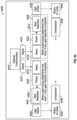
- FIG. 4illustrates an example of an External Remote Controller (ERC) 180 which may be used to non-invasively control the spinal adjustment implant 500 by means of a magnetic coupling of torque.
- ERC 180comprises a magnetic handpiece 178 , a control box 176 (containing a processor) which may be integrated with the handpiece 178 and a power supply 174 such as a battery or external plug for connection to a standard power outlet.
- the control box 176includes a control panel 182 having one or more controls (buttons, switches or tactile, motion, audio or light sensors) and a display 184 .
- the display 184may be visual, auditory, tactile, the like, or some combination of the aforementioned features, or any other display/UI described in this disclosure.
- the control box 176may further contain a transceiver for communication with a transceiver in the implant and/or other external devices.
- FIG. 5illustrates an internal assembly 478 of the magnetic handpiece 178 configured for applying a moving magnetic field to allow for non-invasive adjustment of the spinal adjustment implant 500 by turning the cylindrical, radially-poled permanent magnet 516 within the spinal adjustment implant 500 .
- the cylindrical, radially-poled permanent magnet 516 of the spinal adjustment implant 500includes a north pole 406 and a south pole 408 .
- a motor 480 with a gear box 482outputs to a motor gear 484 .
- the motor gear 484engages and turns a central (idler) gear 486 , which has the appropriate number of teeth to turn first and second magnet gears 488 , 490 at identical rotational speeds.
- First and second magnets 492 , 494turn in unison with the first and second magnet gears 488 , 490 , respectively.
- Each magnet 492 , 494is held within a respective magnet cup 496 (shown partially).
- An exemplary rotational speedis 60 RPM or less. This speed range may be desired in order to limit the amount of current density included in the body tissue and fluids, to meet international guidelines or standards.
- the south pole 498 of the first magnet 492is oriented the same as the north pole 404 of the second magnet 494 , and likewise, the first magnet 492 has its north pole 400 oriented the same and the south pole 402 of the second magnet 494 .
- magnets 492 , 494apply a complementary and additive moving magnetic field to the cylindrical, radially-poled permanent magnet 516 .
- Magnets having multiple north poles (e.g., two or more) and multiple south poles (e.g., two or more)are also contemplated in each of the devices.
- a single magnete.g., a magnet with a larger diameter
- the magnetic couplingcauses the cylindrical, radially-poled permanent magnet 516 to turn in a second, opposite rotational direction 412 (i.e., clockwise).
- the rotational direction of the motor 480is controlled by buttons 414 , 416 .
- One or more circuit boards 418contain control circuitry for both sensing rotation of the magnets 492 , 494 and controlling the rotation of the magnets 492 , 494 .
- one or more electromagnetsmay be used in place of or in conjunction with the magnets 492 , 494 .
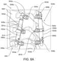
- FIG. 6 ATwo spinal adjustment implants 500 a , 500 b coupled bilaterally to three lumbar vertebrae are shown in FIG. 6 A .
- the first spinal adjustment implant 500 a and second spinal adjustment implant 500 bmay be secured to the spinal system 600 as is described below.
- the first rod 558 a of the first spinal adjustment implant 500 ais secured to the L5 lumbar vertebra 602 by a pedicle screw 604 a
- the first rod 558 b of the second spinal adjustment implant 500 bis secured to the L5 lumbar vertebra 602 by a pedicle screw 604 b .
- the second rod 588 a of the first spinal adjustment implant 500 ais secured to the L3 lumbar vertebra 608 by a pedicle screw 604 c
- the second rod 588 b of the second spinal adjustment implant 500 bis secured to the L3 lumbar vertebra 608 by a pedicle screw 604 d
- the first rods 558 a , 558 b and second rods 588 a , 588 bmay be coupled to the pedicle screws 604 a , 604 b , 604 c , 604 d via first and second extension members 566 a , 566 b , 594 a , 594 b .
- the housings 502 a , 502 bmay be secured by pedicle screws 606 a , 606 b , via third extension members 581 a , 581 b , to the L4 lumbar vertebra 610 .
- Such securement of the housings 502 a , 502 to an intermediary vertebra (L4, 610 ) between the two vertebrae to be adjusted (L5 and 13, 602 , 608 )helps assure that the implants 500 a , 500 b maintain set locations on the spinal system 600 and can serve as reference points to the adjustment of the first rods 558 a , 558 b and second rods 588 a , 588 b .
- Adjusting the spinal adjustment implants 500 a , 500 b by rotating driving member 514 in the first direction 556 ( FIG. 3 A )increases compression on and between the L5 lumbar vertebra 602 and L3 lumbar vertebra 608 .
- Increasing compression on implants such as those shown in FIG. 6may advantageously increase lordosis in the sagittal plane.
- the spinal adjustment implants 500 a , 500 bmay be secured to the dorsal (posterior) side of the vertebrae 602 , 608 , 610 .
- the dorsal sides of the vertebrae 602 , 608 , 610may be brought closer together than the anterior (ventral) sides of the vertebrae 602 , 608 , 610 (opposite the side of pedicle screw insertion). That differential displacement increases the angle of lordosis.
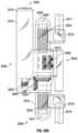
- FIG. 6 Billustrates an embodiment of an adjustment implant.
- the implantincludes a housing 650 .
- the housingis formed monolithically.
- the housingis formed from two halves joined at a joint (e.g., a threaded or welded joint) 651 .
- a jointe.g., a threaded or welded joint
- Using a housing formed from two halvesmay advantageously ease the manufacturing and assembly process, particularly for parts, such as the thrust bearings, which are held by features of the inner wall of the housing (such as abutments).
- the implantalso includes a first rod 660 and a second rod 661 .
- the first rod 660has a proximal end that is at least partially contained within the housing and has a first rod hollow or cavity 662 .
- the proximal portion of the first rod 660 contained within the housingmay have a slot, groove, or other linear feature 666 on at least part of its surface. As will be explained below, the slot 666 may serve as a portion of an anti-rotation system.
- the first rod 660also has a distal end that extends away from the housing and is used to attach the device to the skeletal system of a patient/subject. In some embodiments, the rod 660 is straight prior to implantation. In other embodiments, the rod 660 is curved prior to implantation.
- the rod 660is bendable prior to or during surgery, for example, by an implanting surgeon, so that the rod may best conform to the individual patient into which it is being implanted.
- the rodmay be fixed directly to the patient's skeletal system, for example, using standard pedicle screws.
- the rod 660may be attached to the patient's skeletal system using a keyhole extender system that holds the rod 660 some distance away from the skeletal system.
- the keyhole extender systemmay include a ring 664 off of which a shaft or bar extends. The ring 664 may be slid up and down the rod 660 , thereby improving adjustability. Once the desired position of the ring 664 is identified, it may be reversibly fixed to the rod 660 using a set screw 670 .
- the proximal end of the first rod 660has an outer diameter that is just smaller than an inner diameter of the housing 650 . In that way, a seal may be formed by using conventional methods, such as o-rings.
- FIG. 6 Bshows an annular groove containing an o-ring on an outer surface of the proximal end of the first rod 660 . However, it should be understood that a groove for containing an o-ring may be included on the inner surface of the housing.
- the housing 650may be hollow across its entire length. However, while the housing 650 may be hollow, the inner diameter may change across its length.
- the housing 650may include one or more corners, steps or abutments to hold one or more internal features of the device, such as portion(s) of the drive train, for example one or more bearing (e.g., thrust bearings and/or radial bearings). As shown in FIG.
- the housing 650includes a step or abutment that holds a radial bearing, which, in turn, holds axially a spindle of the rotating magnet 652 (e.g., a spindle of a housing holding the magnet 652 , or a spindle that extends through and is axially fixed with respect to the magnet 652 ).
- the housing 650is also shown as having a set screw, key, or protrusion 646 that mates with the slot to prevent rotation of the rod 660 with respect to the housing 650 .
- the rod 660may have a plurality of slots 666 while the housing has a single protrusion 646 .
- the rotational orientation of the rod 660 with respect to the housing 650may be changed by merely withdrawing the protrusion 646 , rotating the rod 660 until the rod 660 is at the slot 666 closest to the desired rotational orientation, and reinserting the protrusion 646 .
- the housing 650holds the rotating magnet 652 .
- the rotating magnet 652is coupled to the drive shaft 642 in a one to one manner, such that one rotation of the rotating magnet 652 causes one rotation of the drive shaft 642 .
- any number of gearing systemssuch as or similar to those described elsewhere herein, may be interposed between the rotating magnet 652 and the drive shaft 642 . In that way, more turns of the rotating magnet 652 may be required to effectuate a full turn of the drive shaft 642 , thereby increasing the torque of the drive shaft 642 by comparison to the rotating magnet 652 .
- the device shown in FIG. 6 Bis substantially bilaterally symmetrical from proximal to distal end. Therefore, the opposite elements, such as the second rod 661 and the second drive shaft 643 , may be the same as has already been discussed.
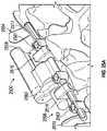
- FIG. 6 Cillustrates two spinal adjustment implants 620 and 621 , similar to the two spinal adjustment implants 500 a , 500 b coupled bilaterally to three lumbar vertebrae shown in FIG. 6 .
- the two spinal adjustment implants 620 and 621share many of the same features as is described with respect to other embodiments disclosed herein. However, rather than being attached to the three lumbar vertebrae using standard pedicle screws, as is shown in FIG. 6 A , the two spinal adjustment implants 620 and 621 are coupled to the three lumbar vertebrae using a different type of specialized screw having a different head 622 . As can be seen, the heads of the specialized screws 622 are facing to the rear (the same as the pedicle screws shown in FIG. 6 A ) of the spine.
- any type of screw and head fixturemay be used so long as it adequately anchors the extension rods (and therefore the spinal adjustment implants) with respect to the spine.
- caremay need to be taken not to allow excess rod length to impinge on nervous or other critical tissues.
- the excess length of the extension rods, on the side of the pedicle screw opposite the spinal implantmay be trimmed so that the extension rod terminates in a surface substantially flush with the outer surface of the pedicle screw housing.
- FIGS. 6 A and 6 Cillustrate two spinal adjustment implants bilaterally implanted next to the spine and attached to the spine using three extension members, each, which are, in turn, fixed to three adjacent vertebrae using pedicle screws and housings.
- the three extension membersextend transversely or laterally, and the pedicle screw housings face to the rear of the patient.
- the pedicle screws in FIGS. 6 A and 6 Care inserted into their respective vertebrae substantially in a posterior-anterior direction.
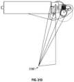
- FIG. 6 Dillustrates the right-lateral spinal adjustment implant from a more frontal viewpoint. While FIGS.
- 6 A, 6 C, and 6 Dillustrate the spinal adjustment devices predominantly to the lateral sides of the lumbar spine, it should be understood that the spinal adjustment devices may be placed closer or further away from the spinal midline laterally, or closer or further away from the spinal midline anterior-posteriorly. This may be accomplished through selective placement, including angling, of the pedicle screw as well as inserting the extension member into one side or the other of the pedicle screw housing.
- Flexion of the first and/or second rods 558 a , 558 b , 588 a , 588 bmay increase the amount of angle increase that can occur during compressive adjustment.
- smaller diameter rodsare used to increase the possible flexion.
- rods having a diameter of less than about 6.5 mm, less than about 5.5 mm less than about 4.5 mm, less than about 3.5 or less than about 2.5 mmare used.
- rodscomprise PEEK (polyether ether ketone) to increase flexion.
- flexible rodscomprise a laser-cut structure and/or a Nitinol structure. In FIG.
- the lordotic Cobb angle (angle of Lordosis) a between the L3 608 and L5 602 lumbar vertebraeis shown in a radiographic image of an L3-L5 fusion having first and second interbody spacers 612 , 614 placed between the vertebral bodies of the L3, L4, and L5 lumbar vertebrae 608 , 610 , 602 .
- Some flexion of the rods 616 , 618is shown. It will be understood that because the image is taken laterally, rods 616 and 618 are overlaid and thus appear to be only one rod. But, two rods are actually present.
- the lordotic Cobb anglemay be increased (or decreased) by about 0.5-15°, about 1-13°, about 1.5-11°, about 2-9°, about 2.5-7°, or about 3-5° per level through use of the spinal adjustment implants such as those described above (e.g., 500 a , 500 b ) either unilaterally or bilaterally placed in the L3-L5 segments, for a total L3 to L5 angle increase of about 1-30°.
- the spinal adjustment implantssuch as those described above (e.g., 500 a , 500 b ) either unilaterally or bilaterally placed in the L3-L5 segments, for a total L3 to L5 angle increase of about 1-30°.
- one or more gear modulesare placed between the driving member 514 and one or both of the first and second threaded drivers 528 , 542 , in order to increase the amount of compressive force that may be applied during adjustment.
- the gear modulescomprise planetary gearing, including possibly one or more of sun gears, ring gears and planet gears.
- At least one planetary gear stage(e.g., two, three, four, five, six, or even more planetary gear stages) is included between (operatively coupled to both of and/or between) the permanent magnet and the drive shaft (e.g., drive member, lead screw).
- Each planetary gear stagecan comprise a sun gear and a plurality of planetary gears (e.g., three, four, five, six, or even more planetary gears), which are rotatably held within a frame, e.g., by pins.
- the sun gearis either a part of the magnet housing (e.g., the sun gear may be directly connected to the magnet/magnet housing), or a part of the gear frame.
- the rotation of the sun gearcauses the planetary gears to rotate and track along inner teeth of a ring gear insert (e.g., a ring gear insert).
- a gear reduction ratioe.g., of 3:1, 4:1, 5:1, 6:1, 7:1, 8:1, or even more
- the total reduction ratiois merely the individual reduction radios multiplied. Therefore, a planetary gear system having 4 stages, each with a ratio of 3:1 would have a total reduction ratio of (3 ⁇ 3 ⁇ 3 ⁇ 3):(1 ⁇ 1 ⁇ 1 ⁇ 1), or 81:1. It should be understood that other gear reductions, and numbers of stages may be used.
- a slip clutchis placed between the driving member 514 and one or both of the first and second threaded drivers 528 , 542 , in order to set a maximum compressive force that can be applied between the two drivers.
- a differentialis placed between the driving member 514 and the first and second threaded drivers 528 , 542 to allow one of the first and second rods 558 , 588 to continue adjusting after the other rod is no longer able to adjust due to having reached a threshold resistive force.
- the differentialincorporates differential gears.
- the differential gearsmay include, for example, bevel gears, spur gears, worm gears, and/or a Torsen-type differential—such differential gears will be discussed in more detail, below.
- one or more thrust bearingsis incorporated in order to protect one or more of the driving member 514 , slip clutch(s), gear module(s), and/or differential from excessive stresses.
- Such thrust bearingsmay be held substantially fixed with respect to and by the walls of the housing 502 , for example, by ledges, abutments, rings, or other structures incorporated into or extending from the housing 502 (e.g., an inner wall of the housing).
- FIG. 8illustrates a spinal adjustment implant 500 a implanted in an L3-L5 fusion having first and second interbody spacers 612 , 614 placed between the L3 and L4, and L4 and L5 lumbar vertebrae 608 , 610 , 602 , respectively. All of the connections between the rods, extension members and pedicle screws are shown in FIG. 8 as being fixed.
- Non-invasive actuation and rotation of the driving member 514(depending on the thread handedness, in the first rotational direction 556 or the second rotational direction 559 ( FIG. 3 A )) increases compression, e.g., along line C.
- the compressive forcescan decrease dorsal distance Dd more than anterior distance Da thereby advantageously increasing the lordotic Cobb angle.
- FIG. 9illustrates an embodiment of a spinal adjustment implant 700 .
- the spinal adjustment implant 700is similar to the implant 500 of FIGS. 1 - 3 C and 500 a of FIG. 8 , but additionally includes a first pivotable interface 729 between the first rod 758 and pedicle screw 725 and a second pivotable interface 727 between the second rod 788 and pedicle screw 723 . Examples of such pivotable interfaces will be discussed in additional detail below, for example with respect to FIGS. 45 A- 48 .
- Such pivotable interfacesallow the pedicle screws and the vertebrae to which they are attached to change angle more easily; consequently, to decrease Dorsal distance Dd more than Anterior distance Da the spinal adjustment implant need not rely on only potential or minor flexion in the extension rods and/or pedicle screws.
- the first and second pivotable interfaces 729 , 727may allow a potentially greater increase in the lordotic Cobb angle during compression than that permitted by the spinal adjustment implant 500 a of FIG. 8 (which lacks pivotable interfaces 729 , 727 ).
- the L5 lumbar vertebra 602is able to rotate according to or along arc R1 with respect to an axis of rotation 719 of the first pivotable interface 729 .
- the L3 lumbar vertebra 608is able to rotate according to or along arc R2 with respect to an axis of rotation 721 of the second pivotable interface 727 .
- the first and second pivotable interfaces 729 , 727are lockable and unlockable to allow free rotation about the axes of rotation 721 , 719 during adjustment and to inhibit rotation about the axes of rotation 721 , 719 after adjustment is complete.
- the first and second pivotable interfaces 729 , 727are non-invasively lockable and unlockable (such as by using a magnetic field to lock and unlock or by using an electromagnetic signal, such as RF, Bluetooth, etc.). In some embodiments the first and second pivotable interfaces 729 , 727 are configured to be non-invasively lockable and unlockable as part of the non-invasive adjustment. In some embodiments the first and second pivotable interfaces 729 , 727 are configured to be non-invasively lockable and unlockable in conjunction with the rotation of the driving member 514 . In some embodiments, the pivotable interfaces 729 , 727 are configured to be intermittently locked and unlocked during an adjustment procedure.
- one or more of the pivotable interfacesis configured to rotate freely in either direction (e.g., clockwise and/or counterclockwise). In some embodiments, one or more of the pivotable interfaces is partially constrained to have free rotation in one direction but no rotation in the other direction—this may be accomplished using a free wheel or other one-way clutching. Examples of devices that may be used to allow unidirectional rotational movement are provided below—in some embodiments, a clutch system, ratchet system, or other motion inhibiting device may be used. In some embodiments, the pivotable interfaces include two-way locking so that they may lock and unlock automatically by the operation of the spinal adjustment implant.
- the External Remote Controllermay be used to lock and unlock a magnetic lock which is capable of reversibly removing the rotational freedom of the pivotable interface(s).
- An example of one such deviceis shown in FIG. 48 .
- theremay additionally by constrained rotation or motion, wherein there are limits, extents, or detents that limit the total amount of travel of a particular rotation or motion.
- structural motion limitersmay be set prior to implantation. For example, the implanting surgeon might evaluate the patient's spine and determine that a maximum correction of 10 degrees per pivotable interface (for a total correction of 20 degrees) is all that is needed and/or permissible.
- each physical motion limitermay be set to “10 degrees” (for example, the pivotable interface may have markings or holes identifying the maximum angle of rotation to which the surgeon may move the physical motion limiter). While 10 degrees was used as an example, it should be understood, that any degree may be use—however, physically, the range of correction will generally be less than about 30, less than about 25, less than about 20, less than about 15, less than about 10, or even less than about 5 degrees per pivotable interface.
- FIGS. 10 - 12illustrate a spinal adjustment implant 800 for implantation along the spine of a subject.
- the spinal adjustment implant 800comprises a housing 802 having a first end 804 and a second end 806 .
- the housing 802includes a cavity 808 , which extends between the first end 804 of the housing 802 and the second end 806 of the housing 802 .
- the cavity 808may have a variable inner diameter along its length or may have a generally constant inner diameter.
- the inner wall 810 of the housing 802may have circumferential grooves or abutments 812 , in order to axially maintain certain elements of the assembly.
- a driving member 814is rotatably disposed within the cavity 808 .
- the driving member 814may comprise any non-invasively rotatable element, such as those described with respect to FIGS. 13 - 16 .
- the embodiment of the driving member 814 illustrated in FIG. 12comprises a cylindrical, radially-poled permanent magnet 816 secured within a first magnet housing 818 and a second magnet housing 820 .
- the driving member 814is positioned longitudinally between two abutments 812 by two radial bearings 824 , which facilitate free rotation of the driving member 814 about a driving member axis 826 .
- a first threaded driver 828has a first end 830 having a shaft 832
- the first magnet housing 818has a cylindrical cavity 838 .
- a first clutch 836engages the inside of the cylindrical cavity 838
- inner cavity of the first clutch 836engages the shaft 832 of the first threaded driver 828 .
- the first clutch 836is configured to couple rotational motion between the first magnet housing 818 and the first threaded driver 828 in a first rotational direction 856 when the first magnet housing 818 is turned by the radially-poled permanent magnet 816 in a first rotational direction 856 . But, the first clutch 836 is configured to cause slippage between the first magnet housing 818 and the first threaded driver 828 when the first magnet housing 818 is turned by the radially-poled permanent magnet 816 in a second rotational direction 859 (e.g., opposite the first rotational direction 856 ).
- a second clutch 842engages the inside of the cylindrical cavity 844 of the second magnet housing 820 , and inner cavity of the second clutch 842 engages the shaft 846 of the second threaded driver 850 .
- the second clutch 842is configured to couple rotational motion between the second magnet housing 820 and the second threaded driver 850 in the second rotational direction 859 when the second magnet housing 820 is turned by the radially-poled permanent magnet 816 in the second rotational direction 859 .
- the second clutch 842is configured to cause slippage between the second magnet housing 820 and the second threaded driver 850 when the second magnet housing 820 is turned by the radially-poled permanent magnet 816 in the first rotational direction 856 .
- one-way clutchesmay allow the driving member 814 to be capable of independently driving either the first threaded driver 828 or the second threaded driver 850 depending on which direction (e.g., first rotational direction 856 or second rotational direction 859 ) the driving member 814 is caused to turn.
- the first and second clutches 836 , 842comprises a number of different types of one-way clutching, including but not limited to a needle clutch, a free wheel, a sprag clutch, a spring clutch, a face gear, or a ratchet.
- the radial bearings or thrust bearingsare themselves be configured as one-way clutches (e.g., as a hybrid component). Indeed, any of a number of different clutch mechanisms may be used as the one-way clutches 836 , 842 . Additional examples are discussed in greater detail, below, with respect to at least FIGS. 40 A- 40 C .
- the first and second threaded drivers 828 , 850have second ends 858 , 860 having male threads 862 , 864 , which engage female threads 866 , 868 of first and second rods 870 , 872 .
- the spinal adjustment implant 800is configured for compression (i.e., the threads of both of the first and second threaded drivers 828 , 850 and the female threads 866 , 868 are right-handed).
- the spinal adjustment implant 800is configured for tension/distraction (i.e., the threads of both of the first and second threaded drivers 828 , 850 and the female threads 866 , 868 are left-handed).
- Extension members 874 , 876 , 878may be configured to couple to the first rod 870 , second rod 872 and housing 802 , respectively.
- the extension members 874 , 876 , 878may be coupled to pedicle screws (not shown). These extension members may be the same as the many other extension members discussed in detail above.
- embodiments of the systems for spinal adjustmentmay have one driving system (e.g., lead screws and permanent magnet, etc.), or more than one driving system.
- the systems for spinal adjustment discloses hereinmay be attached to two vertebrae, to three vertebrae, to four vertebrae, to five vertebrae, to six vertebrae or even more vertebrae, as needed.
- the devicemay be a single device, attached to the vertebrae at various points (e.g., the systems shown in FIGS. 1 - 3 and/or 10 - 12 )—of course, the device may have one or more than one complete drive system.
- the system for spinal adjustmentmay be modular, so that multiple (e.g., more than one), smaller devices may be connected to the desired vertebrae (e.g., the system shown in FIG. 20 )—these devices will generally, but not always, have their own, unique drive systems (e.g., one drive system per modular portion).
- the extension member's attachment rings(having the set screw) may be moved up and down the rods and or the housing, the vertebrae to which the extension members are attached may be adjacent, separated by one or more vertebrae, or a combination of the two.
- degenerative deformity patientsmay also be treated with spinal adjustment implants as disclosed herein.
- Embodiments of the spinal adjustment implants disclosed hereinmay be used for initial fusion surgery, or in revision surgeries.
- Embodiments of the spinal adjustment implants disclosed hereinmay be used to instrument only particular levels of the lumbar vertebrae or vertebrae of other sections of the spine.
- Embodiments of the spinal adjustment implants disclosed hereinmay be implanted using minimally invasive surgery (MIS) techniques, for example, using medial placement through a mid-line incision or by placement through small incisions using endoscopes or even operating microscopes.
- MISminimally invasive surgery
- FIGS. 13 - 16illustrate embodiments of alternate sources to the cylindrical, radially-poled permanent magnet 516 as the driving member 514 of a spinal adjustment implant 500 , 700 , 800 .
- FIG. 13illustrates a non-invasively adjustable system 1300 comprising an implant 1306 having a first implant portion 1302 and a second implant portion 1304 , the second implant portion 1304 non-invasively displaceable with relation to the first implant portion 1302 .
- the first implant portion 1302is secured to a first bone portion 197 and the second implant portion 1304 is secured to a second bone portion 199 within a patient 191 .
- a motor 1308is operable to cause the first implant portion 1302 and the second implant portion 1304 to displace relative to one another.
- An external remote controller (ERC) 1310has a control panel 1312 for input by an operator, a display 1314 and a transmitter 1316 .
- the transmitter 1316sends a control signal 1318 through the skin 195 of the patient 191 to an implanted receiver 1320 .
- Implanted receiver 1320communicates with the motor 1308 via a conductor 1322 .
- the motor 1308may be powered by an implantable battery, or may be powered or charged by inductive coupling.
- FIG. 14illustrates a non-invasively adjustable system 1400 comprising an implant 1406 having a first implant portion 1402 and a second implant portion 1404 , the second implant portion 1404 non-invasively displaceable with relation to the first implant portion 1402 .
- the first implant portion 1402is secured to a first bone portion 197 and the second implant portion 1404 is secured to a second bone portion 199 within a patient 191 .
- An ultrasonic motor 1408is operable to cause the first implant portion 1402 and the second implant portion 1404 to displace relative to one another.
- An external remote controller (ERC) 1410has a control panel 1412 for input by an operator, a display 1414 and an ultrasonic transducer 1416 , which is coupled to the skin 195 of the patient 191 .
- the ultrasonic transducer 1416produces ultrasonic waves 1418 which pass through the skin 195 of the patient 191 and operate the ultrasonic motor 1408 .
- FIG. 15illustrates a non-invasively adjustable system 1700 comprising an implant 1706 having a first implant portion 1702 and a second implant portion 1704 , the second implant portion 1704 non-invasively displaceable with relation to the first implant portion 1702 .
- the first implant portion 1702is secured to a first bone portion 197 and the second implant portion 1704 is secured to a second bone portion 199 within a patient 191 .
- a shape memory actuator 1708is operable to cause the first implant portion 1702 and the second implant portion 1704 to displace relative to one another.
- An external remote controller (ERC) 1710has a control panel 1712 for input by an operator, a display 1714 and a transmitter 1716 .
- the transmitter 1716sends a control signal 1718 through the skin 195 of the patient 191 to an implanted receiver 1720 .
- Implanted receiver 1720communicates with the shape memory actuator 1708 via a conductor 1722 .
- the shape memory actuator 1708may be powered by an implantable battery, or may be powered or charged by inductive coupling.
- FIG. 16illustrates a non-invasively adjustable system 1800 comprising an implant 1806 having a first implant portion 1802 and a second implant portion 1804 , the second implant portion 1804 non-invasively displaceable with relation to the first implant portion 1802 .
- the first implant portion 1802is secured to a first bone portion 197 and the second implant portion 1804 is secured to a second bone portion 199 within a patient 191 .
- a hydraulic pump 1808is operable to cause the first implant portion 1802 and the second implant portion 1804 to displace relative to one another.
- An external remote controller (ERC) 1810has a control panel 1812 for input by an operator, a display 1814 and a transmitter 1816 .
- ERPexternal remote controller
- the transmitter 1816sends a control signal 1818 through the skin 195 of the patient 191 to an implanted receiver 1820 .
- Implanted receiver 1820communicates with the hydraulic pump 1808 via a conductor 1822 .
- the hydraulic pump 1808may be powered by an implantable battery, or may be powered or charged by inductive coupling.
- the hydraulic pump 1808may alternatively be replaced by a pneumatic pump.
- another driving element 242may include a magnetorestrictive element.
- a number of materialsmay be used to produce the components like the housing, first distraction rod, second distraction rod, first lead screw, and second lead screw, including but not limited to titanium, titanium alloys, titanium 6-4, cobalt-chromium alloys, and stainless steel.
- the threads on the lead screwin some embodiments may comprise Acme threads, square threads or buttress threads. A number of other possible driving systems are discussed in some detail below.
- FIGS. 17 - 18illustrate an implant system 1000 comprising a spinal adjustment implant 1002 , first pedicle screw 1004 and second pedicle screw 1006 .
- the spinal adjustment implant 1002includes a housing 1008 , which may comprise a first housing portion 1010 and a second housing portion 1012 , joined together at a joint 1014 (e.g., similar to the joint described with respect to FIG. 6 B ).
- the jointmay be a weld joint, adhesive joint, threaded joint, or other type of joint.
- the housing 1008may be constructed of a single, monolithic structure, as described in U.S. Pat. No. 9,179,938, which is incorporated by reference herein in its entirety.
- the housing 1008is coupled at a first end 1016 to a base 1018 having a rod 1020 .
- housing 1008is fixedly coupled to the base 1018 .
- the housing 1008is movably couple to the base 1018 , so as to, for example, allow pivoting movement or to allow further distraction/retraction capability (through the addition of another drive system, or the incorporation of another drive member into the currently present drive system). While certain features of the rod 1020 are described below, it should be understood that any modification of this general structure is contemplated by this disclosure.
- the rod 1020may extend in a generally parallel direction to the housing 1008 , and be offset from the housing by a distance D. Alternatively, the rod 1020 may extend directly along the longitudinal axis of the housing. The rod 1020 is shown as extending alongside the housing on the same side as the rod 1040 . In some embodiments, the rod 1020 and the rod 1040 are not aligned with each other.
- the rod 1020 and the rod 1040are offset by an angle in the range of about 1-180 degrees, about 5-160 degrees, about 10-140 degrees, about 15-120 degrees, about 20-100 degrees, about 25-80 degrees, and about 30-60 degrees or any other degree of offset that may be advantageous—it will be understood that such an offset may be advantageous for applications related to the spine, or applications related to other portions of the skeletal system.
- the rod 1020is configured for securement to the second pedicle screw 1006 , having a threaded shank 1022 a head 1024 and a tightening nut 1026 .
- a pedicle screwis described, one of ordinary skill in the art will readily understand that any of a number of systems may be used to fix the rod 1020 to the body of a patient, for example the skeletal system (e.g., a ring and extension member-based system, such as disclosed elsewhere herein).
- the skeletal systeme.g., a ring and extension member-based system, such as disclosed elsewhere herein.
- a rod 1028(which may share one or more characteristics with rod 1020 , just described) is configured to be telescopically moveably into and out of (e.g., moveable/translatable relative/with respect to) an interior 1030 of the housing 1008 at a second end 1036 thereof.
- the rod 1028may include one or more longitudinal grooves 1032 which may be engaged by an insert 1034 within the housing 1008 , thus allowing longitudinal displacement between the housing 1008 and the rod 1028 , but stopping any significant rotation between the housing 1008 and the rod 1028 (this anti-rotation member may function substantially the same as was described above with respect to other embodiments).
- the rod 1028may be coupled to a base 1038 having a rod 1040 , which may extend in a generally parallel direction to the housing 1008 and/or the rod 1028 .
- the base 1038may be coupled to the rod 1028 by welding, or by a screw 1029 .
- the base 1038is pivotably coupled to the rod 1028 so that some rotational movement is allowed between the two at the connection of the two (other types of pivotable/moveable joints are contemplated, such as those that allow unidirectional motion, and/or those that allow movement in more than a single plane (i.e., rotational movement only)).
- the rod 1028is movably couple to the base 1038 , so as to, for example, allow pivoting movement or to allow further distraction/retraction capability (through the addition of another drive system, or the incorporation of another drive member into the currently present drive system).
- the rod 1040may be configured for securement to the first pedicle screw 1004 , which may include similar components as the second pedicle screw 1006 .
- the first pedicle screw 1004is engaged into a first vertebra
- the second pedicle screwis engaged into a second vertebra. While a pedicle screw is described, one of ordinary skill in the art will readily understand that any of a number of systems may be used to fix the rod 1040 to the body of a patient, for example the skeletal system (e.g., a ring and extension member-based system, such as disclosed elsewhere herein).
- the first and second vertebramay be adjacent each other. In other cases, the first and second vertebra may have one ore move intervening vertebrae.
- the spinal adjustment implant 1002is configured to be non-invasively shortened or lengthened, in order to move a first and second vertebra with respect to each other.
- a magnet 1042(for example, a radially poled, cylindrical magnet) may held within a casing 1046 which is rotatably held within the housing 1008 by a radial bearing 1044 .
- a pin 1048 at one end of the casing 1046may be insertable within (e.g., held by) an inner bore 1050 of the radial bearing 1044 .
- One or more planetary gear modules 1052 , 1054may couple the magnet 1042 and casing 1046 to a lead screw (e.g., drive member, drive shaft, drive element, etc.) 1056 .
- a thrust bearing 1058may be secured within the housing 1008 to protect the planetary gear modules (or stages) 1052 , 1054 and the magnet 1042 from axial compressive (and/or tensile) stresses.
- the lead screw 1056may be coupled to the gear modules 1052 , 1054 or the magnet 1042 (of course, it will be understood that gearing increases the possible torque of the system and therefore the possible force that can be generated by the system).
- the lead screwis connected to the gear modules or the magnet using a coupler 1057 that allows some amount of axial play (as discussed above), such as by a pin 1060 .
- the rod 1028may have a hollow interior 1062 , which may contain threads.
- the hollow inter 1062itself is threaded.
- the hollow interior 1062may contain a nut 1064 having a female thread 1066 (e.g., the nut may be fixedly bonded to the inner surface of the hollow interior 1062 ).
- the pieces of the system 1000may be sealed in any of a number of ways to keep out bodily fluids and to keep in any fluids contained by the device (e.g., lubricants or other fluids). Any of the seals discussed elsewhere herein may be used here as well.
- an o-ring 1068may be held within a circumferentially extending groove 1070 in the rod 1028 to provide a dynamic seal against an inner surface 1072 of the housing 1008 (of course, the groove may be in the inner surface of the housing as opposed to the outer surface of the rod).
- a moving magnetic fieldfor example, applied non-invasively by the External Remote Controlled (ERC) 180 of FIGS. 4 - 5 , may be used in a patient (including but not limited to a conscious patient) to change the length of the spinal adjustment implant 1002 , thus changing the distance and/or angle between the first vertebrae and the second vertebrae,
- Implant system 1000has been described as having an axially asymmetric drive system. That is to say that, by contrast to the device shown in FIG. 6 B , the implant system 1000 has a drive shaft on only one side of the spinning magnet. This means that only one end of the implant system 1000 may extend or retract from within the housing. In some embodiments, that is sufficient. However, in other embodiments, the housing contains a bilaterally symmetrical drive system, including, for example, one magnet, two gear systems, and two drive shafts (as will be easily understood in view of the disclosure presented herein).
- FIG. 19illustrates a cross-sectional view of the system 1000 shown in FIG. 18 , but rotated approximately 90 degrees clockwise.
- FIG. 20illustrates two systems, such as the system 1000 of FIGS. 18 - 19 attached to the spinal column in a modular fashion at a joint (which may also be attached to the spinal column). The two devices are secured to the spinal column in series, with a shared base between them. The telescopic rods of each of the implants are secured to the shared base.
- FIGS. 21 A- 21 D and FIGS. 22 A- 22 Eillustrates an embodiment of the spinal adjustment implant 2100 for implantation along the spinal system of a subject.
- the spinal adjustment implant 2100is similar to the implant 700 of FIG. 9 as it provides pivotable interfaces that may allow a potentially greater increase in the lordotic Cobb angle during compression than that permitted by the spinal adjustment implant 500 a of FIG. 8 .
- the driving member of the spinal adjustment implant 2100can be rotated to generate a compression force that to allow a first attached vertebra to rotate with respect to a second attached vertebra.
- the spinal adjustment implant 2100comprises a driving member that is rotatably coupled to a plurality of gears.
- the plurality of gearsis coupled to a linkage system that can be coupled to a plurality of vertebra.
- the driving memberis rotated, the plurality of gears translates the rotational motion to cause the linkage system to pivot about center of rotation which can cause one of the attached vertebrae to rotate about the center of rotation.
- FIGS. 21 A- 22 Egenerally illustrate an embodiment which may use a motor or magnet or alternative non-invasively operable drive system to turn a worm (labeled as “worm gear” in provisional) which is engaged to a worm wheel, which moves a link in order to change the distance and/or angle between two rods (red and green) to which pedicle screws may be secured.
- FIG. 21 Aillustrates an embodiment of the spinal adjustment implant 2100 .
- the spinal adjustment implant 2100can further include a housing system (not pictured) that can be disposed about the surface of the spinal adjustment implant 2100 .
- the spinal adjustment implant 2100can include a driving member 2114 having a first end 2106 and a second end 2104 .
- the driving member 2114may comprise any non-invasively rotatable element, such as a magnet.
- the driving member 2114can be disposed about a first rod 2170 that extends from the first end 2106 and is rotationally coupled to a gear system 2120 .
- the gear system 2120can be a planetary or a harmonic drive. As the driving member 2114 is rotated, the rotation is translated to the gear system 2120 . In some embodiments the gear system 2120 can provide a high gear reduction ratio in a limited space. As the driving member 2114 is rotate, the rotation is causes the gear system 2120 to rotate.
- the gear system 2120can be coupled to a second rod 2136 that is coupled to a worm drive 2130 .
- FIG. 21 Cprovides a side view of the worm drive 2130 .
- the worm drive 2130includes a worm screw 2132 and a worm wheel 2134 .
- the worm drive 2130can provide large gear reductions.
- the worm drive 2130can provide a locking feature which can act as a brake to ensure that the worm wheel 2134 does not unintentionally cause the worm screw 2132 . As illustrated in FIG.
- the worm screw 2132is disposed about the second rod 2136 and is threaded to engage with the worm wheel 2134 .
- the gear system 2120can then cause the rotation of the worm drive 2130 which engages with the worm wheel 2134 .
- the worm drive 2130may engage a linkage system 2105 which can cause the rotation of an attached vertebra.
- FIGS. 21 B- 21 Cillustrates two side views of the spinal adjustment implant 2100 engaged with the linkage system 2105 .
- the linkage systemcan include a driven link 2140 , a coupler link 2150 , and a ground link 2160 .
- the worm wheel 2134 of the worm drive 2130has an extended portion (not illustrated) that engages with a portion of the driven link such that rotation of the worm wheel 2134 can cause rotation of the driven link 2140 .
- the driven link 2140can be movably coupled with the coupler link 2150 to cause a portion of the coupler link 2150 to pivot in a first direction as the driver link 2140 rotates.
- the coupler link 2150can be further secured to a ground link 2160 which allows a first attached vertebra to rotate with respect to a second attached vertebra.
- the driven link 2140can be movably coupled to the coupler link 2150 through the engagement portion 2142 of the driven link 2140 .
- the engagement portion 2142 of the driven link 2140can be disposed about the protrusion 2151 of the coupler link 2150 .
- a first end of the protrusion 2151 of the coupler link 2150can be seen in FIG. 21 C with the driven link 2140 disposed about it. As will be discussed in more detail below, as the driven link 2140 is rotated, this can cause a portion of the coupler link to pivot.
- the coupler link 2150can comprise a plurality of components. As illustrated in FIG. 21 A- 21 B , in some embodiments, the coupler link 2150 can include a first body 2152 , a second body 2143 , and a coupler rod 2156 . As discussed above, a first end of the first body 2152 of the coupler link 2150 can include a protrusion 2151 that is disposed within an engagement portion of the driven link 2140 and is movably coupled such that rotation of the driven link 2140 can cause the first body 2152 of the coupler link 2150 to pivot. The second end of the first body 2152 of the coupler link 2150 can be movably engaged with the second body 2158 of the coupler link 2150 .
- a coupler rod 2156can extend from the surface of the second body 2158 to engage with a first vertebra.
- the coupler rod 2156can have a base portion 2154 that is movably coupled with the second body 2158 .
- the base portion 2154can be circular and disposed within an opening in the second body 2158 .
- the second body 2158 of the coupler link 2150can further include a protrusion 2153 that is movably coupled with the ground link 2160 at the engagement portion 2166 .
- a first end of the protrusion 2153 of the ground link 2160can be seen in FIG. 21 C with the ground link 2160 disposed about it.
- the movable connection between the ground link 2160 and the second body 2158 of the coupler link 2150can cause the second body 2158 to rotate about the engagement portion 2166 .
- the ground link 2160can anchor the spinal adjustment implant 2100 to a second vertebra to provide for the rotation of the first vertebra attached to the coupler rod 2156 of the coupler link 2150 .
- the ground link 2160can include a body 2162 , a joint portion 2168 , and a ground rod 2164 .
- the body 2162 of the ground link 2160can include a first end that includes an engagement portion 2166 that is movably engaged with the joint portion 2168 , and a portion of the second body 2158 of the coupler link 2150 .
- the body 2162 of the ground link 2160can further include the ground rod 2164 that extends from a surface of the body 2162 at the second end.
- the ground rod 2164can extend from the surface of the second body 2158 to engage with a second vertebra. In some embodiments, the ground rod 2164 is anchored to the second vertebra to secure the spinal adjustment implant 2100 as the first vertebra is rotated.
- FIG. 21 Dillustrates the center of rotation 2180 of the spinal adjustment implant 2100 .
- the rotational movement of the driving member 2114is translated to a rotation of the driven link through the gear system 2120 and the worm drive 2130 .
- the driven link 2140is rotated in a first direction, this can cause the first body 2152 of the coupler link 2150 to pivot in a first direction.
- This pivoting motionis translated to the second body 2158 of the coupler link 2150 and the attached first vertebra attached to the coupler rod 2156 .
- the body 2162 of the ground link 2160is secured to a second vertebra.
- the second body 2158is movably attached to a first end of the body 2162 of the ground link 2160 such that the second body 2158 can rotate about the engagement portion 2166 of the body 2162 , causing the first vertebra to rotate in a first direction relative to the second vertebra.
- FIGS. 22 A- 22 Eillustrates an example of the rotation of a first vertebra as a result of the rotation of the driving member 2114 .
- FIG. 22 Aillustrates the spinal adjustment implant 2100 secured to a first vertebra 2191 and a second vertebra 2192 using a plurality of attachment systems 2193 , 2194 .
- the attachment systemscan include one or more of: a pedicle screw, hook, or a wire.
- the coupler rod 2156is secured to the first vertebra 2191 using the attachment system 2193 and the ground rod 2164 is secured to the second vertebra 2192 using the attachment system 2194 .
- FIGS. 22 B- 22 Cillustrate the position of the first vertebra 2191 and second vertebra 2192 as the driving member 2114 is rotated.
- FIG. 22 Billustrates the position of the first vertebra 2191 before the driving member 2114 is rotated.
- FIG. 22 Cillustrates the position of the first vertebra 2191 after the driving member 2114 is rotated.
- the first vertebra 2191is rotated such that it is in close proximity with the second vertebra.
- FIGS. 22 D- 22 Eillustrates close up of the linkage system of the spinal adjustment implant 2100 before and after the driving member 2114 is rotated. As seen in FIG.
- the rotation of the driving member 2114rotates the worm drive 2130 such that the driven link 2140 pivots in a first direction and the coupler link 2150 rotates in a first direction about the center of rotation 2180 .
- the rotation of the coupler link 2150rotates the attached first vertebra 2191 such that the distance between the first vertebra 2191 and the second vertebra 2192 is reduced.
- FIGS. 23 A- 23 Cgenerally illustrate an embodiment using differential gearing, including one or more sun gears and planetary gears, to increase the amount of force that can be placed on the vertebrae during adjustment (e.g., compression) via relatively high gear ratios.
- the compact packaging of the gearsincreases the efficiency of the torque, and thus force, that can be delivered within a small profile implant.
- FIGS. 23 A-Cillustrate a spinal adjustment implant 2300 for implantation along the spinal system of a subject.
- the subjectmay be a patient having degenerative disc disease that necessitates fusion of some or all of the lumbar vertebrae through fusion surgery.
- the spinal implant 2300is configured to be used in place of traditional rods, which are used to maintain posterior decompression and stabilize during fusion surgery. Some embodiments of the spinal implant 2300 are compatible with interbody spacers placed between the vertebrae being treated.
- the spinal adjustment implant 2300may comprise a housing 2302 which includes a first end and a second end.
- the housing 2302includes a cavity 2304 which may be substantially similar to the cavities described in other embodiments disclosed herein.
- the cavity 2304may include elements configured to maintain certain elements of the assembly within the housing 2304 , for example, protrusions, grooves, or abutments.
- the housing 2302may be made from materials which are biocompatible and which may allow for relatively small wall thicknesses while maintaining the structural integrity of the housing 2302 when in use.
- the housing 2302may comprise titanium alloys, ceramics and/or biocompatible polymers.
- Various sizes and shape of the housing 2302are expressly contemplated, although preferably the housing 2302 is sized to be implanted within the body of a patient.
- the housing 2302comprises a cylindrical shape, can have an outer diameter of about 10 mm, and can have a length of about 45 mm.
- the housing 2302may be from about 20 mm to about 70 mm long, from about 30 mm to about 60 mm long, or from about 40 mm to about 50 mm long.
- the housing 2302may have a diameter from about 5 mm to about 20 mm, from about 7 mm to about 15 mm, or from about 9 mm to about 11 mm.
- a driving member 2306is rotatably disposed within the cavity 2304 of the housing 2302 .
- the driving member 2306may comprise any non-invasively rotatable element, for example a rotatable element that is substantially similar to rotatable elements described in other embodiments disclosed herein.
- the particular embodiment of the driving member 2306 illustrated in FIGS. 23 A-Ccomprises a cylindrical, radially-poled permanent magnet 2308 that is secured within the cavity 2304 .
- the magnet 2308is disposed in the cavity 2304 such that the magnet 2308 is free to rotate about a central axis 2310 within the cavity 2304 .
- the magnetmay be secured within the cavity by means substantially similar to those means described in other embodiments disclosed herein.
- the magnet 2308may comprise a variety of shapes and sizes. In the embodiment illustrated in FIGS. 23 A-C the magnet comprises a cylindrical shape.
- the magnet 2308is sized to fit within the cavity 2304 .
- the magnet 2308may be about 9.5 mm in diameter and about 21 mm long.
- the magnet 2308may have a diameter from about 5 mm to about 20 mm, from about 7 mm to about 15 mm, or from about 9 mm to about 11 mm.
- the magnet 2308may be from about 10 mm to 30 mm long, from about 15 mm to about 25 mm long, or from about 17.5 mm to about 22.5 mm long.
- the spinal adjustment implant 2300can include at least a first rotatable driver 2312 which includes a hole that comprises a female threaded portion 2314 .
- the driving member 2306includes a first driver 2312 and a second driver 2316 .
- the second driver 2316can be substantially identical to the first driver 2312 and can include a hole that comprises a female threaded portion 2318 .
- the first and second drivers 2312 , 2316can be coupled to the driving member 2306 by mean substantially similar to those described in embodiments disclosed herein.
- a first rod 2320has a first end comprising a male threaded portion 2322 and a second end 2324 configured to be coupled to a portion of the skeletal system.
- the second end 2324 of the first rod 2320is configured to be coupled to a first portion of the spinal system via means substantially similar to those described in embodiments disclosed herein.
- the first portion of the spinal systemmay be a first vertebra.
- the second end 2324 of the first rod 2320may be coupled to the first vertebra by a first extension member 2326 , or directly via one or more of: a pedicle screw; hook; wire; or other attachment system.
- the first extension member 2326may be substantially similar to an extension member described in other embodiments disclosed herein.
- the first extension member 2326may extend generally transversely in relation to the housing 2302 and/or first rod 2320 .
- the first extension member 2326may be coupled to a first vertebra directly, via one or more of: a pedicle screw; hook; wire; or other attachment system.
- a second rod 2328may be substantially similar to the first rod 2320 .
- the second rod 2328may comprise a first end comprising a male threaded portion 2330 and a second end 2332 configured to be coupled to a portion of the skeletal system, for example a second vertebra.
- the second rod 2328may be secured to the second vertebra by a second extension member 2334 .
- the second extension member 2334may be coupled to the second vertebra directly, via one or more of: a pedicle screw; hook; wire; or other attachment system.
- the female threaded portion 2314 of the first driver 2312 and the male threaded portion 2322 of the first rod 2320threadingly engage each other such that rotation of the first driver 2312 causes the first rod 2320 to move along a first longitudinal axis 2336 ( FIG. 23 A ) in a first longitudinal direction 2338 .
- the female threaded portion 2318 of the second driver 2316 and the male threaded portion 2330 of the second rod 2328threadingly engage each other such that rotation of the second driver 2316 causes the second rod 2328 to move along a second longitudinal axis 2340 ( FIG. 23 A ) in a second longitudinal direction 2342 .
- the drivers 2312 , 2316are described as comprising female threaded portions 2314 , 2318 which engage with male threaded portions 2322 , 2330 of the rods, in some embodiments the drivers 2312 , 2316 may comprise male threaded portions and the rods may comprise corresponding female threaded portions.
- the spinal adjustment implant 2300may additionally comprise a gear module or modules which can be placed between the driving member 2306 and one or both of the first and second threaded drivers 2312 , 2316 .
- one or both of the threaded drivers 2312 , 2316may comprise a gear including a plurality of teeth positioned around an outer edge of the driver and configured to engage with the gear modules.
- each of the first and second drivers 2312 , 2316may comprise 32 teeth.
- the drivers 2312 , 2316may each comprise from 20 to 40 teeth, from 10 to 80 teeth, or more than 80 teeth.
- the first driver 2312comprises 32 teeth which are configured to engage with the first gear module 2344 .
- the gear module 2344may comprise a gear train which can provide a high gear reduction between the driving member 2306 and the first driver 2312 .
- a high gear reduction, or step-down,allows for a relatively small torque generated by the driving member 2306 to be amplified, thereby allowing the first driver 2312 to apply high force to the first rod 2320 .
- the gear reduction between the driving member 2306 and the drivers 2312 , 2316may be about 4:1.
- the gear reduction ratiomay be greater than 1:1, for example 2:1, 4:1, 8:1, 16:1 or more.
- the gear module or modulescan comprise planetary gearing, including sun gears, ring gears and planet gears.
- the gear modulemay comprise differential gears.
- the differential gearsmay include, for example, bevel gears, spur gears, worm gears, and/or a Torsen-type differential.
- the first gear module 2344may comprise a first grouping of gears 2346 , 2348 which are positioned at a first end of the rotatable element, for example the magnet 2308 of the driving member 2306 .
- the first grouping of gearsmay comprise more or fewer gears, for example, 1 gear, 3 gears, 4 gears, 5 gears, or more.
- the gears 2346 , 2348 of the first grouping of gearsare radially arranged around the central axis 2310 of the magnet 2308 .
- the gears 2346 , 2348may comprise, for example, 10 teeth. In some embodiments the gears 2346 , 2358 may comprise more or fewer teeth, for example, from 5 to 30, from 7 to 20, or from 10 to 15 teeth.
- the gears 2346 , 2348engage with a second grouping of gears 2350 , 2352 , which are positioned at the first end of the magnet 2308 , and are radially arranged around the central axis 2310 of the magnet 2308 adjacent to gears 2346 , 2348 , respectively.
- the gears 2350 , 2352may have a height greater than the height of the gears 2346 , 2348 such that the gears 2350 , 2352 extend outwardly past the gears 2346 , 2348 along the direction of the central axis 2310 .
- the gears 2350 , 2352 of the second groupingmay have the same, or about the same number of teeth as the gears 2346 , 2348 of the first grouping, for example 10 teeth.
- the second groupingmay comprise a number of gears corresponding to the number of gears in the first grouping, for example the second grouping may comprise the same number of gears as the first grouping.
- the gears 2350 , 2352 of the second groupingmay act as planetary gears and can engage with a first sun gear 2354 positioned at a first end of the magnet 2308 such that the central axis of the sun gear 2354 is aligned with the central axis 2310 of the rotatable element, for example the magnet 2308 , of the driving member 2306 .
- the sun gear 2354comprises a greater number of teeth than each of the gears 2350 , 2352 so as to provide a gear reduction and amplify the torque generated by the rotatable element of the driving member 2306 .
- the sun gear 2354may comprise 16 teeth.
- the sun gearmay comprise from 15 to 30 teeth, from 30 to 50 teeth, from 50 to 100 teeth, or more than 100 teeth.
- the sun gear 2354additionally engages with a first intermediate gear 2356 that comprises a greater number of teeth than the sun gear 2354 so as so provide a gear reduction and amplify the input torque from the sun gear 2354 .
- the first intermediate gear 2356may comprise a number of teeth corresponding to the number of teeth of the sun gear 2352 , for example twice as many teeth, 4 times as many teeth, 8 times as many teeth, or more. In some embodiments the first intermediate gear may comprise 32 teeth.
- the first intermediate gear 2354can be fixedly attached to the second intermediate gear 2356 such that the central axes of the gears 2354 , 2356 are substantially aligned. One rotation of the first intermediate gear 2354 will thereby result in one rotation of the second intermediate gear 2356 .
- the second intermediate gear 2356comprises fewer teeth than the first intermediate gear 2354 , for example half as many teeth, one quarter as many teeth, one eighth as many teeth or fewer. In some embodiments the second intermediate gear 2356 may comprise 16 teeth.
- the second intermediate gear 2356engages with the teeth of the first driver 2312 and provides for a gear reduction between the rotation of the rotatable element of the driving member 2306 and the first driver 2312 as described above.
- the first gear module 2344therefore allows the relatively small torque generated by the driving member 2306 to be converted into a relatively high torque at the first driver 2312 , the rotation of which thereby causes the first rod 2320 to move along a first longitudinal axis 2336 ( FIG. 23 A ) in a first longitudinal direction 2338 .
- the spinal adjustment implant 2300may additionally comprise a second gear module 2358 which is substantially similar to the first gear module 2344 and is positioned at the second end of the rotatable element of the driving member 2306 .
- the second gear module 2358can be placed between driving member 2306 and the second driver 2316 and may function in a substantially identical manner as the first gear module 2344 as described above.
- the first and second groupings of gears of the second gears modulemay be attached or engaged with the corresponding gears of the first and second grouping of the first gear module 2344 .
- the corresponding gears of the first and second groupings of the first and second gears modulesmay share corresponding axles.
- the sun gears of the first and second gear modulesmay not be attached or engaged with one another and the sun gear 2354 of the first gear module may rotate independently from the sun gear of the second gear module 2358 .
- the threaded portions of the first and second rods 2324 , 2328 and the threaded portions of the first and second drivers 2312 , 2316are configured such that rotation of the rotatable element of the driving member 2306 causes a corresponding rotation of the first and second drivers 2312 , 2316 which thereby causes the first rod 2324 to move in a first axial direction 2328 and the second rod 2328 to move in a second axial direction 2342 .
- the first and second gear modules 2344 , 2358may be positioned within a first gear module housing 2360 and a second gear module housing 2362 , respectively.
- the gear module housings 2360 , 2362can be attached to, and/or integrally formed with the housing 2302 and positioned at the first and second ends thereof.
- the gear module housings 2360 , 2362may include cavities configured to maintain the gear modules or modules therein.
- the cavitiesmay include elements configured to maintain certain elements of the assembly within the housings 2360 , 2362 , for example, protrusions, grooves, or abutments.
- the housings 2360 , 2362may be made from materials which are biocompatible and which may allow for relatively small wall thicknesses while maintaining the structural integrity of the housings 2360 , 2362 when in use.
- the housings 2360 , 2362may comprise the same or similar materials as the housing 2302 .
- the spinal adjustment implant 2300may further comprise a retainer 2364 which is configured to receive the threaded portions 2322 , 2330 of the first and second rods 2320 , 2328 .
- the retainercan take the form of, for example, a hollow tube, with the threaded portions 2322 , 2330 of the rods disposed therein.
- the retainer 2364can be secured to a portion of the skeletal system, for example a third vertebra, preferably positioned between the first and second vertebra.
- the retainer 2364can be secured to the third vertebra directly, by a third extension member 2366 , and/or in a manner similar to the manner in which the first rod 2320 is secured to the first vertebra as described above.
- the third extension member 2366may be coupled to the third vertebra directly, via one or more of: a pedicle screw; hook; wire; or other attachment system.
- the retainer 2364can be attached to, and/or integrally formed with the gear module housings 2360 , 2362 at the respective ends of the retainer 2364 . In this manner the retainer 2364 , which is secured to a portion of the skeletal system, may provide support for, and secure, the housing 2302 via the gear module housings 2360 , 2362 , within the body of the patient.
- a central axis of the retainer 2364may be substantially parallel to a central axis of the driving member driving member 2306 , with an offset therefrom.
- the offset between the central axis of the retainer 2364 and the central axis of the housing 2302 and/or driving member 2306may be about 12 mm. In some embodiments the offset may be from about 4 to about 16 mm, greater than 16 mm, or greater than 32 mm or greater.
- FIGS. 24 A- 24 Dgenerally illustrate an embodiment wherein a motor or magnet, etc. drives a worm that engages and turns a worm gear which may be rotationally coupled (e.g., in serial) with a pinion that drives a rack.
- FIGS. 24 A-Dillustrate another embodiment of the spinal adjustment implant 2400 .
- the spinal adjustment implant 2400includes a drive member 2402 , a first rod 2404 , a second rod 2406 , a first securement portion 2408 , a second securement portion 2410 , and a third securement portion 2412 .
- the driving membercan include a first end that is attached to a worm screw 2416 of a worm drive 2414 .
- the drive member 2402rotates, the worm screw 2416 of the worm drive 2414 is rotated.
- the worm screw 2416is configured to engage the worm wheel 2418 of the worm drive 2414 and translates the rotational energy of the drive member 2402 and worm screw 2416 in a first direction to a rotation in a second direction.
- the driving membercan be a magnet.
- the magnetmay be 9 mm in diameter and 25 mm long.
- the drive member 2402 and the worm drive 2414can be covered in a flexible membrane or below covering assembly that can be configured to protect the teeth of the worm drive 2414 from body materials.
- this housing 2420can be 10 mm in diameter, 38 mm long, and 10 mm in offset.
- the first rod 2404 and the second rod 2406can include a tooth portion that is configured to engage the teeth of the worm wheel 2418 .
- the first rod 2404 and second rod 2406can include an external housing 2422 that can secure the position of the first rod 2404 and second rod 2406 about the worm wheel 2418 .
- one end of the first rod 2404is located above one end of the second rod 2406 .
- the first rod 2404has a first engagement portion 2424 that includes a plurality of teeth that is configured to engage the teeth of the worm wheel 2418 above the second rod 2406 .
- the second rod 2406has a second engagement portion 2426 that includes a plurality of teeth that is configured to engage the teeth of the worm wheel 2418 below the first rod 2404 .
- FIG. 24 Cillustrates the movement of the first rod 2404 and the second rod 2406 as the worm wheel 2418 of the worm drive 2414 is rotated.
- the worm wheel 2418rotates in a first direction, it causes the first engagement portion 2424 of the first rod 2404 and the second engagement portion 2426 of the second rod 2406 to engage with the teeth and to move past each other.
- the first rod 2404 and the second rod 2406move past each other, the first rod 2404 pivots downward near the engagement portion to cause the opposite end of the first rod 2404 to tilt upward.
- the second rod 2406pivots downward near the engagement portion to cause the opposite end of the second rod 2406 to tilt upward.
- this compression near the worm wheel 2418can occur simultaneously in both the first rod 2404 and the second rod 2406 as shown.
- the compressiondoes not need to be purely linear as there is a rotational degree of freedom.
- the first rod 2404 and the second rod 2406can be bent past each of the respective engagement portions.
- FIG. 24 Dillustrates a cross sectional view of the spinal adjustment implant 2400 as it is implanted into a plurality of vertebra of the spinal system.
- the first rod 2404can be secured to a first vertebra 2428 of the spinal system using a first securement portion 2408 .
- the first securement portion 2408can be a screw.
- the second rod 2406can be secured to a second vertebra 2430 of the spinal system using a second securement portion 2410 .
- the second securement portion 2410can be a screw.
- a third securement portion 2412 adjacent to the second engagement portion 2426 of the second rod 2406can be secured to a middle vertebra 2432 of the spinal system.
- the middle vertebra 2432can be located between the first vertebra 2428 and the second vertebra 2430 .
- the third securement portion 2412can be the point about which compression of the first vertebra 2428 and second vertebra 2430 occur.
- the first engagement portion 2424 of the first rod 2404can move past the second engagement portion 2426 of the second rod 2406 .
- the ends of the first rod 2404 and second rod 2406 where the respective engagement portions are locatedbend downward, such that either ends of the first rod 2404 and second rod 2406 bend upwards. This can create a curve in the spinal system about the middle vertebra 2432 .
- FIGS. 25 A- 25 Egenerally illustrate an embodiment including a Torsen differential which may allow a single motor or magnet output (rotation) to drive two sides of an implant at the same rate, or at different rates from each other. For example, different displacement rates or different angulation change rates.
- FIGS. 25 A- 25 Eillustrate a spinal adjustment implant 2500 for implantation along the spinal system of a subject.
- the spinal adjustment implant 2500is similar to the implant 700 of FIG. 9 as it includes a first pivotable interface and a second pivotable interface that may allow a potentially greater increase in the lordotic Cobb angle during compression than that permitted by spinal adjustment implants such as the spinal adjustment implant 500 of FIGS. 1 - 3 C .
- the spinal implant 2500is configured to be used in place of traditional rods, which are used to main posterior decompression and stabilize during fusion.
- Some embodiments of the spinal implant 2500are compatible with interbody spacers placed between the vertebrae being treated.
- the spinal implant 2500comprises a housing 2502 having a first end 2504 and a second end 2506 .
- the housing 2502can include a plurality of portions that extend between the first end 2504 of the housing 2502 and the second end 2506 of the housing 2502 .
- the housing 2502can include a first extendible portion 2508 , a planet housing 2512 , a second extendible portion 2510 , and a magnet housing 2514 .
- the planet housing 2512can include openings at both ends and a cavity 2513 there through. As will be discussed in more detail below, the planet housing 2512 can be configured to house a plurality of gears that can translate rotational motion into a longitudinal extension or retraction through the housing 2502 .
- the planet housing 2512is positioned longitudinally between the first extendible portion 2508 and the second extendible portion 2510 .
- the first extendible portion 2508is located at the first end 2504 of the housing 2502 and the second extendible portion 2510 is located at the second end 2506 of the housing 2502 .
- the first extendible portion 2508 and the second extendible portion 2510can both include a first cavity 2509 and a second cavity 2511 respectively that can house a screw.
- the first extendible portion 2508 and the second extendible portion 2510can include a projection portion 2516 , 2518 that extends perpendicularly from the surface of the first extendible portion 2508 and second extendible portion 2510 respectively.
- a rod 2517can be configured to extend from the projection 2516 in a first direction and a rod 2519 can be configured to extend from the projection 2518 in a second direction such that the rod 2517 and rod 2519 extend in opposite directions away from each other.
- the first cavity 2509 and the second cavity 2511can include an inner thread that can each threadingly engage their respective screws such that rotation of each of the screws can cause the first extendible portion 2508 and the second extendible portion 2510 to extend or retract from the planet housing 2512 .
- the magnet housing 2514can be located adjacent to the planet housing 2512 such that the magnet housing 2514 and the planet housing 2512 run parallel to one another.
- the magnet housing 2514can include a cavity 2514 which extends between the first end 2504 and the second end 2506 .
- the cavity 2514may have a variable inner diameter along its length or may have a generally constant inner diameter.
- the inner wall of the magnet housing 2514may have circumferential grooves or abutments (not illustrated) that axially maintain certain elements of the assembly.
- a driving member 2520can be rotatably disposed within the cavity 2515 .
- the driving member 2520may comprise any non-invasively rotatable element such as those described in relation to FIGS. 20 - 23 .
- the driving member 2520can be a magnet.
- the magnetmay be 9.5 mm in diameter and 41 mm long. Of course it will be understood that other dimensions may be used.
- the planet housing 2512 and the magnet housing 2514can include a side opening near the second end of the planet housing 2512 and magnet housing 2514 that provides an interior connection between the planet housing 2512 and the magnet housing 2514 .
- the interior connectioncan house a gear system that translates rotational movement of the driving member 2520 into longitudinal translation (e.g. extension or retraction) of the first extendible portion 2508 and the second extendible portion 2510 .
- FIG. 2 Cillustrates an enlarged view of the second end 2506 of the spinal adjustment implant 2500 with the housing 2502 removed.
- the housing 2502can include a driving member 2520 , a worm drive 2530 , a miter gear mesh 2540 , a first screw 2524 , a second screw 2522 , a Torsen differential 2524 that is housed in a planet carrier 2552 .
- the driving member 2520can be disposed about a rod 2531 that extend from the second end 2506 and is rotationally coupled to a worm drive 2530 .
- the worm drive 2530can include a worm screw 2532 and a worm wheel 2534 .
- the worm gear reductionmay be 20:1. As the driving member 2520 is rotated, the attached rod 2531 rotates the worm drive 2530 which causes the worm wheel 2534 to turn.
- the worm drive 2530may engage a miter gear mesh 2540 which can translate the rotational energy of the worm drive 2530 into longitudinal movement along the length of the housing 2502 .
- a type of bevel gear, miter gearsare useful for transmitting rotational motion at a 90 degree angle.
- the miter gear mesh 2540can translate rotational motion at a 90 degree angle with a 1.3:1 ratio.
- the miter gear mesh 2540can be replaced with any type of gear system that can translate rotational motion at an angle.
- the miter gear mesh 2540can include a first gear 2542 and a second gear 2544 .
- the first gear 2542is attached to the worm wheel 2534 , such that rotation of the worm wheel 2534 causes rotation of the first gear 2542 .
- the first gear 2542can have a plurality of teeth that can engage with the teeth of the second gear 2544 .
- the second gear 2544can be disposed about a rod 2523 such that rotation of the second gear 2544 causes rotation of the rod 2523 in the same direction.
- the second gear 2544 of the miter gear mesh 2540can be attached to a rod 2554 that engages with a Torsen differential 2550 that is located within a planetary carrier 2552 .
- a Torsen differentialserves to provide a mechanical self-locking center differential which regulates the power between the front and rear axles according to demand.
- a Torsen differentialoperates on the basis of torque sending and responds to varying rotational forces between the input and output shafts. This can enable variable distribution of the driving torque between the axles.
- the plurality of output gearsare interconnected by worm gears. This can limit high differential rotational speeds, but still balance the speeds when cornering.
- the Torsen differential 2550can provide a different rate of rotation of attached members.
- FIG. 25 Dillustrates an enlarged view of the Torsen differential 2550 without the planetary carrier 2552 .
- the Torsen differential 2550can engage with the rod 2554 at a second end 2506 and a portion of the first screw 2524 at a first end 2504 .
- rotation of the rod 2554 by miter gear mesh 2540can cause the Torsen differential 2550 to translate the rotational energy to the first screw 2524 .
- the spinal adjustment implant 2500can be sued to non-invasively maintaining or changing the magnitude of compression between two vertebrae following fusion surgery (post-operatively) and/or non-invasively changing the magnitude of lordosis.
- the spinal adjustment implant 2500can provide for a potentially greater increase in the lordotic Cobb angle during compression. This can be done by first rotating the driving member 2520 which causes rotation of the worm screw 2532 of the worm drive 2530 .
- the worm screw 2532engages with the worm wheel 2534 of the worm drive 2530 and rotates the attached first gear 2542 of the miter gear mesh 2540 .
- the first gear 2542 of the miter gear mesh 2540engages with the second gear 2544 of the miter gear mesh 2540 to translate the rotational energy at an angle.
- the rotation of the second gear 2544rotates the attached rod 2523 and engages the Torsen differential 2550 .
- the Torsen differential 2550can engage with a portion of the first screw 2524 to rotate the first screw 2524 .
- the rod 2523is attached to the second screw 2522 and rotates the screw.
- the Torsen differential 2550can provide the same or a different rate of rotation of the first screw 2524 and the second screw 2522 . In some embodiments, this can provide for different displacement rates between the first screw 2524 and the second screw 2522 . In some embodiments, this can produce the same or different angulation change rate between vertebrae that are attached to the spinal adjustment implant 2500 .
- the first extendible portion 2508 and the second extendible portion 2510further include a first cavity 2509 and second cavity 2511 respectively.
- Each of the first cavity 2509 and second cavity 2511can further include a threaded interior that can be configured to movably engage the first screw 2524 and second screw 2522 respectively.
- the rotation in a first rotational direction of the driving member 2520causes both the first screw 2524 and the second screw 2544 to move into the first cavity 2509 and second cavity 2511 respectively. This can cause the rod 2517 attached to the first extendible portion 2508 and the rod 2519 of the second extendible portion 2510 to move towards each other and reduce the reach of the rod 2517 and rod 2519 .
- This motionis capable of generating a force on the spine at the points of attachment of the spinal adjustment implant 2500 and increasing the compressive force(s) between the vertebrae.
- the rotation in a second rotational direction of the driving member 2520causes both the first screw 2524 and the second screw 2544 to extend out of the first cavity 2509 and second cavity 2511 respectively.
- the rotation in a second rotational directioncan cause the first extendible portion 2508 and the second extendible portion 2510 to move in opposite directions along the same axis. This can cause the rod 2517 attached to the first extendible portion 2508 and the rod 2519 of the second extendible portion 2510 to move away from each other and increase the reach of the rod 2517 and rod 2519 .
- This motionis capable of generating a force on the spine at the points of attachment of the spinal adjustment implant 2500 and decreasing the compressive force(s) between the vertebrae.
- the inner threading of the first cavity 2509 and second cavity 2511can cause the first screw 2524 and second screw 2544 to rotate to move the attached first extendible portion 2508 and second extendible portion 2510 to move in the same direction along the same axis.
- the first extendible portion 2508can move in a first direction along the axis, wherein the first screw 2524 extends out of the first cavity 2509 and the second extendible portion 2510 can move in a first direction as well along the axis, wherein the second screw 2544 retracts into the second cavity 2511 .
- the attached rod 2517 and rod 2519thereby move in the first direction.
- the distance between the rod 2517 and rod 2519can maintain their distance, reduce their distance, or increase in distance. The aforementioned embodiment could apply in the reverse as well—wherein the first extendible portion 2508 and second extendible portion 2510 move in a second direction along the axis.
- FIGS. 25 A and 25 Eillustrate the spinal adjustment implant 2500 secured to a plurality of vertebra.
- the spinal adjustment implant 2500can be secured to a plurality of vertebrae that are secured using a plurality of rods.
- the spinal adjustment implant 2500includes a first rod 2561 located near the first end 2504 of the housing 2502 .
- the first rod 2561can be configured to couple to a first portion of the spinal system.
- the first portion of the spinal systemmay be a first vertebra 2571 .
- the spinal adjustment implant 2500includes a second rod 2563 located near the second end 2506 of the housing 2502 .
- the second rod 2563can be configured to couple to a second portion of the spinal system.
- the second portion of the spinal systemmay be a second vertebra 2573 .
- the spinal adjustment implant 2500includes a middle rod 2562 located between the first end 2504 and the second end 2506 of the housing 2502 .
- the middle rod 2562can be configured to couple to a third portion of the spinal system.
- the third portion of the spinal systemmay be a third vertebra 2572 located between the first vertebra 2571 and the second vertebra 2573 .
- a first angle of rotationis in a clockwise direction while a second angle of rotation is in a counter-clockwise direction.
- the Torsen differentialcan cause the rotation about the first and second angles of rotation to occur at the same or different rates.
- the first rod 2561 and second rod 2563can serve as a plurality of pivotable interfaces that can allow a potentially greater increase in the lordotic Cobb angle during compress. As is illustrated in FIG. 25 E , the first rod 2561 and second rod 2563 allow the secured first vertebra 2571 and the second vertebra 2573 to pivot about the middle rod 2563 that is secured to the third vertebra 2572 . The direction of the rotation of the rods is illustrated by the curved arrows illustrated in FIG. 25 E . In some embodiments, the first rod 2561 and second rod 2563 are non-invasively lockable and nonlockable.
- the first and second rods 2561 , 2563are configure to be non-invasively lockable and unlockable as part of the non-invasive adjustment. In some embodiments, the first and second rods 2561 , 2563 are configured to be non-invasively lockable and unlockable in conjunction with the rotation of the driving member 2520 . In some embodiments, the first and second rods 2561 , 2563 are intermittently locked and unlocked during an adjustment procedure.
- one or more of the pivotable interfacesis configured to rotate freely in either direction (e.g., clockwise and/or counterclockwise). In some embodiments, one or more of the pivotable interfaces is partially constrained to have free rotation in one direction but no rotation in the other direction—this may be accomplished using a free wheel or other one-way clutching.
- the rodsinclude two-way locking so that they may lock and unlock automatically by the operation of the spinal adjustment implant.
- the Eternal Remote Controllermay be used to lock and unlock a magnetic lock which is capable of reversibly removing the rotational freedom of the pivotable interface(s).
- there may additionally by constrained rotation or motionwherein there are limits, extents, or detents that limit the total amount of travel of a particular rotation or motion.
- FIGS. 26 A- 26 Hgenerally illustrate a motor or magnet that by use of a cam is able to intermittently lock o unlock a mechanism, as it is adjusted. In some embodiments, the unlocking may temporarily allow for change in angulation, which is then locked again, after the change occurs.
- FIGS. 26 A- 26 Hillustrate various views of a pivot lock mechanism 2600 , according to some embodiments.
- the pivot lock mechanism 2600may be used, for example, to lock and unlock the first and second pivotable interfaces 729 , 727 of the spinal adjustment implant 700 shown in FIG. 9 .
- the pivot lock mechanism 2600includes a motor 2602 operably coupled to a drive shaft 2608 .
- the motor 2602comprises a magnet that may be magnetically coupled to one or more other magnets.
- the motor 2602may be magnetically coupled to the one or more magnets of the magnetic handpiece 178 shown in FIGS. 4 and 5 .
- the magnet 2602comprises a cylindrical, radially-poled permanent magnet, although any suitable size, shape, and polarity is appreciated.
- the magnetmay include a north pole 2618 and a south pole 2620 .
- the drive shaft 2608may extend longitudinally from the motor 2602 .
- the center longitudinal axes of the motor 2602 and the drive shaft 2608are aligned.
- the motor 2602 and the drive shaft 2608may be operably coupled such that the drive shaft 2608 rotates when the motor 2602 rotates.
- the drive shaft 2608 and the motor 2602rotate at the same angular velocity and/or at different angular velocities.
- the motor 2602rotates at one, two, three, or more discreet angular velocities, and/or at any angular velocity between a minimum and maximum value.
- the motor 2602 and the drive shaft 2608may rotate at any suitable angular velocity.
- the motor 2602can rotate in either direction (e.g., clockwise and/or counterclockwise).
- the pivot lock mechanism 2600further includes a rod 2616 , a pivot member 2614 , and a pin 2615 .
- a first end of the rod 2616may be attached to, for example, a pedicle screw, and a second end of the rod 2616 may be attached to the pivot member 2614 .
- the rod 2616can be any of the rods disclosed herein, such as the rod shown in FIG. 48 .
- the pin 2615may couple the pivot member 2614 to a pivot slide 2612 .
- the pivot slide 2612includes a slot 2621 configured to accommodate first and second pivot locks 2604 a , 2604 b .
- the first and second pivot locks 2604 a , 2604 bmay be constrained to vertical motion and may be independently spring loaded downward with corresponding first and second elastic members 2606 a , 2606 b , respectively.
- the first and second elastic members 2606 a , 2606 bcomprise springs, such as, for example, compression springs.
- the pivot slide 2612As the pivot member 2614 rotates, the pivot slide 2612 is configured to translate horizontally back and forth.
- the pivot slide 2612may be able to cyclically translate in opposing first and second directions.
- the horizontal translation of the pivot slide 2612is perpendicular relative to the vertical motion of the first and second pivot locks 2604 a , 2604 b . Translation of the pivot slide 2612 may cause the rod 2616 to adjust the positioning of one or more pedicle screws and/or the positioning of one or more other rods.
- the slot 2621has two ramps 2622 , 2624 spaced opposite of each other.
- the bottom surface of the slot 2621 that extends between the two ramps 2622 , 2624may be flat or any other suitably shaped surface.
- the first and second pivot locks 2604 a , 2604 bmay be configured to settle into ramps 2624 , 2622 , respectively, regardless of the angle of the rod 2616 .
- the rod 2616is unable to force the pivot slide 2612 to move when the first and second pivot locks 2604 a , 2604 b are in place.
- FIGS. 26 D and 26 Eillustrate two exemplary views showing the first and second pivot locks 2604 a , 2604 b locked in place.
- the pivot lock mechanism 2600also includes a cam 2610 operably coupled to the drive shaft 2608 .
- the cam 2610alternately unlocks and locks the pivot member 2614 by engaging the first and second pivot locks 2604 a , 2604 b .
- Rotation of the cam 2610may alternately unlock and lock the pivot member 2614 as it is rotated.
- unlocking the pivot lock mechanism 2600may temporarily allow for a change in angulation of the rod 2616 , after which the pivot member 2614 may be locked.
- the cam 2610may intermittently unlock the pivot member 2614 by lifting the first and/or second pivot locks 2604 a , 2604 b upward by overcoming the downward force exerted by the first and/or second elastic members 2606 a , 2606 b , respectively.
- a rotation of the pivot member 2614 in the range of about 1 degree to about 45 degreesmay cause a translation of the pivot slide 2612 in the range of about 0.01 mm to about 0.8 mm, although any suitable range for these respective movements are appreciated.
- a 10 degree rotation of the pivot member 2614may cause a 0.5 mm translation in the pivot slide 2612 .
- the cam 2610may intermittently lock the pivot member 2614 when the first and/or second pivot locks 2604 a , 2604 b settle back into the slot 2621 after the cam 2610 disengages the first and/or second pivot locks 2604 a , 2604 b .
- the cam 2610may lift the first and/or second pivot locks 2604 a , 2604 b for a prescribed duration, the duration of which may be controlled by the cam shape and/or gearing.
- the first and second pivot locks 2604 a , 2604 bmay move in opposing first and second vertical directions.
- the cam 2610may rotate in either direction (e.g., clockwise and/or counterclockwise), and in other embodiments, the cam 2610 may rotate in only one direction (e.g., only clockwise or counterclockwise).
- FIG. 26 Hvarious dimensions of the pivot lock mechanism 2600 are shown. However, it should be understood that while certain dimensions are shown in FIG. 26 H , other suitable dimensions are also appreciated.
- FIGS. 27 - 30illustrate various types of spinal implant adjustment structures 2700 , according to some embodiments.
- the adjustment structures 2700may be used, for example, to adjust one or more rods of the spinal implants shown in FIGS. 1 - 12 .
- the adjustment structures 2700may be functionally similar to driving members 514 and 814 shown in FIGS. 3 A and 12 . Similar to driving members 514 and 814 , the adjustment structures 2700 may be configured to engage first and second threaded drivers to cause pistoning of one or more corresponding rods.
- the adjustment structures 2700may be used in lieu of driving member 514 to rotate the first and second threaded drives 528 , 542 to cause the first and second rods 558 , 588 to move into or out of the cavity 508 of the housing 502 , thereby causing the longitudinal distance L between points A and B to decrease or increase.
- any of the adjustment structures 2700 shown in FIGS. 27 - 30may be used as a driving member in any of the spinal implant embodiments described herein.
- Each of the adjustment structures 2700 shown in FIGS. 27 - 30may be activated in a different way to rotate one or more threaded drivers and cause pistoning of one or more corresponding implant rods.
- FIG. 27illustrates hydraulic activation
- FIG. 28illustrates magnetic fluid pump activation
- FIGS. 29 and 30illustrate composite fluid coil spring activation.
- the adjustment structures 2700are configured to rotate one or more threaded drivers by delivering energy to them when activated.
- the hydraulic activated adjustment structure 2700may be fluidically connected to a minimally invasive hydraulic system 2710 .
- the hydraulic system 2710may include a fluid pump 2702 , first and second tubing segments 2703 , 2710 , first and second hypo needles 2704 , 2709 , and a fluid reservoir 2711 .
- the adjustment structure 2700may include first and second cannulated rods 2714 , 2715 into which the first and second hypo needs 2704 , 2709 may be inserted after being inserted through the skin 2720 and subdermal tissue.
- the first and second cannulated rods 2714 , 2715have one or more access points (e.g., access points 2712 and 2713 ) positioned along their length so that the first and second hypo needles 2704 , 2709 may access the first and second cannulas 2705 , 2708 of the first and second cannulated rods 2714 , 2715 .
- Each access pointsmay be, for example, a hole covered by septum such as a rubber stopper which prevents surrounding bodily fluid from entering the adjustment structure 2700 .
- the adjustment structure 2700may include a chamber 2706 which houses an impeller 2707 .
- the impellerrotates.
- the rotation of the impellerdrives the first and second cannulated rods 2714 , 2715
- the rotation of the impellerdrives first and second threaded drivers (not shown), thereby causing pistoning of the first and second cannulated rods 2714 , 2715 .
- the chamber 2706may be tapered into a nozzle at one end to increase the velocity of the fluid flowing past the impeller 2707 .
- the first and second cannulas 2705 , 2708are the same or different sizes depending on the flow rate to be achieved across the impeller 2707 .
- fluidis post-operatively delivered to the adjustment structure 2700 via a simple procedure such as an injection.
- the injected fluidmay increase or decrease the length of the implant by turning the impeller 2707 as described above.
- the fluid pumped by the hydraulic systemmay be saline, although any suitable fluid is appreciated.
- a biphasic fluidmay be used so that its change in characteristics (e.g. volume) can be harnessed.
- SF6sulfur Hexafluoride
- C3F8Oxyl fluoropropane
- a ratchet mechanismmay be used in tandem to maintain device length change as the impeller rotates.
- FIG. 28generally illustrates an implant comprising a magnetically-driven impeller to drive fluid pressure and/or flow changes to cause pistoning adjustment of a rod which is dynamically sealed within a cavity of a housing.
- the adjustment structure 2700 illustrated in FIG. 28is similar to that shown in FIG. 27 except that the impeller 2707 in FIG. 28 is driven by a magnet rotor 2717 rather than fluid flow alone.
- the magnetically-driven impeller 2707drives fluid pressure and/or flow changes to cause pistoning adjustment of one or more rods (e.g., first and second cannulated rods 2714 , 2715 ).
- the one or more rodsmay be sealed within a cavity of a housing of the spinal implant, and in some embodiments, the one or more rods may be dynamically sealed within a cavity of a housing of the spinal implant.
- a hydraulic systemmay be connected to the adjustment structure 2700 .
- the magnetically-driven impeller 2707moves fluid from a first reservoir to a second reservoir of the hydraulic system.
- FIG. 29generally illustrates an implant having a support structure (e.g., a skeleton) that has an internal pressurized chamber or series of chambers that cooperatively maintain axial stiffness.
- a support structuree.g., a skeleton
- the pressuremay be controllably decreased, thereby lessening the total axial compression, and allowing the controlled shortening of the implant.
- Each chambermay be configured to be permanently punctured, wherein all of its fluid is removed, or may have a resealable skin, wherein a controlled amount of fluid may be removed, or even replaced.
- FIG. 29illustrates an adjustment structure 2700 comprising a composite fluid coil spring assembly 2902 .
- the assembly 2902includes a support structure 2904 (also referred to as a skeleton) and an extension spring 2906 .
- the extension spring 2906supplies a compressive force (i.e., potential energy) to the support structure 2904 .
- the support structure 2904may include one or more fluid filled chambers 2905 that maintain the axial stiffness of the extension spring 2906 .
- the chambers 2905may be pressurized.
- each chambermay be configured to be permanently punctured, wherein all of its fluid is removed, or may have a resealable skin, wherein a controlled amount of fluid may be removed, or even replaced.
- the pressure in one or more of the chambers 2905may be controllably increased, thus increasing the total axial compression exerted by the extension spring 2906 , and thereby allowing the length of the implant to be controllably lengthened.
- the support structure 2904thereby controls the amount of collapse and/or expansion of the extension spring 2906 .
- the one or more chambers 2905store compressive energy by resisting the compressive force exerted by the extension spring 2906 .
- the extension spring 2906becomes activated (i.e., it is allowed to compress).
- a needle 2908 and a syringe 2910may be used to remove fluid from one or more of the chambers 2905 , although any suitable fluid removal method and/or apparatus is appreciated.
- salinemay be used to fill the chambers 2905 , although any suitable fluid is appreciated.
- FIG. 30generally illustrates an implant that is similar to the embodiment in FIG. 29 , but the “skeleton” is replaced by a compression spring. Fluid may be removed (as described in relation to FIG. 29 ) or, as shown in FIG. 30 , a magnetic release valve may be operated non-invasively (with an external magnetic field), to open an orifice to allow fluid to escape (pressure to decrease).
- FIG. 30illustrates a composite fluid coil spring assembly 3002 that is similar to the spring assembly 2902 shown in FIG. 29 , but the support structure 2904 of spring assembly 2902 is replaced by a compression spring 3004 . Fluid may be removed or replaced as described above in relation to FIG. 29 , or, as shown in FIG.
- a magnetic release valve 3006may be operated non-invasively (e.g., with an external magnetic field), to open an orifice to allow fluid to escape into a fluid reservoir 3008 and allow the pressure to decrease in the compression spring 3004 , thereby allowing the length of the implant to be controllably shortened.
- fluidmay be replaced in the compression spring 3004 , thereby allowing the length of the implant to be controllably lengthened.
- the compression spring 3004is installed in tension.
- the compression spring 3004may store fluid in one or more pressurized compartments. In some embodiments, one or more of the compartments may be incrementally drained via the magnetic release valve 3006 . By selectively removing fluid from one or more of the chambers 2905 (e.g., some or all of the fluid), the compression spring 3006 becomes activated (i.e., it is allowed to compress).
- FIGS. 31 A- 31 Cillustrate different types of springs 3100 that may be incorporated, for example into the embodiment of FIG. 30 , to vary the application of force as conditions are varied.
- FIG. 32illustrates an implant 3200 having one or more shaped memory Nitinol wires 3202 in tension whose length may be made to change upon application of current (for example, non-invasively through inductive coupling, or via a battery 3204 ).
- a change in length of the Nitinol wires 3202may cause a ratchet 3206 to controllably change the length of the implant 3200 by allowing a teethed bar 3208 to freely slide past.
- the Nitinol wires 3202may store potential energy which may be activated remotely via electronics that apply current to the wires.
- the application of current to the Nitinol wirescauses the Nitinol wires to undergo a phase change, such as, for example, changing state and/or shape.
- the Nitinol wires 3202contract when current is run through them, shortening the implant 3200 .
- one or more of the Nitinol wires 3202may be Nitinol springs.
- the ratchet 3206may be disengaged with the teethed rod 3208 when current is running through the wires 3202 .
- FIG. 33illustrates an implant 3300 having a magnetically operated rotational ratchet 3306 that allows the controlled rotation and compression of a lead screw 3302 .
- a torsion spring 3304supplies the potential energy, such that, when the ratchet is in release mode, the lead screw 3302 is turned until the ratchet locks back down.
- the torsion spring 3304may be a pre-wound spiral torsion spring, although any suitable torsion spring is appreciated.
- FIGS. 34 A- 34 Bgenerally illustrate a harmonic drive that may be used together with any of the embodiments described herein, to increase efficiency (decrease losses, e.g., frictional losses).
- a harmonic drivealso known as a strain wave gear
- a harmonic drivefor example, the embodiments shown in FIGS. 34 A and 34 B , may be used together with any of the embodiments described herein, to increase efficiency.
- Using a harmonic drivemay decrease losses, such as, for example, frictional losses.
- Some advantages of using a harmonic driveinclude, but are not limited to, a possible extremely large gear reduction (150:1), an efficiency between 60-90% depending on the design, and the ability to have the input/output shafts generally along the same axis.
- the gear reduction ratiomay be 120:1.
- the efficiencymay be 82%.
- FIG. 34 Bshows a harmonic drive 3400 with a wave generator 3410 , flex spline 3412 , and circular spline 3416 .
- Some advantages of a strain gear waveinclude, but are not limited to, lack of backlash, compactness and lightweight, high gear ratios, reconfigurable ratios within a standard housing, good resolution and excellent repeatability (linear representation) when repositioning inertial loads, high torque capability, and coaxial input and output shafts.
- High gear reduction ratiosmay be possible in small volume.
- a harmonic drivemay produce a ratio from 30:1 up to 320:1 in the same space in which planetary gears typically only produce a 10:1 ratio.
- the wave generator 3410is attached to an input shaft (not shown).
- the flex spline 3412is like a shallow cup, where the sides of the flex spline 3412 are very thin but the bottom is thick and rigid. This results in significant flexibility of the walls at the open end due to the thin wall but rigidity in the closed side, where the closed side may be tightly secured, for example, to a shaft.
- Teeth 3414are positioned radially around the outside of the flex spline 3412 .
- the flex spline 3412fits tightly over the wave generator 3410 , so that when the wave generator plug is rotated, the flex spline 3412 deforms to the shape of a rotating ellipse but does not rotate with the wave generator 3410 .
- the flex spline 3412may attach to an output shaft (not shown).
- the output shaftmay have a maximum rating of 30-70 mNm.
- the circular spline 3416is a rigid circular ring with teeth 3418 on the inside.
- the flex spline 3412 and wave generator 3410are placed inside the circular spline 3416 , meshing the flex spline teeth 3414 and the circular spline teeth 3418 . Because the flex spline 3412 has an elliptical shape, its teeth 3414 only actually mesh with the circular spline teeth 3418 in two regions on opposite sides of the flex spline 3412 along the major axis of the ellipse.
- the wave generator 3410may be the input rotation. As the wave generator plug rotates the flex spline teeth 3414 that are meshed with the circular spline teeth 3418 change. The major axis of the flex spline 3412 actually rotates with the wave generator 3410 , so the points where the teeth mesh revolve around the center point at the same rate as the wave generator 3410 . In some embodiments, there are fewer flex spline teeth 3414 than there are circular spline teeth 3418 , for example, two fewer teeth. This means that for every full rotation of the wave generator 3410 , the flex spline 3412 would be required to rotate a small amount, for example, two teeth, backward relative to the circular spline 3416 .
- the flex splinewould spin at 1/100 the speed of the wave generator plug and in the opposite direction.
- FIG. 35generally illustrates a cycloidal drive that may be used together with any of the embodiments described herein.
- the cycloidal drivecan allow for high ratios (thus significantly reduced speed, increase precision, increased torque delivery) in a small profile.
- the cycloidal disc (gold)is driven by an input shaft (green) having an eccentric bearing (green/white), thus turning the cycloidal disc in relation to the circumferentially oriented ring pins (white semi-circles) which are attached to the chassis.
- the green shaftmay be driven by a magnet or motor).
- the holes in the cycloidal discdrive the output disc (purple) via the pins (purple).
- a cycloidal drivemay be used, such as the cycloid drive illustrated in FIGS.
- a cycloidal drivealso known as a cycloidal speed reducer is a mechanism for reducing the speed of an input shaft by a certain ratio.
- a cycloidal driveallows for high ratios in a small profile; thus, resulting in significantly reduced speed, increased precision, and increased torque delivery.
- the reduction ratiomay be up to 119:1 for single stage and up to 7569:1 for double stage. In some embodiments, the efficiency may approach 93% for single stage and approach 86% for double stage.
- the cycloidal disc 3510is driven by an input shaft 3512 mounted eccentrically to a bearing 3514 , thus turning the cycloidal disc 3510 in relation to the circumferentially oriented ring pins 3516 that are attached to the chassis.
- the cycloidal disc 3510independently rotates around the bearing 3514 as it is pushed against the ring gear.
- the holes 3518 in the cycloidal disc 3510drive the output disc 3520 via the pins 3522 .
- the number of ring pins 3516is larger than the number of lobes 3524 in the cycloidal disc 3510 causing the cycloidal disc 3510 to rotate around the bearing 3514 faster than the input shaft 3512 is moving it around, giving an overall rotation in the direction opposing the rotation of the input shaft 3512 .
- the input shaft 3512may be driven by a magnet or motor.
- FIG. 36generally illustrates a roller screw drive which may be used together with any of the embodiments described herein.
- the roller screw drivemay allow for increased precision and torque magnification.
- a roller screw drivesuch as the embodiment shown in FIG. 36 , may be used together with any of the embodiments described herein.
- the roller screw drivemay convert rotational motion to linear motion.
- the roller screw drivemay allow for increased precision and torque magnification. In some embodiments, the roller screw drive has 75-90% efficiency.
- the screw shaft 3610has a multi-start V-shaped thread, which provides a helical raceway for multiple rollers 3612 radially arrayed around the screw shaft 3610 and encapsulated by a threaded nut 3614 .
- the thread of the screw shaft 3610is identical to the internal thread of the nut 3614 .
- the thread of the screw shaft 3610is opposite to the internal thread of the nut 3614 .
- a spur gearsuch as the embodiment shown in FIG. 37 , may be used together with any of the embodiments described herein.
- a spur gearmay be used as a differential.
- the advantages of using a spur gearmay include, but are not limited to, allowing one side to keep advancing even if the other side is stalled, increasing efficiency, being less complex and flexible, and being able to be designed to fit around a central screw.
- a Torsen-type(also commonly known as a worm gear), such as the embodiment shown in FIG. 38 , may be used together with any of the embodiments described herein.
- a worm gearmay be used as a differential.
- the advantages to using a worm gear differentialmay include, but are not limited to, allowing one side to keep advancing even if the other side has stalled, limiting or eliminating the ability to back-drive the system.
- a differential screwsuch as the embodiment shown in FIG. 39 , may be used together with any of the embodiments described herein.
- a single screw 3910has a first threaded portion 3911 having a first pitch A and a second threaded portion 3912 having a second pitch B. Both first threaded portion 3911 and second threaded portion 3912 have the threads in the same direction as each other.
- the screw 3910may have a driving member (not shown) directly attached to the screw 3910 or attached to the screw 3910 via gearing, etc.
- the first housing portion 3921may be attached to a first vertebra (not shown) and the second housing portion 3922 may be attached to a second vertebra (not shown).
- the first housing portion 3921moves in a first longitudinal direction in relation to the screw 3910 and the second housing portion 3921 moves in a first longitudinal direction in relation to the screw 3910 .
- the second housing portion 3922 and the second threaded portion 3912have a larger thread pitch B than the thread pitch A of the first housing portion 3921 and first threaded portion 3911 , the second housing portion 3922 begins to “overtake” the first housing portion 3921 and so the two housing portions move relatively closer to each other.
- the longitudinal distance that housings move relatively towards each otheris equal to the difference in pitch (B-A) per turn of the screw.
- clutchessuch as, for example, those shown in FIGS. 40 A- 40 C , may be required to eliminate the ability for the system to back-drive.
- Two types of clutchesmay help: over running or on/off. Over running clutches only run in one direction, may lack controls, and may limit and/or eliminate the ability to drive the system in both directions. Examples of over running type clutches include: ratchet, needle clutch, free wheel, sprag clutch, spring clutch, face gear. On/off clutches may lock in either direction and need to be controlled (unlocked). Examples of on/off type clutches include: spring clutch with tang and face gears.
- a ball screw mechanismsuch as, for example, the embodiment shown in FIG. 41 , may be used together with any of the embodiments described herein, to increase efficiency, and decrease losses (e.g., frictional losses). Using a ball screw mechanism may decrease losses, for example, frictional losses. In some embodiments, a ball screw mechanism may translate rotational to linear motion.
- the ball bearings 4114fit between the screw shaft 4110 and the nut 4112 . The ball bearings 4114 may reduce friction and input torque and as a result improve efficiency.
- FIGS. 42 - 44illustrate three different systems of torque split, differential, and/or gear reduction.
- the features shown in FIGS. 42 - 44may be used in various combinations, not all of which may be shown in the figures.
- the flow chartsshow some embodiments of systems, where a signal or signals from an external communicator results in compression.
- an external communicator 4210may generate and transmit a signal 4212 to a motor 4214 in subsystem 4205 .
- the motor output torque 4216determines how much, if any, gear reduction 4218 is required.
- the high torque 4220is split over a differential 4222 .
- the torque split ratiocan vary from 100/0 to 50/50.
- the torque split ratiois 50/50 so that half the high torque is transmitted to a first side 4224 and half the high torque is transmitted to a second side 4226 .
- the high torque on the first side 4224may be converted from rotary to linear motion 4230 resulting in compression to the first side 4228 .
- the high torque on the second side 4226may be converted from rotary to linear motion 4232 resulting in compression on the second side 4234 .
- the rotary to linear motion conversion mechanisms on the first and second sides 4230 and 4232are the same or substantially similar.
- the rotary to linear motion conversion mechanisms on the first and second sides 4230 and 4232are different.
- the amounts of compression on the first and second sides 4228 and 4234are the same or substantially similar. In some embodiments, the amounts of compression on the first and second sides 4230 and 4232 are different.
- an external communicator 4310may generate and transmit a signal 4312 to a motor 4314 .
- the motor output torque 4316is split over a differential 4318 .
- the torque split ratiocan vary from 100/0 to 50/50.
- the torque split ratiois 50/50 so that half the torque is transmitted to a first side 4320 and half the torque is transmitted to a second side 4322 .
- the torque on the first side 4320is transferred by gear reduction 4326 to increase the amount of torque, resulting in a high torque 4324 .
- the torque on the second side 4322is transferred by gear reduction 4328 to increase the amount of torque, resulting in a high torque 4330 .
- the first side gear reduction 4326is by the same value as the second side gear reduction 4326 .
- the first and second sideshave different gear reduction values.
- the first and second gear reductionsmay be done by similar reduction drives.
- the first and second gear reductionsmay be done by the different style reduction drives.
- gear reduction 4326 or 4328may not be necessary, depending on the value of the torque 4320 or 4322 .
- the high torque on the first side 4324may be converted from rotary to linear motion 4334 resulting in compression to the first side 4332 .
- the high torque on the second side 4330may be converted from rotary to linear motion 4336 resulting in compression on the second side 4338 .
- the rotary to linear motion conversion mechanisms on the first and second sides 4334 and 4336are the same or substantially similar. In some embodiments, the rotary to linear motion conversion mechanisms on the first and second sides 4334 and 4336 are different.
- the amounts of compression on the first and second sides 4332 and 4338are the same or substantially similar. In some embodiments, the amounts of compression on the first and second sides 4332 and 4238 are different.
- an external communicator 4410may generate and transmit a first signal 4412 and a second signal 4414 to a first motor 4416 and a second motor 4418 , respectively.
- the external communicatormay generate and transmit at least one signal, such as, for example, 1, 2, 10, or 100 signals.
- the first signal 4412 and the second signal 4414are the same or substantially similar.
- the first and second signals 4412 and 4414are different.
- the first motor 4416is part of a subsystem 4405 and the second motor 4418 is part of a subsystem 4415 .
- the motor output torques 4420 and 4422determine how much, if any, gear reduction 4424 and 4426 is required.
- the first motor output torque 4420 and the second motor output torque 4422are the same or substantially similar values. In some embodiments, the first and second motor output torques 4420 and 4422 are different values. In some embodiments, there may be no gear reduction. In some embodiments, the high torque on the first side 4428 may be converted from rotary to linear motion 4432 resulting in compression to the first side 4336 . In some embodiments, the high torque on the second side 4430 may be converted from rotary to linear motion 4434 resulting in compression on the second side 4438 . In some embodiments, the rotary to linear motion conversion mechanisms on the first and second sides 4432 and 4434 are the same or substantially similar.
- the rotary to linear motion conversion mechanisms on the first and second sides 4432 and 4434are different.
- the amounts of compression on the first and second sides 4436 and 4438are the same or substantially similar. In some embodiments, the amounts of compression on the first and second sides 4436 and 4438 are different.
- FIGS. 45 A- 45 Cgenerally illustrate various types of a pivot for coupling to pedicle screws, which are able to turn only in a single direction, thus allowing, for example, an increase in lordosis, without a loss.
- the implantwill be adjustable only in a first angular direction, and will not allow back adjustment in the opposite angular direction.
- FIG. 45 Cillustrates a pivot with a sprag clutch.
- a one way locking pivotsuch, as for example, the embodiments shown in FIGS. 45 A- 45 C , may be used for coupling to pedicle screws.
- the pivotmay move in one rotational direction but not the other.
- the pivotmay be configured to be movable in the rotational direction at which lordosis is increased and not be movable in the opposite direction; thus, increasing lordosis without a loss.
- the pivotmay comprise a freewheel or other one-way clutching concepts presented herein.
- one way pivotingmay be provided by a ratchet or other type of commonly known device allowing rotation in one way but not the other.
- the pivotmay comprise a sprag clutch, such as for example, the embodiments shown in FIGS. 46 A and 46 B . Using a pivot may allow an extra degree of freedom for lordotic compression but may limit how much compression.
- FIG. 47shows an embodiment where the pivot's 4710 rotation is controlled by axial movement (e.g. retraction) of an implant.
- a pivotmay include extension members 4712 that are partially constrained. For example, they may be constrained in a single linear degree of freedom, for example, slidable in a groove or slot 4713 or 4714 .
- a first linkage 4715 and a second linkage 4716are similar to the boom and stick of a backhoe.
- the housing 4718 and rod 4720are similar to the backhoe cylinder.
- Noninvasive shortening of the length of the implantallows slots 4713 and 4714 of first linkage 4715 and second linkage 4716 , respectively, slide along the housing extension member, which attaches the housing 4722 to the middle pedicle screw that is connected to vertebra B.
- the two outer extension members 4712are rigidly secured respectively to the first and second linkages 4715 and 4716 , and thus, they cause the two outer pedicle screws to rotate and force an increase of lordosis between vertebra A and vertebra C.
- a torque-limiting brakethat is configured to lock and unlock a pivot may be used, such as, for example, the embodiment shown in FIG. 48 .
- the pivotmay allow for changes in angulation, such as to change an angle of lordosis.
- slippageoccurs at point A, thus unlocking the brake and allowing the pivot 4810 to temporarily unlock.
- implantable non-invasively adjustable non-distraction devicesincluding, for example, adjustable restriction devices for gastrointestinal disorders such as GERD, obesity, or sphincter laxity (such as in fecal incontinence), or other disorders such as sphincter laxity in urinary incontinence.
- adjustable restriction devices for gastrointestinal disorderssuch as GERD, obesity, or sphincter laxity (such as in fecal incontinence), or other disorders such as sphincter laxity in urinary incontinence.
- sphincter laxitysuch as in fecal incontinence
- urinary incontinencemay incorporate magnets to enable the non-invasive adjustment.
Landscapes
- Health & Medical Sciences (AREA)
- Orthopedic Medicine & Surgery (AREA)
- Surgery (AREA)
- Life Sciences & Earth Sciences (AREA)
- Neurology (AREA)
- Engineering & Computer Science (AREA)
- Molecular Biology (AREA)
- Electromagnetism (AREA)
- Physics & Mathematics (AREA)
- Biomedical Technology (AREA)
- Heart & Thoracic Surgery (AREA)
- Medical Informatics (AREA)
- Nuclear Medicine, Radiotherapy & Molecular Imaging (AREA)
- Animal Behavior & Ethology (AREA)
- General Health & Medical Sciences (AREA)
- Public Health (AREA)
- Veterinary Medicine (AREA)
- Surgical Instruments (AREA)
- Prostheses (AREA)
Abstract
Description
reduction ratio=(flex spline teeth−circular spline teeth)/flex spline teeth.
reduction ratio=(number of ring pins−number of cycloidal disc lobes)/number of cycloidal disc lobes.
Claims (20)
Priority Applications (3)
| Application Number | Priority Date | Filing Date | Title |
|---|---|---|---|
| US16/270,976US11612416B2 (en) | 2015-02-19 | 2019-02-08 | Systems and methods for vertebral adjustment |
| US18/157,923US12076051B2 (en) | 2015-02-19 | 2023-01-23 | Systems and methods for vertebral adjustment |
| US18/815,026US20240415547A1 (en) | 2015-02-19 | 2024-08-26 | Systems and methods for vertebral adjustment |
Applications Claiming Priority (3)
| Application Number | Priority Date | Filing Date | Title |
|---|---|---|---|
| US201562118411P | 2015-02-19 | 2015-02-19 | |
| US15/048,928US10238427B2 (en) | 2015-02-19 | 2016-02-19 | Systems and methods for vertebral adjustment |
| US16/270,976US11612416B2 (en) | 2015-02-19 | 2019-02-08 | Systems and methods for vertebral adjustment |
Related Parent Applications (1)
| Application Number | Title | Priority Date | Filing Date |
|---|---|---|---|
| US15/048,928ContinuationUS10238427B2 (en) | 2015-02-19 | 2016-02-19 | Systems and methods for vertebral adjustment |
Related Child Applications (1)
| Application Number | Title | Priority Date | Filing Date |
|---|---|---|---|
| US18/157,923ContinuationUS12076051B2 (en) | 2015-02-19 | 2023-01-23 | Systems and methods for vertebral adjustment |
Publications (2)
| Publication Number | Publication Date |
|---|---|
| US20190239927A1 US20190239927A1 (en) | 2019-08-08 |
| US11612416B2true US11612416B2 (en) | 2023-03-28 |
Family
ID=56689495
Family Applications (4)
| Application Number | Title | Priority Date | Filing Date |
|---|---|---|---|
| US15/048,928Active2036-03-19US10238427B2 (en) | 2015-02-19 | 2016-02-19 | Systems and methods for vertebral adjustment |
| US16/270,976Active2036-03-05US11612416B2 (en) | 2015-02-19 | 2019-02-08 | Systems and methods for vertebral adjustment |
| US18/157,923ActiveUS12076051B2 (en) | 2015-02-19 | 2023-01-23 | Systems and methods for vertebral adjustment |
| US18/815,026PendingUS20240415547A1 (en) | 2015-02-19 | 2024-08-26 | Systems and methods for vertebral adjustment |
Family Applications Before (1)
| Application Number | Title | Priority Date | Filing Date |
|---|---|---|---|
| US15/048,928Active2036-03-19US10238427B2 (en) | 2015-02-19 | 2016-02-19 | Systems and methods for vertebral adjustment |
Family Applications After (2)
| Application Number | Title | Priority Date | Filing Date |
|---|---|---|---|
| US18/157,923ActiveUS12076051B2 (en) | 2015-02-19 | 2023-01-23 | Systems and methods for vertebral adjustment |
| US18/815,026PendingUS20240415547A1 (en) | 2015-02-19 | 2024-08-26 | Systems and methods for vertebral adjustment |
Country Status (2)
| Country | Link |
|---|---|
| US (4) | US10238427B2 (en) |
| WO (1) | WO2016134326A2 (en) |
Families Citing this family (30)
| Publication number | Priority date | Publication date | Assignee | Title |
|---|---|---|---|---|
| ES2874194T3 (en) | 2009-12-16 | 2021-11-04 | Boston Scient Scimed Inc | Arrangements for making an endoluminal anatomical structure |
| US9179938B2 (en)* | 2013-03-08 | 2015-11-10 | Ellipse Technologies, Inc. | Distraction devices and method of assembling the same |
| US9931138B2 (en)* | 2014-10-15 | 2018-04-03 | Globus Medical, Inc. | Orthopedic extendable rods |
| US10238427B2 (en) | 2015-02-19 | 2019-03-26 | Nuvasive Specialized Orthopedics, Inc. | Systems and methods for vertebral adjustment |
| US9949759B2 (en)* | 2015-10-05 | 2018-04-24 | Globus Medical, Inc. | Growing rod for treating spinal deformities and method for using same |
| US11071568B2 (en)* | 2015-10-05 | 2021-07-27 | Globus Medical, Inc. | Growing rod for treating spinal deformities and method for using same |
| US11259844B2 (en)* | 2015-10-05 | 2022-03-01 | Globus Medical Inc. | Growing rod for treating spinal deformities and method for using same |
| US10226281B2 (en)* | 2015-10-05 | 2019-03-12 | Globus Medical, Inc. | Growing rod for treating spinal deformities and method for using same |
| US10595941B2 (en)* | 2015-10-30 | 2020-03-24 | Orthosensor Inc. | Spine measurement system and method therefor |
| US10456172B2 (en) | 2016-02-12 | 2019-10-29 | Nuvasive, Inc. | Magnetically actuateable rod insertion for minimally invasive surgery |
| WO2017139780A1 (en)* | 2016-02-12 | 2017-08-17 | Nuvasive, Inc. | Magnetically actuateable rod insertion for minimally invasive surgery |
| US12262917B2 (en) | 2016-05-19 | 2025-04-01 | Auctus Surgical, Inc. | Spinal curvature modulation systems and methods |
| CN109152596B (en) | 2016-05-19 | 2022-07-08 | 奥图斯外科手术股份有限公司 | Spinal curvature adjustment system |
| WO2018009725A1 (en)* | 2016-07-06 | 2018-01-11 | Amdt Holdings, Inc. | Bone defect bridging devices and related methods |
| US11039859B2 (en)* | 2016-07-28 | 2021-06-22 | Warsaw Orthopedic, Inc. | Spinal correction construct and method |
| JP7061256B2 (en)* | 2017-03-07 | 2022-04-28 | 国立大学法人山梨大学 | Fixture |
| US10966757B2 (en)* | 2018-03-09 | 2021-04-06 | ANDRO Computational Solutions LLC | Vertebral assist spinal medical device |
| ES3011907T3 (en) | 2018-03-28 | 2025-04-08 | Si Bone Inc | Threaded implants for use across bone segments |
| WO2020033375A1 (en)* | 2018-08-07 | 2020-02-13 | Boston Scientific Scimed, Inc. | Systems, devices, and related methods for retracting tissue |
| CN108703798A (en)* | 2018-08-13 | 2018-10-26 | 北京大学人民医院 | The noninvasive growing rod of contactless electromagnetic drive for scoliosis orthopedic |
| JP2022521180A (en) | 2019-02-13 | 2022-04-06 | ザ トラスティーズ オブ ザ ユニバーシティ オブ ペンシルバニア | Smart implantable skull-systems and methods for chin facial extension devices |
| JP7646654B2 (en) | 2019-11-21 | 2025-03-17 | エスアイ-ボーン・インコーポレイテッド | Rod coupling assembly for bone stabilization construct - Patent application |
| US12035887B2 (en)* | 2020-11-24 | 2024-07-16 | Boston Scientific Scimed, Inc. | Clutch system for flexible endoscopes |
| CN112780753A (en)* | 2021-01-20 | 2021-05-11 | 清华大学 | Rod-shaped device |
| CN113827330B (en)* | 2021-10-15 | 2024-10-15 | 郝定均 | Internal fixation system for anatomical reduction of vertebral body and bone grafting in vertebral body of spinal fracture |
| JP2024545100A (en)* | 2021-12-07 | 2024-12-05 | ニューベイシブ スペシャライズド オーソペディックス,インコーポレイテッド | Adjustable implant with cycloid gear |
| US20230371987A1 (en)* | 2022-05-17 | 2023-11-23 | Nuvasive Specialized Orthopedics, Inc. | Implant with multi-modal adjustment |
| CN116236268B (en)* | 2023-04-11 | 2024-08-20 | 中国医学科学院北京协和医院 | Spinal column correction device and control method for spinal column correction device |
| US20240341814A1 (en)* | 2023-04-13 | 2024-10-17 | University Of Cincinnati | Adjustable device for correcting scoliosis |
| WO2025038769A1 (en) | 2023-08-15 | 2025-02-20 | Si-Bone Inc. | Pelvic stabilization implants, methods of use and manufacture |
Citations (831)
| Publication number | Priority date | Publication date | Assignee | Title |
|---|---|---|---|---|
| US1599538A (en) | 1919-12-06 | 1926-09-14 | Mintrop Ludger | Geological testing method |
| US3111945A (en) | 1961-01-05 | 1963-11-26 | Solbrig Charles R Von | Bone band and process of applying the same |
| US3372476A (en) | 1967-04-05 | 1968-03-12 | Amp Inc | Method of making permanent connections between interfitting parts |
| US3377576A (en) | 1965-05-03 | 1968-04-09 | Metcom Inc | Gallium-wetted movable electrode switch |
| US3397928A (en) | 1965-11-08 | 1968-08-20 | Edward M. Galle | Seal means for drill bit bearings |
| DE1541262A1 (en) | 1966-06-23 | 1969-06-19 | Gruenert Dr Med Rolf Dieter | Device for closing and opening a natural or artificially created passage way in human or animal bodies |
| GB1174814A (en) | 1966-02-10 | 1969-12-17 | Rolf Dieter Grunert | Device for Occlusion and Release of Natural or Artificially Constructed Ducts in the Human or Animal Body |
| US3512901A (en) | 1967-07-28 | 1970-05-19 | Carrier Corp | Magnetically coupled pump with slip detection means |
| US3527220A (en) | 1968-06-28 | 1970-09-08 | Fairchild Hiller Corp | Implantable drug administrator |
| US3597781A (en) | 1967-06-05 | 1971-08-10 | Christian Eibes | Self-tapping threaded bushings |
| US3726279A (en) | 1970-10-08 | 1973-04-10 | Carolina Medical Electronics I | Hemostatic vascular cuff |
| US3749098A (en) | 1970-04-07 | 1973-07-31 | Anvar | Apparatus for intracorporeal control,in particular of the cross-section of an organic vessel or duct |
| US3750194A (en) | 1971-03-16 | 1973-08-07 | Fairchild Industries | Apparatus and method for reversibly closing a natural or implanted body passage |
| US3810259A (en) | 1971-01-25 | 1974-05-14 | Fairchild Industries | Implantable urinary control apparatus |
| US3840018A (en) | 1973-01-31 | 1974-10-08 | M Heifetz | Clamp for occluding tubular conduits in the human body |
| US3866510A (en) | 1967-06-05 | 1975-02-18 | Carl B H Eibes | Self-tapping threaded bushings |
| US3900025A (en) | 1974-04-24 | 1975-08-19 | Jr Walter P Barnes | Apparatus for distracting or compressing longitudinal bone segments |
| US3915151A (en) | 1973-03-23 | 1975-10-28 | Werner Kraus | Apparatus for promoting healing processes |
| USRE28907E (en) | 1967-06-05 | 1976-07-20 | Self-tapping threaded bushings | |
| US3976060A (en) | 1974-04-09 | 1976-08-24 | Messerschmitt-Bolkow-Blohm Gmbh | Extension apparatus, especially for osteotomic surgery |
| US4010758A (en) | 1975-09-03 | 1977-03-08 | Medtronic, Inc. | Bipolar body tissue electrode |
| US4056743A (en) | 1973-07-30 | 1977-11-01 | Horstmann Clifford Magnetics Ltd. | Oscillating reed electric motors |
| US4068821A (en) | 1976-09-13 | 1978-01-17 | Acf Industries, Incorporated | Valve seat ring having a corner groove to receive an elastic seal ring |
| US4078559A (en) | 1975-05-30 | 1978-03-14 | Erkki Einari Nissinen | Straightening and supporting device for the spinal column in the surgical treatment of scoliotic diseases |
| US4118805A (en) | 1977-02-28 | 1978-10-10 | Codman & Shurtleff, Inc. | Artificial sphincter |
| US4204541A (en) | 1977-01-24 | 1980-05-27 | Kapitanov Nikolai N | Surgical instrument for stitching up soft tissues with lengths of spiked suture material |
| US4222374A (en) | 1978-06-16 | 1980-09-16 | Metal Bellows Corporation | Septum locating apparatus |
| US4235246A (en) | 1979-02-05 | 1980-11-25 | Arco Medical Products Company | Epicardial heart lead and assembly and method for optimal fixation of same for cardiac pacing |
| US4256094A (en) | 1979-06-18 | 1981-03-17 | Kapp John P | Arterial pressure control system |
| US4286584A (en) | 1978-06-16 | 1981-09-01 | Infusaid Corporation | Septum locating apparatus |
| US4300223A (en) | 1977-12-20 | 1981-11-10 | Ebauches Electroniques Sa | System for making-up steps lost by the motor of a time-piece |
| US4357946A (en) | 1980-03-24 | 1982-11-09 | Medtronic, Inc. | Epicardial pacing lead with stylet controlled helical fixation screw |
| US4386603A (en) | 1981-03-23 | 1983-06-07 | Mayfield Jack K | Distraction device for spinal distraction systems |
| US4395259A (en) | 1980-09-22 | 1983-07-26 | Siemens Aktiengesellschaft | Device for the infusion of fluids into the human or animal body |
| US4448191A (en) | 1981-07-07 | 1984-05-15 | Rodnyansky Lazar I | Implantable correctant of a spinal curvature and a method for treatment of a spinal curvature |
| US4484570A (en)* | 1980-05-28 | 1984-11-27 | Synthes Ltd. | Device comprising an implant and screws for fastening said implant to a bone, and a device for connecting two separated pieces of bone |
| US4486176A (en) | 1981-10-08 | 1984-12-04 | Kollmorgen Technologies Corporation | Hand held device with built-in motor |
| US4501266A (en) | 1983-03-04 | 1985-02-26 | Biomet, Inc. | Knee distraction device |
| US4522501A (en) | 1984-04-06 | 1985-06-11 | Northern Telecom Limited | Monitoring magnetically permeable particles in admixture with a fluid carrier |
| US4537520A (en) | 1982-11-16 | 1985-08-27 | Tokyo Electric Co., Ltd. | Dot printer head with reduced magnetic interference |
| DE8515687U1 (en) | 1985-05-29 | 1985-10-24 | Aesculap-Werke Ag Vormals Jetter & Scheerer, 7200 Tuttlingen | Distraction device for extension osteotomy |
| US4550279A (en) | 1982-09-10 | 1985-10-29 | Fabriques D'horlogerie De Fontainemelon S.A. | Step-by-step motor unit |
| US4561798A (en) | 1982-03-09 | 1985-12-31 | Thomson Csf | Telescopic cylindrical tube column |
| US4573454A (en) | 1984-05-17 | 1986-03-04 | Hoffman Gregory A | Spinal fixation apparatus |
| US4592339A (en) | 1985-06-12 | 1986-06-03 | Mentor Corporation | Gastric banding device |
| US4592355A (en) | 1983-01-28 | 1986-06-03 | Eliahu Antebi | Process for tying live tissue and an instrument for performing the tying operation |
| US4595007A (en) | 1983-03-14 | 1986-06-17 | Ethicon, Inc. | Split ring type tissue fastener |
| WO1986004498A1 (en) | 1985-02-01 | 1986-08-14 | Astra Meditec Aktiebolag | Surgical device |
| US4642257A (en) | 1985-06-13 | 1987-02-10 | Michael Chase | Magnetic occluding device |
| US4658809A (en) | 1983-02-25 | 1987-04-21 | Firma Heinrich C. Ulrich | Implantable spinal distraction splint |
| US4696288A (en) | 1985-08-14 | 1987-09-29 | Kuzmak Lubomyr I | Calibrating apparatus and method of using same for gastric banding surgery |
| US4700091A (en) | 1986-08-22 | 1987-10-13 | Timex Corporation | Bipolar stepping motor rotor with drive pinion and method of manufacture |
| WO1987007134A1 (en) | 1986-05-30 | 1987-12-03 | John Bumpus | Distraction rods |
| US4747832A (en) | 1983-09-02 | 1988-05-31 | Jacques Buffet | Device for the injection of fluid, suitable for implantation |
| US4760837A (en) | 1987-02-19 | 1988-08-02 | Inamed Development Company | Apparatus for verifying the position of needle tip within the injection reservoir of an implantable medical device |
| US4854304A (en) | 1987-03-19 | 1989-08-08 | Oscobal Ag | Implant for the operative correction of spinal deformity |
| WO1989006940A1 (en) | 1988-02-03 | 1989-08-10 | Biomet, Inc. | Variable length fixation device |
| US4872515A (en) | 1986-10-15 | 1989-10-10 | Sandvik Ab | Drill rod for percussion drilling |
| US4904861A (en) | 1988-12-27 | 1990-02-27 | Hewlett-Packard Company | Optical encoder using sufficient inactive photodetectors to make leakage current equal throughout |
| US4940467A (en) | 1988-02-03 | 1990-07-10 | Tronzo Raymond G | Variable length fixation device |
| US4957495A (en) | 1987-04-01 | 1990-09-18 | Patrick Kluger | Device for setting the spinal column |
| US4973331A (en) | 1989-03-08 | 1990-11-27 | Autogenesis Corporation | Automatic compression-distraction-torsion method and apparatus |
| US4978323A (en) | 1989-08-10 | 1990-12-18 | George Freedman | System and method for preventing closure of passageways |
| US4998013A (en) | 1988-12-27 | 1991-03-05 | Hewlett-Packard Company | Optical encoder with inactive photodetectors |
| US5010879A (en) | 1989-03-31 | 1991-04-30 | Tanaka Medical Instrument Manufacturing Co. | Device for correcting spinal deformities |
| US5030235A (en) | 1990-04-20 | 1991-07-09 | Campbell Robert M Jr | Prosthetic first rib |
| US5041112A (en) | 1989-11-30 | 1991-08-20 | Citieffe S.R.L. | External splint for the treatment of fractures of the long bones of limbs |
| US5053047A (en) | 1989-05-16 | 1991-10-01 | Inbae Yoon | Suture devices particularly useful in endoscopic surgery and methods of suturing |
| US5074868A (en) | 1990-08-03 | 1991-12-24 | Inamed Development Company | Reversible stoma-adjustable gastric band |
| US5074882A (en) | 1988-06-09 | 1991-12-24 | Medinov Sarl | Progressive elongation centro-medullar nail |
| US5092889A (en) | 1989-04-14 | 1992-03-03 | Campbell Robert M Jr | Expandable vertical prosthetic rib |
| US5133716A (en) | 1990-11-07 | 1992-07-28 | Codespi Corporation | Device for correction of spinal deformities |
| US5142407A (en) | 1989-12-22 | 1992-08-25 | Donnelly Corporation | Method of reducing leakage current in electrochemichromic solutions and solutions based thereon |
| US5152770A (en) | 1990-03-22 | 1992-10-06 | Ab Hepar | Implantable device for occluding a duct in the body of a living being |
| US5156605A (en) | 1990-07-06 | 1992-10-20 | Autogenesis Corporation | Automatic internal compression-distraction-method and apparatus |
| US5176618A (en) | 1989-08-10 | 1993-01-05 | George Freedman | System for preventing closure of passageways |
| US5180380A (en) | 1989-03-08 | 1993-01-19 | Autogenesis Corporation | Automatic compression-distraction-torsion method and apparatus |
| JPH05104022A (en) | 1991-10-21 | 1993-04-27 | Magnet Seizo Kk | Non-magnetic metal separation device |
| US5222976A (en) | 1989-05-16 | 1993-06-29 | Inbae Yoon | Suture devices particularly useful in endoscopic surgery |
| US5226429A (en) | 1991-06-20 | 1993-07-13 | Inamed Development Co. | Laparoscopic gastric band and method |
| US5263955A (en) | 1989-07-04 | 1993-11-23 | Rainer Baumgart | Medullary nail |
| US5290289A (en) | 1990-05-22 | 1994-03-01 | Sanders Albert E | Nitinol spinal instrumentation and method for surgically treating scoliosis |
| US5306275A (en) | 1992-12-31 | 1994-04-26 | Bryan Donald W | Lumbar spine fixation apparatus and method |
| US5334202A (en) | 1993-04-06 | 1994-08-02 | Carter Michael A | Portable bone distraction apparatus |
| US5336223A (en) | 1993-02-04 | 1994-08-09 | Rogers Charles L | Telescoping spinal fixator |
| US5356411A (en) | 1993-02-18 | 1994-10-18 | Spievack Alan R | Bone transporter |
| US5356424A (en) | 1993-02-05 | 1994-10-18 | American Cyanamid Co. | Laparoscopic suturing device |
| US5360407A (en) | 1991-08-29 | 1994-11-01 | C. R. Bard, Inc. | Implantable dual access port with tactile ridge for position sensing |
| US5364396A (en) | 1993-03-29 | 1994-11-15 | Robinson Randolph C | Distraction method and apparatus |
| US5381943A (en) | 1992-10-09 | 1995-01-17 | Ethicon, Inc. | Endoscopic surgical stapling instrument with pivotable and rotatable staple cartridge |
| US5399168A (en) | 1991-08-29 | 1995-03-21 | C. R. Bard, Inc. | Implantable plural fluid cavity port |
| US5403322A (en) | 1993-07-08 | 1995-04-04 | Smith & Nephew Richards Inc. | Drill guide and method for avoiding intramedullary nails in the placement of bone pins |
| US5429638A (en) | 1993-02-12 | 1995-07-04 | The Cleveland Clinic Foundation | Bone transport and lengthening system |
| US5433721A (en) | 1992-01-17 | 1995-07-18 | Ethicon, Inc. | Endoscopic instrument having a torsionally stiff drive shaft for applying fasteners to tissue |
| EP0663184A1 (en) | 1994-01-13 | 1995-07-19 | Ethicon Inc. | Spiral surgical tack |
| US5437266A (en) | 1992-07-02 | 1995-08-01 | Mcpherson; William | Coil screw surgical retractor |
| US5449368A (en) | 1993-02-18 | 1995-09-12 | Kuzmak; Lubomyr I. | Laparoscopic adjustable gastric banding device and method for implantation and removal thereof |
| US5466261A (en) | 1992-11-19 | 1995-11-14 | Wright Medical Technology, Inc. | Non-invasive expandable prosthesis for growing children |
| US5468030A (en) | 1994-01-04 | 1995-11-21 | Caterpillar Inc. | Tube clamp and coupling |
| US5468241A (en) | 1988-02-18 | 1995-11-21 | Howmedica Gmbh | Support device for the human vertebral column |
| US5480437A (en) | 1987-08-27 | 1996-01-02 | Draenert; Klaus | Prestressed surgical network |
| WO1996001597A2 (en) | 1994-07-11 | 1996-01-25 | Dacomed Corporation | Vessel occlusive prosthesis ___________________________ |
| US5498262A (en) | 1992-12-31 | 1996-03-12 | Bryan; Donald W. | Spinal fixation apparatus and method |
| US5509888A (en) | 1994-07-26 | 1996-04-23 | Conceptek Corporation | Controller valve device and method |
| US5516335A (en) | 1993-03-24 | 1996-05-14 | Hospital For Joint Diseases Orthopaedic Institute | Intramedullary nail for femoral lengthening |
| US5527309A (en) | 1993-04-21 | 1996-06-18 | The Trustees Of Columbia University In The City Of New York | Pelvo-femoral fixator |
| US5536269A (en) | 1993-02-18 | 1996-07-16 | Genesis Orthopedics | Bone and tissue lengthening device |
| US5536296A (en) | 1995-05-03 | 1996-07-16 | Alumax Inc. | Process for treating molten aluminum with chlorine gas and sulfur hexafluoride to remove impurities |
| US5549610A (en) | 1994-10-31 | 1996-08-27 | Smith & Nephew Richards Inc. | Femoral intramedullary nail |
| US5575790A (en) | 1995-03-28 | 1996-11-19 | Rensselaer Polytechnic Institute | Shape memory alloy internal linear actuator for use in orthopedic correction |
| US5582616A (en) | 1994-08-05 | 1996-12-10 | Origin Medsystems, Inc. | Surgical helical fastener with applicator |
| US5601224A (en) | 1992-10-09 | 1997-02-11 | Ethicon, Inc. | Surgical instrument |
| JPH0956736A (en) | 1995-08-25 | 1997-03-04 | Tanaka Ika Kikai Seisakusho:Kk | Device for straightening spinal curvature |
| US5620449A (en) | 1994-07-28 | 1997-04-15 | Orthofix, S.R.L. | Mechanical system for blind nail-hole alignment of bone screws |
| US5620445A (en) | 1994-07-15 | 1997-04-15 | Brosnahan; Robert | Modular intramedullary nail |
| US5626613A (en) | 1995-05-04 | 1997-05-06 | Arthrex, Inc. | Corkscrew suture anchor and driver |
| US5626579A (en) | 1993-02-12 | 1997-05-06 | The Cleveland Clinic Foundation | Bone transport and lengthening system |
| US5628888A (en) | 1996-03-28 | 1997-05-13 | Rscecat, Usa, Inc. | Apparatus for electrochemical treatment of water and/or water solutions |
| US5632744A (en) | 1992-06-08 | 1997-05-27 | Campbell, Jr.; Robert M. | Segmental rib carriage instrumentation and associated methods |
| US5659217A (en) | 1995-02-10 | 1997-08-19 | Petersen; Christian C. | Permanent magnet d.c. motor having a radially-disposed working flux gap |
| US5662683A (en) | 1995-08-22 | 1997-09-02 | Ortho Helix Limited | Open helical organic tissue anchor and method of facilitating healing |
| US5672177A (en) | 1996-01-31 | 1997-09-30 | The General Hospital Corporation | Implantable bone distraction device |
| US5672175A (en) | 1993-08-27 | 1997-09-30 | Martin; Jean Raymond | Dynamic implanted spinal orthosis and operative procedure for fitting |
| US5676162A (en) | 1992-08-06 | 1997-10-14 | Electric Boat Corporation | Reciprocating pump and linear motor arrangement |
| US5700263A (en) | 1996-06-17 | 1997-12-23 | Schendel; Stephen A. | Bone distraction apparatus |
| DE19626230A1 (en) | 1996-06-29 | 1998-01-02 | Inst Physikalische Hochtech Ev | Device for determining the position of magnetic marker through Magen-Darm tract |
| US5704939A (en) | 1996-04-09 | 1998-01-06 | Justin; Daniel F. | Intramedullary skeletal distractor and method |
| US5704938A (en) | 1996-03-27 | 1998-01-06 | Volunteers For Medical Engineering | Implantable bone lengthening apparatus using a drive gear mechanism |
| US5720746A (en) | 1994-11-16 | 1998-02-24 | Soubeiran; Arnaud Andre | Device for displacing two bodies relative to each other |
| WO1998008454A1 (en) | 1994-05-25 | 1998-03-05 | Jackson Roger P | Apparatus and method for spinal fixation and correction of spinal deformities |
| US5743910A (en) | 1996-11-14 | 1998-04-28 | Xomed Surgical Products, Inc. | Orthopedic prosthesis removal instrument |
| US5762599A (en) | 1994-05-02 | 1998-06-09 | Influence Medical Technologies, Ltd. | Magnetically-coupled implantable medical devices |
| US5766208A (en) | 1994-08-09 | 1998-06-16 | The Regents Of The University Of California | Body monitoring and imaging apparatus and method |
| US5771903A (en) | 1995-09-22 | 1998-06-30 | Kirk Promotions Limited | Surgical method for reducing the food intake of a patient |
| WO1998030163A1 (en) | 1997-01-07 | 1998-07-16 | Wittenstein Motion Control Gmbh | Distraction device for moving apart two bone sections |
| US5810815A (en) | 1996-09-20 | 1998-09-22 | Morales; Jose A. | Surgical apparatus for use in the treatment of spinal deformities |
| WO1998044858A1 (en) | 1997-04-09 | 1998-10-15 | Societe De Fabrication De Materiel Orthopedique - Sofamor | Apparatus for lumbar osteosynthesis to correct spondylolisthesis by posterior route |
| US5827286A (en) | 1997-02-14 | 1998-10-27 | Incavo; Stephen J. | Incrementally adjustable tibial osteotomy fixation device and method |
| US5830221A (en) | 1996-09-20 | 1998-11-03 | United States Surgical Corporation | Coil fastener applier |
| WO1998050309A1 (en) | 1996-03-27 | 1998-11-12 | Bakhir Vitold M | Apparatus for electrochemical treatment of water and/or water solutions |
| DE19751733A1 (en) | 1997-06-09 | 1998-12-10 | Arnold Dipl Ing Dr Med Pier | Gastric band that can be used laparoscopically |
| WO1999003348A1 (en) | 1997-07-16 | 1999-01-28 | Zeneca Limited | Herbicidal compositions of tetrazolinone herbicides and antidotes therefor |
| US5874796A (en) | 1995-02-10 | 1999-02-23 | Petersen; Christian C. | Permanent magnet D.C. motor having a radially-disposed working flux gap |
| DE19745654A1 (en) | 1997-10-16 | 1999-04-22 | Hans Peter Prof Dr Med Zenner | Port for subcutaneous infusion |
| US5902304A (en) | 1995-12-01 | 1999-05-11 | Walker; David A. | Telescopic bone plate for use in bone lengthening by distraction osteogenesis |
| WO1999023744A1 (en) | 1997-11-03 | 1999-05-14 | Isis Innovation Limited | Electromechanical transducer |
| US5935127A (en) | 1997-12-17 | 1999-08-10 | Biomet, Inc. | Apparatus and method for treatment of a fracture in a long bone |
| US5938669A (en) | 1997-05-07 | 1999-08-17 | Klasamed S.A. | Adjustable gastric banding device for contracting a patient's stomach |
| US5945762A (en) | 1998-02-10 | 1999-08-31 | Light Sciences Limited Partnership | Movable magnet transmitter for inducing electrical current in an implanted coil |
| US5954915A (en) | 1996-05-24 | 1999-09-21 | Voorwood Company | Surface finishing apparatus |
| US5961553A (en) | 1995-02-13 | 1999-10-05 | Medinov-Amp | Long bone elongation device |
| WO1999051160A1 (en) | 1998-04-02 | 1999-10-14 | The University Of Birmingham | Distraction device |
| US5976138A (en) | 1997-02-28 | 1999-11-02 | Baumgart; Rainer | Distraction system for long bones |
| US5979456A (en) | 1996-04-22 | 1999-11-09 | Magovern; George J. | Apparatus and method for reversibly reshaping a body part |
| US5985110A (en) | 1996-03-28 | 1999-11-16 | Bakhir; Vitold M. | Apparatus for electrochemical treatment of water and/or water solutions |
| US5997490A (en) | 1997-02-12 | 1999-12-07 | Exogen, Inc. | Method and system for therapeutically treating bone fractures and osteoporosis |
| WO1999063907A1 (en) | 1998-06-09 | 1999-12-16 | Timm Medical Technologies, Inc. | Vessel occlusive apparatus and method |
| US6009837A (en) | 1998-03-25 | 2000-01-04 | Mcclasky; David R. | Purple martin birdhouse and telescoping pole |
| WO2000000108A1 (en) | 1998-06-29 | 2000-01-06 | Obtech Medical Ag | Device for reducing the food intake of a patient |
| US6033412A (en) | 1997-04-03 | 2000-03-07 | Losken; H. Wolfgang | Automated implantable bone distractor for incremental bone adjustment |
| US6034296A (en) | 1997-03-11 | 2000-03-07 | Elvin; Niell | Implantable bone strain telemetry sensing system and method |
| US6067991A (en) | 1998-08-13 | 2000-05-30 | Forsell; Peter | Mechanical food intake restriction device |
| US6074882A (en) | 1992-07-02 | 2000-06-13 | Siemens Aktiengesellschaft | Device determining a concentration of a gas mixture |
| US6106525A (en) | 1997-09-22 | 2000-08-22 | Sachse; Hans | Fully implantable bone expansion device |
| US6126660A (en) | 1998-07-29 | 2000-10-03 | Sofamor Danek Holdings, Inc. | Spinal compression and distraction devices and surgical methods |
| US6126661A (en) | 1997-01-20 | 2000-10-03 | Orthofix S.R.L. | Intramedullary cavity nail and kit for the treatment of fractures of the hip |
| US6139316A (en) | 1999-01-26 | 2000-10-31 | Sachdeva; Rohit C. L. | Device for bone distraction and tooth movement |
| US6138681A (en) | 1997-10-13 | 2000-10-31 | Light Sciences Limited Partnership | Alignment of external medical device relative to implanted medical device |
| WO2000072768A1 (en) | 1999-06-01 | 2000-12-07 | Fortin Frederic | Distraction device for the bones of children |
| US6162223A (en) | 1999-04-09 | 2000-12-19 | Smith & Nephew, Inc. | Dynamic wrist fixation apparatus for early joint motion in distal radius fractures |
| WO2001005463A1 (en) | 1999-07-19 | 2001-01-25 | Endoart S.A. | Flow control method and device |
| US6183476B1 (en) | 1998-06-26 | 2001-02-06 | Orto Maquet Gmbh & Co. Kg | Plate arrangement for osteosynthesis |
| WO2001012108A1 (en) | 1999-08-12 | 2001-02-22 | Potencia Medical Ag | Medical implant apparatus with wireless energy transmission |
| US6200317B1 (en) | 1996-12-23 | 2001-03-13 | Universiteit Twente And Technologiestichting Stw | Device for moving two objects relative to each other |
| US6210347B1 (en) | 1998-08-13 | 2001-04-03 | Peter Forsell | Remote control food intake restriction device |
| WO2001024742A1 (en) | 1999-10-01 | 2001-04-12 | Medical Innovation Developpement | Adjustable gastric implant |
| WO2001024697A1 (en) | 1999-10-06 | 2001-04-12 | Orthodyne, Inc. | Device and method for measuring skeletal distraction |
| US6217847B1 (en) | 1994-07-01 | 2001-04-17 | The Board Of Trustees Of The Leland Stanford Junior University | Non-invasive localization of a light-emitting conjugate in a mammal |
| US6221074B1 (en) | 1999-06-10 | 2001-04-24 | Orthodyne, Inc. | Femoral intramedullary rod system |
| US6234956B1 (en) | 1999-08-11 | 2001-05-22 | Hongping He | Magnetic actuation urethral valve |
| US6241730B1 (en) | 1997-11-26 | 2001-06-05 | Scient'x (Societe A Responsabilite Limitee) | Intervertebral link device capable of axial and angular displacement |
| WO2001041671A2 (en) | 1999-12-07 | 2001-06-14 | Transneuronix, Inc. | Removable gastric band |
| FR2802406A1 (en) | 1999-12-21 | 2001-06-22 | Rc Medical | Gastroplasty ring has closure opened and closed by pneumatic system |
| WO2001045597A1 (en) | 1999-12-21 | 2001-06-28 | Compagnie Europeenne D'etude Et De Recherche De Dispositifs Pour L'implantation Par Laparoscopie | Gastroplasty ring that can be loosened |
| WO2001045487A2 (en) | 2000-02-10 | 2001-06-28 | Potencia Medical Ag | Anal incontinence treatment apparatus with wireless energy supply |
| WO2001045485A2 (en) | 2000-02-10 | 2001-06-28 | Obtech Medical Ag | Controlled heartburn and reflux disease treatment apparatus |
| US20010011543A1 (en) | 1999-08-12 | 2001-08-09 | Peter Forsell | Controlled food flow in a patient |
| WO2001058390A1 (en) | 2000-02-10 | 2001-08-16 | Potencia Medical Ag | Anal incontinence treatment with controlled wireless energy supply |
| US6283156B1 (en) | 1998-06-17 | 2001-09-04 | Halliburton Energy Services, Inc. | Expandable O-ring seal, method of sealing and apparatus having such seals |
| WO2001067973A2 (en) | 2000-03-15 | 2001-09-20 | Sdgi Holdings, Inc. | Multidirectional pivoting bone screw and fixation system |
| US6296643B1 (en) | 1999-04-23 | 2001-10-02 | Sdgi Holdings, Inc. | Device for the correction of spinal deformities through vertebral body tethering without fusion |
| US6299613B1 (en) | 1999-04-23 | 2001-10-09 | Sdgi Holdings, Inc. | Method for the correction of spinal deformities through vertebral body tethering without fusion |
| WO2001078614A1 (en) | 2000-04-13 | 2001-10-25 | University College London | Surgical distraction device |
| US6315784B1 (en) | 1999-02-03 | 2001-11-13 | Zarija Djurovic | Surgical suturing unit |
| US6321106B1 (en) | 1996-11-05 | 2001-11-20 | Jerome Lemelson | System and method for treating select tissue in a living being |
| US6319255B1 (en) | 1996-12-18 | 2001-11-20 | Eska Implants Gmbh & Co. | Prophylactic implant against fracture of osteoporosis-affected bone segments |
| US6325805B1 (en) | 1999-04-23 | 2001-12-04 | Sdgi Holdings, Inc. | Shape memory alloy staple |
| US6331744B1 (en) | 1998-02-10 | 2001-12-18 | Light Sciences Corporation | Contactless energy transfer apparatus |
| US6336929B1 (en) | 1998-01-05 | 2002-01-08 | Orthodyne, Inc. | Intramedullary skeletal distractor and method |
| US6343568B1 (en) | 1998-03-25 | 2002-02-05 | Mcclasky David R. | Non-rotating telescoping pole |
| US20020019580A1 (en) | 2000-03-10 | 2002-02-14 | Lilip Lau | Expandable cardiac harness for treating congestive heart failure |
| US6358283B1 (en) | 1999-06-21 | 2002-03-19 | Hoegfors Christian | Implantable device for lengthening and correcting malpositions of skeletal bones |
| US6375682B1 (en) | 2001-08-06 | 2002-04-23 | Lewis W. Fleischmann | Collapsible, rotatable and expandable spinal hydraulic prosthetic device |
| US20020050112A1 (en) | 2000-11-02 | 2002-05-02 | Okin Gesselschaft Fur Antriebstechnik Mbh & Co. Kg | Telescopic column |
| US6386083B1 (en) | 1999-12-23 | 2002-05-14 | Ber-Fong Hwang | Vertically movable foam sponge cutting apparatus |
| US6389187B1 (en) | 1997-06-20 | 2002-05-14 | Qinetiq Limited | Optical fiber bend sensor |
| US20020072758A1 (en) | 2000-12-13 | 2002-06-13 | Reo Michael L. | Processes for producing anastomotic components having magnetic properties |
| US6409175B1 (en) | 1999-07-13 | 2002-06-25 | Grant Prideco, Inc. | Expandable joint connector |
| US6416516B1 (en) | 1999-02-16 | 2002-07-09 | Wittenstein Gmbh & Co. Kg | Active intramedullary nail for the distraction of bone parts |
| US6423061B1 (en) | 2000-03-14 | 2002-07-23 | Amei Technologies Inc. | High tibial osteotomy method and apparatus |
| US6432040B1 (en) | 2000-09-14 | 2002-08-13 | Nizam N. Meah | Implantable esophageal sphincter apparatus for gastroesophageal reflux disease and method |
| US6450946B1 (en) | 2000-02-11 | 2002-09-17 | Obtech Medical Ag | Food intake restriction with wireless energy transfer |
| US6450173B1 (en) | 1999-08-12 | 2002-09-17 | Obtech Medical Ag | Heartburn and reflux disease treatment with controlled wireless energy supply |
| US6454700B1 (en) | 2000-02-09 | 2002-09-24 | Obtech Medical Ag | Heartburn and reflux disease treatment apparatus with wireless energy supply |
| US6454698B1 (en) | 1999-08-12 | 2002-09-24 | Obtech Medical Ag | Anal incontinence treatment with energy transfer device |
| US6454701B1 (en) | 1999-08-12 | 2002-09-24 | Obtech Medical Ag | Heartburn and reflux disease treatment apparatus with energy transfer device |
| US6454699B1 (en) | 2000-02-11 | 2002-09-24 | Obtech Medical Ag | Food intake restriction with controlled wireless energy supply |
| US6453907B1 (en) | 1999-08-12 | 2002-09-24 | Obtech Medical Ag | Food intake restriction with energy transfer device |
| US6460543B1 (en) | 1998-08-13 | 2002-10-08 | Obtech Medical Ag | Non-injection port food intake restriction device |
| US6464628B1 (en) | 1999-08-12 | 2002-10-15 | Obtech Medical Ag | Mechanical anal incontinence |
| US6463935B1 (en) | 2000-02-10 | 2002-10-15 | Obtech Medical Ag | Controlled heartburn and reflux disease treatment |
| FR2823663A1 (en) | 2001-04-18 | 2002-10-25 | Cousin Biotech | Surgical implant for treating obesity comprises inflatable band with male and female couplings to make ring round oesophagus or stomach |
| US6470892B1 (en) | 2000-02-10 | 2002-10-29 | Obtech Medical Ag | Mechanical heartburn and reflux treatment |
| US6471635B1 (en) | 2000-02-10 | 2002-10-29 | Obtech Medical Ag | Anal incontinence disease treatment with controlled wireless energy supply |
| US6475136B1 (en) | 2000-02-14 | 2002-11-05 | Obtech Medical Ag | Hydraulic heartburn and reflux treatment |
| US6482145B1 (en) | 2000-02-14 | 2002-11-19 | Obtech Medical Ag | Hydraulic anal incontinence treatment |
| US6494879B2 (en) | 1998-10-15 | 2002-12-17 | Scimed Life Systems, Inc. | Treating urinary retention |
| US6500110B1 (en) | 1996-08-15 | 2002-12-31 | Neotonus, Inc. | Magnetic nerve stimulation seat device |
| US6499907B1 (en) | 1998-02-24 | 2002-12-31 | Franz Baur | Connecting means for the releasable connection and method for releasing a connection between a first component and a second component |
| US6508820B2 (en) | 2000-02-03 | 2003-01-21 | Joel Patrick Bales | Intramedullary interlock screw |
| US6510345B1 (en) | 2000-04-24 | 2003-01-21 | Medtronic, Inc. | System and method of bridging a transreceiver coil of an implantable medical device during non-communication periods |
| US6511490B2 (en) | 2001-06-22 | 2003-01-28 | Antoine Jean Henri Robert | Gastric banding device and method |
| FR2827756A1 (en) | 2001-07-25 | 2003-01-31 | Patrick Rat | Snare and associated applicators used in endoscopic surgery comprises bandage circumscribing esophagus to form closed loop |
| US20030040671A1 (en) | 1996-06-17 | 2003-02-27 | Somogyi Christopher P. | Medical tube for insertion and detection within the body of a patient |
| US6527701B1 (en) | 2000-09-29 | 2003-03-04 | Precision Medical Devices, Inc. | Body fluid flow control device |
| US6527702B2 (en) | 2000-02-01 | 2003-03-04 | Abbeymoor Medical, Inc. | Urinary flow control device and method |
| US6537196B1 (en) | 2000-10-24 | 2003-03-25 | Stereotaxis, Inc. | Magnet assembly with variable field directions and methods of magnetically navigating medical objects |
| US6547801B1 (en) | 1998-09-14 | 2003-04-15 | Sofradim Production | Gastric constriction device |
| US6554831B1 (en) | 2000-09-01 | 2003-04-29 | Hopital Sainte-Justine | Mobile dynamic system for treating spinal disorder |
| US6558400B2 (en) | 2001-05-30 | 2003-05-06 | Satiety, Inc. | Obesity treatment tools and methods |
| US6565573B1 (en) | 2001-04-16 | 2003-05-20 | Smith & Nephew, Inc. | Orthopedic screw and method of use |
| US6565576B1 (en) | 1998-12-04 | 2003-05-20 | Wittenstein Gmbh & Co. Kg | Distraction assembly |
| US6573706B2 (en) | 1999-11-18 | 2003-06-03 | Intellijoint Systems Ltd. | Method and apparatus for distance based detection of wear and the like in joints |
| US20030114731A1 (en) | 2001-12-14 | 2003-06-19 | Cadeddu Jeffrey A. | Magnetic positioning system for trocarless laparoscopic instruments |
| JP2003172372A (en) | 2001-11-29 | 2003-06-20 | Gkn Loebro Gmbh | Longitudinal direction insertion unit |
| US6582313B2 (en) | 2000-12-22 | 2003-06-24 | Delphi Technologies, Inc. | Constant velocity stroking joint having recirculating spline balls |
| US6587719B1 (en) | 1999-07-01 | 2003-07-01 | Cyberonics, Inc. | Treatment of obesity by bilateral vagus nerve stimulation |
| WO2003059215A1 (en) | 2002-01-15 | 2003-07-24 | Compagnie Europeenne D'etude Et De Recherche De Dispositifs Pour L'implantation Par Laparoscopie | Gastric ring made of variable hardness elastomeric material |
| US6604529B2 (en) | 2001-04-24 | 2003-08-12 | Young D. Kim | External electromagnetic system for assisting systolic and diastolic ventricular function, and method therefor |
| US6609025B2 (en) | 2001-01-02 | 2003-08-19 | Cyberonics, Inc. | Treatment of obesity by bilateral sub-diaphragmatic nerve stimulation |
| US6607363B1 (en) | 2002-02-20 | 2003-08-19 | Terumo Cardiovascular Systems Corporation | Magnetic detent for rotatable knob |
| US6612978B2 (en) | 1999-12-22 | 2003-09-02 | Paracor Surgical, Inc. | Expandable cardiac harness for treating congestive heart failure |
| US6626917B1 (en) | 1999-10-26 | 2003-09-30 | H. Randall Craig | Helical suture instrument |
| US6626899B2 (en) | 1999-06-25 | 2003-09-30 | Nidus Medical, Llc | Apparatus and methods for treating tissue |
| US6627206B2 (en) | 2001-07-25 | 2003-09-30 | Greg A. Lloyd | Method and apparatus for treating obesity and for delivering time-released medicaments |
| US20030208212A1 (en) | 1999-12-07 | 2003-11-06 | Valerio Cigaina | Removable gastric band |
| US20030220643A1 (en) | 2002-05-24 | 2003-11-27 | Ferree Bret A. | Devices to prevent spinal extension |
| US20030220644A1 (en) | 2002-05-23 | 2003-11-27 | Thelen Sarah L. | Method and apparatus for reducing femoral fractures |
| US6656135B2 (en) | 2000-05-01 | 2003-12-02 | Southwest Research Institute | Passive and wireless displacement measuring device |
| US6656194B1 (en) | 2002-11-05 | 2003-12-02 | Satiety, Inc. | Magnetic anchoring devices |
| US6667725B1 (en) | 2002-08-20 | 2003-12-23 | The United States Of America As Represented By The Administrator Of The National Aeronautics And Space Administration | Radio frequency telemetry system for sensors and actuators |
| US6669687B1 (en) | 1999-06-25 | 2003-12-30 | Vahid Saadat | Apparatus and methods for treating tissue |
| US6673079B1 (en) | 1999-08-16 | 2004-01-06 | Washington University | Device for lengthening and reshaping bone by distraction osteogenesis |
| US20040006342A1 (en) | 2002-02-13 | 2004-01-08 | Moti Altarac | Posterior polyaxial plate system for the spine |
| US6676674B1 (en) | 1999-03-17 | 2004-01-13 | Moshe Dudai | Gastric band |
| US20040011137A1 (en) | 2002-07-10 | 2004-01-22 | Hnat William P. | Strain sensing system |
| US20040011365A1 (en) | 2002-07-18 | 2004-01-22 | Assaf Govari | Medical sensor having power coil, sensing coil and control chip |
| US20040019353A1 (en) | 2002-02-01 | 2004-01-29 | Freid James M. | Spinal plate system for stabilizing a portion of a spine |
| US20040023623A1 (en) | 2000-11-09 | 2004-02-05 | Roman Stauch | Device for controlling, regulating and/or putting an active implant into operation |
| WO2004014245A1 (en) | 2002-08-13 | 2004-02-19 | Inamed Medical Products Corporation | Remotely adjustable gastric banding device and method |
| US6702816B2 (en) | 2001-05-25 | 2004-03-09 | Sulzer Orthopedics Ltd. | Femur marrow nail for insertion at the knee joint |
| WO2004019796A1 (en) | 2002-08-30 | 2004-03-11 | Arnaud Soubeiran | Implantable mechanical device with adjustable geometry |
| US6706042B2 (en) | 2001-03-16 | 2004-03-16 | Finsbury (Development) Limited | Tissue distractor |
| WO2004021870A2 (en) | 2002-09-06 | 2004-03-18 | Apneon, Inc. | Magnetic force devices, systems, and methods for resisting tissue collapse within the pharyngal conduit |
| US6709385B2 (en) | 2000-02-11 | 2004-03-23 | Obtech Medical Ag | Urinary incontinence treatment apparatus |
| US6709293B2 (en) | 2001-08-09 | 2004-03-23 | Kabushiki Kaisha Tokai Rika Denki Seisakusho | Printed-circuit board connector |
| US20040055610A1 (en) | 2002-09-25 | 2004-03-25 | Peter Forsell | Detection of implanted wireless energy receiving device |
| US20040064030A1 (en) | 2002-10-01 | 2004-04-01 | Peter Forsell | Detection of implanted injection port |
| US6730087B1 (en) | 1998-07-02 | 2004-05-04 | Michael Butsch | Bone distraction device |
| US20040098121A1 (en) | 2002-11-07 | 2004-05-20 | Nmt Medical, Inc. | Patent foramen ovale (PFO) closure with magnetic force |
| WO2004043280A1 (en) | 2002-11-08 | 2004-05-27 | Curon Medical, Inc. | Systems and methods for treating obesity and other gastrointestinal conditions |
| US6749556B2 (en) | 2002-05-10 | 2004-06-15 | Scimed Life Systems, Inc. | Electroactive polymer based artificial sphincters and artificial muscle patches |
| US20040116773A1 (en) | 1999-08-04 | 2004-06-17 | Furness John B. | Method and apparatus for treating incontinence |
| US6752754B1 (en) | 2003-02-04 | 2004-06-22 | Imagine Enterprise, Inc. | Artificial rectum and related method |
| US20040133219A1 (en) | 2002-07-29 | 2004-07-08 | Peter Forsell | Multi-material constriction device for forming stoma opening |
| US6761503B2 (en) | 2002-04-24 | 2004-07-13 | Torque-Traction Technologies, Inc. | Splined member for use in a slip joint and method of manufacturing the same |
| US20040138725A1 (en) | 2002-09-20 | 2004-07-15 | Peter Forsell | Harmless wireless energy transmission to implant |
| US20040147928A1 (en)* | 2002-10-30 | 2004-07-29 | Landry Michael E. | Spinal stabilization system using flexible members |
| US6769499B2 (en) | 2001-06-28 | 2004-08-03 | Halliburton Energy Services, Inc. | Drilling direction control device |
| US6774624B2 (en) | 2002-03-27 | 2004-08-10 | Ge Medical Systems Global Technology Company, Llc | Magnetic tracking system |
| US20040158254A1 (en) | 2003-02-12 | 2004-08-12 | Sdgi Holdings, Inc. | Instrument and method for milling a path into bone |
| US20040172040A1 (en) | 2001-10-19 | 2004-09-02 | Heggeness Michael H. | Bone compression devices and systems and methods of contouring and using same |
| US6789442B2 (en) | 2000-09-15 | 2004-09-14 | Heidelberger Druckmaschinen Ag | Gear stage assembly with preload torque |
| US6796984B2 (en) | 2000-02-29 | 2004-09-28 | Soubeiran Andre Arnaud | Device for relative displacement of two bodies |
| US20040193266A1 (en) | 2003-03-31 | 2004-09-30 | Meyer Rudolf Xaver | Expansible prosthesis and magnetic apparatus |
| US6802847B1 (en) | 2000-04-29 | 2004-10-12 | Ventrica, Inc. | Devices and methods for forming magnetic anastomoses and ports in vessels |
| US6802844B2 (en) | 2001-03-26 | 2004-10-12 | Nuvasive, Inc | Spinal alignment apparatus and methods |
| US6809434B1 (en) | 1999-06-21 | 2004-10-26 | Fisher & Paykel Limited | Linear motor |
| US20040260319A1 (en) | 2003-06-04 | 2004-12-23 | Walter Egle | Device for generating an artificial constriction in the gastrointestinal tract |
| US6835207B2 (en) | 1996-07-22 | 2004-12-28 | Fred Zacouto | Skeletal implant |
| US20050002984A1 (en) | 2003-06-27 | 2005-01-06 | Byrum Randal T. | Implantable band with attachment mechanism having dissimilar material properties |
| US6852113B2 (en) | 2001-12-14 | 2005-02-08 | Orthopaedic Designs, Llc | Internal osteotomy fixation device |
| WO2005023090A2 (en) | 2003-09-04 | 2005-03-17 | Texas Scottish Rite Hospital For Children | Method for the correction of spinal deformities using rod-plates anterior system |
| US20050070937A1 (en) | 2003-09-30 | 2005-03-31 | Jambor Kristin L. | Segmented gastric band |
| US20050080439A1 (en) | 2000-04-29 | 2005-04-14 | Carson Dean F. | Devices and methods for forming magnetic anastomoses and ports in vessels |
| US20050090823A1 (en) | 2003-10-28 | 2005-04-28 | Bartimus Christopher S. | Posterior fixation system |
| US20050096750A1 (en) | 2002-11-01 | 2005-05-05 | Jonathan Kagan | Apparatus and methods for treatment of morbid obesity |
| US20050131352A1 (en) | 2003-06-16 | 2005-06-16 | Conlon Sean P. | Subcutaneous injection port for applied fasteners |
| EP1547549A2 (en) | 2003-12-17 | 2005-06-29 | Ethicon Endo-Surgery, Inc. | Mechanically adjustable gastric band |
| US6915165B2 (en) | 2001-06-28 | 2005-07-05 | Obtech Medical Ag | Intestine dysfunction treatment apparatus |
| US6918910B2 (en) | 2002-12-16 | 2005-07-19 | John T. Smith | Implantable distraction device |
| US20050159755A1 (en) | 2004-01-21 | 2005-07-21 | Odrich Ronald B. | Bone growth via periosteal distraction |
| US20050159754A1 (en) | 2004-01-21 | 2005-07-21 | Odrich Ronald B. | Periosteal distraction bone growth |
| US6921400B2 (en) | 1999-10-21 | 2005-07-26 | Gary W. Sohngen | Modular intramedullary nail |
| US20050165440A1 (en) | 2002-06-13 | 2005-07-28 | Richard Cancel | System for treating obesity and implant for a system of this type |
| US20050171543A1 (en) | 2003-05-02 | 2005-08-04 | Timm Jens P. | Spine stabilization systems and associated devices, assemblies and methods |
| WO2005072195A2 (en) | 2004-01-23 | 2005-08-11 | Inamed Medical Products Corporation | Releasably-securable one-piece adjustable gastric band |
| US20050177164A1 (en) | 2003-05-02 | 2005-08-11 | Carmen Walters | Pedicle screw devices, systems and methods having a preloaded set screw |
| WO2005072664A1 (en) | 2004-01-16 | 2005-08-11 | Medical Innovation Developpement | Gastric belt |
| US20050182400A1 (en) | 2003-05-02 | 2005-08-18 | Jeffrey White | Spine stabilization systems, devices and methods |
| US20050182401A1 (en) | 2003-05-02 | 2005-08-18 | Timm Jens P. | Systems and methods for spine stabilization including a dynamic junction |
| US20050182412A1 (en) | 2000-08-14 | 2005-08-18 | Wesley Johnson | Transverse cavity device and method |
| US20050192629A1 (en) | 1999-06-25 | 2005-09-01 | Usgi Medical Inc. | Methods and apparatus for creating and regulating a gastric stoma |
| US20050222489A1 (en) | 2003-10-01 | 2005-10-06 | Ample Medical, Inc. | Devices, systems, and methods for reshaping a heart valve annulus, including the use of a bridge implant |
| US6953429B2 (en) | 2000-02-14 | 2005-10-11 | Obtech Medical Ag | Hydraulic urinary incontinence treatment apparatus |
| US20050234448A1 (en) | 2004-03-19 | 2005-10-20 | Mccarthy James | Implantable bone-lengthening device |
| US20050234289A1 (en) | 2003-06-26 | 2005-10-20 | Anstadt Mark P | Therapeutic agent delivery apparatus with direct mechanical ventricular assistance capability |
| US20050234462A1 (en) | 2004-01-05 | 2005-10-20 | Hershberger Troy W | Method and instrumentation for performing minimally invasive hip arthroplasty |
| US6961553B2 (en) | 2003-04-11 | 2005-11-01 | Motorola, Inc. | Bidirectional distributed amplifier |
| WO2005105001A2 (en) | 2004-04-21 | 2005-11-10 | Europlak | Motor-operated gastric banding device |
| US20050261779A1 (en) | 2003-11-17 | 2005-11-24 | Meyer Rudolf X | Expansible rod-type prosthesis and external magnetic apparatus |
| US20050272976A1 (en) | 2004-03-15 | 2005-12-08 | Olympus Corporation | Endoscope insertion aiding device |
| US20060020278A1 (en) | 2003-07-28 | 2006-01-26 | Polymorfix, Inc. | Gastric retaining devices and methods |
| US6997952B2 (en) | 2001-03-08 | 2006-02-14 | Nec Tokin Corporation | Artificial sphincter |
| US20060036251A1 (en) | 2004-08-09 | 2006-02-16 | Reiley Mark A | Systems and methods for the fixation or fusion of bone |
| US20060036323A1 (en) | 2004-08-03 | 2006-02-16 | Carl Alan L | Facet device and method |
| US20060036324A1 (en) | 2004-08-03 | 2006-02-16 | Dan Sachs | Adjustable spinal implant device and method |
| US20060036259A1 (en) | 2004-08-03 | 2006-02-16 | Carl Allen L | Spine treatment devices and methods |
| US7001346B2 (en) | 2001-11-14 | 2006-02-21 | Michael R. White | Apparatus and methods for making intraoperative orthopedic measurements |
| WO2006019521A2 (en) | 2004-07-15 | 2006-02-23 | Micardia Corporation | Shape memory devices and methods for reshaping heart anatomy |
| US7008425B2 (en) | 1999-05-27 | 2006-03-07 | Jonathan Phillips | Pediatric intramedullary nail and method |
| US7011621B2 (en) | 2000-09-29 | 2006-03-14 | Precision Medical Devices, Inc. | Body fluid flow control method and device |
| US7011682B2 (en) | 2000-01-31 | 2006-03-14 | Edwards Lifesciences Ag | Methods and apparatus for remodeling an extravascular tissue structure |
| US7011658B2 (en) | 2002-03-04 | 2006-03-14 | Sdgi Holdings, Inc. | Devices and methods for spinal compression and distraction |
| US7018380B2 (en) | 1999-06-10 | 2006-03-28 | Cole J Dean | Femoral intramedullary rod system |
| US20060079897A1 (en) | 2004-09-29 | 2006-04-13 | Harrison Michael R | Apparatus and methods for magnetic alteration of anatomical features |
| US7029475B2 (en) | 2003-05-02 | 2006-04-18 | Yale University | Spinal stabilization method |
| US7041105B2 (en) | 2001-06-06 | 2006-05-09 | Sdgi Holdings, Inc. | Dynamic, modular, multilock anterior cervical plate system having detachably fastened assembleable and moveable segments |
| US7060080B2 (en) | 2002-09-04 | 2006-06-13 | Endoart S.A. | Closure system for surgical ring |
| US7063706B2 (en) | 2001-11-19 | 2006-06-20 | Wittenstein Ag | Distraction device |
| US20060136062A1 (en) | 2004-12-17 | 2006-06-22 | Dinello Alexandre | Height-and angle-adjustable motion disc implant |
| US20060142767A1 (en) | 2004-12-27 | 2006-06-29 | Green Daniel W | Orthopedic device and method for correcting angular bone deformity |
| US20060155279A1 (en) | 2004-10-28 | 2006-07-13 | Axial Biotech, Inc. | Apparatus and method for concave scoliosis expansion |
| US7083629B2 (en) | 2001-05-30 | 2006-08-01 | Satiety, Inc. | Overtube apparatus for insertion into a body |
| US20060184248A1 (en) | 2005-02-17 | 2006-08-17 | Edidin Avram A | Percutaneous spinal implants and methods |
| US20060184240A1 (en) | 2003-06-25 | 2006-08-17 | Georgia Tech Research Corporation | Annuloplasty chain |
| WO2006089085A2 (en) | 2005-02-17 | 2006-08-24 | Kyphon Inc. | Percutaneous spinal implants and methods |
| WO2006090380A2 (en) | 2005-02-22 | 2006-08-31 | Orthogon Technologies 2003 Ltd. | Device and method for vertebral column distraction and oscillation |
| US20060195102A1 (en) | 2005-02-17 | 2006-08-31 | Malandain Hugues F | Apparatus and method for treatment of spinal conditions |
| US7105029B2 (en) | 2002-02-04 | 2006-09-12 | Zimmer Spine, Inc. | Skeletal fixation device with linear connection |
| US7105968B2 (en) | 2004-12-03 | 2006-09-12 | Edward William Nissen | Magnetic transmission |
| US20060204156A1 (en) | 2005-03-08 | 2006-09-14 | Nsk Ltd. | Wheel supporting bearing assembly and method for producing the same |
| US7115129B2 (en) | 2001-10-19 | 2006-10-03 | Baylor College Of Medicine | Bone compression devices and systems and methods of contouring and using same |
| WO2006105084A2 (en) | 2005-03-25 | 2006-10-05 | Mitralsolutions, Inc. | Methods and apparatus for controlling the internal circumference of an anatomic orifice or lumen |
| WO2006103071A1 (en) | 2005-03-31 | 2006-10-05 | Stryker Trauma Gmbh | A hybrid electromagnetic-acoustic distal targeting system |
| WO2006103074A1 (en) | 2005-03-31 | 2006-10-05 | Covidien Ag | Connector for medical applications |
| US20060235424A1 (en) | 2005-04-01 | 2006-10-19 | Foster-Miller, Inc. | Implantable bone distraction device and method |
| US20060235299A1 (en) | 2005-04-13 | 2006-10-19 | Martinelli Michael A | Apparatus and method for intravascular imaging |
| US20060241746A1 (en) | 2005-04-21 | 2006-10-26 | Emanuel Shaoulian | Magnetic implants and methods for reshaping tissue |
| US20060249914A1 (en) | 2005-05-06 | 2006-11-09 | Dulin Robert D | Enhanced reliability sealing system |
| US20060252983A1 (en) | 2005-02-11 | 2006-11-09 | Lembo Nicholas J | Dynamically adjustable gastric implants and methods of treating obesity using dynamically adjustable gastric implants |
| US7135022B2 (en) | 2001-05-23 | 2006-11-14 | Orthogon 2003 Ltd. | Magnetically-actuable intramedullary device |
| US20060271107A1 (en) | 2004-09-29 | 2006-11-30 | Harrison Michael R | Apparatus and methods for magnetic alteration of anatomical features |
| US20060276812A1 (en) | 2005-04-04 | 2006-12-07 | Hill James W | Dynamic reinforcement of the lower esophageal sphincter |
| US20060282073A1 (en) | 2003-04-03 | 2006-12-14 | Naum Simanovsky | Implant for treating idiopathic scoliosis and a method for using the same |
| US20060293683A1 (en) | 2003-04-16 | 2006-12-28 | Roman Stauch | Device for lengthening bones or bone parts |
| US20060289014A1 (en) | 2002-09-06 | 2006-12-28 | Apneon, Inc. | Devices, systems, and methods using magnetic force systems in or on tissue in an airway |
| US7160312B2 (en) | 1999-06-25 | 2007-01-09 | Usgi Medical, Inc. | Implantable artificial partition and methods of use |
| US20070010814A1 (en) | 2003-08-28 | 2007-01-11 | Roman Stauch | Device for extending bones |
| US7163538B2 (en) | 2002-02-13 | 2007-01-16 | Cross Medical Products, Inc. | Posterior rod system |
| US20070015955A1 (en) | 2005-07-15 | 2007-01-18 | Mark Tsonton | Accordion-like gastric band |
| EP1745765A2 (en) | 2001-09-05 | 2007-01-24 | Potencia Medical AG | Stoma opening forming apparatus with connection device |
| US20070021644A1 (en) | 2005-03-02 | 2007-01-25 | Woolson Steven T | Noninvasive methods, apparatus, kits, and systems for intraoperative position and length determination |
| WO2007013059A2 (en) | 2005-07-26 | 2007-02-01 | Ram Weiss | Extending intrabody capsule |
| US7172607B2 (en) | 2002-08-16 | 2007-02-06 | Ami Agency For Medical Innovations Gmbh | Device for generating an artificial constriction in the gastrointestinal tract |
| US20070031131A1 (en) | 2005-08-04 | 2007-02-08 | Mountain Engineering Ii, Inc. | System for measuring the position of an electric motor |
| WO2007015239A2 (en) | 2005-08-01 | 2007-02-08 | Orthogon Technologies 2003 Ltd. | An implantable magnetically activated actuator |
| US7175660B2 (en) | 2002-08-29 | 2007-02-13 | Mitralsolutions, Inc. | Apparatus for implanting surgical devices for controlling the internal circumference of an anatomic orifice or lumen |
| US7175589B2 (en) | 2002-07-02 | 2007-02-13 | The Foundry Inc. | Methods and devices for luminal and sphincter augmentation |
| US20070043376A1 (en) | 2003-02-21 | 2007-02-22 | Osteobiologics, Inc. | Bone and cartilage implant delivery device |
| US20070050030A1 (en) | 2005-08-23 | 2007-03-01 | Kim Richard C | Expandable implant device with interchangeable spacer |
| JP2007050339A (en) | 2005-08-17 | 2007-03-01 | Shibata Kagaku Kk | Organic synthesizer |
| WO2007025191A1 (en) | 2005-08-23 | 2007-03-01 | Smith & Nephew, Inc. | Telemetric orthopaedic implant |
| US20070055368A1 (en) | 2005-09-07 | 2007-03-08 | Richard Rhee | Slotted annuloplasty ring |
| US20070055237A1 (en) | 2005-02-17 | 2007-03-08 | Edidin Avram A | Percutaneous spinal implants and methods |
| US7191007B2 (en) | 2004-06-24 | 2007-03-13 | Ethicon Endo-Surgery, Inc | Spatially decoupled twin secondary coils for optimizing transcutaneous energy transfer (TET) power transfer characteristics |
| US7188627B2 (en) | 2002-09-06 | 2007-03-13 | Apneon, Inc. | Magnetic force devices, systems, and methods for resisting tissue collapse within the pharyngeal conduit |
| US7189005B2 (en) | 2005-03-14 | 2007-03-13 | Borgwarner Inc. | Bearing system for a turbocharger |
| US7194297B2 (en) | 2001-11-13 | 2007-03-20 | Boston Scientific Scimed, Inc. | Impedance-matching apparatus and construction for intravascular device |
| US7195608B2 (en) | 2002-02-25 | 2007-03-27 | Burnett Daniel R | Implantable fluid management system for the removal of excess fluid |
| US7198774B2 (en) | 1994-07-01 | 2007-04-03 | The Board Of Trustees Of The Leland Stanford Junior University | Non-invasive localization of a light-emitting conjugate in a mammal |
| DE102005045070A1 (en) | 2005-09-21 | 2007-04-05 | Siemens Ag | Bone implant, in particular femoral neck prosthesis |
| WO2007048012A2 (en) | 2005-10-21 | 2007-04-26 | Synthes (U.S.A.) | Method and instruments to treat spondylolisthesis by an anterior minimally invasive approach of the spine |
| FR2892617A1 (en) | 2005-11-02 | 2007-05-04 | Frederic Fortin | Infant vertebral column scoliosis distracting, cushioning and correcting device, has distractor device, cushioning device and curvature correction device for exerting longitudinal extension and transverse forces and cushioning effect |
| US7216648B2 (en) | 2002-09-06 | 2007-05-15 | Apneon, Inc. | Systems and methods for moving and/or restraining tissue in the upper respiratory system |
| US7218232B2 (en) | 2003-07-11 | 2007-05-15 | Depuy Products, Inc. | Orthopaedic components with data storage element |
| US20070118215A1 (en) | 2005-11-16 | 2007-05-24 | Micardia Corporation | Magnetic engagement of catheter to implantable device |
| US20070135913A1 (en) | 2004-06-29 | 2007-06-14 | Micardia Corporation | Adjustable annuloplasty ring activation system |
| US7232449B2 (en) | 2000-04-29 | 2007-06-19 | Medtronic, Inc. | Components, systems and methods for forming anastomoses using magnetism or other coupling means |
| US7238191B2 (en) | 2002-09-04 | 2007-07-03 | Endoart S.A. | Surgical ring featuring a reversible diameter remote control system |
| US7241300B2 (en) | 2000-04-29 | 2007-07-10 | Medtronic, Inc, | Components, systems and methods for forming anastomoses using magnetism or other coupling means |
| US7243719B2 (en) | 2004-06-07 | 2007-07-17 | Pathfinder Energy Services, Inc. | Control method for downhole steering tool |
| WO2007081304A2 (en) | 2006-01-04 | 2007-07-19 | Allergan, Inc. | Self-regulating gastric band |
| US20070173837A1 (en) | 2005-11-18 | 2007-07-26 | William Marsh Rice University | Bone fixation and dynamization devices and methods |
| US20070179493A1 (en) | 2006-01-13 | 2007-08-02 | Kim Richard C | Magnetic spinal implant device |
| US7255714B2 (en) | 2003-09-30 | 2007-08-14 | Michel H. Malek | Vertically adjustable intervertebral disc prosthesis |
| US7255682B1 (en) | 2004-09-09 | 2007-08-14 | Bartol Jr Robert J | Spot locator device |
| US20070213751A1 (en) | 2006-03-13 | 2007-09-13 | Scirica Paul A | Transdermal magnetic coupling gastric banding |
| US20070239159A1 (en) | 2005-07-22 | 2007-10-11 | Vertiflex, Inc. | Systems and methods for stabilization of bone structures |
| WO2007114489A1 (en) | 2006-03-30 | 2007-10-11 | Fujifilm Corporation | Solid electrolyte membrane, method and apparatus for producing the same, membrane electrode assembly and fuel cell |
| US7282023B2 (en) | 2000-09-11 | 2007-10-16 | Magnetic Developpement Medical | Method and device for controlling the inflation of an inflatable prosthetic envelope |
| WO2007118179A2 (en) | 2006-04-06 | 2007-10-18 | Synthes (U.S.A.) | Remotely adjustable tissue displacement device |
| US7285087B2 (en) | 2004-07-15 | 2007-10-23 | Micardia Corporation | Shape memory devices and methods for reshaping heart anatomy |
| US7288064B2 (en) | 2002-05-31 | 2007-10-30 | Textile Hi Tec | Gastric ring |
| US20070255088A1 (en) | 2006-04-11 | 2007-11-01 | Jacobson Andrew D | Implantable, magnetic actuator |
| US20070256693A1 (en) | 2002-09-06 | 2007-11-08 | Apneon, Inc. | Devices, systems, and methods using magnetic force systems in or on soft palate tissue |
| US20070260270A1 (en) | 2000-02-16 | 2007-11-08 | Trans1 Inc. | Cutter for preparing intervertebral disc space |
| FR2900563A1 (en) | 2006-05-05 | 2007-11-09 | Frederic Fortin | Scoliosis rectification device for bone, has central module with toothed wheel whose rotation displaces rods in identical manner for extending scoliotic curvature in longitudinal direction and reducing curvature |
| US20070264605A1 (en) | 2005-05-19 | 2007-11-15 | Theodore Belfor | System and method to bioengineer facial form in adults |
| US20070270631A1 (en) | 2003-01-22 | 2007-11-22 | Apneon, Inc. | Magnetic force devices, systems, and methods for resisting tissue collapse within the pharyngeal conduit |
| US20070276372A1 (en) | 2005-02-17 | 2007-11-29 | Malandain Hugues F | Percutaneous Spinal Implants and Methods |
| US20070276493A1 (en) | 2005-02-17 | 2007-11-29 | Malandain Hugues F | Percutaneous spinal implants and methods |
| US20070276373A1 (en) | 2005-02-17 | 2007-11-29 | Malandain Hugues F | Percutaneous Spinal Implants and Methods |
| US20070276369A1 (en) | 2006-05-26 | 2007-11-29 | Sdgi Holdings, Inc. | In vivo-customizable implant |
| US7302858B2 (en) | 2004-09-24 | 2007-12-04 | Kevin Walsh | MEMS capacitive cantilever strain sensor, devices, and formation methods |
| US20070288183A1 (en) | 2006-06-07 | 2007-12-13 | Cherik Bulkes | Analog signal transition detector |
| US20070288024A1 (en) | 2006-06-06 | 2007-12-13 | Sohrab Gollogly | Bone fixation |
| FR2901991A1 (en) | 2006-06-13 | 2007-12-14 | Arnaud Andre Soubeiran | INTRACORPOREAL LENGTH DEVICE WITH TENSIONED SCREW |
| WO2007149555A2 (en) | 2006-06-22 | 2007-12-27 | Ams Research Corporation | Adjustable tension incontinence sling assemblies |
| US7314372B2 (en) | 2004-05-19 | 2008-01-01 | Orthovisage, Inc. | System and method to bioengineer facial form in adults |
| US7314443B2 (en) | 2002-03-08 | 2008-01-01 | Allergan Medical S.A. | Implantable device |
| WO2008003952A1 (en) | 2006-07-04 | 2008-01-10 | The University Of Birmingham | Distraction device |
| US20080015577A1 (en) | 2006-07-11 | 2008-01-17 | Alexander Loeb | Spinal Correction Device |
| US7320706B2 (en) | 2001-04-10 | 2008-01-22 | Azad Al-Najjar | Artificial heart |
| US20080021456A1 (en) | 2006-07-21 | 2008-01-24 | Depuy Spine, Inc. | Sacral or iliac cross connector |
| US20080021454A1 (en) | 2006-07-21 | 2008-01-24 | Depuy Spine, Inc. | Sacral or iliac connector |
| US20080021455A1 (en) | 2006-07-21 | 2008-01-24 | Depuy Spine, Inc. | Articulating Sacral or Iliac Connector |
| US20080033431A1 (en) | 2006-06-29 | 2008-02-07 | Searete Llc, A Limited Liability Corporation Of The State Of Delaware | Position augmenting mechanism |
| WO2008015679A2 (en) | 2006-08-03 | 2008-02-07 | Intellimedi Ltd. | System and method for monitoring displacements of in vivo objects |
| US7333013B2 (en) | 2004-05-07 | 2008-02-19 | Berger J Lee | Medical implant device with RFID tag and method of identification of device |
| US20080051784A1 (en) | 2006-08-03 | 2008-02-28 | Sohrab Gollogly | Bone repositioning apparatus and methodology |
| US7338433B2 (en) | 2002-08-13 | 2008-03-04 | Allergan, Inc. | Remotely adjustable gastric banding method |
| US20080066764A1 (en) | 2002-09-06 | 2008-03-20 | Apneon, Inc. | Implantable devices, systems, and methods for maintaining desired orientations in targeted tissue regions |
| US7351240B2 (en) | 2004-05-28 | 2008-04-01 | Ethicon Endo—Srugery, Inc. | Thermodynamically driven reversible infuser pump for use as a remotely controlled gastric band |
| US7351198B2 (en) | 2004-06-02 | 2008-04-01 | Ethicon Endo-Surgery, Inc. | Implantable adjustable sphincter system |
| EP1905388A1 (en) | 2006-09-29 | 2008-04-02 | DePuy Products, Inc. | Monitoring orthopaedic implant data over a cellular network |
| US7353747B2 (en) | 2005-07-28 | 2008-04-08 | Ethicon Endo-Surgery, Inc. | Electroactive polymer-based pump |
| US20080086128A1 (en) | 2006-09-07 | 2008-04-10 | David Warren Lewis | Method and apparatus for treatment of scoliosis |
| WO2008040880A2 (en) | 2006-10-03 | 2008-04-10 | Arnaud Soubeiran | Intracorporeal elongation device with a permanent magnet |
| US7357037B2 (en) | 2002-07-10 | 2008-04-15 | Orthodata Technologies Llc | Strain sensing system |
| US20080091059A1 (en) | 2004-05-14 | 2008-04-17 | Ample Medical, Inc. | Devices, systems, and methods for reshaping a heart valve annulus, including the use of a bridge implant having an adjustable bridge stop |
| US7361192B2 (en) | 2005-04-22 | 2008-04-22 | Doty Keith L | Spinal disc prosthesis and methods of use |
| US7360542B2 (en) | 2002-09-06 | 2008-04-22 | Apneon, Inc. | Devices, systems, and methods to fixate tissue within the regions of body, such as the pharyngeal conduit |
| US7364542B2 (en) | 2005-07-15 | 2008-04-29 | Ethicon Endo-Surgery, Inc. | Gastric band suture tab extender |
| US7367937B2 (en) | 2005-07-15 | 2008-05-06 | Ethicon Endo-Surgey, Inc. | Gastric band |
| US7367938B2 (en) | 2000-02-10 | 2008-05-06 | Obtech Medical Ag | Mechanical impotence treatment apparatus |
| US20080108995A1 (en) | 2006-11-06 | 2008-05-08 | Janet Conway | Internal bone transport |
| US7371244B2 (en) | 2003-08-25 | 2008-05-13 | Ethicon, Inc. | Deployment apparatus for suture anchoring device |
| US7374557B2 (en) | 2003-06-16 | 2008-05-20 | Ethicon Endo-Surgery, Inc. | Subcutaneous self attaching injection port with integral fasteners |
| US20080140188A1 (en) | 2001-10-01 | 2008-06-12 | Ample Medical, Inc. | Devices, systems, and methods for reshaping a heart valve annulus |
| US7390007B2 (en) | 2005-06-06 | 2008-06-24 | Ibis Tek, Llc | Towbar system |
| US7390294B2 (en) | 2004-05-28 | 2008-06-24 | Ethicon Endo-Surgery, Inc. | Piezo electrically driven bellows infuser for hydraulically controlling an adjustable gastric band |
| US20080161933A1 (en) | 2005-09-26 | 2008-07-03 | Innvotec Surgical, Inc. | Selectively expanding spine cage, hydraulically controllable in three dimensions for vertebral body replacement |
| US20080167685A1 (en) | 2007-01-05 | 2008-07-10 | Warsaw Orthopedic, Inc. | System and Method For Percutanously Curing An Implantable Device |
| US20080172063A1 (en) | 2004-07-29 | 2008-07-17 | Andrew Clive Taylor | Auto-Extensible Device |
| US7402134B2 (en) | 2004-07-15 | 2008-07-22 | Micardia Corporation | Magnetic devices and methods for reshaping heart anatomy |
| US20080177319A1 (en) | 2006-12-09 | 2008-07-24 | Helmut Schwab | Expansion Rod, Self-Adjusting |
| US20080177326A1 (en) | 2007-01-19 | 2008-07-24 | Matthew Thompson | Orthosis to correct spinal deformities |
| US20080195156A1 (en) | 2003-10-23 | 2008-08-14 | Trans1 Inc. | Methods for Deploying Spinal Motion Preservation Assemblies |
| US7416528B2 (en) | 2005-07-15 | 2008-08-26 | Ethicon Endo-Surgery, Inc. | Latching device for gastric band |
| US7422566B2 (en) | 2002-12-11 | 2008-09-09 | Christoph Miethke Gmbh & Co. Kg | Method of treating a patient with hydrocephalus and apparatus therefor |
| US20080228186A1 (en) | 2005-04-01 | 2008-09-18 | The Regents Of The University Of Colorado | Graft Fixation Device |
| US7429259B2 (en) | 2003-12-02 | 2008-09-30 | Cadeddu Jeffrey A | Surgical anchor and system |
| US7431692B2 (en) | 2006-03-09 | 2008-10-07 | Edwards Lifesciences Corporation | Apparatus, system, and method for applying and adjusting a tensioning element to a hollow body organ |
| US20080255615A1 (en) | 2007-03-27 | 2008-10-16 | Warsaw Orthopedic, Inc. | Treatments for Correcting Spinal Deformities |
| US7441559B2 (en) | 2002-09-06 | 2008-10-28 | Koninklijke Philips Electronics N.V. | Devices, systems, and methods to fixate tissue within the regions of body, such as the pharyngeal conduit |
| US7442196B2 (en) | 2004-02-06 | 2008-10-28 | Synvasive Technology, Inc. | Dynamic knee balancer |
| US7445010B2 (en) | 2003-01-29 | 2008-11-04 | Torax Medical, Inc. | Use of magnetic implants to treat issue structures |
| US20080272928A1 (en) | 2007-05-03 | 2008-11-06 | Shuster Gary S | Signaling light with motion-sensing light control circuit |
| US20080275557A1 (en) | 2007-05-01 | 2008-11-06 | Exploramed Nc4, Inc. | Adjustable absorber designs for implantable device |
| US20080275555A1 (en) | 2007-05-01 | 2008-11-06 | Exploramed Nc4, Inc. | Extra-Articular Implantable Mechanical Energy Absorbing Systems |
| WO2008140756A2 (en) | 2007-05-09 | 2008-11-20 | Vertiflex, Inc. | Systems and methods for posterior dynamic stabilization of the spine |
| US7458981B2 (en) | 2004-03-09 | 2008-12-02 | The Board Of Trustees Of The Leland Stanford Junior University | Spinal implant and method for restricting spinal flexion |
| FR2916622A1 (en) | 2007-05-28 | 2008-12-05 | Arnaud Andre Soubeiran | J-shaped implantable distracter for use in spine surgery, has rods arranged such that direction of one end towards another end of one rod is significantly same as direction of third end towards fourth end of another rod |
| US7481841B2 (en) | 2004-06-30 | 2009-01-27 | Depuy Products, Inc. | Adjustable orthopaedic prosthesis and associated method |
| US7481763B2 (en) | 2004-05-28 | 2009-01-27 | Ethicon Endo-Surgery, Inc. | Metal bellows position feedback for hydraulic control of an adjustable gastric band |
| US7485149B1 (en) | 2003-10-06 | 2009-02-03 | Biomet Manufacturing Corporation | Method and apparatus for use of a non-invasive expandable implant |
| US7489495B2 (en) | 2004-04-15 | 2009-02-10 | Greatbatch-Sierra, Inc. | Apparatus and process for reducing the susceptibility of active implantable medical devices to medical procedures such as magnetic resonance imaging |
| US20090076597A1 (en) | 2007-09-19 | 2009-03-19 | Jonathan Micheal Dahlgren | System for mechanical adjustment of medical implants |
| US20090082815A1 (en) | 2007-09-20 | 2009-03-26 | Zimmer Gmbh | Spinal stabilization system with transition member |
| US20090088803A1 (en) | 2007-10-01 | 2009-04-02 | Warsaw Orthopedic, Inc. | Flexible members for correcting spinal deformities |
| US20090093820A1 (en) | 2007-10-09 | 2009-04-09 | Warsaw Orthopedic, Inc. | Adjustable spinal stabilization systems |
| US20090093890A1 (en) | 2007-10-04 | 2009-04-09 | Daniel Gelbart | Precise control of orthopedic actuators |
| US20090112207A1 (en)* | 2007-10-30 | 2009-04-30 | Blair Walker | Skeletal manipulation method |
| DE102007053362A1 (en) | 2007-11-06 | 2009-05-07 | Universität Rostock | Magnetically stored artificial joint |
| US7530981B2 (en) | 2002-02-18 | 2009-05-12 | Crimean Traumatology and Orthopedics Centre Named After A. I. Bliskunov “Abas” | Bliskunov device for elongating long bones |
| US7531002B2 (en) | 2004-04-16 | 2009-05-12 | Depuy Spine, Inc. | Intervertebral disc with monitoring and adjusting capabilities |
| US7553298B2 (en) | 2003-12-19 | 2009-06-30 | Ethicon Endo-Surgery, Inc. | Implantable medical device with cover and method |
| US20090171356A1 (en) | 2008-01-02 | 2009-07-02 | International Business Machines Corporation | Bone Repositioning Apparatus and System |
| US20090177203A1 (en) | 2008-01-04 | 2009-07-09 | Inbone Technologies, Inc. | Devices, systems and methods for re-alignment of bone |
| US7561916B2 (en) | 2005-06-24 | 2009-07-14 | Ethicon Endo-Surgery, Inc. | Implantable medical device with indicator |
| US7559951B2 (en) | 2004-09-30 | 2009-07-14 | Depuy Products, Inc. | Adjustable, remote-controllable orthopaedic prosthesis and associated method |
| US20090192514A1 (en) | 2007-10-09 | 2009-07-30 | Feinberg Stephen E | Implantable distraction osteogenesis device and methods of using same |
| US7569057B2 (en) | 2003-09-11 | 2009-08-04 | Warsaw Orthopedic, Inc. | Impulsive percussion instruments for endplate preparation |
| US20090198144A1 (en) | 2007-09-25 | 2009-08-06 | Neosync, Inc. | Systems and Methods for Anxiety Treatment Using Neuro-EEG Synchronization Therapy |
| US20090216113A1 (en) | 2005-11-17 | 2009-08-27 | Eric Meier | Apparatus and Methods for Using an Electromagnetic Transponder in Orthopedic Procedures |
| US20090240173A1 (en) | 2003-11-20 | 2009-09-24 | Apneon, Inc. | Devices, systems, and methods to fixate tissue within the regions of body, such as the pharyngeal conduit |
| US7601156B2 (en) | 2001-12-05 | 2009-10-13 | Randolph C. Robinson | Limb lengthener |
| US7601162B2 (en) | 2005-01-14 | 2009-10-13 | Ethicon Endo-Surgery, Inc. | Actuator for an implantable band |
| US7611526B2 (en) | 2004-08-03 | 2009-11-03 | K Spine, Inc. | Spinous process reinforcement device and method |
| US20090275984A1 (en) | 2008-05-02 | 2009-11-05 | Gabriel Min Kim | Reforming device |
| US7615068B2 (en) | 2003-05-02 | 2009-11-10 | Applied Spine Technologies, Inc. | Mounting mechanisms for pedicle screws and related assemblies |
| US7615001B2 (en) | 2005-07-15 | 2009-11-10 | Ethicon Endo-Surgery, Inc. | Precurved gastric band |
| US20090281575A1 (en)* | 2008-05-06 | 2009-11-12 | Warsaw Orthopedic, Inc. An Indiana Corporation | Tethering Devices and Methods to Treat a Spinal Deformity |
| US7618435B2 (en) | 2003-03-04 | 2009-11-17 | Nmt Medical, Inc. | Magnetic attachment systems |
| US20100004654A1 (en) | 2008-07-01 | 2010-01-07 | Schmitz Gregory P | Access and tissue modification systems and methods |
| US7651483B2 (en) | 2005-06-24 | 2010-01-26 | Ethicon Endo-Surgery, Inc. | Injection port |
| WO2010017649A1 (en) | 2008-08-15 | 2010-02-18 | Ao Technology Ag | Bone fixation device |
| US7666184B2 (en) | 2003-08-28 | 2010-02-23 | Wittenstein Ag | Planetary roll system, in particular for a device for extending bones |
| US7666210B2 (en) | 2002-02-11 | 2010-02-23 | Scient'x Sa | Connection system between a spinal rod and a transverse bar |
| US20100057127A1 (en) | 2008-08-26 | 2010-03-04 | Mcguire Brian | Expandable Laminoplasty Fixation System |
| US7678139B2 (en) | 2004-04-20 | 2010-03-16 | Allez Spine, Llc | Pedicle screw assembly |
| US7678136B2 (en) | 2002-02-04 | 2010-03-16 | Spinal, Llc | Spinal fixation assembly |
| US7695512B2 (en) | 2000-01-31 | 2010-04-13 | Edwards Lifesciences Ag | Remotely activated mitral annuloplasty system and methods |
| US20100100185A1 (en) | 2008-10-22 | 2010-04-22 | Warsaw Orthopedic, Inc. | Intervertebral Disc Prosthesis Having Viscoelastic Properties |
| US7704279B2 (en) | 2005-04-12 | 2010-04-27 | Moskowitz Mosheh T | Bi-directional fixating transvertebral body screws, zero-profile horizontal intervertebral miniplates, expansile intervertebral body fusion devices, and posterior motion-calibrating interarticulating joint stapling device for spinal fusion |
| US20100106193A1 (en) | 2008-10-27 | 2010-04-29 | Barry Mark A | System and method for aligning vertebrae in the amelioration of aberrant spinal column deviation conditions in patients requiring the accomodation of spinal column growth or elongation |
| US20100106192A1 (en) | 2008-10-27 | 2010-04-29 | Barry Mark A | System and method for aligning vertebrae in the amelioration of aberrant spinal column deviation condition in patients requiring the accomodation of spinal column growth or elongation |
| US7708779B2 (en) | 2006-05-01 | 2010-05-04 | Warsaw Orthopedic, Inc. | Expandable intervertebral spacers and methods of use |
| US7708762B2 (en) | 2005-04-08 | 2010-05-04 | Warsaw Orthopedic, Inc. | Systems, devices and methods for stabilization of the spinal column |
| US7708737B2 (en) | 2005-07-12 | 2010-05-04 | Intramed Systems Ltd | Intramedullar distraction device with user actuated distraction |
| WO2010050891A1 (en) | 2008-10-31 | 2010-05-06 | Teslux Holding S.A. | Device and method for bone adjustment operating with wireless transmission energy |
| US20100114103A1 (en) | 2008-11-06 | 2010-05-06 | The Regents Of The University Of California | Apparatus and methods for alteration of anatomical features |
| US7713287B2 (en) | 2003-05-02 | 2010-05-11 | Applied Spine Technologies, Inc. | Dynamic spine stabilizer |
| US20100121457A1 (en) | 2007-05-01 | 2010-05-13 | Moximed, Inc. | Extra-articular implantable mechanical energy absorbing systems and implantation method |
| US7717959B2 (en) | 2002-03-30 | 2010-05-18 | Lytton William | Intervertebral device and method of use |
| WO2010056650A1 (en) | 2008-11-11 | 2010-05-20 | Kspine, Inc. | Growth directed vertebral fixation system with distractible connector(s) and apical control |
| US20100130941A1 (en) | 2003-06-16 | 2010-05-27 | Conlon Sean P | Audible And Tactile Feedback |
| US7727143B2 (en) | 2006-05-31 | 2010-06-01 | Allergan, Inc. | Locator system for implanted access port with RFID tag |
| US7727141B2 (en) | 2005-05-04 | 2010-06-01 | Ethicon Endo-Surgery, Inc. | Magnetic resonance imaging (MRI) safe remotely adjustable artifical sphincter |
| US20100137872A1 (en) | 2008-12-03 | 2010-06-03 | Linvatec Corporation | Drill guide for cruciate ligament repair |
| US20100145449A1 (en) | 2007-05-01 | 2010-06-10 | Moximed, Inc. | Adjustable absorber designs for implantable device |
| US20100145462A1 (en) | 2006-10-24 | 2010-06-10 | Trans1 Inc. | Preformed membranes for use in intervertebral disc spaces |
| US20100168751A1 (en) | 2002-03-19 | 2010-07-01 | Anderson D Greg | Method, Implant & Instruments for Percutaneous Expansion of the Spinal Canal |
| US7749224B2 (en) | 2005-12-08 | 2010-07-06 | Ebi, Llc | Foot plate fixation |
| US7753913B2 (en) | 2002-10-03 | 2010-07-13 | Virginia Polytechnic Institute And State University | Magnetic targeting device |
| US7753915B1 (en) | 2007-06-14 | 2010-07-13 | August Eksler | Bi-directional bone length adjustment system |
| US20100179601A1 (en) | 2006-06-29 | 2010-07-15 | Jung Edward K Y | Threadless position augmenting mechanism |
| US7757552B2 (en) | 2003-11-20 | 2010-07-20 | Schlumberger Technology Corporation | Downhole tool sensor system and method |
| US7762998B2 (en) | 2003-09-15 | 2010-07-27 | Allergan, Inc. | Implantable device fastening system and methods of use |
| US7763053B2 (en) | 2004-08-30 | 2010-07-27 | Gordon Jeffrey D | Implant for correction of spinal deformity |
| US7763080B2 (en) | 2004-04-30 | 2010-07-27 | Depuy Products, Inc. | Implant system with migration measurement capacity |
| US7766815B2 (en) | 2005-07-28 | 2010-08-03 | Ethicon Endo-Surgery, Inc. | Electroactive polymer actuated gastric band |
| US7775215B2 (en) | 2005-02-24 | 2010-08-17 | Ethicon Endo-Surgery, Inc. | System and method for determining implanted device positioning and obtaining pressure data |
| US7776061B2 (en) | 2004-09-28 | 2010-08-17 | Garner Dean L | Fluid adjustable band |
| US7776075B2 (en) | 2006-01-31 | 2010-08-17 | Warsaw Orthopedic, Inc. | Expandable spinal rods and methods of use |
| US7776068B2 (en) | 2003-10-23 | 2010-08-17 | Trans1 Inc. | Spinal motion preservation assemblies |
| US7776091B2 (en) | 2004-06-30 | 2010-08-17 | Depuy Spine, Inc. | Adjustable posterior spinal column positioner |
| US7780590B2 (en) | 2006-05-31 | 2010-08-24 | Allergan, Inc. | Method for locating an implanted fluid access port |
| US7787958B2 (en) | 2001-04-13 | 2010-08-31 | Greatbatch Ltd. | RFID detection and identification system for implantable medical lead systems |
| US7789912B2 (en) | 2004-01-08 | 2010-09-07 | Spine Wave, Inc. | Apparatus and method for injecting fluent material at a distracted tissue site |
| US7794476B2 (en) | 2003-08-08 | 2010-09-14 | Warsaw Orthopedic, Inc. | Implants formed of shape memory polymeric material for spinal fixation |
| US7793583B2 (en) | 2006-12-06 | 2010-09-14 | Schaeffler Kg | Mechanical tappet in particular for a fuel pump of an internal combustion engine |
| US7794447B2 (en) | 2002-11-01 | 2010-09-14 | Valentx, Inc. | Gastrointestinal sleeve device and methods for treatment of morbid obesity |
| US7798954B2 (en) | 2006-01-04 | 2010-09-21 | Allergan, Inc. | Hydraulic gastric band with collapsible reservoir |
| US7799080B2 (en) | 2005-04-22 | 2010-09-21 | Doty Keith L | Spinal disc prosthesis and methods of use |
| US20100249839A1 (en) | 2009-03-30 | 2010-09-30 | Simpirica Spine, Inc. | Methods and apparatus for improving shear loading capacity of a spinal segment |
| US20100249782A1 (en) | 2002-10-03 | 2010-09-30 | Durham Alfred A | Intramedullary nail targeting device |
| US20100256626A1 (en) | 2009-04-02 | 2010-10-07 | Avedro, Inc. | Eye therapy system |
| US7811328B2 (en) | 2005-04-29 | 2010-10-12 | Warsaw Orthopedic, Inc. | System, device and methods for replacing the intervertebral disc with a magnetic or electromagnetic prosthesis |
| US7811275B2 (en) | 2003-09-15 | 2010-10-12 | Allergan, Inc. | Methods of implanting an injection port |
| US7811298B2 (en) | 2002-08-28 | 2010-10-12 | Allergan, Inc. | Fatigue-resistant gastric banding device |
| US7828813B2 (en) | 2001-06-01 | 2010-11-09 | Surgical-Ioc | Gastric band |
| US20100286791A1 (en) | 2006-11-21 | 2010-11-11 | Goldsmith David S | Integrated system for the ballistic and nonballistic infixion and retrieval of implants |
| US7837669B2 (en) | 2002-11-01 | 2010-11-23 | Valentx, Inc. | Devices and methods for endolumenal gastrointestinal bypass |
| US7846188B2 (en) | 2005-04-12 | 2010-12-07 | Moskowitz Nathan C | Bi-directional fixating transvertebral body screws, zero-profile horizontal intervertebral miniplates, total intervertebral body fusion devices, and posterior motion-calibrating interarticulating joint stapling device for spinal fusion |
| US7845356B2 (en) | 2002-09-06 | 2010-12-07 | Koninklijke Philips Electronics N.V. | Implantable devices, systems, and methods for maintaining desired orientations in targeted tissue regions |
| US20100318129A1 (en) | 2009-06-16 | 2010-12-16 | Kspine, Inc. | Deformity alignment system with reactive force balancing |
| US20100331883A1 (en) | 2004-10-15 | 2010-12-30 | Schmitz Gregory P | Access and tissue modification systems and methods |
| US7862586B2 (en) | 2003-11-25 | 2011-01-04 | Life Spine, Inc. | Spinal stabilization systems |
| US20110004076A1 (en) | 2008-02-01 | 2011-01-06 | Smith & Nephew, Inc. | System and method for communicating with an implant |
| US7867235B2 (en) | 2005-06-14 | 2011-01-11 | Fell Barry M | System and method for joint restoration by extracapsular means |
| US7875033B2 (en) | 2004-07-19 | 2011-01-25 | Synthes Usa, Llc | Bone distraction apparatus |
| US7887566B2 (en) | 2004-09-16 | 2011-02-15 | Hynes Richard A | Intervertebral support device with bias adjustment and related methods |
| WO2011018778A1 (en) | 2009-08-13 | 2011-02-17 | Cork Institute Of Technology | Intramedullary nails for long bone fracture setting |
| US7901419B2 (en) | 2002-09-04 | 2011-03-08 | Allergan, Inc. | Telemetrically controlled band for regulating functioning of a body organ or duct, and methods of making, implantation and use |
| US20110057756A1 (en) | 2009-09-04 | 2011-03-10 | Electron Energy Corporation | Rare Earth Composite Magnets with Increased Resistivity |
| US7909839B2 (en) | 2004-05-26 | 2011-03-22 | Bariatec Corporation | Gastric bypass band and surgical method |
| US7909852B2 (en) | 2004-03-31 | 2011-03-22 | Depuy Spine Sarl | Adjustable-angle spinal fixation element |
| US7918844B2 (en) | 2005-06-24 | 2011-04-05 | Ethicon Endo-Surgery, Inc. | Applier for implantable medical device |
| WO2011041398A1 (en) | 2009-10-01 | 2011-04-07 | Biomet Manufacturing Corp. | Patient-specific alignment guide with cutting surface and laser indicator |
| US7927357B2 (en) | 2005-02-02 | 2011-04-19 | Depuy Spine, Inc. | Adjustable length implant |
| US7927354B2 (en) | 2005-02-17 | 2011-04-19 | Kyphon Sarl | Percutaneous spinal implants and methods |
| US20110098748A1 (en) | 2009-10-26 | 2011-04-28 | Warsaw Orthopedic, Inc. | Adjustable vertebral rod system and methods of use |
| US7938836B2 (en) | 2003-10-23 | 2011-05-10 | Trans1, Inc. | Driver assembly for simultaneous axial delivery of spinal implants |
| US7942908B2 (en) | 2005-02-02 | 2011-05-17 | Depuy Spine, Inc. | Adjustable length implant |
| US7942903B2 (en) | 2005-04-12 | 2011-05-17 | Moskowitz Ahmnon D | Bi-directional fixating transvertebral body screws and posterior cervical and lumbar interarticulating joint calibrated stapling devices for spinal fusion |
| US7951067B2 (en) | 2003-06-27 | 2011-05-31 | Ethicon Endo-Surgery, Inc. | Implantable band having improved attachment mechanism |
| US7972346B2 (en) | 2002-09-04 | 2011-07-05 | Allergan Medical S.A. | Telemetrically controlled band for regulating functioning of a body organ or duct, and methods of making, implantation and use |
| US7972363B2 (en) | 2005-04-12 | 2011-07-05 | Moskowitz Ahmnon D | Bi-directional fixating/locking transvertebral body screw/intervertebral cage stand-alone constructs and posterior cervical and lumbar interarticulating joint stapling guns and devices for spinal fusion |
| US7983763B2 (en) | 2007-11-20 | 2011-07-19 | Greatbatch Ltd. | Implanted lead sleeve having RFID tag |
| US7985256B2 (en) | 2005-09-26 | 2011-07-26 | Coalign Innovations, Inc. | Selectively expanding spine cage, hydraulically controllable in three dimensions for enhanced spinal fusion |
| US7987241B2 (en) | 2008-10-15 | 2011-07-26 | Xerox Corporation | Sharing EIP service applications across a fleet of multi-function document reproduction devices in a peer-aware network |
| US7988709B2 (en) | 2005-02-17 | 2011-08-02 | Kyphon Sarl | Percutaneous spinal implants and methods |
| US7993397B2 (en) | 2004-04-05 | 2011-08-09 | Edwards Lifesciences Ag | Remotely adjustable coronary sinus implant |
| US7993342B2 (en) | 2005-02-17 | 2011-08-09 | Kyphon Sarl | Percutaneous spinal implants and methods |
| US7998208B2 (en) | 2005-02-17 | 2011-08-16 | Kyphon Sarl | Percutaneous spinal implants and methods |
| US7998174B2 (en) | 2005-02-17 | 2011-08-16 | Kyphon Sarl | Percutaneous spinal implants and methods |
| US20110202138A1 (en) | 2009-08-27 | 2011-08-18 | The Foundry Llc | Method and Apparatus for Force Redistribution in Articular Joints |
| US8002809B2 (en) | 2004-02-10 | 2011-08-23 | Atlas Spine, Inc. | Dynamic cervical plate |
| US8011308B2 (en) | 2006-11-14 | 2011-09-06 | Unifor S.P.A. | Telescopic table support |
| US8016745B2 (en) | 2005-02-24 | 2011-09-13 | Ethicon Endo-Surgery, Inc. | Monitoring of a food intake restriction device |
| WO2011116158A2 (en) | 2010-03-19 | 2011-09-22 | Zahrly Daniel C | Telescoping im nail and actuating mechanism |
| US8026729B2 (en) | 2003-09-16 | 2011-09-27 | Cardiomems, Inc. | System and apparatus for in-vivo assessment of relative position of an implant |
| US8029567B2 (en) | 2005-02-17 | 2011-10-04 | Kyphon Sarl | Percutaneous spinal implants and methods |
| US8034080B2 (en) | 2005-02-17 | 2011-10-11 | Kyphon Sarl | Percutaneous spinal implants and methods |
| US8037871B2 (en) | 2003-08-12 | 2011-10-18 | Cameron International Corporation | Seal assembly for a pressurized fuel feed system for an internal combustion engine |
| US8038698B2 (en) | 2005-02-17 | 2011-10-18 | Kphon Sarl | Percutaneous spinal implants and methods |
| US20110257655A1 (en) | 2008-10-02 | 2011-10-20 | Copf Jr Franz | Instrument for measuring the distraction pressure between vertebral bodies |
| US8043290B2 (en) | 2004-09-29 | 2011-10-25 | The Regents Of The University Of California, San Francisco | Apparatus and methods for magnetic alteration of deformities |
| US8043206B2 (en) | 2006-01-04 | 2011-10-25 | Allergan, Inc. | Self-regulating gastric band with pressure data processing |
| US8043299B2 (en) | 2006-11-06 | 2011-10-25 | Janet Conway | Internal bone transport |
| US8043338B2 (en) | 2008-12-03 | 2011-10-25 | Zimmer Spine, Inc. | Adjustable assembly for correcting spinal abnormalities |
| US8048169B2 (en) | 2003-07-28 | 2011-11-01 | Baronova, Inc. | Pyloric valve obstructing devices and methods |
| US8057513B2 (en) | 2005-02-17 | 2011-11-15 | Kyphon Sarl | Percutaneous spinal implants and methods |
| US8057473B2 (en) | 2007-10-31 | 2011-11-15 | Wright Medical Technology, Inc. | Orthopedic device |
| US20110284014A1 (en) | 2010-05-19 | 2011-11-24 | The Board Of Regents Of The University Of Texas System | Medical Devices That Include Removable Magnet Units and Related Methods |
| US8066650B2 (en) | 2004-07-08 | 2011-11-29 | Deborah Schenberger | Strain monitoring system and apparatus |
| US8074654B2 (en) | 2002-09-06 | 2011-12-13 | Koninklijke Philips Electronics N.V. | Implantable devices, systems, and methods for maintaining desired orientations in targeted tissue regions |
| FR2961386A1 (en) | 2010-06-21 | 2011-12-23 | Arnaud Soubeiran | Intramedullary elongating device for relative displacement of two portions of long bone e.g. nail bone, of human/animal body for medical/aesthetic purpose, has stopper blocking longitudinal displacement of moving part with respect to body |
| US8092499B1 (en) | 2008-01-11 | 2012-01-10 | Roth Herbert J | Skeletal flexible/rigid rod for treating skeletal curvature |
| US8095317B2 (en) | 2008-10-22 | 2012-01-10 | Gyrodata, Incorporated | Downhole surveying utilizing multiple measurements |
| US8092459B2 (en) | 2005-02-17 | 2012-01-10 | Kyphon Sarl | Percutaneous spinal implants and methods |
| US8097018B2 (en) | 2005-02-17 | 2012-01-17 | Kyphon Sarl | Percutaneous spinal implants and methods |
| US8096995B2 (en) | 2005-02-17 | 2012-01-17 | Kyphon Sarl | Percutaneous spinal implants and methods |
| US8100943B2 (en) | 2005-02-17 | 2012-01-24 | Kyphon Sarl | Percutaneous spinal implants and methods |
| US20120019342A1 (en) | 2010-07-21 | 2012-01-26 | Alexander Gabay | Magnets made from nanoflake precursors |
| US20120019341A1 (en) | 2010-07-21 | 2012-01-26 | Alexandr Gabay | Composite permanent magnets made from nanoflakes and powders |
| US8105360B1 (en) | 2009-07-16 | 2012-01-31 | Orthonex LLC | Device for dynamic stabilization of the spine |
| US8114158B2 (en) | 2004-08-03 | 2012-02-14 | Kspine, Inc. | Facet device and method |
| US8123805B2 (en) | 2007-05-01 | 2012-02-28 | Moximed, Inc. | Adjustable absorber designs for implantable device |
| US20120053633A1 (en) | 2010-08-26 | 2012-03-01 | Wittenstein Ag | Actuator for correcting scoliosis |
| US8133280B2 (en) | 2008-12-19 | 2012-03-13 | Depuy Spine, Inc. | Methods and devices for expanding a spinal canal |
| US8142494B2 (en) | 2000-09-20 | 2012-03-27 | Mvrx, Inc. | Devices, systems, and methods for retaining a native heart valve leaflet |
| US8142454B2 (en) | 2004-09-29 | 2012-03-27 | The Regents Of The University Of California, San Francisco | Apparatus and method for magnetic alteration of anatomical features |
| US8147549B2 (en) | 2008-11-24 | 2012-04-03 | Warsaw Orthopedic, Inc. | Orthopedic implant with sensor communications antenna and associated diagnostics measuring, monitoring, and response system |
| US8147517B2 (en) | 2006-05-23 | 2012-04-03 | Warsaw Orthopedic, Inc. | Systems and methods for adjusting properties of a spinal implant |
| US20120088953A1 (en) | 2010-10-08 | 2012-04-12 | Jerry King | Fractured Bone Treatment Methods And Fractured Bone Treatment Assemblies |
| US8157841B2 (en) | 2005-02-17 | 2012-04-17 | Kyphon Sarl | Percutaneous spinal implants and methods |
| US8162897B2 (en) | 2003-12-19 | 2012-04-24 | Ethicon Endo-Surgery, Inc. | Audible and tactile feedback |
| US8163013B2 (en) | 2001-10-01 | 2012-04-24 | Mvrx, Inc. | Devices, systems, and methods for reshaping a heart valve annulus, including the use of magnetic tools |
| US8162979B2 (en) | 2007-06-06 | 2012-04-24 | K Spine, Inc. | Medical device and method to correct deformity |
| US20120109207A1 (en) | 2010-10-29 | 2012-05-03 | Warsaw Orthopedic, Inc. | Enhanced Interfacial Conformance for a Composite Rod for Spinal Implant Systems with Higher Modulus Core and Lower Modulus Polymeric Sleeve |
| US20120116535A1 (en) | 2010-06-07 | 2012-05-10 | Yves-Alain Ratron | Telescopic prosthesis |
| US8177789B2 (en) | 2007-10-01 | 2012-05-15 | The General Hospital Corporation | Distraction osteogenesis methods and devices |
| US8182411B2 (en) | 2005-07-15 | 2012-05-22 | Ethicon Endo-Surgery, Inc. | Gastric band with mating end profiles |
| US8187324B2 (en) | 2002-11-15 | 2012-05-29 | Advanced Cardiovascular Systems, Inc. | Telescoping apparatus for delivering and adjusting a medical device in a vessel |
| US8211151B2 (en) | 2009-10-30 | 2012-07-03 | Warsaw Orthopedic | Devices and methods for dynamic spinal stabilization and correction of spinal deformities |
| US8211149B2 (en) | 2008-05-12 | 2012-07-03 | Warsaw Orthopedic | Elongated members with expansion chambers for treating bony members |
| US20120172883A1 (en) | 2009-10-05 | 2012-07-05 | Sayago Ruben Fernando | Remote-controlled internal hydraulic osseous distractor |
| US8221420B2 (en) | 2009-02-16 | 2012-07-17 | Aoi Medical, Inc. | Trauma nail accumulator |
| US20120185040A1 (en) | 2000-09-20 | 2012-07-19 | Mvrx, Inc. | Devices, systems, and methods for retaining a native heart valve leaflet |
| US8226690B2 (en) | 2005-07-22 | 2012-07-24 | The Board Of Trustees Of The Leland Stanford Junior University | Systems and methods for stabilization of bone structures |
| US8236002B2 (en) | 2002-08-13 | 2012-08-07 | Siguler Guff Distressed Oppurtunities Fund III, LP | Distraction and damping system which can be adjusted as the vertebral column grows |
| US8241292B2 (en) | 2006-06-30 | 2012-08-14 | Howmedica Osteonics Corp. | High tibial osteotomy system |
| US8241293B2 (en) | 2006-02-27 | 2012-08-14 | Biomet Manufacturing Corp. | Patient specific high tibia osteotomy |
| US8241331B2 (en) | 2007-11-08 | 2012-08-14 | Spine21 Ltd. | Spinal implant having a post-operative adjustable dimension |
| US8251888B2 (en) | 2005-04-13 | 2012-08-28 | Mitchell Steven Roslin | Artificial gastric valve |
| US8252063B2 (en) | 2009-03-04 | 2012-08-28 | Wittenstein Ag | Growing prosthesis |
| US8257370B2 (en) | 2005-04-12 | 2012-09-04 | Moskowitz Ahmnon D | Posterior cervical and lumbar interarticulating joint staples, stapling guns, and devices for spinal fusion |
| US8263024B2 (en) | 2008-07-09 | 2012-09-11 | Micropoint Bioscience, Inc. | Analytical cartridge with fluid flow control |
| US8267969B2 (en) | 2004-10-20 | 2012-09-18 | Exactech, Inc. | Screw systems and methods for use in stabilization of bone structures |
| US8278941B2 (en) | 2003-09-16 | 2012-10-02 | Cardiomems, Inc. | Strain monitoring system and apparatus |
| US8282671B2 (en) | 2010-10-25 | 2012-10-09 | Orthonex | Smart device for non-invasive skeletal adjustment |
| US8287540B2 (en) | 2010-06-18 | 2012-10-16 | Kettering University | Easily implantable and stable nail-fastener for skeletal fixation and method |
| US20120271353A1 (en) | 2010-08-16 | 2012-10-25 | Mark Barry | System and method for aligning vertebrae in the amelioration of aberrant spinal column deviation conditions in patients requiring the accomodation of spinal column growth or elongation |
| US8298240B2 (en) | 2006-04-06 | 2012-10-30 | Synthes (Usa) | Remotely adjustable tissue displacement device |
| US8298133B2 (en) | 2005-07-15 | 2012-10-30 | Ethicon Endo-Surgery, Inc. | Gastric band composed of different hardness materials |
| US20120296234A1 (en) | 2011-05-16 | 2012-11-22 | Smith & Nephew, Inc. | Measuring skeletal distraction |
| US8323290B2 (en) | 2006-03-03 | 2012-12-04 | Biomet Manufacturing Corp. | Tensor for use in surgical navigation |
| US8328807B2 (en) | 2008-07-09 | 2012-12-11 | Icon Orthopaedic Concepts, Llc | Ankle arthrodesis nail and outrigger assembly |
| US8328854B2 (en) | 2004-02-10 | 2012-12-11 | Atlas Spine, Inc. | Cervical plate ratchet pedicle screws |
| US20120312307A1 (en) | 2002-09-06 | 2012-12-13 | Koninklijke Philips Electronics N.V. | Implantable devices, systems, and methods for maintaining desired orientations in targeted tissue regions |
| US20130013066A1 (en) | 2011-07-06 | 2013-01-10 | Moximed, Inc. | Methods and Devices for Joint Load Control During Healing of Joint Tissue |
| US8357183B2 (en) | 2009-03-26 | 2013-01-22 | Kspine, Inc. | Semi-constrained anchoring system |
| US8357169B2 (en) | 2006-01-27 | 2013-01-22 | Spinal Ventures, Llc | System and method for delivering an agglomeration of solid beads and cement to the interior of a bone in order to form an implant within the bone |
| US8366628B2 (en) | 2007-06-07 | 2013-02-05 | Kenergy, Inc. | Signal sensing in an implanted apparatus with an internal reference |
| US8386018B2 (en) | 2006-12-13 | 2013-02-26 | Wittenstein Ag | Medical device for determining the position of intracorporeal implants |
| US8388667B2 (en) | 2004-08-09 | 2013-03-05 | Si-Bone, Inc. | Systems and methods for the fixation or fusion of bone using compressive implants |
| US8394124B2 (en) | 2009-06-18 | 2013-03-12 | The University Of Toledo | Unidirectional rotatory pedicle screw and spinal deformity correction device for correction of spinal deformity in growing children |
| US8403958B2 (en) | 2006-08-21 | 2013-03-26 | Warsaw Orthopedic, Inc. | System and method for correcting spinal deformity |
| US8414648B2 (en) | 2004-08-09 | 2013-04-09 | Si-Bone Inc. | Apparatus, systems, and methods for achieving trans-iliac lumbar fusion |
| US8414584B2 (en) | 2008-07-09 | 2013-04-09 | Icon Orthopaedic Concepts, Llc | Ankle arthrodesis nail and outrigger assembly |
| US8425608B2 (en) | 2008-01-18 | 2013-04-23 | Warsaw Orthopedic, Inc. | Lordotic expanding vertebral body spacer |
| US8425570B2 (en) | 2004-08-09 | 2013-04-23 | Si-Bone Inc. | Apparatus, systems, and methods for achieving anterior lumbar interbody fusion |
| US8435268B2 (en) | 2007-01-19 | 2013-05-07 | Reduction Technologies, Inc. | Systems, devices and methods for the correction of spinal deformities |
| US8439915B2 (en) | 2004-09-29 | 2013-05-14 | The Regents Of The University Of California | Apparatus and methods for magnetic alteration of anatomical features |
| US8439926B2 (en) | 2001-05-25 | 2013-05-14 | Conformis, Inc. | Patient selectable joint arthroplasty devices and surgical tools |
| US8444693B2 (en) | 2004-08-09 | 2013-05-21 | Si-Bone Inc. | Apparatus, systems, and methods for achieving lumbar facet fusion |
| US20130138017A1 (en) | 2010-03-24 | 2013-05-30 | Jonathon Jundt | Ultrasound guided automated wireless distraction osteogenesis |
| US20130150889A1 (en) | 2011-12-12 | 2013-06-13 | Stephen D. Fening | Noninvasive device for adjusting fastener |
| US8469908B2 (en) | 2007-04-06 | 2013-06-25 | Wilson T. Asfora | Analgesic implant device and system |
| US8470003B2 (en) | 2009-10-30 | 2013-06-25 | DePuy Synthes Products, LLC | Laminoplasty plates and methods of expanding the spinal canal |
| US8470004B2 (en) | 2004-08-09 | 2013-06-25 | Si-Bone Inc. | Apparatus, systems, and methods for stabilizing a spondylolisthesis |
| US8475499B2 (en) | 2006-07-14 | 2013-07-02 | DePuy Synthes Products, LLC. | Rod to rod connectors and methods of adjusting the length of a spinal rod construct |
| US8480668B2 (en) | 2006-04-29 | 2013-07-09 | Board Of Regents Of The University Of Texas System | Devices for use in transluminal and endoluminal surgery |
| US20130178903A1 (en) | 2011-07-07 | 2013-07-11 | Samy Abdou | Devices and methods to prevent or limit spondlylolisthesis and other aberrant movements of the vertebral bones |
| US8486076B2 (en) | 2011-01-28 | 2013-07-16 | DePuy Synthes Products, LLC | Oscillating rasp for use in an orthopaedic surgical procedure |
| US8486147B2 (en) | 2006-04-12 | 2013-07-16 | Spinalmotion, Inc. | Posterior spinal device and method |
| US8494805B2 (en) | 2005-11-28 | 2013-07-23 | Orthosensor | Method and system for assessing orthopedic alignment using tracking sensors |
| US8496662B2 (en) | 2005-01-31 | 2013-07-30 | Arthrex, Inc. | Method and apparatus for forming a wedge-like opening in a bone for an open wedge osteotomy |
| US20130204266A1 (en) | 2011-01-27 | 2013-08-08 | Biomet Manufacturing Coporation | Method And Apparatus For Aligning Bone Screw Holes |
| US8506569B2 (en) | 2009-12-31 | 2013-08-13 | DePuy Synthes Products, LLC | Reciprocating rasps for use in an orthopaedic surgical procedure |
| WO2013119528A1 (en) | 2012-02-07 | 2013-08-15 | Io Surgical, Llc | Sensor system, implantable sensor and method for remote sensing of a stimulus in vivo |
| US8518062B2 (en) | 2000-04-29 | 2013-08-27 | Medtronic, Inc. | Devices and methods for forming magnetic anastomoses between vessels |
| US8523866B2 (en) | 2007-02-09 | 2013-09-03 | Christopher G. Sidebotham | Modular tapered hollow reamer for medical applications |
| US8522790B2 (en) | 2002-09-06 | 2013-09-03 | Koninklijke Philips N.V. | Stabilized magnetic force devices, systems and methods |
| US8523865B2 (en) | 2005-07-22 | 2013-09-03 | Exactech, Inc. | Tissue splitter |
| US8529607B2 (en) | 2009-02-02 | 2013-09-10 | Simpirica Spine, Inc. | Sacral tether anchor and methods of use |
| US8529606B2 (en) | 2009-03-10 | 2013-09-10 | Simpirica Spine, Inc. | Surgical tether apparatus and methods of use |
| US20130253587A1 (en) | 2012-03-20 | 2013-09-26 | Warsaw Orthopedic, Inc. | Spinal systems and methods for correction of spinal disorders |
| US20130261672A1 (en) | 2010-12-10 | 2013-10-03 | Celgen Ag | Universal distraction device for bone regeneration |
| US8551092B2 (en) | 2004-06-07 | 2013-10-08 | DePuy Synthes Products, LLC | Orthopaedic implant with sensors |
| US8556901B2 (en) | 2009-12-31 | 2013-10-15 | DePuy Synthes Products, LLC | Reciprocating rasps for use in an orthopaedic surgical procedure |
| US8556975B2 (en) | 2009-09-28 | 2013-10-15 | Lfc Sp. Z.O.O. | Device for surgical displacement of vertebrae |
| US8556911B2 (en) | 2009-01-27 | 2013-10-15 | Vishal M. Mehta | Arthroscopic tunnel guide for rotator cuff repair |
| US8562653B2 (en) | 2009-03-10 | 2013-10-22 | Simpirica Spine, Inc. | Surgical tether apparatus and methods of use |
| US8568457B2 (en) | 2009-12-01 | 2013-10-29 | DePuy Synthes Products, LLC | Non-fusion scoliosis expandable spinal rod |
| US8574267B2 (en) | 2008-10-23 | 2013-11-05 | Linares Medical Devices, Llc | Assembleable jack braces for seating and supporting angular processes |
| US20130296863A1 (en) | 2010-06-07 | 2013-11-07 | Carbofix Orthopedics Ltd. | Plate with contour |
| US8585740B1 (en)* | 2010-01-12 | 2013-11-19 | AMB Surgical, LLC | Automated growing rod device |
| US8591549B2 (en) | 2011-04-08 | 2013-11-26 | Warsaw Orthopedic, Inc. | Variable durometer lumbar-sacral implant |
| US20130325006A1 (en) | 2012-05-30 | 2013-12-05 | Acumed Llc | Articulated intramedullary nail |
| US20130325071A1 (en) | 2012-05-30 | 2013-12-05 | Marcin Niemiec | Aligning Vertebral Bodies |
| US20130345802A1 (en) | 2002-08-29 | 2013-12-26 | St. Jude Medical, Cardiology Division, Inc. | Implantable devices for controlling the size and shape of an anatomical structure or lumen |
| US8617220B2 (en) | 2012-01-04 | 2013-12-31 | Warsaw Orthopedic, Inc. | System and method for correction of a spinal disorder |
| US8623036B2 (en) | 2004-09-29 | 2014-01-07 | The Regents Of The University Of California | Magnamosis |
| US8632547B2 (en) | 2010-02-26 | 2014-01-21 | Biomet Sports Medicine, Llc | Patient-specific osteotomy devices and methods |
| US8632544B2 (en) | 2008-03-19 | 2014-01-21 | Synoste Oy | Internal osteodistraction device |
| US8632563B2 (en) | 2003-05-08 | 2014-01-21 | Olympus Corporation | Surgical instrument |
| US8636770B2 (en) | 2011-08-08 | 2014-01-28 | Zimmer Spine, Inc. | Bone anchoring device |
| US8636771B2 (en) | 2010-11-29 | 2014-01-28 | Life Spine, Inc. | Spinal implants for lumbar vertebra to sacrum fixation |
| US8636802B2 (en) | 2004-03-06 | 2014-01-28 | DePuy Synthes Products, LLC | Dynamized interspinal implant |
| US8641719B2 (en) | 2005-02-23 | 2014-02-04 | Pioneer Surgical Technology, Inc. | Minimally invasive surgical system |
| US8641723B2 (en) | 2010-06-03 | 2014-02-04 | Orthonex LLC | Skeletal adjustment device |
| US8652175B2 (en) | 2003-05-02 | 2014-02-18 | Rachiotek, Llc | Surgical implant devices and systems including a sheath member |
| US20140052134A1 (en) | 2012-02-08 | 2014-02-20 | Bruce Orisek | Limb lengthening apparatus and methods |
| US8657856B2 (en) | 2009-08-28 | 2014-02-25 | Pioneer Surgical Technology, Inc. | Size transition spinal rod |
| US20140058450A1 (en) | 2012-08-22 | 2014-02-27 | Warsaw Orthopedic, Inc. | Spinal correction system and method |
| US20140058392A1 (en) | 2011-02-08 | 2014-02-27 | Stryker Trauma Gmbh | Implant system for bone fixation |
| US8663287B2 (en) | 2006-01-10 | 2014-03-04 | Life Spine, Inc. | Pedicle screw constructs and spinal rod attachment assemblies |
| US8663285B2 (en) | 2009-09-03 | 2014-03-04 | Dalmatic Lystrup A/S | Expansion devices |
| WO2014040013A1 (en) | 2012-09-10 | 2014-03-13 | Cotera, Inc. | Method and apparatus for treating canine cruciate ligament disease |
| US8690858B2 (en) | 2000-09-20 | 2014-04-08 | Mvrx, Inc. | Devices, systems, and methods for reshaping a heart valve annulus, including the use of magnetic tools |
| US8707959B2 (en) | 2002-09-06 | 2014-04-29 | Koninklijke Philips N.V. | Implantable devices, systems, and methods for maintaining desired orientations in targeted tissue regions |
| US8709090B2 (en) | 2007-05-01 | 2014-04-29 | Moximed, Inc. | Adjustable absorber designs for implantable device |
| US8715243B2 (en) | 2003-06-16 | 2014-05-06 | Ethicon Endo-Surgery, Inc. | Injection port applier with downward force actuation |
| US20140163664A1 (en) | 2006-11-21 | 2014-06-12 | David S. Goldsmith | Integrated system for the ballistic and nonballistic infixion and retrieval of implants with or without drug targeting |
| US8758355B2 (en) | 2004-02-06 | 2014-06-24 | Synvasive Technology, Inc. | Dynamic knee balancer with pressure sensing |
| US8758347B2 (en) | 2010-03-19 | 2014-06-24 | Nextremity Solutions, Inc. | Dynamic bone plate |
| US8762308B2 (en) | 2009-04-08 | 2014-06-24 | Virginia Commonwealth University | Combining predictive capabilities of Transcranial Doppler (TCD) with Electrocardiogram (ECG) to predict hemorrhagic shock |
| US8771272B2 (en) | 2010-06-18 | 2014-07-08 | Kettering University | Easily implantable and stable nail-fastener for skeletal fixation and method |
| US8777947B2 (en) | 2010-03-19 | 2014-07-15 | Smith & Nephew, Inc. | Telescoping IM nail and actuating mechanism |
| US8777995B2 (en) | 2008-02-07 | 2014-07-15 | K2M, Inc. | Automatic lengthening bone fixation device |
| US8790409B2 (en) | 2012-12-07 | 2014-07-29 | Cochlear Limited | Securable implantable component |
| US8790380B2 (en) | 2007-07-26 | 2014-07-29 | Dynamic Spine, Llc | Segmental orthopaedic device for spinal elongation and for treatment of scoliosis |
| US8790343B2 (en) | 2008-10-11 | 2014-07-29 | Epix Orthopaedics, Inc. | Intramedullary rod with pivotable and fixed fasteners and method for using same |
| US8828058B2 (en) | 2008-11-11 | 2014-09-09 | Kspine, Inc. | Growth directed vertebral fixation system with distractible connector(s) and apical control |
| US8845724B2 (en) | 2009-08-27 | 2014-09-30 | Cotera, Inc. | Method and apparatus for altering biomechanics of the articular joints |
| US20140296918A1 (en) | 2011-12-12 | 2014-10-02 | Stephen D. Fening | Noninvasive device for adjusting fastener |
| US20140303540A1 (en) | 2013-04-08 | 2014-10-09 | Elwha Llc | Apparatus, System, and Method for Controlling Movement of an Orthopedic Joint Prosthesis in a Mammalian Subject |
| US8864823B2 (en) | 2005-03-25 | 2014-10-21 | StJude Medical, Cardiology Division, Inc. | Methods and apparatus for controlling the internal circumference of an anatomic orifice or lumen |
| US8870959B2 (en) | 2009-11-24 | 2014-10-28 | Spine21 Ltd. | Spinal fusion cage having post-operative adjustable dimensions |
| US8870881B2 (en) | 2012-04-06 | 2014-10-28 | Warsaw Orthopedic, Inc. | Spinal correction system and method |
| US20140358150A1 (en) | 2013-05-29 | 2014-12-04 | Children's National Medical Center | Surgical distraction device with external activation |
| US8915915B2 (en) | 2004-09-29 | 2014-12-23 | The Regents Of The University Of California | Apparatus and methods for magnetic alteration of anatomical features |
| US8920422B2 (en) | 2011-09-16 | 2014-12-30 | Stryker Trauma Gmbh | Method for tibial nail insertion |
| US8945188B2 (en) | 2012-04-06 | 2015-02-03 | William Alan Rezach | Spinal correction system and method |
| US8956407B2 (en) | 2000-09-20 | 2015-02-17 | Mvrx, Inc. | Methods for reshaping a heart valve annulus using a tensioning implant |
| US8961567B2 (en) | 2010-11-22 | 2015-02-24 | DePuy Synthes Products, LLC | Non-fusion scoliosis expandable spinal rod |
| US8968402B2 (en) | 2011-10-18 | 2015-03-03 | Arthrocare Corporation | ACL implants, instruments, and methods |
| US8992527B2 (en) | 2009-06-24 | 2015-03-31 | Jean-Marc Guichet | Elongation nail for long bone or similar |
| US20150105782A1 (en) | 2013-10-15 | 2015-04-16 | XpandOrtho, Inc. | Actuated positioning device for arthroplasty and methods of use |
| US9022917B2 (en) | 2012-07-16 | 2015-05-05 | Sophono, Inc. | Magnetic spacer systems, devices, components and methods for bone conduction hearing aids |
| US9028550B2 (en) | 2005-09-26 | 2015-05-12 | Coalign Innovations, Inc. | Selectively expanding spine cage with enhanced bone graft infusion |
| US9044218B2 (en) | 2010-04-14 | 2015-06-02 | Depuy (Ireland) | Distractor |
| US9060810B2 (en) | 2008-05-28 | 2015-06-23 | Kerflin Orthopedic Innovations, Llc | Fluid-powered elongation instrumentation for correcting orthopedic deformities |
| US9072606B2 (en) | 2012-07-17 | 2015-07-07 | Clemson University Research Foundation | Lockable knee implants and related methods |
| US9078703B2 (en) | 2009-11-25 | 2015-07-14 | Spine21 Ltd. | Spinal rod having a post-operative adjustable dimension |
| US9095437B2 (en) | 2009-04-14 | 2015-08-04 | The Invention Science Fund I, Llc | Adjustable orthopedic implant and method for treating an orthopedic condition in a subject |
| US9101422B2 (en) | 2002-02-01 | 2015-08-11 | Zimmer Spine, Inc. | Spinal plate system for stabilizing a portion of a spine |
| US9107706B2 (en) | 2009-03-10 | 2015-08-18 | Simpirica Spine, Inc. | Surgical tether apparatus and methods of use |
| US9113967B2 (en) | 2009-09-09 | 2015-08-25 | Arnaud Soubeiran | Intracorporeal device for moving tissue |
| US9138266B2 (en) | 2011-09-15 | 2015-09-22 | Wittenstein Ag | Intramedullary nail |
| US9168071B2 (en) | 2009-09-15 | 2015-10-27 | K2M, Inc. | Growth modulation system |
| US9168076B2 (en) | 2011-01-25 | 2015-10-27 | Bridging Medical, Llc | Bone compression screw |
| US9173715B2 (en) | 2011-06-22 | 2015-11-03 | DePuy Synthes Products, Inc. | Ultrasound CT registration for positioning |
| US9198771B2 (en) | 2011-05-12 | 2015-12-01 | Lfc Spolka Z O.O. | Intervertebral implant for mutual situating of adjacent vertebrae |
| US9204908B2 (en) | 2007-07-26 | 2015-12-08 | Dynamic Spine, Llc | Segmental orthopedic device for spinal elongation and for treatment of scoliosis |
| US9242070B2 (en) | 2007-12-21 | 2016-01-26 | MicronVention, Inc. | System and method for locating detachment zone of a detachable implant |
| US20160022316A1 (en) | 2013-03-15 | 2016-01-28 | Anand K. Agarwal | Spinal Rods Formed From Polymer and Hybrid Materials and Growth Rod Distraction System Including Same |
| US9308089B2 (en) | 2011-06-27 | 2016-04-12 | University Of Cape Town | Endoprosthesis |
| US9326728B2 (en) | 2008-09-02 | 2016-05-03 | Innovative In Vivo Sensing, Llc | BioMEMS sensor and apparatuses and methods therefor |
| US9333009B2 (en) | 2011-06-03 | 2016-05-10 | K2M, Inc. | Spinal correction system actuators |
| US9339197B2 (en) | 2012-03-26 | 2016-05-17 | Medtronic, Inc. | Intravascular implantable medical device introduction |
| US9339300B2 (en) | 2012-11-05 | 2016-05-17 | University of Medical Center of Johannes Guten University Mainz | Dynamic stabilizing device for bones |
| US9364267B2 (en) | 2012-04-17 | 2016-06-14 | Aurora Spine, Inc. | Dynamic and non-dynamic interspinous fusion implant and bone growth stimulation system |
| US9439797B2 (en) | 2013-04-08 | 2016-09-13 | Elwha Llc | Apparatus, system, and method for controlling movement of an orthopedic joint prosthesis in a mammalian subject |
| US9445848B2 (en) | 2011-10-21 | 2016-09-20 | Innovative Surgical Designs, Inc. | Surgical implants for percutaneous lengthening of spinal pedicles to correct spinal stenosis |
| US9474612B2 (en) | 2010-05-24 | 2016-10-25 | Synoste Oy | Implantable treatment device fixed or interlinked to bone |
| US9498366B2 (en) | 2003-07-28 | 2016-11-22 | Baronova, Inc. | Devices and methods for pyloric anchoring |
| US9532804B2 (en) | 2013-03-15 | 2017-01-03 | Moximed, Inc. | Implantation approach and instrumentality for an energy absorbing system |
| US9561062B2 (en) | 2012-03-19 | 2017-02-07 | Alphatec Spine, Inc. | Spondylolisthesis reduction system |
| US9572910B2 (en) | 2011-05-19 | 2017-02-21 | Northwestern University | pH responsive self-healing hydrogels formed by boronate-catechol complexation |
| US9579203B2 (en) | 2010-03-23 | 2017-02-28 | Arnaud Soubeiran | Device for the displacement of tissues, especially bone tissues |
| US9668868B2 (en) | 2009-08-27 | 2017-06-06 | Cotera, Inc. | Apparatus and methods for treatment of patellofemoral conditions |
| US9700450B2 (en) | 2003-07-28 | 2017-07-11 | Baronova, Inc. | Devices and methods for gastrointestinal stimulation |
| US9717537B2 (en) | 2004-08-30 | 2017-08-01 | Globus Medical, Inc. | Device and method for treatment of spinal deformity |
| US9724135B2 (en) | 2010-12-17 | 2017-08-08 | DePuy Synthes Products, Inc. | Methods and systems for minimally invasive posterior arch expansion |
| US9848894B2 (en) | 2012-01-05 | 2017-12-26 | Pivot Medical, Inc. | Flexible drill bit and angled drill guide for use with the same |
| US9848993B2 (en) | 2005-04-12 | 2017-12-26 | Nathan C. Moskowitz | Zero-profile expandable intervertebral spacer devices for distraction and spinal fusion and a universal tool for their placement and expansion |
Family Cites Families (10)
| Publication number | Priority date | Publication date | Assignee | Title |
|---|---|---|---|---|
| US2702031A (en) | 1953-09-25 | 1955-02-15 | Wenger Herman Leslie | Method and apparatus for treatment of scoliosis |
| USD460184S1 (en) | 2000-01-28 | 2002-07-09 | Stephen A. Schendel | Bone distraction device |
| HU223454B1 (en) | 2000-07-21 | 2004-07-28 | László Bodó | Strain-setting device for tendonrekonstruction or replacement and introductionspipe for implant a tension-adjusting device |
| KR100498951B1 (en) | 2003-01-02 | 2005-07-04 | 삼성전자주식회사 | Method of Motion Estimation for Video Coding in MPEG-4/H.263 Standards |
| DK1613388T3 (en) | 2004-03-27 | 2008-03-25 | Christoph Miethke Gmbh & Co Kg | Adjustable hydrocephalus valve |
| US11241257B2 (en)* | 2008-10-13 | 2022-02-08 | Nuvasive Specialized Orthopedics, Inc. | Spinal distraction system |
| US8591519B2 (en)* | 2010-10-29 | 2013-11-26 | Warsaw Orthopedic, Inc. | Surgical instrument with cycloidal gear system |
| US9179938B2 (en)* | 2013-03-08 | 2015-11-10 | Ellipse Technologies, Inc. | Distraction devices and method of assembling the same |
| EP2915496B2 (en)* | 2014-03-06 | 2024-06-26 | MPS Micro Precision Systems AG | Implantable device |
| US10238427B2 (en) | 2015-02-19 | 2019-03-26 | Nuvasive Specialized Orthopedics, Inc. | Systems and methods for vertebral adjustment |
- 2016
- 2016-02-19USUS15/048,928patent/US10238427B2/enactiveActive
- 2016-02-19WOPCT/US2016/018797patent/WO2016134326A2/ennot_activeCeased
- 2019
- 2019-02-08USUS16/270,976patent/US11612416B2/enactiveActive
- 2023
- 2023-01-23USUS18/157,923patent/US12076051B2/enactiveActive
- 2024
- 2024-08-26USUS18/815,026patent/US20240415547A1/enactivePending
Patent Citations (1322)
| Publication number | Priority date | Publication date | Assignee | Title |
|---|---|---|---|---|
| US1599538A (en) | 1919-12-06 | 1926-09-14 | Mintrop Ludger | Geological testing method |
| US3111945A (en) | 1961-01-05 | 1963-11-26 | Solbrig Charles R Von | Bone band and process of applying the same |
| US3377576A (en) | 1965-05-03 | 1968-04-09 | Metcom Inc | Gallium-wetted movable electrode switch |
| US3397928A (en) | 1965-11-08 | 1968-08-20 | Edward M. Galle | Seal means for drill bit bearings |
| GB1174814A (en) | 1966-02-10 | 1969-12-17 | Rolf Dieter Grunert | Device for Occlusion and Release of Natural or Artificially Constructed Ducts in the Human or Animal Body |
| DE1541262A1 (en) | 1966-06-23 | 1969-06-19 | Gruenert Dr Med Rolf Dieter | Device for closing and opening a natural or artificially created passage way in human or animal bodies |
| US3372476A (en) | 1967-04-05 | 1968-03-12 | Amp Inc | Method of making permanent connections between interfitting parts |
| USRE28907E (en) | 1967-06-05 | 1976-07-20 | Self-tapping threaded bushings | |
| US3597781A (en) | 1967-06-05 | 1971-08-10 | Christian Eibes | Self-tapping threaded bushings |
| US3866510A (en) | 1967-06-05 | 1975-02-18 | Carl B H Eibes | Self-tapping threaded bushings |
| US3512901A (en) | 1967-07-28 | 1970-05-19 | Carrier Corp | Magnetically coupled pump with slip detection means |
| US3527220A (en) | 1968-06-28 | 1970-09-08 | Fairchild Hiller Corp | Implantable drug administrator |
| US3749098A (en) | 1970-04-07 | 1973-07-31 | Anvar | Apparatus for intracorporeal control,in particular of the cross-section of an organic vessel or duct |
| US3726279A (en) | 1970-10-08 | 1973-04-10 | Carolina Medical Electronics I | Hemostatic vascular cuff |
| US3810259A (en) | 1971-01-25 | 1974-05-14 | Fairchild Industries | Implantable urinary control apparatus |
| US3750194A (en) | 1971-03-16 | 1973-08-07 | Fairchild Industries | Apparatus and method for reversibly closing a natural or implanted body passage |
| US3840018A (en) | 1973-01-31 | 1974-10-08 | M Heifetz | Clamp for occluding tubular conduits in the human body |
| US3915151A (en) | 1973-03-23 | 1975-10-28 | Werner Kraus | Apparatus for promoting healing processes |
| US4056743A (en) | 1973-07-30 | 1977-11-01 | Horstmann Clifford Magnetics Ltd. | Oscillating reed electric motors |
| US3976060A (en) | 1974-04-09 | 1976-08-24 | Messerschmitt-Bolkow-Blohm Gmbh | Extension apparatus, especially for osteotomic surgery |
| US3900025A (en) | 1974-04-24 | 1975-08-19 | Jr Walter P Barnes | Apparatus for distracting or compressing longitudinal bone segments |
| US4078559A (en) | 1975-05-30 | 1978-03-14 | Erkki Einari Nissinen | Straightening and supporting device for the spinal column in the surgical treatment of scoliotic diseases |
| US4010758A (en) | 1975-09-03 | 1977-03-08 | Medtronic, Inc. | Bipolar body tissue electrode |
| US4068821A (en) | 1976-09-13 | 1978-01-17 | Acf Industries, Incorporated | Valve seat ring having a corner groove to receive an elastic seal ring |
| US4204541A (en) | 1977-01-24 | 1980-05-27 | Kapitanov Nikolai N | Surgical instrument for stitching up soft tissues with lengths of spiked suture material |
| US4118805A (en) | 1977-02-28 | 1978-10-10 | Codman & Shurtleff, Inc. | Artificial sphincter |
| US4300223A (en) | 1977-12-20 | 1981-11-10 | Ebauches Electroniques Sa | System for making-up steps lost by the motor of a time-piece |
| US4286584A (en) | 1978-06-16 | 1981-09-01 | Infusaid Corporation | Septum locating apparatus |
| US4222374A (en) | 1978-06-16 | 1980-09-16 | Metal Bellows Corporation | Septum locating apparatus |
| US4235246A (en) | 1979-02-05 | 1980-11-25 | Arco Medical Products Company | Epicardial heart lead and assembly and method for optimal fixation of same for cardiac pacing |
| US4256094A (en) | 1979-06-18 | 1981-03-17 | Kapp John P | Arterial pressure control system |
| US4357946A (en) | 1980-03-24 | 1982-11-09 | Medtronic, Inc. | Epicardial pacing lead with stylet controlled helical fixation screw |
| US4484570A (en)* | 1980-05-28 | 1984-11-27 | Synthes Ltd. | Device comprising an implant and screws for fastening said implant to a bone, and a device for connecting two separated pieces of bone |
| US4395259A (en) | 1980-09-22 | 1983-07-26 | Siemens Aktiengesellschaft | Device for the infusion of fluids into the human or animal body |
| US4386603A (en) | 1981-03-23 | 1983-06-07 | Mayfield Jack K | Distraction device for spinal distraction systems |
| US4448191A (en) | 1981-07-07 | 1984-05-15 | Rodnyansky Lazar I | Implantable correctant of a spinal curvature and a method for treatment of a spinal curvature |
| US4486176A (en) | 1981-10-08 | 1984-12-04 | Kollmorgen Technologies Corporation | Hand held device with built-in motor |
| US4561798A (en) | 1982-03-09 | 1985-12-31 | Thomson Csf | Telescopic cylindrical tube column |
| US4550279A (en) | 1982-09-10 | 1985-10-29 | Fabriques D'horlogerie De Fontainemelon S.A. | Step-by-step motor unit |
| US4537520A (en) | 1982-11-16 | 1985-08-27 | Tokyo Electric Co., Ltd. | Dot printer head with reduced magnetic interference |
| US4592355A (en) | 1983-01-28 | 1986-06-03 | Eliahu Antebi | Process for tying live tissue and an instrument for performing the tying operation |
| US4658809A (en) | 1983-02-25 | 1987-04-21 | Firma Heinrich C. Ulrich | Implantable spinal distraction splint |
| US4501266A (en) | 1983-03-04 | 1985-02-26 | Biomet, Inc. | Knee distraction device |
| US4595007A (en) | 1983-03-14 | 1986-06-17 | Ethicon, Inc. | Split ring type tissue fastener |
| US4747832A (en) | 1983-09-02 | 1988-05-31 | Jacques Buffet | Device for the injection of fluid, suitable for implantation |
| US4522501A (en) | 1984-04-06 | 1985-06-11 | Northern Telecom Limited | Monitoring magnetically permeable particles in admixture with a fluid carrier |
| US4573454A (en) | 1984-05-17 | 1986-03-04 | Hoffman Gregory A | Spinal fixation apparatus |
| WO1986004498A1 (en) | 1985-02-01 | 1986-08-14 | Astra Meditec Aktiebolag | Surgical device |
| DE8515687U1 (en) | 1985-05-29 | 1985-10-24 | Aesculap-Werke Ag Vormals Jetter & Scheerer, 7200 Tuttlingen | Distraction device for extension osteotomy |
| US4592339A (en) | 1985-06-12 | 1986-06-03 | Mentor Corporation | Gastric banding device |
| US4642257A (en) | 1985-06-13 | 1987-02-10 | Michael Chase | Magnetic occluding device |
| US4696288A (en) | 1985-08-14 | 1987-09-29 | Kuzmak Lubomyr I | Calibrating apparatus and method of using same for gastric banding surgery |
| WO1987007134A1 (en) | 1986-05-30 | 1987-12-03 | John Bumpus | Distraction rods |
| US4931055A (en) | 1986-05-30 | 1990-06-05 | John Bumpus | Distraction rods |
| US4700091A (en) | 1986-08-22 | 1987-10-13 | Timex Corporation | Bipolar stepping motor rotor with drive pinion and method of manufacture |
| US5064004A (en) | 1986-10-15 | 1991-11-12 | Sandvik Ab | Drill rod for percussion drilling |
| US4872515A (en) | 1986-10-15 | 1989-10-10 | Sandvik Ab | Drill rod for percussion drilling |
| US4760837A (en) | 1987-02-19 | 1988-08-02 | Inamed Development Company | Apparatus for verifying the position of needle tip within the injection reservoir of an implantable medical device |
| US4854304A (en) | 1987-03-19 | 1989-08-08 | Oscobal Ag | Implant for the operative correction of spinal deformity |
| US4957495A (en) | 1987-04-01 | 1990-09-18 | Patrick Kluger | Device for setting the spinal column |
| US5480437A (en) | 1987-08-27 | 1996-01-02 | Draenert; Klaus | Prestressed surgical network |
| WO1989006940A1 (en) | 1988-02-03 | 1989-08-10 | Biomet, Inc. | Variable length fixation device |
| US4940467A (en) | 1988-02-03 | 1990-07-10 | Tronzo Raymond G | Variable length fixation device |
| US5468241A (en) | 1988-02-18 | 1995-11-21 | Howmedica Gmbh | Support device for the human vertebral column |
| US5074882A (en) | 1988-06-09 | 1991-12-24 | Medinov Sarl | Progressive elongation centro-medullar nail |
| US4904861A (en) | 1988-12-27 | 1990-02-27 | Hewlett-Packard Company | Optical encoder using sufficient inactive photodetectors to make leakage current equal throughout |
| US4998013A (en) | 1988-12-27 | 1991-03-05 | Hewlett-Packard Company | Optical encoder with inactive photodetectors |
| US5180380A (en) | 1989-03-08 | 1993-01-19 | Autogenesis Corporation | Automatic compression-distraction-torsion method and apparatus |
| US4973331A (en) | 1989-03-08 | 1990-11-27 | Autogenesis Corporation | Automatic compression-distraction-torsion method and apparatus |
| US5010879A (en) | 1989-03-31 | 1991-04-30 | Tanaka Medical Instrument Manufacturing Co. | Device for correcting spinal deformities |
| US5092889A (en) | 1989-04-14 | 1992-03-03 | Campbell Robert M Jr | Expandable vertical prosthetic rib |
| US5261908A (en) | 1989-04-14 | 1993-11-16 | Campbell Robert M Jr | Expandable vertical prosthetic rib |
| US5053047A (en) | 1989-05-16 | 1991-10-01 | Inbae Yoon | Suture devices particularly useful in endoscopic surgery and methods of suturing |
| US5222976A (en) | 1989-05-16 | 1993-06-29 | Inbae Yoon | Suture devices particularly useful in endoscopic surgery |
| US5330503A (en) | 1989-05-16 | 1994-07-19 | Inbae Yoon | Spiral suture needle for joining tissue |
| US5263955A (en) | 1989-07-04 | 1993-11-23 | Rainer Baumgart | Medullary nail |
| US5176618A (en) | 1989-08-10 | 1993-01-05 | George Freedman | System for preventing closure of passageways |
| US4978323A (en) | 1989-08-10 | 1990-12-18 | George Freedman | System and method for preventing closure of passageways |
| US5041112A (en) | 1989-11-30 | 1991-08-20 | Citieffe S.R.L. | External splint for the treatment of fractures of the long bones of limbs |
| US5142407A (en) | 1989-12-22 | 1992-08-25 | Donnelly Corporation | Method of reducing leakage current in electrochemichromic solutions and solutions based thereon |
| US5152770A (en) | 1990-03-22 | 1992-10-06 | Ab Hepar | Implantable device for occluding a duct in the body of a living being |
| US5030235A (en) | 1990-04-20 | 1991-07-09 | Campbell Robert M Jr | Prosthetic first rib |
| US5290289A (en) | 1990-05-22 | 1994-03-01 | Sanders Albert E | Nitinol spinal instrumentation and method for surgically treating scoliosis |
| US5156605A (en) | 1990-07-06 | 1992-10-20 | Autogenesis Corporation | Automatic internal compression-distraction-method and apparatus |
| US5074868A (en) | 1990-08-03 | 1991-12-24 | Inamed Development Company | Reversible stoma-adjustable gastric band |
| US5133716A (en) | 1990-11-07 | 1992-07-28 | Codespi Corporation | Device for correction of spinal deformities |
| US5226429A (en) | 1991-06-20 | 1993-07-13 | Inamed Development Co. | Laparoscopic gastric band and method |
| US5399168A (en) | 1991-08-29 | 1995-03-21 | C. R. Bard, Inc. | Implantable plural fluid cavity port |
| US5360407A (en) | 1991-08-29 | 1994-11-01 | C. R. Bard, Inc. | Implantable dual access port with tactile ridge for position sensing |
| JPH05104022A (en) | 1991-10-21 | 1993-04-27 | Magnet Seizo Kk | Non-magnetic metal separation device |
| US5433721A (en) | 1992-01-17 | 1995-07-18 | Ethicon, Inc. | Endoscopic instrument having a torsionally stiff drive shaft for applying fasteners to tissue |
| US5632744A (en) | 1992-06-08 | 1997-05-27 | Campbell, Jr.; Robert M. | Segmental rib carriage instrumentation and associated methods |
| US5800434A (en) | 1992-06-08 | 1998-09-01 | Campbell, Jr.; Robert M. | Segmental rib carriage instrumentation and associated methods |
| US6074882A (en) | 1992-07-02 | 2000-06-13 | Siemens Aktiengesellschaft | Device determining a concentration of a gas mixture |
| US5437266A (en) | 1992-07-02 | 1995-08-01 | Mcpherson; William | Coil screw surgical retractor |
| US5573496A (en) | 1992-07-02 | 1996-11-12 | Mcpherson; William E. | Method of using a coil screw surgical retractor |
| US5702430A (en) | 1992-08-06 | 1997-12-30 | Electric Boat Corporation | Surgically implantable power supply |
| US5758666A (en) | 1992-08-06 | 1998-06-02 | Electric Boat Corporation | Reciprocating pump with imperforate piston |
| US5722429A (en) | 1992-08-06 | 1998-03-03 | Electric Boat Corporation | Connecting arrangement for medical device |
| US5879375A (en) | 1992-08-06 | 1999-03-09 | Electric Boat Corporation | Implantable device monitoring arrangement and method |
| US5843129A (en) | 1992-08-06 | 1998-12-01 | Electric Boat Corporation | Electrical circuit for equipment requiring redundant flow paths and method of use |
| US5676162A (en) | 1992-08-06 | 1997-10-14 | Electric Boat Corporation | Reciprocating pump and linear motor arrangement |
| US5722930A (en) | 1992-08-06 | 1998-03-03 | Electric Boat Corporation | Reciprocating pump circulatory assist arrangement |
| US5693091A (en) | 1992-08-06 | 1997-12-02 | Electric Boat Corporation | Artificial heart and method of maintaining blood flow |
| US5601224A (en) | 1992-10-09 | 1997-02-11 | Ethicon, Inc. | Surgical instrument |
| US5381943A (en) | 1992-10-09 | 1995-01-17 | Ethicon, Inc. | Endoscopic surgical stapling instrument with pivotable and rotatable staple cartridge |
| US5829662A (en) | 1992-10-09 | 1998-11-03 | Ethicon, Inc. | Endoscopic surgical stapling instrument with pivotable and rotatable staple cartridge |
| US5466261A (en) | 1992-11-19 | 1995-11-14 | Wright Medical Technology, Inc. | Non-invasive expandable prosthesis for growing children |
| US5306275A (en) | 1992-12-31 | 1994-04-26 | Bryan Donald W | Lumbar spine fixation apparatus and method |
| US5498262A (en) | 1992-12-31 | 1996-03-12 | Bryan; Donald W. | Spinal fixation apparatus and method |
| US5336223A (en) | 1993-02-04 | 1994-08-09 | Rogers Charles L | Telescoping spinal fixator |
| US5356424A (en) | 1993-02-05 | 1994-10-18 | American Cyanamid Co. | Laparoscopic suturing device |
| US5429638A (en) | 1993-02-12 | 1995-07-04 | The Cleveland Clinic Foundation | Bone transport and lengthening system |
| US5626579A (en) | 1993-02-12 | 1997-05-06 | The Cleveland Clinic Foundation | Bone transport and lengthening system |
| US5536269A (en) | 1993-02-18 | 1996-07-16 | Genesis Orthopedics | Bone and tissue lengthening device |
| US5356411A (en) | 1993-02-18 | 1994-10-18 | Spievack Alan R | Bone transporter |
| US5449368A (en) | 1993-02-18 | 1995-09-12 | Kuzmak; Lubomyr I. | Laparoscopic adjustable gastric banding device and method for implantation and removal thereof |
| US5516335A (en) | 1993-03-24 | 1996-05-14 | Hospital For Joint Diseases Orthopaedic Institute | Intramedullary nail for femoral lengthening |
| US5364396A (en) | 1993-03-29 | 1994-11-15 | Robinson Randolph C | Distraction method and apparatus |
| US5334202A (en) | 1993-04-06 | 1994-08-02 | Carter Michael A | Portable bone distraction apparatus |
| US5527309A (en) | 1993-04-21 | 1996-06-18 | The Trustees Of Columbia University In The City Of New York | Pelvo-femoral fixator |
| US5403322A (en) | 1993-07-08 | 1995-04-04 | Smith & Nephew Richards Inc. | Drill guide and method for avoiding intramedullary nails in the placement of bone pins |
| US5672175A (en) | 1993-08-27 | 1997-09-30 | Martin; Jean Raymond | Dynamic implanted spinal orthosis and operative procedure for fitting |
| US5468030A (en) | 1994-01-04 | 1995-11-21 | Caterpillar Inc. | Tube clamp and coupling |
| EP0663184A1 (en) | 1994-01-13 | 1995-07-19 | Ethicon Inc. | Spiral surgical tack |
| US5762599A (en) | 1994-05-02 | 1998-06-09 | Influence Medical Technologies, Ltd. | Magnetically-coupled implantable medical devices |
| US6417750B1 (en) | 1994-05-02 | 2002-07-09 | Srs Medical Systems, Inc. | Magnetically-coupled implantable medical devices |
| WO1998008454A1 (en) | 1994-05-25 | 1998-03-05 | Jackson Roger P | Apparatus and method for spinal fixation and correction of spinal deformities |
| US7255851B2 (en) | 1994-07-01 | 2007-08-14 | The Board Of Trustees Of The Leland Stanford Junior University | Non-invasive localization of a light-emitting conjugate in a mammal |
| US6908605B2 (en) | 1994-07-01 | 2005-06-21 | Board Of Trustees Of The Leland Stanford Junior University | Non-invasive localization of a light-emitting conjugate in a mammal |
| US6890515B2 (en) | 1994-07-01 | 2005-05-10 | Board Of Trustees Of The Leland Stanford Junior University | Non-invasive localization of a light-emitting conjugate in a mammal |
| US6217847B1 (en) | 1994-07-01 | 2001-04-17 | The Board Of Trustees Of The Leland Stanford Junior University | Non-invasive localization of a light-emitting conjugate in a mammal |
| US6649143B1 (en) | 1994-07-01 | 2003-11-18 | The Board Of Trustees Of The Leland Stanford Junior University | Non-invasive localization of a light-emitting conjugate in a mammal |
| US7198774B2 (en) | 1994-07-01 | 2007-04-03 | The Board Of Trustees Of The Leland Stanford Junior University | Non-invasive localization of a light-emitting conjugate in a mammal |
| US6939533B2 (en) | 1994-07-01 | 2005-09-06 | Board Of Trustees Of The Leland Stanford Junior University | Non-invasive localization of a light-emitting conjugate in a mammal |
| US8545814B2 (en) | 1994-07-01 | 2013-10-01 | The Board Of Trustees Of The Leland Stanford Junior University | Non-invasive localization of a light-emitting conjugate in a mammal |
| US6923951B2 (en) | 1994-07-01 | 2005-08-02 | Board Of Trustees Of The Leland Stanford University | Non-invasive localization of a light-emitting conjugate in a mammal |
| US20080226563A1 (en) | 1994-07-01 | 2008-09-18 | Contag Pamela R | Non-invasive localization of a light-emitting conjugate in a mammal |
| US6916462B2 (en) | 1994-07-01 | 2005-07-12 | Board Of Trustees Of The Leland Stanford Junior University | Non-invasive localization of a light-emitting conjugate in a mammal |
| WO1996001597A2 (en) | 1994-07-11 | 1996-01-25 | Dacomed Corporation | Vessel occlusive prosthesis ___________________________ |
| US5704893A (en) | 1994-07-11 | 1998-01-06 | Dacomed Corportion | Vessel occlusive apparatus and method |
| US5620445A (en) | 1994-07-15 | 1997-04-15 | Brosnahan; Robert | Modular intramedullary nail |
| US5509888A (en) | 1994-07-26 | 1996-04-23 | Conceptek Corporation | Controller valve device and method |
| US5620449A (en) | 1994-07-28 | 1997-04-15 | Orthofix, S.R.L. | Mechanical system for blind nail-hole alignment of bone screws |
| US6296656B1 (en) | 1994-08-05 | 2001-10-02 | Origin Medsystems, Inc. | Surgical helical fastener with applicator |
| US6562051B1 (en) | 1994-08-05 | 2003-05-13 | Sherwood Services Ag | Surgical helical fastener with applicator |
| US20080097523A1 (en) | 1994-08-05 | 2008-04-24 | Lee Bolduc | Surgical helical fastener with applicator |
| US6884248B2 (en) | 1994-08-05 | 2005-04-26 | Sherwood Services Ag | Surgical helical fastener with applicator |
| US5824008A (en) | 1994-08-05 | 1998-10-20 | Origin Medsystems, Inc. | System for applying fasteners to tissue |
| US5582616A (en) | 1994-08-05 | 1996-12-10 | Origin Medsystems, Inc. | Surgical helical fastener with applicator |
| US8579919B2 (en) | 1994-08-05 | 2013-11-12 | Covidien Lp | Surgical helical fastener with applicator |
| US5766208A (en) | 1994-08-09 | 1998-06-16 | The Regents Of The University Of California | Body monitoring and imaging apparatus and method |
| US5549610A (en) | 1994-10-31 | 1996-08-27 | Smith & Nephew Richards Inc. | Femoral intramedullary nail |
| US5720746A (en) | 1994-11-16 | 1998-02-24 | Soubeiran; Arnaud Andre | Device for displacing two bodies relative to each other |
| US5659217A (en) | 1995-02-10 | 1997-08-19 | Petersen; Christian C. | Permanent magnet d.c. motor having a radially-disposed working flux gap |
| US5874796A (en) | 1995-02-10 | 1999-02-23 | Petersen; Christian C. | Permanent magnet D.C. motor having a radially-disposed working flux gap |
| US5961553A (en) | 1995-02-13 | 1999-10-05 | Medinov-Amp | Long bone elongation device |
| US5575790A (en) | 1995-03-28 | 1996-11-19 | Rensselaer Polytechnic Institute | Shape memory alloy internal linear actuator for use in orthopedic correction |
| US5536296A (en) | 1995-05-03 | 1996-07-16 | Alumax Inc. | Process for treating molten aluminum with chlorine gas and sulfur hexafluoride to remove impurities |
| US5626613A (en) | 1995-05-04 | 1997-05-06 | Arthrex, Inc. | Corkscrew suture anchor and driver |
| US7189251B2 (en) | 1995-08-22 | 2007-03-13 | Orthohelix Surgical Designs, Inc. | Open helical organic tissue anchor having recessible head and method of making the organic tissue anchor |
| US5662683A (en) | 1995-08-22 | 1997-09-02 | Ortho Helix Limited | Open helical organic tissue anchor and method of facilitating healing |
| JPH0956736A (en) | 1995-08-25 | 1997-03-04 | Tanaka Ika Kikai Seisakusho:Kk | Device for straightening spinal curvature |
| US6102922A (en) | 1995-09-22 | 2000-08-15 | Kirk Promotions Limited | Surgical method and device for reducing the food intake of patient |
| US5771903A (en) | 1995-09-22 | 1998-06-30 | Kirk Promotions Limited | Surgical method for reducing the food intake of a patient |
| US5902304A (en) | 1995-12-01 | 1999-05-11 | Walker; David A. | Telescopic bone plate for use in bone lengthening by distraction osteogenesis |
| US5672177A (en) | 1996-01-31 | 1997-09-30 | The General Hospital Corporation | Implantable bone distraction device |
| US5704938A (en) | 1996-03-27 | 1998-01-06 | Volunteers For Medical Engineering | Implantable bone lengthening apparatus using a drive gear mechanism |
| WO1998050309A1 (en) | 1996-03-27 | 1998-11-12 | Bakhir Vitold M | Apparatus for electrochemical treatment of water and/or water solutions |
| US5628888A (en) | 1996-03-28 | 1997-05-13 | Rscecat, Usa, Inc. | Apparatus for electrochemical treatment of water and/or water solutions |
| US5985110A (en) | 1996-03-28 | 1999-11-16 | Bakhir; Vitold M. | Apparatus for electrochemical treatment of water and/or water solutions |
| US5704939A (en) | 1996-04-09 | 1998-01-06 | Justin; Daniel F. | Intramedullary skeletal distractor and method |
| US5979456A (en) | 1996-04-22 | 1999-11-09 | Magovern; George J. | Apparatus and method for reversibly reshaping a body part |
| US5954915A (en) | 1996-05-24 | 1999-09-21 | Voorwood Company | Surface finishing apparatus |
| US6536499B2 (en) | 1996-05-24 | 2003-03-25 | Voorwood Company | Surface finishing apparatus and method |
| US6234299B1 (en) | 1996-05-24 | 2001-05-22 | Voorwood Company | Surface finishing apparatus and method |
| US20030040671A1 (en) | 1996-06-17 | 2003-02-27 | Somogyi Christopher P. | Medical tube for insertion and detection within the body of a patient |
| US5700263A (en) | 1996-06-17 | 1997-12-23 | Schendel; Stephen A. | Bone distraction apparatus |
| DE19626230A1 (en) | 1996-06-29 | 1998-01-02 | Inst Physikalische Hochtech Ev | Device for determining the position of magnetic marker through Magen-Darm tract |
| US20050055025A1 (en) | 1996-07-22 | 2005-03-10 | Fred Zacouto | Skeletal implant |
| US6835207B2 (en) | 1996-07-22 | 2004-12-28 | Fred Zacouto | Skeletal implant |
| US6500110B1 (en) | 1996-08-15 | 2002-12-31 | Neotonus, Inc. | Magnetic nerve stimulation seat device |
| US5810815A (en) | 1996-09-20 | 1998-09-22 | Morales; Jose A. | Surgical apparatus for use in the treatment of spinal deformities |
| US5830221A (en) | 1996-09-20 | 1998-11-03 | United States Surgical Corporation | Coil fastener applier |
| US6327492B1 (en) | 1996-11-05 | 2001-12-04 | Jerome Lemelson | System and method for treating select tissue in a living being |
| US6321106B1 (en) | 1996-11-05 | 2001-11-20 | Jerome Lemelson | System and method for treating select tissue in a living being |
| US6400980B1 (en) | 1996-11-05 | 2002-06-04 | Jerome Lemelson | System and method for treating select tissue in a living being |
| US5743910A (en) | 1996-11-14 | 1998-04-28 | Xomed Surgical Products, Inc. | Orthopedic prosthesis removal instrument |
| US6319255B1 (en) | 1996-12-18 | 2001-11-20 | Eska Implants Gmbh & Co. | Prophylactic implant against fracture of osteoporosis-affected bone segments |
| US6200317B1 (en) | 1996-12-23 | 2001-03-13 | Universiteit Twente And Technologiestichting Stw | Device for moving two objects relative to each other |
| JP2001507608A (en) | 1997-01-07 | 2001-06-12 | ベッツ アウグスティン | Distraction device for separating two parts of a bone from each other |
| WO1998030163A1 (en) | 1997-01-07 | 1998-07-16 | Wittenstein Motion Control Gmbh | Distraction device for moving apart two bone sections |
| US6245075B1 (en) | 1997-01-07 | 2001-06-12 | Wittenstein Motion Control Gmbh | Distraction device for moving apart two bone sections |
| US6126661A (en) | 1997-01-20 | 2000-10-03 | Orthofix S.R.L. | Intramedullary cavity nail and kit for the treatment of fractures of the hip |
| US6022349A (en) | 1997-02-12 | 2000-02-08 | Exogen, Inc. | Method and system for therapeutically treating bone fractures and osteoporosis |
| US5997490A (en) | 1997-02-12 | 1999-12-07 | Exogen, Inc. | Method and system for therapeutically treating bone fractures and osteoporosis |
| US5964763A (en) | 1997-02-14 | 1999-10-12 | Incavo; Stephen J. | Incrementally adjustable tibial osteotomy fixation device and method |
| US5827286A (en) | 1997-02-14 | 1998-10-27 | Incavo; Stephen J. | Incrementally adjustable tibial osteotomy fixation device and method |
| US5976138A (en) | 1997-02-28 | 1999-11-02 | Baumgart; Rainer | Distraction system for long bones |
| US6034296A (en) | 1997-03-11 | 2000-03-07 | Elvin; Niell | Implantable bone strain telemetry sensing system and method |
| US6033412A (en) | 1997-04-03 | 2000-03-07 | Losken; H. Wolfgang | Automated implantable bone distractor for incremental bone adjustment |
| WO1998044858A1 (en) | 1997-04-09 | 1998-10-15 | Societe De Fabrication De Materiel Orthopedique - Sofamor | Apparatus for lumbar osteosynthesis to correct spondylolisthesis by posterior route |
| US5938669A (en) | 1997-05-07 | 1999-08-17 | Klasamed S.A. | Adjustable gastric banding device for contracting a patient's stomach |
| DE19751733A1 (en) | 1997-06-09 | 1998-12-10 | Arnold Dipl Ing Dr Med Pier | Gastric band that can be used laparoscopically |
| US6389187B1 (en) | 1997-06-20 | 2002-05-14 | Qinetiq Limited | Optical fiber bend sensor |
| US6621956B2 (en) | 1997-06-20 | 2003-09-16 | Qinetiq Limited | Optical fibre bend sensor |
| WO1999003348A1 (en) | 1997-07-16 | 1999-01-28 | Zeneca Limited | Herbicidal compositions of tetrazolinone herbicides and antidotes therefor |
| US6106525A (en) | 1997-09-22 | 2000-08-22 | Sachse; Hans | Fully implantable bone expansion device |
| US6138681A (en) | 1997-10-13 | 2000-10-31 | Light Sciences Limited Partnership | Alignment of external medical device relative to implanted medical device |
| DE19745654A1 (en) | 1997-10-16 | 1999-04-22 | Hans Peter Prof Dr Med Zenner | Port for subcutaneous infusion |
| WO1999023744A1 (en) | 1997-11-03 | 1999-05-14 | Isis Innovation Limited | Electromechanical transducer |
| US6241730B1 (en) | 1997-11-26 | 2001-06-05 | Scient'x (Societe A Responsabilite Limitee) | Intervertebral link device capable of axial and angular displacement |
| US5935127A (en) | 1997-12-17 | 1999-08-10 | Biomet, Inc. | Apparatus and method for treatment of a fracture in a long bone |
| US6336929B1 (en) | 1998-01-05 | 2002-01-08 | Orthodyne, Inc. | Intramedullary skeletal distractor and method |
| US6092531A (en) | 1998-02-10 | 2000-07-25 | Light Sciences Limited Partnership | Movable magnet transmitter for inducing electrical current in an implanted coil |
| US6657351B2 (en) | 1998-02-10 | 2003-12-02 | Light Sciences Corporation | Contactless energy transfer apparatus |
| US5945762A (en) | 1998-02-10 | 1999-08-31 | Light Sciences Limited Partnership | Movable magnet transmitter for inducing electrical current in an implanted coil |
| US6331744B1 (en) | 1998-02-10 | 2001-12-18 | Light Sciences Corporation | Contactless energy transfer apparatus |
| US7468060B2 (en) | 1998-02-19 | 2008-12-23 | Respiratory Diagnostic, Inc. | Systems and methods for treating obesity and other gastrointestinal conditions |
| US20090118699A1 (en) | 1998-02-19 | 2009-05-07 | Respiratory Diagnostic, Inc. | Systems and methods for treating obesity and other gastrointestinal conditions |
| US6765330B2 (en) | 1998-02-24 | 2004-07-20 | Franz Baur | Magnetic drive device for a releasable connection |
| US6499907B1 (en) | 1998-02-24 | 2002-12-31 | Franz Baur | Connecting means for the releasable connection and method for releasing a connection between a first component and a second component |
| US6343568B1 (en) | 1998-03-25 | 2002-02-05 | Mcclasky David R. | Non-rotating telescoping pole |
| US6009837A (en) | 1998-03-25 | 2000-01-04 | Mcclasky; David R. | Purple martin birdhouse and telescoping pole |
| WO1999051160A1 (en) | 1998-04-02 | 1999-10-14 | The University Of Birmingham | Distraction device |
| US6074341A (en) | 1998-06-09 | 2000-06-13 | Timm Medical Technologies, Inc. | Vessel occlusive apparatus and method |
| WO1999063907A1 (en) | 1998-06-09 | 1999-12-16 | Timm Medical Technologies, Inc. | Vessel occlusive apparatus and method |
| US6283156B1 (en) | 1998-06-17 | 2001-09-04 | Halliburton Energy Services, Inc. | Expandable O-ring seal, method of sealing and apparatus having such seals |
| US6183476B1 (en) | 1998-06-26 | 2001-02-06 | Orto Maquet Gmbh & Co. Kg | Plate arrangement for osteosynthesis |
| WO2000000108A1 (en) | 1998-06-29 | 2000-01-06 | Obtech Medical Ag | Device for reducing the food intake of a patient |
| US6730087B1 (en) | 1998-07-02 | 2004-05-04 | Michael Butsch | Bone distraction device |
| US6126660A (en) | 1998-07-29 | 2000-10-03 | Sofamor Danek Holdings, Inc. | Spinal compression and distraction devices and surgical methods |
| US6460543B1 (en) | 1998-08-13 | 2002-10-08 | Obtech Medical Ag | Non-injection port food intake restriction device |
| US6210347B1 (en) | 1998-08-13 | 2001-04-03 | Peter Forsell | Remote control food intake restriction device |
| US6067991A (en) | 1998-08-13 | 2000-05-30 | Forsell; Peter | Mechanical food intake restriction device |
| US20030019498A1 (en) | 1998-08-13 | 2003-01-30 | Obtech Medical Ag. | Non-injection port food intake restriction device |
| US6547801B1 (en) | 1998-09-14 | 2003-04-15 | Sofradim Production | Gastric constriction device |
| US7547291B2 (en) | 1998-10-15 | 2009-06-16 | Boston Scientific Scimed, Inc. | Treating urinary retention |
| US6494879B2 (en) | 1998-10-15 | 2002-12-17 | Scimed Life Systems, Inc. | Treating urinary retention |
| US6835183B2 (en) | 1998-10-15 | 2004-12-28 | Scimed Life Systems Inc. | Treating urinary retention |
| US8007458B2 (en) | 1998-10-15 | 2011-08-30 | Boston Scientific Scimed, Inc. | Treating urinary retention |
| US20090204055A1 (en) | 1998-10-15 | 2009-08-13 | Lennox Charles D | Treating urinary retention |
| US6565576B1 (en) | 1998-12-04 | 2003-05-20 | Wittenstein Gmbh & Co. Kg | Distraction assembly |
| US6139316A (en) | 1999-01-26 | 2000-10-31 | Sachdeva; Rohit C. L. | Device for bone distraction and tooth movement |
| US6315784B1 (en) | 1999-02-03 | 2001-11-13 | Zarija Djurovic | Surgical suturing unit |
| US6416516B1 (en) | 1999-02-16 | 2002-07-09 | Wittenstein Gmbh & Co. Kg | Active intramedullary nail for the distraction of bone parts |
| US6676674B1 (en) | 1999-03-17 | 2004-01-13 | Moshe Dudai | Gastric band |
| US20040153106A1 (en) | 1999-03-17 | 2004-08-05 | Moshe Dudai | Gastric band |
| US6162223A (en) | 1999-04-09 | 2000-12-19 | Smith & Nephew, Inc. | Dynamic wrist fixation apparatus for early joint motion in distal radius fractures |
| US6296643B1 (en) | 1999-04-23 | 2001-10-02 | Sdgi Holdings, Inc. | Device for the correction of spinal deformities through vertebral body tethering without fusion |
| US6773437B2 (en) | 1999-04-23 | 2004-08-10 | Sdgi Holdings, Inc. | Shape memory alloy staple |
| US6299613B1 (en) | 1999-04-23 | 2001-10-09 | Sdgi Holdings, Inc. | Method for the correction of spinal deformities through vertebral body tethering without fusion |
| US6616669B2 (en) | 1999-04-23 | 2003-09-09 | Sdgi Holdings, Inc. | Method for the correction of spinal deformities through vertebral body tethering without fusion |
| US6325805B1 (en) | 1999-04-23 | 2001-12-04 | Sdgi Holdings, Inc. | Shape memory alloy staple |
| US7008425B2 (en) | 1999-05-27 | 2006-03-07 | Jonathan Phillips | Pediatric intramedullary nail and method |
| US7842036B2 (en) | 1999-05-27 | 2010-11-30 | Jonathan Phillips | Pediatric intramedullary nail and method |
| WO2000072768A1 (en) | 1999-06-01 | 2000-12-07 | Fortin Frederic | Distraction device for the bones of children |
| US7018380B2 (en) | 1999-06-10 | 2006-03-28 | Cole J Dean | Femoral intramedullary rod system |
| US6402753B1 (en) | 1999-06-10 | 2002-06-11 | Orthodyne, Inc. | Femoral intramedullary rod system |
| US6221074B1 (en) | 1999-06-10 | 2001-04-24 | Orthodyne, Inc. | Femoral intramedullary rod system |
| US6809434B1 (en) | 1999-06-21 | 2004-10-26 | Fisher & Paykel Limited | Linear motor |
| US6358283B1 (en) | 1999-06-21 | 2002-03-19 | Hoegfors Christian | Implantable device for lengthening and correcting malpositions of skeletal bones |
| US6864647B2 (en) | 1999-06-21 | 2005-03-08 | Fisher & Paykel Limited | Linear motor |
| US8523883B2 (en) | 1999-06-25 | 2013-09-03 | Hansen Medical, Inc. | Apparatus and methods for treating tissue |
| US7186262B2 (en) | 1999-06-25 | 2007-03-06 | Vahid Saadat | Apparatus and methods for treating tissue |
| US8333204B2 (en) | 1999-06-25 | 2012-12-18 | Hansen Medical, Inc. | Apparatus and methods for treating tissue |
| US7160312B2 (en) | 1999-06-25 | 2007-01-09 | Usgi Medical, Inc. | Implantable artificial partition and methods of use |
| US6669687B1 (en) | 1999-06-25 | 2003-12-30 | Vahid Saadat | Apparatus and methods for treating tissue |
| US20050192629A1 (en) | 1999-06-25 | 2005-09-01 | Usgi Medical Inc. | Methods and apparatus for creating and regulating a gastric stoma |
| US7217284B2 (en) | 1999-06-25 | 2007-05-15 | Houser Russell A | Apparatus and methods for treating tissue |
| US6626899B2 (en) | 1999-06-25 | 2003-09-30 | Nidus Medical, Llc | Apparatus and methods for treating tissue |
| US7562660B2 (en) | 1999-06-25 | 2009-07-21 | Hansen Medical, Inc. | Apparatus and methods for treating tissue |
| US7299091B2 (en) | 1999-07-01 | 2007-11-20 | Cyberonics, Inc. | Treatment of obesity by bilateral vagus nerve stimulation |
| US6587719B1 (en) | 1999-07-01 | 2003-07-01 | Cyberonics, Inc. | Treatment of obesity by bilateral vagus nerve stimulation |
| US6409175B1 (en) | 1999-07-13 | 2002-06-25 | Grant Prideco, Inc. | Expandable joint connector |
| US8079974B2 (en) | 1999-07-19 | 2011-12-20 | Allergan, Inc. | Flow control method and device |
| WO2001005463A1 (en) | 1999-07-19 | 2001-01-25 | Endoart S.A. | Flow control method and device |
| US8506517B2 (en) | 1999-07-19 | 2013-08-13 | Allergan, Inc. | Flow control method and device |
| US20110130702A1 (en) | 1999-07-19 | 2011-06-02 | Allergan Medical S.A. | Flow control method and device |
| US8932247B2 (en) | 1999-07-19 | 2015-01-13 | Apollo Endosurgery, Inc. | Flow control method and device |
| US20040116773A1 (en) | 1999-08-04 | 2004-06-17 | Furness John B. | Method and apparatus for treating incontinence |
| US6234956B1 (en) | 1999-08-11 | 2001-05-22 | Hongping He | Magnetic actuation urethral valve |
| WO2001012108A1 (en) | 1999-08-12 | 2001-02-22 | Potencia Medical Ag | Medical implant apparatus with wireless energy transmission |
| US6461292B1 (en) | 1999-08-12 | 2002-10-08 | Obtech Medical Ag | Anal incontinence treatment with wireless energy supply |
| US8545384B2 (en) | 1999-08-12 | 2013-10-01 | Obtech Medical Ag | Anal incontinence disease treatment with controlled wireless energy supply |
| US6503189B1 (en) | 1999-08-12 | 2003-01-07 | Obtech Medical Ag | Controlled anal incontinence disease treatment |
| US6450173B1 (en) | 1999-08-12 | 2002-09-17 | Obtech Medical Ag | Heartburn and reflux disease treatment with controlled wireless energy supply |
| US6454698B1 (en) | 1999-08-12 | 2002-09-24 | Obtech Medical Ag | Anal incontinence treatment with energy transfer device |
| US20010011543A1 (en) | 1999-08-12 | 2001-08-09 | Peter Forsell | Controlled food flow in a patient |
| US6454701B1 (en) | 1999-08-12 | 2002-09-24 | Obtech Medical Ag | Heartburn and reflux disease treatment apparatus with energy transfer device |
| US7666132B2 (en) | 1999-08-12 | 2010-02-23 | Obtech Medical Ag | Anal incontinence disease treatment with controlled wireless energy supply |
| US6464628B1 (en) | 1999-08-12 | 2002-10-15 | Obtech Medical Ag | Mechanical anal incontinence |
| US6453907B1 (en) | 1999-08-12 | 2002-09-24 | Obtech Medical Ag | Food intake restriction with energy transfer device |
| US6461293B1 (en) | 1999-08-12 | 2002-10-08 | Obtech Medical Ag | Controlled food intake restriction |
| US20030066536A1 (en) | 1999-08-12 | 2003-04-10 | Obtech Medical Ag | Controlled food intake restriction |
| US9439744B2 (en) | 1999-08-12 | 2016-09-13 | Obtech Medical Ag | Anal incontinence disease treatment with controlled wireless energy supply |
| US8096938B2 (en) | 1999-08-12 | 2012-01-17 | Obtech Medical Ag | Controlled anal incontinence disease treatment |
| US6673079B1 (en) | 1999-08-16 | 2004-01-06 | Washington University | Device for lengthening and reshaping bone by distraction osteogenesis |
| WO2001024742A1 (en) | 1999-10-01 | 2001-04-12 | Medical Innovation Developpement | Adjustable gastric implant |
| WO2001024697A1 (en) | 1999-10-06 | 2001-04-12 | Orthodyne, Inc. | Device and method for measuring skeletal distraction |
| US6926719B2 (en) | 1999-10-21 | 2005-08-09 | Gary W. Sohngen | Modular intramedullary nail |
| US6921400B2 (en) | 1999-10-21 | 2005-07-26 | Gary W. Sohngen | Modular intramedullary nail |
| US6626917B1 (en) | 1999-10-26 | 2003-09-30 | H. Randall Craig | Helical suture instrument |
| US6583630B2 (en) | 1999-11-18 | 2003-06-24 | Intellijoint Systems Ltd. | Systems and methods for monitoring wear and/or displacement of artificial joint members, vertebrae, segments of fractured bones and dental implants |
| US6573706B2 (en) | 1999-11-18 | 2003-06-03 | Intellijoint Systems Ltd. | Method and apparatus for distance based detection of wear and the like in joints |
| US20030208212A1 (en) | 1999-12-07 | 2003-11-06 | Valerio Cigaina | Removable gastric band |
| WO2001041671A2 (en) | 1999-12-07 | 2001-06-14 | Transneuronix, Inc. | Removable gastric band |
| FR2802406A1 (en) | 1999-12-21 | 2001-06-22 | Rc Medical | Gastroplasty ring has closure opened and closed by pneumatic system |
| WO2001045597A1 (en) | 1999-12-21 | 2001-06-28 | Compagnie Europeenne D'etude Et De Recherche De Dispositifs Pour L'implantation Par Laparoscopie | Gastroplasty ring that can be loosened |
| US6702732B1 (en) | 1999-12-22 | 2004-03-09 | Paracor Surgical, Inc. | Expandable cardiac harness for treating congestive heart failure |
| US6612978B2 (en) | 1999-12-22 | 2003-09-02 | Paracor Surgical, Inc. | Expandable cardiac harness for treating congestive heart failure |
| US6386083B1 (en) | 1999-12-23 | 2002-05-14 | Ber-Fong Hwang | Vertically movable foam sponge cutting apparatus |
| US20060116757A1 (en) | 2000-01-31 | 2006-06-01 | Randall Lashinski | Methods and apparatus for remodeling an extravascular tissue structure |
| US7695512B2 (en) | 2000-01-31 | 2010-04-13 | Edwards Lifesciences Ag | Remotely activated mitral annuloplasty system and methods |
| US7296577B2 (en) | 2000-01-31 | 2007-11-20 | Edwards Lifescience Ag | Transluminal mitral annuloplasty with active anchoring |
| US7011682B2 (en) | 2000-01-31 | 2006-03-14 | Edwards Lifesciences Ag | Methods and apparatus for remodeling an extravascular tissue structure |
| US7507252B2 (en) | 2000-01-31 | 2009-03-24 | Edwards Lifesciences Ag | Adjustable transluminal annuloplasty system |
| US7803106B2 (en) | 2000-02-01 | 2010-09-28 | Abbeymoor Medical, Inc. | Urinary flow control device and method |
| US7001327B2 (en) | 2000-02-01 | 2006-02-21 | Abbeymoor Medical, Inc. | Urinary flow control device and method |
| US6527702B2 (en) | 2000-02-01 | 2003-03-04 | Abbeymoor Medical, Inc. | Urinary flow control device and method |
| US6508820B2 (en) | 2000-02-03 | 2003-01-21 | Joel Patrick Bales | Intramedullary interlock screw |
| US6454700B1 (en) | 2000-02-09 | 2002-09-24 | Obtech Medical Ag | Heartburn and reflux disease treatment apparatus with wireless energy supply |
| WO2001045487A2 (en) | 2000-02-10 | 2001-06-28 | Potencia Medical Ag | Anal incontinence treatment apparatus with wireless energy supply |
| US6470892B1 (en) | 2000-02-10 | 2002-10-29 | Obtech Medical Ag | Mechanical heartburn and reflux treatment |
| WO2001045485A2 (en) | 2000-02-10 | 2001-06-28 | Obtech Medical Ag | Controlled heartburn and reflux disease treatment apparatus |
| US6463935B1 (en) | 2000-02-10 | 2002-10-15 | Obtech Medical Ag | Controlled heartburn and reflux disease treatment |
| WO2001058390A1 (en) | 2000-02-10 | 2001-08-16 | Potencia Medical Ag | Anal incontinence treatment with controlled wireless energy supply |
| US6471635B1 (en) | 2000-02-10 | 2002-10-29 | Obtech Medical Ag | Anal incontinence disease treatment with controlled wireless energy supply |
| US7367938B2 (en) | 2000-02-10 | 2008-05-06 | Obtech Medical Ag | Mechanical impotence treatment apparatus |
| US6450946B1 (en) | 2000-02-11 | 2002-09-17 | Obtech Medical Ag | Food intake restriction with wireless energy transfer |
| US8734318B2 (en) | 2000-02-11 | 2014-05-27 | Obtech Medical Ag | Mechanical anal incontinence |
| US6454699B1 (en) | 2000-02-11 | 2002-09-24 | Obtech Medical Ag | Food intake restriction with controlled wireless energy supply |
| US6709385B2 (en) | 2000-02-11 | 2004-03-23 | Obtech Medical Ag | Urinary incontinence treatment apparatus |
| US20150057490A1 (en) | 2000-02-11 | 2015-02-26 | Peter Forsell | Mechanical anal incontinence |
| US6475136B1 (en) | 2000-02-14 | 2002-11-05 | Obtech Medical Ag | Hydraulic heartburn and reflux treatment |
| US6482145B1 (en) | 2000-02-14 | 2002-11-19 | Obtech Medical Ag | Hydraulic anal incontinence treatment |
| US8313423B2 (en) | 2000-02-14 | 2012-11-20 | Peter Forsell | Hydraulic anal incontinence treatment |
| US6953429B2 (en) | 2000-02-14 | 2005-10-11 | Obtech Medical Ag | Hydraulic urinary incontinence treatment apparatus |
| US20070260270A1 (en) | 2000-02-16 | 2007-11-08 | Trans1 Inc. | Cutter for preparing intervertebral disc space |
| US6796984B2 (en) | 2000-02-29 | 2004-09-28 | Soubeiran Andre Arnaud | Device for relative displacement of two bodies |
| US7124493B2 (en) | 2000-03-10 | 2006-10-24 | Paracor Medical, Inc. | Method of manufacturing a cardiac harness |
| US7276022B2 (en) | 2000-03-10 | 2007-10-02 | Paracor Medical, Inc. | Expandable cardiac harness for treating congestive heart failure |
| US20020019580A1 (en) | 2000-03-10 | 2002-02-14 | Lilip Lau | Expandable cardiac harness for treating congestive heart failure |
| US7238152B2 (en) | 2000-03-10 | 2007-07-03 | Paracor Medical, Inc. | Self-adjusting expandable cardiac harness for treating congestive heart failure |
| US6612979B2 (en) | 2000-03-10 | 2003-09-02 | Paracor Surgical, Inc. | Expandable cardiac harness for treating congestive heart failure |
| US6682474B2 (en) | 2000-03-10 | 2004-01-27 | Paracor Surgical, Inc. | Expandable cardiac harness for treating congestive heart failure |
| US7077802B2 (en) | 2000-03-10 | 2006-07-18 | Paracor Medical, Inc. | Expandable cardiac harness for treating congestive heart failure |
| US7081086B2 (en) | 2000-03-10 | 2006-07-25 | Paracor Medical, Inc. | Expandable cardiac harness for treating congestive heart failure |
| US6602184B2 (en) | 2000-03-10 | 2003-08-05 | Paracor Surgical, Inc. | Expandable cardiac harness for treating congestive heart failure |
| US7097611B2 (en) | 2000-03-10 | 2006-08-29 | Paracor Medical, Inc. | Expandable cardiac harness for treating congestive heart failure |
| US7410461B2 (en) | 2000-03-10 | 2008-08-12 | Paracor Medical, Inc. | Cardiac treatment apparatus |
| US7189202B2 (en) | 2000-03-10 | 2007-03-13 | Paracor Medical, Inc. | Self-sizing cardiac harness for treating congestive heart failure |
| US6595912B2 (en) | 2000-03-10 | 2003-07-22 | Paracor Surgical, Inc. | Expandable cardiac harness for treating congestive heart failure |
| US20020164905A1 (en) | 2000-03-14 | 2002-11-07 | Amei Technologies Inc., A Delaware Corporation | Osteotomy guide and method |
| US6423061B1 (en) | 2000-03-14 | 2002-07-23 | Amei Technologies Inc. | High tibial osteotomy method and apparatus |
| WO2001067973A2 (en) | 2000-03-15 | 2001-09-20 | Sdgi Holdings, Inc. | Multidirectional pivoting bone screw and fixation system |
| JP2003530195A (en) | 2000-04-13 | 2003-10-14 | ユニバーシティ カレッジ ロンドン | Surgical stretching device |
| WO2001078614A1 (en) | 2000-04-13 | 2001-10-25 | University College London | Surgical distraction device |
| US6849076B2 (en) | 2000-04-13 | 2005-02-01 | University College London | Surgical distraction device |
| US6510345B1 (en) | 2000-04-24 | 2003-01-21 | Medtronic, Inc. | System and method of bridging a transreceiver coil of an implantable medical device during non-communication periods |
| US7241300B2 (en) | 2000-04-29 | 2007-07-10 | Medtronic, Inc, | Components, systems and methods for forming anastomoses using magnetism or other coupling means |
| US8518062B2 (en) | 2000-04-29 | 2013-08-27 | Medtronic, Inc. | Devices and methods for forming magnetic anastomoses between vessels |
| US6802847B1 (en) | 2000-04-29 | 2004-10-12 | Ventrica, Inc. | Devices and methods for forming magnetic anastomoses and ports in vessels |
| US20070250084A1 (en) | 2000-04-29 | 2007-10-25 | Sharkawy A A | Components, systems, and methods for forming anastomoses using magnetism or other coupling means |
| US20050080439A1 (en) | 2000-04-29 | 2005-04-14 | Carson Dean F. | Devices and methods for forming magnetic anastomoses and ports in vessels |
| US20110184505A1 (en) | 2000-04-29 | 2011-07-28 | Medtronic, Inc. | Components, Systems and Methods for Forming Anastomoses Using Magnetism or Other Coupling Means |
| US7938841B2 (en) | 2000-04-29 | 2011-05-10 | Medtronic, Inc. | Components, systems and methods for forming anastomoses using magnetism or other coupling means |
| US7232449B2 (en) | 2000-04-29 | 2007-06-19 | Medtronic, Inc. | Components, systems and methods for forming anastomoses using magnetism or other coupling means |
| US20040068205A1 (en) | 2000-05-01 | 2004-04-08 | Southwest Research Institute | Passive and wireless displacement measuring device using parallel sensors |
| US6656135B2 (en) | 2000-05-01 | 2003-12-02 | Southwest Research Institute | Passive and wireless displacement measuring device |
| US7234468B2 (en) | 2000-08-14 | 2007-06-26 | Spine Wave, Inc. | Transverse cavity device and method |
| US20070162032A1 (en) | 2000-08-14 | 2007-07-12 | Spine Wave, Inc. | Transverse Cavity Device and Method |
| US7815643B2 (en) | 2000-08-14 | 2010-10-19 | Spine Wave, Inc. | Transverse cavity device and method |
| US20050182412A1 (en) | 2000-08-14 | 2005-08-18 | Wesley Johnson | Transverse cavity device and method |
| US7114501B2 (en) | 2000-08-14 | 2006-10-03 | Spine Wave, Inc. | Transverse cavity device and method |
| US6554831B1 (en) | 2000-09-01 | 2003-04-29 | Hopital Sainte-Justine | Mobile dynamic system for treating spinal disorder |
| US7282023B2 (en) | 2000-09-11 | 2007-10-16 | Magnetic Developpement Medical | Method and device for controlling the inflation of an inflatable prosthetic envelope |
| US6432040B1 (en) | 2000-09-14 | 2002-08-13 | Nizam N. Meah | Implantable esophageal sphincter apparatus for gastroesophageal reflux disease and method |
| US6789442B2 (en) | 2000-09-15 | 2004-09-14 | Heidelberger Druckmaschinen Ag | Gear stage assembly with preload torque |
| US8142494B2 (en) | 2000-09-20 | 2012-03-27 | Mvrx, Inc. | Devices, systems, and methods for retaining a native heart valve leaflet |
| US8956407B2 (en) | 2000-09-20 | 2015-02-17 | Mvrx, Inc. | Methods for reshaping a heart valve annulus using a tensioning implant |
| US9610161B2 (en) | 2000-09-20 | 2017-04-04 | Mvrx, Inc. | Devices, systems, and methods for supplementing, repairing or replacing a native heart valve leaflet |
| US20120185040A1 (en) | 2000-09-20 | 2012-07-19 | Mvrx, Inc. | Devices, systems, and methods for retaining a native heart valve leaflet |
| US8784482B2 (en) | 2000-09-20 | 2014-07-22 | Mvrx, Inc. | Method of reshaping a heart valve annulus using an intravascular device |
| US8690858B2 (en) | 2000-09-20 | 2014-04-08 | Mvrx, Inc. | Devices, systems, and methods for reshaping a heart valve annulus, including the use of magnetic tools |
| US20140222138A1 (en) | 2000-09-20 | 2014-08-07 | Mvrx, Inc. | Devices, Systems, and Methods for Reshaping a Heart Valve Annulus, Including the Use of Magnetic Tools |
| US8382652B2 (en) | 2000-09-29 | 2013-02-26 | Peter H. Sayet | Body fluid flow control method and device |
| US6689046B2 (en) | 2000-09-29 | 2004-02-10 | Precision Medical Devices, Inc. | Body fluid flow control method and device |
| US6527701B1 (en) | 2000-09-29 | 2003-03-04 | Precision Medical Devices, Inc. | Body fluid flow control device |
| US9144482B2 (en) | 2000-09-29 | 2015-09-29 | Peter H. Sayet | Body canal contacting means for body fluid flow control methods and devices |
| US7476195B2 (en) | 2000-09-29 | 2009-01-13 | Precision Medical Devices, Inc. | Body fluid flow control device |
| US8360955B2 (en) | 2000-09-29 | 2013-01-29 | Precision Medical Devices, Inc. | Body fluid flow control method and device |
| US7011621B2 (en) | 2000-09-29 | 2006-03-14 | Precision Medical Devices, Inc. | Body fluid flow control method and device |
| US6537196B1 (en) | 2000-10-24 | 2003-03-25 | Stereotaxis, Inc. | Magnet assembly with variable field directions and methods of magnetically navigating medical objects |
| WO2002036975A1 (en) | 2000-11-02 | 2002-05-10 | OKIN Gesellschaft für Antriebstechnik mbH & Co. KG | Telescopic arm |
| US20020050112A1 (en) | 2000-11-02 | 2002-05-02 | Okin Gesselschaft Fur Antriebstechnik Mbh & Co. Kg | Telescopic column |
| US20040023623A1 (en) | 2000-11-09 | 2004-02-05 | Roman Stauch | Device for controlling, regulating and/or putting an active implant into operation |
| US20020072758A1 (en) | 2000-12-13 | 2002-06-13 | Reo Michael L. | Processes for producing anastomotic components having magnetic properties |
| US6582313B2 (en) | 2000-12-22 | 2003-06-24 | Delphi Technologies, Inc. | Constant velocity stroking joint having recirculating spline balls |
| US7340306B2 (en) | 2001-01-02 | 2008-03-04 | Cyberonics, Inc. | Treatment of obesity by sub-diaphragmatic nerve stimulation |
| US6609025B2 (en) | 2001-01-02 | 2003-08-19 | Cyberonics, Inc. | Treatment of obesity by bilateral sub-diaphragmatic nerve stimulation |
| US20080147139A1 (en) | 2001-01-02 | 2008-06-19 | Cyberonics, Inc. | Treatment of obesity by sub-diaphragmatic nerve stimulation |
| US6997952B2 (en) | 2001-03-08 | 2006-02-14 | Nec Tokin Corporation | Artificial sphincter |
| US6706042B2 (en) | 2001-03-16 | 2004-03-16 | Finsbury (Development) Limited | Tissue distractor |
| US20080065077A1 (en) | 2001-03-26 | 2008-03-13 | Nuvasive, Inc. | Spinal alignment system and related methods |
| US6802844B2 (en) | 2001-03-26 | 2004-10-12 | Nuvasive, Inc | Spinal alignment apparatus and methods |
| US20080071275A1 (en) | 2001-03-26 | 2008-03-20 | Nu Vasive, Inc. | Spinal alignment system and related methods |
| US20040260287A1 (en) | 2001-03-26 | 2004-12-23 | Nuvasive, Inc. | Spinal alignment system and related methods |
| US20080071276A1 (en) | 2001-03-26 | 2008-03-20 | Nu Vasive, Inc. | Spinal alignment system and related methods |
| US7320706B2 (en) | 2001-04-10 | 2008-01-22 | Azad Al-Najjar | Artificial heart |
| US7787958B2 (en) | 2001-04-13 | 2010-08-31 | Greatbatch Ltd. | RFID detection and identification system for implantable medical lead systems |
| US6565573B1 (en) | 2001-04-16 | 2003-05-20 | Smith & Nephew, Inc. | Orthopedic screw and method of use |
| US20030187447A1 (en) | 2001-04-16 | 2003-10-02 | Joseph Ferrante | Orthopedic screw and method of use |
| FR2823663A1 (en) | 2001-04-18 | 2002-10-25 | Cousin Biotech | Surgical implant for treating obesity comprises inflatable band with male and female couplings to make ring round oesophagus or stomach |
| US20040173222A1 (en) | 2001-04-24 | 2004-09-09 | Kim Young D. | Magnetic pellets and external electromagnetic device for assisting left ventricular contraction, method of pellet insertion, and method of ventricular electromagnetic assistance |
| US6604529B2 (en) | 2001-04-24 | 2003-08-12 | Young D. Kim | External electromagnetic system for assisting systolic and diastolic ventricular function, and method therefor |
| US7135022B2 (en) | 2001-05-23 | 2006-11-14 | Orthogon 2003 Ltd. | Magnetically-actuable intramedullary device |
| US8439926B2 (en) | 2001-05-25 | 2013-05-14 | Conformis, Inc. | Patient selectable joint arthroplasty devices and surgical tools |
| US20140031826A1 (en) | 2001-05-25 | 2014-01-30 | Conformis, Inc. | Patient Selectable Joint Arthroplasty Devices and Surgical Tools |
| US9579110B2 (en) | 2001-05-25 | 2017-02-28 | Conformis, Inc. | Patient selectable joint arthroplasty devices and surgical tools |
| US6702816B2 (en) | 2001-05-25 | 2004-03-09 | Sulzer Orthopedics Ltd. | Femur marrow nail for insertion at the knee joint |
| US8529630B2 (en) | 2001-05-25 | 2013-09-10 | Conformis, Inc. | Patient selectable joint arthroplasty devices and surgical tools |
| US7083629B2 (en) | 2001-05-30 | 2006-08-01 | Satiety, Inc. | Overtube apparatus for insertion into a body |
| US7288099B2 (en) | 2001-05-30 | 2007-10-30 | Satiety, Inc. | Obesity treatment tools and methods |
| US8613749B2 (en) | 2001-05-30 | 2013-12-24 | Ethicon Endo-Surgery, Inc. | Obesity treatment tools and methods |
| US7288101B2 (en) | 2001-05-30 | 2007-10-30 | Satiety, Inc. | Obesity treatment tools and methods |
| US8075577B2 (en) | 2001-05-30 | 2011-12-13 | Ethicon Endo-Surgery, Inc. | Obesity treatment tools and methods |
| US7909838B2 (en) | 2001-05-30 | 2011-03-22 | Satiety, Inc. | Obesity treatment tools and methods |
| US7503922B2 (en) | 2001-05-30 | 2009-03-17 | Satiety, Inc. | Obesity treatment tools and methods |
| US8080022B2 (en) | 2001-05-30 | 2011-12-20 | Ethicon Endo-Surgery, Inc. | Obesity treatment tools and methods |
| US7510559B2 (en) | 2001-05-30 | 2009-03-31 | Satiety, Inc. | Obesity treatment tools and methods |
| US8137366B2 (en) | 2001-05-30 | 2012-03-20 | Ethicon Endo-Surgery, Inc. | Obesity treatment tools and methods |
| US7862574B2 (en) | 2001-05-30 | 2011-01-04 | Satiety, Inc. | Obesity treatment tools and methods |
| US6558400B2 (en) | 2001-05-30 | 2003-05-06 | Satiety, Inc. | Obesity treatment tools and methods |
| US8419755B2 (en) | 2001-05-30 | 2013-04-16 | Ethicon Endo-Surgery, Inc. | Obesity treatment tools and methods |
| US7306614B2 (en) | 2001-05-30 | 2007-12-11 | Satiety, Inc. | Overtube apparatus for insertion into a body |
| US8080025B2 (en) | 2001-05-30 | 2011-12-20 | Ethicon Endo-Surgery, Inc. | Obesity treatment tools and methods |
| US8123765B2 (en) | 2001-05-30 | 2012-02-28 | Ethicon Endo-Surgery, Inc. | Obesity treatment tools and methods |
| US8794243B2 (en) | 2001-05-30 | 2014-08-05 | Ethicon Endo-Surgery, Inc. | Obesity treatment tools and methods |
| US8137367B2 (en) | 2001-05-30 | 2012-03-20 | Ethicon Endo-Surgery, Inc. | Obesity treatment tools and methods |
| US7828813B2 (en) | 2001-06-01 | 2010-11-09 | Surgical-Ioc | Gastric band |
| US7041105B2 (en) | 2001-06-06 | 2006-05-09 | Sdgi Holdings, Inc. | Dynamic, modular, multilock anterior cervical plate system having detachably fastened assembleable and moveable segments |
| US7115130B2 (en) | 2001-06-06 | 2006-10-03 | Warsaw Orthopedic, Inc. | Method for installing dynamic, modular, multilock anterior cervical plate system having detachably fastened assembleable and moveable segments |
| US7803157B2 (en) | 2001-06-06 | 2010-09-28 | Warsaw Orthopedic, Inc. | Dynamic, modular, multilock anterior cervical plate system having detachably fastened assembleable and moveable segments and instrumentation for installation thereof |
| US6511490B2 (en) | 2001-06-22 | 2003-01-28 | Antoine Jean Henri Robert | Gastric banding device and method |
| US6769499B2 (en) | 2001-06-28 | 2004-08-03 | Halliburton Energy Services, Inc. | Drilling direction control device |
| US7234544B2 (en) | 2001-06-28 | 2007-06-26 | Halliburton Energy Services, Inc. | Drill tool shaft-to-housing locking device |
| US6915165B2 (en) | 2001-06-28 | 2005-07-05 | Obtech Medical Ag | Intestine dysfunction treatment apparatus |
| US7400926B2 (en) | 2001-06-28 | 2008-07-15 | Peter Forsell | Intestine dysfunction treatment apparatus |
| FR2827756A1 (en) | 2001-07-25 | 2003-01-31 | Patrick Rat | Snare and associated applicators used in endoscopic surgery comprises bandage circumscribing esophagus to form closed loop |
| US6627206B2 (en) | 2001-07-25 | 2003-09-30 | Greg A. Lloyd | Method and apparatus for treating obesity and for delivering time-released medicaments |
| US6375682B1 (en) | 2001-08-06 | 2002-04-23 | Lewis W. Fleischmann | Collapsible, rotatable and expandable spinal hydraulic prosthetic device |
| US6709293B2 (en) | 2001-08-09 | 2004-03-23 | Kabushiki Kaisha Tokai Rika Denki Seisakusho | Printed-circuit board connector |
| EP1745765A2 (en) | 2001-09-05 | 2007-01-24 | Potencia Medical AG | Stoma opening forming apparatus with connection device |
| US20080140188A1 (en) | 2001-10-01 | 2008-06-12 | Ample Medical, Inc. | Devices, systems, and methods for reshaping a heart valve annulus |
| US8163013B2 (en) | 2001-10-01 | 2012-04-24 | Mvrx, Inc. | Devices, systems, and methods for reshaping a heart valve annulus, including the use of magnetic tools |
| US9005251B2 (en) | 2001-10-19 | 2015-04-14 | Baylor College Of Medicine | Bone compression device |
| US7115129B2 (en) | 2001-10-19 | 2006-10-03 | Baylor College Of Medicine | Bone compression devices and systems and methods of contouring and using same |
| US20060293671A1 (en) | 2001-10-19 | 2006-12-28 | Baylor College Of Medicine | Bone compression device |
| US7931679B2 (en) | 2001-10-19 | 2011-04-26 | Baylor College Of Medicine | Bone compression device |
| US20040172040A1 (en) | 2001-10-19 | 2004-09-02 | Heggeness Michael H. | Bone compression devices and systems and methods of contouring and using same |
| US7194297B2 (en) | 2001-11-13 | 2007-03-20 | Boston Scientific Scimed, Inc. | Impedance-matching apparatus and construction for intravascular device |
| US7001346B2 (en) | 2001-11-14 | 2006-02-21 | Michael R. White | Apparatus and methods for making intraoperative orthopedic measurements |
| US7063706B2 (en) | 2001-11-19 | 2006-06-20 | Wittenstein Ag | Distraction device |
| JP2003172372A (en) | 2001-11-29 | 2003-06-20 | Gkn Loebro Gmbh | Longitudinal direction insertion unit |
| US6918838B2 (en) | 2001-11-29 | 2005-07-19 | Gkn Lobro Gmbh | Longitudinal plunging unit with a hollow profiled journal |
| US7601156B2 (en) | 2001-12-05 | 2009-10-13 | Randolph C. Robinson | Limb lengthener |
| US20090318919A1 (en) | 2001-12-05 | 2009-12-24 | Robinson Randolph C | Limb lengthener |
| US20030114731A1 (en) | 2001-12-14 | 2003-06-19 | Cadeddu Jeffrey A. | Magnetic positioning system for trocarless laparoscopic instruments |
| US6852113B2 (en) | 2001-12-14 | 2005-02-08 | Orthopaedic Designs, Llc | Internal osteotomy fixation device |
| WO2003059215A1 (en) | 2002-01-15 | 2003-07-24 | Compagnie Europeenne D'etude Et De Recherche De Dispositifs Pour L'implantation Par Laparoscopie | Gastric ring made of variable hardness elastomeric material |
| US20040019353A1 (en) | 2002-02-01 | 2004-01-29 | Freid James M. | Spinal plate system for stabilizing a portion of a spine |
| US9101422B2 (en) | 2002-02-01 | 2015-08-11 | Zimmer Spine, Inc. | Spinal plate system for stabilizing a portion of a spine |
| US8128628B2 (en) | 2002-02-01 | 2012-03-06 | Zimmer Spine, Inc. | Spinal plate system for stabilizing a portion of a spine |
| US8814869B2 (en) | 2002-02-01 | 2014-08-26 | Zimmer Spine, Inc. | Spinal plate system for stabilizing a portion of a spine |
| US20040092939A1 (en) | 2002-02-01 | 2004-05-13 | Freid James M. | Spinal plate system for stabilizing a portion of a spine |
| US7105029B2 (en) | 2002-02-04 | 2006-09-12 | Zimmer Spine, Inc. | Skeletal fixation device with linear connection |
| US7678136B2 (en) | 2002-02-04 | 2010-03-16 | Spinal, Llc | Spinal fixation assembly |
| US20100241168A1 (en) | 2002-02-11 | 2010-09-23 | Bruno Franck | Connection System Between a Spinal Rod and a Transverse Bar |
| US7666210B2 (en) | 2002-02-11 | 2010-02-23 | Scient'x Sa | Connection system between a spinal rod and a transverse bar |
| US7163538B2 (en) | 2002-02-13 | 2007-01-16 | Cross Medical Products, Inc. | Posterior rod system |
| US20040006342A1 (en) | 2002-02-13 | 2004-01-08 | Moti Altarac | Posterior polyaxial plate system for the spine |
| US7530981B2 (en) | 2002-02-18 | 2009-05-12 | Crimean Traumatology and Orthopedics Centre Named After A. I. Bliskunov “Abas” | Bliskunov device for elongating long bones |
| US6971143B2 (en) | 2002-02-20 | 2005-12-06 | Terumo Cardiovascular Systems Corporation | Magnetic detent for rotatable knob |
| US6607363B1 (en) | 2002-02-20 | 2003-08-19 | Terumo Cardiovascular Systems Corporation | Magnetic detent for rotatable knob |
| US8517973B2 (en) | 2002-02-25 | 2013-08-27 | Sequana Medical Ag | Implantable fluid management system for the removal of excess fluid |
| US9421347B2 (en) | 2002-02-25 | 2016-08-23 | Sequana Medical Ag | Implantable fluid management system for the removal of excess fluid |
| US7621886B2 (en) | 2002-02-25 | 2009-11-24 | Novashunt Ag | Implantable fluid management system for the removal of excess fluid |
| US7311690B2 (en) | 2002-02-25 | 2007-12-25 | Novashunt Ag | Implantable fluid management system for the removal of excess fluid |
| US7909790B2 (en) | 2002-02-25 | 2011-03-22 | Novashunt Ag | Implantable fluid management system for the removal of excess fluid |
| US7195608B2 (en) | 2002-02-25 | 2007-03-27 | Burnett Daniel R | Implantable fluid management system for the removal of excess fluid |
| US8882699B2 (en) | 2002-02-25 | 2014-11-11 | Sequana Medical Ag | Implantable fluid management system for the removal of excess fluid |
| US7011658B2 (en) | 2002-03-04 | 2006-03-14 | Sdgi Holdings, Inc. | Devices and methods for spinal compression and distraction |
| US7959552B2 (en) | 2002-03-08 | 2011-06-14 | Allergan Medical S. A. | Implantable device |
| US7314443B2 (en) | 2002-03-08 | 2008-01-01 | Allergan Medical S.A. | Implantable device |
| US20100168751A1 (en) | 2002-03-19 | 2010-07-01 | Anderson D Greg | Method, Implant & Instruments for Percutaneous Expansion of the Spinal Canal |
| US7096148B2 (en) | 2002-03-27 | 2006-08-22 | Ge Medical Systems Global Technology Company, Llc | Magnetic tracking system |
| US6980921B2 (en) | 2002-03-27 | 2005-12-27 | Ge Medical Systems Global Technology Company, Llc | Magnetic tracking system |
| US6774624B2 (en) | 2002-03-27 | 2004-08-10 | Ge Medical Systems Global Technology Company, Llc | Magnetic tracking system |
| US7835779B2 (en) | 2002-03-27 | 2010-11-16 | Ge Medical Systems Global Technology Company Llc | Magnetic tracking system |
| US8632594B2 (en) | 2002-03-30 | 2014-01-21 | Infinity Orthopaedics Company, Ltd | Intervertebral device and method of use |
| US7717959B2 (en) | 2002-03-30 | 2010-05-18 | Lytton William | Intervertebral device and method of use |
| US6761503B2 (en) | 2002-04-24 | 2004-07-13 | Torque-Traction Technologies, Inc. | Splined member for use in a slip joint and method of manufacturing the same |
| US6749556B2 (en) | 2002-05-10 | 2004-06-15 | Scimed Life Systems, Inc. | Electroactive polymer based artificial sphincters and artificial muscle patches |
| US6921360B2 (en) | 2002-05-10 | 2005-07-26 | Boston Scientific Scimed. Inc. | Electroactive polymer based artificial sphincters and artificial muscle patches |
| US8100819B2 (en) | 2002-05-10 | 2012-01-24 | Boston Scientific Scimed, Inc. | Electroactive polymer based artificial sphincters and artificial muscle patches |
| US7128707B2 (en) | 2002-05-10 | 2006-10-31 | Boston Scientific Scimed, Inc. | Electroactive polymer based artificial sphincters and artificial muscle patches |
| US7566297B2 (en) | 2002-05-10 | 2009-07-28 | Boston Scientific Scimed, Inc. | Electroactive polymer based artificial sphincters and artificial muscle patches |
| US20030220644A1 (en) | 2002-05-23 | 2003-11-27 | Thelen Sarah L. | Method and apparatus for reducing femoral fractures |
| US20030220643A1 (en) | 2002-05-24 | 2003-11-27 | Ferree Bret A. | Devices to prevent spinal extension |
| US7288064B2 (en) | 2002-05-31 | 2007-10-30 | Textile Hi Tec | Gastric ring |
| US20050165440A1 (en) | 2002-06-13 | 2005-07-28 | Richard Cancel | System for treating obesity and implant for a system of this type |
| US8070671B2 (en) | 2002-07-02 | 2011-12-06 | Torax Medical, Inc. | Methods and devices for luminal and sphincter augmentation |
| US8070670B2 (en) | 2002-07-02 | 2011-12-06 | Torax Medical, Inc. | Methods and devices for luminal and sphincter augmentation |
| US7175589B2 (en) | 2002-07-02 | 2007-02-13 | The Foundry Inc. | Methods and devices for luminal and sphincter augmentation |
| US7357037B2 (en) | 2002-07-10 | 2008-04-15 | Orthodata Technologies Llc | Strain sensing system |
| US20040011137A1 (en) | 2002-07-10 | 2004-01-22 | Hnat William P. | Strain sensing system |
| US20050080427A1 (en) | 2002-07-18 | 2005-04-14 | Assaf Govari | Distal targeting of locking screws in intramedullary nails |
| US7060075B2 (en) | 2002-07-18 | 2006-06-13 | Biosense, Inc. | Distal targeting of locking screws in intramedullary nails |
| US20040011365A1 (en) | 2002-07-18 | 2004-01-22 | Assaf Govari | Medical sensor having power coil, sensing coil and control chip |
| US20040133219A1 (en) | 2002-07-29 | 2004-07-08 | Peter Forsell | Multi-material constriction device for forming stoma opening |
| US7338433B2 (en) | 2002-08-13 | 2008-03-04 | Allergan, Inc. | Remotely adjustable gastric banding method |
| US8236002B2 (en) | 2002-08-13 | 2012-08-07 | Siguler Guff Distressed Oppurtunities Fund III, LP | Distraction and damping system which can be adjusted as the vertebral column grows |
| WO2004014245A1 (en) | 2002-08-13 | 2004-02-19 | Inamed Medical Products Corporation | Remotely adjustable gastric banding device and method |
| US20090182356A1 (en) | 2002-08-13 | 2009-07-16 | Coe Frederick L | Remotely adjustable gastric banding device |
| US7172607B2 (en) | 2002-08-16 | 2007-02-06 | Ami Agency For Medical Innovations Gmbh | Device for generating an artificial constriction in the gastrointestinal tract |
| US6667725B1 (en) | 2002-08-20 | 2003-12-23 | The United States Of America As Represented By The Administrator Of The National Aeronautics And Space Administration | Radio frequency telemetry system for sensors and actuators |
| US7811298B2 (en) | 2002-08-28 | 2010-10-12 | Allergan, Inc. | Fatigue-resistant gastric banding device |
| US7175660B2 (en) | 2002-08-29 | 2007-02-13 | Mitralsolutions, Inc. | Apparatus for implanting surgical devices for controlling the internal circumference of an anatomic orifice or lumen |
| US20130345802A1 (en) | 2002-08-29 | 2013-12-26 | St. Jude Medical, Cardiology Division, Inc. | Implantable devices for controlling the size and shape of an anatomical structure or lumen |
| US20140018913A1 (en) | 2002-08-29 | 2014-01-16 | StJude Medical, Cardiology Division, Inc. | Methods for controlling the internal circumference of an anatomic orifice or lumen |
| US20140031929A1 (en) | 2002-08-29 | 2014-01-30 | StJude Medical, Cardiology Division, Inc. | Implantable devices for controlling the internal circumference of an anatomic orifice or lumen |
| US8673001B2 (en) | 2002-08-29 | 2014-03-18 | StJude Medical, Cardiology Division, Inc. | Methods for controlling the internal circumference of an anatomic orifice or lumen |
| US8945210B2 (en) | 2002-08-29 | 2015-02-03 | StJude Medical, Cardiology Division, Inc. | Implantable devices for controlling the internal circumference of an anatomic orifice or lumen |
| US7297150B2 (en) | 2002-08-29 | 2007-11-20 | Mitralsolutions, Inc. | Implantable devices for controlling the internal circumference of an anatomic orifice or lumen |
| US7455690B2 (en) | 2002-08-29 | 2008-11-25 | Mitralsolutions, Inc. | Methods for controlling the internal circumference of an anatomic orifice or lumen |
| US8758372B2 (en) | 2002-08-29 | 2014-06-24 | St. Jude Medical, Cardiology Division, Inc. | Implantable devices for controlling the size and shape of an anatomical structure or lumen |
| US8882830B2 (en) | 2002-08-29 | 2014-11-11 | StJude Medical, Cardiology Division, Inc. | Implantable devices for controlling the internal circumference of an anatomic orifice or lumen |
| US20050246034A1 (en) | 2002-08-30 | 2005-11-03 | Arnaud Soubeiran | Implantable mechanical device with adjustable geometry |
| US20050251109A1 (en) | 2002-08-30 | 2005-11-10 | Arnaud Soubeiran | Device for locking/unlocking rotation in the organism |
| WO2004019796A1 (en) | 2002-08-30 | 2004-03-11 | Arnaud Soubeiran | Implantable mechanical device with adjustable geometry |
| US7238191B2 (en) | 2002-09-04 | 2007-07-03 | Endoart S.A. | Surgical ring featuring a reversible diameter remote control system |
| US7972346B2 (en) | 2002-09-04 | 2011-07-05 | Allergan Medical S.A. | Telemetrically controlled band for regulating functioning of a body organ or duct, and methods of making, implantation and use |
| US8012162B2 (en) | 2002-09-04 | 2011-09-06 | Allergan, Inc. | Surgical ring featuring a reversible diameter remote control system |
| US7060080B2 (en) | 2002-09-04 | 2006-06-13 | Endoart S.A. | Closure system for surgical ring |
| US7901419B2 (en) | 2002-09-04 | 2011-03-08 | Allergan, Inc. | Telemetrically controlled band for regulating functioning of a body organ or duct, and methods of making, implantation and use |
| US7958896B2 (en) | 2002-09-06 | 2011-06-14 | Koninklijke Philips Electronics N.V. | Magnetic force devices, systems, and methods for resisting tissue collapse within the pharyngeal conduit |
| US20150073565A1 (en) | 2002-09-06 | 2015-03-12 | Koninklijke Philips N.V. | Devices, systems, and methods to fixate tissue within the regions of body, such as the pharyngeal conduit |
| WO2004021870A2 (en) | 2002-09-06 | 2004-03-18 | Apneon, Inc. | Magnetic force devices, systems, and methods for resisting tissue collapse within the pharyngal conduit |
| US7188627B2 (en) | 2002-09-06 | 2007-03-13 | Apneon, Inc. | Magnetic force devices, systems, and methods for resisting tissue collapse within the pharyngeal conduit |
| US20120312307A1 (en) | 2002-09-06 | 2012-12-13 | Koninklijke Philips Electronics N.V. | Implantable devices, systems, and methods for maintaining desired orientations in targeted tissue regions |
| US7921850B2 (en) | 2002-09-06 | 2011-04-12 | Koninklijke Philips Electronics N.V. | Systems and methods for moving and/or restraining tissue in the upper respiratory system |
| US8316856B2 (en) | 2002-09-06 | 2012-11-27 | Koninklijke Philips Electronics N.V. | Systems and methods for moving and/or restraining tissue in the upper respiratory system |
| US20080066764A1 (en) | 2002-09-06 | 2008-03-20 | Apneon, Inc. | Implantable devices, systems, and methods for maintaining desired orientations in targeted tissue regions |
| US7216648B2 (en) | 2002-09-06 | 2007-05-15 | Apneon, Inc. | Systems and methods for moving and/or restraining tissue in the upper respiratory system |
| US7845356B2 (en) | 2002-09-06 | 2010-12-07 | Koninklijke Philips Electronics N.V. | Implantable devices, systems, and methods for maintaining desired orientations in targeted tissue regions |
| US7958895B2 (en) | 2002-09-06 | 2011-06-14 | Koninklijke Philips Electronics N.V. | Magnetic force devices, systems, and methods for resisting tissue collapse within the pharyngeal conduit |
| US7441559B2 (en) | 2002-09-06 | 2008-10-28 | Koninklijke Philips Electronics N.V. | Devices, systems, and methods to fixate tissue within the regions of body, such as the pharyngeal conduit |
| US7500484B2 (en) | 2002-09-06 | 2009-03-10 | Koninklijke Philips Electronics N.V. | Magnetic force devices, systems, and methods for resisting tissue collapse within the pharyngeal conduit |
| US7367340B2 (en) | 2002-09-06 | 2008-05-06 | Apneon, Inc. | Systems and methods for moving and/or restraining tissue in the upper respiratory system |
| US20150013687A1 (en) | 2002-09-06 | 2015-01-15 | Koninklijke Philips N.V. | Implantable devices, systems, and methods for maintaining desired orientations in targeted tissue regions |
| US20060289014A1 (en) | 2002-09-06 | 2006-12-28 | Apneon, Inc. | Devices, systems, and methods using magnetic force systems in or on tissue in an airway |
| US20070256693A1 (en) | 2002-09-06 | 2007-11-08 | Apneon, Inc. | Devices, systems, and methods using magnetic force systems in or on soft palate tissue |
| US20110275879A1 (en) | 2002-09-06 | 2011-11-10 | Koninklijke Philips Electronics N.V. | Magnetic force devices, systems, and methods for resisting tissue collapse within the pharyngeal conduit |
| US8074654B2 (en) | 2002-09-06 | 2011-12-13 | Koninklijke Philips Electronics N.V. | Implantable devices, systems, and methods for maintaining desired orientations in targeted tissue regions |
| US8096302B2 (en) | 2002-09-06 | 2012-01-17 | Koninklijke Philips Electronics N.V. | Devices, systems, and methods to fixate tissue within the regions of the body, such as the pharyngeal conduit |
| US8707959B2 (en) | 2002-09-06 | 2014-04-29 | Koninklijke Philips N.V. | Implantable devices, systems, and methods for maintaining desired orientations in targeted tissue regions |
| US9161856B2 (en) | 2002-09-06 | 2015-10-20 | Koninklijke Philips N.V. | Stabilized magnetic force devices, systems and methods |
| CN101040807A (en) | 2002-09-06 | 2007-09-26 | 爱普能公司 | Implanted system |
| US8752552B2 (en) | 2002-09-06 | 2014-06-17 | Koninklijke Philips N.V. | Devices, systems, and methods to fixate tissue within the regions of body, such as the pharyngeal conduit |
| US8522790B2 (en) | 2002-09-06 | 2013-09-03 | Koninklijke Philips N.V. | Stabilized magnetic force devices, systems and methods |
| US7360542B2 (en) | 2002-09-06 | 2008-04-22 | Apneon, Inc. | Devices, systems, and methods to fixate tissue within the regions of body, such as the pharyngeal conduit |
| US20040138725A1 (en) | 2002-09-20 | 2004-07-15 | Peter Forsell | Harmless wireless energy transmission to implant |
| US20060155347A1 (en) | 2002-09-20 | 2006-07-13 | Potencia Medical Ag | Harmless wireless energy transmission to implant |
| US20040250820A1 (en) | 2002-09-25 | 2004-12-16 | Potencia Medical Ag | Detection of implanted wireless energy receiving device |
| US20040055610A1 (en) | 2002-09-25 | 2004-03-25 | Peter Forsell | Detection of implanted wireless energy receiving device |
| US20080083413A1 (en) | 2002-10-01 | 2008-04-10 | Potencia Medical Ag | Detection of implanted injection port |
| US20060124140A1 (en) | 2002-10-01 | 2006-06-15 | Peter Forsell | Detection of implanted injection port |
| US20040064030A1 (en) | 2002-10-01 | 2004-04-01 | Peter Forsell | Detection of implanted injection port |
| US7753913B2 (en) | 2002-10-03 | 2010-07-13 | Virginia Polytechnic Institute And State University | Magnetic targeting device |
| US20100249782A1 (en) | 2002-10-03 | 2010-09-30 | Durham Alfred A | Intramedullary nail targeting device |
| US20040147928A1 (en)* | 2002-10-30 | 2004-07-29 | Landry Michael E. | Spinal stabilization system using flexible members |
| US7837669B2 (en) | 2002-11-01 | 2010-11-23 | Valentx, Inc. | Devices and methods for endolumenal gastrointestinal bypass |
| US9060844B2 (en) | 2002-11-01 | 2015-06-23 | Valentx, Inc. | Apparatus and methods for treatment of morbid obesity |
| US7794447B2 (en) | 2002-11-01 | 2010-09-14 | Valentx, Inc. | Gastrointestinal sleeve device and methods for treatment of morbid obesity |
| US20050096750A1 (en) | 2002-11-01 | 2005-05-05 | Jonathan Kagan | Apparatus and methods for treatment of morbid obesity |
| US20070173869A1 (en) | 2002-11-05 | 2007-07-26 | Jamy Gannoe | Magnetic anchoring devices |
| US6656194B1 (en) | 2002-11-05 | 2003-12-02 | Satiety, Inc. | Magnetic anchoring devices |
| US7211094B2 (en) | 2002-11-05 | 2007-05-01 | Satiety, Inc. | Magnetic anchoring devices |
| US20040098121A1 (en) | 2002-11-07 | 2004-05-20 | Nmt Medical, Inc. | Patent foramen ovale (PFO) closure with magnetic force |
| WO2004043280A1 (en) | 2002-11-08 | 2004-05-27 | Curon Medical, Inc. | Systems and methods for treating obesity and other gastrointestinal conditions |
| US8187324B2 (en) | 2002-11-15 | 2012-05-29 | Advanced Cardiovascular Systems, Inc. | Telescoping apparatus for delivering and adjusting a medical device in a vessel |
| US7422566B2 (en) | 2002-12-11 | 2008-09-09 | Christoph Miethke Gmbh & Co. Kg | Method of treating a patient with hydrocephalus and apparatus therefor |
| US6918910B2 (en) | 2002-12-16 | 2005-07-19 | John T. Smith | Implantable distraction device |
| US20070270631A1 (en) | 2003-01-22 | 2007-11-22 | Apneon, Inc. | Magnetic force devices, systems, and methods for resisting tissue collapse within the pharyngeal conduit |
| US7481224B2 (en) | 2003-01-22 | 2009-01-27 | Koninklijke Philips Electronics N.V. | Magnetic force device, systems, and methods for resisting tissue collapse within the pharyngeal conduit |
| US7445010B2 (en) | 2003-01-29 | 2008-11-04 | Torax Medical, Inc. | Use of magnetic implants to treat issue structures |
| US8475356B2 (en) | 2003-02-04 | 2013-07-02 | Imagine Enterprise, Inc. | Implantable device for controlling defecation and related method |
| US6752754B1 (en) | 2003-02-04 | 2004-06-22 | Imagine Enterprise, Inc. | Artificial rectum and related method |
| US7828714B2 (en) | 2003-02-04 | 2010-11-09 | Imagine Enterprise, Inc. | Implantable device for controlling defecation and related method |
| US20100324684A1 (en) | 2003-02-12 | 2010-12-23 | Warsaw Orthopedic, Inc. | Spinal Prosthetic Joints |
| US7503934B2 (en) | 2003-02-12 | 2009-03-17 | Warsaw Orthopedic, Inc. | Articular disc prosthesis for anterior-oblique insertion |
| US7364589B2 (en) | 2003-02-12 | 2008-04-29 | Warsaw Orthopedic, Inc. | Mobile bearing articulating disc |
| US7331995B2 (en) | 2003-02-12 | 2008-02-19 | Sdgi Holdings, Inc. | Method for inserting an articular disc prosthesis via the transforaminal approach |
| US20040220567A1 (en) | 2003-02-12 | 2004-11-04 | Sdgi Holdings, Inc. | Instruments and methods for aligning implants for insertion |
| US20040158254A1 (en) | 2003-02-12 | 2004-08-12 | Sdgi Holdings, Inc. | Instrument and method for milling a path into bone |
| US7850735B2 (en) | 2003-02-12 | 2010-12-14 | Warsaw Orthopedic, Inc. | Articular disc prosthesis and method for treating spondylolisthesis |
| US20040220668A1 (en) | 2003-02-12 | 2004-11-04 | Sdgi Holdings, Inc. | Method and device for correcting spondylolisthesis from the lateral approach |
| US20040230307A1 (en) | 2003-02-12 | 2004-11-18 | Sdgi Holdings, Inc. | Device for fusing two bone segments |
| US20050043802A1 (en) | 2003-02-12 | 2005-02-24 | Sdgi Holdings, Inc. | Articular disc prosthesis for lateral insertion |
| US8617243B2 (en) | 2003-02-12 | 2013-12-31 | Warsaw Orthopedic, Inc. | Spinal disc prosthesis and associated methods |
| US20070043376A1 (en) | 2003-02-21 | 2007-02-22 | Osteobiologics, Inc. | Bone and cartilage implant delivery device |
| US7618435B2 (en) | 2003-03-04 | 2009-11-17 | Nmt Medical, Inc. | Magnetic attachment systems |
| US20040193266A1 (en) | 2003-03-31 | 2004-09-30 | Meyer Rudolf Xaver | Expansible prosthesis and magnetic apparatus |
| US20060282073A1 (en) | 2003-04-03 | 2006-12-14 | Naum Simanovsky | Implant for treating idiopathic scoliosis and a method for using the same |
| US6961553B2 (en) | 2003-04-11 | 2005-11-01 | Motorola, Inc. | Bidirectional distributed amplifier |
| US20060293683A1 (en) | 2003-04-16 | 2006-12-28 | Roman Stauch | Device for lengthening bones or bone parts |
| US9655651B2 (en) | 2003-05-02 | 2017-05-23 | Yale University | Dynamic spine stabilizer |
| US7713287B2 (en) | 2003-05-02 | 2010-05-11 | Applied Spine Technologies, Inc. | Dynamic spine stabilizer |
| US20050182400A1 (en) | 2003-05-02 | 2005-08-18 | Jeffrey White | Spine stabilization systems, devices and methods |
| US7615068B2 (en) | 2003-05-02 | 2009-11-10 | Applied Spine Technologies, Inc. | Mounting mechanisms for pedicle screws and related assemblies |
| US20050177164A1 (en) | 2003-05-02 | 2005-08-11 | Carmen Walters | Pedicle screw devices, systems and methods having a preloaded set screw |
| US7029475B2 (en) | 2003-05-02 | 2006-04-18 | Yale University | Spinal stabilization method |
| US7988707B2 (en) | 2003-05-02 | 2011-08-02 | Yale University | Dynamic spine stabilizer |
| US8652175B2 (en) | 2003-05-02 | 2014-02-18 | Rachiotek, Llc | Surgical implant devices and systems including a sheath member |
| US20050171543A1 (en) | 2003-05-02 | 2005-08-04 | Timm Jens P. | Spine stabilization systems and associated devices, assemblies and methods |
| US20050182401A1 (en) | 2003-05-02 | 2005-08-18 | Timm Jens P. | Systems and methods for spine stabilization including a dynamic junction |
| US9034016B2 (en) | 2003-05-02 | 2015-05-19 | Yale University | Dynamic spine stabilizer |
| US7635379B2 (en) | 2003-05-02 | 2009-12-22 | Applied Spine Technologies, Inc. | Pedicle screw assembly with bearing surfaces |
| US7476238B2 (en) | 2003-05-02 | 2009-01-13 | Yale University | Dynamic spine stabilizer |
| US8333790B2 (en) | 2003-05-02 | 2012-12-18 | Yale University | Dynamic spine stabilizer |
| US8632563B2 (en) | 2003-05-08 | 2014-01-21 | Olympus Corporation | Surgical instrument |
| US20050288672A1 (en) | 2003-05-23 | 2005-12-29 | Nuvasive, Inc. | Devices to prevent spinal extension |
| US20040260319A1 (en) | 2003-06-04 | 2004-12-23 | Walter Egle | Device for generating an artificial constriction in the gastrointestinal tract |
| US20050131352A1 (en) | 2003-06-16 | 2005-06-16 | Conlon Sean P. | Subcutaneous injection port for applied fasteners |
| US7862546B2 (en) | 2003-06-16 | 2011-01-04 | Ethicon Endo-Surgery, Inc. | Subcutaneous self attaching injection port with integral moveable retention members |
| US8764713B2 (en) | 2003-06-16 | 2014-07-01 | Ethicon Endo-Surgery, Inc. | Method of repositioning an injection port |
| US8864717B2 (en) | 2003-06-16 | 2014-10-21 | Ethicon Endo-Surgery, Inc. | Subcutaneous self attaching injection port with integral moveable retention members |
| US20100130941A1 (en) | 2003-06-16 | 2010-05-27 | Conlon Sean P | Audible And Tactile Feedback |
| US8007474B2 (en) | 2003-06-16 | 2011-08-30 | Ethicon Endo-Surgery, Inc. | Implantable medical device with reversible attachment mechanism and method |
| US8758303B2 (en) | 2003-06-16 | 2014-06-24 | Ethicon Endo-Surgery, Inc. | Injection port with applier |
| US8715243B2 (en) | 2003-06-16 | 2014-05-06 | Ethicon Endo-Surgery, Inc. | Injection port applier with downward force actuation |
| US7374557B2 (en) | 2003-06-16 | 2008-05-20 | Ethicon Endo-Surgery, Inc. | Subcutaneous self attaching injection port with integral fasteners |
| US8211127B2 (en) | 2003-06-16 | 2012-07-03 | Ethicon Endo-Surgery, Inc. | Injection port with extendable and retractable fasteners |
| US20060184240A1 (en) | 2003-06-25 | 2006-08-17 | Georgia Tech Research Corporation | Annuloplasty chain |
| US20060142634A1 (en) | 2003-06-26 | 2006-06-29 | Advanced Resuscitation, Llc | Sensor-equipped and algorithm controlled direct mechanical ventricular assist device |
| US20050234289A1 (en) | 2003-06-26 | 2005-10-20 | Anstadt Mark P | Therapeutic agent delivery apparatus with direct mechanical ventricular assistance capability |
| US20060211909A1 (en) | 2003-06-26 | 2006-09-21 | Advanced Resuscitation, Llc | Method and apparatus for direct mechanical ventricular actuation with favorable conditioning and minimal heart stress |
| US7494459B2 (en) | 2003-06-26 | 2009-02-24 | Biophan Technologies, Inc. | Sensor-equipped and algorithm-controlled direct mechanical ventricular assist device |
| US7951067B2 (en) | 2003-06-27 | 2011-05-31 | Ethicon Endo-Surgery, Inc. | Implantable band having improved attachment mechanism |
| US20050002984A1 (en) | 2003-06-27 | 2005-01-06 | Byrum Randal T. | Implantable band with attachment mechanism having dissimilar material properties |
| US7704282B2 (en) | 2003-07-11 | 2010-04-27 | Depuy Products, Inc. | Orthopaedic element with self-contained data storage |
| US7218232B2 (en) | 2003-07-11 | 2007-05-15 | Depuy Products, Inc. | Orthopaedic components with data storage element |
| US20150150561A1 (en) | 2003-07-28 | 2015-06-04 | Baronova, Inc. | Gastric retaining devices and methods |
| US9700450B2 (en) | 2003-07-28 | 2017-07-11 | Baronova, Inc. | Devices and methods for gastrointestinal stimulation |
| US20060020278A1 (en) | 2003-07-28 | 2006-01-26 | Polymorfix, Inc. | Gastric retaining devices and methods |
| US8048169B2 (en) | 2003-07-28 | 2011-11-01 | Baronova, Inc. | Pyloric valve obstructing devices and methods |
| US9642735B2 (en) | 2003-07-28 | 2017-05-09 | Baronova, Inc. | Pyloric valve corking device |
| US20090216262A1 (en) | 2003-07-28 | 2009-08-27 | Burnett Daniel R | Gastric retaining devices and methods |
| US9510834B2 (en) | 2003-07-28 | 2016-12-06 | Baronova, Inc. | Gastric retaining devices and methods |
| US20090259236A2 (en) | 2003-07-28 | 2009-10-15 | Baronova, Inc. | Gastric retaining devices and methods |
| US9498366B2 (en) | 2003-07-28 | 2016-11-22 | Baronova, Inc. | Devices and methods for pyloric anchoring |
| US9687243B2 (en) | 2003-07-28 | 2017-06-27 | Baronova, Inc. | Gastric retaining devices and methods |
| US8657885B2 (en) | 2003-07-28 | 2014-02-25 | Baronova, Inc. | Pyloric valve obstructing devices and methods |
| US8663338B2 (en) | 2003-07-28 | 2014-03-04 | Baronova, Inc. | Pyloric valve obstructing devices and methods |
| US7794476B2 (en) | 2003-08-08 | 2010-09-14 | Warsaw Orthopedic, Inc. | Implants formed of shape memory polymeric material for spinal fixation |
| US8845692B2 (en) | 2003-08-08 | 2014-09-30 | Warsaw Orthopedic, Inc. | Implants formed of a shape memory polymeric material for spinal fixation |
| US8037871B2 (en) | 2003-08-12 | 2011-10-18 | Cameron International Corporation | Seal assembly for a pressurized fuel feed system for an internal combustion engine |
| US8813727B2 (en) | 2003-08-12 | 2014-08-26 | Ge Oil & Gas Compression Systems, Llc | Seal assembly for a pressurized fuel feed system for an internal combustion engine |
| US7371244B2 (en) | 2003-08-25 | 2008-05-13 | Ethicon, Inc. | Deployment apparatus for suture anchoring device |
| US20070010814A1 (en) | 2003-08-28 | 2007-01-11 | Roman Stauch | Device for extending bones |
| US7666184B2 (en) | 2003-08-28 | 2010-02-23 | Wittenstein Ag | Planetary roll system, in particular for a device for extending bones |
| WO2005023090A2 (en) | 2003-09-04 | 2005-03-17 | Texas Scottish Rite Hospital For Children | Method for the correction of spinal deformities using rod-plates anterior system |
| US20090270871A1 (en) | 2003-09-11 | 2009-10-29 | Mingyan Liu | Impulsive percussion instruments for endplate preparation |
| US7569057B2 (en) | 2003-09-11 | 2009-08-04 | Warsaw Orthopedic, Inc. | Impulsive percussion instruments for endplate preparation |
| US7901381B2 (en) | 2003-09-15 | 2011-03-08 | Allergan, Inc. | Implantable device fastening system and methods of use |
| US7972315B2 (en) | 2003-09-15 | 2011-07-05 | Allergan, Inc. | Implantable injection port and protective cap |
| US7811275B2 (en) | 2003-09-15 | 2010-10-12 | Allergan, Inc. | Methods of implanting an injection port |
| US8409203B2 (en) | 2003-09-15 | 2013-04-02 | Allergan, Inc. | Implantable medical implants having fasteners |
| US8079989B2 (en) | 2003-09-15 | 2011-12-20 | Allergan, Inc. | Methods of operating an implantable injection port system |
| US8007479B2 (en) | 2003-09-15 | 2011-08-30 | Allergan, Inc. | Implantable injection port |
| US7947011B2 (en) | 2003-09-15 | 2011-05-24 | Allergan, Inc. | Implantable device fastening system and methods of use |
| US8317761B2 (en) | 2003-09-15 | 2012-11-27 | Allergan, Inc. | Methods of deploying an implantable injection port |
| US7762998B2 (en) | 2003-09-15 | 2010-07-27 | Allergan, Inc. | Implantable device fastening system and methods of use |
| US8278941B2 (en) | 2003-09-16 | 2012-10-02 | Cardiomems, Inc. | Strain monitoring system and apparatus |
| US8026729B2 (en) | 2003-09-16 | 2011-09-27 | Cardiomems, Inc. | System and apparatus for in-vivo assessment of relative position of an implant |
| US20050070937A1 (en) | 2003-09-30 | 2005-03-31 | Jambor Kristin L. | Segmented gastric band |
| US7402176B2 (en) | 2003-09-30 | 2008-07-22 | Malek Michel H | Intervertebral disc prosthesis |
| US7255714B2 (en) | 2003-09-30 | 2007-08-14 | Michel H. Malek | Vertically adjustable intervertebral disc prosthesis |
| US8097038B2 (en) | 2003-09-30 | 2012-01-17 | Mmsn Limited Partnership | Prosthetic vertebral assembly |
| US20050222489A1 (en) | 2003-10-01 | 2005-10-06 | Ample Medical, Inc. | Devices, systems, and methods for reshaping a heart valve annulus, including the use of a bridge implant |
| US7691144B2 (en) | 2003-10-01 | 2010-04-06 | Mvrx, Inc. | Devices, systems, and methods for reshaping a heart valve annulus |
| US7485149B1 (en) | 2003-10-06 | 2009-02-03 | Biomet Manufacturing Corporation | Method and apparatus for use of a non-invasive expandable implant |
| US7776068B2 (en) | 2003-10-23 | 2010-08-17 | Trans1 Inc. | Spinal motion preservation assemblies |
| US7938836B2 (en) | 2003-10-23 | 2011-05-10 | Trans1, Inc. | Driver assembly for simultaneous axial delivery of spinal implants |
| US8038680B2 (en) | 2003-10-23 | 2011-10-18 | Trans1 Inc. | Drivers for inserts to bone anchors |
| US7601171B2 (en) | 2003-10-23 | 2009-10-13 | Trans1 Inc. | Spinal motion preservation assemblies |
| US20080195156A1 (en) | 2003-10-23 | 2008-08-14 | Trans1 Inc. | Methods for Deploying Spinal Motion Preservation Assemblies |
| US20050090823A1 (en) | 2003-10-28 | 2005-04-28 | Bartimus Christopher S. | Posterior fixation system |
| US20050261779A1 (en) | 2003-11-17 | 2005-11-24 | Meyer Rudolf X | Expansible rod-type prosthesis and external magnetic apparatus |
| US7757552B2 (en) | 2003-11-20 | 2010-07-20 | Schlumberger Technology Corporation | Downhole tool sensor system and method |
| US7775099B2 (en) | 2003-11-20 | 2010-08-17 | Schlumberger Technology Corporation | Downhole tool sensor system and method |
| US20090240173A1 (en) | 2003-11-20 | 2009-09-24 | Apneon, Inc. | Devices, systems, and methods to fixate tissue within the regions of body, such as the pharyngeal conduit |
| US8486113B2 (en) | 2003-11-25 | 2013-07-16 | Michel H. Malek | Spinal stabilization systems |
| US7862586B2 (en) | 2003-11-25 | 2011-01-04 | Life Spine, Inc. | Spinal stabilization systems |
| US7429259B2 (en) | 2003-12-02 | 2008-09-30 | Cadeddu Jeffrey A | Surgical anchor and system |
| US9033957B2 (en) | 2003-12-02 | 2015-05-19 | Board Of Regents, The University Of Texas System | Surgical anchor and system |
| EP1547549A2 (en) | 2003-12-17 | 2005-06-29 | Ethicon Endo-Surgery, Inc. | Mechanically adjustable gastric band |
| US8162897B2 (en) | 2003-12-19 | 2012-04-24 | Ethicon Endo-Surgery, Inc. | Audible and tactile feedback |
| US7850660B2 (en) | 2003-12-19 | 2010-12-14 | Ethicon Endo-Surgery, Inc. | Implantable medical device with simultaneous attachment mechanism and method |
| US7553298B2 (en) | 2003-12-19 | 2009-06-30 | Ethicon Endo-Surgery, Inc. | Implantable medical device with cover and method |
| US8029477B2 (en) | 2003-12-19 | 2011-10-04 | Ethicon Endo-Surgery, Inc. | Applier with safety for implantable medical device |
| US20050234462A1 (en) | 2004-01-05 | 2005-10-20 | Hershberger Troy W | Method and instrumentation for performing minimally invasive hip arthroplasty |
| US7854769B2 (en) | 2004-01-05 | 2010-12-21 | Biomet Manufacturing Corp. | Method and instrumentation for performing minimally invasive hip arthroplasty |
| US7976545B2 (en) | 2004-01-05 | 2011-07-12 | Biomet Manufacturing Corp. | Method and instrumentation for performing minimally invasive hip arthroplasty |
| US7833228B1 (en) | 2004-01-05 | 2010-11-16 | Biomet Manufacturing Corp. | Method and instrumentation for performing minimally invasive hip arthroplasty |
| US8197544B1 (en) | 2004-01-08 | 2012-06-12 | Spine Wave, Inc. | Method for distracting opposing vertebral bodies of a spine |
| US7789912B2 (en) | 2004-01-08 | 2010-09-07 | Spine Wave, Inc. | Apparatus and method for injecting fluent material at a distracted tissue site |
| US8317802B1 (en) | 2004-01-08 | 2012-11-27 | Spine Wave, Inc. | System for distracting opposing vertebral bodies of a spine |
| US8246630B2 (en) | 2004-01-08 | 2012-08-21 | Spine Wave, Inc. | Apparatus and method for injecting fluent material at a distracted tissue site |
| WO2005072664A1 (en) | 2004-01-16 | 2005-08-11 | Medical Innovation Developpement | Gastric belt |
| US20050159755A1 (en) | 2004-01-21 | 2005-07-21 | Odrich Ronald B. | Bone growth via periosteal distraction |
| US20050159754A1 (en) | 2004-01-21 | 2005-07-21 | Odrich Ronald B. | Periosteal distraction bone growth |
| WO2005072195A2 (en) | 2004-01-23 | 2005-08-11 | Inamed Medical Products Corporation | Releasably-securable one-piece adjustable gastric band |
| US7442196B2 (en) | 2004-02-06 | 2008-10-28 | Synvasive Technology, Inc. | Dynamic knee balancer |
| US7578821B2 (en) | 2004-02-06 | 2009-08-25 | Synvasive Technology, Inc. | Dynamic knee balancer with pressure sensing |
| US9572588B2 (en) | 2004-02-06 | 2017-02-21 | Synvasive Technology, Inc. | Dynamic knee balancer with force or pressure sensing |
| US7837691B2 (en) | 2004-02-06 | 2010-11-23 | Synvasive Technology, Inc. | Dynamic knee balancer with opposing adjustment mechanism |
| US8715290B2 (en) | 2004-02-06 | 2014-05-06 | Synvasive Technology, Inc. | Dynamic knee balancer with pressure sensing |
| US8758355B2 (en) | 2004-02-06 | 2014-06-24 | Synvasive Technology, Inc. | Dynamic knee balancer with pressure sensing |
| US8491589B2 (en) | 2004-02-06 | 2013-07-23 | Synvasive Technology, Inc. | Dynamic knee balancer with pressure sensing |
| US8328854B2 (en) | 2004-02-10 | 2012-12-11 | Atlas Spine, Inc. | Cervical plate ratchet pedicle screws |
| US8002809B2 (en) | 2004-02-10 | 2011-08-23 | Atlas Spine, Inc. | Dynamic cervical plate |
| US8636802B2 (en) | 2004-03-06 | 2014-01-28 | DePuy Synthes Products, LLC | Dynamized interspinal implant |
| US20140107704A1 (en) | 2004-03-06 | 2014-04-17 | DePuy Synthes Products, LLC | Dynamized Interspinal Implant |
| US8105363B2 (en) | 2004-03-09 | 2012-01-31 | The Board Of Trustees Of The Leland Stanford Junior University | Spinal implant and method for restricting spinal flexion |
| US7458981B2 (en) | 2004-03-09 | 2008-12-02 | The Board Of Trustees Of The Leland Stanford Junior University | Spinal implant and method for restricting spinal flexion |
| US8216275B2 (en) | 2004-03-09 | 2012-07-10 | The Board Of Trustees Of The Leland Stanford Junior University | Spinal implant and method for restricting spinal flexion |
| US8486110B2 (en) | 2004-03-09 | 2013-07-16 | The Board Of Trustees Of The Leland Stanford Junior University | Spinal implant and method for restricting spinal flexion |
| US20050272976A1 (en) | 2004-03-15 | 2005-12-08 | Olympus Corporation | Endoscope insertion aiding device |
| US20050234448A1 (en) | 2004-03-19 | 2005-10-20 | Mccarthy James | Implantable bone-lengthening device |
| US9498258B2 (en) | 2004-03-31 | 2016-11-22 | Medos International Sarl | Adjustable-angle spinal fixation element |
| US8109974B2 (en) | 2004-03-31 | 2012-02-07 | Depuy Spine Sarl | Adjustable-angle spinal fixation element |
| US9155565B2 (en) | 2004-03-31 | 2015-10-13 | Medos International Sarl | Adjustable-angle spinal fixation element |
| US8870918B2 (en) | 2004-03-31 | 2014-10-28 | Depuy Spine Sarl | Adjustable-angle spinal fixation element |
| US7909852B2 (en) | 2004-03-31 | 2011-03-22 | Depuy Spine Sarl | Adjustable-angle spinal fixation element |
| US8795339B2 (en) | 2004-03-31 | 2014-08-05 | Depuy Spine Sarl | Adjustable-angle spinal fixation element |
| US7993397B2 (en) | 2004-04-05 | 2011-08-09 | Edwards Lifesciences Ag | Remotely adjustable coronary sinus implant |
| US7489495B2 (en) | 2004-04-15 | 2009-02-10 | Greatbatch-Sierra, Inc. | Apparatus and process for reducing the susceptibility of active implantable medical devices to medical procedures such as magnetic resonance imaging |
| US7531002B2 (en) | 2004-04-16 | 2009-05-12 | Depuy Spine, Inc. | Intervertebral disc with monitoring and adjusting capabilities |
| US20130079830A1 (en) | 2004-04-20 | 2013-03-28 | Laszlo Garamszegi | Pedicle screw assembly |
| US7678139B2 (en) | 2004-04-20 | 2010-03-16 | Allez Spine, Llc | Pedicle screw assembly |
| US8273112B2 (en) | 2004-04-20 | 2012-09-25 | Phygen, Llc | Pedicle screw assembly |
| WO2005105001A2 (en) | 2004-04-21 | 2005-11-10 | Europlak | Motor-operated gastric banding device |
| US7763080B2 (en) | 2004-04-30 | 2010-07-27 | Depuy Products, Inc. | Implant system with migration measurement capacity |
| US7333013B2 (en) | 2004-05-07 | 2008-02-19 | Berger J Lee | Medical implant device with RFID tag and method of identification of device |
| US7932825B2 (en) | 2004-05-07 | 2011-04-26 | Berger J Lee | Medical implant device with RFID tag and method of identification of device |
| US20080091059A1 (en) | 2004-05-14 | 2008-04-17 | Ample Medical, Inc. | Devices, systems, and methods for reshaping a heart valve annulus, including the use of a bridge implant having an adjustable bridge stop |
| US7357635B2 (en) | 2004-05-19 | 2008-04-15 | Orthovisage Inc. | System and method to bioengineer facial form in adults |
| US7314372B2 (en) | 2004-05-19 | 2008-01-01 | Orthovisage, Inc. | System and method to bioengineer facial form in adults |
| US20140051914A1 (en) | 2004-05-26 | 2014-02-20 | Bariatec Corporation | Gastric bypass band and surgical method |
| US7909839B2 (en) | 2004-05-26 | 2011-03-22 | Bariatec Corporation | Gastric bypass band and surgical method |
| US8469978B2 (en) | 2004-05-26 | 2013-06-25 | Bariatec Corporation | Gastric bypass band and surgical method |
| US7390294B2 (en) | 2004-05-28 | 2008-06-24 | Ethicon Endo-Surgery, Inc. | Piezo electrically driven bellows infuser for hydraulically controlling an adjustable gastric band |
| US7351240B2 (en) | 2004-05-28 | 2008-04-01 | Ethicon Endo—Srugery, Inc. | Thermodynamically driven reversible infuser pump for use as a remotely controlled gastric band |
| US7481763B2 (en) | 2004-05-28 | 2009-01-27 | Ethicon Endo-Surgery, Inc. | Metal bellows position feedback for hydraulic control of an adjustable gastric band |
| US7351198B2 (en) | 2004-06-02 | 2008-04-01 | Ethicon Endo-Surgery, Inc. | Implantable adjustable sphincter system |
| US7243719B2 (en) | 2004-06-07 | 2007-07-17 | Pathfinder Energy Services, Inc. | Control method for downhole steering tool |
| US8551092B2 (en) | 2004-06-07 | 2013-10-08 | DePuy Synthes Products, LLC | Orthopaedic implant with sensors |
| US7584788B2 (en) | 2004-06-07 | 2009-09-08 | Smith International Inc. | Control method for downhole steering tool |
| US7191007B2 (en) | 2004-06-24 | 2007-03-13 | Ethicon Endo-Surgery, Inc | Spatially decoupled twin secondary coils for optimizing transcutaneous energy transfer (TET) power transfer characteristics |
| US20070135913A1 (en) | 2004-06-29 | 2007-06-14 | Micardia Corporation | Adjustable annuloplasty ring activation system |
| US20120221101A1 (en) | 2004-06-29 | 2012-08-30 | Micardia Corporation | Adjustable annuloplasty ring activation system |
| US7481841B2 (en) | 2004-06-30 | 2009-01-27 | Depuy Products, Inc. | Adjustable orthopaedic prosthesis and associated method |
| US8500810B2 (en) | 2004-06-30 | 2013-08-06 | DePuy Synthes Products, LLC | Adjustable posterior spinal column positioner |
| US7776091B2 (en) | 2004-06-30 | 2010-08-17 | Depuy Spine, Inc. | Adjustable posterior spinal column positioner |
| US8622936B2 (en) | 2004-07-08 | 2014-01-07 | Deborah Schenberger (Munro) | Strain monitoring system and apparatus |
| US8070695B2 (en) | 2004-07-08 | 2011-12-06 | Deborah Schenberger | Strain monitoring system and apparatus |
| US8529474B2 (en) | 2004-07-08 | 2013-09-10 | Deborah Schenberger | Strain monitoring system and apparatus |
| US8721570B2 (en) | 2004-07-08 | 2014-05-13 | Deborah Munro (Schenberger) | Strain monitoring system and apparatus |
| US8066650B2 (en) | 2004-07-08 | 2011-11-29 | Deborah Schenberger | Strain monitoring system and apparatus |
| US20080293995A1 (en) | 2004-07-15 | 2008-11-27 | Micardia Corporation | Magnetic devices and methods for reshaping heart anatomy |
| WO2006019520A2 (en) | 2004-07-15 | 2006-02-23 | Micardia Corporation | Magnetic devices and methods for reshaping heart anatomy |
| US20100081868A1 (en) | 2004-07-15 | 2010-04-01 | Micardia Corporation | Shape memory devices and methods for reshaping heart anatomy |
| US7594887B2 (en) | 2004-07-15 | 2009-09-29 | Micardia Corporation | Shape memory devices and methods for reshaping heart anatomy |
| WO2006019521A2 (en) | 2004-07-15 | 2006-02-23 | Micardia Corporation | Shape memory devices and methods for reshaping heart anatomy |
| US7402134B2 (en) | 2004-07-15 | 2008-07-22 | Micardia Corporation | Magnetic devices and methods for reshaping heart anatomy |
| US7285087B2 (en) | 2004-07-15 | 2007-10-23 | Micardia Corporation | Shape memory devices and methods for reshaping heart anatomy |
| US7875033B2 (en) | 2004-07-19 | 2011-01-25 | Synthes Usa, Llc | Bone distraction apparatus |
| US20080172063A1 (en) | 2004-07-29 | 2008-07-17 | Andrew Clive Taylor | Auto-Extensible Device |
| US8114158B2 (en) | 2004-08-03 | 2012-02-14 | Kspine, Inc. | Facet device and method |
| US7708765B2 (en) | 2004-08-03 | 2010-05-04 | K Spine, Inc. | Spine stabilization device and method |
| US8043345B2 (en) | 2004-08-03 | 2011-10-25 | K Spine, Inc. | Device and method for correcting a spinal deformity |
| US20060036259A1 (en) | 2004-08-03 | 2006-02-16 | Carl Allen L | Spine treatment devices and methods |
| US7658753B2 (en) | 2004-08-03 | 2010-02-09 | K Spine, Inc. | Device and method for correcting a spinal deformity |
| US7611526B2 (en) | 2004-08-03 | 2009-11-03 | K Spine, Inc. | Spinous process reinforcement device and method |
| US9011491B2 (en) | 2004-08-03 | 2015-04-21 | K Spine, Inc. | Facet device and method |
| US8002801B2 (en) | 2004-08-03 | 2011-08-23 | K Spine, Inc. | Adjustable spinal implant device and method |
| US8016860B2 (en) | 2004-08-03 | 2011-09-13 | K Spine, Inc. | Device and method for correcting a spinal deformity |
| US20120089186A1 (en) | 2004-08-03 | 2012-04-12 | K Spine, Inc. | Device and method for correcting a spinal deformity |
| US9451997B2 (en) | 2004-08-03 | 2016-09-27 | K2M, Inc. | Facet device and method |
| US20060036324A1 (en) | 2004-08-03 | 2006-02-16 | Dan Sachs | Adjustable spinal implant device and method |
| US20060036323A1 (en) | 2004-08-03 | 2006-02-16 | Carl Alan L | Facet device and method |
| US8986348B2 (en) | 2004-08-09 | 2015-03-24 | Si-Bone Inc. | Systems and methods for the fusion of the sacral-iliac joint |
| US8425570B2 (en) | 2004-08-09 | 2013-04-23 | Si-Bone Inc. | Apparatus, systems, and methods for achieving anterior lumbar interbody fusion |
| US8414648B2 (en) | 2004-08-09 | 2013-04-09 | Si-Bone Inc. | Apparatus, systems, and methods for achieving trans-iliac lumbar fusion |
| US8202305B2 (en) | 2004-08-09 | 2012-06-19 | Si-Bone Inc. | Systems and methods for the fixation or fusion of bone |
| US8388667B2 (en) | 2004-08-09 | 2013-03-05 | Si-Bone, Inc. | Systems and methods for the fixation or fusion of bone using compressive implants |
| US7922765B2 (en) | 2004-08-09 | 2011-04-12 | Si-Bone, Inc. | Systems and methods for the fixation or fusion of bone |
| US9820789B2 (en) | 2004-08-09 | 2017-11-21 | Si-Bone Inc. | Systems and methods for the fixation or fusion of bone |
| US20060036251A1 (en) | 2004-08-09 | 2006-02-16 | Reiley Mark A | Systems and methods for the fixation or fusion of bone |
| US8444693B2 (en) | 2004-08-09 | 2013-05-21 | Si-Bone Inc. | Apparatus, systems, and methods for achieving lumbar facet fusion |
| US8470004B2 (en) | 2004-08-09 | 2013-06-25 | Si-Bone Inc. | Apparatus, systems, and methods for stabilizing a spondylolisthesis |
| US20080065215A1 (en) | 2004-08-09 | 2008-03-13 | Inbone Technologies, Inc. | Systems and methods for the fixation or fusion of bone |
| US9743969B2 (en) | 2004-08-09 | 2017-08-29 | Si-Bone Inc. | Systems and methods for the fixation or fusion of bone |
| US9561063B2 (en) | 2004-08-09 | 2017-02-07 | Si-Bone Inc. | Systems and methods for the fixation or fusion of bone |
| US8840651B2 (en) | 2004-08-09 | 2014-09-23 | Si-Bone Inc. | Systems and methods for the fixation or fusion of bone |
| US8840623B2 (en) | 2004-08-09 | 2014-09-23 | Si-Bone Inc. | Systems and methods for the fixation or fusion of bone |
| US8308779B2 (en) | 2004-08-09 | 2012-11-13 | Si-Bone, Inc. | Systems and methods for the fixation or fusion of bone |
| US9717537B2 (en) | 2004-08-30 | 2017-08-01 | Globus Medical, Inc. | Device and method for treatment of spinal deformity |
| US20100286730A1 (en) | 2004-08-30 | 2010-11-11 | Gordon Jeffrey D | Implant for correction of spinal deformity |
| US7763053B2 (en) | 2004-08-30 | 2010-07-27 | Gordon Jeffrey D | Implant for correction of spinal deformity |
| US7255682B1 (en) | 2004-09-09 | 2007-08-14 | Bartol Jr Robert J | Spot locator device |
| US7887566B2 (en) | 2004-09-16 | 2011-02-15 | Hynes Richard A | Intervertebral support device with bias adjustment and related methods |
| US7302858B2 (en) | 2004-09-24 | 2007-12-04 | Kevin Walsh | MEMS capacitive cantilever strain sensor, devices, and formation methods |
| US7776061B2 (en) | 2004-09-28 | 2010-08-17 | Garner Dean L | Fluid adjustable band |
| US8142454B2 (en) | 2004-09-29 | 2012-03-27 | The Regents Of The University Of California, San Francisco | Apparatus and method for magnetic alteration of anatomical features |
| US20060079897A1 (en) | 2004-09-29 | 2006-04-13 | Harrison Michael R | Apparatus and methods for magnetic alteration of anatomical features |
| US8043290B2 (en) | 2004-09-29 | 2011-10-25 | The Regents Of The University Of California, San Francisco | Apparatus and methods for magnetic alteration of deformities |
| US20060271107A1 (en) | 2004-09-29 | 2006-11-30 | Harrison Michael R | Apparatus and methods for magnetic alteration of anatomical features |
| US8623036B2 (en) | 2004-09-29 | 2014-01-07 | The Regents Of The University Of California | Magnamosis |
| US8439915B2 (en) | 2004-09-29 | 2013-05-14 | The Regents Of The University Of California | Apparatus and methods for magnetic alteration of anatomical features |
| US8915915B2 (en) | 2004-09-29 | 2014-12-23 | The Regents Of The University Of California | Apparatus and methods for magnetic alteration of anatomical features |
| US7559951B2 (en) | 2004-09-30 | 2009-07-14 | Depuy Products, Inc. | Adjustable, remote-controllable orthopaedic prosthesis and associated method |
| US8419801B2 (en) | 2004-09-30 | 2013-04-16 | DePuy Synthes Products, LLC | Adjustable, remote-controllable orthopaedic prosthesis and associated method |
| US20130204376A1 (en) | 2004-09-30 | 2013-08-08 | Mark R. DiSilvestro | Adjustable, remote-controllable orthopaedic prosthesis and associated method |
| US8568416B2 (en) | 2004-10-15 | 2013-10-29 | Baxano Surgical, Inc. | Access and tissue modification systems and methods |
| US20100331883A1 (en) | 2004-10-15 | 2010-12-30 | Schmitz Gregory P | Access and tissue modification systems and methods |
| US9320618B2 (en) | 2004-10-15 | 2016-04-26 | Amendia, Inc. | Access and tissue modification systems and methods |
| US8267969B2 (en) | 2004-10-20 | 2012-09-18 | Exactech, Inc. | Screw systems and methods for use in stabilization of bone structures |
| US8551142B2 (en) | 2004-10-20 | 2013-10-08 | Exactech, Inc. | Methods for stabilization of bone structures |
| US20060155279A1 (en) | 2004-10-28 | 2006-07-13 | Axial Biotech, Inc. | Apparatus and method for concave scoliosis expansion |
| US7105968B2 (en) | 2004-12-03 | 2006-09-12 | Edward William Nissen | Magnetic transmission |
| US20060136062A1 (en) | 2004-12-17 | 2006-06-22 | Dinello Alexandre | Height-and angle-adjustable motion disc implant |
| US20060142767A1 (en) | 2004-12-27 | 2006-06-29 | Green Daniel W | Orthopedic device and method for correcting angular bone deformity |
| US7601162B2 (en) | 2005-01-14 | 2009-10-13 | Ethicon Endo-Surgery, Inc. | Actuator for an implantable band |
| US8496662B2 (en) | 2005-01-31 | 2013-07-30 | Arthrex, Inc. | Method and apparatus for forming a wedge-like opening in a bone for an open wedge osteotomy |
| US7927357B2 (en) | 2005-02-02 | 2011-04-19 | Depuy Spine, Inc. | Adjustable length implant |
| US7942908B2 (en) | 2005-02-02 | 2011-05-17 | Depuy Spine, Inc. | Adjustable length implant |
| US20060252983A1 (en) | 2005-02-11 | 2006-11-09 | Lembo Nicholas J | Dynamically adjustable gastric implants and methods of treating obesity using dynamically adjustable gastric implants |
| US20070276493A1 (en) | 2005-02-17 | 2007-11-29 | Malandain Hugues F | Percutaneous spinal implants and methods |
| US20080058936A1 (en) | 2005-02-17 | 2008-03-06 | Malandain Hugues F | Percutaneous spinal implants and methods |
| WO2006089085A2 (en) | 2005-02-17 | 2006-08-24 | Kyphon Inc. | Percutaneous spinal implants and methods |
| US20080082118A1 (en) | 2005-02-17 | 2008-04-03 | Edidin Avram A | Percutaneous spinal implants and methods |
| US8100943B2 (en) | 2005-02-17 | 2012-01-24 | Kyphon Sarl | Percutaneous spinal implants and methods |
| US8029567B2 (en) | 2005-02-17 | 2011-10-04 | Kyphon Sarl | Percutaneous spinal implants and methods |
| US20070055237A1 (en) | 2005-02-17 | 2007-03-08 | Edidin Avram A | Percutaneous spinal implants and methods |
| US8034080B2 (en) | 2005-02-17 | 2011-10-11 | Kyphon Sarl | Percutaneous spinal implants and methods |
| US7927354B2 (en) | 2005-02-17 | 2011-04-19 | Kyphon Sarl | Percutaneous spinal implants and methods |
| US20080147192A1 (en) | 2005-02-17 | 2008-06-19 | Kyphon, Inc. | Percutaneous spinal implants and methods |
| US8038698B2 (en) | 2005-02-17 | 2011-10-18 | Kphon Sarl | Percutaneous spinal implants and methods |
| US20070276373A1 (en) | 2005-02-17 | 2007-11-29 | Malandain Hugues F | Percutaneous Spinal Implants and Methods |
| US20080051895A1 (en) | 2005-02-17 | 2008-02-28 | Malandain Hugues F | Percutaneous spinal implants and methods |
| US8157841B2 (en) | 2005-02-17 | 2012-04-17 | Kyphon Sarl | Percutaneous spinal implants and methods |
| US20060195102A1 (en) | 2005-02-17 | 2006-08-31 | Malandain Hugues F | Apparatus and method for treatment of spinal conditions |
| US20080082167A1 (en) | 2005-02-17 | 2008-04-03 | Kyphon, Inc. | Percutaneous spinal implants and methods |
| US20070276372A1 (en) | 2005-02-17 | 2007-11-29 | Malandain Hugues F | Percutaneous Spinal Implants and Methods |
| US20080058937A1 (en) | 2005-02-17 | 2008-03-06 | Malandain Hugues F | Percutaneous spinal implants and methods |
| US8096995B2 (en) | 2005-02-17 | 2012-01-17 | Kyphon Sarl | Percutaneous spinal implants and methods |
| US8057513B2 (en) | 2005-02-17 | 2011-11-15 | Kyphon Sarl | Percutaneous spinal implants and methods |
| US7998174B2 (en) | 2005-02-17 | 2011-08-16 | Kyphon Sarl | Percutaneous spinal implants and methods |
| US7998208B2 (en) | 2005-02-17 | 2011-08-16 | Kyphon Sarl | Percutaneous spinal implants and methods |
| US8097018B2 (en) | 2005-02-17 | 2012-01-17 | Kyphon Sarl | Percutaneous spinal implants and methods |
| US20060184248A1 (en) | 2005-02-17 | 2006-08-17 | Edidin Avram A | Percutaneous spinal implants and methods |
| US7993342B2 (en) | 2005-02-17 | 2011-08-09 | Kyphon Sarl | Percutaneous spinal implants and methods |
| US8092459B2 (en) | 2005-02-17 | 2012-01-10 | Kyphon Sarl | Percutaneous spinal implants and methods |
| US8679161B2 (en) | 2005-02-17 | 2014-03-25 | Warsaw Orthopedic, Inc. | Percutaneous spinal implants and methods |
| US7988709B2 (en) | 2005-02-17 | 2011-08-02 | Kyphon Sarl | Percutaneous spinal implants and methods |
| WO2006090380A2 (en) | 2005-02-22 | 2006-08-31 | Orthogon Technologies 2003 Ltd. | Device and method for vertebral column distraction and oscillation |
| US8641719B2 (en) | 2005-02-23 | 2014-02-04 | Pioneer Surgical Technology, Inc. | Minimally invasive surgical system |
| US9033988B2 (en) | 2005-02-23 | 2015-05-19 | Pioneer Surgical Technology, Inc. | Minimally invasive surgical system |
| US9730738B2 (en) | 2005-02-23 | 2017-08-15 | Pioneer Surgical Technology, Inc. | Minimally invasive surgical system |
| US7775215B2 (en) | 2005-02-24 | 2010-08-17 | Ethicon Endo-Surgery, Inc. | System and method for determining implanted device positioning and obtaining pressure data |
| US8016745B2 (en) | 2005-02-24 | 2011-09-13 | Ethicon Endo-Surgery, Inc. | Monitoring of a food intake restriction device |
| US20070021644A1 (en) | 2005-03-02 | 2007-01-25 | Woolson Steven T | Noninvasive methods, apparatus, kits, and systems for intraoperative position and length determination |
| US20060204156A1 (en) | 2005-03-08 | 2006-09-14 | Nsk Ltd. | Wheel supporting bearing assembly and method for producing the same |
| US7189005B2 (en) | 2005-03-14 | 2007-03-13 | Borgwarner Inc. | Bearing system for a turbocharger |
| US8326435B2 (en) | 2005-03-21 | 2012-12-04 | Greatbatch Ltd. | RFID detection and identification system for implantable medical lead systems |
| WO2006105084A2 (en) | 2005-03-25 | 2006-10-05 | Mitralsolutions, Inc. | Methods and apparatus for controlling the internal circumference of an anatomic orifice or lumen |
| US8864823B2 (en) | 2005-03-25 | 2014-10-21 | StJude Medical, Cardiology Division, Inc. | Methods and apparatus for controlling the internal circumference of an anatomic orifice or lumen |
| US20140336756A1 (en) | 2005-03-25 | 2014-11-13 | StJude Medical, Cardiology Division, Inc. | Methods and apparatus for controlling the internal circumference of an anatomic orifice or lumen |
| US9492276B2 (en) | 2005-03-25 | 2016-11-15 | St. Jude Medical, Cardiology Division, Inc. | Methods and apparatus for controlling the internal circumference of an anatomic orifice or lumen |
| WO2006103071A1 (en) | 2005-03-31 | 2006-10-05 | Stryker Trauma Gmbh | A hybrid electromagnetic-acoustic distal targeting system |
| WO2006103074A1 (en) | 2005-03-31 | 2006-10-05 | Covidien Ag | Connector for medical applications |
| US20080228186A1 (en) | 2005-04-01 | 2008-09-18 | The Regents Of The University Of Colorado | Graft Fixation Device |
| US20060235424A1 (en) | 2005-04-01 | 2006-10-19 | Foster-Miller, Inc. | Implantable bone distraction device and method |
| US20060276812A1 (en) | 2005-04-04 | 2006-12-07 | Hill James W | Dynamic reinforcement of the lower esophageal sphincter |
| US7708762B2 (en) | 2005-04-08 | 2010-05-04 | Warsaw Orthopedic, Inc. | Systems, devices and methods for stabilization of the spinal column |
| US8105364B2 (en) | 2005-04-08 | 2012-01-31 | Warsaw Orthopedic, Inc. | Systems, devices and methods for stabilization of the spinal column |
| US7951180B2 (en) | 2005-04-12 | 2011-05-31 | Moskowitz Mosheh T | Bi-directional fixating transvertebral body screws, zero-profile horizontal intervertebral miniplates, expansile intervertebral body fusion devices, and posterior motion-calibrating interarticulating joint stapling device for spinal fusion |
| US20150105824A1 (en) | 2005-04-12 | 2015-04-16 | Nathan C. Moskowitz | Bi-directional fixating transvertebral body screws, zero-profile horizontal intervertebral miniplates, total intervertebral body fusion devices, and posterior motion-calibrating interarticulating joint stapling device for spinal fusion |
| US9603713B2 (en) | 2005-04-12 | 2017-03-28 | Nathan C. Moskowitz | Bi-directional fixating/locking transvertebral body screw/intervertebral cage stand-alone constructs and posterior cervical and lumbar interarticulating joint stapling guns and devices for spinal fusion |
| US7942903B2 (en) | 2005-04-12 | 2011-05-17 | Moskowitz Ahmnon D | Bi-directional fixating transvertebral body screws and posterior cervical and lumbar interarticulating joint calibrated stapling devices for spinal fusion |
| US9867719B2 (en) | 2005-04-12 | 2018-01-16 | Nathan C. Moskowitz | Bi-directional fixating transvertebral body screws and posterior cervical and lumbar interarticulating joint calibrated stapling devices for spinal fusion |
| US9005293B2 (en) | 2005-04-12 | 2015-04-14 | Ahmnon D. Moskowitz | Bi-directional fixating transvertebral body screws and posterior cervical and lumbar interarticulating joint calibrated stapling devices for spinal fusion |
| US8734516B2 (en) | 2005-04-12 | 2014-05-27 | Ahmnon D. Moskowitz | Bi-directional fixating/locking transvertebral body screw/intervertebral cage stand-alone constructs having a central screw locking lever, and pliers and devices for spinal fusion |
| US20130023991A1 (en) | 2005-04-12 | 2013-01-24 | Moskowitz Ahmnon D | Bi-directional fixating transvertebral body screws and posterior cervical and lumbar interarticulating joint calibrated stapling devices for spinal fusion |
| US20130018468A1 (en) | 2005-04-12 | 2013-01-17 | Moskowitz Ahmnon D | Bi-directional fixating transvertebral body screws and posterior cervical and lumbar interarticulating joint calibrated stapling devices for spinal fusion |
| US9848993B2 (en) | 2005-04-12 | 2017-12-26 | Nathan C. Moskowitz | Zero-profile expandable intervertebral spacer devices for distraction and spinal fusion and a universal tool for their placement and expansion |
| US20130018469A1 (en) | 2005-04-12 | 2013-01-17 | Moskowitz Ahmnon D | Bi-directional fixating transvertebral body screws and posterior cervical and lumbar interarticulating joint calibrated stapling devices for spinal fusion |
| US8353913B2 (en) | 2005-04-12 | 2013-01-15 | Moskowitz Ahmnon D | Bi-directional fixating transvertebral body screws and posterior cervical and lumbar interarticulating joint calibrated stapling devices for spinal fusion |
| US7704279B2 (en) | 2005-04-12 | 2010-04-27 | Moskowitz Mosheh T | Bi-directional fixating transvertebral body screws, zero-profile horizontal intervertebral miniplates, expansile intervertebral body fusion devices, and posterior motion-calibrating interarticulating joint stapling device for spinal fusion |
| US7846188B2 (en) | 2005-04-12 | 2010-12-07 | Moskowitz Nathan C | Bi-directional fixating transvertebral body screws, zero-profile horizontal intervertebral miniplates, total intervertebral body fusion devices, and posterior motion-calibrating interarticulating joint stapling device for spinal fusion |
| US8257370B2 (en) | 2005-04-12 | 2012-09-04 | Moskowitz Ahmnon D | Posterior cervical and lumbar interarticulating joint staples, stapling guns, and devices for spinal fusion |
| US9301854B2 (en) | 2005-04-12 | 2016-04-05 | Ahmnon D. Moskowitz | Bi-directional fixating transvertebral body screws and posterior cervical and lumbar interarticulating joint calibrated stapling devices for spinal fusion |
| US7972363B2 (en) | 2005-04-12 | 2011-07-05 | Moskowitz Ahmnon D | Bi-directional fixating/locking transvertebral body screw/intervertebral cage stand-alone constructs and posterior cervical and lumbar interarticulating joint stapling guns and devices for spinal fusion |
| US9622875B2 (en) | 2005-04-12 | 2017-04-18 | Nathan C. Moskowitz | Bi-directional fixating/locking transvertebral body screw/intervertebral cage stand-alone constructs having a central screw locking lever, and pliers and devices for spinal fusion |
| US8251888B2 (en) | 2005-04-13 | 2012-08-28 | Mitchell Steven Roslin | Artificial gastric valve |
| US8623042B2 (en) | 2005-04-13 | 2014-01-07 | Mitchell Roslin | Artificial gastric valve |
| US20060235299A1 (en) | 2005-04-13 | 2006-10-19 | Martinelli Michael A | Apparatus and method for intravascular imaging |
| US20060241746A1 (en) | 2005-04-21 | 2006-10-26 | Emanuel Shaoulian | Magnetic implants and methods for reshaping tissue |
| US7361192B2 (en) | 2005-04-22 | 2008-04-22 | Doty Keith L | Spinal disc prosthesis and methods of use |
| US7799080B2 (en) | 2005-04-22 | 2010-09-21 | Doty Keith L | Spinal disc prosthesis and methods of use |
| US7811328B2 (en) | 2005-04-29 | 2010-10-12 | Warsaw Orthopedic, Inc. | System, device and methods for replacing the intervertebral disc with a magnetic or electromagnetic prosthesis |
| US8211179B2 (en) | 2005-04-29 | 2012-07-03 | Warsaw Orthopedic | System, device and methods for replacing the intervertebral disc with a magnetic or electromagnetic prosthesis |
| US7727141B2 (en) | 2005-05-04 | 2010-06-01 | Ethicon Endo-Surgery, Inc. | Magnetic resonance imaging (MRI) safe remotely adjustable artifical sphincter |
| US20060249914A1 (en) | 2005-05-06 | 2006-11-09 | Dulin Robert D | Enhanced reliability sealing system |
| US20070264605A1 (en) | 2005-05-19 | 2007-11-15 | Theodore Belfor | System and method to bioengineer facial form in adults |
| US7390007B2 (en) | 2005-06-06 | 2008-06-24 | Ibis Tek, Llc | Towbar system |
| US7867235B2 (en) | 2005-06-14 | 2011-01-11 | Fell Barry M | System and method for joint restoration by extracapsular means |
| US7561916B2 (en) | 2005-06-24 | 2009-07-14 | Ethicon Endo-Surgery, Inc. | Implantable medical device with indicator |
| US7918844B2 (en) | 2005-06-24 | 2011-04-05 | Ethicon Endo-Surgery, Inc. | Applier for implantable medical device |
| US7651483B2 (en) | 2005-06-24 | 2010-01-26 | Ethicon Endo-Surgery, Inc. | Injection port |
| US7708737B2 (en) | 2005-07-12 | 2010-05-04 | Intramed Systems Ltd | Intramedullar distraction device with user actuated distraction |
| US7364542B2 (en) | 2005-07-15 | 2008-04-29 | Ethicon Endo-Surgery, Inc. | Gastric band suture tab extender |
| US7367937B2 (en) | 2005-07-15 | 2008-05-06 | Ethicon Endo-Surgey, Inc. | Gastric band |
| US7416528B2 (en) | 2005-07-15 | 2008-08-26 | Ethicon Endo-Surgery, Inc. | Latching device for gastric band |
| US8182411B2 (en) | 2005-07-15 | 2012-05-22 | Ethicon Endo-Surgery, Inc. | Gastric band with mating end profiles |
| US7615001B2 (en) | 2005-07-15 | 2009-11-10 | Ethicon Endo-Surgery, Inc. | Precurved gastric band |
| US20070015955A1 (en) | 2005-07-15 | 2007-01-18 | Mark Tsonton | Accordion-like gastric band |
| US8298133B2 (en) | 2005-07-15 | 2012-10-30 | Ethicon Endo-Surgery, Inc. | Gastric band composed of different hardness materials |
| US8226690B2 (en) | 2005-07-22 | 2012-07-24 | The Board Of Trustees Of The Leland Stanford Junior University | Systems and methods for stabilization of bone structures |
| US8523865B2 (en) | 2005-07-22 | 2013-09-03 | Exactech, Inc. | Tissue splitter |
| US20070239159A1 (en) | 2005-07-22 | 2007-10-11 | Vertiflex, Inc. | Systems and methods for stabilization of bone structures |
| US20120089191A1 (en) | 2005-07-22 | 2012-04-12 | Exactech, Inc. | Methods for stabilizing bone structures |
| WO2007013059A2 (en) | 2005-07-26 | 2007-02-01 | Ram Weiss | Extending intrabody capsule |
| US7353747B2 (en) | 2005-07-28 | 2008-04-08 | Ethicon Endo-Surgery, Inc. | Electroactive polymer-based pump |
| US7766815B2 (en) | 2005-07-28 | 2010-08-03 | Ethicon Endo-Surgery, Inc. | Electroactive polymer actuated gastric band |
| US20100228167A1 (en) | 2005-08-01 | 2010-09-09 | Mordechay Ilovich | Implantable Magnetically Activated Actuator |
| WO2007015239A2 (en) | 2005-08-01 | 2007-02-08 | Orthogon Technologies 2003 Ltd. | An implantable magnetically activated actuator |
| US20070031131A1 (en) | 2005-08-04 | 2007-02-08 | Mountain Engineering Ii, Inc. | System for measuring the position of an electric motor |
| JP2007050339A (en) | 2005-08-17 | 2007-03-01 | Shibata Kagaku Kk | Organic synthesizer |
| US8486070B2 (en) | 2005-08-23 | 2013-07-16 | Smith & Nephew, Inc. | Telemetric orthopaedic implant |
| US8747444B2 (en) | 2005-08-23 | 2014-06-10 | Nathan Moskowitz | Bi-directional fixating transvertebral body screws, zero-profile horizontal intervertebral miniplates, total intervertebral body fusion devices, and posterior motion-calibrating interarticulating joint stapling device for spinal fusion |
| US8721643B2 (en) | 2005-08-23 | 2014-05-13 | Smith & Nephew, Inc. | Telemetric orthopaedic implant |
| US20070050030A1 (en) | 2005-08-23 | 2007-03-01 | Kim Richard C | Expandable implant device with interchangeable spacer |
| WO2007025191A1 (en) | 2005-08-23 | 2007-03-01 | Smith & Nephew, Inc. | Telemetric orthopaedic implant |
| US20070055368A1 (en) | 2005-09-07 | 2007-03-08 | Richard Rhee | Slotted annuloplasty ring |
| DE102005045070A1 (en) | 2005-09-21 | 2007-04-05 | Siemens Ag | Bone implant, in particular femoral neck prosthesis |
| US8394143B2 (en) | 2005-09-26 | 2013-03-12 | Coalign Innovations, Inc. | Selectively expanding spine cage, hydraulically controllable in three dimensions for enhanced spinal fusion |
| US8454695B2 (en) | 2005-09-26 | 2013-06-04 | Coalign Innovations, Inc. | Selectively expanding spine cage, hydraulically controllable in three dimensions for enhanced spinal fusion |
| US20080161933A1 (en) | 2005-09-26 | 2008-07-03 | Innvotec Surgical, Inc. | Selectively expanding spine cage, hydraulically controllable in three dimensions for vertebral body replacement |
| US9814600B2 (en) | 2005-09-26 | 2017-11-14 | Howmedica Osteonics Corp. | Selectively expanding spine cage with enhanced bone graft infusion |
| US7985256B2 (en) | 2005-09-26 | 2011-07-26 | Coalign Innovations, Inc. | Selectively expanding spine cage, hydraulically controllable in three dimensions for enhanced spinal fusion |
| US8070813B2 (en) | 2005-09-26 | 2011-12-06 | Coalign Innovations, Inc. | Selectively expanding spine cage, hydraulically controllable in three dimensions for vertebral body replacement |
| US9028550B2 (en) | 2005-09-26 | 2015-05-12 | Coalign Innovations, Inc. | Selectively expanding spine cage with enhanced bone graft infusion |
| US8480741B2 (en) | 2005-09-26 | 2013-07-09 | Coalign Innovations, Inc. | Selectively expanding spine cage, hydraulically controllable in three dimensions for vertebral body replacement |
| WO2007048012A2 (en) | 2005-10-21 | 2007-04-26 | Synthes (U.S.A.) | Method and instruments to treat spondylolisthesis by an anterior minimally invasive approach of the spine |
| FR2892617A1 (en) | 2005-11-02 | 2007-05-04 | Frederic Fortin | Infant vertebral column scoliosis distracting, cushioning and correcting device, has distractor device, cushioning device and curvature correction device for exerting longitudinal extension and transverse forces and cushioning effect |
| US20070118215A1 (en) | 2005-11-16 | 2007-05-24 | Micardia Corporation | Magnetic engagement of catheter to implantable device |
| US20090216113A1 (en) | 2005-11-17 | 2009-08-27 | Eric Meier | Apparatus and Methods for Using an Electromagnetic Transponder in Orthopedic Procedures |
| US20070173837A1 (en) | 2005-11-18 | 2007-07-26 | William Marsh Rice University | Bone fixation and dynamization devices and methods |
| US8494805B2 (en) | 2005-11-28 | 2013-07-23 | Orthosensor | Method and system for assessing orthopedic alignment using tracking sensors |
| US7749224B2 (en) | 2005-12-08 | 2010-07-06 | Ebi, Llc | Foot plate fixation |
| WO2007081304A2 (en) | 2006-01-04 | 2007-07-19 | Allergan, Inc. | Self-regulating gastric band |
| US8043206B2 (en) | 2006-01-04 | 2011-10-25 | Allergan, Inc. | Self-regulating gastric band with pressure data processing |
| US7798954B2 (en) | 2006-01-04 | 2010-09-21 | Allergan, Inc. | Hydraulic gastric band with collapsible reservoir |
| US8663287B2 (en) | 2006-01-10 | 2014-03-04 | Life Spine, Inc. | Pedicle screw constructs and spinal rod attachment assemblies |
| US20070179493A1 (en) | 2006-01-13 | 2007-08-02 | Kim Richard C | Magnetic spinal implant device |
| US9301792B2 (en) | 2006-01-27 | 2016-04-05 | Stryker Corporation | Low pressure delivery system and method for delivering a solid and liquid mixture into a target site for medical treatment |
| US8357169B2 (en) | 2006-01-27 | 2013-01-22 | Spinal Ventures, Llc | System and method for delivering an agglomeration of solid beads and cement to the interior of a bone in order to form an implant within the bone |
| US7776075B2 (en) | 2006-01-31 | 2010-08-17 | Warsaw Orthopedic, Inc. | Expandable spinal rods and methods of use |
| US20140194932A1 (en) | 2006-01-31 | 2014-07-10 | Warsaw Orthopedic, Inc. | Expandable spinal rods and methods of use |
| US8728125B2 (en) | 2006-01-31 | 2014-05-20 | Warsaw Orthopedic, Inc | Expandable spinal rods and methods of use |
| US8241293B2 (en) | 2006-02-27 | 2012-08-14 | Biomet Manufacturing Corp. | Patient specific high tibia osteotomy |
| US8828087B2 (en) | 2006-02-27 | 2014-09-09 | Biomet Manufacturing, Llc | Patient-specific high tibia osteotomy |
| US8323290B2 (en) | 2006-03-03 | 2012-12-04 | Biomet Manufacturing Corp. | Tensor for use in surgical navigation |
| US7871368B2 (en) | 2006-03-09 | 2011-01-18 | Edwards Lifesciences Corporation | Apparatus, system, and method for applying and adjusting a tensioning element to a hollow body organ |
| US7431692B2 (en) | 2006-03-09 | 2008-10-07 | Edwards Lifesciences Corporation | Apparatus, system, and method for applying and adjusting a tensioning element to a hollow body organ |
| US20070213751A1 (en) | 2006-03-13 | 2007-09-13 | Scirica Paul A | Transdermal magnetic coupling gastric banding |
| WO2007114489A1 (en) | 2006-03-30 | 2007-10-11 | Fujifilm Corporation | Solid electrolyte membrane, method and apparatus for producing the same, membrane electrode assembly and fuel cell |
| WO2007118179A2 (en) | 2006-04-06 | 2007-10-18 | Synthes (U.S.A.) | Remotely adjustable tissue displacement device |
| US8298240B2 (en) | 2006-04-06 | 2012-10-30 | Synthes (Usa) | Remotely adjustable tissue displacement device |
| US9259243B2 (en) | 2006-04-06 | 2016-02-16 | DePuy Synthes Products, Inc. | Remotely adjustable tissue displacement device |
| US8016837B2 (en) | 2006-04-06 | 2011-09-13 | Synthes Usa, Llc | Remotely adjustable tissue displacement device |
| US8894663B2 (en) | 2006-04-06 | 2014-11-25 | DePuy Synthes Products, LLC | Remotely adjustable tissue displacement device |
| US20070255088A1 (en) | 2006-04-11 | 2007-11-01 | Jacobson Andrew D | Implantable, magnetic actuator |
| US8734519B2 (en) | 2006-04-12 | 2014-05-27 | Spinalmotion, Inc. | Posterior spinal device and method |
| US8486147B2 (en) | 2006-04-12 | 2013-07-16 | Spinalmotion, Inc. | Posterior spinal device and method |
| US8480668B2 (en) | 2006-04-29 | 2013-07-09 | Board Of Regents Of The University Of Texas System | Devices for use in transluminal and endoluminal surgery |
| US8579979B2 (en) | 2006-05-01 | 2013-11-12 | Warsaw Orthopedic, Inc. | Expandable intervertebral spacers and methods of use |
| US7708779B2 (en) | 2006-05-01 | 2010-05-04 | Warsaw Orthopedic, Inc. | Expandable intervertebral spacers and methods of use |
| US8257442B2 (en) | 2006-05-01 | 2012-09-04 | Warsaw Orthopedic, Inc. | Expandable intervertebral spacers and methods of use |
| FR2900563A1 (en) | 2006-05-05 | 2007-11-09 | Frederic Fortin | Scoliosis rectification device for bone, has central module with toothed wheel whose rotation displaces rods in identical manner for extending scoliotic curvature in longitudinal direction and reducing curvature |
| US8147517B2 (en) | 2006-05-23 | 2012-04-03 | Warsaw Orthopedic, Inc. | Systems and methods for adjusting properties of a spinal implant |
| US20070276369A1 (en) | 2006-05-26 | 2007-11-29 | Sdgi Holdings, Inc. | In vivo-customizable implant |
| WO2007140180A2 (en) | 2006-05-26 | 2007-12-06 | Warsaw Orthopedic, Inc. | In vivo-customizable implant |
| US7780590B2 (en) | 2006-05-31 | 2010-08-24 | Allergan, Inc. | Method for locating an implanted fluid access port |
| US7727143B2 (en) | 2006-05-31 | 2010-06-01 | Allergan, Inc. | Locator system for implanted access port with RFID tag |
| US20070288024A1 (en) | 2006-06-06 | 2007-12-13 | Sohrab Gollogly | Bone fixation |
| US20100030281A1 (en) | 2006-06-06 | 2010-02-04 | Sohrab Gollogly | Bone fixation apparatus |
| US20070288183A1 (en) | 2006-06-07 | 2007-12-13 | Cherik Bulkes | Analog signal transition detector |
| US8137349B2 (en) | 2006-06-13 | 2012-03-20 | Arnaud Soubeiran | Intrabody distraction device with a screw working in traction |
| FR2901991A1 (en) | 2006-06-13 | 2007-12-14 | Arnaud Andre Soubeiran | INTRACORPOREAL LENGTH DEVICE WITH TENSIONED SCREW |
| WO2007149555A2 (en) | 2006-06-22 | 2007-12-27 | Ams Research Corporation | Adjustable tension incontinence sling assemblies |
| US20100179601A1 (en) | 2006-06-29 | 2010-07-15 | Jung Edward K Y | Threadless position augmenting mechanism |
| US20100274290A1 (en) | 2006-06-29 | 2010-10-28 | Searete Llc, A Limited Liability Corporation Of The State Of Delaware | Position augmenting mechanism |
| US20100249847A1 (en) | 2006-06-29 | 2010-09-30 | Searete Llc, A Limited Liability Corporation Of The State Of Delaware | Position augmenting mechanism |
| US20080033431A1 (en) | 2006-06-29 | 2008-02-07 | Searete Llc, A Limited Liability Corporation Of The State Of Delaware | Position augmenting mechanism |
| US9603605B2 (en) | 2006-06-30 | 2017-03-28 | Howmedica Osteomics Corp. | High tibial osteotomy guide |
| US8241292B2 (en) | 2006-06-30 | 2012-08-14 | Howmedica Osteonics Corp. | High tibial osteotomy system |
| US8545508B2 (en) | 2006-06-30 | 2013-10-01 | Howmedica Osteonics Corp. | High tibial osteotomy guide |
| US8372078B2 (en) | 2006-06-30 | 2013-02-12 | Howmedica Osteonics Corp. | Method for performing a high tibial osteotomy |
| WO2008003952A1 (en) | 2006-07-04 | 2008-01-10 | The University Of Birmingham | Distraction device |
| US20080015577A1 (en) | 2006-07-11 | 2008-01-17 | Alexander Loeb | Spinal Correction Device |
| US8475499B2 (en) | 2006-07-14 | 2013-07-02 | DePuy Synthes Products, LLC. | Rod to rod connectors and methods of adjusting the length of a spinal rod construct |
| WO2008013623A2 (en) | 2006-07-21 | 2008-01-31 | Depuy Spine, Inc. | Sacral or iliac cross connector |
| US20080021455A1 (en) | 2006-07-21 | 2008-01-24 | Depuy Spine, Inc. | Articulating Sacral or Iliac Connector |
| US20080021454A1 (en) | 2006-07-21 | 2008-01-24 | Depuy Spine, Inc. | Sacral or iliac connector |
| US20080021456A1 (en) | 2006-07-21 | 2008-01-24 | Depuy Spine, Inc. | Sacral or iliac cross connector |
| US20080051784A1 (en) | 2006-08-03 | 2008-02-28 | Sohrab Gollogly | Bone repositioning apparatus and methodology |
| WO2008015679A2 (en) | 2006-08-03 | 2008-02-07 | Intellimedi Ltd. | System and method for monitoring displacements of in vivo objects |
| US8403958B2 (en) | 2006-08-21 | 2013-03-26 | Warsaw Orthopedic, Inc. | System and method for correcting spinal deformity |
| US20080086128A1 (en) | 2006-09-07 | 2008-04-10 | David Warren Lewis | Method and apparatus for treatment of scoliosis |
| EP1905388A1 (en) | 2006-09-29 | 2008-04-02 | DePuy Products, Inc. | Monitoring orthopaedic implant data over a cellular network |
| US8632548B2 (en) | 2006-10-03 | 2014-01-21 | Arnaud Soubeiran | Intracorporeal elongation device with a permanent magnet |
| WO2008040880A2 (en) | 2006-10-03 | 2008-04-10 | Arnaud Soubeiran | Intracorporeal elongation device with a permanent magnet |
| US20100145462A1 (en) | 2006-10-24 | 2010-06-10 | Trans1 Inc. | Preformed membranes for use in intervertebral disc spaces |
| US20080108995A1 (en) | 2006-11-06 | 2008-05-08 | Janet Conway | Internal bone transport |
| US8043299B2 (en) | 2006-11-06 | 2011-10-25 | Janet Conway | Internal bone transport |
| US8011308B2 (en) | 2006-11-14 | 2011-09-06 | Unifor S.P.A. | Telescopic table support |
| US20140163664A1 (en) | 2006-11-21 | 2014-06-12 | David S. Goldsmith | Integrated system for the ballistic and nonballistic infixion and retrieval of implants with or without drug targeting |
| US20100286791A1 (en) | 2006-11-21 | 2010-11-11 | Goldsmith David S | Integrated system for the ballistic and nonballistic infixion and retrieval of implants |
| US7793583B2 (en) | 2006-12-06 | 2010-09-14 | Schaeffler Kg | Mechanical tappet in particular for a fuel pump of an internal combustion engine |
| US20080177319A1 (en) | 2006-12-09 | 2008-07-24 | Helmut Schwab | Expansion Rod, Self-Adjusting |
| US8386018B2 (en) | 2006-12-13 | 2013-02-26 | Wittenstein Ag | Medical device for determining the position of intracorporeal implants |
| US20080167685A1 (en) | 2007-01-05 | 2008-07-10 | Warsaw Orthopedic, Inc. | System and Method For Percutanously Curing An Implantable Device |
| US8435268B2 (en) | 2007-01-19 | 2013-05-07 | Reduction Technologies, Inc. | Systems, devices and methods for the correction of spinal deformities |
| US20080177326A1 (en) | 2007-01-19 | 2008-07-24 | Matthew Thompson | Orthosis to correct spinal deformities |
| US20120130426A1 (en) | 2007-01-19 | 2012-05-24 | Matthew Thompson | Orthosis to Correct Spinal Deformities |
| US8523866B2 (en) | 2007-02-09 | 2013-09-03 | Christopher G. Sidebotham | Modular tapered hollow reamer for medical applications |
| US20080255615A1 (en) | 2007-03-27 | 2008-10-16 | Warsaw Orthopedic, Inc. | Treatments for Correcting Spinal Deformities |
| US9572746B2 (en) | 2007-04-06 | 2017-02-21 | Asfora Ip, Llc | Analgesic implant device and system |
| US8657765B2 (en) | 2007-04-06 | 2014-02-25 | Wilson T. Asfora | Analgesic implant device and system |
| US9724265B2 (en) | 2007-04-06 | 2017-08-08 | Asfora Ip, Llc | Analgesic implant device and system |
| US9456953B2 (en) | 2007-04-06 | 2016-10-04 | Asfora Ip, Llc | Analgesic implant device and system |
| US8663140B2 (en) | 2007-04-06 | 2014-03-04 | Wilson T. Asfora | Analgesic implant device and system |
| US8469908B2 (en) | 2007-04-06 | 2013-06-25 | Wilson T. Asfora | Analgesic implant device and system |
| US8808206B2 (en) | 2007-04-06 | 2014-08-19 | Wilson T. Asfora | Analgesic implant device and system |
| US8663139B2 (en) | 2007-04-06 | 2014-03-04 | Wilson T. Asfora | Analgesic implant device and system |
| US9278046B2 (en) | 2007-04-06 | 2016-03-08 | Wilson T. Asfora | Analgesic implant device and system |
| US9687414B2 (en) | 2007-04-06 | 2017-06-27 | Asfora Ip, Llc | Analgesic implant device and system |
| US8100967B2 (en) | 2007-05-01 | 2012-01-24 | Moximed, Inc. | Adjustable absorber designs for implantable device |
| US20080275552A1 (en) | 2007-05-01 | 2008-11-06 | Exploramed Nc4, Inc. | Adjustable absorber designs for implantable device |
| US9700419B2 (en) | 2007-05-01 | 2017-07-11 | Moximed, Inc. | Extra-articular implantable mechanical energy absorbing systems and implantation method |
| US9005298B2 (en) | 2007-05-01 | 2015-04-14 | Moximed, Inc. | Extra-articular implantable mechanical energy absorbing systems |
| US20130197639A1 (en) | 2007-05-01 | 2013-08-01 | Moximed, Inc. | Extra-articular implantable mechanical energy absorbing systems and implantation method |
| US20120179273A1 (en) | 2007-05-01 | 2012-07-12 | Moximed, Inc. | Extra-articular implantable mechanical energy absorbing systems and implantation method |
| US8409281B2 (en) | 2007-05-01 | 2013-04-02 | Moximed, Inc. | Adjustable absorber designs for implantable device |
| US20120136449A1 (en) | 2007-05-01 | 2012-05-31 | Moximed, Inc. | Adjustable Absorber Designs For Implantable Device |
| US8709090B2 (en) | 2007-05-01 | 2014-04-29 | Moximed, Inc. | Adjustable absorber designs for implantable device |
| US20110060422A1 (en) | 2007-05-01 | 2011-03-10 | Moximed, Inc. | Adjustable Absorber Designs for Implantable Device |
| US20080275557A1 (en) | 2007-05-01 | 2008-11-06 | Exploramed Nc4, Inc. | Adjustable absorber designs for implantable device |
| US20140067075A1 (en) | 2007-05-01 | 2014-03-06 | Moximed, Inc. | Extra-Articular Implantable Mechanical Energy Absorbing Systems |
| US8088166B2 (en) | 2007-05-01 | 2012-01-03 | Moximed, Inc. | Adjustable absorber designs for implantable device |
| US20080275555A1 (en) | 2007-05-01 | 2008-11-06 | Exploramed Nc4, Inc. | Extra-Articular Implantable Mechanical Energy Absorbing Systems |
| US20080275567A1 (en) | 2007-05-01 | 2008-11-06 | Exploramed Nc4, Inc. | Extra-Articular Implantable Mechanical Energy Absorbing Systems |
| US8123805B2 (en) | 2007-05-01 | 2012-02-28 | Moximed, Inc. | Adjustable absorber designs for implantable device |
| US20120116522A1 (en) | 2007-05-01 | 2012-05-10 | Moximed, Inc. | Adjustable absorber designs for implantable device |
| US20100145449A1 (en) | 2007-05-01 | 2010-06-10 | Moximed, Inc. | Adjustable absorber designs for implantable device |
| US9125746B2 (en) | 2007-05-01 | 2015-09-08 | Moximed, Inc. | Methods of implanting extra-articular implantable mechanical energy absorbing systems |
| US20140172097A1 (en) | 2007-05-01 | 2014-06-19 | Moximed, Inc. | Extra-Articular Implantable Mechanical Energy Absorbing Systems and Implantation Method |
| US8801795B2 (en) | 2007-05-01 | 2014-08-12 | Moximed, Inc. | Extra-articular implantable mechanical energy absorbing systems |
| US20100121457A1 (en) | 2007-05-01 | 2010-05-13 | Moximed, Inc. | Extra-articular implantable mechanical energy absorbing systems and implantation method |
| US20080272928A1 (en) | 2007-05-03 | 2008-11-06 | Shuster Gary S | Signaling light with motion-sensing light control circuit |
| WO2008140756A2 (en) | 2007-05-09 | 2008-11-20 | Vertiflex, Inc. | Systems and methods for posterior dynamic stabilization of the spine |
| FR2916622A1 (en) | 2007-05-28 | 2008-12-05 | Arnaud Andre Soubeiran | J-shaped implantable distracter for use in spine surgery, has rods arranged such that direction of one end towards another end of one rod is significantly same as direction of third end towards fourth end of another rod |
| US8162979B2 (en) | 2007-06-06 | 2012-04-24 | K Spine, Inc. | Medical device and method to correct deformity |
| US8366628B2 (en) | 2007-06-07 | 2013-02-05 | Kenergy, Inc. | Signal sensing in an implanted apparatus with an internal reference |
| US7753915B1 (en) | 2007-06-14 | 2010-07-13 | August Eksler | Bi-directional bone length adjustment system |
| US9204908B2 (en) | 2007-07-26 | 2015-12-08 | Dynamic Spine, Llc | Segmental orthopedic device for spinal elongation and for treatment of scoliosis |
| US8790380B2 (en) | 2007-07-26 | 2014-07-29 | Dynamic Spine, Llc | Segmental orthopaedic device for spinal elongation and for treatment of scoliosis |
| US9204899B2 (en) | 2007-07-26 | 2015-12-08 | Dynamic Spine, Llc | Segmental orthopedic device for spinal elongation and for treatment of scoliosis |
| US20090076597A1 (en) | 2007-09-19 | 2009-03-19 | Jonathan Micheal Dahlgren | System for mechanical adjustment of medical implants |
| US20090082815A1 (en) | 2007-09-20 | 2009-03-26 | Zimmer Gmbh | Spinal stabilization system with transition member |
| US9015057B2 (en) | 2007-09-25 | 2015-04-21 | Neosync, Inc. | Systems and methods for controlling and billing neuro-EEG synchronization therapy |
| US8961386B2 (en) | 2007-09-25 | 2015-02-24 | Neosync, Inc. | Systems and methods for neuro-EEG synchronization therapy |
| US9272159B2 (en) | 2007-09-25 | 2016-03-01 | Neosync, Inc. | Systems and methods for neuro-EEG synchronization therapy |
| US20090198144A1 (en) | 2007-09-25 | 2009-08-06 | Neosync, Inc. | Systems and Methods for Anxiety Treatment Using Neuro-EEG Synchronization Therapy |
| US9308387B2 (en) | 2007-09-25 | 2016-04-12 | Neosync, Inc. | Systems and methods for neuro-EEG synchronization therapy |
| US8888672B2 (en) | 2007-09-25 | 2014-11-18 | Neosync, Inc. | Systems and methods for neuro-EEG synchronization therapy |
| US8480554B2 (en) | 2007-09-25 | 2013-07-09 | Neosync, Inc. | Systems and methods for depression treatment using neuro-EEG synchronization therapy |
| US8475354B2 (en) | 2007-09-25 | 2013-07-02 | Neosync, Inc. | Systems and methods for neuro-EEG synchronization therapy |
| US8888673B2 (en) | 2007-09-25 | 2014-11-18 | Neosync, Inc. | Systems and methods for neuro-EEG synchronization therapy |
| US20090088803A1 (en) | 2007-10-01 | 2009-04-02 | Warsaw Orthopedic, Inc. | Flexible members for correcting spinal deformities |
| US8177789B2 (en) | 2007-10-01 | 2012-05-15 | The General Hospital Corporation | Distraction osteogenesis methods and devices |
| US20090093890A1 (en) | 2007-10-04 | 2009-04-09 | Daniel Gelbart | Precise control of orthopedic actuators |
| US20090093820A1 (en) | 2007-10-09 | 2009-04-09 | Warsaw Orthopedic, Inc. | Adjustable spinal stabilization systems |
| US20090192514A1 (en) | 2007-10-09 | 2009-07-30 | Feinberg Stephen E | Implantable distraction osteogenesis device and methods of using same |
| US20100198261A1 (en) | 2007-10-09 | 2010-08-05 | Warsaw Orthopedic, Inc. | Adjustable spinal stabilization systems |
| US20090112207A1 (en)* | 2007-10-30 | 2009-04-30 | Blair Walker | Skeletal manipulation method |
| US8585702B2 (en) | 2007-10-31 | 2013-11-19 | Wright Medical Technology, Inc. | Orthopedic device |
| US9492199B2 (en) | 2007-10-31 | 2016-11-15 | Wright Medical Technology, Inc. | Orthopedic device |
| US8057473B2 (en) | 2007-10-31 | 2011-11-15 | Wright Medical Technology, Inc. | Orthopedic device |
| US9084632B2 (en) | 2007-10-31 | 2015-07-21 | Wright Medical Technology, Inc. | Orthopedic device |
| DE102007053362A1 (en) | 2007-11-06 | 2009-05-07 | Universität Rostock | Magnetically stored artificial joint |
| US8968406B2 (en) | 2007-11-08 | 2015-03-03 | Spine21 Ltd. | Spinal implant having a post-operative adjustable dimension |
| US8241331B2 (en) | 2007-11-08 | 2012-08-14 | Spine21 Ltd. | Spinal implant having a post-operative adjustable dimension |
| US7983763B2 (en) | 2007-11-20 | 2011-07-19 | Greatbatch Ltd. | Implanted lead sleeve having RFID tag |
| US9242070B2 (en) | 2007-12-21 | 2016-01-26 | MicronVention, Inc. | System and method for locating detachment zone of a detachable implant |
| US20090171356A1 (en) | 2008-01-02 | 2009-07-02 | International Business Machines Corporation | Bone Repositioning Apparatus and System |
| US20090177203A1 (en) | 2008-01-04 | 2009-07-09 | Inbone Technologies, Inc. | Devices, systems and methods for re-alignment of bone |
| US9861404B2 (en) | 2008-01-04 | 2018-01-09 | Inbone Technologies, Inc. | Devices, systems and methods for re-alignment of bone |
| US20130138154A1 (en) | 2008-01-04 | 2013-05-30 | Inbone Medical Technologies, Inc. | Devices, systems and methods for re-alignment of bone |
| US8092499B1 (en) | 2008-01-11 | 2012-01-10 | Roth Herbert J | Skeletal flexible/rigid rod for treating skeletal curvature |
| US8425608B2 (en) | 2008-01-18 | 2013-04-23 | Warsaw Orthopedic, Inc. | Lordotic expanding vertebral body spacer |
| US20110004076A1 (en) | 2008-02-01 | 2011-01-06 | Smith & Nephew, Inc. | System and method for communicating with an implant |
| US9339307B2 (en) | 2008-02-07 | 2016-05-17 | K2M, Inc. | Automatic lengthening bone fixation device |
| US8777995B2 (en) | 2008-02-07 | 2014-07-15 | K2M, Inc. | Automatic lengthening bone fixation device |
| US8632544B2 (en) | 2008-03-19 | 2014-01-21 | Synoste Oy | Internal osteodistraction device |
| US20090275984A1 (en) | 2008-05-02 | 2009-11-05 | Gabriel Min Kim | Reforming device |
| US20090281575A1 (en)* | 2008-05-06 | 2009-11-12 | Warsaw Orthopedic, Inc. An Indiana Corporation | Tethering Devices and Methods to Treat a Spinal Deformity |
| US8211149B2 (en) | 2008-05-12 | 2012-07-03 | Warsaw Orthopedic | Elongated members with expansion chambers for treating bony members |
| US9060810B2 (en) | 2008-05-28 | 2015-06-23 | Kerflin Orthopedic Innovations, Llc | Fluid-powered elongation instrumentation for correcting orthopedic deformities |
| US20100004654A1 (en) | 2008-07-01 | 2010-01-07 | Schmitz Gregory P | Access and tissue modification systems and methods |
| US20140080203A1 (en) | 2008-07-09 | 2014-03-20 | Micropoint Bioscience Inc. | Analytical Cartridge with Fluid Flow Control |
| US8328807B2 (en) | 2008-07-09 | 2012-12-11 | Icon Orthopaedic Concepts, Llc | Ankle arthrodesis nail and outrigger assembly |
| US8551422B2 (en) | 2008-07-09 | 2013-10-08 | Micropoint Bioscience, Inc. | Analytical cartridge with fluid flow control |
| US8414584B2 (en) | 2008-07-09 | 2013-04-09 | Icon Orthopaedic Concepts, Llc | Ankle arthrodesis nail and outrigger assembly |
| US8263024B2 (en) | 2008-07-09 | 2012-09-11 | Micropoint Bioscience, Inc. | Analytical cartridge with fluid flow control |
| US9226783B2 (en) | 2008-07-09 | 2016-01-05 | Icon Orthopaedic Concepts, Llc | Ankle arthrodesis nail and outrigger assembly |
| WO2010017649A1 (en) | 2008-08-15 | 2010-02-18 | Ao Technology Ag | Bone fixation device |
| US20100057127A1 (en) | 2008-08-26 | 2010-03-04 | Mcguire Brian | Expandable Laminoplasty Fixation System |
| US9326728B2 (en) | 2008-09-02 | 2016-05-03 | Innovative In Vivo Sensing, Llc | BioMEMS sensor and apparatuses and methods therefor |
| US20110257655A1 (en) | 2008-10-02 | 2011-10-20 | Copf Jr Franz | Instrument for measuring the distraction pressure between vertebral bodies |
| US8790343B2 (en) | 2008-10-11 | 2014-07-29 | Epix Orthopaedics, Inc. | Intramedullary rod with pivotable and fixed fasteners and method for using same |
| US7987241B2 (en) | 2008-10-15 | 2011-07-26 | Xerox Corporation | Sharing EIP service applications across a fleet of multi-function document reproduction devices in a peer-aware network |
| US20100100185A1 (en) | 2008-10-22 | 2010-04-22 | Warsaw Orthopedic, Inc. | Intervertebral Disc Prosthesis Having Viscoelastic Properties |
| US8095317B2 (en) | 2008-10-22 | 2012-01-10 | Gyrodata, Incorporated | Downhole surveying utilizing multiple measurements |
| US8781744B2 (en) | 2008-10-22 | 2014-07-15 | Gyrodata Incorporated | Downhole surveying utilizing multiple measurements |
| US8433519B2 (en) | 2008-10-22 | 2013-04-30 | Gyrodata, Incorporated | Downhole surveying utilizing multiple measurements |
| US8574267B2 (en) | 2008-10-23 | 2013-11-05 | Linares Medical Devices, Llc | Assembleable jack braces for seating and supporting angular processes |
| US8617212B2 (en) | 2008-10-23 | 2013-12-31 | Linares Medical Devices, Llc | Inter-vertebral support kit including main insert jack and dual secondary auxiliary support jacks located between succeeding transverse processes |
| US8585738B2 (en) | 2008-10-23 | 2013-11-19 | Miguel A. Linares | One and two piece spinal jack incorporating varying mechanical pivot, hinge and cam lift constructions for establishing a desired spacing between succeeding vertebrae |
| US8613758B2 (en) | 2008-10-23 | 2013-12-24 | Linares Medical Devices, Llc | Two piece spinal jack incorporating varying mechanical and fluidic lift mechanisms for establishing a desired spacing between succeeding vertebrae |
| US8623056B2 (en) | 2008-10-23 | 2014-01-07 | Linares Medical Devices, Llc | Support insert associated with spinal vertebrae |
| US20100106192A1 (en) | 2008-10-27 | 2010-04-29 | Barry Mark A | System and method for aligning vertebrae in the amelioration of aberrant spinal column deviation condition in patients requiring the accomodation of spinal column growth or elongation |
| US20100106193A1 (en) | 2008-10-27 | 2010-04-29 | Barry Mark A | System and method for aligning vertebrae in the amelioration of aberrant spinal column deviation conditions in patients requiring the accomodation of spinal column growth or elongation |
| WO2010050891A1 (en) | 2008-10-31 | 2010-05-06 | Teslux Holding S.A. | Device and method for bone adjustment operating with wireless transmission energy |
| US20110196435A1 (en) | 2008-10-31 | 2011-08-11 | Milux Holding Sa | Device and method for bone adjustment operating with wireless transmission energy |
| US20110196371A1 (en) | 2008-10-31 | 2011-08-11 | Milux Holdings SA | Device and method for bone adjustment with anchoring function |
| US20100114103A1 (en) | 2008-11-06 | 2010-05-06 | The Regents Of The University Of California | Apparatus and methods for alteration of anatomical features |
| WO2010056650A1 (en) | 2008-11-11 | 2010-05-20 | Kspine, Inc. | Growth directed vertebral fixation system with distractible connector(s) and apical control |
| US8828058B2 (en) | 2008-11-11 | 2014-09-09 | Kspine, Inc. | Growth directed vertebral fixation system with distractible connector(s) and apical control |
| US8147549B2 (en) | 2008-11-24 | 2012-04-03 | Warsaw Orthopedic, Inc. | Orthopedic implant with sensor communications antenna and associated diagnostics measuring, monitoring, and response system |
| US8449553B2 (en) | 2008-12-03 | 2013-05-28 | Linvatec Corporation | Method of using a drill guide for forming tibial bone tunnels |
| US8043338B2 (en) | 2008-12-03 | 2011-10-25 | Zimmer Spine, Inc. | Adjustable assembly for correcting spinal abnormalities |
| US20100137872A1 (en) | 2008-12-03 | 2010-06-03 | Linvatec Corporation | Drill guide for cruciate ligament repair |
| US8449580B2 (en) | 2008-12-19 | 2013-05-28 | Depuy Spine, Inc. | Methods and devices for expanding a spinal canal |
| US8133280B2 (en) | 2008-12-19 | 2012-03-13 | Depuy Spine, Inc. | Methods and devices for expanding a spinal canal |
| US20130238094A1 (en) | 2008-12-19 | 2013-09-12 | DePuy Synthes Products, LLC | Methods and devices for expanding a spinal canal |
| US20150272600A1 (en) | 2009-01-27 | 2015-10-01 | Vishal Mahul Mehta | Arthroscopic tunnel guide for rotator cuff repair |
| US9072530B2 (en) | 2009-01-27 | 2015-07-07 | Vishal Mahul Mehta | Arthroscopic tunnel guide for rotator cuff repair |
| US8556911B2 (en) | 2009-01-27 | 2013-10-15 | Vishal M. Mehta | Arthroscopic tunnel guide for rotator cuff repair |
| US20130331889A1 (en) | 2009-02-02 | 2013-12-12 | Simpirica Spine, Inc. | Sacral tether anchor and methods of use |
| US20150134007A1 (en) | 2009-02-02 | 2015-05-14 | Simpirica Spine, Inc. | Sacral tether anchor and methods of use |
| US8529607B2 (en) | 2009-02-02 | 2013-09-10 | Simpirica Spine, Inc. | Sacral tether anchor and methods of use |
| US20120277747A1 (en) | 2009-02-16 | 2012-11-01 | Jason Keller | Trauma nail accumulator |
| US8221420B2 (en) | 2009-02-16 | 2012-07-17 | Aoi Medical, Inc. | Trauma nail accumulator |
| US8252063B2 (en) | 2009-03-04 | 2012-08-28 | Wittenstein Ag | Growing prosthesis |
| US9107706B2 (en) | 2009-03-10 | 2015-08-18 | Simpirica Spine, Inc. | Surgical tether apparatus and methods of use |
| US8529606B2 (en) | 2009-03-10 | 2013-09-10 | Simpirica Spine, Inc. | Surgical tether apparatus and methods of use |
| US20140039558A1 (en) | 2009-03-10 | 2014-02-06 | Simpirica Spine, Inc. | Surgical tether apparatus and methods of use |
| US20150313649A1 (en) | 2009-03-10 | 2015-11-05 | Simpirica Spine, Inc. | Surgical tether apparatus and methods of use |
| US8562653B2 (en) | 2009-03-10 | 2013-10-22 | Simpirica Spine, Inc. | Surgical tether apparatus and methods of use |
| US8357182B2 (en) | 2009-03-26 | 2013-01-22 | Kspine, Inc. | Alignment system with longitudinal support features |
| US9358044B2 (en) | 2009-03-26 | 2016-06-07 | K2M, Inc. | Semi-constrained anchoring system |
| US8357183B2 (en) | 2009-03-26 | 2013-01-22 | Kspine, Inc. | Semi-constrained anchoring system |
| US8518086B2 (en) | 2009-03-26 | 2013-08-27 | K Spine, Inc. | Semi-constrained anchoring system |
| US9173681B2 (en) | 2009-03-26 | 2015-11-03 | K2M, Inc. | Alignment system with longitudinal support features |
| US20100249839A1 (en) | 2009-03-30 | 2010-09-30 | Simpirica Spine, Inc. | Methods and apparatus for improving shear loading capacity of a spinal segment |
| US20140135838A1 (en) | 2009-03-30 | 2014-05-15 | Simpirica Spine, Inc. | Methods and apparatus for improving shear loading capacity of a spinal segment |
| US8668719B2 (en) | 2009-03-30 | 2014-03-11 | Simpirica Spine, Inc. | Methods and apparatus for improving shear loading capacity of a spinal segment |
| US20100256626A1 (en) | 2009-04-02 | 2010-10-07 | Avedro, Inc. | Eye therapy system |
| US8762308B2 (en) | 2009-04-08 | 2014-06-24 | Virginia Commonwealth University | Combining predictive capabilities of Transcranial Doppler (TCD) with Electrocardiogram (ECG) to predict hemorrhagic shock |
| US9095437B2 (en) | 2009-04-14 | 2015-08-04 | The Invention Science Fund I, Llc | Adjustable orthopedic implant and method for treating an orthopedic condition in a subject |
| US9095436B2 (en) | 2009-04-14 | 2015-08-04 | The Invention Science Fund I, Llc | Adjustable orthopedic implant and method for treating an orthopedic condition in a subject |
| US20100318129A1 (en) | 2009-06-16 | 2010-12-16 | Kspine, Inc. | Deformity alignment system with reactive force balancing |
| US8394124B2 (en) | 2009-06-18 | 2013-03-12 | The University Of Toledo | Unidirectional rotatory pedicle screw and spinal deformity correction device for correction of spinal deformity in growing children |
| US8992527B2 (en) | 2009-06-24 | 2015-03-31 | Jean-Marc Guichet | Elongation nail for long bone or similar |
| US8105360B1 (en) | 2009-07-16 | 2012-01-31 | Orthonex LLC | Device for dynamic stabilization of the spine |
| WO2011018778A1 (en) | 2009-08-13 | 2011-02-17 | Cork Institute Of Technology | Intramedullary nails for long bone fracture setting |
| US8915917B2 (en) | 2009-08-13 | 2014-12-23 | Cork Institute Of Technology | Intramedullary nails for long bone fracture setting |
| US9339312B2 (en) | 2009-08-13 | 2016-05-17 | Cork Institute Of Technology | Intramedullary nails for long bone fracture setting |
| US8597362B2 (en) | 2009-08-27 | 2013-12-03 | Cotera, Inc. | Method and apparatus for force redistribution in articular joints |
| US9278004B2 (en) | 2009-08-27 | 2016-03-08 | Cotera, Inc. | Method and apparatus for altering biomechanics of the articular joints |
| US9795410B2 (en) | 2009-08-27 | 2017-10-24 | Cotera, Inc. | Method and apparatus for force redistribution in articular joints |
| US9114016B2 (en) | 2009-08-27 | 2015-08-25 | Cotera, Inc. | Method and apparatus for altering biomechanics of the articular joints |
| US9668868B2 (en) | 2009-08-27 | 2017-06-06 | Cotera, Inc. | Apparatus and methods for treatment of patellofemoral conditions |
| US20110202138A1 (en) | 2009-08-27 | 2011-08-18 | The Foundry Llc | Method and Apparatus for Force Redistribution in Articular Joints |
| US8845724B2 (en) | 2009-08-27 | 2014-09-30 | Cotera, Inc. | Method and apparatus for altering biomechanics of the articular joints |
| US8657856B2 (en) | 2009-08-28 | 2014-02-25 | Pioneer Surgical Technology, Inc. | Size transition spinal rod |
| US8663285B2 (en) | 2009-09-03 | 2014-03-04 | Dalmatic Lystrup A/S | Expansion devices |
| US20110057756A1 (en) | 2009-09-04 | 2011-03-10 | Electron Energy Corporation | Rare Earth Composite Magnets with Increased Resistivity |
| US20150132174A1 (en) | 2009-09-04 | 2015-05-14 | Electron Energy Corporation | Rare Earth Composite Magnets with Increased Resistivity |
| US9113967B2 (en) | 2009-09-09 | 2015-08-25 | Arnaud Soubeiran | Intracorporeal device for moving tissue |
| US9168071B2 (en) | 2009-09-15 | 2015-10-27 | K2M, Inc. | Growth modulation system |
| US8556975B2 (en) | 2009-09-28 | 2013-10-15 | Lfc Sp. Z.O.O. | Device for surgical displacement of vertebrae |
| WO2011041398A1 (en) | 2009-10-01 | 2011-04-07 | Biomet Manufacturing Corp. | Patient-specific alignment guide with cutting surface and laser indicator |
| US20120172883A1 (en) | 2009-10-05 | 2012-07-05 | Sayago Ruben Fernando | Remote-controlled internal hydraulic osseous distractor |
| US20110098748A1 (en) | 2009-10-26 | 2011-04-28 | Warsaw Orthopedic, Inc. | Adjustable vertebral rod system and methods of use |
| US8211151B2 (en) | 2009-10-30 | 2012-07-03 | Warsaw Orthopedic | Devices and methods for dynamic spinal stabilization and correction of spinal deformities |
| US20130261623A1 (en) | 2009-10-30 | 2013-10-03 | DePuy Synthes Products, LLC | Laminoplasty Plates and Methods of Expanding the Spinal Canal |
| US8470003B2 (en) | 2009-10-30 | 2013-06-25 | DePuy Synthes Products, LLC | Laminoplasty plates and methods of expanding the spinal canal |
| US8870959B2 (en) | 2009-11-24 | 2014-10-28 | Spine21 Ltd. | Spinal fusion cage having post-operative adjustable dimensions |
| US9078703B2 (en) | 2009-11-25 | 2015-07-14 | Spine21 Ltd. | Spinal rod having a post-operative adjustable dimension |
| US8568457B2 (en) | 2009-12-01 | 2013-10-29 | DePuy Synthes Products, LLC | Non-fusion scoliosis expandable spinal rod |
| US9282997B2 (en) | 2009-12-01 | 2016-03-15 | DePuy Synthes Products, Inc. | Non-fusion scoliosis expandable spinal rod |
| US9186158B2 (en) | 2009-12-31 | 2015-11-17 | DePuy Synthes Products, Inc. | Reciprocating rasps for use in an orthopaedic surgical procedure |
| US8506569B2 (en) | 2009-12-31 | 2013-08-13 | DePuy Synthes Products, LLC | Reciprocating rasps for use in an orthopaedic surgical procedure |
| US8961521B2 (en) | 2009-12-31 | 2015-02-24 | DePuy Synthes Products, LLC | Reciprocating rasps for use in an orthopaedic surgical procedure |
| US8556901B2 (en) | 2009-12-31 | 2013-10-15 | DePuy Synthes Products, LLC | Reciprocating rasps for use in an orthopaedic surgical procedure |
| US9826987B2 (en) | 2009-12-31 | 2017-11-28 | DePuy Synthes Products, Inc. | Reciprocating rasps for use in an orthopaedic surgical procedure |
| US8585740B1 (en)* | 2010-01-12 | 2013-11-19 | AMB Surgical, LLC | Automated growing rod device |
| US8632547B2 (en) | 2010-02-26 | 2014-01-21 | Biomet Sports Medicine, Llc | Patient-specific osteotomy devices and methods |
| US8758347B2 (en) | 2010-03-19 | 2014-06-24 | Nextremity Solutions, Inc. | Dynamic bone plate |
| US9408644B2 (en) | 2010-03-19 | 2016-08-09 | Smith & Nephew, Inc. | Telescoping IM nail and actuating mechanism |
| WO2011116158A2 (en) | 2010-03-19 | 2011-09-22 | Zahrly Daniel C | Telescoping im nail and actuating mechanism |
| US8777947B2 (en) | 2010-03-19 | 2014-07-15 | Smith & Nephew, Inc. | Telescoping IM nail and actuating mechanism |
| US9579203B2 (en) | 2010-03-23 | 2017-02-28 | Arnaud Soubeiran | Device for the displacement of tissues, especially bone tissues |
| US20130138017A1 (en) | 2010-03-24 | 2013-05-30 | Jonathon Jundt | Ultrasound guided automated wireless distraction osteogenesis |
| US9044218B2 (en) | 2010-04-14 | 2015-06-02 | Depuy (Ireland) | Distractor |
| US20110284014A1 (en) | 2010-05-19 | 2011-11-24 | The Board Of Regents Of The University Of Texas System | Medical Devices That Include Removable Magnet Units and Related Methods |
| US9474612B2 (en) | 2010-05-24 | 2016-10-25 | Synoste Oy | Implantable treatment device fixed or interlinked to bone |
| US8641723B2 (en) | 2010-06-03 | 2014-02-04 | Orthonex LLC | Skeletal adjustment device |
| US9370388B2 (en) | 2010-06-07 | 2016-06-21 | Carbofix Orthopedics Ltd. | Composite material bone implant |
| US20120116535A1 (en) | 2010-06-07 | 2012-05-10 | Yves-Alain Ratron | Telescopic prosthesis |
| US9101427B2 (en) | 2010-06-07 | 2015-08-11 | Carbofix Orthopedics Ltd. | Self tapping insert |
| US20130296863A1 (en) | 2010-06-07 | 2013-11-07 | Carbofix Orthopedics Ltd. | Plate with contour |
| US8287540B2 (en) | 2010-06-18 | 2012-10-16 | Kettering University | Easily implantable and stable nail-fastener for skeletal fixation and method |
| US8771272B2 (en) | 2010-06-18 | 2014-07-08 | Kettering University | Easily implantable and stable nail-fastener for skeletal fixation and method |
| FR2961386A1 (en) | 2010-06-21 | 2011-12-23 | Arnaud Soubeiran | Intramedullary elongating device for relative displacement of two portions of long bone e.g. nail bone, of human/animal body for medical/aesthetic purpose, has stopper blocking longitudinal displacement of moving part with respect to body |
| US20120019341A1 (en) | 2010-07-21 | 2012-01-26 | Alexandr Gabay | Composite permanent magnets made from nanoflakes and powders |
| US20120019342A1 (en) | 2010-07-21 | 2012-01-26 | Alexander Gabay | Magnets made from nanoflake precursors |
| US20120271353A1 (en) | 2010-08-16 | 2012-10-25 | Mark Barry | System and method for aligning vertebrae in the amelioration of aberrant spinal column deviation conditions in patients requiring the accomodation of spinal column growth or elongation |
| US20120053633A1 (en) | 2010-08-26 | 2012-03-01 | Wittenstein Ag | Actuator for correcting scoliosis |
| US20120088953A1 (en) | 2010-10-08 | 2012-04-12 | Jerry King | Fractured Bone Treatment Methods And Fractured Bone Treatment Assemblies |
| US8282671B2 (en) | 2010-10-25 | 2012-10-09 | Orthonex | Smart device for non-invasive skeletal adjustment |
| US20120109207A1 (en) | 2010-10-29 | 2012-05-03 | Warsaw Orthopedic, Inc. | Enhanced Interfacial Conformance for a Composite Rod for Spinal Implant Systems with Higher Modulus Core and Lower Modulus Polymeric Sleeve |
| US8961567B2 (en) | 2010-11-22 | 2015-02-24 | DePuy Synthes Products, LLC | Non-fusion scoliosis expandable spinal rod |
| US9861390B2 (en) | 2010-11-22 | 2018-01-09 | DePuy Synthes Products, Inc. | Non-fusion scoliosis expandable spinal rod |
| US8636771B2 (en) | 2010-11-29 | 2014-01-28 | Life Spine, Inc. | Spinal implants for lumbar vertebra to sacrum fixation |
| US20130261672A1 (en) | 2010-12-10 | 2013-10-03 | Celgen Ag | Universal distraction device for bone regeneration |
| US9724135B2 (en) | 2010-12-17 | 2017-08-08 | DePuy Synthes Products, Inc. | Methods and systems for minimally invasive posterior arch expansion |
| US9168076B2 (en) | 2011-01-25 | 2015-10-27 | Bridging Medical, Llc | Bone compression screw |
| US20130204266A1 (en) | 2011-01-27 | 2013-08-08 | Biomet Manufacturing Coporation | Method And Apparatus For Aligning Bone Screw Holes |
| US8585595B2 (en) | 2011-01-27 | 2013-11-19 | Biomet Manufacturing, Llc | Method and apparatus for aligning bone screw holes |
| US9861376B2 (en) | 2011-01-28 | 2018-01-09 | DePuy Synthes Products, Inc. | Oscillating rasp for use in an orthopaedic surgical procedure |
| US8486076B2 (en) | 2011-01-28 | 2013-07-16 | DePuy Synthes Products, LLC | Oscillating rasp for use in an orthopaedic surgical procedure |
| US9089348B2 (en) | 2011-01-28 | 2015-07-28 | DePuy Synthes Products, Inc. | Oscillating rasp for use in an orthopaedic surgical procedure |
| US9782206B2 (en) | 2011-02-08 | 2017-10-10 | Stryker European Holdings I, Llc | Implant system for bone fixation |
| US20140058392A1 (en) | 2011-02-08 | 2014-02-27 | Stryker Trauma Gmbh | Implant system for bone fixation |
| US8591549B2 (en) | 2011-04-08 | 2013-11-26 | Warsaw Orthopedic, Inc. | Variable durometer lumbar-sacral implant |
| US9198771B2 (en) | 2011-05-12 | 2015-12-01 | Lfc Spolka Z O.O. | Intervertebral implant for mutual situating of adjacent vertebrae |
| US20120296234A1 (en) | 2011-05-16 | 2012-11-22 | Smith & Nephew, Inc. | Measuring skeletal distraction |
| US9572910B2 (en) | 2011-05-19 | 2017-02-21 | Northwestern University | pH responsive self-healing hydrogels formed by boronate-catechol complexation |
| US9333009B2 (en) | 2011-06-03 | 2016-05-10 | K2M, Inc. | Spinal correction system actuators |
| US9173715B2 (en) | 2011-06-22 | 2015-11-03 | DePuy Synthes Products, Inc. | Ultrasound CT registration for positioning |
| US9833291B2 (en) | 2011-06-22 | 2017-12-05 | DePuy Synthes Products, Inc. | Ultrasound CT registration for positioning |
| US9308089B2 (en) | 2011-06-27 | 2016-04-12 | University Of Cape Town | Endoprosthesis |
| US20140142698A1 (en) | 2011-07-06 | 2014-05-22 | Moximed, Inc. | Methods and devices for joint load control during healing of joint tissue |
| US20130013066A1 (en) | 2011-07-06 | 2013-01-10 | Moximed, Inc. | Methods and Devices for Joint Load Control During Healing of Joint Tissue |
| US20130178903A1 (en) | 2011-07-07 | 2013-07-11 | Samy Abdou | Devices and methods to prevent or limit spondlylolisthesis and other aberrant movements of the vertebral bones |
| US8636770B2 (en) | 2011-08-08 | 2014-01-28 | Zimmer Spine, Inc. | Bone anchoring device |
| US9186185B2 (en) | 2011-08-08 | 2015-11-17 | Zimmer Spine, Inc. | Bone anchoring device |
| US9138266B2 (en) | 2011-09-15 | 2015-09-22 | Wittenstein Ag | Intramedullary nail |
| US9427267B2 (en) | 2011-09-16 | 2016-08-30 | Stryker European Holdings I, Llc | Method for tibial nail insertion |
| US8920422B2 (en) | 2011-09-16 | 2014-12-30 | Stryker Trauma Gmbh | Method for tibial nail insertion |
| US8968402B2 (en) | 2011-10-18 | 2015-03-03 | Arthrocare Corporation | ACL implants, instruments, and methods |
| US20150142110A1 (en) | 2011-10-18 | 2015-05-21 | Imds Corporation | Acl implants, instruments, and methods |
| US9445848B2 (en) | 2011-10-21 | 2016-09-20 | Innovative Surgical Designs, Inc. | Surgical implants for percutaneous lengthening of spinal pedicles to correct spinal stenosis |
| US20130150889A1 (en) | 2011-12-12 | 2013-06-13 | Stephen D. Fening | Noninvasive device for adjusting fastener |
| US20140296918A1 (en) | 2011-12-12 | 2014-10-02 | Stephen D. Fening | Noninvasive device for adjusting fastener |
| US9220536B2 (en) | 2012-01-04 | 2015-12-29 | Warsaw Orthopedic, Inc. | System and method for correction of a spinal disorder |
| US8617220B2 (en) | 2012-01-04 | 2013-12-31 | Warsaw Orthopedic, Inc. | System and method for correction of a spinal disorder |
| US9848894B2 (en) | 2012-01-05 | 2017-12-26 | Pivot Medical, Inc. | Flexible drill bit and angled drill guide for use with the same |
| WO2013119528A1 (en) | 2012-02-07 | 2013-08-15 | Io Surgical, Llc | Sensor system, implantable sensor and method for remote sensing of a stimulus in vivo |
| US20140052134A1 (en) | 2012-02-08 | 2014-02-20 | Bruce Orisek | Limb lengthening apparatus and methods |
| US9561062B2 (en) | 2012-03-19 | 2017-02-07 | Alphatec Spine, Inc. | Spondylolisthesis reduction system |
| US20130253587A1 (en) | 2012-03-20 | 2013-09-26 | Warsaw Orthopedic, Inc. | Spinal systems and methods for correction of spinal disorders |
| US9339197B2 (en) | 2012-03-26 | 2016-05-17 | Medtronic, Inc. | Intravascular implantable medical device introduction |
| US8945188B2 (en) | 2012-04-06 | 2015-02-03 | William Alan Rezach | Spinal correction system and method |
| US8870881B2 (en) | 2012-04-06 | 2014-10-28 | Warsaw Orthopedic, Inc. | Spinal correction system and method |
| US9364267B2 (en) | 2012-04-17 | 2016-06-14 | Aurora Spine, Inc. | Dynamic and non-dynamic interspinous fusion implant and bone growth stimulation system |
| US20130325006A1 (en) | 2012-05-30 | 2013-12-05 | Acumed Llc | Articulated intramedullary nail |
| WO2013181329A1 (en) | 2012-05-30 | 2013-12-05 | Globus Medical, Inc. | Aligning vertebral bodies |
| US20130325071A1 (en) | 2012-05-30 | 2013-12-05 | Marcin Niemiec | Aligning Vertebral Bodies |
| US9022917B2 (en) | 2012-07-16 | 2015-05-05 | Sophono, Inc. | Magnetic spacer systems, devices, components and methods for bone conduction hearing aids |
| US9693867B2 (en) | 2012-07-17 | 2017-07-04 | Clemson University Research Foundation | Lockable knee implants and related methods |
| US9072606B2 (en) | 2012-07-17 | 2015-07-07 | Clemson University Research Foundation | Lockable knee implants and related methods |
| US9393123B2 (en) | 2012-07-17 | 2016-07-19 | Clemson University Research Foundation | Lockable implants |
| US20140058450A1 (en) | 2012-08-22 | 2014-02-27 | Warsaw Orthopedic, Inc. | Spinal correction system and method |
| WO2014040013A1 (en) | 2012-09-10 | 2014-03-13 | Cotera, Inc. | Method and apparatus for treating canine cruciate ligament disease |
| US9339300B2 (en) | 2012-11-05 | 2016-05-17 | University of Medical Center of Johannes Guten University Mainz | Dynamic stabilizing device for bones |
| US8790409B2 (en) | 2012-12-07 | 2014-07-29 | Cochlear Limited | Securable implantable component |
| US9532804B2 (en) | 2013-03-15 | 2017-01-03 | Moximed, Inc. | Implantation approach and instrumentality for an energy absorbing system |
| US20160022316A1 (en) | 2013-03-15 | 2016-01-28 | Anand K. Agarwal | Spinal Rods Formed From Polymer and Hybrid Materials and Growth Rod Distraction System Including Same |
| US9439797B2 (en) | 2013-04-08 | 2016-09-13 | Elwha Llc | Apparatus, system, and method for controlling movement of an orthopedic joint prosthesis in a mammalian subject |
| US20140303539A1 (en) | 2013-04-08 | 2014-10-09 | Elwha Llc | Apparatus, System, and Method for Controlling Movement of an Orthopedic Joint Prosthesis in a Mammalian Subject |
| US20140303540A1 (en) | 2013-04-08 | 2014-10-09 | Elwha Llc | Apparatus, System, and Method for Controlling Movement of an Orthopedic Joint Prosthesis in a Mammalian Subject |
| US20140358150A1 (en) | 2013-05-29 | 2014-12-04 | Children's National Medical Center | Surgical distraction device with external activation |
| US20150105782A1 (en) | 2013-10-15 | 2015-04-16 | XpandOrtho, Inc. | Actuated positioning device for arthroplasty and methods of use |
Non-Patent Citations (103)
| Title |
|---|
| Abe, Jun, Kensei Nagata, Mamoru Ariyoshi, and Akio Inoue. "Experimental external fixation combined with percutaneous discectomy in the management of scoliosis." Spine 24, No. 7 (1999): 646-653. |
| Ahlbom, A., U. Bergqvist, J. H. Bernhardt, J. P. Cesarini, M. Grandolfo, M. Hietanen, A. F. Mckinlay et al. "Guidelines for limiting exposure to time-varying electric, magnetic, and electromagnetic fields (up to 300 GHz). International Commission on Non-Ionizing Radiation Protection." Health Phys 74, No. 4 (1998): 494-522. |
| Amer, A. R. A. L., and Ashraf A. Khanfour. "Evaluation of treatment of late-onset tibia vara using gradual angulationtranslation high tibial osteotomy." Acta orthopaedica Belgica 76, No. 3 (2010): 360. |
| Angrisani et al., "Lap-Band® Rapid Port™ System: Preliminary results in 21 patients", Obesity Surgery, 2005, p. 936, 15, No. 7. |
| Baumgart, R., P. Thaller, S. Hinterwimmer, M. Krammer, T. Hierl, and W. Mutschler. "A fully implantable, programmable distraction nail (Fitbone)—new perspectives for corrective and reconstructive limb surgery." In Practice of Intramedullary Locked Nails, pp. 189-198. Springer Berlin Heidelberg, 2006. |
| Baumgart, Rainer, Stefan Hinterwimmer, Michael Krammer, Oliver Muensterer, and Wolf Mutschler. "The bioexpandable prosthesis: a new perspective after resection of malignant bone tumors in children." Journal of pediatric hematology/oncology 27, No. 8 (2005): 452-455. |
| Bodó, László, László Hangody, Balázs Borsitzky, György Béres, Gabriella Arató, Péter Nagy, and Gábor K. Ráthonyi. "Development of a tension-adjustable implant for anterior cruciate ligament reconstruction." Eklem Hast Cerrahisi 19, No. 1 (2008): 27-32. |
| Boudjemline, Younes, Emmanuelle Pineau, Caroline Bonnet, Alix Mollet, Sylvia Abadir, Damien Bonnet, Daniel Sidi, and Gabriella Agnoletti. "Off-label use of an adjustable gastric banding system for pulmonary artery banding." The Journal of thoracic and cardiovascular surgery 131, No. 5 (2006): 1130-1135. |
| Brochure—VEPTR II Technique Guide Apr. 2008. |
| Brochure—VEPTR Patient Guide dated Feb. 2005. |
| Brown, S. "Single Port Surgery and the Dundee Endocone." SAGES Annual Scientific Sessions, Poster Abstracts (2007): 323-324. |
| Buchowski, Jacob M., Rishi Bhatnagar, David L. Skaggs, and Paul D. Sponseller. "Temporary internal distraction as an aid to correction of severe scoliosis." The Journal of Bone & Joint Surgery 88, No. 9 (2006): 2035-2041. |
| Burghardt, R. D., J. E. Herzenberg, S. C. Specht, and D. Paley. "Mechanical failure of the Intramedullary Skeletal Kinetic Distractor in limb lengthening." Journal of Bone & Joint Surgery, British vol. 93, No. 5 (2011): 639-643. |
| Burke, John Gerard. "Design of a minimally invasive non fusion device for the surgical management of scoliosis in the skeletally immature." Studies in health technology and informatics 123 (2005): 378-384. |
| Carter, D. R., and W. E. Caler. "A cumulative damage model for bone fracture." Journal of Orthopaedic Research 3, No. 1 (1985): 84-90. |
| Chapman, Andrew E., George Kiroff, Philip Game, Bruce Foster, Paul O'Brien, John Ham, and Guy J. Maddern. "Laparoscopic adjustable gastric banding in the treatment of obesity: a systematic literature review." Surgery 135, No. 3 (2004): 326-351. |
| Cole, J. Dean, Daniel Justin, Tagus Kasparis, Derk DeVlught, and Carl Knobloch. "The intramedullary skeletal distractor (ISKD): first clinical results of a new intramedullary nail for lengthening of the femur and tibia." Injury 32 (2001): 129-139. |
| Cole, J., D. Paley, and M. Dahl. "Operative Technique. ISKD. Intramedullary Skeletal Kinetic Distractor. Tibial Surgical Technique." IS-0508 (A)-OPT-US © Orthofix Inc 28 (2005). |
| Dailey, Hannah L., Charles J. Daly, John G. Galbraith, Michael Cronin, and James A. Harty. "A novel intramedullary nail for micromotion stimulation of tibial fractures." Clinical Biomechanics 27, No. 2 (2012): 182-188. |
| Daniels, A. U., Patrick Gemperline, Allen R. Grahn, and Harold K. Dunn. "A new method for continuous intraoperative measurement of Harrington rod loading patterns." Annals of biomedical engineering 12, No. 3 (1984): 233-246. |
| De Giorgi, G., G. Stella, S. Becchetti, G. Martucci, and D. Miscioscia. "Cotrel-Dubousset instrumentation for the treatment of severe scoliosis." European Spine Journal 8, No. 1 (1999): 8-15. |
| Dorsey, W. O., Bruce S. Miller, Jared P. Tadje, and Cari R. Bryant. "The stability of three commercially available implants used in medial opening wedge high tibial osteotomy." The journal of knee surgery 19, No. 2 (2006): 95-98. |
| Edeland, H. G., G. Eriksson, and E. Dahlberg. "Instrumentation for distraction by limited surgery in scoliosis treatment." Journal of biomedical engineering 3, No. 2 (1981): 143-146. |
| Ember, T., and H. Noordeen. "Distraction forces required during growth rod lengthening." Journal of Bone & Joint Surgery, British vol. 88, No. SUPP II (2006): 229-229. |
| Fabry, Hans, Robrecht Van Hee, Leo Hendrickx, and Eric Totté. "A technique for prevention of port adjustable silicone gastric banding." Obesity surgery 12, No. 2 (2002): 285-288. |
| Fried, M., W. Lechner, and K. Kormanova. "In vivo measurements of different gastric band pressures towards the gastric wall at the stoma region." In Obesity Surgery, vol. 14, No. 7, pp. 914-914. 3100 Bayview Ave, Unit 4, Toronto, Ontario M2N 5L3, Canada: F D-Communications Inc, 2004. |
| Gao, Xiaochong, Derek Gordon, Dongping Zhang, Richard Browne, Cynthia Helms, Joseph Gillum, Samuel Weber et al. "CHD7 gene polymorphisms are associated with susceptibility to idiopathic scoliosis." The American Journal of Human Genetics 80, No. 5 (2007): 957-965. |
| Gebhart, M., M. Neel, A. Soubeiran, and J. Dubousset. "Early clinical experience with a custom made growing endoprosthesis in children with malignant bone tumors of the lower extremity actioned by an external permanent magnet: the Phenix M system." In International Society of Limb Salvage 14th International Symposium on Limb Salvage.2007. |
| Gillespie, R., and J. Obrien. "Harrington instrumentation without fusion." In Journal of Bone and Joint SurgeryBritish Volume, vol. 63, No. 3, pp. 461-461. 22 Buckingham Street, London, England WC2N 6ET: British Editorial Soc Bone Joint Surgery, 1981. |
| Goodship, Allen E., James L. Cunningham, and John Kenwright. "Strain rate and timing of stimulation in mechanical modulation of fracture healing." Clinical orthopaedics and related research 355 (1998): S105-S115. |
| Grass, P. Jose, A. Valentin Soto, and H. Paula Araya. "Intermittent distracting rod for correction of high neurologic risk congenital scoliosis." Spine 22, No. 16 (1997): 1922-1927. |
| Gray's Anatomy, http://education.yahoo.com/reference/gray/subjects/subject/128, published Jul. 1, 2007. |
| Grimer, R., S. Carter, R. Tillman, A. Abudu, and L. Jeys. "Non-Invasive Extendable Endoprostheses for Children—Expensive but Worth It!." Journal of Bone & Joint Surgery, British vol. 93, No. Supp I (2011): 5-5. |
| Grünert, R. D. "[The development of a totally implantable electronic sphincter]." Langenbecks Archiv fur Chirurgie 325 (1968): 1170-1174. |
| Guichet, Jean-Marc, Barbara Deromedis, Leo T. Donnan, Giovanni Peretti, Pierre Lascombes, and Flavio Bado. "Gradual femoral lengthening with the Albizzia intramedullary nail." The Journal of Bone & Joint Surgery 85, No. 5 (2003): 838-848. |
| Gupta, A., J. Meswania, R. Pollock, S. R. Cannon, T. W. R. Briggs, S. Taylor, and G. Blunn. "Non-invasive distal femoral expandable endoprosthesis for limb-salvage surgery in paediatric tumours." Journal of Bone & Joint Surgery, British vol. 88, No. 5 (2006): 649-654. |
| Hankemeier S, Gösling T, Pape HC, et al. Limb lengthening with the Intramedullary Skeletal Kinetic Distractor (ISKD) Oper Orthop Traumatol. 2005;17:79-101. |
| Harrington PR (1962) Treatment of scoliosis. Correction and internal fixation by spine instrumentation. J Bone Joint Surg Am 44-A:591-610. |
| Hazem Elsebaie, M. D. "Single Growing Rods." Changing the Foundations: Does it affect the Results., J Child Orthop. (2007) 1:258. |
| Hennig, Alex C.; Incavo, Stephen J.; Beynnon, Bruce D.; Abate, Joseph A.; Urse, John S.; Kelly, Stephen / The safety and efficacy of a new adjustable plate used for proximal tibial opening wedge osteotomy in the treatment of unicompartmental knee osteoarthrosis. In: The journal of knee surgery, vol. 20, No. 1, Jan. 1, 2007, p. 6-14. |
| Hofmeister, M., C. Hierholzer, and V. Bühren. "Callus Distraction with the Albizzia Nail." In Practice of Intramedullary Locked Nails, pp. 211-215. Springer Berlin Heidelberg, 2006. |
| Horbach, T., D. Herzog, and I. Knerr. "First experiences with the routine use of the Rapid Port (TM) system with the Lap-Band (R)." In Obesity Surgery, vol. 16, No. 4, pp. 418-418. 3100 Bayview Ave, Unit 4, Toronto, Ontario M2N 5L3, Canada: F D-Communications Inc, 2006. |
| Hyodo, Akira, Helmuth Kotschi, Helen Kambic, and George Muschler. "Bone transport using intramedullary fixation and a single flexible traction cable." Clinical orthopaedics and related research 325 (1996): 256-268. |
| International Commission on Non-Ionizing Radiation Protection. "Guidelines on limits of exposure to static magnetic fields." Health Physics 96, No. 4 (2009): 504-514. |
| INVIS®/Lamello Catalog, 2006, Article No. 68906A001 GB. |
| Kasliwal, Manish K., Justin S. Smith, Adam Kanter, Ching-Jen Chen, Praveen V. Mummaneni, Robert A. Hart, and Christopher I. Shaffrey. "Management of high-grade spondylolisthesis." Neurosurgery Clinics of North America 24, No. 2 (2013): 275-291. |
| Kenawey, Mohamed, Christian Krettek, Emmanouil Liodakis, Ulrich Wiebking, and Stefan Hankemeier. "Leg lengthening using intramedullay skeletal kinetic distractor: results of 57 consecutive applications." Injury 42, No. 2 (2011): 150-155. |
| Kent, Matthew E., Arvind Arora, P. Julian Owen, and Vikas Khanduja. "Assessment and correction of femoral malrotation following intramedullary nailing of the femur." Acta Orthop Belg 76, No. 5 (2010): 580-4. |
| Klemme, William R., Francis Denis, Robert B. Winter, John W. Lonstein, and Steven E. Koop. "Spinal instrumentation without fusion for progressive scoliosis in young children." Journal of Pediatric Orthopaedics 17, No. 6 (1997): 734-742. |
| Korenkov, M., S. Sauerland, N. Yücel, L. Köhler, P. Goh, J. Schierholz, and H. Troidl. "Port function after laparoscopic adjustable gastric banding for morbid obesity." Surgical Endoscopy And Other Interventional Techniques 17, No. 7 (2003): 1068-1071. |
| Krieg, Andreas H., Bernhard M. Speth, and Bruce K. Foster. "Leg lengthening with a motorized nail in adolescents." Clinical orthopaedics and related research 466, No. 1 (2008): 189-197. |
| Kucukkaya, Metin, Raffi Armagan, and Unal Kuzgun. "The new intramedullary cable bone transport technique." Journal of orthopaedic trauma 23, No. 7 (2009): 531-536. |
| Lechner, W. L., W. Kirchmayr, and G. Schwab. "In vivo band manometry: a new method in band adjustment." In Obesity Surgery, vol. 15, No. 7, pp. 935-935. 3100 Bayview Ave, Unit 4, Toronto, Ontario M2N 5L3, Canada: F DCommunicationsInc, 2005. |
| Lechner, W., M. Gadenstatter, R. Ciovica, W. Kirchmayer, and G. Schwab. "Intra-band manometry for band adjustments: The basics." In Obesity Surgery, vol. 16, No. 4, pp. 417-418. 3100 Bayview Ave, Unit 4, Toronto, Ontario M2N 5L3, Canada: F D-Communications Inc, 2006. |
| Li, G., S. Berven, N. A. Athanasou, and A. H. R. W. Simpson. "Bone transport over an intramedullary nail: A case report with histologic examination of the regenerated segment." Injury 30, No. 8 (1999): 525-534. |
| Lonner, Baron S. "Emerging minimally invasive technologies for the management of scoliosis." Orthopedic Clinics of North America 38, No. 3 (2007): 431-440. |
| Matthews, Michael Wayne, Harry Conrad Eggleston, Steven D. Pekarek, and Greg Eugene Hilmas. "Magnetically adjustable intraocular lens." Journal of Cataract & Refractive Surgery 29, No. 11 (2003): 2211-2216. |
| Micromotion "Micro Drive Engineering-General catalogue" pp. 14-24; Jun. 2009. |
| Mineiro, Jorge, and Stuart L. Weinstein. "Subcutaneous rodding for progressive spinal curvatures: early results." Journal of Pediatric Orthopaedics 22, No. 3 (2002): 290-295. |
| Moe, John H., Khalil Kharrat, Robert B. Winter, and John L. Cummine. "Harrington instrumentation without fusion plus external orthotic support for the treatment of difficult curvature problems in young children." Clinical orthopaedics and related research 185 (1984): 35-45. |
| Montague, R. G., C. M. Bingham, and K. Atallah. "Magnetic gear dynamics for servo control." In Melecon 2010-2010 15th IEEE Mediterranean Electrotechnical Conference, pp. 1192-1197. IEEE, 2010. |
| Montague, Ryan, Chris Bingham, and Kais Atallah. "Servo control of magnetic gears." Mechatronics, IEEE/ASME Transactions on 17, No. 2 (2012): 269-278. |
| Nachemson, ALF, and Gosta Elfström. "Intravital wireless telemetry of axial forces in Harrington distraction rods in patients with idiopathic scoliosis." The Journal of Bone & Joint Surgery 53, No. 3 (1971): 445-465. |
| Nachlas, I. William, and Jesse N. Borden. "The cure of experimental scoliosis by directed growth control." The Journal of Bone & Joint Surgery 33, No. 1 (1951): 24-34. |
| Newton, P. "Fusionless Scoliosis Correction by Anterolateral Tethering . . . Can it Work?." In 39th Annual Scoliosis Research Society Meeting. 2004. |
| Observations by a third party under Article 115 EPC issued by the European Patent Office dated Feb. 15, 2010 in European Patent Application No. 08805612.2, Applicant: Soubeiran, Arnaud (7 pages). |
| Oh, Chang-Wug, Hae-Ryong Song, Jae-Young Roh, Jong-Keon Oh, Woo-Kie Min, Hee-Soo Kyung, Joon-Woo Kim, Poong-Taek Kim, and Joo-Chul Ihn. "Bone transport over an intramedullary nail for reconstruction of long bone defects in tibia." Archives of orthopaedic and trauma surgery 128, No. 8 (2008): 801-808. |
| Ozcivici, Engin, Yen Kim Luu, Ben Adler, Yi-Xian Qin, Janet Rubin, Stefan Judex, and Clinton T. Rubin. "Mechanical signals as anabolic agents in bone." Nature Reviews Rheumatology 6, No. 1 (2010): 50-59. |
| Patient Guide, VEPTR Vertical Expandable Prosthetic Titanium Rib, Synthes Spine (2005) (23pages). |
| Piorkowski, James R., Scott J. Ellner, Arun A. Mavanur, and Carlos A. Barba. "Preventing port site inversion in laparoscopic adjustable gastric banding." Surgery for Obesity and Related Diseases 3, No. 2 (2007): 159-161. |
| Prontes, Isabel, http://wwwehow.com/about_4795793_longest-bone-body.html, published Jun. 12, 2012. |
| Rathjen, Karl, Megan Wood, Anna McClung, and Zachary Vest. "Clinical and radiographic results after implant removal in idiopathic scoliosis." Spine 32, No. 20 (2007): 2184-2188. |
| Ren, Christine J., and George A. Fielding. "Laparoscopic adjustable gastric banding: surgical technique." Journal of Laparoendoscopic & Advanced Surgical Techniques 13, No. 4 (2003): 257-263. |
| Reyes-Sanchez, Alejandro, Luis Miguel Rosales, and Víctor Miramontes. "External fixation for dynamic correction of severe scoliosis." The Spine Journal 5, No. 4 (2005): 418-426. |
| Rinsky, Lawrence A., James G. Gamble, and Eugene E. Bleck. "Segmental Instrumentation Without Fusion in Children With Progressive Scoliosis." Journal of Pediatric Orthopedics 5, No. 6 (1985): 687-690. |
| Rode, V., F. Gay, A. J. Baraza, and J. Dargent. "A simple way to adjust bands under radiologic control." In Obesity Surgery, vol. 16, No. 4, pp. 418-418. 3100 Bayview Ave, Unit 4, Toronto, Ontario M2N 5L3, Canada: F DCommunications Inc, 2006. |
| Schmerling, M. A., M. A. Wilkov, A. E. Sanders, and J. E. Woosley. "Using the shape recovery of nitinol in the Harrington rod treatment of scoliosis." Journal of biomedical materials research 10, No. 6 (1976): 879-892. |
| Scott, D. J., S. J. Tang, R. Fernandez, R. Bergs, and J. A. Cadeddu. "Transgastric, transcolonic, and transvaginal cholecystectomy using magnetically anchored instruments." In SAGES Meeting, p. P511. 2007. |
| Sharke, Paul. "The machinery of life." Mechanical Engineering 126, No. 2 (2004): 30. |
| Shiha, Anis, Mohamed Alam El-Deen, Abdel Rahman Khalifa, and Mohamed Kenawey. "Ilizarov gradual correction of genu varum deformity in adults." Acta Orthop Belg 75 (2009): 784-91. |
| Simpson, A. H. W. R., H. Shalaby, and G. Keenan. "Femoral lengthening with the intramedullary skeletal kinetic distractor." Journal of Bone & Joint Surgery, British vol. 91, No. 7 (2009): 955-961. |
| Smith, John T. "The use of growth-sparing instrumentation in pediatric spinal deformity." Orthopedic Clinics of North America 38, No. 4 (2007): 547-552. |
| Soubeiran, A., M. Gebhart, L. Miladi, J. Griffet, M. Neel, and J. Dubousset. "The Phenix M System. A Mechanical Fully Implanted Lengthening Device Externally Controllable Through the Skin with a Palm Size Permanent Magnet; Applications to Pediatric Orthopaedics." In 6th European Research Conference in Pediatric Orthopaedics. 2006. |
| Stokes et al., "Reducing radiation exposure in early-onset scoliosis surgery patients: Novel use of ultrasonography to measure lengthening in magnetically-controlled growing rods. Prospective validation study and assessment of clinical algorithm", 20th International Meeting on Advanced Spine Techniques, Jul. 11, 2013. Vancouver, Canada. Scoliosis Research Society. |
| Sun, Zongyang, Katherine L. Rafferty, Mark A. Egbert, and Susan W. Herring. "Masticatory mechanics of a mandibular distraction osteogenesis site: interfragmentary micromovement." Bone 41, No. 2 (2007): 188-196. |
| Takaso, Masashi, Hideshige Moriya, Hiroshi Kitahara, Shohei Minami, Kazuhisa Takahashi, Keijiro Isobe, Masatsune Yamagata, Yoshinori Otsuka, Yoshinori Nakata, and Masatoshi Inoue. "New remote-controlled growing-rod spinal instrumentation possibly applicable for scoliosis in young children." Journal of orthopaedic science 3, No. 6 (1998): 336-340. |
| Teli, Marco MD. "Measurement of Forces Generated During Distraction of Growing Rods, J." Marco Teli. Journal of Child Orthop 1 (2007): 257-258. |
| Tello, Carlos A. "Harrington instrumentation without arthrodesis and consecutive distraction program for young children with severe spinal deformities. Experience and technical details." The Orthopedic clinics of North America 25, No. 2 (1994): 333-351. |
| Thaller, Peter Helmut, Julian Fürmetz, Florian Wolf, Thorsten Eilers, and Wolf Mutschler. "Limb lengthening with fully implantable magnetically actuated mechanical nails (PHENIX®)—Preliminary results." Injury 45 (2014): S60-S65. |
| Thompson, George H., Lawrence G. Lenke, Behrooz A. Akbarnia, Richard E. McCarthy, and Robert M. Campbell. "Early onset scoliosis: future directions." The Journal of Bone & Joint Surgery 89, No. suppl 1 (2007): 163-166. |
| Thonse, Raghuram, John E. Herzenberg, Shawn C. Standard, and Dror Paley. "Limb lengthening with a fully implantable, telescopic, intramedullary nail." Operative Techniques in Orthopedics 15, No. 4 (2005): 355-362. |
| Trias, A., P. Bourassa, and M. Massoud. "Dynamic loads experienced in correction of idiopathic scoliosis using two types of Harrington rods." Spine 4, No. 3 (1978): 228-235. |
| US 9,161,784 B2, 10/2015, Buttermann (withdrawn) |
| VEPTR II. Vertical Expandable Prosthetic Titanium Rib II, Technique Guide, Systhes Spine (2008) (40 pages). |
| Verkerke, G. J., H. Schraffordt Koops, R. P. H. Veth, H. H. van den Kroonenberg, H. J. Grootenboer, H. K. L. Nielsen, J. Oldhoff, and A. Postma. "An extendable modular endoprosthetic system for bone tumour management in the leg." Journal of biomedical engineering 12, No. 2 (1990): 91-96. |
| Verkerke, G. J., H. Schraffordt Koops, R. P. H. Veth, J. Oldhoff, H. K. L. Nielsen, H. H. Van den Kroonenberg, H. J. Grootenboer, and F. M. Van Krieken. "Design of a lengthening element for a modular femur endoprosthetic system." Proceedings of the Institution of Mechanical Engineers, Part H: Journal of Engineering in Medicine 203, No. 2 (1989): 97-102. |
| Verkerke, G. J., Koops H. Schraffordt, R. P. Veth, H. J. Grootenboer, L. J. De Boer, J. Oldhoff, and A. Postma. "Development and test of an extendable endoprosthesis for bone reconstruction in the leg." The International journal of artificial organs 17, No. 3 (1994): 155-162. |
| Weiner, Rudolph A., Michael Korenkov, Esther Matzig, Sylvia Weiner, and Woiteck K. Karcz. "Initial clinical experience with telemetrically adjustable gastric banding." Surgical technology international 15 (2005): 63-69. |
| Wenger, H. L. "Spine Jack Operation in the Correction of Scoliotic Deformity: A Direct Intrathoracic Attack to Straighten the Laterally Bent Spine: Preliminary Report." Archives of Surgery 83, No. 6 (1961): 901-910. |
| White III, Augustus A., and Manohar M. Panjabi. "The clinical biomechanics of scoliosis." Clinical orthopaedics and related research 118 (1976): 100-112. |
| Yonnet, Jean-Paul. "A new type of permanent magnet coupling." Magnetics, IEEE Transactions on 17, No. 6 (1981): 2991-2993. |
| Yonnet, Jean-Paul. "Passive magnetic bearings with permanent magnets." Magnetics, IEEE Transactions on 14, No. 5 (1978): 803-805. |
| Zheng, Pan, Yousef Haik, Mohammad Kilani, and Ching-Jen Chen. "Force and torque characteristics for magnetically driven blood pump." Journal of Magnetism and Magnetic Materials 241, No. 2 (2002): 292-302. |
Also Published As
| Publication number | Publication date |
|---|---|
| US20230149048A1 (en) | 2023-05-18 |
| US20160270825A1 (en) | 2016-09-22 |
| US20240415547A1 (en) | 2024-12-19 |
| US12076051B2 (en) | 2024-09-03 |
| US20190239927A1 (en) | 2019-08-08 |
| US10238427B2 (en) | 2019-03-26 |
| WO2016134326A2 (en) | 2016-08-25 |
| WO2016134326A3 (en) | 2016-10-13 |
Similar Documents
| Publication | Publication Date | Title |
|---|---|---|
| US12076051B2 (en) | Systems and methods for vertebral adjustment | |
| US12295619B2 (en) | Adjustable magnetic devices and methods of using same | |
| US10842640B2 (en) | Articulating and expandable vertebral implant | |
| US11963705B2 (en) | Systems and methods for distraction | |
| CA2773041C (en) | Intracorporeal device for moving tissue | |
| CN109481099B (en) | Fusion device | |
| KR101891194B1 (en) | Length adjustable rod for fixing the vertebra |
Legal Events
| Date | Code | Title | Description |
|---|---|---|---|
| AS | Assignment | Owner name:ELLIPSE TECHNOLOGIES, INC., CALIFORNIA Free format text:ASSIGNMENT OF ASSIGNORS INTEREST;ASSIGNORS:WENTZ, MICHAEL;AN, JOON KI;LITKE, RONALD;AND OTHERS;SIGNING DATES FROM 20150602 TO 20150613;REEL/FRAME:048282/0868 Owner name:NUVASIVE SPECIALIZED ORTHOPEDICS, INC., CALIFORNIA Free format text:MERGER AND CHANGE OF NAME;ASSIGNORS:ELLIPSE TECHNOLOGIES, INC.;NUVASIVE SPECIALIZED ORTHOPEDICS, INC.;REEL/FRAME:048282/0911 Effective date:20160211 | |
| FEPP | Fee payment procedure | Free format text:ENTITY STATUS SET TO UNDISCOUNTED (ORIGINAL EVENT CODE: BIG.); ENTITY STATUS OF PATENT OWNER: LARGE ENTITY | |
| AS | Assignment | Owner name:BANK OF AMERICA, N.A., AS ADMINISTRATIVE AGENT, NORTH CAROLINA Free format text:SECURITY INTEREST;ASSIGNORS:NUVASIVE, INC.;NUVASIVE CLINICAL SERVICES MONITORING, INC.;NUVASIVE CLINICAL SERVICES, INC.;AND OTHERS;REEL/FRAME:052918/0595 Effective date:20200224 | |
| STPP | Information on status: patent application and granting procedure in general | Free format text:NON FINAL ACTION MAILED | |
| STPP | Information on status: patent application and granting procedure in general | Free format text:RESPONSE TO NON-FINAL OFFICE ACTION ENTERED AND FORWARDED TO EXAMINER | |
| STPP | Information on status: patent application and granting procedure in general | Free format text:RESPONSE TO NON-FINAL OFFICE ACTION ENTERED AND FORWARDED TO EXAMINER | |
| STPP | Information on status: patent application and granting procedure in general | Free format text:FINAL REJECTION MAILED | |
| STPP | Information on status: patent application and granting procedure in general | Free format text:NON FINAL ACTION MAILED | |
| STPP | Information on status: patent application and granting procedure in general | Free format text:RESPONSE TO NON-FINAL OFFICE ACTION ENTERED AND FORWARDED TO EXAMINER | |
| STPP | Information on status: patent application and granting procedure in general | Free format text:FINAL REJECTION MAILED | |
| STPP | Information on status: patent application and granting procedure in general | Free format text:ADVISORY ACTION MAILED | |
| STPP | Information on status: patent application and granting procedure in general | Free format text:DOCKETED NEW CASE - READY FOR EXAMINATION | |
| STPP | Information on status: patent application and granting procedure in general | Free format text:NON FINAL ACTION MAILED | |
| STPP | Information on status: patent application and granting procedure in general | Free format text:RESPONSE TO NON-FINAL OFFICE ACTION ENTERED AND FORWARDED TO EXAMINER | |
| STPP | Information on status: patent application and granting procedure in general | Free format text:NOTICE OF ALLOWANCE MAILED -- APPLICATION RECEIVED IN OFFICE OF PUBLICATIONS | |
| STPP | Information on status: patent application and granting procedure in general | Free format text:AWAITING TC RESP., ISSUE FEE NOT PAID | |
| STPP | Information on status: patent application and granting procedure in general | Free format text:NOTICE OF ALLOWANCE MAILED -- APPLICATION RECEIVED IN OFFICE OF PUBLICATIONS | |
| STCF | Information on status: patent grant | Free format text:PATENTED CASE |