US11611223B2 - Charging adapter for vaporizer device - Google Patents
Charging adapter for vaporizer deviceDownload PDFInfo
- Publication number
- US11611223B2 US11611223B2US16/657,925US201916657925AUS11611223B2US 11611223 B2US11611223 B2US 11611223B2US 201916657925 AUS201916657925 AUS 201916657925AUS 11611223 B2US11611223 B2US 11611223B2
- Authority
- US
- United States
- Prior art keywords
- chamber wall
- charging
- adapter assembly
- vaporizer
- vaporizer device
- Prior art date
- Legal status (The legal status is an assumption and is not a legal conclusion. Google has not performed a legal analysis and makes no representation as to the accuracy of the status listed.)
- Active, expires
Links
Images


Classifications
- A—HUMAN NECESSITIES
- A24—TOBACCO; CIGARS; CIGARETTES; SIMULATED SMOKING DEVICES; SMOKERS' REQUISITES
- A24F—SMOKERS' REQUISITES; MATCH BOXES; SIMULATED SMOKING DEVICES
- A24F40/00—Electrically operated smoking devices; Component parts thereof; Manufacture thereof; Maintenance or testing thereof; Charging means specially adapted therefor
- A24F40/90—Arrangements or methods specially adapted for charging batteries thereof
- H—ELECTRICITY
- H02—GENERATION; CONVERSION OR DISTRIBUTION OF ELECTRIC POWER
- H02J—CIRCUIT ARRANGEMENTS OR SYSTEMS FOR SUPPLYING OR DISTRIBUTING ELECTRIC POWER; SYSTEMS FOR STORING ELECTRIC ENERGY
- H02J7/00—Circuit arrangements for charging or depolarising batteries or for supplying loads from batteries
- H02J7/0042—Circuit arrangements for charging or depolarising batteries or for supplying loads from batteries characterised by the mechanical construction
- A—HUMAN NECESSITIES
- A61—MEDICAL OR VETERINARY SCIENCE; HYGIENE
- A61M—DEVICES FOR INTRODUCING MEDIA INTO, OR ONTO, THE BODY; DEVICES FOR TRANSDUCING BODY MEDIA OR FOR TAKING MEDIA FROM THE BODY; DEVICES FOR PRODUCING OR ENDING SLEEP OR STUPOR
- A61M11/00—Sprayers or atomisers specially adapted for therapeutic purposes
- A61M11/04—Sprayers or atomisers specially adapted for therapeutic purposes operated by the vapour pressure of the liquid to be sprayed or atomised
- A61M11/041—Sprayers or atomisers specially adapted for therapeutic purposes operated by the vapour pressure of the liquid to be sprayed or atomised using heaters
- A61M11/042—Sprayers or atomisers specially adapted for therapeutic purposes operated by the vapour pressure of the liquid to be sprayed or atomised using heaters electrical
- A—HUMAN NECESSITIES
- A24—TOBACCO; CIGARS; CIGARETTES; SIMULATED SMOKING DEVICES; SMOKERS' REQUISITES
- A24F—SMOKERS' REQUISITES; MATCH BOXES; SIMULATED SMOKING DEVICES
- A24F40/00—Electrically operated smoking devices; Component parts thereof; Manufacture thereof; Maintenance or testing thereof; Charging means specially adapted therefor
- A24F40/10—Devices using liquid inhalable precursors
- A—HUMAN NECESSITIES
- A61—MEDICAL OR VETERINARY SCIENCE; HYGIENE
- A61M—DEVICES FOR INTRODUCING MEDIA INTO, OR ONTO, THE BODY; DEVICES FOR TRANSDUCING BODY MEDIA OR FOR TAKING MEDIA FROM THE BODY; DEVICES FOR PRODUCING OR ENDING SLEEP OR STUPOR
- A61M2205/00—General characteristics of the apparatus
- A61M2205/82—Internal energy supply devices
- A61M2205/8206—Internal energy supply devices battery-operated
- A—HUMAN NECESSITIES
- A61—MEDICAL OR VETERINARY SCIENCE; HYGIENE
- A61M—DEVICES FOR INTRODUCING MEDIA INTO, OR ONTO, THE BODY; DEVICES FOR TRANSDUCING BODY MEDIA OR FOR TAKING MEDIA FROM THE BODY; DEVICES FOR PRODUCING OR ENDING SLEEP OR STUPOR
- A61M2205/00—General characteristics of the apparatus
- A61M2205/82—Internal energy supply devices
- A61M2205/8237—Charging means
- A—HUMAN NECESSITIES
- A61—MEDICAL OR VETERINARY SCIENCE; HYGIENE
- A61M—DEVICES FOR INTRODUCING MEDIA INTO, OR ONTO, THE BODY; DEVICES FOR TRANSDUCING BODY MEDIA OR FOR TAKING MEDIA FROM THE BODY; DEVICES FOR PRODUCING OR ENDING SLEEP OR STUPOR
- A61M2205/00—General characteristics of the apparatus
- A61M2205/82—Internal energy supply devices
- A61M2205/8262—Internal energy supply devices connectable to external power source, e.g. connecting to automobile battery through the cigarette lighter
- A—HUMAN NECESSITIES
- A61—MEDICAL OR VETERINARY SCIENCE; HYGIENE
- A61M—DEVICES FOR INTRODUCING MEDIA INTO, OR ONTO, THE BODY; DEVICES FOR TRANSDUCING BODY MEDIA OR FOR TAKING MEDIA FROM THE BODY; DEVICES FOR PRODUCING OR ENDING SLEEP OR STUPOR
- A61M2209/00—Ancillary equipment
- A61M2209/04—Tools for specific apparatus
Definitions
- the subject matter described hereinrelates to relates to a charging adapter, including a charging adapter configured to charge a vaporizer device.
- Vaporizer deviceswhich can also be referred to as vaporizers, electronic vaporizer devices or e-vaporizer devices, can be used for delivery of an aerosol (or “vapor”) containing one or more active ingredients by inhalation of the aerosol by a user of the vaporizing device.
- aerosolor “vapor”
- ETSelectronic nicotine delivery systems
- vaporizer devicesthat are battery powered and that may be used to simulate the experience of smoking, but without burning of tobacco or other substances.
- a vaporizer deviceIn use of a vaporizer device, the user inhales an aerosol, commonly called vapor, which may be generated by a heating element that vaporizes (e.g., causing a liquid or solid to at least partially transition to the gas phase) a vaporizable material, which may be liquid, a solution, a solid, a wax, or any other form as may be compatible with use of a specific vaporizer device.
- the vaporizable material used with a vaporizercan be provided within a cartridge (e.g., a separable part of the vaporizer that contains the vaporizable material in a reservoir) that includes a mouthpiece (e.g., for inhalation by a user).
- a usermay, in certain examples, activate the vaporizer device by taking a puff, by pressing a button, or by some other approach.
- a puffrefers to inhalation by the user in a manner that causes a volume of air to be drawn into the vaporizer device such that the inhalable aerosol is generated by a combination of vaporized vaporizable material with the air.
- vaporizer devicegenerally refers to portable, self-contained, devices that are convenient for personal use. Typically, such devices are controlled by one or more switches, buttons, touch sensitive devices, or other user input functionality or the like (which can be referred to generally as controls) on the vaporizer, although a number of devices that may wirelessly communicate with an external controller (e.g., a smartphone, a smart watch, other wearable electronic devices, etc.) have recently become available.
- an external controllere.g., a smartphone, a smart watch, other wearable electronic devices, etc.
- Controlin this context, refers generally to an ability to influence one or more of a variety of operating parameters, which may include without limitation any of causing the heater to be turned on and/or off, adjusting a minimum and/or maximum temperature to which the heater is heated during operation, interactive features that a user might access on a device, and/or other operations.
- aspects of the current subject matterrelate inter alia to a charging adapter assembly for charging a vaporizer device.
- the charging adapter assemblymay include a housing including a coupling end configured to couple to the vaporizer device.
- the coupling end of the housingmay include a chamber having a base and at least one chamber wall defining a perimeter of the chamber.
- the basemay include at least one charging contact and a power adapter extending from the housing.
- the power adaptermay be configured to provide an electrical pathway between a power source and the at least one charging contact.
- a first chamber wall of the at least one chamber wallmay include a window configured to allow light to pass therethrough.
- the windowmay be positioned along the first chamber wall such that it may align with an indicator light along the vaporizer device when the vaporizer device is coupled to the charging adapter assembly.
- the windowmay include a window area having a window wall thickness that is less than a chamber wall thickness of a part of the first chamber wall. The part of the first chamber wall may surround the window area.
- the window areamay include a material having an opacity of approximately 85 percent to approximately 99 percent.
- the at least one chamber wallmay be made out of a flexible material thereby allowing deformation of the chamber.
- the flexible materialmay include a silicon material.
- the housingmay include a structural support that is made out of a first material that is stiffer compared to the flexible material.
- the structural supportmay extend along a first chamber wall thereby allowing the first chamber wall to have a greater stiffness compared to a second chamber wall.
- the structural supportmay extend along a third chamber wall thereby allowing the first chamber wall and the third chamber wall to have a greater stiffness compared to the second chamber wall and a fourth chamber wall.
- the housingmay include a structural support having a cutout that aligns with an indicator light along the vaporizer device when the vaporizer device is coupled to the charging adapter assembly.
- the at least one charging contactmay be positioned along the base to align with and contact at least one vaporizer contact along a charging end of the vaporizer device to allow charging of the vaporizer device.
- a method of coupling a vaporizer device to a charging adapter assembly for charging the vaporizer devicemay include receiving a charging end of the vaporizer device in a chamber of the charging adapter assembly.
- the charging adapter assemblymay include a housing including a coupling end configured to couple to the vaporizer device.
- the coupling end of the housingmay include the chamber.
- the chambermay include a base and at least one chamber wall defining a perimeter of the chamber.
- the basemay include at least one charging contact.
- a power adaptermay extend from the housing. The power adapter may be configured to provide an electrical pathway between a power source and the at least one charging contact.
- the methodmay further include allowing light emitted from an indicator light along the vaporizer device to be observed through the window.
- the indicator lightmay provide an indication of a charging state of the vaporizer device.
- FIG. 1illustrates a block diagram of a vaporizer consistent with implementations of the current subject matter
- FIG. 2 Aillustrates a top perspective view of a vaporizer device coupled to an embodiment of a charging adapter assembly consistent with implementations of the current subject matter
- FIG. 2 Billustrates a top transparent view of a distal end of the charging adapter assembly of FIG. 2 A showing a charging body including a support;
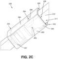
- FIG. 2 Cillustrates a side perspective transparent view of the charging body of FIG. 2 B showing the support
- FIG. 2 Dillustrates a side perspective view of the support of FIG. 2 C ;
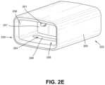
- FIG. 2 Eillustrates a side isometric view of the charging body of FIG. 2 B showing a window and a charging contact;
- FIG. 2 Fillustrates an end view of the charging body of FIG. 2 A showing a pair of charging contacts
- FIG. 3illustrates a perspective view of another embodiment of a charging body including a charging port.
- Implementations of the current subject matterinclude methods, apparatuses, articles of manufacture, and systems relating to vaporization of one or more materials for inhalation by a user.
- Example implementationsinclude vaporizer devices and systems including vaporizer devices.
- the term “vaporizer device” as used in the following description and claimsrefers to any of a self-contained apparatus, an apparatus that includes two or more separable parts (for example, a vaporizer body that includes a battery and other hardware, and a cartridge that includes a vaporizable material), and/or the like.
- a “vaporizer system,” as used herein,can include one or more components, such as a vaporizer device.
- vaporizer devicesconsistent with implementations of the current subject matter include electronic vaporizers, electronic nicotine delivery systems (ENDS), and/or the like.
- electronic vaporizerselectronic vaporizers
- EDSelectronic nicotine delivery systems
- vaporizer devicesare hand-held devices that heat (such as by convection, conduction, radiation, and/or some combination thereof) a vaporizable material to provide an inhalable dose of the material.
- the vaporizer devicecan include a power supply, such as a rechargeable battery. Certain rechargeable batteries may need to be recharged quickly so that the user can continue to use the vaporizer. Some vaporizers may be recharged by, for example, connecting the device to an external power supply via a wired connection or a USB connection with a desktop computer, and/or connected with a wall outlet. Some charging adapters can be used to couple a vaporizer to an external power supply to allow the vaporizer to recharge. Some vaporizer batteries may discharge after use and thus require recharging before subsequent use.
- the charging adapter assemblyconsistent with implementations of the current subject matter may provide an efficient and effective way to charge vaporizers, as will be described in greater detail below.
- Typical portable charging devicesmay be heavy, difficult to carry, may be bulky, difficult to determine charging status of vaporizer (e.g., charging, charged, etc.), difficult to couple to a vaporizer for charging, and/or difficult to clean.
- the charging adapter assemblyin accordance with implementations of the current subject matter can desirably provide a low profile charging adapter assembly that can secure and/or provide power to the vaporizer.
- the charging adapter assemblycan be lightweight and/or less bulky compared to some currently available portable chargers.
- the charging adapter assemblycan be generally aesthetically pleasing and/or easy to use.
- the charging adapter assemblycan be easy to clean, which may prolong the effective and efficient functioning of the charger adapter assembly.
- the charging adapter assemblymay allow a charging indicator light to illuminate through at least a part of the charging adapter assembly thereby allowing a user to determine a charging status of the vaporizer, as will be described in greater detail below.
- the charging adapter assemblymay be flexible thereby allowing, for example, cleaning of internal areas of the charging adapter, and may include a structural support to provide structural integrity.
- Other benefits of the charging adapter assembly described hereincan include providing efficient and effective coupling of a vaporizer to the charging adapter assembly.
- the charging adapter assemblycan be made of one or more of a corrosion resistant material, a biocompatible material, plastic, aluminum, or other materials. Other features and benefits are within the scope of this disclosure.
- a charging adapter assembly for a vaporizer devicemay provide advantages and improvements relative to existing approaches, while also introducing additional benefits as described herein.
- the vaporizable material used with a vaporizer devicecan be provided within a cartridge (for example, a part of the vaporizer that contains the vaporizable material in a reservoir or other container) which can be refillable when empty, or disposable such that a new cartridge containing additional vaporizable material of a same or different type can be used).
- a cartridgefor example, a part of the vaporizer that contains the vaporizable material in a reservoir or other container
- a cartridgefor example, a part of the vaporizer that contains the vaporizable material in a reservoir or other container
- a vaporizer devicecan be a cartridge-using vaporizer device, a cartridge-less vaporizer device, or a multi-use vaporizer device capable of use with or without a cartridge.
- a vaporizer devicecan include a heating chamber (for example, an oven or other region in which material is heated by a heating element) configured to receive a vaporizable material directly into the heating chamber, and/or a reservoir or the like for containing the vaporizable material.
- a vaporizer devicecan be configured for use with a liquid vaporizable material (for example, a carrier solution in which an active and/or inactive ingredient(s) are suspended or held in solution, or a liquid form of the vaporizable material itself), a paste, a wax, and/or a solid vaporizable material.
- a solid vaporizable materialcan include a plant material that emits some part of the plant material as the vaporizable material (for example, some part of the plant material remains as waste after the material is vaporized for inhalation by a user) or optionally can be a solid form of the vaporizable material itself, such that all of the solid material can eventually be vaporized for inhalation.
- a liquid vaporizable materialcan likewise be capable of being completely vaporized, or can include some portion of the liquid material that remains after all of the material suitable for inhalation has been vaporized.
- a vaporizer device 100can include a power source 112 (for example, a battery, which can be a rechargeable battery), and a controller 104 (for example, a processor, circuitry, etc. capable of executing logic) for controlling delivery of heat to an atomizer 141 to cause a vaporizable material 102 to be converted from a condensed form (such as a solid, a liquid, a solution, a suspension, a part of an at least partially unprocessed plant material, etc.) to the gas phase.
- the controller 104can be part of one or more printed circuit boards (PCBs) consistent with certain implementations of the current subject matter.
- At least some of the vaporizable material 102 in the gas phasecan condense to form particulate matter in at least a partial local equilibrium with the gas phase as part of an aerosol, which can form some or all of an inhalable dose provided by the vaporizer device 100 during a user's puff or draw on the vaporizer device 100 .
- the interplay between gas and condensed phases in an aerosol generated by a vaporizer device 100can be complex and dynamic, due to factors such as ambient temperature, relative humidity, chemistry, flow conditions in airflow paths (both inside the vaporizer and in the airways of a human or other animal), and/or mixing of the vaporizable material 102 in the gas phase or in the aerosol phase with other air streams, which can affect one or more physical parameters of an aerosol.
- the inhalable dosecan exist predominantly in the gas phase (for example, formation of condensed phase particles can be very limited).
- the atomizer 141 in the vaporizer device 100can be configured to vaporize a vaporizable material 102 .
- the vaporizable material 102can be a liquid. Examples of the vaporizable material 102 include neat liquids, suspensions, solutions, mixtures, and/or the like.
- the atomizer 141can include a wicking element (i.e., a wick) configured to convey an amount of the vaporizable material 102 to a part of the atomizer 141 that includes a heating element (not shown in FIG. 1 ).
- the wicking elementcan be configured to draw the vaporizable material 102 from a reservoir 140 configured to contain the vaporizable material 102 , such that the vaporizable material 102 can be vaporized by heat delivered from a heating element.
- the wicking elementcan also optionally allow air to enter the reservoir 140 and replace the volume of vaporizable material 102 removed.
- capillary actioncan pull the vaporizable material 102 into the wick for vaporization by the heating element, and air can return to the reservoir 140 through the wick to at least partially equalize pressure in the reservoir 140 .
- Other methods of allowing air back into the reservoir 140 to equalize pressureare also within the scope of the current subject matter.
- wickor “wicking element” include any material capable of causing fluid motion via capillary pressure.
- the heating elementcan include one or more of a conductive heater, a radiative heater, and/or a convective heater.
- a resistive heating elementwhich can include a material (such as a metal or alloy, for example a nickel-chromium alloy, or a non-metallic resistor) configured to dissipate electrical power in the form of heat when electrical current is passed through one or more resistive segments of the heating element.
- the atomizer 141can include a heating element which includes a resistive coil or other heating element wrapped around, positioned within, integrated into a bulk shape of, pressed into thermal contact with, or otherwise arranged to deliver heat to a wicking element, to cause the vaporizable material 102 drawn from the reservoir 140 by the wicking element to be vaporized for subsequent inhalation by a user in a gas and/or a condensed (for example, aerosol particles or droplets) phase.
- wicking elements, heating elements, and/or atomizer assembly configurationsare also possible.
- Certain vaporizer devicesmay, additionally or alternatively, be configured to create an inhalable dose of the vaporizable material 102 in the gas phase and/or aerosol phase via heating of the vaporizable material 102 .
- the vaporizable material 102can be a solid-phase material (such as a wax or the like) or plant material (for example, tobacco leaves and/or parts of tobacco leaves).
- a resistive heating elementcan be part of, or otherwise incorporated into or in thermal contact with, the walls of an oven or other heating chamber into which the vaporizable material 102 is placed.
- a resistive heating element or elementscan be used to heat air passing through or past the vaporizable material 102 , to cause convective heating of the vaporizable material 102 .
- a resistive heating element or elementscan be disposed in intimate contact with plant material such that direct conductive heating of the plant material occurs from within a mass of the plant material, as opposed to only by conduction inward from walls of an oven.
- the heating elementcan be activated in association with a user puffing (i.e., drawing, inhaling, etc.) on a mouthpiece 130 of the vaporizer device 100 to cause air to flow from an air inlet, along an airflow path that passes the atomizer 141 (i.e., wicking element and heating element).
- aircan flow from an air inlet through one or more condensation areas or chambers, to an air outlet in the mouthpiece 130 .
- Incoming air moving along the airflow pathmoves over or through the atomizer 141 , where vaporizable material 102 in the gas phase is entrained into the air.
- the heating elementcan be activated via the controller 104 , which can optionally be a part of a vaporizer body 110 as discussed herein, causing current to pass from the power source 112 through a circuit including the resistive heating element, which is optionally part of a vaporizer cartridge 120 as discussed herein.
- the entrained vaporizable material 102 in the gas phasecan condense as it passes through the remainder of the airflow path such that an inhalable dose of the vaporizable material 102 in an aerosol form can be delivered from the air outlet (for example, the mouthpiece 130 ) for inhalation by a user.
- Activation of the heating elementcan be caused by automatic detection of a puff based on one or more signals generated by one or more of a sensor 113 .
- the sensor 113 and the signals generated by the sensor 113can include one or more of: a pressure sensor or sensors disposed to detect pressure along the airflow path relative to ambient pressure (or optionally to measure changes in absolute pressure), a motion sensor or sensors (for example, an accelerometer) of the vaporizer device 100 , a flow sensor or sensors of the vaporizer device 100 , a capacitive lip sensor of the vaporizer device 100 , detection of interaction of a user with the vaporizer device 100 via one or more input devices 116 (for example, buttons or other tactile control devices of the vaporizer device 100 ), receipt of signals from a computing device in communication with the vaporizer device 100 , and/or via other approaches for determining that a puff is occurring or imminent.
- a pressure sensor or sensorsdisposed to detect pressure along the airflow path relative to ambient pressure (or optionally to measure changes in absolute pressure
- the vaporizer device 100can be configured to connect (such as, for example, wirelessly or via a wired connection) to a computing device (or optionally two or more devices) in communication with the vaporizer device 100 .
- the controller 104can include communication hardware 105 .
- the controller 104can also include a memory 108 .
- the communication hardware 105can include firmware and/or can be controlled by software for executing one or more cryptographic protocols for the communication.
- a computing devicecan be a component of a vaporizer system that also includes the vaporizer device 100 , and can include its own hardware for communication, which can establish a wireless communication channel with the communication hardware 105 of the vaporizer device 100 .
- a computing device used as part of a vaporizer systemcan include a general-purpose computing device (such as a smartphone, a tablet, a personal computer, some other portable device such as a smartwatch, or the like) that executes software to produce a user interface for enabling a user to interact with the vaporizer device 100 .
- such a device used as part of a vaporizer systemcan be a dedicated piece of hardware such as a remote control or other wireless or wired device having one or more physical or soft (i.e., configurable on a screen or other display device and selectable via user interaction with a touch-sensitive screen or some other input device like a mouse, pointer, trackball, cursor buttons, or the like) interface controls.
- the vaporizer device 100can also include one or more outputs 117 or devices for providing information to the user.
- the outputs 117can include one or more light emitting diodes (LEDs) configured to provide feedback to a user based on a status and/or mode of operation of the vaporizer device 100 .
- LEDslight emitting diodes
- the computing deviceexecutes one or more computer instruction sets to provide a user interface and underlying data handling.
- detection by the computing device of user interaction with one or more user interface elementscan cause the computing device to signal the vaporizer device 100 to activate the heating element to reach an operating temperature for creation of an inhalable dose of vapor/aerosol.
- Other functions of the vaporizer device 100can be controlled by interaction of a user with a user interface on a computing device in communication with the vaporizer device 100 .
- the temperature of a resistive heating element of the vaporizer device 100can depend on a number of factors, including an amount of electrical power delivered to the resistive heating element and/or a duty cycle at which the electrical power is delivered, conductive heat transfer to other parts of the electronic vaporizer device 100 and/or to the environment, latent heat losses due to vaporization of the vaporizable material 102 from the wicking element and/or the atomizer 141 as a whole, and convective heat losses due to airflow (i.e., air moving across the heating element or the atomizer 141 as a whole when a user inhales on the vaporizer device 100 ).
- the vaporizer device 100may, in some implementations of the current subject matter, make use of signals from the sensor 113 (for example, a pressure sensor) to determine when a user is inhaling.
- the sensor 113can be positioned in the airflow path and/or can be connected (for example, by a passageway or other path) to an airflow path containing an inlet for air to enter the vaporizer device 100 and an outlet via which the user inhales the resulting vapor and/or aerosol such that the sensor 113 experiences changes (for example, pressure changes) concurrently with air passing through the vaporizer device 100 from the air inlet to the air outlet.
- the heating elementcan be activated in association with a user's puff, for example by automatic detection of the puff, or by the sensor 113 detecting a change (such as a pressure change) in the airflow path.
- the sensor 113can be positioned on or coupled to (i.e., electrically or electronically connected, either physically or via a wireless connection) the controller 104 (for example, a printed circuit board assembly or other type of circuit board).
- the controller 104for example, a printed circuit board assembly or other type of circuit board.
- the seal 127which can be a gasket, can be configured to at least partially surround the sensor 113 such that connections of the sensor 113 to the internal circuitry of the vaporizer device 100 are separated from a part of the sensor 113 exposed to the airflow path.
- the seal 127can also separate parts of one or more electrical connections between the vaporizer body 110 and the vaporizer cartridge 120 .
- Such arrangements of the seal 127 in the vaporizer device 100can be helpful in mitigating against potentially disruptive impacts on vaporizer components resulting from interactions with environmental factors such as water in the vapor or liquid phases, other fluids such as the vaporizable material 102 , etc., and/or to reduce the escape of air from the designated airflow path in the vaporizer device 100 .
- Unwanted air, liquid or other fluid passing and/or contacting circuitry of the vaporizer device 100can cause various unwanted effects, such as altered pressure readings, and/or can result in the buildup of unwanted material, such as moisture, excess vaporizable material 102 , etc., in parts of the vaporizer device 100 where they can result in poor pressure signal, degradation of the sensor 113 or other components, and/or a shorter life of the vaporizer device 100 .
- Leaks in the seal 127can also result in a user inhaling air that has passed over parts of the vaporizer device 100 containing, or constructed of, materials that may not be desirable to be inhaled.
- the vaporizer body 110includes the controller 104 , the power source 112 (for example, a battery), one more of the sensor 113 , charging contacts (such as those for charging the power source 112 ), the seal 127 , and a cartridge receptacle 118 configured to receive the vaporizer cartridge 120 for coupling with the vaporizer body 110 through one or more of a variety of attachment structures.
- the vaporizer cartridge 120includes the reservoir 140 for containing the vaporizable material 102 , and the mouthpiece 130 has an aerosol outlet for delivering an inhalable dose to a user.
- the vaporizer cartridge 120can include the atomizer 141 having a wicking element and a heating element.
- the wicking element and the heating elementcan be part of the vaporizer body 110 .
- the vaporizer device 100can be configured to supply the vaporizable material 102 from the reservoir 140 in the vaporizer cartridge 120 to the part(s) of the atomizer 141 included in the vaporizer body 110 .
- Cartridge-based configurations for the vaporizer device 100 that generate an inhalable dose of a vaporizable material 102 that is not a liquid, via heating of a non-liquid materialare also within the scope of the current subject matter.
- the vaporizer cartridge 120can include a mass of a plant material that is processed and formed to have direct contact with parts of one or more resistive heating elements, and the vaporizer cartridge 120 can be configured to be coupled mechanically and/or electrically to the vaporizer body 110 that includes the controller 104 , the power source 112 , and one or more receptacle contacts 125 a and 125 b configured to connect to one or more corresponding cartridge contacts 124 a and 124 b and complete a circuit with the one or more resistive heating elements.
- the vaporizer device 100can include electrical connection features (for example, means for completing a circuit) for completing a circuit that includes the controller 104 (for example, a printed circuit board, a microcontroller, or the like), the power source 112 , and the heating element (for example, a heating element within the atomizer 141 ).
- electrical connection featuresfor example, means for completing a circuit
- the controller 104for example, a printed circuit board, a microcontroller, or the like
- the power source 112for example, a heating element within the atomizer 141 .
- These featurescan include one or more contacts (referred to herein as cartridge contacts 124 a and 124 b ) on a bottom surface of the vaporizer cartridge 120 and at least two contacts (referred to herein as receptacle contacts 125 a and 125 b ) disposed near a base of the cartridge receptacle 118 of the vaporizer device 100 such that the cartridge contacts 124 a and 124 b and the receptacle contacts 125 a and 125 b make electrical connections when the vaporizer cartridge 120 is inserted into and coupled with the cartridge receptacle 118 .
- the circuit completed by these electrical connectionscan allow delivery of electrical current to a heating element and can further be used for additional functions, such as measuring a resistance of the heating element for use in determining and/or controlling a temperature of the heating element based on a thermal coefficient of resistivity of the heating element.
- the cartridge contacts 124 a and 124 b and the receptacle contacts 125 a and 125 bcan be configured to electrically connect in either of at least two orientations.
- one or more circuits necessary for operation of the vaporizer device 100can be completed by insertion of the vaporizer cartridge 120 into the cartridge receptacle 118 in a first rotational orientation (around an axis along which the vaporizer cartridge 120 is inserted into the cartridge receptacle 118 of the vaporizer body 110 ) such that the cartridge contact 124 a is electrically connected to the receptacle contact 125 a and the cartridge contact 124 b is electrically connected to the receptacle contact 125 b .
- the one or more circuits necessary for operation of the vaporizer device 100can be completed by insertion of the vaporizer cartridge 120 in the cartridge receptacle 118 in a second rotational orientation such cartridge contact 124 a is electrically connected to the receptacle contact 125 b and cartridge contact 124 b is electrically connected to the receptacle contact 125 a.
- the vaporizer body 110includes one or more detents (for example, dimples, protrusions, etc.) protruding inwardly from an inner surface of the cartridge receptacle 118 , additional material (such as metal, plastic, etc.) formed to include a portion protruding into the cartridge receptacle 118 , and/or the like.
- detentsfor example, dimples, protrusions, etc.
- additional materialsuch as metal, plastic, etc.
- One or more exterior surfaces of the vaporizer cartridge 120can include corresponding recesses (not shown in FIG.
- the vaporizer cartridge 120 and the vaporizer body 110are coupled (e.g., by insertion of the vaporizer cartridge 120 into the cartridge receptacle 118 of the vaporizer body 110 ), the detents or protrusions of the vaporizer body 110 can fit within and/or otherwise be held within the recesses of the vaporizer cartridge 120 , to hold the vaporizer cartridge 120 in place when assembled.
- Such an assemblycan provide enough support to hold the vaporizer cartridge 120 in place to ensure good contact between the cartridge contacts 124 a and 124 b and the receptacle contacts 125 a and 125 b , while allowing release of the vaporizer cartridge 120 from the vaporizer body 110 when a user pulls with reasonable force on the vaporizer cartridge 120 to disengage the vaporizer cartridge 120 from the cartridge receptacle 118 .
- the vaporizer cartridge 120can have a non-circular cross section transverse to the axis along which the vaporizer cartridge 120 is inserted into the cartridge receptacle 118 .
- the non-circular cross sectioncan be approximately rectangular, approximately elliptical (i.e., have an approximately oval shape), non-rectangular but with two sets of parallel or approximately parallel opposing sides (i.e., having a parallelogram-like shape), or other shapes having rotational symmetry of at least order two.
- approximate shapeindicates that a basic likeness to the described shape is apparent, but that sides of the shape in question need not be completely linear and vertices need not be completely sharp. Rounding of both or either of the edges or the vertices of the cross-sectional shape is contemplated in the description of any non-circular cross section referred to herein.
- the cartridge contacts 124 a and 124 b and the receptacle contacts 125 a and 125 bcan take various forms.
- one or both sets of contactscan include conductive pins, tabs, posts, receiving holes for pins or posts, or the like.
- Some types of contactscan include springs or other features to facilitate better physical and electrical contact between the contacts on the vaporizer cartridge 120 and the vaporizer body 110 .
- the electrical contactscan optionally be gold-plated, and/or include other materials.
- the vaporizer devicemay include a power supply, such as a rechargeable battery.
- Typical vaporizersmay be rechargeable by, for example, connecting the vaporizer device to an external power supply via a wired connection or a USB connection with a desktop computer, and/or connected with a wall outlet.
- the charging adapter assemblyconsistent with implementations of the current subject matter may provide an efficient and effective way to charge vaporizers, as will be described in greater detail below.
- the charging adapter assemblyin accordance with implementations of the current subject matter may desirably provide a low profile charging adapter assembly that can secure and/or provide power to the vaporizer.
- the charging adapter assemblycan be lightweight and/or less bulky compared to some currently available portable chargers.
- the charging adapter assemblycan be generally aesthetically pleasing and/or easy to use.
- the charging adapter assemblycan be easy to clean, which may prolong the effective and efficient functioning of the charging adapter assembly.
- the charging adapter assemblymay allow a charging indicator light of the vaporizer to illuminate through at least a part of the charging adapter assembly thereby allowing a user to determine a charging status of the vaporizer, as will be described in greater detail below.
- the charging adapter assemblymay be sufficiently flexible to achieve one or more benefits (e.g., allow cleaning of internal areas of the charging adapter) and may also include a structural support to provide structural integrity and other benefits (e.g., allow for efficient coupling of a vaporizer to the charging adapter assembly).
- the charging adapter assemblycan be made out of one or more of a corrosion resistant material, biocompatible material, plastic, aluminum, and/or other materials. Other features and benefits are within the scope of this disclosure, some of which are described in further detail below.
- FIGS. 2 A- 2 Fillustrate an embodiment of a charging adapter assembly 250 consistent with implementations of the current subject matter.
- FIG. 2 Aillustrates a vaporizer device 200 coupled to the charging adapter assembly 250 .
- the charging adapter assembly 250includes a charging body 252 with a cord 254 extending therefrom for connecting to an external power source (e.g., via a plug, USB feature, etc.).
- a charging end 211 of the vaporizer device 200may include one or more contacts (e.g., receptacle contacts 125 a and 125 b ), may be inserted into a coupling end 259 of the charging body 252 , thereby coupling the charging end 211 of the vaporizer device 200 to the charging body 252 , as shown in FIG. 2 A .
- some configurations of the charging adapter assembly 250may be configured to accept a part of a cartridge 220 coupled to the vaporizer body 210 .
- the charging body 252may include a chamber 256 defined by a bottom surface 257 and chamber walls 258 forming a perimeter of the chamber 256 .
- the chamber 256may include a square or rectangular volume defined by four chamber walls 258 extending between the bottom surface 257 of the chamber 256 and an end surface of the coupling end 259 of the charging body 252 .
- the bottom surface 257 of the chamber 256may include one or more charging contacts 261 that may mate with the one or more contacts of the vaporizer device 200 for charging the vaporizer device 200 .
- the chamber walls 258may provide coupling support between the vaporizer device 200 and charging body 252 and may assist in retaining the vaporizer device 200 in the chamber 256 of the charging body 252 , such as during charging.
- the charging body 252may be made out of a material that allows at least the chamber walls 258 to flex.
- the chamber walls 258may be made out of a material (e.g., silicon) that allows a user to insert a cleaning tool and/or finger into the chamber 256 thereby allowing the user to clean the chamber 256 .
- Such cleaning of the chamber 256which includes the charging contacts 261 , may lengthen the lifespan and/or efficient and effective use of the charging adapter assembly 250 by allowing material that may interfere with charging to be removed from the chamber 256 .
- Other benefits associated with such featuresmay be appreciated and are within the scope of this disclosure.
- the charging body 252may include a support 260 , which may be made out of a material that is stiffer compared to the charging body material.
- the support 260may be made out of a metal and molded into a part of the charging body 252 during manufacturing.
- the support 260may substantially extend along two opposing walls of the charging body 252 and not extend along the remaining two opposing walls, as shown in FIG. 2 C .
- Such configuration of the support 260may limit the direction and extent the charging body 252 may flex. For example, as shown in FIGS.
- a gap 262 formed between opposing sides of the support 260may allow the charging body 252 and/or chamber 256 , including one or more of the chamber walls 258 , to flex.
- the ability of the chamber 256 to flexcan allow opposing chamber walls 258 to be pushed towards and away from each other, which can assist with allowing the chamber 256 to be cleaned.
- some or all of the charging body 252may be made out of a material having an opacity that allows a charging light 268 along the vaporizer device 200 to illuminate therethrough.
- a substantial part of the charging body 252may be made out of a material having an opacity of approximately 85% to approximately 99%, such as 95%.
- one or more parts of the charging body 252may include a different material and/or structural property to allow light to travel therethrough.
- the charging body 252may include a window 264 configured to allow light emitted from the charging light 268 to pass through the window 264 .
- the window 264may include a through hole that extends through the chamber wall 258 .
- the window 268may include an area along the chamber wall 258 that includes a thinner wall thickness compared to a part of the chamber wall surrounding the window 264 .
- the window 264can include a different material property compared to a part of the chamber wall surrounding the window 264 (e.g., less than 50% opacity).
- the window 264may align with a charging light 268 on an embodiment of a vaporizer body 210 when the vaporizer body 210 is coupled to the charging body 252 , as shown in FIG. 2 B .
- a usermay be able to observe light emitted from the charging light 268 through the window 264 thereby allowing the user to determine the charging status of the vaporizer device 200 , such as while the vaporizer device 200 is charging.
- the support 260may include a cutout 266 that aligns with the window 264 thereby allowing the charging light 268 to illuminate through the charging body 252 , including the support 260 .
- the cutout 266may include a through-hole that is sized and shaped the same as or similar to the window 264 .
- the cutout 266can further provide support around the window 264 to ensure the charging light 268 is aligned with the window 264 , thereby allowing light from the charging light 268 to pass through the cutout 266 and window 264 .
- FIG. 3illustrates an embodiment of the charging body 352 including a charging port 370 .
- the charging port 370may be configured to couple to a power cord (e.g., cord 254 ), thereby providing electrical communication between an external power source and charging contacts of the charging body 352 .
- the charging port 370may be located on a side opposing the coupling end 359 of the charging body 352 .
- references to a structure or feature that is disposed “adjacent” another featurecan have portions that overlap or underlie the adjacent feature.
- phrases such as “at least one of” or “one or more of”may occur followed by a conjunctive list of elements or features.
- the term “and/or”may also occur in a list of two or more elements or features. Unless otherwise implicitly or explicitly contradicted by the context in which it used, such a phrase is intended to mean any of the listed elements or features individually or any of the recited elements or features in combination with any of the other recited elements or features.
- the phrases “at least one of A and B;” “one or more of A and B;” and “A and/or B”are each intended to mean “A alone, B alone, or A and B together.”
- a similar interpretationis also intended for lists including three or more items.
- the phrases “at least one of A, B, and C;” “one or more of A, B, and C;” and “A, B, and/or C”are each intended to mean “A alone, B alone, C alone, A and B together, A and C together, B and C together, or A and B and C together.”
- Use of the term “based on,” above and in the claimsis intended to mean, “based at least in part on,” such that an unrecited feature or element is also permissible.
- spatially relative termssuch as “forward”, “rearward”, “under”, “below”, “lower”, “over”, “upper” and the like, may be used herein for ease of description to describe one element or feature's relationship to another element(s) or feature(s) as illustrated in the figures. It will be understood that the spatially relative terms are intended to encompass different orientations of the device in use or operation in addition to the orientation depicted in the figures. For example, if a device in the figures is inverted, elements described as “under” or “beneath” other elements or features would then be oriented “over” the other elements or features. Thus, the exemplary term “under” can encompass both an orientation of over and under.
- the devicecan be otherwise oriented (rotated 90 degrees or at other orientations) and the spatially relative descriptors used herein interpreted accordingly.
- the terms “upwardly”, “downwardly”, “vertical”, “horizontal” and the likeare used herein for the purpose of explanation only unless specifically indicated otherwise.
- first and secondmay be used herein to describe various features/elements (including steps), these features/elements should not be limited by these terms, unless the context indicates otherwise. These terms may be used to distinguish one feature/element from another feature/element. Thus, a first feature/element discussed below could be termed a second feature/element, and similarly, a second feature/element discussed below could be termed a first feature/element without departing from the teachings provided herein.
- a numeric valuecan have a value that is +/ ⁇ 0.1% of the stated value (or range of values), +/ ⁇ 1% of the stated value (or range of values), +/ ⁇ 2% of the stated value (or range of values), +/ ⁇ 5% of the stated value (or range of values), +/ ⁇ 10% of the stated value (or range of values), etc.
- Any numerical values given hereinshould also be understood to include about or approximately that value, unless the context indicates otherwise. For example, if the value “10” is disclosed, then “about 10” is also disclosed. Any numerical range recited herein is intended to include all sub-ranges subsumed therein.
- One or more aspects or features of the subject matter described hereincan be realized in digital electronic circuitry, integrated circuitry, specially designed application specific integrated circuits (ASICs), field programmable gate arrays (FPGAs) computer hardware, firmware, software, and/or combinations thereof.
- ASICsapplication specific integrated circuits
- FPGAsfield programmable gate arrays
- These various aspects or featurescan include implementation in one or more computer programs that are executable and/or interpretable on a programmable system including at least one programmable processor, which can be special or general purpose, coupled to receive data and instructions from, and to transmit data and instructions to, a storage system, at least one input device, and at least one output device.
- the programmable system or computing systemcan include clients and servers.
- a client and serverare generally remote from each other and typically interact through a communication network. The relationship of client and server arises by virtue of computer programs running on the respective computers and having a client-server relationship to each other.
- machine-readable signalrefers to any signal used to provide machine instructions and/or data to a programmable processor.
- the machine-readable mediumcan store such machine instructions non-transitorily, such as for example as would a non-transient solid-state memory or a magnetic hard drive or any equivalent storage medium.
- the machine-readable mediumcan alternatively or additionally store such machine instructions in a transient manner, such as for example, as would a processor cache or other random access memory associated with one or more physical processor cores.
Landscapes
- Health & Medical Sciences (AREA)
- Engineering & Computer Science (AREA)
- Life Sciences & Earth Sciences (AREA)
- Biomedical Technology (AREA)
- Heart & Thoracic Surgery (AREA)
- Hematology (AREA)
- Anesthesiology (AREA)
- Animal Behavior & Ethology (AREA)
- General Health & Medical Sciences (AREA)
- Public Health (AREA)
- Veterinary Medicine (AREA)
- Power Engineering (AREA)
- Catching Or Destruction (AREA)
- Charge And Discharge Circuits For Batteries Or The Like (AREA)
- Vaporization, Distillation, Condensation, Sublimation, And Cold Traps (AREA)
Abstract
Description
Claims (20)
Priority Applications (1)
| Application Number | Priority Date | Filing Date | Title |
|---|---|---|---|
| US16/657,925US11611223B2 (en) | 2018-10-19 | 2019-10-18 | Charging adapter for vaporizer device |
Applications Claiming Priority (2)
| Application Number | Priority Date | Filing Date | Title |
|---|---|---|---|
| US201862748150P | 2018-10-19 | 2018-10-19 | |
| US16/657,925US11611223B2 (en) | 2018-10-19 | 2019-10-18 | Charging adapter for vaporizer device |
Publications (2)
| Publication Number | Publication Date |
|---|---|
| US20200127475A1 US20200127475A1 (en) | 2020-04-23 |
| US11611223B2true US11611223B2 (en) | 2023-03-21 |
Family
ID=68733593
Family Applications (1)
| Application Number | Title | Priority Date | Filing Date |
|---|---|---|---|
| US16/657,925Active2040-12-25US11611223B2 (en) | 2018-10-19 | 2019-10-18 | Charging adapter for vaporizer device |
Country Status (3)
| Country | Link |
|---|---|
| US (1) | US11611223B2 (en) |
| TW (1) | TWI826556B (en) |
| WO (1) | WO2020082040A1 (en) |
Families Citing this family (7)
| Publication number | Priority date | Publication date | Assignee | Title |
|---|---|---|---|---|
| US11413409B2 (en) | 2018-09-12 | 2022-08-16 | Juul Labs, Inc. | Vaporizer including positive temperature coefficient of resistivity (PTCR) heating element |
| AR116722A1 (en) | 2018-10-08 | 2021-06-09 | Juul Labs Inc | ASSEMBLY OF CHARGE ADAPTER OF A VAPORIZER |
| EP3876763B1 (en) | 2018-11-05 | 2022-12-28 | Juul Labs, Inc. | A cartridge for a vaporizer device |
| ES2932748T3 (en) | 2018-11-05 | 2023-01-25 | Juul Labs Inc | Cartridges for vaporizer devices |
| CN113939203A (en) | 2019-01-15 | 2022-01-14 | 尤尔实验室有限公司 | Evaporator device |
| WO2020154690A1 (en) | 2019-01-25 | 2020-07-30 | Juul Labs, Inc. | Vaporizer device and cartridge |
| USD944211S1 (en)* | 2019-05-28 | 2022-02-22 | Taylor Cipully | Cell phone vaporizer cartridge adapter |
Citations (96)
| Publication number | Priority date | Publication date | Assignee | Title |
|---|---|---|---|---|
| US3792704A (en) | 1971-05-12 | 1974-02-19 | M Parker | Pipe tobacco smoking system |
| US5934289A (en) | 1996-10-22 | 1999-08-10 | Philip Morris Incorporated | Electronic smoking system |
| WO2000021598A1 (en) | 1998-10-14 | 2000-04-20 | Chrysalis Technologies Incorporated | Aerosol generator and methods of making and using an aerosol generator |
| US20050225292A1 (en) | 2002-07-01 | 2005-10-13 | Jean-Jacques Damlamian | Charger and recharger device |
| WO2005106350A2 (en) | 2004-04-23 | 2005-11-10 | Philip Morris Usa Inc. | Aerosol generators and methods for producing aerosols |
| US20070045276A1 (en) | 2005-08-16 | 2007-03-01 | Gary Fisher | Flameless lighter |
| US20070072443A1 (en) | 2005-09-26 | 2007-03-29 | Apple Computer, Inc. | Magnetic connector for electronic device |
| WO2007078273A1 (en) | 2005-12-22 | 2007-07-12 | Augite Incorporation | No-tar electronic smoking utensils |
| US20070229025A1 (en) | 2006-04-04 | 2007-10-04 | Kye Systems Corp. | Connector charger |
| US20080207276A1 (en) | 2007-02-26 | 2008-08-28 | Burrell David C | Adjustable cell phone charger holder |
| KR20090010954A (en) | 2006-04-11 | 2009-01-30 | 에스.씨. 존슨 앤드 선, 인코포레이티드 | Electronic aerosol device |
| KR20090008914U (en) | 2009-07-28 | 2009-09-02 | 황일영 | E-cigarette Battery charger case |
| USD601500S1 (en) | 2009-01-09 | 2009-10-06 | Amazon Technologies, Inc. | Slideable power adapter |
| US20090283103A1 (en)* | 2008-05-13 | 2009-11-19 | Nielsen Michael D | Electronic vaporizing devices and docking stations |
| USD611409S1 (en) | 2009-01-09 | 2010-03-09 | Amazon Technologies Inc. | Power adapter |
| CN202004499U (en) | 2011-05-04 | 2011-10-05 | 何芊 | Bluetooth vertical holder charger with rotary USB (universal serial bus) interface |
| US8113855B2 (en) | 2009-01-26 | 2012-02-14 | Amazon Technologies, Inc. | Electrical power adapter |
| WO2012026963A2 (en) | 2010-08-23 | 2012-03-01 | Darren Rubin | Systems and methods of aerosol delivery with airflow regulation |
| US20120060853A1 (en) | 2006-10-18 | 2012-03-15 | R.J. Reynolds Tobacco Company | Tobacco-containing smoking article |
| US20120223673A1 (en) | 2011-03-01 | 2012-09-06 | Shih-Hui Chen | Charging module |
| US20120227753A1 (en) | 2010-12-06 | 2012-09-13 | Newton Kyle D | Charger Package for Electronic Cigarette Components |
| US20130099725A1 (en) | 2011-10-14 | 2013-04-25 | Research In Motion Limited | Clip-on charging system with variable charging rates |
| WO2013093695A1 (en) | 2011-12-18 | 2013-06-27 | Sis Resources Ltd. | Charging electronic cigarette |
| CN203087525U (en) | 2012-06-14 | 2013-07-31 | 深圳市新宜康科技有限公司 | Environment-friendly type non-ignitable atomizing electronic cigarette |
| CN203168035U (en) | 2012-12-05 | 2013-09-04 | 刘秋明 | Electronic cigarette preventing smoke from condensing |
| USD697029S1 (en) | 2013-02-05 | 2014-01-07 | Asian Power Devices, Inc. | Power adapter |
| US20140041655A1 (en) | 2012-08-11 | 2014-02-13 | Grenco Science, Inc | Portable Vaporizer |
| US20140053857A1 (en)* | 2012-08-24 | 2014-02-27 | Qiuming Liu | Electronic Cigarette Device |
| US20140060552A1 (en)* | 2012-08-28 | 2014-03-06 | Ploom, Inc. | Methods and devices for delivery and monitoring of tobacco, nicotine, or other substances |
| WO2014071329A1 (en) | 2012-11-05 | 2014-05-08 | The Safe Cig, Llc | Device and method for vaporizing a fluid |
| US20140123990A1 (en) | 2012-11-08 | 2014-05-08 | Ludovicus Josephine Felicien Timmermans | Real time variable programmable electronic cigarette system |
| US20140253144A1 (en) | 2013-03-07 | 2014-09-11 | R.J. Reynolds Tobacco Company | Spent cartridge detection method and system for an electronic smoking article |
| US20150009027A1 (en) | 2013-07-08 | 2015-01-08 | Darcia Harvey | Ornamental Person Locator with Imbedded Tracker and Personal Identification |
| EP1471955B1 (en) | 2002-01-15 | 2015-03-04 | Philip Morris Products S.a.s. | Aerosol generator for drug formulation |
| WO2015054862A1 (en) | 2013-10-17 | 2015-04-23 | 吉瑞高新科技股份有限公司 | Battery assembly, electronic cigarette, and electronic cigarette charging device |
| US20150141093A1 (en) | 2012-05-30 | 2015-05-21 | Sagi Sela | Cover for Mobile Device with Ecological Lighter |
| US20150164142A1 (en) | 2013-12-13 | 2015-06-18 | Shenzhen First Union Technology Co., Ltd. | Electronic cigarette, atomizing device, power pole and charger connector |
| US9066543B2 (en) | 2012-07-31 | 2015-06-30 | The Safe Cig, Llc | Container device and apparatus |
| WO2015100361A1 (en) | 2013-12-23 | 2015-07-02 | Pax Labs, Inc. | Vaporization device systems and methods |
| USD734259S1 (en) | 2013-07-23 | 2015-07-14 | Motorola Mobility Llc | Power adapter |
| US9089166B1 (en) | 2014-05-09 | 2015-07-28 | Njoy, Inc. | Packaging for vaporizing device |
| WO2015109616A1 (en) | 2014-01-24 | 2015-07-30 | 吉瑞高新科技股份有限公司 | Wireless charging system for electronic cigarette |
| US20150216235A1 (en) | 2013-04-08 | 2015-08-06 | Quiming Liu | Electronic cigarette and circuit used in the same |
| US20150313284A1 (en) | 2012-10-05 | 2015-11-05 | Smart Chip Microelectronic Co. Limited | Electronic smoke apparatus |
| WO2015184747A1 (en) | 2014-06-05 | 2015-12-10 | 王晓琼 | Multi-flavour electronic cigarette |
| US20150357839A1 (en) | 2014-06-09 | 2015-12-10 | Silergy Semiconductor Technology (Hangzhou) Ltd. | Electronic cigarette and integrated circuit therefor |
| EP2800489B1 (en) | 2012-01-03 | 2015-12-23 | Philip Morris Products S.A. | Polygonal aerosol-generating device |
| US20160021771A1 (en)* | 2014-07-18 | 2016-01-21 | Xiaomi Inc. | Wearable device and method for manufacturing the same |
| WO2016019573A1 (en) | 2014-08-08 | 2016-02-11 | 刘水根 | Electronic hookah charcoal and method for heating tobacco leaves by electronic hookah charcoal |
| US20160106153A1 (en) | 2014-10-21 | 2016-04-21 | Xiaochun Zhu | Heating assemblies for e-cigarette vaporizers |
| WO2016058189A1 (en) | 2014-10-17 | 2016-04-21 | 惠州市吉瑞科技有限公司 | Battery assembly and charging control method thereof, and electronic cigarette |
| WO2016058992A2 (en) | 2014-10-14 | 2016-04-21 | Fontem Holdings 2 B.V. | Electronic smoking device and capsule |
| US20160143358A1 (en) | 2014-11-25 | 2016-05-26 | Xiaochun Zhu | Heating assembly for electronic cigarette vaporizer |
| EP3031339A1 (en) | 2014-12-09 | 2016-06-15 | Xiaochun Zhu | Top refillable electronic cigarettes |
| EP2800485B1 (en) | 2012-01-03 | 2016-07-27 | Philip Morris Products S.a.s. | Polygonal aerosol-generating device |
| US20160219932A1 (en) | 2015-01-29 | 2016-08-04 | Lawrence F. Glaser | E-Cigarettes, E-Cigars, Vape-Device Public Safety and Protection Mechanisms |
| US20160227837A1 (en) | 2015-02-06 | 2016-08-11 | The Vapor Bar | Disposable electronic cigarette tank |
| US9427023B2 (en) | 2012-06-20 | 2016-08-30 | Huizhou Kimree Technology Co., Ltd., Shenzhen Branch | Electronic cigarette and electronic cigarette device |
| WO2016166670A1 (en) | 2015-04-13 | 2016-10-20 | G.D S.P.A. | Electric cartridge for electronic cigarette and electronic cigarette |
| WO2016166661A1 (en) | 2015-04-13 | 2016-10-20 | G.D S.P.A. | Electric cartridge for an electronic cigarette and method for making the electric cartridge |
| EP3085257A1 (en) | 2015-04-22 | 2016-10-26 | Fontem Holdings 1 B.V. | Electronic smoking device |
| WO2016172802A1 (en) | 2015-04-29 | 2016-11-03 | Poda Technologies Ltd. | Vaporizer apparatus, device, and methods |
| US20160338405A1 (en) | 2014-02-12 | 2016-11-24 | Qiuming Liu | Atomizing assembly and electronic cigarette |
| US20160345625A1 (en) | 2014-02-12 | 2016-12-01 | Kimree Hi-Tech Inc. | Electronic cigarette |
| US20160366935A1 (en) | 2014-02-12 | 2016-12-22 | Qiuming Liu | Electronic cigarette |
| WO2017034597A1 (en) | 2015-08-27 | 2017-03-02 | Ccnk Llc | Electric vapor apparatus |
| WO2017064323A1 (en) | 2015-10-16 | 2017-04-20 | Fontem Holdings 1 B.V. | Electronic smoking device with two parallel flow paths having a constant total flow resistance |
| US20170127726A1 (en) | 2014-06-30 | 2017-05-11 | Kimree Hi-Tech Inc. | Control circuit, electronic cigarette and method for controlling electronic cigarette |
| US20170135402A1 (en) | 2014-06-27 | 2017-05-18 | Fontem Holdings 1 B.V. | Electronic smoking device and capsule system |
| WO2017084920A2 (en) | 2015-11-19 | 2017-05-26 | Fontem Holdings 1 B.V. | Module for powering an electronic smoking device portion |
| WO2017085240A1 (en) | 2015-11-19 | 2017-05-26 | Fontem Holdings 1 B.V. | Electronic smoking device with non-simultaneously operated heating elements |
| USD790463S1 (en) | 2016-03-11 | 2017-06-27 | Fsp Technology Inc. | Power adapter |
| USD790465S1 (en) | 2016-06-20 | 2017-06-27 | Dongguan Zhaoshun Electronics Technology Co., Ltd | Power adapter |
| EP3195738A2 (en) | 2016-01-20 | 2017-07-26 | Xiaochun Zhu | Ceramic vaporizer and electronic cigarettes having the ceramic vaporizer |
| US20170208862A1 (en) | 2016-01-25 | 2017-07-27 | Shenzhen First Union Technology Co., Ltd. | Electronic cigarette case |
| US20170215479A1 (en) | 2016-02-03 | 2017-08-03 | Nathan R. Kies | Portable vaporizer and storage systems |
| US20170302089A1 (en) | 2014-10-28 | 2017-10-19 | Philip Morris Products S.A. | Adaptive battery charging method and system |
| US20180027878A1 (en)* | 2016-07-31 | 2018-02-01 | Charles Dendy | Electronic vaping device, battery section, and charger |
| CA2920973C (en) | 2016-01-26 | 2018-09-18 | Xiaochun Zhu | Ceramic vaporizer with replaceable e-liquid storage medium and electronic cigarettes having the same |
| US20180271167A1 (en)* | 2014-02-28 | 2018-09-27 | Beyond Twenty Ltd. | E-cigarette personal vaporizer |
| EP3292771B1 (en) | 2016-09-06 | 2018-11-21 | Fontem Holdings 2 B.V. | Case for an electronic smoking device with a first and a second wing element |
| DE202014011273U1 (en) | 2013-11-12 | 2018-12-12 | VMR Products, LLC | Evaporator and charger |
| DE102017222528B3 (en) | 2017-12-12 | 2019-01-24 | Heraeus Sensor Technology Gmbh | Heating unit for a system for providing an inhalable aerosol |
| DE202015009690U1 (en) | 2014-05-13 | 2019-03-14 | Fontem Holdings 4 B.V. | Electronic smoke device and data exchange applications |
| EP3294348B1 (en) | 2015-05-09 | 2019-04-17 | Grättinger, Günter | Electric fragrance diffuser |
| US10420708B2 (en) | 2018-04-24 | 2019-09-24 | Arrix, Inc. | Systems and methods for medication management |
| US20190387791A1 (en)* | 2018-06-22 | 2019-12-26 | Airmyth Supply Company, LLC | Electronic vaporizing apparatus |
| US20200028372A1 (en)* | 2018-07-19 | 2020-01-23 | Fuul Tech Llc | Charging device for electronic cigarette |
| US10575562B2 (en) | 2017-06-30 | 2020-03-03 | Rai Strategic Holdings, Inc. | Smoking article for identifying an attribute of an aerosol-generating element for adaptive power output and an associated method |
| US20200112188A1 (en)* | 2018-10-08 | 2020-04-09 | Juul Labs, Inc. | Vaporizer charging adapter assembly |
| EP3175507B1 (en) | 2014-07-29 | 2020-09-02 | Nicoventures Holdings Limited | E-cigarette and re-charging pack |
| US10834969B2 (en) | 2015-08-28 | 2020-11-17 | Fontem Holdings 2 B.V. | Electronic smoking device with reservoir detection element |
| EP3609356B1 (en) | 2017-04-11 | 2021-06-02 | Philip Morris Products S.A. | Aerosol-generating device |
| US20210161214A1 (en) | 2018-07-25 | 2021-06-03 | Philip Morris Products S.A. | A method of controlling heating in an aerosol-generating system |
| US11123504B2 (en)* | 2016-07-25 | 2021-09-21 | Fontem Holdings 1 B.V. | Electronic cigarette |
| GB2593118A (en)* | 2018-09-24 | 2021-09-22 | Nerudia Ltd | Charging case and associated system |
- 2019
- 2019-10-18WOPCT/US2019/057083patent/WO2020082040A1/ennot_activeCeased
- 2019-10-18USUS16/657,925patent/US11611223B2/enactiveActive
- 2019-10-21TWTW108137943Apatent/TWI826556B/enactive
Patent Citations (140)
| Publication number | Priority date | Publication date | Assignee | Title |
|---|---|---|---|---|
| US3792704A (en) | 1971-05-12 | 1974-02-19 | M Parker | Pipe tobacco smoking system |
| US5934289A (en) | 1996-10-22 | 1999-08-10 | Philip Morris Incorporated | Electronic smoking system |
| WO2000021598A1 (en) | 1998-10-14 | 2000-04-20 | Chrysalis Technologies Incorporated | Aerosol generator and methods of making and using an aerosol generator |
| US6234167B1 (en) | 1998-10-14 | 2001-05-22 | Chrysalis Technologies, Incorporated | Aerosol generator and methods of making and using an aerosol generator |
| US6516796B1 (en) | 1998-10-14 | 2003-02-11 | Chrysalis Technologies Incorporated | Aerosol generator and methods of making and using an aerosol generator |
| EP1471955B1 (en) | 2002-01-15 | 2015-03-04 | Philip Morris Products S.a.s. | Aerosol generator for drug formulation |
| US20050225292A1 (en) | 2002-07-01 | 2005-10-13 | Jean-Jacques Damlamian | Charger and recharger device |
| US7500479B2 (en) | 2004-04-23 | 2009-03-10 | Philip Morris Usa Inc. | Aerosol generators and methods for producing aerosols |
| WO2005106350A2 (en) | 2004-04-23 | 2005-11-10 | Philip Morris Usa Inc. | Aerosol generators and methods for producing aerosols |
| US20070045276A1 (en) | 2005-08-16 | 2007-03-01 | Gary Fisher | Flameless lighter |
| US20070072443A1 (en) | 2005-09-26 | 2007-03-29 | Apple Computer, Inc. | Magnetic connector for electronic device |
| US7311526B2 (en) | 2005-09-26 | 2007-12-25 | Apple Inc. | Magnetic connector for electronic device |
| WO2007078273A1 (en) | 2005-12-22 | 2007-07-12 | Augite Incorporation | No-tar electronic smoking utensils |
| US20070229025A1 (en) | 2006-04-04 | 2007-10-04 | Kye Systems Corp. | Connector charger |
| KR20090010954A (en) | 2006-04-11 | 2009-01-30 | 에스.씨. 존슨 앤드 선, 인코포레이티드 | Electronic aerosol device |
| US8899238B2 (en) | 2006-10-18 | 2014-12-02 | R.J. Reynolds Tobacco Company | Tobacco-containing smoking article |
| US20120060853A1 (en) | 2006-10-18 | 2012-03-15 | R.J. Reynolds Tobacco Company | Tobacco-containing smoking article |
| US20080207276A1 (en) | 2007-02-26 | 2008-08-28 | Burrell David C | Adjustable cell phone charger holder |
| US20090283103A1 (en)* | 2008-05-13 | 2009-11-19 | Nielsen Michael D | Electronic vaporizing devices and docking stations |
| USD601500S1 (en) | 2009-01-09 | 2009-10-06 | Amazon Technologies, Inc. | Slideable power adapter |
| USD611409S1 (en) | 2009-01-09 | 2010-03-09 | Amazon Technologies Inc. | Power adapter |
| US8113855B2 (en) | 2009-01-26 | 2012-02-14 | Amazon Technologies, Inc. | Electrical power adapter |
| KR20090008914U (en) | 2009-07-28 | 2009-09-02 | 황일영 | E-cigarette Battery charger case |
| WO2012026963A2 (en) | 2010-08-23 | 2012-03-01 | Darren Rubin | Systems and methods of aerosol delivery with airflow regulation |
| US20120227753A1 (en) | 2010-12-06 | 2012-09-13 | Newton Kyle D | Charger Package for Electronic Cigarette Components |
| US8978663B2 (en) | 2010-12-06 | 2015-03-17 | Kyle D. Newton | Charger package for electronic cigarette components |
| US20120223673A1 (en) | 2011-03-01 | 2012-09-06 | Shih-Hui Chen | Charging module |
| CN202004499U (en) | 2011-05-04 | 2011-10-05 | 何芊 | Bluetooth vertical holder charger with rotary USB (universal serial bus) interface |
| US20130099725A1 (en) | 2011-10-14 | 2013-04-25 | Research In Motion Limited | Clip-on charging system with variable charging rates |
| WO2013093695A1 (en) | 2011-12-18 | 2013-06-27 | Sis Resources Ltd. | Charging electronic cigarette |
| US20150020831A1 (en)* | 2011-12-18 | 2015-01-22 | Sis Resources Ltd. | Charging electronic cigarette |
| EP2790537B1 (en) | 2011-12-18 | 2018-04-11 | SIS Resources Ltd. | Electronic cigarette charging system comprising an electronic cigarette with a magnetic electrical contact in form of an outer ring |
| EP2800485B1 (en) | 2012-01-03 | 2016-07-27 | Philip Morris Products S.a.s. | Polygonal aerosol-generating device |
| EP2800489B1 (en) | 2012-01-03 | 2015-12-23 | Philip Morris Products S.A. | Polygonal aerosol-generating device |
| US20150141093A1 (en) | 2012-05-30 | 2015-05-21 | Sagi Sela | Cover for Mobile Device with Ecological Lighter |
| US9641208B2 (en) | 2012-05-30 | 2017-05-02 | Sagi Sela | Cover for mobile device with ecological lighter |
| CN203087525U (en) | 2012-06-14 | 2013-07-31 | 深圳市新宜康科技有限公司 | Environment-friendly type non-ignitable atomizing electronic cigarette |
| US9427023B2 (en) | 2012-06-20 | 2016-08-30 | Huizhou Kimree Technology Co., Ltd., Shenzhen Branch | Electronic cigarette and electronic cigarette device |
| US9066543B2 (en) | 2012-07-31 | 2015-06-30 | The Safe Cig, Llc | Container device and apparatus |
| US20140041655A1 (en) | 2012-08-11 | 2014-02-13 | Grenco Science, Inc | Portable Vaporizer |
| CA2882464C (en) | 2012-08-24 | 2017-07-25 | Kimree Hi-Tech Inc. | Electronic cigarette apparatus |
| US20140053857A1 (en)* | 2012-08-24 | 2014-02-27 | Qiuming Liu | Electronic Cigarette Device |
| US8973587B2 (en) | 2012-08-24 | 2015-03-10 | Kimree Hi-Tech Inc. | Electronic cigarette device |
| US20140060552A1 (en)* | 2012-08-28 | 2014-03-06 | Ploom, Inc. | Methods and devices for delivery and monitoring of tobacco, nicotine, or other substances |
| US20150313284A1 (en) | 2012-10-05 | 2015-11-05 | Smart Chip Microelectronic Co. Limited | Electronic smoke apparatus |
| EP2903466B1 (en) | 2012-10-05 | 2021-02-17 | Altria Client Services LLC | Electronic smoke apparatus |
| US20140123989A1 (en) | 2012-11-05 | 2014-05-08 | The Safe Cig, Llc | Device and method for vaporizing a fluid |
| US20170295848A1 (en) | 2012-11-05 | 2017-10-19 | The Safe Cig, Llc | Device and method for vaporizing a fluid |
| WO2014071329A1 (en) | 2012-11-05 | 2014-05-08 | The Safe Cig, Llc | Device and method for vaporizing a fluid |
| US20140123990A1 (en) | 2012-11-08 | 2014-05-08 | Ludovicus Josephine Felicien Timmermans | Real time variable programmable electronic cigarette system |
| US9675114B2 (en) | 2012-11-08 | 2017-06-13 | Ludovicus Josephine Felicien Timmermans | Real time variable voltage programmable electronic cigarette and method |
| CN203168035U (en) | 2012-12-05 | 2013-09-04 | 刘秋明 | Electronic cigarette preventing smoke from condensing |
| USD697029S1 (en) | 2013-02-05 | 2014-01-07 | Asian Power Devices, Inc. | Power adapter |
| WO2014138244A1 (en) | 2013-03-07 | 2014-09-12 | R. J. Reynolds Tobacco Company | Spent cartridge detection method and system for an electronic smoking article |
| EP2964037B1 (en) | 2013-03-07 | 2020-06-10 | RAI Strategic Holdings, Inc. | Spent cartridge detection method and system for an electronic smoking article |
| US20140253144A1 (en) | 2013-03-07 | 2014-09-11 | R.J. Reynolds Tobacco Company | Spent cartridge detection method and system for an electronic smoking article |
| US20150216235A1 (en) | 2013-04-08 | 2015-08-06 | Quiming Liu | Electronic cigarette and circuit used in the same |
| US20150009027A1 (en) | 2013-07-08 | 2015-01-08 | Darcia Harvey | Ornamental Person Locator with Imbedded Tracker and Personal Identification |
| USD734259S1 (en) | 2013-07-23 | 2015-07-14 | Motorola Mobility Llc | Power adapter |
| WO2015054862A1 (en) | 2013-10-17 | 2015-04-23 | 吉瑞高新科技股份有限公司 | Battery assembly, electronic cigarette, and electronic cigarette charging device |
| DE202014011284U1 (en) | 2013-11-12 | 2019-01-15 | VMR Products, LLC | Evaporator and charger |
| DE202014011273U1 (en) | 2013-11-12 | 2018-12-12 | VMR Products, LLC | Evaporator and charger |
| US20150164142A1 (en) | 2013-12-13 | 2015-06-18 | Shenzhen First Union Technology Co., Ltd. | Electronic cigarette, atomizing device, power pole and charger connector |
| WO2015100361A1 (en) | 2013-12-23 | 2015-07-02 | Pax Labs, Inc. | Vaporization device systems and methods |
| WO2015109616A1 (en) | 2014-01-24 | 2015-07-30 | 吉瑞高新科技股份有限公司 | Wireless charging system for electronic cigarette |
| US20160338405A1 (en) | 2014-02-12 | 2016-11-24 | Qiuming Liu | Atomizing assembly and electronic cigarette |
| US20160366935A1 (en) | 2014-02-12 | 2016-12-22 | Qiuming Liu | Electronic cigarette |
| US20160345625A1 (en) | 2014-02-12 | 2016-12-01 | Kimree Hi-Tech Inc. | Electronic cigarette |
| US20180271167A1 (en)* | 2014-02-28 | 2018-09-27 | Beyond Twenty Ltd. | E-cigarette personal vaporizer |
| US9089166B1 (en) | 2014-05-09 | 2015-07-28 | Njoy, Inc. | Packaging for vaporizing device |
| DE202015009690U1 (en) | 2014-05-13 | 2019-03-14 | Fontem Holdings 4 B.V. | Electronic smoke device and data exchange applications |
| DE202015009689U1 (en) | 2014-05-13 | 2019-03-14 | Fontem Holdings 4 B.V. | Electronic smoke device and data exchange applications |
| WO2015184747A1 (en) | 2014-06-05 | 2015-12-10 | 王晓琼 | Multi-flavour electronic cigarette |
| US20150357839A1 (en) | 2014-06-09 | 2015-12-10 | Silergy Semiconductor Technology (Hangzhou) Ltd. | Electronic cigarette and integrated circuit therefor |
| US10069320B2 (en) | 2014-06-09 | 2018-09-04 | Silergy Semiconductor Technology (Hangzhou) Ltd. | Electronic cigarette with miniaturized charging and discharging integrated circuit therefor |
| US20170135402A1 (en) | 2014-06-27 | 2017-05-18 | Fontem Holdings 1 B.V. | Electronic smoking device and capsule system |
| EP2959784B1 (en) | 2014-06-27 | 2019-04-03 | Fontem Holdings 1 B.V. | Electronic smoking device and capsule system |
| US20170127726A1 (en) | 2014-06-30 | 2017-05-11 | Kimree Hi-Tech Inc. | Control circuit, electronic cigarette and method for controlling electronic cigarette |
| US9615791B2 (en)* | 2014-07-18 | 2017-04-11 | Xiaomi Inc. | Wearable device and method for manufacturing the same |
| US20160021771A1 (en)* | 2014-07-18 | 2016-01-21 | Xiaomi Inc. | Wearable device and method for manufacturing the same |
| EP3175507B1 (en) | 2014-07-29 | 2020-09-02 | Nicoventures Holdings Limited | E-cigarette and re-charging pack |
| WO2016019573A1 (en) | 2014-08-08 | 2016-02-11 | 刘水根 | Electronic hookah charcoal and method for heating tobacco leaves by electronic hookah charcoal |
| EP3009017B1 (en) | 2014-10-14 | 2020-07-29 | Fontem Holdings 1 B.V. | Electronic smoking device and cartridge |
| WO2016058992A2 (en) | 2014-10-14 | 2016-04-21 | Fontem Holdings 2 B.V. | Electronic smoking device and capsule |
| US20170215485A1 (en) | 2014-10-14 | 2017-08-03 | Fontem Holdings 1 B.V. | Electronic smoking device and capsule |
| US20170250552A1 (en) | 2014-10-17 | 2017-08-31 | Huizhou Kimree Technology Co., Ltd. | Battery assembly and charging method thereof, and electronic cigarette |
| WO2016058189A1 (en) | 2014-10-17 | 2016-04-21 | 惠州市吉瑞科技有限公司 | Battery assembly and charging control method thereof, and electronic cigarette |
| US20160106153A1 (en) | 2014-10-21 | 2016-04-21 | Xiaochun Zhu | Heating assemblies for e-cigarette vaporizers |
| US9795168B2 (en) | 2014-10-21 | 2017-10-24 | Xiaochun Zhu | Heating assemblies for E-cigarette vaporizers |
| EP3213385B1 (en) | 2014-10-28 | 2019-02-20 | Philip Morris Products S.a.s. | An adaptive battery charging method and system |
| US10439419B2 (en) | 2014-10-28 | 2019-10-08 | Philip Morris Products S.A. | Adaptive battery charging method and system |
| US20170302089A1 (en) | 2014-10-28 | 2017-10-19 | Philip Morris Products S.A. | Adaptive battery charging method and system |
| US20160143358A1 (en) | 2014-11-25 | 2016-05-26 | Xiaochun Zhu | Heating assembly for electronic cigarette vaporizer |
| EP3031339A1 (en) | 2014-12-09 | 2016-06-15 | Xiaochun Zhu | Top refillable electronic cigarettes |
| US20160219932A1 (en) | 2015-01-29 | 2016-08-04 | Lawrence F. Glaser | E-Cigarettes, E-Cigars, Vape-Device Public Safety and Protection Mechanisms |
| US20160227837A1 (en) | 2015-02-06 | 2016-08-11 | The Vapor Bar | Disposable electronic cigarette tank |
| WO2016166670A1 (en) | 2015-04-13 | 2016-10-20 | G.D S.P.A. | Electric cartridge for electronic cigarette and electronic cigarette |
| US20180116286A1 (en) | 2015-04-13 | 2018-05-03 | G.D S.P.A. | Electric cartridge for an electronic cigarette and method for making the electric cigarette |
| WO2016166661A1 (en) | 2015-04-13 | 2016-10-20 | G.D S.P.A. | Electric cartridge for an electronic cigarette and method for making the electric cartridge |
| US20180116285A1 (en) | 2015-04-13 | 2018-05-03 | G.D S.P.A. | Electric cartridge for electronic cigarette and electronic cigarette |
| EP3085257A1 (en) | 2015-04-22 | 2016-10-26 | Fontem Holdings 1 B.V. | Electronic smoking device |
| US20180103685A1 (en) | 2015-04-22 | 2018-04-19 | Fontem Holdings 1 B.V. | Electronic smoking device |
| WO2016169796A1 (en) | 2015-04-22 | 2016-10-27 | Fontem Holdings 1 B.V. | Electronic smoking device |
| EP3085257B1 (en) | 2015-04-22 | 2019-06-05 | Fontem Holdings 1 B.V. | Electronic smoking device |
| US20180117268A1 (en) | 2015-04-29 | 2018-05-03 | Poda Technologies Ltd. | Vaporizer, apparatus, device, and methods |
| WO2016172802A1 (en) | 2015-04-29 | 2016-11-03 | Poda Technologies Ltd. | Vaporizer apparatus, device, and methods |
| EP3294348B1 (en) | 2015-05-09 | 2019-04-17 | Grättinger, Günter | Electric fragrance diffuser |
| WO2017034597A1 (en) | 2015-08-27 | 2017-03-02 | Ccnk Llc | Electric vapor apparatus |
| US20170055579A1 (en) | 2015-08-27 | 2017-03-02 | Ccnk Llc | Electric Vapor Apparatus |
| US10834969B2 (en) | 2015-08-28 | 2020-11-17 | Fontem Holdings 2 B.V. | Electronic smoking device with reservoir detection element |
| EP3155910B1 (en) | 2015-10-16 | 2020-07-08 | Fontem Holdings 1 B.V. | Electronic smoking device with two parallel flow paths having a constant total flow resistance |
| WO2017064323A1 (en) | 2015-10-16 | 2017-04-20 | Fontem Holdings 1 B.V. | Electronic smoking device with two parallel flow paths having a constant total flow resistance |
| WO2017084920A2 (en) | 2015-11-19 | 2017-05-26 | Fontem Holdings 1 B.V. | Module for powering an electronic smoking device portion |
| EP3308661B1 (en) | 2015-11-19 | 2020-10-21 | Fontem Holdings 1 B.V. | Module for powering an electronic smoking device portion |
| EP3170414B1 (en) | 2015-11-19 | 2019-02-27 | Fontem Holdings 1 B.V. | Module for powering an electronic smoking device portion |
| WO2017085240A1 (en) | 2015-11-19 | 2017-05-26 | Fontem Holdings 1 B.V. | Electronic smoking device with non-simultaneously operated heating elements |
| EP3195738A2 (en) | 2016-01-20 | 2017-07-26 | Xiaochun Zhu | Ceramic vaporizer and electronic cigarettes having the ceramic vaporizer |
| EP3195738B1 (en) | 2016-01-20 | 2018-09-19 | Xiaochun Zhu | Electronic cigarette having a ceramic vaporizer |
| EP3195737B1 (en) | 2016-01-25 | 2020-09-09 | Shenzhen First Union Technology Co., Ltd. | Electronic cigarette case |
| US20170208862A1 (en) | 2016-01-25 | 2017-07-27 | Shenzhen First Union Technology Co., Ltd. | Electronic cigarette case |
| CA2920973C (en) | 2016-01-26 | 2018-09-18 | Xiaochun Zhu | Ceramic vaporizer with replaceable e-liquid storage medium and electronic cigarettes having the same |
| EP3199042B1 (en) | 2016-01-26 | 2020-12-30 | Xiaochun Zhu | Ceramic vaporizer with replaceable e-liquid storage medium and electronic cigarettes having the same |
| US20170215479A1 (en) | 2016-02-03 | 2017-08-03 | Nathan R. Kies | Portable vaporizer and storage systems |
| USD790463S1 (en) | 2016-03-11 | 2017-06-27 | Fsp Technology Inc. | Power adapter |
| USD790465S1 (en) | 2016-06-20 | 2017-06-27 | Dongguan Zhaoshun Electronics Technology Co., Ltd | Power adapter |
| US11123504B2 (en)* | 2016-07-25 | 2021-09-21 | Fontem Holdings 1 B.V. | Electronic cigarette |
| US20180027878A1 (en)* | 2016-07-31 | 2018-02-01 | Charles Dendy | Electronic vaping device, battery section, and charger |
| EP3315034B1 (en) | 2016-09-06 | 2018-12-05 | Fontem Holdings 2 B.V. | Case for an electronic smoking device with a first and a second wing element |
| EP3292771B1 (en) | 2016-09-06 | 2018-11-21 | Fontem Holdings 2 B.V. | Case for an electronic smoking device with a first and a second wing element |
| EP3609356B1 (en) | 2017-04-11 | 2021-06-02 | Philip Morris Products S.A. | Aerosol-generating device |
| US10834973B2 (en) | 2017-06-30 | 2020-11-17 | Rai Strategic Holdings, Inc. | Smoking article for identifying an attribute of an aerosol-generating element for adaptive power output and an associated method |
| US10575562B2 (en) | 2017-06-30 | 2020-03-03 | Rai Strategic Holdings, Inc. | Smoking article for identifying an attribute of an aerosol-generating element for adaptive power output and an associated method |
| DE102017222528B3 (en) | 2017-12-12 | 2019-01-24 | Heraeus Sensor Technology Gmbh | Heating unit for a system for providing an inhalable aerosol |
| US10420708B2 (en) | 2018-04-24 | 2019-09-24 | Arrix, Inc. | Systems and methods for medication management |
| US20190387791A1 (en)* | 2018-06-22 | 2019-12-26 | Airmyth Supply Company, LLC | Electronic vaporizing apparatus |
| US20200028372A1 (en)* | 2018-07-19 | 2020-01-23 | Fuul Tech Llc | Charging device for electronic cigarette |
| US20210161214A1 (en) | 2018-07-25 | 2021-06-03 | Philip Morris Products S.A. | A method of controlling heating in an aerosol-generating system |
| GB2593118A (en)* | 2018-09-24 | 2021-09-22 | Nerudia Ltd | Charging case and associated system |
| WO2020076866A1 (en) | 2018-10-08 | 2020-04-16 | Juul Labs, Inc. | Vaporizer charging adapter assembly |
| US20200112188A1 (en)* | 2018-10-08 | 2020-04-09 | Juul Labs, Inc. | Vaporizer charging adapter assembly |
Non-Patent Citations (2)
| Title |
|---|
| (Jan. 6, 2018) User Manual Fitbit Blaze: "Table of Contents", Retrieved from the Internet: URL: https://staticcs.fitbit.com/content/assets/help/manuals/manual_blaze_en_US.pdf, 49 pages. |
| User Manual Fitbit Flex "User Manual", Retrieved from the Web: https://staticcs.fitbit.com/content/assets/help/manuals/manual_flex_en_US.pdf. Retrieved on Feb. 17, 2020 32 Pages. |
Also Published As
| Publication number | Publication date |
|---|---|
| WO2020082040A1 (en) | 2020-04-23 |
| TW202042679A (en) | 2020-12-01 |
| US20200127475A1 (en) | 2020-04-23 |
| TWI826556B (en) | 2023-12-21 |
Similar Documents
| Publication | Publication Date | Title |
|---|---|---|
| US11611223B2 (en) | Charging adapter for vaporizer device | |
| US20250060259A1 (en) | Vaporizer heater and temperature sensing element | |
| US11553734B2 (en) | Cartridges for vaporizer devices | |
| US12133951B2 (en) | Cartridges for vaporizer devices with combined wicking and heating element | |
| US12149109B2 (en) | Vaporizer charging adapter assembly | |
| US20200138116A1 (en) | Cartridges for Vaporizer Devices | |
| US12233200B2 (en) | Cartridges for vaporizer devices | |
| US11980710B2 (en) | Cartridges with uninterrupted airflow and vapor paths for vaporizer devices | |
| US20240423280A1 (en) | Cartridges for Vaporizer Devices | |
| WO2020247857A1 (en) | Vaporizer device | |
| US20230043830A1 (en) | Charger for a vaporizer device | |
| US20220248770A1 (en) | Self-Cleaning Thermal Flow Sensor | |
| US20220264944A1 (en) | Safety Feature for Battery Cell Design |
Legal Events
| Date | Code | Title | Description |
|---|---|---|---|
| FEPP | Fee payment procedure | Free format text:ENTITY STATUS SET TO UNDISCOUNTED (ORIGINAL EVENT CODE: BIG.); ENTITY STATUS OF PATENT OWNER: LARGE ENTITY | |
| STPP | Information on status: patent application and granting procedure in general | Free format text:DOCKETED NEW CASE - READY FOR EXAMINATION | |
| AS | Assignment | Owner name:JUUL LABS, INC., CALIFORNIA Free format text:ASSIGNMENT OF ASSIGNORS INTEREST;ASSIGNORS:CHEUNG, BRANDON;LOMELI, KEVIN;MONSEES, JAMES;AND OTHERS;SIGNING DATES FROM 20200629 TO 20200707;REEL/FRAME:053271/0278 | |
| AS | Assignment | Owner name:CORTLAND CAPITAL MARKET SERVICES LLC, ILLINOIS Free format text:SECURITY INTEREST;ASSIGNOR:JUUL LABS, INC.;REEL/FRAME:053418/0664 Effective date:20200806 | |
| AS | Assignment | Owner name:MUFG UNION BANK, N.A., CALIFORNIA Free format text:PATENT SECURITY AGREEMENT;ASSIGNOR:JUUL LABS, INC.;REEL/FRAME:053535/0433 Effective date:20200528 | |
| STPP | Information on status: patent application and granting procedure in general | Free format text:NON FINAL ACTION MAILED | |
| STPP | Information on status: patent application and granting procedure in general | Free format text:RESPONSE TO NON-FINAL OFFICE ACTION ENTERED AND FORWARDED TO EXAMINER | |
| AS | Assignment | Owner name:JUUL LABS, INC., DISTRICT OF COLUMBIA Free format text:RELEASE BY SECURED PARTY;ASSIGNOR:MUFG UNION BANK, N.A.;REEL/FRAME:060446/0261 Effective date:20220425 | |
| STPP | Information on status: patent application and granting procedure in general | Free format text:NOTICE OF ALLOWANCE MAILED -- APPLICATION RECEIVED IN OFFICE OF PUBLICATIONS | |
| AS | Assignment | Owner name:ALTER DOMUS (US) LLC, ILLINOIS Free format text:SECURITY INTEREST;ASSIGNOR:JUUL LABS, INC.;REEL/FRAME:061578/0865 Effective date:20220930 | |
| AS | Assignment | Owner name:JUUL LABS, INC., DISTRICT OF COLUMBIA Free format text:RELEASE BY SECURED PARTY;ASSIGNOR:CORTLAND CAPITAL MARKET SERVICES LLC;REEL/FRAME:061588/0176 Effective date:20220930 | |
| STPP | Information on status: patent application and granting procedure in general | Free format text:DOCKETED NEW CASE - READY FOR EXAMINATION | |
| STPP | Information on status: patent application and granting procedure in general | Free format text:NOTICE OF ALLOWANCE MAILED -- APPLICATION RECEIVED IN OFFICE OF PUBLICATIONS | |
| AS | Assignment | Owner name:JLI NATIONAL SETTLEMENT TRUST, CALIFORNIA Free format text:SECURITY INTEREST;ASSIGNOR:JUUL LABS, INC.;REEL/FRAME:062114/0195 Effective date:20221207 | |
| AS | Assignment | Owner name:JLI NATIONAL SETTLEMENT TRUST, CALIFORNIA Free format text:CORRECTIVE ASSIGNMENT TO CORRECT THE THE ASSIGNEE ADDRESS PREVIOUSLY RECORDED AT REEL: 062114 FRAME: 0196. ASSIGNOR(S) HEREBY CONFIRMS THE ASSIGNMENT;ASSIGNOR:JUUL LABS, INC.;REEL/FRAME:062214/0142 Effective date:20221207 | |
| STCF | Information on status: patent grant | Free format text:PATENTED CASE | |
| AS | Assignment | Owner name:ALTER DOMUS (US) LLC, ILLINOIS Free format text:SECURITY INTEREST;ASSIGNORS:JUUL LABS, INC.;VMR PRODUCTS LLC;ENVENIO INC.;REEL/FRAME:064252/0225 Effective date:20230706 | |
| AS | Assignment | Owner name:ENVENIO INC., CANADA Free format text:RELEASE BY SECURED PARTY;ASSIGNOR:ALTER DOMUS (US) LLC;REEL/FRAME:069185/0228 Effective date:20240912 Owner name:VMR PRODUCTS LLC, FLORIDA Free format text:RELEASE BY SECURED PARTY;ASSIGNOR:ALTER DOMUS (US) LLC;REEL/FRAME:069185/0228 Effective date:20240912 Owner name:JUUL LABS, INC., DISTRICT OF COLUMBIA Free format text:RELEASE BY SECURED PARTY;ASSIGNOR:ALTER DOMUS (US) LLC;REEL/FRAME:069185/0228 Effective date:20240912 |