US11607810B2 - Adaptor for food-safe, bin-compatible, washable, tool-changer utensils - Google Patents
Adaptor for food-safe, bin-compatible, washable, tool-changer utensilsDownload PDFInfo
- Publication number
- US11607810B2 US11607810B2US16/571,003US201916571003AUS11607810B2US 11607810 B2US11607810 B2US 11607810B2US 201916571003 AUS201916571003 AUS 201916571003AUS 11607810 B2US11607810 B2US 11607810B2
- Authority
- US
- United States
- Prior art keywords
- interface component
- adaptor
- tool
- connector
- actuator
- Prior art date
- Legal status (The legal status is an assumption and is not a legal conclusion. Google has not performed a legal analysis and makes no representation as to the accuracy of the status listed.)
- Active, expires
Links
Images


Classifications
- A—HUMAN NECESSITIES
- A47—FURNITURE; DOMESTIC ARTICLES OR APPLIANCES; COFFEE MILLS; SPICE MILLS; SUCTION CLEANERS IN GENERAL
- A47J—KITCHEN EQUIPMENT; COFFEE MILLS; SPICE MILLS; APPARATUS FOR MAKING BEVERAGES
- A47J44/00—Multi-purpose machines for preparing food with several driving units
- B—PERFORMING OPERATIONS; TRANSPORTING
- B25—HAND TOOLS; PORTABLE POWER-DRIVEN TOOLS; MANIPULATORS
- B25J—MANIPULATORS; CHAMBERS PROVIDED WITH MANIPULATION DEVICES
- B25J9/00—Programme-controlled manipulators
- B25J9/16—Programme controls
- B25J9/1656—Programme controls characterised by programming, planning systems for manipulators
- B25J9/1664—Programme controls characterised by programming, planning systems for manipulators characterised by motion, path, trajectory planning
- B25J9/1666—Avoiding collision or forbidden zones
- B—PERFORMING OPERATIONS; TRANSPORTING
- B25—HAND TOOLS; PORTABLE POWER-DRIVEN TOOLS; MANIPULATORS
- B25J—MANIPULATORS; CHAMBERS PROVIDED WITH MANIPULATION DEVICES
- B25J11/00—Manipulators not otherwise provided for
- B25J11/0045—Manipulators used in the food industry
- B—PERFORMING OPERATIONS; TRANSPORTING
- B25—HAND TOOLS; PORTABLE POWER-DRIVEN TOOLS; MANIPULATORS
- B25J—MANIPULATORS; CHAMBERS PROVIDED WITH MANIPULATION DEVICES
- B25J13/00—Controls for manipulators
- B25J13/003—Controls for manipulators by means of an audio-responsive input
- B—PERFORMING OPERATIONS; TRANSPORTING
- B25—HAND TOOLS; PORTABLE POWER-DRIVEN TOOLS; MANIPULATORS
- B25J—MANIPULATORS; CHAMBERS PROVIDED WITH MANIPULATION DEVICES
- B25J13/00—Controls for manipulators
- B25J13/08—Controls for manipulators by means of sensing devices, e.g. viewing or touching devices
- B25J13/085—Force or torque sensors
- B—PERFORMING OPERATIONS; TRANSPORTING
- B25—HAND TOOLS; PORTABLE POWER-DRIVEN TOOLS; MANIPULATORS
- B25J—MANIPULATORS; CHAMBERS PROVIDED WITH MANIPULATION DEVICES
- B25J13/00—Controls for manipulators
- B25J13/08—Controls for manipulators by means of sensing devices, e.g. viewing or touching devices
- B25J13/088—Controls for manipulators by means of sensing devices, e.g. viewing or touching devices with position, velocity or acceleration sensors
- B—PERFORMING OPERATIONS; TRANSPORTING
- B25—HAND TOOLS; PORTABLE POWER-DRIVEN TOOLS; MANIPULATORS
- B25J—MANIPULATORS; CHAMBERS PROVIDED WITH MANIPULATION DEVICES
- B25J15/00—Gripping heads and other end effectors
- B25J15/0052—Gripping heads and other end effectors multiple gripper units or multiple end effectors
- B—PERFORMING OPERATIONS; TRANSPORTING
- B25—HAND TOOLS; PORTABLE POWER-DRIVEN TOOLS; MANIPULATORS
- B25J—MANIPULATORS; CHAMBERS PROVIDED WITH MANIPULATION DEVICES
- B25J15/00—Gripping heads and other end effectors
- B25J15/04—Gripping heads and other end effectors with provision for the remote detachment or exchange of the head or parts thereof
- B25J15/0408—Connections means
- B—PERFORMING OPERATIONS; TRANSPORTING
- B25—HAND TOOLS; PORTABLE POWER-DRIVEN TOOLS; MANIPULATORS
- B25J—MANIPULATORS; CHAMBERS PROVIDED WITH MANIPULATION DEVICES
- B25J19/00—Accessories fitted to manipulators, e.g. for monitoring, for viewing; Safety devices combined with or specially adapted for use in connection with manipulators
- B25J19/0075—Means for protecting the manipulator from its environment or vice versa
- B25J19/0083—Means for protecting the manipulator from its environment or vice versa using gaiters
- B—PERFORMING OPERATIONS; TRANSPORTING
- B25—HAND TOOLS; PORTABLE POWER-DRIVEN TOOLS; MANIPULATORS
- B25J—MANIPULATORS; CHAMBERS PROVIDED WITH MANIPULATION DEVICES
- B25J19/00—Accessories fitted to manipulators, e.g. for monitoring, for viewing; Safety devices combined with or specially adapted for use in connection with manipulators
- B25J19/02—Sensing devices
- B25J19/021—Optical sensing devices
- B25J19/023—Optical sensing devices including video camera means
- B—PERFORMING OPERATIONS; TRANSPORTING
- B25—HAND TOOLS; PORTABLE POWER-DRIVEN TOOLS; MANIPULATORS
- B25J—MANIPULATORS; CHAMBERS PROVIDED WITH MANIPULATION DEVICES
- B25J9/00—Programme-controlled manipulators
- B25J9/0009—Constructional details, e.g. manipulator supports, bases
- B—PERFORMING OPERATIONS; TRANSPORTING
- B25—HAND TOOLS; PORTABLE POWER-DRIVEN TOOLS; MANIPULATORS
- B25J—MANIPULATORS; CHAMBERS PROVIDED WITH MANIPULATION DEVICES
- B25J9/00—Programme-controlled manipulators
- B25J9/16—Programme controls
- B—PERFORMING OPERATIONS; TRANSPORTING
- B25—HAND TOOLS; PORTABLE POWER-DRIVEN TOOLS; MANIPULATORS
- B25J—MANIPULATORS; CHAMBERS PROVIDED WITH MANIPULATION DEVICES
- B25J9/00—Programme-controlled manipulators
- B25J9/16—Programme controls
- B25J9/1602—Programme controls characterised by the control system, structure, architecture
- B25J9/161—Hardware, e.g. neural networks, fuzzy logic, interfaces, processor
- B—PERFORMING OPERATIONS; TRANSPORTING
- B25—HAND TOOLS; PORTABLE POWER-DRIVEN TOOLS; MANIPULATORS
- B25J—MANIPULATORS; CHAMBERS PROVIDED WITH MANIPULATION DEVICES
- B25J9/00—Programme-controlled manipulators
- B25J9/16—Programme controls
- B25J9/1628—Programme controls characterised by the control loop
- B25J9/1633—Programme controls characterised by the control loop compliant, force, torque control, e.g. combined with position control
- B—PERFORMING OPERATIONS; TRANSPORTING
- B25—HAND TOOLS; PORTABLE POWER-DRIVEN TOOLS; MANIPULATORS
- B25J—MANIPULATORS; CHAMBERS PROVIDED WITH MANIPULATION DEVICES
- B25J9/00—Programme-controlled manipulators
- B25J9/16—Programme controls
- B25J9/1628—Programme controls characterised by the control loop
- B25J9/1653—Programme controls characterised by the control loop parameters identification, estimation, stiffness, accuracy, error analysis
- B—PERFORMING OPERATIONS; TRANSPORTING
- B25—HAND TOOLS; PORTABLE POWER-DRIVEN TOOLS; MANIPULATORS
- B25J—MANIPULATORS; CHAMBERS PROVIDED WITH MANIPULATION DEVICES
- B25J9/00—Programme-controlled manipulators
- B25J9/16—Programme controls
- B25J9/1656—Programme controls characterised by programming, planning systems for manipulators
- B25J9/1664—Programme controls characterised by programming, planning systems for manipulators characterised by motion, path, trajectory planning
- B—PERFORMING OPERATIONS; TRANSPORTING
- B25—HAND TOOLS; PORTABLE POWER-DRIVEN TOOLS; MANIPULATORS
- B25J—MANIPULATORS; CHAMBERS PROVIDED WITH MANIPULATION DEVICES
- B25J9/00—Programme-controlled manipulators
- B25J9/16—Programme controls
- B25J9/1674—Programme controls characterised by safety, monitoring, diagnostic
- B25J9/1676—Avoiding collision or forbidden zones
- B—PERFORMING OPERATIONS; TRANSPORTING
- B25—HAND TOOLS; PORTABLE POWER-DRIVEN TOOLS; MANIPULATORS
- B25J—MANIPULATORS; CHAMBERS PROVIDED WITH MANIPULATION DEVICES
- B25J9/00—Programme-controlled manipulators
- B25J9/16—Programme controls
- B25J9/1679—Programme controls characterised by the tasks executed
- B25J9/1682—Dual arm manipulator; Coordination of several manipulators
- B—PERFORMING OPERATIONS; TRANSPORTING
- B25—HAND TOOLS; PORTABLE POWER-DRIVEN TOOLS; MANIPULATORS
- B25J—MANIPULATORS; CHAMBERS PROVIDED WITH MANIPULATION DEVICES
- B25J9/00—Programme-controlled manipulators
- B25J9/16—Programme controls
- B25J9/1679—Programme controls characterised by the tasks executed
- B25J9/1687—Assembly, peg and hole, palletising, straight line, weaving pattern movement
- B—PERFORMING OPERATIONS; TRANSPORTING
- B25—HAND TOOLS; PORTABLE POWER-DRIVEN TOOLS; MANIPULATORS
- B25J—MANIPULATORS; CHAMBERS PROVIDED WITH MANIPULATION DEVICES
- B25J9/00—Programme-controlled manipulators
- B25J9/16—Programme controls
- B25J9/1694—Programme controls characterised by use of sensors other than normal servo-feedback from position, speed or acceleration sensors, perception control, multi-sensor controlled systems, sensor fusion
- B25J9/1697—Vision controlled systems
- B—PERFORMING OPERATIONS; TRANSPORTING
- B65—CONVEYING; PACKING; STORING; HANDLING THIN OR FILAMENTARY MATERIAL
- B65G—TRANSPORT OR STORAGE DEVICES, e.g. CONVEYORS FOR LOADING OR TIPPING, SHOP CONVEYOR SYSTEMS OR PNEUMATIC TUBE CONVEYORS
- B65G1/00—Storing articles, individually or in orderly arrangement, in warehouses or magazines
- B65G1/02—Storage devices
- B65G1/04—Storage devices mechanical
- B65G1/137—Storage devices mechanical with arrangements or automatic control means for selecting which articles are to be removed
- G—PHYSICS
- G05—CONTROLLING; REGULATING
- G05D—SYSTEMS FOR CONTROLLING OR REGULATING NON-ELECTRIC VARIABLES
- G05D1/00—Control of position, course, altitude or attitude of land, water, air or space vehicles, e.g. using automatic pilots
- G05D1/02—Control of position or course in two dimensions
- G—PHYSICS
- G06—COMPUTING OR CALCULATING; COUNTING
- G06N—COMPUTING ARRANGEMENTS BASED ON SPECIFIC COMPUTATIONAL MODELS
- G06N3/00—Computing arrangements based on biological models
- G06N3/02—Neural networks
- G06N3/04—Architecture, e.g. interconnection topology
- G06N3/0464—Convolutional networks [CNN, ConvNet]
- G—PHYSICS
- G06—COMPUTING OR CALCULATING; COUNTING
- G06N—COMPUTING ARRANGEMENTS BASED ON SPECIFIC COMPUTATIONAL MODELS
- G06N3/00—Computing arrangements based on biological models
- G06N3/02—Neural networks
- G06N3/08—Learning methods
- G—PHYSICS
- G06—COMPUTING OR CALCULATING; COUNTING
- G06Q—INFORMATION AND COMMUNICATION TECHNOLOGY [ICT] SPECIALLY ADAPTED FOR ADMINISTRATIVE, COMMERCIAL, FINANCIAL, MANAGERIAL OR SUPERVISORY PURPOSES; SYSTEMS OR METHODS SPECIALLY ADAPTED FOR ADMINISTRATIVE, COMMERCIAL, FINANCIAL, MANAGERIAL OR SUPERVISORY PURPOSES, NOT OTHERWISE PROVIDED FOR
- G06Q10/00—Administration; Management
- G06Q10/06—Resources, workflows, human or project management; Enterprise or organisation planning; Enterprise or organisation modelling
- G06Q10/063—Operations research, analysis or management
- G06Q10/0631—Resource planning, allocation, distributing or scheduling for enterprises or organisations
- G06Q10/06316—Sequencing of tasks or work
- G—PHYSICS
- G06—COMPUTING OR CALCULATING; COUNTING
- G06V—IMAGE OR VIDEO RECOGNITION OR UNDERSTANDING
- G06V40/00—Recognition of biometric, human-related or animal-related patterns in image or video data
- G06V40/20—Movements or behaviour, e.g. gesture recognition
- G06V40/28—Recognition of hand or arm movements, e.g. recognition of deaf sign language
- G—PHYSICS
- G10—MUSICAL INSTRUMENTS; ACOUSTICS
- G10L—SPEECH ANALYSIS TECHNIQUES OR SPEECH SYNTHESIS; SPEECH RECOGNITION; SPEECH OR VOICE PROCESSING TECHNIQUES; SPEECH OR AUDIO CODING OR DECODING
- G10L15/00—Speech recognition
- G10L15/22—Procedures used during a speech recognition process, e.g. man-machine dialogue
- G—PHYSICS
- G05—CONTROLLING; REGULATING
- G05B—CONTROL OR REGULATING SYSTEMS IN GENERAL; FUNCTIONAL ELEMENTS OF SUCH SYSTEMS; MONITORING OR TESTING ARRANGEMENTS FOR SUCH SYSTEMS OR ELEMENTS
- G05B19/00—Programme-control systems
- G05B19/02—Programme-control systems electric
- G05B19/18—Numerical control [NC], i.e. automatically operating machines, in particular machine tools, e.g. in a manufacturing environment, so as to execute positioning, movement or co-ordinated operations by means of programme data in numerical form
- G05B19/406—Numerical control [NC], i.e. automatically operating machines, in particular machine tools, e.g. in a manufacturing environment, so as to execute positioning, movement or co-ordinated operations by means of programme data in numerical form characterised by monitoring or safety
- G05B19/4061—Avoiding collision or forbidden zones
- G—PHYSICS
- G05—CONTROLLING; REGULATING
- G05B—CONTROL OR REGULATING SYSTEMS IN GENERAL; FUNCTIONAL ELEMENTS OF SUCH SYSTEMS; MONITORING OR TESTING ARRANGEMENTS FOR SUCH SYSTEMS OR ELEMENTS
- G05B2219/00—Program-control systems
- G05B2219/30—Nc systems
- G05B2219/32—Operator till task planning
- G05B2219/32335—Use of ann, neural network
- G—PHYSICS
- G05—CONTROLLING; REGULATING
- G05B—CONTROL OR REGULATING SYSTEMS IN GENERAL; FUNCTIONAL ELEMENTS OF SUCH SYSTEMS; MONITORING OR TESTING ARRANGEMENTS FOR SUCH SYSTEMS OR ELEMENTS
- G05B2219/00—Program-control systems
- G05B2219/30—Nc systems
- G05B2219/39—Robotics, robotics to robotics hand
- G05B2219/39001—Robot, manipulator control
- G—PHYSICS
- G05—CONTROLLING; REGULATING
- G05B—CONTROL OR REGULATING SYSTEMS IN GENERAL; FUNCTIONAL ELEMENTS OF SUCH SYSTEMS; MONITORING OR TESTING ARRANGEMENTS FOR SUCH SYSTEMS OR ELEMENTS
- G05B2219/00—Program-control systems
- G05B2219/30—Nc systems
- G05B2219/39—Robotics, robotics to robotics hand
- G05B2219/39091—Avoid collision with moving obstacles
- G—PHYSICS
- G05—CONTROLLING; REGULATING
- G05B—CONTROL OR REGULATING SYSTEMS IN GENERAL; FUNCTIONAL ELEMENTS OF SUCH SYSTEMS; MONITORING OR TESTING ARRANGEMENTS FOR SUCH SYSTEMS OR ELEMENTS
- G05B2219/00—Program-control systems
- G05B2219/30—Nc systems
- G05B2219/39—Robotics, robotics to robotics hand
- G05B2219/39319—Force control, force as reference, active compliance
- G—PHYSICS
- G05—CONTROLLING; REGULATING
- G05B—CONTROL OR REGULATING SYSTEMS IN GENERAL; FUNCTIONAL ELEMENTS OF SUCH SYSTEMS; MONITORING OR TESTING ARRANGEMENTS FOR SUCH SYSTEMS OR ELEMENTS
- G05B2219/00—Program-control systems
- G05B2219/30—Nc systems
- G05B2219/39—Robotics, robotics to robotics hand
- G05B2219/39342—Adaptive impedance control
- G—PHYSICS
- G05—CONTROLLING; REGULATING
- G05B—CONTROL OR REGULATING SYSTEMS IN GENERAL; FUNCTIONAL ELEMENTS OF SUCH SYSTEMS; MONITORING OR TESTING ARRANGEMENTS FOR SUCH SYSTEMS OR ELEMENTS
- G05B2219/00—Program-control systems
- G05B2219/30—Nc systems
- G05B2219/39—Robotics, robotics to robotics hand
- G05B2219/39468—Changeable hand, tool, code carrier, detector
- G—PHYSICS
- G05—CONTROLLING; REGULATING
- G05B—CONTROL OR REGULATING SYSTEMS IN GENERAL; FUNCTIONAL ELEMENTS OF SUCH SYSTEMS; MONITORING OR TESTING ARRANGEMENTS FOR SUCH SYSTEMS OR ELEMENTS
- G05B2219/00—Program-control systems
- G05B2219/30—Nc systems
- G05B2219/40—Robotics, robotics mapping to robotics vision
- G05B2219/40201—Detect contact, collision with human
- G—PHYSICS
- G05—CONTROLLING; REGULATING
- G05B—CONTROL OR REGULATING SYSTEMS IN GENERAL; FUNCTIONAL ELEMENTS OF SUCH SYSTEMS; MONITORING OR TESTING ARRANGEMENTS FOR SUCH SYSTEMS OR ELEMENTS
- G05B2219/00—Program-control systems
- G05B2219/30—Nc systems
- G05B2219/40—Robotics, robotics mapping to robotics vision
- G05B2219/40202—Human robot coexistence
- G—PHYSICS
- G05—CONTROLLING; REGULATING
- G05B—CONTROL OR REGULATING SYSTEMS IN GENERAL; FUNCTIONAL ELEMENTS OF SUCH SYSTEMS; MONITORING OR TESTING ARRANGEMENTS FOR SUCH SYSTEMS OR ELEMENTS
- G05B2219/00—Program-control systems
- G05B2219/30—Nc systems
- G05B2219/40—Robotics, robotics mapping to robotics vision
- G05B2219/40411—Robot assists human in non-industrial environment like home or office
- G—PHYSICS
- G05—CONTROLLING; REGULATING
- G05B—CONTROL OR REGULATING SYSTEMS IN GENERAL; FUNCTIONAL ELEMENTS OF SUCH SYSTEMS; MONITORING OR TESTING ARRANGEMENTS FOR SUCH SYSTEMS OR ELEMENTS
- G05B2219/00—Program-control systems
- G05B2219/30—Nc systems
- G05B2219/40—Robotics, robotics mapping to robotics vision
- G05B2219/40497—Collision monitor controls planner in real time to replan if collision
- G—PHYSICS
- G05—CONTROLLING; REGULATING
- G05B—CONTROL OR REGULATING SYSTEMS IN GENERAL; FUNCTIONAL ELEMENTS OF SUCH SYSTEMS; MONITORING OR TESTING ARRANGEMENTS FOR SUCH SYSTEMS OR ELEMENTS
- G05B2219/00—Program-control systems
- G05B2219/30—Nc systems
- G05B2219/45—Nc applications
- G05B2219/45111—Meal, food assistance
- G—PHYSICS
- G05—CONTROLLING; REGULATING
- G05B—CONTROL OR REGULATING SYSTEMS IN GENERAL; FUNCTIONAL ELEMENTS OF SUCH SYSTEMS; MONITORING OR TESTING ARRANGEMENTS FOR SUCH SYSTEMS OR ELEMENTS
- G05B2219/00—Program-control systems
- G05B2219/30—Nc systems
- G05B2219/49—Nc machine tool, till multiple
- G05B2219/49157—Limitation, collision, interference, forbidden zones, avoid obstacles
- G—PHYSICS
- G05—CONTROLLING; REGULATING
- G05B—CONTROL OR REGULATING SYSTEMS IN GENERAL; FUNCTIONAL ELEMENTS OF SUCH SYSTEMS; MONITORING OR TESTING ARRANGEMENTS FOR SUCH SYSTEMS OR ELEMENTS
- G05B2219/00—Program-control systems
- G05B2219/30—Nc systems
- G05B2219/50—Machine tool, machine tool null till machine tool work handling
- G05B2219/50391—Robot
- H—ELECTRICITY
- H04—ELECTRIC COMMUNICATION TECHNIQUE
- H04L—TRANSMISSION OF DIGITAL INFORMATION, e.g. TELEGRAPHIC COMMUNICATION
- H04L67/00—Network arrangements or protocols for supporting network services or applications
- H04L67/01—Protocols
- H04L67/12—Protocols specially adapted for proprietary or special-purpose networking environments, e.g. medical networks, sensor networks, networks in vehicles or remote metering networks
Definitions
- an adaptorand a corresponding method for use, includes an element with a first interface component and second interface component.
- the first interface componentis configured to removably mate with a connector of a robot and the second interface component is configured to attach to a tool.
- the toolmay be controllable by moving the connector when the first interface component is mated with the connector and the second interface component is attached to the tool.
- the toolmay be a static tool such as a spatula, rake, peeler, whisk, strainer, knife, ladle, or spoon.
- the adaptormay further include an actuator, coupled to the element such that the actuator can be controlled by the robot when the first interface component is mated with the connector and an actuatable tool is controllable by moving the connector and the actuator when the first interface component is mated with the connector and the second interface component is attached to the actuatable tool.
- the actuatable toolmay be a spice mill, egg beater, frother, crusher, tongs, disher, or ice cream scooper.
- the actuatormay be coupled to the element at a port, the port configured to allow a connection between the connector and the actuator when the first interface component is mated with the connector.
- the actuatormay be a linear actuator configured to move a joint of the attached actuatable tool.
- the actuatormay be a rotary actuator configured to move a joint of the attached actuatable tool.
- the adaptormay include a spring configured to apply a tensile force opposing movement created by the actuator.
- the actuatorwhen it is a rotary actuator, it may include a drive shaft having a proximal end coupled to the element, and having a distal end having a pinion and a rack, coupled to the second interface component, configured to mate with the pinion of the drive shaft, and further configured to apply force to the joint of the actuatable tool through the second interface component when the drive shaft is rotated and the second interface component is attached to the actuatable tool.
- the adaptormay further comprise a visual marker attached to the element configured to provide, to an imaging system at least one of the position and the orientation of the tool in space with respect to the connector.
- the element of the adaptormay include at least one electrical feedthrough that enable power or data to be transmitted between the robot and the tool when the first interface component is mated with the connector and the second interface component is attached to the tool.
- the element of the adaptormay a plurality of air feedthroughs which enable compressed air to pass between the robot and the tool when the first interface component is mated with the connector and the second interface component is attached to the existing tool. If the adaptor includes an actuator, the actuator may be driven by at least one of electricity, air pressure, water pressure, or magnetism.
- the adaptorcan be formed by at least one of: a single material in an injection molding process or a single material created by 3D printing or casting.
- the element, the second interface, and the toolmay form a monolithic block.
- the first interface componentmay have an eccentric circular perimeter configured to constrain the location and position of the adaptor when the first interface component is mated with the connector.
- the first interface componentmay include a volume, enclosed by the element, configured to receive a protruding element of the connector when the first interface component is mated with the connector.
- a method for adapting a tool for robotic useincludes providing an adaptor.
- the adaptorincludes an element having a first interface component and a second interface component.
- the methodfurther includes mating the first interface component to a connector of a robot.
- the methodfurther includes attaching the second interface component to the tool.
- FIG. 1is a block diagram illustrating an example embodiment of a quick service food environment of embodiments of the present disclosure.
- FIG. 2 Ais a diagram illustrating an example embodiment of an adaptor from a side profile view.
- FIG. 2 Bis a diagram illustrating an example embodiment of the adaptor from a frontal perspective with respect to the side of the adapter that connects with the flange of the robot.
- FIGS. 2 C- 2 Dare cross-sectional diagrams illustrating an example embodiment of a first interface component of an adaptor mating with an element of a robotic connector.
- FIG. 2 Eis a cross-sectional diagram illustrating an example embodiment of an adaptor with an actuator mating with a robot connector.
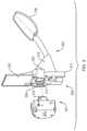
- FIG. 3is a diagram illustrating an example embodiment of a robotic connector mating with a tool with an adaptor.
- FIG. 4 Ais a diagram illustrating an example embodiment of an adaptor attached to a serving spoon from a side profile perspective.
- FIG. 4 Bis a diagram illustrating an example embodiment of an adaptor attached to a serving spoon from an overhead view.
- FIG. 4 Cis an exploded view diagram illustrating an example embodiment of an adaptor attached to a serving spoon in an isometric view.
- FIG. 5is a diagram illustrating an example embodiment of an adaptor attached to disher/scooping tool utilizing air pressure to activate an actuator to control a dispensing mechanism.
- FIG. 6 Ais a diagram illustrating an example embodiment of an adaptor attached to a disher with a mechanical actuator from a side profile perspective.
- FIG. 6 Bis a diagram illustrating an example embodiment of the adaptor attached to a disher with a mechanical actuator from an overhead view.
- FIG. 6 Cis an exploded view diagram illustrating an example embodiment of an adaptor attached to a disher with a mechanical actuator in an isometric view
- FIG. 7is a diagram illustrating an example embodiment of an adaptor attached to tong tool utilizing air pressure to activate an actuator to control the tong movement.
- FIG. 8is a picture of an example embodiment of an adaptor attached to tong tool utilizing air pressure to activate an actuator to control the tong movement in an open and closed position.
- FIG. 9 Ais a diagram illustrating an example embodiment of an adaptor attached to a pair of tongs with a mechanical actuator from a side profile perspective.
- FIG. 9 Bis a diagram illustrating an example embodiment of an adaptor attached to a pair of tongs with a mechanical actuator from an overhead view
- FIG. 9 Cis an exploded view diagram illustrating an example embodiment of an adaptor attached to a pair of tongs with a mechanical actuator in an isometric view.
- FIG. 10is a diagram illustrating an example embodiment of a monolithic tool and adaptor that does not require actuation.
- FIG. 11is a picture of example embodiments of the present disclosure for a set of food preparation and serving tools.
- FIG. 12is a diagram illustrating an example embodiment of an adaptor with storage rack.
- FIG. 13is a diagram illustrating example embodiments of adaptors attached to a set of static tools.
- FIG. 14is a diagram illustrating example embodiments of adaptors attached to a set of actuatable tools.
- the present disclosureprovides an apparatus and corresponding method that solves problems relating to employing robotics in a food service environment.
- the apparatusenables safe manipulation of foodstuffs by connecting, to a robot, (1) a tool having a monolithic form factor or (2) an existing tool with an adaptor allowing it to be controlled and used by a robot.
- the monolithic designenables ease of cleaning and can be designed to be dishwasher safe.
- the disclosureprovides for common or standardized geometry to allow multiple adaptors, for a range of tools, to attach and detach to a common master robotic connector at a flange. In other words, the multiple adaptors, for the range of tools, are compatible with a common master robotic connector.
- the materials usedare food-safe, waterproof and can be compatible with an injection molding process providing a route to cost effective manufacturing.
- the present disclosurerelates to an adaptor attachable to new and existing utensils so that they maintain their original function (e.g., manipulating, preparing, and serving food) while enabling them to be used by a robot.
- the end effectorse.g., utensils
- Contaminationcan include allergens (e.g., peanuts), dietary preferences (e.g., contamination from pork for a vegetarian or kosher customer), dirt/bacteria/viruses, or other non-ingestible materials (e.g., oil, plastic, or particles from the robot itself).
- allergense.g., peanuts
- dietary preferencese.g., contamination from pork for a vegetarian or kosher customer
- dirt/bacteria/virusese.g., oil, plastic, or particles from the robot itself.
- the robotshould be operated within its design specifications, and not exposed to excessive temperatures or incompatible liquids, without sacrificing cleanliness.
- the robotshould be able to manipulate food stuffs, which are often fracturable and deformable materials, and further the robot must be able to measure an amount of material controlled by its utensil in order to dispense specific portions.
- the robotshould be able to automatically and seamlessly switch utensils (e.g., switch between a ladle and salad tongs).
- the utensilsshould be adapted to be left in an assigned food container and interchanged with the robot as needed, in situ.
- the interchangeable partse.g., utensils
- the robotshould be able to autonomously generate a task plan and motion plan(s) to assemble all ingredients in a recipe, and execute that plan.
- the robotshould be able to modify or stop a motion plan based on detected interference or voice commands to stop or modify the robot's plan.
- the robotshould be able to minimize the applied torque based on safety requirements or the task context or the task parameters (e.g., density and viscosity) of the material to be gathered.
- the systemshould be able to receive an electronic order from a user, assemble the meal for the user, and place the meal for the user in a designated area for pickup automatically with minimal human involvement.
- FIG. 1is a block diagram illustrating an example embodiment of a quick service food environment 100 of embodiments of the present disclosure.
- the quick service food environment 100includes a food preparation area 102 and a patron area 120 .
- the food preparation area 102includes a plurality of ingredient containers 106 a - d each having a particular foodstuff (e.g., lettuce, chicken, cheese, tortilla chips, guacamole, beans, rice, various sauces or dressings, etc.).
- Each ingredient container 106 a - dstores in situ its corresponding ingredients.
- Utensils 108 a - dmay be stored in situ in the ingredient containers or in a stand-alone tool rack 109 .
- the utensils 108 a - dcan be spoons, ladles, tongs, dishers (scoopers), spatulas, or other utensils.
- Each utensil 108 a - eis configured to mate with and disconnect from a tool changer interface 112 of a robot arm 110 . While the term utensil is used throughout this application, a person having ordinary skill in the art can recognize that the principles described in relation to utensils can apply in general to end effectors in other contexts (e.g., end effectors for moving fracturable or deformable materials in construction with an excavator or backhoe, etc.); and a robot arm can be replaced with any computer controlled actuatable system which can interact with its environment to manipulate a deformable material.
- the robot arm 110includes sensor elements/modules such as stereo vision systems (SVS), 3D vision sensors (e.g., Microsoft KinectTM or an Intel RealSenseTM), LIDAR sensors, audio sensors (e.g., microphones), inertial sensors (e.g., internal motion unit (IMU), torque sensor, weight sensor, etc.) for sensing aspects of the environment, including pose (i.e., X, Y, Z coordinates and roll, pitch, and yaw angles) of tools for the robot to mate, shape and volume of foodstuffs in ingredient containers, shape and volume of foodstuffs deposited into food assembly container, moving or static obstacles in the environment, etc.
- SVSstereo vision systems
- 3D vision sensorse.g., Microsoft KinectTM or an Intel RealSenseTM
- LIDAR sensorse.g., LIDAR sensors
- audio sensorse.g., microphones
- inertial sensorse.g., internal motion unit (IMU), torque sensor, weight sensor, etc.
- pose
- a patron in the patron area 120enters an order 124 in an ordering station 122 a - b , which is forwarded to a network 126 .
- a patron on a mobile device 128can, within or outside of the patron area 120 , generate an optional order 132 .
- the network 126forwards the order to a controller 114 of the robot arm 110 .
- the controllergenerates a task plan 130 for the robot arm 110 to execute.
- the task plan 130includes a list of motion plans 132 a - d for the robot arm 110 to execute.
- Each motion plan 132 a - dis a plan for the robot arm 110 to engage with a respective utensil 108 a - e , gather ingredients from the respective ingredient container 106 a - d , and empty the utensil 108 a - e in an appropriate location of a food assembly container 104 for the patron, which can be a plate, bowl, or other container.
- the robot arm 110then returns the utensil 108 a - e to its respective ingredient container 106 a - d , the tool rack 109 , or other location as determined by the task plan 130 or motion plan 132 a - d , and releases the utensil 108 a - d .
- the robot armexecutes each motion plan 132 a - d in a specified order, causing the food to be assembled within the food assembly container 104 in a planned and aesthetic manner.
- the environment 100 illustrated by FIG. 1can improve food service to patrons by assembling meals faster, more accurately, and more sanitarily than a human can assemble a meal.
- FIG. 2 Ais a diagram illustrating an example embodiment of an adaptor 200 from a side profile perspective.
- FIG. 2 Bis a diagram illustrating an example embodiment of the adaptor 200 from a frontal perspective with respect to the side of the adapter 200 that connects with the flange of the robot.
- the adaptor 200has two ends: a robot end 201 and a tool end 202 .
- the robot end 201 and tool end 202are separated by an adapter body 203 .
- the adaptor body 203 in FIG. 2 Ahas the particular configuration illustrated, but a person having ordinary skill in the art can recognize that the adaptor body 203 may also be any geometry, size, and shape, and further can be composed of any material depending on the needs of the food service environment.
- the adaptor body 203may have a unique design for a specific utensil. Alternatively, the adaptor body 203 may have a common design employed for compatibility with all types of tools.
- the adaptor body 203may be monolithic in certain embodiments
- the body 203 of adaptor 200shown in FIGS. 2 A-B , includes a circular truncated cone 205 having its upper (e.g., smaller) radius facing the robot end 201 and its lower (e.g., larger) radius attached to a first side 206 a of cylinder 206 .
- the radius of cylinder 206is greater than the lower radius of circular truncated cone 205 . Therefore, the profile of the cylinder 206 extends past the profile of the circular truncated cone 205 , providing a splash guard protector for food material and a backstop for the connector of the robot when it is mated with first interface 204 .
- a second (e.g., opposite or opposing) side 206 b of cylinder 206is connected to a larger base of a tapered hexagonal prism 207 .
- a smaller base of the tapered hexagonal prism 207faces tool end 202 .
- a second interface(not shown in FIGS. 2 A and 2 B ) configured to attach to a tool/utensil can be located on the smaller base of tapered hexagonal prism 207 .
- the adaptor 200can be connected to any part of a tool by the second interface at tool side 202 .
- the adaptor 200 and the second interfacecan be configured to attached to any type of desired tool included existing tools and custom designed tools.
- Elements of adaptor body 203can be tapered, which allows for the adaptor to be self-locating within a holder using the aid of gravity.
- the adaptor 200may also include port 211 , which allows the robot to control an actuator attached to adaptor 200 and the actuator employed to create movement in an actuatable utensil attached to the second interface of adaptor 200 .
- Port 211may be an opening through body 203 that permits a robot on the robot end 201 to control, activate, and/or mechanically manipulate an actuator located at the tool end 202 .
- Port 211may include elements that hold actuator at a determined position for consistent actuation by and connection with an actuator controller of the robot.
- the robot end 201includes a first interface component 204 configured to removably mate with a robot connector.
- the robot connectormay include a flange that is designed to couple with a first interface component 204 .
- the first interface component 204is of any size and shape matching the flange of the robot connector, but can have any geometry and location.
- a person having ordinary skill in the artcan recognize that the first interface component 204 may also be any geometry, size, and shape, and further can be composed of any material depending on the needs of the food service environment.
- first interface component 204is located on the upper base of circular truncated cone 205 .
- the location, position, and orientation of the robot connectorcontrols the location, position, and orientation of the tool attached to adaptor 200 when the interface component 204 mates with the flange of a robot connector.
- the first interface component 204 of the adaptor 200shown in FIGS. 2 A-B , includes a volume 208 enclosed by a body 203 .
- An entrance to the volume 208comprises a hollow circular truncated cone 209 protruding from the body 203 at the robot end 201 .
- a hollow circular truncated cone 209may have a slightly eccentric circumference that constrains the location and position of the adaptor when the first interface component 204 mates with a flange having a matching eccentric circumference.
- FIGS. 2 C- 2 Dare cross-sectional diagrams illustrating an example embodiment of a first interface component of an adaptor mating with an element of a robotic flange.
- the adaptor 200 illustrated by FIGS. 2 C-Dhas the same dimensions as adaptor 200 show in FIGS. 2 A-B .
- the robot connectorincludes a protruding element 210 located within a flange.
- the protruding element 210has dimensions and geometry that allows it to enter volume 208 and through the interior of hollow circular truncated cone 209 of first interface component 204 .
- Volume 208receives protruding element 210 , which locks into place inside volume 208 .
- a piston 215extends through the protruding element 210 into volume 208 , and then expands three captive ball bearings 216 in a radial direction.
- the ball bearingsmate to an internally sloped surface 217 on the interior of volume 208 , which results in the protruding element 210 being pulled into contact with the bottom of volume 208 .
- piston 215retracts, freeing ball bearings 216 and allows the protruding element 210 to be removed and the robotic flange is disconnected from first interface component 204 .
- adaptor 200includes feedthroughs that enable power (e.g., electricity) or data to be transmitted between the robot and the tool when the first interface component is mated with the flange and the second interface component is attached to the utensil.
- the electrical feedthroughsmay be located within adaptor body 203 , first interface component 204 , or the second interface.
- adaptor 200includes air feedthroughs that enable compressed air to pass between the robot and the utensil when the first interface component is mated with the flange and the second interface component is attached to the existing utensil.
- the air feedthroughsmay be located within at least one of adaptor body 203 , first interface component 204 , and/or second interface.
- the actuator 220is a drive shaft that the actuator controller 213 can rotate, however, the actuator 220 , the actuator controller 213 , and the port 211 may have any geometry and configuration be any size or shape and be made of any material depending upon the utensil actuated and the requirements of the food service environment employing robot 250 and adaptor 200 .
- the actuator controller 213is connected to actuator by at least one electrical, water, and/or air feedthrough.
- the feedthroughsmay be connected to actuator 220 and any attached tool through port 211 .
- the feedthroughsmay also be external to adaptor 200 and connected to actuator 220 and any attached tool by circumventing adaptor 200 .
- FIG. 3is a diagram illustrating an example embodiment of a master robot connector 312 mating with a tool with an adaptor 300 .
- the adaptor 300is configured to attach the tool 108 , a serving spoon, to a robot connector 312 to allow for the control and manipulation of tool 108 by a robot.
- a robot side 301 of the adaptor 300mates with the robot connector 312 by connecting a first interface component 304 with a flange 314 .
- the robot connector 312can connect and disconnect with the adaptor 300 allowing a single robot, through connector 312 , to connect to and control multiple tools 108 , at different times, having adaptors 300 with first interface components 304 that match flange 314 .
- the adaptor 300may include ports 311 employed for rotational alignment, pneumatic signals, electrical modules to carry electrical signals, and/or actuator connections.
- the adaptor 300may also include a visual tag feature for easier recognition by vision systems of the robot.
- a visual marker/tag 316is attached to the top of body 303 .
- the visual marker 316provides the position, orientation, and/or the rotation of the tool 108 and adaptor 300 in space with respect to the robot connector 312 , allowing for easier attachment of first interface component 304 with flange 314 .
- the adaptor body 303includes a bottom feature 317 that allows tool 108 and adaptor 300 to rest in a consistent location in a food container, even if the food container stores varying levels of food.
- the bottom feature 317allows the robot to more easily find and attach to adaptor 300 because it more easily rests in a standard position.
- the bottom feature 317can include one or more members extending from the adaptor 300 , tool 108 , or tool handle configured to latch on to or rest against an edge of a material bin or other element in the environment.
- the tool side 302 of the adaptor 300attaches to the tool 108 through the second interface 315 .
- the tool 108is removably attached to the second interface 315 .
- the tool 108can be permanently attached to the second interface 315 .
- the tool 108 and the adaptor 300may be composed of a single monolithic block.
- the tool 108may be a previously existing utensil with known properties and meeting established safety and cleanliness.
- the adaptor 300allows the tool 108 , previously designed for human use, to be used and controlled by a robot. Utilizing existing tools instead of designing robot specific tools can provide a simpler, cheaper, and more intuitive way to transition a food service environment from human control to robotic control. Additionally, existing tools have undergone food safety testing and meet other requirements for safe and efficient use.
- the tool 108is a static tool without any joints that require manipulation and can be fully controlled without an actuator. Therefore, the adaptor 300 for use with tool 108 , does not include an actuator.
- the tool 108when the adaptor 300 is connected to the robot connector 312 , can be controlled by changing the location, position, and orientation of the robot connector 312 and be used by the robot to mimic any action a human could take with the tool 108 .
- the robotcan be configured to use the tool 108 to deliver amounts of food stuff in the food service environment shown in FIG. 1 .
- the robot 110can use the robot connector 112 , 312 to connect to utensil 108 d having adaptor 300 , use utensil 108 d to accomplish a task, place it back in container 106 d , disconnect from the utensil 108 d , attach to utensil 108 c , use utensil 108 c to accomplish a second task, place utensil 108 c back in container 106 c , and disconnect to utensil 108 d .
- the adaptor 300allows for a single robot arm 110 with a master connector 112 to utilize multiple utensils 108 a - d , even if the utensils require different manners of operation and connection.
- FIG. 4 Ais a diagram illustrating an example embodiment of an adaptor 400 attached to a serving spoon from a side profile perspective.
- the adaptor 400is attached to tool 108 through second interface component 415 .
- the adaptor 400has a first interface component 404 that can removably mate with a flange of the robot connector 112 .
- the tool 108is a serving spoon with a screw hole at the end of its handle.
- the second interface component 415includes, a holder 420 that the handle of tool 108 rests against and a screw 421 that secures the handle of the tool 108 to the holder.
- the second interface component 415securely couples the tool 108 to the adaptor 400 .
- Actuatable toolsare tools that require internal movement to be effectively used, such as tongs, or an ice scream scooper with a dispensing mechanism.
- the adaptorincludes an actuator employed to create movement of elements in the tool.
- Embodimentsinclude specialized actuators designed to operate any manner of actuatable tools.
- the actuatormay be a linear or rotary actuator configured to create either linear or rotational movement at a joint of an actuatable actual tool.
- the adaptormay also include a spring to apply a tensile force opposing movement created by the actuator. The tensile force can cause stable movement of the joint and/or provide that the tool returns to a resting position after the desired movement induced by the actuator is completed.
- the actuatorcan be mechanical, pneumatic, hydraulic, electrical and utilize any other known method of or apparatus for creating and controlling movement.
- an attached toolis controlled by the actuator, and the position, location, and orientation of the robotic connector when the first interface component is mated with the flange of the robot's connector and the second interface component is attached to the actual tool.
- FIG. 5is a diagram illustrating an example embodiment of an adaptor 500 attached to disher/scooping tool utilizing air pressure to activate an actuator to control a dispensing mechanism.
- the adaptor 500includes pneumatic actuator used to activate an element of the disher 108 .
- the body 503encloses a portion of or all of a pneumatic actuator including a pneumatic rotary actuator 502 and a coupling 501 .
- the pneumatic rotary actuator 502is mounted to adaptor base 503 .
- the pneumatic rotary actuator 502is configured to rotate 180 degrees clockwise or counter clockwise using pressurized air.
- a pneumatic valveis located the robot control equipment and enables the pneumatic rotary actuator 502 to switch between clockwise and counter clockwise rotation.
- the pneumatic rotary actuator 502is attached with the pneumatic coupling 501 to a dispensing rod element 506 that scrapes the inside surface of the scooper half-dome 108 to dislodge the foodstuffs when pneumatic rotary actuator 502 is rotated.
- the pneumatic actuator 502receives air through the robot connector and ports 511 in the robot side of adaptor 500 .
- a second interface 515attaches the disher 108 to the body 503 of the adaptor 500 and holds the rest of the disher 108 steady when the pneumatic actuator creates movement.
- the robotcontrols the pneumatic actuator when attached to the adaptor 500 at first interface 504 through utilizing air-pressure pass-throughs located in the ports 511 .
- a valve located with the robot control equipmentconnects to pneumatic actuator 502 and passes air through pass-throughs 511 to actuate the pneumatic actuator 502 .
- One position of the valverotates the dispensing rod element of disher 108 , the other position returns the dispensing rod element to its initial position.
- the adaptor 500mates with the robot connector at the first interface 504 to be physically locked to the robot, but also receive air pressure pneumatically.
- the adaptor 500also can contain an electric actuator which utilizes electrical pass-throughs from the robot connector.
- FIG. 6 Ais a diagram illustrating an example embodiment of an adaptor 600 attached to a disher with a mechanical actuator 620 from a side profile perspective.
- the adaptor 600is attached to tool 108 through a second interface component 615 .
- the adaptor 600includes a first interface component 604 that can removably mate with a flange of robot connector 112 .
- Adaptor 600also includes an actuator 620 that can be controlled by an attached to and manipulated by a robot through port 611 .
- the tool 108is a disher utensil used for serving food.
- Second interface component 615can securely couple tool 108 to adaptor 600 .
- FIG. 6 Bis a diagram illustrating an example embodiment of the adaptor 600 attached to a disher with a mechanical actuator 620 from an overhead view.
- a trigger 601actuates the disher 108 .
- the force on the trigger 601moves rack 602 in a transverse path across the body of the disher 108 .
- the rack 602mates with the teeth of pinion 603 .
- Movement of rack 602causes the pinion 603 to rotate.
- a rod attached to the pinion 603rotates with the pinion 603 , causing an open circular end attached to the shaft to rotate and scrape the surface of the bowl of disher 108 , dispensing any food contained in the bowl of the disher 108 .
- Disher 108includes a torsion 621 spring that returns the scraping bracket to a normal position along the scooping bowl.
- the actuator 620is a drive shaft that attached to the pinion 603 at the end of the drive shaft distal from the adaptor 600 .
- the actuator drive shaftrotates the pinion 603 and mimics the force created by a human pulling the trigger 601 and causes the disher 108 to dispense food contained in the disher bowl in a similar manner.
- the actuator 620can be rotated by a motor contained in the robot connector 112 by attaching to the end of the motor through port 611 to a proximate end of the actuator 620 .
- the end of actuator 620 proximate to adaptor 600can include a gear to allow for manipulation by the robot.
- FIG. 6 Cis an exploded view diagram illustrating an example embodiment of an adaptor 620 attached to a disher with a mechanical actuator in an isometric view.
- FIG. 6 Cillustrates an existing utensil, the disher 108 , attached to adaptor 600 with modifications that do not impact the performance of the utensil.
- the base of the disher 108is removed, relative to FIGS. 6 A-B , and second interface 615 is placed within a handle of disher 108 .
- the disher 108is secured to the second interface 615 with a pair of screws and corresponding securing screw holes.
- a person having ordinary skill in the artcan understand that corresponding nuts, bolts, washers, etc. can be necessary to secure the disher 108 to the second interface 615 .
- the adaptor 600including first and second interfaces 604 and 615 , can be monolithic. In an embodiment, the only modification of the disher 108 is the addition of the securing screws and removal of the base.
- the first interface component 604 attachable to the robot master connector, the second interface component 615 attachable to the tool 108 , and also accommodate mounting features for the required 620may all be included in a monolithic design.
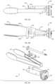
- FIG. 7is a diagram illustrating an example embodiment of an adaptor 700 attached to tong tool utilizing air pressure to activate an actuator to control the tong movement.
- a linear pneumatic actuator 701is attached to the adaptor body 703 .
- Second interface component 715is configured to attach to a set of tongs 108 and is a deformable flexure structure.
- the robotcontrols the pneumatic actuator when the robot is attached to adaptor 700 at first interface 704 by utilizing air-pressure pass-throughs located in ports 711 .
- the adaptor 700mates with the robot connector at first interface 704 to be physically locked to the robot and to receive air pressure pneumatically.
- a valve located with the robot control equipmentconnects to pneumatic cylinder 702 and passes air through pass-throughs 711 to actuate the pneumatic cylinder 702 .
- One position of the valvecauses the pneumatic cylinder 702 move outwards to open the tongs, and the other position of the value uses the pneumatic cylinder 702 move inwards to close the tongs with a gripping force.
- the adaptor 700also can contain an electric actuator or hydraulic actuator, instead of a pneumatic actuator, for utilizing electrical or water pass-throughs from the robot connector.
- FIG. 8is a picture of an example embodiment of an adaptor attached to tong tool utilizing air pressure to activate an actuator to control the tong movement in an open and closed position.
- the embodiment illustrated by FIG. 8is a monolithic design, where the tongs and adaptor body are created from a single material.
- FIG. 9 Ais a diagram illustrating an example embodiment of an adaptor 900 attached to a pair of tongs with a mechanical actuator 920 from a side perspective.
- the adaptor 900is attached to the tool, a pair of tongs 108 , through second interface component 915 .
- the second interface component 915attaches to the side of each tong 108 a and 108 b .
- the adaptor 900includes a first interface component 904 that can removably mate with a flange of robot connector 112 .
- the adaptor 900also includes actuator 920 that can be controlled by an attached robot through port 911 .
- the tool 108is a pair of tongs utensil employed for serving food.
- the second interface component 915may have any set of components, geometry, shape, or size and be made of any material that can securely couple tool 108 to adaptor 900 .
- FIG. 9 Bis a diagram illustrating an example embodiment of an adaptor 900 attached to a pair of tongs with a mechanical actuator 920 , from an overhead view.
- a traditional, manually operated, pair of tongscomposed of two individual tongs connected at a base, are actuated by the manual user applying force on outer sides of each tong, which creates a resulting gripping force between the tong ends.
- a pair of tongs 108composed two individual tongs 108 a and 108 b connected at their base by a living hinge, are actuated by applying force on the outer sides of each tong 108 a and 108 b to create the gripping force between the tong ends through robotic means.
- each tong 108 a and 108 bis created by a human user's hand squeezing the tongs 108 using traditional, manually operated tongs.
- the living hinge at the base tongs 108 a and 108 bapplies the force to return the tongs 108 a and 108 b to their open position when the squeezing force is removed.
- the hingeis pinned and includes a torsion spring opposing the squeezing force.
- the actuator 920is a drive shaft attached to pinion 903 at the end of the drive shaft distal from the body of adaptor 900 .
- the teeth of pinion 903are interlocked with the rack 902 .
- the rack 902is part of second interface component 915 and is securely attached to tong 108 a but not attached to tong 108 b .
- the actuator drive shaftrotates pinion 903 and causes rack 902 to move in a transverse motion across the unattached tong 108 b .
- the transverse motion of rack 902creates a force on the attached tong 108 a towards the unattached tong 108 b creating a gripping force between the tong ends.
- the gripping forcecan be lessened or terminated by reversing the rotation of the drive shaft of actuator 920 .
- the actuator 920can be rotated by a motor contained in the robot connector 112 by attaching to the end proximate end of actuator 920 of the motor through port 911 .
- the end of actuator 920 proximate to adaptor 900can include a gear to allow for manipulation by the robot.
- the teeth of pinion 903 , location of rack 902 , and the restorative force of the living hingereturn the tongs to a normal position and can be used to ensure the drive shaft of actuator 920 has the correct orientation for connecting to the motor contained in the robot connector 112 .
- FIG. 9 Cis an exploded view diagram illustrating an example embodiment of an adaptor 900 attached to a pair of tongs with a mechanical actuator 920 , from an isometric view.
- FIG. 9 Cillustrates how an existing utensil, the pair of tongs 108 , is attached to adaptor 900 with modifications that do not affect its performance.
- the outside surface of each tong 108 a and 108 b proximate to their attached baseare placed against a flat protruding surface of second interface 915 .
- Tongs 108 a and 108 bare each secured to second interface 915 with a screw.
- the Tong 108 ais also attached to rack 902 using screws.
- the only modification of tongs 108is the addition of the securing screws and other securing hardware (e.g., nuts, bolts, washers, etc.).
- Adaptor 900can be monolithic.
- the first interface component 904 attachable to the robot connector, the second interface component 915 attachable to the tool 108 , and also according mounting features for the required actuatormay all be included in a monolithic design.
- FIG. 10is a diagram illustrating an example embodiment of a monolithic tool that does not require actuation.
- Embodiments of the disclosurecan utilize elements composed of, or be entirely made from, a variety of foodsafe and/or waterproof plastics, including food-safe polycarbonate, PC-ISO, for use on a Stratasys Fortus 3D-printing machine.
- One of the novel features of the disclosureis the ability to combine the adaptor with the tool body as illustrated by FIG. 10 , for example.
- Embodiments of the disclosurecan be manufactured using 3D printing technology. Complex geometries can be rapidly fabricated and combined into functional prototypes. Additional features (e.g., bin clocking and visual tag alignment) are cost effective and can be rapidly incorporated into designs. Embodiments of the disclosure can also use of any other known printing machines and plastic material. Further, food service applications are, generally speaking, low-load. This enables the usage of 3D printed plastic materials without need for large supporting structures. Many of the available tool changers are over-designed to work in higher load applications.
- Injection moldingsare also possible in embodiments, and other food-safe plastics and/or waterproof can be used for elements or the entirety of the adaptor, such as high-density polyethylene (HDPE), polyethylene terephthalate (PET) or polycarbonate.
- HDPEhigh-density polyethylene
- PETpolyethylene terephthalate
- compatible designscan also be fabricated with injection molding processes. For designs that do not require actuation, the tool and adaptor can be completely monolithic.
- a plastic food-safe and water proof adaptorcan be attached to an existing metal, or other material, tool.
- both the adaptor and the toolcan be composed of a plastic food-safe and water proof material either as separate pieces or as a monolithic design incorporating both the adaptor and tool.
- actuatorscan be moved from the tool and/or adaptor to a robotic connector master that has these additional actuation capabilities. Removing the actuator from the tool/adaptor would enable actuatable tool designs such as the scooper and tongs to be truly monolithic.
- the adaptor and tooleither their entirety or their individual elements can be composed of at least one of, nylon, stainless steel, aluminum, and/or silicone.
- prior art adaptorssuch as ATI QC-11 can be mated to spoons and ladles.
- the prior art adaptorsrequire significant rewording of the tools to be used.
- Other prior art solutionsuse new hand-like tools (i.e. shadow hand from the Shadow Robot Company), however, these are currently not at a state of reliability to be used in the near future, especially in a food environment and cannot take advantage of the known qualities of existing tools and utensils.
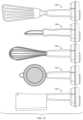
- FIG. 11is a picture of embodiments of the present disclosure for a set of food preparation and serving tools 1100 .
- the tools 1102 , 1103 , 1106 , 1108 , 1110can be repurposed regular kitchen tools simply attached to an adaptor.
- the ice cream scooper 1104is an ice cream scoop attached to an adaptor at its handle.
- tools 1102 , 1104 , and 1106include a visual tag feature on its tool changer interface.
- tools 1102 , 1103 , 1106 , 1108 , 1110have the same first interface component configured to removably mate with a flange of a robot connector, tools 1102 , 1103 , 1106 , 1108 , 1110 can all be utilized by a single robot arm as shown in the service environment of FIG. 1 . Additionally, because the disclosure's adaptor allows tools 1102 , 1103 , 1106 , 1108 , 1110 to be repurposed regular kitchen tools the transition from a human operated service environment to a robotic operated service environment is far simpler, cheaper, and streamlined than if the highly modified or newly designed tools are required to function.
- FIG. 12is a diagram illustrating an example embodiment of an adaptor 1200 with storage rack 1230 .
- the adaptor 1200includes a tool end 1202 configured to interface with an opening 1231 of storage rack 1230 .
- Robot 1250connects to the adaptor 1200 attached to tool 108 while adaptor 1200 is held by opening 1231 of storage rack 1230 .
- After robot 1250 connects to the adaptor 1200it can employ tool 108 .
- robot 1250no longer needs tool 108 , it places the adaptor 1200 back in opening 1231 of storage rack 1230 and disconnects from the adaptor 1200 .
- Tool 108remains in opening 1231 of storage rack 1230 after the robot 1250 disconnected.
- the storage rack 1230can include multiple openings 1231 for holding a range of tools with adaptors configured to removably mate with robot 1250 .
- FIG. 13is a diagram illustrating example embodiments of adaptors 1300 attached to a set of static tools.
- the disclosure's adaptorcan be configured to attach to and permit a robot to control and manipulate a wide range of static tools.
- FIG. 14is a diagram illustrating example embodiments of adaptors 1400 attached to a set of actuatable tools.
- the disclosure's adaptorcan be configured to attach to and permit a robot to control and manipulate a wide range of actuatable tools.
Landscapes
- Engineering & Computer Science (AREA)
- Mechanical Engineering (AREA)
- Robotics (AREA)
- Physics & Mathematics (AREA)
- Theoretical Computer Science (AREA)
- Automation & Control Theory (AREA)
- Software Systems (AREA)
- Artificial Intelligence (AREA)
- Evolutionary Computation (AREA)
- Mathematical Physics (AREA)
- Life Sciences & Earth Sciences (AREA)
- Food Science & Technology (AREA)
- General Physics & Mathematics (AREA)
- Health & Medical Sciences (AREA)
- Business, Economics & Management (AREA)
- Computational Linguistics (AREA)
- General Health & Medical Sciences (AREA)
- Fuzzy Systems (AREA)
- Human Resources & Organizations (AREA)
- Data Mining & Analysis (AREA)
- Molecular Biology (AREA)
- Computing Systems (AREA)
- General Engineering & Computer Science (AREA)
- Biophysics (AREA)
- Biomedical Technology (AREA)
- Human Computer Interaction (AREA)
- Multimedia (AREA)
- Manipulator (AREA)
- Strategic Management (AREA)
- Entrepreneurship & Innovation (AREA)
- Economics (AREA)
- Development Economics (AREA)
- Educational Administration (AREA)
- Operations Research (AREA)
- Quality & Reliability (AREA)
- Tourism & Hospitality (AREA)
- General Business, Economics & Management (AREA)
- Game Theory and Decision Science (AREA)
- Marketing (AREA)
- Audiology, Speech & Language Pathology (AREA)
Abstract
Description
Claims (24)
Priority Applications (1)
| Application Number | Priority Date | Filing Date | Title |
|---|---|---|---|
| US16/571,003US11607810B2 (en) | 2018-09-13 | 2019-09-13 | Adaptor for food-safe, bin-compatible, washable, tool-changer utensils |
Applications Claiming Priority (7)
| Application Number | Priority Date | Filing Date | Title |
|---|---|---|---|
| US201862730947P | 2018-09-13 | 2018-09-13 | |
| US201862730933P | 2018-09-13 | 2018-09-13 | |
| US201862730703P | 2018-09-13 | 2018-09-13 | |
| US201862730918P | 2018-09-13 | 2018-09-13 | |
| US201862730934P | 2018-09-13 | 2018-09-13 | |
| US201862731398P | 2018-09-14 | 2018-09-14 | |
| US16/571,003US11607810B2 (en) | 2018-09-13 | 2019-09-13 | Adaptor for food-safe, bin-compatible, washable, tool-changer utensils |
Publications (2)
| Publication Number | Publication Date |
|---|---|
| US20200086502A1 US20200086502A1 (en) | 2020-03-19 |
| US11607810B2true US11607810B2 (en) | 2023-03-21 |
Family
ID=68069913
Family Applications (12)
| Application Number | Title | Priority Date | Filing Date |
|---|---|---|---|
| US16/571,025AbandonedUS20200086497A1 (en) | 2018-09-13 | 2019-09-13 | Stopping Robot Motion Based On Sound Cues |
| US16/570,855Active2041-11-22US11673268B2 (en) | 2018-09-13 | 2019-09-13 | Food-safe, washable, thermally-conductive robot cover |
| US16/571,041Active2039-12-05US11648669B2 (en) | 2018-09-13 | 2019-09-13 | One-click robot order |
| US16/570,606Active2040-04-20US11872702B2 (en) | 2018-09-13 | 2019-09-13 | Robot interaction with human co-workers |
| US16/570,976Active2040-06-18US11571814B2 (en) | 2018-09-13 | 2019-09-13 | Determining how to assemble a meal |
| US16/571,040Active2040-08-18US11597087B2 (en) | 2018-09-13 | 2019-09-13 | User input or voice modification to robot motion plans |
| US16/570,915Active2039-09-24US11597085B2 (en) | 2018-09-13 | 2019-09-13 | Locating and attaching interchangeable tools in-situ |
| US16/570,955Active2041-06-08US11597086B2 (en) | 2018-09-13 | 2019-09-13 | Food-safe, washable interface for exchanging tools |
| US16/570,736Active2039-10-01US11597084B2 (en) | 2018-09-13 | 2019-09-13 | Controlling robot torque and velocity based on context |
| US16/571,003Active2041-02-14US11607810B2 (en) | 2018-09-13 | 2019-09-13 | Adaptor for food-safe, bin-compatible, washable, tool-changer utensils |
| US16/570,100Active2039-11-28US11628566B2 (en) | 2018-09-13 | 2019-09-13 | Manipulating fracturable and deformable materials using articulated manipulators |
| US18/541,877ActiveUS12403602B2 (en) | 2018-09-13 | 2023-12-15 | Robot interaction with human co-workers |
Family Applications Before (9)
| Application Number | Title | Priority Date | Filing Date |
|---|---|---|---|
| US16/571,025AbandonedUS20200086497A1 (en) | 2018-09-13 | 2019-09-13 | Stopping Robot Motion Based On Sound Cues |
| US16/570,855Active2041-11-22US11673268B2 (en) | 2018-09-13 | 2019-09-13 | Food-safe, washable, thermally-conductive robot cover |
| US16/571,041Active2039-12-05US11648669B2 (en) | 2018-09-13 | 2019-09-13 | One-click robot order |
| US16/570,606Active2040-04-20US11872702B2 (en) | 2018-09-13 | 2019-09-13 | Robot interaction with human co-workers |
| US16/570,976Active2040-06-18US11571814B2 (en) | 2018-09-13 | 2019-09-13 | Determining how to assemble a meal |
| US16/571,040Active2040-08-18US11597087B2 (en) | 2018-09-13 | 2019-09-13 | User input or voice modification to robot motion plans |
| US16/570,915Active2039-09-24US11597085B2 (en) | 2018-09-13 | 2019-09-13 | Locating and attaching interchangeable tools in-situ |
| US16/570,955Active2041-06-08US11597086B2 (en) | 2018-09-13 | 2019-09-13 | Food-safe, washable interface for exchanging tools |
| US16/570,736Active2039-10-01US11597084B2 (en) | 2018-09-13 | 2019-09-13 | Controlling robot torque and velocity based on context |
Family Applications After (2)
| Application Number | Title | Priority Date | Filing Date |
|---|---|---|---|
| US16/570,100Active2039-11-28US11628566B2 (en) | 2018-09-13 | 2019-09-13 | Manipulating fracturable and deformable materials using articulated manipulators |
| US18/541,877ActiveUS12403602B2 (en) | 2018-09-13 | 2023-12-15 | Robot interaction with human co-workers |
Country Status (3)
| Country | Link |
|---|---|
| US (12) | US20200086497A1 (en) |
| EP (3) | EP3849755A1 (en) |
| WO (11) | WO2020056295A2 (en) |
Cited By (3)
| Publication number | Priority date | Publication date | Assignee | Title |
|---|---|---|---|---|
| US20220048186A1 (en)* | 2020-08-15 | 2022-02-17 | Rapyuta Robotics Co., Ltd. | Dynamically generating solutions for updating plans and task allocation strategies |
| US20230021286A1 (en)* | 2021-07-13 | 2023-01-19 | Piotr Gurgul | Voice-controlled settings and navigation |
| US11872702B2 (en) | 2018-09-13 | 2024-01-16 | The Charles Stark Draper Laboratory, Inc. | Robot interaction with human co-workers |
Families Citing this family (110)
| Publication number | Priority date | Publication date | Assignee | Title |
|---|---|---|---|---|
| CN105446350B (en)* | 2014-09-26 | 2018-05-29 | 科沃斯机器人股份有限公司 | Self-movement robot moves boundary demarcation method |
| US12257711B2 (en)* | 2015-08-18 | 2025-03-25 | Mbl Limited | Robotic kitchen systems and methods in an instrumented environment with electronic cooking libraries |
| US20170221296A1 (en) | 2016-02-02 | 2017-08-03 | 6d bytes inc. | Automated preparation and dispensation of food and beverage products |
| FR3052861B1 (en)* | 2016-06-20 | 2018-07-13 | Ixblue | METHOD FOR COMPENSATION OF CORIOLIS, CENTRIFUGAL AND GRAVITY COUPLES IN A MOTION SIMULATOR, MOTION SIMULATOR SYSTEM |
| CN106406312B (en)* | 2016-10-14 | 2017-12-26 | 平安科技(深圳)有限公司 | Guide to visitors robot and its moving area scaling method |
| US20210030199A1 (en) | 2017-03-06 | 2021-02-04 | Miso Robotics, Inc. | Augmented reality-enhanced food preparation system and related methods |
| US11142412B2 (en) | 2018-04-04 | 2021-10-12 | 6d bytes inc. | Dispenser |
| US20190307262A1 (en) | 2018-04-04 | 2019-10-10 | 6d bytes inc. | Solid Dispenser |
| US11420344B2 (en) | 2018-04-24 | 2022-08-23 | Miso Robotics, Inc. | Smooth surfaced flexible and stretchable skin for covering robotic arms in restaurant and food preparation applications |
| US11170224B2 (en) | 2018-05-25 | 2021-11-09 | Vangogh Imaging, Inc. | Keyframe-based object scanning and tracking |
| US11192258B2 (en) | 2018-08-10 | 2021-12-07 | Miso Robotics, Inc. | Robotic kitchen assistant for frying including agitator assembly for shaking utensil |
| US11436753B2 (en) | 2018-10-30 | 2022-09-06 | Liberty Reach, Inc. | Machine vision-based method and system to facilitate the unloading of a pile of cartons in a carton handling system |
| US11577401B2 (en)* | 2018-11-07 | 2023-02-14 | Miso Robotics, Inc. | Modular robotic food preparation system and related methods |
| JP6997068B2 (en)* | 2018-12-19 | 2022-01-17 | ファナック株式会社 | Robot control device, robot control system, and robot control method |
| JP7339124B2 (en)* | 2019-02-26 | 2023-09-05 | 株式会社Preferred Networks | Control device, system and control method |
| WO2020184756A1 (en)* | 2019-03-13 | 2020-09-17 | 엘지전자 주식회사 | Robot |
| US11170526B2 (en)* | 2019-03-26 | 2021-11-09 | Samsung Electronics Co., Ltd. | Method and apparatus for estimating tool trajectories |
| US11170552B2 (en) | 2019-05-06 | 2021-11-09 | Vangogh Imaging, Inc. | Remote visualization of three-dimensional (3D) animation with synchronized voice in real-time |
| US11232633B2 (en)* | 2019-05-06 | 2022-01-25 | Vangogh Imaging, Inc. | 3D object capture and object reconstruction using edge cloud computing resources |
| DE102019208624A1 (en)* | 2019-06-13 | 2020-12-17 | Deckel Maho Seebach Gmbh | CONTROL DEVICE FOR USE ON A NUMERICALLY CONTROLLED MACHINE TOOL AND MACHINE TOOL WITH A CONTROL DEVICE |
| US12133615B2 (en) | 2019-07-26 | 2024-11-05 | Miso Robotics, Inc. | Transportable robotic-automated kitchen workcell |
| HK30006163A2 (en)* | 2019-08-02 | 2020-05-15 | 燧氏科技有限公司 | Automated cooking system |
| US12360532B2 (en)* | 2019-08-16 | 2025-07-15 | isee | Latent belief space planning using a trajectory tree |
| US20220234209A1 (en)* | 2019-08-23 | 2022-07-28 | Ilya A. Kriveshko | Safe operation of machinery using potential occupancy envelopes |
| US11348332B2 (en)* | 2019-09-25 | 2022-05-31 | Toyota Research Institute, Inc. | Object location analysis |
| US11164336B2 (en) | 2019-09-27 | 2021-11-02 | Martin Adrian FISCH | Methods and apparatus for orientation keypoints for complete 3D human pose computerized estimation |
| US11315326B2 (en)* | 2019-10-15 | 2022-04-26 | At&T Intellectual Property I, L.P. | Extended reality anchor caching based on viewport prediction |
| US11591170B2 (en) | 2019-10-25 | 2023-02-28 | Dexai Robotics, Inc. | Robotic systems and methods for conveyance of items |
| US11288509B2 (en)* | 2019-11-12 | 2022-03-29 | Toyota Research Institute, Inc. | Fall detection and assistance |
| US11335063B2 (en) | 2020-01-03 | 2022-05-17 | Vangogh Imaging, Inc. | Multiple maps for 3D object scanning and reconstruction |
| JP7364032B2 (en)* | 2020-02-25 | 2023-10-18 | 日本電気株式会社 | Control device, control method and program |
| JP7416197B2 (en)* | 2020-02-25 | 2024-01-17 | 日本電気株式会社 | Control device, control method and program |
| US11964247B2 (en) | 2020-03-06 | 2024-04-23 | 6d bytes inc. | Automated blender system |
| US11446875B2 (en)* | 2020-03-09 | 2022-09-20 | International Business Machines Corporation | Devising a self-movement path for at least one printing device |
| CN111360780A (en)* | 2020-03-20 | 2020-07-03 | 北京工业大学 | Garbage picking robot based on visual semantic SLAM |
| EP3893064A1 (en)* | 2020-04-07 | 2021-10-13 | GF Machining Solutions AG | Method for predicting status of machining operation |
| US12311070B2 (en) | 2020-05-08 | 2025-05-27 | Robust AI, Inc. | Robotic social interaction |
| GB2595289A (en)* | 2020-05-21 | 2021-11-24 | Bae Systems Plc | Collaborative robot system |
| CN111504328B (en)* | 2020-05-22 | 2022-07-08 | 梅卡曼德(北京)机器人科技有限公司 | Robot motion planning method, path planning method, grasping method and device thereof |
| CN111696152B (en)* | 2020-06-12 | 2023-05-12 | 杭州海康机器人股份有限公司 | Method, device, computing equipment, system and storage medium for detecting package stack |
| CN113759731B (en)* | 2020-06-22 | 2025-02-21 | 北京京东乾石科技有限公司 | A method and device for dispatching a robotic arm |
| JP7535400B2 (en)* | 2020-07-14 | 2024-08-16 | 株式会社キーエンス | Image Processing Device |
| CN111823277A (en)* | 2020-07-24 | 2020-10-27 | 上海大学 | An object grasping platform and method based on machine vision |
| CN111855262A (en)* | 2020-07-28 | 2020-10-30 | 季华实验室 | Soil collection system and robot |
| EP3960392A1 (en)* | 2020-08-24 | 2022-03-02 | ABB Schweiz AG | Method and system for robotic programming |
| US11550904B2 (en)* | 2020-08-25 | 2023-01-10 | Robert Bosch Gmbh | System and method for improving measurements of an intrusion detection system by transforming one dimensional measurements into multi-dimensional images |
| TWI876090B (en)* | 2020-09-08 | 2025-03-11 | 荷蘭商Asm Ip私人控股有限公司 | Method of replacing end effector, semiconductor processing system, and end effector jig |
| US12277518B2 (en)* | 2020-10-05 | 2025-04-15 | Hyphen Technologies, Inc. | Modular system for food assembly |
| WO2022074448A1 (en)* | 2020-10-06 | 2022-04-14 | Mark Oleynik | Robotic kitchen hub systems and methods for minimanipulation library adjustments and calibrations of multi-functional robotic platforms for commercial and residential environments with artificial intelligence and machine learning |
| JP7492440B2 (en)* | 2020-11-10 | 2024-05-29 | 株式会社日立製作所 | ROBOT CONTROL SYSTEM, ROBOT CONTROL METHOD, AND PROGRAM |
| CN116507459A (en)* | 2020-11-11 | 2023-07-28 | 索尼集团公司 | Information processing equipment and cooking system |
| US20220152824A1 (en)* | 2020-11-13 | 2022-05-19 | Armstrong Robotics, Inc. | System for automated manipulation of objects using a vision-based collision-free motion plan |
| WO2022120670A1 (en)* | 2020-12-10 | 2022-06-16 | 深圳市优必选科技股份有限公司 | Movement trajectory planning method and apparatus for mechanical arm, and mechanical arm and storage medium |
| US11607809B2 (en)* | 2020-12-22 | 2023-03-21 | Intrinsic Innovation Llc | Robot motion planning accounting for object pose estimation accuracy |
| US12437441B2 (en) | 2021-01-05 | 2025-10-07 | Liberty Robotics Inc. | Method and system for decanting a plurality of items supported on a transport structure at one time with a picking tool for placement into a transport container |
| CN112917477B (en)* | 2021-01-28 | 2024-06-11 | 武汉精锋微控科技有限公司 | Multi-degree-of-freedom robot static environment motion planning method |
| EP4052865A1 (en)* | 2021-03-05 | 2022-09-07 | Canon Kabushiki Kaisha | Information processing apparatus, robot system, information processing method, program, and recording medium |
| US12103185B2 (en) | 2021-03-10 | 2024-10-01 | Samsung Electronics Co., Ltd. | Parameterized waypoint generation on dynamically parented non-static objects for robotic autonomous tasks |
| US11945117B2 (en) | 2021-03-10 | 2024-04-02 | Samsung Electronics Co., Ltd. | Anticipating user and object poses through task-based extrapolation for robot-human collision avoidance |
| US20220297293A1 (en)* | 2021-03-22 | 2022-09-22 | X Development Llc | Dynamic torque saturation limits for robot actuator(s) |
| KR20220132241A (en)* | 2021-03-23 | 2022-09-30 | 삼성전자주식회사 | Robot and its control method |
| US11981517B2 (en)* | 2021-03-30 | 2024-05-14 | Dexterity, Inc. | Robotic line kitting system safety features |
| US11833691B2 (en)* | 2021-03-30 | 2023-12-05 | Samsung Electronics Co., Ltd. | Hybrid robotic motion planning system using machine learning and parametric trajectories |
| CN117083157A (en)* | 2021-03-30 | 2023-11-17 | Abb瑞士股份有限公司 | Method for controlling displacement of robot |
| US12157644B2 (en) | 2021-03-30 | 2024-12-03 | Dexterity, Inc. | Autonomous and safe integration of human task in robotic operation |
| US11897706B2 (en) | 2021-03-30 | 2024-02-13 | Dexterity, Inc. | Robotic system with zone-based control |
| DE102021109333B4 (en)* | 2021-04-14 | 2023-07-06 | Robert Bosch Gesellschaft mit beschränkter Haftung | Device and method for training a neural network for controlling a robot for an insertion task |
| WO2022221137A1 (en)* | 2021-04-16 | 2022-10-20 | Dexterity, Inc. | Backlash adjustment mechanism |
| KR102333675B1 (en)* | 2021-04-22 | 2021-12-02 | 주식회사 라운지랩 | Robot arm system for making icecream and controlling method for the same |
| US12082742B2 (en) | 2021-05-01 | 2024-09-10 | Miso Robotics, Inc. | Automated bin system for accepting food items in robotic kitchen workspace |
| US11883962B2 (en)* | 2021-05-28 | 2024-01-30 | Mitsubishi Electric Research Laboratories, Inc. | Object manipulation with collision avoidance using complementarity constraints |
| US12135533B2 (en) | 2021-06-03 | 2024-11-05 | Miso Robotics, Inc. | Automated kitchen system for assisting human worker prepare food |
| US20240269840A1 (en)* | 2021-06-24 | 2024-08-15 | Fuji Corporation | Method for controlling robot and arm |
| US11833680B2 (en) | 2021-06-25 | 2023-12-05 | Boston Dynamics, Inc. | Robot movement and online trajectory optimization |
| US12213744B2 (en)* | 2021-07-15 | 2025-02-04 | Mazor Robotics Ltd. | Path planning based on work volume mapping |
| CA3227645A1 (en) | 2021-08-04 | 2023-02-09 | Rajat BHAGERIA | System and/or method for robotic foodstuff assembly |
| DE102021208576B3 (en)* | 2021-08-06 | 2022-10-06 | Fraunhofer-Gesellschaft zur Förderung der angewandten Forschung eingetragener Verein | Specification of a permissible maximum speed of a robotic device |
| CN113696186B (en)* | 2021-10-09 | 2022-09-30 | 东南大学 | Mechanical arm autonomous moving and grabbing method based on visual-touch fusion under complex illumination condition |
| CN113848803B (en)* | 2021-10-14 | 2023-09-12 | 成都永峰科技有限公司 | Deep cavity curved surface machining tool path generation method |
| US12202146B2 (en)* | 2021-10-15 | 2025-01-21 | Fanuc Corporation | Method of robotic system dynamic velocity modification |
| US12168300B2 (en) | 2021-10-18 | 2024-12-17 | Boston Dynamics, Inc. | Nonlinear trajectory optimization for robotic devices |
| CN113843803B (en)* | 2021-10-20 | 2024-08-13 | 上海景吾智能科技有限公司 | Method and system for planning overturning real-time following track of reversible object |
| US11993498B2 (en)* | 2021-10-28 | 2024-05-28 | Toyota Research Institute, Inc. | Structures and sensor assemblies having engagement structures for securing a compliant substrate assembly |
| KR20230069333A (en)* | 2021-11-12 | 2023-05-19 | 한국전자기술연구원 | Data processing method and device for smart logistics control |
| US20230182315A1 (en)* | 2021-12-10 | 2023-06-15 | Boston Dynamics, Inc. | Systems and methods for object detection and pick order determination |
| US12202147B2 (en)* | 2021-12-17 | 2025-01-21 | Nvidia Corporation | Neural networks to generate robotic task demonstrations |
| US12415270B2 (en) | 2021-12-17 | 2025-09-16 | Nvidia Corporation | Neural networks to generate robotic task demonstrations |
| US12246459B2 (en)* | 2021-12-17 | 2025-03-11 | Chef Robotics, Inc. | System and/or method of cooperative dynamic insertion scheduling of independent agents |
| US20220118621A1 (en)* | 2021-12-24 | 2022-04-21 | Intel Corporation | Enhanced robot safety perception and integrity monitoring |
| US12409550B2 (en)* | 2022-01-12 | 2025-09-09 | Mantis Robotics, Inc. | Robot system with casing elements |
| CN114536338B (en)* | 2022-03-03 | 2023-09-26 | 深圳亿嘉和科技研发有限公司 | Control method of hydraulic mechanical arm |
| WO2023170988A1 (en)* | 2022-03-08 | 2023-09-14 | 株式会社安川電機 | Robot control system, robot control method, and robot control program |
| CN114833825B (en)* | 2022-04-19 | 2024-06-14 | 深圳市大族机器人有限公司 | Collaborative robot control method, device, computer equipment and storage medium |
| US12265917B2 (en)* | 2022-04-28 | 2025-04-01 | Theai, Inc. | Agent-based training of artificial intelligence character models |
| US12350842B2 (en)* | 2022-06-03 | 2025-07-08 | Southwest Research Institute | Collaborative robotic system |
| US20240066686A1 (en)* | 2022-08-26 | 2024-02-29 | Körber Supply Chain Llc | Robotic gripper alignment monitoring system |
| WO2024089814A1 (en)* | 2022-10-26 | 2024-05-02 | 株式会社Fuji | Robot and method for mounting cover to robot |
| GB2625052B (en)* | 2022-11-30 | 2025-09-24 | Ocado Innovation Ltd | Detecting a Moving Picking Station on a Grid |
| US12397422B2 (en) | 2022-12-02 | 2025-08-26 | Boston Dynamics, Inc. | Robot movement and interaction with massive bodies |
| US20240198528A1 (en)* | 2022-12-15 | 2024-06-20 | The Boeing Company | Apparatus and methods to reduce impact of robot collision and/or avoid robot collision |
| KR102594422B1 (en)* | 2023-07-11 | 2023-10-27 | 주식회사 딥핑소스 | Method for training object detector capable of predicting center of mass of object projected onto the ground, method for identifying same object in specific space captured from multiple cameras having different viewing frustums using trained object detector, and learning device and object identifying device using the same |
| WO2025043066A2 (en)* | 2023-08-22 | 2025-02-27 | Trustees Of Tufts College | Correction of robot instructions |
| CN116934206A (en)* | 2023-09-18 | 2023-10-24 | 浙江菜鸟供应链管理有限公司 | Scheduling method and system |
| FR3157620A1 (en) | 2023-12-21 | 2025-06-27 | Solystic | Reinforced learning process for an individual item handling system |
| CN117863187A (en)* | 2024-02-01 | 2024-04-12 | 北京有竹居网络技术有限公司 | Task execution method, device, equipment and computer medium |
| US12436546B2 (en) | 2024-03-01 | 2025-10-07 | Robust AI, Inc. | Systems and methods for an autonomous mobile robot fleet coordination |
| US12416930B1 (en) | 2024-03-01 | 2025-09-16 | Robust AI, Inc. | Systems and methods for an autonomous mobile robot |
| US12204350B1 (en) | 2024-03-04 | 2025-01-21 | Robust AI, Inc. | Autonomous robot double drive assembly |
| CN117933666B (en)* | 2024-03-21 | 2024-07-12 | 合肥壹号智能科技有限公司 | Intensive warehouse robot scheduling method, device, medium, equipment and system |
| CN118288298B (en)* | 2024-06-06 | 2024-08-27 | 杭州丰坦机器人有限公司 | Linear interpolation motion control system of 7-axis robot based on reinforcement learning |
Citations (159)
| Publication number | Priority date | Publication date | Assignee | Title |
|---|---|---|---|---|
| US4512709A (en) | 1983-07-25 | 1985-04-23 | Cincinnati Milacron Inc. | Robot toolchanger system |
| EP0138461A2 (en) | 1983-10-03 | 1985-04-24 | AT&T Corp. | Protective robot covering |
| US4513709A (en) | 1981-02-27 | 1985-04-30 | Ford Motor Company | Internal combustion engine and cylinder head therefor |
| US4604787A (en) | 1984-08-15 | 1986-08-12 | Transamerica Delaval Inc. | Tool changer for manipulator arm |
| US4611377A (en) | 1984-06-04 | 1986-09-16 | Eoa Systems, Inc. | Interchangeable robot end-of-arm tooling system |
| US4624043A (en) | 1982-09-29 | 1986-11-25 | The Boeing Company | Quick release tool holder for robots |
| US4676142A (en) | 1984-06-04 | 1987-06-30 | Eoa Systems, Inc. | Adapter with modular components for a robot end-of-arm interchangeable tooling system |
| DE3723329A1 (en) | 1986-07-16 | 1988-01-21 | Tokico Ltd | Industrial reproduction robot |
| US4875275A (en) | 1987-12-07 | 1989-10-24 | Megamation Incoporated | Novel automatic tool changer |
| DE3823102A1 (en) | 1988-07-07 | 1990-01-11 | Siemens Ag | Method for the operation of a numerical controller |
| US4896357A (en) | 1986-04-09 | 1990-01-23 | Tokico Ltd. | Industrial playback robot having a teaching mode in which teaching data are given by speech |
| US4904514A (en) | 1988-09-13 | 1990-02-27 | Kimberly-Clark Corporation | Protective covering for a mechanical linkage |
| US5018266A (en) | 1987-12-07 | 1991-05-28 | Megamation Incorporated | Novel means for mounting a tool to a robot arm |
| US5044063A (en) | 1990-11-02 | 1991-09-03 | The United States Of America As Represented By The Administrator Of The National Aeronautics And Space Administration | Robotic tool change mechanism |
| EP0474881A1 (en) | 1990-03-29 | 1992-03-18 | Fanuc Ltd | Method of controlling stop of industrial robot |
| US5131706A (en) | 1991-07-01 | 1992-07-21 | Rockwell International Corporation | Straight line gripper tool and changer |
| US5136223A (en) | 1988-12-12 | 1992-08-04 | Fanuc Ltd. | Robot operating method capable of manual correction |
| US5360249A (en) | 1991-09-13 | 1994-11-01 | Refac Technology Development, Corporation | Multifunctional end effectors |
| US5396346A (en) | 1992-06-10 | 1995-03-07 | Canon Kabushiki Kaisha | Image processing method and apparatus using rounding processing |
| US5774841A (en) | 1995-09-20 | 1998-06-30 | The United States Of America As Represented By The Adminstrator Of The National Aeronautics And Space Administration | Real-time reconfigurable adaptive speech recognition command and control apparatus and method |
| WO1999003653A1 (en) | 1997-07-14 | 1999-01-28 | Fanuc Ltd | Shielded industrial robot |
| US5879277A (en) | 1997-06-11 | 1999-03-09 | Kawasaki Robotics (Usa) Inc. | Tool storage and retrieval system |
| US6223110B1 (en) | 1997-12-19 | 2001-04-24 | Carnegie Mellon University | Software architecture for autonomous earthmoving machinery |
| EP1145804A1 (en) | 1999-09-27 | 2001-10-17 | Matsushita Electric Industrial Co., Ltd. | Robot controller |
| US6427995B1 (en) | 1999-04-26 | 2002-08-06 | Prairie Technical Industries, Inc. | Quick change jaw system |
| US20020144565A1 (en) | 2001-04-06 | 2002-10-10 | Metrica, Inc | Robotic system |
| US20020151848A1 (en) | 2001-04-11 | 2002-10-17 | Capote Dagoberto T. | Protective cover for an elongated instrument |
| US20020158599A1 (en) | 2000-03-31 | 2002-10-31 | Masahiro Fujita | Robot device, robot device action control method, external force detecting device and external force detecting method |
| US20020181773A1 (en) | 2001-03-28 | 2002-12-05 | Nobuo Higaki | Gesture recognition system |
| US20030060930A1 (en) | 2000-10-13 | 2003-03-27 | Masahiro Fujita | Robot device and behavior control method for robot device |
| US6569070B1 (en) | 2002-01-09 | 2003-05-27 | Dallas Design And Technology, Inc. | System for changing the tooling carried by a robot |
| US6678572B1 (en) | 1998-12-31 | 2004-01-13 | Asml Holdings, N.V. | Recipe cascading in a wafer processing system |
| US20040039483A1 (en) | 2001-06-01 | 2004-02-26 | Thomas Kemp | Man-machine interface unit control method, robot apparatus, and its action control method |
| US20040172380A1 (en) | 2001-09-29 | 2004-09-02 | Xiaolin Zhang | Automatic cooking method and system |
| JP2004295620A (en) | 2003-03-27 | 2004-10-21 | Toyota Motor Corp | Vehicle collision possibility detection device |
| US20050004710A1 (en) | 2002-03-06 | 2005-01-06 | Hideki Shimomura | Learning equipment and learning method, and robot apparatus |
| US20050171643A1 (en) | 1998-09-10 | 2005-08-04 | Kotaro Sabe | Robot apparatus |
| WO2005072917A1 (en) | 2004-01-30 | 2005-08-11 | Wisematic Oy | Machine vision controlled robot tool system |
| US20050193901A1 (en)* | 2004-02-18 | 2005-09-08 | Buehler David B. | Food preparation system |
| US20050283475A1 (en) | 2004-06-22 | 2005-12-22 | Beranek Michael J | Method and system for keyword detection using voice-recognition |
| US20060141200A1 (en) | 2003-03-31 | 2006-06-29 | D Andreta Mark | Robot cover |
| US20060137164A1 (en) | 2002-09-13 | 2006-06-29 | Daimlerchrysler Ag | Method and device for mounting several add-on parts on production part |
| US20060165953A1 (en) | 2004-11-29 | 2006-07-27 | T D Industrial Covering, Inc. | Ring assembly for a covered paint robot |
| US20070233321A1 (en) | 2006-03-29 | 2007-10-04 | Kabushiki Kaisha Toshiba | Position detecting device, autonomous mobile device, method, and computer program product |
| WO2007122717A1 (en) | 2006-04-20 | 2007-11-01 | Guardner Co., Ltd. | Robot jacket |
| US20070276539A1 (en) | 2006-05-25 | 2007-11-29 | Babak Habibi | System and method of robotically engaging an object |
| US20070274812A1 (en) | 2006-05-29 | 2007-11-29 | Fanuc Ltd | Workpiece picking device and method |
| US20080059178A1 (en) | 2006-08-30 | 2008-03-06 | Kabushiki Kaisha Toshiba | Interface apparatus, interface processing method, and interface processing program |
| JP2008049462A (en) | 2006-08-28 | 2008-03-06 | National Institute Of Advanced Industrial & Technology | Robot emergency stop method and system using scream |
| US20080161970A1 (en) | 2004-10-19 | 2008-07-03 | Yuji Adachi | Robot apparatus |
| US20080177421A1 (en) | 2007-01-19 | 2008-07-24 | Ensky Technology (Shenzhen) Co., Ltd. | Robot and component control module of the same |
| US20080201016A1 (en) | 2005-07-06 | 2008-08-21 | Prosurgics Limited | Robot and Method of Registering a Robot |
| US20080237921A1 (en) | 2007-03-27 | 2008-10-02 | Butterworth Industries, Inc. | Polymeric cover for robots |
| EP2011610A2 (en) | 2007-04-24 | 2009-01-07 | Fanuc Ltd | Fitting device |
| US20090075796A1 (en) | 2007-08-28 | 2009-03-19 | Fredy Doll | Tool-changing system for an industrial robot |
| WO2009045827A2 (en) | 2007-09-30 | 2009-04-09 | Intuitive Surgical, Inc. | Methods and systems for tool locating and tool tracking robotic instruments in robotic surgical systems |
| US20090292298A1 (en) | 2008-05-22 | 2009-11-26 | Gm Global Technology Operations, Inc. | Reconfigurable robotic end-effectors for material handling |
| US20100114371A1 (en) | 2007-07-05 | 2010-05-06 | Yuko Tsusaka | Robot arm control device and control method, robot, and control program |
| US20100292707A1 (en) | 2008-01-24 | 2010-11-18 | Kuka Roboter Gmbh | Sterile Barrier For A Surgical Robot With Torque Sensors |
| US20110060462A1 (en) | 2009-09-04 | 2011-03-10 | Kuka Roboter Gmbh | Method And Device For Stopping A Manipulator |
| US20110125504A1 (en) | 2009-11-24 | 2011-05-26 | Samsung Electronics Co., Ltd. | Mobile device and method and computer-readable medium controlling same |
| US20110238212A1 (en) | 2010-03-26 | 2011-09-29 | Sony Corporation | Robot apparatus, information providing method carried out by the robot apparatus and computer storage media |
| US20110256995A1 (en)* | 2008-08-01 | 2011-10-20 | Honda Motor Co., Ltd. | Module for automatic tool exchange device |
| US8095237B2 (en) | 2002-01-31 | 2012-01-10 | Roboticvisiontech Llc | Method and apparatus for single image 3D vision guided robotics |
| US20120016678A1 (en) | 2010-01-18 | 2012-01-19 | Apple Inc. | Intelligent Automated Assistant |
| US20120255388A1 (en) | 2011-04-05 | 2012-10-11 | Mcclosky Stan H | Line management system and a method for routing flexible lines for a robot |
| US20120290134A1 (en) | 2011-05-13 | 2012-11-15 | Intuitive Surgical Operations, Inc. | Estimation of a position and orientation of a frame used in controlling movement of a tool |
| US20130079930A1 (en) | 2011-09-27 | 2013-03-28 | Disney Enterprises, Inc. | Operational space control of rigid-body dynamical systems including humanoid robots |
| US20130103918A1 (en)* | 2011-10-24 | 2013-04-25 | Barracuda Networks, Inc | Adaptive Concentrating Data Transmission Heap Buffer and Method |
| US20140067121A1 (en) | 2012-08-31 | 2014-03-06 | Rodney Brooks | Systems and methods for safe robot operation |
| US20140163736A1 (en) | 2012-12-10 | 2014-06-12 | Intuitive Surgical Operations, Inc. | Collision avoidance during controlled movement of image capturing device and manipulatable device movable arms |
| US20140316636A1 (en) | 2013-04-23 | 2014-10-23 | Samsung Electronics Co., Ltd. | Moving robot, user terminal apparatus and control method thereof |
| US20150032260A1 (en) | 2013-07-29 | 2015-01-29 | Samsung Electronics Co., Ltd. | Auto-cleaning system, cleaning robot and method of controlling the cleaning robot |
| US20150051734A1 (en) | 2013-08-15 | 2015-02-19 | Yu Zheng | Human motion tracking control with strict contact force contstraints for floating-base humanoid robots |
| US20150052703A1 (en) | 2013-08-23 | 2015-02-26 | Lg Electronics Inc. | Robot cleaner and method for controlling a robot cleaner |
| US20150114236A1 (en) | 2010-06-04 | 2015-04-30 | Shambhu Nath Roy | Robotic kitchen top cooking apparatus and method for preparation of dishes using computer recipies |
| US20150117156A1 (en) | 2013-10-28 | 2015-04-30 | University Of Houston System | System and method for ultrasound identification and manipulation of molecular interactions |
| US20150148953A1 (en) | 2013-11-22 | 2015-05-28 | Brain Corporation | Discrepancy detection apparatus and methods for machine learning |
| US20150149175A1 (en) | 2013-11-27 | 2015-05-28 | Sharp Kabushiki Kaisha | Voice recognition terminal, server, method of controlling server, voice recognition system, non-transitory storage medium storing program for controlling voice recognition terminal, and non-transitory storage medium storing program for controlling server |
| US20150178953A1 (en) | 2013-12-20 | 2015-06-25 | Qualcomm Incorporated | Systems, methods, and apparatus for digital composition and/or retrieval |
| FR3015334A1 (en) | 2013-12-23 | 2015-06-26 | Electricite De France | ROTARY ANNULAR CONNECTOR FOR ENVELOPE FOR PROTECTING AN ARTICULATED ROBOT ARM |
| US20150277430A1 (en) | 2014-04-01 | 2015-10-01 | Bot & Dolly, Llc | Runtime Controller for Robotic Manufacturing System |
| US9186795B1 (en) | 2013-06-24 | 2015-11-17 | Redwood Robotics, Inc. | Programming and execution of force-based tasks with torque-controlled robot arms |
| US9189742B2 (en) | 2013-11-20 | 2015-11-17 | Justin London | Adaptive virtual intelligent agent |
| US20150375402A1 (en) | 2014-06-25 | 2015-12-31 | Td Industrial Coverings, Inc. | Cover member for a robot used in a painting process having absorptive properties |
| US20160016315A1 (en) | 2014-07-16 | 2016-01-21 | Google Inc. | Virtual safety cages for robotic devices |
| US9259840B1 (en) | 2013-03-13 | 2016-02-16 | Hrl Laboratories, Llc | Device and method to localize and control a tool tip with a robot arm |
| US20160075023A1 (en) | 2014-09-12 | 2016-03-17 | Toyota Jidosha Kabushiki Kaisha | Robot motion replanning based on user motion |
| US20160073644A1 (en)* | 2014-09-15 | 2016-03-17 | Roger Dickey | Automated processing and placement of three-dimensional food ingredients on a surface of an object |
| US20160103202A1 (en) | 2013-04-12 | 2016-04-14 | Hitachi, Ltd. | Mobile Robot and Sound Source Position Estimation System |
| US9427876B2 (en) | 2011-12-19 | 2016-08-30 | Irobot Corporation | Inflatable robots, robotic components and assemblies and methods including same |
| US20160291571A1 (en) | 2015-03-31 | 2016-10-06 | Recognition Robotics, Inc. | System and method for aligning a coordinated movement machine reference frame with a measurement system reference frame |
| US20160372138A1 (en) | 2014-03-25 | 2016-12-22 | Sharp Kabushiki Kaisha | Interactive home-appliance system, server device, interactive home appliance, method for allowing home-appliance system to interact, and nonvolatile computer-readable data recording medium encoded with program for allowing computer to implement the method |
| US20170004406A1 (en) | 2015-06-30 | 2017-01-05 | Qualcomm Incorporated | Parallel belief space motion planner |
| CN106313068A (en) | 2016-09-23 | 2017-01-11 | 长沙喵厨智能科技有限公司 | Automatic cooking robot |
| US9547306B2 (en) | 2014-09-30 | 2017-01-17 | Speak Loud SPA | State and context dependent voice based interface for an unmanned vehicle or robot |
| US20170080565A1 (en) | 2014-06-05 | 2017-03-23 | Softbank Robotics Europe | Humanoid robot with collision avoidance and trajectory recovery capabilitles |
| US20170087722A1 (en) | 2015-09-28 | 2017-03-30 | Per-Olof Aberg | Method and a Data Processing System for Simulating and Handling of Anti-Collision Management for an Area of a Production Plant |
| US9615066B1 (en) | 2016-05-03 | 2017-04-04 | Bao Tran | Smart lighting and city sensor |
| US9621984B1 (en) | 2015-10-14 | 2017-04-11 | Amazon Technologies, Inc. | Methods to process direction data of an audio input device using azimuth values |
| US20170133009A1 (en) | 2015-11-10 | 2017-05-11 | Samsung Electronics Co., Ltd. | Electronic device and method for controlling the same |
| US9659225B2 (en) | 2014-02-12 | 2017-05-23 | Microsoft Technology Licensing, Llc | Restaurant-specific food logging from images |
| US20170168488A1 (en) | 2015-12-15 | 2017-06-15 | Qualcomm Incorporated | Autonomous visual navigation |
| US20170178352A1 (en) | 2015-12-18 | 2017-06-22 | Iris Automation, Inc. | Systems and methods for generating a 3d world model using velocity data of a vehicle |
| CN107092209A (en) | 2017-05-25 | 2017-08-25 | 葛武 | One kind is cooked robot |
| US9744668B1 (en) | 2015-08-21 | 2017-08-29 | X Development Llc | Spatiotemporal robot reservation systems and method |
| US9800973B1 (en) | 2016-05-10 | 2017-10-24 | X Development Llc | Sound source estimation based on simulated sound sensor array responses |
| US9801517B2 (en) | 2015-03-06 | 2017-10-31 | Wal-Mart Stores, Inc. | Shopping facility assistance object detection systems, devices and methods |
| WO2017197170A1 (en) | 2016-05-12 | 2017-11-16 | The Regents Of The University Of California | Safely controlling an autonomous entity in presence of intelligent agents |
| US20170326728A1 (en) | 2016-05-11 | 2017-11-16 | X Development Llc | Generating a grasp pose for grasping of an object by a grasping end effector of a robot |
| GB2550396A (en) | 2016-05-19 | 2017-11-22 | Cambridge Medical Robotics Ltd | Cooling a surgical robot arm |
| US20170334066A1 (en) | 2016-05-20 | 2017-11-23 | Google Inc. | Machine learning methods and apparatus related to predicting motion(s) of object(s) in a robot's environment based on image(s) capturing the object(s) and based on parameter(s) for future robot movement in the environment |
| US20170354294A1 (en) | 2016-06-14 | 2017-12-14 | Vinay Shivaiah | Recipe driven kitchen automation of food preparation |
| US20170361461A1 (en) | 2016-06-16 | 2017-12-21 | General Electric Company | System and method for controlling robotic machine assemblies to perform tasks on vehicles |
| US20170361468A1 (en) | 2016-06-15 | 2017-12-21 | Irobot Corporation | Systems and methods to control an autonomous mobile robot |
| US20180043952A1 (en) | 2016-08-12 | 2018-02-15 | Spin Master Ltd. | Spherical mobile robot with shifting weight steering |
| US20180056520A1 (en) | 2016-08-23 | 2018-03-01 | Fanuc Corporation | Machine learning device, robot system, and machine learning method for learning motion of robot engaged in task performed by human and robot in cooperate with each other |
| US20180070776A1 (en)* | 2016-09-09 | 2018-03-15 | Mark Ganninger | System and method for automated preparation of food-based materials |
| US20180121994A1 (en) | 2016-10-28 | 2018-05-03 | International Business Machines Corporation | Optimization of delivery to a recipient in a moving vehicle |
| US20180144244A1 (en) | 2016-11-23 | 2018-05-24 | Vital Images, Inc. | Distributed clinical workflow training of deep learning neural networks |
| US20180147718A1 (en) | 2014-02-20 | 2018-05-31 | Mbl Limited | Methods and systems for food preparation in a robotic cooking kitchen |
| US20180147723A1 (en) | 2016-03-03 | 2018-05-31 | Google Llc | Deep machine learning methods and apparatus for robotic grasping |
| US20180150661A1 (en) | 2016-11-28 | 2018-05-31 | David R. Hall | Container and Robot Communication in Inventory System |
| US20180200014A1 (en) | 2015-07-23 | 2018-07-19 | Think Surgical, Inc. | Protective drape for robotic systems |
| US20180202819A1 (en) | 2017-01-18 | 2018-07-19 | Microsoft Technology Licensing, Llc | Automatic routing to event endpoints |
| US20180200885A1 (en) | 2017-01-17 | 2018-07-19 | Fanuc Corporation | Robot control device |
| WO2018133861A1 (en) | 2017-01-23 | 2018-07-26 | Shanghai Changshan Intelligent Technology Corporation Limited | Automatic cooking apparatus and method of using it for cooking |
| US20180214221A1 (en) | 2012-06-21 | 2018-08-02 | Globus Medical, Inc. | Systems and methods for automatically changing an end-effector on a surgical robot |
| US20180257221A1 (en)* | 2015-08-24 | 2018-09-13 | Calvin Toothaker | Quick-release mechanism for tool adapter plate and robots incorporating the same |
| US20180275632A1 (en) | 2017-03-23 | 2018-09-27 | Abb Schweiz Ag | Robot localization in a workspace via detection of a datum |
| US10131053B1 (en) | 2016-09-14 | 2018-11-20 | X Development Llc | Real time robot collision avoidance |
| US20180338504A1 (en)* | 2017-05-25 | 2018-11-29 | Ghanshyam Lavri | Automated made to order food preparation device and system |
| US20180348783A1 (en) | 2017-05-31 | 2018-12-06 | Neato Robotics, Inc. | Asynchronous image classification |
| US20180345479A1 (en) | 2017-06-03 | 2018-12-06 | Rocco Martino | Robotic companion device |
| US20180354140A1 (en) | 2015-12-07 | 2018-12-13 | Kawasaki Jukogyo Kabushiki Kaisha | Robot system and operation method thereof |
| US20190001489A1 (en) | 2017-07-03 | 2019-01-03 | X Development Llc | Determining and utilizing corrections to robot actions |
| US20190039241A1 (en) | 2015-07-17 | 2019-02-07 | Deka Products Limited Partnership | Robotic Surgery System, Method, and Apparatus |
| US20190049970A1 (en) | 2017-08-08 | 2019-02-14 | Uber Technologies, Inc. | Object Motion Prediction and Autonomous Vehicle Control |
| US20190056751A1 (en) | 2017-07-28 | 2019-02-21 | Nuro, Inc. | Fleet of robot vehicles for food product preparation |
| US20190066680A1 (en) | 2017-08-25 | 2019-02-28 | Samsung Electronics Co., Ltd. | Method of activating voice-recognition service and electronic device for implementing same |
| US20190212441A1 (en) | 2018-01-08 | 2019-07-11 | Anki, Inc. | Map Related Acoustic Filtering by a Mobile Robot |
| US20190291277A1 (en) | 2017-07-25 | 2019-09-26 | Mbl Limited | Systems and methods for operating a robotic system and executing robotic interactions |
| US10427306B1 (en) | 2017-07-06 | 2019-10-01 | X Development Llc | Multimodal object identification |
| US20190310611A1 (en) | 2018-04-04 | 2019-10-10 | 6d bytes inc. | Automated Food Production Kiosk |
| US20190321989A1 (en) | 2018-04-24 | 2019-10-24 | Miso Robotics, Inc. | Smooth surfaced flexible and stretchable skin for covering robotic arms in restaurant and food preparation applications |
| US20190381617A1 (en)* | 2018-06-18 | 2019-12-19 | Effecto Group S.P.A. | Tool changer device for a robotic arm |
| US20200023520A1 (en) | 2018-07-19 | 2020-01-23 | International Business Machines Corporation | Perform peg-in-hole task with unknown tilt |
| US20200030966A1 (en) | 2017-02-22 | 2020-01-30 | Kawasaki Jukogyo Kabushiki Kaisha | Food cooking device |
| US20200047349A1 (en)* | 2018-08-10 | 2020-02-13 | Miso Robotics, Inc. | Robotic kitchen assistant including universal utensil gripping assembly |
| JP2020028957A (en) | 2018-08-24 | 2020-02-27 | ファナック株式会社 | Interference avoidance device and robot system |
| US20200073367A1 (en) | 2018-08-29 | 2020-03-05 | Rockwell Automation Technologies, Inc. | Audio recognition-based industrial automation control |
| US20200073358A1 (en) | 2018-08-30 | 2020-03-05 | Dmitriy DEDKOV | Systems and methods for automatic sensor registration and configuration |
| US20200070355A1 (en) | 2018-09-04 | 2020-03-05 | Irobot Corporation | Mobile robots with intelligent capacitive touch sensing |
| WO2020056362A1 (en) | 2018-09-13 | 2020-03-19 | The Charles Stark Draper Laboratory, Inc. | Food-safe, washable interface for exchanging tools |
| US20200298403A1 (en)* | 2016-03-29 | 2020-09-24 | Cognibotics Ab | Method, constraining device and system for determining geometric properties of a manipulator |
| US11016491B1 (en) | 2018-01-26 | 2021-05-25 | X Development Llc | Trajectory planning for mobile robots |
| US11116593B2 (en) | 2015-08-25 | 2021-09-14 | Kawasaki Jukogyo Kabushiki Kaisha | Robot system |
| US20220066456A1 (en) | 2016-02-29 | 2022-03-03 | AI Incorporated | Obstacle recognition method for autonomous robots |
| US11351673B2 (en) | 2017-03-06 | 2022-06-07 | Miso Robotics, Inc. | Robotic sled-enhanced food preparation system and related methods |
Family Cites Families (22)
| Publication number | Priority date | Publication date | Assignee | Title |
|---|---|---|---|---|
| US3186795A (en) | 1961-10-31 | 1965-06-01 | United States Steel Corp | Method of recovering ammonia |
| US3095237A (en) | 1962-04-10 | 1963-06-25 | Joseph H Desnoyers | Retractible chair coupler |
| US4523409A (en) | 1983-05-19 | 1985-06-18 | The Charles Stark Draper Laboratory, Inc. | Automatic contour grinding system |
| JP3879848B2 (en)* | 2003-03-14 | 2007-02-14 | 松下電工株式会社 | Autonomous mobile device |
| JP2004298977A (en)* | 2003-03-28 | 2004-10-28 | Sony Corp | Action control device, action control method, action control program and mobile robot device |
| JP2006049462A (en) | 2004-08-03 | 2006-02-16 | Seiko Epson Corp | Dry etching apparatus and semiconductor device manufacturing method |
| US8315738B2 (en)* | 2008-05-21 | 2012-11-20 | Fanuc Robotics America, Inc. | Multi-arm robot system interference check via three dimensional automatic zones |
| CN102934148A (en) | 2010-06-11 | 2013-02-13 | 株式会社安川电机 | Service providing system and service providing method |
| CN103130680B (en) | 2013-02-04 | 2014-12-10 | 上海交通大学 | High-optical-purity alkannin and Akannin naphthazarin nuclear parent hydroxyl methylation carbonyl oxime derivative and preparation method and application thereof |
| AU2015210646B2 (en)* | 2014-02-03 | 2020-01-16 | Serenete Corporation | Food preparation device |
| US10518409B2 (en)* | 2014-09-02 | 2019-12-31 | Mark Oleynik | Robotic manipulation methods and systems for executing a domain-specific application in an instrumented environment with electronic minimanipulation libraries |
| WO2016075796A1 (en) | 2014-11-13 | 2016-05-19 | 日立マクセル株式会社 | Projection image display apparatus and image display method |
| US20220184823A1 (en)* | 2015-07-23 | 2022-06-16 | Think Surgical, Inc. | Protective drape for robotic systems |
| US9776323B2 (en)* | 2016-01-06 | 2017-10-03 | Disney Enterprises, Inc. | Trained human-intention classifier for safe and efficient robot navigation |
| US9981383B1 (en)* | 2016-08-02 | 2018-05-29 | X Development Llc | Real-time trajectory generation for actuators of a robot to reduce chance of collision with obstacle(s) |
| CN106313066A (en) | 2016-09-14 | 2017-01-11 | 华南理工大学 | Multi-purpose mechanical arm device based on plane quadrilateral mechanism |
| CN109214980B (en)* | 2017-07-04 | 2023-06-23 | 阿波罗智能技术(北京)有限公司 | Three-dimensional attitude estimation method, three-dimensional attitude estimation device, three-dimensional attitude estimation equipment and computer storage medium |
| US10656657B2 (en)* | 2017-08-08 | 2020-05-19 | Uatc, Llc | Object motion prediction and autonomous vehicle control |
| US20190220016A1 (en)* | 2018-01-15 | 2019-07-18 | Uber Technologies, Inc. | Discrete Decision Architecture for Motion Planning System of an Autonomous Vehicle |
| GB2570514B8 (en)* | 2018-01-30 | 2023-06-07 | Cmr Surgical Ltd | Surgical drape |
| US10732639B2 (en)* | 2018-03-08 | 2020-08-04 | GM Global Technology Operations LLC | Method and apparatus for automatically generated curriculum sequence based reinforcement learning for autonomous vehicles |
| EP3738723A1 (en)* | 2019-05-17 | 2020-11-18 | Siemens Aktiengesellschaft | Robots and method, computer program product and robot control for contact-based location of objects which can be moved by robots during manipulation |
- 2019
- 2019-09-13USUS16/571,025patent/US20200086497A1/ennot_activeAbandoned
- 2019-09-13USUS16/570,855patent/US11673268B2/enactiveActive
- 2019-09-13WOPCT/US2019/051061patent/WO2020056295A2/ennot_activeCeased
- 2019-09-13WOPCT/US2019/051161patent/WO2020056362A1/ennot_activeCeased
- 2019-09-13USUS16/571,041patent/US11648669B2/enactiveActive
- 2019-09-13USUS16/570,606patent/US11872702B2/enactiveActive
- 2019-09-13WOPCT/US2019/051148patent/WO2020056353A1/ennot_activeCeased
- 2019-09-13WOPCT/US2019/051040patent/WO2020056279A1/ennot_activeCeased
- 2019-09-13EPEP19779288.0Apatent/EP3849755A1/enactivePending
- 2019-09-13WOPCT/US2019/051067patent/WO2020056301A1/ennot_activeCeased
- 2019-09-13USUS16/570,976patent/US11571814B2/enactiveActive
- 2019-09-13USUS16/571,040patent/US11597087B2/enactiveActive
- 2019-09-13WOPCT/US2019/051175patent/WO2020056373A1/ennot_activeCeased
- 2019-09-13WOPCT/US2019/051179patent/WO2020056376A1/ennot_activeCeased
- 2019-09-13USUS16/570,915patent/US11597085B2/enactiveActive
- 2019-09-13EPEP19778761.7Apatent/EP3849754A1/enactivePending
- 2019-09-13WOPCT/US2019/051183patent/WO2020056380A1/ennot_activeCeased
- 2019-09-13EPEP19779653.5Apatent/EP3849756A1/ennot_activeCeased
- 2019-09-13WOPCT/US2019/051177patent/WO2020056375A1/ennot_activeCeased
- 2019-09-13USUS16/570,955patent/US11597086B2/enactiveActive
- 2019-09-13USUS16/570,736patent/US11597084B2/enactiveActive
- 2019-09-13WOPCT/US2019/051180patent/WO2020056377A1/ennot_activeCeased
- 2019-09-13WOPCT/US2019/051176patent/WO2020056374A1/ennot_activeCeased
- 2019-09-13USUS16/571,003patent/US11607810B2/enactiveActive
- 2019-09-13USUS16/570,100patent/US11628566B2/enactiveActive
- 2023
- 2023-12-15USUS18/541,877patent/US12403602B2/enactiveActive
Patent Citations (180)
| Publication number | Priority date | Publication date | Assignee | Title |
|---|---|---|---|---|
| US4513709A (en) | 1981-02-27 | 1985-04-30 | Ford Motor Company | Internal combustion engine and cylinder head therefor |
| US4624043A (en) | 1982-09-29 | 1986-11-25 | The Boeing Company | Quick release tool holder for robots |
| US4512709A (en) | 1983-07-25 | 1985-04-23 | Cincinnati Milacron Inc. | Robot toolchanger system |
| EP0138461A2 (en) | 1983-10-03 | 1985-04-24 | AT&T Corp. | Protective robot covering |
| US4611377A (en) | 1984-06-04 | 1986-09-16 | Eoa Systems, Inc. | Interchangeable robot end-of-arm tooling system |
| US4676142A (en) | 1984-06-04 | 1987-06-30 | Eoa Systems, Inc. | Adapter with modular components for a robot end-of-arm interchangeable tooling system |
| US4604787A (en) | 1984-08-15 | 1986-08-12 | Transamerica Delaval Inc. | Tool changer for manipulator arm |
| US4896357A (en) | 1986-04-09 | 1990-01-23 | Tokico Ltd. | Industrial playback robot having a teaching mode in which teaching data are given by speech |
| DE3723329A1 (en) | 1986-07-16 | 1988-01-21 | Tokico Ltd | Industrial reproduction robot |
| US4875275A (en) | 1987-12-07 | 1989-10-24 | Megamation Incoporated | Novel automatic tool changer |
| US5018266A (en) | 1987-12-07 | 1991-05-28 | Megamation Incorporated | Novel means for mounting a tool to a robot arm |
| DE3823102A1 (en) | 1988-07-07 | 1990-01-11 | Siemens Ag | Method for the operation of a numerical controller |
| US4904514A (en) | 1988-09-13 | 1990-02-27 | Kimberly-Clark Corporation | Protective covering for a mechanical linkage |
| US5136223A (en) | 1988-12-12 | 1992-08-04 | Fanuc Ltd. | Robot operating method capable of manual correction |
| EP0474881A1 (en) | 1990-03-29 | 1992-03-18 | Fanuc Ltd | Method of controlling stop of industrial robot |
| US5044063A (en) | 1990-11-02 | 1991-09-03 | The United States Of America As Represented By The Administrator Of The National Aeronautics And Space Administration | Robotic tool change mechanism |
| US5131706A (en) | 1991-07-01 | 1992-07-21 | Rockwell International Corporation | Straight line gripper tool and changer |
| US5360249A (en) | 1991-09-13 | 1994-11-01 | Refac Technology Development, Corporation | Multifunctional end effectors |
| US5396346A (en) | 1992-06-10 | 1995-03-07 | Canon Kabushiki Kaisha | Image processing method and apparatus using rounding processing |
| US5774841A (en) | 1995-09-20 | 1998-06-30 | The United States Of America As Represented By The Adminstrator Of The National Aeronautics And Space Administration | Real-time reconfigurable adaptive speech recognition command and control apparatus and method |
| US5879277A (en) | 1997-06-11 | 1999-03-09 | Kawasaki Robotics (Usa) Inc. | Tool storage and retrieval system |
| WO1999003653A1 (en) | 1997-07-14 | 1999-01-28 | Fanuc Ltd | Shielded industrial robot |
| US6223110B1 (en) | 1997-12-19 | 2001-04-24 | Carnegie Mellon University | Software architecture for autonomous earthmoving machinery |
| US20050171643A1 (en) | 1998-09-10 | 2005-08-04 | Kotaro Sabe | Robot apparatus |
| US6678572B1 (en) | 1998-12-31 | 2004-01-13 | Asml Holdings, N.V. | Recipe cascading in a wafer processing system |
| US6427995B1 (en) | 1999-04-26 | 2002-08-06 | Prairie Technical Industries, Inc. | Quick change jaw system |
| EP1145804A1 (en) | 1999-09-27 | 2001-10-17 | Matsushita Electric Industrial Co., Ltd. | Robot controller |
| US20020158599A1 (en) | 2000-03-31 | 2002-10-31 | Masahiro Fujita | Robot device, robot device action control method, external force detecting device and external force detecting method |
| US20030060930A1 (en) | 2000-10-13 | 2003-03-27 | Masahiro Fujita | Robot device and behavior control method for robot device |
| US20020181773A1 (en) | 2001-03-28 | 2002-12-05 | Nobuo Higaki | Gesture recognition system |
| US20020144565A1 (en) | 2001-04-06 | 2002-10-10 | Metrica, Inc | Robotic system |
| US20020151848A1 (en) | 2001-04-11 | 2002-10-17 | Capote Dagoberto T. | Protective cover for an elongated instrument |
| US20040039483A1 (en) | 2001-06-01 | 2004-02-26 | Thomas Kemp | Man-machine interface unit control method, robot apparatus, and its action control method |
| US20040172380A1 (en) | 2001-09-29 | 2004-09-02 | Xiaolin Zhang | Automatic cooking method and system |
| US6569070B1 (en) | 2002-01-09 | 2003-05-27 | Dallas Design And Technology, Inc. | System for changing the tooling carried by a robot |
| US8095237B2 (en) | 2002-01-31 | 2012-01-10 | Roboticvisiontech Llc | Method and apparatus for single image 3D vision guided robotics |
| US20050004710A1 (en) | 2002-03-06 | 2005-01-06 | Hideki Shimomura | Learning equipment and learning method, and robot apparatus |
| US20060137164A1 (en) | 2002-09-13 | 2006-06-29 | Daimlerchrysler Ag | Method and device for mounting several add-on parts on production part |
| JP2004295620A (en) | 2003-03-27 | 2004-10-21 | Toyota Motor Corp | Vehicle collision possibility detection device |
| US20060141200A1 (en) | 2003-03-31 | 2006-06-29 | D Andreta Mark | Robot cover |
| WO2005072917A1 (en) | 2004-01-30 | 2005-08-11 | Wisematic Oy | Machine vision controlled robot tool system |
| US20050193901A1 (en)* | 2004-02-18 | 2005-09-08 | Buehler David B. | Food preparation system |
| US20050283475A1 (en) | 2004-06-22 | 2005-12-22 | Beranek Michael J | Method and system for keyword detection using voice-recognition |
| US20080161970A1 (en) | 2004-10-19 | 2008-07-03 | Yuji Adachi | Robot apparatus |
| US20060165953A1 (en) | 2004-11-29 | 2006-07-27 | T D Industrial Covering, Inc. | Ring assembly for a covered paint robot |
| US20080201016A1 (en) | 2005-07-06 | 2008-08-21 | Prosurgics Limited | Robot and Method of Registering a Robot |
| US20070233321A1 (en) | 2006-03-29 | 2007-10-04 | Kabushiki Kaisha Toshiba | Position detecting device, autonomous mobile device, method, and computer program product |
| WO2007122717A1 (en) | 2006-04-20 | 2007-11-01 | Guardner Co., Ltd. | Robot jacket |
| US20070276539A1 (en) | 2006-05-25 | 2007-11-29 | Babak Habibi | System and method of robotically engaging an object |
| US20070274812A1 (en) | 2006-05-29 | 2007-11-29 | Fanuc Ltd | Workpiece picking device and method |
| JP2008049462A (en) | 2006-08-28 | 2008-03-06 | National Institute Of Advanced Industrial & Technology | Robot emergency stop method and system using scream |
| US20080059178A1 (en) | 2006-08-30 | 2008-03-06 | Kabushiki Kaisha Toshiba | Interface apparatus, interface processing method, and interface processing program |
| US20080177421A1 (en) | 2007-01-19 | 2008-07-24 | Ensky Technology (Shenzhen) Co., Ltd. | Robot and component control module of the same |
| US20080237921A1 (en) | 2007-03-27 | 2008-10-02 | Butterworth Industries, Inc. | Polymeric cover for robots |
| EP2011610A2 (en) | 2007-04-24 | 2009-01-07 | Fanuc Ltd | Fitting device |
| US20100114371A1 (en) | 2007-07-05 | 2010-05-06 | Yuko Tsusaka | Robot arm control device and control method, robot, and control program |
| US20090075796A1 (en) | 2007-08-28 | 2009-03-19 | Fredy Doll | Tool-changing system for an industrial robot |
| WO2009045827A2 (en) | 2007-09-30 | 2009-04-09 | Intuitive Surgical, Inc. | Methods and systems for tool locating and tool tracking robotic instruments in robotic surgical systems |
| US20100292707A1 (en) | 2008-01-24 | 2010-11-18 | Kuka Roboter Gmbh | Sterile Barrier For A Surgical Robot With Torque Sensors |
| US20090292298A1 (en) | 2008-05-22 | 2009-11-26 | Gm Global Technology Operations, Inc. | Reconfigurable robotic end-effectors for material handling |
| US20110256995A1 (en)* | 2008-08-01 | 2011-10-20 | Honda Motor Co., Ltd. | Module for automatic tool exchange device |
| US20110060462A1 (en) | 2009-09-04 | 2011-03-10 | Kuka Roboter Gmbh | Method And Device For Stopping A Manipulator |
| US20110125504A1 (en) | 2009-11-24 | 2011-05-26 | Samsung Electronics Co., Ltd. | Mobile device and method and computer-readable medium controlling same |
| US20120016678A1 (en) | 2010-01-18 | 2012-01-19 | Apple Inc. | Intelligent Automated Assistant |
| US20110238212A1 (en) | 2010-03-26 | 2011-09-29 | Sony Corporation | Robot apparatus, information providing method carried out by the robot apparatus and computer storage media |
| US20150114236A1 (en) | 2010-06-04 | 2015-04-30 | Shambhu Nath Roy | Robotic kitchen top cooking apparatus and method for preparation of dishes using computer recipies |
| US20120255388A1 (en) | 2011-04-05 | 2012-10-11 | Mcclosky Stan H | Line management system and a method for routing flexible lines for a robot |
| US20120290134A1 (en) | 2011-05-13 | 2012-11-15 | Intuitive Surgical Operations, Inc. | Estimation of a position and orientation of a frame used in controlling movement of a tool |
| US20130079930A1 (en) | 2011-09-27 | 2013-03-28 | Disney Enterprises, Inc. | Operational space control of rigid-body dynamical systems including humanoid robots |
| US20130103918A1 (en)* | 2011-10-24 | 2013-04-25 | Barracuda Networks, Inc | Adaptive Concentrating Data Transmission Heap Buffer and Method |
| US9427876B2 (en) | 2011-12-19 | 2016-08-30 | Irobot Corporation | Inflatable robots, robotic components and assemblies and methods including same |
| US20180214221A1 (en) | 2012-06-21 | 2018-08-02 | Globus Medical, Inc. | Systems and methods for automatically changing an end-effector on a surgical robot |
| US20140067121A1 (en) | 2012-08-31 | 2014-03-06 | Rodney Brooks | Systems and methods for safe robot operation |
| US20140163736A1 (en) | 2012-12-10 | 2014-06-12 | Intuitive Surgical Operations, Inc. | Collision avoidance during controlled movement of image capturing device and manipulatable device movable arms |
| US9259840B1 (en) | 2013-03-13 | 2016-02-16 | Hrl Laboratories, Llc | Device and method to localize and control a tool tip with a robot arm |
| US20160103202A1 (en) | 2013-04-12 | 2016-04-14 | Hitachi, Ltd. | Mobile Robot and Sound Source Position Estimation System |
| US20140316636A1 (en) | 2013-04-23 | 2014-10-23 | Samsung Electronics Co., Ltd. | Moving robot, user terminal apparatus and control method thereof |
| US9186795B1 (en) | 2013-06-24 | 2015-11-17 | Redwood Robotics, Inc. | Programming and execution of force-based tasks with torque-controlled robot arms |
| US9346164B1 (en) | 2013-06-24 | 2016-05-24 | Redwood Robotics Inc. | Programming and execution of force-based tasks with torque-controlled robot arms |
| US20150032260A1 (en) | 2013-07-29 | 2015-01-29 | Samsung Electronics Co., Ltd. | Auto-cleaning system, cleaning robot and method of controlling the cleaning robot |
| US20150051734A1 (en) | 2013-08-15 | 2015-02-19 | Yu Zheng | Human motion tracking control with strict contact force contstraints for floating-base humanoid robots |
| US20150052703A1 (en) | 2013-08-23 | 2015-02-26 | Lg Electronics Inc. | Robot cleaner and method for controlling a robot cleaner |
| US20150117156A1 (en) | 2013-10-28 | 2015-04-30 | University Of Houston System | System and method for ultrasound identification and manipulation of molecular interactions |
| US9189742B2 (en) | 2013-11-20 | 2015-11-17 | Justin London | Adaptive virtual intelligent agent |
| US20150148953A1 (en) | 2013-11-22 | 2015-05-28 | Brain Corporation | Discrepancy detection apparatus and methods for machine learning |
| US20150149175A1 (en) | 2013-11-27 | 2015-05-28 | Sharp Kabushiki Kaisha | Voice recognition terminal, server, method of controlling server, voice recognition system, non-transitory storage medium storing program for controlling voice recognition terminal, and non-transitory storage medium storing program for controlling server |
| US20150178953A1 (en) | 2013-12-20 | 2015-06-25 | Qualcomm Incorporated | Systems, methods, and apparatus for digital composition and/or retrieval |
| FR3015334A1 (en) | 2013-12-23 | 2015-06-26 | Electricite De France | ROTARY ANNULAR CONNECTOR FOR ENVELOPE FOR PROTECTING AN ARTICULATED ROBOT ARM |
| US9659225B2 (en) | 2014-02-12 | 2017-05-23 | Microsoft Technology Licensing, Llc | Restaurant-specific food logging from images |
| US20180147718A1 (en) | 2014-02-20 | 2018-05-31 | Mbl Limited | Methods and systems for food preparation in a robotic cooking kitchen |
| US20160372138A1 (en) | 2014-03-25 | 2016-12-22 | Sharp Kabushiki Kaisha | Interactive home-appliance system, server device, interactive home appliance, method for allowing home-appliance system to interact, and nonvolatile computer-readable data recording medium encoded with program for allowing computer to implement the method |
| US20150277430A1 (en) | 2014-04-01 | 2015-10-01 | Bot & Dolly, Llc | Runtime Controller for Robotic Manufacturing System |
| US20170080565A1 (en) | 2014-06-05 | 2017-03-23 | Softbank Robotics Europe | Humanoid robot with collision avoidance and trajectory recovery capabilitles |
| US20150375402A1 (en) | 2014-06-25 | 2015-12-31 | Td Industrial Coverings, Inc. | Cover member for a robot used in a painting process having absorptive properties |
| US20160016315A1 (en) | 2014-07-16 | 2016-01-21 | Google Inc. | Virtual safety cages for robotic devices |
| US20160075023A1 (en) | 2014-09-12 | 2016-03-17 | Toyota Jidosha Kabushiki Kaisha | Robot motion replanning based on user motion |
| US20160073644A1 (en)* | 2014-09-15 | 2016-03-17 | Roger Dickey | Automated processing and placement of three-dimensional food ingredients on a surface of an object |
| US9547306B2 (en) | 2014-09-30 | 2017-01-17 | Speak Loud SPA | State and context dependent voice based interface for an unmanned vehicle or robot |
| US9801517B2 (en) | 2015-03-06 | 2017-10-31 | Wal-Mart Stores, Inc. | Shopping facility assistance object detection systems, devices and methods |
| US20160291571A1 (en) | 2015-03-31 | 2016-10-06 | Recognition Robotics, Inc. | System and method for aligning a coordinated movement machine reference frame with a measurement system reference frame |
| US20170004406A1 (en) | 2015-06-30 | 2017-01-05 | Qualcomm Incorporated | Parallel belief space motion planner |
| US20190039241A1 (en) | 2015-07-17 | 2019-02-07 | Deka Products Limited Partnership | Robotic Surgery System, Method, and Apparatus |
| US20180200014A1 (en) | 2015-07-23 | 2018-07-19 | Think Surgical, Inc. | Protective drape for robotic systems |
| US9744668B1 (en) | 2015-08-21 | 2017-08-29 | X Development Llc | Spatiotemporal robot reservation systems and method |
| US20180257221A1 (en)* | 2015-08-24 | 2018-09-13 | Calvin Toothaker | Quick-release mechanism for tool adapter plate and robots incorporating the same |
| US11116593B2 (en) | 2015-08-25 | 2021-09-14 | Kawasaki Jukogyo Kabushiki Kaisha | Robot system |
| US20170087722A1 (en) | 2015-09-28 | 2017-03-30 | Per-Olof Aberg | Method and a Data Processing System for Simulating and Handling of Anti-Collision Management for an Area of a Production Plant |
| US9621984B1 (en) | 2015-10-14 | 2017-04-11 | Amazon Technologies, Inc. | Methods to process direction data of an audio input device using azimuth values |
| US20170133009A1 (en) | 2015-11-10 | 2017-05-11 | Samsung Electronics Co., Ltd. | Electronic device and method for controlling the same |
| US20180354140A1 (en) | 2015-12-07 | 2018-12-13 | Kawasaki Jukogyo Kabushiki Kaisha | Robot system and operation method thereof |
| US20170168488A1 (en) | 2015-12-15 | 2017-06-15 | Qualcomm Incorporated | Autonomous visual navigation |
| US20170178352A1 (en) | 2015-12-18 | 2017-06-22 | Iris Automation, Inc. | Systems and methods for generating a 3d world model using velocity data of a vehicle |
| US20220066456A1 (en) | 2016-02-29 | 2022-03-03 | AI Incorporated | Obstacle recognition method for autonomous robots |
| US20180147723A1 (en) | 2016-03-03 | 2018-05-31 | Google Llc | Deep machine learning methods and apparatus for robotic grasping |
| US20200298403A1 (en)* | 2016-03-29 | 2020-09-24 | Cognibotics Ab | Method, constraining device and system for determining geometric properties of a manipulator |
| US9615066B1 (en) | 2016-05-03 | 2017-04-04 | Bao Tran | Smart lighting and city sensor |
| US9800973B1 (en) | 2016-05-10 | 2017-10-24 | X Development Llc | Sound source estimation based on simulated sound sensor array responses |
| US20170326728A1 (en) | 2016-05-11 | 2017-11-16 | X Development Llc | Generating a grasp pose for grasping of an object by a grasping end effector of a robot |
| WO2017197170A1 (en) | 2016-05-12 | 2017-11-16 | The Regents Of The University Of California | Safely controlling an autonomous entity in presence of intelligent agents |
| GB2550396A (en) | 2016-05-19 | 2017-11-22 | Cambridge Medical Robotics Ltd | Cooling a surgical robot arm |
| US20170334066A1 (en) | 2016-05-20 | 2017-11-23 | Google Inc. | Machine learning methods and apparatus related to predicting motion(s) of object(s) in a robot's environment based on image(s) capturing the object(s) and based on parameter(s) for future robot movement in the environment |
| US20170354294A1 (en) | 2016-06-14 | 2017-12-14 | Vinay Shivaiah | Recipe driven kitchen automation of food preparation |
| US20170361468A1 (en) | 2016-06-15 | 2017-12-21 | Irobot Corporation | Systems and methods to control an autonomous mobile robot |
| US20170361461A1 (en) | 2016-06-16 | 2017-12-21 | General Electric Company | System and method for controlling robotic machine assemblies to perform tasks on vehicles |
| US20180043952A1 (en) | 2016-08-12 | 2018-02-15 | Spin Master Ltd. | Spherical mobile robot with shifting weight steering |
| US20180056520A1 (en) | 2016-08-23 | 2018-03-01 | Fanuc Corporation | Machine learning device, robot system, and machine learning method for learning motion of robot engaged in task performed by human and robot in cooperate with each other |
| US20180070776A1 (en)* | 2016-09-09 | 2018-03-15 | Mark Ganninger | System and method for automated preparation of food-based materials |
| US10131053B1 (en) | 2016-09-14 | 2018-11-20 | X Development Llc | Real time robot collision avoidance |
| CN106313068A (en) | 2016-09-23 | 2017-01-11 | 长沙喵厨智能科技有限公司 | Automatic cooking robot |
| US20180121994A1 (en) | 2016-10-28 | 2018-05-03 | International Business Machines Corporation | Optimization of delivery to a recipient in a moving vehicle |
| US20180144244A1 (en) | 2016-11-23 | 2018-05-24 | Vital Images, Inc. | Distributed clinical workflow training of deep learning neural networks |
| US20180150661A1 (en) | 2016-11-28 | 2018-05-31 | David R. Hall | Container and Robot Communication in Inventory System |
| US20180200885A1 (en) | 2017-01-17 | 2018-07-19 | Fanuc Corporation | Robot control device |
| US20180202819A1 (en) | 2017-01-18 | 2018-07-19 | Microsoft Technology Licensing, Llc | Automatic routing to event endpoints |
| WO2018133861A1 (en) | 2017-01-23 | 2018-07-26 | Shanghai Changshan Intelligent Technology Corporation Limited | Automatic cooking apparatus and method of using it for cooking |
| US20200030966A1 (en) | 2017-02-22 | 2020-01-30 | Kawasaki Jukogyo Kabushiki Kaisha | Food cooking device |
| US11351673B2 (en) | 2017-03-06 | 2022-06-07 | Miso Robotics, Inc. | Robotic sled-enhanced food preparation system and related methods |
| US20180275632A1 (en) | 2017-03-23 | 2018-09-27 | Abb Schweiz Ag | Robot localization in a workspace via detection of a datum |
| US20180338504A1 (en)* | 2017-05-25 | 2018-11-29 | Ghanshyam Lavri | Automated made to order food preparation device and system |
| CN107092209A (en) | 2017-05-25 | 2017-08-25 | 葛武 | One kind is cooked robot |
| US20180348783A1 (en) | 2017-05-31 | 2018-12-06 | Neato Robotics, Inc. | Asynchronous image classification |
| US20180345479A1 (en) | 2017-06-03 | 2018-12-06 | Rocco Martino | Robotic companion device |
| US20190001489A1 (en) | 2017-07-03 | 2019-01-03 | X Development Llc | Determining and utilizing corrections to robot actions |
| US10427306B1 (en) | 2017-07-06 | 2019-10-01 | X Development Llc | Multimodal object identification |
| US20190291277A1 (en) | 2017-07-25 | 2019-09-26 | Mbl Limited | Systems and methods for operating a robotic system and executing robotic interactions |
| US20190056751A1 (en) | 2017-07-28 | 2019-02-21 | Nuro, Inc. | Fleet of robot vehicles for food product preparation |
| US20190049970A1 (en) | 2017-08-08 | 2019-02-14 | Uber Technologies, Inc. | Object Motion Prediction and Autonomous Vehicle Control |
| US20190066680A1 (en) | 2017-08-25 | 2019-02-28 | Samsung Electronics Co., Ltd. | Method of activating voice-recognition service and electronic device for implementing same |
| US20190212441A1 (en) | 2018-01-08 | 2019-07-11 | Anki, Inc. | Map Related Acoustic Filtering by a Mobile Robot |
| US11016491B1 (en) | 2018-01-26 | 2021-05-25 | X Development Llc | Trajectory planning for mobile robots |
| US20190310611A1 (en) | 2018-04-04 | 2019-10-10 | 6d bytes inc. | Automated Food Production Kiosk |
| US20190321989A1 (en) | 2018-04-24 | 2019-10-24 | Miso Robotics, Inc. | Smooth surfaced flexible and stretchable skin for covering robotic arms in restaurant and food preparation applications |
| US20190381617A1 (en)* | 2018-06-18 | 2019-12-19 | Effecto Group S.P.A. | Tool changer device for a robotic arm |
| US20200023520A1 (en) | 2018-07-19 | 2020-01-23 | International Business Machines Corporation | Perform peg-in-hole task with unknown tilt |
| US20200047349A1 (en)* | 2018-08-10 | 2020-02-13 | Miso Robotics, Inc. | Robotic kitchen assistant including universal utensil gripping assembly |
| JP2020028957A (en) | 2018-08-24 | 2020-02-27 | ファナック株式会社 | Interference avoidance device and robot system |
| US20200073367A1 (en) | 2018-08-29 | 2020-03-05 | Rockwell Automation Technologies, Inc. | Audio recognition-based industrial automation control |
| US20200073358A1 (en) | 2018-08-30 | 2020-03-05 | Dmitriy DEDKOV | Systems and methods for automatic sensor registration and configuration |
| US20200070355A1 (en) | 2018-09-04 | 2020-03-05 | Irobot Corporation | Mobile robots with intelligent capacitive touch sensing |
| US20200086485A1 (en) | 2018-09-13 | 2020-03-19 | The Charles Stark Draper Laboratory, Inc. | Manipulating Fracturable And Deformable Materials Using Articulated Manipulators |
| WO2020056377A1 (en) | 2018-09-13 | 2020-03-19 | The Charles Stark Draper Laboratory, Inc. | One-click robot order |
| WO2020056301A1 (en) | 2018-09-13 | 2020-03-19 | The Charles Stark Draper Laboratory, Inc. | Robot interaction with human co-workers |
| WO2020056380A1 (en) | 2018-09-13 | 2020-03-19 | The Charles Stark Draper Laboratory, Inc. | Locating and attaching interchangeable tools in-situ |
| US20200086482A1 (en) | 2018-09-13 | 2020-03-19 | The Charles Stark Draper Laboratory, Inc. | Controlling Robot Torque And Velocity Based On Context |
| US20200086503A1 (en) | 2018-09-13 | 2020-03-19 | The Charles Stark Draper Laboratory, Inc. | Food-Safe, Washable Interface For Exchanging Tools |
| US20200086497A1 (en) | 2018-09-13 | 2020-03-19 | The Charles Stark Draper Laboratory, Inc. | Stopping Robot Motion Based On Sound Cues |
| WO2020056376A1 (en) | 2018-09-13 | 2020-03-19 | The Charles Stark Draper Laboratory, Inc. | An adaptor for food-safe, bin-compatible, washable, tool-changer utensils |
| US20200087069A1 (en) | 2018-09-13 | 2020-03-19 | The Charles Stark Draper Laboratory, Inc. | One-Click Robot Order |
| WO2020056279A1 (en) | 2018-09-13 | 2020-03-19 | The Charles Stark Draper Laboratory, Inc. | Manipulating fracturable and deformable materials using articulated manipulators |
| WO2020056373A1 (en) | 2018-09-13 | 2020-03-19 | The Charles Stark Draper Laboratory, Inc. | Stopping robot motion based on sound cues |
| WO2020056375A1 (en) | 2018-09-13 | 2020-03-19 | The Charles Stark Draper Laboratory, Inc. | Voice modification to robot motion plans |
| US20200086437A1 (en) | 2018-09-13 | 2020-03-19 | The Charles Stark Draper Laboratory, Inc. | Locating And Attaching Interchangeable Tools In-Situ |
| US20200086509A1 (en) | 2018-09-13 | 2020-03-19 | The Charles Stark Draper Laboratory, Inc. | Food-Safe, Washable, Thermally-Conductive Robot Cover |
| US20200090099A1 (en) | 2018-09-13 | 2020-03-19 | The Charles Stark Draper Laboratory, Inc. | Determining How To Assemble A Meal |
| US20200086498A1 (en) | 2018-09-13 | 2020-03-19 | The Charles Stark Draper Laboratory, Inc. | Voice Modification To Robot Motion Plans |
| WO2020056353A1 (en) | 2018-09-13 | 2020-03-19 | The Charles Stark Draper Laboratory, Inc. | Food-safe, washable, thermally-conductive robot cover |
| US20200086487A1 (en) | 2018-09-13 | 2020-03-19 | The Charles Stark Draper Laboratory, Inc. | Robot Interaction With Human Co-Workers |
| WO2020056295A2 (en) | 2018-09-13 | 2020-03-19 | The Charles Stark Draper Laboratory, Inc. | Controlling robot torque and velocity based on context |
| WO2020056374A1 (en) | 2018-09-13 | 2020-03-19 | The Charles Stark Draper Laboratory, Inc. | Determining how to assemble a meal |
| WO2020056362A1 (en) | 2018-09-13 | 2020-03-19 | The Charles Stark Draper Laboratory, Inc. | Food-safe, washable interface for exchanging tools |
Non-Patent Citations (48)
| Title |
|---|
| "Draper Spins Out Dexai Robotics", Mar. 21, 2019, retrieved from Internet from Feb. 5, 2020. https://www.draper.com/news-releases/draper-spins-out-dexai-robotics. |
| Anandan, T.M., "The Shrinking Footprint of Robot Safety", Robotics Online, Oct. 6, 2014. https://www.robotics.org/content-detail.cfm/Industrial-Robotics-Industry-Insights/The-Shrinking-Footprint-of-Robot-Safety/content_id/5059. |
| Anonymous: "Pate a pizza fine—Notre recette avec photos—Meilleur du Chef," Retrieved from the Internet: URL: https://www.meilleurduchef.com/fr/recette/pate-pizza-fine.html# [retrieved on Dec. 5, 2019]. |
| ATI Industrial Automation: Automatic/RoboticTool Changers, "Automatic/RoboticTool Changes", Tool Changer News. Downloaded from Internet Feb. 4, 2020. https://www.ati-ia.com/products/toolchanger/robot_tool_changer.aspx. |
| Blutinger, J., et al., "Scoop: Automating the Ice Cream Scooping Process", Introduction to Robotics MECE E4602, Group 8 Final Project, Dec. 2016. |
| Bollini, M., et al., "Interpreting and Executing Recipes with a Cooking Robot", Experimental Robotics, 2013. |
| Cao, Z., et al. "Realtime Multi-Person 2D Pose Estimation using Part Affinity Fields", Proceedings of the IEEE Conference on Computer Vision and Pattern Recognition. 2017. |
| Charabaruk, Nicholas; "Development of an Autonomous Omnidirectional Hazardous Material Handling Robot";. University of Ontario Institute of Technology (Canada). ProQuest Dissertations Publishing, 2015. 10006730. (Year: 2015). |
| Dantam, N.T., et al. "Incremental Task and Motion Planning a Constraint-Based Approach", Robotics: Science and Systems 12, 00052, 2016. |
| Dexai Robotics: "A Robot Company is Born", retrieved from Internet from Feb. 5, 2020. https://draper.com/dexai-robotics. |
| Dexai Robotics: "Alfred Sous-Chef scooping ice-cream" Youtube, retrieved from Internet Jun. 8, 2018. https://www.youtube.com/watch?v=caNG4qrZhRU. |
| Draper—"A ‘Preceptive Robot’ Earns Draper Spots as KUKA Innovation Award Finalist" Aug. 30, 2017, retrieved from Internet from Feb. 5, 2020. https://www.draper.com/news-releases/perceptive-robot-eams-draper-spot-kuka-innovation-award-finalist. |
| Dynamic Robotic Manipulation—KUKA Innovation—Finalist Spotlight—Apr. 26, 2018 retrieved from Internet Feb. 5, 2020. https://youtube.com/watch?v=7wGc-4uqOKw. |
| Feddema, John T., et al., Model-Based Visual Feedback Control for a Hand-Eye Coordinated Robotic System, Aug. 1992, IEEE, vol. 25, Issue: 8, pp. 21-31 (Year: 1992). |
| Ferrer-Mestres, J., et al., "Combined Task and Motion Planning as a Classical AI Planning" arXiv preprint arXiv: 1706.06927, 2017—arxiv.org; Jun. 21, 2017. |
| International Search Report and Written Opinino for PCT/US2019/051183 dated Jan. 14, 2020 entitled "Locating and Attaching Interchangeable Tools In-Situ". |
| International Search Report and Written Opinion for PCT/US2019/051040 dated Feb. 7, 2020 entitled "Manipulating Fracturable and Deformable Materials Using Articulated Manipulators". |
| International Search Report and Written Opinion for PCT/US2019/051061 dated Apr. 3, 2020 titled "Controlling Robot Torque and Velocity Based on Context". |
| International Search Report and Written Opinion for PCT/US2019/051067 dated Jan. 16, 2020 entitled "Robot Interaction With Human Co-Workers". |
| International Search Report and Written Opinion for PCT/US2019/051148 dated Dec. 12, 2019 entitled "Food-Safe, Washable, Thermally-Conductive Robot Cover". |
| International Search Report and Written Opinion for PCT/US2019/051161 dated Jan. 15, 2020 entitled "Food-Safe, Washable Interface for Exchanging Tools". |
| International Search Report and Written Opinion for PCT/US2019/051175 dated Jan. 3, 2020 entitled Stopping Robot Motion Based on Sound Cues. |
| International Search Report and Written Opinion for PCT/US2019/051176 dated Dec. 12, 2019 entitled "Determining How to Assemble a Meal". |
| International Search Report and Written Opinion for PCT/US2019/051177 dated Jan. 9, 2020 entitled "Voice Modification to Robot Motion Plans". |
| International Search Report and Written Opinion for PCT/US2019/051179 dated Jan. 9, 2020 entitled "An Adaptor tor Food-Safe, Bin-Compatible, Washable, Tool-Changer Utensils". |
| International Search Report and Written Opinion for PCT/US2019/051180 dated Jan. 31, 2020 entitled "One-Click Robot Order". |
| Kaelbling, L.P, et al., "Integrated task and motion planning in beliefs space" The International Journal of Robotics Research; 0(0) 1-34; 2013. |
| Langsfeld, Joshua D..; "Learning Task Models for Robotic Manipulation of Nonrigid Objects"; University of Maryland, College Park. ProQuest Dissertations Publishing, 2017. 10255938. (Year: 2017). |
| Martinez, J., et al., "On human motion prediction using recurrent neural networks." Proceedings of the IEEE Conference on Computer Vision and Pattern Recognition. 2017. |
| Nedunuri, S., et al., "SMT-Based Synthesis of Integrated Task and Motion Plan from Plan Outlines"; the Proceedings of the 2014 IEEE Inti. Conf. on Robotics and Automation (ICRA2014). |
| Olin College of Engineering, "Autonomous Tool Changer" Draper 2016-2017, retrieved from Internet Feb. 5, 2020. http://www.olin.edu/sites/default/files/draperarchival2.pdf. |
| Olin College of Engineering, Autonomous Tool Changer, MoMap and the Future, "How Can We Enable a Robotic Arm to Change and Use Human Tools Autonomously". Date unknown. |
| Rennekamp, T., et al., "Distributed Sensing and Prediction of Obstacle Motions for Mobile Robot Motion Planning," 2006, IEEE, International Conference on Intelligent Robots and Systems, pp. 4833-4838 (Year: 2006). |
| Saxena, A., et al., "RoboBrain: Large-Scale Knowledge Engine for Robots", arXiv preprint:arXiv:1412.0691 (2014). |
| Schenck, C., et al., "Learning Robotic Manipulation of Granular Media", 1st Conference on Robot Learning, arXiv: 1709.02833, Oct. 25, 2017. |
| Shimizu, T. and Kubota, T., "Advanced Sampling Scheme Based on Environmental Stiffness for a Smart Manipulator", Robot Intelligence Technology and Applications, pp. 19-208. 2012. |
| Siciliano, B., et al. "Chapter 8—Motion Control—Robotics Modelling Planning and Control", In: Robotics Modelling Planning and Control, Dec. 23, 2009. |
| Siciliano, B., et al. "Chapter 9—Force Control—Robotics Modelling Planning and Control", in: Robotics Modelling Planning and Control, Dec. 23, 2009. |
| Srivastava, S., et al. "Combined Task and Motion Planning Through an Extensible Planner-Independent Interface Layer"; 2014 IEEE international conference on robotics and automation (ICRA), 639-646. |
| Stentz, A., et al., "A Robotic Excavator for Autonomous Truck Loading", in Proceedings of the IEEE/RSJ International Conference on Intelligent Robotic Systems, 1998. |
| Villegas, et al., "Learning to Generate Long-term Future via Hierarchical Prediction", in Proceedings of the 34th International Conference on Machine Learning (ICML), 2017. |
| Walker, J., et al.,"The pose knows: Video forecasting by generating pose futures", in the IEEE International Conference on Computer Vision (ICCV), Oct. 2017. |
| Watson, J,. Kevin, et al. "Use of Voice Recognition for Control of a Robotic Welding Workcell", IEEE Control Systems Magazine; p. 16-18; (ISSN 0272-1708); 7 , Jun. 1, 1987. |
| Wong, J.M., et al., "SegICP: Integrated Deep Semantic Segmentation and Pose Estimation", Massachusetts Institute of Technology, 2017 IEEE/RSJ International Conference on Intelligent Robots and Systems (IROS); Sep. 5, 2017. |
| Wong, J.M., et al., "SegICP-DSR: Dense Semantic Scene Reconstruction and Registration", Draper, arXiv: 1711 02216; Nov. 6, 2017. |
| Wu, J., et al., "Real-Time Object Pose Estimation with Pose Interpreter Networks", IEEE/RSJ International Conference on Intelligent Robots and Systems (IROS), 2018. |
| Yang et al., "Obstacle Avoidance through Deep Networks based Intermediate Perception", Apr. 27, 2017, The Robotics Instiute, Carnegie Mellon University (Year: 2017). |
| Ye, G., et al., "Demonstration-Guided Motion Planning" Robotics Research. Springer Tracts in Advanced Robotics, vol. 100, 2017. |
Cited By (6)
| Publication number | Priority date | Publication date | Assignee | Title |
|---|---|---|---|---|
| US11872702B2 (en) | 2018-09-13 | 2024-01-16 | The Charles Stark Draper Laboratory, Inc. | Robot interaction with human co-workers |
| US20220048186A1 (en)* | 2020-08-15 | 2022-02-17 | Rapyuta Robotics Co., Ltd. | Dynamically generating solutions for updating plans and task allocation strategies |
| US20230021286A1 (en)* | 2021-07-13 | 2023-01-19 | Piotr Gurgul | Voice-controlled settings and navigation |
| US11893989B2 (en)* | 2021-07-13 | 2024-02-06 | Snap Inc. | Voice-controlled settings and navigation |
| US20240135926A1 (en)* | 2021-07-13 | 2024-04-25 | Piotr Gurgul | Voice-controlled settings and navigation |
| US12205594B2 (en)* | 2021-07-13 | 2025-01-21 | Snap Inc. | Voice-controlled settings and navigation |
Also Published As
Similar Documents
| Publication | Publication Date | Title |
|---|---|---|
| US11607810B2 (en) | Adaptor for food-safe, bin-compatible, washable, tool-changer utensils | |
| JP7358352B2 (en) | A system for automatically cooking food according to a selected recipe and its method of operation | |
| US20050193901A1 (en) | Food preparation system | |
| CA3071332A1 (en) | Systems and methods for operations a robotic system and executing robotic interactions | |
| CN111053429A (en) | Cooking machine | |
| JP2019527625A (en) | Dish operation system and method | |
| TW201842879A (en) | Device for cooking food | |
| WO2022236227A1 (en) | Automated bin system for accepting food items in robotic kitchen workspace and related methods | |
| Pereira et al. | Towards Foodservice Robotics: a taxonomy of actions of foodservice workers and a critical review of supportive technology | |
| GB2547286A (en) | Production system for individual freshly cooked meals | |
| US20230123516A1 (en) | Robotic end effector system | |
| US20230274603A1 (en) | Apparatus, methods, and system for vending an assembled food item from a vending apparatus | |
| JP7400726B2 (en) | Information processing device, scheduling method and program | |
| US20230284838A1 (en) | Apparatus and Method for Automated Food Preparation | |
| US20090133493A1 (en) | Measuring scoop for prep cooking | |
| CN223380389U (en) | Lightweight cooking robot | |
| CN221469666U (en) | Cooking apparatus | |
| CN118695925A (en) | Automatic station including tools for processing edible liquids and method of assembling the same | |
| WO2020150576A2 (en) | Food preparation apparatus, system, and method |
Legal Events
| Date | Code | Title | Description |
|---|---|---|---|
| FEPP | Fee payment procedure | Free format text:ENTITY STATUS SET TO UNDISCOUNTED (ORIGINAL EVENT CODE: BIG.); ENTITY STATUS OF PATENT OWNER: LARGE ENTITY | |
| STPP | Information on status: patent application and granting procedure in general | Free format text:DOCKETED NEW CASE - READY FOR EXAMINATION | |
| STPP | Information on status: patent application and granting procedure in general | Free format text:NON FINAL ACTION MAILED | |
| STPP | Information on status: patent application and granting procedure in general | Free format text:RESPONSE TO NON-FINAL OFFICE ACTION ENTERED AND FORWARDED TO EXAMINER | |
| STPP | Information on status: patent application and granting procedure in general | Free format text:NOTICE OF ALLOWANCE MAILED -- APPLICATION RECEIVED IN OFFICE OF PUBLICATIONS | |
| STPP | Information on status: patent application and granting procedure in general | Free format text:DOCKETED NEW CASE - READY FOR EXAMINATION | |
| AS | Assignment | Owner name:THE CHARLES STARK DRAPER LABORATORY, INC., MASSACHUSETTS Free format text:ASSIGNMENT OF ASSIGNORS INTEREST;ASSIGNORS:JOHNSON, DAVID M.S.;ROONEY, JUSTIN;WAGNER, SYLER;AND OTHERS;SIGNING DATES FROM 20220722 TO 20220825;REEL/FRAME:062486/0422 | |
| AS | Assignment | Owner name:THE CHARLES STARK DRAPER LABORATORY, INC., MASSACHUSETTS Free format text:ASSIGNMENT OF ASSIGNORS INTEREST;ASSIGNORS:JOHNSON, DAVID M.S.;ROONEY, JUSTIN;WAGNER, SYLER;AND OTHERS;SIGNING DATES FROM 20220722 TO 20220825;REEL/FRAME:062530/0086 | |
| STCF | Information on status: patent grant | Free format text:PATENTED CASE | |
| AS | Assignment | Owner name:DEXAI ROBOTICS, INC., CALIFORNIA Free format text:ASSIGNMENT OF ASSIGNORS INTEREST;ASSIGNOR:THE CHARLES START DRAPER LABORATORY, INC.;REEL/FRAME:066964/0614 Effective date:20240216 | |
| AS | Assignment | Owner name:DEXAI ROBOTICS, INC., CALIFORNIA Free format text:CORRECTIVE ASSIGNMENT TO CORRECT THE TYPOGRAPHICAL ERROR IN ASSIGNEE NAME FROM THE CHARLES START DRAPER LABORATORY, INC. TO CHARLES STARK DRAPER LABORATORY, INC. PREVIOUSLY RECORDED AT REEL: 66964 FRAME: 614. ASSIGNOR(S) HEREBY CONFIRMS THE ASSIGNMENT;ASSIGNOR:THE CHARLES STARK DRAPER LABORATORY, INC.;REEL/FRAME:067845/0985 Effective date:20240216 | |
| AS | Assignment | Owner name:DEXAI ROBOTICS, INC., MASSACHUSETTS Free format text:ASSIGNMENT OF ASSIGNORS INTEREST;ASSIGNOR:THE CHARLES STARK DRAPER LABORATORY, INC.;REEL/FRAME:071796/0179 Effective date:20240216 |