US11607346B2 - Dressing for negative pressure wound therapy with filter - Google Patents
Dressing for negative pressure wound therapy with filterDownload PDFInfo
- Publication number
- US11607346B2 US11607346B2US16/759,988US201816759988AUS11607346B2US 11607346 B2US11607346 B2US 11607346B2US 201816759988 AUS201816759988 AUS 201816759988AUS 11607346 B2US11607346 B2US 11607346B2
- Authority
- US
- United States
- Prior art keywords
- layer
- wound
- fluidic connector
- dimensional filter
- filter element
- Prior art date
- Legal status (The legal status is an assumption and is not a legal conclusion. Google has not performed a legal analysis and makes no representation as to the accuracy of the status listed.)
- Active, expires
Links
Images


Classifications
- A—HUMAN NECESSITIES
- A61—MEDICAL OR VETERINARY SCIENCE; HYGIENE
- A61F—FILTERS IMPLANTABLE INTO BLOOD VESSELS; PROSTHESES; DEVICES PROVIDING PATENCY TO, OR PREVENTING COLLAPSING OF, TUBULAR STRUCTURES OF THE BODY, e.g. STENTS; ORTHOPAEDIC, NURSING OR CONTRACEPTIVE DEVICES; FOMENTATION; TREATMENT OR PROTECTION OF EYES OR EARS; BANDAGES, DRESSINGS OR ABSORBENT PADS; FIRST-AID KITS
- A61F13/00—Bandages or dressings; Absorbent pads
- A61F13/05—Bandages or dressings; Absorbent pads specially adapted for use with sub-pressure or over-pressure therapy, wound drainage or wound irrigation, e.g. for use with negative-pressure wound therapy [NPWT]
- A61F13/0216—
- A61F13/00068—
- A—HUMAN NECESSITIES
- A61—MEDICAL OR VETERINARY SCIENCE; HYGIENE
- A61F—FILTERS IMPLANTABLE INTO BLOOD VESSELS; PROSTHESES; DEVICES PROVIDING PATENCY TO, OR PREVENTING COLLAPSING OF, TUBULAR STRUCTURES OF THE BODY, e.g. STENTS; ORTHOPAEDIC, NURSING OR CONTRACEPTIVE DEVICES; FOMENTATION; TREATMENT OR PROTECTION OF EYES OR EARS; BANDAGES, DRESSINGS OR ABSORBENT PADS; FIRST-AID KITS
- A61F13/00—Bandages or dressings; Absorbent pads
- A61F13/02—Adhesive bandages or dressings
- A61F13/0203—Adhesive bandages or dressings with fluid retention members
- A61F13/0206—Adhesive bandages or dressings with fluid retention members with absorbent fibrous layers, e.g. woven or non-woven absorbent pads or island dressings
- A—HUMAN NECESSITIES
- A61—MEDICAL OR VETERINARY SCIENCE; HYGIENE
- A61M—DEVICES FOR INTRODUCING MEDIA INTO, OR ONTO, THE BODY; DEVICES FOR TRANSDUCING BODY MEDIA OR FOR TAKING MEDIA FROM THE BODY; DEVICES FOR PRODUCING OR ENDING SLEEP OR STUPOR
- A61M1/00—Suction or pumping devices for medical purposes; Devices for carrying-off, for treatment of, or for carrying-over, body-liquids; Drainage systems
- A61M1/90—Negative pressure wound therapy devices, i.e. devices for applying suction to a wound to promote healing, e.g. including a vacuum dressing
- A61M1/91—Suction aspects of the dressing
- A61M1/912—Connectors between dressing and drainage tube
- A61M1/913—Connectors between dressing and drainage tube having a bridging element for transferring the reduced pressure from the connector to the dressing
- A—HUMAN NECESSITIES
- A61—MEDICAL OR VETERINARY SCIENCE; HYGIENE
- A61M—DEVICES FOR INTRODUCING MEDIA INTO, OR ONTO, THE BODY; DEVICES FOR TRANSDUCING BODY MEDIA OR FOR TAKING MEDIA FROM THE BODY; DEVICES FOR PRODUCING OR ENDING SLEEP OR STUPOR
- A61M1/00—Suction or pumping devices for medical purposes; Devices for carrying-off, for treatment of, or for carrying-over, body-liquids; Drainage systems
- A61M1/90—Negative pressure wound therapy devices, i.e. devices for applying suction to a wound to promote healing, e.g. including a vacuum dressing
- A61M1/91—Suction aspects of the dressing
- A61M1/915—Constructional details of the pressure distribution manifold
- A—HUMAN NECESSITIES
- A61—MEDICAL OR VETERINARY SCIENCE; HYGIENE
- A61M—DEVICES FOR INTRODUCING MEDIA INTO, OR ONTO, THE BODY; DEVICES FOR TRANSDUCING BODY MEDIA OR FOR TAKING MEDIA FROM THE BODY; DEVICES FOR PRODUCING OR ENDING SLEEP OR STUPOR
- A61M1/00—Suction or pumping devices for medical purposes; Devices for carrying-off, for treatment of, or for carrying-over, body-liquids; Drainage systems
- A61M1/90—Negative pressure wound therapy devices, i.e. devices for applying suction to a wound to promote healing, e.g. including a vacuum dressing
- A61M1/98—Containers specifically adapted for negative pressure wound therapy
- A61M1/984—Containers specifically adapted for negative pressure wound therapy portable on the body
- A61M1/985—Containers specifically adapted for negative pressure wound therapy portable on the body the dressing itself forming the collection container
- A—HUMAN NECESSITIES
- A61—MEDICAL OR VETERINARY SCIENCE; HYGIENE
- A61M—DEVICES FOR INTRODUCING MEDIA INTO, OR ONTO, THE BODY; DEVICES FOR TRANSDUCING BODY MEDIA OR FOR TAKING MEDIA FROM THE BODY; DEVICES FOR PRODUCING OR ENDING SLEEP OR STUPOR
- A61M1/00—Suction or pumping devices for medical purposes; Devices for carrying-off, for treatment of, or for carrying-over, body-liquids; Drainage systems
- A61M1/71—Suction drainage systems
- A61M1/78—Means for preventing overflow or contamination of the pumping systems
- A61M1/784—Means for preventing overflow or contamination of the pumping systems by filtering, sterilising or disinfecting the exhaust air, e.g. swellable filter valves
- A—HUMAN NECESSITIES
- A61—MEDICAL OR VETERINARY SCIENCE; HYGIENE
- A61M—DEVICES FOR INTRODUCING MEDIA INTO, OR ONTO, THE BODY; DEVICES FOR TRANSDUCING BODY MEDIA OR FOR TAKING MEDIA FROM THE BODY; DEVICES FOR PRODUCING OR ENDING SLEEP OR STUPOR
- A61M2205/00—General characteristics of the apparatus
- A61M2205/75—General characteristics of the apparatus with filters
- A61M2205/7518—General characteristics of the apparatus with filters bacterial
- A—HUMAN NECESSITIES
- A61—MEDICAL OR VETERINARY SCIENCE; HYGIENE
- A61M—DEVICES FOR INTRODUCING MEDIA INTO, OR ONTO, THE BODY; DEVICES FOR TRANSDUCING BODY MEDIA OR FOR TAKING MEDIA FROM THE BODY; DEVICES FOR PRODUCING OR ENDING SLEEP OR STUPOR
- A61M2205/00—General characteristics of the apparatus
- A61M2205/75—General characteristics of the apparatus with filters
- A61M2205/7536—General characteristics of the apparatus with filters allowing gas passage, but preventing liquid passage, e.g. liquophobic, hydrophobic, water-repellent membranes
Definitions
- Embodiments of the present inventionrelate generally to the treatment of wounds using negative pressure wound therapy and more specifically to wound treatment apparatuses including a wound dressing and a fluidic connector for use therewith.
- Negative pressure wound therapy (NPWT) systemscurrently known in the art commonly involve placing a cover that is impermeable or semi-permeable to fluids over the wound, using various means to seal the cover to the tissue of the patient surrounding the wound, and connecting a source of negative pressure (such as a vacuum pump) to the cover in a manner so that negative pressure is created and maintained under the cover. It is believed that such negative pressures promote wound healing by facilitating the formation of granulation tissue at the wound site and assisting the body's normal inflammatory process while simultaneously removing excess fluid, which may contain adverse cytokines bacteria.
- further improvements in NPWTare needed to fully realize the benefits of treatment.
- wound dressingsare known for aiding in NPWT systems. These different types of wound dressings include many different types of materials and layers, for example, gauze, pads, foam pads or multi-layer wound dressings.
- a multi-layer wound dressingis the PICO dressing, available from Smith & Nephew, which includes a superabsorbent layer beneath a backing layer to provide a canister-less system for treating a wound with NPWT.
- the wound dressingmay be sealed to a suction port providing connection to a length of tubing, which may be used to pump fluid out of the dressing and/or to transmit negative pressure from a pump to the wound dressing.
- a filter to prevent wound fluid from escaping a wound dressing or a suction port and entering a pumpmay be required to be included in the wound dressing or the suction port.
- it would desirable that such filterallows uninterrupted air flow such that the negative pressure from a pump is transmitted to the wound site.
- accumulation of wound fluid under the filter, especially under the negative pressuremay obstruct air flow through filters, and thus compromise the benefit of NPWT. Accordingly, there is a need to provide for an improved apparatus, method, and system for filter for the treatment and closure of wounds.
- Embodiments of the present disclosurerelate to wound treatment apparatuses, wound treatment devices and methods of treating a wound.
- a three-dimensional filter elementis utilized with a wound dressing comprising an absorbent material.
- Wound treatment apparatusesmay also comprise a fluidic connector that may be used in combination with the three-dimensional filter element and the wound dressing described herein.
- a three-dimensional filter elementis incorporated into a fluidic connector so that the fluidic connector and the three-dimensional filter are part of an integral or integrated fluidic connector structure that delivers negative pressure to the wound dressing and prevents wound exudate from escaping from the wound dressing.
- a wound dressingcomprising:
- a fluidic connectorconfigured to provide negative pressure to the wound dressing through the aperture in the cover layer
- a three-dimensional filter elementconfigured to prevent wound exudate from exiting the wound dressing through the aperture of the cover layer when negative pressure is provided to the wound dressing, wherein the three-dimensional filter extends vertically along at least a portion of the thickness of the absorbent layer within the recess.
- the wound treatment apparatus of the preceding paragraph or in other embodimentscan include one or more of the following features.
- the three-dimensional filter elementspans the aperture in the cover layer.
- the recessmay be a through-hole which extends through the entire thickness of the absorbent layer.
- the three-dimensional filter elementmay be at least partially cylindrically shaped or cuboid-shaped.
- the three-dimensional filter elementmay have a height greater than 3 mm.
- the three-dimensional filter elementfurther comprises a filter layer.
- the filter layermay be oleophobic.
- the three-dimensional filter elementfurther comprises a spacer core, wherein the spacer core is at least partially enclosed by the filter layer.
- the spacer coremay comprise cellulose.
- the three-dimensional filter elementis adhered to the fluidic connector.
- the three-dimensional filter elementmay extend below the fluidic connector.
- the wound dressingfurther comprises a wound contact layer, a transmission layer, and/or a source of negative pressure.
- a wound dressingcomprising:
- a fluidic connectorconfigured to provide negative pressure to the wound dressing through the aperture in the cover layer
- a three-dimensional filter elementconfigured to prevent wound exudate from exiting the wound dressing through the aperture of the cover layer when negative pressure is provided to the wound dressing.
- the wound treatment apparatus of the preceding paragraph or in other embodimentscan include one or more of the following features.
- the three-dimensional filter elementextends along at least a portion of the thickness of the absorbent layer.
- the absorbent layermay comprise a recess extending vertically through a thickness of the absorbent layer at least partially, and three-dimensional filter element may extend vertically along at least a portion of the thickness of the absorbent layer within the recess.
- the three-dimensional filter elementmay be above the absorbent layer.
- the three-dimensional filter elementmay spans the aperture in the cover layer.
- the three-dimensional filter elementmay be at least partially cylindrically shaped or cuboid-shaped.
- the three-dimensional filter elementmay have a height greater than 3 mm.
- the three-dimensional filter elementfurther comprises a filter layer.
- the filter layermay be oleophobic.
- the three-dimensional filter elementfurther comprises a spacer core, wherein the spacer core is at least partially enclosed by the filter layer.
- the spacer coremay comprise cellulose.
- the three-dimensional filter elementis adhered to the fluidic connector.
- the three-dimensional filter elementmay extend below the fluidic connector.
- the wound dressingfurther comprises a wound contact layer, a transmission layer and/or a source of negative pressure.
- FIG. 1 Aillustrates an embodiment of a negative pressure wound treatment system employing a flexible fluidic connector and a wound dressing capable of absorbing and storing wound exudate;
- FIG. 1 Billustrates an embodiment of a negative pressure wound treatment system employing a flexible fluidic connector and a wound dressing capable of absorbing and storing wound exudate;
- FIG. 2 Aillustrates an embodiment of a negative pressure wound treatment system employing a flexible fluidic connector and a wound dressing capable of absorbing and storing wound exudate;
- FIG. 2 Billustrates a cross section of an embodiment of a fluidic connector connected to a wound dressing
- FIGS. 3 A-Cillustrate various embodiments of the enlarged end of a flexible fluidic connector
- FIGS. 4 A-Dillustrate the use and application of an embodiment of a wound treatment system onto a patient
- FIG. 5 Aillustrates a top view of an embodiment of a flexible fluidic connector
- FIG. 5 Billustrates a bottom view of an embodiment of a flexible fluidic connector
- FIG. 5 Cillustrates a perspective exploded view of an embodiment of a flexible fluidic connector
- FIG. 6illustrates an embodiment of a flexible fluidic connector attached to a wound dressing
- FIGS. 7 A-Billustrate an embodiment of a flexible fluidic connector attached to a wound dressing, and another embodiment of a flexible fluidic connector including a three-dimensional filter element attached to a wound dressing;
- FIG. 8illustrates a cross-section of an embodiment of a fluidic connector connected to a wound dressing with a three-dimensional filter
- FIG. 9illustrates a cross-section of an embodiment of a three-dimensional filter
- FIG. 10 Aillustrates a schematic view of an embodiment of a fluidic connector having a three-dimensional filter attached to a wound dressing
- FIG. 10 Billustrates a perspective exploded view of the fluidic connector of FIG. 10 A ;
- FIG. 11 Aillustrates a schematic view of an embodiment of a fluidic connector and a wound dressing having a three-dimensional filter.
- FIG. 11 Billustrates a schematic view of an embodiment of a fluidic connector and a wound dressing having a three-dimensional filter.
- woundrefers to wound therapy for a human or animal body. Therefore, any reference to a wound herein can refer to a wound on a human or animal body, and any reference to a body herein can refer to a human or animal body.
- woundincludes any body part of a patient that may be treated using negative pressure. Wounds include, but are not limited to, open wounds, incisions, lacerations, abrasions, contusions, burns, diabetic ulcers, pressure ulcers, stoma, surgical wounds, trauma and venous ulcers or the like.
- Treatment of such woundscan be performed using negative pressure wound therapy, wherein a reduced or negative pressure can be applied to the wound to facilitate and promote healing of the wound.
- a reduced or negative pressurecan be applied to the wound to facilitate and promote healing of the wound.
- the fluidic connector and methods as disclosed hereinmay be applied to other parts of the body, and are not necessarily limited to treatment of wounds.
- Certain embodiments of this applicationrelated to a wound treatment apparatus employing a wound dressing and a fluidic connector, and to methods of using the same. Certain embodiments of this application relate to a fluidic connector and methods of using the same.
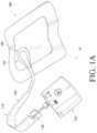
- FIGS. 1 A-Billustrate embodiments of a negative pressure wound treatment system 10 employing a wound dressing 100 in conjunction with a fluidic connector 110 .
- the fluidic connector 110may comprise an elongate conduit, more preferably a bridge 120 having a proximal end 130 and a distal end 140 , and an applicator 180 at the distal end 140 of the bridge 120 .
- An optional coupling 160is preferably disposed at the proximal end 130 of the bridge 120 .
- a cap 170may be provided with the system (and can in some cases, as illustrated, be attached to the coupling 160 ). The cap 170 can be useful in preventing fluids from leaking out of the proximal end 130 .
- the system 10may include a source of negative pressure such as a pump or negative pressure unit 150 capable of supplying negative pressure.
- the pumpmay comprise a canister or other container for the storage of wound exudates and other fluids that may be removed from the wound.
- a canister or containermay also be provided separate from the pump.
- the pump 150can be a canisterless pump such as the PICOTM pump, as sold by Smith & Nephew.
- the pump 150may be connected to the coupling 160 via a tube 190 , or the pump 150 may be connected directly to the coupling 160 or directly to the bridge 120 .
- the dressing 100is placed over a suitably-prepared wound, which may in some cases be filled with a wound packing material such as foam or gauze.
- the applicator 180 of the fluidic connector 110has a sealing surface that is placed over an aperture in the dressing 100 and is sealed to the top surface of the dressing 100 .
- the pump 150is connected via the tube 190 to the coupling 160 , or is connected directly to the coupling 160 or to the bridge 120 .
- the pumpis then activated, thereby supplying negative pressure to the wound. Application of negative pressure may be applied until a desired level of healing of the wound is achieved.
- treatment of a wound with negative pressureuses a wound dressing 100 capable of absorbing and storing wound exudate in conjunction with a flexible fluidic connector 110 .
- the wound dressing 100may be substantially similar to wound dressings and have the same or similar components as those described throughout International Patent Publication WO2013175306, WO2014020440, WO2014020443 and U.S. Publication No. 2011/0282309 A1, which are incorporated by reference in their entireties.
- the wound dressingmay simply comprise one or more backing layers configured to form a sealed chamber over the wound site.
- the wound sitemay be filled partially or completely with a wound packing material.
- This wound packing materialis optional, but may be desirable in certain wounds, for example deeper wounds.
- the wound packing materialcan be used in addition to the wound dressing 100 .
- the wound packing materialgenerally may comprise a porous and conformable material, for example foam (including reticulated foams), and gauze.
- the wound packing materialis sized or shaped to fit within the wound site so as to fill any empty spaces.
- the wound dressing 100may then be placed over the wound site and wound packing material overlying the wound site.
- negative pressuremay be transmitted from a pump or other source of negative pressure through a flexible tubing via the fluidic connector 110 to the wound dressing 100 , through the wound packing material, and finally to the wound site. This negative pressure draws wound exudate and other fluids or secretions away from the wound site.
- the fluidic connector 110preferably comprises an enlarged distal end, or head 140 that is in fluidic communication with the dressing 100 as will be described in further detail below.
- the enlarged distal endhas a round or circular shape.
- the head 140is illustrated here as being positioned near an edge of the dressing 100 , but may also be positioned at any location on the dressing. For example, some embodiments may provide for a centrally or off-centered location not on or near an edge or corner of the dressing 100 .
- the dressing 10may comprise two or more fluidic connectors 110 , each comprising one or more heads 140 , in fluidic communication therewith.
- the head 140may measure 30 mm along its widest edge.
- the head 140forms at least in part the applicator 180 , described above, that is configured to seal against a top surface of the wound dressing.
- FIG. 2 Billustrates a cross-section through a wound dressing 100 similar to the wound dressing 10 as shown in FIG. 1 B and described in International Patent Publication WO2013175306, which is incorporated by reference in its entirety, along with fluidic connector 110 .
- the wound dressing 100which can alternatively be any wound dressing embodiment disclosed herein or any combination of features of any number of wound dressing embodiments disclosed herein, can be located over a wound site to be treated.
- the dressing 100may be placed to as to form a sealed cavity over the wound site.
- the dressing 100comprises a top or cover layer, or backing layer 220 attached to an optional wound contact layer 222 , both of which are described in greater detail below.
- This interior space or chambermay comprise additional structures that may be adapted to distribute or transmit negative pressure, store wound exudate and other fluids removed from the wound, and other functions which will be explained in greater detail below. Examples of such structures, described below, include a transmission layer 226 and an absorbent layer 221 .
- the wound contact layer 222can be a polyurethane layer or polyethylene layer or other flexible layer which is perforated, for example via a hot pin process, laser ablation process, ultrasound process or in some other way or otherwise made permeable to liquid and gas.
- the wound contact layer 222has a lower surface 224 and an upper surface 223 .
- the perforations 225preferably comprise through holes in the wound contact layer 222 which enable fluid to flow through the layer 222 .
- the wound contact layer 222helps prevent tissue ingrowth into the other material of the wound dressing.
- the perforationsare small enough to meet this requirement while still allowing fluid to flow therethrough.
- perforations formed as slits or holes having a size ranging from 0.025 mm to 1.2 mmare considered small enough to help prevent tissue ingrowth into the wound dressing while allowing wound exudate to flow into the dressing.
- the wound contact layer 222may help maintain the integrity of the entire dressing 100 while also creating an air tight seal around the absorbent pad in order to maintain negative pressure at the wound.
- the wound contact layer 222may also act as a carrier for an optional lower and upper adhesive layer (not shown).
- a lower pressure sensitive adhesivemay be provided on the lower surface 224 of the wound dressing 100 whilst an upper pressure sensitive adhesive layer may be provided on the upper surface 223 of the wound contact layer.
- the pressure sensitive adhesivewhich may be a silicone, hot melt, hydrocolloid or acrylic based adhesive or other such adhesives, may be formed on both sides or optionally on a selected one or none of the sides of the wound contact layer. When a lower pressure sensitive adhesive layer is utilized, it may be helpful to adhere the wound dressing 100 to the skin around a wound site.
- the wound contact layermay comprise perforated polyurethane film.
- the lower surface of the filmmay be provided with a silicone pressure sensitive adhesive and the upper surface may be provided with an acrylic pressure sensitive adhesive, which may help the dressing maintain its integrity.
- a polyurethane film layermay be provided with an adhesive layer on both its upper surface and lower surface, and all three layers may be perforated together.
- a layer 226 of porous materialcan be located above the wound contact layer 222 .
- This porous layer, or transmission layer, 226allows transmission of fluid including liquid and gas away from a wound site into upper layers of the wound dressing.
- the transmission layer 226preferably ensures that an open air channel can be maintained to communicate negative pressure over the wound area even when the absorbent layer has absorbed substantial amounts of exudates.
- the layer 226should preferably remain open under the typical pressures that will be applied during negative pressure wound therapy as described above, so that the whole wound site sees an equalized negative pressure.
- the layer 226may be formed of a material having a three dimensional structure. For example, a knitted or woven spacer fabric (for example Baltex 7970 weft knitted polyester) or a non-woven fabric could be used.
- the transmission layer 226comprises a 3D polyester spacer fabric layer including a top layer (that is to say, a layer distal from the wound-bed in use) which is a 84/144 textured polyester, and a bottom layer (that is to say, a layer which lies proximate to the wound bed in use) which is a 10 denier flat polyester and a third layer formed sandwiched between these two layers which is a region defined by a knitted polyester viscose, cellulose or the like mono filament fiber. Other materials and other linear mass densities of fiber could of course be used.
- top spacer fabricthus has more filaments in a yarn used to form it than the number of filaments making up the yarn used to form the bottom spacer fabric layer.
- This differential between filament counts in the spaced apart layershelps control moisture flow across the transmission layer.
- the top layeris made from a yarn having more filaments than the yarn used in the bottom layer, liquid tends to be wicked along the top layer more than the bottom layer.
- this differentialtends to draw liquid away from the wound bed and into a central region of the dressing where the absorbent layer 221 helps lock the liquid away or itself wicks the liquid onwards towards the cover layer where it can be transpired.
- the 3D fabricmay be treated with a dry cleaning agent (such as, but not limited to, Perchloro Ethylene) to help remove any manufacturing products such as mineral oils, fats and/or waxes used previously which might interfere with the hydrophilic capabilities of the transmission layer.
- a dry cleaning agentsuch as, but not limited to, Perchloro Ethylene
- an additional manufacturing stepcan subsequently be carried in which the 3D spacer fabric is washed in a hydrophilic agent (such as, but not limited to, Feran Ice 30 g/l available from the Rudolph Group). This process step helps ensure that the surface tension on the materials is so low that liquid such as water can enter the fabric as soon as it contacts the 3D knit fabric. This also aids in controlling the flow of the liquid insult component of any exudates.
- a layer 221 of absorbent materialis provided above the transmission layer 226 .
- the absorbent materialwhich comprise a foam or non-woven natural or synthetic material, and which may optionally comprise a super-absorbent material, forms a reservoir for fluid, particularly liquid, removed from the wound site.
- the layer 10may also aid in drawing fluids towards the backing layer 220 .
- the material of the absorbent layer 221may also prevent liquid collected in the wound dressing 100 from flowing freely within the dressing, and preferably acts so as to contain any liquid collected within the dressing.
- the absorbent layer 221also helps distribute fluid throughout the layer via a wicking action so that fluid is drawn from the wound site and stored throughout the absorbent layer. This helps prevent agglomeration in areas of the absorbent layer.
- the capacity of the absorbent materialmust be sufficient to manage the exudates flow rate of a wound when negative pressure is applied. Since in use the absorbent layer experiences negative pressures the material of the absorbent layer is chosen to absorb liquid under such circumstances. A number of materials exist that are able to absorb liquid when under negative pressure, for example superabsorber material.
- the absorbent layer 221may typically be manufactured from ALLEVYNTM foam, Freudenberg 114-224-4 and/or Chem-PositeTM 11C-450.
- the absorbent layer 221may comprise a composite comprising superabsorbent powder, fibrous material such as cellulose, and bonding fibers.
- the compositeis an airlaid, thermally-bonded composite.
- the absorbent layer 221is a layer of non-woven cellulose fibers having super-absorbent material in the form of dry particles dispersed throughout.
- Use of the cellulose fibersintroduces fast wicking elements which help quickly and evenly distribute liquid taken up by the dressing.
- the juxtaposition of multiple strand-like fibersleads to strong capillary action in the fibrous pad which helps distribute liquid. In this way, the super-absorbent material is efficiently supplied with liquid.
- the wicking actionalso assists in bringing liquid into contact with the upper cover layer to aid increase transpiration rates of the dressing.
- An aperture, hole, or orifice 227is preferably provided in the backing layer 220 to allow a negative pressure to be applied to the dressing 100 .
- the fluidic connector 110is preferably attached or sealed to the top of the backing layer 220 over the orifice 227 made into the dressing 100 , and communicates negative pressure through the orifice 227 .
- a length of tubingmay be coupled at a first end to the fluidic connector 110 and at a second end to a pump unit (not shown) to allow fluids to be pumped out of the dressing.
- a length of tubingmay be coupled at a first end of the fluidic connector such that the tubing, or conduit, extends away from the fluidic connector parallel or substantially to the top surface of the dressing.
- the fluidic connector 110may be adhered and sealed to the backing layer 220 using an adhesive such as an acrylic, cyanoacrylate, epoxy, UV curable or hot melt adhesive.
- the fluidic connector 110may be formed from a soft polymer, for example a polyethylene, a polyvinyl chloride, a silicone or polyurethane having a hardness of 30 to 90 on the Shore A scale. In some embodiments, the fluidic connector 110 may be made from a soft or conformable material.
- the absorbent layer 221includes at least one through hole 228 located so as to underlie the fluidic connector 110 .
- the through hole 228may in some embodiments be the same size as the opening 227 in the backing layer, or may be bigger or smaller.
- a single through holecan be used to produce an opening underlying the fluidic connector 110 .
- multiple openingscould alternatively be utilized.
- one or multiple openingsmay be made in the absorbent layer and the obscuring layer in registration with each respective fluidic connector.
- the use of through holes in the super-absorbent layermay provide a fluid flow pathway which remains unblocked in particular when the absorbent layer is near saturation.
- the aperture or through-hole 228is preferably provided in the absorbent layer 221 beneath the orifice 227 such that the orifice is connected directly to the transmission layer 226 .
- Thisallows the negative pressure applied to the fluidic connector 110 to be communicated to the transmission layer 226 without passing through the absorbent layer 221 .
- Thisensures that the negative pressure applied to the wound site is not inhibited by the absorbent layer as it absorbs wound exudates.
- no aperturemay be provided in the absorbent layer 221 , or alternatively a plurality of apertures underlying the orifice 227 may be provided.
- additional layerssuch as another transmission layer or an obscuring layer such as described in International Patent Publication WO2014020440 may be provided over the absorbent layer 221 and beneath the backing layer 220 .
- the backing layer 220is preferably gas impermeable, but moisture vapor permeable, and can extend across the width of the wound dressing 100 .
- the backing layer 220which may for example be a polyurethane film (for example, Elastollan SP9109) having a pressure sensitive adhesive on one side, is impermeable to gas and this layer thus operates to cover the wound and to seal a wound cavity over which the wound dressing is placed. In this way an effective chamber is made between the backing layer 220 and a wound site where a negative pressure can be established.
- the backing layer 220is preferably sealed to the wound contact layer 222 in a border region around the circumference of the dressing, ensuring that no air is drawn in through the border area, for example via adhesive or welding techniques.
- the backing layer 220protects the wound from external bacterial contamination (bacterial barrier) and allows liquid from wound exudates to be transferred through the layer and evaporated from the film outer surface.
- the backing layer 220preferably comprises two layers; a polyurethane film and an adhesive pattern spread onto the film.
- the polyurethane filmis preferably moisture vapor permeable and may be manufactured from a material that has an increased water transmission rate when wet. In some embodiments the moisture vapor permeability of the backing layer increases when the backing layer becomes wet. The moisture vapor permeability of the wet backing layer may be up to about ten times more than the moisture vapor permeability of the dry backing layer.
- the absorbent layer 221may be of a greater area than the transmission layer 226 , such that the absorbent layer overlaps the edges of the transmission layer 226 , thereby ensuring that the transmission layer does not contact the backing layer 220 .
- Thisprovides an outer channel of the absorbent layer 221 that is in direct contact with the wound contact layer 222 , which aids more rapid absorption of exudates to the absorbent layer. Furthermore, this outer channel ensures that no liquid is able to pool around the circumference of the wound cavity, which may otherwise seep through the seal around the perimeter of the dressing leading to the formation of leaks.
- the absorbent layer 221may define a smaller perimeter than that of the backing layer 220 , such that a boundary or border region is defined between the edge of the absorbent layer 221 and the edge of the backing layer 220 .
- one embodiment of the wound dressing 100comprises an aperture 228 in the absorbent layer 221 situated underneath the fluidic connector 110 .
- a wound facing portion of the fluidic connectormay thus come into contact with the transmission layer 226 , which can thus aid in transmitting negative pressure to the wound site even when the absorbent layer 221 is filled with wound fluids.
- Some embodimentsmay have the backing layer 220 be at least partly adhered to the transmission layer 226 .
- the aperture 228is at least 1-2 mm larger than the diameter of the wound facing portion of the fluidic connector 11 , or the orifice 227 .
- the fluidic connector 110 and through holemay be located in an off-center position as illustrated in FIG. 2 A .
- Such a locationmay permit the dressing 100 to be positioned onto a patient such that the fluidic connector 110 is raised in relation to the remainder of the dressing 100 . So positioned, the fluidic connector 110 and the filter 214 may be less likely to come into contact with wound fluids that could prematurely occlude the filter 214 so as to impair the transmission of negative pressure to the wound site.
- fluidic connector 110preferred embodiments comprise a sealing surface 216 , a bridge 211 (corresponding to bridge 120 in FIGS. 1 A- 1 B ) with a proximal end 130 and a distal end 140 , and a filter 214 .
- the sealing surface 216preferably forms the applicator previously described that is sealed to the top surface of the wound dressing.
- a bottom layer of the fluidic connector 110may comprise the sealing surface 216 , such as layer 540 in FIG. 5 C below.
- the fluidic connector 110may further comprise an upper surface vertically spaced from the sealing surface 216 , which in some embodiments is defined by a separate upper layer of the fluidic connector such as layer 510 in FIG. 5 C below.
- the upper surface and the lower surfacemay be formed from the same piece of material.
- the sealing surface 216may comprise at least one aperture 229 therein to communicate with the wound dressing.
- the filter 214may be positioned across the opening 229 in the sealing surface, and may span the entire opening 229 .
- the sealing surface 216may be configured for sealing the fluidic connector to the cover layer of the wound dressing, and may comprise an adhesive or weld.
- the sealing surface 216may be placed over an orifice in the cover layer with optional spacer elements 215 configured to create a gap between the filter 214 and the transmission layer 226 .
- the sealing surface 216may be positioned over an orifice in the cover layer and an aperture in the absorbent layer 221 , permitting the fluidic connector 110 to provide air flow through the transmission layer 226 .
- the bridge 211may comprise a first fluid passage 212 in communication with a source of negative pressure, the first fluid passage 212 comprising a porous material, such as a 3D knitted material, which may be the same or different than the porous layer 226 described previously.
- the bridge 211is preferably encapsulated by at least one flexible film layer 208 , 210 having a proximal and distal end and configured to surround the first fluid passage 212 , the distal end of the flexible film being connected the sealing surface 216 .
- the filter 214is configured to substantially prevent wound exudate from entering the bridge, and spacer elements 215 are configured to prevent the fluidic connector from contacting the transmission layer 226 . These elements will be described in greater detail below.
- the fluid passage 212is constructed from a compliant material that is flexible and that also permits fluid to pass through it if the spacer is kinked or folded over.
- Suitable materials for the fluid passage 212include without limitation foams, including open-cell foams such as polyethylene or polyurethane foam, meshes, 3D knitted fabrics, non-woven materials, and fluid channels.
- the fluid passage 212may be constructed from materials similar to those described above in relation to the transmission layer 226 .
- such materials used in the fluid passage 212not only permit greater patient comfort, but may also provide greater kink resistance, such that the fluid passage 212 is still able to transfer fluid from the wound toward the source of negative pressure while being kinked or bent.
- the fluid passage 212may be comprised of a wicking fabric, for example a knitted or woven spacer fabric (such as a knitted polyester 3D fabric, Baltex 7970®, or Gehring 879®) or a nonwoven fabric. These materials selected are preferably suited to channeling wound exudate away from the wound and for transmitting negative pressure and/or vented air to the wound site, and may also confer a degree of kinking or occlusion resistance to the fluid passage 212 .
- the wicking fabricmay have a three-dimensional structure, which in some cases may aid in wicking fluid or transmitting negative pressure.
- the wicking fabricmay comprise several layers of material stacked or layered over each other, which may in some cases be useful in preventing the fluid passage 212 from collapsing under the application of negative pressure.
- the wicking fabric used in the fluid passage 212may be between 1.5 mm and 6 mm; more preferably, the wicking fabric may be between 3 mm and 6 mm thick, and may be comprised of either one or several individual layers of wicking fabric.
- the fluid passage 212may be between 1.2-3 mm thick, and preferably thicker than 1.5 mm.
- a suction adapter used with a dressing which retains liquid such as wound exudatemay employ hydrophobic layers in the fluid passage 212 , and only gases may travel through the fluid passage 212 .
- the materials used in the systemare preferably conformable and soft, which may help to avoid pressure ulcers and other complications which may result from a wound treatment system being pressed against the skin of a patient.
- the filter element 214is impermeable to liquids, but permeable to gases, and is provided to act as a liquid bather and to ensure that no liquids are able to escape from the wound dressing 100 .
- the filter element 214may also function as a bacterial barrier.
- the pore sizeis 0.2 ⁇ m.
- Suitable materials for the filter material of the filter element 214include 0.2 micron GoreTM expanded PTFE from the MMT range, PALL VersaporeTM 200R, and DonaldsonTM TX6628. Larger pore sizes can also be used but these may require a secondary filter layer to ensure full bioburden containment.
- the filter elementcan be attached or sealed to the port and/or the cover film over the orifice.
- the filter element 214may be molded into the fluidic connector 110 , or may be adhered to one or both of the top of the cover layer and bottom of the suction adapter 110 using an adhesive such as, but not limited to, a UV cured adhesive.
- filter element 214More generally a microporous membrane can be used which is a thin, flat sheet of polymeric material, this contains billions of microscopic pores. Depending upon the membrane chosen these pores can range in size from 0.01 to more than 10 micrometers. Microporous membranes are available in both hydrophilic (water filtering) and hydrophobic (water repellent) forms.
- filter element 214comprises a support layer and an acrylic co-polymer membrane formed on the support layer.
- the wound dressing 100according to certain embodiments of the present invention uses microporous hydrophobic membranes (MHMs). Numerous polymers may be employed to form MHMs.
- the MHMsmay be formed from one or more of PTFE, polypropylene, PVDF and acrylic copolymer. All of these optional polymers can be treated in order to obtain specific surface characteristics that can be both hydrophobic and oleophobic. As such these will repel liquids with low surface tensions such as multi-vitamin infusions, lipids, surfactants, oils and organic solvents.
- MHMsblock liquids whilst allowing air to flow through the membranes. They are also highly efficient air filters eliminating potentially infectious aerosols and particles. A single piece of MHM is well known as an option to replace mechanical valves or vents. Incorporation of MHMs can thus reduce product assembly costs improving profits and costs/benefit ratio to a patient.
- the filter element 214may also include an odor absorbent material, for example activated charcoal, carbon fiber cloth or Vitec Carbotec-RT Q2003073 foam, or the like.
- an odor absorbent materialmay form a layer of the filter element 214 or may be sandwiched between microporous hydrophobic membranes within the filter element. The filter element 214 thus enables gas to be exhausted through the orifice. Liquid, particulates and pathogens however are contained in the dressing.
- the wound dressing 100may comprise spacer elements 215 in conjunction with the fluidic connector 110 and the filter 214 . With the addition of such spacer elements 215 the fluidic connector 110 and filter 214 may be supported out of direct contact with the absorbent layer 220 and/or the transmission layer 226 .
- the absorbent layer 220may also act as an additional spacer element to keep the filter 214 from contacting the transmission layer 226 . Accordingly, with such a configuration contact of the filter 214 with the transmission layer 226 and wound fluids during use may thus be minimized.
- the fluidic connector 110 and through holemay be located in an off-center position as illustrated in FIGS. 2 A-B .
- Such a locationmay permit the dressing 100 to be positioned onto a patient such that the fluidic connector 110 is raised in relation to the remainder of the dressing 100 . So positioned, the fluidic connector 110 and the filter 214 may be less likely to come into contact with wound fluids that could prematurely occlude the filter 214 so as to impair the transmission of negative pressure to the wound site.
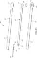
- FIGS. 3 A-Cillustrate various embodiments of the head 140 of the fluidic connector 110 .
- the fluidic connector 110 illustrated in FIG. 2 Ais enlarged at the distal end to be placed over an orifice in the cover layer and the aperture in the absorbent layer of a wound dressing, for example wound dressing 100 of FIGS. 2 A-B , and may form a “teardrop” or other enlarged shape.
- FIG. 3 Aillustrates a fluidic connector 110 with a substantially triangular head 140 .
- FIG. 3 Billustrates a fluidic connector 110 with a substantially pentagonal head 140 .
- FIG. 3 Aillustrates a fluidic connector 110 with a substantially circular head 140 .
- FIGS. 4 A-Dillustrate the use of an embodiment of a negative pressure therapy wound treatment system being used to treat a wound site on a patient.
- FIG. 4 Ashows a wound site 400 being cleaned and prepared for treatment.
- the healthy skin surrounding the wound site 400is preferably cleaned and excess hair removed or shaved.
- the wound site 400may also be irrigated with sterile saline solution if necessary.
- a skin protectantmay be applied to the skin surrounding the wound site 400 .
- a wound packing materialsuch as foam or gauze, may be placed in the wound site 400 . This may be preferable if the wound site 400 is a deeper wound.
- the wound dressing 100may be positioned and placed over the wound site 400 .
- the wound dressing 100is placed with the wound contact layer over and/or in contact with the wound site 400 .
- an adhesive layeris provided on the lower surface of the wound contact layer, which may in some cases be protected by an optional release layer to be removed prior to placement of the wound dressing 100 over the wound site 400 .
- the dressing 100is positioned such that the fluidic connector 110 is in a raised position with respect to the remainder of the dressing 10 so as to avoid fluid pooling around the port.
- the dressing 100is positioned so that the fluidic connector 110 is not directly overlying the wound, and is level with or at a higher point than the wound.
- the edges of the dressing 100are preferably smoothed over to avoid creases or folds.
- the dressing 10is connected to the pump 150 .
- the pump 150is configured to apply negative pressure to the wound site via the dressing 100 , and typically through a conduit.
- a fluidic connector 110may be used to join the conduit 190 from the pump to the dressing 100 .
- a length of tubingmay be coupled at a first end of the fluidic connector such that the tubing, or conduit, extends away from the fluidic connector parallel to the top of the dressing.
- the conduitmay comprise a fluidic connector. It is expressly contemplated that a conduit may be a soft bridge, a hard tube, or any other apparatus which may serve to transport fluid.
- the dressing 100may in some embodiments partially collapse and present a wrinkled appearance as a result of the evacuation of some or all of the air underneath the dressing 100 .
- the pump 150may be configured to detect if any leaks are present in the dressing 100 , such as at the interface between the dressing 100 and the skin surrounding the wound site 400 . Should a leak be found, such leak is preferably remedied prior to continuing treatment.
- fixation strips 410may also be attached around the edges of the dressing 100 .
- Such fixation strips 410may be advantageous in some situations so as to provide additional sealing against the skin of the patient surrounding the wound site 400 .
- the fixation strips 410may provide additional sealing for when a patient is more mobile.
- the fixation strips 410may be used prior to activation of the pump 150 , particularly if the dressing 100 is placed over a difficult to reach or contoured area.
- Treatment of the wound site 400preferably continues until the wound has reached a desired level of healing.
- FIGS. 5 A-Billustrate an embodiment of a flexible port or fluidic connector 500 .
- FIG. 5 Cillustrates a perspective exploded view the fluidic connector 500 that may be used to connect a wound dressing to a source of negative pressure.
- the fluidic connector 500comprises a top layer 510 , a spacer layer 520 , a filter element 530 , a bottom layer 540 , and a conduit 550 .
- the conduitoptionally comprises a coupling 560 .
- the conduitmay comprise a fluidic connector. It is expressly contemplated that a conduit may be a soft bridge, a hard tube, or any other apparatus which may serve to transport fluid.
- the distal end of the fluidic connector 500(the end connectable to a dressing) is depicted as having an enlarged circular shape, although it will be appreciated that any suitable shape may be used and that the distal end need not be enlarged.
- the distal endcan have any of the shapes shown in FIGS. 3 A- 3 C above.
- the bottom layer 540may comprise an elongate bridge portion 544 , an enlarged (e.g., rounded or circular) sealing portion 545 , and an orifice 541 .
- a plurality of orificesmay be provided in the bottom layer.
- Some embodiments of the rounded sealing portion 545may comprise a layer of adhesive, for example a pressure sensitive adhesive, on the lower surface for use in sealing the fluidic connector 500 to a dressing.
- the fluidic connectormay be sealed to a cover layer of the dressing.
- the orifice 541 in the bottom layer 540 of the port 500may be aligned with an orifice in the cover layer of the dressing in order to transmit negative pressure through the dressing and into a wound site.
- the top layer 515may be substantially the same shape as the bottom layer in that it comprises an elongate bridge 514 and an enlarged (e.g., rounded or circular) portion 545 .
- the top layer 515 and the bottom layer 545may be sealed together, for example by heat welding.
- the bottom layer 545may be substantially flat and the top layer 515 may be slightly larger than the bottom layer 545 in order to accommodate the height of the spacer layer 520 and seal to the bottom layer 545 .
- the top layer 515 and bottom layer 3145may be substantially the same size, and the layers may be sealed together approximately at the middle of the height of the spacer layer 520 .
- the elongate bridge portions 544 , 514may have a length of 10 cm (or about 10 cm) or more, more preferably a length of 20 cm (or about 20 cm) or more and in some embodiments, may be about 69 cm (or 27 cm) long.
- Some embodiments of the entire fluidic connector, from a proximal-most edge of the top and bottom layers to a distal-most edge of the top and bottom layers,may be between 20 cm and 80 cm (or about 20 cm to about 80 cm) long, more preferably about 60 cm and 80 cm (or between about 60 cm and about 80 cm) long, for example about 70 cm long.
- the elongate bridge portionsmay have a width of between 1 cm and 4 cm (or between about 1 cm and about 4 cm), and in one embodiment, is about 2.5 cm wide.
- the ratio of the length of the elongate bridge portions 544 , 514 to their widthsmay in some embodiments exceed 6:1, and may more preferably exceed 8:1 or even 10:1.
- the diameter of the circular portion 545 , 515may be about 3.5 cm in some embodiments.
- the bottom and top layersmay comprise at least one layer of a flexible film, and in some embodiments may be transparent. Some embodiments of the bottom layer 540 and top layer 515 may be polyurethane, and may be liquid impermeable.
- the fluidic connector 500may comprise a spacer layer 520 , such as the 3D fabric discussed above, positioned between the lower layer 540 and the top layer 510 .
- the spacer layer 520may be made of any suitable material, for example material resistant to collapsing in at least one direction, thereby enabling effective transmission of negative pressure therethrough.
- some embodiments of the spacer layer 520may comprise a fabric configured for lateral wicking of fluid, which may comprise viscose, polyester, polypropylene, cellulose, or a combination of some or all of these, and the material may be needle-punched.
- spacer layer 520may comprise polyethylene in the range of 40-160 grams per square meter (gsm) (or about 40 to about 160 gsm), for example 80 (or about 80) gsm. Such materials may be constructed so as to resist compression under the levels of negative pressure commonly applied during negative pressure therapy.
- the spacer layer 520may comprise an elongate bridge portion 524 , an enlarged (e.g., rounded or circular) portion 525 , and may optionally include a fold 521 .
- the elongate bridge portionmay have dimensions in the same ranges as the bridge portions of the upper and lower layers described above though slightly smaller, and in one embodiment is about 25.5 cm long and 1.5 cm wide.
- the diameter of the circular portion 525may be slightly smaller than the diameters of the enlarged ends 545 , 515 , and in one embodiment is about 2 cm.
- the spacer layer 520may have adhesive on one or both of its proximal and distal ends (e.g., one or more dabs of adhesive) in order to secure the spacer layer 520 to the top layer 510 and/or the bottom layer 540 .
- Adhesivemay also be provided along a portion or the entire length of the spacer layer.
- the spacer layer 520may be freely movable within the sealed chamber of the top and bottom layers.
- the fold 521 of the spacer layermay make the end of the fluidic connector 500 softer and therefore more comfortable for a patient, and may also help prevent the conduit 550 from blockage.
- the fold 521may further protect the end of the conduit 550 from being occluded by the top or bottom layers.
- the fold 521may, in some embodiments, be between 1 cm and 3 cm (or between about 1 cm and about 3 cm) long, and in one embodiment is 2 cm (or about 2 cm) long.
- the spacer layermay be folded underneath itself that is toward the bottom layer 540 , and in other embodiments may be folded upward toward the top layer 510 .
- Other embodiments of the spacer layer 520may contain no fold.
- a slot or channel 522may extend perpendicularly away from the proximal end of the fold 521 , and the conduit 550 may rest in the slot or channel 522 .
- the slot 522may extend through one layer of the fold, and in others it may extend through both layers of the fold.
- the slot 522may, in some embodiments, be 1 cm (or about 1 cm) long.
- Some embodimentsmay instead employ a circular or elliptical hole in the fold 521 . The hole may face proximally so that the conduit 550 may be inserted into the hole and rest between the folded layers of spacer fabric.
- the conduit 550may be adhered to the material of the fold 521 , while in other embodiments it may not.
- the fluidic connector 500may have a filter element 530 located adjacent the orifice 541 , and as illustrated is located between the lower layer 540 and the spacer layer 520 .
- the filter element 530may be positioned across the opening or orifice of the fluidic connector 500 .
- the filter element 530is impermeable to liquids, but permeable to gases.
- the filter elementmay be similar to the element described above with respect to FIG. 1 B , and as illustrated may have a round or disc shape.
- the filter element 530can act as a liquid bather, to substantially prevent or inhibit liquids from escaping from the wound dressing, as well as an odor bather.
- the filter element 530may also function as a bacterial bather.
- the pore size of the filter element 530can be approximately 0.2 ⁇ m.
- Suitable materials for the filter material of the filter elementinclude 0.2 micron GoreTM expanded PTFE from the MMT range, PALL VersaporeTM 200R, and DonaldsonTM TX6628.
- the filter element 530thus enables gas to be exhausted through the orifice. Liquid, particulates and pathogens however are contained in the dressing. Larger pore sizes can also be used but these may require a secondary filter layer to ensure full bioburden containment.
- the filter element 530may be adhered to one or both of top surface of the bottom layer 540 and the bottom surface of the spacer layer 520 using an adhesive such as, but not limited to, a UV cured adhesive. In other embodiments, the filter 530 may be welded to the inside of the spacer layer 520 and to the top surface of the bottom layer 540 . The filter may also be provided adjacent the orifice on a lower surface of the bottom layer 540 . Other possible details regarding the filter are disclosed in U.S. Patent Pub. No. 2011/0282309 and incorporated by reference herein.
- the proximal end of the fluidic connector 500may be connected to the distal end of a conduit 550 .
- the conduit 550may comprise one or more circular ribs 551 .
- the ribs 551may be formed in the conduit 550 by grooves in a mold during the manufacturing of the conduit. During heat welding of the upper and lower layers 515 , 545 melted material from those layers may flow around the ribs 551 , advantageously providing a stronger connection between the conduit 550 and the layers. As a result, it may be more difficult to dislodge the conduit 550 out from between the layers during use of the fluidic connector 500 .
- the proximal end of the conduit 550may be optionally attached to a coupling 560 .
- the coupling 560may be used to connect the fluidic connector 500 to a source of negative pressure, or in some embodiments to an extension conduit which may in turn be connected to a source of negative pressure.
- the proximal end of the conduit 550which is inserted into the spacer fabric 520 , may be shaped in such a way to reduce the possibility of occlusion.
- some embodimentsmay have a triangular portion cut out of the end of the conduit, and other embodiments may have a plurality of holes therethrough.
- FIG. 6illustrates an embodiment of a wound dressing 610 with a fluidic connector 620 such as described above with respect to FIGS. 5 A-C attached to the dressing.
- the fluidic connector 620may be the fluidic connector described above in FIGS. 5 A-C .
- the fluidic connector 620may comprise a conduit 630 and a coupling 640 for connecting the fluidic connector to a source of negative pressure or to an extension conduit. Although in this depiction the fluidic connector 620 is connected over a circular window in the obscuring layer of the dressing 610 , in other embodiments the fluidic connector 620 may be connected over a maltese cross in the obscuring layer.
- the maltese crossmay be of a larger diameter than the fluidic connector 620 and may be at least partially viewable after the fluidic connector 620 is attached to the dressing 610 .
- the dressing 610 and other dressings to which the fluidic connector can be connectedare described in International Patent Publications WO2012020440 and WO2014020443, the entireties of which are hereby incorporated by reference.
- Further details regarding wound dressings and fluidic connectorscan be found in U.S. patent application Ser. No. 14/715,527, titled “FLUIDIC CONNECTOR FOR NEGATIVE PRESSURE WOUND THERAPY” filed May 18, 2015, published as US 2016/0339158, the entirety of which are hereby incorporated by reference.
- a negative pressure wound therapy systemmay include a three-dimensional filter element to prevent or inhibit wound fluid or exudate from escaping from a wound dressing.
- the three-dimensional filter elementmay be placed within the wound dressing and/or the fluidic connector, and replace the filter element such as the filter element 214 described in relation to FIG. 2 B , or the filter element 530 described in relation to FIG. 5 C .
- a negative pressure wound therapy systemmay contain both the three-dimensional filter element and the filter element such as the filter element 214 described in relation to FIG. 2 B or the filter element 530 described in relation to FIG. 5 C .
- the three-dimensional filter elementmay have a substantial thickness or height perpendicular to a width, a length, and/or a diameter, and thus define three-dimensional shape, as compared with the filter elements 214 or 530 , which are relatively flatter and have minimal thickness or height.
- the three-dimensional filtermay have more surface area than a two-dimensional filter having a same cross-sectional area.
- a cylindrical three-dimensional filter element having a cross-sectional radius of r and a height of hmay have a surface area of 2 ⁇ rh (side wall)+ ⁇ r 2 (bottom surface), while a circular two-dimensional filter having a radius r will only have a surface area of ⁇ r 2 .
- the increased surface area of the three-dimensional filtermay allow improved filtering capacity and better air flow even when the filter is partially blocked.
- FIGS. 7 A-BSuch advantage of three-dimensional filters is further depicted in FIGS. 7 A-B , wherein a NPWT system 700 having a two-dimensional filter 710 , and another NPWT system 750 having a three dimensional filter 720 are schematically shown.
- FIGS. 7 A and 7 Bthe NPWT systems 700 and 750 without negative pressure applied are shown on the left, while the NPWT systems 700 and 750 under negative pressure are shown on the right.
- the three-dimensional filter element 720may be configured to maintain its height under negative pressure, thereby maintain its increased surface area.
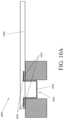
- FIG. 8illustrates a cross-sectional view through an embodiment of a negative pressure wound therapy apparatus having a wound dressing 800 along with a fluidic connector 810 .
- Each of the wound dressing 800 and the fluidic connector 810may be constructed similar to the wound dressing 100 and the fluidic connecter 110 shown in and described in relation to FIG. 2 B or elsewhere in the specification, respectively, except as noted below.
- the references numerals used to designate the various components of the wound dressing 800 and the fluidic connector 810are identical to those used for identifying the corresponding components of the wound dressing 100 and the fluidic connector 110 .
- the fluidic connector 810may include a three-dimensional filter element 850 .
- the three-dimensional filter element 850may be positioned across the opening 229 in the sealing surface 216 of the fluidic connector 810 , and may span the entire opening 229 and/or the aperture 227 of the cover layer 220 .
- the three-dimensional filter element 850may located within the fluidic connector.
- the filter element 850may extrude out or extend out of the fluidic connector 810 . The extruded-out portion of the filter element 850 may pass and extend through the aperture 227 of the cover layer 220 and/or the aperture or through-hole 228 of the absorbent layer 221 of the dressing 800 .
- the aperture or through-hole 228may be a recess which only partially extends through the thickness of the absorbent layer 221 .
- the aperture, through-hole, and the recess 228 of the absorbent layer 221are interchangeable variations of cut-outs in the absorbent layer 221 , and these terms may be used interchangeably hereinafter.
- the sealing surface 216may be placed over the orifice 227 in the cover layer with optional spacer elements 215 configured to offset the height or thickness of the three-dimensional filter element 850 , such that only pre-determined portion of the three-dimensional filter 850 extends out of the sealing surface of the fluidic connector through the opening 229 and maintains a gap between the filter element 850 and the transmission layer 226 .
- the filter element 850may be entirely within the fluidic connector 810 and does not extend to the wound dressing 800 .
- a three-dimensional filtermay be placed at/on the wound dressing 800 .
- the three-dimensional filtermay be placed within the aperture 227 of the cover layer 220 and the aperture 228 of the absorbent layer 221 .
- the three-dimensional filtermay be thinner than the depth of the aperture 228 , such that the three-dimensional filter is fully embedded in the aperture 228 .
- the three-dimensional filtermay be thicker than the depth of the aperture 228 , such that the three-dimensional filter element extrudes out from the absorbent layer/wound dressing through the aperture 228 .
- the three-dimensional filter elementmay be placed at any location relative to the absorbent layer 221 .
- the three-dimensional filtermay be placed above the absorbent layer 221 , or next to the side wall of the absorbent layer 221 .
- the three-dimensional filter elementmay be fixed to the fluidic connector or the wound dressing element by any suitable means, such as glue or an adhesive, as explained below in further detail.
- the three-dimensional filter elementmay be molded with the fluidic connector or the wound dressing as an integrated part.
- the filter element 850may be constructed to conform to the shape and the size of the opening 229 and/or the aperture in the wound dressing 800 .
- the filter 850may have the exact same shape and size with the aperture 228 and/or the opening 229 , such that wound exudate does not leak along the gap between the perimeter of the three-dimensional filter element 850 and the aperture 228 or the opening 229 .
- the three-dimensional filter elementhas length or width greater than 1 mm, 3 mm, 5 mm, 1 cm, 3 cm or 5 cm.
- the three-dimensional filer 850may be constructed to have a height or thickness such that the gap between the three-dimensional filter and the bottom of the recess 228 or the transmission layer 226 may be maintained under negative pressure.
- the height of the three-dimensional filter 850may not be greater than the thickness of the absorbent layer 221 under negative pressure, such that the three-dimensional filter 850 does not reach the transmission layer 226 through the aperture 228 even when the absorbent layer 221 collapses under negative pressure.
- the three-dimensional filter elementmay have a certain amount of thickness or height to have an advantage of having a three-dimensional structure described in this section or elsewhere in the specification.
- the three-dimensional filter 850may have a thickness greater than, for example, 1 mm, 2 mm, 3 mm, 5 mm, 1 cm or 5 cm.
- the three-dimensional filter 850may have a thickness or height greater than its length or width.
- the three-dimensional filter 850may have a thickness or height smaller than its length or width.
- the three-dimensional filtermay have any suitable shape.
- the filter element 850may be cylindrical or cuboid.
- the cross-section along the horizontal plane of the filter element 850may have a circular, elliptical, square, rectangular, diamond, or any other suitable cross-sectional shape.
- the three-dimensional filter elementmay include one or more filter layers constructed from filter materials forming the three-dimensional shape. In some embodiments, the three-dimensional filter element also includes an optional spacer to maintain the three-dimensional shape of the filter element.
- FIG. 9illustrates a vertical cross-sectional view of an embodiment of a three-dimensional filter element 900 similar to the three-dimensional filter element 850 described in relation to FIG. 8 or any three-dimensional filter elements described in this section or elsewhere in the specification.
- the three-dimensional filter element 900may include a filter layer 910 and a spacer material core 920 .
- the filter layer 910may at least partially enclose a spacer material core 920 , such that the filter layer is placed on the outside of the three-dimensional filter element to maximize filtering area, while the spacer material core inside allows air flow and supports the overall structure of the three-dimensional filter element. Having the spacer material core may also contribute to the ease of constructing the three-dimensional filter element, as it may be easier to apply the filter layer over the three-dimensional-structured spacer material core than building a three-dimensional structure solely with the filter material.
- the filter layer 910is impermeable to liquids, but permeable to gases, and may be constructed from any materials suitable for the filter element 214 described in relation to FIG. 2 B or the filter element 530 described in relation to FIG. 5 C .
- the filter layer 910may be constructed from 0.2 micron GoreTM expanded PTFE from the MMT range, PALL VersaporeTM 200R, PALL VersaporeTM 1200R and DonaldsonTM TX6628. Larger pore sizes can also be used but these may require a secondary filter layer to ensure full bioburden containment.
- the filter material 910may be hydrophobic.
- a portion of the filter layercan be attached or sealed to the fluidic connector and/or the wound dressing.
- the filter layer 910may be molded into the fluidic connector, or may be adhered to one or both of the wound dressing and the suction adapter using an adhesive such as, but not limited to, a UV cured adhesive, as described further below in relation to FIGS. 10 A- 11 B .
- the filter layer 910 of the three-dimensional filter element 900may be constructed not to collapse substantially under negative pressure, such that it maintains the unobstructed air flow under the negative pressure.
- the spacer material core 920may be constructed from any soft spacer material that allows an air flow throughout.
- the spacer material core 920may be constructed from materials suitable for the absorbent layer 220 described in relation to FIG. 2 B , such as ALLEVYNTM foam, Freudenberg 114-224-4 and/or Chem-PositeTM 11C-450, Baltex 7970®, or fibrous material such as cellulose.
- the filter material 910may be adhered to the spacer material core 910 using an adhesive such as, but not limited to, a UV cured adhesive.
- the spacer material core 920may also be constructed from any soft spacer material that allows an air flow throughout.
- the spacer material core 920may be constructed from materials suitable for the spacer layer 520 , the spacer element 215 , or any other spacers described elsewhere in the specification, such as a knitted polyester 3D fabric, Gehring 879®, a fabric comprising comprise viscose, polyester, polypropylene, cellulose, or a combination of some or all of these.
- FIGS. 10 A- 11 Billustrates different embodiments of a wound dressing and a fluidic connector having a three-dimensional filter element.
- FIG. 10 Aillustrates a schematic view of an embodiment of the NPWT system 1000 where the three-dimensional filter element 1050 is attached to the fluidic connector 1020 .
- the filter element 1050may have a filter layer 1055 with a flap portion 1059 , and the flap portion 1059 may adhere to the fluidic connector 1020 , for example, using an adhesive 1057 .
- FIG. 10 Billustrates a plan view of an embodiment of the fluidic connector 1020 .
- the fluidic connector 1020may be constructed similar to the fluidic connector 500 shown in and described in relation to FIG. 5 C or elsewhere in the specification, except that the fluidic connector 1020 includes the three-dimensional filter element 1050 , instead of the filter element 530 .
- the references numerals used to designate the various components of the fluidic connector 1020are identical to those used for identifying the corresponding components of the fluidic connector 500 .
- the filter element 1050may adhere to the fluidic connector 1020 in a similar fashion to the filter element 530 adhering to the fluidic connector 500 as described in relation to FIG. 5 C .
- the filter element 1050may be located adjacent the orifice of the fluidic connector orifice 541
- the flap portion 1059may be located between the lower layer 540 and the spacer layer 520 .
- the filter element 1050may be positioned across the opening or orifice 541 of the fluidic connector 1020 .
- the flap portion 1059 of the filter element 1050may be adhered to one or both of the top surface of the bottom layer 540 and the bottom surface of the spacer layer 520 using an adhesive such as, but not limited to, a UV cured adhesive. In other embodiments, the flap portion 1059 or the entire filter element 1050 may be welded to the inside of the spacer layer 520 and to the top surface of the bottom layer 540 . The filter element 1050 may also be provided adjacent the orifice on a lower surface of the bottom layer 540 .
- the filter element 1050may not include the flap portion 1057 , and the mechanism to attach the filter element 1050 to the fluidic connector 1020 may not be limited to the above embodiment.
- the filter elementmay be adhered or welded to any portion of the fluidic connector 1020 using any suitable methods, so as to prevent wound fluid and exudate from the wound dressing leaks into the fluidic connector under negative pressure.
- the filter element 1050may further include a spacer material core within the space defined by the filter layer 1055 as described above in relation to FIG. 9 .
- a filter material for the filter layer 1055may be cut into a thin strip and looped into a tube. Then, a spacer material may be cut into a disc using, for example, a clicker press, to form the spacer material core. Then, the tube of the filter material may be placed around the disc of the spacer material core and held in place with, for example, an adhesive, to provide an intermediate assembly.
- a disc of the filter materialmay be prepared, and the disc of the filter material may be attached to the bottom of the intermediate assembly with, for example, an adhesive, to provide a three-dimensional filter element 1050 . Then the filter element may be inserted into aperture of the lower layer of the fluidic connector 1110 and fixed onto the lower layer of the fluidic connector 1110 .
- a three-dimensional filter elementmay be placed within a wound dressing such as the wound dressing 100 described in relation with FIG. 2 B .
- each an absorbent layer and a top filmmay be cut to create a hole.
- a spacer layermay be placed on a wound contact layer sheet, followed by placement of the absorbent layer.
- the three-dimensional filter elementmay be put in place with the absorbent layer hole, and then the dressing may be covered by the top film sheet, in alignment with the hole of the absorbent layer. Holes of the absorbent layer and the top film sheet may be aligned for the fluidic connector attachment.
- the three-dimensional filter elementmay be placed into the wound dressing in various methods.
- a filter materialmay be cut into a thin strip and looped into a tube, then slits may be cut into the top and bottom of the tube to form foldable flaps 1172 .
- the tubemay be inserted into the aperture 1180 of absorbent layer 1120 of the wound dressing, and the flaps may be folded and attached onto top and bottom side of the absorbent layer 1120 , for example with an adhesive 1175 .
- two pieces of the filter material 1173for example in a square-shaped filter material, may cover each side of the tube. This assembly of the filter material and the absorbent layer can be then placed on top of a spacer layer and under a cover layer to form a wound dressing, and the fluidic connector 1110 may be applied over the wound dressing.
- a three-dimensional filter elementmay be constructed from multiple layers of the filter material.
- the filter materialmay be cut into discs 1150 , which will be stacked and placed within the aperture 1160 of the absorbent layer 1120 .
- the filter material discs 1150may not be fixed or attached, as they can be contained within the area after a fluidic connector 1110 is attached to the wound dressing 1100 and cover the aperture 1160 .
- FIGS. 10 A to 11 B and associated descriptionshave described locations of the three-dimensional filter within the NPWT system and how the three-dimensional filter can be attached to the wound dressing or the fluidic connector, these embodiments have been presented by way of example only, and locations of the three-dimensional filter within the NPWT system and method to provide and install the three-dimensional filter element are not limited by embodiments of FIGS. 10 A- 11 B or any other embodiments described elsewhere in the specification.
- the three-dimensional filter elementmay be placed in any suitable location by any suitable methods so as to prevent the wound exudate from flowing out of the wound dressing.
- the three-dimensional filtermay be placed above the wound dressing or next to the wound dressing.
Landscapes
- Health & Medical Sciences (AREA)
- Heart & Thoracic Surgery (AREA)
- General Health & Medical Sciences (AREA)
- Engineering & Computer Science (AREA)
- Biomedical Technology (AREA)
- Life Sciences & Earth Sciences (AREA)
- Animal Behavior & Ethology (AREA)
- Vascular Medicine (AREA)
- Public Health (AREA)
- Veterinary Medicine (AREA)
- Anesthesiology (AREA)
- Hematology (AREA)
- Media Introduction/Drainage Providing Device (AREA)
Abstract
Description
- a cover layer comprising an aperture; and
- an absorbent layer comprising a recess extending vertically through a thickness of the absorbent layer at least partially, the absorbent layer positioned beneath the cover layer; and
- a cover layer comprising an aperture; and
- an absorbent layer positioned beneath the cover layer, the absorbent layer having a thickness;
Claims (22)
Applications Claiming Priority (4)
| Application Number | Priority Date | Filing Date | Title |
|---|---|---|---|
| GBGB1718014.2AGB201718014D0 (en) | 2017-11-01 | 2017-11-01 | Dressing for negative pressure wound therapy with filter |
| GB1718014 | 2017-11-01 | ||
| GB1718014.2 | 2017-11-01 | ||
| PCT/EP2018/079329WO2019086330A1 (en) | 2017-11-01 | 2018-10-25 | Dressing for negative pressure wound therapy with filter |
Related Parent Applications (1)
| Application Number | Title | Priority Date | Filing Date |
|---|---|---|---|
| PCT/EP2018/079329A-371-Of-InternationalWO2019086330A1 (en) | 2017-11-01 | 2018-10-25 | Dressing for negative pressure wound therapy with filter |
Related Child Applications (1)
| Application Number | Title | Priority Date | Filing Date |
|---|---|---|---|
| US18/121,535ContinuationUS12171643B2 (en) | 2017-11-01 | 2023-03-14 | Dressing for negative pressure wound therapy with filter |
Publications (2)
| Publication Number | Publication Date |
|---|---|
| US20200282115A1 US20200282115A1 (en) | 2020-09-10 |
| US11607346B2true US11607346B2 (en) | 2023-03-21 |
Family
ID=60580141
Family Applications (3)
| Application Number | Title | Priority Date | Filing Date |
|---|---|---|---|
| US16/759,988Active2038-10-31US11607346B2 (en) | 2017-11-01 | 2018-10-25 | Dressing for negative pressure wound therapy with filter |
| US18/121,535ActiveUS12171643B2 (en) | 2017-11-01 | 2023-03-14 | Dressing for negative pressure wound therapy with filter |
| US18/980,185PendingUS20250107939A1 (en) | 2017-11-01 | 2024-12-13 | Dressing for negative pressure wound therapy with filter |
Family Applications After (2)
| Application Number | Title | Priority Date | Filing Date |
|---|---|---|---|
| US18/121,535ActiveUS12171643B2 (en) | 2017-11-01 | 2023-03-14 | Dressing for negative pressure wound therapy with filter |
| US18/980,185PendingUS20250107939A1 (en) | 2017-11-01 | 2024-12-13 | Dressing for negative pressure wound therapy with filter |
Country Status (4)
| Country | Link |
|---|---|
| US (3) | US11607346B2 (en) |
| EP (1) | EP3703637B1 (en) |
| GB (1) | GB201718014D0 (en) |
| WO (1) | WO2019086330A1 (en) |
Cited By (1)
| Publication number | Priority date | Publication date | Assignee | Title |
|---|---|---|---|---|
| US20230285200A1 (en)* | 2017-11-01 | 2023-09-14 | Smith & Nephew Plc | Dressing for negative pressure wound therapy with filter |
Families Citing this family (23)
| Publication number | Priority date | Publication date | Assignee | Title |
|---|---|---|---|---|
| GB0808376D0 (en) | 2008-05-08 | 2008-06-18 | Bristol Myers Squibb Co | Wound dressing |
| GB0817796D0 (en) | 2008-09-29 | 2008-11-05 | Convatec Inc | wound dressing |
| GB201020236D0 (en) | 2010-11-30 | 2011-01-12 | Convatec Technologies Inc | A composition for detecting biofilms on viable tissues |
| WO2012078724A1 (en) | 2010-12-08 | 2012-06-14 | Convatec Technologies Inc. | Apparatus and method for applying pressure to a wound site |
| ES2748519T3 (en) | 2010-12-08 | 2020-03-17 | Convatec Technologies Inc | Wound exudate system accessory |
| US10207031B2 (en) | 2010-12-08 | 2019-02-19 | Convatec Technologies Inc. | Integrated system for assessing wound exudates |
| GB201115182D0 (en) | 2011-09-02 | 2011-10-19 | Trio Healthcare Ltd | Skin contact material |
| GB2497406A (en) | 2011-11-29 | 2013-06-12 | Webtec Converting Llc | Dressing with a perforated binder layer |
| JP2016507663A (en) | 2012-12-20 | 2016-03-10 | コンバテック・テクノロジーズ・インコーポレイテッドConvatec Technologies Inc | Processing of chemically modified cellulosic fibers |
| GB2543544A (en) | 2015-10-21 | 2017-04-26 | Brightwake Ltd | Wound dressing |
| AU2017243601A1 (en) | 2016-03-30 | 2018-11-22 | Acib Gmbh | Detecting microbial infection in wounds |
| PL3435941T3 (en) | 2016-03-30 | 2022-05-09 | Convatec Technologies Inc. | Detecting microbial infections in wounds |
| MX2019000232A (en) | 2016-07-08 | 2019-11-12 | Convatec Technologies Inc | Fluid flow sensing. |
| DK3481349T3 (en) | 2016-07-08 | 2021-07-12 | Convatec Technologies Inc | Flexible vacuum system |
| EP3481348A4 (en) | 2016-07-08 | 2020-02-26 | ConvaTec Technologies Inc. | Fluid collection apparatus |
| CN111836655A (en) | 2017-11-16 | 2020-10-27 | 康沃特克有限公司 | fluid collection equipment |
| CA3084180A1 (en) | 2017-12-06 | 2019-06-13 | Cornell University | Manually-operated negative pressure wound therapy (npwt) bandage with improved pump efficiency, automatic pressure indicator and automatic pressure limiter |
| EP3969071A1 (en)* | 2019-05-13 | 2022-03-23 | KCI Licensing, Inc. | Dressing including outlet connection fluid buffer |
| EP4295869A3 (en) | 2019-06-03 | 2024-03-20 | Convatec Limited | Methods and devices to disrupt and contain pathogens |
| US11771819B2 (en) | 2019-12-27 | 2023-10-03 | Convatec Limited | Low profile filter devices suitable for use in negative pressure wound therapy systems |
| US11331221B2 (en) | 2019-12-27 | 2022-05-17 | Convatec Limited | Negative pressure wound dressing |
| WO2022148801A1 (en)* | 2021-01-06 | 2022-07-14 | Sunmedic Ab | Negative pressure wound therapy systems |
| USD1090862S1 (en)* | 2022-08-26 | 2025-08-26 | Deka Products Limited Partnership | Adhering assembly for medical devices and the like |
Citations (173)
| Publication number | Priority date | Publication date | Assignee | Title |
|---|---|---|---|---|
| US3568675A (en) | 1968-08-30 | 1971-03-09 | Clyde B Harvey | Fistula and penetrating wound dressing |
| US3943734A (en) | 1969-02-26 | 1976-03-16 | Vepa Ag | Apparatus for the continuous treatment of textile material |
| US4605399A (en) | 1984-12-04 | 1986-08-12 | Complex, Inc. | Transdermal infusion device |
| US4921492A (en) | 1988-05-31 | 1990-05-01 | Laser Technologies Group, Inc. | End effector for surgical plume evacuator |
| US4969880A (en) | 1989-04-03 | 1990-11-13 | Zamierowski David S | Wound dressing and treatment method |
| US5056510A (en) | 1989-04-13 | 1991-10-15 | The Kendall Company | Vented wound dressing |
| US5100396A (en) | 1989-04-03 | 1992-03-31 | Zamierowski David S | Fluidic connection system and method |
| US5106362A (en) | 1989-04-13 | 1992-04-21 | The Kendall Company | Vented absorbent dressing |
| US5180375A (en) | 1991-05-02 | 1993-01-19 | Feibus Miriam H | Woven surgical drain and woven surgical sponge |
| US5261893A (en) | 1989-04-03 | 1993-11-16 | Zamierowski David S | Fastening system and method |
| US5358492A (en) | 1991-05-02 | 1994-10-25 | Feibus Miriam H | Woven surgical drain and method of making |
| US5527293A (en) | 1989-04-03 | 1996-06-18 | Kinetic Concepts, Inc. | Fastening system and method |
| US5599289A (en) | 1993-07-20 | 1997-02-04 | Bristol-Myers Squibb Co. | Medical dressing with semi-peripheral delivery system |
| US5618556A (en) | 1994-03-23 | 1997-04-08 | Smith & Nephew United Inc | Dressings |
| US5645081A (en) | 1991-11-14 | 1997-07-08 | Wake Forest University | Method of treating tissue damage and apparatus for same |
| US5678564A (en) | 1992-08-07 | 1997-10-21 | Bristol Myers Squibb | Liquid removal system |
| US5701917A (en) | 1994-03-30 | 1997-12-30 | Khouri Biomedical Research, Inc. | Method and apparatus for promoting soft tissue enlargement and wound healing |
| US5795584A (en) | 1993-01-27 | 1998-08-18 | United States Surgical Corporation | Post-surgical anti-adhesion device |
| US6071267A (en) | 1998-02-06 | 2000-06-06 | Kinetic Concepts, Inc. | Medical patient fluid management interface system and method |
| WO2000061206A1 (en) | 1999-04-09 | 2000-10-19 | Kci Licensing, Inc. | Wound therapy device |
| US6209541B1 (en)* | 1998-02-25 | 2001-04-03 | Sims Portex Inc. | Hydrophobic electrostatic breathing filters, and methods of manufacturing the same |
| US6345623B1 (en) | 1997-09-12 | 2002-02-12 | Keith Patrick Heaton | Surgical drape and suction head for wound treatment |
| US6458109B1 (en) | 1998-08-07 | 2002-10-01 | Hill-Rom Services, Inc. | Wound treatment apparatus |
| US20030060750A1 (en) | 1999-12-21 | 2003-03-27 | Van Der Linden Jan | Method and a device for creating a protecting atmosphere |
| US6626891B2 (en) | 1997-07-03 | 2003-09-30 | Polymedics N.V. | Drainage system to be used with an open wound, an element which is used thereby for placing a drainage tube or hose, and a method of using said drainage system |
| US6648862B2 (en) | 2001-11-20 | 2003-11-18 | Spheric Products, Ltd. | Personally portable vacuum desiccator |
| US6685681B2 (en) | 2000-11-29 | 2004-02-03 | Hill-Rom Services, Inc. | Vacuum therapy and cleansing dressing for wounds |
| WO2004018020A1 (en) | 2002-08-21 | 2004-03-04 | Hill-Rom Services, Inc. | Wound packing for preventing wound closure |
| US6755807B2 (en) | 1999-11-29 | 2004-06-29 | Hill-Rom Services, Inc. | Wound treatment apparatus |
| US6855135B2 (en) | 2000-11-29 | 2005-02-15 | Hill-Rom Services, Inc. | Vacuum therapy and cleansing dressing for wounds |
| WO2005016179A2 (en) | 2003-08-08 | 2005-02-24 | Advance Wound Systems, Llc | Friction reducing devices |
| US20050119607A1 (en) | 2002-04-15 | 2005-06-02 | Van Der Linden Jan | Device for the supply of a gas |
| US20050137539A1 (en) | 2002-09-13 | 2005-06-23 | Biggie John J. | Closed wound drainage system |
| WO2005061025A1 (en) | 2003-12-22 | 2005-07-07 | Medela Holding Ag | Drainage apparatus and method |
| US6936037B2 (en) | 2002-12-31 | 2005-08-30 | Kci Licensing, Inc. | Tissue closure treatment system, patient interface and method |
| USD515701S1 (en) | 2001-11-06 | 2006-02-21 | Stephen Horhota | Adhesive patch |
| US7004915B2 (en) | 2001-08-24 | 2006-02-28 | Kci Licensing, Inc. | Negative pressure assisted tissue treatment system |
| US7070584B2 (en) | 2001-02-20 | 2006-07-04 | Kci Licensing, Inc. | Biocompatible wound dressing |
| EP0982015B1 (en) | 1994-11-21 | 2006-08-30 | Arizant Healthcare Inc. | A wound cover |
| US7108683B2 (en) | 2001-04-30 | 2006-09-19 | Kci Licensing, Inc | Wound therapy and tissue management system and method with fluid differentiation |
| WO2007006306A2 (en) | 2005-07-08 | 2007-01-18 | Coloplast A/S | An access port |
| WO2007016590A2 (en) | 2005-07-29 | 2007-02-08 | Diadexus, Inc. | Ovr232v3 antibody compositions and methods of use |
| WO2007019038A2 (en) | 2005-08-08 | 2007-02-15 | Innovative Therapies, Inc. | Wound irrigation device pressure monitoring and control system |
| US20070057389A1 (en) | 1998-12-23 | 2007-03-15 | Davis Kenneth A | Sanitized Water Dispenser |
| US7216651B2 (en) | 1991-11-14 | 2007-05-15 | Wake Forest University Health Sciences | Wound treatment employing reduced pressure |
| WO2007085396A1 (en) | 2006-01-25 | 2007-08-02 | Birgit Riesinger | Prefabricated wound dressing with superabsorber |
| WO2007095180A2 (en) | 2006-02-13 | 2007-08-23 | Adel Aali | Wound shield |
| WO2007106591A2 (en) | 2006-03-14 | 2007-09-20 | Kci Licensing Inc. | System and method for purging a reduced pressure apparatus during the administration of reduced pressure treatment |
| WO2007106590A2 (en) | 2006-03-14 | 2007-09-20 | Kci Licensing Inc. | System for administering reduced pressure treatment having a manifold with a primary flow passage and a blockage prevention member |
| US7279612B1 (en) | 1999-04-22 | 2007-10-09 | Kci Licensing, Inc. | Wound treatment apparatus employing reduced pressure |
| US20070265585A1 (en) | 2006-05-11 | 2007-11-15 | Joshi Ashok V | Device and method for wound therapy |
| WO2008008032A1 (en) | 2006-07-11 | 2008-01-17 | Mölnlycke Health Care Ab | Irrigation dressing and method of applying such an irrigating dressing |
| WO2008012278A1 (en) | 2006-07-24 | 2008-01-31 | Coloplast A/S | Canister, suction device and system for vacuum treatment securing a fixed treatment pressure |
| US20080033325A1 (en) | 2006-08-04 | 2008-02-07 | Ip Randwyck B.V. | Wound-stimulating unit and method |
| US7338482B2 (en) | 2002-02-28 | 2008-03-04 | Hill-Rom Services, Inc. | External catheter access to vacuum bandage |
| WO2008043067A2 (en) | 2006-10-05 | 2008-04-10 | Innovative Therapies, Inc. | Device for active treatment and regeneration of tissues such as wounds |
| US7381859B2 (en) | 2000-05-09 | 2008-06-03 | Kci Licensing, Inc. | Removable wound closure |
| US7438705B2 (en) | 2005-07-14 | 2008-10-21 | Boehringer Technologies, L.P. | System for treating a wound with suction and method detecting loss of suction |
| WO2008131895A1 (en) | 2007-04-29 | 2008-11-06 | Iskia Gmbh & Co. Kg | Flat drainage system for wound treatment |
| WO2008135997A2 (en) | 2007-05-07 | 2008-11-13 | Carmeli Adahan | Suction system |
| WO2008141470A1 (en) | 2007-05-22 | 2008-11-27 | Medela Holding Ag | Drainage tube unit |
| US7485112B2 (en) | 2004-11-08 | 2009-02-03 | Boehringer Technologies, L.P. | Tube attachment device for wound treatment |
| US7503910B2 (en) | 2006-02-01 | 2009-03-17 | Carmeli Adahan | Suctioning system, method and kit |
| US7531711B2 (en) | 2003-09-17 | 2009-05-12 | Ossur Hf | Wound dressing and method for manufacturing the same |
| US7534927B2 (en) | 2001-12-26 | 2009-05-19 | Hill-Rom Services, Inc. | Vacuum bandage packing |
| WO2009068665A1 (en) | 2007-11-30 | 2009-06-04 | Coloplast A/S | Tube assembly for use in a wound drainage system |
| WO2009086580A1 (en) | 2008-01-07 | 2009-07-16 | Cerulean Medical Pty Ltd | Negative pressure treatment device |
| WO2009088925A1 (en) | 2008-01-03 | 2009-07-16 | Kci Licensing Inc. | Low-profile reduced pressure treatment system |
| US7569742B2 (en) | 2005-09-07 | 2009-08-04 | Tyco Healthcare Group Lp | Self contained wound dressing with micropump |
| US7611500B1 (en) | 1994-08-22 | 2009-11-03 | Kci Licensing, Inc. | Wound therapy device and related methods |
| WO2009137194A2 (en) | 2008-04-01 | 2009-11-12 | Ohio Medical Corporation | Wound treatment system |
| WO2009140376A1 (en) | 2008-05-13 | 2009-11-19 | Kci Licensing, Inc. | Catheter/filament style device and methods for treatment of wounds beneath the surface of the skin |
| US20090299308A1 (en) | 2008-05-30 | 2009-12-03 | Kazala Jr Richard Marvin | Inflatable bladder dressings, systems, and methods |
| US20090299251A1 (en) | 2008-05-27 | 2009-12-03 | John Buan | Negative pressure wound therapy device |
| US7645269B2 (en) | 2001-04-30 | 2010-01-12 | Kci Licensing, Inc. | Gradient wound treatment system and method |
| US7651484B2 (en) | 2006-02-06 | 2010-01-26 | Kci Licensing, Inc. | Systems and methods for improved connection to wound dressings in conjunction with reduced pressure wound treatment systems |
| US20100030178A1 (en) | 2008-08-01 | 2010-02-04 | Macmeccan Robert M | Composite article suitable for use as a wound dressing |
| US7670323B2 (en) | 1995-11-14 | 2010-03-02 | Kci Licensing, Inc. | Portable wound treatment apparatus having pressure feedback capabilities |
| US7678102B1 (en) | 1999-11-09 | 2010-03-16 | Kci Licensing, Inc. | Wound suction device with multi lumen connector |
| US20100069886A1 (en) | 2008-09-18 | 2010-03-18 | Wilkes Robert P | System and method for delivering reduced pressure to subcutaneous tissue |
| US20100069850A1 (en) | 2006-10-03 | 2010-03-18 | Molnlycke Health Care Ab | Wound dressing having pressure-distributing tube inlet |
| US7686785B2 (en) | 2006-07-13 | 2010-03-30 | Boehringer Laboratories, Incorporated | Medical suction control with isolation characteristics |
| US7699831B2 (en) | 2006-06-02 | 2010-04-20 | Surgical Design Solutions, Llc | Assemblies, systems, and methods for vacuum assisted internal drainage during wound healing |
| US20100125259A1 (en) | 2008-11-19 | 2010-05-20 | Jonathan Scott Olson | Dynamic, reduced-pressure treatment systems and methods |
| US20100160901A1 (en) | 2008-11-25 | 2010-06-24 | Dean Hu | Device for delivery of reduced pressure to body surfaces |
| WO2010078166A2 (en) | 2008-12-31 | 2010-07-08 | Kci Licensing, Inc. | Sleeves, manifolds, systems, and methods for applying reduced pressure to a subcutaneous tissue site |
| WO2010120470A1 (en) | 2009-04-01 | 2010-10-21 | Aalnex, Inc. | Systems and methods for wound protection and exudate management |
| US7862718B2 (en) | 2004-08-11 | 2011-01-04 | Vlaamse Instelling Voor Technologisch Onderzoek (Vito) | Integrated permeate channel membrane |
| US7880050B2 (en) | 2007-02-09 | 2011-02-01 | Kci Licensing, Inc. | Breathable interface system for topical reduced pressure |
| US20110028918A1 (en) | 2007-11-21 | 2011-02-03 | Edward Yerbury Hartwell | Wound dressing |
| US7896864B2 (en) | 2001-12-26 | 2011-03-01 | Lockwood Jeffrey S | Vented vacuum bandage with irrigation for wound healing and method |
| US20110054421A1 (en) | 2007-11-21 | 2011-03-03 | Smith & Nephew Plc | Wound dressing |
| US20110071483A1 (en) | 2007-08-06 | 2011-03-24 | Benjamin Gordon | Apparatus |
| US7922703B2 (en) | 2004-11-24 | 2011-04-12 | Birgit Riesinger | Drainage device for treating wounds using a reduced pressure |
| WO2011049562A1 (en) | 2009-10-20 | 2011-04-28 | Kci Licensing, Inc. | Dressing reduced-pressure indicators, systems, and methods |
| US7942866B2 (en) | 2003-08-28 | 2011-05-17 | Boehringer Technologies, L.P. | Device for treating a wound |
| US7951124B2 (en) | 2004-04-13 | 2011-05-31 | Boehringer Technologies, Lp | Growth stimulating wound dressing with improved contact surfaces |
| US20110130712A1 (en) | 2008-05-21 | 2011-06-02 | Moris Topaz | Wound healing device |
| US7976519B2 (en) | 2002-12-31 | 2011-07-12 | Kci Licensing, Inc. | Externally-applied patient interface system and method |
| US20110172615A2 (en) | 2007-11-21 | 2011-07-14 | Smith & Nephew Plc | Vacuum assisted wound dressing |
| US7981098B2 (en) | 2002-09-16 | 2011-07-19 | Boehringer Technologies, L.P. | System for suction-assisted wound healing |
| WO2011100851A1 (en) | 2010-02-16 | 2011-08-25 | Medela Holding Ag | Coupling part of a drainage tube unit |
| US8021347B2 (en) | 2008-07-21 | 2011-09-20 | Tyco Healthcare Group Lp | Thin film wound dressing |
| US8083712B2 (en) | 2007-03-20 | 2011-12-27 | Neogen Technologies, Inc. | Flat-hose assembly for wound drainage system |
| US8105295B2 (en) | 2004-04-28 | 2012-01-31 | Smith & Nephew Plc | Dressing and apparatus for cleansing the wounds |
| US8152785B2 (en) | 2008-03-13 | 2012-04-10 | Tyco Healthcare Group Lp | Vacuum port for vacuum wound therapy |
| US8158844B2 (en) | 2008-10-08 | 2012-04-17 | Kci Licensing, Inc. | Limited-access, reduced-pressure systems and methods |
| US8162907B2 (en) | 2009-01-20 | 2012-04-24 | Tyco Healthcare Group Lp | Method and apparatus for bridging from a dressing in negative pressure wound therapy |
| US8168848B2 (en) | 2002-04-10 | 2012-05-01 | KCI Medical Resources, Inc. | Access openings in vacuum bandage |
| US8187237B2 (en) | 2008-05-30 | 2012-05-29 | Kci Licensing, Inc | Reduced-pressure, linear wound closing bolsters and systems |
| US8192409B2 (en) | 2008-10-29 | 2012-06-05 | Kci Licensing, Inc. | Open-cavity, reduced-pressure treatment devices and systems |
| US8246606B2 (en) | 2008-09-18 | 2012-08-21 | Kci Licensing, Inc. | Systems and methods for controlling inflammatory response |
| US8267908B2 (en) | 2007-02-09 | 2012-09-18 | Kci Licensing, Inc. | Delivery tube, system, and method for storing liquid from a tissue site |
| WO2012142002A1 (en) | 2011-04-12 | 2012-10-18 | Kci Licensing, Inc. | Evaporative fluid pouch and systems for use with body fluids |
| US20120302976A1 (en) | 2011-05-27 | 2012-11-29 | Kci Licensing, Inc. | Systems and methods for delivering fluid to a wound therapy dressing |
| EP2529766A2 (en) | 2011-06-01 | 2012-12-05 | Suzric Enterprise Co., Ltd | Wound drainage equipment, conduit, connector and wound cover |
| WO2013016239A1 (en) | 2011-07-26 | 2013-01-31 | Kci Licensing, Inc. | Systems and methods for treating a tissue site with reduced pressure involving a reduced-pressure interface having a multi-lumen conduit for contacting a manifold |
| US20130030395A1 (en) | 2011-07-26 | 2013-01-31 | Pierre Croizat | Connecting device for use in vacuum therapy of wounds |
| WO2013019438A1 (en) | 2011-08-03 | 2013-02-07 | Kci Licensing, Inc. | Reduced-pressure wound dressings |
| US8372049B2 (en) | 2008-03-05 | 2013-02-12 | Kci Licensing, Inc. | Dressing and method for applying reduced pressure to and collecting and storing fluid from a tissue site |
| US8376972B2 (en) | 2005-02-15 | 2013-02-19 | Wilhelm Fleischmann | Wound treatment device |
| US8382731B2 (en) | 2008-04-09 | 2013-02-26 | Molnlycke Health Care Ab | Device for treatment of wound using reduced pressure |
| WO2013043972A1 (en) | 2011-09-23 | 2013-03-28 | Avery Dennison Corporation | Negative pressure wound therapy apparatus including a fluid port and methods |
| US8409170B2 (en) | 2007-02-09 | 2013-04-02 | Kci Licensing, Inc. | System and method for managing reduced pressure at a tissue site |
| US20130123723A1 (en)* | 2011-11-11 | 2013-05-16 | Kci Licensing, Inc. | Reduced-pressure, tunnel-wound dressings, systems, and methods |
| US20130172835A1 (en) | 2009-06-18 | 2013-07-04 | Tyco Healthcare Group Lp | Apparatus for Vacuum Bridging and/or Exudate Collection |
| US20130190706A1 (en) | 2010-12-01 | 2013-07-25 | Daniel Eduard Kleiner | Device for use in endoluminal vacuum therapy |
| US8506554B2 (en) | 2005-07-24 | 2013-08-13 | Carmeli Adahan | Wound closure and drainage system |
| US8513481B2 (en) | 2009-06-15 | 2013-08-20 | Molnlycke Health Care Ab | Wound dressing with high liquid handling capacity |
| WO2013123005A1 (en) | 2012-02-13 | 2013-08-22 | Integrated Healing Technologies | Wound dressing apparatus |
| US8545466B2 (en) | 2007-06-27 | 2013-10-01 | Mölnlycke Health Care Ab | Device for treatment of wounds with reduced pressure |
| WO2014022400A1 (en)* | 2012-07-30 | 2014-02-06 | Kci Licensing, Inc. | Reduced-pressure absorbent dressing, system for treating a tissue site, and method of manufacturing the dressing |
| WO2014043238A2 (en) | 2012-09-12 | 2014-03-20 | Kci Licensing, Inc. | Systems and methods for collecting exudates in reduced-pressure therapy |
| US20140121615A1 (en) | 2012-10-25 | 2014-05-01 | Kci Licensing, Inc. | Wound connection pad with pneumatic connection confirmation ability |
| US8734410B2 (en) | 2007-12-06 | 2014-05-27 | Smith & Nephew Plc | Apparatus for topical negative pressure therapy |
| EP2628500B1 (en) | 2012-02-16 | 2014-05-28 | Lohmann & Rauscher GmbH | Wound treatment assembly |
| US20140163490A1 (en)* | 2012-08-13 | 2014-06-12 | Kci Licensing, Inc. | Intelligent therapy system with evaporation management |
| US8771244B2 (en) | 2009-12-23 | 2014-07-08 | Paul Hartmann Aktiengesellschaft | Attachment device for use in the vacuum therapy of wounds |
| US20140194835A1 (en) | 2011-06-23 | 2014-07-10 | Medela Holding Ag | System for aspirating fluids from a body using negative pressure |
| US8784392B2 (en) | 2009-06-01 | 2014-07-22 | Smith & Nephew, Inc. | System for providing continual drainage in negative pressure wound therapy |
| US8801685B2 (en) | 2009-12-22 | 2014-08-12 | Smith & Nephew, Inc. | Apparatuses and methods for negative pressure wound therapy |
| US20140228786A1 (en) | 2012-12-21 | 2014-08-14 | Paul Hartmann Ag | Absorbent body for the therapeutic treatment of a wound by means of negative pressure |
| US8814842B2 (en) | 2010-03-16 | 2014-08-26 | Kci Licensing, Inc. | Delivery-and-fluid-storage bridges for use with reduced-pressure systems |
| US20140296805A1 (en) | 2011-11-03 | 2014-10-02 | Porex Corporation | Hydrophobic porous non mechanical valve for medical suction device |
| WO2014158526A1 (en) | 2013-03-14 | 2014-10-02 | Kci Licensing, Inc. | Negative pressure therapy with dynamic profile capability |
| US20140343520A1 (en) | 2010-08-12 | 2014-11-20 | Oakwell Distribution, Inc. | Integrated Negative Pressure Bandages |
| US20140350494A1 (en) | 2011-05-17 | 2014-11-27 | Smith & Nephew Plc | Tissue healing |
| US8905985B2 (en) | 2010-09-20 | 2014-12-09 | Smith & Nephew Plc | Systems and methods for controlling operation of a reduced pressure therapy system |
| US9033942B2 (en) | 2008-03-07 | 2015-05-19 | Smith & Nephew, Inc. | Wound dressing port and associated wound dressing |
| US9050398B2 (en) | 2010-12-22 | 2015-06-09 | Smith & Nephew, Inc. | Apparatuses and methods for negative pressure wound therapy |
| US20150157784A1 (en) | 2006-03-14 | 2015-06-11 | Kci Licensing, Inc. | Manifolds, systems, and methods for administering reduced pressure to a subcutaneous tissue site |
| US9061095B2 (en) | 2010-04-27 | 2015-06-23 | Smith & Nephew Plc | Wound dressing and method of use |
| US20150190286A1 (en) | 2012-08-01 | 2015-07-09 | Smith & Nephew Plc | Wound dressing and method of treatment |
| US20150231314A1 (en)* | 2014-02-14 | 2015-08-20 | Kci Licensing, Inc. | Systems and methods for increasing absorbent capacity of a dressing |
| USD746435S1 (en) | 2010-12-22 | 2015-12-29 | Smith & Nephew, Inc. | Suction adapter |
| US9227000B2 (en) | 2006-09-28 | 2016-01-05 | Smith & Nephew, Inc. | Portable wound therapy system |
| USRE45864E1 (en) | 2010-10-15 | 2016-01-26 | Smith & Nephew Plc | Medical dressing |
| USD755980S1 (en) | 2013-08-30 | 2016-05-10 | Mölnlycke Health Care Ab | Wound dressing |
| US20160144084A1 (en) | 2013-03-15 | 2016-05-26 | Smith & Nephew Plc | Wound dressing and method of treatment |
| US9364647B1 (en)* | 2014-07-30 | 2016-06-14 | University Of South Florida | Shunt catheter system |
| US9474654B2 (en) | 2008-08-08 | 2016-10-25 | Smith & Nephew, Inc. | Wound dressing of continuous fibers |
| WO2016174048A1 (en) | 2015-04-27 | 2016-11-03 | Smith & Nephew Plc | Reduced pressure apparatuses |
| US20160339158A1 (en)* | 2015-05-18 | 2016-11-24 | Smith & Nephew Plc | Fluidic connector for negative pressure wound therapy |
| US9539373B2 (en) | 2006-08-30 | 2017-01-10 | Southeastern Medical Technologies, Llc | Methods, compositions and apparatuses to treat wounds with pressures altered from atmospheric |
| USRE46289E1 (en) | 2010-10-15 | 2017-01-31 | Smith & Nephew Plc | Medical dressing |
| WO2017068364A1 (en) | 2015-10-21 | 2017-04-27 | Brightwake Limited | Wound dressing |
| WO2017087163A1 (en) | 2015-11-20 | 2017-05-26 | Kci Licensing, Inc. | Medical system with flexible fluid storage bridge |
| WO2017097834A1 (en) | 2015-12-09 | 2017-06-15 | Paul Hartmann Ag | Connection device for use in the negative pressure therapy of wounds |
| US9681993B2 (en) | 2011-06-07 | 2017-06-20 | Kci Licensing, Inc. | Solutions for bridging and pressure concentration reduction at wound sites |
| WO2017186771A1 (en) | 2016-04-26 | 2017-11-02 | Smith & Nephew Plc | Wound dressings and methods of use with integrated negative pressure source having a fluid ingress inhibition component |
| US9877872B2 (en) | 2011-07-14 | 2018-01-30 | Smith & Nephew Plc | Wound dressing and method of treatment |
| US20180042521A1 (en) | 2015-02-10 | 2018-02-15 | Cg Bio Co., Ltd. | Wound volume measuring method and device |
| US9907703B2 (en) | 2012-05-23 | 2018-03-06 | Smith & Nephew Plc | Apparatuses and methods for negative pressure wound therapy |
Family Cites Families (19)
| Publication number | Priority date | Publication date | Assignee | Title |
|---|---|---|---|---|
| US4487606A (en) | 1983-01-31 | 1984-12-11 | Becton, Dickinson And Company | Suction canister with shut-off valve and smoke filter |
| US6780309B2 (en) | 2002-03-22 | 2004-08-24 | Allegiance Corporation | Tapered hydrophobic filter for suction canisters |
| GB0224986D0 (en) | 2002-10-28 | 2002-12-04 | Smith & Nephew | Apparatus |
| FR2859112A1 (en) | 2003-09-03 | 2005-03-04 | Gce Sas | Filtration system for a vacuum pump designed to protect a vacuum reservoir, comprises at least a dust and a hydrophobic filter in a container |
| US7153294B1 (en) | 2004-06-16 | 2006-12-26 | H2Or, Inc. | Surgical vacuum canister |
| US20070196414A1 (en) | 2006-02-23 | 2007-08-23 | Ola Hammarsten | Device to prevent blood leakage using intravenous catheters |
| US7779625B2 (en) | 2006-05-11 | 2010-08-24 | Kalypto Medical, Inc. | Device and method for wound therapy |
| US8267909B2 (en) | 2008-05-01 | 2012-09-18 | Devilbiss Healthcare, Llc | Canister having fluid flow control |
| US20120109034A1 (en) | 2010-10-27 | 2012-05-03 | Kci Licensing, Inc. | Interactive, wireless reduced-pressure dressings, methods, and systems |
| US20120253302A1 (en) | 2011-04-04 | 2012-10-04 | Tyco Healthcare Group Lp | Negative Pressure Wound Therapy Dressing |
| US9078990B1 (en)* | 2012-02-03 | 2015-07-14 | Andrew Thomas Obst | Devices and methods for treatment of fistulas and complex wounds |
| JP6250571B2 (en) | 2012-03-12 | 2017-12-20 | スミス アンド ネフュー ピーエルシーSmith & Nephew Public Limited Company | Pressure reducing apparatus and method |
| US9427710B2 (en) | 2013-03-15 | 2016-08-30 | Bemis Company, Inc. | Radial filtration vent and medical device packaging |
| US20140331863A1 (en) | 2013-05-08 | 2014-11-13 | Essentra Porous Technologies Corp. | Integrated Canister Shut-Off Valve and Filtration System |
| US11026844B2 (en) | 2014-03-03 | 2021-06-08 | Kci Licensing, Inc. | Low profile flexible pressure transmission conduit |
| JP6660939B2 (en) | 2014-08-13 | 2020-03-11 | ユニバーシティ オブ フロリダ リサーチ ファンデーション インコーポレーティッド | Preservative removal from eye drops |
| US10315141B2 (en) | 2015-10-29 | 2019-06-11 | Parker Hannifin Filtration (Us), Inc. | Thermally bonded multi-layer felt filtration media |
| EP3195921A1 (en) | 2016-01-22 | 2017-07-26 | Gambro Lundia AB | Filter membrane and device |
| GB201718014D0 (en)* | 2017-11-01 | 2017-12-13 | Smith & Nephew | Dressing for negative pressure wound therapy with filter |
- 2017
- 2017-11-01GBGBGB1718014.2Apatent/GB201718014D0/ennot_activeCeased
- 2018
- 2018-10-25USUS16/759,988patent/US11607346B2/enactiveActive
- 2018-10-25WOPCT/EP2018/079329patent/WO2019086330A1/ennot_activeCeased
- 2018-10-25EPEP18795498.7Apatent/EP3703637B1/enactiveActive
- 2023
- 2023-03-14USUS18/121,535patent/US12171643B2/enactiveActive
- 2024
- 2024-12-13USUS18/980,185patent/US20250107939A1/enactivePending
Patent Citations (189)
| Publication number | Priority date | Publication date | Assignee | Title |
|---|---|---|---|---|
| US3568675A (en) | 1968-08-30 | 1971-03-09 | Clyde B Harvey | Fistula and penetrating wound dressing |
| US3943734A (en) | 1969-02-26 | 1976-03-16 | Vepa Ag | Apparatus for the continuous treatment of textile material |
| US4605399A (en) | 1984-12-04 | 1986-08-12 | Complex, Inc. | Transdermal infusion device |
| US4921492A (en) | 1988-05-31 | 1990-05-01 | Laser Technologies Group, Inc. | End effector for surgical plume evacuator |
| US4969880A (en) | 1989-04-03 | 1990-11-13 | Zamierowski David S | Wound dressing and treatment method |
| US5100396A (en) | 1989-04-03 | 1992-03-31 | Zamierowski David S | Fluidic connection system and method |
| US5261893A (en) | 1989-04-03 | 1993-11-16 | Zamierowski David S | Fastening system and method |
| US5527293A (en) | 1989-04-03 | 1996-06-18 | Kinetic Concepts, Inc. | Fastening system and method |
| US5056510A (en) | 1989-04-13 | 1991-10-15 | The Kendall Company | Vented wound dressing |
| US5106362A (en) | 1989-04-13 | 1992-04-21 | The Kendall Company | Vented absorbent dressing |
| US5180375A (en) | 1991-05-02 | 1993-01-19 | Feibus Miriam H | Woven surgical drain and woven surgical sponge |
| US5358492A (en) | 1991-05-02 | 1994-10-25 | Feibus Miriam H | Woven surgical drain and method of making |
| US7216651B2 (en) | 1991-11-14 | 2007-05-15 | Wake Forest University Health Sciences | Wound treatment employing reduced pressure |
| US5645081A (en) | 1991-11-14 | 1997-07-08 | Wake Forest University | Method of treating tissue damage and apparatus for same |
| US5678564A (en) | 1992-08-07 | 1997-10-21 | Bristol Myers Squibb | Liquid removal system |
| US5795584A (en) | 1993-01-27 | 1998-08-18 | United States Surgical Corporation | Post-surgical anti-adhesion device |
| US5599289A (en) | 1993-07-20 | 1997-02-04 | Bristol-Myers Squibb Co. | Medical dressing with semi-peripheral delivery system |
| US5618556A (en) | 1994-03-23 | 1997-04-08 | Smith & Nephew United Inc | Dressings |
| US5701917A (en) | 1994-03-30 | 1997-12-30 | Khouri Biomedical Research, Inc. | Method and apparatus for promoting soft tissue enlargement and wound healing |
| US7611500B1 (en) | 1994-08-22 | 2009-11-03 | Kci Licensing, Inc. | Wound therapy device and related methods |
| EP0982015B1 (en) | 1994-11-21 | 2006-08-30 | Arizant Healthcare Inc. | A wound cover |
| US7670323B2 (en) | 1995-11-14 | 2010-03-02 | Kci Licensing, Inc. | Portable wound treatment apparatus having pressure feedback capabilities |
| US6626891B2 (en) | 1997-07-03 | 2003-09-30 | Polymedics N.V. | Drainage system to be used with an open wound, an element which is used thereby for placing a drainage tube or hose, and a method of using said drainage system |
| US6345623B1 (en) | 1997-09-12 | 2002-02-12 | Keith Patrick Heaton | Surgical drape and suction head for wound treatment |
| US6071267A (en) | 1998-02-06 | 2000-06-06 | Kinetic Concepts, Inc. | Medical patient fluid management interface system and method |
| US6209541B1 (en)* | 1998-02-25 | 2001-04-03 | Sims Portex Inc. | Hydrophobic electrostatic breathing filters, and methods of manufacturing the same |
| US6458109B1 (en) | 1998-08-07 | 2002-10-01 | Hill-Rom Services, Inc. | Wound treatment apparatus |
| US20070057389A1 (en) | 1998-12-23 | 2007-03-15 | Davis Kenneth A | Sanitized Water Dispenser |
| WO2000061206A1 (en) | 1999-04-09 | 2000-10-19 | Kci Licensing, Inc. | Wound therapy device |
| US7279612B1 (en) | 1999-04-22 | 2007-10-09 | Kci Licensing, Inc. | Wound treatment apparatus employing reduced pressure |
| US7678102B1 (en) | 1999-11-09 | 2010-03-16 | Kci Licensing, Inc. | Wound suction device with multi lumen connector |
| US6755807B2 (en) | 1999-11-29 | 2004-06-29 | Hill-Rom Services, Inc. | Wound treatment apparatus |
| US20030060750A1 (en) | 1999-12-21 | 2003-03-27 | Van Der Linden Jan | Method and a device for creating a protecting atmosphere |
| US7381859B2 (en) | 2000-05-09 | 2008-06-03 | Kci Licensing, Inc. | Removable wound closure |
| US6855135B2 (en) | 2000-11-29 | 2005-02-15 | Hill-Rom Services, Inc. | Vacuum therapy and cleansing dressing for wounds |
| US6752794B2 (en) | 2000-11-29 | 2004-06-22 | Hill-Rom Services, Inc. | Vacuum therapy and cleansing dressing for wounds |
| US6685681B2 (en) | 2000-11-29 | 2004-02-03 | Hill-Rom Services, Inc. | Vacuum therapy and cleansing dressing for wounds |
| US7070584B2 (en) | 2001-02-20 | 2006-07-04 | Kci Licensing, Inc. | Biocompatible wound dressing |
| US7645269B2 (en) | 2001-04-30 | 2010-01-12 | Kci Licensing, Inc. | Gradient wound treatment system and method |
| US7108683B2 (en) | 2001-04-30 | 2006-09-19 | Kci Licensing, Inc | Wound therapy and tissue management system and method with fluid differentiation |
| US7004915B2 (en) | 2001-08-24 | 2006-02-28 | Kci Licensing, Inc. | Negative pressure assisted tissue treatment system |
| USD515701S1 (en) | 2001-11-06 | 2006-02-21 | Stephen Horhota | Adhesive patch |
| US6648862B2 (en) | 2001-11-20 | 2003-11-18 | Spheric Products, Ltd. | Personally portable vacuum desiccator |
| US7534927B2 (en) | 2001-12-26 | 2009-05-19 | Hill-Rom Services, Inc. | Vacuum bandage packing |
| US7896864B2 (en) | 2001-12-26 | 2011-03-01 | Lockwood Jeffrey S | Vented vacuum bandage with irrigation for wound healing and method |
| US7338482B2 (en) | 2002-02-28 | 2008-03-04 | Hill-Rom Services, Inc. | External catheter access to vacuum bandage |
| US8168848B2 (en) | 2002-04-10 | 2012-05-01 | KCI Medical Resources, Inc. | Access openings in vacuum bandage |
| US20050119607A1 (en) | 2002-04-15 | 2005-06-02 | Van Der Linden Jan | Device for the supply of a gas |
| WO2004018020A1 (en) | 2002-08-21 | 2004-03-04 | Hill-Rom Services, Inc. | Wound packing for preventing wound closure |
| US20050137539A1 (en) | 2002-09-13 | 2005-06-23 | Biggie John J. | Closed wound drainage system |
| US7981098B2 (en) | 2002-09-16 | 2011-07-19 | Boehringer Technologies, L.P. | System for suction-assisted wound healing |
| US6951553B2 (en) | 2002-12-31 | 2005-10-04 | Kci Licensing, Inc | Tissue closure treatment system and method with externally-applied patient interface |
| US7976519B2 (en) | 2002-12-31 | 2011-07-12 | Kci Licensing, Inc. | Externally-applied patient interface system and method |
| US6936037B2 (en) | 2002-12-31 | 2005-08-30 | Kci Licensing, Inc. | Tissue closure treatment system, patient interface and method |
| WO2005016179A2 (en) | 2003-08-08 | 2005-02-24 | Advance Wound Systems, Llc | Friction reducing devices |
| US7942866B2 (en) | 2003-08-28 | 2011-05-17 | Boehringer Technologies, L.P. | Device for treating a wound |
| US7531711B2 (en) | 2003-09-17 | 2009-05-12 | Ossur Hf | Wound dressing and method for manufacturing the same |
| WO2005061025A1 (en) | 2003-12-22 | 2005-07-07 | Medela Holding Ag | Drainage apparatus and method |
| US7951124B2 (en) | 2004-04-13 | 2011-05-31 | Boehringer Technologies, Lp | Growth stimulating wound dressing with improved contact surfaces |
| US8105295B2 (en) | 2004-04-28 | 2012-01-31 | Smith & Nephew Plc | Dressing and apparatus for cleansing the wounds |
| US7862718B2 (en) | 2004-08-11 | 2011-01-04 | Vlaamse Instelling Voor Technologisch Onderzoek (Vito) | Integrated permeate channel membrane |
| US7485112B2 (en) | 2004-11-08 | 2009-02-03 | Boehringer Technologies, L.P. | Tube attachment device for wound treatment |
| US7922703B2 (en) | 2004-11-24 | 2011-04-12 | Birgit Riesinger | Drainage device for treating wounds using a reduced pressure |
| US8376972B2 (en) | 2005-02-15 | 2013-02-19 | Wilhelm Fleischmann | Wound treatment device |
| WO2007006306A2 (en) | 2005-07-08 | 2007-01-18 | Coloplast A/S | An access port |
| US7438705B2 (en) | 2005-07-14 | 2008-10-21 | Boehringer Technologies, L.P. | System for treating a wound with suction and method detecting loss of suction |
| US8506554B2 (en) | 2005-07-24 | 2013-08-13 | Carmeli Adahan | Wound closure and drainage system |
| WO2007016590A2 (en) | 2005-07-29 | 2007-02-08 | Diadexus, Inc. | Ovr232v3 antibody compositions and methods of use |
| WO2007019038A2 (en) | 2005-08-08 | 2007-02-15 | Innovative Therapies, Inc. | Wound irrigation device pressure monitoring and control system |
| US7569742B2 (en) | 2005-09-07 | 2009-08-04 | Tyco Healthcare Group Lp | Self contained wound dressing with micropump |
| WO2007085396A1 (en) | 2006-01-25 | 2007-08-02 | Birgit Riesinger | Prefabricated wound dressing with superabsorber |
| US7503910B2 (en) | 2006-02-01 | 2009-03-17 | Carmeli Adahan | Suctioning system, method and kit |
| US7651484B2 (en) | 2006-02-06 | 2010-01-26 | Kci Licensing, Inc. | Systems and methods for improved connection to wound dressings in conjunction with reduced pressure wound treatment systems |
| WO2007095180A2 (en) | 2006-02-13 | 2007-08-23 | Adel Aali | Wound shield |
| WO2007106590A2 (en) | 2006-03-14 | 2007-09-20 | Kci Licensing Inc. | System for administering reduced pressure treatment having a manifold with a primary flow passage and a blockage prevention member |
| US20150157784A1 (en) | 2006-03-14 | 2015-06-11 | Kci Licensing, Inc. | Manifolds, systems, and methods for administering reduced pressure to a subcutaneous tissue site |
| WO2007106591A2 (en) | 2006-03-14 | 2007-09-20 | Kci Licensing Inc. | System and method for purging a reduced pressure apparatus during the administration of reduced pressure treatment |
| US20070265585A1 (en) | 2006-05-11 | 2007-11-15 | Joshi Ashok V | Device and method for wound therapy |
| US7699831B2 (en) | 2006-06-02 | 2010-04-20 | Surgical Design Solutions, Llc | Assemblies, systems, and methods for vacuum assisted internal drainage during wound healing |
| WO2008008032A1 (en) | 2006-07-11 | 2008-01-17 | Mölnlycke Health Care Ab | Irrigation dressing and method of applying such an irrigating dressing |
| US7686785B2 (en) | 2006-07-13 | 2010-03-30 | Boehringer Laboratories, Incorporated | Medical suction control with isolation characteristics |
| WO2008012278A1 (en) | 2006-07-24 | 2008-01-31 | Coloplast A/S | Canister, suction device and system for vacuum treatment securing a fixed treatment pressure |
| US20080033325A1 (en) | 2006-08-04 | 2008-02-07 | Ip Randwyck B.V. | Wound-stimulating unit and method |
| US9539373B2 (en) | 2006-08-30 | 2017-01-10 | Southeastern Medical Technologies, Llc | Methods, compositions and apparatuses to treat wounds with pressures altered from atmospheric |
| US9227000B2 (en) | 2006-09-28 | 2016-01-05 | Smith & Nephew, Inc. | Portable wound therapy system |
| US20100069850A1 (en) | 2006-10-03 | 2010-03-18 | Molnlycke Health Care Ab | Wound dressing having pressure-distributing tube inlet |
| WO2008043067A2 (en) | 2006-10-05 | 2008-04-10 | Innovative Therapies, Inc. | Device for active treatment and regeneration of tissues such as wounds |
| US7880050B2 (en) | 2007-02-09 | 2011-02-01 | Kci Licensing, Inc. | Breathable interface system for topical reduced pressure |
| US8267908B2 (en) | 2007-02-09 | 2012-09-18 | Kci Licensing, Inc. | Delivery tube, system, and method for storing liquid from a tissue site |
| US8409170B2 (en) | 2007-02-09 | 2013-04-02 | Kci Licensing, Inc. | System and method for managing reduced pressure at a tissue site |
| US8083712B2 (en) | 2007-03-20 | 2011-12-27 | Neogen Technologies, Inc. | Flat-hose assembly for wound drainage system |
| WO2008131895A1 (en) | 2007-04-29 | 2008-11-06 | Iskia Gmbh & Co. Kg | Flat drainage system for wound treatment |
| WO2008135997A2 (en) | 2007-05-07 | 2008-11-13 | Carmeli Adahan | Suction system |
| WO2008141470A1 (en) | 2007-05-22 | 2008-11-27 | Medela Holding Ag | Drainage tube unit |
| US8545466B2 (en) | 2007-06-27 | 2013-10-01 | Mölnlycke Health Care Ab | Device for treatment of wounds with reduced pressure |
| US20110071483A1 (en) | 2007-08-06 | 2011-03-24 | Benjamin Gordon | Apparatus |
| US20110054421A1 (en) | 2007-11-21 | 2011-03-03 | Smith & Nephew Plc | Wound dressing |
| US20110172615A2 (en) | 2007-11-21 | 2011-07-14 | Smith & Nephew Plc | Vacuum assisted wound dressing |
| US20110028918A1 (en) | 2007-11-21 | 2011-02-03 | Edward Yerbury Hartwell | Wound dressing |
| WO2009068665A1 (en) | 2007-11-30 | 2009-06-04 | Coloplast A/S | Tube assembly for use in a wound drainage system |
| US8734410B2 (en) | 2007-12-06 | 2014-05-27 | Smith & Nephew Plc | Apparatus for topical negative pressure therapy |
| WO2009088925A1 (en) | 2008-01-03 | 2009-07-16 | Kci Licensing Inc. | Low-profile reduced pressure treatment system |
| WO2009086580A1 (en) | 2008-01-07 | 2009-07-16 | Cerulean Medical Pty Ltd | Negative pressure treatment device |
| US8372049B2 (en) | 2008-03-05 | 2013-02-12 | Kci Licensing, Inc. | Dressing and method for applying reduced pressure to and collecting and storing fluid from a tissue site |
| US9033942B2 (en) | 2008-03-07 | 2015-05-19 | Smith & Nephew, Inc. | Wound dressing port and associated wound dressing |
| US8152785B2 (en) | 2008-03-13 | 2012-04-10 | Tyco Healthcare Group Lp | Vacuum port for vacuum wound therapy |
| WO2009137194A2 (en) | 2008-04-01 | 2009-11-12 | Ohio Medical Corporation | Wound treatment system |
| US8382731B2 (en) | 2008-04-09 | 2013-02-26 | Molnlycke Health Care Ab | Device for treatment of wound using reduced pressure |
| WO2009140376A1 (en) | 2008-05-13 | 2009-11-19 | Kci Licensing, Inc. | Catheter/filament style device and methods for treatment of wounds beneath the surface of the skin |
| US20110130712A1 (en) | 2008-05-21 | 2011-06-02 | Moris Topaz | Wound healing device |
| US20090299251A1 (en) | 2008-05-27 | 2009-12-03 | John Buan | Negative pressure wound therapy device |
| US8147468B2 (en) | 2008-05-30 | 2012-04-03 | Kci Licensing, Inc. | Reduced-pressure, linear-wound treatment systems |
| US8202261B2 (en) | 2008-05-30 | 2012-06-19 | Kci Licensing, Inc. | Dressing assemblies for wound treatment using reduced pressure |
| US8133211B2 (en) | 2008-05-30 | 2012-03-13 | Kci Licensing, Inc. | Reduced pressure, compression systems and apparatuses for use on joints |
| US20090299308A1 (en) | 2008-05-30 | 2009-12-03 | Kazala Jr Richard Marvin | Inflatable bladder dressings, systems, and methods |
| US20090299340A1 (en) | 2008-05-30 | 2009-12-03 | Kazala Jr Richard Marvin | Anistropic drapes and systems |
| US8129580B2 (en) | 2008-05-30 | 2012-03-06 | Kci Licensing, Inc. | Reduced-pressure, compression systems and apparatuses for use on a curved body part |
| US8188331B2 (en) | 2008-05-30 | 2012-05-29 | Kci Licensing, Inc. | See-through, reduced-pressure dressings and systems |
| US8187237B2 (en) | 2008-05-30 | 2012-05-29 | Kci Licensing, Inc | Reduced-pressure, linear wound closing bolsters and systems |
| US20090299257A1 (en) | 2008-05-30 | 2009-12-03 | Justin Alexander Long | Reduced-pressure surgical wound treatment systems and methods |
| US8399730B2 (en) | 2008-05-30 | 2013-03-19 | Kci Licensing, Inc. | Reduced-pressure dressing assemblies for use in applying a closing force |
| US8241261B2 (en) | 2008-05-30 | 2012-08-14 | Kci Licensing, Inc. | Super-absorbent, reduced-pressure wound dressings and systems |
| US20090293887A1 (en) | 2008-05-30 | 2009-12-03 | Robert Peyton Wilkes | Reduced-pressure, compression systems and apparatuses for use on breast tissue |
| US8021347B2 (en) | 2008-07-21 | 2011-09-20 | Tyco Healthcare Group Lp | Thin film wound dressing |
| US20100030178A1 (en) | 2008-08-01 | 2010-02-04 | Macmeccan Robert M | Composite article suitable for use as a wound dressing |
| US9474654B2 (en) | 2008-08-08 | 2016-10-25 | Smith & Nephew, Inc. | Wound dressing of continuous fibers |
| US8246606B2 (en) | 2008-09-18 | 2012-08-21 | Kci Licensing, Inc. | Systems and methods for controlling inflammatory response |
| US20100069886A1 (en) | 2008-09-18 | 2010-03-18 | Wilkes Robert P | System and method for delivering reduced pressure to subcutaneous tissue |
| US8158844B2 (en) | 2008-10-08 | 2012-04-17 | Kci Licensing, Inc. | Limited-access, reduced-pressure systems and methods |
| US8192409B2 (en) | 2008-10-29 | 2012-06-05 | Kci Licensing, Inc. | Open-cavity, reduced-pressure treatment devices and systems |
| US20100125259A1 (en) | 2008-11-19 | 2010-05-20 | Jonathan Scott Olson | Dynamic, reduced-pressure treatment systems and methods |
| US20100160901A1 (en) | 2008-11-25 | 2010-06-24 | Dean Hu | Device for delivery of reduced pressure to body surfaces |
| WO2010078166A2 (en) | 2008-12-31 | 2010-07-08 | Kci Licensing, Inc. | Sleeves, manifolds, systems, and methods for applying reduced pressure to a subcutaneous tissue site |
| US8162907B2 (en) | 2009-01-20 | 2012-04-24 | Tyco Healthcare Group Lp | Method and apparatus for bridging from a dressing in negative pressure wound therapy |
| WO2010120470A1 (en) | 2009-04-01 | 2010-10-21 | Aalnex, Inc. | Systems and methods for wound protection and exudate management |
| US8784392B2 (en) | 2009-06-01 | 2014-07-22 | Smith & Nephew, Inc. | System for providing continual drainage in negative pressure wound therapy |
| US8513481B2 (en) | 2009-06-15 | 2013-08-20 | Molnlycke Health Care Ab | Wound dressing with high liquid handling capacity |
| US20130172835A1 (en) | 2009-06-18 | 2013-07-04 | Tyco Healthcare Group Lp | Apparatus for Vacuum Bridging and/or Exudate Collection |
| WO2011049562A1 (en) | 2009-10-20 | 2011-04-28 | Kci Licensing, Inc. | Dressing reduced-pressure indicators, systems, and methods |
| US8801685B2 (en) | 2009-12-22 | 2014-08-12 | Smith & Nephew, Inc. | Apparatuses and methods for negative pressure wound therapy |
| US8771244B2 (en) | 2009-12-23 | 2014-07-08 | Paul Hartmann Aktiengesellschaft | Attachment device for use in the vacuum therapy of wounds |
| WO2011100851A1 (en) | 2010-02-16 | 2011-08-25 | Medela Holding Ag | Coupling part of a drainage tube unit |
| US8814842B2 (en) | 2010-03-16 | 2014-08-26 | Kci Licensing, Inc. | Delivery-and-fluid-storage bridges for use with reduced-pressure systems |
| US20150320604A1 (en)* | 2010-04-27 | 2015-11-12 | Smith & Nephew Plc | Wound dressing and method of use |
| US9061095B2 (en) | 2010-04-27 | 2015-06-23 | Smith & Nephew Plc | Wound dressing and method of use |
| US20140343520A1 (en) | 2010-08-12 | 2014-11-20 | Oakwell Distribution, Inc. | Integrated Negative Pressure Bandages |
| US8905985B2 (en) | 2010-09-20 | 2014-12-09 | Smith & Nephew Plc | Systems and methods for controlling operation of a reduced pressure therapy system |
| USRE46289E1 (en) | 2010-10-15 | 2017-01-31 | Smith & Nephew Plc | Medical dressing |
| USRE45864E1 (en) | 2010-10-15 | 2016-01-26 | Smith & Nephew Plc | Medical dressing |
| US20130190706A1 (en) | 2010-12-01 | 2013-07-25 | Daniel Eduard Kleiner | Device for use in endoluminal vacuum therapy |
| USD746435S1 (en) | 2010-12-22 | 2015-12-29 | Smith & Nephew, Inc. | Suction adapter |
| US9050398B2 (en) | 2010-12-22 | 2015-06-09 | Smith & Nephew, Inc. | Apparatuses and methods for negative pressure wound therapy |
| WO2012142002A1 (en) | 2011-04-12 | 2012-10-18 | Kci Licensing, Inc. | Evaporative fluid pouch and systems for use with body fluids |
| US20140350494A1 (en) | 2011-05-17 | 2014-11-27 | Smith & Nephew Plc | Tissue healing |
| US20120302976A1 (en) | 2011-05-27 | 2012-11-29 | Kci Licensing, Inc. | Systems and methods for delivering fluid to a wound therapy dressing |
| EP2529766A3 (en) | 2011-06-01 | 2012-12-12 | Suzric Enterprise Co., Ltd | Wound drainage equipment, conduit, connector and wound cover |
| EP2529766A2 (en) | 2011-06-01 | 2012-12-05 | Suzric Enterprise Co., Ltd | Wound drainage equipment, conduit, connector and wound cover |
| US9681993B2 (en) | 2011-06-07 | 2017-06-20 | Kci Licensing, Inc. | Solutions for bridging and pressure concentration reduction at wound sites |
| US20140194835A1 (en) | 2011-06-23 | 2014-07-10 | Medela Holding Ag | System for aspirating fluids from a body using negative pressure |
| US9877872B2 (en) | 2011-07-14 | 2018-01-30 | Smith & Nephew Plc | Wound dressing and method of treatment |
| WO2013016239A1 (en) | 2011-07-26 | 2013-01-31 | Kci Licensing, Inc. | Systems and methods for treating a tissue site with reduced pressure involving a reduced-pressure interface having a multi-lumen conduit for contacting a manifold |
| US20130030395A1 (en) | 2011-07-26 | 2013-01-31 | Pierre Croizat | Connecting device for use in vacuum therapy of wounds |
| WO2013019438A1 (en) | 2011-08-03 | 2013-02-07 | Kci Licensing, Inc. | Reduced-pressure wound dressings |
| WO2013043972A1 (en) | 2011-09-23 | 2013-03-28 | Avery Dennison Corporation | Negative pressure wound therapy apparatus including a fluid port and methods |
| US20140296805A1 (en) | 2011-11-03 | 2014-10-02 | Porex Corporation | Hydrophobic porous non mechanical valve for medical suction device |
| US20130123723A1 (en)* | 2011-11-11 | 2013-05-16 | Kci Licensing, Inc. | Reduced-pressure, tunnel-wound dressings, systems, and methods |
| WO2013123005A1 (en) | 2012-02-13 | 2013-08-22 | Integrated Healing Technologies | Wound dressing apparatus |
| EP2628500B1 (en) | 2012-02-16 | 2014-05-28 | Lohmann & Rauscher GmbH | Wound treatment assembly |
| US9907703B2 (en) | 2012-05-23 | 2018-03-06 | Smith & Nephew Plc | Apparatuses and methods for negative pressure wound therapy |
| WO2014022400A1 (en)* | 2012-07-30 | 2014-02-06 | Kci Licensing, Inc. | Reduced-pressure absorbent dressing, system for treating a tissue site, and method of manufacturing the dressing |
| US20150190286A1 (en) | 2012-08-01 | 2015-07-09 | Smith & Nephew Plc | Wound dressing and method of treatment |
| US20140163490A1 (en)* | 2012-08-13 | 2014-06-12 | Kci Licensing, Inc. | Intelligent therapy system with evaporation management |
| WO2014043238A3 (en) | 2012-09-12 | 2014-09-12 | Kci Licensing, Inc. | Systems and methods for collecting exudates in reduced-pressure therapy |
| WO2014043238A2 (en) | 2012-09-12 | 2014-03-20 | Kci Licensing, Inc. | Systems and methods for collecting exudates in reduced-pressure therapy |
| US20140121615A1 (en) | 2012-10-25 | 2014-05-01 | Kci Licensing, Inc. | Wound connection pad with pneumatic connection confirmation ability |
| US20140228786A1 (en) | 2012-12-21 | 2014-08-14 | Paul Hartmann Ag | Absorbent body for the therapeutic treatment of a wound by means of negative pressure |
| WO2014158526A1 (en) | 2013-03-14 | 2014-10-02 | Kci Licensing, Inc. | Negative pressure therapy with dynamic profile capability |
| US20160144084A1 (en) | 2013-03-15 | 2016-05-26 | Smith & Nephew Plc | Wound dressing and method of treatment |
| USD755980S1 (en) | 2013-08-30 | 2016-05-10 | Mölnlycke Health Care Ab | Wound dressing |
| US20150231314A1 (en)* | 2014-02-14 | 2015-08-20 | Kci Licensing, Inc. | Systems and methods for increasing absorbent capacity of a dressing |
| US9364647B1 (en)* | 2014-07-30 | 2016-06-14 | University Of South Florida | Shunt catheter system |
| US20180042521A1 (en) | 2015-02-10 | 2018-02-15 | Cg Bio Co., Ltd. | Wound volume measuring method and device |
| WO2016174048A1 (en) | 2015-04-27 | 2016-11-03 | Smith & Nephew Plc | Reduced pressure apparatuses |
| US20160339158A1 (en)* | 2015-05-18 | 2016-11-24 | Smith & Nephew Plc | Fluidic connector for negative pressure wound therapy |
| US10076594B2 (en) | 2015-05-18 | 2018-09-18 | Smith & Nephew Plc | Fluidic connector for negative pressure wound therapy |
| WO2017068364A1 (en) | 2015-10-21 | 2017-04-27 | Brightwake Limited | Wound dressing |
| WO2017087163A1 (en) | 2015-11-20 | 2017-05-26 | Kci Licensing, Inc. | Medical system with flexible fluid storage bridge |
| WO2017097834A1 (en) | 2015-12-09 | 2017-06-15 | Paul Hartmann Ag | Connection device for use in the negative pressure therapy of wounds |
| WO2017186771A1 (en) | 2016-04-26 | 2017-11-02 | Smith & Nephew Plc | Wound dressings and methods of use with integrated negative pressure source having a fluid ingress inhibition component |
Non-Patent Citations (4)
| Title |
|---|
| International Preliminary Reporton Patentability for Application No. PCT/EP2018/079329, dated May 14, 2020, 8 pages. |
| International Search Report and Written Opinion for Application No. PCT/EP2018/079329, dated Feb. 1, 2019, 9 pages (PT-5134-WO-PCT). |
| The Wayback Machine, "Comfort advantages with AirX™," retrieved from http://web.archive.org/web/20090121000205/http://www.airx.eu:80/content/view/2/3/lang,en/, on Jan. 21, 2009, 1 page. |
| The Wayback Machine, "Moisture-Transporting Material," retrieved from http://web.archive.org/web/20090121001036/http://www.airx.eu/content/view/1/14/lang,en/, on Jan. 21, 2009, 1 page. |
Cited By (2)
| Publication number | Priority date | Publication date | Assignee | Title |
|---|---|---|---|---|
| US20230285200A1 (en)* | 2017-11-01 | 2023-09-14 | Smith & Nephew Plc | Dressing for negative pressure wound therapy with filter |
| US12171643B2 (en)* | 2017-11-01 | 2024-12-24 | Smith & Nephew Plc | Dressing for negative pressure wound therapy with filter |
Also Published As
| Publication number | Publication date |
|---|---|
| US12171643B2 (en) | 2024-12-24 |
| EP3703637B1 (en) | 2024-09-25 |
| US20200282115A1 (en) | 2020-09-10 |
| US20250107939A1 (en) | 2025-04-03 |
| EP3703637A1 (en) | 2020-09-09 |
| US20230285200A1 (en) | 2023-09-14 |
| WO2019086330A1 (en) | 2019-05-09 |
| GB201718014D0 (en) | 2017-12-13 |
Similar Documents
| Publication | Publication Date | Title |
|---|---|---|
| US12171643B2 (en) | Dressing for negative pressure wound therapy with filter | |
| US12042361B2 (en) | Fluidic connector for negative pressure wound therapy | |
| US20230065604A1 (en) | Negative pressure wound therapy apparatus | |
| US11766365B2 (en) | Negative pressure wound therapy apparatus | |
| US11648152B2 (en) | Absorbent negative pressure wound therapy dressing | |
| US20240398627A1 (en) | Negative pressure wound therapy apparatus | |
| US20210378872A1 (en) | Absorbent negative pressure wound therapy dressing | |
| US20190290499A1 (en) | Negative pressure wound therapy apparatus for post breast surgery wounds |
Legal Events
| Date | Code | Title | Description |
|---|---|---|---|
| FEPP | Fee payment procedure | Free format text:ENTITY STATUS SET TO UNDISCOUNTED (ORIGINAL EVENT CODE: BIG.); ENTITY STATUS OF PATENT OWNER: LARGE ENTITY | |
| STPP | Information on status: patent application and granting procedure in general | Free format text:APPLICATION DISPATCHED FROM PREEXAM, NOT YET DOCKETED | |
| AS | Assignment | Owner name:SMITH & NEPHEW PLC, UNITED KINGDOM Free format text:ASSIGNMENT OF ASSIGNORS INTEREST;ASSIGNOR:T.J.SMITH AND NEPHEW,LIMITED;REEL/FRAME:054744/0009 Effective date:20171120 Owner name:T.J.SMITH AND NEPHEW,LIMITED, UNITED KINGDOM Free format text:ASSIGNMENT OF ASSIGNORS INTEREST;ASSIGNORS:MORTIMER, SAMUEL JOHN;GARDNER, BENJAMIN;RAWSON, NEILL;REEL/FRAME:054743/0980 Effective date:20171114 | |
| STPP | Information on status: patent application and granting procedure in general | Free format text:DOCKETED NEW CASE - READY FOR EXAMINATION | |
| STPP | Information on status: patent application and granting procedure in general | Free format text:NON FINAL ACTION MAILED | |
| STPP | Information on status: patent application and granting procedure in general | Free format text:RESPONSE TO NON-FINAL OFFICE ACTION ENTERED AND FORWARDED TO EXAMINER | |
| STPP | Information on status: patent application and granting procedure in general | Free format text:FINAL REJECTION MAILED | |
| STPP | Information on status: patent application and granting procedure in general | Free format text:DOCKETED NEW CASE - READY FOR EXAMINATION | |
| STPP | Information on status: patent application and granting procedure in general | Free format text:NON FINAL ACTION MAILED | |
| STPP | Information on status: patent application and granting procedure in general | Free format text:RESPONSE TO NON-FINAL OFFICE ACTION ENTERED AND FORWARDED TO EXAMINER | |
| STPP | Information on status: patent application and granting procedure in general | Free format text:NOTICE OF ALLOWANCE MAILED -- APPLICATION RECEIVED IN OFFICE OF PUBLICATIONS | |
| STCF | Information on status: patent grant | Free format text:PATENTED CASE |