US11607343B2 - Medical dressings, systems, and methods with thermally-enhanced vapor transmission - Google Patents
Medical dressings, systems, and methods with thermally-enhanced vapor transmissionDownload PDFInfo
- Publication number
- US11607343B2 US11607343B2US16/527,622US201916527622AUS11607343B2US 11607343 B2US11607343 B2US 11607343B2US 201916527622 AUS201916527622 AUS 201916527622AUS 11607343 B2US11607343 B2US 11607343B2
- Authority
- US
- United States
- Prior art keywords
- interface
- processor
- drape
- disposed adjacent
- manifold
- Prior art date
- Legal status (The legal status is an assumption and is not a legal conclusion. Google has not performed a legal analysis and makes no representation as to the accuracy of the status listed.)
- Active, expires
Links
- 230000005540biological transmissionEffects0.000titleclaimsdescription26
- 238000000034methodMethods0.000titleabstractdescription14
- 239000007788liquidSubstances0.000claimsabstractdescription38
- 238000010438heat treatmentMethods0.000claimsabstractdescription24
- 239000000463materialSubstances0.000claimsdescription40
- 239000012530fluidSubstances0.000claimsdescription25
- 230000008878couplingEffects0.000claimsdescription14
- 238000010168coupling processMethods0.000claimsdescription14
- 238000005859coupling reactionMethods0.000claimsdescription14
- ZZUFCTLCJUWOSV-UHFFFAOYSA-NfurosemideChemical compoundC1=C(Cl)C(S(=O)(=O)N)=CC(C(O)=O)=C1NCC1=CC=CO1ZZUFCTLCJUWOSV-UHFFFAOYSA-N0.000claimsdescription13
- 239000006260foamSubstances0.000claimsdescription9
- 238000003306harvestingMethods0.000claimsdescription9
- 210000000416exudates and transudateAnatomy0.000claimsdescription7
- XLOMVQKBTHCTTD-UHFFFAOYSA-NZinc monoxideChemical compound[Zn]=OXLOMVQKBTHCTTD-UHFFFAOYSA-N0.000claimsdescription4
- 239000000292calcium oxideSubstances0.000claimsdescription4
- ODINCKMPIJJUCX-UHFFFAOYSA-Ncalcium oxideInorganic materials[Ca]=OODINCKMPIJJUCX-UHFFFAOYSA-N0.000claimsdescription4
- 239000002250absorbentSubstances0.000claimsdescription3
- BRPQOXSCLDDYGP-UHFFFAOYSA-Ncalcium oxideChemical compound[O-2].[Ca+2]BRPQOXSCLDDYGP-UHFFFAOYSA-N0.000claimsdescription3
- 235000019645odorNutrition0.000claimsdescription3
- 229920000914Metallic fiberPolymers0.000claimsdescription2
- 230000002745absorbentEffects0.000claimsdescription2
- 239000011787zinc oxideSubstances0.000claimsdescription2
- 239000003575carbonaceous materialSubstances0.000claims1
- 239000004332silverSubstances0.000claims1
- 229910052709silverInorganic materials0.000claims1
- 206010052428WoundDiseases0.000abstractdescription120
- 208000027418Wounds and injuryDiseases0.000abstractdescription120
- 238000012545processingMethods0.000description25
- 238000001914filtrationMethods0.000description13
- 238000001704evaporationMethods0.000description8
- 230000008020evaporationEffects0.000description8
- 210000001519tissueAnatomy0.000description8
- 230000001939inductive effectEffects0.000description7
- 230000008901benefitEffects0.000description6
- 230000001965increasing effectEffects0.000description5
- 239000000126substanceSubstances0.000description5
- OKTJSMMVPCPJKN-UHFFFAOYSA-NCarbonChemical compound[C]OKTJSMMVPCPJKN-UHFFFAOYSA-N0.000description4
- 230000010261cell growthEffects0.000description4
- 238000006243chemical reactionMethods0.000description4
- 229920000954PolyglycolidePolymers0.000description3
- 239000000499gelSubstances0.000description3
- 239000004633polyglycolic acidSubstances0.000description3
- 210000003491skinAnatomy0.000description3
- XLYOFNOQVPJJNP-UHFFFAOYSA-NwaterChemical compoundOXLYOFNOQVPJJNP-UHFFFAOYSA-N0.000description3
- 230000004075alterationEffects0.000description2
- 210000004207dermisAnatomy0.000description2
- 210000002615epidermisAnatomy0.000description2
- 238000007726management methodMethods0.000description2
- 238000004519manufacturing processMethods0.000description2
- 239000000203mixtureSubstances0.000description2
- -1open-cellPolymers0.000description2
- 206010033675panniculitisDiseases0.000description2
- 230000037361pathwayEffects0.000description2
- 230000002093peripheral effectEffects0.000description2
- 239000004626polylactic acidSubstances0.000description2
- 229920000642polymerPolymers0.000description2
- 229920002635polyurethanePolymers0.000description2
- 239000004814polyurethaneSubstances0.000description2
- 239000011148porous materialSubstances0.000description2
- 230000008569processEffects0.000description2
- 230000005855radiationEffects0.000description2
- 230000000717retained effectEffects0.000description2
- 238000007789sealingMethods0.000description2
- 210000004304subcutaneous tissueAnatomy0.000description2
- 2390000050591,4-CyclohexyldiisocyanateSubstances0.000description1
- BXGYYDRIMBPOMN-UHFFFAOYSA-N2-(hydroxymethoxy)ethoxymethanolChemical compoundOCOCCOCOBXGYYDRIMBPOMN-UHFFFAOYSA-N0.000description1
- JRQLZCFSWYQHPI-UHFFFAOYSA-N4,5-dichloro-2-cyclohexyl-1,2-thiazol-3-oneChemical compoundO=C1C(Cl)=C(Cl)SN1C1CCCCC1JRQLZCFSWYQHPI-UHFFFAOYSA-N0.000description1
- 229920000049Carbon (fiber)Polymers0.000description1
- 235000014653Carica parvifloraNutrition0.000description1
- 241000243321CnidariaSpecies0.000description1
- 102000008186CollagenHuman genes0.000description1
- 108010035532CollagenProteins0.000description1
- 239000004952PolyamideSubstances0.000description1
- 239000004372Polyvinyl alcoholSubstances0.000description1
- 239000004820Pressure-sensitive adhesiveSubstances0.000description1
- 229920001247Reticulated foamPolymers0.000description1
- 229920006397acrylic thermoplasticPolymers0.000description1
- 239000000853adhesiveSubstances0.000description1
- 230000001070adhesive effectEffects0.000description1
- 230000000844anti-bacterial effectEffects0.000description1
- 229940088710antibiotic agentDrugs0.000description1
- 239000000440bentoniteSubstances0.000description1
- 229910000278bentoniteInorganic materials0.000description1
- SVPXDRXYRYOSEX-UHFFFAOYSA-NbentoquatamChemical compoundO.O=[Si]=O.O=[Al]O[Al]=OSVPXDRXYRYOSEX-UHFFFAOYSA-N0.000description1
- 239000000560biocompatible materialSubstances0.000description1
- 230000015572biosynthetic processEffects0.000description1
- 239000000872bufferSubstances0.000description1
- JEDYYFXHPAIBGR-UHFFFAOYSA-NbutafenacilChemical compoundO=C1N(C)C(C(F)(F)F)=CC(=O)N1C1=CC=C(Cl)C(C(=O)OC(C)(C)C(=O)OCC=C)=C1JEDYYFXHPAIBGR-UHFFFAOYSA-N0.000description1
- WERYXYBDKMZEQL-UHFFFAOYSA-Nbutane-1,4-diolChemical compoundOCCCCOWERYXYBDKMZEQL-UHFFFAOYSA-N0.000description1
- AXCZMVOFGPJBDE-UHFFFAOYSA-Lcalcium dihydroxideChemical compound[OH-].[OH-].[Ca+2]AXCZMVOFGPJBDE-UHFFFAOYSA-L0.000description1
- 239000000920calcium hydroxideSubstances0.000description1
- 235000011116calcium hydroxideNutrition0.000description1
- 229910001861calcium hydroxideInorganic materials0.000description1
- 239000001506calcium phosphateSubstances0.000description1
- 229910000389calcium phosphateInorganic materials0.000description1
- 235000011010calcium phosphatesNutrition0.000description1
- 239000004917carbon fiberSubstances0.000description1
- 150000004649carbonic acid derivativesChemical class0.000description1
- 239000003518causticsSubstances0.000description1
- 230000001413cellular effectEffects0.000description1
- 238000000576coating methodMethods0.000description1
- 229920001436collagenPolymers0.000description1
- 229920001577copolymerPolymers0.000description1
- 238000013461designMethods0.000description1
- 150000002009diolsChemical class0.000description1
- 229940079593drugDrugs0.000description1
- 239000003814drugSubstances0.000description1
- 238000005485electric heatingMethods0.000description1
- 230000002708enhancing effectEffects0.000description1
- 230000007613environmental effectEffects0.000description1
- 239000004744fabricSubstances0.000description1
- PCHJSUWPFVWCPO-UHFFFAOYSA-NgoldChemical compound[Au]PCHJSUWPFVWCPO-UHFFFAOYSA-N0.000description1
- 239000003102growth factorSubstances0.000description1
- 230000035876healingEffects0.000description1
- 239000000416hydrocolloidSubstances0.000description1
- 239000000017hydrogelSubstances0.000description1
- 230000002209hydrophobic effectEffects0.000description1
- 125000002887hydroxy groupChemical group[H]O*0.000description1
- 208000015181infectious diseaseDiseases0.000description1
- 238000009413insulationMethods0.000description1
- 238000002803macerationMethods0.000description1
- 238000002483medicationMethods0.000description1
- VNWKTOKETHGBQD-UHFFFAOYSA-NmethaneChemical compoundCVNWKTOKETHGBQD-UHFFFAOYSA-N0.000description1
- 238000012986modificationMethods0.000description1
- 230000004048modificationEffects0.000description1
- 239000002105nanoparticleSubstances0.000description1
- 238000000206photolithographyMethods0.000description1
- 239000002985plastic filmSubstances0.000description1
- 229920000747poly(lactic acid)Polymers0.000description1
- 229920003229poly(methyl methacrylate)Polymers0.000description1
- 229920002647polyamidePolymers0.000description1
- 229920001610polycaprolactonePolymers0.000description1
- 239000004632polycaprolactoneSubstances0.000description1
- 229920000515polycarbonatePolymers0.000description1
- 239000004417polycarbonateSubstances0.000description1
- 229920000728polyesterPolymers0.000description1
- 229920003225polyurethane elastomerPolymers0.000description1
- 229920006264polyurethane filmPolymers0.000description1
- 229920002451polyvinyl alcoholPolymers0.000description1
- 229920000036polyvinylpyrrolidonePolymers0.000description1
- 239000001267polyvinylpyrrolidoneSubstances0.000description1
- 235000013855polyvinylpyrrolidoneNutrition0.000description1
- 230000002441reversible effectEffects0.000description1
- 229920006395saturated elastomerPolymers0.000description1
- 229920002050silicone resinPolymers0.000description1
- 229920002379silicone rubberPolymers0.000description1
- HEMHJVSKTPXQMS-UHFFFAOYSA-Msodium hydroxideSubstances[OH-].[Na+]HEMHJVSKTPXQMS-UHFFFAOYSA-M0.000description1
- 238000006467substitution reactionMethods0.000description1
- 239000000758substrateSubstances0.000description1
- ISXSCDLOGDJUNJ-UHFFFAOYSA-Ntert-butyl prop-2-enoateChemical compoundCC(C)(C)OC(=O)C=CISXSCDLOGDJUNJ-UHFFFAOYSA-N0.000description1
- 238000012549trainingMethods0.000description1
- 238000012546transferMethods0.000description1
- QORWJWZARLRLPR-UHFFFAOYSA-Htricalcium bis(phosphate)Chemical compound[Ca+2].[Ca+2].[Ca+2].[O-]P([O-])([O-])=O.[O-]P([O-])([O-])=OQORWJWZARLRLPR-UHFFFAOYSA-H0.000description1
- 230000000007visual effectEffects0.000description1
Images


Classifications
- A—HUMAN NECESSITIES
- A61—MEDICAL OR VETERINARY SCIENCE; HYGIENE
- A61F—FILTERS IMPLANTABLE INTO BLOOD VESSELS; PROSTHESES; DEVICES PROVIDING PATENCY TO, OR PREVENTING COLLAPSING OF, TUBULAR STRUCTURES OF THE BODY, e.g. STENTS; ORTHOPAEDIC, NURSING OR CONTRACEPTIVE DEVICES; FOMENTATION; TREATMENT OR PROTECTION OF EYES OR EARS; BANDAGES, DRESSINGS OR ABSORBENT PADS; FIRST-AID KITS
- A61F13/00—Bandages or dressings; Absorbent pads
- A61F13/05—Bandages or dressings; Absorbent pads specially adapted for use with sub-pressure or over-pressure therapy, wound drainage or wound irrigation, e.g. for use with negative-pressure wound therapy [NPWT]
- A61F13/00068—
- A61F13/00012—
- A61F13/00017—
- A61F13/00034—
- A—HUMAN NECESSITIES
- A61—MEDICAL OR VETERINARY SCIENCE; HYGIENE
- A61F—FILTERS IMPLANTABLE INTO BLOOD VESSELS; PROSTHESES; DEVICES PROVIDING PATENCY TO, OR PREVENTING COLLAPSING OF, TUBULAR STRUCTURES OF THE BODY, e.g. STENTS; ORTHOPAEDIC, NURSING OR CONTRACEPTIVE DEVICES; FOMENTATION; TREATMENT OR PROTECTION OF EYES OR EARS; BANDAGES, DRESSINGS OR ABSORBENT PADS; FIRST-AID KITS
- A61F13/00—Bandages or dressings; Absorbent pads
- A61F13/00051—Accessories for dressings
- A61F13/00063—Accessories for dressings comprising medicaments or additives, e.g. odor control, PH control, debriding, antimicrobic
- A—HUMAN NECESSITIES
- A61—MEDICAL OR VETERINARY SCIENCE; HYGIENE
- A61F—FILTERS IMPLANTABLE INTO BLOOD VESSELS; PROSTHESES; DEVICES PROVIDING PATENCY TO, OR PREVENTING COLLAPSING OF, TUBULAR STRUCTURES OF THE BODY, e.g. STENTS; ORTHOPAEDIC, NURSING OR CONTRACEPTIVE DEVICES; FOMENTATION; TREATMENT OR PROTECTION OF EYES OR EARS; BANDAGES, DRESSINGS OR ABSORBENT PADS; FIRST-AID KITS
- A61F13/00—Bandages or dressings; Absorbent pads
- A61F13/01—Non-adhesive bandages or dressings
- A61F13/01008—Non-adhesive bandages or dressings characterised by the material
- A61F13/01012—Non-adhesive bandages or dressings characterised by the material being made of natural material, e.g. cellulose-, protein-, collagen-based
- A—HUMAN NECESSITIES
- A61—MEDICAL OR VETERINARY SCIENCE; HYGIENE
- A61F—FILTERS IMPLANTABLE INTO BLOOD VESSELS; PROSTHESES; DEVICES PROVIDING PATENCY TO, OR PREVENTING COLLAPSING OF, TUBULAR STRUCTURES OF THE BODY, e.g. STENTS; ORTHOPAEDIC, NURSING OR CONTRACEPTIVE DEVICES; FOMENTATION; TREATMENT OR PROTECTION OF EYES OR EARS; BANDAGES, DRESSINGS OR ABSORBENT PADS; FIRST-AID KITS
- A61F13/00—Bandages or dressings; Absorbent pads
- A61F13/01—Non-adhesive bandages or dressings
- A61F13/01008—Non-adhesive bandages or dressings characterised by the material
- A61F13/01017—Non-adhesive bandages or dressings characterised by the material synthetic, e.g. polymer based
- A—HUMAN NECESSITIES
- A61—MEDICAL OR VETERINARY SCIENCE; HYGIENE
- A61F—FILTERS IMPLANTABLE INTO BLOOD VESSELS; PROSTHESES; DEVICES PROVIDING PATENCY TO, OR PREVENTING COLLAPSING OF, TUBULAR STRUCTURES OF THE BODY, e.g. STENTS; ORTHOPAEDIC, NURSING OR CONTRACEPTIVE DEVICES; FOMENTATION; TREATMENT OR PROTECTION OF EYES OR EARS; BANDAGES, DRESSINGS OR ABSORBENT PADS; FIRST-AID KITS
- A61F13/00—Bandages or dressings; Absorbent pads
- A61F13/01—Non-adhesive bandages or dressings
- A61F13/01034—Non-adhesive bandages or dressings characterised by a property
- A—HUMAN NECESSITIES
- A61—MEDICAL OR VETERINARY SCIENCE; HYGIENE
- A61M—DEVICES FOR INTRODUCING MEDIA INTO, OR ONTO, THE BODY; DEVICES FOR TRANSDUCING BODY MEDIA OR FOR TAKING MEDIA FROM THE BODY; DEVICES FOR PRODUCING OR ENDING SLEEP OR STUPOR
- A61M1/00—Suction or pumping devices for medical purposes; Devices for carrying-off, for treatment of, or for carrying-over, body-liquids; Drainage systems
- A61M1/90—Negative pressure wound therapy devices, i.e. devices for applying suction to a wound to promote healing, e.g. including a vacuum dressing
- A61M1/96—Suction control thereof
- A61M1/962—Suction control thereof having pumping means on the suction site, e.g. miniature pump on dressing or dressing capable of exerting suction
- A—HUMAN NECESSITIES
- A61—MEDICAL OR VETERINARY SCIENCE; HYGIENE
- A61F—FILTERS IMPLANTABLE INTO BLOOD VESSELS; PROSTHESES; DEVICES PROVIDING PATENCY TO, OR PREVENTING COLLAPSING OF, TUBULAR STRUCTURES OF THE BODY, e.g. STENTS; ORTHOPAEDIC, NURSING OR CONTRACEPTIVE DEVICES; FOMENTATION; TREATMENT OR PROTECTION OF EYES OR EARS; BANDAGES, DRESSINGS OR ABSORBENT PADS; FIRST-AID KITS
- A61F13/00—Bandages or dressings; Absorbent pads
- A61F2013/00089—Wound bandages
- A61F2013/00187—Wound bandages insulating; warmth or cold applying
- A61F2013/00191—Wound bandages insulating; warmth or cold applying cooled by evaporation
- A—HUMAN NECESSITIES
- A61—MEDICAL OR VETERINARY SCIENCE; HYGIENE
- A61F—FILTERS IMPLANTABLE INTO BLOOD VESSELS; PROSTHESES; DEVICES PROVIDING PATENCY TO, OR PREVENTING COLLAPSING OF, TUBULAR STRUCTURES OF THE BODY, e.g. STENTS; ORTHOPAEDIC, NURSING OR CONTRACEPTIVE DEVICES; FOMENTATION; TREATMENT OR PROTECTION OF EYES OR EARS; BANDAGES, DRESSINGS OR ABSORBENT PADS; FIRST-AID KITS
- A61F13/00—Bandages or dressings; Absorbent pads
- A61F2013/00089—Wound bandages
- A61F2013/00187—Wound bandages insulating; warmth or cold applying
- A61F2013/002—Wound bandages insulating; warmth or cold applying with temperature control
- A—HUMAN NECESSITIES
- A61—MEDICAL OR VETERINARY SCIENCE; HYGIENE
- A61F—FILTERS IMPLANTABLE INTO BLOOD VESSELS; PROSTHESES; DEVICES PROVIDING PATENCY TO, OR PREVENTING COLLAPSING OF, TUBULAR STRUCTURES OF THE BODY, e.g. STENTS; ORTHOPAEDIC, NURSING OR CONTRACEPTIVE DEVICES; FOMENTATION; TREATMENT OR PROTECTION OF EYES OR EARS; BANDAGES, DRESSINGS OR ABSORBENT PADS; FIRST-AID KITS
- A61F13/00—Bandages or dressings; Absorbent pads
- A61F2013/00089—Wound bandages
- A61F2013/00187—Wound bandages insulating; warmth or cold applying
- A61F2013/00204—Wound bandages insulating; warmth or cold applying insulating
- A61F2013/00212—Wound bandages insulating; warmth or cold applying insulating infrared absorbing or reflecting
- A—HUMAN NECESSITIES
- A61—MEDICAL OR VETERINARY SCIENCE; HYGIENE
- A61F—FILTERS IMPLANTABLE INTO BLOOD VESSELS; PROSTHESES; DEVICES PROVIDING PATENCY TO, OR PREVENTING COLLAPSING OF, TUBULAR STRUCTURES OF THE BODY, e.g. STENTS; ORTHOPAEDIC, NURSING OR CONTRACEPTIVE DEVICES; FOMENTATION; TREATMENT OR PROTECTION OF EYES OR EARS; BANDAGES, DRESSINGS OR ABSORBENT PADS; FIRST-AID KITS
- A61F13/00—Bandages or dressings; Absorbent pads
- A61F2013/00089—Wound bandages
- A61F2013/00217—Wound bandages not adhering to the wound
- A61F2013/00234—Wound bandages not adhering to the wound metallic layer
- A—HUMAN NECESSITIES
- A61—MEDICAL OR VETERINARY SCIENCE; HYGIENE
- A61F—FILTERS IMPLANTABLE INTO BLOOD VESSELS; PROSTHESES; DEVICES PROVIDING PATENCY TO, OR PREVENTING COLLAPSING OF, TUBULAR STRUCTURES OF THE BODY, e.g. STENTS; ORTHOPAEDIC, NURSING OR CONTRACEPTIVE DEVICES; FOMENTATION; TREATMENT OR PROTECTION OF EYES OR EARS; BANDAGES, DRESSINGS OR ABSORBENT PADS; FIRST-AID KITS
- A61F13/00—Bandages or dressings; Absorbent pads
- A61F2013/00361—Plasters
- A61F2013/00727—Plasters means for wound humidity control
- A—HUMAN NECESSITIES
- A61—MEDICAL OR VETERINARY SCIENCE; HYGIENE
- A61M—DEVICES FOR INTRODUCING MEDIA INTO, OR ONTO, THE BODY; DEVICES FOR TRANSDUCING BODY MEDIA OR FOR TAKING MEDIA FROM THE BODY; DEVICES FOR PRODUCING OR ENDING SLEEP OR STUPOR
- A61M2205/00—General characteristics of the apparatus
- A61M2205/36—General characteristics of the apparatus related to heating or cooling
- A61M2205/3613—General characteristics of the apparatus related to heating or cooling by body heat
Definitions
- the present disclosurerelates generally to medical treatment systems for treating wounds that produce liquids, such as exudate, and more particularly, but not by way of limitation, to medical dressings, systems, and methods with thermally-enhanced vapor transmission.
- WoundsCaring for wounds is important in the healing process. Wounds often produce considerable liquids, e.g., exudate. Medical dressings are often used in wound care to address the production of liquids from the wound. If not properly addressed, liquids at the wound can lead to infection or maceration of the periwound area. As used throughout this document, “or” does not require mutual exclusivity. Wound dressings may be used alone or as an aspect of applying reduced pressure to a tissue site.
- a wound dressingincludes a high-moisture-vapor-transmission-rate drape having a first side and a second, patient-facing side and includes a thermally-conductive, vapor-permeable member.
- the thermally-conductive, vapor-permeable memberincludes a drape-interface member having a first side and a second, patient-facing side, wherein the first side of the drape-interface member is proximate the second, patient-facing side of the high-moisture-vapor-transmission-rate drape; a patient-interface member having a first side and a second, patient-facing side, wherein the second, patient-facing side of the patient-interface member is proximate to the patient; and a coupling member that thermally couples the drape-interface member and the patient-interface member.
- the wound dressingfurther includes a liquid-processing member disposed between the drape-interface member and the patient-interface member, wherein the liquid-processing member is operable to at least temporarily retain liquids from the wound.
- the thermally-conductive, vapor-permeable memberis operable to conduct body heat from the patient to the high-moisture-vapor-transmission-rate drape to enhance transmission of vapor through the high-moisture-vapor-transmission-rate drape. A number of additional elements may be added to further enhance transmission across the high-moisture-vapor-transmission-rate drape.
- a method for treating a wound on a patientincludes covering the wound with a wound dressing.
- the wound dressingincludes a high-moisture-vapor-transmission-rate drape having a first side and a second, patient-facing side, a thermally-conductive, vapor-permeable member, and a liquid-processing member.
- the methodalso includes using the thermally-conductive, vapor-permeable member to conduct heat from the patient's body to the high-moisture-vapor-transmission-rate drape to enhance vapor transmission.
- a method of manufacturing a wound dressingincludes providing a thermally-conductive, vapor-permeable member.
- the thermally-conductive, vapor-permeable memberincludes a drape-interface member having a first side and a second, patient-facing side; a patient-interface member having a first side and a second, patient-facing side, wherein the second, patient-facing side of the patient-interface member is for placing proximate to the patient; and a coupling member thermally coupling the drape-interface member and the patient-interface member.
- the methodalso includes disposing a liquid-processing member between the drape-interface member and the patient-interface member, wherein the liquid-processing member is operable to at least temporarily retain liquids from the wound; and disposing a high-moisture-vapor-transmission-rate drape having a first side and a second, patient-facing side over the thermally-conductive, vapor-permeable member, wherein the first side of the drape-interface member is proximate the second, patient-facing side of the high-moisture-vapor-transmission-rate drape.
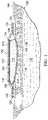
- FIG. 1is a cross section of an illustrative embodiment of a wound dressing on a patient's wound
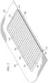
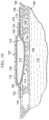
- FIG. 2is an exploded, perspective view, with a portion (an edge) shown in cross section, of an illustrative embodiment of a wound dressing;
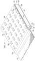
- FIG. 3is a perspective view, with a portion shown in cross section, of the wound dressing of FIG. 2 shown with a plurality nano-antennas;
- FIG. 4is a perspective view, with a portion shown in cross section, of a portion of the wound dressing of FIG. 3 ;
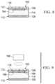
- FIG. 5is a cross section of an illustrative embodiment of a portion of a wound dressing including a filtering layer
- FIG. 6is a cross section of an illustrative embodiment of a portion of a wound dressing including a hydro-activated, exothermic material
- FIG. 7is a cross section of an illustrative embodiment of a portion of a wound dressing including an electrical heating element
- FIG. 8is a cross section of an illustrative embodiment of a portion of a wound dressing
- FIG. 9is a cross section of an illustrative embodiment of a portion of a wound dressing including inductive elements
- FIG. 10is a cross section of an illustrative embodiment of a wound dressing shown on a patient
- FIG. 11is a plan view of the illustrative embodiment of a wound dressing of FIG. 10 ;
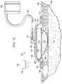
- FIG. 12is a cross section of an illustrative system for treating a wound
- FIG. 13is a cross section of an illustrative system for treating a wound.
- FIG. 14is a cross section of an illustrative embodiment of a portion of a wound dressing.
- the illustrative medical systems, dressings, and methods hereinimprove the fluid management of a wound.
- the illustrative medical systems, dressings, and methodsthermally-enhance transmission of vapor across a sealing member to allow the system or dressing to process more liquid than otherwise possible.
- FIGS. 1 - 4an illustrative embodiment of a wound dressing 102 is presented.
- the wound dressing 102is shown on a wound 104 , or tissue site.
- the woundis through a patient's 106 epidermis 108 , a dermis 109 , and into subcutaneous tissue 110 .
- the wound dressing 102includes a thermally-conductive, vapor-permeable member 112 and a liquid-processing member 114 . While referencing only “vapor” in its name, the thermally-conductive, vapor-permeable member 112 is operable to allow vapor and liquid to pass.
- the thermally-conductive, vapor-permeable member 112 and liquid-processing member 114are covered by a high-moisture-vapor-transmission-rate drape 116 (high-MVTR drape).
- the thermally-conductive, vapor-permeable member 112is operable to conduct body heat from the patient 106 at or near the wound 104 to the high-moisture-vapor-transmission-rate drape 116 to enhance transmission of vapor through the high-moisture-vapor-transmission-rate drape 116 .
- the heat captured by the thermally-conductive, vapor-permeable member 112 of the wound dressing 102 and delivered specifically to the high-moisture-vapor-transmission-rate drape 116increases vapor transmission through the high-moisture-vapor-transmission-rate drape 116 .
- other sources of internal and external heatmay be utilized with the wound dressing 102 to increase vapor transmission through the high-moisture-vapor-transmission-rate drape 116 .
- Enhancing the vapor transmission through the wound dressing 102maximizes the capacity of the wound dressing 102 .
- the wound dressing 102becomes operable to process more liquid over time than the wound dressing 102 can hold at one time.
- the wound dressing 102effectually removes or manages liquid from the wound 104 .
- the increased vapor transmissioncan be notable. For example, increasing the temperature from 20° C. to 30° C. or 40° C. may add orders of magnitude to the evaporation rate. In one illustrative, non-limiting example, a 1.3 fold increase in evaporation rate per degree was associated with each degree increase in Celsius (C) from 25° C. to 37° C. The increased evaporation rate in turn may greatly enhance the amount of liquid from the wound 104 that may be processed over time by the wound dressing 102 .
- the high-moisture-vapor-transmission-rate drape 116has a first side 118 and a second, patient-facing side 120 .
- “Moisture Vapor Transmission Rate” or “MVTR”represents the amount of moisture that can pass through a material in a given period of time.
- the high-moisture-vapor-transmission-rate drape 116will typically have an MVTR greater than 300 g/24 hours/m 2 and more typically a value greater than or equal to 1000 g/24 hours/m 2 .
- the high-moisture-vapor-transmission-rate drape 116allows vapor to egress from the wound through the wound dressing 102 to the atmosphere.
- the high-moisture-vapor-transmission-rate drape 116may comprise any of numerous materials, such as any of the following: hydrophilic polyurethane, cellulosics, hydrophilic polyamides, polyvinyl alcohol, polyvinyl pyrrolidone, hydrophilic acrylics, hydrophilic silicone elastomers, and copolymers of these.
- the high-moisture-vapor-transmission-rate drape 116may be formed from a breathable cast matt polyurethane film sold under the name INSPIRE 2301 from Expopack Advanced Coatings of Wrexham, United Kingdom.
- That illustrative filmhas a MVTR (inverted cup technique) of 14400 g/m 2 /24 hours.
- the high-moisture-vapor-transmission-rate drape 116may have various thicknesses, such as 10 to 40 microns ( ⁇ m), e.g., 15, 20, 25, 30, 35, 40 microns or any number in the stated range.
- a peripheral edge 122 of the high-moisture-vapor-transmission-rate drape 116has an attachment device 124 on the second, patient-facing side 120 .
- the attachment device 124secures or helps secure the high-moisture-vapor-transmission-rate drape 116 to the patient's intact skin at or near the wound 104 .
- the attachment device 124may be a medically-acceptable, pressure-sensitive adhesive; a double-sided drape tape; paste; hydrocolloid; hydro gel; or other sealing devices or elements.
- the thermally-conductive, vapor-permeable member 112functionally conducts heat from the patient 106 at or near the wound 104 to the high-moisture-vapor-transmission-rate drape 116 and allows or enhances vapor transmission through the thermally-conductive, vapor-permeable member 112 . While the thermally-conductive, vapor-permeable member 112 may be formed as integral components, the thermally-conductive, vapor-permeable member 112 may nonetheless be viewed as comprising three portions or members: a drape-interface member 126 , a patient-interface member 128 , and a coupling member 130 .
- the drape-interface member 126has a first side 132 and a second, patient-facing side 134 .
- the first side 132 of the drape-interface member 126is proximate the second, patient-facing side 120 of the high-moisture-vapor-transmission-rate drape 116 .
- the patient-interface member 128has a first side 136 and a second, patient-facing side 138 .
- the second, patient-facing side 138 of the patient-interface member 128is proximate to the patient 106 .
- the coupling member 130thermally couples the drape-interface member 126 and the patient-interface member 128 .
- the thermally-conductive, vapor-permeable member 112may be formed from any material that conducts thermal energy and allows liquid and vapor to transgress the material.
- the thermally-conductive, vapor-permeable member 112may comprise one or more of the following: woven or non-woven material, activated carbon material, porous foam, sintered polymer, carbon fiber material, woven metallic fibers, zinc oxide, or mesh fabric.
- the thermally-conductive, vapor-permeable member 112is sized and configured to be flexible enough to conform to the shape of the wound 104 .
- the liquid-processing member 114Disposed between the drape-interface member 126 and the patient-interface member 128 is the liquid-processing member 114 .
- the liquid-processing member 114is operable to at least temporarily retain liquids from the wound 104 .
- the liquid-processing member 114has a first side 140 and a second, patient-facing side 142 .
- the first side 140is proximate the second, patient-facing side 134 of the drape-interface member 126 .
- the second, patient-facing side 142is proximate to the first side 136 of the patient-interface member 128 .
- the liquid-processing member 114functions to retain, at least temporarily, liquids from the wound 104 .
- the liquid-processing member 114buffers liquids while waiting on evaporation or removal or may store a certain quantity of liquids for other reasons.
- the liquid-processing member 114may be formed from one or more of the following: open-cell foam, non-woven material, a super-absorbent material, gel materials, absorbent clays or inorganic or polymer particulates, and nano particles.
- thermal energymay be added to enhance evaporation from an internal heat source or external heat source.
- heat from external air temperature, light, artificial radiation (infrared), hydro-activated chemicals, inductive materials, piezoelectric members, electric heating elements, or sonic heating (thermo-acoustic)may be used to enhance transmission of vapor through the high-moisture-vapor-transmission-rate drape 116 .
- a plurality of nano-antennas 144 or nantennashave been added on the first side 118 of the high-moisture-vapor-transmission-rate drape 116 .
- the plurality of nano-antennas 144are a way of harvesting the environmental energy, e.g., energy from light or heat from the patient.
- a nano-antennais an electromagnetic collector designed to absorb specific wavelengths that are proportional to the size of the nano-antenna.
- the nano-atennas 144may be sized to focus on absorbing infrared radiation with wavelengths from 1 micron to 300 microns and may, in some embodiments, focus on 12 micron wavelengths which are the wavelength that the human body at normal temeprature emits as heat.
- Design of the nano-antenna 144may be a type of interlocking spiral such as those from MicroContinuum Inc. These type of antennas are manufactured by photo-lithography using gold foil on a plastic sheet substrate. The energy harnessed is electrical.
- the high-moisture-vapor-transmission-rate drape 116may include corrugated portions 146 as shown in FIG. 6 .
- the corrugated portions 146increase the surface area available to assist with evaporation and may encourage turbulent air flow across the first side 118 of the high-moisture-vapor-transmission-rate drape 116 .
- the thermally-conductive, vapor-permeable member 112which has the liquid-processing member 114 between portions thereof, is disposed proximate to the wound 104 .
- the patient-interface member 128 of the thermally-conductive, vapor-permeable member 112is disposed proximate to the wound 104 .
- the high-moisture-vapor-transmission-rate drape 116is disposed over the thermally-conductive, vapor-permeable member 112 .
- the second, patient-facing side 120 of the high-moisture-vapor-transmission-rate drape 116is disposed proximate to the first side 132 of the drape-interface member 126 .
- release linersmay be removed from the attachment device 124 .
- the wound dressing 102may remain on the wound 104 for a few hours up to many days, e.g., 2 days, 4 days, 7 days, or more.
- a saturation indicator(visual indicator of moisture)(not shown) may be added to the thermally-conductive, vapor-permeable member 112 or liquid-processing member 114 to indicate when the wound dressing 102 is full.
- nano-antennas 144are included (e.g., FIGS. 3 - 4 , 6 , 12 ), the nano-antennas 144 may absorb energy from ambient light or may receive light from a directed light source (see, e.g., FIG. 12 ).
- the wound 104produces a liquid, e.g., exudate, that flows through the patient-interface member 128 and into the liquid-processing member 114 , which temporarily holds the liquid.
- the liquid in the liquid-processing member 114 that is against or near the high-moisture-vapor-transmission-rate drape 116evaporates and is transmitted through the high-moisture-vapor-transmission-rate drape 116 .
- the transmission rate through the high-moisture-vapor-transmission-rate drape 116is increased or enhanced by the thermal energy delivery from the patient 106 through the thermally-conductive, vapor-permeable member 112 .
- the transmission ratemay further be enhanced by additional energy added externally or internally as presented elsewhere herein.
- FIG. 5a cross section of a portion of a wound dressing 102 is shown according to one illustrative embodiment.
- This embodimentis analogous to the embodiment of FIG. 1 , except a filtering layer 148 has been added.
- the filtering layer 148is shown disposed between the high-moisture-vapor-transmission-rate drape 116 and the drape-interface member 126 of the thermally-conductive, vapor-permeable member 112 . It should be understood that the filtering layer 148 may be at any location between the patient and the high-moisture-vapor-transmission-rate drape 116 . It should also be understood that filtering layer 148 may be used with any embodiment herein.
- the filtering layer 148may serve one or more purposes.
- the filtering layer 148may prevent any substances other than water vapor from reaching the high-moisture-vapor-transmission-rate drape 116 .
- the filtering layer 148may serve to filter odors from the vapor transmitted through the high-moisture-vapor-transmission-rate drape 116 to the atmosphere.
- the filtering layermay be formed from activated carbon material, activated clays (such as Bentonite), silicone resins, or coated porous (foams, sintered media) elements.
- FIG. 6an illustrative embodiment of a portion of a wound dressing 102 is shown that is analogous to the wound dressing 102 of FIG. 1 , except that the high-moisture-vapor-transmission-rate drape 116 includes corrugated portions 146 and nano-antennas 144 and the wound dressing 102 includes a hydro-activated, exothermic material 150 .
- the corrugated portions 146 and nano-antennas 144have previously been discussed.
- the hydro-activated, exothermic material 150may be disposed on or in the liquid-processing member 114 near the drape-interface member 126 . When the hydro-activated, exothermic material 150 is exposed to a watery liquid, a resultant chemical reaction produces heat.
- the hydro-activated, exothermic material 150may be calcium oxide such that when water in the exudate reaches the hydro-activated, exothermic material 150 a reaction occurs: CaO(s)+H2O(l) ⁇ Ca(OH)2(s).
- CaO(s)+H2O(l) ⁇ Ca(OH)2(s)is another example, albeit a highly exothermic (and more caustic) one, is NaO (s) +H 2 O (l) ⁇ NaOH (s) .
- NaO (s) +H 2 O (l) ⁇ NaOH (s)is a highly exothermic (and more caustic) one.
- NaO (s) +H 2 O (l) ⁇ NaOH (s)is a highly exothermic (and more caustic) one.
- NaO (s) +H 2 O (l) ⁇ NaOH (s)is another example (used in hand warmers for example) is 4Fe (s) +3O 2(
- FIG. 7an illustrative embodiment of a portion of a wound dressing 102 that includes an internal heat source in the form of an electrical heating element 152 is presented.
- the wound dressing 102is analogous in most respects to the wound dressing of FIG. 1 , except that it further includes the electrical heating element 152 and associated components.
- the electrical heating element 152may be a resistive heating element that is disposed inside or on the thermally-conductive, vapor-permeable member 112 and is thereby thermally coupled to the high-moisture-vapor-transmission-rate drape 116 .
- the electrical heating element 152provides thermal energy when energized.
- the illustrative electrical heating element 152is shown as a plurality of electrical conduits disposed within the thermally-conductive, vapor-permeable member 112 and electrically coupled to one another by leads 154 .
- the electrical heating element 152is electrically coupled to a control circuit 156 by another lead 158 .
- a power supply 160is electrically coupled to the control circuit 156 by another lead 162 .
- the control circuit 156may be used to set the desired temperature and to control the heat developed by the electrical heating element 152 .
- FIG. 8an illustrative embodiment of a portion of a wound dressing 102 that includes an internal heat source in the form of a piezoelectric member 164 is shown.
- the wound dressing 102is analogous in most respects to the wound dressing of FIG. 1 , except that the wound dressing 102 further includes the piezoelectric member 164 .
- the piezoelectric member 164is operable to provide energy to the wound dressing 102 when the piezoelectric member 164 is moved.
- the piezoelectric member 164generates an electrical current during flexing that is then used to generate heat.
- FIG. 9an illustrative embodiment of a portion of a wound dressing 102 that includes inductive elements 166 and a source of magnetic energy 168 is presented.
- the wound dressing 102is analogous in most respects to the wound dressing of FIG. 1 , except the inductive elements 166 have been added.
- the inductive elements 166are disposed within or on the thermally-conductive, vapor-permeable member 112 .
- the source of magnetic energy 168emits magnetic energy that is received by the inductive elements 166 to produce thermal energy that is conducted to the thermally-conductive, vapor-permeable member 112 and thereby to the high-moisture-vapor-transmission-rate drape 116 .
- FIGS. 10 and 11an illustrative embodiment of a wound dressing 102 is presented that is analogous in most respects to the wound dressing 102 of FIG. 1 , except that the wound dressing 102 includes a patient-interface member 128 that is larger than the drape-interface member 126 of the thermally-conductive, vapor-permeable member 112 .
- the patient-interface member 128is larger to provide a greater surface area over which to capture heat from the patient.
- a seal 170may be provided on a portion of the patient-interface member 128 proximate to an edge of the drape-interface member 126 to provide a fluid seal. The seal inhibits fluid flow but allows thermal energy to pass.
- the planar surface area (A 1 ) of the drape-interface member 126is less than the planar surface area (A 2 ) of the patient-interface member 128 , i.e., A 1 ⁇ A 2 .
- An adhesive(not shown) may be applied on peripheral portion of the patient-facing side of the patient-interface member 128 to hold the additional portion of the patient-interface member 128 to intact skin on the patient.
- the wound dressing 102is disposed proximate to the wound 104 .
- the patient-interface member 128is proximate to the wound 104 .
- the other layers or membersare assembled or pre-assembled as shown in the figures with the high-moisture-vapor-transmission-rate Drape on the top (for the orientation shown).
- the vapor leaving the thermally-conductive, vapor-permeable member 112moves through the filtering layer 148 , which removes odor or particulates that might otherwise escape.
- the vapor transmission rateis enhanced by the patient's body heat and heat from the hydro-activated, exothermic material 150 once the watery liquid reaches the hydro-activated, exothermic material 150 .
- the transmission ratemay be relatively increased by using a greater surface area due to the corrugated portions 146 .
- the transmission rateis enhanced by the patient's body heat and heat from the electrical heating element 152 .
- the amount of heat added by the electrical heating element 152is controlled by the control circuit or controller 156 .
- An electrical fill indicator(not shown) may be included in the liquid-processing member 114 and electrically coupled to the control circuit 156 such that the control circuit 156 activates the electrical heating element 152 once the liquid-processing member 114 is saturated.
- the control circuit 156may activate the electrical heating element 152 based on timer intervals or when manually activated.
- the transmission rateis enhanced by the patient's body heat and heat from the piezoelectric member 164 .
- the piezoelectric member 164may take movement and create thermal energy.
- the element labeled 164may be a material that otherwise generates heat as the element is flexed.
- castable polyester polyurethane elastomersbased on the system polycaprolactone diol (Capa 225)/trans 1.4-cyclohexane diisocyanate (CHDI)/1.4-butane diol (1.4-BD) and 1.4-cyclohexane dimethanol (1.4-CHDM).
- CHDIsystem polycaprolactone diol
- 1.4-BD1.4-cyclohexane diisocyanate
- 1.4-CHDM1.4-cyclohexane dimethanol
- the system 100includes a wound dressing 102 , which is analogous in many respects to the wound dressing 102 of FIG. 1 .
- the system 100provides for enhanced liquid management and also for the application of reduced pressure on a wound 104 .
- the system 100includes a manifold member 172 disposed proximate to the wound 104 .
- the wound 104extends through epidermis 108 , dermis 109 , and into subcutaneous tissue 110 .
- the manifold member 172is a substance or structure that is provided to assist in applying reduced pressure to, delivering fluids to, or removing fluids from a tissue site or wound 104 .
- the manifold member 172includes a plurality of flow channels or pathways that distribute fluids provided to and removed from the tissue site around the manifold member 172 . In one illustrative embodiment, the flow channels or pathways are interconnected to improve distribution of fluids provided to or removed from the wound 104 .
- the manifold member 172may be a biocompatible material that is capable of being placed in contact with the wound 104 and distributing reduced pressure.
- manifold members 172include, without limitation, one or more of the following: devices that have structural elements arranged to form flow channels, such as, for example, cellular foam, open-cell foam, porous tissue collections, liquids, gels, and foams that include, or cure to include, flow channels; porous material porous, such as foam, gauze, felted mat, or any other material suited to a particular biological application; or porous foam that includes a plurality of interconnected cells or pores that act as flow channels, e.g., a polyurethane, open-cell, reticulated foam such as GranuFoam® material manufactured by Kinetic Concepts, Incorporated of San Antonio, Tex.; a bioresorbable material; or a scaffold material.
- devices that have structural elements arranged to form flow channelssuch as, for example, cellular foam, open-cell foam, porous tissue collections, liquid
- the manifold member 172may also be used to distribute fluids such as medications, antibacterials, growth factors, and various solutions to the tissue site.
- Other layersmay be included in or on the manifold member 172 , such as absorptive materials, wicking materials, hydrophobic materials, and hydrophilic materials.
- the manifold member 172may be constructed from a bioresorbable material that remains in a patient's body following use of the reduced-pressure dressing. Suitable bioresorbable materials include, without limitation, a polymeric blend of polylactic acid (PLA) and polyglycolic acid (PGA). The polymeric blend may also include without limitation polycarbonates, polyfumarates, and capralactones.
- the manifold member 172may further serve as a scaffold for new cell-growth, or a scaffold material may be used in conjunction with the manifold member 172 to promote cell-growth.
- a scaffoldis a substance or structure used to enhance or promote the growth of cells or formation of tissue, such as a three-dimensional porous structure that provides a template for cell growth.
- Illustrative examples of scaffold materialsinclude calcium phosphate, collagen, PLA/PGA, coral hydroxy apatites, carbonates, or processed allograft materials.
- the wound dressing 102includes a high-moisture-vapor-transmission-rate drape 116 ; a thermally-conductive, vapor-permeable member 112 ; and a liquid-processing member 114 .
- the high-moisture-vapor-transmission-rate drape 116may include nano-antennas 144 .
- Applied on or through the high-moisture-vapor-transmission-rate drape 116is a reduced-pressure interface 174 .
- the reduced-pressure interface 174is a T.R.A.C.® Pad or Sensa T.R.A.C.® Pad available from KCI of San Antonio, Tex.
- An external energy source 176may be used to provide additional energy to the wound dressing 102 .
- the external energy source 176may be a light source 178 , e.g., an LED light, that provides light to the high-moisture-vapor-transmission-rate drape 116 directly or by providing energy to the nano-antennas 144 .
- the high-moisture-vapor-transmission-rate drape 116creates a sealed space 180 between the wound 104 and the second, patient-facing side 120 of the high-moisture-vapor-transmission-rate drape 116 .
- a reduced-pressure source 182is fluidly coupled to the sealed space 180 .
- the reduced-pressure source 182may be any device for supplying a reduced pressure, such as a vacuum pump, wall suction, micro-pump, or other source.
- the reduced pressurewill typically be between ⁇ 5 mm Hg ( ⁇ 667 Pa) and ⁇ 500 mm Hg ( ⁇ 66.7 kPa) and more typically between ⁇ 75 mm Hg ( ⁇ 9.9 kPa) and ⁇ 300 mm Hg ( ⁇ 39.9 kPa).
- the reduced-pressure source 182may be fluidly coupled to the sealed space 180 , which includes the manifold member 172 , by a reduced-pressure delivery conduit 184 and the reduced-pressure interface 174 or by directly inserting the reduced-pressure delivery conduit 184 through the high-moisture-vapor-transmission-rate drape 116 into the sealed space 180 .
- the fluid couplingmay be due to the position of the reduced-pressure source 182 ; for example, if the reduced-pressure source 182 is a micro-pump, the intake may be directly, fluidly coupled to the sealed space 180 .
- the micro-pumpis thermally coupled to the high-moisture-vapor-transmission-rate drape 116 .
- the manifold member 172is disposed proximate to the wound 104 .
- the wound dressing 102is placed proximate to a first side 173 of the manifold member 172 .
- the high-moisture-vapor-transmission-rate drape 116 over the patient's skincreates the sealed space 180 .
- the reduced-pressure delivery conduit 184is fluidly coupled to the sealed space 180 and thereby the manifold member 172 . Reduced pressure is then applied to help treat the wound 102 .
- liquidsare delivered to the reduced-pressure source 182 , but evaporation and transmission through the high-moisture-vapor-transmission-rate drape 116 may also occur.
- the reduced-pressure source 182is a micro-pump
- the liquidwill be retained in the wound dressing 102 until transmitted through the high-moisture-vapor-transmission-rate drape 116 .
- the transmission rateis enhanced by the patient's body heat (delivered through the thermally-conductive, vapor-permeable member 112 ) and may be enhanced by nano-antennas 144 if included.
- the nano-antennas 144may be energized by a light source 178 .
- FIG. 13another illustrative embodiment of a wound dressing 102 is presented.
- the wound dressing 102is analogous in most respects to the wound dressing 102 of FIG. 1 , except external baffles 186 and an air mover 188 have been added.
- the external baffles 186are on the first side of the high-moisture-vapor-transmission-rate drape 116 and form a channel 190 .
- the air mover 188is fluidly coupled to the channel 190 by a conduit 192 .
- the air mover 188provides air flow against the first side 118 of the high-moisture-vapor-transmission-rate drape 116 and thereby further increases the evaporation rate.
- the components of the various figuresmay be combined with others. Thus, for example, the air mover 188 and external baffles 186 may be added to any of the other embodiments herein.
- the wound dressing 102is analogous in most respects to the wound dressing 102 of FIG. 1 .
- the wound dressing 102has a thermally-conductive, vapor-permeable member 112 .
- a liquid-processing member 114is between portions of the thermally-conductive, vapor-permeable member 112 .
- the wound dressing 102further includes a high-moisture-vapor-transmission-rate drape 116 .
- the thermally-conductive, vapor-permeable member 112has a drape-interface member 126 , a patient-interface member 128 , and a coupling member 130 .
- the coupling member 130is presented in a different location in part to emphasize that the coupling member 130 may be in numerous locations.
- the coupling member 130has been to one side of the liquid-processing member 114 .
- the coupling member 130extends from the patient-interface member 128 to the drape-interface member 126 through the body or main portion of the liquid-processing member 114 . Because it is generally desirable to transfer heat from the patient to the drape-interface member 126 without heating up the liquid-processing member 114 , insulation 194 may be placed around the coupling member 130 . It should be understood that the coupling member 130 functions to thermally couple the drape-interface member 126 and the patient-interface member 128 and may be located at any point with respect to those members, e.g., sides or middle or any where between.
- any feature that is described in connection to any one embodimentmay also be applicable to any other embodiment.
- the nano-antennas 144may be added to any embodiment herein.
- the filtering layer 148may be added to any embodiment herein.
- the corrugated portions 146may be added to any of the embodiments herein.
- the hydro-activated, exothermic material 150may be added to any of the embodiments herein.
- the electrical heating element 152(and associated components) may be added to any embodiment herein or the piezoelectric member 164 added to any embodiment.
- reduced pressuremay be used with any of the embodiments.
- the external baffles 186 and air mover 188( FIG. 13 ) may be used with any embodiment.
- the different componentsmay be used in any combination.
- a wound dressing 102may have a nano-antennas 144 on the high-moisture-vapor-transmission-rate drape 116 , a filtering layer 148 below (for orientation shown in FIG. 5 ), a hydro-activated, exothermic material 150 proximate the filtering layer 148 , and an electrical heating element 152 in the thermally-conductive, vapor-permeable member 112 .
- a nano-antennas 144on the high-moisture-vapor-transmission-rate drape 116
- a filtering layer 148 belowfor orientation shown in FIG. 5
- a hydro-activated, exothermic material 150proximate the filtering layer 148
- an electrical heating element 152in the thermally-conductive, vapor-permeable member 112 .
- Numerous other examplesare possible.
- the piezoelectric member 164( FIG. 8 ) may be included with the reduced-pressure components of FIG. 12 . Then in operation, the reduced-pressure components may be used in a pulsed fashion to move and excite the piezoelectric member 164 to generate heat.
- the wound dressing 102may have an enhanced capacity because the wound dressing 102 is able to offload liquid from the wound dressing 102 in the form of vapor exiting the wound dressing 102 through the high-moisture-vapor-transmission-rate drape 116 . And, because of the additional thermal energy, the wound dressings 102 are operable to transmit relatively more liquid through the high-moisture-vapor-transmission-rate drape 116 over a given time. Moreover, the wound dressings 102 may stay in place longer. The wound dressings 102 may be used without requiring additional training. The wound dressings 102 may convert liquids retained into the wound dressing 102 to a gel and thereby make disposal easier.
Landscapes
- Health & Medical Sciences (AREA)
- Heart & Thoracic Surgery (AREA)
- Animal Behavior & Ethology (AREA)
- General Health & Medical Sciences (AREA)
- Biomedical Technology (AREA)
- Veterinary Medicine (AREA)
- Vascular Medicine (AREA)
- Life Sciences & Earth Sciences (AREA)
- Public Health (AREA)
- Engineering & Computer Science (AREA)
- Chemical & Material Sciences (AREA)
- Medicinal Chemistry (AREA)
- Anesthesiology (AREA)
- Hematology (AREA)
- Media Introduction/Drainage Providing Device (AREA)
- Thermotherapy And Cooling Therapy Devices (AREA)
Abstract
Description
Claims (28)
Priority Applications (1)
| Application Number | Priority Date | Filing Date | Title |
|---|---|---|---|
| US16/527,622US11607343B2 (en) | 2011-11-15 | 2019-07-31 | Medical dressings, systems, and methods with thermally-enhanced vapor transmission |
Applications Claiming Priority (4)
| Application Number | Priority Date | Filing Date | Title |
|---|---|---|---|
| US201161560090P | 2011-11-15 | 2011-11-15 | |
| US13/678,492US9233028B2 (en) | 2011-11-15 | 2012-11-15 | Medical dressings, systems, and methods with thermally-enhanced vapor transmissions |
| US14/960,058US10413448B2 (en) | 2011-11-15 | 2015-12-04 | Medical dressings, systems, and methods with thermally-enhanced vapor transmission |
| US16/527,622US11607343B2 (en) | 2011-11-15 | 2019-07-31 | Medical dressings, systems, and methods with thermally-enhanced vapor transmission |
Related Parent Applications (1)
| Application Number | Title | Priority Date | Filing Date |
|---|---|---|---|
| US14/960,058DivisionUS10413448B2 (en) | 2011-11-15 | 2015-12-04 | Medical dressings, systems, and methods with thermally-enhanced vapor transmission |
Publications (2)
| Publication Number | Publication Date |
|---|---|
| US20190350763A1 US20190350763A1 (en) | 2019-11-21 |
| US11607343B2true US11607343B2 (en) | 2023-03-21 |
Family
ID=47263602
Family Applications (3)
| Application Number | Title | Priority Date | Filing Date |
|---|---|---|---|
| US13/678,492Active2033-11-15US9233028B2 (en) | 2011-11-15 | 2012-11-15 | Medical dressings, systems, and methods with thermally-enhanced vapor transmissions |
| US14/960,058Active2034-03-23US10413448B2 (en) | 2011-11-15 | 2015-12-04 | Medical dressings, systems, and methods with thermally-enhanced vapor transmission |
| US16/527,622Active2034-02-10US11607343B2 (en) | 2011-11-15 | 2019-07-31 | Medical dressings, systems, and methods with thermally-enhanced vapor transmission |
Family Applications Before (2)
| Application Number | Title | Priority Date | Filing Date |
|---|---|---|---|
| US13/678,492Active2033-11-15US9233028B2 (en) | 2011-11-15 | 2012-11-15 | Medical dressings, systems, and methods with thermally-enhanced vapor transmissions |
| US14/960,058Active2034-03-23US10413448B2 (en) | 2011-11-15 | 2015-12-04 | Medical dressings, systems, and methods with thermally-enhanced vapor transmission |
Country Status (7)
| Country | Link |
|---|---|
| US (3) | US9233028B2 (en) |
| EP (2) | EP3669841B1 (en) |
| JP (1) | JP6305927B2 (en) |
| CN (1) | CN103889378B (en) |
| AU (1) | AU2012340381B2 (en) |
| CA (1) | CA2854632C (en) |
| WO (1) | WO2013074825A1 (en) |
Cited By (1)
| Publication number | Priority date | Publication date | Assignee | Title |
|---|---|---|---|---|
| US12059325B2 (en) | 2015-04-27 | 2024-08-13 | Smith & Nephew Plc | Reduced pressure apparatuses and methods |
Families Citing this family (34)
| Publication number | Priority date | Publication date | Assignee | Title |
|---|---|---|---|---|
| GB0808376D0 (en) | 2008-05-08 | 2008-06-18 | Bristol Myers Squibb Co | Wound dressing |
| GB0817796D0 (en) | 2008-09-29 | 2008-11-05 | Convatec Inc | wound dressing |
| GB201020236D0 (en) | 2010-11-30 | 2011-01-12 | Convatec Technologies Inc | A composition for detecting biofilms on viable tissues |
| US10207031B2 (en) | 2010-12-08 | 2019-02-19 | Convatec Technologies Inc. | Integrated system for assessing wound exudates |
| WO2012078724A1 (en) | 2010-12-08 | 2012-06-14 | Convatec Technologies Inc. | Apparatus and method for applying pressure to a wound site |
| ES2748519T3 (en) | 2010-12-08 | 2020-03-17 | Convatec Technologies Inc | Wound exudate system accessory |
| WO2013066426A2 (en) | 2011-06-24 | 2013-05-10 | Kci Licensing, Inc. | Reduced-pressure dressings employing tissue-fixation elements |
| GB201115182D0 (en) | 2011-09-02 | 2011-10-19 | Trio Healthcare Ltd | Skin contact material |
| GB2497406A (en) | 2011-11-29 | 2013-06-12 | Webtec Converting Llc | Dressing with a perforated binder layer |
| GB201120693D0 (en) | 2011-12-01 | 2012-01-11 | Convatec Technologies Inc | Wound dressing for use in vacuum therapy |
| USD733896S1 (en) | 2012-05-04 | 2015-07-07 | Genadyne Biotechnologies, Inc. | Abdominal dressing |
| JP2016507663A (en) | 2012-12-20 | 2016-03-10 | コンバテック・テクノロジーズ・インコーポレイテッドConvatec Technologies Inc | Processing of chemically modified cellulosic fibers |
| US9579414B2 (en)* | 2013-07-08 | 2017-02-28 | Hossam Abdel Salam El Sayed Mohamed | Devices and methods for effecting faster healing of orthopedic and other wounds |
| US10226566B2 (en) | 2014-04-23 | 2019-03-12 | Genadyne Biotechnologies, Inc. | System and process for removing bodily fluids from a body opening |
| AU2015373537B2 (en) | 2014-12-29 | 2020-09-03 | Smith & Nephew Plc | Negative pressure wound therapy apparatus and method of operating the apparatus |
| WO2016138488A2 (en) | 2015-02-26 | 2016-09-01 | The Broad Institute Inc. | T cell balance gene expression, compositions of matters and methods of use thereof |
| KR101698324B1 (en)* | 2015-05-22 | 2017-01-20 | 주식회사 퓨처바이오웍스 | Moist wound dressing band for electric stimulating |
| GB2543544A (en) | 2015-10-21 | 2017-04-26 | Brightwake Ltd | Wound dressing |
| US11364150B2 (en)* | 2015-12-30 | 2022-06-21 | Smith & Nephew Plc | Negative pressure wound therapy apparatus |
| AU2017243601A1 (en) | 2016-03-30 | 2018-11-22 | Acib Gmbh | Detecting microbial infection in wounds |
| PL3435941T3 (en) | 2016-03-30 | 2022-05-09 | Convatec Technologies Inc. | Detecting microbial infections in wounds |
| EP3481348A4 (en) | 2016-07-08 | 2020-02-26 | ConvaTec Technologies Inc. | Fluid collection apparatus |
| DK3481349T3 (en) | 2016-07-08 | 2021-07-12 | Convatec Technologies Inc | Flexible vacuum system |
| MX2019000232A (en) | 2016-07-08 | 2019-11-12 | Convatec Technologies Inc | Fluid flow sensing. |
| CN110913811A (en) | 2017-06-07 | 2020-03-24 | 凯希美国公司 | Wound dressing with odor absorption and increased moisture vapor transmission |
| AU2018282188A1 (en)* | 2017-06-07 | 2019-12-19 | 3M Innovative Properties Company | Tissue contact interface |
| CN111836655A (en) | 2017-11-16 | 2020-10-27 | 康沃特克有限公司 | fluid collection equipment |
| WO2020014310A1 (en)* | 2018-07-13 | 2020-01-16 | Kci Licensing, Inc. | Advanced wound dressing with compression and increased total fluid handling |
| US20200038251A1 (en)* | 2018-08-03 | 2020-02-06 | Kci Licensing, Inc. | Flexible and conformable wound dressing with enhanced fluid absorption capability |
| DE102019200253A1 (en) | 2019-01-10 | 2020-07-16 | B. Braun Melsungen Ag | Medical fluid line arrangement and medical elastomer pump with such a fluid line arrangement |
| EP4295869A3 (en) | 2019-06-03 | 2024-03-20 | Convatec Limited | Methods and devices to disrupt and contain pathogens |
| US11331221B2 (en) | 2019-12-27 | 2022-05-17 | Convatec Limited | Negative pressure wound dressing |
| US11771819B2 (en) | 2019-12-27 | 2023-10-03 | Convatec Limited | Low profile filter devices suitable for use in negative pressure wound therapy systems |
| CN114469519B (en)* | 2022-01-27 | 2022-08-05 | 长沙海润生物技术有限公司 | Negative-pressure coupling electric field signal feedback treatment system |
Citations (166)
| Publication number | Priority date | Publication date | Assignee | Title |
|---|---|---|---|---|
| US1355846A (en) | 1920-02-06 | 1920-10-19 | David A Rannells | Medical appliance |
| US2547758A (en) | 1949-01-05 | 1951-04-03 | Wilmer B Keeling | Instrument for treating the male urethra |
| US2632443A (en) | 1949-04-18 | 1953-03-24 | Eleanor P Lesher | Surgical dressing |
| GB692578A (en) | 1949-09-13 | 1953-06-10 | Minnesota Mining & Mfg | Improvements in or relating to drape sheets for surgical use |
| US2682873A (en) | 1952-07-30 | 1954-07-06 | Johnson & Johnson | General purpose protective dressing |
| US2910763A (en) | 1955-08-17 | 1959-11-03 | Du Pont | Felt-like products |
| US2969057A (en) | 1957-11-04 | 1961-01-24 | Brady Co W H | Nematodic swab |
| US3066672A (en) | 1960-09-27 | 1962-12-04 | Jr William H Crosby | Method and apparatus for serial sampling of intestinal juice |
| US3367332A (en) | 1965-08-27 | 1968-02-06 | Gen Electric | Product and process for establishing a sterile area of skin |
| US3520300A (en) | 1967-03-15 | 1970-07-14 | Amp Inc | Surgical sponge and suction device |
| US3568675A (en) | 1968-08-30 | 1971-03-09 | Clyde B Harvey | Fistula and penetrating wound dressing |
| US3648692A (en) | 1970-12-07 | 1972-03-14 | Parke Davis & Co | Medical-surgical dressing for burns and the like |
| US3682180A (en) | 1970-06-08 | 1972-08-08 | Coilform Co Inc | Drain clip for surgical drain |
| US3826254A (en) | 1973-02-26 | 1974-07-30 | Verco Ind | Needle or catheter retaining appliance |
| DE2640413A1 (en) | 1976-09-08 | 1978-03-09 | Wolf Gmbh Richard | CATHETER MONITORING DEVICE |
| US4080970A (en) | 1976-11-17 | 1978-03-28 | Miller Thomas J | Post-operative combination dressing and internal drain tube with external shield and tube connector |
| US4096853A (en) | 1975-06-21 | 1978-06-27 | Hoechst Aktiengesellschaft | Device for the introduction of contrast medium into an anus praeter |
| US4139004A (en) | 1977-02-17 | 1979-02-13 | Gonzalez Jr Harry | Bandage apparatus for treating burns |
| US4165748A (en) | 1977-11-07 | 1979-08-28 | Johnson Melissa C | Catheter tube holder |
| US4184510A (en) | 1977-03-15 | 1980-01-22 | Fibra-Sonics, Inc. | Valued device for controlling vacuum in surgery |
| WO1980002182A1 (en) | 1979-04-06 | 1980-10-16 | J Moss | Portable suction device for collecting fluids from a closed wound |
| US4233969A (en) | 1976-11-11 | 1980-11-18 | Lock Peter M | Wound dressing materials |
| US4245630A (en) | 1976-10-08 | 1981-01-20 | T. J. Smith & Nephew, Ltd. | Tearable composite strip of materials |
| US4256109A (en) | 1978-07-10 | 1981-03-17 | Nichols Robert L | Shut off valve for medical suction apparatus |
| US4261363A (en) | 1979-11-09 | 1981-04-14 | C. R. Bard, Inc. | Retention clips for body fluid drains |
| US4275721A (en) | 1978-11-28 | 1981-06-30 | Landstingens Inkopscentral Lic, Ekonomisk Forening | Vein catheter bandage |
| US4284079A (en) | 1979-06-28 | 1981-08-18 | Adair Edwin Lloyd | Method for applying a male incontinence device |
| US4297995A (en) | 1980-06-03 | 1981-11-03 | Key Pharmaceuticals, Inc. | Bandage containing attachment post |
| US4333468A (en) | 1980-08-18 | 1982-06-08 | Geist Robert W | Mesentery tube holder apparatus |
| US4373519A (en) | 1981-06-26 | 1983-02-15 | Minnesota Mining And Manufacturing Company | Composite wound dressing |
| US4382441A (en) | 1978-12-06 | 1983-05-10 | Svedman Paul | Device for treating tissues, for example skin |
| US4392853A (en) | 1981-03-16 | 1983-07-12 | Rudolph Muto | Sterile assembly for protecting and fastening an indwelling device |
| US4392858A (en) | 1981-07-16 | 1983-07-12 | Sherwood Medical Company | Wound drainage device |
| US4419097A (en) | 1981-07-31 | 1983-12-06 | Rexar Industries, Inc. | Attachment for catheter tube |
| EP0100148A1 (en) | 1982-07-06 | 1984-02-08 | Dow Corning Limited | Medical-surgical dressing and a process for the production thereof |
| US4465485A (en) | 1981-03-06 | 1984-08-14 | Becton, Dickinson And Company | Suction canister with unitary shut-off valve and filter features |
| EP0117632A2 (en) | 1983-01-27 | 1984-09-05 | Johnson & Johnson Products Inc. | Adhesive film dressing |
| US4475909A (en) | 1982-05-06 | 1984-10-09 | Eisenberg Melvin I | Male urinary device and method for applying the device |
| US4480638A (en) | 1980-03-11 | 1984-11-06 | Eduard Schmid | Cushion for holding an element of grafted skin |
| US4525374A (en) | 1984-02-27 | 1985-06-25 | Manresa, Inc. | Treating hydrophobic filters to render them hydrophilic |
| US4525166A (en) | 1981-11-21 | 1985-06-25 | Intermedicat Gmbh | Rolled flexible medical suction drainage device |
| US4540412A (en) | 1983-07-14 | 1985-09-10 | The Kendall Company | Device for moist heat therapy |
| US4543100A (en) | 1983-11-01 | 1985-09-24 | Brodsky Stuart A | Catheter and drain tube retainer |
| US4548202A (en) | 1983-06-20 | 1985-10-22 | Ethicon, Inc. | Mesh tissue fasteners |
| US4551139A (en) | 1982-02-08 | 1985-11-05 | Marion Laboratories, Inc. | Method and apparatus for burn wound treatment |
| EP0161865A2 (en) | 1984-05-03 | 1985-11-21 | Smith and Nephew Associated Companies p.l.c. | Adhesive wound dressing |
| US4569348A (en) | 1980-02-22 | 1986-02-11 | Velcro Usa Inc. | Catheter tube holder strap |
| AU550575B2 (en) | 1981-08-07 | 1986-03-27 | Richard Christian Wright | Wound drainage device |
| US4605399A (en) | 1984-12-04 | 1986-08-12 | Complex, Inc. | Transdermal infusion device |
| US4608041A (en) | 1981-10-14 | 1986-08-26 | Frese Nielsen | Device for treatment of wounds in body tissue of patients by exposure to jets of gas |
| US4640688A (en) | 1985-08-23 | 1987-02-03 | Mentor Corporation | Urine collection catheter |
| US4655754A (en) | 1984-11-09 | 1987-04-07 | Stryker Corporation | Vacuum wound drainage system and lipids baffle therefor |
| US4664662A (en) | 1984-08-02 | 1987-05-12 | Smith And Nephew Associated Companies Plc | Wound dressing |
| WO1987004626A1 (en) | 1986-01-31 | 1987-08-13 | Osmond, Roger, L., W. | Suction system for wound and gastro-intestinal drainage |
| US4710165A (en) | 1985-09-16 | 1987-12-01 | Mcneil Charles B | Wearable, variable rate suction/collection device |
| US4733659A (en) | 1986-01-17 | 1988-03-29 | Seton Company | Foam bandage |
| GB2195255A (en) | 1986-09-30 | 1988-04-07 | Vacutec Uk Limited | Method and apparatus for vacuum treatment of an epidermal surface |
| US4743232A (en) | 1986-10-06 | 1988-05-10 | The Clinipad Corporation | Package assembly for plastic film bandage |
| GB2197789A (en) | 1986-11-28 | 1988-06-02 | Smiths Industries Plc | Anti-foaming disinfectants used in surgical suction apparatus |
| US4758220A (en) | 1985-09-26 | 1988-07-19 | Alcon Laboratories, Inc. | Surgical cassette proximity sensing and latching apparatus |
| US4787888A (en) | 1987-06-01 | 1988-11-29 | University Of Connecticut | Disposable piezoelectric polymer bandage for percutaneous delivery of drugs and method for such percutaneous delivery (a) |
| US4826494A (en) | 1984-11-09 | 1989-05-02 | Stryker Corporation | Vacuum wound drainage system |
| US4838883A (en) | 1986-03-07 | 1989-06-13 | Nissho Corporation | Urine-collecting device |
| US4840187A (en) | 1986-09-11 | 1989-06-20 | Bard Limited | Sheath applicator |
| US4863449A (en) | 1987-07-06 | 1989-09-05 | Hollister Incorporated | Adhesive-lined elastic condom cathether |
| US4872450A (en) | 1984-08-17 | 1989-10-10 | Austad Eric D | Wound dressing and method of forming same |
| US4878901A (en) | 1986-10-10 | 1989-11-07 | Sachse Hans Ernst | Condom catheter, a urethral catheter for the prevention of ascending infections |
| GB2220357A (en) | 1988-05-28 | 1990-01-10 | Smiths Industries Plc | Medico-surgical containers |
| US4897081A (en) | 1984-05-25 | 1990-01-30 | Thermedics Inc. | Percutaneous access device |
| US4906233A (en) | 1986-05-29 | 1990-03-06 | Terumo Kabushiki Kaisha | Method of securing a catheter body to a human skin surface |
| US4906240A (en) | 1988-02-01 | 1990-03-06 | Matrix Medica, Inc. | Adhesive-faced porous absorbent sheet and method of making same |
| US4919654A (en) | 1988-08-03 | 1990-04-24 | Kalt Medical Corporation | IV clamp with membrane |
| US4928681A (en)* | 1987-07-01 | 1990-05-29 | Charcoal Cloth Limited | Wound dressing |
| CA2005436A1 (en) | 1988-12-13 | 1990-06-13 | Glenda G. Kalt | Transparent tracheostomy tube dressing |
| US4941882A (en) | 1987-03-14 | 1990-07-17 | Smith And Nephew Associated Companies, P.L.C. | Adhesive dressing for retaining a cannula on the skin |
| US4953565A (en) | 1986-11-26 | 1990-09-04 | Shunro Tachibana | Endermic application kits for external medicines |
| WO1990010424A1 (en) | 1989-03-16 | 1990-09-20 | Smith & Nephew Plc | Absorbent devices and precursors therefor |
| US4969880A (en) | 1989-04-03 | 1990-11-13 | Zamierowski David S | Wound dressing and treatment method |
| US4985019A (en) | 1988-03-11 | 1991-01-15 | Michelson Gary K | X-ray marker |
| GB2235877A (en) | 1989-09-18 | 1991-03-20 | Antonio Talluri | Closed wound suction apparatus |
| US5037397A (en) | 1985-05-03 | 1991-08-06 | Medical Distributors, Inc. | Universal clamp |
| US5086170A (en) | 1989-01-16 | 1992-02-04 | Roussel Uclaf | Process for the preparation of azabicyclo compounds |
| US5092858A (en) | 1990-03-20 | 1992-03-03 | Becton, Dickinson And Company | Liquid gelling agent distributor device |
| US5100396A (en) | 1989-04-03 | 1992-03-31 | Zamierowski David S | Fluidic connection system and method |
| US5134994A (en) | 1990-02-12 | 1992-08-04 | Say Sam L | Field aspirator in a soft pack with externally mounted container |
| US5149331A (en)* | 1991-05-03 | 1992-09-22 | Ariel Ferdman | Method and device for wound closure |
| US5167613A (en) | 1992-03-23 | 1992-12-01 | The Kendall Company | Composite vented wound dressing |
| US5176663A (en) | 1987-12-02 | 1993-01-05 | Pal Svedman | Dressing having pad with compressibility limiting elements |
| WO1993009727A1 (en) | 1991-11-14 | 1993-05-27 | Wake Forest University | Method and apparatus for treating tissue damage |
| US5215522A (en) | 1984-07-23 | 1993-06-01 | Ballard Medical Products | Single use medical aspirating device and method |
| US5232453A (en) | 1989-07-14 | 1993-08-03 | E. R. Squibb & Sons, Inc. | Catheter holder |
| US5261893A (en) | 1989-04-03 | 1993-11-16 | Zamierowski David S | Fastening system and method |
| US5278100A (en) | 1991-11-08 | 1994-01-11 | Micron Technology, Inc. | Chemical vapor deposition technique for depositing titanium silicide on semiconductor wafers |
| US5279550A (en) | 1991-12-19 | 1994-01-18 | Gish Biomedical, Inc. | Orthopedic autotransfusion system |
| US5298015A (en) | 1989-07-11 | 1994-03-29 | Nippon Zeon Co., Ltd. | Wound dressing having a porous structure |
| US5342376A (en) | 1993-05-03 | 1994-08-30 | Dermagraphics, Inc. | Inserting device for a barbed tissue connector |
| US5344415A (en) | 1993-06-15 | 1994-09-06 | Deroyal Industries, Inc. | Sterile system for dressing vascular access site |
| DE4306478A1 (en) | 1993-03-02 | 1994-09-08 | Wolfgang Dr Wagner | Drainage device, in particular pleural drainage device, and drainage method |
| WO1994020041A1 (en) | 1993-03-09 | 1994-09-15 | Wake Forest University | Wound treatment employing reduced pressure |
| US5358494A (en) | 1989-07-11 | 1994-10-25 | Svedman Paul | Irrigation dressing |
| US5437651A (en) | 1993-09-01 | 1995-08-01 | Research Medical, Inc. | Medical suction apparatus |
| US5437622A (en) | 1992-04-29 | 1995-08-01 | Laboratoire Hydrex (Sa) | Transparent adhesive dressing with reinforced starter cuts |
| DE29504378U1 (en) | 1995-03-15 | 1995-09-14 | MTG Medizinisch, technische Gerätebau GmbH, 66299 Friedrichsthal | Electronically controlled low-vacuum pump for chest and wound drainage |
| WO1996005873A1 (en) | 1994-08-22 | 1996-02-29 | Kinetic Concepts Inc. | Wound drainage equipment |
| US5527293A (en) | 1989-04-03 | 1996-06-18 | Kinetic Concepts, Inc. | Fastening system and method |
| US5549584A (en) | 1994-02-14 | 1996-08-27 | The Kendall Company | Apparatus for removing fluid from a wound |
| US5556375A (en) | 1994-06-16 | 1996-09-17 | Hercules Incorporated | Wound dressing having a fenestrated base layer |
| US5607388A (en) | 1994-06-16 | 1997-03-04 | Hercules Incorporated | Multi-purpose wound dressing |
| WO1997018007A1 (en) | 1995-11-14 | 1997-05-22 | Kci Medical Limited | Portable wound treatment apparatus |
| GB2329127A (en) | 1997-09-12 | 1999-03-17 | Kci Medical Ltd | Suction head and drape wound treatment assembly |
| US5947914A (en)* | 1995-02-21 | 1999-09-07 | Augustine Medical, Inc. | Wound covering |
| US6071267A (en) | 1998-02-06 | 2000-06-06 | Kinetic Concepts, Inc. | Medical patient fluid management interface system and method |
| US6071304A (en) | 1998-04-06 | 2000-06-06 | Augustine Medical, Inc. | Wound treatment apparatus with a heater adhesively joined to a bandage |
| US6110197A (en) | 1994-11-21 | 2000-08-29 | Augustine Medical, Inc. | Flexible non-contact wound treatment device with a single joint |
| US6135116A (en) | 1997-07-28 | 2000-10-24 | Kci Licensing, Inc. | Therapeutic method for treating ulcers |
| US6241747B1 (en) | 1993-05-03 | 2001-06-05 | Quill Medical, Inc. | Barbed Bodily tissue connector |
| US6287316B1 (en) | 1999-03-26 | 2001-09-11 | Ethicon, Inc. | Knitted surgical mesh |
| US20020077661A1 (en) | 2000-12-20 | 2002-06-20 | Vahid Saadat | Multi-barbed device for retaining tissue in apposition and methods of use |
| US20020115951A1 (en) | 2001-02-22 | 2002-08-22 | Core Products International, Inc. | Ankle brace providing upper and lower ankle adjustment |
| US20020120185A1 (en) | 2000-05-26 | 2002-08-29 | Kci Licensing, Inc. | System for combined transcutaneous blood gas monitoring and vacuum assisted wound closure |
| US20020143286A1 (en) | 2001-03-05 | 2002-10-03 | Kci Licensing, Inc. | Vacuum assisted wound treatment apparatus and infection identification system and method |
| US6488643B1 (en) | 1998-10-08 | 2002-12-03 | Kci Licensing, Inc. | Wound healing foot wrap |
| US6493568B1 (en) | 1994-07-19 | 2002-12-10 | Kci Licensing, Inc. | Patient interface system |
| AU755496B2 (en) | 1997-09-12 | 2002-12-12 | Kci Licensing, Inc. | Surgical drape and suction head for wound treatment |
| US6613953B1 (en) | 2002-03-22 | 2003-09-02 | Dan Altura | Insulator-conductor device for maintaining a wound near normal body temperature |
| US20040030304A1 (en) | 2000-05-09 | 2004-02-12 | Kenneth Hunt | Abdominal wound dressing |
| US20040030276A1 (en) | 1997-09-22 | 2004-02-12 | Flick Bart A. | Conductive wound dressings and methods of use |
| US20040267299A1 (en) | 2003-06-30 | 2004-12-30 | Kuriger Rex J. | Lancing devices and methods of using the same |
| US20050240151A1 (en) | 2004-01-29 | 2005-10-27 | Hansmann Douglas R | Treatment of vascular occlusions using elevated temperatures |
| US20060020235A1 (en) | 2004-07-16 | 2006-01-26 | Polyremedy, Inc. | Wound dressing and apparatus for forming same |
| US7048976B2 (en) | 1997-04-03 | 2006-05-23 | Cryomed France | Cooling article involving evaporation of water from a polymer absorbent |
| US20060155260A1 (en) | 2002-10-28 | 2006-07-13 | Blott Patrick L | Apparatus for aspirating, irrigating and cleansing wounds |
| WO2007070697A2 (en) | 2005-12-15 | 2007-06-21 | Adel Aali | Wound shield and wound warming apparatus and method |
| US20080004559A1 (en) | 2004-11-02 | 2008-01-03 | Birgit Riesinger | Multi-Component Dressing for Wound Treatment on the Human or Animal Body with Application of Reduced Pressure |
| US20080167594A1 (en) | 2007-01-10 | 2008-07-10 | Oleg Siniaguine | Wound dressing with controllable permeability |
| JP4129536B2 (en) | 2000-02-24 | 2008-08-06 | ヴェネテック インターナショナル,インコーポレイテッド | Highly compatible catheter anchoring system |
| US20080306456A1 (en) | 2005-12-14 | 2008-12-11 | Birgit Riesinger | Wound Treatment Device with Elastically Deformable Vacuum-Generating Element |
| US20080312572A1 (en) | 2005-11-02 | 2008-12-18 | Birgit Riesinger | Absorbent Article for Application to Human or Animal Skin Surfaces |
| US20090099519A1 (en) | 2007-09-07 | 2009-04-16 | Albert Einstein Healthcare Network | Advanced abdominal dressing for the treatment of the postoperative hypothermic patients with an open abdomen |
| US20090227969A1 (en) | 2008-03-05 | 2009-09-10 | Jonathan Paul Jaeb | Dressing and method for applying reduced pressure to and collecting and storing fluid from a tissue site |
| US20090299342A1 (en) | 2008-05-30 | 2009-12-03 | Cavanaugh Ii Matthew Francis | Reduced pressure, compression systems and apparatuses for use on joints |
| US20100030171A1 (en) | 2008-08-01 | 2010-02-04 | Canada T Andrew | Composite article suitable for use as a wound dressing |
| US20100262090A1 (en) | 2006-10-02 | 2010-10-14 | Birgit Riesinger | Wound care article for extraction and control of wound fluids |
| US7846141B2 (en) | 2002-09-03 | 2010-12-07 | Bluesky Medical Group Incorporated | Reduced pressure treatment system |
| US20100312200A1 (en) | 2003-06-02 | 2010-12-09 | Nel Technologies Limited | Method of using a topical application device |
| US20100324516A1 (en) | 2009-06-18 | 2010-12-23 | Tyco Healthcare Group Lp | Apparatus for Vacuum Bridging and/or Exudate Collection |
| US20110015565A1 (en) | 2009-07-15 | 2011-01-20 | Hursey Francis X | Gas dispenser with therapeutic agent |
| US20110028918A1 (en) | 2007-11-21 | 2011-02-03 | Edward Yerbury Hartwell | Wound dressing |
| US20110040289A1 (en) | 2003-08-14 | 2011-02-17 | Canada T Andrew | Wound Care Device Having Fluid Transfer Properties |
| WO2011130570A1 (en) | 2010-04-16 | 2011-10-20 | Kci Licensing, Inc. | Dressings and methods for treating a tissue site on a patient |
| US20110282309A1 (en)* | 2010-04-27 | 2011-11-17 | Smith & Nephew Plc | Wound dressing and method of use |
| US20110313373A1 (en)* | 2004-11-02 | 2011-12-22 | Birgit Riesinger | Device for the treatment of wounds using a vacuum |
| WO2012019147A1 (en) | 2010-08-06 | 2012-02-09 | Kci Licensing, Inc. | System and method for treating tissue of a patient using a thermoelectric generator |
| US8216198B2 (en) | 2009-01-09 | 2012-07-10 | Tyco Healthcare Group Lp | Canister for receiving wound exudate in a negative pressure therapy system |
| US8251979B2 (en) | 2009-05-11 | 2012-08-28 | Tyco Healthcare Group Lp | Orientation independent canister for a negative pressure wound therapy device |
| US8257327B2 (en) | 2003-10-28 | 2012-09-04 | Smith & Nephew Plc | Wound cleansing apparatus with actives |
| US20120238971A1 (en) | 2011-01-18 | 2012-09-20 | Omnitek Partners Llc | Shape and Pressure Adjustable Dressing For Blisters and Puncture Wounds |
| ES2389004T3 (en)* | 2006-01-25 | 2012-10-22 | Birgit Riesinger | Prefabricated dressing with superabsorbent |
| US8449509B2 (en) | 2004-04-05 | 2013-05-28 | Bluesky Medical Group Incorporated | Flexible reduced pressure treatment appliance |
| US20130165821A1 (en) | 2011-11-01 | 2013-06-27 | J&M Shuler Medical, Inc. | Mechanical Wound Therapy for Sub-Atmospheric Wound Care System |
| US8529548B2 (en) | 2004-04-27 | 2013-09-10 | Smith & Nephew Plc | Wound treatment apparatus and method |
| US8551060B2 (en) | 2008-07-17 | 2013-10-08 | Smith & Nephew, Inc. | Subatmospheric pressure mechanism for wound therapy system and related methods therefor |
| US8853603B2 (en) | 2009-05-05 | 2014-10-07 | Fastform Research Ltd. | Thermo-formable support products and heating means therefor |
| US8926592B2 (en) | 2003-10-28 | 2015-01-06 | Smith & Nephew Plc | Wound cleansing apparatus with heat |
| US9017302B2 (en) | 2008-07-21 | 2015-04-28 | Smith & Nephew, Inc. | Thin film wound dressing |
| US20160184595A1 (en) | 2012-12-18 | 2016-06-30 | Syed Hossainy | Piezoelectric medical implant |
Family Cites Families (10)
| Publication number | Priority date | Publication date | Assignee | Title |
|---|---|---|---|---|
| JPS62275456A (en)* | 1986-05-22 | 1987-11-30 | 帝三製薬株式会社 | Wound protective material |
| US6489346B1 (en)* | 1996-01-04 | 2002-12-03 | The Curators Of The University Of Missouri | Substituted benzimidazole dosage forms and method of using same |
| JP3757132B2 (en)* | 2001-06-05 | 2006-03-22 | 織田寝装株式会社 | Steam generator |
| GB2382305B (en)* | 2001-11-23 | 2004-12-15 | Johnson & Johnson Medical Ltd | Absorbent wound dressings containing a hydrogel layer |
| US20040003030A1 (en)* | 2002-06-28 | 2004-01-01 | Ems Inc. | Mail server with forwarding function and a storage medium storing a program for the mail server |
| US7517536B2 (en)* | 2005-11-25 | 2009-04-14 | Feng Chia University | Antimicrobial compositions and wound dressings |
| ES2361025T3 (en)* | 2006-11-07 | 2011-06-13 | Paul Hartmann Ag | ABSORBENT BOTTOM OF MULTIPLE LAYERS WITH A HYDROPHYLE LAYER OF CONTACT WITH THE WOUND. |
| EP2263703B1 (en)* | 2009-06-18 | 2013-12-25 | The Procter and Gamble Company | Absorbent articles comprising an odour control system |
| KR101035408B1 (en)* | 2009-07-01 | 2011-05-20 | 주식회사 하이닉스반도체 | Semiconductor device |
| NO20093306A1 (en)* | 2009-11-09 | 2011-05-10 | Badger Explorer Asa | System for exploring underground structures |
- 2012
- 2012-11-15AUAU2012340381Apatent/AU2012340381B2/enactiveActive
- 2012-11-15USUS13/678,492patent/US9233028B2/enactiveActive
- 2012-11-15WOPCT/US2012/065335patent/WO2013074825A1/enactiveApplication Filing
- 2012-11-15EPEP20156978.7Apatent/EP3669841B1/enactiveActive
- 2012-11-15JPJP2014541430Apatent/JP6305927B2/enactiveActive
- 2012-11-15CACA2854632Apatent/CA2854632C/enactiveActive
- 2012-11-15CNCN201280052521.0Apatent/CN103889378B/enactiveActive
- 2012-11-15EPEP12794613.5Apatent/EP2779975B1/enactiveActive
- 2015
- 2015-12-04USUS14/960,058patent/US10413448B2/enactiveActive
- 2019
- 2019-07-31USUS16/527,622patent/US11607343B2/enactiveActive
Patent Citations (190)
| Publication number | Priority date | Publication date | Assignee | Title |
|---|---|---|---|---|
| US1355846A (en) | 1920-02-06 | 1920-10-19 | David A Rannells | Medical appliance |
| US2547758A (en) | 1949-01-05 | 1951-04-03 | Wilmer B Keeling | Instrument for treating the male urethra |
| US2632443A (en) | 1949-04-18 | 1953-03-24 | Eleanor P Lesher | Surgical dressing |
| GB692578A (en) | 1949-09-13 | 1953-06-10 | Minnesota Mining & Mfg | Improvements in or relating to drape sheets for surgical use |
| US2682873A (en) | 1952-07-30 | 1954-07-06 | Johnson & Johnson | General purpose protective dressing |
| US2910763A (en) | 1955-08-17 | 1959-11-03 | Du Pont | Felt-like products |
| US2969057A (en) | 1957-11-04 | 1961-01-24 | Brady Co W H | Nematodic swab |
| US3066672A (en) | 1960-09-27 | 1962-12-04 | Jr William H Crosby | Method and apparatus for serial sampling of intestinal juice |
| US3367332A (en) | 1965-08-27 | 1968-02-06 | Gen Electric | Product and process for establishing a sterile area of skin |
| US3520300A (en) | 1967-03-15 | 1970-07-14 | Amp Inc | Surgical sponge and suction device |
| US3568675A (en) | 1968-08-30 | 1971-03-09 | Clyde B Harvey | Fistula and penetrating wound dressing |
| US3682180A (en) | 1970-06-08 | 1972-08-08 | Coilform Co Inc | Drain clip for surgical drain |
| US3648692A (en) | 1970-12-07 | 1972-03-14 | Parke Davis & Co | Medical-surgical dressing for burns and the like |
| US3826254A (en) | 1973-02-26 | 1974-07-30 | Verco Ind | Needle or catheter retaining appliance |
| US4096853A (en) | 1975-06-21 | 1978-06-27 | Hoechst Aktiengesellschaft | Device for the introduction of contrast medium into an anus praeter |
| DE2640413A1 (en) | 1976-09-08 | 1978-03-09 | Wolf Gmbh Richard | CATHETER MONITORING DEVICE |
| US4245630A (en) | 1976-10-08 | 1981-01-20 | T. J. Smith & Nephew, Ltd. | Tearable composite strip of materials |
| US4233969A (en) | 1976-11-11 | 1980-11-18 | Lock Peter M | Wound dressing materials |
| US4080970A (en) | 1976-11-17 | 1978-03-28 | Miller Thomas J | Post-operative combination dressing and internal drain tube with external shield and tube connector |
| US4139004A (en) | 1977-02-17 | 1979-02-13 | Gonzalez Jr Harry | Bandage apparatus for treating burns |
| US4184510A (en) | 1977-03-15 | 1980-01-22 | Fibra-Sonics, Inc. | Valued device for controlling vacuum in surgery |
| US4165748A (en) | 1977-11-07 | 1979-08-28 | Johnson Melissa C | Catheter tube holder |
| US4256109A (en) | 1978-07-10 | 1981-03-17 | Nichols Robert L | Shut off valve for medical suction apparatus |
| US4275721A (en) | 1978-11-28 | 1981-06-30 | Landstingens Inkopscentral Lic, Ekonomisk Forening | Vein catheter bandage |
| US4382441A (en) | 1978-12-06 | 1983-05-10 | Svedman Paul | Device for treating tissues, for example skin |
| WO1980002182A1 (en) | 1979-04-06 | 1980-10-16 | J Moss | Portable suction device for collecting fluids from a closed wound |
| US4284079A (en) | 1979-06-28 | 1981-08-18 | Adair Edwin Lloyd | Method for applying a male incontinence device |
| US4261363A (en) | 1979-11-09 | 1981-04-14 | C. R. Bard, Inc. | Retention clips for body fluid drains |
| US4569348A (en) | 1980-02-22 | 1986-02-11 | Velcro Usa Inc. | Catheter tube holder strap |
| US4480638A (en) | 1980-03-11 | 1984-11-06 | Eduard Schmid | Cushion for holding an element of grafted skin |
| US4297995A (en) | 1980-06-03 | 1981-11-03 | Key Pharmaceuticals, Inc. | Bandage containing attachment post |
| US4333468A (en) | 1980-08-18 | 1982-06-08 | Geist Robert W | Mesentery tube holder apparatus |
| US4465485A (en) | 1981-03-06 | 1984-08-14 | Becton, Dickinson And Company | Suction canister with unitary shut-off valve and filter features |
| US4392853A (en) | 1981-03-16 | 1983-07-12 | Rudolph Muto | Sterile assembly for protecting and fastening an indwelling device |
| US4373519A (en) | 1981-06-26 | 1983-02-15 | Minnesota Mining And Manufacturing Company | Composite wound dressing |
| US4392858A (en) | 1981-07-16 | 1983-07-12 | Sherwood Medical Company | Wound drainage device |
| US4419097A (en) | 1981-07-31 | 1983-12-06 | Rexar Industries, Inc. | Attachment for catheter tube |
| AU550575B2 (en) | 1981-08-07 | 1986-03-27 | Richard Christian Wright | Wound drainage device |
| US4608041A (en) | 1981-10-14 | 1986-08-26 | Frese Nielsen | Device for treatment of wounds in body tissue of patients by exposure to jets of gas |
| US4525166A (en) | 1981-11-21 | 1985-06-25 | Intermedicat Gmbh | Rolled flexible medical suction drainage device |
| US4551139A (en) | 1982-02-08 | 1985-11-05 | Marion Laboratories, Inc. | Method and apparatus for burn wound treatment |
| US4475909A (en) | 1982-05-06 | 1984-10-09 | Eisenberg Melvin I | Male urinary device and method for applying the device |
| EP0100148A1 (en) | 1982-07-06 | 1984-02-08 | Dow Corning Limited | Medical-surgical dressing and a process for the production thereof |
| EP0117632A2 (en) | 1983-01-27 | 1984-09-05 | Johnson & Johnson Products Inc. | Adhesive film dressing |
| US4548202A (en) | 1983-06-20 | 1985-10-22 | Ethicon, Inc. | Mesh tissue fasteners |
| US4540412A (en) | 1983-07-14 | 1985-09-10 | The Kendall Company | Device for moist heat therapy |
| US4543100A (en) | 1983-11-01 | 1985-09-24 | Brodsky Stuart A | Catheter and drain tube retainer |
| US4525374A (en) | 1984-02-27 | 1985-06-25 | Manresa, Inc. | Treating hydrophobic filters to render them hydrophilic |
| EP0161865A2 (en) | 1984-05-03 | 1985-11-21 | Smith and Nephew Associated Companies p.l.c. | Adhesive wound dressing |
| US4897081A (en) | 1984-05-25 | 1990-01-30 | Thermedics Inc. | Percutaneous access device |
| US5215522A (en) | 1984-07-23 | 1993-06-01 | Ballard Medical Products | Single use medical aspirating device and method |
| US4664662A (en) | 1984-08-02 | 1987-05-12 | Smith And Nephew Associated Companies Plc | Wound dressing |
| US4872450A (en) | 1984-08-17 | 1989-10-10 | Austad Eric D | Wound dressing and method of forming same |
| US4655754A (en) | 1984-11-09 | 1987-04-07 | Stryker Corporation | Vacuum wound drainage system and lipids baffle therefor |
| US4826494A (en) | 1984-11-09 | 1989-05-02 | Stryker Corporation | Vacuum wound drainage system |
| US4605399A (en) | 1984-12-04 | 1986-08-12 | Complex, Inc. | Transdermal infusion device |
| US5037397A (en) | 1985-05-03 | 1991-08-06 | Medical Distributors, Inc. | Universal clamp |
| US4640688A (en) | 1985-08-23 | 1987-02-03 | Mentor Corporation | Urine collection catheter |
| US4710165A (en) | 1985-09-16 | 1987-12-01 | Mcneil Charles B | Wearable, variable rate suction/collection device |
| US4758220A (en) | 1985-09-26 | 1988-07-19 | Alcon Laboratories, Inc. | Surgical cassette proximity sensing and latching apparatus |
| US4733659A (en) | 1986-01-17 | 1988-03-29 | Seton Company | Foam bandage |
| WO1987004626A1 (en) | 1986-01-31 | 1987-08-13 | Osmond, Roger, L., W. | Suction system for wound and gastro-intestinal drainage |
| US4838883A (en) | 1986-03-07 | 1989-06-13 | Nissho Corporation | Urine-collecting device |
| US4906233A (en) | 1986-05-29 | 1990-03-06 | Terumo Kabushiki Kaisha | Method of securing a catheter body to a human skin surface |
| US4840187A (en) | 1986-09-11 | 1989-06-20 | Bard Limited | Sheath applicator |
| GB2195255A (en) | 1986-09-30 | 1988-04-07 | Vacutec Uk Limited | Method and apparatus for vacuum treatment of an epidermal surface |
| US4743232A (en) | 1986-10-06 | 1988-05-10 | The Clinipad Corporation | Package assembly for plastic film bandage |
| US4878901A (en) | 1986-10-10 | 1989-11-07 | Sachse Hans Ernst | Condom catheter, a urethral catheter for the prevention of ascending infections |
| US4953565A (en) | 1986-11-26 | 1990-09-04 | Shunro Tachibana | Endermic application kits for external medicines |
| GB2197789A (en) | 1986-11-28 | 1988-06-02 | Smiths Industries Plc | Anti-foaming disinfectants used in surgical suction apparatus |
| US4941882A (en) | 1987-03-14 | 1990-07-17 | Smith And Nephew Associated Companies, P.L.C. | Adhesive dressing for retaining a cannula on the skin |
| US4787888A (en) | 1987-06-01 | 1988-11-29 | University Of Connecticut | Disposable piezoelectric polymer bandage for percutaneous delivery of drugs and method for such percutaneous delivery (a) |
| US4928681A (en)* | 1987-07-01 | 1990-05-29 | Charcoal Cloth Limited | Wound dressing |
| US4863449A (en) | 1987-07-06 | 1989-09-05 | Hollister Incorporated | Adhesive-lined elastic condom cathether |
| US5176663A (en) | 1987-12-02 | 1993-01-05 | Pal Svedman | Dressing having pad with compressibility limiting elements |
| US4906240A (en) | 1988-02-01 | 1990-03-06 | Matrix Medica, Inc. | Adhesive-faced porous absorbent sheet and method of making same |
| US4985019A (en) | 1988-03-11 | 1991-01-15 | Michelson Gary K | X-ray marker |
| GB2220357A (en) | 1988-05-28 | 1990-01-10 | Smiths Industries Plc | Medico-surgical containers |
| EP0358302A2 (en) | 1988-05-28 | 1990-03-14 | Smiths Industries Public Limited Company | Medico-surgical suction container |
| US4919654A (en) | 1988-08-03 | 1990-04-24 | Kalt Medical Corporation | IV clamp with membrane |
| CA2005436A1 (en) | 1988-12-13 | 1990-06-13 | Glenda G. Kalt | Transparent tracheostomy tube dressing |
| US5086170A (en) | 1989-01-16 | 1992-02-04 | Roussel Uclaf | Process for the preparation of azabicyclo compounds |
| WO1990010424A1 (en) | 1989-03-16 | 1990-09-20 | Smith & Nephew Plc | Absorbent devices and precursors therefor |
| US4969880A (en) | 1989-04-03 | 1990-11-13 | Zamierowski David S | Wound dressing and treatment method |
| US5100396A (en) | 1989-04-03 | 1992-03-31 | Zamierowski David S | Fluidic connection system and method |
| US5261893A (en) | 1989-04-03 | 1993-11-16 | Zamierowski David S | Fastening system and method |
| US5527293A (en) | 1989-04-03 | 1996-06-18 | Kinetic Concepts, Inc. | Fastening system and method |
| US5298015A (en) | 1989-07-11 | 1994-03-29 | Nippon Zeon Co., Ltd. | Wound dressing having a porous structure |
| US5358494A (en) | 1989-07-11 | 1994-10-25 | Svedman Paul | Irrigation dressing |
| US5232453A (en) | 1989-07-14 | 1993-08-03 | E. R. Squibb & Sons, Inc. | Catheter holder |
| GB2235877A (en) | 1989-09-18 | 1991-03-20 | Antonio Talluri | Closed wound suction apparatus |
| US5134994A (en) | 1990-02-12 | 1992-08-04 | Say Sam L | Field aspirator in a soft pack with externally mounted container |
| US5092858A (en) | 1990-03-20 | 1992-03-03 | Becton, Dickinson And Company | Liquid gelling agent distributor device |
| US5149331A (en)* | 1991-05-03 | 1992-09-22 | Ariel Ferdman | Method and device for wound closure |
| US5278100A (en) | 1991-11-08 | 1994-01-11 | Micron Technology, Inc. | Chemical vapor deposition technique for depositing titanium silicide on semiconductor wafers |
| US5645081A (en) | 1991-11-14 | 1997-07-08 | Wake Forest University | Method of treating tissue damage and apparatus for same |
| US5636643A (en) | 1991-11-14 | 1997-06-10 | Wake Forest University | Wound treatment employing reduced pressure |
| WO1993009727A1 (en) | 1991-11-14 | 1993-05-27 | Wake Forest University | Method and apparatus for treating tissue damage |
| US5279550A (en) | 1991-12-19 | 1994-01-18 | Gish Biomedical, Inc. | Orthopedic autotransfusion system |
| US5167613A (en) | 1992-03-23 | 1992-12-01 | The Kendall Company | Composite vented wound dressing |
| US5437622A (en) | 1992-04-29 | 1995-08-01 | Laboratoire Hydrex (Sa) | Transparent adhesive dressing with reinforced starter cuts |
| DE4306478A1 (en) | 1993-03-02 | 1994-09-08 | Wolfgang Dr Wagner | Drainage device, in particular pleural drainage device, and drainage method |
| WO1994020041A1 (en) | 1993-03-09 | 1994-09-15 | Wake Forest University | Wound treatment employing reduced pressure |
| US6241747B1 (en) | 1993-05-03 | 2001-06-05 | Quill Medical, Inc. | Barbed Bodily tissue connector |
| US5342376A (en) | 1993-05-03 | 1994-08-30 | Dermagraphics, Inc. | Inserting device for a barbed tissue connector |
| US5344415A (en) | 1993-06-15 | 1994-09-06 | Deroyal Industries, Inc. | Sterile system for dressing vascular access site |
| US5437651A (en) | 1993-09-01 | 1995-08-01 | Research Medical, Inc. | Medical suction apparatus |
| US5549584A (en) | 1994-02-14 | 1996-08-27 | The Kendall Company | Apparatus for removing fluid from a wound |
| US5556375A (en) | 1994-06-16 | 1996-09-17 | Hercules Incorporated | Wound dressing having a fenestrated base layer |
| US5607388A (en) | 1994-06-16 | 1997-03-04 | Hercules Incorporated | Multi-purpose wound dressing |
| US6493568B1 (en) | 1994-07-19 | 2002-12-10 | Kci Licensing, Inc. | Patient interface system |
| WO1996005873A1 (en) | 1994-08-22 | 1996-02-29 | Kinetic Concepts Inc. | Wound drainage equipment |
| US6110197A (en) | 1994-11-21 | 2000-08-29 | Augustine Medical, Inc. | Flexible non-contact wound treatment device with a single joint |
| US5947914A (en)* | 1995-02-21 | 1999-09-07 | Augustine Medical, Inc. | Wound covering |
| DE29504378U1 (en) | 1995-03-15 | 1995-09-14 | MTG Medizinisch, technische Gerätebau GmbH, 66299 Friedrichsthal | Electronically controlled low-vacuum pump for chest and wound drainage |
| WO1997018007A1 (en) | 1995-11-14 | 1997-05-22 | Kci Medical Limited | Portable wound treatment apparatus |
| US7048976B2 (en) | 1997-04-03 | 2006-05-23 | Cryomed France | Cooling article involving evaporation of water from a polymer absorbent |
| US6135116A (en) | 1997-07-28 | 2000-10-24 | Kci Licensing, Inc. | Therapeutic method for treating ulcers |
| US6345623B1 (en) | 1997-09-12 | 2002-02-12 | Keith Patrick Heaton | Surgical drape and suction head for wound treatment |
| GB2333965A (en) | 1997-09-12 | 1999-08-11 | Kci Medical Ltd | Surgical drape |
| EP1018967A1 (en) | 1997-09-12 | 2000-07-19 | KCI Medical Ltd. | Surgical drape and suction head for wound treatment |
| GB2329127A (en) | 1997-09-12 | 1999-03-17 | Kci Medical Ltd | Suction head and drape wound treatment assembly |
| US6553998B2 (en) | 1997-09-12 | 2003-04-29 | Kci Licensing, Inc. | Surgical drape and suction head for wound treatment |
| WO1999013793A1 (en) | 1997-09-12 | 1999-03-25 | Kci Medical Limited | Surgical drape and suction head for wound treatment |
| AU745271B2 (en) | 1997-09-12 | 2002-03-14 | Kci Licensing, Inc. | Surgical drape and suction head for wound treatment |
| AU755496B2 (en) | 1997-09-12 | 2002-12-12 | Kci Licensing, Inc. | Surgical drape and suction head for wound treatment |
| US6814079B2 (en) | 1997-09-12 | 2004-11-09 | Kci Licensing, Inc. | Surgical drape and suction head for wound treatment |
| US20040030276A1 (en) | 1997-09-22 | 2004-02-12 | Flick Bart A. | Conductive wound dressings and methods of use |
| US6071267A (en) | 1998-02-06 | 2000-06-06 | Kinetic Concepts, Inc. | Medical patient fluid management interface system and method |
| US6071304A (en) | 1998-04-06 | 2000-06-06 | Augustine Medical, Inc. | Wound treatment apparatus with a heater adhesively joined to a bandage |
| US6488643B1 (en) | 1998-10-08 | 2002-12-03 | Kci Licensing, Inc. | Wound healing foot wrap |
| US6287316B1 (en) | 1999-03-26 | 2001-09-11 | Ethicon, Inc. | Knitted surgical mesh |
| JP4129536B2 (en) | 2000-02-24 | 2008-08-06 | ヴェネテック インターナショナル,インコーポレイテッド | Highly compatible catheter anchoring system |
| US20040030304A1 (en) | 2000-05-09 | 2004-02-12 | Kenneth Hunt | Abdominal wound dressing |
| US8672903B2 (en) | 2000-05-09 | 2014-03-18 | Kci Licensing, Inc. | Abdominal wound dressing |
| US20020120185A1 (en) | 2000-05-26 | 2002-08-29 | Kci Licensing, Inc. | System for combined transcutaneous blood gas monitoring and vacuum assisted wound closure |
| US20020077661A1 (en) | 2000-12-20 | 2002-06-20 | Vahid Saadat | Multi-barbed device for retaining tissue in apposition and methods of use |
| US20020115951A1 (en) | 2001-02-22 | 2002-08-22 | Core Products International, Inc. | Ankle brace providing upper and lower ankle adjustment |
| US20020143286A1 (en) | 2001-03-05 | 2002-10-03 | Kci Licensing, Inc. | Vacuum assisted wound treatment apparatus and infection identification system and method |
| US6613953B1 (en) | 2002-03-22 | 2003-09-02 | Dan Altura | Insulator-conductor device for maintaining a wound near normal body temperature |
| US9211365B2 (en) | 2002-09-03 | 2015-12-15 | Bluesky Medical Group, Inc. | Reduced pressure treatment system |
| US8062273B2 (en) | 2002-09-03 | 2011-11-22 | Bluesky Medical Group Incorporated | Reduced pressure treatment system |
| US7846141B2 (en) | 2002-09-03 | 2010-12-07 | Bluesky Medical Group Incorporated | Reduced pressure treatment system |
| US20060155260A1 (en) | 2002-10-28 | 2006-07-13 | Blott Patrick L | Apparatus for aspirating, irrigating and cleansing wounds |
| US8535296B2 (en) | 2002-10-28 | 2013-09-17 | Smith & Nephew Plc | Apparatus for aspirating, irrigating and cleansing wounds |
| US8398614B2 (en) | 2002-10-28 | 2013-03-19 | Smith & Nephew Plc | Apparatus for aspirating, irrigating and cleansing wounds |
| US8834451B2 (en) | 2002-10-28 | 2014-09-16 | Smith & Nephew Plc | In-situ wound cleansing apparatus |
| US20100312200A1 (en) | 2003-06-02 | 2010-12-09 | Nel Technologies Limited | Method of using a topical application device |
| US20040267299A1 (en) | 2003-06-30 | 2004-12-30 | Kuriger Rex J. | Lancing devices and methods of using the same |
| US20110040289A1 (en) | 2003-08-14 | 2011-02-17 | Canada T Andrew | Wound Care Device Having Fluid Transfer Properties |
| US8257327B2 (en) | 2003-10-28 | 2012-09-04 | Smith & Nephew Plc | Wound cleansing apparatus with actives |
| US8926592B2 (en) | 2003-10-28 | 2015-01-06 | Smith & Nephew Plc | Wound cleansing apparatus with heat |
| US9289542B2 (en) | 2003-10-28 | 2016-03-22 | Smith & Nephew Plc | Wound cleansing apparatus |
| US20050240151A1 (en) | 2004-01-29 | 2005-10-27 | Hansmann Douglas R | Treatment of vascular occlusions using elevated temperatures |
| US9198801B2 (en) | 2004-04-05 | 2015-12-01 | Bluesky Medical Group, Inc. | Flexible reduced pressure treatment appliance |
| US8449509B2 (en) | 2004-04-05 | 2013-05-28 | Bluesky Medical Group Incorporated | Flexible reduced pressure treatment appliance |
| US8529548B2 (en) | 2004-04-27 | 2013-09-10 | Smith & Nephew Plc | Wound treatment apparatus and method |
| US20150080788A1 (en) | 2004-04-27 | 2015-03-19 | Smith & Nephew Plc | Wound treatment apparatus and method |
| US20060020235A1 (en) | 2004-07-16 | 2006-01-26 | Polyremedy, Inc. | Wound dressing and apparatus for forming same |
| US20110313373A1 (en)* | 2004-11-02 | 2011-12-22 | Birgit Riesinger | Device for the treatment of wounds using a vacuum |
| US20080004559A1 (en) | 2004-11-02 | 2008-01-03 | Birgit Riesinger | Multi-Component Dressing for Wound Treatment on the Human or Animal Body with Application of Reduced Pressure |
| US20080312572A1 (en) | 2005-11-02 | 2008-12-18 | Birgit Riesinger | Absorbent Article for Application to Human or Animal Skin Surfaces |
| US20080306456A1 (en) | 2005-12-14 | 2008-12-11 | Birgit Riesinger | Wound Treatment Device with Elastically Deformable Vacuum-Generating Element |
| WO2007070697A2 (en) | 2005-12-15 | 2007-06-21 | Adel Aali | Wound shield and wound warming apparatus and method |
| ES2389004T3 (en)* | 2006-01-25 | 2012-10-22 | Birgit Riesinger | Prefabricated dressing with superabsorbent |
| US20100262090A1 (en) | 2006-10-02 | 2010-10-14 | Birgit Riesinger | Wound care article for extraction and control of wound fluids |
| US20080167594A1 (en) | 2007-01-10 | 2008-07-10 | Oleg Siniaguine | Wound dressing with controllable permeability |
| US20090099519A1 (en) | 2007-09-07 | 2009-04-16 | Albert Einstein Healthcare Network | Advanced abdominal dressing for the treatment of the postoperative hypothermic patients with an open abdomen |
| US20110028918A1 (en) | 2007-11-21 | 2011-02-03 | Edward Yerbury Hartwell | Wound dressing |
| US20090240185A1 (en)* | 2008-03-05 | 2009-09-24 | Jonathan Paul Jaeb | Dressing and method for applying reduced pressure to and collecting and storing fluid from a tissue site |
| US20090227969A1 (en) | 2008-03-05 | 2009-09-10 | Jonathan Paul Jaeb | Dressing and method for applying reduced pressure to and collecting and storing fluid from a tissue site |
| US20090299342A1 (en) | 2008-05-30 | 2009-12-03 | Cavanaugh Ii Matthew Francis | Reduced pressure, compression systems and apparatuses for use on joints |
| US20140163491A1 (en) | 2008-07-17 | 2014-06-12 | Smith & Nephew, Inc. | Subatmospheric pressure mechanism for wound therapy system and related methods therefor |
| US8551060B2 (en) | 2008-07-17 | 2013-10-08 | Smith & Nephew, Inc. | Subatmospheric pressure mechanism for wound therapy system and related methods therefor |
| US9017302B2 (en) | 2008-07-21 | 2015-04-28 | Smith & Nephew, Inc. | Thin film wound dressing |
| US20100030171A1 (en) | 2008-08-01 | 2010-02-04 | Canada T Andrew | Composite article suitable for use as a wound dressing |
| US8216198B2 (en) | 2009-01-09 | 2012-07-10 | Tyco Healthcare Group Lp | Canister for receiving wound exudate in a negative pressure therapy system |
| US8679081B2 (en) | 2009-01-09 | 2014-03-25 | Smith & Nephew, Inc. | Canister for receiving wound exudate in a negative pressure therapy system |
| US8853603B2 (en) | 2009-05-05 | 2014-10-07 | Fastform Research Ltd. | Thermo-formable support products and heating means therefor |
| US8251979B2 (en) | 2009-05-11 | 2012-08-28 | Tyco Healthcare Group Lp | Orientation independent canister for a negative pressure wound therapy device |
| US8568386B2 (en) | 2009-05-11 | 2013-10-29 | Smith & Nephew, Inc. | Orientation independent canister for a negative pressure wound therapy device |
| US20100324516A1 (en) | 2009-06-18 | 2010-12-23 | Tyco Healthcare Group Lp | Apparatus for Vacuum Bridging and/or Exudate Collection |
| US20110015565A1 (en) | 2009-07-15 | 2011-01-20 | Hursey Francis X | Gas dispenser with therapeutic agent |
| WO2011130570A1 (en) | 2010-04-16 | 2011-10-20 | Kci Licensing, Inc. | Dressings and methods for treating a tissue site on a patient |
| US20110257572A1 (en) | 2010-04-16 | 2011-10-20 | Christopher Brian Locke | Dressings and methods for treating a tissue site on a patient |
| US20110282309A1 (en)* | 2010-04-27 | 2011-11-17 | Smith & Nephew Plc | Wound dressing and method of use |
| WO2012019147A1 (en) | 2010-08-06 | 2012-02-09 | Kci Licensing, Inc. | System and method for treating tissue of a patient using a thermoelectric generator |
| US20120238971A1 (en) | 2011-01-18 | 2012-09-20 | Omnitek Partners Llc | Shape and Pressure Adjustable Dressing For Blisters and Puncture Wounds |
| US20130165821A1 (en) | 2011-11-01 | 2013-06-27 | J&M Shuler Medical, Inc. | Mechanical Wound Therapy for Sub-Atmospheric Wound Care System |
| US20160184595A1 (en) | 2012-12-18 | 2016-06-30 | Syed Hossainy | Piezoelectric medical implant |
Non-Patent Citations (44)
| Title |
|---|
| A.A. Safronov, Dissertation Abstract, Vacuum Therapy of Trophic Ulcers of the Lower Leg with Simultaneous Autoplasty of the Skin (Central Scientific Research Institute of Traumatology and Orthopedics, Moscow, U.S.S.R. 1967) (certified translation). |
| Arnljots, Björn et al.: "Irrigation Treatment in Split-Thickness Skin Grafting of Intractable Leg Ulcers", Scand J. Plast Reconstr. Surg., No. 19, 1985, pp. 211-213. |
| Australian Patent Examination No. 1 corresponding to AU2012340381 dated Jul. 13, 2016. |
| C.E. Tennants, "The Use of Hypermia in the Postoperative Treatment of Lesions of the Extremities and Thorax," Journal of the American Medical Association 64 (1915), pp. 1548-1549. |
| Chariker, Mark E., M.D., et al; "Effective Management of incisional and cutaneous fistulae with closed suction wound drainage"; Contemporary Surgery, vol. 34, Jun. 1989, pp. 59-63. |
| Chinn, Steven D. et al.: "Closed Wound Suction Drainage", The Journal of Foot Surgery, vol. 24, No. 1, 1985, pp. 76-81. |
| D.E. Tribble, An Improved Sump Drain-Irrigation Device of Simple Construction, Archives of Surgery 105 (1972) pp. 511-513. |
| Dattilo, Philip P., Jr., et al; "Medical Textiles: Application of an Absorbable Barbed Bi-directional Surgical Suture"; Journal of Textile and Apparel, Technology and Management, vol. 2, Issue 2, Spring 2002, pp. 1-5. |
| Davydov, Yu. A., et al; "Vacuum Therapy in the Treatment of Purulent Lactation Mastitis"; Vestnik Khirurgi, May 14, 1986, pp. 66-70, and 9 page English translation thereof. |
| Davydov, Yu.A., et al; "Bacteriological and Cytological Assessment of Vacuum Therapy for Purulent Wounds"; Vestnik Khirugi, Oct. 1988, pp. 48-52, and 8 page English translation thereof. |
| Davydov, Yu.A., et al; "Concepts for the Clinical-Biological Management of the Wound Process in the Treatment of Purulent Wounds by Means of Vacuum Therapy"; Vestnik Khirurgi, Jul. 7, 1980, pp. 132-136, and 8 page English translation thereof. |
| Egnell Minor, Instruction Book, First Edition, 300 7502, Feb. 1975, pp. 24. |
| Egnell Minor: Addition to the Users Manual Concerning Overflow Protection—Concerns all Egnell Pumps, Feb. 3, 1983, pp. 2. |
| European Search Report for corresponding application 12794613.5, dated Sep. 4, 2017. |
| F.E. Johnson, "An Improved Technique for Skin Graft Placement Using a Suction Drain," Surgery, Gynecology, and Obstetrics 159 (1984), pp. 584-585. |
| G. {hacek over (Z)}ivadinovi?, V. ?uki?, {hacek over (Z)}. Maksimovi?, ?. Radak, and P. Pe{hacek over (s)}ka, "Vacuum Therapy in the Treatment of Peripheral Blood Vessels," Timok Medical Journal 11 (1986), pp. 161-164 (certified translation). |
| George V. Letsou, MD., et al; "Stimulation of Adenylate Cyclase Activity in Cultured Endothelial Cells Subjected to Cyclic Stretch"; Journal of Cardiovascular Surgery, 31, 1990, pp. 634-639. |
| International Search Report and Written Opinion for corresponding PCT/US2012/065335, dated Feb. 4, 2013. |
| International Search Report for PCT International Application PCT/GB95/01983; dated Nov. 23, 1995. |
| Iranian Journal of Polymer Science & Technology_ vol. 1, No. 1. Jan. 1992. Internal Heat Generation and Fatigue Life Behaviour of Polyurethane Elastomer Based on Trans 1, 4-Cyclohexane Diisocyanate. |
| James H. Blackburn II, MD et al.: Negative-Pressure Dressings as a Bolster for Skin Grafts; Annals of Plastic Surgery, vol. 40, No. 5, May 1998, pp. 453-457; Lippincott Williams & Wilkins, Inc., Philidelphia, PA, USA. |
| John Masters; "Reliable, Inexpensive and Simple Suction Dressings"; Letter to the Editor, British Journal of Plastic Surgery, 1998, vol. 51 (3), p. 267; Elsevier Science/The British Association of Plastic Surgeons, UK. |
| K.F. Jeter, T.E. Tintle, and M. Chariker, "Managing Draining Wounds and Fistulae: New and Established Methods," Chronic Wound Care, edited by D. Krasner (Health Management Publications, Inc., King of Prussia, PA 1990), pp. 240-246. |
| Kostyuchenok, B.M., et al; "Vacuum Treatment in the Surgical Management of Purulent Wounds"; Vestnik Khirurgi, Sep. 1986, pp. 18-21 and 6 page English translation thereof. |
| Louis C. Argenta, MD and Michael J. Morykwas, Phd; Vacuum-Assisted Closure: A New Method for Wound Control and Treatment: Clinical Experience; Annals of Plastic Surgery; vol. 38, No. 6, Jun. 1997; pp. 563-576. |
| M. Schein, R. Saadia, J.R. Jamieson, and G.A.G. Decker, "The ‘Sandwich Technique’ in the Management of the Open Abdomen," British Journal of Surgery 73 (1986), pp. 369-370. |
| M.J. Morykwas, L.C. Argenta, E.I. Shelton-Brown, and W. McGuirt, "Vacuum-Assisted Closure: A New Method for Wound Control and Treatment: Animal Studies and Basic Foundation," Annals of Plastic Surgery 38 (1997), pp. 553-562 (Morykwas I). |
| N.A. Bagautdinov, "Variant of External Vacuum Aspiration in the Treatment of Purulent Diseases of Soft Tissues," Current Problems in Modern Clinical Surgery: Interdepartmental Collection, edited by V. Ye Volkov et al. (Chuvashia State University, Cheboksary, U.S.S.R. 1986); pp. 94-96 (certified translation). |
| Orringer, Jay, et al; "Management of Wounds in Patients with Complex Enterocutaneous Fistulas"; Surgery, Gynecology & Obstetrics, Jul. 1987, vol. 165, pp. 79-80. |
| PCT International Examination and Search Report, PCT International Application PCT/GB96/02802; dated Jan. 15, 1998 & Apr. 29, 1997. |
| PCT International Search Report for PCT International Application PCT/GB98/02713; dated Jan. 8, 1999. |
| PCT Written Opinion, PCT International Application PCT/GB96/02802; dated Sep. 3, 1997. |
| PCT Written Opinion; PCT International Application PCT/GB98/02713; dated Jun. 8, 1999. |
| S.E. Greer, et al. "The Use of Subatmospheric Pressure Dressing Therapy to Close Lymphocutaneous Fistulas of the Groin" British Journal of Plastic Surgery (2000), 53, pp. 484-487. |
| Selections from W. Meyer and V. Schmieden, Bier's Hyperemic Treatment in Surgery, Medicine, and the Specialties: A Manual of Its Practical Application, (W.B. Saunders Co., Philadelphia, PA 1909), pp. 17-25, 44-64, 90-96, 167-170, and 210-211. |
| Susan Mendez-Eatmen, RN; "When wounds Won't Heal" RN Jan. 1998, vol. 61 (1); Medical Economics Company, Inc., Montvale, NJ, USA; pp. 20-24. |
| Svedman, P. et al: "A Dressing System Providing Fluid Supply and Suction Drainage Used for Continuous of Intermittent Irrigation", Annals of Plastic Surgery, vol. 17, No. 2, Aug. 1986, pp. 125-133. |
| Svedman, P.: "A Dressing Allowing Continuous Treatment of a Biosurface", IRCS Medical Science: Biomedical Technology, Clinical Medicine, Surgery and Transplantation, vol. 7, 1979, p. 221. |
| Svedman, P.: "Irrigation Treatment of Leg Ulcers", The Lancet, Sep. 3, 1983, pp. 532-534. |
| V.A. Kuznetsov & N.a. Bagautdinov, "Vacuum and Vacuum-Sorption Treatment of Open Septic Wounds," in II All-Union Conference on Wounds and Wound Infections: Presentation Abstracts, edited by B.M. Kostyuchenok et al. (Moscow, U.S.S.R. Oct. 28-29, 1986) pp. 91-92 ("Bagautdinov II"). |
| V.A. Solovev et al., Guidelines, The Method of Treatment of Immature External Fistulas in the Upper Gastrointestinal Tract, editor-in-chief Prov. V.I. Parahonyak (S.M. Kirov Gorky State Medical Institute, Gorky, U.S.S.R. 1987) ("Solovev Guidelines"). |
| V.A. Solovev, Dissertation Abstract, Treatment and Prevention of Suture Failures after Gastric Resection (S.M. Kirov Gorky State Medical Institute, Gorky, U.S.S.R. 1988) ("Solovev Abstract"). |
| V.A.C.® Therapy Clinical Guidelines: A Reference Source for Clinicians; Jul. 2007. |
| Yusupov. Yu.N., et al; "Active Wound Drainage", Vestnki Khirurgi, vol. 138, Issue 4, 1987, and 7 page English translation thereof. |
Cited By (1)
| Publication number | Priority date | Publication date | Assignee | Title |
|---|---|---|---|---|
| US12059325B2 (en) | 2015-04-27 | 2024-08-13 | Smith & Nephew Plc | Reduced pressure apparatuses and methods |
Also Published As
| Publication number | Publication date |
|---|---|
| EP2779975B1 (en) | 2020-02-19 |
| US9233028B2 (en) | 2016-01-12 |
| CA2854632A1 (en) | 2013-05-23 |
| EP3669841A1 (en) | 2020-06-24 |
| JP2015501671A (en) | 2015-01-19 |
| AU2012340381A1 (en) | 2014-04-17 |
| US20190350763A1 (en) | 2019-11-21 |
| US20130123728A1 (en) | 2013-05-16 |
| JP6305927B2 (en) | 2018-04-04 |
| CN103889378B (en) | 2016-08-17 |
| CN103889378A (en) | 2014-06-25 |
| AU2012340381B2 (en) | 2017-04-06 |
| US10413448B2 (en) | 2019-09-17 |
| EP3669841B1 (en) | 2024-05-15 |
| EP2779975A1 (en) | 2014-09-24 |
| CA2854632C (en) | 2020-05-12 |
| WO2013074825A1 (en) | 2013-05-23 |
| US20160151207A1 (en) | 2016-06-02 |
Similar Documents
| Publication | Publication Date | Title |
|---|---|---|
| US11607343B2 (en) | Medical dressings, systems, and methods with thermally-enhanced vapor transmission | |
| US20190298577A1 (en) | Reduced-pressure, wound-treatment dressings and systems | |
| EP3281616B1 (en) | Dressing with fluid acquisition and distribution characteristics | |
| EP3110379B1 (en) | Hybrid drape having a gel-coated perforated mesh | |
| TW201200177A (en) | Delivery-and-fluid-storage bridges for use with reduced-pressure systems | |
| CN104955425A (en) | Moisture absorbing seal | |
| JP2022532492A (en) | Dressing material that enables improved joint movement due to its strategic shape | |
| AU2014233596B2 (en) | Reduced-pressure, wound-treatment dressings and systems | |
| HK1158487A (en) | Reduced-pressure, wound-treatment dressings and systems |
Legal Events
| Date | Code | Title | Description |
|---|---|---|---|
| FEPP | Fee payment procedure | Free format text:ENTITY STATUS SET TO UNDISCOUNTED (ORIGINAL EVENT CODE: BIG.); ENTITY STATUS OF PATENT OWNER: LARGE ENTITY | |
| STPP | Information on status: patent application and granting procedure in general | Free format text:APPLICATION DISPATCHED FROM PREEXAM, NOT YET DOCKETED | |
| AS | Assignment | Owner name:KCI LICENSING, INC., TEXAS Free format text:ASSIGNMENT OF ASSIGNORS INTEREST;ASSIGNORS:PRATT, BENJAMIN A.;LOCKE, CHRISTOPHER BRIAN;COULTHARD, RICHARD DANIEL JOHN;AND OTHERS;REEL/FRAME:051128/0304 Effective date:20131017 | |
| STPP | Information on status: patent application and granting procedure in general | Free format text:DOCKETED NEW CASE - READY FOR EXAMINATION | |
| STPP | Information on status: patent application and granting procedure in general | Free format text:NON FINAL ACTION MAILED | |
| STPP | Information on status: patent application and granting procedure in general | Free format text:FINAL REJECTION MAILED | |
| STPP | Information on status: patent application and granting procedure in general | Free format text:RESPONSE AFTER FINAL ACTION FORWARDED TO EXAMINER | |
| STPP | Information on status: patent application and granting procedure in general | Free format text:ADVISORY ACTION MAILED | |
| STPP | Information on status: patent application and granting procedure in general | Free format text:DOCKETED NEW CASE - READY FOR EXAMINATION | |
| STPP | Information on status: patent application and granting procedure in general | Free format text:NON FINAL ACTION MAILED | |
| STPP | Information on status: patent application and granting procedure in general | Free format text:RESPONSE TO NON-FINAL OFFICE ACTION ENTERED AND FORWARDED TO EXAMINER | |
| STPP | Information on status: patent application and granting procedure in general | Free format text:NOTICE OF ALLOWANCE MAILED -- APPLICATION RECEIVED IN OFFICE OF PUBLICATIONS | |
| STCF | Information on status: patent grant | Free format text:PATENTED CASE | |
| AS | Assignment | Owner name:3M INNOVATIVE PROPERTIES COMPANY, MINNESOTA Free format text:ASSIGNMENT OF ASSIGNORS INTEREST;ASSIGNOR:KCI LICENSING, INC.;REEL/FRAME:064718/0544 Effective date:20230824 | |
| AS | Assignment | Owner name:SOLVENTUM INTELLECTUAL PROPERTIES COMPANY, MINNESOTA Free format text:ASSIGNMENT OF ASSIGNORS INTEREST;ASSIGNOR:3M INNOVATIVE PROPERTIES COMPANY;REEL/FRAME:066436/0063 Effective date:20240201 |