US11603100B2 - Automated reversing by following user-selected trajectories and estimating vehicle motion - Google Patents
Automated reversing by following user-selected trajectories and estimating vehicle motionDownload PDFInfo
- Publication number
- US11603100B2 US11603100B2US16/530,931US201916530931AUS11603100B2US 11603100 B2US11603100 B2US 11603100B2US 201916530931 AUS201916530931 AUS 201916530931AUS 11603100 B2US11603100 B2US 11603100B2
- Authority
- US
- United States
- Prior art keywords
- path
- data processing
- processing hardware
- vehicle
- instructions
- Prior art date
- Legal status (The legal status is an assumption and is not a legal conclusion. Google has not performed a legal analysis and makes no representation as to the accuracy of the status listed.)
- Active, expires
Links
- 230000033001locomotionEffects0.000titleclaimsdescription39
- 238000000034methodMethods0.000claimsabstractdescription66
- 238000012545processingMethods0.000claimsdescription93
- 238000004891communicationMethods0.000claimsdescription32
- 230000006399behaviorEffects0.000description20
- 238000013459approachMethods0.000description12
- 238000005259measurementMethods0.000description11
- 230000008859changeEffects0.000description10
- 239000011159matrix materialSubstances0.000description7
- 238000004590computer programMethods0.000description6
- 230000006870functionEffects0.000description6
- 238000004364calculation methodMethods0.000description5
- 241000238876AcariSpecies0.000description4
- 230000005540biological transmissionEffects0.000description4
- 238000004422calculation algorithmMethods0.000description4
- 239000000725suspensionSubstances0.000description4
- 230000001133accelerationEffects0.000description3
- 230000009471actionEffects0.000description3
- 238000001514detection methodMethods0.000description3
- 230000007246mechanismEffects0.000description3
- 230000003287optical effectEffects0.000description3
- 230000000644propagated effectEffects0.000description2
- 238000000926separation methodMethods0.000description2
- 244000261422Lysimachia clethroidesSpecies0.000description1
- 239000006096absorbing agentSubstances0.000description1
- 238000005516engineering processMethods0.000description1
- 230000014509gene expressionEffects0.000description1
- 244000144972livestockSpecies0.000description1
- 238000007726management methodMethods0.000description1
- 239000000203mixtureSubstances0.000description1
- 238000012986modificationMethods0.000description1
- 230000004048modificationEffects0.000description1
- 230000008447perceptionEffects0.000description1
- 230000008569processEffects0.000description1
- 230000035939shockEffects0.000description1
- 239000000758substrateSubstances0.000description1
- 238000012360testing methodMethods0.000description1
- 238000012549trainingMethods0.000description1
- 230000000007visual effectEffects0.000description1
Images


Classifications
- B—PERFORMING OPERATIONS; TRANSPORTING
- B60—VEHICLES IN GENERAL
- B60D—VEHICLE CONNECTIONS
- B60D1/00—Traction couplings; Hitches; Draw-gear; Towing devices
- B60D1/24—Traction couplings; Hitches; Draw-gear; Towing devices characterised by arrangements for particular functions
- B60D1/36—Traction couplings; Hitches; Draw-gear; Towing devices characterised by arrangements for particular functions for facilitating connection, e.g. hitch catchers, visual guide means, signalling aids
- B—PERFORMING OPERATIONS; TRANSPORTING
- B60—VEHICLES IN GENERAL
- B60W—CONJOINT CONTROL OF VEHICLE SUB-UNITS OF DIFFERENT TYPE OR DIFFERENT FUNCTION; CONTROL SYSTEMS SPECIALLY ADAPTED FOR HYBRID VEHICLES; ROAD VEHICLE DRIVE CONTROL SYSTEMS FOR PURPOSES NOT RELATED TO THE CONTROL OF A PARTICULAR SUB-UNIT
- B60W30/00—Purposes of road vehicle drive control systems not related to the control of a particular sub-unit, e.g. of systems using conjoint control of vehicle sub-units
- B60W30/18—Propelling the vehicle
- B60W30/18009—Propelling the vehicle related to particular drive situations
- B60W30/18036—Reversing
- B—PERFORMING OPERATIONS; TRANSPORTING
- B60—VEHICLES IN GENERAL
- B60D—VEHICLE CONNECTIONS
- B60D1/00—Traction couplings; Hitches; Draw-gear; Towing devices
- B60D1/58—Auxiliary devices
- B60D1/62—Auxiliary devices involving supply lines, electric circuits, or the like
- B—PERFORMING OPERATIONS; TRANSPORTING
- B62—LAND VEHICLES FOR TRAVELLING OTHERWISE THAN ON RAILS
- B62D—MOTOR VEHICLES; TRAILERS
- B62D15/00—Steering not otherwise provided for
- B62D15/02—Steering position indicators ; Steering position determination; Steering aids
- B62D15/029—Steering assistants using warnings or proposing actions to the driver without influencing the steering system
- G—PHYSICS
- G05—CONTROLLING; REGULATING
- G05D—SYSTEMS FOR CONTROLLING OR REGULATING NON-ELECTRIC VARIABLES
- G05D1/00—Control of position, course, altitude or attitude of land, water, air or space vehicles, e.g. using automatic pilots
- G05D1/0088—Control of position, course, altitude or attitude of land, water, air or space vehicles, e.g. using automatic pilots characterized by the autonomous decision making process, e.g. artificial intelligence, predefined behaviours
- G—PHYSICS
- G05—CONTROLLING; REGULATING
- G05D—SYSTEMS FOR CONTROLLING OR REGULATING NON-ELECTRIC VARIABLES
- G05D1/00—Control of position, course, altitude or attitude of land, water, air or space vehicles, e.g. using automatic pilots
- G05D1/02—Control of position or course in two dimensions
- G05D1/021—Control of position or course in two dimensions specially adapted to land vehicles
- G05D1/0231—Control of position or course in two dimensions specially adapted to land vehicles using optical position detecting means
- G05D1/0246—Control of position or course in two dimensions specially adapted to land vehicles using optical position detecting means using a video camera in combination with image processing means
- B—PERFORMING OPERATIONS; TRANSPORTING
- B60—VEHICLES IN GENERAL
- B60W—CONJOINT CONTROL OF VEHICLE SUB-UNITS OF DIFFERENT TYPE OR DIFFERENT FUNCTION; CONTROL SYSTEMS SPECIALLY ADAPTED FOR HYBRID VEHICLES; ROAD VEHICLE DRIVE CONTROL SYSTEMS FOR PURPOSES NOT RELATED TO THE CONTROL OF A PARTICULAR SUB-UNIT
- B60W2520/00—Input parameters relating to overall vehicle dynamics
- B60W2520/06—Direction of travel
- B—PERFORMING OPERATIONS; TRANSPORTING
- B60—VEHICLES IN GENERAL
- B60W—CONJOINT CONTROL OF VEHICLE SUB-UNITS OF DIFFERENT TYPE OR DIFFERENT FUNCTION; CONTROL SYSTEMS SPECIALLY ADAPTED FOR HYBRID VEHICLES; ROAD VEHICLE DRIVE CONTROL SYSTEMS FOR PURPOSES NOT RELATED TO THE CONTROL OF A PARTICULAR SUB-UNIT
- B60W2540/00—Input parameters relating to occupants
- B60W2540/18—Steering angle
- G05D2201/0213—
Definitions
- This disclosurerelates to a method and device for automated reversing by following user-selected trajectories and estimating vehicle motion.
- Trailersare usually unpowered vehicles that are pulled by a powered tow vehicle.
- a trailermay be a utility trailer, a popup camper, a travel trailer, livestock trailer, flatbed trailer, enclosed car hauler, and boat trailer, among others.
- the tow vehiclemay be a car, a crossover, a truck, a van, a sports-utility-vehicle (SUV), a recreational vehicle (RV), or any other vehicle configured to attach to the trailer and pull the trailer.
- the trailermay be attached to a powered vehicle using a trailer hitch.
- a receiver hitchmounts on the tow vehicle and connects to the trailer hitch to form a connection.
- the trailer hitchmay be a ball and socket, a fifth wheel and gooseneck, or a trailer jack.
- the traileris electrically connected to the tow vehicle.
- the electrical connectionallows the trailer to take the feed from the powered vehicle's rear light circuit, allowing the trailer to have taillights, turn signals, and brake lights that are in sync with the lights of the powered vehicle.
- One aspect of the disclosureprovides a method of autonomously driving a vehicle in a rearward direction towards a point of interest.
- the methodincludes receiving, at data processing hardware, one or more images from a camera positioned on a back portion of the vehicle and in communication with the data processing hardware.
- the methodalso includes receiving, at the data processing hardware, a driver planned path from a user interface in communication with the data processing hardware.
- the driver planned pathincludes a plurality of waypoints.
- the methodincludes transmitting, from the data processing hardware to a drive system in communication with the data processing hardware, one or more commands causing the vehicle to autonomously maneuver along the driver planned path.
- the methodincludes determining, at the data processing hardware, a current vehicle position.
- the methodincludes determining, at the data processing hardware, an estimated subsequent vehicle position based on the driver planned path.
- the estimated subsequent vehicle positionbeing at a subsequent waypoint along the driver planned path from the current vehicle position.
- the methodalso includes determining, at the data processing hardware, a path adjustment from the current vehicle position to the estimated subsequent vehicle position.
- the methodincludes transmitting, from the data processing hardware to the drive system, instructions causing the vehicle to autonomously maneuver towards the estimated subsequent vehicle position based on the path adjustment.
- Another aspect of the disclosureprovides a method of autonomously driving a vehicle in a rearward direction towards a point of interest.
- the methodincludes receiving, at data processing hardware, one or more images from one or more cameras positioned on a back portion of the vehicle and in communication with the data processing hardware.
- the methodincludes receiving, at the data processing hardware, a driver planned path from a user interface in communication with the data processing hardware.
- the methodalso includes transmitting, from the data processing hardware to a drive system in communication with the data processing hardware, one or more commands causing the vehicle to autonomously maneuver along the driver planned path. Additionally, the method includes determining, at the data processing hardware, an estimated vehicle position based on the driver planned path.
- the methodalso includes determining, at the data processing hardware, a current vehicle position and determining, at the data processing hardware, an error based on the estimated vehicle position and the current vehicle position.
- the methodalso includes determining, at the data processing hardware, one or more path adjustment commands causing the vehicle to autonomously maneuver from the current vehicle position to the estimated vehicle position eliminating the error.
- the methodincludes transmitting, from the data processing hardware to the drive system, the one or more path adjustment commands.
- the systemincludes: data processing hardware; and memory hardware in communication with the data processing hardware.
- the memory hardwarestores instructions that when executed on the data processing hardware cause the data processing hardware to perform operations that include the methods described above.
- Implementations of the aspects of the disclosuremay include one or more of the following optional features.
- the methodincludes overlaying a path on the one or more images and receiving a command by way of the user interface in communication with the data processing hardware.
- the commandincluding instructions to adjust the path as the driver planned path.
- the commandmay include instructions to adjust a distance of the path.
- the commandincludes instructions to adjust an angle of the path.
- the commandmay include instructions to adjust an angle of an end portion of the path.
- determining the current vehicle positionincludes receiving wheel encoder sensor data associated with one or more wheels and receiving steering angle sensor data. The current vehicle position is based on the wheel encoder sensor data and the steering angle sensor data.
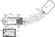
- FIG. 1is a schematic top view of an exemplary tow vehicle at a distance from a trailer.
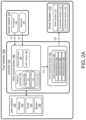
- FIGS. 2 A- 2 Bare schematic views of an exemplary tow vehicle system.
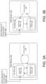
- FIGS. 3 A and 3 Bare schematic views of exemplary state charts of the system.
- FIGS. 4 A and 4 Bare schematic views of an exemplary angle mode.
- FIGS. 5 A and 5 Bare schematic views of an exemplary distance mode.
- FIGS. 6 A and 6 Bare schematic views of an exemplary bi-arc mode.
- FIGS. 7 A and 7 Bare schematic views of the trajectory generation calculations.
- FIGS. 8 A and 8 Bare schematic views of motion estimation calculations.
- FIG. 9is a schematic view of an exemplary method of autonomously driving a vehicle in a rearward direction towards a point of interest.
- FIG. 10is a schematic view of an exemplary method of autonomously driving a vehicle in a rearward direction towards a point of interest.
- a tow vehiclesuch as, but not limited to a car, a crossover, a truck, a van, a sports-utility-vehicle (SUV), and a recreational vehicle (RV) may be configured to tow a trailer.
- the tow vehicleconnects to the trailer by way of a trailer hitch. Backing up to a trailer manually may need a lot of effort from the driver. The driver must constantly monitor a rear vehicle camera and steer the vehicle to bring the tow ball of the vehicle underneath the coupler of a trailer. Therefore, it is desirable to have a tow vehicle that is capable of autonomously backing up towards a driver specified position, for example a trailer, identified from an image of the rearward environment of the vehicle and displayed on a user interface, such as a user display.
- a driver of a tow vehicle 100wants to connect the tow vehicle 100 with a trailer 200 positioned behind the tow vehicle 100 .
- the driverwants to specify a location or a trailer 200 behind the tow vehicle such that the tow vehicle 100 can autonomously maneuver towards the location or the trailer 200 .
- the tow vehicle 100may be hitched (e.g., by way of the driver or autonomously) with the trailer 200 .
- the tow vehicle 100includes a tow vehicle hitch 120 having a tow ball 122 .
- the trailer 200may include a trailer hitch 210 that includes a trailer coupler 212 and a tow bar 214 . Therefore, the tow ball 122 is coupled with the trailer coupler 212 when the tow vehicle 100 and the trailer 200 are hitched.
- the tow vehicle 100may include a drive system 110 that maneuvers the tow vehicle 100 across a road surface based on drive commands having x, y, and z components, for example.
- the drive system 110includes a front right wheel 112 , 112 a , a front left wheel 112 , 112 b , a rear right wheel 112 , 112 c , and a rear left wheel 112 , 112 d .
- the drive system 110may include other wheel configurations as well.
- the drive system 110may also include a brake system 114 that includes brakes associated with each wheel 112 , 112 a - d , and an acceleration system 116 that is configured to adjust a speed and direction of the tow vehicle 100 .
- the drive system 110may include a suspension system 118 that includes tires associates with each wheel 112 , 112 a - d , tire air, springs, shock absorbers, and linkages that connect the tow vehicle 100 to its wheels 112 , 112 a - d and allows relative motion between the tow vehicle 100 and the wheels 112 , 112 a - d .
- the suspension system 132may be configured to adjust a height of the tow vehicle 100 allowing a tow vehicle hitch 120 (e.g., a tow vehicle hitch ball 122 ) to align with a trailer hitch 210 (e.g., trailer hitch coupler 212 ), which allows for autonomous connection between the tow vehicle 100 and the trailer 200 .
- a tow vehicle hitch 120e.g., a tow vehicle hitch ball 122
- trailer hitch 210e.g., trailer hitch coupler 212
- the tow vehicle 100may move across the road surface by various combinations of movements relative to three mutually perpendicular axes defined by the tow vehicle 100 : a transverse axis X, a fore-aft axis Y, and a central vertical axis Z.
- the transverse axis xextends between a right side and a left side of the tow vehicle 100 .
- a forward drive direction along the fore-aft axis Yis designated as F, also referred to as a forward motion.
- an aft or rearward drive direction along the fore-aft direction Yis designated as R, also referred to as rearward motion.
- the suspension system 118adjusts the suspension of the tow vehicle 100
- the tow vehicle 100may tilt about the X axis and or Y axis, or move along the central vertical axis Z.
- the tow vehicle 100may include a user interface 130 .
- the user interface 130may include the display 132 , a knob 134 , and a button 136 , which are used as input mechanisms.
- the display 132may show the knob 134 and the button 136 .
- the knob 134 and the button 136are a knob-button combination.
- the user interface 130receives one or more driver commands from the driver via one or more input mechanisms or a touch screen display 132 and/or displays one or more notifications to the driver.
- the user interface 130is in communication with a vehicle controller 150 , which is in turn in communication with a sensor system 140 .
- the display 132displays an image 143 of an environment of the tow vehicle 100 leading to one or more commands being received by the user interface 130 (from the driver) that initiate execution of one or more behaviors.
- the user display 132displays an image 143 of the rearward environment of the vehicle 100 . In this case, the driver can select a position within the image 143 that the driver wants the vehicle to autonomously maneuver towards.
- the user display 132displays one or more representations of trailers 200 positioned behind the vehicle 100 . In this case, the driver selects one representation of a trailer 200 for the vehicle 100 to autonomously maneuver towards or the driver selects a path 162 causing the tow vehicle 100 to maneuver towards a selects trailer 200 .
- the tow vehicle 100may include a sensor system 140 to provide reliable and robust driving.
- the sensor system 140may include different types of sensors that may be used separately or with one another to create a perception of the environment of the tow vehicle 100 that is used for the tow vehicle 100 to drive and aid the driver in make intelligent decisions based on objects and obstacles detected by the sensor system 140 .
- the sensor system 140may include the one or more cameras 142 .
- the sensor system 140may include a rearward camera 142 mounted on the vehicle 100 to provide a view of a rear-driving path for the tow vehicle 100 .
- the rear camera 142may include a fisheye lens that includes an ultra wide-angle lens that produces strong visual distortion intended to create a wide panoramic or hemispherical image. Fisheye cameras capture images having an extremely wide angle of view. Moreover, images captured by the fisheye camera have a characteristic convex non-rectilinear appearance. Other types of cameras may also be used to capture images of the rear of the vehicle 100 .
- the sensor system 140may include other sensors such as, but not limited to, inertial measuring unit (IMU) radar, sonar, LIDAR (Light Detection and Ranging, which can entail optical remote sensing that measures properties of scattered light to find range and/or other information of a distant target), LADAR (Laser Detection and Ranging), ultrasonic sensors, etc.
- IMUinertial measuring unit
- sonarSonar
- LIDARLight Detection and Ranging
- LADARLaser Detection and Ranging
- ultrasonic sensorsetc.
- the vehicle controller 150includes a computing device (or processor) 152 (e.g., central processing unit having one or more computing processors) in communication with non-transitory memory 154 (e.g., a hard disk, flash memory, random-access memory, memory hardware) capable of storing instructions executable on the computing processor(s) 152 .
- a computing deviceor processor
- non-transitory memory 154e.g., a hard disk, flash memory, random-access memory, memory hardware
- the vehicle controller 150executes a hitch assist system 160 that aids the driver in selecting a path 162 for autonomously driving the tow vehicle 100 towards the trailer 200 .
- the drivermay initiate execution of the hitch assist system 160 by way of the user interface 130 , for example, making a selection on the display 132 .
- the hitch assist system 160instructs the display 132 to display a path 162 of the vehicle 100 that is superimposed on the camera image 143 of the rearward environment of the vehicle 100 .
- the drivermay change the planned path 162 using the user interface 130 . For example, the driver may turn the knob 134 , which simulates a virtual steering wheel.
- the planned path 162 shown on the display 132is updated.
- the driveradjusts the displayed path 162 until an updated planned path 162 displayed on the display 132 intersects the trailer representation 138 or other object that the driver wants the vehicle 100 to drive towards.
- the driverexecutes an action indicative of finalizing the path 162 which allows the vehicle 100 to autonomously follow the planned path.
- the hitch assist system 160includes a trajectory generator 170 , a motion estimator 180 , and a path tracker 182 .
- the trajectory generator 170determines an estimated position of the vehicle 100 based on the driver selected path 162 .
- the motion estimator 180determines an actual position of the vehicle 100
- the path tracker 580determines an error 184 based on the estimated position Pe and the actual position Pa and adjusts the planned path 162 of the vehicle 100 to eliminate the error 184 between the actual position Pa and the estimated position Pe.
- the trajectory generator 170receives images 143 from the camera 142 and superimposes the vehicle path 162 on the received image 143 .
- the drivermay adjust the path 162 selection based on one or more path modes 172 .
- the path modes 172include an arc mode 172 having an angle sub-mode 174 and a distance sub-mode 176 .
- the path modes 172may include a bi-arc mode 178 . Therefore, the driver may select between the angle sub-mode 174 , the distance sub-mode, and/or the bi-arc mode 178 for determining and adjusting the path 162 to a trailer 200 or an object.
- the angle sub-mode 174 and the distance sub-mode 176are part of the arc-mode 172 ( FIG. 3 A ), therefore, the driver first selects a mode 172 , 178 , and then selects the sub-mode within the selected mode 172 , 178 .
- the display 132may display an arc mode button 136 and a bi-arc mode button 136 , that the driver can select from.
- FIG. 3 Bshows an example, where each sub-mode/mode 174 , 176 , 178 is independent. Therefore, a press or push of the button 136 rotates between the three modes 174 , 176 , 178 .
- the angle sub-mode 174is configured to adjust a curvature angle of the path 162 as shown in FIGS. 4 A and 4 B . Therefore, the driver can turn the knob 134 to the right causing the displayed path 162 to have a curvature to the right as shown in FIG. 4 A . In addition, the driver my turn the knob 134 to the left causing the displayed path 162 to have a curvature to the left as shown in FIG. 4 B .
- the distance sub-mode 176is configured to adjust a length of the expected path 162 as shown in FIGS. 5 A and 5 B . For examples, referring to FIG. 5 A , the driver can rotate the knob 134 to position a destination of the path 162 adjacent the trailer representation 138 in the image 143 .
- the image 143shows the path 162 having a shorter length than the path shown in FIG. 5 A . Therefore, in this case, the driver may want that the tow vehicle 100 to autonomously move few meters in the rearward direction R.
- the bi-arc mode 178is configured to adjust an approach angle indicative of how the vehicle 100 will be oriented with respect to the trailer 200 (or other object) at the end of the path 162 as shown in FIGS. 6 A and 6 B .
- the bi-arc mode 178aids the driver in aligning the tow vehicle 100 with the trailer 200 such that the fore-aft axis Y of the vehicle 100 is aligned with a fore-aft axis Y of the trailer 200 , which helps the driver during the hitching process between the tow vehicle 100 and the trailer 200 .
- the arc mode 172 and the bi-arc mode 178both have the same end point; however, the bi-arc mode 178 allows for an adjustment of the approach angle towards the trailer 200 .
- the trajectory generator 170keeps the start and end locations the same.
- the drivermay adjust only the approach angle to the trailer 200 .
- the driverdoes not adjust the distance in the bi-arc mode 178 .
- the radius and length of the driver selected path 162determine the final position of the vehicle 100 .
- the vehicle controller 150uses Dubins path to determine the path 162 which is an optimal calculation.
- the drivermay finalize the path 162 by pressing the button 136 . Otherwise, the driver adjusts the knob 134 for the third time to change the shape of a bi-arc or other suitable path 162 . This allows for adjusting the final approach angle to the trailer 200 or other object. Once the driver is satisfied with the choice of approach angle, he/she presses the button 136 to finalize the path choice.
- the driverparks the tow vehicle 100 in a location where the trailer 200 , or other object or point of interest, is within a field of view of the rear camera 142 of the vehicle 100 .
- the engine of the tow vehicle 100may be idling, and the transmission in Park position.
- the drivermay initiate the trajectory generator 170 by pressing the button 136 and/or making a selection on the display 132 .
- the display 132shows a selectable option or button 136 allowing the driver to initiate the Arc mode 172 .
- the trajectory generator 170begins by executing the angle sub-mode 174 of the arc mode 172 , as shown in FIGS. 3 A and 3 B .
- the driverswitches to distance sub-mode 176 to adjust the distance of the path 162 , by for example, pressing the button 136 .
- the drivermay adjust the path 162 by switching between angle sub-mode 174 and distance sub-mode 176 and adjusting the path 162 until the desired path 162 is shown on the display.
- the driveradjusts the path 162 such that the outer boundaries 164 of the path 162 interest the trailer 200 (i.e., the trailer representation 138 within the image 143 ) or other point of interest.
- the final approach angle to the trailer 200 or the point of interestis important, for example, for aligning the vehicle fore-aft axis Y with the trailer fore-aft axis Y.
- the drivermay select or press the “Arc/Bi-Arc Mode” button 136 (displayed on the display 132 ) and switch to the bi-arc mode 178 .
- the bi-arc mode 178the previously set endpoint of the path 162 stays constant, and the driver adjusts the final approach angle with the knob 134 .
- the drivermay confirm the selected path 162 by executing an action.
- the driverswitches the transmission to reverse which is indicative that the driver is satisfied with the displayed path 162 .
- the driverswitches the transmission into reverse with the brake on, then releases the brake, and the vehicle 100 follows the selected path 162 .
- the drivermay stop the tow vehicle 100 by, for example, pressing the brake. This causes the vehicle controller 150 to exit the hitch assist system 160 .
- the trajectory generator 170sets the path distance at a default, which allows the driver to only adjust the steering angle until it intersects the trailer 200 or other point of interest.
- the final approach angleis not adjusted. Instead, the final approach angle is always the same as the initial vehicle departure angle. So, the final vehicle fore-aft axis Y is parallel to the initial vehicle fore-aft axis Y. In this case, the driver adjusts the final location of the path 162 to interest with the trailer.
- the display 132may show a progress of the vehicle 100 along the path 162 .
- the display 132may show an original trajectory projected on the ground, but updated by the vehicle's changing position.
- the display 132may also show an indication of how well the vehicle is following this trajectory.
- the trajectory generator 170receives data from other vehicle systems to generate the path 162 .
- the trajectory generator 170receive vehicle pose data defined by (x, y, ⁇ ) where x is the position of a center of the tow vehicle 100 along the transverse axis X in and X-Y plane, y is the position of a center of the vehicle along the fore-aft axis Y in the X-Y plane, and ⁇ is the heading of the tow vehicle 100 .
- the trajectory generator 170may receive a position of the knob 134 , e.g., a knob angle, from the knob 134 .
- the trajectory generator 170may also receive a mode button state (i.e., arc mode 172 or bi-arc mode 178 ), and the sub-mode button state (i.e., angle sub-mode 174 or distance sub-mode 176 ). Based on the received data, the trajectory generator 170 adjusts the path 162 and instructs the display 132 to display the path 162 .
- the path 162includes outer boundaries 164 and a tow ball path 166 being the estimated path of the tow ball 122 .
- the trajectory generator 170may also instruct the display 132 to show the current mode or sub-mode status indicative of the mode/sub-mode the drive has selected to adjust the path 162 .
- the vehicle controller 150executes the driver assistance system 190 to follow the planned path 162 .
- the driver assistance system 190includes path following behaviors 192 .
- the path following behaviors 330receive the selected path 162 and executes one or more behaviors 330 a - b that send commands 194 to the drive system 110 , causing the vehicle 100 to autonomously drive along the planned path 162 .
- the hitch assist system 160continuously updates the path 162 based on the motion estimator 180 and the path tracker as discussed below.
- the motion estimator 180determines a current position Pa of the vehicle 100 as it is autonomously maneuvering in the rearward direction R along the path 162 .
- the trajectory generator 170determines where the vehicle 100 should be based on the planned path 162 , i.e., estimated position Pe; therefore the motion estimator determines an actual position Pa of the vehicle 100 .
- the motion estimatorincludes a motion estimation algorithm that outputs relative vehicle position and speed.
- the motion estimation algorithmmay include an Extended Kalman Filter (EKF).
- the EKFuses measurements, such as, but not limited to, encoders from 4 wheels (e.g., 96 ticks per revolution), and steering angle.
- the motion estimator 180fuses the measurements to determine the actual position of the vehicle 100 .
- the motion estimator 180may use bicycle model due to the slow speed of the tow vehicle 100 as it is autonomously moving in the rearward direction.
- the bicycle modeluses a single steered wheel in front to represent both front wheels, and it uses a single non-steered wheel in the rear to represent both rear wheels.
- the wheelsare joined by a single rigid link.
- Motionis restricted to a two-dimensional horizontal ground plane.
- the inputs of the bicycle modelare speed and steer angle, while its state is position and heading.
- the motion estimator 180estimates linear and rotational speeds, and position (e.g., orientation of the vehicle).
- the motion estimator 180considers sensor data from the sensor system 140 , for example, camera, radar, GPS measurement to improve any drift.
- the motion estimator 180uses an Extended Kalman Filter (EKF).
- EKFExtended Kalman Filter
- the EKF equationsare also provided below as equations (3)-(7).
- the motion estimator 180provides a vehicle speed estimate. It is common to compute an approximate speed by dividing distance change by time change ( ⁇ d/ ⁇ t), however, this would be very noisy for the situation here, where there are relatively few wheel encoder counts, and the vehicle is moving relatively slowly. Thus, to avoid a direct calculation involving dividing distance change by time change ( ⁇ d/ ⁇ t), the motion estimator 180 estimates the vehicle linear speed v by using the EKF, based on the measured wheel accumulated distances, and there is no explicit rate calculation involving division.
- the Extended Kalman Filtermay be written as two Prediction equations and three Measurement equations.
- Equation (3)provides an update to the state ⁇ .
- Equation (4)provides an update to the covariance ⁇ .
- the covarianceprovides an estimate of the current uncertainty of the states.
- the matrix Ris the noise covariance for the state ⁇ .
- Equation (5)sets the value of the optimal Kalman gain K. Equation (6) provides an update to the state ⁇ . Equation (7) provides an update to the covariance E.
- the matrix Qis the noise covariance for the measurement z.
- the matrix Gis the derivative of this vector function. For convenience, it will be provided as well.
- the vector function gis given by:
- g ⁇ ( ⁇ )⁇ + [ ( v ⁇ ⁇ cos ⁇ ⁇ ⁇ ) ⁇ ⁇ ⁇ ⁇ t ( v ⁇ ⁇ sin ⁇ ⁇ ⁇ ) ⁇ ⁇ ⁇ ⁇ t ⁇ ⁇ ⁇ ⁇ ⁇ t 0 0 ( v - w ⁇ ⁇ ⁇ / 2 ) ⁇ ⁇ ⁇ ⁇ t ( v + w ⁇ ⁇ ⁇ / 2 ) ⁇ ⁇ ⁇ t - ⁇ ⁇ ⁇ t ⁇ ( l ⁇ ⁇ ) 2 + ( v - w ⁇ ⁇ ⁇ / 2 ) 2 - ⁇ ⁇ ⁇ t ⁇ ( l ⁇ ⁇ ⁇ ) 2 + ( v + w ⁇ ⁇ ⁇ / 2 ) 2 ] .
- wis the “track width” of the vehicle. More specifically, it is the lateral distance from the center of a left tire to the center of a right tire. It is assumed that the front and rear distances between tires are the same.
- the wheelbaseis denoted by 1. Note that in the last two elements, there is a minus sign where expressions are subtracted from d lf and d rf . This minus sign assumes backward motion. Thus, this prediction equation could not be used for forward motion. However, if there were some measurement of the direction of the vehicle (forward or backward), then it would be a simple matter to change the sign of the last two elements (positive for forward, negative for backward) to make the equations valid for both forward and backward directions.
- G _ 13- ( v ⁇ ⁇ sin ⁇ ⁇ ⁇ )
- ⁇ G _ 14( cos ⁇ ⁇ ⁇ ) ⁇ ⁇
- G _ 23( v ⁇ ⁇ cos ⁇ ⁇ ⁇ )
- ⁇ G _ 75( w / 2 ) ⁇
- G 84- v - w ⁇ ⁇ / 2 ( l ⁇ ⁇ ⁇ ) 2 + ( v - w ⁇ ⁇ ⁇ / 2 ) 2
- ⁇ G _ 85- - ( w / 2 ) ⁇ ⁇ ( v - w ⁇ ⁇ ⁇ / 2 ) 2
- the complete updateassumes measurements of the wheel ticks and the wheel angle are all available at the same time. If only the wheel ticks are available, then they may be incorporated separately, and if only the wheel angle is available, it may be incorporated separately.
- the vector his defined.
- the matrix His the derivative of this vector function. For convenience, it will be provided as well.
- the vector function his given by:
- H matrixis the derivative of h and is 5 ⁇ .
- H 54⁇ l ⁇ /( v 2 +l 2 ⁇ 2 )
- H 55lv /( v 2 +l 2 ⁇ 2 )
- v 2 +l 2 ⁇ 2 ⁇ 0certain quantities, h 5 , H 54 , H 55 , involve divisors which could easily be zero. Thus, implementation requires testing that these divisors are not zero before performing the divisions.
- a measurement consisting of wheel ticks alonecan be accommodated, as can a measurement consisting of steering angle alone.
- these variationsare not included because they are straightforward, given the information that has been provided.
- the trajectory generator 170determines where the vehicle 100 should be based on the planned path 162 , i.e., estimated position Pe; while the motion estimator 180 determines an actual position Pa of the vehicle 100 ; therefore the path tracker 182 determines an error 184 based on the estimated position Pe and the actual position Pa.
- the path tracker 182adjusts the vehicle's current position Pa based on the error 184 such that the vehicle 100 continues to follow the planned path 162 .
- the path tracker 182executes a pure pursuit approach to keep the vehicle 100 on the planned path 162 .
- the driver selected path 162is sampled at predefined intervals of time, for examples, every minute, to produce a plurality of waypoints 168 positioned along the tow ball path 166 of the planned path 162 .
- the path tracker 182(e.g., algorithm) compares a current tow-ball position and heading Pa received from the motion estimator 180 with the next waypoint position Pb.
- the vehicle hitch assist system 160constantly adjusted the vehicle steering toward the current waypoint Pb, i.e., the waypoint that the vehicle is driving towards.
- the path tracker 182allows the vehicle tow-ball 122 to track each waypoint 168 .
- the path tracker 182allows for the tow-ball 122 to go to each waypoint along the tow ball path 166 .
- the waypoint 168is transformed into vehicle coordinates from world coordinates.
- the path tracker 182calculates a center Cc of a turning circle based on the tow-ball position Pa and the waypoint position Pb. Then the path tracker 182 calculates a vehicle turning radius Rr based on the center of the turning circle. Finally, the path tracker 182 calculates a steering angle based on the center of turning circle using Ackermann angle.
- the path tracker 580compares an estimated location Pe with the current location Pa to make sure the vehicle is following the path and determines a next waypoint Pb and determines or adjusts the path from the current vehicle position and heading to the next or subsequent waypoint Pb.
- the path tracker 580maintains that the tow vehicle 100 autonomously maneuvers along the planned path and adjusts the vehicle's behavior or driving when the vehicle 100 veers from the planned path.
- the controllerincludes an object detection system (not shown) that identifies one or more objects along the planned path 162 .
- the hitch assist system 160adjusts the path 162 to avoid the detected one or more objects.
- the hitch assist system 160determines a probability of collision and if the probability of collision exceeds a predetermined threshold, the hitch assist system 160 adjusts the path 162 and sends it to the driver assistance system 190 .
- the vehicle controller 150executes a driver assistance system 190 , which in turn includes path following behaviors 330 .
- the path following behaviors 330receive the selected path 162 and executes one or more behaviors 330 a - b that send commands 194 to the drive system 110 , causing the vehicle 100 to autonomously drive along the planned path in the rearward direction R.
- the path following behaviors 192 a - bmay include one or more behaviors, such as, but not limited to, a braking behavior 192 a , a speed behavior 192 b , and a steering behavior 192 c .
- Each behavior 192 a - bcauses the vehicle 100 to take an action, such as driving backward, turning at a specific angle, breaking, speeding, slowing down, among others.
- the vehicle controller 150may maneuver the vehicle 100 in any direction across the road surface by controlling the drive system 110 , more specifically by issuing commands 194 to the drive system 110 .
- the braking behavior 192 amay be executed to either stop the vehicle 100 or to slow down the vehicle 100 based on the planned path.
- the braking behavior 192 asends a signal or command 194 to the drive system 110 , e.g., the brake system (not shown), to either stop the vehicle 100 or reduce the speed of the vehicle 100 .
- the speed behavior 192 bmay be executed to change the speed of the vehicle 100 by either accelerating or decelerating based on the planned path 162 .
- the speed behavior 192 bsends a signal or command 194 to the brake system 114 for decelerating or the acceleration system 116 for accelerating.
- the steering behavior 192 cmay be executed to change the direction of the vehicle 100 based on the planned path 162 . As such, the steering behavior 192 c sends the acceleration system 130 a signal or command 194 indicative of an angle of steering causing the drive system 110 to change direction.
- FIG. 9provides an example arrangement of operations of a method 900 for autonomously maneuvering a vehicle 100 (e.g., a tow vehicle) in a rearward direction R towards a point of interest, such as a trailer 200 , using the system described in FIGS. 1 - 8 B .
- the method 900includes, receiving, at data processing hardware 152 , one or more images 143 from a camera 142 positioned on a back portion of the vehicle 100 and in communication with the data processing hardware 152 .
- the method 900includes receiving, at the data processing hardware 152 , a driver planned path 162 from a user interface 130 in communication with the data processing hardware 152 .
- the driver planned path 162includes a plurality of waypoints 168 .
- the method 900includes transmitting, from the data processing hardware 152 to a drive system 110 in communication with the data processing hardware 152 , one or more commands 161 , 194 causing the vehicle 100 to autonomously maneuver along the driver planned path 162 .
- the method 900includes determining, at the data processing hardware 152 , a current vehicle position Pa.
- the method 900includes determining, at the data processing hardware 152 , an estimated subsequent vehicle position based on the driver planned path, the estimated subsequent vehicle position being at a subsequent waypoint Pb along the driver planned path 162 from the current vehicle position Pa.
- the method 900includes determining, at the data processing hardware 152 , a path adjustment from the current vehicle position Pa to the estimated subsequent vehicle position Pb.
- the method 900includes transmitting, from the data processing hardware 152 to the drive system 110 , instructions causing the vehicle 100 to autonomously maneuver towards the estimated subsequent vehicle position Pb based on the path adjustment.
- FIG. 10provides an example arrangement of operations of another method 1000 for autonomously maneuvering a vehicle 100 (e.g., a tow vehicle) in a rearward direction R towards a point of interest, such as a trailer 200 , using the system described in FIGS. 1 - 8 B .
- the method 1000includes receiving, at data processing hardware 152 , one or more images 143 from one or more cameras 142 positioned on a back portion of the vehicle 100 and in communication with the data processing hardware 152 .
- the method 1000includes receiving, at the data processing hardware 152 , a driver planned path 162 from a user interface 130 in communication with the data processing hardware 152 .
- the method 1000includes transmitting, from the data processing hardware 152 to a drive system 110 in communication with the data processing hardware 152 , one or more commands causing the vehicle 100 to autonomously maneuver along the driver planned path 162 .
- the method 1000includes determining, at the data processing hardware 152 , an estimated vehicle position Pe based on the driver planned path 162 .
- the method 1000includes determining, at the data processing hardware 152 , a current vehicle position Pa.
- the method 1000includes determining, at the data processing hardware 152 , an error 184 based on the estimated vehicle position Pe and the current vehicle position Pa.
- the method 1000includes determining, at the data processing hardware 152 , one or more path adjustment commands causing the vehicle 100 to autonomously maneuver from the current vehicle position Pa to the estimated vehicle position Pe eliminating the error 184 .
- the method 1000includes transmitting, from the data processing hardware 152 to the drive system 110 , the one or more path adjustment commands.
- the method 900 , 1000includes overlaying a path on the one or more images 143 and receiving a command by way of the user interface 130 in communication with the data processing hardware 152 .
- the commandincludes instructions to adjust the path as the driver planned path 162 .
- the commandincludes instructions to adjust a distance of the path.
- the commandmay include instructions to adjust an angle of the path and or instructions to adjust an angle of an end portion of the path.
- determining the current vehicle positionincludes receiving wheel encoder sensor data 145 associated with one or more wheels 112 and receiving steering angle sensor data 145 .
- the current vehicle position Pais based on the wheel encoder sensor data 145 and the steering angle sensor data 145 .
- the proposed algorithmis designed to work in real time in a standard CPU with or without the use of GPU, graphic accelerators, training, or FPGAs.
- the proposed approachprovides an automated method that only needs initial input from the driver.
- the described systemprovides a compromise between providing guidelines for the driver and automating all rearward functions.
- implementations of the systems and techniques described herecan be realized in digital electronic circuitry, integrated circuitry, specially designed ASICs (application specific integrated circuits), computer hardware, firmware, software, and/or combinations thereof.
- ASICsapplication specific integrated circuits
- These various implementationscan include implementation in one or more computer programs that are executable and/or interpretable on a programmable system including at least one programmable processor, which may be special or general purpose, coupled to receive data and instructions from, and to transmit data and instructions to, a storage system, at least one input device, and at least one output device.
- Implementations of the subject matter and the functional operations described in this specificationcan be implemented in digital electronic circuitry, or in computer software, firmware, or hardware, including the structures disclosed in this specification and their structural equivalents, or in combinations of one or more of them.
- subject matter described in this specificationcan be implemented as one or more computer program products, i.e., one or more modules of computer program instructions encoded on a computer readable medium for execution by, or to control the operation of, data processing apparatus.
- the computer readable mediumcan be a machine-readable storage device, a machine-readable storage substrate, a memory device, a composition of matter effecting a machine-readable propagated signal, or a combination of one or more of them.
- data processing apparatusencompass all apparatus, devices, and machines for processing data, including by way of example a programmable processor, a computer, or multiple processors or computers.
- the apparatuscan include, in addition to hardware, code that creates an execution environment for the computer program in question, e.g., code that constitutes processor firmware, a protocol stack, a database management system, an operating system, or a combination of one or more of them.
- a propagated signalis an artificially generated signal, e.g., a machine-generated electrical, optical, or electromagnetic signal that is generated to encode information for transmission to suitable receiver apparatus.
Landscapes
- Engineering & Computer Science (AREA)
- Transportation (AREA)
- Mechanical Engineering (AREA)
- Automation & Control Theory (AREA)
- Physics & Mathematics (AREA)
- Aviation & Aerospace Engineering (AREA)
- General Physics & Mathematics (AREA)
- Remote Sensing (AREA)
- Radar, Positioning & Navigation (AREA)
- Health & Medical Sciences (AREA)
- Electromagnetism (AREA)
- Multimedia (AREA)
- Computer Vision & Pattern Recognition (AREA)
- Business, Economics & Management (AREA)
- Artificial Intelligence (AREA)
- Evolutionary Computation (AREA)
- Game Theory and Decision Science (AREA)
- Medical Informatics (AREA)
- Combustion & Propulsion (AREA)
- Chemical & Material Sciences (AREA)
- Control Of Driving Devices And Active Controlling Of Vehicle (AREA)
Abstract
Description
μ=[x y θv ω dirdrrdifdrf]T (1)
The first three are the “pose” of the vehicle, (x, y, θ). The next two are the linear and angular speeds, (v, ω). The final four are the distances traveled by the four tires, (dlr, drr, dlf, drf), left-rear, right-rear, left-front, right-front, respectively.
z=[dirdrrdifdrfϕ]T. (2)
The first four are, again, the distances traveled by the four tires, (dlr, drr, dlf, drf). The final element φ is the average front wheel angle (not the steering wheel angle but the average angle of the front tires with respect to the longitudinal axis).
Equation (3) provides an update to the state μ. Equation (4) provides an update to the covariance Σ. The covariance provides an estimate of the current uncertainty of the states. The matrix R is the noise covariance for the state μ.
Kt=
μt=
Σt=(I−KtHt)
Here, w is the “track width” of the vehicle. More specifically, it is the lateral distance from the center of a left tire to the center of a right tire. It is assumed that the front and rear distances between tires are the same. The wheelbase is denoted by 1. Note that in the last two elements, there is a minus sign where expressions are subtracted from dlfand drf. This minus sign assumes backward motion. Thus, this prediction equation could not be used for forward motion. However, if there were some measurement of the direction of the vehicle (forward or backward), then it would be a simple matter to change the sign of the last two elements (positive for forward, negative for backward) to make the equations valid for both forward and backward directions.
G=I+
I is the 9×9 identity matrix. Then,
All other elements are zero.
The H matrix is the derivative of h and is 5×. The non-zero elements are
H11=H22=H33=H44=1
H54=−lω/(v2+l2ω2),H55=lv/(v2+l2ω2),v2+l2ω2≠0
Note that certain quantities, h5, H54, H55, involve divisors which could easily be zero. Thus, implementation requires testing that these divisors are not zero before performing the divisions.
Claims (21)
Priority Applications (5)
| Application Number | Priority Date | Filing Date | Title |
|---|---|---|---|
| US16/530,931US11603100B2 (en) | 2018-08-03 | 2019-08-02 | Automated reversing by following user-selected trajectories and estimating vehicle motion |
| EP19755477.7AEP3829959A1 (en) | 2018-08-03 | 2019-08-05 | Automated reversing by following user-selected trajectories and estimating vehicle motion |
| PCT/US2019/045075WO2020028893A1 (en) | 2018-08-03 | 2019-08-05 | Automated reversing by following user-selected trajectories and estimating vehicle motion |
| JP2021505931AJP7412412B2 (en) | 2018-08-03 | 2019-08-05 | Automatic reversing by following user-selected trajectory and estimating vehicle movement |
| CN201980065059.XACN112805208B (en) | 2018-08-03 | 2019-08-05 | Automated reversing by following user-selected trajectories and estimating vehicle motion |
Applications Claiming Priority (2)
| Application Number | Priority Date | Filing Date | Title |
|---|---|---|---|
| US201862714385P | 2018-08-03 | 2018-08-03 | |
| US16/530,931US11603100B2 (en) | 2018-08-03 | 2019-08-02 | Automated reversing by following user-selected trajectories and estimating vehicle motion |
Publications (2)
| Publication Number | Publication Date |
|---|---|
| US20200062257A1 US20200062257A1 (en) | 2020-02-27 |
| US11603100B2true US11603100B2 (en) | 2023-03-14 |
Family
ID=67660470
Family Applications (1)
| Application Number | Title | Priority Date | Filing Date |
|---|---|---|---|
| US16/530,931Active2039-08-11US11603100B2 (en) | 2018-08-03 | 2019-08-02 | Automated reversing by following user-selected trajectories and estimating vehicle motion |
Country Status (5)
| Country | Link |
|---|---|
| US (1) | US11603100B2 (en) |
| EP (1) | EP3829959A1 (en) |
| JP (1) | JP7412412B2 (en) |
| CN (1) | CN112805208B (en) |
| WO (1) | WO2020028893A1 (en) |
Families Citing this family (14)
| Publication number | Priority date | Publication date | Assignee | Title |
|---|---|---|---|---|
| CN109376734B (en)* | 2018-08-13 | 2020-07-31 | 东南大学 | A positive azimuth towing induction method for road rescue equipment based on license plate corner features |
| US11247520B2 (en)* | 2019-03-20 | 2022-02-15 | Ford Global Technologies, Llc | System and method for trailer alignment |
| US11180148B2 (en)* | 2019-09-03 | 2021-11-23 | Ford Global Technologies, Llc | Detection and response to confined trailer in system-assisted hitch operation |
| US11390294B2 (en)* | 2019-09-25 | 2022-07-19 | Ford Global Technologies, Llc | Differentiating between near trailer and connected trailer |
| US11964689B2 (en)* | 2019-12-16 | 2024-04-23 | Magna Electronics Inc. | Vehicular trailering guidance system |
| CN111731381B (en)* | 2020-06-30 | 2021-09-24 | 三一专用汽车有限责任公司 | Vehicle lateral adaptive control method, control device and vehicle |
| CN112729320B (en)* | 2020-12-22 | 2022-05-17 | 中国第一汽车股份有限公司 | Method, device and equipment for constructing obstacle map and storage medium |
| DE102021002955B3 (en)* | 2021-06-10 | 2022-08-11 | Jost-Werke Deutschland Gmbh | Method of moving a vehicle to a component of an object spaced therefrom (preposition point) |
| US11801870B2 (en)* | 2021-09-10 | 2023-10-31 | GM Global Technology Operations LLC | System for guiding an autonomous vehicle by a towing taxi |
| CN113916247B (en)* | 2021-10-13 | 2023-10-13 | 苏州科技大学 | Device and method for road selection and path planning of intelligent networked tour vehicles |
| US20250153733A1 (en)* | 2022-02-15 | 2025-05-15 | Volkswagen Aktiengesellschaft | Method for operating an assistance system, computer program product, and assistance system |
| KR20230135292A (en)* | 2022-03-16 | 2023-09-25 | 현대자동차주식회사 | Method and device for generating path of autonomous vehicle |
| CN115503714A (en)* | 2022-09-28 | 2022-12-23 | 浙江吉利控股集团有限公司 | Automatic tracking reversing control method and system |
| US20240278794A1 (en)* | 2023-02-20 | 2024-08-22 | Toyota Motor Engineering & Manufacturing North America, Inc. | Systems and methods for controlling a vehicle |
Citations (54)
| Publication number | Priority date | Publication date | Assignee | Title |
|---|---|---|---|---|
| JP2004291866A (en) | 2003-03-27 | 2004-10-21 | Toyota Motor Corp | Parking assistance device |
| JP2005014775A (en) | 2003-06-26 | 2005-01-20 | Toyota Motor Corp | Vehicle travel support device |
| US20050074143A1 (en) | 2003-10-02 | 2005-04-07 | Nissan Motor Co., Ltd. | Vehicle backing assist apparatus and vehicle backing assist method |
| JP2005313710A (en) | 2004-04-27 | 2005-11-10 | Toyota Motor Corp | Parking assistance device |
| CN101270983A (en) | 2007-03-21 | 2008-09-24 | 福特环球技术公司 | Trailer reversing guidance |
| US20100096203A1 (en) | 2008-10-17 | 2010-04-22 | Gm Global Technology Operations, Inc. | Vehicle docking assistance system |
| DE102012001380A1 (en) | 2012-01-24 | 2012-08-02 | Daimler Ag | Assistance method for coupling maneuver of motor car with trailer coupling at trailer hitch pan using driver assistance system, involves overlying screen display of image with trajectory between trailer coupling and clutch pan |
| DE102012005707A1 (en) | 2012-03-20 | 2012-10-18 | Daimler Ag | Method for coupling trailer of motor vehicle by automatic cross-guiding of motor vehicle with rear camera during maneuvering, involves defining target sector by spherical head of coupling device of motor vehicle |
| CN102745193A (en) | 2011-04-19 | 2012-10-24 | 福特全球技术公司 | Trailer path curvature control for trailer backup assist |
| US20130006472A1 (en) | 2011-06-30 | 2013-01-03 | Continental Automotive System, Inc. | Electronic path entering for autonomous or semi-autonomous trailer backing |
| US20130024064A1 (en)* | 2011-07-18 | 2013-01-24 | Daniel Robert Shepard | Trailer backing up device and table based method |
| US8560234B2 (en)* | 2008-05-13 | 2013-10-15 | The United States Of America, As Represented By The Secretary Of The Navy | System and method of navigation based on state estimation using a stepped filter |
| EP2682329A1 (en) | 2012-07-05 | 2014-01-08 | Uusi, LLC | Vehicle trailer connect system |
| US20140052337A1 (en) | 2011-04-19 | 2014-02-20 | Ford Global Technologies | Trailer backup assist system |
| US20140058614A1 (en) | 2011-04-19 | 2014-02-27 | Ford Global Technologies, Llc | Trailer monitoring system and method |
| US20140218522A1 (en) | 2013-02-04 | 2014-08-07 | Ford Global Technologies | Trailer active back-up assist with lane width hmi |
| US20140267688A1 (en) | 2011-04-19 | 2014-09-18 | Ford Global Technologies, Llc | Display system utilizing vehicle and trailer dynamics |
| US20140358429A1 (en) | 2011-04-19 | 2014-12-04 | Ford Global Technologies, Llc | Method of inputting a path for a vehicle and trailer |
| US20150094945A1 (en)* | 2013-09-27 | 2015-04-02 | Transoft Solutions, Inc. | Method and apparatus for generating a vehicle path |
| CN104590116A (en) | 2013-10-31 | 2015-05-06 | 福特全球技术公司 | Trailer monitoring system and method |
| US20150217693A1 (en) | 2014-02-04 | 2015-08-06 | Magna Electronics Inc. | Trailer backup assist system |
| US20160023601A1 (en) | 2014-07-22 | 2016-01-28 | Joshua G. Windeler | Trailer hitch guidance method |
| US20160052548A1 (en) | 2013-04-26 | 2016-02-25 | Jaguar Land Rover Limited | Vehicle Hitch Assistance System |
| US9290202B2 (en) | 2011-04-19 | 2016-03-22 | Ford Global Technologies, Llc | System and method of calibrating a trailer backup assist system |
| US20160129939A1 (en) | 2013-07-04 | 2016-05-12 | Jaguar Land Rover Limited | Vehicle control system |
| US20160146618A1 (en) | 2014-11-26 | 2016-05-26 | Toyota Motor Engineering & Manufacturing North America, Inc. | Method to gain driver's attention for autonomous vehicle |
| WO2016164118A2 (en) | 2015-04-10 | 2016-10-13 | Robert Bosch Gmbh | Object position measurement with automotive camera using vehicle motion data |
| EP3081405A2 (en) | 2015-04-14 | 2016-10-19 | Continental Automotive Systems, Inc. | Automated hitch assist system |
| US9500497B2 (en)* | 2011-04-19 | 2016-11-22 | Ford Global Technologies, Llc | System and method of inputting an intended backing path |
| US20160362135A1 (en)* | 2015-06-11 | 2016-12-15 | Ford Global Technologies, Llc | Trailer length estimation method using trailer yaw rate signal |
| US20160378118A1 (en) | 2015-06-23 | 2016-12-29 | GM Global Technology Operations LLC | Smart trailer hitch control using hmi assisted visual servoing |
| US9533683B2 (en)* | 2014-12-05 | 2017-01-03 | Ford Global Technologies, Llc | Sensor failure mitigation system and mode management |
| US20170050672A1 (en) | 2015-08-18 | 2017-02-23 | Magna Electronics Inc. | Trailer parking assist system for vehicle |
| US20170140228A1 (en) | 2015-11-13 | 2017-05-18 | Mekra Lang Gmbh & Co. Kg | System And Method For Capturing A Rear Part Of A Vehicle |
| CN106697050A (en) | 2015-11-16 | 2017-05-24 | 奥迪股份公司 | Method for driving motor vehicle under reversing running conditions |
| US20170151846A1 (en) | 2015-12-01 | 2017-06-01 | GM Global Technology Operations LLC | Guided tow hitch control system and method |
| US20180079395A1 (en) | 2016-09-16 | 2018-03-22 | Horizon Global Americas Inc. | Trailer brake control unit controls and communications |
| US20180088590A1 (en) | 2016-09-27 | 2018-03-29 | Baidu Usa Llc | Vehicle position point forwarding method for autonomous vehicles |
| US9969386B1 (en)* | 2017-01-10 | 2018-05-15 | Mitsubishi Electric Research Laboratories, Inc. | Vehicle automated parking system and method |
| US20180188734A1 (en) | 2016-12-29 | 2018-07-05 | Baidu Usa Llc | Method and system for improving stability of autonomous driving vehicles |
| US20180194344A1 (en) | 2016-07-29 | 2018-07-12 | Faraday&Future Inc. | System and method for autonomous vehicle navigation |
| US20180215382A1 (en)* | 2017-02-01 | 2018-08-02 | Magna Electronics Inc. | Vehicle trailer hitch assist system |
| US20180251153A1 (en) | 2017-03-03 | 2018-09-06 | Continental Automotive Systems, Inc. | Autonomous Trailer Hitching Using Neural Network |
| US20180312022A1 (en) | 2017-05-01 | 2018-11-01 | Ford Global Technologies, Llc | System to automate hitching a trailer |
| US20180350108A1 (en) | 2017-05-30 | 2018-12-06 | Denso International America, Inc. | Smart Hitch Assistant System |
| US20190029109A1 (en) | 2016-03-31 | 2019-01-24 | Murata Manufacturing Co., Ltd. | Front-end circuit and high-frequency module |
| US20190346858A1 (en) | 2018-05-08 | 2019-11-14 | Continental Automotive Systems, Inc. | User-Adjustable Trajectories for Automated Vehicle Reversing |
| US20190383945A1 (en)* | 2018-06-15 | 2019-12-19 | Uber Technologies, Inc. | Autonomous vehicle localization using a lidar intensity map |
| US20200001790A1 (en)* | 2018-06-27 | 2020-01-02 | Ford Global Technologies, Llc | Vehicle hitch assist system |
| US20200019182A1 (en)* | 2018-07-16 | 2020-01-16 | Ford Global Technologies, Llc | Hitch assist system |
| US20200097021A1 (en)* | 2018-09-19 | 2020-03-26 | Continental Automotive Systems, Inc. | Autonomous Farm Equipment Hitching To A Tractor |
| US10829045B2 (en) | 2018-07-11 | 2020-11-10 | Continental Automotive Systems, Inc. | System and method for calibrating a motion estimation algorithm using a vehicle camera |
| US20210163068A1 (en)* | 2018-04-16 | 2021-06-03 | Ohio University | Obstacle avoidance guidance for ground vehicles |
| US20210197798A1 (en)* | 2019-12-31 | 2021-07-01 | Zoox, Inc. | Action-based reference systems for vehicle control |
Family Cites Families (4)
| Publication number | Priority date | Publication date | Assignee | Title |
|---|---|---|---|---|
| US8126642B2 (en) | 2008-10-24 | 2012-02-28 | Gray & Company, Inc. | Control and systems for autonomously driven vehicles |
| US9683848B2 (en)* | 2011-04-19 | 2017-06-20 | Ford Global Technologies, Llc | System for determining hitch angle |
| US9926008B2 (en)* | 2011-04-19 | 2018-03-27 | Ford Global Technologies, Llc | Trailer backup assist system with waypoint selection |
| US10112646B2 (en)* | 2016-05-05 | 2018-10-30 | Ford Global Technologies, Llc | Turn recovery human machine interface for trailer backup assist |
- 2019
- 2019-08-02USUS16/530,931patent/US11603100B2/enactiveActive
- 2019-08-05WOPCT/US2019/045075patent/WO2020028893A1/ennot_activeCeased
- 2019-08-05EPEP19755477.7Apatent/EP3829959A1/enactivePending
- 2019-08-05JPJP2021505931Apatent/JP7412412B2/enactiveActive
- 2019-08-05CNCN201980065059.XApatent/CN112805208B/enactiveActive
Patent Citations (71)
| Publication number | Priority date | Publication date | Assignee | Title |
|---|---|---|---|---|
| US20040254720A1 (en) | 2003-03-27 | 2004-12-16 | Aisin Seiki Kabushiki Kaisha | Parking assist apparatus |
| JP2004291866A (en) | 2003-03-27 | 2004-10-21 | Toyota Motor Corp | Parking assistance device |
| JP2005014775A (en) | 2003-06-26 | 2005-01-20 | Toyota Motor Corp | Vehicle travel support device |
| US20050021203A1 (en)* | 2003-06-26 | 2005-01-27 | Toyota Jidosha Kabushiki Kaisha | Driving assist apparatus and method for vehicle |
| CN1577199A (en) | 2003-06-26 | 2005-02-09 | 丰田自动车株式会社 | Driving assist apparatus and method for vehicle |
| US20050074143A1 (en) | 2003-10-02 | 2005-04-07 | Nissan Motor Co., Ltd. | Vehicle backing assist apparatus and vehicle backing assist method |
| JP2005313710A (en) | 2004-04-27 | 2005-11-10 | Toyota Motor Corp | Parking assistance device |
| US20050264432A1 (en) | 2004-04-27 | 2005-12-01 | Aisin Seiki Kabushiki Kaisha | Parking assist apparatus for vehicle |
| CN101270983A (en) | 2007-03-21 | 2008-09-24 | 福特环球技术公司 | Trailer reversing guidance |
| US20080231701A1 (en) | 2007-03-21 | 2008-09-25 | Jeremy John Greenwood | Vehicle maneuvering aids |
| US8560234B2 (en)* | 2008-05-13 | 2013-10-15 | The United States Of America, As Represented By The Secretary Of The Navy | System and method of navigation based on state estimation using a stepped filter |
| US20100096203A1 (en) | 2008-10-17 | 2010-04-22 | Gm Global Technology Operations, Inc. | Vehicle docking assistance system |
| US9500497B2 (en)* | 2011-04-19 | 2016-11-22 | Ford Global Technologies, Llc | System and method of inputting an intended backing path |
| CN102745193A (en) | 2011-04-19 | 2012-10-24 | 福特全球技术公司 | Trailer path curvature control for trailer backup assist |
| US20120271515A1 (en) | 2011-04-19 | 2012-10-25 | Douglas Scott Rhode | Trailer path curvature control for trailer backup assist |
| US9290202B2 (en) | 2011-04-19 | 2016-03-22 | Ford Global Technologies, Llc | System and method of calibrating a trailer backup assist system |
| US20140052337A1 (en) | 2011-04-19 | 2014-02-20 | Ford Global Technologies | Trailer backup assist system |
| US20140058614A1 (en) | 2011-04-19 | 2014-02-27 | Ford Global Technologies, Llc | Trailer monitoring system and method |
| US20140267688A1 (en) | 2011-04-19 | 2014-09-18 | Ford Global Technologies, Llc | Display system utilizing vehicle and trailer dynamics |
| US20140358429A1 (en) | 2011-04-19 | 2014-12-04 | Ford Global Technologies, Llc | Method of inputting a path for a vehicle and trailer |
| US20130006472A1 (en) | 2011-06-30 | 2013-01-03 | Continental Automotive System, Inc. | Electronic path entering for autonomous or semi-autonomous trailer backing |
| CN103998325A (en) | 2011-06-30 | 2014-08-20 | 大陆汽车系统公司 | Electronic path entering for autonomous or semi-autonomous trailer backing |
| US20130024064A1 (en)* | 2011-07-18 | 2013-01-24 | Daniel Robert Shepard | Trailer backing up device and table based method |
| DE102012001380A1 (en) | 2012-01-24 | 2012-08-02 | Daimler Ag | Assistance method for coupling maneuver of motor car with trailer coupling at trailer hitch pan using driver assistance system, involves overlying screen display of image with trajectory between trailer coupling and clutch pan |
| DE102012005707A1 (en) | 2012-03-20 | 2012-10-18 | Daimler Ag | Method for coupling trailer of motor vehicle by automatic cross-guiding of motor vehicle with rear camera during maneuvering, involves defining target sector by spherical head of coupling device of motor vehicle |
| EP2682329A1 (en) | 2012-07-05 | 2014-01-08 | Uusi, LLC | Vehicle trailer connect system |
| US20140218522A1 (en) | 2013-02-04 | 2014-08-07 | Ford Global Technologies | Trailer active back-up assist with lane width hmi |
| US20160052548A1 (en) | 2013-04-26 | 2016-02-25 | Jaguar Land Rover Limited | Vehicle Hitch Assistance System |
| US20160129939A1 (en) | 2013-07-04 | 2016-05-12 | Jaguar Land Rover Limited | Vehicle control system |
| US20150094945A1 (en)* | 2013-09-27 | 2015-04-02 | Transoft Solutions, Inc. | Method and apparatus for generating a vehicle path |
| CN104590116A (en) | 2013-10-31 | 2015-05-06 | 福特全球技术公司 | Trailer monitoring system and method |
| US20150217693A1 (en) | 2014-02-04 | 2015-08-06 | Magna Electronics Inc. | Trailer backup assist system |
| US20160023601A1 (en) | 2014-07-22 | 2016-01-28 | Joshua G. Windeler | Trailer hitch guidance method |
| US20160146618A1 (en) | 2014-11-26 | 2016-05-26 | Toyota Motor Engineering & Manufacturing North America, Inc. | Method to gain driver's attention for autonomous vehicle |
| US9533683B2 (en)* | 2014-12-05 | 2017-01-03 | Ford Global Technologies, Llc | Sensor failure mitigation system and mode management |
| WO2016164118A2 (en) | 2015-04-10 | 2016-10-13 | Robert Bosch Gmbh | Object position measurement with automotive camera using vehicle motion data |
| US20180181142A1 (en) | 2015-04-10 | 2018-06-28 | Robert Bosch Gmbh | Object position measurement with automotive camera using vehicle motion data |
| CN107567412A (en) | 2015-04-10 | 2018-01-09 | 罗伯特·博世有限公司 | Object Position Measurement Using Vehicle Motion Data Using Automotive Cameras |
| EP3081405A2 (en) | 2015-04-14 | 2016-10-19 | Continental Automotive Systems, Inc. | Automated hitch assist system |
| US20160304122A1 (en) | 2015-04-14 | 2016-10-20 | Continental Automotive Systems, Inc. | Automated hitching assist system |
| JP2016203972A (en) | 2015-04-14 | 2016-12-08 | コンチネンタル オートモーティブ システムズ インコーポレイテッドContinental Automotive Systems, Inc. | Automated hitching assist system |
| CN106043281A (en) | 2015-04-14 | 2016-10-26 | 大陆汽车系统公司 | Automated hitching assist system |
| US20160362135A1 (en)* | 2015-06-11 | 2016-12-15 | Ford Global Technologies, Llc | Trailer length estimation method using trailer yaw rate signal |
| US20160378118A1 (en) | 2015-06-23 | 2016-12-29 | GM Global Technology Operations LLC | Smart trailer hitch control using hmi assisted visual servoing |
| US20170050672A1 (en) | 2015-08-18 | 2017-02-23 | Magna Electronics Inc. | Trailer parking assist system for vehicle |
| US20170140228A1 (en) | 2015-11-13 | 2017-05-18 | Mekra Lang Gmbh & Co. Kg | System And Method For Capturing A Rear Part Of A Vehicle |
| JP2017105439A (en) | 2015-11-13 | 2017-06-15 | メクラ・ラング・ゲーエムベーハー・ウント・コー・カーゲーMEKRA Lang GmbH & Co. KG | Vehicle rear capture system and method |
| CN106697050A (en) | 2015-11-16 | 2017-05-24 | 奥迪股份公司 | Method for driving motor vehicle under reversing running conditions |
| US20170151846A1 (en) | 2015-12-01 | 2017-06-01 | GM Global Technology Operations LLC | Guided tow hitch control system and method |
| US20190029109A1 (en) | 2016-03-31 | 2019-01-24 | Murata Manufacturing Co., Ltd. | Front-end circuit and high-frequency module |
| US20180194344A1 (en) | 2016-07-29 | 2018-07-12 | Faraday&Future Inc. | System and method for autonomous vehicle navigation |
| US20180079395A1 (en) | 2016-09-16 | 2018-03-22 | Horizon Global Americas Inc. | Trailer brake control unit controls and communications |
| US20180088590A1 (en) | 2016-09-27 | 2018-03-29 | Baidu Usa Llc | Vehicle position point forwarding method for autonomous vehicles |
| CN108136867A (en) | 2016-09-27 | 2018-06-08 | 百度(美国)有限责任公司 | The vehicle location point retransmission method of automatic driving vehicle |
| US20180188734A1 (en) | 2016-12-29 | 2018-07-05 | Baidu Usa Llc | Method and system for improving stability of autonomous driving vehicles |
| CN108255171A (en) | 2016-12-29 | 2018-07-06 | 百度(美国)有限责任公司 | For improving the method and system of the stability of autonomous land vehicle |
| US9969386B1 (en)* | 2017-01-10 | 2018-05-15 | Mitsubishi Electric Research Laboratories, Inc. | Vehicle automated parking system and method |
| US20180215382A1 (en)* | 2017-02-01 | 2018-08-02 | Magna Electronics Inc. | Vehicle trailer hitch assist system |
| US20180251153A1 (en) | 2017-03-03 | 2018-09-06 | Continental Automotive Systems, Inc. | Autonomous Trailer Hitching Using Neural Network |
| WO2018160960A1 (en) | 2017-03-03 | 2018-09-07 | Continental Automotive Systems, Inc. | Autonomous trailer hitching using neural network |
| US20180312022A1 (en) | 2017-05-01 | 2018-11-01 | Ford Global Technologies, Llc | System to automate hitching a trailer |
| US20180350108A1 (en) | 2017-05-30 | 2018-12-06 | Denso International America, Inc. | Smart Hitch Assistant System |
| US20210163068A1 (en)* | 2018-04-16 | 2021-06-03 | Ohio University | Obstacle avoidance guidance for ground vehicles |
| CN112805207A (en) | 2018-05-08 | 2021-05-14 | 大陆汽车系统公司 | User adjustable trajectory for automatic vehicle reversing |
| US20190346858A1 (en) | 2018-05-08 | 2019-11-14 | Continental Automotive Systems, Inc. | User-Adjustable Trajectories for Automated Vehicle Reversing |
| US20190383945A1 (en)* | 2018-06-15 | 2019-12-19 | Uber Technologies, Inc. | Autonomous vehicle localization using a lidar intensity map |
| US20200001790A1 (en)* | 2018-06-27 | 2020-01-02 | Ford Global Technologies, Llc | Vehicle hitch assist system |
| US10829045B2 (en) | 2018-07-11 | 2020-11-10 | Continental Automotive Systems, Inc. | System and method for calibrating a motion estimation algorithm using a vehicle camera |
| US20200019182A1 (en)* | 2018-07-16 | 2020-01-16 | Ford Global Technologies, Llc | Hitch assist system |
| US20200097021A1 (en)* | 2018-09-19 | 2020-03-26 | Continental Automotive Systems, Inc. | Autonomous Farm Equipment Hitching To A Tractor |
| US20210197798A1 (en)* | 2019-12-31 | 2021-07-01 | Zoox, Inc. | Action-based reference systems for vehicle control |
Non-Patent Citations (5)
| Title |
|---|
| Chinese Office Action dated Jul. 12, 2022 for the counterpart Chinese Patent Application No. 201980065059.X. |
| File history for U.S. Appl. No. 16/407,081, including non-final Office Action dated Jun. 30, 2021. |
| File history of U.S. Appl. No. 16/575,096, including non-final Office Action dated Apr. 23, 2021. |
| Japanese Office Action dated May 30, 2022 for the counterpart Japanese Patent Application No. 2021-505931. |
| The International Search Report and Written Opinion of the International Searching Authority dated Nov. 8, 2019 for corresponding PCT application No. PCT/US2019/045075. |
Also Published As
| Publication number | Publication date |
|---|---|
| CN112805208A (en) | 2021-05-14 |
| JP2021533028A (en) | 2021-12-02 |
| JP7412412B2 (en) | 2024-01-12 |
| CN112805208B (en) | 2024-01-30 |
| EP3829959A1 (en) | 2021-06-09 |
| WO2020028893A1 (en) | 2020-02-06 |
| US20200062257A1 (en) | 2020-02-27 |
Similar Documents
| Publication | Publication Date | Title |
|---|---|---|
| US11603100B2 (en) | Automated reversing by following user-selected trajectories and estimating vehicle motion | |
| EP3787909B1 (en) | Coupler and tow-bar detection for automated trailer hitching via cloud points | |
| EP3853047B1 (en) | Autonomous farm equipment hitching to a tractor | |
| US11148667B2 (en) | Automated reversing by choice of target location | |
| US11198341B2 (en) | Trailer detection and autonomous hitching | |
| CN112424002B (en) | Visual Object Tracker | |
| JP7520875B2 (en) | Autonomous steering and parking of vehicles-trailers | |
| CN112512843A (en) | Real-time trailer coupling positioning and tracking | |
| US11669104B2 (en) | User-adjustable trajectories for automated vehicle reversing | |
| US10744943B1 (en) | System and method for trailer alignment |
Legal Events
| Date | Code | Title | Description |
|---|---|---|---|
| FEPP | Fee payment procedure | Free format text:ENTITY STATUS SET TO UNDISCOUNTED (ORIGINAL EVENT CODE: BIG.); ENTITY STATUS OF PATENT OWNER: LARGE ENTITY | |
| AS | Assignment | Owner name:CONTINENTAL AUTOMOTIVE SYSTEMS, INC., MICHIGAN Free format text:ASSIGNMENT OF ASSIGNORS INTEREST;ASSIGNORS:BERKEMEIER, MATTHEW DONALD;YU, XIN;BYNUM, DANNY;AND OTHERS;SIGNING DATES FROM 20190815 TO 20190826;REEL/FRAME:050294/0736 | |
| STPP | Information on status: patent application and granting procedure in general | Free format text:APPLICATION DISPATCHED FROM PREEXAM, NOT YET DOCKETED | |
| STPP | Information on status: patent application and granting procedure in general | Free format text:DOCKETED NEW CASE - READY FOR EXAMINATION | |
| STPP | Information on status: patent application and granting procedure in general | Free format text:NON FINAL ACTION MAILED | |
| STPP | Information on status: patent application and granting procedure in general | Free format text:FINAL REJECTION MAILED | |
| STPP | Information on status: patent application and granting procedure in general | Free format text:DOCKETED NEW CASE - READY FOR EXAMINATION | |
| STPP | Information on status: patent application and granting procedure in general | Free format text:NON FINAL ACTION MAILED | |
| STPP | Information on status: patent application and granting procedure in general | Free format text:RESPONSE TO NON-FINAL OFFICE ACTION ENTERED AND FORWARDED TO EXAMINER | |
| STPP | Information on status: patent application and granting procedure in general | Free format text:FINAL REJECTION MAILED | |
| AS | Assignment | Owner name:CONTINENTAL AUTONOMOUS MOBILITY US, LLC., MICHIGAN Free format text:ASSIGNMENT OF ASSIGNORS INTEREST;ASSIGNOR:CONTINENTAL AUTOMOTIVE SYSTEMS, INC.;REEL/FRAME:061100/0217 Effective date:20220707 | |
| STPP | Information on status: patent application and granting procedure in general | Free format text:DOCKETED NEW CASE - READY FOR EXAMINATION | |
| STPP | Information on status: patent application and granting procedure in general | Free format text:NOTICE OF ALLOWANCE MAILED -- APPLICATION RECEIVED IN OFFICE OF PUBLICATIONS | |
| STPP | Information on status: patent application and granting procedure in general | Free format text:NOTICE OF ALLOWANCE MAILED -- APPLICATION RECEIVED IN OFFICE OF PUBLICATIONS | |
| STCF | Information on status: patent grant | Free format text:PATENTED CASE |