US11602260B2 - Method and device for image guided post-nasal nerve ablation - Google Patents
Method and device for image guided post-nasal nerve ablationDownload PDFInfo
- Publication number
- US11602260B2 US11602260B2US15/431,740US201715431740AUS11602260B2US 11602260 B2US11602260 B2US 11602260B2US 201715431740 AUS201715431740 AUS 201715431740AUS 11602260 B2US11602260 B2US 11602260B2
- Authority
- US
- United States
- Prior art keywords
- imaging assembly
- imaging
- cannula
- ablation
- working cannula
- Prior art date
- Legal status (The legal status is an assumption and is not a legal conclusion. Google has not performed a legal analysis and makes no representation as to the accuracy of the status listed.)
- Active, expires
Links
- 238000000034methodMethods0.000titleclaimsabstractdescription58
- 238000002679ablationMethods0.000titleclaimsdescription161
- 210000005036nerveAnatomy0.000titleclaimsdescription75
- 238000003384imaging methodMethods0.000claimsabstractdescription358
- 230000001225therapeutic effectEffects0.000claimsabstractdescription98
- 238000012800visualizationMethods0.000claimsabstractdescription25
- 206010039083rhinitisDiseases0.000claimsabstractdescription18
- 238000002560therapeutic procedureMethods0.000claimsabstractdescription15
- 239000000523sampleSubstances0.000claimsdescription100
- 210000003928nasal cavityAnatomy0.000claimsdescription44
- 238000003780insertionMethods0.000claimsdescription31
- 230000037431insertionEffects0.000claimsdescription31
- 238000013519translationMethods0.000claimsdescription27
- 239000012530fluidSubstances0.000claimsdescription17
- 238000011282treatmentMethods0.000claimsdescription17
- 230000007246mechanismEffects0.000claimsdescription10
- 238000010317ablation therapyMethods0.000claimsdescription8
- 230000004913activationEffects0.000claimsdescription3
- 238000000608laser ablationMethods0.000claimsdescription3
- 238000007674radiofrequency ablationMethods0.000claimsdescription3
- 238000000315cryotherapyMethods0.000claimsdescription2
- 238000001704evaporationMethods0.000claimsdescription2
- 239000000126substanceSubstances0.000claimsdescription2
- 210000001519tissueAnatomy0.000description50
- 230000006870functionEffects0.000description41
- 239000003795chemical substances by applicationSubstances0.000description18
- 210000003128headAnatomy0.000description17
- 230000003444anaesthetic effectEffects0.000description15
- 210000001944turbinateAnatomy0.000description10
- 239000000463materialSubstances0.000description9
- 230000000699topical effectEffects0.000description8
- 238000007493shaping processMethods0.000description7
- 210000003717douglas' pouchAnatomy0.000description6
- 239000012636effectorSubstances0.000description6
- 239000000835fiberSubstances0.000description6
- 238000002347injectionMethods0.000description6
- 239000007924injectionSubstances0.000description6
- 210000001331noseAnatomy0.000description6
- 230000009977dual effectEffects0.000description5
- 230000000694effectsEffects0.000description5
- 238000010438heat treatmentMethods0.000description5
- 210000002850nasal mucosaAnatomy0.000description5
- 230000008901benefitEffects0.000description4
- 239000003193general anesthetic agentSubstances0.000description4
- 238000012986modificationMethods0.000description4
- 230000004048modificationEffects0.000description4
- HLXZNVUGXRDIFK-UHFFFAOYSA-Nnickel titaniumChemical compound[Ti].[Ti].[Ti].[Ti].[Ti].[Ti].[Ti].[Ti].[Ti].[Ti].[Ti].[Ni].[Ni].[Ni].[Ni].[Ni].[Ni].[Ni].[Ni].[Ni].[Ni].[Ni].[Ni].[Ni].[Ni]HLXZNVUGXRDIFK-UHFFFAOYSA-N0.000description4
- 229910001000nickel titaniumInorganic materials0.000description4
- 210000003695paranasal sinusAnatomy0.000description4
- 238000003825pressingMethods0.000description4
- 230000000172allergic effectEffects0.000description3
- 238000004891communicationMethods0.000description3
- 230000001734parasympathetic effectEffects0.000description3
- RYGMFSIKBFXOCR-UHFFFAOYSA-NCopperChemical compound[Cu]RYGMFSIKBFXOCR-UHFFFAOYSA-N0.000description2
- 208000003098Ganglion CystsDiseases0.000description2
- NNJVILVZKWQKPM-UHFFFAOYSA-NLidocaineChemical compoundCCN(CC)CC(=O)NC1=C(C)C=CC=C1CNNJVILVZKWQKPM-UHFFFAOYSA-N0.000description2
- 206010028748Nasal obstructionDiseases0.000description2
- 208000036071RhinorrheaDiseases0.000description2
- 206010039101RhinorrhoeaDiseases0.000description2
- 229910000831SteelInorganic materials0.000description2
- 208000005400Synovial CystDiseases0.000description2
- 239000003082abrasive agentSubstances0.000description2
- 229910052782aluminiumInorganic materials0.000description2
- XAGFODPZIPBFFR-UHFFFAOYSA-NaluminiumChemical compound[Al]XAGFODPZIPBFFR-UHFFFAOYSA-N0.000description2
- 210000003484anatomyAnatomy0.000description2
- 238000013459approachMethods0.000description2
- 208000010668atopic eczemaDiseases0.000description2
- 230000002567autonomic effectEffects0.000description2
- 230000009286beneficial effectEffects0.000description2
- 201000009151chronic rhinitisDiseases0.000description2
- 239000011248coating agentSubstances0.000description2
- 238000000576coating methodMethods0.000description2
- 238000010276constructionMethods0.000description2
- 238000001816coolingMethods0.000description2
- 229910052802copperInorganic materials0.000description2
- 239000010949copperSubstances0.000description2
- 238000002681cryosurgeryMethods0.000description2
- 238000013461designMethods0.000description2
- 230000010339dilationEffects0.000description2
- 238000011010flushing procedureMethods0.000description2
- 230000010354integrationEffects0.000description2
- 229960004194lidocaineDrugs0.000description2
- 229910052751metalInorganic materials0.000description2
- 239000002184metalSubstances0.000description2
- 210000005037parasympathetic nerveAnatomy0.000description2
- 239000004033plasticSubstances0.000description2
- 229920003023plasticPolymers0.000description2
- 229920000642polymerPolymers0.000description2
- 229920001296polysiloxanePolymers0.000description2
- 229920002635polyurethanePolymers0.000description2
- 239000004814polyurethaneSubstances0.000description2
- 238000002271resectionMethods0.000description2
- 230000004044responseEffects0.000description2
- 230000001953sensory effectEffects0.000description2
- 239000007787solidSubstances0.000description2
- 239000010959steelSubstances0.000description2
- 238000001356surgical procedureMethods0.000description2
- 229910001369BrassInorganic materials0.000description1
- 206010011224CoughDiseases0.000description1
- 208000003556Dry Eye SyndromesDiseases0.000description1
- 206010013774Dry eyeDiseases0.000description1
- 206010016654FibrosisDiseases0.000description1
- 206010020751HypersensitivityDiseases0.000description1
- 206010028740Nasal drynessDiseases0.000description1
- 206010030111Oedema mucosalDiseases0.000description1
- 239000004642PolyimideSubstances0.000description1
- 208000035965Postoperative ComplicationsDiseases0.000description1
- 206010039085Rhinitis allergicDiseases0.000description1
- 229910000639Spring steelInorganic materials0.000description1
- 238000011298ablation treatmentMethods0.000description1
- 230000002745absorbentEffects0.000description1
- 239000002250absorbentSubstances0.000description1
- 210000004079adrenergic fiberAnatomy0.000description1
- 230000002411adverseEffects0.000description1
- 208000026935allergic diseaseDiseases0.000description1
- 201000010105allergic rhinitisDiseases0.000description1
- 238000002399angioplastyMethods0.000description1
- 210000001367arteryAnatomy0.000description1
- 230000003190augmentative effectEffects0.000description1
- 210000003050axonAnatomy0.000description1
- 230000000740bleeding effectEffects0.000description1
- 239000010951brassSubstances0.000description1
- 230000001684chronic effectEffects0.000description1
- 230000000295complement effectEffects0.000description1
- 239000002131composite materialSubstances0.000description1
- 230000008878couplingEffects0.000description1
- 238000010168coupling processMethods0.000description1
- 238000005859coupling reactionMethods0.000description1
- 238000005520cutting processMethods0.000description1
- 230000000994depressogenic effectEffects0.000description1
- 239000003814drugSubstances0.000description1
- 239000013013elastic materialSubstances0.000description1
- 229920001971elastomerPolymers0.000description1
- 239000000806elastomerSubstances0.000description1
- 210000005081epithelial layerAnatomy0.000description1
- 230000004761fibrosisEffects0.000description1
- 239000006260foamSubstances0.000description1
- 230000004047hyperresponsivenessEffects0.000description1
- 230000009610hypersensitivityEffects0.000description1
- 230000006872improvementEffects0.000description1
- 238000011065in-situ storageMethods0.000description1
- 208000015181infectious diseaseDiseases0.000description1
- 230000005764inhibitory processEffects0.000description1
- 230000030214innervationEffects0.000description1
- 230000003993interactionEffects0.000description1
- 230000002452interceptive effectEffects0.000description1
- 230000002427irreversible effectEffects0.000description1
- 210000004561lacrimal apparatusAnatomy0.000description1
- 229920000126latexPolymers0.000description1
- 239000004816latexSubstances0.000description1
- 239000007788liquidSubstances0.000description1
- 238000004519manufacturing processMethods0.000description1
- 210000004228maxillary nerveAnatomy0.000description1
- 229910001092metal group alloyInorganic materials0.000description1
- 238000005272metallurgyMethods0.000description1
- 210000004400mucous membraneAnatomy0.000description1
- 230000010352nasal breathingEffects0.000description1
- 210000004126nerve fiberAnatomy0.000description1
- 230000001537neural effectEffects0.000description1
- 230000003287optical effectEffects0.000description1
- 239000013307optical fiberSubstances0.000description1
- 210000003254palateAnatomy0.000description1
- 229920001721polyimidePolymers0.000description1
- 230000011514reflexEffects0.000description1
- 230000002787reinforcementEffects0.000description1
- 238000007634remodelingMethods0.000description1
- 230000028327secretionEffects0.000description1
- 210000002955secretory cellAnatomy0.000description1
- 239000012781shape memory materialSubstances0.000description1
- 229920000431shape-memory polymerPolymers0.000description1
- 206010041232sneezingDiseases0.000description1
- 230000000392somatic effectEffects0.000description1
- 230000003238somatosensory effectEffects0.000description1
- 230000003068static effectEffects0.000description1
- 230000002889sympathetic effectEffects0.000description1
- 208000024891symptomDiseases0.000description1
- 229940124597therapeutic agentDrugs0.000description1
- 208000001319vasomotor rhinitisDiseases0.000description1
- 210000003462veinAnatomy0.000description1
- 239000002023woodSubstances0.000description1
Images


Classifications
- A—HUMAN NECESSITIES
- A61—MEDICAL OR VETERINARY SCIENCE; HYGIENE
- A61B—DIAGNOSIS; SURGERY; IDENTIFICATION
- A61B1/00—Instruments for performing medical examinations of the interior of cavities or tubes of the body by visual or photographical inspection, e.g. endoscopes; Illuminating arrangements therefor
- A61B1/00064—Constructional details of the endoscope body
- A61B1/00071—Insertion part of the endoscope body
- A61B1/0008—Insertion part of the endoscope body characterised by distal tip features
- A61B1/00087—Tools
- A—HUMAN NECESSITIES
- A61—MEDICAL OR VETERINARY SCIENCE; HYGIENE
- A61B—DIAGNOSIS; SURGERY; IDENTIFICATION
- A61B1/00—Instruments for performing medical examinations of the interior of cavities or tubes of the body by visual or photographical inspection, e.g. endoscopes; Illuminating arrangements therefor
- A61B1/00002—Operational features of endoscopes
- A61B1/00043—Operational features of endoscopes provided with output arrangements
- A61B1/00045—Display arrangement
- A61B1/00052—Display arrangement positioned at proximal end of the endoscope body
- A—HUMAN NECESSITIES
- A61—MEDICAL OR VETERINARY SCIENCE; HYGIENE
- A61B—DIAGNOSIS; SURGERY; IDENTIFICATION
- A61B1/00—Instruments for performing medical examinations of the interior of cavities or tubes of the body by visual or photographical inspection, e.g. endoscopes; Illuminating arrangements therefor
- A61B1/00064—Constructional details of the endoscope body
- A61B1/00066—Proximal part of endoscope body, e.g. handles
- A—HUMAN NECESSITIES
- A61—MEDICAL OR VETERINARY SCIENCE; HYGIENE
- A61B—DIAGNOSIS; SURGERY; IDENTIFICATION
- A61B1/00—Instruments for performing medical examinations of the interior of cavities or tubes of the body by visual or photographical inspection, e.g. endoscopes; Illuminating arrangements therefor
- A61B1/00064—Constructional details of the endoscope body
- A61B1/00071—Insertion part of the endoscope body
- A61B1/0008—Insertion part of the endoscope body characterised by distal tip features
- A61B1/00082—Balloons
- A—HUMAN NECESSITIES
- A61—MEDICAL OR VETERINARY SCIENCE; HYGIENE
- A61B—DIAGNOSIS; SURGERY; IDENTIFICATION
- A61B1/00—Instruments for performing medical examinations of the interior of cavities or tubes of the body by visual or photographical inspection, e.g. endoscopes; Illuminating arrangements therefor
- A61B1/00064—Constructional details of the endoscope body
- A61B1/00071—Insertion part of the endoscope body
- A61B1/0008—Insertion part of the endoscope body characterised by distal tip features
- A61B1/00091—Nozzles
- A—HUMAN NECESSITIES
- A61—MEDICAL OR VETERINARY SCIENCE; HYGIENE
- A61B—DIAGNOSIS; SURGERY; IDENTIFICATION
- A61B1/00—Instruments for performing medical examinations of the interior of cavities or tubes of the body by visual or photographical inspection, e.g. endoscopes; Illuminating arrangements therefor
- A61B1/00064—Constructional details of the endoscope body
- A61B1/00071—Insertion part of the endoscope body
- A61B1/0008—Insertion part of the endoscope body characterised by distal tip features
- A61B1/00094—Suction openings
- A—HUMAN NECESSITIES
- A61—MEDICAL OR VETERINARY SCIENCE; HYGIENE
- A61B—DIAGNOSIS; SURGERY; IDENTIFICATION
- A61B1/00—Instruments for performing medical examinations of the interior of cavities or tubes of the body by visual or photographical inspection, e.g. endoscopes; Illuminating arrangements therefor
- A61B1/00064—Constructional details of the endoscope body
- A61B1/00071—Insertion part of the endoscope body
- A61B1/0008—Insertion part of the endoscope body characterised by distal tip features
- A61B1/00096—Optical elements
- A—HUMAN NECESSITIES
- A61—MEDICAL OR VETERINARY SCIENCE; HYGIENE
- A61B—DIAGNOSIS; SURGERY; IDENTIFICATION
- A61B1/00—Instruments for performing medical examinations of the interior of cavities or tubes of the body by visual or photographical inspection, e.g. endoscopes; Illuminating arrangements therefor
- A61B1/00064—Constructional details of the endoscope body
- A61B1/00071—Insertion part of the endoscope body
- A61B1/0008—Insertion part of the endoscope body characterised by distal tip features
- A61B1/00098—Deflecting means for inserted tools
- A—HUMAN NECESSITIES
- A61—MEDICAL OR VETERINARY SCIENCE; HYGIENE
- A61B—DIAGNOSIS; SURGERY; IDENTIFICATION
- A61B1/00—Instruments for performing medical examinations of the interior of cavities or tubes of the body by visual or photographical inspection, e.g. endoscopes; Illuminating arrangements therefor
- A61B1/00064—Constructional details of the endoscope body
- A61B1/00105—Constructional details of the endoscope body characterised by modular construction
- A—HUMAN NECESSITIES
- A61—MEDICAL OR VETERINARY SCIENCE; HYGIENE
- A61B—DIAGNOSIS; SURGERY; IDENTIFICATION
- A61B1/00—Instruments for performing medical examinations of the interior of cavities or tubes of the body by visual or photographical inspection, e.g. endoscopes; Illuminating arrangements therefor
- A61B1/00131—Accessories for endoscopes
- A61B1/0014—Fastening element for attaching accessories to the outside of an endoscope, e.g. clips, clamps or bands
- A—HUMAN NECESSITIES
- A61—MEDICAL OR VETERINARY SCIENCE; HYGIENE
- A61B—DIAGNOSIS; SURGERY; IDENTIFICATION
- A61B1/00—Instruments for performing medical examinations of the interior of cavities or tubes of the body by visual or photographical inspection, e.g. endoscopes; Illuminating arrangements therefor
- A61B1/00163—Optical arrangements
- A61B1/00174—Optical arrangements characterised by the viewing angles
- A61B1/00181—Optical arrangements characterised by the viewing angles for multiple fixed viewing angles
- A—HUMAN NECESSITIES
- A61—MEDICAL OR VETERINARY SCIENCE; HYGIENE
- A61B—DIAGNOSIS; SURGERY; IDENTIFICATION
- A61B1/00—Instruments for performing medical examinations of the interior of cavities or tubes of the body by visual or photographical inspection, e.g. endoscopes; Illuminating arrangements therefor
- A61B1/005—Flexible endoscopes
- A61B1/0051—Flexible endoscopes with controlled bending of insertion part
- A—HUMAN NECESSITIES
- A61—MEDICAL OR VETERINARY SCIENCE; HYGIENE
- A61B—DIAGNOSIS; SURGERY; IDENTIFICATION
- A61B1/00—Instruments for performing medical examinations of the interior of cavities or tubes of the body by visual or photographical inspection, e.g. endoscopes; Illuminating arrangements therefor
- A61B1/005—Flexible endoscopes
- A61B1/009—Flexible endoscopes with bending or curvature detection of the insertion part
- A—HUMAN NECESSITIES
- A61—MEDICAL OR VETERINARY SCIENCE; HYGIENE
- A61B—DIAGNOSIS; SURGERY; IDENTIFICATION
- A61B1/00—Instruments for performing medical examinations of the interior of cavities or tubes of the body by visual or photographical inspection, e.g. endoscopes; Illuminating arrangements therefor
- A61B1/012—Instruments for performing medical examinations of the interior of cavities or tubes of the body by visual or photographical inspection, e.g. endoscopes; Illuminating arrangements therefor characterised by internal passages or accessories therefor
- A61B1/015—Control of fluid supply or evacuation
- A—HUMAN NECESSITIES
- A61—MEDICAL OR VETERINARY SCIENCE; HYGIENE
- A61B—DIAGNOSIS; SURGERY; IDENTIFICATION
- A61B1/00—Instruments for performing medical examinations of the interior of cavities or tubes of the body by visual or photographical inspection, e.g. endoscopes; Illuminating arrangements therefor
- A61B1/04—Instruments for performing medical examinations of the interior of cavities or tubes of the body by visual or photographical inspection, e.g. endoscopes; Illuminating arrangements therefor combined with photographic or television appliances
- A61B1/05—Instruments for performing medical examinations of the interior of cavities or tubes of the body by visual or photographical inspection, e.g. endoscopes; Illuminating arrangements therefor combined with photographic or television appliances characterised by the image sensor, e.g. camera, being in the distal end portion
- A—HUMAN NECESSITIES
- A61—MEDICAL OR VETERINARY SCIENCE; HYGIENE
- A61B—DIAGNOSIS; SURGERY; IDENTIFICATION
- A61B1/00—Instruments for performing medical examinations of the interior of cavities or tubes of the body by visual or photographical inspection, e.g. endoscopes; Illuminating arrangements therefor
- A61B1/06—Instruments for performing medical examinations of the interior of cavities or tubes of the body by visual or photographical inspection, e.g. endoscopes; Illuminating arrangements therefor with illuminating arrangements
- A61B1/0625—Instruments for performing medical examinations of the interior of cavities or tubes of the body by visual or photographical inspection, e.g. endoscopes; Illuminating arrangements therefor with illuminating arrangements for multiple fixed illumination angles
- A—HUMAN NECESSITIES
- A61—MEDICAL OR VETERINARY SCIENCE; HYGIENE
- A61B—DIAGNOSIS; SURGERY; IDENTIFICATION
- A61B1/00—Instruments for performing medical examinations of the interior of cavities or tubes of the body by visual or photographical inspection, e.g. endoscopes; Illuminating arrangements therefor
- A61B1/06—Instruments for performing medical examinations of the interior of cavities or tubes of the body by visual or photographical inspection, e.g. endoscopes; Illuminating arrangements therefor with illuminating arrangements
- A61B1/0661—Endoscope light sources
- A61B1/0676—Endoscope light sources at distal tip of an endoscope
- A—HUMAN NECESSITIES
- A61—MEDICAL OR VETERINARY SCIENCE; HYGIENE
- A61B—DIAGNOSIS; SURGERY; IDENTIFICATION
- A61B1/00—Instruments for performing medical examinations of the interior of cavities or tubes of the body by visual or photographical inspection, e.g. endoscopes; Illuminating arrangements therefor
- A61B1/233—Instruments for performing medical examinations of the interior of cavities or tubes of the body by visual or photographical inspection, e.g. endoscopes; Illuminating arrangements therefor for the nose, i.e. nasoscopes, e.g. testing of patency of Eustachian tubes
- A—HUMAN NECESSITIES
- A61—MEDICAL OR VETERINARY SCIENCE; HYGIENE
- A61B—DIAGNOSIS; SURGERY; IDENTIFICATION
- A61B18/00—Surgical instruments, devices or methods for transferring non-mechanical forms of energy to or from the body
- A61B18/02—Surgical instruments, devices or methods for transferring non-mechanical forms of energy to or from the body by cooling, e.g. cryogenic techniques
- A—HUMAN NECESSITIES
- A61—MEDICAL OR VETERINARY SCIENCE; HYGIENE
- A61B—DIAGNOSIS; SURGERY; IDENTIFICATION
- A61B18/00—Surgical instruments, devices or methods for transferring non-mechanical forms of energy to or from the body
- A61B18/04—Surgical instruments, devices or methods for transferring non-mechanical forms of energy to or from the body by heating
- A61B18/06—Surgical instruments, devices or methods for transferring non-mechanical forms of energy to or from the body by heating caused by chemical reaction, e.g. moxaburners
- A—HUMAN NECESSITIES
- A61—MEDICAL OR VETERINARY SCIENCE; HYGIENE
- A61B—DIAGNOSIS; SURGERY; IDENTIFICATION
- A61B18/00—Surgical instruments, devices or methods for transferring non-mechanical forms of energy to or from the body
- A61B18/04—Surgical instruments, devices or methods for transferring non-mechanical forms of energy to or from the body by heating
- A61B18/12—Surgical instruments, devices or methods for transferring non-mechanical forms of energy to or from the body by heating by passing a current through the tissue to be heated, e.g. high-frequency current
- A61B18/14—Probes or electrodes therefor
- A61B18/1492—Probes or electrodes therefor having a flexible, catheter-like structure, e.g. for heart ablation
- A—HUMAN NECESSITIES
- A61—MEDICAL OR VETERINARY SCIENCE; HYGIENE
- A61B—DIAGNOSIS; SURGERY; IDENTIFICATION
- A61B18/00—Surgical instruments, devices or methods for transferring non-mechanical forms of energy to or from the body
- A61B18/18—Surgical instruments, devices or methods for transferring non-mechanical forms of energy to or from the body by applying electromagnetic radiation, e.g. microwaves
- A61B18/20—Surgical instruments, devices or methods for transferring non-mechanical forms of energy to or from the body by applying electromagnetic radiation, e.g. microwaves using laser
- A61B18/22—Surgical instruments, devices or methods for transferring non-mechanical forms of energy to or from the body by applying electromagnetic radiation, e.g. microwaves using laser the beam being directed along or through a flexible conduit, e.g. an optical fibre; Couplings or hand-pieces therefor
- A61B18/24—Surgical instruments, devices or methods for transferring non-mechanical forms of energy to or from the body by applying electromagnetic radiation, e.g. microwaves using laser the beam being directed along or through a flexible conduit, e.g. an optical fibre; Couplings or hand-pieces therefor with a catheter
- A—HUMAN NECESSITIES
- A61—MEDICAL OR VETERINARY SCIENCE; HYGIENE
- A61B—DIAGNOSIS; SURGERY; IDENTIFICATION
- A61B90/00—Instruments, implements or accessories specially adapted for surgery or diagnosis and not covered by any of the groups A61B1/00 - A61B50/00, e.g. for luxation treatment or for protecting wound edges
- A61B90/36—Image-producing devices or illumination devices not otherwise provided for
- A61B90/361—Image-producing devices, e.g. surgical cameras
- A—HUMAN NECESSITIES
- A61—MEDICAL OR VETERINARY SCIENCE; HYGIENE
- A61B—DIAGNOSIS; SURGERY; IDENTIFICATION
- A61B18/00—Surgical instruments, devices or methods for transferring non-mechanical forms of energy to or from the body
- A61B2018/00053—Mechanical features of the instrument of device
- A61B2018/00214—Expandable means emitting energy, e.g. by elements carried thereon
- A61B2018/0022—Balloons
- A—HUMAN NECESSITIES
- A61—MEDICAL OR VETERINARY SCIENCE; HYGIENE
- A61B—DIAGNOSIS; SURGERY; IDENTIFICATION
- A61B18/00—Surgical instruments, devices or methods for transferring non-mechanical forms of energy to or from the body
- A61B2018/00315—Surgical instruments, devices or methods for transferring non-mechanical forms of energy to or from the body for treatment of particular body parts
- A61B2018/00321—Head or parts thereof
- A61B2018/00327—Ear, nose or throat
- A—HUMAN NECESSITIES
- A61—MEDICAL OR VETERINARY SCIENCE; HYGIENE
- A61B—DIAGNOSIS; SURGERY; IDENTIFICATION
- A61B18/00—Surgical instruments, devices or methods for transferring non-mechanical forms of energy to or from the body
- A61B2018/00315—Surgical instruments, devices or methods for transferring non-mechanical forms of energy to or from the body for treatment of particular body parts
- A61B2018/00434—Neural system
- A—HUMAN NECESSITIES
- A61—MEDICAL OR VETERINARY SCIENCE; HYGIENE
- A61B—DIAGNOSIS; SURGERY; IDENTIFICATION
- A61B18/00—Surgical instruments, devices or methods for transferring non-mechanical forms of energy to or from the body
- A61B2018/00571—Surgical instruments, devices or methods for transferring non-mechanical forms of energy to or from the body for achieving a particular surgical effect
- A61B2018/00577—Ablation
- A—HUMAN NECESSITIES
- A61—MEDICAL OR VETERINARY SCIENCE; HYGIENE
- A61B—DIAGNOSIS; SURGERY; IDENTIFICATION
- A61B18/00—Surgical instruments, devices or methods for transferring non-mechanical forms of energy to or from the body
- A61B2018/00636—Sensing and controlling the application of energy
- A61B2018/00696—Controlled or regulated parameters
- A61B2018/00714—Temperature
- A—HUMAN NECESSITIES
- A61—MEDICAL OR VETERINARY SCIENCE; HYGIENE
- A61B—DIAGNOSIS; SURGERY; IDENTIFICATION
- A61B18/00—Surgical instruments, devices or methods for transferring non-mechanical forms of energy to or from the body
- A61B2018/00982—Surgical instruments, devices or methods for transferring non-mechanical forms of energy to or from the body combined with or comprising means for visual or photographic inspections inside the body, e.g. endoscopes
- A—HUMAN NECESSITIES
- A61—MEDICAL OR VETERINARY SCIENCE; HYGIENE
- A61B—DIAGNOSIS; SURGERY; IDENTIFICATION
- A61B18/00—Surgical instruments, devices or methods for transferring non-mechanical forms of energy to or from the body
- A61B2018/00994—Surgical instruments, devices or methods for transferring non-mechanical forms of energy to or from the body combining two or more different kinds of non-mechanical energy or combining one or more non-mechanical energies with ultrasound
- A—HUMAN NECESSITIES
- A61—MEDICAL OR VETERINARY SCIENCE; HYGIENE
- A61B—DIAGNOSIS; SURGERY; IDENTIFICATION
- A61B18/00—Surgical instruments, devices or methods for transferring non-mechanical forms of energy to or from the body
- A61B18/02—Surgical instruments, devices or methods for transferring non-mechanical forms of energy to or from the body by cooling, e.g. cryogenic techniques
- A61B2018/0212—Surgical instruments, devices or methods for transferring non-mechanical forms of energy to or from the body by cooling, e.g. cryogenic techniques using an instrument inserted into a body lumen, e.g. catheter
- A—HUMAN NECESSITIES
- A61—MEDICAL OR VETERINARY SCIENCE; HYGIENE
- A61B—DIAGNOSIS; SURGERY; IDENTIFICATION
- A61B18/00—Surgical instruments, devices or methods for transferring non-mechanical forms of energy to or from the body
- A61B18/18—Surgical instruments, devices or methods for transferring non-mechanical forms of energy to or from the body by applying electromagnetic radiation, e.g. microwaves
- A61B18/1815—Surgical instruments, devices or methods for transferring non-mechanical forms of energy to or from the body by applying electromagnetic radiation, e.g. microwaves using microwaves
- A61B2018/1861—Surgical instruments, devices or methods for transferring non-mechanical forms of energy to or from the body by applying electromagnetic radiation, e.g. microwaves using microwaves with an instrument inserted into a body lumen or cavity, e.g. a catheter
- A—HUMAN NECESSITIES
- A61—MEDICAL OR VETERINARY SCIENCE; HYGIENE
- A61B—DIAGNOSIS; SURGERY; IDENTIFICATION
- A61B34/00—Computer-aided surgery; Manipulators or robots specially adapted for use in surgery
- A61B34/20—Surgical navigation systems; Devices for tracking or guiding surgical instruments, e.g. for frameless stereotaxis
- A61B2034/2046—Tracking techniques
- A61B2034/2055—Optical tracking systems
- A61B2034/2057—Details of tracking cameras
- A—HUMAN NECESSITIES
- A61—MEDICAL OR VETERINARY SCIENCE; HYGIENE
- A61B—DIAGNOSIS; SURGERY; IDENTIFICATION
- A61B90/00—Instruments, implements or accessories specially adapted for surgery or diagnosis and not covered by any of the groups A61B1/00 - A61B50/00, e.g. for luxation treatment or for protecting wound edges
- A61B90/30—Devices for illuminating a surgical field, the devices having an interrelation with other surgical devices or with a surgical procedure
- A61B2090/309—Devices for illuminating a surgical field, the devices having an interrelation with other surgical devices or with a surgical procedure using white LEDs
- A—HUMAN NECESSITIES
- A61—MEDICAL OR VETERINARY SCIENCE; HYGIENE
- A61B—DIAGNOSIS; SURGERY; IDENTIFICATION
- A61B90/00—Instruments, implements or accessories specially adapted for surgery or diagnosis and not covered by any of the groups A61B1/00 - A61B50/00, e.g. for luxation treatment or for protecting wound edges
- A61B90/36—Image-producing devices or illumination devices not otherwise provided for
- A61B90/361—Image-producing devices, e.g. surgical cameras
- A61B2090/3614—Image-producing devices, e.g. surgical cameras using optical fibre
- A—HUMAN NECESSITIES
- A61—MEDICAL OR VETERINARY SCIENCE; HYGIENE
- A61B—DIAGNOSIS; SURGERY; IDENTIFICATION
- A61B2218/00—Details of surgical instruments, devices or methods for transferring non-mechanical forms of energy to or from the body
- A61B2218/001—Details of surgical instruments, devices or methods for transferring non-mechanical forms of energy to or from the body having means for irrigation and/or aspiration of substances to and/or from the surgical site
- A61B2218/002—Irrigation
- A—HUMAN NECESSITIES
- A61—MEDICAL OR VETERINARY SCIENCE; HYGIENE
- A61B—DIAGNOSIS; SURGERY; IDENTIFICATION
- A61B2218/00—Details of surgical instruments, devices or methods for transferring non-mechanical forms of energy to or from the body
- A61B2218/001—Details of surgical instruments, devices or methods for transferring non-mechanical forms of energy to or from the body having means for irrigation and/or aspiration of substances to and/or from the surgical site
- A61B2218/007—Aspiration
Definitions
- the present inventionrelates to cryosurgical probes and their methods of use. More particularly, the present invention relates to cryosurgical probes which are configured to be advanced into a nasal cavity for treating conditions such as rhinitis.
- the major symptoms of allergic or non-allergic chronic rhinitisare sneezing, rhinorrhea, and night time coughing which are brought about by mucosal swelling, hyper-responsiveness of the sensory nerves, and an increased number and augmented responses of secretory cells in the inferior turbinates, respectively.
- chronic severe nasal obstruction resulting from remodeling of submucosal tissues of the inferior turbinates due to dilation of the venous sinuses or fibrosiscan interfere with the quality of life (QOL).
- One strategyis the surgical treatment of chronic rhinitis; that is to physically eliminate the tissue of the inferior turbinate. Removal or ablation of the mucosal tissue including the surface epithelial layer has the disadvantage of postoperative complications such as crusting and an increased infection rate.
- Cauterization of the surface epithelia of the inferior turbinate using electrocautery, cryosurgery, or laseryields only short-term benefits to nasal breathing. Submucosal diathermy or cryosurgery also shows only a short-term effect. Turbinectomy is thought to have the greatest effect on nasal obstruction, and slight improvement in some rhinitis patients but it is accompanied by severe adverse effects such as bleeding, crusting, and nasal dryness.
- Golding-Woodwho recommended cutting the parasympathetic nerve fibers in the vidian canal to decrease the parasympathetic tone to the nasal mucosa, introduced a different approach for the treatment of hypersecretion in 1961.
- Various approaches to the vidian canalwere subsequently developed, and the method was widely employed in the 1970s.
- the original techniquewas abandoned at the beginning of the 1980s because of its irreversible complications such as dry eyes.
- the pterygoid canalcarries both parasympathetic and sympathetic fibers, namely the vidian nerve, to the sphenopalatine ganglion. Subsequently, these autonomic fibers, which relay in the sphenopalatine ganglion, reach the nasal mucosa through the sphenopalatine foramen as the posterior nasal nerve. Resection of the posterior nasal nerve has the effect of both parasympathetic and sympathetic resection in the nasal mucosa, similar to vidian neurectomy. In addition, this procedure, in which somatic afferent innervation to the nasal mucosa is also interrupted, can be expected to reduce the hypersensitivity and axon reflexes of the nasal mucosa.
- the posterior nasal nervewhich follows the sphenopalatine artery and vein, arises within the sphenopalatine foramen and can be easily identified. Furthermore, selective interruption of the posterior nasal nerves has no complications, like those of vidian neurectomy, since the secretomotor supply to the lacrimal gland and the somatosensory supply to the palate are intact, and overpenetration of the pterygoid canal does not occur.
- Posterior nasal neurectomyis a novel alternative method in which neural bundles are selectively cut or cauterized from the sphenopalatine foramen.
- Autonomic and sensory nerve fibers that pass through the foramenanatomically branch into the inferior turbinate and are distributed around the mucosal layer. Therefore, selective neurectomy at this point enables physicians to theoretically avoid surgical complications such as inhibition of lacrimal secretion.
- tissueit may be beneficial to deliver energy to treat tissue.
- Current methods of delivering energy to tissue in the bodyrequire using an energy delivery device and a separate device (such as a flexible or rigid endoscope) for direct or indirect visualization.
- Such visualization devicesare expensive, bulky, and difficult to operate simultaneously with energy delivery devices.
- using an energy delivery device with a rigid endoscopemay require the healthcare provider to use both hands, or may require a second individual to perform the procedure, which may make the procedure more time consuming and costly.
- separate rigid or flexible endoscopes and existing visualization devicesmay not allow a healthcare provider to access far enough into the target anatomy. Accordingly, improved methods and devices are desired.
- the objective of this inventionis to design a device and method for ablating one or more of these three branches to reduce or eliminate rhinitis.
- a surgical probeconfigured for ablation of posterior nasal nerve function including a hollow elongated structure with a distal end, and a proximal end, an ablation element disposed in the vicinity of the distal end, and a means for connecting the ablation element to a source of an ablation agent at the proximal end.
- the probefurther includes a camera disposed in the vicinity of the ablation element connected to an image display, whereby the distal region of the probe comprises a user articulated segment, and wherein the ablation element may comprise one of the following ablation element types: cryo-ablation, radiofrequency ablation, ultrasonic ablation, laser ablation, microwave ablation, or chemo-ablation.
- a surgical probeconfigured for ablation of posterior nasal nerve function including a hollow elongated structure with a distal end, and a proximal end, an ablation element disposed in the vicinity of the distal end, and a means for connecting the ablation element to a source of an ablation agent at the proximal end.
- the probefurther includes a camera disposed in the vicinity of the ablation element connected to an image display, whereby the distal region of the probe comprises a user articulated segment, and wherein the camera is associated with the user articulated segment.
- a surgical probeconfigured for ablation of posterior nasal nerve function including a hollow elongated structure with a distal end, and a proximal end, an ablation element disposed in the vicinity of the distal end, and a means for connecting the ablation element to a source of an ablation agent at the proximal end.
- the probefurther includes a camera disposed in the vicinity of the ablation element connected to an image display, whereby the distal region of the probe comprises a user articulated segment, and wherein the camera is associated with the articulated segment and is extendable and retractable by the user.
- a surgical probeconfigured for ablation of posterior nasal nerve function including a hollow elongated structure with a distal end, and a proximal end, an ablation element disposed in the vicinity of the distal end, and a means for connecting the ablation element to a source of an ablation agent at the proximal end.
- the probefurther includes a camera disposed in the vicinity of the ablation element connected to an image display, whereby the distal region of the probe comprises a user articulated segment, wherein the camera is associated with the articulated segment and configured for distal imaging.
- a surgical probeconfigured for ablation of posterior nasal nerve function including a hollow elongated structure with a distal end, and a proximal end; an ablation element disposed in the vicinity of the distal end, and a means for connecting the ablation element to a source of an ablation agent at the proximal end.
- the probefurther includes a camera disposed in the vicinity of the ablation element connected to an image display, whereby the distal region of the probe comprises a user articulated segment, wherein the camera is associated with the articulated segment and configured for distal imaging when in a retracted position, and configured for proximal imaging when in an extended position.
- a surgical probeconfigured for ablation of posterior nasal nerve function including a hollow elongated structure with a distal end, and a proximal end; an ablation element disposed in the vicinity of the distal end, and a means for connecting the ablation element to a source of an ablation agent at the proximal end.
- the probefurther includes a camera assembly disposed in the vicinity of the ablation element connected to an image display, whereby the distal region of the probe comprises a user articulated segment, and wherein the camera assembly is associated with the articulated segment and comprises a camera configured for distal imaging, and a second camera configured for proximal imaging.
- Additional embodiments of this inventioninclude a hand-piece associated with the proximal end of the elongated structure.
- the hand-piecemay include an internal supply of an ablation agent such as cryogen used in conjunction with a cryo-ablation element disposed in the vicinity of the distal end of the elongated structure.
- the hand-piecemay also include a means for delivering an ablation agent to the ablation element in a controllable manner, by means of a user actuated switch or valve, or some other ablation agent delivery control means.
- the hand-piecemay include a means for articulation of the distal end, or a means for extending or retracting a camera associated with the distal end of the elongated structure.
- the hand-piecemay further be configured for pressing the ablation element against a lateral nasal wall proximate to a posterior nasal nerve.
- the pressing meansmay include applying a torsional or lateral force to the proximal end of the elongated structure.
- the hand-piecemay include an indication to the user of the amount of pressing force that is being applied to the lateral nasal wall.
- the hand-piecemay be configured with an electrical connection means for connecting the camera(s) to an imaging display.
- the ablation agent sourcemay be external to the hand-piece, whereby the hand-piece includes a means for connection to the external ablation agent source.
- Additional embodiments of the inventionprovide the user with a means for accomplishing additional surgical steps that are associated with surgical treatment of rhinitis.
- the additional surgical stepsmay include access to a nasal sinus, dilation of the nasal cavity, or nasal sinus, or another surgical step.
- the means for accomplishing said additional surgical stepsmay include a working channel between the proximal and distal ends of the elongated structure, whereby the working channel is configured for introducing a surgical instrument into the nasal cavity or nasal sinus.
- the apparatusmay be configured for delivering an anesthetic agent to the tissue in the vicinity of the target Post-Nasal Nerve prior to an ablation.
- the delivery meansmay include an injection of an anesthetic into the tissue proximate to the target Post-Nasal Nerve by means of a laterally deployable needle that is connected to a syringe.
- An anesthetic agentmay also be delivered topically from the surface of the ablation element, wherein the surface of the ablation element may include an absorbent structure such as a fibrous structure, a hydrophilic coating, or some other means for delivering a topical anesthetic agent.
- the anesthetic agentmay include lidocaine.
- An additional aspect to this inventionis a method for treating rhinitis by ablation of a posterior nasal nerve under image guidance.
- the methodincludes the steps of inserting the distal end of a posterior nasal nerve surgical probe into a nasal cavity of a patient, the posterior nasal nerve surgical probe including a hollow elongated structure with a distal end, and a proximal end, an ablation element disposed in the vicinity of the distal end, a means for connecting the ablation element to a source of an ablation agent at the proximal end, and a camera disposed in the vicinity of the ablation element connected to an image display, whereby the distal region of the probe comprises a user articulated segment, and wherein the camera is associated with the articulated segment and configured for distal or proximal imaging.
- the methodfurther includes identifying the ablation target region of the lateral nasal wall with the camera, articulating the distal end of the surgical probe in a lateral direction, pressing the ablation element against the target region of the lateral nasal wall using the images from the camera, and applying the ablation agent to the lateral nasal wall to effect ablation of posterior nasal nerve function.
- a single handheld integrated therapy and imaging devicein another aspect, includes a hollow elongated cannula with a proximal portion and a distal portion, a therapeutic element coupled to the distal portion of the cannula, an imaging assembly coupled to the cannula and configured to provide visualization of the therapeutic element, and an articulating region operably coupled to the imaging assembly and configured to articulate the imaging assembly relative to an axis of insertion of the cannula into a nasal cavity.
- the articulating regionmay be configured to articulate the imaging device so as to translate vertically, axially, laterally, and/or rotationally to aid in visualization of the therapeutic element.
- the articulating regionmay be configured to vertically, axially, laterally, and/or rotationally translate the imaging assembly by user operation.
- the articulating regionmay be configured to vertically translate the imaging assembly so as to adjust a height of the imaging assembly relative to the insertion axis of the cannula.
- the articulating regionmay be configured to adjust the height of the imaging assembly relative to the insertion axis in a range from about 1 mm to about 10 mm.
- the articulating regionmay be configured to axially translate the imaging assembly so as to adjust an axial position of the imaging assembly along the insertion axis of the cannula.
- the articulating regionmay be configured to adjust the axial position in a range from about 5 mm to about 60 mm.
- the articulating regionmay be configured to laterally translate the imaging assembly so as to adjust an angular position of the imaging assembly relative to a central axis of the imaging assembly.
- the articulating regionmay be configured to adjust the angular position of the imaging assembly relative to the central axis of the imaging assembly in a range from about 0 degrees to about 30 degrees.
- the articulating regionmay be configured to adjust the angular position of the imaging assembly relative to the central axis of the imaging assembly in a range from about 0 degrees to about 20 degrees while maintaining a height of the imaging assembly relative to the cannula.
- the articulating regionmay be configured to rotationally translate the imaging assembly about the insertion axis of the cannula.
- the articulating regionmay be configured to rotationally translate the imaging assembly in a range from about 0 degrees to about 360 degrees about the insertion axis of the cannula, about 0 degrees to about 180 degrees about the insertion axis of the cannula, and/or 45 degrees in both directions from the insertion axis of cannula.
- the imaging assemblymay include a detector and a light element.
- the detector and light elementmay be coupled to an exterior surface of the cannula via a coupler attachment.
- the detector and light elementmay be partially within a lumen of the cannula.
- the detector and light elementare co-axially arranged.
- the detector and light elementare off-axis with respect to each other.
- the arrangement of the imaging assembly relative to the therapeutic elementmay aid in visualization and limit the invasiveness of using the device.
- the imaging assemblyis coupled to the cannula so that the articulating region is configured to articulate the imaging assembly simultaneously with the therapeutic element.
- the devicemay include a locking mechanism configured to maintain a fixed position of the imaging assembly relative to the therapeutic element upon articulation of the imaging assembly to a desired viewing angle or position with respect to the therapeutic element.
- itmay be desirable to arrange the imaging assembly to minimize engagement with nasal tissue.
- the imaging assemblymay be arranged proximally from the therapeutic element so as to minimize engagement with nasal tissue.
- the imaging assemblymay be vertically stacked relative to the cannula so as to minimize engagement with the nasal tissue.
- the imaging assemblymay be operably coupled to a display for visualization of the therapeutic element on the display.
- the devicemay include an image display disposed at the proximal end of the device and operably coupled to the imaging assembly for visualization of the therapeutic element on the display.
- the devicemay include a display adaptor disposed at the proximal end of the device and operably coupled to the imaging assembly.
- the devicemay further include a display removably coupled to the display adaptor for visualization of the therapeutic element on the display.
- the display adaptormay include a magnetic adapter for removably coupling the display to the proximal end of the device.
- the devicemay be used to provide ablation therapy.
- the therapeutic elementmay include at least one of a cryo-ablation element, a radiofrequency ablation element, an ultrasonic ablation element, a laser ablation element, a microwave ablation element, and/or a chemo-ablation element.
- the therapeutic elementmay be a cryo-ablation element which is expandable from a deflated configuration to an expanded configuration. It may be desirable to keep the therapeutic element from interfering with the imaging assembly.
- the devicemay further include a temperature control element coupled to the imaging assembly. The temperature control element may be configured to maintain the imaging assembly within an operating temperature range during activation of the therapeutic element.
- the devicemay include a handle coupled to the proximal portion.
- the handlemay include an articulation actuator configured to actuate the articulating region.
- the imaging assemblymay be disposed on a flexible distal portion of an imaging cannula, the imaging cannula comprising a rigid proximal portion coupled to a handle of the device.
- the rigid proximal portionis removably coupled to the handle of the device by a handle attachment base, the handle attachment base being configured for axial translation along the nose of the handle and rotational translation about a central axis of the nose of the handle.
- the flexible distal portionis shapeable so as to obtain a desired viewing angle or position of the imaging assembly relative to the therapeutic element.
- the devicemay include at least one port configured to direct a fluid or other agent into the nasal cavity and/or suction a fluid or other agent from the nasal cavity.
- the at least one portmay be disposed on the distal portion of the cannula and fluidly coupled to a lumen of the cannula.
- the at least one portmay be disposed on the imaging assembly.
- a single handheld integrated cryo-therapy and imaging devicemay include a hollow elongated cannula with a proximal portion and a distal portion, a cryo-ablation element coupled to the distal portion of the cannula, the cryo-ablation element being expandable from a deflated configuration to an expanded configuration, an imaging assembly coupled to the cannula and configured to provide visualization of the cryo-ablation element, and an articulating region operably coupled to the imaging assembly and configured to articulate the imaging assembly relative to an axis of insertion of the cannula into a nasal cavity.
- a method for treating rhinitis in a tissue region within a nasal cavityincludes inserting a distal end of an integrated therapy and imaging probe into a nasal cavity of a patient, the probe comprising a hollow elongated cannula with a proximal end and a distal end, a therapeutic element coupled to the distal end of the cannula, and an imaging assembly coupled to the cannula to provide visualization of the therapeutic element.
- the methodfurther includes articulating the imaging assembly relative to an axis of insertion of the cannula into the nasal cavity until a desired viewing angle or position of the therapeutic element is obtained, and applying ablation therapy to a tissue region of a lateral nasal wall with the therapeutic element so as to treat rhinitis.
- the imaging assemblymay be articulated in various directions to obtain the desired viewing angle or position.
- Articulating the imaging assemblymay include one of vertically translating the imaging assembly so as to adjust a height of the imaging assembly relative to the insertion axis of the cannula, axially translating the imaging assembly so as to adjust an axial position of the imaging assembly along the insertion axis of the cannula, laterally translating the imaging assembly so as to adjust an angular position of the imaging assembly relative to a central axis of the imaging assembly, or rotating the imaging assembly about the insertion axis of cannula.
- articulating the imaging assemblyincludes translating the imaging assembly such that the imaging assembly is positioned distal of the therapeutic element.
- the methodfurther includes locking a position of the imaging assembly relative to the therapeutic element upon articulation of the imaging assembly to the desired viewing angle or position with respect to the therapeutic element.
- the displaymay be removably coupled to the proximal end of the probe.
- the therapeutic elementmay also be articulated.
- the methodmay further include articulating the therapeutic element of the probe so as to position the therapeutic element adjacent to the lateral nasal wall tissue region. This may allow for improved therapeutic effects.
- applying ablation therapy to the lateral nasal wall tissue regionmay include ablating at least one posterior nasal nerve within the tissue region of the lateral nasal wall with the therapeutic element.
- applying ablation therapymay including delivering energy to the tissue region.
- applying ablation therapymay include delivering cryogenic energy, radio frequency energy, ultrasonic energy, light energy, microwave energy, or chemical energy to ablate the at least one posterior nasal nerve.
- the methodmay include expanding the therapeutic element from a deflated configuration to an expanded configuration in contact against the lateral nasal wall tissue region.
- expandingmay include introducing a cryogenic fluid into the therapeutic element such that it is inflated from the deflated configuration into the expanded configuration against the tissue region, wherein introducing the cryogenic fluid comprises evaporating the cryogenic fluid within the therapeutic element so as to cryo-ablate the at least one posterior nasal nerve.
- the imaging assemblymay be desirable to control the temperature of the imaging assembly.
- the imaging assemblymay be maintained within an operating temperature range during ablation of the at least one posterior nasal nerve.
- the probeincludes at least one port disposed at the distal end of the probe.
- the portmay be disposed at the distal end of the cannula and fluidly coupled to a lumen within the cannula.
- the portmay be disposed on the imaging assembly.
- the methodfurther includes at least one of providing fluid or other agent into the nasal cavity using the at least one port and/or suctioning a fluid or other agent from the nasal cavity using the at least one port.
- the imaging assemblymay be disposed on an imaging cannula separate from the working cannula of the device.
- the imaging assemblymay be disposed on a flexible distal portion of an imaging cannula, the imaging cannula comprising a rigid proximal portion coupled to a handle of the device.
- the rigid proximal portionis removably coupled to the handle of the device by a handle attachment base
- the methodfurther includes at least one of axially translating the handle attachment base along the nose of the handle so as to axially translate the imaging assembly, and/or rotationally translating the handle attachment base about a central axis of the nose of the handle so as to rotationally translate the imaging assembly about the insertion axis of cannula.
- articulating the imaging assemblycomprises shaping, using a template, the flexible distal portion of the imaging lumen prior to inserting the distal end of the integrated therapy and imaging probe into the nasal cavity of the patient.
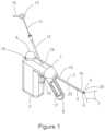
- FIG. 1is a schematic illustration of a surgical ablation probe configured for ablation of posterior nasal nerve function.
- FIG. 2 Ais a side view schematic illustration of a surgical probe configured for ablation of posterior nasal nerve function with the articulated segment in an axial configuration, with the camera retracted.
- FIG. 2 Bis a side view schematic illustration of a surgical probe configured for ablation of posterior nasal nerve function with the articulated segment in an axial configuration, with the camera extended.
- FIG. 3 Ais a side view schematic illustration of a surgical probe configured for ablation of posterior nasal nerve function with the articulated segment in an axial configuration, with the camera retracted.
- FIG. 3 Bis a side view schematic illustration of a surgical probe configured for ablation of posterior nasal nerve function with the articulated segment in a lateral configuration with the camera retracted.
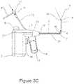
- FIG. 3 Cis a side view schematic illustration of a surgical probe configured for ablation of posterior nasal nerve function with the articulated segment in a lateral configuration with the camera extended.
- FIG. 4is a side view schematic illustration of surgical probe configured for ablation of posterior nasal nerve function showing a sinuplasty balloon mounted on the camera shaft proximal to the camera.
- FIG. 5 Ais a schematic illustration of the distal end of a surgical probe configured for ablation of posterior nasal nerve function with the articulated segment in an axial configuration with the camera retracted.
- FIG. 5 Bis a schematic illustration of the distal end of a surgical probe configured for ablation of posterior nasal nerve function with the articulated segment in an axial configuration with the camera extended.
- FIG. 6 Ais a schematic illustration of the distal end of a surgical probe configured for ablation of posterior nasal nerve function with the articulated segment in a lateral configuration at approximately 45 degrees with the camera retracted.
- FIG. 6 Bis a schematic illustration of the distal end of a surgical probe configured for ablation of posterior nasal nerve function with the articulated segment in a lateral configuration at approximately 45 degrees with the camera extended.
- FIG. 6 Cis a schematic illustration of the distal end of a surgical probe configured for ablation of posterior nasal nerve function with the articulated segment in a lateral configuration at approximately 90 degrees with the camera retracted.
- FIG. 6 Ais a schematic illustration of the distal end of a surgical probe configured for ablation of posterior nasal nerve function with the articulated segment in a lateral configuration at approximately 45 degrees with the camera retracted.
- FIG. 6 Dis a schematic illustration of the distal end of a surgical probe configured for ablation of posterior nasal nerve function with the articulated segment in a lateral configuration at approximately 90 degrees with the camera extended.
- FIG. 6 Eis a schematic illustration of the distal end of a surgical probe configured for ablation of posterior nasal nerve function with the articulated segment in a lateral configuration at approximately 120 degrees with the camera retracted.
- FIG. 6 Fis a schematic illustration of the distal end of a surgical probe configured for ablation of posterior nasal nerve function with the articulated segment in a lateral configuration at approximately 120 degrees with the camera extended.
- FIG. 7 Ais a schematic illustration of the distal end of an alternative embodiment of a surgical probe configured for ablation of posterior nasal nerve function with the articulated segment in an axial configuration and a back looking camera retracted.
- FIG. 7 Bis a schematic illustration of the distal end of an alternative embodiment of a surgical probe configured for ablation of posterior nasal nerve function with the articulated segment in an axial configuration and a back looking camera in its initial stage of extension.
- FIG. 7 Cis a schematic illustration of the distal end of an alternative embodiment of a surgical probe configured for ablation of posterior nasal nerve function with the articulated segment in an axial configuration and a back looking camera in its fully extended position.
- FIG. 7 Ais a schematic illustration of the distal end of an alternative embodiment of a surgical probe configured for ablation of posterior nasal nerve function with the articulated segment in an axial configuration and a back looking camera retracted.
- FIG. 7 Bis a schematic illustration of the distal end of an alternative embodiment of a surgical probe configured for ablation of posterior nasal nerve function with
- 7 Dis a schematic illustration of the distal end of an alternative embodiment of a surgical probe configured for ablation of posterior nasal nerve function with the articulated segment in an approximately 120 degree lateral configuration, and a back looking camera in its fully extended position, which is the normal ablation configuration.
- FIG. 8is a schematic illustration of the distal end of an alternative embodiment of a surgical probe configured for ablation of posterior nasal nerve function with the articulated segment in an axial configuration and a camera assembly comprising a distal looking camera and a proximal looking camera in its extended position.
- FIG. 9is a schematic illustration of the distal end of an alternative embodiment of a surgical probe configured for ablation of posterior nasal nerve function with the articulated segment in an approximately 120 degree lateral configuration, a camera in its extended position and a laterally deployed needle for anesthetic injection into the posterior nasal nerve ablation target region of the lateral nasal wall.
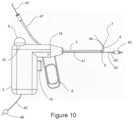
- FIG. 10is a schematic illustration of the distal end of an alternative embodiment of a surgical probe configured for ablation of posterior nasal nerve function with the articulated segment in a 90 degree lateral configuration, a camera mounted at the distal end of the ablation element, and a sinuplasty balloon catheter extending beyond the distal end of a working channel.
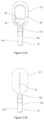
- FIGS. 11 A- 11 Dshow views of a therapeutic element at the distal end of a surgical probe, according to embodiments of the invention.
- FIG. 12 Ais a perspective view of an integrated therapy and imaging device with a display, according to embodiments of the invention.
- FIGS. 12 B-Eare perspective views of alternative embodiments of the distal end of the integrated therapy and imaging device of FIG. 12 A , according to embodiments of the invention.
- FIGS. 13 A and 13 Bshow simplified schematics of alternative arrangements of imaging sensors and light elements, according to embodiments of the invention.
- FIGS. 14 A- 14 Eshow views of a distal end of an integrated therapy and imaging device, according to embodiments of the invention.
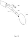
- FIG. 15shows a perspective view of an articulating imaging attachment, according to embodiments of the invention.
- FIGS. 16 A and 16 Bshow views of a device with an integrated articulating imaging attachment in a non-articulated position, according to embodiments of the invention.
- FIGS. 17 A and 17 Bshow views of device with an articulating imaging attachment in an elevated position, according to embodiments of the invention.
- FIGS. 18 A and 18 Bshow views of device with an articulating imaging attachment in an elevated and downwardly angled position, according to embodiments of the invention.
- FIG. 19shows a perspective view of an imaging attachment with a malleable distal portion, according to embodiments of the invention.
- FIGS. 20 A and 20 Bshow views of a template used to shape the malleable distal portion of the imaging attachment of FIG. 19 , according to embodiments of the invention.
- FIG. 21 Ashows a perspective view of a device with an integrated imaging attachment, according to embodiments of the invention.
- FIGS. 21 B and 21 Cshow perspective views of a device with an imaging attachment at various rotated positions relative to FIG. 21 A , according to embodiments of the invention.
- FIG. 1is a schematic illustration of surgical ablation probe 1 configured for ablation of posterior nasal nerve function.
- surgical ablation probe 1and its alternative embodiments are cryo-ablation probes.
- alternative ablation and therapeutic modalitiesincluding radiofrequency, laser, microwave, ultrasonic, and chemo-ablation remain within the scope of this invention.
- Surgical ablation probe 1comprises handle assembly 2 , probe shaft 3 , and camera assembly 6 .
- Handle assembly 2comprises handle housing 19 , cryogen cartridge receptacle 18 , cryogen cartridge 9 , cryogen control trigger 10 , distal segment actuator lever 8 with finger grip 17 , and camera tube 12 .
- Probe shaft 3comprises proximal end 15 , distal end 16 , cryo-ablation element 4 , distal articulated segment 5 , proximal segment 21 , and camera channel 22 .
- Camera assembly 6comprises camera head 20 , camera shaft 11 , camera hub 13 , camera electrical cable 14 , and camera field of view 7 is depicted in the distal direction.
- Probe shaft 3is between approximately 3 mm and 5 mm in diameter, and between approximately 40 mm and 100 mm long.
- Cryo-ablation element 4is disposed in the vicinity of distal end 16 of probe shaft 3 , and is associated with articulated segment 5 .
- Distal articulated segment 5is between approximately 8 mm to 20 mm long and comprises distal end 16 .
- Camera head 20may include a miniature CMOS camera and light source, and is mounted on the distal end of camera shaft 11 . As depicted, camera field of view 7 is in the distal direction. Cameras with integrated light source are manufactured by Awaiba, which are described in detail at awaiba.com.
- Camera shaft 11comprises a hollow flexible tube, which may be metallic, or a suitable plastic such polyimide. Camera shaft 11 houses wires that connect the camera and light source within camera housing 20 to an imaging console, not shown, through camera hub 13 , and camera cable 14 . Camera assembly 6 , and alternate embodiments will be described in further detail below.
- Probe shaft 3also comprises camera lumen 22 , which is contiguous with camera tube 12 .
- Cryogen cartridge 9comprises a cryogen supply which may be in liquid or gas form.
- Cryogen cartridgeis in fluidic communication with cryo-ablation element 4 , through a cryogen control valve associated with cryogen trigger 10 .
- cryogen trigger 10When cryogen trigger 10 is depressed by the user, cryogen flows to cryo-ablation element 4 .
- cryogen trigger 10is released by the user cryogen flow terminates. Exhausted cryogen from cryo-ablation element is vented to the room through the interior of probe shaft 3 , and a port in handle assembly 2 , not shown.
- FIG. 2 Ais a side view schematic illustration of surgical probe 1 with distal articulated segment 5 in an axial configuration with camera head 20 retracted.
- FIG. 2 Bis a side view schematic illustration of surgical probe 1 with distal articulated segment 5 in an axial configuration, with camera head 20 extended.
- Camera assembly 6comprises camera head 20 , camera shaft 11 , camera hub 13 , camera cable 14 , and an electrical connector, not shown, configured for electrical connection to an imaging display, also not shown.
- Camera shaft 11is in a slidable relationship with camera tube 12 , and camera lumen 22 of probe shaft 3 . As depicted, camera head 20 is extended by sliding camera shaft 11 in the distal direction, and retraction of camera head 20 is accomplished by sliding camera shaft 11 in the proximal direction.
- FIG. 3 Ais a side view schematic illustration of surgical probe 1 configured for ablation of posterior nasal nerve function with articulated segment 5 and cryo-ablation element 4 in an axial configuration, with the camera assembly 6 retracted into its proximal most position.
- FIG. 3 Bis a side view schematic illustration of surgical probe 1 with articulated segment 5 and cryo-ablation element in a lateral configuration with camera assembly 4 retracted in its proximal most position.
- FIG. 3 Cis a side view schematic illustration of surgical probe 1 with articulated segment 5 in a lateral configuration and with camera assembly 4 extended to its distal most position.
- Distal segment actuator lever 8controls the position of distal articulated segment 5 and cryo-ablation element 4 .
- distal segment actuator lever 8When distal segment actuator lever 8 is in its forward position as depicted in FIG. 3 A , distal articulated segment 5 and cryo-ablation element 4 is in an axial configuration as shown. When distal segment actuator lever 8 is pulled in the proximal direction, distal articulated segment 5 and cryo-ablation element are deflected into a lateral or non-axial position as shown in FIGS. 3 B and 3 C .
- actuator lever 8it will be understood that other mechanisms may be employed for creating a distal articulated segment as depicted here, including the use of eccentrically anchored pull wires.
- articulated distal segment 5 and associated camera assembly 6provides the user with a means of endoscopically examining a nasal cavity in a distal axial and distal lateral directions, and the extension of camera assembly 6 as depicted allows the user to endoscopically examine nasal sinuses from the nasal cavity.
- Probe shaft 3is configurable to be torsionally stiff to provide a rotational manipulation in addition to the lateral manipulation as described. This allows camera head 20 to be aimed over a spherical arc, and also provides the user the means to press cry-ablation element against the lateral nasal wall using torsional force.
- FIG. 4is a side view schematic illustration of surgical probe 1 configured for ablation of posterior nasal nerve function showing a sinuplasty balloon 26 mounted on camera shaft 24 proximal to camera head 20 of camera/balloon assembly 23 .
- posterior nasal nerve ablation probe 1is substantially identical in form and function as previously described.
- a sinuplasty functionalityis added, by adding a dilatation balloon to the distal camera shaft.
- Sinuplastyrefers to dilatation of the os of a nasal cavity to facilitate sinus drainage.
- camera/balloon assembly 23comprises camera head 20 , which retains the form and function as previously described, camera shaft 24 , which includes a balloon inflation lumen, not shown, and the electrical wires connected to the CMOS camera, not shown.
- Camera hub 25comprises a female luer fitting, which is in fluidic communication with the balloon inflation lumen, and electrical cable 14 and an electrical connector, not shown.
- Dilatation balloon 26is substantially similar to dilatation balloons used in angioplasty procedure. Those skilled in the art of surgical dilatation balloon design and manufacture are familiar with the means for incorporating a dilatation balloon as depicted; therefore, no further description of the dilatation balloon is warranted. As depicted, camera head 20 is extended, and balloon 26 is inflated.
- balloon 26is deflated and resides within camera shaft lumen 28 .
- a syringedis connected to female luer fitting 27 , and the syringe is used to inflate balloon 27 .
- Balloon 27may be between approximately 3 to 10 mm in diameter when fully inflated, and may have a functional length between approximately 10 mm and 20 mm.
- the camerais used to located the os of the sinus, and camera head 20 is inserted through the os of the sinus, and balloon 26 is placed into a straddling position within the os, and then inflated to dilate the os. Balloon 26 is then deflated, and camera head 20 is withdrawn from the sinus.
- FIG. 5 Ais a schematic illustration of the distal end of a surgical probe 1 configured for ablation of posterior nasal nerve function with distal articulated segment 5 and cryo-ablation element 4 in an axial configuration with camera assembly 6 retracted.
- FIG. 5 Bis a schematic illustration of the distal end of surgical probe 1 with distal articulated segment 5 and cryo-ablation element 4 in an axial configuration with camera assembly 6 extended.
- Camera objective 29 , and camera light source 30is depicted.
- relief slits 31 in the wall of distal articulated segment 5which are oriented on the side of lateral deflection. Relief slits 31 facilitate lateral deflection with a relatively short radius by removing shaft material on the inner bend radius.
- Camera shaft lumen 22may comprise coiled wire reinforcement, not shown, in the vicinity of distal articulated segment 5 to prevent kinking.
- FIG. 6 Ais a schematic illustration of the distal end of a surgical probe 1 configured for ablation of posterior nasal nerve function with distal articulated segment 5 and cryo-ablation element 4 in a lateral configuration at approximately 45 degrees with the camera assembly 6 retracted.
- FIG. 6 Bis a schematic illustration of the distal articulated segment 5 and cryo-ablation element 4 in a lateral configuration at approximately 45 degrees with camera assembly 6 extended.
- FIG. 6 Cis a schematic illustration of the distal end of a surgical probe 1 with distal articulated segment 5 and cryo-ablation element 4 in a lateral configuration at approximately 90 degrees with camera assembly 6 retracted.
- FIG. 6 Ais a schematic illustration of the distal end of a surgical probe 1 configured for ablation of posterior nasal nerve function with distal articulated segment 5 and cryo-ablation element 4 in a lateral configuration at approximately 45 degrees with the camera assembly 6 retracted.
- FIG. 6 Bis a schematic illustration of the distal articulated segment 5 and cryo-ablation element 4 in
- FIG. 6 Dis a schematic illustration of the distal end of a surgical probe 1 with distal articulated segment 5 and cryo-ablation element 4 in a lateral configuration at approximately 90 degrees with camera assembly 6 extended.
- FIG. 6 Eis a schematic illustration of the distal end of surgical probe 1 with distal articulated segment 5 and cryo-ablation element 4 in a lateral configuration at approximately 120 degrees with camera assembly 6 retracted.
- FIG. 6 Fis a schematic illustration of the distal end of a surgical probe with distal articulated segment 5 and cryo-ablation element 4 in a lateral configuration at approximately 120 degrees with camera assembly 6 extended.
- FIG. 6 A through 6 Fare illustrative of the range of motion of distal articulated segment 5 , cryo-ablation element 4 and camera assembly 6 .
- FIG. 7 Ais a schematic illustration of the distal end of an alternative embodiment of a surgical probe configured for ablation of posterior nasal nerve function with distal articulated segment 5 in an axial configuration with back looking camera assembly 33 retracted.
- FIG. 7 Bis a schematic illustration of the distal end of the alternative embodiment with distal articulated segment 5 in an axial configuration and back looking camera assembly 33 in its initial stage of extension.
- FIG. 7 Cis a schematic illustration of the distal end of the alternative embodiment with distal articulated segment 5 in an axial configuration and back looking camera assembly 33 in its fully extended position.
- FIG. 7 Ais a schematic illustration of the distal end of an alternative embodiment of a surgical probe configured for ablation of posterior nasal nerve function with distal articulated segment 5 in an axial configuration with back looking camera assembly 33 retracted.
- FIG. 7 Bis a schematic illustration of the distal end of the alternative embodiment with distal articulated segment 5 in an axial configuration and back looking camera assembly 33 in its initial stage of extension.
- FIG. 7 Cis a schematic
- FIG. 7 Dis a schematic illustration of the distal end of the alternative embodiment with distal articulated segment 5 in an approximately 120 degree lateral configuration, and back looking camera assembly 33 in its fully extended position, which is the normal ablation configuration.
- Back looking camera assembly 33provides the user with a means for confirming the correct placement of cryo-ablation element 4 against the lateral nasal wall proximate to a target Post Nasal Nerve.
- Back looking camera assembly 33comprises camera head 20 , as previously described, curved camera shaft 32 , and camera hub 13 , and camera cable 14 , not shown, but previously described.
- Curved camera shaft 32has pre-formed curve as shown.
- Curved camera shaftmay be fabricated using a super elastic metal alloy such Nitinol® in the form of a hypotube. Those skilled in the art of super-elastic metallurgy are familiar with means for creating the pre-formed curve as shown; therefore, no further description is warranted.
- FIG. 8is a schematic illustration of the distal end of an alternative embodiment of a surgical probe configured for ablation of posterior nasal nerve function with distal articulated segment 5 in an axial configuration and dual camera assembly 34 comprising a distal looking camera and a proximal looking camera in its extended position, as illustrated by camera field of views 7 .
- Dual camera assembly 34comprises dual camera head 35 , camera shaft 11 , camera hub 13 and camera cable 14 , not shown but previously described.
- Dual camera head 35comprises a forward-looking CMOS camera and light source as previously described, and a second back-looking CMOS camera and light source.
- FIG. 9is a schematic illustration of the distal end of an alternative embodiment of a surgical probe configured for ablation of posterior nasal nerve function comprising cryo-ablation element 39 configured with lateral injection needle 37 , lateral fenestration 36 , and topical anesthetic delivery surface 38 .
- cryo-ablation element 39configured with lateral injection needle 37 , lateral fenestration 36 , and topical anesthetic delivery surface 38 .
- distal articulated segment 5is in an approximately 120 degree lateral configuration
- dual camera assembly 34 camerain its fully extended position and lateral injection needle 37 is deployed for anesthetic injection into the posterior nasal nerve ablation target region of the lateral nasal wall.
- Topical anesthetic delivery surface 38is configured for applying a topical anesthetic to the lateral nasal wall proximate to the target posterior nasal nerve, in order to numb the region prior to injection of the anesthetic through lateral needle 37 .
- Lateral needle 37is a hypotube, which may be fabricated from a super-elastic metal, such as Nitinol®. Lateral needle 37 is in fluidic communication with a proximal syringe, not shown, and is configured with a proximal needle deployment mechanism, not shown.
- proximal syringenot shown
- proximal needle deployment mechanismnot shown.
- Topical anesthetic delivery surface 38may comprises an anesthetic carrying means such as a hydrophilic coating, or a foam or fibrous absorbable material that can absorb a topical anesthetic and deliver the anesthetic to the surface of a nasal wall by contact.
- Topical anesthetic delivery surface 38may comprise an abrasive material configured to abrade the nasal wall to enhance the effectiveness of the topical anesthetic.
- the abrasive materialmay comprise crystalline lidocaine, or similar anesthetic material.
- FIG. 10is a schematic illustration of the distal end of an alternative embodiment of a surgical probe configured for ablation of posterior nasal nerve function comprising distal camera 44 mounted at the distal end of cryo-ablation element 4 , and working channel 41 , which is configured to introduce surgical instruments into the nasal cavity under image guidance.
- balloon catheter 40is inserted into working 41 , with balloon 42 , and the distal end of catheter shaft 43 extending beyond the distal end of working channel 41 .
- the proximal end of catheter shaftis depicted entering working channel 41 through working channel tube 47 .
- Distal camera 44is connected to an image display, not shown by electrical cable 45 , and electrical connector 46 .
- distal articulated segment 5is in a 90 degree lateral configuration.
- the range of motion of distal articulated segment 5is substantially the same as previously describe and between approximately zero and 120 degrees.
- Working channel 41may be configured for use with catheters and probes between approximately 3 and 6 French.
- FIGS. 11 A- 11 Dshow views of one such alternate embodiment of a cryogenic ablation element, according to embodiments of the invention.
- the side view of FIG. 11 Ashows a structure or member 83 which is formed into a looped and elongated structure having arcuate edges for presenting an atraumatic surface.
- the structure 83may be formed of a relatively rigid wire or member instead which maintains its configuration when pressed against a tissue surface.
- Structure 83may form a continuous structure which defines an opening there through such as a looped or elongated and looped member which is open through the loop.
- the structure 83may be contained entirely within the expandable structure 81 which may be formed to have a predefined shape which is distensible or non-distensible when inflated by the cryogen.
- the expandable structure 81may be formed to surround the structure 83 entirely without being supported by or attached to the structure 83 itself.
- Such a structure 83may provide a configuration which presents a low-profile as the device is advanced into and through the nasal cavity and between the nasal turbinate tissues. Yet because of the relatively flattened shape and rigidity and integrity of the structure 83 , the structure 83 may be used to manipulate, move, or otherwise part the tissues of the nasal cavity without having to rely upon the expandable structure 81 . Additionally, the low-profile enables the structure 83 to be positioned desirably within the narrowed confines of, e.g., the cul-de-sac in proximity to the posterior nasal nerves (as shown by cul-de-sac 13 shown in FIG. 1 of previously incorporated U.S. Patent Application Publication No. 2015/0164571).
- the expandable to structure 81When the expandable to structure 81 is in its deflated state, it may form a flattened shape and when inflated, the expandable structure 81 may inflate into a configuration which remains unsupported by or attached to the structure 83 . Because the structure 83 may be formed of a member which solid along its length, the cryogen may be introduced directly into the expandable structure 81 through a distal opening defined in the probe shaft 145 .
- structure 83may be formed of a hollow tubular member which itself is formed into the continuous or looped shape.
- the cryogenmay be optionally introduced through the hollow tubular member and dispersed within the interior of the expandable structure 81 through one or more openings which may be defined along the tubular member.
- the structure 83may be formed into a flattened shape rather than a looped shape. In this configuration, the structure may be either solid or hollow such that that cryogen may be introduced through the structure and into the interior of the expandable structure 81 via one or more openings defined along the structure.
- the structure 83may extend and remain attached to the probe shaft 145 , but the remainder of the structure 83 which extends within the expandable structure 81 may remain unattached or unconnected to any portion of the expandable structure 81 .
- the structure 83may be adjusted in position or moved via manipulating the probe shaft 145 relative to the interior of the expandable structure 81 to enable the targeted positioning and cooling of the tissue region when in contact against the outer surface of the expandable structure 81 .
- the structure 83may press laterally upon a particular region of the underlying tissue to stretch or thin out the contacted tissue region to facilitate the cryogenic treatment.
- the expandable structure 81may remain in a static position against a contacted tissue region allowing for limited repositioning of the structure 83 within.
- the structure 83may be attached along the interior of the expandable structure 81 partially at particular portions of the structure 83 or along the entirety of the structure 83 .
- structure 83may be attached, adhered, or otherwise coupled over its entirety to expandable structure 81 while in other variations, a distal portion of structure 83 may be attached, adhered, or otherwise coupled to a distal portion of the expandable structure 81 while in yet other variations, portions of the structure 83 may be attached, adhered, or otherwise coupled to the expandable structure 81 along its side portions. Any of these variations may be optionally utilized depending upon the desired interaction and treatment between the structure 83 , expandable structure 81 , and underlying tissue region to be treated.
- the lumen 84 for introducing the cryogen into the interior of the expandable structure 81may be extended past the distal end of the probe shaft such that the cryogen is released within the interior at a more distal location.
- the cryogen lumen 84may be supported along the structure 83 , e.g., via a bar or member 85 which extends across the structure 83 .
- This particular variationmay allow for the cryogen to be introduced into the distal portion of the interior of the expandable member 81 . Either this variation or the variation where the cryogen is released from an opening of the probe shaft may be utilized as desired.
- FIG. 11 Bshows a side view of the embodiment of FIG. 11 A illustrating how the structure 83 can be formed from a relatively flattened configuration relative to the inflated expandable structure 81 .
- the structure 83may provide for targeted treatment of the tissue when contacted by the device.
- FIG. 11 Cshows the side view of the inflated expandable structure 81 when pressed in a longitudinal direction by its distal tip against the underlying tissue surface S.
- the relative strength of the structure 83provides for the ability to press the device against the tissue surface such that the remainder of the expandable structure 81 may maintain its inflated configuration to potentially insulate the other surrounding tissue regions.
- FIG. 11 Dlikewise shows the device when the structure 83 is pressed laterally along its side against the tissue surface S such that the structure 83 lies flat. The contacted tissue region may be treated while the remainder of the surrounding tissue is potentially insulated by the expanded structure 81 .
- the same end effectormay be used in other regions of the nasal cavity as well.
- the end effectormay then be moved to an adjacent tissue region, e.g., region immediately inferior to the cul-de-sac, and ablation treatment may be effected again.
- the end effectormay also be used to further treat additional tissue regions, e.g., posterior aspect of the superior, middle, and/or inferior turbinates (any one, two, or all three regions).
- additional tissue regionse.g., posterior aspect of the superior, middle, and/or inferior turbinates (any one, two, or all three regions).
- the end effectormay remain in place until the tissue region has thawed partially or completely before the end effector is moved to the adjacent tissue region for further treatment.
- the tissue regionmay be assessed utilizing any number of mechanisms. For instance, the tissue region may be visually assessed utilizing an imager during and/or after ablation.
- the devicemay be utilized with a temperature sensor, e.g., thermistor, thermocouple, etc., which may be mounted along the shaft, within or along the expandable structure 81 , along the structure 83 , etc., to monitor the temperature not only of the cryogen but also a temperature of the tissue region as well under treatment.
- a temperature sensore.g., thermistor, thermocouple, etc.
- the expandable structure 81may also be vibrated while maintaining the structure 83 against the interior of the expandable structure 81 and the tissue region utilizing any number of vibrational actuators which may be mounted anywhere along the device as appropriate.
- the vibrationsmay be applied directly against the tissue region or, e.g., through a layer of gel to facilitate the vibrational contact with the tissue.
- biocompatible agentsmay be used in combination with the cryogenic treatment.
- an anestheticmay be applied to the tissue region to be treated prior to or during the cryogenic treatment.
- FIG. 12 Ais a perspective view of an integrated therapy and imaging device 1200 with a display 1208
- FIG. 12 Bis a perspective view of the distal end of the integrated therapy and imaging device of FIG. 12 A , according to embodiments of the invention.
- Device 1200may operate similarly to probe 1 described above, except that it may incorporate a display 1208 for ease of viewing during insertion of the distal end of device 1200 into a patient's nasal cavity.
- handle 1202includes an actuator 1220 that may cause cryogen contained in the cryogen container (not shown) housed in handle 1202 to flow through cannula 1216 to cryo-ablation element 1218 .
- cryo-ablation element 1218may be an inflatable structure with an internal structure 1222 , which may be similar to expandable structure 81 and structure 83 described above with respect to FIGS. 11 A- 11 D .
- Cannula 1216extends from an opening in housing 1210 of device 1200 .
- Imaging Device 1200also includes an imaging cannula 1212 that extends from the opening in housing 1210 .
- Imaging cannula 1212may have an imaging assembly 1214 disposed at the distal end thereof.
- Imaging assembly 1214may include an imaging sensor (not shown) and light element (not shown) configured to provide visualization of cryo-ablation element 1218 .
- the imaging sensor of imaging assembly 1214may be a CMOS imaging sensor, a CCD imaging sensor, or any other suitable sensor or sensors for detecting image information and converting that information into signals to be displayed on display 1208 .
- imaging assemblymay utilize one or more protected optic fibers that run within a lumen inside imaging cannula 1212 to a camera mount disposed on device 1200 , at which point a CMOS or CCD imaging sensor may be coupled to the fibers.
- Light element of imaging assembly 1214may include one or more LEDs disposed at the distal end of imaging cannula 1212 , although other suitable light generating elements may also be used.
- one or more optic fibers that run within imaging cannula 1212may be used to channel light to the working area around cryo-ablation element 1218 .
- Such optic fibersmay be coupled to one or more LEDs or other light generating elements integrated into handle 1202 , or may be terminated at a standard ACMI adapter port to enable connection to an external light source as desired.
- the imaging assembly 1214In order to be used in the nasal cavity, it may be preferable for the imaging assembly 1214 to have a field of view of at least 75 degrees and a viewing distance of at least 5 mm. Moreover, it may be preferable for imaging assembly 1214 to have an effective diameter of less than 2.5 mm.
- FIG. 12 Cshows an embodiment of the device 1200 with a malleable imaging cannula 1212 C.
- Cannula 1212 Cmay be constructed of malleable materials such as aluminum, copper, annealed steel, or some polymers.
- Cannula 1212 Ccan be shaped in situ to a shape that is conducive to the desired field of view of the ablation element 1218 .
- An initial shapeis shown as 1275 A, and an exemplary resulting shape is shown as 1275 B.
- a flexible or elastic imaging componentcan be inserted into the cannula 1212 C and then pushed forward until it exits the distal end of the cannula and naturally be in the proper location as defined by cannula 1212 C apriori.
- FIG. 12 Dshows imaging assembly 1204 D inserted through malleable imaging cannula 1212 C after cannula 1212 C has been formed into shape 1275 B described above.
- Imaging assembly 1204 Dmay be constructed of elastic material such as a spring coil or nitinol or an elastomer like silicone or polyurethane.
- the elastomeric property of this variation of assembly 1404 Dallows it to be easily inserted into the cannula 1212 C described with reference to FIG. 12 C and push out the distal end of malleable cannula 1212 C.
- FIG. 12 Eshows another embodiment of device 1200 with a shape memory image assembly 1204 E.
- Shape memory image assembly 1204 Eis made out of a material with shape memory such as spring steel, nitinol, shape memory polymers, or other suitable shape memory materials.
- Shape memory image assembly 1204 Emay have an original shape that allows a desired viewing angle and/or position relative to therapeutic element 1218 .
- Shape memory image assembly 1204 Emay be inserted into cannula 1212 E and be elastic enough to take a straight shape while moving through cannula 1212 E, and take its original shape as it exits cannula 1212 E.
- the original shapemay be any suitable shape, and may have a curved, zigzag, or dogleg shape as needed.
- FIGS. 13 A and 13 Bshow simplified schematics of alternative arrangements of imaging sensors 1302 and light elements 1304 , according to embodiments of the invention. It will be understood that these arrangements of imaging sensors 1302 and 1304 can be employed in imaging assembly 1214 or any other imaging assembly described herein.
- FIG. 13 Ashows a co-axial arrangement of imaging sensor 1302 A and light element 1304 A.
- light element 1304 Amay be a ring of LEDs surrounding imaging sensor 1302 A.
- FIG. 13 Bshows an off-axis arrangement, with light element 1304 B directing light off-axis of imaging sensor 1302 B.
- Device 1200may include an articulation actuator that is embedded or attached to device handle 1202 , which may cause either or both of imaging assembly 1214 and/or cryoablation element 1218 to articulate in the manner described herein.
- the actuatormay be configured to cause an articulating region of cannula 1216 or imaging lumen 1212 to articulate as described with respect to FIGS. 1 - 9 and 14 - 21 herein.
- device 1200may include a display 1208 operably coupled to imaging assembly 1214 .
- Display 1208may be a smart phone, tablet, or other stand-alone display that can output video with a desired resolution.
- Display 1208may be integrated with device 1200 , or, alternatively, may be removably coupled from device 1200 .
- display 1208may be removably coupled to display adapter 1206 by any suitable connection allowing attachment and detachment as needed by the user.
- display adapter 1206may include one or more magnetic elements that attract complementary magnetic elements on display 1208 to keep display 1208 in place as shown, but which allow a user to detach display 1208 as needed.
- Display adapter 1206may also include the requisite electrical connections which connect display 1208 to imaging assembly 1204 and any components thereof. Thus, when connected to display adapter 1206 , display 1208 can receive signals from imaging assembly 1204 and the components thereof to display cryo-ablation element 1218 and the surrounding areas during use of device 1200 .
- the placement of display 1208 on device 1200 as shownmay be preferable to using an external display at a remote location, since display 1208 may more easily fall in the line of sight of the healthcare provider during use of device 1200 . This way, the healthcare provider will not need to look away from the patient when using device 1200 .
- FIGS. 14 A- 14 Eshow views of a distal end of an integrated therapy and imaging device 1400 , according to embodiments of the invention.
- Device 1400may be used to provide therapy in the nasal cavity as described above.
- device 1400may be used to deliver energy to tissue in the nasal cavity to ablate a posterior nasal nerve to treat rhinitis.
- device 1400may have a therapeutic element 1410 for delivering the energy to tissue via working cannula 1408 .
- therapeutic element 1410may be a cryo-ablation element as described previously.
- Imaging attachment 1401may include an imaging cannula 1402 with an imaging assembly 1404 disposed at the distal end of imaging cannula 1402 .
- Imaging cannula 1402 and imaging assembly 1404may generally be similar to imaging cannula 1212 and imaging assembly 1214 described above with respect to FIGS. 12 A- 12 B , except that rather than extending from within a housing in device 1400 , they are externally coupled to the working cannula 1408 via one or more couplers 1406 .
- Couplers 1406may be a C-shaped clip that keep imaging attachment 1401 coupled to working cannula 1408 , but allow particular movement of imaging attachment 1401 and imaging assembly 1404 relative to therapeutic element 1410 .
- couplers 1406may be friction fittings that allow relative movement between working cannula 1408 and imaging cannula 1402 , but only upon relative friction above a certain threshold.
- the threshold relative frictionmay be 1 ⁇ 2 to 1 pound of force. This will allow the imaging cannula 1402 to remain coupled to working cannula 1408 during normal operation of device 1400 , but still allow relative translation when desired upon minimal application of force by the user.
- Couplers 1406may be made of polyurethane, latex, silicone, or other similar materials.
- device 1400may have a display disposed at the proximal end of the device that is operably coupled to the imaging assembly 1404 for visualization of the therapeutic element 1410 .
- device 1400may have a display adaptor disposed at the proximal end that is operably coupled to the imaging assembly 1404 via wiring or optical fibers disposed in imaging cannula 1402 .
- the display adaptormay be configured to connect to any suitable external display for providing visualization of the images detected by imaging assembly 1404 .
- the imaging attachment 1401may include an articulating region 1403 that is operably coupled to the imaging assembly 1404 and configured to articulate the imaging assembly 1404 .
- imaging assembly 1404may be configured to translate axially in the X direction to adjust the distance from therapeutic element 1410 .
- Axial translation in this directionmay range from about 5 mm to about 60 mm.
- Imaging assembly 1404may also be configured to translate vertically in the Y direction to adjust the height of imaging assembly 1404 relative to working cannula 1408 . Vertical translation in this direction may range from about 1 mm to about 10 mm.
- Imaging assembly 1404may also be configured to laterally translate to adjust an angle ⁇ with respect to a central axis 1412 of imaging assembly. This may allow imaging assembly to obtain a desired viewing angle of therapeutic element 1410 . This lateral translation may range from about 0 degrees to about 30 degrees. Additionally, imaging assembly 1404 may be configured to rotationally translate in the “R” direction about the insertion axis 1414 of the working cannula 1408 . The range of rotation may be the entire 360 degrees about the insertion axis 1414 , 0 to 180 degrees about the insertion axis 1414 , or 45 degrees rotation about the insertion axis 1414 in either direction (from the initial position shown in FIG. 14 A ).
- imaging assembly 1404may view therapeutic element 1410 from different vantage points as may be needed during use of device 1400 . These degrees of freedom will also allow the imaging assembly 1404 to be positioned in a different location during insertion than during delivery of a therapeutic agent by therapeutic element 1410 .
- imaging assemblymay be coupled to a temperature control element 1425 (shown schematically in FIG. 14 A ).
- Temperature control element 1425may include temperature sensors to detect the temperature of the imaging assembly 1404 and heating or cooling elements that can be controlled in response to the detected temperatures to maintain the imaging assembly within an operating temperature range during activation of therapeutic element 1410 .
- a heating elementsuch as a heating coil may be provided to maintain imaging assembly within a suitable operating temperature.
- the light element of imaging assembly 1404may act as a heating element to keep imaging assembly within a suitable operating temperature.
- one or more LEDs used as lighting elementsmay also be used has heating elements to keep imaging assembly 1404 (including image sensor) within a suitable operating temperature.
- imaging assembly 1404may be in a default position prior to any articulation.
- imaging assembly 1404may be in an elevated position after vertical translation thereof.
- imaging assembly 1404may be both elevated vertically and angled laterally to point at therapeutic element 1410 from above.
- imaging assembly 1404is rotationally translated from the position in FIG. 14 B .
- articulation of the imaging assembly 1404may be effected using pullwires, slides, and/or dials that terminate at the proximal end of the device, where the user can manipulate the imaging assembly 1404 with their hand.
- pullwires coupled to imaging assembly 1404may extend through imaging cannula 1402 and may be tightened or loosened by the user using levers or other articulation actuators so as to cause articulating region 1403 to axially, vertically, laterally, and rotationally translate imaging assembly 1404 as desired.
- axial and rotational translationmay be directly caused manually by the user, while lateral and vertical translation may be actuated with levers coupled to guide wires.
- imaging assembly 1404may be disposed proximally of therapeutic element 1410 so as to minimize engagement with nasal tissue when the distal end of device 1400 is inserted into the nasal cavity.
- imaging assembly 1404may be dimensioned to fit within the profile dimensions of therapeutic element 1410 so that therapeutic element 1410 effectively protects imaging assembly from engagement with nasal tissue. Since therapeutic element 1410 has a predominantly vertical profile, it may be desirable to vertically stack imaging assembly 1404 and its components within this profile. Additionally, in some embodiments it may be desirable to limit the articulation of imaging assembly 1404 to remain within the profile of therapeutic element 1410 .
- FIG. 14 Eshows a schematic illustration of one or more flushing and/or vacuum ports 1430 disposed on imaging assembly 1404 and/or working cannula 1408 , according to embodiments of the invention.
- ports 1430 for flushing and/or vacuummay either embedded on working cannula 1408 or embedded on the body of the imaging assembly 1404 .
- Ports 1430may be fluidly coupled to channels within working cannula 1408 and/or imaging cannula 1402 to allow fluid to pass through, exit at the distal end of the working cannula 1408 , and/or be sucked back outside the body.
- flush ports 1430may be designed to direct fluid at the imaging assembly 1404 and vacuum ports may be positioned about 180 degrees around the imaging assembly from the flush ports 1430 to catch fluid passing towards the imaging assembly 1404 .
- the flush port inner lumen diametermay range from about 0.005 inches to 0.025 inches.
- the vacuum port inner lumen diametermay range from 0.005 inches to 0.025 inches and can be contoured to the outer edge of the imaging element.
- couplers 1406may be used so that there are multiple attachment points between imaging attachment 1401 and working cannula 1408 .
- couplers 1406may provide attachment points on articulating region 1403 so as to allow articulation of therapeutic element 1410 together with or independently of imaging assembly 1404 .
- an imaging attachmentsuch as imaging attachment 1401
- the integration of the imaging attachment with the therapeutic elementmay allow a user such as a healthcare provider to perform a therapeutic procedure with visualization using a single hand. This may decrease the time, cost, and labor involved in a given procedure, and may decrease the degree of difficulty for a given procedure.
- the integration of the imaging attachment with the therapeutic procedurewill improve the visualization of such a procedure, since it will ensure that the imaging will be able to reach sufficiently posterior to obtain detailed visualization of the target region. This is in contrast with rigid or flexible endoscopes which often do not allow imaging sufficiently close to the relevant working tool. Because the imaging attachment is coupled to the working device and can be manipulated to and then fixed at a desired position relative to the therapeutic element, it will assuredly reach posterior enough to provide sufficiently detailed imaging of the therapeutic element and target region.
- FIG. 15shows a perspective view of an articulating imaging attachment 1500 , according to embodiments of the invention.
- Articulating imaging attachment 1500may include a handle attachment base 1516 which may connect imaging attachment 1500 to a handle of a therapeutic device as will be described with reference to FIGS. 16 A-B , 17 A-B, and 18 A-B.
- Articulating imaging attachment 1500may have an imaging cannula 1502 similar to imaging cannula 1402 described above, with an imaging assembly 1504 , similar to imaging assembly 1404 described above, disposed at the distal end.
- Imaging cannula 1402may be coupled to a working cannula of a device via one or more couplers 1506 similar to couplers 1406 described above.
- Articulating imaging attachment 1500may also have articulating region 1503 similar to articulating region 1403 .
- articulating imaging attachment 1500may have a flexing lever 1518 that translates back and forth as shown by arrows 1517 .
- Flexing lever 1518may be coupled to pull wires housed in imaging cannula 1502 and coupled to imaging assembly 1504 , so that when flexing lever is initially pulled in the proximal direction, the pull wire attached to the imaging assembly 1504 tightens and causes imaging assembly 1504 to vertically translate.
- imaging assembly 1504may stop vertically translating and may begin to laterally translate to angle image assembly 1504 relative to its central axis.
- the anglemay range from about 0 to about 20 degrees from the central axis of imaging assembly 1504 without losing the vertical translation, similar to the lateral translation angle ⁇ described above with respect to imaging assembly 1404 .
- flexing lever 1518may allow for vertical and lateral translation of imaging assembly 1504 .
- a locking mechanism 1520shown schematically in FIG. 15 .
- Locking mechanism 1520may be any suitable mechanism that keeps flexing lever 1518 in a desired position.
- locking mechanism 1520may automatically or upon actuation of a button or other mechanism keep flexing lever 1518 in the desired position so that the position and/or viewing angle of imaging assembly 1504 is fixed relative to the therapeutic element of the device that imaging attachment 1500 is attached to.
- Imaging attachment 1500may also allow axial and rotational translation of imaging assembly 1504 as described above with respect to imaging assembly 1404 .
- handle attachment base 1516may snap onto the handle of a therapeutic device 1600 as shown in FIGS. 16 A- 16 B, 17 A- 17 B, and 18 A- 18 B .
- the connection between handle attachment base 1516 and device 1600may allow base 1516 to translate axially in the X direction (shown in FIG. 16 A ) and rotationally in the R direction around the distal nose of the handle of device 1600 (shown in FIG. 16 A ) similar to the axial and rotational translation described with respect to imaging assembly 1404 above.
- the portion of imaging cannula 1502 extending from attachment base 1516 to coupler 1506may be rigid. This way, the axial and rotational translation may be manually done by a user by axially translating and rotating attachment base 1516 .
- the range of axial and rotational translationmay be the same as described above with respect to imaging assembly 1404 .
- FIGS. 16 A and 16 Bshow views of a device 1600 with integrated articulating imaging attachment 1500 in a non-articulated position, according to embodiments of the invention.
- FIG. 16 Awhen imaging assembly 1504 is not articulated, flexing lever 1518 is in its most distal position. Upon pulling of flexing lever 1518 proximally (or in direction 1700 shown in FIG. 17 A ), imaging assembly 1504 may begin to articulate vertically.
- FIGS. 17 A and 17 Bshow views of device 1600 with articulating imaging attachment 1500 in an elevated position, according to embodiments of the invention.
- flexing lever 1518is translated proximally in direction 1700 with respect to the position of flexing lever 1518 in FIGS. 16 A- 16 B , and this translation has caused articulating region 1503 to bend, which has vertically translated imaging assembly 1504 at a height above working cannula 1608 .
- FIGS. 18 A and 18 Bshow views of device 1600 with articulating imaging attachment 1500 in an elevated and downwardly angled position, according to embodiments of the invention.
- flexing lever 1518is translated at the most proximal location in direction 1700 with respect to the position of flexing lever 1518 in FIGS. 17 A- 17 B , and this translation has caused articulating region 1503 to further bend, which has angled imaging assembly 1504 downwardly towards therapeutic element 1610 .
- FIG. 19shows a perspective view of an imaging attachment 1900 with a malleable distal portion 1903 , according to embodiments of the invention.
- Imaging attachment 1900may be similar to imaging attachment 1500 , except that rather than a lever-actuated articulating region, imaging attachment has a malleable distal portion 1903 on which imaging assembly 1904 is disposed, and a proximal rigid portion 1905 coupled to handle attachment base 1916 .
- the malleability of distal portion 1903may allow this portion to be shaped (such as shape 1903 A) by a user for a desired position and/or viewing angle of imaging assembly 1904 .
- proximal rigid portion 1905may be made of a rigid steel, brass, aluminum, copper tubing, or rigid plastic, and malleable distal portion 1903 may be made of the same material as rigid portion 1905 , but may be fully annealed, selectively annealed, thinned, or otherwise treated so as to be sufficiently malleable to be shaped by a user prior to use.
- the malleable distal portion 1903may be made of a composite of polymer and metal.
- Malleable distal portion 1903may be sufficiently malleable so as to be shaped by hand by a user, with or without application of additional energy such as heat. Once shaped as desired, malleable distal portion 1903 may remain semi-flexible, but generally maintain its shape in operation.
- a templatemay be used to shape the malleable distal portion 1903 .
- the templatemay allow consistency across a number of healthcare providers or other users, while still allowing the users to provide a choice in the exact shape of the malleable distal portion 1903 so as to adjust the viewing angle and position of imaging assembly 1904 relative to a therapeutic element.
- FIGS. 20 A and 20 Bshow an exemplary template 2000 used to shape the malleable distal portion 1903 of imaging attachment 1900 , according to embodiments of the invention.
- Template 2000may have one or more shaping channels 2003 in which the malleable distal portion 1903 may be placed for shaping.
- Shaping channels 2003may be designed to obtain a desired default shape for malleable portion 1903 , which shape may provide an optimal position and/or angle with respect to a therapeutic element of a device. The user may then press the distal portion to follow the contours of shaping channel 2003 to obtain the desired shape for a given procedure.
- different templatesmay be generated and used for different procedures and/or different patients. For example, a given procedure may require a different shape to obtain an optimal position or angle, and thus a different template or a different shaping channel within the same template (as shown in FIG. 20 ) may be used to shape the malleable portion 1903 .
- a single template such as template 2000may have multiple shaping channels to account for variations in the anatomy while still providing a uniform shape across healthcare providers.
- FIG. 21 Ashows a perspective view of a device 2100 with imaging attachment 1900 , according to embodiments of the invention.
- Device 2100may be a therapeutic device with a working cannula 2108 and therapeutic element 2110 disposed at the distal end, similar to the devices described above.
- handle attachment base 1916 of imaging attachment 1900may snap onto the handle of device 2100 , and the connection between handle attachment base 1916 and device 2100 may allow base 1916 to translate axially in the X direction (shown in FIG. 21 A ) and rotationally in the R direction around the distal nose of the handle of device 2100 (shown in FIG. 21 A ).
- the rigidity of portion 1905will ensure one to one rotation between handle attachment base 1916 and imaging assembly 1904 .
- FIGS. 21 B and 21 Cshow perspective views of device 2100 with imaging attachment 1900 at various rotated positions relative to FIG. 21 A , according to embodiments of the invention. As can be seen in FIGS. 21 A- 21 C , imaging assembly 1904 remains in the same position and viewing angle as originally shaped, and merely rotates in the R direction to various positions about the axis of insertion of cannula 2108 .
Landscapes
- Health & Medical Sciences (AREA)
- Life Sciences & Earth Sciences (AREA)
- Surgery (AREA)
- Engineering & Computer Science (AREA)
- Nuclear Medicine, Radiotherapy & Molecular Imaging (AREA)
- Public Health (AREA)
- Veterinary Medicine (AREA)
- Biomedical Technology (AREA)
- Heart & Thoracic Surgery (AREA)
- Medical Informatics (AREA)
- Molecular Biology (AREA)
- Animal Behavior & Ethology (AREA)
- General Health & Medical Sciences (AREA)
- Physics & Mathematics (AREA)
- Optics & Photonics (AREA)
- Pathology (AREA)
- Radiology & Medical Imaging (AREA)
- Biophysics (AREA)
- Otolaryngology (AREA)
- Plasma & Fusion (AREA)
- Electromagnetism (AREA)
- Cardiology (AREA)
- Oral & Maxillofacial Surgery (AREA)
- Chemical & Material Sciences (AREA)
- Chemical Kinetics & Catalysis (AREA)
- General Chemical & Material Sciences (AREA)
- Surgical Instruments (AREA)
- Endoscopes (AREA)
- Laser Surgery Devices (AREA)
Abstract
Description
Claims (45)
Priority Applications (2)
| Application Number | Priority Date | Filing Date | Title |
|---|---|---|---|
| US15/431,740US11602260B2 (en) | 2016-02-11 | 2017-02-13 | Method and device for image guided post-nasal nerve ablation |
| US18/111,979US20230218147A1 (en) | 2016-02-11 | 2023-02-21 | Method and device for image guided post-nasal nerve ablation |
Applications Claiming Priority (2)
| Application Number | Priority Date | Filing Date | Title |
|---|---|---|---|
| US201662294142P | 2016-02-11 | 2016-02-11 | |
| US15/431,740US11602260B2 (en) | 2016-02-11 | 2017-02-13 | Method and device for image guided post-nasal nerve ablation |
Related Child Applications (1)
| Application Number | Title | Priority Date | Filing Date |
|---|---|---|---|
| US18/111,979ContinuationUS20230218147A1 (en) | 2016-02-11 | 2023-02-21 | Method and device for image guided post-nasal nerve ablation |
Publications (2)
| Publication Number | Publication Date |
|---|---|
| US20170231474A1 US20170231474A1 (en) | 2017-08-17 |
| US11602260B2true US11602260B2 (en) | 2023-03-14 |
Family
ID=59560496
Family Applications (2)
| Application Number | Title | Priority Date | Filing Date |
|---|---|---|---|
| US15/431,740Active2039-04-25US11602260B2 (en) | 2016-02-11 | 2017-02-13 | Method and device for image guided post-nasal nerve ablation |
| US18/111,979PendingUS20230218147A1 (en) | 2016-02-11 | 2023-02-21 | Method and device for image guided post-nasal nerve ablation |
Family Applications After (1)
| Application Number | Title | Priority Date | Filing Date |
|---|---|---|---|
| US18/111,979PendingUS20230218147A1 (en) | 2016-02-11 | 2023-02-21 | Method and device for image guided post-nasal nerve ablation |
Country Status (5)
| Country | Link |
|---|---|
| US (2) | US11602260B2 (en) |
| EP (1) | EP3413822B1 (en) |
| JP (1) | JP7125349B2 (en) |
| CN (1) | CN109561923B (en) |
| WO (1) | WO2017139805A1 (en) |
Cited By (2)
| Publication number | Priority date | Publication date | Assignee | Title |
|---|---|---|---|---|
| US20200261149A1 (en)* | 2019-02-15 | 2020-08-20 | Acclarent, Inc. | Instrument for endoscopic posterior nasal nerve ablation |
| US12357817B2 (en) | 2021-04-06 | 2025-07-15 | Aerin Medical Inc. | Nasal neuromodulation devices and methods |
Families Citing this family (41)
| Publication number | Priority date | Publication date | Assignee | Title |
|---|---|---|---|---|
| WO2016183337A2 (en) | 2015-05-12 | 2016-11-17 | National University Of Ireland Galway | Devices for therapeutic nasal neuromodulation and associated methods and systems |
| US12268433B2 (en) | 2015-05-12 | 2025-04-08 | National University Of Ireland, Galway | Devices for therapeutic nasal neuromodulation and associated methods and systems |
| EP3413822B1 (en) | 2016-02-11 | 2023-08-30 | Arrinex, Inc. | Device for image guided post-nasal nerve ablation |
| US11253312B2 (en) | 2016-10-17 | 2022-02-22 | Arrinex, Inc. | Integrated nasal nerve detector ablation-apparatus, nasal nerve locator, and methods of use |
| DE102017107978B4 (en)* | 2017-04-12 | 2019-01-10 | Konstantin Bob | Endoscope head with swiveling camera and working channel unit |
| EP3614940B1 (en)* | 2017-04-28 | 2024-11-20 | Arrinex, Inc. | Systems for locating blood vessels in the treatment of rhinitis |
| CN108294821A (en)* | 2018-01-24 | 2018-07-20 | 深圳市凯思特医疗科技股份有限公司 | Laser imaging targeting ablation conduit |
| US11294414B2 (en) | 2018-04-05 | 2022-04-05 | Medos International Sàrl | Surgical instruments with rotation stop devices |
| WO2019241697A1 (en)* | 2018-06-14 | 2019-12-19 | Arrinex, Inc. | Drug delivery systems and methods for treating the nasal cavity |
| US11986232B2 (en) | 2018-07-20 | 2024-05-21 | Arrinex, Inc. | Systems and methods for improved treatment of headache |
| US11583170B2 (en)* | 2018-08-02 | 2023-02-21 | Boston Scientific Scimed, Inc. | Devices for treatment of body lumens |
| US11547473B2 (en) | 2018-12-11 | 2023-01-10 | Neurent Medical Limited | Systems and methods for therapeutic nasal neuromodulation |
| WO2020194051A2 (en)* | 2019-03-27 | 2020-10-01 | 3Nt Medical Ltd. | Handle for paranasal sinus access device |
| US12011213B2 (en) | 2019-03-29 | 2024-06-18 | Acclarent, Inc. | System and method for treating epistaxis |
| US11534235B2 (en) | 2019-04-04 | 2022-12-27 | Acclarent, Inc. | Needle instrument for posterior nasal neurectomy ablation |
| US11464567B2 (en) | 2019-06-07 | 2022-10-11 | Valam Corporation | Device and methods of laser treatment for rhinitis |
| US11317970B2 (en) | 2019-06-07 | 2022-05-03 | Valam Corporation | Device and methods of laser treatment for rhinitis |
| WO2020252312A1 (en)* | 2019-06-14 | 2020-12-17 | Arrinex, Inc. | Cryotherapy systems and methods |
| JP2022539457A (en)* | 2019-07-09 | 2022-09-09 | アリネックス, インコーポレイテッド | Devices and methods for treating ear, nose and throat disorders |
| US12121281B2 (en) | 2019-08-07 | 2024-10-22 | Christopher M. Shaari | Systems and methods for cryogenic treatment of headache |
| CN114727839A (en)* | 2019-11-18 | 2022-07-08 | 瑟卡科学有限公司 | Device port for epicardial ablation with inflatable balloon |
| EP4069053A1 (en)* | 2019-12-03 | 2022-10-12 | CooperSurgical, Inc. | Endoscopic cannulas and related methods |
| WO2021205229A1 (en) | 2020-04-09 | 2021-10-14 | Neurent Medical Limited | Systems and methods for improving sleep with therapeutic nasal treatment |
| US11896818B2 (en) | 2020-04-09 | 2024-02-13 | Neurent Medical Limited | Systems and methods for therapeutic nasal treatment |
| AU2021281496A1 (en)* | 2020-05-26 | 2023-01-05 | FemDx Medsystems, Inc. | Oscillating endoscopic catheter for fallopian tube navigation |
| US11986199B2 (en)* | 2020-07-16 | 2024-05-21 | EndoGear, LLC | Grasping device for independent tissue manipulation during gastrointestinal endoscopic procedures and methods of use |
| US12016612B2 (en) | 2020-08-19 | 2024-06-25 | Acclarent, Inc. | ENT ablation instrument with electrode loop |
| US20220087739A1 (en)* | 2020-09-18 | 2022-03-24 | Acclarent, Inc. | Ent instrument with expandable ablation feature |
| CA3184286A1 (en)* | 2020-09-28 | 2022-03-31 | Arrinex, Inc. | Cryotherapy system of treatment for ear, nose, and throat disorders |
| US12022996B2 (en)* | 2020-10-15 | 2024-07-02 | American Endoscopic Innovations, LLC | Endoscopic system with attached instruments |
| EP4243671A4 (en)* | 2020-11-12 | 2024-09-11 | Cardiofocus, Inc. | Ablation catheters with multiple endoscopes and imaging chip endoscopes and system for altering an orientation of an endoscopic image |
| CN112842517A (en)* | 2021-02-22 | 2021-05-28 | 河南省中医院(河南中医药大学第二附属医院) | Minimally invasive adenoid ablation device |
| US12318138B2 (en) | 2021-06-15 | 2025-06-03 | Valam Corporation | Device and methods of laser treatment for rhinology |
| WO2023278591A1 (en)* | 2021-06-29 | 2023-01-05 | Resnent, Llc | Articulating cannula with endoscope attachment |
| US12318252B2 (en) | 2021-09-13 | 2025-06-03 | FemDx Medsystems, Inc. | Combined ultrasonic and direct visual hysteroscope |
| US11806072B2 (en)* | 2021-11-15 | 2023-11-07 | Dorna Hakimimehr | Method and apparatus for treating peripheral olfactory dysfunction |
| WO2023119022A1 (en)* | 2021-12-21 | 2023-06-29 | Acclarent, Inc. | Ent instrument with deformable guide having translatable imaging feature |
| US20230200637A1 (en)* | 2021-12-29 | 2023-06-29 | Dorna Hakimimehr | Devices and methods for endoscopic neuroablation in the tympanic cavity |
| CN119156178A (en)* | 2022-03-24 | 2024-12-17 | 赛速股份有限公司 | Surgical tool with positioning guidance |
| EP4292555A1 (en)* | 2022-06-15 | 2023-12-20 | Valam Corporation | Laser treatment for rhinology |
| CN119837628B (en)* | 2025-03-18 | 2025-07-15 | 成都美创医疗科技股份有限公司 | Rhinitis ablation electrode |
Citations (182)
| Publication number | Priority date | Publication date | Assignee | Title |
|---|---|---|---|---|
| US5527351A (en) | 1994-09-21 | 1996-06-18 | Friedman; Mark H. | Treatment of vascular and tension headache atypical facial pain allergic rhinitis and cervical muscle hyperactivity |
| US5611796A (en) | 1994-08-04 | 1997-03-18 | Kamami; Yves-Victor | Handpiece for a device for performing laser surgery of the nose |
| US5733280A (en) | 1995-11-15 | 1998-03-31 | Avitall; Boaz | Cryogenic epicardial mapping and ablation |
| US5843077A (en) | 1994-06-24 | 1998-12-01 | Somnus Medical Technologies, Inc. | Minimally invasive apparatus for internal ablation of turbinates with surface cooling |
| WO1999020185A1 (en) | 1997-10-23 | 1999-04-29 | Arthrocare Corporation | Systems and methods for tissue resection, ablation and aspiration |
| US5899898A (en) | 1997-02-27 | 1999-05-04 | Cryocath Technologies Inc. | Cryosurgical linear ablation |
| WO1999027862A1 (en) | 1997-12-02 | 1999-06-10 | Odyssey Technologies, Inc. | Apparatus and method for cryogenic inhibition of hyperplasia |
| WO1999030655A1 (en) | 1997-12-15 | 1999-06-24 | Arthrocare Corporation | Systems and methods for electrosurgical treatment of the head and neck |
| WO2000009053A1 (en) | 1998-08-11 | 2000-02-24 | Arthrocare Corporation | Systems and methods for electrosurgical tissue treatment in the presence of electrically conductive fluid |
| US6045549A (en) | 1997-09-30 | 2000-04-04 | Somnus Medical Technologies, Inc. | Tissue ablation apparatus and device for use therein and method |
| WO2000047118A1 (en) | 1999-02-10 | 2000-08-17 | Swaminathan Jayaraman | Balloon catheter for cryotherapy and method of using same |
| US6106518A (en) | 1998-04-09 | 2000-08-22 | Cryocath Technologies, Inc. | Variable geometry tip for a cryosurgical ablation device |
| WO2000054684A1 (en) | 1999-03-15 | 2000-09-21 | Cryovascular Systems, Inc. | Cryosurgical fluid supply |
| US6210355B1 (en) | 1996-02-23 | 2001-04-03 | Somnus Medical Technologies, Inc. | Cell necrosis apparatus |
| US6270476B1 (en) | 1999-04-23 | 2001-08-07 | Cryocath Technologies, Inc. | Catheter |
| US6277064B1 (en) | 1997-12-30 | 2001-08-21 | Inbae Yoon | Surgical instrument with rotatably mounted offset endoscope |
| US6283959B1 (en) | 1999-08-23 | 2001-09-04 | Cyrocath Technologies, Inc. | Endovascular cryotreatment catheter |
| WO2001064145A1 (en) | 2000-03-01 | 2001-09-07 | Innercool Therapies, Inc. | Cooling therapies/device for angioplasty with restenosis |
| WO2001095819A1 (en) | 2000-06-09 | 2001-12-20 | Arthrocare Corporation | Electrosurgical apparatus and methods for ablating tissue |
| WO2002000128A2 (en) | 2000-06-23 | 2002-01-03 | Cryocath Technologies, Inc. | Cryotreatment device and method |
| WO2002004042A2 (en) | 2000-07-06 | 2002-01-17 | Cryogen, Inc. | Balloon cryogenic catheter |
| WO2002007628A2 (en) | 2000-07-19 | 2002-01-31 | Cryovascular Systems, Inc. | Improved safety cryotherapy catheter |
| US6361531B1 (en)* | 2000-01-21 | 2002-03-26 | Medtronic Xomed, Inc. | Focused ultrasound ablation devices having malleable handle shafts and methods of using the same |
| US6375654B1 (en) | 2000-05-19 | 2002-04-23 | Cardiofocus, Inc. | Catheter system with working portion radially expandable upon rotation |
| US20020049367A1 (en) | 2000-02-01 | 2002-04-25 | Irion Klaus M. | Device for intracorporal, minimal-invasive treatment of a patient |
| US6428534B1 (en) | 1999-02-24 | 2002-08-06 | Cryovascular Systems, Inc. | Cryogenic angioplasty catheter |
| WO2002069862A1 (en) | 2001-03-01 | 2002-09-12 | Innercool Therapies, Inc. | Method and device for performing cooling- or cryo-therapies for, e.g., angioplasty with reduced restenosis or pulmonary vein cell necrosis to inhibit atrial fibrillation employing tissue protection |
| WO2002083196A2 (en) | 2001-04-12 | 2002-10-24 | Boston Scientific Limited, An Irish Compagny | Cryo balloon for atrial ablation |
| US6517533B1 (en) | 1997-07-29 | 2003-02-11 | M. J. Swaminathan | Balloon catheter for controlling tissue remodeling and/or tissue proliferation |
| WO2003013653A1 (en) | 2001-08-10 | 2003-02-20 | Kemeny Lajos | Phototherapeutical apparatus |
| WO2003020334A2 (en) | 2001-08-31 | 2003-03-13 | Miriam Lane | Endovascular cryotreatment catheter |
| WO2003026719A2 (en) | 2001-09-27 | 2003-04-03 | Galil Medical Ltd. | Cryoplasty apparatus and method |
| WO2003028524A2 (en) | 2001-08-17 | 2003-04-10 | Innercool Therapies, Inc. | Preparation of working fluid for use in cryotherapies |
| WO2003051214A1 (en) | 2001-12-18 | 2003-06-26 | Boston Scientific Limited | Cryo-temperature monitoring |
| US20030144659A1 (en) | 1994-06-24 | 2003-07-31 | Edwards Stuart D. | Apparatus for ablating turbinates |
| US6602276B2 (en) | 1998-03-31 | 2003-08-05 | Innercool Therapies, Inc. | Method and device for performing cooling- or cryo-therapies for, e.g., angioplasty with reduced restenosis or pulmonary vein cell necrosis to inhibit atrial fibrillation |
| WO2003088857A2 (en) | 2002-04-19 | 2003-10-30 | Boston Scientific Limited | Cryo balloon |
| US6648879B2 (en) | 1999-02-24 | 2003-11-18 | Cryovascular Systems, Inc. | Safety cryotherapy catheter |
| WO2004000092A2 (en) | 2001-08-13 | 2003-12-31 | Cryovascular Systems, Inc. | Cryotherapy methods for treating vessel dissections and side branch occlusion |
| US6673066B2 (en) | 2000-11-10 | 2004-01-06 | Cardiostream, Inc. | Apparatus and method to diagnose and treat vulnerable plaque |
| US6685732B2 (en) | 1998-03-31 | 2004-02-03 | Innercool Therapies, Inc. | Method and device for performing cooling- or cryo-therapies for, e.g., angioplasty with reduced restenosis or pulmonary vein cell necrosis to inhibit atrial fibrillation employing microporous balloon |
| US20040024412A1 (en) | 2002-08-05 | 2004-02-05 | Clements Don A. | Apparatus for delivery of fluid to ophthalmic surgical handpiece |
| US6736809B2 (en) | 2001-09-26 | 2004-05-18 | Cryocath Technologies Inc. | Method and device for treatment of aneurysms |
| US6786900B2 (en) | 2001-08-13 | 2004-09-07 | Cryovascular Systems, Inc. | Cryotherapy methods for treating vessel dissections and side branch occlusion |
| WO2004108207A2 (en) | 2003-06-04 | 2004-12-16 | Cryovascular Systems, Inc. | Controllable pressure cryogenic balloon treatment system and method |
| US6949096B2 (en) | 1998-01-21 | 2005-09-27 | Arthrocare Corporation | Electrosurgical ablation and aspiration apparatus having flow directing feature and methods related thereto |
| WO2005089853A1 (en) | 2004-03-23 | 2005-09-29 | Cryocath Technologies Inc. | Method and apparatus for inflating and deflating balloon catheters |
| WO2006002337A2 (en) | 2004-06-24 | 2006-01-05 | Arthrocare Corporation | Electrosurgical device having planar vertical electrode and related methods |
| US6991631B2 (en) | 2000-06-09 | 2006-01-31 | Arthrocare Corporation | Electrosurgical probe having circular electrode array for ablating joint tissue and systems related thereto |
| WO2006017073A2 (en) | 2004-07-08 | 2006-02-16 | Cryocath Technologies Inc. | Endovascular cryotreatment catheter |
| US7001378B2 (en) | 1998-03-31 | 2006-02-21 | Innercool Therapies, Inc. | Method and device for performing cooling or cryo-therapies, for, e.g., angioplasty with reduced restenosis or pulmonary vein cell necrosis to inhibit atrial fibrillation employing tissue protection |
| US20060063973A1 (en) | 2004-04-21 | 2006-03-23 | Acclarent, Inc. | Methods and apparatus for treating disorders of the ear, nose and throat |
| US7081112B2 (en) | 1999-02-24 | 2006-07-25 | Cryovascular Systems, Inc. | Cryogenically enhanced intravascular interventions |
| US7104984B2 (en) | 2003-08-22 | 2006-09-12 | Cryocor, Inc. | Reshapeable tip for a cryoprobe |
| US20060235474A1 (en) | 2002-04-08 | 2006-10-19 | Ardian, Inc. | Methods and apparatus for multi-vessel renal neuromodulation |
| WO2006118725A1 (en) | 2005-04-29 | 2006-11-09 | Cryocath Technologies Inc. | Wide area ablation of myocardial tissue |
| WO2006119615A1 (en) | 2005-05-13 | 2006-11-16 | Cryocath Technologies Inc. | Contact assessment of balloon catheters |
| WO2006124176A1 (en) | 2005-05-13 | 2006-11-23 | Cryocath Technologies Inc. | Compliant balloon catheter |
| US20060276852A1 (en) | 2002-04-08 | 2006-12-07 | Ardian, Inc. | Methods and apparatus for treating hypertension |
| US20070093710A1 (en) | 2005-10-20 | 2007-04-26 | Michael Maschke | Cryocatheter for introduction into a body vessel together with medical investigation and treatment equipment |
| US20070173899A1 (en) | 2002-04-08 | 2007-07-26 | Ardian, Inc. | Renal nerve stimulation method for treatment of patients |
| US20070179380A1 (en)* | 2006-01-12 | 2007-08-02 | Gynesonics, Inc. | Interventional deployment and imaging system |
| US7291144B2 (en) | 1998-03-31 | 2007-11-06 | Innercool Therapies, Inc. | Method and device for performing cooling- or cryo-therapies for, e.g., angioplasty with reduced restenosis or pulmonary vein cell necrosis to inhibit atrial fibrillation |
| US20070265687A1 (en) | 2002-04-08 | 2007-11-15 | Ardian, Inc. | Apparatuses for renal neuromodulation |
| US20070293726A1 (en) | 2004-04-21 | 2007-12-20 | Eric Goldfarb | Endoscopic methods and devices for transnasal procedures |
| WO2007145759A2 (en) | 2006-06-05 | 2007-12-21 | Cryocath Technologies Inc. | Distal cooling distribution system for a medical device |
| US20070299433A1 (en) | 2006-06-27 | 2007-12-27 | C2 Therapeutics | Barrett's Esophagus Cryogenic Ablation System |
| WO2008000065A1 (en) | 2006-06-28 | 2008-01-03 | Cryocath Technologies Inc. | Variable geometry cooling chamber |
| US20080027423A1 (en)* | 2006-07-25 | 2008-01-31 | Zoom Therapeutics, Inc. | Systems for treatment of nasal tissue |
| US20080082045A1 (en) | 2006-09-15 | 2008-04-03 | Eric Goldfarb | Methods and devices for facilitating visualization in a surgical environment |
| WO2008042890A1 (en) | 2006-10-02 | 2008-04-10 | Boston Scientific Limited . | Common bond, double-balloon catheter |
| WO2008046183A1 (en) | 2006-10-16 | 2008-04-24 | Cryocath Technologies Inc. | Method and apparatus for inflating and deflating balloon catheters |
| WO2008051918A2 (en) | 2006-10-23 | 2008-05-02 | Allux Medical, Inc. | Methods, devices and kits for phototherapy and photodynamic therapy treatment of body cavities |
| US7418292B2 (en) | 2003-10-01 | 2008-08-26 | Medtronic, Inc. | Device and method for attenuating an immune response |
| WO2008157042A1 (en) | 2007-06-14 | 2008-12-24 | Boston Scientific Scimed, Inc. | Cryogenic balloon ablation instruments and systems |
| US20090062873A1 (en) | 2006-06-28 | 2009-03-05 | Ardian, Inc. | Methods and systems for thermally-induced renal neuromodulation |
| US20090171271A1 (en) | 2005-11-15 | 2009-07-02 | The Johns Hopkins University | Active Cannula for Bio-Sensing and Surgical Intervention |
| US20090182193A1 (en) | 2008-01-10 | 2009-07-16 | Power Medical Interventions, Inc. | Imaging System For A Surgical Device |
| US20090182318A1 (en) | 2005-11-18 | 2009-07-16 | Cryocath Technologies Inc. | System and method for monitoring bioimpedance and respiration |
| US20090234345A1 (en) | 2008-03-13 | 2009-09-17 | Raphael Hon | Cryo-ablation refrigerant distribution catheter |
| WO2009146372A1 (en) | 2008-05-29 | 2009-12-03 | Boston Scientific Scimed, Inc. | Regulating internal pressure of a cryotherapy balloon catheter |
| US20090326318A1 (en)* | 2008-06-27 | 2009-12-31 | Intuitive Surgical, Inc. | Medical robotic system providing an auxilary view including range of motion limitations for articulatable instruments extending out of a distal end of an entry guide |
| US20100057150A1 (en) | 2002-04-08 | 2010-03-04 | Ardian, Inc. | Methods and apparatus for pulsed electric field neuromodulation via an intra-to-extravascular approach |
| US20100121270A1 (en) | 2008-11-12 | 2010-05-13 | Gunday Erhan H | Resector Balloon System |
| US20100137952A1 (en) | 2002-04-08 | 2010-06-03 | Ardian, Inc. | Apparatuses for thermally-induced renal neuromodulation |
| US20100137860A1 (en) | 2002-04-08 | 2010-06-03 | Ardian, Inc. | Apparatus for performing a non-continuous circumferential treatment of a body lumen |
| US7740627B2 (en) | 2005-04-29 | 2010-06-22 | Medtronic Cryocath Lp | Surgical method and apparatus for treating atrial fibrillation |
| US20100168739A1 (en) | 2008-12-31 | 2010-07-01 | Ardian, Inc. | Apparatus, systems, and methods for achieving intravascular, thermally-induced renal neuromodulation |
| US20100168731A1 (en) | 2008-12-31 | 2010-07-01 | Ardian, Inc. | Apparatus, systems, and methods for achieving intravascular, thermally-induced renal neuromodulation |
| US20100174282A1 (en) | 2002-04-08 | 2010-07-08 | Ardian, Inc. | Apparatus for thermal modulation of nerves contributing to renal function |
| WO2010083281A1 (en) | 2009-01-15 | 2010-07-22 | Boston Scientific Scimed, Inc. | Controlling depth of cryoablation |
| US7769442B2 (en) | 2003-10-01 | 2010-08-03 | Medtronic, Inc. | Device and method for inhibiting release of pro-inflammatory mediator |
| WO2010111122A1 (en) | 2009-03-23 | 2010-09-30 | Boston Scientific Scimed, Inc. | Systems apparatus for distributing coolant within a cryo-ablation device |
| US7842031B2 (en) | 2005-11-18 | 2010-11-30 | Medtronic Cryocath Lp | Bioimpedance measurement system and method |
| WO2011014812A1 (en) | 2009-07-31 | 2011-02-03 | Boston Scientific Scimed, Inc. | Systems and methods for regulating pressure levels in an inter-expansion-element space of a cryoablation system |
| US20110152855A1 (en) | 2009-10-27 | 2011-06-23 | Mayse Martin L | Delivery devices with coolable energy emitting assemblies |
| US20110184402A1 (en) | 2009-11-02 | 2011-07-28 | Cpsi Biotech | Flexible Cryogenic Probe Tip |
| WO2011091508A1 (en) | 2010-01-27 | 2011-08-04 | Medtronic Cryocath Lp | Partially compliant balloon device |
| WO2011091507A1 (en) | 2010-01-28 | 2011-08-04 | Medtronic Cryocath Lp | Triple balloon catheter |
| WO2011091509A1 (en) | 2010-01-29 | 2011-08-04 | Medtronic Cryocath Lp | Multifunctional ablation device |
| WO2011091533A1 (en) | 2010-01-27 | 2011-08-04 | Medtronic Cryocath Lp | Cryoballoon refrigerant dispersion control |
| US8088127B2 (en) | 2008-05-09 | 2012-01-03 | Innovative Pulmonary Solutions, Inc. | Systems, assemblies, and methods for treating a bronchial tree |
| US20120029493A1 (en) | 2010-07-27 | 2012-02-02 | Dan Wittenberger | Dual injection tube cryocatheter and method for using same |
| WO2012012869A1 (en) | 2010-07-28 | 2012-02-02 | Medtronic Cryocath Lp | Device and method for pulmonary vein isolation |
| WO2012012868A1 (en) | 2010-07-28 | 2012-02-02 | Medtronic Cryocath Lp | Endoluminal ablation cryoballoon and method |
| WO2012019156A1 (en) | 2010-08-05 | 2012-02-09 | Medtronic Ardian Luxembourg S.A.R.L. | Cryoablation apparatuses, systems, and methods for renal neuromodulation |
| WO2012027641A2 (en) | 2010-08-26 | 2012-03-01 | Cryomedix, Llc | Cryoablation balloon catheter and related method |
| US8142424B2 (en) | 2004-05-10 | 2012-03-27 | Boston Scientific Scimed, Inc. | Probe based low temperature lesion formation apparatus, systems and methods |
| US20120088968A1 (en)* | 2010-10-11 | 2012-04-12 | Epic Medical Inc. | Methods and devices for visualization and access |
| WO2012051697A1 (en) | 2010-10-22 | 2012-04-26 | Medtronic Cryocath Lp | Balloon catheter with deformable fluid delivery conduit |
| WO2012058159A1 (en) | 2010-10-26 | 2012-05-03 | Naomi Buckley | Neuromodulation cryotherapeutic devices and associated systems and methods |
| US8177779B2 (en) | 2004-06-02 | 2012-05-15 | Boston Scientific Scimed, Inc. | Controllable pressure cryogenic balloon treatment system and method |
| US8231613B2 (en) | 1999-07-14 | 2012-07-31 | Cardiofocus, Inc. | Deflectable sheath catheters |
| US8292887B2 (en) | 2006-03-02 | 2012-10-23 | Arthrocare Corporation | Internally located return electrode electrosurgical apparatus, system and method |
| EP2532300A2 (en) | 2005-01-18 | 2012-12-12 | Acclarent, Inc. | Paranasal insertion device |
| WO2012174161A1 (en) | 2011-06-14 | 2012-12-20 | Aerin Medical, Inc. | Devices for treating nasal airways |
| US20130006326A1 (en) | 2010-11-16 | 2013-01-03 | Douglas Michael Ackermann | Stimulation devices and methods |
| US20130018366A1 (en) | 2011-07-11 | 2013-01-17 | C2 Therapeutics | Focal Ablation Assembly |
| US8382746B2 (en) | 2008-11-21 | 2013-02-26 | C2 Therapeutics, Inc. | Cryogenic ablation system and method |
| US8388600B1 (en) | 2008-09-04 | 2013-03-05 | Dolor Technologies | Apparatus, system, and method for treating atypical headaches |
| US8394075B2 (en) | 2000-06-16 | 2013-03-12 | Mehdi M. Ansarinia | Stimulation method for the sphenopalatine ganglia, sphenopalatine nerve, or vidian nerve for treatment of medical conditions |
| WO2013035192A1 (en) | 2011-09-09 | 2013-03-14 | 医療法人社団アドベント | Method and device for treating symptom of rhinitis surgically |
| US8425457B2 (en) | 2004-04-21 | 2013-04-23 | Acclarent, Inc. | Devices, systems and methods for diagnosing and treating sinusitus and other disorder of the ears, nose and/or throat |
| US8465481B2 (en) | 2008-10-20 | 2013-06-18 | Boston Scientific Scimed, Inc. | Providing cryotherapy with a balloon catheter having a non-uniform thermal profile |
| WO2013110156A1 (en) | 2012-01-27 | 2013-08-01 | Medtronic Cryocath Lp | Balloon design to enhance cooling uniformity |
| US8512229B2 (en) | 2004-04-14 | 2013-08-20 | Usgi Medical Inc. | Method and apparatus for obtaining endoluminal access |
| US20130253387A1 (en) | 2012-03-08 | 2013-09-26 | Sonitec, LLC | Vibratory energy systems and methods for occluded body cavities |
| US20130281778A1 (en) | 2012-04-19 | 2013-10-24 | Terumo Kabushiki Kaisha | Treatment instrument for medical use and method |
| WO2013163325A2 (en) | 2012-04-27 | 2013-10-31 | Medtronic Ardian Luxembourg Sarl | Shafts with pressure relief in cryotherapeutic catheters and associated devices, systems, and methods |
| WO2013173481A2 (en) | 2012-05-18 | 2013-11-21 | Holaira, Inc. | Compact delivery pulmonary treatment systems and methods for improving pulmonary function |
| US20130345700A1 (en) | 2008-02-15 | 2013-12-26 | Holaira, Inc. | System and method for bronchial dilation |
| US8632529B2 (en) | 2008-01-11 | 2014-01-21 | Boston Scientific Scimed, Inc. | Ablation devices and methods of use |
| US8676324B2 (en) | 2005-11-10 | 2014-03-18 | ElectroCore, LLC | Electrical and magnetic stimulators used to treat migraine/sinus headache, rhinitis, sinusitis, rhinosinusitis, and comorbid disorders |
| US8715275B2 (en) | 2007-11-14 | 2014-05-06 | Myoscience, Inc. | Pain management using cryogenic remodeling |
| US8747401B2 (en) | 2011-01-20 | 2014-06-10 | Arthrocare Corporation | Systems and methods for turbinate reduction |
| US20140186341A1 (en) | 2012-12-27 | 2014-07-03 | Holaira, Inc. | Methods for improving drug efficacy |
| WO2014113864A1 (en) | 2013-01-23 | 2014-07-31 | Medtronic Cryocath Lp | Purge phase for cryoablation systems |
| US20140228875A1 (en) | 2013-02-08 | 2014-08-14 | Nidus Medical, Llc | Surgical device with integrated visualization and cauterization |
| US8827952B2 (en) | 2010-12-06 | 2014-09-09 | Boston Scientific Scimed, Inc. | Biasing mechanism for a balloon catheter |
| US20140257271A1 (en) | 2011-10-05 | 2014-09-11 | Holaira, Inc. | Apparatus for injuring nerve tissue |
| US20140277429A1 (en) | 2013-03-12 | 2014-09-18 | Oculeve, Inc. | Implant delivery devices, systems, and methods |
| WO2014138867A1 (en) | 2013-03-14 | 2014-09-18 | Medtronic Cryocath Lp | Cryoablation device and method for improved safety and efficacy |
| US20140276792A1 (en) | 2013-03-13 | 2014-09-18 | Holaira, Inc. | Fluid delivery system and method for treatment |
| WO2014138866A1 (en) | 2013-03-14 | 2014-09-18 | Medtronic Cryocath Lp | Method and apparatus for cryoadhesion |
| US20140316310A1 (en) | 2013-04-19 | 2014-10-23 | Oculeve, Inc. | Nasal stimulation devices and methods |
| US20150031946A1 (en) | 2013-07-24 | 2015-01-29 | Nidus Medical, Llc | Direct vision cryosurgical probe and methods of use |
| WO2015038523A1 (en) | 2013-09-13 | 2015-03-19 | Aerin Medical Inc. | Devices to treat nasal airways |
| WO2015048806A2 (en) | 2013-09-30 | 2015-04-02 | Nidus Medical, Llc | Apparatus and methods for treating rhinitis |
| US20150119868A1 (en) | 2013-10-30 | 2015-04-30 | Medtronic Cryocath Lp | Feedback system for cryoablation of cardiac tissue |
| US20150126986A1 (en) | 2011-04-25 | 2015-05-07 | Medtronic Ardian Luxembourg S.A.R.L. | Apparatus and Methods Related to Constrained Deployment of Cryogenic Balloons for Limited Cryogenic Abiation of Vessel Walls |
| US9050073B2 (en) | 2013-11-01 | 2015-06-09 | C2 Therapeutics, Inc. | Cryogenic balloon ablation system |
| US20150157382A1 (en) | 2013-12-06 | 2015-06-11 | Medtronic Cryocath Lp | Distal balloon impedance and temperature recording to monitor pulmonary vein ablation and occlusion |
| US9060754B2 (en) | 2010-10-26 | 2015-06-23 | Medtronic Ardian Luxembourg S.A.R.L. | Neuromodulation cryotherapeutic devices and associated systems and methods |
| US20150190188A1 (en) | 2010-10-27 | 2015-07-09 | Medtronic Cryocath Lp | Compatible cryogenic cooling system |
| US20150190042A1 (en)* | 2013-03-19 | 2015-07-09 | Olympus Medical Systems Corp. | Endoscope apparatus |
| US20150196740A1 (en) | 2014-01-14 | 2015-07-16 | Medtronic Cryocath Lp | Balloon catheter with fluid injection elements |
| US9084592B2 (en) | 2011-07-11 | 2015-07-21 | C2 Therapeutics, Inc. | Focal ablation assembly |
| WO2015114038A1 (en) | 2014-01-30 | 2015-08-06 | Oncotherm Kft. | Shape-adapting electrode for electromagnetic energy transfer |
| US20150238754A1 (en) | 2014-02-25 | 2015-08-27 | Oculeve, Inc. | Polymer formulations for nasolacrimal stimulation |
| US20150250524A1 (en) | 2014-03-07 | 2015-09-10 | Medtronic Ardian Luxembourg S.A.R.L. | Monitoring and Controlling Internally Administered Cryotherapy |
| WO2015139117A1 (en) | 2014-03-21 | 2015-09-24 | Medtronic Cryocath Lp | Balloon design to reduce distal length |
| WO2015139118A1 (en) | 2014-03-21 | 2015-09-24 | Medtronic Cryocath Lp | Shape changing ablation balloon |
| WO2015153696A1 (en) | 2014-04-03 | 2015-10-08 | Aerin Medical Inc. | Post nasal drip treatment |
| US9168079B2 (en) | 2010-12-27 | 2015-10-27 | Medtronic Cryocath Lp | Method and system to prevent complete obstruction in catheter in case of a kink |
| US20160012118A1 (en) | 2010-04-27 | 2016-01-14 | Cornell University | System and methods for mapping and searching objects in multidimensional space |
| US20160022992A1 (en) | 2014-07-25 | 2016-01-28 | Oculeve, Inc. | Stimulation patterns for treating dry eye |
| US9254166B2 (en) | 2013-01-17 | 2016-02-09 | Arthrocare Corporation | Systems and methods for turbinate reduction |
| US20160045277A1 (en) | 2014-07-25 | 2016-02-18 | Nidus Medical, Llc | Apparatus and method for treating rhinitis |
| US9265956B2 (en) | 2013-03-08 | 2016-02-23 | Oculeve, Inc. | Devices and methods for treating dry eye in animals |
| US20160114163A1 (en) | 2014-10-22 | 2016-04-28 | Oculeve, Inc. | Implantable nasal stimulator systems and methods |
| US20160114172A1 (en) | 2014-10-22 | 2016-04-28 | Oculeve, Inc. | Contact lens for increasing tear production |
| US20160128549A1 (en)* | 2013-07-05 | 2016-05-12 | Olympus Winter & Ibe Gmbh | Video endoscopy system, coupling device, video endoscope, and control device |
| US9414878B1 (en) | 2015-05-15 | 2016-08-16 | C2 Therapeutics, Inc. | Cryogenic balloon ablation system |
| US9415194B2 (en) | 2011-06-14 | 2016-08-16 | Aerin Medical Inc. | Post nasal drip treatment |
| US9439709B2 (en) | 2014-01-31 | 2016-09-13 | Cryofocus Medtech (Shanghai) Co., Ltd. | Cryoablation balloon catheter with guide wire lumen |
| US9480521B2 (en) | 2009-08-14 | 2016-11-01 | Boston Scientific Scimed, Inc. | Systems and methods for making and using medical ablation systems having mapping catheters with improved anchoring ability |
| US20160331459A1 (en) | 2015-05-12 | 2016-11-17 | National University Of Ireland, Galway | Devices for therapeutic nasal neuromodulation and associated methods and systems |
| US9555223B2 (en) | 2004-03-23 | 2017-01-31 | Medtronic Cryocath Lp | Method and apparatus for inflating and deflating balloon catheters |
| WO2017034705A1 (en) | 2015-08-25 | 2017-03-02 | Acclarent, Inc. | Dilation catheter with expandable stop element |
| WO2017047545A1 (en) | 2015-09-14 | 2017-03-23 | テルモ株式会社 | Ablation catheter |
| WO2017047543A1 (en) | 2015-09-14 | 2017-03-23 | テルモ株式会社 | Ablation catheter |
| WO2017139805A1 (en) | 2016-02-11 | 2017-08-17 | Arrinex, Inc. | Method and device for image guided post-nasal nerve ablation |
Family Cites Families (2)
| Publication number | Priority date | Publication date | Assignee | Title |
|---|---|---|---|---|
| WO2010009292A1 (en)* | 2008-07-18 | 2010-01-21 | Boston Scientific Scimed, Inc. | Endoscope with guide |
| US10045758B2 (en)* | 2014-11-26 | 2018-08-14 | Visura Technologies, LLC | Apparatus, systems and methods for proper transesophageal echocardiography probe positioning by using camera for ultrasound imaging |
- 2017
- 2017-02-13EPEP17750991.6Apatent/EP3413822B1/enactiveActive
- 2017-02-13WOPCT/US2017/017741patent/WO2017139805A1/ennot_activeCeased
- 2017-02-13JPJP2018543156Apatent/JP7125349B2/enactiveActive
- 2017-02-13USUS15/431,740patent/US11602260B2/enactiveActive
- 2017-02-13CNCN201780022765.7Apatent/CN109561923B/enactiveActive
- 2023
- 2023-02-21USUS18/111,979patent/US20230218147A1/enactivePending
Patent Citations (324)
| Publication number | Priority date | Publication date | Assignee | Title |
|---|---|---|---|---|
| US5843077A (en) | 1994-06-24 | 1998-12-01 | Somnus Medical Technologies, Inc. | Minimally invasive apparatus for internal ablation of turbinates with surface cooling |
| US20030144659A1 (en) | 1994-06-24 | 2003-07-31 | Edwards Stuart D. | Apparatus for ablating turbinates |
| US5611796A (en) | 1994-08-04 | 1997-03-18 | Kamami; Yves-Victor | Handpiece for a device for performing laser surgery of the nose |
| US5527351A (en) | 1994-09-21 | 1996-06-18 | Friedman; Mark H. | Treatment of vascular and tension headache atypical facial pain allergic rhinitis and cervical muscle hyperactivity |
| US5733280A (en) | 1995-11-15 | 1998-03-31 | Avitall; Boaz | Cryogenic epicardial mapping and ablation |
| US6210355B1 (en) | 1996-02-23 | 2001-04-03 | Somnus Medical Technologies, Inc. | Cell necrosis apparatus |
| US5899898A (en) | 1997-02-27 | 1999-05-04 | Cryocath Technologies Inc. | Cryosurgical linear ablation |
| US5899899A (en) | 1997-02-27 | 1999-05-04 | Cryocath Technologies Inc. | Cryosurgical linear ablation structure |
| US6517533B1 (en) | 1997-07-29 | 2003-02-11 | M. J. Swaminathan | Balloon catheter for controlling tissue remodeling and/or tissue proliferation |
| US6045549A (en) | 1997-09-30 | 2000-04-04 | Somnus Medical Technologies, Inc. | Tissue ablation apparatus and device for use therein and method |
| WO1999020185A1 (en) | 1997-10-23 | 1999-04-29 | Arthrocare Corporation | Systems and methods for tissue resection, ablation and aspiration |
| US6355029B1 (en) | 1997-12-02 | 2002-03-12 | Cryovascular Systems, Inc. | Apparatus and method for cryogenic inhibition of hyperplasia |
| US5971979A (en) | 1997-12-02 | 1999-10-26 | Odyssey Technologies, Inc. | Method for cryogenic inhibition of hyperplasia |
| WO1999027862A1 (en) | 1997-12-02 | 1999-06-10 | Odyssey Technologies, Inc. | Apparatus and method for cryogenic inhibition of hyperplasia |
| US6908462B2 (en) | 1997-12-02 | 2005-06-21 | Cryovascular Systems, Inc. | Apparatus and method for cryogenic inhibition of hyperplasia |
| WO1999030655A1 (en) | 1997-12-15 | 1999-06-24 | Arthrocare Corporation | Systems and methods for electrosurgical treatment of the head and neck |
| US6277064B1 (en) | 1997-12-30 | 2001-08-21 | Inbae Yoon | Surgical instrument with rotatably mounted offset endoscope |
| US6949096B2 (en) | 1998-01-21 | 2005-09-27 | Arthrocare Corporation | Electrosurgical ablation and aspiration apparatus having flow directing feature and methods related thereto |
| US7449018B2 (en) | 1998-03-31 | 2008-11-11 | Innercool Therapies, Inc. | Method and device for performing cooling- or cryo-therapies for, e.g., angioplasty with reduced restenosis or pulmonary vein cell necrosis to inhibit atrial fibrillation employing microporous balloon |
| US6905494B2 (en) | 1998-03-31 | 2005-06-14 | Innercool Therapies, Inc. | Method and device for performing cooling- or cryo-therapies for, e.g., angioplasty with reduced restenosis or pulmonary vein cell necrosis to inhibit atrial fibrillation employing tissue protection |
| US7291144B2 (en) | 1998-03-31 | 2007-11-06 | Innercool Therapies, Inc. | Method and device for performing cooling- or cryo-therapies for, e.g., angioplasty with reduced restenosis or pulmonary vein cell necrosis to inhibit atrial fibrillation |
| US7001378B2 (en) | 1998-03-31 | 2006-02-21 | Innercool Therapies, Inc. | Method and device for performing cooling or cryo-therapies, for, e.g., angioplasty with reduced restenosis or pulmonary vein cell necrosis to inhibit atrial fibrillation employing tissue protection |
| US8043283B2 (en) | 1998-03-31 | 2011-10-25 | Innercool Therapies, Inc. | Method and device for performing cooling- or cryo-therapies for, e.g., angioplasty with reduced restenosis or pulmonary vein cell necrosis to inhibit atrial fibrillation |
| US6685732B2 (en) | 1998-03-31 | 2004-02-03 | Innercool Therapies, Inc. | Method and device for performing cooling- or cryo-therapies for, e.g., angioplasty with reduced restenosis or pulmonary vein cell necrosis to inhibit atrial fibrillation employing microporous balloon |
| US8043351B2 (en) | 1998-03-31 | 2011-10-25 | Innercool Therapies, Inc. | Method and device for performing cooling- or cryo-therapies for, e.g., angioplasty with reduced restenosis or pulmonary vein cell necrosis to inhibit atrial fibrillation employing tissue protection |
| US7288089B2 (en) | 1998-03-31 | 2007-10-30 | Innercool Therapies, Inc. | Method and device for performing cooling- or cryo-therapies for, e.g., angioplasty with reduced restenosis or pulmonary vein cell necrosis to inhibit atrial fibrillation employing tissue protection |
| US8157794B2 (en) | 1998-03-31 | 2012-04-17 | Innercool Therapies, Inc. | Method and device for performing cooling-or cryo-therapies for, e.g., angioplasty with reduced restenosis or pulmonary vein cell necrosis to inhibit atrial fibrillation |
| US6602276B2 (en) | 1998-03-31 | 2003-08-05 | Innercool Therapies, Inc. | Method and device for performing cooling- or cryo-therapies for, e.g., angioplasty with reduced restenosis or pulmonary vein cell necrosis to inhibit atrial fibrillation |
| US6106518A (en) | 1998-04-09 | 2000-08-22 | Cryocath Technologies, Inc. | Variable geometry tip for a cryosurgical ablation device |
| WO2000009053A1 (en) | 1998-08-11 | 2000-02-24 | Arthrocare Corporation | Systems and methods for electrosurgical tissue treatment in the presence of electrically conductive fluid |
| WO2000047118A1 (en) | 1999-02-10 | 2000-08-17 | Swaminathan Jayaraman | Balloon catheter for cryotherapy and method of using same |
| US6428534B1 (en) | 1999-02-24 | 2002-08-06 | Cryovascular Systems, Inc. | Cryogenic angioplasty catheter |
| US7081112B2 (en) | 1999-02-24 | 2006-07-25 | Cryovascular Systems, Inc. | Cryogenically enhanced intravascular interventions |
| US6648879B2 (en) | 1999-02-24 | 2003-11-18 | Cryovascular Systems, Inc. | Safety cryotherapy catheter |
| US6811550B2 (en) | 1999-03-15 | 2004-11-02 | Cryovascular Systems, Inc. | Safety cryotherapy catheter |
| US6514245B1 (en) | 1999-03-15 | 2003-02-04 | Cryovascular Systems, Inc. | Safety cryotherapy catheter |
| US6432102B2 (en) | 1999-03-15 | 2002-08-13 | Cryovascular Systems, Inc. | Cryosurgical fluid supply |
| US7641679B2 (en) | 1999-03-15 | 2010-01-05 | Boston Scientific Scimed, Inc. | Cryosurgical fluid supply |
| US6786901B2 (en) | 1999-03-15 | 2004-09-07 | Cryovascular Systems, Inc. | Cryosurgical fluid supply |
| US8333758B2 (en) | 1999-03-15 | 2012-12-18 | Boston Scientific Scimed | Cryosurgical fluid supply |
| US9050074B2 (en) | 1999-03-15 | 2015-06-09 | Boston Scientific Scimed, Inc. | Cryosurgical fluid supply |
| US6972015B2 (en) | 1999-03-15 | 2005-12-06 | Cryovascular Systems, Inc. | Cryosurgical fluid supply |
| WO2000054684A1 (en) | 1999-03-15 | 2000-09-21 | Cryovascular Systems, Inc. | Cryosurgical fluid supply |
| US6270476B1 (en) | 1999-04-23 | 2001-08-07 | Cryocath Technologies, Inc. | Catheter |
| US8231613B2 (en) | 1999-07-14 | 2012-07-31 | Cardiofocus, Inc. | Deflectable sheath catheters |
| US6575966B2 (en) | 1999-08-23 | 2003-06-10 | Cryocath Technologies Inc. | Endovascular cryotreatment catheter |
| US7648497B2 (en) | 1999-08-23 | 2010-01-19 | Medtronic Cryocath Lp | Endovascular cryotreatment catheter |
| US7527622B2 (en) | 1999-08-23 | 2009-05-05 | Cryocath Technologies Inc. | Endovascular cryotreatment catheter |
| US7300433B2 (en) | 1999-08-23 | 2007-11-27 | Cryocath Technologies Inc. | Endovascular cryotreatment catheter |
| US8298217B2 (en) | 1999-08-23 | 2012-10-30 | Medtronic Cryocath Lp | Endovascular cryotreatment catheter |
| US6283959B1 (en) | 1999-08-23 | 2001-09-04 | Cyrocath Technologies, Inc. | Endovascular cryotreatment catheter |
| US6361531B1 (en)* | 2000-01-21 | 2002-03-26 | Medtronic Xomed, Inc. | Focused ultrasound ablation devices having malleable handle shafts and methods of using the same |
| US20020049367A1 (en) | 2000-02-01 | 2002-04-25 | Irion Klaus M. | Device for intracorporal, minimal-invasive treatment of a patient |
| WO2001064145A1 (en) | 2000-03-01 | 2001-09-07 | Innercool Therapies, Inc. | Cooling therapies/device for angioplasty with restenosis |
| US6375654B1 (en) | 2000-05-19 | 2002-04-23 | Cardiofocus, Inc. | Catheter system with working portion radially expandable upon rotation |
| US6991631B2 (en) | 2000-06-09 | 2006-01-31 | Arthrocare Corporation | Electrosurgical probe having circular electrode array for ablating joint tissue and systems related thereto |
| WO2001095819A1 (en) | 2000-06-09 | 2001-12-20 | Arthrocare Corporation | Electrosurgical apparatus and methods for ablating tissue |
| US8394075B2 (en) | 2000-06-16 | 2013-03-12 | Mehdi M. Ansarinia | Stimulation method for the sphenopalatine ganglia, sphenopalatine nerve, or vidian nerve for treatment of medical conditions |
| WO2002000128A2 (en) | 2000-06-23 | 2002-01-03 | Cryocath Technologies, Inc. | Cryotreatment device and method |
| US6595988B2 (en) | 2000-06-23 | 2003-07-22 | Cryocath Technologies Inc. | Cryotreatment device and method |
| WO2002004042A2 (en) | 2000-07-06 | 2002-01-17 | Cryogen, Inc. | Balloon cryogenic catheter |
| US6537271B1 (en) | 2000-07-06 | 2003-03-25 | Cryogen, Inc. | Balloon cryogenic catheter |
| WO2002007628A2 (en) | 2000-07-19 | 2002-01-31 | Cryovascular Systems, Inc. | Improved safety cryotherapy catheter |
| US6673066B2 (en) | 2000-11-10 | 2004-01-06 | Cardiostream, Inc. | Apparatus and method to diagnose and treat vulnerable plaque |
| WO2002069862A1 (en) | 2001-03-01 | 2002-09-12 | Innercool Therapies, Inc. | Method and device for performing cooling- or cryo-therapies for, e.g., angioplasty with reduced restenosis or pulmonary vein cell necrosis to inhibit atrial fibrillation employing tissue protection |
| WO2002083196A2 (en) | 2001-04-12 | 2002-10-24 | Boston Scientific Limited, An Irish Compagny | Cryo balloon for atrial ablation |
| US6666858B2 (en) | 2001-04-12 | 2003-12-23 | Scimed Life Systems, Inc. | Cryo balloon for atrial ablation |
| US7101368B2 (en) | 2001-04-12 | 2006-09-05 | Scimed Life Systems, Inc. | Cryo balloon for atrial ablation |
| WO2003013653A1 (en) | 2001-08-10 | 2003-02-20 | Kemeny Lajos | Phototherapeutical apparatus |
| US7862557B2 (en) | 2001-08-13 | 2011-01-04 | Boston Scientific Scimed, Inc. | Cryotherapy methods for treating vessel dissections and side branch occlusion |
| WO2004000092A2 (en) | 2001-08-13 | 2003-12-31 | Cryovascular Systems, Inc. | Cryotherapy methods for treating vessel dissections and side branch occlusion |
| US6786900B2 (en) | 2001-08-13 | 2004-09-07 | Cryovascular Systems, Inc. | Cryotherapy methods for treating vessel dissections and side branch occlusion |
| WO2003028524A2 (en) | 2001-08-17 | 2003-04-10 | Innercool Therapies, Inc. | Preparation of working fluid for use in cryotherapies |
| WO2003020334A2 (en) | 2001-08-31 | 2003-03-13 | Miriam Lane | Endovascular cryotreatment catheter |
| US6736809B2 (en) | 2001-09-26 | 2004-05-18 | Cryocath Technologies Inc. | Method and device for treatment of aneurysms |
| US6875209B2 (en) | 2001-09-27 | 2005-04-05 | Galil Medical Ltd. | Cryoplasty apparatus and method |
| WO2003026719A2 (en) | 2001-09-27 | 2003-04-03 | Galil Medical Ltd. | Cryoplasty apparatus and method |
| US7354434B2 (en) | 2001-09-27 | 2008-04-08 | Galil Medical Ltd. | Method of controlling the temperature of gasses passing through a Joule-Thomson orifice |
| US8235976B2 (en) | 2001-12-18 | 2012-08-07 | Boston Scientific Scimed, Inc. | Cryo-temperature monitoring |
| WO2003051214A1 (en) | 2001-12-18 | 2003-06-26 | Boston Scientific Limited | Cryo-temperature monitoring |
| US20100137860A1 (en) | 2002-04-08 | 2010-06-03 | Ardian, Inc. | Apparatus for performing a non-continuous circumferential treatment of a body lumen |
| US20070173899A1 (en) | 2002-04-08 | 2007-07-26 | Ardian, Inc. | Renal nerve stimulation method for treatment of patients |
| US20060235474A1 (en) | 2002-04-08 | 2006-10-19 | Ardian, Inc. | Methods and apparatus for multi-vessel renal neuromodulation |
| US20090036948A1 (en) | 2002-04-08 | 2009-02-05 | Ardian, Inc. | Renal nerve stimulation methods for treatment of patients |
| US20060276852A1 (en) | 2002-04-08 | 2006-12-07 | Ardian, Inc. | Methods and apparatus for treating hypertension |
| US20100174282A1 (en) | 2002-04-08 | 2010-07-08 | Ardian, Inc. | Apparatus for thermal modulation of nerves contributing to renal function |
| US20100191112A1 (en) | 2002-04-08 | 2010-07-29 | Ardian, Inc. | Ultrasound apparatuses for thermally-induced renal neuromodulation |
| US20100057150A1 (en) | 2002-04-08 | 2010-03-04 | Ardian, Inc. | Methods and apparatus for pulsed electric field neuromodulation via an intra-to-extravascular approach |
| US20070265687A1 (en) | 2002-04-08 | 2007-11-15 | Ardian, Inc. | Apparatuses for renal neuromodulation |
| US20100137952A1 (en) | 2002-04-08 | 2010-06-03 | Ardian, Inc. | Apparatuses for thermally-induced renal neuromodulation |
| US6989009B2 (en) | 2002-04-19 | 2006-01-24 | Scimed Life Systems, Inc. | Cryo balloon |
| US7189227B2 (en) | 2002-04-19 | 2007-03-13 | Boston Scientific Scimed, Inc. | Cryo balloon |
| WO2003088857A2 (en) | 2002-04-19 | 2003-10-30 | Boston Scientific Limited | Cryo balloon |
| US20040024412A1 (en) | 2002-08-05 | 2004-02-05 | Clements Don A. | Apparatus for delivery of fluid to ophthalmic surgical handpiece |
| US7060062B2 (en) | 2003-06-04 | 2006-06-13 | Cryo Vascular Systems, Inc. | Controllable pressure cryogenic balloon treatment system and method |
| WO2004108207A2 (en) | 2003-06-04 | 2004-12-16 | Cryovascular Systems, Inc. | Controllable pressure cryogenic balloon treatment system and method |
| US7104984B2 (en) | 2003-08-22 | 2006-09-12 | Cryocor, Inc. | Reshapeable tip for a cryoprobe |
| US7769442B2 (en) | 2003-10-01 | 2010-08-03 | Medtronic, Inc. | Device and method for inhibiting release of pro-inflammatory mediator |
| US7418292B2 (en) | 2003-10-01 | 2008-08-26 | Medtronic, Inc. | Device and method for attenuating an immune response |
| US8900222B2 (en) | 2004-03-23 | 2014-12-02 | Medtronic Cryocath Lp | Method and apparatus for inflating and deflating balloon catheters |
| US20150045781A1 (en) | 2004-03-23 | 2015-02-12 | Medtronic Cryocath Lp | Method and apparatus for inflating and deflating balloon catheters |
| US9555223B2 (en) | 2004-03-23 | 2017-01-31 | Medtronic Cryocath Lp | Method and apparatus for inflating and deflating balloon catheters |
| US20080009925A1 (en) | 2004-03-23 | 2008-01-10 | Cryocath Technologies Inc. | Method and Apparatus for Inflating and Deflating Balloon Catheters |
| US8491636B2 (en) | 2004-03-23 | 2013-07-23 | Medtronic Cryopath LP | Method and apparatus for inflating and deflating balloon catheters |
| US7727228B2 (en) | 2004-03-23 | 2010-06-01 | Medtronic Cryocath Lp | Method and apparatus for inflating and deflating balloon catheters |
| US8545491B2 (en) | 2004-03-23 | 2013-10-01 | Medtronic Cryocath Lp | Method and apparatus for inflating and deflating balloon catheters |
| US8382747B2 (en) | 2004-03-23 | 2013-02-26 | Medtronic Cryocath Lp | Method and apparatus for inflating and deflating balloon catheters |
| WO2005089853A1 (en) | 2004-03-23 | 2005-09-29 | Cryocath Technologies Inc. | Method and apparatus for inflating and deflating balloon catheters |
| US8512229B2 (en) | 2004-04-14 | 2013-08-20 | Usgi Medical Inc. | Method and apparatus for obtaining endoluminal access |
| US20060063973A1 (en) | 2004-04-21 | 2006-03-23 | Acclarent, Inc. | Methods and apparatus for treating disorders of the ear, nose and throat |
| US20070293726A1 (en) | 2004-04-21 | 2007-12-20 | Eric Goldfarb | Endoscopic methods and devices for transnasal procedures |
| US8425457B2 (en) | 2004-04-21 | 2013-04-23 | Acclarent, Inc. | Devices, systems and methods for diagnosing and treating sinusitus and other disorder of the ears, nose and/or throat |
| US20080119693A1 (en)* | 2004-04-21 | 2008-05-22 | Acclarent, Inc. | Methods and Apparatus for Treating Disorders of the Ear, Nose and Throat |
| US8142424B2 (en) | 2004-05-10 | 2012-03-27 | Boston Scientific Scimed, Inc. | Probe based low temperature lesion formation apparatus, systems and methods |
| US8177779B2 (en) | 2004-06-02 | 2012-05-15 | Boston Scientific Scimed, Inc. | Controllable pressure cryogenic balloon treatment system and method |
| WO2006002337A2 (en) | 2004-06-24 | 2006-01-05 | Arthrocare Corporation | Electrosurgical device having planar vertical electrode and related methods |
| US7892230B2 (en) | 2004-06-24 | 2011-02-22 | Arthrocare Corporation | Electrosurgical device having planar vertical electrode and related methods |
| WO2006017073A2 (en) | 2004-07-08 | 2006-02-16 | Cryocath Technologies Inc. | Endovascular cryotreatment catheter |
| EP2532300A2 (en) | 2005-01-18 | 2012-12-12 | Acclarent, Inc. | Paranasal insertion device |
| WO2006118725A1 (en) | 2005-04-29 | 2006-11-09 | Cryocath Technologies Inc. | Wide area ablation of myocardial tissue |
| US8475440B2 (en) | 2005-04-29 | 2013-07-02 | Medtronic Cryocath Lp | Wide area ablation of myocardial tissue |
| US7740627B2 (en) | 2005-04-29 | 2010-06-22 | Medtronic Cryocath Lp | Surgical method and apparatus for treating atrial fibrillation |
| US7794455B2 (en) | 2005-04-29 | 2010-09-14 | Medtronic Cryocath Lp | Wide area ablation of myocardial tissue |
| US8679104B2 (en) | 2005-04-29 | 2014-03-25 | Medtronic Cryocath Lp | Wide area ablation of myocardial tissue |
| US8512324B2 (en) | 2005-04-29 | 2013-08-20 | Medtronic Cryocath Lp | Wide area ablation of myocardial tissue |
| US7727191B2 (en) | 2005-05-13 | 2010-06-01 | Medtronic Cryocath Lp | Compliant balloon catheter |
| US9572536B2 (en) | 2005-05-13 | 2017-02-21 | Medtronic Cryocath Lp | Contact assessment of balloon catheters |
| US20130218151A1 (en) | 2005-05-13 | 2013-08-22 | Medtronic Cryocath Lp | Compliant balloon catheter |
| WO2006119615A1 (en) | 2005-05-13 | 2006-11-16 | Cryocath Technologies Inc. | Contact assessment of balloon catheters |
| WO2006124176A1 (en) | 2005-05-13 | 2006-11-23 | Cryocath Technologies Inc. | Compliant balloon catheter |
| US8425456B2 (en) | 2005-05-13 | 2013-04-23 | Medtronic Cryocath Lp | Compliant balloon catheter |
| US8771264B2 (en) | 2005-05-13 | 2014-07-08 | Medtronic Cryocath Lp | Contact assessment of balloon catheters |
| US7442190B2 (en) | 2005-05-13 | 2008-10-28 | Cryocath Technologies Inc. | Contact assessment of balloon catheters |
| US20070093710A1 (en) | 2005-10-20 | 2007-04-26 | Michael Maschke | Cryocatheter for introduction into a body vessel together with medical investigation and treatment equipment |
| US8676324B2 (en) | 2005-11-10 | 2014-03-18 | ElectroCore, LLC | Electrical and magnetic stimulators used to treat migraine/sinus headache, rhinitis, sinusitis, rhinosinusitis, and comorbid disorders |
| US20090171271A1 (en) | 2005-11-15 | 2009-07-02 | The Johns Hopkins University | Active Cannula for Bio-Sensing and Surgical Intervention |
| US20090182318A1 (en) | 2005-11-18 | 2009-07-16 | Cryocath Technologies Inc. | System and method for monitoring bioimpedance and respiration |
| US7842031B2 (en) | 2005-11-18 | 2010-11-30 | Medtronic Cryocath Lp | Bioimpedance measurement system and method |
| US20070179380A1 (en)* | 2006-01-12 | 2007-08-02 | Gynesonics, Inc. | Interventional deployment and imaging system |
| US8292887B2 (en) | 2006-03-02 | 2012-10-23 | Arthrocare Corporation | Internally located return electrode electrosurgical apparatus, system and method |
| WO2007145759A2 (en) | 2006-06-05 | 2007-12-21 | Cryocath Technologies Inc. | Distal cooling distribution system for a medical device |
| US9211393B2 (en) | 2006-06-05 | 2015-12-15 | Medtronic Cryocath Lp | Distal cooling distribution system for a medical device |
| US20070299433A1 (en) | 2006-06-27 | 2007-12-27 | C2 Therapeutics | Barrett's Esophagus Cryogenic Ablation System |
| US20090076409A1 (en) | 2006-06-28 | 2009-03-19 | Ardian, Inc. | Methods and systems for thermally-induced renal neuromodulation |
| WO2008000065A1 (en) | 2006-06-28 | 2008-01-03 | Cryocath Technologies Inc. | Variable geometry cooling chamber |
| US20090062873A1 (en) | 2006-06-28 | 2009-03-05 | Ardian, Inc. | Methods and systems for thermally-induced renal neuromodulation |
| US20080009851A1 (en) | 2006-06-28 | 2008-01-10 | Dan Wittenberger | Variable geometry cooling chamber |
| US20080027423A1 (en)* | 2006-07-25 | 2008-01-31 | Zoom Therapeutics, Inc. | Systems for treatment of nasal tissue |
| US20080082045A1 (en) | 2006-09-15 | 2008-04-03 | Eric Goldfarb | Methods and devices for facilitating visualization in a surgical environment |
| WO2008042890A1 (en) | 2006-10-02 | 2008-04-10 | Boston Scientific Limited . | Common bond, double-balloon catheter |
| US8617149B2 (en) | 2006-10-02 | 2013-12-31 | Boston Scientific Scimed, Inc. | Common bond, double-balloon catheter |
| WO2008046183A1 (en) | 2006-10-16 | 2008-04-24 | Cryocath Technologies Inc. | Method and apparatus for inflating and deflating balloon catheters |
| WO2008051918A2 (en) | 2006-10-23 | 2008-05-02 | Allux Medical, Inc. | Methods, devices and kits for phototherapy and photodynamic therapy treatment of body cavities |
| US20140207130A1 (en) | 2007-06-14 | 2014-07-24 | Boston Scientific Scimed, Inc. | Cryogenic balloon ablation instruments and systems |
| US20160066975A1 (en) | 2007-06-14 | 2016-03-10 | Boston Scientific Scimed, Inc. | Cryogenic balloon ablation instruments and systems |
| US8663211B2 (en) | 2007-06-14 | 2014-03-04 | Boston Scientific Scimed, Inc. | Cryogenic balloon ablation instruments and systems |
| WO2008157042A1 (en) | 2007-06-14 | 2008-12-24 | Boston Scientific Scimed, Inc. | Cryogenic balloon ablation instruments and systems |
| US8715275B2 (en) | 2007-11-14 | 2014-05-06 | Myoscience, Inc. | Pain management using cryogenic remodeling |
| US20090182193A1 (en) | 2008-01-10 | 2009-07-16 | Power Medical Interventions, Inc. | Imaging System For A Surgical Device |
| US8632529B2 (en) | 2008-01-11 | 2014-01-21 | Boston Scientific Scimed, Inc. | Ablation devices and methods of use |
| US20140236148A1 (en) | 2008-02-15 | 2014-08-21 | Holaira, Inc. | System and method for bronchial dilation |
| US20130345700A1 (en) | 2008-02-15 | 2013-12-26 | Holaira, Inc. | System and method for bronchial dilation |
| US20090234345A1 (en) | 2008-03-13 | 2009-09-17 | Raphael Hon | Cryo-ablation refrigerant distribution catheter |
| WO2009114701A1 (en) | 2008-03-13 | 2009-09-17 | Boston Scientific Scimed, Inc. | Cryo-ablation refrigerant distribution catheter |
| US20140058369A1 (en) | 2008-03-13 | 2014-02-27 | Boston Scientific Scimed, Inc. | Cryo-ablation refrigerant distribution catheter |
| US8088127B2 (en) | 2008-05-09 | 2012-01-03 | Innovative Pulmonary Solutions, Inc. | Systems, assemblies, and methods for treating a bronchial tree |
| EP2662116A1 (en) | 2008-05-09 | 2013-11-13 | Holaira, Inc. | Systems, assemblies, and methods for treating a bronchial tree |
| EP2662046A1 (en) | 2008-05-09 | 2013-11-13 | Holaira, Inc. | Systems, assemblies, and methods for treating a bronchial tree |
| EP2662027A1 (en) | 2008-05-09 | 2013-11-13 | Holaira, Inc. | Systems, assemblies, and methods for treating a bronchial tree |
| US8187261B2 (en) | 2008-05-29 | 2012-05-29 | Boston Scientific Scimed, Inc. | Regulating internal pressure of a cryotherapy balloon catheter |
| WO2009146372A1 (en) | 2008-05-29 | 2009-12-03 | Boston Scientific Scimed, Inc. | Regulating internal pressure of a cryotherapy balloon catheter |
| US8715274B2 (en) | 2008-05-29 | 2014-05-06 | Boston Scientific Scimed, Inc. | Regulating internal pressure of a cryotherapy balloon catheter |
| US8439906B2 (en) | 2008-05-29 | 2013-05-14 | Boston Scientific Schimed, Inc. | Regulating internal pressure of a cryotherapy balloon catheter |
| US20090326318A1 (en)* | 2008-06-27 | 2009-12-31 | Intuitive Surgical, Inc. | Medical robotic system providing an auxilary view including range of motion limitations for articulatable instruments extending out of a distal end of an entry guide |
| US8388600B1 (en) | 2008-09-04 | 2013-03-05 | Dolor Technologies | Apparatus, system, and method for treating atypical headaches |
| US8465481B2 (en) | 2008-10-20 | 2013-06-18 | Boston Scientific Scimed, Inc. | Providing cryotherapy with a balloon catheter having a non-uniform thermal profile |
| US20100121270A1 (en) | 2008-11-12 | 2010-05-13 | Gunday Erhan H | Resector Balloon System |
| US8382746B2 (en) | 2008-11-21 | 2013-02-26 | C2 Therapeutics, Inc. | Cryogenic ablation system and method |
| US9168081B2 (en) | 2008-11-21 | 2015-10-27 | C2 Therapeutics, Inc. | Cryogenic ablation system and method |
| US20100168739A1 (en) | 2008-12-31 | 2010-07-01 | Ardian, Inc. | Apparatus, systems, and methods for achieving intravascular, thermally-induced renal neuromodulation |
| US20100168731A1 (en) | 2008-12-31 | 2010-07-01 | Ardian, Inc. | Apparatus, systems, and methods for achieving intravascular, thermally-induced renal neuromodulation |
| US8480664B2 (en) | 2009-01-15 | 2013-07-09 | Boston Scientific Scimed, Inc. | Controlling depth of cryoablation |
| WO2010083281A1 (en) | 2009-01-15 | 2010-07-22 | Boston Scientific Scimed, Inc. | Controlling depth of cryoablation |
| WO2010081221A1 (en) | 2009-01-19 | 2010-07-22 | Medtronic Cryocath Lp | System and method for monitoring bioimpedance and respiration |
| US8764740B2 (en) | 2009-03-23 | 2014-07-01 | Boston Scientific Scimed, Inc. | Systems apparatus and methods for distributing coolant within a cryo-ablation device |
| WO2010111122A1 (en) | 2009-03-23 | 2010-09-30 | Boston Scientific Scimed, Inc. | Systems apparatus for distributing coolant within a cryo-ablation device |
| US8591504B2 (en) | 2009-07-31 | 2013-11-26 | Boston Scientific Scimed, Inc. | Systems and methods for regulating pressure levels in an inter-expansion-element space of a cryoablation system |
| WO2011014812A1 (en) | 2009-07-31 | 2011-02-03 | Boston Scientific Scimed, Inc. | Systems and methods for regulating pressure levels in an inter-expansion-element space of a cryoablation system |
| US20170042601A1 (en) | 2009-08-14 | 2017-02-16 | Boston Scientific Scimed Inc. | Systems and methods for making and using medical ablation systems having mapping catheters with improved anchoring ability |
| US9480521B2 (en) | 2009-08-14 | 2016-11-01 | Boston Scientific Scimed, Inc. | Systems and methods for making and using medical ablation systems having mapping catheters with improved anchoring ability |
| US20110152855A1 (en) | 2009-10-27 | 2011-06-23 | Mayse Martin L | Delivery devices with coolable energy emitting assemblies |
| US20110184402A1 (en) | 2009-11-02 | 2011-07-28 | Cpsi Biotech | Flexible Cryogenic Probe Tip |
| WO2011091533A1 (en) | 2010-01-27 | 2011-08-04 | Medtronic Cryocath Lp | Cryoballoon refrigerant dispersion control |
| US9089314B2 (en) | 2010-01-27 | 2015-07-28 | Medtronic Cryocath Lp | Partially compliant balloon device |
| WO2011091508A1 (en) | 2010-01-27 | 2011-08-04 | Medtronic Cryocath Lp | Partially compliant balloon device |
| US8986293B2 (en) | 2010-01-27 | 2015-03-24 | Medtronic Cryocath Lp | Cryoballoon refrigerant dispersion control |
| WO2011091507A1 (en) | 2010-01-28 | 2011-08-04 | Medtronic Cryocath Lp | Triple balloon catheter |
| US8926602B2 (en) | 2010-01-28 | 2015-01-06 | Medtronic Cryocath Lp | Triple balloon catheter |
| US9445859B2 (en) | 2010-01-29 | 2016-09-20 | Medtronic Cryocath Lp | Multifunctional ablation device |
| WO2011091509A1 (en) | 2010-01-29 | 2011-08-04 | Medtronic Cryocath Lp | Multifunctional ablation device |
| US20160354134A1 (en) | 2010-01-29 | 2016-12-08 | Medtronic Cryocath Lp | Multifunctional ablation device |
| US20160166306A1 (en) | 2010-01-29 | 2016-06-16 | Medtronic Cryocath Lp | Multifunctional ablation device |
| US20160012118A1 (en) | 2010-04-27 | 2016-01-14 | Cornell University | System and methods for mapping and searching objects in multidimensional space |
| WO2012015636A1 (en) | 2010-07-27 | 2012-02-02 | Medtronic Cryocath Lp | Dual injection tube cryocatheter and method for using same |
| US20120029493A1 (en) | 2010-07-27 | 2012-02-02 | Dan Wittenberger | Dual injection tube cryocatheter and method for using same |
| WO2012012869A1 (en) | 2010-07-28 | 2012-02-02 | Medtronic Cryocath Lp | Device and method for pulmonary vein isolation |
| US8679105B2 (en) | 2010-07-28 | 2014-03-25 | Medtronic Cryocath Lp | Device and method for pulmonary vein isolation |
| US8672930B2 (en) | 2010-07-28 | 2014-03-18 | Medtronic Cryocath Lp | Endoluminal ablation cryoballoon and method |
| WO2012012868A1 (en) | 2010-07-28 | 2012-02-02 | Medtronic Cryocath Lp | Endoluminal ablation cryoballoon and method |
| WO2012019156A1 (en) | 2010-08-05 | 2012-02-09 | Medtronic Ardian Luxembourg S.A.R.L. | Cryoablation apparatuses, systems, and methods for renal neuromodulation |
| US20160038212A1 (en)* | 2010-08-05 | 2016-02-11 | Medtronic Ardian Luxembourg S.A.R.L. | Cryoablation Apparatuses, Systems, and Methods for Renal Neuromodulation |
| WO2012027641A2 (en) | 2010-08-26 | 2012-03-01 | Cryomedix, Llc | Cryoablation balloon catheter and related method |
| US20120088968A1 (en)* | 2010-10-11 | 2012-04-12 | Epic Medical Inc. | Methods and devices for visualization and access |
| US20160220295A1 (en) | 2010-10-22 | 2016-08-04 | Medtronic Cryocath Lp | Balloon catheter with deformable fluid delivery conduit |
| US20150080870A1 (en) | 2010-10-22 | 2015-03-19 | Medtronic Cryocath Lp | Balloon catheter with deformable fluid delivery conduit |
| US9333023B2 (en) | 2010-10-22 | 2016-05-10 | Medtronic Cryocath Lp | Balloon catheter with deformable fluid delivery conduit |
| WO2012051697A1 (en) | 2010-10-22 | 2012-04-26 | Medtronic Cryocath Lp | Balloon catheter with deformable fluid delivery conduit |
| US8911434B2 (en) | 2010-10-22 | 2014-12-16 | Medtronic Cryocath Lp | Balloon catheter with deformable fluid delivery conduit |
| WO2012058167A1 (en) | 2010-10-26 | 2012-05-03 | Medtronic Ardian Luxembourg S.A.R.L. | Neuromodulation cryotherapeutic and associated systems and methods |
| WO2012058165A1 (en) | 2010-10-26 | 2012-05-03 | Naomi Buckley | Neuromodulation cryotherapeutic devices and associated systems and methods |
| US20170056087A1 (en) | 2010-10-26 | 2017-03-02 | Medtronic Ardian Luxembourg S.A.R.L. | Neuromodulation Cryotherapeutic Devices and Associated Systems and Methods |
| US9066713B2 (en) | 2010-10-26 | 2015-06-30 | Medtronic Ardian Luxembourg S.A.R.L. | Neuromodulation cryotherapeutic devices and associated systems and methods |
| US9060754B2 (en) | 2010-10-26 | 2015-06-23 | Medtronic Ardian Luxembourg S.A.R.L. | Neuromodulation cryotherapeutic devices and associated systems and methods |
| US9060755B2 (en) | 2010-10-26 | 2015-06-23 | Medtronic Ardian Luxembourg S.A.R.L. | Neuromodulation cryotherapeutic devices and associated systems and methods |
| WO2012058161A1 (en) | 2010-10-26 | 2012-05-03 | Clark Benjamin J | Neuromodulations cryotherapeutic devices and associated systems and methods |
| WO2012058156A1 (en) | 2010-10-26 | 2012-05-03 | Medtronic Ardian Luxembourg S.A.R.L. | Neuromodulation cryotherapeutic devices associated systems and methods |
| WO2012058159A1 (en) | 2010-10-26 | 2012-05-03 | Naomi Buckley | Neuromodulation cryotherapeutic devices and associated systems and methods |
| US8945107B2 (en) | 2010-10-26 | 2015-02-03 | Medtronic Ardian Luxembourg S.A.R.L. | Neuromodulation cryotherapeutic devices and associated systems and methods |
| WO2012058160A1 (en) | 2010-10-26 | 2012-05-03 | Medtronic Ardian Luxembourg S.A.R.L. | Neuromodultion cryotherapeutic devices and associated systems and methods |
| US20150190188A1 (en) | 2010-10-27 | 2015-07-09 | Medtronic Cryocath Lp | Compatible cryogenic cooling system |
| US20130006326A1 (en) | 2010-11-16 | 2013-01-03 | Douglas Michael Ackermann | Stimulation devices and methods |
| US8827952B2 (en) | 2010-12-06 | 2014-09-09 | Boston Scientific Scimed, Inc. | Biasing mechanism for a balloon catheter |
| US9168079B2 (en) | 2010-12-27 | 2015-10-27 | Medtronic Cryocath Lp | Method and system to prevent complete obstruction in catheter in case of a kink |
| US8747401B2 (en) | 2011-01-20 | 2014-06-10 | Arthrocare Corporation | Systems and methods for turbinate reduction |
| US20150126986A1 (en) | 2011-04-25 | 2015-05-07 | Medtronic Ardian Luxembourg S.A.R.L. | Apparatus and Methods Related to Constrained Deployment of Cryogenic Balloons for Limited Cryogenic Abiation of Vessel Walls |
| US9801752B2 (en) | 2011-06-14 | 2017-10-31 | Aerin Medical, Inc. | Post nasal drip treatment |
| US9072597B2 (en) | 2011-06-14 | 2015-07-07 | Aerin Medical Inc. | Methods and devices to treat nasal airways |
| US9179967B2 (en) | 2011-06-14 | 2015-11-10 | Aerin Medical, Inc. | Devices to treat nasal airways |
| US9526571B2 (en) | 2011-06-14 | 2016-12-27 | Aerin Medical, Inc. | Methods and devices to treat nasal airways |
| US20170007316A1 (en) | 2011-06-14 | 2017-01-12 | Aerin Medical Inc. | Methods and devices to treat nasal airways |
| WO2012174161A1 (en) | 2011-06-14 | 2012-12-20 | Aerin Medical, Inc. | Devices for treating nasal airways |
| US9486278B2 (en) | 2011-06-14 | 2016-11-08 | Aerin Medical Inc. | Methods and devices to treat nasal airways |
| US9415194B2 (en) | 2011-06-14 | 2016-08-16 | Aerin Medical Inc. | Post nasal drip treatment |
| US20160361112A1 (en) | 2011-06-14 | 2016-12-15 | Aerin Medical Inc. | Devices to treat nasal airways |
| US9179964B2 (en) | 2011-06-14 | 2015-11-10 | Aerin Medical, Inc. | Methods and devices to treat nasal airways |
| US8936594B2 (en) | 2011-06-14 | 2015-01-20 | Aerin Medical Inc. | Methods and devices to treat nasal airways |
| US20170014258A1 (en) | 2011-06-14 | 2017-01-19 | Aerin Medical Inc. | Post nasal drip treatment |
| US20160287315A1 (en) | 2011-06-14 | 2016-10-06 | Aerin Medical Inc. | Pressure sensitive tissue treatment device |
| US9433463B2 (en) | 2011-06-14 | 2016-09-06 | Aerin Medical, Inc. | Devices to treat nasal airways |
| US9452010B2 (en) | 2011-06-14 | 2016-09-27 | Aerin Medical, Inc. | Methods and devices to treat airways |
| US9237924B2 (en) | 2011-06-14 | 2016-01-19 | Aerin Medical, Inc. | Methods and devices to treat nasal airways |
| US20150313661A1 (en) | 2011-07-11 | 2015-11-05 | C2 Therapeutics, Inc. | Focal ablation assembly |
| US20130018366A1 (en) | 2011-07-11 | 2013-01-17 | C2 Therapeutics | Focal Ablation Assembly |
| US9084592B2 (en) | 2011-07-11 | 2015-07-21 | C2 Therapeutics, Inc. | Focal ablation assembly |
| WO2013035192A1 (en) | 2011-09-09 | 2013-03-14 | 医療法人社団アドベント | Method and device for treating symptom of rhinitis surgically |
| US20140257271A1 (en) | 2011-10-05 | 2014-09-11 | Holaira, Inc. | Apparatus for injuring nerve tissue |
| US9220556B2 (en) | 2012-01-27 | 2015-12-29 | Medtronic Cryocath Lp | Balloon design to enhance cooling uniformity |
| WO2013110156A1 (en) | 2012-01-27 | 2013-08-01 | Medtronic Cryocath Lp | Balloon design to enhance cooling uniformity |
| US20160074090A1 (en) | 2012-01-27 | 2016-03-17 | Medtronic Cryocath Lp | Balloon design to enhance cooling uniformity |
| US20130253387A1 (en) | 2012-03-08 | 2013-09-26 | Sonitec, LLC | Vibratory energy systems and methods for occluded body cavities |
| US20130281778A1 (en) | 2012-04-19 | 2013-10-24 | Terumo Kabushiki Kaisha | Treatment instrument for medical use and method |
| US20160166305A1 (en) | 2012-04-27 | 2016-06-16 | Medtronic Ardian Luxembourg S.A.R.L. | Shafts With Pressure Relief in Cryotherapeutic Catheters and Associated Devices, Systems, and Methods |
| WO2013163325A2 (en) | 2012-04-27 | 2013-10-31 | Medtronic Ardian Luxembourg Sarl | Shafts with pressure relief in cryotherapeutic catheters and associated devices, systems, and methods |
| US9241752B2 (en) | 2012-04-27 | 2016-01-26 | Medtronic Ardian Luxembourg S.A.R.L. | Shafts with pressure relief in cryotherapeutic catheters and associated devices, systems, and methods |
| WO2013173481A2 (en) | 2012-05-18 | 2013-11-21 | Holaira, Inc. | Compact delivery pulmonary treatment systems and methods for improving pulmonary function |
| US20130310822A1 (en) | 2012-05-18 | 2013-11-21 | Holaira, Inc. | Compact delivery pulmonary treatment systems and methods for improving pulmonary function |
| US8986301B2 (en) | 2012-06-13 | 2015-03-24 | Aerin Medical Inc. | Methods and devices to treat nasal airways |
| US20140186341A1 (en) | 2012-12-27 | 2014-07-03 | Holaira, Inc. | Methods for improving drug efficacy |
| US20160143683A1 (en) | 2013-01-17 | 2016-05-26 | Arthrocare Corporation | Systems and methods for turbinate reduction |
| US9254166B2 (en) | 2013-01-17 | 2016-02-09 | Arthrocare Corporation | Systems and methods for turbinate reduction |
| WO2014113864A1 (en) | 2013-01-23 | 2014-07-31 | Medtronic Cryocath Lp | Purge phase for cryoablation systems |
| US9522030B2 (en) | 2013-01-23 | 2016-12-20 | Medtronic Cryocath Lp | Purge phase for cryoablation systems |
| US20140228875A1 (en) | 2013-02-08 | 2014-08-14 | Nidus Medical, Llc | Surgical device with integrated visualization and cauterization |
| US20160317794A1 (en) | 2013-02-08 | 2016-11-03 | Aminex, Inc. | Surgical device with integrated visualization and cauterization |
| US9265956B2 (en) | 2013-03-08 | 2016-02-23 | Oculeve, Inc. | Devices and methods for treating dry eye in animals |
| US20140277429A1 (en) | 2013-03-12 | 2014-09-18 | Oculeve, Inc. | Implant delivery devices, systems, and methods |
| US20140276792A1 (en) | 2013-03-13 | 2014-09-18 | Holaira, Inc. | Fluid delivery system and method for treatment |
| WO2014138867A1 (en) | 2013-03-14 | 2014-09-18 | Medtronic Cryocath Lp | Cryoablation device and method for improved safety and efficacy |
| WO2014138866A1 (en) | 2013-03-14 | 2014-09-18 | Medtronic Cryocath Lp | Method and apparatus for cryoadhesion |
| US20150223860A1 (en) | 2013-03-14 | 2015-08-13 | Medtronic Cryocath Lp | Method and apparatus for cryoadhesion |
| US9084590B2 (en) | 2013-03-14 | 2015-07-21 | Medtronic Cryocath Lp | Device and method for improved safety and efficacy for cryoablation |
| US20150190042A1 (en)* | 2013-03-19 | 2015-07-09 | Olympus Medical Systems Corp. | Endoscope apparatus |
| US8996137B2 (en) | 2013-04-19 | 2015-03-31 | Oculeve, Inc. | Nasal stimulation devices and methods |
| US20140316310A1 (en) | 2013-04-19 | 2014-10-23 | Oculeve, Inc. | Nasal stimulation devices and methods |
| US20140371812A1 (en) | 2013-04-19 | 2014-12-18 | Oculeve, Inc. | Nasal stimulation devices and methods |
| US20160158548A1 (en) | 2013-04-19 | 2016-06-09 | Oculeve, Inc. | Nasal stimulation devices and methods |
| US20160128549A1 (en)* | 2013-07-05 | 2016-05-12 | Olympus Winter & Ibe Gmbh | Video endoscopy system, coupling device, video endoscope, and control device |
| US20150031946A1 (en) | 2013-07-24 | 2015-01-29 | Nidus Medical, Llc | Direct vision cryosurgical probe and methods of use |
| WO2015038523A1 (en) | 2013-09-13 | 2015-03-19 | Aerin Medical Inc. | Devices to treat nasal airways |
| US20160354135A1 (en) | 2013-09-30 | 2016-12-08 | Nidus Medical, Llc | Apparatus and Methods for Treating Rhinitis |
| US20160354136A1 (en) | 2013-09-30 | 2016-12-08 | Nidus Medical, Llc | Apparatus and Methods for Treating Rhinitis |
| WO2015048806A2 (en) | 2013-09-30 | 2015-04-02 | Nidus Medical, Llc | Apparatus and methods for treating rhinitis |
| US20150164571A1 (en)* | 2013-09-30 | 2015-06-18 | Nidus Medical, Llc | Apparatus and methods for treating rhinitis |
| WO2015061883A1 (en) | 2013-10-30 | 2015-05-07 | Medtronic Cryocath Lp | Feedback system for cryoablation of cardiac tissue |
| US20150119868A1 (en) | 2013-10-30 | 2015-04-30 | Medtronic Cryocath Lp | Feedback system for cryoablation of cardiac tissue |
| US9050073B2 (en) | 2013-11-01 | 2015-06-09 | C2 Therapeutics, Inc. | Cryogenic balloon ablation system |
| US20150196345A1 (en) | 2013-11-01 | 2015-07-16 | C2 Therapeutics, Inc. | Cryogenic balloon ablation system |
| WO2015081420A1 (en) | 2013-12-06 | 2015-06-11 | Medtronic Cryocath Lp | Distal balloon impedance and temperature recording to monitor pulmonary vein ablation and occlusion |
| US20150157382A1 (en) | 2013-12-06 | 2015-06-11 | Medtronic Cryocath Lp | Distal balloon impedance and temperature recording to monitor pulmonary vein ablation and occlusion |
| WO2015106335A1 (en) | 2014-01-14 | 2015-07-23 | Medtronic Cryocath Lp | Balloon catheter with fluid injection elements |
| US20150196740A1 (en) | 2014-01-14 | 2015-07-16 | Medtronic Cryocath Lp | Balloon catheter with fluid injection elements |
| WO2015114038A1 (en) | 2014-01-30 | 2015-08-06 | Oncotherm Kft. | Shape-adapting electrode for electromagnetic energy transfer |
| US9439709B2 (en) | 2014-01-31 | 2016-09-13 | Cryofocus Medtech (Shanghai) Co., Ltd. | Cryoablation balloon catheter with guide wire lumen |
| US20150238754A1 (en) | 2014-02-25 | 2015-08-27 | Oculeve, Inc. | Polymer formulations for nasolacrimal stimulation |
| US20150250524A1 (en) | 2014-03-07 | 2015-09-10 | Medtronic Ardian Luxembourg S.A.R.L. | Monitoring and Controlling Internally Administered Cryotherapy |
| WO2015139117A1 (en) | 2014-03-21 | 2015-09-24 | Medtronic Cryocath Lp | Balloon design to reduce distal length |
| US20150265329A1 (en) | 2014-03-21 | 2015-09-24 | Medtronic Cryocath Lp | Shape changing ablation balloon |
| WO2015139118A1 (en) | 2014-03-21 | 2015-09-24 | Medtronic Cryocath Lp | Shape changing ablation balloon |
| US20150265812A1 (en) | 2014-03-21 | 2015-09-24 | Medtronic Cryocath Lp | Balloon design to reduce distal length |
| WO2015153696A1 (en) | 2014-04-03 | 2015-10-08 | Aerin Medical Inc. | Post nasal drip treatment |
| US20160022992A1 (en) | 2014-07-25 | 2016-01-28 | Oculeve, Inc. | Stimulation patterns for treating dry eye |
| US20160045277A1 (en) | 2014-07-25 | 2016-02-18 | Nidus Medical, Llc | Apparatus and method for treating rhinitis |
| US20160114172A1 (en) | 2014-10-22 | 2016-04-28 | Oculeve, Inc. | Contact lens for increasing tear production |
| US20160114163A1 (en) | 2014-10-22 | 2016-04-28 | Oculeve, Inc. | Implantable nasal stimulator systems and methods |
| WO2016183337A2 (en) | 2015-05-12 | 2016-11-17 | National University Of Ireland Galway | Devices for therapeutic nasal neuromodulation and associated methods and systems |
| US20160331459A1 (en) | 2015-05-12 | 2016-11-17 | National University Of Ireland, Galway | Devices for therapeutic nasal neuromodulation and associated methods and systems |
| US20160331433A1 (en) | 2015-05-15 | 2016-11-17 | C2 Therapeutics, Inc. | Cryogenic balloon ablation system |
| WO2016186964A1 (en) | 2015-05-15 | 2016-11-24 | C2 Therapeutics, Inc. | Cryogenic balloon ablation system |
| US9414878B1 (en) | 2015-05-15 | 2016-08-16 | C2 Therapeutics, Inc. | Cryogenic balloon ablation system |
| WO2017034705A1 (en) | 2015-08-25 | 2017-03-02 | Acclarent, Inc. | Dilation catheter with expandable stop element |
| US20170056632A1 (en) | 2015-08-25 | 2017-03-02 | Acclarent, Inc. | Dilation catheter with expandable stop element |
| WO2017047545A1 (en) | 2015-09-14 | 2017-03-23 | テルモ株式会社 | Ablation catheter |
| WO2017047543A1 (en) | 2015-09-14 | 2017-03-23 | テルモ株式会社 | Ablation catheter |
| WO2017139805A1 (en) | 2016-02-11 | 2017-08-17 | Arrinex, Inc. | Method and device for image guided post-nasal nerve ablation |
Non-Patent Citations (17)
| Title |
|---|
| Arora et al., "Cryodestruction of Vidian Nerve Branches", Indian Journal of Otolaryngology, vol. 32, No. 3, Sep. 1980, pp. 80-82. |
| Bicknell et al., "Cryosurrgery for Allergic and Vasomotor Rhinitis", The Journal of Laryngology and Otology, vol. 93, Feb. 1979, 143-146. |
| Bluestone et al., "Intranasal Freezing for Severe Epistaxis", Arch Otolaryng, vol. 85, Apr. 1967, 119-121. |
| Bumsted , "Cryotherapy for Chronic Vasomotor Rhinitis: Technique and Patient Selection for Improved Results", Laryngoscope, vol. 94, Apr. 1984, pp. 539-544. |
| Costa et al., "Radiographic and Anatomic Characterization of the Nasal Septal Swell Body", Arch Otolaryngol Head Neck Surg., vol. 136, No. 11, Nov. 2010, 1109. |
| Girdhar-Gopal , "An Assessment of Postganglionic Cryoneurolysis for Managing Vasomotor Rhinitis", American Journal of Rhinology, vol. 8, No. 4,, Jul.-Aug. 1994, pp. 157-164. |
| Golhar et al., "The effect of Cryodestruction of Vidian Nasal Branches on Nasal Mucus Flow in Vasomotor Rhinitis", Indian Journal of Otolaryngology, vol. 33, No. 1, Mar. 1981, pp. 12-14. |
| Goode , "A Liquid Nitrogen Turbinate Probe for Hypertrophic Rhinitis", Arch Otolaryngol., vol. 103, 1977, p. 431. |
| Mehra et al., "Cryosurgery in Vasomotor Rhinitis—An Analysis of 156 Patients", Indian Journal of Otolaryngology, vol. 42, No. 3, Sep. 1990, pp. 95-98. |
| Ozenberger , "Cryosurgery for the Treatment of Chronic Rhinitis", Laryngoscope, vol. 83, No. 4, 1973, pp. 508-516. |
| Ozenberger , "Cryosurgery in Chronic Rhinitis", The Laryngoscope, vol. 80, No. 5, May 1970, pp. 723-734. |
| Principato , "Chronic Vasomotor Rhinitis: Cryogenic and Other Surgical Modes of Treatment", The Laryngoscope, vol. 89, 1979, pp. 619-638. |
| Rao , "Cryosurgery on Inferior turbinate hypertrophy under topical anaesthesia—is it boon in electricity deprived places", National Journal of Otorhinolaryngology and Head & Neck Surgery, vol. 1 (10), No. 1, Apr. 2013, pp. 7-9. |
| Sanu , "Two Hundred Years of Controversy Between UK and USA", Rhinology, 86-91. |
| Settipane et al., "Update on Nonallergic Rhinitis", Annals of Allergy Asthma & Immunology, vol. 86, 2001, 494-508. |
| Strome , "A long-term assessment of cryotherapy for treating vasomotor instability", vol. 69, No. 12, http://apps.webofknowledge.com.laneproxy.stanford.edu/OutboundServic...marked_list_candidates=1&excludeEventConfig=ExcludelfFromFullRecPage, Dec. 1990, pp. 839-842. |
| Terao et al., "Cryosurgery on Postganglionic Fibers (Posterior Nasal Branches) of the Pterygopalatine Ganglion for Vasomotor Rhinitis", Acta Otolaryngol., vol. 96, 1983, pp. 139-148. |
Cited By (3)
| Publication number | Priority date | Publication date | Assignee | Title |
|---|---|---|---|---|
| US20200261149A1 (en)* | 2019-02-15 | 2020-08-20 | Acclarent, Inc. | Instrument for endoscopic posterior nasal nerve ablation |
| US11786296B2 (en)* | 2019-02-15 | 2023-10-17 | Accularent, Inc. | Instrument for endoscopic posterior nasal nerve ablation |
| US12357817B2 (en) | 2021-04-06 | 2025-07-15 | Aerin Medical Inc. | Nasal neuromodulation devices and methods |
Also Published As
| Publication number | Publication date |
|---|---|
| EP3413822A1 (en) | 2018-12-19 |
| WO2017139805A1 (en) | 2017-08-17 |
| US20230218147A1 (en) | 2023-07-13 |
| US20170231474A1 (en) | 2017-08-17 |
| EP3413822B1 (en) | 2023-08-30 |
| CN109561923A (en) | 2019-04-02 |
| JP2019511266A (en) | 2019-04-25 |
| CN109561923B (en) | 2022-03-01 |
| JP7125349B2 (en) | 2022-08-24 |
| EP3413822A4 (en) | 2019-09-11 |
Similar Documents
| Publication | Publication Date | Title |
|---|---|---|
| US20230218147A1 (en) | Method and device for image guided post-nasal nerve ablation | |
| US20250160923A1 (en) | Systems and methods for prostate treatment | |
| US11116392B2 (en) | Paranasal ostium finder devices and methods | |
| EP3122413B1 (en) | Injectate delivery devices | |
| JP4203216B2 (en) | Articulatable ionizable gas coagulator | |
| AU2020311378B2 (en) | Devices and methods for treating ear, nose, and throat afflictions | |
| KR20190074291A (en) | Expansion system | |
| EP3785654A1 (en) | Multifunctional high-frequency electric knife | |
| US12016612B2 (en) | ENT ablation instrument with electrode loop | |
| JP6886200B2 (en) | Endoscope assist device and endoscopy system | |
| CN107072491B (en) | Plug-in part installation equipment of plug-in equipment, plug-in system | |
| CN111601568B (en) | Compensation assembly for fluid injection line of intravascular catheter system | |
| CN117440783A (en) | ENT instrument with RF electrode on wire frame | |
| CN114302756A (en) | Device for performing interventional endoscopic ultrasound surgery | |
| JP2022540883A (en) | Endoscopic Tool Stabilization and Related Uses | |
| HK40037515A (en) | Multifunctional high-frequency electric knife | |
| HK40037515B (en) | Multifunctional high-frequency electric knife |
Legal Events
| Date | Code | Title | Description |
|---|---|---|---|
| AS | Assignment | Owner name:ARRINEX, INC., CALIFORNIA Free format text:ASSIGNMENT OF ASSIGNORS INTEREST;ASSIGNORS:SAADAT, VAHID;SAADAT, MOJGAN;FOX, WILLIAM JASON;SIGNING DATES FROM 20170222 TO 20170223;REEL/FRAME:041995/0376 | |
| STPP | Information on status: patent application and granting procedure in general | Free format text:DOCKETED NEW CASE - READY FOR EXAMINATION | |
| STPP | Information on status: patent application and granting procedure in general | Free format text:NON FINAL ACTION MAILED | |
| STPP | Information on status: patent application and granting procedure in general | Free format text:RESPONSE TO NON-FINAL OFFICE ACTION ENTERED AND FORWARDED TO EXAMINER | |
| STPP | Information on status: patent application and granting procedure in general | Free format text:NON FINAL ACTION MAILED | |
| STPP | Information on status: patent application and granting procedure in general | Free format text:FINAL REJECTION MAILED | |
| STPP | Information on status: patent application and granting procedure in general | Free format text:DOCKETED NEW CASE - READY FOR EXAMINATION | |
| STPP | Information on status: patent application and granting procedure in general | Free format text:NON FINAL ACTION MAILED | |
| STPP | Information on status: patent application and granting procedure in general | Free format text:RESPONSE TO NON-FINAL OFFICE ACTION ENTERED AND FORWARDED TO EXAMINER | |
| STPP | Information on status: patent application and granting procedure in general | Free format text:FINAL REJECTION MAILED | |
| STPP | Information on status: patent application and granting procedure in general | Free format text:RESPONSE AFTER FINAL ACTION FORWARDED TO EXAMINER | |
| STPP | Information on status: patent application and granting procedure in general | Free format text:NOTICE OF ALLOWANCE MAILED -- APPLICATION RECEIVED IN OFFICE OF PUBLICATIONS | |
| STCF | Information on status: patent grant | Free format text:PATENTED CASE |