US11599257B2 - Electronic tracking device and charging apparatus - Google Patents
Electronic tracking device and charging apparatusDownload PDFInfo
- Publication number
- US11599257B2 US11599257B2US17/095,311US202017095311AUS11599257B2US 11599257 B2US11599257 B2US 11599257B2US 202017095311 AUS202017095311 AUS 202017095311AUS 11599257 B2US11599257 B2US 11599257B2
- Authority
- US
- United States
- Prior art keywords
- beacon
- given
- ports
- kit
- charging station
- Prior art date
- Legal status (The legal status is an assumption and is not a legal conclusion. Google has not performed a legal analysis and makes no representation as to the accuracy of the status listed.)
- Active
Links
Images


Classifications
- G—PHYSICS
- G06—COMPUTING OR CALCULATING; COUNTING
- G06F—ELECTRIC DIGITAL DATA PROCESSING
- G06F1/00—Details not covered by groups G06F3/00 - G06F13/00 and G06F21/00
- G06F1/16—Constructional details or arrangements
- G06F1/1613—Constructional details or arrangements for portable computers
- G06F1/163—Wearable computers, e.g. on a belt
- G—PHYSICS
- G06—COMPUTING OR CALCULATING; COUNTING
- G06F—ELECTRIC DIGITAL DATA PROCESSING
- G06F1/00—Details not covered by groups G06F3/00 - G06F13/00 and G06F21/00
- G06F1/16—Constructional details or arrangements
- G06F1/1613—Constructional details or arrangements for portable computers
- G06F1/1632—External expansion units, e.g. docking stations
- G—PHYSICS
- G06—COMPUTING OR CALCULATING; COUNTING
- G06F—ELECTRIC DIGITAL DATA PROCESSING
- G06F3/00—Input arrangements for transferring data to be processed into a form capable of being handled by the computer; Output arrangements for transferring data from processing unit to output unit, e.g. interface arrangements
- G06F3/01—Input arrangements or combined input and output arrangements for interaction between user and computer
- G06F3/011—Arrangements for interaction with the human body, e.g. for user immersion in virtual reality
- G—PHYSICS
- G06—COMPUTING OR CALCULATING; COUNTING
- G06F—ELECTRIC DIGITAL DATA PROCESSING
- G06F3/00—Input arrangements for transferring data to be processed into a form capable of being handled by the computer; Output arrangements for transferring data from processing unit to output unit, e.g. interface arrangements
- G06F3/01—Input arrangements or combined input and output arrangements for interaction between user and computer
- G06F3/03—Arrangements for converting the position or the displacement of a member into a coded form
- G06F3/0304—Detection arrangements using opto-electronic means
- G06F3/0325—Detection arrangements using opto-electronic means using a plurality of light emitters or reflectors or a plurality of detectors forming a reference frame from which to derive the orientation of the object, e.g. by triangulation or on the basis of reference deformation in the picked up image
- G—PHYSICS
- G06—COMPUTING OR CALCULATING; COUNTING
- G06F—ELECTRIC DIGITAL DATA PROCESSING
- G06F3/00—Input arrangements for transferring data to be processed into a form capable of being handled by the computer; Output arrangements for transferring data from processing unit to output unit, e.g. interface arrangements
- G06F3/01—Input arrangements or combined input and output arrangements for interaction between user and computer
- G06F3/048—Interaction techniques based on graphical user interfaces [GUI]
- G06F3/0484—Interaction techniques based on graphical user interfaces [GUI] for the control of specific functions or operations, e.g. selecting or manipulating an object, an image or a displayed text element, setting a parameter value or selecting a range
- G06F3/04847—Interaction techniques to control parameter settings, e.g. interaction with sliders or dials
- G—PHYSICS
- G06—COMPUTING OR CALCULATING; COUNTING
- G06F—ELECTRIC DIGITAL DATA PROCESSING
- G06F3/00—Input arrangements for transferring data to be processed into a form capable of being handled by the computer; Output arrangements for transferring data from processing unit to output unit, e.g. interface arrangements
- G06F3/01—Input arrangements or combined input and output arrangements for interaction between user and computer
- G06F3/048—Interaction techniques based on graphical user interfaces [GUI]
- G06F3/0487—Interaction techniques based on graphical user interfaces [GUI] using specific features provided by the input device, e.g. functions controlled by the rotation of a mouse with dual sensing arrangements, or of the nature of the input device, e.g. tap gestures based on pressure sensed by a digitiser
- G06F3/0488—Interaction techniques based on graphical user interfaces [GUI] using specific features provided by the input device, e.g. functions controlled by the rotation of a mouse with dual sensing arrangements, or of the nature of the input device, e.g. tap gestures based on pressure sensed by a digitiser using a touch-screen or digitiser, e.g. input of commands through traced gestures
- G06F3/04883—Interaction techniques based on graphical user interfaces [GUI] using specific features provided by the input device, e.g. functions controlled by the rotation of a mouse with dual sensing arrangements, or of the nature of the input device, e.g. tap gestures based on pressure sensed by a digitiser using a touch-screen or digitiser, e.g. input of commands through traced gestures for inputting data by handwriting, e.g. gesture or text
- G—PHYSICS
- G08—SIGNALLING
- G08C—TRANSMISSION SYSTEMS FOR MEASURED VALUES, CONTROL OR SIMILAR SIGNALS
- G08C23/00—Non-electrical signal transmission systems, e.g. optical systems
- G08C23/04—Non-electrical signal transmission systems, e.g. optical systems using light waves, e.g. infrared
- G—PHYSICS
- G09—EDUCATION; CRYPTOGRAPHY; DISPLAY; ADVERTISING; SEALS
- G09G—ARRANGEMENTS OR CIRCUITS FOR CONTROL OF INDICATING DEVICES USING STATIC MEANS TO PRESENT VARIABLE INFORMATION
- G09G3/00—Control arrangements or circuits, of interest only in connection with visual indicators other than cathode-ray tubes
- G09G3/20—Control arrangements or circuits, of interest only in connection with visual indicators other than cathode-ray tubes for presentation of an assembly of a number of characters, e.g. a page, by composing the assembly by combination of individual elements arranged in a matrix no fixed position being assigned to or needed to be assigned to the individual characters or partial characters
- G09G3/34—Control arrangements or circuits, of interest only in connection with visual indicators other than cathode-ray tubes for presentation of an assembly of a number of characters, e.g. a page, by composing the assembly by combination of individual elements arranged in a matrix no fixed position being assigned to or needed to be assigned to the individual characters or partial characters by control of light from an independent source
- G09G3/3433—Control arrangements or circuits, of interest only in connection with visual indicators other than cathode-ray tubes for presentation of an assembly of a number of characters, e.g. a page, by composing the assembly by combination of individual elements arranged in a matrix no fixed position being assigned to or needed to be assigned to the individual characters or partial characters by control of light from an independent source using light modulating elements actuated by an electric field and being other than liquid crystal devices and electrochromic devices
- G09G3/344—Control arrangements or circuits, of interest only in connection with visual indicators other than cathode-ray tubes for presentation of an assembly of a number of characters, e.g. a page, by composing the assembly by combination of individual elements arranged in a matrix no fixed position being assigned to or needed to be assigned to the individual characters or partial characters by control of light from an independent source using light modulating elements actuated by an electric field and being other than liquid crystal devices and electrochromic devices based on particles moving in a fluid or in a gas, e.g. electrophoretic devices
- H—ELECTRICITY
- H02—GENERATION; CONVERSION OR DISTRIBUTION OF ELECTRIC POWER
- H02J—CIRCUIT ARRANGEMENTS OR SYSTEMS FOR SUPPLYING OR DISTRIBUTING ELECTRIC POWER; SYSTEMS FOR STORING ELECTRIC ENERGY
- H02J7/00—Circuit arrangements for charging or depolarising batteries or for supplying loads from batteries
- H02J7/00032—Circuit arrangements for charging or depolarising batteries or for supplying loads from batteries characterised by data exchange
- H02J7/00034—Charger exchanging data with an electronic device, i.e. telephone, whose internal battery is under charge
- H—ELECTRICITY
- H02—GENERATION; CONVERSION OR DISTRIBUTION OF ELECTRIC POWER
- H02J—CIRCUIT ARRANGEMENTS OR SYSTEMS FOR SUPPLYING OR DISTRIBUTING ELECTRIC POWER; SYSTEMS FOR STORING ELECTRIC ENERGY
- H02J7/00—Circuit arrangements for charging or depolarising batteries or for supplying loads from batteries
- H02J7/0013—Circuit arrangements for charging or depolarising batteries or for supplying loads from batteries acting upon several batteries simultaneously or sequentially
- H—ELECTRICITY
- H02—GENERATION; CONVERSION OR DISTRIBUTION OF ELECTRIC POWER
- H02J—CIRCUIT ARRANGEMENTS OR SYSTEMS FOR SUPPLYING OR DISTRIBUTING ELECTRIC POWER; SYSTEMS FOR STORING ELECTRIC ENERGY
- H02J7/00—Circuit arrangements for charging or depolarising batteries or for supplying loads from batteries
- H02J7/0042—Circuit arrangements for charging or depolarising batteries or for supplying loads from batteries characterised by the mechanical construction
- H02J7/0044—Circuit arrangements for charging or depolarising batteries or for supplying loads from batteries characterised by the mechanical construction specially adapted for holding portable devices containing batteries
- H—ELECTRICITY
- H02—GENERATION; CONVERSION OR DISTRIBUTION OF ELECTRIC POWER
- H02J—CIRCUIT ARRANGEMENTS OR SYSTEMS FOR SUPPLYING OR DISTRIBUTING ELECTRIC POWER; SYSTEMS FOR STORING ELECTRIC ENERGY
- H02J7/00—Circuit arrangements for charging or depolarising batteries or for supplying loads from batteries
- H02J7/0042—Circuit arrangements for charging or depolarising batteries or for supplying loads from batteries characterised by the mechanical construction
- H02J7/0045—Circuit arrangements for charging or depolarising batteries or for supplying loads from batteries characterised by the mechanical construction concerning the insertion or the connection of the batteries
- H—ELECTRICITY
- H02—GENERATION; CONVERSION OR DISTRIBUTION OF ELECTRIC POWER
- H02J—CIRCUIT ARRANGEMENTS OR SYSTEMS FOR SUPPLYING OR DISTRIBUTING ELECTRIC POWER; SYSTEMS FOR STORING ELECTRIC ENERGY
- H02J7/00—Circuit arrangements for charging or depolarising batteries or for supplying loads from batteries
- H02J7/0047—Circuit arrangements for charging or depolarising batteries or for supplying loads from batteries with monitoring or indicating devices or circuits
- H—ELECTRICITY
- H04—ELECTRIC COMMUNICATION TECHNIQUE
- H04N—PICTORIAL COMMUNICATION, e.g. TELEVISION
- H04N5/00—Details of television systems
- H04N5/222—Studio circuitry; Studio devices; Studio equipment
- H04N5/2224—Studio circuitry; Studio devices; Studio equipment related to virtual studio applications
- G—PHYSICS
- G06—COMPUTING OR CALCULATING; COUNTING
- G06F—ELECTRIC DIGITAL DATA PROCESSING
- G06F3/00—Input arrangements for transferring data to be processed into a form capable of being handled by the computer; Output arrangements for transferring data from processing unit to output unit, e.g. interface arrangements
- G06F3/01—Input arrangements or combined input and output arrangements for interaction between user and computer
- G06F3/048—Interaction techniques based on graphical user interfaces [GUI]
- G06F3/0481—Interaction techniques based on graphical user interfaces [GUI] based on specific properties of the displayed interaction object or a metaphor-based environment, e.g. interaction with desktop elements like windows or icons, or assisted by a cursor's changing behaviour or appearance
- G06F3/0482—Interaction with lists of selectable items, e.g. menus
- G—PHYSICS
- G06—COMPUTING OR CALCULATING; COUNTING
- G06F—ELECTRIC DIGITAL DATA PROCESSING
- G06F3/00—Input arrangements for transferring data to be processed into a form capable of being handled by the computer; Output arrangements for transferring data from processing unit to output unit, e.g. interface arrangements
- G06F3/01—Input arrangements or combined input and output arrangements for interaction between user and computer
- G06F3/048—Interaction techniques based on graphical user interfaces [GUI]
- G06F3/0484—Interaction techniques based on graphical user interfaces [GUI] for the control of specific functions or operations, e.g. selecting or manipulating an object, an image or a displayed text element, setting a parameter value or selecting a range
- G06F3/0486—Drag-and-drop
- G—PHYSICS
- G09—EDUCATION; CRYPTOGRAPHY; DISPLAY; ADVERTISING; SEALS
- G09G—ARRANGEMENTS OR CIRCUITS FOR CONTROL OF INDICATING DEVICES USING STATIC MEANS TO PRESENT VARIABLE INFORMATION
- G09G2354/00—Aspects of interface with display user
Definitions
- Tracking objects in a physical spacecan be difficult, as people and things move freely and sometimes unexpectedly.
- Electronic tracking devicescan be put on people and things. These tracking devices require an apparatus to provide an electrical charge.
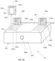
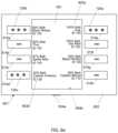
- FIG. 6 ais a front perspective view of a charging station according to an example embodiment.
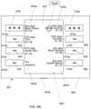
- the data from the sensorsis transmitted from the beacon to the tracking server 103 using the wireless communication subsystem, and the tracking server 103 uses this information to compute the position or orientation, or both, of the beacon.
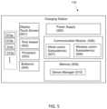
- Information about the battery useincluding remaining charge information (e.g. as a percentage or as time remaining, or both), is also transmitted using the wireless communication subsystem to one or more charging stations 110 , so that the one or more charging stations can display remaining battery charge information for the given beacon.
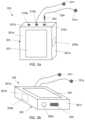
- the beaconalso detects when a working light source is connected to a given port 215 a , 215 b , 215 c , etc., and this information is displayed on the display screen 201 . In this way, a user can visually discern if a light source connected to a port in the beacon is emitting light or not. It will be appreciated that when using an infrared light source (e.g. infrared LED), a user cannot see whether the light source is working by looking at the infrared light source. An indicator that is visible to the user, such as on the display screen 201 , informs the user.
- an infrared light sourcee.g. infrared LED
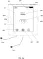
- pressing one of the buttons 205 a , 205 b , 205 cmomentarily illuminates the display. In dark or low-light environments, this helps a user to see the GUIs displayed on the display.
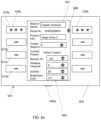
- one or more configuration optionsare provided to change a setting of the beacon, or to change an ID of the beacon, or both.
- each charging portis a connector 600 that provides power and transfers data.
- the connector 600connects to the port 302 of a given beacon.
- the connector 600is a male USB-C connector and the port 302 is a female USB-C connector. It will be appreciated that other types of connectors can be used.
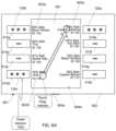
- the actor for the Hulkcan now take the beacon 120 a . This allows for a very quick swap of beacons, as well as beacon settings.
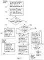
- Block 701The charging station receives user input via the touch screen to set a beacon ID, or to modify another beacon setting, in association with a given charging port (also referred to as “CP” in FIG. 7 ).
- This user inputfor example, can be updated via the detailed view as shown in FIG. 6 c , or can be a swapping gesture in FIG. 6 d , or some other type of input.
- block 704 and 705are executed.
- the electronic displayis an electronic paper display.
- the given tracking beaconwirelessly transmits status data to the charging station, and the status data is shown on the display of the charging station.
- a beacon setting updateis made via the GUI in relation to an empty charging port and, after the given tracking beacon is inserted into the empty charging port, the given tracking beacon is automatically updated with the beacon setting update.
Landscapes
- Engineering & Computer Science (AREA)
- Theoretical Computer Science (AREA)
- General Engineering & Computer Science (AREA)
- Physics & Mathematics (AREA)
- General Physics & Mathematics (AREA)
- Power Engineering (AREA)
- Human Computer Interaction (AREA)
- Computer Hardware Design (AREA)
- Multimedia (AREA)
- Signal Processing (AREA)
- Charge And Discharge Circuits For Batteries Or The Like (AREA)
Abstract
Description
Claims (14)
Priority Applications (2)
| Application Number | Priority Date | Filing Date | Title |
|---|---|---|---|
| US17/095,311US11599257B2 (en) | 2019-11-12 | 2020-11-11 | Electronic tracking device and charging apparatus |
| US18/110,696US11829596B2 (en) | 2019-11-12 | 2023-02-16 | Electronic tracking device and charging apparatus |
Applications Claiming Priority (2)
| Application Number | Priority Date | Filing Date | Title |
|---|---|---|---|
| US201962934215P | 2019-11-12 | 2019-11-12 | |
| US17/095,311US11599257B2 (en) | 2019-11-12 | 2020-11-11 | Electronic tracking device and charging apparatus |
Related Child Applications (1)
| Application Number | Title | Priority Date | Filing Date |
|---|---|---|---|
| US18/110,696ContinuationUS11829596B2 (en) | 2019-11-12 | 2023-02-16 | Electronic tracking device and charging apparatus |
Publications (2)
| Publication Number | Publication Date |
|---|---|
| US20210141520A1 US20210141520A1 (en) | 2021-05-13 |
| US11599257B2true US11599257B2 (en) | 2023-03-07 |
Family
ID=75847511
Family Applications (2)
| Application Number | Title | Priority Date | Filing Date |
|---|---|---|---|
| US17/095,311ActiveUS11599257B2 (en) | 2019-11-12 | 2020-11-11 | Electronic tracking device and charging apparatus |
| US18/110,696ActiveUS11829596B2 (en) | 2019-11-12 | 2023-02-16 | Electronic tracking device and charging apparatus |
Family Applications After (1)
| Application Number | Title | Priority Date | Filing Date |
|---|---|---|---|
| US18/110,696ActiveUS11829596B2 (en) | 2019-11-12 | 2023-02-16 | Electronic tracking device and charging apparatus |
Country Status (1)
| Country | Link |
|---|---|
| US (2) | US11599257B2 (en) |
Cited By (2)
| Publication number | Priority date | Publication date | Assignee | Title |
|---|---|---|---|---|
| US20220187408A1 (en)* | 2019-05-13 | 2022-06-16 | Cast Group Of Companies Inc. | Electronic tracking device and related system |
| US11829596B2 (en) | 2019-11-12 | 2023-11-28 | Cast Group Of Companies Inc. | Electronic tracking device and charging apparatus |
Citations (71)
| Publication number | Priority date | Publication date | Assignee | Title |
|---|---|---|---|---|
| US4542291A (en)* | 1982-09-29 | 1985-09-17 | Vpl Research Inc. | Optical flex sensor |
| US4631676A (en)* | 1983-05-25 | 1986-12-23 | Hospital For Joint Diseases Or | Computerized video gait and motion analysis system and method |
| US4665928A (en)* | 1983-08-10 | 1987-05-19 | Orthotronics, Inc. | Range of motion measuring and displaying device |
| US4988981A (en)* | 1987-03-17 | 1991-01-29 | Vpl Research, Inc. | Computer data entry and manipulation apparatus and method |
| US5229756A (en)* | 1989-02-07 | 1993-07-20 | Yamaha Corporation | Image control apparatus |
| US5372365A (en)* | 1991-01-22 | 1994-12-13 | Sportsense, Inc. | Methods and apparatus for sports training |
| US5429140A (en)* | 1993-06-04 | 1995-07-04 | Greenleaf Medical Systems, Inc. | Integrated virtual reality rehabilitation system |
| US5524637A (en)* | 1994-06-29 | 1996-06-11 | Erickson; Jon W. | Interactive system for measuring physiological exertion |
| US5583478A (en)* | 1995-03-01 | 1996-12-10 | Renzi; Ronald | Virtual environment tactile system |
| US5638300A (en)* | 1994-12-05 | 1997-06-10 | Johnson; Lee E. | Golf swing analysis system |
| US5641288A (en)* | 1996-01-11 | 1997-06-24 | Zaenglein, Jr.; William G. | Shooting simulating process and training device using a virtual reality display screen |
| US5790076A (en)* | 1995-08-28 | 1998-08-04 | Sypniewski; Jozef | Tracking sensor specially for computer applications |
| US5826578A (en)* | 1994-05-26 | 1998-10-27 | Curchod; Donald B. | Motion measurement apparatus |
| US5844824A (en)* | 1995-10-02 | 1998-12-01 | Xybernaut Corporation | Hands-free, portable computer and system |
| US5846086A (en)* | 1994-07-01 | 1998-12-08 | Massachusetts Institute Of Technology | System for human trajectory learning in virtual environments |
| US5913727A (en)* | 1995-06-02 | 1999-06-22 | Ahdoot; Ned | Interactive movement and contact simulation game |
| US5914701A (en)* | 1995-05-08 | 1999-06-22 | Massachusetts Institute Of Technology | Non-contact system for sensing and signalling by externally induced intra-body currents |
| US5930741A (en)* | 1995-02-28 | 1999-07-27 | Virtual Technologies, Inc. | Accurate, rapid, reliable position sensing using multiple sensing technologies |
| US5963891A (en)* | 1997-04-24 | 1999-10-05 | Modern Cartoons, Ltd. | System for tracking body movements in a virtual reality system |
| US6005548A (en)* | 1996-08-14 | 1999-12-21 | Latypov; Nurakhmed Nurislamovich | Method for tracking and displaying user's spatial position and orientation, a method for representing virtual reality for a user, and systems of embodiment of such methods |
| US6097369A (en)* | 1991-12-16 | 2000-08-01 | Wambach; Mark L. | Computer mouse glove |
| US6353932B2 (en)* | 2000-06-22 | 2002-03-12 | Alan I. Stembridge | Martial arts Gi with targets |
| US20020036617A1 (en)* | 1998-08-21 | 2002-03-28 | Timothy R. Pryor | Novel man machine interfaces and applications |
| US20030014212A1 (en)* | 2001-07-12 | 2003-01-16 | Ralston Stuart E. | Augmented vision system using wireless communications |
| US6512947B2 (en)* | 2001-04-05 | 2003-01-28 | David G. Bartholome | Heart rate monitoring system with illuminated floor mat |
| US6597443B2 (en)* | 2001-06-27 | 2003-07-22 | Duane Boman | Spatial tracking system |
| US6691074B1 (en)* | 2001-02-08 | 2004-02-10 | Netmore Ltd. | System for three dimensional positioning and tracking |
| US6701296B1 (en)* | 1988-10-14 | 2004-03-02 | James F. Kramer | Strain-sensing goniometers, systems, and recognition algorithms |
| US6710713B1 (en)* | 2002-05-17 | 2004-03-23 | Tom Russo | Method and apparatus for evaluating athletes in competition |
| US6757068B2 (en)* | 2000-01-28 | 2004-06-29 | Intersense, Inc. | Self-referenced tracking |
| US20040143176A1 (en)* | 1998-04-17 | 2004-07-22 | Massachusetts Institute Of Technology, A Massachusetts Corporation | Motion tracking system |
| US20040219498A1 (en)* | 2002-04-09 | 2004-11-04 | Davidson Lance Samuel | Training apparatus and methods |
| US6909420B1 (en)* | 1998-12-03 | 2005-06-21 | Nicolas Frederic | Device indicating movements for software |
| US6984208B2 (en)* | 2002-08-01 | 2006-01-10 | The Hong Kong Polytechnic University | Method and apparatus for sensing body gesture, posture and movement |
| US7046151B2 (en)* | 2003-07-14 | 2006-05-16 | Michael J. Dundon | Interactive body suit and interactive limb covers |
| US20070021208A1 (en)* | 2002-07-27 | 2007-01-25 | Xiadong Mao | Obtaining input for controlling execution of a game program |
| US20070250286A1 (en)* | 2003-07-01 | 2007-10-25 | Queensland University Of Technology | Motion Monitoring and Analysis System |
| US7292151B2 (en)* | 2004-07-29 | 2007-11-06 | Kevin Ferguson | Human movement measurement system |
| US7331871B2 (en)* | 2004-05-05 | 2008-02-19 | Miguel Lopez | Tactile signal-producing vest worn while playing a video game |
| US7602301B1 (en)* | 2006-01-09 | 2009-10-13 | Applied Technology Holdings, Inc. | Apparatus, systems, and methods for gathering and processing biometric and biomechanical data |
| US7698830B2 (en)* | 2001-02-23 | 2010-04-20 | Microstrain, Inc. | Posture and body movement measuring system |
| US20100105475A1 (en)* | 2005-10-26 | 2010-04-29 | Sony Computer Entertainment Inc. | Determining location and movement of ball-attached controller |
| US7712365B1 (en)* | 2004-11-23 | 2010-05-11 | Terry L. James | Accelerometer for data collection and communication |
| US7725279B2 (en)* | 2007-03-15 | 2010-05-25 | Xsens Technologies, B.V. | System and a method for motion tracking using a calibration unit |
| US20100164862A1 (en)* | 2008-12-31 | 2010-07-01 | Lucasfilm Entertainment Company Ltd. | Visual and Physical Motion Sensing for Three-Dimensional Motion Capture |
| US7755602B2 (en)* | 1995-11-30 | 2010-07-13 | Immersion Corporation | Tactile feedback man-machine interface device |
| US7774155B2 (en)* | 2006-03-10 | 2010-08-10 | Nintendo Co., Ltd. | Accelerometer-based controller |
| US7980141B2 (en)* | 2007-07-27 | 2011-07-19 | Robert Connor | Wearable position or motion sensing systems or methods |
| US8019121B2 (en)* | 2002-07-27 | 2011-09-13 | Sony Computer Entertainment Inc. | Method and system for processing intensity from input devices for interfacing with a computer program |
| US20120025945A1 (en)* | 2010-07-27 | 2012-02-02 | Cyberglove Systems, Llc | Motion capture data glove |
| US20120050535A1 (en)* | 2010-08-31 | 2012-03-01 | Gilray Densham | System and method for tracking |
| US8231506B2 (en)* | 2008-12-05 | 2012-07-31 | Nike, Inc. | Athletic performance monitoring systems and methods in a team sports environment |
| US8323106B2 (en)* | 2008-05-30 | 2012-12-04 | Sony Computer Entertainment America Llc | Determination of controller three-dimensional location using image analysis and ultrasonic communication |
| US8328691B2 (en)* | 2007-02-14 | 2012-12-11 | Koninklijke Philips Electronics N.V. | Feedback device for guiding and supervising physical excercises |
| US8636605B2 (en)* | 2006-03-01 | 2014-01-28 | Acushnet Company | IR system for kinematic analysis |
| US8639666B2 (en) | 2008-09-05 | 2014-01-28 | Cast Group Of Companies Inc. | System and method for real-time environment tracking and coordination |
| US9055226B2 (en) | 2010-08-31 | 2015-06-09 | Cast Group Of Companies Inc. | System and method for controlling fixtures based on tracking data |
| US9177387B2 (en)* | 2003-02-11 | 2015-11-03 | Sony Computer Entertainment Inc. | Method and apparatus for real time motion capture |
| US9350923B2 (en) | 2010-08-31 | 2016-05-24 | Cast Group Of Companies Inc. | System and method for tracking |
| US9538156B2 (en) | 2011-01-31 | 2017-01-03 | Cast Group Of Companies Inc. | System and method for providing 3D sound |
| US9573056B2 (en)* | 2005-10-26 | 2017-02-21 | Sony Interactive Entertainment Inc. | Expandable control device via hardware attachment |
| US9582072B2 (en)* | 2013-09-17 | 2017-02-28 | Medibotics Llc | Motion recognition clothing [TM] with flexible electromagnetic, light, or sonic energy pathways |
| US20170140617A1 (en)* | 2015-11-16 | 2017-05-18 | W. W. Grainger, Inc. | Methods and apparatus for securing a tracking beacon to personal protection equipment |
| US9822956B2 (en) | 2012-01-05 | 2017-11-21 | Cast Group Of Companies Inc. | System and method for calibrating a fixture configured to rotate and/or translate |
| US9823634B2 (en) | 2012-04-24 | 2017-11-21 | Cast Group Of Companies Inc. | System and method for providing three-dimensional paths |
| US20180196585A1 (en) | 2017-01-10 | 2018-07-12 | Cast Group Of Companies Inc. | Systems and Methods for Tracking and Interacting With Zones in 3D Space |
| US20190138107A1 (en)* | 2016-10-11 | 2019-05-09 | Valve Corporation | Virtual reality hand gesture generation |
| US20190280535A1 (en)* | 2018-03-12 | 2019-09-12 | Mediatek Inc. | Combined Wireless Charging And Position Tracking |
| US10437658B2 (en)* | 2013-06-06 | 2019-10-08 | Zebra Technologies Corporation | Method, apparatus, and computer program product for collecting and displaying sporting event data based on real time data for proximity and movement of objects |
| US10455874B2 (en)* | 2014-10-17 | 2019-10-29 | Yamaha Corporation | Data glove |
| US20200363490A1 (en)* | 2019-05-13 | 2020-11-19 | Cast Group Of Companies Inc. | Electronic tracking device and related system |
Family Cites Families (20)
| Publication number | Priority date | Publication date | Assignee | Title |
|---|---|---|---|---|
| US7156310B2 (en) | 1990-09-17 | 2007-01-02 | Metrologic Instruments, Inc. | Automatically-activated hand-supportable laser scanning bar code symbol reading system with data transmission activation switch |
| US5347387A (en) | 1992-03-24 | 1994-09-13 | Rice Robert C | Self-aligning optical transceiver |
| US5513854A (en)* | 1993-04-19 | 1996-05-07 | Daver; Gil J. G. | System used for real time acquistion of data pertaining to persons in motion |
| US6825980B2 (en) | 1995-12-18 | 2004-11-30 | Metrologic Instruments, Inc. | DOE-based systems and devices for producing laser beams having modified beam characteristics |
| US7123413B2 (en) | 1995-12-18 | 2006-10-17 | Metrologic Instruments, Inc. | DOE-based systems and devices for producing laser beams having modified beam characteristics |
| DE69920969T2 (en) | 1998-12-03 | 2005-10-20 | Metrologic Instruments Inc. | Automatically activated, portable laser bar code scanner with data transfer device |
| US7445550B2 (en)* | 2000-02-22 | 2008-11-04 | Creative Kingdoms, Llc | Magical wand and interactive play experience |
| US8313379B2 (en)* | 2005-08-22 | 2012-11-20 | Nintendo Co., Ltd. | Video game system with wireless modular handheld controller |
| EP2050544B1 (en) | 2005-09-30 | 2011-08-31 | iRobot Corporation | Robot system with wireless communication by TCP/IP transmissions |
| US7705736B1 (en) | 2008-01-18 | 2010-04-27 | John Kedziora | Method and apparatus for data logging of physiological and environmental variables for domestic and feral animals |
| US20120235579A1 (en) | 2008-04-14 | 2012-09-20 | Digital Lumens, Incorporated | Methods, apparatus and systems for providing occupancy-based variable lighting |
| US9626786B1 (en)* | 2010-07-19 | 2017-04-18 | Lucasfilm Entertainment Company Ltd. | Virtual-scene control device |
| US11232626B2 (en)* | 2011-12-21 | 2022-01-25 | Twenieth Century Fox Film Corporation | System, method and apparatus for media pre-visualization |
| US9104373B1 (en)* | 2012-10-16 | 2015-08-11 | Nova Solutions, Inc. | Electronic tablet storage and management apparatus and system |
| US9576425B2 (en)* | 2013-03-15 | 2017-02-21 | Nguyen Gaming Llc | Portable intermediary trusted device |
| US20160113581A1 (en)* | 2013-06-07 | 2016-04-28 | Healthwatch Ltd. | Docking station for smart garments |
| US20150097946A1 (en) | 2013-10-03 | 2015-04-09 | Jigabot, Llc | Emitter device and operating methods |
| WO2016092451A1 (en) | 2014-12-09 | 2016-06-16 | Basf Se | Optical detector |
| CN112585838B (en)* | 2018-11-21 | 2024-02-09 | 华为数字能源技术有限公司 | Out-of-band communication during wireless battery charging |
| US11599257B2 (en)* | 2019-11-12 | 2023-03-07 | Cast Group Of Companies Inc. | Electronic tracking device and charging apparatus |
- 2020
- 2020-11-11USUS17/095,311patent/US11599257B2/enactiveActive
- 2023
- 2023-02-16USUS18/110,696patent/US11829596B2/enactiveActive
Patent Citations (79)
| Publication number | Priority date | Publication date | Assignee | Title |
|---|---|---|---|---|
| US4542291A (en)* | 1982-09-29 | 1985-09-17 | Vpl Research Inc. | Optical flex sensor |
| US4631676A (en)* | 1983-05-25 | 1986-12-23 | Hospital For Joint Diseases Or | Computerized video gait and motion analysis system and method |
| US4665928A (en)* | 1983-08-10 | 1987-05-19 | Orthotronics, Inc. | Range of motion measuring and displaying device |
| US4988981B1 (en)* | 1987-03-17 | 1999-05-18 | Vpl Newco Inc | Computer data entry and manipulation apparatus and method |
| US4988981A (en)* | 1987-03-17 | 1991-01-29 | Vpl Research, Inc. | Computer data entry and manipulation apparatus and method |
| US6701296B1 (en)* | 1988-10-14 | 2004-03-02 | James F. Kramer | Strain-sensing goniometers, systems, and recognition algorithms |
| US5229756A (en)* | 1989-02-07 | 1993-07-20 | Yamaha Corporation | Image control apparatus |
| US5372365A (en)* | 1991-01-22 | 1994-12-13 | Sportsense, Inc. | Methods and apparatus for sports training |
| US6097369A (en)* | 1991-12-16 | 2000-08-01 | Wambach; Mark L. | Computer mouse glove |
| US5429140A (en)* | 1993-06-04 | 1995-07-04 | Greenleaf Medical Systems, Inc. | Integrated virtual reality rehabilitation system |
| US5826578A (en)* | 1994-05-26 | 1998-10-27 | Curchod; Donald B. | Motion measurement apparatus |
| US5524637A (en)* | 1994-06-29 | 1996-06-11 | Erickson; Jon W. | Interactive system for measuring physiological exertion |
| US5846086A (en)* | 1994-07-01 | 1998-12-08 | Massachusetts Institute Of Technology | System for human trajectory learning in virtual environments |
| US5638300A (en)* | 1994-12-05 | 1997-06-10 | Johnson; Lee E. | Golf swing analysis system |
| US5930741A (en)* | 1995-02-28 | 1999-07-27 | Virtual Technologies, Inc. | Accurate, rapid, reliable position sensing using multiple sensing technologies |
| US5583478A (en)* | 1995-03-01 | 1996-12-10 | Renzi; Ronald | Virtual environment tactile system |
| US5914701A (en)* | 1995-05-08 | 1999-06-22 | Massachusetts Institute Of Technology | Non-contact system for sensing and signalling by externally induced intra-body currents |
| US5913727A (en)* | 1995-06-02 | 1999-06-22 | Ahdoot; Ned | Interactive movement and contact simulation game |
| US5790076A (en)* | 1995-08-28 | 1998-08-04 | Sypniewski; Jozef | Tracking sensor specially for computer applications |
| US5844824A (en)* | 1995-10-02 | 1998-12-01 | Xybernaut Corporation | Hands-free, portable computer and system |
| US7755602B2 (en)* | 1995-11-30 | 2010-07-13 | Immersion Corporation | Tactile feedback man-machine interface device |
| US5641288A (en)* | 1996-01-11 | 1997-06-24 | Zaenglein, Jr.; William G. | Shooting simulating process and training device using a virtual reality display screen |
| US6005548A (en)* | 1996-08-14 | 1999-12-21 | Latypov; Nurakhmed Nurislamovich | Method for tracking and displaying user's spatial position and orientation, a method for representing virtual reality for a user, and systems of embodiment of such methods |
| US5963891A (en)* | 1997-04-24 | 1999-10-05 | Modern Cartoons, Ltd. | System for tracking body movements in a virtual reality system |
| US20040143176A1 (en)* | 1998-04-17 | 2004-07-22 | Massachusetts Institute Of Technology, A Massachusetts Corporation | Motion tracking system |
| US20020036617A1 (en)* | 1998-08-21 | 2002-03-28 | Timothy R. Pryor | Novel man machine interfaces and applications |
| US6909420B1 (en)* | 1998-12-03 | 2005-06-21 | Nicolas Frederic | Device indicating movements for software |
| US6757068B2 (en)* | 2000-01-28 | 2004-06-29 | Intersense, Inc. | Self-referenced tracking |
| US6353932B2 (en)* | 2000-06-22 | 2002-03-12 | Alan I. Stembridge | Martial arts Gi with targets |
| US6691074B1 (en)* | 2001-02-08 | 2004-02-10 | Netmore Ltd. | System for three dimensional positioning and tracking |
| US7698830B2 (en)* | 2001-02-23 | 2010-04-20 | Microstrain, Inc. | Posture and body movement measuring system |
| US6512947B2 (en)* | 2001-04-05 | 2003-01-28 | David G. Bartholome | Heart rate monitoring system with illuminated floor mat |
| US6597443B2 (en)* | 2001-06-27 | 2003-07-22 | Duane Boman | Spatial tracking system |
| US20030014212A1 (en)* | 2001-07-12 | 2003-01-16 | Ralston Stuart E. | Augmented vision system using wireless communications |
| US20040219498A1 (en)* | 2002-04-09 | 2004-11-04 | Davidson Lance Samuel | Training apparatus and methods |
| US6710713B1 (en)* | 2002-05-17 | 2004-03-23 | Tom Russo | Method and apparatus for evaluating athletes in competition |
| US20070021208A1 (en)* | 2002-07-27 | 2007-01-25 | Xiadong Mao | Obtaining input for controlling execution of a game program |
| US8019121B2 (en)* | 2002-07-27 | 2011-09-13 | Sony Computer Entertainment Inc. | Method and system for processing intensity from input devices for interfacing with a computer program |
| US6984208B2 (en)* | 2002-08-01 | 2006-01-10 | The Hong Kong Polytechnic University | Method and apparatus for sensing body gesture, posture and movement |
| US9177387B2 (en)* | 2003-02-11 | 2015-11-03 | Sony Computer Entertainment Inc. | Method and apparatus for real time motion capture |
| US20070250286A1 (en)* | 2003-07-01 | 2007-10-25 | Queensland University Of Technology | Motion Monitoring and Analysis System |
| US7046151B2 (en)* | 2003-07-14 | 2006-05-16 | Michael J. Dundon | Interactive body suit and interactive limb covers |
| US7331871B2 (en)* | 2004-05-05 | 2008-02-19 | Miguel Lopez | Tactile signal-producing vest worn while playing a video game |
| US7292151B2 (en)* | 2004-07-29 | 2007-11-06 | Kevin Ferguson | Human movement measurement system |
| US7712365B1 (en)* | 2004-11-23 | 2010-05-11 | Terry L. James | Accelerometer for data collection and communication |
| US10279254B2 (en)* | 2005-10-26 | 2019-05-07 | Sony Interactive Entertainment Inc. | Controller having visually trackable object for interfacing with a gaming system |
| US20100105475A1 (en)* | 2005-10-26 | 2010-04-29 | Sony Computer Entertainment Inc. | Determining location and movement of ball-attached controller |
| US9573056B2 (en)* | 2005-10-26 | 2017-02-21 | Sony Interactive Entertainment Inc. | Expandable control device via hardware attachment |
| US7821407B2 (en)* | 2006-01-09 | 2010-10-26 | Applied Technology Holdings, Inc. | Apparatus, systems, and methods for gathering and processing biometric and biomechanical data |
| US7602301B1 (en)* | 2006-01-09 | 2009-10-13 | Applied Technology Holdings, Inc. | Apparatus, systems, and methods for gathering and processing biometric and biomechanical data |
| US20120143093A1 (en)* | 2006-01-09 | 2012-06-07 | Applied Technology Holdings, Inc. | Apparatus, systems, and methods for gathering and processing biometric and biomechanical data |
| US8636605B2 (en)* | 2006-03-01 | 2014-01-28 | Acushnet Company | IR system for kinematic analysis |
| US7774155B2 (en)* | 2006-03-10 | 2010-08-10 | Nintendo Co., Ltd. | Accelerometer-based controller |
| US8328691B2 (en)* | 2007-02-14 | 2012-12-11 | Koninklijke Philips Electronics N.V. | Feedback device for guiding and supervising physical excercises |
| US7725279B2 (en)* | 2007-03-15 | 2010-05-25 | Xsens Technologies, B.V. | System and a method for motion tracking using a calibration unit |
| US7980141B2 (en)* | 2007-07-27 | 2011-07-19 | Robert Connor | Wearable position or motion sensing systems or methods |
| US8323106B2 (en)* | 2008-05-30 | 2012-12-04 | Sony Computer Entertainment America Llc | Determination of controller three-dimensional location using image analysis and ultrasonic communication |
| US8639666B2 (en) | 2008-09-05 | 2014-01-28 | Cast Group Of Companies Inc. | System and method for real-time environment tracking and coordination |
| US8938431B2 (en) | 2008-09-05 | 2015-01-20 | Cast Group Of Companies Inc. | System and method for real-time environment tracking and coordination |
| US8231506B2 (en)* | 2008-12-05 | 2012-07-31 | Nike, Inc. | Athletic performance monitoring systems and methods in a team sports environment |
| US20100164862A1 (en)* | 2008-12-31 | 2010-07-01 | Lucasfilm Entertainment Company Ltd. | Visual and Physical Motion Sensing for Three-Dimensional Motion Capture |
| US20120025945A1 (en)* | 2010-07-27 | 2012-02-02 | Cyberglove Systems, Llc | Motion capture data glove |
| US9055226B2 (en) | 2010-08-31 | 2015-06-09 | Cast Group Of Companies Inc. | System and method for controlling fixtures based on tracking data |
| US8854594B2 (en)* | 2010-08-31 | 2014-10-07 | Cast Group Of Companies Inc. | System and method for tracking |
| US9350923B2 (en) | 2010-08-31 | 2016-05-24 | Cast Group Of Companies Inc. | System and method for tracking |
| US9747697B2 (en) | 2010-08-31 | 2017-08-29 | Cast Group Of Companies Inc. | System and method for tracking |
| US20120050535A1 (en)* | 2010-08-31 | 2012-03-01 | Gilray Densham | System and method for tracking |
| US9538156B2 (en) | 2011-01-31 | 2017-01-03 | Cast Group Of Companies Inc. | System and method for providing 3D sound |
| US9822956B2 (en) | 2012-01-05 | 2017-11-21 | Cast Group Of Companies Inc. | System and method for calibrating a fixture configured to rotate and/or translate |
| US9823634B2 (en) | 2012-04-24 | 2017-11-21 | Cast Group Of Companies Inc. | System and method for providing three-dimensional paths |
| US10437658B2 (en)* | 2013-06-06 | 2019-10-08 | Zebra Technologies Corporation | Method, apparatus, and computer program product for collecting and displaying sporting event data based on real time data for proximity and movement of objects |
| US9582072B2 (en)* | 2013-09-17 | 2017-02-28 | Medibotics Llc | Motion recognition clothing [TM] with flexible electromagnetic, light, or sonic energy pathways |
| US10455874B2 (en)* | 2014-10-17 | 2019-10-29 | Yamaha Corporation | Data glove |
| US20170140617A1 (en)* | 2015-11-16 | 2017-05-18 | W. W. Grainger, Inc. | Methods and apparatus for securing a tracking beacon to personal protection equipment |
| US20190138107A1 (en)* | 2016-10-11 | 2019-05-09 | Valve Corporation | Virtual reality hand gesture generation |
| US20180196585A1 (en) | 2017-01-10 | 2018-07-12 | Cast Group Of Companies Inc. | Systems and Methods for Tracking and Interacting With Zones in 3D Space |
| US20210042019A1 (en)* | 2017-01-10 | 2021-02-11 | Cast Group Of Companies Inc. | Systems and Methods for Tracking and Interacting With Zones in 3D Space |
| US20190280535A1 (en)* | 2018-03-12 | 2019-09-12 | Mediatek Inc. | Combined Wireless Charging And Position Tracking |
| US20200363490A1 (en)* | 2019-05-13 | 2020-11-19 | Cast Group Of Companies Inc. | Electronic tracking device and related system |
Non-Patent Citations (3)
| Title |
|---|
| "BlackTrax Unveils Version 2.2"; Lighting And Sound America; retrieved Aug. 5, 2021; published Oct. 16, 2017; URL:<http://www.lightingandsoundamerica.com/news/story.asp?ID=4UP6S>. |
| "BlackTrax Wiki—History:BTBeacon—Preview of version 9"; CAST Group of Companies Inc.; retrieved Aug. 5, 2021; published Feb. 24, 2016; URL:<http://wiki.blacktrax.ca/tiki-pagehistory.php?page=BTBeacon&preview=99>. |
| "BlackTrax Wiki—History:BTSmart Charger—Preview of version 12"; CAST Group of Companies Inc.; retrieved Aug. 5, 2021; published Apr. 15, 2019; URL:<http://wiki.blacktrax.ca/tiki-pagehistory.php?page=BTSmart+Charger&preview=12>. |
Cited By (3)
| Publication number | Priority date | Publication date | Assignee | Title |
|---|---|---|---|---|
| US20220187408A1 (en)* | 2019-05-13 | 2022-06-16 | Cast Group Of Companies Inc. | Electronic tracking device and related system |
| US11879959B2 (en)* | 2019-05-13 | 2024-01-23 | Cast Group Of Companies Inc. | Electronic tracking device and related system |
| US11829596B2 (en) | 2019-11-12 | 2023-11-28 | Cast Group Of Companies Inc. | Electronic tracking device and charging apparatus |
Also Published As
| Publication number | Publication date |
|---|---|
| US20210141520A1 (en) | 2021-05-13 |
| US11829596B2 (en) | 2023-11-28 |
| US20230195297A1 (en) | 2023-06-22 |
Similar Documents
| Publication | Publication Date | Title |
|---|---|---|
| US11829596B2 (en) | Electronic tracking device and charging apparatus | |
| WO2018128475A1 (en) | Augmented reality control of internet of things devices | |
| CN110800260B (en) | Method for operating augmented reality device, augmented reality device and storage medium | |
| JP2018036869A5 (en) | ||
| JP5258558B2 (en) | Method for control of equipment | |
| EP2782359B1 (en) | Air conditioner and remote control | |
| US8747224B2 (en) | Operating device | |
| EP2830398B1 (en) | Lighting system for registering a lighting apparatus | |
| US20070229671A1 (en) | Remote control system including remote controller with image pickup function | |
| ES2795409T3 (en) | Home automation system | |
| CN103706116A (en) | Expanding operating device and operating system | |
| CN104837433A (en) | Medical control system | |
| CN114503178A (en) | Imaging device for shelf support and shelf system comprising the imaging device | |
| US20210405701A1 (en) | Dockable apparatus for automatically-initiated control of external devices | |
| US20190005636A1 (en) | Methods and systems for operating an apparatus through augmented reality | |
| CN104700604A (en) | Equipment remote control method, device and terminal | |
| CN105706436A (en) | Information processing device, imaging device, imaging system, information processing device control method, imaging device control method and program | |
| CN101479689A (en) | NFC enabled pointing with a mobile device | |
| CN114116110A (en) | Augmented reality-based smart interface | |
| KR101684682B1 (en) | Suspension apparatus for smart-phone, security camera, remote-control system and control method thereof using smart-phone with suspension apparatus | |
| JP2018528493A (en) | Self-balancing car control method, apparatus, program, and recording medium | |
| WO2015119917A1 (en) | Remote monitoring system for handheld electronic devices | |
| US11717257B2 (en) | Fetal ultrasound monitoring method and system | |
| KR101845675B1 (en) | Desktop robot dispenser system using wireless controller | |
| US20240272767A1 (en) | Computer-implemented method, computer, and program for rendering a three-dimensional object in a virtual reality space |
Legal Events
| Date | Code | Title | Description |
|---|---|---|---|
| FEPP | Fee payment procedure | Free format text:ENTITY STATUS SET TO UNDISCOUNTED (ORIGINAL EVENT CODE: BIG.); ENTITY STATUS OF PATENT OWNER: SMALL ENTITY | |
| FEPP | Fee payment procedure | Free format text:ENTITY STATUS SET TO SMALL (ORIGINAL EVENT CODE: SMAL); ENTITY STATUS OF PATENT OWNER: SMALL ENTITY | |
| AS | Assignment | Owner name:CAST GROUP OF COMPANIES INC., CANADA Free format text:ASSIGNMENT OF ASSIGNORS INTEREST;ASSIGNORS:DENSHAM, GILRAY;GORDON, ANDREW;DENSHAM, AARON;SIGNING DATES FROM 20201110 TO 20201111;REEL/FRAME:054674/0437 | |
| AS | Assignment | Owner name:U.S. BANK NATIONAL ASSOCIATION, AS COLLATERAL AGENT, MINNESOTA Free format text:SECURITY INTEREST;ASSIGNOR:CORE SCIENTIFIC, INC.;REEL/FRAME:055996/0839 Effective date:20210419 | |
| STPP | Information on status: patent application and granting procedure in general | Free format text:DOCKETED NEW CASE - READY FOR EXAMINATION | |
| STPP | Information on status: patent application and granting procedure in general | Free format text:NON FINAL ACTION MAILED | |
| STPP | Information on status: patent application and granting procedure in general | Free format text:RESPONSE TO NON-FINAL OFFICE ACTION ENTERED AND FORWARDED TO EXAMINER | |
| STPP | Information on status: patent application and granting procedure in general | Free format text:FINAL REJECTION MAILED | |
| STPP | Information on status: patent application and granting procedure in general | Free format text:DOCKETED NEW CASE - READY FOR EXAMINATION | |
| STPP | Information on status: patent application and granting procedure in general | Free format text:AWAITING TC RESP., ISSUE FEE NOT PAID | |
| STPP | Information on status: patent application and granting procedure in general | Free format text:NOTICE OF ALLOWANCE MAILED -- APPLICATION RECEIVED IN OFFICE OF PUBLICATIONS | |
| STCF | Information on status: patent grant | Free format text:PATENTED CASE | |
| FEPP | Fee payment procedure | Free format text:ENTITY STATUS SET TO UNDISCOUNTED (ORIGINAL EVENT CODE: BIG.); ENTITY STATUS OF PATENT OWNER: LARGE ENTITY |