US11599107B2 - Apparatus, methods and systems for remote or onboard control of flights - Google Patents
Apparatus, methods and systems for remote or onboard control of flightsDownload PDFInfo
- Publication number
- US11599107B2 US11599107B2US17/110,576US202017110576AUS11599107B2US 11599107 B2US11599107 B2US 11599107B2US 202017110576 AUS202017110576 AUS 202017110576AUS 11599107 B2US11599107 B2US 11599107B2
- Authority
- US
- United States
- Prior art keywords
- control
- controller
- wheel
- control target
- throttle setting
- Prior art date
- Legal status (The legal status is an assumption and is not a legal conclusion. Google has not performed a legal analysis and makes no representation as to the accuracy of the status listed.)
- Active
Links
Images


Classifications
- G—PHYSICS
- G05—CONTROLLING; REGULATING
- G05D—SYSTEMS FOR CONTROLLING OR REGULATING NON-ELECTRIC VARIABLES
- G05D1/00—Control of position, course, altitude or attitude of land, water, air or space vehicles, e.g. using automatic pilots
- G05D1/0011—Control of position, course, altitude or attitude of land, water, air or space vehicles, e.g. using automatic pilots associated with a remote control arrangement
- G05D1/0016—Control of position, course, altitude or attitude of land, water, air or space vehicles, e.g. using automatic pilots associated with a remote control arrangement characterised by the operator's input device
- B—PERFORMING OPERATIONS; TRANSPORTING
- B64—AIRCRAFT; AVIATION; COSMONAUTICS
- B64C—AEROPLANES; HELICOPTERS
- B64C13/00—Control systems or transmitting systems for actuating flying-control surfaces, lift-increasing flaps, air brakes, or spoilers
- B64C13/02—Initiating means
- B64C13/04—Initiating means actuated personally
- B64C13/10—Initiating means actuated personally comprising warning devices
- G—PHYSICS
- G05—CONTROLLING; REGULATING
- G05D—SYSTEMS FOR CONTROLLING OR REGULATING NON-ELECTRIC VARIABLES
- G05D1/00—Control of position, course, altitude or attitude of land, water, air or space vehicles, e.g. using automatic pilots
- G05D1/0011—Control of position, course, altitude or attitude of land, water, air or space vehicles, e.g. using automatic pilots associated with a remote control arrangement
- G05D1/005—Control of position, course, altitude or attitude of land, water, air or space vehicles, e.g. using automatic pilots associated with a remote control arrangement by providing the operator with signals other than visual, e.g. acoustic, haptic
- G—PHYSICS
- G05—CONTROLLING; REGULATING
- G05D—SYSTEMS FOR CONTROLLING OR REGULATING NON-ELECTRIC VARIABLES
- G05D1/00—Control of position, course, altitude or attitude of land, water, air or space vehicles, e.g. using automatic pilots
- G05D1/0055—Control of position, course, altitude or attitude of land, water, air or space vehicles, e.g. using automatic pilots with safety arrangements
- G05D1/0072—Control of position, course, altitude or attitude of land, water, air or space vehicles, e.g. using automatic pilots with safety arrangements to counteract a motor failure
- G—PHYSICS
- G05—CONTROLLING; REGULATING
- G05D—SYSTEMS FOR CONTROLLING OR REGULATING NON-ELECTRIC VARIABLES
- G05D1/00—Control of position, course, altitude or attitude of land, water, air or space vehicles, e.g. using automatic pilots
- G05D1/10—Simultaneous control of position or course in three dimensions
- G05D1/101—Simultaneous control of position or course in three dimensions specially adapted for aircraft
- B—PERFORMING OPERATIONS; TRANSPORTING
- B64—AIRCRAFT; AVIATION; COSMONAUTICS
- B64U—UNMANNED AERIAL VEHICLES [UAV]; EQUIPMENT THEREFOR
- B64U2201/00—UAVs characterised by their flight controls
- B64U2201/20—Remote controls
Definitions
- the present disclosurerelates generally to control systems, and in particular apparatus, methods, and systems for controlling flights of Unmanned Aerial Systems (UAS) as well as onboard-piloted aircraft.
- UASUnmanned Aerial Systems
- Some embodimentsdisclose a controller that includes an interface for controlling the thrust of control targets such as flying objects.
- the controllermay also have a feedback system configured to alert pilots of obstacles that a flying object senses on its flying path.
- FIG. 1is an example schematic of a control system for remote or onboard control of flights, according to an embodiment.
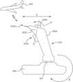
- FIG. 2 Ais a side view illustrating a controller including the control system of FIG. 1 , according to an embodiment.
- FIG. 2 Bis a view illustrating the control system of FIG. 1 , according to an embodiment.
- FIG. 2 Cis a front view illustrating the controller of FIG. 2 A , according to an embodiment.
- FIG. 2 Dis a side view illustrating a controller including the control system of FIG. 1 , according to an embodiment.
- FIG. 2 Eis a cross-sectional side view illustrating a gimbal mechanism of the controller of FIG. 2 D , according to an embodiment.
- FIG. 3 Ais a schematic of a controller with a feedback system configured to communicate with a control target to receive feedback from the control target, according to an embodiment.
- FIG. 3 Bis a cross-sectional top-view of the feedback system of the controller of FIG. 3 A , according to an embodiment.
- FIG. 3 Cis a side view of a schematic of a user handling the controller of FIG. 3 A , according to an embodiment.
- a unified hand controllermay allow a user to control the motion of a target in one or more DoFs, the one or more DoFs including three rotational DoFs (e.g., pitch, yaw, and roll) and three translational DoFs (e.g., movements along x, y and z axes).
- DoFdegrees of freedom
- a unified hand controllermay allow a user to control the motion of a target in one or more DoFs, the one or more DoFs including three rotational DoFs (e.g., pitch, yaw, and roll) and three translational DoFs (e.g., movements along x, y and z axes).
- a unified hand controllermay allow a user to control the motion of a target in three rotational DoFs (e.g., pitch, yaw, and roll) and one translational DoF (e.g., movements along z axis).
- the control systemmay also be configured to allow a user to control the movements of a control target in virtual settings, such as but not limited to gaming environments.
- the control systemmay also allow a user to receive feedback from the control target based on sensory inputs or measurements procured by the control target, whether in real or virtual environments.
- control target 106can be physical or virtual objects, such as remotely controlled objects (e.g., drones, aircraft, fixed-wing aircraft, helicopters, robots, end effectors (e.g., the end of a robotic forceps, a robotic arm end effector), etc.), camera field-of-views (e.g., including a camera center field-of-view and zoom), vehicle velocity vectors, and/or the like.
- remotely controlled objectse.g., drones, aircraft, fixed-wing aircraft, helicopters, robots, end effectors (e.g., the end of a robotic forceps, a robotic arm end effector), etc.
- camera field-of-viewse.g., including a camera center field-of-view and zoom
- vehicle velocity vectorse.g., vehicle velocity vectors, and/or the like.
- the controller 102can be onboard the control target 106 .
- the operator, pilot, etc.may be onboard the control target 106 (e.g., a piloted/crewed flight).
- Other examples of control targets, whether remotely controlled or otherwise,include electric, hybrid, and/or combustion powered aircrafts, remotely operated vehicles (ROVs), crewed submersibles, spacecrafts, and virtual crafts (e.g., operative in a three-dimensional virtual world).
- the controller 102 and the signal conversion system 104may be combined into a single system, while in other embodiments, the controller 102 and the signal conversion system 104 may be separate (e.g., physically distinct, in separate housings, etc.) systems.
- the controller 102includes multiple control members 102 a - 102 n .
- the controller 102may include the first control member 102 a , which in turn may include or incorporate the rest of the control members 102 b - 102 n , i.e., the rest of the control members 102 b - 102 n may be located on the first control member 102 a , which in turn is a part of the controller 102 .
- a controller processor 108 ais coupled to each of the control members 102 a - 102 n .
- the controller processor 108 amay be a central processing unit, a programmable logic controller, and/or a variety of other processors.
- the controller processor 108 amay also be coupled to each of a rotational module 108 b , a translational module 108 c , and a transceiver 108 d .
- connections and/or couplingse.g., wired or wireless
- the controller processor 108 athe rotational module 108 b
- the translational module 108 cthe translational module 108 c
- the transceiver 108 dthere may exist one or more connections and/or couplings (e.g., wired or wireless) between the multiple control members 102 a - 102 n , the controller processor 108 a , the rotational module 108 b , the translational module 108 c , and the transceiver 108 d.
- the signal conversion system 104 in the control system 100includes a transceiver 104 a that may couple to the transceiver 108 d in the controller 102 through a wired connection, a wireless connection, and/or a variety of other connections.
- a conversion processor 104 bis coupled to the transceiver 104 a , a control module 104 c , and configuration parameters 104 d that may be included on a memory, a storage device, and/or other computer-readable mediums.
- the conversion processor 104 bmay be a central processing unit, a programmable logic controller, and/or a variety of other processors.
- connections and/or couplingse.g., wired or wireless
- the control module 104 cmay be coupled to the control target 106 through a wired connection, a wireless connection, and/or a variety of other connections.
- the controller 102is configured to receive input from a user through one of more of the multiple control members 102 a - 102 n and transmit a signal based on the input.
- the controller 102may be provided as a “joystick” or a control stick configured for navigating in a virtual environment (e.g., in a video game, on a real-world simulator, in a virtual reality environment, in an augmented reality environment, as part of a remote control virtual/real-world control system, and/or in a variety of other virtual environments).
- the controller 102may be provided as a control stick for controlling a vehicle, which may be manned or unmanned, such as but not limited to an aircraft, a submersible, a spacecraft, a watercraft, and/or the like. That is, the controller 102 may be provided as a control stick for controlling flying objects such as but not limited to unmanned or remotely-piloted vehicles (e.g., “drones”); manned, unmanned, or remotely-piloted vehicles and land-craft; manned, unmanned, or remotely-piloted aircraft (e.g., fixed-wing aircraft); manned, unmanned, or remotely-piloted watercraft; manned, unmanned, or remotely-piloted submersibles; manned, unmanned, or remotely-piloted space vehicles, rocketry, satellites, and/or the like.
- unmanned or remotely-piloted vehiclese.g., “drones”
- manned, unmanned, or remotely-piloted vehicles and land-craftmanned, unmanned, or remotely
- the controller 102may be provided as a control stick for controlling an electric crewed aerial vehicle, such as, for example, a piloted multirotor drone, often known as an electric-Vertical Takeoff and Land (e-VTOL) aircraft.
- the controller 102may be provided as a control stick for controlling a robot or other non-vehicle device (e.g., a surgical device, an assembly device, and/or the like).
- FIGS. 2 A- 2 Eshow example schematic implementations of the controller 102 (or 202 ).
- Rotational inputs using the first control member 102 amay be detected and/or measured using the rotational module 108 b .
- the rotational module 108 bmay include displacement detectors for detecting the displacement of the first control member 102 a from a starting position as one or more of the pitch inputs, yaw inputs, and roll inputs discussed above.
- Displacement detectorsmay include photo detectors for detecting light beams, rotary and/or linear potentiometers, inductively coupled coils, physical actuators, gyroscopes, switches, transducers, and/or a variety of other displacement detectors.
- the rotational module 108 bmay include accelerometers for detecting the displacement of the first control member 102 a from a starting position in space.
- the accelerometersmay each measure the proper acceleration of the first control member 102 a with respect to an inertial frame of reference.
- inputs using the first control member 102 amay be detected and/or measured using breakout switches, transducers, and/or direct switches for each of the three ranges of motion (e.g., front to back, side to side, and rotation about a longitudinal axis) of the first control member 102 a .
- breakout switchesmay be used to detect when the first control member 102 a is initially moved (e.g., by an angular displacement in the range from about 0.5 degree to about 5 degrees, from about 1 degree to about 3 degrees, about 2 degrees, including values and subranges therebetween) from a null position for each range of rotation; transducers may provide a signal that is proportional to the displacement of the first control member 102 a for each range of motion, and direct switches may detect when the first control member 102 a is further moved (e.g., by an angular displacement in the range from about 10 degrees to about 15 degrees, from about 11 degree to about 13 degrees, about 12 degrees, including values and subranges therebetween) from the null position for each range of motion.
- the breakout switches and direct switchesmay also allow for acceleration of the first control member 102 a to be detected.
- redundant detectors and/or switchesmay be provided in the controller 102 to ensure that the control system 100 is fault tolerant.
- Translational inputs using the second control member 102 bmay be detected and/or measured using the translational module 108 c .
- the translational module 108 cmay include translational detectors for detecting the displacement of the second control member 102 b from a starting position as the z-axis (i.e., vertical motion) inputs discussed above.
- the second control member 102 bcan be a wheel (e.g., knurled wheel) as discussed with reference to FIGS. 2 A-C
- the translational module 108 cmay be configured to detect the rotation of the wheel as input related to the z-axis motion of the control target 106 .
- Translation detectorsmay include physical actuators, translational accelerometers, and/or a variety of other translation detectors (e.g., detectors and switches discussed above for detecting and/or measuring rotational input may be repurposed for detecting and/or measuring translation input).
- the second control member 102 bcan be spring-centered and configured to be pushed down by a user (e.g., towards the surface of the first control member 102 a from which it extends), and pulled up by a user (e.g., away from the surface of the first control member 102 a from which it extends), to, for example, provide Z-axis movement or control of the control target 205 (pushing down causing movement in the negative Z direction, and pulling up causing movement in the positive Z direction, for example).
- the controller processor 108 a of the controller 102is configured to generate control signals to be transmitted by the transceiver 108 d .
- the controller processor 108 amay be configured to generate a control signal based on one or more rotational inputs detected and/or measured by the rotational module 108 b and/or one or more translational inputs detected and/or measured by the translational module 108 c .
- Those control signal generated by the controller processor 108 amay include parameters defining movement output signals for one or more of 4-DOF (i.e., pitch, yaw, roll, movement along a z-axis).
- a discrete control signal type(e.g., yaw output signals, pitch output signals, roll output signals, and z-axis movement output signals) is produced for each discrete predefined movement (e.g., first control member 102 a movement for providing pitch input, first control member 102 a movement for providing yaw input, first control member 102 a movement for providing roll input, and second control member 102 b movement for providing z-axis input) that produces that discrete control signal.
- discrete featuressuch as ON/OFF, trim, and other multi-function commands may be transmitted to the control target 106 .
- data or feedbackmay be received on the controller 102 (e.g., an indicator such as an LED may be illuminated green to indicate the controller 102 is on).
- the transceiver 108 d of the controller 102is configured to transmit the control signal through a wired or wireless connection.
- the control signalmay be one or more of a radio frequency (“RF”) signal, an infrared (“IR”) signal, a visible light signal, and/or a variety of other control signals.
- the transceiver 108 dmay be a BLUETOOTH® transmitter configured to transmit the control signal as an RF signal according to the BLUETOOTH® protocol.
- the transceiver 104 a of the signal conversion system 104is configured to receive the control signal transmitted by the transceiver 108 d of the controller 102 through a wired or wireless connection, discussed above, and provide the received control signal to the conversion processor 104 b of the signal conversion system 104 .
- the transceiver 108 dcan be configured to receive signals (for example, from the transceiver 104 a ).
- the conversion processor 104 bis configured to process the control signals received from the controller 102 .
- the conversion processor 104 bmay be coupled to a computer-readable medium including instructions that, when executed by the conversion processor 104 b , cause the conversion processor 104 b to provide a control program that is configured to convert the control signal into movement commands and use the control module 104 c of the signal conversion system 104 to control the control target 106 according to the movement commands.
- the conversion processor 104 bmay convert the control signal into movement commands for a virtual three-dimensional (“3D”) environment (e.g., a virtual representation of surgical patient, a video game, a simulator, a virtual reality (VR) environment, an augmented virtual reality (AVR environment), and/or a variety of other virtual 3D environments).
- a virtual three-dimensional (“3D”) environmente.g., a virtual representation of surgical patient, a video game, a simulator, a virtual reality (VR) environment, an augmented virtual reality (AVR environment), and/or a variety of other virtual 3D environments.
- the control target 106may exist in a virtual space, and the user may be provided a point of view or a virtual representation of the virtual environment from a point of view inside the control target (i.e., the control system 100 may include a display that provides the user a point of view from the control target in the virtual environment).
- control target 106may be a physical device such as a robot, an end effector, a surgical tool, a lifting system, etc., and/or a variety of steerable mechanical devices, including, without limitation, vehicles such as unmanned or remotely-piloted vehicles (e.g., “drones”); manned, unmanned, or remotely-piloted vehicles and land-craft; manned, unmanned, or remotely-piloted aircraft (e.g., fixed-winged aircraft); manned, unmanned, or remotely-piloted watercraft; manned, unmanned, or remotely-piloted submersibles; as well as manned, unmanned, or remotely-piloted space vehicles, rocketry, satellites, and such like.
- vehiclessuch as unmanned or remotely-piloted vehicles (e.g., “drones”); manned, unmanned, or remotely-piloted vehicles and land-craft; manned, unmanned, or remotely-piloted aircraft (e.g., fixed-winged aircraft); manned, unmanned
- control module 104 c of the signal conversion system 104is configured to control movement of the control target 106 based on the movement commands provided from the control program in signal conversion system 104 .
- control module 104 cmay include an application programming interface (API) for moving a virtual representation or point of view within the virtual environment. API's may also provide the control module 104 c with feedback from the virtual environment such as, for example, collision feedback.
- APIapplication programming interface
- feedback from the control target 106may allow the control module 104 c to automatically adjust the movement of the control target to, for example, avoid a collision with a designated region (e.g., objects in a real or virtual environment, critical regions of a real or virtual patient, etc.).
- a designated regione.g., objects in a real or virtual environment, critical regions of a real or virtual patient, etc.
- the control module 104 cmay include one or more controllers for controlling the movement of the physical device.
- the signal conversion system 104may be installed on-board a vehicle, and the control module 104 c may include a variety of physical controllers for controlling various propulsion and/or steering mechanisms of the vehicle.
- the signal conversion system 104includes operating parameters 104 d for use by the conversion processor 104 b when generating movement commands using the signals from the controller 102 .
- Operating parametersmay include, but are not limited to, gains (i.e., sensitivity), rates of onset (i.e., lag), deadbands (i.e., neutral), limits (i.e., maximum angular displacement), and/or the like.
- the gains of the first control member 102 a and the second control member 102 bmay be independently defined by a user.
- the second control member 102 bmay have increased sensitivity compared to the first control member 102 a to compensate, for example, for the second control member 102 b having a smaller range of motion that the first control member 102 a .
- the rates of onset for the first control member 102 a and the second control member 102 bmay be defined independently to determine the amount of time that should pass (i.e., lag) before a repositioning of the first control member 102 a and the second control member 102 b should be converted to actual movement of the control target 106 .
- the limits and deadbands of the first control member 102 a and the second control member 102 bmay be independently defined as well by calibrating the neutral and maximal positions of each.
- operating parametersmay also define how signals sent from the controller 102 in response to the different movements of the first control member 102 a and the second control member 102 b are translated into movement commands that are sent to the control target.
- particular movements of the first control member 102 amay produce pitch, yaw, and roll rotational movement output signals, while particular movements of the second control member 102 b may produce z-axis (i.e., vertical) translational movement output signals.
- the operating parametersmay define which movement commands are sent to the control target 106 in response to movements and resulting movement output signals from the first control member 102 a and second control member 102 b.
- the operating parameters 104 dmay be received from an external computing device (not shown) operated by the user.
- the external computing devicemay be preconfigured with software for interfacing with the controller 102 and/or the signal conversion system 104 .
- the operating parameters 104 dmay be input directly by a user using a display screen included with the controller 102 or the signal conversion system 104 .
- the first control member 102 a and/or second control member 102 bmay be used to navigate a configuration menu for defining the operating parameters 104 d.
- the controller 202includes a control stick 202 a as the first control member 102 a that is configured to be repositioned by the user with respect to the base 208 .
- the repositioning of the control stick 202 aallows the user to provide rotational inputs using the first control member 102 a (e.g., three degrees of freedom) that include pitch inputs, yaw inputs, and roll inputs, and causes the controller processor 108 a to output rotational movement output signals including pitch movement output signals, a yaw movement output signals, and roll movement output signals.
- tilting the control stick 202 a forward and backward along the axis “A”FIG.
- the movement output signals that result from the repositioning of the first control member 102 amay be reconfigured from that discussed above such that similar movements of the first control member 102 a to those discussed above result in different inputs and movement output signals (e.g., tilting the control stick 202 a side to side along the axis “C” with respect to the base 208 may be configured to provide the yaw input that produces the yaw movement output signal while rotating the control stick 202 a about its longitudinal axis may be configured provide the roll input that produces the roll movement output signal).
- movement output signalse.g., tilting the control stick 202 a side to side along the axis “C” with respect to the base 208 may be configured to provide the yaw input that produces the yaw movement output signal while rotating the control stick 202 a about its longitudinal axis may be configured provide the roll input that produces the roll movement output signal).
- the control stick 202 aincludes a wheel 202 b (e.g., knurled wheel) as one of the multiple control members 202 b - 202 n .
- the wheel 202 bcan be the second control member 102 b that is configured to be rotated by the user of the controller 202 about or with respect to the axis “D” ( FIGS. 2 A and 2 C ) along the line E ( FIG. 2 A ).
- the rotation of the second control member 102 ballows the user to provide translational movement input to the controller using the second control member 102 b and causes the controller processor 108 a to output translational movement output signals including vertical or z-axis movement output signals.
- the translational movement inputmay include input related to the throttle thrust (e.g., when the control target is a fixed-wing aircraft) and direction of the second control member 102 b .
- a user of the controller 102may apply a force on the wheel 202 b to cause the wheel 202 b to rotate in a forward direction or backward direction along the line E and about or with respect to the axis “D”.
- the translational movement inputcan include the throttle setting of the wheel 202 b after the force is applied (e.g., corresponding to the thrust of the throttle) and/or the direction of the force (e.g., corresponding to the direction of the throttle), and the translational movement output signals generated by the controller processor 108 a as a result of the input can include output signals related to the speed of the control target 205 and/or the direction of the movement of the control target 205 (e.g., up (+z axis) or down ( ⁇ z axis) direction), respectively.
- the wheel 202 bmay include markings 210 that include values or modes of the throttle setting of the wheel 202 b , such a throttle setting corresponding to the mobility state of the control target 205 such as but not limited to an “off” setting corresponding to the engine/motor(s) of the control target 205 being turned off, an “idle” setting corresponding to the engine/motor(s) of the control target 205 being idled, and/or one or more settings corresponding to the control target 106 being in motion (e.g., traveling in the vertical or z-direction at “low” speed, “high” speed, etc.).
- a throttle setting corresponding to the mobility state of the control target 205such as but not limited to an “off” setting corresponding to the engine/motor(s) of the control target 205 being turned off, an “idle” setting corresponding to the engine/motor(s) of the control target 205 being idled, and/or one or more settings corresponding to the control target 106 being in motion (e.g., traveling
- the controller 202may include an indicator 212 (e.g., a tab) that is configured to identify the marking that aligns with the indicator 212 when the wheel 202 b comes to rest as the throttle setting of the wheel 202 b .
- an indicator 212e.g., a tab
- the controller 202 and the wheel 202 bmay be positioned relative to each other such that the indicator 212 is aligned with the marking on the wheel 202 b identifying the throttle setting of the wheel 202 b as “off” or “idle”, respectively.
- a usermay then apply force onto the wheel 202 b to rotate the wheel 202 b such that the indicator 212 aligns with the marking on the wheel 202 b identifying the throttle setting of the wheel 202 b as “low,” “high,” or any other throttle setting.
- the responsiveness of the second control member 102 b to an applied force by a usermay be regulated by another control member (e.g., one or more of the control members 102 c - 102 n ).
- another control membere.g., one or more of the control members 102 c - 102 n .
- the responsiveness of the wheel 202 b to the amount of force applied on the wheel 202 b when changing the throttle setting of the wheel 202 bmay be regulated by a tension tuner 202 c that is configured to vary the friction experienced by the wheel 202 b as the wheel 202 b rotates under the influence of the force. That is, the throttle setting of the wheel 202 b may be adjusted by the tension tuner 202 c .
- the amount of force one may have to apply to the wheel 202 b to produce a given amount of control target speedmay be varied using the tension tuner 202 c .
- the tension tuner 202 cmay have a range of settings (values or modes, for example), and when the tension tuner 202 c is set at different values or modes, a user may have to apply different amounts of force to the wheel 202 b to produce same control target speed.
- the controller 102may include a safety mechanism 202 d configured to prevent the unintended rotation of the wheel 202 b , and as such unintended change in the throttle setting of the wheel 202 b , which may correspond to unintended change in mobility state of the control target 205 .
- the safety mechanism 202 dcan be one of the multiple control members 102 a - 102 n and may be configured to prevent the wheel 202 b from rotating along the line E (i.e., about or with respect to the axis “D”) (even when force is applied by the user, for example) unless the safety mechanism is deactivated (e.g., a preceding or concurrent action is taken with respect to the safety mechanism 202 d ).
- the safety mechanism 202 dmay include a ball plunger that would have to be depressed for the safety mechanism 202 d to allow the wheel 202 b to rotate when a force is applied on the wheel 202 b by the user.
- no throttle setting of the wheel 202 bmay be changed unless the safety mechanism 102 d is deactivated.
- a first set of throttle settings of the wheel 202 bmay not be changed to a second set of throttle settings unless the safety mechanism 202 d is deactivated, while other changes can occur without deactivating the safety mechanism 202 d .
- the safety mechanism 202 dmay be configured such that a throttle setting change from “idle” to “off” may not be allowed unless the safety mechanism 202 d is deactivated (e.g., the ball plunger is depressed), preventing unintended rotation of the wheel 202 b , and consequently unintended change in the mobility state of the control target 106 from “idle” to “off” as well.
- the multiple control members 102 a - 102 ninclude, in addition to the control stick 202 a , the wheel 202 b , the tension tuner 202 c and/or the safety mechanism 202 d , other control members configured to allow a user provide inputs to the controller 202 , and cause the controller processor 108 a to generate output signals for transmission to the control target 205 .
- the other control membersmay also be configured to receive data from the control target 205 and/or external devices (not shown) and display the data (or representation thereof) at a user interface (not shown) of the controller 202 .
- the other control membersmay include a radio communications interface (e.g., push-to-talk radio button), a control member for steering the nose wheel of the control target 205 , a control member for reversing thrust, and/or the like.
- the other control membersmay include a trim control 202 e configured to allow a user input settings for the DoFs of the control target 205 controlled by the controller 202 .
- the trim control 202 emay be configured to allow a user input command settings for one or more of the three rotational DoFs of the control target 205 , i.e., one or more of the pitch, the yaw, and the roll of the control target 205 .
- the trim control 202 emay be configured to allow a user input command settings for the one translational DoF of the control target 205 (e.g., movement along z axis).
- the trim control 202 emay be in the form of trim buttons that allow a user input command settings (e.g., rotational parameters for the pitch, yaw and/or roll of the control target 205 ) for the control target to be guided by during its motion.
- the trim control 202 e(e.g., the set of trim buttons for the pitch, yaw and/or roll) may be configured to be separable from the control stick 202 a .
- the control stick 202 amay include a button (e.g., a push button) configured to cause the release or decoupling of the trim control 202 e from the control stick 202 a when engaged (e.g., pushed).
- control target 205may be powered by multiple power sources, and the controller 202 may be configured to allow a user to control the motion of a control target 205 in the one or more DoFs (e.g., the three rotational DoFs (e.g., pitch, yaw, and roll) and one translational DoF (e.g., longitudinal movement along the x axis such as thrust for a fixed-wing aircraft)) by controlling the individual power sources separately as discussed throughout the instant specification.
- DoFse.g., the three rotational DoFs (e.g., pitch, yaw, and roll) and one translational DoF (e.g., longitudinal movement along the x axis such as thrust for a fixed-wing aircraft)
- control target 205may be a multi-engine flying object
- the control stick 202 amay include multiple wheels 204 where each wheel of the multiple wheels 204 is configured for controlling one engine of the multi-engine control target 205 (e.g., a multi-engine commercial jet aircraft, such as a B737 or the like).
- the multi-engine control target 205e.g., a multi-engine commercial jet aircraft, such as a B737 or the like.
- the safety mechanism 206may also include at least as many safety mechanism elements as the number of wheels of the multiple wheels 204 , and each safety mechanism element may be configured to prevent the unintended rotation of the respective wheel of the multiple wheels 204 .
- the safety mechanism 206can be configured to prevent abrupt shutoff of a motor, engine, rotor, and/or the like associated with the control target. More specifically, the safety mechanism 206 can prevent one or more wheels 204 from moving from an “idle” position to an “off” position when the safety mechanism 206 is engaged, and allow movement from the “idle” position to the “off” position when the safety mechanism 206 is disengaged.
- the multiple wheels 204may be synchronized with each other such that when a user of the controller 202 applies a force on one of the multiple wheels 204 to cause that multiple wheel to rotate, the other(s) of the multiple wheels 204 may also rotate in a substantially similar manner as that multiple wheel. In other implementations, the multiple wheels 204 may not be synchronized and a user may engage the multiple wheels 204 separately to control the multiple power sources of the control target 205 separately.
- a usermay use one of the multiple wheels 204 to idle or shut down one engine of the multi-engine control target 205 (e.g., by aligning the throttle setting “idle” or “off” of that one wheel with the indicator 212 of the controller 202 , respectively) while the other engine is operating.
- the synchronization, or lack thereof, of the multiple wheels 204may be controlled by a synchronicity control element (e.g., a tab) (not shown) that is located on the controller 202 and configured to allow a substantially precise adjustment of the throttle settings of the multiple wheels 204 with one hand of a user while the other hand is placed on the control stick 202 a.
- the controller 202has (a) a first control member 202 a , a joystick-like structure with three independent degrees of movement that is intended to be gripped by a user's hand, and (b) a second control member 202 b mounted on the first control member 202 a for manipulation by a thumb or other digit on the hand of the user that is gripping the first control member 202 a , which enable a user to generate four independent control inputs for commanding movement of the vehicle in four DoFs.
- a proximal end of the first control member 202 ais pivotally connected to the base 208 so that the first control member 202 a can be independently pivoted along an x-axis and independently pivoted along a y-axis.
- the base 208is configured to be supported by a user (e.g. held by a user's hand or otherwise carried on the user's body such as by an arm brace, harness, etc.).
- a base supported by a userprovides a consistent, known reference frame even while moving, e.g., walking, skiing, running, driving, can be used for inspection, security and cinematographic drone missions.
- a resilient membersuch as, for example, a spring, may be positioned between the first control member 202 a and the base 208 in order to provide resilient movement up or down along the longitudinal axis of the first control member 202 a .
- such movement up or down along the longitudinal axis of the first control member relative to the base 208may be configured to generate Z-axis movement (up or down, vertical movement) of the control target.
- movement forward or aft relative to the longitudinal axis of the first control member relative to the base 208may be configured to generate X-axis movement (forward or aft, longitudinal movement) of the control target (e.g., a fixed-wing aircraft).
- the controller 202can include a two-axis gimbal mount 230 that can be used as part of an input device for generating control inputs to command a camera or sensor steering system.
- the two-axis gimbal mount 230can be used to support simultaneous angular displacement and measurement of the angular displacement in two DoFs but may be adapted by locking one DoF to be used to support a first control member 202 a (e.g., as shown in FIG. 2 D ) for displacement in a single DoF.
- the gimbalcan be mounted in a base, such as base 208 . Its post 222 can couple the gimbal mount 230 to the first control member 202 a .
- the first control member 202 apivots the post 222 about two orthogonal axes that intersect at the center of the gimbal. One axis remains fixed relative to the base and the other rotates about the fixed axis.
- Two-axis gimbal mount 230is a representative example of a two-axis gimbal that has been adapted to generate to haptic feedback upon the first control member 202 a leaving and reentering a predefined null position for each of these two axes of rotation.
- the detents for generating force feedback for rotation about the locked or blocked axiscould be omitted.
- the gimbalcan be comprised of two members: a first member 232 that remains fixed with respect to base 236 and a second member 228 that is constrained by the first member 232 to rotate about a single axis or to rotate about each of two orthogonal axes, and to otherwise restrict relative rotation of the first and second members 232 , 228 around any other axis.
- a post 222is coupled to the second member 228 to pivot about each of the two orthogonal axes. If the second member 228 is restricted to rotate only about one of the two orthogonal axes, the post 222 is coupled with the second member 228 so that it is can pivot about the second axis without rotating the second member 228 .
- a ball (i.e., the second member) 228is mounted within a socket (i.e., the first member) 232 .
- An extension 234 of the post 222fits within a complementary opening formed in the ball 228 so that angular displacement or pivoting of the post 222 also rotates the ball 228 .
- the ball 228is retained within the socket 232 so that it can freely rotate within the socket 232 in two DoFs, about each of two axes that are mutually orthogonal to each other, with one of the two axes remaining fixed relative to the base 236 of the gimbal mount 230 .
- the base 236is representative of a structure for mounting the gimbal on to the base 208 , against which the first control member 202 a may react.
- a cap 238 that is connected with the post 222extends over a spherically-shaped outer surface of the socket 232 and has a complementary, spherical inner surface. Pivoting of the post 222 moves the cap relative to the socket.
- socket 232can complement and support rotation of the ball 228
- the ball 228can, in alternative embodiments, be supported for rotation about one or both mutually orthogonal axes of rotation in other ways and by other means, including by one or more shafts or axles that support rotation of the ball 228 relative to the socket 232 .
- the ball 228 and inside surfaces of the socket 232need not be spherical or complementary.
- the controller 202can be configured to control a crewed aerial vehicle with distributed electric propulsion (with electrical power supplied by a battery and/or hybrid system), such as, for example, a piloted multirotor drone, with or without wings to generate additional lift.
- the first control member 202 acan include a spring-centered mechanism, as described in further detail herein, thereby providing translational control (e.g., subtle translation) along the X, Y, and Z axis, as well as rotational control (e.g., yaw), as described in various embodiments herein.
- the wheels 204can each control a separate thrust component (e.g., a pusher prop behind the piloted multirotor drone).
- one thrust componentcan provide for levitation and orientation
- a second thrust componentcan provide for speed (e.g., a “go fast”) control, e.g., once safe cruise altitude is achieved.
- the control target 306such as but not limited to remotely-piloted vehicles (e.g., “drones”), land-craft, aircraft (e.g., fixed-wing aircraft), watercraft, submersibles, space vehicles, rocketry, satellites, a surgical device, an assembly or industrial device, and/or the like may be equipped with detectors configured to sense objects 304 in the vicinity of the control target 306 and/or obstacles along the travel path of the control target 306 .
- the detectorsmay be configured to detect still as well as moving objects that pose a risk of collision with the control target 306 .
- the detectorsmay be configured to detect still objects that are within a specified radius of the control target 306 .
- the detectorsmay be configured to detect moving objects that are within a specified radius of the control target and are traveling at greater than a given velocity.
- detectorsinclude light detecting and ranging (LIDAR) systems, radar, GPS (with reference to a MAP), ADS-B (for avoiding other aircraft), video (and associated video analytics).
- LIDARlight detecting and ranging
- radarradar
- GPSwith reference to a MAP
- ADS-Bfor avoiding other aircraft
- videoand associated video analytics
- the control target 306may provide feedback to the controller 302 controlling the control target 306 regarding the presence and status of the sensed objects or obstacles 304 .
- the detectors and/or other communication system operatively coupled to the control target 306may transmit data to the controller 302 (e.g., to the transceiver 104 a of the controller 302 ), the data including sensed object information such as but not limited to the distance of the sensed object 304 from the control target 306 , the angular displacement of the sensed object 304 from the control target 306 , the velocity of the sensed object 304 if the sensed object is in motion, and/or the like.
- the controller 302may include a control module (not shown) (e.g., such as the control module 104 c ) configured to analyze the received data and generate signals configured to trigger, based on the result of the analysis, user feedback systems located within the controller 302 .
- the received datamay include successive data including location information of a sensed object 304 , and the analysis may determine the speed and direction of a sensed object or obstacle 304 approaching the control target 306 .
- the received datamay already include the information related to the speed and direction of the approach of the sensed object or obstacle 304 .
- control modulemay trigger a feedback system of the controller 302 in a manner that informs the user of the controller 302 the direction (e.g., from the perspective of the control target 306 ) at which the sensed object or obstacle 304 is located or from which the sensed object or obstacle 304 is approaching, and/or the rate at which the sensed object or obstacle 304 is approaching the control target 306 .
- the feedback systeminforms the user of the controller 302 information related to objects or obstacles 304 sensed by the control target 306 can depend on the feedback elements of the controller 302 .
- the feedbackmay be in the form of haptic feedback
- the feedback elements of the controller 302can be one or more vibration haptic motors 308 a - 308 n located or positioned on or within the controller 302 (e.g., two, three, four, five, six, seven, eight, etc., vibration haptic motors 308 a - 308 n ).
- control module of the controller 302may generate signals that are configured to cause the vibration haptic motors 308 a - 308 n of the controller vibrate according to a pre-defined relationship between the pattern of vibration of the vibration haptic motors 308 a - 308 n and information related to the sensed objects or obstacles 304 .
- the rate of vibration of the vibration haptic motors 308 a - 308 nmay be related to the distance of the sensed objects or obstacles 304 .
- the control modulemay generate signals that increase the rate of vibration of the vibration haptic motors 308 a - 308 n (e.g., this can occur in real-time or nearly real-time as the data is continuously or substantially continuously sent from the control target 306 to the controller 302 ).
- the pre-defined relationship between the pattern of vibration of the vibration haptic motors 308 a - 308 n and information related to the sensed objects or obstacles 304may inform which one(s) of the vibration haptic motors 308 a - 308 n may vibrate depending on the information.
- the control modulemay generate a signal that causes the vibration haptic motor that is on the right side of the controller to vibrate.
- FIG. 3 Bshows a top cross-sectional view of an example distribution of vibration haptic motors 308 a - 308 n within the controller 302 .
- the “right” vibration haptic motorwhich is closest to the palm of a user handling the controller (e.g., FIG. 3 C ), may vibrate, indicating or informing the user that the control target 306 is being approached by an object or obstacle from the right side of the control target 306 .
- the vibration haptic motors 308 a - 308 nmay be located within the controller 302 .
- one or more of the vibration haptic motors 308 a - 308 nmay be part of or integral to other features of the controller 302 .
- the controller 302may include a thumb saddle 310 for resting a thumb of a user handling the controller (e.g., FIG. 3 C ), and one or more of the vibration haptic motors 308 a - 308 n may be integral to the thumb saddle 310 .
- the controller 302may include a control button 312 (e.g., such as but not limited to the trim control 202 e ), and one or more of the vibration haptic motors 308 a - 308 n may be integral to the control button 312 .
- a control button 312e.g., such as but not limited to the trim control 202 e
- one or more of the vibration haptic motors 308 a - 308 nmay be integral to the control button 312 .
- each of the vibration haptic motors 308 a - 308 ncan be vibrationally isolated with vibration absorbent materials, thus allowing for discrete vibration signals to be transferred to the hand grip of the controller 302 .
- the pilot or operatoris given spatially distinct feedback, e.g., an approaching aircraft on the left side, etc.
- the feedbackmay include visual feedback
- the feedback elements of the controller 302can be one or more light sources (not shown) such as but not limited to LEDs, etc., located on the controller 302 and configured to illuminate in response to the signals from the control module.
- the control module of the controller 302may generate signals that are configured to cause the light sources to light up according to a pre-defined relationship between the pattern of illumination of the light sources and information related to the sensed objects or obstacles 304 .
- the pattern, intensity and/or order of illumination of the light sourcesmay be related to the distance of the sensed objects or obstacles 304 and/or the rate at which the sensed objects or obstacles 304 are approaching the control target 306 .
- the control modulemay generate signals that cause the light sources to increase the intensity or their illumination and/or blink rate (e.g., this can occur in real-time or nearly real-time as the data is continuously or substantially continuously sent from the control target 306 to the controller 302 ).
- the pre-defined relationship between the pattern of illumination of the light sources and information related to the sensed objects or obstacles 304may inform which one(s) of the light sources may vibrate depending on the information.
- control modulemay generate a signal that causes the light sources on the left side of the controller to light up, while the light sources in the middle and the right side are off.
- inventive embodimentsare presented by way of example only and that, within the scope of the appended claims and equivalents thereto; inventive embodiments may be practiced otherwise than as specifically described and claimed.
- inventive embodiments of the present disclosureare directed to each individual feature, system, article, material, kit, and/or method described herein.
- embodiments of the present technologymay be implemented using hardware, firmware, software or a combination thereof.
- firmware and/or softwarethe firmware and/or software code can be executed on any suitable processor or collection of logic components, whether provided in a single device or distributed among multiple devices.
- inventive conceptsmay be embodied as a computer readable storage medium (or multiple computer readable storage media) (e.g., a computer memory, one or more floppy discs, compact discs, optical discs, magnetic tapes, flash memories, circuit configurations in Field Programmable Gate Arrays or other semiconductor devices, or other non-transitory medium or tangible computer storage medium) encoded with one or more programs that, when executed on one or more computers or other processors, perform methods that implement the various embodiments of the invention discussed above.
- the computer readable medium or mediacan be transportable, such that the program or programs stored thereon can be loaded onto one or more different computers or other processors to implement various aspects of the present invention as discussed above.
- programor “software” are used herein in a generic sense to refer to any type of computer code or set of computer-executable instructions that can be employed to program a computer or other processor to implement various aspects of embodiments as discussed above. Additionally, it should be appreciated that according to one aspect, one or more computer programs that when executed perform methods of the present invention need not reside on a single computer or processor, but may be distributed in a modular fashion amongst a number of different computers or processors to implement various aspects of the present invention.
- Computer-executable instructionsmay be in many forms, such as program modules, executed by one or more computers or other devices.
- program modulesinclude routines, programs, objects, components, data structures, etc. that perform particular tasks or implement particular abstract data types.
- functionality of the program modulesmay be combined or distributed as desired in various embodiments.
- data structuresmay be stored in computer-readable media in any suitable form.
- data structuresmay be shown to have fields that are related through location in the data structure. Such relationships may likewise be achieved by assigning storage for the fields with locations in a computer-readable medium that convey relationship between the fields.
- any suitable mechanismmay be used to establish a relationship between information in fields of a data structure, including through the use of pointers, tags or other mechanisms that establish relationship between data elements.
- a reference to “A and/or B”, when used in conjunction with open-ended language such as “comprising”can refer, in one embodiment, to A only (optionally including elements other than B); in another embodiment, to B only (optionally including elements other than A); in yet another embodiment, to both A and B (optionally including other elements); etc.
- the phrase “at least one,” in reference to a list of one or more elements,should be understood to mean at least one element selected from any one or more of the elements in the list of elements, but not necessarily including at least one of each and every element specifically listed within the list of elements and not excluding any combinations of elements in the list of elements.
- This definitionalso allows that elements may optionally be present other than the elements specifically identified within the list of elements to which the phrase “at least one” refers, whether related or unrelated to those elements specifically identified.
- “at least one of A and B”can refer, in one embodiment, to at least one, optionally including more than one, A, with no B present (and optionally including elements other than B); in another embodiment, to at least one, optionally including more than one, B, with no A present (and optionally including elements other than A); in yet another embodiment, to at least one, optionally including more than one, A, and at least one, optionally including more than one, B (and optionally including other elements); etc.
Landscapes
- Engineering & Computer Science (AREA)
- Physics & Mathematics (AREA)
- Aviation & Aerospace Engineering (AREA)
- Automation & Control Theory (AREA)
- Radar, Positioning & Navigation (AREA)
- Remote Sensing (AREA)
- General Physics & Mathematics (AREA)
- Theoretical Computer Science (AREA)
- Mathematical Physics (AREA)
- Computing Systems (AREA)
- Acoustics & Sound (AREA)
- Human Computer Interaction (AREA)
- Toys (AREA)
- Control Of Position, Course, Altitude, Or Attitude Of Moving Bodies (AREA)
- Mechanical Control Devices (AREA)
Abstract
Description
Claims (30)
Priority Applications (4)
| Application Number | Priority Date | Filing Date | Title |
|---|---|---|---|
| US17/110,576US11599107B2 (en) | 2019-12-09 | 2020-12-03 | Apparatus, methods and systems for remote or onboard control of flights |
| PCT/US2020/063577WO2021118921A1 (en) | 2019-12-09 | 2020-12-07 | Apparatus, methods and systems for remote or onboard control of flights |
| CN202080096083.2ACN115210671A (en) | 2019-12-09 | 2020-12-07 | Apparatus, method and system for remote or onboard control of flight |
| EP20898180.3AEP4073609A4 (en) | 2019-12-09 | 2020-12-07 | Apparatus, methods and systems for remote or onboard control of flights |
Applications Claiming Priority (2)
| Application Number | Priority Date | Filing Date | Title |
|---|---|---|---|
| US201962945339P | 2019-12-09 | 2019-12-09 | |
| US17/110,576US11599107B2 (en) | 2019-12-09 | 2020-12-03 | Apparatus, methods and systems for remote or onboard control of flights |
Publications (2)
| Publication Number | Publication Date |
|---|---|
| US20210173391A1 US20210173391A1 (en) | 2021-06-10 |
| US11599107B2true US11599107B2 (en) | 2023-03-07 |
Family
ID=76209805
Family Applications (1)
| Application Number | Title | Priority Date | Filing Date |
|---|---|---|---|
| US17/110,576ActiveUS11599107B2 (en) | 2019-12-09 | 2020-12-03 | Apparatus, methods and systems for remote or onboard control of flights |
Country Status (4)
| Country | Link |
|---|---|
| US (1) | US11599107B2 (en) |
| EP (1) | EP4073609A4 (en) |
| CN (1) | CN115210671A (en) |
| WO (1) | WO2021118921A1 (en) |
Families Citing this family (13)
| Publication number | Priority date | Publication date | Assignee | Title |
|---|---|---|---|---|
| GB9505259D0 (en) | 1995-03-16 | 1995-05-03 | Sandoz Ltd | Improvements in or relating to organic compounds |
| US20130293362A1 (en) | 2012-05-03 | 2013-11-07 | The Methodist Hospital Research Institute | Multi-degrees-of-freedom hand controller |
| GB2554363B (en) | 2016-09-21 | 2021-12-08 | Cmr Surgical Ltd | User interface device |
| US10198086B2 (en) | 2016-10-27 | 2019-02-05 | Fluidity Technologies, Inc. | Dynamically balanced, multi-degrees-of-freedom hand controller |
| WO2019084505A1 (en) | 2017-10-27 | 2019-05-02 | Fluidity Technologies, Inc. | Multi-axis gimbal mounting for controller providing tactile feedback for the null command |
| CN111566579A (en) | 2017-10-27 | 2020-08-21 | 流体技术股份有限公司 | Camera and sensor controls for remotely operated vehicles and virtual environments |
| WO2019084506A1 (en) | 2017-10-27 | 2019-05-02 | Fluidity Technologies, Inc. | Controller with situational awareness display |
| US11868125B2 (en)* | 2021-07-23 | 2024-01-09 | Yawman LLC | Controlling simulated and remotely controlled flyable aircraft with handheld devices |
| USD992645S1 (en) | 2021-07-23 | 2023-07-18 | Yawman LLC | Handheld controller for a flight simulator or a remotely controlled aircraft |
| US12312067B2 (en)* | 2022-01-24 | 2025-05-27 | Lockheed Martin Corporation | Deadband control for an aircraft |
| US11662835B1 (en)* | 2022-04-26 | 2023-05-30 | Fluidity Technologies Inc. | System and methods for controlling motion of a target object and providing discrete, directional tactile feedback |
| US11696633B1 (en) | 2022-04-26 | 2023-07-11 | Fluidity Technologies Inc. | System and methods for controlling motion of a target object and providing discrete, directional tactile feedback |
| US11911651B1 (en)* | 2023-08-10 | 2024-02-27 | Barron Associates, Inc. | System, device and method for electronically mediated upper extremity therapy |
Citations (191)
| Publication number | Priority date | Publication date | Assignee | Title |
|---|---|---|---|---|
| US3028126A (en) | 1960-05-10 | 1962-04-03 | Euclid C Holleman | Three axis controller |
| US3260826A (en) | 1964-10-26 | 1966-07-12 | Ling Temco Vought Inc | Three-axis and translational movement controller |
| US3394611A (en) | 1966-04-25 | 1968-07-30 | Bell Telephone Labor Inc | Output control device with adjustable self-returning null |
| US4012014A (en) | 1975-09-11 | 1977-03-15 | Mcdonnell Douglas Corporation | Aircraft flight controller |
| US4069720A (en) | 1976-11-05 | 1978-01-24 | Thor Wayne A | Two axis side controller for aircraft |
| US4216467A (en) | 1977-12-22 | 1980-08-05 | Westinghouse Electric Corp. | Hand controller |
| US4306208A (en) | 1978-05-30 | 1981-12-15 | Ledex, Inc. | Joy-stick controller |
| GB2091423A (en) | 1981-01-21 | 1982-07-28 | Bideford Electronics Ltd | Control lever |
| US4420808A (en) | 1980-04-01 | 1983-12-13 | United Technologies Corporation | Multi-axis force stick, self-trimmed aircraft flight control system |
| US4533899A (en) | 1982-12-23 | 1985-08-06 | Akermans Verkstad Ab | Joystick controller with improved motion control with plate having bevelled flat edges that correspond to planes of maneuverability |
| US4584510A (en) | 1982-09-08 | 1986-04-22 | The United States Of America As Represented By The Administrator Of The National Aeronautics And Space Administration | Thumb-actuated two-axis controller |
| US4590339A (en) | 1985-02-19 | 1986-05-20 | Gravis Computer Peripherals Inc. | Joystick |
| US4733214A (en) | 1983-05-23 | 1988-03-22 | Andresen Herman J | Multi-directional controller having resiliently biased cam and cam follower for tactile feedback |
| US4895039A (en) | 1988-07-20 | 1990-01-23 | Honeywell Inc. | Hand controller having pivot axis for minimizing forearm movement |
| US4914976A (en) | 1988-04-13 | 1990-04-10 | Honeywell Inc. | Five and six degree of freedom hand controllers |
| US5042314A (en) | 1989-11-02 | 1991-08-27 | Caterpillar Inc. | Steering and transmission shifting control mechanism |
| US5128671A (en) | 1990-04-12 | 1992-07-07 | Ltv Aerospace And Defense Company | Control device having multiple degrees of freedom |
| US5127608A (en) | 1990-11-06 | 1992-07-07 | Societe Nationale Industrielle Et Aerospatiale | System for integrated pitch and thrust control of an aircraft |
| US5223776A (en) | 1990-12-31 | 1993-06-29 | Honeywell Inc. | Six-degree virtual pivot controller |
| US5317301A (en) | 1992-07-15 | 1994-05-31 | Devolpi Dean | Joy stick |
| US5459382A (en) | 1992-12-02 | 1995-10-17 | Cybernet Systems Corporation | Method and system for providing a tactile virtual reality and manipulator defining an interface device therefor |
| US5503040A (en) | 1993-11-12 | 1996-04-02 | Binagraphics, Inc. | Computer interface device |
| US5532929A (en)* | 1992-12-16 | 1996-07-02 | Toyota Jidosha Kabushiki Kaisha | Apparatus for controlling vehicle driving power |
| US5559432A (en) | 1992-02-27 | 1996-09-24 | Logue; Delmar L. | Joystick generating a polar coordinates signal utilizing a rotating magnetic field within a hollow toroid core |
| US5565891A (en) | 1992-03-05 | 1996-10-15 | Armstrong; Brad A. | Six degrees of freedom graphics controller |
| USD375765S (en) | 1994-12-08 | 1996-11-19 | Snk Corporation | Joystick attachment for a CD ROM video game player |
| US5607158A (en) | 1994-11-28 | 1997-03-04 | Chan; Wah L. | Detachable joystick handle |
| US5617515A (en) | 1994-07-11 | 1997-04-01 | Dynetics, Inc. | Method and apparatus for controlling and programming a robot or other moveable object |
| US5643087A (en) | 1994-05-19 | 1997-07-01 | Microsoft Corporation | Input device including digital force feedback apparatus |
| US5687080A (en) | 1995-06-20 | 1997-11-11 | Ziba Design, Inc. | Multiple axis data input apparatus and method |
| US5694153A (en) | 1995-07-31 | 1997-12-02 | Microsoft Corporation | Input device for providing multi-dimensional position coordinate signals to a computer |
| USD389198S (en) | 1996-04-10 | 1998-01-13 | Sega Enterprises, Ltd. | Controller for video game machine |
| US5749577A (en) | 1995-03-15 | 1998-05-12 | Sega Enterprises, Ltd. | Perpheral input device with six-axis capability |
| US5781180A (en) | 1995-03-15 | 1998-07-14 | Sega Of America, Inc. | Convertible peripheral device |
| US5831408A (en) | 1992-12-02 | 1998-11-03 | Cybernet Systems Corporation | Force feedback system |
| JPH11154031A (en) | 1997-11-24 | 1999-06-08 | Futoshi Shiomi | Joy stick capable of inputting components of three systems at a time with one finger |
| US5963196A (en) | 1995-05-10 | 1999-10-05 | Nintendo Co., Ltd. | Image processing system utilizing analog joystick |
| USH1822H (en) | 1998-12-16 | 1999-12-07 | Caterpillar Inc. | Miniature joystick mounted on a joystick |
| US6024576A (en) | 1996-09-06 | 2000-02-15 | Immersion Corporation | Hemispherical, high bandwidth mechanical interface for computer systems |
| US6068554A (en) | 1997-11-25 | 2000-05-30 | Tyler; Kelly D. | Hand manipulated dual controller assembly |
| US6198471B1 (en) | 1997-11-07 | 2001-03-06 | Brandt A. Cook | Free-floating multi-axis controller |
| US6201196B1 (en) | 1995-06-02 | 2001-03-13 | Gerhard Wergen | Joystick assembly |
| US6222525B1 (en) | 1992-03-05 | 2001-04-24 | Brad A. Armstrong | Image controllers with sheet connected sensors |
| US20010002127A1 (en) | 1999-03-23 | 2001-05-31 | Wen Feng Cheng | Gimbal mounted joy stick with z-axis switch |
| CN1310366A (en) | 2000-02-18 | 2001-08-29 | 罗技欧洲公司 | Forked universal arm force feedback mechanism |
| US20020080112A1 (en) | 2000-09-28 | 2002-06-27 | Braun Adam C. | Directional tactile feedback for haptic feedback interface devices |
| US6429849B1 (en) | 2000-02-29 | 2002-08-06 | Microsoft Corporation | Haptic feedback joystick |
| US20020128064A1 (en) | 2001-03-06 | 2002-09-12 | Sobota John F. | Game controller |
| US6459420B1 (en) | 2000-06-26 | 2002-10-01 | Curtis James Harris | Ergonomical joystick design or attachment |
| US20020148715A1 (en) | 2000-08-25 | 2002-10-17 | Leopold Kostal Gmbh & Co., Kg | Rotating actuator |
| US20020190948A1 (en) | 2001-06-15 | 2002-12-19 | Coutant Alan R. | Arcuate track joystick assembly |
| US20030006956A1 (en) | 1999-05-24 | 2003-01-09 | Charles Yimin Wu | Data entry device recording input in two dimensions |
| US20030038783A1 (en) | 2001-08-27 | 2003-02-27 | Baughman Pamela M. | Wearable ergonomic computer mouse |
| US20030058219A1 (en) | 2001-09-14 | 2003-03-27 | Shaw Stephen W. | Computer mouse input device with multi-axis palm control |
| US6580418B1 (en) | 2000-02-29 | 2003-06-17 | Microsoft Corporation | Three degree of freedom mechanism for input devices |
| US6597347B1 (en) | 1991-11-26 | 2003-07-22 | Itu Research Inc. | Methods and apparatus for providing touch-sensitive input in multiple degrees of freedom |
| US6614420B1 (en) | 1999-02-22 | 2003-09-02 | Microsoft Corporation | Dual axis articulated electronic input device |
| US6624806B2 (en) | 2001-08-27 | 2003-09-23 | Weistech Technology Co., Ltd. | Joystick capable of controlling direction rudder and accelerator synchronously |
| US6630924B1 (en) | 2000-02-22 | 2003-10-07 | International Business Machines Corporation | Gesture sensing split keyboard and approach for capturing keystrokes |
| US6644141B2 (en) | 2000-01-17 | 2003-11-11 | Ponsse Oyg | Arrangement in connection with control device |
| US20030214484A1 (en) | 2002-05-20 | 2003-11-20 | Haywood Chad Christian | Convertible mouse |
| US6664946B1 (en) | 1999-02-22 | 2003-12-16 | Microsoft Corporation | Dual axis articulated computer input device and method of operation |
| US20040082885A1 (en) | 2000-03-14 | 2004-04-29 | Orthologic Corp. | Combination pro/supination and flexion therapeutic mobilization device |
| US20040083940A1 (en) | 2000-02-10 | 2004-05-06 | Shelton Chris D. | Remote operated vehicles |
| US6865342B2 (en) | 2001-07-03 | 2005-03-08 | Matsushita Electric Industrial Co., Ltd. | Operation lever apparatus |
| US20050104742A1 (en) | 2003-11-13 | 2005-05-19 | James Phifer | Ergonomic television remote control |
| US20050159850A1 (en) | 2004-01-16 | 2005-07-21 | Emanuel Melman | Shift knob computer operating device |
| US20050236536A1 (en) | 2004-04-27 | 2005-10-27 | Eagle Fan | Electronic appliance holding device |
| US20050277470A1 (en) | 2004-06-14 | 2005-12-15 | Watanachote Susornpol J | Control unit for controlling a sophisticated character |
| US6989497B1 (en) | 2004-07-22 | 2006-01-24 | Taiwan Pwl Corporation | Rocker lever assembly |
| US6992602B2 (en) | 2000-03-17 | 2006-01-31 | Penny & Giles Controls Limited | Joystick controller |
| US7019732B2 (en) | 2002-01-30 | 2006-03-28 | Mitsumi Electric Co., Ltd. | Joystick |
| US20060137931A1 (en) | 2004-12-23 | 2006-06-29 | Caterpillar Inc. | Steering system with joystick mounted controls |
| US20060156848A1 (en) | 2003-01-13 | 2006-07-20 | Commissariat A L'energie Atomique | Manual simulation interface |
| US20060164383A1 (en) | 2004-12-16 | 2006-07-27 | Media Lab Europe (In Voluntary Liquidation) | Remote controller ring for user interaction |
| US20060224280A1 (en)* | 2005-04-01 | 2006-10-05 | Flanigan Thomas C | Remote vehicle control systems |
| US7131389B1 (en) | 2004-01-22 | 2006-11-07 | Graham Hawkes | Submersible |
| US20060262000A1 (en) | 2005-05-20 | 2006-11-23 | Strong Russell W | Portable controller for operating a device from a remote location |
| US20070080934A1 (en) | 2005-10-11 | 2007-04-12 | Elaine Chen | Human interface input acceleration system |
| WO2007055606A1 (en)* | 2005-11-12 | 2007-05-18 | Cwf Hamilton & Co Limited | Propulsion and control system for a marine vessel |
| US20070144279A1 (en) | 2005-12-27 | 2007-06-28 | Chou-Hsin Wu | Quick-Releasing Linear Actuator |
| US20070156286A1 (en) | 2005-12-30 | 2007-07-05 | Irobot Corporation | Autonomous Mobile Robot |
| US20070262959A1 (en) | 2006-05-12 | 2007-11-15 | Industrial Technology Research Institute | Magnetic joystick |
| US7320263B2 (en) | 2002-10-03 | 2008-01-22 | Parker Hannifin Ab | Controller and method for controlling a control object |
| US20080063400A1 (en) | 2006-05-12 | 2008-03-13 | Irobot Corporation | Method and Device for Controlling a Remote Vehicle |
| US20080132334A1 (en) | 2006-11-17 | 2008-06-05 | Nintendo Co., Ltd. | Game system and storage medium storing game program |
| US20080174550A1 (en) | 2005-02-24 | 2008-07-24 | Kari Laurila | Motion-Input Device For a Computing Terminal and Method of its Operation |
| US20080217147A1 (en) | 2005-07-15 | 2008-09-11 | Michael Martin | Multistage switch |
| US20080278448A1 (en) | 2005-03-30 | 2008-11-13 | Jonas Nilsagard | Control Device |
| US20080282507A1 (en) | 2007-05-14 | 2008-11-20 | Fci Americas Technology, Inc. | Tool arm support |
| US20090030353A1 (en) | 2007-07-25 | 2009-01-29 | Bonutti Peter M | Orthosis Apparatus and Method of Using an Orthosis Apparatus |
| US20090043310A1 (en) | 2005-02-08 | 2009-02-12 | Rasmussen G Lynn | Arthroplasty systems and methods for optimally aligning and tensioning a knee prosthesis |
| US20090084214A1 (en) | 2006-04-28 | 2009-04-02 | Toyo Denson Co., Ltd. | Joystick type switch device |
| US20090152782A1 (en) | 2007-12-17 | 2009-06-18 | Honeywell International, Inc. | User interface with controllable dual spring rate return to null cantilever springs |
| US20090179869A1 (en) | 2008-01-14 | 2009-07-16 | Benjamin Slotznick | Combination thumb keyboard and mouse |
| US7575491B1 (en) | 2007-04-18 | 2009-08-18 | Southern Marine, Inc. | Controller for an electric propulsion system for watercraft |
| US20090213073A1 (en) | 2002-04-12 | 2009-08-27 | Obermeyer Henry K | Multi-Axis Joystick and Transducer Means Therefore |
| US20090248220A1 (en) | 2008-03-27 | 2009-10-01 | Mark Ecton | Remote control system having a touchscreen for controlling a railway vehicle |
| US20090267035A1 (en) | 2008-04-29 | 2009-10-29 | Wood Graham P | Apparatus having a selectively engagable fastener set |
| US20090295724A1 (en) | 2008-05-28 | 2009-12-03 | Wen-Feng Cheng | Adjustable torque joystick |
| US20100097309A1 (en) | 2008-10-16 | 2010-04-22 | Kenichi Nishida | Information processing apparatus and computer-readable recording medium recording information processing program |
| US7793890B2 (en) | 2007-01-31 | 2010-09-14 | Patrick L. Scherer | Control system for an aircraft |
| US7823685B2 (en) | 2007-02-02 | 2010-11-02 | Deere & Company | Operating device for a vehicle |
| US20100302017A1 (en) | 2009-06-01 | 2010-12-02 | Econtrols, Inc. | Tactile Feedback for Joystick Position/Speed Controls |
| US20110088961A1 (en) | 2009-10-19 | 2011-04-21 | Cnh America Llc | Electronic throttle on control handle |
| US7931239B2 (en) | 2002-08-30 | 2011-04-26 | Brad Pedersen | Homeostatic flying hovercraft |
| US20110148667A1 (en) | 2009-12-23 | 2011-06-23 | Tzu-Yuan Yeh | Intelligent multi-axial intuitive joystick suitable for use by both left-handers and right-handers |
| EP1621954B1 (en) | 2004-07-28 | 2011-07-20 | Marquardt GmbH | Electrical joystick |
| US20110213384A1 (en) | 2008-10-31 | 2011-09-01 | Chang Wook Jeong | Surgical robot system having tool for minimally invasive surgery |
| US20110219899A1 (en) | 2010-03-11 | 2011-09-15 | Hdt Robotics, Inc. | HIGH DEGREE OF FREEDOM (DoF) CONTROL ACTUATOR |
| US8089225B2 (en) | 2008-10-29 | 2012-01-03 | Honeywell International Inc. | Systems and methods for inertially controlling a hovering unmanned aerial vehicles |
| US20120012677A1 (en) | 2010-07-16 | 2012-01-19 | Crossley Iii L T Tom | Spray gun handle support and quick release trigger assembly |
| CN102346498A (en) | 2010-07-27 | 2012-02-08 | Pg驱动技术有限公司 | Control device |
| US20120071752A1 (en) | 2010-09-17 | 2012-03-22 | Sewell Christopher M | User interface and method for operating a robotic medical system |
| US20120152052A1 (en) | 2010-11-17 | 2012-06-21 | Katsutoshi Suzuki | Manipulation device |
| US8212770B2 (en) | 2008-02-11 | 2012-07-03 | Caterpillar Inc. | Joystick assembly for improved machine control |
| US20120187238A1 (en) | 2011-01-20 | 2012-07-26 | Future Toys Design Ltd | Helicopter with remote control |
| US8258917B2 (en) | 2010-03-03 | 2012-09-04 | Measurement Systems, Inc. | Intuitive multiple degrees of freedom portable control device |
| US8276476B2 (en) | 2007-10-03 | 2012-10-02 | Caterpillar Inc. | Joystick offset controls |
| US20120249456A1 (en) | 2011-03-29 | 2012-10-04 | Aisin Aw Co., Ltd. | Display device, display method, and display program |
| US8300012B2 (en) | 2008-08-22 | 2012-10-30 | Sony Corporation | Input apparatus, control apparatus, control system, and control method |
| US20120294696A1 (en)* | 2011-05-20 | 2012-11-22 | Harris Corporation | Haptic device for manipulator and vehicle control |
| US20120295501A1 (en)* | 2010-11-05 | 2012-11-22 | Kennon Guglielmo | Apparatus and Method for the Control of Engine Throttle for Inboard and Outboard Boat Motors |
| CN102824746A (en) | 2011-08-30 | 2012-12-19 | 微软公司 | Ergonomic game controller |
| US8345004B1 (en) | 2009-03-06 | 2013-01-01 | Pixar | Methods and apparatus for differentially controlling degrees of freedom of an object |
| US20130020105A1 (en) | 2010-03-24 | 2013-01-24 | Bryan Cook | Ergonomic hand-held power tool and methods of use |
| US8371187B2 (en) | 2004-12-20 | 2013-02-12 | Simon Fraser University | Spherical linkage and force feedback controls |
| US8380402B2 (en) | 2010-09-14 | 2013-02-19 | Bucyrus Intl. Inc. | Control systems and methods for heavy equipment |
| USD678281S1 (en) | 2010-10-21 | 2013-03-19 | Ever Sparkle Technologies Ltd. | Game console |
| US20130081256A1 (en) | 2011-09-30 | 2013-04-04 | Leonard Richiuso | Filter Clamp Lock |
| US20130148273A1 (en) | 2011-12-07 | 2013-06-13 | Wen-Feng Tsai | Mobile electronic device holder |
| US20130147611A1 (en) | 2010-08-31 | 2013-06-13 | Wolfgang Brendel | Radio remote control with position sensor system |
| US8471815B2 (en) | 2010-01-04 | 2013-06-25 | Guillemot Corporation, S.A. | Joystick with compensation springs and corresponding method of manufacture and controller |
| US20130178293A1 (en) | 2011-11-23 | 2013-07-11 | Sony Computer Entertainment Inc. | Gaming Controller |
| US8576168B2 (en) | 2007-12-07 | 2013-11-05 | Sony Corporation | Input apparatus, control apparatus, control system, control method, and handheld apparatus |
| US20130293362A1 (en) | 2012-05-03 | 2013-11-07 | The Methodist Hospital Research Institute | Multi-degrees-of-freedom hand controller |
| US20130296757A1 (en) | 2010-12-15 | 2013-11-07 | Wieland Kaphingst | Orthosis for movement damping |
| US20140083225A1 (en) | 2012-09-25 | 2014-03-27 | Penny & Giles Controls Limited | Control module for an electric wheelchair |
| US8716973B1 (en) | 2011-02-28 | 2014-05-06 | Moog Inc. | Haptic user interface |
| US8770055B2 (en) | 2010-06-11 | 2014-07-08 | Mason Electric Company | Multi-axis pivot assembly for control sticks and associated systems and methods |
| US20140249695A1 (en) | 2013-03-01 | 2014-09-04 | Robotex Inc. | Low latency data link system and method |
| US20140247119A1 (en) | 2007-04-24 | 2014-09-04 | Irobot Corporation | Control System for a Remote Vehicle |
| US20140249944A1 (en) | 2013-01-13 | 2014-09-04 | Bruce J. Hicks | Wearable mobile scanner system with mobile tablet having a mobile pos and enterprise resource planning application for pos customer order fulfillment and in store inventory management for retail establishment |
| US20140311009A1 (en) | 2013-04-17 | 2014-10-23 | Donald Neal Anglin | Light source and firearm magazine holder clamp |
| US8887597B2 (en) | 2001-04-26 | 2014-11-18 | Jlg Industries, Inc. | Split grip control lever for heavy machinery |
| US20150173992A1 (en) | 2013-12-19 | 2015-06-25 | Hiwin Technologies Corp. | Force feedback type complaint orthotic device |
| US20150174737A1 (en) | 2013-12-20 | 2015-06-25 | Chung Li Chen | Bar clamp having a ratchet mechanism for fastening a clamped work piece |
| US20150253801A1 (en) | 2014-03-04 | 2015-09-10 | Deere & Company | Multi-function control grip for work vehicles |
| US9201514B1 (en) | 2008-10-16 | 2015-12-01 | Danfoss Power Solutions Inc. | Joystick grip with integrated display |
| US20160068267A1 (en) | 2014-09-05 | 2016-03-10 | SZ DJI Technology Co., Ltd | Context-based flight mode selection |
| US20160077589A1 (en) | 2014-09-16 | 2016-03-17 | E-Concept | Multidimension vibrating mouse |
| DE102015102317A1 (en) | 2015-02-18 | 2016-08-18 | Elobau Gmbh & Co. Kg | joystick |
| US20160241767A1 (en) | 2015-02-13 | 2016-08-18 | Lg Electronics Inc. | Mobile terminal and method for controlling the same |
| US9501084B1 (en) | 2013-10-10 | 2016-11-22 | SD Technologies, LLC | Wearable electronic device with force feedback |
| US20170121000A1 (en) | 2014-06-04 | 2017-05-04 | Rolls-Royce Ab | Parking position |
| US20170133175A1 (en) | 2015-11-11 | 2017-05-11 | Htc Corporation | Switch assembly and hand-held device |
| US20170175884A1 (en)* | 2015-12-21 | 2017-06-22 | Kabushiki Kaisha Tokai-Rika-Denki-Seisakusho | Shift device |
| US9727076B2 (en) | 2012-10-31 | 2017-08-08 | Sarcos Lc | Hand control device for controlling a peripheral system |
| US20170233983A1 (en) | 2016-02-16 | 2017-08-17 | Caterpillar Inc. | Control device for an implement system |
| US20170246533A1 (en) | 2016-02-26 | 2017-08-31 | Impyrium, Inc. | Joystick Input Apparatus with Living Hinges |
| US20170269587A1 (en) | 2015-09-04 | 2017-09-21 | YooJung Hong | Drone controller |
| US20170277176A1 (en)* | 2016-03-25 | 2017-09-28 | Qualcomm Incorporated | Multi-axis controller |
| US20180055591A1 (en) | 2015-03-27 | 2018-03-01 | Think Surgical, Inc. | Modular wrist guide for surgical instruments |
| US20180081387A1 (en) | 2016-09-20 | 2018-03-22 | Kabushiki Kaisha Tokai Rika Denki Seisakusho | Multidirectional operating device |
| US20180085277A1 (en) | 2015-04-06 | 2018-03-29 | Ekso Bionics, Inc. | Exoskeleton Cord Loop-Type Actuator |
| US9931701B1 (en) | 2017-01-17 | 2018-04-03 | The Boeing Company | Hand tool support device and method |
| US20180161190A1 (en) | 2015-06-22 | 2018-06-14 | curmed GmbH & Co. KG | Device for treating carpal tunnel syndrome of a person's hand |
| US20180164799A1 (en) | 2016-02-24 | 2018-06-14 | YooJung Hong | Object controller |
| US10073488B2 (en) | 2014-09-11 | 2018-09-11 | Grayhill, Inc. | Multifunction joystick apparatus and a method for using same |
| US20180271447A1 (en) | 2017-03-24 | 2018-09-27 | Zhongshan Anbo Health Technology Co., Ltd. | Smart toilet with a function of human blood pressure detection |
| US10152853B2 (en) | 2012-06-13 | 2018-12-11 | University Of Utah Research Foundation | Skin stretch feedback devices, systems, and methods |
| US20180356907A1 (en) | 2016-10-27 | 2018-12-13 | Fluidity Technologies, Inc. | Dynamically Balanced, Multi-Degrees-of-Freedom Hand Controller |
| US20190025869A1 (en) | 2016-10-27 | 2019-01-24 | Fluidity Technologies, Inc. | Dynamically Balanced Multi-Degrees-of-Freedom Hand Controller |
| US20190041891A1 (en) | 2016-10-27 | 2019-02-07 | Fluidity Technologies, Inc. | Dynamically Balanced Multi-Degrees-of-Freedom Hand Controller |
| US20190042003A1 (en) | 2016-10-27 | 2019-02-07 | Fluidity Technologies, Inc. | Controller with Situational Awareness Display |
| US20190042004A1 (en) | 2016-10-27 | 2019-02-07 | Fluidity Technologies, Inc. | Camera and Sensor Controls for Remotely Operated Vehicles and Virtual Environments |
| US20190041894A1 (en) | 2016-10-27 | 2019-02-07 | Fluidity Technologies, Inc. | Multi-Axis Gimbal Mounting for Controller Providing Tactile Feedback for the Null Command |
| US10222794B2 (en) | 2014-09-30 | 2019-03-05 | SZ DJI Technology Co., Ltd. | Remote controller using retaining device |
| US20190071167A1 (en)* | 2017-09-01 | 2019-03-07 | Kitty Hawk Corporation | Decoupled hand controls for aircraft with vertical takeoff and landing and forward flight capabilities |
| WO2019084504A1 (en) | 2017-10-27 | 2019-05-02 | Fluidity Technologies, Inc. | Dynamically balanced, multi-degrees-of-freedom hand held controller |
| WO2019122926A1 (en) | 2017-12-22 | 2019-06-27 | Neoptera Ltd | A tandem wing tail-sitting aircraft with tilting body |
| US20190292751A1 (en)* | 2014-07-31 | 2019-09-26 | Cnh Industrial America Llc | Active Force/Vibration Feedback Control Method and Apparatus for a Movable Machine |
| US20200056741A1 (en) | 2016-02-15 | 2020-02-20 | Honda Motor Co., Ltd. | Orthotic device for use with user-operated tool |
| US20200053995A1 (en) | 2018-08-14 | 2020-02-20 | James Andrews | Attachment kits for fish-landing nets and associated systems and methods |
| US10610438B1 (en) | 2016-11-17 | 2020-04-07 | University Of South Florida | Resistive localized rehabilitation exoskeleton |
| US10768658B2 (en) | 2018-09-25 | 2020-09-08 | Hosiden Corporation | Multi-directional input device |
| US20200387238A1 (en) | 2017-10-27 | 2020-12-10 | Fluidity Technologies Inc. | Controller with situational awareness display |
| US20200385956A1 (en) | 2019-06-06 | 2020-12-10 | Grammer Ag | Manually operable control device |
| US20200387239A1 (en) | 2017-10-27 | 2020-12-10 | Fluidity Technologies Inc. | Camera and sensor controls for remotely operated vehicles and virtual environments |
| US20200393865A1 (en) | 2017-10-27 | 2020-12-17 | Fluidity Technologies Inc. | Multi-axis gimbal mounting for controller providing tactile feedback for the null command |
| US20220269300A1 (en) | 2021-02-25 | 2022-08-25 | Fluidity Technologies Inc. | Multi-axis gimbal and controller comprising same |
Family Cites Families (3)
| Publication number | Priority date | Publication date | Assignee | Title |
|---|---|---|---|---|
| CA2669919C (en)* | 2007-08-08 | 2015-06-23 | Moog Inc. | Control stick adapted for use in a fly-by-wire flight control system, and linkage for use therein |
| US9734726B2 (en)* | 2014-02-17 | 2017-08-15 | The Boeing Company | Systems and methods for providing landing exceedance warnings and avoidance |
| CN110325939B (en)* | 2017-03-09 | 2023-08-01 | 深圳市大疆创新科技有限公司 | System and method for operating an unmanned aerial vehicle |
- 2020
- 2020-12-03USUS17/110,576patent/US11599107B2/enactiveActive
- 2020-12-07CNCN202080096083.2Apatent/CN115210671A/enactivePending
- 2020-12-07WOPCT/US2020/063577patent/WO2021118921A1/ennot_activeCeased
- 2020-12-07EPEP20898180.3Apatent/EP4073609A4/ennot_activeCeased
Patent Citations (229)
| Publication number | Priority date | Publication date | Assignee | Title |
|---|---|---|---|---|
| US3028126A (en) | 1960-05-10 | 1962-04-03 | Euclid C Holleman | Three axis controller |
| US3260826A (en) | 1964-10-26 | 1966-07-12 | Ling Temco Vought Inc | Three-axis and translational movement controller |
| US3394611A (en) | 1966-04-25 | 1968-07-30 | Bell Telephone Labor Inc | Output control device with adjustable self-returning null |
| US4012014A (en) | 1975-09-11 | 1977-03-15 | Mcdonnell Douglas Corporation | Aircraft flight controller |
| US4069720A (en) | 1976-11-05 | 1978-01-24 | Thor Wayne A | Two axis side controller for aircraft |
| US4216467A (en) | 1977-12-22 | 1980-08-05 | Westinghouse Electric Corp. | Hand controller |
| US4306208A (en) | 1978-05-30 | 1981-12-15 | Ledex, Inc. | Joy-stick controller |
| US4420808A (en) | 1980-04-01 | 1983-12-13 | United Technologies Corporation | Multi-axis force stick, self-trimmed aircraft flight control system |
| GB2091423A (en) | 1981-01-21 | 1982-07-28 | Bideford Electronics Ltd | Control lever |
| US4584510A (en) | 1982-09-08 | 1986-04-22 | The United States Of America As Represented By The Administrator Of The National Aeronautics And Space Administration | Thumb-actuated two-axis controller |
| US4533899A (en) | 1982-12-23 | 1985-08-06 | Akermans Verkstad Ab | Joystick controller with improved motion control with plate having bevelled flat edges that correspond to planes of maneuverability |
| US4733214A (en) | 1983-05-23 | 1988-03-22 | Andresen Herman J | Multi-directional controller having resiliently biased cam and cam follower for tactile feedback |
| US4590339A (en) | 1985-02-19 | 1986-05-20 | Gravis Computer Peripherals Inc. | Joystick |
| US4914976A (en) | 1988-04-13 | 1990-04-10 | Honeywell Inc. | Five and six degree of freedom hand controllers |
| US4895039A (en) | 1988-07-20 | 1990-01-23 | Honeywell Inc. | Hand controller having pivot axis for minimizing forearm movement |
| US5042314A (en) | 1989-11-02 | 1991-08-27 | Caterpillar Inc. | Steering and transmission shifting control mechanism |
| US5128671A (en) | 1990-04-12 | 1992-07-07 | Ltv Aerospace And Defense Company | Control device having multiple degrees of freedom |
| US5127608A (en) | 1990-11-06 | 1992-07-07 | Societe Nationale Industrielle Et Aerospatiale | System for integrated pitch and thrust control of an aircraft |
| US5223776A (en) | 1990-12-31 | 1993-06-29 | Honeywell Inc. | Six-degree virtual pivot controller |
| US6597347B1 (en) | 1991-11-26 | 2003-07-22 | Itu Research Inc. | Methods and apparatus for providing touch-sensitive input in multiple degrees of freedom |
| US5559432A (en) | 1992-02-27 | 1996-09-24 | Logue; Delmar L. | Joystick generating a polar coordinates signal utilizing a rotating magnetic field within a hollow toroid core |
| US5565891A (en) | 1992-03-05 | 1996-10-15 | Armstrong; Brad A. | Six degrees of freedom graphics controller |
| US6222525B1 (en) | 1992-03-05 | 2001-04-24 | Brad A. Armstrong | Image controllers with sheet connected sensors |
| US5317301A (en) | 1992-07-15 | 1994-05-31 | Devolpi Dean | Joy stick |
| US5459382A (en) | 1992-12-02 | 1995-10-17 | Cybernet Systems Corporation | Method and system for providing a tactile virtual reality and manipulator defining an interface device therefor |
| US5831408A (en) | 1992-12-02 | 1998-11-03 | Cybernet Systems Corporation | Force feedback system |
| US5459382B1 (en) | 1992-12-02 | 1998-06-09 | Cybernet Systems Corp | Method and system for providing a tactile virtual reality and manipulator defining an interface device therefor |
| US5532929A (en)* | 1992-12-16 | 1996-07-02 | Toyota Jidosha Kabushiki Kaisha | Apparatus for controlling vehicle driving power |
| US5503040A (en) | 1993-11-12 | 1996-04-02 | Binagraphics, Inc. | Computer interface device |
| US5643087A (en) | 1994-05-19 | 1997-07-01 | Microsoft Corporation | Input device including digital force feedback apparatus |
| US5617515A (en) | 1994-07-11 | 1997-04-01 | Dynetics, Inc. | Method and apparatus for controlling and programming a robot or other moveable object |
| US5607158A (en) | 1994-11-28 | 1997-03-04 | Chan; Wah L. | Detachable joystick handle |
| USD375765S (en) | 1994-12-08 | 1996-11-19 | Snk Corporation | Joystick attachment for a CD ROM video game player |
| US5749577A (en) | 1995-03-15 | 1998-05-12 | Sega Enterprises, Ltd. | Perpheral input device with six-axis capability |
| US5781180A (en) | 1995-03-15 | 1998-07-14 | Sega Of America, Inc. | Convertible peripheral device |
| US5963196A (en) | 1995-05-10 | 1999-10-05 | Nintendo Co., Ltd. | Image processing system utilizing analog joystick |
| US6201196B1 (en) | 1995-06-02 | 2001-03-13 | Gerhard Wergen | Joystick assembly |
| US5687080A (en) | 1995-06-20 | 1997-11-11 | Ziba Design, Inc. | Multiple axis data input apparatus and method |
| US5694153A (en) | 1995-07-31 | 1997-12-02 | Microsoft Corporation | Input device for providing multi-dimensional position coordinate signals to a computer |
| USD389198S (en) | 1996-04-10 | 1998-01-13 | Sega Enterprises, Ltd. | Controller for video game machine |
| US6024576A (en) | 1996-09-06 | 2000-02-15 | Immersion Corporation | Hemispherical, high bandwidth mechanical interface for computer systems |
| US6198471B1 (en) | 1997-11-07 | 2001-03-06 | Brandt A. Cook | Free-floating multi-axis controller |
| JPH11154031A (en) | 1997-11-24 | 1999-06-08 | Futoshi Shiomi | Joy stick capable of inputting components of three systems at a time with one finger |
| US6068554A (en) | 1997-11-25 | 2000-05-30 | Tyler; Kelly D. | Hand manipulated dual controller assembly |
| USH1822H (en) | 1998-12-16 | 1999-12-07 | Caterpillar Inc. | Miniature joystick mounted on a joystick |
| US6614420B1 (en) | 1999-02-22 | 2003-09-02 | Microsoft Corporation | Dual axis articulated electronic input device |
| US6664946B1 (en) | 1999-02-22 | 2003-12-16 | Microsoft Corporation | Dual axis articulated computer input device and method of operation |
| US6512509B1 (en) | 1999-03-22 | 2003-01-28 | Logitech Europe S.A. | Forked gimbal arm force feedback mechanism |
| US20010002127A1 (en) | 1999-03-23 | 2001-05-31 | Wen Feng Cheng | Gimbal mounted joy stick with z-axis switch |
| US6353430B2 (en) | 1999-03-23 | 2002-03-05 | Cts Corporation | Gimbal mounted joy stick with z-axis switch |
| US20030006956A1 (en) | 1999-05-24 | 2003-01-09 | Charles Yimin Wu | Data entry device recording input in two dimensions |
| US6644141B2 (en) | 2000-01-17 | 2003-11-11 | Ponsse Oyg | Arrangement in connection with control device |
| US20040083940A1 (en) | 2000-02-10 | 2004-05-06 | Shelton Chris D. | Remote operated vehicles |
| CN1310366A (en) | 2000-02-18 | 2001-08-29 | 罗技欧洲公司 | Forked universal arm force feedback mechanism |
| US6630924B1 (en) | 2000-02-22 | 2003-10-07 | International Business Machines Corporation | Gesture sensing split keyboard and approach for capturing keystrokes |
| US6429849B1 (en) | 2000-02-29 | 2002-08-06 | Microsoft Corporation | Haptic feedback joystick |
| US6580418B1 (en) | 2000-02-29 | 2003-06-17 | Microsoft Corporation | Three degree of freedom mechanism for input devices |
| US20040082885A1 (en) | 2000-03-14 | 2004-04-29 | Orthologic Corp. | Combination pro/supination and flexion therapeutic mobilization device |
| US6992602B2 (en) | 2000-03-17 | 2006-01-31 | Penny & Giles Controls Limited | Joystick controller |
| US6459420B1 (en) | 2000-06-26 | 2002-10-01 | Curtis James Harris | Ergonomical joystick design or attachment |
| US6613997B2 (en) | 2000-08-25 | 2003-09-02 | Leopold Kostal Gmbh & Co. Kg | Control device for a joystick |
| US20020148715A1 (en) | 2000-08-25 | 2002-10-17 | Leopold Kostal Gmbh & Co., Kg | Rotating actuator |
| US20020080112A1 (en) | 2000-09-28 | 2002-06-27 | Braun Adam C. | Directional tactile feedback for haptic feedback interface devices |
| US20020128064A1 (en) | 2001-03-06 | 2002-09-12 | Sobota John F. | Game controller |
| US8887597B2 (en) | 2001-04-26 | 2014-11-18 | Jlg Industries, Inc. | Split grip control lever for heavy machinery |
| US20020190948A1 (en) | 2001-06-15 | 2002-12-19 | Coutant Alan R. | Arcuate track joystick assembly |
| US6865342B2 (en) | 2001-07-03 | 2005-03-08 | Matsushita Electric Industrial Co., Ltd. | Operation lever apparatus |
| US20030038783A1 (en) | 2001-08-27 | 2003-02-27 | Baughman Pamela M. | Wearable ergonomic computer mouse |
| US6624806B2 (en) | 2001-08-27 | 2003-09-23 | Weistech Technology Co., Ltd. | Joystick capable of controlling direction rudder and accelerator synchronously |
| US20030058219A1 (en) | 2001-09-14 | 2003-03-27 | Shaw Stephen W. | Computer mouse input device with multi-axis palm control |
| US7019732B2 (en) | 2002-01-30 | 2006-03-28 | Mitsumi Electric Co., Ltd. | Joystick |
| US20090213073A1 (en) | 2002-04-12 | 2009-08-27 | Obermeyer Henry K | Multi-Axis Joystick and Transducer Means Therefore |
| US20030214484A1 (en) | 2002-05-20 | 2003-11-20 | Haywood Chad Christian | Convertible mouse |
| US7931239B2 (en) | 2002-08-30 | 2011-04-26 | Brad Pedersen | Homeostatic flying hovercraft |
| US7320263B2 (en) | 2002-10-03 | 2008-01-22 | Parker Hannifin Ab | Controller and method for controlling a control object |
| US20060156848A1 (en) | 2003-01-13 | 2006-07-20 | Commissariat A L'energie Atomique | Manual simulation interface |
| US7170420B2 (en) | 2003-11-13 | 2007-01-30 | James Phifer | Ergonomic television remote control |
| US20050104742A1 (en) | 2003-11-13 | 2005-05-19 | James Phifer | Ergonomic television remote control |
| US20050159850A1 (en) | 2004-01-16 | 2005-07-21 | Emanuel Melman | Shift knob computer operating device |
| US7131389B1 (en) | 2004-01-22 | 2006-11-07 | Graham Hawkes | Submersible |
| US20050236536A1 (en) | 2004-04-27 | 2005-10-27 | Eagle Fan | Electronic appliance holding device |
| US20050277470A1 (en) | 2004-06-14 | 2005-12-15 | Watanachote Susornpol J | Control unit for controlling a sophisticated character |
| US6989497B1 (en) | 2004-07-22 | 2006-01-24 | Taiwan Pwl Corporation | Rocker lever assembly |
| EP1621954B1 (en) | 2004-07-28 | 2011-07-20 | Marquardt GmbH | Electrical joystick |
| US20060164383A1 (en) | 2004-12-16 | 2006-07-27 | Media Lab Europe (In Voluntary Liquidation) | Remote controller ring for user interaction |
| US8371187B2 (en) | 2004-12-20 | 2013-02-12 | Simon Fraser University | Spherical linkage and force feedback controls |
| US20060137931A1 (en) | 2004-12-23 | 2006-06-29 | Caterpillar Inc. | Steering system with joystick mounted controls |
| US20090043310A1 (en) | 2005-02-08 | 2009-02-12 | Rasmussen G Lynn | Arthroplasty systems and methods for optimally aligning and tensioning a knee prosthesis |
| US20080174550A1 (en) | 2005-02-24 | 2008-07-24 | Kari Laurila | Motion-Input Device For a Computing Terminal and Method of its Operation |
| US20080278448A1 (en) | 2005-03-30 | 2008-11-13 | Jonas Nilsagard | Control Device |
| US20060224280A1 (en)* | 2005-04-01 | 2006-10-05 | Flanigan Thomas C | Remote vehicle control systems |
| US20060262000A1 (en) | 2005-05-20 | 2006-11-23 | Strong Russell W | Portable controller for operating a device from a remote location |
| US20080217147A1 (en) | 2005-07-15 | 2008-09-11 | Michael Martin | Multistage switch |
| US20070080934A1 (en) | 2005-10-11 | 2007-04-12 | Elaine Chen | Human interface input acceleration system |
| WO2007055606A1 (en)* | 2005-11-12 | 2007-05-18 | Cwf Hamilton & Co Limited | Propulsion and control system for a marine vessel |
| US20070144279A1 (en) | 2005-12-27 | 2007-06-28 | Chou-Hsin Wu | Quick-Releasing Linear Actuator |
| US20070156286A1 (en) | 2005-12-30 | 2007-07-05 | Irobot Corporation | Autonomous Mobile Robot |
| US20090084214A1 (en) | 2006-04-28 | 2009-04-02 | Toyo Denson Co., Ltd. | Joystick type switch device |
| US20070262959A1 (en) | 2006-05-12 | 2007-11-15 | Industrial Technology Research Institute | Magnetic joystick |
| US20080063400A1 (en) | 2006-05-12 | 2008-03-13 | Irobot Corporation | Method and Device for Controlling a Remote Vehicle |
| US7548697B2 (en) | 2006-05-12 | 2009-06-16 | Edison Hudson | Method and device for controlling a remote vehicle |
| US20080132334A1 (en) | 2006-11-17 | 2008-06-05 | Nintendo Co., Ltd. | Game system and storage medium storing game program |
| US7793890B2 (en) | 2007-01-31 | 2010-09-14 | Patrick L. Scherer | Control system for an aircraft |
| US7823685B2 (en) | 2007-02-02 | 2010-11-02 | Deere & Company | Operating device for a vehicle |
| US7575491B1 (en) | 2007-04-18 | 2009-08-18 | Southern Marine, Inc. | Controller for an electric propulsion system for watercraft |
| US20140247119A1 (en) | 2007-04-24 | 2014-09-04 | Irobot Corporation | Control System for a Remote Vehicle |
| US20080282507A1 (en) | 2007-05-14 | 2008-11-20 | Fci Americas Technology, Inc. | Tool arm support |
| US8273043B2 (en) | 2007-07-25 | 2012-09-25 | Bonutti Research, Inc. | Orthosis apparatus and method of using an orthosis apparatus |
| US20090030353A1 (en) | 2007-07-25 | 2009-01-29 | Bonutti Peter M | Orthosis Apparatus and Method of Using an Orthosis Apparatus |
| US8276476B2 (en) | 2007-10-03 | 2012-10-02 | Caterpillar Inc. | Joystick offset controls |
| US8576168B2 (en) | 2007-12-07 | 2013-11-05 | Sony Corporation | Input apparatus, control apparatus, control system, control method, and handheld apparatus |
| US20090152782A1 (en) | 2007-12-17 | 2009-06-18 | Honeywell International, Inc. | User interface with controllable dual spring rate return to null cantilever springs |
| US20090179869A1 (en) | 2008-01-14 | 2009-07-16 | Benjamin Slotznick | Combination thumb keyboard and mouse |
| US8212770B2 (en) | 2008-02-11 | 2012-07-03 | Caterpillar Inc. | Joystick assembly for improved machine control |
| US20090248220A1 (en) | 2008-03-27 | 2009-10-01 | Mark Ecton | Remote control system having a touchscreen for controlling a railway vehicle |
| US20090267035A1 (en) | 2008-04-29 | 2009-10-29 | Wood Graham P | Apparatus having a selectively engagable fastener set |
| US20090295724A1 (en) | 2008-05-28 | 2009-12-03 | Wen-Feng Cheng | Adjustable torque joystick |
| US8300012B2 (en) | 2008-08-22 | 2012-10-30 | Sony Corporation | Input apparatus, control apparatus, control system, and control method |
| US9201514B1 (en) | 2008-10-16 | 2015-12-01 | Danfoss Power Solutions Inc. | Joystick grip with integrated display |
| US20100097309A1 (en) | 2008-10-16 | 2010-04-22 | Kenichi Nishida | Information processing apparatus and computer-readable recording medium recording information processing program |
| US8089225B2 (en) | 2008-10-29 | 2012-01-03 | Honeywell International Inc. | Systems and methods for inertially controlling a hovering unmanned aerial vehicles |
| US20110213384A1 (en) | 2008-10-31 | 2011-09-01 | Chang Wook Jeong | Surgical robot system having tool for minimally invasive surgery |
| US8345004B1 (en) | 2009-03-06 | 2013-01-01 | Pixar | Methods and apparatus for differentially controlling degrees of freedom of an object |
| US20100302017A1 (en) | 2009-06-01 | 2010-12-02 | Econtrols, Inc. | Tactile Feedback for Joystick Position/Speed Controls |
| US8100218B2 (en) | 2009-10-19 | 2012-01-24 | Cnh America Llc | Electronic throttle on control handle |
| US20110088961A1 (en) | 2009-10-19 | 2011-04-21 | Cnh America Llc | Electronic throttle on control handle |
| US8344914B2 (en) | 2009-12-23 | 2013-01-01 | Tzu-Yuan Yeh | Intelligent multi-axial intuitive joystick suitable for use by both left-handers and right-handers |
| US20110148667A1 (en) | 2009-12-23 | 2011-06-23 | Tzu-Yuan Yeh | Intelligent multi-axial intuitive joystick suitable for use by both left-handers and right-handers |
| US8471815B2 (en) | 2010-01-04 | 2013-06-25 | Guillemot Corporation, S.A. | Joystick with compensation springs and corresponding method of manufacture and controller |
| US8258917B2 (en) | 2010-03-03 | 2012-09-04 | Measurement Systems, Inc. | Intuitive multiple degrees of freedom portable control device |
| US8881616B2 (en) | 2010-03-11 | 2014-11-11 | Hdt Robotics, Inc. | High degree of freedom (DoF) controller |
| US20110219899A1 (en) | 2010-03-11 | 2011-09-15 | Hdt Robotics, Inc. | HIGH DEGREE OF FREEDOM (DoF) CONTROL ACTUATOR |
| US20130020105A1 (en) | 2010-03-24 | 2013-01-24 | Bryan Cook | Ergonomic hand-held power tool and methods of use |
| US8770055B2 (en) | 2010-06-11 | 2014-07-08 | Mason Electric Company | Multi-axis pivot assembly for control sticks and associated systems and methods |
| US20120012677A1 (en) | 2010-07-16 | 2012-01-19 | Crossley Iii L T Tom | Spray gun handle support and quick release trigger assembly |
| US8829894B2 (en) | 2010-07-27 | 2014-09-09 | Penny & Giles Controls Limited | Control device |
| CN102346498A (en) | 2010-07-27 | 2012-02-08 | Pg驱动技术有限公司 | Control device |
| US20130147611A1 (en) | 2010-08-31 | 2013-06-13 | Wolfgang Brendel | Radio remote control with position sensor system |
| US8866597B2 (en) | 2010-08-31 | 2014-10-21 | Wolfgang Brendel | Radio remote control with position sensor system |
| US8380402B2 (en) | 2010-09-14 | 2013-02-19 | Bucyrus Intl. Inc. | Control systems and methods for heavy equipment |
| US20120071752A1 (en) | 2010-09-17 | 2012-03-22 | Sewell Christopher M | User interface and method for operating a robotic medical system |
| USD678281S1 (en) | 2010-10-21 | 2013-03-19 | Ever Sparkle Technologies Ltd. | Game console |
| US20120295501A1 (en)* | 2010-11-05 | 2012-11-22 | Kennon Guglielmo | Apparatus and Method for the Control of Engine Throttle for Inboard and Outboard Boat Motors |
| US20120152052A1 (en) | 2010-11-17 | 2012-06-21 | Katsutoshi Suzuki | Manipulation device |
| US20130296757A1 (en) | 2010-12-15 | 2013-11-07 | Wieland Kaphingst | Orthosis for movement damping |
| US20120187238A1 (en) | 2011-01-20 | 2012-07-26 | Future Toys Design Ltd | Helicopter with remote control |
| US8716973B1 (en) | 2011-02-28 | 2014-05-06 | Moog Inc. | Haptic user interface |
| US20120249456A1 (en) | 2011-03-29 | 2012-10-04 | Aisin Aw Co., Ltd. | Display device, display method, and display program |
| US20120294696A1 (en)* | 2011-05-20 | 2012-11-22 | Harris Corporation | Haptic device for manipulator and vehicle control |
| US9504912B2 (en) | 2011-08-30 | 2016-11-29 | Microsoft Technology Licensing, Llc | Ergonomic game controller |
| CN102824746A (en) | 2011-08-30 | 2012-12-19 | 微软公司 | Ergonomic game controller |
| US20130081256A1 (en) | 2011-09-30 | 2013-04-04 | Leonard Richiuso | Filter Clamp Lock |
| US20130178293A1 (en) | 2011-11-23 | 2013-07-11 | Sony Computer Entertainment Inc. | Gaming Controller |
| US20130148273A1 (en) | 2011-12-07 | 2013-06-13 | Wen-Feng Tsai | Mobile electronic device holder |
| US20130293362A1 (en) | 2012-05-03 | 2013-11-07 | The Methodist Hospital Research Institute | Multi-degrees-of-freedom hand controller |
| US10324540B1 (en) | 2012-05-03 | 2019-06-18 | Fluidity Technologies, Inc. | Multi-degrees-of-freedom hand controller |
| US9547380B2 (en) | 2012-05-03 | 2017-01-17 | Fluidity Technologies, Inc. | Multi-degrees-of-freedom hand controller |
| US10481704B2 (en) | 2012-05-03 | 2019-11-19 | Fluidity Technologies, Inc. | Multi-degrees-of-freedom hand controller |
| US20200285326A1 (en) | 2012-05-03 | 2020-09-10 | Fluidity Technologies Inc. | Multi-degrees-of-freedom hand controller |
| US11281308B2 (en) | 2012-05-03 | 2022-03-22 | Fluidity Technologies Inc. | Multi-degrees-of-freedom hand controller |
| US20190033987A1 (en) | 2012-05-03 | 2019-01-31 | Fluidity Technologies, Inc. | Multi-Degrees-of-Freedom Hand Controller |
| US20160195939A1 (en)* | 2012-05-03 | 2016-07-07 | Fluidity Technologies, Inc. | Multi-Degrees-of-Freedom Hand Controller |
| US20220164040A1 (en) | 2012-05-03 | 2022-05-26 | Fluidity Technologies Inc. | Multi-degrees-of-freedom hand controller |
| US10152853B2 (en) | 2012-06-13 | 2018-12-11 | University Of Utah Research Foundation | Skin stretch feedback devices, systems, and methods |
| US20140083225A1 (en) | 2012-09-25 | 2014-03-27 | Penny & Giles Controls Limited | Control module for an electric wheelchair |
| US9727076B2 (en) | 2012-10-31 | 2017-08-08 | Sarcos Lc | Hand control device for controlling a peripheral system |
| US20140249944A1 (en) | 2013-01-13 | 2014-09-04 | Bruce J. Hicks | Wearable mobile scanner system with mobile tablet having a mobile pos and enterprise resource planning application for pos customer order fulfillment and in store inventory management for retail establishment |
| US20140249695A1 (en) | 2013-03-01 | 2014-09-04 | Robotex Inc. | Low latency data link system and method |
| US20140311009A1 (en) | 2013-04-17 | 2014-10-23 | Donald Neal Anglin | Light source and firearm magazine holder clamp |
| US9501084B1 (en) | 2013-10-10 | 2016-11-22 | SD Technologies, LLC | Wearable electronic device with force feedback |
| US20150173992A1 (en) | 2013-12-19 | 2015-06-25 | Hiwin Technologies Corp. | Force feedback type complaint orthotic device |
| US20150174737A1 (en) | 2013-12-20 | 2015-06-25 | Chung Li Chen | Bar clamp having a ratchet mechanism for fastening a clamped work piece |
| US20150253801A1 (en) | 2014-03-04 | 2015-09-10 | Deere & Company | Multi-function control grip for work vehicles |
| US20170121000A1 (en) | 2014-06-04 | 2017-05-04 | Rolls-Royce Ab | Parking position |
| US20190292751A1 (en)* | 2014-07-31 | 2019-09-26 | Cnh Industrial America Llc | Active Force/Vibration Feedback Control Method and Apparatus for a Movable Machine |
| US20160068267A1 (en) | 2014-09-05 | 2016-03-10 | SZ DJI Technology Co., Ltd | Context-based flight mode selection |
| US10073488B2 (en) | 2014-09-11 | 2018-09-11 | Grayhill, Inc. | Multifunction joystick apparatus and a method for using same |
| US20160077589A1 (en) | 2014-09-16 | 2016-03-17 | E-Concept | Multidimension vibrating mouse |
| US10222794B2 (en) | 2014-09-30 | 2019-03-05 | SZ DJI Technology Co., Ltd. | Remote controller using retaining device |
| US20160241767A1 (en) | 2015-02-13 | 2016-08-18 | Lg Electronics Inc. | Mobile terminal and method for controlling the same |
| DE102015102317A1 (en) | 2015-02-18 | 2016-08-18 | Elobau Gmbh & Co. Kg | joystick |
| US20180055591A1 (en) | 2015-03-27 | 2018-03-01 | Think Surgical, Inc. | Modular wrist guide for surgical instruments |
| US20180085277A1 (en) | 2015-04-06 | 2018-03-29 | Ekso Bionics, Inc. | Exoskeleton Cord Loop-Type Actuator |
| US20180161190A1 (en) | 2015-06-22 | 2018-06-14 | curmed GmbH & Co. KG | Device for treating carpal tunnel syndrome of a person's hand |
| US20170269587A1 (en) | 2015-09-04 | 2017-09-21 | YooJung Hong | Drone controller |
| US20170133175A1 (en) | 2015-11-11 | 2017-05-11 | Htc Corporation | Switch assembly and hand-held device |
| US20170175884A1 (en)* | 2015-12-21 | 2017-06-22 | Kabushiki Kaisha Tokai-Rika-Denki-Seisakusho | Shift device |
| US20200056741A1 (en) | 2016-02-15 | 2020-02-20 | Honda Motor Co., Ltd. | Orthotic device for use with user-operated tool |
| US20170233983A1 (en) | 2016-02-16 | 2017-08-17 | Caterpillar Inc. | Control device for an implement system |
| US20180164799A1 (en) | 2016-02-24 | 2018-06-14 | YooJung Hong | Object controller |
| US20170246533A1 (en) | 2016-02-26 | 2017-08-31 | Impyrium, Inc. | Joystick Input Apparatus with Living Hinges |
| CN108885452A (en) | 2016-03-25 | 2018-11-23 | 高通股份有限公司 | multi-axis controller |
| US20170277176A1 (en)* | 2016-03-25 | 2017-09-28 | Qualcomm Incorporated | Multi-axis controller |
| US10133271B2 (en) | 2016-03-25 | 2018-11-20 | Qualcomm Incorporated | Multi-axis controlller |
| US20180081387A1 (en) | 2016-09-20 | 2018-03-22 | Kabushiki Kaisha Tokai Rika Denki Seisakusho | Multidirectional operating device |
| US20210011561A1 (en) | 2016-10-27 | 2021-01-14 | Fluidity Technologies Inc. | Dynamically balanced multi-degrees-of-freedom hand controller |
| US10921904B2 (en) | 2016-10-27 | 2021-02-16 | Fluidity Technologies Inc. | Dynamically balanced multi-degrees-of-freedom hand controller |
| US20180356907A1 (en) | 2016-10-27 | 2018-12-13 | Fluidity Technologies, Inc. | Dynamically Balanced, Multi-Degrees-of-Freedom Hand Controller |
| US10198086B2 (en) | 2016-10-27 | 2019-02-05 | Fluidity Technologies, Inc. | Dynamically balanced, multi-degrees-of-freedom hand controller |
| US10324487B2 (en) | 2016-10-27 | 2019-06-18 | Fluidity Technologies, Inc. | Multi-axis gimbal mounting for controller providing tactile feedback for the null command |
| US20190042004A1 (en) | 2016-10-27 | 2019-02-07 | Fluidity Technologies, Inc. | Camera and Sensor Controls for Remotely Operated Vehicles and Virtual Environments |
| US10331233B2 (en) | 2016-10-27 | 2019-06-25 | Fluidity Technologies, Inc. | Camera and sensor controls for remotely operated vehicles and virtual environments |
| US10331232B2 (en) | 2016-10-27 | 2019-06-25 | Fluidity Technologies, Inc. | Controller with situational awareness display |
| US20210325977A1 (en) | 2016-10-27 | 2021-10-21 | Fluidity Technologies Inc. | Dynamically balanced, multi-degrees-of-freedom hand controller |
| US20190243468A1 (en) | 2016-10-27 | 2019-08-08 | Fluidity Technologies, Inc. | Dynamically Balanced, Multi-Degrees-of-Freedom Hand Controller |
| US20190041894A1 (en) | 2016-10-27 | 2019-02-07 | Fluidity Technologies, Inc. | Multi-Axis Gimbal Mounting for Controller Providing Tactile Feedback for the Null Command |
| US20190042003A1 (en) | 2016-10-27 | 2019-02-07 | Fluidity Technologies, Inc. | Controller with Situational Awareness Display |
| US10520973B2 (en) | 2016-10-27 | 2019-12-31 | Fluidity Technologies, Inc. | Dynamically balanced multi-degrees-of-freedom hand controller |
| US20190025869A1 (en) | 2016-10-27 | 2019-01-24 | Fluidity Technologies, Inc. | Dynamically Balanced Multi-Degrees-of-Freedom Hand Controller |
| US20190041891A1 (en) | 2016-10-27 | 2019-02-07 | Fluidity Technologies, Inc. | Dynamically Balanced Multi-Degrees-of-Freedom Hand Controller |
| US10664002B2 (en) | 2016-10-27 | 2020-05-26 | Fluidity Technologies Inc. | Multi-degrees-of-freedom hand held controller |
| US10610438B1 (en) | 2016-11-17 | 2020-04-07 | University Of South Florida | Resistive localized rehabilitation exoskeleton |
| US9931701B1 (en) | 2017-01-17 | 2018-04-03 | The Boeing Company | Hand tool support device and method |
| US20180271447A1 (en) | 2017-03-24 | 2018-09-27 | Zhongshan Anbo Health Technology Co., Ltd. | Smart toilet with a function of human blood pressure detection |
| US20190071167A1 (en)* | 2017-09-01 | 2019-03-07 | Kitty Hawk Corporation | Decoupled hand controls for aircraft with vertical takeoff and landing and forward flight capabilities |
| US20200387238A1 (en) | 2017-10-27 | 2020-12-10 | Fluidity Technologies Inc. | Controller with situational awareness display |
| WO2019084504A1 (en) | 2017-10-27 | 2019-05-02 | Fluidity Technologies, Inc. | Dynamically balanced, multi-degrees-of-freedom hand held controller |
| US20200387239A1 (en) | 2017-10-27 | 2020-12-10 | Fluidity Technologies Inc. | Camera and sensor controls for remotely operated vehicles and virtual environments |
| US20200393865A1 (en) | 2017-10-27 | 2020-12-17 | Fluidity Technologies Inc. | Multi-axis gimbal mounting for controller providing tactile feedback for the null command |
| US20220291708A1 (en) | 2017-10-27 | 2022-09-15 | Fluidity Technologies Inc. | Multi-axis gimbal mounting for controller providing tactile feedback for the null command |
| KR20200090786A (en) | 2017-10-27 | 2020-07-29 | 플루이더티 테크놀로지스 인코포레이티드 | Dynamically balanced multi-purpose handheld controller |
| US11199914B2 (en) | 2017-10-27 | 2021-12-14 | Fluidity Technologies Inc. | Camera and sensor controls for remotely operated vehicles and virtual environments |
| US11194358B2 (en) | 2017-10-27 | 2021-12-07 | Fluidity Technologies Inc. | Multi-axis gimbal mounting for controller providing tactile feedback for the null command |
| US11194407B2 (en) | 2017-10-27 | 2021-12-07 | Fluidity Technologies Inc. | Controller with situational awareness display |
| WO2019122926A1 (en) | 2017-12-22 | 2019-06-27 | Neoptera Ltd | A tandem wing tail-sitting aircraft with tilting body |
| US20200053995A1 (en) | 2018-08-14 | 2020-02-20 | James Andrews | Attachment kits for fish-landing nets and associated systems and methods |
| US10768658B2 (en) | 2018-09-25 | 2020-09-08 | Hosiden Corporation | Multi-directional input device |
| US20200385956A1 (en) | 2019-06-06 | 2020-12-10 | Grammer Ag | Manually operable control device |
| US20220269300A1 (en) | 2021-02-25 | 2022-08-25 | Fluidity Technologies Inc. | Multi-axis gimbal and controller comprising same |
Non-Patent Citations (45)
| Title |
|---|
| "CES 2018: TIE Develop World's First One-Hand Drone Controller System," Live at PC.com, https://liveatpc.com/ces-2018-tie-develops-worlds-first-one-hand-drone-controller-system/, dated Jan. 2018. |
| "H.E.A.R.T.—Hall Effect Accurate Technology: A Unique 3D Technological Innovation Built Into the New Thrustmaster Joystick," Thrustmaster, http://www.thrustmaster.com/press/heart-hall-effect-accurate-technology-unique-3d-technological-innovation-built-new-thrustmaste, dated Jan. 7, 2009. |
| "InnovRC Firmware v1.2", InnovRC, http://www.innovrc.de/ivrcwiki/index.php?title=Hauptseite, dated Mar. 2013, 2 pages. |
| "Learn How to Pilot in Less Than 2 Minutes", Wepulsit, http://www.wepulsit.com/, dated 2017. |
| Dent, S., "Feel Your Drone With MotionPilot's Haptic Joystick", Engadget, [Online], Retrieved from the Internet: <URL: https://www.engadget.com/2018-01-19-motionpilot-haptic-drone-joystick.html>, dated Jan. 19, 2018, 1 page. |
| Extended European Search Report for European Application No. 17865929.8, dated Nov. 13, 2020, 9 pages. |
| Extended European Search Report for European Application No. 18870040.5, dated Jun. 25, 2021, 9 pages. |
| Extended European Search Report for European Application No. 18870577.6, dated Jul. 23, 2021, 8 pages. |
| Extended European Search Report for European Application No. 18871150.1, dated Aug. 19, 2021, 10 pages. |
| Extended European Search Report for European Application No. 18871801.9, dated Aug. 27, 2021, 13 pages. |
| First Office Action for Chinese Application No. 201780080619.X, dated Mar. 16, 2020, 15 pages. |
| First Office Action for Chinese Application No. 201880083427.9, dated Jun. 28, 2021, 13 pages. |
| International Search Report and Written Opinion for International Application No. PCT/US2017/058905, dated Feb. 23, 2018, 5 pages. |
| International Search Report and Written Opinion for International Application No. PCT/US2018/057862, dated Jan. 11, 2019, 15 pages. |
| International Search Report and Written Opinion for International Application No. PCT/US2018/057864, dated Feb. 26, 2019, 14 pages. |
| International Search Report and Written Opinion for International Application No. PCT/US2018/057865, dated Jan. 4, 2019, 10 pages. |
| International Search Report and Written Opinion for International Application No. PCT/US2018/057874, dated Jan. 10, 2019, 10 pages. |
| International Search Report and Written Opinion for International Application No. PCT/US2020/063577, dated Apr. 14, 2021, 9 pages. |
| International Search Report and Written Opinion for International Application No. PCT/US2022/016963, dated Jun. 3, 2022, 15 pages. |
| Office Action for U.S. Appl. No. 13/797,184, dated Mar. 2, 2015, 16 pages. |
| Office Action for U.S. Appl. No. 13/797,184, dated Oct. 16, 2015, 15 pages. |
| Office Action for U.S. Appl. No. 15/071,624, dated May 17, 2016, 20 pages. |
| Office Action for U.S. Appl. No. 15/394,490, dated Nov. 21, 2018, 10 pages. |
| Office Action for U.S. Appl. No. 15/796,744, dated Aug. 7, 2019, 21 pages. |
| Office Action for U.S. Appl. No. 15/796,744, dated Dec. 21, 2018, 8 pages. |
| Office Action for U.S. Appl. No. 15/964,064, dated Mar. 18, 2019, 11 pages. |
| Office Action for U.S. Appl. No. 16/163,561, dated Dec. 11, 2018, 13 pages. |
| Office Action for U.S. Appl. No. 16/163,563, dated Dec. 12, 2018, 22 pages. |
| Office Action for U.S. Appl. No. 16/163,565, dated Dec. 19, 2018, 39 pages. |
| Office Action for U.S. Appl. No. 16/682,509, dated Jul. 20, 2020, 11 pages. |
| Office Action for U.S. Appl. No. 16/682,509, dated Mar. 16, 2021, 26 pages. |
| Office Action for U.S. Appl. No. 16/858,202, dated Dec. 30, 2020, 7 pages. |
| Office Action for U.S. Appl. No. 16/858,212, dated Jan. 29, 2021, 7 pages. |
| Office Action for U.S. Appl. No. 16/858,217, dated Feb. 3, 2021, 7 pages. |
| Office Action for U.S. Appl. No. 17/155,946, dated Aug. 2, 2021, 7 pages. |
| Office Action for U.S. Appl. No. 17/155,946, dated Feb. 16, 2022, 8 pages. |
| Office Action for U.S. Appl. No. 17/679,471, dated Apr. 29, 2022, 11 pages. |
| Office Action for U.S. Appl. No. 17/679,471, dated Sep. 6, 2022, 13 pages. |
| Office Action for U.S. Appl. No. 17/729,888, dated Oct. 6, 2022, 19 pages. |
| Office Action for U.S. Appl. No. 17/729,924, dated Aug. 4, 2022, 14 pages. |
| Pamplona, V. F. et al., "The image-based data glove," Proceedings of the 10th Symposium on Virtual and Augmented Reality, (SVR'2008), Joao Pessoa, Brazil, 2008, 204-211. |
| Partial Supplementary European Search Report for European Application No. 18871801.9, dated May 27, 2021, 15 pages. |
| Valentak, Z., "[Review] JJRC H37 Baby Elfie: Is it a Worthy Successor?" DronesGlobe, [Online], Retrieved from the Internet: <URL: http://www.dronesglobe.com/review/baby-elfie/>, dated Oct. 7, 2017, 5 pages. |
| Wilbert, J. et al., "Semi-robotic 6 degree of freedom positioning for intracranial high precision radiotherapy; first phantom and clinical results," Radiation Oncology, 5(42), 11 pages, May 26, 2010. |
| Zhai, X., "Human performance in six degree of freedom input control," Doctoral Dissertation University of Toronto, Graduate Department of Industrial Engineering, 179 pages, 1995. |
Also Published As
| Publication number | Publication date |
|---|---|
| EP4073609A4 (en) | 2023-11-08 |
| US20210173391A1 (en) | 2021-06-10 |
| WO2021118921A1 (en) | 2021-06-17 |
| CN115210671A (en) | 2022-10-18 |
| EP4073609A1 (en) | 2022-10-19 |
Similar Documents
| Publication | Publication Date | Title |
|---|---|---|
| US11599107B2 (en) | Apparatus, methods and systems for remote or onboard control of flights | |
| US11281308B2 (en) | Multi-degrees-of-freedom hand controller | |
| US20230280839A1 (en) | Dynamically balanced, multi-degrees-of-freedom hand held controller | |
| US11905005B2 (en) | Unmanned vehicles capable of environmental interaction | |
| US8634969B2 (en) | Teleoperation method and human robot interface for remote control of a machine by a human operator | |
| US9908614B2 (en) | Crew seat integral inceptor system for aircraft | |
| CN109313487B (en) | Object controller | |
| EP3274779B1 (en) | Path-based flight maneuvering system | |
| EP3198349B1 (en) | Haptic feedback for realtime trajectory constraints | |
| US10331120B2 (en) | Remote control device, control system and method of controlling | |
| IL301217A (en) | Loosely integrated distributed control over the drone and payloads carried by the drone | |
| Wang et al. | Development of an unmanned helicopter for vertical replenishment | |
| US20160122001A1 (en) | Electronic flight controls with parallel processed torque & positioning for pilot or astronaut touch feedback | |
| He et al. | Real-time visual feedback control of multi-camera UAV | |
| KR20200002166A (en) | Drone manipulation method and device using wrist inclination | |
| Mettler et al. | A first investigation into the teleoperation of a miniature rotorcraft | |
| Troy et al. | Closed-loop motion capture feedback control of small-scale aerial vehicles | |
| Suzuki et al. | Teleoperation of a tail-sitter VTOL UAV | |
| KR20190042821A (en) | Control device | |
| Wenzel et al. | A Quadrocopter Hovering above a Person Wearing a Modified Cap | |
| Majnoon | Dynamic Modeling and Vision-Based Mobile-Target Tracking in UAVs Using Wide FOV Cameras | |
| Walter | Intuitive one-hand controls for robotic camera arms | |
| Singh et al. | Super Squadron technical paper for International Aerial Robotics Competition |
Legal Events
| Date | Code | Title | Description |
|---|---|---|---|
| FEPP | Fee payment procedure | Free format text:ENTITY STATUS SET TO UNDISCOUNTED (ORIGINAL EVENT CODE: BIG.); ENTITY STATUS OF PATENT OWNER: SMALL ENTITY | |
| FEPP | Fee payment procedure | Free format text:ENTITY STATUS SET TO SMALL (ORIGINAL EVENT CODE: SMAL); ENTITY STATUS OF PATENT OWNER: SMALL ENTITY | |
| AS | Assignment | Owner name:FLUIDITY TECHNOLOGIES INC., TEXAS Free format text:ASSIGNMENT OF ASSIGNORS INTEREST;ASSIGNORS:PARAZYNSKI, SCOTT EDWARD;GUERRERO, JORGE ANTONIO;BROOKS, KEITH EDWARD, III;SIGNING DATES FROM 20201207 TO 20201221;REEL/FRAME:055163/0307 | |
| STPP | Information on status: patent application and granting procedure in general | Free format text:FINAL REJECTION MAILED | |
| AS | Assignment | Owner name:FLUID PHOENIX, LLC, TEXAS Free format text:SECURITY INTEREST;ASSIGNOR:FLUIDITY TECHNOLOGIES INC.;REEL/FRAME:057191/0314 Effective date:20210625 | |
| AS | Assignment | Owner name:FLUID PHOENIX, LLC, TEXAS Free format text:SECURITY INTEREST;ASSIGNOR:FLUIDITY TECHNOLOGIES INC.;REEL/FRAME:057213/0848 Effective date:20210715 | |
| STPP | Information on status: patent application and granting procedure in general | Free format text:DOCKETED NEW CASE - READY FOR EXAMINATION | |
| STPP | Information on status: patent application and granting procedure in general | Free format text:NON FINAL ACTION MAILED | |
| STPP | Information on status: patent application and granting procedure in general | Free format text:RESPONSE TO NON-FINAL OFFICE ACTION ENTERED AND FORWARDED TO EXAMINER | |
| STPP | Information on status: patent application and granting procedure in general | Free format text:NOTICE OF ALLOWANCE MAILED -- APPLICATION RECEIVED IN OFFICE OF PUBLICATIONS | |
| STCF | Information on status: patent grant | Free format text:PATENTED CASE |