US11599086B2 - Natural language user interface for computer-aided design systems - Google Patents
Natural language user interface for computer-aided design systemsDownload PDFInfo
- Publication number
- US11599086B2 US11599086B2US15/861,490US201815861490AUS11599086B2US 11599086 B2US11599086 B2US 11599086B2US 201815861490 AUS201815861490 AUS 201815861490AUS 11599086 B2US11599086 B2US 11599086B2
- Authority
- US
- United States
- Prior art keywords
- model
- descriptor
- graphical
- characteristic
- graphical model
- Prior art date
- Legal status (The legal status is an assumption and is not a legal conclusion. Google has not performed a legal analysis and makes no representation as to the accuracy of the status listed.)
- Active
Links
Images


Classifications
- G—PHYSICS
- G05—CONTROLLING; REGULATING
- G05B—CONTROL OR REGULATING SYSTEMS IN GENERAL; FUNCTIONAL ELEMENTS OF SUCH SYSTEMS; MONITORING OR TESTING ARRANGEMENTS FOR SUCH SYSTEMS OR ELEMENTS
- G05B19/00—Programme-control systems
- G05B19/02—Programme-control systems electric
- G05B19/18—Numerical control [NC], i.e. automatically operating machines, in particular machine tools, e.g. in a manufacturing environment, so as to execute positioning, movement or co-ordinated operations by means of programme data in numerical form
- G05B19/4093—Numerical control [NC], i.e. automatically operating machines, in particular machine tools, e.g. in a manufacturing environment, so as to execute positioning, movement or co-ordinated operations by means of programme data in numerical form characterised by part programming, e.g. entry of geometrical information as taken from a technical drawing, combining this with machining and material information to obtain control information, named part programme, for the NC machine
- G—PHYSICS
- G06—COMPUTING OR CALCULATING; COUNTING
- G06F—ELECTRIC DIGITAL DATA PROCESSING
- G06F30/00—Computer-aided design [CAD]
- G—PHYSICS
- G06—COMPUTING OR CALCULATING; COUNTING
- G06F—ELECTRIC DIGITAL DATA PROCESSING
- G06F40/00—Handling natural language data
- G06F40/30—Semantic analysis
- G—PHYSICS
- G10—MUSICAL INSTRUMENTS; ACOUSTICS
- G10L—SPEECH ANALYSIS TECHNIQUES OR SPEECH SYNTHESIS; SPEECH RECOGNITION; SPEECH OR VOICE PROCESSING TECHNIQUES; SPEECH OR AUDIO CODING OR DECODING
- G10L15/00—Speech recognition
- G10L15/26—Speech to text systems
- G—PHYSICS
- G05—CONTROLLING; REGULATING
- G05B—CONTROL OR REGULATING SYSTEMS IN GENERAL; FUNCTIONAL ELEMENTS OF SUCH SYSTEMS; MONITORING OR TESTING ARRANGEMENTS FOR SUCH SYSTEMS OR ELEMENTS
- G05B2219/00—Program-control systems
- G05B2219/30—Nc systems
- G05B2219/35—Nc in input of data, input till input file format
- G05B2219/35453—Voice announcement, oral, speech input
- G—PHYSICS
- G10—MUSICAL INSTRUMENTS; ACOUSTICS
- G10L—SPEECH ANALYSIS TECHNIQUES OR SPEECH SYNTHESIS; SPEECH RECOGNITION; SPEECH OR VOICE PROCESSING TECHNIQUES; SPEECH OR AUDIO CODING OR DECODING
- G10L15/00—Speech recognition
- Y—GENERAL TAGGING OF NEW TECHNOLOGICAL DEVELOPMENTS; GENERAL TAGGING OF CROSS-SECTIONAL TECHNOLOGIES SPANNING OVER SEVERAL SECTIONS OF THE IPC; TECHNICAL SUBJECTS COVERED BY FORMER USPC CROSS-REFERENCE ART COLLECTIONS [XRACs] AND DIGESTS
- Y02—TECHNOLOGIES OR APPLICATIONS FOR MITIGATION OR ADAPTATION AGAINST CLIMATE CHANGE
- Y02P—CLIMATE CHANGE MITIGATION TECHNOLOGIES IN THE PRODUCTION OR PROCESSING OF GOODS
- Y02P90/00—Enabling technologies with a potential contribution to greenhouse gas [GHG] emissions mitigation
- Y02P90/02—Total factory control, e.g. smart factories, flexible manufacturing systems [FMS] or integrated manufacturing systems [IMS]
Definitions
- the present inventiongenerally relates to the field of computer-aided design.
- the present inventionis directed to natural language user interfaces for computer-aided design systems.
- CADComputer-aided design
- the present disclosureis directed to a method for providing a natural language interface for a computer-aided design (CAD) system.
- the methodincludes automatedly receiving, via the computing device, a user voice input including a plurality of words.
- the methodincludes automatedly, via the computing device, parsing the user voice input.
- the methodincludes automatedly, via the computing device, determining a meaning for the parsed user voice input, the meaning including one or more words associated with an object and one or more words associated with a characteristic of the object.
- the methodincludes automatedly, via the computing device, retrieving from a model descriptor database at least an object model descriptor and at least a characteristic descriptor, using the determined meaning.
- the object model descriptorincludes at least a mathematical description of a three-dimensional object form of the object and at least a first parametric instruction for manufacturing the object using the three-dimensional object form.
- the methodincludes automatedly, via the computing device, generating at least a graphical model of the object using the at least an object model descriptor.
- the methodincludes automatedly, via the computing device, generating at least a modified graphical model of the object, using the at least a characteristic descriptor.
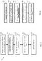
- FIG. 1 Ais a block diagram schematically illustrating a system according to one embodiment of the present invention
- FIG. 1 Bis a block diagram schematically illustrating an alternative system according to another embodiment of the present invention.
- FIG. 2is a flow diagram illustrating a high level method according to an embodiment of the present invention
- FIG. 3is a flow diagram illustrating another embodiment of a method according to the present invention with more detail
- FIG. 4is a flow diagram illustrating a sub-step within the embodiments shown in FIG. 2 or 3 ;
- FIG. 5schematically represents a partial example of information contained within a context database according to an embodiment of the present invention
- FIG. 6is a flow diagram illustrating one possible embodiment of a query generation algorithm according to the present invention.
- FIGS. 7 A and 7 Bare block diagrams schematically illustrating another exemplary embodiment of query generating algorithm, wherein FIG. 7 A represents an exemplary parsing algorithm and FIG. 7 B represents an exemplary query algorithm;
- FIG. 8represents an exemplary model descriptor database in an embodiment
- FIG. 9represents an exemplary method for providing a natural language interface for a computer-aided design (CAD) system in an embodiment
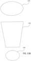
- FIGS. 10 A-Crepresent exemplary isometric diagrams of graphical models of objects as described herein in an embodiment
- FIG. 11represents an exemplary method for providing a natural language interface for a computer-aided design (CAD) system in an embodiment
- FIG. 12represents an exemplary method for providing a natural language interface for a computer-aided design (CAD) system in an embodiment
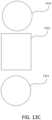
- FIGS. 13 A-Drepresent exemplary diagrams of steps for conversion of a two-dimensional image to a three-dimensional image as described herein in an embodiment
- FIG. 14represents an exemplary reverse projection database as described herein in an embodiment
- FIG. 15represents an exemplary method of populating a model descriptor database in an embodiment
- FIG. 16is a block diagram schematically illustrating exemplary hardware implementations of embodiments of the present invention.
- aspects of the present inventioninclude techniques, methods, hardware and software for providing natural language interfaces in and for computer-aided design (CAD) systems. Exemplary embodiments are described herein below and illustrated in the accompanying drawings. It will be understood by those skilled in the art that various changes, omissions and additions may be made to that which is specifically disclosed herein without departing from the spirit and scope of the present invention.
- CADcomputer-aided design
- a structuremay be an object or part having a particular geometry
- a computer modelmay be a virtual representation of a structure and may be created using an appropriate CAD system or program.
- a designermay be the designer of a computer model, a purchaser, an agent of the purchaser, and a consumer, a home user, or a customer, among others.
- Examples of a structureinclude a piece of sheet metal, a solid cube, a cylindrical pipe, an injection molded plastic toy, an article of clothing such as a shirt made of cotton, and an assembly of various parts such as a vehicle, among others.
- a project (or design)may refer to a CAD model of a part or an assembly of CAD models of parts that may be a virtual representation of a particular structure and may be created using one or more appropriate CAD systems or programs.
- One or more aspects of the present inventioncan be implemented in any of a wide variety of manners, such as within a single computing device or by two or more networked computing devices, among others.
- functionalities of systems described hereinmay be integrated into computer modeling programs directly via add-on software.
- aspects and embodiments of the inventionmay be applied to any number of manufacturing types, including but not limited to the manufacture of apparel and sheet metal products among others.
- designersuse CAD systems to design their products, using sheets of flat material for manufacture.
- Design datasuch as material choice, precise dimensions, or locations of additional features may be embedded within the digital design.
- Designersmay choose different metals or fabrics (including non-woven materials such as leather) depending on the strength and other inherent properties of the material, which affects what manufacturing methods may be necessary to work the material.
- Purchased componentsin some cases, identical purchased components
- CAD programsmay be used to visualize the shape of the finished product.
- sheet metal and apparel manufacturingthe sheet (metal or fabric) may be cut or stamped by a variety of methods using computerized machines. Units are moved from station to station during manufacture. Where sheet metal is connected by rivets or welding, sheet fabric is connected by stitching or gluing. Surface finishes may be applied to both; both may be painted, silk-screened, or otherwise covered with a protective substance. While sheet metal and fabric apparel products have commonalities as discussed above, it will be appreciated by those skilled in the art that other design and manufacturing types which may or may not share many of the same attributes are also amenable to application of embodiments of the present invention.
- system 100comprises one or more computing devices with appropriately networked and/or communicating modules.
- sub-system 102may comprise a computer, other computing device or other system as may be devised by a person of ordinary skill for executing functionalities as described herein based on appropriately coded instructions.
- I/O devices 104include language-based I/O devices such as a microphone and speakers, as well as other I/O devices such as mouse, keyboard, touch pad or touch screen.
- CAD program 106 and memory 118are also included in sub-system 102 .
- CAD program 106includes, in addition to conventional CAD system functionality, natural language command program 110 .
- Natural language command program 110comprises parser 112 , CAD model analyzer 114 and language database 116 .
- CAD model 120typically resides in a memory device, such as memory 118 although the memory need not be configured as a part of the system per se, but may be functionally remote and communicate with the system through an appropriate network.
- CAD model analyzer 114functions as a form of interrogator that interrogates the CAD model to return CAD model data as called for by various program functions.
- other system modulesmay include and/or maintain such an interrogator for interrogating information from a CAD model.
- natural language program sever module 122 , and/or resource provider server module 132may contain such an interrogator, for example, as a portion of or add-on to a CAD program.
- CAD model analyzer 114may analyze a CAD model and output data that may be received and used by natural language command program module 110 or other system modules. Illustrative embodiments for such an analyzer/interrogator may be found in U.S.
- the CAD model datais interrogated to determine and store in memory supply or structure parameters, to compare to parameters of a possible supplier to determine whether or not the possible supplier is capable of and/or willing to supply one or more physical instantiations of the structure.
- supply parametersmay comprise a list of objective requirements for fabricating a structure associated with the RFP and may be generated using fabrication data associated with the RFP.
- Such objective requirementsmay specify baseline capabilities that suppliers must possess in order to be able to successfully fabricate the structure and may include, for example, a maximum dimension of the structure, a material required for the structure, finishing needs, required tolerances, extrapolated machine type(s), and/or a quantity of parts and/or structures, among others, as further described herein.
- the objective requirementsmay be generated by analyzing the fabrication data associated with the RFP to determine such information (maximum dimensions, materials, finishing needs, required tolerances, machine type(s), quantity, etc.).
- the CAD modelmay be constantly interrogated (running in the background) to establish a list of suppliers before an RFP is received and then when a RFP is received, having a narrowed supplier list to query for a cost.
- a usermay input parameters. For example, a user may input a quantity.
- CAD program module 106may comprise any of the modules in a conventional CAD system or program that govern one or more functions of the CAD program as would be understood by persons of ordinary skill in the art. Examples of other CAD system models, not shown, may include: create new item module, select material module, bend module, weld module or cut module. However, natural language command program module 110 is in addition to the conventional modules of the CAD system or program.
- Parser 112parses content of spoken commands received through I/O devices 104 and communicates with language database 116 to determine relevant portions of the spoken command for formulating a query as discussed in more detail below.
- CAD model analyzer 114like interrogator, searches for specific information in CAD model 120 and communicates with natural language server module 122 .
- Natural language program server modulewhich may be remotely located, may comprise a high capacity server/database to assist in parsing any natural language commands that cannot be parsed through resident module 110 .
- natural language program server module 122includes parser 126 , which is similar in function to parser 112 but more powerful, and API 124 , which would be used to translate commands into required syntax for other system modules, for example, to communicate with resource provider server module 132 .
- Language database 128is a larger, more powerful version of database 116 , and may comprise multiple specialized, plurally accessible library-type databases.
- Query generator 130may comprise the artificial intelligence for query generation as described herein below (see, for example, FIGS. 6 , 7 A and 7 B ) and thus may comprise a processor and memory of its own, as well as other associated hardware and software suited for its query generation function.
- CAD context database 144contains CAD specific information as shown in FIG. 5 and described in more detail below.
- Resource provider server module 132provides external services and/or information when called for by module 122 . For example, when information needed to respond to a query resides outside of the CAD system and natural language program server module 122 , automated searching of appropriate databases is initiated, the databases being supplied as resource provider server modules 132 in order to provide information from suppliers, marketplaces, and other external services.
- resource provider server module 132is an external service supplier marketplace database, either a source of information or standalone entity that will perform calculations.
- a natural language command plus any additional information concomitantly enteredis received through I/O devices 104 and directed to natural language command program module 110 , which then parses the command, breaking it into pieces and identifying, using language database 116 , the meaning of the command.
- Information that is identified as being contained within CAD model 120is analyzed and retrieved by CAD model analyzer 114 by interrogating the CAD model. If for some reason natural language command program module 110 is unable to determine the meaning of a command, it will send an audio file to natural language program server module 122 to be further parsed by parser 126 , accessing language database(s) 128 .
- CAD context database 144communicates with parser 126 to determine what information must be pulled from CAD model 120 . Pulled information is sent back through CAD model analyzer 114 to server module 122 and query generator 130 generates a query based on retrieved information.
- CAD context database 144supplements language databases 116 and 128 with CAD specific contextual information that is accessed, for example, when parser 126 is unable to parse a command by access to the more general language databases or if more than one contextual meaning is identified.
- CAD context database 144contains information necessary to identify a bolt as a purchase part that is associated with a nut, to separate it from other general language context meanings (i.e., to leave quickly or a lightning bolt).
- CAD context database 144also contains information to direct natural language server program module 122 to query resource provider modules 132 when supplier-type or other externally provided information is needed for query completion.
- the commandis translated to the CAD program through natural language command program module 110 .
- the queryis then translated by API 124 and sent to resource provider server module 132 for answer.
- API 124translates the response into a format that can be used by the CAD program module and it is sent back through natural language command program module 110 , which delivers an output, such as an auditory output, through I/O devices 104 and/or instructs the CAD command program module 108 to execute the command.
- FIG. 1 Ba further alternative system is described. As will be seen, the basic components of FIG. 1 A are carried over to the embodiment of FIG. 1 B .
- Added componentsinclude network connection device 134 that permits communication with a network, the Internet or information stored in a cloud. Communication through this path may be with natural language program server module 122 as previously described, as well as multiple resource provider server modules 132 and direction with resource provider databases 142 .
- CAD program 106also includes plural CAD program modules 108 a, b . . . n communicating with natural language command program module 110 through template API 138 .
- Template API 138is used to translate commands and other information coming back from the natural language command program module 110 into a command that can be used by the particular CAD program.
- GUI 136is also added, optionally communicating between I/O devices 104 and natural language command program module 110 to facilitate interaction with the user.
- Optional API 140 inside natural language command program module 110translates and facilitates communications between the various sub-modules.
- CAD command templates 146are used in conjunction with template API 138 to send instructions in the language that the CAD program will understand.
- CAD model 120 a, b, . . . nis to be changed using a command program module.
- Template API 138translates a command in a template form to a command that is actually understood by the module.
- the “system”is assigned a name to be spoken by the user to initiation language recognition and parsing, and to distinguish commands from other spoken words. Any suitable name may be assigned. In this case, for illustration purposes only, the assigned name is “Nalcop,” representing natural language command program module 110 .
- Example 1In operation, a user clicks a hole and says, “Nalcop, I need bolts to fit this hole.” Nalcop parses the command with parser 112 and determines that “this hole” refers to a highlighted feature in the displayed CAD model. Natural language command program module 110 then uses CAD model analyzer 114 to gather all data related to the hole from CAD model 120 . Then, it sends the data plus message to natural language command program server module 122 , where the natural language statement and CAD model data is further parsed (if necessary). Query generator 130 creates a search command using the parsed statement and the CAD model data, and searches resource provider server modules 132 or databases 142 for bolts of the correct diameter and correct length that are compatible with the material in which the hole is located. That data is returned to natural language command program module 110 , which displays it in GUI 136 .
- Example 2In operation, a user says, “Nalcop, this shelf needs to hold 40 pounds.” Natural language command program module 110 cannot initially parse this command, so it sends a voice record to natural language program server module 122 . Server module 122 parses the statement and determines that the user's statement is a request to calculate whether the structure can hold 40 pounds. Based on this determination, made using parser 126 , language database 128 and CAD context database 144 , server module 122 sends natural language command program module 110 instructions to analyze the entire CAD model (to get material, thickness, and angles) and to ask the user which way is up (e.g.
- Natural language command program module 110thus poses the required questions through GUI 136 and/or I/O devices 104 and waits for a response from the user.
- Required CAD model datais accessed by CAD model analyzer 114 , combined with user inputs in response to stated questions and transmitted to server module 122 .
- API 124puts the information in the correct format and sends the data to a resource provider server module 132 which can perform a stress (statics) analysis on a model of that shape using that material.
- server module 122sends a “no” answer to natural language command program module 110 , which communicates the answer to the user through GUI 136 and/or I/O devices 104 . Such communication may take the form of a statement delivered through system speakers. The user may choose to respond to the “no” answer with a further question, such as “Well Nalcop, what will work?” In such a case, that question is parsed to be a request for design modifications.
- Server module 122sends common fabrication material options to resource provider server modules 132 to determine whether using a different material in the bracket will work. For purposes of this example, assume stainless steel would be sufficient to hold the weight.
- server module 122may also send different bracket thicknesses, but using the original material (aluminum), to resource provider server modules 132 . Assume it is determined that doubling the thickness in the original material will also work. Server module 122 then sends natural language command program module 110 information that the CAD model as it exists will not hold 40 pounds, but stainless steel or double-thickness aluminum will. Natural language command program module 110 then prompts the user through I/O devices 104 and or GUI 136 to indicate whether he wants to use stainless steel or double the thickness of aluminum.
- natural language command program module 110then prompts the user through I/O devices 104 and or GUI 136 to indicate whether he wants to use stainless steel or double the thickness of aluminum.
- the user selectionis sent back to server module 122 , which fills out a CAD Command Template 146 , which is sent back through natural language command program module 110 to template API 138 , which instructs CAD program module(s) 108 a, b . . . n to make the change.
- CAD Command Template 146which is sent back through natural language command program module 110 to template API 138 , which instructs CAD program module(s) 108 a, b . . . n to make the change.
- system 100may include a model descriptor database 148 .
- Model descriptor database 148may contain object model descriptors, as depicted and described in further detail below.
- Object model descriptorsmay include any units of data from which system 100 may reconstruct a graphical model of an object, such as an object that may be modeled in a CAD model such as CAD model 120 .
- Model descriptor database 148may contain one or more characteristic descriptors, each characteristic descriptor of which may describe a way in which a graphical model of an object may be modified to generate a new graphical model of an object, as described in further detail below.
- Model descriptor database 148may include one or more words associated with object model descriptors and/or characteristic descriptors.
- System 100may add records to model descriptor database by creating new object model descriptors, which may be accomplished, among other things, by generating new geometries or mathematical descriptions of graphical models of objects, by combining existing object model descriptors with other existing object model descriptors, by combining object model descriptors with characteristics to modify the object model descriptors, or by any combination thereof, as described in further detail below.
- Systemmay also retrieve records from model descriptor database and convert retrieved records into graphical models in response to queries describing features of a desired graphical model or of an object modeled therein, or to match other graphical models or images, as described in further detail below.
- model descriptor database 148may be in communication with natural language command program 110 ; for instance, queries to submit to model descriptor database may be generated by natural language command program 110 and submitted model descriptor database 148 .
- Model descriptor database 148may also be in communication with any other module or element of system 100 as described above, including without limitation CAD program module 106 and/or CAD program modules 108 a - n.
- FIG. 2illustrates a high-level method comprising five general steps.
- Step 205comprises receiving user natural language and input/output device inputs, in other words the user speaks and may also use keyboard or mouse to highlight. For example, a user may say “I need a bolt to fit this hole” while using the mouse to identify the hole and natural language command program module 110 will appropriately associate the two different types of inputs based on context and proximity in time.
- the context of the parsecan include recognition of keyboard/mouse commands such as “make this ⁇ highlighted with mouse>, aluminum.”
- distinct commandsmay be assigned to correspond to the mouse or keyboard commands so that context is not required, for example, predetermining that spoken “this” plus an immediate physical I/O action go together.
- Step 210comprises parsing the natural language inputs to determine meaning and required information.
- Step 215comprises analyzing CAD model 120 for required information, typically using CAD model analyzer 114 .
- Step 220comprises determining actions to be carried out, for example determining results using resource provider server modules or databases as described above.
- Step 225comprises carrying out the action or actions or delivering results to the user.
- a first step 305comprises receiving a user voice input and optionally input/output device input as described.
- step 310the meaning of voice and I/O device inputs is determined. More detail on this step is provided in the discussion of FIG. 4 below.
- server module 122selects a resource provider server module 132 to which the query is to be directed.
- Step 320requires a determination of whether more information is required. If YES, step 322 generates a query to the user to provide additional information and program flow returns to step 305 upon information receipt. If NO, program flow continues on to step 325 . In step 325 the query is assembled and then sent in step 330 . In step 335 resource provider results are received from either or both of the resource provider server module or databases. Step 340 comprises translating the resource provider results to a response in a form useable by the CAD system. In step 345 , the translated response is sent to the natural language command program module.
- Step 350requires another determination, in this case whether the returned response is a CAD command or a response to be directed to the user.
- step 405receives user voice input and optionally I/O device input, in this case the same as step 305 .
- the voice inputis parsed to determine the meaning as is generally understood by persons skilled in the art of natural language program interfaces.
- step 415required CAD model information corresponding to as determined CAD-related command topics is further determined.
- step 420CAD model features are analyzed (for example, by CAD model analyzer 114 ) for required CAD model information.
- step 425CAD model data and optionally voice input are sent to the natural language program server module for further action as elsewhere described herein.
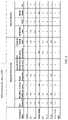
- FIG. 5illustrates exemplary contents of CAD context database 500 in an abbreviated form suitable for representation within the drawings of a patent application.
- contents of a CAD context database as described hereinwill in practice be substantially more voluminous.
- CAD context database 500is located within natural language program server module 122 . However, it may be otherwise located without departing from the scope of the invention.
- CAD context database 500comprises a series of command topics in a first column and at least two super-columns thereafter that identify required information and corresponding search addresses or locations for information corresponding to each command topic.
- a “Yes” entry in any columnindicates applicable or required information
- an “X” entryindicates that information is not required or not applicable.
- the required information super-columnindicates each specific type of information that CAD analyzer 114 must pull from CAD model 120 to respond to a command related to the indicated topic or which must be obtained from a resource provider or other third party source.
- the search address super-columnindicates applicable sources associated with each topic from which the required information may be potentially obtained.
- search address columnshave been populated with a number of well-known industrial suppliers—McMaster Carr, PEM and Metal Depot—but any source of information appropriate for the particular structures to be made may be populated in the search address columns.
- source of the formulamay be a memory location or calculation engine located within the system or internally networked, in addition to third party or cloud sources.
- CAD context database 500The information thus provided by CAD context database 500 is used to generate search queries, for example as shown in FIG. 6 .
- the flow diagram of FIG. 6illustrates one possible algorithm for query determination according to embodiments of the present invention, which will be illustrated by two examples with reference to FIG. 6 and Table 1 below.
- a voice inputis provided, such as “Nalcop, can you find a bolt to fit the selected hole?”
- a device inputis also provided in step 608 .
- This device inputmay, in this example, be mouse clicking on a hole in the displayed structure from the CAD model.
- the voice inputis parsed to determine actions, topics and required information.
- bolt as a topicreturns needed information such as diameter, length, and material. This information is returned from CAD context database 500 as described above.
- required CAD informationincludes hole diameter, the material, and thickness of material at the hole location.
- the CAD modelis analyzed to extract the required information.
- formulae or enginesare accessed and applied as needed to calculate further required information.
- max bolt diametermight be calculated at 0.95 in and minimum bolt length at 1.1 in.
- a queryis generated at step 623 .
- the length of fitting partscould be much longer than thickness of material, leading to many possible fitting results, in which case the natural language command program module will ask the user “What length part do you want?”
- Table 1 belowshows how the initial search request—“Nalcop, can you find a bolt to fit the selected hole?”—is parsed and the associated program actions and other associated events that flow from the request.
- CAD Context Term Specific Parameterse.g. bolt diameter, length & material
- CAD Context Term Specific Parameterse.g. bolt diameter, length & material
- CAD N/A N/A Supply Term- N/A N/A Context Specific Parameters Databasefor bolt, e.g., Interaction diameter, length, material
- Resource N/A Search AddressMcMaster Required corresponding CAD-interrogated Provider
- FIGS. 7 A and 7 Billustrate further alternative parsing and query algorithms, respectively, according to alternative embodiments of the invention.
- voice input 702plus I/O device input 704 plus CAD model data 706 that is the basis for output setting 708 plus action 710 plus direct object 712 .
- the voice input of natural language command program module 110is “I need a bolt to fit this” 714 and mousing over the hole as I/O device input 716 plus CAD model data the hole diameter is half an inch and length is two inches 718 , is the basis for a setting of purchased parts catalog 720 , an action of search 722 , and then the direct object or the search terms is “bolt of half an inch diameter and at least two inches length” 724 .
- the setting, action and object thus determinedforms inputs to the query algorithm shown in FIG. 7 B , wherein the setting 730 plus action 732 plus direct object 734 generate an address 736 plus action 738 plus search term(s) 740 - 744 .
- These generic algorithm stepscorrespond, in this specific example, to, respectively, an actual query of purchased parts catalog 746 plus search 748 plus Bolt of 0.5 in diameter and at least 2 in length 750 , provides a specific address of a resource catalog 752 , a specific action of the search 754 and three search terms 756 , 758 and 760 that come out of the direct object.
- a local sub-servermay be provided with specialized language databases that apply only to a group of designers so that the group may create or use their own individualized glossary commands and terms that might not be used by others outside the group and thus would not parse correctly. This would allow, for example, the users of that group to drop common adjectives from names when all parts have that name. For example, if all bolts were red, it would not be necessary for users within the identified group to specify a red bolt because the system would know the bolt color was red unless otherwise stated.
- a voice recognition sub-modulemay be included within natural language command program module 110 so that commands can be locked out from unrecognized voices to permit only authorized users to edit the CAD model.
- commandscan be locked out from unrecognized voices to permit only authorized users to edit the CAD model.
- such functionalitymay help to prevent untrained users from changing the CAD model inadvertently.
- further functionalitymay be added to permit response by the system in natural language to questions about why a specific command or operation is not working.
- an initial commandcomprises a request to add a steel bolt to an aluminum structure and the system does not allow it because steel fasteners pull through the aluminum
- the natural language command program module 110would respond with an error message or say “this won't work” in audible tone all of the words—“this won't work for these reasons.” This could be very helpful to users, especially for those people learning as they make mistakes and understand why it's wrong not just that it's wrong.
- Another alternative embodimentmay present help menu material tutorials as a natural language response, effectively reading the manual, so that, for example, the user may concentrate on the actions necessary with the keyboard and mouse without diverting his eyes to read from the screen.
- Model descriptor databaseincludes at least an object model descriptor 800 ; at least an object model descriptor 800 may include plurality of object model descriptors. Each object model descriptor may include at least a mathematical description 804 of a three-dimensional form of an object. At least a mathematical description 804 may include any description that any graphical modeling program, such as CAD module 106 or CAD modules 108 a - n , may use to store and/or render geometric features of a modeled object, including without limitation CAD model 120 .
- At least a mathematical description 804may include parameters describing locations of vertices, edges, surfaces, volumes, or other elements of a graphical model of an object, with respect to any coordinate system used in a graphical modeling program. At least a mathematical description 804 may include any formula for any curve, surface, or area, with respect to any coordinate system used in a graphical modeling program. At least a mathematical descriptor may include, without limitation, a formula for rendering a geometric primitive, a formula for combining geometric primitives to form more complex structures, or formulas combining such complex structures to form new structures; formulas for combination may described both adding positive volume in the form of a given geometric primitive or combination thereof, or removal of volume in the form of a given geometric primitive or combination thereof.
- At least a mathematical descriptormay include instructions to add a cylinder to a planar surface of another object, forming a model of that object with a cylindrical projection, an instruction to create a recess in the planar surface having the form of a rectangular prism, causing the object to be as before but with a recess, similar acts involving any geometric elements, or combinations of similar acts.
- At least a mathematical description 804may describe edges, vertices, surfaces, volumes, or other elements of a graphical model in any mathematical terms, including in terms of points, lines, vectors, triangles (as in an “STL” file), or other conventions for rendering images.
- At least a mathematical description 804may include a model stored in any manner used for storing a model in a modeling program model, such as a CAD model, as machine-readable data.
- object model descriptormay include at least a parametric instruction 808 .
- At least a parametric instruction 808may be any instruction that combines with at least a mathematical formula to describe a full set of features of object model descriptor.
- At least a parametric instruction 808may include an absolute or relative dimension such as a size, height, volume, ratio one geometric element to another, or the like.
- At least a parametric instruction 808may include a finish or coating for a surface of an object modeled using object model descriptor. At least a parametric instruction 808 may include a part number of one or more parts to be combined with an object modeled using object model descriptor. At least a parametric instruction 808 may be created, without limitation, by combining any existing object model descriptor with any characteristic as described below.
- At least a parametric instruction 808may be stored in the same data structure or data location as at least a mathematical description 804 ; for instance, where a modeling program such as a CAD program is designed to store or retrieve models using a protocol that stores both at least a mathematical description 804 and at least a parametric instruction 808 together, model descriptor database 148 may store at least a mathematical description 804 and at least a parametric instruction 808 together according to that protocol.
- model descriptor database 148may include at least a characteristic descriptor 812 .
- At least a characteristic descriptor 812may include one or more instructions for modifying at least an object model descriptor 800 .
- a characteristic descriptormay include an instruction to set one or more dimensions of an object model descriptor to a particular size by reference to a norm of a coordinate system or a unit of measurement; for instance, one characteristic descriptor may instruct that an object model descriptor be modified to have a particular maximum length along a specified axis in the coordinate system, or that a particular geometric primitive have a specified length, breadth, depth, axis length, volume and/or other dimensional parameter.
- a characteristic descriptormay include an instruction to set one or more dimensions of an object model descriptor to a relative size; for instance, the length and breadth of a face, projection, or orifice described in object model descriptor may be sized to fit against, around, or in a feature of another object.
- a characteristic descriptormay instruct one element of object to be increased or decreased in length, breadth, depth, volume, or the like as a proportion of another element of object; for instance, a characteristic descriptor may require that a cylindrical object having an opening at one end be modified so that the opening has a greater cross-sectional area than the remainder of the cylinder, modifying the mouth to be a “wide mouth” such as those sometimes found on cups or drinking glasses.
- At least a characteristic descriptor 812may include one or more instructions for combining an object model descriptor with another object model descriptor; as a non-limiting example, the at least a characteristic descriptor 812 may instruct to remove a volume equal to one object modeled in a first object model descriptor from a face of another object described in a second object model descriptor.
- a first object model descriptormay describe a cylinder having a first internal diameter while a second object model descriptor may describe a funnel-like structure that has an initial end with a second internal diameter and a terminal end with a larger third internal diameter; a characteristic descriptor of at least a characteristic descriptor 812 may instruct resizing the second object model descriptor so that the second internal diameter matches the first internal diameter, while the third internal remains proportionally larger as before, and then combining the resized funnel structure with the cylinder to form a cylindrical structure with a wide mouth.
- At least a characteristic descriptor 812may include any instruction to add any parametric instruction to any object model descriptor. Persons skilled in the art, upon reading the entirety of this disclosure, will be aware of many ways in which at least a characteristic descriptor 812 may instruct modification of at least an object descriptor.
- At least a mathematical description 804may be created, among other means, by incorporating at least a characteristic descriptor 812 ; for instance, at least a mathematical description for a new object model descriptor may contain at least a mathematical description for one or more existent object model descriptors combined with one or more characteristic descriptors such as instructions for combining the one or more existent object model descriptors' mathematical descriptions and/or modifications thereto.
- At least a parametric instruction 808may include one or more characteristic descriptors 812 ; where, as disclosed in further detail below, a method creates a modified model of an object by combining a model generated from an object model descriptor with one or more characteristic descriptors, the modified model may be saved in model descriptor database 148 by creating mathematical descriptions and parametric instructions combining the mathematical descriptions and parametric instructions corresponding to the unmodified object with the one or more characteristic descriptors used to produce the modified object model. In this way, new object models can be built recursively by reference to previously existent object models.
- each of at least a characteristic descriptor 812 and/or at least an object model descriptor 800may be associated with at least a descriptive word 816 .
- At least a descriptive word 816may include one or more words or phrases describing the object represented by an object model descriptor of the at least an object model descriptor 800 and/or the characteristic represented by a characteristic descriptor of the at least a characteristic descriptor 812 .
- At least a descriptive word 816may include one or more words, phrases, or other terms used by a user to describe an object represented by an object model descriptor of the at least an object model descriptor 800 ; for instance, at without limitation, an object model descriptor associated with a drinking vessel may also be linked in model descriptor database 148 to a first descriptive word of “cup,” a second descriptive word of “glass,” and a third descriptive word of “mug,” with the result that a query containing any one of those three words may occasion the retrieval of the object model descriptor.
- At least a descriptive word 816 linked to a characteristic descriptor of at least a characteristic descriptor 812may include one or more words a user uses to describe a characteristic associated with the characteristic descriptor; for example, and without limitation, a characteristic associated with a circular opening of a cylinder that bevels out to a wider opening than an interior diameter of the cylinder may be associated with a first descriptive word of “wide mouth” and a second descriptive word of “open mouth,” with the result that a query containing any one of those three words may occasion the retrieval of the characteristic descriptor.
- a descriptive word of at least a descriptive word 816may be added to model descriptor database 148 when a new object model descriptor or characteristic descriptor is created as described below; additional descriptive words may be added where a user enters one or more new words that become associated with an existing object model descriptor and/or characteristic descriptor, such as when the existing object model descriptor and/or characteristic descriptor is retrieved to match a user-submitted image as describe below in reference to FIG. 12 .
- Words of instruction submitted by a user to produce modified object model or in other user commands as described regarding methods disclosed hereinmay also be inserted as one or more descriptive words 816 .
- object model descriptors 800may be defined recursively; for instance, an object model descriptor 800 corresponding to a combination of other object model descriptors and rules for combination of the other object model descriptors may have at least a mathematical description 804 containing a reference to one or more of the other object model descriptors; a parametric instruction may indicate how the one or more other object model descriptors are modified to combine together and form the object model.
- some object model descriptors of the at least an object model descriptor 800may include descriptions of geometric primitives, while others may include references to geometric primitives, combined with instructions for combining them into a more complicated object; the same combination may be performed combining a plurality of more complex object models and/or combining more complex object models with geometric primitive, associated with one or more words that a user might use to describe the objects in question. May also include associations to existing models of objects.
- Model descriptor database 148may be implemented using any hardware or software module or modules suitable for the implementation of any database as described above, including without limitation CAD context database 500 . Model descriptor database 148 may be implemented on the same device or devices housing CAD context database 500 , or on a different device or devices.
- a voice input containing a plurality of wordsis automatedly received via a computing device. In an embodiment, this may be implemented as described above in reference to FIGS. 1 A- 8 .
- the user inputis automatedly parsed via the computing device; this may be implemented as described above in reference to FIGS. 1 A- 8 .
- a meaningis automatedly determined via the computing device; determination of meaning may be performed generally as described above in connection with FIGS. 1 A- 8 .
- Determined meaningmay include one or more words associated with an object and one or more words associated with a characteristic of the object.
- Characteristicmay be any characteristic that may be associated with at least a characteristic descriptor 812 as described above.
- At step 920at least an object model descriptor 800 and at least a characteristic descriptor 812 are retrieved from a model descriptor database 148 via the computing device.
- Retrieval of at least an object model descriptor 800may include assembling a query using one or more words associated with an object; model descriptor database 148 may be queried using the assembled query.
- Retrieval of the at least a characteristic descriptor 812may include assembling a query using one or more words associated with a characteristic; model descriptor database 148 may be queried using the assembled query.
- a combined querymay additionally or alternatively be generated, for instance to locate at least an object model descriptor 800 matching both one or more words matching object and one or more words associated with characteristic of the object, or for receiving results combining the two in a single line of results; for instance, each characteristic descriptor matching the one or more words associated with a characteristic and each object model descriptor matching the one or more words associated with the object may be combined to form a distinct result returned by model descriptor database 148 , presenting a plurality of responses to the query.
- At least an object model descriptor 800may be retrieved by matching at least a descriptive word 816 linked to at least an object model descriptor 800 with the one or more words associated with the object.
- At least a characteristic descriptor 812may be retrieved by matching at least a descriptive word 816 linked to at least a characteristic descriptor with the one or more words associated with the characteristic.
- At least an object model descriptor 800may include at least a mathematical description 804 of a three-dimensional form of the object and at least a first parametric instruction for manufacturing the object using the three-dimensional object form, for instance as described above in reference to FIG. 8 .
- At step 925at least a graphical model of the object is automatedly generated using the at least an object model descriptor 800 via the computing device.
- at least an object model descriptor 800is stored in a manner used by a modeling program, such as a CAD module 106 , 108 a - n to store a graphical model, such as CAD model 120
- generating at least a graphical model of the objectmay be performed according to any protocol used by modeling program to generate graphical models in general.
- generating the object modelmay include retrieving, from the model descriptor database 148 , at least a graphical model associated with the object model descriptor, where retrieving a graphical model is performed in the same way that modeling program retrieves any model from memory.
- Generating object modelmay include rendering the three-dimensional object form according to at least a mathematical description 804 ; this may or may not be performed according to modeling program processes for retrieving and rendering graphical models from memory.
- generating object modelmay include retrieving at least a modification to the at least a graphical model associated with the object model descriptor.
- At least a modificationmay be stored as at least a parametric descriptor; alternatively or additionally, at least a modification may be stored as a characteristic descriptor.
- At least a modificationmay be associated with object model descriptor, for instance by inclusion as at least a parametric descriptor included in or referred to by object model descriptor or as a characteristic descriptor referred to by object model descriptor.
- Generating object modelmay further include modifying at least a graphical model using the at least a modification.
- generating object modelmay include retrieving, from the model descriptor database 148 , at least a graphical model associated with the object model descriptor, retrieving at least a modification to the at least a graphical model, and modifying the at least a graphical model.
- generating object modelmay include rendering three-dimensional object form according to at least a mathematical description 804 and modifying the three-dimensional object form using at least a modification; at least a modification may include at least a parametric instruction 808 .
- Object modelmay be generated as a function of three-dimensional object form and at least a modification.
- At least an object model descriptor 800may include a plurality of object model descriptors, and generating at least a graphical model of object may include generating a plurality of graphical models of the object, each of the plurality of graphical models of the object generated using an object model descriptor of the plurality of object model descriptors.
- a query provided to model descriptor database 148may produce multiple results as described above.
- Each resultwhich may include an object model descriptor and/or a characteristic descriptor, may be separately rendered, producing various graphical models responsive to the query, as generated from the user voice input.
- At step 930at least a modified graphical model of object is generated via computing device using the at least a characteristic descriptor 812 .
- At least a modified graphical model of objectmay be created by providing a modeling program, such as CAD module 106 and/or 108 a - n as described above, with a command to include at least a characteristic in modified graphical model of object; this may be implemented as described above in reference to FIGS. 1 A- 8 .
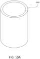
- a first graphical model 1000 of objectmay depict a particular three-dimensional figure modeling the object; for instance, and without limitation, a cylindrical drinking vessel, which may have been retrieved in response to a user voice input containing the word “cup” or the like.
- a characteristic descriptor retrieved as described abovemay include a reference to a second object model descriptor rendered as a second graphical model 1004 ; characteristic descriptor may include instructions for modifying first graphical model 1000 by the inclusion of second graphical model.
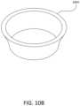
- second graphical model 1004may include a funnel-shaped object that links a narrower circular opening to a broader circular opening, which may be associated with a second part of user command requesting a “wide mouth.”
- characteristic descriptormay include an instruction to modify one or more portions of a model such as first graphical model 1000 , for instance, by instructing that a circular opening be widened by increasing its diameter and including a beveling portion at that end of a cylinder having the circular opening.
- a modified graphical model 1008may be formed using characteristic descriptor; for instance, where characteristic descriptor refers to a second graphical model 1004 , first graphical model 1000 may be modified to include second graphical model, which may involve without limitation adding second graphical model 1004 to a particular location of first graphical model 1000 , removing a volume corresponding to second graphical model 1004 from first graphical model 1000 , and/or replacing a portion of first graphical model 1000 with a part or all of second graphical model 1004 ; as a non-limiting example, a portion of an end of a cylindrical drinking cup may be replaced with a funnel-shaped object, producing a version of the cylindrical drinking cup having a mouth that bevels outward to form a wider opening.
- First or second modelmay also be modified according to instructions of characteristic descriptor or of another characteristic descriptor; continuing the non-limiting example, for instance, funnel shaped object may be resized to match the wall thickness and inner diameter of cylindrical drinking vessel.
- interrogator enginemay identify a mismatch between objects and automatedly modify one or the other to permit a fit.
- characteristic descriptoris an instruction for modifying one or more dimensions or geometries of first model 1000
- first modelmay be modified accordingly; as a non-limiting example, an opening of first model 1000 may be widened to produce modified model 1008 .
- modifying at least a graphical model of objectmay include modifying each of a plurality of graphical models as a function of the at least a characteristic; for instance, where query returns a plurality of object model descriptors, resulting in the generation of a plurality of graphical models of objects, at least a characteristic may be used to modify each graphical model of the plurality of graphical models.
- the at least a characteristic descriptor 812may include a plurality of characteristic descriptors; for example, a query entered to model descriptor database 148 using one or more words associated with characteristic may return multiple results matching the one or more words.
- modifying at least a graphical model of the objectmay include generating a plurality of modified graphical models, the plurality of modified graphical models including a modified graphical model representing the at least an object modified using each characteristic descriptor of the plurality of characteristic descriptors; in other words, each graphical model of the at least a graphical model of the object may be modified with each characteristic descriptor of the plurality of characteristic descriptors.
- a plurality of object model descriptors and a plurality of characteristic descriptorsare retrieved, this may result in a large number of modified graphical objects.
- At least a characteristic descriptor 812may include a modification to at least a mathematical description 804 of graphical model of the object; in that case, modification of graphical model of object may include modifying the graphical model of the object as a function of the modification.
- At least a characteristic descriptor 812may include a descriptor associated with at least a geometrical model, such as another object model descriptor; modifying graphical model of object using the at least a characteristic descriptor 812 may include adding the at least a geometric model to the graphical model of the object.
- At least a characteristic descriptor 812may include at least a mathematical description 804 of a three-dimensional characteristic form represented in geometric model and at least a second parametric instruction for manufacturing the characteristic using the three-dimensional characteristic form; modification may therefore include modifying the geometric model using the at least a second parametric instruction and adding the geometric model so modified to the at least a graphical model of the object.
- adding at least a geometrical model to graphical model of the objectmay include identifying the representation of the specific location in the graphical model of the object and adding the at least a geometric model at the representation of the specific location. This may be performed as described above in reference to FIGS. 1 A- 8 .
- an interrogator engine operating on the computing devicemay include without limitation CAD model analyzer 114 , may determine that a characteristic descriptor of at least a characteristic descriptor 812 is incompatible with a graphical model of object of at least a graphical model of object. Determination of incompatibility may be performed as described above and in above-mentioned material incorporated by reference for determination of incompatibility by an interrogator engine.
- characteristic descriptormay be modified to be compatible with graphical model of object; for instance, where characteristic descriptor includes or refers to a model of an additional object to be attached to object, and one or more dimensions of additional object are determined to be too large or small by interrogator, one or more dimensions in a model of additional object may be modified to have the correct size for compatibility.
- graphical model of objectmay be modified to be compatible with characteristic descriptor.
- Combination of characteristic descriptor and graphical model of objectmay be excluded from at least a modified graphical model of the object based on detected incompatibility; for instance, where the graphical model of the object is a model of an object made of a first material and characteristic descriptor is for a finish that may only be applied to an alternate material, the combination of the two may be eliminated from the set of combinations presented in at least a modified graphical model of the object.
- additional information describing objectmay be automatedly identified in a CAD context database; this may be performed as described above in reference to FIGS. 1 A- 8 .
- system 100may generate a query to CAD context database to find additional information usable to improve the query.
- CAD context databasemay also be queried based on determinations as described above in reference to FIGS. 1 A- 8 .
- Retrieving at least an object model descriptor 800may additionally involve retrieving at the at least an object model descriptor 800 using additional information; in an embodiment, one or more words may be replaced by words included in the additional information. Alternatively or additionally, words included in the additional information may be added to query without replacing one or more words.
- CAD context database 500may link one or more words of user voice input to categories or geometries; as a non-limiting example, CAD context database 500 may link the word “cup” to words describing upwardly opening recesses, cylindrical forms, or the like. Additional information may result in return of “best match” queries that, as indicated by CAD context database 500 , may describe some but not all features of the object to which user voice input refers.
- Additional information in CAD context database 500may also link a word user voice input used to describe a characteristic to words model descriptor database 148 links to particular characteristic descriptors; this may enable system 100 to match a user instruction with one or modifications to at least a graphical model of object that may partially or wholly match user needs. This may be performed, for instance, when a number of object model descriptors and/or characteristic descriptors initially returned by model descriptor database 148 is below a certain threshold, such as without limitation if no object model descriptors and/or no characteristic descriptors are initially returned. Additional information may similarly be used to retrieve at least a characteristic descriptor.
- system 100may determine that additional information is necessary to perform method 900 .
- a query for additional informationmay be automatedly assembled via the computing device, based on determined meaning, as described above in reference to FIGS. 1 A- 8 .
- Query for additional informationmay be automatedly provided to a resource provider service via computing device, for instance as described above in reference to FIGS. 1 A- 8 .
- Additional informationmay be automatedly received from resource provider service as described above in reference to FIGS. 1 A- 8 ; additional information may include information regarding object.
- Object model identifiermay be retrieved using additional information; additional information may be used to retrieve object model identifier in any manner described above for use of additional information obtained from CAD context database.
- resource provider servicemay link one or more words of user voice input to categories or geometries; as a non-limiting example, Resource provider service may link the word “cup” to words describing upwardly opening recesses, cylindrical forms, or the like. Additional information may result in return of “best match” queries that, as indicated by Resource provider service, may describe some but not all features of the object to which user voice input refers.
- Additional information in Resource provider servicemay also link a word user voice input used to describe a characteristic to words model descriptor database 148 links to particular characteristic descriptors; this may enable system 100 to match a user instruction with one or modifications to at least a graphical model of object that may partially or wholly match user needs.
- Thismay be performed, for instance, when a number of object model descriptors and/or characteristic descriptors initially returned by model descriptor database 148 is below a certain threshold, such as without limitation if no object model descriptors and/or no characteristic descriptors are initially returned; query to resource provider services may, as a non-limiting example, be performed after query to CAD context database 500 fails to produce additional object model descriptors and/or characteristic descriptors in excess of a threshold, which may be the same threshold described above.
- a request for missing informationmay be provided to a user. This may be performed as described above in reference to FIGS. 1 A- 8 .
- Request for additional informationmay be provided to a user where a number of object model descriptors and/or characteristic descriptors initially returned by model descriptor database 148 is below a certain threshold, such as without limitation if no object model descriptors and/or no characteristic descriptors are initially returned either before or after modification of query using CAD context database 500 and/or resource providers as described above.
- Requests for additional informationmay also be generated on discovery of incompatibility of models to be combined or of characteristic with object, for instance as detected by interrogator engine in accordance with any means or methods described above in reference to FIGS. 1 A- 8 or within materials incorporated herein by reference.
- At least a modified graphical modelmay be displayed to a user. This may be performed using GUI 136 as described above.
- the plurality of graphical modelsmay be displayed to the user; plurality may be ranked, for instance according to degree of match with query, and displayed in rank-order. Plurality may be filtered or capped as described above.
- a selection of a modified graphical model from the plurality of modified graphical modelsmay be received from a user; for instance, user may use a locator device such as a mouse, a keyboard, or an additional voice command to select a graphical model of the plurality of graphical models.
- object model and/or characteristic descriptor as retrievedmay not match what the user had in mind when describing object and/or characteristic; user may choose a most relevant version of modified graphical model from a plurality thereof.
- Such “partial matches”may be produced by one or more words of the user query matching an object model descriptor or characteristic descriptor that differs to a greater or lesser extent from what the user intended; partial matches may also be generated by CAD context database 500 and/or resource providers that have generated related words to the words the user produced.
- any steps of method 900 or of any other method hereinmay be used one or more times to further modify user queries, graphical model of object, modified graphical model of object, and the like; for instance, user can specify a further modification to a graphical model of object, whether by reference to an additional characteristic or through use of voice-controlled CAD processes described above or below, to further shape the final result into a model matching the user's vision.
- Any completed or partially completed modified graphical model of objectmay be stored in its turn in model descriptor database 148 ; words associated therewith as stored in model descriptor database 148 may include one or more words of user query and/or additional information received from CAD context database 500 and/or resource providers.
- method 900may include initiating manufacture of the object using the modified graphical model of the object.
- Initiating manufacturemay involve commencing any manufacturing process that may be performed by a manufacturing system.
- a manufacturing systemmay include one or more automated manufacturing devices such as, without limitation subtractive manufacturing devices such as computer numerical control (CNC) machines, machine tools, and the like, additive manufacturing devices such as three-dimensional printers, stereolithographic devices, and the like, cutting, stamping, or electronic discharge machining (EDM) devices.
- Initiating manufacturemay include receiving, at an input port of system 100 , a manufacture initiation signal, which may be any user command to initiate manufacture as described herein.
- Initiating manufacturemay include generating a manufacture guidance file, such as a design file, a computer aided manufacturing (CAM) file, or the like, which may be implemented on system 100 or a remote device.
- Initiating manufacturemay include generating manufacturing instructions, which may include one or more steps for an automated manufacturing device to perform in a manufacturing process. Manufacturing instructions may be generated by system 100 or by a remote device at the direction of system; direction of remote device to generate manufacturing instructions may be performed by transmitting a computer model, such as modified graphical model of object to remote device, without associated and/or embedded instructions to create manufacturing instructions.
- Initiating manufacturemay include starting a manufacturing device; starting a manufacturing device may include transmitting manufacturing instructions to manufacturing device.
- Starting a manufacturing devicemay include transmitting a design file to manufacturing device 712 .
- Starting a manufacturing devicemay include transmitting a signal to manufacturing device that the manufacturing device is configured to interpret as causing manufacturing device to perform physical operations as described above.
- Transmissionas used herein, may be direct, via a network, via a memory storage device, or via another automated manufacturing device.
- method 900permits a user to produce a new product, from conception to manufacture, using a verbal description to the system 100 ; a vocabulary of words describing objects and potential modifications thereto, as understood in colloquial language, is translated into models and instructions for modifications thereof that system 100 may then use to generate a model and/or object, matching a statement by a user.
- a user with no technical knowledgemay use this process to produce a prototype of a new design using a verbal description in the user's own words, translated into precise operational instructions by artificial intelligence, language analysis, and reference to a vocabulary of simple and complex forms.
- a user text input including a plurality of wordsis received.
- Text inputmay be received using any suitable input method.
- Text inputmay be entered by a user by means of a keyboard, touchscreen, touchpad, keypad, or other input device capable of receiving text.
- Text inputmay be received as a voice input that is translated into text using voice-recognition software.
- user text inputis automatedly parsed via the computing device; this may be performed as described above in reference to FIGS. 1 A- 9 .
- a meaningis determined for parsed user text input, the meaning including one or more words associated with an object and one or more words associated with a characteristic of the object; this may be implemented as described above in reference to FIGS. 1 A- 9 .
- at least an object model descriptor 800 and at least a character descriptorare retrieved from a model descriptor database 148 using determined meaning, via computing device. In an embodiment, this may be implemented as described above in reference to FIG. 9 .
- at least a graphical model of objectis generated using at least an object model descriptor 800 ; this may be implemented as described above in reference to FIG. 9 .
- graphical model of object tis modified using at least a characteristic descriptor 812 . In an embodiment, this may be implemented as described above in reference to FIG. 9 .
- Any step or steps of methods 900 and/or 1100may be repeated, omitted, and/or combined with any step or sets of steps of any other method described or alluded to herein, including without limitation use of methods 900 or steps of methods 900 and/or 1100 to further modify models generated in method 1200 and/or models retrieved from or added to model descriptor database 148 for instance and without limitation as described below regarding method 1500 .
- a user selection of at least an imageis automatedly received via a computing device.
- Receipt of user selection of at least an imagemay include receipt of at least an image from the user, via a network connection or from an electronic memory storage medium.
- Receipt of the imagemay be performed by capturing an image of an object; capturing may include scanning or photographing at least an image of the object. Capturing may include scanning or photographing object directly; for instance, a set of images may be produced by photographing object from one or more angles.
- Objectmay be scanned to produce a three-dimensional image of object, for example using computed tomography (CT) scanning techniques or the like.
- CTcomputed tomography
- usermay provide a link or reference to at least an image stored in memory accessible to computing device or to a network address where at least an image may be collected.
- At least an imagemay include a three-dimensional graphical model of object.
- Three-dimensional graphical modelmay be any three-dimensional graphical model as described above, including without limitation a CAD model of object.
- Three-dimensional graphical modelmay be generated automatedly from a three-dimensional scan such as a CT scan; as a non-limiting example, this may be accomplished using one or more computer modeling programs, including without limitation one or more CAD modules 106 or 108 a - n .
- Three-dimensional graphical modelmay be generated by a user utilizing one or more computer programs including without limitation one or more CAD modules 106 or 108 a - n .
- the at least an imageincludes at least a two-dimensional image, such as a photograph or two-dimensional CAD model illustrating a view of object; view may be a straightaway side view, an isometric view, a perspective view, or the like.
- a user input including a plurality of wordsis received.
- User inputmay be a user voice input.
- User inputmay be a user text input. This may be implemented as described above in reference to FIGS. 1 A- 9 .
- the user voice inputis automatedly parsed via the computing device; in an embodiment this may be implemented as disclosed above in connection with FIGS. 1 A- 9 .
- a meaning including one or more words associated with a characteristicis determined for the parsed user input; this may be performed according to any means or manner for determining a meaning including one or more words associated with a characteristic as described above in reference to FIGS. 1 A- 9 .
- Characteristicmay be a characteristic not depicted in the at least an image.
- characteristicmay include a geometric feature absent from at least an image, such as a projection, recess, flange, surface feature, or distortion of object depicted in the at least an image.
- Characteristicmay include a surface texture of object not depicted in at least an image.
- Characteristicmay include a color not depicted in the at least an image.
- Characteristicmay include a material component not depicted in the at least an image.
- At step 1225at least a three-dimensional graphical model of object is generated.
- at least a mathematical description 804 of the objectis automatedly generated as a function of the at least an image via the computing device.
- At least a mathematical description 804may be any at least a mathematical description 804 as described above in reference to FIGS. 1 A- 9 .
- generating at least a mathematical description 804may include extracting at least a three-dimensional geometric form making up a component of the three-dimensional graphical model.
- identification and extraction of component geometries of three-dimensional modelmay be performed according to any method for identification and extraction or reproduction of geometries by any interrogator, interrogator engine, or the like described above or in material incorporated herein by reference.
- Component of three-dimensional graphical formmay include the geometric form of any portion of three-dimensional graphical form and/or of the entire three-dimensional graphical form.
- Interrogatormay generate a mathematical description of the at least a three-dimensional geometric form; for instance, interrogator may determine a formula for an edge, curve, or surface of the three-dimensional geometric form, a location of a vertex, edge, or other point in a coordinate system to be used by modeling program or modeling programs, or any other factors necessary to render the three-dimensional geometric form in modeling program or modeling programs.
- at least a three-dimensional geometric formincludes a plurality of three-dimensional geometric forms; interrogator may garage a mathematical description for each three-dimensional geometric form of the plurality of three-dimensional geometric forms.
- Interrogatormay generate one or more rules for combining the plurality of three-dimensional geometric forms to form a model of object; rules for combining the three-dimensional geometric forms may include at least a parametric descriptor, a reference to at least a characteristic descriptor 812 , or the like.
- generatingmay include identification by interrogator of at least a first two-dimensional geometric form in a first image of the at least a two-dimensional image.
- At least a first two-dimensional geometric formmay by identified by comparison of one or more features of at least a two-dimensional image to one or more geometric primitive forms, as illustrated and described in further detail below.
- Interrogatormay match the at least a first two-dimensional geometric form to at least a first three-dimensional form; the at least a first two-dimensional geometric form may represent a two-dimensional projection of the at least a first three-dimensional form.
- At least a two-dimensional image 1300may include a depiction of object in a two-dimensional form 1304 ;
- objectmay be a geometric primitive, such as without limitation a cylinder, or a combination of geometric primitives of one or more types to form a more complex form.
- form 1304may represent a two-dimensional projection of the object.
- form 1304may be some projection of a cylinder, which may include some combination of circles or ellipses and/or straight lines.
- Interrogatormay identify one or more geometric components 1308 of form 1304 ; this may be performed using the same functionality use for identification of geometric forms in a three-dimensional file.
- two-dimensional imagemay be transformed into a computer model, such as a CAD model, incorporating two-dimensional form as a single face or planar structure 1312 , which interrogator may then interrogate.
- interrogatormay extract from a two-dimensional projection of a cylinder two ellipses and a quadrilateral form such as a trapezoid.
- Interrogatormay identify faces or cross-sectional forms of a three-dimensional figure using functionality that computer modeling programs such as CAD modules 106 and/or 108 a - n ; as a non-limiting example, interrogator may identify a rectangular as one possible cross-sectional form or face that appears in a projection as a trapezoid, and a circle as a possible projection of an ellipse. Alternatively or additionally, interrogator may refer to a reverse-projection database as described in further detail below. Matched projections, including faces and/or cross-sectional forms, may then be assembled using a computer modeling program, such as CAD modules 106 and/or 108 a - n , to generate a three-dimensional model 1316 .
- CAD modules 106 and/or 108 a - nmay be assembled using a computer modeling program, such as CAD modules 106 and/or 108 a - n , to generate a three-dimensional model 1316 .
- Reverse projection database 1400may relate at least an object model descriptor to one or more projections 1404 ; one or more projections 1404 may be two-dimensional views of object model, including views of faces, cross-sections, and/or perspective projections.
- One or more projections 1404may be automatedly generated using a computer modeling program such as CAD module 106 and/or 108 a - n . Generation of one or more projections 1404 may be performed upon the creation of a new object model descriptor, for instance as set forth below.
- a querymay return an object model associated with one or more projections 1404 .
- matching the at least a first two-dimensional imagemay include generating a mathematical description of the at least a first two-dimensional image; mathematical description may be any mathematical description as described above in reference to FIGS. 1 A- 9 .
- Matching the at least a first two-dimensional imagemay include querying reverse projection database 1400 linking a plurality of object model descriptors 800 of three-dimensional objects to mathematical descriptions 1404 of two-dimensional objects using the mathematical description.
- the result set of the querymay include at least a three-dimensional object as described by at least an object model descriptor 800 .
- At least a three-dimensional geometric formmay include a plurality of three-dimensional geometric forms.
- a two-dimensional imagemay represent a two-dimensional projection of more than one possible three-dimensional image; for instance, what appears from a first view to be a cylinder may have conflicting or additional features on a side that in the two-dimensional image is occluded.
- a cupfor instance, may be purely cylindrical as seen from one side, while from another side may include a handle or other projection, or a flat portion.
- interrogatormay generate more than one three-dimensional form of which at least a first two-dimensional geometric form is a projection.
- a plurality of three-dimensional geometric forms in the databasemay match at least a first two-dimensional form, and that plurality may be returned.
- plurality of three-dimensional geometric formsmay be filtered by presentation to the user of a plurality of three-dimensional models as described below.
- interrogatormay filter plurality of three-dimensional graphical forms by reference to a second two-dimensional image of the at least an image.
- Interrogatormay extract at least a second two-dimensional form from second two-dimensional image and match with at least a second three-dimensional form; this may be performed as described above for matching at least a first two-dimensional form to at least a first three-dimensional form.
- Interrogatormay then compare at least a first three-dimensional form to at least a second three-dimensional form.
- Interrogatormay alternatively or additionally generate one or more two-dimensional projections of first three-dimensional form and compare the one or more two-dimensional projections to at least a second two-dimensional form.
- Interrogatormay alternatively or additionally compute one or more dimensional measurements of at least a second two-dimensional form and compare the one or more dimensional measurements to dimensional measurements of the at least a first three-dimensional form. In some embodiment, Interrogator eliminates forms of at least a three-dimensional form that conflict with second two-dimensional image based on the above comparisons. Alternatively or additionally, interrogator may combine at least a second three-dimensional form and at least a first three-dimensional form to produce a modified at least a first three-dimensional form.
- interrogatormay modify first three-dimensional form to include the mug handle.
- interrogatormay generate at least a three-dimensional graphical model of object as a function of the at least a three-dimensional form.
- interrogatormay create a three-dimensional graphical model based solely or principally on at least a three-dimensional form.
- interrogatormay generate at least a three-dimensional graphical model of object by combining the plurality of three-dimensional forms.
- Interrogatormay generate a plurality of three-dimensional graphical models of object; for instance, where a given component of object may be represented by more than one three-dimensional form, interrogator may create a three-dimensional graphical model representing each possible combination of three-dimensional graphical forms. Interrogator may filter the plurality of possible combinations; for instance, interrogator may discard combinations of models that are determined to be incompatible, for instance using compatibility testing as described in materials incorporated herein by reference. Interrogator may filter the plurality of three-dimensional graphical forms. In an embodiment, interrogator may identify at least a second two-dimensional geometric form in at least a second image; this may be performed as described above.
- Interrogatormay compare each three-dimensional graphical model of plurality of three-dimensional graphical models to at least a second two-dimensional geometric form, using any method or means described above for comparing at least a first three-dimensional form to at least a second two-dimensional geometric form or to a three-dimensional graphical form generated therefrom.
- interrogatormay generate at least a two-dimensional projection of at least a three-dimensional form from which the three-dimensional graphical model was generated and compare the at least a two-dimensional projection to the at least a second two-dimensional geometric form.
- At least a three-dimensional graphical model of objectmay be displayed to the user.
- system 100may display the plurality of three-dimensional graphical models to the user.
- Plurality of three-dimensional graphical modelsmay be ranked; ranking may be performed similarly to ranking as described above in reference to FIG. 9 .
- filtering of plurality of graphical modelsmay be performed using user feedback.
- each three-dimensional graphical model of the plurality of three-dimensional graphical modelsmay be displayed to the user; a user input may be received indicating whether the three-dimensional graphical model matches the object.
- Usermay select one or more three-dimensional graphical models, using a check-box or similar selection facility, to indicate that the one or more three-dimensional graphical models match the object.
- Usermay select one or more three-dimensional graphical models, using a check-box or similar selection facility, to indicate that the one or more three-dimensional graphical models do not match the object.
- subsequent steps of method 1200are performed with three-dimensional graphical models user has indicated are matches.
- At step 1230at least a three-dimensional graphical model of the object is modified using the at least a characteristic descriptor 812 ; this may be performed as described above in reference to FIG. 9 .
- At least a three-dimensional graphical model of the object as modifiedmay be displayed to the user.
- at least a three-dimensional graphical model of the object as modifiedmay include a plurality of such models, and user may select one or more such models.
- System 100may store selected model in model descriptor database 148 according to methods described herein; system 100 may prompt and/or receive from user one or more words to associated with selected model. System 100 may initiate manufacture of selected model.
- a usercan take advantage of the language-processing, artificial intelligence, and image processing capabilities of system 100 to create a model or object based on existing object or image thereof the user has encountered; for instance, user may see an object such as a machine part, an item of flatware, or any other item that may be manufactured, take one or more photographs of the object, or scan the object in a three-dimensional scanner such as a CT scanner, then verbally or textually describe modifications thereto that produce a new object the user wishes to produce.
- a usercan utilize an image taken from the Internet or the like as a starting point for a creative process whereby user commands submitted in textual or verbal form shape the object depicted to match the user's own vision.
- Any step or steps of method 1200may be repeated, omitted, and/or combined with any step or sets of steps of any other method described or alluded to herein, including without limitation use of method 1200 or steps of method 1200 to further modify models generated in methods 900 and/or 1100 and/or models retrieved from or added to model descriptor database 148 for instance and without limitation as described below regarding method 1500 .
- At step 1505at least an image representing an object is automatedly received via a computing device; this may be implemented as described above in reference to FIG. 12 .
- At least an imagemay include a three-dimensional image of object; alternatively or additionally, at least an image may include at least a two-dimensional image of object.
- At step 1510at least a three-dimensional geometric component of the image is identified by an interrogator engine operating on the computing device.
- Interrogator enginemay be any interrogator engine as described above. Where at least an image includes a three-dimensional image, interrogator engine may extract at least a three-dimensional geometric form as described above.
- interrogator enginemay match at least a three-dimensional graphical form to at least a two-dimensional graphical form extracted from the two-dimensional image, as described above, and identify the matching at least a three-dimensional form as at least a three-dimensional component of image.
- At least a three-dimensional geometric component as used hereinmay include a geometric representation of entire image, or a geometric representation of a portion of image.
- interrogator enginederives a mathematical description of each three-dimensional geometric component of the at least a three-dimensional geometric component of the image; this may be implemented as described above in reference to FIG. 12 .
- model descriptor database 148is queried using the mathematical description; model descriptor database 148 may be a model descriptor database as described above.
- a querymay be assembled using one or more mathematical descriptions; as a non-limiting example, where one or more mathematical descriptions are stored as a binary or text description, this may be performed using a textual search.
- Querymay be formed and/or searched for using any suitable method or means for querying a data store for data elements.
- Result setis received from model descriptor database 148 .
- Result setmay be null.
- Result setmay have one or more results, representing object model descriptors; object model descriptors may include exact or partial matches to a three-dimensional geometric component of at least a three-dimensional geometric component.
- result setmay include object model descriptors that collectively contain all three-dimensional geometric components but do not include an object model descriptor having a parametric descriptor furnishing one or more rules for combining three-dimensional geometric components to form a model of object; as another example, result set may contain a set of object model descriptors, and the set may lack any object model descriptor containing at least one three-dimensional geometric component of at least a three-dimensional geometric component. Result set may be null.
- a recordis added to the model descriptor database 148 .
- Recordincludes an object model descriptor containing a reference to each three-dimensional geometric component of at least a three-dimensional geometric component and a parametric descriptor describing a rule for combining each three-dimensional geometric component of the at least a three-dimensional geometric component to form a model of object.
- at least one of the at least a three-dimensional geometric componentwas not contained in the result set, at least a mathematical description 804 describing the at least a three-dimensional geometric component may be included in object model descriptor.
- At least a word associated with object model descriptormay be added to model descriptor database 148 and associated with object model descriptor in model descriptor database 148 ; in an embodiment, at least a word may be received from a user. As a result, at least a word may later be useable to retrieve object model descriptor from model descriptor database 148 .
- method 1500 or steps thereofare used to store object models in model descriptor database 148 as generated during methods 900 , 1100 , and/or 1200 , or performance of any steps thereof, words from user verbal or textual inputs received in the course of such methods may be used to generate at least a word.
- method 1500permits system 100 to create and augment an expanding vocabulary of symbols, linked to language utilized by users, to permit user verbal commands to be used in creating and/or modifying graphical models. Any step or steps of method 1500 may be repeated, omitted, and/or combined with any step or sets of steps of any other method described or alluded to herein, including without limitation use of method 1500 or steps of method 1500 to store models generated or received at any stage of methods 900 , 1100 , and/or 1200 in model descriptor database 148 .
- any one or more of the aspects and embodiments described hereinmay be conveniently implemented using one or more machines (e.g., one or more computing devices that are utilized as a user computing device for an electronic document, one or more server devices, such as a document server) programmed according to the teachings of the present specification, as will be apparent to those of ordinary skill in the computer art.
- Appropriate software codingcan readily be prepared by skilled programmers based on the teachings of the present disclosure, as will be apparent to those of ordinary skill in the software art.
- Aspects and implementations discussed above employing software and/or software modulesmay also include appropriate hardware for assisting in the implementation of the machine executable instructions of the software and/or software module.
- Such softwaremay be a computer program product that employs a machine-readable storage medium.
- a machine-readable storage mediummay be any medium that is capable of storing and/or encoding a sequence of instructions for execution by a machine (e.g., a computing device) and that causes the machine to perform any one of the methodologies and/or embodiments described herein.
- Examples of a machine-readable storage mediuminclude, but are not limited to, a magnetic disk (e.g., a conventional floppy disk, a hard drive disk), an optical disk (e.g., a compact disk “CD”, such as a readable, writeable, and/or re-writable CD; a digital video disk “DVD”, such as a readable, writeable, and/or rewritable DVD), a magneto-optical disk, a read-only memory “ROM” device, a random access memory “RAM” device, a magnetic card, an optical card, a solid-state memory device (e.g., a flash memory), an EPROM, an EEPROM, and any combinations thereof.
- a magnetic diske.g., a conventional floppy disk, a hard drive disk
- an optical diske.g., a compact disk “CD”, such as a readable, writeable, and/or re-writable CD; a digital video disk “DVD”,
- a machine-readable mediumis intended to include a single medium as well as a collection of physically separate media, such as, for example, a collection of compact disks or one or more hard disk drives in combination with a computer memory.
- a machine-readable storage mediumdoes not include a signal.
- Such softwaremay also include information (e.g., data) carried as a data signal on a data carrier, such as a carrier wave.
- a data carriersuch as a carrier wave.
- machine-executable informationmay be included as a data-carrying signal embodied in a data carrier in which the signal encodes a sequence of instruction, or portion thereof, for execution by a machine (e.g., a computing device) and any related information (e.g., data structures and data) that causes the machine to perform any one of the methodologies and/or embodiments described herein.
- Examples of a computing deviceinclude, but are not limited to, an electronic book reading device, a computer workstation, a terminal computer, a server computer, a handheld device (e.g., a tablet computer, a personal digital assistant “PDA”, a mobile telephone, a smartphone, etc.), a web appliance, a network router, a network switch, a network bridge, any machine capable of executing a sequence of instructions that specify an action to be taken by that machine, and any combinations thereof.
- a computing devicemay include and/or be included in a kiosk.
- FIG. 16shows a diagrammatic representation of one embodiment of a computing device in the exemplary form of a computer system or computing module 1600 within which a set of instructions for causing a control system, for example, system 100 , sub-system 102 or CAD program module 106 , to perform any one or more of the aspects and/or methodologies of the present disclosure may be executed. It is also contemplated that multiple computing devices may be utilized to implement a specially configured set of instructions for causing the device to perform any one or more of the aspects and/or methodologies of the present disclosure.
- Computer system or module 1600includes a processor 1604 and a memory 1608 that communicate with each other, and with other components, via a bus 1612 .
- Bus 1612may include any of several types of bus structures including, but not limited to, a memory bus, a memory controller, a peripheral bus, a local bus, and any combinations thereof, using any of a variety of bus architectures.
- Memory 1608may include various components (e.g., machine readable media) including, but not limited to, a random access memory component (e.g., a static RAM “SRAM”, a dynamic RAM “DRAM”, etc.), a read only component, and any combinations thereof.
- a basic input/output system 1616(BIOS), including basic routines that help to transfer information between elements within computer system 1600 , such as during start-up, may be stored in memory 1608 .
- BIOSbasic input/output system 1616
- Memory 1608may also include (e.g., stored on one or more machine-readable media) instructions (e.g., software) 1620 embodying any one or more of the aspects and/or methodologies of the present disclosure.
- memory 1608may further include any number of program modules including, but not limited to, an operating system, one or more application programs, other program modules, program data, and any combinations thereof.
- Computer system 1600may also include a storage device 1624 .
- a storage devicee.g., storage device 1624
- Examples of a storage deviceinclude, but are not limited to, a hard disk drive for reading from and/or writing to a hard disk, a magnetic disk drive for reading from and/or writing to a removable magnetic disk, an optical disk drive for reading from and/or writing to an optical medium (e.g., a CD, a DVD, etc.), a solid-state memory device, and any combinations thereof.
- Storage device 1624may be connected to bus 1612 by an appropriate interface (not shown).
- Example interfacesinclude, but are not limited to, SCSI, advanced technology attachment (ATA), serial ATA, universal serial bus (USB), IEEE 1244 (FIREWIRE), and any combinations thereof.
- storage device 1624(or one or more components thereof) may be removably interfaced with computer system 1600 (e.g., via an external port connector (not shown)). Particularly, storage device 1624 and an associated machine-readable medium 1628 may provide nonvolatile and/or volatile storage of machine-readable instructions, data structures, program modules, and/or other data for computer system 1600 .
- software 1620may reside, completely or partially, within machine-readable medium 1628 . In another example, software 1620 may reside, completely or partially, within processor 1604 .
- Computer system 1600may also include an input device 1632 .
- a user of computer system 1600may enter commands and/or other information into computer system 1600 via input device 1632 .
- Examples of an input device 1632include, but are not limited to, an alpha-numeric input device (e.g., a keyboard), a pointing device, a joystick, a gamepad, an audio input device (e.g., a microphone, a voice response system, etc.), a cursor control device (e.g., a mouse), a touchpad, an optical scanner, a video capture device (e.g., a still camera, a video camera), touchscreen, and any combinations thereof.
- an alpha-numeric input devicee.g., a keyboard
- a pointing devicee.g., a joystick, a gamepad
- an audio input devicee.g., a microphone, a voice response system, etc.
- a cursor control devicee.g., a mouse
- Input device 1632may be interfaced to bus 1612 via any of a variety of interfaces (not shown) including, but not limited to, a serial interface, a parallel interface, a game port, a USB interface, a FIREWIRE interface, a direct interface to bus 1612 , and any combinations thereof.
- Input device 1632may include a touch screen interface that may be a part of or separate from display 1636 , discussed further below.
- Input device 1632may be utilized as a user selection device for selecting one or more graphical representations in a graphical interface as described above.
- a usermay also input commands and/or other information to computer system 1600 via storage device 1624 (e.g., a removable disk drive, a flash drive, etc.) and/or network interface device 1640 .
- a network interface devicesuch as network interface device 1640 may be utilized for connecting computer system 1600 to one or more of a variety of networks, such as network 1644 , and one or more remote devices 1648 connected thereto. Examples of a network interface device include, but are not limited to, a network interface card (e.g., a mobile network interface card, a LAN card), a modem, and any combination thereof.
- Examples of a networkinclude, but are not limited to, a wide area network (e.g., the Internet, an enterprise network), a local area network (e.g., a network associated with an office, a building, a campus or other relatively small geographic space), a telephone network, a data network associated with a telephone/voice provider (e.g., a mobile communications provider data and/or voice network), a direct connection between two computing devices, and any combinations thereof.
- a networksuch as network 1644 , may employ a wired and/or a wireless mode of communication. In general, any network topology may be used.
- Informatione.g., data, software 1620 , etc.
- Computer system 1600may further include a video display adapter 1652 for communicating a displayable image to a display device, such as display device 1636 .
- a display deviceinclude, but are not limited to, a liquid crystal display (LCD), a cathode ray tube (CRT), a plasma display, a light emitting diode (LED) display, and any combinations thereof.
- Display adapter 1652 and display device 1636may be utilized in combination with processor 1604 to provide graphical representations of aspects of the present disclosure.
- a computer system 1600may include one or more other peripheral output devices including, but not limited to, an audio speaker, a printer, and any combinations thereof.
- peripheral output devicesmay be connected to bus 1612 via a peripheral interface 1656 . Examples of a peripheral interface include, but are not limited to, a serial port, a USB connection, a FIREWIRE connection, a parallel connection, and any combinations thereof.
Landscapes
- Engineering & Computer Science (AREA)
- Physics & Mathematics (AREA)
- Theoretical Computer Science (AREA)
- General Physics & Mathematics (AREA)
- Human Computer Interaction (AREA)
- Geometry (AREA)
- Audiology, Speech & Language Pathology (AREA)
- General Engineering & Computer Science (AREA)
- Health & Medical Sciences (AREA)
- Computational Linguistics (AREA)
- Automation & Control Theory (AREA)
- Manufacturing & Machinery (AREA)
- Computer Hardware Design (AREA)
- General Health & Medical Sciences (AREA)
- Evolutionary Computation (AREA)
- Artificial Intelligence (AREA)
- Acoustics & Sound (AREA)
- Multimedia (AREA)
- Processing Or Creating Images (AREA)
- Architecture (AREA)
- Software Systems (AREA)
Abstract
Description
| TABLE 1 | ||||||
| Parsed | “Nalcop” | “can you | “a bolt” | “to fit” | “the selected” | “hole?” |
| Voice Input | find” | |||||
| I/O Device | N/A | N/A | N/A | N/A | “selected” = identify | N/A |
| Association | I/O device input for | |||||
| selected feature | ||||||
| Program | “Nalcop” = | “you find” = | “bolt” = | Identify selected feature and determine |
| Actions | Activate | Action will | Recognize CAD | associated parameters (e.g. hole diameter, |
| and Topics | natural | be a search | Context Term; | depth & surrounding material) |
| language | Retrieve Term- | Construct query: “fit . . . selected hole” [verb + | ||
| program | Specific parameters | direct object] = correlate feature parameters | ||
| interface | for search from CAD | (e.g. hole diameter, depth & surrounding | ||
| Context Database | material) with CAD Context Term Specific | |||
| Parameters (e.g. bolt diameter, length & | ||||
| material) and other purchased parts | ||||
| compatibility data. |
| CAD | N/A | N/A | Supply Term- | N/A | N/A |
| Context | Specific Parameters | ||||
| Database | (for bolt, e.g., | ||||
| Interaction | diameter, length, | ||||
| material) |
| Resource | N/A | Search | Address = McMaster | Required corresponding CAD-interrogated |
| Provider | Carr catalog | information used to narrow search | ||
| Extension | Search term = bolt | (e.g., Search term = diameter of hole; Search | ||
| Actions | term = material; Search term = thickness of | |||
| and Topics | material) | |||
- 605 Voice Input—“Nalcop, can you find a stud to fit the selected hole?”
- 608 I/O Device Input—Mouse clicks on a hole
- 611 Parse Voice Input and determine actions and topics (Stud=diameter, length, material) by accessing
CAD Context Database 500 - 614 Determine required CAD model information (CAD information=diameter of hole, thickness of material, material)
- 617 Analyze CAD model for required information (Diameter=0.25 in Thickness=0.090 in Material=Aluminum)
- 620 Use formulae or engines to calculate further information (Diameter +/−0.10 in Thickness=/−0.007 in)
- 623 Generate Query Addresses (PEM catalog Action: search—Term 1: “stud”—Term 2: “diameter=0.15 in to 0.35 in”—Term 3: “thickness=0.083 in to 0.097 in”—Term 4: “material=aluminum”)
- 626 Provide missing information (After query is executed, the length of the stud can be variable and independent of the part being analyzed, leading to many possible choices.
NLCP Module 110 asks, “Is there a specific length stud you want?” This information is then added to the query as Term 5 and the query is executed again)
Claims (18)
Priority Applications (1)
| Application Number | Priority Date | Filing Date | Title |
|---|---|---|---|
| US15/861,490US11599086B2 (en) | 2014-09-15 | 2018-01-03 | Natural language user interface for computer-aided design systems |
Applications Claiming Priority (3)
| Application Number | Priority Date | Filing Date | Title |
|---|---|---|---|
| US14/486,550US9613020B1 (en) | 2014-09-15 | 2014-09-15 | Natural language user interface for computer-aided design systems |
| US15/388,940US10229679B1 (en) | 2014-09-15 | 2016-12-22 | Natural language user interface for computer-aided design systems |
| US15/861,490US11599086B2 (en) | 2014-09-15 | 2018-01-03 | Natural language user interface for computer-aided design systems |
Related Parent Applications (1)
| Application Number | Title | Priority Date | Filing Date |
|---|---|---|---|
| US15/388,940Continuation-In-PartUS10229679B1 (en) | 2014-09-15 | 2016-12-22 | Natural language user interface for computer-aided design systems |
Publications (2)
| Publication Number | Publication Date |
|---|---|
| US20180129188A1 US20180129188A1 (en) | 2018-05-10 |
| US11599086B2true US11599086B2 (en) | 2023-03-07 |
Family
ID=62065704
Family Applications (1)
| Application Number | Title | Priority Date | Filing Date |
|---|---|---|---|
| US15/861,490ActiveUS11599086B2 (en) | 2014-09-15 | 2018-01-03 | Natural language user interface for computer-aided design systems |
Country Status (1)
| Country | Link |
|---|---|
| US (1) | US11599086B2 (en) |
Cited By (1)
| Publication number | Priority date | Publication date | Assignee | Title |
|---|---|---|---|---|
| US20230418632A1 (en)* | 2022-09-10 | 2023-12-28 | Nikolas Louis Ciminelli | Generating and Editing User Interfaces Via Chat |
Families Citing this family (12)
| Publication number | Priority date | Publication date | Assignee | Title |
|---|---|---|---|---|
| US10796266B2 (en)* | 2018-05-08 | 2020-10-06 | The Boeing Company | Automated context driven build plan lifecycle |
| JP7142315B2 (en)* | 2018-09-27 | 2022-09-27 | パナソニックIpマネジメント株式会社 | Explanation support device and explanation support method |
| WO2020163799A1 (en)* | 2019-02-07 | 2020-08-13 | Goldmine World, Inc. | Personalized language conversion device for automatic translation of software interfaces |
| CN113906427A (en)* | 2019-03-15 | 2022-01-07 | 西门子工业软件有限公司 | Volume separation in CAD models |
| EP3761211A1 (en)* | 2019-07-04 | 2021-01-06 | Dassault Systèmes | Designing a part featuring a bump |
| US20220269838A1 (en)* | 2019-08-29 | 2022-08-25 | Siemens Aktiengesellschaft | Conversational design bot for system design |
| DE102020115209A1 (en)* | 2020-06-08 | 2021-12-09 | Erich Netzsch Gmbh & Co. Holding Kg | System and procedure for testing the technical applicability of industrial property rights |
| US11727460B2 (en)* | 2020-07-31 | 2023-08-15 | Kinaxis Inc. | Systems, methods, and non-transitory computer-readable storage medium for obtaining product information via a conversational user interface |
| TWI744147B (en)* | 2020-12-24 | 2021-10-21 | 財團法人工業技術研究院 | A method and a control host for a motion test of a movable machinery |
| US20220319156A1 (en)* | 2021-04-05 | 2022-10-06 | Nec Laboratories America, Inc. | Approach to unsupervised data labeling |
| CN115455510A (en)* | 2022-09-26 | 2022-12-09 | 上海弘玑信息技术有限公司 | Automatic drawing method, electronic equipment and storage medium |
| US12189843B2 (en)* | 2022-10-07 | 2025-01-07 | Chegg, Inc. | Describing content entities for visually impaired users of augmented reality applications |
Citations (178)
| Publication number | Priority date | Publication date | Assignee | Title |
|---|---|---|---|---|
| US4495559A (en) | 1981-11-02 | 1985-01-22 | International Business Machines Corporation | Optimization of an organization of many discrete elements |
| US5117354A (en) | 1988-05-24 | 1992-05-26 | Carnes Company, Inc. | Automated system for pricing and ordering custom manufactured parts |
| CN2112190U (en) | 1991-07-27 | 1992-08-05 | 殷为民 | Simple electronic-control led display screen |
| US5465221A (en) | 1993-12-30 | 1995-11-07 | The United States Of America As Represented By The Secretary Of The Air Force | Automated process planning for quality control inspection |
| US5495430A (en) | 1991-12-13 | 1996-02-27 | Kabushiki Kaisha Toyota Chuo Kenkyusho | Process time estimating apparatus |
| US5552995A (en) | 1993-11-24 | 1996-09-03 | The Trustees Of The Stevens Institute Of Technology | Concurrent engineering design tool and method |
| US5570291A (en) | 1994-08-24 | 1996-10-29 | Wallace Computer Services, Inc. | Custom product estimating and order processing system |
| US5655087A (en) | 1993-05-17 | 1997-08-05 | Nec Corporation | CAD system capable of calculating costs during CAD operation |
| US5758328A (en) | 1996-02-22 | 1998-05-26 | Giovannoli; Joseph | Computerized quotation system and method |
| US5847971A (en) | 1996-01-05 | 1998-12-08 | Steelcase Incorporated | 3-D spatial GUI querying and manipulating an RDMS for order-entry applications |
| US5870719A (en) | 1996-07-03 | 1999-02-09 | Sun Microsystems, Inc. | Platform-independent, usage-independent, and access-independent distributed quote configuraton system |
| US5937189A (en) | 1996-11-12 | 1999-08-10 | International Business Machines Corporation | Object oriented framework mechanism for determining configuration relations |
| US6031535A (en) | 1996-06-27 | 2000-02-29 | Sun Microsystems, Inc. | Nodal model for status based dynamic display of user interface controls |
| US6112133A (en) | 1998-02-27 | 2000-08-29 | Imcs, Inc. | Visual system and method for generating a CNC program for machining parts with planar and curvilinear surfaces |
| US20010023418A1 (en) | 2000-03-15 | 2001-09-20 | Noriyasu Suzuki | Method and apparatus for estimating product cost |
| US6295513B1 (en) | 1999-03-16 | 2001-09-25 | Eagle Engineering Of America, Inc. | Network-based system for the manufacture of parts with a virtual collaborative environment for design, developement, and fabricator selection |
| WO2001077781A2 (en) | 2000-04-07 | 2001-10-18 | Optimation, Inc. | Method and system to obtain automatic quotations from manufacturing details |
| US20010047251A1 (en) | 2000-03-03 | 2001-11-29 | Kemp William H. | CAD system which designs 3-D models |
| US6341271B1 (en) | 1998-11-13 | 2002-01-22 | General Electric Company | Inventory management system and method |
| US6343285B1 (en) | 1997-10-20 | 2002-01-29 | Sumitomo Heavy Industries, Ltd. | Estimation and designing supporting apparatus |
| US20020065790A1 (en) | 2000-11-20 | 2002-05-30 | Toshihiro Oouchi | Cost estimation method, cost estimation apparatus, product manufacturing estimation method and product manufacturing estimation apparatus |
| US20020087440A1 (en) | 2000-12-29 | 2002-07-04 | Blair William R. | Method for reconstructing and validating a bill of materials and creating a comprehensive bill of materials |
| US20020099579A1 (en) | 2001-01-22 | 2002-07-25 | Stowell David P. M. | Stateless, event-monitoring architecture for performance-based supply chain management system and method |
| US20020107673A1 (en) | 2001-02-08 | 2002-08-08 | Haller Kirk D. | Automated connections of computer-aided design components |
| US20020152133A1 (en) | 2001-03-09 | 2002-10-17 | King John Thorne | Marketplaces for on-line contract negotiation, formation, and price and availability querying |
| US20030018490A1 (en) | 2001-07-06 | 2003-01-23 | Marathon Ashland Petroleum L.L.C. | Object oriented system and method for planning and implementing supply-chains |
| US20030069824A1 (en) | 2001-03-23 | 2003-04-10 | Restaurant Services, Inc. ("RSI") | System, method and computer program product for bid proposal processing using a graphical user interface in a supply chain management framework |
| US20030078846A1 (en) | 2001-03-23 | 2003-04-24 | Burk Michael James | System, method and computer program product for auditing performance in a supply chain framework |
| US20030139995A1 (en) | 2002-01-23 | 2003-07-24 | Frankie Farley | CyberSTEEL dynamo internet based procurement and price risk management method and trading system |
| US20030149500A1 (en) | 2002-02-01 | 2003-08-07 | M. Omar Faruque | System And Method Of Interactively Assembling A Model |
| US6611725B1 (en) | 2000-02-03 | 2003-08-26 | Solidworks Corporation | Computer drawing system |
| US20030163212A1 (en) | 2002-02-25 | 2003-08-28 | Smith Kevin Scott | Method and system for manufacture of parts |
| US20030172008A1 (en) | 2002-03-08 | 2003-09-11 | Agile Software Corporation | System and method for managing and monitoring supply costs |
| US6647373B1 (en) | 1998-12-24 | 2003-11-11 | John Carlton-Foss | Method and system for processing and transmitting electronic reverse auction information |
| US20030212610A1 (en) | 2000-02-25 | 2003-11-13 | Duffy Christopher A. | System and method for specification and exchange management |
| US20030220911A1 (en) | 2002-05-23 | 2003-11-27 | Tompras Anthony D. | Solid model library tool |
| US20040008876A1 (en) | 2002-07-09 | 2004-01-15 | Deus Technologies, Llc | Input/output interface for computer aided diagnosis (CAD) system |
| US6701200B1 (en) | 2001-12-27 | 2004-03-02 | The Protomold Company, Inc. | Automated custom mold manufacture |
| US6750864B1 (en) | 1999-11-15 | 2004-06-15 | Polyvista, Inc. | Programs and methods for the display, analysis and manipulation of multi-dimensional data implemented on a computer |
| US20040113945A1 (en) | 2002-12-12 | 2004-06-17 | Herman Miller, Inc. | Graphical user interface and method for interfacing with a configuration system for highly configurable products |
| US20040195224A1 (en) | 2003-04-02 | 2004-10-07 | Kanodia Vinod L. | Automated weld location system for vehicles |
| US6834312B2 (en) | 2000-05-02 | 2004-12-21 | Cadopener.Com 11C | Method and apparatus for delivery of data over a network |
| US6836699B2 (en) | 2001-12-27 | 2004-12-28 | The Protomold Company, Inc. | Automated quoting of molds and molded parts |
| US6859768B1 (en) | 2000-03-03 | 2005-02-22 | The Beck Technology | Computer-implemented automated building design and modeling and project cost estimation and scheduling system |
| US20050055299A1 (en) | 2000-02-23 | 2005-03-10 | Phyllis Chambers | System and method for facilitating a request for proposal process |
| US20050125092A1 (en) | 2001-12-27 | 2005-06-09 | The Protomold Company, Inc. | Automated quoting of molds and molded parts |
| US20050144033A1 (en) | 2003-12-30 | 2005-06-30 | Rational Systems, Llc | Structured products based enterprise management system |
| US6917847B2 (en) | 2003-07-18 | 2005-07-12 | Motorola, Inc. | Method and apparatus for design for manufacturing |
| US6922701B1 (en) | 2000-08-03 | 2005-07-26 | John A. Ananian | Generating cad independent interactive physical description remodeling, building construction plan database profile |
| US20050171790A1 (en) | 2004-01-30 | 2005-08-04 | Theodore Thomas Blackmon | Construction project management system and method |
| US20050251478A1 (en) | 2004-05-04 | 2005-11-10 | Aura Yanavi | Investment and method for hedging operational risk associated with business events of another |
| US20050273401A1 (en) | 2003-06-06 | 2005-12-08 | Pu-Yang Yeh | Cost comparing system and method |
| US7006084B1 (en) | 2000-09-26 | 2006-02-28 | Faro Technologies, Inc. | Method and system for computer aided manufacturing measurement analysis |
| US20060085322A1 (en) | 1999-06-04 | 2006-04-20 | Crookshanks Rex J | Internet-based method for construction bid and contract management |
| US7058465B2 (en) | 2000-12-28 | 2006-06-06 | Amada Company, Limited | Method of preparing estimate for sheet metal working |
| US7085687B2 (en) | 2001-07-23 | 2006-08-01 | Delphi Technologies, Inc. | Method and apparatus for manufacturing packaging optimization |
| US7089082B1 (en) | 2005-04-25 | 2006-08-08 | The Protomold Company, Inc. | Automated multi-customer molding |
| WO2006086332A2 (en) | 2005-02-07 | 2006-08-17 | Yatt Barry D | Method and system for building, designing with and managing elements of construction |
| US7123986B2 (en) | 2005-03-07 | 2006-10-17 | The Protomold Company, Inc. | Family molding |
| US7134096B2 (en) | 2002-02-22 | 2006-11-07 | Flextronics International Usa, Inc. | System and method for design, procurement and manufacturing collaboration |
| US20060253214A1 (en) | 2005-02-16 | 2006-11-09 | William Gross | System |
| US20070016437A1 (en) | 2005-03-29 | 2007-01-18 | Laura Elmufdi | Product pricing system and method for providing multi-dimensional pricing capability for rates, adjustments and fees |
| US20070067146A1 (en) | 2005-09-16 | 2007-03-22 | Velmurugan Devarajan | System and method of interactively optimizing shipping density for a container |
| US20070073593A1 (en) | 2005-09-28 | 2007-03-29 | Redcarpet, Inc. | Method and system for consumer price alerts |
| US20070112635A1 (en) | 2005-11-14 | 2007-05-17 | Sanjin Loncaric | System and method for monitoring, aggregation and presentation of product prices collected from multiple electronic marketplaces |
| WO2007067248A2 (en) | 2005-12-07 | 2007-06-14 | Marathon Petroleum Company Llc | System for operating data management and control |
| US20070198231A1 (en) | 2006-01-11 | 2007-08-23 | The Gannon Technologies Group | Program managed design for complex construction projects |
| US7299101B2 (en) | 2006-03-06 | 2007-11-20 | The Protomold Company, Inc. | Manipulatable model for communicating manufacturing issues of a custom part |
| US7305367B1 (en) | 2000-12-13 | 2007-12-04 | Quickparts.Com | Instantaneous price quotation system for custom manufactured parts |
| US7327869B2 (en) | 2004-06-21 | 2008-02-05 | The Boeing Company | Computer aided quality assurance software system |
| US7343212B1 (en) | 2003-12-17 | 2008-03-11 | Glovia International, Inc. | Item substitution in the manufacture of products |
| US7359886B2 (en) | 2002-05-15 | 2008-04-15 | Ricoh Company, Ltd. | Injection-molding cost estimation system |
| US7366643B2 (en) | 2003-03-20 | 2008-04-29 | Delphi Technologies, Inc. | System, method, and storage medium for determining a packaging design for a container |
| US7369970B2 (en) | 2000-06-27 | 2008-05-06 | Honda Giken Kogyo Kabushiki Kaisha | Method and apparatus for estimating product cost |
| US20080120086A1 (en) | 2006-11-17 | 2008-05-22 | Protocase Inc. | Method and system for the design of an enclosure to house internal components |
| US20080183614A1 (en) | 1999-03-31 | 2008-07-31 | Ariba, Inc. | System and method for conducting electronic auctions with multi-parameter optimal bidding |
| US20080189091A1 (en)* | 2006-01-06 | 2008-08-07 | Fujitsu Limited | Screw fastening part analysis model creation method, recording media, and apparatus |
| US7418307B2 (en) | 2006-05-16 | 2008-08-26 | International Business Machines Corporation | System and process for supply management for the assembly of expensive products |
| US20080269942A1 (en) | 2007-04-26 | 2008-10-30 | David Mitchell Free | Computer system and method for providing real-world market-based information corresponding with a theoretical cad model and/or rfq/rfp data |
| US20080281678A1 (en) | 2007-05-09 | 2008-11-13 | Mclagan Partners, Inc. | Practice management analysis tool for financial advisors |
| US7499871B1 (en) | 2002-05-20 | 2009-03-03 | Honda Motor Co., Ltd. | System and method for procurement of products |
| US20090058860A1 (en) | 2005-04-04 | 2009-03-05 | Mor (F) Dynamics Pty Ltd. | Method for Transforming Language Into a Visual Form |
| US7523411B2 (en) | 2000-08-22 | 2009-04-21 | Bruce Carlin | Network-linked interactive three-dimensional composition and display of saleable objects in situ in viewer-selected scenes for purposes of object promotion and procurement, and generation of object advertisements |
| US7526358B2 (en) | 2001-05-23 | 2009-04-28 | Honda Giken Kogyo Kabushiki Kaisha | Three-dimensional CAD system and part cost calculation system |
| US7565139B2 (en) | 2004-02-20 | 2009-07-21 | Google Inc. | Image-based search engine for mobile phones with camera |
| US7565223B2 (en) | 2006-09-06 | 2009-07-21 | Applied Robotics, Inc. | Methods and systems for handling a work piece for a machining process |
| US7568155B1 (en) | 2000-08-10 | 2009-07-28 | Oracle International Corporation | Visual configurator |
| US7567849B1 (en) | 2005-05-10 | 2009-07-28 | Tramco, Inc. | Systems and methods for designing and manufacturing engineered objects |
| US7571166B1 (en) | 2001-06-19 | 2009-08-04 | Click Acquisitions, Inc. | Virtual private supply chain |
| US7574339B2 (en) | 2006-09-19 | 2009-08-11 | The Protomold Company | Automated generation of lean models for injection molding simulation |
| US20090208773A1 (en) | 2007-08-24 | 2009-08-20 | Lehigh University | Graded transitions for joining dissimilar metals and methods of fabrication therefor |
| US7590565B2 (en) | 2005-01-31 | 2009-09-15 | Amazon Technologies, Inc. | Method and apparatus for subscription-based shipping |
| US7606628B2 (en) | 2005-01-07 | 2009-10-20 | Fujitsu Limited | Design and manufacturing management system, method, and program |
| US20090299799A1 (en) | 2008-05-30 | 2009-12-03 | Yahoo Inc. | Placement pricing in a networked advertising environment |
| US7630783B2 (en) | 2005-02-01 | 2009-12-08 | Proto Labs, Inc. | Communicating mold/part manufacturability issues |
| US20090319388A1 (en) | 2008-06-20 | 2009-12-24 | Jian Yuan | Image Capture for Purchases |
| US7656402B2 (en) | 2006-11-15 | 2010-02-02 | Tahg, Llc | Method for creating, manufacturing, and distributing three-dimensional models |
| US7689936B2 (en) | 2004-03-12 | 2010-03-30 | Dassault Systemes | Process for selecting and handling objects in a computer-aided design system |
| US7733339B2 (en) | 2004-05-04 | 2010-06-08 | Raytheon Company | System and method for partitioning CAD models of parts into simpler sub-parts for analysis of physical characteristics of the parts |
| US7747469B2 (en) | 2004-03-31 | 2010-06-29 | Lee M Hinman | System and method for a made to specification e-commerce quoting and orders processing system on a stand alone or integrated portal |
| US7748622B2 (en) | 2006-03-30 | 2010-07-06 | Microsoft Corporation | Direct customer ERP access |
| US7761319B2 (en) | 2001-06-08 | 2010-07-20 | Click Acqusitions, Inc. | Supply chain management |
| US7822682B2 (en) | 2005-06-08 | 2010-10-26 | Jpmorgan Chase Bank, N.A. | System and method for enhancing supply chain transactions |
| US7836573B2 (en) | 2006-10-25 | 2010-11-23 | Proto Labs, Inc. | Method of machining a part |
| US7840443B2 (en) | 2001-12-27 | 2010-11-23 | Proto Labs, Inc. | Automated quoting of CNC machined custom molds and/or custom parts |
| US20110040542A1 (en) | 2009-08-13 | 2011-02-17 | Honda Research Institute Europe Gmbh | Method and system for the integration of functional cae data in a cad based styling process for industrial design, esp. cars, motorbikes or aeronautic vehicles |
| US7908200B2 (en) | 2000-05-16 | 2011-03-15 | Versata Development Group, Inc. | Method and apparatus for efficiently generating electronic requests for quote |
| US7957830B2 (en) | 2008-06-10 | 2011-06-07 | Proto Labs, Inc. | CNC instructions for solidification fixturing of parts |
| US7979313B1 (en) | 2004-09-15 | 2011-07-12 | Peter Baar | Parts usage comparison system and methods |
| US7993140B2 (en) | 2005-02-03 | 2011-08-09 | Christopher Sakezles | Models and methods of using same for testing medical devices |
| US8000987B2 (en) | 2007-08-15 | 2011-08-16 | International Business Machines Corporation | Quality model certification assessment cost estimation and optimization |
| US20110209081A1 (en) | 2010-02-23 | 2011-08-25 | Honeywell International Inc. | Methods and systems for constructing multi-dimensional data models for distribution networks |
| US20110213757A1 (en) | 2008-11-11 | 2011-09-01 | Srinivasan Bhaskaran | System and method for automatic standardization and verification of system design requirements |
| US8024207B2 (en) | 2004-06-04 | 2011-09-20 | Sap Ag | Attribute modeler |
| WO2011139630A1 (en) | 2010-04-26 | 2011-11-10 | Psi Systems, Inc. | Method and system for comparing cost of shipping options |
| WO2011140646A1 (en) | 2010-05-12 | 2011-11-17 | Avant-Garde Technologie Cfma Inc. | Method and system for generating instructions for an automated machine |
| US20120016678A1 (en) | 2010-01-18 | 2012-01-19 | Apple Inc. | Intelligent Automated Assistant |
| US20120072299A1 (en) | 2010-09-16 | 2012-03-22 | David Harrold Sampsell | Request-for-proposal (rfp) system with selective disclosure of information from competing bidders |
| US8170946B2 (en) | 2004-08-21 | 2012-05-01 | Co-Exprise, Inc. | Cost management file translation methods, systems, and apparatuses for extended commerce |
| US20120109591A1 (en)* | 2010-10-28 | 2012-05-03 | Brian Thompson | Methods and systems for enforcing parametric constraints in a direct modeling interface in computer-aided design |
| US8175933B2 (en) | 2001-06-11 | 2012-05-08 | Mariner Supply, Inc. | Interactive exploded view diagram ordering tool |
| US8180396B2 (en) | 2007-10-18 | 2012-05-15 | Yahoo! Inc. | User augmented reality for camera-enabled mobile devices |
| US8209327B2 (en) | 2007-03-05 | 2012-06-26 | Kelora Systems, Llc | Display and search interface for product database |
| US8249329B2 (en) | 2004-06-09 | 2012-08-21 | Cognex Technology And Investment Corporation | Method and apparatus for detecting and characterizing an object |
| US20120230548A1 (en) | 2011-03-08 | 2012-09-13 | Bank Of America Corporation | Vehicle recognition |
| US8271118B2 (en) | 2006-03-23 | 2012-09-18 | Autoform Engineering Gmbh | Method planning for manufacturing sheet-metal forming parts |
| US8275583B2 (en) | 2005-09-16 | 2012-09-25 | Ford Motor Company | System and method of interactively optimizing shipping density for a container |
| US8295971B2 (en) | 2009-09-02 | 2012-10-23 | Proto Labs, Inc. | Computer assisted determination of tapped threads from CAD file |
| US20120316667A1 (en) | 2011-06-09 | 2012-12-13 | Proto Labs, Inc. | Visual Change Cue For Communicating Manufacturing Issues Of A Custom Part |
| US20130055126A1 (en) | 2011-08-22 | 2013-02-28 | Google Inc. | Multi-function affine tool for computer-aided design |
| US8417478B2 (en) | 2010-09-23 | 2013-04-09 | Ixia | Network test conflict checking |
| US20130097259A1 (en) | 2011-10-13 | 2013-04-18 | Autodesk, Inc. | In-product micro-blogging for design sharing |
| WO2013058764A1 (en) | 2011-10-21 | 2013-04-25 | Iomnis Surveillance Solution | Network design system |
| US20130100128A1 (en) | 2008-03-31 | 2013-04-25 | Microsoft | Using photo collections for three dimensional modeling |
| US8441502B2 (en) | 2007-05-01 | 2013-05-14 | M.E.P. Cad, Inc. | Methods and apparatuses for resolving a CAD drawing conflict with an arm around |
| US20130138529A1 (en) | 2010-08-27 | 2013-05-30 | I-shun Hou | System and method for remotely customized ordering commodity's design and manufacture combined with a network |
| US20130144566A1 (en) | 2011-08-02 | 2013-06-06 | Design Play Technologies Inc. | Real-time collaborative design platform |
| US8515820B2 (en) | 2003-01-17 | 2013-08-20 | Uniloc Luxembourg S.A. | Automated pricing system |
| US20130218961A1 (en) | 2007-01-08 | 2013-08-22 | Mspot, Inc. | Method and apparatus for providing recommendations to a user of a cloud computing service |
| US8554250B2 (en) | 2007-02-27 | 2013-10-08 | Accenture Global Services Limited | Remote object recognition |
| US8571298B2 (en) | 2008-12-23 | 2013-10-29 | Datalogic ADC, Inc. | Method and apparatus for identifying and tallying objects |
| US20130297460A1 (en) | 2012-05-01 | 2013-11-07 | Zambala Lllp | System and method for facilitating transactions of a physical product or real life service via an augmented reality environment |
| US20130297320A1 (en) | 2012-05-04 | 2013-11-07 | Anthony James Buser | Voice-controlled three-dimensional fabrication system |
| US20130311914A1 (en) | 2011-11-11 | 2013-11-21 | Rockwell Automation Technologies, Inc. | Method and apparatus for computer aided design of human-machine interface animated graphical elements |
| US8595171B2 (en) | 2007-03-23 | 2013-11-26 | Siemens Product Lifecycle Management Software Inc. | System and method for rule set validation |
| US20130325410A1 (en) | 2012-03-06 | 2013-12-05 | Kierantimberlake Associates, Llp | Method for real time estimation of embodied environmental impact in a building design |
| US20140042136A1 (en) | 2006-12-20 | 2014-02-13 | Lincoln Global, Inc. | System and method of exporting or using welding sequencer data for external systems |
| US20140067333A1 (en) | 2012-09-04 | 2014-03-06 | Belcan Corporation | CAD-Based System for Product Definition, Inspection and Validation |
| US20140075342A1 (en) | 2005-08-25 | 2014-03-13 | Scott Corlett | Collaborative on-line design landscape design tool |
| US20140098094A1 (en) | 2012-10-05 | 2014-04-10 | Ulrich Neumann | Three-dimensional point processing and model generation |
| US8700185B2 (en) | 2009-10-23 | 2014-04-15 | Sermet Yucel | Machine, comprising a computer processor for evaluating candidate designs based upon constraints |
| US8706607B2 (en) | 1999-08-24 | 2014-04-22 | Elance, Inc. | Method and apparatus for an electronic marketplace for services having a collaborative workspace |
| US20140157579A1 (en) | 2012-12-08 | 2014-06-12 | 8 Tree, Llc | Networked marketplace for custom 3D fabrication |
| US20140207605A1 (en) | 2013-01-22 | 2014-07-24 | Textura Corporation | Invitation-to-bid management system |
| US8798324B2 (en) | 2012-11-14 | 2014-08-05 | Ebay Inc. | Vehicle identification based on an image |
| US20140229316A1 (en) | 2013-02-13 | 2014-08-14 | Mark Brandon | Systems and methods for quoting vehicle part repairs associated with vehicle inspections |
| US8830267B2 (en) | 2009-11-16 | 2014-09-09 | Alliance For Sustainable Energy, Llc | Augmented reality building operations tool |
| US20140279177A1 (en) | 2013-03-15 | 2014-09-18 | Fathom, Inc. | Systems and methods for providing price quotes for 3d objects |
| WO2014152396A2 (en) | 2013-03-14 | 2014-09-25 | Samtec, Inc. | User interface providing configuration and design solutions based on user inputs |
| US8849636B2 (en) | 2009-12-18 | 2014-09-30 | Airbus Operations Gmbh | Assembly and method for verifying a real model using a virtual model and use in aircraft construction |
| US8861005B2 (en) | 2012-09-28 | 2014-10-14 | Interactive Memories, Inc. | Methods for real time discovery, selection, and engagement of most economically feasible printing service vendors among multiple known vendors |
| US8874413B2 (en) | 2011-06-29 | 2014-10-28 | Rael Automatic Sprinkler Company, Inc. | Computer-implemented system and method for designing a fire protection system |
| US20140379119A1 (en) | 2013-06-20 | 2014-12-25 | Maro Sciacchitano | System for remote and automated manufacture of products from user data |
| US8923650B2 (en) | 2013-01-07 | 2014-12-30 | Wexenergy Innovations Llc | System and method of measuring distances related to an object |
| WO2015004476A1 (en) | 2013-07-11 | 2015-01-15 | Fibercore Limited | Polarisation maintaining optical fiber package |
| US20150055085A1 (en) | 2013-08-22 | 2015-02-26 | Bespoke, Inc. | Method and system to create products |
| US20150066189A1 (en) | 2013-09-03 | 2015-03-05 | MiFaktory Ltd. | System and method for creating on-demand products |
| US8977558B2 (en) | 2010-08-11 | 2015-03-10 | Certusview Technologies, Llc | Methods, apparatus and systems for facilitating generation and assessment of engineering plans |
| US20150127480A1 (en) | 2013-10-17 | 2015-05-07 | Plethora Corporation | Method for quoting part production |
| US9037692B2 (en) | 2008-11-26 | 2015-05-19 | Red Hat, Inc. | Multiple cloud marketplace aggregation |
| US9055120B1 (en) | 2011-12-16 | 2015-06-09 | Google Inc. | Device capability filtering |
| US20150213154A1 (en)* | 2014-01-28 | 2015-07-30 | Stephan Toebben | Transitioning cad model data into variant configurations |
| US9106764B2 (en) | 2011-12-29 | 2015-08-11 | Elwha Llc | Customized hardware selection for a mobile phone |
| US20150234377A1 (en) | 2014-02-18 | 2015-08-20 | ResiWeb Limited | Construction management system |
| US20160314341A1 (en)* | 2013-12-15 | 2016-10-27 | Socovar, Société En Commandite | Method and system for comparing 3d models |
| WO2017001626A1 (en) | 2015-06-30 | 2017-01-05 | British Telecommunications Public Limited Company | Quality of service management in a network |
| US20180330042A1 (en)* | 2017-05-09 | 2018-11-15 | General Electric Company | Model comparison tool |
| US10773466B1 (en)* | 2015-07-02 | 2020-09-15 | Dassault Systemes Solidworks Corporation | Consumer-driven personalization of three-dimensional objects |
- 2018
- 2018-01-03USUS15/861,490patent/US11599086B2/enactiveActive
Patent Citations (193)
| Publication number | Priority date | Publication date | Assignee | Title |
|---|---|---|---|---|
| US4495559A (en) | 1981-11-02 | 1985-01-22 | International Business Machines Corporation | Optimization of an organization of many discrete elements |
| US5117354A (en) | 1988-05-24 | 1992-05-26 | Carnes Company, Inc. | Automated system for pricing and ordering custom manufactured parts |
| CN2112190U (en) | 1991-07-27 | 1992-08-05 | 殷为民 | Simple electronic-control led display screen |
| US5495430A (en) | 1991-12-13 | 1996-02-27 | Kabushiki Kaisha Toyota Chuo Kenkyusho | Process time estimating apparatus |
| US5655087A (en) | 1993-05-17 | 1997-08-05 | Nec Corporation | CAD system capable of calculating costs during CAD operation |
| US5552995A (en) | 1993-11-24 | 1996-09-03 | The Trustees Of The Stevens Institute Of Technology | Concurrent engineering design tool and method |
| US5465221A (en) | 1993-12-30 | 1995-11-07 | The United States Of America As Represented By The Secretary Of The Air Force | Automated process planning for quality control inspection |
| US5570291A (en) | 1994-08-24 | 1996-10-29 | Wallace Computer Services, Inc. | Custom product estimating and order processing system |
| US5847971A (en) | 1996-01-05 | 1998-12-08 | Steelcase Incorporated | 3-D spatial GUI querying and manipulating an RDMS for order-entry applications |
| US5758328A (en) | 1996-02-22 | 1998-05-26 | Giovannoli; Joseph | Computerized quotation system and method |
| US6031535A (en) | 1996-06-27 | 2000-02-29 | Sun Microsystems, Inc. | Nodal model for status based dynamic display of user interface controls |
| US5870719A (en) | 1996-07-03 | 1999-02-09 | Sun Microsystems, Inc. | Platform-independent, usage-independent, and access-independent distributed quote configuraton system |
| US5937189A (en) | 1996-11-12 | 1999-08-10 | International Business Machines Corporation | Object oriented framework mechanism for determining configuration relations |
| US6343285B1 (en) | 1997-10-20 | 2002-01-29 | Sumitomo Heavy Industries, Ltd. | Estimation and designing supporting apparatus |
| US6112133A (en) | 1998-02-27 | 2000-08-29 | Imcs, Inc. | Visual system and method for generating a CNC program for machining parts with planar and curvilinear surfaces |
| US6341271B1 (en) | 1998-11-13 | 2002-01-22 | General Electric Company | Inventory management system and method |
| US6647373B1 (en) | 1998-12-24 | 2003-11-11 | John Carlton-Foss | Method and system for processing and transmitting electronic reverse auction information |
| US6295513B1 (en) | 1999-03-16 | 2001-09-25 | Eagle Engineering Of America, Inc. | Network-based system for the manufacture of parts with a virtual collaborative environment for design, developement, and fabricator selection |
| US20080183614A1 (en) | 1999-03-31 | 2008-07-31 | Ariba, Inc. | System and method for conducting electronic auctions with multi-parameter optimal bidding |
| US20060085322A1 (en) | 1999-06-04 | 2006-04-20 | Crookshanks Rex J | Internet-based method for construction bid and contract management |
| US8706607B2 (en) | 1999-08-24 | 2014-04-22 | Elance, Inc. | Method and apparatus for an electronic marketplace for services having a collaborative workspace |
| US6750864B1 (en) | 1999-11-15 | 2004-06-15 | Polyvista, Inc. | Programs and methods for the display, analysis and manipulation of multi-dimensional data implemented on a computer |
| US6611725B1 (en) | 2000-02-03 | 2003-08-26 | Solidworks Corporation | Computer drawing system |
| US20050055299A1 (en) | 2000-02-23 | 2005-03-10 | Phyllis Chambers | System and method for facilitating a request for proposal process |
| US20030212610A1 (en) | 2000-02-25 | 2003-11-13 | Duffy Christopher A. | System and method for specification and exchange management |
| US7496487B2 (en) | 2000-03-03 | 2009-02-24 | Beck Technology, Ltd. | Computer-implemented building design and modeling and project cost estimation and scheduling system |
| US7529650B2 (en) | 2000-03-03 | 2009-05-05 | Beck Technology, Ltd | Computer-implemented building design and modeling and project cost estimation and scheduling system |
| US6859768B1 (en) | 2000-03-03 | 2005-02-22 | The Beck Technology | Computer-implemented automated building design and modeling and project cost estimation and scheduling system |
| US20010047251A1 (en) | 2000-03-03 | 2001-11-29 | Kemp William H. | CAD system which designs 3-D models |
| US20010023418A1 (en) | 2000-03-15 | 2001-09-20 | Noriyasu Suzuki | Method and apparatus for estimating product cost |
| WO2001077781A2 (en) | 2000-04-07 | 2001-10-18 | Optimation, Inc. | Method and system to obtain automatic quotations from manufacturing details |
| US6834312B2 (en) | 2000-05-02 | 2004-12-21 | Cadopener.Com 11C | Method and apparatus for delivery of data over a network |
| US7908200B2 (en) | 2000-05-16 | 2011-03-15 | Versata Development Group, Inc. | Method and apparatus for efficiently generating electronic requests for quote |
| US7369970B2 (en) | 2000-06-27 | 2008-05-06 | Honda Giken Kogyo Kabushiki Kaisha | Method and apparatus for estimating product cost |
| US6922701B1 (en) | 2000-08-03 | 2005-07-26 | John A. Ananian | Generating cad independent interactive physical description remodeling, building construction plan database profile |
| US7568155B1 (en) | 2000-08-10 | 2009-07-28 | Oracle International Corporation | Visual configurator |
| US7523411B2 (en) | 2000-08-22 | 2009-04-21 | Bruce Carlin | Network-linked interactive three-dimensional composition and display of saleable objects in situ in viewer-selected scenes for purposes of object promotion and procurement, and generation of object advertisements |
| US7006084B1 (en) | 2000-09-26 | 2006-02-28 | Faro Technologies, Inc. | Method and system for computer aided manufacturing measurement analysis |
| US20020065790A1 (en) | 2000-11-20 | 2002-05-30 | Toshihiro Oouchi | Cost estimation method, cost estimation apparatus, product manufacturing estimation method and product manufacturing estimation apparatus |
| US7305367B1 (en) | 2000-12-13 | 2007-12-04 | Quickparts.Com | Instantaneous price quotation system for custom manufactured parts |
| US7058465B2 (en) | 2000-12-28 | 2006-06-06 | Amada Company, Limited | Method of preparing estimate for sheet metal working |
| US20020087440A1 (en) | 2000-12-29 | 2002-07-04 | Blair William R. | Method for reconstructing and validating a bill of materials and creating a comprehensive bill of materials |
| US20020099579A1 (en) | 2001-01-22 | 2002-07-25 | Stowell David P. M. | Stateless, event-monitoring architecture for performance-based supply chain management system and method |
| US20020107673A1 (en) | 2001-02-08 | 2002-08-08 | Haller Kirk D. | Automated connections of computer-aided design components |
| US7079990B2 (en) | 2001-02-08 | 2006-07-18 | Solidworks Corporation | Automated connections of computer-aided design components |
| US20020152133A1 (en) | 2001-03-09 | 2002-10-17 | King John Thorne | Marketplaces for on-line contract negotiation, formation, and price and availability querying |
| US20030078846A1 (en) | 2001-03-23 | 2003-04-24 | Burk Michael James | System, method and computer program product for auditing performance in a supply chain framework |
| US20030069824A1 (en) | 2001-03-23 | 2003-04-10 | Restaurant Services, Inc. ("RSI") | System, method and computer program product for bid proposal processing using a graphical user interface in a supply chain management framework |
| US7526358B2 (en) | 2001-05-23 | 2009-04-28 | Honda Giken Kogyo Kabushiki Kaisha | Three-dimensional CAD system and part cost calculation system |
| US7761319B2 (en) | 2001-06-08 | 2010-07-20 | Click Acqusitions, Inc. | Supply chain management |
| US8175933B2 (en) | 2001-06-11 | 2012-05-08 | Mariner Supply, Inc. | Interactive exploded view diagram ordering tool |
| US7571166B1 (en) | 2001-06-19 | 2009-08-04 | Click Acquisitions, Inc. | Virtual private supply chain |
| US20030018490A1 (en) | 2001-07-06 | 2003-01-23 | Marathon Ashland Petroleum L.L.C. | Object oriented system and method for planning and implementing supply-chains |
| US7085687B2 (en) | 2001-07-23 | 2006-08-01 | Delphi Technologies, Inc. | Method and apparatus for manufacturing packaging optimization |
| US7590466B2 (en) | 2001-12-27 | 2009-09-15 | Proto Labs, Inc. | Automated quoting of molds and molded parts |
| US20050125092A1 (en) | 2001-12-27 | 2005-06-09 | The Protomold Company, Inc. | Automated quoting of molds and molded parts |
| US8140401B2 (en) | 2001-12-27 | 2012-03-20 | Proto Labs, Inc. | Automated quoting of molds and parts from customer CAD file part data |
| US7496528B2 (en) | 2001-12-27 | 2009-02-24 | Proto Labs, Inc. | Automated quoting of molds and molded parts |
| US6836699B2 (en) | 2001-12-27 | 2004-12-28 | The Protomold Company, Inc. | Automated quoting of molds and molded parts |
| US7840443B2 (en) | 2001-12-27 | 2010-11-23 | Proto Labs, Inc. | Automated quoting of CNC machined custom molds and/or custom parts |
| US6701200B1 (en) | 2001-12-27 | 2004-03-02 | The Protomold Company, Inc. | Automated custom mold manufacture |
| US20030139995A1 (en) | 2002-01-23 | 2003-07-24 | Frankie Farley | CyberSTEEL dynamo internet based procurement and price risk management method and trading system |
| US20030149500A1 (en) | 2002-02-01 | 2003-08-07 | M. Omar Faruque | System And Method Of Interactively Assembling A Model |
| US7467074B2 (en) | 2002-02-01 | 2008-12-16 | Ford Motor Company | System and method of interactively assembling a model |
| US7134096B2 (en) | 2002-02-22 | 2006-11-07 | Flextronics International Usa, Inc. | System and method for design, procurement and manufacturing collaboration |
| US8806398B2 (en) | 2002-02-22 | 2014-08-12 | Flextronics Ap, Llc | System and method for design, procurement and manufacturing collaboration |
| US20030163212A1 (en) | 2002-02-25 | 2003-08-28 | Smith Kevin Scott | Method and system for manufacture of parts |
| US20030172008A1 (en) | 2002-03-08 | 2003-09-11 | Agile Software Corporation | System and method for managing and monitoring supply costs |
| US7359886B2 (en) | 2002-05-15 | 2008-04-15 | Ricoh Company, Ltd. | Injection-molding cost estimation system |
| US7499871B1 (en) | 2002-05-20 | 2009-03-03 | Honda Motor Co., Ltd. | System and method for procurement of products |
| US20030220911A1 (en) | 2002-05-23 | 2003-11-27 | Tompras Anthony D. | Solid model library tool |
| US20040008876A1 (en) | 2002-07-09 | 2004-01-15 | Deus Technologies, Llc | Input/output interface for computer aided diagnosis (CAD) system |
| US20040113945A1 (en) | 2002-12-12 | 2004-06-17 | Herman Miller, Inc. | Graphical user interface and method for interfacing with a configuration system for highly configurable products |
| US8515820B2 (en) | 2003-01-17 | 2013-08-20 | Uniloc Luxembourg S.A. | Automated pricing system |
| US7366643B2 (en) | 2003-03-20 | 2008-04-29 | Delphi Technologies, Inc. | System, method, and storage medium for determining a packaging design for a container |
| US20040195224A1 (en) | 2003-04-02 | 2004-10-07 | Kanodia Vinod L. | Automated weld location system for vehicles |
| US20050273401A1 (en) | 2003-06-06 | 2005-12-08 | Pu-Yang Yeh | Cost comparing system and method |
| US6917847B2 (en) | 2003-07-18 | 2005-07-12 | Motorola, Inc. | Method and apparatus for design for manufacturing |
| US7343212B1 (en) | 2003-12-17 | 2008-03-11 | Glovia International, Inc. | Item substitution in the manufacture of products |
| US20050144033A1 (en) | 2003-12-30 | 2005-06-30 | Rational Systems, Llc | Structured products based enterprise management system |
| US20050171790A1 (en) | 2004-01-30 | 2005-08-04 | Theodore Thomas Blackmon | Construction project management system and method |
| US7565139B2 (en) | 2004-02-20 | 2009-07-21 | Google Inc. | Image-based search engine for mobile phones with camera |
| US7689936B2 (en) | 2004-03-12 | 2010-03-30 | Dassault Systemes | Process for selecting and handling objects in a computer-aided design system |
| US7747469B2 (en) | 2004-03-31 | 2010-06-29 | Lee M Hinman | System and method for a made to specification e-commerce quoting and orders processing system on a stand alone or integrated portal |
| US20050251478A1 (en) | 2004-05-04 | 2005-11-10 | Aura Yanavi | Investment and method for hedging operational risk associated with business events of another |
| US7733339B2 (en) | 2004-05-04 | 2010-06-08 | Raytheon Company | System and method for partitioning CAD models of parts into simpler sub-parts for analysis of physical characteristics of the parts |
| US8024207B2 (en) | 2004-06-04 | 2011-09-20 | Sap Ag | Attribute modeler |
| US8249329B2 (en) | 2004-06-09 | 2012-08-21 | Cognex Technology And Investment Corporation | Method and apparatus for detecting and characterizing an object |
| US7327869B2 (en) | 2004-06-21 | 2008-02-05 | The Boeing Company | Computer aided quality assurance software system |
| US8170946B2 (en) | 2004-08-21 | 2012-05-01 | Co-Exprise, Inc. | Cost management file translation methods, systems, and apparatuses for extended commerce |
| US7979313B1 (en) | 2004-09-15 | 2011-07-12 | Peter Baar | Parts usage comparison system and methods |
| US7606628B2 (en) | 2005-01-07 | 2009-10-20 | Fujitsu Limited | Design and manufacturing management system, method, and program |
| US7590565B2 (en) | 2005-01-31 | 2009-09-15 | Amazon Technologies, Inc. | Method and apparatus for subscription-based shipping |
| US7630783B2 (en) | 2005-02-01 | 2009-12-08 | Proto Labs, Inc. | Communicating mold/part manufacturability issues |
| US7993140B2 (en) | 2005-02-03 | 2011-08-09 | Christopher Sakezles | Models and methods of using same for testing medical devices |
| WO2006086332A2 (en) | 2005-02-07 | 2006-08-17 | Yatt Barry D | Method and system for building, designing with and managing elements of construction |
| US20060185275A1 (en) | 2005-02-07 | 2006-08-24 | Yatt Barry D | Method and system for building, designing with and managing elements of construction |
| US20060253214A1 (en) | 2005-02-16 | 2006-11-09 | William Gross | System |
| US7603191B2 (en) | 2005-02-16 | 2009-10-13 | Idealab | System and method for design of a component |
| US7123986B2 (en) | 2005-03-07 | 2006-10-17 | The Protomold Company, Inc. | Family molding |
| US20070016437A1 (en) | 2005-03-29 | 2007-01-18 | Laura Elmufdi | Product pricing system and method for providing multi-dimensional pricing capability for rates, adjustments and fees |
| US20090058860A1 (en) | 2005-04-04 | 2009-03-05 | Mor (F) Dynamics Pty Ltd. | Method for Transforming Language Into a Visual Form |
| US7089082B1 (en) | 2005-04-25 | 2006-08-08 | The Protomold Company, Inc. | Automated multi-customer molding |
| US7567849B1 (en) | 2005-05-10 | 2009-07-28 | Tramco, Inc. | Systems and methods for designing and manufacturing engineered objects |
| US7822682B2 (en) | 2005-06-08 | 2010-10-26 | Jpmorgan Chase Bank, N.A. | System and method for enhancing supply chain transactions |
| US20140075342A1 (en) | 2005-08-25 | 2014-03-13 | Scott Corlett | Collaborative on-line design landscape design tool |
| US20070067146A1 (en) | 2005-09-16 | 2007-03-22 | Velmurugan Devarajan | System and method of interactively optimizing shipping density for a container |
| US8275583B2 (en) | 2005-09-16 | 2012-09-25 | Ford Motor Company | System and method of interactively optimizing shipping density for a container |
| US20070073593A1 (en) | 2005-09-28 | 2007-03-29 | Redcarpet, Inc. | Method and system for consumer price alerts |
| US20070112635A1 (en) | 2005-11-14 | 2007-05-17 | Sanjin Loncaric | System and method for monitoring, aggregation and presentation of product prices collected from multiple electronic marketplaces |
| WO2007067248A2 (en) | 2005-12-07 | 2007-06-14 | Marathon Petroleum Company Llc | System for operating data management and control |
| US20080189091A1 (en)* | 2006-01-06 | 2008-08-07 | Fujitsu Limited | Screw fastening part analysis model creation method, recording media, and apparatus |
| US20070198231A1 (en) | 2006-01-11 | 2007-08-23 | The Gannon Technologies Group | Program managed design for complex construction projects |
| US7299101B2 (en) | 2006-03-06 | 2007-11-20 | The Protomold Company, Inc. | Manipulatable model for communicating manufacturing issues of a custom part |
| US8271118B2 (en) | 2006-03-23 | 2012-09-18 | Autoform Engineering Gmbh | Method planning for manufacturing sheet-metal forming parts |
| US7748622B2 (en) | 2006-03-30 | 2010-07-06 | Microsoft Corporation | Direct customer ERP access |
| US7418307B2 (en) | 2006-05-16 | 2008-08-26 | International Business Machines Corporation | System and process for supply management for the assembly of expensive products |
| US7565223B2 (en) | 2006-09-06 | 2009-07-21 | Applied Robotics, Inc. | Methods and systems for handling a work piece for a machining process |
| US7574339B2 (en) | 2006-09-19 | 2009-08-11 | The Protomold Company | Automated generation of lean models for injection molding simulation |
| US8239284B2 (en) | 2006-10-25 | 2012-08-07 | Proto Labs, Inc. | Automated quoting of CNC machined custom parts |
| US7836573B2 (en) | 2006-10-25 | 2010-11-23 | Proto Labs, Inc. | Method of machining a part |
| US7656402B2 (en) | 2006-11-15 | 2010-02-02 | Tahg, Llc | Method for creating, manufacturing, and distributing three-dimensional models |
| US20080120086A1 (en) | 2006-11-17 | 2008-05-22 | Protocase Inc. | Method and system for the design of an enclosure to house internal components |
| US20140042136A1 (en) | 2006-12-20 | 2014-02-13 | Lincoln Global, Inc. | System and method of exporting or using welding sequencer data for external systems |
| US20130218961A1 (en) | 2007-01-08 | 2013-08-22 | Mspot, Inc. | Method and apparatus for providing recommendations to a user of a cloud computing service |
| US8554250B2 (en) | 2007-02-27 | 2013-10-08 | Accenture Global Services Limited | Remote object recognition |
| US8209327B2 (en) | 2007-03-05 | 2012-06-26 | Kelora Systems, Llc | Display and search interface for product database |
| US8595171B2 (en) | 2007-03-23 | 2013-11-26 | Siemens Product Lifecycle Management Software Inc. | System and method for rule set validation |
| US20080269942A1 (en) | 2007-04-26 | 2008-10-30 | David Mitchell Free | Computer system and method for providing real-world market-based information corresponding with a theoretical cad model and/or rfq/rfp data |
| US20110047140A1 (en) | 2007-04-26 | 2011-02-24 | MFG.com. Inc. | Computer System and Method for Providing Real-World Market-Based Information Corresponding with a Theoretical CAD Model and/or RFQ/RFP Data |
| US8441502B2 (en) | 2007-05-01 | 2013-05-14 | M.E.P. Cad, Inc. | Methods and apparatuses for resolving a CAD drawing conflict with an arm around |
| US20080281678A1 (en) | 2007-05-09 | 2008-11-13 | Mclagan Partners, Inc. | Practice management analysis tool for financial advisors |
| US8000987B2 (en) | 2007-08-15 | 2011-08-16 | International Business Machines Corporation | Quality model certification assessment cost estimation and optimization |
| US20090208773A1 (en) | 2007-08-24 | 2009-08-20 | Lehigh University | Graded transitions for joining dissimilar metals and methods of fabrication therefor |
| US8180396B2 (en) | 2007-10-18 | 2012-05-15 | Yahoo! Inc. | User augmented reality for camera-enabled mobile devices |
| US20130100128A1 (en) | 2008-03-31 | 2013-04-25 | Microsoft | Using photo collections for three dimensional modeling |
| US20090299799A1 (en) | 2008-05-30 | 2009-12-03 | Yahoo Inc. | Placement pricing in a networked advertising environment |
| US7957830B2 (en) | 2008-06-10 | 2011-06-07 | Proto Labs, Inc. | CNC instructions for solidification fixturing of parts |
| US20090319388A1 (en) | 2008-06-20 | 2009-12-24 | Jian Yuan | Image Capture for Purchases |
| US20110213757A1 (en) | 2008-11-11 | 2011-09-01 | Srinivasan Bhaskaran | System and method for automatic standardization and verification of system design requirements |
| US8768651B2 (en) | 2008-11-11 | 2014-07-01 | Airbus Engineering Centre India | System and method for automatic standardization and verification of system design requirements |
| US9037692B2 (en) | 2008-11-26 | 2015-05-19 | Red Hat, Inc. | Multiple cloud marketplace aggregation |
| US8571298B2 (en) | 2008-12-23 | 2013-10-29 | Datalogic ADC, Inc. | Method and apparatus for identifying and tallying objects |
| US20110040542A1 (en) | 2009-08-13 | 2011-02-17 | Honda Research Institute Europe Gmbh | Method and system for the integration of functional cae data in a cad based styling process for industrial design, esp. cars, motorbikes or aeronautic vehicles |
| US8295971B2 (en) | 2009-09-02 | 2012-10-23 | Proto Labs, Inc. | Computer assisted determination of tapped threads from CAD file |
| US8700185B2 (en) | 2009-10-23 | 2014-04-15 | Sermet Yucel | Machine, comprising a computer processor for evaluating candidate designs based upon constraints |
| US8830267B2 (en) | 2009-11-16 | 2014-09-09 | Alliance For Sustainable Energy, Llc | Augmented reality building operations tool |
| US8849636B2 (en) | 2009-12-18 | 2014-09-30 | Airbus Operations Gmbh | Assembly and method for verifying a real model using a virtual model and use in aircraft construction |
| US20120016678A1 (en) | 2010-01-18 | 2012-01-19 | Apple Inc. | Intelligent Automated Assistant |
| US20110209081A1 (en) | 2010-02-23 | 2011-08-25 | Honeywell International Inc. | Methods and systems for constructing multi-dimensional data models for distribution networks |
| US20130166470A1 (en) | 2010-04-26 | 2013-06-27 | Psi Systems, Inc. | Method and system for comparing cost of shipping options |
| WO2011139630A1 (en) | 2010-04-26 | 2011-11-10 | Psi Systems, Inc. | Method and system for comparing cost of shipping options |
| WO2011140646A1 (en) | 2010-05-12 | 2011-11-17 | Avant-Garde Technologie Cfma Inc. | Method and system for generating instructions for an automated machine |
| US8977558B2 (en) | 2010-08-11 | 2015-03-10 | Certusview Technologies, Llc | Methods, apparatus and systems for facilitating generation and assessment of engineering plans |
| US20130138529A1 (en) | 2010-08-27 | 2013-05-30 | I-shun Hou | System and method for remotely customized ordering commodity's design and manufacture combined with a network |
| US20120072299A1 (en) | 2010-09-16 | 2012-03-22 | David Harrold Sampsell | Request-for-proposal (rfp) system with selective disclosure of information from competing bidders |
| US8417478B2 (en) | 2010-09-23 | 2013-04-09 | Ixia | Network test conflict checking |
| US20120109591A1 (en)* | 2010-10-28 | 2012-05-03 | Brian Thompson | Methods and systems for enforcing parametric constraints in a direct modeling interface in computer-aided design |
| US20120230548A1 (en) | 2011-03-08 | 2012-09-13 | Bank Of America Corporation | Vehicle recognition |
| US20120316667A1 (en) | 2011-06-09 | 2012-12-13 | Proto Labs, Inc. | Visual Change Cue For Communicating Manufacturing Issues Of A Custom Part |
| US8874413B2 (en) | 2011-06-29 | 2014-10-28 | Rael Automatic Sprinkler Company, Inc. | Computer-implemented system and method for designing a fire protection system |
| US20130144566A1 (en) | 2011-08-02 | 2013-06-06 | Design Play Technologies Inc. | Real-time collaborative design platform |
| US20130055126A1 (en) | 2011-08-22 | 2013-02-28 | Google Inc. | Multi-function affine tool for computer-aided design |
| US20130097259A1 (en) | 2011-10-13 | 2013-04-18 | Autodesk, Inc. | In-product micro-blogging for design sharing |
| WO2013058764A1 (en) | 2011-10-21 | 2013-04-25 | Iomnis Surveillance Solution | Network design system |
| US20130311914A1 (en) | 2011-11-11 | 2013-11-21 | Rockwell Automation Technologies, Inc. | Method and apparatus for computer aided design of human-machine interface animated graphical elements |
| US9055120B1 (en) | 2011-12-16 | 2015-06-09 | Google Inc. | Device capability filtering |
| US9106764B2 (en) | 2011-12-29 | 2015-08-11 | Elwha Llc | Customized hardware selection for a mobile phone |
| US20130325410A1 (en) | 2012-03-06 | 2013-12-05 | Kierantimberlake Associates, Llp | Method for real time estimation of embodied environmental impact in a building design |
| US20130293580A1 (en) | 2012-05-01 | 2013-11-07 | Zambala Lllp | System and method for selecting targets in an augmented reality environment |
| US20130297460A1 (en) | 2012-05-01 | 2013-11-07 | Zambala Lllp | System and method for facilitating transactions of a physical product or real life service via an augmented reality environment |
| US20130297320A1 (en) | 2012-05-04 | 2013-11-07 | Anthony James Buser | Voice-controlled three-dimensional fabrication system |
| US20140067333A1 (en) | 2012-09-04 | 2014-03-06 | Belcan Corporation | CAD-Based System for Product Definition, Inspection and Validation |
| US8861005B2 (en) | 2012-09-28 | 2014-10-14 | Interactive Memories, Inc. | Methods for real time discovery, selection, and engagement of most economically feasible printing service vendors among multiple known vendors |
| US20140098094A1 (en) | 2012-10-05 | 2014-04-10 | Ulrich Neumann | Three-dimensional point processing and model generation |
| US8798324B2 (en) | 2012-11-14 | 2014-08-05 | Ebay Inc. | Vehicle identification based on an image |
| US20140157579A1 (en) | 2012-12-08 | 2014-06-12 | 8 Tree, Llc | Networked marketplace for custom 3D fabrication |
| US8923650B2 (en) | 2013-01-07 | 2014-12-30 | Wexenergy Innovations Llc | System and method of measuring distances related to an object |
| US20140207605A1 (en) | 2013-01-22 | 2014-07-24 | Textura Corporation | Invitation-to-bid management system |
| US20140229316A1 (en) | 2013-02-13 | 2014-08-14 | Mark Brandon | Systems and methods for quoting vehicle part repairs associated with vehicle inspections |
| WO2014152396A2 (en) | 2013-03-14 | 2014-09-25 | Samtec, Inc. | User interface providing configuration and design solutions based on user inputs |
| US20140279177A1 (en) | 2013-03-15 | 2014-09-18 | Fathom, Inc. | Systems and methods for providing price quotes for 3d objects |
| US20140379119A1 (en) | 2013-06-20 | 2014-12-25 | Maro Sciacchitano | System for remote and automated manufacture of products from user data |
| WO2015004476A1 (en) | 2013-07-11 | 2015-01-15 | Fibercore Limited | Polarisation maintaining optical fiber package |
| US20150055085A1 (en) | 2013-08-22 | 2015-02-26 | Bespoke, Inc. | Method and system to create products |
| US20150066189A1 (en) | 2013-09-03 | 2015-03-05 | MiFaktory Ltd. | System and method for creating on-demand products |
| US20150127480A1 (en) | 2013-10-17 | 2015-05-07 | Plethora Corporation | Method for quoting part production |
| US20160314341A1 (en)* | 2013-12-15 | 2016-10-27 | Socovar, Société En Commandite | Method and system for comparing 3d models |
| US20150213154A1 (en)* | 2014-01-28 | 2015-07-30 | Stephan Toebben | Transitioning cad model data into variant configurations |
| US20150234377A1 (en) | 2014-02-18 | 2015-08-20 | ResiWeb Limited | Construction management system |
| WO2017001626A1 (en) | 2015-06-30 | 2017-01-05 | British Telecommunications Public Limited Company | Quality of service management in a network |
| US10773466B1 (en)* | 2015-07-02 | 2020-09-15 | Dassault Systemes Solidworks Corporation | Consumer-driven personalization of three-dimensional objects |
| US20180330042A1 (en)* | 2017-05-09 | 2018-11-15 | General Electric Company | Model comparison tool |
Non-Patent Citations (59)
| Title |
|---|
| "123D Catch." Autodesk. http://apps.123dapp.com/catch/ [online] [retrieved Mar. 31, 2017]. |
| "Quartiles." Mathisfun.com. Web. <https://www.mathsisfun.com/data/quartiles.html>. Archive. <https://web.archive.org/web/20170313183511/https://www.mathsisfun.com/data/quartiles.html> [online] [retrieved Mar. 31, 2017]. |
| "Upload Your Photos, Print a 3D Model with hypr3D." SolidSmack. http://www.solidsmack.com/cad-design-news/hypr3d-photo-video-3d-print/; last accessed on Oct. 13, 2015. |
| 3Diligent, Source Smarter, http://www.3diligent.com/customer.html; Sep. 28, 2015. |
| Dassault Systemes, Brochure, Mar. 24, 2010: New Features Type3ToCatia http://www.type3.us/content/download/2202/405535/file/New%20Feature_Type3ToCatia_2010_US%20old.pdf. |
| Dealer Information Systems Corporation. "Parts Inventory." http://dis-corp.com/content/agriculture/inventory/parts-inventory. [online] [retrieved Mar. 31, 2017]. |
| Defining Lead Time for APS Planning; http://t3.apptrix.com/syteline/Language/en-US/Other/Process/Defining_Lead_Time.htm [online][retrieved Mar. 31, 2017]. |
| EMachineShop. "Emachineshop Features." http://www.emachineshop.com/machine-shop/Features/page518.html. [online] [retrieved Mar. 31, 2017]. |
| http://citeseerx.ist.psu.edu/viewdoc/download?doi=10.1.1.194.7785&rep=rep1&type=pdf Kim, Jin Baek, and Arie Segev. "A web services-enabled marketplace architecture for negotiation process management." Decision Support Systems 40.1 (2005): 71-87. |
| http://www.bridgelinedigital.com/File%20Library/Repository/eCommerce/Sample-eCommerce-RFP-Template_Bridgeline-Digital.pdf. Sample RFP Template: Ecommerce Platform, Bridgeline Digital, 2014. |
| http://www.computer.org/csdl/proceedings/hicss/2005/2268/01/22680038.pdf Bui, Tung, and Alexandre Gachet. "Web services for negotiation and bargaining in electronic markets: Design requirements and implementation framework." System Sciences, 2005. HICSS'05. Proceedings of the 38th Annual Hawaii International Conference on. IEEE, 2005. |
| Jaiswal, Ashutosh et al., "Design and Implementation of a Secure Multi-Agent Marketplace", Elsevier Science, pp. 1-23, Jun. 3, 2004; http://magnet.cs.umn.edu/papers/Jaiswal04cera.pdf. |
| Kalpakjian, S. and Schmid, S., Manufacturing Processes for Engineering Materials, 5th Ed. Pearson (Jul. 27, 2007). |
| Kou, X. Y., S. K. Xue, and S. T. Tan. "Knowledge-guided inference for voice-enabled CAD." Computer-Aided Design 42.6 (2010): 545-557. |
| Matchbook, Tealbook, http://www.matchbookinc.com/ Sep. 28, 2015. |
| Retrieved from: http://www.gom.com/fileadmin/user_upload/industries/touch_probe_fixtures_EN.pdf; Application Example: Quality Control, Online Calibration and Validation of Fixtures, Jigs and Gauges. GOM mbH, 2008. |
| Retrieved from:http://www.solidworks.com/sw/products/3d-cad/manufacturing-cost-estimation-quoting.htm p. 1: Automatic Manufacturing Cost Estimation Overview; Solidworks; 2015. |
| Rothganger et al. "3D Object Modeling and Recognition from Photographs and Image Sequences." Toward Category-Level Object Recognition. 2006, pp. 105-126, vol. 4170 of the series Lecture Notes in Computer Science. Springer Berlin Heidelberg. |
| Sharma, Anirudh, et al. "MozArt: a multimodal interface for conceptual 3D modeling." Proceedings of the 13th international conference on multimodal interfaces. ACM, 2011. |
| Sorpas ("User Manual,", Swanted Software and Engineering Aps, 2011 (120 pages)). |
| U.S. Appl. No. 14/053,222, filed Oct. 14, 2013, now U.S. Pat. No. 9,606,701. |
| U.S. Appl. No. 14/053,222, Jan. 29, 2016, Office Action, now U.S. Pat. No. 9,606,701. |
| U.S. Appl. No. 14/053,222, Jul. 29, 2016, Response to Office Action. |
| U.S. Appl. No. 14/060,033, filed Oct. 22, 2013. |
| U.S. Appl. No. 14/060,033, Jun. 15, 2016, Office Action. |
| U.S. Appl. No. 14/062,947, filed Oct. 25, 2013. |
| U.S. Appl. No. 14/062,947, Sep. 16, 2016, Office Action. |
| U.S. Appl. No. 14/172,404, filed Feb. 4, 2014. |
| U.S. Appl. No. 14/172,404, Oct. 20, 2017, Office Action. |
| U.S. Appl. No. 14/172,462, filed Oct. 16, 2013. |
| U.S. Appl. No. 14/172,462, Jul. 6, 2016, Office Action. |
| U.S. Appl. No. 14/185,204, filed Feb. 20, 2014. |
| U.S. Appl. No. 14/185,204, Jul. 29, 2016, Office Action. |
| U.S. Appl. No. 14/195,391, filed Mar. 3, 2014. |
| U.S. Appl. No. 14/195,391, Oct. 18, 2017, Office Action. |
| U.S. Appl. No. 14/197,922, Apr. 27, 2015, Response to Office Action. |
| U.S. Appl. No. 14/197,922, filed Mar. 5, 2014. |
| U.S. Appl. No. 14/197,922, May 15, 2015, Office Action. |
| U.S. Appl. No. 14/197,922, Nov. 26, 2014, Office Action. |
| U.S. Appl. No. 14/229,008, filed Mar. 28, 2014. |
| U.S. Appl. No. 14/229,008, Jan. 13, 2017, Office Action. |
| U.S. Appl. No. 14/246,254, filed Apr. 7, 2014. |
| U.S. Appl. No. 14/246,254, Jan. 11, 2017, Office Action. |
| U.S. Appl. No. 14/263,665, filed Apr. 28, 2014. |
| U.S. Appl. No. 14/263,665, Oct. 8, 2015, Office Action. |
| U.S. Appl. No. 14/267,447, Aug. 5, 2015, Office Action. |
| U.S. Appl. No. 14/267,447, filed May 1, 2014. |
| U.S. Appl. No. 14/267,447, Jun. 18, 2015, Response to Office Action. |
| U.S. Appl. No. 14/275,116, Dec. 28, 2016, Office Action. |
| U.S. Appl. No. 14/303,372, filed Jun. 12, 2014. |
| U.S. Appl. No. 14/303,372, Jan. 11, 2017, Office Action. |
| U.S. Appl. No. 14/311,943, Apr. 27, 2016, Office Action. |
| U.S. Appl. No. 14/311,943, filed Jun. 23, 2014. |
| U.S. Appl. No. 14/457,758, Mar. 29, 2017, Response to Office Action. |
| U.S. Appl. No. 14/457,758, Sep. 30, 2016, Office Action. |
| U.S. Appl. No. 14/486,550, May 26, 2016, Office Action. |
| Wang and Bourne, Design and Manufacturing of Sheet Metal Parts: Using Features to Aid Process Planning and Resolve Manufacturability Problems, Robotics and Computer-Integrated Manufacturing, vol. 13, No. 3, pp. 281-294 (1997). |
| Wu et al. Interactive 3D Geometric Modelers with 2D UI, 2002, State University of Campinas, www.dca.fee.unicamp.br, Sao Paulo, Brazil; 2002, 8 pages. |
| Xue, S., X. Y. Kou, and S. T. Tan. "Natural voice-enabled CAD: modeling via natural discourse." Computer-Aided Design and Applications 6.1 (2009): 125-136. |
Cited By (1)
| Publication number | Priority date | Publication date | Assignee | Title |
|---|---|---|---|---|
| US20230418632A1 (en)* | 2022-09-10 | 2023-12-28 | Nikolas Louis Ciminelli | Generating and Editing User Interfaces Via Chat |
Also Published As
| Publication number | Publication date |
|---|---|
| US20180129188A1 (en) | 2018-05-10 |
Similar Documents
| Publication | Publication Date | Title |
|---|---|---|
| US11599086B2 (en) | Natural language user interface for computer-aided design systems | |
| US10079016B2 (en) | Natural language user interface for computer-aided design systems | |
| US10162337B2 (en) | Natural language user interface for computer-aided design systems | |
| US10095217B2 (en) | Natural language user interface for computer-aided design systems | |
| US20170018019A1 (en) | System and method for list shopping over a computer network | |
| JP6276279B2 (en) | Method and apparatus for graphic code database update and retrieval | |
| CN110532462A (en) | A kind of recommended method, device, equipment and readable storage medium storing program for executing | |
| US20080256067A1 (en) | File Search Engine and Computerized Method of Tagging Files with Vectors | |
| US20180144187A1 (en) | Method and Apparatus for Providing Business Object Information | |
| KR20200046523A (en) | Automatic Logo Creating System on basis of Artificial Intelligence and Method for Logo Creating Service using the same | |
| JP7488821B2 (en) | Image Management Using Region-Based Metadata Indexing | |
| US9342577B2 (en) | Preference-based data representation framework | |
| EP2889788A1 (en) | Accessing information content in a database platform using metadata | |
| US11586783B2 (en) | Intelligent design platform using digital assistants for design process support | |
| WO2025097987A1 (en) | Model evaluation method, electronic device, and storage medium | |
| CN118277588A (en) | Query request processing method, electronic device and storage medium | |
| JP2021015460A (en) | Question/answer display server, question/answer display method and question/answer display program | |
| US10331686B2 (en) | Conducting search sessions utilizing navigation patterns | |
| CN113127597B (en) | Search information processing method and device and electronic equipment | |
| US11748392B1 (en) | Systems and methods for substantially real-time adaptive report generation | |
| CN115080720A (en) | Text processing method, device, equipment and medium based on RPA and AI | |
| CN120448507B (en) | Dialogue method, device, equipment and storage medium based on multimodal large model | |
| KR20210063133A (en) | Apparatus and method for supporting review of contract document in shipbuilding and marine sector | |
| CN118468090B (en) | Product menu diagnosis method and device | |
| US20250252124A1 (en) | System and method for integrating artificial intelligence assistants with website building systems |
Legal Events
| Date | Code | Title | Description |
|---|---|---|---|
| FEPP | Fee payment procedure | Free format text:ENTITY STATUS SET TO UNDISCOUNTED (ORIGINAL EVENT CODE: BIG.); ENTITY STATUS OF PATENT OWNER: SMALL ENTITY | |
| FEPP | Fee payment procedure | Free format text:ENTITY STATUS SET TO SMALL (ORIGINAL EVENT CODE: SMAL); ENTITY STATUS OF PATENT OWNER: SMALL ENTITY | |
| STPP | Information on status: patent application and granting procedure in general | Free format text:DOCKETED NEW CASE - READY FOR EXAMINATION | |
| AS | Assignment | Owner name:DESPREZ, LLC, NEW HAMPSHIRE Free format text:ASSIGNMENT OF ASSIGNORS INTEREST;ASSIGNOR:JACOBS, JAMES L;REEL/FRAME:048965/0892 Effective date:20190417 | |
| STPP | Information on status: patent application and granting procedure in general | Free format text:NON FINAL ACTION MAILED | |
| STPP | Information on status: patent application and granting procedure in general | Free format text:RESPONSE TO NON-FINAL OFFICE ACTION ENTERED AND FORWARDED TO EXAMINER | |
| STPP | Information on status: patent application and granting procedure in general | Free format text:FINAL REJECTION MAILED | |
| STPP | Information on status: patent application and granting procedure in general | Free format text:DOCKETED NEW CASE - READY FOR EXAMINATION | |
| STPP | Information on status: patent application and granting procedure in general | Free format text:NOTICE OF ALLOWANCE MAILED -- APPLICATION RECEIVED IN OFFICE OF PUBLICATIONS | |
| STCF | Information on status: patent grant | Free format text:PATENTED CASE |