US11596467B2 - Articulating tip for bipolar pencil - Google Patents
Articulating tip for bipolar pencilDownload PDFInfo
- Publication number
- US11596467B2 US11596467B2US16/781,557US202016781557AUS11596467B2US 11596467 B2US11596467 B2US 11596467B2US 202016781557 AUS202016781557 AUS 202016781557AUS 11596467 B2US11596467 B2US 11596467B2
- Authority
- US
- United States
- Prior art keywords
- locking
- series
- locking plate
- electrode assembly
- assembly according
- Prior art date
- Legal status (The legal status is an assumption and is not a legal conclusion. Google has not performed a legal analysis and makes no representation as to the accuracy of the status listed.)
- Active, expires
Links
- 239000000919ceramicSubstances0.000claimsdescription8
- 229910001220stainless steelInorganic materials0.000claimsdescription3
- 239000010935stainless steelSubstances0.000claimsdescription3
- WFKWXMTUELFFGS-UHFFFAOYSA-NtungstenChemical compound[W]WFKWXMTUELFFGS-UHFFFAOYSA-N0.000claimsdescription3
- 229910052721tungstenInorganic materials0.000claimsdescription2
- 239000010937tungstenSubstances0.000claimsdescription2
- SECKRCOLJRRGGV-UHFFFAOYSA-NVardenafilChemical compoundCCCC1=NC(C)=C(C(N=2)=O)N1NC=2C(C(=CC=1)OCC)=CC=1S(=O)(=O)N1CCN(CC)CC1SECKRCOLJRRGGV-UHFFFAOYSA-N0.000description26
- 239000012636effectorSubstances0.000description21
- 238000002271resectionMethods0.000description14
- 230000004913activationEffects0.000description11
- 230000000694effectsEffects0.000description11
- 230000005540biological transmissionEffects0.000description9
- 238000005520cutting processMethods0.000description6
- 230000006870functionEffects0.000description5
- 230000015271coagulationEffects0.000description4
- 238000005345coagulationMethods0.000description4
- 239000004020conductorSubstances0.000description4
- 238000000034methodMethods0.000description4
- 239000000203mixtureSubstances0.000description4
- 238000012986modificationMethods0.000description3
- 230000004048modificationEffects0.000description3
- 238000001356surgical procedureMethods0.000description3
- 230000001112coagulating effectEffects0.000description2
- 230000023597hemostasisEffects0.000description2
- 238000004519manufacturing processMethods0.000description2
- 239000000463materialSubstances0.000description2
- 230000008569processEffects0.000description2
- 238000007789sealingMethods0.000description2
- 102000008186CollagenHuman genes0.000description1
- 108010035532CollagenProteins0.000description1
- 239000000853adhesiveSubstances0.000description1
- 230000001070adhesive effectEffects0.000description1
- 230000000712assemblyEffects0.000description1
- 238000000429assemblyMethods0.000description1
- 230000008901benefitEffects0.000description1
- 229920001436collagenPolymers0.000description1
- 238000010276constructionMethods0.000description1
- 230000000994depressogenic effectEffects0.000description1
- 230000009977dual effectEffects0.000description1
- 238000010892electric sparkMethods0.000description1
- 238000004146energy storageMethods0.000description1
- 230000007613environmental effectEffects0.000description1
- -1for exampleSubstances0.000description1
- 239000000446fuelSubstances0.000description1
- 230000008571general functionEffects0.000description1
- 230000001939inductive effectEffects0.000description1
- 238000009413insulationMethods0.000description1
- 238000005259measurementMethods0.000description1
- 238000002156mixingMethods0.000description1
- 230000007935neutral effectEffects0.000description1
- 230000003287optical effectEffects0.000description1
- 230000002093peripheral effectEffects0.000description1
- 230000010287polarizationEffects0.000description1
- 230000000717retained effectEffects0.000description1
- 239000007921spraySubstances0.000description1
- 210000001835visceraAnatomy0.000description1
Images


Classifications
- A—HUMAN NECESSITIES
- A61—MEDICAL OR VETERINARY SCIENCE; HYGIENE
- A61B—DIAGNOSIS; SURGERY; IDENTIFICATION
- A61B18/00—Surgical instruments, devices or methods for transferring non-mechanical forms of energy to or from the body
- A61B18/04—Surgical instruments, devices or methods for transferring non-mechanical forms of energy to or from the body by heating
- A61B18/12—Surgical instruments, devices or methods for transferring non-mechanical forms of energy to or from the body by heating by passing a current through the tissue to be heated, e.g. high-frequency current
- A61B18/14—Probes or electrodes therefor
- A61B18/1402—Probes for open surgery
- A—HUMAN NECESSITIES
- A61—MEDICAL OR VETERINARY SCIENCE; HYGIENE
- A61B—DIAGNOSIS; SURGERY; IDENTIFICATION
- A61B18/00—Surgical instruments, devices or methods for transferring non-mechanical forms of energy to or from the body
- A61B18/04—Surgical instruments, devices or methods for transferring non-mechanical forms of energy to or from the body by heating
- A61B18/12—Surgical instruments, devices or methods for transferring non-mechanical forms of energy to or from the body by heating by passing a current through the tissue to be heated, e.g. high-frequency current
- A61B18/14—Probes or electrodes therefor
- A61B18/1442—Probes having pivoting end effectors, e.g. forceps
- A61B18/1445—Probes having pivoting end effectors, e.g. forceps at the distal end of a shaft, e.g. forceps or scissors at the end of a rigid rod
- A—HUMAN NECESSITIES
- A61—MEDICAL OR VETERINARY SCIENCE; HYGIENE
- A61B—DIAGNOSIS; SURGERY; IDENTIFICATION
- A61B18/00—Surgical instruments, devices or methods for transferring non-mechanical forms of energy to or from the body
- A61B18/04—Surgical instruments, devices or methods for transferring non-mechanical forms of energy to or from the body by heating
- A61B18/12—Surgical instruments, devices or methods for transferring non-mechanical forms of energy to or from the body by heating by passing a current through the tissue to be heated, e.g. high-frequency current
- A61B18/14—Probes or electrodes therefor
- A61B18/16—Indifferent or passive electrodes for grounding
- A—HUMAN NECESSITIES
- A61—MEDICAL OR VETERINARY SCIENCE; HYGIENE
- A61B—DIAGNOSIS; SURGERY; IDENTIFICATION
- A61B18/00—Surgical instruments, devices or methods for transferring non-mechanical forms of energy to or from the body
- A61B2018/00053—Mechanical features of the instrument of device
- A61B2018/00172—Connectors and adapters therefor
- A61B2018/00178—Electrical connectors
- A—HUMAN NECESSITIES
- A61—MEDICAL OR VETERINARY SCIENCE; HYGIENE
- A61B—DIAGNOSIS; SURGERY; IDENTIFICATION
- A61B18/00—Surgical instruments, devices or methods for transferring non-mechanical forms of energy to or from the body
- A61B2018/00571—Surgical instruments, devices or methods for transferring non-mechanical forms of energy to or from the body for achieving a particular surgical effect
- A61B2018/00601—Cutting
- A—HUMAN NECESSITIES
- A61—MEDICAL OR VETERINARY SCIENCE; HYGIENE
- A61B—DIAGNOSIS; SURGERY; IDENTIFICATION
- A61B18/00—Surgical instruments, devices or methods for transferring non-mechanical forms of energy to or from the body
- A61B18/04—Surgical instruments, devices or methods for transferring non-mechanical forms of energy to or from the body by heating
- A61B18/12—Surgical instruments, devices or methods for transferring non-mechanical forms of energy to or from the body by heating by passing a current through the tissue to be heated, e.g. high-frequency current
- A61B18/14—Probes or electrodes therefor
- A61B2018/1405—Electrodes having a specific shape
- A61B2018/1412—Blade
- A—HUMAN NECESSITIES
- A61—MEDICAL OR VETERINARY SCIENCE; HYGIENE
- A61B—DIAGNOSIS; SURGERY; IDENTIFICATION
- A61B18/00—Surgical instruments, devices or methods for transferring non-mechanical forms of energy to or from the body
- A61B18/04—Surgical instruments, devices or methods for transferring non-mechanical forms of energy to or from the body by heating
- A61B18/12—Surgical instruments, devices or methods for transferring non-mechanical forms of energy to or from the body by heating by passing a current through the tissue to be heated, e.g. high-frequency current
- A61B18/14—Probes or electrodes therefor
- A61B2018/1495—Electrodes being detachable from a support structure
Definitions
- the present disclosurerelates generally to electrosurgical instruments and, more particularly, to an articulating tip for an electrosurgical bipolar pencil configured for bipolar resection.
- Electrosurgical instrumentshave become widely used by surgeons in recent years. Accordingly, a need has developed for equipment and instruments which are easy to handle, are reliable and are safe in an operating environment.
- electrosurgical instrumentsare hand-held instruments, e.g., an electrosurgical pencil, which transfer radio-frequency (RF) electrical or electrosurgical energy to a tissue site.
- the electrosurgical energyis returned to the electrosurgical source via a return electrode pad positioned under a patient (i.e., a monopolar system configuration) or a smaller return electrode positionable in bodily contact with or immediately adjacent to the surgical site (i.e., a bipolar system configuration).
- the waveforms produced by the RF sourceyield a predetermined electrosurgical effect known generally as electrosurgical coagulation, electrosurgical sealing, electrosurgical cutting, and/or electrosurgical fulguration or, in some instances, an electrosurgical blend thereof.
- electrosurgical fulgurationincludes the application of an electric spark to biological tissue, for example, human flesh or the tissue of internal organs, without significant cutting.
- the sparkis produced by bursts of radio-frequency electrical or electrosurgical energy generated from an appropriate electrosurgical generator.
- Coagulationis defined as a process of desiccating tissue wherein the tissue cells are ruptured and dehydrated/dried.
- Electrosurgical cutting/dissectingincludes applying an electrical spark to tissue in order to produce a cutting, dissecting and/or dividing effect. Blending includes the function of cutting/dissecting combined with the production of a hemostasis effect.
- sealing/hemostasisis defined as the process of liquefying the collagen in the tissue so that it forms into a fused mass.
- electrosurgical pencilis intended to include instruments that have a handpiece which is attached to an active electrode and that is used to cauterize, coagulate and/or cut tissue.
- the electrosurgical pencilmay be operated by a handswitch or a foot switch.
- the handpiece of the electrosurgical pencilis connected to a suitable electrosurgical energy source (e.g., generator) that produces the radio-frequency electrical energy necessary for the operation of the electrosurgical pencil.
- a suitable electrosurgical energy sourcee.g., generator
- electrical energy from the electrosurgical generatoris conducted through the active electrode to the tissue at the site of the operation and then through the patient to a return electrode.
- the return electrodeis typically placed at a convenient place on the patient's body and is attached to the generator by a conductive material.
- the surgeonactivates the controls on the electrosurgical pencil to select the modes/waveforms to achieve a desired surgical effect.
- the “modes”relate to the various electrical waveforms, e.g., a cutting waveform has a tendency to cut tissue, a coagulating wave form has a tendency to coagulate tissue, and a blend wave form tends to be somewhere between a cut and coagulate wave from.
- the power or energy parametersare typically controlled from outside the sterile field which requires an intermediary like a circulating nurse to make such adjustment.
- the electrode faceWhen an operation is performed on a patient with an electrosurgical pencil in a bipolar mode, the electrode face includes at least one pair of bipolar electrodes and electrical energy from the electrosurgical generator is conducted through tissue between the pair of bipolar electrodes.
- a typical electrosurgical generatorhas numerous controls for selecting an electrosurgical output. For example, the surgeon can select various surgical “modes” to treat tissue: cut, blend (blend levels 1-3), low cut, desiccate, fulgurate, spray, etc. The surgeon also has the option of selecting a range of power settings typically ranging from 1-300 W. As can be appreciated, this gives the surgeon a great deal of variety when treating tissue. Surgeons typically follow preset control parameters and stay within known modes and power settings and electrosurgical pencils include simple and ergonomically friendly controls that are easily selected to regulate the various modes and power settings
- Electrosurgical instrumentsare typically configured such that power output can be adjusted without the surgeon having to turn his or her vision away from the operating site and toward the electrosurgical generator.
- distalrefers to the portion that is described which is further from a user
- proximalrefers to the portion that is being described which is closer to a user.
- substantially and approximatelyaccount for industry-accepted material, manufacturing, measurement, use, and/or environmental tolerances. Further, any or all of the aspects and features described herein, to the extent consistent, may be used in conjunction with any or all of the other aspects and features described herein.
- an electrode assembly for an electrosurgical pencilincluding an insulative housing having a longitudinal axis defined therethrough.
- a locking plateis supported at a distal end of the insulative housing about a pivot, the locking plate including a series of locking holes defined therein.
- a tip assemblyis coupled to a distal end of the locking plate and is configured to treat tissue.
- a coaxial connectionis coupled to a proximal end of the insulative housing and is electrically coupled to the tip assembly.
- One or more locking fingersis operably disposed within the housing and is movable between a first position allowing rotation of the locking plate and the tip assembly relative to the longitudinal axis about the pivot and a second position preventing rotation of the locking plate and the tip assembly about the pivot, wherein the one or more fingers is configured to engage a corresponding one of the series of locking holes to prevent rotation of the locking plate and the tip assembly about the pivot.
- two opposing locking fingersare operably disposed within the housing and are movable between respective first and second positions to selectively engage corresponding pairs of locking holes defined in opposite sides of the locking plate.
- the one or more fingersis resilient.
- the locking holesare arranged on the locking plate in an arcuate fashion.
- the locking plateis pivotable in either direction about the longitudinal axis within the range of about 0 degrees to about 30 degrees. In other aspects according to the present disclosure, the locking plate is U-shaped. In still other aspects according to the present disclosure, the tip assembly includes an active wire and a ground return electrode.
- the tip assemblyincludes a ceramic core operably coupled to the locking plate, the ceramic core supporting an active electrode wire about a periphery thereof and a ground electrode on one or both sides thereof.
- a coaxial connectoris operably coupled to the insulative housing and wherein the active electrode wire operably connects to a center core of the coaxial connector and the ground electrode operably connects to a concentric sleeve defined therethrough.
- the active wireis made from tungsten or stainless steel.
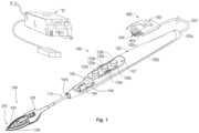
- FIG. 1is a perspective view of a commonly-owned electrosurgical system including an electrosurgical pencil including a housing having a shaft extending therefrom with an end effector attached to a distal end thereof, the end effector configured for bipolar resection in accordance with an embodiment of the present disclosure;
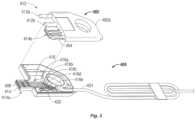
- FIG. 2is a front, top perspective view of the electrosurgical pencil of FIG. 1 , with a top-half shell of the housing removed;
- FIG. 3is a perspective view of the plug assembly of FIG. 1 , with a top-half shell section removed therefrom;
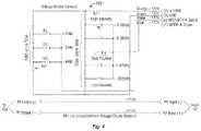
- FIG. 4is a schematic illustration of a voltage divider network for use with the electrosurgical pencil of FIG. 1 and embodiments according to the present disclosure
- FIG. 5 Ais an enlarged, top view of one embodiment of an end effector assembly according to the present disclosure
- FIG. 5 Bis an enlarged, side view of the end effector assembly of FIG. 5 A ;
- FIG. 5 Cis an enlarged, top view of the end effector assembly of FIG. 5 A shown in a first articulated position
- FIG. 5 Dis an enlarged, top view of the end effector assembly of FIG. 5 A shown in a second articulated position
- FIG. 5 Eis schematic view of the end effector assembly of FIG. 5 A shown in use treating tissue “T”.
- distalrefers to that portion which is further from the user while the term “proximal” refers to that portion which is closer to the user or clinician.
- leading edgerefers to the most forward edge with respect to the direction of travel while the term “trailing edge” refers to the edge opposite the leading edge with respect to the direction of travel.
- FIG. 1sets forth a perspective view of an electrosurgical system including a commonly-owned electrosurgical pencil 100 constructed for bipolar resection in accordance with one embodiment of the present disclosure. While the following description is directed towards electrosurgical pencils for bipolar resection, the features and concepts (or portions thereof) of the present disclosure may be applied to any electrosurgical type instrument, e.g., forceps, suction coagulators, vessel sealers, wands, etc. The construction, functionality and operation of electrosurgical pencils, with respect to use for bipolar resection, is described herein. Further details of the electrosurgical pencil are provided in commonly-owned U.S. patent application Ser. No. 16/540,593 filed Aug. 14, 2019 by Baril et al., the entire contents of which being incorporated by reference herein.
- Electrosurgical pencil 100includes an elongated housing 102 having a top-half shell portion 102 a and a bottom-half shell portion 102 b .
- the elongated housing 102includes a distal opening 103 b , through which a shaft 112 of an end effector assembly 200 extends, and a proximal opening 103 a , through which connecting wire 224 (see FIG. 1 ) extends.
- Top-half shell portion 102 a and bottom-half shell portion 102 bmay be bonded together using any suitable method, e.g., sonic energy, adhesives, snap-fit assemblies, etc.
- Electrosurgical pencil 100further includes a shaft receptacle 104 disposed at a distal end 103 b of housing 102 that is configured to receive the shaft 112 of the selectively removable end effector assembly 200 .
- Electrode assembly 200is configured to electrically connect to generator “G” through various electrical conductors (not shown) formed in the shaft 112 , elongated housing 102 , connecting wire 224 and plug assembly 400 .
- Generator “G”may be incorporated into the elongated housing 102 and powered by an internal energy supply, e.g., battery or other energy storage device, fuel cell or other energy generation device or any other suitable portable power source.
- Shaft 112is selectively retained by shaft receptacle 104 disposed in housing 102 .
- Shaft 112may include a plurality of conductive traces or wires (not shown) along the length of the shaft 112 .
- the conductive traces or wiresmay be fabricated from a conductive type material, such as, for example, stainless steel, or shaft may be coated with an electrically conductive material.
- Shaft receptacle 104is fabricated from electrically conductive materials or includes electrically conductive contacts configured to couple with the plurality of conductive traces or wires of the shaft 112 .
- Shaft receptacle 104is electrically connected to voltage divider network 127 ( FIGS. 2 and 4 ) as explained in more detail below.
- Conductive traces or wires of the shaft 112electrically connect to the electrode assembly 200 as explained in more detail below.
- electrosurgical pencil 100may be coupled to a conventional electrosurgical generator “G” via a plug assembly 400 (see FIG. 3 ), as will be described in greater detail below.
- switchincludes electrical actuators, mechanical actuators, electro-mechanical actuators (rotatable actuators, pivotable actuators, toggle-like actuators, buttons, etc.) or optical actuators.
- Electrosurgical pencil 100includes one or more activation switches, and may include three activation switches 120 a - 120 c , each of which extends through top-half shell portion 102 a of elongated housing 102 .
- Each activation switch 120 a - 120 cis operatively supported on a respective tactile element 122 a - 122 c provided on a switch plate 124 , as illustrated in FIG. 2 .
- Each activation switch 120 a - 120 ccontrols the transmission of RF electrical energy supplied from generator “G” to bipolar electrodes 138 on electrode face 105 of electrode body 112 .
- switch plate 124is positioned on top of a voltage divider network 127 (hereinafter “VDN 127 ”) such that tactile elements 122 a - 122 c are operatively associated therewith.
- VDN 127e.g., here shown in FIG. 2 as a film-type potentiometer
- VDN 127forms a switch closure.
- the term “voltage divider network”relates to any known form of resistive, capacitive or inductive switch closure (or the like) which determines the output voltage across a voltage source (e.g., one of two impedances) connected in series.
- a “voltage divider” as used hereinrelates to a number of resistors connected in series which are provided with taps at certain points to make available a fixed or variable fraction of the applied voltage. Further details of electrosurgical pencil control are provided in above-mentioned U.S. patent application Ser. No. 16/540,593.
- electrosurgical generator “G”In use, depending on which activation switch 120 a - 120 c is depressed a respective tactile element 122 a - 122 c is pressed into contact with VDN 127 and a characteristic signal is transmitted to electrosurgical generator “G” via control wires 416 (see FIG. 3 ).
- three control wires 416 a - 416 c(one for each activation switch 120 a - 120 c , respectively) are provided.
- Control wires 416 a - 416 care electrically connected to switches 120 a - 120 c via a control terminal 215 (see FIG. 2 ) which is operatively connected to VDN 127 .
- electrosurgical generator “G”may be used in conjunction with the device wherein generator “G” includes a circuit for interpreting and responding to the VDN 127 settings.
- Activation switches 120 a , 120 b , 120 care configured and adapted to control the mode and/or “waveform duty cycle” to achieve a desired surgical intent.
- a first activation switch 120 acan be set to deliver a characteristic signal to electrosurgical generator “G” which, in turn, transmits a duty cycle and/or waveform shape that produces a first desirable resection effect.
- second activation switch 120 bcan be set to deliver a characteristic signal to electrosurgical generator “G” which, in turn, transmits a duty cycle and/or waveform shape that produces a second desirable resection effect.
- third activation switch 120 ccan be set to deliver a characteristic signal to electrosurgical generator “G” which, in turn, transmits a duty cycle and/or waveform shape that produces a third electrosurgical effect/function.
- Desirable resection effectsmay include a mode for bipolar coagulation and/or cauterization with an undeployed blade, a mode for bipolar resection with a partially deployed blade, a mode for bipolar resection with a fully deployed blade, a mode for monopolar resection and a mode for resection with blended energy delivery (monopolar and bipolar modes), as will be described in greater detail hereinbelow.
- fourth and fifth wiresare provided and electrically connect to respective active and return electrodes 239 , 234 of the end effector assembly 200 (See FIG. 1 ). Since first RF line 416 d and second RF line 416 e are directly connected to the end effector assembly 200 , first RF line 416 d and second RF line 416 e bypass the VDN 127 and are isolated from VDN 127 and control wires 416 a - 416 c .
- the electrosurgical currentdoes not flow through VDN 127 . This, in turn, increases the longevity and life of VDN 127 and/or activation switches 120 a , 120 b , 120 c.
- VDN 127is shown and includes a first transmission line 127 a configured to operate the various modes of electrosurgical pencil 100 ; a second transmission line 127 b configured to operate the various intensities of electrosurgical pencil 100 ; a third transmission line 127 c configured to function as a ground for VDN 127 ; and a fourth transmission line 127 d which transmits up to about +5 volts to VDN 127 .
- First RF line 416 d and second RF line 416 eare isolated from or otherwise completely separate from VDN 127 .
- first RF line 416 d and second RF line 416 eextends directly from the RF input or generator “G” to the active electrode 239 and return electrodes 234 a , 234 b of the end effector assembly 200 as explained in more detail below.
- VDN 127may include a plurality of resistors “R 1 ” (e.g., six resistors), connected in a first series between third transmission line 127 c and fourth transmission line 127 d .
- the first series of resistors “R 1 ”may combine to total about 1000 ohms of resistance.
- the first series of resistors “R 1 ”are each separated by a first set of switches “S 1 ”. Each switch of the first set of switches “S 1 ” may be electrically connected between adjacent resistors “R 1 ” and first transmission line 127 a of VDN 127 . In operation, depending on which switch or switches of the first set of switches “S 1 ” is/are closed, a different mode of operation for electrosurgical pencil 100 is activated.
- Resectionmay be performed with electrosurgical energy including waveforms having a duty cycle from about 10% to about 100%.
- the dual effect of coagulating and cauterizing, as described herein,may be performed with a waveform having a duty cycle from about 10% to about 100%.
- To increase the depth of coagulationmay require a waveform with a duty cycle from about 50% to 100%. It is important to note that these percentages are approximated and may be customized to deliver the desired surgical effect for various tissue types and characteristics.
- the waveforms provided to the bipolar electrosurgical pencil 100may be dynamically controlled by the generator “G”.
- the mode of operation provided by switches S 1 , S 2 , S 3may indicate a range of operation for the generator “G”.
- Generator “G”provides a waveform within the specified range of operation wherein the waveform is dynamically changed based on a parameter, wherein the parameter may be related to one of energy delivery, the target tissue and the duration of energy delivery.
- the parametermay be obtained from a source external to the generator “G”, such as, a measured parameter or clinician provided parameter, or the parameter may include an internal parameter obtained, measured or determined by the generator “G”.
- electrosurgical pencil 100further includes an intensity controller 128 slidingly supported on or in elongated housing 102 .
- Intensity controller 128may be configured to function as a slide potentiometer, sliding over and along VDN 127 wherein the distal-most position corresponds to a relative high intensity setting, the proximal-most position corresponds to a low intensity settings with a plurality of intermediate positions therebetween.
- the intensity settings from the proximal end to the distal endmay be reversed, e.g., high to low.
- the intensity settingsare typically preset and selected from a look-up table based on a choice of electrosurgical instruments/attachments, desired surgical effect, surgical specialty and/or surgeon preference, the type of end effector assembly 200 and the arrangement of the active and return electrodes 239 , 234 .
- the selection of the end effector assembly 200 , the intensity setting and duty cycledetermines the surgical effect.
- the settingsmay be selected manually by the user or automatically.
- the electrosurgical generator “G”may automatically determine the type of end effector assembly 200 and a predetermined intensity value may be selected and subsequently adjusted by the user or the electrosurgical generator “G”.
- Plug assembly 400includes a housing portion 402 and a connecting wire 424 that electrically interconnects the housing portion 402 and the control terminal 215 in the electrosurgical pencil 100 (see FIG. 2 ).
- Housing portion 402includes a first half-section 402 a and a second half-section 402 b operatively engageable with one another, e.g., via a snap-fit engagement.
- First half-section 402 a and second half-section 402 bare configured and adapted to retain a common power pin 404 and a plurality of electrical contacts 406 therebetween.
- Common power pin 404 of plug assembly 400extends distally from housing portion 402 at a location between first half-section 402 a and second half-section 402 b .
- Common power pin 404may be positioned to be off center, i.e., closer to one side edge of housing portion 402 than the other.
- Plug assembly 400further includes at least one a pair of position pins 412 also extending from housing portion 402 .
- Position pins 412may be positioned between the first half-section 402 a and the second half-section 402 b of housing portion 402 and are oriented in the same direction as common power pin 404 .
- a first position pin 412 ais positioned in close proximity to a center of housing portion 402 and a second position pin 412 b is positioned to be off center and in close proximity to an opposite side edge of housing portion 402 as compared to common power pin 404 .
- First position pin 412 a , second position pin 412 b and common power pin 404may be located on housing portion 402 at locations which correspond to pin receiving positions (not shown) of a connector receptacle “R” of electrosurgical generator “G” (see FIG. 1 ).
- Plug assembly 400further includes a prong 414 extending from housing portion 402 .
- prong 414includes a body portion 414 a extending from second half-section 402 b of housing portion 402 and a cover portion 414 b extending from first half-section 402 a of housing portion 402 .
- cover portion 414 b of prong 414encloses the body portion 414 a .
- Prong 414may be positioned between common power pin 404 and first position pin 412 a .
- Prong 414is configured and adapted to retain electrical contacts 406 therein such that a portion of each electrical contact 406 is exposed along a front or distal edge thereof. While five electrical contacts 406 are shown, any number of electrical contacts 406 can be provided, including and not limited to two, six and eight. Prong 414 may be located on housing portion 402 at a location that corresponds to a prong receiving position (not shown) of connector receptacle “R” of electrosurgical generator “G” (see FIG. 1 ).
- prong 414extends from second half-section 402 b of housing portion 402 , housing portion 402 of plug assembly 400 will not enter connector receptacle “R” of electrosurgical generator “G” unless housing portion 402 is in a proper orientation. In other words, prong 414 functions as a polarization member. This ensures that common power pin 404 is properly received in connector receptacle “R” of electrosurgical generator “G”.
- Connecting wire 424includes a power supplying wire 420 electrically connected to common power pin 404 , control wires 416 a - 416 c electrically connected to a respective electrical contact 406 , and first RF line 416 d and second RF line 416 e electrically connected to a respective electrical contact 406 .
- End effector 300includes a shaft 312 ( FIG. 5 B ) having an exposed proximal portion 314 configured to mechanically and electrically engage an active electrical connection 108 of pencil 100 (See FIG. 1 ).
- a more distal portion of shaft 312is configured to engage a shaft receptacle 104 which ultimately connects to a electrical ground.
- a plurality of suitable electrical connectionsmay be disposed within housing 102 to facilitate the delivery of electrosurgical energy from the electrosurgical generator “G” (See FIG. 1 ) to an active electrode 379 and return or ground electrode 374 ( FIG. 5 B ) of tip assembly 375 .
- Shaft 312is coaxial, i.e., shaft 312 is configured to include both an active connection and a ground return connection. Specifically, a proximal-most tip of shaft 312 includes the exposed active pin 314 which is then concentrically-insulated from the outer ground connection or sleeve 340 that connects to receptacle 104 . Further insulation (not shown) surrounds the ground connection. Active pin 314 is configured to electrically and mechanically engage electrical connector 108 and outer ground connection 340 is configured to electrically and mechanically engage shaft receptacle 104 .
- Shaft 312 and/or shaft receptacle 104may include a locking device, such as, for example, a shaft locking pin that slides into and engages a shaft locking pin receptacle (not explicitly shown). Any suitable securing and/or locking apparatus may be used to releasably secure the shaft 312 to the elongated housing 102 . As described herein, the shaft 312 may be interchangeable within a distal end 107 of the elongated housing 102 . In other embodiments, shaft 312 is integrated into the elongated housing 102 and is not replaceable.
- a locking devicesuch as, for example, a shaft locking pin that slides into and engages a shaft locking pin receptacle (not explicitly shown). Any suitable securing and/or locking apparatus may be used to releasably secure the shaft 312 to the elongated housing 102 . As described herein, the shaft 312 may be interchangeable within a distal end 107 of the elongated housing 102 . In
- bipolar tip assembly 375 of electrode assembly 300includes an insulative support 376 , e.g., a ceramic core, configured to support active electrode or active wire 379 , e.g., a tungsten wire, around a peripheral surface thereof. Active wire 379 may be crimped or otherwise secured about all or a portion of the ceramic core 376 . Active wire 379 electrically couples to active pin 314 which, in turn, electrically couples to contact 108 disposed in housing 102 .
- active electrode or active wire 379e.g., a tungsten wire
- a ground return plate 374is disposed along the tip assembly 375 and through electrode assembly 300 for connection to corresponding receptacle 104 disposed in distal opening 103 b upon engagement of the end effector assembly 300 with the housing 102 for ultimate connection to a ground (See FIG. 1 ).
- Shaft receptacle 104may include one or more mechanical interfaces, e.g., step-like surfaces, to facilitate engagement of the end effector 300 with housing 102 .
- Contact 108operably couples to one or more switches 120 a - 120 c (See FIG. 2 ) disposed on housing 102 used to activate the generator “G” to energize the electrodes, e.g., active wire 379 and ground return plate 374 , in a bipolar manner.
- the variously described switches 120 a - 120 c with respect to FIGS. 1 - 4may also be utilized along with the intensity controllers 129 a , 129 b associated therewith.
- electrode assembly 300includes an articulation assembly 330 configured to allow mechanical articulation of the tip assembly 375 either prior to use or during use thereof.
- Articulation assembly 330includes a U-shaped articulation or locking plate 331 pivotably mounted to housing 320 via pivot 345 and attached at a distal surface thereof to the tip assembly 375 .
- Pivot 345allows the tip assembly 375 to be articulated toward the left “RL” or to the right “RR” depending upon a particular purpose.
- the tip assembly 375may be articulated in the direction “RL” at an angle alpha ( ⁇ ) in the range of about 0 to about 30 degrees.
- the tip assembly 375may be articulated in the direction “RR” at an angle beta ( ⁇ ) in the range of about 0 to about 30 degrees.
- U-shaped plate 331includes a series of locking holes 335 a - 335 e defined in each side of the plate 331 that are configured to align in transverse pairs on either side of the pivot 345 .
- the holes 335 a - 335 emay be defined in the locking plate 331 in an arcuate manner.
- a pair of resilient locking fingers 332 a and 332 bextends distally from housing 320 and is configured to engage locking holes 335 a - 335 e to lock the tip assembly 375 at an angle alpha ( ⁇ ) or an angle beta ( ⁇ ) depending upon a particular purpose.
- each locking finger 332 a , 332 bincludes a substantially right angled hook portion 334 a and 334 b that extends transversally relative to a longitudinal axis “A” defined through the electrode assembly 300 ( FIGS. 5 C and 5 D ).
- Each hook portion 334 a and 334 bis configured to engage one of a respective pair of locking holes, e.g., locking holes 335 c , to lock the plate 331 at a specific angle alpha ( ⁇ ) or angle beta ( ⁇ ).
- Each hook portion 334 a and 334 bis configured to resiliently flex inwardly under a bias toward axis “A” to allow selective release of plate 331 therefrom and allow manual rotation of the plate 331 and tip assembly 375 to a desired angle alpha ( ⁇ ) or an angle beta ( ⁇ ).
- the hook portions 334 a and 334 bmay be released which causes the hook portions 334 a and 334 b to flex outwardly relative to axis “A” to engage a corresponding pair of opposing locking holes, e.g., locking holes 335 d.
- the tip assembly 375may be oriented to a desired angle alpha ( ⁇ ) or an angle beta ( ⁇ ) prior to surgery or at any time during surgery. Any number of locking holes 335 a - 335 e may be utilized to provide more flexibility and angles of operation to the surgeon. Moreover, the surgeon may opt to maintain the tip assembly 375 at a neutral angle, i.e., wherein the tip assembly 375 remains in-line with axis “A”. Angulation of the tip assembly 375 provides better access and visibility to the surgical site and tissue specimens “T” ( FIG. 5 E ).
- the various embodiments disclosed hereinmay also be configured to work with robotic surgical systems and what is commonly referred to as “Telesurgery.”
- Such systemsemploy various robotic elements to assist the clinician and allow remote operation (or partial remote operation) of surgical instrumentation.
- Various robotic arms, gears, cams, pulleys, electric and mechanical motors, etc.may be employed for this purpose and may be designed with a robotic surgical system to assist the clinician during the course of an operation or treatment.
- Such robotic systemsmay include remotely steerable systems, automatically flexible surgical systems, remotely flexible surgical systems, remotely articulating surgical systems, wireless surgical systems, modular or selectively configurable remotely operated surgical systems, etc.
- the robotic surgical systemsmay be employed with one or more consoles that are next to the operating theater or located in a remote location.
- one team of cliniciansmay prep the patient for surgery and configure the robotic surgical system with one or more of the instruments disclosed herein while another clinician (or group of clinicians) remotely controls the instruments via the robotic surgical system.
- another clinicianor group of clinicians
- a highly skilled clinicianmay perform multiple operations in multiple locations without leaving his/her remote console which can be both economically advantageous and a benefit to the patient or a series of patients.
Landscapes
- Health & Medical Sciences (AREA)
- Surgery (AREA)
- Engineering & Computer Science (AREA)
- Life Sciences & Earth Sciences (AREA)
- Biomedical Technology (AREA)
- Otolaryngology (AREA)
- Nuclear Medicine, Radiotherapy & Molecular Imaging (AREA)
- Plasma & Fusion (AREA)
- Physics & Mathematics (AREA)
- Heart & Thoracic Surgery (AREA)
- Medical Informatics (AREA)
- Molecular Biology (AREA)
- Animal Behavior & Ethology (AREA)
- General Health & Medical Sciences (AREA)
- Public Health (AREA)
- Veterinary Medicine (AREA)
- Surgical Instruments (AREA)
Abstract
Description
Claims (11)
Priority Applications (1)
| Application Number | Priority Date | Filing Date | Title |
|---|---|---|---|
| US16/781,557US11596467B2 (en) | 2020-02-04 | 2020-02-04 | Articulating tip for bipolar pencil |
Applications Claiming Priority (1)
| Application Number | Priority Date | Filing Date | Title |
|---|---|---|---|
| US16/781,557US11596467B2 (en) | 2020-02-04 | 2020-02-04 | Articulating tip for bipolar pencil |
Publications (2)
| Publication Number | Publication Date |
|---|---|
| US20210236194A1 US20210236194A1 (en) | 2021-08-05 |
| US11596467B2true US11596467B2 (en) | 2023-03-07 |
Family
ID=77062555
Family Applications (1)
| Application Number | Title | Priority Date | Filing Date |
|---|---|---|---|
| US16/781,557Active2041-02-14US11596467B2 (en) | 2020-02-04 | 2020-02-04 | Articulating tip for bipolar pencil |
Country Status (1)
| Country | Link |
|---|---|
| US (1) | US11596467B2 (en) |
Families Citing this family (1)
| Publication number | Priority date | Publication date | Assignee | Title |
|---|---|---|---|---|
| US11931067B2 (en) | 2020-08-15 | 2024-03-19 | Covidien Lp | Insertable cutting guards |
Citations (136)
| Publication number | Priority date | Publication date | Assignee | Title |
|---|---|---|---|---|
| US2022065A (en) | 1932-07-07 | 1935-11-26 | Frederick C Wappler | Therapeutic applicator device |
| US2047535A (en) | 1932-10-07 | 1936-07-14 | Frederick C Wappler | Surgical electrodes |
| US3516412A (en) | 1965-08-16 | 1970-06-23 | Electro Catheter Corp | Bipolar electrode having irregularity at inserting end thereof and method of insertion |
| US3886944A (en) | 1973-11-19 | 1975-06-03 | Khosrow Jamshidi | Microcautery device |
| US3911241A (en)* | 1972-12-15 | 1975-10-07 | Neomed Inc | Switching device for electro-surgical instruments |
| US3920022A (en)* | 1974-04-19 | 1975-11-18 | Macey A Pastor | Surgical instrument |
| US4161950A (en) | 1975-08-01 | 1979-07-24 | The United States Of America As Represented By The United States Department Of Energy | Electrosurgical knife |
| US4170234A (en)* | 1977-10-11 | 1979-10-09 | Dytek Corporation | System for use with electro-surgical pencil |
| US4196734A (en) | 1978-02-16 | 1980-04-08 | Valleylab, Inc. | Combined electrosurgery/cautery system and method |
| US4198957A (en) | 1967-11-09 | 1980-04-22 | Robert F. Shaw | Method of using an electrically heated surgical cutting instrument |
| US4485810A (en) | 1980-10-28 | 1984-12-04 | Oximetrix, Inc. | Surgical cutting blade |
| US4534347A (en) | 1983-04-08 | 1985-08-13 | Research Corporation | Microwave coagulating scalpel |
| US4622966A (en) | 1981-06-30 | 1986-11-18 | Abbott Laboratories | Surgical cutting device |
| US4633880A (en) | 1984-04-06 | 1987-01-06 | Peter Osypka | Surgical electrode |
| US4862890A (en) | 1988-02-29 | 1989-09-05 | Everest Medical Corporation | Electrosurgical spatula blade with ceramic substrate |
| US5013312A (en) | 1990-03-19 | 1991-05-07 | Everest Medical Corporation | Bipolar scalpel for harvesting internal mammary artery |
| US5085659A (en) | 1990-11-21 | 1992-02-04 | Everest Medical Corporation | Biopsy device with bipolar coagulation capability |
| US5176702A (en)* | 1991-04-04 | 1993-01-05 | Symbiosis Corporation | Ratchet locking mechanism for surgical instruments |
| US5275608A (en)* | 1991-10-16 | 1994-01-04 | Implemed, Inc. | Generic endoscopic instrument |
| US5300068A (en) | 1992-04-21 | 1994-04-05 | St. Jude Medical, Inc. | Electrosurgical apparatus |
| US5360428A (en) | 1992-07-22 | 1994-11-01 | Hutchinson Jr William B | Laparoscopic instrument with electrical cutting wires |
| US5395367A (en)* | 1992-07-29 | 1995-03-07 | Wilk; Peter J. | Laparoscopic instrument with bendable shaft and removable actuator |
| US5441499A (en) | 1993-07-14 | 1995-08-15 | Dekna Elektro-U. Medizinische Apparatebau Gesellschaft Mbh | Bipolar radio-frequency surgical instrument |
| US5454827A (en)* | 1994-05-24 | 1995-10-03 | Aust; Gilbert M. | Surgical instrument |
| US5467763A (en)* | 1992-01-21 | 1995-11-21 | Mcmahon; Michael J. | Surgical instruments |
| US5490819A (en)* | 1991-08-05 | 1996-02-13 | United States Surgical Corporation | Articulating endoscopic surgical apparatus |
| US5514157A (en)* | 1992-02-12 | 1996-05-07 | United States Surgical Corporation | Articulating endoscopic surgical apparatus |
| US5520678A (en)* | 1993-11-30 | 1996-05-28 | Richard Wolf Gmbh | Manipulator arm with proximal and distal control balls |
| US5531744A (en) | 1991-11-01 | 1996-07-02 | Medical Scientific, Inc. | Alternative current pathways for bipolar surgical cutting tool |
| US5536267A (en) | 1993-11-08 | 1996-07-16 | Zomed International | Multiple electrode ablation apparatus |
| US5540706A (en)* | 1993-01-25 | 1996-07-30 | Aust; Gilbert M. | Surgical instrument |
| US5582617A (en)* | 1993-07-21 | 1996-12-10 | Charles H. Klieman | Surgical instrument for endoscopic and general surgery |
| US5599295A (en) | 1992-08-12 | 1997-02-04 | Vidamed, Inc. | Medical probe apparatus with enhanced RF, resistance heating, and microwave ablation capabilities |
| US5599346A (en) | 1993-11-08 | 1997-02-04 | Zomed International, Inc. | RF treatment system |
| US5611798A (en) | 1995-03-02 | 1997-03-18 | Eggers; Philip E. | Resistively heated cutting and coagulating surgical instrument |
| US5693044A (en)* | 1992-12-11 | 1997-12-02 | Cosmescu; Ioan | Telescopic surgical device and method therefor |
| US5702408A (en)* | 1996-07-17 | 1997-12-30 | Ethicon Endo-Surgery, Inc. | Articulating surgical instrument |
| US5752951A (en)* | 1996-07-02 | 1998-05-19 | Yanik; Gary W. | Shielded monopolar electrosurgical apparatus |
| US5849011A (en)* | 1995-06-19 | 1998-12-15 | Vidamed, Inc. | Medical device with trigger actuation assembly |
| US5916146A (en)* | 1995-12-22 | 1999-06-29 | Bieffe Medital S.P.A. | System for support and actuation with vertebrae in particular for surgical and diagnostic instruments |
| US6027501A (en) | 1995-06-23 | 2000-02-22 | Gyrus Medical Limited | Electrosurgical instrument |
| US6113599A (en)* | 1997-06-04 | 2000-09-05 | Kalpa Engineering, Inc. | Apparatus for internal mandibular distraction |
| US6190385B1 (en)* | 1998-12-11 | 2001-02-20 | Ethicon, Inc. | Cable for bipolar electro-surgical instrument |
| US6217528B1 (en) | 1999-02-11 | 2001-04-17 | Scimed Life Systems, Inc. | Loop structure having improved tissue contact capability |
| US20020022838A1 (en)* | 2000-02-16 | 2002-02-21 | Sherwood Services Ag | Inert gas inhanced electrosurgical apparatus |
| US6361532B1 (en)* | 1996-05-01 | 2002-03-26 | Bovie Medical Corporation | Electrosurgical pencil |
| US6494881B1 (en) | 1997-09-30 | 2002-12-17 | Scimed Life Systems, Inc. | Apparatus and method for electrode-surgical tissue removal having a selectively insulated electrode |
| US6530924B1 (en) | 2000-11-03 | 2003-03-11 | Alan G. Ellman | Electrosurgical tonsilar and adenoid electrode |
| US6533781B2 (en) | 1997-12-23 | 2003-03-18 | Team Medical Llc | Electrosurgical instrument |
| US6752767B2 (en) | 2002-04-16 | 2004-06-22 | Vivant Medical, Inc. | Localization element with energized tip |
| US20040236316A1 (en)* | 2003-05-23 | 2004-11-25 | Danitz David J. | Articulating mechanism for remote manipulation of a surgical or diagnostic tool |
| US20050070895A1 (en) | 2003-09-30 | 2005-03-31 | Thomas Ryan | Electrosurgical instrument and method for transecting an organ |
| US20050107667A1 (en)* | 2003-05-23 | 2005-05-19 | Novare Surgical Systems, Inc. | Hand-actuated device for remote manipulation of a grasping tool |
| US20050273085A1 (en)* | 2004-06-07 | 2005-12-08 | Novare Surgical Systems, Inc. | Articulating mechanism with flex-hinged links |
| US20050273084A1 (en)* | 2004-06-07 | 2005-12-08 | Novare Surgical Systems, Inc. | Link systems and articulation mechanisms for remote manipulation of surgical or diagnostic tools |
| US20050283149A1 (en) | 2004-06-08 | 2005-12-22 | Thorne Jonathan O | Electrosurgical cutting instrument |
| US20060020287A1 (en)* | 2003-10-30 | 2006-01-26 | Woojin Lee | Surgical instrument |
| US7033354B2 (en) | 2002-12-10 | 2006-04-25 | Sherwood Services Ag | Electrosurgical electrode having a non-conductive porous ceramic coating |
| US20060111209A1 (en)* | 2004-11-23 | 2006-05-25 | Novare Surgical Systems, Inc. | Articulating mechanisms and link systems with torque transmission in remote manipulation of instruments and tools |
| US20060111615A1 (en)* | 2004-11-23 | 2006-05-25 | Novare Surgical Systems, Inc. | Articulating sheath for flexible instruments |
| US20060178667A1 (en)* | 2003-11-20 | 2006-08-10 | Sartor Joe D | Electrosurgical pencil with advanced es controls |
| US20070078454A1 (en) | 2005-09-30 | 2007-04-05 | Mcpherson James W | System and method for creating lesions using bipolar electrodes |
| US20070118110A1 (en) | 2005-11-18 | 2007-05-24 | Boston Scientific Scimed, Inc. | Radio frequency lasso |
| US20070149966A1 (en) | 1995-11-22 | 2007-06-28 | Arthrocare Corporation | Electrosurgical Apparatus and Methods for Treatment and Removal of Tissue |
| US20070179494A1 (en) | 2003-05-16 | 2007-08-02 | Andre Faure | Medical device using a coiled electrode |
| US20070198009A1 (en)* | 2006-01-31 | 2007-08-23 | Macdonald Bruce | Electrosurgery pencil |
| US20070219546A1 (en) | 2006-03-17 | 2007-09-20 | Mody Dinesh I | Devices and methods for creating continuous lesions |
| US20070260240A1 (en) | 2006-05-05 | 2007-11-08 | Sherwood Services Ag | Soft tissue RF transection and resection device |
| US20070265609A1 (en) | 2006-05-12 | 2007-11-15 | Thapliyal Hira V | Method for Ablating Body Tissue |
| US20070282371A1 (en)* | 2006-06-05 | 2007-12-06 | Cambridge Endoscopic Devices, Inc. | Surgical instrument |
| US20080015631A1 (en)* | 2006-07-11 | 2008-01-17 | Woojin Lee | Surgical instrument |
| US20080046000A1 (en)* | 2006-08-16 | 2008-02-21 | Woojin Lee | Surgical instrument |
| US20080058595A1 (en)* | 2006-06-14 | 2008-03-06 | Snoke Phillip J | Medical device introduction systems and methods |
| US7371234B2 (en) | 2005-05-18 | 2008-05-13 | Boston Scienitific Scimed, Inc. | Low profile radiofrequency electrode array |
| US7399299B2 (en) | 2003-07-11 | 2008-07-15 | S.D.M.H. Pty. Ltd. | Thermal ablation of biological tissue |
| US7419488B2 (en) | 2001-02-09 | 2008-09-02 | Arthrocare Corporation | Electrosurgical probe with movable return electrode and methods related thereto |
| US20080281323A1 (en) | 1999-01-27 | 2008-11-13 | Burbank Fred H | Tissue specimen isolating and damaging device and method |
| US20080312668A1 (en)* | 1996-11-22 | 2008-12-18 | Intuitive Surgical, Inc. | Rigidly-linked articulating wrist with decoupled motion transmission |
| US20090069804A1 (en)* | 2007-09-12 | 2009-03-12 | Jensen Jeffrey L | Apparatus for efficient power delivery |
| US20090138006A1 (en)* | 2007-11-28 | 2009-05-28 | Bales Thomas O | Cordless power-assisted medical cauterization and cutting device |
| US20090248017A1 (en)* | 2008-03-31 | 2009-10-01 | Tyco Healthcare Group Lp | Electrosurgical Pencil Including Improved Controls |
| US20090306642A1 (en) | 2008-06-10 | 2009-12-10 | Vankov Alexander B | Method for low temperature electrosugery and rf generator |
| US20100010512A1 (en)* | 2006-10-05 | 2010-01-14 | Taylor Eric J | Flexible endoscopic stitching devices |
| US20100041945A1 (en)* | 2008-08-18 | 2010-02-18 | Isbell Jr Lewis | Instrument with articulation lock |
| US20100286480A1 (en)* | 2009-05-06 | 2010-11-11 | Peine William J | Surgical instrument |
| US7846158B2 (en) | 2006-05-05 | 2010-12-07 | Covidien Ag | Apparatus and method for electrode thermosurgery |
| US20110184459A1 (en)* | 2008-08-04 | 2011-07-28 | Malkowski Jaroslaw T | Articulating Surgical Device |
| US20110230875A1 (en)* | 2008-02-06 | 2011-09-22 | Erik Walberg | Articulable electrosurgical instrument with a stabilizable articulation actuator |
| US8137345B2 (en) | 2009-01-05 | 2012-03-20 | Peak Surgical, Inc. | Electrosurgical devices for tonsillectomy and adenoidectomy |
| US20120116416A1 (en) | 2010-11-08 | 2012-05-10 | Kuka Laboratories Gmbh | Medical Workstation |
| US20120330307A1 (en)* | 2011-06-23 | 2012-12-27 | Tyco Healthcare Group Lp | Shaped Electrode Bipolar Resection Apparatus, System and Methods of Use |
| US20130023924A1 (en)* | 2011-07-20 | 2013-01-24 | Tyco Healthcare Group Lp | Articulating Surgical Apparatus |
| US20130023911A1 (en)* | 2010-04-02 | 2013-01-24 | Catalin Esanu | Surgical endoscopic device with detachable clamp, clamp retrieving device and method for their use |
| US20130304049A1 (en)* | 2012-05-11 | 2013-11-14 | Tyco Healthcare Group Lp | System and Method for Directing Energy to Tissue |
| US20130331830A1 (en)* | 2012-06-12 | 2013-12-12 | Covidien Lp | Electrosurgical dissector with thermal management |
| US20140121595A1 (en)* | 2012-10-30 | 2014-05-01 | Troy T. Tegg | Push-coil steering mechanism |
| US20140257276A1 (en)* | 2013-03-06 | 2014-09-11 | Covidien Lp | System and method for sinus surgery |
| US8968301B2 (en) | 2012-12-31 | 2015-03-03 | Tdm Surgitech, Inc. | Apparatus, systems and methods for tissue dissection and modification |
| US9060765B2 (en) | 2010-11-08 | 2015-06-23 | Bovie Medical Corporation | Electrosurgical apparatus with retractable blade |
| US20150359585A1 (en)* | 2014-06-11 | 2015-12-17 | Tdm Surgitech, Inc. | Apparatus, systems, and methods for dissection and modification of tissues |
| WO2016025132A1 (en) | 2014-08-13 | 2016-02-18 | Covidien Lp | Robotically controlling mechanical advantage gripping |
| US20160074028A1 (en)* | 2013-05-20 | 2016-03-17 | Medrobotics Corporation | Articulating surgical instruments and method of deploying the same |
| US20160143658A1 (en)* | 2014-11-25 | 2016-05-26 | Ethicon Endo-Surgery, Inc. | Features to drive fluid toward an ultrasonic blade of a surgical instrument |
| US9445863B2 (en) | 2013-03-15 | 2016-09-20 | Gyrus Acmi, Inc. | Combination electrosurgical device |
| US20160310816A1 (en)* | 2015-04-21 | 2016-10-27 | True Turn, Inc. | Thoracic isolation and training system |
| US20160331455A1 (en)* | 2013-12-23 | 2016-11-17 | Creo Medical Limited | Electrosurgical forceps for delivering rf and/or microwave energy into biological tissue |
| US20170105786A1 (en)* | 2015-10-16 | 2017-04-20 | Ethicon Endo-Surgery, Llc | Electrode wiping surgical device |
| US20170105782A1 (en)* | 2015-10-16 | 2017-04-20 | Ethicon Endo-Surgery, Llc | Control and electrical connections for electrode endocutter device |
| US20170181604A1 (en)* | 2014-03-17 | 2017-06-29 | Intuitive Surgical Operations, Inc. | Multi-stage instrument connector |
| US20170245933A1 (en)* | 2014-09-18 | 2017-08-31 | Omniguide, Inc. | Laparoscopic handpiece for waveguides |
| US20170273733A1 (en)* | 2016-03-26 | 2017-09-28 | Paul Joseph Weber | Apparatus, systems and methods for minimally invasive dissection of tissues |
| US9775665B2 (en) | 2013-03-15 | 2017-10-03 | Alan G Ellman | Fixed position RF electrode |
| US20170325886A1 (en)* | 2016-05-16 | 2017-11-16 | Omniguide, Inc. | Multi-function handpieces for energy-based surgery |
| US20180078301A1 (en)* | 2016-09-16 | 2018-03-22 | Invuity, Inc. | Methods and apparatus for electrosurgical illumination |
| US20180132850A1 (en)* | 2014-03-26 | 2018-05-17 | Ethicon Llc | Surgical instrument comprising a sensor system |
| US9993287B2 (en) | 2013-03-13 | 2018-06-12 | Covidien Lp | System configured to provide controlled depth of hemostasis |
| US10045761B2 (en) | 2012-12-31 | 2018-08-14 | Tdm Surgitech, Inc. | Systems, apparatus and methods for tissue dissection |
| WO2018162423A1 (en)* | 2017-03-06 | 2018-09-13 | Polydiagnost Entwicklungs-, Produktions-, Vertriebs-, Und Servicegesellschaft Für Medizinelektronische Diagnostik- Und Therapiegeräte Mbh | Endoscope handle and endoscope |
| US20180333195A1 (en)* | 2017-05-18 | 2018-11-22 | Megadyne Medical Products, Inc. | Hand-held instrument with body-swivel |
| US20180353162A1 (en)* | 2015-10-02 | 2018-12-13 | Creo Medical Limited | Biopsy forceps tool |
| US20190125454A1 (en)* | 2017-10-30 | 2019-05-02 | Ethicon Llc | Method of hub communication with surgical instrument systems |
| US20190125361A1 (en)* | 2017-10-30 | 2019-05-02 | Ethicon Llc | Method for operating a powered articulating multi-clip applier |
| US20190125476A1 (en)* | 2017-10-30 | 2019-05-02 | Ethicon Llc | Surgical instrument systems comprising lockout mechanisms |
| US20190175257A1 (en)* | 2016-06-20 | 2019-06-13 | Olympus Corporation | Treatment instrument |
| US10322281B2 (en)* | 2016-11-26 | 2019-06-18 | Xialing Zhang | Adjustable angle neuro stimulation probe apapratus |
| US20190206565A1 (en)* | 2017-12-28 | 2019-07-04 | Ethicon Llc | Method for operating surgical instrument systems |
| US20190201021A1 (en)* | 2017-12-28 | 2019-07-04 | Ethicon Llc | Surgical instrument having a flexible circuit |
| US20190201139A1 (en)* | 2017-12-28 | 2019-07-04 | Ethicon Llc | Communication arrangements for robot-assisted surgical platforms |
| US20190201137A1 (en)* | 2017-12-28 | 2019-07-04 | Ethicon Llc | Method of robotic hub communication, detection, and control |
| US10376314B2 (en) | 2006-07-14 | 2019-08-13 | Neuwave Medical, Inc. | Energy delivery systems and uses thereof |
| US10433898B2 (en) | 2015-01-13 | 2019-10-08 | Megadyne Medical Products, Inc. | Tapered precision blade electrosurgical instrument |
| US10433899B2 (en) | 2015-01-13 | 2019-10-08 | Megadyne Medical Products, Inc. | Precision blade electrosurgical instrument |
| US10531917B2 (en) | 2016-04-15 | 2020-01-14 | Neuwave Medical, Inc. | Systems and methods for energy delivery |
| US20210121226A1 (en)* | 2019-10-28 | 2021-04-29 | Medtronic Xomed, Inc. | Articulating medical grasper |
| US20210196356A1 (en)* | 2019-12-30 | 2021-07-01 | Ethicon Llc | Surgical instrument with rotatable and articulatable surgical end effector |
| US20210386473A1 (en)* | 2020-06-12 | 2021-12-16 | Covidien Lp | End effector assembly for bipolar pencil |
- 2020
- 2020-02-04USUS16/781,557patent/US11596467B2/enactiveActive
Patent Citations (143)
| Publication number | Priority date | Publication date | Assignee | Title |
|---|---|---|---|---|
| US2022065A (en) | 1932-07-07 | 1935-11-26 | Frederick C Wappler | Therapeutic applicator device |
| US2047535A (en) | 1932-10-07 | 1936-07-14 | Frederick C Wappler | Surgical electrodes |
| US3516412A (en) | 1965-08-16 | 1970-06-23 | Electro Catheter Corp | Bipolar electrode having irregularity at inserting end thereof and method of insertion |
| US4198957A (en) | 1967-11-09 | 1980-04-22 | Robert F. Shaw | Method of using an electrically heated surgical cutting instrument |
| US3911241A (en)* | 1972-12-15 | 1975-10-07 | Neomed Inc | Switching device for electro-surgical instruments |
| US3886944A (en) | 1973-11-19 | 1975-06-03 | Khosrow Jamshidi | Microcautery device |
| US3920022A (en)* | 1974-04-19 | 1975-11-18 | Macey A Pastor | Surgical instrument |
| US4161950A (en) | 1975-08-01 | 1979-07-24 | The United States Of America As Represented By The United States Department Of Energy | Electrosurgical knife |
| US4170234A (en)* | 1977-10-11 | 1979-10-09 | Dytek Corporation | System for use with electro-surgical pencil |
| US4196734A (en) | 1978-02-16 | 1980-04-08 | Valleylab, Inc. | Combined electrosurgery/cautery system and method |
| US4485810A (en) | 1980-10-28 | 1984-12-04 | Oximetrix, Inc. | Surgical cutting blade |
| US4622966A (en) | 1981-06-30 | 1986-11-18 | Abbott Laboratories | Surgical cutting device |
| US4534347A (en) | 1983-04-08 | 1985-08-13 | Research Corporation | Microwave coagulating scalpel |
| US4633880A (en) | 1984-04-06 | 1987-01-06 | Peter Osypka | Surgical electrode |
| US4862890A (en) | 1988-02-29 | 1989-09-05 | Everest Medical Corporation | Electrosurgical spatula blade with ceramic substrate |
| US5013312A (en) | 1990-03-19 | 1991-05-07 | Everest Medical Corporation | Bipolar scalpel for harvesting internal mammary artery |
| US5085659A (en) | 1990-11-21 | 1992-02-04 | Everest Medical Corporation | Biopsy device with bipolar coagulation capability |
| US5176702A (en)* | 1991-04-04 | 1993-01-05 | Symbiosis Corporation | Ratchet locking mechanism for surgical instruments |
| US5490819A (en)* | 1991-08-05 | 1996-02-13 | United States Surgical Corporation | Articulating endoscopic surgical apparatus |
| US5275608A (en)* | 1991-10-16 | 1994-01-04 | Implemed, Inc. | Generic endoscopic instrument |
| US5531744A (en) | 1991-11-01 | 1996-07-02 | Medical Scientific, Inc. | Alternative current pathways for bipolar surgical cutting tool |
| US5467763A (en)* | 1992-01-21 | 1995-11-21 | Mcmahon; Michael J. | Surgical instruments |
| US5514157A (en)* | 1992-02-12 | 1996-05-07 | United States Surgical Corporation | Articulating endoscopic surgical apparatus |
| US5300068A (en) | 1992-04-21 | 1994-04-05 | St. Jude Medical, Inc. | Electrosurgical apparatus |
| US5360428A (en) | 1992-07-22 | 1994-11-01 | Hutchinson Jr William B | Laparoscopic instrument with electrical cutting wires |
| US5395367A (en)* | 1992-07-29 | 1995-03-07 | Wilk; Peter J. | Laparoscopic instrument with bendable shaft and removable actuator |
| US5599295A (en) | 1992-08-12 | 1997-02-04 | Vidamed, Inc. | Medical probe apparatus with enhanced RF, resistance heating, and microwave ablation capabilities |
| US5693044A (en)* | 1992-12-11 | 1997-12-02 | Cosmescu; Ioan | Telescopic surgical device and method therefor |
| US5540706A (en)* | 1993-01-25 | 1996-07-30 | Aust; Gilbert M. | Surgical instrument |
| US5441499A (en) | 1993-07-14 | 1995-08-15 | Dekna Elektro-U. Medizinische Apparatebau Gesellschaft Mbh | Bipolar radio-frequency surgical instrument |
| US5582617A (en)* | 1993-07-21 | 1996-12-10 | Charles H. Klieman | Surgical instrument for endoscopic and general surgery |
| US5536267A (en) | 1993-11-08 | 1996-07-16 | Zomed International | Multiple electrode ablation apparatus |
| US5599346A (en) | 1993-11-08 | 1997-02-04 | Zomed International, Inc. | RF treatment system |
| US5520678A (en)* | 1993-11-30 | 1996-05-28 | Richard Wolf Gmbh | Manipulator arm with proximal and distal control balls |
| US5454827A (en)* | 1994-05-24 | 1995-10-03 | Aust; Gilbert M. | Surgical instrument |
| US5611798A (en) | 1995-03-02 | 1997-03-18 | Eggers; Philip E. | Resistively heated cutting and coagulating surgical instrument |
| US5849011A (en)* | 1995-06-19 | 1998-12-15 | Vidamed, Inc. | Medical device with trigger actuation assembly |
| US6027501A (en) | 1995-06-23 | 2000-02-22 | Gyrus Medical Limited | Electrosurgical instrument |
| US20070149966A1 (en) | 1995-11-22 | 2007-06-28 | Arthrocare Corporation | Electrosurgical Apparatus and Methods for Treatment and Removal of Tissue |
| US5916146A (en)* | 1995-12-22 | 1999-06-29 | Bieffe Medital S.P.A. | System for support and actuation with vertebrae in particular for surgical and diagnostic instruments |
| US6361532B1 (en)* | 1996-05-01 | 2002-03-26 | Bovie Medical Corporation | Electrosurgical pencil |
| US5752951A (en)* | 1996-07-02 | 1998-05-19 | Yanik; Gary W. | Shielded monopolar electrosurgical apparatus |
| US5702408A (en)* | 1996-07-17 | 1997-12-30 | Ethicon Endo-Surgery, Inc. | Articulating surgical instrument |
| US20100217284A1 (en)* | 1996-11-22 | 2010-08-26 | Intuitive Surgical Operations, Inc. | Rigidly-linked articulating wrist with decoupled motion transmission |
| US20080312668A1 (en)* | 1996-11-22 | 2008-12-18 | Intuitive Surgical, Inc. | Rigidly-linked articulating wrist with decoupled motion transmission |
| US6113599A (en)* | 1997-06-04 | 2000-09-05 | Kalpa Engineering, Inc. | Apparatus for internal mandibular distraction |
| US6494881B1 (en) | 1997-09-30 | 2002-12-17 | Scimed Life Systems, Inc. | Apparatus and method for electrode-surgical tissue removal having a selectively insulated electrode |
| US6533781B2 (en) | 1997-12-23 | 2003-03-18 | Team Medical Llc | Electrosurgical instrument |
| US6190385B1 (en)* | 1998-12-11 | 2001-02-20 | Ethicon, Inc. | Cable for bipolar electro-surgical instrument |
| US20080281323A1 (en) | 1999-01-27 | 2008-11-13 | Burbank Fred H | Tissue specimen isolating and damaging device and method |
| US6217528B1 (en) | 1999-02-11 | 2001-04-17 | Scimed Life Systems, Inc. | Loop structure having improved tissue contact capability |
| US20020022838A1 (en)* | 2000-02-16 | 2002-02-21 | Sherwood Services Ag | Inert gas inhanced electrosurgical apparatus |
| US6530924B1 (en) | 2000-11-03 | 2003-03-11 | Alan G. Ellman | Electrosurgical tonsilar and adenoid electrode |
| US7419488B2 (en) | 2001-02-09 | 2008-09-02 | Arthrocare Corporation | Electrosurgical probe with movable return electrode and methods related thereto |
| US6752767B2 (en) | 2002-04-16 | 2004-06-22 | Vivant Medical, Inc. | Localization element with energized tip |
| US7846108B2 (en) | 2002-04-16 | 2010-12-07 | Vivant Medical, Inc. | Localization element with energized tip |
| US7033354B2 (en) | 2002-12-10 | 2006-04-25 | Sherwood Services Ag | Electrosurgical electrode having a non-conductive porous ceramic coating |
| US20070179494A1 (en) | 2003-05-16 | 2007-08-02 | Andre Faure | Medical device using a coiled electrode |
| US20050107667A1 (en)* | 2003-05-23 | 2005-05-19 | Novare Surgical Systems, Inc. | Hand-actuated device for remote manipulation of a grasping tool |
| US20040236316A1 (en)* | 2003-05-23 | 2004-11-25 | Danitz David J. | Articulating mechanism for remote manipulation of a surgical or diagnostic tool |
| US7399299B2 (en) | 2003-07-11 | 2008-07-15 | S.D.M.H. Pty. Ltd. | Thermal ablation of biological tissue |
| US20050070895A1 (en) | 2003-09-30 | 2005-03-31 | Thomas Ryan | Electrosurgical instrument and method for transecting an organ |
| US20060020287A1 (en)* | 2003-10-30 | 2006-01-26 | Woojin Lee | Surgical instrument |
| US20060178667A1 (en)* | 2003-11-20 | 2006-08-10 | Sartor Joe D | Electrosurgical pencil with advanced es controls |
| US20050273084A1 (en)* | 2004-06-07 | 2005-12-08 | Novare Surgical Systems, Inc. | Link systems and articulation mechanisms for remote manipulation of surgical or diagnostic tools |
| US20050273085A1 (en)* | 2004-06-07 | 2005-12-08 | Novare Surgical Systems, Inc. | Articulating mechanism with flex-hinged links |
| US20050283149A1 (en) | 2004-06-08 | 2005-12-22 | Thorne Jonathan O | Electrosurgical cutting instrument |
| US20060111209A1 (en)* | 2004-11-23 | 2006-05-25 | Novare Surgical Systems, Inc. | Articulating mechanisms and link systems with torque transmission in remote manipulation of instruments and tools |
| US20060111615A1 (en)* | 2004-11-23 | 2006-05-25 | Novare Surgical Systems, Inc. | Articulating sheath for flexible instruments |
| US20060111210A1 (en)* | 2004-11-23 | 2006-05-25 | Novare Surgical Systems, Inc. | Articulating mechanisms and link systems with torque transmission in remote manipulation of instruments and tools |
| US7371234B2 (en) | 2005-05-18 | 2008-05-13 | Boston Scienitific Scimed, Inc. | Low profile radiofrequency electrode array |
| US20070078454A1 (en) | 2005-09-30 | 2007-04-05 | Mcpherson James W | System and method for creating lesions using bipolar electrodes |
| US20070118110A1 (en) | 2005-11-18 | 2007-05-24 | Boston Scientific Scimed, Inc. | Radio frequency lasso |
| US20070198009A1 (en)* | 2006-01-31 | 2007-08-23 | Macdonald Bruce | Electrosurgery pencil |
| US20070219546A1 (en) | 2006-03-17 | 2007-09-20 | Mody Dinesh I | Devices and methods for creating continuous lesions |
| US20070260240A1 (en) | 2006-05-05 | 2007-11-08 | Sherwood Services Ag | Soft tissue RF transection and resection device |
| US7846158B2 (en) | 2006-05-05 | 2010-12-07 | Covidien Ag | Apparatus and method for electrode thermosurgery |
| US20070265609A1 (en) | 2006-05-12 | 2007-11-15 | Thapliyal Hira V | Method for Ablating Body Tissue |
| US20070282371A1 (en)* | 2006-06-05 | 2007-12-06 | Cambridge Endoscopic Devices, Inc. | Surgical instrument |
| US20080058595A1 (en)* | 2006-06-14 | 2008-03-06 | Snoke Phillip J | Medical device introduction systems and methods |
| US20080015631A1 (en)* | 2006-07-11 | 2008-01-17 | Woojin Lee | Surgical instrument |
| US10376314B2 (en) | 2006-07-14 | 2019-08-13 | Neuwave Medical, Inc. | Energy delivery systems and uses thereof |
| US20080046000A1 (en)* | 2006-08-16 | 2008-02-21 | Woojin Lee | Surgical instrument |
| US20100010512A1 (en)* | 2006-10-05 | 2010-01-14 | Taylor Eric J | Flexible endoscopic stitching devices |
| US20090069804A1 (en)* | 2007-09-12 | 2009-03-12 | Jensen Jeffrey L | Apparatus for efficient power delivery |
| US20090138006A1 (en)* | 2007-11-28 | 2009-05-28 | Bales Thomas O | Cordless power-assisted medical cauterization and cutting device |
| US20110230875A1 (en)* | 2008-02-06 | 2011-09-22 | Erik Walberg | Articulable electrosurgical instrument with a stabilizable articulation actuator |
| US20090248017A1 (en)* | 2008-03-31 | 2009-10-01 | Tyco Healthcare Group Lp | Electrosurgical Pencil Including Improved Controls |
| US20090306642A1 (en) | 2008-06-10 | 2009-12-10 | Vankov Alexander B | Method for low temperature electrosugery and rf generator |
| US20110184459A1 (en)* | 2008-08-04 | 2011-07-28 | Malkowski Jaroslaw T | Articulating Surgical Device |
| US9883880B2 (en)* | 2008-08-04 | 2018-02-06 | Covidien Lp | Articulating surgical device |
| US20100041945A1 (en)* | 2008-08-18 | 2010-02-18 | Isbell Jr Lewis | Instrument with articulation lock |
| US8137345B2 (en) | 2009-01-05 | 2012-03-20 | Peak Surgical, Inc. | Electrosurgical devices for tonsillectomy and adenoidectomy |
| US20100286480A1 (en)* | 2009-05-06 | 2010-11-11 | Peine William J | Surgical instrument |
| US20130023911A1 (en)* | 2010-04-02 | 2013-01-24 | Catalin Esanu | Surgical endoscopic device with detachable clamp, clamp retrieving device and method for their use |
| US9060765B2 (en) | 2010-11-08 | 2015-06-23 | Bovie Medical Corporation | Electrosurgical apparatus with retractable blade |
| US20120116416A1 (en) | 2010-11-08 | 2012-05-10 | Kuka Laboratories Gmbh | Medical Workstation |
| US9358065B2 (en) | 2011-06-23 | 2016-06-07 | Covidien Lp | Shaped electrode bipolar resection apparatus, system and methods of use |
| US20120330307A1 (en)* | 2011-06-23 | 2012-12-27 | Tyco Healthcare Group Lp | Shaped Electrode Bipolar Resection Apparatus, System and Methods of Use |
| US20190083172A1 (en) | 2011-06-23 | 2019-03-21 | Covidien Lp | Shaped electrode bipolar resection apparatus, system and methods of use |
| US20130023924A1 (en)* | 2011-07-20 | 2013-01-24 | Tyco Healthcare Group Lp | Articulating Surgical Apparatus |
| US20130304049A1 (en)* | 2012-05-11 | 2013-11-14 | Tyco Healthcare Group Lp | System and Method for Directing Energy to Tissue |
| US20130331830A1 (en)* | 2012-06-12 | 2013-12-12 | Covidien Lp | Electrosurgical dissector with thermal management |
| US20140121595A1 (en)* | 2012-10-30 | 2014-05-01 | Troy T. Tegg | Push-coil steering mechanism |
| US10045761B2 (en) | 2012-12-31 | 2018-08-14 | Tdm Surgitech, Inc. | Systems, apparatus and methods for tissue dissection |
| US8968301B2 (en) | 2012-12-31 | 2015-03-03 | Tdm Surgitech, Inc. | Apparatus, systems and methods for tissue dissection and modification |
| US20140257276A1 (en)* | 2013-03-06 | 2014-09-11 | Covidien Lp | System and method for sinus surgery |
| US9993287B2 (en) | 2013-03-13 | 2018-06-12 | Covidien Lp | System configured to provide controlled depth of hemostasis |
| US9445863B2 (en) | 2013-03-15 | 2016-09-20 | Gyrus Acmi, Inc. | Combination electrosurgical device |
| US9775665B2 (en) | 2013-03-15 | 2017-10-03 | Alan G Ellman | Fixed position RF electrode |
| US20160074028A1 (en)* | 2013-05-20 | 2016-03-17 | Medrobotics Corporation | Articulating surgical instruments and method of deploying the same |
| US20160331455A1 (en)* | 2013-12-23 | 2016-11-17 | Creo Medical Limited | Electrosurgical forceps for delivering rf and/or microwave energy into biological tissue |
| US20170181604A1 (en)* | 2014-03-17 | 2017-06-29 | Intuitive Surgical Operations, Inc. | Multi-stage instrument connector |
| US20180132850A1 (en)* | 2014-03-26 | 2018-05-17 | Ethicon Llc | Surgical instrument comprising a sensor system |
| US20150359585A1 (en)* | 2014-06-11 | 2015-12-17 | Tdm Surgitech, Inc. | Apparatus, systems, and methods for dissection and modification of tissues |
| WO2016025132A1 (en) | 2014-08-13 | 2016-02-18 | Covidien Lp | Robotically controlling mechanical advantage gripping |
| US10426546B2 (en)* | 2014-09-18 | 2019-10-01 | Omniguide, Inc. | Laparoscopic handpiece for waveguides |
| US20170245933A1 (en)* | 2014-09-18 | 2017-08-31 | Omniguide, Inc. | Laparoscopic handpiece for waveguides |
| US20160143658A1 (en)* | 2014-11-25 | 2016-05-26 | Ethicon Endo-Surgery, Inc. | Features to drive fluid toward an ultrasonic blade of a surgical instrument |
| US10433898B2 (en) | 2015-01-13 | 2019-10-08 | Megadyne Medical Products, Inc. | Tapered precision blade electrosurgical instrument |
| US10433899B2 (en) | 2015-01-13 | 2019-10-08 | Megadyne Medical Products, Inc. | Precision blade electrosurgical instrument |
| US20160310816A1 (en)* | 2015-04-21 | 2016-10-27 | True Turn, Inc. | Thoracic isolation and training system |
| US20180353162A1 (en)* | 2015-10-02 | 2018-12-13 | Creo Medical Limited | Biopsy forceps tool |
| US20170105786A1 (en)* | 2015-10-16 | 2017-04-20 | Ethicon Endo-Surgery, Llc | Electrode wiping surgical device |
| US20170105782A1 (en)* | 2015-10-16 | 2017-04-20 | Ethicon Endo-Surgery, Llc | Control and electrical connections for electrode endocutter device |
| US20170273733A1 (en)* | 2016-03-26 | 2017-09-28 | Paul Joseph Weber | Apparatus, systems and methods for minimally invasive dissection of tissues |
| US10531917B2 (en) | 2016-04-15 | 2020-01-14 | Neuwave Medical, Inc. | Systems and methods for energy delivery |
| US20170325886A1 (en)* | 2016-05-16 | 2017-11-16 | Omniguide, Inc. | Multi-function handpieces for energy-based surgery |
| US20190175257A1 (en)* | 2016-06-20 | 2019-06-13 | Olympus Corporation | Treatment instrument |
| US20180078301A1 (en)* | 2016-09-16 | 2018-03-22 | Invuity, Inc. | Methods and apparatus for electrosurgical illumination |
| US10322281B2 (en)* | 2016-11-26 | 2019-06-18 | Xialing Zhang | Adjustable angle neuro stimulation probe apapratus |
| WO2018162423A1 (en)* | 2017-03-06 | 2018-09-13 | Polydiagnost Entwicklungs-, Produktions-, Vertriebs-, Und Servicegesellschaft Für Medizinelektronische Diagnostik- Und Therapiegeräte Mbh | Endoscope handle and endoscope |
| US20180333195A1 (en)* | 2017-05-18 | 2018-11-22 | Megadyne Medical Products, Inc. | Hand-held instrument with body-swivel |
| US20190125476A1 (en)* | 2017-10-30 | 2019-05-02 | Ethicon Llc | Surgical instrument systems comprising lockout mechanisms |
| US20190125361A1 (en)* | 2017-10-30 | 2019-05-02 | Ethicon Llc | Method for operating a powered articulating multi-clip applier |
| US20190125454A1 (en)* | 2017-10-30 | 2019-05-02 | Ethicon Llc | Method of hub communication with surgical instrument systems |
| US20190201137A1 (en)* | 2017-12-28 | 2019-07-04 | Ethicon Llc | Method of robotic hub communication, detection, and control |
| US20190201139A1 (en)* | 2017-12-28 | 2019-07-04 | Ethicon Llc | Communication arrangements for robot-assisted surgical platforms |
| US20190201021A1 (en)* | 2017-12-28 | 2019-07-04 | Ethicon Llc | Surgical instrument having a flexible circuit |
| US20190206565A1 (en)* | 2017-12-28 | 2019-07-04 | Ethicon Llc | Method for operating surgical instrument systems |
| US20210121226A1 (en)* | 2019-10-28 | 2021-04-29 | Medtronic Xomed, Inc. | Articulating medical grasper |
| US20210196356A1 (en)* | 2019-12-30 | 2021-07-01 | Ethicon Llc | Surgical instrument with rotatable and articulatable surgical end effector |
| US20210386473A1 (en)* | 2020-06-12 | 2021-12-16 | Covidien Lp | End effector assembly for bipolar pencil |
Non-Patent Citations (1)
| Title |
|---|
| U.S. Appl. No. 16/540,593 to Baril et al. |
Also Published As
| Publication number | Publication date |
|---|---|
| US20210236194A1 (en) | 2021-08-05 |
Similar Documents
| Publication | Publication Date | Title |
|---|---|---|
| US10179023B2 (en) | Shaped electrode bipolar resection apparatus, system and methods of use | |
| US9023035B2 (en) | Monopolar pencil with integrated bipolar/ligasure tweezers | |
| US8449540B2 (en) | Electrosurgical pencil with improved controls | |
| US7156844B2 (en) | Electrosurgical pencil with improved controls | |
| US8945122B2 (en) | Power glove | |
| US7828794B2 (en) | Handheld electrosurgical apparatus for controlling operating room equipment | |
| US7156842B2 (en) | Electrosurgical pencil with improved controls | |
| US20110112530A1 (en) | Battery Powered Electrosurgery | |
| US20110092971A1 (en) | Electrosurgical Pencil with Advanced ES Controls | |
| WO2005060849A1 (en) | Electrosurgical pencil with plurality of controls | |
| US11864817B2 (en) | Low profile single pole tip for bipolar pencil | |
| US20230310064A1 (en) | Smoke mitigation assembly for bipolar pencil | |
| US11596467B2 (en) | Articulating tip for bipolar pencil | |
| US11779394B2 (en) | Single-sided low profile end effector for bipolar pencil | |
| US11399888B2 (en) | Bipolar pencil | |
| US11564732B2 (en) | Tensioning mechanism for bipolar pencil | |
| US11864818B2 (en) | End effector assembly for bipolar pencil | |
| US11712285B2 (en) | Dual-threaded tensioning mechanism for bipolar pencil | |
| US20210307807A1 (en) | Multi-modality forceps | |
| US20220031380A1 (en) | Plunging tip for bipolar pencil |
Legal Events
| Date | Code | Title | Description |
|---|---|---|---|
| AS | Assignment | Owner name:COVIDIEN LP, MASSACHUSETTS Free format text:ASSIGNMENT OF ASSIGNORS INTEREST;ASSIGNOR:BARIL, JACOB C.;REEL/FRAME:051715/0612 Effective date:20200204 | |
| FEPP | Fee payment procedure | Free format text:ENTITY STATUS SET TO UNDISCOUNTED (ORIGINAL EVENT CODE: BIG.); ENTITY STATUS OF PATENT OWNER: LARGE ENTITY | |
| STPP | Information on status: patent application and granting procedure in general | Free format text:APPLICATION DISPATCHED FROM PREEXAM, NOT YET DOCKETED | |
| STPP | Information on status: patent application and granting procedure in general | Free format text:DOCKETED NEW CASE - READY FOR EXAMINATION | |
| STPP | Information on status: patent application and granting procedure in general | Free format text:NON FINAL ACTION MAILED | |
| STPP | Information on status: patent application and granting procedure in general | Free format text:FINAL REJECTION MAILED | |
| STPP | Information on status: patent application and granting procedure in general | Free format text:RESPONSE AFTER FINAL ACTION FORWARDED TO EXAMINER | |
| STPP | Information on status: patent application and granting procedure in general | Free format text:ADVISORY ACTION MAILED | |
| STPP | Information on status: patent application and granting procedure in general | Free format text:DOCKETED NEW CASE - READY FOR EXAMINATION | |
| STPP | Information on status: patent application and granting procedure in general | Free format text:NOTICE OF ALLOWANCE MAILED -- APPLICATION RECEIVED IN OFFICE OF PUBLICATIONS | |
| STCF | Information on status: patent grant | Free format text:PATENTED CASE |