US11596435B2 - Tissue slitting methods and systems - Google Patents
Tissue slitting methods and systemsDownload PDFInfo
- Publication number
- US11596435B2 US11596435B2US15/940,548US201815940548AUS11596435B2US 11596435 B2US11596435 B2US 11596435B2US 201815940548 AUS201815940548 AUS 201815940548AUS 11596435 B2US11596435 B2US 11596435B2
- Authority
- US
- United States
- Prior art keywords
- tissue
- lead
- slitting device
- blade
- shaft
- Prior art date
- Legal status (The legal status is an assumption and is not a legal conclusion. Google has not performed a legal analysis and makes no representation as to the accuracy of the status listed.)
- Active, expires
Links
Images


Classifications
- A—HUMAN NECESSITIES
- A61—MEDICAL OR VETERINARY SCIENCE; HYGIENE
- A61B—DIAGNOSIS; SURGERY; IDENTIFICATION
- A61B17/00—Surgical instruments, devices or methods
- A61B17/32—Surgical cutting instruments
- A61B17/3205—Excision instruments
- A61B17/3207—Atherectomy devices working by cutting or abrading; Similar devices specially adapted for non-vascular obstructions
- A61B17/32075—Pullback cutting; combined forward and pullback cutting, e.g. with cutters at both sides of the plaque
- A—HUMAN NECESSITIES
- A61—MEDICAL OR VETERINARY SCIENCE; HYGIENE
- A61B—DIAGNOSIS; SURGERY; IDENTIFICATION
- A61B17/00—Surgical instruments, devices or methods
- A61B17/32—Surgical cutting instruments
- A61B17/3203—Fluid jet cutting instruments
- A—HUMAN NECESSITIES
- A61—MEDICAL OR VETERINARY SCIENCE; HYGIENE
- A61B—DIAGNOSIS; SURGERY; IDENTIFICATION
- A61B17/00—Surgical instruments, devices or methods
- A61B17/32—Surgical cutting instruments
- A61B17/3203—Fluid jet cutting instruments
- A61B17/32037—Fluid jet cutting instruments for removing obstructions from inner organs or blood vessels, e.g. for atherectomy
- A—HUMAN NECESSITIES
- A61—MEDICAL OR VETERINARY SCIENCE; HYGIENE
- A61B—DIAGNOSIS; SURGERY; IDENTIFICATION
- A61B17/00—Surgical instruments, devices or methods
- A61B17/32—Surgical cutting instruments
- A61B17/3205—Excision instruments
- A61B17/3207—Atherectomy devices working by cutting or abrading; Similar devices specially adapted for non-vascular obstructions
- A61B17/320725—Atherectomy devices working by cutting or abrading; Similar devices specially adapted for non-vascular obstructions with radially expandable cutting or abrading elements
- A—HUMAN NECESSITIES
- A61—MEDICAL OR VETERINARY SCIENCE; HYGIENE
- A61B—DIAGNOSIS; SURGERY; IDENTIFICATION
- A61B17/00—Surgical instruments, devices or methods
- A61B17/32—Surgical cutting instruments
- A61B17/3209—Incision instruments
- A61B17/3211—Surgical scalpels, knives; Accessories therefor
- A—HUMAN NECESSITIES
- A61—MEDICAL OR VETERINARY SCIENCE; HYGIENE
- A61B—DIAGNOSIS; SURGERY; IDENTIFICATION
- A61B17/00—Surgical instruments, devices or methods
- A61B17/50—Instruments, other than pincettes or toothpicks, for removing foreign bodies from the human body
- A—HUMAN NECESSITIES
- A61—MEDICAL OR VETERINARY SCIENCE; HYGIENE
- A61B—DIAGNOSIS; SURGERY; IDENTIFICATION
- A61B18/00—Surgical instruments, devices or methods for transferring non-mechanical forms of energy to or from the body
- A61B18/18—Surgical instruments, devices or methods for transferring non-mechanical forms of energy to or from the body by applying electromagnetic radiation, e.g. microwaves
- A61B18/20—Surgical instruments, devices or methods for transferring non-mechanical forms of energy to or from the body by applying electromagnetic radiation, e.g. microwaves using laser
- A61B18/22—Surgical instruments, devices or methods for transferring non-mechanical forms of energy to or from the body by applying electromagnetic radiation, e.g. microwaves using laser the beam being directed along or through a flexible conduit, e.g. an optical fibre; Couplings or hand-pieces therefor
- A61B18/24—Surgical instruments, devices or methods for transferring non-mechanical forms of energy to or from the body by applying electromagnetic radiation, e.g. microwaves using laser the beam being directed along or through a flexible conduit, e.g. an optical fibre; Couplings or hand-pieces therefor with a catheter
- A61B18/245—Surgical instruments, devices or methods for transferring non-mechanical forms of energy to or from the body by applying electromagnetic radiation, e.g. microwaves using laser the beam being directed along or through a flexible conduit, e.g. an optical fibre; Couplings or hand-pieces therefor with a catheter for removing obstructions in blood vessels or calculi
- A—HUMAN NECESSITIES
- A61—MEDICAL OR VETERINARY SCIENCE; HYGIENE
- A61B—DIAGNOSIS; SURGERY; IDENTIFICATION
- A61B90/00—Instruments, implements or accessories specially adapted for surgery or diagnosis and not covered by any of the groups A61B1/00 - A61B50/00, e.g. for luxation treatment or for protecting wound edges
- A61B90/02—Devices for expanding tissue, e.g. skin tissue
- A—HUMAN NECESSITIES
- A61—MEDICAL OR VETERINARY SCIENCE; HYGIENE
- A61N—ELECTROTHERAPY; MAGNETOTHERAPY; RADIATION THERAPY; ULTRASOUND THERAPY
- A61N1/00—Electrotherapy; Circuits therefor
- A61N1/02—Details
- A61N1/04—Electrodes
- A61N1/05—Electrodes for implantation or insertion into the body, e.g. heart electrode
- A61N1/056—Transvascular endocardial electrode systems
- A61N1/057—Anchoring means; Means for fixing the head inside the heart
- G—PHYSICS
- G10—MUSICAL INSTRUMENTS; ACOUSTICS
- G10L—SPEECH ANALYSIS TECHNIQUES OR SPEECH SYNTHESIS; SPEECH RECOGNITION; SPEECH OR VOICE PROCESSING TECHNIQUES; SPEECH OR AUDIO CODING OR DECODING
- G10L21/00—Speech or voice signal processing techniques to produce another audible or non-audible signal, e.g. visual or tactile, in order to modify its quality or its intelligibility
- H—ELECTRICITY
- H04—ELECTRIC COMMUNICATION TECHNIQUE
- H04L—TRANSMISSION OF DIGITAL INFORMATION, e.g. TELEGRAPHIC COMMUNICATION
- H04L65/00—Network arrangements, protocols or services for supporting real-time applications in data packet communication
- H04L65/40—Support for services or applications
- H04L65/403—Arrangements for multi-party communication, e.g. for conferences
- H—ELECTRICITY
- H04—ELECTRIC COMMUNICATION TECHNIQUE
- H04M—TELEPHONIC COMMUNICATION
- H04M3/00—Automatic or semi-automatic exchanges
- H04M3/42—Systems providing special services or facilities to subscribers
- H04M3/56—Arrangements for connecting several subscribers to a common circuit, i.e. affording conference facilities
- H04M3/568—Arrangements for connecting several subscribers to a common circuit, i.e. affording conference facilities audio processing specific to telephonic conferencing, e.g. spatial distribution, mixing of participants
- A—HUMAN NECESSITIES
- A61—MEDICAL OR VETERINARY SCIENCE; HYGIENE
- A61B—DIAGNOSIS; SURGERY; IDENTIFICATION
- A61B17/00—Surgical instruments, devices or methods
- A61B17/32—Surgical cutting instruments
- A61B2017/320004—Surgical cutting instruments abrasive
- A—HUMAN NECESSITIES
- A61—MEDICAL OR VETERINARY SCIENCE; HYGIENE
- A61B—DIAGNOSIS; SURGERY; IDENTIFICATION
- A61B17/00—Surgical instruments, devices or methods
- A61B17/32—Surgical cutting instruments
- A61B2017/320044—Blunt dissectors
- A—HUMAN NECESSITIES
- A61—MEDICAL OR VETERINARY SCIENCE; HYGIENE
- A61N—ELECTROTHERAPY; MAGNETOTHERAPY; RADIATION THERAPY; ULTRASOUND THERAPY
- A61N1/00—Electrotherapy; Circuits therefor
- A61N1/02—Details
- A61N1/04—Electrodes
- A61N1/05—Electrodes for implantation or insertion into the body, e.g. heart electrode
- A61N1/056—Transvascular endocardial electrode systems
- A61N1/057—Anchoring means; Means for fixing the head inside the heart
- A61N2001/0578—Anchoring means; Means for fixing the head inside the heart having means for removal or extraction
- F—MECHANICAL ENGINEERING; LIGHTING; HEATING; WEAPONS; BLASTING
- F04—POSITIVE - DISPLACEMENT MACHINES FOR LIQUIDS; PUMPS FOR LIQUIDS OR ELASTIC FLUIDS
- F04C—ROTARY-PISTON, OR OSCILLATING-PISTON, POSITIVE-DISPLACEMENT MACHINES FOR LIQUIDS; ROTARY-PISTON, OR OSCILLATING-PISTON, POSITIVE-DISPLACEMENT PUMPS
- F04C2270/00—Control; Monitoring or safety arrangements
- F04C2270/04—Force
- F04C2270/041—Controlled or regulated
Definitions
- the present disclosurerelates generally to devices, methods and systems for separating tissue in a patient, and more specifically, to techniques for separating tissue attached to leads in a patient.
- Cardiac pacing systemstypically include a pacemaker and one or more leads, which are placed inside the body of a patient.
- the pacemakerincludes a power source and circuitry configured to send timed electrical pulses to the lead.
- the leadcarries the electrical pulse to the heart to initiate a heartbeat, and transmits information about the heart's electrical activity to the pacemaker.
- the leadcan include a fixation mechanism that holds the lead to the cardiac tissue.
- a leadis inserted through a vein or artery (collectively vasculature) and guided to the heart where it is attached. In other instances, a lead is attached to the outside of the heart.
- tissuecan attach to the lead in the form of lesions, adhesions or scar tissue, or tissue can encase a lead.
- the lead and/or tissuecan become attached to the vasculature wall.
- leadsmay be removed from patients for numerous reasons, including but not limited to, infections, lead age, and lead malfunction. Accordingly, removal or extraction of the lead may present associated complications.
- Dilation techniquestypically involve pushing tissue away from the lead when the sheath is pushed longitudinally along the lead.
- this pushing techniquemay be difficult to implement, particularly when the lead has a tortuous path or curvature because the requisite longitudinal forces to extract the tissue from the lead in under these circumstances increase.
- the longitudinal forcesalso may require heavy counter forces on the lead, which may result in lead breakage.
- Some mechanical sheathshave proposed trigger mechanisms for extending a blade from a sheath. At least some of these devices, however, involve complicated activation mechanisms and may not be well suited for negotiating the tortuous paths that exist in certain vascular or physiological environments.
- Laser devicestypically employ laser energy to cut the scar tissue away from the lead thus allowing for removal. Examples of such laser devices and systems are described and illustrated in U.S. Pat. Nos. 5,383,199 and 5,824,026 and 5,916,210 and 6,228,076 and 6,290,668 all of which are hereby incorporated herein by reference in their entirety for all that they teach and for all purposes.
- the leadsmay be located in, and/or attached to, the body of a patient in a structurally-weak portion of the vasculature.
- typical leads in a humanmay pass through the innominate vein, past the superior vena cava (“SVC”), and into the right atrium of the heart.
- SVCsuperior vena cava
- a majority of tissue growthcan occur along the SVC and other locations along the innominate vein where the leads make contact with the vein walls.
- tissue growthcan also occur at locations within a patient where the leads make contact with arterials or other areas of the vasculature.
- Certain veins and arteries, and certain areas of vein and arterial wallscan be thin which can make lead removal a complicated and delicate process.
- a traditional approach to removing tissue from implanted leadsis based on the presumption that the tissue growths are adhered directly to the surfaces of the implanted leads. As such, methods and systems have been designed to dislocate the connection between the tissue attached to the implanted device and the body of a patient. Although some tissue may remain on the lead, current methods focus on removing most of the tissue surrounding a circumference of the lead. In other words, while tissue may remain attached around the lead, current systems essentially core around this tissue surrounding the circumference of a lead to free the lead along with a section of the cored tissue to create slack for removing the lead from a patient.
- tissue growthmay not adhere directly to the implanted lead but actually form a substantially cylindrical “tube” around the implanted substantially cylindrical lead at a given contact area.
- tissue growthtypically does not physically adhere to the lead.
- this tissue growthonce formed completely around a lead, forms a tubular-shaped member that essentially holds the lead and resists lead removal.
- the tubular-shaped section of formed tissue around an implanted devicemay impart a combination of connection forces/modes that prevent the removal of the device from a patient.
- the tubular-shaped section of formed tissue, or tissue growthmay constrict, capture, and/or surround implanted leads.
- the tissue growthmay constrict a lead, especially if a force is applied to one end of the lead during a removal operation.
- the tissue growthmay capture the lead and prevent removal, by, among other things, being attached to the patient and the lead simultaneously. Additionally or alternatively, the tissue growth, during attempted lead removal, may at least partially adhere to the lead in one or more sections while completely forming around the lead.
- tissue growthmay not be directly adhered to the implanted lead
- alternative devices and methodsmay be used to extract an object from such tissue.
- methods and devicesare disclosed herein, that are capable of exploiting the growth nature of the tissue around a lead to efficiently extract the lead from tissue that acts to hold the lead with some type of force.
- the tissue growthmay form around the lead such that the lead is contained from free movement within a patient.
- the tissue growthmay impart a clamping, or constrictive, force around the circumference of the lead that can prevent movement of the lead within this constrictive tissue growth.
- the leadmay be able to be removed without mechanically removing or laser ablating the entire tissue region surrounding the lead in a 360 degree, or circumferential, fashion. Rather, initiating a cut and/or slit of the tissue along a longitudinal axis of the lead may allow a surgeon to easily separate the lead from the tissue via the slit. For example, once the tissue is initially slit, a surgeon may be able to extract the lead from the tissue, by pulling the lead with the use of a lead locking, or similar, device. This lead extraction may be made possible by the initial slit reducing the restrictive forces caused by tissue growth in a given area. Lead extraction may also be effected by moving the lead against the initial slit created to tear through the tissue growth.
- the tissue growthmay need to be slit or cut along an entire length of tissue growth such that the tissue growth is no longer capable of imparting clamping, or constrictive, forces around the lead.
- removal of the lead from the section of tissue growthcan be achieved using various lead removal techniques, including but not limited to, traction/counter-traction applied to the lead and growth, lead locking devices, snares, sheath insertion, moving the lead against the slit portion of the tissue, and the like.
- a device, method and/or systemsuch as a device that includes a tissue slitting or cutting edge that facilitates slitting a length of formed tissue surrounding a lead, and optionally a method and system capable of removing the lead from the formed tissue that captures at least a portion of an implanted lead.
- a tissue slitting apparatuscomprising: a shaft, wherein the shaft is flexible, the shaft having a proximal and a distal end, and wherein the shaft includes an inner lumen running from the proximal to the distal end to receive at least one of an implanted object and mechanical traction device; and a tissue slitting tip disposed adjacent to the distal end of the shaft, wherein the tissue slitting tip is configured to separate a tissue growth along a side and a length of the tissue growth, and wherein the tissue slitting apparatus separates a first, but not a second, portion of the tissue growth around a circumference of the implanted object.
- a methodcomprising: separating only a portion of a tissue growth at least substantially surrounding an implanted object in a patient; and thereafter removing the implanted object from the tissue growth.
- the separating and thereafter removing stepsmay comprise the sub-steps: attaching a mechanical traction device to the implanted object; inserting the mechanical traction device into a tissue slitting apparatus, the tissue slitting apparatus further comprising: a flexible shaft, wherein the flexible shaft has a proximal and a distal end; an internal lumen, wherein the internal lumen is configured to allow at least one of an implanted object and mechanical traction device to pass therethrough; and a tissue slitting tip operatively connected to the distal end of the flexible shaft; applying a mechanical traction force to the mechanical traction device; indexing the tissue slitting apparatus to an engagement area of the tissue growth in contact with the implanted object; and moving the tissue slitting tip into the tissue growth, such that the tissue growth is
- a system to remove tissue from a vascular lumencomprising: a lead locking device for locking onto a lead within the vascular lumen; a flexible shaft comprising: a proximal end; a distal end comprising a sharp leading edge capable of cutting tissue; and an internal lumen configured to allow at least one lead to pass therethrough, wherein the lead locking device holds the lead while the sharp leading edge cuts tissue surrounding at least a portion of the lead.
- the methodcan include the steps of cutting only a portion of a tissue growth at least substantially surrounding an implanted object in a patient and thereafter removing the implanted object.
- the tissue growthmay be subjected to a slitting action about a partial (i.e., not complete) periphery of an internal diameter of the tissue growth.
- the tissue growth portion cutcan be no more than about 50% of a perimeter of the tissue growth adjacent to and surrounding, substantially or completely, the implanted object at any point along an encased length of the implanted object.
- the tissue slitting edgemay include sharpened area, point, or blade, in a static fixed and/or dynamically deployable configuration. Additionally or alternatively, the tissue slitting edge may utilize grinding mechanisms to cause a slit in the formed tissue. Additionally or alternatively, the tissue slitting edge may utilize emitted energy, such as light, thermal energy, electromagnetic energy, and/or high-pressure fluid emission to cause a slit in the formed tissue.
- the tissue slitting edgecan be an energy device, such as a power sheath, which typically applies a form of energy at the sheath tip to cut the scar tissue away from the lead thus allowing for removal.
- the operatorcan turn on the sheath's energy source to heat or vaporize scar tissue, forming the desired slit.
- One of these specialized sheathsuses electrocautery, similar to what is used to cut through tissue in surgery.
- Another sheathhas one or more tiny lasers at its tip or edge. When activated, the lasers vaporize water molecules in scar tissue within 1 mm, forming the desired slit or cut.
- dilating telescopic sheaths or inflatable balloons having a longitudinally positioned tissue slitting edgecan be expanded, thereby deploying the tissue slitting edge to form the desired slit.
- slitting devicese.g., in the form of knife-edges, blades, planers, lasers and other electromagnetic radiation emitters, high-pressure fluid, grinders, sanders, drills, RF devices, ultrasonic devices, and the like
- slitting devicescan be configured in various combinations and methods by which formed tissue can be removed from an implanted lead subjected to any combination of connection modes via the formed tissue.
- Removal of the formed tissue, or tissue growth, from a leadmay be effected by creating a slit, or cut, along a length of the tissue growth.
- tissue slitting devicemay allow the implanted lead to essentially peel away from the tissue previously surrounding the implanted lead, thereby releasing it from containment.
- the tissue slitting deviceincludes a flexible shaft having a proximal end, a distal end, and an internal lumen having an internal diameter configured to allow a lead, lead locking device, and/or other implanted device to pass through it.
- the devicemay also include a tissue slitting tip operatively coupled with the distal end of the flexible shaft.
- the slitting of formed tissuecan be performed by at least one of cutting, drilling, slicing, stripping, chopping, sanding, grinding, planing, abrasion, high-pressure fluid, laser ablation, and combinations thereof. It is anticipated that the tissue slitting device may be oriented within a patient via use of the flexible shaft and monitor, or a catheter-based system.
- the tissue slitting devicemay be positioned toward the center of the vasculature, and/or proximal to a non-traumatic leading edge, such that any sharp, or working, edge is caused to contact tissue growth and not contact the vasculature.
- the slitting section of the tissue slitting devicemay be biased against a lead/object via spring force.
- the tissue slitting devicemay include a flexible portion configured to allow the tissue slitting device to move as directed within a patient.
- each of the expressions “at least one of A, B and C”, “at least one of A, B, or C”, “one or more of A, B, and C”, “one or more of A, B, or C” and “A, B, and/or C”means A alone, B alone, C alone, A and B together, A and C together, B and C together, or A, B and C together.
- each one of A, B, and C in the above expressionsrefers to an element, such as X, Y, and Z, or class of elements, such as X 1 -X n , Y 1 -Y m , and Z 1 -Z 0
- the phraseis intended to refer to a single element selected from X, Y, and Z, a combination of elements selected from the same class (e.g., X 1 and X 2 ) as well as a combination of elements selected from two or more classes (e.g., Y 1 and Z 0 ).
- Electromagnetic radiation(EM radiation or EMR) is a form of energy emitted and/or absorbed by charged particles, which exhibits wave-like behavior as it travels through space. EMR has both electric and magnetic field components, which stand in a fixed ratio of intensity to each other, and which oscillate in phase perpendicular to each other and perpendicular to the direction of energy and wave propagation. EM radiation is commonly classified by wavelength into radio, microwave, infrared, the visible spectrum perceived as visible light, ultraviolet, X-rays, and gamma rays. “Radiation” includes both EM radiation and static electric and magnetic and near fields.
- a “lead”is a conductive structure, typically an electrically insulated coiled wire.
- the electrically conductive materialcan be any conductive material, with metals and intermetallic alloys common.
- the outer sheath of insulative materialis biocompatible and biostable (e.g., non-dissolving in the body) and generally includes organic materials such as polyurethane and polyimide.
- Lead typesinclude, by way of non-limiting example, epicardial and endocardial leads. Leads are commonly implanted into a body percutaneously or surgically.
- a “surgical implant”is a medical device manufactured to replace a missing biological structure, support, stimulate, or treat a damaged biological structure, or enhance, stimulate, or treat an existing biological structure.
- Medical implantsare man-made devices, in contrast to a transplant, which is a transplanted biomedical tissue. In some cases implants contain electronics, including, without limitation, artificial pacemaker, defibrillator, electrodes, and cochlear implants. Some implants are bioactive, including, without limitation, subcutaneous drug delivery devices in the form of implantable pills or drug-eluting stents.
- FIG. 1shows an exemplary patient vasculature in section with implanted lead and multiple locations of tissue growth in accordance with some embodiments of the present disclosure
- FIG. 2 Ashows a detail section view of a patient vasculature and implanted lead subjected to a traction force in a first path in accordance with some embodiments of the present disclosure
- FIG. 2 Bshows a detail section view of a patient vasculature and implanted lead subjected to a traction force in second path in accordance with some embodiments of the present disclosure
- FIG. 2 Cshows a detail section view of a patient vasculature and implanted lead subjected to a traction force in third path in accordance with some embodiments of the present disclosure
- FIG. 3shows a section view of a curved area of vasculature with tissue growth formed around an implanted lead in accordance with embodiments of the present disclosure
- FIG. 4shows a cross-sectional view of the curved area of vasculature of FIG. 3 taken along line A-A;
- FIG. 5 Ashows a cross-sectional view of an area of vasculature with a tissue slitting device introduced in accordance with embodiments of the present disclosure
- FIG. 5 Bshows a cross-sectional view of an area of vasculature with a tissue slitting device engaging formed tissue in accordance with embodiments of the present disclosure
- FIG. 5 Cshows a cross-sectional view of an area of vasculature with a tissue slitting device slitting formed tissue in accordance with embodiments of the present disclosure
- FIG. 6 Ashows a section view of a curved area of vasculature with a tissue slitting device first introduced in accordance with embodiments of the present disclosure
- FIG. 6 Bshows a section view of a curved area of vasculature with a tissue slitting device in a first slitting position in accordance with embodiments of the present disclosure
- FIG. 6 Cshows a section view of a curved area of vasculature with a tissue slitting device in a second slitting position in accordance with embodiments of the present disclosure
- FIG. 6 Dshows a section view of a curved area of vasculature with a tissue slitting device in a third slitting position in accordance with embodiments of the present disclosure
- FIG. 7 Ashows a section view of a tissue slitting device in accordance with embodiments of the present disclosure
- FIG. 7 Bshows a perspective view of the tissue slitting device of FIG. 7 A ;
- FIG. 8shows a perspective view of a tissue slitting device in accordance with embodiments of the present disclosure
- FIG. 9 Ashows a plan view of a tissue slitting device in accordance with embodiments of the present disclosure
- FIG. 9 Bshows an end view of a tissue slitting device in accordance with embodiments of the present disclosure
- FIG. 10shows a first embodiment of a tissue slitting device inside an area of vasculature having formed tissue surrounding an implanted lead in accordance with embodiments of the present disclosure
- FIG. 11shows a second embodiment of a tissue slitting device inside an area of vasculature having formed tissue surrounding an implanted lead in accordance with embodiments of the present disclosure
- FIG. 12shows a third embodiment of a tissue slitting device inside an area of vasculature having formed tissue surrounding an implanted lead in accordance with embodiments of the present disclosure
- FIG. 13shows a fourth embodiment of a tissue slitting device inside an area of vasculature having formed tissue surrounding an implanted lead in accordance with embodiments of the present disclosure
- FIG. 14 Ashows a first configuration of a fifth embodiment of a tissue slitting device inside an area of vasculature having formed tissue surrounding an implanted lead in accordance with embodiments of the present disclosure
- FIG. 14 Bshows a second configuration of the fifth embodiment of a tissue slitting device inside an area of vasculature having formed tissue surrounding an implanted lead in accordance with embodiments of the present disclosure
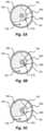
- FIG. 15 Ashows a first configuration of a sixth embodiment of a tissue slitting device inside an area of vasculature having formed tissue surrounding an implanted lead in accordance with embodiments of the present disclosure
- FIG. 15 Bshows a second configuration of a sixth embodiment of a tissue slitting device inside an area of vasculature having formed tissue surrounding an implanted lead in accordance with embodiments of the present disclosure
- FIG. 16shows a seventh embodiment of a tissue slitting device inside an area of vasculature having formed tissue surrounding an implanted lead in accordance with embodiments of the present disclosure
- FIG. 17shows a eighth embodiment of a tissue slitting device inside an area of vasculature having formed tissue surrounding an implanted lead in accordance with embodiments of the present disclosure
- FIG. 18shows a ninth embodiment of a tissue slitting device inside an area of vasculature having formed tissue surrounding an implanted lead in accordance with embodiments of the present disclosure
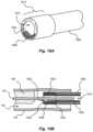
- FIG. 19 Ashows a perspective view of a tenth embodiment of a tissue slitting device in accordance with embodiments of the present disclosure
- FIG. 19 Bshows a section view of the tissue slitting device of FIG. 19 A ;
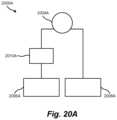
- FIG. 20 Ashows a laser ablation tissue slitting apparatus including a tissue slitting device utilizing laser ablation, a first laser generator or system, a second laser generator or system, and an optical component.
- FIG. 20 Bshows an eleventh embodiment of a tissue slitting device inside an area of vasculature having formed tissue surrounding an implanted lead in accordance with embodiments of the present disclosure
- FIG. 21shows an end view of a twelfth embodiment of a tissue slitting device in accordance with embodiments of the present disclosure
- FIG. 22shows an end view of a thirteenth embodiment of a tissue slitting device in accordance with embodiments of the present disclosure
- FIG. 23shows an end view of a fourteenth embodiment of a tissue slitting device in accordance with embodiments of the present disclosure
- FIG. 24shows an end view of a fifteenth embodiment of a tissue slitting device in accordance with embodiments of the present disclosure
- FIG. 25shows an end view of a sixteenth embodiment of a tissue slitting device in accordance with embodiments of the present disclosure
- FIG. 26shows a seventeenth embodiment of a tissue slitting device inside an area of vasculature having formed tissue surrounding an implanted lead in accordance with embodiments of the present disclosure
- FIG. 27is a flow diagram depicting a tissue slitting method in accordance with embodiments of the present disclosure.
- FIG. 28shows an embodiment of a grinding tissue slitting device inside an area of vasculature having formed tissue surrounding an implanted lead in accordance with embodiments of the present disclosure.
- Embodiments of the present disclosureare directed to tissue slitting or cutting devices and methods of using tissue slitting devices to remove an implanted lead from within the vascular system of a patient.
- the method of removing an implanted lead from formed tissuemay include causing at least a partial separation of tissue that lies along an axial length of the implanted lead.
- the tissuemay be slit or cut along an entire length of the tissue growth to enable removal of the implanted lead.
- the tissuemay be slit or cut along a section of the tissue growth to allow an implanted lead to be removed from a patient.
- tissue slitting edgeor “tissue cutting edge” are used in this disclosure, it is not limited to a blade or other cutting surface. These phrases are further intended to encompass any modality for slitting or cutting tissue, including the various modalities discussed herein. Non-limiting examples include not only a sharpened area, point, or blade but also an abrasive or cutting wire or fiber, atherotomes (microsurgical blades) mounted on an inflatable (cutting) balloon, a grinder, high intensity light such as produced by a laser, thermal or infrared energy, electromagnetic energy, and/or high-pressure fluid.
- FIG. 1depicts an exemplary patient 102 with an implanted lead 104 running along the left innonimate vein 112 past the superior vena cava (“SVC”) and connected into, or about, the right ventricle of the heart 106 .
- SVCsuperior vena cava
- the tissue 108may completely surround a section of the lead 104 .
- the one or more of the tissue growths 108may act to contain the lead 104 .
- the tissue 108may impart one or more forces (e.g., constrictive, shear, compression, and the like) on the lead 104 that may act to prevent successful removal of the lead 104 when subjected to a traction force 120 .
- forcese.g., constrictive, shear, compression, and the like
- FIGS. 2 A-Cshow examples of an implanted lead 104 subjected to a traction force via different paths in a patient 102 vasculature. Accordingly, the methods and/or devices disclosed in conjunction with any of the FIGS. 2 A-C may equally apply to all instances disclosed.
- FIG. 2 Ashows a detail view of a heart 106 having an implanted lead 104 subjected to a traction force 120 in a first path in accordance with embodiments of the present disclosure.
- a lead 104 explant proceduremay involve removing the lead from a patient 102 via one or more paths.
- a lead-locking, or other traction, devicemay be engaged with the lead 104 and then used to pull the lead 104 from a patient.
- the lead 104may be contained by a formed tissue growth 108 that resists the traction force 120 applied to the lead 104 .
- a tissue growth 108may form along a critical area of the vasculature, such as the SVC curve 116 , of a patient. If this critical area is torn during a lead 104 explant procedure, the result can be fatal to the patient 102 .
- Complicating the lead 104 removal processis the fact that the tissue growth 108 surrounding a lead 104 may attach to a vessel in a curved portion of the vasculature. Removal of the lead 104 from such a curved portion of vasculature can present a challenge when introducing tissue removal devices alone or in conjunction with traction devices.
- the tissue removal devicesinclude sharp edges, aggressive tips, or imprecise actuation mechanisms that can puncture the thin walls of a patient 102 vasculature. It is an aspect of the present disclosure to orient a tissue slitting working end adjacent to the unconnected, or tissue free, side 124 of a vessel wall. This orientation can prevent puncture and/or damage occurring to the vasculature at the tissue connected side 128 of the vessel wall.
- FIG. 2 Ba detail section view of a patient vasculature and implanted lead 104 subjected to a traction force 120 in second path in accordance with some embodiments of the present disclosure is shown.
- at least one end of the lead 104may be directed inside a patient 102 for removal via a path within the vasculature.
- Direction of the lead 104may be effected via a snaring tool, lead-locking device, traction device, combinations thereof, and the like.
- the lead 104is directed toward the general direction of a patient's femoral artery via the inferior vena cava.
- the lead 104may be directed in the manner shown to provide additional tearing forces on the tissue growth 108 by the lead 104 being subjected to a traction force 120 .
- the tissue growth 108may be at least partially slit and the tearing forces created by pulling the lead 104 along the traction force 120 line cause the lead 104 to separate from the tissue growth 108 .
- a tissue slitting devicemay be run along the lead 104 to the tissue growth 108 via the femoral artery.
- the lead 104may be captured and pulled such that the pull force causes the lead 104 to turn inside a patient 102 .
- This mode of capture and pullingmay cause a bending at a first connection point between the tissue growth 108 and the lead 104 .
- the assistive bending force provided by the traction force 120can aid in slitting the tissue growth 108 .
- the bending forcemay cause a stretching of the tissue growth 108 where the lead engages with the tissue growth 108 .
- This stretching of tissuemay assist in the slitting operation by causing tension on the fibers of the tissue growth 108 that, when slit, pull away from the tissue slitting device engagement area.
- the slitting operationmay be performed in any area within a patient that is capable of receiving a tissue slitting device.
- FIG. 2 Cshows a detail section view of a patient vasculature and implanted lead 104 subjected to a traction force 120 in third path in accordance with some embodiments of the present disclosure. Similar to FIG. 2 A and 2 B , the lead 104 may be directed along a path in the patient vasculature. In this case, the lead 104 may be directed toward the general direction of a patient's jugular vein.
- the path chosen for removal of a lead 104 from a patient 102may depend on one or more of the orientation of the lead 104 within a patient 102 , the state of the at least one tissue growth 108 , the lead removal device used, and the tissue slitting device used.
- the lead 104e.g., pacing, defibrillator, etc.
- the lead 104may have moved after implantation. In these scenarios, the lead 104 may have to be captured via some other method.
- a capturing tool equipped with a lasso, snare, or other lead grasping elementmay need to be inserted into the patient 102 .
- the capturing toolmay be inserted into the patient 102 via any number of the veins and/or arteries that are interconnected to the lead 104 location in the vasculature.
- the lead 104may be grasped via a capturing tool that has been inserted through a patient's femoral artery and led to the point of the vasculature where the lead's 104 free end may be located.
- the capturing toolmay be used to provide traction force 120 during the tissue slitting operation.
- the leadmay be grasped via a capturing tool, or lead-locking device, and/or removed via some other pathway in the vasculature.
- the leadmay be accessed via one or more veins, arteries, chambers, biological channels, and/or other sections of the vasculature of a patient 102 .
- FIG. 3shows a section view of a curved area of vasculature with tissue growth 108 formed around an implanted lead 104 in accordance with embodiments of the present disclosure.
- the tissue growth 108may completely surround a section of the lead 104 and even be attached to a vessel wall at a tissue connected side 128 of the vasculature.
- the tissue growth 108may not be adhered to at least one free side 124 of a vessel, such that a vessel opening 126 exists where bodily fluid may pass through the vessel unobstructed.
- the tissue growth 108before attempted lead extraction, is commonly at least substantially free of and even more commonly completely free of attachment to the lead 104 .
- FIG. 4shows a cross-sectional view of the curved area of vasculature of FIG. 3 taken along line A-A.
- referencemay be made to the tissue growth 108 forming a tube 132 (or cylindrical or sock-like structure) around the implanted lead 104 .
- Previous methodshave been disclosed that are directed to separating the tissue around the lead 104 in the area defined by the tube 132 . It is an aspect of the present disclosure to provide one or more methods and devices to effectively separate the tissue growth 108 along a length of the lead to release the lead 104 from the containing forces of the tissue growth 108 .
- the tissue growth 108may be slit at a portion of the tissue growth 108 where the thickness of tissue is minimal between the lead 104 and the open area 126 of the vessel.
- the tissue growth 108may be subjected to a slitting action about a partial (i.e., not complete) periphery of an internal diameter of the tissue growth 108 .
- the amount of the adjacent tissue cut or slit 130 to free the lead 104is commonly no more than about 50%, more commonly no more than about 25%, more commonly no more than about 10%, and even more commonly no more than about 5% of the diameter of the tissue growth 108 or tube 132 .
- the length of the cut or slit 130 in the tissue growth 108 or tube 132is commonly at least about 50%, more commonly at least about 75%, more commonly at least about 90%, and even more commonly at least about 95% of the total length of the portion of the lead 104 surrounded by the tissue growth 108 or tube 132 along an actual and projected line of the cut or slit.
- FIGS. 5 A-Cshow a cross-section of a vessel where a tissue slitting device 504 is progressively engaged with a tissue growth 108 .
- the tissue slitting devicecauses a section of the tissue growth 108 to separate from a portion of the lead 104 allowing the forces containing the lead 104 to be severely weakened and/or eliminated.
- the tissue slitting device 504includes a tissue slitting tip 508 that is configured to separate tissue growth 108 .
- the tissue slitting tip 508may be oriented such that a slitting operation is performed on the thinnest section of tissue growth 108 between the lead 104 and the open area 126 of the vessel. Orientation of the tissue slitting device 504 may be achieved in operation via a fluoroscopy and/or other monitoring devices and the use of one or more radiopaque markers on the tissue slitting device 504 .
- the tissue slitting device 504may contact the tissue growth 108 at an engagement area 510 .
- the tissue slitting devicemay include an imaging system configured to provide an image from within the vasculature of a patient 102 . It is anticipated that the imaging system may be disposed adjacent to the distal tip of the tissue slitting device. Examples of such imaging systems may include, but are in no way limited to, technology incorporating Intravascular Ultrasound (“IVUS”), Optical Coherence Tomography (“OCT”), radio imaging, magnetic tracking, three-dimensional (“3D”) imaging, and other technologies that may be used to obtain an image within a patient.
- IVUSIntravascular Ultrasound
- OCTOptical Coherence Tomography
- 3Dthree-dimensional
- FIG. 5 Bshows a cross-sectional view of an area of vasculature with a tissue slitting device 504 engaging formed tissue 108 in accordance with embodiments of the present disclosure.
- the tissue slitting device 504may slit the tissue growth 108 by splitting, cutting, tearing, grinding, sanding, ablating, and/or otherwise causing a separation of tissue at the engagement area 510 .
- FIG. 5 Cshows a cross-sectional view of an area of vasculature with a tissue slitting device 504 slitting formed tissue 108 in accordance with embodiments of the present disclosure.
- the tissue growth 108is separated along a section of the lead 104 about the engagement area 510 .
- the tissue slitting devicemay be subsequently removed from the tissue growth 108 by moving the lead 104 in the direction of the separated tissue.
- FIGS. 6 A-Dshow a section view of a curved area of vasculature where an embodiment of a tissue slitting device 604 is progressively engaged with a tissue growth 108 .
- the tissue slitting device 604causes a section of the tissue growth 108 to separate from a portion of the lead 104 allowing the forces containing the lead 104 to be severely weakened and/or eliminated.
- FIG. 6 Ashows a section view of a curved area of vasculature with a tissue slitting device 604 first introduced in accordance with embodiments of the present disclosure.
- the tissue slitting device 604is indexed into position via a directional force 618 adjacent to the tissue growth 108 .
- the directional force 618may be applied to the tissue slitting device 604 via one or more mechanical actuators, electrical actuators, manual positioning, and combinations thereof
- the tissue slitting device 604includes a flexible shaft having a proximal end, a distal end 612 , and an internal lumen 616 having an internal diameter configured to allow a lead, lead locking device, and/or other implanted device to pass through it.
- the devicemay also include a tissue slitting tip 608 operatively attached to the distal end 612 of the flexible shaft.
- the slitting of formed tissuecan be performed by at least one of cutting, drilling, slicing, stripping, chopping, sanding, grinding, planing, abrasion, high-pressure fluid, laser ablation, and combinations thereof.
- tissue slitting device 604may be oriented within a patient via use of the flexible shaft and monitor, or a catheter-based system. In some cases, the tissue slitting device 604 may be positioned toward the center of the vasculature, and/or proximal to a non-traumatic leading edge, such that any sharp, or working, edge is caused to contact tissue growth 108 and not contact the vasculature (e.g., the tissue connected side 128 wall and the free side 124 wall of a vessel).
- tissue slitting device 604may be oriented within a patient via use of the flexible shaft and monitor, or a catheter-based system. In some cases, the tissue slitting device 604 may be positioned toward the center of the vasculature, and/or proximal to a non-traumatic leading edge, such that any sharp, or working, edge is caused to contact tissue growth 108 and not contact the vasculature (e.g., the tissue connected side 128 wall and the free side 124 wall of
- tissue slitting tip 608 and effective slitting section of the tissue slitting device 604may be biased against a lead 104 via spring force.
- the tissue slitting device 604may include a flexible portion configured to allow the tissue slitting device 604 to move as directed within a patient.
- FIG. 6 Bshows a section view of a curved area of vasculature with a tissue slitting device 604 in a first slitting position in accordance with embodiments of the present disclosure.
- the tissue slitting tip 608causes the tissue growth 108 to separate along the engagement area 610 .
- the separated tissue 614allows the tissue slitting device 604 to be further engaged with the tissue growth 108 .
- the separated tissue 604by releasing forces containing the lead, can allow the lead 104 to be moved about the area of the tissue slitting tip 608 .
- FIG. 6 Cshows a section of a curved area of vasculature with the tissue slitting device 604 in a second slitting position in accordance with embodiments of the present disclosure.
- the tissue slitting device 604As the tissue slitting device 604 is indexed in a direction 618 into the tissue growth 108 the tissue slitting device 604 separates tissue along an axial length of at least one side of the lead 104 .
- the lead 104may be subjected to a traction force 120 that may be opposite to the index direction 618 of the tissue slitting device 604 . This applied traction force 120 may assist in pulling the lead 104 away from the tissue growth 108 as the lead 104 is separated from containing tissue growth 108 .
- FIG. 6 Dshows a section view of a curved area of vasculature with a tissue slitting device 604 in a third slitting position in accordance with embodiments of the present disclosure.
- the tissue slitting device 604is indexed further into the tissue growth 108 such that the tissue growth 108 is almost completely separated from the lead 104 along a length of the tissue growth 108 .
- slitting at least a portion of the tissue growth 108may allow the lead 104 to be removed in an explant procedure.
- the lead 104may be subjected to a traction force 120 to pull the lead 104 away from any remaining the tissue growth 108 .
- the lead 104may be pulled against the remaining tissue growth 108 that surrounds the lead 104 .
- the tissue slitting device 604may be indexed along the entire length of the tissue growth 108 to completely separate the tissue growth 108 from encapsulating, or surrounding, the lead 104 .
- FIGS. 7 A- 12are directed to embodiments of a tissue slitting device that include one or more cutting features that are configured to cut at least a portion of a tissue growth 108 along a lead 104 implanted in a patient 102 .
- FIGS. 10 - 12show embodiments of the tissue slitting device inside an area of vasculature where an implanted lead 104 is encapsulated by a tissue growth 108 . In addition to surrounding the lead 104 along a section, the tissue growth 108 is connected to a portion of the vessel wall.
- the cutting surfacemay be guarded by a mechanical sheath.
- a mechanical sheathmay include at least one surface that acts to guard and/or protect a cutting surface from being accidentally exposed to one or more sensitive areas of the vasculature during navigation of a tissue slitting device within a patient 102 .
- a mechanical sheathmay at least partially shroud a portion of a cutting surface with a compliant material (e.g., silicone, polyurethane, rubber, polymer, combinations thereof, and the like). It is anticipated that the compliant material may be compressed when subjected to an operation force. The compression of the compliant material may subsequently expose the cutting surface of the tissue slitting device.
- a compliant materiale.g., silicone, polyurethane, rubber, polymer, combinations thereof, and the like
- the mechanical sheathmay include a non-compliant material (e.g., metal, carbon fiber, plastic, resin, combinations thereof, and the like) that is configured to at least partially shroud a portion of a cutting surface.
- the non-compliant material mechanical sheathmay be configured to at least partially shroud the cutting surface via a compliant member (e.g., spring, flexure, compliant material, combinations thereof, etc.) in connection with the non-compliant member that maintains a shrouded position of the non-compliant material mechanical sheath.
- a compliant membere.g., spring, flexure, compliant material, combinations thereof, etc.
- the operational forcemay be directed to the compliant member, which subsequently exposes the cutting surface from the mechanical sheath.
- the tissue slitting device 704comprises an inner lumen 716 , at least one cutting surface, or knife-edge 708 , a wedge tapered section 720 , and a tapered section transition 724 .
- the inner lumen 716can be disposed between the proximal and distal end of the tissue slitting device 704 .
- the inner lumen 716may be configured to allow a lead 104 and/or other objects to pass therethrough (e.g., a lead-locking device, fraction device, snare tool, etc.).
- the tissue slitting device 704may be indexed and/or guided along the lead 104 via the inner lumen 716 of the device 704 .
- the tissue slitting device 704may be configured to engage with the tissue growth 108 in a patient 102 at a distal tip 712 of the device 704 .
- the distal tip 712 of the devicemay be equipped with a knife-edge 708 configured to cut the tissue growth 108 .
- the knife-edge 708may be configured to part the tissue as it cuts.
- the knife-edge 708 of the distal tip 712may include a wedge shape 720 . As the knife-edge 708 is moved into the tissue growth 108 , the cutting surface of the knife-edge 708 may sever the tissue while simultaneously parting it along the wedge shape 720 of the device 704 .
- the wedge shape 720may cause a parting of separated tissue and bias the cutting surface of the knife-edge 708 against remaining tissue growth 108 attached to the lead 104 . Additionally or alternatively, the wedge shape 720 may be configured as a scalloped shape that can provide added strength to the structure of the distal tip 712 of the tissue slitting device 704 .
- the distal tip 712 of the tissue slitting device 704includes a knife-edge 708 disposed at the most distal portion of the tip 712 and a tapered wedge section 720 proximal to the knife-edge 708 .
- the tapered wedge section 720may be configured in one or more shapes designed to slope proximal from the knife-edge 708 distal end.
- the proximal end point of the tapered wedge sectionmay include a smooth surface 724 that transitions from the tapered slope angle of the tip to the circumferential surface of the device 704 .
- the smooth surface 724may include a radius joining the circumferential surface with the distal tip 712 .
- the taper and/or radiusmay be configured to reduce trauma during navigation through the vasculature and/or during the cutting of tissue.
- the taper associated with the distal tip of the tissue slitting devicemay be configured with various shapes, angles, and dimensions.
- the tapermay be arranged at an angle ranging from 10 to 50 degrees from a plane that is coincident with at least two points on an axis running along the lumen of the tissue slitting device.
- the tapered section of the distal tip of the tissue slitting devicemay be defined by its axial length from the distal end.
- the axial length of the tapered section of the distal tipmay range from 0.025′′ to 0.500′′.
- the axial length of the tapered section of the distal tipmay range from 0.050′′ to 0.300′′.
- FIG. 8shows a perspective view of a tissue slitting device 804 in accordance with embodiments of the present disclosure.
- the tissue slitting device 804comprises an inner lumen 816 , at least one cutting surface, or knife-edge 808 , a tapered section 820 , and a tapered section transition 824 .
- the inner lumen 816may be configured to allow a lead 104 and/or other objects to pass therethrough (e.g., a lead-locking device, traction device, snare tool, etc.).
- the tissue slitting device 804may be indexed and/or guided along the lead 104 via the inner lumen 816 of the device 804 .
- the knife-edge 808may at least partially surround the leading edges 828 adjacent to the knife-edge 808 at the distal portion of the tissue slitting device 804 . In other embodiments, the knife-edge 808 may completely surround the leading edges at the distal portion of the tissue slitting device 804 .
- embodiments of the present disclosureanticipate including a sufficiently sharp portion of the knife-edge configured to slit tissue.
- some leads 104 , or implanted devicesmay include dual-coils, exposed coils, and/or other undulating geometry. As such, tissue may be caused to form in and/or around the coils/geometry. It is anticipated that a tissue slitting tip, or knife-edge 808 , with an extended blade portion 828 disposed at least partially around its distal circumference may remove this additionally formed tissue growth 108 .
- FIGS. 9 A and 9 Bshow a tissue slitting device 904 showing various cutting surface locations in accordance with embodiments of the present disclosure.
- the tissue slitting device 904comprises an inner lumen 916 , at least one cutting surface, or knife-edge 908 , a tapered section 920 , and a tapered section transition 924 .
- the knife-edge 908may be disposed at a distal end of the tissue slitting device 904 .
- the knife-edge 908may be oriented at a leading edge of a tissue slitting device 904 .
- the knife-edge 908may be disposed at least partially inside the lumen 916 of the tissue slitting device 904 .
- tissue slitting devices disclosed hereinmay include at least one fluorescing material or marker (e.g., radiopaque band, marker, and the like).
- the radiopaque markermay be arranged about and/or adjacent to a knife-edge 908 of the tissue slitting device 904 .
- the radiopaque markermay assist in identifying a location of the knife-edge 908 via a monitoring device.
- radiopaque markersmay include, but are in no way limited to, materials and/or particles containing tantalum, tungsten, carbide, iridium, bismuth oxide, barium sulfate, cobalt, platinum and/or alloys and combinations thereof.
- the inner lumen 916may be configured to allow a lead 104 and/or other objects to pass therethrough (e.g., a lead-locking device, traction device, snare tool, etc.).
- the tissue slitting device 904may be indexed and/or guided along the lead 104 via the inner lumen 916 of the device 904 .
- a knife-edge 908is oriented at least partially within the lumen 916 of the tissue slitting device 904 , which may allow the device 904 to be routed through the vasculature of a patient 102 without presenting sharp edges, cutting surfaces, or knife-edges 908 toward sensitive areas.
- the knife-edge 908 oriented at least partially within the lumen 916 of the tissue slitting device 904may allow the cutting surface of the knife-edge 908 to be biased toward the tissue growth 108 in connection with the lead 104 .
- the knife-edge 908may be configured as a blade positioned perpendicular to the outer circumferential surface of the lead.
- the blademay be spring-loaded and/or arranged such that lead 104 is pushed against the blade when the tissue slitting device 904 is actuated along the axial length of the lead 104 .
- the blademay be equipped with a wedge 920 to peel the tissue away as it is being cut by the blade portion.
- the angle of the blade relative to the axis, and/or outer circumferential surface, of the lead 104may be configured to achieve an adequate cutting angle in the tissue growth 108 , such that the tissue 108 is slit in a manner to best achieve lead 104 removal. That is, due to the overall size of the lumen, a small angle itself may create a sharp leading edge sufficient to cut and slit the tissue growth 108 . The angle may also create smooth translation and slitting of the remainder of the tissue as the tissue slitting device 904 traverses longitudinally along a direction of the lead 104 .
- the tissue slitting device 1004comprises an inner lumen 1016 , at least one cutting surface 1008 , a tapered section 1020 , and a tapered section transition 1024 .
- the inner lumen 1016may be configured to allow a lead 104 and/or other objects to pass therethrough (e.g., a lead-locking device, traction device, snare tool, etc.).
- the tissue slitting device 1004may be indexed and/or guided along the lead 104 via the inner lumen 1016 of the device 1004 .
- a cutting surfacee.g., a blade
- the cutting surface 1008may be arranged at an angle at the leading edge of the tissue slitting device 1004 . The angle may be configured to present the cutting surface in the direction of formed tissue that is distally adjacent to the tip of the tissue slitting device 1004 .
- the planing-style blade 1008may be configured to remove a section of tissue 108 along at least one of a length and width of a lead 104 .
- FIG. 11shows a second embodiment of a tissue slitting device 1104 inside an area of vasculature having tissue growth 108 surrounding an implanted lead 104 in accordance with embodiments of the present disclosure.
- the tissue slitting device 1104comprises an inner lumen 1116 , at least one knife-edge 1408 , a wedge and/or ramp 1122 , a tapered section 1120 , and a tapered section transition 1124 .
- the inner lumen 1116may be configured to allow a lead 104 and/or other objects to pass therethrough (e.g., a lead-locking device, fraction device, snare tool, etc.).
- the tissue slitting device 1104may be indexed and/or guided along the lead 104 via the inner lumen 1116 of the device 1104 .
- the knife-edge 1108may include a blade that is positioned tangent to the outer circumferential surface of the lead 104 .
- the blademay be spring-loaded and/or arranged such that the lead 104 is pushed against the blade when the tissue slitting device 1104 is actuated along the axial length of the lead 104 .
- the knife-edge 1108 , or blademay be equipped with a wedge, or ramp, 1120 to part the tissue as it is being cut by the blade.
- the angle of the blade relative to the axis of the lead 104may be configured to achieve an adequate stripping of tissue growth 108 in a specific area, such that the tissue 108 is slit at the specific area.
- the knife-edge 1108may be mechanically actuated to assist in cutting tissue growth 108 .
- the knife-edge 1108may be configured to move along an axis defined by at least one sharp edge of the knife-edge 1108 .
- Actuation of the knife-edge 1108may be achieved via a mechanism operatively connected to the knife-edge 1108 that can move the blade from one direction along the axis defined by at least one sharp edge to the opposite direction along the axis defined by the at least one sharp edge.
- This oscillating movementmay be made at a sub-ultrasonic frequency.
- the oscillating blademay move at an ultrasonic frequency.
- the frequency of oscillation of the knife-edge 1108may be adjusted to suit preferences of the operator.
- the knife-edge 1108may be configured to move along an axis that is perpendicular to an axis created by the at least one sharp edge of the knife-edge 1108 .
- the knife-edge 1108may be configured to move from a proximal position to a distal position along the axis of the tissue slitting device 1104 .
- the movement of the knife-edge 1108may be actuated to repetitively move from the proximal position to the distal position and back to the proximal position. This oscillating movement may be made at a sub-ultrasonic frequency. Additionally or alternatively, the oscillating blade may move at an ultrasonic frequency. In one embodiment, the frequency of oscillation of the knife-edge 1108 may be adjusted to suit preferences of the operator.
- FIG. 12shows a third embodiment of a tissue slitting device 1204 inside an area of vasculature having formed tissue growth 108 surrounding an implanted lead 104 in accordance with embodiments of the present disclosure.
- the tissue slitting device 1204comprises an inner lumen 1216 , at least one cutting surface 1208 , a tapered section 1220 , a tapered section transition 1224 , and a tissue tension taper 1222 .
- the inner lumen 1216may be configured to allow a lead 104 and/or other objects to pass therethrough (e.g., a lead-locking device, fraction device, snare tool, etc.).
- the tissue slitting device 1204may be indexed and/or guided along the lead 104 via the inner lumen 1216 of the device 1204 .
- the cutting surface 1208 of the tissue slitting device 1204may be oriented proximal to the leading edge 1226 of the distal tip 1212 of the tissue slitting device 1204 .
- the cutting surface 1208may be arranged such that any sharp edge is concealed behind a smooth and/or dull surface. This arrangement can allow the tissue slitting device 1204 to be safely routed within a convoluted vasculature of a patient 102 .
- the tapered surfaces 1220 , 1222 of the leading edge 1226allows the tissue growth to be stretched as it is engaged and presented to the cutting surface. As disclosed herein, the stretching of the tissue growth 108 fibers assists in the cutting operation performed by the tissue slitting device 1204 . Among other things, the tension placed on the tissue growth 108 fibers provide a taught area for the cutting surface 1208 to engage and cut along.
- the leading edge 1226 of the distal tip 1212 of the tissue slitting device 1204may comprise a non-traumatic surface.
- the leading edge 1226may include a non-traumatic surface where at least some of the exposed sharp edges have been removed (e.g., a ball end, radiused surface, other curved section, etc.).
- the tapered surface 1222may include a cutting surface. For instance, as the tapered surface 1222 wedges into and engages a tissue growth 108 , it may simultaneously cut the tissue along the tapered surface 1222 as it stretches the fibers of the tissue growth 108 .
- the knife-edge 708 , 808 , 908 , 1008 , 1108 , 1208may be advanced into the tissue growth 108 . This advancement may be continuous or periodic. Additionally or alternatively, the knife-edge 708 , 808 , 908 , 1008 , 1108 , 1208 may be actuated in a direction toward and away from the tissue such that the knife-edge 708 , 808 , 908 , 1008 , 1108 , 1208 is presented to an area of the tissue growth 108 , removed from the area, and represented to an area of the tissue growth 108 to successively cut the tissue growth 108 over a number of movements.
- the tissue growth 108is cut in a similar manner to that of an axe chopping at a tree.
- traction forcemay be applied to the lead 104 during the cutting of the tissue growth 108 .
- traction force 120can prevent tears, punctures, and other catastrophic failures caused by the force exerted on the tissue growth and/or adjacent vasculature by the tissue slitting device 704 , 804 , 904 , 1004 , 1104 , 1204 .
- the knife-edgemay be manufactured from a material with a suitable hardness for slitting tissue.
- the knife-edge 708 , 808 , 908 , 1008 , 1108 , 1208may be manufactured from a polymeric material with a durometer configured to cut a patient's tissue.
- polymeric materialmay include, but are not limited to, plastics, silicone, polytetrafluoroethylene (“PTFE”), polyethylene, polyurethane, polycarbonate, polypropylene, polyvinyl chloride (“PVC”), polystyrene, acetal, polyacetal, acetal resin, polyformaldehyde, and the like.
- the knife-edge 708 , 808 , 908 , 1008 , 1108 , 1208may be constructed from a crystalline or amorphous metal alloy.
- the knife-edge 708 , 808 , 908 , 1008 , 1108 , 1208may comprise at least a portion of the distal tip of the tissue slitting device 704 , 804 , 904 , 1004 , 1104 , 1204 .
- the knife-edge 708 , 808 , 908 , 1008 , 1108 , 1208may comprise a metal insert.
- knife-edge 708 , 808 , 908 , 1008 , 1108 , 1208 metalsmay include, but are not limited to, steel, stainless steel (e.g., austenitic type 304 , 316 , martensitic type 420 , 17 - 4 , etc.), aluminum, titanium, tungsten carbide, silver, platinum, copper, and combinations thereof.
- the metalmay be hardened to, among other things, maintain a sharp edge during the tissue slitting process.
- the knife-edge 708 , 808 , 908 , 1008 , 1108 , 1208 or cutting surfacemay be removably attached to the distal tip of the tissue slitting device 704 , 804 , 904 , 1004 , 1104 , 1204 .
- Benefits of a removably attached knife-edge 708 , 808 , 908 , 1008 , 1108 , 1208allow for quick replacement of cutting surfaces during lead removal procedures. As can be appreciated, the replacement of the cutting surface may be initiated upon detecting that the cutting surface is dulling. In some cases the cutting surface may be replaced with a different style of blade.
- the style of blademay be configured to suit a number of desires, including but not limited to, navigating difficult areas in a patient (e.g., using a curved blade, etc.), cutting difficult, dense, and/or hard tissue (e.g., using a serrated blade, a hardened blade, and combinations thereof, etc.), cutting tissue in confined and/or low-growth areas (e.g., using a miniature blade), and even removing the blade completely (e.g., using the tissue slitting device as a counter-traction sheath, etc.).
- navigating difficult areas in a patiente.g., using a curved blade, etc.
- cutting difficult, dense, and/or hard tissuee.g., using a serrated blade, a hardened blade, and combinations thereof, etc.
- cutting tissue in confined and/or low-growth arease.g., using a miniature blade
- the tissue slitting devices disclosed hereinmay include at least one non-traumatic leading edge disposed at the most distal end of the device.
- the non-traumatic leading edgemay include a distal end and a proximal end.
- Non-traumatic surfaces on the leading edge of the devicemay include but are not limited to, spheroidal, ball-nose, radiused, smooth, round, and/or other shapes having a reduced number of sharp edges. These non-traumatic surfaces may be configured to prevent accidental puncture or harmful contact with the patient 102 .
- the non-traumatic leading edgemay be configured to include a tapered and/or a wedge-shaped portion.
- the cross-sectional area of the tapered portionincreases along a length of the non-traumatic leading edge from the distal end to the proximal end of the leading edge.
- a knife-edge and/or cutting surfacemay be disposed proximal to or along the tapered portion of the non-traumatic leading edge of the tissue slitting device.
- the non-traumatic leading edgemay be positioned to insert into an area between the tissue growth 108 and the implanted lead 104 .
- the tapered geometry and the arrangement of the tissue slitting device tipmay allow the most distal portion of the non-traumatic leading edge to bias against the lead 104 and wedge under any surrounding tissue growth 108 .
- the tissue growthis caused to stretch and pull away from the lead 104 .
- the cutting surface of the tissue slitting devicemay be caused to slit the tissue along a length of the tissue growth.
- the cutting surfacemay include but is not limited to one or more knife-edge and/or cutting devices disclosed herein.
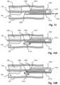
- FIG. 13shows a fourth embodiment of a tissue slitting device 1304 inside an area of vasculature having formed tissue growth 108 surrounding an implanted lead 104 in accordance with embodiments of the present disclosure.
- the tissue slitting device 1304comprises an inner lumen 1316 , at least one reciprocating cutting blade 1308 , a reciprocating blade actuation element 1310 , a tapered section 1320 , and a tapered section transition 1324 .
- the inner lumen 1316may be configured to allow a lead 104 and/or other objects to pass therethrough (e.g., a lead-locking device, traction device, snare tool, etc.).
- the tissue slitting device 1304may be indexed and/or guided along the lead 104 via the inner lumen 1316 of the device 1304 .
- the knife-edgemay be configured as a reciprocating blade 1308 .
- the knife-edgemay be configured to move back-and-forth in an axial direction 1318 .
- This actuationmay be independent of the movement of the outer shaft of the device 1304 .
- the reciprocating motion of the blade 1308may be achieved via a reciprocating actuator that is operatively connected proximal to the distal tip.
- the reciprocating actuatormay be an electrical motor that is located at the proximal end of the flexible shaft.
- the reciprocating actuatormay be manually operated via a mechanical movement at the proximal end of the flexible shaft.
- energy from the actuatormay be transferred to the blade 1308 via an actuation element 1310 .
- the actuation element 1310may comprise one or more of a shaft, rod, bar, link, and the like, that is configured to transmit force from the proximal end of the tissue slitting device 1304 to the blade 1308 .
- the reciprocating blade 1308may be configured to move a cutting surface horizontal to the central axis of the tissue slitting device.
- the reciprocating blade in this embodimentmay operate across (or side-to-side) the distal tip of the tissue slitting device.
- the actuation of the blade 1308may be provided at a frequency below 20 kHz.
- the actuation frequency of the blade 1308may exceed 20 kHz (e.g., ultrasonic range). In either case, it is anticipated that the actuation frequency of the blade 1308 may be adjusted higher or lower to suit a cutting application (e.g., index speed, tissue type, operator preference, and the like).
- the blade 1308may be deployed from within a shaft of the tissue slitting device 1308 .
- any tissue slitting membere.g., cutting tip, grinding tips, laser ablation, RF cutting, pressurized fluid cutters
- any sharp or working membersmay be concealed from exposure to the patient 102 and/or vasculature, during navigation to a tissue growth 108 site. This concealment and/or shielding may act to prevent damage to a patient 102 .
- any of the tissue slitting devices disclosed hereinmay utilize a deployable and/or shielded slitting member.
- FIGS. 14 A and 14 Bshow a disk-style tissue slitting device 1404 inside an area of vasculature in accordance with embodiments of the present disclosure.
- the tissue slitting device 1404comprises an inner lumen 1416 , at least one disk-style cutting blade 1408 , a disk-style cutting blade actuation element 1410 , a tapered section 1420 , and a tapered section transition 1424 .
- the inner lumen 1416may be configured to allow a lead 104 and/or other objects to pass therethrough (e.g., a lead-locking device, traction device, snare tool, etc.).
- the tissue slitting device 1404may be indexed and/or guided along the lead 104 via the inner lumen 1416 of the device 1404 .
- the disk-style cutting blade 1408can move in one or more rotational direction 1418 .
- the disk-style cutting blade 1408may rotate continually in one direction, while actuated.
- the actuation element 1410may be operatively connected to the disk-style cutting blade 1408 at a point that is off of the axis of revolution of the blade 1408 . By moving the actuation element 1410 axially in this example the off-axis motion could engender rotation about a fixed axis of revolution.
- the actuation element 1410may be an electrical connection to a power source at the proximal end of the tissue slitting device 1404 .
- the disk-style cutting blade 1408may include a motor at the distal end that is operatively attached to the blade 1408 and is powered by a power source connected to the electrical connection.
- the disk-style cutting blade 1408may repeatedly alternate directions of rotation (e.g., from a clockwise to a counterclockwise direction, and so forth).
- the disk-style cutting blademay cause at least a partial slit in the engaged tissue growth 108 .
- the disk-style cutting blade 1408may be oriented such that the cutting surface of the blade 1408 is maintained substantially parallel with the outer surface of the lead 104 during cutting and engagement with a tissue growth 108 .
- the angle of the disk-style cutting blade 1408may be arranged such that an obtuse angle is formed between a plane that is coincident with the lead axis 104 and a non-cutting surface of the disk-style cutting blade 1408 . Orienting the disk-style cutting blade 1408 at an angle to the tissue growth 108 may assist in the cutting of at least one slit in the tissue growth 108 formed around the lead 104 .
- FIG. 14 Bshows the disk-style cutting blade 1408 oriented such that the cutting surface of the blade 1408 is maintained substantially perpendicular to the outer surface of the lead 104 during cutting and engagement with a tissue growth 108 .
- the disk-style cutting blade 1408may not be connected to a power source via the actuation element 1410 .
- the cutting blade 1408may be free to rotate about a fixed axis of revolution and as such may be presented to the tissue growth 108 and engaged further into the growth 108 to create a slit in the tissue 108 .
- FIGS. 15 A and 15 Bshow a deployable cutting element tissue slitting device 1504 inside an area of vasculature in accordance with embodiments of the present disclosure.
- the tissue slitting device 1504comprises an inner lumen 1516 , at least one deployable cutting element 1508 , a leading edge 1526 , a tapered section 1520 , a tapered section transition 1524 , a tissue tension taper 1522 , a cutout 1530 , a deployment element 1534 connected to an actuation element 1538 , and a cutting element retaining member 1542 .
- the inner lumen 1516may be configured to allow a lead 104 and/or other objects to pass therethrough (e.g., a lead-locking device, traction device, snare tool, etc.). As can be appreciated, the tissue slitting device 1504 may be indexed and/or guided along the lead 104 via the inner lumen 1516 of the device 1504 .
- the tissue slitting device 1504may include a section having a concealed blade or deployable cutting surface.
- the leading edge 1526may incorporate a tapered non-traumatic leading edge disposed at the distal most end of the tissue slitting device 1504 , as previously disclosed. Additionally or alternatively, one or more features of the tissue slitting device 1504 may be configured to wedge in between the tissue growth 108 and the lead 104 .
- the tissue slitting device 1504may include a slot, cutout, keyway, opening, or other volume 1530 , housing a cutting surface 1508 .
- the cutting surface 1508may be operatively attached to a deployment element 1534 that is configured to deploy and/or conceal the cutting surface 1508 upon receiving an input directing an actuation.
- the deployment element 1534may comprise, but is not limited to, one or more of, a balloon, a ramp, a screw, a wedge, an expansible member, a cam-operated lever, a lever, a cam, and combinations thereof.
- the tissue slitting device 1504may be oriented into a position, such that the leading edge 1526 of the tissue slitting device 1504 engages with a tissue growth 108 .
- an operatormay deploy the cutting surface 1508 of the tissue slitting device 1504 from a concealed position (see, e.g., FIG. 15 A ) by actuating the deployment element 1534 via the actuation element 1538 .
- the tissue slitting device 1504may be indexed further along the lead 104 and into the formed tissue 108 .
- the formed tissue 108is slit along a length adjacent to the cutting surface 1508 .
- This arrangementoffers the additional benefit of navigating the cutting surface 1508 (and any sharp and/or hardened blade) inside a patient in a safe collapsed, retracted, concealed, and/or undeployed, state.
- the cutting element 1508may be deployed by actuating a balloon operatively connected to the cutting element 1508 .
- the deployment element 1534may comprise a balloon
- the actuation element 1538may comprise a lumen configured to convey a fluid (e.g., gas or liquid) suitable to inflate the balloon and extend the cutting element 1508 .
- the cutting elementmay be retained in the cutout 1530 via a retaining member 1542 .
- the retaining membermay include a spring connected to the tissue slitting device 1504 (e.g., at the cutout 1530 ) and the cutting member 1508 .
- the retaining member 1542may assist in returning the cutting element 1508 to a retracted, or concealed, state. In the case of a spring, the retaining member 1542 may exert a force on the cutting element 1508 to resist deployment without sufficient actuation via the deployment element 1534 .
- the cutting element 1508may be deployed via a cam element operatively connected to the cutting element 1508 .
- the cam elementmay be actuated via a rotation or other movement of the actuation element 1538 that is connected to the cam element.
- the retaining member 1542may include a cam groove, guide, raceway, combinations thereof, or other combination of elements to direct and retain the cutting member 1508 .
- the tissue slitting device 1604comprises an inner lumen 1616 , at least one reciprocating grinder 1608 , a reciprocating grinder actuation element 1610 , a tapered section 1620 , and a tapered section transition 1624 .
- the inner lumen 1616may be configured to allow a lead 104 and/or other objects to pass therethrough (e.g., a lead-locking device, fraction device, snare tool, etc.).
- the tissue slitting device 1604may be indexed and/or guided along the lead 104 via the inner lumen 1616 of the device 1604 .
- the reciprocating grinder 1608may be configured to move back-and-forth in an axial direction 1618 . This actuation may be independent of the movement of the outer shaft of the device 1604 .
- the reciprocating motion of the grinder 1608may be achieved via a reciprocating actuator that is operatively connected proximal to the distal tip.
- the reciprocating actuatormay be an electrical motor that is located at the proximal end of the flexible shaft.
- the reciprocating actuatormay be manually operated via a mechanical movement at the proximal end of the flexible shaft connected to the tissue slitting device 1604 .
- energy from the actuatormay be transferred to the grinder 1608 via an actuation element 1610 .
- the actuation element 1610may comprise one or more of a shaft, rod, bar, link, and the like, that is configured to transmit force from the proximal end of the tissue slitting device 1604 to the grinder 1608 .
- the reciprocating blade 1608may be configured to move a grinding surface horizontal to the central axis of the tissue slitting device 1604 .
- the reciprocating grinder in this embodimentmay operate across (or side-to-side) the distal tip of the tissue slitting device 1604 .
- the actuation of the grinder 1608may be provided at a frequency below 20 kHz.
- the actuation frequency of the grinder 1608may exceed 20 kHz (e.g., ultrasonic range). In either case, it is anticipated that the actuation frequency of the grinder 1608 may be adjusted higher or lower to suit a cutting application (e.g., index speed, tissue type, operator preference, and the like).
- the tissue slitting device 1604may include a grinder disposed at the distal tip of the device 1604 .
- the grinder 1608may be configured to slit the formed tissue 108 by subjecting the tissue 108 to a moving abrasive surface.
- the grinder 1608may include a grinding tip located at the distal tip of the device 1604 .
- the grinder 1608may include an abrasive surface disposed on at least one surface that is caused to contact formed tissue 108 on a given side of the lead 104 .
- the grinder 1608may be engaged with the tissue growth 108 where the grinder 1608 emaciates the formed tissue 108 until the tissue 108 is slit at the point of contact with the grinder 1608 .
- the grinding or abrasive surfacemay include at least one rough surface, knurl, machined/formed metal, abrasive surface, diamond deposition, and combinations thereof and the like.
- the tissue slitting device 1704comprises an inner lumen 1716 , at least one grinding mechanism 1708 comprising an abrasive element 1728 and at least one roller 1730 , an actuation element 1710 , a tapered section 1720 , and a tapered section transition 1724 .
- the inner lumen 1716may be configured to allow a lead 104 and/or other objects to pass therethrough (e.g., a lead-locking device, traction device, snare tool, etc.).
- the tissue slitting device 1704may be indexed and/or guided along the lead 104 via the inner lumen 1716 of the device 1704 .
- the grinding mechanism 1708can move in one or more rotational direction 1718 .
- the grinding mechanism 1708may rotate continually in one direction, while actuated.
- the actuation element 1710may be operatively connected to the at least one roller 1730 to turn the abrasive element 1728 .
- the grinding mechanism 1708may emaciate tissue it engages at the distal tip of the tissue slitting device 1704 .
- the actuation element 1710may be an electrical connection to a power source at the proximal end of the tissue slitting device 1704 .
- the grinding mechanism 1708may include a motor at the distal end that is operatively attached to the at least one roller 1730 and is powered by a power source connected to the electrical connection.
- the at least one roller 1730may repeatedly alternate directions of rotation (e.g., from a clockwise to a counterclockwise direction, and so forth).
- the abrasive element 1728When the abrasive element 1728 is engaged with a tissue growth 108 , and actuated, the abrasive element 1728 may cause at least a partial slit in the engaged tissue growth 108 .
- FIG. 18shows an embodiment of a tissue slitting device 1804 inside an area of vasculature having formed tissue 108 surrounding an implanted lead 104 in accordance with embodiments of the present disclosure.
- the tissue slitting device 1804comprises an inner lumen 1816 , at least one grinding wheel 1808 comprising at least one abrasive surface 1828 , an actuation element 1810 , a tapered section 1820 , and a tapered section transition 1824 .
- the inner lumen 1816may be configured to allow a lead 104 and/or other objects to pass therethrough (e.g., a lead-locking device, traction device, snare tool, etc.).
- the tissue slitting device 1804may be indexed and/or guided along the lead 104 via the inner lumen 1816 of the device 1804 .
- the grinding wheel 1808can move in one or more rotational direction 1818 .
- the grinding wheel 1808may rotate continually in one direction, while actuated.
- the actuation element 1810may be operatively connected to the at least wheel 1808 to rotate the wheel 1808 about a fixed axis. As the grinding wheel 1808 is rotated it can emaciate tissue it engages at the distal tip of the tissue slitting device 1804 .
- the actuation element 1810may be an electrical connection to a power source at the proximal end of the tissue slitting device 1804 .
- the grinding wheel 1808may include a motor at the distal end that is operatively attached to the grinding wheel 1808 and is powered by a power source connected to the electrical connection.
- the grinding wheel 1808may repeatedly alternate directions of rotation (e.g., from a clockwise to a counterclockwise direction, and so forth).
- the grinding wheel 1808may cause at least a partial slit in the engaged tissue growth 108 by emaciating contacted tissue growth 108 .
- the tissue slitting device 1904comprises an inner lumen 1916 , at least one grinding surface 1908 having an exposed edge 1926 inside a lumen cutout 1930 of the distal tip 1912 , a shielded lumen portion 1920 , a tapered transition 1924 , and a transmission shaft 1934 .
- the inner lumen 1916may be configured to allow a lead 104 and/or other objects to pass therethrough (e.g., a lead-locking device, traction device, snare tool, etc.).
- the tissue slitting device 1904may be indexed and/or guided along the lead 104 via the inner lumen 1916 of the device 1904 .
- the tissue slitting device 1904provides a rotating grinding surface 1908 to emaciate tissue growth 108 along one side of the lead 104 .
- the tissue slitting device 1904includes a cutout 1930 to expose a grinding edge 1926 to the tissue growth 108 .
- the grinding surface 1908may be rotated and/or operate similarly to the previously disclosed grinding embodiments. In other words, the grinding surface 1908 may be rotated in one direction continuously and/or periodically, and/or in alternate directions (e.g., clockwise and counterclockwise) continuously and/or periodically.
- the grinding surfacemay be partially covered by a shielded lumen portion 1920 .
- the shielded lumen portion 1920may prevent contact of the grinding surface with areas of the vasculature, or lead 104 , other than a section of the formed tissue 108 surrounding the lead 104 .
- the partial coveringmay present an exposed section of the grinding surface 1908 to contact the formed tissue that is engaged with the distal tip of the tissue slitting device 1904 .
- the grinding surface 1908may be angled, or disposed at an angle, in relation to the distal tip 1912 of the tissue slitting device 1904 .
- FIG. 20 Ashows a laser ablation tissue slitting apparatus 2000 A including a tissue slitting device 2004 A utilizing laser ablation, a first laser generator or system 2006 A, a second laser generator or system 2008 A, and an optical component 2010 A.
- FIGS. 20 B- 25show embodiments of a tissue slitting device utilizing laser ablation and one or more light guides that are configured to transmit light to ablate the tissue 108 surrounding at least a portion of the lead 104 .
- the laser ablation embodimentsmay be used alone or in combination with any of the other embodiments set forth in this disclosure. That is, the laser ablation embodiments may be used in conjunction with the cutting, grinding, planing, high-pressure solution, and other embodiments discussed herein.
- FIG. 20 Bshows an embodiment of a tissue slitting device 2004 inside an area of vasculature having formed tissue 108 surrounding an implanted lead 104 in accordance with embodiments of the present disclosure.
- the tissue slitting device 2004comprises an inner lumen 2016 , a light-emitting distal end 2008 , at least one light guide 2010 , a tapered section 2020 , and a tapered section transition 2024 .
- the inner lumen 2016may be configured to allow a lead 104 and/or other objects to pass therethrough (e.g., a lead-locking device, fraction device, snare tool, etc.).
- the tissue slitting device 2004may be indexed and/or guided along the lead 104 via the inner lumen 2016 of the device 2004 .
- the light-emitting distal end 2008 of the tissue slitting device 2004may comprise one or more terminated light guides 2010 .
- the one or more terminated light guides 2010may be optical fibers that can are arranged such that light is directed along a path 2018 toward a tissue growth 108 surrounding an area of a lead 104 . It is anticipated that the optical fibers can conduct laser light generated by a laser system located at the proximal end of the tissue slitting device 2004 . In some cases, the laser light may be generated in the 308 nM range. Exemplary laser light may include pulsed laser light created by an XeCl Excimer laser system (for example, the first laser generator or system 2006 A).
- the wavelength of the laser light conducted by the optical fibers, and/or light guides 2010may be adjusted to match a desired ablation energy for various deposits and/or growths inside a patient.
- different deposits and/or growthsmay require different laser wavelengths for efficient ablation.
- These depositsmay include tissue, fat, collagen, elastin, lipid accumulation, fibrotic layers, plaque, calcified layers, and the like.
- the wavelength of the laser systemmay be selectively tuned using one or more optical components (for example, the optical component 2010 A) to provide a second laser wavelength.
- the one or more optical componentsmay alter a characteristic associated with the light energy emitted by a laser source.
- optical componentsmay include, but are not limited to, one or more filters, lenses, prisms, coatings, films, and deposited layers of optically transmissive material.
- a second laser system(for example, the second laser generator or system 2008 A) may be optically coupled with the optical fibers and/or light guides to provide the second laser wavelength.
- This second laser system and the corresponding second wavelengthmay be activated in conjunction with the laser system.
- the second laser system and second laser wavelengthmay be activated separately from the laser system.
- the wavelength of the laser light conducted by the optical fibers and/or light guidesmay be adjusted during an ablation operation.
- an operatormay select an appropriate wavelength of laser light as required to ablate various deposits. This selection may be performed without requiring removal of the optical fibers and/or light guides from the patient.
- a switch from one laser wavelength to another laser wavelengthcan be performed outside of the patient at the laser system and/or the second laser system.
- the tissue slitting device 2004may include features that contact the lead 104 and allow the light-emitting distal end 2008 to accept deviations in lead geometry and location.
- the featuresmay include a spring, band, or other elastic member that is operatively connected to an area of the light-emitting distal end 2008 .
- the elastic membercan accommodate the change and adjust a position and/or orientation of the light-emitting distal end 2008 .
- the tissue slitting device 2004may be configured to cause an ablation of tissue in a given width and/or depth along an axial length of the lead 104 .
- the light-emitting distal end 2008may be configured to cauterize, ablate, or otherwise separate tissue growth 108 along a thin section.
- the tissue slitting device 2004may create an initial separation of tissue as wide as the array of one or more optical fibers.
- the width of the initial tissue separationcan be correlated to the arrangement and width of the one or more light guide 2010 of the tissue slitting device 2004 .
- the one or more light guide 2010may direct light at least partially inward toward the central axis of the lead 104 .
- the one or more light guide 2010may be disposed to conduct at least portion of the light angularly toward the distal end of the tissue slitting device 2004 and/or toward the central axis of the lead 104 .
- each of the plurality of light guides 2010includes a terminating end, and the terminating ends are disposed to emit light energy at an angle relative to the axis of the device 2004 .
- the laser lightmay be activated and the tissue 108 may be severed along the line of conducted light.
- FIG. 21shows an embodiment of a tissue slitting device 2104 in accordance with embodiments of the present disclosure.
- the tissue slitting device 2104comprises an inner lumen 2116 , a wall disposed radially outwardly relative to the inner lumen 2116 , a laser member 2112 comprising a light-emitting distal end 2108 at least one light guide 2128 and a lead engagement feature 2132 , and a tapered section transition 2124 .
- the inner lumen 2116may be configured to allow a lead 104 and/or other objects to pass therethrough (e.g., a lead-locking device, traction device, snare tool, etc.).
- the tissue slitting device 2104may be indexed and/or guided along the lead 104 via the inner lumen 2116 of the device 2104 .
- the laser member 2112may include one or more features 2132 to engage with an implanted lead 104 .
- a lead engagement feature 2132may include an arcuate surface that is disposed on the lead 104 side of the laser member 2112 .
- the arcuate surface of the lead engagement feature 2132may substantially contact the lead 104 at more than one point. This multiple-point contact may provide stability to the tissue slitting device 2104 as it is indexed along the lead 104 .
- a plurality of light guides 2128may be arranged vertically. As such, the light guides 2128 may direct laser light along a plane that runs along, or parallel to, the lead 104 axis. Stated another way, each of the plurality of light guides 2128 includes a terminating end, and the terminating ends are disposed to emit light energy parallel to the axis of the device 2104 . In other words, the tissue slitting device 2104 , when actuated and presented adjacent to a tissue growth 108 , may cause a separation of tissue in a tissue growth 108 along an axial length of the growth 108 .
- FIG. 22shows an embodiment of a tissue slitting device 2204 in accordance with embodiments of the present disclosure.
- the tissue slitting device 2204comprises an inner lumen 2216 , a laser member 2212 comprising a light-emitting distal end 2208 at least one light guide 2228 and a lead engagement feature 2232 , and a tapered section transition 2224 .
- the inner lumen 2216may be configured to allow a lead 104 and/or other objects to pass therethrough (e.g., a lead-locking device, traction device, snare tool, etc.).
- the tissue slitting device 2204may be indexed and/or guided along the lead 104 via the inner lumen 2216 of the device 2204 .
- the laser member 2212may include one or more features 2232 to engage with an implanted lead 104 .
- a lead engagement feature 2232may include an arcuate surface that is disposed on the lead 104 side of the laser member 2212 .
- the arcuate surface of the lead engagement feature 2232may substantially contact the lead 104 at more than one point. This multiple-point contact may provide stability to the tissue slitting device 2204 as it is indexed along the lead 104 .
- a plurality of light guides 2228may be arranged horizontally. As such, the light guides 2228 may direct laser light along a plane that runs along, or parallel to, the outer circumference of the lead 104 .
- the tissue slitting device 2204when actuated and presented adjacent to a tissue growth 108 , may cause a separation of tissue in a tissue growth 108 along an axial length and width of the growth 108 . This separation of tissue is similar to the removal of tissue provided by the embodiment disclosed in FIG. 11 .
- FIG. 23shows a distal end view of a laser tissue slitting device 2304 in accordance with embodiments of the present disclosure.
- the tissue slitting device 2304comprises a shaft 2324 , an inner lumen 2316 , and a plurality of optical fibers 2328 . illustrates a tube having a distal end with optical fibers included therein.
- the inner lumen 2316may be configured to allow a lead 104 and/or other objects to pass therethrough (e.g., a lead-locking device, fraction device, snare tool, etc.).
- the tissue slitting device 2304may be indexed and/or guided along the lead 104 via the inner lumen 2316 of the device 2304 .
- the optical fibers 2328may be used to ablate a section of tissue growth 108 surrounding a lead 104 . Additionally or alternatively, the optical fibers 2328 may be disposed in a portion of the shaft 2324 or about the entire periphery of the shaft 2324 .
- FIGS. 24 - 25show embodiments where one or more laser ablation features are combined with other tissue slitting embodiments as disclosed or suggested herein.
- the tissue slitting device 2404comprises a shaft 2424 , an inner lumen 2416 , at least one wedge feature 2420 , and a plurality of optical fibers 2428 . Additionally or alternatively, the tissue slitting device 2404 may include a cutting edge 2408 .
- the inner lumen 2416may be configured to allow a lead 104 and/or other objects to pass therethrough (e.g., a lead-locking device, traction device, snare tool, etc.).
- the tissue slitting device 2404may be indexed and/or guided along the lead 104 via the inner lumen 2416 of the device 2404 .
- the optical fibers 2428may be used to ablate a section of tissue growth 108 surrounding a lead 104 .
- the optical fibers 2428may be disposed in a portion of the shaft 2424 or about the entire periphery of the shaft 2424 . In some embodiments, when the optical fibers 2428 are included in only a portion of the shaft 2424 , it may be preferable to bias the optical fibers 2428 adjacent to the cutting edge 2408 or cutting tip of the shaft 2424 as shown.
- optical fibers 2428may be included at a distance away from the cutting edge 2408 or cutting tip of the shaft 2424 . In some embodiments, it may be preferable to include as many optical fibers 2428 as possible within the circumference of the shaft 2424 .
- FIG. 25shows a distal end view of a tissue slitting device 2504 in accordance with embodiments of the present disclosure.
- the tissue slitting device 2504comprises a shaft 2524 , an inner lumen 2516 , at least one cutting wedge feature 2520 , and a plurality of optical fibers 2528 . Additionally or alternatively, the tissue slitting device 2504 may include a distal cutting edge 2508 .
- the inner lumen 2516may be configured to allow a lead 104 and/or other objects to pass therethrough (e.g., a lead-locking device, traction device, snare tool, etc.).
- the tissue slitting device 2504may be indexed and/or guided along the lead 104 via the inner lumen 2516 of the device 2504 .
- the optical fibers 2528may be used to ablate a section of tissue growth 108 surrounding a lead 104 .
- the optical fibers 2528may be disposed in a portion of the shaft 2524 or about the entire periphery of the shaft 2524 . In some embodiments, when the optical fibers 2528 are included in only a portion of the shaft 2524 , it may be preferable to bias the optical fibers 2528 adjacent to the distal cutting edge 2508 or cutting tip of the shaft 2524 as shown.
- optical fibers 2528may be included at a distance away from the cutting edge 2508 or cutting tip of the shaft 2524 . In some embodiments, it may be preferable to include as many optical fibers 2528 as possible within the circumference of the shaft 2524 .
- the tissue slitting edgemay utilize other wavelengths of emitted radiation energy, such as thermal or infrared energy, electromagnetic radiation, and/or other radiation wavelengths to slit or cut the formed tissue.
- the tissue slitting edgecan, for example, be an energy device, such as a power sheath (of a catheter), which typically applies a form of energy at the sheath tip to cut the scar tissue away from the lead thus allowing for removal.
- a power sheathof a catheter
- the operatorcan turn on the sheath's energy source to heat or vaporize scar tissue, forming the desired slit.
- One such sheathuses electrocautery, similar to what is used to cut through tissue in surgery.
- Another sheathhas one or more tiny energy emitters at its tip or edge. When activated, the emitted energy vaporizes water molecules in scar tissue within about 1 mm, thereby forming the desired slit or cut. Additionally or alternatively, dilating telescopic sheaths or cutting balloons of a catheter having a longitudinally positioned tissue slitting edge can be fully or partially expanded or inflated, thereby deploying the tissue slitting edge to form the desired slit.
- the distal tip of the tissue slitting device 2504may include a wedge cutting feature 2520 .
- the wedge cutting feature 2520may comprise a blade and a wedge configured to peel the tissue away from the cutting edge 2508 of the tissue slitting device 2504 as it is being cut by the cutting edge 2508 and the blade. Utilizing a combination of laser ablation embodiments with other tissue slitting embodiments allows for creative solutions to various tissue growths 108 .
- the laser light in a laser tissue slitting device 2504may be actuated in pulses to ablate sections of difficult tissue growth 108 while the wedge cutting feature 2520 acts to cut and separate ablated and other areas of the tissue growth 108 .
- various laser embodiments and/or actuation techniques and other tissue slitting featuresmay be combined to best suit individual tissue growth 108 in a patient 102 .
- the tissue slitting devices disclosed hereinmay include at least one fluorescing material or marker (e.g., radiopaque band, marker, and the like).
- the radiopaque markermay be arranged about and/or adjacent to a tissue cutting area (e.g., laser optical fibers, blades, planers, electromagnetic radiation emitter, RF devices, high-pressure fluid, grinders, sanders, drills, ultrasonic devices, and the like) of the tissue slitting device.
- the radiopaque markermay assist in identifying a location of the tissue cutting area via a monitoring device.
- radiopaque markersmay include, but are in no way limited to, materials and/or particles containing tantalum, tungsten, carbide, iridium, bismuth oxide, barium sulfate, cobalt, platinum and/or alloys and combinations thereof.
- FIG. 26shows a tissue slitting device 2604 inside an area of vasculature having tissue growth 108 surrounding an implanted lead 104 in accordance with embodiments of the present disclosure.
- the tissue slitting device 2604comprises a shaft 2606 , an inner lumen 2616 , at least one fluid channel 2610 , at least one nozzle 2608 , a tissue-side taper 2620 , and an opening-side taper 2608 .
- the tissue slitting device 2604may include a port opening 2630 .
- the inner lumen 2616may be configured to allow a lead 104 and/or other objects to pass therethrough (e.g., a lead-locking device, traction device, snare tool, etc.).
- the tissue slitting device 2604may be indexed and/or guided along the lead 104 via the inner lumen 2616 of the device 2604 .
- a solutione.g., NaCl, MgCl, saline, etc.
- the pressurized solutione.g., NaCl, saline, etc.
- the channel 2610may taper in the form of a nozzle 2608 at the distal end to focus fluid expelled from the channel 2610 .
- the focus of the fluid out of the nozzle 2608increases the pressure of the fluid that contacts a tissue growth 108 .
- a fluid channel 2610may include a port opening 2630 that does not include any taper. As such, the fluid is not focused as it is expelled from the fluid port opening 2630 .
- the channel 2610may include a plurality of orifices configured to expel saline solution. This plurality of orifices may include one or more nozzle 2608 features to control the rate of flow of the saline solution.
- the at least one orificemay be directed toward the lead 104 , formed tissue 108 , or other object and/or obstruction.
- a first orificemay be oriented at a first angle to the lead 104 and/or formed tissue 108
- a second orificemay be oriented at a second angle to the lead 104 and/or formed tissue 108 .
- the angle and/or shape of the nozzle 2608 , opening 2630 , or orificesmay be affected by the angle of the tissue-side taper 2620 and/or the opening-side taper 2608 .
- the orificesmay be used to clear obstructions, clean the lead 104 as the tissue slitting device 2604 is moved along the lead 104 , and/or provide lubrication for the inner lumen 2616 of tissue slitting device 2604 as it is moved along a lead 104 .
- solutionmay be forced between the tissue growth 108 and the lead 104 via at least one channel 2610 associated with the tissue slitting device 2604 .
- the forced solutionmay act to expand and/or dilate the tissue growth 108 formed around a lead 104 or object.
- the dilation of the formed tissue 108 created by the solutionmay create an opening for insertion of the distal end of the tissue slitting device 2604 .
- the forced solutionmay be combined with any other device and/or method disclosed herein.
- the forced solutionmay cause the formed tissue 108 to expand around the lead 104 such that the formed tissue 108 no longer applies any forces to the lead 104 .
- the lead 104may be removed from the formed tissue 108 while it is dilated.
- a tissue slitting method 2700will be described in accordance with at least some embodiments of the present disclosure.
- the method 2700starts at 2704 and begins by connecting a lead-locking device or other traction device to the lead 104 (step 2708 ).
- the lead-locking devicemay be inserted into the core of an implanted lead 104 .
- a traction devicemay be connected to the lead 104 to provide traction on the lead 104 .
- mechanical tractioncan be achieved in leads 104 by inserting a locking stylet into the lead 104 and applying a pull force onto the lead 104 via the locking stylet.
- the traction devicecan be threaded through the internal, or inner, lumen of the tissue slitting device (step 2712 ).
- the lead-locking devicemay be inserted through the lumen in an implanted lead 104 and attached to the internal portions of the implanted lead 104 , which can be at the distal portion or proximal to the distal portion of the lead 104 .
- the tissue slitting devicemay be part of a catheter that rides over the external portion of the lead 104 and lead-locking device and is configured to remove tissue along an axial length of the tissue 108 in contact with the lead 104 .
- tissue slitting deviceAs the tissue slitting device is engaged with the lead 104 , a slight traction force may be applied to the lead 104 to allow the tissue slitting device to guide along the lead 104 (step 2716 ).
- the tissue slitting devicecan be moved toward the first formed tissue growth while applying a mechanical traction force to the lead 104 itself or through a locking stylet, or other traction device.
- Mechanical traction forceshould be applied with appropriate force to prevent tearing the vein or artery wall by moving the lead 104 and tissue before they are separated.
- the tissue slitting devicemay be observed moving inside a patient 102 via a fluoroscope or other monitor.
- the distal tip, or some other area, of the tissue slitting devicemay include a fluorescing material or marker (e.g., radiopaque band, and the like). This fluorescing material or marker may be used to aid in monitoring the movement of the tissue slitting device when it is inside a patient.
- a fluorescing material or markere.g., radiopaque band, and the like.
- the tissue slitteris moved into contact with the formed tissue growth (step 2720 ).
- the slitting portion of the tissue slitting devicemay be oriented toward the center of the vein, or away from the vein wall connecting the lead 104 to the vein.
- this orientation of the tissue slitting devicemay aid in the slitting and peeling away of the tissue 108 from the implanted lead 104 .
- a tissue slitting devicemay include a distal tip with a wedge and/or tapered portion proximal to the sharp portion of the tissue slitting device.
- the distal tip of the tissue slitting devicemay include a non-traumatic leading edge.
- the non-traumatic leading edge and the tapered portionmay comprise the distal tip of the tissue slitting device.
- the leading portion (of the tissue slitting device)may include a sharp, cutting, ablating, or grinding portion, which may be configured to cut into the tissue growth 108 .
- the cutting portion of the tissue slitting devicecontinues to separate the formed tissue 108 .
- leading portionwhich may include a wedge and/or tapered portion, can act to cause a stretching of the formed tissue growth 108 at the point where it engages with the tissue slitting device.
- This stretching of tissuemay assist in the slitting operation by causing tension on the fibers of the tissue growth 108 that, when slit, pull back (or away) from the tissue slitting device engagement area.
- the tissue slitting devicemay be actuated and moved along the lead to further engage with the tissue growth 108 (step 2724 ).
- the tissue slitting devicemay be indexed forward (into the tissue formation 108 ) continuously or periodically.
- the tissue slitting devicemay be repeatedly indexed into and removed from the engagement area of the formed tissue growth 108 . It is anticipated that each time the tissue slitting device is indexed into the engagement area the device can make a successively longer slit in the formed tissue 108 .
- the method 2700may be continued by determining whether other tissue growths exist, and if so, indexing the tissue slitting device through each formed tissue growth 108 that is surrounding a section of the implanted lead 104 in the vasculature (step 2728 ).
- the tissue slitting devicemay be removed from the patient 102 (step 2732 ). Additionally or alternatively, once the slits have been made the lead 104 may be removed by applying a pull force to the lead-locking device in the same direction as the mechanical traction force previously applied to the lead 104 . It is anticipated that any movement of the tissue slitting device may be accompanied by an applied mechanical traction force to the lead/lead-locking device.
- the method 2700ends at step 2736 .
- the tissue slitting device 2804comprises an inner lumen 2816 , at least one grinding surface 2808 having an exposed portion 2826 at least partially surrounded by a distal tip shield 2820 , a tapered transition 2824 , and a transmission shaft 2834 .
- the inner lumen 2816may be configured to allow a lead 104 and/or other objects to pass therethrough (e.g., a lead-locking device, traction device, snare tool, etc.).
- the tissue slitting device 2804may be indexed and/or guided along the lead 104 via the inner lumen 2816 of the device 2804 .
- the tissue slitting device 2804provides one or more rotating grinding surface 2808 to emaciate tissue growth 108 along at least one side of the lead 104 .
- the tissue slitting device 2804includes at least one opening 2830 to expose a grinding edge 2826 to the tissue growth 108 .
- the grinding surface 2808may be rotated and/or operate similarly to the previously disclosed grinding embodiments.
- the grinding surface 2808may be rotated in one direction continuously and/or periodically, and/or in alternate directions (e.g., clockwise and counterclockwise) continuously and/or periodically.
- the tissue slitting device 2804may include one or more grinding surfaces 2808 that can be linked and/or geared together.
- the tissue slitting device 2804includes two or more grinding surfaces 2808
- the two or more grinding surfacesmay be geared to operate simultaneously.
- the grinding surfacesmay be directly geared and/or indirectly geared to rotate/move in alternate and/or similar rotational directions, respectively.
- the grinding surface 2808may be partially covered by a shielded portion 2820 .
- the shielded portion 2820may prevent contact of the grinding surface with areas of the vasculature, or lead 104 , other than a section of the formed tissue 108 surrounding the lead 104 .
- the partial coveringmay present an exposed section of the grinding surface 2808 to contact the formed tissue that is engaged with the distal tip of the tissue slitting device 2804 .
- the grinding surface 2808may be angled, or disposed at an angle, in relation to the distal tip of the tissue slitting device 2804 .
- the device(s)may be electrical, mechanical, electro-mechanical, and/or combinations thereof.
- the present disclosurein various aspects, embodiments, and/or configurations, includes components, methods, processes, systems and/or apparatus substantially as depicted and described herein, including various aspects, embodiments, configurations embodiments, subcombinations, and/or subsets thereof.
- the present disclosurein various aspects, embodiments, and/or configurations, includes providing devices and processes in the absence of items not depicted and/or described herein or in various aspects, embodiments, and/or configurations hereof, including in the absence of such items as may have been used in previous devices or processes, e.g., for improving performance, achieving ease and/or reducing cost of implementation.
Landscapes
- Health & Medical Sciences (AREA)
- Engineering & Computer Science (AREA)
- Life Sciences & Earth Sciences (AREA)
- Surgery (AREA)
- Heart & Thoracic Surgery (AREA)
- General Health & Medical Sciences (AREA)
- Veterinary Medicine (AREA)
- Public Health (AREA)
- Nuclear Medicine, Radiotherapy & Molecular Imaging (AREA)
- Biomedical Technology (AREA)
- Animal Behavior & Ethology (AREA)
- Medical Informatics (AREA)
- Molecular Biology (AREA)
- Vascular Medicine (AREA)
- Cardiology (AREA)
- Multimedia (AREA)
- Radiology & Medical Imaging (AREA)
- Signal Processing (AREA)
- Physics & Mathematics (AREA)
- Dermatology (AREA)
- Pathology (AREA)
- Oral & Maxillofacial Surgery (AREA)
- Quality & Reliability (AREA)
- Computational Linguistics (AREA)
- Acoustics & Sound (AREA)
- Audiology, Speech & Language Pathology (AREA)
- Human Computer Interaction (AREA)
- Optics & Photonics (AREA)
- Electromagnetism (AREA)
- Otolaryngology (AREA)
- Computer Networks & Wireless Communication (AREA)
- Surgical Instruments (AREA)
- Electrotherapy Devices (AREA)
Abstract
Description
Claims (17)
Priority Applications (2)
| Application Number | Priority Date | Filing Date | Title |
|---|---|---|---|
| US15/940,548US11596435B2 (en) | 2012-09-14 | 2018-03-29 | Tissue slitting methods and systems |
| US18/107,072US20230181215A1 (en) | 2012-09-14 | 2023-02-08 | Tissue slitting methods and systems |
Applications Claiming Priority (3)
| Application Number | Priority Date | Filing Date | Title |
|---|---|---|---|
| US201261701521P | 2012-09-14 | 2012-09-14 | |
| US13/828,231US9949753B2 (en) | 2012-09-14 | 2013-03-14 | Tissue slitting methods and systems |
| US15/940,548US11596435B2 (en) | 2012-09-14 | 2018-03-29 | Tissue slitting methods and systems |
Related Parent Applications (1)
| Application Number | Title | Priority Date | Filing Date |
|---|---|---|---|
| US13/828,231ContinuationUS9949753B2 (en) | 2012-09-14 | 2013-03-14 | Tissue slitting methods and systems |
Related Child Applications (1)
| Application Number | Title | Priority Date | Filing Date |
|---|---|---|---|
| US18/107,072ContinuationUS20230181215A1 (en) | 2012-09-14 | 2023-02-08 | Tissue slitting methods and systems |
Publications (2)
| Publication Number | Publication Date |
|---|---|
| US20180214175A1 US20180214175A1 (en) | 2018-08-02 |
| US11596435B2true US11596435B2 (en) | 2023-03-07 |
Family
ID=50275252
Family Applications (13)
| Application Number | Title | Priority Date | Filing Date |
|---|---|---|---|
| US13/828,310Active2034-06-22US9413896B2 (en) | 2012-09-14 | 2013-03-14 | Tissue slitting methods and systems |
| US13/828,441Active2033-07-19US9763692B2 (en) | 2012-09-14 | 2013-03-14 | Tissue slitting methods and systems |
| US13/828,231Active2036-08-26US9949753B2 (en) | 2012-09-14 | 2013-03-14 | Tissue slitting methods and systems |
| US13/828,383ActiveUS10531891B2 (en) | 2012-09-14 | 2013-03-14 | Tissue slitting methods and systems |
| US13/828,536Active2034-05-08US9724122B2 (en) | 2012-09-14 | 2013-03-14 | Expandable lead jacket |
| US13/828,638AbandonedUS20140081289A1 (en) | 2012-09-14 | 2013-03-14 | Lead removal sleeve |
| US14/877,683AbandonedUS20160022303A1 (en) | 2012-09-14 | 2015-10-07 | Lead removal sleeve |
| US15/229,873Active2033-11-29US10368900B2 (en) | 2012-09-14 | 2016-08-05 | Tissue slitting methods and systems |
| US15/621,728AbandonedUS20170340346A1 (en) | 2012-09-14 | 2017-06-13 | Expandable lead jacket |
| US15/666,338AbandonedUS20170325835A1 (en) | 2012-09-14 | 2017-08-01 | Tissue slitting methods and systems |
| US15/940,548Active2033-11-02US11596435B2 (en) | 2012-09-14 | 2018-03-29 | Tissue slitting methods and systems |
| US16/703,566AbandonedUS20200107854A1 (en) | 2012-09-14 | 2019-12-04 | Tissue slitting methods and systems |
| US18/107,072PendingUS20230181215A1 (en) | 2012-09-14 | 2023-02-08 | Tissue slitting methods and systems |
Family Applications Before (10)
| Application Number | Title | Priority Date | Filing Date |
|---|---|---|---|
| US13/828,310Active2034-06-22US9413896B2 (en) | 2012-09-14 | 2013-03-14 | Tissue slitting methods and systems |
| US13/828,441Active2033-07-19US9763692B2 (en) | 2012-09-14 | 2013-03-14 | Tissue slitting methods and systems |
| US13/828,231Active2036-08-26US9949753B2 (en) | 2012-09-14 | 2013-03-14 | Tissue slitting methods and systems |
| US13/828,383ActiveUS10531891B2 (en) | 2012-09-14 | 2013-03-14 | Tissue slitting methods and systems |
| US13/828,536Active2034-05-08US9724122B2 (en) | 2012-09-14 | 2013-03-14 | Expandable lead jacket |
| US13/828,638AbandonedUS20140081289A1 (en) | 2012-09-14 | 2013-03-14 | Lead removal sleeve |
| US14/877,683AbandonedUS20160022303A1 (en) | 2012-09-14 | 2015-10-07 | Lead removal sleeve |
| US15/229,873Active2033-11-29US10368900B2 (en) | 2012-09-14 | 2016-08-05 | Tissue slitting methods and systems |
| US15/621,728AbandonedUS20170340346A1 (en) | 2012-09-14 | 2017-06-13 | Expandable lead jacket |
| US15/666,338AbandonedUS20170325835A1 (en) | 2012-09-14 | 2017-08-01 | Tissue slitting methods and systems |
Family Applications After (2)
| Application Number | Title | Priority Date | Filing Date |
|---|---|---|---|
| US16/703,566AbandonedUS20200107854A1 (en) | 2012-09-14 | 2019-12-04 | Tissue slitting methods and systems |
| US18/107,072PendingUS20230181215A1 (en) | 2012-09-14 | 2023-02-08 | Tissue slitting methods and systems |
Country Status (3)
| Country | Link |
|---|---|
| US (13) | US9413896B2 (en) |
| EP (3) | EP2895087B1 (en) |
| WO (2) | WO2014043329A1 (en) |
Families Citing this family (31)
| Publication number | Priority date | Publication date | Assignee | Title |
|---|---|---|---|---|
| EP2677961B1 (en) | 2011-02-24 | 2024-12-11 | Eximo Medical Ltd. | Hybrid catheter for vascular intervention |
| US9413896B2 (en) | 2012-09-14 | 2016-08-09 | The Spectranetics Corporation | Tissue slitting methods and systems |
| US9283040B2 (en)* | 2013-03-13 | 2016-03-15 | The Spectranetics Corporation | Device and method of ablative cutting with helical tip |
| US10835279B2 (en) | 2013-03-14 | 2020-11-17 | Spectranetics Llc | Distal end supported tissue slitting apparatus |
| US20170079718A1 (en) | 2014-05-18 | 2017-03-23 | Eximo Medical Ltd. | System for tissue ablation using pulsed laser |
| US20170105762A1 (en)* | 2015-10-15 | 2017-04-20 | Medtronic Advanced Energy Llc | Lead extraction |
| DE102016003295B3 (en)* | 2016-03-04 | 2017-05-11 | Technische Universität Ilmenau | Adaptive electrode carrier, its use and method for its insertion |
| US10960216B2 (en)* | 2016-03-31 | 2021-03-30 | Cardiac Pacemakers, Inc. | Extraction devices configued to extract chronically implanted medical devices |
| CN109414292A (en) | 2016-05-05 | 2019-03-01 | 爱克斯莫医疗有限公司 | Device and method for cutting off and/or melting unwanted tissue |
| WO2017217998A1 (en)* | 2016-06-16 | 2017-12-21 | Datta Subhajit | Dual vacuum device for medical fixture placement including thoracoscopic left ventricular lead placement |
| CN106943176A (en)* | 2017-04-28 | 2017-07-14 | 卞晓明 | Double-jacket tube knife Harvesting of Great Saphenous Vein device |
| US11690645B2 (en) | 2017-05-03 | 2023-07-04 | Medtronic Vascular, Inc. | Tissue-removing catheter |
| EP4018946A1 (en) | 2017-05-03 | 2022-06-29 | Medtronic Vascular, Inc. | Tissue-removing catheter |
| US10933247B2 (en) | 2017-08-21 | 2021-03-02 | MRM MedTech, LLC | Lead with integrated features to facilitate extraction and associated methods of extraction |
| US11865334B2 (en) | 2017-08-21 | 2024-01-09 | MRM MedTech, LLC | Lead with integrated feature including a low friction component to facilitate extraction and associated methods of extraction |
| TWI734958B (en) | 2018-03-19 | 2021-08-01 | 日商泰爾茂股份有限公司 | Puncture needle and catheter assembly |
| US10441449B1 (en) | 2018-05-30 | 2019-10-15 | Vesper Medical, Inc. | Rotary handle stent delivery system and method |
| US10449073B1 (en) | 2018-09-18 | 2019-10-22 | Vesper Medical, Inc. | Rotary handle stent delivery system and method |
| EP3636158A1 (en) | 2018-10-10 | 2020-04-15 | Koninklijke Philips N.V. | Image guidance for implanted lead extraction |
| CN118697424A (en) | 2018-11-16 | 2024-09-27 | 美敦力瓦斯科尔勒公司 | Tissue Removal Catheter |
| EP3914169A1 (en)* | 2019-01-21 | 2021-12-01 | Koninklijke Philips N.V. | Vascular treatment systems and devices including intravascular imaging capabilities |
| US11819236B2 (en) | 2019-05-17 | 2023-11-21 | Medtronic Vascular, Inc. | Tissue-removing catheter |
| US11672524B2 (en) | 2019-07-15 | 2023-06-13 | Ancora Heart, Inc. | Devices and methods for tether cutting |
| US11678908B2 (en) | 2019-09-06 | 2023-06-20 | Koninklijke Philips N.V. | Traction applying devices for lead removal systems |
| WO2021136203A1 (en)* | 2019-12-30 | 2021-07-08 | 杭州诺茂医疗科技有限公司 | Lead extraction apparatus |
| WO2021136210A1 (en)* | 2019-12-30 | 2021-07-08 | 杭州诺茂医疗科技有限公司 | Removal device |
| US11219541B2 (en) | 2020-05-21 | 2022-01-11 | Vesper Medical, Inc. | Wheel lock for thumbwheel actuated device |
| US12035966B2 (en) | 2020-05-30 | 2024-07-16 | International Business Machines Corporation | Laser-assisted treatment of Pachyonychia Congenita |
| US12376904B1 (en) | 2020-09-08 | 2025-08-05 | Angiodynamics, Inc. | Dynamic laser stabilization and calibration system |
| US20220323098A1 (en)* | 2021-04-12 | 2022-10-13 | Medtronic Vascular, Inc. | Tissue Removing Catheter with Tissue-Removing Element having Oblique Distal End Face |
| US12038322B2 (en) | 2022-06-21 | 2024-07-16 | Eximo Medical Ltd. | Devices and methods for testing ablation systems |
Citations (502)
| Publication number | Priority date | Publication date | Assignee | Title |
|---|---|---|---|---|
| US1663761A (en) | 1927-02-07 | 1928-03-27 | George A Johnson | Surgical instrument |
| US3400708A (en) | 1965-11-24 | 1968-09-10 | Robert A. Scheidt | Cytologic endocrine evaluation device |
| US3521640A (en) | 1967-12-07 | 1970-07-28 | Jane T Carey | Surgical apparatus for use with a diseased lung or the like and related method |
| US3614953A (en) | 1968-01-30 | 1971-10-26 | Nat Res Dev | Drills for clearing obstructions in arteries |
| US3805382A (en) | 1971-06-17 | 1974-04-23 | Ajax Tool Works Inc | Coaxial cable slitter |
| US3831274A (en) | 1973-12-28 | 1974-08-27 | Scott & Fetzer Co | Jacket stripper |
| US3858577A (en) | 1974-04-05 | 1975-01-07 | Univ Southern California | Fiber optic laser light delivery system |
| US4051596A (en) | 1975-09-10 | 1977-10-04 | U.S. Philips Corporation | Wire cutter, particularly for cutting electrical connection wires |
| US4203444A (en) | 1977-11-07 | 1980-05-20 | Dyonics, Inc. | Surgical instrument suitable for closed surgery such as of the knee |
| US4246902A (en) | 1978-03-10 | 1981-01-27 | Miguel Martinez | Surgical cutting instrument |
| US4274414A (en) | 1979-02-21 | 1981-06-23 | Dyonics, Inc. | Surgical instrument |
| US4311138A (en) | 1980-03-10 | 1982-01-19 | Sugarman Edward D | Illuminated hypodermic needle |
| US4471777A (en) | 1983-03-30 | 1984-09-18 | Mccorkle Jr Charles E | Endocardial lead extraction apparatus and method |
| US4517977A (en) | 1981-07-24 | 1985-05-21 | Unisearch Limited | Co-axial tube surgical infusion/suction cutter tip |
| US4559927A (en) | 1979-11-26 | 1985-12-24 | Thomas J. Fogarty | Endarterectomy apparatus and process |
| US4566438A (en) | 1984-10-05 | 1986-01-28 | Liese Grover J | Fiber-optic stylet for needle tip localization |
| US4567882A (en) | 1982-12-06 | 1986-02-04 | Vanderbilt University | Method for locating the illuminated tip of an endotracheal tube |
| US4576162A (en) | 1983-03-30 | 1986-03-18 | Mccorkle Charles E | Apparatus and method for separation of scar tissue in venous pathway |
| US4582056A (en) | 1983-03-30 | 1986-04-15 | Mccorkle Jr Charles E | Endocardial lead extraction apparatus and method |
| US4598710A (en) | 1984-01-20 | 1986-07-08 | Urban Engineering Company, Inc. | Surgical instrument and method of making same |
| US4627436A (en) | 1984-03-01 | 1986-12-09 | Innoventions Biomedical Inc. | Angioplasty catheter and method for use thereof |
| US4641912A (en) | 1984-12-07 | 1987-02-10 | Tsvi Goldenberg | Excimer laser delivery system, angioscope and angioplasty system incorporating the delivery system and angioscope |
| US4646738A (en) | 1985-12-05 | 1987-03-03 | Concept, Inc. | Rotary surgical tool |
| US4662869A (en) | 1984-11-19 | 1987-05-05 | Wright Kenneth W | Precision intraocular apparatus |
| US4674502A (en) | 1985-09-27 | 1987-06-23 | Coopervision, Inc. | Intraocular surgical instrument |
| US4718417A (en) | 1985-03-22 | 1988-01-12 | Massachusetts Institute Of Technology | Visible fluorescence spectral diagnostic for laser angiosurgery |
| US4729763A (en) | 1986-06-06 | 1988-03-08 | Henrie Rodney A | Catheter for removing occlusive material |
| US4754755A (en) | 1984-05-14 | 1988-07-05 | Husted Royce Hill | Catheter with a rotary blade |
| US4767403A (en) | 1987-02-09 | 1988-08-30 | The Boc Group, Inc. | Positive pulse device and system |
| US4844062A (en) | 1987-10-23 | 1989-07-04 | Spectranetics Corporation | Rotating fiberoptic laser catheter assembly with eccentric lumen |
| US4862886A (en) | 1985-05-08 | 1989-09-05 | Summit Technology Inc. | Laser angioplasty |
| US4911148A (en) | 1989-03-14 | 1990-03-27 | Intramed Laboratories, Inc. | Deflectable-end endoscope with detachable flexible shaft assembly |
| US4943289A (en) | 1989-05-03 | 1990-07-24 | Cook Pacemaker Corporation | Apparatus for removing an elongated structure implanted in biological tissue |
| US4988347A (en) | 1988-11-09 | 1991-01-29 | Cook Pacemaker Corporation | Method and apparatus for separating a coiled structure from biological tissue |
| US4997424A (en) | 1989-04-05 | 1991-03-05 | Medamicus, Inc. | Catheter introducer and introducer slitter |
| US5011482A (en) | 1989-01-17 | 1991-04-30 | Cook Pacemaker Corporation | Apparatus for removing an elongated structure implanted in biological tissue |
| US5013310A (en) | 1988-11-09 | 1991-05-07 | Cook Pacemaker Corporation | Method and apparatus for removing an implanted pacemaker lead |
| WO1991006271A1 (en) | 1989-10-25 | 1991-05-16 | Jack Murray Dodick | Surgical instrument with input power transducer |
| US5030207A (en) | 1990-11-02 | 1991-07-09 | Becton, Dickinson And Company | Instantaneous vein entry indicator for intravenous needle |
| US5031634A (en) | 1990-01-19 | 1991-07-16 | Beth Israel Hospital Assoc., Inc. | Adjustable biopsy needle-guide device |
| US5041108A (en) | 1981-12-11 | 1991-08-20 | Pillco Limited Partnership | Method for laser treatment of body lumens |
| WO1991017711A1 (en) | 1990-05-21 | 1991-11-28 | Cardiovascular Imaging Systems, Inc. | Intravascular catheter having combined imaging abrasion head |
| US5114403A (en) | 1989-09-15 | 1992-05-19 | Eclipse Surgical Technologies, Inc. | Catheter torque mechanism |
| DE4038773A1 (en) | 1990-12-05 | 1992-06-11 | Klaas Dieter | Ultrasonic phako probe for cataract operation - has hollow suction needle connected to ultrasonic source and withdrawing natural eye lens tissue |
| US5129897A (en) | 1989-02-15 | 1992-07-14 | S.L.T. Japan Co., Ltd. | Curved laser light emitter |
| US5139495A (en) | 1989-01-17 | 1992-08-18 | S. L. T. Japan Co., Ltd. | Bent and tapered laser light emitting probe |
| US5139494A (en) | 1988-11-10 | 1992-08-18 | Premier Laser Systems, Inc. | Multiwavelength medical laser method |
| US5148599A (en) | 1989-05-01 | 1992-09-22 | Purcell Thomas L | Mold extractor and method |
| US5152744A (en) | 1990-02-07 | 1992-10-06 | Smith & Nephew Dyonics | Surgical instrument |
| US5186634A (en) | 1991-12-20 | 1993-02-16 | John Fluke Mfg. Co., Inc. | Electrical contact having spring-biased tabs for mounting to a circuit board |
| US5201316A (en) | 1991-03-18 | 1993-04-13 | Cardiovascular Imaging Systems, Inc. | Guide wire receptacle for catheters having rigid housings |
| US5207683A (en) | 1988-11-09 | 1993-05-04 | Cook Pacemaker Corporation | Apparatus for removing an elongated structure implanted in biological tissue |
| US5230334A (en) | 1992-01-22 | 1993-07-27 | Summit Technology, Inc. | Method and apparatus for generating localized hyperthermia |
| WO1993018818A1 (en) | 1992-03-18 | 1993-09-30 | The Spectranetics Corporation | Fiber optic catheter with twistable tip |
| US5250045A (en) | 1991-06-11 | 1993-10-05 | The Spectranetics Corporation | Optical fiber catheter with spaced optical fiber |
| US5263928A (en) | 1991-06-14 | 1993-11-23 | Baxter International Inc. | Catheter and endoscope assembly and method of use |
| US5275609A (en) | 1990-06-22 | 1994-01-04 | Vance Products Incorporated | Surgical cutting instrument |
| US5290303A (en) | 1990-06-22 | 1994-03-01 | Vance Products Incorporated D/B/A Cook Urological Incorporated | Surgical cutting instrument |
| US5290280A (en) | 1989-09-08 | 1994-03-01 | S.L.T. Japan Co., Ltd. | Laser light irradiation apparatus |
| US5290275A (en) | 1985-03-22 | 1994-03-01 | Massachusetts Institute Of Technology | Catheter for laser angiosurgery |
| US5353786A (en) | 1992-01-24 | 1994-10-11 | Wilk Peter J | Surgical lighting method |
| US5358487A (en) | 1993-10-15 | 1994-10-25 | Cordis Corporation | Frangible balloon catheter |
| US5373840A (en) | 1992-10-02 | 1994-12-20 | Knighton; David R. | Endoscope and method for vein removal |
| US5377683A (en) | 1989-07-31 | 1995-01-03 | Barken; Israel | Ultrasound-laser surgery apparatus and method |
| US5383199A (en) | 1992-07-02 | 1995-01-17 | Advanced Interventional Systems, Inc. | Apparatus and method for optically controlling the output energy of a pulsed laser source |
| US5395328A (en) | 1994-01-19 | 1995-03-07 | Daig Corporation | Steerable catheter tip having an X-shaped lumen |
| US5396902A (en) | 1993-02-03 | 1995-03-14 | Medtronic, Inc. | Steerable stylet and manipulative handle assembly |
| US5423806A (en) | 1993-10-01 | 1995-06-13 | Medtronic, Inc. | Laser extractor for an implanted object |
| US5423330A (en) | 1993-03-10 | 1995-06-13 | The University Of Miami | Capsule suction punch instrument and method of use |
| US5456680A (en) | 1993-09-14 | 1995-10-10 | Spectranetics Corp | Fiber optic catheter with shortened guide wire lumen |
| US5460182A (en) | 1992-09-14 | 1995-10-24 | Sextant Medical Corporation | Tissue penetrating apparatus and methods |
| US5466234A (en) | 1994-01-31 | 1995-11-14 | Trimedyne, Inc. | Expandable laser catheter |
| US5468238A (en) | 1993-06-11 | 1995-11-21 | Ethicon, Inc. | Endoscopic laser instrument |
| US5470330A (en) | 1984-12-07 | 1995-11-28 | Advanced Interventional Systems, Inc. | Guidance and delivery system for high-energy pulsed laser light |
| WO1995033513A1 (en) | 1994-06-08 | 1995-12-14 | Cook Pacemaker Corporation | Locally flexible dilator sheath |
| US5484433A (en) | 1993-12-30 | 1996-01-16 | The Spectranetics Corporation | Tissue ablating device having a deflectable ablation area and method of using same |
| US5507760A (en)* | 1993-11-09 | 1996-04-16 | Devices For Vascular Intervention, Inc. | Cutter device |
| US5562694A (en) | 1994-10-11 | 1996-10-08 | Lasersurge, Inc. | Morcellator |
| US5569284A (en) | 1994-09-23 | 1996-10-29 | United States Surgical Corporation | Morcellator |
| US5573531A (en) | 1994-06-20 | 1996-11-12 | Gregory; Kenton W. | Fluid core laser angioscope |
| US5575797A (en) | 1993-09-24 | 1996-11-19 | Siemens Elema Ab | Device for explanting a medical electrode device |
| US5605539A (en) | 1992-09-11 | 1997-02-25 | Urohealth Systems, Inc. | Self-introducing infusion catheter |
| US5620414A (en) | 1992-06-30 | 1997-04-15 | Campbell, Jr.; Robert M. | Apparatus and method for effecting surgical incision through use of a fluid jet |
| US5620451A (en) | 1995-04-25 | 1997-04-15 | Intermedics, Inc. | Lead extraction system for transvenous defibrillation leads and for endocardial pacing leads |
| US5651781A (en) | 1995-04-20 | 1997-07-29 | Grace-Wells Technology Partners No. 1, L.P. | Surgical cutting instrument |
| US5665051A (en) | 1994-08-12 | 1997-09-09 | Imagyn Medical | Endoscope with axially movable optical fiber guide to compensate changes in length |
| US5667473A (en) | 1994-03-18 | 1997-09-16 | Clarus Medical Systems, Inc. | Surgical instrument and method for use with a viewing system |
| US5682199A (en) | 1996-03-28 | 1997-10-28 | Jedmed Instrument Company | Video endoscope with interchangeable endoscope heads |
| US5697936A (en) | 1988-11-10 | 1997-12-16 | Cook Pacemaker Corporation | Device for removing an elongated structure implanted in biological tissue |
| US5700270A (en) | 1995-10-20 | 1997-12-23 | United States Surgical Corporation | Surgical clip applier |
| US5707389A (en) | 1995-06-07 | 1998-01-13 | Baxter International Inc. | Side branch occlusion catheter device having integrated endoscope for performing endoscopically visualized occlusion of the side branches of an anatomical passageway |
| US5718237A (en) | 1993-11-15 | 1998-02-17 | Haaga; John R. | Biopsy needle |
| US5725523A (en) | 1996-03-29 | 1998-03-10 | Mueller; Richard L. | Lateral-and posterior-aspect method and apparatus for laser-assisted transmyocardial revascularization and other surgical applications |
| US5735847A (en) | 1995-08-15 | 1998-04-07 | Zomed International, Inc. | Multiple antenna ablation apparatus and method with cooling element |
| US5746738A (en) | 1996-11-20 | 1998-05-05 | Cleary & Oxford Associates | Laser surgical device |
| US5766164A (en) | 1996-07-03 | 1998-06-16 | Eclipse Surgical Technologies, Inc. | Contiguous, branched transmyocardial revascularization (TMR) channel, method and device |
| US5782823A (en) | 1996-04-05 | 1998-07-21 | Eclipse Surgical Technologies, Inc. | Laser device for transmyocardial revascularization procedures including means for enabling a formation of a pilot hole in the epicardium |
| US5807399A (en) | 1996-10-23 | 1998-09-15 | Medtronic, Inc. | Method for removal of chronically implanted leads and leads optimized for use therewith |
| US5814044A (en) | 1995-02-10 | 1998-09-29 | Enable Medical Corporation | Apparatus and method for morselating and removing tissue from a patient |
| US5824026A (en) | 1996-06-12 | 1998-10-20 | The Spectranetics Corporation | Catheter for delivery of electric energy and a process for manufacturing same |
| US5823971A (en) | 1993-10-29 | 1998-10-20 | Boston Scientific Corporation | Multiple biopsy sampling coring device |
| US5825958A (en) | 1996-01-25 | 1998-10-20 | Pharos Optics, Inc. | Fiber optic delivery system for infrared lasers |
| US5863294A (en) | 1996-01-26 | 1999-01-26 | Femrx, Inc. | Folded-end surgical tubular cutter and method for fabrication |
| WO1999007295A1 (en) | 1997-08-05 | 1999-02-18 | Femrx, Inc. | Disposable laparoscopic morcellator |
| US5873886A (en) | 1995-04-04 | 1999-02-23 | United States Surgical Corporation | Surgical cutting apparatus |
| US5879365A (en) | 1995-04-04 | 1999-03-09 | United States Surgical Corporation | Surgical cutting apparatus |
| US5893862A (en) | 1997-04-10 | 1999-04-13 | Pratt; Arthur William | Surgical apparatus |
| US5899915A (en) | 1996-12-02 | 1999-05-04 | Angiotrax, Inc. | Apparatus and method for intraoperatively performing surgery |
| US5906611A (en) | 1997-07-28 | 1999-05-25 | Dodick; Jack Murray | Surgical instrument with laser target |
| US5910150A (en) | 1996-12-02 | 1999-06-08 | Angiotrax, Inc. | Apparatus for performing surgery |
| US5916210A (en) | 1990-01-26 | 1999-06-29 | Intraluminal Therapeutics, Inc. | Catheter for laser treatment of atherosclerotic plaque and other tissue abnormalities |
| US5947958A (en) | 1995-09-14 | 1999-09-07 | Conceptus, Inc. | Radiation-transmitting sheath and methods for its use |
| US5951543A (en) | 1997-06-30 | 1999-09-14 | Clinicon Corporation | Delivery system and method for surgical laser |
| WO1999049937A1 (en) | 1998-03-27 | 1999-10-07 | The General Hospital Corporation | Method and apparatus for the selective targeting of lipid-rich tissues |
| US5972012A (en) | 1997-10-17 | 1999-10-26 | Angiotrax, Inc. | Cutting apparatus having articulable tip |
| US5970982A (en) | 1997-02-20 | 1999-10-26 | Perkins; Rodney C. | Minimally invasive biological vessel harvesting method |
| US5980545A (en) | 1996-05-13 | 1999-11-09 | United States Surgical Corporation | Coring device and method |
| US5980515A (en) | 1997-12-19 | 1999-11-09 | Irvine Biomedical, Inc. | Devices and methods for lead extraction |
| WO1999058066A1 (en) | 1998-05-12 | 1999-11-18 | Med-En Ltd. | Device and method for evacuating refuse from tissues of the body |
| US5989243A (en) | 1984-12-07 | 1999-11-23 | Advanced Interventional Systems, Inc. | Excimer laser angioplasty system |
| US6010476A (en) | 1996-12-02 | 2000-01-04 | Angiotrax, Inc. | Apparatus for performing transmyocardial revascularization |
| US6019756A (en) | 1996-04-05 | 2000-02-01 | Eclipse Surgical Technologies, Inc. | Laser device for transmyocardial revascularization procedures |
| US6022336A (en) | 1996-05-20 | 2000-02-08 | Percusurge, Inc. | Catheter system for emboli containment |
| US6027497A (en) | 1996-03-29 | 2000-02-22 | Eclipse Surgical Technologies, Inc. | TMR energy delivery system |
| US6027450A (en) | 1994-12-30 | 2000-02-22 | Devices For Vascular Intervention | Treating a totally or near totally occluded lumen |
| US6033402A (en) | 1998-09-28 | 2000-03-07 | Irvine Biomedical, Inc. | Ablation device for lead extraction and methods thereof |
| US6051008A (en) | 1996-12-02 | 2000-04-18 | Angiotrax, Inc. | Apparatus having stabilization members for percutaneously performing surgery and methods of use |
| US6080175A (en) | 1998-07-29 | 2000-06-27 | Corvascular, Inc. | Surgical cutting instrument and method of use |
| US6083237A (en) | 1998-10-23 | 2000-07-04 | Ethico Endo-Surgery, Inc. | Biopsy instrument with tissue penetrating spiral |
| US6099537A (en) | 1996-02-26 | 2000-08-08 | Olympus Optical Co., Ltd. | Medical treatment instrument |
| US6102926A (en) | 1996-12-02 | 2000-08-15 | Angiotrax, Inc. | Apparatus for percutaneously performing myocardial revascularization having means for sensing tissue parameters and methods of use |
| US6117128A (en) | 1997-04-30 | 2000-09-12 | Kenton W. Gregory | Energy delivery catheter and method for the use thereof |
| US6120520A (en) | 1997-05-27 | 2000-09-19 | Angiotrax, Inc. | Apparatus and methods for stimulating revascularization and/or tissue growth |
| US6123718A (en) | 1998-11-02 | 2000-09-26 | Polymerex Medical Corp. | Balloon catheter |
| US6126654A (en) | 1997-04-04 | 2000-10-03 | Eclipse Surgical Technologies, Inc. | Method of forming revascularization channels in myocardium using a steerable catheter |
| US6136005A (en) | 1988-11-09 | 2000-10-24 | Cook Pacemaker Corporation | Apparatus for removing a coiled structure implanted in biological tissue, having expandable means including a laterally deflectable member |
| US6139543A (en) | 1998-07-22 | 2000-10-31 | Endovasix, Inc. | Flow apparatus for the disruption of occlusions |
| US6152918A (en) | 1996-04-05 | 2000-11-28 | Eclipse Surgical Technologies, Inc. | Laser device with auto-piercing tip for myocardial revascularization procedures |
| US6152909A (en) | 1996-05-20 | 2000-11-28 | Percusurge, Inc. | Aspiration system and method |
| US6156049A (en) | 1997-04-11 | 2000-12-05 | Coherent Inc. | Method and apparatus for transurethral resection of the prostate |
| US6159225A (en) | 1995-10-13 | 2000-12-12 | Transvascular, Inc. | Device for interstitial transvascular intervention and revascularization |
| US6159203A (en) | 1985-07-31 | 2000-12-12 | Cardiofocus, Inc. | Infrared laser catheter system |
| US6162214A (en) | 1997-10-30 | 2000-12-19 | Eclipse Surgical Technologies, Inc. | Corning device for myocardial revascularization |
| US6167315A (en) | 1999-04-05 | 2000-12-26 | Spectranetics Corporation | Lead locking device and method |
| US6165188A (en) | 1996-12-02 | 2000-12-26 | Angiotrax, Inc. | Apparatus for percutaneously performing myocardial revascularization having controlled cutting depth and methods of use |
| US6174307B1 (en) | 1996-03-29 | 2001-01-16 | Eclipse Surgical Technologies, Inc. | Viewing surgical scope for minimally invasive procedures |
| US6190353B1 (en) | 1995-10-13 | 2001-02-20 | Transvascular, Inc. | Methods and apparatus for bypassing arterial obstructions and/or performing other transvascular procedures |
| US6190352B1 (en) | 1997-10-01 | 2001-02-20 | Boston Scientific Corporation | Guidewire compatible port and method for inserting same |
| US6193650B1 (en) | 1995-10-25 | 2001-02-27 | Edwin H. Ryan, Jr. | Shielded illumination device for ophthalmic surgery and the like |
| US6203537B1 (en) | 1999-02-04 | 2001-03-20 | Sorin Adrian | Laser-driven acoustic ablation catheter |
| US6210400B1 (en) | 1998-07-22 | 2001-04-03 | Endovasix, Inc. | Flexible flow apparatus and method for the disruption of occlusions |
| US6228052B1 (en) | 1996-02-29 | 2001-05-08 | Medtronic Inc. | Dilator for introducer system having injection port |
| US6228076B1 (en) | 1999-01-09 | 2001-05-08 | Intraluminal Therapeutics, Inc. | System and method for controlling tissue ablation |
| US6235044B1 (en) | 1999-08-04 | 2001-05-22 | Scimed Life Systems, Inc. | Percutaneous catheter and guidewire for filtering during ablation of mycardial or vascular tissue |
| US6241692B1 (en) | 1998-10-06 | 2001-06-05 | Irvine Biomedical, Inc. | Ultrasonic ablation device and methods for lead extraction |
| US6245011B1 (en) | 1997-11-04 | 2001-06-12 | Karl Storz Gmbh & Co. Kg | Endoscopic instrument with cutting tool |
| US6290668B1 (en) | 1998-04-30 | 2001-09-18 | Kenton W. Gregory | Light delivery catheter and methods for the use thereof |
| US20010031981A1 (en) | 2000-03-31 | 2001-10-18 | Evans Michael A. | Method and device for locating guidewire and treating chronic total occlusions |
| WO2001076680A1 (en) | 2000-04-05 | 2001-10-18 | Stx Medical, Inc. | Intralumenal material removal systems and methods |
| US6315774B1 (en) | 1996-03-29 | 2001-11-13 | Eclipse Surgical Technologies, Inc. | Minimally invasive apparatus for forming revascularization channels |
| US20010041899A1 (en) | 1998-03-27 | 2001-11-15 | James B. Hunt | Minimally-invasive medical retrieval device |
| US20020002372A1 (en) | 2000-04-27 | 2002-01-03 | Medtronic, Inc. | Suction stabilized epicardial ablation devices |
| US20020007204A1 (en) | 2000-05-17 | 2002-01-17 | Cook Vascular Incorporated | Apparatus for removing an elongated structure implanted in biological tissue |
| US20020016628A1 (en) | 2000-01-31 | 2002-02-07 | Langberg Jonathan J. | Percutaneous mitral annuloplasty with hemodynamic monitoring |
| US20020026127A1 (en) | 2000-03-23 | 2002-02-28 | Balbierz Daniel J. | Tissue biopsy and treatment apparatus and method |
| US6368318B1 (en) | 1998-01-23 | 2002-04-09 | The Regents Of The University Of California | Opto-acoustic recanilization delivery system |
| US20020042610A1 (en) | 1996-10-22 | 2002-04-11 | Epicor, Inc. | Methods and devices for ablation |
| US20020045811A1 (en) | 1985-03-22 | 2002-04-18 | Carter Kittrell | Laser ablation process and apparatus |
| US6395002B1 (en) | 2000-01-18 | 2002-05-28 | Alan G. Ellman | Electrosurgical instrument for ear surgery |
| US20020065543A1 (en) | 2000-11-29 | 2002-05-30 | Pacesetter, Inc. | Double threaded stylet for extraction of leads with a threaded electrode |
| US20020068954A1 (en) | 1999-03-26 | 2002-06-06 | Cook Urological Inc. | Minimally-invasive medical retrieval device |
| US6402771B1 (en) | 1999-12-23 | 2002-06-11 | Guidant Endovascular Solutions | Snare |
| US20020077593A1 (en) | 1999-10-21 | 2002-06-20 | Pulmonx | Apparatus and method for isolated lung access |
| US20020087151A1 (en) | 2000-12-29 | 2002-07-04 | Afx, Inc. | Tissue ablation apparatus with a sliding ablation instrument and method |
| US6419684B1 (en) | 2000-05-16 | 2002-07-16 | Linvatec Corporation | End-cutting shaver blade for axial resection |
| US6419674B1 (en) | 1996-11-27 | 2002-07-16 | Cook Vascular Incorporated | Radio frequency dilator sheath |
| US6423051B1 (en) | 1999-09-16 | 2002-07-23 | Aaron V. Kaplan | Methods and apparatus for pericardial access |
| US20020103532A1 (en) | 2001-01-30 | 2002-08-01 | Langberg Jonathan J. | Transluminal mitral annuloplasty |
| US20020103477A1 (en) | 1999-02-19 | 2002-08-01 | Michael Grasso | Laser lithotripsy device with suction |
| US6428539B1 (en) | 2000-03-09 | 2002-08-06 | Origin Medsystems, Inc. | Apparatus and method for minimally invasive surgery using rotational cutting tool |
| US6428556B1 (en) | 1999-08-25 | 2002-08-06 | Origin Medsystems, Inc. | Longitudinal dilator and method |
| US6432119B1 (en) | 1999-03-17 | 2002-08-13 | Angiotrax, Inc. | Apparatus and methods for performing percutaneous myocardial revascularization and stimulating angiogenesis using autologous materials |
| US6436054B1 (en) | 1998-11-25 | 2002-08-20 | United States Surgical Corporation | Biopsy system |
| US6436114B1 (en) | 1998-02-18 | 2002-08-20 | Storz Endoskop Gmbh | Apparatus for treating body tissue with ultrasound |
| US6440125B1 (en) | 2000-01-04 | 2002-08-27 | Peter Rentrop | Excimer laser catheter |
| US20020123785A1 (en) | 2001-03-02 | 2002-09-05 | Cardiac Pacemakers, Inc. | Cardiac lead permitting easy extraction |
| US6454758B1 (en) | 1996-12-19 | 2002-09-24 | Ep Technologies, Inc. | Loop structures for supporting multiple electrode elements |
| US6454741B1 (en) | 1997-03-06 | 2002-09-24 | Medtronic Percusurge, Inc. | Aspiration method |
| US6461349B1 (en) | 1997-10-24 | 2002-10-08 | Carl Zeiss Meditec Ag | Medical handpiece with a light guide which can be displaced in an axial direction |
| US20020151961A1 (en) | 2000-01-31 | 2002-10-17 | Lashinski Randall T. | Medical system and method for remodeling an extravascular tissue structure |
| US20020156346A1 (en) | 2001-01-12 | 2002-10-24 | Kamrava Michael M. | Endoscopic devices and method of use |
| US6478777B1 (en) | 2000-05-25 | 2002-11-12 | Medtronic, Inc. | Introducer system for medical electrical lead |
| US6485413B1 (en) | 1991-04-29 | 2002-11-26 | The General Hospital Corporation | Methods and apparatus for forward-directed optical scanning instruments |
| US6485485B1 (en) | 1998-08-13 | 2002-11-26 | Intraluminal Therapeutics, Inc. | Expandable laser catheter |
| US6488636B2 (en) | 1997-09-19 | 2002-12-03 | United States Surgical Corporation | Biopsy apparatus |
| US20020183735A1 (en) | 2000-04-25 | 2002-12-05 | Edwards Stuart D. | Ablation of rectal and other internal body structures |
| US20020188278A1 (en) | 2001-06-07 | 2002-12-12 | Bruce Tockman | Method and apparatus for an adjustable shape guide catheter |
| US20030009157A1 (en) | 1998-07-22 | 2003-01-09 | Marc-Alan Levine | Flexible flow apparatus and method for the disruption of occlusions |
| US6512959B1 (en) | 2000-11-28 | 2003-01-28 | Pacesetter, Inc. | Double threaded stylet for extraction of leads with a threaded electrode |
| US6527752B1 (en) | 1999-09-24 | 2003-03-04 | Cook Urological, Inc. | Embryo transfer catheter |
| US20030065312A1 (en) | 1998-11-30 | 2003-04-03 | Nikon Corporation | Laser treatment apparatus |
| US20030073985A1 (en) | 1996-06-13 | 2003-04-17 | Mueller Richard L. | Intraoperative myocardial device and stimulation procedure |
| US20030078562A1 (en) | 2001-01-17 | 2003-04-24 | Transvascular, Inc. | Methods and apparatus for acute or chronic delivery of substances or apparatus to extravascular treatment sites |
| US6554779B2 (en) | 1998-02-20 | 2003-04-29 | United States Surgical Corporation | Biopsy instrument driver apparatus |
| WO2002049690A9 (en) | 2000-12-20 | 2003-05-01 | Fox Hollow Technologies Inc | Debulking catheter |
| US20030092995A1 (en) | 2001-11-13 | 2003-05-15 | Medtronic, Inc. | System and method of positioning implantable medical devices |
| US6565588B1 (en) | 2000-04-05 | 2003-05-20 | Pathway Medical Technologies, Inc. | Intralumenal material removal using an expandable cutting device |
| US6565583B1 (en) | 1999-07-08 | 2003-05-20 | Acumen Vascular, Inc. | Endarterectomy apparatus and method |
| US6569082B1 (en) | 1999-08-10 | 2003-05-27 | Origin Medsystems, Inc. | Apparatus and methods for cardiac restraint |
| US20030105451A1 (en) | 2001-12-04 | 2003-06-05 | Cardiac Pacemakers, Inc. | Adjustable length catheter assembly |
| US6575997B1 (en) | 1999-12-23 | 2003-06-10 | Endovascular Technologies, Inc. | Embolic basket |
| US20030125619A1 (en) | 2001-12-31 | 2003-07-03 | Cardiac Pacemakers, Inc. | Telescoping guide catheter with peel-away outer sheath |
| US6595982B2 (en) | 1996-06-03 | 2003-07-22 | Terumo Kabushiki Kaisha | Tubular medical device |
| US6599296B1 (en) | 2001-07-27 | 2003-07-29 | Advanced Cardiovascular Systems, Inc. | Ratcheting handle for intraluminal catheter systems |
| US20030144594A1 (en) | 2002-01-31 | 2003-07-31 | Gellman Barry N. | Needle device |
| US6610046B1 (en) | 1999-04-30 | 2003-08-26 | Usaminanotechnology Inc. | Catheter and guide wire |
| US6610066B2 (en) | 1999-09-24 | 2003-08-26 | Medtronic Xomed, Inc. | Suction rasp and handpiece adapter assembly and powered surgical handpiece assembly including a suction rasp |
| US6620160B2 (en) | 1996-09-26 | 2003-09-16 | Nanoptics, Inc. | Method and device for electro microsurgery in a physiological liquid environment |
| US6620180B1 (en) | 1998-09-09 | 2003-09-16 | Medtronic Xomed, Inc. | Powered laryngeal cutting blade |
| US20030181935A1 (en) | 2002-02-15 | 2003-09-25 | Medtronic, Inc. | Slitting tool |
| US20030187460A1 (en) | 1999-08-10 | 2003-10-02 | Chin Albert K. | Methods and apparatus for endoscopic cardiac surgery |
| US20030187461A1 (en) | 1999-08-10 | 2003-10-02 | Chin Albert K. | Releasable guide and method for endoscopic cardiac lead placement |
| US20030208209A1 (en) | 2000-03-03 | 2003-11-06 | Gambale Richard A. | Endoscopic tissue apposition device with multiple suction ports |
| US6652480B1 (en) | 1997-03-06 | 2003-11-25 | Medtronic Ave., Inc. | Methods for reducing distal embolization |
| US6660021B1 (en) | 1999-12-23 | 2003-12-09 | Advanced Cardiovascular Systems, Inc. | Intravascular device and system |
| US20030229353A1 (en) | 2000-02-16 | 2003-12-11 | Cragg Andrew H. | Method and apparatus for providing posterior or anterior trans-sacral access to spinal vertebrae |
| US6663621B1 (en) | 1997-07-09 | 2003-12-16 | Intraluminal Therapeutics, Inc. | Systems and methods for steering a catheter through body tissue |
| US6663626B2 (en) | 1998-07-13 | 2003-12-16 | Novacept | Apparatuses and methods for interstitial tissue removal |
| US6669685B1 (en) | 1997-11-06 | 2003-12-30 | Biolase Technology, Inc. | Tissue remover and method |
| US20040006358A1 (en) | 2000-04-05 | 2004-01-08 | Pathway Medical Technologies, Inc. | Intralumenal material removal using a cutting device for differential cutting |
| US20040010248A1 (en) | 2002-07-10 | 2004-01-15 | Appling William M. | Endovascular treatment device having a fiber tip spacer |
| US20040015193A1 (en) | 2002-04-11 | 2004-01-22 | Transvascular, Inc. | Devices and methods for transluminal or transthoracic interstitial electrode placement |
| US20040019359A1 (en) | 2002-07-24 | 2004-01-29 | Worley Seth J. | Telescopic introducer with a compound curvature for inducing alignment and method of using the same |
| US20040049208A1 (en) | 2002-04-03 | 2004-03-11 | Thomas Fogarty, M.D. | Methods and systems for vein harvesting and fistula creation |
| US6706052B1 (en) | 1999-08-10 | 2004-03-16 | Origin Medsystems, Inc. | Longitudinal dilator and method |
| US20040054388A1 (en) | 2002-07-19 | 2004-03-18 | Osypka Thomas P. | Device and method for delivering cardiac leads |
| US20040059348A1 (en) | 2002-09-23 | 2004-03-25 | Geske Jeff B. | Non-sheath based medical device delivery system |
| US20040059404A1 (en) | 2002-09-24 | 2004-03-25 | Bjorklund Vicki L. | Deployable medical lead fixation system and method |
| US6712773B1 (en) | 2000-09-11 | 2004-03-30 | Tyco Healthcare Group Lp | Biopsy system |
| US20040064024A1 (en) | 2002-09-30 | 2004-04-01 | Sommer John L. | Cardiac vein lead and guide catheter |
| US20040097788A1 (en) | 2002-05-30 | 2004-05-20 | Mourlas Nicholas J. | Apparatus and methods for coronary sinus access |
| US20040102804A1 (en) | 1999-08-10 | 2004-05-27 | Chin Albert K. | Apparatus and methods for endoscopic surgical procedures |
| US20040111101A1 (en) | 1999-08-10 | 2004-06-10 | Chin Albert K. | Endoscopic subxiphoid surgical procedures |
| WO2004049956A2 (en) | 2002-11-27 | 2004-06-17 | The Anspach Effort | Powered kerrison-like rongeur system |
| US20040116992A1 (en) | 2002-09-26 | 2004-06-17 | Wardle John L. | Cardiovascular anchoring device and method of deploying same |
| US20040133220A1 (en) | 2000-01-31 | 2004-07-08 | Randall Lashinski | Adjustable transluminal annuloplasty system |
| US20040138562A1 (en) | 2002-01-17 | 2004-07-15 | Joshua Makower | Devices, systems and methods for acute or chronic delivery of substances or apparatus to extravascular treatment sites |
| US20040138528A1 (en) | 2000-10-12 | 2004-07-15 | Jorn Richter | Surgical instrument |
| US20040143284A1 (en) | 2003-01-17 | 2004-07-22 | Chin Albert K. | Subxiphoid procedures and apparatus for placement of cardiac defibrillator and pacer |
| US20040147912A1 (en) | 1999-08-25 | 2004-07-29 | Cardiofocus, Inc. | Surgical ablation system with sliding ablation device |
| US6772014B2 (en) | 2000-12-04 | 2004-08-03 | The Spectranetics Corporation | Lead locking device and method |
| US20040153096A1 (en) | 2003-02-05 | 2004-08-05 | Goode Louis B. | Device for removing an elongated structure implanted in biological tissue |
| US20040153098A1 (en) | 1999-08-10 | 2004-08-05 | Chin Albert K. | Apparatus and method for endoscopic cardiac mapping and lead placement |
| US20040158236A1 (en) | 2003-02-12 | 2004-08-12 | Reinhardt Thyzel | Surgical needle with laser target |
| US20040172116A1 (en) | 2003-01-31 | 2004-09-02 | Medtronic, Inc. | Arrangement for implanting a miniaturized cardiac lead having a fixation helix |
| WO2004080507A2 (en) | 2003-03-10 | 2004-09-23 | Pathway Medical Technologies, Inc. | Interventional catheters assemblies and control systems |
| US6802838B2 (en) | 2002-04-22 | 2004-10-12 | Trimedyne, Inc. | Devices and methods for directed, interstitial ablation of tissue |
| US20040216748A1 (en) | 1999-08-10 | 2004-11-04 | Chin Albert K. | Apparatus and method for endoscopic encirclement of pulmonary veins for epicardial ablation |
| US20040225280A1 (en) | 2003-05-09 | 2004-11-11 | John Horrigan | Laminated catheter comprising ultra high molecular weight high density polyethylene |
| US20040230212A1 (en) | 2000-04-05 | 2004-11-18 | Pathway Medical Technologies, Inc. | Medical sealed tubular structures |
| US20040230213A1 (en) | 2000-04-05 | 2004-11-18 | Pathway Medical Technologies, Inc. | Liquid seal assembly for a rotating torque tube |
| US20040236397A1 (en) | 1999-04-05 | 2004-11-25 | The Spectranetics Corporation | Lead locking device and method |
| US20040243162A1 (en) | 2000-04-05 | 2004-12-02 | Pathway Medical Technologies, Inc. | Interventional catheter assemblies and control systems |
| US20040254534A1 (en) | 2003-06-11 | 2004-12-16 | Bjorkman Bradford A. | Sliding connection assembly to facilitate lead stabilization |
| US20040260322A1 (en) | 2003-06-20 | 2004-12-23 | Rudko Robert I. | Endovascular tissue removal device |
| US20040267276A1 (en) | 2003-06-30 | 2004-12-30 | Camino Thomas S. | Slide and kit for delivering implants |
| US20040267304A1 (en) | 2003-06-30 | 2004-12-30 | Zannis Anthony D. | Instrument for delivery of implant |
| US20050004644A1 (en) | 2003-05-06 | 2005-01-06 | Enpath Medical, Inc. | Rotatable lead introducer |
| US20050025798A1 (en) | 2003-07-29 | 2005-02-03 | Harry Moulis | Medical liquid delivery device |
| US20050027199A1 (en) | 2001-04-11 | 2005-02-03 | Clarke Dana S. | Tissue structure identification in advance of instrument |
| US20050027337A1 (en) | 2003-07-28 | 2005-02-03 | Rudko Robert I. | Endovascular tissue removal device |
| US6855143B2 (en) | 1997-06-13 | 2005-02-15 | Arthrocare Corporation | Electrosurgical systems and methods for recanalization of occluded body lumens |
| US20050038419A9 (en) | 1994-09-09 | 2005-02-17 | Cardiofocus, Inc. | Coaxial catheter instruments for ablation with radiant energy |
| US6858027B2 (en) | 2001-06-05 | 2005-02-22 | E-Globe Technologies Ltd. | Vein stripping instrument |
| US6860860B2 (en) | 2000-11-27 | 2005-03-01 | Tyco Healthcare Group, Lp | Tissue sampling and removal apparatus and method |
| US20050060030A1 (en) | 2000-01-31 | 2005-03-17 | Lashinski Randall T. | Remotely activated mitral annuloplasty system and methods |
| US6869431B2 (en) | 1997-07-08 | 2005-03-22 | Atrionix, Inc. | Medical device with sensor cooperating with expandable member |
| US6884240B1 (en) | 2001-12-07 | 2005-04-26 | Ronald Dykes | Protection system for surgical instruments |
| US20050096643A1 (en) | 2003-10-30 | 2005-05-05 | Medical Cv, Inc. | Apparatus and method for laser treatment |
| US20050096740A1 (en) | 2001-01-30 | 2005-05-05 | Edwards Lifesciences Ag | Transluminal mitral annuloplasty |
| US20050131399A1 (en) | 2002-04-22 | 2005-06-16 | Loeb Marvin P. | Devices and methods for directed, interstitial ablation of tissue |
| US20050149104A1 (en) | 2003-10-03 | 2005-07-07 | Leeflang Stephen A. | Expandable guide sheath and apparatus and methods for making them |
| US20050165288A1 (en) | 2004-01-27 | 2005-07-28 | Scimed Life Systems, Inc. | Systems and methods for treating breast tissue |
| US20050197623A1 (en) | 2004-02-17 | 2005-09-08 | Leeflang Stephen A. | Variable steerable catheters and methods for using them |
| US20050228402A1 (en) | 2002-01-24 | 2005-10-13 | Lawrence Hofmann | Methods and devices for percutaneous and surgical interventions |
| US20050228452A1 (en) | 2004-02-11 | 2005-10-13 | Mourlas Nicholas J | Steerable catheters and methods for using them |
| US6962585B2 (en) | 2002-11-22 | 2005-11-08 | Poleo Jr Louis A | Catherization system and method |
| US20050251116A1 (en) | 2004-05-05 | 2005-11-10 | Minnow Medical, Llc | Imaging and eccentric atherosclerotic material laser remodeling and/or ablation catheter |
| US6966906B2 (en) | 2001-06-08 | 2005-11-22 | Joe Denton Brown | Deflection mechanism for a surgical instrument, such as a laser delivery device and/or endoscope, and method of use |
| US20050259942A1 (en) | 2004-04-08 | 2005-11-24 | Burak Temelkuran | Photonic crystal fibers and medical systems including photonic crystal fibers |
| US20050273090A1 (en) | 2004-06-07 | 2005-12-08 | Tim Nieman | Methods and devices for directionally ablating tissue |
| US20050288604A1 (en) | 2002-09-26 | 2005-12-29 | Eigler Neal L | Implantable pressure transducer system optimized to correct environmental factors |
| US20060004317A1 (en) | 2004-06-30 | 2006-01-05 | Christophe Mauge | Hydrocephalus shunt |
| WO2006007410A2 (en) | 2004-06-16 | 2006-01-19 | Medtronic, Inc. | Minimally invasive coring vein harvester |
| US6999809B2 (en) | 2002-07-16 | 2006-02-14 | Edwards Lifesciences Corporation | Central venous catheter having a soft tip and fiber optics |
| US20060052660A1 (en) | 1999-08-10 | 2006-03-09 | Chin Albert K | Apparatus and methods for cardiac restraint |
| US7029467B2 (en) | 2002-07-16 | 2006-04-18 | Edwards Lifesciences Corporation | Multiple lumen catheter having a soft tip |
| US7063693B2 (en) | 2003-01-15 | 2006-06-20 | Medtronic, Inc. | Methods and tools for accessing an anatomic space |
| US7077856B2 (en) | 1999-06-02 | 2006-07-18 | Power Medical Interventions, Inc. | Electromechanical driver and remote surgical instrument attachment having computer assisted control capabilities |
| US20060167417A1 (en) | 2005-01-26 | 2006-07-27 | Thomas Medical Products, Inc. | Catheter sheath slitter and method of use |
| US20060173440A1 (en) | 2001-01-17 | 2006-08-03 | Medtronic Vascular, Inc. | Microcatheter Devices and Methods for Targeted Substance Delivery |
| US20060217755A1 (en) | 2004-10-04 | 2006-09-28 | Eversull Christian S | Expandable guide sheath with steerable backbone and methods for making and using them |
| US7114642B2 (en) | 1999-07-12 | 2006-10-03 | Power Medical Interventions, Inc. | Expanding parallel jaw device for use with an electromechanical driver device |
| US20060235431A1 (en) | 2005-04-15 | 2006-10-19 | Cook Vascular Incorporated | Lead extraction device |
| US20060247751A1 (en) | 2005-04-28 | 2006-11-02 | Seifert Kevin R | Guide catheters for accessing cardiac sites |
| US20060265042A1 (en) | 2005-05-20 | 2006-11-23 | Exploramed Nc2, Inc. | Devices, systems and methods for retracting, lifting, compressing, supporting or repositioning tissues or anatomical structures |
| US20060276871A1 (en) | 2005-05-20 | 2006-12-07 | Exploramed Nc2, Inc. | Devices, systems and methods for treating benign prostatic hyperplasia and other conditions |
| US20060287574A1 (en) | 1999-08-25 | 2006-12-21 | Chin Albert K | Longitudinal dilator |
| US20070016130A1 (en) | 2005-05-06 | 2007-01-18 | Leeflang Stephen A | Complex Shaped Steerable Catheters and Methods for Making and Using Them |
| US20070050003A1 (en) | 2005-08-30 | 2007-03-01 | Cardiac Pacemakers, Inc. | Device on lead to prevent perforation and/or fixate lead |
| US20070049929A1 (en) | 2005-05-20 | 2007-03-01 | Catanese Joseph Iii | Apparatus and method for manipulating or retracting tissue and anatomical structure |
| US20070078500A1 (en) | 2005-09-30 | 2007-04-05 | Cornova, Inc. | Systems and methods for analysis and treatment of a body lumen |
| US20070083217A1 (en) | 2002-05-30 | 2007-04-12 | Eversull Christian S | Apparatus and Methods for Placing Leads Using Direct Visualization |
| US7226459B2 (en) | 2001-10-26 | 2007-06-05 | Smith & Nephew, Inc. | Reciprocating rotary arthroscopic surgical instrument |
| US20070142846A1 (en) | 2005-05-20 | 2007-06-21 | Neotract, Inc. | Integrated handle assembly for anchor delivery system |
| US7238180B2 (en) | 2003-10-30 | 2007-07-03 | Medicalcv Inc. | Guided ablation with end-fire fiber |
| US7238179B2 (en) | 2003-10-30 | 2007-07-03 | Medical Cv, Inc. | Apparatus and method for guided ablation treatment |
| US7252641B2 (en) | 2003-02-25 | 2007-08-07 | Ethicon Endo-Surgery, Inc. | Method of operating a biopsy device |
| US20070197861A1 (en) | 1998-04-06 | 2007-08-23 | Kyphon Inc. | Systems and methods for creating cavities in interior body regions |
| US7276052B2 (en) | 2002-07-23 | 2007-10-02 | Nipro Corporation | Medical aspirator |
| US20070232981A1 (en) | 2005-11-10 | 2007-10-04 | Phase One Medical Llc | Catheter device |
| US20080004644A1 (en) | 2006-06-30 | 2008-01-03 | Atheromed, Inc. | Atherectomy devices and methods |
| US20080004647A1 (en) | 2006-06-30 | 2008-01-03 | Atheromed, Inc. | Atherectomy devices and methods |
| US20080004646A1 (en) | 2006-06-30 | 2008-01-03 | Atheromed, Inc. | Atherectomy devices and methods |
| WO2008005888A2 (en) | 2006-06-30 | 2008-01-10 | Atheromed, Inc. | Atherectomy devices and methods |
| US20080015625A1 (en) | 2004-10-04 | 2008-01-17 | Acumen Medical, Inc. | Shapeable for steerable guide sheaths and methods for making and using them |
| US7328071B1 (en) | 2005-10-12 | 2008-02-05 | Pacesetter, Inc. | Lead placement device |
| US20080033458A1 (en) | 2005-05-20 | 2008-02-07 | Neotract, Inc. | Multi-actuating trigger anchor delivery system |
| US20080039893A1 (en) | 2005-05-20 | 2008-02-14 | Neotract, Inc. | Multi-actuating trigger anchor delivery system |
| US20080045986A1 (en) | 2006-06-30 | 2008-02-21 | Atheromed, Inc. | Atherectomy devices and methods |
| US20080071341A1 (en) | 2005-04-15 | 2008-03-20 | Cook Vascular Incorporated | Tip for lead extraction device |
| WO2008042987A2 (en) | 2006-10-04 | 2008-04-10 | Pathway Medical Technologies, Inc. | Interventional catheters |
| US20080097378A1 (en) | 2006-08-02 | 2008-04-24 | Zuckerman Stephen D | Optical device for needle placement into a joint |
| US7369901B1 (en) | 2004-02-11 | 2008-05-06 | Pacesetter, Inc. | Myocardial lead and lead system |
| US20080125634A1 (en) | 2006-06-14 | 2008-05-29 | Cornova, Inc. | Method and apparatus for identifying and treating myocardial infarction |
| US20080125748A1 (en) | 2006-09-25 | 2008-05-29 | Medtronic Vascular, Inc. | High Torque, Low Profile Catheters and Methods for Transluminal Interventions |
| US20080147061A1 (en) | 2006-12-15 | 2008-06-19 | Cook Vascular Incorporated | Device for extracting an elongated structure implanted in biological tissue |
| US7392095B2 (en) | 1998-07-22 | 2008-06-24 | Cardiac Pacemakers, Inc. | Extendable and retractable lead having a snap-fit terminal connector |
| US20080154293A1 (en) | 2006-12-22 | 2008-06-26 | The Spectranetics Corporation | Retractable Separating Systems and Methods |
| US20080154296A1 (en) | 2006-12-22 | 2008-06-26 | The Spectranetics Corporation | Tissue Separating Systems and Methods |
| US7396354B2 (en) | 2002-08-05 | 2008-07-08 | Rychnovsky Steven J | Light delivery catheter |
| US20080183163A1 (en) | 2007-01-30 | 2008-07-31 | Lampropoulos Fred P | Introducer sheath and hub assembly |
| US20080194969A1 (en) | 2005-04-29 | 2008-08-14 | The Regents Of The University Of Colorado | Multi-Excitation Diagnostic System and Methods for Classification of Tissue |
| US20080208105A1 (en) | 2006-12-12 | 2008-08-28 | Zelickson Brian D | Laser energy device for soft tissue removal |
| US20080221560A1 (en) | 2003-05-01 | 2008-09-11 | Keio University | Intravascular Diagnostic or Therapeutic Apparatus Using High-Intensity Pulsed Light |
| US20080249516A1 (en) | 2007-03-05 | 2008-10-09 | Amj Bv | Device for creating openings in pressurized vessels with deformable walls |
| US7449010B1 (en) | 2002-07-15 | 2008-11-11 | Motoya Hayase | Material removal catheter and method |
| US20080281308A1 (en) | 2007-05-07 | 2008-11-13 | Ceramoptec Industries, Inc. | Device and method for improved vascular laser treatment |
| US20080287888A1 (en) | 2005-11-10 | 2008-11-20 | Ravenscroft Adrian C | Catheter device |
| US20090012510A1 (en) | 2001-12-04 | 2009-01-08 | Endoscopic Technologies, Inc. | Cardiac ablation devices and methods |
| WO2009005779A1 (en) | 2007-06-29 | 2009-01-08 | Atheromed, Inc. | Atherectomy devices, systems, and methods |
| US20090018553A1 (en) | 2007-07-09 | 2009-01-15 | Neotract, Inc. | Multi-actuating trigger anchor delivery system |
| US7494484B2 (en) | 1999-12-10 | 2009-02-24 | Beck Robert C | Method of removing particulate debris with an interventional device |
| US20090054918A1 (en) | 2007-08-06 | 2009-02-26 | Henson Michael R | Thrombectomy System and Method |
| US20090071012A1 (en) | 2007-09-18 | 2009-03-19 | Ela Medical S.A.S., 98, Rue Maurice-Arnoux, F-9212 | Slitter tool for cutting a tubular sheath of a guide catheter |
| US20090076522A1 (en) | 2007-09-18 | 2009-03-19 | Ela Medical S.A.S. | Toolkit for implanting an intracorporeal lead such as for cardiac pacing or sensing |
| US7510524B2 (en) | 2005-04-04 | 2009-03-31 | Invuity, Inc. | Optical waveguide sheath |
| WO2009054968A1 (en) | 2007-10-22 | 2009-04-30 | Atheromed, Inc. | Atherectomy devices and methods |
| WO2009065082A1 (en) | 2007-11-14 | 2009-05-22 | Pathway Medical Technologies, Inc. | Methods and systems for biological sample collection and analysis |
| US7540865B2 (en) | 2003-03-27 | 2009-06-02 | Boston Scientific Scimed, Inc. | Medical device |
| US20090182313A1 (en) | 2008-01-15 | 2009-07-16 | Jack Robert Auld | Targeted Illumination For Surgical Instrument |
| US20090187196A1 (en) | 2007-10-17 | 2009-07-23 | Vetter Rio J | Guide tube for an implantable device system |
| US20090198098A1 (en) | 2008-02-01 | 2009-08-06 | Olympus Medical Systems Corp. | Endoscope treatment instrument |
| US20090221994A1 (en) | 2006-05-11 | 2009-09-03 | Wolfgang Neuberger | Device and Method for Improved Vascular Laser Treatment |
| US20090227999A1 (en) | 2007-05-11 | 2009-09-10 | Voyage Medical, Inc. | Visual electrode ablation systems |
| US20090234378A1 (en) | 2007-10-22 | 2009-09-17 | Atheromed, Inc. | Atherectomy devices and methods |
| US7591790B2 (en) | 2001-03-23 | 2009-09-22 | Stryker Puerto Rico Limited | Micro-invasive device |
| USD600792S1 (en) | 2009-02-12 | 2009-09-22 | Pathway Medical Technologies, Inc. | Tubing cassette |
| WO2009126309A2 (en) | 2008-04-10 | 2009-10-15 | Atheromed, Inc. | Atherectomy devices and methods |
| US7611474B2 (en) | 2004-12-29 | 2009-11-03 | Ethicon Endo-Surgery, Inc. | Core sampling biopsy device with short coupled MRI-compatible driver |
| US20090319015A1 (en) | 2008-06-23 | 2009-12-24 | Horn-Wyffels Mitchell L | Expandable assembly for cardiac lead fixation |
| US7637904B2 (en) | 2003-12-19 | 2009-12-29 | Vance Products Incorporated | Catheter with snap on feature |
| US20100004606A1 (en) | 2008-07-02 | 2010-01-07 | William Cook Europe Aps | Deployment assembly and introducer |
| US7648466B2 (en) | 2000-10-13 | 2010-01-19 | Ethicon Endo-Surgery, Inc. | Manually rotatable piercer |
| US7651503B1 (en) | 2005-10-26 | 2010-01-26 | The Spectranetics Corporation | Endocardial lead cutting apparatus |
| US20100030161A1 (en) | 2008-07-30 | 2010-02-04 | Niall Duffy | Integrated slitter for medical instrument inserter |
| US20100030262A1 (en) | 2005-05-20 | 2010-02-04 | Neotract, Inc. | Anchor delivery system with replaceable cartridge |
| US20100030154A1 (en) | 2008-07-30 | 2010-02-04 | Niall Duffy | Medical instrument inserter |
| US20100030263A1 (en) | 2005-05-20 | 2010-02-04 | Neotracrt, Inc. | Slotted anchor device |
| USD610259S1 (en) | 2008-10-23 | 2010-02-16 | Vertos Medical, Inc. | Tissue modification device |
| US20100049225A1 (en) | 2007-10-22 | 2010-02-25 | Atheromed, Inc. | Atherectomy devices and methods |
| USD611146S1 (en) | 2008-10-23 | 2010-03-02 | Vertos Medical, Inc. | Tissue modification device |
| US20100063488A1 (en) | 2008-09-09 | 2010-03-11 | Fischer Jr Frank J | Wire guided thrombectomy device |
| US7695485B2 (en) | 2001-11-30 | 2010-04-13 | Power Medical Interventions, Llc | Surgical device |
| US20100125253A1 (en) | 2008-11-17 | 2010-05-20 | Avinger | Dual-tip Catheter System for Boring through Blocked Vascular Passages |
| US7722549B2 (en) | 2004-11-29 | 2010-05-25 | Granit Medical Innovations, Llc | Rotating fine needle for core tissue sampling |
| US20100137873A1 (en) | 2004-11-03 | 2010-06-03 | Grady Jr Mark P | Aiming Arm for Bone Plates |
| US7740626B2 (en) | 2003-11-21 | 2010-06-22 | Terumo Kabushiki Kaisha | Laser induced liquid jet generating apparatus |
| US7743960B2 (en) | 2002-06-14 | 2010-06-29 | Power Medical Interventions, Llc | Surgical device |
| USD619253S1 (en) | 2008-10-23 | 2010-07-06 | Vertos Medical, Inc. | Tissue modification device |
| USD619252S1 (en) | 2008-10-23 | 2010-07-06 | Vertos Medical, Inc. | Tissue modification device |
| US20100191165A1 (en) | 2009-01-29 | 2010-07-29 | Angiodynamics, Inc. | Multilumen Catheters and Method of Manufacturing |
| US20100198229A1 (en) | 2009-01-13 | 2010-08-05 | Leadex Cardiac Ltd. | Lead extraction methods and apparatus |
| USD621939S1 (en) | 2008-10-23 | 2010-08-17 | Vertos Medical, Inc. | Tissue modification device |
| US20100217277A1 (en) | 2009-02-25 | 2010-08-26 | Pacesetter, Inc. | Device and method for the implantation of active fixation medical leads |
| US20100222787A1 (en) | 2009-03-02 | 2010-09-02 | Cook Vascular Incorporated | Tension control device |
| US20100222737A1 (en) | 2007-04-24 | 2010-09-02 | Arizant Healthcare Inc. | High flow rate infusion unit and heat exchanger |
| US7794411B2 (en) | 1994-03-24 | 2010-09-14 | Devicor Medical Products, Inc. | Methods and devices for automated biopsy and collection of soft tissue |
| US7801624B1 (en) | 2007-01-16 | 2010-09-21 | Pacesetter, Inc. | Reduced perforation distal tip for an implantable cardiac electrotherapy lead |
| US7798813B1 (en) | 2007-11-20 | 2010-09-21 | Harrel Stephen K | Rotary tissue removing instrument |
| US20100240951A1 (en) | 2005-05-20 | 2010-09-23 | Neotract, Inc. | Integrated Handle Assembly for Anchor Delivery System |
| US7803151B2 (en) | 2001-12-04 | 2010-09-28 | Power Medical Interventions, Llc | System and method for calibrating a surgical instrument |
| US7806835B2 (en) | 2007-11-20 | 2010-10-05 | Devicor Medical Products, Inc. | Biopsy device with sharps reduction feature |
| US20100256616A1 (en) | 2007-09-26 | 2010-10-07 | Retrovascular, Inc. | Recanalizing occluded vessels using radiofrequency energy |
| US20100268175A1 (en) | 2009-04-21 | 2010-10-21 | Xlumena, Inc. | System and method for delivering expanding trocar through a sheath |
| US20100280496A1 (en) | 2009-05-01 | 2010-11-04 | Shippert Ronald D | Tissue transfer cannula |
| US20100324472A1 (en) | 2007-11-14 | 2010-12-23 | Pathway Medical Technologies, Inc. | Delivery and administration of compositions using interventional catheters |
| US7858038B2 (en) | 2007-11-20 | 2010-12-28 | Devicor Medical Products, Inc. | Biopsy device with illuminated tissue holder |
| US20100331793A1 (en) | 2008-02-21 | 2010-12-30 | Amj B.V. | Laser catheter for bypass surgery and assembly comprising said catheter |
| WO2011003113A1 (en) | 2009-07-03 | 2011-01-06 | Tactus Technology | User interface enhancement system |
| US20110022057A1 (en) | 2006-02-03 | 2011-01-27 | Pacesetter, Inc. | Apparatus and methods for transferring an implanted elongate body to a remote site |
| US20110028959A1 (en) | 2009-07-30 | 2011-02-03 | Paul Chasan | Surgical Apparatus and Method for Performing Minimally Invasive Surgery |
| US20110040326A1 (en) | 2005-05-20 | 2011-02-17 | Neotract, Inc. | Coiled anchor device |
| US20110040238A1 (en) | 2009-08-12 | 2011-02-17 | Pathway Medical Technologies, Inc. | Interventional catheter assemblies incorporating guide wire brake and management systems |
| US20110040312A1 (en) | 2005-05-20 | 2011-02-17 | Neotract, Inc. | Deforming anchor device |
| US20110046648A1 (en) | 2005-05-20 | 2011-02-24 | Neotract, Inc. | Latching anchor device |
| US7896879B2 (en) | 2004-07-29 | 2011-03-01 | Vertos Medical, Inc. | Spinal ligament modification |
| US20110054493A1 (en) | 2005-05-20 | 2011-03-03 | Neotract, Inc. | Multi-Actuating Trigger Anchor Delivery System |
| US20110060349A1 (en) | 2005-05-20 | 2011-03-10 | Neotract, Inc. | Anchor delivery system |
| US7914464B2 (en) | 1999-12-17 | 2011-03-29 | Devicor Medical Products, Inc. | Surgical biopsy system with control unit for selecting an operational mode |
| USD635671S1 (en) | 2008-10-23 | 2011-04-05 | Vertos Medical, Inc. | Tissue modification device |
| US7918230B2 (en) | 2007-09-21 | 2011-04-05 | Tyco Healthcare Group Lp | Surgical device having a rotatable jaw portion |
| US20110105947A1 (en) | 2009-10-30 | 2011-05-05 | Wilson-Cook Medical Inc. | System and method for performing a full thickness tissue biopsy |
| US20110106004A1 (en) | 2009-08-12 | 2011-05-05 | Pathway Medical Technologies, Inc. | Systems and methods for operating interventional catheters using a common operating console and adaptive interface components |
| US20110106099A1 (en) | 2009-10-29 | 2011-05-05 | Medtronic, Inc. | Lead extraction device |
| US7938786B2 (en) | 2006-12-13 | 2011-05-10 | Devicor Medical Products, Inc. | Vacuum timing algorithm for biopsy device |
| US20110112564A1 (en) | 2008-05-21 | 2011-05-12 | Wolf Yehuda G | Device And Method For Crossing Occlusions |
| US20110112548A1 (en) | 2009-11-06 | 2011-05-12 | Daniel Fifer | Methods and systems for removal of implantable intravascular devices |
| US20110112563A1 (en) | 2006-06-30 | 2011-05-12 | Atheromed, Inc. | Atherectomy devices and methods |
| US7942830B2 (en) | 2006-05-09 | 2011-05-17 | Vertos Medical, Inc. | Ipsilateral approach to minimally invasive ligament decompression procedure |
| US20110118660A1 (en) | 2006-10-04 | 2011-05-19 | Pathway Medical Technologies, Inc. | Interventional catheters incorporating an active aspiration system |
| US7951071B2 (en) | 1999-06-02 | 2011-05-31 | Tyco Healthcare Group Lp | Moisture-detecting shaft for use with an electro-mechanical surgical device |
| US20110144423A1 (en) | 2005-05-20 | 2011-06-16 | Neotract, Inc. | Median Lobe Retraction Apparatus and Method |
| US7963433B2 (en) | 2007-09-21 | 2011-06-21 | Tyco Healthcare Group Lp | Surgical device having multiple drivers |
| US20110152906A1 (en) | 2006-06-30 | 2011-06-23 | Atheromed, Inc. | Devices, systems, and methods for debulking restenosis of a blood vessel |
| US20110160747A1 (en) | 2005-05-20 | 2011-06-30 | Neotract, Inc. | Continuous Indentation Lateral Lobe Apparatus and Method |
| US20110160748A1 (en) | 2005-05-20 | 2011-06-30 | Neotract, Inc. | Median Lobe Band Implant Apparatus and Method |
| US20110166564A1 (en) | 2005-05-20 | 2011-07-07 | Neotract, Inc. | Median Lobe Destruction Apparatus and Method |
| WO2011084863A2 (en) | 2010-01-07 | 2011-07-14 | Cheetah Omni, Llc | Fiber lasers and mid-infrared light sources in methods and systems for selective biological tissue processing and spectroscopy |
| US7981049B2 (en) | 2006-12-13 | 2011-07-19 | Devicor Medical Products, Inc. | Engagement interface for biopsy system vacuum module |
| US20110178543A1 (en) | 2010-01-20 | 2011-07-21 | Pavilion Medical Innovations | Systems and methods for removal of intravascular leads |
| US7993359B1 (en) | 2005-07-27 | 2011-08-09 | The Spectrametics Corporation | Endocardial lead removing apparatus |
| US20110196298A1 (en) | 2008-10-31 | 2011-08-11 | Cathrx Ltd | Catheter Assembly |
| US20110196357A1 (en) | 2008-12-14 | 2011-08-11 | Pattanam Srinivasan | Fiber Embedded Hollow Needle For Percutaneous Delivery of Laser Energy |
| US20110196355A1 (en) | 2008-11-18 | 2011-08-11 | Precise Light Surgical, Inc. | Flash vaporization surgical systems |
| US20110208207A1 (en) | 2005-07-27 | 2011-08-25 | Bowe Wade A | Endocardial lead removing apparatus |
| US20110218528A1 (en) | 2010-03-05 | 2011-09-08 | Retro Vascular, Inc. | Anatomical structure access and penetration |
| US8016844B2 (en) | 1998-10-23 | 2011-09-13 | Devicor Medical Products, Inc. | Surgical device for the collection of soft tissue |
| US8016855B2 (en) | 2002-01-08 | 2011-09-13 | Tyco Healthcare Group Lp | Surgical device |
| US8025199B2 (en) | 2004-02-23 | 2011-09-27 | Tyco Healthcare Group Lp | Surgical cutting and stapling device |
| US20110238078A1 (en) | 2010-03-29 | 2011-09-29 | Cook Medical Technologies Llc | Device and method for positioning an implanted structure to facilitate removal |
| US20110238102A1 (en) | 2007-06-14 | 2011-09-29 | Pacesetter, Inc. | Transseptal delivery instrument |
| US20110270169A1 (en) | 2010-04-30 | 2011-11-03 | Medtronic, Inc. | Steerable Stylet with Guidewire Tip |
| US20110270170A1 (en) | 2010-04-30 | 2011-11-03 | Medtronic, Inc. | Steerable Medical Device Having Means For Imparting Multiple Curves in the Device |
| US8052616B2 (en) | 2007-11-20 | 2011-11-08 | Devicor Medical Products, Inc. | Biopsy device with fine pitch drive train |
| US20110300010A1 (en) | 2009-08-12 | 2011-12-08 | Pathway Medical Technologies, Inc. | Peristaltic pump assemblies, tubing cassettes, and systems incorporating such pump assemblies |
| WO2011162595A1 (en) | 2010-06-24 | 2011-12-29 | Vascular Connect B.V. | Laser catheter for bypass surgery |
| WO2012009697A1 (en) | 2010-07-16 | 2012-01-19 | Pathway Medical Technologies, Inc. | Peristaltic pump assemblies and systems incorporating such pump assemblies |
| US20120035590A1 (en) | 2006-02-03 | 2012-02-09 | Pacesetter, Inc. | System and method for manipulating insertion pathways for accessing target sites |
| US8128636B2 (en) | 2006-02-13 | 2012-03-06 | Cook Medical Technologies Llc | Device and method for removing lumenless leads |
| US20120065466A1 (en) | 2009-05-22 | 2012-03-15 | Slater Charles R | Endoscopic Instrument |
| US20120065659A1 (en) | 2009-02-09 | 2012-03-15 | To John T | Helical groove dilating device and related methods |
| US20120083826A1 (en) | 2009-04-03 | 2012-04-05 | The Board Of Trustees Of The Leland Stanford Junior University | Surgical device and methods |
| US20120095447A1 (en) | 2010-10-19 | 2012-04-19 | Occam Scientific, Llc | Apparatus for rotating medical devices, systems including the apparatus, and associated methods |
| US20120097174A1 (en) | 2009-07-07 | 2012-04-26 | The Trustees Of Columbia University In The City Of | Coronary Sinus Cannula With Left Ventricle Lead And Pressure Tent |
| US20120123411A1 (en) | 2010-11-12 | 2012-05-17 | Estech, Inc. (Endoscopic Technologies, Inc.) | Stabilized ablation systems and methods |
| US8187268B2 (en) | 2004-05-26 | 2012-05-29 | Kimberly-Clark, Inc. | Electrosurgical apparatus having a temperature sensor |
| US8187204B2 (en) | 2007-10-01 | 2012-05-29 | Suros Surgical Systems, Inc. | Surgical device and method for using same |
| US20120165861A1 (en) | 1999-12-23 | 2012-06-28 | Abbott Laboratories | Snare |
| US20120165827A1 (en) | 2010-12-13 | 2012-06-28 | Alexander Khairkhahan | Pacemaker Retrieval Systems and Methods |
| US20120191015A1 (en) | 2004-10-29 | 2012-07-26 | Depuy Products, Inc. | Coordinate instrument set |
| WO2012098335A1 (en) | 2011-01-20 | 2012-07-26 | A Raymond Et Cie | Device for introducing elements into a body |
| US20120215305A1 (en) | 2007-08-10 | 2012-08-23 | Micardia Corporation | Adjustable annuloplasty ring and activation system |
| US8251916B2 (en) | 2006-12-13 | 2012-08-28 | Devicor Medical Products, Inc. | Revolving tissue sample holder for biopsy device |
| WO2012114333A1 (en) | 2011-02-24 | 2012-08-30 | Ilan Ben Oren | Hybrid catheter for vascular intervention |
| US20120239008A1 (en) | 2010-10-19 | 2012-09-20 | Distal Access, Llc | Apparatus for rotating medical devices, systems including the apparatus, and associated methods |
| US20120253229A1 (en) | 2011-04-01 | 2012-10-04 | Cook Medical Technologies Llc | Tissue Sampling Device And Method |
| US20120265183A1 (en) | 2009-09-11 | 2012-10-18 | Amj Bv | Catheter system for bypass surgery and a method for preparing a catheter system for bypass surgery |
| US20120265229A1 (en)* | 2009-09-03 | 2012-10-18 | Dan Rottenberg | Lancet micro-catheter |
| US8326437B2 (en) | 2009-03-04 | 2012-12-04 | W. L. Gore & Associates, Inc. | Atraumatic lead removal sheath |
| US20120323253A1 (en) | 2010-09-28 | 2012-12-20 | Ellis Garai | Device and method for positioning an electrode in tissue |
| US20120323252A1 (en) | 2011-06-16 | 2012-12-20 | Cook Medical Technologies Llc | Tip for lead extraction device |
| WO2012177117A1 (en) | 2011-06-21 | 2012-12-27 | Amj B.V. | Laser catheter for bypass surgery, as well as assembly comprising such a catheter |
| US20120330292A1 (en) | 2011-06-24 | 2012-12-27 | Arqos Surgical, Inc. | Tissue extraction devices and methods |
| US20130006228A1 (en) | 2000-07-25 | 2013-01-03 | Johnson Theododre C | Methods and apparatuses for tissue treatment |
| US8353899B1 (en) | 2007-03-18 | 2013-01-15 | Lockheed Martin Corporation | Multiple-mode device for high-power short-pulse laser ablation and CW cauterization of bodily tissues |
| US8364280B2 (en) | 2004-05-28 | 2013-01-29 | Boston Scientific Neuromodulation Corporation | Engagement tool for implantable medical devices |
| US8372098B2 (en) | 2006-02-08 | 2013-02-12 | Merit Medical Systems, Inc. | Fluid line removal device for removing a fluid line from a body and related methods |
| WO2013036588A1 (en) | 2011-09-07 | 2013-03-14 | Circulite, Inc. | Cannula tips, tissue attachment rings, and methods of delivering and using the same |
| US20130085486A1 (en) | 2011-10-03 | 2013-04-04 | Biolase, Inc. | Surgical Laser Cutting Device |
| US20130103047A1 (en) | 2011-10-24 | 2013-04-25 | Medtronic, Inc. | Delivery system assemblies and associated methods for implantable medical devices |
| US20140081367A1 (en) | 2012-09-14 | 2014-03-20 | The Spectranetics Corporation | Expandable lead jacket |
| US20140276695A1 (en) | 2013-03-13 | 2014-09-18 | The Spectranetics Corporation | Angular optical fiber catheter |
| US20140275982A1 (en) | 2013-03-13 | 2014-09-18 | The Spectranetics Corporation | Catheter movement control |
| US20140277037A1 (en) | 2013-03-15 | 2014-09-18 | The Spectranetics Corporation | Retractable blade for lead removal device |
| US20140276920A1 (en) | 2013-03-13 | 2014-09-18 | The Spectranetics Corporation | System and method of ablative cutting and pulsed vacuum aspiration |
| US20140276696A1 (en) | 2013-03-14 | 2014-09-18 | The Spectranetics Corporation | Threaded lead extraction device |
| US20140276694A1 (en) | 2013-03-13 | 2014-09-18 | The Spectranetics Corporation | Device and Method of Ablative Cutting with Helical Tip |
| US20140276683A1 (en) | 2013-03-13 | 2014-09-18 | The Spectranetics Corporation | Laser Ablation Catheter |
| US20140276682A1 (en) | 2013-03-13 | 2014-09-18 | The Spectranetics Corporation | Laser Catheter with Helical Internal Lumen |
| US20140296897A1 (en) | 2013-03-14 | 2014-10-02 | The Spectranetics Corporation | Distal end supported tissue slitting apparatus |
| US9504807B2 (en) | 2008-10-10 | 2016-11-29 | Intervalve, Inc. | Valvuloplasty catheter and methods |
Family Cites Families (17)
| Publication number | Priority date | Publication date | Assignee | Title |
|---|---|---|---|---|
| US4571240A (en)* | 1983-08-12 | 1986-02-18 | Advanced Cardiovascular Systems, Inc. | Catheter having encapsulated tip marker |
| US4842578A (en)* | 1986-03-12 | 1989-06-27 | Dyonics, Inc. | Surgical abrading instrument |
| US5203779A (en)* | 1989-03-17 | 1993-04-20 | Schott Glaswerke | Catheter system for vessel recanalization in the human body |
| US5188634A (en)* | 1990-07-13 | 1993-02-23 | Trimedyne, Inc. | Rotatable laser probe with beveled tip |
| US5522795A (en)* | 1993-01-25 | 1996-06-04 | United States Surgical Corporation | Endoscopic swab device |
| US5489291A (en)* | 1994-02-23 | 1996-02-06 | Wiley; Roy C. | Apparatus for removing tissue during surgical procedures |
| AU701424B2 (en)* | 1994-10-24 | 1999-01-28 | Smith & Nephew, Inc. | Hollow surgical cutter with apertured flutes |
| US5766194A (en)* | 1996-12-23 | 1998-06-16 | Georgia Skin And Cancer Clinic, Pc | Surgical apparatus for tissue removal |
| US6053923A (en)* | 1998-03-17 | 2000-04-25 | Arthrotek, Inc. | Method and apparatus for abrading tissue |
| US6579270B2 (en)* | 1998-06-04 | 2003-06-17 | Alcon Manufacturing, Ltd. | Liquefracture handpiece tip |
| DE60221294T2 (en)* | 2001-11-21 | 2008-04-03 | HydroCision, Inc., Billerica | SURGICAL LIQUID LIGHT INSTRUMENTS WITH CHANNEL OPENINGS ALONG THE BEAM |
| US7077845B2 (en)* | 2003-03-11 | 2006-07-18 | Arthrex, Inc. | Surgical abrader with suction port proximal to bearing |
| WO2006066160A1 (en)* | 2004-12-14 | 2006-06-22 | Hydrocision, Inc. | Liquid jet surgical instrument |
| EP2037795A2 (en)* | 2006-07-10 | 2009-03-25 | Boston Scientific Limited | Optical spectroscopic injection needle |
| US9254144B2 (en)* | 2007-03-30 | 2016-02-09 | Covidien Lp | Methods and apparatus for thrombectomy system |
| JP5696484B2 (en)* | 2011-01-12 | 2015-04-08 | セイコーエプソン株式会社 | Fluid ejection device, medical equipment |
| US20130031800A1 (en)* | 2011-08-02 | 2013-02-07 | Su-Fang Ou | Shoe Vamp |
- 2013
- 2013-03-14USUS13/828,310patent/US9413896B2/enactiveActive
- 2013-03-14USUS13/828,441patent/US9763692B2/enactiveActive
- 2013-03-14USUS13/828,231patent/US9949753B2/enactiveActive
- 2013-03-14USUS13/828,383patent/US10531891B2/enactiveActive
- 2013-03-14USUS13/828,536patent/US9724122B2/enactiveActive
- 2013-03-14USUS13/828,638patent/US20140081289A1/ennot_activeAbandoned
- 2013-09-12WOPCT/US2013/059434patent/WO2014043329A1/enactiveApplication Filing
- 2013-09-12EPEP13836886.5Apatent/EP2895087B1/enactiveActive
- 2013-09-12EPEP13837908.6Apatent/EP2895078A4/ennot_activeCeased
- 2013-09-12EPEP17191205.8Apatent/EP3284420A1/ennot_activeWithdrawn
- 2013-09-12WOPCT/US2013/059448patent/WO2014043337A1/enactiveApplication Filing
- 2015
- 2015-10-07USUS14/877,683patent/US20160022303A1/ennot_activeAbandoned
- 2016
- 2016-08-05USUS15/229,873patent/US10368900B2/enactiveActive
- 2017
- 2017-06-13USUS15/621,728patent/US20170340346A1/ennot_activeAbandoned
- 2017-08-01USUS15/666,338patent/US20170325835A1/ennot_activeAbandoned
- 2018
- 2018-03-29USUS15/940,548patent/US11596435B2/enactiveActive
- 2019
- 2019-12-04USUS16/703,566patent/US20200107854A1/ennot_activeAbandoned
- 2023
- 2023-02-08USUS18/107,072patent/US20230181215A1/enactivePending
Patent Citations (802)
| Publication number | Priority date | Publication date | Assignee | Title |
|---|---|---|---|---|
| US1663761A (en) | 1927-02-07 | 1928-03-27 | George A Johnson | Surgical instrument |
| US3400708A (en) | 1965-11-24 | 1968-09-10 | Robert A. Scheidt | Cytologic endocrine evaluation device |
| US3521640A (en) | 1967-12-07 | 1970-07-28 | Jane T Carey | Surgical apparatus for use with a diseased lung or the like and related method |
| US3614953A (en) | 1968-01-30 | 1971-10-26 | Nat Res Dev | Drills for clearing obstructions in arteries |
| US3805382A (en) | 1971-06-17 | 1974-04-23 | Ajax Tool Works Inc | Coaxial cable slitter |
| US3831274A (en) | 1973-12-28 | 1974-08-27 | Scott & Fetzer Co | Jacket stripper |
| US3858577A (en) | 1974-04-05 | 1975-01-07 | Univ Southern California | Fiber optic laser light delivery system |
| US4051596A (en) | 1975-09-10 | 1977-10-04 | U.S. Philips Corporation | Wire cutter, particularly for cutting electrical connection wires |
| US4203444A (en) | 1977-11-07 | 1980-05-20 | Dyonics, Inc. | Surgical instrument suitable for closed surgery such as of the knee |
| US4203444B1 (en) | 1977-11-07 | 1987-07-21 | ||
| US4246902A (en) | 1978-03-10 | 1981-01-27 | Miguel Martinez | Surgical cutting instrument |
| US4274414A (en) | 1979-02-21 | 1981-06-23 | Dyonics, Inc. | Surgical instrument |
| US4559927A (en) | 1979-11-26 | 1985-12-24 | Thomas J. Fogarty | Endarterectomy apparatus and process |
| US4311138A (en) | 1980-03-10 | 1982-01-19 | Sugarman Edward D | Illuminated hypodermic needle |
| US4517977A (en) | 1981-07-24 | 1985-05-21 | Unisearch Limited | Co-axial tube surgical infusion/suction cutter tip |
| US5041108A (en) | 1981-12-11 | 1991-08-20 | Pillco Limited Partnership | Method for laser treatment of body lumens |
| US4567882A (en) | 1982-12-06 | 1986-02-04 | Vanderbilt University | Method for locating the illuminated tip of an endotracheal tube |
| US4471777A (en) | 1983-03-30 | 1984-09-18 | Mccorkle Jr Charles E | Endocardial lead extraction apparatus and method |
| US4576162A (en) | 1983-03-30 | 1986-03-18 | Mccorkle Charles E | Apparatus and method for separation of scar tissue in venous pathway |
| US4582056A (en) | 1983-03-30 | 1986-04-15 | Mccorkle Jr Charles E | Endocardial lead extraction apparatus and method |
| US4598710A (en) | 1984-01-20 | 1986-07-08 | Urban Engineering Company, Inc. | Surgical instrument and method of making same |
| US4627436A (en) | 1984-03-01 | 1986-12-09 | Innoventions Biomedical Inc. | Angioplasty catheter and method for use thereof |
| US4754755A (en) | 1984-05-14 | 1988-07-05 | Husted Royce Hill | Catheter with a rotary blade |
| US4566438A (en) | 1984-10-05 | 1986-01-28 | Liese Grover J | Fiber-optic stylet for needle tip localization |
| US4662869A (en) | 1984-11-19 | 1987-05-05 | Wright Kenneth W | Precision intraocular apparatus |
| US4641912A (en) | 1984-12-07 | 1987-02-10 | Tsvi Goldenberg | Excimer laser delivery system, angioscope and angioplasty system incorporating the delivery system and angioscope |
| US5989243A (en) | 1984-12-07 | 1999-11-23 | Advanced Interventional Systems, Inc. | Excimer laser angioplasty system |
| US5470330A (en) | 1984-12-07 | 1995-11-28 | Advanced Interventional Systems, Inc. | Guidance and delivery system for high-energy pulsed laser light |
| US4718417A (en) | 1985-03-22 | 1988-01-12 | Massachusetts Institute Of Technology | Visible fluorescence spectral diagnostic for laser angiosurgery |
| US20020045811A1 (en) | 1985-03-22 | 2002-04-18 | Carter Kittrell | Laser ablation process and apparatus |
| US5290275A (en) | 1985-03-22 | 1994-03-01 | Massachusetts Institute Of Technology | Catheter for laser angiosurgery |
| US4862886A (en) | 1985-05-08 | 1989-09-05 | Summit Technology Inc. | Laser angioplasty |
| US6159203A (en) | 1985-07-31 | 2000-12-12 | Cardiofocus, Inc. | Infrared laser catheter system |
| US4674502A (en) | 1985-09-27 | 1987-06-23 | Coopervision, Inc. | Intraocular surgical instrument |
| US4646738A (en) | 1985-12-05 | 1987-03-03 | Concept, Inc. | Rotary surgical tool |
| US4729763A (en) | 1986-06-06 | 1988-03-08 | Henrie Rodney A | Catheter for removing occlusive material |
| US4767403A (en) | 1987-02-09 | 1988-08-30 | The Boc Group, Inc. | Positive pulse device and system |
| US4844062A (en) | 1987-10-23 | 1989-07-04 | Spectranetics Corporation | Rotating fiberoptic laser catheter assembly with eccentric lumen |
| US6136005A (en) | 1988-11-09 | 2000-10-24 | Cook Pacemaker Corporation | Apparatus for removing a coiled structure implanted in biological tissue, having expandable means including a laterally deflectable member |
| US5507751A (en) | 1988-11-09 | 1996-04-16 | Cook Pacemaker Corporation | Locally flexible dilator sheath |
| US5632749A (en) | 1988-11-09 | 1997-05-27 | Cook Pacemaker Corporation | Apparatus for removing an elongated structure implanted in biological tissue |
| US5013310A (en) | 1988-11-09 | 1991-05-07 | Cook Pacemaker Corporation | Method and apparatus for removing an implanted pacemaker lead |
| US4988347A (en) | 1988-11-09 | 1991-01-29 | Cook Pacemaker Corporation | Method and apparatus for separating a coiled structure from biological tissue |
| US5207683A (en) | 1988-11-09 | 1993-05-04 | Cook Pacemaker Corporation | Apparatus for removing an elongated structure implanted in biological tissue |
| US5139494A (en) | 1988-11-10 | 1992-08-18 | Premier Laser Systems, Inc. | Multiwavelength medical laser method |
| US5697936A (en) | 1988-11-10 | 1997-12-16 | Cook Pacemaker Corporation | Device for removing an elongated structure implanted in biological tissue |
| US5139495A (en) | 1989-01-17 | 1992-08-18 | S. L. T. Japan Co., Ltd. | Bent and tapered laser light emitting probe |
| US5011482A (en) | 1989-01-17 | 1991-04-30 | Cook Pacemaker Corporation | Apparatus for removing an elongated structure implanted in biological tissue |
| US5129897A (en) | 1989-02-15 | 1992-07-14 | S.L.T. Japan Co., Ltd. | Curved laser light emitter |
| US4911148A (en) | 1989-03-14 | 1990-03-27 | Intramed Laboratories, Inc. | Deflectable-end endoscope with detachable flexible shaft assembly |
| US4997424A (en) | 1989-04-05 | 1991-03-05 | Medamicus, Inc. | Catheter introducer and introducer slitter |
| US5148599A (en) | 1989-05-01 | 1992-09-22 | Purcell Thomas L | Mold extractor and method |
| US4943289A (en) | 1989-05-03 | 1990-07-24 | Cook Pacemaker Corporation | Apparatus for removing an elongated structure implanted in biological tissue |
| US5377683A (en) | 1989-07-31 | 1995-01-03 | Barken; Israel | Ultrasound-laser surgery apparatus and method |
| US5290280A (en) | 1989-09-08 | 1994-03-01 | S.L.T. Japan Co., Ltd. | Laser light irradiation apparatus |
| US5114403A (en) | 1989-09-15 | 1992-05-19 | Eclipse Surgical Technologies, Inc. | Catheter torque mechanism |
| WO1991006271A1 (en) | 1989-10-25 | 1991-05-16 | Jack Murray Dodick | Surgical instrument with input power transducer |
| US5031634A (en) | 1990-01-19 | 1991-07-16 | Beth Israel Hospital Assoc., Inc. | Adjustable biopsy needle-guide device |
| US5916210A (en) | 1990-01-26 | 1999-06-29 | Intraluminal Therapeutics, Inc. | Catheter for laser treatment of atherosclerotic plaque and other tissue abnormalities |
| US5152744A (en) | 1990-02-07 | 1992-10-06 | Smith & Nephew Dyonics | Surgical instrument |
| WO1991017711A1 (en) | 1990-05-21 | 1991-11-28 | Cardiovascular Imaging Systems, Inc. | Intravascular catheter having combined imaging abrasion head |
| US5275609A (en) | 1990-06-22 | 1994-01-04 | Vance Products Incorporated | Surgical cutting instrument |
| US5290303A (en) | 1990-06-22 | 1994-03-01 | Vance Products Incorporated D/B/A Cook Urological Incorporated | Surgical cutting instrument |
| US5030207A (en) | 1990-11-02 | 1991-07-09 | Becton, Dickinson And Company | Instantaneous vein entry indicator for intravenous needle |
| DE4038773A1 (en) | 1990-12-05 | 1992-06-11 | Klaas Dieter | Ultrasonic phako probe for cataract operation - has hollow suction needle connected to ultrasonic source and withdrawing natural eye lens tissue |
| US5201316A (en) | 1991-03-18 | 1993-04-13 | Cardiovascular Imaging Systems, Inc. | Guide wire receptacle for catheters having rigid housings |
| US6485413B1 (en) | 1991-04-29 | 2002-11-26 | The General Hospital Corporation | Methods and apparatus for forward-directed optical scanning instruments |
| US5250045A (en) | 1991-06-11 | 1993-10-05 | The Spectranetics Corporation | Optical fiber catheter with spaced optical fiber |
| US5263928A (en) | 1991-06-14 | 1993-11-23 | Baxter International Inc. | Catheter and endoscope assembly and method of use |
| US5186634A (en) | 1991-12-20 | 1993-02-16 | John Fluke Mfg. Co., Inc. | Electrical contact having spring-biased tabs for mounting to a circuit board |
| US5230334A (en) | 1992-01-22 | 1993-07-27 | Summit Technology, Inc. | Method and apparatus for generating localized hyperthermia |
| US5353786A (en) | 1992-01-24 | 1994-10-11 | Wilk Peter J | Surgical lighting method |
| WO1993018818A1 (en) | 1992-03-18 | 1993-09-30 | The Spectranetics Corporation | Fiber optic catheter with twistable tip |
| US5620414A (en) | 1992-06-30 | 1997-04-15 | Campbell, Jr.; Robert M. | Apparatus and method for effecting surgical incision through use of a fluid jet |
| US5383199A (en) | 1992-07-02 | 1995-01-17 | Advanced Interventional Systems, Inc. | Apparatus and method for optically controlling the output energy of a pulsed laser source |
| US5605539A (en) | 1992-09-11 | 1997-02-25 | Urohealth Systems, Inc. | Self-introducing infusion catheter |
| US5460182A (en) | 1992-09-14 | 1995-10-24 | Sextant Medical Corporation | Tissue penetrating apparatus and methods |
| US5373840A (en) | 1992-10-02 | 1994-12-20 | Knighton; David R. | Endoscope and method for vein removal |
| US5396902A (en) | 1993-02-03 | 1995-03-14 | Medtronic, Inc. | Steerable stylet and manipulative handle assembly |
| US5423330A (en) | 1993-03-10 | 1995-06-13 | The University Of Miami | Capsule suction punch instrument and method of use |
| US5468238A (en) | 1993-06-11 | 1995-11-21 | Ethicon, Inc. | Endoscopic laser instrument |
| US5456680A (en) | 1993-09-14 | 1995-10-10 | Spectranetics Corp | Fiber optic catheter with shortened guide wire lumen |
| US5575797A (en) | 1993-09-24 | 1996-11-19 | Siemens Elema Ab | Device for explanting a medical electrode device |
| US5423806A (en) | 1993-10-01 | 1995-06-13 | Medtronic, Inc. | Laser extractor for an implanted object |
| US5674217A (en) | 1993-10-01 | 1997-10-07 | Wahlstrom; Dale A. | Heart synchronized extractor for an implanted object |
| US5358487A (en) | 1993-10-15 | 1994-10-25 | Cordis Corporation | Frangible balloon catheter |
| US5823971A (en) | 1993-10-29 | 1998-10-20 | Boston Scientific Corporation | Multiple biopsy sampling coring device |
| US5507760A (en)* | 1993-11-09 | 1996-04-16 | Devices For Vascular Intervention, Inc. | Cutter device |
| US5718237A (en) | 1993-11-15 | 1998-02-17 | Haaga; John R. | Biopsy needle |
| US5484433A (en) | 1993-12-30 | 1996-01-16 | The Spectranetics Corporation | Tissue ablating device having a deflectable ablation area and method of using same |
| US5395328A (en) | 1994-01-19 | 1995-03-07 | Daig Corporation | Steerable catheter tip having an X-shaped lumen |
| US5466234A (en) | 1994-01-31 | 1995-11-14 | Trimedyne, Inc. | Expandable laser catheter |
| US5667473A (en) | 1994-03-18 | 1997-09-16 | Clarus Medical Systems, Inc. | Surgical instrument and method for use with a viewing system |
| US7794411B2 (en) | 1994-03-24 | 2010-09-14 | Devicor Medical Products, Inc. | Methods and devices for automated biopsy and collection of soft tissue |
| US7918803B2 (en) | 1994-03-24 | 2011-04-05 | Devicor Medical Products, Inc. | Methods and devices for automated biopsy and collection of soft tissue |
| US7981050B2 (en) | 1994-03-24 | 2011-07-19 | Devicor Medical Products, Inc. | Methods and devices for automated biopsy and collection of soft tissue |
| WO1995033513A1 (en) | 1994-06-08 | 1995-12-14 | Cook Pacemaker Corporation | Locally flexible dilator sheath |
| US5573531A (en) | 1994-06-20 | 1996-11-12 | Gregory; Kenton W. | Fluid core laser angioscope |
| US5665051A (en) | 1994-08-12 | 1997-09-09 | Imagyn Medical | Endoscope with axially movable optical fiber guide to compensate changes in length |
| US20050038419A9 (en) | 1994-09-09 | 2005-02-17 | Cardiofocus, Inc. | Coaxial catheter instruments for ablation with radiant energy |
| US8241272B2 (en) | 1994-09-09 | 2012-08-14 | Cardiofocus, Inc. | Methods for ablation with radiant energy |
| US5569284A (en) | 1994-09-23 | 1996-10-29 | United States Surgical Corporation | Morcellator |
| US5562694A (en) | 1994-10-11 | 1996-10-08 | Lasersurge, Inc. | Morcellator |
| US6027450A (en) | 1994-12-30 | 2000-02-22 | Devices For Vascular Intervention | Treating a totally or near totally occluded lumen |
| US6007512A (en) | 1995-02-10 | 1999-12-28 | Enable Medical Corporation | Apparatus and method for morselating and removing tissue from a patient |
| US5814044A (en) | 1995-02-10 | 1998-09-29 | Enable Medical Corporation | Apparatus and method for morselating and removing tissue from a patient |
| US5873886A (en) | 1995-04-04 | 1999-02-23 | United States Surgical Corporation | Surgical cutting apparatus |
| US5879365A (en) | 1995-04-04 | 1999-03-09 | United States Surgical Corporation | Surgical cutting apparatus |
| US5651781A (en) | 1995-04-20 | 1997-07-29 | Grace-Wells Technology Partners No. 1, L.P. | Surgical cutting instrument |
| US5620451A (en) | 1995-04-25 | 1997-04-15 | Intermedics, Inc. | Lead extraction system for transvenous defibrillation leads and for endocardial pacing leads |
| US5707389A (en) | 1995-06-07 | 1998-01-13 | Baxter International Inc. | Side branch occlusion catheter device having integrated endoscope for performing endoscopically visualized occlusion of the side branches of an anatomical passageway |
| US5735847A (en) | 1995-08-15 | 1998-04-07 | Zomed International, Inc. | Multiple antenna ablation apparatus and method with cooling element |
| US20050283143A1 (en) | 1995-08-31 | 2005-12-22 | Rizoiu Ioana M | Tissue remover and method |
| US5947958A (en) | 1995-09-14 | 1999-09-07 | Conceptus, Inc. | Radiation-transmitting sheath and methods for its use |
| US6190353B1 (en) | 1995-10-13 | 2001-02-20 | Transvascular, Inc. | Methods and apparatus for bypassing arterial obstructions and/or performing other transvascular procedures |
| US6159225A (en) | 1995-10-13 | 2000-12-12 | Transvascular, Inc. | Device for interstitial transvascular intervention and revascularization |
| US5700270A (en) | 1995-10-20 | 1997-12-23 | United States Surgical Corporation | Surgical clip applier |
| US6193650B1 (en) | 1995-10-25 | 2001-02-27 | Edwin H. Ryan, Jr. | Shielded illumination device for ophthalmic surgery and the like |
| US5825958A (en) | 1996-01-25 | 1998-10-20 | Pharos Optics, Inc. | Fiber optic delivery system for infrared lasers |
| US5863294A (en) | 1996-01-26 | 1999-01-26 | Femrx, Inc. | Folded-end surgical tubular cutter and method for fabrication |
| US6099537A (en) | 1996-02-26 | 2000-08-08 | Olympus Optical Co., Ltd. | Medical treatment instrument |
| US6228052B1 (en) | 1996-02-29 | 2001-05-08 | Medtronic Inc. | Dilator for introducer system having injection port |
| US5682199A (en) | 1996-03-28 | 1997-10-28 | Jedmed Instrument Company | Video endoscope with interchangeable endoscope heads |
| US5725523A (en) | 1996-03-29 | 1998-03-10 | Mueller; Richard L. | Lateral-and posterior-aspect method and apparatus for laser-assisted transmyocardial revascularization and other surgical applications |
| US6315774B1 (en) | 1996-03-29 | 2001-11-13 | Eclipse Surgical Technologies, Inc. | Minimally invasive apparatus for forming revascularization channels |
| US6174307B1 (en) | 1996-03-29 | 2001-01-16 | Eclipse Surgical Technologies, Inc. | Viewing surgical scope for minimally invasive procedures |
| US6258083B1 (en) | 1996-03-29 | 2001-07-10 | Eclipse Surgical Technologies, Inc. | Viewing surgical scope for minimally invasive procedures |
| US20010025174A1 (en) | 1996-03-29 | 2001-09-27 | Daniel Steven A. | Viewing surgical scope for minimally invasive procedures |
| US6027497A (en) | 1996-03-29 | 2000-02-22 | Eclipse Surgical Technologies, Inc. | TMR energy delivery system |
| US6036685A (en) | 1996-03-29 | 2000-03-14 | Eclipse Surgical Technologies. Inc. | Lateral- and posterior-aspect method for laser-assisted transmyocardial revascularization and other surgical applications |
| US6152918A (en) | 1996-04-05 | 2000-11-28 | Eclipse Surgical Technologies, Inc. | Laser device with auto-piercing tip for myocardial revascularization procedures |
| US5782823A (en) | 1996-04-05 | 1998-07-21 | Eclipse Surgical Technologies, Inc. | Laser device for transmyocardial revascularization procedures including means for enabling a formation of a pilot hole in the epicardium |
| US6019756A (en) | 1996-04-05 | 2000-02-01 | Eclipse Surgical Technologies, Inc. | Laser device for transmyocardial revascularization procedures |
| US5980545A (en) | 1996-05-13 | 1999-11-09 | United States Surgical Corporation | Coring device and method |
| US6022336A (en) | 1996-05-20 | 2000-02-08 | Percusurge, Inc. | Catheter system for emboli containment |
| US6152909A (en) | 1996-05-20 | 2000-11-28 | Percusurge, Inc. | Aspiration system and method |
| US6398773B1 (en) | 1996-05-20 | 2002-06-04 | Medtronic Percusurge, Inc | Aspiration system and method |
| US6595982B2 (en) | 1996-06-03 | 2003-07-22 | Terumo Kabushiki Kaisha | Tubular medical device |
| US5824026A (en) | 1996-06-12 | 1998-10-20 | The Spectranetics Corporation | Catheter for delivery of electric energy and a process for manufacturing same |
| US20030073985A1 (en) | 1996-06-13 | 2003-04-17 | Mueller Richard L. | Intraoperative myocardial device and stimulation procedure |
| US6620153B2 (en) | 1996-06-13 | 2003-09-16 | Richard L. Mueller | Intraoperative myocardial device and stimulation procedure |
| US6066131A (en) | 1996-07-03 | 2000-05-23 | Eclipse Surgical Technologies, Inc. | Contiguous, branched transmyocardial revascularization (TMR) channel, method and device |
| US5766164A (en) | 1996-07-03 | 1998-06-16 | Eclipse Surgical Technologies, Inc. | Contiguous, branched transmyocardial revascularization (TMR) channel, method and device |
| US6620160B2 (en) | 1996-09-26 | 2003-09-16 | Nanoptics, Inc. | Method and device for electro microsurgery in a physiological liquid environment |
| US20020042610A1 (en) | 1996-10-22 | 2002-04-11 | Epicor, Inc. | Methods and devices for ablation |
| US5807399A (en) | 1996-10-23 | 1998-09-15 | Medtronic, Inc. | Method for removal of chronically implanted leads and leads optimized for use therewith |
| US5746738A (en) | 1996-11-20 | 1998-05-05 | Cleary & Oxford Associates | Laser surgical device |
| US6419674B1 (en) | 1996-11-27 | 2002-07-16 | Cook Vascular Incorporated | Radio frequency dilator sheath |
| US6051008A (en) | 1996-12-02 | 2000-04-18 | Angiotrax, Inc. | Apparatus having stabilization members for percutaneously performing surgery and methods of use |
| US5899915A (en) | 1996-12-02 | 1999-05-04 | Angiotrax, Inc. | Apparatus and method for intraoperatively performing surgery |
| US5951581A (en) | 1996-12-02 | 1999-09-14 | Angiotrax, Inc. | Cutting apparatus having disposable handpiece |
| US5931848A (en) | 1996-12-02 | 1999-08-03 | Angiotrax, Inc. | Methods for transluminally performing surgery |
| US6010476A (en) | 1996-12-02 | 2000-01-04 | Angiotrax, Inc. | Apparatus for performing transmyocardial revascularization |
| US5910150A (en) | 1996-12-02 | 1999-06-08 | Angiotrax, Inc. | Apparatus for performing surgery |
| US6165188A (en) | 1996-12-02 | 2000-12-26 | Angiotrax, Inc. | Apparatus for percutaneously performing myocardial revascularization having controlled cutting depth and methods of use |
| USRE42959E1 (en) | 1996-12-02 | 2011-11-22 | Abbott Cardiovascular Systems Inc. | Apparatus and methods for stimulating revascularization and/or tissue growth |
| US6251121B1 (en) | 1996-12-02 | 2001-06-26 | Angiotrax, Inc. | Apparatus and methods for intraoperatively performing surgery |
| USRE43300E1 (en) | 1996-12-02 | 2012-04-03 | Abbott Cardiovascular Systems Inc. | Apparatus having stabilization members for percutaneously performing surgery and methods of use |
| US5941893A (en) | 1996-12-02 | 1999-08-24 | Angiotrax, Inc. | Apparatus for transluminally performing surgery |
| US6102926A (en) | 1996-12-02 | 2000-08-15 | Angiotrax, Inc. | Apparatus for percutaneously performing myocardial revascularization having means for sensing tissue parameters and methods of use |
| US6454758B1 (en) | 1996-12-19 | 2002-09-24 | Ep Technologies, Inc. | Loop structures for supporting multiple electrode elements |
| US5970982A (en) | 1997-02-20 | 1999-10-26 | Perkins; Rodney C. | Minimally invasive biological vessel harvesting method |
| US6805692B2 (en) | 1997-03-06 | 2004-10-19 | Medtronic Ave, Inc. | Aspiration method |
| US6454741B1 (en) | 1997-03-06 | 2002-09-24 | Medtronic Percusurge, Inc. | Aspiration method |
| US7033344B2 (en) | 1997-03-06 | 2006-04-25 | Medtronic Vascular, Inc. | Methods for reducing distal embolization |
| US20030009146A1 (en) | 1997-03-06 | 2003-01-09 | Muni Ketan P. | Aspiration method |
| US6652480B1 (en) | 1997-03-06 | 2003-11-25 | Medtronic Ave., Inc. | Methods for reducing distal embolization |
| US6126654A (en) | 1997-04-04 | 2000-10-03 | Eclipse Surgical Technologies, Inc. | Method of forming revascularization channels in myocardium using a steerable catheter |
| US5893862A (en) | 1997-04-10 | 1999-04-13 | Pratt; Arthur William | Surgical apparatus |
| US6156049A (en) | 1997-04-11 | 2000-12-05 | Coherent Inc. | Method and apparatus for transurethral resection of the prostate |
| US6117128A (en) | 1997-04-30 | 2000-09-12 | Kenton W. Gregory | Energy delivery catheter and method for the use thereof |
| US6120520A (en) | 1997-05-27 | 2000-09-19 | Angiotrax, Inc. | Apparatus and methods for stimulating revascularization and/or tissue growth |
| US6855143B2 (en) | 1997-06-13 | 2005-02-15 | Arthrocare Corporation | Electrosurgical systems and methods for recanalization of occluded body lumens |
| US5951543A (en) | 1997-06-30 | 1999-09-14 | Clinicon Corporation | Delivery system and method for surgical laser |
| US6869431B2 (en) | 1997-07-08 | 2005-03-22 | Atrionix, Inc. | Medical device with sensor cooperating with expandable member |
| US6663621B1 (en) | 1997-07-09 | 2003-12-16 | Intraluminal Therapeutics, Inc. | Systems and methods for steering a catheter through body tissue |
| US5906611A (en) | 1997-07-28 | 1999-05-25 | Dodick; Jack Murray | Surgical instrument with laser target |
| WO1999007295A1 (en) | 1997-08-05 | 1999-02-18 | Femrx, Inc. | Disposable laparoscopic morcellator |
| US6488636B2 (en) | 1997-09-19 | 2002-12-03 | United States Surgical Corporation | Biopsy apparatus |
| US6613013B2 (en) | 1997-10-01 | 2003-09-02 | Boston Scientific Corporation | Guidewire compatible port and method for inserting same |
| US6190352B1 (en) | 1997-10-01 | 2001-02-20 | Boston Scientific Corporation | Guidewire compatible port and method for inserting same |
| US7033335B2 (en) | 1997-10-01 | 2006-04-25 | Boston Scientific Corporation | Guidewire compatible port and method for inserting same |
| US7513892B1 (en) | 1997-10-01 | 2009-04-07 | Navilyst Medical, Inc. | Guidewire compatible port and method for inserting same |
| US20090157045A1 (en) | 1997-10-01 | 2009-06-18 | Brett Haarala | Guidewire Compatible Port and Method for Inserting the Same |
| US20030229323A1 (en) | 1997-10-01 | 2003-12-11 | Boston Scientific Corporation | Guidewire compatible port and method for inserting same |
| US20010016717A1 (en) | 1997-10-01 | 2001-08-23 | Boston Scientific Corporation | Guidewire compatible port and method for inserting same |
| US5972012A (en) | 1997-10-17 | 1999-10-26 | Angiotrax, Inc. | Cutting apparatus having articulable tip |
| US6461349B1 (en) | 1997-10-24 | 2002-10-08 | Carl Zeiss Meditec Ag | Medical handpiece with a light guide which can be displaced in an axial direction |
| US6162214A (en) | 1997-10-30 | 2000-12-19 | Eclipse Surgical Technologies, Inc. | Corning device for myocardial revascularization |
| US6245011B1 (en) | 1997-11-04 | 2001-06-12 | Karl Storz Gmbh & Co. Kg | Endoscopic instrument with cutting tool |
| US6669685B1 (en) | 1997-11-06 | 2003-12-30 | Biolase Technology, Inc. | Tissue remover and method |
| US20040068256A1 (en) | 1997-11-06 | 2004-04-08 | Biolase Technology, Inc. | Tissue remover and method |
| US5980515A (en) | 1997-12-19 | 1999-11-09 | Irvine Biomedical, Inc. | Devices and methods for lead extraction |
| US6368318B1 (en) | 1998-01-23 | 2002-04-09 | The Regents Of The University Of California | Opto-acoustic recanilization delivery system |
| US6436114B1 (en) | 1998-02-18 | 2002-08-20 | Storz Endoskop Gmbh | Apparatus for treating body tissue with ultrasound |
| US6554779B2 (en) | 1998-02-20 | 2003-04-29 | United States Surgical Corporation | Biopsy instrument driver apparatus |
| WO1999049937A1 (en) | 1998-03-27 | 1999-10-07 | The General Hospital Corporation | Method and apparatus for the selective targeting of lipid-rich tissues |
| US6500182B2 (en) | 1998-03-27 | 2002-12-31 | Cook Urological, Incorporated | Minimally-invasive medical retrieval device |
| US20010041899A1 (en) | 1998-03-27 | 2001-11-15 | James B. Hunt | Minimally-invasive medical retrieval device |
| US7060061B2 (en) | 1998-03-27 | 2006-06-13 | Palomar Medical Technologies, Inc. | Method and apparatus for the selective targeting of lipid-rich tissues |
| US20070198020A1 (en) | 1998-04-06 | 2007-08-23 | Kyphon Inc. | Apparatus and method for creating cavities in interior body regions |
| US20070197861A1 (en) | 1998-04-06 | 2007-08-23 | Kyphon Inc. | Systems and methods for creating cavities in interior body regions |
| US6290668B1 (en) | 1998-04-30 | 2001-09-18 | Kenton W. Gregory | Light delivery catheter and methods for the use thereof |
| WO1999058066A1 (en) | 1998-05-12 | 1999-11-18 | Med-En Ltd. | Device and method for evacuating refuse from tissues of the body |
| US6663626B2 (en) | 1998-07-13 | 2003-12-16 | Novacept | Apparatuses and methods for interstitial tissue removal |
| US7192430B2 (en) | 1998-07-13 | 2007-03-20 | Cytyc Corporation | Apparatuses and methods for interstitial tissue removal |
| US20040054368A1 (en) | 1998-07-13 | 2004-03-18 | Novacept | Apparatuses and methods for interstitial tissue removal |
| US20070293853A1 (en) | 1998-07-13 | 2007-12-20 | Cytyc Corporation | Apparatuses and Methods for Interstitial Tissue Removal |
| US6210400B1 (en) | 1998-07-22 | 2001-04-03 | Endovasix, Inc. | Flexible flow apparatus and method for the disruption of occlusions |
| US20030065316A1 (en) | 1998-07-22 | 2003-04-03 | Marc-Alan Levine | Flexible flow apparatus and method for the disruption of occlusions |
| US6139543A (en) | 1998-07-22 | 2000-10-31 | Endovasix, Inc. | Flow apparatus for the disruption of occlusions |
| US7392095B2 (en) | 1998-07-22 | 2008-06-24 | Cardiac Pacemakers, Inc. | Extendable and retractable lead having a snap-fit terminal connector |
| US20030009157A1 (en) | 1998-07-22 | 2003-01-09 | Marc-Alan Levine | Flexible flow apparatus and method for the disruption of occlusions |
| US6080175A (en) | 1998-07-29 | 2000-06-27 | Corvascular, Inc. | Surgical cutting instrument and method of use |
| US6485485B1 (en) | 1998-08-13 | 2002-11-26 | Intraluminal Therapeutics, Inc. | Expandable laser catheter |
| US6620180B1 (en) | 1998-09-09 | 2003-09-16 | Medtronic Xomed, Inc. | Powered laryngeal cutting blade |
| US6033402A (en) | 1998-09-28 | 2000-03-07 | Irvine Biomedical, Inc. | Ablation device for lead extraction and methods thereof |
| US6241692B1 (en) | 1998-10-06 | 2001-06-05 | Irvine Biomedical, Inc. | Ultrasonic ablation device and methods for lead extraction |
| US8016844B2 (en) | 1998-10-23 | 2011-09-13 | Devicor Medical Products, Inc. | Surgical device for the collection of soft tissue |
| US8206409B2 (en) | 1998-10-23 | 2012-06-26 | Devicor Medical Products, Inc. | Surgical device for the collection of soft tissue |
| US6083237A (en) | 1998-10-23 | 2000-07-04 | Ethico Endo-Surgery, Inc. | Biopsy instrument with tissue penetrating spiral |
| US6123718A (en) | 1998-11-02 | 2000-09-26 | Polymerex Medical Corp. | Balloon catheter |
| US6436054B1 (en) | 1998-11-25 | 2002-08-20 | United States Surgical Corporation | Biopsy system |
| US20030065312A1 (en) | 1998-11-30 | 2003-04-03 | Nikon Corporation | Laser treatment apparatus |
| US6228076B1 (en) | 1999-01-09 | 2001-05-08 | Intraluminal Therapeutics, Inc. | System and method for controlling tissue ablation |
| US6203537B1 (en) | 1999-02-04 | 2001-03-20 | Sorin Adrian | Laser-driven acoustic ablation catheter |
| US20040243123A1 (en) | 1999-02-19 | 2004-12-02 | Scimed Life Systems, Inc. | Laser lithotripsy device with suction |
| US7104983B2 (en) | 1999-02-19 | 2006-09-12 | Boston Scientific Scimed, Inc. | Laser lithotripsy device with suction |
| US20020103477A1 (en) | 1999-02-19 | 2002-08-01 | Michael Grasso | Laser lithotripsy device with suction |
| US6432119B1 (en) | 1999-03-17 | 2002-08-13 | Angiotrax, Inc. | Apparatus and methods for performing percutaneous myocardial revascularization and stimulating angiogenesis using autologous materials |
| US6893450B2 (en) | 1999-03-26 | 2005-05-17 | Cook Urological Incorporated | Minimally-invasive medical retrieval device |
| US20020068954A1 (en) | 1999-03-26 | 2002-06-06 | Cook Urological Inc. | Minimally-invasive medical retrieval device |
| US20040236397A1 (en) | 1999-04-05 | 2004-11-25 | The Spectranetics Corporation | Lead locking device and method |
| US6324434B2 (en) | 1999-04-05 | 2001-11-27 | Spectranetics Corporation | Lead locking device and method |
| US6167315A (en) | 1999-04-05 | 2000-12-26 | Spectranetics Corporation | Lead locking device and method |
| US6610046B1 (en) | 1999-04-30 | 2003-08-26 | Usaminanotechnology Inc. | Catheter and guide wire |
| US8016858B2 (en) | 1999-06-02 | 2011-09-13 | Tyco Healthcare Group Ip | Electromechanical driver and remote surgical instrument attachment having computer assisted control capabilities |
| US7077856B2 (en) | 1999-06-02 | 2006-07-18 | Power Medical Interventions, Inc. | Electromechanical driver and remote surgical instrument attachment having computer assisted control capabilities |
| US7951071B2 (en) | 1999-06-02 | 2011-05-31 | Tyco Healthcare Group Lp | Moisture-detecting shaft for use with an electro-mechanical surgical device |
| US7758613B2 (en) | 1999-06-02 | 2010-07-20 | Power Medical Interventions, Llc | Electromechanical driver and remote surgical instrument attachment having computer assisted control capabilities |
| US6565583B1 (en) | 1999-07-08 | 2003-05-20 | Acumen Vascular, Inc. | Endarterectomy apparatus and method |
| US7845538B2 (en) | 1999-07-12 | 2010-12-07 | Power Medical Interventions, Llc | Expanding parallel jaw device for use with an electromechanical driver device |
| US7114642B2 (en) | 1999-07-12 | 2006-10-03 | Power Medical Interventions, Inc. | Expanding parallel jaw device for use with an electromechanical driver device |
| US8056791B2 (en) | 1999-07-12 | 2011-11-15 | Tyco Healthcare Group Lp | Expanding parallel jaw device for use with an electromechanical driver device |
| US8118208B2 (en) | 1999-07-12 | 2012-02-21 | Tyco Healthcare Group Lp | Expanding parallel jaw device for use with an electromechanical driver device |
| US7537602B2 (en) | 1999-07-12 | 2009-05-26 | Power Medical Interventions, Inc. | Expanding parallel jaw device for use with an electromechanical driver device |
| US8186559B1 (en) | 1999-07-12 | 2012-05-29 | Tyco Healthcare Group Lp | Expanding parallel jaw device for use with an electromechanical driver device |
| US20080097426A1 (en) | 1999-08-04 | 2008-04-24 | Boston Scientific Scimed, Inc. | Percutaneous catheter and guidewire for filtering during ablation of myocardial or vascular tissue |
| US7326226B2 (en) | 1999-08-04 | 2008-02-05 | Boston Scientific Scimed, Inc. | Percutaneous catheter and guidewire for filtering during ablation of myocardial or vascular tissue |
| US6673090B2 (en) | 1999-08-04 | 2004-01-06 | Scimed Life Systems, Inc. | Percutaneous catheter and guidewire for filtering during ablation of myocardial or vascular tissue |
| US20040093016A1 (en) | 1999-08-04 | 2004-05-13 | Scimed Life Systems, Inc. | Percutaneous catheter and guidewire for filtering during ablation of myocardial or vascular tissue |
| US6235044B1 (en) | 1999-08-04 | 2001-05-22 | Scimed Life Systems, Inc. | Percutaneous catheter and guidewire for filtering during ablation of mycardial or vascular tissue |
| US20010005789A1 (en) | 1999-08-04 | 2001-06-28 | Embol-X, Inc. | Percutaneous catheter and guidewire for filtering during ablation of myocardial or vascular tissue |
| US20030187461A1 (en) | 1999-08-10 | 2003-10-02 | Chin Albert K. | Releasable guide and method for endoscopic cardiac lead placement |
| US20060052660A1 (en) | 1999-08-10 | 2006-03-09 | Chin Albert K | Apparatus and methods for cardiac restraint |
| US20090131907A1 (en) | 1999-08-10 | 2009-05-21 | Maquet Cardiovascular Llc | Endoscopic Cardiac Surgery |
| US20040153098A1 (en) | 1999-08-10 | 2004-08-05 | Chin Albert K. | Apparatus and method for endoscopic cardiac mapping and lead placement |
| US20030187460A1 (en) | 1999-08-10 | 2003-10-02 | Chin Albert K. | Methods and apparatus for endoscopic cardiac surgery |
| US7398781B1 (en) | 1999-08-10 | 2008-07-15 | Maquet Cardiovascular, Llc | Method for subxiphoid endoscopic access |
| US20040111101A1 (en) | 1999-08-10 | 2004-06-10 | Chin Albert K. | Endoscopic subxiphoid surgical procedures |
| US20040102804A1 (en) | 1999-08-10 | 2004-05-27 | Chin Albert K. | Apparatus and methods for endoscopic surgical procedures |
| US20040216748A1 (en) | 1999-08-10 | 2004-11-04 | Chin Albert K. | Apparatus and method for endoscopic encirclement of pulmonary veins for epicardial ablation |
| US7526342B2 (en) | 1999-08-10 | 2009-04-28 | Maquet Cardiovascular Llc | Apparatus for endoscopic cardiac mapping and lead placement |
| US6569082B1 (en) | 1999-08-10 | 2003-05-27 | Origin Medsystems, Inc. | Apparatus and methods for cardiac restraint |
| US7597698B2 (en) | 1999-08-10 | 2009-10-06 | Maquet Cardiovascular Llc | Apparatus and method for endoscopic encirclement of pulmonary veins for epicardial ablation |
| US6706052B1 (en) | 1999-08-10 | 2004-03-16 | Origin Medsystems, Inc. | Longitudinal dilator and method |
| US7264587B2 (en) | 1999-08-10 | 2007-09-04 | Origin Medsystems, Inc. | Endoscopic subxiphoid surgical procedures |
| US20080306333A1 (en) | 1999-08-10 | 2008-12-11 | Chin Albert K | Apparatus and Method for Endoscopic Surgical Procedures |
| US7214180B2 (en) | 1999-08-10 | 2007-05-08 | Origin Medsystems, Inc. | Method for cardiac restraint |
| US20060229490A1 (en) | 1999-08-10 | 2006-10-12 | Chin Albert K | Method for cardiac restaint |
| US6428556B1 (en) | 1999-08-25 | 2002-08-06 | Origin Medsystems, Inc. | Longitudinal dilator and method |
| US20040147912A1 (en) | 1999-08-25 | 2004-07-29 | Cardiofocus, Inc. | Surgical ablation system with sliding ablation device |
| US20060287574A1 (en) | 1999-08-25 | 2006-12-21 | Chin Albert K | Longitudinal dilator |
| US20040147911A1 (en) | 1999-08-25 | 2004-07-29 | Cardiofocus, Inc. | Surgical ablation instruments for forming an encircling lesion |
| US20040147913A1 (en) | 1999-08-25 | 2004-07-29 | Cardiofocus, Inc. | Surgical ablation instruments with irrigation features |
| US6607547B1 (en) | 1999-08-25 | 2003-08-19 | Origin Medsystems, Inc. | Longitudinal dilator and method |
| US6423051B1 (en) | 1999-09-16 | 2002-07-23 | Aaron V. Kaplan | Methods and apparatus for pericardial access |
| US6527752B1 (en) | 1999-09-24 | 2003-03-04 | Cook Urological, Inc. | Embryo transfer catheter |
| US6610066B2 (en) | 1999-09-24 | 2003-08-26 | Medtronic Xomed, Inc. | Suction rasp and handpiece adapter assembly and powered surgical handpiece assembly including a suction rasp |
| US20020077593A1 (en) | 1999-10-21 | 2002-06-20 | Pulmonx | Apparatus and method for isolated lung access |
| US7494484B2 (en) | 1999-12-10 | 2009-02-24 | Beck Robert C | Method of removing particulate debris with an interventional device |
| US7914464B2 (en) | 1999-12-17 | 2011-03-29 | Devicor Medical Products, Inc. | Surgical biopsy system with control unit for selecting an operational mode |
| US6913612B2 (en) | 1999-12-23 | 2005-07-05 | Endovascular Technologies, Inc. | Snare |
| US8137377B2 (en) | 1999-12-23 | 2012-03-20 | Abbott Laboratories | Embolic basket |
| US6575997B1 (en) | 1999-12-23 | 2003-06-10 | Endovascular Technologies, Inc. | Embolic basket |
| US7780694B2 (en) | 1999-12-23 | 2010-08-24 | Advanced Cardiovascular Systems, Inc. | Intravascular device and system |
| US20050222607A1 (en) | 1999-12-23 | 2005-10-06 | Olin Palmer | Snare |
| US20110004238A1 (en) | 1999-12-23 | 2011-01-06 | Abbott Laboratories | Intravascular device and system |
| US6592607B1 (en) | 1999-12-23 | 2003-07-15 | Endovascular Technologies, Inc. | Snare |
| US20080275497A1 (en) | 1999-12-23 | 2008-11-06 | Endosvascular Technologies, Inc. | Snare |
| US20040068288A1 (en) | 1999-12-23 | 2004-04-08 | Olin Palmer | Intravascular device and system |
| US20080275498A1 (en) | 1999-12-23 | 2008-11-06 | Endosvascular Technologies, Inc. | Embolic basket |
| US6641590B1 (en) | 1999-12-23 | 2003-11-04 | Endovascular Technologies, Inc. | Snare |
| US8142442B2 (en) | 1999-12-23 | 2012-03-27 | Abbott Laboratories | Snare |
| US20120165861A1 (en) | 1999-12-23 | 2012-06-28 | Abbott Laboratories | Snare |
| US20030204202A1 (en) | 1999-12-23 | 2003-10-30 | Olin Palmer | Embolic basket |
| US6660021B1 (en) | 1999-12-23 | 2003-12-09 | Advanced Cardiovascular Systems, Inc. | Intravascular device and system |
| US20030199921A1 (en) | 1999-12-23 | 2003-10-23 | Olin Palmer | Snare |
| US7004956B2 (en) | 1999-12-23 | 2006-02-28 | Endovascular Technologies, Inc. | Embolic basket |
| US20060100663A1 (en) | 1999-12-23 | 2006-05-11 | Olin Palmer | Embolic basket |
| US6402771B1 (en) | 1999-12-23 | 2002-06-11 | Guidant Endovascular Solutions | Snare |
| US6440125B1 (en) | 2000-01-04 | 2002-08-27 | Peter Rentrop | Excimer laser catheter |
| US7811281B1 (en) | 2000-01-04 | 2010-10-12 | Peter Rentrop | Excimer laser catheter |
| US6395002B1 (en) | 2000-01-18 | 2002-05-28 | Alan G. Ellman | Electrosurgical instrument for ear surgery |
| US6989028B2 (en) | 2000-01-31 | 2006-01-24 | Edwards Lifesciences Ag | Medical system and method for remodeling an extravascular tissue structure |
| US20020016628A1 (en) | 2000-01-31 | 2002-02-07 | Langberg Jonathan J. | Percutaneous mitral annuloplasty with hemodynamic monitoring |
| US20050060030A1 (en) | 2000-01-31 | 2005-03-17 | Lashinski Randall T. | Remotely activated mitral annuloplasty system and methods |
| US20040138744A1 (en) | 2000-01-31 | 2004-07-15 | Randall Lashinski | Transluminal mitral annuloplasty with active anchoring |
| US20040133220A1 (en) | 2000-01-31 | 2004-07-08 | Randall Lashinski | Adjustable transluminal annuloplasty system |
| US6709456B2 (en) | 2000-01-31 | 2004-03-23 | Ev3 Santa Rosa, Inc. | Percutaneous mitral annuloplasty with hemodynamic monitoring |
| US20040102841A1 (en) | 2000-01-31 | 2004-05-27 | Langberg Jonathan J. | Percutaneous mitral annuloplasty with cardiac rhythm management |
| US6402781B1 (en) | 2000-01-31 | 2002-06-11 | Mitralife | Percutaneous mitral annuloplasty and cardiac reinforcement |
| US20040153146A1 (en) | 2000-01-31 | 2004-08-05 | Randall Lashinski | Methods and apparatus for remodeling an extravascular tissue structure |
| US20110009957A1 (en) | 2000-01-31 | 2011-01-13 | Edwards Lifesciences Ag | Percutaneous mitral annulplasty with cardiac rhythm management |
| US7935146B2 (en) | 2000-01-31 | 2011-05-03 | Edwards Lifesciences Ag | Percutaneous mitral annuloplasty with hemodynamic monitoring |
| US20040176840A1 (en) | 2000-01-31 | 2004-09-09 | Langberg Jonathan J. | Percutaneous mitral annuloplasty with hemodynamic monitoring |
| US7695512B2 (en) | 2000-01-31 | 2010-04-13 | Edwards Lifesciences Ag | Remotely activated mitral annuloplasty system and methods |
| US6537314B2 (en) | 2000-01-31 | 2003-03-25 | Ev3 Santa Rosa, Inc. | Percutaneous mitral annuloplasty and cardiac reinforcement |
| US7507252B2 (en) | 2000-01-31 | 2009-03-24 | Edwards Lifesciences Ag | Adjustable transluminal annuloplasty system |
| US7296577B2 (en) | 2000-01-31 | 2007-11-20 | Edwards Lifescience Ag | Transluminal mitral annuloplasty with active anchoring |
| US20020151961A1 (en) | 2000-01-31 | 2002-10-17 | Lashinski Randall T. | Medical system and method for remodeling an extravascular tissue structure |
| US20060116757A1 (en) | 2000-01-31 | 2006-06-01 | Randall Lashinski | Methods and apparatus for remodeling an extravascular tissue structure |
| US6706065B2 (en) | 2000-01-31 | 2004-03-16 | Ev3 Santa Rosa, Inc. | Endoluminal ventricular retention |
| US7011682B2 (en) | 2000-01-31 | 2006-03-14 | Edwards Lifesciences Ag | Methods and apparatus for remodeling an extravascular tissue structure |
| US20020103533A1 (en) | 2000-01-31 | 2002-08-01 | Langberg Jonathan J. | Percutaneous mitral annuloplasty and cardiac reinforcement |
| US7988726B2 (en) | 2000-01-31 | 2011-08-02 | Edward Lifesciences Llc | Percutaneous mitral annuloplasty with cardiac rhythm management |
| US20030229353A1 (en) | 2000-02-16 | 2003-12-11 | Cragg Andrew H. | Method and apparatus for providing posterior or anterior trans-sacral access to spinal vertebrae |
| US20080262516A1 (en) | 2000-03-03 | 2008-10-23 | C.R. Bard, Inc. | Endoscopic tissue apposition device with multiple suction ports |
| US8100920B2 (en) | 2000-03-03 | 2012-01-24 | C.R. Bard, Inc. | Endoscopic tissue apposition device with multiple suction ports |
| US20030208209A1 (en) | 2000-03-03 | 2003-11-06 | Gambale Richard A. | Endoscopic tissue apposition device with multiple suction ports |
| US6428539B1 (en) | 2000-03-09 | 2002-08-06 | Origin Medsystems, Inc. | Apparatus and method for minimally invasive surgery using rotational cutting tool |
| US6702813B1 (en) | 2000-03-09 | 2004-03-09 | Origin Medsystems, Inc. | Apparatus and method for minimally invasive surgery using rotational cutting tool |
| US7033357B2 (en) | 2000-03-09 | 2006-04-25 | Origin Medsystems, Inc. | Apparatus and method for minimally invasive surgery using rotational cutting tool |
| US20020026127A1 (en) | 2000-03-23 | 2002-02-28 | Balbierz Daniel J. | Tissue biopsy and treatment apparatus and method |
| US20030055444A1 (en) | 2000-03-31 | 2003-03-20 | Bacchus Vascular, Inc. | Expansible shearing catheters for thrombus and occlusive material removal |
| US20030055445A1 (en) | 2000-03-31 | 2003-03-20 | Bacchus Vascular, Inc. | Expansible shearing catheters for thrombus and occlusive material removal |
| US20010031981A1 (en) | 2000-03-31 | 2001-10-18 | Evans Michael A. | Method and device for locating guidewire and treating chronic total occlusions |
| US20020010487A1 (en) | 2000-03-31 | 2002-01-24 | Evans Michael A. | Expansible shearing catheters for thrombus removal |
| US6652548B2 (en) | 2000-03-31 | 2003-11-25 | Bacchus Vascular Inc. | Expansible shearing catheters for thrombus removal |
| US20040243162A1 (en) | 2000-04-05 | 2004-12-02 | Pathway Medical Technologies, Inc. | Interventional catheter assemblies and control systems |
| US20040230213A1 (en) | 2000-04-05 | 2004-11-18 | Pathway Medical Technologies, Inc. | Liquid seal assembly for a rotating torque tube |
| US20040230212A1 (en) | 2000-04-05 | 2004-11-18 | Pathway Medical Technologies, Inc. | Medical sealed tubular structures |
| US20040006358A1 (en) | 2000-04-05 | 2004-01-08 | Pathway Medical Technologies, Inc. | Intralumenal material removal using a cutting device for differential cutting |
| US6565588B1 (en) | 2000-04-05 | 2003-05-20 | Pathway Medical Technologies, Inc. | Intralumenal material removal using an expandable cutting device |
| US7344546B2 (en) | 2000-04-05 | 2008-03-18 | Pathway Medical Technologies | Intralumenal material removal using a cutting device for differential cutting |
| WO2001076680A1 (en) | 2000-04-05 | 2001-10-18 | Stx Medical, Inc. | Intralumenal material removal systems and methods |
| US6818001B2 (en) | 2000-04-05 | 2004-11-16 | Pathway Medical Technologies, Inc. | Intralumenal material removal systems and methods |
| US20020183735A1 (en) | 2000-04-25 | 2002-12-05 | Edwards Stuart D. | Ablation of rectal and other internal body structures |
| US20030167056A1 (en) | 2000-04-27 | 2003-09-04 | Jahns Scott E. | Suction stabilized epicardial ablation devices |
| US6887238B2 (en) | 2000-04-27 | 2005-05-03 | Medtronic, Inc. | Suction stabilized epicardial ablation devices |
| US6558382B2 (en) | 2000-04-27 | 2003-05-06 | Medtronic, Inc. | Suction stabilized epicardial ablation devices |
| US20020002372A1 (en) | 2000-04-27 | 2002-01-03 | Medtronic, Inc. | Suction stabilized epicardial ablation devices |
| US6419684B1 (en) | 2000-05-16 | 2002-07-16 | Linvatec Corporation | End-cutting shaver blade for axial resection |
| US7359756B2 (en) | 2000-05-17 | 2008-04-15 | Cook Vascular Incorporated | Method of removing an elongated structure implanted in biological tissue |
| US6687548B2 (en) | 2000-05-17 | 2004-02-03 | Cook Vascular Incorporated | Apparatus for removing an elongated structure implanted in biological tissue |
| US20020007204A1 (en) | 2000-05-17 | 2002-01-17 | Cook Vascular Incorporated | Apparatus for removing an elongated structure implanted in biological tissue |
| US20040116939A1 (en) | 2000-05-17 | 2004-06-17 | Cook Vascular Incorporated | Apparatus for removing an elongated structure implanted in biological tissue |
| US20020010475A1 (en) | 2000-05-17 | 2002-01-24 | Cook Vascular Incorporated | Apparatus for removing an elongated structure implanted in biological tissue |
| US6712826B2 (en) | 2000-05-17 | 2004-03-30 | Cook Vascular Incorporated | Apparatus for removing an elongated structure implanted in biological tissue |
| US6478777B1 (en) | 2000-05-25 | 2002-11-12 | Medtronic, Inc. | Introducer system for medical electrical lead |
| US20130006228A1 (en) | 2000-07-25 | 2013-01-03 | Johnson Theododre C | Methods and apparatuses for tissue treatment |
| US6712773B1 (en) | 2000-09-11 | 2004-03-30 | Tyco Healthcare Group Lp | Biopsy system |
| US8128577B2 (en) | 2000-09-11 | 2012-03-06 | Tyco Healthcare Group Lp | Biopsy system |
| US7189207B2 (en) | 2000-09-11 | 2007-03-13 | Tyco Healthcare Group Lp | Biopsy system having a single use loading unit operable with a trocar driver, a knife driver and firing module |
| US20040138528A1 (en) | 2000-10-12 | 2004-07-15 | Jorn Richter | Surgical instrument |
| US7648466B2 (en) | 2000-10-13 | 2010-01-19 | Ethicon Endo-Surgery, Inc. | Manually rotatable piercer |
| US7513877B2 (en) | 2000-11-27 | 2009-04-07 | Tyco Healthcare Group Lp | Tissue sampling and removal apparatus and method |
| US6860860B2 (en) | 2000-11-27 | 2005-03-01 | Tyco Healthcare Group, Lp | Tissue sampling and removal apparatus and method |
| US6512959B1 (en) | 2000-11-28 | 2003-01-28 | Pacesetter, Inc. | Double threaded stylet for extraction of leads with a threaded electrode |
| US20020065543A1 (en) | 2000-11-29 | 2002-05-30 | Pacesetter, Inc. | Double threaded stylet for extraction of leads with a threaded electrode |
| US6772014B2 (en) | 2000-12-04 | 2004-08-03 | The Spectranetics Corporation | Lead locking device and method |
| WO2002049690A9 (en) | 2000-12-20 | 2003-05-01 | Fox Hollow Technologies Inc | Debulking catheter |
| JP2004516073A (en) | 2000-12-20 | 2004-06-03 | フォックス ハロウ テクノロジーズ,インコーポレイティド | Reduced volume catheter |
| US20030069575A1 (en) | 2000-12-29 | 2003-04-10 | Afx, Inc. | Tissue ablation system with a sliding ablating device and method |
| US20020087151A1 (en) | 2000-12-29 | 2002-07-04 | Afx, Inc. | Tissue ablation apparatus with a sliding ablation instrument and method |
| US20030050630A1 (en) | 2000-12-29 | 2003-03-13 | Afx, Inc. | Tissue ablation apparatus with a sliding ablation instrument and method |
| US20030050631A1 (en) | 2000-12-29 | 2003-03-13 | Afx, Inc. | Tissue ablation apparatus with a sliding ablation instrument and method |
| US20020156346A1 (en) | 2001-01-12 | 2002-10-24 | Kamrava Michael M. | Endoscopic devices and method of use |
| US20060173440A1 (en) | 2001-01-17 | 2006-08-03 | Medtronic Vascular, Inc. | Microcatheter Devices and Methods for Targeted Substance Delivery |
| US20050090748A1 (en) | 2001-01-17 | 2005-04-28 | Transvascular, Inc. | Methods and apparatus for acute or chronic delivery of substances or apparatus to extravascular treatment sites |
| US6602241B2 (en) | 2001-01-17 | 2003-08-05 | Transvascular, Inc. | Methods and apparatus for acute or chronic delivery of substances or apparatus to extravascular treatment sites |
| US20100016836A1 (en) | 2001-01-17 | 2010-01-21 | Medtronic Vascular, Inc. | Methods and Apparatus for Acute or Chronic Delivery or Substances or Apparatus to Extravascular Treatment Sites |
| US7606615B2 (en) | 2001-01-17 | 2009-10-20 | Medtronic Vascular, Inc. | Methods and apparatus for acute or chronic delivery of substances or apparatus to extravascular treatment sites |
| US8090430B2 (en) | 2001-01-17 | 2012-01-03 | Medtronic Vascular, Inc. | Methods and apparatus for acute or chronic delivery or substances or apparatus to extravascular treatment sites |
| US20030078562A1 (en) | 2001-01-17 | 2003-04-24 | Transvascular, Inc. | Methods and apparatus for acute or chronic delivery of substances or apparatus to extravascular treatment sites |
| US6810882B2 (en) | 2001-01-30 | 2004-11-02 | Ev3 Santa Rosa, Inc. | Transluminal mitral annuloplasty |
| US20050096740A1 (en) | 2001-01-30 | 2005-05-05 | Edwards Lifesciences Ag | Transluminal mitral annuloplasty |
| US20020103532A1 (en) | 2001-01-30 | 2002-08-01 | Langberg Jonathan J. | Transluminal mitral annuloplasty |
| US7510576B2 (en) | 2001-01-30 | 2009-03-31 | Edwards Lifesciences Ag | Transluminal mitral annuloplasty |
| US20020123785A1 (en) | 2001-03-02 | 2002-09-05 | Cardiac Pacemakers, Inc. | Cardiac lead permitting easy extraction |
| US7591790B2 (en) | 2001-03-23 | 2009-09-22 | Stryker Puerto Rico Limited | Micro-invasive device |
| US20050027199A1 (en) | 2001-04-11 | 2005-02-03 | Clarke Dana S. | Tissue structure identification in advance of instrument |
| US6858027B2 (en) | 2001-06-05 | 2005-02-22 | E-Globe Technologies Ltd. | Vein stripping instrument |
| US7875018B2 (en) | 2001-06-07 | 2011-01-25 | Cardiac Pacemakers, Inc. | Method for manipulating an adjustable shape guide catheter |
| US20020188278A1 (en) | 2001-06-07 | 2002-12-12 | Bruce Tockman | Method and apparatus for an adjustable shape guide catheter |
| US6966906B2 (en) | 2001-06-08 | 2005-11-22 | Joe Denton Brown | Deflection mechanism for a surgical instrument, such as a laser delivery device and/or endoscope, and method of use |
| US6599296B1 (en) | 2001-07-27 | 2003-07-29 | Advanced Cardiovascular Systems, Inc. | Ratcheting handle for intraluminal catheter systems |
| US7226459B2 (en) | 2001-10-26 | 2007-06-05 | Smith & Nephew, Inc. | Reciprocating rotary arthroscopic surgical instrument |
| US20030092995A1 (en) | 2001-11-13 | 2003-05-15 | Medtronic, Inc. | System and method of positioning implantable medical devices |
| US8021373B2 (en) | 2001-11-30 | 2011-09-20 | Tyco Healthcare Group Lp | Surgical device |
| US7695485B2 (en) | 2001-11-30 | 2010-04-13 | Power Medical Interventions, Llc | Surgical device |
| US7803151B2 (en) | 2001-12-04 | 2010-09-28 | Power Medical Interventions, Llc | System and method for calibrating a surgical instrument |
| US20030105451A1 (en) | 2001-12-04 | 2003-06-05 | Cardiac Pacemakers, Inc. | Adjustable length catheter assembly |
| US6706018B2 (en) | 2001-12-04 | 2004-03-16 | Cardiac Pacemakers, Inc. | Adjustable length catheter assembly |
| US20090012510A1 (en) | 2001-12-04 | 2009-01-08 | Endoscopic Technologies, Inc. | Cardiac ablation devices and methods |
| US6884240B1 (en) | 2001-12-07 | 2005-04-26 | Ronald Dykes | Protection system for surgical instruments |
| US8126570B2 (en) | 2001-12-31 | 2012-02-28 | Cardiac Pacemakers, Inc. | Telescoping guide catheter with peel-away outer sheath |
| US20030125619A1 (en) | 2001-12-31 | 2003-07-03 | Cardiac Pacemakers, Inc. | Telescoping guide catheter with peel-away outer sheath |
| US20100198194A1 (en) | 2001-12-31 | 2010-08-05 | Manning Frank E | Telescoping Guide Catheter with Peel-Away Outer Sheath |
| US7697996B2 (en) | 2001-12-31 | 2010-04-13 | Cardiac Pacemakers, Inc. | Telescoping guide catheter with peel-away outer sheath |
| US20050065561A1 (en) | 2001-12-31 | 2005-03-24 | Cardiac Pacemakers, Inc. | Methods of using a telescoping guide catheter with peel-away outer sheath |
| US6979319B2 (en) | 2001-12-31 | 2005-12-27 | Cardiac Pacemakers, Inc. | Telescoping guide catheter with peel-away outer sheath |
| US20070021812A1 (en) | 2001-12-31 | 2007-01-25 | Cardiac Pacemakers, Inc. | Telescoping guide catheter with peel-away outer sheath |
| US7117039B2 (en) | 2001-12-31 | 2006-10-03 | Cardiac Pacemakers, Inc. | Methods of using a telescoping guide catheter with peel-away outer sheath |
| US8016855B2 (en) | 2002-01-08 | 2011-09-13 | Tyco Healthcare Group Lp | Surgical device |
| US7357794B2 (en) | 2002-01-17 | 2008-04-15 | Medtronic Vascular, Inc. | Devices, systems and methods for acute or chronic delivery of substances or apparatus to extravascular treatment sites |
| US20040138562A1 (en) | 2002-01-17 | 2004-07-15 | Joshua Makower | Devices, systems and methods for acute or chronic delivery of substances or apparatus to extravascular treatment sites |
| US20080058759A1 (en) | 2002-01-17 | 2008-03-06 | Medtronic Vascular, Inc. | Devices, Systems and Methods for Acute or Chronic Delivery of Substances or Apparatus to Extravascular Treatment Sites |
| US20080051756A1 (en) | 2002-01-17 | 2008-02-28 | Medtronic Vascular, Inc. | Devices, Systems and Methods for Acute or Chronic Delivery of Substances or Apparatus to Extravascular Treatment Sites |
| US20110245751A1 (en) | 2002-01-24 | 2011-10-06 | The John Hopkins University | Methods and devices for percutaneous and surgical interventions |
| US20050228402A1 (en) | 2002-01-24 | 2005-10-13 | Lawrence Hofmann | Methods and devices for percutaneous and surgical interventions |
| US20030144594A1 (en) | 2002-01-31 | 2003-07-31 | Gellman Barry N. | Needle device |
| US20030181935A1 (en) | 2002-02-15 | 2003-09-25 | Medtronic, Inc. | Slitting tool |
| US20040049208A1 (en) | 2002-04-03 | 2004-03-11 | Thomas Fogarty, M.D. | Methods and systems for vein harvesting and fistula creation |
| US20040015193A1 (en) | 2002-04-11 | 2004-01-22 | Transvascular, Inc. | Devices and methods for transluminal or transthoracic interstitial electrode placement |
| US8295947B2 (en) | 2002-04-11 | 2012-10-23 | Medtronic Vascular, Inc. | Devices and methods for transluminal or transthoracic interstitial electrode placement |
| US20070100410A1 (en) | 2002-04-11 | 2007-05-03 | Medtronic Vascular, Inc. | Devices and methods for transluminal or transthoracic interstitial electrode placement |
| US7191015B2 (en) | 2002-04-11 | 2007-03-13 | Medtronic Vascular, Inc. | Devices and methods for transluminal or transthoracic interstitial electrode placement |
| US7306588B2 (en) | 2002-04-22 | 2007-12-11 | Trimedyne, Inc. | Devices and methods for directed, interstitial ablation of tissue |
| US6802838B2 (en) | 2002-04-22 | 2004-10-12 | Trimedyne, Inc. | Devices and methods for directed, interstitial ablation of tissue |
| US20050131399A1 (en) | 2002-04-22 | 2005-06-16 | Loeb Marvin P. | Devices and methods for directed, interstitial ablation of tissue |
| US20040097788A1 (en) | 2002-05-30 | 2004-05-20 | Mourlas Nicholas J. | Apparatus and methods for coronary sinus access |
| US20060084839A1 (en) | 2002-05-30 | 2006-04-20 | Mourlas Nicholas J | Apparatus and methods for coronary sinus access |
| US20110301417A1 (en) | 2002-05-30 | 2011-12-08 | The Board Of Trustees Of The Leland Stanford Jr. University | Apparatus and methods for coronary sinus access |
| US20070015964A1 (en) | 2002-05-30 | 2007-01-18 | Eversull Christian S | Apparatus and Methods for Coronary Sinus Access |
| US6979290B2 (en) | 2002-05-30 | 2005-12-27 | The Board Of Trustees Of The Leland Stanford Junior University | Apparatus and methods for coronary sinus access |
| US8016748B2 (en) | 2002-05-30 | 2011-09-13 | The Board Of Trustees Of The Leland Stanford Jr. University | Apparatus and methods for coronary sinus access |
| US20070083217A1 (en) | 2002-05-30 | 2007-04-12 | Eversull Christian S | Apparatus and Methods for Placing Leads Using Direct Visualization |
| US20110034790A1 (en) | 2002-05-30 | 2011-02-10 | The Board Of Trustees Of The Leland Stanford Jr. University | Apparatus and methods for coronary sinus access |
| US7743960B2 (en) | 2002-06-14 | 2010-06-29 | Power Medical Interventions, Llc | Surgical device |
| US8056786B2 (en) | 2002-06-14 | 2011-11-15 | Tyco Healthcare Group Lp | Surgical device |
| US7273478B2 (en) | 2002-07-10 | 2007-09-25 | Angiodynamics, Inc. | Endovascular treatment device having a fiber tip spacer |
| US20040010248A1 (en) | 2002-07-10 | 2004-01-15 | Appling William M. | Endovascular treatment device having a fiber tip spacer |
| US7449010B1 (en) | 2002-07-15 | 2008-11-11 | Motoya Hayase | Material removal catheter and method |
| US20120209173A1 (en) | 2002-07-15 | 2012-08-16 | Motoya Hayase | Material removal catheter and method |
| US20090036871A1 (en) | 2002-07-15 | 2009-02-05 | Motoya Hayase | Material removal catheter and method |
| US8133214B2 (en) | 2002-07-15 | 2012-03-13 | Motoya Hayase | Material removal catheter and method |
| US6999809B2 (en) | 2002-07-16 | 2006-02-14 | Edwards Lifesciences Corporation | Central venous catheter having a soft tip and fiber optics |
| US7029467B2 (en) | 2002-07-16 | 2006-04-18 | Edwards Lifesciences Corporation | Multiple lumen catheter having a soft tip |
| US20040054388A1 (en) | 2002-07-19 | 2004-03-18 | Osypka Thomas P. | Device and method for delivering cardiac leads |
| US7151965B2 (en) | 2002-07-19 | 2006-12-19 | Oscor Inc. | Device and method for delivering cardiac leads |
| US7276052B2 (en) | 2002-07-23 | 2007-10-02 | Nipro Corporation | Medical aspirator |
| US20040019359A1 (en) | 2002-07-24 | 2004-01-29 | Worley Seth J. | Telescopic introducer with a compound curvature for inducing alignment and method of using the same |
| US7993351B2 (en) | 2002-07-24 | 2011-08-09 | Pressure Products Medical Supplies, Inc. | Telescopic introducer with a compound curvature for inducing alignment and method of using the same |
| US7396354B2 (en) | 2002-08-05 | 2008-07-08 | Rychnovsky Steven J | Light delivery catheter |
| US20040059348A1 (en) | 2002-09-23 | 2004-03-25 | Geske Jeff B. | Non-sheath based medical device delivery system |
| US7092765B2 (en) | 2002-09-23 | 2006-08-15 | Medtronic, Inc. | Non-sheath based medical device delivery system |
| US20040059404A1 (en) | 2002-09-24 | 2004-03-25 | Bjorklund Vicki L. | Deployable medical lead fixation system and method |
| US20050288722A1 (en) | 2002-09-26 | 2005-12-29 | Eigler Neal L | Implantable pressure transducer system optimized for anchoring and positioning |
| US20050288604A1 (en) | 2002-09-26 | 2005-12-29 | Eigler Neal L | Implantable pressure transducer system optimized to correct environmental factors |
| US7149587B2 (en) | 2002-09-26 | 2006-12-12 | Pacesetter, Inc. | Cardiovascular anchoring device and method of deploying same |
| US20050288596A1 (en) | 2002-09-26 | 2005-12-29 | Eigler Neal L | Implantable pressure transducer system optimized for reduced thrombosis effect |
| US20070106328A1 (en) | 2002-09-26 | 2007-05-10 | Wardle John L | Retrieval devices for anchored cardiovascular sensors |
| US7890186B2 (en) | 2002-09-26 | 2011-02-15 | Pacesetter, Inc. | Retrieval devices for anchored cardiovascular sensors |
| US7509169B2 (en) | 2002-09-26 | 2009-03-24 | Pacesetter, Inc. | Implantable pressure transducer system optimized for anchoring and positioning |
| US8303511B2 (en) | 2002-09-26 | 2012-11-06 | Pacesetter, Inc. | Implantable pressure transducer system optimized for reduced thrombosis effect |
| US20040116992A1 (en) | 2002-09-26 | 2004-06-17 | Wardle John L. | Cardiovascular anchoring device and method of deploying same |
| US20040064024A1 (en) | 2002-09-30 | 2004-04-01 | Sommer John L. | Cardiac vein lead and guide catheter |
| US6871085B2 (en) | 2002-09-30 | 2005-03-22 | Medtronic, Inc. | Cardiac vein lead and guide catheter |
| US6962585B2 (en) | 2002-11-22 | 2005-11-08 | Poleo Jr Louis A | Catherization system and method |
| WO2004049956A2 (en) | 2002-11-27 | 2004-06-17 | The Anspach Effort | Powered kerrison-like rongeur system |
| US7063693B2 (en) | 2003-01-15 | 2006-06-20 | Medtronic, Inc. | Methods and tools for accessing an anatomic space |
| US7288096B2 (en) | 2003-01-17 | 2007-10-30 | Origin Medsystems, Inc. | Apparatus for placement of cardiac defibrillator and pacer |
| US20040143284A1 (en) | 2003-01-17 | 2004-07-22 | Chin Albert K. | Subxiphoid procedures and apparatus for placement of cardiac defibrillator and pacer |
| US20060116746A1 (en) | 2003-01-17 | 2006-06-01 | Chin Albert K | Cardiac electrode attachment procedure |
| US20040172116A1 (en) | 2003-01-31 | 2004-09-02 | Medtronic, Inc. | Arrangement for implanting a miniaturized cardiac lead having a fixation helix |
| US20040153096A1 (en) | 2003-02-05 | 2004-08-05 | Goode Louis B. | Device for removing an elongated structure implanted in biological tissue |
| US7651504B2 (en) | 2003-02-05 | 2010-01-26 | Cook Vascular Incorporated | Device for removing an elongated structure implanted in biological tissue |
| US20040158236A1 (en) | 2003-02-12 | 2004-08-12 | Reinhardt Thyzel | Surgical needle with laser target |
| US7252641B2 (en) | 2003-02-25 | 2007-08-07 | Ethicon Endo-Surgery, Inc. | Method of operating a biopsy device |
| WO2004080345A2 (en) | 2003-03-10 | 2004-09-23 | Pathway Medical Technologies Inc. | Interventional catheters having differential cutting surfaces |
| US20040181249A1 (en) | 2003-03-10 | 2004-09-16 | Pathway Medical Technologies, Inc. | Bearing system to support a rotatable operating head in an intracorporeal device |
| US20040236312A1 (en) | 2003-03-10 | 2004-11-25 | Pathway Medical Technologies, Inc. | Seal for a connector of a movable catheter system |
| US7674272B2 (en) | 2003-03-10 | 2010-03-09 | Pathway Medical Technologies, Inc. | Bearing system to support a rotatable operating head in an intracorporeal device |
| US20110112562A1 (en) | 2003-03-10 | 2011-05-12 | Pathway Medical Technologies, Inc. | Interventional catheter assemblies and control systems |
| US7713231B2 (en) | 2003-03-10 | 2010-05-11 | Pathway Medical Technologies, Inc. | Interventional catheter assemblies and control systems |
| US20040220519A1 (en) | 2003-03-10 | 2004-11-04 | Pathway Medical Technologies, Inc. | Interventional catheter assemblies and control systems |
| US8323240B2 (en) | 2003-03-10 | 2012-12-04 | Medrad, Inc. | Interventional catheter assemblies and control systems |
| WO2004080507A2 (en) | 2003-03-10 | 2004-09-23 | Pathway Medical Technologies, Inc. | Interventional catheters assemblies and control systems |
| US20040235611A1 (en) | 2003-03-10 | 2004-11-25 | Pathway Medical Technologies, Inc. | Tubular torque transmitting system for medical device |
| US7485127B2 (en) | 2003-03-10 | 2009-02-03 | Pathway Medical Technologies, Inc. | Tubular torque transmitting system for medical device |
| US20080228208A1 (en) | 2003-03-10 | 2008-09-18 | Pathway Medical Technologies, Inc. | Intralumenal material removal using a cutting device for differential cutting |
| US7540865B2 (en) | 2003-03-27 | 2009-06-02 | Boston Scientific Scimed, Inc. | Medical device |
| US20080221560A1 (en) | 2003-05-01 | 2008-09-11 | Keio University | Intravascular Diagnostic or Therapeutic Apparatus Using High-Intensity Pulsed Light |
| US7930040B1 (en) | 2003-05-06 | 2011-04-19 | Greatbatch Ltd. | Rotatable lead introducer |
| US7544197B2 (en) | 2003-05-06 | 2009-06-09 | Greatbatch Ltd. | Rotatable lead introducer |
| US7890192B1 (en) | 2003-05-06 | 2011-02-15 | Greatbatch Ltd. | Method for inserting a lead electrode into body tissue using a rotatable lead introducer |
| US20050004644A1 (en) | 2003-05-06 | 2005-01-06 | Enpath Medical, Inc. | Rotatable lead introducer |
| US20040225280A1 (en) | 2003-05-09 | 2004-11-11 | John Horrigan | Laminated catheter comprising ultra high molecular weight high density polyethylene |
| US20040254534A1 (en) | 2003-06-11 | 2004-12-16 | Bjorkman Bradford A. | Sliding connection assembly to facilitate lead stabilization |
| US20040260322A1 (en) | 2003-06-20 | 2004-12-23 | Rudko Robert I. | Endovascular tissue removal device |
| US20040267304A1 (en) | 2003-06-30 | 2004-12-30 | Zannis Anthony D. | Instrument for delivery of implant |
| US20040267276A1 (en) | 2003-06-30 | 2004-12-30 | Camino Thomas S. | Slide and kit for delivering implants |
| US7559941B2 (en) | 2003-06-30 | 2009-07-14 | Depuy Products, Inc. | Instrument for delivery of implant |
| US20070129710A1 (en) | 2003-07-28 | 2007-06-07 | Rudko Robert I | Endovascular tissue removal device |
| US20050027337A1 (en) | 2003-07-28 | 2005-02-03 | Rudko Robert I. | Endovascular tissue removal device |
| US20050025798A1 (en) | 2003-07-29 | 2005-02-03 | Harry Moulis | Medical liquid delivery device |
| US7204824B2 (en) | 2003-07-29 | 2007-04-17 | Harry Moulis | Medical liquid delivery device |
| US7713281B2 (en) | 2003-10-03 | 2010-05-11 | Medtronic, Inc. | Expandable guide sheath and apparatus and methods for making them |
| US20050149104A1 (en) | 2003-10-03 | 2005-07-07 | Leeflang Stephen A. | Expandable guide sheath and apparatus and methods for making them |
| US20050149105A1 (en) | 2003-10-03 | 2005-07-07 | Leeflang Stephen A. | Expandable guide sheath and apparatus and methods for making them |
| US8252015B2 (en) | 2003-10-03 | 2012-08-28 | Medtronic, Inc. | Expandable guide sheath and apparatus and methods for making them |
| US20100160952A1 (en) | 2003-10-03 | 2010-06-24 | Medtronic, Inc. | Expandable Guide Sheath and Apparatus and Methods for Making Them |
| US7238180B2 (en) | 2003-10-30 | 2007-07-03 | Medicalcv Inc. | Guided ablation with end-fire fiber |
| US20050096643A1 (en) | 2003-10-30 | 2005-05-05 | Medical Cv, Inc. | Apparatus and method for laser treatment |
| US7238179B2 (en) | 2003-10-30 | 2007-07-03 | Medical Cv, Inc. | Apparatus and method for guided ablation treatment |
| US7740626B2 (en) | 2003-11-21 | 2010-06-22 | Terumo Kabushiki Kaisha | Laser induced liquid jet generating apparatus |
| US7637904B2 (en) | 2003-12-19 | 2009-12-29 | Vance Products Incorporated | Catheter with snap on feature |
| US20050165288A1 (en) | 2004-01-27 | 2005-07-28 | Scimed Life Systems, Inc. | Systems and methods for treating breast tissue |
| US7369901B1 (en) | 2004-02-11 | 2008-05-06 | Pacesetter, Inc. | Myocardial lead and lead system |
| US20050228452A1 (en) | 2004-02-11 | 2005-10-13 | Mourlas Nicholas J | Steerable catheters and methods for using them |
| US20050197623A1 (en) | 2004-02-17 | 2005-09-08 | Leeflang Stephen A. | Variable steerable catheters and methods for using them |
| US8025199B2 (en) | 2004-02-23 | 2011-09-27 | Tyco Healthcare Group Lp | Surgical cutting and stapling device |
| US7991258B2 (en) | 2004-04-08 | 2011-08-02 | Omniguide, Inc. | Photonic crystal fibers and medical systems including photonic crystal fibers |
| US20090034927A1 (en) | 2004-04-08 | 2009-02-05 | Burak Temelkuran | Photonic crystal fibers and medical systems including photonic crystal fibers |
| US20050259942A1 (en) | 2004-04-08 | 2005-11-24 | Burak Temelkuran | Photonic crystal fibers and medical systems including photonic crystal fibers |
| US20050251116A1 (en) | 2004-05-05 | 2005-11-10 | Minnow Medical, Llc | Imaging and eccentric atherosclerotic material laser remodeling and/or ablation catheter |
| US8187268B2 (en) | 2004-05-26 | 2012-05-29 | Kimberly-Clark, Inc. | Electrosurgical apparatus having a temperature sensor |
| US8364280B2 (en) | 2004-05-28 | 2013-01-29 | Boston Scientific Neuromodulation Corporation | Engagement tool for implantable medical devices |
| US20050273090A1 (en) | 2004-06-07 | 2005-12-08 | Tim Nieman | Methods and devices for directionally ablating tissue |
| US20050288654A1 (en) | 2004-06-07 | 2005-12-29 | Tim Nieman | Methods and devices for delivering ablative energy |
| WO2006007410A2 (en) | 2004-06-16 | 2006-01-19 | Medtronic, Inc. | Minimally invasive coring vein harvester |
| US20060004317A1 (en) | 2004-06-30 | 2006-01-05 | Christophe Mauge | Hydrocephalus shunt |
| US7896879B2 (en) | 2004-07-29 | 2011-03-01 | Vertos Medical, Inc. | Spinal ligament modification |
| US20080015625A1 (en) | 2004-10-04 | 2008-01-17 | Acumen Medical, Inc. | Shapeable for steerable guide sheaths and methods for making and using them |
| US20110257592A1 (en) | 2004-10-04 | 2011-10-20 | Medtronic, Inc. | Shapeable or Steerable Guide Sheaths and Methods for Making and Using Them |
| US7993350B2 (en) | 2004-10-04 | 2011-08-09 | Medtronic, Inc. | Shapeable or steerable guide sheaths and methods for making and using them |
| US20060217755A1 (en) | 2004-10-04 | 2006-09-28 | Eversull Christian S | Expandable guide sheath with steerable backbone and methods for making and using them |
| US7875049B2 (en) | 2004-10-04 | 2011-01-25 | Medtronic, Inc. | Expandable guide sheath with steerable backbone and methods for making and using them |
| US20120191015A1 (en) | 2004-10-29 | 2012-07-26 | Depuy Products, Inc. | Coordinate instrument set |
| US20100137873A1 (en) | 2004-11-03 | 2010-06-03 | Grady Jr Mark P | Aiming Arm for Bone Plates |
| US7722549B2 (en) | 2004-11-29 | 2010-05-25 | Granit Medical Innovations, Llc | Rotating fine needle for core tissue sampling |
| US7611474B2 (en) | 2004-12-29 | 2009-11-03 | Ethicon Endo-Surgery, Inc. | Core sampling biopsy device with short coupled MRI-compatible driver |
| US7462167B2 (en) | 2005-01-26 | 2008-12-09 | Thomas Medical Products, Inc. | Catheter sheath slitter and method of use |
| US20060167417A1 (en) | 2005-01-26 | 2006-07-27 | Thomas Medical Products, Inc. | Catheter sheath slitter and method of use |
| US7510524B2 (en) | 2005-04-04 | 2009-03-31 | Invuity, Inc. | Optical waveguide sheath |
| US20060235431A1 (en) | 2005-04-15 | 2006-10-19 | Cook Vascular Incorporated | Lead extraction device |
| US20060253179A1 (en) | 2005-04-15 | 2006-11-09 | Cook Vascular Incorporated | Tip for lead extraction device |
| US20080071341A1 (en) | 2005-04-15 | 2008-03-20 | Cook Vascular Incorporated | Tip for lead extraction device |
| US20080071342A1 (en) | 2005-04-15 | 2008-03-20 | Cook Vascular Incorporated | Vessel entry device |
| US20060247751A1 (en) | 2005-04-28 | 2006-11-02 | Seifert Kevin R | Guide catheters for accessing cardiac sites |
| US7974710B2 (en) | 2005-04-28 | 2011-07-05 | Medtronic, Inc. | Guide catheters for accessing cardiac sites |
| US20080194969A1 (en) | 2005-04-29 | 2008-08-14 | The Regents Of The University Of Colorado | Multi-Excitation Diagnostic System and Methods for Classification of Tissue |
| US20070016130A1 (en) | 2005-05-06 | 2007-01-18 | Leeflang Stephen A | Complex Shaped Steerable Catheters and Methods for Making and Using Them |
| US20110040326A1 (en) | 2005-05-20 | 2011-02-17 | Neotract, Inc. | Coiled anchor device |
| US7815655B2 (en) | 2005-05-20 | 2010-10-19 | Neotract, Inc. | Devices, systems and methods for retracting, lifting, compressing, supporting or repositioning tissues or anatomical structures |
| US8157815B2 (en) | 2005-05-20 | 2012-04-17 | Neotract, Inc. | Integrated handle assembly for anchor delivery system |
| US7951158B2 (en) | 2005-05-20 | 2011-05-31 | Neotract, Inc. | Devices, systems and methods for retracting, lifting, compressing, supporting or repositioning tissues or anatomical structures |
| US20090060977A1 (en) | 2005-05-20 | 2009-03-05 | Neotract, Inc. | Devices, systems and methods for treating benign prostatic hyperplasia and other conditions |
| US20090018523A1 (en) | 2005-05-20 | 2009-01-15 | Neotract, Inc. | Devices, systems and methods for treating benign prostatic hyperplasia and other conditions |
| US20110144425A1 (en) | 2005-05-20 | 2011-06-16 | Neotract, Inc. | Apparatus and Method for Manipulating or Retracting Tissue and Anatomical Structure |
| US20110144423A1 (en) | 2005-05-20 | 2011-06-16 | Neotract, Inc. | Median Lobe Retraction Apparatus and Method |
| US8211118B2 (en) | 2005-05-20 | 2012-07-03 | Neotract, Inc. | Apparatus and method for manipulating or retracting tissue and anatomical structure |
| US8216254B2 (en) | 2005-05-20 | 2012-07-10 | Neotract, Inc. | Anchor delivery system with replaceable cartridge |
| US20100030262A1 (en) | 2005-05-20 | 2010-02-04 | Neotract, Inc. | Anchor delivery system with replaceable cartridge |
| US20110152607A1 (en) | 2005-05-20 | 2011-06-23 | Neotract, Inc. | Apparatus and Method for Manipulating or Retracting Tissue and Anatomical Structure |
| US7645286B2 (en) | 2005-05-20 | 2010-01-12 | Neotract, Inc. | Devices, systems and methods for retracting, lifting, compressing, supporting or repositioning tissues or anatomical structures |
| US20060265042A1 (en) | 2005-05-20 | 2006-11-23 | Exploramed Nc2, Inc. | Devices, systems and methods for retracting, lifting, compressing, supporting or repositioning tissues or anatomical structures |
| US20120245600A1 (en) | 2005-05-20 | 2012-09-27 | Neotract, Inc. | Anchor delivery system with replaceable cartridge |
| US8333776B2 (en) | 2005-05-20 | 2012-12-18 | Neotract, Inc. | Anchor delivery system |
| US20090192439A1 (en) | 2005-05-20 | 2009-07-30 | Neotract, Inc. | Devices, systems and methods for treating benign prostatic hyperplasia and other conditions |
| US7914542B2 (en) | 2005-05-20 | 2011-03-29 | Neotract, Inc. | Devices, systems and methods for treating benign prostatic hyperplasia and other conditions |
| US8343187B2 (en) | 2005-05-20 | 2013-01-01 | Neotract, Inc. | Devices, systems and methods for treating benign prostatic hyperplasia and other conditions |
| US8043309B2 (en) | 2005-05-20 | 2011-10-25 | Neotract, Inc. | Devices, systems and methods for retracting, lifting, compressing, supporting or repositioning tissues or anatomical structures |
| US20080039889A1 (en) | 2005-05-20 | 2008-02-14 | Neotract, Inc. | Devices, systems and methods for treating benign prostatic hyperplasia and other conditions |
| US7758594B2 (en) | 2005-05-20 | 2010-07-20 | Neotract, Inc. | Devices, systems and methods for treating benign prostatic hyperplasia and other conditions |
| US20080039872A1 (en) | 2005-05-20 | 2008-02-14 | Neotract, Inc. | Apparatus and method for manipulating or retracting tissue and anatomical structure |
| US20080039833A1 (en) | 2005-05-20 | 2008-02-14 | Neotract, Inc. | Apparatus and method for maniuplating or retracting tissue and anatomical structure |
| US7766923B2 (en) | 2005-05-20 | 2010-08-03 | Neotract, Inc. | Integrated handle assembly for anchor delivery system |
| US20080039893A1 (en) | 2005-05-20 | 2008-02-14 | Neotract, Inc. | Multi-actuating trigger anchor delivery system |
| US20080039875A1 (en) | 2005-05-20 | 2008-02-14 | Neotract, Inc. | Apparatus and method for manipulating or retracting tissue and anatomical structure |
| US20080039894A1 (en) | 2005-05-20 | 2008-02-14 | Neotract, Inc. | Devices, systems and methods for retracting, lifting, compressing, supporting or repositioning tissues or anatomical structures |
| US7780682B2 (en) | 2005-05-20 | 2010-08-24 | Neotract, Inc. | Apparatus and method for manipulating or retracting tissue and anatomical structure |
| US20080039874A1 (en) | 2005-05-20 | 2008-02-14 | Neotract, Inc. | Devices, systems and methods for retracting, lifting, compressing, supporting or repositioning tissues or anatomical structures |
| US20080039876A1 (en) | 2005-05-20 | 2008-02-14 | Neotract, Inc. | Apparatus and method for manipulating or retracting tissue and anatomical structure |
| US20080033488A1 (en) | 2005-05-20 | 2008-02-07 | Neotract, Inc. | Devices, systems and methods for retracting, lifting, compressing, supporting or repositioning tissues or anatomical structures |
| US20080033456A1 (en) | 2005-05-20 | 2008-02-07 | Neotract, Inc. | Integrated handle assembly for anchor delivery system |
| US20080033232A1 (en) | 2005-05-20 | 2008-02-07 | Neotract, Inc. | Devices, systems and methods for retracting, lifting, compressing, supporting or repositioning tissues or anatomical structures |
| US20080033458A1 (en) | 2005-05-20 | 2008-02-07 | Neotract, Inc. | Multi-actuating trigger anchor delivery system |
| US20110160747A1 (en) | 2005-05-20 | 2011-06-30 | Neotract, Inc. | Continuous Indentation Lateral Lobe Apparatus and Method |
| US20100240951A1 (en) | 2005-05-20 | 2010-09-23 | Neotract, Inc. | Integrated Handle Assembly for Anchor Delivery System |
| US7909836B2 (en) | 2005-05-20 | 2011-03-22 | Neotract, Inc. | Multi-actuating trigger anchor delivery system |
| US8007503B2 (en) | 2005-05-20 | 2011-08-30 | Neotract, Inc. | Apparatus and method for manipulating or retracting tissue and anatomical structure |
| US7905889B2 (en) | 2005-05-20 | 2011-03-15 | Neotract, Inc. | Integrated handle assembly for anchor delivery system |
| US20080021484A1 (en) | 2005-05-20 | 2008-01-24 | Neotract, Inc. | Apparatus and method for manipulating or retracting tissue and anatomical structure |
| US20100030263A1 (en) | 2005-05-20 | 2010-02-04 | Neotracrt, Inc. | Slotted anchor device |
| US20110060349A1 (en) | 2005-05-20 | 2011-03-10 | Neotract, Inc. | Anchor delivery system |
| US20080021485A1 (en) | 2005-05-20 | 2008-01-24 | Neotract, Inc. | Apparatus and method for manipulating or retracting tissue and anatomical structure |
| US20110054493A1 (en) | 2005-05-20 | 2011-03-03 | Neotract, Inc. | Multi-Actuating Trigger Anchor Delivery System |
| US8394110B2 (en) | 2005-05-20 | 2013-03-12 | Neotract, Inc. | Apparatus and method for manipulating or retracting tissue and anatomical structure |
| US20110190758A1 (en) | 2005-05-20 | 2011-08-04 | Neotract, Inc. | Devices, systems and methods for treating benign prostatic hyperplasia and other conditions |
| US8394113B2 (en) | 2005-05-20 | 2013-03-12 | Neotract, Inc. | Coiled anchor device |
| US20130096582A1 (en) | 2005-05-20 | 2013-04-18 | Neotract, Inc. | Anchor delivery system |
| US8425535B2 (en) | 2005-05-20 | 2013-04-23 | Neotract, Inc. | Multi-actuating trigger anchor delivery system |
| US20070276412A1 (en) | 2005-05-20 | 2007-11-29 | Neotract, Inc. | Integrated handle assembly for anchor delivery system |
| US7896891B2 (en) | 2005-05-20 | 2011-03-01 | Neotract, Inc. | Apparatus and method for manipulating or retracting tissue and anatomical structure |
| US20070142846A1 (en) | 2005-05-20 | 2007-06-21 | Neotract, Inc. | Integrated handle assembly for anchor delivery system |
| US20060276871A1 (en) | 2005-05-20 | 2006-12-07 | Exploramed Nc2, Inc. | Devices, systems and methods for treating benign prostatic hyperplasia and other conditions |
| US20110046648A1 (en) | 2005-05-20 | 2011-02-24 | Neotract, Inc. | Latching anchor device |
| US20110166564A1 (en) | 2005-05-20 | 2011-07-07 | Neotract, Inc. | Median Lobe Destruction Apparatus and Method |
| US20070049929A1 (en) | 2005-05-20 | 2007-03-01 | Catanese Joseph Iii | Apparatus and method for manipulating or retracting tissue and anatomical structure |
| US20110160748A1 (en) | 2005-05-20 | 2011-06-30 | Neotract, Inc. | Median Lobe Band Implant Apparatus and Method |
| US20090204128A1 (en) | 2005-05-20 | 2009-08-13 | Neotract, Inc. | Devices, systems and methods for treating benign prostatic hyperplasia and other conditions |
| US20110040312A1 (en) | 2005-05-20 | 2011-02-17 | Neotract, Inc. | Deforming anchor device |
| US20090222025A1 (en) | 2005-05-20 | 2009-09-03 | Neotract, Inc. | Devices, systems and methods for retracting, lifting, compressing, supporting or repositioning tissues or anatomical structures |
| US7993359B1 (en) | 2005-07-27 | 2011-08-09 | The Spectrametics Corporation | Endocardial lead removing apparatus |
| US20120095479A1 (en) | 2005-07-27 | 2012-04-19 | Bowe Wade A | Endocardial Lead Removing Apparatus |
| US20110208207A1 (en) | 2005-07-27 | 2011-08-25 | Bowe Wade A | Endocardial lead removing apparatus |
| US8097012B2 (en) | 2005-07-27 | 2012-01-17 | The Spectranetics Corporation | Endocardial lead removing apparatus |
| US20070050003A1 (en) | 2005-08-30 | 2007-03-01 | Cardiac Pacemakers, Inc. | Device on lead to prevent perforation and/or fixate lead |
| US8239039B2 (en) | 2005-08-30 | 2012-08-07 | Cardiac Pacemakers, Inc. | Device on lead to prevent perforation and/or fixate lead |
| US20070078500A1 (en) | 2005-09-30 | 2007-04-05 | Cornova, Inc. | Systems and methods for analysis and treatment of a body lumen |
| US7328071B1 (en) | 2005-10-12 | 2008-02-05 | Pacesetter, Inc. | Lead placement device |
| US7651503B1 (en) | 2005-10-26 | 2010-01-26 | The Spectranetics Corporation | Endocardial lead cutting apparatus |
| US20070232981A1 (en) | 2005-11-10 | 2007-10-04 | Phase One Medical Llc | Catheter device |
| US8007488B2 (en) | 2005-11-10 | 2011-08-30 | Phase One Medical Llc | Catheter device |
| US8052659B2 (en) | 2005-11-10 | 2011-11-08 | Phase One Medical Llc | Catheter device |
| US20120053564A1 (en) | 2005-11-10 | 2012-03-01 | Ravenscroft Adrian C | Catheter device |
| US20080287888A1 (en) | 2005-11-10 | 2008-11-20 | Ravenscroft Adrian C | Catheter device |
| US20120035590A1 (en) | 2006-02-03 | 2012-02-09 | Pacesetter, Inc. | System and method for manipulating insertion pathways for accessing target sites |
| US8235916B2 (en) | 2006-02-03 | 2012-08-07 | Pacesetter, Inc. | System and method for manipulating insertion pathways for accessing target sites |
| US20120041422A1 (en) | 2006-02-03 | 2012-02-16 | Pacesetter, Inc. | System and method for manipulating insertion pathways for accessing target sites |
| US20110022057A1 (en) | 2006-02-03 | 2011-01-27 | Pacesetter, Inc. | Apparatus and methods for transferring an implanted elongate body to a remote site |
| US8372098B2 (en) | 2006-02-08 | 2013-02-12 | Merit Medical Systems, Inc. | Fluid line removal device for removing a fluid line from a body and related methods |
| US8128636B2 (en) | 2006-02-13 | 2012-03-06 | Cook Medical Technologies Llc | Device and method for removing lumenless leads |
| US7942830B2 (en) | 2006-05-09 | 2011-05-17 | Vertos Medical, Inc. | Ipsilateral approach to minimally invasive ligament decompression procedure |
| US20090221994A1 (en) | 2006-05-11 | 2009-09-03 | Wolfgang Neuberger | Device and Method for Improved Vascular Laser Treatment |
| US20080125634A1 (en) | 2006-06-14 | 2008-05-29 | Cornova, Inc. | Method and apparatus for identifying and treating myocardial infarction |
| US7981128B2 (en) | 2006-06-30 | 2011-07-19 | Atheromed, Inc. | Atherectomy devices and methods |
| WO2008005888A2 (en) | 2006-06-30 | 2008-01-10 | Atheromed, Inc. | Atherectomy devices and methods |
| US20110270289A1 (en) | 2006-06-30 | 2011-11-03 | Atheromed, Inc. | Atherectomy devices and methods |
| US8007506B2 (en) | 2006-06-30 | 2011-08-30 | Atheromed, Inc. | Atherectomy devices and methods |
| US20080004647A1 (en) | 2006-06-30 | 2008-01-03 | Atheromed, Inc. | Atherectomy devices and methods |
| US20080004645A1 (en) | 2006-06-30 | 2008-01-03 | Atheromed, Inc. | Atherectomy devices and methods |
| US20080004643A1 (en) | 2006-06-30 | 2008-01-03 | Atheromed, Inc. | Atherectomy devices and methods |
| US20080004646A1 (en) | 2006-06-30 | 2008-01-03 | Atheromed, Inc. | Atherectomy devices and methods |
| US8361094B2 (en) | 2006-06-30 | 2013-01-29 | Atheromed, Inc. | Atherectomy devices and methods |
| US20110112563A1 (en) | 2006-06-30 | 2011-05-12 | Atheromed, Inc. | Atherectomy devices and methods |
| US20110152906A1 (en) | 2006-06-30 | 2011-06-23 | Atheromed, Inc. | Devices, systems, and methods for debulking restenosis of a blood vessel |
| US20110301626A1 (en) | 2006-06-30 | 2011-12-08 | Atheromed, Inc. | Atherectomy devices and methods |
| WO2008005891A2 (en) | 2006-06-30 | 2008-01-10 | Atheromed, Inc. | Atherectomy devices and methods |
| US20110152907A1 (en) | 2006-06-30 | 2011-06-23 | Atheromed, Inc. | Devices, systems, and methods for performing atherectomy including delivery of a bioactive material |
| US20080004644A1 (en) | 2006-06-30 | 2008-01-03 | Atheromed, Inc. | Atherectomy devices and methods |
| US20110040315A1 (en) | 2006-06-30 | 2011-02-17 | Atheromed, Inc. | Devices, systems, and methods for cutting and removing occlusive material from a body lumen |
| US20080045986A1 (en) | 2006-06-30 | 2008-02-21 | Atheromed, Inc. | Atherectomy devices and methods |
| US20080097378A1 (en) | 2006-08-02 | 2008-04-24 | Zuckerman Stephen D | Optical device for needle placement into a joint |
| US20080125748A1 (en) | 2006-09-25 | 2008-05-29 | Medtronic Vascular, Inc. | High Torque, Low Profile Catheters and Methods for Transluminal Interventions |
| WO2008042987A2 (en) | 2006-10-04 | 2008-04-10 | Pathway Medical Technologies, Inc. | Interventional catheters |
| US20080103439A1 (en) | 2006-10-04 | 2008-05-01 | Pathway Medical Technologies, Inc. | Interventional catheters incorporating an active aspiration system |
| US20080103446A1 (en) | 2006-10-04 | 2008-05-01 | Pathway Medical Technologies, Inc. | Interventional catheters incorporating aspiration and/or infusion systems |
| US20080103516A1 (en) | 2006-10-04 | 2008-05-01 | Pathway Medical Technologies, Inc. | Interventional catheters having cutter assemblies and differential cutting surfaces for use in such assemblies |
| US20110071440A1 (en) | 2006-10-04 | 2011-03-24 | Pathway Medical Technologies, Inc. | Interventional catheters incorporating aspiration and/or infusion systems |
| US7842009B2 (en) | 2006-10-04 | 2010-11-30 | Pathway Medical Technologies, Inc. | Interventional catheters incorporating aspiration and/or infusion systems |
| US20110118660A1 (en) | 2006-10-04 | 2011-05-19 | Pathway Medical Technologies, Inc. | Interventional catheters incorporating an active aspiration system |
| US7713235B2 (en) | 2006-10-04 | 2010-05-11 | Pathway Medical Technologies, Inc. | Interventional catheters incorporating an active aspiration system |
| US20080208105A1 (en) | 2006-12-12 | 2008-08-28 | Zelickson Brian D | Laser energy device for soft tissue removal |
| US7981049B2 (en) | 2006-12-13 | 2011-07-19 | Devicor Medical Products, Inc. | Engagement interface for biopsy system vacuum module |
| US8251916B2 (en) | 2006-12-13 | 2012-08-28 | Devicor Medical Products, Inc. | Revolving tissue sample holder for biopsy device |
| US7938786B2 (en) | 2006-12-13 | 2011-05-10 | Devicor Medical Products, Inc. | Vacuum timing algorithm for biopsy device |
| US20080147061A1 (en) | 2006-12-15 | 2008-06-19 | Cook Vascular Incorporated | Device for extracting an elongated structure implanted in biological tissue |
| US8192430B2 (en) | 2006-12-15 | 2012-06-05 | Cook Medical Technologies Llc | Device for extracting an elongated structure implanted in biological tissue |
| US20080154296A1 (en) | 2006-12-22 | 2008-06-26 | The Spectranetics Corporation | Tissue Separating Systems and Methods |
| US20080154293A1 (en) | 2006-12-22 | 2008-06-26 | The Spectranetics Corporation | Retractable Separating Systems and Methods |
| US7801624B1 (en) | 2007-01-16 | 2010-09-21 | Pacesetter, Inc. | Reduced perforation distal tip for an implantable cardiac electrotherapy lead |
| US20080183163A1 (en) | 2007-01-30 | 2008-07-31 | Lampropoulos Fred P | Introducer sheath and hub assembly |
| US8273078B2 (en) | 2007-03-05 | 2012-09-25 | Amj Bv | Device for creating openings in pressurized vessels with deformable walls |
| US20080249516A1 (en) | 2007-03-05 | 2008-10-09 | Amj Bv | Device for creating openings in pressurized vessels with deformable walls |
| US8353899B1 (en) | 2007-03-18 | 2013-01-15 | Lockheed Martin Corporation | Multiple-mode device for high-power short-pulse laser ablation and CW cauterization of bodily tissues |
| US20100222737A1 (en) | 2007-04-24 | 2010-09-02 | Arizant Healthcare Inc. | High flow rate infusion unit and heat exchanger |
| US20080281308A1 (en) | 2007-05-07 | 2008-11-13 | Ceramoptec Industries, Inc. | Device and method for improved vascular laser treatment |
| US20090227999A1 (en) | 2007-05-11 | 2009-09-10 | Voyage Medical, Inc. | Visual electrode ablation systems |
| US20110238102A1 (en) | 2007-06-14 | 2011-09-29 | Pacesetter, Inc. | Transseptal delivery instrument |
| WO2009005779A1 (en) | 2007-06-29 | 2009-01-08 | Atheromed, Inc. | Atherectomy devices, systems, and methods |
| US20090018553A1 (en) | 2007-07-09 | 2009-01-15 | Neotract, Inc. | Multi-actuating trigger anchor delivery system |
| US20090054918A1 (en) | 2007-08-06 | 2009-02-26 | Henson Michael R | Thrombectomy System and Method |
| US8343167B2 (en) | 2007-08-06 | 2013-01-01 | Reverse Medical Corporation | Thrombectomy system and method |
| US20120215305A1 (en) | 2007-08-10 | 2012-08-23 | Micardia Corporation | Adjustable annuloplasty ring and activation system |
| US20090071012A1 (en) | 2007-09-18 | 2009-03-19 | Ela Medical S.A.S., 98, Rue Maurice-Arnoux, F-9212 | Slitter tool for cutting a tubular sheath of a guide catheter |
| US20090076522A1 (en) | 2007-09-18 | 2009-03-19 | Ela Medical S.A.S. | Toolkit for implanting an intracorporeal lead such as for cardiac pacing or sensing |
| US8142446B2 (en) | 2007-09-18 | 2012-03-27 | Sorin Crm S.A.S. | Toolkit for implanting an intracorporeal lead such as for cardiac pacing or sensing |
| US7963040B2 (en) | 2007-09-18 | 2011-06-21 | Ela Medical S.A.S. | Slitter tool for cutting a tubular sheath of a guide catheter |
| US8272554B2 (en) | 2007-09-21 | 2012-09-25 | Tyco Healthcare Group Lp | Surgical device having multiple drivers |
| US7992758B2 (en) | 2007-09-21 | 2011-08-09 | Tyco Healthcare Group Lp | Surgical device having a rotatable jaw portion |
| US7963433B2 (en) | 2007-09-21 | 2011-06-21 | Tyco Healthcare Group Lp | Surgical device having multiple drivers |
| US7918230B2 (en) | 2007-09-21 | 2011-04-05 | Tyco Healthcare Group Lp | Surgical device having a rotatable jaw portion |
| US20100256616A1 (en) | 2007-09-26 | 2010-10-07 | Retrovascular, Inc. | Recanalizing occluded vessels using radiofrequency energy |
| US8202229B2 (en) | 2007-10-01 | 2012-06-19 | Suros Surgical Systems, Inc. | Surgical device |
| US8187204B2 (en) | 2007-10-01 | 2012-05-29 | Suros Surgical Systems, Inc. | Surgical device and method for using same |
| US20090187196A1 (en) | 2007-10-17 | 2009-07-23 | Vetter Rio J | Guide tube for an implantable device system |
| WO2009054968A1 (en) | 2007-10-22 | 2009-04-30 | Atheromed, Inc. | Atherectomy devices and methods |
| US20100049225A1 (en) | 2007-10-22 | 2010-02-25 | Atheromed, Inc. | Atherectomy devices and methods |
| US8070762B2 (en) | 2007-10-22 | 2011-12-06 | Atheromed Inc. | Atherectomy devices and methods |
| US8337516B2 (en) | 2007-10-22 | 2012-12-25 | Atheromed, Inc. | Atherectomy devices and methods |
| US8236016B2 (en) | 2007-10-22 | 2012-08-07 | Atheromed, Inc. | Atherectomy devices and methods |
| US20120083810A1 (en) | 2007-10-22 | 2012-04-05 | Atheromed, Inc. | Atherectomy devices and methods |
| US20090234378A1 (en) | 2007-10-22 | 2009-09-17 | Atheromed, Inc. | Atherectomy devices and methods |
| US20110151463A1 (en) | 2007-11-14 | 2011-06-23 | Pathway Medical Technologies, Inc. | Methods and systems for biological sample collection and analysis |
| WO2009065082A1 (en) | 2007-11-14 | 2009-05-22 | Pathway Medical Technologies, Inc. | Methods and systems for biological sample collection and analysis |
| US20100324472A1 (en) | 2007-11-14 | 2010-12-23 | Pathway Medical Technologies, Inc. | Delivery and administration of compositions using interventional catheters |
| US7798813B1 (en) | 2007-11-20 | 2010-09-21 | Harrel Stephen K | Rotary tissue removing instrument |
| US7858038B2 (en) | 2007-11-20 | 2010-12-28 | Devicor Medical Products, Inc. | Biopsy device with illuminated tissue holder |
| US7806835B2 (en) | 2007-11-20 | 2010-10-05 | Devicor Medical Products, Inc. | Biopsy device with sharps reduction feature |
| US8052616B2 (en) | 2007-11-20 | 2011-11-08 | Devicor Medical Products, Inc. | Biopsy device with fine pitch drive train |
| US20090182313A1 (en) | 2008-01-15 | 2009-07-16 | Jack Robert Auld | Targeted Illumination For Surgical Instrument |
| US20090198098A1 (en) | 2008-02-01 | 2009-08-06 | Olympus Medical Systems Corp. | Endoscope treatment instrument |
| US20100331793A1 (en) | 2008-02-21 | 2010-12-30 | Amj B.V. | Laser catheter for bypass surgery and assembly comprising said catheter |
| WO2009126309A2 (en) | 2008-04-10 | 2009-10-15 | Atheromed, Inc. | Atherectomy devices and methods |
| US20110112564A1 (en) | 2008-05-21 | 2011-05-12 | Wolf Yehuda G | Device And Method For Crossing Occlusions |
| US20090319015A1 (en) | 2008-06-23 | 2009-12-24 | Horn-Wyffels Mitchell L | Expandable assembly for cardiac lead fixation |
| US20100004606A1 (en) | 2008-07-02 | 2010-01-07 | William Cook Europe Aps | Deployment assembly and introducer |
| US20100030154A1 (en) | 2008-07-30 | 2010-02-04 | Niall Duffy | Medical instrument inserter |
| US8007469B2 (en) | 2008-07-30 | 2011-08-30 | Medtronic, Inc. | Medical instrument inserter |
| US8257312B2 (en) | 2008-07-30 | 2012-09-04 | Medtronic, Inc. | Integrated slitter for medical instrument inserter |
| US20100030161A1 (en) | 2008-07-30 | 2010-02-04 | Niall Duffy | Integrated slitter for medical instrument inserter |
| US20100063488A1 (en) | 2008-09-09 | 2010-03-11 | Fischer Jr Frank J | Wire guided thrombectomy device |
| US9504807B2 (en) | 2008-10-10 | 2016-11-29 | Intervalve, Inc. | Valvuloplasty catheter and methods |
| USD621939S1 (en) | 2008-10-23 | 2010-08-17 | Vertos Medical, Inc. | Tissue modification device |
| USD611146S1 (en) | 2008-10-23 | 2010-03-02 | Vertos Medical, Inc. | Tissue modification device |
| USD619252S1 (en) | 2008-10-23 | 2010-07-06 | Vertos Medical, Inc. | Tissue modification device |
| USD635671S1 (en) | 2008-10-23 | 2011-04-05 | Vertos Medical, Inc. | Tissue modification device |
| USD619253S1 (en) | 2008-10-23 | 2010-07-06 | Vertos Medical, Inc. | Tissue modification device |
| USD610259S1 (en) | 2008-10-23 | 2010-02-16 | Vertos Medical, Inc. | Tissue modification device |
| US20110196298A1 (en) | 2008-10-31 | 2011-08-11 | Cathrx Ltd | Catheter Assembly |
| US20100125253A1 (en) | 2008-11-17 | 2010-05-20 | Avinger | Dual-tip Catheter System for Boring through Blocked Vascular Passages |
| US20110196355A1 (en) | 2008-11-18 | 2011-08-11 | Precise Light Surgical, Inc. | Flash vaporization surgical systems |
| US20110196357A1 (en) | 2008-12-14 | 2011-08-11 | Pattanam Srinivasan | Fiber Embedded Hollow Needle For Percutaneous Delivery of Laser Energy |
| US20100198229A1 (en) | 2009-01-13 | 2010-08-05 | Leadex Cardiac Ltd. | Lead extraction methods and apparatus |
| US20120136341A1 (en) | 2009-01-29 | 2012-05-31 | Appling William M | Multilumen Catheters and Method of Manufacturing |
| US20100191165A1 (en) | 2009-01-29 | 2010-07-29 | Angiodynamics, Inc. | Multilumen Catheters and Method of Manufacturing |
| US20120065659A1 (en) | 2009-02-09 | 2012-03-15 | To John T | Helical groove dilating device and related methods |
| USD600792S1 (en) | 2009-02-12 | 2009-09-22 | Pathway Medical Technologies, Inc. | Tubing cassette |
| US20100217277A1 (en) | 2009-02-25 | 2010-08-26 | Pacesetter, Inc. | Device and method for the implantation of active fixation medical leads |
| US20100222787A1 (en) | 2009-03-02 | 2010-09-02 | Cook Vascular Incorporated | Tension control device |
| US8326437B2 (en) | 2009-03-04 | 2012-12-04 | W. L. Gore & Associates, Inc. | Atraumatic lead removal sheath |
| US20120083826A1 (en) | 2009-04-03 | 2012-04-05 | The Board Of Trustees Of The Leland Stanford Junior University | Surgical device and methods |
| US20100268175A1 (en) | 2009-04-21 | 2010-10-21 | Xlumena, Inc. | System and method for delivering expanding trocar through a sheath |
| US8333740B2 (en) | 2009-05-01 | 2012-12-18 | Shippert Ronald D | Tissue transfer cannula |
| US20100280496A1 (en) | 2009-05-01 | 2010-11-04 | Shippert Ronald D | Tissue transfer cannula |
| US20120065466A1 (en) | 2009-05-22 | 2012-03-15 | Slater Charles R | Endoscopic Instrument |
| WO2011003113A1 (en) | 2009-07-03 | 2011-01-06 | Tactus Technology | User interface enhancement system |
| US20120097174A1 (en) | 2009-07-07 | 2012-04-26 | The Trustees Of Columbia University In The City Of | Coronary Sinus Cannula With Left Ventricle Lead And Pressure Tent |
| US20110028959A1 (en) | 2009-07-30 | 2011-02-03 | Paul Chasan | Surgical Apparatus and Method for Performing Minimally Invasive Surgery |
| US20110040238A1 (en) | 2009-08-12 | 2011-02-17 | Pathway Medical Technologies, Inc. | Interventional catheter assemblies incorporating guide wire brake and management systems |
| US20110300010A1 (en) | 2009-08-12 | 2011-12-08 | Pathway Medical Technologies, Inc. | Peristaltic pump assemblies, tubing cassettes, and systems incorporating such pump assemblies |
| US20110106004A1 (en) | 2009-08-12 | 2011-05-05 | Pathway Medical Technologies, Inc. | Systems and methods for operating interventional catheters using a common operating console and adaptive interface components |
| US20120265229A1 (en)* | 2009-09-03 | 2012-10-18 | Dan Rottenberg | Lancet micro-catheter |
| US20120265183A1 (en) | 2009-09-11 | 2012-10-18 | Amj Bv | Catheter system for bypass surgery and a method for preparing a catheter system for bypass surgery |
| US20110106099A1 (en) | 2009-10-29 | 2011-05-05 | Medtronic, Inc. | Lead extraction device |
| US20110105947A1 (en) | 2009-10-30 | 2011-05-05 | Wilson-Cook Medical Inc. | System and method for performing a full thickness tissue biopsy |
| US20110112548A1 (en) | 2009-11-06 | 2011-05-12 | Daniel Fifer | Methods and systems for removal of implantable intravascular devices |
| WO2011084863A2 (en) | 2010-01-07 | 2011-07-14 | Cheetah Omni, Llc | Fiber lasers and mid-infrared light sources in methods and systems for selective biological tissue processing and spectroscopy |
| US20110178543A1 (en) | 2010-01-20 | 2011-07-21 | Pavilion Medical Innovations | Systems and methods for removal of intravascular leads |
| US8632558B2 (en) | 2010-01-20 | 2014-01-21 | Pavilion Medical Innovations, Llc | Systems and methods for removal of intravascular leads |
| US20110213398A1 (en) | 2010-01-20 | 2011-09-01 | Pavilion Medical Innovations | Systems and Methods for Removal of Intravascular Leads |
| US20110218528A1 (en) | 2010-03-05 | 2011-09-08 | Retro Vascular, Inc. | Anatomical structure access and penetration |
| US20110238078A1 (en) | 2010-03-29 | 2011-09-29 | Cook Medical Technologies Llc | Device and method for positioning an implanted structure to facilitate removal |
| WO2011133941A2 (en) | 2010-04-22 | 2011-10-27 | Precise Light Surgical, Inc. | Flash vaporization surgical systems |
| US20130035676A1 (en) | 2010-04-22 | 2013-02-07 | Precise Light Surgical, Inc. | Flash vaporization surgical systems |
| US20110270170A1 (en) | 2010-04-30 | 2011-11-03 | Medtronic, Inc. | Steerable Medical Device Having Means For Imparting Multiple Curves in the Device |
| US20110270169A1 (en) | 2010-04-30 | 2011-11-03 | Medtronic, Inc. | Steerable Stylet with Guidewire Tip |
| WO2011162595A1 (en) | 2010-06-24 | 2011-12-29 | Vascular Connect B.V. | Laser catheter for bypass surgery |
| WO2012009697A4 (en) | 2010-07-16 | 2012-04-05 | Pathway Medical Technologies, Inc. | Peristaltic pump assemblies and systems incorporating such pump assemblies |
| WO2012009697A1 (en) | 2010-07-16 | 2012-01-19 | Pathway Medical Technologies, Inc. | Peristaltic pump assemblies and systems incorporating such pump assemblies |
| US20120323253A1 (en) | 2010-09-28 | 2012-12-20 | Ellis Garai | Device and method for positioning an electrode in tissue |
| US20120239008A1 (en) | 2010-10-19 | 2012-09-20 | Distal Access, Llc | Apparatus for rotating medical devices, systems including the apparatus, and associated methods |
| US20120095447A1 (en) | 2010-10-19 | 2012-04-19 | Occam Scientific, Llc | Apparatus for rotating medical devices, systems including the apparatus, and associated methods |
| US20120123411A1 (en) | 2010-11-12 | 2012-05-17 | Estech, Inc. (Endoscopic Technologies, Inc.) | Stabilized ablation systems and methods |
| US20120165827A1 (en) | 2010-12-13 | 2012-06-28 | Alexander Khairkhahan | Pacemaker Retrieval Systems and Methods |
| WO2012098335A1 (en) | 2011-01-20 | 2012-07-26 | A Raymond Et Cie | Device for introducing elements into a body |
| WO2012114333A1 (en) | 2011-02-24 | 2012-08-30 | Ilan Ben Oren | Hybrid catheter for vascular intervention |
| US20140031800A1 (en)* | 2011-02-24 | 2014-01-30 | Eximo Medical Ltd. | Hybrid catheter for vascular intervention |
| US20120253229A1 (en) | 2011-04-01 | 2012-10-04 | Cook Medical Technologies Llc | Tissue Sampling Device And Method |
| US20120323252A1 (en) | 2011-06-16 | 2012-12-20 | Cook Medical Technologies Llc | Tip for lead extraction device |
| WO2012177117A1 (en) | 2011-06-21 | 2012-12-27 | Amj B.V. | Laser catheter for bypass surgery, as well as assembly comprising such a catheter |
| US20120330292A1 (en) | 2011-06-24 | 2012-12-27 | Arqos Surgical, Inc. | Tissue extraction devices and methods |
| WO2013036588A1 (en) | 2011-09-07 | 2013-03-14 | Circulite, Inc. | Cannula tips, tissue attachment rings, and methods of delivering and using the same |
| US20130085486A1 (en) | 2011-10-03 | 2013-04-04 | Biolase, Inc. | Surgical Laser Cutting Device |
| US20130103047A1 (en) | 2011-10-24 | 2013-04-25 | Medtronic, Inc. | Delivery system assemblies and associated methods for implantable medical devices |
| US20140081306A1 (en) | 2012-09-14 | 2014-03-20 | The Spectranetics Corporation | Tissue slitting methods and systems |
| US20140081304A1 (en) | 2012-09-14 | 2014-03-20 | The Spectranetics Corporation | Tissue slitting methods and systems |
| US20140081289A1 (en) | 2012-09-14 | 2014-03-20 | The Spectranetics Corporation | Lead removal sleeve |
| US20140081252A1 (en) | 2012-09-14 | 2014-03-20 | The Spectranetics Corporation | Tissue slitting methods and systems |
| US20140081367A1 (en) | 2012-09-14 | 2014-03-20 | The Spectranetics Corporation | Expandable lead jacket |
| US20140276920A1 (en) | 2013-03-13 | 2014-09-18 | The Spectranetics Corporation | System and method of ablative cutting and pulsed vacuum aspiration |
| US20140275982A1 (en) | 2013-03-13 | 2014-09-18 | The Spectranetics Corporation | Catheter movement control |
| US20140276694A1 (en) | 2013-03-13 | 2014-09-18 | The Spectranetics Corporation | Device and Method of Ablative Cutting with Helical Tip |
| US20140276683A1 (en) | 2013-03-13 | 2014-09-18 | The Spectranetics Corporation | Laser Ablation Catheter |
| US20140276682A1 (en) | 2013-03-13 | 2014-09-18 | The Spectranetics Corporation | Laser Catheter with Helical Internal Lumen |
| US20140276695A1 (en) | 2013-03-13 | 2014-09-18 | The Spectranetics Corporation | Angular optical fiber catheter |
| US20140276696A1 (en) | 2013-03-14 | 2014-09-18 | The Spectranetics Corporation | Threaded lead extraction device |
| US20140296897A1 (en) | 2013-03-14 | 2014-10-02 | The Spectranetics Corporation | Distal end supported tissue slitting apparatus |
| US20140277037A1 (en) | 2013-03-15 | 2014-09-18 | The Spectranetics Corporation | Retractable blade for lead removal device |
Non-Patent Citations (32)
| Title |
|---|
| Decision to Grant for European Patent Application No. 07255018.9, dated Aug. 8, 2013, 2 pages. |
| Department of Health and Ageing in Australian Government, "Horizon Scanning Technology Prioritising: Laser Extraction Systems." 2010. 15 pages. |
| Extended European Search Report for European Application No. 07255018.9, dated Nov. 12, 2010, 7 pages. |
| Extended European Search Report issued in EP application 13837908, dated May 5, 2016, 6 pages. |
| Extended European Search Report issued in EP Application No. 13836886.5, dated Apr. 7, 2016, 6 pages. |
| Final Action for U.S. Appl. No. 11/615,005, dated Nov. 21, 2013, 20 pages. |
| Final Action for U.S. Appl. No. 11/615,005, dated Nov. 9, 2009, 10 pages. |
| Final Action for U.S. Appl. No. 11/615,006 dated Oct. 26, 2009, 9 pages. |
| Intent to Grant for European Patent Application No. 07255018.9, dated Nov. 29, 2012, 7 pages. |
| International Preliminary Examination Report issued in PCT/US2013/059448, completed Mar. 26, 2015, 9 pages. |
| International Search Report and Written Opinion for International Patent Application No. PCT/US2013/059434, dated Dec. 13, 2013, 14 pages. |
| International Search Report and Written Opinion issued in PCT/US2013/059448, dated Dec. 16, 2013, 12 pages. |
| Kennergren et al. "Laser-Assisted Lead Extraction: the European Experience." Europace. 2007, vol. 9, No. 8. 6 pages. |
| Notice of Allowance for European Patent Application No. 07255018.9, dated Jul. 26, 2012, 47 pages. |
| Notice of Allowance for Japan Patent Application No. 2007-333273, dated Jan. 16, 2014, 3 pages. |
| Official Action for European Application No. 07255019.7, dated Jul. 21, 2010 4 pages. |
| Official Action for European Patent Application No. 07255018.9, dated Jul. 19, 2011, 3 pages. |
| Official Action for U.S. Appl. No. 11/615,005, dated Apr. 16, 2009, 13 pages. |
| Official Action for U.S. Appl. No. 11/615,005, dated Feb. 11, 2011, 12 pages. |
| Official Action for U.S. Appl. No. 11/615,005, dated Jul. 21, 2010, 10 pages. |
| Official Action for U.S. Appl. No. 11/615,005, dated Mar. 14, 2013, 16 pages. |
| Official Action for U.S. Appl. No. 11/615,006 dated Apr. 24, 2009, 7 pages. |
| Official Action for U.S. Appl. No. 11/615,006 dated Feb. 17, 2010, 8 pages. |
| Official Action for U.S. Appl. No. 11/615,006 dated Jul. 20, 2010, 9 pages. |
| Official Action for U.S. Appl. No. 11/615,006 dated Mar. 14, 2013, 16 pages. |
| Official Action for U.S. Appl. No. 11/615,006 dated Nov. 22, 2013, 16 pages. |
| Official Action for U.S. Appl. No. 13/800,728, dated Jan. 16, 2014, 14 pages. |
| Official Action with English translation for Japan Patent Application No. 2007-333173, dated Apr. 30, 2013, 5 pages. |
| Official Action with English translation for Japan Patent Application No. 2007-333173, dated Aug. 13, 2012, 7 pages. |
| Papaioannou, T., et al. Excimer Laser (308 nm) Recanalisation of In-Stent Restenosis: Thermal Considerations, Lasers Med Sci., 16(2):90-100, 2001. [Abstract Only]. |
| St. Luke's Roosevelt Hospital Center. Laser Lead Extraction. Arrhythmia News, 11(2), 3 pages, 2006. |
| Wikoff, Bruce et al. "Pacemaker Lead Extraction with the Laser Sheath: Results of the Pacing Lead Extraction with the Excimer Sheath (PLEXES) Trial." Journal of the American College of Cardiology, 1999. vol. 33, No. 6. 8 pages. |
Also Published As
| Publication number | Publication date |
|---|---|
| US20140081252A1 (en) | 2014-03-20 |
| US20170340346A1 (en) | 2017-11-30 |
| EP2895087A1 (en) | 2015-07-22 |
| US20140081303A1 (en) | 2014-03-20 |
| US20140081306A1 (en) | 2014-03-20 |
| US20230181215A1 (en) | 2023-06-15 |
| US20140081367A1 (en) | 2014-03-20 |
| US9724122B2 (en) | 2017-08-08 |
| EP2895087B1 (en) | 2017-10-25 |
| EP2895078A4 (en) | 2016-06-08 |
| US20140081289A1 (en) | 2014-03-20 |
| US20140081304A1 (en) | 2014-03-20 |
| US10531891B2 (en) | 2020-01-14 |
| EP3284420A1 (en) | 2018-02-21 |
| EP2895078A1 (en) | 2015-07-22 |
| WO2014043337A1 (en) | 2014-03-20 |
| US9763692B2 (en) | 2017-09-19 |
| WO2014043329A1 (en) | 2014-03-20 |
| US20170325835A1 (en) | 2017-11-16 |
| US20180214175A1 (en) | 2018-08-02 |
| EP2895087A4 (en) | 2016-05-11 |
| US20200107854A1 (en) | 2020-04-09 |
| US20160022303A1 (en) | 2016-01-28 |
| US9949753B2 (en) | 2018-04-24 |
| US20160338727A1 (en) | 2016-11-24 |
| US9413896B2 (en) | 2016-08-09 |
| US10368900B2 (en) | 2019-08-06 |
Similar Documents
| Publication | Publication Date | Title |
|---|---|---|
| US20230181215A1 (en) | Tissue slitting methods and systems | |
| US11925380B2 (en) | Distal end supported tissue slitting apparatus | |
| US6162214A (en) | Corning device for myocardial revascularization | |
| EP3354221B1 (en) | Recanalizing occluded vessels using radiofrequency energy | |
| US10183151B2 (en) | Reentry catheter and method thereof | |
| US8328829B2 (en) | High capacity debulking catheter with razor edge cutting window | |
| US5941869A (en) | Apparatus and method for controlled removal of stenotic material from stents | |
| US6319242B1 (en) | Apparatus and method for controlled removal of stenotic material from stents | |
| US10448999B2 (en) | Surgical instrument for removing an implanted object | |
| EP2197383B1 (en) | Recanalizing occluded vessels using radiofrequency energy | |
| US20130006167A1 (en) | Reentry Catheter and Method Thereof | |
| KR20090049051A (en) | Atherosclerosis apparatus and method | |
| KR20110005842A (en) | Atherosclerosis apparatus and method | |
| WO2007146526A2 (en) | Tissue debulking device and method of using the same | |
| CA3150870A1 (en) | Catheter, sheath or dilator for heart valve decalcification treatment and method of use thereof | |
| US20240197347A1 (en) | Devices, systems, and methods for removing obstructive material from body lumens |
Legal Events
| Date | Code | Title | Description |
|---|---|---|---|
| AS | Assignment | Owner name:THE SPECTRANETICS CORPORATION, COLORADO Free format text:ASSIGNMENT OF ASSIGNORS INTEREST;ASSIGNORS:BOWE, WADE A.;BURTON, GEORGE WOODROW;DALBY, PAUL JOSEPH;AND OTHERS;REEL/FRAME:045391/0690 Effective date:20130411 | |
| FEPP | Fee payment procedure | Free format text:ENTITY STATUS SET TO UNDISCOUNTED (ORIGINAL EVENT CODE: BIG.); ENTITY STATUS OF PATENT OWNER: LARGE ENTITY | |
| STPP | Information on status: patent application and granting procedure in general | Free format text:DOCKETED NEW CASE - READY FOR EXAMINATION | |
| STPP | Information on status: patent application and granting procedure in general | Free format text:NON FINAL ACTION MAILED | |
| STPP | Information on status: patent application and granting procedure in general | Free format text:NON FINAL ACTION MAILED | |
| STPP | Information on status: patent application and granting procedure in general | Free format text:DOCKETED NEW CASE - READY FOR EXAMINATION | |
| STPP | Information on status: patent application and granting procedure in general | Free format text:NON FINAL ACTION MAILED | |
| STPP | Information on status: patent application and granting procedure in general | Free format text:RESPONSE TO NON-FINAL OFFICE ACTION ENTERED AND FORWARDED TO EXAMINER | |
| STPP | Information on status: patent application and granting procedure in general | Free format text:FINAL REJECTION MAILED | |
| STPP | Information on status: patent application and granting procedure in general | Free format text:RESPONSE AFTER FINAL ACTION FORWARDED TO EXAMINER | |
| STPP | Information on status: patent application and granting procedure in general | Free format text:ADVISORY ACTION MAILED | |
| STPP | Information on status: patent application and granting procedure in general | Free format text:DOCKETED NEW CASE - READY FOR EXAMINATION | |
| STPP | Information on status: patent application and granting procedure in general | Free format text:NON FINAL ACTION MAILED | |
| STPP | Information on status: patent application and granting procedure in general | Free format text:RESPONSE TO NON-FINAL OFFICE ACTION ENTERED AND FORWARDED TO EXAMINER | |
| STPP | Information on status: patent application and granting procedure in general | Free format text:FINAL REJECTION MAILED | |
| STPP | Information on status: patent application and granting procedure in general | Free format text:ADVISORY ACTION MAILED | |
| STPP | Information on status: patent application and granting procedure in general | Free format text:NON FINAL ACTION MAILED | |
| STPP | Information on status: patent application and granting procedure in general | Free format text:RESPONSE TO NON-FINAL OFFICE ACTION ENTERED AND FORWARDED TO EXAMINER | |
| STPP | Information on status: patent application and granting procedure in general | Free format text:FINAL REJECTION MAILED | |
| STPP | Information on status: patent application and granting procedure in general | Free format text:NOTICE OF ALLOWANCE MAILED -- APPLICATION RECEIVED IN OFFICE OF PUBLICATIONS | |
| STCF | Information on status: patent grant | Free format text:PATENTED CASE |