US11596423B2 - System for treating occlusions in body lumens - Google Patents
System for treating occlusions in body lumensDownload PDFInfo
- Publication number
- US11596423B2 US11596423B2US16/436,186US201916436186AUS11596423B2US 11596423 B2US11596423 B2US 11596423B2US 201916436186 AUS201916436186 AUS 201916436186AUS 11596423 B2US11596423 B2US 11596423B2
- Authority
- US
- United States
- Prior art keywords
- insulated
- conductive tube
- wire
- elongated conductive
- coiled portion
- Prior art date
- Legal status (The legal status is an assumption and is not a legal conclusion. Google has not performed a legal analysis and makes no representation as to the accuracy of the status listed.)
- Active, expires
Links
Images


Classifications
- A—HUMAN NECESSITIES
- A61—MEDICAL OR VETERINARY SCIENCE; HYGIENE
- A61B—DIAGNOSIS; SURGERY; IDENTIFICATION
- A61B17/00—Surgical instruments, devices or methods
- A61B17/22—Implements for squeezing-off ulcers or the like on inner organs of the body; Implements for scraping-out cavities of body organs, e.g. bones; for invasive removal or destruction of calculus using mechanical vibrations; for removing obstructions in blood vessels, not otherwise provided for
- A61B17/22004—Implements for squeezing-off ulcers or the like on inner organs of the body; Implements for scraping-out cavities of body organs, e.g. bones; for invasive removal or destruction of calculus using mechanical vibrations; for removing obstructions in blood vessels, not otherwise provided for using mechanical vibrations, e.g. ultrasonic shock waves
- A61B17/22012—Implements for squeezing-off ulcers or the like on inner organs of the body; Implements for scraping-out cavities of body organs, e.g. bones; for invasive removal or destruction of calculus using mechanical vibrations; for removing obstructions in blood vessels, not otherwise provided for using mechanical vibrations, e.g. ultrasonic shock waves in direct contact with, or very close to, the obstruction or concrement
- A61B17/22022—Implements for squeezing-off ulcers or the like on inner organs of the body; Implements for scraping-out cavities of body organs, e.g. bones; for invasive removal or destruction of calculus using mechanical vibrations; for removing obstructions in blood vessels, not otherwise provided for using mechanical vibrations, e.g. ultrasonic shock waves in direct contact with, or very close to, the obstruction or concrement using electric discharge
- A—HUMAN NECESSITIES
- A61—MEDICAL OR VETERINARY SCIENCE; HYGIENE
- A61B—DIAGNOSIS; SURGERY; IDENTIFICATION
- A61B17/00—Surgical instruments, devices or methods
- A61B17/22—Implements for squeezing-off ulcers or the like on inner organs of the body; Implements for scraping-out cavities of body organs, e.g. bones; for invasive removal or destruction of calculus using mechanical vibrations; for removing obstructions in blood vessels, not otherwise provided for
- A61B17/22004—Implements for squeezing-off ulcers or the like on inner organs of the body; Implements for scraping-out cavities of body organs, e.g. bones; for invasive removal or destruction of calculus using mechanical vibrations; for removing obstructions in blood vessels, not otherwise provided for using mechanical vibrations, e.g. ultrasonic shock waves
- A61B17/22012—Implements for squeezing-off ulcers or the like on inner organs of the body; Implements for scraping-out cavities of body organs, e.g. bones; for invasive removal or destruction of calculus using mechanical vibrations; for removing obstructions in blood vessels, not otherwise provided for using mechanical vibrations, e.g. ultrasonic shock waves in direct contact with, or very close to, the obstruction or concrement
- A—HUMAN NECESSITIES
- A61—MEDICAL OR VETERINARY SCIENCE; HYGIENE
- A61M—DEVICES FOR INTRODUCING MEDIA INTO, OR ONTO, THE BODY; DEVICES FOR TRANSDUCING BODY MEDIA OR FOR TAKING MEDIA FROM THE BODY; DEVICES FOR PRODUCING OR ENDING SLEEP OR STUPOR
- A61M25/00—Catheters; Hollow probes
- A61M25/10—Balloon catheters
- A61M25/104—Balloon catheters used for angioplasty
- A—HUMAN NECESSITIES
- A61—MEDICAL OR VETERINARY SCIENCE; HYGIENE
- A61B—DIAGNOSIS; SURGERY; IDENTIFICATION
- A61B17/00—Surgical instruments, devices or methods
- A61B2017/00017—Electrical control of surgical instruments
- A61B2017/00137—Details of operation mode
- A61B2017/00154—Details of operation mode pulsed
- A—HUMAN NECESSITIES
- A61—MEDICAL OR VETERINARY SCIENCE; HYGIENE
- A61B—DIAGNOSIS; SURGERY; IDENTIFICATION
- A61B17/00—Surgical instruments, devices or methods
- A61B17/22—Implements for squeezing-off ulcers or the like on inner organs of the body; Implements for scraping-out cavities of body organs, e.g. bones; for invasive removal or destruction of calculus using mechanical vibrations; for removing obstructions in blood vessels, not otherwise provided for
- A61B2017/22001—Angioplasty, e.g. PCTA
- A—HUMAN NECESSITIES
- A61—MEDICAL OR VETERINARY SCIENCE; HYGIENE
- A61B—DIAGNOSIS; SURGERY; IDENTIFICATION
- A61B17/00—Surgical instruments, devices or methods
- A61B17/22—Implements for squeezing-off ulcers or the like on inner organs of the body; Implements for scraping-out cavities of body organs, e.g. bones; for invasive removal or destruction of calculus using mechanical vibrations; for removing obstructions in blood vessels, not otherwise provided for
- A61B17/22004—Implements for squeezing-off ulcers or the like on inner organs of the body; Implements for scraping-out cavities of body organs, e.g. bones; for invasive removal or destruction of calculus using mechanical vibrations; for removing obstructions in blood vessels, not otherwise provided for using mechanical vibrations, e.g. ultrasonic shock waves
- A61B2017/22005—Effects, e.g. on tissue
- A61B2017/22007—Cavitation or pseudocavitation, i.e. creation of gas bubbles generating a secondary shock wave when collapsing
- A61B2017/22008—Cavitation or pseudocavitation, i.e. creation of gas bubbles generating a secondary shock wave when collapsing used or promoted
- A—HUMAN NECESSITIES
- A61—MEDICAL OR VETERINARY SCIENCE; HYGIENE
- A61B—DIAGNOSIS; SURGERY; IDENTIFICATION
- A61B17/00—Surgical instruments, devices or methods
- A61B17/22—Implements for squeezing-off ulcers or the like on inner organs of the body; Implements for scraping-out cavities of body organs, e.g. bones; for invasive removal or destruction of calculus using mechanical vibrations; for removing obstructions in blood vessels, not otherwise provided for
- A61B17/22004—Implements for squeezing-off ulcers or the like on inner organs of the body; Implements for scraping-out cavities of body organs, e.g. bones; for invasive removal or destruction of calculus using mechanical vibrations; for removing obstructions in blood vessels, not otherwise provided for using mechanical vibrations, e.g. ultrasonic shock waves
- A61B2017/22005—Effects, e.g. on tissue
- A61B2017/22011—Combined types of vibration, e.g. ultrasonic and electrohydraulic
- A—HUMAN NECESSITIES
- A61—MEDICAL OR VETERINARY SCIENCE; HYGIENE
- A61B—DIAGNOSIS; SURGERY; IDENTIFICATION
- A61B17/00—Surgical instruments, devices or methods
- A61B17/22—Implements for squeezing-off ulcers or the like on inner organs of the body; Implements for scraping-out cavities of body organs, e.g. bones; for invasive removal or destruction of calculus using mechanical vibrations; for removing obstructions in blood vessels, not otherwise provided for
- A61B17/22004—Implements for squeezing-off ulcers or the like on inner organs of the body; Implements for scraping-out cavities of body organs, e.g. bones; for invasive removal or destruction of calculus using mechanical vibrations; for removing obstructions in blood vessels, not otherwise provided for using mechanical vibrations, e.g. ultrasonic shock waves
- A61B17/22012—Implements for squeezing-off ulcers or the like on inner organs of the body; Implements for scraping-out cavities of body organs, e.g. bones; for invasive removal or destruction of calculus using mechanical vibrations; for removing obstructions in blood vessels, not otherwise provided for using mechanical vibrations, e.g. ultrasonic shock waves in direct contact with, or very close to, the obstruction or concrement
- A61B17/2202—Implements for squeezing-off ulcers or the like on inner organs of the body; Implements for scraping-out cavities of body organs, e.g. bones; for invasive removal or destruction of calculus using mechanical vibrations; for removing obstructions in blood vessels, not otherwise provided for using mechanical vibrations, e.g. ultrasonic shock waves in direct contact with, or very close to, the obstruction or concrement the ultrasound transducer being inside patient's body at the distal end of the catheter
- A61B2017/22021—Implements for squeezing-off ulcers or the like on inner organs of the body; Implements for scraping-out cavities of body organs, e.g. bones; for invasive removal or destruction of calculus using mechanical vibrations; for removing obstructions in blood vessels, not otherwise provided for using mechanical vibrations, e.g. ultrasonic shock waves in direct contact with, or very close to, the obstruction or concrement the ultrasound transducer being inside patient's body at the distal end of the catheter electric leads passing through the catheter
- A—HUMAN NECESSITIES
- A61—MEDICAL OR VETERINARY SCIENCE; HYGIENE
- A61B—DIAGNOSIS; SURGERY; IDENTIFICATION
- A61B17/00—Surgical instruments, devices or methods
- A61B17/22—Implements for squeezing-off ulcers or the like on inner organs of the body; Implements for scraping-out cavities of body organs, e.g. bones; for invasive removal or destruction of calculus using mechanical vibrations; for removing obstructions in blood vessels, not otherwise provided for
- A61B17/22004—Implements for squeezing-off ulcers or the like on inner organs of the body; Implements for scraping-out cavities of body organs, e.g. bones; for invasive removal or destruction of calculus using mechanical vibrations; for removing obstructions in blood vessels, not otherwise provided for using mechanical vibrations, e.g. ultrasonic shock waves
- A61B17/22012—Implements for squeezing-off ulcers or the like on inner organs of the body; Implements for scraping-out cavities of body organs, e.g. bones; for invasive removal or destruction of calculus using mechanical vibrations; for removing obstructions in blood vessels, not otherwise provided for using mechanical vibrations, e.g. ultrasonic shock waves in direct contact with, or very close to, the obstruction or concrement
- A61B2017/22025—Implements for squeezing-off ulcers or the like on inner organs of the body; Implements for scraping-out cavities of body organs, e.g. bones; for invasive removal or destruction of calculus using mechanical vibrations; for removing obstructions in blood vessels, not otherwise provided for using mechanical vibrations, e.g. ultrasonic shock waves in direct contact with, or very close to, the obstruction or concrement applying a shock wave
- A—HUMAN NECESSITIES
- A61—MEDICAL OR VETERINARY SCIENCE; HYGIENE
- A61B—DIAGNOSIS; SURGERY; IDENTIFICATION
- A61B17/00—Surgical instruments, devices or methods
- A61B17/22—Implements for squeezing-off ulcers or the like on inner organs of the body; Implements for scraping-out cavities of body organs, e.g. bones; for invasive removal or destruction of calculus using mechanical vibrations; for removing obstructions in blood vessels, not otherwise provided for
- A61B2017/22038—Implements for squeezing-off ulcers or the like on inner organs of the body; Implements for scraping-out cavities of body organs, e.g. bones; for invasive removal or destruction of calculus using mechanical vibrations; for removing obstructions in blood vessels, not otherwise provided for with a guide wire
- A61B2017/22042—Details of the tip of the guide wire
- A—HUMAN NECESSITIES
- A61—MEDICAL OR VETERINARY SCIENCE; HYGIENE
- A61B—DIAGNOSIS; SURGERY; IDENTIFICATION
- A61B17/00—Surgical instruments, devices or methods
- A61B17/22—Implements for squeezing-off ulcers or the like on inner organs of the body; Implements for scraping-out cavities of body organs, e.g. bones; for invasive removal or destruction of calculus using mechanical vibrations; for removing obstructions in blood vessels, not otherwise provided for
- A61B2017/22051—Implements for squeezing-off ulcers or the like on inner organs of the body; Implements for scraping-out cavities of body organs, e.g. bones; for invasive removal or destruction of calculus using mechanical vibrations; for removing obstructions in blood vessels, not otherwise provided for with an inflatable part, e.g. balloon, for positioning, blocking, or immobilisation
- A61B2017/22065—Functions of balloons
- A61B2017/22067—Blocking; Occlusion
- A—HUMAN NECESSITIES
- A61—MEDICAL OR VETERINARY SCIENCE; HYGIENE
- A61B—DIAGNOSIS; SURGERY; IDENTIFICATION
- A61B17/00—Surgical instruments, devices or methods
- A61B17/22—Implements for squeezing-off ulcers or the like on inner organs of the body; Implements for scraping-out cavities of body organs, e.g. bones; for invasive removal or destruction of calculus using mechanical vibrations; for removing obstructions in blood vessels, not otherwise provided for
- A61B2017/22079—Implements for squeezing-off ulcers or the like on inner organs of the body; Implements for scraping-out cavities of body organs, e.g. bones; for invasive removal or destruction of calculus using mechanical vibrations; for removing obstructions in blood vessels, not otherwise provided for with suction of debris
- A—HUMAN NECESSITIES
- A61—MEDICAL OR VETERINARY SCIENCE; HYGIENE
- A61B—DIAGNOSIS; SURGERY; IDENTIFICATION
- A61B17/00—Surgical instruments, devices or methods
- A61B17/22—Implements for squeezing-off ulcers or the like on inner organs of the body; Implements for scraping-out cavities of body organs, e.g. bones; for invasive removal or destruction of calculus using mechanical vibrations; for removing obstructions in blood vessels, not otherwise provided for
- A61B2017/22094—Implements for squeezing-off ulcers or the like on inner organs of the body; Implements for scraping-out cavities of body organs, e.g. bones; for invasive removal or destruction of calculus using mechanical vibrations; for removing obstructions in blood vessels, not otherwise provided for for crossing total occlusions, i.e. piercing
Definitions
- the present disclosurerelates generally to a system for treating occlusions in a body lumen.
- the systemis useful for a chronic total coronary occlusion (“CTO”), a partial coronary occlusion, or a kidney stone in ureter, in order to restore normal flow in a lumen (e.g., the artery or the ureter).
- CTOchronic total coronary occlusion
- a partial coronary occlusione.g., a partial coronary occlusion
- a kidney stone in uretere.g., the artery or the ureter
- an angioplasty balloonis used to dilate a lesion (e.g., calcified lesion) and restore normal blood flow in the artery.
- a lesione.g., calcified lesion
- an angioplasty balloonis advanced into the vasculature (e.g., along a guide wire) until the balloon is aligned with calcified plaques. The balloon is then pressurized with a fluid to expand the vessel to permit blood flow.
- Electrodesare disposed in the angioplasty balloon. Once the balloon is initially positioned adjacent a blockage, a series of high voltage pulses are applied to the electrodes in a manner to generate a series of shock waves. The shock waves act to crack calcified lesions. Once the lesions are cracked, the balloon can be inflated, in a more gentle fashion, to expand the vessel and improve circulation.
- Arteriesare sometimes totally or partially occluded, for example, with thrombus, plaque, fibrous plaque, and/or calcium deposits.
- the physicianmust first cross the occlusion, and then feed the angioplasty balloon and/or other tools down the artery to the desired location of blockage to perform the desired procedure.
- the occlusionis so tight and solid, making it difficult to cross the treatment device into the true lumen of the distal vessel.
- CTOsremain a challenge in percutaneous coronary interventions, as well as a challenge for the periphery, causing critical limb ischemia and amputations.
- many of the currently available equipmentare incapable of physically crossing the tough proximal cap or distal cap (retrograde approach) of the CTO.
- attempting to penetrate the CTO cap using soft guide wirecauses buckling (e.g., deflecting the guidewire to a subintimal passage or collateral branch).
- stiffer guide wiresmay damage the artery wall when forced against the CTO.
- some currently available equipmentoperate by generating strong mechanical vibrations to break the CTO, but the intensity of the vibration may damage the artery wall and make the system less durable and more difficult to control.
- the inventionprovides a system for treating an occlusion such as CTO or kidney stones within a lumen such as a blood vessel or a ureter.
- the systemcomprises an insulated outer sheath, an elongated conductive tube, wherein the insulated outer sheath is circumferentially mounted around the elongated conductive tube, and an insulated wire having a helically coiled portion at a distal end of the insulated wire.
- the coiled portionincludes an exposed distal tip.
- a distal portion of the elongated conductive tubeis circumferentially mounted around the distal coiled portion of the insulated wire.
- a currentis configured to flow from the exposed distal tip of the insulated wire to the elongated conductive tube to ionize the fluid around it and generate a plurality of cavitation bubbles and bubble-associated dynamics (collapses, jets, etc.).
- a method for treating an occlusion within a lumencomprises advancing a treatment device within the lumen to contact the occlusion.
- the treatment devicecomprises: an insulated outer sheath; an elongated conductive tube, wherein the insulated outer sheath is circumferentially mounted around the elongated conductive tube; and an insulated wire having a helically coiled portion at a distal end of the insulated wire, wherein the coiled portion includes an exposed distal tip and wherein a distal portion of the elongated conductive tube is circumferentially mounted around the distal coiled portion of the insulated wire.
- the methodfurther comprises injecting conductive fluid (i.e.
- a system for treating an occlusion within a body lumenincludes an insulated wire having a helically coiled portion near the distal end thereof, and with the distal tip of the insulated wire having a portion of the insulation removed to define an electrode.
- the systemfurther includes an elongated central electrode with the distal end thereof being received within the helically coiled portion of the insulated wire.
- the systemfurther includes an insulated tube located about the distal end of the central electrode and within the helically coiled portion of the insulated wire.
- a tubular outer shellis provided for covering the coiled portion of the insulated wire.
- the proximal ends of the insulated wire and the central electrodeare connectable to the terminals of an electrical pulse generator so that in use, when voltage pulses are applied to the central electrode and the insulated wire, a series of cavitation bubbles are created between the electrode of the insulated wire and the central electrode.
- FIG. 1is a perspective view of an exemplary system for treating an occlusion, in accordance with some embodiments.
- FIG. 2 Ais an expanded view of an exemplary bubble generating tip of the treatment system, in accordance with some embodiments.
- FIG. 2 Bis a cross-sectional view of an exemplary bubble generating tip of the treatment system, in accordance with some embodiments.
- FIG. 2 Cis a cross-sectional view of an exemplary bubble generating tip of the treatment system, in accordance with some embodiments.
- FIG. 3is a perspective view of another exemplary bubble generating tip of the treatment system, in accordance with some embodiments.
- FIG. 4is a side view of an exemplary system for treating an occlusion, in accordance with some embodiments.
- FIG. 5is a schematic view of an exemplary system for treating an occlusion, in accordance with some embodiments.
- FIG. 6is a schematic view of another exemplary system for treating an occlusion, in accordance with some embodiments.
- FIG. 7is an expanded view of another exemplary system for treating an occlusion, in accordance with some embodiments.
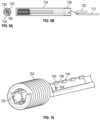
- FIG. 8is a perspective view of the system of FIG. 7 .
- FIG. 9 Ais an end view of the system of FIG. 7 .
- FIG. 9 Bis a cross-sectional view of the system of FIG. 7 .
- FIG. 10is a perspective view of a bubble generating tip system of another exemplary in accordance with some embodiments.
- the treatment systemincludes a forward bubble generating tip to be advanced within the lumen to contact the occlusion.
- the forward bubble generating tipincludes electrodes that, when provided with a relatively low-voltage and high-PRF (pulse repetition rate) generator, form plasma arcs that in turn lead to cavitation bubbles.
- the cavitation bubblescreate mechanical vibrations, turbulence, jets, and/or forceful collapses to break the occlusion.
- the output of the generatoris configured to be sufficient for creating electro-hydraulic discharge and cavitation bubbles for effectively drilling, but not enough to create a powerful shock wave that may compromise the durability of the system.
- the mechanical vibrationsare relatively gentle compared to currently available equipment. Accordingly, the treatment system is less likely to cause damage to the lumen wall (e.g., vessel wall) and is easier to control and more durable.
- FIG. 1is a perspective view of an exemplary treatment system 100 in accordance with some embodiments.
- the treatment systemincludes a forward bubble generating tip 102 (shown in an expanded view), an insulated outer sheath 104 , a proximal balloon 106 mounted over a length of the insulated outer sheath, a waste conduit 108 , and insulated wires 110 and 112 .
- the forward bubble generating tip 102includes electrodes and is described in detail with reference to FIGS. 2 A-C .
- conductive fluidsuch as saline (or saline contrast mix) is injected from the proximal opening of the insulated outer sheath 104 and flows toward the distal end.
- cavitation bubbles and/or shock wavesare generated via the conductive fluid at the forward bubble generating tip.
- the cavitation bubbles and/or shock waveslead to sustained mechanical vibrations in the forward direction, breaking down the occlusion such as CTO or kidney stones.
- debrissuch as broken down occlusion pieces, metals, and bubbles are flushed toward the proximal balloon and carried out of the lumen via the waste conduit 108 .
- FIG. 2 Adepicts an expanded view of the forward bubble generating tip 102 of FIG. 1 .
- the forward bubble generating tip 102includes an elongated conductive tube 208 , a helically coiled portion 202 at the distal end of the insulated wire 112 , and an optional insulated layer 206 disposed between the elongated conductive tube 208 and the helically coiled portion 202 .
- the insulated layer 206includes a plurality of holes 204 arranged along the longitudinal axis.
- the elongated conductive tube 208can be a stainless steel hypotube.
- the insulated wires 110 and 112can be polyimide-insulated copper wires.
- the insulated layer 206can be a polyimide tubular insulator.
- the insulated layerprovides an extra layer of insulation between the conductive core of wire 112 and the elongated conductive tube 208 and is helpful in case the insulation around the coiled portion 202 has defects and/or experiences damages (e.g., scratching during assembly).
- the forward bubble generating tip 102does not include the insulated layer 206 .
- epoxy or cyano gluecan be used between the coiled portion 202 and the elongated conductive tube 208 to fix the relative positioning of the two.
- FIG. 2 Bdepicts a cross-sectional view of the forward bubble generating tip 102 .
- the insulated outer sheath 104is circumferentially mounted over the elongated conductive tube 208 .
- the distal edge of the elongated conductive tube 208extends over distal edge of the insulated outer sheath 104 by distance A.
- the distance Acan be adjusted based on the characteristics of the occlusion. For example, the distance A can be set to be longer than the thickness of the calcified cap of the CTO to be drilled through. If not, the crossing profile would need to be undesirably increased (i.e. a bigger hole needs to be drilled to accommodate the insulated outer sheath).
- the distance Aranges from 0.004′′ to 0.01′′.
- an insulated layer 206is disposed, for a longitudinal length of L, between the elongated conductive tube 208 and the helically coiled wire portion 202 . The distal end of the insulated wire 110 is welded to the elongated conductive tube 208 .
- the distal edge of the insulated layer 206is aligned with the distal edge of the elongated conductive tube 208 . Further, the distal edge of the elongated conductive tube 208 extends beyond the helically coiled wire portion 202 by distance B. In some examples, the distance B ranges from 0 mm (i.e., the distal end of the coiled portion is aligned with the distal edge of the elongated tube) to 0.5 mm. In some examples, one or more of the other factors that affect the efficiency of the operation, such as the flow rate of the conductive fluid, the applied voltage, the shape and composition of the occlusion, are taken into account when setting distance B to achieve an optimal configuration.
- This relative positioning of the helically coiled wire portion 202 and the distal edges of the insulated layer 206 and elongated conductive tube 208ensures safety to the surrounding tissue, protects the catheter from the vibrations emitting from the tip, and causes the mechanical vibrations to be generated in a forward-facing direction, thus increasing the intensity, and thus the effectiveness, of the treatment system in breaking down the occlusion. Further, the forward-facing mechanical vibrations, along with the continuous flow rate in the forward direction, result in drilling of holes that are consistent (e.g., in size, in shape), thus making the treatment system easier to operate.
- the treatment systemis configured to drill holes of around 1 mm in diameter in calcified materials.
- the flow of saline or saline/angiographic contrast mixis adjusted to avoid over-heating issues and control drilling efficiency and rate.
- the flow rateis configured to be in the range of 1 to 30 mL/min to improve breakability of calcified structures.
- a currentflows from the distal end 210 of the insulated wire 112 to the elongated conductive tube 208 .
- the currentcan cause a plurality of plasma arcs to be formed between the distal end 210 of the insulated wire 112 and the inner diameter of the elongated conductive tube 208 (e.g., across the distal edge 203 of the insulated layer 206 or through the holes 204 in 206 ).
- the plasma arcslead to cavitation bubbles in a controlled fashion (one at a time, at a particular rate), which in turn lead to mechanical vibrations, and other bubble dynamics-related effects such as collapses, turbulence, jetting, etc. in the conductive fluid (e.g., via the expansion and collapse of the bubbles).
- the mechanical vibrationsserve to break or chip away the occlusion.
- the generator for this systemis configured to generate lower-voltage pulses at a higher pulse repetition rate in order to minimize the strength of the shock waves and optimize and maximize bubble growth and collapse.
- each pulsemight be about 3000 volts with a 1 Hz repetition rate.
- the voltagecan be under 1000 volts with the repetition rates ranging from 14 to 200 Hz.
- repetition ratescan as high as 800 Hz.
- the helically coiled wire portion 202 and/or the insulation over the coiled wire portioncan disintegrate and shorten over time.
- the insulation layer 206 and the distal edge of the elongated conductive tube 208can disintegrate due to use.
- the rates at which the coiled wire portion, the insulated layer, and the elongated conductive tube disintegratecan vary based on physical characteristics of each component (e.g., the diameter of the wire, the property of the wire, the thickness of the insulation layer), the polarities of the applied voltage, the magnitude of the applied voltage, etc.
- a wire that is relatively thin, connected to a relatively high voltage supply, and/or connected to the positive voltage portwould erode faster.
- the plasma arcsare generated across the distal edge 203 of the insulated layer 206 .
- the distance between the distal end 210 of the insulated wire 112 and the distal edge of the insulated layer 206increases. Due to the increased distance, plasma arcs are no longer generated across the distal edge 203 of the insulated layer 206 .
- plasma arcsare generated across one of the holes 204 (e.g., the hole located closest to the distal end 210 of the shortened helically coiled wire portion) in the insulated layer 206 .
- a plurality of holesare provided along the longitudinal axis of the insulated layer 206 , thus allowing plasma arcs to be formed even as the helically coiled wire portion 202 shortens and improving the durability of the treatment system.
- the holes in the conductive layeraim to become new spark areas as the device (i.e., the electrodes) erodes.
- the plurality of holesis arranged in a spiral orientation to be aligned with the coil to control the maximum arc length.
- the applied voltageis sustained for a relatively long periods of time (e.g., minutes) to achieve continuous generation of cavitation bubbles and eventual crossing. Note that as the coiled wire portion erodes, the location of the generation of the cavitation bubbles will change. In the illustrated embodiment, the location of the generation of the cavity bubbles will rotate circumferentially about the periphery of the conductive tube 208 .
- various parameterscan be adjusted during the operation to slow down or even out the erosion of the electrodes.
- the frequency of bubble generation/emissioncan be adjusted to control the tip erosion, durability and drilling time.
- the frequency of bubble generationcan be controlled by reducing the capacitance (so a capacitance switch can change the speed on demand), or by reducing the current power supply.
- the applied voltagecan be adjusted as a function of drilling time to control the emitter erosion and device durability while maintaining the frequency constant as a function of drilling time.
- polarity of the electrodescan be reversed for a period of time equivalent to a fraction of the treatment time (e.g., 10% to 100% of the time) while maintaining the voltage and frequency constant as a function of drilling time in order to control electrode wear and improve device durability.
- the thickness of the wire insulationcan be chosen to control the durability of the wire.
- U.S. Pat. No. 10,226,265incorporated by reference, teaches various approaches for switching polarity of electrode pairs positioned in a conductive fluid. Those types of approaches can be utilized with the subject device.
- the spark gapshould be constant. As the electrodes erode away, the gap can vary. To compensate for this variation in gap size, the polarity on the electrodes can be reversed.
- the polarity reversal frequencycan be used to help control variations in the length of the spark gap. It is possible to tune the polarity reversal frequency based on the power being delivered, wire diameter and insulator thickness. It is also possible to have the generator detect the power degradation and automatically reverse the polarity on the electrodes.
- FIG. 2 Cis a cross-sectional view of an exemplary bubble generating tip of the treatment system, in accordance with some embodiments.
- the insulated wire 112has a typical diameter of 0.005′′ in the core (e.g., copper core) with 0.0005′′ polyimide coating.
- the number of turns of the coiled wire portiondictates the life of the electrode. With ⁇ 500V-700V arcing at 100 Hz, one turn can last approximately 30-40 seconds. Thus, for a 10-minute procedure, the coiled wire portion can include around 17 turns and the coil length would be around 0.1′′.
- the length of the elongated conductive tube 208should be longer than the coil length to support internal features.
- the insulated layer 206(e.g., polyimide insulator sheath) can have a thickness of 0.001′′.
- the outer diameter of the insulated layer 206is fitted inside the inner diameter of the elongated conductive tube 208 .
- the outer diameter of the elongated conductive tube 208(e.g., stainless steel hypotube) can range between 0.035′′ to 0.065′′ with the thickness of 0.002′′.
- Arcing gap between the wire core (e.g., copper core) and the inner diameter of the elongated conductive tubeis around 0.004′′-0.007′′.
- the arc gapcould be longer if the insulting layer 206 and a hole 204 is further away, for example the other side of the tube.
- the arcing gapis the ideal range to maximize the cavitation.
- the various dimensions of the systemare selected to be compatible with off-shelf components.
- FIG. 3depicts a perspective view of an alternative forward bubble generating tip 300 of the treatment system, in accordance with some embodiments.
- the forward bubble generating tip 300includes a plurality of atraumatic arms or tines 302 extending from the distal end of the elongated conductive tube 208 .
- the tines 302are made of flexible materials and are designed to deflect the tip from perforating the lumen wall.
- the tinescan be coated with elastomer (i.e., silicone rubber) or low durometer polymer (i.e., polyurethane), and can be around 0.035′′ in length.
- elastomeri.e., silicone rubber
- low durometer polymeri.e., polyurethane
- the forward bubble generating tip 300includes a plurality of spikes 304 extending from the distal end of the elongated conductive tube 208 .
- the spikes 304are designed to direct the plasma arcs between the distal end 310 of the coiled wire portion and the distal edge of the elongated conductive tube 208 , for example, across the distal edge of the insulated layer 306 .
- FIG. 4is a side view of an exemplary system 400 for treating an occlusion, in accordance with some embodiments.
- the proximal end of the insulated outer sheathforms an inlet 402 for injecting conductive fluid (e.g., saline).
- This port 402could also act as a conduit to introduce a guidewire (e.g., a 0.014′′ guidewire) after flushing or while flushing the saline.
- the injected conductive fluidserves a number of purposes.
- plasma arcscan be formed via the conductive fluid at the forward bubble generating tip, as described above with reference to FIGS. 1 - 3 .
- conductive fluidflushes through the coiled wire portion at the forward bubble generating tip and carries the debris such as broken down occlusion pieces, metals, and bubbles away from the forward bubble generating tip 401 toward the proximal balloon 406 .
- the proximal balloonwhen inflated, traps the debris and prevents the debris from entering the main artery.
- a conduit 404extends through the proximal balloon 406 , and the distal end 409 of the conduit 404 serves as a waste inlet for receiving the flushed debris and transporting the debris to the waste outlet 408 at the proximal end of the conduit.
- suctionis provided at the proximal end of the conduit 404 to facilitate the removal of debris. The rapid removal of debris helps to refresh the cavitation.
- FIG. 5is a schematic view of an exemplary system 500 for treating an occlusion, illustrating further aspects of the invention.
- the system 500further includes a control console 502 having an infusion pump 504 and a generator 506 .
- the infusion pumpprovides the flow of conductive fluid (e.g., saline) toward the forward bubble generating tip via the irrigation lumen.
- a auxiliary pumpmay be used for aspiration and removal of debris.
- the generatorserves as a voltage supply for the electrodes at the forward bubble generating tip.
- the pulseshave a voltage in the range of 500 to 3000 volts and more preferably 600 to 1000 volts.
- Ideal electrical energies applied for CTO crossingare very low (between 5 and 50 mJ per pulse) to avoid generating excess heat, and more preferably 30 mJ. Current ranges from 1-15 Amperes.
- the pulsesare generated with a repetition rate in the range of 14 to 800 Hz.
- the systemfurther includes a visualization system and/or a steering system for properly navigating (e.g., side branches) and placing the forward bubble generating tip.
- the forward bubble generating tipcould be made of a radiopaque material that is easy to see under fluoroscopic guidance.
- materials filled with Barium sulfate, tungsten or other radiopaque materials, or materials filled with radiopaque materialscan be used so that the device can be tracked.
- a guidewirecan be advanced through the central open region in the device and towards the hole drilled or being drilled in the occlusion.
- the guidewirecan be advanced through the drilled hole to guide the advancement of the treatment system, which continues drilling until the occlusion is crossed.
- the guidewirecan be advanced through the elongated conductive tube (e.g., from saline inlet 402 ), more specifically, through the center of the coiled portion of the bubble generating tip. After the occlusion is crossed, the forward bubble generating tip can be withdrawn, while the guidewire can remain to allow the access of other tools such as angioplasty or LithoplastyTM balloons using over the wire entry.
- Lithoplastyis the trademark of assignee directed to its intravascular lithotripsy (shock wave) catheters.
- an angioplasty balloon cathetercan be advanced through the drilled hole to a distal end of the occlusion and aligned with the occlusion.
- FIG. 6is a schematic view of another exemplary system 600 for treating an occlusion, in accordance with some embodiments.
- the treatment systemcan be used alone or in conjunction with an angioplasty balloon 602 .
- the forward bubble generating tipis first advanced within a lumen (e.g., blood vessel or ureter) to contact the occlusion to drill a hole through the occlusion in accordance with processes described above.
- the balloonis advanced to the lesion.
- the balloon 602is then pressurized with a fluid to expand the lumen to enhance flow (e.g., blood flow).
- the advancement and positioning of the ballooncan be aided with a guidewire passed through the center of the device.
- the angioplasty balloonis a lithotripsy balloon and a shock wave generator may be disposed within the balloon 602 .
- the shock wave generatormay take the form of, for example, a pair of electrodes.
- a shock waveis formed that propagates through the fluid and impinges upon the wall of the balloon and the occlusion. Repeated shock waves break up the occlusion without damaging surrounding soft tissues.
- the shock wavescan be generated along an axis perpendicular to the axis of the catheter (instead of being forwardly directed) so that they treat different parts of the occlusion.
- the angioplasty balloon 602can then be expanded to further open up the lumen.
- the control console 603includes a selector switch 604 for selecting between “CTO” and “LithoplastyTM” for switching the voltage supply between providing lower voltage pulses to the forward bubble generating tip and providing higher voltage pulses to the shock wave generator within the balloon 602 .
- the proximal ballooncan be placed on either side of the lithotripsy balloon.
- FIGS. 7 to 9represent an alternate embodiment of the subject treatment system. Similar to the previous embodiments, the embodiment of FIGS. 7 to 9 includes a helically coiled portion 702 at the distal end of an insulated wire 712 . In addition, the distal end of the coil is not insulated and forms one electrode. Unlike the previous embodiments that included a second conductor in the form of an outer cylindrical tube, in this embodiment, the second conductor is in the form of a cylindrical central electrode 720 .
- the distal end of the central electrode 720is received within the coiled portion 702 of the insulated wire.
- an insulated tube 706surrounds the distal end of the central electrode.
- the insulated tubeincludes a plurality of holes 704 that provide additional pathways for conducting current as the coiled portion of the insulated wire erodes during use.
- an annular channel 730is formed between the outer surface of the insulated tube 706 and the inner surface of the coiled portion 702 . This channel can be used to supply conductive fluid to the distal tip of the device. Since the wire 712 is insulated, it may be possible to configure the device without the insulated tube 706 .
- a cylindrical outer shell 724surrounds the distal end of the device.
- the shellcan be formed from a metal such as stainless steel.
- the shellcould be made from a non-metal such as Polyether ether ketone (PEEK) or a polyimide-based plastics such as Vespel 198 .
- PEEKPolyether ether ketone
- the materialshould be heat resistant and provide some stiffness for crossing the occlusion.
- the proximal end portion of the outer shell ( 728 ),is formed from a more flexible material to facilitate advancement of the device through the circulatory system.
- FIGS. 7 to 9would be used in a manner similar to the previously discussed embodiments. Briefly, the proximal ends of the insulated wire and central electrode are connected to a power source generating pulses with a repetition rate on the order of hundreds of pulses per second. The pulses create cavitation bubbles in the conductive fluid at the distal end of the device. The cavitation bubbles create mechanical vibrations that can chip away at the occlusion.
- the end of the coiled portion of the insulate wirewill typically erode.
- the point at which the cavitation bubbles are generatedmoves circumferentially about the periphery of the central electrode.
- the holes 704 in the insulated tube 706provide sequential pathways for the current as the coiled wire erodes.
- the central electrode 720is removably mounted within the device. In use, after the occlusion has been opened, the central electrode can be removed providing a channel for insertion of a guidewire or other device for further treatment.
- FIG. 10illustrates a variant of the embodiment of FIGS. 7 to 9 .
- the outer surface of the insulated tube 706includes radially projecting spacers 740 .
- the spacers 740function to space the central electrode 720 from the inner surface of the coiled portion 702 of insulated wire 712 .
Landscapes
- Health & Medical Sciences (AREA)
- Life Sciences & Earth Sciences (AREA)
- Engineering & Computer Science (AREA)
- Surgery (AREA)
- Heart & Thoracic Surgery (AREA)
- General Health & Medical Sciences (AREA)
- Vascular Medicine (AREA)
- Veterinary Medicine (AREA)
- Public Health (AREA)
- Biomedical Technology (AREA)
- Animal Behavior & Ethology (AREA)
- Molecular Biology (AREA)
- Nuclear Medicine, Radiotherapy & Molecular Imaging (AREA)
- Mechanical Engineering (AREA)
- Orthopedic Medicine & Surgery (AREA)
- Medical Informatics (AREA)
- Anesthesiology (AREA)
- Biophysics (AREA)
- Pulmonology (AREA)
- Child & Adolescent Psychology (AREA)
- Hematology (AREA)
- Surgical Instruments (AREA)
- Investigating Or Analyzing Materials By The Use Of Ultrasonic Waves (AREA)
- Crystals, And After-Treatments Of Crystals (AREA)
- Exposure Of Semiconductors, Excluding Electron Or Ion Beam Exposure (AREA)
Abstract
Description
Claims (30)
Priority Applications (3)
| Application Number | Priority Date | Filing Date | Title |
|---|---|---|---|
| US16/436,186US11596423B2 (en) | 2018-06-21 | 2019-06-10 | System for treating occlusions in body lumens |
| US18/104,170US12114874B2 (en) | 2018-06-21 | 2023-01-31 | System for treating occlusions in body lumens |
| US18/883,250US20250000531A1 (en) | 2018-06-21 | 2024-09-12 | System for treating occlusions in body lumens |
Applications Claiming Priority (2)
| Application Number | Priority Date | Filing Date | Title |
|---|---|---|---|
| US201862688110P | 2018-06-21 | 2018-06-21 | |
| US16/436,186US11596423B2 (en) | 2018-06-21 | 2019-06-10 | System for treating occlusions in body lumens |
Related Child Applications (1)
| Application Number | Title | Priority Date | Filing Date |
|---|---|---|---|
| US18/104,170DivisionUS12114874B2 (en) | 2018-06-21 | 2023-01-31 | System for treating occlusions in body lumens |
Publications (2)
| Publication Number | Publication Date |
|---|---|
| US20190388110A1 US20190388110A1 (en) | 2019-12-26 |
| US11596423B2true US11596423B2 (en) | 2023-03-07 |
Family
ID=67003716
Family Applications (3)
| Application Number | Title | Priority Date | Filing Date |
|---|---|---|---|
| US16/436,186Active2040-05-11US11596423B2 (en) | 2018-06-21 | 2019-06-10 | System for treating occlusions in body lumens |
| US18/104,170ActiveUS12114874B2 (en) | 2018-06-21 | 2023-01-31 | System for treating occlusions in body lumens |
| US18/883,250PendingUS20250000531A1 (en) | 2018-06-21 | 2024-09-12 | System for treating occlusions in body lumens |
Family Applications After (2)
| Application Number | Title | Priority Date | Filing Date |
|---|---|---|---|
| US18/104,170ActiveUS12114874B2 (en) | 2018-06-21 | 2023-01-31 | System for treating occlusions in body lumens |
| US18/883,250PendingUS20250000531A1 (en) | 2018-06-21 | 2024-09-12 | System for treating occlusions in body lumens |
Country Status (7)
| Country | Link |
|---|---|
| US (3) | US11596423B2 (en) |
| EP (1) | EP3809988B1 (en) |
| JP (1) | JP7280897B2 (en) |
| CN (1) | CN112367934B (en) |
| AU (2) | AU2019290401B2 (en) |
| ES (1) | ES2948245T3 (en) |
| WO (1) | WO2019245746A1 (en) |
Cited By (7)
| Publication number | Priority date | Publication date | Assignee | Title |
|---|---|---|---|---|
| US11992232B2 (en) | 2020-10-27 | 2024-05-28 | Shockwave Medical, Inc. | System for treating thrombus in body lumens |
| US12114874B2 (en) | 2018-06-21 | 2024-10-15 | Shockwave Medical, Inc. | System for treating occlusions in body lumens |
| US12256989B2 (en) | 2022-09-29 | 2025-03-25 | Calyxo, Inc. | Tool guiding device for kidney stone treatment apparatus |
| US12329399B2 (en) | 2022-03-02 | 2025-06-17 | Calyxo, Inc. | Kidney stone treatment system |
| US12402897B2 (en) | 2019-09-24 | 2025-09-02 | Shockwave Medical, Inc. | System for treating thrombus in body lumens |
| US12402899B2 (en) | 2023-11-30 | 2025-09-02 | Shockwave Medical, Inc. | Systems, devices, and methods for generating shock waves in a forward direction |
| US12433620B2 (en) | 2024-02-23 | 2025-10-07 | Shockwave Medical, Inc. | Locus emitter shock wave catheter devices with increased longevity and higher sonic output |
Families Citing this family (44)
| Publication number | Priority date | Publication date | Assignee | Title |
|---|---|---|---|---|
| US11819229B2 (en) | 2019-06-19 | 2023-11-21 | Boston Scientific Scimed, Inc. | Balloon surface photoacoustic pressure wave generation to disrupt vascular lesions |
| US12402946B2 (en) | 2019-06-19 | 2025-09-02 | Boston Scientific Scimed, Inc. | Breakdown of laser pulse energy for breakup of vascular calcium |
| US11717139B2 (en) | 2019-06-19 | 2023-08-08 | Bolt Medical, Inc. | Plasma creation via nonaqueous optical breakdown of laser pulse energy for breakup of vascular calcium |
| US11660427B2 (en) | 2019-06-24 | 2023-05-30 | Boston Scientific Scimed, Inc. | Superheating system for inertial impulse generation to disrupt vascular lesions |
| US12280223B2 (en) | 2019-06-26 | 2025-04-22 | Boston Scientific Scimed, Inc. | Focusing element for plasma system to disrupt vascular lesions |
| US11583339B2 (en) | 2019-10-31 | 2023-02-21 | Bolt Medical, Inc. | Asymmetrical balloon for intravascular lithotripsy device and method |
| US12102384B2 (en) | 2019-11-13 | 2024-10-01 | Bolt Medical, Inc. | Dynamic intravascular lithotripsy device with movable energy guide |
| US12274497B2 (en) | 2019-12-18 | 2025-04-15 | Bolt Medical, Inc. | Multiplexer for laser-driven intravascular lithotripsy device |
| US11672599B2 (en) | 2020-03-09 | 2023-06-13 | Bolt Medical, Inc. | Acoustic performance monitoring system and method within intravascular lithotripsy device |
| US20210290286A1 (en) | 2020-03-18 | 2021-09-23 | Bolt Medical, Inc. | Optical analyzer assembly and method for intravascular lithotripsy device |
| US11707323B2 (en) | 2020-04-03 | 2023-07-25 | Bolt Medical, Inc. | Electrical analyzer assembly for intravascular lithotripsy device |
| US12295654B2 (en) | 2020-06-03 | 2025-05-13 | Boston Scientific Scimed, Inc. | System and method for maintaining balloon integrity within intravascular lithotripsy device with plasma generator |
| US12207870B2 (en) | 2020-06-15 | 2025-01-28 | Boston Scientific Scimed, Inc. | Spectroscopic tissue identification for balloon intravascular lithotripsy guidance |
| CN111790046B (en)* | 2020-07-31 | 2024-09-27 | 深圳市赛禾医疗技术有限公司 | A pressure wave balloon catheter |
| CN114191034B (en)* | 2020-09-18 | 2024-10-01 | 微创投资控股有限公司 | Medical catheter and medical catheter system |
| US20220125454A1 (en)* | 2020-10-23 | 2022-04-28 | Vicora, Inc. | Actuated thrombectomy device |
| US12016610B2 (en) | 2020-12-11 | 2024-06-25 | Bolt Medical, Inc. | Catheter system for valvuloplasty procedure |
| EP4277548B1 (en) | 2021-01-12 | 2025-06-04 | Bolt Medical, Inc. | Balloon assembly for valvuloplasty catheter system |
| US11672585B2 (en) | 2021-01-12 | 2023-06-13 | Bolt Medical, Inc. | Balloon assembly for valvuloplasty catheter system |
| US11911056B2 (en) | 2021-02-26 | 2024-02-27 | Fastwave Medical Inc. | Intravascular lithotripsy |
| US11484327B2 (en) | 2021-02-26 | 2022-11-01 | Fastwave Medical Inc. | Intravascular lithotripsy |
| US11944331B2 (en) | 2021-02-26 | 2024-04-02 | Fastwave Medical Inc. | Intravascular lithotripsy |
| US11648057B2 (en) | 2021-05-10 | 2023-05-16 | Bolt Medical, Inc. | Optical analyzer assembly with safety shutdown system for intravascular lithotripsy device |
| US11806075B2 (en) | 2021-06-07 | 2023-11-07 | Bolt Medical, Inc. | Active alignment system and method for laser optical coupling |
| CN113404669A (en)* | 2021-06-16 | 2021-09-17 | 安徽省立医院(中国科学技术大学附属第一医院) | Automatic induction air charging and discharging joint device |
| US11801066B2 (en) | 2021-08-05 | 2023-10-31 | Nextern Innovation, Llc | Systems, devices and methods for selection of arc location within a lithoplasty balloon spark gap |
| US11896248B2 (en) | 2021-08-05 | 2024-02-13 | Nextern Innovation, Llc | Systems, devices and methods for generating subsonic pressure waves in intravascular lithotripsy |
| US11957369B2 (en) | 2021-08-05 | 2024-04-16 | Nextern Innovation, Llc | Intravascular lithotripsy systems and methods |
| US11877761B2 (en) | 2021-08-05 | 2024-01-23 | Nextern Innovation, Llc | Systems, devices and methods for monitoring voltage and current and controlling voltage of voltage pulse generators |
| US12089861B2 (en) | 2021-08-05 | 2024-09-17 | Nextern Innovation, Llc | Intravascular lithotripsy system and device |
| KR102403123B1 (en)* | 2021-09-30 | 2022-06-07 | 주식회사 정록 | External electrode part and Plasma generating device having thereof |
| US12023098B2 (en) | 2021-10-05 | 2024-07-02 | Shockwave Medical, Inc. | Lesion crossing shock wave catheter |
| CR20240179A (en) | 2021-10-19 | 2024-06-12 | Shockwave Medical Inc | Intravascular lithotripsy catheter with interfering shock waves |
| US20230165598A1 (en)* | 2021-11-30 | 2023-06-01 | Shockwave Medical, Inc. | Electrode design for directional lithotripsy catheters |
| US11839391B2 (en) | 2021-12-14 | 2023-12-12 | Bolt Medical, Inc. | Optical emitter housing assembly for intravascular lithotripsy device |
| US12193738B2 (en) | 2022-06-01 | 2025-01-14 | Fastwave Medical Inc. | Intravascular lithotripsy |
| AU2023280407A1 (en) | 2022-06-01 | 2024-11-07 | Fastwave Medical Inc. | Intravascular lithotripsy |
| CN116784933A (en)* | 2022-09-26 | 2023-09-22 | 苏州润迈德医疗科技有限公司 | Shock wave sacculus catheter device |
| CN116173386B (en)* | 2023-03-21 | 2024-08-23 | 深圳市赛禾医疗技术有限公司 | Shock wave balloon catheter |
| US12035932B1 (en) | 2023-04-21 | 2024-07-16 | Shockwave Medical, Inc. | Intravascular lithotripsy catheter with slotted emitter bands |
| US12220141B2 (en) | 2023-06-29 | 2025-02-11 | Shockwave Medical, Inc. | Catheter system with independently controllable bubble and arc generation |
| US12426904B2 (en) | 2023-11-17 | 2025-09-30 | Shockwave Medical, Inc. | Intravascular lithotripsy catheter with oscillating impactor |
| WO2025171173A1 (en) | 2024-02-08 | 2025-08-14 | IV-X Medical, LLC | Intravascular lithotripsy system |
| US12178458B1 (en) | 2024-05-16 | 2024-12-31 | Shockwave Medical, Inc. | Guidewireless shock wave catheters |
Citations (194)
| Publication number | Priority date | Publication date | Assignee | Title |
|---|---|---|---|---|
| US3051862A (en)* | 1960-02-10 | 1962-08-28 | Tappan Co | Gas ignitor |
| US3413976A (en) | 1963-07-29 | 1968-12-03 | G Elektrotekhnichesky Zd Vef | Arrangement for removal of concretions from urinary tract |
| US3785382A (en) | 1971-05-14 | 1974-01-15 | Wolf Gmbh Richard | Device for destroying stones in the bladder, in the ureter, in the kidneys and the like |
| US3902499A (en) | 1974-01-02 | 1975-09-02 | Hoffman Saul | Stone disintegrator |
| US4027674A (en) | 1975-06-06 | 1977-06-07 | Tessler Arthur N | Method and device for removing concretions within human ducts |
| US4030505A (en) | 1975-11-28 | 1977-06-21 | Calculus Instruments Ltd. | Method and device for disintegrating stones in human ducts |
| DE3038445A1 (en) | 1980-10-11 | 1982-05-27 | Dornier Gmbh, 7990 Friedrichshafen | Pressure wave generator for diagnosis and therapy - has spark gap in inflatable balloon at end of catheter |
| JPS60191353U (en) | 1984-05-25 | 1985-12-18 | 日立工機株式会社 | Ink ribbon feeding control device |
| US4662126A (en) | 1986-05-23 | 1987-05-05 | Fike Corporation | Vibration resistant explosion control vent |
| US4671254A (en) | 1985-03-01 | 1987-06-09 | Memorial Hospital For Cancer And Allied Diseases | Non-surgical method for suppression of tumor growth |
| JPS6299210U (en) | 1985-12-12 | 1987-06-24 | ||
| US4685458A (en) | 1984-03-01 | 1987-08-11 | Vaser, Inc. | Angioplasty catheter and method for use thereof |
| JPS62275446A (en) | 1986-05-21 | 1987-11-30 | オリンパス光学工業株式会社 | Discharge stone crushing apparatus |
| US4809682A (en) | 1985-12-12 | 1989-03-07 | Dornier Medizintechnik Gmbh | Underwater electrodes for contactless lithotripsy |
| US4813934A (en) | 1987-08-07 | 1989-03-21 | Target Therapeutics | Valved catheter device and method |
| US4870953A (en) | 1987-11-13 | 1989-10-03 | Donmicheal T Anthony | Intravascular ultrasonic catheter/probe and method for treating intravascular blockage |
| US4878495A (en) | 1987-05-15 | 1989-11-07 | Joseph Grayzel | Valvuloplasty device with satellite expansion means |
| US4900303A (en) | 1978-03-10 | 1990-02-13 | Lemelson Jerome H | Dispensing catheter and method |
| US4994032A (en) | 1987-12-01 | 1991-02-19 | Terumo Kabushiki Kaisha | Balloon catheter |
| JPH0363059A (en) | 1989-04-26 | 1991-03-19 | Advanced Cardiovascular Syst Inc | Blood flow measurement using self-irrigation catheter for blood vessel formation and its device |
| US5009232A (en) | 1988-08-17 | 1991-04-23 | Siemens Aktiengesellschaft | Extracorporeal lithotripsy apparatus using high intensity shock waves for calculus disintegration and low intensity shock waves for imaging |
| EP0442199A2 (en) | 1990-02-12 | 1991-08-21 | BS & B SAFETY SYSTEMS, INC. | Low pressure non-fragmenting rupture disks |
| US5057106A (en) | 1986-02-27 | 1991-10-15 | Kasevich Associates, Inc. | Microwave balloon angioplasty |
| US5057103A (en) | 1990-05-01 | 1991-10-15 | Davis Emsley A | Compressive intramedullary nail |
| US5061240A (en) | 1990-04-02 | 1991-10-29 | George Cherian | Balloon tip catheter for venous valve ablation |
| US5078717A (en) | 1989-04-13 | 1992-01-07 | Everest Medical Corporation | Ablation catheter with selectively deployable electrodes |
| WO1992003975A1 (en) | 1990-09-04 | 1992-03-19 | Cannon Robert L Iii | Catheter and apparatus for the treatment, inter alia, of pulmonary embolisms |
| US5103804A (en) | 1990-07-03 | 1992-04-14 | Boston Scientific Corporation | Expandable tip hemostatic probes and the like |
| US5103556A (en)* | 1988-05-05 | 1992-04-14 | Circon Corporation | Method of manufacturing an electrohydraulic probe |
| US5125928A (en) | 1989-04-13 | 1992-06-30 | Everest Medical Corporation | Ablation catheter with selectively deployable electrodes |
| US5150717A (en) | 1988-11-10 | 1992-09-29 | Arye Rosen | Microwave aided balloon angioplasty with guide filament |
| US5152767A (en) | 1990-11-23 | 1992-10-06 | Northgate Technologies, Inc. | Invasive lithotripter with focused shockwave |
| US5152768A (en) | 1991-02-26 | 1992-10-06 | Bhatta Krishna M | Electrohydraulic lithotripsy |
| US5154722A (en) | 1988-05-05 | 1992-10-13 | Circon Corporation | Electrohydraulic probe having a controlled discharge path |
| US5176675A (en) | 1985-04-24 | 1993-01-05 | The General Hospital Corporation | Use of lasers to break down objects for removal from within the body |
| US5195508A (en) | 1990-05-18 | 1993-03-23 | Dornier Medizintechnik Gmbh | Spark gap unit for lithotripsy |
| US5246447A (en) | 1989-02-22 | 1993-09-21 | Physical Sciences, Inc. | Impact lithotripsy |
| US5245988A (en) | 1989-11-15 | 1993-09-21 | Dormer Gmbh | Preparing a circuit for the production of shockwaves |
| US5254121A (en) | 1992-05-22 | 1993-10-19 | Meditron Devices, Inc. | Method and device for removing concretions within human ducts |
| EP0571306A1 (en) | 1992-05-22 | 1993-11-24 | LASER MEDICAL TECHNOLOGY, Inc. | Apparatus and method for removal of deposits from the walls of body passages |
| US5281231A (en) | 1989-02-22 | 1994-01-25 | Physical Sciences, Inc. | Impact lithotrypsy |
| US5295958A (en) | 1991-04-04 | 1994-03-22 | Shturman Cardiology Systems, Inc. | Method and apparatus for in vivo heart valve decalcification |
| JPH06125915A (en) | 1992-10-21 | 1994-05-10 | Inter Noba Kk | Catheter type medical instrument |
| US5321715A (en) | 1993-05-04 | 1994-06-14 | Coherent, Inc. | Laser pulse format for penetrating an absorbing fluid |
| US5324255A (en) | 1991-01-11 | 1994-06-28 | Baxter International Inc. | Angioplasty and ablative devices having onboard ultrasound components and devices and methods for utilizing ultrasound to treat or prevent vasopasm |
| US5336234A (en) | 1992-04-17 | 1994-08-09 | Interventional Technologies, Inc. | Method and apparatus for dilatation of a stenotic vessel |
| US5362309A (en) | 1992-09-14 | 1994-11-08 | Coraje, Inc. | Apparatus and method for enhanced intravascular phonophoresis including dissolution of intravascular blockage and concomitant inhibition of restenosis |
| EP0623360A1 (en) | 1993-02-05 | 1994-11-09 | The Joe W. And Dorothy Dorsett Brown Foundation | Ultrasonic angioplasty balloon catheter |
| US5364393A (en) | 1990-07-02 | 1994-11-15 | Heart Technology, Inc. | Tissue dissipative recanalization catheter |
| US5368591A (en) | 1988-10-28 | 1994-11-29 | Prutech Research And Development Partnership Ii | Heated balloon catheters |
| US5395335A (en) | 1991-05-24 | 1995-03-07 | Jang; G. David | Universal mode vascular catheter system |
| EP0647435A1 (en) | 1993-10-12 | 1995-04-12 | Arrow International Investment Corporation | Electrode-carrying catheter and method of making same |
| US5425735A (en) | 1989-02-22 | 1995-06-20 | Psi Medical Products, Inc. | Shielded tip catheter for lithotripsy |
| US5472406A (en) | 1991-10-03 | 1995-12-05 | The General Hospital Corporation | Apparatus and method for vasodilation |
| WO1996024297A1 (en) | 1995-02-09 | 1996-08-15 | C.R. Bard, Inc. | Angioplasty catheter used to expand and/or open up blood vessels |
| US5582578A (en) | 1995-08-01 | 1996-12-10 | Duke University | Method for the comminution of concretions |
| US5603731A (en) | 1994-11-21 | 1997-02-18 | Whitney; Douglass G. | Method and apparatus for thwarting thrombosis |
| US5697281A (en) | 1991-10-09 | 1997-12-16 | Arthrocare Corporation | System and method for electrosurgical cutting and ablation |
| US5735811A (en) | 1995-11-30 | 1998-04-07 | Pharmasonics, Inc. | Apparatus and methods for ultrasonically enhanced fluid delivery |
| JPH1099444A (en) | 1996-09-27 | 1998-04-21 | Advanced Cardeovascular Syst Inc | Vibratory stent to open calcified lesion part |
| JPH10314177A (en) | 1997-04-26 | 1998-12-02 | Convergenza Ag | Device with treating catheter |
| US5846218A (en) | 1996-09-05 | 1998-12-08 | Pharmasonics, Inc. | Balloon catheters having ultrasonically driven interface surfaces and methods for their use |
| WO1999000060A1 (en) | 1997-06-26 | 1999-01-07 | Advanced Coronary Intervention | Electrosurgical catheter for resolving obstructions by radio frequency ablation |
| WO1999002096A1 (en) | 1997-07-08 | 1999-01-21 | The Regents Of The University Of California | Circumferential ablation device assembly and method |
| US5931805A (en) | 1997-06-02 | 1999-08-03 | Pharmasonics, Inc. | Catheters comprising bending transducers and methods for their use |
| US6080119A (en) | 1997-05-02 | 2000-06-27 | Hmt Holding Ag | Process and device for generating shock waves for medical uses |
| US6113560A (en) | 1994-09-21 | 2000-09-05 | Hmt High Medical Techologies | Method and device for generating shock waves for medical therapy, particularly for electro-hydraulic lithotripsy |
| WO2000051502A1 (en) | 1996-06-20 | 2000-09-08 | Ernesto Fina | Device for the electrolytic dissolution of urinary stones |
| WO2000056237A2 (en) | 1999-03-19 | 2000-09-28 | Atrionix, Inc. | Atrial annulus ablation device |
| US6186963B1 (en) | 1997-05-02 | 2001-02-13 | Hmt Holding Ag | Device for generating acoustic shock waves, especially for medical applications |
| US6210408B1 (en) | 1999-02-24 | 2001-04-03 | Scimed Life Systems, Inc. | Guide wire system for RF recanalization of vascular blockages |
| US6210404B1 (en) | 1998-10-28 | 2001-04-03 | John H. Shadduck | Microjoule electrical discharge catheter for thrombolysis in stroke patients |
| US6217531B1 (en) | 1997-10-24 | 2001-04-17 | Its Medical Technologies & Services Gmbh | Adjustable electrode and related method |
| US6267747B1 (en) | 1998-05-11 | 2001-07-31 | Cardeon Corporation | Aortic catheter with porous aortic root balloon and methods for inducing cardioplegic arrest |
| US6277138B1 (en) | 1999-08-17 | 2001-08-21 | Scion Cardio-Vascular, Inc. | Filter for embolic material mounted on expandable frame |
| US20010044596A1 (en) | 2000-05-10 | 2001-11-22 | Ali Jaafar | Apparatus and method for treatment of vascular restenosis by electroporation |
| US6352535B1 (en) | 1997-09-25 | 2002-03-05 | Nanoptics, Inc. | Method and a device for electro microsurgery in a physiological liquid environment |
| US6367203B1 (en) | 2000-09-11 | 2002-04-09 | Oklahoma Safety Equipment Co., Inc. | Rupture panel |
| US6371971B1 (en) | 1999-11-15 | 2002-04-16 | Scimed Life Systems, Inc. | Guidewire filter and methods of use |
| US20020045890A1 (en) | 1996-04-24 | 2002-04-18 | The Regents Of The University O F California | Opto-acoustic thrombolysis |
| US6398792B1 (en) | 1999-06-21 | 2002-06-04 | O'connor Lawrence | Angioplasty catheter with transducer using balloon for focusing of ultrasonic energy and method for use |
| US6406486B1 (en) | 1991-10-03 | 2002-06-18 | The General Hospital Corporation | Apparatus and method for vasodilation |
| US20020077653A1 (en) | 1998-04-08 | 2002-06-20 | Hudson John Overton | Hemostatic system for body cavities |
| US20020077643A1 (en) | 1999-10-05 | 2002-06-20 | Robert Rabiner | Method of removing occlusions using ultrasonic medical device operating in a transverse mode |
| US20030004434A1 (en) | 2001-06-29 | 2003-01-02 | Francesco Greco | Catheter system having disposable balloon |
| US6514203B2 (en) | 2001-02-12 | 2003-02-04 | Sonata Technologies Ltd. | Method for ultrasonic coronary thrombolysis |
| US6524251B2 (en) | 1999-10-05 | 2003-02-25 | Omnisonics Medical Technologies, Inc. | Ultrasonic device for tissue ablation and sheath for use therewith |
| US20030088262A1 (en) | 2001-11-06 | 2003-05-08 | Possis Medical,Inc | Guidewire having occlusive device and repeatably crimpable proximal end |
| US6589253B1 (en) | 1999-12-30 | 2003-07-08 | Advanced Cardiovascular Systems, Inc. | Ultrasonic angioplasty transmission wire |
| US6607003B1 (en) | 2001-04-23 | 2003-08-19 | Oklahoma Safety Equipment Co, | Gasket-lined rupture panel |
| US20030176873A1 (en) | 2002-03-12 | 2003-09-18 | Lithotech Medical Ltd. | Method for intracorporeal lithotripsy fragmentation and apparatus for its implementation |
| US6638246B1 (en) | 2000-11-28 | 2003-10-28 | Scimed Life Systems, Inc. | Medical device for delivery of a biologically active material to a lumen |
| US20030229370A1 (en) | 2002-06-11 | 2003-12-11 | Miller Paul James | Catheter balloon with ultrasonic microscalpel blades |
| US20040006333A1 (en) | 1994-09-09 | 2004-01-08 | Cardiofocus, Inc. | Coaxial catheter instruments for ablation with radiant energy |
| US20040010249A1 (en) | 2000-08-01 | 2004-01-15 | Csaba Truckai | Voltage threshold ablation apparatus |
| JP2004081374A (en) | 2002-08-26 | 2004-03-18 | Dairin Kk | Instrument for removing sediment in tubular organ |
| US6736784B1 (en) | 1999-06-24 | 2004-05-18 | Ferton Holding S.A. | Medical instrument for treating biological tissue and method for transmitting pressure waves |
| US20040097963A1 (en)* | 2002-11-19 | 2004-05-20 | Seddon J. Michael | Method and apparatus for disintegrating urinary tract stones |
| US20040097996A1 (en) | 1999-10-05 | 2004-05-20 | Omnisonics Medical Technologies, Inc. | Apparatus and method of removing occlusions using an ultrasonic medical device operating in a transverse mode |
| US6740081B2 (en) | 2002-01-25 | 2004-05-25 | Applied Medical Resources Corporation | Electrosurgery with improved control apparatus and method |
| US6755821B1 (en) | 1998-12-08 | 2004-06-29 | Cardiocavitational Systems, Inc. | System and method for stimulation and/or enhancement of myocardial angiogenesis |
| US20040162508A1 (en) | 2003-02-19 | 2004-08-19 | Walter Uebelacker | Shock wave therapy method and device |
| US20040193046A1 (en) | 2003-03-28 | 2004-09-30 | John E. Nash | Catheter with associated extension lumen |
| US20040254570A1 (en) | 2003-06-13 | 2004-12-16 | Andreas Hadjicostis | Endoscopic medical treatment involving acoustic ablation |
| JP2004357792A (en) | 2003-06-02 | 2004-12-24 | Keio Gijuku | Apparatus for preventing and treating vascular restenosis by sound pressure wave induced by high intensity pulsed light irradiation |
| US20050015953A1 (en) | 2003-07-21 | 2005-01-27 | Yaron Keidar | Method for making a spiral array ultrasound transducer |
| US20050021013A1 (en) | 1997-10-21 | 2005-01-27 | Endo Vasix, Inc. | Photoacoustic removal of occlusions from blood vessels |
| US6855123B2 (en) | 2002-08-02 | 2005-02-15 | Flow Cardia, Inc. | Therapeutic ultrasound system |
| US20050059965A1 (en) | 2003-09-15 | 2005-03-17 | Scimed Life Systems, Inc. | Catheter balloons |
| US20050075662A1 (en) | 2003-07-18 | 2005-04-07 | Wesley Pedersen | Valvuloplasty catheter |
| JP2005095410A (en) | 2003-09-25 | 2005-04-14 | Keisei Ika Kogyo Kk | Catheter for thrombus removal |
| US20050090888A1 (en) | 2003-10-28 | 2005-04-28 | Hines Richard A. | Pleated stent assembly |
| US20050113822A1 (en) | 2002-07-23 | 2005-05-26 | Fuimaono Kristine B. | Ablation catheter having stabilizing array |
| US20050113722A1 (en) | 2003-03-14 | 2005-05-26 | Sws Shock Wave Systems Ag | Apparatus and process for optimized electro-hydraulic pressure pulse generation |
| US20050171527A1 (en) | 2003-12-31 | 2005-08-04 | Sumita Bhola | Circumferential ablation device assembly with an expandable member |
| US20050228372A1 (en) | 2000-08-01 | 2005-10-13 | Sciogen, Inc. | Voltage threshold ablation apparatus |
| WO2005099594A1 (en) | 2004-04-08 | 2005-10-27 | Boston Scientific Limited | Cutting balloon catheter and method for blade mounting |
| US20050245866A1 (en) | 1996-05-20 | 2005-11-03 | Medtronic Vascular, Inc. | Exchange method for emboli containment |
| US20050251131A1 (en) | 1997-05-09 | 2005-11-10 | Lesh Michael D | Circumferential ablation device assembly |
| US20060004286A1 (en) | 2004-04-21 | 2006-01-05 | Acclarent, Inc. | Methods and devices for performing procedures within the ear, nose, throat and paranasal sinuses |
| WO2006006169A2 (en) | 2004-07-14 | 2006-01-19 | By-Pass, Inc. | Material delivery system |
| US6989009B2 (en) | 2002-04-19 | 2006-01-24 | Scimed Life Systems, Inc. | Cryo balloon |
| US20060069424A1 (en) | 2004-09-27 | 2006-03-30 | Xtent, Inc. | Self-constrained segmented stents and methods for their deployment |
| US20060074484A1 (en) | 2004-10-02 | 2006-04-06 | Huber Christoph H | Methods and devices for repair or replacement of heart valves or adjacent tissue without the need for full cardiopulmonary support |
| US20060085054A1 (en) | 2004-09-09 | 2006-04-20 | Zikorus Arthur W | Methods and apparatus for treatment of hollow anatomical structures |
| US20060184076A1 (en)* | 2004-12-01 | 2006-08-17 | Gill Robert P | Ultrasonic device and method for treating stones within the body |
| WO2006127158A2 (en) | 2005-05-23 | 2006-11-30 | Qi Yu | An intravascular ultrasound catheter device and method for ablating atheroma |
| DE202006014285U1 (en) | 2006-09-13 | 2006-12-28 | Walz Elektronik Gmbh | Probe for generating an electro-hydraulic pressure wave for shattering concrete bodies has coil electrode wound around rod electrode at the end of a sheath |
| US20070016112A1 (en) | 2005-06-09 | 2007-01-18 | Reiner Schultheiss | Shock Wave Treatment Device and Method of Use |
| US20070088380A1 (en) | 2005-10-14 | 2007-04-19 | Endocross Ltd. | Balloon catheter system for treating vascular occlusions |
| WO2007088546A2 (en) | 2006-02-02 | 2007-08-09 | Releaf Medical Ltd. | Shock-wave generating device, such as for the treatment of calcific aortic stenosis |
| CN101043914A (en) | 2004-07-14 | 2007-09-26 | 旁路公司 | Material delivery system |
| US20070239253A1 (en) | 2006-04-06 | 2007-10-11 | Jagger Karl A | Oscillation assisted drug elution apparatus and method |
| US20070239082A1 (en) | 2006-01-27 | 2007-10-11 | General Patent, Llc | Shock Wave Treatment Device |
| US20070244423A1 (en) | 2002-05-29 | 2007-10-18 | Jona Zumeris | Acoustic add-on device for biofilm prevention in urinary catheter |
| US20070255270A1 (en) | 2006-04-27 | 2007-11-01 | Medtronic Vascular, Inc. | Intraluminal guidance system using bioelectric impedance |
| US20070282301A1 (en) | 2004-02-26 | 2007-12-06 | Segalescu Victor A | Dilatation Balloon Catheter Including External Means For Endoluminal Therapy And For Drug Activation |
| WO2007149905A2 (en) | 2006-06-20 | 2007-12-27 | Aortx, Inc. | Prosthetic valve implant site preparation techniques |
| US20070299481A1 (en) | 2006-06-21 | 2007-12-27 | Intrapace, Inc. | Endoscopic device delivery system |
| US20080097251A1 (en) | 2006-06-15 | 2008-04-24 | Eilaz Babaev | Method and apparatus for treating vascular obstructions |
| US20080188913A1 (en) | 2006-10-18 | 2008-08-07 | Minnow Medical, Inc. | Inducing desirable temperature effects on body tissue |
| US20090041833A1 (en) | 2005-04-18 | 2009-02-12 | Bracco Research S.A. | Composition comprising gas-filled microcapsules for ultrasound mediated delivery |
| US7505812B1 (en) | 1993-05-10 | 2009-03-17 | Arthrocare Corporation | Electrosurgical system for treating restenosis of body lumens |
| US20090177085A1 (en) | 2005-09-22 | 2009-07-09 | Adam Maxwell | Histotripsy for thrombolysis |
| US20090247945A1 (en) | 2006-10-13 | 2009-10-01 | Endocross | Balloons and balloon catheter systems for treating vascular occlusions |
| WO2009121017A1 (en) | 2008-03-27 | 2009-10-01 | The Regents Of The University Of California | Balloon catheter for reducing restenosis via irreversible electroporation |
| WO2009126544A1 (en) | 2008-04-08 | 2009-10-15 | Arizona Board Of Regents, A Body Corporate Of The State Of Arizona Acting For And On Behalf Of Arizona State University | Assemblies and methods for reducing warp and bow of a flexible substrate during semiconductor processing |
| US20090312768A1 (en) | 2008-06-13 | 2009-12-17 | Aspen Medtech, Inc. | Shockwave balloon catheter system |
| US20100016862A1 (en) | 2008-07-16 | 2010-01-21 | Daniel Hawkins | Method of providing embolic protection and shockwave angioplasty therapy to a vessel |
| WO2010014515A2 (en) | 2008-07-27 | 2010-02-04 | Klein, David | Fracturing calcifications in heart valves |
| US20100036294A1 (en) | 2008-05-07 | 2010-02-11 | Robert Mantell | Radially-Firing Electrohydraulic Lithotripsy Probe |
| US20100094209A1 (en) | 2008-10-10 | 2010-04-15 | Intervalve, Inc. | Valvuloplasty Catheter And Methods |
| US20100114065A1 (en) | 2008-11-04 | 2010-05-06 | Daniel Hawkins | Drug delivery shockwave balloon catheter system |
| US20100114020A1 (en) | 2008-11-05 | 2010-05-06 | Daniel Hawkins | Shockwave valvuloplasty catheter system |
| US20100121322A1 (en) | 2002-09-24 | 2010-05-13 | Endoscopic Technologies, Inc. (Estech) | Electrophysiology electrode having multiple power connections and electrophysiology devices including the same |
| EP2253884A1 (en) | 2008-03-14 | 2010-11-24 | Yantai Longyuan Power Technology Co. Ltd. | A method of reducing nitrogen oxides of a pulverized coal boiler using inner combustion type burners |
| US7873404B1 (en) | 2008-05-29 | 2011-01-18 | Seth Caplan | Method for performing angioplasty and angiography with a single catheter |
| US20110034832A1 (en) | 2009-07-08 | 2011-02-10 | Iulian Cioanta | Usage of Extracorporeal and Intracorporeal Pressure Shock Waves in Medicine |
| CN102057422A (en) | 2008-04-14 | 2011-05-11 | 阿夫纳·斯佩科特 | Automatic adjustable voltage for pressure stabilization of shock wave medical therapy equipment |
| WO2011094111A2 (en) | 2010-01-29 | 2011-08-04 | Ethicon Endo-Surgery, Inc. | Surgical instrument comprising an electrode |
| EP2359764A1 (en) | 2010-02-24 | 2011-08-24 | Safepass Vascular Ltd | Probe with electrodes for disrupting an occlusion |
| US20110257523A1 (en) | 2010-04-14 | 2011-10-20 | Roger Hastings | Focused ultrasonic renal denervation |
| WO2011143468A2 (en) | 2010-05-12 | 2011-11-17 | Shifamed, Llc | Low profile electrode assembly |
| CN102355856A (en) | 2009-01-19 | 2012-02-15 | 美敦力 | System and method for monitoring bioimpedance and respiration |
| WO2012025833A2 (en) | 2010-08-27 | 2012-03-01 | Socpra- Sciences Et Génie, S.E.C. | Mechanical wave generator and method thereof |
| US20120095461A1 (en) | 2010-04-09 | 2012-04-19 | Minnow Medical, Inc. | Power generating and control apparatus for the treatment of tissue |
| US20120116289A1 (en) | 2010-11-09 | 2012-05-10 | Daniel Hawkins | Shockwave valvuloplasty device with guidewire and debris basket |
| US20120203255A1 (en) | 2011-02-04 | 2012-08-09 | Daniel Hawkins | High pressure balloon shockwave catheter and method |
| US20120221013A1 (en) | 2008-06-13 | 2012-08-30 | Daniel Hawkins | Non-cavitation shockwave balloon catheter system |
| CN102765785A (en) | 2012-07-16 | 2012-11-07 | 广州埔玛电气有限公司 | Device and method for sterilizing and disinfecting wastewater by pulsed liquid-phase discharge plasma |
| US20130030431A1 (en) | 2008-06-13 | 2013-01-31 | Adams John M | Shock wave balloon catheter system with off center shock wave generator |
| WO2013059735A1 (en) | 2011-10-19 | 2013-04-25 | Mercator Medsystems, Inc. | Localized modulation of tissues and cells to enhance therapeutic effects including renal denervation |
| US20130116714A1 (en) | 2011-11-08 | 2013-05-09 | John M. Adams | Shock wave valvuloplasty device with moveable shock wave generator |
| US20130150874A1 (en) | 2011-12-12 | 2013-06-13 | Kassab Kughn Endovascular Devices Llc | Catheter system with balloon-mounted plaque-modifying elements |
| US20140005576A1 (en)* | 2012-06-27 | 2014-01-02 | Shockwave Medical, Inc. | Shock wave balloon catheter with multiple shock wave sources |
| US20140039513A1 (en)* | 2012-08-06 | 2014-02-06 | Shockwave Medical, Inc. | Low profile electrodes for an angioplasty shock wave catheter |
| US20140046229A1 (en) | 2012-08-10 | 2014-02-13 | Shockwave Medical, Inc. | Shockwave nerve therapy system and method |
| US20140052145A1 (en) | 2012-08-17 | 2014-02-20 | Shockwave Medical, Inc. | Shock wave catheter system with arc preconditioning |
| US20140074111A1 (en) | 2012-09-13 | 2014-03-13 | Shockwave Medical, Inc. | Shockwave catheter system with energy control |
| US20140288570A1 (en) | 2012-09-13 | 2014-09-25 | Shockwave Medical, Inc. | Shockwave catheter system with energy control |
| US8856371B2 (en) | 2006-08-07 | 2014-10-07 | Oovoo Llc | Video conferencing over IP networks |
| WO2015017499A1 (en) | 2013-07-31 | 2015-02-05 | Shockwave Medical, Inc. | Device for generating shockwaves |
| US20150320432A1 (en)* | 2014-05-08 | 2015-11-12 | Shockwave Medical, Inc. | Shock wave guide wire |
| US9198825B2 (en) | 2012-06-22 | 2015-12-01 | Sanuwave, Inc. | Increase electrode life in devices used for extracorporeal shockwave therapy (ESWT) |
| US20160184570A1 (en) | 2014-12-30 | 2016-06-30 | The Spectranetics Corporation | Electrically-induced fluid filled balloon catheter |
| WO2016109739A1 (en) | 2014-12-30 | 2016-07-07 | The Spectranetics Corporation | Electrically-induced pressure wave emitting catheter sheath |
| US20170135709A1 (en) | 2015-11-18 | 2017-05-18 | Shockwave Medical, Inc. | Shock wave electrodes |
| US20180098779A1 (en) | 2016-10-06 | 2018-04-12 | Shockwave Medical, Inc. | Aortic leaflet repair using shock wave applicators |
| US9999788B2 (en) | 2014-06-05 | 2018-06-19 | International Business Machines Corporation | Fast and accurate proton therapy dose calculations |
| US20180360482A1 (en) | 2017-06-19 | 2018-12-20 | Shockwave Medical, Inc. | Device and method for generating forward directed shock waves |
| US10226265B2 (en) | 2016-04-25 | 2019-03-12 | Shockwave Medical, Inc. | Shock wave device with polarity switching |
| US20190150960A1 (en) | 2017-11-17 | 2019-05-23 | Shockwave Medical, Inc. | Low profile electrodes for a shock wave catheter |
| US10765440B2 (en) | 2017-11-14 | 2020-09-08 | Sonic Vascular, Inc. | Focused intraluminal lithectomy catheter device and methods |
| US20210085348A1 (en) | 2019-09-24 | 2021-03-25 | Shockwave Medical, Inc. | System for treating thrombus in body lumens |
Family Cites Families (74)
| Publication number | Priority date | Publication date | Assignee | Title |
|---|---|---|---|---|
| US2916647A (en) | 1959-03-18 | 1959-12-08 | Roscoe H George | Spark gap impulse generator |
| BE654594A (en) | 1963-10-28 | 1965-04-20 | ||
| US3412288A (en) | 1965-01-25 | 1968-11-19 | Gen Motors Corp | Arc suppression circuit for inductive loads |
| US3583766A (en) | 1969-05-22 | 1971-06-08 | Louis R Padberg Jr | Apparatus for facilitating the extraction of minerals from the ocean floor |
| CH574734A5 (en) | 1973-10-12 | 1976-04-30 | Dornier System Gmbh | |
| JPS5832754A (en)* | 1981-08-19 | 1983-02-25 | オリンパス光学工業株式会社 | Stone breaking apparatus |
| US4445509A (en) | 1982-02-04 | 1984-05-01 | Auth David C | Method and apparatus for removal of enclosed abnormal deposits |
| EP0196353A3 (en) | 1985-04-04 | 1987-02-04 | DORNIER SYSTEM GmbH | Device for the avoidance or reduction of pain in extracorporal lithotripsy |
| CA1293663C (en) | 1986-01-06 | 1991-12-31 | David Christopher Auth | Transluminal microdissection device |
| US4741405A (en) | 1987-01-06 | 1988-05-03 | Tetra Corporation | Focused shock spark discharge drill using multiple electrodes |
| US4890603A (en) | 1987-11-09 | 1990-01-02 | Filler William S | Extracorporeal shock wave lithotripsy employing non-focused, spherical-sector shock waves |
| US4909252A (en) | 1988-05-26 | 1990-03-20 | The Regents Of The Univ. Of California | Perfusion balloon catheter |
| AU4945490A (en) | 1989-01-06 | 1990-08-01 | Angioplasty Systems Inc. | Electrosurgical catheter for resolving atherosclerotic plaque |
| US6146358A (en) | 1989-03-14 | 2000-11-14 | Cordis Corporation | Method and apparatus for delivery of therapeutic agent |
| US5709676A (en) | 1990-02-14 | 1998-01-20 | Alt; Eckhard | Synergistic treatment of stenosed blood vessels using shock waves and dissolving medication |
| US6524274B1 (en) | 1990-12-28 | 2003-02-25 | Scimed Life Systems, Inc. | Triggered release hydrogel drug delivery system |
| US5893840A (en) | 1991-01-04 | 1999-04-13 | Medtronic, Inc. | Releasable microcapsules on balloon catheters |
| US5102402A (en) | 1991-01-04 | 1992-04-07 | Medtronic, Inc. | Releasable coatings on balloon catheters |
| US5116227A (en) | 1991-03-01 | 1992-05-26 | Endo Technic Corporation | Process for cleaning and enlarging passages |
| US5304134A (en) | 1992-01-17 | 1994-04-19 | Danforth Biomedical, Inc. | Lubricious yet bondable catheter channel sleeve for over-the-wire catheters |
| CA2104414A1 (en) | 1993-08-19 | 1995-02-20 | Krishna M. Bhatta | Electrohydraulic lithotripsy |
| IL109669A (en) | 1994-05-17 | 1997-09-30 | Hadasit Med Res Service | System and method for coronary angioplasty |
| US5584843A (en) | 1994-12-20 | 1996-12-17 | Boston Scientific Corporation | Shaped wire multi-burr rotational ablation device |
| US6090104A (en) | 1995-06-07 | 2000-07-18 | Cordis Webster, Inc. | Catheter with a spirally wound flat ribbon electrode |
| CN1204242A (en) | 1995-10-13 | 1999-01-06 | 血管转换公司 | Methods and devices for bypassing and/or other transvascular procedures for arterial blockages |
| US7186234B2 (en)* | 1995-11-22 | 2007-03-06 | Arthrocare Corporation | Electrosurgical apparatus and methods for treatment and removal of tissue |
| EP1013142A4 (en) | 1996-08-05 | 2002-06-05 | Tetra Corp | Electrohydraulic pressure wave projectors |
| US6719755B2 (en)* | 1996-10-22 | 2004-04-13 | Epicor Medical, Inc. | Methods and devices for ablation |
| US6494890B1 (en) | 1997-08-14 | 2002-12-17 | Shturman Cardiology Systems, Inc. | Eccentric rotational atherectomy device |
| US6132444A (en) | 1997-08-14 | 2000-10-17 | Shturman Cardiology Systems, Inc. | Eccentric drive shaft for atherectomy device and method for manufacture |
| US6056722A (en) | 1997-09-18 | 2000-05-02 | Iowa-India Investments Company Limited Of Douglas | Delivery mechanism for balloons, drugs, stents and other physical/mechanical agents and methods of use |
| US9586023B2 (en) | 1998-02-06 | 2017-03-07 | Boston Scientific Limited | Direct stream hydrodynamic catheter system |
| US6206283B1 (en) | 1998-12-23 | 2001-03-27 | At&T Corp. | Method and apparatus for transferring money via a telephone call |
| US6440124B1 (en) | 1998-07-22 | 2002-08-27 | Endovasix, Inc. | Flexible flow apparatus and method for the disruption of occlusions |
| US20070066972A1 (en)* | 2001-11-29 | 2007-03-22 | Medwaves, Inc. | Ablation catheter apparatus with one or more electrodes |
| AU5144300A (en) | 1999-05-21 | 2000-12-12 | Board Of Trustees Of The Leland Stanford Junior University | Microfluidic devices and methods for producing pulsed microfluidic jets in a liquid environment |
| US20040249401A1 (en) | 1999-10-05 | 2004-12-09 | Omnisonics Medical Technologies, Inc. | Apparatus and method for an ultrasonic medical device with a non-compliant balloon |
| US6364894B1 (en) | 2000-06-12 | 2002-04-02 | Cordis Corporation | Method of making an angioplasty balloon catheter |
| US20020082553A1 (en) | 2000-12-22 | 2002-06-27 | Advanced Cardiovascular Systems, Inc. | Balloon designs for angioplasty |
| DE10100974B4 (en) | 2001-01-11 | 2004-07-08 | Hmt High Medical Technologies Ag | Device for generating shock waves |
| KR101193709B1 (en) | 2004-04-19 | 2012-10-23 | 프로리듬, 인크. | Ablation devices with sensor structures |
| US7389148B1 (en) | 2004-05-05 | 2008-06-17 | Pacesetter, Inc. | Electrode design for defibrillation and/or sensing capabilities |
| US8750983B2 (en) | 2004-09-20 | 2014-06-10 | P Tech, Llc | Therapeutic system |
| US7309324B2 (en) | 2004-10-15 | 2007-12-18 | Futuremed Interventional, Inc. | Non-compliant medical balloon having an integral woven fabric layer |
| WO2006084256A2 (en)* | 2005-02-02 | 2006-08-10 | Peacock James C | Total vascular occlusion treatment system and method |
| US7595615B2 (en) | 2005-04-05 | 2009-09-29 | Texas Instruments Incorporated | Systems and methods for providing over-current protection in a switching power supply |
| US7853332B2 (en) | 2005-04-29 | 2010-12-14 | Medtronic, Inc. | Lead electrode for use in an MRI-safe implantable medical device |
| GB2426456B (en) | 2005-05-26 | 2010-10-27 | Leonid Shturman | Rotational device with eccentric abrasive element and method of use |
| EP2759276A1 (en) | 2005-06-20 | 2014-07-30 | Medtronic Ablation Frontiers LLC | Ablation catheter |
| US20090299447A1 (en) | 2005-07-01 | 2009-12-03 | Marc Jensen | Deployable epicardial electrode and sensor array |
| JP5032500B2 (en) | 2006-01-03 | 2012-09-26 | アルコン,インコーポレイティド | System for dissociation and removal of proteinaceous tissue |
| US7651492B2 (en) | 2006-04-24 | 2010-01-26 | Covidien Ag | Arc based adaptive control system for an electrosurgical unit |
| US10220187B2 (en) | 2010-06-16 | 2019-03-05 | St. Jude Medical, Llc | Ablation catheter having flexible tip with multiple flexible electrode segments |
| IL188067A (en) | 2007-12-12 | 2011-12-29 | Lithotech Medical Ltd | Device for fragmenting and removing concretions from body ducts and cavities |
| US8466605B2 (en) | 2008-03-13 | 2013-06-18 | Ultrashape Ltd. | Patterned ultrasonic transducers |
| US8177801B2 (en) | 2008-04-18 | 2012-05-15 | Cardiovascular Systems, Inc. | Method and apparatus for increasing rotational amplitude of abrasive element on high-speed rotational atherectomy device |
| US10702293B2 (en) | 2008-06-13 | 2020-07-07 | Shockwave Medical, Inc. | Two-stage method for treating calcified lesions within the wall of a blood vessel |
| WO2010080886A1 (en) | 2009-01-09 | 2010-07-15 | Recor Medical, Inc. | Methods and apparatus for treatment of mitral valve in insufficiency |
| EP2506781B1 (en) | 2009-12-05 | 2018-03-21 | Pi-R-Squared Ltd. | Device for fracturing calcifications in heart valves |
| JP6291253B2 (en) | 2010-08-27 | 2018-03-14 | イーコス・コーポレイシヨン | Ultrasound catheter |
| US20130123694A1 (en) | 2010-09-17 | 2013-05-16 | Angiometrix Corporation | Diagnostic kit and method for measuring balloon dimension in vivo |
| US9204922B2 (en) | 2010-12-01 | 2015-12-08 | Enable Urology, Llc | Method and apparatus for remodeling/profiling a tissue lumen, particularly in the urethral lumen in the prostate gland |
| US11246653B2 (en) | 2010-12-07 | 2022-02-15 | Boaz Avitall | Catheter systems for cardiac arrhythmia ablation |
| US8979840B2 (en) | 2010-12-17 | 2015-03-17 | St. Jude Medical, Atrial Fibrillation Division, Inc. | Irrigant distribution system for flexible electrodes |
| US20130041355A1 (en) | 2011-08-11 | 2013-02-14 | Tammo Heeren | Reducing Damage From A Dielectric Breakdown in Surgical Applications |
| CA2881184C (en) | 2012-08-06 | 2019-06-04 | Shockwave Medical, Inc. | Shockwave catheter |
| US10835767B2 (en)* | 2013-03-08 | 2020-11-17 | Board Of Regents, The University Of Texas System | Rapid pulse electrohydraulic (EH) shockwave generator apparatus and methods for medical and cosmetic treatments |
| CN203564304U (en) | 2013-07-08 | 2014-04-30 | 刘京山 | Shock-wave guide tube of in-vivo electro-hydraulic lithotripsy electrode |
| CN113974824A (en)* | 2015-01-12 | 2022-01-28 | 维兰德.K.沙马 | Methods and devices for tissue ablation |
| CN109890300B (en) | 2016-08-12 | 2023-02-28 | 艾鲁森特医疗股份有限公司 | Surgical device guidance and monitoring devices, systems, and methods |
| US10712567B2 (en) | 2017-06-15 | 2020-07-14 | Microsoft Technology Licensing, Llc | Holographic display system |
| WO2019152898A1 (en) | 2018-02-03 | 2019-08-08 | Caze Technologies | Surgical systems with sensing and machine learning capabilities and methods thereof |
| EP3809988B1 (en) | 2018-06-21 | 2023-06-07 | Shockwave Medical, Inc. | System for treating occlusions in body lumens |
| US11992232B2 (en) | 2020-10-27 | 2024-05-28 | Shockwave Medical, Inc. | System for treating thrombus in body lumens |
- 2019
- 2019-06-06EPEP19733308.1Apatent/EP3809988B1/enactiveActive
- 2019-06-06WOPCT/US2019/035750patent/WO2019245746A1/ennot_activeCeased
- 2019-06-06ESES19733308Tpatent/ES2948245T3/enactiveActive
- 2019-06-06CNCN201980041113.7Apatent/CN112367934B/enactiveActive
- 2019-06-06JPJP2020570466Apatent/JP7280897B2/enactiveActive
- 2019-06-06AUAU2019290401Apatent/AU2019290401B2/enactiveActive
- 2019-06-10USUS16/436,186patent/US11596423B2/enactiveActive
- 2023
- 2023-01-31USUS18/104,170patent/US12114874B2/enactiveActive
- 2024
- 2024-09-12USUS18/883,250patent/US20250000531A1/enactivePending
- 2025
- 2025-05-15AUAU2025203504Apatent/AU2025203504A1/enactivePending
Patent Citations (284)
| Publication number | Priority date | Publication date | Assignee | Title |
|---|---|---|---|---|
| US3051862A (en)* | 1960-02-10 | 1962-08-28 | Tappan Co | Gas ignitor |
| US3413976A (en) | 1963-07-29 | 1968-12-03 | G Elektrotekhnichesky Zd Vef | Arrangement for removal of concretions from urinary tract |
| US3785382A (en) | 1971-05-14 | 1974-01-15 | Wolf Gmbh Richard | Device for destroying stones in the bladder, in the ureter, in the kidneys and the like |
| US3902499A (en) | 1974-01-02 | 1975-09-02 | Hoffman Saul | Stone disintegrator |
| US4027674A (en) | 1975-06-06 | 1977-06-07 | Tessler Arthur N | Method and device for removing concretions within human ducts |
| US4030505A (en) | 1975-11-28 | 1977-06-21 | Calculus Instruments Ltd. | Method and device for disintegrating stones in human ducts |
| US4900303A (en) | 1978-03-10 | 1990-02-13 | Lemelson Jerome H | Dispensing catheter and method |
| DE3038445A1 (en) | 1980-10-11 | 1982-05-27 | Dornier Gmbh, 7990 Friedrichshafen | Pressure wave generator for diagnosis and therapy - has spark gap in inflatable balloon at end of catheter |
| US4685458A (en) | 1984-03-01 | 1987-08-11 | Vaser, Inc. | Angioplasty catheter and method for use thereof |
| JPS60191353U (en) | 1984-05-25 | 1985-12-18 | 日立工機株式会社 | Ink ribbon feeding control device |
| US4671254A (en) | 1985-03-01 | 1987-06-09 | Memorial Hospital For Cancer And Allied Diseases | Non-surgical method for suppression of tumor growth |
| US5176675A (en) | 1985-04-24 | 1993-01-05 | The General Hospital Corporation | Use of lasers to break down objects for removal from within the body |
| JPS6299210U (en) | 1985-12-12 | 1987-06-24 | ||
| US4809682A (en) | 1985-12-12 | 1989-03-07 | Dornier Medizintechnik Gmbh | Underwater electrodes for contactless lithotripsy |
| US5057106A (en) | 1986-02-27 | 1991-10-15 | Kasevich Associates, Inc. | Microwave balloon angioplasty |
| JPS62275446A (en) | 1986-05-21 | 1987-11-30 | オリンパス光学工業株式会社 | Discharge stone crushing apparatus |
| US4662126A (en) | 1986-05-23 | 1987-05-05 | Fike Corporation | Vibration resistant explosion control vent |
| US4878495A (en) | 1987-05-15 | 1989-11-07 | Joseph Grayzel | Valvuloplasty device with satellite expansion means |
| US4813934B1 (en) | 1987-08-07 | 1992-05-12 | Target Therapeutics Inc | |
| US4813934A (en) | 1987-08-07 | 1989-03-21 | Target Therapeutics | Valved catheter device and method |
| US4870953A (en) | 1987-11-13 | 1989-10-03 | Donmicheal T Anthony | Intravascular ultrasonic catheter/probe and method for treating intravascular blockage |
| US4994032A (en) | 1987-12-01 | 1991-02-19 | Terumo Kabushiki Kaisha | Balloon catheter |
| US5154722A (en) | 1988-05-05 | 1992-10-13 | Circon Corporation | Electrohydraulic probe having a controlled discharge path |
| US5103556A (en)* | 1988-05-05 | 1992-04-14 | Circon Corporation | Method of manufacturing an electrohydraulic probe |
| US5009232A (en) | 1988-08-17 | 1991-04-23 | Siemens Aktiengesellschaft | Extracorporeal lithotripsy apparatus using high intensity shock waves for calculus disintegration and low intensity shock waves for imaging |
| US5368591A (en) | 1988-10-28 | 1994-11-29 | Prutech Research And Development Partnership Ii | Heated balloon catheters |
| US5150717A (en) | 1988-11-10 | 1992-09-29 | Arye Rosen | Microwave aided balloon angioplasty with guide filament |
| US5425735A (en) | 1989-02-22 | 1995-06-20 | Psi Medical Products, Inc. | Shielded tip catheter for lithotripsy |
| US5281231A (en) | 1989-02-22 | 1994-01-25 | Physical Sciences, Inc. | Impact lithotrypsy |
| US5246447A (en) | 1989-02-22 | 1993-09-21 | Physical Sciences, Inc. | Impact lithotripsy |
| US5078717A (en) | 1989-04-13 | 1992-01-07 | Everest Medical Corporation | Ablation catheter with selectively deployable electrodes |
| US5125928A (en) | 1989-04-13 | 1992-06-30 | Everest Medical Corporation | Ablation catheter with selectively deployable electrodes |
| US5046503A (en) | 1989-04-26 | 1991-09-10 | Advanced Cardiovascular Systems, Inc. | Angioplasty autoperfusion catheter flow measurement method and apparatus |
| JPH0363059A (en) | 1989-04-26 | 1991-03-19 | Advanced Cardiovascular Syst Inc | Blood flow measurement using self-irrigation catheter for blood vessel formation and its device |
| US5245988A (en) | 1989-11-15 | 1993-09-21 | Dormer Gmbh | Preparing a circuit for the production of shockwaves |
| EP0442199A2 (en) | 1990-02-12 | 1991-08-21 | BS & B SAFETY SYSTEMS, INC. | Low pressure non-fragmenting rupture disks |
| US5061240A (en) | 1990-04-02 | 1991-10-29 | George Cherian | Balloon tip catheter for venous valve ablation |
| US5057103A (en) | 1990-05-01 | 1991-10-15 | Davis Emsley A | Compressive intramedullary nail |
| US5195508A (en) | 1990-05-18 | 1993-03-23 | Dornier Medizintechnik Gmbh | Spark gap unit for lithotripsy |
| US5364393A (en) | 1990-07-02 | 1994-11-15 | Heart Technology, Inc. | Tissue dissipative recanalization catheter |
| US5103804A (en) | 1990-07-03 | 1992-04-14 | Boston Scientific Corporation | Expandable tip hemostatic probes and the like |
| WO1992003975A1 (en) | 1990-09-04 | 1992-03-19 | Cannon Robert L Iii | Catheter and apparatus for the treatment, inter alia, of pulmonary embolisms |
| US5152767A (en) | 1990-11-23 | 1992-10-06 | Northgate Technologies, Inc. | Invasive lithotripter with focused shockwave |
| US5324255A (en) | 1991-01-11 | 1994-06-28 | Baxter International Inc. | Angioplasty and ablative devices having onboard ultrasound components and devices and methods for utilizing ultrasound to treat or prevent vasopasm |
| US5152768A (en) | 1991-02-26 | 1992-10-06 | Bhatta Krishna M | Electrohydraulic lithotripsy |
| US5295958A (en) | 1991-04-04 | 1994-03-22 | Shturman Cardiology Systems, Inc. | Method and apparatus for in vivo heart valve decalcification |
| US5395335A (en) | 1991-05-24 | 1995-03-07 | Jang; G. David | Universal mode vascular catheter system |
| US5472406A (en) | 1991-10-03 | 1995-12-05 | The General Hospital Corporation | Apparatus and method for vasodilation |
| US6406486B1 (en) | 1991-10-03 | 2002-06-18 | The General Hospital Corporation | Apparatus and method for vasodilation |
| US6033371A (en) | 1991-10-03 | 2000-03-07 | The General Hospital Corporation | Apparatus and method for vasodilation |
| US5662590A (en) | 1991-10-03 | 1997-09-02 | The General Hospital Corporation | Apparatus and method for vasodilation |
| US5697281A (en) | 1991-10-09 | 1997-12-16 | Arthrocare Corporation | System and method for electrosurgical cutting and ablation |
| US5336234A (en) | 1992-04-17 | 1994-08-09 | Interventional Technologies, Inc. | Method and apparatus for dilatation of a stenotic vessel |
| US5254121A (en) | 1992-05-22 | 1993-10-19 | Meditron Devices, Inc. | Method and device for removing concretions within human ducts |
| EP0571306A1 (en) | 1992-05-22 | 1993-11-24 | LASER MEDICAL TECHNOLOGY, Inc. | Apparatus and method for removal of deposits from the walls of body passages |
| JPH0889511A (en) | 1992-05-22 | 1996-04-09 | Laser Medical Technol Inc | Method and device to remove deposit from lumen |
| US5362309A (en) | 1992-09-14 | 1994-11-08 | Coraje, Inc. | Apparatus and method for enhanced intravascular phonophoresis including dissolution of intravascular blockage and concomitant inhibition of restenosis |
| JPH06125915A (en) | 1992-10-21 | 1994-05-10 | Inter Noba Kk | Catheter type medical instrument |
| JPH0747135A (en) | 1993-02-05 | 1995-02-21 | Joe W & Dorothy Dorsett Brown Found:The | Ultrasonic angioplasty balloon catheter |
| EP0623360A1 (en) | 1993-02-05 | 1994-11-09 | The Joe W. And Dorothy Dorsett Brown Foundation | Ultrasonic angioplasty balloon catheter |
| US5609606A (en) | 1993-02-05 | 1997-03-11 | Joe W. & Dorothy Dorsett Brown Foundation | Ultrasonic angioplasty balloon catheter |
| US5321715A (en) | 1993-05-04 | 1994-06-14 | Coherent, Inc. | Laser pulse format for penetrating an absorbing fluid |
| US7505812B1 (en) | 1993-05-10 | 2009-03-17 | Arthrocare Corporation | Electrosurgical system for treating restenosis of body lumens |
| US5417208A (en) | 1993-10-12 | 1995-05-23 | Arrow International Investment Corp. | Electrode-carrying catheter and method of making same |
| EP0647435A1 (en) | 1993-10-12 | 1995-04-12 | Arrow International Investment Corporation | Electrode-carrying catheter and method of making same |
| US20040006333A1 (en) | 1994-09-09 | 2004-01-08 | Cardiofocus, Inc. | Coaxial catheter instruments for ablation with radiant energy |
| US6113560A (en) | 1994-09-21 | 2000-09-05 | Hmt High Medical Techologies | Method and device for generating shock waves for medical therapy, particularly for electro-hydraulic lithotripsy |
| US5603731A (en) | 1994-11-21 | 1997-02-18 | Whitney; Douglass G. | Method and apparatus for thwarting thrombosis |
| WO1996024297A1 (en) | 1995-02-09 | 1996-08-15 | C.R. Bard, Inc. | Angioplasty catheter used to expand and/or open up blood vessels |
| JPH10513379A (en) | 1995-02-09 | 1998-12-22 | シー.アール.バード インコーポレイテッド | Angioplasty catheter for dilating and / or opening blood vessels |
| US6007530A (en) | 1995-02-09 | 1999-12-28 | C.R. Bard, Inc. | Angioplasty catheter for expanding and/or opening up blood vessels |
| US5582578A (en) | 1995-08-01 | 1996-12-10 | Duke University | Method for the comminution of concretions |
| US5735811A (en) | 1995-11-30 | 1998-04-07 | Pharmasonics, Inc. | Apparatus and methods for ultrasonically enhanced fluid delivery |
| US20020045890A1 (en) | 1996-04-24 | 2002-04-18 | The Regents Of The University O F California | Opto-acoustic thrombolysis |
| US20050245866A1 (en) | 1996-05-20 | 2005-11-03 | Medtronic Vascular, Inc. | Exchange method for emboli containment |
| WO2000051502A1 (en) | 1996-06-20 | 2000-09-08 | Ernesto Fina | Device for the electrolytic dissolution of urinary stones |
| US20020177889A1 (en) | 1996-09-05 | 2002-11-28 | Pharmasonics, Inc. | Ballon catheters having ultraonically driven interface surfaces and methods for their use |
| US5846218A (en) | 1996-09-05 | 1998-12-08 | Pharmasonics, Inc. | Balloon catheters having ultrasonically driven interface surfaces and methods for their use |
| US6287272B1 (en) | 1996-09-05 | 2001-09-11 | Pharmasonics, Inc. | Balloon catheters having ultrasonically driven interface surfaces and methods for their use |
| US6083232A (en) | 1996-09-27 | 2000-07-04 | Advanced Cardivascular Systems, Inc. | Vibrating stent for opening calcified lesions |
| JPH1099444A (en) | 1996-09-27 | 1998-04-21 | Advanced Cardeovascular Syst Inc | Vibratory stent to open calcified lesion part |
| US20070129667A1 (en) | 1997-04-26 | 2007-06-07 | Convergenza Ag | Device with a therapeutic catheter |
| US6689089B1 (en) | 1997-04-26 | 2004-02-10 | Convergenza Ag | Therapeutic catheter having sensor for monitoring distal environment |
| JPH10314177A (en) | 1997-04-26 | 1998-12-02 | Convergenza Ag | Device with treating catheter |
| US6186963B1 (en) | 1997-05-02 | 2001-02-13 | Hmt Holding Ag | Device for generating acoustic shock waves, especially for medical applications |
| US6080119A (en) | 1997-05-02 | 2000-06-27 | Hmt Holding Ag | Process and device for generating shock waves for medical uses |
| US20050251131A1 (en) | 1997-05-09 | 2005-11-10 | Lesh Michael D | Circumferential ablation device assembly |
| US5931805A (en) | 1997-06-02 | 1999-08-03 | Pharmasonics, Inc. | Catheters comprising bending transducers and methods for their use |
| WO1999000060A1 (en) | 1997-06-26 | 1999-01-07 | Advanced Coronary Intervention | Electrosurgical catheter for resolving obstructions by radio frequency ablation |
| CN1269708A (en) | 1997-07-08 | 2000-10-11 | 加利福尼亚大学董事会 | Circumferential ablation device assembly and method |
| WO1999002096A1 (en) | 1997-07-08 | 1999-01-21 | The Regents Of The University Of California | Circumferential ablation device assembly and method |
| US6352535B1 (en) | 1997-09-25 | 2002-03-05 | Nanoptics, Inc. | Method and a device for electro microsurgery in a physiological liquid environment |
| US20050021013A1 (en) | 1997-10-21 | 2005-01-27 | Endo Vasix, Inc. | Photoacoustic removal of occlusions from blood vessels |
| US6217531B1 (en) | 1997-10-24 | 2001-04-17 | Its Medical Technologies & Services Gmbh | Adjustable electrode and related method |
| US20020077653A1 (en) | 1998-04-08 | 2002-06-20 | Hudson John Overton | Hemostatic system for body cavities |
| US6267747B1 (en) | 1998-05-11 | 2001-07-31 | Cardeon Corporation | Aortic catheter with porous aortic root balloon and methods for inducing cardioplegic arrest |
| US6210404B1 (en) | 1998-10-28 | 2001-04-03 | John H. Shadduck | Microjoule electrical discharge catheter for thrombolysis in stroke patients |
| US6755821B1 (en) | 1998-12-08 | 2004-06-29 | Cardiocavitational Systems, Inc. | System and method for stimulation and/or enhancement of myocardial angiogenesis |
| US6210408B1 (en) | 1999-02-24 | 2001-04-03 | Scimed Life Systems, Inc. | Guide wire system for RF recanalization of vascular blockages |
| WO2000056237A2 (en) | 1999-03-19 | 2000-09-28 | Atrionix, Inc. | Atrial annulus ablation device |
| US7241295B2 (en) | 1999-03-19 | 2007-07-10 | Astrionix | Circumferential ablation device assembly and methods of use and manufacture providing an ablative circumferential band along an expandable member |
| JP2002538932A (en) | 1999-03-19 | 2002-11-19 | アトリオニクス・インコーポレーテツド | Perimeter linear reformer assembly for providing a modifying perimeter linear band along an inflatable member and method of use and manufacture thereof |
| US6398792B1 (en) | 1999-06-21 | 2002-06-04 | O'connor Lawrence | Angioplasty catheter with transducer using balloon for focusing of ultrasonic energy and method for use |
| US6736784B1 (en) | 1999-06-24 | 2004-05-18 | Ferton Holding S.A. | Medical instrument for treating biological tissue and method for transmitting pressure waves |
| US6277138B1 (en) | 1999-08-17 | 2001-08-21 | Scion Cardio-Vascular, Inc. | Filter for embolic material mounted on expandable frame |
| US20020077643A1 (en) | 1999-10-05 | 2002-06-20 | Robert Rabiner | Method of removing occlusions using ultrasonic medical device operating in a transverse mode |
| US6524251B2 (en) | 1999-10-05 | 2003-02-25 | Omnisonics Medical Technologies, Inc. | Ultrasonic device for tissue ablation and sheath for use therewith |
| US20040097996A1 (en) | 1999-10-05 | 2004-05-20 | Omnisonics Medical Technologies, Inc. | Apparatus and method of removing occlusions using an ultrasonic medical device operating in a transverse mode |
| US6652547B2 (en) | 1999-10-05 | 2003-11-25 | Omnisonics Medical Technologies, Inc. | Apparatus and method of removing occlusions using ultrasonic medical device operating in a transverse mode |
| US20170231649A1 (en) | 1999-10-05 | 2017-08-17 | Cybersonics, Inc. | Medical systems and related methods |
| US6371971B1 (en) | 1999-11-15 | 2002-04-16 | Scimed Life Systems, Inc. | Guidewire filter and methods of use |
| US6589253B1 (en) | 1999-12-30 | 2003-07-08 | Advanced Cardiovascular Systems, Inc. | Ultrasonic angioplasty transmission wire |
| US20010044596A1 (en) | 2000-05-10 | 2001-11-22 | Ali Jaafar | Apparatus and method for treatment of vascular restenosis by electroporation |
| US20040010249A1 (en) | 2000-08-01 | 2004-01-15 | Csaba Truckai | Voltage threshold ablation apparatus |
| JP2005501597A (en) | 2000-08-01 | 2005-01-20 | トラッカイ,サバ | Voltage threshold excision method and apparatus |
| US20050228372A1 (en) | 2000-08-01 | 2005-10-13 | Sciogen, Inc. | Voltage threshold ablation apparatus |
| US20100305565A1 (en) | 2000-08-01 | 2010-12-02 | Arqos Surgical, Inc. | Voltage threshold ablation apparatus |
| US6367203B1 (en) | 2000-09-11 | 2002-04-09 | Oklahoma Safety Equipment Co., Inc. | Rupture panel |
| US7569032B2 (en) | 2000-11-28 | 2009-08-04 | Boston Scientific Scimed, Inc. | Medical device for delivery of a biologically active material to a lumen |
| US20040044308A1 (en) | 2000-11-28 | 2004-03-04 | Scimed Life Systems, Inc. | Medical device for delivery of a biologically active material to a lumen |
| US6638246B1 (en) | 2000-11-28 | 2003-10-28 | Scimed Life Systems, Inc. | Medical device for delivery of a biologically active material to a lumen |
| US6514203B2 (en) | 2001-02-12 | 2003-02-04 | Sonata Technologies Ltd. | Method for ultrasonic coronary thrombolysis |
| US6607003B1 (en) | 2001-04-23 | 2003-08-19 | Oklahoma Safety Equipment Co, | Gasket-lined rupture panel |
| US20030004434A1 (en) | 2001-06-29 | 2003-01-02 | Francesco Greco | Catheter system having disposable balloon |
| US20030088262A1 (en) | 2001-11-06 | 2003-05-08 | Possis Medical,Inc | Guidewire having occlusive device and repeatably crimpable proximal end |
| US6740081B2 (en) | 2002-01-25 | 2004-05-25 | Applied Medical Resources Corporation | Electrosurgery with improved control apparatus and method |
| JP2005515825A (en) | 2002-01-25 | 2005-06-02 | アプライド メディカル リソーシーズ コーポレイション | Electrosurgical instrument using improved control device and method of handling the same |
| US20030176873A1 (en) | 2002-03-12 | 2003-09-18 | Lithotech Medical Ltd. | Method for intracorporeal lithotripsy fragmentation and apparatus for its implementation |
| US7087061B2 (en)* | 2002-03-12 | 2006-08-08 | Lithotech Medical Ltd | Method for intracorporeal lithotripsy fragmentation and apparatus for its implementation |
| US6989009B2 (en) | 2002-04-19 | 2006-01-24 | Scimed Life Systems, Inc. | Cryo balloon |
| US20070244423A1 (en) | 2002-05-29 | 2007-10-18 | Jona Zumeris | Acoustic add-on device for biofilm prevention in urinary catheter |
| US20030229370A1 (en) | 2002-06-11 | 2003-12-11 | Miller Paul James | Catheter balloon with ultrasonic microscalpel blades |
| US20050113822A1 (en) | 2002-07-23 | 2005-05-26 | Fuimaono Kristine B. | Ablation catheter having stabilizing array |
| US6855123B2 (en) | 2002-08-02 | 2005-02-15 | Flow Cardia, Inc. | Therapeutic ultrasound system |
| JP2004081374A (en) | 2002-08-26 | 2004-03-18 | Dairin Kk | Instrument for removing sediment in tubular organ |
| US20100121322A1 (en) | 2002-09-24 | 2010-05-13 | Endoscopic Technologies, Inc. (Estech) | Electrophysiology electrode having multiple power connections and electrophysiology devices including the same |
| US20040097963A1 (en)* | 2002-11-19 | 2004-05-20 | Seddon J. Michael | Method and apparatus for disintegrating urinary tract stones |
| JP2006516465A (en) | 2003-02-03 | 2006-07-06 | カーディオフォーカス・インコーポレイテッド | Coaxial catheter device for ablation with radiant energy |
| WO2004069072A2 (en) | 2003-02-03 | 2004-08-19 | Cardiofocus, Inc. | Coaxial catheter instruments for ablation with radiant energy |
| US20040162508A1 (en) | 2003-02-19 | 2004-08-19 | Walter Uebelacker | Shock wave therapy method and device |
| US20050113722A1 (en) | 2003-03-14 | 2005-05-26 | Sws Shock Wave Systems Ag | Apparatus and process for optimized electro-hydraulic pressure pulse generation |
| US20040193046A1 (en) | 2003-03-28 | 2004-09-30 | John E. Nash | Catheter with associated extension lumen |
| JP2004357792A (en) | 2003-06-02 | 2004-12-24 | Keio Gijuku | Apparatus for preventing and treating vascular restenosis by sound pressure wave induced by high intensity pulsed light irradiation |
| US20040254570A1 (en) | 2003-06-13 | 2004-12-16 | Andreas Hadjicostis | Endoscopic medical treatment involving acoustic ablation |
| US20050075662A1 (en) | 2003-07-18 | 2005-04-07 | Wesley Pedersen | Valvuloplasty catheter |
| US20050015953A1 (en) | 2003-07-21 | 2005-01-27 | Yaron Keidar | Method for making a spiral array ultrasound transducer |
| US20050059965A1 (en) | 2003-09-15 | 2005-03-17 | Scimed Life Systems, Inc. | Catheter balloons |
| WO2005034793A2 (en) | 2003-09-19 | 2005-04-21 | Omnisonics Medical Technologies, Inc. | Apparatus and method for an ultrasonic medical device with a non-compliant balloon |
| JP2005095410A (en) | 2003-09-25 | 2005-04-14 | Keisei Ika Kogyo Kk | Catheter for thrombus removal |
| US20050090888A1 (en) | 2003-10-28 | 2005-04-28 | Hines Richard A. | Pleated stent assembly |
| US20050171527A1 (en) | 2003-12-31 | 2005-08-04 | Sumita Bhola | Circumferential ablation device assembly with an expandable member |
| US20070282301A1 (en) | 2004-02-26 | 2007-12-06 | Segalescu Victor A | Dilatation Balloon Catheter Including External Means For Endoluminal Therapy And For Drug Activation |
| JP2007532182A (en) | 2004-04-08 | 2007-11-15 | ボストン サイエンティフィック リミテッド | Cutting balloon catheter and blade mounting method |
| WO2005099594A1 (en) | 2004-04-08 | 2005-10-27 | Boston Scientific Limited | Cutting balloon catheter and method for blade mounting |
| US20060004286A1 (en) | 2004-04-21 | 2006-01-05 | Acclarent, Inc. | Methods and devices for performing procedures within the ear, nose, throat and paranasal sinuses |
| US20060190022A1 (en) | 2004-07-14 | 2006-08-24 | By-Pass, Inc. | Material delivery system |
| WO2006006169A2 (en) | 2004-07-14 | 2006-01-19 | By-Pass, Inc. | Material delivery system |
| CN101043914A (en) | 2004-07-14 | 2007-09-26 | 旁路公司 | Material delivery system |
| JP2008506447A (en) | 2004-07-14 | 2008-03-06 | バイ−パス, インコーポレイテッド | Material delivery system |
| US20060085054A1 (en) | 2004-09-09 | 2006-04-20 | Zikorus Arthur W | Methods and apparatus for treatment of hollow anatomical structures |
| US20060069424A1 (en) | 2004-09-27 | 2006-03-30 | Xtent, Inc. | Self-constrained segmented stents and methods for their deployment |
| US20060074484A1 (en) | 2004-10-02 | 2006-04-06 | Huber Christoph H | Methods and devices for repair or replacement of heart valves or adjacent tissue without the need for full cardiopulmonary support |
| US20060184076A1 (en)* | 2004-12-01 | 2006-08-17 | Gill Robert P | Ultrasonic device and method for treating stones within the body |
| US20090041833A1 (en) | 2005-04-18 | 2009-02-12 | Bracco Research S.A. | Composition comprising gas-filled microcapsules for ultrasound mediated delivery |
| WO2006127158A2 (en) | 2005-05-23 | 2006-11-30 | Qi Yu | An intravascular ultrasound catheter device and method for ablating atheroma |
| US8162859B2 (en) | 2005-06-09 | 2012-04-24 | General Patent , LLC | Shock wave treatment device and method of use |
| US20070016112A1 (en) | 2005-06-09 | 2007-01-18 | Reiner Schultheiss | Shock Wave Treatment Device and Method of Use |
| US20090177085A1 (en) | 2005-09-22 | 2009-07-09 | Adam Maxwell | Histotripsy for thrombolysis |
| US20090254114A1 (en) | 2005-10-14 | 2009-10-08 | Eran Hirszowicz | Balloon catheter system for treating vascular occlusions |
| US20070088380A1 (en) | 2005-10-14 | 2007-04-19 | Endocross Ltd. | Balloon catheter system for treating vascular occlusions |
| US20070239082A1 (en) | 2006-01-27 | 2007-10-11 | General Patent, Llc | Shock Wave Treatment Device |
| WO2007088546A2 (en) | 2006-02-02 | 2007-08-09 | Releaf Medical Ltd. | Shock-wave generating device, such as for the treatment of calcific aortic stenosis |
| US20070239253A1 (en) | 2006-04-06 | 2007-10-11 | Jagger Karl A | Oscillation assisted drug elution apparatus and method |
| US20070255270A1 (en) | 2006-04-27 | 2007-11-01 | Medtronic Vascular, Inc. | Intraluminal guidance system using bioelectric impedance |
| US20080097251A1 (en) | 2006-06-15 | 2008-04-24 | Eilaz Babaev | Method and apparatus for treating vascular obstructions |
| WO2007149905A2 (en) | 2006-06-20 | 2007-12-27 | Aortx, Inc. | Prosthetic valve implant site preparation techniques |
| US20070299481A1 (en) | 2006-06-21 | 2007-12-27 | Intrapace, Inc. | Endoscopic device delivery system |
| US8856371B2 (en) | 2006-08-07 | 2014-10-07 | Oovoo Llc | Video conferencing over IP networks |
| DE202006014285U1 (en) | 2006-09-13 | 2006-12-28 | Walz Elektronik Gmbh | Probe for generating an electro-hydraulic pressure wave for shattering concrete bodies has coil electrode wound around rod electrode at the end of a sheath |
| US20090247945A1 (en) | 2006-10-13 | 2009-10-01 | Endocross | Balloons and balloon catheter systems for treating vascular occlusions |
| US20080188913A1 (en) | 2006-10-18 | 2008-08-07 | Minnow Medical, Inc. | Inducing desirable temperature effects on body tissue |
| JP2011513694A (en) | 2008-03-14 | 2011-04-28 | 煙台竜源電力技術股▲ふん▼有限公司 | Method for reducing nitrogen oxides in pulverized coal boilers using an internal combustion burner |
| EP2253884A1 (en) | 2008-03-14 | 2010-11-24 | Yantai Longyuan Power Technology Co. Ltd. | A method of reducing nitrogen oxides of a pulverized coal boiler using inner combustion type burners |
| WO2009121017A1 (en) | 2008-03-27 | 2009-10-01 | The Regents Of The University Of California | Balloon catheter for reducing restenosis via irreversible electroporation |
| JP2011520248A (en) | 2008-04-08 | 2011-07-14 | アリゾナ ボード オブ リージェンツ ア ボディー コーポレート アクティング オン ビハーフ オブ アリゾナ ステイト ユニバーシティ | Assembly and method for reducing warp and bow of a flexible substrate during semiconductor processing |
| WO2009126544A1 (en) | 2008-04-08 | 2009-10-15 | Arizona Board Of Regents, A Body Corporate Of The State Of Arizona Acting For And On Behalf Of Arizona State University | Assemblies and methods for reducing warp and bow of a flexible substrate during semiconductor processing |
| CN102057422A (en) | 2008-04-14 | 2011-05-11 | 阿夫纳·斯佩科特 | Automatic adjustable voltage for pressure stabilization of shock wave medical therapy equipment |
| US20120071889A1 (en) | 2008-05-07 | 2012-03-22 | Northgate Technologies Inc. | Radially-firing electrohydraulic lithotripsy probe |
| US20100036294A1 (en) | 2008-05-07 | 2010-02-11 | Robert Mantell | Radially-Firing Electrohydraulic Lithotripsy Probe |
| US7873404B1 (en) | 2008-05-29 | 2011-01-18 | Seth Caplan | Method for performing angioplasty and angiography with a single catheter |
| US20130030447A1 (en) | 2008-06-13 | 2013-01-31 | Adams John M | Shockwave balloon catheter system |
| JP2011524203A (en) | 2008-06-13 | 2011-09-01 | ダニエル ホーキンス、 | Shock wave balloon catheter device |
| US20150238208A1 (en) | 2008-06-13 | 2015-08-27 | Shockwave Medical, Inc. | Shockwave balloon catheter system |
| US8956374B2 (en) | 2008-06-13 | 2015-02-17 | Shockwave Medical, Inc. | Shockwave balloon catheter system |
| US9011462B2 (en) | 2008-06-13 | 2015-04-21 | Shockwave Medical, Inc. | Shockwave balloon catheter system |
| US20130030431A1 (en) | 2008-06-13 | 2013-01-31 | Adams John M | Shock wave balloon catheter system with off center shock wave generator |
| US20120221013A1 (en) | 2008-06-13 | 2012-08-30 | Daniel Hawkins | Non-cavitation shockwave balloon catheter system |
| US20110166570A1 (en) | 2008-06-13 | 2011-07-07 | Daniel Hawkins | Shockwave balloon catheter system |
| WO2009152352A2 (en) | 2008-06-13 | 2009-12-17 | Aspen Medtech, Inc. | Shockwave balloon catheter system |
| US20090312768A1 (en) | 2008-06-13 | 2009-12-17 | Aspen Medtech, Inc. | Shockwave balloon catheter system |
| US8956371B2 (en) | 2008-06-13 | 2015-02-17 | Shockwave Medical, Inc. | Shockwave balloon catheter system |
| US20100016862A1 (en) | 2008-07-16 | 2010-01-21 | Daniel Hawkins | Method of providing embolic protection and shockwave angioplasty therapy to a vessel |
| WO2010014515A3 (en) | 2008-07-27 | 2010-08-12 | Klein, David | Fracturing calcifications in heart valves |
| US20110118634A1 (en) | 2008-07-27 | 2011-05-19 | Erez Golan | Fracturing calcifications in heart valves |
| JP2011528963A (en) | 2008-07-27 | 2011-12-01 | ゴラン、エレズ | Fracture of calcified part in heart valve |
| WO2010014515A2 (en) | 2008-07-27 | 2010-02-04 | Klein, David | Fracturing calcifications in heart valves |
| JP2012505050A (en) | 2008-10-10 | 2012-03-01 | インターバルブ, インコーポレイテッド | Valvuloplasty catheter and method |
| US20100094209A1 (en) | 2008-10-10 | 2010-04-15 | Intervalve, Inc. | Valvuloplasty Catheter And Methods |
| US7951111B2 (en) | 2008-10-10 | 2011-05-31 | Intervalve, Inc. | Valvuloplasty catheter and methods |
| US20100114065A1 (en) | 2008-11-04 | 2010-05-06 | Daniel Hawkins | Drug delivery shockwave balloon catheter system |
| CN102271748A (en) | 2008-11-05 | 2011-12-07 | 丹尼尔·霍金斯 | Shockwave Valvuloplasty Catheter System |
| US9421025B2 (en) | 2008-11-05 | 2016-08-23 | Shockwave Medical, Inc. | Shockwave valvuloplasty catheter system |
| US20160324534A1 (en) | 2008-11-05 | 2016-11-10 | Shockwave Medical, Inc. | Shockwave valvuloplasty catheter system |
| JP2012508042A (en) | 2008-11-05 | 2012-04-05 | ダニエル ホーキンス、 | Shock wave valve forming catheter system |
| JP6029828B2 (en) | 2008-11-05 | 2016-11-24 | ショックウェーブ メディカル, インコーポレイテッド | Shock wave valve forming catheter system |
| JP6081510B2 (en) | 2008-11-05 | 2017-02-15 | ショックウェーブ メディカル, インコーポレイテッド | Shock wave valve forming catheter system |
| AU2009313507B2 (en) | 2008-11-05 | 2014-11-27 | Djt, Llc | Shockwave valvuloplasty catheter system |
| WO2010054048A2 (en) | 2008-11-05 | 2010-05-14 | Daniel Hawkins | Shockwave valvuloplasty catheter system |
| US20110295227A1 (en) | 2008-11-05 | 2011-12-01 | Daniel Hawkins | Shockwave valvuloplasty catheter system |
| US9044619B2 (en) | 2008-11-05 | 2015-06-02 | Shockwave Medical, Inc. | Shockwave valvuloplasty catheter system |
| EP2362798B1 (en) | 2008-11-05 | 2014-04-09 | Djt, Llc. | Shockwave valvuloplasty catheter system |
| WO2010054048A3 (en) | 2008-11-05 | 2010-09-02 | Daniel Hawkins | Shockwave valvuloplasty catheter system |
| US20150238209A1 (en) | 2008-11-05 | 2015-08-27 | Shockwave Medical, Inc. | Shockwave valvuloplasty catheter system |
| US9044618B2 (en) | 2008-11-05 | 2015-06-02 | Shockwave Medical, Inc. | Shockwave valvuloplasty catheter system |
| US20100114020A1 (en) | 2008-11-05 | 2010-05-06 | Daniel Hawkins | Shockwave valvuloplasty catheter system |
| CN102355856A (en) | 2009-01-19 | 2012-02-15 | 美敦力 | System and method for monitoring bioimpedance and respiration |
| US20110034832A1 (en) | 2009-07-08 | 2011-02-10 | Iulian Cioanta | Usage of Extracorporeal and Intracorporeal Pressure Shock Waves in Medicine |
| US8556813B2 (en) | 2009-07-08 | 2013-10-15 | Sanuwave, Inc. | Extracorporeal pressure shock wave device |
| WO2011094111A2 (en) | 2010-01-29 | 2011-08-04 | Ethicon Endo-Surgery, Inc. | Surgical instrument comprising an electrode |
| EP2359764A1 (en) | 2010-02-24 | 2011-08-24 | Safepass Vascular Ltd | Probe with electrodes for disrupting an occlusion |
| US20110208185A1 (en)* | 2010-02-24 | 2011-08-25 | Valery Diamant | Method and system for assisting a wire guide to cross occluded ducts |
| US20120095461A1 (en) | 2010-04-09 | 2012-04-19 | Minnow Medical, Inc. | Power generating and control apparatus for the treatment of tissue |
| US20110257523A1 (en) | 2010-04-14 | 2011-10-20 | Roger Hastings | Focused ultrasonic renal denervation |
| WO2011143468A2 (en) | 2010-05-12 | 2011-11-17 | Shifamed, Llc | Low profile electrode assembly |
| US20130158453A1 (en) | 2010-08-27 | 2013-06-20 | Socpra Sciences Et Génie S.E.C. | Mechanical wave generator and method thereof |
| WO2012025833A2 (en) | 2010-08-27 | 2012-03-01 | Socpra- Sciences Et Génie, S.E.C. | Mechanical wave generator and method thereof |
| US20120116289A1 (en) | 2010-11-09 | 2012-05-10 | Daniel Hawkins | Shockwave valvuloplasty device with guidewire and debris basket |
| US20120203255A1 (en) | 2011-02-04 | 2012-08-09 | Daniel Hawkins | High pressure balloon shockwave catheter and method |
| WO2013059735A1 (en) | 2011-10-19 | 2013-04-25 | Mercator Medsystems, Inc. | Localized modulation of tissues and cells to enhance therapeutic effects including renal denervation |
| US8574247B2 (en) | 2011-11-08 | 2013-11-05 | Shockwave Medical, Inc. | Shock wave valvuloplasty device with moveable shock wave generator |
| US20140214061A1 (en) | 2011-11-08 | 2014-07-31 | Shockwave Medical, Inc. | Shock wave valvuloplasty device with moveable shock wave generator |
| US20160151081A1 (en) | 2011-11-08 | 2016-06-02 | Shockwave Medical, Inc. | Shock wave valvuloplasty device with moveable shock wave generator |
| US8709075B2 (en) | 2011-11-08 | 2014-04-29 | Shockwave Medical, Inc. | Shock wave valvuloplasty device with moveable shock wave generator |
| US20130116714A1 (en) | 2011-11-08 | 2013-05-09 | John M. Adams | Shock wave valvuloplasty device with moveable shock wave generator |
| US20130150874A1 (en) | 2011-12-12 | 2013-06-13 | Kassab Kughn Endovascular Devices Llc | Catheter system with balloon-mounted plaque-modifying elements |
| US9198825B2 (en) | 2012-06-22 | 2015-12-01 | Sanuwave, Inc. | Increase electrode life in devices used for extracorporeal shockwave therapy (ESWT) |
| US20140243820A1 (en) | 2012-06-27 | 2014-08-28 | Shockwave Medical, Inc. | Shock wave balloon catheter with multiple shock wave sources |
| US9642673B2 (en) | 2012-06-27 | 2017-05-09 | Shockwave Medical, Inc. | Shock wave balloon catheter with multiple shock wave sources |
| US9993292B2 (en) | 2012-06-27 | 2018-06-12 | Shockwave Medical, Inc. | Shock wave balloon catheter with multiple shock wave sources |
| US20140005576A1 (en)* | 2012-06-27 | 2014-01-02 | Shockwave Medical, Inc. | Shock wave balloon catheter with multiple shock wave sources |
| US9011463B2 (en) | 2012-06-27 | 2015-04-21 | Shockwave Medical, Inc. | Shock wave balloon catheter with multiple shock wave sources |
| CN102765785A (en) | 2012-07-16 | 2012-11-07 | 广州埔玛电气有限公司 | Device and method for sterilizing and disinfecting wastewater by pulsed liquid-phase discharge plasma |
| US8888788B2 (en) | 2012-08-06 | 2014-11-18 | Shockwave Medical, Inc. | Low profile electrodes for an angioplasty shock wave catheter |
| US20160331389A1 (en) | 2012-08-06 | 2016-11-17 | Shockwave Medical, Inc. | Low profile electrodes for an angioplasty shock wave catheter |
| US20150073430A1 (en) | 2012-08-06 | 2015-03-12 | Shockwave Medical, Inc. | Low profile electrodes for an angioplasty shock wave catheter |
| US20140039513A1 (en)* | 2012-08-06 | 2014-02-06 | Shockwave Medical, Inc. | Low profile electrodes for an angioplasty shock wave catheter |
| US20140052147A1 (en) | 2012-08-06 | 2014-02-20 | Shockwave Medical, Inc. | Low profile electrodes for an angioplasty shock wave catheter |
| US9433428B2 (en) | 2012-08-06 | 2016-09-06 | Shockwave Medical, Inc. | Low profile electrodes for an angioplasty shock wave catheter |
| US8747416B2 (en) | 2012-08-06 | 2014-06-10 | Shockwave Medical, Inc. | Low profile electrodes for an angioplasty shock wave catheter |
| US20140046229A1 (en) | 2012-08-10 | 2014-02-13 | Shockwave Medical, Inc. | Shockwave nerve therapy system and method |
| US20140052145A1 (en) | 2012-08-17 | 2014-02-20 | Shockwave Medical, Inc. | Shock wave catheter system with arc preconditioning |
| US20140074111A1 (en) | 2012-09-13 | 2014-03-13 | Shockwave Medical, Inc. | Shockwave catheter system with energy control |
| US20160183957A1 (en) | 2012-09-13 | 2016-06-30 | Shockwave Medical, Inc. | Shockwave catheter system with energy control |
| US9333000B2 (en) | 2012-09-13 | 2016-05-10 | Shockwave Medical, Inc. | Shockwave catheter system with energy control |
| US8728091B2 (en) | 2012-09-13 | 2014-05-20 | Shockwave Medical, Inc. | Shockwave catheter system with energy control |
| US20140074113A1 (en) | 2012-09-13 | 2014-03-13 | Shockwave Medical, Inc. | Shockwave catheter system with energy control |
| US9005216B2 (en) | 2012-09-13 | 2015-04-14 | Shockwave Medical, Inc. | Shockwave catheter system with energy control |
| US20190254692A1 (en) | 2012-09-13 | 2019-08-22 | Shockwave Medical, Inc. | Shockwave catheter system with energy control |
| US20140288570A1 (en) | 2012-09-13 | 2014-09-25 | Shockwave Medical, Inc. | Shockwave catheter system with energy control |
| US20140243847A1 (en) | 2012-09-13 | 2014-08-28 | Shockwave Medical, Inc. | Shockwave catheter system with energy control |
| WO2015017499A1 (en) | 2013-07-31 | 2015-02-05 | Shockwave Medical, Inc. | Device for generating shockwaves |
| US20150320432A1 (en)* | 2014-05-08 | 2015-11-12 | Shockwave Medical, Inc. | Shock wave guide wire |
| US20170311965A1 (en) | 2014-05-08 | 2017-11-02 | Shockwave Medical, Inc. | Shock wave guide wire |
| US9730715B2 (en) | 2014-05-08 | 2017-08-15 | Shockwave Medical, Inc. | Shock wave guide wire |
| US9999788B2 (en) | 2014-06-05 | 2018-06-19 | International Business Machines Corporation | Fast and accurate proton therapy dose calculations |
| WO2016109739A1 (en) | 2014-12-30 | 2016-07-07 | The Spectranetics Corporation | Electrically-induced pressure wave emitting catheter sheath |
| US20160184570A1 (en) | 2014-12-30 | 2016-06-30 | The Spectranetics Corporation | Electrically-induced fluid filled balloon catheter |
| US20170135709A1 (en) | 2015-11-18 | 2017-05-18 | Shockwave Medical, Inc. | Shock wave electrodes |
| US10226265B2 (en) | 2016-04-25 | 2019-03-12 | Shockwave Medical, Inc. | Shock wave device with polarity switching |
| US20180098779A1 (en) | 2016-10-06 | 2018-04-12 | Shockwave Medical, Inc. | Aortic leaflet repair using shock wave applicators |
| US20180360482A1 (en) | 2017-06-19 | 2018-12-20 | Shockwave Medical, Inc. | Device and method for generating forward directed shock waves |
| US10765440B2 (en) | 2017-11-14 | 2020-09-08 | Sonic Vascular, Inc. | Focused intraluminal lithectomy catheter device and methods |
| US20190150960A1 (en) | 2017-11-17 | 2019-05-23 | Shockwave Medical, Inc. | Low profile electrodes for a shock wave catheter |
| US20210085348A1 (en) | 2019-09-24 | 2021-03-25 | Shockwave Medical, Inc. | System for treating thrombus in body lumens |
Non-Patent Citations (176)
| Title |
|---|
| Advisory Action received for U.S. Appl. No. 12/482,995, dated Jun. 2, 2014, 3 pages. |
| Advisory Action received for U.S. Appl. No. 12/482,995, dated Sep. 29, 2011, 2 pages. |
| Advisory Action received for U.S. Appl. No. 12/581,295, dated Jul. 3, 2014, 3 pages. |
| Advisory Action received for U.S. Appl. No. 13/049,199, dated Jun. 7, 2012, 3 pages. |
| Advisory Action received for U.S. Appl. No. 13/267,383, dated Jan. 6, 2014, 4 pages. |
| Advisory Action received for U.S. Appl. No. 13/615,107, dated Nov. 6, 2015, 3 pages. |
| Bom et al., "Intra-arterial Ultrasonic Imaging for Recanalization by Spark Erosion", Ultrasound in Medicine & Biology, vol. 14, No. 4, 1988, pp. 257-261. |
| Cleveland et al., "The Physics of Shock Wave Lithotripsy", Extracorporeal Shock Wave Lithotripsy Part IV, Chapter 38, 2012, pp. 317-332. |
| Connors et al., "Renal Nerves Mediate Changes in Contralateral Renal Blood Flow after Extracorporeal Shockwave Lithotripsy", Nephron Physiol, vol. 95, 2003, pp. 67-75. |
| Decision of Appeals Notice received for Japanese Patent Application No. 2011-534914, dated Oct. 17, 2016., 2 pages (Official copy only) (See Communication under 37 CFR § 1.98(a) (3)). |
| Decision to Grant received for European Patent Application No. 09825393.3, dated Mar. 13, 2014, 2 pages. |
| Decision to Grant received for European Patent Application No. 13756766.5, dated May 27, 2016, 2 pages. |
| Decision to Grant received for Japanese Patent Application No. 2011-513694, dated Oct. 7, 2014, 3 pages (Official copy only) (See Communication under 37 CFR § 1.98(a) (3)). |
| Extended European Search Report (includes Supplementary European Search Report and Search Opinion) received for European Patent Application No. 09763640.1, dated Oct. 10, 2013, 5 pages. |
| Extended European Search Report and Search Opinion received for European Patent Application No. 09825393.3, dated Feb. 28, 2013, 6 pages. |
| Extended European Search Report received for European Patent Application No. 13827971.6, dated Apr. 12, 2016, 8 pages. |
| Final Office Action received for U.S. Appl. No. 12/482,995, dated Feb. 20, 2014, 11 pages. |
| Final Office Action received for U.S. Appl. No. 12/482,995, dated Jul. 22, 2011, 14 pages. |
| Final Office Action received for U.S. Appl. No. 12/501,619, dated Feb. 21, 2012, 12 pages. |
| Final Office Action received for U.S. Appl. No. 12/581,295, dated Jun. 5, 2014, 14 pages. |
| Final Office Action received for U.S. Appl. No. 12/611,997, dated Dec. 11, 2012, 9 pages. |
| Final Office Action received for U.S. Appl. No. 12/611,997, dated Nov. 10, 2011, 15 pages. |
| Final Office Action received for U.S. Appl. No. 12/611,997, dated Oct. 24, 2013, 10 pages. |
| Final Office Action received for U.S. Appl. No. 13/049,199 dated Aug. 11, 2014, 8 pages. |
| Final Office Action received for U.S. Appl. No. 13/049,199, dated Apr. 4, 2012, 10 pages. |
| Final Office Action received for U.S. Appl. No. 13/207,381, dated Nov. 2, 2012, 7 pages. |
| Final Office Action received for U.S. Appl. No. 13/207,381, dated Nov. 7, 2013, 7 pages. |
| Final Office Action received for U.S. Appl. No. 13/267,383, dated May 28, 2015, 12 pages. |
| Final Office Action received for U.S. Appl. No. 13/267,383, dated Oct. 25, 2013, 8 pages. |
| Final Office Action received for U.S. Appl. No. 13/534,658, dated Aug. 23, 2016, 11 pages. |
| Final Office Action received for U.S. Appl. No. 13/615,107 dated Sep. 1, 2015, 9 pages. |
| Final Office Action received for U.S. Appl. No. 13/646,570, dated Dec. 23, 2014, 10 pages. |
| Final Office Action received for U.S. Appl. No. 14/229,735, dated Aug. 27, 2015, 7 pages. |
| Final Office Action received for U.S. Appl. No. 14/271,342 dated Feb. 27, 2015, 7 pages. |
| Final Office Action received for U.S. Appl. No. 14/273,063, dated Dec. 28, 2016, 11 pages. |
| Final Office Action received for U.S. Appl. No. 14/660,539, dated Aug. 3, 2017, 11 pages. |
| Gambihler et al., "Permeabilization of the Plasma Membrane of LI210 Mouse Leukemia Cells Using Lithotripter Shock Waves", The Journal of Membrane Biology, vol. 141, 1994, pp. 267-275. |
| Grassi et al., "Novel Antihypertensive Therapies: Renal Sympathetic Nerve Ablation and Carotid Baroreceptor Stimulation", Curr Hypertens Rep vol. 14, 2012, pp. 567-572. |
| Intention to Grant received for European Patent Application No. 13756766.5, dated Jan. 8, 2016, 5 pages. |
| International Preliminary Report on Patentability received for PCT Patent Application No. PCT/US2009/047070, dated Dec. 23, 2010, 7 pages. |
| International Preliminary Report on Patentability received for PCT Patent Application No. PCT/US2009/063354, dated May 19, 2011, 6 pages. |
| International Preliminary Report on Patentability received for PCT Patent Application No. PCT/US2011/047070, dated Feb. 21, 2013, 7 pages. |
| International Preliminary Report on Patentability received for PCT Patent Application No. PCT/US2012/023172, dated Aug. 15, 2013, 6 pages. |
| International Preliminary Report on Patentability received for PCT Patent Application No. PCT/US2012/063925, dated May 22, 2014, 12 pages. |
| International Preliminary Report on Patentability received for PCT Patent Application No. PCT/US2013/031805, dated Feb. 19, 2015, 11 pages. |
| International Preliminary Report on Patentability received for PCT Patent Application No. PCT/US2013/039987, dated Nov. 20, 2014, 11 pages. |
| International Preliminary Report on Patentability received for PCT Patent Application No. PCT/US2013/048277, dated Jan. 8, 2015, 9 pages. |
| International Preliminary Report on Patentability received for PCT Patent Application No. PCT/US2013/055431, dated Feb. 26, 2015, 7 pages. |
| International Preliminary Report on Patentability received for PCT Patent Application No. PCT/US2013/059533 dated Mar. 26, 2015, 10 pages. |
| International Preliminary Report on Patentability received for PCT Patent Application No. PCT/US2015/029088, dated Nov. 17, 2016, 8 pages. |
| International Preliminary Report on Patentability received for PCT Patent Application No. PCT/US2019/035750, dated Dec. 30, 2020, 11 pages. |
| International Search Report and Written Opinion received for PCT Application No. PCT/US2018/034855, dated Aug. 23, 2018, 13 pages. |
| International Search Report and Written Opinion received for PCT Patent Application No. PCT/US2013/031805 dated May 20, 2013, 13 pages. |
| International Search Report and Written Opinion received for PCT Patent Application No. PCT/US2013/039987, dated Sep. 23, 2013, 15 pages. |
| International Search Report and Written Opinion received for PCT Patent Application No. PCT/US2013/048277, dated Oct. 2, 2013, 14 pages. |
| International Search Report and Written Opinion received for PCT Patent Application No. PCT/US2013/055431, dated Nov. 12, 2013, 9 pages. |
| International Search Report and Written Opinion received for PCT Patent Application No. PCT/US2013/059533, dated Nov. 7, 2013, 14 pages. |
| International Search Report and Written Opinion received for PCT Patent Application No. PCT/US2015/029088, dated Jul. 16, 2015, 13 pages. |
| International Search Report and Written Opinion received for PCT Patent Application No. PCT/US2016/060817, dated Feb. 20, 2017, 13 pages. |
| International Search Report and Written Opinion received for PCT Patent Application No. PCT/US2019/035750, dated Aug. 1, 2019, 21 pages. |
| International Search Report and Written Opinion received for PCT Patent Application No. PCT/US2020/051551, dated Jan. 11, 2021, 16 pages. |
| International Search Report and Written Opinion received for PCT Patent Application No. PCT/US2021/071938 dated Jan. 18, 2022, 13 pages. |
| International Search Report received for PCT Patent Application No. PCT/US2009/047070, dated Jan. 19, 2010, 4 pages. |
| International Search Report received for PCT Patent Application No. PCT/US2009/063354, dated Jun. 11, 2010, 3 pages. |
| International Search Report received for PCT Patent Application No. PCT/US2012/023172, dated Sep. 28, 2012, 3 pages. |
| International Written Opinion received for PCT Patent Application No. PCT/US2009/063354, dated Jun. 11, 2010, 4 pages. |
| International Written Opinion received for PCT Patent Application No. PCT/US2011/047070, dated May 1, 2012, 5 pages. |
| Kodama et al., "Shock Wave-mediated Molecular Delivery into Cells", Biochimica et Biophysica Acta vol. 1542, 2002, pp. 186-194. |
| Lauer et al., "Shock Wave Permeabilization as a New Gene Transfer Method", Gene Therapy vol. 4, 1997, pp. 710-715. |
| Non-Final Office Action received for U.S. Appl. No. 12/482,995, dated Aug. 13, 2014, 10 pages. |
| Non-Final Office Action received for U.S. Appl. No. 12/482,995, dated Feb. 11, 2011, 27 pages. |
| Non-Final Office Action received for U.S. Appl. No. 12/482,995, dated Jul. 12, 2013, 11 pages. |
| Non-Final Office Action received for U.S. Appl. No. 12/501,619, dated Jan. 28, 2014, 10 pages. |
| Non-Final Office Action received for U.S. Appl. No. 12/501,619, dated Nov. 3, 2011, 10 pages. |
| Non-Final Office Action received for U.S. Appl. No. 12/581,295, dated Jan. 15, 2015, 14 pages. |
| Non-Final Office Action received for U.S. Appl. No. 12/581,295, dated Mar. 10, 2014, 11 pages. |
| Non-Final Office Action received for U.S. Appl. No. 12/611,997, dated Apr. 8, 2013, 9 pages. |
| Non-Final Office Action received for U.S. Appl. No. 12/611,997, dated Aug. 24, 2012, 11 pages. |
| Non-Final Office Action received for U.S. Appl. No. 12/611,997, dated Feb. 13, 2014, 9 pages. |
| Non-Final Office Action received for U.S. Appl. No. 12/611,997, dated Jun. 21, 2011, 13 pages. |
| Non-Final Office Action received for U.S. Appl. No. 12/611,997, dated Nov. 26, 2014, 8 pages. |
| Non-Final Office Action received for U.S. Appl. No. 13/049,199, dated Dec. 12, 2011, 10 pages. |
| Non-Final Office Action received for U.S. Appl. No. 13/049,199, dated Feb. 4, 2014, 8 pages. |
| Non-Final Office Action received for U.S. Appl. No. 13/207,381, dated Feb. 22, 2013, 7 pages. |
| Non-Final Office Action received for U.S. Appl. No. 13/207,381, dated Feb. 25, 2014, 8 pages. |
| Non-Final Office Action received for U.S. Appl. No. 13/207,381, dated Jun. 12, 2012, 6 pages. |
| Non-Final Office Action received for U.S. Appl. No. 13/207,381, dated Nov. 25, 2014, 5 pages. |
| Non-Final Office Action received for U.S. Appl. No. 13/267,383, dated Feb. 25, 2015, 9 pages. |
| Non-Final Office Action received for U.S. Appl. No. 13/465,264, dated Dec. 23, 2014, 13 pages. |
| Non-Final Office Action received for U.S. Appl. No. 13/465,264, dated Oct. 29, 2014, 13 pages. |
| Non-Final Office Action received for U.S. Appl. No. 13/534,658, dated Mar. 11, 2016, 12 pages. |
| Non-Final Office Action received for U.S. Appl. No. 13/615,107, dated Apr. 24, 2015, 9 pages. |
| Non-Final Office Action received for U.S. Appl. No. 13/646,570, dated Oct. 29, 2014, 10 pages. |
| Non-Final Office Action received for U.S. Appl. No. 13/646,583, dated Oct. 31, 2014, 8 pages. |
| Non-Final Office Action received for U.S. Appl. No. 14/061,554, dated Mar. 12, 2014, 14 pages. |
| Non-Final Office Action received for U.S. Appl. No. 14/079,463, dated Mar. 4, 2014, 9 pages. |
| Non-Final Office Action received for U.S. Appl. No. 14/218,858, dated Mar. 30, 2016, 13 pages. |
| Non-Final Office Action received for U.S. Appl. No. 14/271,276, dated Aug. 4, 2014, 7 pages. |
| Non-Final Office Action received for U.S. Appl. No. 14/271,342, dated Sep. 2, 2014, 6 pages. |
| Non-Final Office Action received for U.S. Appl. No. 14/273,063, dated Jun. 3, 2016, 9 pages. |
| Non-Final Office Action received for U.S. Appl. No. 14/515,130, dated Jan. 14, 2016, 16 pages. |
| Non-Final Office Action received for U.S. Appl. No. 14/660,539, dated Mar. 6, 2017, 14 pages. |
| Non-Final Office Action received for U.S. Appl. No. 14/660,539, dated Nov. 24, 2017, 10 pages. |
| Non-Final Office Action received for U.S. Appl. No. 14/693,155, dated Jan. 15, 2016, 6 pages. |
| Non-Final Office Action received for U.S. Appl. No. 15/474,885, dated Oct. 5, 2017, 9 pages. |
| Non-Final Office Action received for U.S. Appl. No. 15/652,070, dated Jan. 11, 2019, 9 pages. |
| Notice of Acceptance received for Australian Patent Application No. 2009257368, dated Aug. 28, 2014, 2 pages. |
| Notice of Acceptance received for Australian Patent Application No. 2009313507, dated Nov. 17, 2014, 2 pages. |
| Notice of Allowance received for Canadian Patent Application No. 2,727,429, dated May 26, 2015, 1 page. |
| Notice of Allowance received for Canadian Patent Application No. 2,779,600, dated Jul. 7, 2017, 1 page. |
| Notice of Allowance received for Chinese Patent Application No. 201380033808.3, dated Dec. 29, 2016, 4 pages (Official copy only) (See Communication under 37 CFR § 1.98(a) (3)). |
| Notice of Allowance received for Chinese Patent Application No. 201380041656.1, dated Mar. 3, 2017, 4 pages (Official copy only) (See Communication under 37 CFR § 1.98(a) (3)). |
| Notice of Allowance received for Japanese Patent Application No. 2015-036444, dated Jan. 13, 2017, 3 pages (Official copy only) (See Communication under 37 CFR § 1.98(a) (3)). |
| Notice of Allowance received for Japanese Patent Application No. 2015-520522, dated Feb. 23, 2017, 3 pages (Official copy only) (See Communication under 37 CFR § 1.98(a) (3)). |
| Notice of Allowance received for U.S. Appl. No. 12/482,995, dated Dec. 24, 2014, 6 pages. |
| Notice of Allowance received for U.S. Appl. No. 12/581,295, dated Jul. 10, 2015, 15 pages. |
| Notice of Allowance received for U.S. Appl. No. 12/581,295, dated Jul. 29, 2015, 7 pages. |
| Notice of Allowance received for U.S. Appl. No. 12/611,997, dated Apr. 15, 2015, 7 pages. |
| Notice of Allowance received for U.S. Appl. No. 13/049,199, dated Dec. 15, 2014, 7 pages. |
| Notice of Allowance received for U.S. Appl. No. 13/049,199, dated Jan. 13, 2015, 4 pages. |
| Notice of Allowance received for U.S. Appl. No. 13/207,381, dated Apr. 14, 2015, 7 pages. |
| Notice of Allowance received for U.S. Appl. No. 13/465,264, dated May 8, 2015, 7 pages. |
| Notice of Allowance received for U.S. Appl. No. 13/534,658, dated Jan. 18, 2017, 4 pages. |
| Notice of Allowance received for U.S. Appl. No. 13/534,658, dated Jan. 5, 2017, 6 pages. |
| Notice of Allowance received for U.S. Appl. No. 13/615,107, dated Dec. 31, 2015, 10 pages. |
| Notice of Allowance received for U.S. Appl. No. 13/646,570, dated Mar. 11, 2015, 7 pages. |
| Notice of Allowance received for U.S. Appl. No. 13/777,807, dated May 19, 2015, 13 pages. |
| Notice of Allowance received for U.S. Appl. No. 13/831,543, dated Oct. 8, 2014, 14 pages. |
| Notice of Allowance received for U.S. Appl. No. 13/957,276, dated Aug. 28, 2015, 9 pages. |
| Notice of Allowance received for U.S. Appl. No. 14/061,554, dated Apr. 25, 2014, 8 pages. |
| Notice of Allowance received for U.S. Appl. No. 14/079,463, dated Apr. 1, 2014, 5 pages. |
| Notice of Allowance received for U.S. Appl. No. 14/218,858, dated Aug. 26, 2016, 8 pages. |
| Notice of Allowance received for U.S. Appl. No. 14/271,276, dated Feb. 25, 2015, 8 pages. |
| Notice of Allowance received for U.S. Appl. No. 14/271,342, dated Mar. 13, 2015, 5 pages. |
| Notice of Allowance received for U.S. Appl. No. 14/273,063, dated Apr. 12, 2017., 7 pages. |
| Notice of Allowance received for U.S. Appl. No. 14/515,130, dated May 2, 2016, 8 pages. |
| Notice of Allowance received for U.S. Appl. No. 14/515,130, dated May 25, 2016, 3 pages. |
| Notice of Allowance received for U.S. Appl. No. 14/660,539, dated Apr. 6, 2018, 7 pages. |
| Notice of Allowance received for U.S. Appl. No. 14/693,155, dated Apr. 26, 2016, 9 pages. |
| Notice of Allowance received for U.S. Appl. No. 15/474,885, dated Feb. 14, 2018, 5 pages. |
| Notice of Allowance received for U.S. Appl. No. 15/652,070, dated May 21, 2019, 8 pages. |
| Office Action received for Australian Patent Application No. 2009257368, dated Apr. 28, 2014, 4 pages. |
| Office Action received for Australian Patent Application No. 2009257368, dated Jul. 31, 2013, 4 pages. |
| Office Action received for Australian Patent Application No. 2009313507, dated Nov. 13, 2013, 3 pages. |
| Office Action received for Australian Patent Application No. 2013284490, dated Jun. 5, 2017, 4 pages. |
| Office Action received for Australian Patent Application No. 2013300176, dated Nov. 10, 2016, 2 pages. |
| Office Action received for Canadian Patent Application No. 2,727,429, dated Apr. 14, 2015, 4 pages. |
| Office Action received for Canadian Patent Application No. 2,779,600, dated Jan. 4, 2016, 6 pages. |
| Office Action received for Canadian Patent Application No. 2,779,600, dated Oct. 19, 2016, 3 pages. |
| Office Action received for Chinese Patent Application No. 200980153687.x, dated Dec. 26, 2012, 11 pages (Official copy only) (See Communication under 37 CFR § 1.98(a) (3)). |
| Office Action received for Chinese Patent Application No. 200980153687.x, dated Jul. 11, 2013, 11 pages (Official copy only) (See Communication under 37 CFR § 1.98(a) (3)). |
| Office Action received for Chinese Patent Application No. 201380033808.3, dated Jul. 5, 2016., 9 pages (3 pages of English Translation and 6 pages of Official copy). |
| Office Action received for Chinese Patent Application No. 201380041656.1, dated Jul. 5, 2016., 9 pages (4 pages of English Translation and 5 pages of Official copy). |
| Office Action received for Chinese Patent Application No. 201380042887.4, dated Aug. 8, 2016, 9 pages (4 pages of English Translation and 5 pages of Official copy). |
| Office Action received for European Patent Application No. 09763640.1, dated Dec. 2, 2016, 4 pages. |
| Office Action received for Japanese Patent Application No. 2011-513694, dated Aug. 27, 2013, 6 pages (3 pages of English Translation and 3 pages of Official copy). |
| Office Action received for Japanese Patent Application No. 2011-513694, dated Jun. 10, 2014, 4 pages total (2 pages of Official copy and 2 pages of English Translation) . |
| Office Action received for Japanese Patent Application No. 2011-534914, dated Jan. 13, 2015, 9 pages(7 pages of English Translation and 2 pages of Official copy. |
| Office Action received for Japanese Patent Application No. 2011-534914, dated Jul. 15, 2014, 3 pages (1 page of English Translation and 2 pages of Official copy). |
| Office Action received for Japanese Patent Application No. 2011-534914, dated May 10, 2016, 10 pages (4 pages of Official copy and 6 pages of English Translation). |
| Office Action received for Japanese Patent Application No. 2011-534914, dated Oct. 1, 2013, 5 pages (2 pages of English Translation and 3 pages of Official copy). |
| Office Action received for Japanese Patent Application No. 2014-158517, dated Feb. 15, 2017, 8 pages (5 pages of English Translation and 3 pages of Official copy). |
| Office Action received for Japanese Patent Application No. 2014-158517, dated Jun. 22, 2017., 14 pages (Official copy only) (See Communication under 37 CFR § 1.98(a) (3)). |
| Office Action received for Japanese Patent Application No. 2014-158517, dated May 19, 2015, 5 pages (2 pages of English Translation and 3 pages of Official copy). |
| Office Action received for Japanese Patent Application No. 2015-036444, dated Feb. 23, 2016, 3 pages of English Translation only. |
| Office Action received for Japanese Patent Application No. 2015-036444, dated Sep. 14, 2016, 5 pages (3 pages of English Translation and 2 pages of Official copy). |
| Office Action received for Japanese Patent Application No. 2015-526523, dated Jan. 25, 2017, 8 pages (5 pages of English Translation and 3 pages of Official copy). |
| Office Action received for Japanese Patent Application No. 2016-094326, dated Dec. 2, 2016, 4 pages (2 pages of English Translation and 2 pages Official copy). |
| Office Action received for Japanese Patent Application No. 2016-094326, dated Jul. 6, 2017, 2 pages (Official copy only) (See Communication under 37 CFR § 1.98(a) (3)). |
| Office Action received for Japanese Patent Application No. 2016-143049, dated Apr. 24, 2017., 5 pages (2 pages of English Translation and 3 pages of Official copy). |
| Rosenschein et al., "Shock-wave Thrombus Ablation, a New Method for Noninvasive Mechanical Thrombolysis", The American Journal of Cardiology, vol. 70, Nov. 15, 1992, pp. 1358-1361. |
| Sakes et al., "Crossing Total Occlusions: Navigating Towards Recanalization", Cardiovascular Engineering and Technology, vol. 7, No. 2, Jun. 2016, pp. 103-117. |
| U.S. Appl. No. 17/025,866, filed Sep. 18, 2020, titled "System for Treating Thrombus in Body Lumens," (Copy not submitted herewith pursuant to the waiver of 37 C.F.R. § 1.98(a)(2)(iii)). |
| Written Opinion received for PCT Patent Application No. PCT/US2009/047070, dated Jan. 19, 2010, 5 pages. |
| Written Opinion received for PCT Patent Application No. PCT/US2012/023172, dated Sep. 28, 2012, 4 pages. |
| Zhong et al., "Transient Oscillation of Cavitation Bubbles Near Stone Surface During Electrohydraulic Lithotripsy", Journal of Endourology, vol. 11, No. 1, Feb. 1997, pp. 55-61. |
Cited By (8)
| Publication number | Priority date | Publication date | Assignee | Title |
|---|---|---|---|---|
| US12114874B2 (en) | 2018-06-21 | 2024-10-15 | Shockwave Medical, Inc. | System for treating occlusions in body lumens |
| US12402897B2 (en) | 2019-09-24 | 2025-09-02 | Shockwave Medical, Inc. | System for treating thrombus in body lumens |
| US11992232B2 (en) | 2020-10-27 | 2024-05-28 | Shockwave Medical, Inc. | System for treating thrombus in body lumens |
| US12329399B2 (en) | 2022-03-02 | 2025-06-17 | Calyxo, Inc. | Kidney stone treatment system |
| US12329396B2 (en) | 2022-03-02 | 2025-06-17 | Calyxo, Inc. | Kidney stone treatment system |
| US12256989B2 (en) | 2022-09-29 | 2025-03-25 | Calyxo, Inc. | Tool guiding device for kidney stone treatment apparatus |
| US12402899B2 (en) | 2023-11-30 | 2025-09-02 | Shockwave Medical, Inc. | Systems, devices, and methods for generating shock waves in a forward direction |
| US12433620B2 (en) | 2024-02-23 | 2025-10-07 | Shockwave Medical, Inc. | Locus emitter shock wave catheter devices with increased longevity and higher sonic output |
Also Published As
| Publication number | Publication date |
|---|---|
| AU2025203504A1 (en) | 2025-06-19 |
| CN112367934A (en) | 2021-02-12 |
| WO2019245746A1 (en) | 2019-12-26 |
| EP3809988B1 (en) | 2023-06-07 |
| JP2021527504A (en) | 2021-10-14 |
| AU2019290401B2 (en) | 2025-02-27 |
| JP7280897B2 (en) | 2023-05-24 |
| US12114874B2 (en) | 2024-10-15 |
| ES2948245T3 (en) | 2023-09-06 |
| EP3809988A1 (en) | 2021-04-28 |
| EP3809988C0 (en) | 2023-06-07 |
| US20190388110A1 (en) | 2019-12-26 |
| CN112367934B (en) | 2024-12-27 |
| AU2019290401A1 (en) | 2021-01-07 |
| US20250000531A1 (en) | 2025-01-02 |
| US20230181203A1 (en) | 2023-06-15 |
Similar Documents
| Publication | Publication Date | Title |
|---|---|---|
| US12114874B2 (en) | System for treating occlusions in body lumens | |
| US12402897B2 (en) | System for treating thrombus in body lumens | |
| US12232754B2 (en) | Device and method for generating forward directed shock waves | |
| US11992232B2 (en) | System for treating thrombus in body lumens | |
| US20240350154A1 (en) | Intravascular lithotripsy catheter with slotted emitter bands | |
| US20250176986A1 (en) | Shock wave catheter with shock absorber | |
| CN119074132A (en) | A shock wave guide for penetrating high resistance lesions |
Legal Events
| Date | Code | Title | Description |
|---|---|---|---|
| FEPP | Fee payment procedure | Free format text:ENTITY STATUS SET TO UNDISCOUNTED (ORIGINAL EVENT CODE: BIG.); ENTITY STATUS OF PATENT OWNER: LARGE ENTITY | |
| FEPP | Fee payment procedure | Free format text:ENTITY STATUS SET TO SMALL (ORIGINAL EVENT CODE: SMAL); ENTITY STATUS OF PATENT OWNER: LARGE ENTITY | |
| AS | Assignment | Owner name:SHOCKWAVE MEDICAL, INC., CALIFORNIA Free format text:ASSIGNMENT OF ASSIGNORS INTEREST;ASSIGNORS:NGUYEN, HOA D.;SAAIBI, CAMILO PEREZ;SIGNING DATES FROM 20191025 TO 20191026;REEL/FRAME:050851/0742 | |
| STPP | Information on status: patent application and granting procedure in general | Free format text:DOCKETED NEW CASE - READY FOR EXAMINATION | |
| STPP | Information on status: patent application and granting procedure in general | Free format text:NON FINAL ACTION MAILED | |
| STPP | Information on status: patent application and granting procedure in general | Free format text:RESPONSE TO NON-FINAL OFFICE ACTION ENTERED AND FORWARDED TO EXAMINER | |
| STPP | Information on status: patent application and granting procedure in general | Free format text:NON FINAL ACTION MAILED | |
| FEPP | Fee payment procedure | Free format text:ENTITY STATUS SET TO UNDISCOUNTED (ORIGINAL EVENT CODE: BIG.); ENTITY STATUS OF PATENT OWNER: LARGE ENTITY | |
| STPP | Information on status: patent application and granting procedure in general | Free format text:RESPONSE TO NON-FINAL OFFICE ACTION ENTERED AND FORWARDED TO EXAMINER | |
| STPP | Information on status: patent application and granting procedure in general | Free format text:NOTICE OF ALLOWANCE MAILED -- APPLICATION RECEIVED IN OFFICE OF PUBLICATIONS | |
| STPP | Information on status: patent application and granting procedure in general | Free format text:DOCKETED NEW CASE - READY FOR EXAMINATION | |
| STPP | Information on status: patent application and granting procedure in general | Free format text:NON FINAL ACTION MAILED | |
| STPP | Information on status: patent application and granting procedure in general | Free format text:RESPONSE TO NON-FINAL OFFICE ACTION ENTERED AND FORWARDED TO EXAMINER | |
| AS | Assignment | Owner name:WELLS FARGO BANK, NATIONAL ASSOCIATION, NORTH CAROLINA Free format text:SECURITY AGREEMENT;ASSIGNOR:SHOCKWAVE MEDICAL, INC.;REEL/FRAME:061728/0132 Effective date:20221019 | |
| STPP | Information on status: patent application and granting procedure in general | Free format text:NOTICE OF ALLOWANCE MAILED -- APPLICATION RECEIVED IN OFFICE OF PUBLICATIONS | |
| STPP | Information on status: patent application and granting procedure in general | Free format text:NOTICE OF ALLOWANCE MAILED -- APPLICATION RECEIVED IN OFFICE OF PUBLICATIONS | |
| STCF | Information on status: patent grant | Free format text:PATENTED CASE | |
| AS | Assignment | Owner name:SHOCKWAVE MEDICAL, INC., CALIFORNIA Free format text:TERMINATION OF PATENT SECURITY AGREEMENT;ASSIGNOR:WELLS FARGO BANK, NATIONAL ASSOCIATION, AS ADMINISTRATIVE AGENT;REEL/FRAME:067605/0799 Effective date:20240531 |