US11590574B2 - Method for manufacturing metal components using recycled feedstock and additive manufacturing - Google Patents
Method for manufacturing metal components using recycled feedstock and additive manufacturingDownload PDFInfo
- Publication number
- US11590574B2 US11590574B2US16/599,378US201916599378AUS11590574B2US 11590574 B2US11590574 B2US 11590574B2US 201916599378 AUS201916599378 AUS 201916599378AUS 11590574 B2US11590574 B2US 11590574B2
- Authority
- US
- United States
- Prior art keywords
- alloy powder
- additive manufacturing
- cold hearth
- waste feedstock
- powder
- Prior art date
- Legal status (The legal status is an assumption and is not a legal conclusion. Google has not performed a legal analysis and makes no representation as to the accuracy of the status listed.)
- Active, expires
Links
- 238000004519manufacturing processMethods0.000titleclaimsabstractdescription73
- 238000000034methodMethods0.000titleclaimsabstractdescription72
- 239000000654additiveSubstances0.000titleclaimsabstractdescription60
- 230000000996additive effectEffects0.000titleclaimsabstractdescription55
- 229910052751metalInorganic materials0.000titleclaimsabstractdescription27
- 239000002184metalSubstances0.000titleclaimsabstractdescription27
- 239000000843powderSubstances0.000claimsabstractdescription104
- 229910045601alloyInorganic materials0.000claimsabstractdescription73
- 239000000956alloySubstances0.000claimsabstractdescription73
- 238000002156mixingMethods0.000claimsabstractdescription38
- 239000002699waste materialSubstances0.000claimsabstractdescription33
- 239000000203mixtureSubstances0.000claimsabstractdescription29
- 239000000126substanceSubstances0.000claimsabstractdescription16
- 239000002245particleSubstances0.000claimsdescription26
- 239000010936titaniumSubstances0.000claimsdescription17
- 238000002844meltingMethods0.000claimsdescription15
- 230000008018meltingEffects0.000claimsdescription15
- 238000001465metallisationMethods0.000claimsdescription14
- RTAQQCXQSZGOHL-UHFFFAOYSA-NTitaniumChemical compound[Ti]RTAQQCXQSZGOHL-UHFFFAOYSA-N0.000claimsdescription11
- 238000000889atomisationMethods0.000claimsdescription11
- 238000010894electron beam technologyMethods0.000claimsdescription10
- 238000004458analytical methodMethods0.000claimsdescription9
- 229910052719titaniumInorganic materials0.000claimsdescription9
- 230000004927fusionEffects0.000claimsdescription8
- 239000012768molten materialSubstances0.000claimsdescription7
- 229910001069Ti alloyInorganic materials0.000claimsdescription4
- 239000012530fluidSubstances0.000claimsdescription3
- 239000000463materialSubstances0.000description19
- 238000012360testing methodMethods0.000description16
- QVGXLLKOCUKJST-UHFFFAOYSA-Natomic oxygenChemical compound[O]QVGXLLKOCUKJST-UHFFFAOYSA-N0.000description11
- 239000001301oxygenSubstances0.000description11
- 229910052760oxygenInorganic materials0.000description11
- 241000264877Hippospongia communisSpecies0.000description10
- 238000005516engineering processMethods0.000description10
- 239000007787solidSubstances0.000description10
- 238000007639printingMethods0.000description9
- 150000002739metalsChemical class0.000description7
- 238000003754machiningMethods0.000description6
- 238000010438heat treatmentMethods0.000description5
- 229910001092metal group alloyInorganic materials0.000description5
- 238000004064recyclingMethods0.000description5
- 238000012937correctionMethods0.000description4
- 238000012986modificationMethods0.000description4
- 230000004048modificationEffects0.000description4
- 239000000758substrateSubstances0.000description4
- XLYOFNOQVPJJNP-UHFFFAOYSA-NwaterChemical compoundOXLYOFNOQVPJJNP-UHFFFAOYSA-N0.000description4
- 238000007792additionMethods0.000description3
- 239000007789gasSubstances0.000description3
- 239000000155meltSubstances0.000description3
- XKRFYHLGVUSROY-UHFFFAOYSA-NArgonChemical compound[Ar]XKRFYHLGVUSROY-UHFFFAOYSA-N0.000description2
- 229910052782aluminiumInorganic materials0.000description2
- 239000001768carboxy methyl celluloseSubstances0.000description2
- 238000012512characterization methodMethods0.000description2
- 238000005260corrosionMethods0.000description2
- 230000007797corrosionEffects0.000description2
- 238000000151depositionMethods0.000description2
- 230000008021depositionEffects0.000description2
- 238000009689gas atomisationMethods0.000description2
- 239000001257hydrogenSubstances0.000description2
- 229910052739hydrogenInorganic materials0.000description2
- 229910052500inorganic mineralInorganic materials0.000description2
- 239000011707mineralSubstances0.000description2
- 238000000399optical microscopyMethods0.000description2
- 230000003647oxidationEffects0.000description2
- 238000007254oxidation reactionMethods0.000description2
- 238000002360preparation methodMethods0.000description2
- 238000012545processingMethods0.000description2
- 239000002994raw materialSubstances0.000description2
- 239000012266salt solutionSubstances0.000description2
- RYGMFSIKBFXOCR-UHFFFAOYSA-NCopperChemical compound[Cu]RYGMFSIKBFXOCR-UHFFFAOYSA-N0.000description1
- UFHFLCQGNIYNRP-UHFFFAOYSA-NHydrogenChemical compound[H][H]UFHFLCQGNIYNRP-UHFFFAOYSA-N0.000description1
- 229910000831SteelInorganic materials0.000description1
- 229910004349Ti-AlInorganic materials0.000description1
- 229910004692Ti—AlInorganic materials0.000description1
- 241001397658TriadelphiaSpecies0.000description1
- XAGFODPZIPBFFR-UHFFFAOYSA-NaluminiumChemical compound[Al]XAGFODPZIPBFFR-UHFFFAOYSA-N0.000description1
- 229910052786argonInorganic materials0.000description1
- 239000010425asbestosSubstances0.000description1
- 229910052790berylliumInorganic materials0.000description1
- ATBAMAFKBVZNFJ-UHFFFAOYSA-Nberyllium atomChemical compound[Be]ATBAMAFKBVZNFJ-UHFFFAOYSA-N0.000description1
- 229910052793cadmiumInorganic materials0.000description1
- BDOSMKKIYDKNTQ-UHFFFAOYSA-Ncadmium atomChemical compound[Cd]BDOSMKKIYDKNTQ-UHFFFAOYSA-N0.000description1
- 238000012993chemical processingMethods0.000description1
- 239000003153chemical reaction reagentSubstances0.000description1
- 238000004891communicationMethods0.000description1
- 238000011109contaminationMethods0.000description1
- 238000001816coolingMethods0.000description1
- 229910052802copperInorganic materials0.000description1
- 239000010949copperSubstances0.000description1
- 238000013461designMethods0.000description1
- 230000001066destructive effectEffects0.000description1
- 238000010586diagramMethods0.000description1
- 239000012153distilled waterSubstances0.000description1
- 238000009826distributionMethods0.000description1
- 238000005553drillingMethods0.000description1
- 230000005672electromagnetic fieldEffects0.000description1
- 238000009661fatigue testMethods0.000description1
- 239000010419fine particleSubstances0.000description1
- 239000012634fragmentSubstances0.000description1
- 231100001261hazardousToxicity0.000description1
- 150000002431hydrogenChemical class0.000description1
- 230000006698inductionEffects0.000description1
- 239000011261inert gasSubstances0.000description1
- 239000011159matrix materialSubstances0.000description1
- QSHDDOUJBYECFT-UHFFFAOYSA-NmercuryChemical compound[Hg]QSHDDOUJBYECFT-UHFFFAOYSA-N0.000description1
- 229910052753mercuryInorganic materials0.000description1
- 239000002923metal particleSubstances0.000description1
- 230000003287optical effectEffects0.000description1
- 230000003534oscillatory effectEffects0.000description1
- 238000013021overheatingMethods0.000description1
- 239000002244precipitateSubstances0.000description1
- 239000000047productSubstances0.000description1
- 238000010926purgeMethods0.000description1
- 238000010791quenchingMethods0.000description1
- 239000012857radioactive materialSubstances0.000description1
- 230000008439repair processEffects0.000description1
- 238000011160researchMethods0.000description1
- 229920005989resinPolymers0.000description1
- 239000011347resinSubstances0.000description1
- 229910052895riebeckiteInorganic materials0.000description1
- 150000003839saltsChemical class0.000description1
- 238000004626scanning electron microscopyMethods0.000description1
- 210000003625skullAnatomy0.000description1
- 239000002689soilSubstances0.000description1
- 239000000243solutionSubstances0.000description1
- 238000009987spinningMethods0.000description1
- 239000007921spraySubstances0.000description1
- 239000010935stainless steelSubstances0.000description1
- 229910001220stainless steelInorganic materials0.000description1
- 239000010959steelSubstances0.000description1
- 238000003756stirringMethods0.000description1
- 238000010301surface-oxidation reactionMethods0.000description1
- 231100000331toxicToxicity0.000description1
- 230000002588toxic effectEffects0.000description1
- 238000012546transferMethods0.000description1
- 238000011282treatmentMethods0.000description1
- 238000005303weighingMethods0.000description1
Images


Classifications
- B—PERFORMING OPERATIONS; TRANSPORTING
- B22—CASTING; POWDER METALLURGY
- B22F—WORKING METALLIC POWDER; MANUFACTURE OF ARTICLES FROM METALLIC POWDER; MAKING METALLIC POWDER; APPARATUS OR DEVICES SPECIALLY ADAPTED FOR METALLIC POWDER
- B22F8/00—Manufacture of articles from scrap or waste metal particles
- B—PERFORMING OPERATIONS; TRANSPORTING
- B22—CASTING; POWDER METALLURGY
- B22F—WORKING METALLIC POWDER; MANUFACTURE OF ARTICLES FROM METALLIC POWDER; MAKING METALLIC POWDER; APPARATUS OR DEVICES SPECIALLY ADAPTED FOR METALLIC POWDER
- B22F10/00—Additive manufacturing of workpieces or articles from metallic powder
- B22F10/20—Direct sintering or melting
- B22F10/25—Direct deposition of metal particles, e.g. direct metal deposition [DMD] or laser engineered net shaping [LENS]
- B—PERFORMING OPERATIONS; TRANSPORTING
- B22—CASTING; POWDER METALLURGY
- B22F—WORKING METALLIC POWDER; MANUFACTURE OF ARTICLES FROM METALLIC POWDER; MAKING METALLIC POWDER; APPARATUS OR DEVICES SPECIALLY ADAPTED FOR METALLIC POWDER
- B22F10/00—Additive manufacturing of workpieces or articles from metallic powder
- B22F10/20—Direct sintering or melting
- B22F10/28—Powder bed fusion, e.g. selective laser melting [SLM] or electron beam melting [EBM]
- B—PERFORMING OPERATIONS; TRANSPORTING
- B22—CASTING; POWDER METALLURGY
- B22F—WORKING METALLIC POWDER; MANUFACTURE OF ARTICLES FROM METALLIC POWDER; MAKING METALLIC POWDER; APPARATUS OR DEVICES SPECIALLY ADAPTED FOR METALLIC POWDER
- B22F10/00—Additive manufacturing of workpieces or articles from metallic powder
- B22F10/70—Recycling
- B22F10/73—Recycling of powder
- B—PERFORMING OPERATIONS; TRANSPORTING
- B23—MACHINE TOOLS; METAL-WORKING NOT OTHERWISE PROVIDED FOR
- B23K—SOLDERING OR UNSOLDERING; WELDING; CLADDING OR PLATING BY SOLDERING OR WELDING; CUTTING BY APPLYING HEAT LOCALLY, e.g. FLAME CUTTING; WORKING BY LASER BEAM
- B23K15/00—Electron-beam welding or cutting
- B23K15/0046—Welding
- B23K15/0086—Welding welding for purposes other than joining, e.g. built-up welding
- B—PERFORMING OPERATIONS; TRANSPORTING
- B33—ADDITIVE MANUFACTURING TECHNOLOGY
- B33Y—ADDITIVE MANUFACTURING, i.e. MANUFACTURING OF THREE-DIMENSIONAL [3-D] OBJECTS BY ADDITIVE DEPOSITION, ADDITIVE AGGLOMERATION OR ADDITIVE LAYERING, e.g. BY 3-D PRINTING, STEREOLITHOGRAPHY OR SELECTIVE LASER SINTERING
- B33Y10/00—Processes of additive manufacturing
- B—PERFORMING OPERATIONS; TRANSPORTING
- B33—ADDITIVE MANUFACTURING TECHNOLOGY
- B33Y—ADDITIVE MANUFACTURING, i.e. MANUFACTURING OF THREE-DIMENSIONAL [3-D] OBJECTS BY ADDITIVE DEPOSITION, ADDITIVE AGGLOMERATION OR ADDITIVE LAYERING, e.g. BY 3-D PRINTING, STEREOLITHOGRAPHY OR SELECTIVE LASER SINTERING
- B33Y70/00—Materials specially adapted for additive manufacturing
- B—PERFORMING OPERATIONS; TRANSPORTING
- B22—CASTING; POWDER METALLURGY
- B22F—WORKING METALLIC POWDER; MANUFACTURE OF ARTICLES FROM METALLIC POWDER; MAKING METALLIC POWDER; APPARATUS OR DEVICES SPECIALLY ADAPTED FOR METALLIC POWDER
- B22F10/00—Additive manufacturing of workpieces or articles from metallic powder
- B22F10/60—Treatment of workpieces or articles after build-up
- B22F10/64—Treatment of workpieces or articles after build-up by thermal means
- B—PERFORMING OPERATIONS; TRANSPORTING
- B22—CASTING; POWDER METALLURGY
- B22F—WORKING METALLIC POWDER; MANUFACTURE OF ARTICLES FROM METALLIC POWDER; MAKING METALLIC POWDER; APPARATUS OR DEVICES SPECIALLY ADAPTED FOR METALLIC POWDER
- B22F12/00—Apparatus or devices specially adapted for additive manufacturing; Auxiliary means for additive manufacturing; Combinations of additive manufacturing apparatus or devices with other processing apparatus or devices
- B22F12/50—Means for feeding of material, e.g. heads
- B22F12/53—Nozzles
- B—PERFORMING OPERATIONS; TRANSPORTING
- B22—CASTING; POWDER METALLURGY
- B22F—WORKING METALLIC POWDER; MANUFACTURE OF ARTICLES FROM METALLIC POWDER; MAKING METALLIC POWDER; APPARATUS OR DEVICES SPECIALLY ADAPTED FOR METALLIC POWDER
- B22F2301/00—Metallic composition of the powder or its coating
- B22F2301/20—Refractory metals
- B22F2301/205—Titanium, zirconium or hafnium
- C—CHEMISTRY; METALLURGY
- C22—METALLURGY; FERROUS OR NON-FERROUS ALLOYS; TREATMENT OF ALLOYS OR NON-FERROUS METALS
- C22C—ALLOYS
- C22C1/00—Making non-ferrous alloys
- C22C1/04—Making non-ferrous alloys by powder metallurgy
- C22C1/045—Alloys based on refractory metals
- C22C1/0458—Alloys based on titanium, zirconium or hafnium
- Y—GENERAL TAGGING OF NEW TECHNOLOGICAL DEVELOPMENTS; GENERAL TAGGING OF CROSS-SECTIONAL TECHNOLOGIES SPANNING OVER SEVERAL SECTIONS OF THE IPC; TECHNICAL SUBJECTS COVERED BY FORMER USPC CROSS-REFERENCE ART COLLECTIONS [XRACs] AND DIGESTS
- Y02—TECHNOLOGIES OR APPLICATIONS FOR MITIGATION OR ADAPTATION AGAINST CLIMATE CHANGE
- Y02P—CLIMATE CHANGE MITIGATION TECHNOLOGIES IN THE PRODUCTION OR PROCESSING OF GOODS
- Y02P10/00—Technologies related to metal processing
- Y02P10/25—Process efficiency
- Y—GENERAL TAGGING OF NEW TECHNOLOGICAL DEVELOPMENTS; GENERAL TAGGING OF CROSS-SECTIONAL TECHNOLOGIES SPANNING OVER SEVERAL SECTIONS OF THE IPC; TECHNICAL SUBJECTS COVERED BY FORMER USPC CROSS-REFERENCE ART COLLECTIONS [XRACs] AND DIGESTS
- Y02—TECHNOLOGIES OR APPLICATIONS FOR MITIGATION OR ADAPTATION AGAINST CLIMATE CHANGE
- Y02W—CLIMATE CHANGE MITIGATION TECHNOLOGIES RELATED TO WASTEWATER TREATMENT OR WASTE MANAGEMENT
- Y02W30/00—Technologies for solid waste management
- Y02W30/50—Reuse, recycling or recovery technologies
Definitions
- This disclosurerelates to a method for manufacturing metal components using high temperature metal alloys fabricated from a variety of waste feedstocks.
- This disclosurerelates to a method for recycling high temperature metals from a variety of waste feedstocks, which are converted into an additive manufacturing (AM) grade powder, and then into metal alloy components, such as aircraft components.
- AMadditive manufacturing
- a method for manufacturing metal componentsincludes the initial step of providing a waste feedstock having a selected chemical composition.
- Exemplary waste feedstocksinclude failed builds, broken parts, prototype parts, support structures, and used powder.
- recycled aircraft componentscan be used as the waste feedstock.
- the methodalso includes the step of producing an additive manufacturing (AM) grade alloy powder from the waste feedstock using a cold hearth mixing process.
- AMadditive manufacturing
- cold hearth mixinga heat source, such as a plasma torch or an electron beam is used to heat raw materials into a molten material, which is then atomized into a powder.
- Composition correctioncan also be performed using additives.
- the composition of the molten waste feedstockcan be adjusted to achieve a particular composition of metal alloy.
- titanium-based alloy powdersare produced.
- the methodalso includes the steps of providing an additive manufacturing system, and controlling the producing of the alloy powder such that the properties of the alloy powder optimize building of the components using the additive manufacturing system.
- the additive manufacturing systemcan utilize laser powder bed fusion (LPBF) technology, laser metal deposition (LMD) technology or electron beam melting (EBM) technology. With each technology, the properties of the alloy powder produced from the waste feedstock are engineered to satisfy the requirements of the additive manufacturing system.
- LPBFlaser powder bed fusion
- LMDlaser metal deposition
- EBMelectron beam melting
- the methodalso includes the step of building the components using the additive manufacturing (AM) grade alloy powder and the additive manufacturing system.
- AMadditive manufacturing
- LPBFlaser powder bed fusion
- one or more lasersfuse powder particles together layer by layer. After each layer of the part is built, another layer of powder is dispensed over the surface, which is subsequently fused by the laser. The resulting part is cut from a build plate, allowing excess powder to fall away and be recycled.
- LMDlaser metal deposition
- molten powderis deposited directly onto a substrate.
- Laser metal depositiondiffers from laser powder bed fusion (LPBF) in the way powder is delivered.
- LPBFlaser melts powder that is lying stationary in a powder-bed.
- a hopperdispenses powder across the bed and the part is built in layers.
- LMDuses a stream of powder which is melted by a laser as it travels from the nozzle to the substrate.
- EBMelectron beam melting
- an electron beam and lens systemare used to melt and fuse powder particles in layers on a build plate.
- the methodcan also include the steps of heat treating the components, machining the components and testing the components.
- FIG. 1is a flow diagram illustrating steps in a method for manufacturing metal components
- FIG. 2 Ais a schematic view of a waste feedstock used with the method
- FIG. 2 Bis a schematic view illustrating a cold hearth mixing system used with the method
- FIG. 2 Cis a schematic view illustrating an atomization system used with the method during production of an alloy powder
- FIG. 2 Dis a schematic view illustrating the alloy powder produced by the method
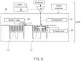
- FIG. 3is a schematic view illustrating an additive manufacturing system that includes a laser powder bed fusion (LPBF) system for performing a building step of the method;
- LPBFlaser powder bed fusion
- FIG. 4 Ais a perspective view of a landing gear coupon component built by the system of FIG. 3 using the method
- FIG. 4 Bis a perspective view of a subscale component built by the system of FIG. 3 using the method
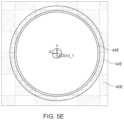
- FIGS. 5 A- 5 Eare schematic views illustrating build plates and support structures for performing a building step of the method
- FIG. 6 Ais a schematic view illustrating an additive manufacturing system that includes a laser metal deposition (LMD) system for performing a building step of the method;
- LMDlaser metal deposition
- FIG. 6 Bis an enlarged side elevation view of a laser head of the laser metal deposition (LMD) system shown in FIG. 6 A ;
- LMDlaser metal deposition
- FIGS. 7 A and 7 Bare schematic views illustrating build plates after printing using the laser metal deposition (LMD) system shown in FIG. 6 A ;
- LMDlaser metal deposition
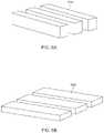
- FIGS. 8 A and 8 Bare schematic views illustrating printed blocks after printing using the laser metal deposition (LMD) system shown in FIG. 6 A ;
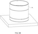
- FIG. 9is a schematic view illustrating an additive manufacturing system that includes an electron beam melting (EBM) system for performing a building step of the method.
- EBMelectron beam melting
- an initial step in the methodcomprises providing a waste feedstock 10 .
- Exemplary waste feedstocks 10include failed builds, broken parts, prototype parts, support structures, and used powder. Titanium, although relatively rare, can be found in aircraft components. In addition, wherever metal parts are expended, steel, stainless steel, aluminum, and copper can be found.
- DMCdeployable manufacturing center
- waste feedstock 10For providing the waste feedstock 10 , large pieces of metal scrap can be collected, analyzed by a handheld XRF, and cut to pieces smaller than 6′′ in diameter. Small fragments of scrap materials are usually not collected due to lower yield, greater variations in alloy composition, and increased likelihood of contamination. Hazardous components, such as radioactive materials, toxic materials such as asbestos, or metals such as beryllium, cadmium, and mercury pose dangers to personnel and are removed from the feedstock 10 before processing.
- chemical analysis of the waste feedstock 10can be performed to predict elements needed for correction of the final composition to the desired alloy. Ideally, a batch is composed of scrap from a single source material. This makes the composition relatively easy to predict and correct. When the waste feedstock is inconsistent, however, predictive analysis is not sufficient. For inconsistent waste feedstock, a post-melt chemical analysis can be performed to determine the composition of the material. After the mixed-scrap composition is determined, the alloy can be corrected to its desired composition.
- the methodalso includes the step of producing an additive manufacturing (AM) grade alloy powder 12 ( FIG. 2 D ) from the waste feedstock 10 using a cold hearth mixing process performed using a cold hearth mixing system 11 ( FIG. 2 B ).
- the cold hearth mixing system 11includes a heat source 16 , such as a torch, and a mixing cold hearth 14 .
- the heat source 16 and the mixing cold hearth 14are operated to produce a molten metal 20 having a uniform composition, with composition correction performed if necessary.
- the mixing cold hearth 14( FIG. 2 B ) can include fluid cooled walls, a melting cavity configured to hold the waste feedstock 10 ( FIG. 2 B ) and the molten metal 20 ( FIG. 2 C ), and an induction coil (not shown) configured to generate an electromagnetic field for stirring and heating the molten metal 20 ( FIG. 2 C ).
- the mixing cold hearth 14( FIG. 2 C ) can also include a mechanical drive (not shown) configured to mount and move the mixing cold hearth 14 ( FIG. 2 C ) for mixing the molten metal 20 ( FIG.
- the mixing cold hearth 14can also include a skull (not shown) at least partially lining the melting cavity and configured to provide a heat transfer boundary for the molten metal 20 ( FIG. 2 C ).
- the mixing cold hearth 14can comprise a removal element of an assembly of interchangeable mixing cold hearths, with each mixing cold hearth 14 of the assembly configured for melting a specific category of raw material to produce a specific product.
- composition correctioncan optionally be performed by adding additives to a known material of undesirable composition to create a new material of a desired composition.
- the cold hearth mixing processis thus controlled to provide the material for making the alloy powder 12 with an exact chemical composition.
- an atomization processcan be performed using a gas atomization system 18 ( FIG. 2 C ) to form the alloy powder 12 ( FIG. 2 D ).
- a gas atomization system 18FIG. 2 C
- Previously cited U.S. Pat. No. 9,925,591 B2discloses exemplary gas atomization systems.
- atomizationcan be performed by pouring the molten metal 20 ( FIG. 2 C ) across a die that produces turbulent high-velocity gas in a sharp stream. The stream of turbulent high-velocity gas disintegrates the molten stream and produces spherical metal particles that are cooled rapidly in flight as they travel through an atomization chamber.
- the metal powdersolidifies and is transferred into a cyclone (not shown) where it is collected as the alloy powder 12 ( FIG. 2 D ).
- atomizationcan be performed with plasma gas, a spinning disk, a vibratory plate, or another method that disintegrates the molten metal into fine particles.
- the atomization processis controlled such that the resulting particle size of the alloy powder 12 ( FIG. 2 D ) can be between 0-350 um.
- the alloy powder 12 ( FIG. 2 D )has a particle size of 10-160 um. In another embodiment, a particle size of 25-50 um is produced.
- the alloy powder 12( FIG. 2 D ) can be analyzed by the SEM analysis apparatus to confirm particle size, microstructure, and elemental composition. Characterization of the alloy powder 12 ( FIG. 2 D ) can include analysis of particle size, size distribution, morphology, density, phase behavior, elemental composition and surface characteristics. Purity, morphology, and defect-free microstructure can also be confirmed upon characterization, as well as avalanche angle and surface fractal. All of these characteristics can be selected to satisfy the requirements of the additive manufacturing system 22 A ( FIG. 3 ) or 22 B ( FIG. 6 A ).
- the methodalso includes the step of building the components using the additive manufacturing (AM) grade alloy powder 12 ( FIG. 2 D ) and an additive manufacturing system 22 A ( FIG. 3 ) or 22 B ( FIG. 6 A ).
- the additive manufacturing system 22 A( FIG. 3 ) employs laser powder bed fusion (LPBF) technology.
- the additive manufacturing system 22 Acan include a laser 24 , a scanner 26 , and a build chamber 28 . Within the build chamber 28 are a powder bed 34 and for containing the alloy powder 12 and a roller rake 30 for conveying the alloy powder 12 into the powder bed 34 for building the components 32 .
- LPBFlaser powder bed fusion
- the additive manufacturing system 22 B( FIG. 6 A ) employs laser metal deposition (LMD) technology.
- Laser Metal Deposition (LMD)is a type of additive manufacturing which deposits molten powder directly onto a substrate. It is different from powder-bed fusion in the way powder is delivered.
- LMDLaser Metal Deposition
- LPBFa laser melts powder which is lying stationary in a powder-bed.
- a hopperdispenses powder across the bed and the part is built in layers.
- LMDuses a stream of powder which is melted by a laser as it travels from the nozzle to the substrate. LMD can be used for building new parts and part repairs.
- the powder used in LMDhas a particle size range of 75-150 ⁇ m, which is too large for LPBF.
- the additive manufacturing system 22 Bincludes a deposition nozzle 46 in flow communication with a quantity of the alloy powder 12 and configured for movement in a direction of travel 54 .
- the deposition nozzle 46produces moving powder particles 56 that are melted by a laser beam 48 emanated from a laser head 58 ( FIG. 6 B ) to form a melt pool 50 and a deposited track 52 .
- landing gear coupon components 36FIG. 4 A
- subscale components 38FIG. 4 B
- AMadditive manufacturing
- the alloy powder 12FIG. 2 D
- Titanium 10-2-3 alloy powderwas produced by MolyWorks Materials Corporation at its R&D facility in Cloverdale, Calif. Alloy powder production was performed via a cold hearth mixing process as previously described using certified scrap feedstock.
- the alloy powder 12had particle sizes up to 75 ⁇ m and the additive manufacturing system included an M100 printer.
- Ti 10-2-3 alloy powderwas tested in-house for oxygen and hydrogen, and sent out for analysis to Anamet Inc., a third-party laboratory specializing in materials analysis (located in Hayward, Calif.).
- Oxygen content of the alloy powderranged from 0.14% to 0.22%.
- the average oxygen content of the alloy powder 12was 0.18% with a CV of 14.1%.
- the oxygen added by the foundrywas in the range of 400-800 ppm, with final oxygen content of the alloy powder 12 typically between 0.16% and 0.2%.
- an analysis from Anametshowed that oxygen content was 0.12%, meeting industry specifications for Titanium.
- coupon components 36 and subscale components 38showed microstructural differences when compared to equivalent wrought components, such as larger grains and smaller dimples in the fracture surfaces.
- Subscale part manufacturing testsindicate that the present method is capable of producing at least seven unique landing gear parts whose production has become obsolete.
- the additive manufacturing systemincluded a 3-D printer in the form of a modified EOS M100 3D-Printer manufactured by EOS GmbH Electro Optical Systems. Fatigue coupons were designed to fit the usable build platform of the M100 and meet ASTM standards. Work was performed with 3DXpert to design build plates and support structures. Files were designed in CAD and converted to 3DXpert, where support structures and tolerances were added. Before printing, 3DXpert files were exported (as .stl files) to EOS Print for positioning on the build platform.
- Couponswere prepared in both vertical and horizontal orientations to test the capabilities of the EOS M100.
- the EOS100required extensive modifications to function as an additive manufacturing system for performing the present method. For example, prior to modifications the usable build volume was found to be approximately 25% of the actual build volume, and the powder hopper was found to be too small to feed a full build plate. Horizontal builds were limited in size due to problems with the powder dispensing system—powder was not dispensed evenly from the hopper.
- the typical oxygen added to titanium parts by the M100 during the reporting periodwas 400-600 ppm. Further oxidation of powder was observed due to overheating of overhangs when no support structures were present. Oxidation problems may be attributed to the inert gas purge system which allows 1000 ppm of oxygen to remain in the build chamber during printing. A vacuum system could reduce the oxygen added to as low as 25 ppm.
- the average production rate of the M100was around 3 coupons per day. Round samples presented challenges when printed in the horizontal orientation. Problems arose from the overhang of the rounded sides, requiring addition of support material. When not firmly supported, parts printed in the horizontal orientation curled away from the build plate due to vertical residual stresses. When support structures were added to compensate for residual stress, the support structures created difficulties in subsequent machining. Closely spaced support material compounded the difficulties of removal in machining.
- FIGS. 5 A- 5 Eillustrate exemplary build plates 40 A- 40 E, build areas 42 A- 40 E and support structures 44 A- 44 E for performing the building step.
- the build plates 40 A- 40 Eare represented by the checkered patterns
- the build areas 42 A- 42 Eare represented by the honeycomb patterns (or plus minus patterns)
- the support structures 44 A- 44 Eby solid lines.
- solid supports 44 Athat are slightly wider than the base of the component were used.
- the supports 44 Awere extruded down 4 mm from the bottom of the part to enable the build plate 40 A to be removed from the component. This method was used for all parts which utilized solid supports.
- Honeycomb build areas 42 A and solid supports 44 Awere used for the bottom.
- the honeycombhad a distance of 2 mm and an external wall. Texture 2 -S was used.
- the solid supports 44 A usedwere mated against flat surfaces on the component (e.g. coupon component 36 — FIG. 4 A ) or subscale part component 38 ( FIG. 4 B ) to facilitate removal.
- a plus minus build area 42 B and solid supports 44 B on a build plate 40 Bwere employed. All of the build areas 42 B beneath and between the supports used a plus-sign pattern with a distance of 3 mm and an external wall.
- the bottom supports 44 Bused texture 1 -S.
- honeycomb build areas 42 C and supports 44 C on a build plate 40 Cwere utilized. External walls were removed from several areas to ease removal of support structures after printing.
- the center solid support 44 Crequired removal by drilling.
- Honeycomb build areas 42 C surrounding the circlehad a distance of 2 mm.
- Honeycomb dimensions of the external wallswere 2.5 mm.
- the remaining honeycomb build areas 42 Cwere set at 3 mm.
- the four supports 44 C on the cornerswere solid, with a small latticed center to provide rigidity.
- the build areas 42 C on the two outside holeswere honeycomb, with a distance of 3 mm.
- External wallswere utilized on some supports and omitted from others for ease of removal and surface finish.
- the support material for the cross-holeswas plus signs with a distance of 4 mm, with external walls eliminated for ease of removal. No textures were utilized for the walls of the supports. In FIG.
- the supports 44 Cwere square grid and solid.
- the square gridhad a distance of 3 mm and an external wall with Texture 2 -S.
- solid supports 44 D and honeycomb build areas 42 D on a build plate 40 Dwere used. All honeycombs for this part had a distance of 3 mm.
- cylindrical solid supports 44 E, square grid build area 42 E and build plate 40 Ewere used.
- the square gridhad a distance of 3 mm, an external wall with Texture 2 -S, and selected cell properties.
- FIGS. 6 A- 6 Bincluded laser metal deposition technology.
- FIGS. 7 A and 7 Bare schematic views illustrating a build plate 60 after printing of block components 62 A, 62 B using the laser metal deposition (LMD) system shown in FIG. 6 A .
- FIGS. 8 A and 8 Bare schematic views illustrating printed block components 62 A, 62 B after printing using the laser metal deposition (LMD) system shown in FIG. 6 A .
- Alloy powder productionwas performed via a cold hearth mixing process as previously described using certified scrap feedstock.
- Ti 10-2-3 alloy powder 12was produced in a size range of 75-150 ⁇ m. Alloy powder 12 with particle sizes in the 75-150 ⁇ m range was sent to Formalloy (Spring Valley, Calif.) for printing of a landing gear part on an L-series LMD system.
- FormalloySpring Valley, Calif.
- prior art partsare typically made from Ti 6-4, in this example the part was built using Ti 10-2-3.
- Oxygen and hydrogenwere measured at each step in the process.
- the datawas collected using an Eltra Elementrac ONH-p.
- the alloy powder 12was analyzed, printed into pins, and analyzed again. The results indicate that the oxygen added to titanium parts was approximately 400-600 ppm.
- Example 1heat treatments were selected to produce the highest-strength condition.
- a Hot Isostatic Press (HIP)was performed by Quintus at 1650 F and 15,000 psi for 2 hours, immediately followed by a solution treatment at 1410 F for 1h followed by a rapid argon quench. Some warping and surface oxidation was observed in the coupon blanks. The oxide layer was removed by subsequent machining. Warping was not significant enough to create problems during machining.
- a stress relief anneal performed while the parts are still attached to the build platemay be used in future tests to prevent warping.
- Example 1After heat treatment, coupons were machined to final geometry and polished.
- Example 2control samples were also machined from Ti 10-2-3 ingot. Controls were cut from a Ti 10-2-3 round forged bar and blanked with an industrial saw.
- the ASTM E606 sampleswere rough turned on a large manual lathe and finish turned on a CNC lathe.
- the ASTM E466 sampleswere CNC milled to rough dimensions, finish ground, and polished. Once machining was completed, density testing was performed, and all coupons were sent to Touchstone Research Laboratory in Triadelphia, W. Va. for testing.
- the density of componentswas measured in-house using an Archimedes apparatus and an analytical balance. Samples were weighed in air and weighed again in distilled water. The temperature of the water was measured and recorded to correct for changes in water density. The samples were carefully inspected during weighing in water to ensure no bubbles were trapped underneath.
- Fatigue coupon fracture surfaceswere viewed in a scanning electron microscope to assess the failure mode. While the surfaces of control samples contained dimples surfaces, the dimple morphology in the printed samples were smaller. The difference between the control samples and printed samples are evident in the morphology of the dimples, which can be attributed to the internal grain structure of the materials. Control samples have very small grain size, while with other printed samples the grain structure appears to be coarse. Typically, smaller grains and smaller feature sizes are associated with better fatigue performance.
- Corrosion resistance testingwas performed in a salt-spray cabinet conforming to ASTM B117. Testing temperatures were 95° F. in chamber, and 117° F. in the bubble tower (containing salt solution). Hot air bubbles were generated which passed through the bubble tower at 12 psi. A 5% salt solution (ASTM D1193, ACS grade salt) was atomized to produce fog in the chamber. Graduated cylinders were used to measure the amount of fog, with a 1-2 mL per hour target. pH was held within the range of 6.5-7.2. Samples were placed on wooden blocks during testing. No corrosion was visible in the Ti 10-2-3 samples upon completion of testing.
- Sampleswere initially prepared for optical microscopy by sectioning using a circular table saw and mounting in resins for further preparation.
- sampleswere ground and polished by standard metallographic specimen preparation procedures and etched with Kroil's reagent to reveal microstructure.
- Wrought materialis typical beta with woven microstructure of alpha plates.
- the imagesreveal typical heat-treated titanium alloy with an average grain size of 20 am.
- Further internal structure of the grainsconsists of Widman Staten structure of alpha laths in a matrix of beta phase grain.
- the as-printed materialshowed larger elongated grains which contained fine precipitates (these may be V—Al or Ti—Al). Compared to the control material, the additively manufactured samples had very coarse grains.
- the additive manufacturing system 22 C( FIG. 9 ) can include electron beam melting (EBM) technology with the alloy powder 12 ( FIG. 2 D ) produced to satisfy the requirements of this technology.
- the additive manufacturing system 22 Ccan include a filament 64 and a lens system 66 configured to produce an electron beam 68 .
- the additive manufacturing system 22 Ccan also include a build plate 72 on a build platform 74 in a vacuum chamber 76 wherein layers of melting powder can be formed into components.
- EBMelectron beam melting
- One suitable additive manufacturing system 22 C that uses electron beam melting (EBM)is commercially available from Arcam EBM of Sweden.
Landscapes
- Engineering & Computer Science (AREA)
- Manufacturing & Machinery (AREA)
- Chemical & Material Sciences (AREA)
- Materials Engineering (AREA)
- Physics & Mathematics (AREA)
- Plasma & Fusion (AREA)
- Life Sciences & Earth Sciences (AREA)
- Sustainable Development (AREA)
- Mechanical Engineering (AREA)
- Powder Metallurgy (AREA)
Abstract
Description
Claims (15)
Priority Applications (2)
| Application Number | Priority Date | Filing Date | Title |
|---|---|---|---|
| US16/599,378US11590574B2 (en) | 2018-12-18 | 2019-10-11 | Method for manufacturing metal components using recycled feedstock and additive manufacturing |
| PCT/US2019/062111WO2020131276A1 (en) | 2018-12-18 | 2019-11-19 | Method for manufacturing metal components using recycled feedstock and additive manufacturing |
Applications Claiming Priority (3)
| Application Number | Priority Date | Filing Date | Title |
|---|---|---|---|
| US201862781107P | 2018-12-18 | 2018-12-18 | |
| US201962790103P | 2019-01-09 | 2019-01-09 | |
| US16/599,378US11590574B2 (en) | 2018-12-18 | 2019-10-11 | Method for manufacturing metal components using recycled feedstock and additive manufacturing |
Publications (2)
| Publication Number | Publication Date |
|---|---|
| US20200189000A1 US20200189000A1 (en) | 2020-06-18 |
| US11590574B2true US11590574B2 (en) | 2023-02-28 |
Family
ID=71071287
Family Applications (1)
| Application Number | Title | Priority Date | Filing Date |
|---|---|---|---|
| US16/599,378Active2040-05-03US11590574B2 (en) | 2018-12-18 | 2019-10-11 | Method for manufacturing metal components using recycled feedstock and additive manufacturing |
Country Status (2)
| Country | Link |
|---|---|
| US (1) | US11590574B2 (en) |
| WO (1) | WO2020131276A1 (en) |
Cited By (1)
| Publication number | Priority date | Publication date | Assignee | Title |
|---|---|---|---|---|
| US12259185B2 (en) | 2020-11-04 | 2025-03-25 | Continuum Powders Corporation | Powder feeder system and method for recycling metal powder |
Families Citing this family (15)
| Publication number | Priority date | Publication date | Assignee | Title |
|---|---|---|---|---|
| US11235389B2 (en) | 2018-09-19 | 2022-02-01 | Molyworks Materials Corp. | Deployable manufacturing center (DMC) system and process for manufacturing metal parts |
| US11623278B2 (en) | 2019-07-10 | 2023-04-11 | MolyWorks Materials Corporation | Expeditionary additive manufacturing (ExAM) system and method |
| US11541458B2 (en) | 2019-07-10 | 2023-01-03 | MolyWorks Materials Corporation | Method and system for manufacturing small adaptive engines |
| DE102020102628A1 (en)* | 2020-02-03 | 2021-08-05 | Eos Gmbh | Method for moderating a reaction of metal particles |
| CN114309642B (en)* | 2020-09-29 | 2024-01-12 | 中国航发商用航空发动机有限责任公司 | Additive manufacturing method of aeroengine component and readable storage medium |
| IT202100006527A1 (en)* | 2021-03-18 | 2022-09-18 | F3Nice S R L | PROCESS FOR THE RECYCLING OF METALLIC MATERIALS, IN PARTICULAR FOR THE CREATION OF RAW MATERIALS FOR ADDITIVE MANUFACTURING |
| CN115475964B (en)* | 2021-06-15 | 2023-06-02 | 中国航发上海商用航空发动机制造有限责任公司 | Recycling method of powder for additive manufacturing |
| US20230015620A1 (en)* | 2021-07-14 | 2023-01-19 | Divergent Technologies, Inc. | Repurposing waste aluminum powder by net shape sintering |
| US11865617B2 (en)* | 2021-08-25 | 2024-01-09 | Divergent Technologies, Inc. | Methods and apparatuses for wide-spectrum consumption of output of atomization processes across multi-process and multi-scale additive manufacturing modalities |
| IT202100024502A1 (en)* | 2021-09-23 | 2023-03-23 | F3Nice S R L | METALLIC ALLOY AND PROCESS, PARTICULARLY FOR THE CREATION OF PRODUCTS SUITABLE FOR USE IN ENVIRONMENTS EXPOSED TO HYDROGEN |
| WO2023076642A1 (en) | 2021-10-29 | 2023-05-04 | MolyWorks Materials Corporation | Tilting melting hearth system and method for recycling metal |
| US12138708B2 (en)* | 2022-02-23 | 2024-11-12 | Goodrich Corporation | Methods, systems, and apparatus for component manufacturing |
| EP4252937A1 (en)* | 2022-03-31 | 2023-10-04 | Airbus S.A.S. | Method of recycling a structure or at least a portion thereof, and component for an aircraft or spacecraft |
| US20230420183A1 (en)* | 2022-06-22 | 2023-12-28 | MolyWorks Materials Corporation | System And Method For Producing Rare Earth Magnets From A Metal Powder Using Recycled Materials And Additive Manufacturing |
| US20250197967A1 (en)* | 2023-12-18 | 2025-06-19 | Continuum Powders Corporation | Melting hearth, cold hearth melting system, and process for producing high temperature metal alloys |
Citations (20)
| Publication number | Priority date | Publication date | Assignee | Title |
|---|---|---|---|---|
| US4750542A (en) | 1987-03-06 | 1988-06-14 | A. Johnson Metals Corporation | Electron beam cold hearth refining |
| US5224534A (en) | 1990-09-21 | 1993-07-06 | Nippon Mining And Metals Company, Limited | Method of producing refractory metal or alloy materials |
| US20090206065A1 (en) | 2006-06-20 | 2009-08-20 | Jean-Pierre Kruth | Procedure and apparatus for in-situ monitoring and feedback control of selective laser powder processing |
| US7754519B1 (en) | 2009-05-13 | 2010-07-13 | Twin Creeks Technologies, Inc. | Methods of forming a photovoltaic cell |
| US20130199611A1 (en) | 2012-02-05 | 2013-08-08 | Twin Creeks Technologies, Inc. | Method for Forming Flexible Solar Cells |
| US20140048201A1 (en) | 2012-08-15 | 2014-02-20 | Gtat Corporation | Bonding of thin lamina |
| US20140252685A1 (en) | 2013-03-06 | 2014-09-11 | University Of Louisville Research Foundation, Inc. | Powder Bed Fusion Systems, Apparatus, and Processes for Multi-Material Part Production |
| US8871109B2 (en) | 2009-04-28 | 2014-10-28 | Gtat Corporation | Method for preparing a donor surface for reuse |
| US20140374933A1 (en) | 2013-06-23 | 2014-12-25 | Addibots LLC | Methods and apparatus for mobile additive manufacturing of advanced structures and roadways |
| US20150020646A1 (en) | 2011-08-22 | 2015-01-22 | Kabushiki Kaisha Kobe Seiko Sho (Kobe Steel, Ltd.) | Method for manufacturing titanium ingot |
| CN104550960A (en) | 2014-12-23 | 2015-04-29 | 中国航空工业集团公司北京航空制造工程研究所 | Metal additive manufacturing method applying cold hearth melting, metal parts and application |
| US20160052060A1 (en)* | 2014-08-21 | 2016-02-25 | Molyworks Materials Corp. | Mixing cold hearth metallurgical system and process for producing metals and metal alloys |
| US20160053346A1 (en) | 2014-08-21 | 2016-02-25 | Honeywell International Inc. | Methods for producing alloy forms from alloys containing one or more extremely reactive elements and for fabricating a component therefrom |
| US20160199907A1 (en) | 2013-08-29 | 2016-07-14 | European Space Agency | Manufacturing of a metal component or a metal matrix composite component involving contactless induction of high-frequency vibrations |
| US9399322B2 (en) | 2012-08-08 | 2016-07-26 | Makerbot Industries, Llc | Three dimensional printer with removable, replaceable print nozzle |
| WO2017203245A1 (en) | 2016-05-24 | 2017-11-30 | Metalysis Limited | Manufacturing apparatus and method |
| US20180133804A1 (en) | 2016-11-11 | 2018-05-17 | United Technologies Corporation | Additive manufacturing process with metal chips produced by machining processes as feedstock |
| US20190119787A1 (en) | 2017-10-19 | 2019-04-25 | The Boeing Company | Titanium-Based Alloy and Method for Manufacturing a Titanium-Based Alloy Component by an Additive Manufacturing Process |
| US20200086390A1 (en) | 2018-09-19 | 2020-03-19 | MolyWorks Material Corp. | Deployable Manufacturing Center (DMC) System And Process For Manufacturing Metal Parts |
| US20210008621A1 (en) | 2019-07-10 | 2021-01-14 | MolyWorks Materials Corporation | EXPEDITIONARY ADDITIVE MANUFACTURING (ExAM) SYSTEM AND METHOD |
- 2019
- 2019-10-11USUS16/599,378patent/US11590574B2/enactiveActive
- 2019-11-19WOPCT/US2019/062111patent/WO2020131276A1/ennot_activeCeased
Patent Citations (24)
| Publication number | Priority date | Publication date | Assignee | Title |
|---|---|---|---|---|
| US4750542A (en) | 1987-03-06 | 1988-06-14 | A. Johnson Metals Corporation | Electron beam cold hearth refining |
| US5224534A (en) | 1990-09-21 | 1993-07-06 | Nippon Mining And Metals Company, Limited | Method of producing refractory metal or alloy materials |
| US20090206065A1 (en) | 2006-06-20 | 2009-08-20 | Jean-Pierre Kruth | Procedure and apparatus for in-situ monitoring and feedback control of selective laser powder processing |
| US8871109B2 (en) | 2009-04-28 | 2014-10-28 | Gtat Corporation | Method for preparing a donor surface for reuse |
| US7754519B1 (en) | 2009-05-13 | 2010-07-13 | Twin Creeks Technologies, Inc. | Methods of forming a photovoltaic cell |
| US20150020646A1 (en) | 2011-08-22 | 2015-01-22 | Kabushiki Kaisha Kobe Seiko Sho (Kobe Steel, Ltd.) | Method for manufacturing titanium ingot |
| US20130199611A1 (en) | 2012-02-05 | 2013-08-08 | Twin Creeks Technologies, Inc. | Method for Forming Flexible Solar Cells |
| US9399322B2 (en) | 2012-08-08 | 2016-07-26 | Makerbot Industries, Llc | Three dimensional printer with removable, replaceable print nozzle |
| US20140048201A1 (en) | 2012-08-15 | 2014-02-20 | Gtat Corporation | Bonding of thin lamina |
| US20140252685A1 (en) | 2013-03-06 | 2014-09-11 | University Of Louisville Research Foundation, Inc. | Powder Bed Fusion Systems, Apparatus, and Processes for Multi-Material Part Production |
| US20140374933A1 (en) | 2013-06-23 | 2014-12-25 | Addibots LLC | Methods and apparatus for mobile additive manufacturing of advanced structures and roadways |
| US20160199907A1 (en) | 2013-08-29 | 2016-07-14 | European Space Agency | Manufacturing of a metal component or a metal matrix composite component involving contactless induction of high-frequency vibrations |
| US20160053346A1 (en) | 2014-08-21 | 2016-02-25 | Honeywell International Inc. | Methods for producing alloy forms from alloys containing one or more extremely reactive elements and for fabricating a component therefrom |
| US20160052060A1 (en)* | 2014-08-21 | 2016-02-25 | Molyworks Materials Corp. | Mixing cold hearth metallurgical system and process for producing metals and metal alloys |
| US9925591B2 (en) | 2014-08-21 | 2018-03-27 | Molyworks Materials Corp. | Mixing cold hearth metallurgical system and process for producing metals and metal alloys |
| US20180169761A1 (en) | 2014-08-21 | 2018-06-21 | Molyworks Materials Corp. | Process for producing metals and metal alloys using mixing cold hearth |
| US10654106B2 (en) | 2014-08-21 | 2020-05-19 | Molyworks Materials Corp. | Process for producing metals and metal alloys using mixing cold hearth |
| CN104550960A (en) | 2014-12-23 | 2015-04-29 | 中国航空工业集团公司北京航空制造工程研究所 | Metal additive manufacturing method applying cold hearth melting, metal parts and application |
| WO2017203245A1 (en) | 2016-05-24 | 2017-11-30 | Metalysis Limited | Manufacturing apparatus and method |
| US20180133804A1 (en) | 2016-11-11 | 2018-05-17 | United Technologies Corporation | Additive manufacturing process with metal chips produced by machining processes as feedstock |
| US20190119787A1 (en) | 2017-10-19 | 2019-04-25 | The Boeing Company | Titanium-Based Alloy and Method for Manufacturing a Titanium-Based Alloy Component by an Additive Manufacturing Process |
| US20200086390A1 (en) | 2018-09-19 | 2020-03-19 | MolyWorks Material Corp. | Deployable Manufacturing Center (DMC) System And Process For Manufacturing Metal Parts |
| US11235389B2 (en) | 2018-09-19 | 2022-02-01 | Molyworks Materials Corp. | Deployable manufacturing center (DMC) system and process for manufacturing metal parts |
| US20210008621A1 (en) | 2019-07-10 | 2021-01-14 | MolyWorks Materials Corporation | EXPEDITIONARY ADDITIVE MANUFACTURING (ExAM) SYSTEM AND METHOD |
Non-Patent Citations (8)
| Title |
|---|
| Abstract SBIR contract solicitation No. 2016.1, "Processing of Metallic Scrap Materials for Battlefield Additive Manufacturing", proposal award date Aug. 1, 2016, pp. 1-3. |
| International application No. PCT/US 19/62111, International Search Report and the Written Opinion of the International Searching Authority, or the Declaration, dated Feb. 27, 2020, pp. 1-11. |
| International Application No. PCT/US 20/ 41106, The International Search Report and the Written Opinion of the Internatinoal Searching Authority, dated Dec. 18, 2020, pp. 1-14. |
| International Application No. PCT/US19/41906, International Search Report and Written Opinion of the International Searching Authority, dated Oct. 22, 2019, pp. 1-11. |
| LaTour, "Processing of Metallic Scrap Materials for Battlefield Additive Manufacturing." SBIR.gov, www.sbir.gov/sbirsearch/detail/1256429, pp. 1-2, Award start date Aug. 1, 2016. |
| Pepi, M. et al., Manufacturing at the Point of Need Using Recycled, Reclaimed, and/or Indigenous Materials, DSIAC Journal, vol. 5, No. 3, Summer 2018, pp. 26-37. |
| Tootooni et al., Classifying the Dimensional Variation in Additive Manufactured Parts From Laser-Scanned Three-Dimensional Point Cloud Dat Using Machine Learning Approaches:, Journal of Manufacturing Science and Engineering, vol. 139, No. 9, 2017. |
| U.S. Appl. No. 16/135,191, filed Sep. 29, 2018 titled: Deployable Manufacturing Center (PMC) System and Process for Manufacturing Metal Parts, pp. 1-17. |
Cited By (1)
| Publication number | Priority date | Publication date | Assignee | Title |
|---|---|---|---|---|
| US12259185B2 (en) | 2020-11-04 | 2025-03-25 | Continuum Powders Corporation | Powder feeder system and method for recycling metal powder |
Also Published As
| Publication number | Publication date |
|---|---|
| WO2020131276A1 (en) | 2020-06-25 |
| US20200189000A1 (en) | 2020-06-18 |
Similar Documents
| Publication | Publication Date | Title |
|---|---|---|
| US11590574B2 (en) | Method for manufacturing metal components using recycled feedstock and additive manufacturing | |
| Kumar et al. | A review on properties of Inconel 625 and Inconel 718 fabricated using direct energy deposition | |
| Karmuhilan et al. | A review on additive manufacturing processes of Inconel 625 | |
| Li et al. | Microstructure evolution characteristics of Inconel 625 alloy from selective laser melting to heat treatment | |
| JP7116495B2 (en) | High carbon cobalt alloy | |
| US11679438B2 (en) | Process for manufacturing metal parts using deployable manufacturing center (DMC) system | |
| Simpson et al. | Considerations for application of additive manufacturing to nuclear reactor core components | |
| CN111386164B (en) | High-hardness 3D printing steel product | |
| Lesyk et al. | Nickel superalloy turbine blade parts printed by laser powder bed fusion: thermo-mechanical post-processing for enhanced surface integrity and precipitation strengthening | |
| Abdulrahman et al. | Laser metal deposition of titanium aluminide composites: A review | |
| Sibisi et al. | LAM additive manufacturing: a fundamental review on mechanical properties, common defects, dominant processing variables, and its applications | |
| Lewis et al. | Properties of near-net shape metallic components made by the directed light fabrication process | |
| EP4136268B1 (en) | Nickel base superalloy for additive manufacturing | |
| Arcella et al. | Titanium alloy structures for airframe application by the laser forming process | |
| Kermani et al. | Assessment of structural defects and mechanical characteristics of IN718/St6 functionally graded material produced by direct laser deposition | |
| Asapu et al. | Microstructural and mechanical characterization of selective Laser melted 17-4 PH stainless steel: effect of Laser scan strategy and heat treatment | |
| CN117396290A (en) | Method for preparing aluminum alloy parts by adopting additive manufacturing technology containing preheating | |
| Vaz et al. | Heat treatment effect on microstructural evolution of cold spray additive manufacturing Ti6Al4V | |
| Yang et al. | Investigation of selective laser melting process for Cu-5Sn alloy on surface roughness, microstructure and mechanical property | |
| Chaabene et al. | Experimental investigation of the influence of process parameters on the mechanical properties of maraging steel produced by electron beam melting | |
| Raghupatruni et al. | Review of Microstructure and Mechanical properties of materials manufactured by direct energy deposition | |
| Dobrzański et al. | Structure and properties of laser alloyed gradient surface layers of the hot-work tool steels | |
| Yuan et al. | Mechanical Properties of 316 Stainless Steel Structure produced by Pulsed Micro-plasma Additive Manufacturing | |
| Ritchie | Corrosion Behaviour of Additively Manufactured High Entropy Alloys | |
| Gamon | Microstructure and Hardness Comparison of Inconel 625 Alloy of Various Additive Manufacturing Processes Following Heat Treatments |
Legal Events
| Date | Code | Title | Description |
|---|---|---|---|
| FEPP | Fee payment procedure | Free format text:ENTITY STATUS SET TO UNDISCOUNTED (ORIGINAL EVENT CODE: BIG.); ENTITY STATUS OF PATENT OWNER: SMALL ENTITY | |
| AS | Assignment | Owner name:MOLYWORKS MATERIALS CORP., CALIFORNIA Free format text:ASSIGNMENT OF ASSIGNORS INTEREST;ASSIGNORS:LATOUR, ANDREW VANOS;EONTA, CHRISTOPHER PAUL;CHARLES, MATTHEW;AND OTHERS;SIGNING DATES FROM 20190920 TO 20191010;REEL/FRAME:050711/0009 | |
| FEPP | Fee payment procedure | Free format text:ENTITY STATUS SET TO SMALL (ORIGINAL EVENT CODE: SMAL); ENTITY STATUS OF PATENT OWNER: SMALL ENTITY | |
| STPP | Information on status: patent application and granting procedure in general | Free format text:DOCKETED NEW CASE - READY FOR EXAMINATION | |
| STPP | Information on status: patent application and granting procedure in general | Free format text:NON FINAL ACTION MAILED | |
| STPP | Information on status: patent application and granting procedure in general | Free format text:RESPONSE TO NON-FINAL OFFICE ACTION ENTERED AND FORWARDED TO EXAMINER | |
| STPP | Information on status: patent application and granting procedure in general | Free format text:FINAL REJECTION MAILED | |
| STPP | Information on status: patent application and granting procedure in general | Free format text:DOCKETED NEW CASE - READY FOR EXAMINATION | |
| STPP | Information on status: patent application and granting procedure in general | Free format text:NON FINAL ACTION MAILED | |
| STPP | Information on status: patent application and granting procedure in general | Free format text:RESPONSE TO NON-FINAL OFFICE ACTION ENTERED AND FORWARDED TO EXAMINER | |
| STCF | Information on status: patent grant | Free format text:PATENTED CASE | |
| AS | Assignment | Owner name:CONTINUUM POWDERS CORPORATION, CALIFORNIA Free format text:CHANGE OF NAME;ASSIGNOR:MOLYWORKS MATERIALS CORPORATION;REEL/FRAME:067277/0947 Effective date:20240419 |