US11589871B2 - Laparoscopic stapler with flippable housing assembly and flippable anvil assembly - Google Patents
Laparoscopic stapler with flippable housing assembly and flippable anvil assemblyDownload PDFInfo
- Publication number
- US11589871B2 US11589871B2US16/758,227US201816758227AUS11589871B2US 11589871 B2US11589871 B2US 11589871B2US 201816758227 AUS201816758227 AUS 201816758227AUS 11589871 B2US11589871 B2US 11589871B2
- Authority
- US
- United States
- Prior art keywords
- anvil
- assembly
- staple housing
- configuration
- housing
- Prior art date
- Legal status (The legal status is an assumption and is not a legal conclusion. Google has not performed a legal analysis and makes no representation as to the accuracy of the status listed.)
- Active
Links
- 238000010304firingMethods0.000claimsdescription4
- 230000006835compressionEffects0.000claimsdescription3
- 238000007906compressionMethods0.000claimsdescription3
- 230000007704transitionEffects0.000claims1
- 230000003872anastomosisEffects0.000description11
- 238000002357laparoscopic surgeryMethods0.000description9
- 210000003238esophagusAnatomy0.000description6
- 108010027529Bio-glueProteins0.000description5
- 238000005516engineering processMethods0.000description5
- 239000003292glueSubstances0.000description4
- 230000008878couplingEffects0.000description3
- 238000010168coupling processMethods0.000description3
- 238000005859coupling reactionMethods0.000description3
- 238000001356surgical procedureMethods0.000description3
- 238000004026adhesive bondingMethods0.000description2
- 238000000034methodMethods0.000description2
- 230000004048modificationEffects0.000description2
- 238000012986modificationMethods0.000description2
- 230000004044responseEffects0.000description2
- 230000003213activating effectEffects0.000description1
- 230000004913activationEffects0.000description1
- 230000000740bleeding effectEffects0.000description1
- 238000010276constructionMethods0.000description1
- 230000009849deactivationEffects0.000description1
- 210000001035gastrointestinal tractAnatomy0.000description1
- 230000035876healingEffects0.000description1
- 239000000463materialSubstances0.000description1
Images


Classifications
- A—HUMAN NECESSITIES
- A61—MEDICAL OR VETERINARY SCIENCE; HYGIENE
- A61B—DIAGNOSIS; SURGERY; IDENTIFICATION
- A61B17/00—Surgical instruments, devices or methods
- A61B17/11—Surgical instruments, devices or methods for performing anastomosis; Buttons for anastomosis
- A61B17/115—Staplers for performing anastomosis, e.g. in a single operation
- A—HUMAN NECESSITIES
- A61—MEDICAL OR VETERINARY SCIENCE; HYGIENE
- A61B—DIAGNOSIS; SURGERY; IDENTIFICATION
- A61B17/00—Surgical instruments, devices or methods
- A61B17/00491—Surgical glue applicators
- A—HUMAN NECESSITIES
- A61—MEDICAL OR VETERINARY SCIENCE; HYGIENE
- A61B—DIAGNOSIS; SURGERY; IDENTIFICATION
- A61B17/00—Surgical instruments, devices or methods
- A61B2017/00367—Details of actuation of instruments, e.g. relations between pushing buttons, or the like, and activation of the tool, working tip, or the like
- A—HUMAN NECESSITIES
- A61—MEDICAL OR VETERINARY SCIENCE; HYGIENE
- A61B—DIAGNOSIS; SURGERY; IDENTIFICATION
- A61B17/00—Surgical instruments, devices or methods
- A61B17/068—Surgical staplers, e.g. containing multiple staples or clamps
- A61B17/072—Surgical staplers, e.g. containing multiple staples or clamps for applying a row of staples in a single action, e.g. the staples being applied simultaneously
- A61B2017/07214—Stapler heads
- A61B2017/07221—Stapler heads curved
- A—HUMAN NECESSITIES
- A61—MEDICAL OR VETERINARY SCIENCE; HYGIENE
- A61B—DIAGNOSIS; SURGERY; IDENTIFICATION
- A61B17/00—Surgical instruments, devices or methods
- A61B17/068—Surgical staplers, e.g. containing multiple staples or clamps
- A61B17/072—Surgical staplers, e.g. containing multiple staples or clamps for applying a row of staples in a single action, e.g. the staples being applied simultaneously
- A61B2017/07214—Stapler heads
- A61B2017/07278—Stapler heads characterised by its sled or its staple holder
- A—HUMAN NECESSITIES
- A61—MEDICAL OR VETERINARY SCIENCE; HYGIENE
- A61B—DIAGNOSIS; SURGERY; IDENTIFICATION
- A61B17/00—Surgical instruments, devices or methods
- A61B17/068—Surgical staplers, e.g. containing multiple staples or clamps
- A61B17/072—Surgical staplers, e.g. containing multiple staples or clamps for applying a row of staples in a single action, e.g. the staples being applied simultaneously
- A61B2017/07214—Stapler heads
- A61B2017/07285—Stapler heads characterised by its cutter
Definitions
- the present inventiongenerally relates to a surgical stapler. More particularly, the present invention relates to a laparoscopic stapler with a flippable staple housing assembly and a flippable anvil assembly.
- a surgeonmay want to position a surgical instrument through an orifice formed in the body of the patient and use the instrument to adjust, position, attach, and/or otherwise interact with tissue within the patient. For instance, in some surgical procedures, portions of the gastrointestinal tract may be cut and removed to eliminate undesirable tissue or for other reasons. Once the desired tissue is removed, the remaining portions of the tissue may need to be recoupled together.
- One of such tools for accomplishing these anastomotic proceduresis a circular stapler.
- an object of the present inventionto provide a laparoscopic stapler which can be used in total laparoscopic surgery. Also, a desired end-to-end anastomosis can be achieved by using such a stapler.
- the laparoscopic staplerfor stapling tissue.
- the laparoscopic stapler according to the present inventioncomprises a flippable anvil assembly and a flippable staple housing assembly which can be moved with respect to the flippable anvil assembly, wherein the anvil assembly and the staple housing assembly are respectively configured to be operable in a first configuration and a second configuration, wherein in the first configuration, the anvil assembly and the staple housing assembly both have a low profile so that the anvil assembly and the staple housing assembly can be delivered separately through a 12 mm trocar, and in the second configuration, the anvil assembly and the staple housing assembly has a high profile for performing tissue stapling.
- the anvil assemblyis coupled to a distal end of a shaft assembly of the stapler, and the staple housing assembly is selectively coupleable to a closure and firing system of the stapler.
- the staple housing assembly and the anvil assemblyboth have a substantially T shaped structure.
- the staple housing assemblycomprises a long circular staple housing and a housing shaft extending proximally from the staple housing.
- the anvil assemblycomprises a long circular anvil and a housing shaft extending proximally from the anvil.
- the laparoscopic staplermay further comprise a visible indicator for indicating a gap distance between the anvil assembly and the staple housing assembly when coupled.
- the laparoscopic staplermay further comprise a first anvil control button operative to move the anvil assembly from the first configuration to the second configuration and a second anvil control button operative to move the anvil assembly from the second configuration to the first configuration.
- the laparoscopic staplermay further comprise a scale indicating that a gap between the staple housing assembly and the anvil assembly is within a desired operating range and a corresponding staple compression representation at each end of scale.
- the staple housing assemblyfurther comprises a blade for tissue cutting.
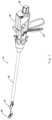
- FIG. 1depicts a perspective view of an exemplary laparoscopic stapler in accordance with the present invention
- FIG. 2shows the staple housing assembly used in the laparoscopic stapler of FIG. 1 ;
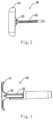
- FIG. 3shows the anvil assembly used in the laparoscopic stapler of FIG. 1 ;
- FIG. 4is a sectional view of the staple housing assembly in accordance with the present invention.
- FIG. 1depicts an exemplary laparoscopic stapling instrument 10 having an anvil assembly 30 , a shaft assembly 40 , and an actuator handle assembly 50 .
- a separate staple housing assembly 20is configured to be operatively coupleable to a closure system and a trigger system of the instrument.
- Staple housing assembly 20is operable to drive staples toward anvil assembly 30 to form the staples when in a coupled position.
- Shaft assembly 40extends distally from actuator handle assembly 50 , and anvil assembly 30 is coupled to a distal end of shaft assembly 40 .
- actuator handle assembly 50is operable to actuate a push trigger of staple housing assembly 20 to drive a plurality of staples out of staple housing assembly 20 that is coupled at the distal end of the instrument.
- Staplesare bent to form completed staples by anvil assembly 30 . Accordingly, tissue between the coupled and closed staple housing assembly 20 and anvil assembly 30 may be stapled utilizing instrument 10 .
- staple housing assembly 20is a separate flippable T shaped assembly.
- staple housing assembly 20comprises a staple housing 21 and a housing shaft 22 extending proximally from staple housing 21 .
- staple housing 21according to the present invention has an oblong or long circular shape, such as a shape of rounded rectangle or ellipse.
- Staple housing 21is linked to housing shaft 22 via a head pivot 23 , for example, and housing shaft 22 is to selectively couple staple housing assembly 20 to the closure system of the instrument.
- staple housing assembly 20is rotatable about a longitudinal axis of the head pivot 23 between a first, linear configuration for delivery and a second, perpendicular configuration as shown for coupling and stapling. It is understood when in the linear configuration, staple housing assembly 20 has a quite low-profile which allows the entire assembly to go through a 12 mm trocar typically used in laparoscopic surgery, and when in the perpendicular configuration, staple housing 21 is pivotal to be perpendicular to housing shaft 22 to exhibit a high-profile. While staple housing assembly 20 is described as selectively coupleable to the closure system in this context, proximal shaft may include a one-way coupling feature such that staple housing assembly 20 cannot be removed from instrument 10 once attached.
- Anvil assembly 30 of the present exampleis also flippable to a substantially T shaped and is coupled to a distal end of shaft assembly 40 .
- anvil assembly 30comprises an anvil 31 and an anvil shaft 32 extending proximally from anvil 31 .
- Anvil 31has a central opening and a long circular staple forming surface at a distal end.
- Housing shaft 22 of staple housing assembly 20may go through the opening to be coupled to the closure system of the instrument.
- Anvil 31may be also linked to anvil shaft 32 via a head pivot 33 , for example.
- anvil assembly 30is also configured to be rotatable about a longitudinal axis of head pivot 33 between a first, linear configuration and a second, perpendicular configuration.
- anvil assembly 30when in the linear configuration, anvil assembly 30 has a quite low-profile which allows the entire assembly to go through a 12 mm trocar, and when in the perpendicular configuration, anvil 31 pivots to be perpendicular to anvil shaft 32 to present a high-profile of T shape.
- staple housing assembly 20is a separate coupleable component
- staple housing assembly 20may be inserted to a portion of tissue in the linear configuration prior to being coupled to the instrument.
- staple housing assembly 20may be inserted into a first tubular portion of tissue, such as esophagus, while instrument 10 is inserted into a second tubular portion of tissue, such as jujune.
- staple housing assembly 20 and anvil assembly 30can both go through 12 mm trocar in its linear configuration, the stapler according to the present invention can be used in total laparoscopic surgery and thus can be called a laparoscopic stapler.
- the high-profile provided by the T shaped staple housing assembly and anvil assemblyallows the stapler according to the present invention to be adapted for a relatively larger lumen to be joined, for example, a lumen with a diameter of 26 mm, 28 mm, 30 mm, 34 mm, 36 mm, 38 mm, 40 mm, or 42 mm.
- staple housing assembly 20is operatively coupleable to the closure system and firing system of instrument 10 to staple material clamped between staple housing assembly 20 and anvil assembly 30 .
- the closure systemis operable to longitudinally translate staple housing assembly 20 relative to anvil assembly 30 to clamp tissue therebetween.
- the firing systemcomprising a trigger 54 may be actuated by a user to drive and fire staples from staple housing assembly.
- staple housing 21 of the present examplecomprises an outer casing 24 and an inner casing 25 .
- a push trigger 26is disposed in staple housing 21 and configured to be driven proximally in response to the actuation of trigger 54 , which in turn may drive a step driver 27 proximally.
- Staple housing 21further includes a blade 28 configured to sever tissue when step driver 27 is actuated proximally.
- a plurality of staples 66 contained within staple pocketsare positioned proximal to step driver 27 such that the proximal actuation of step driver 27 also drives staples proximally.
- staple housing 21further comprises a plurality of glue pockets 29 for containing bio-glue.
- Glue pocketsare provided so that as step driver 27 drives staples 66 to staple tissue, bio-glue can also be pushed out of staple housing 21 into tissue by the same driver.
- glue pockets 29 and staple pocketsare disposed in a pair of concentric long circular rows.
- Blade 28is arranged distal relative to bio-glue and staples.
- step driver 27when step driver 27 is actuated proximally, it first pushes staples and boo glue out of the respective pocket into tissue for stapling and gluing.
- Such delivery of bio-glue into tissuemay prevent leakage and facilitate tissue heal, and thus providing an improved anastomosis.
- step driver 27is further actuated proximally, it drives blade 28 out to achieve tissue cutting.
- anastomosisis made with a delivery channel provided by 12 mm trocar and in the prepared condition, and ends of jujune and esophagus are closed with for example a linear stapler.
- a first stepan opening is made at the prepared closed end of esophagus which may be stabilized with a grasper.
- a staple housing assemblysuch as staple housing assembly 20 described above is inserted through the made opening in its linear configuration and then the assembly 20 is activated to its T shaped configuration to let the housing shaft protrude out of the esophagus end from the opening such that staple housing assembly 20 is ready for coupling.
- the assembly 20may be stabilized with a grasper, for example.
- step driver 27pushes staples and bio-glue into tissue for stapling and gluing and also blade to cut overlapping tissue of esophagus and jujune.
- the surgeonmay return staple housing assembly 20 and anvil assembly 30 back into their linear configuration, and then the stapler may be removed from the patient through the 12 mm trocar.
- staple housing assembly 20when staple housing assembly 20 is coupled to the closure system, the gap distance between a proximal face of staple housing assembly 20 and a distal face of anvil assembly 30 can be reduced.
- the closure systemmay be translatable longitudinally relative to anvil assembly 30 via an adjusting knob 58 located at a proximal end of actuator handle assembly 50 . Accordingly, when staple housing assembly 20 is coupled to the closure system, rotation of adjusting knob 54 reduces gap distance by actuating staple housing assembly 20 relative to anvil assembly 30 .
- staple housing assembly 20is actuated proximally relative to anvil assembly 30 from an initial, open position to a closed position, thereby reducing the gap distance and the distance between the two portions of tissue to be joined. Once the gap distance is brought within a predetermined range, staple housing assembly 20 may be fired by a user pivoting trigger 54 of actuator handle assembly 50 .
- gap distancecorresponds to the distance between staple housing assembly 20 and anvil assembly 30 .
- a moveable indicator barmay be provided to be visible through an indicator window positioned on top of actuator handle assembly 50 .
- an indicator barmay be operable to move in response to rotation of adjusting knob 58 such that the position of indicator bar is representative of the gap distance.
- indicator window 51may further comprise a scale which indicates that the gap is within a desired operating range and a corresponding staple compression representation at each end of scale. Accordingly, a user can view the position of the coupled staple housing assembly 20 relative to the anvil assembly 30 via the indicator bar and the scale.
- anvil control buttons 52 , 53corresponding to the activation of anvil assembly 30 to its T shaped configuration and to the deactivation of anvil assembly 30 to its original, linear configuration are provided on actuator handle assembly 50 , as shown in FIG. 1 .
- the usermay easily return the stapler back to the low profile for removal through the trocar channel.
Landscapes
- Health & Medical Sciences (AREA)
- Life Sciences & Earth Sciences (AREA)
- Surgery (AREA)
- Heart & Thoracic Surgery (AREA)
- Engineering & Computer Science (AREA)
- Biomedical Technology (AREA)
- Nuclear Medicine, Radiotherapy & Molecular Imaging (AREA)
- Medical Informatics (AREA)
- Molecular Biology (AREA)
- Animal Behavior & Ethology (AREA)
- General Health & Medical Sciences (AREA)
- Public Health (AREA)
- Veterinary Medicine (AREA)
- Surgical Instruments (AREA)
Abstract
Description
Claims (20)
Applications Claiming Priority (4)
| Application Number | Priority Date | Filing Date | Title |
|---|---|---|---|
| WOPCT/CN2017/110508 | 2017-11-10 | ||
| CNPCT/CN2017/110508 | 2017-11-10 | ||
| CN2017110508 | 2017-11-10 | ||
| PCT/CN2018/113759WO2019091343A1 (en) | 2017-11-10 | 2018-11-02 | Laparoscopic stapler with flippable staple housing assembly and flippable anvil assembly |
Publications (2)
| Publication Number | Publication Date |
|---|---|
| US20200261091A1 US20200261091A1 (en) | 2020-08-20 |
| US11589871B2true US11589871B2 (en) | 2023-02-28 |
Family
ID=66438716
Family Applications (1)
| Application Number | Title | Priority Date | Filing Date |
|---|---|---|---|
| US16/758,227ActiveUS11589871B2 (en) | 2017-11-10 | 2018-11-02 | Laparoscopic stapler with flippable housing assembly and flippable anvil assembly |
Country Status (4)
| Country | Link |
|---|---|
| US (1) | US11589871B2 (en) |
| EP (1) | EP3706643B1 (en) |
| JP (2) | JP2021502172A (en) |
| WO (1) | WO2019091343A1 (en) |
Families Citing this family (1)
| Publication number | Priority date | Publication date | Assignee | Title |
|---|---|---|---|---|
| US11801054B2 (en) | 2020-09-22 | 2023-10-31 | Covidien Lp | Surgical stapler with oval tool assembly |
Citations (14)
| Publication number | Priority date | Publication date | Assignee | Title |
|---|---|---|---|---|
| US3692224A (en)* | 1970-10-14 | 1972-09-19 | Georgy Vasilievich Astafiev | Surgical apparatus for suturing tissue with staples |
| US5104025A (en)* | 1990-09-28 | 1992-04-14 | Ethicon, Inc. | Intraluminal anastomotic surgical stapler with detached anvil |
| US5758814A (en)* | 1994-08-25 | 1998-06-02 | United States Surgical Corporation | Anvil for circular stapler |
| US20020063143A1 (en) | 2000-10-25 | 2002-05-30 | Adams Ronald D. | Method and device for full thickness resectioning of an organ |
| US20060047308A1 (en)* | 2004-07-28 | 2006-03-02 | Ethicon Endo-Surgery, Inc. | Electroactive polymer-based actuation mechanism for circular stapler |
| US20080142566A1 (en)* | 2001-04-03 | 2008-06-19 | Gresham Richard D | Surgical stapling device for performing circular anastomoses |
| US7600663B2 (en)* | 2007-07-05 | 2009-10-13 | Green David T | Apparatus for stapling and incising tissue |
| US8231042B2 (en)* | 2008-11-06 | 2012-07-31 | Tyco Healthcare Group Lp | Surgical stapler |
| US20140131420A1 (en)* | 2012-11-13 | 2014-05-15 | Ohio State Innovation Foundation | Collapsible anvil head and stapling apparatus |
| JP2015506225A (en) | 2012-01-05 | 2015-03-02 | エシコン・エンド−サージェリィ・インコーポレイテッドEthicon Endo−Surgery,Inc. | Ratchet feature on tissue staple trigger to prevent premature jaw opening |
| WO2015139197A1 (en) | 2014-03-18 | 2015-09-24 | Covidien Lp | Surgical fastener applying apparatus |
| JP2016530063A (en) | 2013-09-23 | 2016-09-29 | エシコン・エンド−サージェリィ・エルエルシーEthicon Endo−Surgery, LLC | Control mechanism for an electric surgical stapling instrument |
| JP2017074440A (en) | 2007-10-04 | 2017-04-20 | エシコン エンド−サージェリー,インク. | Electric self-driven surgical instrument with manual release |
| EP3009080B1 (en) | 2014-10-13 | 2018-01-10 | Ethicon LLC | Staple cartridge |
Family Cites Families (13)
| Publication number | Priority date | Publication date | Assignee | Title |
|---|---|---|---|---|
| US6119913A (en)* | 1996-06-14 | 2000-09-19 | Boston Scientific Corporation | Endoscopic stapler |
| US8540132B2 (en)* | 2006-05-16 | 2013-09-24 | Covidien Lp | Tilt anvil assembly |
| US8109426B2 (en)* | 2008-08-12 | 2012-02-07 | Tyco Healthcare Group Lp | Surgical tilt anvil assembly |
| CN102188271B (en)* | 2010-03-08 | 2012-10-10 | 北京中法派尔特医疗设备有限公司 | Nail anvil assembly capable of falling sideways and resetting, and stapler using the anvil assembly |
| US8708212B2 (en)* | 2011-10-18 | 2014-04-29 | Covidien Lp | Tilt top anvil with torsion spring |
| US9010605B2 (en)* | 2012-01-12 | 2015-04-21 | Covidien Lp | Sliding sleeve for circular stapling instrument reloads |
| US10213205B2 (en)* | 2012-07-06 | 2019-02-26 | Covidien Lp | T-slot tilt anvil for circular stapling instrument |
| DE102012110312A1 (en)* | 2012-10-29 | 2014-04-30 | Aesculap Ag | Anastomosis instrument with swiveling anvil |
| US9498222B2 (en) | 2012-11-29 | 2016-11-22 | Ethicon Endo-Surgery, Llc | Pivoting anvil for surgical circular stapler |
| US9572573B2 (en)* | 2012-12-04 | 2017-02-21 | Ethicon Endo-Surgery, Llc | Trans-oral circular anvil introduction system with dilation feature |
| US9668740B2 (en)* | 2013-06-14 | 2017-06-06 | Covidien Lp | Anvil assembly with sliding sleeve |
| US9693773B2 (en)* | 2013-09-11 | 2017-07-04 | Covidien Lp | Anvil assembly with sliding sleeve |
| US9855045B2 (en)* | 2014-12-09 | 2018-01-02 | Covidien Lp | Anvil assembly delivery system |
- 2018
- 2018-11-02WOPCT/CN2018/113759patent/WO2019091343A1/ennot_activeCeased
- 2018-11-02EPEP18876968.1Apatent/EP3706643B1/enactiveActive
- 2018-11-02JPJP2020525897Apatent/JP2021502172A/enactivePending
- 2018-11-02USUS16/758,227patent/US11589871B2/enactiveActive
- 2023
- 2023-08-22JPJP2023134604Apatent/JP7604575B2/enactiveActive
Patent Citations (14)
| Publication number | Priority date | Publication date | Assignee | Title |
|---|---|---|---|---|
| US3692224A (en)* | 1970-10-14 | 1972-09-19 | Georgy Vasilievich Astafiev | Surgical apparatus for suturing tissue with staples |
| US5104025A (en)* | 1990-09-28 | 1992-04-14 | Ethicon, Inc. | Intraluminal anastomotic surgical stapler with detached anvil |
| US5758814A (en)* | 1994-08-25 | 1998-06-02 | United States Surgical Corporation | Anvil for circular stapler |
| US20020063143A1 (en) | 2000-10-25 | 2002-05-30 | Adams Ronald D. | Method and device for full thickness resectioning of an organ |
| US20080142566A1 (en)* | 2001-04-03 | 2008-06-19 | Gresham Richard D | Surgical stapling device for performing circular anastomoses |
| US20060047308A1 (en)* | 2004-07-28 | 2006-03-02 | Ethicon Endo-Surgery, Inc. | Electroactive polymer-based actuation mechanism for circular stapler |
| US7600663B2 (en)* | 2007-07-05 | 2009-10-13 | Green David T | Apparatus for stapling and incising tissue |
| JP2017074440A (en) | 2007-10-04 | 2017-04-20 | エシコン エンド−サージェリー,インク. | Electric self-driven surgical instrument with manual release |
| US8231042B2 (en)* | 2008-11-06 | 2012-07-31 | Tyco Healthcare Group Lp | Surgical stapler |
| JP2015506225A (en) | 2012-01-05 | 2015-03-02 | エシコン・エンド−サージェリィ・インコーポレイテッドEthicon Endo−Surgery,Inc. | Ratchet feature on tissue staple trigger to prevent premature jaw opening |
| US20140131420A1 (en)* | 2012-11-13 | 2014-05-15 | Ohio State Innovation Foundation | Collapsible anvil head and stapling apparatus |
| JP2016530063A (en) | 2013-09-23 | 2016-09-29 | エシコン・エンド−サージェリィ・エルエルシーEthicon Endo−Surgery, LLC | Control mechanism for an electric surgical stapling instrument |
| WO2015139197A1 (en) | 2014-03-18 | 2015-09-24 | Covidien Lp | Surgical fastener applying apparatus |
| EP3009080B1 (en) | 2014-10-13 | 2018-01-10 | Ethicon LLC | Staple cartridge |
Non-Patent Citations (1)
| Title |
|---|
| Japanese Notification of Reasons for Refusal dated Sep. 27, 2022, for Application No. 2020-525897, 6 pages. |
Also Published As
| Publication number | Publication date |
|---|---|
| US20200261091A1 (en) | 2020-08-20 |
| WO2019091343A1 (en) | 2019-05-16 |
| EP3706643A4 (en) | 2021-08-04 |
| JP2021502172A (en) | 2021-01-28 |
| EP3706643A1 (en) | 2020-09-16 |
| EP3706643C0 (en) | 2024-09-25 |
| JP2023159306A (en) | 2023-10-31 |
| EP3706643B1 (en) | 2024-09-25 |
| JP7604575B2 (en) | 2024-12-23 |
Similar Documents
| Publication | Publication Date | Title |
|---|---|---|
| US11723663B2 (en) | Surgical staple with integral pledget for tip deflection | |
| US11690625B2 (en) | Pivoting anvil for surgical circular stapler | |
| US8905286B2 (en) | Surgical instrument with double cartridge and anvil assemblies | |
| CN104822330B (en) | The surgical stapling device of nail width with the change along different peripheries | |
| JP2006034975A (en) | Articulating surgical stapling instrument incorporating two-piece e-beam firing mechanism | |
| JP7604575B2 (en) | Laparoscopic stapler having flippable staple housing assembly and flippable anvil assembly - Patents.com | |
| US11918225B2 (en) | Laparoscopic stapler having bio-glue in separate pocket to aid in anastomosis | |
| KR102109964B1 (en) | Intraluminal surgical stapler |
Legal Events
| Date | Code | Title | Description |
|---|---|---|---|
| FEPP | Fee payment procedure | Free format text:ENTITY STATUS SET TO UNDISCOUNTED (ORIGINAL EVENT CODE: BIG.); ENTITY STATUS OF PATENT OWNER: LARGE ENTITY | |
| AS | Assignment | Owner name:ETHICON LLC, PUERTO RICO Free format text:ASSIGNMENT OF ASSIGNORS INTEREST;ASSIGNOR:QIN, MINGYANG;REEL/FRAME:052606/0240 Effective date:20200506 | |
| STPP | Information on status: patent application and granting procedure in general | Free format text:DOCKETED NEW CASE - READY FOR EXAMINATION | |
| AS | Assignment | Owner name:CILAG GMBH INTERNATIONAL, SWITZERLAND Free format text:ASSIGNMENT OF ASSIGNORS INTEREST;ASSIGNOR:ETHICON LLC;REEL/FRAME:056983/0569 Effective date:20210405 | |
| STPP | Information on status: patent application and granting procedure in general | Free format text:NOTICE OF ALLOWANCE MAILED -- APPLICATION RECEIVED IN OFFICE OF PUBLICATIONS | |
| STPP | Information on status: patent application and granting procedure in general | Free format text:DOCKETED NEW CASE - READY FOR EXAMINATION | |
| STPP | Information on status: patent application and granting procedure in general | Free format text:NON FINAL ACTION MAILED | |
| STPP | Information on status: patent application and granting procedure in general | Free format text:RESPONSE TO NON-FINAL OFFICE ACTION ENTERED AND FORWARDED TO EXAMINER | |
| STPP | Information on status: patent application and granting procedure in general | Free format text:FINAL REJECTION MAILED | |
| STPP | Information on status: patent application and granting procedure in general | Free format text:RESPONSE AFTER FINAL ACTION FORWARDED TO EXAMINER | |
| STPP | Information on status: patent application and granting procedure in general | Free format text:ADVISORY ACTION MAILED | |
| STPP | Information on status: patent application and granting procedure in general | Free format text:DOCKETED NEW CASE - READY FOR EXAMINATION | |
| STPP | Information on status: patent application and granting procedure in general | Free format text:NOTICE OF ALLOWANCE MAILED -- APPLICATION RECEIVED IN OFFICE OF PUBLICATIONS | |
| STPP | Information on status: patent application and granting procedure in general | Free format text:AWAITING TC RESP., ISSUE FEE NOT PAID | |
| STPP | Information on status: patent application and granting procedure in general | Free format text:AWAITING TC RESP, ISSUE FEE PAYMENT VERIFIED | |
| STCF | Information on status: patent grant | Free format text:PATENTED CASE |