US11583951B2 - Method for collision avoidance and laser machining tool - Google Patents
Method for collision avoidance and laser machining toolDownload PDFInfo
- Publication number
- US11583951B2 US11583951B2US17/275,042US201917275042AUS11583951B2US 11583951 B2US11583951 B2US 11583951B2US 201917275042 AUS201917275042 AUS 201917275042AUS 11583951 B2US11583951 B2US 11583951B2
- Authority
- US
- United States
- Prior art keywords
- laser machining
- image
- workpiece
- collision
- cutting
- Prior art date
- Legal status (The legal status is an assumption and is not a legal conclusion. Google has not performed a legal analysis and makes no representation as to the accuracy of the status listed.)
- Active
Links
- 238000003754machiningMethods0.000titleclaimsabstractdescription114
- 238000000034methodMethods0.000titleclaimsabstractdescription48
- 238000005520cutting processMethods0.000claimsabstractdescription84
- 230000008859changeEffects0.000claimsabstractdescription38
- 238000012544monitoring processMethods0.000claimsabstractdescription12
- 230000003287optical effectEffects0.000claimsabstractdescription9
- 238000012545processingMethods0.000claimsdescription52
- 238000013528artificial neural networkMethods0.000claimsdescription27
- 230000003466anti-cipated effectEffects0.000claims1
- 230000008569processEffects0.000description15
- 238000003698laser cuttingMethods0.000description8
- 238000005259measurementMethods0.000description5
- 238000013519translationMethods0.000description5
- 238000007667floatingMethods0.000description4
- 239000002994raw materialSubstances0.000description4
- 230000009471actionEffects0.000description3
- 238000013459approachMethods0.000description3
- 238000010606normalizationMethods0.000description3
- 230000001133accelerationEffects0.000description2
- 230000004913activationEffects0.000description2
- 230000005540biological transmissionEffects0.000description2
- 230000001419dependent effectEffects0.000description2
- 238000011156evaluationMethods0.000description2
- 238000007429general methodMethods0.000description2
- 239000000463materialSubstances0.000description2
- 230000002265preventionEffects0.000description2
- 230000035484reaction timeEffects0.000description2
- 230000000284resting effectEffects0.000description2
- 238000004891communicationMethods0.000description1
- 238000009826distributionMethods0.000description1
- 230000009977dual effectEffects0.000description1
- 238000005265energy consumptionMethods0.000description1
- 238000005516engineering processMethods0.000description1
- 238000013467fragmentationMethods0.000description1
- 238000006062fragmentation reactionMethods0.000description1
- 238000005286illuminationMethods0.000description1
- 239000002184metalSubstances0.000description1
- 238000012986modificationMethods0.000description1
- 230000004048modificationEffects0.000description1
- 239000013307optical fiberSubstances0.000description1
- 230000000737periodic effectEffects0.000description1
- 230000008439repair processEffects0.000description1
- 230000004044responseEffects0.000description1
- 230000011664signalingEffects0.000description1
- 238000012360testing methodMethods0.000description1
- 230000008646thermal stressEffects0.000description1
- 238000012546transferMethods0.000description1
- 238000012800visualizationMethods0.000description1
- 239000002699waste materialSubstances0.000description1
Images


Classifications
- B—PERFORMING OPERATIONS; TRANSPORTING
- B23—MACHINE TOOLS; METAL-WORKING NOT OTHERWISE PROVIDED FOR
- B23K—SOLDERING OR UNSOLDERING; WELDING; CLADDING OR PLATING BY SOLDERING OR WELDING; CUTTING BY APPLYING HEAT LOCALLY, e.g. FLAME CUTTING; WORKING BY LASER BEAM
- B23K26/00—Working by laser beam, e.g. welding, cutting or boring
- B23K26/02—Positioning or observing the workpiece, e.g. with respect to the point of impact; Aligning, aiming or focusing the laser beam
- B23K26/03—Observing, e.g. monitoring, the workpiece
- B23K26/032—Observing, e.g. monitoring, the workpiece using optical means
- B—PERFORMING OPERATIONS; TRANSPORTING
- B23—MACHINE TOOLS; METAL-WORKING NOT OTHERWISE PROVIDED FOR
- B23K—SOLDERING OR UNSOLDERING; WELDING; CLADDING OR PLATING BY SOLDERING OR WELDING; CUTTING BY APPLYING HEAT LOCALLY, e.g. FLAME CUTTING; WORKING BY LASER BEAM
- B23K26/00—Working by laser beam, e.g. welding, cutting or boring
- B23K26/08—Devices involving relative movement between laser beam and workpiece
- B—PERFORMING OPERATIONS; TRANSPORTING
- B23—MACHINE TOOLS; METAL-WORKING NOT OTHERWISE PROVIDED FOR
- B23K—SOLDERING OR UNSOLDERING; WELDING; CLADDING OR PLATING BY SOLDERING OR WELDING; CUTTING BY APPLYING HEAT LOCALLY, e.g. FLAME CUTTING; WORKING BY LASER BEAM
- B23K26/00—Working by laser beam, e.g. welding, cutting or boring
- B23K26/36—Removing material
- B23K26/38—Removing material by boring or cutting
- G—PHYSICS
- G05—CONTROLLING; REGULATING
- G05B—CONTROL OR REGULATING SYSTEMS IN GENERAL; FUNCTIONAL ELEMENTS OF SUCH SYSTEMS; MONITORING OR TESTING ARRANGEMENTS FOR SUCH SYSTEMS OR ELEMENTS
- G05B19/00—Programme-control systems
- G05B19/02—Programme-control systems electric
- G05B19/18—Numerical control [NC], i.e. automatically operating machines, in particular machine tools, e.g. in a manufacturing environment, so as to execute positioning, movement or co-ordinated operations by means of programme data in numerical form
- G05B19/406—Numerical control [NC], i.e. automatically operating machines, in particular machine tools, e.g. in a manufacturing environment, so as to execute positioning, movement or co-ordinated operations by means of programme data in numerical form characterised by monitoring or safety
- G05B19/4061—Avoiding collision or forbidden zones
- G—PHYSICS
- G05—CONTROLLING; REGULATING
- G05B—CONTROL OR REGULATING SYSTEMS IN GENERAL; FUNCTIONAL ELEMENTS OF SUCH SYSTEMS; MONITORING OR TESTING ARRANGEMENTS FOR SUCH SYSTEMS OR ELEMENTS
- G05B19/00—Programme-control systems
- G05B19/02—Programme-control systems electric
- G05B19/18—Numerical control [NC], i.e. automatically operating machines, in particular machine tools, e.g. in a manufacturing environment, so as to execute positioning, movement or co-ordinated operations by means of programme data in numerical form
- G05B19/406—Numerical control [NC], i.e. automatically operating machines, in particular machine tools, e.g. in a manufacturing environment, so as to execute positioning, movement or co-ordinated operations by means of programme data in numerical form characterised by monitoring or safety
- G05B19/4068—Verifying part programme on screen, by drawing or other means
- G—PHYSICS
- G05—CONTROLLING; REGULATING
- G05B—CONTROL OR REGULATING SYSTEMS IN GENERAL; FUNCTIONAL ELEMENTS OF SUCH SYSTEMS; MONITORING OR TESTING ARRANGEMENTS FOR SUCH SYSTEMS OR ELEMENTS
- G05B2219/00—Program-control systems
- G05B2219/30—Nc systems
- G05B2219/35—Nc in input of data, input till input file format
- G05B2219/35316—Interference checking between tool, machine, part, chuck, machining range
- G—PHYSICS
- G05—CONTROLLING; REGULATING
- G05B—CONTROL OR REGULATING SYSTEMS IN GENERAL; FUNCTIONAL ELEMENTS OF SUCH SYSTEMS; MONITORING OR TESTING ARRANGEMENTS FOR SUCH SYSTEMS OR ELEMENTS
- G05B2219/00—Program-control systems
- G05B2219/30—Nc systems
- G05B2219/37—Measurements
- G05B2219/37555—Camera detects orientation, position workpiece, points of workpiece
Definitions
- the inventionrelates to a method for collision avoidance of a laser machining head and a numerically controlled laser machining tool.
- the inventionrelates to a method for collision avoidance according to claim 1 and a numerically controlled laser machining tool according to claim 12 .
- micro-bridgesThe outer contour of small parts is not completely cut. The parts are still attached at small bridges. At the end of the machining, the parts must be completely cut out or broken out in a further step.
- the provision of an intelligent cutting contourThe cutting head is not moved over already cut parts. This leads to more complex and longer-lasting movement patterns.
- the fragmentation of inner contoursThe waste pieces are crushed in advance so that they fall between the support points and cannot erect. This increases the energy consumption as well as the machining time.
- the use of high-quality raw materialThe use of high-quality raw materials can reduce the thermal expansion, but not the other sources of error.
- the collision avoidance method according to the inventionhas further advantages in addition to the recognition of potential collisions and the prevention of collisions.
- a visualisation of the cutting area for the operatorcan result.
- the condition of the grid and table and the workpiece position, the workpiece size, and damagecan be determined.
- measuring pointsare defined along a cutting contour of a cut part and monitored for brightness and/or colour values.
- This arrangement of measurement pointsenables the use of very efficient algorithms such as the colour-along-edges algorithm.
- the number and exact arrangement of the measuring pointscan be adapted to the circumstances, such as the geometry of the part to be cut, the cutting speed, the material thickness, or the like. All or some sides, such as only one of two opposite sides, can be provided with measurement points.
- the imagesare captured offset in time and that a change in an image of the workpiece is detected relative to a chronologically earlier image of the workpiece. This enables fast image processing.
- a 3D object of the changeis modelled and that the collision between the 3D object and the laser machining head is checked.
- the live data from the sensorsare used to continuously track a 3D model of the cutting area.
- the combination of the planned track of the cutting head and the 3D topology recorded and calculated by the sensorsmakes it possible to recognise collisions early.
- the two shapescomprise or consist of a trace of points inside or outside the cutting contour.
- the offset to the cutting contourmay be in the range of two to ten mm, preferably 5 mm. It is also possible to use more than two shapes, e. g. two shapes inside and two shapes outside the cutting contour.
- a reference image of the part or workpiece before cuttingmay be implemented as a further shape.
- a cutting planmay be projected onto the image to define the cutting contours.
- the image pixelsare normalized.
- the brightness of a pixelis dependent from the reflection of light at that pixel and is an indicator for the orientation or angle of the part on which the pixel is located. Reflection values may reach from dark/black (cut part absent or tilted) to bright/white (full reflection). For example gray scale values from 0 to 256 may be binned.
- Each histogrammay have between 12 and 64, preferably 32 bins, i.e. brightness values. The bins may have the same brightness range or have different sizes or ranges for adapting the resolution or brightness distribution. Normalizing by a histogram results in the same amount of pre-processed data regardless of the shape and the size of any contour.
- first further shapeis located on the cutting contour and a second further shape covers the whole area inside the cutting contour.
- the points in the first further shapemay be spaced very densely, like for example at three points per mm.
- the points in the further three shapesmay be arranged sparser, like for example at two mm distance between two adjacent points. The distance between points may be calculated in mm in the image or in pixels of the image.
- a dynamic 3D model of the parts of the laser machining toolis provided and updated with live coordinates from the laser machining tool, the visible, to be extracted, image pixels are calculated by comparison of the dynamic 3D model with the images.
- a dynamic 3D model of the cutting machineconsisting of bridge, support and cutting head may be implemented.
- the modelmay be updated with live coordinates, i.e. actual positions, velocities and/or accelerations, from the machine and then used to calculate which contours or parts of contours are visible. It may further be calculated which contours or parts of contours are visible from the utilized cameras, e. g. from both cameras, only from the left camera, only from the right camera or not at all.
- the laser machining headis driven to bypass the change or to stop. If no further bypassing is possible due to the speed, acceleration, and/or position of the laser machining head or the position of the change, that is an upright part of the workpiece or a separated part, a stop or emergency stop can be controlled to avoid a collision. If a collision is avoidable, the change is detoured around or bypassed. Then the laser machining head is driven accordingly.
- the numerically controlled laser machining tool according to the invention with a machining space for receiving metallic workpieces to be machined and a laser machining head for machining the workpiecescomprises
- the numerical control unitis configured for collision avoidance in the event of a recognised risk of collision.
- the graphics processing unitis preferably configured for real-time image processing and ideally comprises one or more CPUs and/or GPUs. Particularly suitable are highly parallel GPUs with 256 or more cores. Otherwise the same advantages and modifications apply as described above.
- two camerasare provided, the capture areas of which are aligned in the same direction, and that the capture area of a first camera captures a first half of the machining space and that the capture area of a second camera captures a second half of the machining space.
- the camera or the camerasare connected to the graphics processing unit with a high-speed connection.
- the high-speed linkprovides low-latency transmission.
- the high-speed connectioncan bridge a few meters between the cameras and the graphics processing unit.
- the high-speed connectioncan comprise, for example, optical fibre, coaxial cable, twisted pair, etc.
- a new bus for video datais, for example, the FPD link, which is used in vehicles to drive displays.
- Such links or connectionsallow a high data transfer rate, for example greater than 1 GHz, for the transmission of many high-resolution images.
- the camera system and/or the graphics processing unitis configured to perform a first calibration of the intrinsic camera parameters and a second calibration of translation and rotation parameters of a coordinate system of the camera compared to a coordinate system of the laser machining tool.
- the calibration of the intrinsic camera parametersis complex and not automated. A single pass can be sufficient as long as the lens on the camera is not adjusted. For this calibration, images of for example a chessboard at different angles are needed. The intrinsic parameters are then calibrated with image processing and these images. This calibration creates the software model of the camera and lens.
- the calibration of the translation and rotation parameterscan be repeated with each movement of the camera or the fixtures thereof. This calibration is easy to automate, so it is recommended to periodically recalibrate these parameters.
- Movements over timeare to be expected due to of vibrations or slight thermal deformation of the machine housing.
- At least four points in the machine coordinate system and on the imagemust be known for this calibration.
- a Harris corner of sufficient sizecan be attached to the cutting head. This Harris corner can be recognised with the cameras and compared with the current cutter head coordinate. Corresponding machine and image coordinates can be determined.
- FIG. 2shows a schematic representation of a control of the numerically controlled laser machining tool of FIG. 1 ;
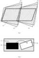
- FIG. 3shows a schematic representation of two cameras of the laser machining tool for capture of the machining space
- FIG. 5shows a schematic representation of the capture areas of the four cameras of FIG. 4 ;
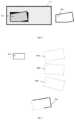
- FIG. 6shows a schematic representation of a flown-away part of a workpiece
- FIG. 7shows a schematic representation of a cut-out part of a workpiece with measuring points
- FIG. 8shows a schematic representation of the cut-out part of FIG. 7 showing the part extracted by image processing
- FIG. 9shows a schematic representation of the matching of the extracted part
- FIG. 10shows a flowchart of a method for collision avoidance of a laser machining head
- FIG. 11shows a flow chart of a general method for collision avoidance of a laser machining head
- FIG. 12shows an exemplary depiction of shapes of a cutting contour.
- FIG. 1shows a schematic perspective view of a numerically controlled laser machining tool 100 , in particular a laser cutting machine with a laser machining head 102 , in particular a laser cutting head.
- the laser cutting head 102is arranged on a movable bridge 104 so that it can be moved in at least the x and y directions in a machining space 106 of the laser machining tool 100 .
- a laser source 108generates laser light and supplies it to the laser cutting head 102 via a light guide 110 .
- a workpiece 112for example a metal sheet, is arranged in the machining space 106 and is cut by the laser beam.
- FIG. 2shows a schematic representation of a controller 200 of the numerically controlled laser machining tool 100 from FIG. 1 .
- a numerical control unit 202also called CNC (Computerised Numerical Control), executes the cutting plan as an EtherCAT master 204 in that the position signals are output via an EtherCAT bus 206 to the drives 208 as EtherCAT slave 210 .
- One of the drives 208is exemplified as EtherCAT slave 210 .
- This EtherCAT slave 210 and other EtherCAT slaveswrite data, for example from sensors, such as incremental encoders, to the EtherCAT bus 206 , and read data, which for example is used to control outputs, from the EtherCAT 206 bus.
- CMOS cameras or image recording unitsare provided without image processing, which enables a very high processing speed.
- the image data of the cameras 212are forwarded to a graphics processing unit 214 where the processing of the image data takes place.
- the graphics processing unit 214preferably comprises a plurality, for example, 512 or more GPUs, and is preferably configured for real-time image processing. Particularly suitable are highly parallel GPUs with 256 or more cores.
- the graphics processing unit 214also operates as EtherCAT slave 210 and thus is in direct communication with numerical control unit 202 .
- the graphics processing unit 214 and/or the numerical control unit 202are configured to carry out the methods or operations illustrated in FIGS. 6 through 10 and described below.
- the graphics processing unit 214is configured to process data from the cameras 212 to recognise changes to the workpiece, to model a change from a 3D object, and, optionally together with the numerical control unit 202 , to check for collision between the 3D object and the laser machining head based on a predetermined one cutting plan and/or the current position of the laser machining head.
- the numerical control unit 202is configured for collision avoidance in the event of a recognised risk of collision.
- the graphics processing unit 214obtains the cutting geometry or trajectory of the laser cutting head from the numerical control unit 202 via the EtherCAT bus 206 . Before a collision event occurs, the graphics processing unit 214 can signal this via the EtherCAT bus 206 . The signalling can be sent to the numerical control unit 202 and/or directly to the drive(s) 208 for the fastest possible response, such as emergency stop or bypass.
- the graphics processing unit 214sends data, such as the position or coordinates of the collision to the numerical control unit 202 , which in turn calculates an evasive route and drives the drives 208 accordingly.
- the new alternate routeis also sent to the graphics processing unit 214 , which now continues to check the new route for collision.
- All elements of the controller 200are configured for a real-time capability of the system.
- the targetfor example a Harris corner, is preferably attached to the cutting head. This target can be recognised automatically if its approximate position on the image is known. This is the case with a periodic recalibration.
- the cutting headis positioned in four defined positions. At each of these positions, one image is taken with each of the two cameras or two viewing angles. On each image, the image coordinates of the Harris corner are determined. From the machine coordinates of the four positions and the image coordinates of the Harris corner, the translation and rotation parameters are calculated.
- the cut part 700is cut out by means of a laser beam 702 . This process is observed by the cameras. Measurements are taken at certain measuring points 704 along the sectional contour in an image processing executed in the graphics processing unit 214 . The measurement points 704 are used to detect a change in an image of the workpiece 112 .
- the tilted cut part 700partially disappears under the remaining workpiece 112 , resulting in a strong contrast.
- the contrastis shown as a change between white and black. In fact, changes in colour values, brightness values and/or contrast values can be used.
- the area around the positionis marked as a risk zone. Now it must be decided what the control unit should initiate as a countermeasure. The collision can be prevented, for example, by stopping the machine rapidly. The even more efficient solution is that the cutting head either drives around the risk zone, lifts up to avoid the collision, or a combination of both.
- a first step 1000camera data are generated, i.e., images of the workpiece with at least one optical sensor, preferably two, four, or more sensors.
- the numerical control process 1012is executed in the numerical control unit.
- the numerical control unitknows the cutting plan 1014 and the current position 1016 of the cutting head, and in step 1018 calculates the planned track or route of the cutting head from the given cutting plan 1014 and/or the current position of the laser machining head.
- the 3D topology 1008 and the planned track 1018are supplied to a collision detector 1020 , an algorithm in the graphics processing unit, and/or the numerical control unit 1012 .
- the collision detector 1020checks to see if the 3D topology 1008 is within the planned track. If it is determined in step 1022 that a collision is possible, the method proceeds to block 1024 . If not, then branching back to the monitoring in step 1002 (not shown) results in a monitoring loop. The block or step 1002 is executed continuously.
- step 1024is supplied to the CNC process 1012 for processing and implementation.
- the drives of the laser machining headcan also be controlled directly, that is without the involvement of the numerical control unit.
- step 1102the change is analysed as outlined above.
- a first shape 1200consists of points lying on the actual cutting line.
- a second shape 1202consists of a trace of points inside the cutting contour, at an offset of five mm.
- a third shape 1204consists of a trace of points outside the cutting contour, also at an offset of for example five mm.
- a fourth shape 1206covers the whole area inside of the cutting contour.
- the size of the vectordiffers for the Neural network for two cameras and the Neural network for one camera.
- the Neural networkaccepts input data as a vector containing the concatenated histograms.
- the following sequenceis used:
- the Neural networkis in this example a deep Neural network consisting of one flattening layer as input layer, five internal dense layers with batch normalization and one dense layer with sigmoid activation as output layer.
- the deep Neural networkoutputs one floating point value in the range from 0,0 to 1,0 per contour. If the value is below 0,5, the contour is predicted to be safe. If the value is 0,5 or above, the contour is predicted to be dangerously tilted.
- the above described implementation of the Neural networkmay replace the interior modelling (steps 1006 and 1010 ) and the step 1008 .
- the above described implementation of the Neural networkmay replace the recognition of local changes (steps 1002 and 1004 ), the interior modelling (steps 1006 and 1010 ), and the step 1008 .
- the method presented here for collision avoidance by a laser machining head in a machining space of a laser machining toolenables a simple and precise recognition of possible obstacles in the planned track in real time and a collision avoidance in case of recognised risk of collision.
Landscapes
- Engineering & Computer Science (AREA)
- Physics & Mathematics (AREA)
- Optics & Photonics (AREA)
- Plasma & Fusion (AREA)
- Mechanical Engineering (AREA)
- Human Computer Interaction (AREA)
- Manufacturing & Machinery (AREA)
- General Physics & Mathematics (AREA)
- Automation & Control Theory (AREA)
- Laser Beam Processing (AREA)
- Numerical Control (AREA)
Abstract
Description
- Monitoring a workpiece in the machining space with at least one optical sensor;
- Capturing images of the workpiece;
- Detecting a change in an image of the workpiece;
- Recognising whether the change comprises an object that stands upright relative to the workpiece;
- Checking for a collision between the upright object and the laser machining head based on a predetermined cutting plan and/or the current position of the laser machining head;
- Controlling the drives for moving the laser machining head to avoid collision in case of recognised risk of collision.
- Calculating at least two shapes consisting of points and located parallel to a border of a cutting contour in an image, wherein one shape is located inside the border and one shape is located outside the border;
- Extracting image pixels according to the points of the shapes;
- Normalizing the image pixels by calculating a histogram of pixel brightness for each shape;
- Inputting the histograms into a deep neural network comprising an input layer, a plurality of internal layers and an output layer;
- Processing the histograms with the deep neural network;
- Outputting a variable by the deep neural network; and
- Recognizing whether an object in the cutting contour is tilted for a value of the variable being on a first side of a threshold or whether an object in the cutting contour is not tilted for a value of the variable being on a second side of a threshold.
- Outputting, by the deep neural network, one floating point variable with a value in the range from 0,0 to 1,0 for the cutting contour; and
- Recognizing whether an object in the cutting contour is tilted for a value of the floating point variable being 0.5 or above or whether an object in the cutting contour is not tilted for a value of the floating point variable below 0.5.
- a numerical control unit,
- an optical sensor system having at least one optical sensor which captures at least a part of the machining space and the workpiece arranged therein,
- a graphics processing unit connected to the optical sensor system and configured to process data from the sensor to recognise changes in the workpiece, and connected to the numerical control unit,
- Shape1200 histogram from right camera (32 values)
- Shape1200 histogram from left camera (32 values)
- Shape1202 histogram from right camera (32 values)
- Shape1202 histogram from left camera (32 values)
- Shape1204 histogram from right camera (32 values)
- Shape1204 histogram from left camera (32 values)
- Shape1206 histogram from right camera (32 values)
- Shape1206 histogram from left camera (32 values)
- Co-occurance histogram from right camera (32×32=1024 values)
- Co-occurance histogram from left camera (32×32=1024 values)
This totals up to 2304 input values for the Neural network.
- Shape1200 histogram (32 values)
- Shape1202 histogram (32 values)
- Shape1204 histogram (32 values)
- Shape1206 histogram (32 values)
- Co-occurance histogram (32×32=1024 values)
This totals up to 1152 input values for the Neural network.
Claims (15)
Applications Claiming Priority (3)
| Application Number | Priority Date | Filing Date | Title |
|---|---|---|---|
| DE102018123363.9ADE102018123363B4 (en) | 2018-09-24 | 2018-09-24 | Procedure for collision avoidance and laser processing machine |
| DE102018123363 | 2018-09-24 | ||
| PCT/EP2019/075456WO2020064589A1 (en) | 2018-09-24 | 2019-09-23 | Method for collision avoidance and laser machining tool |
Publications (2)
| Publication Number | Publication Date |
|---|---|
| US20210245295A1 US20210245295A1 (en) | 2021-08-12 |
| US11583951B2true US11583951B2 (en) | 2023-02-21 |
Family
ID=68281389
Family Applications (1)
| Application Number | Title | Priority Date | Filing Date |
|---|---|---|---|
| US17/275,042ActiveUS11583951B2 (en) | 2018-09-24 | 2019-09-23 | Method for collision avoidance and laser machining tool |
Country Status (7)
| Country | Link |
|---|---|
| US (1) | US11583951B2 (en) |
| EP (1) | EP3857318B1 (en) |
| JP (1) | JP6952218B2 (en) |
| CN (1) | CN112740125A (en) |
| DE (1) | DE102018123363B4 (en) |
| PL (1) | PL3857318T3 (en) |
| WO (1) | WO2020064589A1 (en) |
Cited By (4)
| Publication number | Priority date | Publication date | Assignee | Title |
|---|---|---|---|---|
| US20210323096A1 (en)* | 2018-10-16 | 2021-10-21 | Schuler Pressen Gmbh | Method and device for laser cutting a sheet metal blank from a continuously conveyed sheet metal strip |
| US20220143749A1 (en)* | 2019-02-18 | 2022-05-12 | Amada Co., Ltd. | Laser machining apparatus, laser machining method, and processing program creation device |
| US20230001502A1 (en)* | 2021-06-30 | 2023-01-05 | Messer Cutting Systems Gmbh | Method for the Thermal Processing of a Workpiece with a Thermal Processing Machine |
| US20230118821A1 (en)* | 2020-04-06 | 2023-04-20 | Bystronic Laser Ag | Laser machining tool |
Families Citing this family (18)
| Publication number | Priority date | Publication date | Assignee | Title |
|---|---|---|---|---|
| DE102018123363B4 (en)* | 2018-09-24 | 2021-01-07 | Bystronic Laser Ag | Procedure for collision avoidance and laser processing machine |
| JP7423145B2 (en)* | 2019-12-27 | 2024-01-29 | 株式会社ディスコ | Laser processing equipment and method |
| EP3910434A1 (en) | 2020-05-15 | 2021-11-17 | TRUMPF Werkzeugmaschinen GmbH + Co. KG | Location system with uwb infrastructure and discovery infrastructure |
| EP3944931A1 (en)* | 2020-07-30 | 2022-02-02 | Siemens Aktiengesellschaft | Collision avoidance with artificial intelligence |
| DE102020212510A1 (en) | 2020-10-02 | 2022-04-07 | Trumpf Werkzeugmaschinen Gmbh + Co. Kg | Method and device for showing the influence of cutting parameters on a cut edge |
| EP3984686A1 (en)* | 2020-10-16 | 2022-04-20 | Bystronic Laser AG | Method, control unit and laser cutting system for combined path and laser process planning for highly dynamic real-time systems |
| CN112276340B (en)* | 2020-11-13 | 2022-07-22 | 西安中科微精光子科技股份有限公司 | Machining path collision detection method and device for complex curved surface and storage medium |
| CN115121945B (en)* | 2021-03-22 | 2025-08-05 | 大族激光科技产业集团股份有限公司 | Laser cutting method and system |
| EP4080301B1 (en)* | 2021-04-19 | 2025-03-05 | Bystronic Laser AG | 3d tilt estimation and collision avoidance for laser cutting |
| DE102021110404A1 (en) | 2021-04-23 | 2022-10-27 | Trumpf Werkzeugmaschinen Gmbh + Co. Kg | Collision avoidance method, system and laser cutting device |
| DE102021129148B4 (en) | 2021-11-09 | 2025-05-28 | TRUMPF Werkzeugmaschinen SE + Co. KG | Method and device for collision avoidance during workpiece machining by a multi-axis machining center |
| CH718535B1 (en)* | 2022-03-23 | 2023-03-15 | Reishauer Ag | Method and machine tool system for collision checking of a machining process, with a replacement workpiece. |
| EP4249160A1 (en)* | 2022-03-24 | 2023-09-27 | Bystronic Laser AG | Determination of contour deviations for controlling a laser cutting machine |
| CN114603489B (en)* | 2022-04-21 | 2025-01-28 | 广东猛犸象智能机器人制造有限公司 | A method for intelligently identifying and cutting seamless products using a vision-guided water jet |
| EP4279435B1 (en)* | 2022-09-19 | 2024-10-30 | Siemens Aktiengesellschaft | Operating method for a loading system and automation system for controlling a loading system |
| IT202300006141A1 (en) | 2023-03-29 | 2024-09-29 | Gd Spa | METHOD FOR SIMULATING THE MOTION OF AT LEAST ONE PART OF AN AUTOMATIC MACHINE FOR THE PRODUCTION OR PACKAGING OF CONSUMER ITEMS |
| CN116618855A (en)* | 2023-06-16 | 2023-08-22 | 中冶南方工程技术有限公司 | Automatic control method and system for laser cutting unit |
| DE102023136173A1 (en)* | 2023-12-21 | 2025-06-26 | TRUMPF Werkzeugmaschinen SE + Co. KG | Device and method for avoiding downtimes of a machine tool |
Citations (51)
| Publication number | Priority date | Publication date | Assignee | Title |
|---|---|---|---|---|
| US4613269A (en)* | 1984-02-28 | 1986-09-23 | Object Recognition Systems, Inc. | Robotic acquisition of objects by means including histogram techniques |
| US4618938A (en)* | 1984-02-22 | 1986-10-21 | Kla Instruments Corporation | Method and apparatus for automatic wafer inspection |
| US4667113A (en)* | 1985-08-09 | 1987-05-19 | Hitachi Seiko Ltd. | Tool failure detection apparatus |
| US4794222A (en)* | 1986-06-30 | 1988-12-27 | Manabu Funayama | Laser beam machining apparatus |
| US5359872A (en)* | 1991-08-29 | 1994-11-01 | Okuma Corporation | Method and apparatus for sheet-metal processing |
| US5387061A (en)* | 1990-12-14 | 1995-02-07 | The United States Of America As Represented By The United States Department Of Energy | Parameter monitoring compensation system and method |
| US5489758A (en)* | 1993-01-14 | 1996-02-06 | Fanuc Ltd. | Height-sensing device for a laser robot |
| US5751584A (en)* | 1994-08-15 | 1998-05-12 | Toshiba Kikai Kabushiki Kaisha | Method for checking interference, method for checking processing program, and method for checking processing propriety |
| US5864114A (en)* | 1994-03-10 | 1999-01-26 | Toshiharu Ishikawa | Coating removal apparatus using coordinate-controlled laser beam |
| US6084223A (en)* | 1997-06-13 | 2000-07-04 | Jurca Optoelektronik | Method of welding workpieces and apparatus for carrying it out |
| US6128546A (en)* | 1996-09-30 | 2000-10-03 | Cincinnati Incorporated | Method and apparatus for a cutting system for avoiding pre-cut features |
| US6353203B1 (en)* | 1997-12-26 | 2002-03-05 | Mitsubishi Denki Kabushiki Kaisha | Laser machining device |
| US6603136B1 (en)* | 1999-10-15 | 2003-08-05 | Videojet Systems International | Laser marker focal length setting device |
| US6617541B1 (en)* | 1994-02-22 | 2003-09-09 | Koninklijke Philips Electronics N.V. | Laser etching method |
| US6632053B2 (en)* | 1998-10-08 | 2003-10-14 | Open Mind Software Technologies Gmbh | Method of directing the movement of a tool as part of a process to remove material from a block of material |
| US20030209528A1 (en)* | 1998-08-26 | 2003-11-13 | Choo Dae-Ho | Laser cutting apparatus and method |
| US20040112880A1 (en)* | 2002-12-13 | 2004-06-17 | Kazuma Sekiya | Laser machining method |
| US20050010324A1 (en)* | 2003-06-18 | 2005-01-13 | Siemens Aktiengesellschaft | Device and method for monitoring collisions of a machine component with a workpiece or another machine component |
| US20050226377A1 (en)* | 2004-03-31 | 2005-10-13 | Phillip Wong | Radiosurgery x-ray system with collision avoidance subsystem |
| US7062351B2 (en)* | 2003-09-25 | 2006-06-13 | The Boeing Company | Clamp avoidance cutter path regeneration |
| US20070228025A1 (en)* | 2004-09-04 | 2007-10-04 | Trumpf Werkzeugmaschinen Gmbh + Co. Kg | Determining the relative positions of the axes of a laser machining beam and a process gas jet |
| US7283892B1 (en)* | 2006-04-03 | 2007-10-16 | Servo-Robot Inc. | Hybrid compact sensing apparatus for adaptive robotic processes |
| US20090127762A1 (en)* | 2006-05-24 | 2009-05-21 | Trumpf Werkzeugmaschinen Gmbh + Co. Kg | Work rests for supporting a workpiece in a machining unit and machining units containing such work rests |
| US7638731B2 (en)* | 2005-10-18 | 2009-12-29 | Electro Scientific Industries, Inc. | Real time target topography tracking during laser processing |
| US20100063617A1 (en)* | 2008-09-05 | 2010-03-11 | Mori Seiki Co., Ltd | Machining state checking method and machining state checking apparatus |
| US20100176099A1 (en)* | 2007-04-03 | 2010-07-15 | Sauer Gmbh Lasertec | Method and device for the initial measurement of a workpiece, and the processing of a workpiece |
| US7764039B2 (en)* | 2006-07-25 | 2010-07-27 | Fanuc Ltd | Numerical controller |
| US20110313561A1 (en)* | 2010-06-22 | 2011-12-22 | Samsung Electro-Mechanics Co., Ltd. | Machining error corrector method using optical pickup |
| US8175858B2 (en)* | 2008-03-24 | 2012-05-08 | Okuma Corporation | Machining simulation apparatus |
| US20120267349A1 (en)* | 2009-10-06 | 2012-10-25 | Bayerische Motoren Werke Ag | Joining device for non-positive joining by means of a filler material using sensors |
| US8367969B2 (en)* | 2008-11-18 | 2013-02-05 | Air Liquide Industrial U.S. Lp | Support table frame for high speed laser blanking |
| US8581144B2 (en)* | 2008-08-25 | 2013-11-12 | Disco Corporation | Laser processing apparatus and laser processing method |
| US20130319980A1 (en)* | 2011-02-07 | 2013-12-05 | Trumpf Werkzeugmaschinen Gmbh + Co. Kg | Device and Method for Monitoring a Laser Cutting Process |
| US20140263211A1 (en)* | 2013-03-15 | 2014-09-18 | Apple Inc. | Methods for Trimming Display Polarizers Using Lasers |
| US8987634B2 (en)* | 2008-11-13 | 2015-03-24 | Trumpf Laser- Und Systemtechnik Gmbh | Determining powder feed nozzle misalignment |
| US20150151381A1 (en)* | 2013-11-29 | 2015-06-04 | Fanuc Corporation | Controller of laser machining device and controlling method for reducing approach time |
| US20150165549A1 (en)* | 2013-12-12 | 2015-06-18 | Bystronic Laser Ag | Method for configuring a laser machining machine |
| US9110459B2 (en)* | 2008-07-10 | 2015-08-18 | Citizen Machinery Co., Ltd. | Interference check device, interference check method, and machine tool having the interference check device |
| US9122267B2 (en)* | 2013-02-21 | 2015-09-01 | Mitsubishi Electric Corporation | Interference checking device and numerical control apparatus |
| US20150266133A1 (en)* | 2014-03-24 | 2015-09-24 | Fanuc Corporation | Laser processing apparatus capable of retracting processing nozzle upon detection of power outage |
| US20150352679A1 (en)* | 2013-03-07 | 2015-12-10 | Mitsubishi Heavy Industries, Ltd. | Abnormality diagnosis device for machine tool, and abnormality diagnosis method |
| US20160059350A1 (en)* | 2014-08-02 | 2016-03-03 | Precitec Optronik Gmbh | Method for Measuring the Distance Between a Workpiece and a Machining Head of a Laser Machining Apparatus |
| US20160059351A1 (en)* | 2014-08-27 | 2016-03-03 | Fanuc Corporation | Laser beam machining apparatus with high-speed positioning function |
| US20160158884A1 (en)* | 2013-08-28 | 2016-06-09 | Trumpf Laser- Und Systemtechnik Gmbh | Determining Deviations of an Actual Position of a Laser Machining Head from a Desired Position |
| US20160184923A1 (en)* | 2014-12-25 | 2016-06-30 | Fanuc Corporation | Laser processing device having function for avoiding interference at the time of nozzle approach |
| US20160193692A1 (en)* | 2013-09-13 | 2016-07-07 | Trumpf Werkzeugmaschinen Gmbh + Co. Kg | Devices and Methods for Monitoring, in Particular for Regulating, a Cutting Process |
| US9539664B2 (en)* | 2008-06-17 | 2017-01-10 | Matthew Fagan | Methods and systems for predictive torch height control |
| US20170115656A1 (en)* | 2014-07-11 | 2017-04-27 | Trumpf Werkzeugmaschinen Gmbh + Co. Kg | Image-Based Placing of Workpiece Machining Operations |
| US20190128857A1 (en)* | 2016-04-13 | 2019-05-02 | Shimadzu Corporation | Autosampler |
| US10507558B2 (en)* | 2017-03-02 | 2019-12-17 | Fanuc Corporation | Machine tool system |
| WO2020064589A1 (en)* | 2018-09-24 | 2020-04-02 | Bystronic Laser Ag | Method for collision avoidance and laser machining tool |
Family Cites Families (8)
| Publication number | Priority date | Publication date | Assignee | Title |
|---|---|---|---|---|
| JP2771571B2 (en)* | 1989-01-31 | 1998-07-02 | 株式会社アマダ | Bending and welding combined processing equipment |
| JP3430124B2 (en)* | 2000-06-02 | 2003-07-28 | 山形日本電気株式会社 | Gate part processing apparatus and processing method for semiconductor manufacturing apparatus |
| CN103495807B (en)* | 2013-09-27 | 2015-08-19 | 重庆大学 | Multirobot optical-fiber laser diced system |
| DE102014200208B3 (en)* | 2014-01-09 | 2015-06-11 | Trumpf Werkzeugmaschinen Gmbh + Co. Kg | Method for separating a workpiece |
| CN103878478B (en)* | 2014-01-28 | 2015-11-18 | 华中科技大学 | A kind of three-dimensional laser processing Workpiece fixing measurement mechanism and method thereof |
| EP3907570A1 (en)* | 2015-02-12 | 2021-11-10 | Glowforge Inc. | Cloud controlled laser fabrication |
| CN105195868B (en)* | 2015-11-12 | 2018-05-15 | 上海电气核电设备有限公司 | A kind of robot welding system and its welding method |
| CN106271114A (en)* | 2016-10-10 | 2017-01-04 | 山东科技大学 | Laser processing device |
- 2018
- 2018-09-24DEDE102018123363.9Apatent/DE102018123363B4/ennot_activeExpired - Fee Related
- 2019
- 2019-09-23JPJP2021516614Apatent/JP6952218B2/enactiveActive
- 2019-09-23CNCN201980062101.2Apatent/CN112740125A/enactivePending
- 2019-09-23WOPCT/EP2019/075456patent/WO2020064589A1/ennot_activeCeased
- 2019-09-23PLPL19789593.1Tpatent/PL3857318T3/enunknown
- 2019-09-23USUS17/275,042patent/US11583951B2/enactiveActive
- 2019-09-23EPEP19789593.1Apatent/EP3857318B1/enactiveActive
Patent Citations (52)
| Publication number | Priority date | Publication date | Assignee | Title |
|---|---|---|---|---|
| US4618938A (en)* | 1984-02-22 | 1986-10-21 | Kla Instruments Corporation | Method and apparatus for automatic wafer inspection |
| US4613269A (en)* | 1984-02-28 | 1986-09-23 | Object Recognition Systems, Inc. | Robotic acquisition of objects by means including histogram techniques |
| US4667113A (en)* | 1985-08-09 | 1987-05-19 | Hitachi Seiko Ltd. | Tool failure detection apparatus |
| US4794222A (en)* | 1986-06-30 | 1988-12-27 | Manabu Funayama | Laser beam machining apparatus |
| US5387061A (en)* | 1990-12-14 | 1995-02-07 | The United States Of America As Represented By The United States Department Of Energy | Parameter monitoring compensation system and method |
| US5359872A (en)* | 1991-08-29 | 1994-11-01 | Okuma Corporation | Method and apparatus for sheet-metal processing |
| US5489758A (en)* | 1993-01-14 | 1996-02-06 | Fanuc Ltd. | Height-sensing device for a laser robot |
| US6617541B1 (en)* | 1994-02-22 | 2003-09-09 | Koninklijke Philips Electronics N.V. | Laser etching method |
| US5864114A (en)* | 1994-03-10 | 1999-01-26 | Toshiharu Ishikawa | Coating removal apparatus using coordinate-controlled laser beam |
| US5751584A (en)* | 1994-08-15 | 1998-05-12 | Toshiba Kikai Kabushiki Kaisha | Method for checking interference, method for checking processing program, and method for checking processing propriety |
| US6128546A (en)* | 1996-09-30 | 2000-10-03 | Cincinnati Incorporated | Method and apparatus for a cutting system for avoiding pre-cut features |
| US6084223A (en)* | 1997-06-13 | 2000-07-04 | Jurca Optoelektronik | Method of welding workpieces and apparatus for carrying it out |
| US6353203B1 (en)* | 1997-12-26 | 2002-03-05 | Mitsubishi Denki Kabushiki Kaisha | Laser machining device |
| US20030209528A1 (en)* | 1998-08-26 | 2003-11-13 | Choo Dae-Ho | Laser cutting apparatus and method |
| US6632053B2 (en)* | 1998-10-08 | 2003-10-14 | Open Mind Software Technologies Gmbh | Method of directing the movement of a tool as part of a process to remove material from a block of material |
| US6603136B1 (en)* | 1999-10-15 | 2003-08-05 | Videojet Systems International | Laser marker focal length setting device |
| US20040112880A1 (en)* | 2002-12-13 | 2004-06-17 | Kazuma Sekiya | Laser machining method |
| US20050010324A1 (en)* | 2003-06-18 | 2005-01-13 | Siemens Aktiengesellschaft | Device and method for monitoring collisions of a machine component with a workpiece or another machine component |
| US7062351B2 (en)* | 2003-09-25 | 2006-06-13 | The Boeing Company | Clamp avoidance cutter path regeneration |
| US20050226377A1 (en)* | 2004-03-31 | 2005-10-13 | Phillip Wong | Radiosurgery x-ray system with collision avoidance subsystem |
| US20070228025A1 (en)* | 2004-09-04 | 2007-10-04 | Trumpf Werkzeugmaschinen Gmbh + Co. Kg | Determining the relative positions of the axes of a laser machining beam and a process gas jet |
| US7638731B2 (en)* | 2005-10-18 | 2009-12-29 | Electro Scientific Industries, Inc. | Real time target topography tracking during laser processing |
| US7283892B1 (en)* | 2006-04-03 | 2007-10-16 | Servo-Robot Inc. | Hybrid compact sensing apparatus for adaptive robotic processes |
| US20090127762A1 (en)* | 2006-05-24 | 2009-05-21 | Trumpf Werkzeugmaschinen Gmbh + Co. Kg | Work rests for supporting a workpiece in a machining unit and machining units containing such work rests |
| US8382087B2 (en)* | 2006-05-24 | 2013-02-26 | Trumpf Werkzeugmaschinen Gmbh + Co. Kg | Work rests for supporting a workpiece in a machining unit and machining units containing such work rests |
| US7764039B2 (en)* | 2006-07-25 | 2010-07-27 | Fanuc Ltd | Numerical controller |
| US20100176099A1 (en)* | 2007-04-03 | 2010-07-15 | Sauer Gmbh Lasertec | Method and device for the initial measurement of a workpiece, and the processing of a workpiece |
| US8175858B2 (en)* | 2008-03-24 | 2012-05-08 | Okuma Corporation | Machining simulation apparatus |
| US9539664B2 (en)* | 2008-06-17 | 2017-01-10 | Matthew Fagan | Methods and systems for predictive torch height control |
| US9110459B2 (en)* | 2008-07-10 | 2015-08-18 | Citizen Machinery Co., Ltd. | Interference check device, interference check method, and machine tool having the interference check device |
| US8581144B2 (en)* | 2008-08-25 | 2013-11-12 | Disco Corporation | Laser processing apparatus and laser processing method |
| US20100063617A1 (en)* | 2008-09-05 | 2010-03-11 | Mori Seiki Co., Ltd | Machining state checking method and machining state checking apparatus |
| US8987634B2 (en)* | 2008-11-13 | 2015-03-24 | Trumpf Laser- Und Systemtechnik Gmbh | Determining powder feed nozzle misalignment |
| US8367969B2 (en)* | 2008-11-18 | 2013-02-05 | Air Liquide Industrial U.S. Lp | Support table frame for high speed laser blanking |
| US20120267349A1 (en)* | 2009-10-06 | 2012-10-25 | Bayerische Motoren Werke Ag | Joining device for non-positive joining by means of a filler material using sensors |
| US20110313561A1 (en)* | 2010-06-22 | 2011-12-22 | Samsung Electro-Mechanics Co., Ltd. | Machining error corrector method using optical pickup |
| US20130319980A1 (en)* | 2011-02-07 | 2013-12-05 | Trumpf Werkzeugmaschinen Gmbh + Co. Kg | Device and Method for Monitoring a Laser Cutting Process |
| US9122267B2 (en)* | 2013-02-21 | 2015-09-01 | Mitsubishi Electric Corporation | Interference checking device and numerical control apparatus |
| US20150352679A1 (en)* | 2013-03-07 | 2015-12-10 | Mitsubishi Heavy Industries, Ltd. | Abnormality diagnosis device for machine tool, and abnormality diagnosis method |
| US20140263211A1 (en)* | 2013-03-15 | 2014-09-18 | Apple Inc. | Methods for Trimming Display Polarizers Using Lasers |
| US20160158884A1 (en)* | 2013-08-28 | 2016-06-09 | Trumpf Laser- Und Systemtechnik Gmbh | Determining Deviations of an Actual Position of a Laser Machining Head from a Desired Position |
| US20160193692A1 (en)* | 2013-09-13 | 2016-07-07 | Trumpf Werkzeugmaschinen Gmbh + Co. Kg | Devices and Methods for Monitoring, in Particular for Regulating, a Cutting Process |
| US20150151381A1 (en)* | 2013-11-29 | 2015-06-04 | Fanuc Corporation | Controller of laser machining device and controlling method for reducing approach time |
| US20150165549A1 (en)* | 2013-12-12 | 2015-06-18 | Bystronic Laser Ag | Method for configuring a laser machining machine |
| US20150266133A1 (en)* | 2014-03-24 | 2015-09-24 | Fanuc Corporation | Laser processing apparatus capable of retracting processing nozzle upon detection of power outage |
| US20170115656A1 (en)* | 2014-07-11 | 2017-04-27 | Trumpf Werkzeugmaschinen Gmbh + Co. Kg | Image-Based Placing of Workpiece Machining Operations |
| US20160059350A1 (en)* | 2014-08-02 | 2016-03-03 | Precitec Optronik Gmbh | Method for Measuring the Distance Between a Workpiece and a Machining Head of a Laser Machining Apparatus |
| US20160059351A1 (en)* | 2014-08-27 | 2016-03-03 | Fanuc Corporation | Laser beam machining apparatus with high-speed positioning function |
| US20160184923A1 (en)* | 2014-12-25 | 2016-06-30 | Fanuc Corporation | Laser processing device having function for avoiding interference at the time of nozzle approach |
| US20190128857A1 (en)* | 2016-04-13 | 2019-05-02 | Shimadzu Corporation | Autosampler |
| US10507558B2 (en)* | 2017-03-02 | 2019-12-17 | Fanuc Corporation | Machine tool system |
| WO2020064589A1 (en)* | 2018-09-24 | 2020-04-02 | Bystronic Laser Ag | Method for collision avoidance and laser machining tool |
Non-Patent Citations (1)
| Title |
|---|
| International Preliminary Report on Patentability, dated Sep. 10, 2020, for PCT/EP2019/075456 filed Sep. 23, 2019. |
Cited By (7)
| Publication number | Priority date | Publication date | Assignee | Title |
|---|---|---|---|---|
| US20210323096A1 (en)* | 2018-10-16 | 2021-10-21 | Schuler Pressen Gmbh | Method and device for laser cutting a sheet metal blank from a continuously conveyed sheet metal strip |
| US11911851B2 (en)* | 2018-10-16 | 2024-02-27 | Schuler Pressen Gmbh | Method and device for laser cutting a sheet metal blank from a continuously conveyed sheet metal strip |
| US20220143749A1 (en)* | 2019-02-18 | 2022-05-12 | Amada Co., Ltd. | Laser machining apparatus, laser machining method, and processing program creation device |
| US12370627B2 (en)* | 2019-02-18 | 2025-07-29 | Amada Co., Ltd. | Laser machining apparatus, laser machining method, and processing program creation device |
| US20230118821A1 (en)* | 2020-04-06 | 2023-04-20 | Bystronic Laser Ag | Laser machining tool |
| US11745293B2 (en)* | 2020-04-06 | 2023-09-05 | Bystronic Laser Ag | Laser machining tool |
| US20230001502A1 (en)* | 2021-06-30 | 2023-01-05 | Messer Cutting Systems Gmbh | Method for the Thermal Processing of a Workpiece with a Thermal Processing Machine |
Also Published As
| Publication number | Publication date |
|---|---|
| EP3857318B1 (en) | 2022-07-20 |
| US20210245295A1 (en) | 2021-08-12 |
| DE102018123363A1 (en) | 2020-03-26 |
| JP2021527572A (en) | 2021-10-14 |
| CN112740125A (en) | 2021-04-30 |
| PL3857318T3 (en) | 2022-10-17 |
| JP6952218B2 (en) | 2021-10-20 |
| DE102018123363B4 (en) | 2021-01-07 |
| EP3857318A1 (en) | 2021-08-04 |
| WO2020064589A1 (en) | 2020-04-02 |
Similar Documents
| Publication | Publication Date | Title |
|---|---|---|
| US11583951B2 (en) | Method for collision avoidance and laser machining tool | |
| JP7082715B2 (en) | Detection of machining errors in laser machining systems using deep convolutional neural networks | |
| CA3062044C (en) | System and method for work piece inspection | |
| CN105473927B (en) | For the apparatus and method for the machine for ensureing automatically working | |
| CN113891775A (en) | Method for providing geometric data for slab planning, method for cutting out workpieces and planar laser machine | |
| Golnabi et al. | Design and application of industrial machine vision systems | |
| JP2024083389A (en) | Monitoring of laser machining processes using deep convolutional neural networks | |
| CN102460065B (en) | Information processing apparatus and information processing method | |
| US10532459B2 (en) | Information processing apparatus, information processing method, and storage medium for grasping an object | |
| US20080240511A1 (en) | Apparatus for picking up objects | |
| US20080301072A1 (en) | Robot simulation apparatus | |
| CN111750821B (en) | Pose parameter measuring method, device and system and storage medium | |
| US20210283782A1 (en) | Measurement parameter optimization method and device, and computer control program stored on computer-readable storage medium | |
| US20190257978A1 (en) | Object monitoring device using sensor | |
| US20170294020A1 (en) | Camera pose estimation | |
| CN115014205B (en) | Visual detection method and detection system for tower tray and automatic welding guiding system thereof | |
| JPH05322531A (en) | Three-dimensional shape measuring device of object | |
| TWI608894B (en) | Intelligent anti-collision safety system and tool machine using the same | |
| CN209036141U (en) | Numerically-controlled machine tool processes three-dimensional aided positioning system | |
| CN117532603B (en) | Quick positioning method, system and device for feeding and discharging of mobile robot | |
| KR101293554B1 (en) | Laser scanning measurement apparatus and measurement method of curved sheet using the same | |
| TWI619372B (en) | Ultra-wide depth stereoscopic image system and method | |
| WO2024144471A1 (en) | A vibrating machine conducting fine sanding with at least one detector unit | |
| KR20160109615A (en) | Apparatus and method for inspecting parts using line scanning | |
| WO2023140266A1 (en) | Picking device and image generation program |
Legal Events
| Date | Code | Title | Description |
|---|---|---|---|
| AS | Assignment | Owner name:BYSTRONIC LASER AG, SWITZERLAND Free format text:ASSIGNMENT OF ASSIGNORS INTEREST;ASSIGNORS:FAHRNI, CHRISTOPH;MAZLOUMIAN, SEYED AMIN;REEL/FRAME:055552/0602 Effective date:20210309 | |
| FEPP | Fee payment procedure | Free format text:ENTITY STATUS SET TO UNDISCOUNTED (ORIGINAL EVENT CODE: BIG.); ENTITY STATUS OF PATENT OWNER: LARGE ENTITY | |
| STPP | Information on status: patent application and granting procedure in general | Free format text:RESPONSE TO NON-FINAL OFFICE ACTION ENTERED AND FORWARDED TO EXAMINER | |
| STPP | Information on status: patent application and granting procedure in general | Free format text:NON FINAL ACTION MAILED | |
| STPP | Information on status: patent application and granting procedure in general | Free format text:FINAL REJECTION MAILED | |
| STPP | Information on status: patent application and granting procedure in general | Free format text:DOCKETED NEW CASE - READY FOR EXAMINATION | |
| STPP | Information on status: patent application and granting procedure in general | Free format text:NON FINAL ACTION MAILED | |
| STPP | Information on status: patent application and granting procedure in general | Free format text:RESPONSE TO NON-FINAL OFFICE ACTION ENTERED AND FORWARDED TO EXAMINER | |
| STPP | Information on status: patent application and granting procedure in general | Free format text:FINAL REJECTION MAILED | |
| STPP | Information on status: patent application and granting procedure in general | Free format text:RESPONSE AFTER FINAL ACTION FORWARDED TO EXAMINER | |
| STPP | Information on status: patent application and granting procedure in general | Free format text:ADVISORY ACTION MAILED | |
| STPP | Information on status: patent application and granting procedure in general | Free format text:DOCKETED NEW CASE - READY FOR EXAMINATION | |
| STPP | Information on status: patent application and granting procedure in general | Free format text:NON FINAL ACTION MAILED | |
| STPP | Information on status: patent application and granting procedure in general | Free format text:NOTICE OF ALLOWANCE MAILED -- APPLICATION RECEIVED IN OFFICE OF PUBLICATIONS | |
| STPP | Information on status: patent application and granting procedure in general | Free format text:PUBLICATIONS -- ISSUE FEE PAYMENT VERIFIED | |
| STCF | Information on status: patent grant | Free format text:PATENTED CASE |